To manufacturers of constant wear lifejackets and certification authorities
Fitment of constant wear lifejackets with seatbelts in aircraft
Constant wear lifejackets, including pouch style lifejackets, must not interfere with the proper fitment of aircraft seatbelts. It is imperative that seatbelts are fitted correctly. Not wearing a seatbelt, or wearing it improperly, can significantly increase the risk of serious or fatal injury in the event of an accident.
What happened
On 2 January 2023, Sea World Helicopters was conducting a series of short scenic flights from its base at Sea World on the Gold Coast, Queensland. The operator was using 2 Eurocopter EC130B4 helicopters which were operating from separate helipads about 220 m apart.
As one helicopter approached the southern helipad to land, another took off from the helipad to the north. The helicopters collided mid-air at about 130 ft. One helicopter proceeded to a controlled landing on a sandbar, the pilot and two passengers were seriously injured. The other helicopter fell uncontrolled to the edge of the sandbar. There were 3 passengers seriously injured and the pilot and three passengers were fatally injured. While some occupants of this aircraft survived, the ATSB would categorise the impact with terrain for that helicopter as likely not survivable (the occupants were not expected to survive the impact).
Safety equipment
Seatbelts
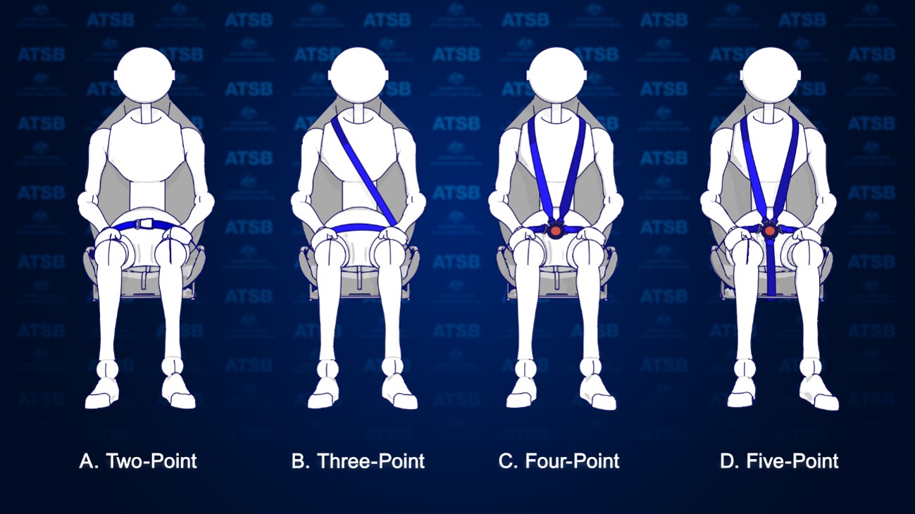
There are several types of seatbelts used to restrain passengers in aircraft. The most common type that passengers are exposed to are lap belts (2-point restraints) like those used on large passenger aircraft. There are also 3-point, 4-point and 5-point restraints, which are more prevalent in light aircraft, that have an added safety harness for the upper body (Figure 1). In the case of the helicopters involved in the accident, all seats were fitted with 4-point restraints.
Figure 1: Types of aircraft seatbelts
Source: ATSB
To be effective in an accident, seatbelts must be fitted correctly. Not wearing a seatbelt or wearing it improperly can result in serious injury or fatalities. For example, the fatality rate in accidents in Canada involving seaplanes has been shown to be 3 to 4 times higher for occupants who don’t wear a restraint system properly over those that do.[1]
For seatbelts to be effective, regulatory and manufacturer guidance advise:[2]
Seatbelts must not be twisted, they must be fitted without slack, and adjusted to fit as tightly as comfort allows.
The lap portion of the seatbelt must be placed low and tight across the hips.
Seatbelts must not be fitted across the abdomen as this can cause internal injuries or result in the person sliding out the bottom of the harness (submarining), nor should they be fitted across the thighs, or the seatbelt will not effectively prevent forward movement.
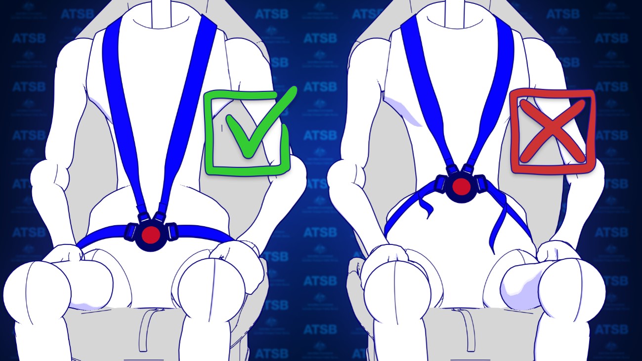
For the fitment of 4-point restraints, the lap belt portion of the restraint should be fitted and adjusted first before the shoulder harness. This is to prevent the shoulder harness from pulling the lap belt off the hips.
Figure 2: Correct and incorrect fitment of 4-point harnesses
Source: ATSB
Constant wear lifejackets
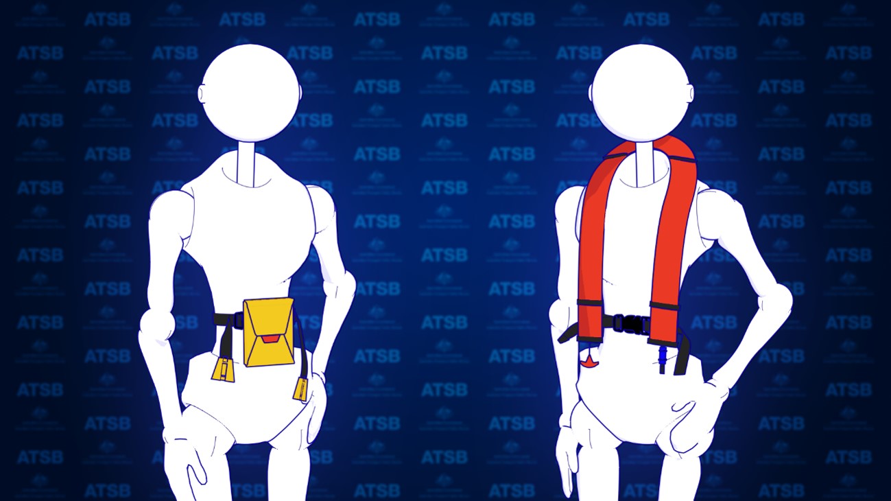
Aviation lifejackets are inflatable and can be packaged in many forms. To ensure passengers have access to a lifejacket in a time limited situation, lifejacket manufacturers have produced lifejackets known as constant wear lifejackets. Constant wear lifejackets come in two packaging forms. There is a yoke style which is worn like a vest (Figure 3, right) and a pouch style which is worn around the waist (Figure 3, left) but readily pulled over the head of the occupant when required. To meet the required aviation standards, operational instructions must be provided in writing and be printed on the lifejacket.
Figure 3: Example of pouch (left) and yoke (right) style constant wear lifejackets
Source: ATSB
What the ATSB found
Passenger photographs and footage from inside both helicopters identified that some passenger seatbelts were not fitted correctly. This was due, in part, to interference caused by the location of the constant wear pouch style lifejackets that were being worn by passengers. The operator’s pre-flight passenger safety briefing video also depicted incorrect use of the 4-point restraint while wearing the lifejacket. The operator’s ground crew, who had been assigned responsibility for the fitment of passenger seatbelts, also indicated in interview that they were not aware that fitting the seatbelt over or above the lifejacket may reduce its effectiveness.
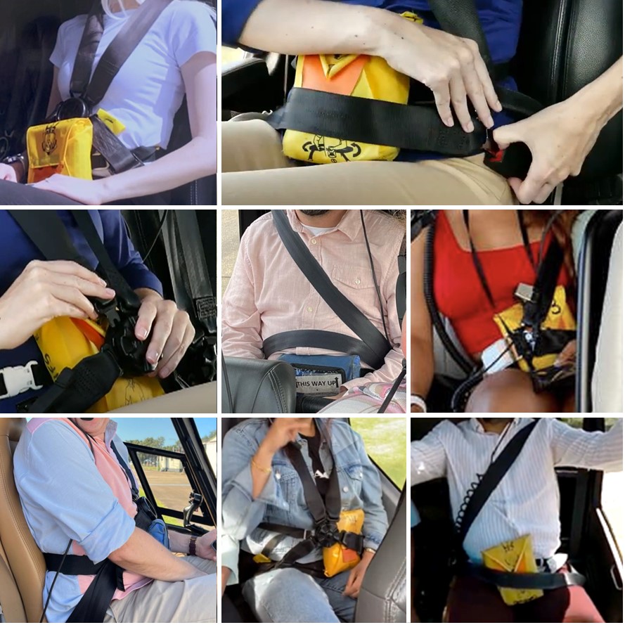
To establish the extent of the issue the ATSB conducted a review of helicopter tourism operations in Australia and around the world through social media. The ATSB found that similar practices of incorrect fitment of seatbelts with constant wear pouch style lifejackets were prevalent. Many relevant social media photos reviewed by the ATSB (see Figure 4 for some examples) showed the seatbelt buckle was positioned above the lifejacket pouch or over it. This meant that the lap belt portion of the seatbelt was not low and tight across the passenger’s hips and the seatbelt buckle was positioned either over the lifejacket (creating slack) or above the lifejacket, close to the passenger’s sternum increasing the risk of injury. This suggests there is a common lack of understanding in the helicopter tourism community about how to integrate constant wear lifejackets with seatbelts, so as not to reduce their effectiveness. Although social media images reviewed by the ATSB predominately showed interference caused by a ‘pouch style’ constant wear lifejacket, the ‘yoke style’ constant wear lifejacket more often used by pilots and commercial passengers, was also shown to have the potential to interfere with the aircraft seatbelt.
For constant wear lifejackets, it is reasonably foreseeable that they would be worn seated in an aircraft and while using the aircraft’s seatbelt. The ATSB reviewed existing guidance from all known manufacturers of aviation constant wear lifejackets, as well as from the Civil Aviation Safety Authority and a range of international aviation regulators. Beyond stating that lifejackets should not interfere with other aircraft equipment, lifejacket manufacturers and regulatory authorities have not provided any readily available guidance to assist helicopter operators on how to position a pouch or yoke style constant wear lifejacket so as not to interfere with an aircraft seatbelt. Additionally, there are no requirements to provide such instructions in the relevant standards.
Figure 4: Examples of lifejacket interference
Sources: Safety briefing videos from YouTube and the operator, and other social media
The ATSB encourages manufacturers of constant wear lifejackets to provide operating instructions and/or guidance material to operators of aircraft on how to wear and use a constant wear lifejacket with a seatbelt (of any configuration) such that it does not interfere with the performance of the seatbelt during an accident.
Further,the ATSB encourages certification authorities to modify lifejacket standards to include the requirement for instructions on how to wear constant wear lifejackets while seated and wearing a seatbelt.
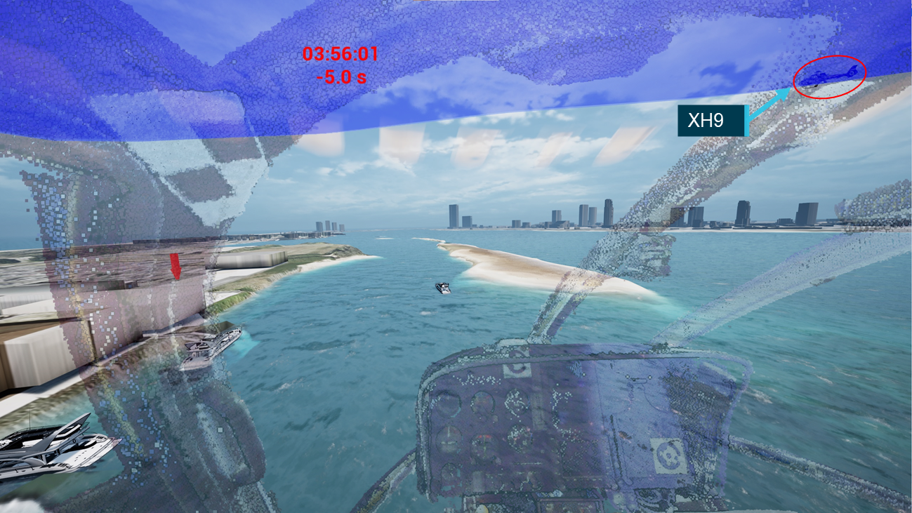
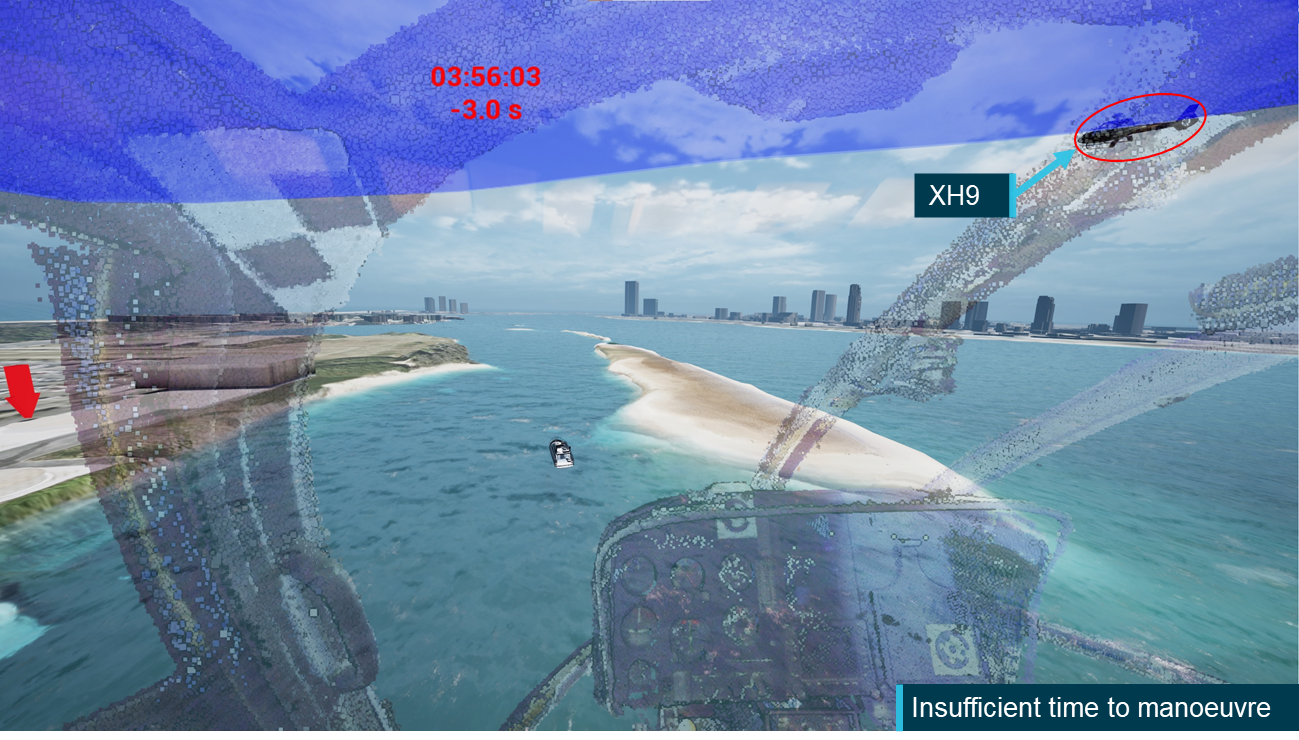
As part of the investigation into the midair collision involving 2 Eurocopter[1] EC130 B4 helicopters, VH‑XH9 and VH‑XKQ, at Main Beach, Gold Coast, Queensland on 2 January 2023, (ATSB Investigation AO-2023-001), the ATSB sought to identify what limitations or opportunities the pilots had to visually detect and avoid the other aircraft. That is, to gain a more detailed understanding of whether the ‘see-and-avoid’ principle, with its known limitations, could have been effective for the pilots of these 2 helicopters in avoiding the collision.
To examine this aspect in detail, the ATSB initiated a cockpit visibility study to examine when each aircraft would likely have been visible to the other pilot. It examined the impact of aircraft structure, pilot positioning and apparel, local environment, visual conspicuity devices and human performance on the opportunity for detection.
The study involved a review of available literature covering the ‘see-and-avoid’ concept, human visibility limitations and helicopter conspicuity. A detailed 3-dimensional model of an exemplar helicopter was used to determine the relative position of the aircraft structure within each pilot’s field of view. To calculate the opportunity for detection, a detailed analysis of onboard data was performed to calculate the relative size, position and closing speed between the 2 helicopters. This was combined with an assessment of elements of the helicopters that could impact visual conspicuity.
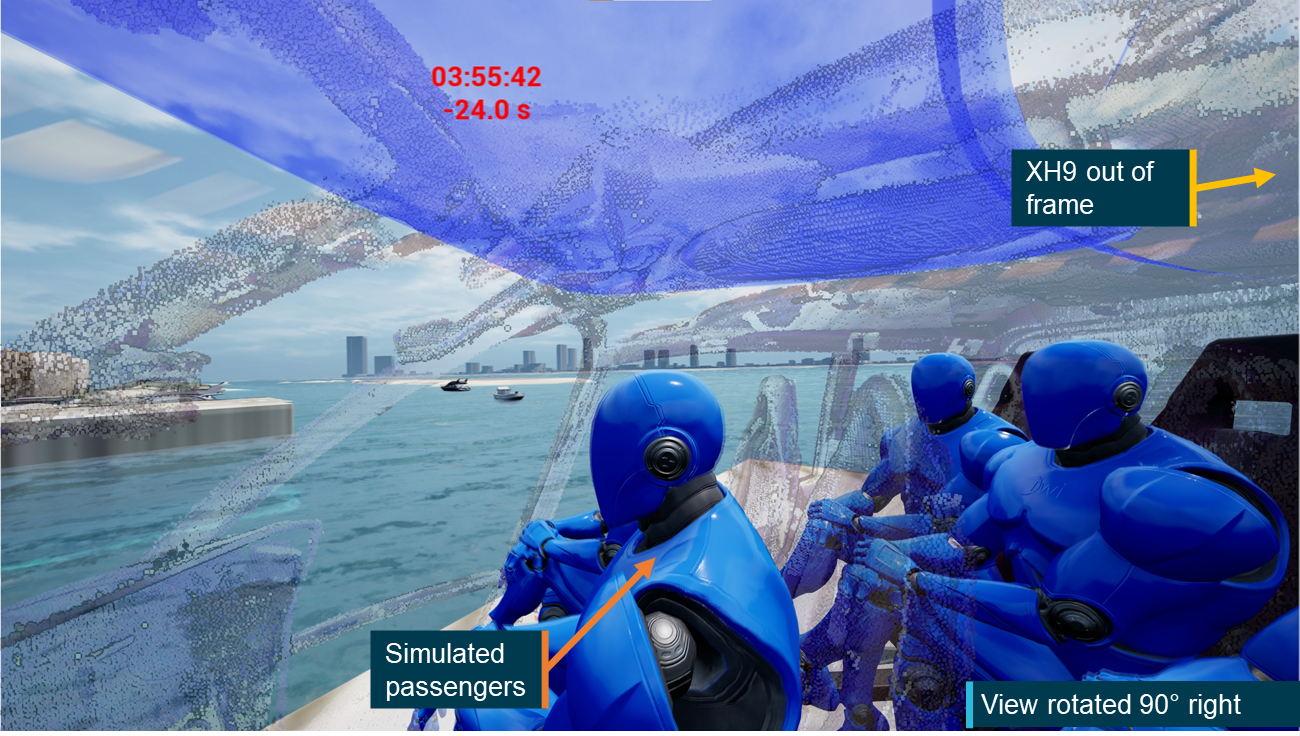
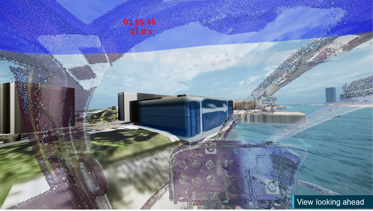
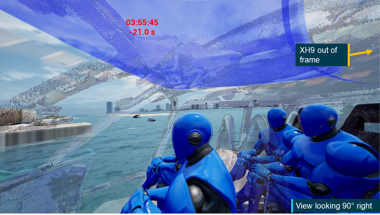
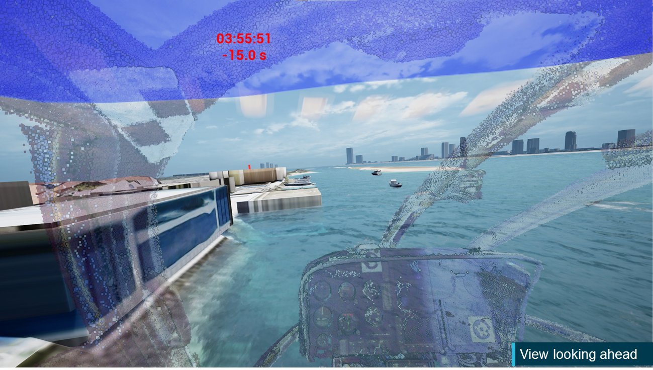
Finally, an animation was developed in collaboration with Airbus Helicopters and a simulation expert at iwiation GmbH in Germany. This animation represented the view from the pilot’s eye position in each aircraft in the lead‑up to the collision and demonstrated the opportunities for detection that the pilots probably encountered.
Throughout the development of the study and accompanying animation multiple data verification processes were employed to ensure that, within the limitations outlined in this report, the analysis aligned with the actual events. This included:
cross‑validation between the results of the visibility study analysis and animation that were developed using separate techniques
validation of aircraft position, orientation and pilot’s eye position against cameras on board XKQ and XH9
validation of aircraft position and orientation against multiple external cameras
validation of results against ATSB wreckage analysis and the pilot of XH9’s comments.
This study does not consider aspects of the pilots’ mental models or the potential impact of electronic conspicuity devices. These aspects are addressed in detail in the investigation report.
What the ATSB found
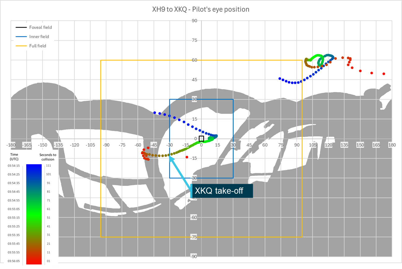
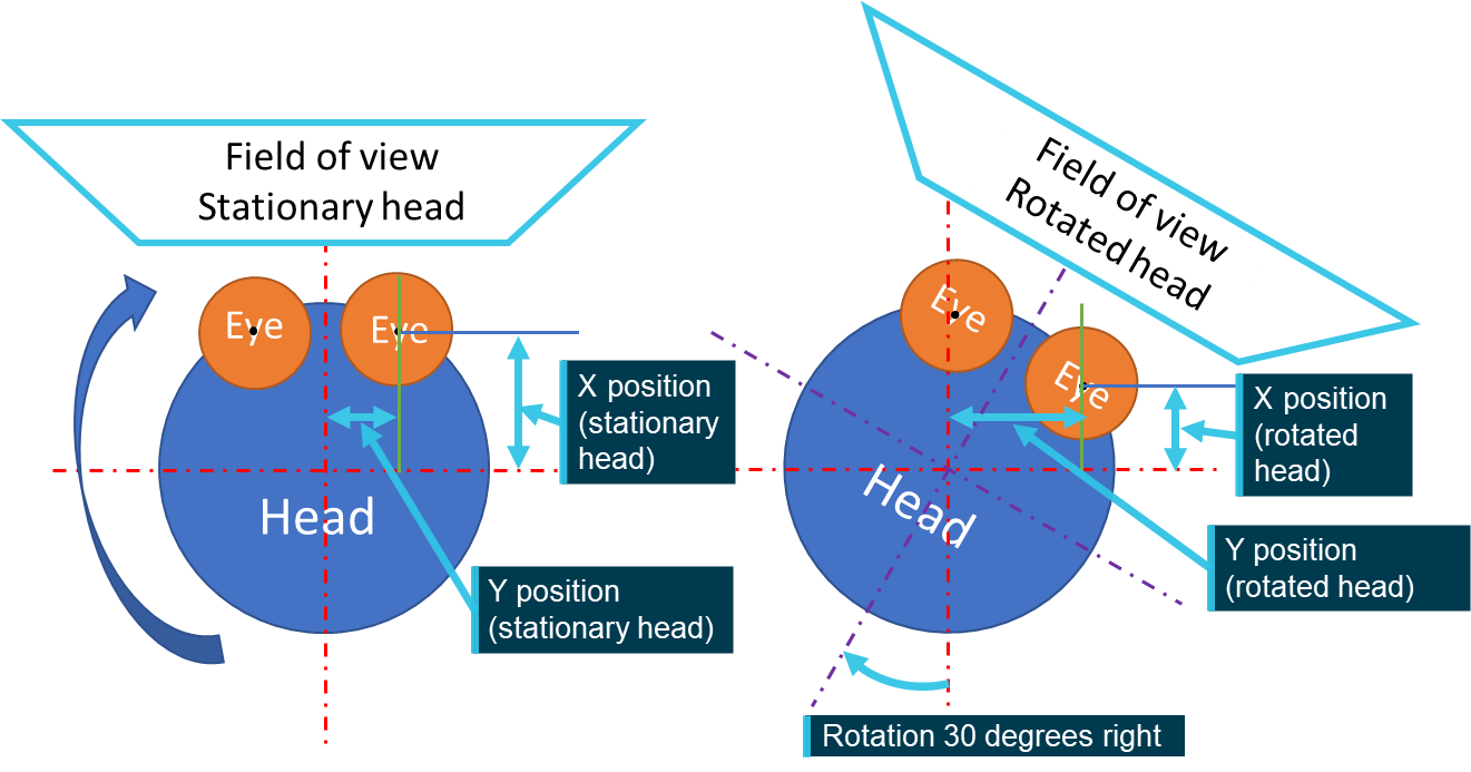
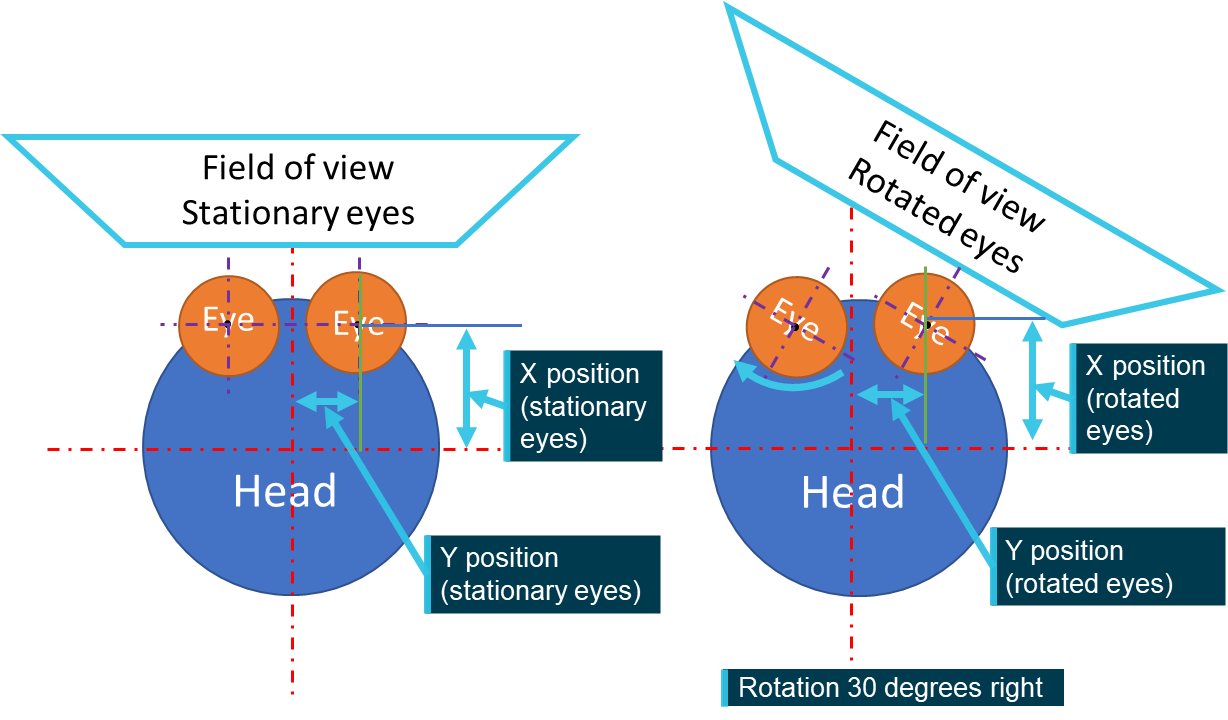
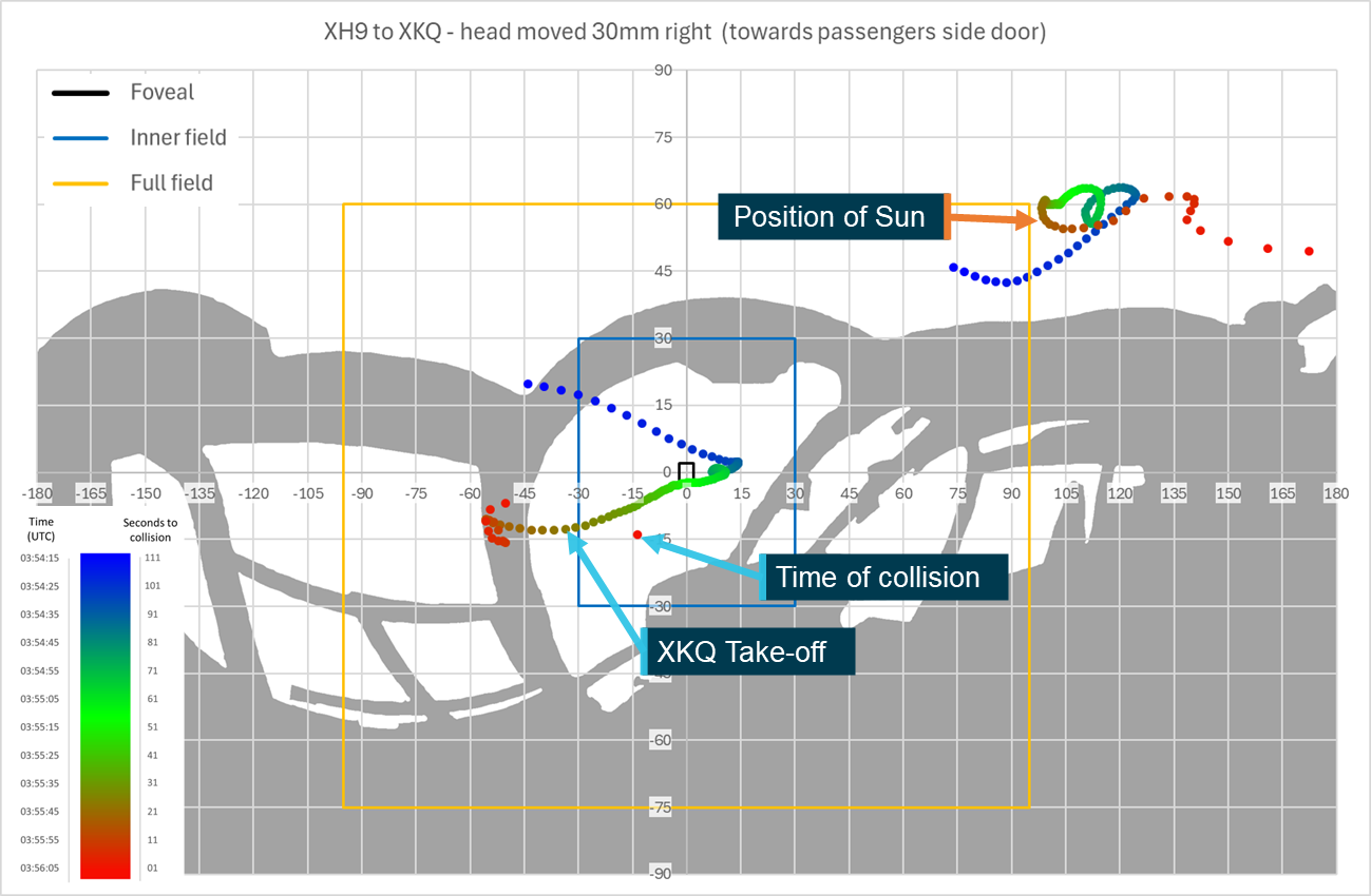
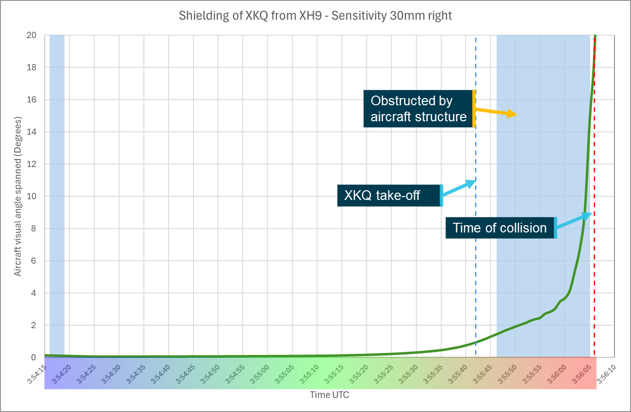
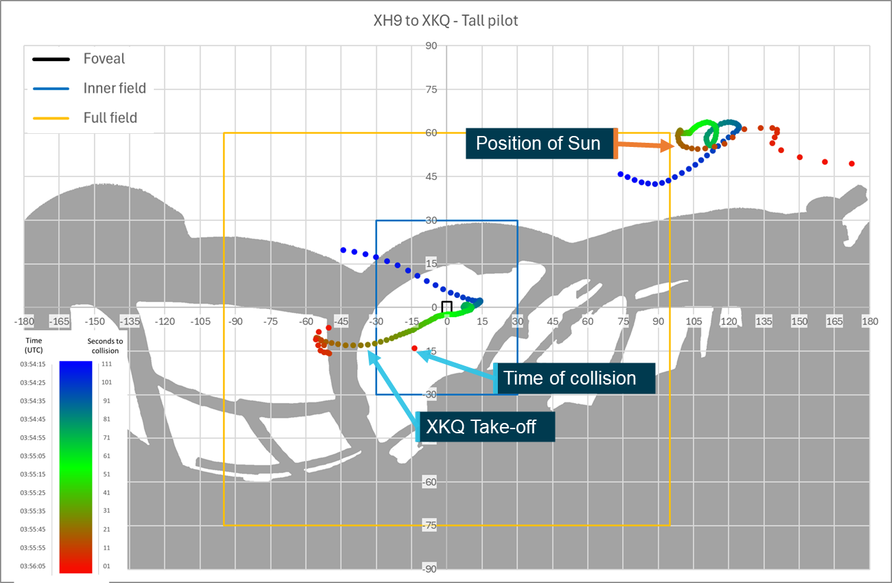
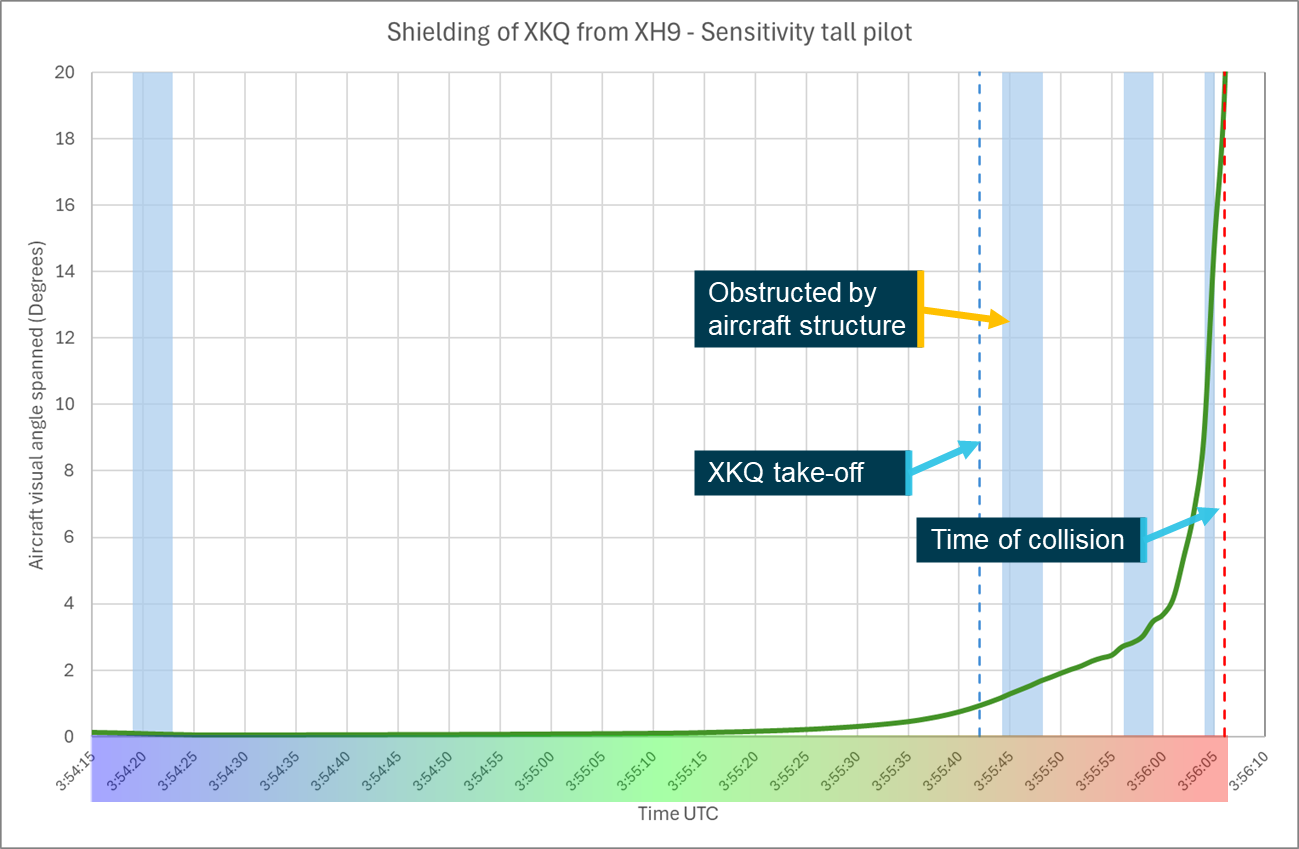
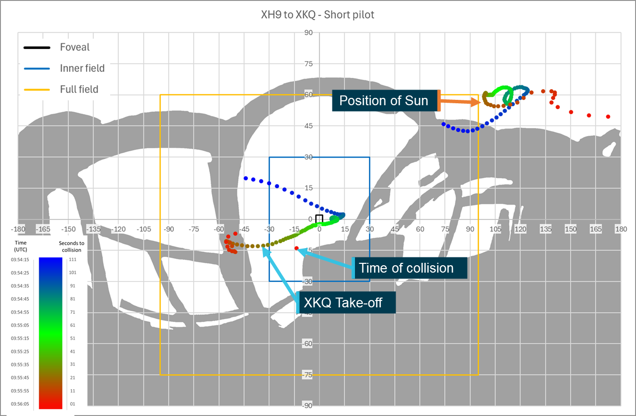
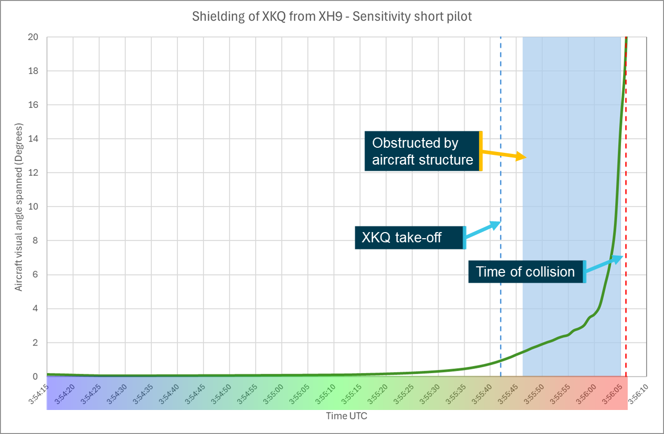
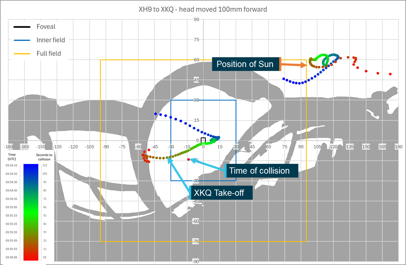
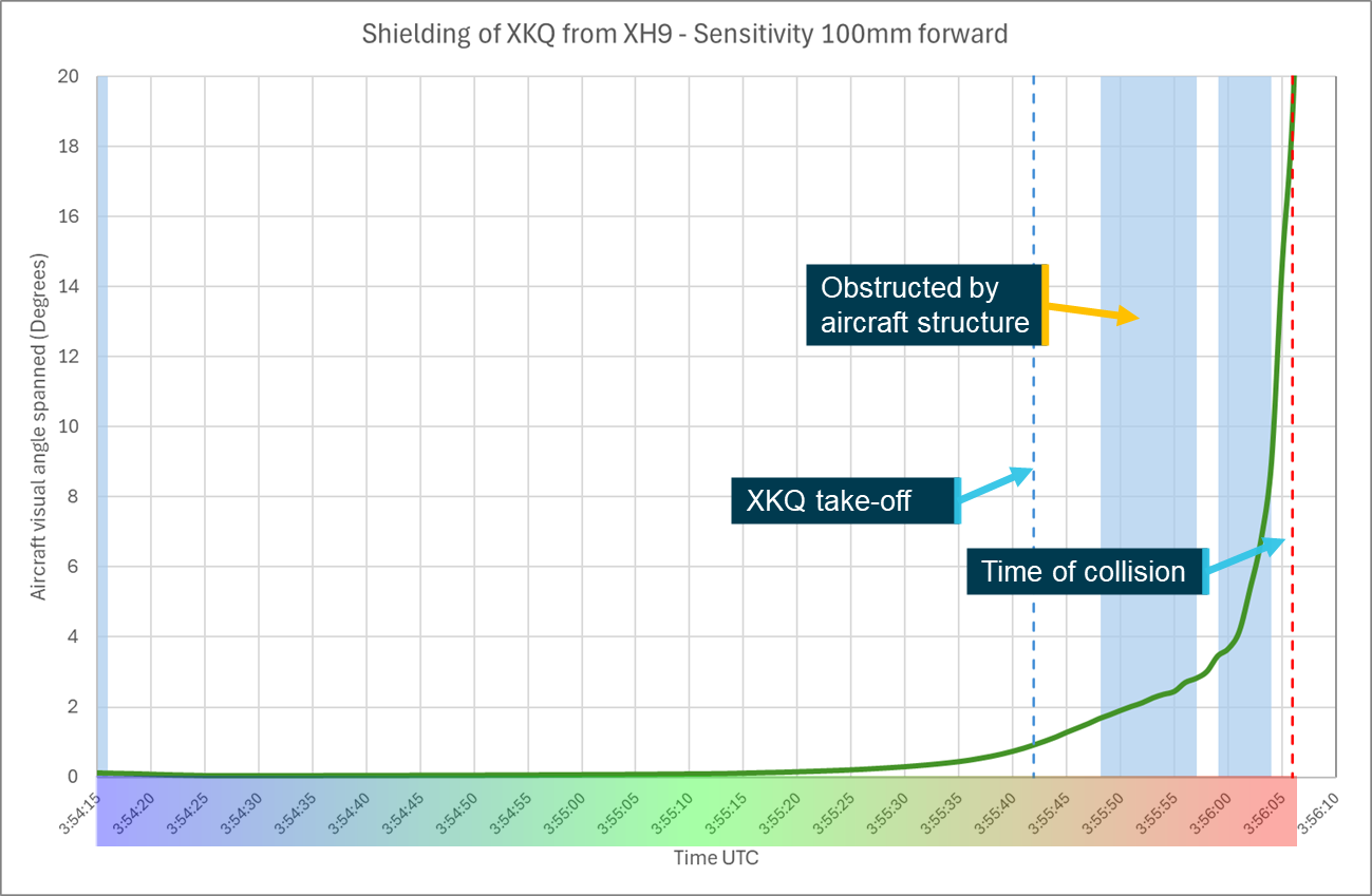
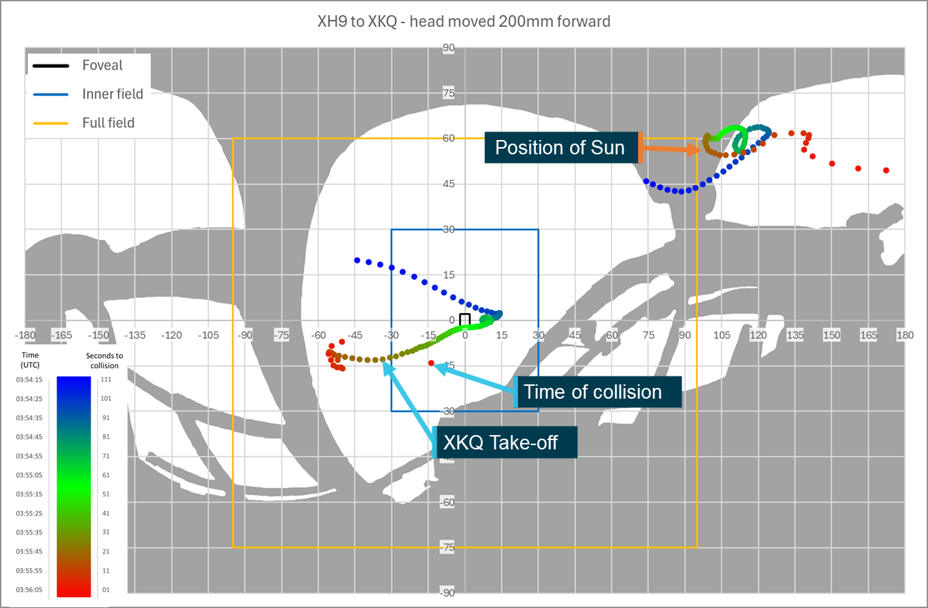
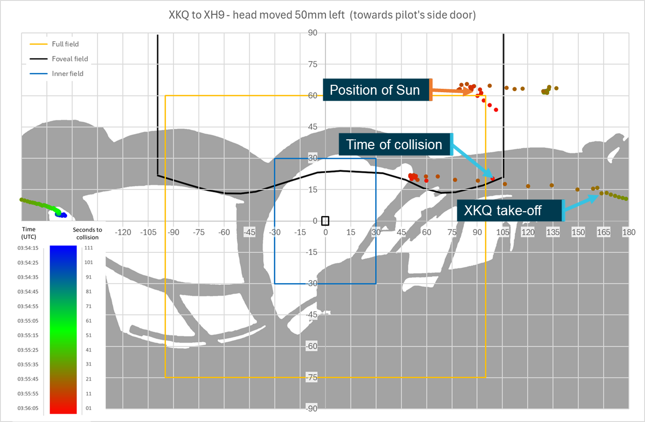
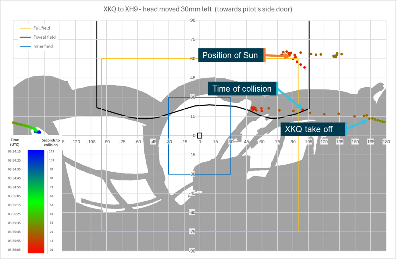
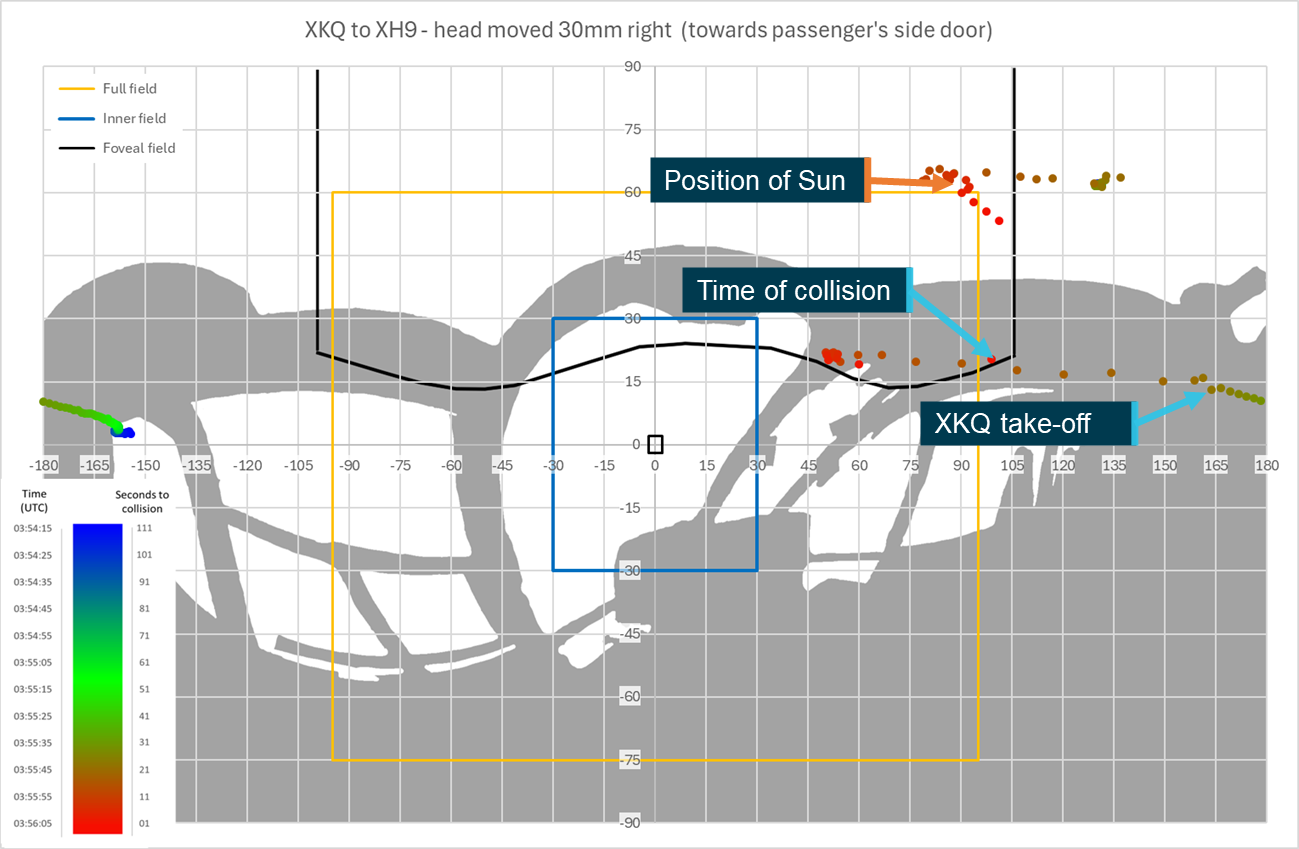
The study determined that from the pilots’ eye positions it was unlikely that either pilot could have detected the other aircraft at critical times in the lead‑up to the collision. This was primarily due to obscuration from the aircraft structure but was also impacted by the relative position and visual size in the simulated pilots’ fields of view, pilots’ apparel, environment and aircraft fitment. Sensitivity analysis showed that the opportunity for detection would have been improved if the pilot’s eye position had been alternately positioned and the head and eyes rotated towards the approaching aircraft at the correct time. This could have both reduced structural shielding and moved the approaching aircraft towards the centre of the pilot’s field of view where detection was more likely.
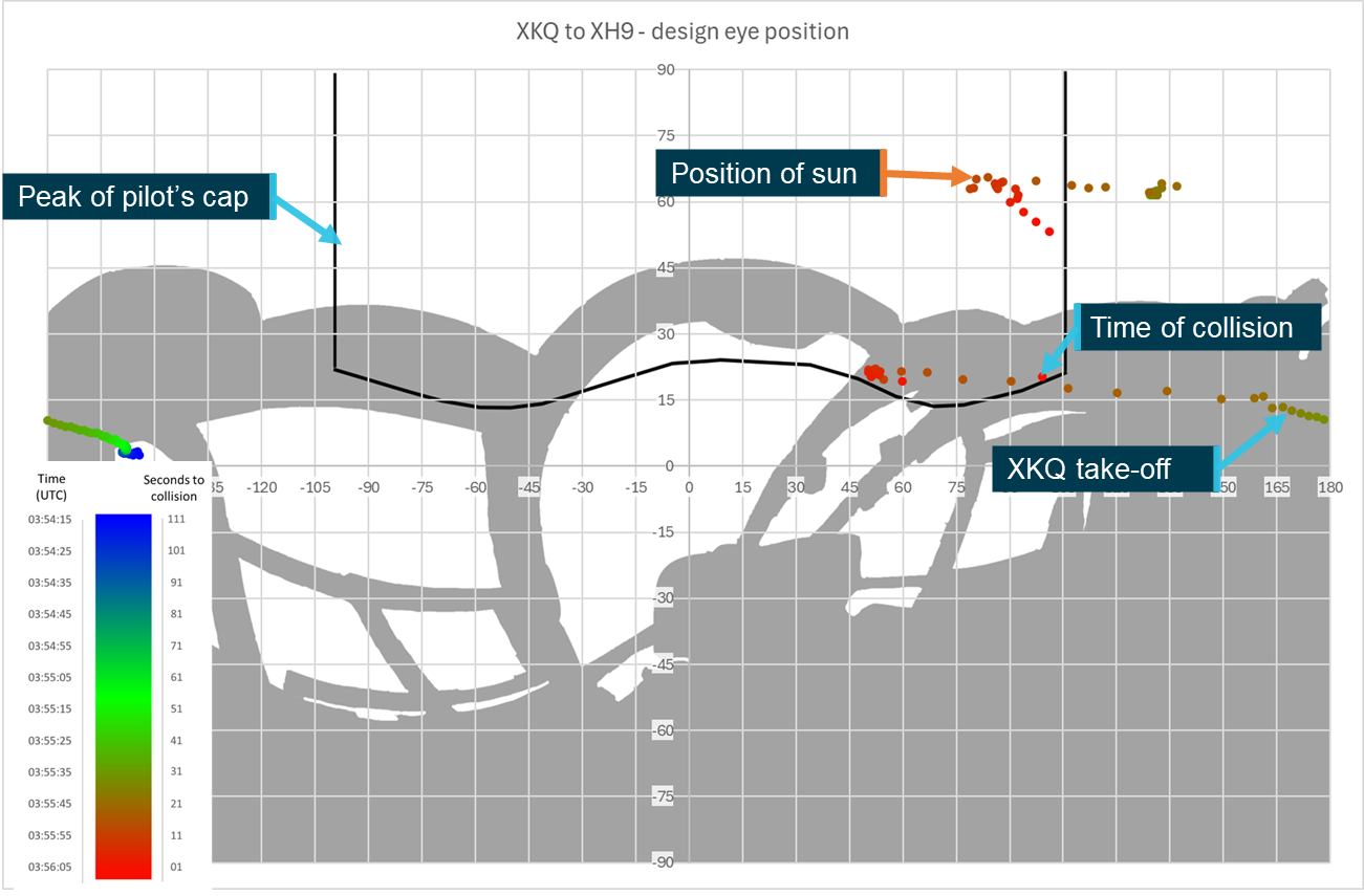
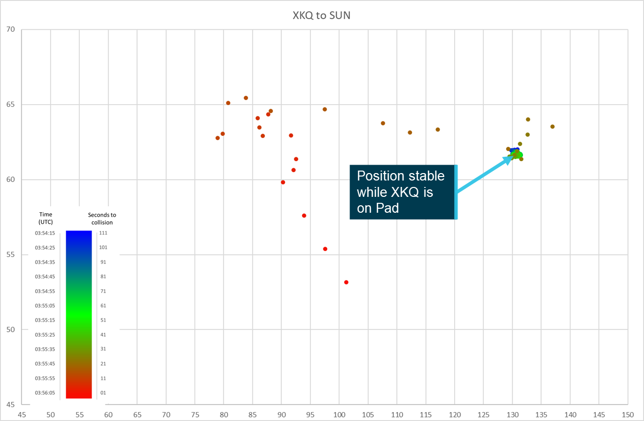
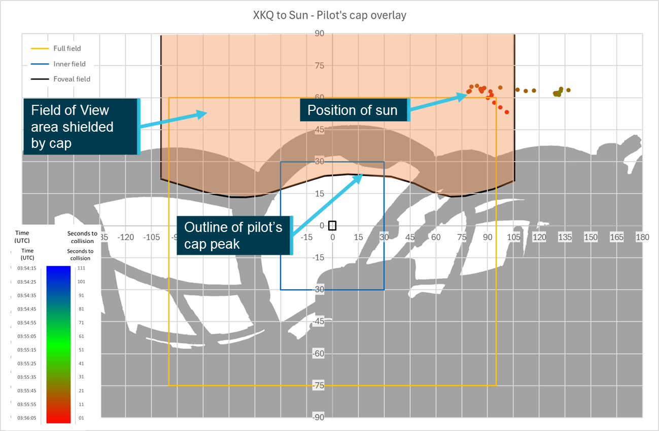
The study also determined that from the pilot’s eye position, it was unlikely that the cap worn by the pilot of XKQ interfered with the opportunity to detect XH9 and that the cap’s presence likely improved the pilot’s visual acuity by blocking the sun that was positioned through the aircraft’s skylight. However, the sensitivity analysis showed that depending on eye position and head rotation, the cap could have interfered with detection opportunity.
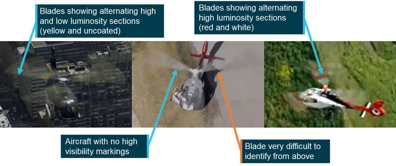
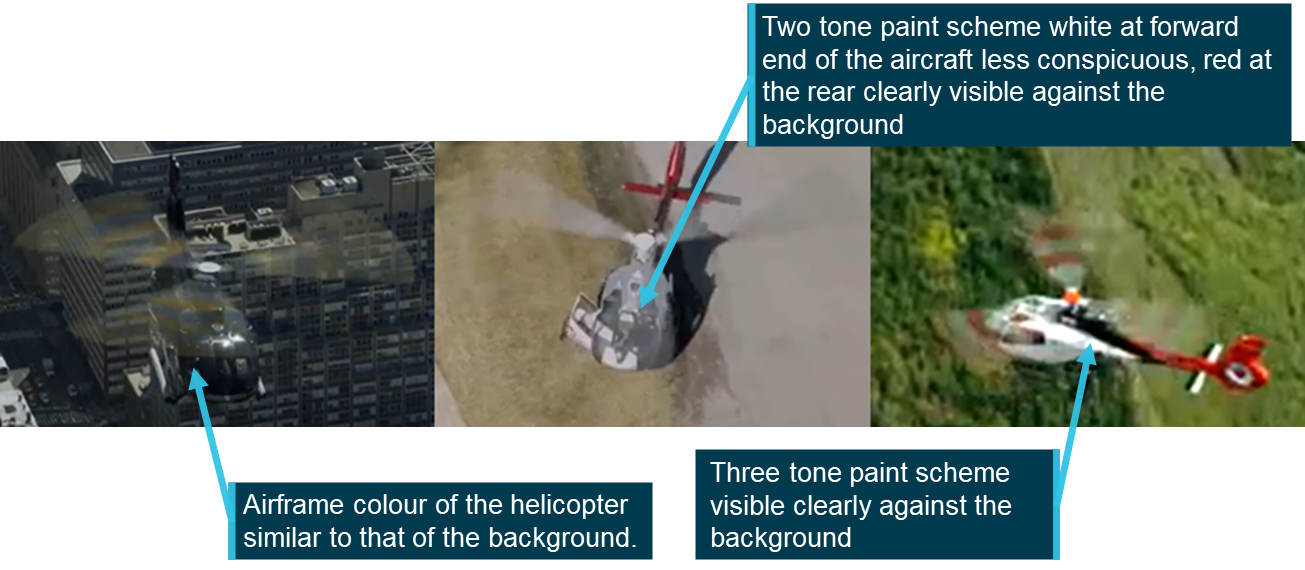
Finally, there were several visual conspicuity devices either fitted or available for fitment that could have been used to improve the opportunity for detection. This included high ‑visibility rotor blades to XKQ, strobe lights for both aircraft and high or higher visibility paint schemes.
Safety message
Visual acquisition is one of the primary tools at a pilot’s disposal to assist them in the location and identification of traffic around them. However, as shown by this study and a volume of previous work, it is highly dependent on the relative location and speed of the other aircraft, the layout and fitment of both aircraft, a range of human performance characteristics, what information is available to the pilot as well as being dependent on what the pilot is doing at that moment. Pilots need to be aware of these limitations and realise that other aircraft in the same airspace will not always be sighted, even when active external visual scans are routinely used. However, these limitations can be offset. The expectation of the presence and approximate location of other aircraft through communications or onboard electronic detection systems has been shown to greatly enhance the effectiveness of sighting other aircraft, while visual conspicuity devices are designed to increase the chance of detection by attracting attention even when not being directly focused on.
The ATSB SafetyWatch highlights the broad safety concerns that come out of our investigation findings and from the occurrence data reported to us by industry. One of the safety concerns is Reducing the collision risk around non-towered airports.
This page gives several other examples of issues and accidents that have occurred around non-towered airports and provides guidance on how pilots can keep themselves and other pilots safe.
Acknowledgements
The ATSB acknowledges the assistance of iwiation GmbH, Airbus Helicopters, Sea World Helicopters, Spidertracks and the United States National Transportation Safety Board Office of Research and Engineering in the development and preparation of this study.
This safety study is presented in 4 sections:
1. Introduction
2. Background and Methodology – contains relevant contextual information related to the occurrence, technologies, processes used and other relevant supporting information.
3. Results and discussion – assesses and presents analysis of the ‘Background’ information
4. Conclusions.
This study does not contain findings, however relevant conclusions and supporting information were considered as part of the safety analysis for AO-2023-001 and influenced relevant findings for that investigation.
Introduction
This visibility study is intended to support ATSB investigation AO-2023-001, Midair collision involving Eurocopter EC130 B4, VH‑XH9, and Eurocopter EC130 B4,VH‑XKQ,Main Beach, Gold Coast, Queensland on 2 January 2023. It should be read in conjunction with, and in the context of, that report. It relies and expands upon factual information presented in that report.
Background
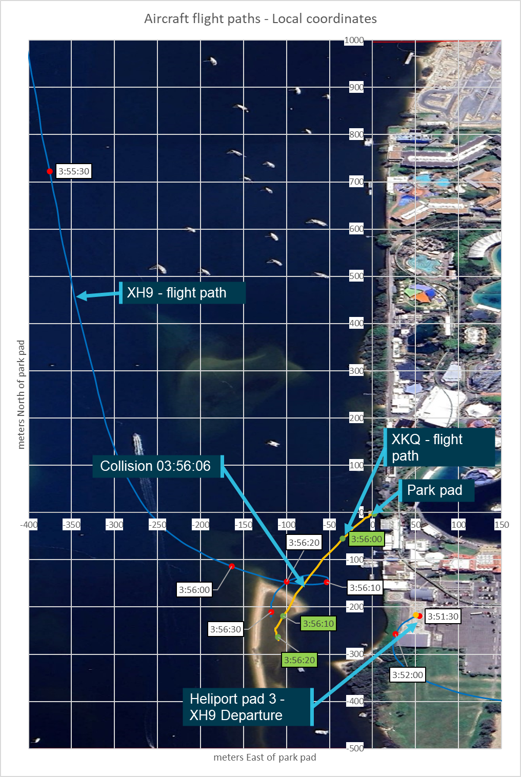
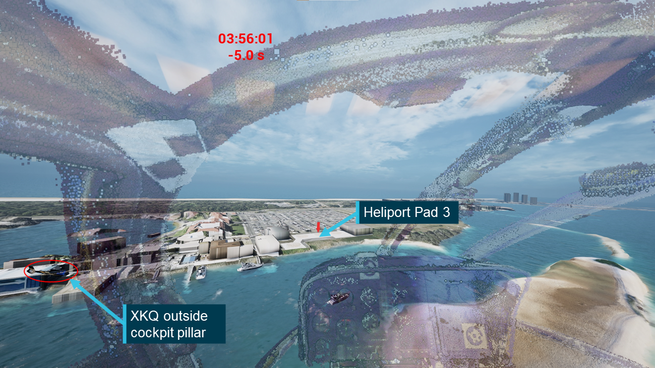
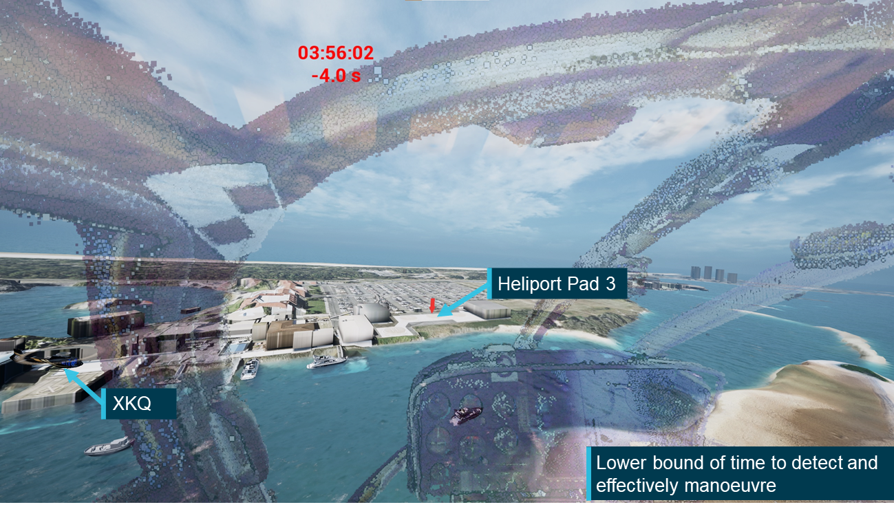
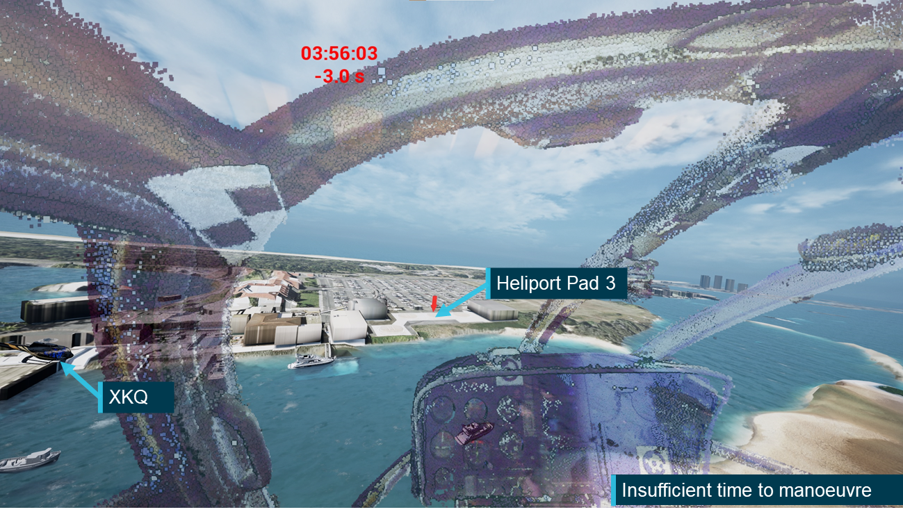
At 13:56:06, 2 January 2023, 2 EC130 B4 helicopters, VH‑XH9 (XH9) and VH‑XKQ (XKQ) operated by Sea World Helicopters collided mid-air over the Gold Coast Broadwater (Broadwater) adjacent to the Sea World theme park on the Gold Coast, Queensland.
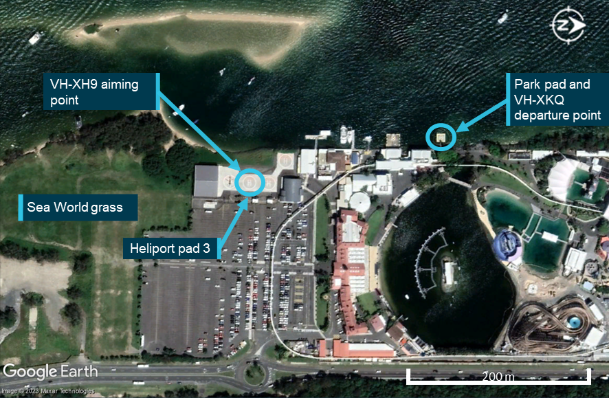
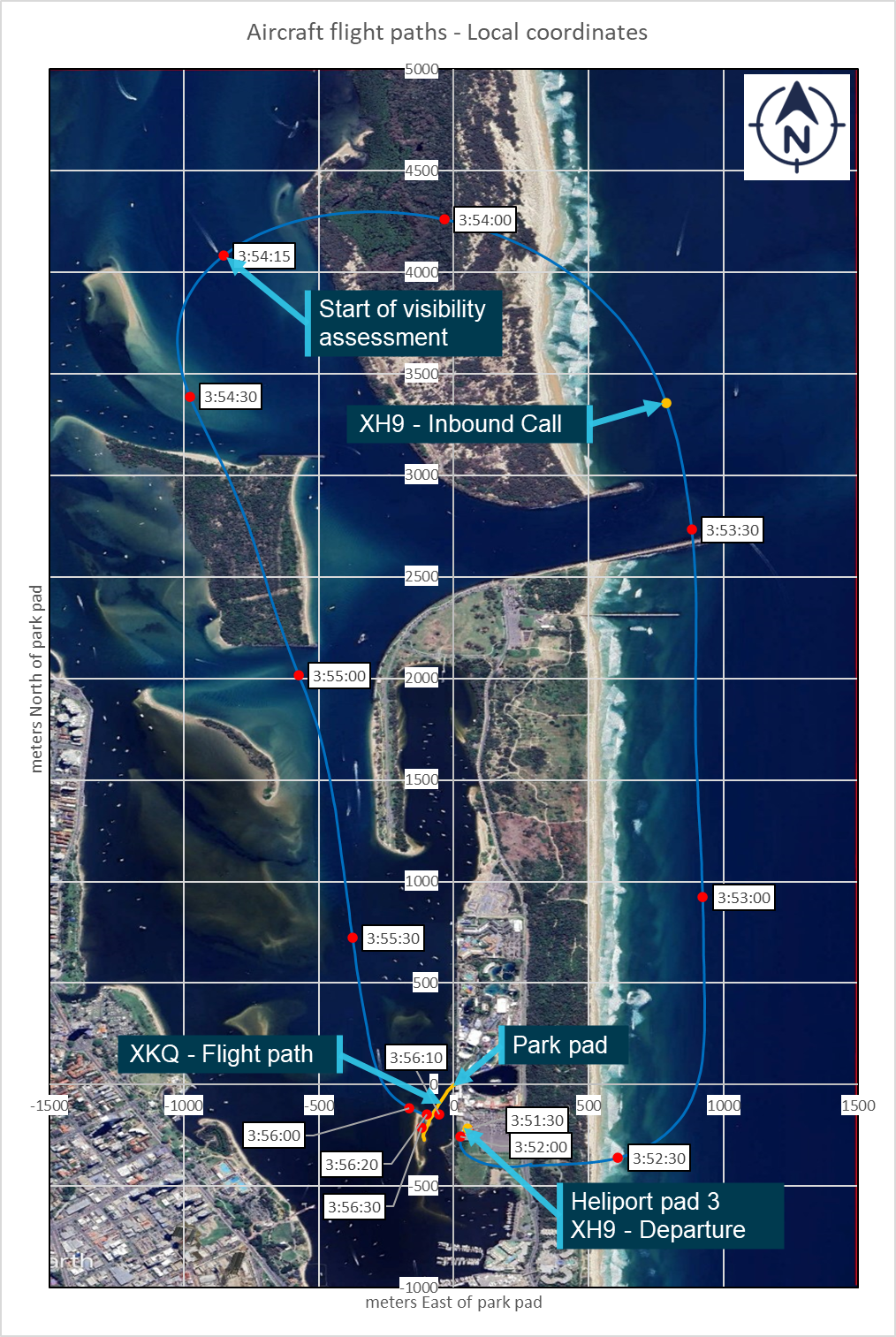
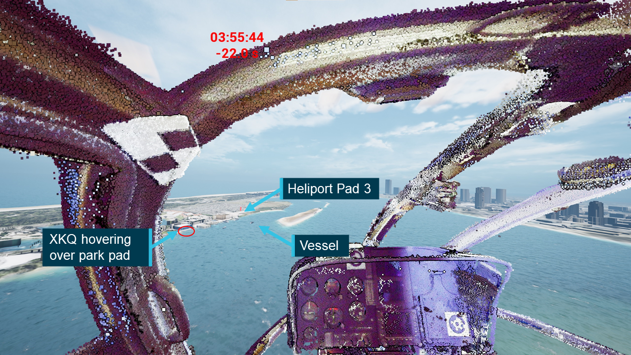
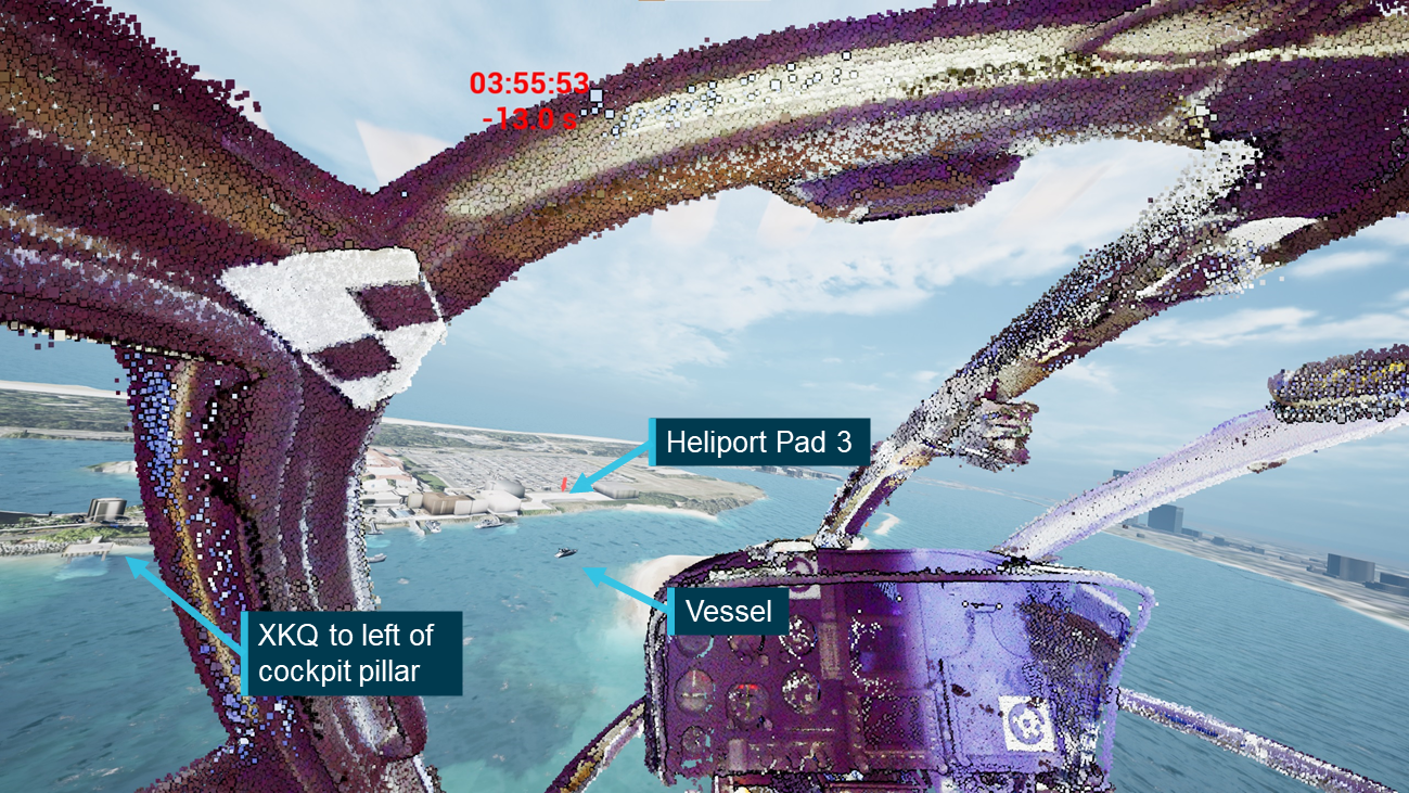
Both aircraft were conducting 5-minute scenic flights; XH9 was on approach to pad 3 at the operator’s heliport, and XKQ had recently departed the operator’s park pad located 220 metres to the north of the heliport (Figure 1). Following the collision, XKQ collided with terrain and XH9 made an emergency landing. Four people were fatally injured with another 6 seriously injured.
The 2 aircraft were operating under Visual Flight Rules (VFR) in visual meteorological conditions (VMC) in non-controlled airspace. In non-controlled airspace, particularly in the vicinity of busy heliports, visual traffic acquisition and avoidance is a key part of a pilot’s defences in avoiding mid‑air collisions. Considering this, the investigation sought to determine whether ‘see-and-avoid’ could have been effective for the pilots and what effect the aircraft structure, pilot positioning and apparel, local environment and visual conspicuity equipment could have had on each pilot’s opportunity to visually acquire the other aircraft in time to initiate an avoiding manoeuvre. To allow for a detailed consideration of these elements and their effect on the development of the accident sequence, the ATSB established this separate safety study which was run in conjunction with the occurrence investigation.
The accident was recorded by a multitude of cameras around the accident site and onboard the aircraft capturing the lead-up to the accident and the accident sequence. This combined with flight path and aircraft orientation information recorded onboard the aircraft allowed for a detailed analysis of the relative positions and orientation of the 2 aircraft, the environmental conditions and the helicopters’ conspicuity.
The ATSB utilised techniques in aircraft position and cockpit visibility assessment developed by the United States National Transportation Safety Board and previously implemented in ATSB investigation AS-2022-001, Aircraft Performance and Cockpit visibility Study supporting AO-2020-012. This was combined with detailed video analysis performed by the ATSB, and video analysis and scenario reconstruction developed by specialists at iwiation GmbH (IWI) in Germany.[2] This was combined with information from a range of human factors literature, the ATSB’s wreckage analysis, the operator, the aircraft manufacturer, recording equipment manufacturers and the Civil Aviation Safety Authority to conduct this study.
Aim
The cockpit visibility study sought to understand the limitations and opportunity that the pilots of XH9 and XKQ had to visually detect and avoid other aircraft in the lead‑up to the collision. Concurrently with the study an animation was developed to demonstrate, as realistically as practical, the conditions that the pilots encountered.
Scope
This study considered visual detectability and conspicuity of the aircraft based on the limits of human performance and apparel worn by the pilots, aircraft structural obscuration (blind spots), and visual conspicuity devices fitted to the helicopters. This was completed using recorded position and orientation data from the aircraft, video recordings of the accident sequence and aircraft and human performance information.
The study did not specifically address the pilots’ mental models of the traffic environment or consider the potential benefits or limitations of electronic conspicuity devices or equipment such as aircraft collision avoidance systems including TCAS, ADS-B In or electronic flight bag applications with a traffic display. The investigation report addresses each of these elements in detail.
Methodology
The methodology for this study was based on the previous ATSB study AS-2022-001, with additional items considering the volume of recorded information that was available. The methodology included:
A literature and document review looking at available information related to human visibility and perception characteristics, aircraft tracking devices and aircraft specifications.
Verification of position and orientation information downloaded from the aircrafts’ Spidertracks units using onboard and external video footage.
Development of to scale 3-dimensional models of the internal and external structures of representative aircraft using laser scanning technologies.
Determination and verification of the design and pilot eye positions within each aircraft.
Development of 2-dimensional representations of each pilot’s view of the aircraft structure. The other aircraft was positioned on this representation to determine when it would have been shielded from the pilot’s view.
Based on the literature review and consultation with ATSB human factors specialists, human visual performance was considered to determine where the aircraft would likely appear to the other pilot, when they would likely have been able to detect it and how the acquisition opportunity could be improved through movement of the eye position.
Finally, an animation was developed using position and orientation data showing the cockpit view for both pilots, demonstrating the effects of the limitations to visual acquisition.
Limitations
This analysis has been developed based on information and data from a wide range of sources, many of which were not designed for the detailed level of analysis that has been completed. Through the development of this study the ATSB, along with our international partners, has sought to cross reference and verify information wherever possible and practical using both onboard and external information sources. Where relevant and practical, summaries and results of these processes have been included. To accommodate for potential sources of error the ATSB has performed sensitivity analyses looking at the effect that certain changes would have had on results produced in this study.
Notes
Throughout this report standard aviation units are used unless specifically stated. These units are nautical miles for distance, feet for altitude and knots (nautical miles per hour) for speed.
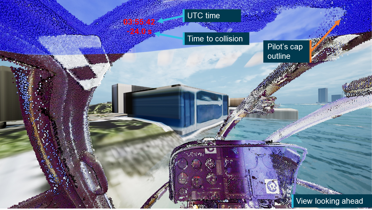
All times in this report are referenced to Coordinated Universal Time (UTC). While the accident occurred in the Australian Eastern Standard Time (AEST) zone (UTC + 10 hours), key data was recorded in UTC which was retained for simplicity of the analysis. The collision occurred at 13:56:06 AEST corresponding to 03:56:06 UTC.
Unless specifically stated otherwise, any reference to the ‘investigation report’ should be taken as referring to ATSB investigation report AO-2023-001.
Background and methodology
Aircraft information
As outlined in the Aircraft information section of the investigation report:
The Eurocopter EC130 B4 is a French-manufactured light utility helicopter developed from the earlier Eurocopter AS350 Écureuil (squirrel). It combined elements of the EC120 and the EC135 into the AS350 product line. The cabin was widened and lengthened, and an 11-blade shrouded Fenestron tail rotor replaced the conventional tail rotor of the AS350. The position of the pilot in command was moved from the front right in the AS350 (standard in most helicopters) to the front left in the EC130 B4.
The maximum all-up weight of the EC130 B4 was 2,427 kg. The single Safran (formerly Turbomeca) Arriel 2B1 turboshaft engine provided a take-off power output of 632 kW.
Both helicopters [VH‑XH9 and VH‑XKQ] were approved to be operated in the air transport[3] category and visual flight rules (VFR) Day meteorological conditions.
XH9 – visual conspicuity
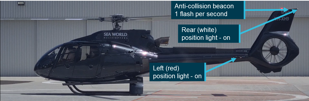
XH9 (S/N 3845) was fitted with lights and a rotor blade paint scheme to improve its visual conspicuity. It was fitted with left (red), right (green) and rear (white) position lights, an anti-collision beacon, landing and approach lights. XH9’s rotor blades were painted with a high‑visibility paint scheme in accordance with the aircraft maintenance manual specifications.
Lighting
XH9 utilised LED position lights, fitted to the centre of the outer edge of the horizontal stabilisers, maximising visible angle from the front of the aircraft. The aircraft was also fitted with a rear LED position light at the top rear of the aircraft’s vertical tail (Figure 2). The manufacturer was unable to confirm the actual power output of these lights, however they confirmed that they met the certification requirements under the United States federal aviation regulation (FAR) 27/29. The regulations defined the required output depending on the angle from which the light was viewed. The left and right position lights were required to have a minimum intensity of 40 cd[4] when looking from dead ahead to 10° from the centre line reducing to 5 cd between 20° and 110°. The rear position light was required to have a minimum intensity of 20 cd.
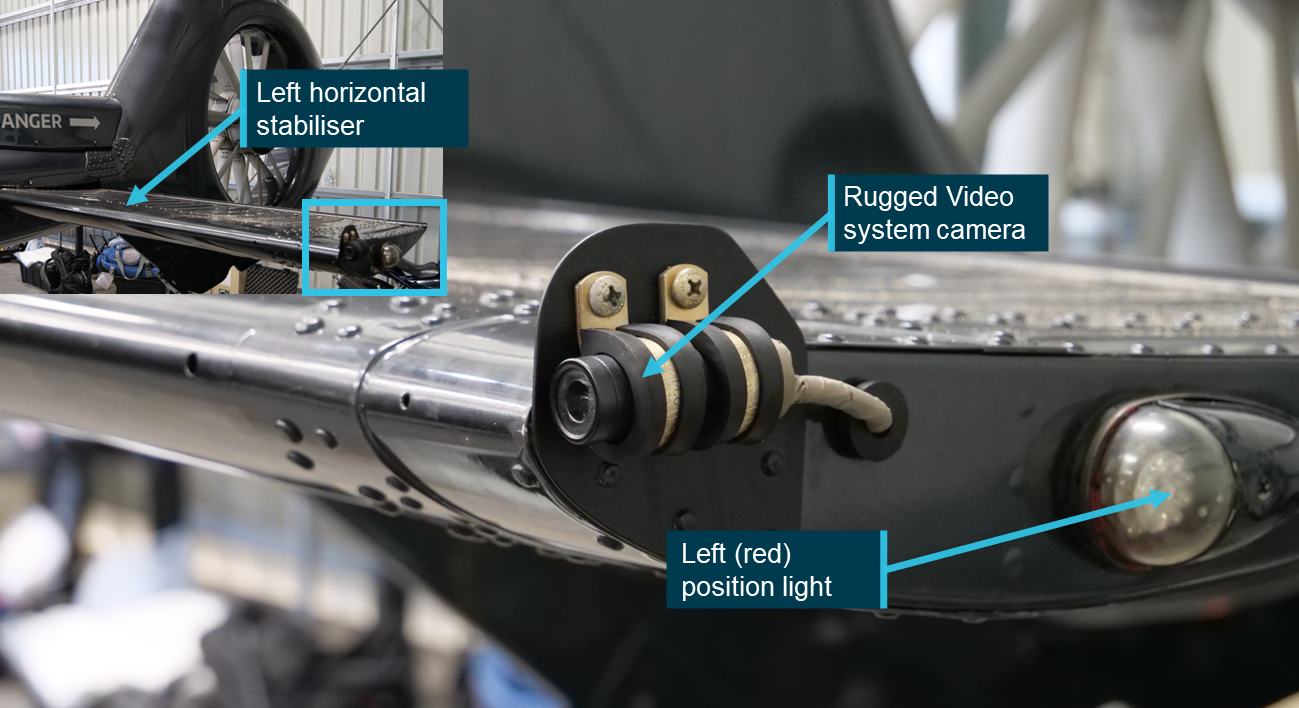
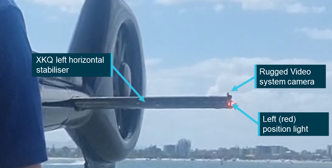
Forward of the left position light, on the outer edge of the horizontal stabiliser, was a small camera connected to the aircraft’s Rugged Video system (refer to the investigation report for further detail on this system) (Figure 3). The location of this camera reduced the visibility of the position light by impacting sight lines to the light from in front of the camera’s position. While there was a reduction in the visible arc, the position on the very forward edge of the stabiliser and above the centreline of the position light means that the impact is minimised. The wreckage examination determined that a camera was not fitted to the right horizontal stabiliser.
Figure 3: XH9 left horizontal stabiliser, Rugged Video system camera and left position light
Source: ATSB
XH9 was fitted with a single anti-collision beacon on the top of the aircraft’s vertical tail. The light consisted of a series of vertical LED strips around a cylindrical core, these LEDs illuminated simultaneously to give one flash per second. As with the position lights the manufacturer was unable to confirm the actual power of this light but confirmed that it met the requirements of FAR 27/29, which required a minimum intensity of 150 candela in line with the light’s horizontal plane. The required intensity reduced as the angle from the horizontal plane increased with a required minimum intensity of 15 candela between 20° and 30° above or below the horizontal plane.
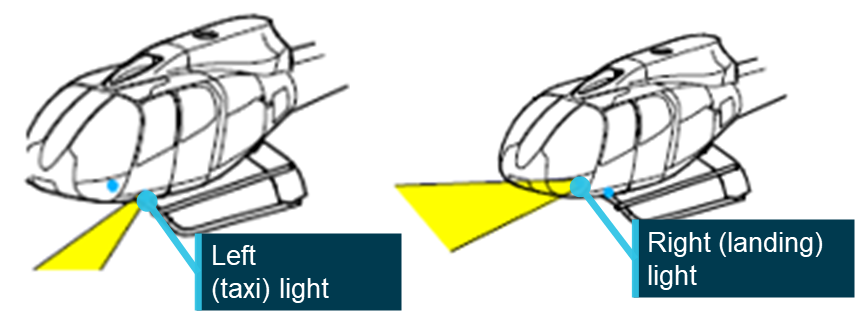
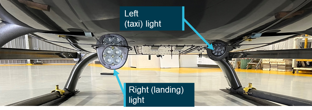
XH9 was fitted with a dual landing light system (see Figure 4), with one light on either side of the aircraft’s centreline, behind the forward landing gear connection point. The 2 lights serve different purposes (see Figure 4). The left or taxi light was designed for a wider beam and to be more vertically oriented for illuminating the area in front of the aircraft during taxi. The right light had a narrower beam, a shallower angle and a higher power rating allowing it to illuminate more of the landing area. The aircraft maintenance manual indicated that the lights were switched separately but activating either of them would illuminate the ‘LITE’ light on the instrument panel.
Figure 5: Landing light configuration on an exemplar aircraft
Note: This image is used to show configuration of the landing and approach lights. The type of light presented is not necessarily the same as that fitted to XH9 or XKQ. Source: ATSB
The left (taxi) location of VH‑XH9 was fitted with a Whelen P36P2T LED landing light. The light is rated to 15,000 cd at the centre of the beam and had a 40° beam spread. The light was recessed into a housing in the belly panel of the aircraft that directed the beam down at approximately 30° from the angle of the panel.
The right (landing) position was fitted with a GE 4681 halogen approach light. The light is rated to a max intensity of 310,000 cd at the centre of the beam with a horizontal beam spread of 15° and vertical spread of 9°. Maintenance documentation also indicated that this light had a retraction option which had not been installed. As with the landing light, the approach light was also recessed into a housing on the belly panel that directed the beam down at an angle of approximately 15° from the panel.
Imagery of the switch positions in the cockpit indicated that for the accident flight the landing and approach lights had not been switched on. Footage from a flight the previous day indicated that both lights were operational. A review of video footage from the accident flight indicated that XH9’s beacon and position lights were all operational (see Figure 2).
XH9 was not fitted with strobe lights, nor was it required to be.
Pulselite system
As outlined in the investigation report:
The Precise Flight Inc. Pulselite system was an approved solid-state electrical switching unit that pulsed existing external aircraft lights ‘to create an illusion of exaggerated motion’ intended to enhance recognition of the helicopter to other pilots. The Pulselite system is typically connected to the approach and landing lights however, other lights can be incorporated as desired.
XH9 had been fitted with the system in 2006 during its time in the United States and the control unit remained fitted to the aircraft. However, the switch to control the system had been removed, rendering it non‑functional. Further detail regarding the system and its operation can be found in the investigation report.
Rotor blades
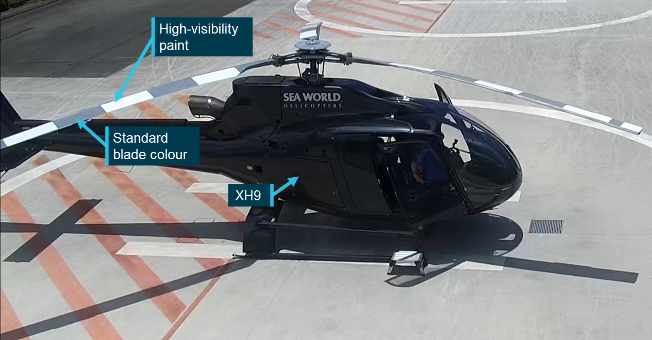
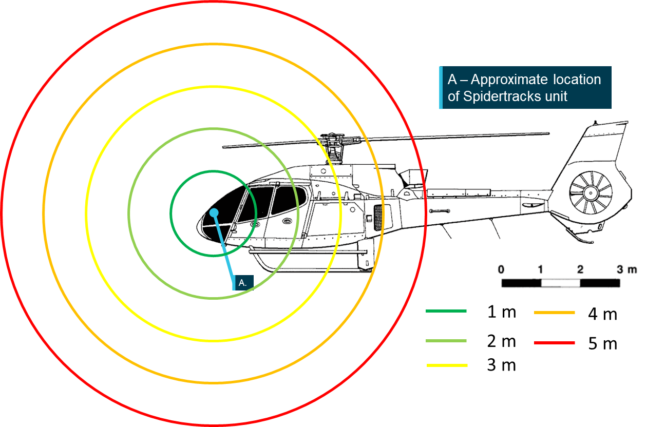
The main rotor blades of VH‑XH9 were painted with a high‑visibility paint scheme which aimed to improve the aircraft’s conspicuity from above. The scheme consisted of 4 white sections painted over the standard grey blade colour. Figure 6 shows XH9 on the day of the accident being prepared for departure with the high‑visibility paint scheme shown on the top surface of the 3 blades. Once the blades were turning this paint scheme created the appearance of a series of concentric white circles, increasing its conspicuity from above.
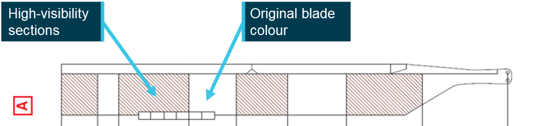
Maintenance documentation indicated there were 2 high‑visibility paint schemes (A and B) that could be applied to the EC130 B4 in 3 different colours (white, red, yellow); inspection of the blades indicated that the blades were painted in the ‘A’ scheme (see Figure 7).
Figure 7: Blade high‑visibility paint scheme A layout
Source: Airbus Helicopters, annotated by the ATSB
The undersides of XH9’s blades were not coated with high‑visibility paint to reduce the risk of flicker vertigo for the pilot.
Surface coatings
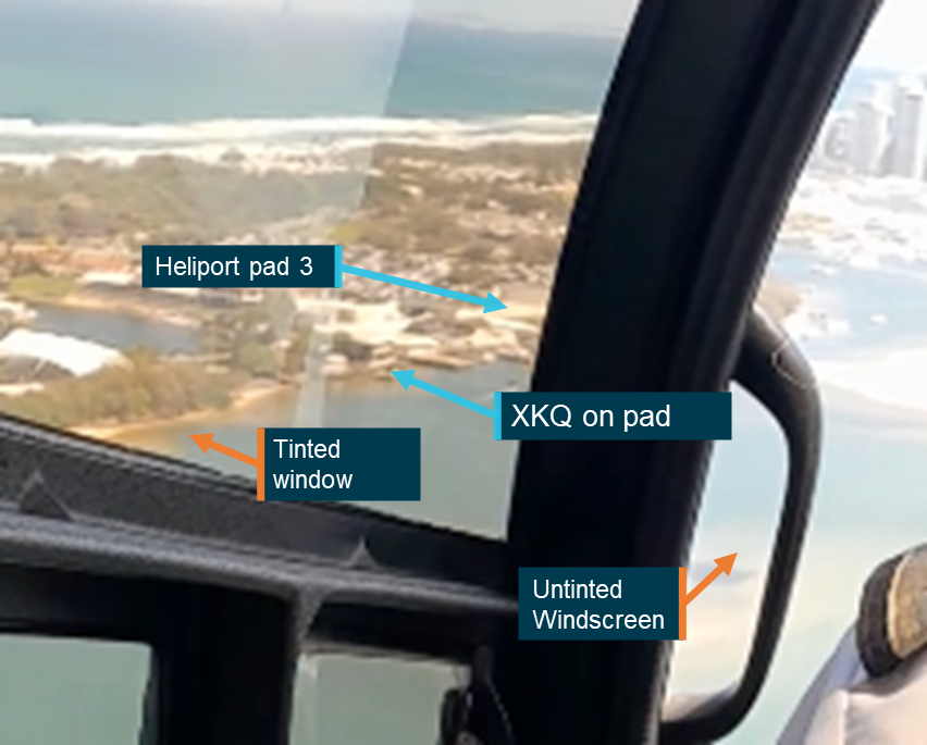
In previous maintenance activities both the left and right windshields of VH‑XH9 had been replaced under a supplemental type certificate (STC). Based on advice from the windscreen manufacturer it was determined that they were not tinted. This was supported by the footage available from inside the aircraft.
Review of the video footage and analysis of the wreckage indicated that the side windows of the aircraft carried a brown tint that was visible in images and video from onboard the aircraft.
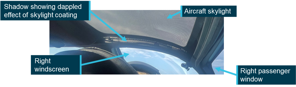
The footage also identified that the aircraft’s 2 skylights[5] had a surface coating applied to them. No record was identified in the available maintenance documentation of this modification. The imagery indicated that the skylight had been covered with a dappled[6] coating (see Figure 8).
This coating would have multiple impacts on the pilot’s visual acuity and acquisition. By introducing physical obstruction over the transparent surface, it would reduce the amount of glare that the pilot was experiencing through the skylight, but may impact both the perceived colour and/or luminance of a target. However, the physical obstruction may shield targets at distance, reducing opportunity to sight them. Finally, the coating may improve the likelihood of detection of a slow‑moving target providing a stationary reference across which the target will move.
Externally XH9 had gone through several different paint schemes throughout its career. At the time it was acquired by the operator and at the time of collision it was painted with a dark grey paint scheme with a lighter grey used for relevant markings and branding.
XKQ – visual conspicuity
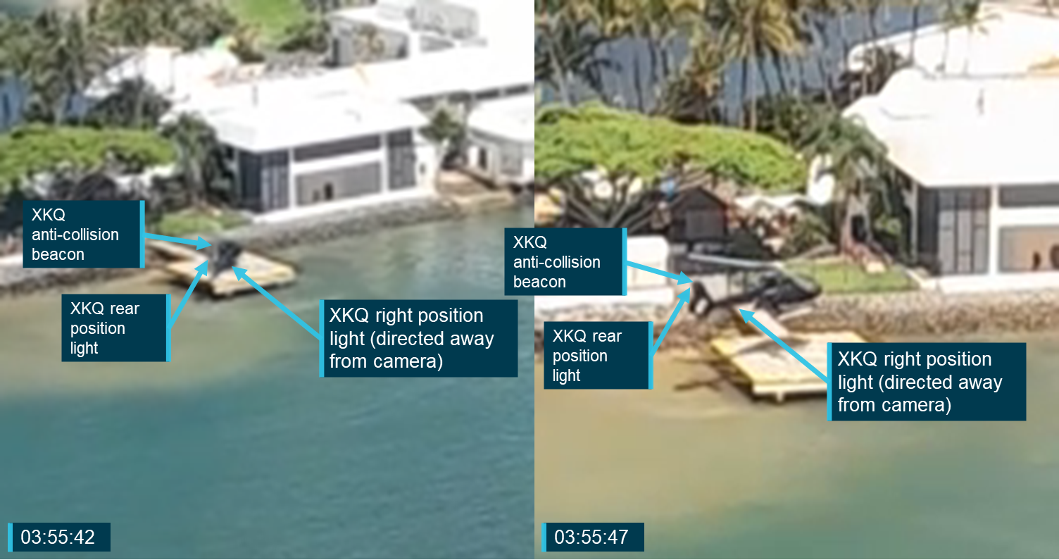
XKQ (S/N 4639) was not fitted with high‑visibility rotor blades but had been retrofitted with side windows that had a tint applied. XKQ was fitted with lights intended to accentuate its visual conspicuity and increase the probability of it being seen by nearby pilots. It was fitted with left, right and rear (red, green and white) position lights, an LED anti-collision beacon and taxi and landing lights.
Lighting
Much of the lighting system in XKQ was the same as that fitted to XH9. XKQ was fitted with left (red), right (green) and rear (white) LED position lights and an LED anti-collision beacon. The manufacturer was unable to confirm the actual power output of these lights, but that they complied with the same regulatory requirements as the lights fitted to XH9. Records indicated that the left and right position lights XKQ had previously been fitted with were a combination LED and strobe light, however ATSB wreckage analysis identified that the strobe variant was no longer fitted.
As with XH9 the left position light of XKQ was partially obscured from ahead and above by the camera of the Rugged Video system.
XKQ was fitted with the same dual landing light configuration as XH9. Maintenance documentation indicated that the left (taxi) position was fitted with an LED landing light, however it did not identify the type or rated power of the light. The right (landing) position was fitted with a GE PAR46 aircraft light which was rated maximum beam candle power of 400,000 candela with a horizontal beam spread of 13° and a vertical beam spread of 14°. Review of video footage indicated that the aircraft’s approach light was on as the aircraft departed the park pad, the landing light was not visible in the footage and as the ‘LITE’ indicator inside the aircraft was active if either landing or approach light was on it was not able to be determined if the landing light was also active. As with XH9 these lights were recessed into housings on the belly panels of the aircraft which angled the beams down. Due to the disruption of the wreckage the angles were not able to be measured, however they appeared substantively like XH9.
XKQ was not fitted with strobe lights, nor was it required to be.
Figure 9: XKQ left horizontal stabiliser, Rugged Video system camera and left position light
Source: Supplied, annotated by the ATSB
Pulselite system
XKQ was fitted with a Pulselite system on 25 May 2009 during the helicopter’s time in New Zealand. The ATSB’s wreckage examination identified that the control unit and the relevant collective switch were present on the aircraft. The system was only connected to the aircraft’s landing and approach lights allowing them to pulse when the system was set to ‘PULSE’ and the landing and approach lights were switched off.
Witness video showed XKQ’s approach light was switched steady on rendering the Pulselite system inactive.
Rotor blades
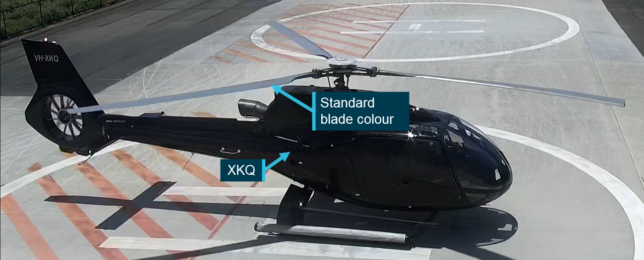
VH-XKQ’s rotor blades were not coated with a high‑visibility paint scheme, nor were they required to be. Figure 10 shows XKQ at the operator’s heliport prior to an earlier flight with the standard grey rotor blade colour visible.
Figure 10: XKQ at the operator’s heliport showing standard visibility blades
Source: Operator, annotated by the ATSB
Surface coatings
Review of the aircraft wreckage and onboard footage indicated that as with XH9, XKQ was fitted with non-original clear windscreens and brown tinted side windows. XKQ’s skylights were untinted and did not show fitment of the same dappled coating as XH9.
As with XH9, at the time it was acquired by the operator and at the time of collision, XKQ was painted with a dark grey paint scheme with a lighter grey used for relevant markings and branding.
Restraint information
XH9 restraints
All seats in XH9 were equipped with Pacific Scientific 4-point rotary buckle harnesses. These consisted of 2 over‑shoulder straps and 2 waist straps, one from each side. The 2 over‑shoulder straps were attached to an inertia reel fitted into the seat back. The inertia reel allowed the seat occupant to lean forwards during normal flight but would lock to restrain the occupant when subjected to a high loading, such as an impact.
Under normal flight conditions this restraint system will allow the pilot to move their torso and consequently, eye position forward and aft. The available movement will be determined by the position of the buckle on the torso, which is determined by the length of the waist straps. When secured in accordance with specifications, low on the hips, the inertia reels will allow the occupant full range of movement in an arc from the hips. While the positioning of the buckle on the torso of the pilot of XH9 could not be determined from available imagery, the inertia reel on the shoulder harnesses would have allowed the pilot to move their torso and head forward. The effect of the freedom of movement has been assessed in the Sensitivity analysis – eye position section of Cockpit visibility.
XKQ restraints
The restraints in XKQ were functionally the same as those in XH9. With the inertial reels allowing for movement of the seat’s occupant during normal flight but locking and restraining the occupant in the event of high loading.
Video footage from inside the aircraft prior to XKQ’s departure shows the pilot leaning forward and to the left demonstrating the movement envelope that these restraints provided under normal operational conditions.
Development of the 3-dimensional model
Overview
Discounting meteorological and human performance factors, which are considered separately, this study assumed that each aircraft would be visible from the other unless an opaque part of the aircraft’s structure was directly in line between, or shielding, the pilot’s eye position from the ’target’ aircraft.
To accurately determine the location of the aircraft’s structure from both pilots’ eye positions, over 3 days in February 2023 ATSB personnel visited the Sea World Helicopters facility on the Gold Coast and measured interior and exterior geometry of the third EC130 B4 in the operator’s fleet (registered VH-XKK) using a laser scanner. Subsequently, these measurements were used to build a full-scale digital model representing the aircraft’s external and internal structures.
General process
A FARO Focus series laser scanner was used to capture a series of 3-dimensional point clouds that define the internal and external geometry of the aircraft. Each point specifies the position coordinates of the material that reflects a laser beam put out by the scanner. As the scanner sweeps through 360° of azimuth and 150° of elevation it creates points representing the three‑dimensional location of the aircraft’s structure. Noting that the laser will only capture data when a reflection is received, transparent objects such as windows may not be identified or identified accurately. However, their position can be deduced from the surrounding structure.
As the scanner can only ‘see’ in a direct line of sight, a single scan cannot capture the whole aircraft as some areas will be in the scanner or aircraft’s shadow. To overcome this, a series of known points or ‘targets’ are set up around the aircraft and then the scanner placed in multiple locations where both the aircraft’s surfaces and the targets can be seen. The patterns created by the targets allow multiple scans to be combined or ‘merged’ by the scanner software.[7] The number of targets and their distribution simplifies the processing as it creates an identifiable pattern in the point cloud that the software can identify.
The ATSB utilised 2 different types of targets – spheres and checkerboards placed throughout the space at locations likely to be overlapped by multiple scans. The utilisation of spheres provided a target that maintains its shape when viewed from any angle so can be referenced in any scan where it is visible. Checkerboards are used as they are easy to transport and position in larger numbers, however flat surfaces mean that they are only usable when the scanner can capture the whole checkerboard.
In more complex areas such as the cockpit, the single position of the Focus series scanner can be limiting as there will be many items, such as the seats and control console casting shadow between the scanner and the aircraft structure. This means that solely using the Focus series scanner, some areas may be missed, or an impractically large number of scans are required to capture the whole structure.
For the cockpit area, to supplement the data captured by the Focus scanner the ATSB employed a FARO Freestyle 2 series hand scanner. The hand scanner allows the operator to access and scan harder to reach areas within the structure and as it does not scan from an individual location it can capture all around objects which would have otherwise required multiple scans from multiple different angles to effectively capture the structure. These scans captured with the Freestyle 2 can then be processed separately into a different model or, provided that sufficient of the checkerboard and sphere targets are captured, combined with the Focus scans to improve coverage and resolution in difficult to access areas.
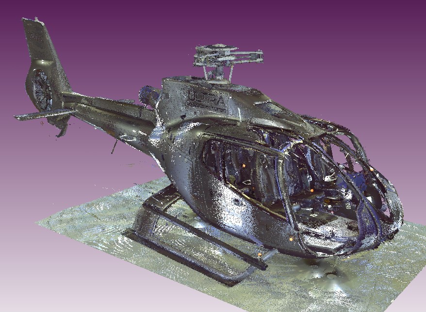
Once merged, the scans generate a point cloud (see Figure 11) and are processed into a triangulated mesh. Both the cloud and the mesh are dimensionally accurate representations of the whole aircraft.
The point cloud that was generated by the scanner contained all the points that the scanner had been able to see. This included not only the aircraft but the surrounding environment and the hangar. Additionally, depending on the nature of the material that the laser was reflecting from, there was some ‘noise’ or spurious points in the scan. To correct this the scan data was automatically and then manually ‘cleansed’ by removing these points from the point cloud.
VH-XKK
Both XH9 and XKQ were EC130 B4s with the same forward airframe and cockpit configuration. This allowed them to be represented by a single aircraft model. Twenty Focus scans were captured, 18 of them external to the aircraft and 2 internal capturing the basic structure. These were then supported by a series of 6 internal scans captured with the Freestyle 2 scanner. Two of these scans focused on the cockpit structure with no personnel in the aircraft. Two scanned the cockpit with an exemplar person in the pilot’s seat and 2 were undertaken with personnel in the passengers’ seats to the pilot’s right.
Passengers
Review of the passenger manifests provided by the operator and the video footage from onboard the aircraft determined that while both aircraft were single pilot operations, passengers were in the seats to the pilots’ right and would have partially obscured the pilots’ views to the right. Even with the passenger video that provided evidence that the passengers were secured within their harnesses throughout the flight it is not possible to determine their exact positions and the extent to which they may have obstructed pilots’ views. To assess what effect a seated passenger may have had, the ATSB developed 2 models of the aircraft, the first without passengers and the second with passengers located in the 2 seats to the right of the pilots. Following initial assessment of the relative location of XH9 from XKQ it was determined that the passengers’ positioning was unlikely to have impacted the detectability of the approaching aircraft and the model without passengers was used for further analysis.
Rotor blades
At the time of scanning, VH-XKK was not fitted with main rotor blades due to ongoing maintenance activities. The ATSB assessed this was the preferred way to model the aircraft as the profile of the blades when the aircraft was on the ground would not have been representative of their location in flight. From the internal passenger videos, it can be clearly seen that while the rotor disc is discernible, due to the rotational speed it did not have a significant impact on the detectability of the approaching aircraft.
Landing gear
VH-XKK was modelled sitting on the ground with weight resting on the skids resulting in slight splay of the skids to support the weight, when the aircraft lifts off and the weight is taken by the rotor system this splay will come off and the landing gear position will change slightly. Due to the position of the skids below and behind the pilot, this will not influence the visibility from or detectability of the aircraft. To limit any effect this may have had on the manipulation of the model in its development (see Point cloud conversion) wherever practical other parts of the aircraft were used for scaling and rotation of the model.
Mod-074581
Any modification affecting the basic dimensions of the aircraft (length, width or height) must be considered when preparing and converting the point cloud. The EC130 B4 aircraft maintenance manual (AMM) identifies 2 length dimensions for the EC130 B4 (10.60 m or 10.81 m) depending on whether an aircraft is pre‑ or post‑mod 074581. Mod 074581 was introduced by Airbus Helicopters to strengthen the connection between the fenestron tail rotor and the tail boom after cracking in the area was identified. ATSB review of the maintenance records identified that VH‑XH9 was post‑modification, while VH‑XKQ was pre‑modification. The Airworthiness Directive (AD) that mandated the modification required that it be introduced to all relevant helicopters by 11 January 2024, but that any helicopter without the modification required inspection every 25hrs until it was completed. As of end of operations on 1 January 2023, XKQ had a further 15 hours until the next inspection was required.
ATSB review of VH-XKK when conducting scanning operations determined that it was a post‑mod 074581 aircraft. This does not affect the ability of the model to be used to replicate the cockpit environment and visibility of VH‑XKQ as the dimensions of the cockpit and the bulk of the body and tail boom of the aircraft, up to the connection between the boom and the fenestron, remain the same.
To create a 2D representation of the pilot’s view the position of their eye relative to the aircraft around it must be known. From this the azimuth and elevation angles from the pilot’s eye to elements of the cockpit structure can be located and plotted on an equirectangular[8] 2-dimensional chart. This chart represents a spherical view of the aircraft around the pilot’s eye position over which the location of the target aircraft can then be plotted.
Locating the design eye position
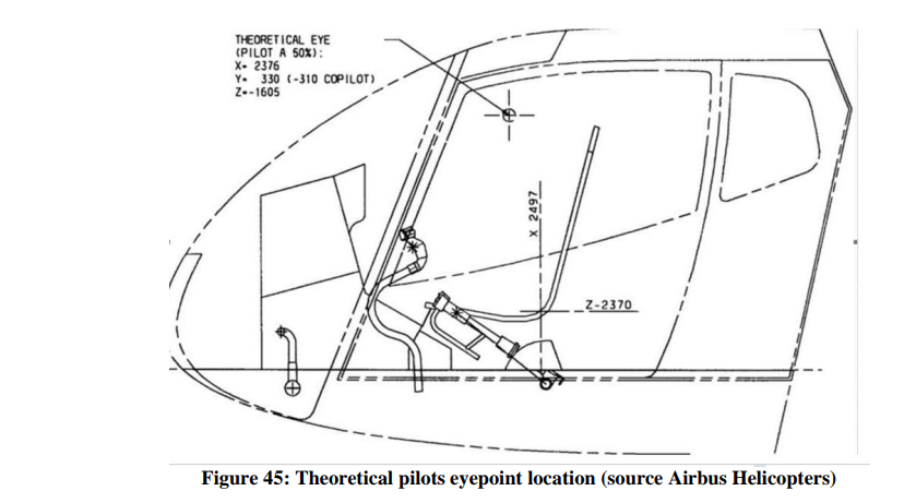
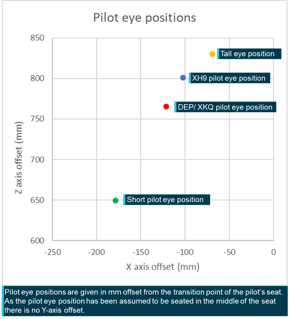
The ATSB obtained the design eye position (DEP) from the aircraft manufacturer (see Figure 12). The DEP is the location from which the manufacturer intends for a 50th percentile pilot to operate the aircraft and view the cockpit. The manufacturer defined this position in millimetres (X = 2,376, Y = 330, Z = −1605) in a coordinate system with an unknown origin point. All the ATSB calculations and measurements used dimensions and locations defined in the AMM. To convert between the coordinate system that the DEP was in and the AMM coordinate system a common point needed to be defined.
It was identified, as shown in Figure 12, that the manufacturer had also identified the X and Z values for the transition point between the base and back of the pilot’s seat in the diagram which showed the coordinates of the DEP. A Y value was obtained by assuming the transition point and the pilot’s eye position would be centred on the seat. The 3D offset between the DEP point and the seat transition point was then calculated.
To convert the DEP to the AMM coordinate systems, the ATSB identified the 3D coordinates of transition point between the base and back of the seat within AMM and applied the offset as calculated from the DEP coordinate system to locate the DEP within the AMM coordinate system.
Figure 12: Manufacturer provided coordinates for the DEP for EC130 B4
Source Airbus Helicopters
Point cloud conversion
All points in the 3-dimensional model were recorded relative to an origin point. In the case of the aircraft scans, the origin was the location of the scanner head when the first scan was taken. These coordinates are referred to as being in the Scanner Axis System.
To calculate the position of the target aircraft relative to the viewer aircraft the target’s 3‑dimensional position in the viewer aircraft’s coordinate system must be known. For this analysis the viewer aircraft’s coordinate system is taken to be as the Body Axis System (BAS) defined by the AMM. Points in the 3-dimensional model are converted from the Scanner Axis System to the BAS using a series of matrix transformations.[9]
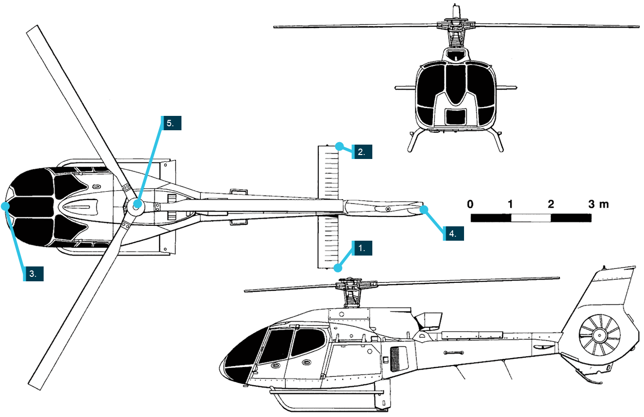
Defining the proper rotation and translation matrices required the identification of several 3‑dimensional points in the Scanner Axis System with known coordinates in the BAS. For this study the ATSB used the rear tips of the left and right horizontal stabilisers, the nose and rear of the aircraft and the top of the rotor head as identified on the aircraft 3‑view diagram (Figure 13). These points were identified in both the Scanner Axis System and in the aircraft’s BAS.
Once the transformation matrices were defined the ATSB transformed each point in the point cloud from the Scanner Axis System into the BAS. A conversion of the DEP is not required as it has already been calculated in the coordinates of the BAS.
With the aircraft fuselage and DEP both located within the BAS, the azimuth and elevation angles of points representing the aircraft structure from the DEP were trigonometrically calculated and plotted on an equirectangular plot (see Figure 14). This chart will be combined in the Results and Discussion section with the relative positions of the target aircraft to determine when the target aircraft would have been shielded from the DEP.
Figure 13: 3-view diagram identifying relevant points of comparison
Source: Airbus helicopters, annotated by the ATSB
Figure 14: Cleaned equirectangular view from the design eye position
Source: ATSB
Pilot information
The details regarding each pilot’s experience, training and other factors can be found in the investigation report. This study will consider 2 aspects of the pilots that can impact the scope of their fields of view: the pilots’ eye positions (considered in Pilot eye positionbelow), and the effect of headwear each pilot wore during the accident flight.
There are 2 elements of headwear that will be considered as part of this analysis – sunglasses and hats.
Sunglasses
In their guidance material Sunglasses for Pilots: Beyond the Image the United States Federal Aviation Administration (FAA) defines the key benefits of sunglasses while operating aircraft:
Sunglasses reduce the effects of harsh sunlight, decrease eye fatigue, and protect ocular tissues from exposure to harmful solar radiation. Additionally, they protect the pilot’s eyes from impact with objects (i.e., flying debris from a bird strike, sudden decompression, or aerobatic maneuvers). Sunglasses can also aid the dark adaptation process, which is delayed by prolonged exposure to bright sunlight.
It is important to note that sunglasses will only provide the benefits stated when they are fitted with the appropriate lenses with relevant impact resistance and tinting characteristics.
Polarisation is a process used on sunglasses allowing them to further reduce glare and eyestrain by blocking reflected light from surfaces such as water or snow. However, this can interfere with visibility of instruments in the cockpit with anti-glare coatings, enhance striations when looking through windscreen materials and mask light reflections from aircraft that may improve visual detection opportunity. There may be further impact on the visibility if sunglasses are worn in an aircraft that is fitted with tinted windscreens or windows as the interaction of the 2 coatings may further mask light reflections or impact the contrast ratio between an object and its background. (FAA Civil Aerospace Medical Institute, 2015)
It is also important to note that where frames of these sunglasses do not wrap around the head, the frames can shield areas of the outer field of view (FOV). Depending on the shape and thickness of the frames this can potentially obscure threats such as birds or other aircraft.
XH9
The pilot of XH9 wore a pair of sunglasses during the accident flight. These sunglasses were fitted with prescription lenses that were required to be worn when exercising the privileges of their pilot licence. These glasses were ‘aviator’ style, meaning that they sat flat across the pilot’s face, not wrapping around the head at the sides. While effective, this style of glasses can allow for visible and UV light to pass around the frames, increasing the amount of glare and eyestrain that a pilot may experience, possibly reducing visual acquisition opportunity.
XKQ
The pilot of XKQ also wore a pair of sunglasses during the accident flight. They were recovered from the accident site by the Queensland Police Service. Manufactured by Versace, these glasses were also ‘aviator’ style and were fitted with impact resistant polarised lenses. As discussed above, the limitation of polarised lenses is that they can interfere with the pilot’s ability to read certain instruments and reduce the detectability of outside objects.
Hat
Wearing a hat limits the direct impact of sunlight shading the eyes or skin. A hat with a broad, 360° brim which shields the eyes and skin all around the head. While providing shade the hat brim will block the visual field above the hat brim. For aviation operations the use of a hat with a 360° brim can be impractical as the rear of the brim will force the pilots head to sit off the headrest (defeating the protective purposes of the headrest) and altering the eye position. In addition, a 360° brim can hinder or prevent the use of over-ear headsets. Alternatively wearing a cap, having only a brim at the front, (its peak), shades over the eyes while eliminating the issues with a 360° brim. Further, the peak may be curved allowing it to be higher in the centre and lower on the edges, reducing the shielding of the wearer’s visual field.
XH9
Video footage from inside XH9 identified that the pilot was not wearing a hat.
XKQ
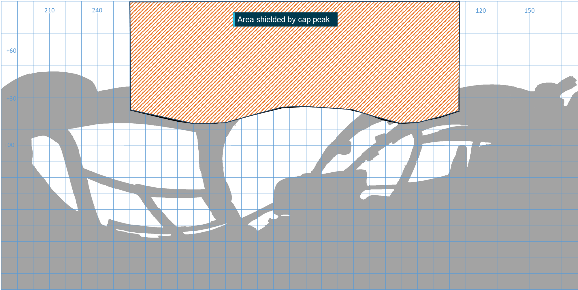
The pilot of XKQ was wearing a Sea World Helicopters cap for the accident flight. This cap was a ‘trucker’ style, with a solid front panel embroidered with the Sea World Helicopters logo and the remaining panels were of mesh construction. While onsite conducting 3D modelling in support of this study ATSB personnel examined an exemplar Sea World Helicopters cap and photographs, 3D scans and measurements of it to help determine its potential impacts on the pilot’s FOV. The exemplar cap had an approximate peak width of 130 mm, height of 40 mm and depth of 80 mm at the centre. It is important to note that the peak of the cap is manipulable and so the impact of the peak of the pilot’s actual cap may have differed slightly from the exemplar.
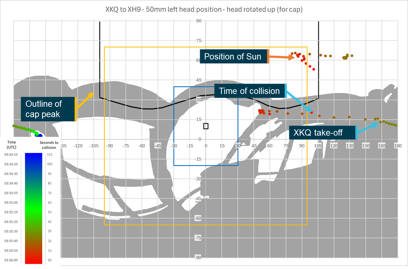
The cap’s peak extended at a slight downward angle from the cap’s body so that the front of the peak sat lower than the body of the cap. To assess how this would impact the pilot’s FOV, the ATSB placed the cap over the lens of a spherical camera to simulate the position of the cap relative to the pilot’s eyes and captured an image from the simulated position. Based on this image, the area of the FOV from the pilot’s eye position that would be obscured by the cap’s peak was determined (see Figure 15). A pilot wearing the cap would have been able to see objects in this area. The area where the cap’s peak obscured the pilot’s FOV was verified by identifying the boundaries of the FOV of an ATSB investigator of the approximate height of XKQ’s pilot seated in the left seat of the helicopter while wearing the cap.
Figure 15: Equirectangular view of the cockpit from the pilot’s eye position showing the area of visibility impacted by the pilot’s cap brim
Source: ATSB
Pilot statement
XH9
The pilot of XH9 provided a range of detailed information to the ATSB supporting the investigation, as presented in relevant sections of the investigation report. For the purposes of the visibility study there were 4 primary pieces of information that were relevant to this work.
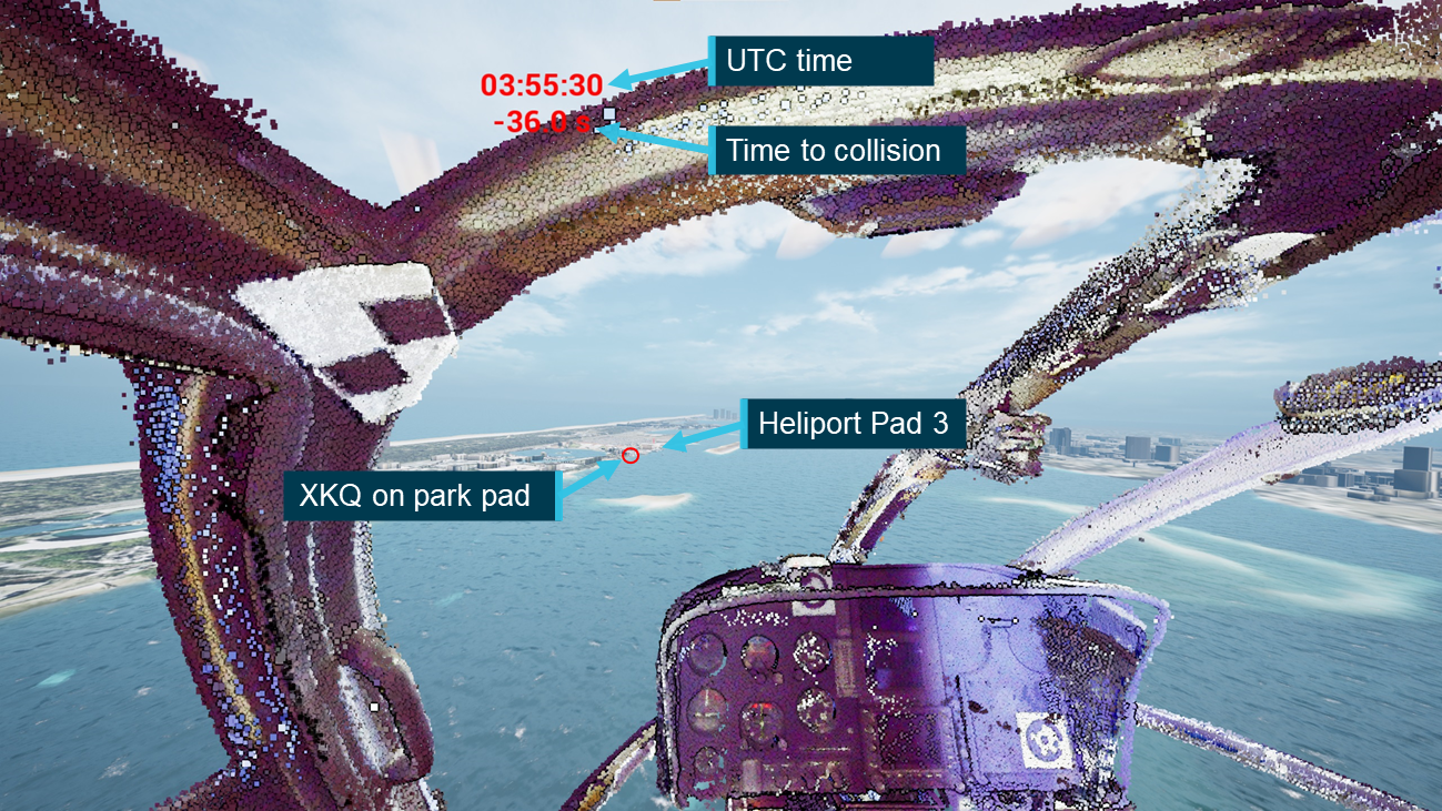
The pilot was aware of XKQ sitting on the park pad as XH9 transited down the Broadwater towards the operator’s heliport, sighting it on the pad with the doors closed.
As XH9 transited past XKQ sitting on the pad, XH9’s pilot assessed that the aircraft would pass behind them on their approach and did not pose a threat.
XH9’s pilot assessed that if XKQ departed, its pilot would make a radio call identifying that fact which would alert them (pilot of XH9) to the changed threat status of XKQ and the need to direct more attention to that aircraft. They reported that no such call was heard.
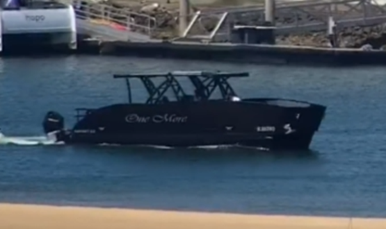
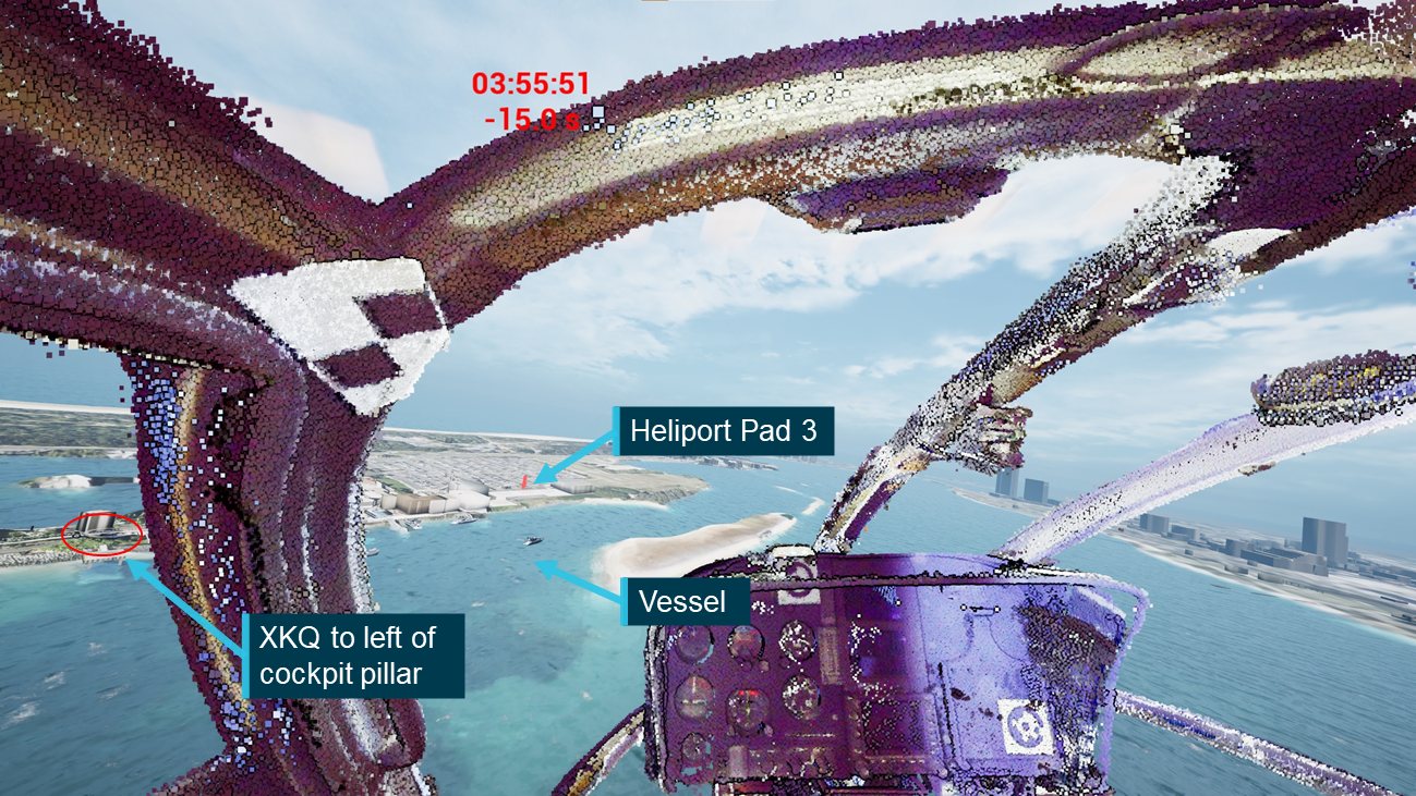
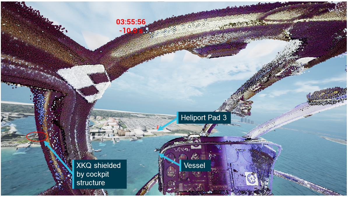
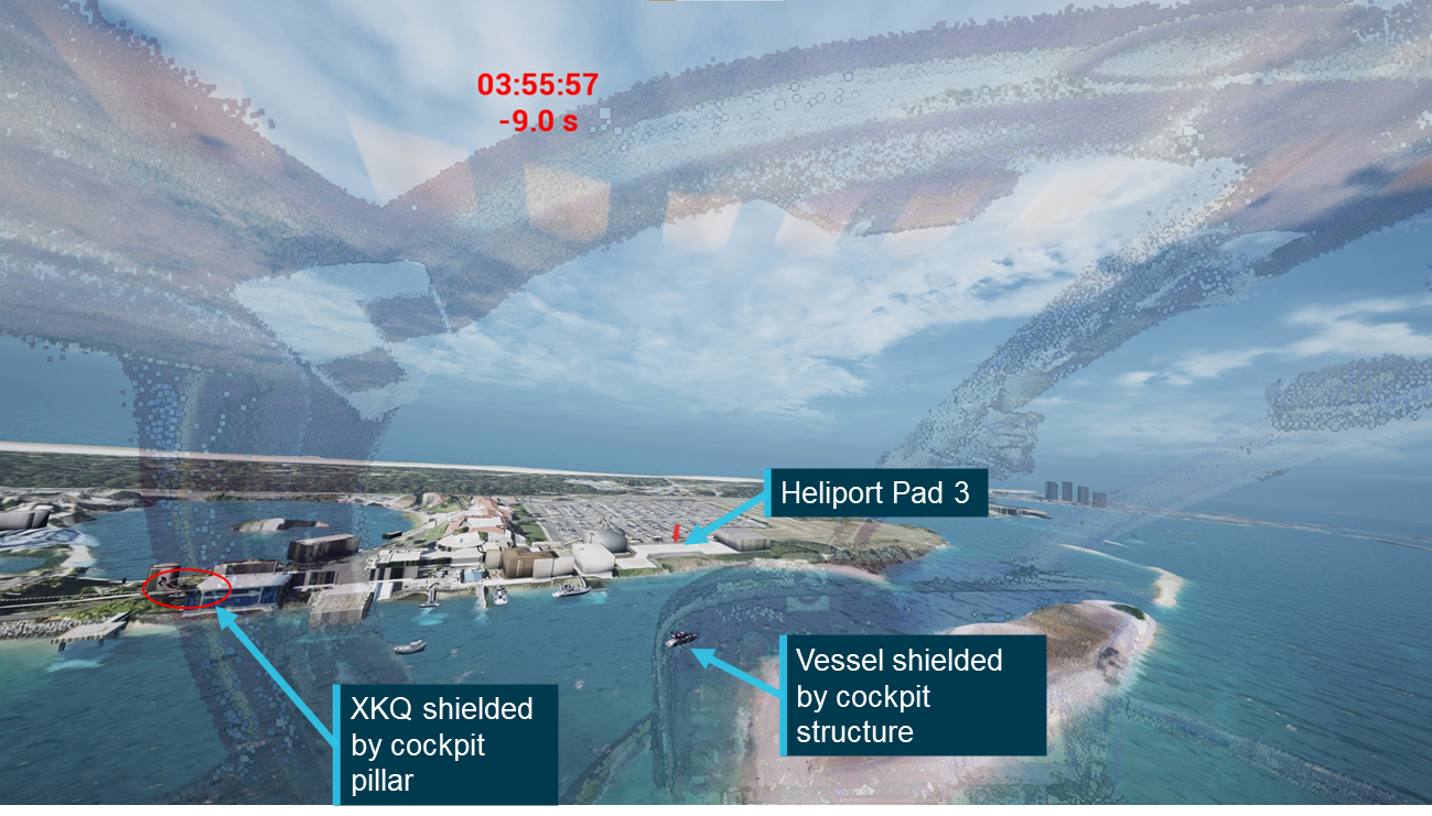
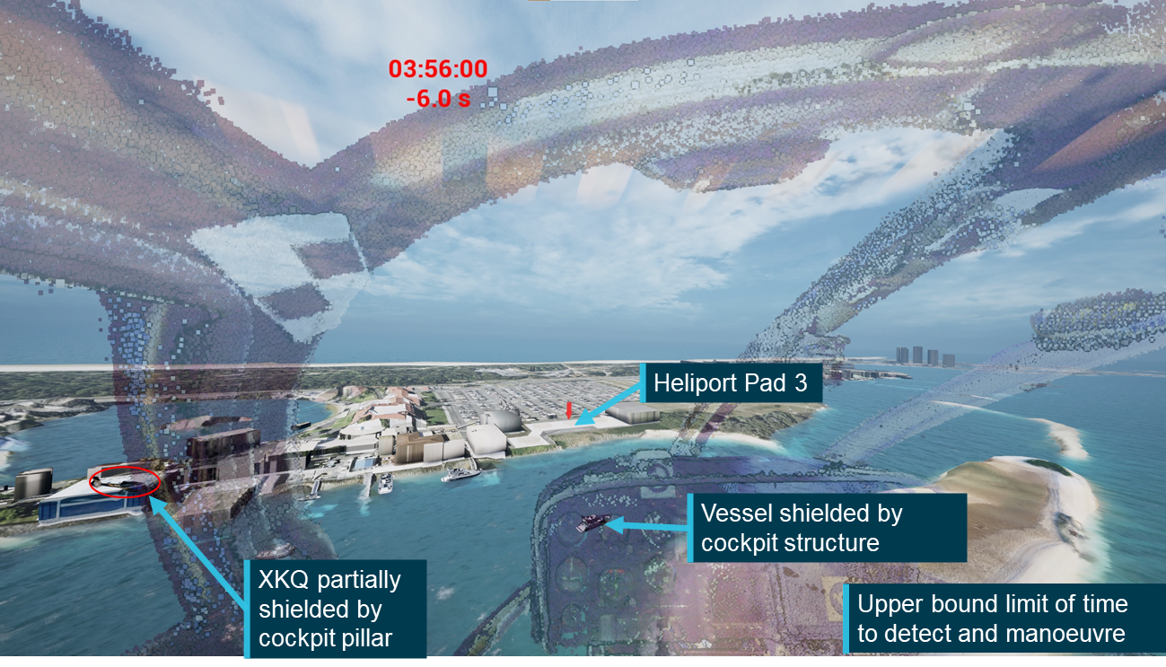
XH9’s pilot had identified a black vessel that was operating in proximity to the approach path that they planned to pass behind.
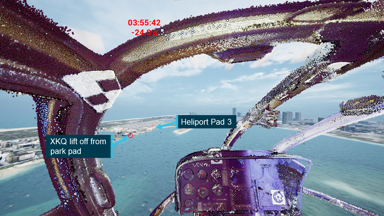
This study has been developed on the assumption that the pilot of XH9 needed to identify the change in status of XKQ at or after the time it lifted from the park pad without a radio call or other alert.
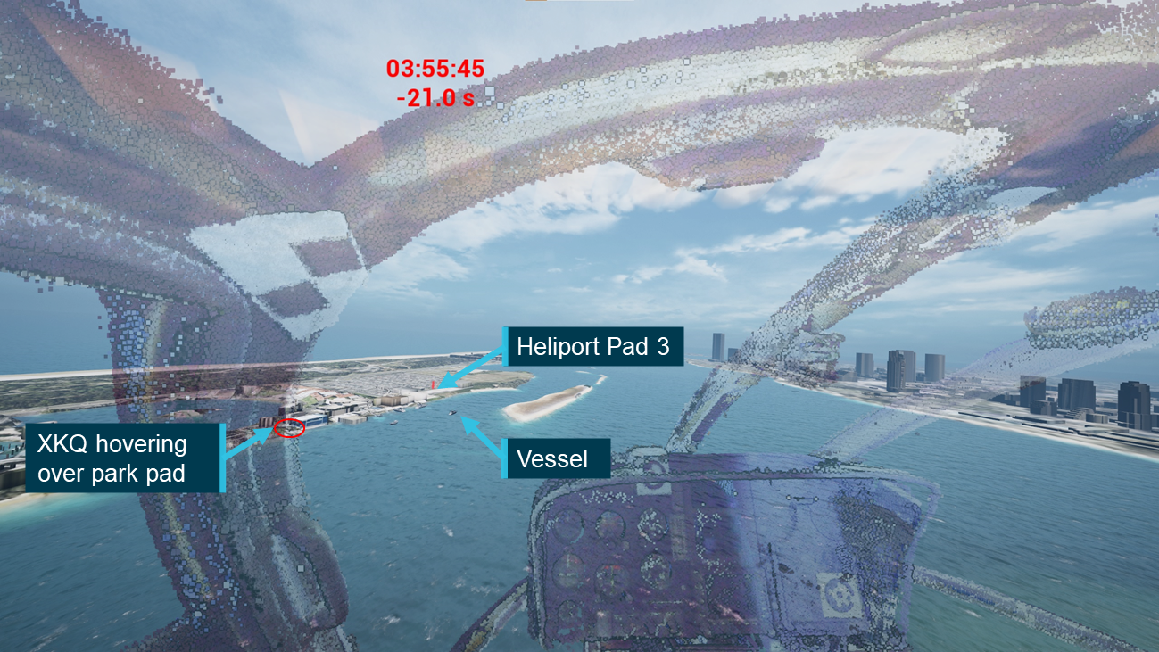
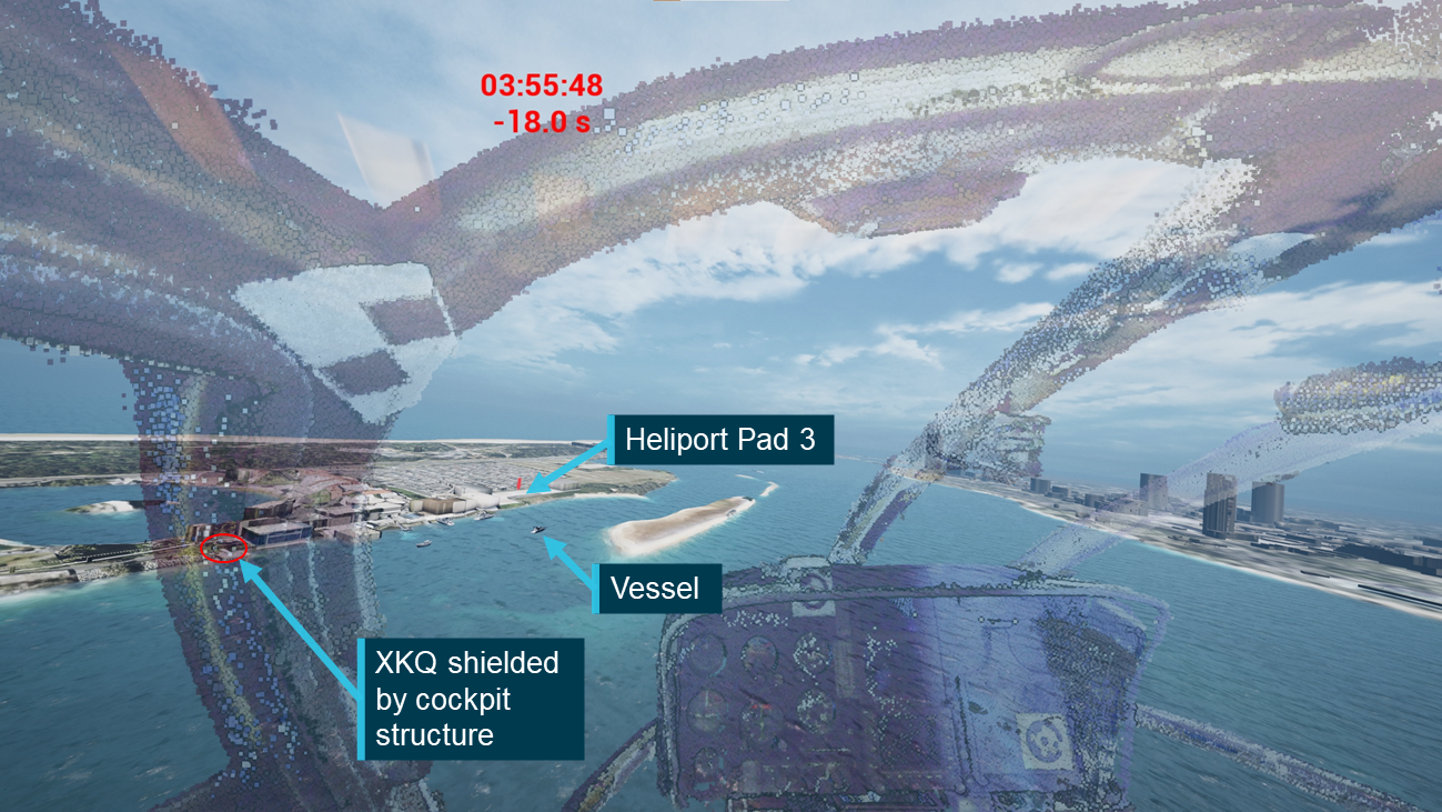
Vessel
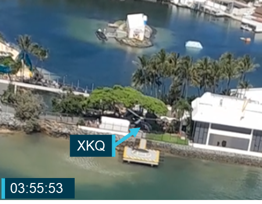
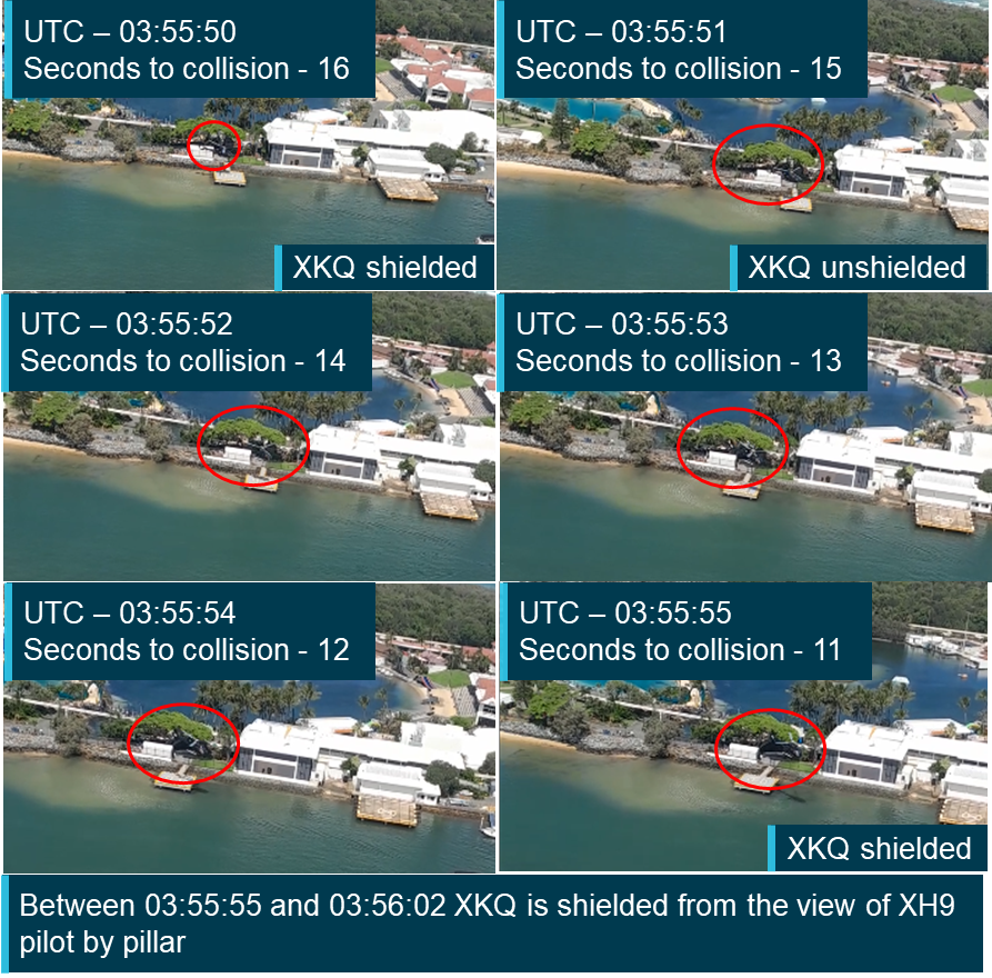
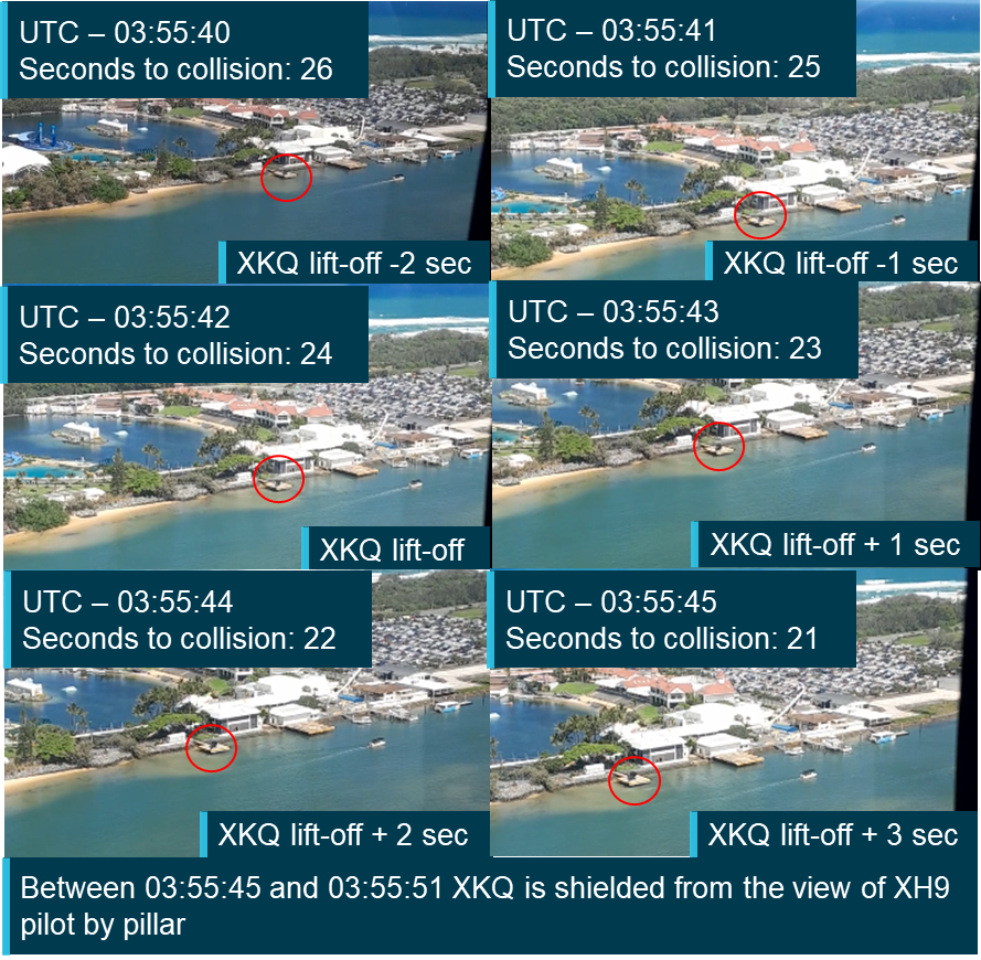
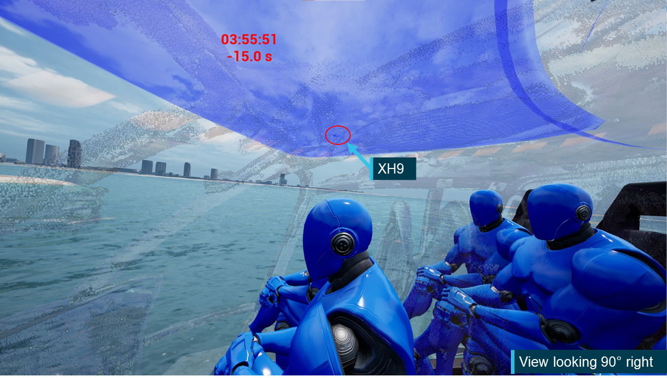
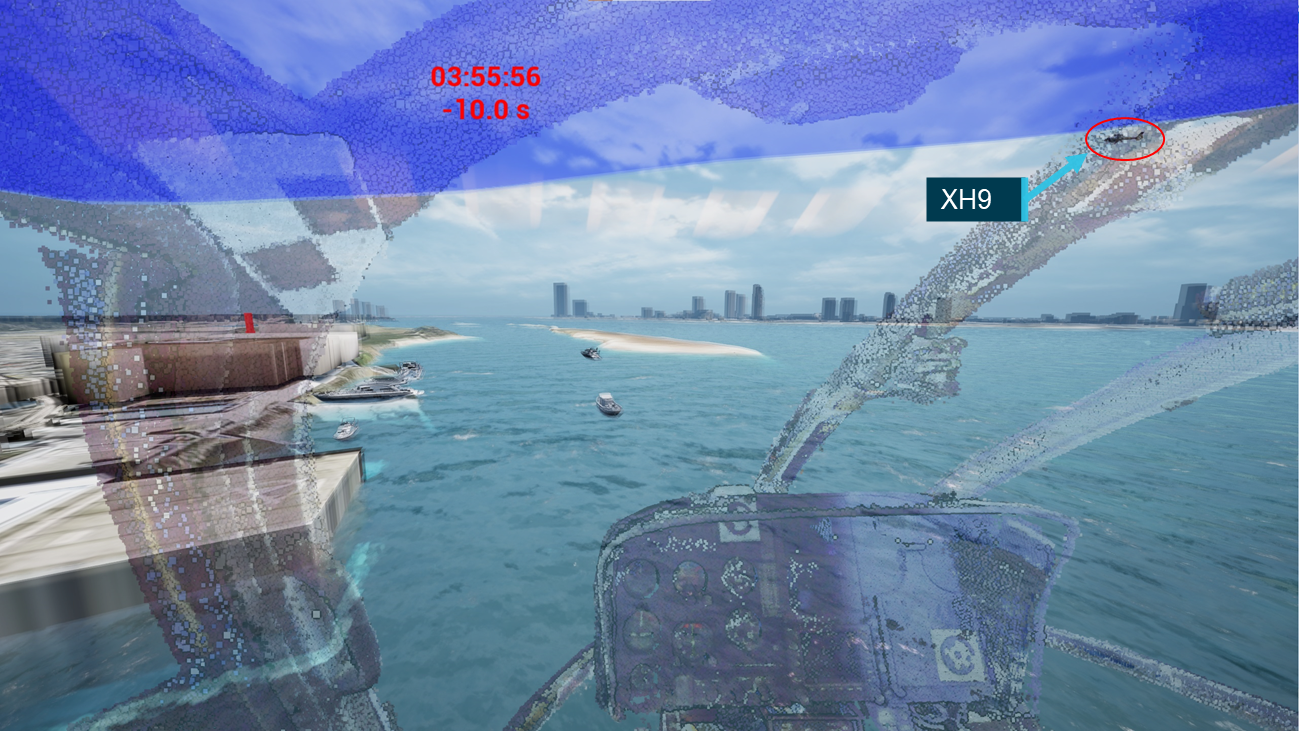
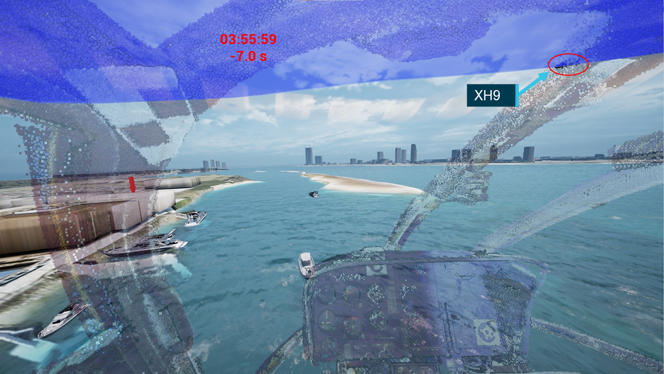
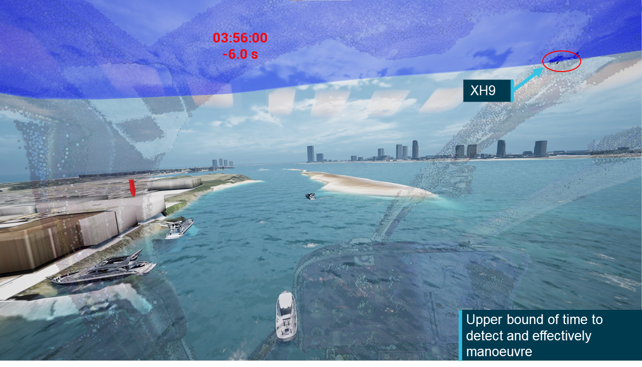
XH9’s pilot stated that the vessel (Figure 16) required their attention; the ATSB sought to determine where it, and XKQ would have appeared in their FOV. The ATSB triangulated the position of the vessel at a series of points based on timestamp corrected frames of video recordings. The position of the boat between these points was interpolated assuming an approximately constant speed. The path of the boat was then simulated and verified using the video recordings.
Due to the limitations of the number and locations of the cameras used to the triangulate the position the vessel was only tracked between 03:55:44 and 03:56:17 (22 seconds before through 11 seconds after the collision). The track of the vessel was continued past the collision time to align with the video footage that had been used to identify its location.
The relative location of the vessel to the pilot of XH9 was then calculated and plotted. This involved the same process used to calculate the relative location between the 2 aircraft in the lead‑up to the collision.
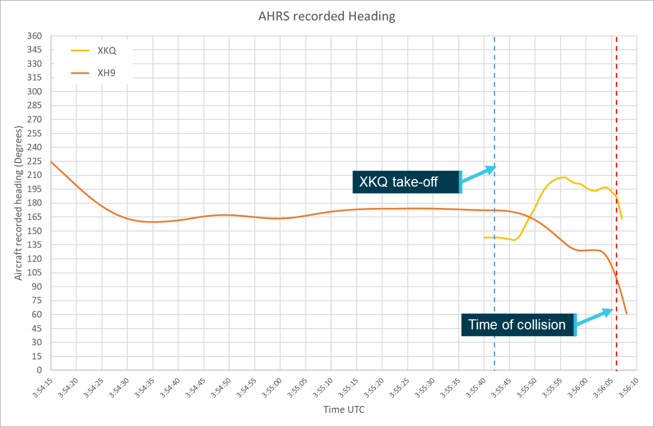
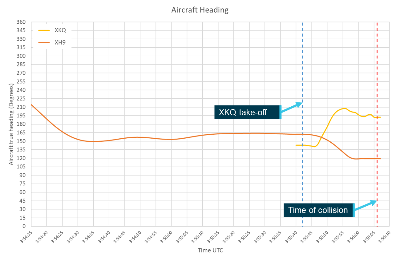
To accurately calculate the position of each aircraft relative to the other pilot’s FOV both aircrafts’ positions and orientation (pitch, roll and heading) parameters were required. As outlined in the investigation report, these parameters were extracted from the Spidertracks SpiderX units of both aircraft.
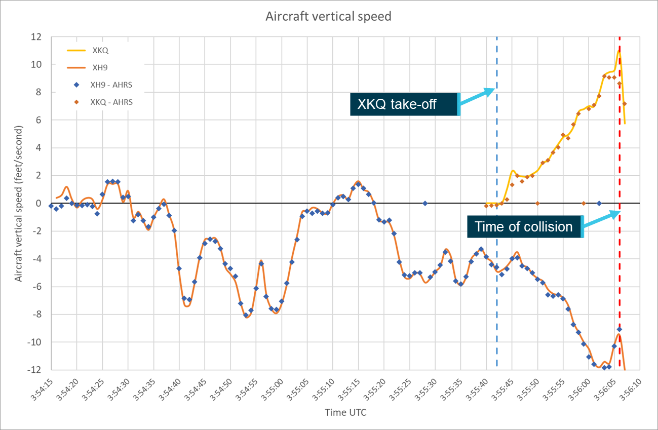
The 1-second attitude heading reference system[10] (AHRS) data was used for initial definition of the flight paths and aircraft orientation parameters. In support of further analysis for XH9 the ATSB also obtained and assessed the sensor outputs from which the AHRS data is calculated using a Kalman filter.[11] Further detail regarding the recovery of information from the Spidertracks units from XH9 and XKQ can be found in the investigation report.
Spidertracks AHRS data records altitude in metres relative to the WGS84 ellipsoidal model of the earth, this model over-estimates values for altitude on the Gold Coast by approximately 40 m. To account for this, a −40 m correction was applied to all altitude values for both aircraft before further analysis was completed.
Position error
Spidertracks units are not certified aviation position reporting devices, and they are not required to meet any performance or accuracy standard.
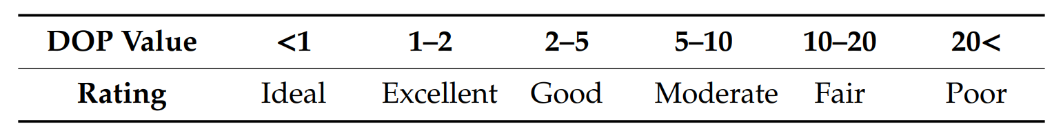
Along with the position and orientation information, the SpiderX units also record the horizontal and vertical positional accuracy and positional dilution of precision[12] (PDOP) parameters. Horizontal and vertical accuracy is reported in metres and PDOP is reported as a dimensionless parameter. The higher its value, the less confidence there is that the accuracy reported is correct. There is no standard interpretation for PDOP coefficients, however they can be generally characterised as per Figure 17. Spidertracks advised that data with PDOP values exceeding 25 or accuracy values exceeding 100 m will be treated as invalid by the system.
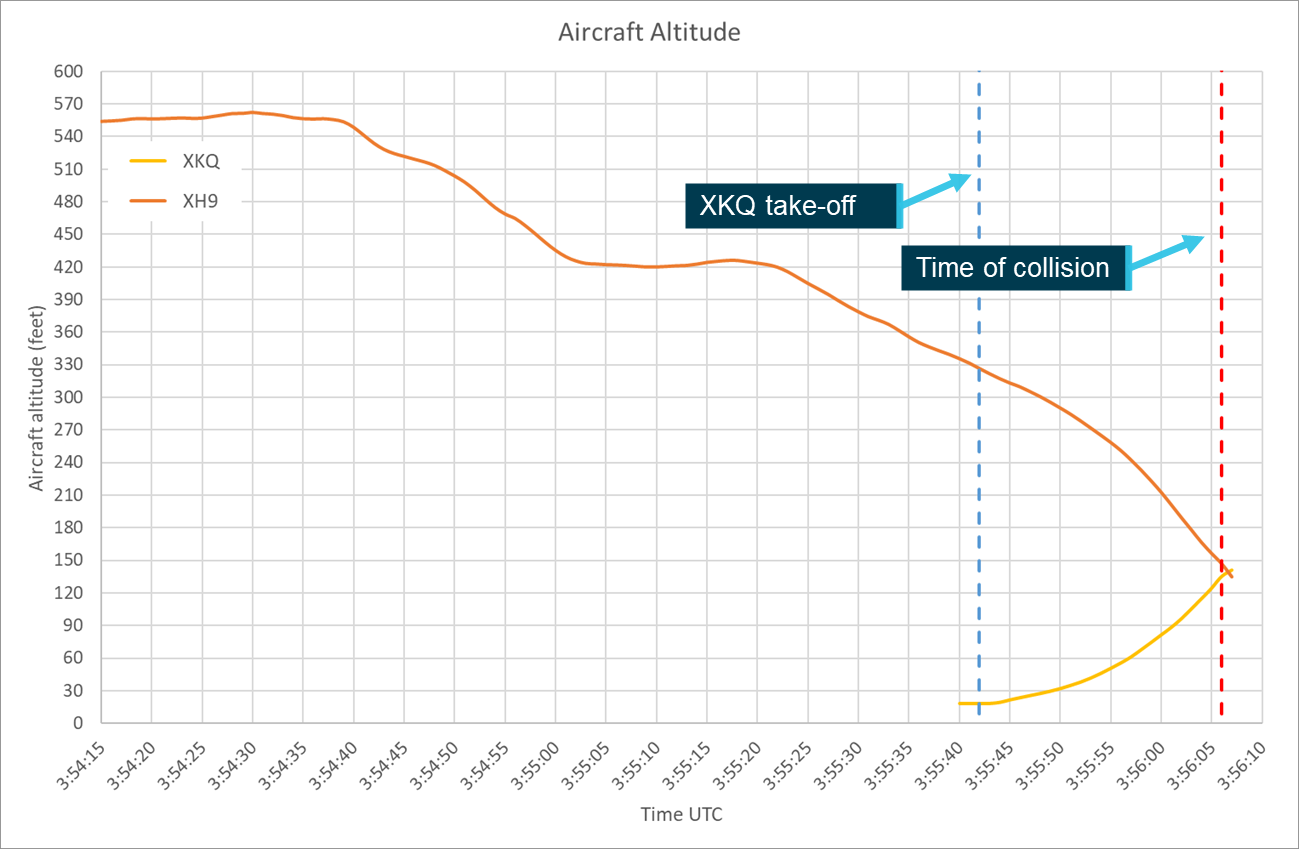
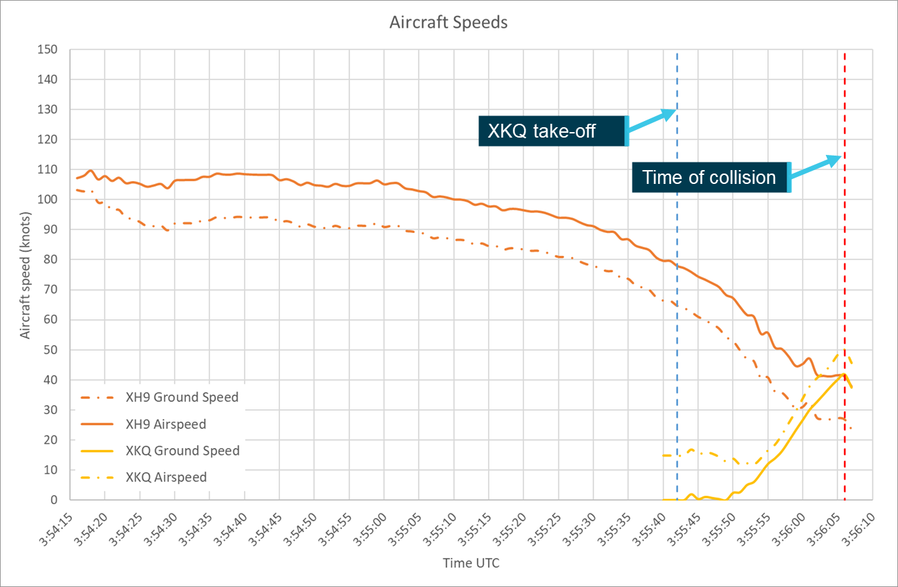
Between 03:51:40 and 03:56:06, from the time XH9 departed the heliport until the collision, XH9’s SpiderX unit reported a constant horizontal and vertical accuracies of 2 and 3 metres respectively and a PDOP value varied between 1.01 and 1.59 averaging 1.11.
Between 03:55:40 and 03:56:06, from shortly before XKQ departed the park pad until the collision, XKQ’s SpiderX unit reported a constant horizontal accuracy of 3 metres and a vertical accuracy of 5 metres improving to 4 metres after 03:56:02. The PDOP value varied between 1.12 and 1.38 averaging 1.25.
These values indicate a high accuracy and confidence in the position being reported.
Figure 18 diagrammatically represents the accuracy margins as reported by the Spidertracks unit from a left side view of the aircraft.
Source: Airbus Helicopters, modified and annotated by the ATSB
Video footage
As outlined in the investigation report, multiple sources of video footage of the flight, collision and the response and recovery efforts were available to assist the investigation and this study. The study used video footage from onboard both aircraft, fixed CCTV cameras on both sides of the Broadwater, and from witnesses around the accident site. This footage was used to verify aircraft configuration, assess the accuracy of other recorded data, locate and assess positions of watercraft and review the position of the pilots within the aircraft.
Data verification
The ATSB, in conjunction with IWI, did several things to verify the aircrafts’ recorded positions and orientation parameters. The ATSB provided IWI with the recorded data and relevant onboard and external video footage. Using this information IWI generated an initial animation of the position and orientation of the aircraft within a simulated environment. To ensure consistency between the animation and the video footage, the view of the animation from the position of the cameras used to develop it was required. The position and orientation of the video cameras within the animation environment were estimated using common features (such as buildings or aircraft structure) and relevant meta data such as time, position and orientation.
By viewing the video footage and the corresponding view of the animation simultaneously and tracking common points between them, differences could be identified. The ATSB attempted to resolve any differences by conducting additional review and analysis of the recorded data and available imagery. Where the cause of a difference was identified, corrections were made accordingly. Where there was insufficient information to determine the cause of a difference and correct the data deterministically the animation was updated with estimates of relevant parameters. This process was then repeated as necessary to minimise the difference between the video footage and the animation.
Limitations
The following sources of potential error were considered when completing the data verification process.
Error in the estimates of the position, orientation and movement of the various cameras used for the verification.
Error introduced by internal parameters of the camera including lens distortion and rolling shutter effect.
Error in the sub second alignment between the recorded data and the video footage. Data is reported at 1 Hz and interpolated to give a constant trajectory, video footage is recorded at various frame rates depending on the camera, leading to a potential misalignment.
Errors, inaccuracies and incompleteness in the simulated external environment and external points used for verification.
These potential sources of error do not invalidate either the verification or further analysis, however they do introduce potential for variation (uncertainty). To account for this uncertainty and other factors, the ATSB completed a sensitivity analysis on the results that the study produced.
Onboard footage
Passengers on board both XH9 and XKQ recorded a range of video footage throughout the accident flights using hand-held electronic devices. For this study the ATSB reviewed these videos looking specifically at indications of the location and orientation of the pilot’s head and resulting eye position, the location and environmental surroundings of the approaching aircraft and the presence and use of visual conspicuity devices.
XH9
Video footage was recorded by 2 rear seat passengers on board XH9 during the final 30 seconds of the flight. The footage captured by the left rear passenger showed XKQ and the background it was traversing across from the time it departed the pad until the collision. It did not provide any information regarding XH9’s pilot’s head but it did show the right (green) position light on XKQ was operational.
The second video was taken from the rear right passenger aboard XH9. It captured 23 seconds of footage leading up to the collision panning from the right of the aircraft and through the cabin. XKQ appeared in this footage for about 3 seconds (between 13 and 10 seconds before the collision) showing the aircraft climbing out of the park pad and moving towards the accident location.
This footage showed the location and orientation of XH9’s pilot’s head for the final 12 seconds before the collision. The footage initially shows the pilot looking straight ahead. Approximately 8 seconds before the collision the pilot appears to look slightly down and to the left for 2 seconds before looking straight ahead again. Five seconds before the collision the pilot rotates their head to the right for approximately 3 seconds before recentering. At this point, 2 seconds before the collision, the pilot again looks right in response to a passenger interaction.
This footage, along with other video and still images taken earlier in the flight, was used to identify the presence of a surface coating on XH9’s skylights.
XKQ
Footage was recorded by 4 passengers on board XKQ. For the purposes of this study the footage reviewed was limited to the 24 seconds between when XKQ departed the park pad and the collision. The only footage of the XKQ’s pilot captured during this time was from the rear of the aircraft. The footage pans across the aircraft showing the pilot twice. The pilot is first shown 16 seconds before the collision looking straight ahead. The pilot is shown again approximately 12 seconds before the collision, appearing to look slightly down and to the right.
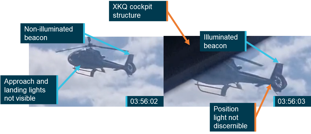
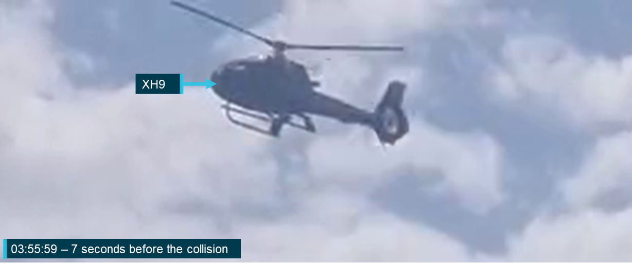
Footage from 2 of the cameras also captured the approach of XH9. Footage from a front passenger captures XH9 for 2 seconds, between 12 and 10 seconds before the collision. Footage from a rear passenger captures XH9 for 4 seconds between 7 and 2 seconds before the collision. This footage was used to verify that XH9’s tail beacon was working and determine the visibility of other aircraft lights prior to the collision. These videos were also used to assess the contrast of the background against which XH9 would have appeared.
Locating the target aircraft
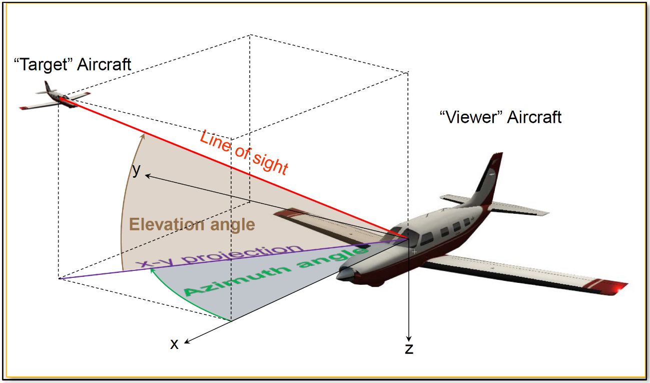
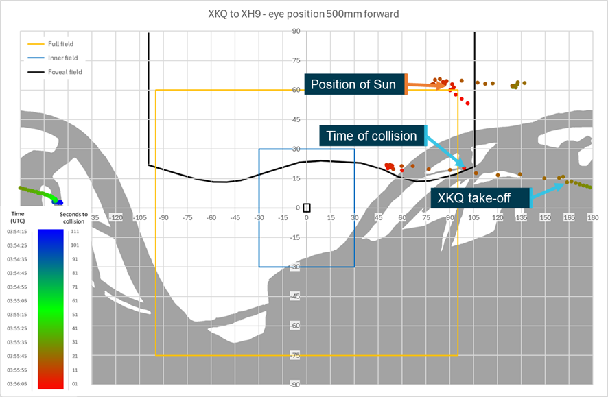
The location of the target aircraft in the field of view of the pilot of the viewer aircraft can be defined in terms of the azimuth and elevation angles from the viewer to the target, as depicted in Figure 19. To compute these angles, the relative position of the 2 aircraft in 3-dimensions must be defined. The target aircraft’s coordinates are first transformed from an Earth-based coordinate system into the viewer aircraft’s BAS. The azimuth and elevation angles from the viewer aircraft to the target can be computer trigonometrically.
The azimuth and elevation angles to the target aircraft are then plotted over the equirectangular plot of the azimuth and elevation angles of the viewer aircraft’s structure (as seen from the DEP), as presented in the section titled Point cloud conversion. At points where the azimuth and elevation coordinates of the target aircraft overlap those of the viewer aircraft’s structure, the target can be considered to be obscured or ‘shielded’ from the pilot of the viewer aircraft. The same process is applied to determine the location and shielding of the sun from the viewer pilot’s DEP.
Figure 19: Azimuth and elevation angles from viewer aircraft to target aircraft
Source: NTSB
Meteorological information
Wind information
As outlined in the investigation report, weather reports for the day indicated that there was a moderate south-easterly wind at around 15 kts with gusts up to 25 kts. These reports were verified with onboard and external photographs and videos showing the sea state, which indicated winds of 11 to 16 kt and the windsock at the park pad showing approximately 12 kts as XKQ departed.
Cloud information
Weather reports, video footage and supplied photographs identified scattered cloud over land at around 3,500 ft. At this level the cloud would not have been a direct factor in the visibility of either aircraft operating at or below 500 ft. However, shading produced by the cloud and changes to luminance characteristics of the background as an aircraft passed in front of a clouded area could have impacted the aircrafts’ detectability to the viewer. For example, a dark coloured aircraft will likely be easier to detect against a white cloud than against a dark cloud.
Sun position
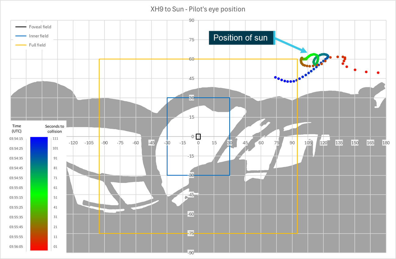
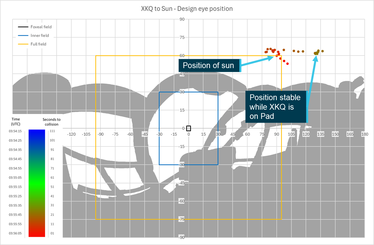
Where the sun is visible, or close to the edge of the field of view, its glare can reduce a pilot’s ability to locate traffic. The ATSB obtained data on the sun’s position relative to the aircraft flight paths and the collision location from the Geoscience Australia sun and moon position calculator.[13] These positions within the pilots FOV will be presented in the Environment section of Aircraft conspicuity and detectability.
Background luminance
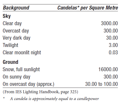
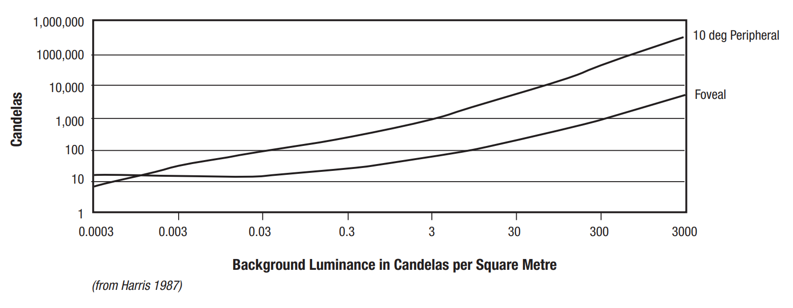
Background luminance[14] is the effective brightness of the background against which an object is being perceived. During the day, the background luminance depends on the sun intensity which is affected by the time of year, location and other atmospheric conditions including cloud or smoke haze. The actual background luminance on the day of the accident was unable to be determined. Table 1 reproduced in Hobbs (1991) from the Illuminating Engineering Society’s (IES) Lighting Handbook provided approximate values for luminance in common conditions. Based on the time of year (mid-summer), time of day (middle of the day), location (southern Queensland), and the limited cloud cover, all supported by witness imagery and video footage, it was assumed that the background luminance was likely best estimated by 3,000 cd/m2 which the IES identifies as a clear day. This was then used for further assessment.
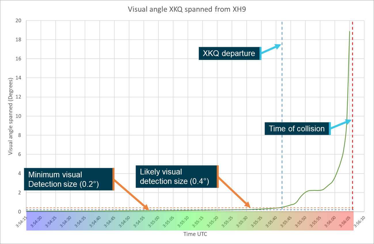
It is not possible to state how large an object needs to be in a person’s field of view before they are able to distinguish it. This is due to a wide variety of factors both internal and external to the viewer and include the background that an object is seen against, where in the field of view it appears, relative motion of the object, vibration and physiological factors such as fatigue, age and hypoxic effects.
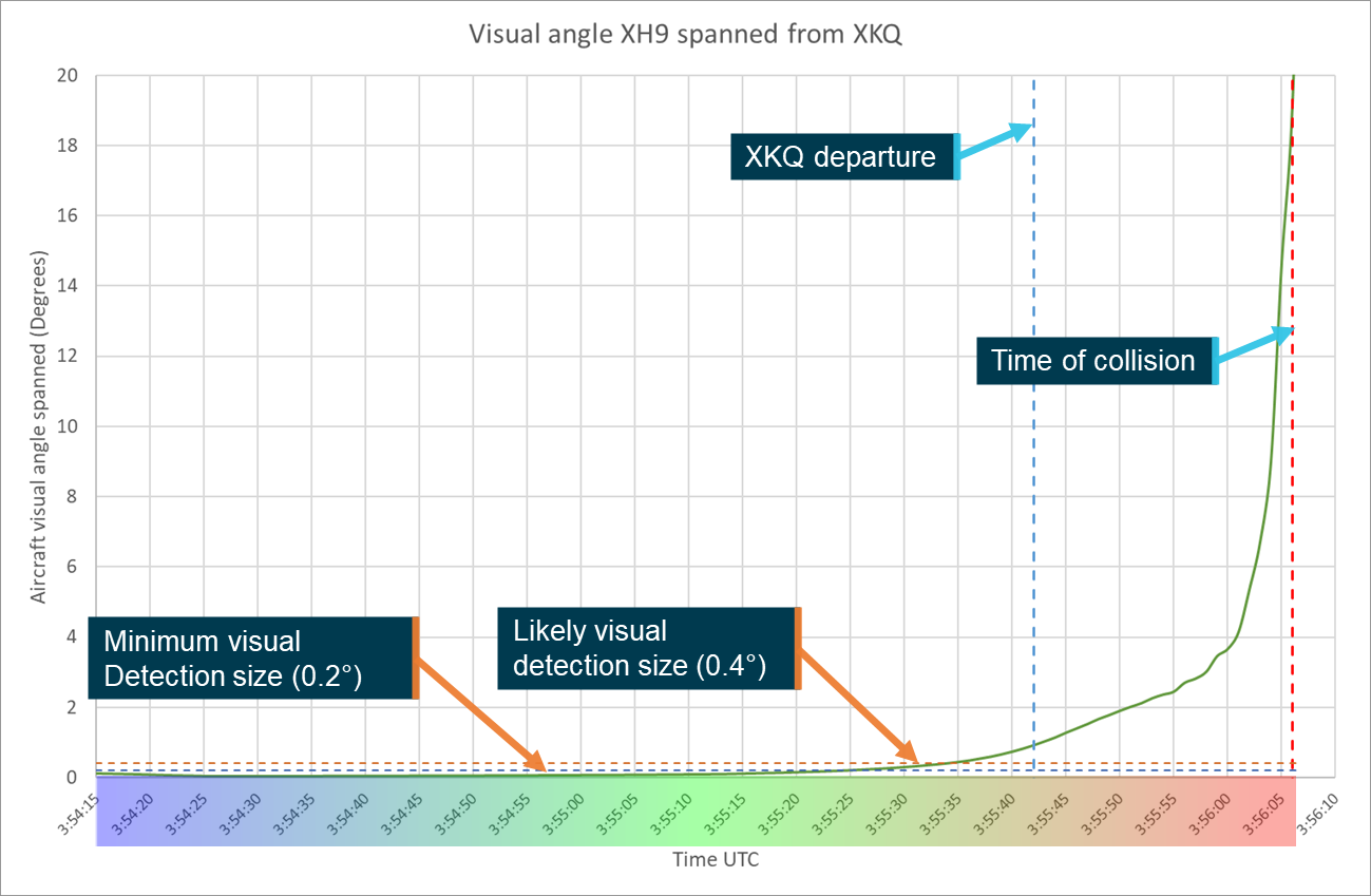
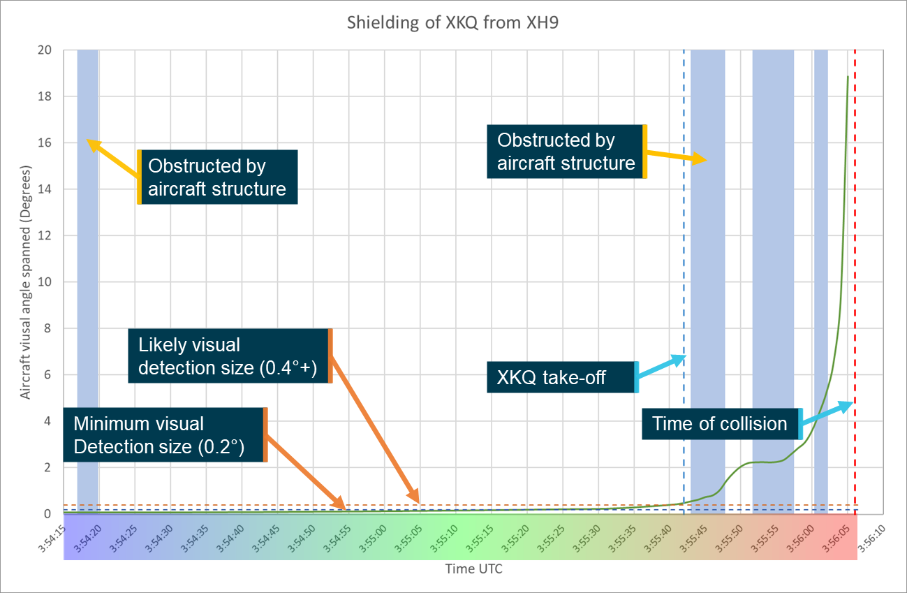
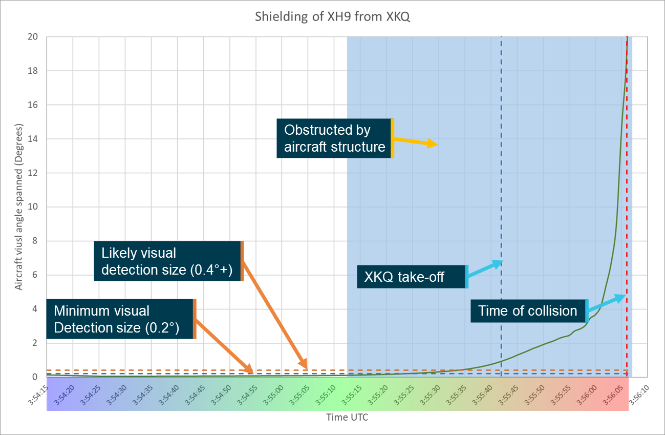
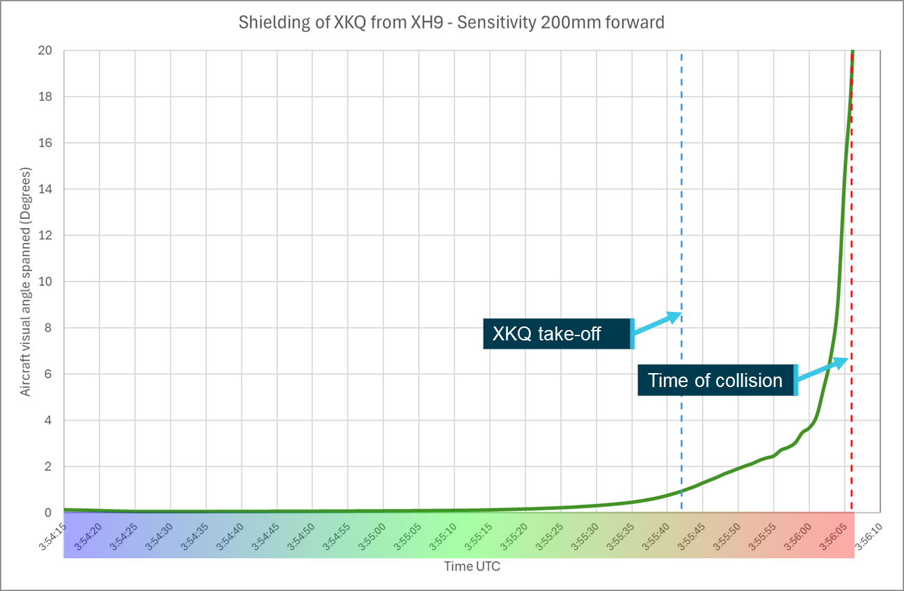
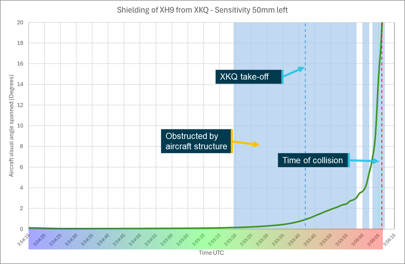
Multiple studies and reports give varying values as to what the minimum perceptible size of an aircraft may be. An NTSB report from a mid-air collision in 1987 (NTSB, 1988), suggested that the largest dimension of the aircraft must span a visual angle[15] greater that 12 minutes of arc (0.2°). Other examples suggest between 24−36 minutes of arc (0.4−0.6°) is more realistic, especially if conditions are sub optimal (Hobbs, 2004). The 3 main factors that will affect the size of the aircraft in the pilot’s eye are the dimensions of the aircraft, its relative orientation and distance from the viewer.
When viewed from head-on, a helicopter’s largest angular dimension will be determined by either the height or width of the fuselage depending on which is larger. If the viewer is perpendicular to the direction of travel the full length of the helicopter will be presented, giving a much larger visual angle spanned. For example, the EC130 has a fuselage width of approximately 2.2 m, height[16] of approximately 1.9 m and a length of approximately 10.8 m.[17] At 200 m these dimensions span visual angles of 0.63°, 0.54° and 3.06° respectively. Depending on the orientation of the aircraft different combination of dimensions may be presented to the viewer. This will mean that the viewer will see an area rather than a single dimension. Due to the comparatively thin nature of the tail boom a helicopter would be best represented by an ellipsoidal shape showing a minor and major axis with major axis represented by the visible length of the helicopter.
Relative movement
An object will be more easily perceived, regardless of where it is in the field of view, if there is relative movement between the object and viewer (Hobbs, 2004). This is due to the human brain’s evolutionary adaptation to perceive movement as an indicator of threat. In general, aircraft on collision courses will not move relative to one another and so the eye will take longer to detect the approaching aircraft. The perception and placement of relative movement in the field of view is assisted where there is a stationary object, such as a structure, past which the object is moving. Under ideal conditions where there is a stationary reference point near the target, movements of 0.017–0.034° of arc per second may be detected. When no such references are available it will require a 10-fold increase in movement for detection (ATSB, 2002).[18]
Strobe or other aircraft lighting may be used to create apparent movement or a focal point that attracts the viewer to the object.
There has been a range of studies assessing the effectiveness of various lights on people’s ability to see or perceive an object. When the viewer knows where to look, a light even of relatively low power can be detected. Where a light is required to attract the attention of a viewer, particularly where it is away from the central FOV, it needs to be 5–10 times brighter than when a person is already alerted to the location and is simply looking for confirmation (Bullough, 2011).
Scene relative movement
Scene relative movement is defined as the movement of an object relative to the scene around it from the perspective of the viewer. Typically, this will be created by the object moving across the background. For example, an aircraft moving across the sky is detectable by a stationary observer on the ground.
If the viewer is moving, then a stationary object is more likely to be detected as the observed background scene will change, creating apparent movement. The impact of this will change depending on the scene. If the scene is relatively constant, such as a clear blue sky, then it will be of minimal assistance as there is minimal change in the scene as the viewer moves. Alternately in a busy scene, such as a cityscape, with changing buildings and colours the object is more likely to be detected as the scene will change more frequently and significantly behind the object.
Further, where there may be little to no relative movement between the object and viewer (such as aircraft on a collision course), the motion of the object through the scene can create an increased detection opportunity with the object crossing stationary references in the scene, drawing the viewer’s attention, while remaining in a constant relative position to the viewer.
Reaction time
Once an object is perceived by the viewer it takes time for the person to identify it, realise it is a threat, determine the appropriate course of action and implement that course of action (ATSB, 2002). In the case of aircraft approaching one another, the implementation of that course of action will not only require an input to the controls from the pilot but also a reaction from the aircraft.
The investigation considered 2 alternate responses for reaction time, non-urgent and urgent. For the non-urgent response, a person identifies a threat and has time to assess it, determine a course of action and respond. For the urgent response, the threat is not detected until it is in close proximity and elicits an instinctive or startle response from the operator.
Non-urgent response
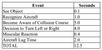
Based on a range of research, the FAA published an advisory circular that defined standard times from pilot perception to the aircraft reaction. This table showed that the total time required was 12.5 seconds. Of this the 2 most significant portions are the determination that the other aircraft is on a collision course and determining the appropriate course of action. These 2 elements make up 9 of those 12.5 seconds. Table 3 is taken from the relevant FAA Advisory circular (AC 90-48E).
Table 2: Aircraft identification and reaction times chart
Source: Federal Aviation Administration
Theoretically, this means that under regular conditions, with no alert or guidance, if an object on a collision course is perceived less than 12.5 seconds prior to impact then the impact will occur regardless of a pilot’s attempted evasive actions. The time available for pilots to react can be increased through the provision of an alert to the pilot to traffic that poses a collision threat and provides an estimate of the location. This may be provided by an air traffic control service, a radio transmission or via an onboard aircraft collision avoidance system (ACAS). Some systems can even provide a manoeuvring recommendation to resolve the conflict (a ‘resolution advisory’) if the aircraft are on a collision course.
Urgent response
ATSB analysis of a previous mid-air collision assessed avoidance response times to unexpected events. This analysis was based on road safety work conducted by Summala in which drivers were required to respond to an unexpected event (ATSB, 2002). The ATSB estimated the pilot’s response time would likely to be between 1.5 and 3.5 seconds. It was assessed that when a pilot response was required to avoid nearby traffic, the more time and distance a pilot has, the more time the response will take as assessing the threat and determining the response become more difficult.
Once the pilot has selected a course of action, they must execute it and the aircraft must respond. From Table 2, these elements of the response require a combined 2.4 seconds.
Based on these estimates if the pilot sighted and perceived the threat when at close range it would likely take between 3.9 and 5.9 seconds from the time the threat was identified before the aircraft had responded.
Complex backgrounds
To identify a target aircraft, the viewing pilot must detect it among other objects in the background. Depending on the approach profile, this background may include clear or cloudy skies, open water, and various terrain from open and flat to heavily forested or mountainous areas.
The human eye uses shapes and the borders between them to differentiate between objects in the field of view. Where objects are close to or overlap one another the shapes or outlines of those objects interact. This is referred to as ‘contour interaction’ and effectively camouflages the shape of both objects (Hobbs, 2004). This contour interaction is most problematic where there is little to no relative movement, a background is complex, containing a range of various shaped features with differing contours, and the background and object are close to one another meaning the contours in the background are more pronounced. Contour interaction affects both peripheral and foveal vision, but it is a more significant problem further out into the field of view (Hobbs, 2004).
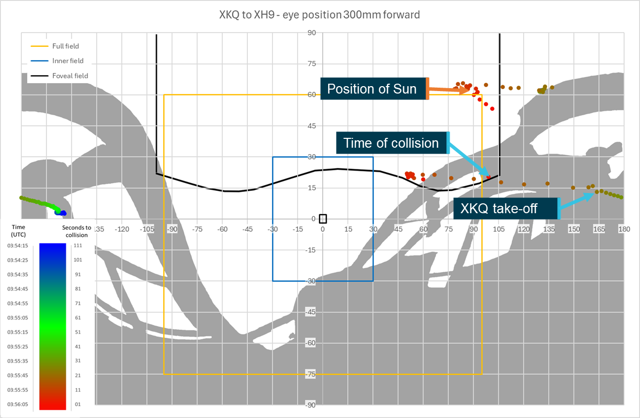
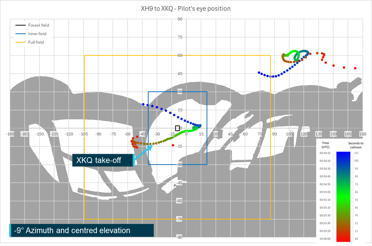
Pilot eye position
The pilot’s eye position relative to the cockpit structure depends on the pilot’s biometrics, the seat position and the way that they are seated in the cockpit. The EC130 B4 has a design eye position from which it is intended that the cockpit be viewed from. The ATSB obtained this position from the manufacturer and located it within the 3D model of the aircraft, refer to Locating the design eye position.
The ATSB, in collaboration with IWI, reviewed the pilots’ head positions from the video footage from inside the aircraft. This indicated that the head of the pilot of XKQ was positioned at the design eye position and the head of the pilot of XH9 was slightly above the design eye position. The eye position of XH9’s pilot was subsequently moved 19 mm backwards and 37 mm upwards.
In the development of the , to assess the impact of variation of the vertical and corresponding lateral movement of the eye position of a taller or shorter pilot, the ATSB, in consultation with IWI, further defined 2 additional head positions.
As the DEP was designated to represent a 50th percentile pilot, 2 additional positions were defined for 25th and 75th percentile pilots and are referred to as the short and tall eye positions respectively. The short eye position located 116 mm lower than the DEP and tall eye position 65 mm above the DEP (refer Figure 20). Due to the shape of the seat and headrest a change to the pilot’s head position will also introduce a lateral movement. For the short eye position 57 mm forward and for the tall eye position 52 mm rearward.
These positions will be used in the to demonstrate the effect of vertical and corresponding lateral movement of the pilots on the visibility of the target aircraft.
A pilot’s field of view (FOV) or visual field, measured in azimuth and elevation angles from the eye, determines how far from the centre point an object can be effectively located. This field will vary from person to person and can change based on a range of factors including age, the geometry of the face and head and existing visual conditions/diseases. A field of view consists of a central binocular area, visible to both eyes, with monocular areas, visible to only one eye, outside. The FOV typically traverses through approximately 200° of azimuth and approximately 135° of elevation with a slight bias towards downwards perception (Boff & Lincoln, 1988) (Wolfe, Dobres, Rosenholtz, & Reimer, 2017).
Human vision has 2 distinct types of photoreceptors for interpreting visual information, cones and rods. The cones operate at higher light levels and as humans tend to operate in higher light level conditions, either natural or manufactured. Most human vision is mediated by cones. Cones are predominantly located within a small central area of the visual field, the fovea, where vision is the most detailed. Rods, which are spread more broadly across the eye are more sensitive to both light and movement, but the image that they produce is less detailed (Hadjikhani & Tootell, 2000).
The fovea covers 1–2° at the centre of the FOV. Once outside of the fovea, the number of cones is reduced, and subsequently visual acuity will decrease and objects appear less sharp. Visual acuity reduces at 2 distinct rates depending on whether an object is more or less than 30° from the centre of the FOV. Between the fovea and 30° the loss of visual acuity is less extreme than beyond 30° (Strasburger, Rentschler, & Juttner, 2011). In addition, between 10° and 30° from the centre of the FOV, luminance contrast threshold of the eye plateaus, before increasing further out (Poppel & Harvey, Jr, 1973). The combination of these factors means that within 30° lesser contrasts and smaller objects can be identified when compared to outside of 30° in the remainder of the visual field.
Outside of 30° visual acuity is reduced further and the luminance contrast threshold increases. Subsequently objects will need to be both larger and have increased contrast to enable detection. The combination of this and the movement sensitivity of the rods, which more heavily mediate vision away from the fovea, result in a movement being key to detection beyond 30° from the centre of the FOV. In Ergonomics in the Automotive Design Process (Bhise, 2012), the role of these 3 areas in driving are summarised as follows.
During driving, the foveal visual field is responsible for detailed vision to read details such as highway signs. The central field [inner vision from the fovea to 30°] provides visual information (i.e. presence and locations) on most targets such as [the] roadway, other vehicles, and traffic control devices. The peripheral vision [beyond 30° from the centre] provides awareness of larger targets (e.g., vehicles in the adjacent lanes) and provides information on moving targets and motion cues.
For this study we will be referring to these 3 areas.
1. The foveal region covering approximately the central 1–2°[19] (both azimuth and elevation) of the visual field. This region is particularly dense with cones providing the highest level of visual acuity.
2. The inner visual field, defined as 60° of azimuth and 60° of elevation split evenly around the centre of the field of view (30° from the centre).
3. The full visual field is the remaining area that a person can see (up to approximately 200° of azimuth and approximately 135° of elevation). This may also be referred to as the outer periphery.
Figure 21 shows an exemplar silhouette of an equirectangular 360° view of a Vans RV-8 aircraft cockpit showing the 3 visual areas of the FOV. Due to the internal structure of the eyes, and the structure of the face a more realistic individual representation, developed by NASA (Parker & West, 1973) is also shown on Figure 21.
Due to the range of individual variations to the FOV, throughout this report an idealised rectangular view will be used to describe the pilot’s visual field. It is worth noting that while all objects in the field of view might be visible to the pilot it is unlikely that all objects, particularly ones on the extremities or in areas where there is a large amount of visual clutter or activity will be detected (Gibb, Gray, & Scharff, 2010).
To improve the effectiveness of ‘see-and-avoid’ pilots are trained to visually scan the airspace around them for potential threats. This is usually combined with an internal scan of the aircraft’s instruments.
General guidance is to ensure that the entire visual field is scanned by moving and rotating the head to reveal objects otherwise lost behind aircraft structure or in visual traps.[20] The FAA recommends a series of regularly spaced eye movements that cover approximately 10°of the visual field and where that area is focused on for one second to allow the eye to adjust and focus in this area to enable detection.
It is further recommended that external viewing occupies 66–75% of the scan time, with the remainder spent scanning instruments and looking inside the aircraft (FAA, 2017).
Visual conspicuity
Lighting
Lighting can increase the opportunity for visual detection by providing a point of increased contrast on the object compared to the background. The visual detection opportunity can be further increased using apparent movement, such as rotation (beacons) or flashing (strobe lights) of the light to attract the viewer’s attention to the object.
Regulatory background
Chapter 11 of the Manual of Standards for Part 133 (Australian Air Transport Operations—Rotorcraft) of the Civil Aviation Safety Regulations outlines the equipment required for Rotorcraft operations in Australia. Division 5 identifies that an aircraft operating under day VFR is required to be fitted with anti-collision lights that must consist of at least one red beacon light or 2 white strobe lights or a combination of beacons and strobes. These lights are required to be displayed from immediately before the engines are started until the time the engines are shut down at the end of the flight.
If the aircraft is to be operated at night, it must also be equipped with landing lights and navigation lights.
Both XH9 and XKQ were certified for day VFR operations and although not required, taxi, landing and position lights were installed on both aircraft. Refer to the relevant aircraft information sections for further details.
Operational requirements
The Sea World Helicopters flight crew operations manual for the EC130 helicopter required the following 3 procedures to be followed for the use of external lighting during operations:
• Anti-collision beacons shall be left ON at all times, even after shut down to warn of accidental battery activation;
• Strobe lights and Nav [position] lights are to be activated before start and deactivated after shutdown.
• Landing lights shall be ON prior to departure and OFF once the aircraft has landed
Under these operational requirements both aircraft should have had beacons, position, strobe, and landing lights all active in the lead‑up to the collision. Neither aircraft was fitted with strobes at the time of the collision.
Visibility
There has been a wide body of research into the effectiveness of aircraft lighting in improving visual detection of aircraft. A range of agencies around the world have encouraged aircraft owners and operators to fit anti-collision lights. The luminance of traditional aircraft lights meant the presence of these lights was of minimal advantage particularly in bright background lighting conditions such as those experienced in daylight (Hobbs, 2004).
Much of the available research into the effectiveness of aircraft lighting was carried out prior to the introduction of light emitting diode (LED) lighting when standard lighting intensities were in the order of a maximum of 300–400 cd. Figure 22, reproduced from (Hobbs, 2004), shows that for these lights to be effective at 3 nautical miles, background luminance cannot be more than approximately 30 cd (equivalent to a very dark day). On a full sunlit or even an overcast day lights of this power this would not be sufficient for an operator to see let alone draw attention.
Figure 22: Required effective intensity of lights at 3 nautical miles
Note: The top 2 y-axis values show 1,000,000, based on the progression of the logarithmic scale the value above 10,000 should read 100,000. Assuming this progression and the lack of comma between the 1 and first 0 it is assumed that this was a typographical error in the source chart. Source: Harris (1987) in Hobbs (1991)
The detectability of a light is also dependent on its directionality or the spread of the beam. The further from the centre of the beam that an observer is, the less bright the light will appear and the less likely it is to aid detection. Some lights, such as landing or approach lights, specifically illuminate certain areas around the aircraft and subsequently the beam is focused on a particular direction. For visual conspicuity this can aid the distance at which the light may be detected but only from angles at which the light is directed.
Currently available lighting
Over the past 15–20 years LED technology has become more commonly used in almost all lighting applications including aviation lighting systems. Due to lower power consumption, higher brightness and longer lifetimes, LEDs provide a significant advantage over the traditional incandescent or halogen bulbs (US DOE, 2022).
The provision of these improvements has led the FAA to encourage the use of landing lights when an aircraft is operating within 10 NM of an airfield or below 10,000 ft (FAA, 2020). The low power consumption and increased brightness of modern LED landing lights provide for visibility at significant distances even in bright daylight. For example, the sunspot series of LED landing lights produced by AeroLEDs in the United States have candela ratings between 150,000 and 420,000 (AeroLEDS, 2021) which is more than sufficient for a light to be seen at distances of 3 NM even outside of the foveal region of highest visual acuity (Figure 22).
Contrast
Visual contrast is the difference between colour or luminance between either an object and its background (external) or different parts of the object itself (internal). The greater the contrast between the 2 elements, whether internal or external, the greater the likelihood of detection.
Factors affecting visual contrast include the power and location of the light source, the target’s colour, reflectivity and its position and orientation towards the viewer and for external contrast, the colour and reflectivity values of the background. Contrast may also be affected by intermediate structures or materials, such as the use of tints to windows, or by apparel of the viewer with the use of sunglasses or light enhancing glasses.
Contrast values can be calculated where all the relevant parameters can be derived or assumed based on known conditions and aircraft fitment. Where these parameters are not known contrast can be assessed using video footage. While the lens of the camera and the human eye have different characteristics and capabilities in detecting colours and responding to changes in light patterns, video can give an estimation of the contrast experienced by a viewer at the time.
Internal and external contrast can have overlapping effects so a colour scheme that contrasts within the body can also contrast against the background that the body is seen against. High‑visibility rotor blades and the aircraft colour scheme can be used to create contrast on a helicopter.
High‑visibility rotor blades
Due to the speed that the rotors move, when they are a single colour the rotor disc of a helicopter effectively becomes see through, reducing visual detection opportunity. To improve detectability from above,[21] the main rotor blades can be coated with strips of contrasting colours. As the blades rotate this creates, to a viewer looking at the aircraft from above, a series of concentric circles of either different colour where multiple higher luminosity colours have been applied or colour and blank where only strips of a single high luminosity colour have been applied. In Figure 23, the left panel shows yellow blade sections being used to contrast with the cityscape background to improve detectability[22] of the disc. The right panel shows the use of alternating red and white sections to contrast both with one another and the green field over which the aircraft is flying. Alternately, the centre panel shows an aircraft not fitted with high‑visibility blades showing the difficulty in detecting the rotor disk.
Figure 23: Examples of use of high‑visibility rotor blade schemes
Note: As the images shown are freeze frame, the impact of the high‑visibility paint scheme depicted is reduced. When the blades are rotating, a compete circular array is visible from above. Source: Airbus Helicopters, annotated by the ATSB
It is important to note that the fitment of high‑visibility rotor blade schemes is not mandatory or standard fitment for new EC130s.
Aircraft colour schemes
The typically lower closure speeds of helicopter operations when compared to fixed wing aircraft mean that the aircraft can be in closer proximity and still have an appropriate amount of time to manoeuvre to effectively avoid one another. This closer proximity means that the aircrafts’ surfaces and their colourisation are more obvious to the viewer.
The use of high luminosity colours such as yellow, red or white in large blocks on the fuselage gives the ability for both internal and external contrast. These colours can actively contrast with one another and a variety of darker or low luminosity backgrounds, subsequently it is common to see these colour schemes on medical evacuation or search and rescue aircraft. This will improve conspicuity not only assisting other aircraft in identifying them but also persons on the ground. It is again important to note that colour scheme is only one element affecting conspicuity. For those on the ground audible conspicuity is often important as it is possible to hear an aircraft much earlier than sighting one even with a high‑visibility paint scheme.
Depending on the background an alternate way to improve conspicuity is to use a very low luminosity colour scheme. By painting an aircraft, or a section of the aircraft black, the same effect can be achieved as having a high luminosity colour scheme. In this case instead of the target luminosity being higher than the background the target luminosity is considerably lower. This is only an effective use of contrast if the background is sufficiently luminous for it to contrast with the aircraft. In late evening or afternoon operations where the background is growing dark this would not improve the conspicuity of the aircraft. Where a section of the aircraft is painted black internal contrast can be used to aid conspicuity without need to consider the colour or luminosity of the background.
Figure 24 below shows the same 3 helicopters as in Figure 23, except it considers the colourisation of the body of the helicopter rather than the blades. These images only represent a single snapshot in time from a particular angle, viewing the same helicopter from an alternate angle with a clear blue sky in the background may significantly alter the detectability with this paint scheme.
Figure 24: Examples of use of varying colour schemes
Source: Airbus Helicopters, annotated by the ATSB
The left panel shows the limitation to visibility when the colourisation of the helicopter is matched to the background with a dark grey paint scheme against the darker buildings.
The centre image shows a 2-tone paint scheme with either white or a light grey on the front of the aircraft and a red tail and fenestron. The image shows that the body colour blends into this background where the alternate colour on the tail has a higher contrast and is subsequently more visible increasing the likelihood of detection.
The right image shows an aircraft with a 3-tone paint scheme, the front being white, the rear being predominantly red with black and white stabilisers with the 2 colours separated by a black streak over the engine cowl. The red and white of the aircraft is clearly visible against the background presented, however the dark coloured streak would improve visibility if the aircraft was to be viewed against a higher luminosity background that the lighter colours may blend in to.
The advantage of the use of a paint scheme is that it is not visible from inside the aircraft so it is highly unlikely to cause any negative impact to the pilot and can subsequently be applied to all the aircraft’s surfaces making it more visible from all angles.
Surface coatings
Surface coatings may be used on the windows of aircraft to reduce sun glare or ultraviolet penetration. There are 2 types of surface coating that may affect the detectability of the target, these are a tint or a dappled surface. The dappled surface coating is designed so that the viewer can still effectively recreate the picture based on what they are seeing. However, if a target remains stationary, common with aircraft on intersecting trajectories, and the size of the target does not exceed that of the solid area of the coating it will not be visible to the observer. Where there is relative movement of the target aircraft the use of this dappled coating can exaggerate the movement with the target moving across the individual holes in the coating which can draw the viewer’s attention.
As tint does not introduce a solid obstruction from the viewpoint of the pilot it will not affect the target’s visibility. However, it can change both the colour and luminance of the target and background altering the likelihood of target detection. For example, if the tint reduces the luminance value of both the target and the background by half, the luminance values of both will be closer together, subsequently reducing the contrast and the associated visibility of the target.
This section outlines how human visual performance, aircraft position and orientation and aircraft structure affected each pilot’s ability to visually detect the other aircraft in the lead‑up to the collision. It will also detail some of the processes that the ATSB and IWI undertook to verify and correct relevant portions of the data based on the video footage from both onboard and external to the aircraft.
The chapter is broken down into 3 sections:
1.The first will examine the position and orientation (pitch, roll and heading) of both aircraft in the lead‑up to the collision.
2.The second will build on this data to determine where the approaching aircraft would have appeared in the viewer pilot’s field of view and the relative size.
3.The final section will examine the effect of the aids and challenges to conspicuity that were introduced in the previous chapter and how they would have impacted each pilot’s ability to visually detect the other aircraft.
This chapter focuses on the physical characteristics of detection by the pilot, it will not assess considerations around the pilots’ mental model or how the use of electronic conspicuity or identification devices such as TCAS, ADS-B In or electronic flight bag applications may have assisted either pilot with the detection of the other aircraft. Detailed analysis of these factors can be found in the investigation report.
Aircraft position and orientation
The AHRS data from XH9 and XKQ’s SpiderX units provided the basis for the aircraft position and orientation information used in this study. The AHRS data for the accident flight included 3‑dimensional position as latitude, longitude and altitude and 3-dimensional orientation as aircraft pitch, roll and yaw. The data was verified and, where necessary, corrected based on a comparison between the animation developed using this data and the footage both onboard and external to both aircraft.
Aircraft position
Lateral position
Lateral position information for both aircraft was recorded at 1 Hz on the second for both aircraft. The AHRS information contains latitude and longitude positions to 6 decimal places. For the purposes of this analysis this information was simplified by a conversion to rectangular cartesian coordinates. In this case, eastings and northings relative to a reference point on the earth’s surface. While these coordinates are not as accurate over a global scale as latitude and longitude, these rectangular coordinates, given in metres, allow for simpler calculation of position and proximity when working locally. For this study the ATSB utilised Geoscience Australia’s Geodetic Calculator[23] to convert the data from latitude and longitude to eastings and northings.
Calculations using eastings and northings are complicated by the size of the values that are encountered due to the reference point against which they are given which is often thousands of kilometres away from the position that is being referenced. To simplify these calculations a local reference point is utilised, and values are given relative to this local reference point. In this case the centre of the park pad was chosen as the local reference point due to its proximity to the accident site, being easily identifiable from satellite imagery and being the location that XKQ departed from. Figure 25 shows the flight paths of both XH9 and XKQ in rectangular cartesian coordinates relative to the centre of the park pad. Thirty second timestamps have been identified along XH9’s track to show the development of the flight from lift-off until the collision. An additional position has been identified showing the location of XH9 at the time that the inbound call was initiated.
Due to the complexity of the analysis required and the relevance of the information, the remainder of the analysis will not consider the whole of XH9’s flight path. The ATSB visibility analysis was initiated from 03:54:15 UTC as XH9 commenced its turn to the left to progress down the Broadwater. This time was selected as it was on a 15‑second divisor and it ensured that data relating to the detectability of XKQ during XH9’s progress down the Broadwater was fully captured. Due to the data processing and visualisation requirements involved with the development of the animation the animation was developed from 13:55:26, 16 seconds before XKQ departs the park pad. This allows the viewer sufficient time to understand the environment and situation before they are required to engage with the animation and assess the conditions that were involved. The AHRS data for both aircraft continued to the sandbar, the visibility analysis was stopped at the point of impact.
Figure 25: Aircraft flight paths in local cartesian coordinates
Note: Satellite image was taken near high tide. Sandbar was exposed at the time of the accident. Source: Google Earth and ATSB, annotated by the ATSB
Figure 26: Close up of collision location flight paths – local cartesian coordinates
Note: Satellite image was taken near high tide. Sandbar was exposed at the time of the accident. Source: Google Earth and ATSB, annotated by the ATSB
Data verification
The data verification process did not identify any errors in position information that fell outside of the error margins as defined for the positional information.
Vertical position (altitude)
Figure 27 shows the corrected altitude profiles, converted from metres to feet, based on the Spidertracks AHRS data. The data shows XH9 descending from 560 ft holding, briefly, at approximately 420 ft before continuing its descent and approach to the pad. At approximately the time that XKQ departs the pad XH9 is continuing its descent through approximately 325 ft, continuing this descent as XKQ climbs out, with the 2 aircraft colliding at approximately 135 ft above mean sea level (AMSL).
The data verification process identified that the altitude of XKQ was overestimated by approximately 14 ft from the time it was on the pad until 4 seconds before the collision. Over these last 4 seconds the variation reduced to approximately 12 feet. This corresponded with the wreckage examination, as outlined in the investigation report, that determined that the initial contact of the main rotor disc of XKQ was with the lower fuselage of XH9 leaving approximately the height of the helicopter between the 2 Spidertracks units at the time of the initial impact.
Aircraft proximity
The relative size of the target aircraft to the viewer aircraft will be a factor of 3 elements, the dimensions of the target aircraft, the relative angle of the target aircraft towards the viewer and the distance between the 2 aircraft. This will depend on the difference between the lateral and vertical positions of both aircraft. Figure 28, Figure 29 and Figure 30[24] plot the lateral, vertical and total proximity of the 2 aircraft from 03:54:15 until the time of the collision. Until XKQ lifts from the pad the change in proximity is solely altered by the movement of XH9. XKQ’s initial climb out of the pad only impacts the vertical proximity of the aircraft. The lateral proximity continues to depend solely on XH9 until XKQ starts its forward motion approximately 5 seconds after it lifts from the pad (03:55:47). The 2 helicopters’ similar headings shortly after XKQ commences its forward flight means that the total proximity is more significantly affected by XKQ’s climb and XH9’s descent than the lateral approach until XH9 commences its final approach to the pad. At this point with the flight paths approaching perpendicular the lateral proximity closes more rapidly.
The ability for a pilot to react and manoeuvre their aircraft to avoid a collision depends on the amount of time that they have to identify a threat and respond. The time available will depend on the rate with which a threat aircraft is approaching. The higher the closure rate the less time that the pilot will have to assess that an approaching aircraft is a threat and respond to it. Helicopters hold an advantage over fixed wing aircraft in that they can hover in position reducing the effective closure rate between the 2 aircraft and providing more time to assess the collision risk.
The closure rate of XH9 and XKQ is calculated based on the vertical and lateral position information over time. Figure 31, Figure 32 and Figure 33 plot the lateral, vertical and total closure rates, based on unsmoothed data leading to the noise that can be seen in the charts. The lateral and total closure rates were calculated in metres per second and for the lateral rate converted to knots. The average total closure rate was calculated as 37 m/sec or 72 kts. The average total closure rate following XKQ’s departure from the pad was 18 m/sec or 36 kts. This corresponds with the flight paths with XKQ departing the pad behind XH9 and initially tracks on a similar heading. The closure rate increases when XH9 makes its turn towards the heliport pads and the tracks become closer to the perpendicular.
The aircrafts’ groundspeed can be relatively easily derived from the lateral position information that was downloaded from the AHRS unit. The aircrafts’ airspeed is a function of the groundspeed of the aircraft, the windspeed and wind direction relative to the aircraft. While not necessary for the further analysis the airspeed was calculated based on the aircraft position information and windspeeds. As outlined in the investigation report the winds on the day were approximately 15 kts gusting to 25 kts and were out of the south‑east meaning that it was approximately a quartering head wind for both aircraft tracking south and a head wind for XH9 as it approached the heliport from the north-west. Figure 34 below plots the groundspeed and estimated aircraft airspeed over time assuming a constant 15 kt wind from the south-east 135° true.
The Spidertracks AHRS unit also records vertical speed in metres per second based on vertical position information received from the GPS unit. The ATSB used the corrected vertical position information from the AHRS unit to confirm the vertical speeds that the AHRS unit was producing. As it had been determined that there were 2 constant offsets being applied, for the ellipsoidal error and to bring XKQ onto the pad, these would not impact the calculated vertical speed. Figure 35 shows the ATSB calculated vertical speed in comparison with the vertical speed value obtained directly from the AHRS unit. As the AHRS unit records vertical speed in metres per second the comparative analysis was completed in metres per second.
Data verification
The alignment between the recorded and calculated data is high, supporting the validity of the analysis that has been completed. The AHRS data shows 2 occasions for each aircraft where the data appears to spike. These occasions are the result of no data, represented as 0 being recorded for the vertical speed parameter in the AHRS data and so have no impact on the outcome of the analysis.
Aircraft orientation is identified in 3 axes, pitch, roll and yaw. Each describes the rotation of the body of the aircraft around the relevant axis. The Spidertracks units fitted to both XH9 and XKQ used three dimensional gyroscopes to calculate pitch and roll and these gyroscopes combined with a magnetometer to determine the aircraft’s yaw around its central axis and subsequently the direction that the helicopter was oriented or its heading. This was corrected internally for the magnetic variation at the aircrafts’ location to give the unit’s true heading.
Pitch
The AHRS unit records pitch values in radians at 1‑second intervals. The ATSB converted these values to degrees and plotted them for both aircraft. Figure 36 shows the pitch values for both aircraft, XH9’s data is plotted from 03:54:15 and XKQ’s data from 03:55:40, 2 seconds before it lifts off the pad.
The data verification process did not identify the requirement for any corrections to the aircraft pitch data.
Roll
The AHRS unit records roll values in radians in 1‑second intervals. The ATSB converted these values to degrees and plotted them against time for both aircraft. Figure 37 shows the roll values for both aircraft, XH9’s data is plotted from 03:54:15 and XKQ’s data from 03:55:40, 2 seconds before it lifts off the pad.
The data verification process did not identify the requirement for any corrections to the aircraft roll data.
Heading
The AHRS unit records a yaw parameter in radians at 1‑second intervals. Based on an assessment of the helicopter location and movement, the ATSB determined that this parameter corresponded with the aircrafts’ true heading values. Figure 38 shows the heading values recorded by the AHRS unit.
The data verification process identified 2 corrections that were required to the heading of XH9. The first was a 10° heading overestimation that was throughout the study period. A review of the device’s positioning within the aircraft, the AHRS and raw sensor information and comparison with XKQ’s data was not able to determine the source of this error. Once the correction was applied the animation and onboard footage synchronised.
Figure 38 shows the need for a second correction associated with XH9’s heading rapidly decreasing in the 3 seconds before the collision. Onboard footage showed the aircraft holding a stable heading. Analysis sensor data on which the AHRS data is based identified that this error was likely due to the Kalman filter attempting to smooth the abrupt turn that was completed by XH9 immediately after the collision. The ATSB attempted to calculate the actual heading based on the sensor values but was not able to do so reliably without the mathematical formula that the filter used. Based on the video footage it was elected to hold the heading value for these last 3 seconds. This synchronised the onboard footage with the animation.
Figure 38 also shows a smaller rapid change in the heading of XKQ immediately after the collision. A review of the video and onboard data indicated that, unlike XH9, the change had not impacted earlier data. Subsequently the heading value from 1 second before the collision was maintained through the collision.
Figure 39 shows the corrected heading values that were used for further analysis of the aircraft positions and visibility for the pilots of the 2 aircraft.
The aircraft position and orientation parameters allow for the calculation of the relative position of each aircraft (the target) from the position of the pilot in the other (viewer) aircraft. The relative position along with the dimensions of the aircraft allow for the calculation of the observed size of the target aircraft from the viewer. The following sections will present the analysis and results for the calculation of these 2 parameters.
Throughout this section, the relative position of the target aircraft and sun at 1‑second intervals through the 111 seconds leading up to the collision is represented by a series of coloured dots. These dots progress from blue through green and to red in accordance with the timescale shown in Figure 40. These dots represent the aircrafts’ relative position and are not representative of aircraft visual angle that the aircraft spanned. The relevant plots for size should be consulted for a complete picture of both the relevant position and size at a point in time. To assist in cross reference a bar with the same colour progression has been placed over the time axis of the relevant aircraft visual angle and target shielding charts.
Figure 40: Exemplar timescale and colour bar
Source: ATSB
Aircraft visual size
Even if unshielded from the viewpoint of the pilot the aircraft must be large enough to be detected. Based on the position and orientation of each aircraft and the dimensions obtained from the aircraft’s maintenance manual, azimuth and elevation angles were calculated to 5 different points at the extremities of the aircraft fuselage These were the:
aircraft nose
aircraft tail
centre of the fuselage
forward outer tips of the 2 horizontal stabilisers.
The visual angle spanned by each aircraft in both azimuth and elevation was calculated by subtracting the maximum from the minimum value across these points. This dimension will represent the largest axis of the aircraft presented to the viewer which as discussed in Object perception will be the determining factor on detectability of the aircraft. It does not represent the area that is presented to viewer which may improve the detectability of the aircraft.
XH9
Figure 41 plots the visual angle XKQ spanned from the pilot’s eye position in XH9. XKQ crossed the likely minimum visual detection threshold of 0.2° at 03:55:25 17 seconds before XKQ departed the pad and the likely visual detection threshold 0.4° 16 seconds later. Supporting that the pilot of XH9 observed XKQ on the pad ready to depart with the doors closed.
Following XKQ’s departure from the pad the visual angle spanned increases rapidly (from 0.7° to 2.2°), then slowed and remained constant (at 2.2°) while XKQ and XH9 maintained similar tracks along the Broadwater between 15 and 11 seconds before the collision (03:55:51 and 03:55:55). As XH9 commenced its turn towards the heliport pads and the flight paths transition from parallel to perpendicular, the visual angle XKQ spanned rapidly increased until the time of collision.
Figure 41: Plot of visual angle XKQ spanned from the pilot's position in XH9
Note: Colour scale overlain on the time axis corresponds to the colourisation of the points used in Aircraft observed position section. Source: ATSB
XKQ
Figure 42 plots the visual angle XH9 spanned from the pilot’s position in XKQ. XH9 crossed the likely minimum visual detection threshold of 0.2° at 03:55:25 17 seconds before XKQ departed the pad and the likely visual detection threshold 0.4° 9 seconds later. Like XH9 it shows a very slow increase in visual angle spanned until just before XKQ departed the park pad. Following XKQ’s departure there is a constant increase until approximately 11 seconds before the collision (03:55:55) when the size rapidly increased corresponding with the transition from parallel to perpendicular flight paths.
Figure 42: Plot of visual angle XH9 spanned from the pilot's position of XKQ
Note: Colour scale overlain on the time axis corresponds to the colourisation of the points used in Aircraft observed position section. Source: ATSB
Aircraft observed position
As outlined in Locating the Target Aircraft the target aircraft’s relative position can be represented as azimuth and elevation angles. These points represent where the target aircraft would have appeared on the spherical representation around the viewer pilot’s eye position. Overlaying these positions with the cockpit mask developed from the pilot’s eye position identifies when the target aircraft would have been shielded by the cockpit structure. This is represented by the grey shading in the figures below.
The following sections present the relative locations of the target aircraft through the 111 seconds before collision (03:54:15 to 03:56:06), from the pilots’ eye positions (estimated from onboard video analysis as discussed in Pilot eye position) and relative to the cockpit mask. Discussion of the implications of the shielding provided by the cockpit mask will be presented in Target shielding. The below analysis assumes the pilot is looking straight ahead. Consideration of differences with head and eye movement is represented in the Sensitivity analysis.
XH9
From the view of XH9’s pilot the target aircraft (XKQ) started high and to the left relative to the pilot’s eye position. It progressed down and towards the centre remaining relatively stationary as XH9 tracked along the Broadwater. As XH9 closed on the position of the park pad and passed behind XKQ the target moved to a relative position on the left and below the centre of the visual field. At the time that XKQ lifted off the pad it was approximately 10 degrees from the left cockpit pillar in the pilot’s field of view. Approximately 3 seconds later, while XKQ was still over the pad it transitioned behind the left cockpit pillar of XH9.
Figure 43 shows the relative positions at 1‑second intervals of the target aircraft from the eye position of the pilot of the viewing aircraft for the final 111 seconds leading up to the collision. Figure 44 plots these same positions showing them relative to the cockpit structure, where the points overlay the cockpit structure the aircraft will be shielded relative to the pilot, refer to Target shielding for further discussion. The second data set shown on the chart is the position of the sun relative to the aircraft (refer to Environment in Aircraft conspicuity and detectability for further detail).
The distances between the points represents the angular speed of the aircraft over time. The further apart these points the greater the angular speed and subsequently relative movement. Over the final few seconds with a smaller separation distance the relative position increases more quickly leading to the significant change seen between the final 2 points. This is discussed further in the Relative movement section.
Figure 43: Relative position of XKQ from XH9 Pilot
Source: ATSB
Figure 44: Relative position of XKQ from XH9 overlaid on pilot’s view
Source: ATSB
Heliport
As part of this analysis, the ATSB also assessed the relative location between XH9 and the pilot’s aiming point, pad 3 of the operator’s heliport, and the vessel that the pilot had identified that they were planning to pass behind on their approach. The relative positions of the pad and vessel have been plotted independently and images from the animation used to show the relative positions throughout the lead‑up to the accident.
During the initial phase of the final 111 seconds leading up to the collision the relative positions of the heliport and XKQ to the pilot of XH9 were similar. This is due to the comparatively short distance (220 m) between the park and heliport pads along XH9’s intended route. As XH9 approached and then passed the park pad, the heliport remained within the windscreen in front of the pilot while the position of XKQ continued traversing to the left. Figure 45 shows the relative position of heliport pad 3 that XH9 was aiming for came to the centre of the pilot’s view as they completed the turn to line up the pad for their final approach. In the final seconds leading up to the collision the relative position of the pad moved up relative to the pilot’s eye position corresponding to the slight nose down pitch recorded.
Figure 45: Relative positions of Heliport pad 3 overlain on pilot’s view
Source: ATSB
Vessel
Figure 46 plots the relative position of the vessel from the pilot of XH9, based on the interpolated 1‑second data from 03:55:44 until 03:56:00. The data shows the vessel tracking ahead of XH9 and slightly to left. As XH9 turned to commence its final approach the vessel tracked to the right being shielded by the instrument panel coaming approximately 10 seconds before the collision.
Figure 46: Relative positions of the vessel overlain on pilot’s view
Source: ATSB
Relative positions
Figure 47, Figure 48, Figure 49 and Figure 50 shows the relative positions, looking ahead from the pilot’s eye position of XH9, of all 3 elements discussed through this section, XKQ, heliport pad 3 and the vessel. The figures, taken from the animation developed in collaboration between the ATSB and IWI, show the relative positions at 4 points through the sequence.
03:55:44, 22 seconds before collision and 2 seconds after XKQ has lifted off the park pad
03:55:53, 13 seconds before the collision and the middle of the time period where XKQ was visible outside the left cockpit pillar of XH9
03:55:56, as the vessel passes behind the instrument panel coaming
03:56:00, start of limiting window for time to react and manoeuvre.
Figure 47: Relative positions of Heliport pad 3, vessel and XKQ at 03:55:44
Source: IWI, annotated by the ATSB
Figure 48: Relative positions of Heliport pad 3, pleasure craft and XKQ at 03:55:53
Source: IWI, annotated by the ATSB
Figure 49: Relative positions of Heliport Pad 3, pleasure craft and XKQ at 03:55:56
Source: IWI, annotated by the ATSB
Figure 50: Relative positions of Heliport pad 3, vessel and XKQ at 03:56:00
Note: Simulation image appears to show approximately half of XKQ as unshielded variation between ATSB analysis and the simulation is discussed in the animation development section. Source: IWI, annotated by the ATSB
XKQ
The positioning of XKQ’s nose towards the south-east corner of the park pad means that XH9’s initial relative position was to the rear left of XKQ. XH9 then tracked across behind XKQ before coming down the right side of the aircraft and above the roof line relative to the pilot’s eye position.
Figure 51 shows the relative positions of the target aircraft (XH9) from the pilot’s eye position of the viewer aircraft (XKQ). Figure 52 plots these positions relative to the cockpit structure, refer to Target shielding for further assessment. The second data set, in Figure 52 is the position of the sun relative to the aircraft (refer to Environment in Aircraft conspicuity and detectability for further detail).
Figure 51: Relative position of XH9 from XKQ pilot
Source: ATSB
Figure 52: Relative position of XH9 from XKQ overlaid on pilot’s view
Source: ATSB
XKQ pilot cap
As outlined in the Pilot information section the pilot of XKQ was wearing a Sea World Helicopters ‘trucker’ style cap for the flight. To assess the impact of the cap on the visibility of the target aircraft the front edge of the estimated cap brim was placed over the representation from the pilot’s viewpoint; anything above the outlined cap brim, shown in Figure 53, would be shielded from the pilot.
As shown in Figure 53 the relative position of the XH9 passes behind the peak of the cap between 03:55:50 and 03:55:51, between this time and the collision XH9 was shielded by cockpit structure. Subsequently, from the DEP, the pilot’s cap will have no impact on detectability of the target aircraft. A further discussion looking at the impacts of the pilot’s cap in an alternate scenario where the aircraft is visible is provided in the Sensitivity analysis. A discussion of the impacts and importance of the pilot’s cap in reducing the impacts of the sun is presented in the Sun position section of Aircraft conspicuity and detectability.
Figure 53: Relative position of XH9 from XKQ overlaid with shielding of pilot’s cap
At the times that the target aircraft position overlies the aircraft structure in the diagrams presented above, the target aircraft will be obstructed from the eye position of the pilot of the viewer aircraft. Based on the aircraft position information presented in Figure 44 and Figure 52 the ATSB assessed when the target aircraft would have been shielded from the pilot of the viewer aircraft.
XH9
For the majority of the final 111 seconds before the collision, XKQ was visible to the pilot of XH9. The ATSB analysis determined that XKQ was likely shielded briefly at the start of the study window for 3 seconds of 03:54:17–19. However as discussed in Aircraft visual size, at this time XKQ would have likely been too small to be reliably detected by the pilot. Following this XKQ was unobstructed until 03:55:45 (3 seconds after XKQ departs the park pad) when it transitioned behind the left cockpit pillar. This corresponds with the pilot’s report that they had sighted XKQ on the pad during their transit down the Broadwater and had observed the doors being closed following the loading of passengers. XKQ was then obstructed for 5 seconds re-emerging on the left of the cockpit pillar at 03:55:51 for a further 3 seconds before being shielded again from 03:55:54 until 03:56:00, partially shielded at 03:56:01 and unshielded from 03:56:02, 4 seconds before the collision and at the limit of time required for an urgent response as discussed in Reaction time.
Figure 54 shows the times that XKQ would have been obstructed from the view of the pilot of XH9. These times are overlain on the visual angle XKQ spanned showing the times when the aircraft was a detectable size and unobstructed.
Figure 54: Target aircraft obstruction periods pilot of XH9
Note: Colour scale overlain on the time axis corresponds to the colourisation of the points used in Aircraft observed position section. Source: ATSB
XKQ
The ATSB analysis identified that XH9 was likely unobstructed through the rear left window of XKQ until 03:55:12, at a position as shown in Figure 52, approximately 150° from centre of the view. This does not consider the effect on structural and other obscuration of loading passengers, which was completed at 03:55:07. The effect of loading may include the movement of persons, opening or closing of doors which may obstruct the pilot’s sight lines. Additionally, during the loading of passengers, the pilot’s attention is likely to be directed to other tasks and not seeking to detect aircraft in their vicinity (refer to the investigation report for further detail and discussion of this aspect). At the time XKQ lifted from the pad, XH9 is positioned almost directly behind it. During the departure XKQ rotated towards the south which increased the speed of XH9’s transition down the right of the aircraft relative to the pilot’s position. XH9‘s trajectory aligned with the position of the overhead panel and then the centre left cockpit pillar shielding it from view until the collision.
Figure 55 shows the times that XH9 would have been shielded from the view of the pilot of XKQ by the aircraft structure. These times are overlain on the visual angle XH9 spanned showing that based on the ATSB’s analysis there was no time that XH9 would have been of a detectable size and unshielded from the pilot of XKQ.
Figure 55: Target aircraft obstruction periods pilot of XKQ
Note: Colour scale overlain on the time axis corresponds to the colourisation of the points used in Aircraft observed position section. Source: ATSB
Field of view analysis
Until this point, the analysis has considered a full spherical representation of the view around the pilot’s head. However, as outlined in the Field of View section, humans can only observe a limited portion of this sphere at any point in time and where a target/stimulus appears within this area will affect the opportunity for it to be detected. The ATSB analysis, which idealised the FOV as rectangular, placed the 3 areas of the FOV, foveal, inner and full,over the diagrams showing the positions of both the target aircraft and the cockpit structure, using these to assess where the target aircraft would have appeared and get a better understanding of the opportunity for detection.
XH9
Figure 56 shows the plot of the areas of the pilot’s FOV overlaid on the cockpit structure and the positions of the target aircraft (XKQ) for a situation where the pilot was looking directly ahead. The data shows that the target aircraft would have traversed across the pilot’s FOV during the final 111 seconds. Importantly in the lead‑up to the collision XKQ traversed across just below the lower edge of the foveal region of highest visual acuity before passing out through the inner visual field and into the outer visual field. This corresponds with the pilot’s report that they were able to identify XKQ on the pad as they came down the Broadwater.
At the time that XKQ lifted from the park pad it appeared on the boundary of the inner and outer visual field to the pilot of XH9, subsequently they would have been less likely to visually detect any change in the status of the target aircraft. To support detection of the aircraft’s status change would have required something to specifically draw the pilot’s attention such as a significant change in contrast or lighting. The chart also identifies that the sun position was proximal to the upper right corner of the pilot’s visual field, based on the ATSB’s rectangular model. Where the sun is near the edge of the pilot’s visual field this can cause glare or be directly in pilots’ eyes limiting their ability to detect threats.
Both the Target Shielding and Field of View analysis conducted in the sections above are based on a stationary head position with the pilot’s eyes directed straight ahead. This is not representative of a real-world environment where the pilot is free, and encouraged, to move their head and eyes to be able to identify threats and developing situations such as approaching aircraft. The sensitivity analysis demonstrates the impacts of various head and eye movements on the opportunity for detection. In this analysis head and eye rotations have been considered independently to allow for independent assessment of their impact. However, as movement of the head and eyes usually interact the impacts presented here will likely compound.
As the pilot’s eye position, cockpit structure and target aircraft position are relative to one another, the sensitivity analysis is also representative of variation in the actual and reported positions of the aircraft. A movement of the pilot’s eye position to the left is the equivalent of the position of the target aircraft moving to the right. Similarly, if the position of the head is moved up this is equivalent to the position of the target aircraft being moved down. For simplicity of the analysis, the discussion will be reflected as movement in the head and eye position.
Position vs rotation
Within the physical limitations of the human body, the head and eyes can be rotated independently of one another. This allows the eyes, which move with the head, to remain focused on an object of interest while the head is moved. However, the movement of the head around its axis of rotation (centre of the neck), either laterally or vertically, will change the position of the eyes. This will affect the relative positions of objects within the field of view. Discounting binocular vision considerations, which for the purpose of this study are considered negligible, the impact of a head rotation should be considered as a movement and rotation of the pilot’s eyes.
Figure 57 and Figure 58 below show highly stylised representations of a 30° rotation of either the head or eyes in the vertical plane. The diagrams demonstrate difference in position of the eyes between a rotation of the head and an independent rotation of the eyes.
Figure 57: Example of eye position displacement due to a head rotation (top down view)
Source: ATSB
Figure 58: Field of view change due to eye rotation (top down view)
Source: ATSB
The following 2 sections present the results of analysis of movement of the pilot’s head and eyes and rotation of the eyes, a combination has not been presented due to the number of possible combinations of movement that could be applied.
Sensitivity analysis of the eye position considered 3 scenarios as outlined below.
Eye position moved 30 and 50 mm to the left and right showing impact of the pilot’s head not being centred on the seat.
The short and tall pilot eye positions.
If the pilots of either aircraft were to lean forward by up to 500 mm (in 100 mm increments) to look for the other aircraft what impact that would have.
In the second and third scenarios, as discussed in Pilot’s eye position, the change in height or lateral (forward) location will also induce a corresponding displacement along the other axis.
For the 2 aircraft a vision map representing each head position was developed and a subsequent chart looking at the times that the target aircraft would have been shielded by the viewer aircraft’s cockpit structure. These charts are presented with a FOV with the pilot looking directly ahead for simplicity. The effect of movement of the FOV is demonstrated in the Sensitivity analysis – eye rotation section.
XH9
The positional sensitivity analysis for XH9 is presented in 4 sections.
The first looking at movements of the head 30 and 50 mm to the left of the pilot’s eye position.
The second 30 and 50 mm to the right of the pilot’s eye position.
The third section will consider the taller and shorter pilot views.
The fourth and final section will present the views moving the pilot’s head forward in 100 mm increments.
The figures showing both the vision map and the aircraft shielding for each of these movements are shown following the supporting analysis but are referenced within the text and shown in Table 3.
This analysis has been designed to support the analysis of video footage that indicated the location of the pilot’s head when it was visible to the cameras on board the aircraft. These movements of the pilot’s head were discussed in the Onboard footage section of Recorded data.
Movement left
Figure 58 and Figure 61 move the pilot’s eye position 50 and 30 mm to the left (towards the pilot’s side door). From 25 seconds before the collision (03:55:41) the target aircraft would be shielded for 8 and 9 seconds respectively, as shown in Figure 60 and Figure 62. In comparison from the pilot’s eye position, the target aircraft is shielded for 14 of the final 25 seconds.
While there is less shielded time this does not immediately equate to an increased likelihood of detection. In both cases the movement left reduces the time that the aircraft is visible within the aircraft’s windscreen after lifting off from 3 seconds at the pilot’s eye position to 2 seconds at 30 mm left and 1 second at 50 mm left. The increase in visible time is when the aircraft is outside of the left cockpit pillar in the pilot’s outer FOV, when facing forward, where detection is less likely. However, the increased visible time allows more opportunity for the pilot to be drawn to the target aircraft and the fact that it is later in the departure sequence increases the size of the aircraft in the FOV, the likelihood that it will contrast with the background against which it appears increases the opportunity for lower powered lights to draw the attention of the pilot.
Movement right
Figure 63 and Figure 65 move the pilot’s eye position 50 and 30 mm to the right (towards the front passengers) this will result in a significant increase in the shielding time of the target aircraft. The aircraft is shielded for 19 of the last 25 seconds in both cases, as shown in Figure 64 and Figure 66. The movement of the eye position to the right moves the relative position of the cockpit pillar to the left. Subsequently there is an additional 1 second where the target aircraft is not shielded before it transitions behind the pillar (03:55:46). However, the target aircraft will now not appear on the outer side of the cockpit pillar, remaining shielded until approximately 1 second before the collision when it becomes large enough to exceed the width of the cockpit pillar and will simultaneously appear on both sides of the pillar.
Pilot height
As discussed in the Pilot eye position section, the eye point of the pilot of XH9 was determined to be above the design eye position for the aircraft. Subsequently, the variation between the pilot’s eye point and the 75th percentile eye position will be lower compared to the design eye position. Conversely, the variation between the pilot’s eye position and 25th percentile eye position is expected to be greater.
The curved shape of the cockpit structure means that as the pilot’s head is moved up or down the shielding will be altered. The movement of the pilot’s eye position up to represent a 75th percentile pilot, as shown in Figure 67, will replicate the effect of moving the pilot’s eye position 50 mm to the left from the pilot’s eye position, with a reduction in target shielding, as shown in Figure 68, with the increased visible time outside of the cockpit pillar.
The movement down for a 25th percentile pilot, as shown in Figure 69, will be the equivalent of a movement 50 mm to the right. As shown in Figure 70 there will be an increase, by 1 second, in the time that the aircraft is not shielded prior to transition through to the cockpit pillar but once shielded by the pillar it will not be unshielded again until 1 second before the collision limiting opportunity for detection.
Movement forward
The ATSB sought to determine how far forward the pilot would have had to lean to make the target aircraft visible through the cockpit windscreen. Five alternate positions were considered moving the head position forward by 100 mm each time and making corresponding vertical position shift assuming that the pilot was leaning forward pivoting from their hips with their restraint correctly fitted low and tight around their hips.
It was determined that a movement between 100 mm forward, as shown in Figure 71 and Figure 72, and 200 mm forward, as shown in Figure 73 and Figure 74, would remove the shielding obstruction from the cockpit structure and give the pilot an unobstructed view of the target aircraft. This lack of obstruction gives the viewer pilot a maximum opportunity to detect the target aircraft. as the size increases and contrast changes as it transits towards them. The movement of the pilot’s head forward will not impact the FOV. Subsequently, if the pilot continues to look directly ahead the target aircraft will still move outside of the pilot’s inner FOV as it approaches. This means that detection still relies on the attention of the pilot being drawn to the target aircraft as it approaches to enable detection. The figures for this section only show the 100 mm and 200 mm forward movement views as beyond this point there is no further shielding to display.
Figure 59: Sensitivity analysis head position 50 mm left
Source: ATSB
Figure 60: Sensitivity analysis head position 50 mm left shielding chart
Source: ATSB
Figure 61: Sensitivity analysis head position 30 mm left
Source: ATSB
Figure 62: Sensitivity analysis head position 30 mm left shielding chart
Source: ATSB
Figure 63: Sensitivity analysis head position 50 mm right
Source: ATSB
Figure 64: Sensitivity analysis head position 50 mm right shielding chart
Source: ATSB
Figure 65: Sensitivity analysis head position 30 mm right
Source: ATSB
Figure 66: Sensitivity analysis head position 30 mm right shielding chart
Source: ATSB
Figure 67: Sensitivity analysis tall head position
Source: ATSB
Figure 68: Sensitivity analysis tall head position shielding chart
Source: ATSB
Figure 69: Sensitivity analysis short head position
Source: ATSB
Figure 70: Sensitivity analysis short head position shielding chart
Source: ATSB
Figure 71: Sensitivity analysis head position 100 mm forward
Source: ATSB
Figure 72: Sensitivity analysis head position 100 mm forward shielding chart
Source: ATSB
Figure 73: Sensitivity analysis head position 200 mm forward
Source: ATSB
Figure 74: Sensitivity analysis head position forward 200 mm shielding chart
Source: ATSB
XKQ
The positional sensitivity analysis for XKQ is presented in the same 4 sections as that for XH9. The first looking at movements of the head 30 and 50 mm to the left of the DEP, the second 30 and 50 mm to the right of the DEP, the third section will consider the taller and shorter pilot views, and the final section will present the views moving the pilot’s head forward in 100mm increments. These 4 sections will consider the impact of shielding of the structure alone and not the pilot’s cap. An additional section will assess the impact of movements in the pilot’s cap. Figures showing the pilot’s view points and the shielding from each point are shown following the analysis. A summary of the figures can be found in Table 4.
For XKQ the target aircraft is initially unshielded appearing through the back left window almost directly behind the pilot. During this period the target aircraft will be unobstructed, however it would be of a size that would be unlikely to be detectable and the pilot would need to rotate their head position through the seat to be able to detect the target aircraft. The following analysis will only consider the shielding from 03:55:35, 7 seconds before XKQ departs the park pad.
Movement left
Moving the pilot’s eye position 30 mm to the left, as shown in Figure 77 and Figure 78 will have no impact on the shielding of the target aircraft with it remaining shielded by the centre cockpit pillar until the collision. Movement 50 mm to the left, as shown in Figure 75andFigure 76 will present an opportunity where the aircraft is unshielded for 2 seconds at 03:55:59 and 03:56:00 and again at 03:56:03 at the top right edge of the pilot’s windscreen. Placing the estimated outline of the pilot’s cap over the pilot’s view, the end of the cap peak would shield the target aircraft from the view of the pilot of XKQ at this time.
Movement right
The movement of the pilot’s eye position to the right 50 or 30 mm as shown in Figure 79, Figure 80, Figure 81, and Figure 82 takes the relative position of the target aircraft back along the roof panel of the aircraft. For the final 32 seconds leading up to the collision the target aircraft remains shielded by the roof structure.
Pilot height
Vertical displacement of the eye position has a significant impact on the shielding of the target aircraft. Lifting the eye position, as shown in Figure 83 and Figure 84, moves the position of the roof structure down relative to the target aircraft. Subsequently, there is no change in shielding, with the target aircraft shielded by the roof and left centre cockpit pillar throughout the final 32 seconds of the approach.
Lowering the eye position provides the least shielded time, with the relative position of the viewer aircraft structure moved up. The target aircraft, as shown in Figure 85 and Figure 86, now passes through the right aircraft skylight, at 03:55:50 (16 seconds before the collision) and will then be unshielded in the aircraft’s central windscreen from 03:55:54 (12 seconds before the collision). This location, while unshielded, is in the outer field of view and on the opposite side of the centre left cockpit pillar, both of which will reduce the likelihood of detection. Positioning the estimated outline of the peak of the pilot’s cap over the view indicates that the cap would shield the target aircraft from the view of the pilot in this position.
Movement forward
As with XH9 the analysis considered the movement required to bring the target aircraft into the aircraft windscreen to improve the pilot’s opportunity for detection. To do this, the pilot’s eye position is moved forward in 100 mm increments between 100 and 500 mm. Moving the pilot’s eye position forward will move the relative position of the cockpit structure backwards. As the relative location of the target aircraft is close to the front edge of the centre left pillar a relatively small movement will impact the shielding and subsequently detectability. Moving the eye position 100 mm forward, as shown in Figure 87 and Figure 88, will mean that the target aircraft is not shielded by cockpit structure for 6 of the last 10 seconds leading up to the collision. Moving 200 mm forward, as shown in Figure 89 and Figure 90 will increase this to 9 of the final 10 seconds which is continued through 300 to 500 mm forward as shown in Figure 91, Figure 92, Figure 93, Figure 94, Figure 95 and Figure 96. This movement will mean the aircraft is not shielded by cockpit structure and can be seen through the pilot’s windscreen. However, the target aircraft remains in the outer visual field where detection is less likely.
During the lateral and vertical head movements the relative location of the peak of the pilot’s cap will not change relative to the position of the eyes. Subsequently, where the eye position movements presented in the sections above reduce the structural shielding, they will not impact the shielding of the pilot’s cap peak, as shown overlain on each of the vision maps. In each case the target aircraft remains shielded by the peak of the pilot’s cap until the collision. The following section will present discussion of the impact of the movement of the pilot’s cap on shielding of the target aircraft.
Cap movement
The shielding provided by the pilot’s cap is dictated by the position of the peak of the cap. There are 2 ways that the location of the peak can be altered. The first is that the cap is moved or positioned higher on the pilot’s head, the second is that the pilot rotates their head upwards. In both cases the peak of the cap will move upwards which will reduce the shielding on the pilot’s FOV.
If the cap, and subsequently the peak, is moved upwards (if the pilot lifts the cap on their head) there will be no impact on the pilot’s FOV or the relative position of the cockpit structure. Subsequently the pilot’s view remains the same, but less is shielded by the cap brim.
Accounting for a vertical rotation of the head is more complex. As the head rotates the brim of the cap and the eyes will rotate with it. This raises the peak of the brim up and the eyes will subsequently move upwards and rearwards from their original position. This moves the relative position of the cockpit structure. As the impact of movement of the eye position has been demonstrated previously, this scenario will assume that the movement in the position of the eyes is accounted for by movement of the torso so the relative position of the cockpit remains constant. The movement of the cap directly corresponds to the rotation of the head, if the head is rotated 10° upwards the elevational location of the cap’s peak will move the equivalent amount.
Figure 97 shows a 10° elevational rotation of the cap over the view from the 50 mm left eye position. The peak of the cap now appears above the relative location of the target aircraft meaning that it will not impact the pilot’s opportunity to visually acquire the target aircraft.
Figure 98 presents an alternate scenario where the head remains in the same relative position (using the 50 mm left eye position) but rotate with the head altering the pilot’s FOV upwards and bringing the position of the target aircraft closer to the pilot’s inner FOV.
In both cases, the movement of the cap means that for the 3 of the final 15 seconds where the aircraft is not shielded by the cockpit structure, it is unobstructed providing an opportunity for detection.
Based on the video footage it is not possible to determine what the pilots were looking at during the lead‑up to the collision as all the onboard footage was taken from behind or beside the pilots and they were wearing sunglasses. The sensitivity analysis will consider positive and negative azimuthal and elevation rotations of 9° to demonstrate the effect of eye rotation on the detectability of the target aircraft. It will additionally consider the impact of rotation for a scenario of each aircraft that is assessed to be substantially similar to the accident scenario. These rotations will all be applied to the baseline pilot’s eye position (see Figure 44 and Figure 52 for comparison) that has been used through the earlier sections of the report.
XH9
For the pilot of XH9 4 figures were developed presenting 9° rotations of the FOV which would be experienced by rotating the eyes. The charts maintain one centred parameter while changing the other, for example in Figure 99, the chart shows a positive 9° azimuthal rotation (right) with the elevation remaining centred.
In the final stages leading up to the collision the aircraft tracks right to left and down through the pilot’s FOV. Positive azimuthal or elevational rotations, rotating the eyes up or right, take the pilot’s view away from location of the target aircraft as the aircraft approach one another. Figure 99 shows a 9° positive azimuthal rotation (right) to the pilot’s eyes. This brings the target aircraft (XKQ) into the foveal region between 03:54:42 and 03:55:05, however during this time aircraft visual angle spanned between 0.08° and 0.13° which is below the threshold of likely detection and while XKQ is still located on the pad. At the time the target aircraft (XKQ) is departing the park pad, a critical time for the pilot to detect a change in threat status, it appears almost 10° further outside of the inner field than it was with the azimuth value centred, decreasing the likelihood of detection at this point. Additionally, this positive rotation makes the sun more visible in the upper right corner of the pilot’s FOV which could promote glare and reduce the pilot’s likelihood of detection of the target aircraft. Figure 100 shows a positive 9° elevational rotation (up), the target aircraft does not enter the foveal region, passing just outside the corner of it at 03:54:25 when the aircraft spans 0.06° and is highly unlikely to be visually acquired. As the aircraft transits down and across the windscreen it passes further from the foveal region to the edge of the inner visual field, as XKQ departs the pad. The appearance lower in the visual field will make visual detection less likely than with the elevation value centred.
A negative azimuthal rotation (eyes left), as shown in Figure 101, improves the opportunity for detection of the target aircraft. While the target aircraft does not appear in the foveal region, passing below it, when it lifts off the pad it appears in the inner visual field and remains, for the first 3 seconds after lift-off, within but on the far left side of the inner visual where the likelihood of detection is higher than in the outer visual field, where it appears with the azimuth centred. This rotation of the eyes also moves the position of the sun further away from the pilot’s FOV decreasing the likelihood that glare would affect the pilot’s ability to detect the target aircraft. A 9° negative elevational rotation, as shown in Figure 102, has minimal impact on the visual detection opportunity compared to the centred view. The target aircraft will track slightly further from and now above the foveal region of the FOV, rather than below it when elevation is centred. There is no impact on the detection opportunity at the time that the target aircraft XKQ lifts off from the pad, meaning that it will still appear outside of the inner visual field, reducing the opportunity for detection by the pilot. While the sun will still be in the pilot’s FOV for the first 8 seconds of the study window the negative elevational rotation will take the sun out of and further away from the pilot’s FOV reducing the likelihood of glare impacting the pilot’s opportunity for detection of the target aircraft.
Figure 99: XH9 pilot’s view with +9 degree azimuth rotation
Source: ATSB
Figure 100: XH9 pilots view with +9 degree elevation rotation
Source: ATSB
Figure 101: XH9 pilot's view with -9 degree azimuth rotation
Source: ATSB
Figure 102: XH9 pilot's view with -9 degree elevation rotation
Source: ATSB
In addition to the consideration of these rotations 2 additional scenarios were assessed based on evidence presented in the investigation report. The first was that the pilot of XH9 was focused on their approach to the helipad and a boat passing across their approach path. The ATSB sought to assess the impact on the detectability of the target aircraft if the pilot was looking at their aiming point, pad 3 of the operator’s heliport, at the time that XKQ lifted from the pad. The relative position of the pad from XH9 was calculated throughout the study window, the position at the time that XKQ lifted from the pad was plotted and the field of view was centred on this position. The time that XKQ lifted from the pad was chosen as this was a time that the aircraft was changing threat status, and the movement provided an increased opportunity for detection. Figure 103 shows the pilot’s FOV centred on the relative position of the helipad at the time the XKQ lifted from the park pad. At the time XKQ departed the pad XH9 was still north of the park pad meaning that both XKQ and pad 3 of the heliport were to the pilot’s left, pad 3 appears closer to the centre as it is further south than XKQ on the park pad. The rotation, −19° azimuth and −8° elevation, to centre the pad means that the target aircraft was within the inner field of the pilot’s FOV increasing the likelihood of detection. It is important to note that this analysis only considers the potential impact of the relative position of the target aircraft and not the impact of the environment around the target aircraft.
Figure 103: XH9 pilot's FOV centred on heliport pad 3 when XKQ takes off
Note: As the foveal region has been centred on the relative position of pad 3 the marker indicating this position is larger than the depicted foveal region and appears behind the marker for the relative position of pad 3. Source: ATSB
The second scenario considered how far the pilot would need to rotate their eyes to look directly at the target aircraft as it departed the park pad. Figure 104 focuses the centre of the FOV at the position of the target aircraft at the time it lifted from the park pad. To centre the foveal region on the departing aircraft and gain the maximum detection opportunity for its change in status would have required rotations of −31° azimuth and −12° elevation. These are well within the 55° limit of human eye rotation. However, it has been identified that for movements greater than 20–30° of azimuth the head will rotate so the eyes do not need to go to the limits of their rotation (Franchak, McGee, & Blanch, 2021), subsequently this rotation may be better represented by rotations as presented in both the eye position and eye rotation sections of the Sensitivity analysis.
Figure 104: XH9 pilot's FOV centred on XKQ as it takes off
Source: ATSB
In the case the pilot did rotate only their eyes to observe the lifting aircraft into their foveal region the pilot would also have brought a significant section of aircraft structure into the inner region of the FOV limiting their opportunity to detect other threats. As stated in the previous section this only considers the relative position of the aircraft and not the impact of the environment around it. In addition to centring XKQ on the pilot’s FOV, it takes the view further away from the sun, reducing the likelihood of direct or indirect impact of the sun on the pilot’s visual acuity.
XKQ
From the DEP the detectability of XH9 from XKQ will not be affected by rotations of the pilot’s eyes as it remains shielded by cockpit structure throughout the lead‑up to the collision. While the sun was close to the edge of the field of view and glare from the sun may have been impacted by rotations of the pilot’s eyes the presence and position of the pilot’s cap mean that further analysis of the DEP is not required.
As shown in the earlier Sensitivity analysis – eye positionsection there were multiple movements from the DEP that could have reduced the shielding time depending on the position of the pilot’s cap. In this case, the analysis will consider a head position 300 mm forward of the DEP with the cap moved up on the pilot’s head to position it 10° higher than its simulated position. From this eye position XH9 is briefly unshielded for 1 second 15 seconds before the collision and then for a further 9 seconds between 11 and 2 seconds before the collision. At the start of this 9 second window the target aircraft will be 59° to the right of centre and 21° above. The rotation required to centre this point in the foveal region (as shown in Figure 105) would require a head and eye rotation as the horizontal rotation of 59° is greater than the maximum 55° as discussed in XH9 section of the Sensitivity analysis – eye rotation. To facilitate this movement, a tilting or twisting action of the head may be used. This will impact the position of the eyes and subsequently the relative position of the cockpit structure which may alter shielding characteristics. While bringing the target aircraft into the foveal region maximises the detection opportunity a smaller lateral rotation of 20–30° which is within the comfortable range of independent eye movement would bring the target aircraft from the outer field into the inner, increasing the opportunity for detection.
Figure 105: FOV centred on XH9 with eye position forward and cap moved up
Source: ATSB
Relative movement
Relative movement increases the opportunity for visual acquisition of a target. With the position of the target aircraft tracked across the viewer pilots’ fields of view at constant 1‑second intervals, the speed of angular motion can be determined. For the purposes of the study the angular speed of movement was considered as a combination of the change in azimuth angle and elevation angle every second (Figure 69), which was converted to a value in degrees per second.
Figure 106: Calculation of speed of angular motion
Source: ATSB
As discussed in the Object perception section, relative movement of 0.017–0.034°/ second (1–2 arcminutes/second) can be detected under optimal conditions where the movement is proximal to a stationary reference. A ‘stationary reference’ is considered to exist when the target is within 5° of azimuth or elevation of the cockpit structure.
Where such a reference was not available, 0.17–0.34°/seconds (10-20 arcminutes/ second) was required for detection. For an aircraft, the location of the aircraft structure in the pilot’s visual field will remain constant and so will act as the stationary reference point. As the Aircraft observed positionand Target shielding sections discussed, the aircraft’s position in the visual field at defined intervals was known so its angular speed through the visual field could be calculated.
XH9
During the final 111 seconds leading up to the collision the speed of angular motion of XKQ varied from 0.11°/sec through to 37°/sec. Through the study period XKQ was within 5 degrees of the cockpit structure for 3 of the first 6 seconds, however at this time it would not have been of a detectable size. The relative position of XKQ then transited to the right through the pilot’s windscreen before transitioning back to the left and out to the cockpit pillar. Before passing behind the pillar XKQ is within 5° of the cockpit pillar and unshielded at 03:55:44 and 03:55:45 (22 and 21 seconds before the collision). During the 2 time windows that XKQ appears to the left of the cockpit pillar it remains within 5°, meaning that there is a lower threshold for the detection of movement.
Subsequently to be detectable the angular motion for the remainder of the unshielded time will need to exceed 0.34°/sec. Through the study period there are a total of 10 seconds where the aircraft moves at an angular speed of less than 0.34°/sec. These are in three 3‑second windows starting at 03:54:35, 03:54:49 and 03:54:59, and a single second at 03:55:53. Except for this 1 second, from 03:55:02 the aircraft’s angular movement remains in the readily detectable range improving the likelihood of overall detection. Figure 107 shows the angular speeds over the 111 seconds leading up to the collision.
Between the time that XKQ lifted from the pad at 03:55:42 and the time it was initially obscured by cockpit structure at 03:55:45, the total angular motion averages 3°/sec which was above the detectable threshold. However, during this period XKQ did not move laterally only increasing height by 5 m. Subsequently there was little to no lateral scene relative movement and so the detection relied on elevational scene relative movement. The elevational speed averaged 0.2°/sec during this time. This movement is theoretically detectable when in proximity of a stationary structure, as it was from 03:55:44, however the target aircraft is only visible for 2 seconds giving a very limited opportunity for the movement to draw the pilot’s attention. Additionally, the cockpit pillar is a vertical structure, and the elevation movement will be parallel to it rather than at an angle or perpendicular. This will mean fewer reference points against which the movement can be sighted and compared to, decreasing the likelihood of detection.
XKQ
During the final 111 seconds leading up to the collision the speed of angular motion of XH9 varied from 0.050°/sec through to 39°/sec. The shielding of XH9 from the pilot of XKQ means that the angular speed provided no opportunity for detection in the 30 seconds leading up to the collision. Figure 108 plots the angular speed of XH9 during the final 111 seconds up until the collision. Shortly after XKQ lifts from the pad there is a significant increase in the angular movement of XH9. This corresponds with the rotation that XKQ completes over the pad, going from facing in towards the south-east to its intended departure track to the south-west. Once XKQ was established on its departure heading and tracking towards the Sea World grass departure point this movement slows as the aircraft track towards one another on relatively stable headings.
Using the Geoscience Australia solar position calculator, the ATSB calculated the relative position of the sun from the location of each helicopter over the final 111 seconds leading up to the collision. Based on this information and treating the sun as the target aircraft and XH9 and XKQ independently as the viewer aircraft the relative position of the sun (in azimuth and elevation angles) from each aircraft was calculated.
Figure 109: XH9 – azimuth and elevation angles to sun
Source: ATSB
Figure 110: XKQ – azimuth and elevation angles to sun
Source: ATSB
To assess the effect of the sun on the pilot it is necessary to determine if the sun will be shielded by the cockpit structure. The impact of the sun on the pilot will be significantly greater where it is unshielded or at the edge of a shielded area as it will induce glare to the pilot reducing their ability to detect other objects. To determine when the sun will be unshielded to the pilot the azimuth and elevation angles to the sun’s position are plotted over the equirectangular view from the pilot’s position developed inPoint cloud conversion.
Due to the time of day and year that the accident occurred, the general position of the sun was near directly above both aircraft.
Figure 109 shows the relative position of the sun from XH9’s pilot with the sun unobstructed through the aircraft’s left skylight, directly above the pilot. As shown in the Field of view analysis section, with the pilot’s view centred, it will not be directly in view for more than 100 seconds before the collision, transiting to the right, away from the visual field. As the sun remains unshielded, the pilot will be subjected to some glare which may impact their visual acuity, however this will reduce the further away from the visual field that the sun moves. The addition of the surface coating (see Aircraft information) that was applied to the skylights will reduce this effect, further providing intermittent shielding to the pilot and reducing the impact of the sun on their visual acuity. Video footage from inside the aircraft showed that in the 12 seconds leading up to the collision the sun was on the pilot. The relative position and orientation of the pilot’s head effectively shades the face from the sun until approximately 5 seconds before the collision when the head is rotated to the right, away from the approaching aircraft. At this point the sun can be seen to illuminate the pilot’s face but with their eyes still shaded by their sunglasses.
Figure 110 shows the relative position of the sun from XKQ’s pilot. At no time during the 110 seconds leading up to the collision is the sun shielded by the cockpit structure. The sun position remains effectively stationary to the view of the pilot of XKQ until the time that XKQ lifts from the pad. The relative position of the sun starts to change noticeably 6 seconds after XKQ lifts from the pad and then starts its transit south towards the Sea World grass departure point. With the pilot’s view centred, based on the ATSB’s rectangular FOV, the sun would briefly appear on the upper right extremity of the pilot’s FOV in the second before the collision and would be proximal to the edge of visual field from shortly after XKQ starts its transition towards the Sea World grass departure point.
If the pilot was looking directly ahead this would have increased the glare from this area of the visual field reducing the pilot’s ability to detect the target aircraft particularly as it is approaching from the direction and in the same quadrant of the visual field that the sun is positioned. The pilot’s cap will provide a significant benefit in reducing the impact of the sun. The cap will provide physical shielding from the direct impact of the sun when in or at the edge of the visual field to the edges of the cap’s peak. Figure 113 shows the position of the sun with the outline of the pilot’s cap peak overlaid.
Overall, the high relative position of the sun to both pilots means that, while unlikely to impact their vision directly, glare through the skylights could have impacted visual acquisition opportunity. Both pilots were wearing sunglasses which would have further assisted in limiting any adverse impacts of the sun in the lead‑up to the collision.
Aircraft
Lighting
Both XH9 and XKQ were fitted with position, anti-collision, landing and approach lights, of various types and rated output powers. Lighting can be one of the most effective methods for assisting in detection of an aircraft by drawing the attention of the viewer. The effectiveness of lighting on detectability of an aircraft will be controlled by 4 factors:
The relative position and orientation of the 2 aircraft.
The geometry and illumination characteristics of the light.
The environment within which the light is being used for detection.
The location in which the light appears to the viewer.
Where actual values for lighting intensity are available these are used, however as discussed in the Aircraft information section the manufacturer was only able to advise that position and beacon lights met the specification in the regulations. For these cases the regulation specification will be used to present a worst-case scenario, where lighting was more powerful this could have potentially improved detectability.
XH9
For a light to aid in the detection of an aircraft it must first be able to be seen by the viewer. As presented in the Target shielding section, XH9 was unshielded from the pilot’s eye position of XKQ until 03:55:12 and appeared through the rear left window of XKQ. While it is unlikely that XH9 would have been of a detectable size at this time the approach and landing lights, mounted to the underside of the helicopter, may have provided an opportunity for detection had they been active. XH9’s landing light had an intensity of 310,000 cd and beam spread of 15° horizontal and 10° vertical; it was sloped back at an angle of approximately 15° from the fuselage. The taxi light had an intensity of 15,000 cd and beam spread of 40°, it was recessed into a housing and sloped back at an angle of 30° from the fuselage. There will likely be some spill of the beam outside of these limits, but the stated intensities apply to the central beam and subsequently detectability of the spill cannot be assessed.
For the light to be detectable it must be directed at the viewer, as the approach and landing lights are secured to the body of the helicopter the lateral angle that the light is on will be approximately equal to the heading of the helicopter. The vertical angle of the light will be equal to the pitch angle of the helicopter minus the angle between the light and the aircraft’s fuselage.
Where the lateral angle and vertical angle, minus the angle of the light, from XH9 to XKQ, as calculated in the Aircraft observed position section, is positioned within the beam spread of the lights it can be assumed that the light is directed at the other helicopter. Between 03:55:01 and 03:55:12 XH9 was directed towards XKQ, however the declination angle of the lights from the fuselage meant that central beam of neither the landing nor approach lights would have been directed at XKQ on the pad.
The intensity of the position and beacon lights of XH9 meant that while unshielded from the pilot’s eye position of XKQ, none of these lights would have provided an opportunity for detection.
XKQ
XH9’s initial track, coming from above and behind XKQ meant that the taxi and landing lights would not have been visible, and XH9 would have initially been presented with the rear position light and anti-collision beacon of XKQ. Once XH9 had passed XKQ and XKQ was approaching from the left, the right position light and beacon would have been presented to XH9.
As discussed in Aircraft Information the rear position light was required to have a minimum intensity of 20 cd and the right position light was required to have a minimum intensity of 5 cd between 20° and 110°. The tail beacon had a minimum required intensity of 150 cd which was reduced to 15 cd between 20° and 30°.
Based on the geometry of XH9’s approach, XKQ’s rear position light would have been visible to the pilot of XH9. At 03:55:50, 16 seconds before the collision, XH9’s relative position passed forward of 110° from XKQ’s centreline meaning that the right position light would have been visible to the pilot, however at the lowest required brightness. At no point is XH9 less than 20° from the centreline of XKQ and subsequently no more than 5 cd is the required intensity. The positioning of XKQ’s anti-collision beacon high on the tail means that it is visible to the pilot of XH9 throughout the approach when XKQ is not shielded by structure. The intensity requirements for this light varies by the elevation angle from which it is detected. At approximately the time that XKQ lifts off the park pad the elevation angle from XH9 is between −10° and −20°. The intensity of lighting required for this range of angles is 30 cd. Figure 114 shows XKQ lifting from the park pad from the footage aboard XH9 with the location of position and anti-collision beacon lights identified.
Figure 114: Footage of XKQ departing the park pad from on board XH9
Source: Supplied, annotated by the ATSB
At the time that XKQ departs the pad the aircraft are approximately 450 m apart. Based on the inverse square relationship it can be assumed that a light with an output 100 times less powerful than that plotted in Figure 22, for a background luminosity of 3,000 cd/m2, would be detectable. Subsequently within the foveal region a light of more than 45 cd would be required and approximately 3,000 cd 10° into the periphery.
Between 03:55:50 and 03:55:54, as XKQ climbs towards XH9 the vertical angle between the 2 aircraft decreases to between 8° and 10°. For most of this time XKQ is unshielded outside of the left cockpit pillar and between 300 and 250 m from XH9. Between 5° and 10° from the horizontal the beacon light is required to have an effective intensity of 90 cd. At 250 m this intensity is within the detectable range for foveal vision, but still well below the 600 cd required 10° into the periphery.
The position lights of XKQ were positioned on the end of the horizontal stabilisers meaning that the background of the light was the dark grey horizontal stabiliser. However, at distance the light will need to be detected against the helicopter’s background as shown in Figure 114. Alternately as the tail beacon is required to have 360° visibility, from most angles except directly above or above and behind, the light will need to be detected against the background.
The detectability of XH9’s tail beacon 4 and 3 seconds before the collision, is shown in Figure 115 which consists of 2 still frames from video footage on board XKQ when the aircraft were between 100 and 75 m apart. While XH9 was not visible to the pilot at this time the images show the complexity of detecting lights, of this power, against a light background.
Figure 115: Footage of XH9 on approach from passenger of XKQ
Source: Supplied, annotated by the ATSB
From the information presented in Aircraft observed position following its departure from the pad XKQ continues to transit towards the left away from the foveal and inner FOV and to the outside of the cockpit pillar. Subsequently even at the reduced distance between the 2 aircraft, the low required intensity of these lights mean that they would have had a minimal, if any, impact on the ability of the pilot of XH9 to have their vision drawn to or detect XKQ.
High‑visibility rotor blades
The utilisation of patterned or high‑visibility rotor blades can allow for increased visibility of a helicopter when viewed from above. XH9 as presented in the Aircraft information section was fitted with these blades. Due to the approach angle between the 2 helicopters the top of the rotor disk of XH9 would not have been presented to the pilot of XKQ at any point during the approach, subsequently there was no opportunity for conspicuity to be increased using these rotor blades.
XKQ was not fitted with high‑visibility rotor blades, nor was it required to be. However, the Aircraft observed position section and video footage from on board XH9 show that the rotor disc of XKQ was presented to the pilot of XH9 during the approach sequence and could have been used as an indicator that XKQ was airborne when not shielded. The concentric circles created by the high‑visibility rotor blades would have provided increased contrast for the disc itself and potentially with the background. This would have increased the likelihood of the pilot of XH9’s attention being drawn to XKQ’s lifting off the pad.
Paint schemes
Both XH9 and XKQ were painted dark grey with lighter grey markings used for relevant branding and other markings, such as registration. The body colour would be likely to contrast against lighter coloured backgrounds such as a blue sky, white buildings, or clouds. However, against complex or darker backgrounds such as water, shaded environments, or suburban environments the body of the aircraft would be harder to detect. Figure 116 shows XKQ as viewed from the passenger of XH9 at 03:55:53 (13 seconds before the collision). It shows the conspicuity limitations of the colour of the paint scheme against the shaded background of the park.
Figure 116: Footage of XKQ departing the park pad showing lack of background contrast
Source: Supplied, annotated by the ATSB
Contrast
Where there is significant contrast between 2 elements, vision is naturally drawn towards this increasing the opportunity for detection.
XH9
XKQ becomes a threat to the pilot of XH9 once it departs the park pad, at 03:55:42. For 3 seconds from the time of departure, for 4 seconds from 03:55:51 (15 to 12 seconds before the collision) and a further 2 seconds from 03:56:02 (4 seconds before the collision) XKQ is unshielded to the pilot of XH9. It was determined that due to the number of variables involved and limitations on the data available a quantitative contrast assessment would not provide reliable results. However, based on footage from on board the aircraft a qualitative assessment was completed looking at the contrast between the aircraft and its background during the first 2 time-windows that XH9 was unshielded after take-off. The third time‑window from 03:56:02 has been discounted as at this time there was insufficient time for the pilot to react and avoid the collision, refer to Reaction time.
Video footage taken by the rear left passenger of XH9 captured XKQ from lift‑off from the park pad until the collision showing both the aircraft and its background. There are 2 important qualifiers that need to be noted as part of this analysis. Firstly, the camera position is approximately 0.5 m aft and below where the pilot’s head was. Due to the angular difference this induces, this will have an impact on the background against which the aircraft is seen. Secondly, the camera image is not a true representation of the colourisation or luminance that the pilot would be seeing for the following reasons:
The target aircraft is viewed through a tinted section of the window, which will affect the both the luminance and the colourisation of the target and the background.
The camera is attempting to compensate for the darkened view through the tint by increasing the exposure, note the overexposed sandbar and buildings as seen through the windscreen.
The internal structure of the aircraft is being reflected in the window further altering the colour perception of both the target and the background. The impact of this on colour and luminosity will vary as the reflection is not uniform across the window.
The pilot is wearing sunglasses which as discussed in the sunglasses section will impact their perception of the colourisation and luminance of the outside environment.
Figure 117 shows the view from the camera looking forward showing the difference between the untinted windscreen and the tinted left windows.
Figure 117: Camera footage from XH9 03:55:14 showing window and visibility of XKQ
Source: Supplied, annotated by the ATSB
Figure 118 shows a series of clipped images from footage captured on board XH9 between 2 seconds before XKQ departs the park pad until 3 seconds after (03:55:45), identified as the time that XKQ would have passed behind the cockpit structure of XH9 and been shielded from the view of the pilot of XH9. The darkened colour of the helicopter blends in with the seawall behind the helicopter. The lower half of the helicopter is more visible against the lighter coloured concrete of the helipad, however there is not a significant contrast that would be likely to draw the attention of a viewer who is otherwise focused. The series of images also demonstrates the difficulty that the pilot of XH9 would have had in detecting XKQ lifting from the pad and its subsequent change in threat status.
Figure 118: Footage from on board XH9 showing the relative contrast between XKQ and its background throughout its departure
Note: The images shown are freeze‑frame, and do not show the impact of movement of either the aircraft or the spinning rotor blades (which were not coated with a high‑visibility paint scheme) on the opportunity for detection. Source: Supplied, annotated by the ATSB
Figure 119 shows the view from the camera at 1‑second intervals between 03:55:50 and 03:55:55. For 4 of these 6 seconds the aircraft would likely have not been shielded from the pilot of XH9 appearing outside the left cockpit pillar. From the camera’s viewpoint the aircraft is sighted primarily against the shaded background of the trees behind it. Initially the aircraft’s tail boom and fenestron contrasts with the white building directly behind it. However, as the aircraft continues to climb, the boom and fenestron move above the building and are also sighted against the shaded background limiting the available contrast to aid detection.
Figure 119: Footage from on board XH9 showing the relative contrast between XKQ and its background for the 4 seconds that it was unshielded between 03:55:51 and 03:55:54
Note: The images shown are freeze‑frame, and do not show the impact of movement of either the aircraft or the spinning rotor blades (which were not coated with a high‑visibility paint scheme) on the opportunity for detection. Source: Supplied, annotated by the ATSB
For comparison, Figure 120 was taken at 03:55:57, 15 seconds after XKQ lifts from the pad. At this time the aircraft is shielded from the pilot of XH9 by cockpit structure. During this transit XKQ passes in front of a white building. This image demonstrates the significant impact contrast can have on the detectability of the target. The dark parts of the helicopter that are seen against the white of the building, notably position 1, are very easy to detect and could draw the attention of the viewer, particularly combined with the movement of the aircraft. The parts of the helicopter seen against the darker surfaces at positions 2 and 3 are much more difficult to locate and would provide less visual detection opportunity.
Figure 120: Footage from on board XH9 showing XKQ transiting across a high contrast background
Source: Supplied, annotated by the ATSB
It is also important to note that XKQ was not fitted with high‑visibility rotor blades, which create the appearance of concentric circles on the rotor disc, this provides an additional element that can contrast either with the colour of the helicopter or the background depending on the viewing angle.
XKQ
While XH9 was likely shielded from the pilot of XKQ the contrast between XH9’s darker coloured paint scheme and the blue or light (white) clouds behind it meant that there was an increased contrast with the background. Figure 121 shows footage of XH9’s approach taken from onboard XKQ 7 seconds before the collision. It shows the effect of this combination and how this could improve the opportunity for detection.
Figure 121: Footage from on board XKQ showing the relative contrast between XH9 and its background
Source: Supplied, annotated by the ATSB
Assessment
As was shown in the cockpit visibility section from 32 seconds before they departed the park pad XH9 would have been shielded from the pilot’s eye position of XKQ by cockpit structure. Prior to this the landing and approach lights on XH9 were not directed at XKQ and these lights were switched off. Subsequently avoidance of the collision required the pilot of XH9 to visually identify the change in status of XKQ at or after the time it lifted from the park pad. This section has considered the aircraft specific factors that could have influenced the likelihood of detection.
While XKQ was positioned on the park pad its dark colour scheme contrasted with the lighter coloured concrete of the pad, against which the pilot of XH9 would have been seeking to detect it. For the time that XKQ was airborne prior to its transition behind the left cockpit pillar of XH9 (03:55:42 – 03:55:47), it continued to be sighted against the lighter colour of the park pad. However as shown by the on board footage and the Scene relative movement analysis the initial vertical movement of the aircraft would have been difficult to detect even against this lighter coloured background. At the next time that XKQ was unshielded from the pilot of XH9 between 03:55:51 and 03:55:54 the aircraft is now sighted against a more complex background with reduced contrast to the aircraft’s colour scheme and subsequent reduction in detection opportunity. During this time XKQ’s tail beacon may have been sufficiently bright to be detected, but only if the pilot was looking directly at it. Neither it nor the aircraft’s other visible lights were bright enough against the background luminosity to draw the pilot’s attention outside of the cockpit structure. Shortly after this (03:55:57) XKQ transitioned into forward flight and was shielded again from the view of the pilot of XH9. At this time, it passed in front of a white building against which the dark colour scheme of the helicopter would have provided a significant contrast and subsequently increased the likelihood of detectability.
The implementation of hi-visibility blades on XKQ could have aided the pilot of XH9 in locating and having their attention drawn to XKQ during the times that it was likely unshielded, particularly where this could have increased contrast with the background.
Animation development and results
Animation development had 2 key roles in supporting this study. The first was, as discussed in the Aircraft position and orientationsection, to verify the flight data, aircraft and pilot’s positions through a comparison with onboard recorded video footage. The second was in the development of a realistic simulation of the accident scenario and what would and would not have been visible from the pilot's eye position in the aircraft. This was to provide investigators, involved parties and the wider community with a better understanding of the limitations of conspicuity from these 2 aircraft in the accident scenario. The development of the animation was an iterative process; as information was refined and updated additional versions of the animation were produced. The following sections will discuss the information used through the animation’s development and then present results of the finalised version of the animation which represents the ATSB’s best estimation of what the pilots of the 2 aircraft would have been able to see if located in the pilot's eye position and looking directly ahead.
Animation development
The animation supporting the visibility study was developed through a collaboration between the ATSB, Airbus Helicopters and IWI. The collaboration was facilitated through an accredited representative from Bureau d'Enquêtes et d'Analyses pour la sécurité de l'aviation civile (BEA) (France) in accordance with ICAO Annex 13.[25] Using the methods discussed through this report, the following information was analysed and refined. It was then used by IWI as the basis for the animation that was produced for the ATSB.
Corrected and verified flight data including aircraft position and orientation parameters, based on video footage
3D point cloud model of the exemplar aircraft
refined design and pilot eye positions
meteorological information for the day of the accident
terrain information for the area around the accident site
aircraft configuration and fitment
pilot of XKQ’s hat.
The animation was initially developed in an interactive tool that allowed the viewer to adjust both the eye point and the field of view. This functionality was used to support the assessments made in both the eye position and rotation sections of the Sensitivity analysis. It allowed investigators to understand what the effects of these movements would have been in a simulated scenario and how the pilots may have increased the chances of visual detection.
The ATSB’s point cloud model of XKK has been used to represent the cockpit structure of the viewer aircraft, replacing the virtual model from the animation software. The replacement was made as the dimensional accuracy of the virtual model in the animation software could not be assured and utilisation of the point cloud model aligned the animation with the analysis performed in this study that uses the point cloud representation of the aircraft.
The ATSB analysis and the IWI animation were produced using separate tools and processing techniques. To transfer relevant information between the systems, calibration was required. The calibration process required the manual selection of points in each model followed by visual alignment of position and rotation. The alignment was able to be completed to an accuracy of approximately 15 mm. Additionally the ATSB technique used a 2D projection of the point cloud compared to the 3D view shown in the animation. The positional accuracy between the 2 analyses aligns within one second. It was determined that to introduce any further correction to either analysis risked introducing errors due to the relative position of the eye point and aircraft structure. Due to the distances and positional accuracy involved this change only had limited impact on most of the analysis. The only significant change that was introduced was the potential for an additional window of time where XKQ could have been partially or fully unshielded outside of the left cockpit pillar from the pilot’s eye position of XH9 between 6 and 5 seconds before the collision.
Passengers have been included in the animation to increase realism and show what effect they could have on the visibility of the pilot. As identified in the analysis, the location of passengers did not at any point during the animated section of the flight shield the other aircraft from view.
Due to the data processing requirements in the development of the animation, only the final stage of each flight was animated. The animation commences at 03:55:27, 15 seconds before XKQ departs the park pad showing the views from both helicopters through to the time of the collision.
Animation results
The full animation representing the pilot’s view from each aircraft in the lead‑up to the collision is available on the ATSB website. The following figures present the animation of the pilots’ view at key points in the accident sequence showing relative location and detectability of the target aircraft. Each shows a 120° by 70° section of the FOV. A red circle in each image represents relative location of the target aircraft.
XH9
The following figures show the view looking ahead from the pilot’s eye position of XH9 at a number of points in the lead‑up to the collision. In images where XKQ appears behind the cockpit structure the transparency of the cockpit mask has been reduced so that the viewer can identify the aircraft where it is shielded by the structure. Table 5 shows the figure numbers of the images of the lead‑up to the collision and where these images fit in the sequence.
Figure 129: View from XH9 6 seconds before collision
Source: IWI, annotated by the ATSB
Figure 130: View from XH9 5 seconds before collision
Source: IWI, annotated by the ATSB
Figure 131: View from XH9 4 seconds before collision
Source: IWI, annotated by the ATSB
Figure 132: View from XH9 3 seconds before collision
Source: IWI, annotated by the ATSB
XKQ
The following figures show the view from XKQ at several points in the lead‑up to the collision. To account for the location of XH9, images were captured both looking ahead and with the FOV rotated to the right to show the positioning of XH9 that lay outside of the 120° field of view shown by the animation screen. In images where XH9 appears behind the cockpit structure the transparency of the cockpit mask has been reduced so that the viewer can identify the aircraft where it is shielded by the structure. The pilot’s cap has also been simulated, shown as a blue transparent overlay on the visuals for the pilot. Where the view has been rotated it has been assumed that the eyes are rotated and not the head so the impact of the cap will be reduced. Table 6 shows the figure numbers of the images of the lead‑up to the collision and where these images fit in the sequence.
Table 6: XKQ animation departure figures
Figure Number
Time (UTC)
Time to collision
Notes
Figure 133
03:55:42
24 seconds
XKQ lifts from the pad – looking forward
Figure 134
03:55:42
24 seconds
XKQ lifts from the pad – rotated right towards XH9 position
Figure 135
03:55:45
21 seconds
Last time XKQ is visible from XH9 – looking forward
Figure 136
03:55:45
21 seconds
Last time XKQ is visible from XH9 – looking right
Figure 137
03:55:51
15 seconds
Looking forward
Figure 138
03:55:51
15 seconds
Looking right
Figure 139
03:55:56
10 seconds
Figure 140
03:55:59
07 seconds
Figure 141
03:56:00
06 seconds
Upper bound limit of time for pilot to detect aircraft and react and manoeuvre to avoid collision
Figure 142
03:56:01
05 seconds
Figure 143
03:56:03
03 seconds
Insufficient time to react and manoeuvre
N/A
03:56:06
0 seconds
XKQ and XH9 collide
Figure 133: Forward facing view from XKQ 24 seconds before collision
Source: IWI, annotated by the ATSB
Figure 134: Right facing view from XKQ 24 seconds before collision
Source: IWI, annotated by the ATSB
Figure 135: Forward facing view from XKQ 21 seconds before collision
Source: IWI, annotated by the ATSB
Figure 136: Right facing view from XKQ 21 seconds before collision
Source: IWI, annotated by the ATSB
Figure 137: Forward facing view from XKQ 15 seconds before collision
Source: IWI, annotated by the ATSB
Figure 138: Right facing view from XKQ 15 seconds before collision
Source: IWI, annotated by the ATSB
Figure 139: View from XKQ 10 seconds before collision
Source: IWI, annotated by the ATSB
Figure 140: View from XKQ 7 seconds before collision
Source: IWI, annotated by the ATSB
Figure 141: View from XKQ 6 seconds before collision
Source: IWI, annotated by the ATSB
Figure 142: View from XKQ 5 seconds before collision
Source: IWI, annotated by the ATSB
Figure 143: View from XKQ 3 seconds before collision
Source: IWI, annotated by the ATSB
Animation videos
As part of the development of the visibility study, 3 videos were specifically extracted from the animation environment. These videos show a 120-degree wide field of view from both aircraft during the lead-up to the accident. Relevant information around the development and limitations of these videos can be found in the Animation development section.
Video 1 shows the view from the pilot’s eye position of XH9 (the approaching aircraft) looking directly ahead from 03:55:27, 39 seconds before the collision.
Video 2 shows the view from pilot’s eye position of XKQ looking directly ahead from 03:55:27, 39 seconds before the accident.
Video 3 shows the view from the pilot’s eye position of XKQ. For this video the view has been rotated towards the right and the transparency of the cockpit structure has been decreased to allow the viewer to see objects that would have otherwise been obscured by the cockpit structure. This video starts from 03:55:41, 1 second before XKQ departs the park pad.
Conclusion
On 2 January 2023 VH‑XH9 and VH‑XKQ collided mid-air over the Gold Coast Broadwater adjacent to the Sea World theme park. In supporting the investigation, the ATSB sought to better understand the potential for visual acquisition for both pilots in the lead‑up to the collision. This analysis incorporated the following:
Consideration of structure, position, orientation and relevant conspicuity and restraint equipment fitted to each aircraft.
Detailed analysis of position and orientation data downloaded from each aircraft.
Development of exemplar cockpit masks from the pilots’ estimated viewpoints and comparison with the relative location of the other aircraft.
Review of the relative location of XH9 pilot's aiming point at the operator’s heliport and a pleasure craft the pilot was seeking to pass behind and XKQ.
Consideration of human reaction times and visual performance limitations.
Review of relevant witness and other local video sources.
Environmental conditions at the time of the accident.
Development of an animation representing the pilots’ views in the lead‑up to the collision.
Key conclusions
Based on this information, and within the limitations of the data available, the ATSB developed the following conclusions regarding the visual acquisition potential in the lead‑up to the accident.
XH9 and XKQ collided at 03:56:06 UTC (13:56:06 local time) approximately 130 ft AMSL 150 m to the south and 90 m to the west of the park pad from which XKQ had departed 24 seconds earlier.
The ATSB analysis indicated that for the pilot of XH9 (the arriving aircraft), XKQ was shielded from the pilot’s eye position between 11 and 6 seconds before the collision, with the aircraft partially unshielded 5 seconds before the collision. Prior to this time, when unshielded and after XKQ lifted off, lack of background contrast, minimal scene relative movement and relative power of the visible aircraft lighting against the ambient lighting would have limited detection opportunity. It has been estimated that the pilot of XH9 would have likely required between 4 and 6 seconds to react and manoeuvre to avoid the collision.
Minor variation between the animation and the ATSB analysis due to the implementation of the 3D model and the visualisation of the ATSB data suggested a potential for XKQ to be partially or fully unshielded, outside of the left cockpit pillar, from the XH9 pilot’s eye position at least 5 seconds before the collision but up to 6 seconds, providing additional detection opportunity of up to 1 second.
In the 20 seconds leading up to the collision, the relative location of the vessel that the pilot of XH9 was planning to pass behind and the pilot’s aiming point at pad 3 of the operator’s heliport were close to the centre of the pilot’s windscreen as viewed from the pilot’s eye position. Comparatively, XKQ appeared on the left edge of the pilot’s windscreen, then transitioned behind the pillar to the left window.
For the pilot of XKQ (the departing aircraft), from 32 seconds before departure from the park pad until the collision, XH9 was shielded from the pilot’s eye position, first by the roof structure and then the left central cockpit pillar. Before this, the pilot of XKQ would have been required to turn to their body left and search for the target aircraft out the rear left window. However, XH9 was unlikely to have been a large enough visual size to be detectable to the pilot XKQ. This was due to the separation distance between the 2 aircraft and corresponding visual angle spanned.
The geometry of the 2 flight paths and the aircraft lights and the target shielding meant that the approach and landing lights, which were the most powerful on each aircraft, would not have been visible and could not have been used to aid in the detection of the other aircraft.
Sensitivity analysis completed on both pilots’ eye positions and rotations indicated that if either pilot had moved and rotated their head and eyes, consistent with a pilot searching for traffic, the opportunity for detection would have been altered due to changes in shielding of the target aircraft and where it appeared in the pilot’s field of view. Depending on which direction they rotated, this would have either improved or reduced the chance of detection.
If the pilot of XH9 had moved their head between 30 and 50 mm to the left of the pilot’s eye position, XKQ would have been visible outside of the cockpit pillar for an additional 6 seconds. If they had leaned between 100 and 200 mm forward, XKQ would have appeared unobstructed within the pilot’s windscreen. In both cases to further increase the likelihood of detection these would have needed to be accompanied by rotation of the eyes to the left which would have placed XKQ more centrally in the field of view.
The pilot of XKQ could have reduced the time that XH9 was shielded through 3 different independent movements either down, forward or to the left. To further improve detection opportunity these movements will also need to be accompanied by rotation of the pilot’s head up to eliminate interference from the pilot’s cap and a rotation of the pilot’s eyes up and to the right to place XH9 more centrally in the field of view.
Due to the geometry of the cockpit and the approach profiles, the cap that the pilot of XKQ was wearing was unlikely to have had an impact on the detectability of XH9 from the pilot’s eye position. It did shield the pilot’s eyes from the sun likely improving their ability to sight and detect threats.
Glossary
Abbreviation
Expanded Form
Definition (where applicable)
AC
Advisory Circular
In Australia – documents that provide advice and guidance to explain particular regulatory requirements of the Civil Aviation Safety Regulations 1998 (CASR) or associated Manual of Standards (MOS). In the United States – documents to provide guidance for compliance with airworthiness regulations, pilot certification, operational standards, training standards, and any other rules within the 14 CFR Aeronautics and Space Title.
AHRS
Attitude, Heading Reference System
AEST
Australian Eastern Standard Time
Time zone of the accident universal coordinated time (UTC) +10 hours
AMM
Aircraft Maintenance Manual
AMSL
Above Mean Sea Level
Az
Azimuth Angle
CCTV
Closed circuit Television
DEP
Design Eye Position
Location within the aircraft identified by the manufacturer from where the cockpit it designed to be viewed.
EFB
Electronic Flight Bag Application
Electronic flight bags applications can electronically store and retrieve documents required for flight operations on a digital device, such as maps, charts, the Flight Crew Operations Manual, Minimum Equipment Lists and other control documents.
El
Elevation Angle
FAA
Federal Aviation Administration
Aviation regulator of the United States
FAR
Federal Aviation Regulations
ft
feet
measure of altitude
GNSS
Global Navigation Satellite System
Generic term for any satellite constellation that provides location, altitude or speed information to a receiver on the ground. The Global Positioning System (GPS) is an example.
GPS
Global Positioning System
United States GNSS constellation.
IWI
iwiation GmbH
Animation and data verification consultants for video based flight data reconstruction and pilots view visualization supporting human factor analysis.
kt
knots
measure of speed in nautical miles per hour
LED
Light Emitting Diode
NM
Nautical Miles
measure of distance
NTSB
United States National Transportation Safety Board
Transportation safety investigation agency of the United States
STC
Supplemental Type Certificate
a type certificate (TC) issued when an applicant has received regulatory approval to modify an aeronautical product from its original design.
TC
Type Certificate
A regulators approval of the airworthiness of a particular aircraft or component design.
UTC
Universal Coordinated Time
Global Aviation time standard based on the time around 0° longitude.
VFR
Visual Flight Rules
a set of regulations that permit a pilot to operate an aircraft in visual meteorological conditions.
VMC
Visual Meteorological Conditions
XH9
VH-XH9
Accident aircraft
XKQ
VH-XKQ
Accident aircraft
XKK
VH-XKK
Exemplar aircraft for XH9 and XKQ
Sources and submissions
Sources of information
The sources of information during the investigation included:
Sea World Helicopters
the pilot of XH9
the Civil Aviation Safety Authority
the Federal Aviation Administration
Geoscience Australia
the Queensland Police Service
SpiderTracks
Airbus Helicopters
iwiation GmbH
the SpiderX units from on board the aircraft
video footage of the accident flight and other photographs and videos taken on the day of the accident
Bhise, V. D. (2012). Ergonomics in the Automotive Design Process. Boca Raton: CRC Press.
Boff, K. R., & Lincoln, J. E. (1988). Engineering Data Compendium: Human Perception and Performance. Dayton: Harry G. Armstrong Aerospace Medical Research Laboratory.
Bullough, J. D. (2011). Aviation Signal Lighting: Impacts of Lighting Charactaristics on Visibility. Advances in Applied Science Research, 16-26.
Colvin, K., Dodhia, R., & Dismukes, R. K. (2005). Is Pilots Scanning Adequate to Avoid Mid-Air Collisions? International Symposium on Aviation Psychology, (pp. 141-146). Dayton.
FAA. (2017). Scanning for Other Aircraft. In FAA, Aeronautical Information Manual (pp. 8-1-7). Washington DC: Department of Transportation.
FAA. (2020). Night Operations - Aircraft Lighting and Equipment. In FAA, FAA Airplane Flying Handbook (pp. 10-5). Washington DC: US Department of Tranportation.
FAA Civil Aerospace Medical Institute. (2015). Sunglasses for Pilots: Beyond the Image. Oklahoma City OK: Federal Aviaition Administration.
Franchak, J. M., McGee, B., & Blanch, G. (2021). Adapting the coordination of eyes and head to differences in take and environment during fully-mobile visual exploration. PLOS One, 1-17.
Gibb, R., Gray, R., & Scharff, L. (2010). Aviation Visual Perception. Surrey: Ashgate Publishing Limited.
Hadjikhani, N., & Tootell, R. B. (2000). Projection of Rods and Cones Within Human Visual Cortex. Human Brain Mapping(9 (1)), 55-63.
Hobbs, A. (2004). Limitiations of the See-and-Avoid Principle. Canberra: Australian Transport Safety Bureau.
Isik, O. K., Hong, J., Petrunin, I., & Tsourdos, A. (2020). Integrity Analysis for GPS-Based Navigation of UAVs. Robotics, 66.
Parker, J. F., & West, V. R. (1973). BioAstronautics Data Book. Washington D.C.: National Aeronautics and Space Adminstration.
Poppel, E., & Harvey, Jr, L. O. (1973). Light-difference threshold and subjective brightness in the periphery of the visual field. Psychologische Forschung, 36(2), 145–161.
Strasburger, H., Rentschler, I., & Juttner, M. (2011). Peripheral vision and pattern recognition: A review. Journal of Vision, 1-84.
Wolfe, B., Dobres, J., Rosenholtz, R., & Reimer, B. (2017). More than the Useful Field: Considering peripheral vision in driving. Applied Ergonomics - Huma Factors in Technology and Society, 316-325.
Submissions
Under section 26 of the Transport Safety Investigation Act 2003, the ATSB may provide a draft report, on a confidential basis, to any person whom the ATSB considers appropriate. That section allows a person receiving a draft report to make submissions to the ATSB about the draft report.
A draft of this report was provided to the following relevant parties:
National Transport Safety Board of the United States
iwiation GmbH
Submissions were received from:
National Transport Safety Board of the United States
iwiation GmbH
The submissions were reviewed and, where considered appropriate, the text of the report was amended accordingly.
Purpose of safety investigations
The objective of a safety investigation is to enhance transport safety. This is done through:
identifying safety issues and facilitating safety action to address those issues
providing information about occurrences and their associated safety factors to facilitate learning within the transport industry.
It is not a function of the ATSB to apportion blame or provide a means for determining liability. At the same time, an investigation report must include factual material of sufficient weight to support the analysis and findings. At all times the ATSB endeavours to balance the use of material that could imply adverse comment with the need to properly explain what happened, and why, in a fair and unbiased manner. The ATSB does not investigate for the purpose of taking administrative, regulatory or criminal action.
Terminology
An explanation of terminology used in ATSB investigation reports is available here. This includes terms such as occurrence, contributing factor, other factor that increased risk, and safety issue.
Publishing information
Released in accordance with section 25 of the Transport Safety Investigation Act 2003
Ownership of intellectual property rights in this publication
Unless otherwise noted, copyright (and any other intellectual property rights, if any) in this report publication is owned by the Commonwealth of Australia.
Creative Commons licence
With the exception of the Commonwealth Coat of Arms, ATSB logo, and photos and graphics in which a third party holds copyright, this report is licensed under a Creative Commons Attribution 4.0 International licence.
The CC BY 4.0 licence enables you to distribute, remix, adapt, and build upon our material in any medium or format, so long as attribution is given to the Australian Transport Safety Bureau.
Copyright in material obtained from other agencies, private individuals or organisations, belongs to those agencies, individuals or organisations. Where you wish to use their material, you will need to contact them directly.
[1]Eurocopter became Airbus Helicopters in 2014. The Eurocopter EC130 series is now sold as the Airbus Helicopters H130.
[2]Collaboration with iwiation GmbH was in accordance with the International Civil Aviation Organization Annex 13 through an accredited representative from Bureau d'Enquêtes et d'Analyses pour la sécurité de l'aviation civile (BEA) (France).
[3]Air transport replaced the term charter and is conducted for hire or reward.
[4]The candela (cd) is the unit for luminous intensity of the International System of Units (SI). It measures the luminous power emitted by a light source. One candela is roughly equivalent to the luminous intensity of a wax candle.
[5]Skylights were panels installed above the pilot and the right front passenger’s seat that improved visibility above the aircraft and let additional light into the cockpit.
[6]Dappled surface: consistent pattern where small holes are punched into a sheet of solid material to enable enough light and visibility that the viewer can create the whole picture but the amount of light entering is reduced. This is the same coating that allows for advertisements to be placed over the windows of transport vehicles while the passengers inside can still effectively see out the window.
[7]FARO Scene 2019 version was used for merging the scan data and processing the models.
[8]An equirectangular image is where a 360-degree image is projected onto a flat 2D surface with equal azimuth and elevation angle.
[9]A mathematical process that converts from one 3-dimensional coordinate system to another through a sequence of axis translations (linear movements in space) and ordered rotations about each axis.
[10]An AHRS consists of a set of gyroscopes, accelerometers, and magnetometers around three axes that compute an aircraft’s orientation parameters (roll, pitch and yaw or heading).
[11]A Kalman filter is a mathematical model used to estimate the actual value of a variable based on a noisy data set including statistical noise and other inaccuracies.
[12]PDOP is a measure of confidence in the precision of a GNSS position reported based on the geometry of the satellites the receiver is connected to.
[13]The solar position calculator gives Azimuth and Elevation angles relative to a position on the earth’s surface, the minor variation with aircraft altitude can then be trigonometrically accounted for.
[14]Luminance is a measure of the intensity of light reflected (illuminance) or emitted (luminance) by a body.
[15]The parameter that is referred to as visual angle throughout this report has been referenced as ‘angular size’ in other ATSB publications AS-2022-001 and AO-2023-024.
[16]Due to the limited visible surface the helicopter’s landing gear and mast have not been included in the calculation of fuselage height.
[17]This length corresponds to an aircraft that has had Mod-074581 implemented (refer Development of the 3-dimensional model for further information).
[18]This research defined the angular speed required to detect movement. It did not define an angular speed that would be able to draw the attention of the viewer, which would be expected to be higher.
[19]Previous ATSB visibility study AS-2022-001 referred to the foveal region as 10 degrees of the visual field. This value was selected to include the fovea and para-fovea which surrounds the Fovea (Strasburger, Rentschler, & Juttner, 2011). For the purposes of this report the Foveal area has been reduced to include only the central fovea.
[20]Visual Trap – When the viewers gaze becomes focused on a particular object in the foreground of the field of view neglecting objects in the distance. For example, a pilot becoming focused on a blemish on the windscreen rather than scanning the whole visual field for traffic.
[21]High‑visibility coating is only applied to the upper surface of the rotor blades as to coat the lower surfaces increases the risk of the pilot flying the helicopter experiencing flicker vertigo.
[22]Due to the shutter speed of the camera on the still images presented the blades do not show as the concentric circles described. To an observer watching the rotating blade the motion will create the appearance of concentric circles.
[23]Geoscience Australia’s Geodetic calculators can be found at Geodetic Calculators (ga.gov.au).
[24]Figure 28, Figure 29 and Figure 30 are presented in metres to ensure ease of cross reference between the lateral, vertical and total proximity.
[25]ICAO Annex 13 establishes the standards and recommended practices for accident investigations by states (countries) and coordination between them.
On 30 August 2023, the flight crew of an Alliance Airlines Fokker 100 aircraft, registered VH-FGB, was operating scheduled passenger flight VA1388 from Brisbane, Queensland to Adelaide, South Australia. At about 1048 local time, the aircraft commenced the standard instrument arrival into Adelaide. During the arrival with the auto‑flight system engaged, the aircraft descended below a segment minimum safe altitude of 3,800 ft.
Observing the deviation, the captain commanded the aircraft to hold its current altitude. However, the first officer observed that the aircraft continued to descend, and in response, disconnected the autopilot and initiated a climb.
The auto-flight system then captured the lateral track of the localiser and intercepted the instrument landing system (ILS) glideslope when the autopilot was subsequently reconnected. The aircraft continued the ILS approach and landed at about 1100.
What the ATSB found
The ATSB found that, for an undetermined reason, the FMS did not capture the selected altitude. This resulted in the aircraft descending about 480 ft below the segment minimum safe altitude.
Safety message
This incident highlights the importance of flight crew continuously monitoring auto-flight systems and reacting quickly when the aircraft is not on the expected flight path to ensure that limits are not exceeded.
The investigation
Decisions regarding the scope of an investigation are based on many factors, including the level of safety benefit likely to be obtained from an investigation and the associated resources required. For this occurrence, a limited-scope investigation was conducted in order to produce a short investigation report, and allow for greater industry awareness of findings that affect safety and potential learning opportunities.
The occurrence
On 30 August 2023, an Alliance Airlines Fokker 100 aircraft, registered VH-FGB, was operating scheduled passenger flight VA1388 from Brisbane, Queensland to Adelaide, South Australia. The first officer was the pilot flying and the captain was the pilot monitoring.[1]
Prior to departure from Brisbane, the flight crew entered the planned route, arrival, and approach procedures into the flight management computer. The flight crew selected the vertical navigation profile (PROF) mode, which was then armed to automatically capture the altitude at which the climb thrust was reduced (see the section titled Automated flight). The PROF mode is a flight management system (FMS) managed mode, in which the FMS controls the aircraft’s vertical path. However, an altitude selected by the flight crew at the flight mode panel (FMP) (Figure 1) takes precedence over PROF commands. The flight crew also selected and armed the FMS-managed lateral navigation (NAV) mode.
Figure 1: Flight mode panel
Source: Fokker, annotated by the ATSB
The aircraft took off at about 0900 Brisbane local time. Recorded flight data showed that passing about 90 ft above mean sea level (AMSL) on climb, the lateral NAV mode activated. A review of flight data identified that, at that time, both the vertical and lateral modes were FMS‑managed, and the armed vertical mode was altitude hold (ALT HOLD). The No. 2 (right) autopilot was engaged passing 574 ft on climb, consistent with the first officer as pilot flying.
When the aircraft reached the cruising altitude of flight level (FL) 320,[2] the active vertical mode changed to FMS-managed altitude hold (ALT HOLD). Apart from during a 30-second period in which the aircraft commenced a climb to a new cruising altitude of FL 340, the selected modes remained unchanged for the cruise phase of the flight.
The flight crew had entered the expected Adelaide BLACK 3A standard instrument arrival (STAR) and instrument landing system (ILS) – Z for runway 23 into the FMS. For that STAR, there were FMS-coded altitude restrictions at waypoints PLEZN (at or below 9,000 ft) and KERRS (at or above 5,000 ft) (Figure 2). The aircraft was required to remain at or above the segment minimum safe altitude of 3,800 ft until reaching GULLY. There was no altitude restriction and therefore no FMS-coded altitude for waypoint GULLY on the STAR (Figure 2). However, the ILS had the FMS‑coded altitude constraint at GULLY as depicted on the ILS chart (Figure 3).
Figure 2: Extract of BLACK 3A standard instrument arrival chart
Source: Airservices Australia, annotated by the ATSB
Figure 3: Extract of ILS-Z Runway 23 Adelaide chart
Source: Airservices Australia, annotated by the ATSB
At about 1036 Adelaide local time, the aircraft commenced descent from FL 340. The selected altitude was set to 9,000 ft, consistent with the air traffic control clearance, the lateral mode remained FMS-managed NAV and the vertical mode became FMS-managed DESCENT.
At 1048:03, the aircraft passed waypoint BLACK at the commencement of the STAR, descending through 13,600 ft. The altitude was then selected to 5,000 ft. About 1 minute later, APP mode was selected on the right electronic flight information system panel in preparation for the ILS.
At 1051:17, the aircraft passed the next waypoint on the STAR (PLEZN), descending through 8,090 ft barometric altitude,[3] thereby meeting the altitude requirement to be at or below 9,000 ft. About 1 minute later, the selected altitude was set to 3,800 ft. The flight crew reported that, in accordance with standard procedure, when they received air traffic control clearance to descend to 3,800 ft, the first officer set that altitude at the FMP and checked that it annunciated on the primary flight display. The first officer reported that they read aloud ‘3,800’ and the captain crosschecked that was the altitude set at the FMP and on the primary flight display. Shortly afterwards, the selected airspeed was reduced from 250 kt to 193 kt.
At 1053:19, descending through 5,377 ft, the recorded flight data showed the FMS-managed vertical mode changed from DESCENT to ALT HOLD, consistent with the auto-flight system reducing the descent rate to meet the altitude constraint at KERRS. The aircraft then passed waypoint KERRS at about the required 5,000 ft altitude, still descending. Shortly afterwards, the vertical mode reverted to FMS-managed DESCENT. About 10 seconds later, the APP mode was selected on the left electronic flight information system panel in preparation for the ILS.
Recorded flight data showed that an altitude alert activated as the aircraft descended through 4,562 ft, consistent with the aircraft being about 750 ft above the selected altitude (of 3,800 ft). The alert ceased as the aircraft passed 4,062 ft, still descending.
At 1054:43, the aircraft was 1.7 NM prior to waypoint GULLY and descending at about 1,100 ft per minute, when it descended below the selected altitude of 3,800 ft, which was the segment minimum safe altitude. The flight crew were monitoring the altitude and noticed that the FMS did not capture the selected altitude. In response, the captain pressed the altitude control knob to command the aircraft to hold the current altitude[4] and the FMS-managed mode was disconnected. The flight crew reported that the aircraft was in and out of cloud at that time, but they had sufficient visibility with the ground and terrain to assess that adequate separation existed. As the aircraft continued to descend through 3,631 ft, the selected airspeed was increased from 193 kt to 206 kt and the selected altitude was then increased to 4,700 ft by the first officer in an attempt to make the auto-flight system commence a climb.
Assessing that the aircraft was continuing to descend, 8 seconds later the first officer disconnected the autopilot, and initiated a climb. The aircraft was then at 3,487 ft. About 15 seconds later, the aircraft passed GULLY at 3,321 ft, descending at 704 ft per minute. The aircraft then entered a gradual climb, but as the aircraft had passed GULLY, the minimum safe altitude was 3,200 ft and no further climb was necessary. The flight crew reported selecting the approach mode (LAND on the FMP), and the aircraft captured the lateral track of the localiser. The autopilot was reinstated 40 seconds later, at which time the aircraft intercepted the ILS glideslope. The aircraft continued the ILS approach and landed at about 1100.
Context
Automated flight
The aircraft was fitted with an automatic flight control and augmentation system (AFCAS), consisting of the automatic flight control, autothrottle and flight augmentation systems. The automatic flight control system (AFCS) provided flight director guidance, autopilot control and altitude alerting. Two flight control computers provided the calculations for the AFCS. AFCS outputs were connected to the electronic flight instrument system (EFIS), autopilot servos for the ailerons, rudder and elevator, and to the flight management system (FMS) and flight warning computer. AFCS modes, speed, altitude, heading and bank limit could be selected at the flight mode panel (FMP), which also had autopilot engage (and an alternate autopilot disconnect).
The AFCAS could be operated in 2 basic states – programmed by the FMS with lateral and vertical navigation modes (NAV/PROF mode), or through flight crew manipulation of the FMP, referred to as AFCAS mode. The flight crew had received training in operating PROF and AFCAS states. The captain reported a preference for AFCAS mode, which required more manual inputs. The first officer, as pilot flying, elected to operate the flight in PROF mode. The flight crew also reported being aware that very rarely, the aircraft did not behave as expected when in PROF mode. As such, the training included monitoring and the importance of reverting to the manual mode if the auto-flight system was not behaving as expected.
The Alliance Airlines Operations Policy and Procedures Manual, section Flight Techniques stated:
The use of PROF mode in certain approach conditions creates extra workload.
Disconnect the PROF mode in cases where:
• Radar headings and/or speed restrictions are given.
• The NAV mode is not used for other reasons.
• Late clearances are given.
• Operationally not acceptable speed targets are issued by FMS.
• PROF should not be used when NAV is not engaged.
None of these listed conditions existed on the incident arrival/approach.
Recorded data
Recorded flight data from the incident flight is depicted in Figure 4. ATSB analysis of the recorded data was unable to determine the reason for the descent below the selected altitude. The ATSB therefore requested assistance from Fokker and Honeywell, as the manufacturer of the flight management computer.
Fokker advised that the flight data recorder only showed No. 1 (left side) parameters. As the first officer was the pilot flying, the aircraft was flying on autopilot No. 2. Therefore, it was possible that the systems were in independent operation and that there was a difference between the 2 systems. However, Alliance Airlines advised that the flight management systems were operating in cross-talk configuration, so both side parameters should have been evident in the recorded data.
Fokker also observed that when the flight crew changed the selected altitude to 3,800 ft, they initially wound the dial down to 3,500 ft before selecting 3,800 ft. Fokker advised that had the system been in altitude hold mode at the time, it would have captured 3,500 ft. However, it was in descent mode at that time and the recorded selected altitude was 3,800 ft. Fokker advised that the alert would activate about 750 ft above the selected altitude and the alert commenced as the aircraft descended through 4,562 ft, supporting that 3,800 ft was selected.
Honeywell was also unable to provide any reason for the occurrence and advised that they reviewed their problem reports and did not identify any similar occurrences.
Alliance Airlines analysed flights that tracked to Adelaide via GULLY from August 2023, and found that the incident flight was the only Alliance Airlines flight below the segment minimum safe altitude at GULLY. Alliance Airlines also provided additional flight data from VH-FGB, which included 4 flights from Brisbane to Adelaide in October 2023. In 2 of those, the arrival and approach were not conducted in FMS-managed mode and in another flight, the FMS‑managed mode was disconnected at about KERRS (the 5,000 ft altitude constrained waypoint).
In data from a flight on 15 October 2023, the auto-flight system entered altitude hold mode and levelled the aircraft at about 4,500 ft halfway between KERRS and GULLY, with the selected altitude of 3,800 ft. No difference was identified in the data to explain why that flight met the minimum safe altitude requirement, and the incident flight did not.
Figure 4: Recorded flight data for the incident flight showing selected parameters
Safety analysis
During the standard instrument arrival to Adelaide Airport, the aircraft was operating in an automated flight mode, in which the flight management system controlled the flight path. Approaching waypoint KERRS, although the automatic flight system entered altitude hold mode, the aircraft continued to descend, but met the 5,000 ft minimum altitude restriction at KERRS. The automatic flight system then returned to the descent mode and did not capture the selected 3,800 ft altitude, which was the segment minimum safe altitude between KERRS and waypoint GULLY.
Despite the ATSB consulting with the aircraft manufacturer, Fokker, and the flight management computer manufacturer, Honeywell, the reason the aircraft did not level at the selected altitude could not be determined.
Fortunately, in this incident the flight crew were monitoring the instruments and disconnected the automatic flight system when they detected the descent below the selected altitude and initiated a climb. By the time the flight crew had completed resolution actions and reinstated the automatic flight system, the aircraft had passed GULLY and intercepted the lateral localiser track. During that period, the aircraft was in and out of cloud and the flight crew were able to visually assess terrain clearance. When the flight crew reconnected the autopilot, the aircraft intercepted the glideslope and completed the instrument landing system approach.
Findings
ATSB investigation report findings focus on safety factors (that is, events and conditions that increase risk). Safety factors include ‘contributing factors’ and ‘other factors that increased risk’ (that is, factors that did not meet the definition of a contributing factor for this occurrence but were still considered important to include in the report for the purpose of increasing awareness and enhancing safety). In addition ‘other findings’ may be included to provide important information about topics other than safety factors.
These findings should not be read as apportioning blame or liability to any particular organisation or individual.
From the evidence available, the following findings are made with respect to the descent below the segment minimum safe altitude involving Fokker 100, VH-FGB, near Adelaide Airport, South Australia on 30 August 2023.
Contributing factors
For reasons that could not be determined, the flight management system did not capture the selected altitude. This resulted in the aircraft descending about 480 ft below the segment minimum safe altitude.
Sources and submissions
Sources of information
The sources of information during the investigation included:
the flight crew
the aircraft operator and manufacturer
the flight computer software manufacturer
Airservices Australia
recorded flight data from the aircraft.
Submissions
Under section 26 of the Transport Safety Investigation Act 2003, the ATSB may provide a draft report, on a confidential basis, to any person whom the ATSB considers appropriate. That section allows a person receiving a draft report to make submissions to the ATSB about the draft report.
A draft of this report was provided to the following directly involved parties:
flight crew
Alliance Airlines
Fokker
Honeywell
United States National Transportation Safety Board
Civil Aviation Safety Authority.
Submissions were received from:
Honeywell
Fokker
Alliance Airlines.
The submissions were reviewed and, where considered appropriate, the text of the report was amended accordingly.
Purpose of safety investigations
The objective of a safety investigation is to enhance transport safety. This is done through:
identifying safety issues and facilitating safety action to address those issues
providing information about occurrences and their associated safety factors to facilitate learning within the transport industry.
It is not a function of the ATSB to apportion blame or provide a means for determining liability. At the same time, an investigation report must include factual material of sufficient weight to support the analysis and findings. At all times the ATSB endeavours to balance the use of material that could imply adverse comment with the need to properly explain what happened, and why, in a fair and unbiased manner. The ATSB does not investigate for the purpose of taking administrative, regulatory or criminal action.
Terminology
An explanation of terminology used in ATSB investigation reports is available here. This includes terms such as occurrence, contributing factor, other factor that increased risk, and safety issue.
Publishing information
Released in accordance with section 25 of the Transport Safety Investigation Act 2003
Ownership of intellectual property rights in this publication
Unless otherwise noted, copyright (and any other intellectual property rights, if any) in this report publication is owned by the Commonwealth of Australia.
Creative Commons licence
With the exception of the Coat of Arms, ATSB logo, and photos and graphics in which a third party holds copyright, this publication is licensed under a Creative Commons Attribution 3.0 Australia licence.
Creative Commons Attribution 3.0 Australia Licence is a standard form licence agreement that allows you to copy, distribute, transmit and adapt this publication provided that you attribute the work.
The ATSB’s preference is that you attribute this publication (and any material sourced from it) using the following wording: Source: Australian Transport Safety Bureau
Copyright in material obtained from other agencies, private individuals or organisations, belongs to those agencies, individuals or organisations. Where you wish to use their material, you will need to contact them directly.
[1]Pilot Flying (PF) and Pilot Monitoring (PM): procedurally assigned roles with specifically assigned duties at specific stages of a flight. The PF does most of the flying, except in defined circumstances, such as planning for descent, approach and landing. The PM carries out support duties and monitors the PF’s actions and the aircraft’s flight path.
[2]Flight level: at altitudes above 10,000 ft in Australia, an aircraft’s height above mean sea level is referred to as a flight level (FL). FL 320 equates to 32,000 ft.
[3]Barometric altitude was pressure altitude corrected for QNH, which was 1018 hPa. Subsequent heights all reference barometric altitude.
[4]The Fokker 100 Aircraft Operating Manual stated that when the ALT control knob is pushed during climb or descent, the aircraft will overshoot the altitude at which it is selected by approximately 10% of the vertical speed.
Occurrence summary
Investigation number
AO-2023-041
Occurrence date
30/08/2023
Location
10 NM from Adelaide Airport
State
South Australia
Report release date
12/04/2024
Report status
Final
Investigation level
Short
Investigation type
Occurrence Investigation
Investigation status
Completed
Mode of transport
Aviation
Aviation occurrence category
Flight below minimum altitude
Occurrence class
Incident
Highest injury level
None
Aircraft details
Manufacturer
Fokker B.V.
Model
Fokker 100
Registration
VH-FGB
Serial number
11446
Aircraft operator
Alliance Airlines Pty Limited
Sector
Jet
Operation type
Part 121 Air transport operations - larger aeroplanes
Managers of the two vessels involved in a fatal crew transfer accident off Brisbane had not ensured personnel had a common and complete understanding of how the transfer would be conducted, an Australian Transport Safety Bureau investigation has concluded.
On 9 August 2021, crew were being transferred to and from the bulk carrier Formosabulk Clement, via the launch boat PT Transporter, in the Port of Brisbane anchorage, about 5 nautical miles off the coast.
The operation involved multiple visits from PT Transporter to transfer crew on and off the anchored bulk carrier.
While the vessels were separated during a break from transfers before the accident, the bulk carrier turned about its anchor, exposing the transfer area to prevailing weather.
Language difficulties between the crews meant the bulk carrier’s main engine was not used to correct this issue, prior to the launch coming back alongside.
As PT Transporter approached, a crewmember of the bulk carrier climbed down the vertical pilot ladder without the knowledge of the ship’s master, or the skipper of the launch.
A wave, larger than previously encountered, then lifted the PT Transporter higher than expected, sufficient for the smaller vessel to make contact with the crewmember, knocking them into the water.
While the crewmember was quickly recovered from the water, they had sustained fatal injuries.
“This was a tragic accident, involving a seafarer who had been at sea for more than 400 days due to global border restrictions during the COVID-19 pandemic,” ATSB Chief Commissioner Angus Mitchell said.
The ATSB’s report notes the bulk carrier was en route to Newcastle and was not scheduled to call at a Queensland port, but had stopped at Brisbane’s outer anchorage to conduct a crew transfer under Maritime Safety Queensland’s ‘COVID crew transfer’ protocols, an equivalent of which was not available in New South Wales.
“At the time, Queensland was considered the most viable jurisdiction in Australia for the transfer and quarantine of ship crew, and more than 9,000 seafarers from almost 1,500 ships had passed through Queensland ports between May 2020 and July 2021, while remaining COVID safe.”
Mr Mitchell said the investigation highlights clear safety lessons for all operators conducting crew transfers like this one, as there was no common or complete understanding amongst the personnel on board either vessel in terms of how the transfer would be conducted.
“Clear, unambiguous communications within and between workgroups are essential for the safe completion of any task,” he said.
“On this occasion, key personnel misinterpreted the actions and intentions of other parties.
“Problems with language, translation and interpretation are known risks in international shipping that were not adequately mitigated on this occasion.
“Both ship and launch crew assumed those on the other vessel understood what was happening and about to happen and were experienced in the transfer operation from each other’s perspective – but this simply was not the case.”
Since the accident, the operator of the launch has updated crew transfer arrangements and procedures, with a traffic light system for operational assessment and control.
The system is designed to be less constrained by language, and amenable to being shared beforehand to assist in achieving the shared mental model of the task among all participants.
The operator of the bulk carrier has also completed investigations and held multiple safety meetings and training exercises to share details of, and lessons learned from, the accident.
Additionally, Maritime Safety Queensland amended its COVID crew change procedure for vessels at anchor, including limiting crew changes to risk-assessed conditions and daylight hours only.
“All parties are reminded of the importance of maintaining active and adaptable communications before and during the planning, co-ordination and control of a complicated task,” Mr Mitchell said.
“Where possible, all parties should share plans and information well before undertaking a task so as to allow all involved to have a common and complete understanding of the planned activity.”
On the night of 7 September 2023, a Malaysia Airlines Airbus A330‑300, registered 9M‑MTL, overran Melbourne Airport (Victoria) runway 34 on take-off. Eleven days later, on the night of 18 September 2023, a Bamboo Airways Boeing 787-9, registered VN‑A819, also overran Melbourne airport runway 34 on take-off. The runway had been temporarily shortened by 1,568 m from the northern (opposite) end due to runway resurfacing works in progress. Both flights lifted off beyond the temporarily displaced runway end, within the 450 m safety zone ahead of the works, and continued to their planned destinations.
The jet blast from each aircraft impacted runway unserviceability lights, works lights and marker cones at the works limit. Personnel were active in the works area at the time of both occurrences however none were physically injured as a result. There was no damage to either aircraft, or injuries to passengers, and both continued with their planned flights.
What the ATSB found
The flight crew of each aircraft reported that they did not recognise that reduced runway length operations would be in effect at the time of departure and used the normal, full‑length of runway 34 for their take-off performance calculations. The resulting reduced‑thrust engine settings extended the aircraft take-off runs beyond the temporary runway end.
Factors such as expectations, workload and time pressures variously influenced the effectiveness of the crews’ reviews of the provided flight information, such that critical information relating to the significantly reduced runway length was not detected.
Each of the flight crews were provided a copy of the relevant runway works notice to airmen (NOTAM), but their review of that information was insufficient to identify that reduced runway length operations would be in effect. Similarly, each flight crew accessed a version of the voice automatic terminal information service (ATIS) that contained information relating to the reduced runway length. However, each crew only recorded the ATIS weather and did not notice the essential aerodrome information relating to the runway.
The respective flight dispatchers, who provided briefing packages for the flight crews of each aircraft, accounted for the reduced runway length in their take-off performance calculations, but because it did not result in an operational restriction, they each did not highlight (draw attention to) the information for the flight crews’ attention. Additionally, in the case of Bamboo Airways, the dispatcher included a misleading crew briefing note that indicated there were no significant NOTAMs for the departure.
While both Malaysia Airlines and Bamboo Airways had an expectation that their dispatchers would highlight the reduced runway length to flight crews, each operator did not ensure that their dispatchers were sufficiently aware of all types of information required to be specifically emphasised.
The Bamboo Airways flight crew also experienced delays and additional workload due to repeated aircraft power outages, which influenced their normal flight information review procedures. Due to the perceived time pressures, the crew did not conduct additional review of the NOTAMs after boarding the aircraft.
Neither flight crew confirmed the ATIS version with air traffic control (ATC) on taxi request, as required and this was not challenged by the duty controller. The Bamboo Airways flight crew also did not review updated ATIS information after the tower controller proactively alerted them to the changed ATIS version when the aircraft was lined up on the runway. Despite this, both flight crews had accessed at least one version of the ATIS with information relating to the runway works, but neither had detected the change in runway length. These and previous, similar occurrences illustrated that while the requirement to confirm ATIS identifier or acknowledge receipt can assist with pilot awareness of information currency, it cannot provide assurance that flight crews have a full awareness of the ATIS content, including essential aerodrome information. If a flight crew does acknowledge ATIS receipt as required, there were no other standard communication procedures in Australia or under International Civil Aviation Organization (ICAO) standards and recommended practices that would provide ATC this assurance.
Prior to commencing take-off on runway 34, the flight crew of both aircraft either did not see the runway works or equipment lights at the far end of the runway or did not recognise them as being associated with a reduction in runway length. Although probably detectable, the lights were not designed or intended for this purpose. Aside from these lights, and temporary runway end lights that would not have provided an effective sense of the distance available from the opposite end of the runway, there was no signage or other visual aids provided to alert departing flight crews to the significant change in runway length.
The use of suitably conspicuous construction or unserviceability signs to draw flight crews’ attention to changes in runway and movement area conditions have been trialled with some success in other jurisdictions. However, the Part 139 (Aerodromes) Manual of Standards 2019 and ICAO Annex 14 Aerodromes did not recommend or provide for these kinds of visual aids for pilots.While visual aids may not always be completely effective, they would provide an additional defensive layer for flight crews, who would otherwise be presented with a visual image almost identical to that of a normal runway.
In summary, the risk controls for preventing a runway excursion on take-off from a reduced length runway were predominantly procedural, relying on the flight crew responsibility to carefully review sources of essential aerodrome information. While the information was available to the flight crews in these occurrences, it was overlooked, which has also been a factor in a number of previous similar occurrences. Despite this, there were limited other preventative risk controls for this scenario. Considering the potentially catastrophic consequence of a runway overrun during reduced length runway works, the introduction of additional defensive layers aimed at directly assuring flight crew awareness and/or visually alerting departing flight crews to significant runway hazards should be considered as mechanisms to further reduce the likelihood of occurrence.
What has been done as a result
Both Malaysia Airlines and Bamboo Airways have updated their procedures and guidance for flight dispatchers to ensure that aeronautical information affecting flight performance, including changes in runway declared distances, is effectively highlighted or directly communicated to flight crews.
Airservices Australia, in consultation with the Civil Aviation Safety Authority (CASA), is examining three change proposals to ATC procedures in providing essential aerodrome information associated with runway works that reduce available runway lengths. If implemented as proposed, the procedures will provide increased assurance that flight crews have received and are aware of safety-critical information, such as temporary runway restrictions. The ATSB will monitor implementation of the change proposals, which are currently expected in March 2026, subject to approvals.
While not as a result of these occurrences, ICAO has implemented amendments to Annex 14 Aerodromes that include the introduction of high conspicuity, unserviceability signage to aerodrome movement areas where there is an operational need to indicate temporary changes to runway declared distances. ICAO noted that introduction of the signs, ‘strongly mitigates the risk of using the wrong TORA [take-off run available] value for take-off.’ CASA noted the proposed ICAO amendments and advised that the standard for unserviceability signs should, pending review, subsequently be provided for in the Part 139 (Aerodromes) Manual of standards 2019, which is aligned with Annex 14 Aerodromes.
Safety message
There is a fundamental pilot responsibility to carefully review all relevant aeronautical information when preparing for a flight, but this process is susceptible to human error. Numerous factors such as workload, distraction, the way the information is presented, and large amounts of less-relevant information can interfere with a person’s comprehension and memory to the extent that even diligent pilots can sometimes overlook critical elements. As a result, while the existing methods of conveying safety‑critical information to pilots are almost always effective, they do not provide a guarantee that all flight crews have a full and correct understanding.
To minimise information errors, flight crews should endeavour to avoid letting external factors diminish the rigour they apply to the review of flight information, such as by taking time for further revision as needed. Similarly, pilots can minimise the likelihood of missing or misunderstood ATIS information by ensuing that they review and record ATIS details in full.
Acknowledging that these types of errors can never be completely eliminated, there remains a need to minimise and accommodate them. Flight dispatchers, aircraft operators, airport operators (and others who create and disseminate the information), individual air traffic controllers, and air traffic services providers can all contribute to an aviation environment that helps ensure pilots are aware of safety-critical information when they need it.
For example, aircraft operators can reduce errors by ensuring that their pilots are effectively reviewing and recording aeronautical information, and that their dispatchers are assisting by communicating or reinforcing with flight crews, all safety-critical flight hazards. Operators should also consider EFB products with enhanced functionality for improving pilot situational awareness around safety-critical NOTAMs.
Although there may not be a requirement for air traffic controllers to directly advise flight crews of certain safety-critical information, controllers can still apply their best judgement if it is prudent to do so, or when there is any doubt over a pilot’s awareness of a significant safety hazard.
Suitably conspicuous visual aids, such as the signage proposed to be introduced to ICAO Annex 14, can also assist as a final defence by providing an indication of changes to the runway conditions, where the runway would otherwise appear normal to flight crews.
Summary video
The occurrences
Overview
Within an 11-day period in September 2023, the ATSB received 2 notifications of runway excursions by scheduled passenger air transport aircraft during take-off at night from runway 34 at Melbourne Airport, Victoria. Runway 34, which was normally 3,657 m long, had been temporarily shortened each night for runway resurfacing works in progress (WIP), leaving 2,089 m available for take-off (Figure 1). Both occurrences were in darkness (past the end of astronomical twilight[1] with the moon well below the horizon) in otherwise good visibility conditions.
Figure 1: Melbourne Airport arrangement relating to the occurrences
Source: Google Earth, annotated by the ATSB
During individual post-occurrence interviews with the ATSB, the flight crew from both aircraft indicated that they did not identify that the shortened runway was in place and used the full length of runway 34 for their take-off performance calculations. Both crews also advised that they had independently conducted the performance calculations and then crosschecked to ensure that the results agreed.
The reduced‑thrust[2] engine settings used by both flight crews extended the take-off runs beyond the temporary runway end lights into a 450‑metre safety zone[3] before the works limit line.
The jet blast from each aircraft impacted runway unserviceability lights,[4] works lights and marker cones. Personnel were active in the works area at the time of both occurrences. No personnel were physically injured, however there was a reported stress-related injury as a result of the proximity of the aircraft to the works area during the second occurrence. There was no damage to either aircraft, or injuries to passengers, and both flight crews continued with their planned flights.
9M-MTL, 7 September 2023
On the night of 7 September 2023, a Malaysia Airlines Berhad (MAB) Airbus A330-300, registered 9M‑MTL, was scheduled for a 2330[5] departure to fly as a scheduled passenger air transport flight from Melbourne to Kuala Lumpur, Malaysia, as flight MH128. The flight crew comprised the first officer (FO) as the pilot flying (PF), and the captain as the pilot monitoring (PM).[6]
The same flight crew had flown into Melbourne via runway 34 the previous night at about 2030. When approaching Melbourne, the flight crew reported that they checked the NOTAMs,[7] through which they identified that taxiway E would be closed as a result of WIP that evening.Though the NOTAM came into effect after they were scheduled to land, the crew enquired about it with air traffic control (ATC), who confirmed that taxiway E could be used to vacate the runway. The aircraft landed without issue.
At around 2100 on 7 September, prior to leaving their hotel, the flight crew each downloaded a copy of the flight briefing package[8] onto their electronic flight bag (EFB).[9] Both crew went ‘briefly’ through the flight plan, including weather and fuel requirements (but not NOTAMs), before travelling to the airport. After arriving at the airport check-in, the flight crew also picked up a printed copy of the briefing package and immediately proceeded through to the aircraft.
The flight crew arrived at the aircraft at about 2245 and reported commencing with the company standard operating procedures (SOP) and checklists to prepare for the flight. This included another review of the flight briefing package.
The FO reported going through the NOTAMs on their EFB using a split-screen display. The captain recalled going ‘briefly’ through the NOTAMs. One of the NOTAMs in the briefing package (Figure 2) indicated that, at the time of the scheduled departure, runway 34 (which was the planned departure runway) had the length reduced by 1,568 m from the northern end due to WIP. It also stated that the take-off run available (TORA)[10] was 2,089 m.
Figure 2: Runway WIP NOTAM as presented in the 9M-MTL briefing package
Note: times are in UTC. See Take-off distances for a description of TORA, TODA, ASDA, and LDA. Other abbreviations are defined in the Airservices Australia Aeronautical Information Package (AIP), Part 1 – General (GEN) 2.2. Source: Malaysia Airlines
Both flight crew members reported listening to the automatic terminal information service (ATIS)[11] and writing down the key information (see Flight crew recollections and Access of ATIS information by MAB flight crew). The version of the ATIS that the flight crew accessed was information Oscar[12] which stated ‘reduced runway length in operation’ and gave both the landing distance available (LDA) and the take-off run available (TORA) as 2,089 m. The ATIS audio was broadcast as follows:
MELBOURNE TERMINAL INFORMATION OSCAR, EXPECT GLS OR RNP APPROACH, RUNWAY THREE FOUR DRY, REDUCED RUNWAY LENGTH IN OPERATION, LANDING DISTANCE AVAILABLE TWO ZERO EIGHT NINER METRES, TORA TWO ZERO EIGHT NINER METRES, WIND THREE THREE ZERO DEGREES ONE ZERO KNOTS, VISIBILITY GREATER THAN ONE ZERO KILOMETRES, CLOUD FEW THREE THOUSAND FIVE HUNDRED FEET, TEMPERATURE ONE ZERO, QNH[13] ONE ZERO ZERO FIVE, ON FIRST CONTACT WITH MELBOURNE GROUND, TOWER OR APPROACH, NOTIFY RECEIPT OF INFORMATION OSCAR.
Neither of the crew recalled recognising from the ATIS that the runway length was reduced. In their written records of the ATIS information, there was no mention of the reduced runway length. The captain reported hearing the runway length available but did not note the actual length or recognise that it was reduced from the published length. The captain noted that runway length was often provided in the ATIS at some airports.
The flight crew proceeded with independent performance calculations using the Airbus EFB software FlySmart on their individual EFB. Both crew selected the full length of the runway for their independent calculations, which resulted in the selection of a reduced‑thrust take-off. The crew then crosschecked the two sets of performance figures, which were the same. The captain recalled that during the crew pre-departure briefing, they discussed the WIP and intended to exercise caution, but did not note the shortened runway and thought that the works would not affect their departure.
At 2327, the crew requested flight clearance to Kuala Lumpur and 2 minutes later requested push back from the gate and engine start. At 2337 the crew requested taxi clearance, and were cleared to holding point K (at taxiway K). At 2343, the tower controller[14] gave the aircraft clearance to line up on runway 34 and, about one minute later, cleared the aircraft for take-off. None of the communications between the flight crew and ATC mentioned the shortened runway, the works in progress or the current ATIS version,[15] which had not changed since the flight crew accessed it.
The crew reported that, in accordance with the airline’s standard operating procedure, the FO (as PF) set the thrust and the captain then put a hand on the throttle levers. The captain reported that during the take-off run, they observed that the runway end lights appeared ‘very close’, but they did not take any corrective action. The captain indicated a concern with rejecting the take-off at that point, and also that they did not advance the throttles to take-off/go-around (TOGA)[16] thrust, as they did not want to distract or startle the FO. The FO did not notice the lights.
Aircraft flight data analysis showed that aircraft rotation was initiated by the PF at 160 kt,[17]approximately 250 m before the runway end (Figure 3). Both crew recalled that the initial rate of rotation was slow,[18] which flight data showed was corrected after about 3 seconds. The data recorded weight off the main landing gear after the end of the runway, approximately 170 m before the works limit line.[19] The aircraft radio altitude (RA)[20] was estimated to be approximately 23 ft (7.0 m) as it crossed the works limit and the jet blast affected workers and vehicles on the site. One of those affected indicated that their ‘vehicle shook violently’ as a result. A visual impression of the proximity of the aircraft to the works limit is shown in (Figure 4).
Once the aircraft was stabilised at 10,000 ft, the crew briefly discussed the proximity of the runway end lights during the take-off. There was no indication of any issue with the aircraft and no contact from ATC to indicate any issue, so the crew continued the flight to Kuala Lumpur.
Figure 3: 9M-MTL take-off relative to runway works
Source: Google Earth, annotated by the ATSB
Figure 4: Visual impression of 9M-MTL over works limit
Source: ATSB
Actions after first occurrence
The airport operator, Australian Pacific Airport Melbourne (APAM), reviewed an incident report from the runway works safety officer on 8 September 2023. After confirming the circumstances of the occurrence, APAM ceased the runway overlay works pending further investigation. APAM liaised with MAB to understand the factors that led to the occurrence. MAB advised APAM that the flight crew were aware of the WIP but had overlooked this during take-off calculations, which were done using the full-length runway. APAM subsequently conducted a risk review for the displaced threshold works[21] and implemented additional safety actions, including updating existing communications and promulgating a safety alert.[22] APAM recommenced the displaced threshold works on 11 September and there were no further reported incidents relating to the works until 18 September.
On 13 September, Airservices Australia released an internal standardisation directive to air traffic controllers (see Air traffic services). The directive identified ‘a recent occurrence’ that highlighted the need to obtain the ATIS identifier from the pilot in command (per the Aerodrome Information Package (AIP) requirement), ‘to ensure pilots in command are in receipt of Essential Aerodrome Information’.
VN-A819, 18 September 2023
On 18 September 2023 at 2230, a Bamboo Airways Vietnam (BAV) Boeing 787-9 aircraft, registered VN-A819, was being prepared to depart Melbourne Airport for scheduled air transport passenger flight QH83 to Hanoi, Vietnam. There were 3 flight crew, who were assigned the roles (according to the operator’s terminology) of pilot in command (PIC) / relief pilot, PM, and PF.[23] For this flight, the PIC sat in the jump seat behind the pilots at the controls, the PM sat in the left pilot’s seat and the PF sat on the right.
The same flight crew had flown into Melbourne via runway 34 at around midday on 17 September. At the time of this arrival there was no WIP and there were no restrictions on the runway or taxiways.
At approximately 2000 on 18 September, prior to leaving their hotel, the flight crew reported downloading and individually reviewing the flight briefing package.[24] The flight dispatcher’s email briefing to the crew, accompanying the briefing package, included several items of particular note for the flight but indicated that there were no special NOTAMs in effect for the flight (Figure 5). The aircraft had an inoperative auxiliary power unit (APU) and had one brake unit (of 8 total) deactivated. The crew then had an initial briefing on the planned flight while on the way to the airport, noting the aircraft defects, but they did not note the WIP and shortened runway.
Figure 5: Excerpt from BAV flight crew dispatcher briefing email
Source: BAV
The flight crew received a printed copy of the flight briefing package at the airport and the PIC reported that a review of the flight information, including NOTAMs was conducted on the EFB as a group. The crew reported observing that the runway NOTAM (essentially the same as the one for the first occurrence, shown in Figure 2) came into effect at 2235,[25] which was 5 minutes after the scheduled departure time (2230).
The PF and PM reported that after arriving at the aircraft, they listened to ATIS information November (see Flight crew recollections and Access of ATIS information by BAV flight crew). The ATIS stated that runway 16/34 was currently closed due to the runway works, that all runways would be closed from 2225, and from 2235 runway 34 would be operational with a displaced threshold. The ATIS was broadcast as:
MELBOURNE TERMINAL INFORMATION NOVEMBER, EXPECT GLS OR ILS APPROACH RUNWAY ZERO NINER TWO SEVEN, RUNWAY ONE SIX THREE FOUR CLOSED DUE WORKS. FROM TIME ONE TWO TWO FIVE ALL RUNWAYS CLOSED, FROM TIME ONE TWO THREE FIVE RUNWAY THREE FOUR WITH DISPLACED THRESHOLD FOR ALL OPERATIONS, WIND THREE SIX ZERO DEGREES SIX KNOTS, CAVOK,[26] TEMPERATURE ONE THREE, QNH ONE ZERO ONE THREE, ON FIRST CONTACT WITH MELBOURNE GROUND, TOWER OR APPROACH, NOTIFY RECEIPT OF INFORMATION NOVEMBER.
The flight crew did not recall recognising the runway closures from ATIS November.
As a result of the APU fault, external power was connected to the aircraft. The crew reported that the power disconnected halfway through flight planning, leaving the aircraft without electrical power. Two further power outages resulted in an estimated 40-minute delay until power was stabilised, and a further 30 minutes to prepare the aircraft again. [27] The flight crew reported that they were experiencing a high workload and time pressures as a result and while they would ordinarily conduct a further review of the flight information prior to departure, this did not occur. The PM accessed the current ATIS information, which had changed to information Oscar from 2220. The aerodrome information was updated, stating that runway 09/27 and runway 16/34 were closed due to WIP and continued to advise that displaced threshold operations would be in effect from 2235:
MELBOURNE TERMINAL INFORMATION OSCAR […] RUNWAY ZERO NINER TWO SEVEN AND ONE SIX THREE FOUR CLOSED DUE WORKS. FROM TIME ONE TWO THREE FIVE RUNWAY THREE FOUR WITH DISPLACED THRESHOLD FOR ALL OPERATIONS…
The flight crew did not recall recognising the runway closures from ATIS Oscar and they did not subsequently listen to the ATIS again.
At 2222 the crew contacted ATC and requested flight clearance to Hanoi. In providing clearance, the delivery controller[28] advised the flight crew to expect to take off from runway 34 and that the ATIS information was now Oscar, which was acknowledged by the crew. The controller did not (and was not required to) mention the runway works or reduced length.
At 2229, due to the APU fault, the crew requested to start one engine at the gate while connected to ground power, which was approved.
ATIS information Papa was broadcast from 2234, stating that the reduced runway length was in operation and provided the associated runway declared distances:
MELBOURNE TERMINAL INFORMATION PAPA…REDUCED RUNWAY LENGTH IN OPERATION TORA TWO ZERO EIGHT NINER METRES, TODA TWO ONE FOUR NINER METRES, ASDA TWO TWO THREE NINER METRES, LANDING DISTANCE AVAILABLE TWO ZERO EIGHT NINER METRES. RUNWAY THREE FOUR DEPARTURES FROM TAXIWAY KILO. CENTRELINE LIGHTS NOT AVAILABLE. RUNWAY ZERO NINER TWO SEVEN CLOSED DUE WORKS…
ATC did not (and was not required to) conduct an all-stations broadcast for the ATIS Papa change.[29]
At 2240, after starting one engine, the flight crew requested and received clearance to push back from the gate and, at 2246, received clearance to taxi to holding point K. The flight crew did not give their current ATIS information identifier to the ground controller[30] on taxi request and the ground controller did not challenge the omission. After commencing taxi, the ground controller contacted the flight crew to advise that their transponder wasn’t showing on the radar, which the crew acknowledged and turned the transponder on.
The flight crew held for about 3 minutes at holding point K for incoming traffic and, at 2254 were cleared to line up on runway 34. About one minute later, when the aircraft was lined up, the tower controller asked the flight crew, ‘confirm you have information Papa’. The crew did not respond to the radio call.
About 25 seconds later, after engaging with another aircraft, the tower controller called VN-A819 again. Once acknowledged, the controller again asked the crew to ‘confirm you have ATIS information Papa’, to which the PM replied, ‘information Papa copy’. At 2256, on receipt of the flight crew’s response, ATC issued the flight take‑off clearance.
During a post-occurrence interview, the PF and PIC recalled recognising at this point that the ATIS version had changed from Oscar to Papa. However, they indicated that in their experience an ATIS revision would normally relate to minor changes in the QNH or wind, and that important changes in the information would have been directly communicated by ATC. The PF also reported feeling under pressure to depart, already being lined up on the runway, with their traffic display showing an aircraft on approach a few miles out behind them.
During the take-off run, the PM and PIC observed that the runway end lights appeared closer than normal at lift-off. ATSB flight data analysis identified the lift-off point[31] as just past the runway intersection with taxiway E (Figure 6). As the aircraft crossed the works limit line, the recorded radio altitude was approximately 15 ft (4.5 m).[32] A visual impression of the proximity of the aircraft to the works limit is shown in Figure 7.
Jet blast on the works limit displaced and damaged unserviceability lights and marking cones. There were no reported physical injuries, however, one worker reported a stress‑related injury as a result of the close proximity of the aircraft to their vehicle.
Figure 6: VN-A819 take-off relative to runway works
Source: Google Earth, annotated by the ATSB
Figure 7: Visual impression of VN-A819 over works limit
Source: ATSB
After the take-off was completed, the crew discussed the proximity of the runway end lights. The crew reported no indication of any fault with the aircraft and no contact from ATC to indicate any other issue. The crew therefore continued the flight as normal to Hanoi.
Airport operator actions after second occurrence
After being notified of the BAV occurrence by runway workers, APAM ceased works for the remainder of the evening and reopened the runway. The following day, APAM ceased works involving a displaced threshold. To complete the minimum amount of works required for the project, APAM descoped several items and completed the remaining works under a 2-hour night closure of both runways.
Context
Personnel information
Malaysia Airlines flight crew
The Malaysia Airlines Berhad (MAB) flight crew were appropriately licensed and qualified to conduct the flight (Table 1). The MAB flight crew operated the inbound flight to Melbourne Airport on 6 September and had approximately 25 hours rest before commencing duty ahead of the occurrence flight. Neither crew member reported any fatigue concerns.
The captain and first officer had most recently previously operated into Melbourne on 8 April 2023 and 18 July 2023 respectively. Those flights were not affected by the periods of displaced threshold runway works.
The Bamboo Airways Vietnam (BAV) flight crew were appropriately licensed and qualified to conduct the flight (Table 2). The PIC also held a Boeing 787 type rating instructor endorsement. The crew consisted of 3 pilots who had also operated the inbound flight to Melbourne Airport on 16 September. The crew were subsequently rested for approximately 33 hours in Melbourne before they reported for duty on 18 September. The individual crew members did not report any fatigue concerns.
The most recent flights departing Melbourne for the PIC, PF and PM were conducted on 16 April 2023, 26 June 2023 and 6 August 2023. Those flights were not affected by the periods of displaced threshold runway works.
Table 2: Bamboo Airways flight crew details
Pilot in Command
Pilot Flying
Pilot Monitoring
License
ATPL
ATPL
ATPL
Medical validity
30 November 2023
31 July 2024
30 June 2024
Total flying hours
26,947
12,108
12,287
Hours on type (B787)
5,145
8,129
4,694
Flying hours in last 90 days
191
159
194
Licence proficiency check completed
25 August 2023
31 August 2023
10 March 2023
Line check completed
19 December 2022
24 February 2023
20 August 2023
Flight crew recollections
Malaysia Airlines flight crew recollections
During individual post-occurrence interviews with the ATSB, the MAB flight crew recognised that they had not identified the reduced runway length through the provided NOTAMs or the ATIS version accessed.
The crew recalled being aware of the runway WIP from their NOTAM review during their approach to Melbourne the previous evening. However, they indicated that their focus at that time was on the associated taxiway closures (for vacating the runway after landing). The crew suggested that this probably contributed to their expectation that the WIP would not affect their departure on the occurrence flight.
In addition, both crew members observed that:
the reduced runway length was not mentioned during any radio communications with controllers, and
they did not notice any clear signs or visual cues to highlight the WIP or indicate that the runway length had changed.
The crew members indicated that, had these additional visual or auditory cues been available, it would likely have assisted with their awareness of the reduced runway length.
Additionally, the FO indicated that reviewing the NOTAMs using the split screen display[35] of their EFB may have affected their ability to detect the shortened runway in the NOTAM list.
Bamboo Airways flight crew recollections
During individual post-occurrence interviews with the ATSB, the BAV flight crew recognised that they had not identified the reduced runway length through the provided NOTAMs. They also did not recall hearing that the runway was ‘shortened’ on either of the ATIS versions accessed.
Regarding their review of the flight information, the crew reported being influenced by their flight dispatcher’s briefing email indicating that there were no special NOTAMs to be aware of for the flight. The crew also noted that the time of the reduced runway length NOTAM effectivity was shortly (5 minutes) after their original scheduled departure, which they said may have caused them to initially overlook the information.
Additionally, the crew reported the high workload resulting from the repeated power outages and feeling under time pressure to depart. The PF advised that the crew would normally have completed an additional review of the available information before pushback, but because of the aircraft issues, they did not have time to do this.
The PF and PM noted that from the time of pushback to the holding point, everything looked normal. There was no advice from ATC regarding the ATIS change or any sign that they were operating with a shortened runway. The crew indicated that receipt of ATIS change advice while waiting at the holding point, rather than when lined up on the runway, would have provided additional time to review.
Recollections of tower controller on duty 18 September
Regarding their request to the BAV flight crew to confirm ATIS P between the line-up and take-off clearances, the tower controller indicated that it was unusual for them to do that. The controller advised that they had no reason to doubt that the flight crew had the current ATIS (P), and that it would have been checked at the time of taxi request in accordance with normal procedures. However, the controller was also aware of the circumstances of the previous occurrence on 7 September and noted that the BAV aircraft was the first to depart on the reduced length runway on 18 September. As such, the controller felt the need to check that the crew had the correct information.
Aircraft information
Both the Airbus A330-300 (9M-MTL) and Boeing 787-9 (VN-A819) are wide-body (dual aisle) twin turbofan engine, long range, air transport operation aircraft. At the time of the occurrence:
9M-MTL had a take-off weight of 216.1 tonnes, out of a maximum take-off weight of 233.0 tonnes. There were no listed performance-related defects.
VN-A819 had a take-off weight of 218.8 tonnes, out of a maximum take-off weight of 252.7 tonnes. The auxiliary power unit and one brake unit (of 8 total) was listed as inoperative.
Take-off performance calculations
Reduced-thrust or derated take-offs are a standard practice to reduce engine wear and overhaul costs when there is more take-off distance available than the aircraft safely needs. Flexible temperature (FLEX in Airbus terminology or assumed temperature in Boeing terminology) settings achieve a reduced-thrust take-off to take advantage of the runway length available by using an artificially high ambient temperature value to limit engine thrust, resulting in longer take-off distances.
Both occurrence crew used electronic flight bag (EFB) systems for pre-flight performance calculations resulting in reduced-thrust take-offs. The MAB aircraft, 9M‑MTL, used the Airbus Flysmart and the BAV aircraft, VN-A819, used the Boeing Onboard Performance Tool.
Both tools enabled flight crews to select the applicable airport and runway for take-off. The runway selection had different options from a drop-down list, that were pre-coded by the aircraft operator. For runway 34, this included ‘RWY 34’ for the normal full length, ‘RWY 34-WIP’ (or TMP) that was correct for the reduced-length runway works, and RWY 34-J for a taxiway J intersection departure. Pilots also had the option of modifying a runway entry if the runway circumstances had not been coded ahead of time.
A comparison of the calculations made by the systems for a full-length and reduced‑length runway applicable to each occurrence, with example performance tool screenshots are shown in Table 3, Figure 8 (MAB) and Table 4, Figure 9 (BAV). In addition to the performance data, both performance tools displayed a graphical representation of the runway and the take-off distances required.[36]
Both crew reported using the full-length runway in their calculations. This resulted in a reduced thrust setting, reduced flaps setting and higher V speeds.[37] This produced an accelerate stop distance required (ASDR)[38] for both aircraft that was significantly in excess of the accelerate stop distance available (ASDA) available at the time (2,239 m).
Table 3: 9M-MTL Airbus Flysmart performancedatacomparison between Melbourne runway 34 full-length and reduced-length
Figure 8: Airbus Flysmart screen images showing performance comparison for 9M-MTL for conditions representative of 7 September 2023. Melbourne runway 34 full-length (centre of image) and reduced-length (right).
Green text from the top down includes: CONF (flaps setting), thrust, V speeds, and a reduced performance MTOW (maximum take-off weight at which the performance is achievable). The green bar on the runway diagram is the accelerate-stop distance required for the given scenario. Source: Malaysia Airlines, modified by the ATSB
Table 4: VN-A819 Boeing Onboard Performance Tool data comparison between Melbourne runway 34 full-length and reduced-length
Runway 34 full length
Runway 34 reduced length
Thrust: reduced-thrust 42 °C
Flaps: 5
V1: 165 kt
VR: 166 kt
ASDR: 3,500 m
Thrust: TOGA
Flaps: 20
V1: 144 kt
VR: 146 kt
ASDR: 2,205 m
Figure 9: Boeing OPTscreen images showing performance comparison for VN‑A819 for conditions representative of 18 September 2023 – Melbourne runway 34 full‑length (left) and reduced‑length (right)
Selections from top left: ARPT (Airport), RWY (Runway), INTX (Intersection),COND (RWY condition), WIND, OAT (outside air temperature), QNH. Key differences being the INTX selection of 34 vs 34 TMP, and the resulting engine select temperature of 42°C vs ‘FULL’ thrust. The runway graphic at the bottom show the take-off distances required against those available, along with the actual figures. Source: Bamboo Airways Vietnam, modified by the ATSB
Recorded information
Recorded data from the following sources was obtained by the ATSB:
quick access recorder (QAR) from each aircraft
ATC audio and surface movement radar
closed-circuit television (CCTV) data from several cameras at Melbourne Airport.
The QAR data was used to inform the take-off performance noted in The occurrences section and shown in Figure 3 and Figure 6. There were no performance issues identified with either aircraft during take-off.
Cockpit voice recorder (CVR) data was overwritten in both events due to continuation of the respective flights to their destination.
Melbourne Airport information
Melbourne Airport is a certified aerodrome[41] operated by Australian Pacific Airport Melbourne (APAM). It operates without a curfew, 24 hours per day, 7 days per week. At the time of the occurrences, it averaged approximately 650 aircraft movements per day, of which about 70 were at night during the reduced runway length operations (comprising about 30 departures and 40 arrivals).
Melbourne Airport had 2 runways:
16/34, which was 3,657 m long
09/27, which was 2,286 m long.
Runway 16/34 crosses approximately through the middle of 09/27, at a point about 2,680 m from the runway 34 threshold. Runway 16/34 has no significant change in elevation that blocks visibility between the 2 runway ends.
Runway works project
Works affecting runway 16/34
APAM commenced a runway overlayand resurfacing works project on 3 November 2022 that was scheduled to be completed in February 2024. The runway overlay had a design life of 10–12 years and had been most recently resurfaced in 2011.
The works were divided into 16 stages, with stage 8 of the works concerning the intersection of runways 16/34 and 09/27. The works plan involved closure of runway 09/27 and, to maintain an operational runway during the works, the runway 16 threshold was displaced, shortening the length of runways 16 and 34 (Figure 1).
Stage 8 of the works was the only one that had displaced threshold runway operations; it spanned three periods:
The first period ran from 23 January 2023 until 3 March 2023 for asphalt works. During that time, APAM recorded 3 minor or potential jet blast incidents from aircraft not correctly following the runway 16 lead-on lights at taxiway E. In one of those occurrences the aircraft backtracked into the runway end safety area (RESA) before departing, which resulted in jet blast on a work safety officer vehicle. APAM reported that it followed up with the operators involved. The events were also reported to the ATSB.
The second period was from 15 to 26 May 2023 for runway grooving works. There were no recorded occurrences relating to the displaced threshold during that period.
The third period, containing the subject occurrences, commenced on 6 September 2023 for airfield ground lighting installation works and was initially scheduled until 28 September, subject to change. During this period, the displaced threshold operations commenced at 2235 each night and finished at 0435 the following morning. The 6‑hour works period corresponded with the period of the airport’s lowest traffic volume.
Runway distance information
The Part 139 (Aerodromes) Manual of Standards 2019 (Part 139 MOS), made under the Civil Aviation Safety Regulations (CASR), defined the following runway ‘declared distances’, which were also the standard reflected in the International Civil Aviation Organization (ICAO) Annex 14 Aerodromes[42] (Figure 10):
- Take-off run available (TORA). The length of runway declared available and suitable for the ground run of an aeroplane taking off.
- Take-off distance available (TODA). The length of the take-off run available plus the length of the clearway (CWY),[43] if provided.
- Accelerate-stop distance available (ASDA). The length of the take-off run available plus the length of the stopway (SWY),[44] if provided.
- Landing distance available (LDA). The length of runway which is declared available and suitable for the ground run of an aeroplane landing.
Figure 10: Runway declared distances
Source: ICAO Annex 14, modified by ATSB
Each distance had an aircraft-performance equivalent (TORR, TODR, ASDR, and LDR respectively, with the final ‘R’ meaning ‘required’) to designate the distances required by a particular aircraft in a nominal set of conditions. For example, pilots can calculate the take-off distance required (TODR) for a particular flight.
Changes in runway declared distances for stage 8 of the works are listed in Table 5.
Table 5: Melbourne runway 34 declared distances
Declared distance type
Normal distance (m)
Distance (m) during stage 8 runway works
Take-off run available (TORA)
3,657
2,089
Take-off distance available (TODA)
3,837
2,149
Accelerate -stop distance available (ASDA)
3,717
2,239
Landing distance available (LDA)
3,657
2,089
Works risk management
Civil Aviation Safety Regulations requirements and guidance
The CASR Part 139 required that:
The operator of a certified aerodrome must ensure that any aerodrome works at the aerodrome are carried out in a way that does not create a hazard to aircraft or cause confusion to pilots.
The Part 139 Manual of Standards (MOS) Chapter 15 contained the requirements for the planning and conduct of aerodrome works. The MOS noted that:
Aerodrome works may be carried out without the closure of the aerodrome, provided safety precautions are adhered to.
The MOS required that the aerodrome operator prepare a method of working plan (MOWP), in accordance with Chapter 16 of the MOS, to accurately set out the arrangements for carrying out the works. When preparing the MOWP, the MOS required the aerodrome operator to consult with stakeholders including, but not limited to, air transport operators and the air traffic services (ATS) provider.
CASA also published AC 139-20(0) Safe Planning and Conduct of Aerodrome Works in March 2007.[45] The AC contained advice, guidance and explanatory material to assist aerodrome operators in safely conducting aerodrome works and in complying with the relevant regulatory (MOS) requirements.
The contents of the MOWP, the MOS more broadly, and the AC guidance, essentially aligned with the requirements of ICAO Doc 9981 Procedures for Air Navigation Services (PANS) Aerodromes, as outlined below.
International Civil Aviation Organization (ICAO) procedures
ICAO Doc 9981 PANS Aerodromes specifically mentioned works on operational runways, noting that:
In some cases, conducting works on a runway while maintaining flight operations may be possible. This is a complex activity directly affecting aircraft performance and safety and requires close coordination with ATS [air traffic services] and aircraft operators…It is important to note that additional hazards may arise when works involving a reduction in the available runway distances are conducted.
And:
8.3.3.6 Aerodrome operators shall ensure that procedures are in place for calculating accurate temporarily reduced declared distances (e.g. due to work in progress on the runway). When reduced declared distances are in operation, the aerodrome operator shall ensure that the temporary markings, lighting and signs accurately portray the reduced distances and that they are well-communicated to the AIS [Aeronautical information service] for publication.
The document included an appendix on reduced runway length operations, stating:[46]
1.1 In circumstances where works require the runway length to be reduced below the declared distances, the aerodrome operator shall:
a) identify and assess the associated risk and mitigate as necessary the potential hazards before, during, and on cessation of operations with reduced runway length available and/or WIP in order to ensure the safety of aircraft operations;
b) calculate and establish, where necessary, a revised runway strip, runway end safety area (RESA) and obstacle limitation surfaces (OLS), such as the approach and take-off climb surfaces;
c) establish a safety zone between the area of the runway that is in use and the WIP or unusable runway;
d) promulgate the details of the reduced runway distances established, using all appropriate methods. As a minimum, it is advisable to issue a NOTAM and, when possible, broadcast the information on automatic terminal information service (ATIS);
e) test, wherever practicable, the suitability of a procedure prior to its implementation;
f) ensure that the roles and responsibilities for operations and tasks associated with the reduction of the runway length available and the WIP are clearly understood and complied with;
g) provide markings and lights to clearly indicate the boundary of the safety zone and the WIP area;
h) clearly mark, light and/or barricade any movement area that is to be used by persons involved in the WIP, and not to be used by aircraft;
i) manage and control the movement on or around a runway or taxiway of contracted staff, who may not be as familiar with the aerodrome and aviation practices;
j) consider and address the impact on the ability of RFF [rescue and fire fighting] and emergency services to perform their functions; and
k) promulgate in a timely manner all the relevant operational information to all relevant parties.
APAM risk management actions
ATSB review of the APAM works documentation found that it had addressed the relevant CASA requirements and ICAO procedures.
During the works planning APAM engaged with relevant stakeholders including CASA, Airservices, the local runway safety team (LRST), [47] and external stakeholders, including airlines. APAM produced a method of working plan (MOWP) for the runway overlay project, in accordance with the Part 139 MOS requirements. APAM published the MOWP on the Melbourne Airport website and distributed it in the weeks ahead of the works commencement and when updated throughout the project, to a stakeholder list of aircraft operators and other organisations, including MAB and BAV.
In preparation for stage 8 of the works, APAM completed a risk assessment for the reduced length runway configuration, in accordance with the Australia Pacific Airport Corporation’s (APAC) documented internal risk assessment framework. This framework was designed in accordance with the principles set out in ISO[48] 31000: Risk management – Principles and guidelines.
APAC’s Risk Handbook stated:
The results from the risk identification process should be documented using APAC’s standard risk management system in sufficient detail to support the subsequent assessment and treatment of risks.
ISO 31010 - Risk management - Risk assessment techniques also recommended documentation of risk assessments:
The results of risk assessment, the methodologies used and the rationale for assumptions and any recommendations should be documented…
The purpose of records is to:
- communicate information about risk to decision makers and other stakeholders including regulators;
- provide a record and justification of the rationale for decisions made;
- preserve the results of assessment for future use and reference;
- track performance and trends;
- provide confidence that risks are understood and are being managed appropriately;
- enable verification of the assessment;
- provide an audit trail.
In this case, the process followed the prescribed steps for hazard identification (recorded as the displaced threshold on runway 16/34) followed by risk evaluation and control implementation. To inform the risks and controls for the displaced threshold works, APAM reported holding a risk workshop involving key stakeholders,[49] where the hazards and risk controls were discussed, agreed and entered into the risk software.
APAM identified a range of possible events associated with the displaced threshold works, including a runway incident or incursion, runway excursion/overrun, missed approach and operational interruption. These were grouped together in APAM’s risk management software under a single displaced threshold hazard entity and linked to the agreed risk controls. The risk controls were applicable to one or more of the identified events, however the mechanism or effectiveness by which each of the risk controls would mitigate the individual events was not detailed.
APAM assessed the worst credible outcome of the displaced threshold works as a ‘catastrophic’ consequence with a less than 1-in-10-year likelihood. This related to the highest consequence and lowest likelihood available in APAC’s risk management framework. The description for a catastrophic consequence was not aviation-specific and corresponded to an ‘event causing two or more fatalities and/ or permanent total disability of any employee, visitor or contractor.’ The likelihood criteria carried the description that the ‘risk is not expected to occur.’
The assessment placed the overall risk at a ‘medium’ level, which was the middle of 5 categories, and was the highest level that did not exceed the organisation’s ‘risk tolerance threshold’ according to the APAM safety management system manual. Acceptance of a medium level risk required escalation to APAM’s safety, risk and compliance executive committee. Managing the risk required active monitoring, and monthly review by the aviation safety and risk committee.
As part of the risk assessment process, APAM highlighted 3 recent displaced threshold occurrence investigations involving Australian runway works.[50] One of those investigations involved 2 events where flight crews had misinterpreted which end of the runway had been displaced. The investigation report found that the flight crews had not fully comprehended NOTAM and ATIS information in relation to the reduced length runway. While the basic details of the occurrence (crew misinterpretation) were noted by APAM, the final report had not been published at the time of the APAM review.
Of the 28 risk mitigations documented in APAM’s risk assessment, those that were most relevant to the subject occurrences included:
Designing the displaced threshold and installing visual aids in accordance with the Part 139 MOS.
Publication and distribution to all relevant stakeholders. This included communication of the stage 8 operating conditions via the MOWP, aeronautical information circulars (AIC), NOTAM, local works plan and airline operator information brief.
ATC surveillance and procedures.
APAM also reported considering installation of a variable message board to indicate the reduced runway length, as a visual aid for flight crews, but ultimately decided not to proceed due to concern that it may have posed a distraction, or that pilots may not have understood it was for them.
Additionally, APAM consulted with the LRST and held online ‘runway overlay consultation forums’ for stakeholders (including airlines) at various stages throughout the works. APAM also incorporated safety learnings from the previous (2011) runway overlay project and first 2 displaced threshold periods into additional preventative actions.
There were 2 AICs published for the overlay project. The first contained a general overview of the works stages and operational impacts. The second contained detailed information on the operational impacts for stages 4 and 8, including the shortened runway. The local works plan outlined the process for establishment of the displaced threshold and changes to the airfield and facilities as a result.
The airline operator information briefcarried details, maps and schedules for the elements of the works program requiring operational restrictions. It included detailed information on the stage 8 displaced threshold arrangement and corresponding reduced runway length, and highlighted the threats associated with operation on the reduced runway lengths. The brief also included indicative visualisations of the approach to runway 16 and 34 with the displaced threshold in place. Appendix A contains excerpts from revision 6 of the airline operator brief.
Safety action after the first occurrence
As outlined in The occurrences, APAM reported engaging with MAB to understand the factors contributing to the 7 September occurrence, and subsequently conducted a risk review for the displaced threshold works involving key internal personnel and Airservices representation from the Melbourne air traffic control tower. APAM revised down the effectiveness of ATIS as a risk control and took the following additional safety actions:
A safety alert[51] was sent to all airlines operating into Melbourne Airport. It outlined the circumstances of the 7 September occurrence (that the flight crew did not consider the displaced threshold for their performance calculations and the incorrect runway length was selected for the shortened runway). The alert reinforced that all required information was published via NOTAM, and instructed airlines to ensure that ATIS was monitored for performance calculations. It recommended that INTAMs[52] and safety alerts get issued to flight crews to ensure their awareness. Read receipts and a signed acknowledgement were advised to show that the airlines had received the alert. APAM reported that BAV acknowledged receipt of the airside safety alert on 13 September.
The aeronautical information circular (AIC)[53] and NOTAM were updated, stating all runway departures must be from taxiway K due to a shortened runway. The AIC also reflected content from the safety alert regarding the incorrect runway length selection occurrence.
The airline operators information brief was updated and re-published on 12 September. It highlighted that departures from runway 34 during the displaced threshold operations would be via taxiway K only. Also, under a section identifying displaced threshold threats, a highlighted reminder was added for operators to ensure that correct landing and take-off performance information was used and that the runway length available was sufficient for the operation.
Additionally, APAM made a request to Airservices that controllers at Melbourne Tower amend take-off phraseology to include that the runway was shortened. However, according to APAM, this request was declined due to it being non-standard and the phraseology that controllers could use was prescriptive in what it could contain. Airservices explained to the ATSB that it needs to follow international requirements regarding phraseology and that it needs to be consistent when considering international operators, where a change of expected phraseology could introduce confusion. Airservices reinforced that it is required to provide essential aerodrome information through ATIS and that controllers confirm that an aircraft has received the information (through ATIS confirmation). Airservices noted the Global Action Plan for the Prevention of Runway Excursions (GAPPRE) and observed that there were no recommendations to use additional phraseology.
Visual aids
The AIC covering stages 4 and 8 of the works detailed the operational impacts of the displaced threshold works and listed changes to visual aids. The MOWP also described and illustrated the arrangement of visual aids for the stage 8, displaced threshold works, which were compliant with the Part 139 MOS.
Movement area guidance signs
Manual of standards
Aerodromes are required to have surface movement area guidance signs (MAGS) under certain conditions to provide guidance to aircraft and ground personnel. The MOS stated that MAGS may[54] be:
(a) mandatory instruction signs; or
(b) information only signs.
Mandatory instruction MAGS have white lettering on a red background and contain instructions that must be obeyed by pilots.
Mandatory instruction MAGS include the following:
(a) runway designation signs;
(b) CAT I, II or III holding position signs;
(d) runway holding position signs;
(d) aircraft NO ENTRY signs;
(e) vehicular STOP signs;
(f) runway/runway intersection signs.
Information MAGS only convey information. They must be in black lettering on a yellow background, or in yellow lettering on a black background.
Information MAGS include the following:
(a) taxiway location signs;
(b) direction signs;
(c) destination signs;
(d) take-off run available signs;
(e) runway exit signs;
(f) distance-to-go signs;
(g) LAHSO distance-to-go signs.
The MOS did not explicitly specify that this list was exhaustive (that is, whether other types of mandatory instruction MAGS or information MAGS were permitted).
With regards to take-off run available (TORA) MAGS the MOS stated:
A take-off run available sign is to indicate to pilots the length of take-off run available from a particular taxiway from which the AIP[55] indicates that an intersection departure[56] is available.
And:
A take-off run available sign must be provided as a final reassurance to the pilot of an aircraft that the pilot is at the correct take-off location.
The departures from the runway 34 threshold did not represent an intersection departure and therefore did not require a TORA MAGS. However, this did not preclude an aerodrome operator from introducing additional TORA MAGS at full-length runway entry points, and a full runway 34 TORA was ordinarily present at the taxiway K holding point. The MOS required that MAGS displaying declared distance information be obscured if incorrect during a period of temporary displaced threshold. This was completed as part of the nightly works set-up and was noted in the works AIC. The sign was not replaced with the actual (reduced) take-off run available and there was no requirement to do so.
International Civil Aviation Organization Annex 14 Aerodromes
ICAO Annex 14 Aerodromes Volume I: Aerodrome Design and Operations (Seventh Edition, July 2016) stated that:
5.4.2.1 Mandatory instruction signs shall include runway designation signs, category I, II or III holding position signs, runway-holding position signs, road-holding position signs and NO ENTRY signs.
And:
5.4.3.1 An information sign shall be provided where there is an operational need to identify by a sign, a specific location, or routing (direction or destination) information.
5.4.3.2 Information signs shall include: direction signs, location signs, destination signs, runway exit signs, runway vacated signs and intersection take-off signs.
ICAO did not provide a standard for runway distance signs other than intersection take‑off signs, which were for the following purpose:
5.4.3.5 Recommendation.— An intersection take-off sign should be provided when there is an operational need to indicate the remaining take-off run available (TORA) for intersection take-offs.
Examples of intersection take-off signs are shown in Figure 11.
Figure 11: Intersection take-off signs
Source: ICAO
Both Annex 14 and the Part 139 MOS required that signs be frangible in construction to minimise the damage or hazard to an aircraft if struck.
Annex 14 additionally recommended provision of a variable message sign where the instruction or information displayed on the sign is relevant only during a certain period of time. ICAO Doc 9157 Aerodrome Design Manual, Part 4 – Visual Aids, had guidelines for the design of variable message signs, including that:
the sign should only include colour and inscription elements that conform to the basic conventions that are to be followed in the design of mandatory and information signs.
Lights
Melbourne Airport has an extensive system of runway, taxiway, and other lights. Changes were made to the runway lighting for runway 34 during the stage 8 works (Figure 12). This included:
The runway centreline lighting was not available (switched off) and the runway edge lights were not colour-coded for the displaced threshold.[57]
Temporary runway 34 end lights were installed, consisting of 6 lights, in 2 groups of 3 with a central gap. This was due to the presence of the declared stopway/starter‑extension, to allow aircraft to pass through for departure from the runway 16 displaced threshold.
A row of evenly-spaced, low-intensity,[58] unserviceability lights were placed across the works limit line.
Figure 12: Temporary runway 34 end and works limit arrangement
Source: APAM, modified by the ATSB
Additionally, the runway works area also had its own lighting to facilitate the works, and all vehicles operating in the works area were required to have an amber beacon fitted, visible from 360° and up to 200 m from the vehicle in normal daylight conditions. APAM included a representative image of the runway 34 lights on approach in the airline operator brief (Figure13). The image note advised that it was indicative only and that airfield taxiway lighting, and lighting related to the construction works, were not illustrated. Imagery from the threshold of runway 34 showing the occurrence pilot’s perspective of the works was not available to the investigation.
Figure 13: Illustration indicative of modified runway 34 lighting on approach at night
Source: APAM
The unserviceability lights and orange strobe lights at the works limit were visible in CCTV video of the occurrence take-offs, with the camera located on the roof of the terminal building at a distance of approximately 900 m.
Neither occurrence aircraft had taxied close to or in the direction of the active works, such that it would have been evident from the lights that there were works active on the runway. Additionally, none of the flight crew members recalled noting the modified lighting configuration or any of the works lights when lined up at the far end of runway 34, before commencing take-off.
Essential aerodrome information
Air traffic services
Airservices Australia is Australia's principal civil air navigation service provider (that is, the provider of air traffic services (ATS) for civil airports and airspace). The functions of Airservices are outlined in the Air Services Act 1995 and include the provision of air navigation services, aeronautical information, and aviation rescue and firefighting services. At Melbourne Airport, its functions include the provision of surface movement and terminal control services.
The Australian Manual of Air Traffic Services (MATS)[59] outlines requirements, procedures and standards for the provision of air traffic services. The listed ATS objectives included:
prevent collisions between aircraft on the manoeuvring area and obstructions on that area;
provide advice and information useful for the safe and efficient conduct of flights;
Regarding the provision of advice and information, MATS required controllers to:
Ensure all aircraft under your control are given the appropriate details when essential aerodrome information has not been fully covered by NOTAM.
MATS defined ‘essential aerodrome information’ as:
That information relating to the aerodrome and its facilities which a pilot requires in order to operate in safety.
Essential aerodrome information included:
a) construction or maintenance work on, or immediately adjacent to, the movement area;
b) rough or broken surfaces on the movement area whether marked or not;
c) water or contaminants on a runway (including a runway condition report), a taxiway or an apron and, when appropriate, braking action as reported by other aircraft;
d) other temporary hazards, including parked aircraft and animal hazards on the ground or in the air;
e) full or partial failure or irregular operation of the aerodrome lighting system, approach aids or emergency equipment; and
f) any other pertinent information including changes to traffic management initiatives such as LAHSO [land and hold short operations].
Provision of essential aerodrome information could be done by a controller via radiotelephony communications and/or through ATIS (see Automatic Terminal Information Service (ATIS)).
The AIP included standard radiotelephony phraseology for ATC and pilots in Australia. The document stated that the phraseologies and requirements were selected to harmonise with ICAO and international practices where applicable. The AIP referred ATS and pilots to ICAO Doc 4444 PANS Air Traffic Management (PANS-ATM), Doc 9432 (Manual of Radiotelephony) and Annex 10 (Aeronautical Telecommunications) as primary reference documents, and to obtain additional information from these documents as necessary.
Regarding the use of standard phraseology, the AIP stated that the:
Use of standard phrases for radio telephony communication is essential to avoid misunderstanding the intent of messages and to reduce the time required for communication.
When circumstances warrant, and no phraseology is available, clear and concise language should be used to indicate intentions.
The AIP contained the following phraseology for ATC communication of aerodrome information associated with WIP:
CAUTION (WORK IN PROGRESS) (OBSTRUCTION) (position and any necessary advice)
This was consistent with PANS-ATM, except that the latter document additionally contained the following phraseology applicable to communicating runway surface condition:
…LENGTH REDUCED TO (number) METRES
Additionally, under the ‘take-off clearance’ section, PANS-ATM noted that:
Note.— The expression TORA, pronounced TOR-AH, may be used to indicate take-off run available.
MATS included standard phraseology for the provision of essential aerodrome information through ATIS, including reduced runway lengths, as shown in Table 6.
Table 6: MATS standard ATIS phraseology
Content
Phraseology
During runway work resulting in reduced runway lengths
REDUCED RUNWAY LENGTH(S) IN OPERATION
ATIS may include:
RUNWAY (number), TORA (or LANDING DISTANCE AVAILABLE) (number) METRES
Other essential operational information
RWY 21 DISPLACED THRESHOLD SOUTH OF RWY 24 INTERSECTION
As stated in The occurrences, all of the ATIS versions accessed by the flight crews on 7 and 18 September included essential aerodrome information, including the displaced threshold and reduced runway lengths.
Additionally, MATS required controllers to transmit take-off or landing information to a pilot who has not notified receipt of the current ATIS. This included the runway in use and weather information, but did not specifically include changes in runway declared distances. Pilots were required to give the identifier of the ATIS version accessed, to ATC on taxi request, as notification of ATIS receipt. If this was not done, the controller would be required to prompt the crew to confirm their ATIS version or otherwise communicate the relevant ATIS information directly.
Other than this, there was no specific requirement for controllers to communicate changes in the runway declared distance to flight crews. However, MATS included the following overarching clause:
Do not allow anything in these instructions to preclude you from exercising your best judgement and initiative when:
a) the safety of an aircraft may be considered to be in doubt; or
b) a situation is not covered specifically by these instructions.
It was reported to the ATSB that some of the Melbourne Airport tower controllers were proactively directly communicating the reduced runway length in take-off clearances during the works period.
The MATS was aligned with PANS-ATM, which described ‘essential information on aerodrome conditions’ as, ‘… information necessary to safety in the operation of aircraft, which pertains to the movement area or any facilities usually associated therewith.’ Under Procedures for aerodrome control service, PANS-ATMdiffered slightly from MATS stating:
Essential information on aerodrome conditions shall be given to every aircraft, except when it is known that the aircraft already has received all or part of the information from other sources. The information shall be given in sufficient time for the aircraft to make proper use of it, and the hazards shall be identified as distinctly as possible.
Note.— “Other sources” include NOTAM, ATIS broadcasts, and the display of suitable signals.
Notice to airmen (NOTAM)
NOTAMs issued for runway works
A notice to airmen (NOTAM) is a notice distributed by means of telecommunication containing information concerning the establishment, condition or change in any aeronautical facility, service, procedure or hazard, the timely knowledge of which is essential to personnel concerned with flight operations.
For aerodrome works where an MOWP is issued, the Part 139 MOS required that:
…a NOTAM giving the time and date of the planned commencement of the works, or a planned change in works stage, must be requested as early as possible but not less than 48 hours before commencement of the works or works stage.
As indicated in The occurrences, APAM arranged various NOTAMs to cover the variety of visual and operational changes to the aerodrome during the different works stages. This included the reduced runway length NOTAM available to the flight crews (as shown in Figure 2), as well as taxiway closures and unserviceable navigation aids and movement area lights.
The NOTAM format provided to the MAB and BAV flight crews appeared to be in accordance with ICAO standard. During interview, one of the MAB crew members stated that they thought the reduced runway length NOTAM was clearly written. None of the flight crew members from either occurrence indicated any specific concern with the NOTAM presentation.
MAB presentation of NOTAMs
MAB indicated that the crew had access to multiple copies of the briefing package: a printed version collected at the airport check-in, an electronic version of the same, and a version provided through their EFBs. Since the latter required internet access to update, the flight crews were required to use the printed version for flight planning after leaving their hotel, as it would contain the latest information.
The MAB briefing package included NOTAMs for the departure, arrival, en route/alternate airports, and crew alert/company NOTAMs. The airport NOTAMs were divided into sub-sections including ‘runway’, ‘approach procedure’, ‘airport’ and ‘company’ NOTAMs. There were 10 Melbourne Airport runway NOTAMS presented to the flight crew over 2 pages. The reduced runway length NOTAM was fifth in the list (see Appendix B).
The NOTAMs were presented in ALL CAPS font, in a single block of text, with margins indented from the NOTAM identifier to assist with differentiating individual NOTAMs. The text included bolding of abbreviations ‘RWY’ and ‘TWY’, and bolding and underlining of ‘U/S’ and ‘CLSD’. There was no emphasis of the reduced runway length operations.
BAV presentation of NOTAMs
BAV also used a printed copy briefing package, to update the one accessible through their EFBs.
BAV’s airport NOTAMs were grouped together under a single heading. There were 19 Melbourne Airport NOTAMs over 3 pages. The reduced runway length NOTAM was sixth in the list (see Appendix B).BAV’s NOTAMs were presented with line breaks but contained no text bolding or highlighting features. There was no emphasis of the reduced runway length operations.
NOTAM effectiveness
The effectiveness of NOTAMs in communicating safety-critical information to pilots has featured in several occurrence investigations (see also Related occurrences). There have also been identified criticisms of the presentation of information to pilots through the NOTAM system, as noted in the 2020 Flight Safety Australia article, Missing the message.[60] The article states that the United States Federal Aviation Administration (FAA) included NOTAMs in its ‘top 5’ hazards in the airspace system partly due to ‘the inability of air traffic controllers or pilots to distinguish between applicable or pertinent NOTAMs in the system.’
The criticisms include the volume of NOTAMs that flight crews receive and limitations with their language (particularly the extensive use of abbreviations and technical syntax), formatting and presentation. Pilots also receive what they consider to be unimportant or less-important information, and there was no highlight or order priority given to the most safety critical NOTAMs in the briefing packages provided to flight crews.
These concerns were highlighted by the US National Transportation Safety Board (NTSB) investigation of the 2017 occurrence involving Air Canada flight 759 at San Francisco, regarding a near-landing on a closed runway (See Related occurrences). The NTSB identified the safety issue that there was a ‘need for more effective presentation of flight operations information to optimise pilot review and retention of relevant information’, noting that:
Although the NOTAM about the runway 28L closure appeared in the flight release and the ACARS [digital data communication system] message that were provided to the flight crew, the presentation of that information did not effectively convey the importance of the runway closure information and promote flight crew review and retention.
Essential information through electronic flight bags
Certain EFB products can assist with pilot situational awareness of essential aerodrome information by filtering and displaying NOTAMs relevant to the destination or departure aerodromes and providing automated alerts and reminders. This information can also be integrated with, and overlaid graphically on, airport diagrams and charts, to assist pilots in visualising hazards such as taxiway closures and runway restrictions.
The EFB product in use by MAB did not automatically integrate NOTAM information onto charts, but pilots could manually add annotations based on NOTAM information. BAV indicated that its EFB product did have the ability to provide notifications to pilots regarding aerodrome unserviceabilities and other operational limitations.[61]
Automatic terminal information service (ATIS)
Content and format of ATIS
ATIS provides current, routine information to arriving and departing aircraft. This is achieved either by means of continuous and repetitive voice broadcasts (voice-ATIS), or receipt of a text-based message via data link (D-ATIS). ATIS eliminates the need for ATC to broadcast the information repeatedly or individually to each aircraft. ATIS is updated either routinely or when changes to aerodrome conditions meet certain thresholds. ATIS versions are identified by consecutive letters of the phonetic alphabet.
In both occurrences, flight crews accessed voice-ATIS, which was voiced by synthetic speech and contained the content shown in The occurrences. The ATIS broadcasts included the request for flight crews, ‘on first contact with ground, tower or approach,’ to notify receipt of ATIS version identifier. This was consistent with Australian aeronautical information publication (AIP) En Route section 2.3 Ground Movement, which required:
When operating from a controlled aerodrome where ATIS is in operation, a pilot in command must obtain the ATIS prior to taxi, and advise ATC of the ATIS code when requesting taxi clearance.
MATS also required a controller to:
Transmit take-off or landing information to a pilot who has not notified receipt of the current ATIS…
The AIP requirements were based on ICAO Annex 11 Air Traffic Services, which stated that:
…aircraft shall acknowledge receipt of the information upon establishing communication with the ATS unit providing approach control service or the aerodrome control tower, as appropriate.
And:
Information contained in a current ATIS, the receipt of which has been acknowledged by the aircraft concerned, need not be included in a directed transmission to the aircraft…
When used in radiotelephony communications, ICAO Annex 10 defined the word ‘acknowledge’ as:
“Let me know that you have received and understood the message.”
ICAO advised the ATSB that:
When read in conjunction, these provisions establish that, provided the relevant requirements of Annexes 10 and 11 have been incorporated into national regulations and are duly implemented, the acknowledgement by an aircraft of receipt of ATIS information signifies both the receipt and understanding of the information it contains. Such acknowledgement enables the appropriate ATS unit to verify whether the aircraft is in possession of the current ATIS information and, when necessary, to transmit any updated information without delay.
Accordingly, the requirements of Annex 11 are intended to provide positive assurance that flight crews have correctly received and comprehended the current ATIS information, and to ensure that any amendments are communicated without delay.
Access of ATIS information by MAB flight crew
ATIS Oscar was the only information active from the time the MAB crew commenced onboard flight planning until take-off. Both flight crew members reported listening to the ATIS and recording the details. The MAB FO wrote the ATIS information on the operator’s pre-departure take-off certificate,[62] while the MAB captain wrote ATIS details on the hardcopy Operational Flight Plan (OFP). Both crew members correctly recorded the runway in use and weather details, but not the reduced runway length information or TORA values.
The MAB pre-departure take-off certificate had spaces for the time the ATIS was accessed, along with weather information and other flight data (Figure 14). There was also a space to record NOTAMs and minimum equipment list (MEL) items.[63] The OFP had a dedicated blank space to record the ATIS information (Figure 15). Neither document had a dedicated space or prompt for the essential aerodrome information or runway distances.
Figure 14: MH128 pre-departure take-off certificate showing recorded ATIS details
Source: MAB, modified by the ATSB
Figure 15: MH128 OFP excerpt showing recorded ATIS details
Source: MAB, modified by the ATSB
Access of ATIS information by BAV flight crew
Three ATIS versions (November, Oscar and Papa) were published during the BAV crew’s onboard flight preparation. The crew reported listening to ATIS November and Oscar, with the PM recording the ATIS details on the OFP (Figure 16). The runway in use and weather was recorded, but there was no record of essential aerodrome information regarding the impending displaced threshold (shortened runway) operations (from time 1235).
The BAV OFP had a dedicated space to record the departure weather. It did not specifically mention ATIS, and did not have specific space or prompt to record essential aerodrome information or runway distances.
Figure 16: QH083 OFP excerpt showing recorded ATIS details
Source: BAV, modified by the ATSB
Aircraft operator information
ICAO guidance on operationally significant information
ICAO Doc 10153 Guidance on the preparation of an operations manual, stated that ‘the [aircraft] operator should ensure that operationally significant information is available to flight crew and other operational staff’. This was information on the adequacy of the facilities available and directly required for a flight and included, ‘notice giving information on the aeroplane performance that will be available on a particular runway which has temporarily shortened declared distances because of maintenance work.’
Flight dispatch information
Flight briefing packages for both MAB and BAV flight crews were prepared by each operator’s respective flight dispatch staff. ICAO Annex 6 Operation of Aircraft defined a flight operations officer/flight dispatcher as:
A person designated by the operator to engage in the control and supervision of flight operations, whether licensed or not, …who supports, briefs and/or assists the pilot-in-command in the safe conduct of the flight.
The following sections summarise the applicable procedures and operator observations in relation to the communication of reduced length runway information by each operator’s flight dispatchers to the respective flight crews.
Malaysia Airlines flight dispatch
The MAB flight dispatch manual listed the duties and responsibilities for company dispatchers and included:
- Checking field conditions and “NOTAMS” for current conditions of en-route and terminal facilities.
- Verifying maximum take-off, landing, and zero fuel weights for each flight segment.
- Initiate and disseminates any pertinent information to Flight Crew at stations that require attention.
- To highlight any significant information deemed important (e.g NOTAM) that may affect the safety and security of flight in the OFP[64] Remarks (Special Notes)[65] when preparing the BP [briefing package].
Regarding the flight dispatcher’s role in providing information on reduced length runways or changes relating to take-off or landing performance, MAB advised that:
The ‘special note’ section of the Operational Flight Plan (OFP) is intended for the flight dispatcher to insert details of any restrictions applied during the calculations of the Regulated Take-off Weight (RTOW) for each flight. This would include information on shortened runway, contaminated runway conditions (snow, slush or standing water), or aircraft technical defect impacting take-off (and landing) performance.
MAB reported that in preparing the flight briefing package for the subject occurrence, the flight dispatcher had correctly taken into account the reduced runway length when conducting their performance calculation. The dispatcher provided the reduced runway length NOTAM to the crew in the standard NOTAM list, however, because the expected aircraft weights were within the aircraft’s performance limitation accounting for the reduced runway length, the dispatcher did not highlight the reduced runway length NOTAM in the special notes section. Additionally, MAB advised that inclusion of this type of information in the special notes section was not routinely completed by the company’s flight dispatchers.
Bamboo Airways flight dispatch
The BAV flight dispatch manual required dispatchers to prepare and provide flight crew all related flight documents, information and data necessary for the safe conduct of the flight. This included ‘all concerning operational information’ and ‘any new or outstanding NOTAM which may affect the…en-route/destination and alternate airport conditions’.
Dispatchers were required to ensure that ‘airport conditions and ground facilities required for the flight are adequate for the type of operation’. This included checking the applicable NOTAMS for runways, taxiways, ramp areas and field conditions. Flight dispatchers were jointly responsible (with the pilot in command) for dispatching a flight by checking the OFP for errors and briefing with the flight crew.
Regarding the flight dispatcher’s role in providing information on reduced length runways or changes relating to take-off or landing performance, BAV advised that:
The flight planning preparation instructions in the flight dispatch manual required the flight dispatcher to provide the crew with ‘any new or outstanding NOTAM.’ It did not explicitly require the dispatcher to highlight NOTAMs or changes in declared distances for the flight crew.
At the time of the occurrence, there was no separate procedure or checklist to provide flight dispatchers with specific guidance about what to alert the flight crew about with regard to departure or performance conditions. However, it was generally expected that the dispatcher, as part of their training and standard operational practices, would communicate relevant updates such as NOTAMs and performance changes to ensure safe flight operations.
BAV reported that the occurrence flight dispatcher had completed the flight planning preparation and included the required reduced runway length NOTAM in the flight briefing package. It was reported that the dispatcher’s performance calculations using the reduced runway length restriction did not show any effect on the aircraft’s planned take‑off weight, and because of this, the dispatcher did not highlight the applicable NOTAM to the flight crew in the short briefing email.
Other operator-produced information
Information provided to flight crews by MAB
MAB issued a ‘fleet operations memo’ to all pilots on 30 November 2022, notifying them of the ongoing runway works at Melbourne Airport. The memo reproduced information contained in the APAM airline operator information brief for stage 4 of the works (taxiway Echo intersection), including an overview map, description of the works and operational impacts. The memo referred flight crew to the latest NOTAMs for effectivity times and requirements. MAB issued a second memo on 7 February 2023, highlighting Stage 8 of the works and the temporary displaced threshold for runway 16/34. This memo was not included in the flight crew briefing package for the occurrence flight.
The MAB investigation report into the occurrence noted that the runway work expanded over 13 months and that the memo highlighting stage 8 was issued 7 months prior to the occurrence. MAB identified that the elapsed time may have influenced the flight crew’s ability to recall the WIP information ahead of the occurrence flight.
MAB also noted that no ‘company NOTAMs’[66] were issued to remind the flight crew of the long-term runway works that would impact certain MAB flights into Melbourne. MAB commented that while a company NOTAM would have reminded the crew to refer to the works NOTAM, it remained the crew's responsibility to review the NOTAMs on every flight.
Information provided to flight crews by BAV
BAV had a recurring internal notice to airline personnel (INTAP) 21-033B titled ’Guidance of using temporary runway,’ which included instructions for flight crews and dispatchers when operating into certain airports where runway works were in progress (including Melbourne). Revision 25 was released on 8 September 2023 (one day after the MAB incident). The document specified the requirement to use the temporary runway distances, if valid, and to crosscheck the NOTAM, AIP and temporary runway data.
The front page of the INTAP had a special note for SYD (Sydney), as shown in Figure 17.
Figure 17: Note relating to Sydney Airport runway works
Source: BAV
There was no similar comment relating to the Melbourne works. The remainder of the document comprised a 4-page list of temporary runway data for 14 different airports, as available for selection in the Boeing onboard performance tool (OPT). The final page was an example of checking a NOTAM against the temporary runway data for Sydney Airport. The bottom of the first page of the INTAP had a green ‘Acknowledge’ button for individual crew members to register their awareness of the document when a new version was flagged.
BAV’s internal investigation noted receipt of the safety alert sent by APAM and the AIC. The report noted that the relevant runway information was already present in the OPT and most recent INTAP version, published on 8 September, and as such, it was decided not to update the INTAP for the new safety alert and AIC.
The INTAP was not included in the flight crew briefing package for the occurrence flight.
Flight crew responsibilities
MAB flight planning requirements
In relation to the responsibility of flight crew to review information relating to the airport and facilities, the MAB Airbus 330-323 Flight Crew Operations Manual standard operating procedures for flight preparation included a review of the weather, NOTAMS, the flight plan and operational requirements.
The PF was required to conduct a departure briefing, including the aircraft, aerodrome and fuel status, and runway information (including length, width and flaps selection).
BAV flight planning requirements
The BAV Flight Operations Manual procedures for flight preparations included that flight crew members were responsible for reviewing the operational flight plan, weather information and NOTAMS applicable to the en route phase of flight and to departure, destination and alternate airports.
The flight crew were required to conduct a departure briefing that included weather, runway condition, specific take-off procedure (if any) and any other relevant operational considerations.
Related occurrences
Reduced length runway operations
The following is a selection of previously investigated occurrences involving limited flight crew awareness of reduced length runway operations. Those findings or observations pertinent to this investigation are noted.
Brisbane Airport, Queensland, 30 November 2022 (AO-2022-064)
During take‑off at Brisbane Airport, a Boeing 737, VH-YFH, briefly entered and became airborne within a section of the runway that was closed due to the runway works. The aircraft completed the departure and continued to its destination.
The investigation found that due to a misunderstanding of a flight dispatcher note, the captain had dismissed an active NOTAM as not being relevant to their operation. While aware of the works, neither flight crew member had identified the significant reduction in TORA that was active during their take-off.
Additionally, NOTAMs were not reviewed on the prior approach to land at Brisbane, and the reduced runway length information in the ATIS was not identified or accounted for in the performance calculations for the landing or subsequent departure, despite confirmation of the ATIS identifier with ATC.
Darwin Airport, Northern Territory, 3 and 19 September 2021 (AO-2021-037)
The investigation examined 2 events where the flight crews of Boeing 737 aircraft, VH‑TIS and VH-YIC, each conducted displaced threshold approaches into runway 11 at Darwin Airport. However, at the time of the occurrences, it was the opposite end of the runway (RWY 29) that was operating with a displaced threshold, meaning the runway 11 threshold was unaffected. The 2 aircraft touched down 1,153 m and 932 m into the runway, respectively. Both aircraft managed to decelerate to a stop before the displaced threshold cones placed at the runway 29 displaced threshold.
The flight crews were each found to have misinterpreted the NOTAM information during pre-flight briefing and had also misinterpreted or did not comprehend the ATIS information prior to arrival.
The pilots of an Airbus A319, G-EZDN, calculated take-off performance using the full length of runway 24 at Prague, when the available runway length was reduced by temporary works. The fight crew realised the error the during take-off roll as the aircraft approached the works at the temporary runway end. The crew rotated the aircraft at the correct speed, but much closer to the works than intended.
In their pre‑flight briefing package, the flight crew had noted a NOTAM for Prague Airport to the effect that the available length of runway 24 was temporarily reduced by works from 3,715 m to 2,500 m, but later forgot about it. The runway in use for take-off was runway 24; the pilots listened to the ATIS broadcast, but it was reportedly in heavily accented English. The pilots acknowledged ATIS receipt with ATC, but they did not detect the included information about the reduced runway length.
The pilot in command subsequently noted that there were no warnings from ATC or ground signage indicating that the runway length was reduced.
At about 0555 local time, the pilot of an Airbus A340, A40-LH, while taking off from runway 20C at Changi Airport, applied TOGA (take-off, go around) power and rotated at a high rate to expedite lift-off when he noticed the colour-coded centreline lights[67] indicating the proximity of the runway end. The crew had calculated the take-off performance based on the original TORA of 4,000 m as they were unaware of the temporary shortening of runway 20C to 2,500 m due to resurfacing works.
The airport had published a NOTAM and AIP supplement to inform operators of the works, however the NOTAM was missed by the dispatch office and the AIP supplement was reportedly not included in the flight briefing package. The flight crew reported that they did not receive a briefing on the shortened runway, however this was disputed by the flight dispatcher.
The flight crew had also not accessed the current ATIS, which indicated that the runway was operating at reduced length. The crew had given the previous ATIS identifier to ATC, which was not corrected. Despite this, the FO informed ATC that he would listen to the latest ATIS, but subsequently did not do so.
Illuminated information signs were used in an attempt to highlight the shortened runway. The existing TORA sign insert was replaced with the temporary runway length, and a yellow SHORTENED RUNWAY sign (Figure 18) was positioned on the opposite side of the runway to the taxiway entrance, where such a sign would not normally be located. The investigation report discussed that the flight crew did not recall seeing the signs, which was probably because they were not expecting a change to the take-off length. The report also noted that the amended TORA sign was ‘of the same size, font and colour indicating the shortened distance’ and that the sign ‘did not contain any attention‑getter to draw the crew’s attention to the reduced TORA’.
Figure 18: Shortened runway sign used at Changi Airport during resurfacing works
Source: AAIB Singapore
Among the immediate safety actions taken by Singapore ATC, was to ensure that all aircraft assigned to runway 20C were reminded of the reduced TORA by having air traffic controllers highlight the information to them during flight crew communications with both the clearance delivery and runway controllers.
Auckland Airport, New Zealand, 22 March 2007 (07-001)
The flight crew of a Boeing 777, A6-EBC, took off on a runway that had been reduced in length during a period of runway works. The flight crew believed that the full runway length was available and started the take-off with less engine thrust and flap than required. Vehicles were present on the runway, but due to the distance to the aircraft, the flight crew did not see them prior to commencing take-off.
During the take-off the flight crew saw the works vehicles and immediately applied full engine thrust. The aircraft became airborne approximately 190 m before the reduced runway end and cleared the height of the work vehicles by about 28 m.
The investigation report identified that the flight crew had the correct information about the reduced runway length and were aware of the likelihood of works due to their earlier NOTAM review for the flight to Auckland. However, they had developed a mindset of normal runway conditions due to their landing in Auckland, where the runway length restrictions had been temporarily removed. Additionally, it was identified that the flight crew did not fully scrutinise the ATIS information, which misleadingly included the phrase ‘normal operations’ to denote an operational condition unrelated to the reduced runway length.
Additionally, while not contributory, the pilots did not confirm the ATIS identifier with ATC and the controller did not challenge the omission.
Of note, the report found that:
ATIS broadcasts were the only normal means used to alert pilots to critical runway information, such as when length restrictions were in effect. Had another defensive layer been established that required controllers to use standardised, unambiguous phraseology to warn pilots whenever runway restrictions were in effect, the pilots’ mindset would likely have been broken.
New Zealand’s air traffic services provider (Airways) advised the New Zealand Transport Accident Investigation Commission (TAIC) that:
…within an hour after the occurrence it had issued an instruction to the Auckland control tower team stating, “All aircraft are to be advised by Delivery/Ground and Tower when reduced length operations are in use”
Auckland International Airport Limited advised TAIC that:
it has enhanced the apron tower procedures to ensure that pilots are always informed of any runway works or reduced runway length.
TAIC also issued a safety recommendation to:
Enhance ATS procedures so that controllers, in addition to what may be contained in ATIS, always unambiguously warn pilots when runway restrictions are in effect.
Manchester Airport, United Kingdom, 16 July 2003 (3/2006)
A Boeing 737, registered G-XLAG, was undertaking a flight from Manchester Airport to Kos, Greece. Runway 06L at Manchester was being operated at reduced length due to work-in-progress to remove rubber deposits at the far end of the runway.
The flight crew were unaware of the reduced runway length and could not see the works vehicle due to a slight crest in the middle of the runway. As a result, they conducted the take-off using a reduced thrust setting based on the normal runway length. As the aircraft passed the runway crest, the flight crew became aware of vehicles at its far end but, being close to their rotation speed, they continued to conduct a normal take-off. The aircraft passed within 17 m of a 4 m high vehicle.
The investigation identified that the flight crew had access to a NOTAM regarding the works, however the copilot did not check the departure airport NOTAMs, and while the captain intended to go through the NOTAMs once on the aircraft, this did not occur. Additionally, the copilot had listened to the ATIS broadcast and confirmed receipt with ATC. However, while the ATIS contained details about the weather, bird activity and the work-in-progress, the copilot only copied down details about the weather.
Pilot awareness or misunderstanding
The following examples do not relate to reduced length runways, but were significant examples relating to pilot awareness of a safety-critical runway condition.
Singapore Airlines flight SQ006, a Boeing 747-400 aircraft, registered 9V-SPK, mistakenly attempted to take off on a runway that was partially closed due to runway works at CKS Airport, Taoyuan, Taiwan. The aircraft was destroyed after colliding with construction equipment and runway construction pits, resulting in fatal injuries to 83 passengers and crew, and serious injuries to 39 passengers and crew, from the 179 total occupants.
The investigation report found that the flight crew were aware of the partial runway closure and that runway 05R was in use for taxi only. However, it was found that the flight crew did not sufficiently review the taxi route to runway 05L and lost situational awareness, resulting in take-off from the closed runway.
Among other factors, the investigation considered the visual cues that were available to the pilots. It was found that, despite poor weather, the crew should have been able to see the existing taxiway and runway lighting, marking and signage. However, the report also identified the airport had not installed runway closure markings away from the works area, at the entrance to runway 05R threshold, and were not required to in accordance with ICAO Annex 14. Additionally, there were no clear regulations for placement of warnings that a temporarily closed runway was available only for taxi operations. The report found that the lack of adequate warnings at the entrance to runway 05R ‘did not provide a potential last defence’ to prevent the crew from mistakenly entering the wrong runway.
San Francisco, United States, 7 July 2017 (NTSB/AIR-18/01)
Air Canada flight 759, an Airbus A320 aircraft, registered C-FKCK, was cleared to land on runway 28R at San Francisco International Airport, but mistakenly lined up with parallel taxiway C, where 4 other aircraft were on the taxiway awaiting take-off clearance. The occurrence aircraft descended to 100 ft (30 m) AGL and overflew the first aircraft on the taxiway. The crew then initiated a go-around and the aircraft reached a minimum altitude of 60 ft (18 m) over the second aircraft. There was no damage or injuries as a result of the occurrence.
Runway 28L was scheduled to close on the night of the occurrence due to construction work, however the investigation report found that the flight crew had a ‘lack of awareness’ about the runway closure and had an expectation that the airport would be operating in its normal runway configuration. Additionally, the 28L runway and approach lights had been turned off. This supported the crew’s assessment and contributed to the crew mistaking runway 28R for 28L and taxiway C for 28R.
A NOTAM was available to the flight crew, who had also requested ATIS information via ACARS,[68] which also included a reference to the NOTAM, indicating that the runway was closed. Additionally, runway 28L had a lighted, flashing ‘X’ signal, consistent with the regulatory requirement to indicate runway closure, however this was found to not have been effective in capturing the attention of flight crews.
The lighted “X” runway closure marker was not designed to address the possibility that a flight crew could misidentify a runway surface due to ineffective signalling of a runway closure. Although air traffic controllers can provide instructions to pilots about the closure of a runway, NOTAMs and ATIS broadcasts/messages are the primary means to inform pilots about runway closures. However, the information about runway closures provided in NOTAMs and ATIS broadcasts/messages is not necessarily a reliable means for ensuring that pilots are aware of the closure information. As previously stated, although the runway 28L closure on the night of the incident was indicated in NOTAM and ATIS information that the incident flight crew received, that information was not effective in preventing the flight crew from misaligning the airplane during the approach to runway 28R
The NTSB went on to identify a safety issue that there was a:
Need for more effective presentation of flight operations information to optimise pilot review and retention of relevant information.
The NTSB also noted:
The way information is presented can significantly affect how information is reviewed and retained because a pilot could miss more relevant information when it is presented with information that is less relevant. Although the NOTAM about the runway 28L closure appeared in the flight release and the ACARS message that were provided to the flight crew, the presentation of that information did not effectively convey the importance of the runway closure information and promote flight crew review and retention. Multiple events in the National Aeronautics and Space Administration’s aviation safety reporting system database showed that this issue has affected other pilots, indicating that all pilots could benefit from the improved display of flight operations information.
The investigation report referenced the reliability of communication via NOTAM and ATIS to a 2001 investigation involving a Boeing 757 that took off from a closed runway at Denver International Airport, Denver, Colorado. A system failure affected the availability of a NOTAM about the runway closure, and a controller cleared the aeroplane to take off from the closed runway. After that incident, the flight crew members stated that they were unaware that the runway was closed, and the captain did not recall if the runway closure information was included in the ATIS broadcast. As a result of the 2001 incident, the NTSB recommended that the FAA ‘require the use of physical devices or other means to clearly indicate to flight crews of arriving and departing aircraft that a runway is closed’ (A-03-5). In response, the FAA issued AC 150/5370-2F Operational Safety on Airports During Construction, ‘which indicated that airports should use physical devices or other means to indicate to flight crews that a runway is closed’.
Initiatives on temporary runway length changes
Federal Aviation Administration (FAA)
Airport Construction Advisory Council
In 2010, the United States Federal Aviation Administration (FAA) initiated the Airport Construction Advisory Council (ACAC),[69] which is a collaborative working group of industry stakeholders. The ACAC’s aim is to help identify hazardous situations during runway and taxiway construction projects and identify ways to mitigate the associated risk. The website contains relevant information, guidance material and checklists.
While only applicable in the United States, the FAA (through the ACAC) introduced additional risk controls for aircraft operations during aerodrome works and/or with reduced runway length. Of relevance to this investigation were modifications to ATC and ATIS phraseology, and the introduction of construction signage for WIP on the movement area, as discussed in the following sections.
Modified phraseology
In 2011, as a result of identified threats to flight operations from construction-related communication issues, the FAA introduced changes to ATC and ATIS phraseology where runways were temporarily shortened, to reduce the risk of pilots assuming that the runway in use was the published maximum length.
In the ATIS, the word ‘WARNING’ prefaced the runway number, and the word ‘shortened’ was included in the text of the message:
PHRASEOLOGY− WARNING, RUNWAY (number) HAS BEEN SHORTENED, (length in feet) FEET AVAILABLE.
EXAMPLE− “Warning, Runway One-Zero has been shortened, niner-thousand eight hundred and fifty feet available.”
Additionally, when the runway length was temporarily or permanently shortened, air traffic controllers state the word ‘shortened’ immediately following the runway number as part of line up and wait, and take-off clearances:
PHRASEOLOGY− RUNWAY (number) SHORTENED, LINE UP AND WAIT. RUNWAY (number) SHORTENED, CLEARED FOR TAKEOFF. RUNWAY (number) AT (taxiway designator) INTERSECTION DEPARTURE SHORTENED, CLEARED FOR TAKEOFF.
EXAMPLEs− “Runway Two-Seven shortened, line up and wait.” “Runway Two-Seven shortened, cleared for takeoff.” “Runway Two-Seven at Juliett, intersection departure shortened, cleared for takeoff.”
REFERENCE− FAA Order JO 7210.3, Para 10-3-12, Airport Construction. FAA Order JO 7210.3, Para 10-3-13, Change in Runway Length Due to Construction.
A July 2012 Flight Safety Foundation article: What’s on your runway[70]commented on the initial effect of modified phraseology from ATC and ACAC representatives:
…While providing on-site support during construction at Lafayette (Louisiana, U.S.) Regional Airport, ACAC representatives heard controllers report that pilots often follow up a clearance to land containing “shortened” with questions about the partial runway closure, such as “Which end is shortened and by how much?”
“These pilots said they did not know that the runway had been shortened until they heard our ‘Runway XX shortened’ phraseology,” [said a spokesman for the ACAC] ... “We also have received that feedback from other places. The tools that we have implemented are taking hold and have had an effect on enhancing safety.”
Similarly, numerous air carrier crews questioned ATC at San Francisco International Airport (SFO) about the state of the runway upon receiving their clearance to land with the “shortened” phraseology, “If our phraseology prompts them to ask these questions about what’s closed on that runway, that’s great,” [said the chairman of the ACAC]. “That’s exactly the kind of response that we were hoping for — an opportunity for clarification and increased awareness. Without the information exchange, I don’t think that pilots were always aware of partial closures that could affect aircraft performance and safety.”
Signage
FAA advisory circular AC 150/5370 Operational Safety on Airports During Construction provided guidance for airport operators to comply with Title 14 Code of Federal Regulations (CFR) Part 139, Certification of Airports. One of the principal changes of revision 2G (December 2017) was the introduction of guidance for the use of temporary orange construction signs. The purpose of the signs was to increase pilot situational awareness, where needed, of change conditions on the movement area. Use of the signs was optional for airport operators and included the guidance to ‘use temporary signs judiciously, striking a balance between the need for information and the increase in pilot workload.’ The AC included 3 permissible sign legends, which were (Figure 19):
1. CONSTRUCTION AHEAD,
2. CONSTRUCTION ON RAMP, and
3. RWY XX TAKEOFF RUN AVAILABLE XXX FT.
Figure 19: FAA approved construction sign legends
Source: FAA AC 150/5370-2G
International Civil Aviation Organization (ICAO)
In May 2023, ICAO distributed a State letter[71] for member states to comment on, concerning a consolidated package of proposed amendments to Annex 14 and PANS Aerodromes. The proposal from the ICAO Air Navigation Commission was recommended by the Aerodrome Design and Operations Panel working on behalf of ICAO and consisting of experts from a range of states.
Of note was the proposed introduction of mandatory orange unserviceability signs, of a design similar to that in use by the FAA, to indicate temporary changes to runway declared distances. ICAO included the following rationale for introduction of the signs:
Unserviceability signs as means of risk mitigation during temporary changes to the movement area (reduction in the runway length, reduction in the maximum allowable wingspan, taxiway closure or any other closure to the movement area) was assessed on several airports in Europe and in the United States. The results showed acceptance and comprehension by pilots, while also portraying safety benefits (decrease in the rate of misleading operations).
The new Standard pertaining to unserviceability signs, where there is an operational need to indicate temporary changes to runway declared distances, strongly mitigates the risk of using the wrong TORA value for take-off.
The provision of unserviceability signs where there is an operational need to indicate temporary changes to taxiways and aprons, is only a recommendation as the safety impact of such a change may not be as high as that of the use of a wrong TORA value.
Existing signs providing inadequate or misleading information as a consequence of temporary changes to the movement area shall be removed or obscured in order to avoid any confusion with the appropriate messages conveyed by unserviceability signs.
The ICAO Air Navigation Commission[72] noted that comments received in response to the proposal, in part, questioned the need for unserviceability signage:
…it is considered that the current measures to denote construction works (NOTAMS, AIP Supplements, ATIS, Instructions by ATC, use of information signs to denote reduced declared distances, use of unserviceability lights and markers) are considered adequate to mitigate the risks arising from the construction works.
In response, ICAO Air Navigation Commission stated that:
...although information is provided through the means, as described, safety occurrence records have indicated that aircrews can miss temporary runway closures and not be aware of the works in progress. There was an urgent need to develop provisions for the use of visual aids to denote temporary runway closure and any other temporary changes to the movement area of an operational aerodrome. The operational benefit of unserviceability signs and markings was validated by numerous experiments conducted in several States.
Global Action Plan for the Prevention of Runway Excursions (GAPPRE)
The Global Action Plan for the Prevention of Runway Excursions (GAPPRE)[73] was developed by an industry working group, coordinated by the Flight Safety Foundation and EUROCONTROL. It was aimed at identifying the most important actions required to address the risk of runway excursions. The document was published in May 2021.
Part 1 of the document contains recommendations, developed and validated by industry working groups, aimed at aircraft operators, air navigation service providers, aircraft manufacturers, regulators and ICAO. Part 2 of the document provides explanatory and guidance material and related best practices for the part 1 recommendations.
There were several recommendations for air navigation service providers that related to ‘the provision of safety critical information to flight crew.’ Of relevance, from the related guidance material (emphasis added):
It is incumbent on all personnel involved in the flow of “essential” information to ensure not only the quality of the data but also the integrity of the processes and procedures that ensure its onward transmission to ATS. ATS working together with partners, should ensure the timely provision and delivery of the information to flight crews to assist in their operational decision-making.
TORA and LDA for a particular runway may vary from those published for a variety of reasons (e.g., construction work or snow clearing operations, which may reduce the take-off and landing distances available). This ‘essential information’ must be made available to flight crews via an appropriate mechanism and format, in accordance with ICAO Annex 15, Aeronautical Information Services, ICAO Doc 4444 PANS ATM and ICAO Doc 10066 PANS AIM. In addition, the temporary reduction of the ‘declared distances’ should be included in the ATIS messages. Nonetheless, ATS may also consider it appropriate to provide this information in ‘real-time,’ even when the changes have been notified in aeronautical publications and/or ATIS/D-ATIS. At aerodromes, where ATIS is not available, ATS should proactively inform the flight crew by means of a radiotelephony (R/T) exchange of the reduced take-off and landing distances available.
Similarly, there were several GAPPRE recommendations for aircraft operators, regarding take-off performance and the use of EFBs. From the related guidance:
Use ‘highlighting or marking’ of relevant NOTAM information in flight preparation tools to make it easy for their flight crews to detect safety-relevant changes to runway data and ultimately detect errors in performance databases more easily.
Safety analysis
Runway excursions
The flight crews from each aircraft both reported some awareness of the works in progress (WIP) at Melbourne Airport (MEL), however none of the crew members recognised that the runway length was reduced, or that it was going to be reduced, at their time of departure.
Expecting a normal departure, the crews of both aircraft selected the pre-coded runway 34 full‑length option when entering take-off performance data into their respective performance tools. This returned an aircraft configuration incorporating reduced thrust (FLEX, or assumed temperature) settings that were incompatible with the significantly reduced runway length. While both the Airbus and Boeing performance tools had a pre‑coded reduced-length runway dropdown option (RWY 34 TMP/34-WIP) that was correct for the situation, neither crew associated the availability of this option with the potential for a reduced-length departure.
Both aircraft performed as expected for the selected configuration, but due to the shortened runway, they both reached the pre-determined rotation speed just prior to the temporary runway end and entered the runway end safety area (RESA) prior to lift-off. While individual crew members observed the unusually close runway end lights and questioned or discussed the proximity of works close to the runway end afterwards, this did not prompt a reflection at the time that they had known about and subsequently forgot to account for the shortened runway.
The flight crews’ actions in selecting the full-length runway represented an information error, in that it was a correct action for their incorrect understanding of the runway conditions. Essentially, had the flight crews recognised the reduced runway length, they would have almost certainly correctly selected the pre-coded runway 34 WIP options. Had they done so, performance calculations indicated that there would have been sufficient runway length for both aircraft to take off safely, even if a take-off had to be rejected for any reason.
Contributing factor
The flight crews of both aircraft did not recognise that reduced runway length operations were in effect at the time of departure, and conducted reduced-thrust take‑offs based on the normal full runway length. This resulted in each aircraft taking off beyond the end of the shortened runway, in close proximity to active runway works.
This analysis will examine the risk controls that were in place during the reduced runway length works, particularly relating to the communication of essential aerodrome information to flight crews and other mechanisms for alerting crews to the change in runway conditions. This included:
notices to airmen (NOTAMs)
automatic terminal information service (ATIS) and air traffic control (ATC) communications.
internal communications to pilots from aircraft operators and their respective flight dispatchers
aerodrome visual aids.
Notice to airmen (NOTAM)
NOTAMs are the primary mechanism for the timely communication of essential aerodrome information to flight crews and each flight crew member had received a copy of the relevant, ‘REDUCED RUNWAY LENGTH’ NOTAM in their respective flight briefing packs. While pilots have a responsibility to review this information during flight preparation, both occurrence flight crews had overlooked the applicable NOTAM in their respective reviews.
Missing or misunderstood NOTAM information was a factor in numerous previous aviation occurrences. As a procedural control that is reliant on the review and assimilation of often significant amounts of information, the effectiveness of NOTAM review is influenced by the format and presentation of that information. In these occurrences, the NOTAMs available to the crews exhibited some of the previously identified limitations or criticisms of NOTAM presentation. Most notably, the NOTAMs of operational significance, such as reduced-length runway information, were not highlighted (emphasised) or prioritised above less safety-critical information, such as a taxiway closure. This absence of distinction inherently made this information more likely to be overlooked.
That said, there were no other reported overrun occurrences during the displaced threshold works periods. This suggested that, despite any broader NOTAM effectiveness concerns, up to 30 departing flight crews each night had identified the hazard and used the correct runway length for their take-off data. While many of those were Australian pilots, likely flying regularly to Melbourne Airport, and therefore had some familiarity with the ongoing WIP, many of those flights would have involved foreign crews, who may have had minimal familiarity similar to that of the 2 occurrence crews.
Additionally, although part of a larger briefing package, the number of Melbourne Airport and/or runway NOTAMs was not so substantial that it would have been onerous for the occurrence crew members to review the individual items. The subject of the relevant NOTAM was also written clearly, without extensive abbreviations or acronyms that could have obscured its meaning. So, while acknowledging the identified issues with NOTAM presentation and their potential to have contributed to missed information, in these occurrences, there was a reasonable opportunity for the crew members to identify the reduced runway length through routine NOTAM review.
The crew members identified various factors that they believed influenced their respective NOTAM reviews. This included the expectation created as a result of ‘normal’ briefing advice and/or due to a focus on taxiway closures when on arrival the previous evening (in the case of the Malaysia Airlines Berhad (MAB) flight). Additionally, the Bamboo Airways Vietnam (BAV) crew noted the flight dispatcher’s briefing email, indicating no special NOTAMs in effect, and the distraction and time pressures created by the repeated aircraft power outages. These factors are discussed further below.
Contributing factor
Acknowledging the known existing limitations of the NOTAM system, the NOTAM reviews by the flight crews of both aircraft were insufficient to identify that reduced runway length operations would be in effect during their respective departures.
Bamboo Airways flight crew time pressures
Repeated aircraft power outages during flight preparation resulted in high workload for the BAV crew, as a result of having to troubleshoot the power issue and recommence the planning multiple times. It also led to an approximate 40-minute delay in their flight preparation.
The crew indicated that this contributed to a deviation from their normal procedure, which was to conduct an additional review of flight information on the flight deck closer to pushback. However, due to the flight preparation delays, they felt they did not have time to conduct this review. Instead, they relied on the information reviewed up to that point, which had not identified the shortened runway. This information included the flight dispatcher's 'no special effect' NOTAM briefing note, which likely contributed to the crew’s expectation of a normal take-off (see BAV flight dispatch).
The perceived time pressures also had the potential to influence the flight crew’s decision to depart without reviewing the revised ATIS information when prompted by ATC. However, that decision was probably also influenced by other factors, including the timing of that request (while lining up on the runway with another aircraft on approach behind them), the crew’s stated expectation of minor ATIS changes that would not affect their take-off, and by the crew’s existing ‘normal take-off’ mindset.
While the crew may not have detected the reduced runway length on a further review of the NOTAMs, deviating from their normal procedure removed the opportunity altogether.
Contributing factor
The Bamboo Airways flight crew were delayed preparing the aircraft for departure due to recurring power outages. As a result of increased workload and perceived time pressure, the crew did not conduct an additional review of the NOTAMs after boarding the aircraft.
Air traffic services provision of information
Flight crew assimilation and retention of ATIS information
Both flight crews had accessed at least one voice-ATIS version that included essential aerodrome information relating to the reduced runway length information. In the MAB event, the reduced runway length was in operation from the time the ATIS was accessed. For the BAV occurrence, ATIS November and Oscar (the 2 versions the flight crew accessed) both contained a statement about the impending reduced runway length, which was shortly after the scheduled departure time.
In both occurrences, the terms ‘reduced runway length’ and ‘displaced threshold’ in the ATIS should have been a prompt for the crews. In addition, the take-off run available (TORA) was also provided. While this value is not specifically required to perform the take-off performance calculations (due to the pre-configured runway options), recording it would have provided an opportunity to cross-reference the calculated take-off distance required with that available.
The reasons the individual crew members missed hearing the reduced runway length information from the voice-ATIS was not fully established. However, there will often be errors of perception where, for various reasons, not all pilots listening to a given ATIS will correctly hear all of the required information. This is illustrated by some of the previous occurrences highlighted in this report.
In these occurrences, each flight crew appeared to be focused on, and therefore only wrote down, the weather information necessary for the take-off performance calculations (omitting the ‘essential aerodrome information’). This attention focus was likely associated with the crews’ expectation of normal runway conditions, and given ATIS contains information not relevant to all crews (for example, approach details for crews preparing to take-off), this would have reduced the attention they gave to listening to the parts of the ATIS that they were not expecting to be relevant to their take-off. For example, the flight crews would not have expected to need the runway length values provided in the ATIS, as they did not need to enter runway length information in their performance tools. While it would be common to hear information in an ATIS that is not relevant to a particular flight, over time this would contribute to a pilot expectation that there will always be some ATIS information that is not relevant.
There are a number of studies (Kobayashi 2005, Kiewra 1989, Van der Weel and others 2024, Mueller and Oppenheimer 2014) demonstrating the positive effects on memory and learning when writing information down compared to simply hearing the information. This is especially true for handwriting (as opposed to typing), and when actively engaging with the material by paraphrasing (as opposed to copying verbatim). As such, had each crew member copied or paraphrased the essential aerodrome information when listening to the ATIS, it very likely would have increased their awareness of the reduced runway length.
In some circumstances, though not in the subject occurrences, ATIS can also be provided via data link (D-ATIS). This provides ATIS information in text format, which can eliminate errors associated with mishearing, allows pilots to review at their own pace and more readily reference the original again later. However, this method of information transfer is also not error-free, and still benefits from pilot engagement (copying or highlighting the information) to maximise understanding and memory retention.
While there was a general requirement for flight crews to review and brief on aerodrome information, neither operator provided a dedicated space or prompt on the relevant documents to record it. The provision of sufficient writing space, and categorisation of information, would help flight crews in assimilating and recording it.
Contributing factor
When accessing the Automatic Terminal Information Service through voice-ATIS, the flight crews of both aircraft only recorded the standard information required for take-off performance calculations and did not notice the aerodrome information regarding the reduced runway length.
Confirming ATIS receipt and currency
The Aeronautical Information Publication (AIP) requirement for flight crews to confirm ATIS identifier ‘on taxi request’ or ‘on first contact with ground, tower or approach’ was a standard practice, consistent with International Civil Aviation Organization (ICAO) Annex 11 and was also broadcast with the ATIS itself. However, in both occurrences, the ATIS identifier was not confirmed by the flight crew on taxi request and each time, this omission was not challenged by the respective ground controller. In the MAB occurrence, the ATIS was not confirmed by the crew at any time. In the BAV occurrence, the delivery controller (who was also the ground controller) did prompt the crew to confirm ATIS Oscar when providing airways clearance, but not on taxi request, after the ATIS had changed to Papa.[74] In each case, omitting the ATIS confirmation removed some assurance that the flight crews had obtained the most current aerodrome information.
Nevertheless, as mentioned above, both flight crews had accessed at least one ATIS version. For the MAB crew, the ATIS did not change, and had they been challenged to confirm ATIS receipt, they likely would have done so without further review. Similarly, the BAV crew partly recorded ATIS Oscar and confirmed its receipt with the delivery controller without recognising the reduced runway information. As such, while ATIS confirmation can be useful in alerting crews to information changes, doing so was unlikely to have influenced the flight crews’ awareness of the reduced runway length.
Other factor that increased risk
On first contact with the Melbourne ground controller in both occurrences, the flight crews did not confirm ATIS identifier as required, and the ground controllers did not challenge the omission. This removed a level of assurance that the flight crews had received current flight planning information.
Confirming flight crew understanding
The Manual of air traffic services (MATS) procedure for air traffic controllers to ‘transmit take-off or landing information to a pilot who has not notified receipt of current ATIS’ was consistent with the requirements of ICAO Annex 11 Air traffic services, which stated that ‘information contained in a current ATIS, the receipt of which has been acknowledged by the aircraft concerned, need not be included in a directed transmission to the aircraft.’ This operated on the assumption that if flight crews confirm (or acknowledge) ATIS receipt, then they will also have understood all of the information it contains (through their normal responsibility to review).
However, the responsibility for pilots to review all available flight information is a procedural control and is susceptible to human error. This susceptibility was illustrated by the subject and previous occurrences noted in this report where flight crews had accessed ATIS and in some of those instances confirmed the ATIS identifier with ATC as required, without having fully reviewed, or otherwise missed or misunderstood essential aerodrome information. Multiple previous occurrences show that while the requirement to confirm ATIS identifier or acknowledge ATIS receipt can assist with pilot awareness of information currency, it cannot provide assurance that flight crews have a full and correct understanding of the ATIS content.
Confirming this was the intention of the tower controller’s request to the BAV crew to confirm ATIS after they were lined up on the runway. However, that request had the same limitation as the existing requirement to confirm ATIS identifier, rather than directly confirming hazard awareness by querying the flight crew’s understanding of the runway being shortened.
The last-minute ATIS check should still have prompted the crew to stop and review the information. However, the BAV crew had a sense of urgency to depart, as they were already lined up on the runway ahead of an approaching aircraft, and the inclusion of only the ATIS version did not dispel the crew’s existing expectation that any ATIS changes would be just minor variations to what they knew. The crew were therefore comfortable enough to depart without it. As a result, it ultimately did not have any influence on the flight crew’s situational awareness, but more importantly, it was a missed opportunity for the BAV crew to ensure they had all of the relevant aerodrome information.
Contributing factor
When lined up on the runway, the Bamboo Airways flight crew confirmed receipt of updated ATIS information without having accessed it. This was due to the flight crew's expectations that the ATIS change would not meaningfully affect their take-off.
As noted above, the Airservices processes and procedures in relation to phraseology and communication of essential information to flight crews are based on ICAO standards and recommended practices. As stated in ICAO Doc 4444 Procedures for Air Navigation Services (PANS) Air Traffic Management (ATM):
Essential information on aerodrome conditions shall be given to every aircraft, except when it is known that the aircraft already has received all or part of the information from other sources…
Note.— “Other sources” include NOTAM, ATIS broadcasts, and the display of suitable signals.
To ‘receive’ information in this scenario would most reasonably be defined as ‘to get or learn’, or ‘to apprehend mentally’, since the purpose of communicating this information is to ensure that it is correctly understood and actioned. However, as discussed above, and despite the intent of the associated provisions, confirmation or acknowledgement of information version is not necessarily an acknowledgement of information understanding. As such, an air traffic controller can only assume but never know that essential aerodrome information has been received and understood by the flight crew, simply by knowing that a relevant ATIS (or NOTAM) has been supplied to an aircraft. This would also be true for the display of ‘suitable signals’ (signs or other visual aids), where their effectiveness is dependent on various factors, which are discussed below.
As a result, an air traffic controller could not be fully assured (‘it is known’) that essential aerodrome information has been received (comprehended) by ‘the aircraft’ (flight crew) from ‘other sources’ unless they directly confirm that information with pilots. However, there were no MATS procedures or ICAO standards and recommended practices to ensure this information transfer had occurred.
Some controllers at Melbourne Airport during the works were proactively using direct communication to directly confirm flight crew knowledge of the reduced length runway. The controllers could have done this using the standard WIP phraseology in the AIP, or through plain language, as appropriate. These actions, while not expressly required, were consistent with the MATS instruction for controllers to use their ‘best judgement and initiative’ to go outside of instructions ‘if the safety of an aircraft may be considered to be in doubt.’ Those controllers may not have specifically doubted the immediate safety of aircraft, but likely recognised the significance of the hazard and elected to have some additional assurance of flight crew understanding.
The risk associated with continuing operations during runway works – and the need for additional assurance – was recognised in the United States by the Federal Aviation Administration (FAA) in its 2011 decision to modify existing ATC communication procedures. The FAA noted that it was imperative ‘that pilots and operators are aware of messages they may hear/see on the ATIS and/or receive as part of their air traffic clearance’. As such, a ‘warning’ was added to ATIS messages, and the word ‘shortened’ added to runway numbers in line-up-and-wait and take-off clearances from controllers.
The Global Action Plan for the Prevention of Runway Excursions (GAPPRE, 2021) also provided guidance relating to the provision to flight crews of safety-critical information relating to changes in declared distances. Although the GAPPRE did not include formal recommendations for enhancing communications in this respect, the associated guidance stated that ‘ATS [air traffic services] may also consider it appropriate to provide this information in “real-time”, even when the changes have been notified in aeronautical publications and/or ATIS/D-ATIS’.[75] This statement recognises that flight crew awareness of safety-critical conditions via review of NOTAM and ATIS may not be completely effective, and that additional assurance could be gained through direct communication.
Enhancing ATC communications to address the risk associated with reduced runway length operations was also recommended by the New Zealand Transport Accident Investigation Commission (TAIC) in their 2007 Auckland occurrence investigation report (see Related occurrences) – that ATS procedures should be enhanced so that ‘controllers, in addition to what may be contained in ATIS, always unambiguously warn pilots when runway restrictions are in effect.’
There are limited specific examples to show the safety benefit of this type of direct communication: if a safety occurrence is averted through the use of a risk control, there is no feedback through an occurrence investigation to show that this happened. However, positive feedback was reported after the United States addition of the term ‘shortened’ to ATC clearances, where pilots did not know that the runway had been shortened until the controller directly advised them.
This does support a benefit in directly communicating safety‑critical information to pilots, even as a ‘last resort’ prompt when lining up on the runway. In the subject occurrences, noting that each of the flight crews had developed expectations or biases around the condition of the runway, both would likely have benefited from this kind of additional direct communication. It would have required each crew to respond to the hazard alert directly and provided additional assurance to ATC (above ATIS identifier confirmation) of the crew’s awareness of the exact nature of the hazard.
Contributing factor
The Australian Aeronautical Information Publication requirement for flight crews to confirm automatic terminal information service (ATIS) identifier with air traffic control did not provide positive assurance that crews had received the information in full, which included essential information on aerodrome conditions, and there were no standard air traffic control, communication procedures for providing this assurance. (Safety issue)
Contributing factor
The International Civil Aviation Organization (ICAO) Annex 11 requirement for flight crews to confirm ATIS identifier with air traffic control did not provide positive assurance that crews had received the information in full, which included essential information on aerodrome conditions, and there were no standard air traffic control, communication procedures for providing this assurance. (Safety issue)
Aircraft operator communications
In addition to the communication of essential aerodrome information via NOTAM and ATIS, an important part of the risk controls implemented by the airport operator, Australia Pacific Airports Melbourne (APAM), for the reduced runway length on take-off involved communication with stakeholders via the method of working plan (MOWP), aeronautical information circulars (AIC), safety alerts and consultation forums. The effectiveness of these communications to aircraft operators relied on those organisations receiving the information, actioning it in terms of determining suitability of conditions for their intended operations, and having robust procedures in place to ensure that the safety-critical information flowed down to flight crews. In these events, it was the information transfer to flight crews that was not effective.
The necessary information reached both of the occurrence aircraft operators, and both took action to disseminate the information through internal memos or notices to pilots. However, the information was not included as part of the flight briefing packages, and would have been received by the occurrence pilots well before they would have been preparing to fly to Melbourne. They were either disseminated some months before the occurrence flights, or in the case of the BAV notice, included temporary runway information for 14 different airports. Considering that individual international pilots often fly to a large number of different airports, these publications were unlikely to ensure that the information regarding the works or change in declared distances was front-of-mind for flight crews when operating into affected airports.
According to ICAO, the flight dispatcher’s role was in supporting, briefing and assisting flight crews in flight preparation and to provide relevant information for the safe conduct of a flight. The aircraft operators’ flight dispatchers were therefore key to ensuring that operationally significant information was communicated in an effective and timely manner.
In the subject occurrences, both dispatchers had taken the restriction into account during their respective preliminary performance calculations. However, because each aircraft was still able to depart at the expected weights, the dispatchers did not highlight the runway length NOTAM in the respective briefings to each flight crew.
Additionally, the BAV dispatcher’s briefing email, which indicated that there were no ‘special’ NOTAMs for the flight, was misleading. This very likely contributed to the crew’s expectation of a normal take-off, due to their reported increased reliance on any supplementary information the flight dispatchers had provided, as a result of their flight preparation delays.
The use of dispatchers does not diminish the flight crew’s immediate responsibility to review the provided flight information. However, this was a missed opportunity in both occurrences for the dispatchers to assist the flight crews by highlighting a safety-critical condition at a time and in a manner favourable to the crews’ flight preparation.
Contributing factor
The flight dispatchers for both flights had accounted for the reduced runway length in their take-off performance calculations, but did not highlight this information to the flight crews. Additionally, in the case of VN-A819, the dispatcher included a misleading crew briefing note that indicated there were no significant NOTAMs for the departure.
Aligned with the defined flight dispatcher role, both operators expected their dispatchers to directly communicate or draw flight crew attention to significant NOTAMs, including notes on aircraft performance calculations involving temporary changes in runway declared distances.
Despite this, the operators’ dispatchers were not always highlighting or alerting crews to changes in runway declared distances, indicating that the dispatchers may not have had a full appreciation of the types of operationally significant information required to be communicated in this manner.
The operators’ respective flight dispatch procedures and guidance would have influenced dispatcher decisions on what information to emphasise to crews. MAB had a requirement ‘to highlight [in the OFP] any significant information deemed important (e.g. NOTAM) that may affect the safety and security of flight’, and BAV had a requirement to provide the crew with ‘any new or outstanding NOTAM’ which may affect the flight and the dispatcher could (and did) add particular items of note in the accompanying email. However, neither of the operators were explicit in the types of significant information that should be directly communicated or otherwise highlighted to crews. This was essentially left to the discretion of the individual dispatcher.
While there was no explicit guidance, the operators indicated that their dispatchers should be aware of the types of information (including changes to departure or performance conditions) and mechanisms to provide it to flight crews as part of their initial and recurrent training. However, if the provision of operationally significant information was not being provided as expected, then it was likely that the operators’ respective training and/or guidance was not effective in ensuring sufficient awareness of this element of their duties.
Contributing factor
Malaysia Airlines did not ensure that its flight dispatchers highlighted to flight crews all types of flight information most critical for flight safety. (Safety issue)
Contributing factor
Bamboo Airways did not ensure that its flight dispatchers highlighted to flight crews all types of flight information most critical for flight safety. (Safety issue)
Available visual indications of runway works or length
Neither flight crew recalled seeing any indications that the runway length had changed or there was anything abnormal before commencing the take-off roll. The MAB crew further suggested that, had there been, it would likely have been of benefit in alerting them to the hazard they had missed in their review of the aeronautical information.
While not specifically intended to alert flight crews taking off from the shortened runway 34, there were differences in the normal arrangement of visual aids that could have provided an indication to the flight crews of a change in runway conditions. These included:
the arrangement of temporary runway end lights and lighting form the works and works vehicles
obscuring (covering) of the take-off run available (TORA) movement area guidance signs (MAGS) at the taxiway K runway holding point.
The ATSB estimated that the works lights were probably perceptible on line-up from the runway 34 threshold, however the distance of approximately 2,500 m would have made it problematic to resolve and accurately locate the lights in space (that is, it would not have been obvious that the lights were closer than the expected runway end). Furthermore, neither flight crew had recently flown to Melbourne Airport and were probably not familiar with the standard lighting conditions. This would have likely further limited the pilots’ ability to recognise that the runway and lighting picture was abnormal and associate the works lights with a runway hazard.
Similarly, the obscured (covered) TORA MAGS at the taxiway K holding point was unlikely to have been an obvious indication of the shortened runway. They would not have known that it was a TORA sign or why it was covered. There was no requirement for a TORA sign at the runway threshold, and the absence of one was unlikely to be recognised, or seen as significant, by flight crews. Operator pre-configuration of the runway length options in the Airbus and Boeing performance tools meant that neither of the occurrence crews had to identify or directly input a runway length figure. As such, even if the TORA MAGS had been present and amended with the actual runway length available, a revised TORA figure on a standard information sign would be unlikely to have disrupted the crew's mindset that the runway conditions were normal unless they specifically crosschecked the runway length.
Notably, the Part 139 (Aerodromes) Manual of Standards 2019 (Part 139 MOS) limited the type of signs that could be installed in this scenario; this is discussed in Supplemental visual aids.
The airport operator, Australian Pacific Airport Melbourne (APAM), considered installing a variable message sign as an additional risk control, but elected not to proceed due to concerns about its potential effectiveness. While variable message signs were not specifically referenced in the Part 139 MOS (as in ICAO Annex 14 Aerodromes, they would be permitted if they met the general MAGS design and construction requirements. This could be regarded as a missed opportunity to provide a supplemental visual aid for flight crews, however the potential effectiveness of any such sign would have depended on its conspicuity and message, as discussed in the following section. Similarly, had runway 16 been used for take-off for the occurrence flights, both aircraft would have taxied in relatively close proximity to the works and, more importantly, it would have resulted in an intersection departure which should have provided a more obvious indicator to the crew that they did not have the full runway length available.
However, with the take-offs commencing from the normal runway 34 location, there were no visual aids installed that would effectively alert flight crews to the reduced length runway when commencing take-off from the threshold of runway 34.
Contributing factor
There were no visual aids installed that were designed to alert departing flight crews to the significant change in runway length. In addition, prior to commencing take-off, the flight crew of both aircraft did not see the runway works or equipment lights or did not recognise them as being associated with a reduction in runway length.
Supplemental visual aids
The limitations of the existing risk controls, and the magnitude of potential consequences associated with maintaining aircraft operations during reduced length runway works (in this case, a runway excursion on take-off, resulting in near-collision between workers and vehicles), suggests that additional defensive layers are required to reduce the risk to as low as reasonably practicable. As noted above, direct communication from ATC to flight crews, where practical, can provide additional assurance of flight crew awareness of critical safety hazards. Similarly, dedicated signage, such as that proposed to be introduced into ICAO Annex 14, or other suitably conspicuous visual aids, can assist as a final defence by providing an indication of changes to the runway conditions where the runway would otherwise present as normal to flight crews. The need for such visual aids was noted in ICAO Air Navigation Commission Working Paper AN‑WP/9707:
…safety occurrence records have indicated that aircrews can miss temporary runway closures and not be aware of the works in progress. There was an urgent need to develop provisions for the use of visual aids to denote temporary runway closure and any other temporary changes to the movement area of an operational aerodrome.
As with modifications to standard radio phraseology, having non-standard signage at an airport increases the chances of misinterpretation or confusion. Accordingly, there were limited options available for airport operators to install visual aids such as signs. Both the Part 139 MOS and ICAO Annex 14 only permitted mandatory instruction or information signs in the movement area. Each document provided standard designs for a range of mandatory instruction and information signs. These included a sign for intersection departures, which did not apply to the occurrence take-offs from the runway 34 threshold.
The type of sign that would have been most helpful in these occurrences – one that directly indicated to pilots that a reduced take-off length was applicable for a threshold take-off – was not expressly provided for by either the Part 139 MOS or ICAO Annex 14. However, a textual interpretation of ICAO Annex 14, and by extension the Part 139 MOS, suggests that the list of permitted MAGS was not finite. This indicated that a fixed or variable sign with alternative messaging, but otherwise meeting the design requirements for a mandatory or information sign, could be permitted.
Even so, the conspicuity of signs within a given environment depends on factors[76], [77] such as the physical characteristics of size, colour, luminescence and contrast (with the scene), as well as the presence of flashing or animated content. It also depends on the location of the sign, and the attention and expectancy of the individual – for example, whether their attention is divided with concurrent tasks, or whether they are expecting to see a sign or a change in that location. This supports the findings from the investigation into the 2007 Changi, Singapore occurrence (see Related occurrences), where the replacement TORA, and supplementary SHORTENED RUNWAY, information MAGS were not effective in alerting the crew to the change in runway length. The investigation report attributed this to the absence of features to draw a pilot’s attention due to the fact that the temporary TORA MAGS was of the same size, font and colour as the one it replaced. Similarly, while the SHORTENED RUNWAY MAGS was not replacing an existing sign, it was the same colour and font as a standard information MAGS. It was also positioned in a location where a sign would not ordinarily be – where the crew may not have been expecting to see a change.
In relation to the physical characteristics, the proposed unserviceability signs under consideration for a future amendment to Annex 14 (and the ones currently used in the United States) had distinct benefits over standard movement area signage based on existing requirements. In the trials conducted at various airports in Europe and the United States, it was noted that the orange colour and lighting features enhanced the conspicuity of the signs, which increased the likelihood of getting the crew's attention. Noting part of ICAO’s rationale for the introduction of the signs, that ‘the results [of sign testing] showed acceptance and comprehension by pilots, while also portraying safety benefits ([a] decrease in the rate of misleading operations).’
The unserviceability sign testing and implementation rationale supports that the provision of this type of suitable, conspicuous visual aid during the subject occurrences would likely have drawn the flight crews’ attention to a condition of which they were otherwise unaware.
In summary, APAM had implemented the required and recommended risk controls for runway works, as existed at the time in the Part 139 MOS, and consistent with the standards and recommended practices of ICAO Annex 14. Had there been a requirement, recommendation or provision for supplemental risk controls in the form of visual aids, it was likely that APAM would have adopted it as part of its risk control strategy.
Contributing factor
The Part 139 (Aerodromes) Manual of Standards 2019 did not recommend, or providestandardised options for, movement area guidance signs or other visual aids to provide enhanced flight crew situational awareness of temporary changes to the runway length available for take-off. (Safety issue)
Contributing factor
The International Civil Aviation Organization (ICAO) Annex 14 standards and recommended practices did not recommend, or provide standardised options for, movement area guidance signs or other visual aids to provide enhanced flight crew situational awareness of temporary changes to the runway length available for take-off. (Safety issue)
Airport works risk management
The CASR required the operator of a certified aerodrome to ensure that works are ‘carried out in a way that that does not create a hazard to aircraft or cause confusion to pilots.’ However, a hazard is naturally created when modifying the standard operating environment at an airport, such as maintaining aircraft operations on a reduced length runway during the conduct of runway works. However, the complete closure of an aerodrome from service would cause significant impact and disruption to users. As a result, airport operators might prefer the more feasible option (permitted by the Part 139 MOS) of continuing operations while ensuring that works are conducted safely, without creating an ‘undue’ hazard to aircraft.
In fulfilling this obligation, APAM conducted a range of activities as set out by the Part 139 MOS, most notably a comprehensive MOWP. In accordance with the applicable requirements, APAM also performed a risk assessment for the ‘displaced threshold’ (shortened runway) works, which considered a range of potential consequences for aircraft operations and identified numerous and varied risk controls to mitigate the risk. The controls implemented by APAM were in accordance with the requirements of the Part 139 MOS, in that there were no required or recommended risk controls that were absent.
However, in documenting the risk, all the identified potential consequences associated with the reduced runway length works (including a runway incident or incursion, runway excursion/overrun, missed approach and operational interruption) were consolidated under a single displaced threshold hazard. As a result, it was not clear which specific scenario(s) were being considered or treated by specific risk controls.
For example, while a missed approach was identified as a possible outcome, the worst credible scenario associated with a missed approach was unlikely to be the same as for a runway excursion/overrun. Additionally, the mechanism or effectiveness by which each of the risk controls would mitigate each potential event or consequence was not detailed. Using the same example, appropriate visual aids for aircraft on approach to land could influence the likelihood of a missed approach or a runway excursion after landing, but have no influence on the likelihood of a runway excursion on take-off. From the documented risk assessment, it was unclear how this was taken into account in determining either the overall risk level or the specific risk of a runway excursion on take‑off.
Given the variety and significance of possible consequences being considered, the absence of recorded detail would have reduced the visibility and understanding of the effect of various risk controls, introduced uncertainties in evaluating the likelihood (since it is not clear which consequence was being considered), and, more broadly, limited a full understanding of the risk for analysts, reviewers and decision-makers. ISO 31010 - Risk management - Risk assessment techniques, recommends documenting risk assessments for these reasons.
Appropriately, APAM had also reviewed the risk after the first runway overrun and implemented (or attempted to implement, in the case of modified ATC phraseology) additional risk controls to ensure the risk was being managed as low as reasonably practical. In summary, APAM had made all of the necessary arrangements (that is, implemented the available risk controls) to ensure the works did not create an unacceptable hazard, however the implemented controls did not achieve the expected outcome. It was unlikely additional risk assessment documentation would have meaningfully influenced the decision-making or outcome in the subject occurrences. That said, the absence of detailed documentation had the potential to limit a full understanding of the risk and control effectiveness, which could influence risk acceptance, risk monitoring and review, and managing risk for future projects.
Other factor that increased risk
Although APAM had identified and implemented all the required and recommended risk controls for the prevention of a runway excursion on take-off, the level of detail recorded for its risk assessment provided limited assurance that the risks were fully understood, and did not allow for effective re-evaluation of original risk control assumptions.
Findings
ATSB investigation report findings focus on safety factors (that is, events and conditions that increase risk). Safety factors include ‘contributing factors’ and ‘other factors that increased risk’ (that is, factors that did not meet the definition of a contributing factor for this occurrence but were still considered important to include in the report for the purpose of increasing awareness and enhancing safety). In addition ‘other findings’ may be included to provide important information about topics other than safety factors.
Safety issues are highlighted in bold to emphasise their importance. A safety issue is a safety factor that (a) can reasonably be regarded as having the potential to adversely affect the safety of future operations, and (b) is a characteristic of an organisation or a system, rather than a characteristic of a specific individual, or characteristic of an operating environment at a specific point in time.
These findings should not be read as apportioning blame or liability to any particular organisation or individual.
From the evidence available, the following findings are made with respect to the runway excursions on take-off involving Airbus A330-323, 9M-MTL, and Boeing 787-9, VN-A819, at Melbourne Airport, Victoria, on 7 and 18 September 2023.
Contributing factors
The flight crews of both aircraft did not recognise that reduced runway length operations were in effect at the time of departure, and conducted reduced-thrust take‑offs based on the normal full runway length. This resulted in each aircraft taking off beyond the end of the shortened runway, in close proximity to active runway works.
Acknowledging the known existing limitations of the NOTAM system, the NOTAM reviews by the flight crews of both aircraft were insufficient to identify that reduced runway length operations would be in effect during their respective departures.
The Bamboo Airways flight crew were delayed preparing the aircraft for departure due to recurring power outages. As a result of increased workload and perceived time pressure, the crew did not conduct an additional review of the NOTAMs after boarding the aircraft.
When accessing the Automatic Terminal Information Service through voice-ATIS, the flight crews of both aircraft only recorded the standard information required for take-off performance calculations and did not notice the aerodrome information regarding the reduced runway length.
When lined up on the runway, the Bamboo Airways flight crew confirmed receipt of updated ATIS information without having accessed it. This was due to the flight crew's expectations that the ATIS change would not meaningfully affect their take-off.
The Australian Aeronautical Information Publication requirement for flight crews to confirm automatic terminal information service (ATIS) identifier with air traffic control did not provide positive assurance that crews had received the information in full, which included essential information on aerodrome conditions, and there were no standard air traffic control communication procedures for providing this assurance. (Safety issue)
The International Civil Aviation Organization (ICAO) Annex 11 requirement for flight crews to confirm ATIS identifier with air traffic control did not provide positive assurance that crews had received the information in full, which included essential information on aerodrome conditions, and there were no standard air traffic control communication procedures for providing this assurance. (Safety issue)
The flight dispatchers for both flights had accounted for the reduced runway length in their take-off performance calculations, but did not highlight this information to the flight crews. Additionally, in the case of VN-A819, the dispatcher included a misleading crew briefing note that indicated there were no significant NOTAMs for the departure.
Malaysia Airlines did not ensure that its flight dispatchers highlighted to flight crews all types of flight information most critical for flight safety. (Safety issue)
Bamboo Airways did not ensure that its flight dispatchers highlighted to flight crews all types of flight information most critical for flight safety. (Safety issue)
There were no visual aids installed that were designed to alert departing flight crews to the significant change in runway length. In addition, prior to commencing take-off, the flight crew of both aircraft did not see the runway works or equipment lights or did not recognise them as being associated with a reduction in runway length.
The Part 139 (Aerodromes) Manual of Standards 2019 did not recommend, or provide standardised options for, movement area guidance signs or other visual aids to provide enhanced flight crew situational awareness of temporary changes to the runway length available for take-off. (Safety issue)
The International Civil Aviation Organization (ICAO) Annex 14 standards and recommended practices did not recommend, or provide standardised options for, movement area guidance signs or other visual aids to provide enhanced flight crew situational awareness of temporary changes to the runway length available for take-off. (Safety issue)
Other factors that increased risk
On first contact with the Melbourne ground controller in both occurrences, the flight crews did not confirm ATIS identifier as required, and the ground controllers did not challenge the omission. This removed a level of assurance that the flight crews had received current flight planning information.
Although APAM had identified and implemented all the required and recommended risk controls for the prevention of a runway excursion on take-off, the level of detail recorded for its risk assessment provided limited assurance that the risks were fully understood, and did not allow for effective re-evaluation of original risk control assumptions.
Other findings
The tower controller made an additional attempt to confirm the reduced runway length with the VN-A819 flight crew by requesting the ATIS identifier as the aircraft was lined up to take off. However, this ultimately had no effect on the crew’s recognition.
Safety issues and actions
Central to the ATSB’s investigation of transport safety matters is the early identification of safety issues. The ATSB expects relevant organisations will address all safety issues an investigation identifies.
Depending on the level of risk of a safety issue, the extent of corrective action taken by the relevant organisation(s), or the desirability of directing a broad safety message to the Aviation industry, the ATSB may issue a formal safety recommendation or safety advisory notice as part of the final report.
All of the directly involved parties were provided with a draft report and invited to provide submissions. As part of that process, each organisation was asked to communicate what safety actions, if any, they had carried out or were planning to carry out in relation to each safety issue relevant to their organisation.
Descriptions of each safety issue, and any associated safety recommendations, are detailed below. Click the link to read the full safety issue description, including the issue status and any safety action/s taken. Safety issues and actions are updated on this website when safety issue owners provide further information concerning the implementation of safety action.
Assurance of receipt of essential aerodrome information (Airservices Australia)
Safety issue description: The Australian Aeronautical Information Publication requirement for flight crews to confirm automatic terminal information service (ATIS) identifier with air traffic control did not provide positive assurance that crews had received the information infull, which included essential information on aerodrome conditions, and there were no standard air traffic control communication procedures for providing this assurance.
Assurance of receipt of essential aerodrome information (ICAO)
Safety issue description: The International Civil Aviation Organization (ICAO) Annex 11 requirement for flight crews to confirm automatic terminal information service (ATIS)identifier with air traffic control did not provide positive assurance that crews had received the information in full, which included essential information on aerodrome conditions, and there were no standard air traffic control communication procedures for providing this assurance.
Safety recommendation to the International Civil Aviation Organization (ICAO)
The ATSB makes a formal safety recommendation, either during or at the end of an investigation, based on the level of risk associated with a safety issue and the extent of corrective action already undertaken. Rather than being prescriptive about the form of corrective action to be taken, the recommendation focuses on the safety issue of concern. It is a matter for the responsible organisation to assess the costs and benefits of any particular method of addressing a safety issue.
Safety recommendation description: The Australian Transport Safety Bureau recommends that the International Civil Aviation Organization (ICAO) reviews Annex 11 standards and recommended practices for the inclusion of air traffic control communication procedures to provide increased assurance that flight crews have received information on safety-critical aerodrome conditions such as reduced runway length.
Safety issue description: Malaysia Airlines did not ensure that its flight dispatchers highlighted to flight crews all types of flight information most critical for flight safety.
Safety issue description: Bamboo Airways did not ensure that its flight dispatchers highlighted to flight crews all types of flight information most critical for flight safety.
Safety issue description: The Part 139 (Aerodromes) Manual of Standards 2019 did not recommend, or provide standardised options for, movement area guidance signs or other visual aids to provide enhanced flight crew situational awareness of temporary changes to the runway length available for take-off.
Safety issue description: The International Civil Aviation Organization (ICAO) Annex 14 standards and recommended practices did not recommend, or provide standardised options for, movement area guidance signs or other visual aids to provide enhanced flight crew situational awareness of temporary changes to the runway length available for take-off.
Safety action not associated with an identified safety issue
Additional safety action by the Australia Pacific Airports Melbourne
In October 2023, Australia Pacific Airports Melbourne (APAM) presented to the National Runway Safety Group (NRSG),[78] lessons learned from the nightly runway closures during the runway overlay project. Specifically, this highlighted the 2 subject runway excursions. Noting that their request for modified phraseology was declined after the first occurrence, APAM recommended that the NRSG decides if current phraseology is sufficient for high risk associated with displaced thresholds. APAM also recommended that the NRSG discuss possible visual enhancements for temporary runway ends.
APAM’s internal recommendations also included a review of alternate program staging for future projects for construction works on the runway intersections.
Glossary
ACAC
Airport Construction Advisory Council
AEST
Australian Eastern Standard Time
AGL
Above ground level
AIC
Aeronautical information circular
AIP
Aeronautical information publication
APAC
Australia Pacific Airports Corporation
APAM
Australia Pacific Airports Melbourne
APU
Auxiliary power unit
ASDA
Accelerate stop distance available
ASDR
Accelerate-stop distance required
ATC
Air traffic control
ATIS
Automatic Terminal Information Service
ATM
Air traffic management
ATPL
Air transport pilot licence
ATS
Air traffic services
BAV
Bamboo Airways Vietnam
CASA
Civil Aviation Safety Authority
CASR
Civil Aviation Safety Regulations
CCTV
Closed-circuit television
CVR
Cockpit voice recorder
CWY
Clearway
EFB
Electronic flight bag
FAA
Federal Aviation Administration
FO
First officer
GAPPRE
Global Action Plan for the Prevention of Runway Excursions
ICAO
International Civil Aviation Organization
LDA
Landing distance available
LRST
Local runway safety team
MAB
Malaysia Airlines Berhad
MAGS
Movement area guidance sign
MATS
Manual of Air Traffic Services
MOS
Manual of standards
MOWP
Method of working plan
NRSG
National Runway Safety Group
NOTAM
Notice to airmen (or notice to air mission)
NTSB
National Transportation Safety Board, United States
OFP
Operational Flight Plan
OPT
Onboard performance tool
PANS
Procedures for air navigation services
Part 139 MOS
Part 139 (Aerodromes) Manual of Standards 2019, made under the Civil Aviation Safety Regulations (CASR)
PF
Pilot flying
PIC
Pilot in command
PM
Pilot monitoring
QAR
Quick access recorder
RA
Radio altitude
RESA
Runway end safety area
SWY
Stopway
TAIC
Transport Accident Investigation Commission, New Zealand
TMP
Temporary
TORA
Take-off run available
TODA
Take-off distance available
TOGA
Take-off, go-around
UTC
Coordinated Universal Time
WIP
Works in progress
Sources and submissions
Sources of information
The sources of information during the investigation included:
pilots of the occurrence flights
duty tower controller for the 18 September occurrence
Malaysia Airlines Berhad
Bamboo Airways Vietnam
Australia Pacific Airports Melbourne
Civil Aviation Safety Authority
Airservices Australia
International Civil Aviation Organization
CCTV footage of the occurrence flights
recorded flight data from the occurrence aircraft.
References
Air Accident Investigation Bureau of Singapore. (2023, October 31). Investigation report AAI CAS.039: Runway excursion involving Boeing 737-800, 9V-MGC, at Singapore Changi Airport on 8 October 2022. Ministry of Transport, Singapore. https://www.mot.gov.sg/docs/default-source/aib/aai-cas-039_final-report.pdf
Australian Transport Safety Bureau. (2023, February 14). Reduced landing distance available involving Boeing 737 aircraft VH-YIS and VH-YFC, Darwin Airport, Northern Territory, on 3 and 19 September 2021 (AO-2021-037). /publications/investigation_reports/2021/aair/ao-2021-037
Bullough, John D. (2017) Factors affecting sign visibility, conspicuity and legibility. Interdisciplinary Journal of Signage and Wayfaring, 1(2), 2-25.
Civil Aviation Safety Authority. (2007). Advisory Circular AC 139.C-20(0) – Safe Planning and Conduct of Aerodrome Works.
Civil Aviation Safety Authority. (2020). Part 139 (Aerodromes) Manual of Standards 2019 (Compilation No. 1, as amended to F2020L00931).
Federal Aviation Administration. (2017). Advisory Circular AC 150/5370-2G: Operational safety on airports during construction. U.S. Department of Transportation.
Federal Aviation Administration. (2023, April 20). Order JO 7210.3DD: Facility operation and administration. U.S. Department of Transportation.
International Civil Aviation Organization. (2021). Aerodrome Design Manual: Part 4 – Visual Aids (5th ed., Doc 9157). ICAO.
International Civil Aviation Organization. (2018). Annex 11 to the Convention on International Civil Aviation: Air Traffic Services (15th ed.). ICAO.
International Civil Aviation Organization. (2022). Annex 14 to the Convention on International Civil Aviation: Aerodromes – Volume I: Aerodrome design and operations (9th ed.). ICAO.
International Civil Aviation Organization. (2020). Procedures for Air Navigation Services – Aerodromes (PANS-Aerodromes) (Doc 9981) (3rd ed.). ICAO.
International Civil Aviation Organization. (2016). Procedures for Air Navigation Services – Air Traffic Management (PANS-ATM) (Doc 4444) (16th ed.). ICAO.
International Civil Aviation Organization. (2021). Guidance on the preparation of an operations manual (Doc 10153) (1st ed.). ICAO.
International Organization for Standardization. (2018). Risk management—Guidelines (ISO Standard No. 31000:2018).
International Organization for Standardization. (2019). Risk management—Risk assessment techniques (ISO Standard No. 31010:2019).
Kobayashi, K. (2005). What limits the encoding effect of note-taking? A meta-analytic examination. Contemporary Educational Psychology, 30(2), 242-262.
Kiewra, K. A. (1989). A review of note-taking: The encoding storage paradigm and beyond. Educational Psychology Review, 1(2), 147–172.
Mueller, P. A., & Oppenheimer, D. M. (2014). The pen is mightier than the keyboard: Advantages of longhand over laptop note taking. Psychological science, 25(6), 1159-1168.
National Transportation Safety Board. (2018). Aircraft incident report AIR-18/01: Taxiway overflight, Air Canada Flight 759, Airbus A320-211, C-FKCK, San Francisco, California, July 7, 2017. U.S. Department of Transportation. https://www.ntsb.gov/investigations/AccidentReports/Reports/AIR1801.pdf
Transport Accident Investigation Commission. (2007, November 22). Incorrect thrust and configuration for take-off involving Boeing 777-300ER, A6-EBC, Auckland International Airport, 22 March 2007 (Report No. 07-001). https://www.taic.org.nz/sites/default/files/inquiry/documents/07-001.pdf
Van der Weel, F. R., & Van der Meer, A. L. (2024). Handwriting but not typewriting leads to widespread brain connectivity: a high-density EEG study with implications for the classroom. Frontiers in psychology, 14, 1219945.
Wickens, C. D., Helton, W. S., Hollands, J. G., & Banbury, S. (2021). Engineering psychology and human performance. Attention in perception and display space, 70-103
Submissions
Under section 26 of the Transport Safety Investigation Act 2003, the ATSB may provide a draft report, on a confidential basis, to any person whom the ATSB considers appropriate. That section allows a person receiving a draft report to make submissions to the ATSB about the draft report.
A draft of this report was provided to the following directly involved parties:
pilots of the occurrence flights
duty tower controller for the 18 September occurrence
Malaysia Airlines Berhad
Bamboo Airways Vietnam
Australia Pacific Airports Melbourne
Civil Aviation Safety Authority
Airservices Australia
Air Accident Investigation Bureau Malaysia
Civil Aviation Authority of Vietnam
International Civil Aviation Organization.
Submissions were received from:
Australia Pacific Airports Melbourne
Civil Aviation Safety Authority
Airservices Australia
Malaysia Airlines Berhad
International Civil Aviation Organization.
The submissions were reviewed and, where considered appropriate, the text of the report was amended accordingly.
Appendices
Appendix A – APAM airline operator brief v6 excerpts
Source: Australia Pacific Airports Corporation
Source: Australia Pacific Airports Corporation
Source: Australia Pacific Airports Corporation
Appendix B – Hard copy NOTAMs excerpts
MAB departure runway NOTAMs (complete)
Source: Malaysia Airlines
BAV airport NOTAMs (page 1 of 3)
Source: Bamboo Airways
Purpose of safety investigations
The objective of a safety investigation is to enhance transport safety. This is done through:
identifying safety issues and facilitating safety action to address those issues
providing information about occurrences and their associated safety factors to facilitate learning within the transport industry.
It is not a function of the ATSB to apportion blame or provide a means for determining liability. At the same time, an investigation report must include factual material of sufficient weight to support the analysis and findings. At all times the ATSB endeavours to balance the use of material that could imply adverse comment with the need to properly explain what happened, and why, in a fair and unbiased manner. The ATSB does not investigate for the purpose of taking administrative, regulatory or criminal action.
About ATSB reports
ATSB investigation reports are organised with regard to international standards or instruments, as applicable, and with ATSB procedures and guidelines.
Reports must include factual material of sufficient weight to support the analysis and findings. At all times the ATSB endeavours to balance the use of material that could imply adverse comment with the need to properly explain what happened, and why, in a fair and unbiased manner.
An explanation of terminology used in ATSB investigation reports is available here. This includes terms such as occurrence, contributing factor, other factor that increased risk, and safety issue.
Publishing information
Released in accordance with section 25 of the Transport Safety Investigation Act 2003
Ownership of intellectual property rights in this publication
Unless otherwise noted, copyright (and any other intellectual property rights, if any) in this report publication is owned by the Commonwealth of Australia.
Creative Commons licence
With the exception of the Commonwealth Coat of Arms, ATSB logo, and photos and graphics in which a third party holds copyright, this report is licensed under a Creative Commons Attribution 4.0 International licence.
The CC BY 4.0 licence enables you to distribute, remix, adapt, and build upon our material in any medium or format, so long as attribution is given to the Australian Transport Safety Bureau.
Copyright in material obtained from other agencies, private individuals or organisations, belongs to those agencies, individuals or organisations. Where you wish to use their material, you will need to contact them directly.
[3]From the end of the temporary runway, the safety zone comprised a 150 m declared stopway, a 60 m gap, then a 240 m runway end safety area (RESA). The stopway included a 60 m clearway (TODA minus TORA). See Runway distance information.
[4]Lights designating the runway unserviceability area.
[5]Local time was Australian Eastern Standard Time (AEST), which is Coordinated Universal Time (UTC) +10 hours. Times in this report are AEST unless otherwise noted.
[6]Pilot flying (PF) and pilot monitoring (PM): procedurally assigned roles with specifically assigned duties at specific stages of a flight. The PF does most of the flying, except in defined circumstances such as planning for descent, approach and landing. The PM carries out support duties and monitors the PF’s actions and the aircraft’s flight path.
[7]Notice to airmen (NOTAM): A notice distributed by means of telecommunication containing information concerning the establishment, condition or change in any aeronautical facility, service, procedure or hazard, the timely knowledge of which is essential to personnel concerned with flight operations. See Notice to airmen (NOTAM).
[8]The briefing package, flight release or dispatch release contained pertinent information and expected conditions for the intended flight, including flight plan, weather reports, NOTAMs and other flight documents. In this case, it was originated by Malaysia Airlines flight dispatch.
[9]Electronic flight bag (EFB): an electronic device or set of devices containing applications used for flight planning, such as take-off performance calculations.
[10]See Take-off distances for a description of TORA, TODA, ASDA, and LDA.
[11]Automatic terminal information service: the provision of current, routine information to arriving and departing aircraft. In these occurrences, this was by means of continuous and repetitive artificial voice broadcasts. ATIS information is prefixed with a unique letter identifier and is updated either routinely or when there is a significant change to weather and/or operations. See Automatic terminal information service (ATIS).
[12]ATIS messages have an identifier in the form of a letter of the ICAO spelling alphabet, with consecutive ATIS messages in alphabetical order.
[13]QNH: the altimeter barometric pressure subscale setting used to indicate the height above mean seal level.
[14]Tower controllers manage arriving and departing aircraft from airports.
[15]Flight crews are required to give their current ATIS identifier when requesting taxi clearance under the Australian Aeronautical Information Publication (AIP).
[16]TOGA: Take-off / go-around, a thrust lever setting that applies maximum available thrust.
[17]The calculated rotation speed (Vr) was 159 kts.
[18]Recorded data showed an initial pitch rate of 2.1°/s, compared to the Airbus standard operating procedure of 3°/s.
[19]Air/ground data was recorded once per second and aircraft ground speed at take-off was 76 m per second. It was therefore possible for the main landing gear to have left the runway between 246 m and 170 m ahead of the works limit.
[20]Radio altitude is calibrated to record zero height above ground as the main landing gear touches the runway in typical landing attitude. The values in this report are corrected for the additional aircraft pitch angle on take-off which would introduce a small error due to the position of the radio antennae. Additionally, the A330 position data was recorded at 2 second intervals, which would also introduce a small uncertainty in the aircraft position and height, however, the relevant data point was adjacent to the works limit.
[21]According to Advisory Circular AC 139.C-09, a ‘displaced threshold’ refers to the displacement of the beginning of a runway. Stage 8 of the runway overlay works was typically referred to as ‘displaced threshold works’ as shorthand, even though the runway was affected in both directions. See Runway works project.
[23]For this operator, these role titles are a general indication of each pilot’s technical role throughout the flight but do not restrict them to any one role. For example, the PIC or PM may control the aircraft at times.
[24]The briefing package, flight release or dispatch release contained pertinent information and expected conditions for the intended flight, including flight plan, weather reports, NOTAMs and other flight documents. In this case, the package was originated by Bamboo Airways flight dispatch.
[25]The NOTAM and ATIS information presented uses UTC time and has been converted to local time for this report, except where quoted. UTC is the preferred convention as it decreases the likelihood of errors during the conversion process.
[26]CAVOK (cloud and visibility OK): visibility, cloud and present weather better than prescribed values or conditions.
[27]The delay time was related to the flight crew commencement, re-commencement and normal expected completion of flight preparation activities, as opposed to a delay to the aircraft departure time.
[28]The delivery controller is responsible for issuing departure or en route flight clearances for flight crews.
[29]There was no requirement in Australia to do so, however some controllers elect to advise all aircraft of ATIS updates, including changes to pertinent operational information.
[30]The ground controller is responsible for coordinating aircraft movements on taxiways and apron areas. During the 18 September event, the same individual was fulfilling the delivery and ground controller roles.
[32]Radio altitude is calibrated to record zero height above ground as the main landing gear touches the runway in typical landing attitude. The values in this report are corrected for the additional aircraft pitch angle on take-off which would introduce a small error due to the position of the radio antennas relative to the main landing gear. The 787 position data was recorded at 1‑second intervals, which would also introduce a small uncertainty in the aircraft position and height.
[33]Operator proficiency check (OPC): a flight review conducted in an approved aircraft type simulator. Pilots demonstrate and are assessed on their ability to safely conduct operations, including emergency procedures, for the aircraft type.
[34]Line check: a flight review conducted during normal flight operations to ensure the flight crew member is competent and safely performing flight tasks to the expected level.
[35]Pilots will use a split screen to allow for the review of 2 documents side-by-side. In this case the pilot was reviewing the list of airport NOTAMs alongside a detailed map of the aerodrome. While this allows for ease of cross-referencing, it halves the amount of screen available to display each document.
[37]V speeds denote different phases of the take-off based on airspeed.
[38]Accelerate-stop distance required (ASDR) is the distance required to accelerate to the decision speed (V1) and assuming the pilot takes action to reject the take-off at V1, bring the aircraft to a stop.
[39]V1: the maximum airspeed at which a rejected take-off can safely be initiated in the event of an emergency.
[40]VR: the speed at which the rotation of the aircraft is initiated to take-off attitude.
[41]The aerodrome is certified to meet the requirements set out in the Part 139 (Aerodromes) Manual of Standards 2019.
[42]As a Member State, Australia aligns its rules with International Civil Aviation Organization (ICAO) standards and recommended practices (SARPs) defined in 19 annexes to the Convention on International Civil Aviation. ICAO also publishes Procedures for Air Navigation Services (PANS), with detailed procedures supporting the SARPs, and Docs (Documents) that include manuals, circulars, and guidance material to assist with the implementation and understanding of SARPs and PANS.
[43]A defined rectangular area on the ground or water under the control of the appropriate authority, selected or prepared as a suitable area over which an aeroplane may make a portion of its initial climb to a specified height.
[44]A defined rectangular area on the ground at the end of take-off run available prepared as a suitable area in which an aircraft can be stopped in the case of an abandoned take-off.
[45] The AC was removed from the CASA website in June 2023 as it was not consistent with the current version of the MOS. At the time of writing, a replacement advisory circular AC 139-C.15 Safe Planning and Conduct of Aerodrome Works was in development by CASA.
[46]The original text included several notes that have not been reproduced here.
[47]The LRST is a team of appropriate local representatives and stakeholders, including (but not limited to) the aerodrome operator, airlines or aircraft operators, aviation rescue and firefighting, pilot associations and ATC, who work together to improve runway safety at the aerodrome.
[53]Aeronautical Information Circular (AIC): a notice containing information that does not qualify for the origination of a NOTAM or for inclusion in the AIP, but which relates to flight safety, air navigation, technical, administrative or legislative matters.
[54]CASA advised that the list is exhaustive; that is, there was no option for types of MAGS other than mandatory instruction signs and information only signs.
[55]AIP: Aeronautical Information Publication, published by Airservices.
[56]Intersection departure: a take-off from a point on a runway other than the designated threshold, usually at an intersection with a taxiway or runway.
[57]For a precision approach runway (including runway 34 at Melbourne), runway centreline and edge lighting is normally colour-coded from a certain distance, to warn pilots of the approaching runway end.
[58]Part 139 MOS 9.133: ‘A works limit light must have a light output that is clearly visible to a pilot approaching the works area but not so great that it creates a hazard.’
[59]Version 65.1, effective 7 September 2023 to 29 November 2023.
[61]Since the occurrence, BAV changed to a different EFB product and it was not possible to determine the extent to which any such notifications would have been presented to the flight crew at the time.
[62]A pre-departure take-off certificate, also referred to as a ‘take-off and landing data card,’ is a form for flight crews to enter flight information for quick reference.
[63]MEL is a document that allows for the operation of a specific aircraft under specific conditions with a particular item(s) of equipment inoperative at the time of dispatch for the intended flight. Despite the inoperative equipment, the aircraft still complies with its type design standards.
[64] The operator’s plan for the safe conduct of the flight based on considerations of aeroplane performance, other operating limitations and relevant expected conditions on the route to be followed and at the aerodromes concerned.
[65]A free text field in the OFP flight brief section that enabled the flight dispatcher to bring any pertinent flight information to the attention of the crew.
[66]Company NOTAMs were operator-created and used to convey essential information in a timely manner to its own flight operations personnel.
[67]Runway centreline lights are colour-coded along their normal length to alert flight crews nearing the end of the runway. Changi Airport had distance-coded runway centreline lights, that were adapted to the reduced runway length. These were not available at Melbourne airport during the subject occurrences.
[68]Aircraft Communications, Addressing and Reporting System is used for the transmission of short messages between ground stations and the aircraft.
[72]ICAO Air Navigation Commission (2024) Final review of proposed amendments to Annex 14, volume i and consequential amendments to pans-aerodromes related to aerodrome design and operations stemming from the fourth meeting of the aerodrome design and operations panel. Working Paper AN-WP/9707.
[74]Although the tower controller proactively prompted the BAV flight crew about the ATIS later, during line up, the timing and other factors likely made this less effective than an earlier prompt would have been.
[75]Text-based digital transmission of ATIS via data link.
[76]Bullough, John D. (2017) Factors affecting sign visibility, conspicuity and legibility. Interdisciplinary Journal of Signage and Wayfaring, 1(2), 2-25.
[77]Wickens, C. D., Helton, W. S., Hollands, J. G., & Banbury, S. (2021). Engineering psychology and human performance.
[78]The National Runway Safety Group is chaired by CASA and is a hazard‑specific working group that facilitates state‑level visibility and continuous improvement in runway safety performance. It brings together industry stakeholders, including representatives from LRST, that have a common goal in enhancing runway safety.
Preliminary report
Report release date: 01/12/2023
This preliminary report details factual information established in the investigation’s early evidence collection phase, and has been prepared to provide timely information to the industry and public. Preliminary reports contain no analysis or findings, which will be detailed in the investigation’s final report. The information contained in this preliminary report is released in accordance with section 25 of the Transport Safety Investigation Act 2003.
The occurrences
Overview
Within an 11-day period in September 2023, the ATSB received two notifications of runway excursions during take-off at night from runway 34 at Melbourne Airport, Victoria. Runway 34, which was normally 3,657 m long, had been temporarily shortened by 1,568 m from the northern end, due to runway resurfacing works in progress (WIP) (Figure 1).
Figure 1: Melbourne Airport arrangement relating to the occurrences
Source: Google Earth, annotated by ATSB
The flight crew of both aircraft did not identify that the shortened runway was in place and used the full length of runway 34 for their take-off performance calculations. As a result, the reduced‑thrust[1] engine settings used by both flight crews extended the take-off runs beyond the temporary runway end lights into a 450‑metre buffer[2] before the works limit line. The jet blast from each aircraft impacted runway unserviceability lights,[3] works lights and marker cones. Personnel were active in the works area at the time of both occurrences, however none were physically injured as a result. There was no damage to either aircraft, or injuries to passengers, and both continued with their planned flights.
9M-MTL, 7 September 2023
On the night of 7 September, a Malaysia Airlines Airbus A330-300, registered 9M‑MTL was scheduled for a 2330 local time[4] departure to fly as a scheduled passenger transport Melbourne to Kuala Lumpur, Malaysia as flight MH128. The first officer (FO) was the pilot flying (PF), and the captain was the pilot monitoring (PM).[5]
The same flight crew had flown into Melbourne via runway 34 the previous night at about 2030, on another A330-300 aircraft. When approaching Melbourne, the flight crew reported that they checked the NOTAMs,[6] which identified that taxiway E would be closed as a result of WIP that evening. Even though the NOTAM came into effect after they were scheduled to land, the crew contacted air traffic control (ATC), who confirmed that taxiway E could be used to vacate the runway. The aircraft landed without issue.
At around 2100 on 7 September, prior to leaving their hotel, the flight crew each downloaded an electronic copy of the flight briefing package.[7] Both crew indicated they went briefly through the flight plan, including weather and fuel, before travelling to the airport. After arriving at the airport check-in, the flight crew also picked up a hard copy of the briefing package and immediately proceeded through to the aircraft.
The flight crew arrived at the aircraft at about 2245 and reported commencing with the company standard operating procedures (SOP) and checklist to prepare for the flight. This included another review of the flight briefing package.
One of the NOTAMs in the briefing package (Figure 2) indicated that, at the time of the scheduled departure, runway 34 had the length reduced by 1,568 m from the northern end due to WIP. It also stated that the take-off run available (TORA) was 2,089 m. Both crew later stated that they were aware of the WIP as a result of checking the runway NOTAMs on approach to Melbourne the previous evening, but missed the NOTAM details while preparing for the occurrence flight. The FO reported going through the NOTAMs on their electronic flight bag (EFB)[8] and indicated that the split screen display may have affected their ability to detect the shortened runway. The captain recalled going ‘briefly’ through the NOTAMs.
Figure 2: Runway WIP NOTAM as presented in the 9M-MTL briefing package
Note: times are in UTC. See Take-off distances for a description of TORA, TODA, ASDA, and LDA.
Source: Malaysia Airlines
Both crew reported listening to the automatic terminal information service (ATIS)[9] and writing down the key information. The FO filled out the operator’s predeparture take-off certificate,[10] which had spaces for the time the ATIS was accessed, along with weather information from the ATIS and other flight data. The version of the ATIS that the flight crew accessed was information Oscar[11] which stated ‘reduced runway length in operation’ and gave both the landing distance available (LDA) and the take-off run available (TORA) as 2,089 m. The ATIS audio was broadcast as follows:
MELBOURNE TERMINAL INFORMATION OSCAR, EXPECT GLS OR RNP APPROACH, RUNWAY THREE FOUR DRY, REDUCED RUNWAY LENGTH IN OPERATION, LANDING DISTANCE AVAILABLE TWO ZERO EIGHT NINER METRES, TORA TWO ZERO EIGHT NINER METRES, WIND THREE THREE ZERO DEGREES ONE ZERO KNOTS, VISIBILITY GREATER THAN ONE ZERO KILOMETRES, CLOUD FEW THREE THOUSAND FIVE HUNDRED FEET, TEMPERATURE ONE ZERO, QNH[12] ONE ZERO ZERO FIVE, ON FIRST CONTACT WITH MELBOURNE GROUND, TOWER OR APPROACH, NOTIFY RECEIPT OF IFORMATION OSCAR.
The flight crew proceeded with independent performance calculations using the Airbus EFB software FlySmart. Neither of the crew recalled recognising, after listening to the ATIS, that the runway length was reduced and there were no notes relating to the runway length recorded on the predeparture take-off certificate. Both crew selected the full length of the runway for their independent calculations, which resulted in the selection of a reduced-thrust take-off. The FO reported then cross-checking the two sets of performance figures, which were the same.
ATC cleared the aircraft to push back from the gate at 2329 and the aircraft was subsequently cleared to taxi to holding point K (at taxiway K) at 2337. At 2343, ATC gave the aircraft clearance to line up on runway 34 and, about one minute later, cleared the aircraft for take-off. None of the communications between the flight crew and ATC mentioned the shortened runway, the works in progress or the current ATIS version, which had not changed since the flight crew accessed it.
The crew reported that, in accordance with the airline’s standard operating procedure, the FO (as PF) set the thrust and the captain then put a hand on the throttle levers. The captain reported that at approximately 100 kt, they observed that the runway end lights appeared ‘close’. The captain considered advancing the throttles to take-off/go-around (TOGA)[13] thrust, but elected not to, as they felt it may distract or startle the FO. The PF reported that they did not notice the lights.
Aircraft flight data showed that upon reaching the calculated rotation speed (VR) of 159 kt, approximately 75 m before the runway end, the aircraft rotated (weight off the nose landing gear), (Figure 3). Both crew recalled that the initial rate of rotation was slow[14] and was subsequently corrected. The data recorded weight off the main landing gear, after the end of the runway, approximately 170 m before the works limit line. The data recorded 21 ft (6.4 m) radio altitude (RA) as the aircraft crossed the works limit.
Figure 3: 9M-MTL take-off relative to runway works
Source: Google Earth, annotated by ATSB
Once the aircraft was stabilised at 10,000 ft, the crew briefly discussed the proximity of the runway end lights during the take-off. There was no indication of any issue with the aircraft and no contact from ATC to indicate any issue, so the crew continued the flight to Kuala Lumpur.
The airport operator, Australian Pacific Airport Melbourne (APAM) reported that it ceased the runway overlay works the day after the occurrence, pending the outcome of its initial investigation. After a review of the existing risk assessment for displaced threshold runway works, APAM carried out a number of safety actions (see Safety action) and recommenced the works on 11 September.
There were no further incidents relating to the runway works reported until 18 September.
VN-A819, 18 September 2023
On 18 September 2023 at 2230, a Bamboo Airways Boeing 787-9 aircraft, registered VN-A819, was being prepared to depart Melbourne Airport for scheduled passenger transport flight QH83 to Hanoi, Vietnam. There were 3 flight crew, who were assigned the roles (according to the operator’s terminology) of pilot in command (PIC), PM, and PF.[15] For this flight, the PIC sat in the jump seat behind the pilots at the controls, the PM sat in the left pilot’s seat and the PF sat on the right.
The same flight crew had flown into Melbourne via runway 34 at around midday on 17 September, on another Boeing 787-9. At the time of this arrival there were no restrictions on the runway or taxiways.
At approximately 2000, prior to leaving their hotel, the flight crew reported downloading and reviewing the flight briefing package[16]. The aircraft had an inoperative auxiliary power unit (APU) and had one brake unit (of 8 total) deactivated. The crew then had an initial briefing on the planned flight while on the way to the airport.
The flight crew received a hard copy of the flight briefing package at the airport and later reported that additional review of the documents was conducted as a group. The flight dispatcher’s email to the crew, accompanying the briefing package, indicated that there was no special effect on the flight. The PIC reported that the NOTAMs were reviewed at this point and identified that the runway works NOTAM (essentially the same as the one for the first occurrence, shown in Figure 2) came into effect at 2235,[17] 5 minutes after the scheduled departure time (2230). The PIC recalled an intent to read the NOTAMS again when conducting the EFB performance calculations.
The PF and PM reported that after arriving at the aircraft, they obtained ATIS information November. This indicated that runway 16/34 was currently closed due to the runway works, that all runways would be closed from 2225, and from 2235 runway 34 would be operational with a displaced threshold. The relevant part of the ATIS was broadcast as:
MELBOURNE TERMINAL INFORMATION NOVEMBER…RUNWAY ONE SIX THREE FOUR CLOSED DUE WORKS. FROM TIME ONE TWO TWO FIVE ALL RUNWAYS CLOSED. FROM TIME ONE TWO THREE FIVE RUNWAY THREE FOUR WITH DISPLACED THRESHOLD FOR ALL OPERATIONS…
As a result of the APU fault, external power was connected to the aircraft. The crew reported that the power disconnected halfway through flight planning, leaving the aircraft completely dark. Two further power outages resulted in an estimated 40-minute delay until power was stabilised, and a further 30 minutes to prepare the aircraft again. The PF and PM reported that they were experiencing a high workload at the time.
The PF recalled obtaining the up-to-date ATIS information, which had changed to information Oscar from 2220. It stated that runway 09/27 and runway 16/34 were closed due to WIP:
MELBOURNE TERMINAL INFORMATION NOVEMBER…RUNWAY ZERO NINER TWO SEVEN AND ONE SIX THREE FOUR CLOSED DUE WORKS. FROM TIME ONE TWO THREE FIVE RUNWAY THREE FOUR WITH DISPLACED THRESHOLD FOR ALL OPERATIONS …
The flight crew did not recall recognising the runway closures from the ATIS and the PIC did not ultimately re-check the NOTAMs as originally intended.
At 2222 the crew requested flight clearance to Hanoi. In providing clearance, ATC advised the flight crew to expect to take off from runway 34 and that the ATIS information was now Oscar, which was acknowledged by the crew. At 2229, due to the APU fault, the crew requested to start one engine at the gate while connected to ground power, which was approved.
ATIS information Papa was broadcast from 2233, stating that the reduced runway length was in operation and provided the associated runway declared distances:
MELBOURNE TERMINAL INFORMATION PAPA…REDUCED RUNWAY LENGTH IN OPERATION TORA TWO ZERO EIGHT NINER METRES, TODA TWO ONE FOUR NINER METRES, ASDA TWO TWO THREE NINER METRES, LANDING DISTANCE AVAILABLE TWO ZERO EIGHT NINER METRES. RUNWAY THREE FOUR DEPARTURES FROM TAXIWAY KILO. CENTRELINE LIGHTS NOT AVAILABLE. RUNWAY ZERO NINER TWO SEVEN CLOSED DUE WORKS…
The flight crew did not access this ATIS version. At 2240, after starting one engine, the flight crew requested and received clearance to push back from the gate and, at 2246, received clearance to taxi to holding point K. About a minute later, ATC contacted the flight crew to advise that their transponder wasn’t showing on the radar, which the crew acknowledged and corrected.
The aircraft held for about 3 minutes at holding point K for incoming traffic and, at 2254 was cleared to line up on runway 34. A minute later, ATC asked the flight crew, ‘confirm you have information Papa’. The crew did not respond to the request.
About 25 seconds later, after engaging with another aircraft, ATC called VN-A819 again. Once acknowledged, ATC again asked the crew to ‘confirm you have ATIS information Papa’, to which the PM replied, ‘information Papa copy’. At 2256, on receipt of their response, ATC gave the flight take off clearance.
During post-occurrence interviews, the PF and PIC recalled that they recognised the ATIS version change from Oscar to Papa at this time, but they had not accessed information Papa. The crew indicated that their expectations around the ATIS change were normally to do with the QNH or wind and that any important change in the information would have been directly communicated by ATC rather than the ATIS. At the time of the question from ATC, the PF indicated they felt pressure already being lined up on the runway, with their traffic display showing an aircraft on approach a few miles out behind them.
Flight path data provided by Bamboo Airways identified the point of weight off the main landing gear as just past taxiway E (Figure 4). Based on witness reports and review of CCTV footage, Melbourne airport estimated the height over the works limit to be 3–5 m (10–16 ft).
Figure 4: VN-A819 take-off relative to runway works
Flight path provided by Bamboo Airways. The point of rotation was not available at the time of writing.
Source: Google Earth, annotated by ATSB
During the take-off run, the flight crew observed that the runway end lights were much closer than normal. After take-off was completed, the crew discussed the proximity of the runway end lights. There was no indication of any fault with the aircraft and no contact from ATC to indicate any other issue. The crew therefore continued the flight to Hanoi.
After this occurrence, APAM ceased works for the remainder of the evening and, on the following day, cancelled any further displaced threshold works for the remainder of the runway overlay project.
Context
Personnel information
Preliminary examination of flight crew details indicated that all flight crew members held appropriate licenses and qualifications to conduct the respective flights. All flight crew members reported being adequately rested, having had at least 24 hours rest before commencing duty ahead of the occurrence flights.
During individual post-occurrence interviews with the ATSB, the flight crew from both aircraft recognised that they had not identified the runway shortening through the available NOTAMs or ATIS. The ATSB asked the flight crews if they had identified any additional opportunities that may have assisted in recognising that the shortened runway was in effect. The crews indicated that there would likely have been some benefit in additional cues to highlight the shortened runway length, including:
Auditory cues, such as having their attention drawn specifically to the shortened runway when given various clearances.
Visual cues, such as signage at the holding point, to highlight the WIP and shortened runway.
Aircraft information
Both the Airbus A330-300 (9M-MTL) and Boeing 787-9 (VN-A819) are wide-body (dual aisle) twin turbofan engine, long range, air transport operation aircraft. At the time of the occurrence:
9M-MTL had a take-off weight of 216.1 tonnes and no listed performance-related defects.
VN-A819 had a take-off weight of 219.8 tonnes and the auxiliary power unit and one brake unit (of 8 total) was listed as inoperative.
Reduced-thrust or derated take-offs are a standard practice to reduce engine wear and overhaul costs when there is more take-off distance available than the aircraft safely needs. Flexible temperature (or FLEX in Airbus terminology) or assumed temperature (in Boeing terminology) settings achieve a reduced-thrust take-off to take advantage of the runway length available by using an artificially high ambient temperature value to limit engine thrust, resulting in longer take-off distances.
Both aircraft used electronic flight bag (EFB) systems for pre-flight performance calculations resulting in reduced-thrust take-offs. 9M‑MTL used the Airbus Flysmart (example shown in Figure 5) and VN-A819 used the Boeing Onboard Performance Tool.
Figure 5: 9M-MTL Airbus Flysmart performance comparison between Melbourne runway 34 full-length (centre of image) and reduced-length (right) under otherwise identical conditions
Green text from the top down includes: CONF (flaps setting), thrust, V speeds, and a reduced performance MTOW (maximum take-off weight at which the performance is achievable). The green bar on the runway diagram is the accelerate-stop distance required for the given scenario.
Source: Malaysia Airlines, modified by the ATSB
A comparison of the calculations made by the systems for a full-length and reduced-length runway applicable to each occurrence is shown in Table 1 (9M-MTL) and Table 2 (VN-A819). Using the full-length runway in the calculations resulted in a reduced thrust setting, reduced flaps setting and higher V speeds.[18]
Table 1: 9M-MTL Airbus Flysmart performancedatacomparison between Melbourne runway 34 full-length and reduced-length
Table 2: VN-A819 Boeing Onboard Performance Tool data comparison between Melbourne runway 34 full-length and reduced-length
Runway 34 full length
Runway 34 reduced length
Thrust: reduced-thrust 42 °C
Flaps: 5
V1: 165 kt
VR: 166 kt
ASDR: 3,500 m
Thrust: TOGA
Flaps: 20
V1: 144 kt
VR: 146 kt
ASDR: 2,205 m
Recorded information
Recorded data from the following sources was obtained by the ATSB:
quick access recorder (QAR) from each aircraft
ATC audio and surface movement radar
closed-circuit television (CCTV) data from several cameras at Melbourne Airport.
Aerodrome information
Runway information
Melbourne Airport is operated by Australian Pacific Airport Melbourne (APAM). It operates without a curfew, 24 hours per day, 7 days per week and has 2 runways:
16/34, which is 3,657 m long
09/27, which is 2,286 m long.
Runway 16/34 crosses approximately through the middle of 09/27, at a point about 2,680 m from the runway 34 threshold.
Runway works
APAM commenced a runway overlay/ resurfacing works project on 3 November 2022, scheduled to be completed in February 2024. APAM published details of the works through a method of working plan (MOWP; see Method of working plan), local works plan (LWP), NOTAMs, a 19-page airline operator brief, aeronautical information circulars (AIC),[21] and also held stakeholder consultation forums prior to and during the works.
Method of working plan
The Civil Aviation Safety Regulation (CASR) Part 139 Manual of Standards (MOS) Chapter 15, Aerodrome works, states that ‘the operator of a certified aerodrome must make all necessary arrangements to ensure that aerodrome works do not create a hazard to aircraft or cause confusion to pilots.’ The same section notes that ‘aerodrome works may be carried out without the closure of the aerodrome, provided safety precautions are adhered to.’ As part of works arrangements, the MOS required aerodrome operators develop a method of working plan (MOWP).
Accordingly, APAM developed the Runway Overlay Project MOWP, which was published on the Melbourne Airport website and distributed to a stakeholder list of airlines and other organisations, including Malaysia Airlines and Bamboo Airways.
The MOWP divided the works into 16 stages, with stage 8 of the works concerning the intersection of runways 16/34 and 09/27. The works plan involved closure of runway 09/27 and, to maintain an operational runway during the works, the runway 16 threshold was displaced, shortening the length of both runways (Figure 1).
Stage 8 of the works was the only one that had displaced threshold runway operations; it spanned three periods, with NOTAMs published to cover each:
The first period ran from 23 January 2023 until 3 March 2023 for asphalt works. During that time, APAM recorded 3 minor or potential jet blast incidents from aircraft not correctly following the runway lead-on lights at taxiway E. There was also one occurrence where an aircraft backtracked into the runway end safety area (RESA) before departing, which resulted in jet blast on a work safety officer vehicle. APAM reported that they followed up with all of the operators involved.
The second period was from 15 to 26 May 2023 for runway grooving works. There were no recorded occurrences relating to the displaced threshold during that period.
The third period, containing the subject occurrences, commenced on 7 September 2023 for airfield ground lighting installation works. During this period, the displaced threshold operations commenced at 2235 each night and finished 6 hours later at 0435 the following morning.
Runway distances
The International Civil Aviation Organization (ICAO) promulgates standards and recommended practices which countries signatory to the Convention on International Civil Aviation (including Australia) are expected to follow. Annex 14 to the Convention contained standards and recommended practices for aerodrome design and operations. To standardise the reporting and calculation of runway distances, Annex 14 defined the following ‘declared distances’ (Figure 6):
Take-off run available (TORA). The length of runway declared available and suitable for the ground run of an aeroplane taking off.
Take-off distance available (TODA). The length of the take-off run available plus the length of the clearway (CWY),[22] if provided.
Accelerate-stop distance available (ASDA). The length of the take-off run available plus the length of the stopway (SWY),[23] if provided.
Landing distance available (LDA). The length of runway which is declared available and suitable for the ground run of an aeroplane landing.
Figure 6: Runway declared distances
Source: ICAO Annex 14, modified by ATSB
Take-off run required (TORR), and landing distance required (LDR) are associated distances required by a particular aircraft at a certain weight, thrust setting, and configuration. Take-off distance required (TODR) is the distance required from commencement of the take-off run for the aircraft to reach 50 ft altitude. Accelerate-stop distance available (ASDR) is the distance required to accelerate to the decision speed (V1) and assuming the pilot takes action to reject the take-off at V1, bring the aircraft to a stop. Declared distances relevant to the subject occurrences are listed in Table 3.
Table 3: Melbourne runway 34 declared distances
Declared distance type
Normal distance (m)
Distance (m) during stage 8 runway works
Take-off run available (TORA)
3,657
2,089
Take-off distance available (TODA)
3,837
2,145
Accelerate-stop distance available (ASDA)
3,717
2,239
Landing distance available (LDA)
3,657
2,089
Visual aids
Aerodromes are required to have surface movement area guidance signs (MAGS) under certain conditions to provide guidance to aircraft and ground personnel. With regards to TORA MAGS the Part 139 MOS stated:
A take-off run available sign is to indicate to pilots the length of take-off run available from a particular taxiway from which the AIP[24] indicates that an intersection departure[25] is available.
A take-off run available sign must be provided as a final reassurance to the pilot of an aircraft that the pilot is at the correct take-off location.
In this occurrence the departures were from the runway 34 threshold, and therefore did not represent an intersection departure or require a TORA MAGS. Despite this, a MAGS was ordinarily present at taxiway K indicating the TORA for the full length runway. During the runway works periods, airside safety officers covered up the existing MAGS daily, prior to commencement of the displaced threshold runway operations. There was no requirement to have a runway works or reduced runway length MAGS at the runway 34 threshold.
Aeronautical information
Aerodrome conditions
The Part 139 MOS required that, for works where an MOWP is issued, a NOTAM giving the time and date of the planned commencement of the works, or a planned change in works stage, must be requested. Similarly, Procedures For Air Navigation Services (PANS)-Aerodromes (ICAODocument 9981), whichoutlined several procedures for operating with runway lengths below the declared distances, one of which is for the aerodrome operator to:
Promulgate the details of the reduced runway distances established, using all appropriate methods. As a minimum, it is advisable to issue a NOTAM and, when possible, broadcast the information on automatic terminal information service (ATIS).
In addition, PANS-Air Traffic Management (ICAO Document 4444), 7.5.3 Procedures for aerodrome control service stated:
Essential information on aerodrome conditions shall be given to every aircraft, except when it is known that the aircraft already has received all or part of the information from other sources. The information shall be given in sufficient time for the aircraft to make proper use of it, and the hazards shall be identified as distinctly as possible.
Note.— “Other sources” include NOTAM, ATIS broadcasts, and the display of suitable signals.
Notice to airmen (NOTAM)
ICAO defines a notice to airmen (NOTAM) as a ‘notice distributed by means of telecommunication containing information concerning the establishment, condition or change in any aeronautical facility, service, procedure or hazard, the timely knowledge of which is essential to personnel concerned with flight operations’.
The Airservices Australia Aeronautical Information Publication (AIP) En Route (section 1.10 (1)) stipulated that ‘before beginning a flight, a pilot in command must study all available information appropriate to the intended operation and make a careful study of… location specific NOTAM for aerodromes.’
Automatic terminal information service (ATIS)
The AIP defined the automatic terminal information service (ATIS) as the provision of current, routine information to arriving and departing aircraft by means of continuous and repetitive broadcasts during the hours when the unit responsible for the service is in operation.
ATIS is a service broadcast over a dedicated radio frequency that provides operational information to aircraft operating in the vicinity of an airport, eliminating the need for a controller to broadcast the information repeatedly. It is normally accomplished through a voice recording, updated when conditions change.
Chapter 4 of ICAO Annex 11 Air Traffic Services outlined the standards related to ATIS, including, whenever Voice-ATIS and/or D-ATIS[26] is provided:
the preparation and dissemination of the ATIS message is the responsibility of the air traffic services.
aircraft must acknowledge receipt of the information upon establishing communication with the controller.
Additionally:
Information contained in a current ATIS, the receipt of which has been acknowledged by the aircraft concerned, need not be included in a directed transmission to the aircraft…
AIP En Route 2.3.2 reflected these requirements in Australian airspace, stating:
When operating from a controlled aerodrome where ATIS is in operation, a pilot in command must obtain the ATIS prior to taxi, and advise ATC of the ATIS code when requesting taxi clearance.
Related occurrences
On 30 November 2022, a Boeing 737 overran runway 19L at Brisbane Airport, Queensland on take-off. Runway 19L was operating with a reduced length due to works in progress. The aircraft briefly entered, and became airborne in, the section of the runway that was closed due to those runway works. The aircraft completed the departure and continued to its destination. The investigation is continuing (ATSB investigation (AO-2022-064).
On 3 and 19 September 2021, the flight crews of Boeing 737 aircraft each conducted displaced threshold approaches into runway 11 at Darwin Airport, Northern Territory. The runway was shortened at the opposite end due to works in progress, meaning the runway 11 threshold was unaffected. The aircraft touched down 1,153 m and 932 m into the runway, respectively, but neither aircraft overran the runway. The flight crews were each found to have misinterpreted the NOTAM information during pre-flight briefing, and had also misinterpreted or did not comprehend the ATIS information prior to arrival (ATSB investigation AO-2021-037).
On the afternoon of 22 March 2007, the flight crew of a Boeing 777 commenced take-off at Auckland Airport, New Zealand, where the runway length had been reduced during a period of runway works. The crew had accessed the relevant NOTAM and ATIS containing this information, however there were several factors identified that contributed to the flight crew’s belief that the full runway length was available. As such, they started the take-off with less engine thrust and flap than required. During the take-off the crew saw work vehicles in the distance on the runway and immediately applied full engine thrust. The aircraft became airborne approximately 190 m before the reduced runway end and cleared the height of the work vehicles by about 28 m. (Transport Accident Investigation Commission report 07-001)
On the afternoon of 16 July 2003 the crew of a Boeing 737 were preparing to depart Manchester Airport, United Kingdom. The runway in use was operating at reduced length due to works in progress at the far end. It was found that although having accessed a NOTAM and ATIS concerning the works the flight crew were unaware of the reduced runway length. The works were also not visible due to the runway being over a slight rise. The crew commenced the take-off using a reduced thrust setting and as they crested the rise, they saw the works vehicles. At that stage, the aircraft was close to the rotation speed, so the crew continued the take-off. The aircraft cleared a 4-m high vehicle by a height of approximately 17 m. (Air Accidents Investigation Branch Report 3/2006)
Previous initiatives
In 2010, the US Federal Aviation Administration (FAA) initiated the Airport Construction Advisory Council (ACAC),[27] which is a collaborative working group of industry stakeholders. The ACAC’s aim is to help identify hazardous situations during runway and taxiway construction projects and identify ways to mitigate the associated risk. The webpage contains information, guidance material and checklists.
The Global Action Plan for the Prevention of Runway Excursions (GAPPRE)[28] is an industry working group coordinated by the Flight Safety Foundation and EUROCONTROL, aimed at identifying the most important actions required to address the risk of runway excursions. The GAPPRE cited an International Air Transport Association (IATA) report that between 2005 and the first half of 2019, 23 percent of accidents in IATA’s database involved a runway excursion, which was also the most frequent accident end-state.
The GAPPRE publication is available for download and contains recommendations, and associated guidance material and best practice information for aerodrome operators, air navigation service providers, aircraft operators, aircraft manufacturers, regulators and ICAO.
Safety action
Australian Pacific Airport Melbourne (APAM)
The day after the 7 September occurrence involving 9M-MTL, Australian Pacific Airport Melbourne (APAM) advised it ceased the runway overlay works, pending the outcome of its initial investigation. After a review of the existing risk assessment for displaced threshold runway works, APAM carried out the following safety actions:
A Safety Alert was sent out to all airlines operating into Melbourne Airport. This included receiving read receipts and signed acknowledgement that they have received the alert. Airlines operating into the displaced threshold window were prioritised.
Updates to the AIC and NOTAM stating all runway departures must be from Taxiway Kilo due to a shortened runway. AIC also included the key contents of the Safety Alert.
APAM had requested for ASA [Airservices Australia] (Melbourne Tower) to amend take off phraseology to include that the runway was shortened, however this was declined as it was non-standard and too prescriptive.
APAM recommenced the works on 11 September.
Immediately following the 18 September occurrence involving VN-A819, APAM ceased the works for the remainder of that evening and, on the following day, APAM cancelled any further displaced threshold works for the remainder of the runway overlay project.
In addition, through its initial investigation, APAM made a number of internal recommendations. This included a review of alternate programs to achieve runway intersection works for future runway projects, and initiation of discussions with industry groups on improving visual aids and communication of information for shortened runway operations.
Malaysia Airlines
In response to the 7 September occurrence involving 9M-MTL, Malaysia Airlines reported that it:
Issued a flight safety alert on 9 September 2023 to all flight crew, to notify of the occurrence, the shortened runway works and the significant difference in performance calculations for the full-length versus shortened runway lengths. Additionally, a notification was issued to flight crews, requiring acknowledgement that it had been read.
Included a reminder in the company NOTAM about the Melbourne Airport runway 16/34 shortening.
Included a special note in the operational flight plan for Melbourne to increase awareness of the shortened runway operations.
Bamboo Airways
In response to the 18 September occurrence involving VN-A819, Bamboo Airways advised that it:
Raised awareness of this occurrence with all flight crews and dispatchers.
Engaged with dispatchers to enhance NOTAM checking and required actions, and also to improve communication of flight information to crews.
Further investigation
To date, the ATSB has:
interviewed the flight crews
reviewed flight planning information for each flight
reviewed initial investigation reports from the aircraft operators and airport operator
reviewed the works planning documents
reviewed NOTAM and ATIS information
analysed recorded flight data from 9M-MTL
reviewed CCTV footage
analysed recorded ATC audio and surface movement radar data
conducted an initial review of regulations, requirements and recommended practices for displaced threshold runway works
conducted an initial review of related occurrences.
The investigation is continuing and will include further review and analysis of the above as well as:
recorded flight data from VN-A819
runway works planning and risk assessments
mechanisms for the communication of safety-critical aeronautical information to air crews.
Should a critical safety issue be identified during the course of the investigation, the ATSB will immediately notify relevant parties so appropriate and timely safety action can be taken.
A final report will be released at the conclusion of the investigation.
Purpose of safety investigations
The objective of a safety investigation is to enhance transport safety. This is done through:
identifying safety issues and facilitating safety action to address those issues
providing information about occurrences and their associated safety factors to facilitate learning within the transport industry.
It is not a function of the ATSB to apportion blame or provide a means for determining liability. At the same time, an investigation report must include factual material of sufficient weight to support the analysis and findings. At all times the ATSB endeavours to balance the use of material that could imply adverse comment with the need to properly explain what happened, and why, in a fair and unbiased manner. The ATSB does not investigate for the purpose of taking administrative, regulatory or criminal action.
Terminology
An explanation of terminology used in ATSB investigation reports is available here. This includes terms such as occurrence, contributing factor, other factor that increased risk, and safety issue.
Publishing information
Released in accordance with section 25 of the Transport Safety Investigation Act 2003
Ownership of intellectual property rights in this publication
Unless otherwise noted, copyright (and any other intellectual property rights, if any) in this report publication is owned by the Commonwealth of Australia.
Creative Commons licence
With the exception of the Coat of Arms, ATSB logo, and photos and graphics in which a third party holds copyright, this publication is licensed under a Creative Commons Attribution 3.0 Australia licence.
Creative Commons Attribution 3.0 Australia Licence is a standard form licence agreement that allows you to copy, distribute, transmit and adapt this publication provided that you attribute the work.
The ATSB’s preference is that you attribute this publication (and any material sourced from it) using the following wording: Source: Australian Transport Safety Bureau
Copyright in material obtained from other agencies, private individuals or organisations, belongs to those agencies, individuals or organisations. Where you wish to use their material, you will need to contact them directly.
[2] Comprising a 210 m clearway (incorporating a 150 m declared stopway) after the runway end, plus a 240 m runway end safety area (RESA). See Melbourne Airport runway works.
[3] Lights designating the runway unserviceability area.
[4] Local time was Australian Eastern Standard Time (AEST), which is Coordinated Universal Time (UTC) +10 hours. Times in this report are AEST unless otherwise noted.
[5] Pilot flying (PF) and Pilot monitoring (PM): procedurally assigned roles with specifically assigned duties at specific stages of a flight. The PF does most of the flying, except in defined circumstances such as planning for descent, approach and landing. The PM carries out support duties and monitors the PF’s actions and the aircraft’s flight path.
[6] Notice to Airmen (NOTAM): A notice distributed by means of telecommunication containing information concerning the establishment, condition or change in any aeronautical facility, service, procedure or hazard, the timely knowledge of which is essential to personnel concerned with flight operations. See Notice to airmen (NOTAM).
[7] The briefing package, flight release or dispatch release contains pertinent information and expected conditions for the intended flight, including flight plan, weather reports, NOTAMs and other flight documents. In this case originated by Malaysia Airlines flight dispatch.
[8] Electronic flight bag (EFB): an electronic device or set of devices containing applications used for flight planning, such as take-off performance calculations.
[9] Automatic terminal information service: The provision of current, routine information to arriving and departing aircraft by means of continuous and repetitive broadcasts. ATIS information is prefixed with a unique letter identifier and is updated either routinely or when there is a significant change to weather and/or operations. See Automatic terminal information service (ATIS).
[10] Also referred to as a ‘take-off and landing data card’. It is a form for flight crews to enter flight information for quick reference.
[11] ATIS messages are identified by a designator in the form of a letter of the ICAO spelling alphabet, with consecutive ATIS messages in alphabetical order.
[12] QNH: the altimeter barometric pressure subscale setting used to indicate the height above mean seal level.
[13] TOGA: Take-off / go-around, a thrust lever setting that applies maximum available thrust.
[14] Recorded data showed a pitch rate of 2.1 degrees per second, compared to the Airbus standard operating procedure of 3 degrees per second.
[15] For this operator, these role titles are a general indication of each pilot’s technical role throughout the flight but do not restrict them to any one role. For example, the PIC or PM may control the aircraft at times.
[16] Originated by Bamboo Airways flight dispatch.
[17] The NOTAM and ATIS information presented uses UTC time and has been converted to local time for this report. UTC is the preferred convention as it decreases the likelihood of errors during the conversion process.
[18] V speeds denote different phases of the take-off based on airspeed.
[19] V1: the maximum airspeed at which a rejected take-off can safely be initiated in the event of an emergency.
[20] ASDR: accelerate-stop distance required. See Runway distances.
[21] Aeronautical Information Circular (AIC): A notice containing information that does not qualify for the origination of a
NOTAM or for inclusion in the AIP, but which relates to flight safety, air navigation, technical, administrative or legislative matters.
[22] A defined rectangular area on the ground or water under the control of the appropriate authority, selected or prepared as a suitable area over which an aeroplane may make a portion of its initial climb to a specified height.
[23] A defined rectangular area on the ground at the end of take-off run available prepared as a suitable area in which an aircraft can be stopped in the case of an abandoned take-off.
[24] AIP: aeronautical information publication, published by Airservices.
[25] Intersection departure: a take-off from a point on a runway other than the designated threshold, usually at an intersection with a taxiway or runway.
[26] The provision of ATIS via continuous and repetitive voice broadcasts (Voice-ATIS), or via data-link (D-ATIS).
On 6 September 2023, following departure from Brisbane, Queensland and while approaching cruise altitude, the flight crew of a B737 registered VH‑YQR, received a call from the cabin crew requesting entry to the flight deck. The aircraft captain, who was the pilot monitoring (PM), reached across the centre aisle stand to activate the flight deck door switch.
Immediately after, the aircraft appeared to momentarily roll and/or yaw, which drew the crew’s attention but, as nothing abnormal was apparent, the PM continued to maintain the switch selection while looking at the door and waiting for it to open. After about 5 seconds, the aircraft began to roll to the left. The first officer, who was the pilot flying (PF), unsuccessfully attempted to correct the roll with autopilot input, and subsequently applied a large manual corrective roll input to bring the wings back to level while the PM released the switch. The aircraft’s bank angle peaked at about 42° left angle of bank and the bank angle alert was triggered.
As the flight crew sought to determine the cause of the inflight upset, the PF needed to maintain significant right wing down aileron input to maintain an approximate wings level attitude. At the PF’s suggestion, the PM checked the aircraft’s rudder trim which was identified as being displaced to the left by about 5°. The trim was returned to neutral and the aircraft continued the flight without further incident, landing at Melbourne, Victoria about an hour later. A cabin crew member sustained a minor injury as a result of the upset.
What the ATSB found
The ATSB investigation found that, after visually identifying the flight deck door unlock switch, the PM diverted their attention to the door, and instead of grasping the door switch, the rudder trim control was selected. The PM then activated that control, and inadvertently applied full left rudder trim for about 8 seconds instead of unlocking the door.
The autopilot responded to the resultant left yaw and induced left roll by applying increasing right wing down aileron input, which was replicated on the pilots’ control wheels. While the autopilot was initially able to maintain an approximate wings level attitude, it reached the limit of its authority after 5 seconds of left rudder trim application and the aircraft began to bank left, with the rate of bank increasing rapidly and resulting in an inflight upset.
Despite the large right wing down aileron input required to recover and maintain the aircraft in an approximate wings level attitude, the flight crew were unable to promptly identify the significant left yaw as the primary initiator of the upset, which delayed the restoration of balanced flight.
What has been done as a result
Following the incident, Virgin Australia implemented changes to the flight deck door entry procedures that limited the time that the door unlock switch was to be held in the unlock position. It also provided a briefing on the event to flight crews and made changes to the non-technical skills program addressing this type of occurrence.
Safety message
When selecting and activating any control or switch, it is critical that flight crew ensure that the intended control or switch is positively identified and actually selected before activating it. Further, it is important that any mis-selection of switches be reported not only to the operator, but also to the manufacturer, as a continuing record of switch mis-selection across a fleet type may indicate a design error that needs correcting.
The investigation
Decisions regarding the scope of an investigation are based on many factors, including the level of safety benefit likely to be obtained from an investigation and the associated resources required. For this occurrence, a limited-scope investigation was conducted in order to produce a short investigation report, and allow for greater industry awareness of findings that affect safety and potential learning opportunities.
The occurrence
At 1605 local time on 6 September 2023, a Virgin Australia Boeing 737-8FE (B737) aircraft registered VH‑YQR departed Brisbane, Queensland for Melbourne, Victoria. The flight crew consisted of the aircraft captain, who was performing the pilot monitoring duties (PM) from the left seat, and the first officer (FO), who was performing the pilot flying (PF) duties from the right seat.[1]
Inadvertent application of rudder trim
Following an uneventful take-off, the aircraft was being controlled through the autopilot for the climb to the intended cruise altitude of flight level (FL) 380.[2] The PF did not have their hands and feet on the flight controls but was in a seating position that enabled full access to those controls.
As the aircraft approached FL 370, with the flight crew engaged in conversation, they received a call from the cabin crew requesting entry into the flight deck. Following completion of security procedures, the PM proceeded to enable entry into the flight deck using the flight deck door switch (FLT DK DOOR). The PM looked to the centre aisle stand, identified the FLT DK DOOR switch, and simultaneously reached across the stand to activate that switch.
However, just prior to grasping the switch, the PM transferred their gaze from the aisle stand to the rear of the flight deck and to the door. In doing so, they inadvertently grasped and, at 1625:22, activated the rudder trim control to the full left position instead of selecting the FLT DK DOOR switch.
On activation of the rudder trim control, both pilots felt the aircraft briefly roll and/or yaw and queried each other on what had occurred. The PM immediately looked forward and outside the aircraft, and then scanned the instruments, while continuing to maintain the input on the rudder trim control. The PF scanned the flight instruments and noted that the position trend vector[3] on the navigation display had begun to indicate a slight left turn. As neither pilot identified anything abnormal, the PM looked back to the cabin door, waiting for it to open, while maintaining the full‑left rudder trim control selection, and the PF continued to monitor the flight instruments.
Autopilot response
The autopilot responded to the increasing left rudder trim and resultant left yaw with an opposing and increasing right wing down aileron input. This was replicated on the control column’s control wheel as an increasing right wing down control wheel displacement. However, a slight left bank began to develop.
After 5 seconds of full left rudder trim input, the autopilot’s application of aileron input to counter the increasing rudder trim and yaw reached the limit of its authority – that is, the autopilot had applied the maximum aileron input available to it. This was also replicated on the control wheel, which by then was displaced to a 22° right wing down position. The aircraft, however, still had a left roll bank angle of about 5°. As the left rudder trim input continued, and in the absence of any further autopilot counter-input, the aircraft responded with an increasing left roll.
Inflight upset and recovery
Identifying the increasing left roll and turn, the PM again looked forward and queried whether the aircraft was supposed to be turning. The PF responded in the negative. At about the same time, about 8 seconds after first applying the unintended input, the PM released the rudder trim control. About 5° of left rudder displacement had been applied and the aircraft was now banked about 10° to the left.
Due to the significant rudder displacement, the aircraft’s left turn bank angle began to rapidly increase. As it passed about 25°, the PF attempted to counter the turn using the heading mode and heading changes on the mode control panel. This had no effect, and with the bank angle increasing past 35°, the PF announced and disconnected the autopilot and autothrottle, taking manual control of the aircraft. Almost simultaneously, the PF briefly applied about two-thirds deflection of the control wheel right wing down input to oppose the left roll.
Almost immediately after, the aircraft’s ground proximity warning system (GPWS) bank angle alert triggered, which the PM responded to by calling ‘upset’. The PF acknowledged the upset call and responded by verbalising and appropriately actioning the upset recovery procedure. A large application of opposite (right) right wing down roll stopped and then reversed the increasing left roll, but not before the aircraft had attained 42° left bank angle. The aircraft was recovered to an approximate wings level attitude of less than 10° bank angle about 18 seconds after the rudder trim input was first applied. Shortly thereafter, the aircraft was banked to the right with the intent to regain tracking.
The flight crew immediately initiated troubleshooting to determine the cause of the uncommanded roll, with the initial focus on an engine‑related issue. The aircraft had not lost any height during the upset, and the required tracking was quickly regained. However, during this period of troubleshooting, the PF needed to hold about 35° of right wing down control wheel displacement to maintain an approximate wings level attitude. The PF stated that, in recovering manual control after disconnecting the autopilot, both hands and feet were returned to the manual flight controls.
While the PM was checking for the cause of the upset, the PF called for the rudder trim to be checked, as there were no alerts or other apparent sources causing the large roll input. The PM checked the trim indicator and identified the inadvertently applied trim. At 1626:34, right rudder trim was then applied to neutralise the rudder position.
Events in the cabin
At the time of the occurrence, the cabin crew had commenced a food service, with service carts moving through the cabin. Due to the movement of the aircraft during the upset, a cabin crew member at the rear of the aircraft sustained a minor injury while stabilising a cart.
Context
Personnel information
The captain held an air transport pilot licence (aeroplane), while the FO held a commercial pilot licence (aeroplane). Both pilot licences included appropriate aircraft ratings, operational ratings and endorsements for operating the B737 aircraft type. Both pilots held a current Class 1 aviation medical certificate. The ATSB found no indicators that increased the risk of the flight crew experiencing a level of fatigue known to affect performance.
The captain had about 19,500 hours of flight experience, of which 13,500 hours were on the B737 type. The FO had about 2,700 hours of flight experience, of which about 350 hours were on the B737. The captain had flown 165 hours, and the FO 178 hours, on the B737 type in the previous 90 days.
Aircraft information
Flight controls
The B737 flight control system uses a conventional control wheel, column and rudder pedals (Figure 1) at each pilot’s station, linked mechanically to hydraulically‑powered control units at each flight control surface. These control units move those flight control surfaces in response to inputs from either pilot or the autopilot. The 2 sets of pilot flight controls are manually linked, such that an input on one control is replicated at the other station.
Control of the aircraft along its 3 axes (Figure 2) is achieved through:
ailerons supplemented by flight spoilers for roll control on the longitudinal axis
rudder for yaw on the vertical axis
elevators for pitch on the lateral axis.
Figure 2: B737 flight control surfaces
A 3-dimensional depiction of the B737 aircraft identifying the 3 axes of motion and the relevant control surfaces for those axes. Source: JTSB investigation AI2014-4, modified by the ATSB
The ailerons/flight spoilers are controlled by the pilots' control wheel. The 4 flight spoilers on the upper surface of each wing supplement roll control when the control wheel is displaced by more than about 10°. The flight spoilers on the up-aileron wing rise with the aileron, while those on the down-aileron wing remain faired. The rudder is controlled through the pilots’ rudder pedals. Rudder displacement is restricted at airspeeds greater than about 135 kt by reducing the amount of hydraulic pressure available to control the rudder.
Rudder trim
The rudder trim control (Figure 3), located on the aft electronic panel (Figure 1), adjusted the rudder’s neutral position by electrically positioning the rudder. The rudder pedals are also displaced proportionately to any rudder trim adjustment. The rudder trim indicator displayed the rudder trim position in non‑dimensional units.
Figure 3: Rudder trim and door lock switch
An image of the normal aisle stand configuration for the operator’s B737 aircraft, with the rudder trim control and position indicator, and the flight deck door switch identified. Source: Virgin, annotated by the ATSB
The rudder trim control was spring‑loaded to return to the neutral (centre) position and activation was through rotating the control in the direction of required trimming. The trim control was a circular rotary switch with segmented straight knurling.
Autopilot flight control
The aircraft was fitted with 2 autopilots (or flight control computers) that could be engaged using controls on the mode control panel (MCP) (Figure 1). Only one autopilot was able to be engaged at a time (except when the approach mode was selected on the MCP). The engaged autopilot controlled the aircraft’s flight path through commands to pitch and roll control units, which then moved the relevant flight control surfaces.
Boeing advised that the autopilot had limited flight control input in certain modes. In particular, during single autopilot operations, there was limited roll input authority, and therefore there was a limit to the maximum aileron input that could be applied. During the occurrence, the recorded data showed the autopilot input for the roll control surfaces reached the allowable limit, while rudder trim input and the resultant roll continued to increase. Upon disconnecting the autopilot, the aileron displacement rapidly increased with the pilot’s input.
The operator’s B737 flight crew operations manual (FCOM) did not document the limitation to the autopilot’s control surface inputs in single autopilot operation. The FCOM did, however, indirectly indicate an autopilot control input limitation in the section on the Roll/Yaw Asymmetry Alert.
Flight deck door lock
The flight deck door switch was a spring‑loaded, elongated, hexagonally (blade) shaped, rotary switch with 3 positions:
UNLKD, which unlocked the door while the selector was maintained in this position
AUTO, which locked the door automatically when closed
DENY, which overrode the alternate method of opening the door.
The switch was spring‑loaded to the AUTO position and had to be pushed in before rotating from AUTO to UNLKD.
Primary flight display with bank angle and slip/skid indicators
The outboard display unit for both pilots (Figure 1) is normally used as the primary flight display (PFD). It provides the information and parameters necessary to monitor and control the aircraft’s flight path. Central to the display is the attitude indicator, which provides an indication of the aircraft’s pitch and roll attitude referenced to the horizon (Figure 4). The following features of the attitude indicator are relevant to this occurrence:
the pitch scale is in 2.5° increments
a bank angle pointer indicates bank angle, and always points to the vertical (a white-outlined triangle in the left panel of Figure 4 and a solid amber triangle in the right panel)
the bank angle pointer turns solid amber when the bank angle is 35° or more
a roll scale is marked to indicate bank angle increments of 10°, 20°, 30°, 45° and 60°.
Figure 4: PFD with bank angle pointer and slip/skid indicator highlighted
Immediately below, and adjacent to, the bank angle pointer is the slip/skid indicator (Figure 4). It is normally represented by a white-outlined rectangle. The slip/skid indicator will displace to the left or right of the bank angle pointer to indicate lateral acceleration (g), with maximum displacement of the indicator occurring at 0.21 g or greater of lateral acceleration.
The outline of the slip/skid indicator will turn amber when the aircraft is banked to 35° or more (see right panel of Figure 4). The indicator turns solid white when at full scale deflection and the bank angle is less than 35°, and solid amber when at full scale deflection and bank angle is 35° or more.
Boeing provided a simulated recreation of the occurrence event’s PFD indications at the maximum bank angle of 42° (right panel of Figure 4). The recreation showed that the bank angle indicator and outline of the slip/skid indicator had turned amber, but the slip/skid indicator was not at its maximum displacement and therefore not solid amber.
GPWS bank angle alert
The aircraft’s ground proximity warning system (GPWS) provided an aural BANK ANGLE, BANK ANGLE alert when roll angle exceeded 35°, 40°, and 45°. Once sounded, the alert was silent for that respective bank angle (35°, 40°, or 45°) until the system was reset by the bank angle decreasing to 30° or less.
Roll/yaw asymmetry alert
Seven of the operator’s B737 aircraft were fitted with a roll/yaw asymmetry (R/YA) alert, although the occurrence aircraft was not. The R/YA alert notified flight crew of an asymmetry issue that had led to yaw-induced roll, through the provision of alerts that identified the level of autopilot roll authority that had been used to counteract the yaw. These alerts were:
the ROLL/YAW ASYMMETRY alert displayed at 75% of the autopilot’s roll authority limit
the ROLL AUTHORITY alert displayed when the autopilot’s roll authority limit reached 100%, which was also accompanied by an aural ROLL AUTHORITY alert.
The asymmetry alerts also caused the bank pointer and slip/skid indicator to become outlined in amber. The slip/skid indicator would also become solid amber when it was displaced by more than 25% of its width (Figure 5).
The captain’s preflight procedure included checking all trim controls for trim’s freedom of movement, and then ensuring that the aileron and rudder trims were set to zero units. The flight crew training manual contained a section on recommended rudder trim technique. This provided guidance and procedures to ensure that the rudder trim was set for minimum drag and zero roll/heading change. Trimming the rudder for minimum drag was a normal and regularly practiced procedure, mostly used early in the cruise phase of flight.
Operation of switches on the flight deck
The operator’s operating policies and procedures (OPP) manual required specific procedures be applied when changes were made to a safety critical system’s switch or control. A critical control or switch was defined as one that controls or alters the configuration, operating mode or function of an aircraft system. A safety critical system was one where mis-selection may lead to an undesired aircraft or system state, incident or accident. The flight deck door lock switch did not fall into these categories and were therefore not subject to the relevant procedures in the OPP. However, the OPP also stated that controls and switches must not be changed or activated prior to positive visual identification.
Flight deck door lock
The OPP manual included a procedure for entering the flight deck, which included a method of communicating and then coordinating entry through the locked flight deck door. The procedure required the use of the flight deck door switch and did not contain any restriction or limitation on the use of that switch.
Bank angle
The OPP manual specified policies for passenger comfort and wellbeing, which limited bank angle to a maximum of 30°.
Inflight upset
The OPP manual defined an ‘upset’ as:
an undesired aircraft state characterised by unintentional divergences from parameters normally experienced during operations.
There was no specific procedure for upset recovery. Instead, the flight crew operating manual (FCOM) quick reference handbook (QRH) provided:
…actions that represent a logical progression for recovering the airplane. The sequence of actions is for guidance only and represents a series of options to be considered and used dependent on the situation.
The upset recovery sequence of actions was included within the non-normal manoeuvres section of the QRH, and contained a preliminary statement that ‘flight crews are expected to do non‑normal maneuvers from memory’. Similar guidance material was also contained in the flight crew training manual (FCTM).
Information on sideslip
The operator published a flight crew information manual, the purpose of which was to provide a consolidated source of training, reference or flight technical information for flight crew. That manual contained the following guidance on pilot-commanded sideslip:
The rudders on modern jet transport aircraft are sized to counter the yawing moment associated with an engine failure at very low take-off speeds and to ensure yaw control throughout the flight envelope, using up to maximum pedal input. This very powerful rudder is also capable of generating large sideslips. An inappropriate rudder input can produce a large sideslip angle, which will generate a large rolling moment that requires significant lateral control input to stop the aircraft from rolling. The rudder should not normally be used to induce roll through sideslip because the transient sideslip can induce very rapid roll rates with significant time delay...
Recorded data
Recorded data from the aircraft’s quick access recorder (QAR), which contained data from the aircraft’s flight data recorder, enabled a detailed examination and recreation of the occurrence event. The ATSB also sought Boeing advice on the aerodynamics of the occurrence event, which stated the following:
Analysis of the QAR data indicates that a roll to the left from wings-level to a peak of -42 °s (left wing down) with the autopilot B channel engaged was the result of a left rudder trim input that persisted for approximately 8 seconds. The rudder trim input remained for approximately 90 seconds during which time an average control wheel deflection of approximately 35 °s (right) was maintained along with a sustained, non-zero lateral acceleration (uncoordinated flight) of around -0.06 g’s (left). As the autopilot reached its maximum control wheel authority to the right with the airplane continuing to increase bank to the left, the flight crew intervened and commanded the control wheel further to the right, causing the autopilot to disconnect and resulting in bank angle returning back towards wings-level. Margin to stall warning activation was generally reduced as a result of elevated normal load factor from the non-zero bank angle and sustained right-wing-down control wheel deflection sufficient to raise the flight spoilers, leading to reduced lift on the wing and elevated angle of attack while the non-zero rudder trim input was maintained. When the rudder trim was returned to near zero °s (neutral), the airplane returned to normal flight; the rudder deflection and control wheel deflection subsequently reduced leading to reduced angle of attack and increased margin to stall warning activation. The airplane systems functioned as expected with no observed anomalies.
Table 1 contains data extracted from the recorded data for specific parameters covering the period from the commencement of the trim application until the aircraft was recovered and stabilised at an approximate wings level attitude.
Table 1: Selected DFDR data for the occurrence event
Boeing advice on the effect of rudder
In May 2002, Boeing published a flight operations technical bulletin[4] (FOTB) on the use of rudder in transport category aircraft. The FOTB provided both generic information applicable to all of its swept wing jet transport aircraft, and specific information relevant to the B737:
Maneuvering an airplane using the rudder will result in a yaw and roll response. The roll response is the result of sideslip. For example, if the pilot applies left rudder the nose will yaw left ... This yawing response to the left will generate a sideslip (right wing forward). The resulting sideslip will cause the airplane to roll to the left (i.e., roll due to sideslip). The actual force on the vertical tail due to the rudder deflection tends to roll the airplane right, but as the sideslip moves the right wing forward, the net airplane roll rate is to the left.
It is difficult to perceive sideslip and few modern transport airplanes have true sideslip indicators. In older transport instrument panels the “ball” was an indicator of side force or acceleration, not sideslip angle. Some newer models have electronic flight displays with a slip/skid indication, which is still an indication of side force or acceleration; not sideslip. As the pilot applies more rudder, more sideslip is generated and a greater roll response will result...
...Because sideslip must build up to generate the roll, there is a time lag between the pilot making a rudder input and the pilot perceiving a roll rate. This lag has caused some pilots to be surprised by the abrupt roll onset and in some cases to interpret the rapid onset of roll as being caused by an outside element not related to their rudder pedal input...
On [the Boeing 737], as the airplane speeds up, the rudder authority is limited, but the gearing between the rudder and the rudder pedal does not change. Since rudder authority is limited, rudder pedal travel is also limited; i.e., full rudder pedal deflection is not required to get full available rudder deflection. Rudder pedal force is a function of rudder pedal deflection, so less force will be required to achieve maximum available rudder deflection as airspeed increases.
Included within the FOTB was a table detailing rudder deflection and force required at various airspeeds (Table 2).[5]
Table 2: Rudder movement parameters for Boeing aircraft
V1 (135 kts)
250 kts
MMO at FL 390
Pedal force (lbs)
Pedal travel (in)
Rudder deflection (degrees)
Pedal force (lbs)
Pedal Travel (in)
Rudder deflection (degrees)
Pedal force (lbs)
Pedal travel (in)
Rudder deflection (degrees)
B737
70
2.8
18
50
1.0
4
50
1.0
4
B747
80
4.0
30
80
4.0
12
80
4.0
8
B767
80
3.6
26
80
3.6
8
80
3.6
7
The PF stated that, immediately on disconnecting the autopilot, they placed their feet on the rudder pedals. However, the displacement of those pedals due to the inadvertent trim input was not detected. This was most likely the result of that displacement being less than about 2 inches (5 cm) despite that displacement corresponding to a significant rudder position change from the neutral. This relatively small pedal displacement in proportion to rudder position is a unique feature of the B737. This factor as well as the PF’s limited experience on the aircraft type likely influenced the rudder pedal displacement associated with the inadvertent rudder trim not being detected.
History of inadvertent rudder trim application events on B737 aircraft
JTSB investigation AI2014-4
On 6 September 2011, a B737-700 operating into Tokyo, Japan experienced an inflight upset during which it deviated significantly from track, reached a bank angle of 131°, lost about 6,000 ft in altitude, and exceeded the aircraft’s load factor limitation during the recovery. The subsequent Japanese Transport Safety Board (JTSB) investigation found that, as the aircraft approached Tokyo at FL 410, the captain briefly left the flight deck and, on notifying the first officer (FO) to allow re‑entry, the FO inadvertently operated the rudder trim switch instead of the flight deck door switch, resulting in left rudder trim being applied.
The trim input exceeded the autopilot’s capacity to control the aircraft’s attitude, resulting in an unusual attitude developing. The FO’s recognition of the unusual attitude was delayed, and the subsequent recovery was insufficient, resulting in the aircraft’s entering a nosedive before being recovered to normal flight about 60 seconds after trim application commenced.
The inadvertent selection of the trim control was partially attributed to the FO having previously flown B737 aircraft with a different trim control/door switch arrangement. In particular, the investigation identified that the rudder trim switch on the occurrence aircraft was in approximately the same location as the flight deck door switch on the B737-500, the type from which the FO had recently transitioned. There were many recommendations arising from this investigation, including the following (JA16AN) to the Federal Aviation Administration (FAA) of the United States:
The aircraft designer and manufacturer shall study the need to reduce or eliminate the similarities between the rudder trim control and the switch for the door lock control of the Boeing 737 series aircraft, in terms of the shape, size and operability as mentioned in this report. In particular, it shall consider the effectiveness of changing the shape and size of the rudder trim control to the design adopted for the rudder trim control for Boeing models other than those of the Boeing 737 series, in which the switch has a cylindrical shape about 50mm in diameter without a brim, so that the difference of the size and shape can be recognized only with a touch.
Boeing human factors analysis of the Tokyo occurrence
Following the Tokyo occurrence, Boeing human factors subject matter experts (SME) conducted a comprehensive analysis of the 2 error types that led to that event. The first error type concerned variation in aisle stand layout across the operator’s fleet and related to the pilot’s transfer from an older B737 model with a different aisle stand layout. This variability in layout was found to have contributed to the inadvertent selection of the rudder trim instead of the door lock switch. To mitigate against that, the SMEs recommended consistency in aisle stand configurations across the various B737 fleet types.
The second error type was substitution, where once having operated the incorrect switch, the pilot continued to believe that the rudder trim knob was the door control knob. To address this error, the SMEs fitted different knob shapes to a simulator to determine if they would more clearly differentiate between the 2 switches. The study found that none of the alternative knob styles prevented confusion in all circumstances, and changing styles could introduce a further inconsistency risk through the period of adoption over the full fleet. The SMEs also considered alternative actions for those controls to further distinguish between them but noted that the 2 switches already had a distinct difference in activation methods.
Boeing’s analysis determined that switch location was more important than shape, and that the most important factor to minimise inadvertent activation was consistency in aisle stand configuration across an operator’s fleet type. While both switches had a similar feel and operation, a standard location and sufficient separation between these controls was recommended. The recommended switch locations were those consistent with the generic Boeing-delivered aircraft (Figure 1). Having the controls placed in these recommended locations:
created a distinctive reach posture for both pilots
provided sufficient separation in relation to reach direction from both seats
provided adjacent tactile landmarks[6] to assist in distinguishing between the switches.
Boeing response to Tokyo occurrence
On 16 July 2012, in response to the Tokyo occurrence, Boeing transmitted a multi operator message (MOM-MOM-12-0489-01B) titled Information – Inadvertent Activation of Rudder Trim. The message was addressed to a broad scope of addressees, including all 737 customers, and had an Engineering and Flight Operations categorisation. It summarised the JTSB incident and alerted operators to the potential for confusion between the rudder trim control and the flight deck door switch on certain models of B737 aircraft. This was based on variability in switch locations on the aisle stand across the B737 fleet, and the similarity in the operation of the 2 controls. It recommended several actions to mitigate the potential for inadvertent rudder trim activation, including:
ensuring flight crew awareness of this specific potential for error and the need for visual identification prior to operating a control
ensuring that no aircraft in their fleet had the rudder trim control in the same location as the flight deck door switch on another aircraft of the same type.
Boeing 737-SL-27-238
Also in response to the Tokyo occurrence, Boeing released service letter 737-SL-27-238, titled Inadvertent Activation of Rudder Trim, dated 19 September 2012.[7] The purpose of the service letter was to notify operators of the potential for confusion of the rudder trim knob and the secure flight deck door knob located on the aisle stand. It contained a description of the Tokyo occurrence, Boeing’s actions in response to this occurrence, and recommendations to operators to prevent any future occurrences. The recommendations reflected those stated in the July 2012 multi operator message.
FAA SAIB NM-15-03
In November 2012, the FAA issued a Special Airworthiness Information Bulletin (SAIB) to advise all owners of Boeing transport category aircraft of an airworthiness concern regarding inadvertent actuation of flight deck controls. The SAIB summarised the Tokyo occurrence and identified the varying locations of the rudder trim control and flight deck door switch across various B737 models. It stated the potential for confusion when pilots transferred between similar model aircraft, but with variation in the switches’ location, and discussed the differences in the switch shapes and similarities in their operation. It referenced Boeing’s MOM and service letter published in response to the event.
The SAIB identified that the potential for error may not be applicable to many operators due to differences in their flight deck procedures to that of the Tokyo occurrence operator. One of those differences was where operators did not use the flight deck door switch to enable fight deck entry, but instead used alternate methods of entry.
The bulletin also provided a summary of Boeing’s human factors analysis on the switch mis‑selection and possible methods to mitigate it.
The SAIB concluded with recommended procedural changes for operators. Where operators did not adopt those procedural changes, the SAIB recommended they should undertake certain configuration changes in the aisle stand location of those controls and where operators did modify their procedures as recommended, they should still undertake the recommended configuration changes.
FAA response to JTSB recommendation
The FAA formally responded to JTSB recommendation JA16AN in May 2015. That response stated that the FAA determined that the risk associated with the Tokyo occurrence warranted the issue of an SAIB and a Continued Airworthiness Notification to the International Community (CANIC). Prior to their issue, the FAA had requested the JTSB review those documents. As publication of the SAIB and CANIC had been finalised, the FAA considered the JTSB recommendation JA16AN had been effectively addressed.
An update of 737-SL-27-238
With the introduction of the B737MAX, Boeing became aware that the issue addressed by 737‑SL-27-238 could also apply to the new model. In May 2017, Boeing issued service letter 737‑SL-27-238-A, a re-issue of the original service letter but modified to include the B737MAX aircraft. The substance of the original service letter remained unchanged.
FOTB 737 21-03 Erroneous Use of Rudder Trim Control
In 2021, Boeing received a report concerning a B737-800 pilot who had mis-selected the rudder trim control and applied left rudder trim while attempting to use the flight deck door switch. The autopilot countered the resultant roll, but the authority limit was reached, after which the aircraft continued to roll. The aircraft was recovered, but not before a BANK ANGLE alert was triggered and the aircraft rolled to nearly 50° bank angle. The occurrence was not subject to an official state‑based investigation, however, the similarities with the Tokyo occurrence prompted Boeing to issue an FOTB on erroneous use of rudder trim.
The FOTB identified the similarities between the new 2021 event and the event reported in the July 2012 MOM and the May 2017 service letter. The FOTB identified that risk of these types of events was elevated when there was variability in the switch locations on the aisle stand across the airline fleet, and due to the similarity in the control operation. As a result, Boeing recommended that operators standardise aisle stand configuration across its B737 fleet, and conduct awareness training for flight crews about the prevention of unintended operation of flight deck controls. This included an emphasis on visual identification of controls and switches prior to operation.
Virgin response to Boeing alerts concerning inadvertent rudder trim activation
Virgin advised that the MOM and service letters had been reviewed by its engineering department, and that while there were some B737 aircraft fitted with a variation in aisle stand layout to the generic configuration, the various aircraft ages and types did not enable exact same aisle stand configurations. Further, the advice in those documents specifically focused on configurations where the rudder trim on one type was in the same location as the door lock on another, and this was not the case for the Virgin fleet. As such, Virgin complied with the advice stated in the MOM and service letters. Virgin did not provide any advice on how the MOM, service letters or FOTB was actioned by the flight operations department.
Safety analysis
In response to a request for entry into the flight deck, the pilot monitoring (PM) intended to activate the flight deck door lock switch. The operator’s policy and procedures manual required flight crew to positively identify any control or switch before manipulating them. The PM visually identified the flight deck door switch, but in reaching for it, did not visually confirm selection or manipulation of the correct switch, instead mis-selecting and activating the rudder trim switch.
A human-factors analysis of the mis-selection of the rudder trim control found that the error was consistent with an unintentional slip. The action occurred during a period of possible distraction when the PM was talking to the pilot flying (PF) and monitoring the aircraft as it approached cruise altitude. The PM’s action of looking away from the panel when selecting the switch was also an example of attention diversion. The distraction and attention diversion were both likely factors that could lead to an unintentional slip. Furthermore, the act of twisting the door switch was a substitution error, predicated by a prior intention to act, and was therefore a routine action which did not go as planned.
As it was routine to operate the door switch, the PM probably did not give sufficient attention to this task. This was further compounded by the physical similarities in the switches and their operation, and their co-location on the aisle stand panel. However, a Boeing human factors examination of possible mitigations to these factors in response to a similar previous occurrence found that changing the switch design was unlikely to mitigate the mis-selection risk, and that the current generic aisle stand configuration and an emphasis on confirmation of switch selection prior to manipulation was the most effective control measure. Finally, Boeing identified the risk of unintentional rudder trim application in an FOTB issued to operators 2 years prior to the occurrence. The FOTB specifically acted as an alert to flight crew of the risk of mis-selection of rudder trim in circumstances identical to those in this incident.
On the initial application of the rudder trim, both pilots felt the aircraft’s immediate yaw/roll response, but were unable to identify the likely cause. Over the following 5 seconds, while the captain maintained activation of the switch and waited for the door to open, the rudder trim progressively increased to the left, causing the rudder to correspondingly move to the left. The autopilot was initially able to compensate for the increasing left yaw input and induced left roll through application of increasing right wing down roll input. This right wing down input was replicated on the pilots’ control wheel.
After 5 seconds of trim input and increasing induced left roll, the autopilot reached its authority limit – that is, the autopilot had reached the maximum roll control input it could apply and maintain. Up to this point, the autopilot had managed to limit the induced roll to a bank angle of less than 5° to the left. However, on reaching the roll authority limit, the increasing rudder trim resulted in the aircraft’s bank angle to the left increasing. As the trim input continued for a further 3 seconds, the aircraft responded with a rapidly increasing rate of roll to the left.
The unexpected and increasing bank angle alerted both pilots to the developing aircraft upset. The PF initially responded by attempting to control the increasing left roll through the use of the mode control panel heading selections and the autopilot. As this had no apparent effect, and with the bank angle continuing to increase, the PF applied a large right wing down control input while almost simultaneously disengaged the autopilot and autothrottle. At about the same time the bank angle alert triggered. The PM responded with an ‘upset’ call, and the PF responded by executing the upset recovery procedure. The aircraft was quickly recovered to about straight and level flight.
Having recovered the aircraft to an approximate wings level attitude, the PF was required to hold about 35° of right wing down control wheel displacement to maintain that attitude. While this large roll input required to maintain a wings level attitude strongly indicated a yaw‑related issue, the crew continued to investigate the cause of the inflight upset unsuccessfully for a further minute. About 70 seconds after the initial misapplication of rudder trim, the PF requested the PM check the rudder trim. Shortly after, the rudder trim was returned to a neutral position. While large right wing down aileron input required to maintain a wings level attitude provided a strong indicator that the upset was linked to a yaw related issue, a combination of the very small displacement of the rudder pedals at the point of maximum trim application, and the PF’s limited experience on the aircraft, probably contributed to some of the delay in identifying the unintended rudder trim.
Findings
ATSB investigation report findings focus on safety factors (that is, events and conditions that increase risk). Safety factors include ‘contributing factors’ and ‘other factors that increased risk’ (that is, factors that did not meet the definition of a contributing factor for this occurrence but were still considered important to include in the report for the purpose of increasing awareness and enhancing safety). In addition ‘other findings’ may be included to provide important information about topics other than safety factors.
These findings should not be read as apportioning blame or liability to any particular organisation or individual.
From the evidence available, the following findings are made with respect to the inadvertent rudder trim activation resulting in an in-flight upset involving Boeing 737-8FE, VH-YQR, 143 km west of Ballina/Byron Gateway Airport, New South Wales on 6 September 2023.
Contributing factors
While actioning a request for entry into the flight deck, the pilot monitoring mis-selected the rudder trim switch instead of the intended flight deck door switch and inadvertently applied rudder trim for about 8 seconds.
The autopilot responded to the trim input and its consequential yaw and roll with application of opposing roll. The maximum roll that the autopilot could apply and maintain (the roll authority limit) was reached after 5 seconds of left rudder trim input, after which the continuing rudder trim input resulted in a rapidly increasing rate of roll and an inflight upset.
During the period of the development and recovery from the upset, and despite the need to use a large right wing down aileron input to maintain an approximate wings level attitude, the flight crew were not able to promptly identify the significant left yaw as the primary initiator of the upset, which in turn delayed the restoration of balanced flight.
Safety actions
Whether or not the ATSB identifies safety issues in the course of an investigation, relevant organisations may proactively initiate safety action in order to reduce their safety risk. The ATSB has been advised of the following proactive safety action in response to this occurrence.
Virgin Australia Airlines advised that, following this occurrence, the flight deck door unlock procedure was reviewed and modified. The new procedure is designed to indicate that the crewmember requesting entry is at the door and ready to enter, thereby limiting the time required for the door unlock switch to be held in the unlock position. Other safety action included a briefing on the event for flight crews, and changes to the non-technical skills program.
Sources and submissions
Sources of information
The sources of information during the investigation included:
the flight crew
Virgin Australia Airlines
Boeing
recorded data from the aircraft.
References
Heckhausen, H and Beckmann, J (1990). Intentional Action and Action Slips. Psychological Review, 97(1), 36–48.
Reason, J (1990). Human Error. Cambridge University Press, New York.
Salvendy, G and Karwowski, W (2021). Handbook of Human Factors and Ergonomics. John Wiley & Sons Incorporated, New Jersey.
Wickens, CD, Helton, WS, Hollands, JG and Banbury, S (2022) Engineering psychology and human performance. Routledge, New York.
Submissions
Under section 26 of the Transport Safety Investigation Act 2003, the ATSB may provide a draft report, on a confidential basis, to any person whom the ATSB considers appropriate. That section allows a person receiving a draft report to make submissions to the ATSB about the draft report.
A draft of this report was provided to the following directly involved parties:
the flight crew
United States National Transportation Safety Board
Boeing
Civil Aviation Safety Authority
Virgin Australia Airlines.
Submissions were received from:
the flight crew
Boeing
Civil Aviation Safety Authority
Virgin Australia Airlines.
The submissions were reviewed and, where considered appropriate, the text of the report was amended accordingly.
Purpose of safety investigations
The objective of a safety investigation is to enhance transport safety. This is done through:
identifying safety issues and facilitating safety action to address those issues
providing information about occurrences and their associated safety factors to facilitate learning within the transport industry.
It is not a function of the ATSB to apportion blame or provide a means for determining liability. At the same time, an investigation report must include factual material of sufficient weight to support the analysis and findings. At all times the ATSB endeavours to balance the use of material that could imply adverse comment with the need to properly explain what happened, and why, in a fair and unbiased manner. The ATSB does not investigate for the purpose of taking administrative, regulatory or criminal action.
Terminology
An explanation of terminology used in ATSB investigation reports is available here. This includes terms such as occurrence, contributing factor, other factor that increased risk, and safety issue.
Publishing information
Released in accordance with section 25 of the Transport Safety Investigation Act 2003
Ownership of intellectual property rights in this publication
Unless otherwise noted, copyright (and any other intellectual property rights, if any) in this report publication is owned by the Commonwealth of Australia.
Creative Commons licence
With the exception of the Commonwealth Coat of Arms, ATSB logo, and photos and graphics in which a third party holds copyright, this report is licensed under a Creative Commons Attribution 4.0 International licence.
The CC BY 4.0 licence enables you to distribute, remix, adapt, and build upon our material in any medium or format, so long as attribution is given to the Australian Transport Safety Bureau.
Copyright in material obtained from other agencies, private individuals or organisations, belongs to those agencies, individuals or organisations. Where you wish to use their material, you will need to contact them directly.
[1]Pilot flying (PF) and Pilot monitoring (PM): procedurally assigned roles with specifically assigned duties at specific stages of a flight. The PF does most of the flying, except in defined circumstances such as planning for descent, approach and landing. The PM carries out support duties and monitors the PF’s actions and the aircraft’s flight path.
[2]Flight level: at altitudes above 10,000 ft in Australia, an aircraft’s height above mean sea level is referred to as a flight level (FL). FL 380 equates to 38,000 ft.
[3]The position trend vector provides a 3-segment vector extending from the aircraft symbol on the pilot’s navigation display. It predicts the aircraft’s position at the end of 30, 60 and 90 second intervals, based on the aircraft’s bank angle and ground speed.
[4]The FOTB had various reference numbers depending on the aircraft type for which it was issued. For the B737 it was B737 02-2, dated 13 May 2002, and titled ‘Use of rudder on transport category airplanes’.
[5]Data for aircraft of a similar generation (B747 and B767 airplanes) has been included for comparison.
[6]These landmarks included the guarded switch located between the 2 controls, and the railing immediately adjacent to the right side of the flight deck door switch.
[7]Service letters provided non-mandatory advice to operators. Service letters were received by the engineering department at Virgin, for determination of action and forwarding to other departments where necessary.
Occurrence summary
Investigation number
AO-2023-042
Occurrence date
06/09/2023
Location
143 km west of Ballina/Byron Gateway Airport
State
New South Wales
Report release date
29/11/2024
Report status
Final
Investigation level
Short
Investigation type
Occurrence Investigation
Investigation status
Completed
Mode of transport
Aviation
Aviation occurrence category
E/GPWS warning, Loss of control
Occurrence class
Serious Incident
Highest injury level
Minor
Aircraft details
Manufacturer
The Boeing Company
Model
737-8FE
Registration
VH-YQR
Serial number
41011
Aircraft operator
Virgin Australia Airlines Pty Ltd
Sector
Jet
Operation type
Part 121 Air transport operations - larger aeroplanes
A preliminary report details factual information established as part of the ATSB’s ongoing investigation into a mid-air collision at Caboolture airfield on the morning of 28 July.
The report does not contain findings but outlines the accident’s sequence of events. It details that a Piper PA-25 glider tug aircraft, with a single pilot on board having just launched a glider, was returning to land from the west on Caboolture’s runway 06, while a Jabiru J430 light aircraft, with a pilot and passenger on board, was preparing to take-off to the south-east from the intersecting runway 11.
A third aircraft, a Cessna 172 was taxiing at the airfield, with a solo student pilot on board, prior to departing on a solo navigation flight.
Caboolture is an ‘aircraft landing area’, which is an airfield that has not been certified by the Civil Aviation Safety Authority. In addition, it is located within class G non-controlled airspace, where pilots make and monitor radio positional broadcasts on a designated common traffic advisory frequency (CTAF) to ensure separation from other aircraft.
Several witnesses monitoring the CTAF recounted hearing the Piper pilot broadcast that they were commencing a final approach to runway 06 and that they would be ‘holding short’, indicating they would not cross the intersection with runway 11/29.
The pilot of the Cessna, meanwhile, reported having turned down the aircraft radio volume to conduct engine run-ups near the intersection of the two runways and had not subsequently restored normal volume. As a result, the pilot did not hear any transmissions from the pilot of the Piper PA-25, and was not aware of the aircraft approaching on runway 06.
Just prior to the Piper touching down, the Cessna taxied across runway 06 ahead of the Piper. The pilot of the Piper initiated a go-around, broadcasting their intention to do so, according to witnesses.
As the Piper began climbing while maintaining the runway 06 heading, the Jabiru lifted off from the intersecting runway 11.
About 5–10 seconds later, while both aircraft were climbing on crossing tracks, the pilot of the Jabiru commenced a left turn, likely in an attempt to avoid a collision.
The two aircraft collided above runway 06, just north-east of the intersection with runway 11, at a height of about 200–300 feet. The Piper PA-25 remained flyable and landed soon afterwards, while the Jabiru J430 collided with the ground near the end of runway 06. Both occupants of the Jabiru aircraft were fatally injured.
“Thanks to CCTV footage, some recorded radio calls, witness accounts, and an examination of the accident site, ATSB investigators have been able to build an understanding of this tragic accident’s sequence of events,” said ATSB Chief Commissioner Angus Mitchell.
“However, I would caution against making any assumptions as to the contributing factors to this accident, and I would note that aviation systems have multiple layers of defence in place to prevent accidents,” he continued.
“Not all radio calls at Caboolture were recorded and our analysis of witnesses recollections of radio calls is continuing, so we are still building our understanding of the nature of the calls made, and giving consideration to a range of other potential factors.”
As the investigation continues, investigators will continue their analysis of aircraft flight paths, with particular attention given to potential visibility restrictions –trees between the intersecting runways partially obscure visibility.
They will also further review aircraft, pilot, aerodrome and operator documentation, analyse procedures at non-controlled aerodromes with intersecting runways, and further examine of aircraft components and other items recovered from the accident site, including two data recording devices from the Jabiru.
A final report, which will include analysis and detail the ATSB’s findings, will be released at the conclusion of the investigation.
“However, should a critical safety issue be identified during the course of the investigation, the ATSB will immediately notify relevant parties so appropriate and timely safety action can be taken,” Mr Mitchell concluded.
This is a limited-scope technical examination report, based on ATSB examination and analysis using evidence provided to the ATSB by external parties. The ATSB did not attend the accident site or conduct other activities normally associated with an ATSB occurrence investigation. The information contained in this technical examination report is released in accordance with section 25 of the Transport Safety Investigation Act 2003.
The occurrence
On 12 August 2023, an amateur-built gyroplane, registered G‑2468, collided with terrain while conducting circuit training near Allworth, New South Wales. The instructor pilot was fatally injured and the student pilot was seriously injured.
The Australian Sport Rotorcraft Association (ASRA) produced an investigation report into the occurrence which was obtained by the ATSB to assist with this technical examination. The investigation report made a number of observations and findings including that:
The gyroplane had descended inverted, almost vertically through trees.
Other than pieces of the propeller blades, the entire wreckage was located within a 5-metre radius.
The tail unit fitted to the gyroplane was second hand and had previously been repaired due to accident damage.
The rudder post (shaft) was not original and had failed in-flight.
The report concluded that ‘the rudder post failed inflight which initiated sequential failures that resulted in the complete detachment of the majority of the tail unit from the gyroplane’ which rendered the gyroplane uncontrollable.
Purpose of the examination
As part of an investigation by the Coroner’s Court of New South Wales, the New South Wales Police Force requested assistance from the ATSB in the examination of components from the gyroplane’s tailplane. The ATSB conducted an examination and assessment of the fractured rudder shaft and fibreglass structure including previous repairs.
Sources of information
The ATSB was supplied with and examined the following components:
The fibreglass sections of the tailplane that had fractured into several pieces and separated from the keel during the accident sequence
The upper half of the fractured rudder shaft and attachment hardware retained within the base of the rudder.
The ATSB was provided with or obtained the following additional information:
ASRA accident report, which included extracts from the aircraft’s logbook
relevant Magni Gyro design drawings and maintenance documentation.
Context
Tailplane history
Gyroplane G‑2468 was fitted with a tail assembly from a factory-built Magni Gyro M22. In the factory installation, the tail assembly was mounted on an aluminium box section in line with the rest of the keel (Figure 1). The rudder mechanism employed a pulley below the keel that turned a rudder shaft, which passed through the box section and was then bolted longitudinally to a tube fixed within the rudder (Figure 2).
In contrast, when installed to G‑2468, the tailplane was welded to the top of the existing keel, which introduced a second aluminium box section into the structure (Figure 3). The additional box section meant that the original rudder shaft was not long enough for this installation, and a replacement was manufactured.
Figure 3: Tail installation on G-2468, highlighting the modified double-height keel
Source: Aeropedia, modified by the ATSB
The parts supplied for examination are shown in Figure 4. In addition to the requested examination, the ATSB noted that the trim tab on the trailing edge of the rudder was not original and had a larger surface area. Magni Gyro was unable to comment on the influence on flight loads of the rudder trim tab modification.
Figure 4: G‑2468 tailplane as supplied for examination
Source: ATSB
The gyroplane’s logbook indicated it was manufactured in 2009 and had accrued approximately 510 flight hours at the time of the accident. The tail was reported to have undergone fibreglass repairs twice due to rollover accidents; once in 2008 (prior to the manufacture of G-2468) and again in February 2015 at 243 flight hours. The logbook recorded that a new rudder shaft was ‘manufactured and installed’ as part of those repairs. Since that time, the fibreglass structure was repaired twice for observed cracking, at 250 flight hours (November 2016) and 401 flight hours (August 2020).
Tailplane examination
Rudder assembly
The rudder shaft was fractured at the point coincident with the bolt hole for attachment to the outer rudder sleeve (Figure 2, 4). The fracture surface exhibited extensive ‘beach mark’ features consistent with high cycle fatigue[1] crack progression (Figure 5). ATSB examination using optical and scanning electron microscopy identified that cracks had originated at all 4 corners of the bolt hole and progressed across approximately 98% of the cross-sectional area before final fracture.
Note: Concentric beach marks radiating outwards from the corners of the central bolt hole. The inside edges of the bolt hole are not square, and there is a difference in cross sectional area between the two sides of the fracture; The bolt hole is slightly offset to the left of the shaft centreline.
Source: ATSB
There was evidence of severe fretting[2] wear between the bolt and the shaft bolt hole. The shaft bolt hole was enlarged at either end, likely due to material loss from the fretting wear. The hole was slightly offset from the shaft centreline and there were no fillets applied to the hole edges for stress relief.
There was also wear between the shaft and the rudder outer sleeve (Figure 6), and between the outer sleeve and the bolt (Figure 7). The sleeve bolt holes were deformed (‘ovalised’) and one side was fatigue-cracked.
Compared to the original design in Figure 1, the rudder sleeve had been shortened and the bolt hole had been changed from the original longitudinal (fore-aft) orientation to a lateral (left-right) orientation. The original M5 (nominal 5 mm diameter) rudder attachment bolt (Figure 2) had been replaced with a 6.25 mm (1/4 inch) bolt, meaning the bolt hole in the rudder shaft and sleeve were similarly oversized. It was not possible to measure the assembly torque on the nut, due to the shaft fracture, deformation and wear.
Energy dispersive x-ray analysis (EDS) of the fractured rudder shaft showed that it was likely manufactured from a 6xxx-series aluminium rod.[3] The shaft diameter measured 14.85 mm across the unworn area adjacent to the bolt hole. Drawings supplied by Magni Gyro showed that the original rudder shaft was a nominal 15 mm diameter,[4] 2.5 mm thick tube, manufactured from SAE 4130N[5] steel.
Figure 6: Rudder shaft wear from contact with outer sleeve
Scale in millimetres.
Source: ATSB
Figure 7: Rudder sleeve wear from contact with washer, and associated cracking
Source: ATSB
Tail structure
As shown in Figure 4, the majority of damage to the fibreglass tail structure was to the left side. The vertical tip was separated, the lower skin and spar was split from the left horizontal stabiliser and a triangular-shaped piece had fractured from the upper skin. No sections had separated from the right side of the tail, however there were large splits in the upper and lower skins at the leading and trailing edges. The underside of the right horizontal stabiliser, adjacent to the keel, appeared to have been sanded in preparation for painting, however the paint coating had not been applied.
There were 2 areas of paint and fibreglass damage to the leading edge of the left stabiliser upper skin (Figure 8). There was also a cut through the upper skin and a larger puncture spanning both halves of the upper skin sections.
The skin of the tail structure was a sandwich panel consisting of fibreglass skins separated by a foam core. The interior of the left stabiliser had evidence of the reported previous repairs. This included significant amounts of resin fill and drops on the lower skin along the spar (Figure 9). Although there was a considerable amount of resin area at the inboard end of the left spar, none of the upper skin panel remained bonded. There were also areas where the inner fibreglass skin and sections of core were missing and resin had been applied over the top of the damaged structure (Figure 10). One of the larger areas of this type had cracked from one side but was otherwise intact after the accident.
Figure 8: Damage to upper skin of left horizontal stabiliser
Source: ATSB
Figure 9: Evidence of prior repair with large volume of disbonded resin
The fatigue cracking of the rudder shaft was the result of fretting fatigue at the areas of highest stress concentration: the sharp corners of the bolt hole. Compared to plain fatigue, fatigue under fretting conditions results in a significant reduction in fatigue life. The progressive wear of the bolt hole and the rudder sleeve would also have resulted in an abnormal loading condition due to the excessive bolt clearance.
The rudder sleeve was the original part, though had been modified. It had been involved in two reported rollover accidents, the most recent of which required manufacture of a new rudder shaft. The condition of the sleeve at the time could not be established, however it was possible that the sleeve had been damaged in one of these events, resulting in deformation of the bolt holes which would have allowed movement and fretting to occur between the components.
Notwithstanding this possibility, the wear and cracking of the rudder shaft was most likely the result of some of the modifications to the original design of the tail assembly during the fitment to G-2468. The most significant was substitution of the original steel rudder shaft for an aluminium component. Although the aluminium component had a slightly larger cross-sectional area (at the bolt hole) than the original steel tube, the steel component would have had considerably superior mechanical properties, including fatigue resistance.
Using a bolt (and hole) with a 25% larger diameter than specified reduced the normal cross‑sectional area of the rudder sleeve and, ordinarily, the shaft. However, because of the other material and dimensional changes to the rudder shaft, the influence of this on the observed damage to the rudder components was not determined.
Similarly, change to the orientation of the rudder bolt may also have altered the normal loading condition of the assembly, however any actual effect was not determined.
Fibreglass repairs
Damage to the tail assembly was largely to the upper surface of the left stabiliser, which was consistent with the ASRA finding that the gyroplane was inverted as it impacted the trees.
Some of the fibreglass repairs on the tail structure were not carried out to a standard that preserved the integrity of the original part. The missing sections of fibreglass skin and core would be detrimental to the strength and stiffness of the structure. Additionally, the large areas of resin that were disbonded from the substrate suggested that those areas of repair likely had a low adhesive strength, which would similarly be detrimental to the structural integrity of the tail.
The nature of the repairs may have influenced the prevalence of post-repair cracking and/or the degree to which the tail broke up during the impact sequence. However, the report that all of the tail structure ended up within a 5-metre radius indicated that it was unlikely that there was a catastrophic failure of the fibreglass structure prior to the initial tree contact.
Summary
Following the limited-scope technical examination, the following conclusions are made with respect to the examination of tail assembly components from the amateur-built gyroplane G-2468:
The rudder shaft fractured as a result of high cycle fatigue cracking caused by severe fretting.
An aluminium rudder shaft had been substituted for the original steel part, which made the rudder shaft significantly more susceptible to fatigue cracking.
There were several other modifications to the original tail design that had the potential to affect the normal loading of the assembly, however the extent of any influence was not determined.
There was evidence of previous repairs to the fibreglass structure that had not preserved the original structural integrity of the part, however it was unlikely that this resulted in a catastrophic fracture of the tail prior to the impact sequence.
Purpose of safety investigations
The objective of a safety investigation is to enhance transport safety. This is done through:
identifying safety issues and facilitating safety action to address those issues
providing information about occurrences and their associated safety factors to facilitate learning within the transport industry.
It is not a function of the ATSB to apportion blame or provide a means for determining liability. At the same time, an investigation report must include factual material of sufficient weight to support the analysis and findings. At all times the ATSB endeavours to balance the use of material that could imply adverse comment with the need to properly explain what happened, and why, in a fair and unbiased manner. The ATSB does not investigate for the purpose of taking administrative, regulatory or criminal action.
Terminology
An explanation of terminology used in ATSB investigation reports is available here. This includes terms such as occurrence, contributing factor, other factor that increased risk, and safety issue.
Publishing information
Released in accordance with section 25 of the Transport Safety Investigation Act 2003
Ownership of intellectual property rights in this publication
Unless otherwise noted, copyright (and any other intellectual property rights, if any) in this report publication is owned by the Commonwealth of Australia.
Creative Commons licence
With the exception of the Coat of Arms, ATSB logo, and photos and graphics in which a third party holds copyright, this publication is licensed under a Creative Commons Attribution 3.0 Australia licence.
Creative Commons Attribution 3.0 Australia Licence is a standard form licence agreement that allows you to copy, distribute, transmit and adapt this publication provided that you attribute the work.
The ATSB’s preference is that you attribute this publication (and any material sourced from it) using the following wording: Source: Australian Transport Safety Bureau
Copyright in material obtained from other agencies, private individuals or organisations, belongs to those agencies, individuals or organisations. Where you wish to use their material, you will need to contact them directly.
[1]High-cycle fatigue cracking is associated with cyclic loading of a magnitude that produces deformation that is primarily elastic. Fracture due to high-cycle fatigue is typically greater than 10,000 cycles.
[2]Fretting refers to wear resulting from repeated, small, relative displacements in tight-fitting assemblies.
[3]Aluminium with principal alloying additions of magnesium and silicon.
[4]Tolerance on the diameter at the bolted area was 14.93–14.95 mm.
[5]Society of Automotive Engineers alloy designation. 4130 N is a medium carbon steel in the ‘normalised’ condition, which involves heating the steel above the austenite transformation temperature and air cooling. The result is a part with increased ductility and toughness, and reduced internal stresses.
During a maintenance inspection of a Bell 206 helicopter, a main rotor blade bolt nut was observed to be misaligned. The Civil Aviation Safety Authority (CASA) requested technical assistance from the ATSB in the metallurgical examination of parts from the main rotor. To facilitate this assistance, the ATSB initiated an external investigation under the provisions of the Transport Safety Investigation Act 2003.
The ATSB has concluded the metallurgical examination of the main rotor hardware and provided the results of that work to CASA on 6 November 2023. The ATSB concluded that a retention nut to the main rotor blade attachment bolt was almost certainly an unapproved part and that it had been manufactured with off-centre and misaligned features. This has led to excessive clearance when the nut was torqued during final assembly.
CASA is responsible for, and will administer, the release of any information from the ATSB’s examination. Any enquires relating to the matter should be directed to CASA at www.casa.gov.au.
On 28 August 2023 an Air New Zealand Q300 passenger aircraft ZK-NES, enroute from Whangarei to Auckland, and a Beech 76 Duchess aircraft ZK-JED, enroute from Auckland to Whangarei, were on reciprocal tracks when reportedly a close proximity event occurred. The crew of ZK-NES took avoiding action. There was no collision, no damage, and nobody was injured.
The Transport Accident Investigation Commission (TAIC) requested assistance from the Australian Transport Safety Bureau (ATSB) to download the aircraft’s cockpit voice recorder (CVR) and assist with reviewing the flight data recorder (FDR) to assist their investigation in Sep 2023.
To facilitate this support and to provide the appropriate protections for the information, the ATSB appointed an accredited representative in accordance with paragraph 5.23 of ICAO Annex 13 and commenced an investigation under the Australian Transport Safety Investigation Act 2003.