On 15 October 2023, the pilot of a Cessna 172M, registered VH-JUA and operated by Air Gold Coast, was conducting a private flight from Gold Coast Airport, Queensland to Murwillumbah, New South Wales.
During the final approach, the pilot estimated that the aircraft was too high for a landing and elected to conduct a go-around. During the go-around, the aircraft did not climb as expected resulting in the pilot conducting a forced landing about 1km north-east of the airport. The aircraft was substantially damaged and the pilot sustained minor injuries.
What the ATSB found
The ATSB found that it was unlikely there was a mechanical fault with the engine and that the pilot’s decision to maintain full flaps in the go-around created a large amount of drag and impaired the aircraft’s climb performance.
The ATSB also found that an unsecured nose-wheel steering tow bar in the aircraft that increased the risk of serious injury to the pilot.
What has been done as a result
Since the accident, the operator has:
updated their quick reference handbook (QRH) to be clearer on balked landings (go-around) procedures
issued an information circular to students and private hire pilots reminding them of the importance to secure items in the baggage area
updated the private hiring agreements with regard to tighter recency requirements.
Safety message
This accident highlights the importance of appropriately actioning checklists and following procedures detailed in the Pilot’s Operating Handbook. The improper or non-use of checklists has been cited as a factor in several aircraft accidents.
Loose items in the baggage area or cockpit can become dangerous projectiles and may cause serious injuries during an abrupt stop, turbulence or an accident sequence. Further, they may hinder an exit in an emergency egress.
The investigation
Decisions regarding the scope of an investigation are based on many factors, including the level of safety benefit likely to be obtained from an investigation and the associated resources required. For this occurrence, a limited-scope investigation was conducted in order to produce a short investigation report, and allow for greater industry awareness of findings that affect safety and potential learning opportunities.
The occurrence
On 15 October 2023, the pilot, who was the sole occupant, of a Cessna 172M, registered VH-JUA and operated by Air Gold Coast, was conducting a private flight from Gold Coast Airport, Queensland to Murwillumbah, New South Wales.
The aircraft departed Gold Coast Airport at 1100 local time, tracked directly to Murwillumbah Airport and joined the circuit on the downwind leg for runway 01.[1] During the final approach, the pilot estimated that the aircraft was approximately 300–350 ft crossing the threshold, and elected to conduct a go-around.
The pilot started to configure the aircraft for the go-around and recalled selecting the carburettor heat to OFF. When midfield over the runway, the pilot applied full throttle; however, the pilot stated that the engine did not respond with adequate power. The pilot recalled checking that the fuel mixture was rich, master switch was selected to ON, magnetos were selected to BOTH and again ensured the carburettor heat was selected to OFF. The pilot did not verify the engine RPM due to the high workload at the time.
The pilot assessed that the aircraft had insufficient power to climb, and there was insufficient runway remaining to land. They advised that turning around to land on the reciprocal runway was not an option due to the aircraft being at a low height.
Concerned about the possibility of a stall,[2] the pilot advised they decided to keep the flaps at 40 degrees to maintain as much lift as possible and to reduce the stall speed.
The pilot raised the aircraft’s nose to climb over buildings located past the end of the runway, however, this resulted in the speed reducing, and the pilot felt the aircraft begin to buffet[3] in response to an approaching stall. In response, the pilot lowered the nose and selected a field about 1 km to the north of the airport, to conduct a forced landing.
The pilot recalled maintaining control of the aircraft during the landing sequence and commencing a long flare before landing hard, resulting in substantial damage to the aircraft.
The pilot selected the master and magnetos switches to OFF and exited the aircraft unassisted, sustaining only a minor injury from the shoulder strap of the seatbelt they were wearing.
Context
Aircraft
The Cessna 172 was manufactured in the United States in 1976 and registered in Australia in 1989. It was an all-metal high wing aircraft with a Lycoming O-320-D2J piston engine. The operator advised that VH-JUA had an airframe total time of 14,158 hours and the engine had 2,668.4 hours since overhaul. They further advised it had flown 18.4 hours since the last 100-hour inspection, and there were no outstanding maintenance items at the time of the incident.
The post-accident engineering inspection did not reveal any faults with the engine.
Pilot
The pilot obtained a recreational pilot licence in January 2023 and at the time of the accident they had accumulated 107 hours of aeronautical experience, with about 72 hours of that in the accident aircraft. 41 of those hours were in command. The pilot had conducted regular dual and solo flights with the operator since obtaining their licence. However, prior to the accident flight, it had been 121 days since the pilot’s last flight.
Witness
An experienced pilot, who was standing outside a hangar adjacent to the mid-point of the runway, observed the aircraft fly along the runway at approximately 100 ft. The witness advised that the engine sounded as though it was running at a low power setting as it flew along the runway.
At approximately halfway down the runway, adjacent to where the witness was standing, the witness observed the aircraft nose being pushed down, which the witness believed was an attempt to land. Shortly after, they observed the aircraft pitch up and they heard a bang or ‘pop’ sound from the aircraft’s engine which they advised sounded like the throttle was pushed forward too quickly.
Meteorology
Wind
The following weather details were obtained from the Bureau of Meteorology, and taken from the nearest observation station, Gold Coast, Queensland:
Table 1: Weather details
Dew point average
16.7
Temperature average
26.5
Humidity
55%
QNH
1017
Wind direction
037
Wind speed
9 kt
Wind gusts
10 kt
These observations were consistent with both the pilot and witness’s recollections that wind conditions were light and northerly. The pilot stated that there was not much difference between the indicated airspeed and groundspeed on the day and did not consider that the wind had any adverse effect. As such, wind speed and direction were not considered a factor in the accident.
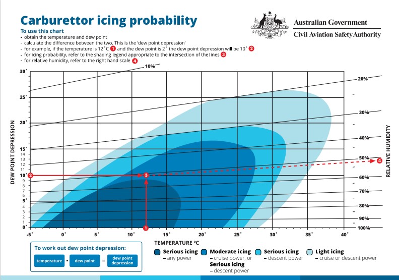
Carburettor icing conditions
The CASA carburettor icing probability chart predicted that serious carburettor icing at descent power was probable (Figure 1). The pilot stated that the engine was performing as expected throughout the approach. However, any loss of power associated with carburettor icing may not have been noticed at low power settings during an approach.
Figure 1: CASA carburettor icing probability chart
Source: CASA annotated by ATSB
Aerodrome information
The Airservices En Route Supplement Australia (ERSA) records Murwillumbah with an elevation of 18ft and runway 01 1,045 m in length.
Recorded data
Data for the flight was obtained from OzRunways, which recorded the aircraft’s location, altitude and speed at 5 second intervals throughout the flight.
When altitude information is transmitted to OzRunways it is truncated to 100 ft increments. This means that the recorded altitude of the aircraft is within a 100 ft altitude band between the altitude recorded and the next 100 ft increment. Altitudes between 0 and 99 ft will be displayed as 0, 100 and 199ft will be displayed as 100 ft and so on.
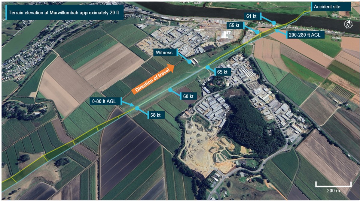
Taking into account the terrain elevation, the data showed the aircraft crossing the threshold below 80 ft above ground level (AGL) at 58 kts ground speed. The aircraft maintained approximately the same speed and altitude until about halfway down the runway.
The aircraft then commenced a climb, to a maximum height of between 200–280 ft, maintaining approximately 60 kts, before descending towards the cane field (Figure 2).
Figure 2: VH-JUA go-around at Murwillumbah Runway 01
Source: Google Earth with OzRunways data annotated by the ATSB
Go-around procedures
The Pilot’s Operating Handbook for the Cessna 172M states that the procedure for a go-around or 'balked landing' was:
Throttle – full open
Carburettor heat – cold
Wing flaps – 20°
Airspeed – 55 kt
Wing flaps – retract slowly
On most aeroplanes the use of full flaps creates large amounts of drag and impairs climb performance. The FAA airplane flying handbook Chapter 9: Approaches and landings stated that:
flap deflection of up to 15° primarily produces lift with minimal drag… Flap deflection beyond 15 degrees produces a large increase in drag.
In addition, the handbook stated that:
the application of power should be smooth, as well as positive. Abrupt movements of the throttle in some airplanes cause the engine to falter.
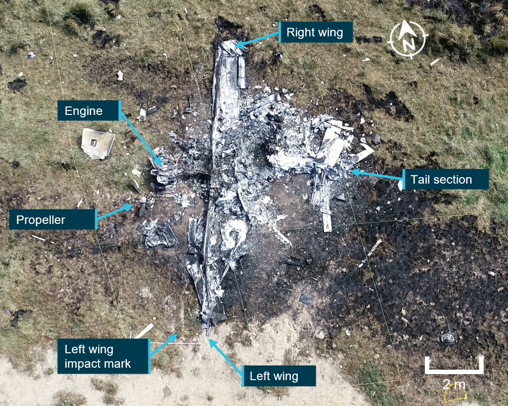
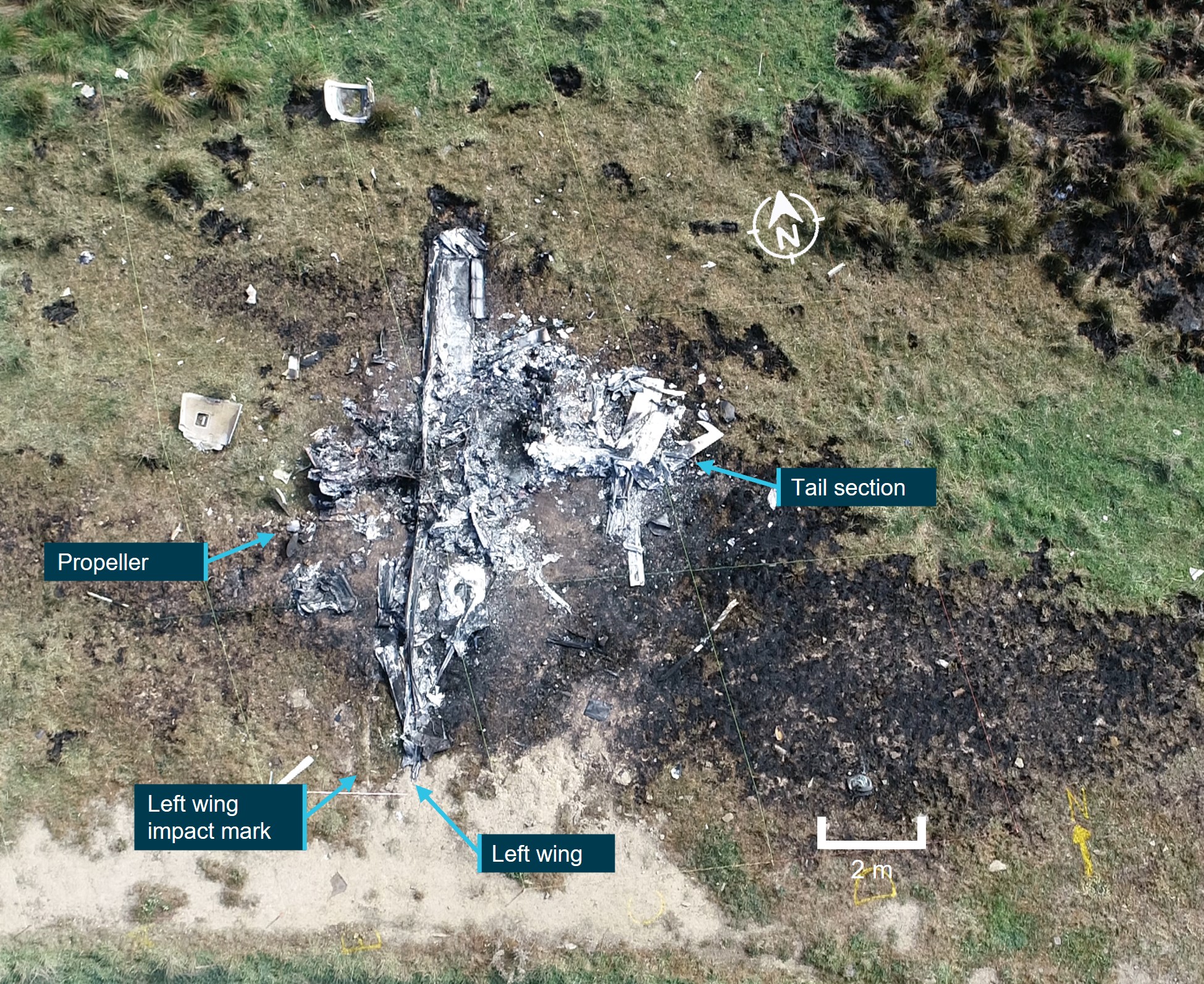
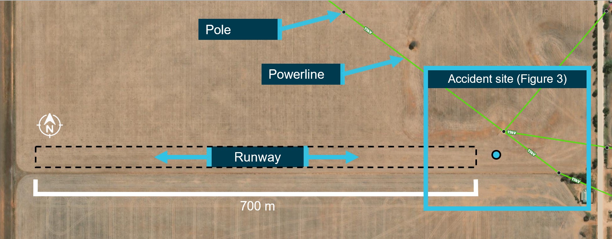
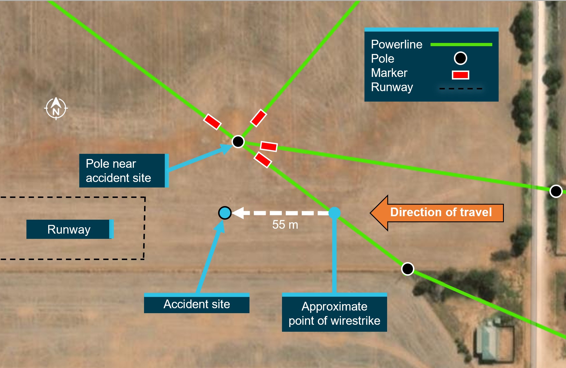
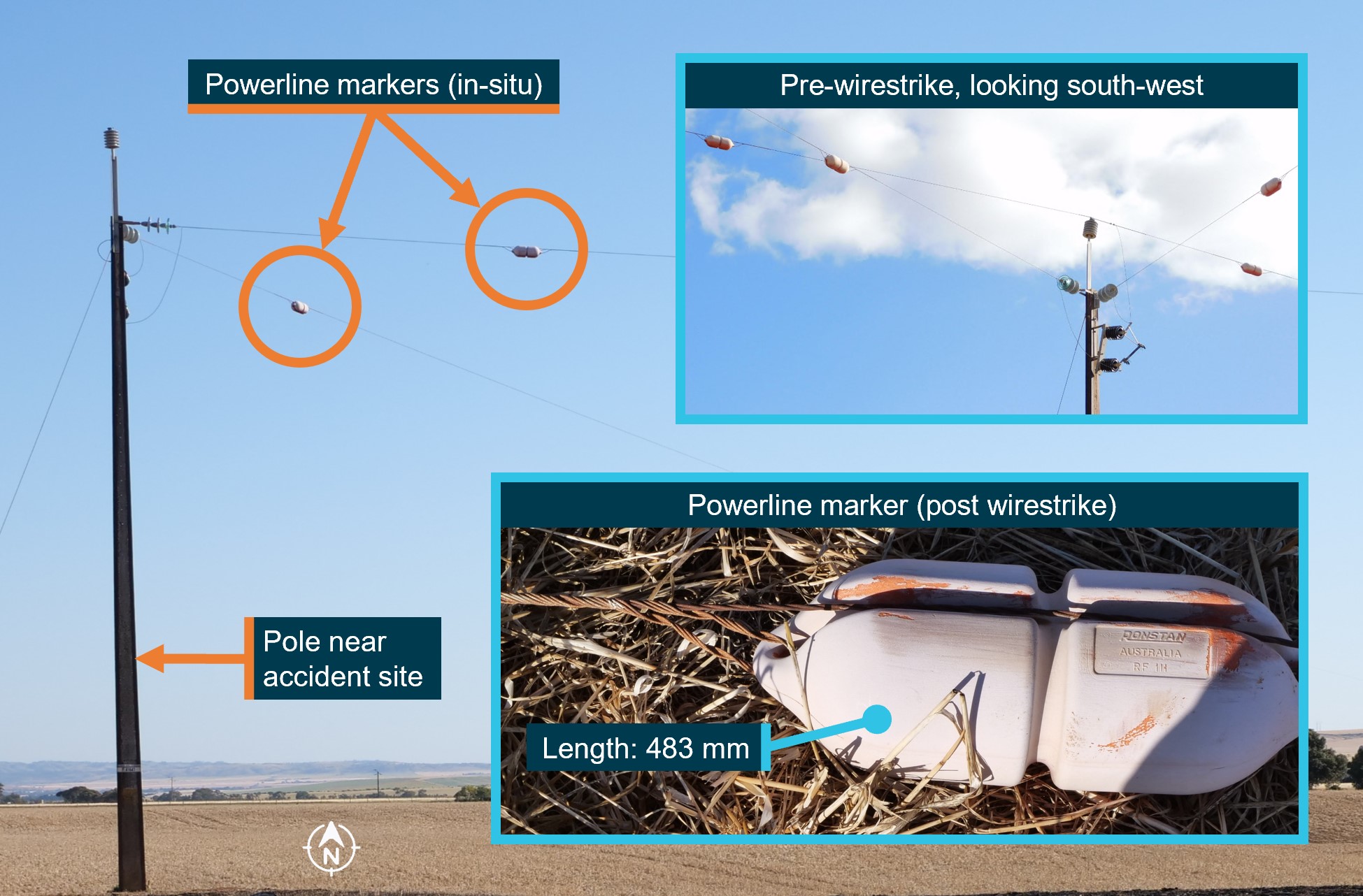
Accident site
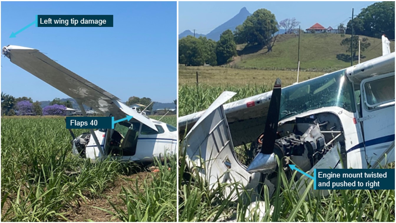
The ATSB did not attend the accident site and therefore did not conduct a detailed inspection of the wreckage. However, photographs of the site were provided to the ATSB (Figures 3 and 4).
These photographs showed evidence of:
QNH subscale was set to the 1017 hPa
flaps extended to approximately 40 degrees
damage to the left wingtip, fuselage and right wing
nose and right main landing gear collapsed
engine pushed to the right
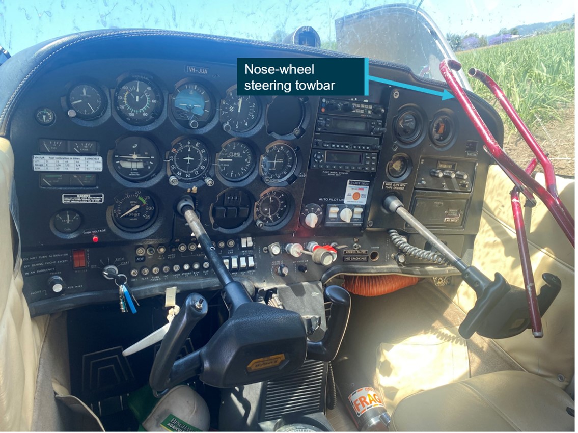
a nose-wheel steering towbar on the front right seat of the aircraft
The operator advised that the aircraft had full fuel prior to the departure and approximately 70 l of fuel was recovered from the fuel tanks after the accident.
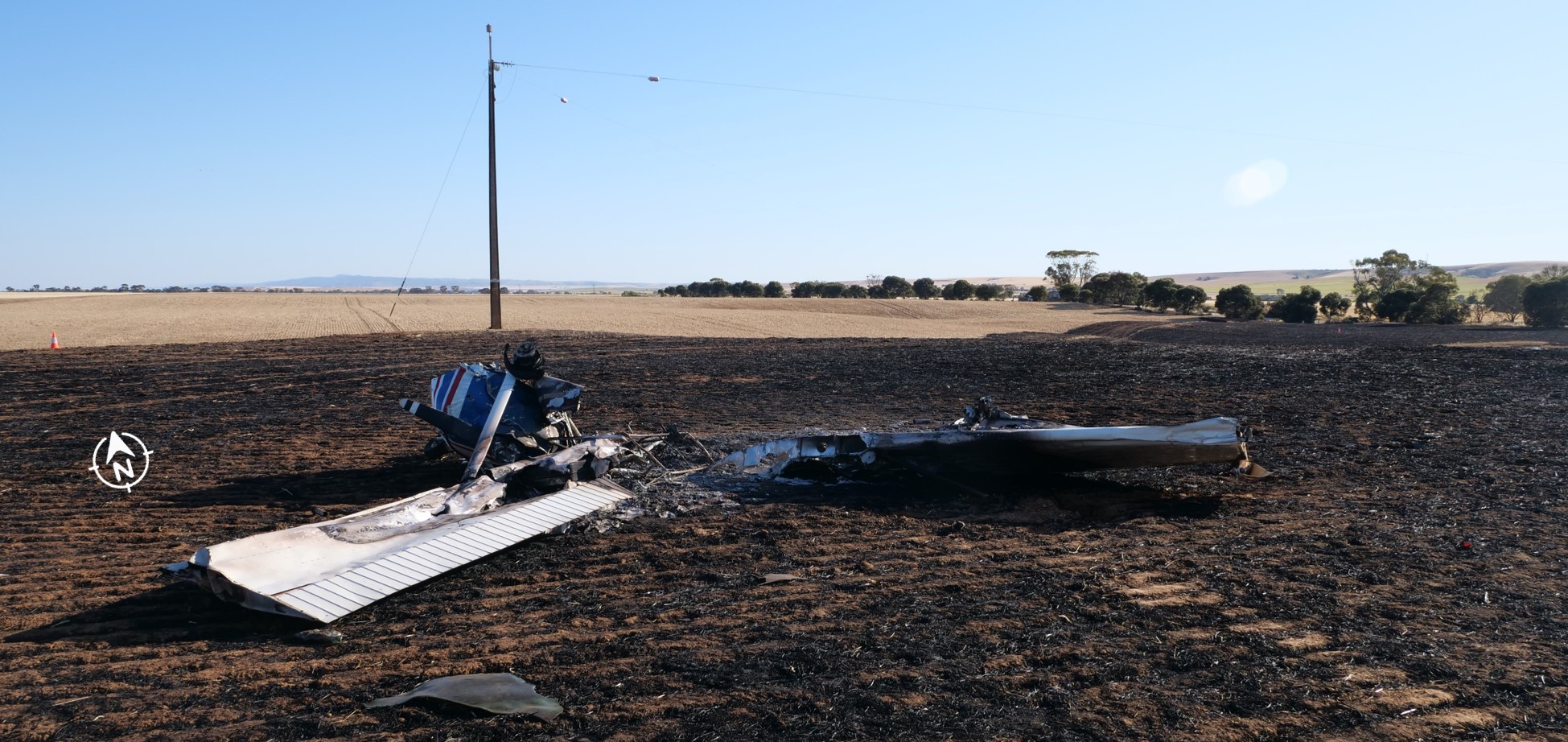
Figure 3: Photos of the aircraft at the accident site
Source: Operator annotated by ATSB
Figure 4: Nose-wheel steering towbar unrestrained in the cockpit
Photograph of the inside of the aircraft after the accident showed the nose-wheel steering towbar on the front passenger seat.
Source: NSW Police annotated by ATSB
The Civil Aviation Safety Regulations 91.600 state that ‘cargo must not be carried in a place where the cargo may damage, obstruct or cause the failure of a control or obstruct or restrict access to an emergency exit’.
While it could not be determined where the towbar was stored prior to the commencement of the flight, the operator’s standard procedure is to put the tow bar under the seat or to be covered by the net in the rear baggage compartment.
Safety analysis
The pilot advised that the aircraft was high on the approach and consequently they conducted a go-around. A go-around is a normal flight manoeuvre and is recommended when a pilot is not comfortable with an approach and as such it was appropriate that the pilot elected to conduct the procedure. However, consistent with the witness’s observations, the flight data indicated that the approach was stable, and that the descent stopped at less than 80 ft above the threshold, which placed the aircraft in a good position to land. It could not be determined why the pilot believed they were at 300–350 ft at this time.
The data further indicates that the aircraft started climbing, consistent with the commencement of a go-around, about half-way down the runway rather than over the threshold as recalled by the pilot.
During the go-around, the pilot advised that the engine did not produce full power. The ATSB could not verify this as there was no recorded data for engine parameters.
However, as the aircraft was able to maintain speed and height across the runway and subsequently climb with full flap, and no faults were found during the engine inspection, it is unlikely that the engine had any mechanical issues or any significant carburettor icing.
The witness’s account of the engine making a loud ‘bang’ as the engine power was applied is consistent with an abrupt forward movement of the throttle, which may have resulted in the engine faltering momentarily.
It is likely that the pilot’s decision to maintain full flap (40 degrees), which creates a large amount of drag and impaired climb performance, resulted in the pilot’s perception that the engine was not performing adequately.
While the nose-wheel steering towbar did not adversely affect the flight or injure the pilot, loose items in the cockpit or baggage area can jam flight controls and become dangerous projectiles and may cause serious injuries during an abrupt stop, turbulence or an accident sequence. Further, they can hinder an emergency evacuation.
Findings
ATSB investigation report findings focus on safety factors (that is, events and conditions that increase risk). Safety factors include ‘contributing factors’ and ‘other factors that increased risk’ (that is, factors that did not meet the definition of a contributing factor for this occurrence but were still considered important to include in the report for the purpose of increasing awareness and enhancing safety). In addition ‘other findings’ may be included to provide important information about topics other than safety factors.
These findings should not be read as apportioning blame or liability to any particular organisation or individual.
From the evidence available, the following findings are made with respect to the collision with terrain involving Cessna 172M, VH-JUA, 1km north-east of Murwillumbah, New South Wales on 15 October 2023:
Contributing factors
During the go-around, it is likely the aircraft was incorrectly configured resulting in reduced climb performance.
Other factors that increased risk
The unrestrained object in the aircraft increased the risk of serious injury to the pilot.
Safety actions
Whether or not the ATSB identifies safety issues in the course of an investigation, relevant organisations may proactively initiate safety action in order to reduce their safety risk. All of the directly involved parties are invited to provide submissions to this draft report. As part of that process, each organisation is asked to communicate what safety actions, if any, they have carried out to reduce the risk associated with this type of occurrences in the future. The ATSB has so far been advised of the following proactive safety action in response to this occurrence.
Safety action by Air Gold Coast
Since the accident, the operator has taken the following safety actions:
updated quick reference handbooks (QRH) to be clearer on balked landings (go-around) procedures.
issued an information circular to students and private hire pilots reminding them of the importance to secure cockpit cargo.
updated the private hiring agreements with regard to tighter recency requirements.
Sources and submissions
Sources of information
The sources of information during the investigation included the:
pilot of the accident flight
operator
accident witnesses
recorded data from OzRunways
NSW Police
References
Cessna 1972, Pilot’s Operating Handbook, Cessna 176 Skyhawk, model 172M
Federal Aviation Administration, 2022, Airplane Flying Handbook, Chapter 9 – approaches and landings’.
Submissions
Under section 26 of the Transport Safety Investigation Act 2003, the ATSB may provide a draft report, on a confidential basis, to any person whom the ATSB considers appropriate. That section allows a person receiving a draft report to make submissions to the ATSB about the draft report.
A draft of this report was provided to the following directly involved parties:
Pilot of the accident flight
Air Gold Coast Pty Ltd
Witness
Civil Aviation Safety Authority
Submissions were received from:
Air Gold Coast Pty Ltd
The submission was reviewed and, where considered appropriate, the text of the report was amended accordingly.
Purpose of safety investigations
The objective of a safety investigation is to enhance transport safety. This is done through:
identifying safety issues and facilitating safety action to address those issues
providing information about occurrences and their associated safety factors to facilitate learning within the transport industry.
It is not a function of the ATSB to apportion blame or provide a means for determining liability. At the same time, an investigation report must include factual material of sufficient weight to support the analysis and findings. At all times the ATSB endeavours to balance the use of material that could imply adverse comment with the need to properly explain what happened, and why, in a fair and unbiased manner. The ATSB does not investigate for the purpose of taking administrative, regulatory or criminal action.
Terminology
An explanation of terminology used in ATSB investigation reports is available here. This includes terms such as occurrence, contributing factor, other factor that increased risk, and safety issue.
Publishing information
Released in accordance with section 25 of the Transport Safety Investigation Act 2003
Ownership of intellectual property rights in this publication
Unless otherwise noted, copyright (and any other intellectual property rights, if any) in this report publication is owned by the Commonwealth of Australia.
Creative Commons licence
With the exception of the Coat of Arms, ATSB logo, and photos and graphics in which a third party holds copyright, this publication is licensed under a Creative Commons Attribution 3.0 Australia licence.
Creative Commons Attribution 3.0 Australia Licence is a standard form licence agreement that allows you to copy, distribute, transmit and adapt this publication provided that you attribute the work.
The ATSB’s preference is that you attribute this publication (and any material sourced from it) using the following wording: Source: Australian Transport Safety Bureau
Copyright in material obtained from other agencies, private individuals or organisations, belongs to those agencies, individuals or organisations. Where you wish to use their material, you will need to contact them directly.
[1] Runway number: the number represents the magnetic heading of the runway.
[2] Aerodynamic stall: occurs when airflow separates from the wing’s upper surface and becomes turbulent.
[3] A buffet is an indication of an approaching aerodynamic stall.
Occurrence summary
Investigation number
AO-2023-048
Occurrence date
15/10/2023
Location
1 km north-east of Murwillumbah
State
New South Wales
Report release date
14/02/2024
Report status
Final
Investigation level
Short
Investigation type
Occurrence Investigation
Investigation status
Completed
Mode of transport
Aviation
Aviation occurrence category
Collision with terrain
Occurrence class
Accident
Highest injury level
Minor
Aircraft details
Manufacturer
Cessna Aircraft Company
Model
172M
Registration
VH-JUA
Serial number
17266434
Aircraft operator
Air Gold Coast Pty Ltd
Sector
Piston
Operation type
Part 141 Recreational, private and commercial pilot flight training
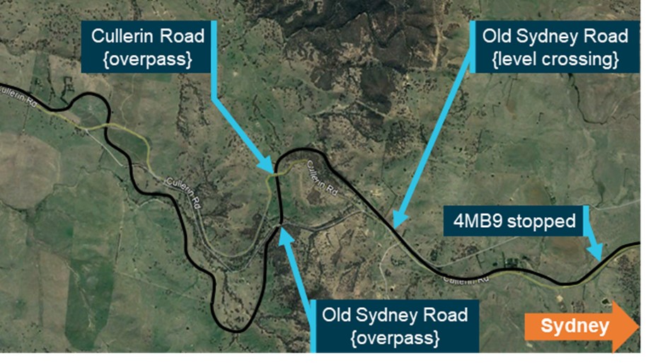
An interim report from the investigation into an accident where the driver of a freight train was fatally injured while outside the cabin details the circumstances of the accident, safety actions taken to date, and areas of ongoing investigation.
The investigation into the 25 August 2022 accident, which occurred between Yass and Goulburn is being undertaken by the NSW Office of Transport Safety Investigations (OTSI), which investigates rail accidents in NSW under a collaboration agreement with the ATSB.
The report details that 2 SCT Logistics locomotives, crewed by a driver and driver’s assistant, were hauling containerised freight train 4MB9 that was en route to Queensland when the fatality occurred.
The driver was found on the footplate on the exterior of the train and had suffered a fatal injury after leaving the cabin to check on equipment during an in-line fuelling operation.
“This interim report details factual information established in the investigation’s evidence collection phase and has been prepared to provide an update to the rail industry and the public,” said OTSI acting CEO and Chief Investigator Jim Modrouvanos.
“As such it does not contain any analysis or findings, which will be detailed in the final report on the investigation.”
Mr Modrouvanos explained that as the investigation progresses investigators will continue to review the rollingstock operator’s management of the in-line fuelling system and whether any permanent lineside structures contributed to the driver’s injury.
The investigation will also consider enterprise training for the in-line fuelling system.
The interim report notes that the train operator has taken proactive safety actions since the accident including issuing an updated instruction for in-line refuelling, as well as an updated procedure prohibiting crew from exiting the locomotive cabin while the train is in motion.
“A final report will be released at the conclusion of the investigation, however, if at any time during the course of the investigation we identify a critical safety issue, relevant stakeholders will be immediately notified so that appropriate safety actions can be taken.”
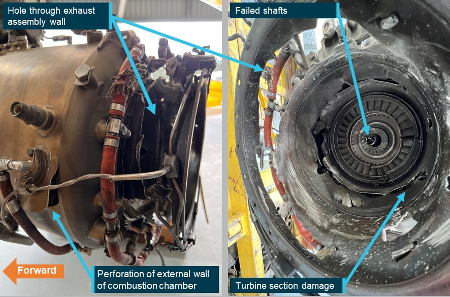
A turboprop-powered DHC-2 Beaver sustained an engine failure soon after parachutists had exited the aircraft above a drop zone at Moruya Airport on the New South Wales south coast, an ATSB report details.
The aircraft was conducting skydiving drops overhead Moruya on 4 April 2022 when, on the second flight of the day, and soon after the parachutists had exited, the pilot heard a loud bang and briefly experienced vibrations.
Believing the aircraft had experienced an engine failure, the pilot pulled the fuel emergency shut-off lever, feathered the propeller, assessed the position of the parachutists, and conducted a forced landing at Moruya Airport.
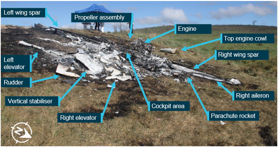
“A post-flight examination of the aircraft identified holes in the cowling above the engine compartment, perforation of the external wall of the engine combustion chamber, holes through the exhaust assembly, and significant damage to the turbine section,” said ATSB Director Transport Safety Kerri Hughes.
“A low-cycle fatigue crack had initiated in the 3rd-stage turbine wheel of the Honeywell International TPE331 engine and grown to failure.”
The ATSB investigation established that errors by a previous maintainer of the aircraft when determining the engine operating cycles and engine component total equivalent cycles meant that the 3rd-stage turbine wheel remained in-service beyond the component life-limit.
“This incident highlights the critical importance of accurate records of equivalent cycles accrued by an engine and engine components,” said Ms Hughes.
“Cycles should be diligently recorded, calculated, and checked to ensure the equivalent cycles accrued by a component is known with confidence.
“This means that components can be replaced prior to the published in-service life-limit being reached.”
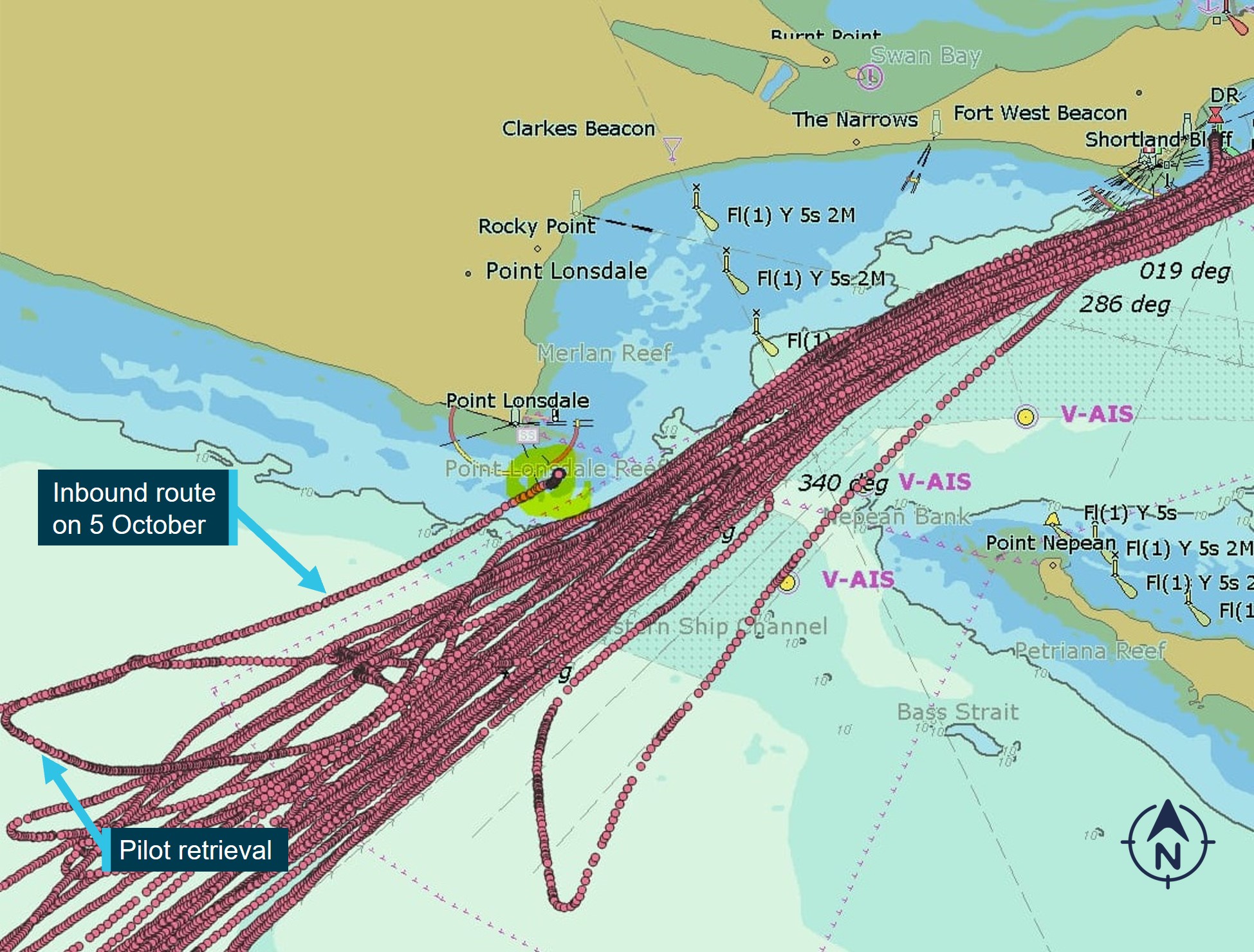
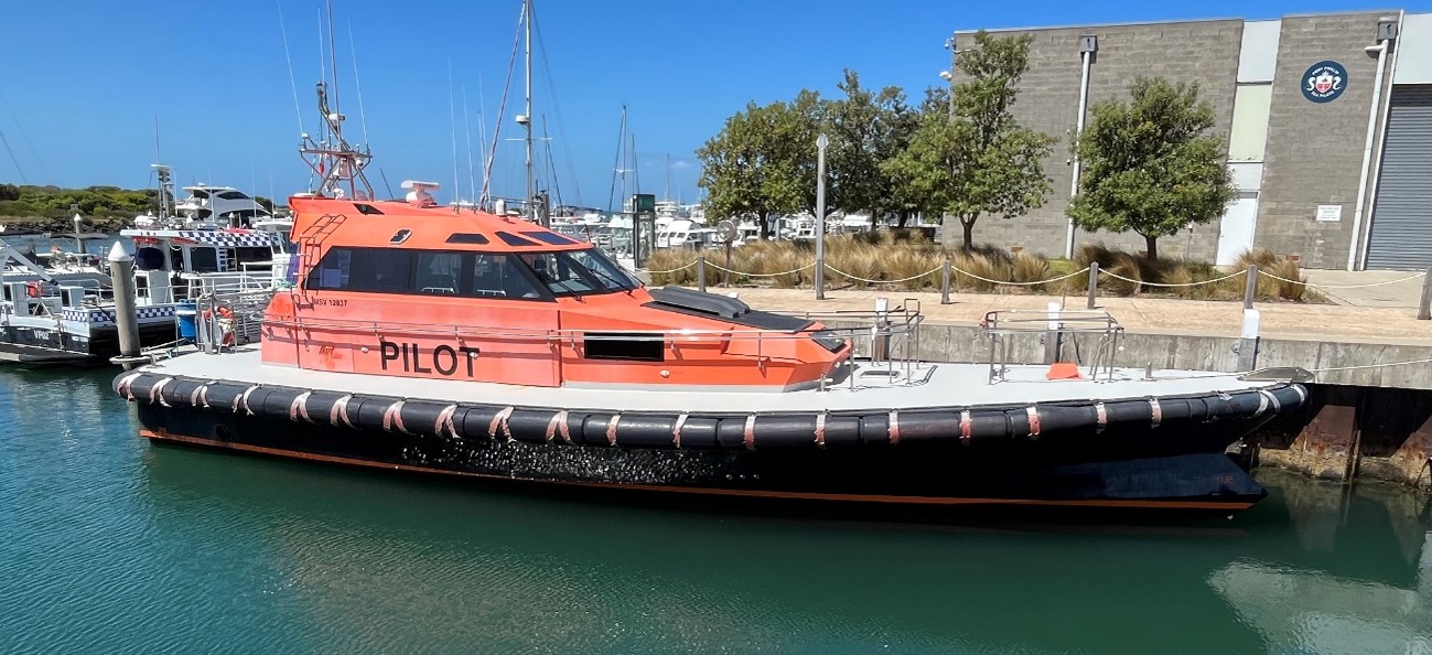
On the evening of 5 October 2023, the pilot launch Corsair was retrieving the pilot from the outbound container ship MV Rio Grande after it had departed Port Phillip. The transfer of the pilot to the launch took place offshore, about 4.2 km south‑west of Point Lonsdale. Port Phillip Sea Pilots (PPSP) was the pilotage service provider and operator of the pilot launch.
The pilot launch commenced its return to the entrance of Port Phillip at about 2307 intending to return to the pilot station at Queenscliff, inside the bay. At about 2310 and when about 2.3 km south‑west of Point Lonsdale, the coxswain commenced a slow course alteration to port of about 18º. Corsair was about 760 m from Point Lonsdale Reef when it steadied on a course towards the reef. Corsair was west of the location intended by the coxswain and subsequently ran aground on Point Lonsdale Reef at about 2313 travelling at 24 knots.
What the ATSB found
It was found that the coxswain of Corsair misinterpreted the leading lights marking the entry to Port Phillip and navigated to the west of their intended course through the entrance. The return to Port Phillip following offshore pilot transfer was a routine activity which had been performed by the coxswain on many occasions. On this night, their perception of navigational lights on Shortland Bluff was probably influenced by their expectations of what they would normally observe.
The likelihood of human error can be reduced by using protective systems of technology, other crew resources, and procedure. In this instance, the coxswain’s navigation of Corsair back to the entrance was predominantly visual with limited reference to onboard equipment to confirm the vessel’s approach. The other launch crew member, a deckhand, was also not actively involved with the vessel’s navigation.
A vessel’s safety management system provides the structures and guidance to support a consistent approach to vessel operations. It was found that the pilot launch safety management system and procedures could be improved with guidance to the launch crew on operational practices for navigation through the entrance to Port Phillip and the effective use of the launch’s equipment and deckhand.
It was also found that training material for launch coxswains contained limited detail on course content and assessment criteria, and training records were incomplete. There was also no refresher crew training in navigational practices.
Although not considered to have influenced this occurrence, additional findings are made on the potential for review by Safe Transport Victoria of the local knowledge certification requirements for masters of domestic commercial vessels operating in Port Phillip Heads.
What has been done as a result
Port Phillip Sea Pilots has developed additional guidance material for pilot launch operations and the use of equipment and crew resources. Training of coxswains and deckhands in crew resource management has also commenced. This work is ongoing and includes the review of the vessel risk register considering single person error and further updates to safety management and training systems. Significant upgrades have been made to launch navigational equipment.
Safety message
The incidence of human error can be reduced through effective use of available resources including a vessel’s equipment and crew. Vessel safety management systems and training should guide crew in the use of such resources.
The occurrence
Prior to the grounding
On 5 October 2023, the Port Phillip Sea Pilots (PPSP) night shift crew of PV Corsair reported on duty at the launch station at Queenscliff harbour at about 1900 local time. The crew comprised the launch coxswain[1] and deckhand. The crew’s first scheduled pilot transfer was later that evening. It involved retrieval of the pilot from the outbound container ship MV Rio Grande after it had departed Port Phillip. The pilot launch was prepared for service and the crew then waited in the crew quarters at the launch station.
At about 1952 that evening, Rio Grande departed Melbourne with a pilot on board and travelled south towards the entrance to Port Phillip (Figure 1).[2]
At about 2230, the PPSP pilot despatch officer informed the launch crew that Rio Grande was expected to be at the Heads at about 2300. The launch crew boarded Corsair and departed the wharf at about 2244. At about 2253, Corsair and Rio Grande converged inside the Heads and from there the ship and launch travelled out through the entrance.
The pilot and coxswain established VHF radio contact at about 2255 and agreed that the ship and launch would rendezvous about 2 nautical miles (NM)[3] offshore and to the south‑west of the entrance in relatively calmer waters. More central to the entrance, seas were rougher due to the strong ebb tide, an opposing sea and a strong breeze from the south-south-west.
Once clear of the Heads, Rio Grande turned to starboard to create a lee on its starboard side for the launch to come alongside to retrieve the pilot. The pilot disembarked the ship onto the launch at about 2306. Soon after, from a position about 2.25 NM (4.2 km) south‑west of Point Lonsdale,[4]Corsair commenced heading back to the entrance of Port Phillip at speeds of between 21 and 24 knots.[5]
At the time, the sky was overcast and dark and the moon had not yet risen.[6] The meteorological visibility considering atmospheric conditions was reported as 7.4 NM.[7]
The grounding
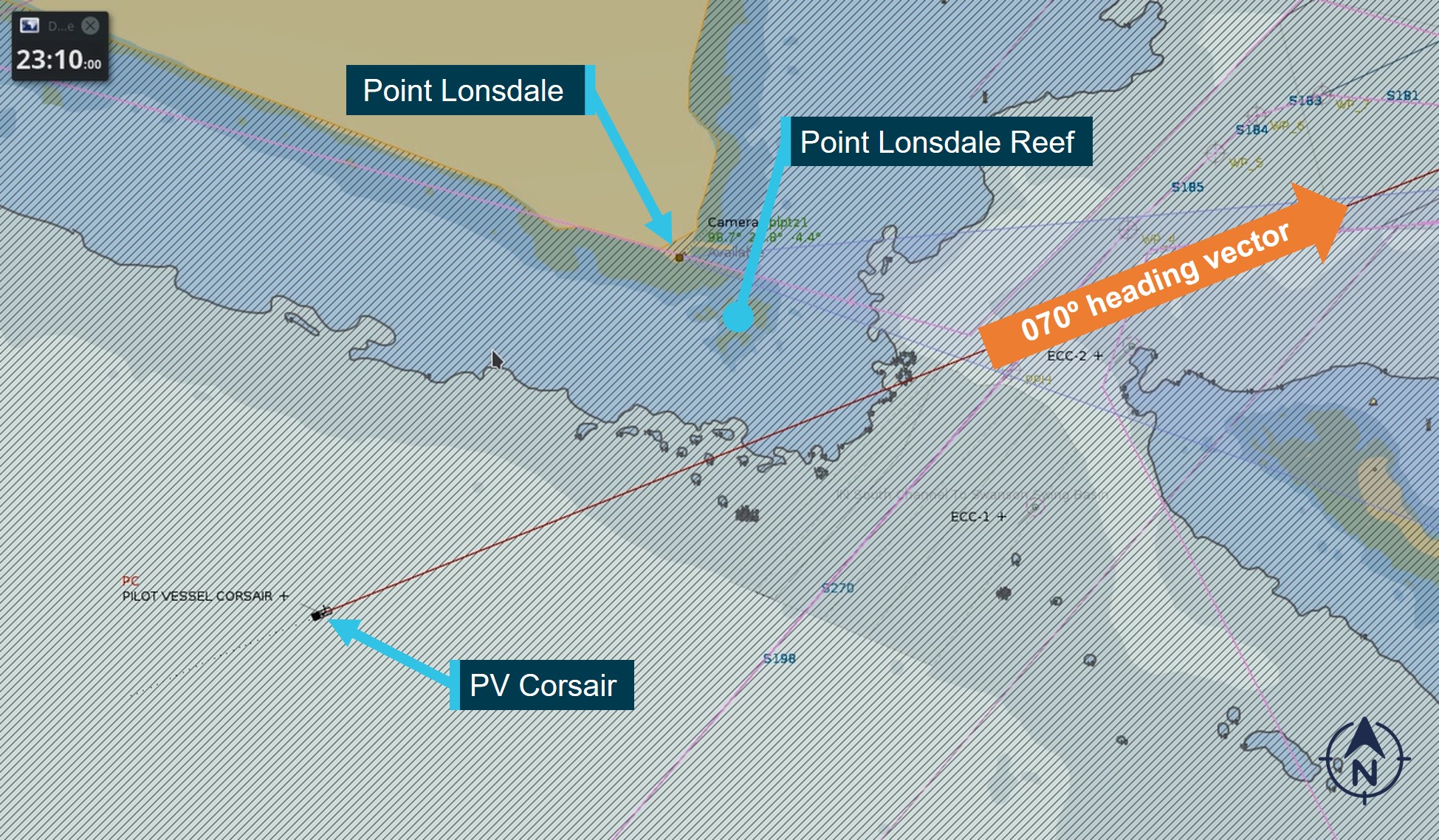
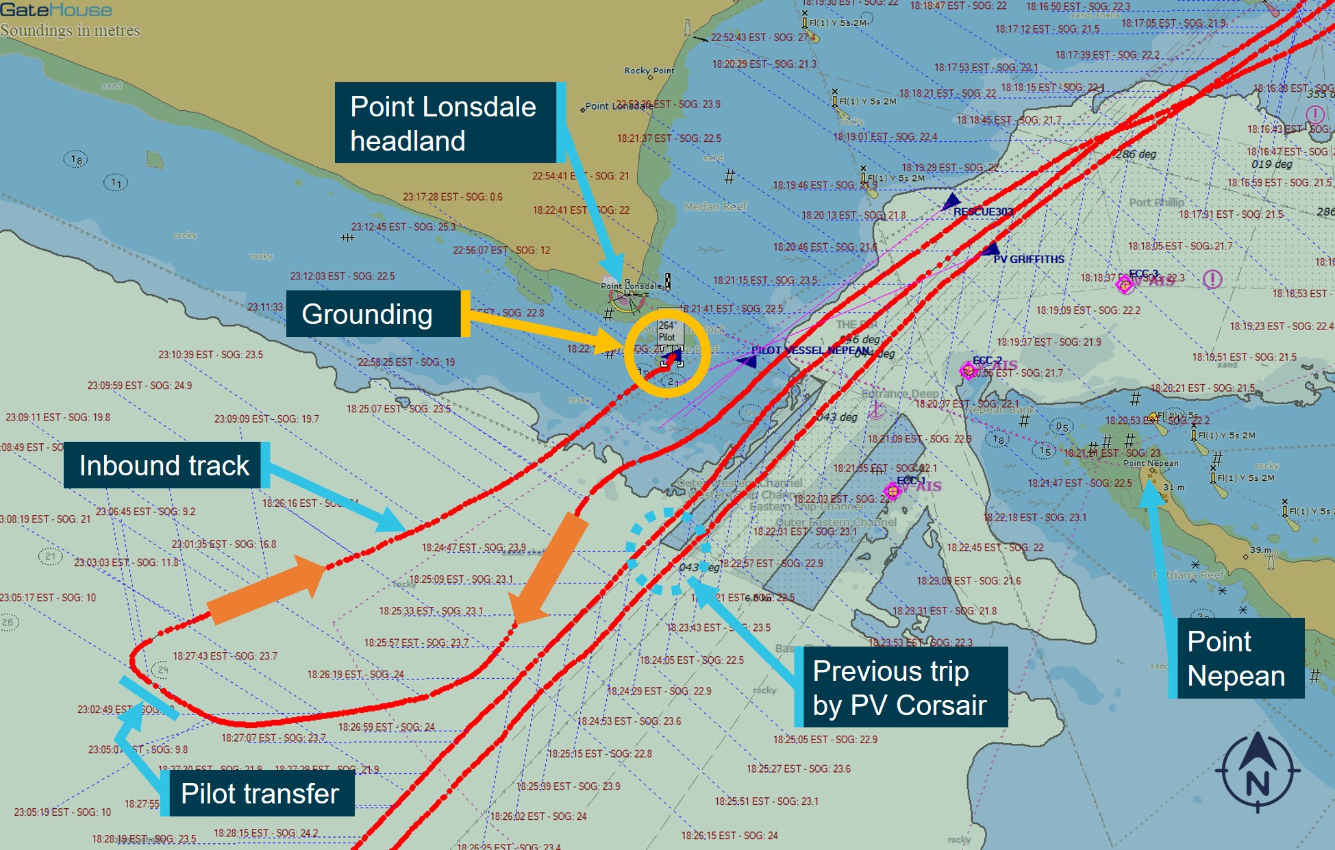
For its return to Queenscliff, Corsair initially settled on a heading 067º and then 070º (Figure 2). On this course, Corsair would pass clear of Point Lonsdale Reef.
Figure 2: The heading vector of PV Corsair at 2310 prior to course alteration to port
The figure shows the course vector of PV Corsair at 2310 when on a 070º heading and about 2.3 km from Point Lonsdale.
Source: Ports Victoria, annotated by the Office of the Chief Investigator
At about 2310, when about 1.25 NM (2.3 km) south‑west of Point Lonsdale and about 2.2 km from the Point Lonsdale Reef, the coxswain commenced a slow alteration of course to port. This course alteration was intended to bring them to the west of the Outer Western (shipping) Channel and onto the four fingers west[8] small craft approach to the entrance. However, Corsair was considerably further west than the coxswain realised.
The course alteration to port was completed and the launch steadied on a course of about 052º when Corsair was about 760 m from the reef. At about 2313 Corsair entered the shallowing water and ran aground travelling at about 24 knots (Figure 3).
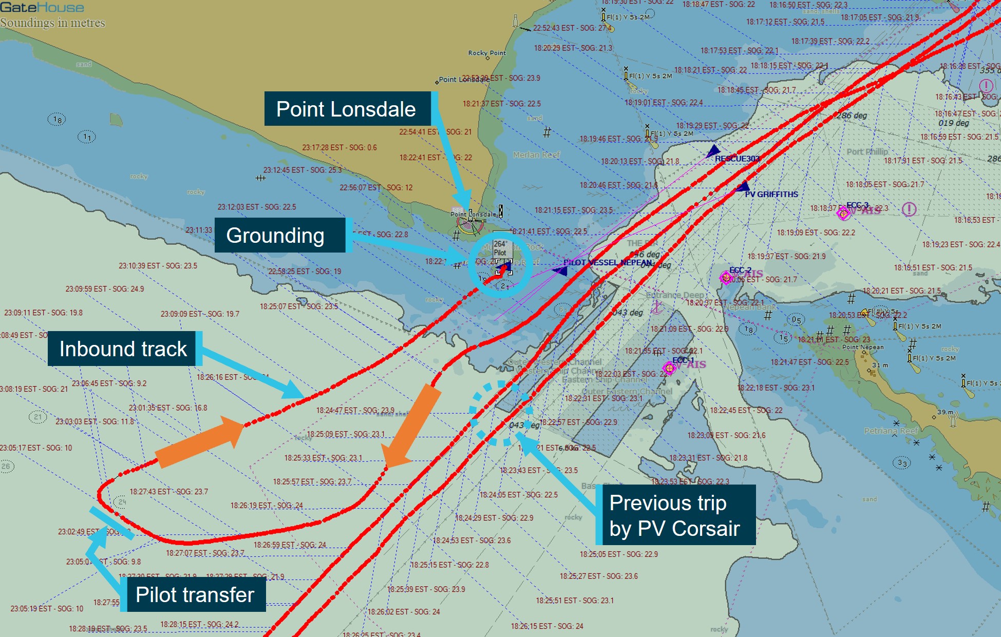
Figure 3: The track of PV Corsair outbound and then inbound towards the reef
The figure also shows the tracks of PV Corsair through the Heads on its previous trip.
Source: Ports Victoria, annotated by the Office of the Chief Investigator
Rescue operation
After attempts were made by the coxswain to clear Corsair from the reef, the launch became disabled and came to rest in a rock pool about 500 m from Point Lonsdale. On checking the navigational aids, the coxswain realised that they were further west than intended and had run aground on Point Lonsdale Reef.
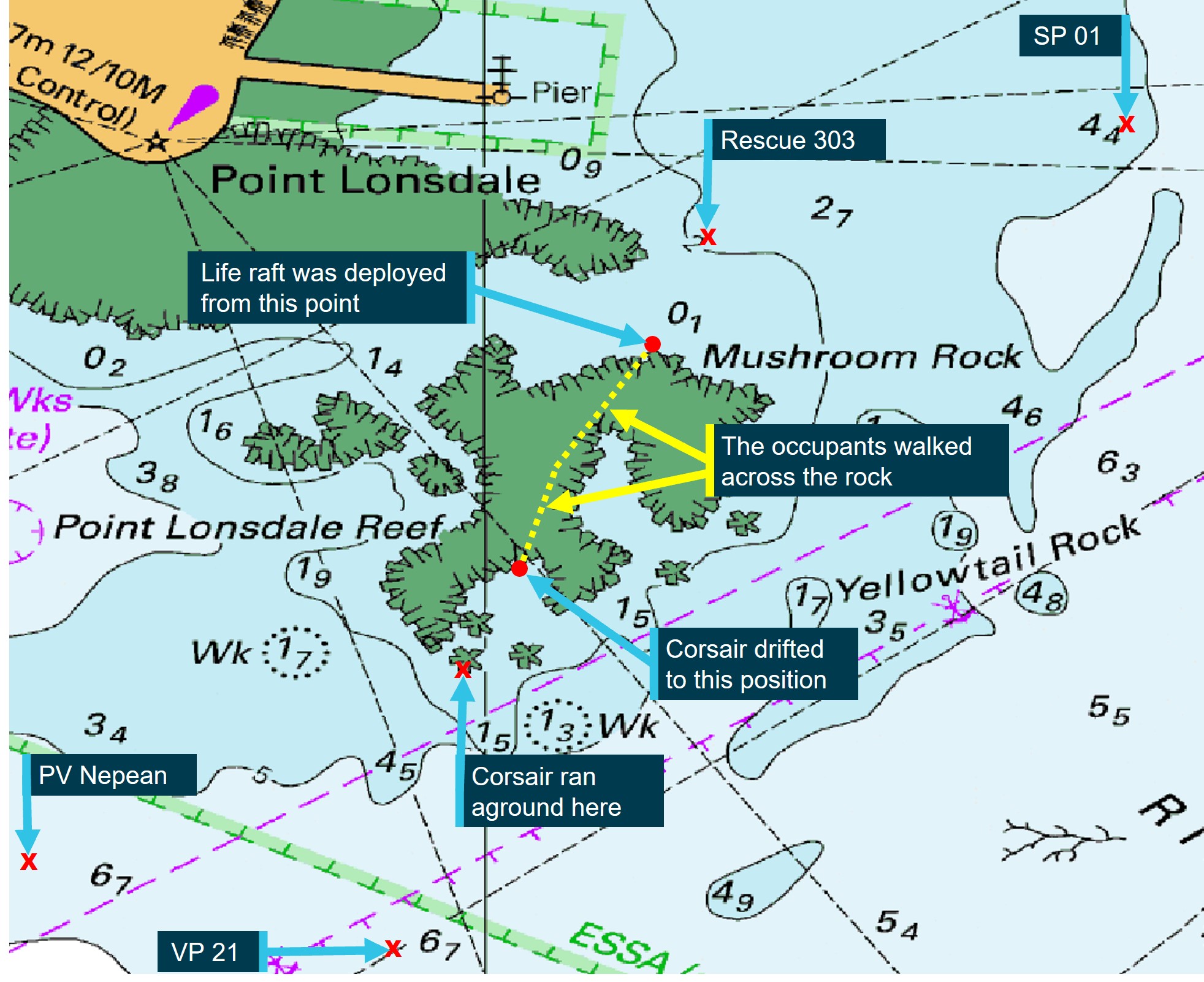
Several calls were made from Corsair seeking assistance, the first by mobile phone at 2317 to the crew of the sister pilot launch, PV Nepean. A Mayday distress broadcast was then transmitted from Corsair at 2319 on VHF radio Ch 12 directed to Ports Victoria Vessel Traffic Services (VTS) (see Port and waterway management). The caller advised that the launch was taking on water and it was not safe to remain onboard. The 2 crew and the pilot took the life raft and other emergency equipment off the pilot launch and waded onto the reef (cover photo). They inflated the life raft, but sea conditions did not yet allow its launch.
On receipt of the mayday call, the VTS contacted the Victoria Police Search and Rescue Squad (VicPol SAR) at the State Rescue Coordination Centre. VicPol SAR then activated the Australian Volunteer Coast Guard at Queenscliff, the Southern Peninsula Rescue Squad at Blairgowrie, and its own rescue response team. The Mayday call was also heard by PV Griffiths, a pilot launch operated by Auriga Pilots Melbourne and also located at Queenscliff.
PV Nepean was the first to arrive at the scene at about 2350. Four other vessels responded including Coast Guard vessel Rescue 303, the Southern Peninsula vessel SP01, the VicPol SAR vessel VP21. PV Griffiths also responded and was on standby to assist.
The crew and pilot from the PV Corsair made their way to the northern edge of the reef. At around 0130 in improving conditions,[9] they launched the life raft and paddled towards Rescue 303 (Figure 4). At about 0132 Rescue 303 reported that they had taken on board the 2 crew and the pilot and requested that SP01 tow the now empty life raft back to Queenscliff.
Figure 4: Vessels responding to the grounding (PV Griffiths was located further east)
The figure captures the location of responding vessels around the time of rescue, except PV Griffiths which was east of SP01.
Source: Australian Hydrographic Office annotated by the Office of the Chief Investigator
The crew and pilot from Corsair were safely landed at Queenscliff at about 0144. They were assessed by Ambulance Victoria and discharged. There were no reported injuries other than mild hypothermia.
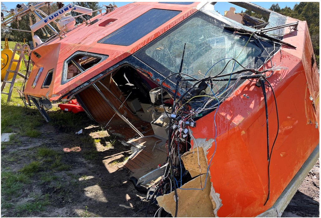
The entrance to Port Phillip was closed to shipping from 0001 to 0210 on 6 October while the rescue was in operation, and again later that morning from 0525 to 1015 while debris from the Corsair was recovered. During the night, the pilot launch had been wrecked by the effect of the sea and reef (Figure 5).
Figure 5: Recovered wheelhouse from PV Corsair
Source: Office of the Chief Investigator
Context
The waterway
Port Phillip Heads
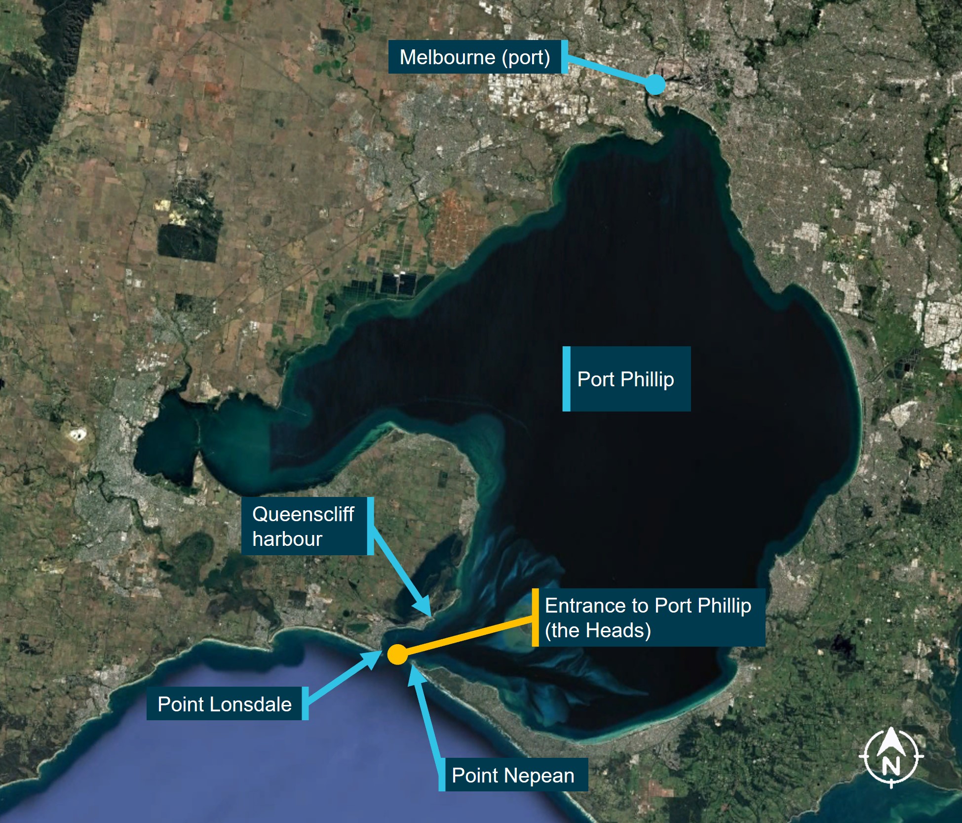
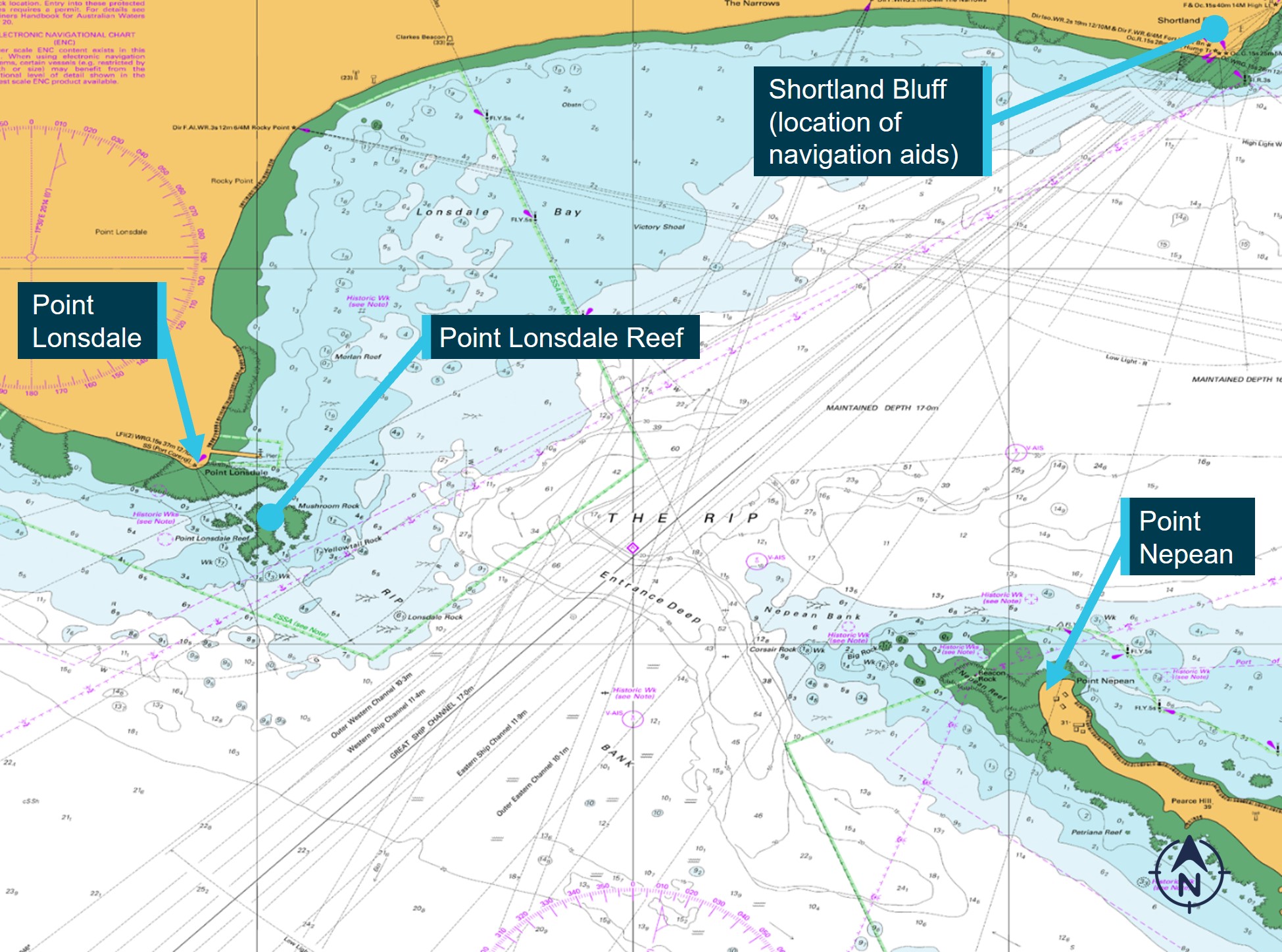
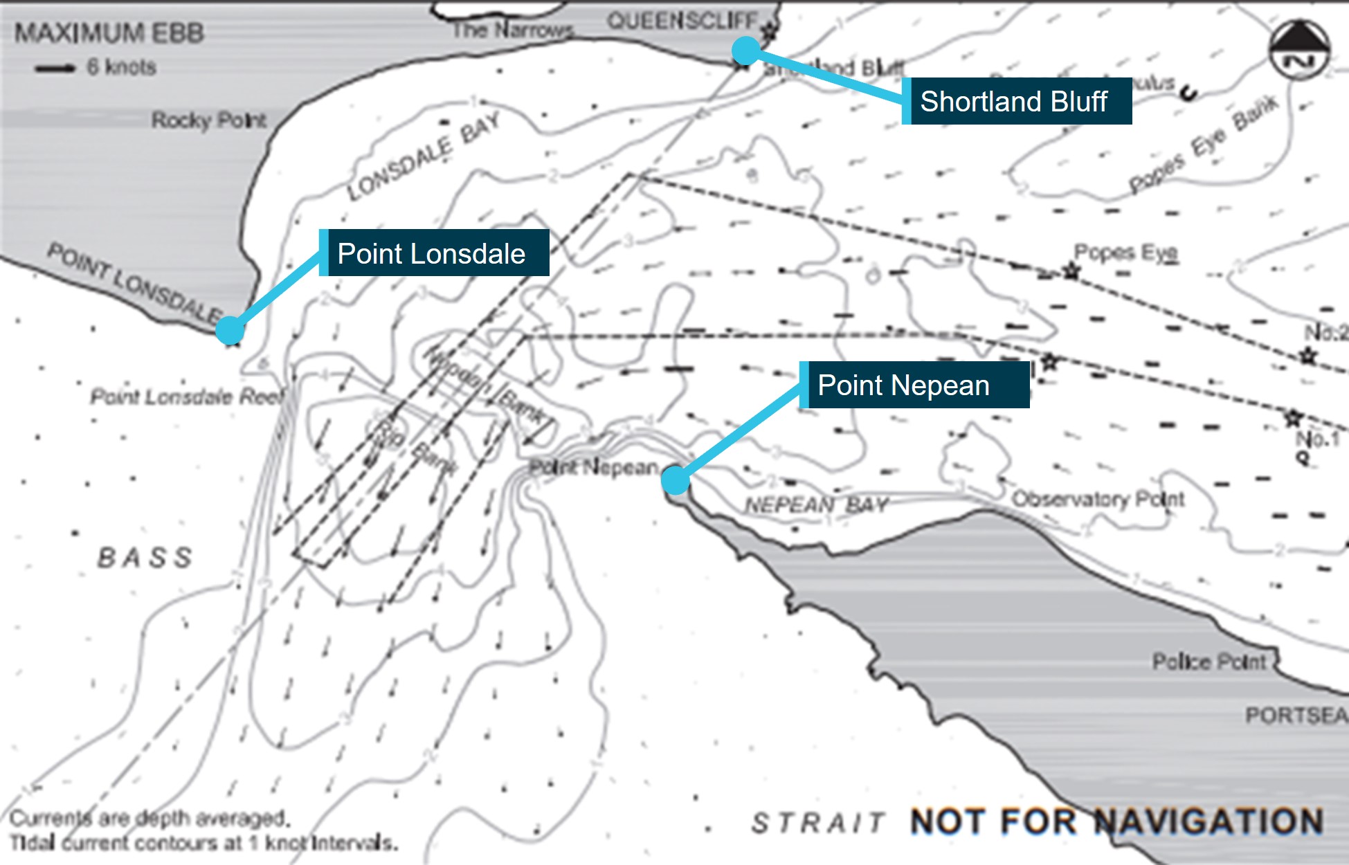
Port Phillip Heads (the Heads) is the narrow waterway entrance connecting Bass Strait to the bay of Port Phillip. The entrance to Port Phillip is between Point Lonsdale and Point Nepean (Figure 6). The distance between the headlands is about 3.5 km although the outlying reefs significantly reduce the width of navigable water. The width of the entrance between the 5 m depth contour lines is about 1750 m and is about 1000 m between the 10 m contours.
Figure 6: The entrance to Port Phillip
Source: Australian Hydrographic Office, annotated by the Office of the Chief Investigator
Point Lonsdale Reef is an outcrop of flat-topped rock extending about 550 m south-east of the headland of Point Lonsdale. The inner and outer sections of the reef are separated by a narrow channel and both sections are exposed at low tide.
Tidal streams
Due to the narrow entrance and sea floor topography, tidal streams of up to 8 knots can be experienced in the Heads. The strongest tidal streams occur around the time of high water (HW) and low water (LW) at Point Lonsdale. This is due to the lag in the equalisation of the water levels inside and outside the Heads. Slack water occurs around midway between high and low water.
The outgoing stream sets towards the bight between Point Lonsdale and Shortland Bluff (Lonsdale Bay), and thence out through the entrance (Figure 7).
Figure 7: Port Phillip Heads current vector diagram for ebbing tidal flow
Source: Ports Victoria, annotated by the Office of the Chief Investigator
Strong winds, swell and seas from the south to south‑west sector during an outgoing tidal stream cause higher than usual seas within the Heads and heightened risk to small vessels. Nearer to Point Lonsdale, waters can be comparatively smoother in such conditions. Small craft therefore favour the western side of the entrance to avoid the main tidal flows through the centre and towards the east of the entrance.
Conditions in the entrance at the time of grounding
Corsair was returning to Port Phillip a short time after low water which was at 2249 at the entrance.[10] The height of the tide at the Heads was about 0.6 m above the charted depth and rising. Due to the earlier described lag in water levels equalising inside and outside the Heads, the tidal stream was still running out of the bay (ebbing) at about 5.6 knots. The wind was from the south-south‑west at 22 knots, gusting to 26 knots.[11] The ebbing tide and opposing sea and wind conditions typically produce localised rough seas.[12]
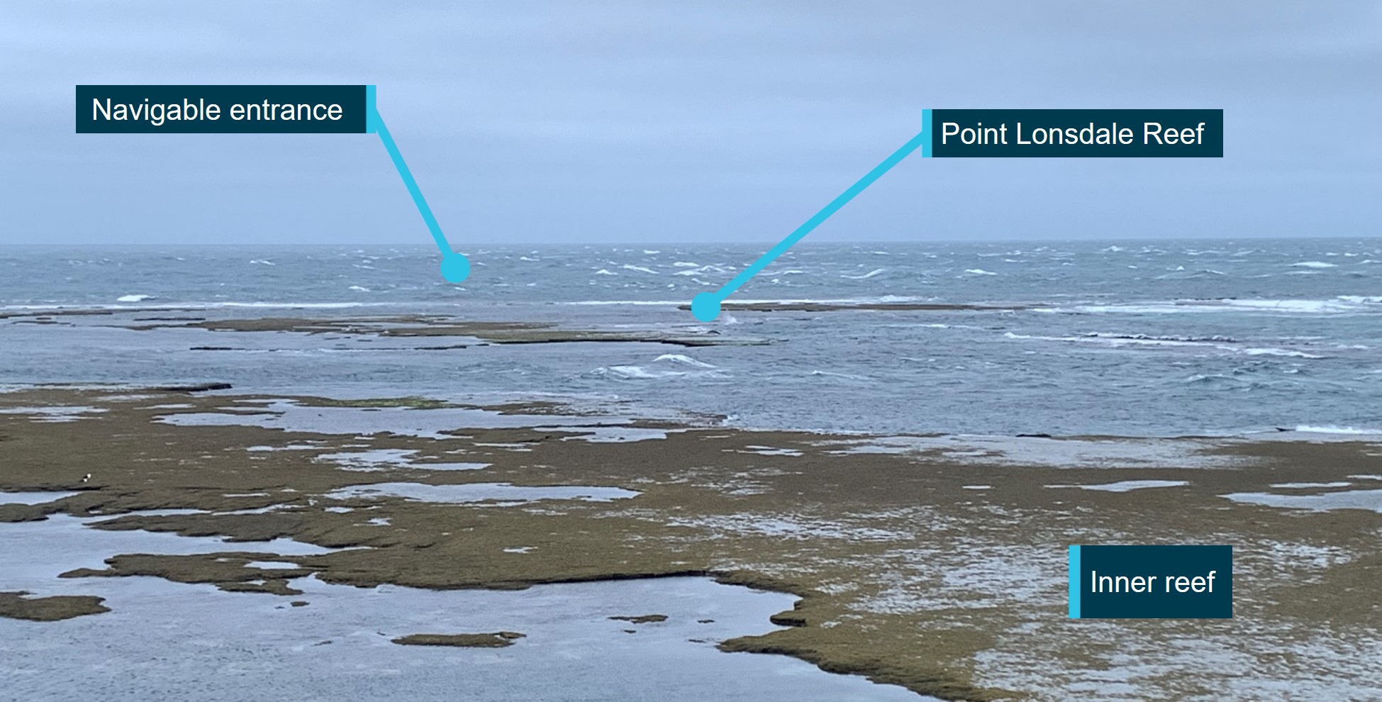
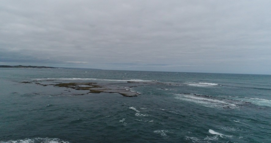
At the time of the grounding, large sections of Point Lonsdale Reef were exposed (Figure 8).
Figure 8: Point Lonsdale Reef with similar conditions to those on 5 October 2023
Source: Office of the Chief Investigator
Navigation through Port Phillip Heads
Aids to navigating through the entrance
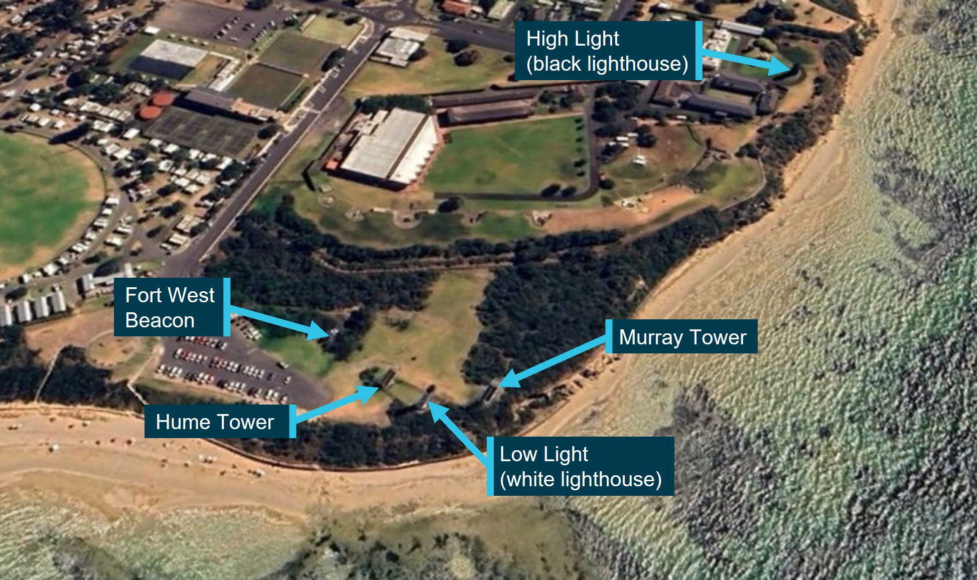
Navigational aids to assist mariners and boaters to navigate through the entrance were located at Shortland Bluff (Figure 9). Point Lonsdale Lighthouse, which is located on the western headland of the entrance, also provided a warning to mariners.[13]
Figure 9: Navigational aids at Shortland Bluff (Queenscliff)
Navigational aids on Shortland Bluff which assist in the navigation of the entrance by small craft are described in Table 1.
Table 1: Navigational aids used to navigate the entrance
Name
Construction
Approximate height of light(s) above sea level
High Light
Black stone tower of 25 m height located about 370 m back from the southern edge of Shortland Bluff.
40 m
Low Light
White stone tower of 25 m height located at Lighthouse Point at the southern end of Shortland Bluff.
28 m
Murray Tower
Green metal framework tower with white vertical stripe, located to the east of the Low Light.
25 m
Hume Tower
Red metal framework tower with white vertical stripe, located to the west of the Low Light.
28 m
Fort West Beacon
Metal framework tower, located further west of Hume Tower.
19 m (note 1)
Note 1. The light at 19 m is for small craft. The beacon has additional lights at about 20 m height that are used by shipping.
At night, navigational aids are identfied through their location and the characteristics of their lights. When viewed from sea, their relative position and light sectors provide information to masters to assist navigation. The lights on navigational aids located at Shortland Bluff are described in Table 2. All lights had a nominal range exceeding 10 NM except for Murray Tower which had a nominal range of 5 NM.
Table 2: Characteristics of navigational lights to navigate the entrance
Note 1. The vertical arcs of visibility are different for the fixed and occulting lights. For small craft, the fixed light is dominant.
Note 2. The red and green lights of the Low Light are in sectors not visible to vessels navigating the entrance.
Note 3. Additional lights used by shipping are not included in this table.
Approaches on the west side of the entrance
Introduction
There are several channels designated for the navigation of ships and other vessels through the entrance to Port Phillip. The Outer Western Channel with a declared depth of 10.3 m was the western most designated shipping channel. The Hume Tower in line with the High Light (alignment 046°) marked the western limit of the Outer Western Channel. At night, this presented to small craft as the white High Light over the 15s occulting red light of Hume Tower.
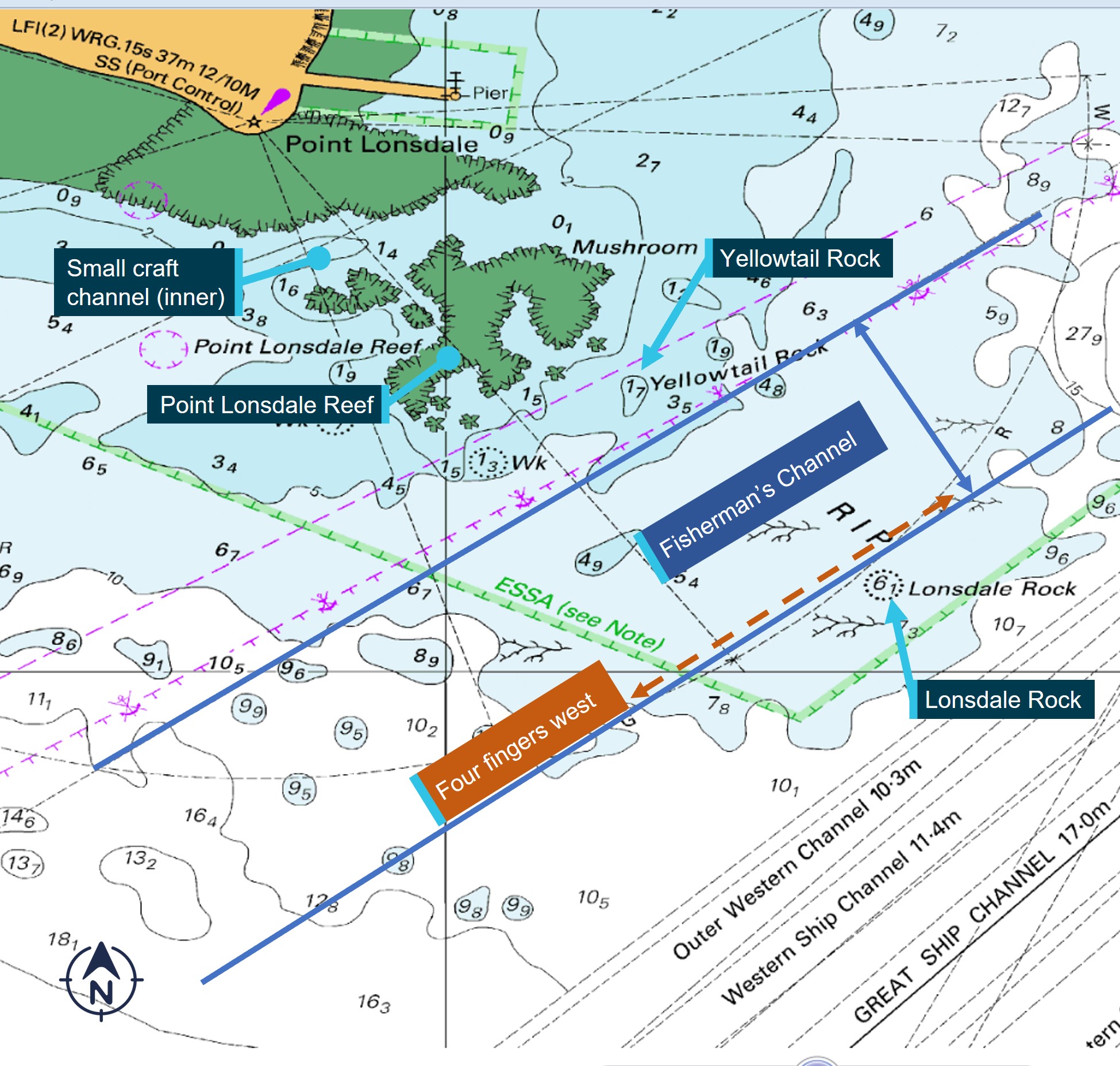
Small craft channels
Smaller craft often used the approaches west of the Outer Western Channel. These shallower approaches included Fisherman’s Channel which ran between the submerged Lonsdale Rock (6.1 m depth) and the submerged Yellowtail Rock (1.7 m depth), and an inner channel with a depth of about 1.4 m running between the inner and outer sections of Lonsdale Reef (Figure 10).
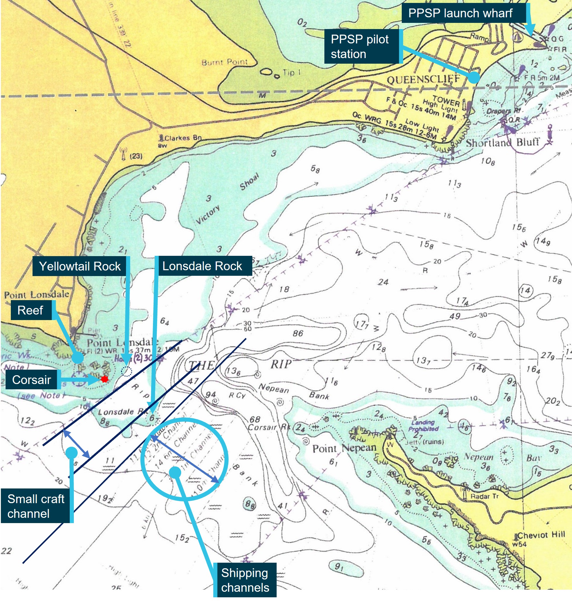
Figure 10: Small craft channels to the west of shipping channels
The approximate approach of four fingers west is also marked on this figure (see Four fingers west).
Source: Australian Hydrographic Office annotated by the Office of the Chief Investigator
Navigating Fisherman’s Channel
The sector lights of Fort West Beacon (FWB) were used to navigate within Fisherman’s Channel and to warn operators when they were west of the channel and in unsafe waters. The white sector light (048.7°-052.7°) of FWB indicated the navigable water between Yellowtail Rock and Lonsdale Rock. Its western edge was marked by the limit of its white sector (052.7°).[16]Further west, FWB displayed a red sector light (052.7°-058.7°) indicating an unsafe sector which included the submerged Yellowtail Rock and Point Lonsdale Reef.
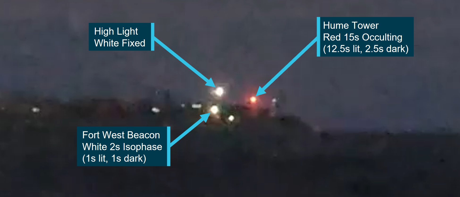
This western limit of Fisherman’s Channel was also indicated by the alignment of Fort West Beacon with the High Light. Safe transit within this small craft channel would therefore be achieved by keeping the High Light to the right of FWB (Figure 11). This approach would keep the High Light between the FWB white isophase light, and the red occulting light of Hume Tower which would also be visible on this approach.
Figure 11: Fisherman’s Channel indicated by the white sector of Fort West Beacon
Source: Office of the Chief Investigator (with contractor)
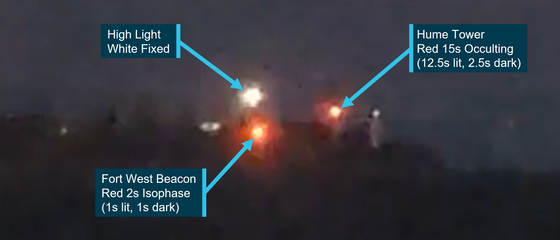
When west of, and outside, Fisherman’s Channel, the High Light would be observed to the left of FWB which would now be in its red sector (Figure 12). Hume Tower would also still be visible in this part of the FWB red sector.
Figure 12: Just west of Fisherman’s Channel in the red sector of Fort West Beason
Source: Office of the Chief Investigator (with contractor)
Four fingers west
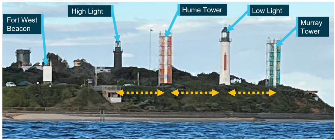
Within Fisherman’s Channel, ‘four fingers west’ referred to the approach when maintaining the High Light, Hume Tower, the Low Light and Murray Tower equispaced (Figure 13). West of this approach, the gap between High Light and Hume Tower would widen. Not all lights on these 4 navigational aids were visible from seaward on the four fingers west approach, and therefore this formation was only reliably referenced in daylight.
Figure 13: Four fingers west when High and Low Lights and Towers were equispaced
Source: Office of the Chief Investigator
Approaching the entrance further west of Fisherman’s Channel
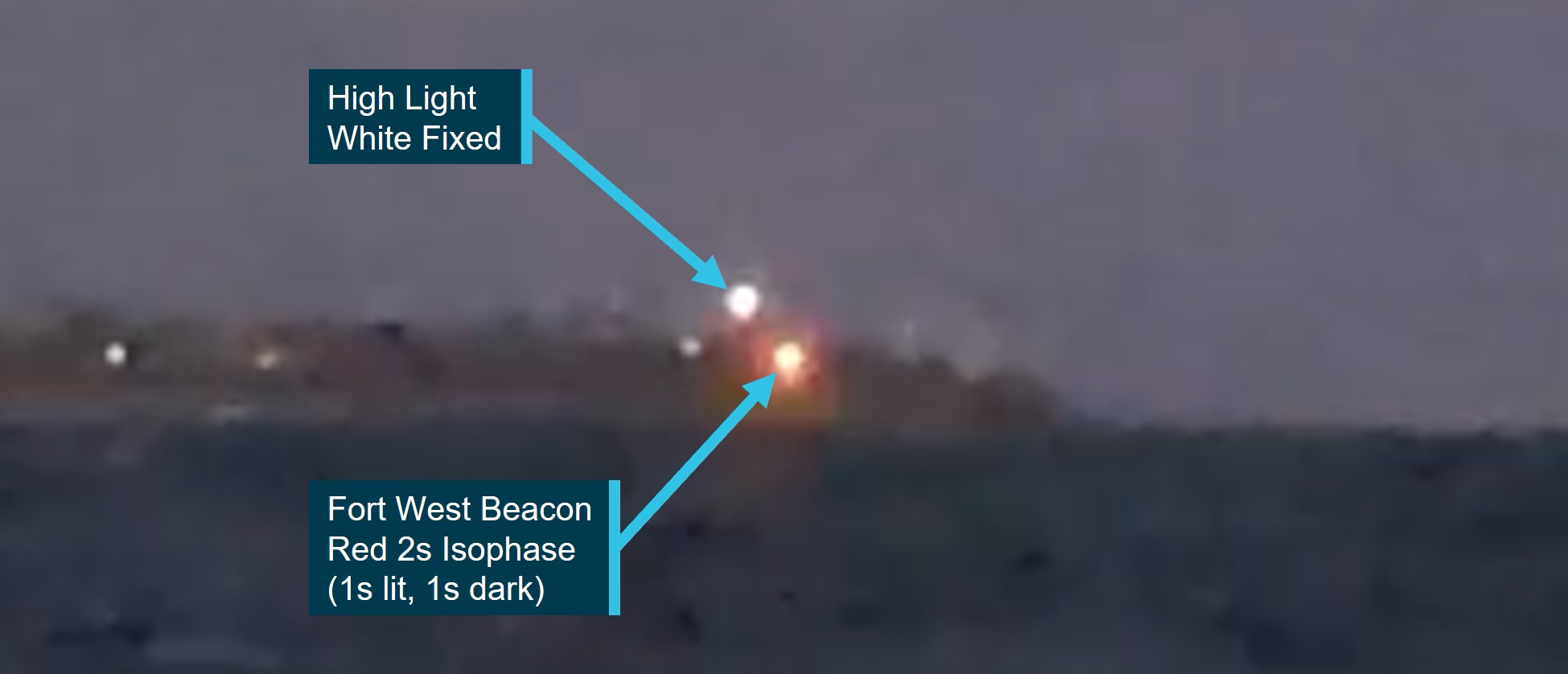
Further to the west, the limit of the Hume Tower red occulting light would be reached and no longer seen (Figure 14). Beyond this limit, the navigational aids visible on Shortland Bluff would be the white High Light above, and to the left of, the red sector light of the Fort West Beacon. Corsair was operating around the western limit of the Hume Tower light. Trials suggest that the Hume Tower light was probably not visible to the crew of Corsair during most of its approach.
Figure 14: Further west of Fisherman’s Channel outside the light sector of Hume Tower
Source: Office of the Chief Investigator (with contractor)
Port and waterway management
This occurrence involved ship pilotage services in support of commercial shipping operations. Most of the operations of Corsair were also within the designated port waters of the port of Melbourne. These waters were managed by the statutory authority Ports Victoria.[17]
Ports Victoria had a stated role to provide safe, fair and efficient access to Victoria’s commercial ports through the provision of marine navigation services. Safety management included the engagement of a licensed Harbour Master for each commercial port and the provision of Vessel Traffic Services (VTS) to mariners.
For the southern parts of Port Phillip and designated port waters outside the Heads, traffic services were provided by ‘Lonsdale VTS’ which was co-located with other VTS operations at the Port Operations Centre in Melbourne. Traffic was monitored using electronic charting systems with AIS and radar overlay, and using CCTV installed at Point Lonsdale and Point Nepean.
The pilotage transfer operations of Corsair were part of port operations. In accordance with safety requirements for port waters,[18] the coxswain of Corsair was required to inform Lonsdale VTS of their departure and the nature of their work, which they did. VTS subsequently monitored the movements of the outbound Rio Grande and Corsair during the pilot transfer. Protocol was for pilots to disembark outbound ships 2 to 5 NM to seaward of the entrance and the pilot transfer from Rio Grande to Corsair was consistent with this protocol.
Once Corsair turned away from Rio Grande and started their return trip, there was no requirement for Corsair to report their in-coming trip to VTS and VTS were not aware of the intended passage of Corsair. Corsair subsequently grounded outside designated commercial port waters.
Pilot launch PV Corsair
Overview
PV Corsair was used for transporting marine pilots from the PPSP pilot station at Queenscliff to inbound ships requiring pilotage to enter port waters, and to retrieve pilots who had piloted ships which were departing port waters. Its sister vessel of the same class was the PV Nepean (Figure 15).
Figure 15: PV Nepean of the same design and construction as Corsair
Source: Office of the Chief Investigator
Corsair was constructed in 2014 by Hart Marine in Mornington, Victoria. It was of monohull design with an overall length of 18.6 m, breadth of 5.5 m, depth of 2.3 m and had a draft of about 1.6 m. Propulsion was by two Cummins marine diesel engines for a maximum speed of about 30 knots.
The vessel was constructed to the requirements of Bureau Veritas[19] and the Australian National Standard for Commercial Vessels (NSCV)[20] for a Class 2C[21] vessel.
Corsair was registered with the Australian Maritime Safety Authority (AMSA) as a domestic commercial vessel (DCV). It had a Certificate of Survey valid until 28 May 2025 and a Certificate of Operations valid until 2 September 2024. The AMSA certificates permitted Corsair to operate as a pilot vessel with a crew of 2 and up to 6 special personnel.[22] Corsair’s certification was for a non‑passenger‑carrying vessel.
At the time of the grounding, the operation of the launch was consistent with its certification. The vessel was appropriately crewed and was transporting one special personnel (the pilot). The pilot was not involved with the navigation of the launch and was not required to be involved.
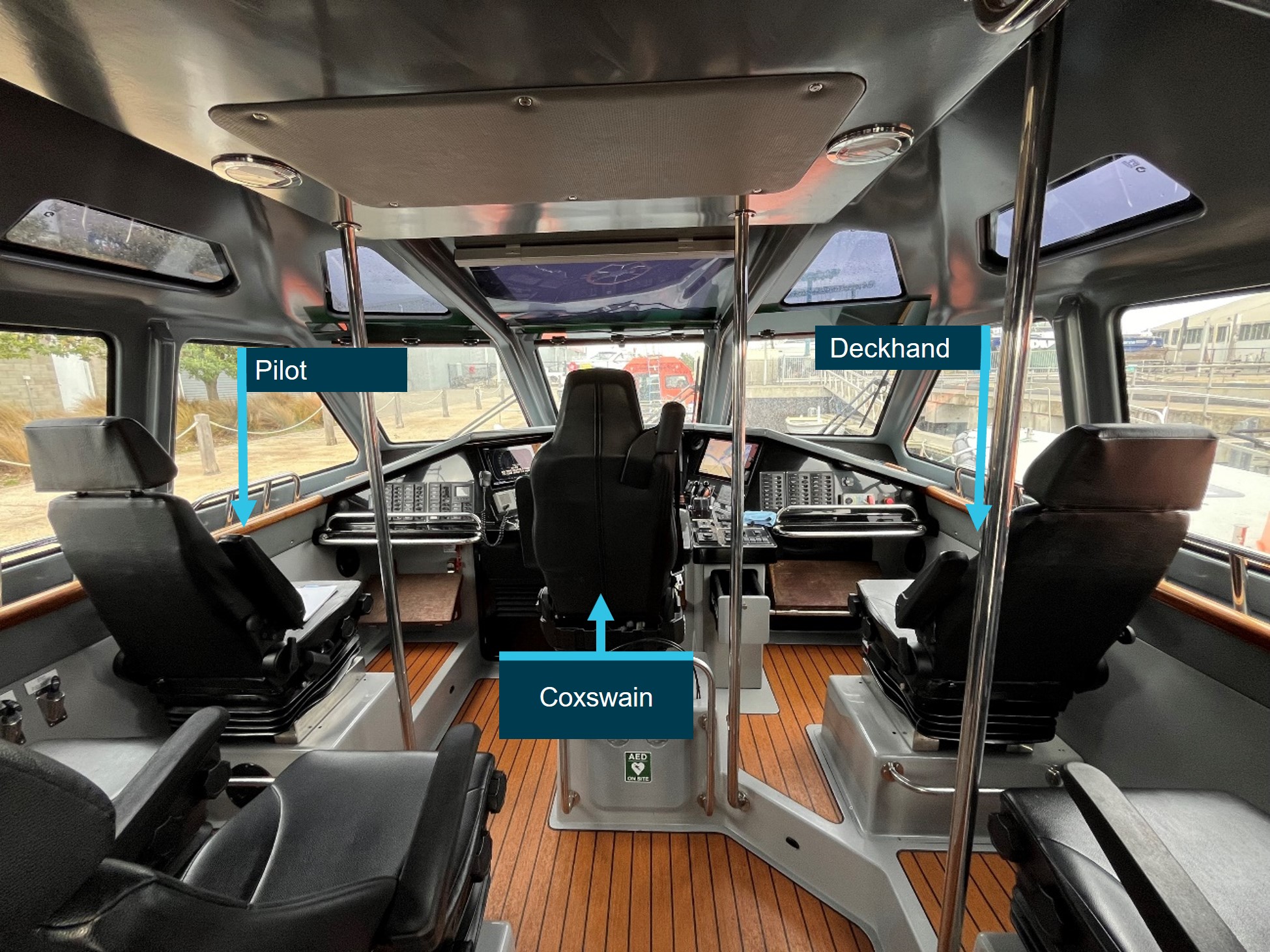
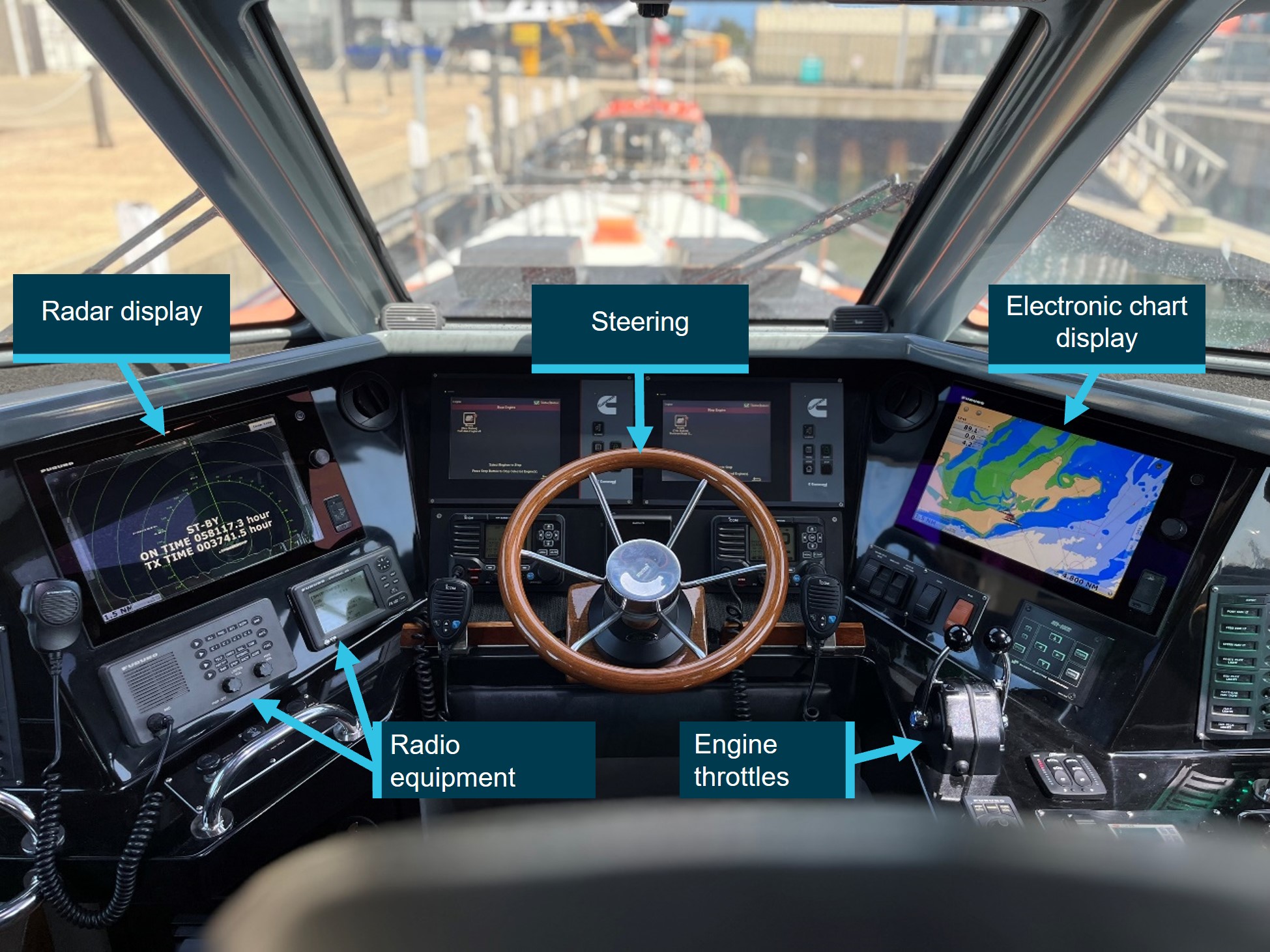
Conning position
The coxswain navigated the launch from the forward position in the wheelhouse. For the return journey of Corsair on the night of the grounding, the deckhand was seated to the right of the coxswain and the returning pilot was seated to the left (Figure 16). The deckhand reported not having a clear view of the navigation displays from their position.
Figure 16: Cabin layout of Corsair and personnel positions (photographed on Nepean)
Source: Office of the Chief Investigator
Navigation equipment
Overview
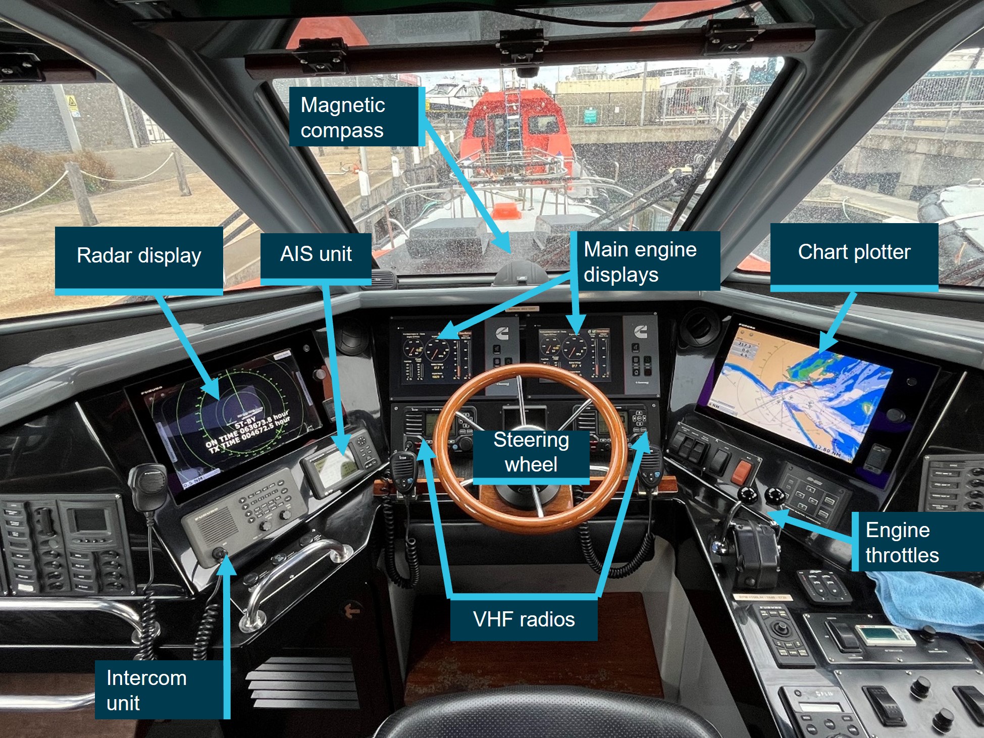
PV Corsair was fitted with a Furuno Navnet 3D Navigation system incorporating an electronic chart plotter and radar displayed on the 2 multi-function (interchangeable) display units, one on each side of the conning position (Figure 17). The displays on Corsair were configured with the chart plotter to the right, and the radar display to the left of the coxswain’s chair and both were dimmed for night operations on the night of the grounding. A third display unit located to the rear of the cabin could be used to replicate either of the navigational console displays, although it was mainly used to log events and check weather.
A GPS unit, a depth sounder and an Automatic Identification System (AIS)[23] unit with separate display screen was integrated into the Navnet 3D system, allowing position information, sea depth information and AIS targets to be displayed. Communications equipment comprised 2 mounted and 2 portable VHF radios.
Figure 17: Configuration of navigation equipment on Corsair (photographed on Nepean)
Wheelhouse configuration on PV Nepean, which was similar to the configuration on PV Corsair.
Source: Office of the Chief Investigator
Chart plotter options and configuration
The chart plotter was loaded with electronic charts for the relevant waterways and the integrated GPS unit provided launch position information. The radar image could be overlaid on the chart plotter and information from the AIS unit displayed on the chart screen. The chart plotter was set to 6 NM at the time of the grounding.
The vessel’s heading vector indicating the direction in which the launch was heading was shown on the chart plotter. The length of the vector was determined by a time variable set by the coxswain. The coxswain advised that on Corsair the heading vector had been set to 10 minutes. This equated to a length of 4 NM if travelling at 24 knots, and 3.5 NM if travelling at 21 knots.
Chart plotter features not used on the night of the grounding included:
designation of ‘no-go’ zones (areas dangerous to surface navigation) by enabling depth shading overlays to highlight shallow water areas and contrastingly, safe navigable areas.
Radar display options and configuration
The radar was a conventional X-band marine radar, incorporating ARPA (automatic radar plotting aid). It had a maximum detection range of 24 NM. The GPS and AIS were also integrated into the radar display. AIS targets could be displayed on the radar. The coxswain advised that the radar display was set to 6 NM.
When operating, the ship’s heading marker extended from the centre of the radar plot (the launch’s position) to the edge of the screen. This served to provide visual warning of any objects in the path of the ship.
The radar had an option to set up a variable range marker (VRM).[25] The VRM could be used to maintain a pre-determined distance off a radar target, a navigational practice sometimes used when rounding points of land or navigational marks. The option to set up guard zones[26] was not available.
Radar (transmission and detection) works by direct line of sight between the radar scanner and an object. The radar had a ‘Gain’ control to reduce the clutter[27] from heavy rain and/or rough seas. However, radar clutter can get sufficiently dense to hide low-lying real objects like small boats and low-lying rocks. While the edge of land at Point Lonsdale would have been clearly visibly on the radar display, the outlying Point Lonsdale Reef being at water level may not have been detected by the radar.
On board recordings
Data storage devices for navigation displays were recovered from the wreckage. However, usable data could not be retrieved due to the damage sustained.
Recovered CCTV footage from Corsair was of poor quality with limited forward vision of navigational lights. Footage did confirm operation of the radar on the vessel’s return journey to the entrance.
Crew of Corsair
Coxswain
The coxswain of Corsair had about 10 years on-water marine experience with PPSP, initially as a deckhand before progressing through coxswain training and becoming an unrestricted launch coxswain in March 2021.
The coxswain held the necessary marine certification to master Corsair. They held a Certificate of Competency as Master <24m NC and a Certificate of Competency as Marine Engine Driver Grade 2 NC, both valid to September 2026. Medical certification was valid to December 2023.[28]
The coxswain also held the waterway certification required by regulator Safe Transport Victoria (see Local knowledge regulation for vessel operators). They held a Local Knowledge Certificate for Port Phillip Bay South valid until October 2027. The coxswain did not hold a Certificate of Local Knowledge for Port Phillip Heads and was not required to hold that certificate.
Deckhand
The deckhand had about 26 years maritime experience, commencing as a deckhand on fishing and charter vessels in Queensland, and then continuing in Victoria from about 2004. They joined PPSP in early 2018 and successfully completed their induction training as deckhand in July 2018 and had been working on pilot launches since.
The deckhand also held a Certificate of Competency as Master <24m NC valid to March 2027, a Certificate of Competency as Marine Engine Driver Grade 2 NC valid to October 2026 and a Local Knowledge Certificate for Port Phillip Bay South valid to November 2025. Medical certification was valid to August 2024.
Port Phillip Sea Pilots
Introduction
Corsair was owned and operated by pilotage service provider Port Phillip Sea Pilots (PPSP). PPSP was established in Victoria in 1839 and was licensed to provide pilotage services in the Victorian ports of Melbourne, Geelong, Hastings and Corner Inlet. It also provided relief pilots to the Port of Portland.
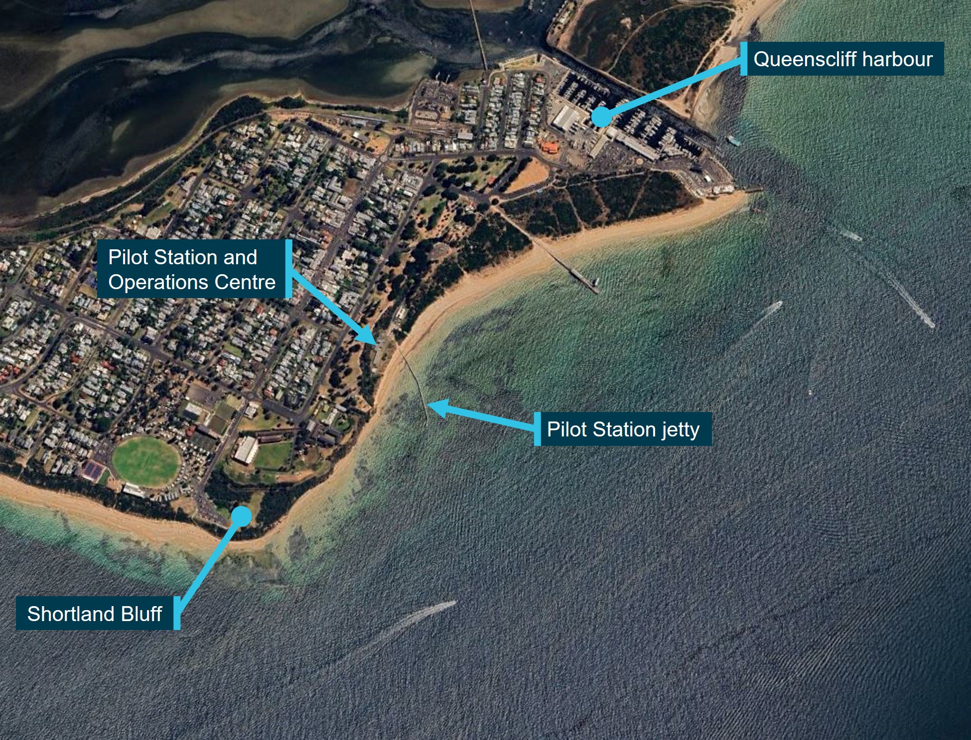
The transfer of pilots to inbound ships, and from outbound ships was managed from its Queenscliff base. Local facilities included launch berths and maintenance workshops at Queenscliff harbour, a Pilot Station incorporating the PPSP Operations Centre, and a jetty for the launch to pick-up and drop-off pilots (Figure 18). The coordination of launch and pilot availability was managed by pilot despatch officers working from the Operations Centre.
Figure 18: Location of PPSP pilot station and jetty in Queenscliff
Obtaining a vessel Certificate of Operations required the launch to have a Safety Management System (SMS) that complied with AMSA Marine Order 504[29] (MO 504). An SMS provides the structures and guidance to support the safe management of a vessel during routine operations and in the case of emergency.
The scope of the developed vessel SMS manual[30] for the pilot launch was consistent with the scope of MO 504 and included sections on:[31]
contact details
risk assessment
owner’s responsibility and authority statement
designated person
coxswain responsibility and authority statement
resources and personnel (including crewing)
procedures for onboard operations
emergency preparedness
follow-up on hazardous occurrences and non-conformance
maintenance of vessel and equipment
documentation
verification, review and evaluation.
The vessel SMS section on procedures for onboard operations referred to the PPSP integrated management system and document QP07.3 Launch Operations.[32]QP07.3 included a wide range of standard operating procedures covering normal operations (including pilot transfer) and emergency scenarios. The manual did not include guidance on voyage planning for transiting Port Phillip Heads, use of navigational equipment[33] or launch resource management (see Safety analysis, Use of available resources).
The detail of a safety management system is scoped based on an assessment of risks for the vessel’s operations. MO 504 specified that procedures for onboard operations be ‘developed for key onboard operations to address any risks identified by the risk assessment’. The concept of reducing risk so far as is reasonably practicable was also established in the marine order.
PPSP had undertaken risk assessment of its launch operations. Launch grounding and associated controls were identified in 2 scenarios:
launch grounding due to severe weather [risk controls included: crew operations procedures].
Coxswain training
Overview
Coxswain selection, training and record keeping was described across a number of documents including the vessel SMS, the Launch Operations procedures manual and a detailed training checklist which also included a trip record table and sign-off.
The coxswain training program involved three stages. The program included a range of topics and skills at each stage, although it did not include supporting course notes or training guidelines. The check-off lists included space to record ‘competent’ or ‘not yet competent’ against each competency. The criteria for assessment of competencies were not detailed.
Progression through each stage of training required sign-off by other coxswains. Documentation was inconsistent and specified sign-off by most, a majority or 3 coxswains between each stage of training. Sign-off by 3 senior coxswains was probably the intention. Final approval included sign‑off by the Managing Director (MD) and the boat repair depot (BRD) manager, and in some documentation the service and compliance manager (SCM).
Basic Training (Stage 1)
In relation to navigating through Port Phillip Heads, the trainee received instruction and was required to demonstrate competency in:
understanding all leading lights for Port Phillip Heads (PPH)
understanding PPH transit in different weather conditions
preliminary PPH transit.
Advanced Training (Stage 2)
This stage involved achieving competencies in technical and practical skills. In relation to launch navigation equipment, the trainee was required to demonstrate competency in:
AIS unit operation
electronic chart operations
radar operations.
Stage 2 training also included the coxswain’s demonstration of practical skills in transiting Port Phillip Heads under a variety of weather and tidal conditions, day and night. A pre‑requisite for progression to Stage 3 required the trainee to be declared competent in transiting Port Phillip Heads.
Advanced Training (Stage 3)
This stage required trainees to conduct launch operation independently under the supervision of the duty coxswain, with a minimum of 20 day transfers and 20 night transfers. On successful completion, the trainee was required to complete at least 30 day transfers as relief Coxswain (unsupervised). Approval by the MD and BRD Manager was required prior to the coxswain being permitted to undertake nightshift duties.
Training documentation suggested that final sign-off was typically by the MD, the BRD manager, the mentor coxswain and 2 other coxswains.
Training records for the coxswain of Corsair
The coxswain’s training logs included entries spanning the period from July 2016 to October 2020. Entries were for training under a range of senior coxswains. Review of log sheets identified records of sign-off by 4 coxswains for progression from Stage 1 to Stage 2, and sign-off by 1 coxswain for progression from Stage 2 to Stage 3. Records were not identified from Stage 3 indicating final sign-off by other coxswains or the BRD manager. Sign-off of the coxswain of Corsair was recorded in MD correspondence in March 2021.
Deckhand training and responsibilities
The position description for deckhands specified that deckhands should have broad practical marine skills with experience working on launches. Although not mandatory, formal marine qualifications were considered an advantage.
Procedures described completion of appropriate on-the-job training and referenced the deckhand induction checklist. The induction training consisted of deckhand familiarisation with routine and emergency vessel procedures, the location and use of emergency equipment, and knowledge of company policies. The deckhand of Corsair had completed the induction.
Deckhand responsibilities included keeping a lookout while the launch was underway. Procedures did not detail any specific involvement in navigation or passage planning with the coxswain.
Local knowledge regulation for vessel operators
Introduction
Safe Transport Victoria (STV) is the Victorian transport safety regulator. Its scope includes some coverage of marine operations on Victorian waters. For several designated Victorian waterways, STV specified requirements for operators of domestic commercial vessels to have STV issued local knowledge certification to complement national maritime qualifications. Local knowledge certification did not apply to vessels requiring a pilot or a pilotage exempt master.
Local knowledge areas relevant to Corsair operations
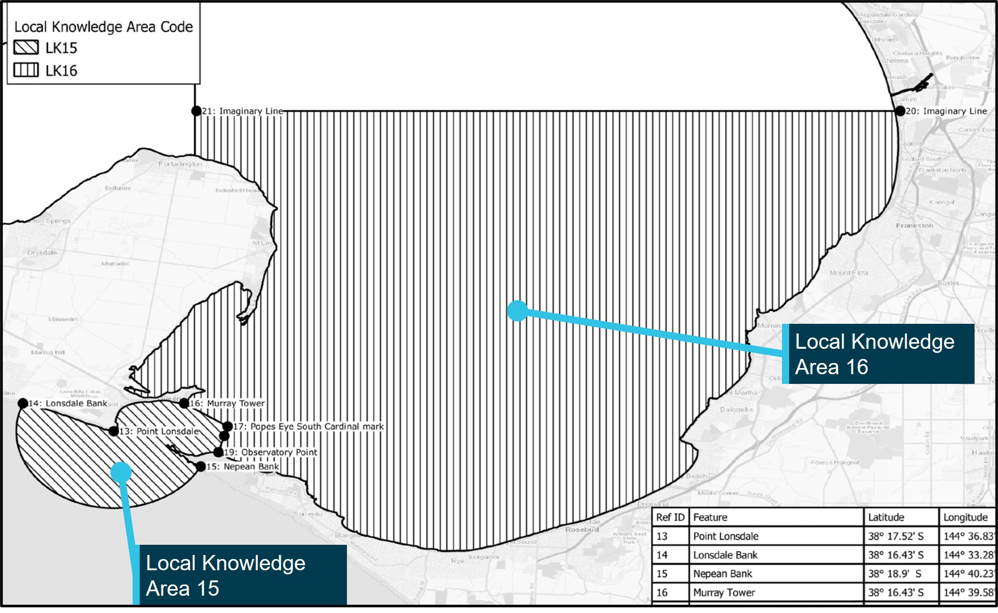
Corsair operated in local knowledge areas 15 (LK15) and 16 (LK16) for its operations between Queenscliff harbour and outside the Heads (Figure 19). LK 15 included the designated hazardous area of Port Phillip Heads and some additional adjoining waters.[34] LK16 extended north from LK15 and was designated Port Phillip Bay South.[35]
Figure 19: Designated local knowledge areas LK15 and LK16
Source: Safe Transport Victoria, annotated by the Office of the Chief Investigator
Certification requirements for masters of vessels in LK16
The master of a trading vessel (passenger and non-passenger) of greater than 12 m in length was required to hold a local knowledge certificate when operating in LK16 waters. This requirement therefore applied to the operation of Corsair and the launch coxswain was suitably certified. Assessment for LK16 did not cover vessel operations and navigation through Port Phillip Heads.[36]
Certification requirements for masters of vessels in LK15
There was no local knowledge certification requirement for masters of non-passenger trading vessels operating in LK15 waters. This differed from LK16 and several other local knowledge areas. Corsair was certified to operate with special personnel only[37] and was therefore a non‑passenger‑carrying vessel. Local knowledge requirements therefore did not apply to the master of Corsair and its coxswain was not required to hold (and did not hold) a certificate of local knowledge when operating Corsair in LK15 waters.
LK15 requirements only applied to masters of passenger-carrying trading vessels of greater than 12 m in length. There was no requirement for local knowledge certification for masters of passenger vessels of 12 m or less.
Training and assessment for a local knowledge certificate for LK15
STV specified the requirements for local knowledge certification for LK15.[38] The candidate was required to complete an approved training course. Marine Training Services (MTS) in Geelong was the (only) trainer accredited by STV for LK15 training. Its course involved theory and practical components which included tidal, weather and sea conditions, vessel handing, emergency procedures and navigation through the entrance. Assessment included written and oral examinations.
Safety analysis
Introduction
On the night of 5 October 2023, the pilot aboard Rio Grande disembarked and transferred to Corsair at a position approximately 2.25 NM (4.2 km) south‑west of Point Lonsdale. Following pilot transfer to the launch, Corsair commenced its return to Queenscliff. On their return, Corsair was navigated to the west of the usual passage through the Heads and grounded on Point Lonsdale Reef.
This analysis discusses:
the circumstances and factors influencing the navigational error
the use of available resources to reduce the likelihood of error
launch safety management system
crew training
local knowledge requirements.
The circumstances and factors influencing the navigational error
Local conditions
The operational parameters on the evening of the grounding were not unusual. However, on this night, pilot retrieval and the starting point for the return journey to the entrance was further west than most recent passages (Figure 20). This westerly position and the need to initially navigate east for an extended duration for a more central approach to the entrance may not have been recognised by the launch coxswain.
Figure 20: Passages of Corsair in last 14 days including on the evening of grounding
Source: Port Phillip Sea Pilots, annotated by the Office of the Chief Investigator
The environmental conditions on the evening of the grounding were also not unusual. However, the prevailing winds, seas and opposing ebb tide led to rough conditions which may have influenced the crew’s view towards the navigational aids located on Shortland Bluff.
The error in navigation
The coxswain’s intention was to initially head towards the entrance until they picked up the lead for the western limit of the Outer West Channel (the white High Light over the Hume Tower occulting red light), then slowly alter course to port for an approach within the small craft channels. The coxswain indicated that their intention was to use the four fingers west approach.
The coxswain reported observing a red light below the High Light. It is probable that the coxswain believed themselves to be near the lead for the Outer West Channel during this phase of the approach and altered their course by about 18° to port in this belief. However, the red light of their focus was very likely to have been the red sector isophase light of the Fort West Beacon rather than the Hume Tower occulting red light. It is possible that the rough seas may have affected the coxswain’s observation of lights from the navigational aids on Shortland Bluff.
Retrieval and return of the pilot to Queenscliff was a routine activity that had been performed by the crew of the Corsair many times and in a range of environmental conditions. Repetitive experience can induce a sense of routine, safety, and normality in an otherwise risky environment (Schager 2008). A sense of routine and complacency probably influenced the coxswain’s state of mind, their reliance on visual cues for navigation and their limited use of the available navigation equipment. Schager (2008) describes that:
Complacency is a passive state, not an active one, and no one chooses to be complacent. It creeps into one’s mind imperceptibly. Individuals are therefore unaware of being complacent and would, if asked, reassuringly deny it. Instead, individuals would probably justify their state of mind as rational, realistic, reasonable and in line with situational requirements, as well as a sign of experience.
The coxswain’s misinterpretation of the navigational aid light was probably influenced by expectation and confirmation bias. Grech et al (2008) describes the role of expectation bias in our perception system:
Our senses – seeing, hearing and feeling – constantly give us inputs. These inputs are processed in our perceptual system. The perceptual system has, just like our senses, certain limitations and weaknesses. The fundamental function of the system is to process sensory inputs on the basis of our experience, motivations, and knowledge. This mechanism is very useful because it gives us the ability to perceive more with increasing knowledge and experience. But it also has some important drawbacks: humans suffer from what is called expectation bias. This means that if we expect to recognize a certain object we will do so even if the object has changed and, perhaps, even if it is missing.
Grech et al (2008) also describes the role of confirmation bias:
Confirmation bias is when we perceive only the information that can confirm our assumption and discard any information falsifying that assumption. Confirmation bias can be a serious threat to safety when the assumption is that a vessel is right on track and everything is working well. Important danger signals are neglected simply because they do not fit with the assumption, and observations confirming the assumption will be overemphasized.
The coxswain probably believed they were on a routine and more central approach to the entrance. For such an approach, they would expect to see the white High Light over the red Hume Tower Light to mark the western edge of the Outer West Channel. This experience probably influenced their interpretation of the observed white over red lights (expectation bias) and them not perceiving the isophase characteristics of the Fort West Beacon red light (confirmation bias).
There was no evidence identified to suggest that fatigue or distraction influenced or contributed to the navigational error.
Contributing factor
The launch coxswain misinterpreted navigational aids marking the entry to Port Phillip and navigated to the west of safe passage through the entrance. The coxswain had transited the Heads many times and their perceptions were probably influenced by the expectations of what they would normally observe.
Use of available resources
Introduction
The likelihood of human error can be reduced by using protective systems of technology, crew, and procedure. The documented study and application of resource management to protect against human error was explored in the aviation sector as cockpit (and then crew) resource management (CRM). Available resources for effective CRM included information, equipment and people. The aim of these studies was to reduce human error and improve safety through an understanding of human capabilities, human limitations and the way people interact with their work environment and other people.
Such resource management in maritime transport is referred to as Bridge Resource Management (BRM). BRM in a ship context can be defined as the effective management and utilisation of all resources, human and technical, available to the bridge team to ensure the safe completion of the vessel’s voyage.[39] BRM provides a method of organising the best use of these resources to reduce the level of operational risk. It establishes defences against single-person errors. Although much of the maritime literature refers to ship applications, the principle of using all available resources including information, equipment and people is valid for vessels of any size.
Navigation equipment
Active use of navigation equipment to mitigate the risk of human error
The chart plotter was set to a 6 NM range and the heading vector length set to 10 minutes. This setting provided the coxswain with an estimate of the vessel’s course over the next 3.5 NM (with a speed of 21 knots) to 4 NM (with a speed of 24 knots).
The radar display was also set to a 6 NM range. The radar heading marker extending from the centre of the plot (the vessel’s position) to the edge of the screen would indicate the likely path of the vessel over the next 6 NM.
When on a heading of 070° on their return, Corsair was about 1.25 NM (2.3 km) from Point Lonsdale and on a course to clear the reef. A slow course alteration to port subsequently placed Corsair on a heading towards the reef. It is probable that the coxswain did not effectively observe the navigation displays during or after completion of the alteration of course and instead relied on their visual observations of navigational aids at Shortland Bluff.
Contributing factor
The launch coxswain relied on their visual observations of navigational aids and did not make effective use of available on-board navigational equipment for the return of Corsair through the entrance to Port Phillip.
Configuration of navigational equipment
Equipment is considered part of the bridge team (Norris 2014). The way in which users interact with the equipment is known as the human machine interface (HMI). The HMI covers such things as displays, menus, switches, controls and audio signals.
The equipment on Corsair had additional capabilities that may have assisted navigation through the Heads. The following are examples:
Way points and no-go zones could be stored and displayed on the chart plotter. A single waypoint could be used to mark a safe point in the entrance, and stored no-go zones could demarcate unsafe areas.
The variable range marker (VRM) on the radar or chart plotter could be used to define a preset range for clearance between Corsair and a point such as Point Lonsdale.
Other finding
The navigation equipment on Corsair had additional (unused) features that could assist launch navigation through Port Phillip Heads.
The deckhand as a resource
Resource management to reduce the risk of human error encompasses the utilisation of other crew members, in this case the deckhand. Although the role of the deckhand included acting as a lookout, it was probably not normal practice for launch deckhands to be actively involved in passage planning and navigation. In addition, the layout of the navigational displays did not provide for easy monitoring by the deckhand.
Other factor that increased risk
It was probably not normal practice for launch deckhands to actively support launch navigation. In addition, the layout of navigation displays on Corsair did not allow for easy referral by the deckhand.
Launch safety management system
An effective safety management system (SMS) includes operational guidance to manage identified risks. Port Phillip Sea Pilots (PPSP) had established an SMS and launch operations procedures for their pilot launches. However, risk assessments did not clearly identify the potential hazard of coxswain navigational error when transiting the Heads and procedural risk controls did not include:
guidance on the safe navigation of Port Phillip Heads including the use of small craft channels
instruction and guidance on the effective use of launch navigational equipment to reduce the likelihood of navigational error
guidance on the role of the launch deckhand in supporting safe navigation.
Other factor that increased risk
The safety management system for Corsair did not include detailed guidance and reference material for the safe navigation of Port Phillip Heads, the effective use of launch navigational equipment and the role of the launch deckhand in supporting safe navigation. (Safety issue)
Coxswain training
Launch coxswain training involved a 3-stage program. Training was delivered on-the-job by senior coxswains following a checklist of required technical and practical skills. Although transiting Port Phillip Heads was a central part of coxswain training, training scope in passage planning and the effective use of launch resources to reduce the likelihood of errors was not clearly documented. The absence of formal course materials and assessment criteria increased the potential for inconsistency in training delivery and outcomes in the adoption of standard operating procedures for navigating Port Phillip Heads. In addition, the training program did not include a refresher component for navigational practices.
For the coxswain of Corsair, there were gaps in records for the staged sign-off of the coxswain during training. In the absence of other documented training assessment criteria and records, the procedural requirements for sign-off by senior coxswains was an important part of the assurance process.
Other factor that increased risk
Documentation supporting the training and competency assessment of launch coxswains was limited in detail and training records were incomplete. (Safety issue)
Local knowledge requirements for Port Phillip Heads
Small commercial non-passenger-carrying operations
The coxswain of Corsair was not required to hold a Safe Transport Victoria (STV) issued local knowledge certificate for operations in Port Phillip Heads and did not hold such a certificate. Given the extensive experience of the coxswain in these waters, the absence of this certification is not considered to have influenced this occurrence. However, aspects of the regulatory framework were inconsistent, suggesting opportunities for further review by STV.
In the majority of gazetted local knowledge areas, a certificate of local knowledge was required for non-passenger-carrying trading vessels over 12 m in length. However, in the local knowledge area of Port Phillip Heads, masters of non-passenger-carrying vessels were not required to hold a certificate of local knowledge.
Other finding
Regulation did not require local knowledge certification of masters of non-passenger domestic commercial vessels (DCV) operating in the high-risk area of Port Phillip Heads. This differed from the remainder of Port Phillip for which local knowledge certification was required for masters of non-passenger-carrying DCV with a length of greater than 12 m. There was an opportunity for Safe Transport Victoria to review the requirement for Port Phillip Heads.
Passenger-carrying operations
Local knowledge certification was required for passenger-carrying trading vessels over 12 m in length operating in Port Phillip Heads. This regulatory requirement was in recognition of the heightened risks associated with the designated hazardous area of Port Phillip Heads.[40] Passenger-carrying vessels of 12 m and below were not required to hold such certification.
Small passenger vessels are exposed to significant safety risks when operating in these waters. Considering also the capsize of a 10.5 m commercial fishing charter vessel and resulting passenger fatality in 2010, there was an opportunity to further consider local knowledge certification requirements for passenger‑carrying commercial vessels below the current length threshold.[41]
Other finding
Regulation did not require local knowledge certification of masters of passenger-carrying domestic commercial vessels (DCV) of 12 m and below operating in the high-risk area of Port Phillip Heads. There was an opportunity for Safe Transport Victoria to review this requirement given the risks associated with smaller passenger-carrying vessels and a previous fatal incident of an under 12 m passenger‑carrying DCV in this area.
Findings
ATSB investigation report findings focus on safety factors (that is, events and conditions that increase risk). Safety factors include ‘contributing factors’ and ‘other factors that increased risk’ (that is, factors that did not meet the definition of a contributing factor for this occurrence but were still considered important to include in the report for the purpose of increasing awareness and enhancing safety). In addition, ‘other findings’ may be included to provide important information about topics other than safety factors.
Safety issues are highlighted in bold to emphasise their importance. A safety issue is a safety factor that (a) can reasonably be regarded as having the potential to adversely affect the safety of future operations, and (b) is a characteristic of an organisation or a system, rather than a characteristic of a specific individual, or characteristic of an operating environment at a specific point in time.
These findings should not be read as apportioning blame or liability to any organisation or individual.
The following findings are made with respect to the grounding of pilot launch PV Corsair at Port Phillip Heads (near Point Lonsdale), Victoria on 5 October 2023.
Contributing factors
The launch coxswain misinterpreted navigational aids marking the entry to Port Phillip and navigated to the west of safe passage through the entrance. The coxswain had transited the Heads many times and their perceptions were probably influenced by the expectations of what they would normally observe.
The launch coxswain relied on their visual observations of navigational aids and did not make effective use of available on-board navigational equipment for the return of Corsair through the entrance to Port Phillip.
Other factors that increased risk
It was probably not normal practice for launch deckhands to actively support launch navigation. In addition, the layout of navigation displays on Corsair did not allow for easy referral by the deckhand.
The safety management system for Corsair did not include detailed guidance and reference material for the safe navigation of Port Phillip Heads, the effective use of launch navigational equipment and the role of the launch deckhand in supporting safe navigation. (Safety issue)
Documentation supporting the training and competency assessment of launch coxswains was limited in detail and training records were incomplete. (Safety issue)
Other findings
The navigation equipment on Corsair had additional (unused) features that could assist launch navigation through Port Phillip Heads.
Regulation did not require local knowledge certification of masters of non‑passenger‑carrying domestic commercial vessels (DCV) operating in the high-risk area of Port Phillip Heads. This differed from the remainder of Port Phillip for which local knowledge certification was required for masters of non-passenger‑carrying DCV with a length of greater than 12 m. There was an opportunity for Safe Transport Victoria to review the requirement for Port Phillip Heads.
Regulation did not require local knowledge certification of masters of passenger‑carrying domestic commercial vessels (DCV) of 12 m and below operating in the high-risk area of Port Phillip Heads. There was an opportunity for Safe Transport Victoria to review this requirement given the risks associated with smaller passenger‑carrying vessels and a previous fatal incident of an under 12 m passenger-carrying DCV in this area.
Safety issues and actions
Central to the ATSB’s investigation of transport safety matters is the early identification of safety issues. The ATSB expects relevant organisations will address all safety issues an investigation identifies.
Depending on the level of risk of a safety issue, the extent of corrective action taken by the relevant organisation(s), or the desirability of directing a broad safety message to the Marine industry, the ATSB may issue a formal safety recommendation or safety advisory notice as part of the final report.
Directly involved parties were provided with a draft report and invited to provide submissions. As part of that process, each organisation was asked to communicate what safety actions they had carried out or were planning to carry out in relation to each safety issue relevant to their organisation.
The initial public version of these safety issues and actions are provided separately on the ATSB website, to facilitate monitoring by interested parties. Where relevant, the safety issues and actions will be updated on the ATSB website as further information about safety action comes to hand.
Safety issue description: The safety management system for Corsair did not include detailed guidance and reference material for the safe navigation of Port Phillip Heads, the effective use of launch navigational equipment and the role of the launch deckhand in supporting safe navigation.
Safety issue description: Documentation supporting the training and competency assessment of launch coxswains was limited in detail and training records were incomplete.
Safety action not associated with an identified safety issue
The ATSB has been advised of the following additional safety actions not directly associated with the listed safety issues.
Additional safety action taken by Port Phillip Sea Pilots
Port Phillip Sea Pilots has made significant upgrades to launch navigational equipment. New display set-up includes the establishment of ‘no-go’ areas and guard zones. The replacement vessel for PV Corsair has also been configured with the deckhand located on the port side and with access to the electronic chart screen.
Safety actions taken by Safe Transport Victoria
Safe Transport Victoria has advised that it will commence a review of local knowledge certification requirements in 2025.
Glossary
AIS
Automatic identification system
AMSA
Australian Maritime Safety Authority
ARPA
Automatic radar plotting aid
ATSB
Australian Transport Safety Bureau
BRD
Boat repair depot
BRM
Bridge resource management
CCTV
Closed-circuit television
GPS
Global positioning system
HMI
Human-machine interface
LK
Local knowledge
MD
Managing director
MV
Motor Vessel
NC
Near Coastal
NSCV
National Standard for Commercial Vessels
OCI
Office of the Chief Investigator
PPH
Port Phillip Heads
PPSP
Port Phillip Sea Pilots
PV
Pilot vessel
SAR
Search and rescue
SCM
Service and compliance manager
SMS
Safety management system
STV
Safe Transport Victoria
VHF
Very high frequency
VRM
Variable range marker
VTS
Vessel Traffic Services
Sources and submissions
Sources of information
The sources of information during the investigation included:
the occupants of PV Corsair
Port Phillip Sea Pilots
Ports Victoria
the Australian Volunteer Coast Guard (Queenscliff)
the Australian Maritime Safety Authority
Safe Transport Victoria
Emergency Management Victoria
Marine Training Services
References
Grech MR, Horberry TJ and Koester T (2008) Human Factors in the Maritime Domain, CRC Press, Taylor & Francis Group.
Norris A (2014) ‘Making equipment a part of the team’, The Navigator, The Nautical Institute and Royal Institute of Navigation, 10-2014:10.
Schager B (2008) Human Error in the Maritime Industry – How to understand, detect and cope. Marine Profile, Sweden.
Submissions
Under section 26 of the Transport Safety Investigation Act 2003, the ATSB may provide a draft report, on a confidential basis, to any person whom the ATSB considers appropriate. That section allows a person receiving a draft report to make submissions to the ATSB about the draft report.
A confidential copy of the draft report was provided to involved parties and agencies. The submissions were reviewed and, where considered appropriate, the text of the report was amended accordingly.
Purpose of safety investigations
The objective of a safety investigation is to enhance transport safety. This is done through:
identifying safety issues and facilitating safety action to address those issues
providing information about occurrences and their associated safety factors to facilitate learning within the transport industry.
It is not a function of the ATSB to apportion blame or provide a means for determining liability. At the same time, an investigation report must include factual material of sufficient weight to support the analysis and findings. At all times the ATSB endeavours to balance the use of material that could imply adverse comment with the need to properly explain what happened, and why, in a fair and unbiased manner. The ATSB does not investigate for the purpose of taking administrative, regulatory or criminal action.
Rail safety investigations in Victoria
Most transport safety investigations into rail accidents and incidents in Victoria and New South Wales (NSW) are conducted in accordance with the Collaboration Agreement for Rail Safety Investigations and Other Matters between the Commonwealth Government of Australia, the State Government of Victoria and the State Government of New South Wales. Under the Collaboration Agreement, rail safety investigations are conducted and resourced in Victoria by the Chief Investigator, Transport Safety (OCI) and in New South Wales by the Office of Transport Safety Investigations (OTSI), on behalf of the ATSB, under the provisions of the Transport Safety Investigation Act 2003.
The Chief Investigator, Transport Safety(OCI) is a statutory position established in 2006 to conduct independent, no-blame investigation of transport safety matters in Victoria. OCI has a broad safety remit that includes the investigation of rail (including tram), marine and bus incidents.
Terminology
An explanation of terminology used in ATSB investigation reports is available here. This includes terms such as occurrence, contributing factor, other factor that increased risk, and safety issue.
Publishing information
Released in accordance with section 25 of the Transport Safety Investigation Act 2003
Ownership of intellectual property rights in this publication
Unless otherwise noted, copyright (and any other intellectual property rights, if any) in this report publication is owned by the Commonwealth of Australia.
Creative Commons licence
With the exception of the Commonwealth Coat of Arms, ATSB logo, and photos and graphics in which a third party holds copyright, this report is licensed under a Creative Commons Attribution 4.0 International licence.
The CC BY 4.0 licence enables you to distribute, remix, adapt, and build upon our material in any medium or format, so long as attribution is given to the Australian Transport Safety Bureau.
Copyright in material obtained from other agencies, private individuals or organisations, belongs to those agencies, individuals or organisations. Where you wish to use their material, you will need to contact them directly.
[1]Consistent with the operator’s terminology, the master of PV Corsair is referred to in this report as its coxswain. This is not a reference to the qualification requirements (see Crew of Corsair).
[2]The ‘entrance’ to Port Phillip is demarcated by an imaginary line drawn between Point Lonsdale and Point Nepean.
[6]Moonrise was later that night at 0213 (Bureau of Meteorology).
[7]Reported by Melbourne VTS. This measure is a defined way of reporting the influence of atmospheric conditions.
[8]Four fingers west is a line of approach sometimes used by smaller craft. It is located west of the shipping channels (see Navigation through Port Phillip Heads).
[9]VTS reported an ebb tide of 2.1 knots and height of tide of 1.55 m at 0146.
[12]The wave buoy recording wave heights outside the Heads was located about 3.5 NM south-east of the entrance and so was probably not representative of localised seas. That wave buoy recorded a significant wave height of about 2.4 m.
[13]Point Lonsdale lighthouse displays sectored white/red/green lights, each light displaying 2 long flashes every 15s. The white sector is visible up to 12 NM and the red and green sectors are visible up to 10 NM.
[14] Occulting lights have a longerperiod of light than darkness.
[15] Isophase lights have an equal period of light and darkness.
[16]The western edge of the small craft channel white sector was about 55 m from Yellowtail Rock.
[17]Parks Victoria also had waterway management responsibilities for Port Phillip. There was no Parks Victoria role identified which was relevant to this occurrence.
[18]Specified in Harbour Master’s Directions for the designated waters of the Port of Melbourne.
[19]Bureau Veritas is a ship classification organisation to certify that the construction of a vessel complied with relevant standards and to carry out regular surveys in service to ensure continuing compliance with the standards.
[20]The National Standard for Commercial Vessels (NSCV) applied to domestic commercial vessels.
[21]A trading vessel engaged in restricted offshore operations.
[22]Special personnel included persons who were not passengers or members of the crew and who were carried on board in connection with the special purpose of that vessel. A pilot meets the definition of a special personnel.
[23]AIS is a maritime communications device that uses the very high frequency (VHF) radio broadcasting system to transfer identity, positional and navigational data.
[24]A waypoint is a point of reference marked on a chart that can be used for location and navigation.
[25]VRM is an electronic range ring circle that can be expanded or contracted to measure the range to a target.
[26]The purpose of a guard zone is to provide audible and visual warnings of any target that came within a pre-determined distance or sector from the vessel.
[27]Clutter is the unwanted echoes returned of sea waves and rain drops that tends to clutter up the radar screen.
[28]The medical declaration and certification was in accordance PPSP internal guidelines.
[29]Marine Order 504 (Certificates of operation and operation requirements – national law) 2018 made under the Marine Safety (Domestic Commercial Vessel) National Law Act 2012.
[30]PPSP Vessel Safety Management System Version 1, Revision 1.0 (1 January 2022).
[31]Under AMSA’s SMS approval process, Corsair’s operations were categorised as low risk. Consistent with AMSA processes for this risk category, AMSA review of the launch SMS was limited to confirming that the SMS was scoped in accordance with the requirements of MO 504.
[33]Except to ensure that the radar was operational in heavy weather and poor visibility.
[34]Port Phillip Heads was defined in regulation as the waters between a line drawn between Shortland Bluff and Point Nepean, and the seaward limits of arc of a circle with a radius of 3 NM miles centred on Point Lonsdale. LK15 included an additional area inside the bay to the east of the Port Phillip Heads defined area. In certain conditions, this additional area was prone to rough conditions.
[35]The demarcation between LK15 and LK16 was indicated by an imaginary line drawn from Murray Tower to Popes Eye South Cardinal mark and thence through the Entrance Beacon North Cardinal mark to Observatory Point
[36]Assessment of applicants for a local knowledge certificate for LK16 was conducted for STV by Ports Victoria.
[38]Local Knowledge Certificate: Determination for Masters of Domestic Commercial Vessels
[39]Focus on Bridge Resource Management. Washington State Department of Ecology, 2007.
[40]Section 5 Definitions of Marine Safety Regulations 2023 S.R. No 36/2023.
[41]Office of the Chief Investigator Marine Safety Investigation Report No 2010/14 Capsize of Vessel ‘The Ultimate’ off Point Nepean 12 December 2010
Preliminary report
Report release date: 22/12/2023
This investigation is being conducted under the Transport Safety Investigation Act 2003 by Victoria’s Chief Investigator, Transport Safety under an agreement with the Chief Commissioner of the Australian Transport Safety Bureau. This preliminary report details factual information established in the investigation’s early evidence collection phase and has been prepared to provide timely information to the industry and public. Preliminary reports contain no analysis or findings, which will be detailed in the investigation’s final report. The information contained in this preliminary report is released in accordance with section 25 of the Transport Safety Investigation Act 2003.
The occurrence
Prior to the incident
At about 1900 local time on 5 October 2023, the night shift crew (the coxswain[1] and deckhand) of the pilot launch PV Corsair reported on duty at the launch wharf in Queenscliff harbour. They were informed by the pilot despatch office that their first job that evening was to pick up the pilot from the outbound container ship MV Rio Grande. After preparing the launch for service, they waited in the crew quarters at the launch station.
Later that evening, Rio Grande departed Melbourne with a pilot on board. It would transit Port Phillip before departing through Port Phillip Heads (the Heads).[2] Once the ship was clear of the entrance,[3] the pilot would disembark onto the pilot launch and be transported back to the pilot station at Queenscliff.
At about 2230, the pilot called the launch crew and advised them that Rio Grande was expected to be at the Heads at about 2300. The coxswain of Corsair reported the weather conditions to the pilot and advised that they would rendezvous with Rio Grande about 2 nautical miles (NM) [4] offshore and to the south-west of the entrance, in relatively calmer water away from the main ebb tide. It was agreed that Rio Grande would create a lee on its starboard side for the launch to come alongside to retrieve the pilot.
The grounding
At about 2252, Corsair met Rio Grande just inside the entrance as they proceeded outbound. At that time there was a strong ebb tide of about 5.6 knots[5] and the height of tide was about 0.6 m above the charted depth. The wind was from the south-south-west direction at an average speed of 22 knots with gusts of up to 26 knots.[6] The recorded wave height outside the Heads was about 2.4 m.[7]
Soon after passing Point Lonsdale, Rio Grande altered its course to starboard, to keep the wind and the sea on its port side, creating a lee on the starboard side to allow the pilot launch to come alongside.
At about 2306, the pilot disembarked into the pilot launch and soon after, from a position about 2.3 NM south-west of Point Lonsdale, Corsair commenced heading back to the entrance on a course of about 070º[8] and at a speed of about 24 knots (Figure 1).[9]
Figure 1: The track of PV Corsair for pilot transfer from Rio Grande
The figure also shows the tracks of PV Corsair through the Heads on its previous trip.
Source: Ports Victoria with annotations by the Office of the Chief Investigator
At about 2310, Corsair was about 1.4 NM south-west from Point Lonsdale when it commenced a slow alteration in course to port. At about 2312, when about 205º and 0.54 NM from Point Lonsdale, the launch steadied on a course of about 051º and its speed was still about 24 knots.
At about 2313 Corsair entered the shallow water surrounding the reef and ran aground. The launch came to rest in a rock pool about 500 m from Point Lonsdale.
Following the grounding
Several calls were made from Corsair seeking assistance, the first by mobile phone to the crew of the sister launch, PV Nepean. A Mayday distress broadcast was subsequently transmitted from Corsair on VHF radio. The distress call was heard by Ports Victoria Vessel Traffic Services (VTS) which contacted the Victoria Police Search and Rescue Squad. Victoria Police then activated the Australian Volunteer Coast Guard at Queenscliff, the Southern Peninsula Rescue Squad at Blairgowrie, and its own rescue response team. Several vessels responded to the emergency and the three occupants of Corsair were subsequently brought aboard the Coast Guard vessel at about 0132 on 6 October. They were uninjured.
The pilot launch was destroyed on the reef during the night and the debris recovered the following day.
Context
Location
Port Phillip Heads
Port Phillip Heads, also known as The Heads or The Rip, is a narrow waterway that connects Port Phillip to Bass Strait and is the only access for ships visiting the ports of Melbourne and Geelong (Figure 2).
Figure 2: Port Phillip Heads and entrance channels
There are five designated channels for larger ships to use when transiting the Heads. From east to west, they are Outer Eastern Channel (10.1 m depth), Eastern Ship Channel (11.9 m), Great Ship Channel (17.0 m), Western Ship Channel (11.4 m), and Outer Western Channel (10.3 m). At the entrance to Port Philip, the combined width of these shipping channels is about 740 m and the western edge of the Outer Western Channel is about 1480 m from Point Lonsdale.
West of the Outer West Channel lies the Small Craft Channel, which was used by smaller boats, fishing vessels and the pilot launches. The channel ran between Yellowtail Rock and Lonsdale Rock (Figure 2).[10] The defined western edge of the channel was about 50 m off Yellowtail rock. The width of the channel at that section was about 300 m and its depth between 5 and 10 m.
Point Lonsdale Reef
Point Lonsdale Reef is an outcrop of flat-topped rocks extending up to about 540 m south-east of Point Lonsdale (Figure 3). The extent of the reef’s exposure and its visibility varies with tide and sea conditions.
Figure 3: Point Lonsdale Reef
Point Lonsdale Reef photographed from Point Lonsdale the day after the grounding.
Source: Elstone Diving Services Pty Ltd
Locations for pilot transfer
The designated pilot boarding ground was 5 NM south-west of the entrance however pilots could disembark outbound ships between 2 and 5 NM to seaward of the entrance. Pilots usually boarded inbound ships between 5 and 8 NM from the entrance.
Port Phillip Sea Pilots
Corsair was owned and operated by Port Phillip Sea Pilots (PPSP). The company was established in Victoria in June 1839 and was licensed to provide pilotage services in the Victorian ports of Melbourne, Geelong, Hastings and Corner Inlet and it also provided relief pilots to the Port of Portland pilotage service. PPSP had 24 active pilots.
The pilot despatch office (pilot station) was located in Queenscliff. The organisation had two dedicated pilot launches (PVCorsair and PV Nepean) stationed at Queenscliff for the transfer of pilots to/from the pilot boarding grounds outside the entrance.
PV Corsair
The pilot launch Corsair was a dedicated pilot transfer vessel of monohull design constructed in 2014 by Hart Marine in Mornington, Victoria (Figure 4). It had an overall length of 18.55 m, breadth of 5.5 m, depth of 2.3 m and a loaded draught of about 1.55 m. Propulsion was by two Cummins QSK 19-M marine diesel engines of 597 kW at 2100 rpm, each driving a fixed pitch propellor. The launch had a maximum speed of about 30 knots.
Figure 4: PV Nepean, the sister vessel of PV Corsair
Source: Office of the Chief Investigator
The launch was used primarily for pilot transfers, transporting pilots to/from the PPSP pilot despatch station at Queenscliff. It was occasionally engaged in relief work at the other pilotage areas within Port Phillip and Westernport.
PV Corsair was registered with the Australian Maritime Safety Authority (AMSA) as a domestic commercial vessel (DCV). At the time of the incident, it had a Certificate of Survey issued on 6 October 2020 valid until 28 May 2025 and a Certificate of Operations valid until 2 September 2024. The certificates permitted Corsair to operate as a pilot vessel, with a total crew of two and carrying up to 6 special personnel.[11] The crew on board at the time of the incident were appropriately qualified to operate Corsair.
The launch was fitted with a central navigational console with two navigation screens, one on each side of the conning position (Figure 5). The screen to the right of the conning position was set to display the electronic charting system and the screen to the left had the radar display. The depth sounder was connected to the charting display. All navigational equipment was reported to be operational at the time of the incident.
Figure 5: PV Corsair navigation equipment demonstrated on PV Nepean
Source: Office of the Chief Investigator
Further investigation
To date, the ATSB has:
interviewed relevant personnel including the crew of the pilot launch
conducted relevant vessel inspections
examined recordings of the pilot launch track on this and previous transits of the Heads
reviewed recordings of relevant communications
The investigation is continuing and will include further examination of:
the operation of the pilot launch including bridge resource management
relevant safety management systems
vessel data recordings
Should a critical safety issue be identified during the course of the investigation, the ATSB will immediately notify relevant parties so appropriate and timely safety action can be taken.
A final report will be released at the conclusion of the investigation.
Purpose of safety investigations
The objective of a safety investigation is to enhance transport safety. This is done through:
identifying safety issues and facilitating safety action to address those issues
providing information about occurrences and their associated safety factors to facilitate learning within the transport industry.
It is not a function of the ATSB to apportion blame or provide a means for determining liability. At the same time, an investigation report must include factual material of sufficient weight to support the analysis and findings. At all times the ATSB endeavours to balance the use of material that could imply adverse comment with the need to properly explain what happened, and why, in a fair and unbiased manner. The ATSB does not investigate for the purpose of taking administrative, regulatory or criminal action.
Terminology
An explanation of terminology used in ATSB investigation reports is available here. This includes terms such as occurrence, contributing factor, other factor that increased risk, and safety issue.
Publishing information
Released in accordance with section 25 of the Transport Safety Investigation Act 2003
Ownership of intellectual property rights in this publication
Unless otherwise noted, copyright (and any other intellectual property rights, if any) in this report publication is owned by the Commonwealth of Australia.
Creative Commons licence
With the exception of the Coat of Arms, ATSB logo, and photos and graphics in which a third party holds copyright, this publication is licensed under a Creative Commons Attribution 3.0 Australia licence.
Creative Commons Attribution 3.0 Australia Licence is a standard form licence agreement that allows you to copy, distribute, transmit and adapt this publication provided that you attribute the work.
The ATSB’s preference is that you attribute this publication (and any material sourced from it) using the following wording: Source: Australian Transport Safety Bureau
Copyright in material obtained from other agencies, private individuals or organisations, belongs to those agencies, individuals or organisations. Where you wish to use their material, you will need to contact them directly.
[1] Consistent with the operator’s terminology, the master of Corsair is referred to in this report as its coxswain.
[2] Port Phillip Heads is defined as the waters between an imaginary line drawn between Shortland Bluff and Point Nepean, and the seaward limits of an imaginary line consisting the arc of a circle with a radius of 3 nautical miles centred on Point Lonsdale.
[3] The ‘entrance’ to Port Phillip is demarcated by an imaginary line drawn between Point Lonsdale and Point Nepean.
[7] Significant wave height recorded by a wave buoy located about 3.5 NM south-east of the entrance.
[8] All bearings and course headings are measured clockwise from the True north (000º).
[9] The passage of PV Corsair was recorded by Melbourne Vessel Traffic Services (VTS).
[10] These rocks were not exposed features and were well below the low water mark. The charted depth at Lonsdale Rock was 6.1 m and the depth at Yellowtail Rock 1.7 m.
[11] “Special personnel” means all persons who are not passengers or members of the crew or children of under one year of age and who are carried on board in connection with the special purpose of that ship or because of special work being carried out aboard that ship.
Flight path design should minimise the potential for conflict and the need for interventions, an ATSB investigation into a close proximity event at Sydney Airport highlights.
The investigation report details that in the early evening of 5 August 2019, a Qantas Boeing 737 was on approach to land on Sydney Airport’s runway 34 right, while a Qantas A330 was awaiting a clearance to line up and take off from the same runway.
After a Dash 8 which had just landed had taxied off the runway, the aerodrome controller in the Sydney air traffic control tower – a qualified controller under training for the aerodrome controller role under the supervision of an instructor – issued the A330 with a clearance for an immediate take-off.
The A330 flight crew complied with the take-off instruction, but the controller, assessing that there could be insufficient runway separation between the departing A330 and the landing 737, then instructed the 737 to go around.
The 737 flight crew initiated the go around by climbing on the runway heading, but did not make a right turn when climbing through 600 ft as required by the missed approach procedure.
About 10 seconds later, the controller instructed the 737 to turn.
Meanwhile, as cleared, the A330 followed the standard instrument departure track by turning right shortly after take-off.
The two flight paths began to converge, with both aircraft turning right and climbing, and the A330 flight crew received a traffic alert from the onboard traffic collision advisory system (TCAS). Shortly after, the A330’s first officer sighted the 737 behind and to the right in a climbing turn.
“The aircraft came into close proximity, with separation between the aircraft reduced to about 0.42 NM (or 800 m) laterally and about 508 ft (or 150 m) vertically,” said ATSB Chief Commissioner Angus Mitchell.
“Nevertheless, the controllers maintained sight of both aircraft throughout the sequence and the risk of a collision was low.”
The ATSB’s investigation found that the close proximity incident was the culmination of a series of events that, individually, would only be minor concerns, but collectively resulted in a significant incident.
That series of events included:
Reduced spacing between arriving aircraft without coordination between controllers;
The 737’s speed during some of the final approach was higher than allowed without the flight crew advising the controller;
The controller's and instructor’s mental models of the developing traffic situation did not fully account for the effects of the 737’s delayed and relatively wide turn, and they expected the A330’s flight path to be further from the 737;
No safety alert or avoiding action advice was given to either flight crew to notify them of their proximity and increase their situational awareness;
The controller did not modify the A330’s flight path, which would have increased the distance between the aircraft;
And, mindful that the trainee controller was (at this stage of their training) meant to be demonstrating the ability to work without intervention, the instructor did not provide effective prompts or intervene.
“The ATSB found that because the respective departure and missed approach procedures both involved climbing from a low level and heading to the east, controller intervention was needed to maintain separation,” said Mr Mitchell.
“In addition, controllers at Sydney did not have procedural controls to draw upon to separate aircraft in this type of situation when it occurred at low altitudes and at night.”
The ATSB identified three safety issues relating to the procedures and controller training, as well as another safety issue relating to the use of operational risk assessments for specific scenarios.
In addressing these issues, in 2020 Airservices redesigned the missed approach procedure for Sydney Airport’s runway 34 right to improve separation with other aircraft departing on a standard departure track from the same runway.
During the investigation Airservices also added compromised separation scenarios involving aircraft at low altitudes at night to the Sydney tower controller instructor guide, while in 2023 Airservices advised that the training program also now included a missed approach with a preceding departure in instrument meteorological conditions.
Qantas, meanwhile, updated the missed approach coding in its 737 flight management computers, incorporated related scenarios into cyclic training sessions, and updated its flight data analysis program to more closely monitor approach speeds and traffic collision avoidance system data.
“In this occurrence, a series of individual errors and decisions made by flight crews and controllers gradually reduced margins to a point where the two aircraft came within close proximity.” Mr Mitchell concluded.
“Although events like this are uncommon, systems should be designed to minimise the likelihood of a more serious outcome.”
On 6 October 2023, a Cirrus Design Corporation SR22 aircraft, registered VH-MSF, was being operated on a private instrument flight rules flight from Canberra, Australian Capital Territory, to Armidale, New South Wales. On board the aircraft were the pilot and 3 passengers.
About 12 minutes after take-off, at an altitude approaching 10,000 ft above mean sea level, the aircraft aerodynamically stalled, departed from controlled flight, entered a high vertical descent developing into a spin, and impacted with terrain. All occupants were fatally injured, and the aircraft was destroyed by a post‑impact fire.
What the ATSB found
The ATSB found that the flight track data showed that, at about 8,000 ft, the aircraft had begun to deviate from its flight track, with heading, altitude and airspeed deviations. Those deviations coincided with reports from ear witnesses located below the aircraft’s flight path of sounds consistent with engine surging.
The data also showed that the aircraft had a high rate of climb (up to 1,500 ft/min) coupled with a low and decreasing airspeed, which led to an aerodynamic stall and rapid descent. Recovery actions from the aerodynamic stall did not occur and the Cirrus aircraft parachute system was not deployed in-flight. It was also noted that no radio calls were received from the pilot to indicate there was a problem prior to the stall.
VH-MSF was not fitted with an anti-icing system and was prohibited from operating in icing conditions. Moderate icing conditions were forecast along the aircraft’s flight path from 7,000 ft to 10,000 ft when in cloud. It was likely that the aircraft had encountered icing conditions prior to the aerodynamic stall. However, the ATSB was unable to determine if these conditions were sufficient to have adversely affected the aircraft’s performance and/or handling.
The ATSB considered several scenarios to establish the reason for the deviations in flight track, subsequent stall and absence of recovery actions. These included in-flight icing, pilot incapacitation and possible aircraft issues. However, due in part to a significant post-impact fire, which limited the collection of evidence, the circumstances preceding the stall and impact with terrain could not be determined.
Safety message
Although it could not be established that icing contributed to the accident, operating in these conditions in aircraft that are prohibited from doing so increases the risk of a loss of control event leading to an accident. Aircraft flying through cloud in sub-freezing temperatures are likely to experience some degree of icing. A pilot can reduce the chance of icing becoming an issue by selecting appropriate flight routes, remaining alert to the possibility of ice formation and knowing how and when to operate de-icing and anti-icing equipment if fitted.
The occurrence
Accident flight details
On 3 October 2023, a Cirrus Design Corporation SR22 aircraft, registered VH-MSF, was operated on a private flight from Redcliffe, Queensland, to Armidale, New South Wales, and then on to Canberra, Australian Capital Territory, the following day.
On 6 October 2023, the return sectors were planned to operate from Canberra to Armidale, with a planned return to Redcliffe. On board the aircraft were the pilot and 3 passengers.
At about 0648 local time, the pilot submitted an instrument flight rules[1] flight plan to Airservices Australia to fly from Canberra to Armidale with an estimated departure time of 1430. The flight planned track was via waypoint[2] ‘CULIN’ (about 31 km west of Goulburn) and Scone, New South Wales, at a cruising altitude of 10,000 ft above mean sea level (AMSL), using RNP 2[3] navigation performance. The lowest safe altitude from Canberra to CULIN was 4,600 ft. While there was no published instrument flight rules route from CULIN to Scone and from Scone to Armidale, the pilot’s flight planning software application provided a lowest safe altitude of 6,000 ft from CULIN to Scone and 6,300 ft from Scone to Armidale using RNP 2 performance.
On contact with Canberra ground air traffic control at 1422, the pilot was provided an airways clearance to track to Armidale via their flight planned route at 10,000 ft.
At about 1437, the aircraft departed Canberra Airport. Soon after take-off, the pilot was transferred to, and established radio communication with, the approach controller, reporting that they were on climb through 3,400 ft (to their assigned cruise altitude) and turning left onto their assigned radar heading of 070°. A short time later, the controller instructed the pilot to turn left onto a heading of 010° and the pilot completed readback of the instruction. About 1 minute 30 seconds later (at about 1442), the controller cleared the pilot to resume their own navigation and track direct to waypoint CULIN. The pilot completed readback of that instruction, which was the last transmission received from the pilot. All transmissions made by the pilot were clear and concise. Flight data showed that the aircraft turned 5° to the left of the direct track to waypoint CULIN.
During the flight, data was being transmitted by the aircraft’s automatic dependent surveillance broadcast (ADS-B) equipment.[4] A review of that data indicated that the aircraft was climbing through about 7,000 ft AMSL as it turned to track towards CULIN. During that turn, the ground speed increased, over a period of about 30 seconds, from about 110 kt (204 km/h) to 135 kt (250 km/h).
Climbing above 7,500 ft, the data indicated the aircraft’s ground speed had started to reduce, at an approximately linear rate, with a reduction of about 22 kt (41 km/h) over a 65‑second period. At that time, the data showed a relatively constant rate of climb generally between 550–750 ft/min.
Passing through 8,300 ft, the somewhat linear flight track altered to an onset of heading, altitude and airspeed variations. The ADS-B data indicated the ground speed then started to increase as the aircraft entered a slight descent. Over the next 4 minutes, the aircraft’s track varied up to 35° and the ground speed fluctuated between 93 kt and 121 kt (172–224 km/h). During this period, the altitude was generally increasing, although at a varying rate, with shorter periods where the altitude and reported rate of altitude change indicated that the aircraft had started to descend.
The ADS-B data showed that, at about 12 minutes into the flight, the aircraft descended by about 250 ft, increased speed by about 13 kts and then climbed at a rate up to about 1,500 ft/min. While in that climb, the airspeed reduced significantly and from a calculated pressure altitude of 9,946 ft, at 1448:37, the aircraft departed controlled flight and descended rapidly towards the ground. For more details on the aircraft’s movements refer to the Recorded information section. About 44 seconds after the onset of the departure from controlled flight, the aircraft collided with terrain (at a ground elevation of about 2,250 ft) and was destroyed by impact forces and a post-impact fire. All occupants were fatally injured. An eyewitness was the first responder on the scene and notified emergency services.
Figure 1 illustrates the ground track of the aircraft departing Canberra while assigned radar vectors and the direct track to CULIN.
Figure 1: Ground track of VH-MSF (in blue) from take-off to the accident site
The aircraft ground track overlaid on this map is referenced to a latitude and longitude grid aligned to true north. The headings assigned by air traffic control are referenced to magnetic north. In the Canberra region, magnetic north is about 12° less than true north. An aircraft’s ground track relevant to the assigned heading can also be affected by wind. Source: OpenStreetMap with ADS-B data from Airservices Australia and aggregated ADS-B data from FlyRealTraffic.com, annotated by the ATSB
Witness observations
Figure 2 and Table 1 show the witness locations and observations along the aircraft’s flight path; earwitnesses reported hearing aircraft engine noises and 2 eyewitnesses reported seeing the aircraft in its final moments before the impact with terrain.
Four independent ear witnesses (1 through 4 in Table 1) in the local area where the aircraft was climbing through about 8,000 ft described hearing a rough running or surging (revs increasing and decreasing) light aircraft engine, which was likely to be VH-MSF. Another 2 earwitnesses located closer to the accident site reported hearing varying engine sounds (5 and 8 in Table 1).
Two eyewitnesses (6 and 7 in Table 1) in the local area of the accident site described seeing the aircraft at a low altitude, descending rapidly with its nose pitched down and rotating like a corkscrew (spiral descent). One of these witnesses stated that they heard the aircraft approaching with the engine noise fluctuating[5] and the engine running during the descent, but went quiet just before impact. The other eyewitness was seated on a tractor with the engine running and did not hear the aircraft engine.
Table 1: Ear and eyewitnesses summaries with reference to Figure 2
Ear/eyewitness
Description
1 - Earwitness
Heard a light aircraft heading in a north-east direction. It was dropping engine revs and returning to normal revs. I heard this happen several times.
2 - Earwitness
Heard a small aircraft that seemed to be having engine problems overhead. The engine was revving then stuttering – they could not see the aircraft (cloud).
3 - Earwitness
Heard a small aircraft making sounds like it was cutting out and restarting – they could not see the aircraft (cloud).
4 - Earwitness
Engine sounded rough, sputtering. It did not sound like the abrupt silence of a mechanical failure. Sounded like the engine might be starving for fuel – they could not see the aircraft (cloud).
5 - Earwitness
Unusual aircraft noise like engine cutting in and out – they could not see the aircraft (cloud).
6 - Eyewitness
Heard the aircraft approaching with engine noise fluctuating but they could not see the aircraft until it exited below cloud in a steep nose down spiralling descent – the engine was running during the descent but went quiet just before impact.
7 - Eyewitness
Eyewitness to the last couple of steep nose down spiral turns below the cloud before impact. They did not see any smoke coming from the aircraft. Was on a tractor and did not hear the aircraft at any time.
8 - Earwitness
I heard a light plane revs of the engine gradually increasing to its maximum revs and then I heard a loud metal on metal clunking sound and then I heard the explosion about 4 seconds later and saw smoke coming up from a neighbouring property.
Figure 2 shows the aircraft flight track, and the location of each ear/eyewitnesses summarised in Table 1.
Figure 2: Aircraft flight path with ear and eyewitnesses’ locations
Source: Google Earth, with ADS-B data from Airservices Australia, annotated by the ATSB
Context
Pilot information
The pilot held a valid private pilot licence (aeroplane), issued in 1985 (re-issued as a Civil Aviation Safety Regulations Part 61 licence in August 2016), and class ratings for single‑ and multi‑engine aeroplanes. The pilot was initially issued with a command instrument rating for single‑engine aeroplanes in 1987 and their most recent flight review, on 29 August 2023, was an instrument rating proficiency check with an endorsement for multi-engine aeroplanes.
Insurance documentation indicated that the pilot had accumulated about 800 hours total flying experience, with about 180 hours in Cirrus SR22 aircraft, including 12.5 hours in VH‑MSF. The owner of VH-MSF had conducted several flights with the pilot and described them as being a good and careful pilot with no problems entering cloud and utilising the instruments.
Aircraft information
General information
VH-MSF was a Cirrus Design Corporation SR22 low-wing aircraft with 4 seats and a fuel‑injected piston engine driving a constant speed 3‑blade propeller. It had a ballistic parachute system (Cirrus airframe parachute system – CAPS) fitted as standard. The aircraft was fitted with a cabin and windshield heating system, which utilised warm air ducted from the engine exhaust shroud.
The aircraft (S/N 0153) was manufactured in the United States in 2002 as a G1 model. It was purchased by the owner in the United States and first placed on the Australian aircraft register in 2017. It was issued a standard certificate of airworthiness in the normal category. Since then, it had been operated by its owner for private use, community service flights and had been leased to other private pilots (Figure 3).
The current maintenance release was on board the aircraft and was destroyed. A carbon copy of the maintenance release was provided by the aircraft maintainer. It showed that the required 100‑hour/annual inspection was conducted and a maintenance release was issued on 9 November 2022 at an aircraft time-in-service of 2,558.9 flight hours. Inspection of the maintenance release copy, aircraft logbook and worksheet records showed there were 2 items of maintenance that were past their calendar due date. They were a standby compass calibration and an outside air temperature/clock back-up battery replacement, both due about 2 months before the accident. The aircraft owner advised that the overdue maintenance items were an oversight.
The aircraft was certified for use in the private category and for instrument flight rules (IFR) operations. Maintenance documentation showed that the CAPS was inspected, and the parachute and rocket motor assemblies were replaced due to time expiry in January 2023. At the time of the accident flight, the airframe, engine and propeller had accumulated the following hours:
airframe – 2,635.5 hours total time-in-service
engine – 1,192.0 hours’ time since overhaul
propeller – 133.3 hours’ time since overhaul.
It was reported that, in September 2023, the aircraft was hard to start, and the starter motor was replaced, which resolved the issue. The aircraft owner also advised that, in the days prior to the accident flight the pilot had reported that the power lever was stiff to operate. In response to this, the owner checked the lever and determined that the reason for the stiffness was due to the friction adjustment, which had been wound up to a high friction setting. Following readjustment, when the friction was wound off, the power lever was free to move with no issues.
Two and 3 days prior to the accident, post-flight at Armidale and Canberra, the pilot had reported to their family and the owner that the aircraft had operated with no issues. The ATSB did not identify any maintenance issues that may have contributed to the accident.
Flight instrumentation
There were 6 primary flight instruments fitted to the aircraft. They were the airspeed indicator, attitude indicator, altitude indicator, turn coordinator, heading indicator, and vertical speed indicator (Figure 4). The aircraft was fitted with a Sandia SAI-340 model attitude indicator, which also incorporated airspeed, altitude and slip indicators. The unit contained a rechargeable battery capable of providing continued operation in the event of aircraft electrical failure. Maintenance documentation showed that the attitude indicator had been replaced in 2018 with a repaired model that had a software upgrade to include the addition of a vertical speed function.
Figure 4: VH-MSF flight instruments with Sandia attitude indicator top centre
Source: Aircraft owner
The United States Federal Aviation Administration issued an emergency airworthiness directive (AD), AD‑2020‑18‑51, for Sandia attitude indicators in 2020. That directive stated the applicability as being for Sandia attitude indicator part number 306171‑10 and 306171‑20. These attitude indicators may be marked as Bendix King Model KI‑300 or Sandia Model SAI‑340A. They may be installed on aircraft certificated in any category. It also stated that the AD was prompted by reports of 54 failed attitude indicators, which produced erroneous attitude data to the pilot and autopilot, if equipped. The FAA issued the AD to prevent aeronautical decision-making based on erroneous attitude information, which may result in loss of control of the aircraft.
The attitude indicator fitted to VH-MSF was the Sandia SAI-340, part number 306171-00, which was outside the applicability of the emergency AD. Further, the aircraft owner reported that the attitude indicator had not had any issues since it was installed in 2018.
Electric trim control system
The aircraft was fitted with an electric pitch, roll and rudder trim system. Electric trim buttons for pitch and roll were located on the top of each control yoke, while the rudder trim switch was mounted in the console next to the wing flap control switch.
The SR22 Pilot’s Operating Handbook (POH) stated that the pitch trim could be controlled by manually moving the switch forward, which would initiate nose‑down trim and moving the switch aft would initiate nose-up trim. This occurred via an electric motor, which changed the neutral position of the spring cartridge attached to the elevator control horn. The pitch trim also provided a secondary means of pitch control in the event of a primary pitch control failure not involving a jammed elevator. The electric pitch trim was used by the autopilot.
For roll trim, moving the switch left would initiate a left-wing-down trim and moving the switch right would initiate a right-wing-down trim. The trim also provided a secondary means of roll control in the event of a failure with the primary roll control system not involving jammed ailerons. The electric roll trim was also used by the autopilot. The rudder trim was not connected to the autopilot.
Autopilot
The aircraft was equipped with a 2-axis (pitch and roll) S-TEC-55X autopilot system that received roll axis control inputs from an integral electric turn coordinator and altitude information from an altitude transducer connected to the pitot-static system. A multifunction control panel was fitted above the altitude indicator, which provided mode selection, disengage, and turn command functions. The autopilot controller or a button on each control yoke handle could be used to disengage the autopilot. The autopilot features included:
roll stabilisation
turn command
navigation localiser and GPS tracking
altitude hold
vertical speed
GPS steering (GPSS) for smoother turns onto a course or during course tracking.
The limitations section of the SR22 POH stipulated that the autopilot should be disconnected when moderate to severe turbulence was experienced.
According to the aircraft owner, when either the altitude hold or vertical speed modes were selected, the autopilot would not disengage automatically. Also, when in these modes and the flight controls were manually manipulated, the system would apply trim in the opposite direction to maintain the selected altitude or vertical speed.
Electric trim and autopilot failure
The POH indicated that, any failure or malfunction of the electric trim or autopilot could be overridden by manually manipulating the control yoke. Further, if a trim runaway occurred, the pilot was to de‑energise the circuit by pulling the circuit breaker (PITCH TRIM, ROLL TRIM, or AUTOPILOT) and land as soon as the conditions permitted.
Icing protection system
The United States Federal Aviation Administration approved the Cirrus SR22 for flight into icing conditions in 2009 based on the introduction of an optional anti-ice system for the wings, windshield, propeller, vertical and horizontal stabiliser leading edges and the stall warning system. This was known as a FIKI (flight into known icing) approval. The accident aircraft was manufactured in 2002, which predated the FIKI approved modification, and the owner confirmed there was no anti-icing system fitted. Further, pilots were required to undergo an online Cirrus training course in icing awareness and use of the FIKI fitted to the SR22 aircraft before the system could be utilised. The manufacturer confirmed that the pilot of VH-MSF had not undergone that training.
VH-MSF was fitted with windshield defrost, pitot heat[6] and an alternate induction air system, which offered some protection against windshield, pitot and engine air intake icing. Each of those items had to be manually selected on by the pilot as required. According to the SR22 POH, the pitot heat was to be turned on for flight into instrument meteorological conditions, flight into visible moisture, or whenever ambient temperatures were 5 °C or less.
Stall warning system
The aircraft was equipped with an electro-pneumatic stall warning system to provide audible warning of an approach to aerodynamic stall.[7] When a slight negative pressure was sensed by the pressure switch from an inlet in the wing leading edge, a warning horn activated. The warning sounded at approximately 5 kt above the stall with full flaps and power off in wings level flight and at slightly greater margins in turning and accelerated flight.
Cirrus airframe parachute system
The Cirrus airframe parachute system (CAPS) was designed to lower the aircraft and its occupants to the ground in the event of a life‐threatening emergency where activation was determined to be safer than continued flight and landing. The system consisted of the following primary components:
parachute
solid-propellant rocket to deploy the parachute
rocket activation handle and cable
harness embedded in the fuselage structure.
The parachute and rocket were located in the empennage behind the rear baggage compartment. The rocket activation handle was mounted in a cabin ceiling enclosure between the 2 front seats and the cable was routed through the cabin ceiling and angled towards the left side of the CAPS compartment.
A safety pin with a remove before flight flag was fitted to the activation handle when operating on the ground. Part of a pilot’s pre-flight checks included a requirement to remove the safety pin prior to engine start. To initiate the CAPS, the pilot was to remove the access cover on the ceiling and pull the rocket activation handle out and down (Figure 5). Movement of the cable compressed the igniter steel spring and cocked the plunger. When one half inch of plunger travel was reached, the primary booster was ignited, which then ignited a secondary booster and the rocket motor.
Figure 5: Activation handle (top left) and parachute system as fitted to the aircraft
Source: Cirrus Design Corporation, annotated by the ATSB
For aircraft with an electronic ignition for the booster (as was fitted to VH-MSF), both aircraft batteries were connected to the system and either could actuate the booster in response to cable movement. Once ignited, the rocket impacted and dis-bonded the parachute compartment cover situated behind the rear cabin window and pulled the deployment bag from the enclosure. The deployment bag then staged the suspension line deployment and inflation of the parachute.
Meteorological information
Accessing weather information
On the morning of the accident, the pilot submitted a location briefing request at 0615 to the National Aeronautical Information Processing System[8] (NAIPS), which included Canberra and Armidale Airports. This was followed by 5 area briefing requests between 0622 and 0635, which included meteorology information, notices and advisories (NOTAMs),[9] and charts. This would have provided the pilot with the New South Wales east (NSW-E) graphical area forecast (GAF) and the NSW grid point wind and temperature (GPWT) charts.
At 1105, the pilot submitted another NAIPS area briefing request for the same weather information requested previously. This was the pilot’s last briefing request to NAIPS.
Bureau of Meteorology
Initial weather forecast
When the pilot submitted their flight plan at 0648, the current NSW GPWT chart was issued at 0454 and valid from 1100. Canberra was located near the intersection of 4 areas on the chart. Interpolation of the data between these 4 areas indicated the freezing level was forecast to be about 5,500 ft above mean sea level. The current NSW‑E GAF was issued at 0302 and valid from 1000 to 1600, which included the pilot’s planned departure time of 1430. Canberra was in subdivision C1 of area C on the GAF, which included the following weather:
broken[10] stratocumulus cloud from 2,000 ft to 7,000 ft in C1 until 1600
scattered drizzle in C1 with visibility reduced to 3,000 m and overcast stratocumulus cloud from 1,000 ft to 8,000 ft
a freezing level[11] of 4,000 ft in the south and 7,000 ft in the north [Canberra was centrally located within the south region].
The remarks field on the GAF provided additional information of operational relevance and included:
cloud above the freezing level implied moderate icing[12]
stratocumulus cloud implied moderate turbulence.
The estimated freezing level of 5,500 ft at Canberra and forecast broken stratocumulus from 2,000 ft to 7,000 ft, indicated an icing layer of about 1,500 ft overhead Canberra. Armidale was in area B, which included broken cumulus/stratocumulus cloud from 6,000 ft to 9,000 ft from 1300, and a freezing level of 9,000 ft.
Subsequent weather forecast
When the pilot submitted their last NAIPS area briefing request at 1105, the current NSW GPWT chart was issued at 0559 and valid from 1400. It indicated the freezing level overhead Canberra was forecast to be at about 7,000 ft with south‑westerly winds increasing from 6 kt at 5,000 ft to 19 kt at 10,000 ft. The NSW-E GAF was issued at 0913 and valid for the period 1000-1600. Canberra and the accident site were in the south of subdivision D1 of area D. The forecast for area D included the following conditions relevant to the pilot’s departure time of 1430:
visibility greater than 10 km, scattered cumulus/stratocumulus cloud from 5,000 ft to 8,000 ft, with broken tops to 10,000 ft in D1/D2 – the Bureau of Meteorology advised the ATSB that this should be interpreted as being broken cumulus/stratocumulus cloud from 5,000 ft to 10,000 ft in D1/D2
visibility reduced to 3,000 m in isolated showers of rain, with broken stratus cloud from 1,500 ft to 4,000 ft and broken cumulus/stratocumulus cloud from 4,000 ft to above 10,000 ft
freezing level of 5,000 ft in the south and 8,000 ft in the north of area D.
The remarks field stated:
cloud above the freezing level implied moderate icing
cumulus and stratocumulus cloud implied moderate turbulence.
The estimated freezing level of 7,000 ft at Canberra and forecast broken cumulus/stratocumulus from 5,000 ft to 10,000 ft indicated the forecast depth of the icing layer overhead Canberra had increased to 3,000 ft. Figure 6 depicts the NSW-E GAF, current at the time of the pilot’s last NAIPS area briefing request. Information relevant to the flight is labelled and highlighted. This forecast included a freezing level of 9,000 ft for the area containing Scone (area B) and a freezing level of above 10,000 ft for the area containing the destination of Armidale (area A).
Figure 6: Graphical area forecast for New South Wales – East
Source: Bureau of Meteorology, annotated by the ATSB
Assessment of the local conditions
The ATSB requested an analysis of the weather conditions by the Bureau of Meteorology applicable to the aircraft’s track. The following is a summary of that analysis:
Satellite observations at 0400Z [1500 local time] indicated that the IR [infrared] cloud top temperature was ‑7°C which corresponds to a cloud top height of 10,000 ft…Taking the base and cloud top estimates, this gives a depth of cloud of approximately 3,000ft.
The weather conditions observed for the area between Canberra and the accident site were consistent with the forecasts for the afternoon of 6 October 2023. The cloud cover was scattered to broken cumulus/stratocumulus, with a freezing level at approximately 7000ft. Cumulus and stratocumulus cloud were forecast on the GAF and observed on satellite imagery. Showers were forecast and observed over the ranges to the north and northeast of Canberra, including just north of the accident site at 0349Z [1449 local time].
These conditions would have been conducive to moderate icing conditions (most likely of the clear icing type) between approximately 7000ft to 10,000ft above mean sea level. The severity of any icing experienced would depend on how long the aircraft is in the cloud layer between these heights, however, the existence and/or type of airframe icing is very difficult to verify, particularly with the absence of any aircraft icing reports from the area at the time.
Based on Himawari-9 satellite imagery and observations from the aerological diagram at Wagga there is high confidence of moderate icing within the cumulus and stratocumulus field that extended across the Canberra region on 6/10/2023. This is consistent with forecast cloud and weather referenced on the NSW-E GAFs and reinforces the GAF statement (noted on all GAF issued by the Bureau of Meteorology) of "CLD ABV FZLVL implies MOD ICE".
Weather observations
Canberra Airport automatic terminal information service
When the pilot contacted Canberra ground air traffic control for an airways clearance, they reported receipt of the automatic terminal information service[13] ‘Golf’. The recording for information ‘Golf’ stated the following regarding the current weather conditions at Canberra Airport:
Expect instrument approach runway 17, wind 200° 8 kt, visibility greater than 10 km, cloud few 3,000 ft scattered 3,500 ft,[14] temperature 18, QNH[15] 1025.
Camera footage of cloud cover at Canberra Airport
A fixed camera was located about 1.3 km to the west of Canberra Airport showing an aspect to the north-north-east. The footage, coupled with other stills taken around the time the aircraft took off to the south and then tracked to the north-north-east, showed broken cumulous/stratocumulus cloud as per the forecast (Figure 7, taken at 1439).
Figure 7: Footage taken near Canberra Airport with a north-north-east aspect at 1439
Source: Aus Web Cams/myairportcams.com
First responders
Shortly after the accident occurred, first responders took a video around the aircraft in the hope that it could assist with the investigation into the accident. Consistent with the forecast, that video showed broken cloud overhead the accident site to the south-west, which was the direction the aircraft had come from (Figure 8).
Figure 8: Video image taken shortly after the accident viewed to the south-west
Source: Supplied
Pilot report of weather
The pilot of a Cirrus SR22T aircraft fitted with a flight into known icing (FIKI) kit was conducting an IFR flight from Wagga to Moruya, New South Wales, via Canberra on the day of the accident, flight planned at 9,000 ft. The pilot recalled using the anti-icing fluid, first to the west of Canberra when the aircraft was in the tops of the clouds at 9,000 ft. The pilot requested and received a clearance from air traffic control to climb to 10,000 ft to clear the cloud. They turned the anti-icing off and passed overhead Canberra at about 1358 (about 50 minutes prior to the accident) where they entered higher level cumulus cloud. The pilot then turned the anti-icing on again for the leg from Canberra to Moruya.
The pilot observed ice build-up on the aircraft in areas that did not receive the anti-icing fluid directly but did not notice any icing on the wings or any loss of engine performance. The pilot reduced the power and speed for turbulence penetration during the trip and assessed their aircraft was experiencing light icing. They also commented that it would have built up rapidly on an aircraft without an anti-icing system.
The pilot was able to recall one prior experience of icing when on descent into Moruya from Dubbo in their previous SR22, which was not fitted with a FIKI kit. The pilot reported that the ice built up quickly on the wings for about 2,000 ft but dissipated rapidly when the aircraft entered warmer air. They did not notice any loss of engine performance but acknowledged they were using a low power setting for the descent.
Airline flight data
A Virgin Australia Boeing 737-800 aircraft, callsign Velocity 1690, transited and descended through airspace and altitude bands close to the outbound flight track of VH‑MSF and at a similar time.
Velocity 1690 was being operated on a flight from the Gold Coast, Queensland, to Canberra with a landing time of 1445:26, about 4 minutes prior to the accident. Runway 17 was the active runway and Velocity 1690 approached Canberra from the north. On descent, at 1437:03, the aircraft data recorded the engine anti-icing system (ENG COWL ANTI-ICE) being turned on by the flight crew at an altitude of 10,144 ft and an outside air temperature (OAT) of −6.2°C (6°C total air temperature (TAT)).[16] The operator reported that the flight crew could not provide a detailed recollection of the approach but that the selection of the anti-ice would be consistent with the aircraft in cloud above the freezing level during the descent. At 1439:35, the flight crew turned the engine anti-icing off at 6,848 ft and an OAT of 0.2°C (10.5°C TAT). Figure 9 depicts the approach flight path of Velocity 1690 with the times, altitudes and temperatures when the engine anti-icing was turned on and off. The flight path of VH-MSF includes the positions that corresponded with the altitude band (shown in red) in which Velocity 1690 used engine anti‑icing.
Figure 9: Relative positions of Velocity 1690 and VH-MSF
Source: Google Earth and Virgin Australia, annotated by the ATSB
ATSB review of satellite imagery
Introduction
The Bureau of Meteorology provided the ATSB access to various satellite imagery of the Canberra region during the afternoon of the accident, which had been processed from the geostationary satellites Himawari-8 and 9, operated by the Japanese Meteorological Agency. Imaging sensors carried on board the satellite would make progressive scans of the Earth’s full disk at 10-minute intervals.
Cloud coverage
Figure 10 is the enhanced visible satellite image showing cloud coverage for the Canberra region for the 10-minute acquisition period commencing 1440, which was the closest image relative to the time of the accident. The areas of cloud are represented by the lighter pixels, where the darker pixels are areas without (or with less) cloud coverage. This image is overlaid with VH-MSF’s flight track, the direct track to waypoint CULIN, the estimated position and time the aircraft climbed through the 0°C estimated freezing level (at about 14:43 and 7,000 ft).[17] It also showed the aircraft’s position at 8,000 ft where flight path variations commence in relation to cloud coverage.
While this shows cloud coverage along parts of the aircraft’s track, it does not provide information about the depth of the cloud or the height of the cloud tops, and whether those tops were above or below the aircraft’s operating altitude.
Figure 10: VH-MSF track (in red) overlaid on an enhanced visible satellite image, taken close to the time of the accident
Source: Bureau of Meteorology and Japan Meteorological Agency, modified by the ATSB
Temperature of reflective surfaces
To assist with the estimation of cloud heights in the vicinity of the aircraft’s flight path, the Himawari‑8 and 9 RGB infrared enhancement image[18] was reviewed for the same period commencing at 1440. For the infrared images, the colour of the pixels is an indicator of the average temperature of the reflecting surface measured by the infrared imaging sensors.
The lighter coloured pixels represent lower temperature (colder) reflecting surfaces and could reasonably be used to infer higher cloud tops in those regions. The darker pixels were consistent with warmer average temperatures of the reflecting surfaces and could suggest lower cloud tops in those areas. Based on the infrared images, the Bureau of Meteorology assessed the cloud conditions as being scattered to broken with a 3,000 ft cloud band between 7,000 and 10,000 ft, with moderate clear icing likely when in cloud from 7,000 ft.
Figure 11 shows a temperature scale, the flight path, times and altitudes with the position of the aircraft at an estimated freezing level of 7,000 ft. It also shows the point at which the aircraft flight path variations commence and the lighter grey areas indicating cloud tops at 10,000 ft. Based on the infrared image, it was considered likely that the aircraft entered cloud above the freezing level. However, the exact amount of time the aircraft spent in cloud could not be determined.
Figure 11: VH-MSF track overlaid on RGB infrared enhancement image, taken close to the time of the accident
Source: Bureau of Meteorology and Japan Meteorological Agency, modified by the ATSB
Comparison with the airline flight data
The infrared imagery for VH-MSF (Figure 11) was compared with the imagery applicable to the Boeing 737-800 (acquisition period commencing 1430) and the corresponding altitude and temperature data for when this aircraft likely entered cloud during descent into Canberra. This indicated that the lightest coloured pixels in the image represented average temperatures of about −6 °C, with the tops of the reflecting surfaces (clouds) being about 10,000 ft as per the forecast.
Recorded information
General information
The aircraft’s Avidyne multi-function display and EMax engine monitoring system had been significantly damaged by the post-impact fire. Technical assessment and X-ray images of the unit’s compact flash data storage card showed considerable thermal damage, which precluded recovery of onboard recorded data. The aircraft was not equipped with a data transfer unit and recoverable data module, which was available as a fitted option in later models of Cirrus aircraft. Therefore, no onboard recording devices were available for data download to assist the investigation.
Flight data performance assessment
The ATSB obtained digital data that had been broadcast by the aircraft’s automatic dependent surveillance broadcast (ADS-B)[19] equipment and which had been recorded by Airservices Australia and other flight tracking websites.[20] That data included information about the aircraft’s position, ground track, ground speed and altitude.
The ADS-B data transmitted by the aircraft did not include parameters such as airspeed, altitude rate of change, heading or temperature. However, the transmitted data could be integrated with other sources of information (such as wind velocity, air temperature and atmospheric pressure), to derive estimates for other relevant performance data. For the purpose of analysing the ADS-B data and to derive estimates of the aircraft’s calibrated airspeed (CAS)[21] during the accident flight, wind and temperature data was obtained from several sources, which included:
the Bureau of Meteorology’s NSW GPWT chart, valid from 1400, providing wind and temperature forecast data in 1.5 by 1.5° grids
the Bureau of Meteorology’s vertical wind profiler observations (averaged over the preceding 30-minute observation period) for Canberra Airport, issued 1430 and 1500
wind and temperature information from the Boeing 737-800 (Velocity 1690) flight data when transiting through the airspace north of Canberra and passing close abeam the accident site about 10 minutes prior
the United States National Centres for Environmental Prediction global forecast system and global data assimilation system in 0.25 by 0.25° grids, valid at 1400.
Evaluation of those sources demonstrated a reasonable correlation between datasets, particularly during the latter stages of the climb and immediately prior to the departure from controlled flight. For the main analysis task, the investigation used the Canberra Airport vertical wind profiler observations, and the wind velocity and temperature data recorded for Velocity 1690. The estimate for CAS was derived from ADS-B recorded ground speed and ground track, using the sources for wind velocity (from Velocity 1690 data and vertical wind profiler observations), and recorded atmospheric pressure at Canberra Airport and temperature (from Velocity 1690 data).
Further, this information, along with published aircraft performance data was used to determine the required engine power and propellor thrust to meet the performance seen in the recorded data. However, due to the limitations of ADS-B broadcast data (such as position errors, recording resolution, and broadcast dropouts) and at times dynamic manoeuvring of the aircraft, the aircraft trajectory and power required analysis was indeterminate for much of the aircraft’s flight.
Figure 12 depicts the ADS-B data for the accident flight, together with an estimate of the aircraft’s airspeed. The initial climb was conducted on reasonably stable headings and climb rates at airspeeds that were estimated to be generally between 85 kt and 105 kt CAS, to an altitude of about 7,000 ft above mean sea level. At one point during this climb, at about 1441 when approaching 6,000 ft, the aircraft appeared to have passed through an area of rising air (Figure 12 ‘vertical air movement’). This was evidenced by the aircraft substantially exceeding the POH published maximum rate of climb performance while the aircraft additionally accelerated slightly.
At 1442:08, the air traffic controller cleared the pilot to resume their own navigation and track direct to CULIN, where the estimated airspeed increased to about 115 kt. At 1443, the airspeed began to progressively reduce as the aircraft continued to climb. For a full‑page view of Figure 12 refer to Appendix A.
The following provides a summary of the data (in sections A to G, as annotated on Figure 12 and Figure 13) from just prior to passing through 8,000 ft until the departure from controlled flight:
A: Over a period of about 90 seconds, the airspeed reduced by about 25 kt at a relatively linear rate.
B: Climbing through 8,300 ft, the airspeed continued to reduce, with a reduction of about 20 kt occurring over a 15‑second period. The aircraft was estimated to have slowed to around 72 kt, which was 5 kt above the calculated stall speed for the flight.
C: The airspeed recovered slightly but, 40 seconds later, the airspeed reduced again to an estimated 70 kt. During this time, the aircraft was passing overhead several witnesses who had reported hearing unusual revving or stuttering from an aircraft engine.
D: The aircraft then accelerated to the best rate of climb speed for about 45 seconds, and the altitude increased by almost 800 ft. This also included what appeared to be a controlled turn (based on a relatively constant turn radius) to the right, changing heading by about 35° (as shown on Figure 1 and Figure 2).
E: At 1447:20, the aircraft entered a final period of unstable flight. The aircraft decelerated from 100 kt to 94 kt while the climb rate reduced to zero.
F: The airspeed then further decreased by 11 kt, before the aircraft descended 250 ft and recovered to an estimated airspeed of 96 kt. A power required analysis suggested the speed loss and descent were possibly conducted with low or idle power, or due to a downdraft.
G: Over the next 30 seconds, the recorded data showed that the aircraft then climbed above the best rate of climb to about 1,500 ft/min while the airspeed reduced.
At 1448:31–33, about 12 minutes after take-off from Canberra, the aircraft reached a maximum altitude of 9,946 ft at an airspeed of 71 kt. Following this, the flight data showed the aircraft’s airspeed and altitude declined, and rapidly so from 1448:37. The descent rate increased to 13,000 ft/min, the ground speed reduced to less than 32 kt and became erratic, and the aircraft track aligned somewhat with the estimated wind direction, all of which indicated the aircraft had likely entered a spin.[22] As the aircraft passed through about 8,000 ft, the rate of descent started to reduce, which was indicative of the increased drag from an increasing air density as the aircraft descended. When the aircraft had reached ground level the descent rate had reduced to around 10,000 ft/min.
Figure 12: Aggregated ADS-B altitude data for VH-MSF, together with estimated airspeed (CAS)
Source: ATSB, using ADS-B data aggregated from Airservices Australia and FlyRealTraffic.com
Figure 13 depicts the aircraft’s flight track looking back along the flight path with A through G labelled to the relevant sections of the flight as shown in Figure 12. As the aircraft climbed through 8,300 ft, the somewhat linear flight track changed, with heading, altitude and airspeed variations commencing.
Figure 13: Aggregated ADS-B data for VH-MSF, looking back along the flight path
Source: Google Earth, with ADS-B data from Airservices Australia and aggregated ADS-B data from FlyRealTraffic.com, annotated by the ATSB
Performance comparison between flights
Figure 14 illustrates ADS-B altitude data from initial climb to about 10,000 ft for the accident flight and the 2 prior flights (on 3 and 4 October 2023)[23] conducted by the pilot in VH-MSF. The data showed the aircraft climb performance for the accident flight was initially similar or better than the prior flights. During the period of flight path variations, the aircraft performance reduced, potentially due to manoeuvring, but then momentarily returned to comparable performance after passing 9,000 ft.
Figure 14: Comparison of ADS-B altitude data for the accident and 2 prior flights
Flight start times have been adjusted to allow for comparison. Source: ATSB, using ADS-B data aggregated from Airservices Australia and FlyRealTraffic.com
The manufacturer was provided a copy of the flight track data for assessment. That assessment was conducted by one of their senior investigators and a senior test pilot. While no definitive conclusions were able to be made based on the data provided, the manufacturer indicated that the aircraft had slowed, aerodynamically stalled and, after a short period of time, entered into a spin.
Wreckage and impact information
Site and wreckage
The aircraft came to rest in an open field adjacent to a dam wall with a 10° downward slope towards the right wing. Although post-impact fire damage precluded examination of a significant proportion of the aircraft, inspection of the site and wreckage showed (Figure 15 and Figure 16):
The impact marks and wreckage distribution indicated that the aircraft impacted with terrain upright, with a slight nose low attitude and no forward momentum. Although the impact evidence was indicative of a spin, it was difficult to ascertain the spin direction.
All of the aircraft extremities (wings and tail section) were accounted for and there was no evidence of an in-flight break‑up.
There were no identified structural defects in the evidence available.
All flight controls systems were inspected to the degree possible with no pre-accident defects identified.
The flap actuator was identified within the wreckage and was in the flap zero position.
The fuel selector was tested and assessed to be in the right tank position.
The fuel tank caps were located and found secured in the filler point opening of each fuel tank.
The engine cowl was located forward of the aircraft outside the fire zone. It did not have any residue to indicate an in-flight loss of oil.
Due to the destruction of the wreckage, cockpit switch settings and circuit breakers, flight/engine control, autopilot or trim positions were unable to be determined.
The engine power lever and mixture control positions could not be determined.
Figure 15: Overview of the accident site and remaining wreckage
Source: ATSB
Figure 16: Aircraft wreckage viewed from the rear showing downslope to the right
Source: ATSB
The cabin heat position was unable to be ascertained, and the engine exhaust and shroud that was utilised for cabin heat was removed so that the exhaust could be examined for pre‑impact defects. No cracks or pre-impact defects were identified in the exhaust that may have led to carbon monoxide[24] being introduced into the cabin by an exhaust leak.
Cirrus aircraft parachute system
The CAPS fuselage cover was located adjacent to the wreckage, but outside the fire zone. Inspection of the cover showed an impact mark on the internal surface at the rocket head location. The cover did not display any thermal or smoke damage (Figure 17). The parachute deployment rocket was not in its original position and was located about 3 m to the right of the fuselage and had dispensed its propellent. The cover and rocket position indicated that the rocket had deployed due to ground impact forces before the post-impact fire had initiated.
The parachute was located in its normal fitted position, remaining in its pack. After an extensive search throughout the remaining wreckage, the parachute deployment handle and safety pin could not be located. Therefore, the ATSB could not establish if an attempt was made to deploy the parachute in-flight.
Figure 17: CAPS external cover showing internal impact mark
Source: ATSB
Propeller and engine examinations
Propeller
The propeller was partially buried at the front of the aircraft. The propeller flange had separated from the engine crankshaft and remained attached to the propeller hub. Two of the 3 propeller blades (Figure 18, blades A and B) were undamaged and showed no signs that they had passed through the ground during the impact with terrain.
Figure 18: Propeller as found at the accident site
Source: ATSB
Propeller blade C was buried in the earth directly under the hub and showed some signs of rotational scoring, some leading-edge gouges, and slight chordwise twisting. A fracture surface at the base of the blade was from back bending overload as a result of the impact with terrain (Figure 19).
Site photographs of the propeller and fractured crankshaft were examined further and blade C was physically examined at the ATSB’s technical facilities in Canberra to determine the level of engine power being produced at the time of impact. The materials failure analysis identified that the propeller hub had fractured from the engine crankshaft at the propeller flange, in a manner consistent with ductile overstress due to bending. The examination determined that propeller blade C exhibited minor compound bending through its section and had a slight twist at the blade tip. Chordwise gouging observed on the front face of the blade was a characteristic of propeller rotation.
With respect to the engine power output, typically, windmilling or an engine at idle power will stop very rapidly when the propeller blades contact the ground. There is often minimal ground entry and little to no distortion to the blade sections. In this case, when blade C entered the ground, the propeller stopped suddenly. Therefore, the ATSB’s analysis concluded that, while there were some signatures that would indicate that the propeller was rotating at the time of impact, there was no evidence of appreciable power being produced by the engine. Rather, the damage to the propeller blades indicated that the engine was operating at low power when it impacted terrain.
Figure 19: Blade C as recovered from the accident site
Source: ATSB
Propeller governor
The propeller governor remained attached to the engine. Impact and fire damage precluded functional testing. The governor was disassembled and inspected at the ATSB’s technical facilities with no pre-impact defects identified.
Engine
The engine was removed from the accident site and taken to an approved engine overhaul facility for disassembly and inspection under the supervision of the ATSB. Sections of the engine were consumed by the intense post-impact fire, which precluded functional testing of specific areas such as the ignition and fuel systems.
The oil filler cap was secured to the crankcase fill adapter. The engine and accessories were completely disassembled. The engine was found to be mechanically sound, with the crankcase section intact and all the cylinders present and securely mounted to the crankcase. No defects were identified in any of the cylinder assemblies that may have provided an indication of a malfunction contributing to a loss of engine power. There was no distress of the main or connecting rod bearings due to oil starvation or loss.
The engine sump was pushed upwards during the impact with terrain, bringing it in contact with the cam shaft drive gear. That contact perforated the sump with gear teeth impressions, indicating that the engine camshaft was not rotating and the engine had stopped by the time the imprints were made (Figure 20).
Figure 20: Camshaft drive gear and impressions made in the engine sump
Source: ATSB
Medical and pathological information
General information
The pilot held a class 2 aviation medical certificate valid to 22 October 2023, with 2 restrictions. These were a requirement for reading and distance vision correction to be worn while flying and that a continuous positive airway pressure (CPAP) machine be used for the sleep period before flying.
The pilot’s last Civil Aviation Safety Authority (CASA) required medical assessment was conducted on 22 October 2021. That documented assessment showed that the pilot had:
been prescribed medication for high cholesterol for over 10 years
an electrocardiogram stress test (heart trace) in 2016 with nil issues reported
their appendix removed in 1980
a computed tomography (CT) angiogram and CT calcium test in 2019 with nil issues reported
a CT chest X-ray in 2019, which was all clear
blood tests in 2016, 2017, 2019 and 2021
a sleep study performed in 2016, which resulted in the use of a CPAP machine (details below).
In 2016, the pilot was identified with moderately severe obstructive sleep apnoea and used a CPAP machine to manage that condition. Downloaded CPAP data showed that the pilot was consistently using the CPAP machine. It was reported that the pilot had their CPAP machine with them during the trip to Canberra and given the previous continuous use it was concluded that the pilot likely utilised the machine during the trip, including the night prior to the accident.
The pilot was reported to have been well rested and had consumed a salmon bowl meal from a local restaurant about 1 hour before the flight. In general, the pilot was reported by their family to be fit and healthy with no known illnesses.
Post-mortem and toxicology results
A full post-mortem[25] of the pilot was conducted. The pilot received extensive thermal injury as a result of the post-impact fire and multiple other injuries from the accident.
The pathologist noted that the pilot had a right coronary artery angulation with an ostium (opening of the artery) that had a slit-like appearance. They stated that it is a rare congenital coronary artery anomaly that, in most cases, does not present with clinical symptoms and may be considered an incidental post-mortem finding in asymptomatic patients. In approximately 20% of cases, the anomaly may result in symptoms such as angina (chest pain), dyspnoea (shortness of breath), syncope (fainting), myocardial ischaemia (reduced blood flow to the heart), ventricular fibrillation (irregular heart rhythm), and sudden death. According to the literature, symptoms generated by congenital coronary artery anomalies are predominantly associated with athlete patients or after intense physical exercise and are rarely present in sedentary individuals.
Toxicology testing was conducted to detect common therapeutic medicines and illicit drug use, and these tests were found to be negative for all substances. The toxicology report noted that a low, insignificant blood alcohol concentration was detected that may have been attributed to post‑mortem decomposition changes (0.006 g per 100 mL). A carbon monoxide saturation level of 2% was also detected in the pilot’s blood, but the report stated that this did not suggest that carbon monoxide poisoning contributed to the accident and death, nor did it suggest a significant survival period after the impact. As previously discussed in ATSB investigation AO‑2017‑118, the physical symptoms and cognitive effects of carbon monoxide exposure generally start to occur at levels of around 10%.
In their concluding remarks the pathologist stated that:
No definite answer can be provided based on the post-mortem findings alone regarding whether the possible sudden incapacitation of the pilot may have contributed to the aviation fatalities. The post‑mortem findings must be correlated carefully with all other available evidence, not least the findings arising from examination of the scene and other relevant evidence as unearthed by detective officers and other investigative authorities.
Specialist medical assessment
Due to the circumstances of the accident and the indeterminate results of the pilot’s post‑mortem, the ATSB requested the assistance of a specialist doctor of forensic pathology to assess the information obtained by the ATSB, which included:
post-mortem and toxicology report
the sequence of events detailed in the ATSB preliminary report
CASA medical records relating to the pilot
Medicare and pharmaceutical benefits scheme records relating to the pilot
compliance and therapy report for the pilot’s ResMed Airsense 10 Elite CPAP machine.
A summary of the specialist’s assessment of the information provided was as follows:
The pilot sustained fatal injuries due to the impact with terrain prior to the post-impact fire.
The blood alcohol level detected was from a sub-optimal sample taken from the chest cavity (often the only choice with severe trauma). Although alcohol consumption could not be ruled out, it was entirely possible that the alcohol was produced post-mortem and could be expected under the given circumstances.
The pilot was known to take rosuvastatin medication for high cholesterol treatment. The drug was not detected in the pilot’s toxicology results and is generally not detectable in routine screening. While it could not be determined if the medication was in the pilot’s blood, the drug would not be expected to have a psychoactive effect or cause incapacitation.
Regarding the identified 3 heart abnormalities in the pilot’s post-mortem, the specialist indicated that:
In the case of the right coronary artery angulation, the specialist indicated that it is an anatomical abnormality in 2% of hearts where one of the 2 main blood vessels suppling the heart muscle is abnormally angled at its origin from the aorta and often presents as a slit‑like opening (as was the case with this pilot), as opposed to the normal opening, which has a round profile. In the majority of cases, it is considered an incidental finding of no clinical significance. In a small percentage of cases, this abnormality is determined to be a cause for heart muscle abnormalities, including the development of cardiac arrhythmias, scarring of heart muscle, and potentially incapacitation and death. It was noted that the pilot had a CT coronary angiogram performed in January 2019, which was reported to be normal. It was considered likely that had a coronary artery abnormality been a clinically significant issue at the time it would have been identified. Also, an absence of fibrosis (scarring) or other changes typical of chronic ischaemia in the distribution of the right coronary artery argues against this being clinically significant in this case.
The second heart abnormality identified was the narrowing of the left anterior descending coronary artery without obvious atherosclerosis. It was considered likely that post‑accident heat effect caused the change rather than natural disease. It was noted again that the pilot had a CT scan in 2019 that was reported as normal, and it would be unlikely that coronary artery disease would have progressed to the extent of being capable of causing incapacitation in that time period.
The third heart abnormality identified was contraction banding in association with lacerations of the heart muscle and was seen in areas supplied by widely patent coronary arteries such as the right coronary artery. In the absence of other indicators, it was considered likely that the contraction banding was a result of the aircraft accident rather than incapacitation due to cardiac disease.
The specialist advised that many natural medical conditions that can result in pilot incapacitation would generally not be detectable from a post-mortem, especially where there have been very extensive injuries, and therefore could not be ruled out. Examples of such conditions include the pilot losing their corrective eyewear at a critical time, the pilot having a coughing fit, the development of many gastrointestinal illnesses including diarrhoea, vomiting, and stomach cramps, and diverse conditions such as fainting spells, kidney stone passage and cardiac arrhythmias.
In conclusion, the specialist stated that it was unlikely that natural disease caused or contributed to the events leading up to the accident. There were no indications of toxicological abnormalities causing incapacitation and/or death. In common with many aircraft accident fatalities, a definitive comment in relation to cause of death could not be made in this case.
Operational information
Icing conditions
The limitations section of the POH stated ‘Flight into known icing conditions is prohibited’. The abnormal procedures section stipulated that, if a pilot inadvertently entered icing conditions, the following abnormal checklist procedure for Inadvertent Icing Encounter was to be applied:
Pitot Heat…ON
Exit icing conditions. Turn back or change altitude.
Cabin Heat…MAXIMUM
Windshield Defrost…FULL OPEN
Alternate Induction Air…ON
The use of alternate induction air was described further in the emergency procedure for Engine Partial Power Loss as follows:
A gradual loss of manifold pressure and eventual engine roughness may result from the formation of intake ice. Opening the alternate engine air will provide air for engine operation if the normal source is blocked or the air filter is iced over.
Aerodynamic stall
A wing generates lift as a result of the pressure differential created by airflow over the wing’s surface. The angle between the incoming or relative air flow and wing chord is known as the angle of attack (AoA). As the AoA increases, lift increases up to a certain angle, known as the critical AoA. At this point, the airflow over the upper surface of the wing becomes separated. This condition is referred to as an aerodynamic stall (or simply a stall) and results in a significant loss of lift and an increase in drag. Due to the sudden reduction in lift from the wing and rearward movement of the centre of lift, typically an uncommanded aircraft nose-down pitch results.
Most general aviation aircraft typically have a critical AoA of around 16°. This critical AoA can be exceeded at any airspeed, any (pitch) attitude and any power setting. However, as most small aircraft are not fitted with an AoA indicator, the AoA at which the stall occurs may be referenced to an airspeed.
A loss of altitude also occurs during the recovery from a stall and it is possible to stall with insufficient height above the ground to recover. The POH stated that the altitude loss during a wings level stall may be 250 ft or more.
The Cirrus SR22 performance data showed that, at the maximum weight of 3,400 lbs (1,542 kg) with 0° bank angle and flaps full up, the power-off stall speeds at the forward and aft centre of gravity limits were 70 kt and 68 kt (indicated airspeed) respectively. The calibrated airspeed (CAS) for each limit was 1 kt less than the indicated.
The stall speed was calculated for a mid-centre of gravity position and corrected for an operating weight of 3,300 lb (1,497 kg), generally representative of the accident flight is mid centre of gravity given the take-off weight was close to the maximum take-off weight. The estimated stall speed was 68 kt (indicated) and 67 kt CAS.
The POH normal procedure for stalls stated:
SR22 stall characteristics are conventional. Power-off stalls may be accompanied by a slight nose bobbing if full aft stick is held. Power-on stalls are marked by a high sink rate at full aft stick.
…
When practicing stalls at altitude, as the airspeed is slowly reduced, you will notice a slight airframe buffet and hear the stall speed warning horn sound between 5 and 10 knots before the stall. Normally, the stall is marked by a gentle nose drop and the wings can easily be held level or in the bank with coordinated use of the ailerons and rudder. Upon stall warning in flight, recovery is accomplished by immediately reducing back pressure [on the control yoke] to maintain safe airspeed, adding power if necessary and rolling wings level with coordinated use of the controls.
Spins
A spin can result when an aircraft simultaneously stalls and yaws.[26] A spin is characterised by the aircraft following a downward, corkscrew path and requires significantly more altitude for recovery compared to a wings level stall (Federal Aviation Administration, 2021).
The limitations section of the POH stated ‘Aerobatic manoeuvres, including spins, are prohibited’. The emergency procedures stipulated that the SR22 was not approved for spins and had not been tested or certified for spin recovery characteristics. The only approved and demonstrated method of spin recovery was the activation of the CAPS (refer to the section titled Cirrus aircraft parachute system deployment). Specifically, the POH stated:
If, at the stall, the controls are misapplied and abused accelerated inputs are made to the elevator, rudder and/or ailerons, an abrupt wing drop may be felt and a spiral or spin may be entered. In some cases, it may be difficult to determine if the aircraft has entered a spiral or the beginning of a spin.
…
In all cases, if the aircraft enters an unusual attitude from which recovery is not expected before ground impact, immediate deployment of the CAPS is required.
…
The minimum demonstrated altitude loss for a CAPS deployment from a one turn spin is 920 feet. Activation at higher altitudes provides enhanced safety margins for parachute recoveries. Do not waste time and altitude trying to recover from a spiral/spin before activating CAPS.
Wood and Sweginnis (2006), Aircraft Accident Investigation – 2nd edition, provides the following description of the wreckage from an aircraft that had spun into the ground, with reference to Figure 21:
There is little or no evidence of forward motion. Although the fuselage probably impacted at a steep nose down attitude [spins can be anywhere between nose up, flat, but most commonly nose down], it is likely that there is evidence of a wing tip striking the ground before the nose. The down-going wing will normally strike the ground before the up-going wing, providing one clue as to the direction of the spin. Both the fuselage and the wings will probably have damage which reflects both a high sink rate and yaw. Tall thin objects on the ground, like trees and fence posts, are likely to penetrate the airplane almost from bottom to top, reflecting the almost vertical trajectory of the airplane. Undamaged objects may be found immediately behind the trailing edges, again indicating the vertical path of the airplane.
Figure 21: Example wreckage pattern from a spin
Source: Wood and Sweginnis (2006)
Cirrus aircraft parachute system deployment
Procedures for deployment
For the deployment of the CAPS, the POH stated:
*Warning*
CAPS deployment is expected to result in loss of the airframe and, depending upon adverse external factors such as high deployment speeds, low altitude, rough terrain or high wind conditions, may result in severe injury or death to the occupants. Because of this, CAPS should only be activated when any other means of handling the emergency would not protect the occupants from serious injury.
*Caution*
Expected impact in a fully stabilized deployment is the equivalent to a drop from approximately 13 feet.
*Note*
Several possible scenarios in which the activation of the CAPS would be appropriate are discussed in section 10 – Safety information of this handbook. These include:
- Mid-air collisions
- Structural failure
- Loss of control
- Landing in inhospitable terrain
- Pilot incapacitation.
The POH also noted that the maximum demonstrated deployment speed was 133 kt (indicated airspeed). Once a decision was made to deploy the CAPS, the airspeed should be reduced to the minimum possible, the mixture should be moved to cutoff, the activation handle cover should be removed and the handle pulled down with both hands. Pull forces up to, or exceeding, 45 lbs (20 kg) may be required. After deployment, the fuel selector, fuel boost pump, battery and alternator master switch and ignition switches were to be turned off and the emergency locator transmitter turned on.
In regard to a CAPS deployment altitude, the POH indicated that:
No minimum altitude for deployment has been set. This is because the actual altitude loss during a particular deployment depends upon the airplane’s airspeed, altitude and attitude at deployment as well as other environmental factors. In all cases, however, the chances of a successful deployment increase with altitude. As a guideline, the demonstrated altitude loss from entry into a one-turn spin until under a stabilized parachute is 920 feet. Altitude loss from level flight deployments has been demonstrated at less than 400 feet. With these numbers in mind it might be useful to keep 2,000 feet AGL in mind as a cut-off decision altitude. Above 2,000 feet, there would normally be time to systematically assess and address the aircraft emergency. Below 2,000 feet, the decision to activate the CAPS has to come almost immediately in order to maximize the possibility of successful deployment. At any altitude, once the CAPS is determined to be the only alternative available for saving the aircraft occupants, deploy the system without delay.
Cirrus, in its guidance document CAPS Guide to the Cirrus Airframe Parachute System, advised that, while the POH noted a maximum demonstrated deployment speed, it was possible for the parachute to withstand deployments at higher speeds. The guide provided examples where the CAPS had been deployed at speeds up to 187 kt (indicated airspeed) with a successful outcome. The guidance reiterated that the maximum demonstrated speed was not intended to be a limitation.
Cirrus also encouraged pilots to conduct a take-off briefing that incorporated when to activate the CAPS, as well as the inclusion of a passenger briefing that included the use of the CAPS. The briefing should include:
- Engage the autopilot using the level button (if equipped)
- Attempt to revive the pilot
- Follow the deployment procedures detailed on the CAPS placard
- Prepare for CAPS touchdown
- Follow egress procedures
The ATSB could not confirm what take-off or passenger briefings were undertaken by the pilot on the day of the accident. Further, nor could it be determined with certainty that the passenger seated adjacent to the pilot would have had the physical capability to undertake the required actions if they had received the briefing on the use of the CAPS.
Deployment history
At the time of writing this report, the aircraft manufacturer reported that there had been 126 in‑flight CAPS deployments. They also stated that there had been 3 CAPS anomalies where the parachute failed to deploy. A recent issue where the rocket did not deploy was related to a batch of rocket motor initiating devices (squibs) manufactured in 2015 and 2016 that would not fully ignite. There was a mandatory service bulletin to have those squibs replaced. The squib on VH‑MSF was replaced when the parachute assembly was replaced in its entirety in January 2023.
The ATSB reviewed several aircraft accident reports, which indicated that there had been a number of CAPS deployments above the maximum recommended indicated airspeed of 133 kt resulting in an overload and separation of the chute from the aircraft. Further, there have been a number of documented accidents where the parachute had not been deployed in‑flight but had ground impact initiations of the rocket.
Loss of control
The POH safety information section listed potential reasons for a loss of control and an associated response to such a situation:
Loss of control may result from many situations, such as: a control system failure (disconnected or jammed controls); severe wake turbulence, severe turbulence causing upset, severe airframe icing, or sustained pilot disorientation caused by vertigo or panic; or a spiral/ spin. If loss of control occurs, determine if the airplane can be recovered. If control cannot be regained, the CAPS should be activated. This decision should be made prior to your pre-determined decision altitude (2,000’ AGL).
Engine issue in-flight
In the event of an engine failure in-flight, the POH emergency procedure checklist stipulated:
If the engine fails at altitude, pitch as necessary to establish best glide speed. While gliding toward a suitable landing area, attempt to identify the cause of the failure and correct it. If altitude or terrain does not permit a safe landing, CAPS deployment may be required.
The emergency procedures section of the POH detailed that, for a partial engine power loss, indications of such include fluctuating revolutions per minute, reduced or fluctuating manifold pressure, low oil pressure, high oil temperature, and a rough-sounding or rough-running engine.
The procedure required that, if a partial engine failure permitted level flight, land at a suitable airfield as soon as the conditions allowed. If the conditions did not permit safe level flight, use partial power as necessary to set up a forced landing pattern over a suitable landing field. It was also advised that a pilot should be prepared for a complete engine failure and consider CAPS deployment if a suitable landing site was not available.
To troubleshoot, the POH advised to select the fuel boost pump on, switch fuel tanks, check the engine controls, and cycle the ignition switch left and right to ensure both magnetos were working. Select alternate induction air on, as a gradual loss of manifold pressure and eventual engine roughness may result from the formation of intake ice. Opening the alternate engine air would provide air for engine operation if the normal source was blocked or the air filter was iced over.
Fuel uplift
The aircraft had a total fuel capacity of 318 L (159 L per wing tank) as stipulated in the POH. According to fuel company records, the aircraft was refuelled on 5 October 2023 (one day prior to the accident) at about midday with 110 L of Avgas from a fuel bowser at Canberra Airport. The fuel remaining in each tank before the refuelling commenced was unable to be determined. However, the fuel uplift was close to the estimated fuel consumption of 118 L for the previous flight from Armidale to Canberra. The estimated fuel consumption from Canberra to the accident site was 22 L.
As part of the Canberra Airport fuel company procedures, a sample of fuel was tested for clarity and water content on the morning the aircraft was refuelled and on the afternoon of the accident, with no issues identified. Several other aircraft utilised the same batch of fuel with no issues reported. Therefore, fuel quality and quantity was not considered to be a factor in the accident.
Weight and balance
The aircraft load data sheet indicated that the empty weight was recorded as 1,045 kg and the gross weight limit for the SR22 was 1,542 kg. For the purpose of calculating the weight and balance for the accident flight, the ATSB assumed full fuel and used average weights for each of the occupants and their luggage, based on 4 separate estimates provided by their relatives. This produced an estimated engine start weight of 1,494 kg, which was 48 kg below the gross weight limit. The centre of gravity was within limits for the entirety of the flight.
Flight into icing
Bureau of Meteorology pilot guidance on icing conditions
The accumulation of ice on an aircraft is ‘one of the most significant hazards to the safe and efficient operation of aircraft as it can reduce aircraft performance in a number of ways’ (Bureau of Meteorology, 2015). This includes:
increased stall speed of the aircraft by increasing its weight with the accumulation of ice
difficulty operating control surfaces and landing gear
increased drag and decreased lift due to ice accumulation on the airframe (tests have shown that icing no thicker or rougher than a piece of coarse sandpaper can reduce lift by 30% and increase drag by 40%)
engine power reductions (intake and carburettor icing)
propeller vibrations due to ice accumulation on the blades
errors in instrument readings of airspeed, altitude and vertical speed due to ice contaminated pitot static systems
interference with communications systems (icing on antennas)
reduced visibility due to icing on the windshield and side windows.
The Bureau of Meteorology aviation weather services brochure titled Hazardous Weather Phenomena – Airframe Icing has informative content for pilots. Included in that brochure was a depiction of the icing environment and the various levels of icing risk based on temperature and water content. As shown in the icing environment depiction (Figure 22), aircraft operating within the 0 to −10°C higher risk range if/when in cloud could experience clear ice conditions.
Figure 22: Icing environment depiction
Source: Bureau of Meteorology
The Bureau of Meteorology classifies icing severity as trace, light, moderate or severe. Moderate icing (as identified on the VH-MSF flight route) means the rate of accumulation is such that even short encounters become potentially hazardous, and the use of de‑icing/anti‑icing equipment or a diversion is necessary. An area forecast will include any expectation of moderate or severe icing, while a SIGMET[27] is only required when severe icing is predicted.
There are 4 types of icing which are clear, rime, mixed ice (a combination of clear and rime icing) and hoar frost. Clear ice is formed when supercooled water droplets impact the aircraft. As the droplets freeze, heat is released, slowing the freezing process. This causes some of the water droplets to flow back over the exposed surfaces and freeze as clear ice. Therefore, clear ice tends to cover a large area of the aircraft and can disrupt the airflow and affect the performance of the aircraft. Clear ice forms most readily in temperatures between 0 ºC and −10ºC but can occur, with reduced intensity, at lower temperatures.
Impact of icing on aircraft performance
Baars et al. (2010) conducted research titled A review on the impact of icing on aircraft stability and control. The research stated that:
Structural ice formation on leading edges of wings and control surfaces initiate significant regions of unsteady flow. This change in performance of the lifting surfaces can result in a major change in the handling of aircraft; the aircraft may stall at higher speeds, the stall angle of attack may decrease and irreversible upset events can be initiated.
In the period of 1990-2000, a total of 3,230 aircraft accidents were recorded by the Air Safety Foundation. Twelve percent of those were related to icing.
…
Studies on ice-related accidents of small general aviation aircraft have revealed that in many cases even the most experienced pilots have less than 5 to 8 minutes to escape the harmful icing conditions before their aircraft experience violent upsets. This suggests that in cruise the accumulation of ice, and its effect on stability of aircraft, remain mostly unobserved. Upon changing the attitude of the aircraft, the formation of ice induces unsteady flow phenomena capable of upsetting the aircraft in a catastrophic manner.
United States Federal Aviation Administration – Pilot Guide: Flight in Icing Conditions
The purpose of the United States Federal Aviation Administration’s advisory circular AC 91‑74B, Pilot Guide: Flight in Icing Conditions, was to provide pilots with a convenient reference guide on the principal factors related to flight in icing conditions and the location of additional information in related publications. It included the following information:
Flight planning
If an aircraft is not certificated for flight in icing conditions, each flight should be planned carefully so that icing conditions are avoided…In the event of an inadvertent icing encounter, the pilot should take appropriate action to exit the conditions immediately, coordinating with ATC [air traffic control] as necessary, and declaring an emergency.
Effects of icing on unprotected wings
…The ice causes an increase in drag, which the pilot detects as a loss in airspeed or an increase in the power required to maintain the same airspeed. (The drag increase is also due to ice on other parts of the aircraft). The longer the encounter, the greater the drag increase; even with increased power, it may not be possible to maintain airspeed. If the aircraft has relatively limited power (as is the case with many aircraft with no ice protection), it may soon approach stall speed and a dangerous situation.
Effects of icing on critical systems
Because contamination of the wing reduces lift, even an operational, ice-free stall warning system may be ineffective because the wing will stall at a lower AOA [angle of attack] due to ice on the airfoil. Heated or unheated, if the wing is contaminated in any way, an AOA will become unreliable. The stall onset would occur prior to activation of stall warning devices leading to a potential pitch or roll upset. It is imperative that pilots maintain airspeed and monitor AOA closely when in icing conditions.
Induction icing
Fuel-injected aircraft engines usually are less vulnerable to icing, but still can be affected if the engine’s air source becomes blocked with ice. Manufacturers provide an alternate air source that may be selected in case the normal system malfunctions.
Moderate icing accretion rate
…
The rate of accumulation is such that anything more than a short encounter is potentially hazardous. A representative accretion rate for reference purposes is 1 to 3 inches (2.5 to 7.5 cm) per hour on the unprotected part of the outer wing. The pilot should consider exiting the condition as soon as possible.
General advice
Avoidance - The pilot of an aircraft that is not certificated for flight in icing conditions should avoid all icing conditions. This guide provides guidance on how to do this, and on how to exit icing conditions promptly and safely should they be inadvertently encountered.
Vigilance - The pilot of an aircraft that is certificated for flight in icing conditions can safely operate in the conditions for which the aircraft was evaluated during the certification process, but should never become complacent about icing. Even short encounters with small amounts of rough icing can be very hazardous.
Guidance - The pilot should be familiar with all information in the AFM [airplane flight manual] or POH concerning flight in icing conditions and follow it carefully. Of particular importance are proper operation of ice protection systems and adherence to minimum airspeeds during or after flight in icing conditions. Monitor airspeed, pitch attitude, and do not rely on the airplane’s autopilot or stall warning system in icing conditions. There are some icing conditions for which no aircraft is evaluated in the certification process, such as SLD [supercooled large droplets] conditions within or below clouds, and flight in these conditions can be very hazardous. The pilot should be familiar with any information in the AFM or POH relating to these conditions, including aircraft-specific cues for recognizing these hazardous conditions.
Cirrus SR22 flight in known icing conditions information
Although not fitted to VH-MSF, the approval and specifications for FIKI (flight into known icing) were reviewed as they provided specific guidance for icing on the Cirrus SR22.
The approved POH and airplane flight manual supplement for the FIKI system recommended that the minimum airspeed for flight into known icing conditions was 95 kt (indicated airspeed). The emergency procedures section contained the following information when discussing an observed or suspected failure of the anti-ice system:
An unobserved failure may be indicated by a decrease in airspeed, anomalous handling characteristics, or airframe vibrations.
Note: Significant loss in cruise or climb performance may be an indication of propeller ice accretions that are not visible to the naked eye. Operation of the engine at 2700 RPM [revolutions per minute] will help shed ice in severe icing conditions.
The performance section of the FIKI supplement further stated:
Airplane performance and stall speeds without ice accumulation are essentially unchanged with the installation of the Ice Protection System. Significant climb and cruise performance degradation, range reduction, as well as buffet and stall speed increase can be expected if ice accumulates on the airframe.
Propeller icing
The adverse effects of propeller icing have been explored for several decades, which included the United States National Advisory Committee for Aeronautics producing a report in 1950 (NACA TN 2212), on the subject of The effects of ice formation on propeller performance. Its report included the following observations:
- when a propeller accumulates ice, the resulting changes in propeller performance are reflected in corresponding changes in aircraft performance
- the combined action of centrifugal force and kinetic heating resulting from an increase in propeller rotational speed is often effective in reducing the extent of the ice accumulation
- thus, it appears that in operation of unprotected or inadequately protected propellers in icing conditions, periodic attempts should be made to throw off the accretions by increasing propeller speed.
The propeller manufacturer for VH-MSF, Hartzell, stated on its website that ‘ice typically appears on propeller blades before it forms on the wings, so it’s important to address propeller icing as quickly as possible’. While the NACA (1950) report and the Cirrus FIKI supplement both indicated that increasing the propeller speed was a technique to address propeller icing, another similar technique, published as an online instructional video, was to cycle the propeller lever forwards and backwards. This would vary the propeller blade angle and propeller speed to promote shedding of ice. As the Cirrus aircraft combine the propeller pitch control and engine power control in one lever, the use of propeller blade angle and rotational speed changes to shed ice would be accompanied by associated engine power changes. The ATSB was unable to establish if the pilot was aware of these techniques to remove ice accumulation on the propeller.
Related occurrences
There have been a number of loss of control accidents involving Cirrus SR22 aircraft with contributors including flight in icing conditions, autopilot control issues, pilot incapacitation and loss of control during stall demonstration to name a few. A varied sample of those events is listed below from the United States National Transportation Safety Board (NTSB) and the ATSB.
NTSB investigation (ATL06LA035)
While climbing on autopilot, the airplane entered clouds at 5,000 ft at an airspeed of 120 kt. Upon reaching 7,000 ft, the airplane encountered icing conditions. The pilot informed air traffic control and requested a clearance to climb to 9,000 ft, which was approved. As the airplane reached the cloud tops at 8,000 ft when in visual flight conditions, the airplane began to buffet. The pilot looked at the airspeed indicator and it showed 80 kt. The airplane subsequently aerodynamically stalled, started to spin and re‑entered instrument flight conditions. The pilot deployed the ballistic parachute system and informed the air traffic controller of his actions. The airplane descended under the parachute canopy into the trees.
The NTSB determined the probable cause of the accident to be:
The pilot’s inadequate pre-flight planning, failure to obtain a current weather briefing, and his decision to operate the airplane into known icing outside the airplanes certification standards resulting in the aircraft accumulating ice, loss of airspeed, an inadvertent stall/spin and subsequent collision with trees.
NTSB investigation (ERA20LA129)
While conducting an instrument landing system approach, the airplane flew through the localizer course, and as it passed outside of the outer edge of the localizer, the autopilot turned off. The pilot could not recall turning the autopilot off, and the reason for the autopilot turning off could not be determined from the available evidence. Over the next minute, a series of altitude excursions occurred during which the airplane repeatedly climbed and descended. The pilot reported that, when he added power, he had difficulty maintaining control of the airplane and that it was unstable. Subsequently, the pilot sensed that he was fighting the airplane and in an unusual attitude, he deployed the airframe’s parachute system. The airplane descended under canopy and touched down in the backyard of a house.
While off course with the autopilot engaged and the vertical speed mode selected, the pilot likely applied and held pitch control input that was sensed by the autopilot auto trim system as an out‑of-trim condition. The autopilot auto trim system responded by trimming the airplane, resulting in the corresponding altitude excursions.
The NTSB determined the probable cause of the accident to be:
The pilot’s incorrect use of the autopilot while approaching the initial approach fix and his subsequent improper primary pitch control input while a pitch mode of the autopilot was engaged, which resulted in pitch excursions and subsequent departure from controlled flight.
NTSB investigation (NYC05LA110)
The airplane was in cruise flight at 3,000 ft when the pilot experienced a seizure and lost consciousness. When the pilot awakened, the airplane was in a high-speed descent. In addition, the pilot felt disoriented and numbness in his right leg. The pilot recovered from the descent at an altitude of about 1,700 ft and elected to deploy the CAPS. The airplane descended via the parachute and impacted in a river. The airplane sustained substantial damage to the underside of the composite fuselage. The pilot sustained a fractured vertebra and was able to egress from the airplane before it sank. Subsequent medical examinations on the pilot revealed the presence of a brain tumour.
The NTSB determined the probable cause(s) of this accident to be:
The pilot's physiological condition, which resulted in his incapacitation during the flight, and subsequent loss of aircraft control.
The aircraft was being operated on a private flight from Archerfield to Kingaroy, Queensland, with the pilot and one passenger on board. On approach to Kingaroy, at about 500 ft above ground level, the pilot extended the flaps and, shortly after, disconnected the autopilot (AP). Upon disconnecting the autopilot, the pilot reported that the aircraft pitched-up violently due to trim runaway.
The AP pitch trim was trimming the aircraft for a nose-up position, even though the AP was disconnected. This required the pilot to use a large amount of forward physical force to maintain stable flight. The pilot attempted to resolve the problem several times by pressing and holding the autopilot disconnect switch located on the control yoke, however, this had no effect.
The pilot then conducted a go-around. They then used the manual electric trim (MET) hat switch located on the control yoke, in an attempt to trim the aircraft nose-down. As the pilot was using the MET to trim the aircraft, which was going against the AP pitch trim runaway, the trim adjusted at a slow rate.
The pilot was able to regain sufficient control of the aircraft and land safely at Kingaroy. The pilot reported that, upon parking the aircraft and after releasing the MET, the pitch trim was at full nose‑up deflection.
When at about 6,000 ft above ground level, the pilot in command (PIC) was demonstrating the aircraft stall and recovery to a prospective purchaser of the aircraft. They selected 50% flap, rolled the aircraft into a left turn at about 25° angle of bank, reduced the power to idle, and raised the nose. As the aircraft approached the stall, the PIC pointed to the vertical speed indicator. As they did this, the right wing dropped rapidly, and the aircraft entered a spin to the right. The PIC reported that, at this time, they performed their normal recovery procedure for this manoeuvre.
The passenger in the front seat reported that, on about the third rotation of the spin, the PIC said ‘I’m sorry’, and realised that the PIC had lost control of the aircraft.
When at about 2,000 ft, the PIC was unsure whether they had enough height remaining to recover control of the aircraft, so they successfully deployed the CAPS, and the aircraft came to rest in a residential backyard. All 3 occupants were uninjured.
Downloaded flight data indicated that the aircraft stalled at an indicated airspeed of 62 kt and the vertical descent rate in the spin increased to a maximum of 14,000 ft/min before the parachute was deployed.
Safety analysis
Introduction
Flight track data showed that, about 12 minutes after take-off and during the climb phase of the flight from Canberra, Australian Capital Territory, to Armidale, New South Wales, VH‑MSF departed controlled flight and entered a rapid descent just prior to reaching the planned cruising level of 10,000 ft. The aircraft subsequently impacted with terrain. The 4 occupants were fatally injured, and a post-impact fire destroyed the aircraft.
This analysis will consider the events leading up to the departure from controlled flight and the possible explanations for this. It will also consider why the pilot did not recover the aircraft from the rapid descent and the forecast and actual meteorological conditions along the aircraft’s flight track.
Aerodynamic stall
Consistent with the 2 previous flights, the aircraft’s flight tracking data showed a normal, stable take-off and climb out of Canberra Airport towards Armidale until about 7,000 ft above mean sea level. This suggested that the pilot may have been using the aircraft’s autopilot system. Also, up to this point, all radio exchanges between the pilot and air traffic control were clear and readback correctly.
Climbing through about 8,300 ft, the flight track data changed from a relatively steady state to variations in heading, altitude and airspeed. This suggested that the aircraft had likely changed from operating with the autopilot on to manually controlled flight. Potential reasons for this change may have included the avoidance of cloud, turbulence or issues with the autopilot. It was around this time that 4 independent witnesses located below the aircraft’s flight track reported that an aircraft obscured by cloud could be heard making engine surging sounds (see Possible explanations for the contributing factors below for further explanation).
Over the next couple of minutes, while the general trajectory of the aircraft remained in a climb, the aircraft slowed to almost the stall speed on 2 occasions. If working as designed, the stall warning system should have sounded when the aircraft’s airspeed deteriorated to about 5 kt above the stall speed, alerting the pilot to an impending stall condition. Additionally, as a precursor to the stall, a slight buffet might have been felt by the pilot through the airframe. The pilot’s operating handbook (POH) stipulated that, when the stall warning sounds, recovery was accomplished by immediately reducing back pressure on the control yoke to reduce the angle of attack, maintain a safe airspeed, and add power as required. Following these 2 occasions, the flight data showed a slight descent and an increase in airspeed, which may have been representative of a possible pre-stall recovery and then the climb continued.
Following a descent, the performance data indicated a climb rate of up to about 1,500 ft/min and the airspeed decreased from an estimated 96 kt to 70 kt past the point of a pre-stall recovery. At a maximum altitude of 9,946 ft, the airspeed and altitude rapidly decreased, which was consistent with the aircraft aerodynamically stalling and departing controlled flight.
Contributing factor
When approaching 10,000 ft above mean sea level, the aircraft climb rate increased significantly combined with a decreasing airspeed, resulting in an aerodynamic stall and departure from controlled flight.
Recovery actions
The POH procedure for a recovery from an aerodynamic stall required the pilot to reduce back pressure on the control yoke to un-stall the wings and apply power, as necessary, to accelerate the aircraft. However, the flight data showed that, following the stall at about 9,900 ft, the rate of descent increased to about 13,000 ft/min, which was inconsistent with a stall recovery. While descending through around 8,000 ft, the ground speed reduced while the variations in the track became larger, and the rate of descent started to reduce towards 10,000 ft/min by ground level. This, combined with the witness observations, wreckage examination, and manufacturer’s assessment of the flight data, indicated the aircraft had likely entered a spin before the impact with terrain.
The POH stipulated that, following a loss of control when recovery may not be possible, the Cirrus airframe parachute system (CAPS) should be used. The POH further indicated that the only method of recovery from a spin was to deploy the CAPS. The decision to activate the CAPS should be made prior to an altitude of 2,000 ft above ground level. The POH also suggested that when no other survivable options were available, the CAPS should be activated regardless of altitude. That said, the ATSB considered there was adequate time (about 44 seconds) to deploy the CAPS following the departure from controlled flight. However, the inspection of the wreckage indicated that the CAPS had not deployed in-flight, but rather due to ground impact forces. That examination also found that the pre‑deployment procedure of shutting down the engine was not conducted.
It was also determined that a deployment failure was unlikely given the system’s recent replacement, high reliability and the ground impact initiation of the rocket. Therefore, the ATSB was unable to ascertain why the aircraft was not recovered from the stall or if an attempt was made to deploy the CAPS in-flight.
Contributing factor
Following the loss of control, for undetermined reasons, an aerodynamic stall recovery did not occur nor was the Cirrus aircraft parachute system deployed before the impact with terrain.
Possible explanations for the contributing factors
The flight data showed aircraft performance and handling that was beyond what was considered normal, particularly the maintained climb at reducing airspeed leading to the stall. As such, the following section will discuss several scenarios that were considered by the ATSB, which may explain the stall and subsequent loss of control, with no recovery action taken. Those factors include whether there was an aircraft issue, if the pilot had some level of incapacitation, or if in‑flight icing was experienced.
Aircraft issue
There were no reported problems with the aircraft on the 2 flights in the days that preceded the accident. A review of the maintenance documentation revealed 2 items of maintenance that were overdue, which were the standby compass calibration and an outside air temperature/clock back-up battery replacement. However, neither of those items were of significance and should not have contributed to the loss of control. All major aircraft components were identified in the general area of the accident site with an in-flight failure of the airframe structure ruled out. While the post‑impact fire prevented examination of a significant proportion of the aircraft, an inspection of the remaining aircraft structure and flight controls did not identify any pre-accident anomalies.
There have been previous occurrences related to the autopilot and pitch trim systems. However, in this case, the position of the relevant switches and trim could not be established due to the extent of damage.
Witnesses reported hearing surging or a rough running engine along the aircraft flight path in the minutes prior to the departure from controlled flight. If the sound heard was from VH‑MSF, this could potentially suggest an engine issue or alternatively, the pilot manipulating the engine power lever. There were also short periods in the flight track that indicated possible power reductions and loss of altitude, but the general trajectory of the aircraft remained in a climb until the aerodynamic stall.
The engine was disassembled and inspected by the ATSB with no pre-impact mechanical defects identified. The inspection of the propeller damage and crankshaft fracture indicated evidence that the engine was running at low power when it impacted with terrain, although the ATSB was unable to ascertain if the engine controls were set at a low power setting (matching the observed propeller damage). It was also noted that no radio call was received from the pilot advising of a problem, nor had they attempted a diversion to a nearby airfield or return to Canberra, which would be expected if an aircraft issue was experienced.
Therefore, while there were no observable indications of an issue, due to the limited remaining aircraft structure and systems that were available for inspection, an unidentified mechanical failure or anomaly could not be discounted.
Pilot incapacitation
Partial or complete incapacitation can adversely affect a pilot’s psychological and/or physiological capacity to operate an aircraft. Research has shown that pilot incapacitation occurs for a variety of reasons including acute medical conditions (such as food poisoning and gastroenteritis) and pre‑existing medical conditions (such as heart disease, leading to a heart attack). While pilot incapacitation in general aviation accounted for only 13% of all reported occurrences between 2010 and 2014, 70% of those influenced flight operations, namely a return to the departure aerodrome or in the worst case, a collision with terrain (ATSB, 2016). In this accident, indicators of a potential incapacitation were:
the absence of radio calls to indicate a problem or phase of distress
the lack of stall recovery actions with ample altitude and time to recover
the non-use of the CAPS as a procedural recovery action when there was sufficient altitude for deployment.
The pilot’s post-mortem identified a heart anomaly, however, it was noted that in most cases symptoms do not present. Overall, the post-mortem report concluded that the cause of death was undetermined and that an assessment should be made in consideration of the other available evidence to determine if sudden incapacitation may have contributed to the accident.
Therefore, to further examine the possibility of an incapacitating event, the ATSB requested the assistance of an independent doctor of forensic pathology to undertake an assessment of the pilot’s post‑mortem, toxicology and medical history. However, that assessment did not identify any underlying medical conditions, natural disease or toxicological abnormalities that could have led to an incapacitation event.
In addition, records indicated the pilot consistently used a continuous positive airway pressure machine to manage sleep apnoea. As the pilot had taken the machine on their trip, it was likely that they had used it the night before the accident. Also, it was noted that the pilot had lunch just prior to departure, and as the research has shown, gastroenteritis related incapacitation can occur and therefore could not be discounted.
Further, there was no evidence to suggest that the pilot's general health on the day of the accident was degraded. Similarly, the pilot was reported to be fit and healthy and had no identified health conditions that were not being appropriately treated. Consequently, there was insufficient evidence to determine if incapacitation was a contributing factor. That said, medical incapacitation can result for many reasons that may have been undetectable in the post-mortem, toxicology and review of the available medical information.
Icing conditions
The subsequent graphical area forecast accessed by the pilot, which was valid for the flight, indicated broken cloud was expected from 5,000 ft to 10,000 ft along the aircraft’s flight path after departing Canberra. The Bureau of Meteorology’s post-accident analysis concluded that the actual conditions experienced were consistent with the forecast conditions. This analysis estimated a cloud depth of 3,000 ft, with a top height of 10,000 ft, which was the pilot’s nominated cruising altitude. The ATSB’s analysis of the satellite imagery also showed cloud coverage along parts of the aircraft’s track. Likewise, the camera footage and automatic terminal information service at Canberra, and video from first responders at the accident site also noted cloud in the vicinity.
The Bureau of Meteorology’s analysis also determined an approximate freezing level of 7,000 ft. On that basis, it was concluded that the conditions would have been conducive to moderate icing between about 7,000 ft and 10,000 ft, when in cloud. The presence of icing was consistent with pilot observations and data from other aircraft operating in the vicinity of Canberra. The pilot of another Cirrus aircraft reported using the icing protection system when operating at about 9,000 ft. Likewise, the flight data from Velocity 1690 showed that, on descent, the engine anti-ice system had been used from about 10,000 ft down to 7,000 ft, indicating the aircraft was operating in cloud above the freezing level during that time. Therefore, considering the flight path and cruising altitude, VH-MSF likely entered cloud at some point during the flight and was subject to icing conditions.
Operations in icing conditions can lead to performance degradation and changes in aircraft handling due to ice accretion on the wings and control surfaces, and a reduction in engine power due to blocked engine air intakes and ice‑affected propeller blades. It can also result in erroneous airspeed and altitude information due to blocked pitot static systems, loss of visibility due to ice on the windshield, render a stall warning system ineffective, and weaken radio signals due to ice accretion on antennas.
The propeller will likely accumulate ice faster than the airframe and there are techniques for shedding propeller ice, which involve increasing the propeller speed and varying the propeller blade angle. In the Cirrus SR22 aircraft, the propeller lever is combined with the engine power lever and therefore the use of propeller speed and blade angle variations to shed ice would be accompanied by engine power changes. While this technique might have produced the engine power fluctuations heard by witnesses, who were located where the aircraft’s flight path was above the freezing level, the ATSB was unable to determine if the pilot was aware of this technique.
Consistent with the United States Federal Aviation Administration’s guidance, the POH stipulated that, when icing was encountered, the pilot should immediately exit icing conditions by turning back or changing altitude. However, the flight data showed that, overall, the aircraft continued to climb toward the cruising altitude. Also, while there were some variations in the aircraft’s track with a more observable change up to 35° later in the flight, there was no indication of a turnback towards Canberra. Likewise, there was no radio call received from the pilot advising of an intention to change altitude, divert from track or turnback due to icing. Although it was noted that icing has the potential to interfere with communication systems.
The POH also stated that a gradual loss of engine manifold pressure and eventual engine roughness due to intake icing could result, like what was heard by witnesses. However, the ATSB was unable to ascertain if the change in engine sound was from the pilot manipulating the engine control or uncommanded surging of the engine. Despite this, and as previously noted, there was no radio call received from the pilot advising of an engine issue nor was there an attempted diversion or return.
The Federal Aviation Administration’s guidance also indicated that, in moderate icing, a representative accretion rate for reference purposes was about 2.5 to 7.5 cm per hour on the outer wing. If the aircraft was in cloud for the entire period above the freezing level, the maximum amount of time spent in icing conditions before the loss of control would have been about 5 minutes. Therefore, a worst-case scenario was that the aircraft’s outer wings accumulated between 2.1 mm to 6.2 mm of ice. That said, satellite imagery with a flight track overlay showed some flight above the freezing level was likely to have been clear of cloud. Therefore, it was likely that the amount of time spent in icing conditions was less than 5 minutes. However, the exact amount of time spent in these conditions was unable to be determined due to the dynamic nature of the cloud on the day of the accident and the 10‑minute capture between local area satellite images.
When about 1,000 ft above the freezing level, the heading, altitude and airspeed variations had commenced, which might suggest performance effects from icing or cloud avoidance. However, the general trajectory of the aircraft was a climb up to the point of the stall. Also, the aircraft went through a period of about 45 seconds where it achieved the best rate of climb, which was about 1 minute and 30 seconds before the stall. That rate of climb would likely be unachievable if the aircraft had significant icing accretion. Further, as shown in the SR22 ice accretion accident example in this report, if an aircraft was affected by ice the stall speed for the aircraft would likely be much higher than the normal stall speed.
In summary, icing may explain the rough running engine, the variations observed in the flight data, and reduction in airspeed to the point of a stall. However, from the available evidence, it could not be established with a reasonable degree of probability that the aircraft experienced icing for a duration sufficient to result in performance degradation or other known icing issues and, therefore, contributed to the accident. Also, experiencing icing did not explain why the CAPS was not deployed following the loss of control and entry into a spin.
Flight plan
On the morning of the accident, the pilot lodged an instrument flight rules plan with a cruising altitude of 10,000 ft. Canberra Airport was within an area that had a forecast for broken cloud with a layer of moderate icing present below the pilot’s planned cruising altitude. At the time the pilot submitted the flight plan, the cloud tops along the planned route from Canberra to waypoint CULIN were forecast to be 7,000 ft and the layer of icing was expected to be about 1,500 ft deep with the top 3,000 ft below the planned cruising level. However, when the pilot checked the weather later in the morning the cloud tops were forecast to reach 10,000 ft and the icing layer was expected to be about 3,000 ft deep, which could only be avoided if the aircraft remained clear of the broken cloud. The aircraft was not fitted with anti‑icing equipment and was prohibited from operating in icing conditions. Therefore, the only way for the pilot to ensure that icing conditions would be avoided (if they did not amend their planned flight track) was to avoid flying the aircraft in cloud at those levels where icing was forecast.
Noting the lowest safe altitude from Canberra to CULIN was 4,600 ft, the pilot had the opportunity to amend their flight plan to fly this sector at 6,000 ft, below the freezing level. Alternatively, before departing Canberra, the pilot could have requested from air traffic control either a change of cruising altitude and/or a change in track. Likewise, a clearance to manoeuvre left or right of the planned track, or to climb or descend clear of cloud if icing became an issue after take-off, was a possibility. Neither of those options occurred and while the satellite imagery, and recorded images from Canberra and the accident site, indicated there were patches of clear sky, it was considered unlikely that the pilot was able to avoid all cloud above the freezing level.
Noting that the aircraft would have likely been subject to moderate turbulence during the climb, it was possible the pilot was expecting smooth and clear flying conditions on top of the cloud at 10,000 ft. While this might have been a consideration for the pilot’s plan, it could not be confirmed if that was the reason. Despite this, and as discussed above, the ATSB was unable to determine if the aircraft experienced icing to an extent that affected performance and handling.
However, aircraft flying through cloud in sub-freezing temperatures are likely to experience some degree of icing. Operating in these conditions in aircraft that are prohibited from doing so increases the risk of a loss of control event leading to an accident. A pilot can reduce the chance of icing becoming an issue by selecting appropriate routes during the flight planning stage.
Other factor that increased risk
The flight was planned and flown through forecast moderate icing conditions from about 7,000 ft in an aircraft that was prohibited from operating in those conditions. It was therefore likely that the aircraft encountered icing, however, there was insufficient evidence to determine if it was at a level sufficient to affect aircraft performance and/or handling.
Findings
ATSB investigation report findings focus on safety factors (that is, events and conditions that increase risk). Safety factors include ‘contributing factors’ and ‘other factors that increased risk’ (that is, factors that did not meet the definition of a contributing factor for this occurrence but were still considered important to include in the report for the purpose of increasing awareness and enhancing safety). In addition ‘other findings’ may be included to provide important information about topics other than safety factors.
These findings should not be read as apportioning blame or liability to any particular organisation or individual.
From the evidence available, the following findings are made with respect to the loss of control and collision with terrain involving Cirrus SR22, VH-MSF, near Gundaroo, New South Wales, on 6 October 2023.
Contributing factors
When approaching 10,000 ft above mean sea level, the aircraft climb rate increased significantly combined with a decreasing airspeed, resulting in an aerodynamic stall and departure from controlled flight.
Following the loss of control, for undetermined reasons, an aerodynamic stall recovery did not occur nor was the Cirrus aircraft parachute system deployed before the impact with terrain.
Other factors that increased risk
The flight was planned and flown through forecast moderate icing conditions from about 7,000 ft in an aircraft that was prohibited from operating in those conditions. It was therefore likely that the aircraft encountered icing, however, there was insufficient evidence to determine if it was at a level sufficient to affect aircraft performance and/or handling.
Glossary
ADS-B
Automatic dependant surveillance broadcast
AGL
Above ground level
AMSL
Above mean sea level
AoA
Angle of attack
CAPS
Cirrus airframe parachute system
CAS
Calibrated airspeed
CPAP
Continuous positive airway pressure
FIKI
Flight into known icing
GAF
Graphical area forecast
GPWT
Grid point wind and temperature forecast
IFR
Instrument flight rules
NAIPS
National Aeronautical Information Processing System
NOTAM
Notice to airmen
NTSB
United States National Transportation Safety Board
POH
Pilot’s operating handbook
RNP
Required navigation performance
Sources and submissions
Sources of information
The sources of information during the investigation included:
Cirrus Design Corporation
the aircraft owner
the maintenance organisation
witnesses
Airservices Australia
Bureau of Meteorology
Civil Aviation Safety Authority
forensic pathology specialist
NSW Police Force
United States National Transportation Safety Board.
National Transportation Safety Board. (2022).Investigation ERA20LA129 - Autopilot issue and loss of control - Cirrus SR22 – Conway, South Carolina USA – March 17, 2020. https://data.ntsb.gov
National Transportation Safety Board. (2006). Investigation ATL06LA035 - Icing conditions and loss of control - Cirrus SR22 – Childersburg, Alabama USA. https://data.ntsb.gov
National Transportation Safety Board. (2006). Investigation NYC05LA110 - Pilot incapacitation and loss of control - Cirrus SR22 - Haverstraw, New York USA – June 30, 2005. https://data.ntsb.gov
Under section 26 of the Transport Safety Investigation Act 2003, the ATSB may provide a draft report, on a confidential basis, to any person whom the ATSB considers appropriate. That section allows a person receiving a draft report to make submissions to the ATSB about the draft report.
A draft of this report was provided to the following directly involved parties:
Cirrus Design Corporation
aircraft owner
maintenance organisation
Bureau of Meteorology
Airservices Australia
Civil Aviation Safety Authority
forensic pathology specialist
United States National Transportation Safety Board.
Submissions were received from the:
aircraft owner
Civil Aviation Safety Authority
Bureau of Meteorology.
The submissions were reviewed and, where considered appropriate, the text of the report was amended accordingly.
Appendix A
VH-MSF aggregated ADS-B altitude data for the accident flight, together with the estimated airspeed.
This image depicts selected ADS-B data and derived estimates of calibrated airspeed and altitude for VH-MSF during the accident flight. The airspeed has been estimated using data from a Boeing 737 descending into Canberra, Australian Capital Territory, a short time prior to the accident. Source: ATSB, using ADS-B data aggregated from Airservices Australia and FlyRealTraffic.com
Purpose of safety investigations
The objective of a safety investigation is to enhance transport safety. This is done through:
identifying safety issues and facilitating safety action to address those issues
providing information about occurrences and their associated safety factors to facilitate learning within the transport industry.
It is not a function of the ATSB to apportion blame or provide a means for determining liability. At the same time, an investigation report must include factual material of sufficient weight to support the analysis and findings. At all times the ATSB endeavours to balance the use of material that could imply adverse comment with the need to properly explain what happened, and why, in a fair and unbiased manner. The ATSB does not investigate for the purpose of taking administrative, regulatory or criminal action.
About ATSB reports
ATSB investigation reports are organised with regard to international standards or instruments, as applicable, and with ATSB procedures and guidelines.
Reports must include factual material of sufficient weight to support the analysis and findings. At all times the ATSB endeavours to balance the use of material that could imply adverse comment with the need to properly explain what happened, and why, in a fair and unbiased manner.
An explanation of terminology used in ATSB investigation reports is available here. This includes terms such as occurrence, contributing factor, other factor that increased risk, and safety issue.
Publishing information
Released in accordance with section 25 of the Transport Safety Investigation Act 2003
Ownership of intellectual property rights in this publication
Unless otherwise noted, copyright (and any other intellectual property rights, if any) in this report publication is owned by the Commonwealth of Australia.
Creative Commons licence
With the exception of the Commonwealth Coat of Arms, ATSB logo, and photos and graphics in which a third party holds copyright, this report is licensed under a Creative Commons Attribution 4.0 International licence.
The CC BY 4.0 licence enables you to distribute, remix, adapt, and build upon our material in any medium or format, so long as attribution is given to the Australian Transport Safety Bureau.
Copyright in material obtained from other agencies, private individuals or organisations, belongs to those agencies, individuals or organisations. Where you wish to use their material, you will need to contact them directly.
[1]Instrument flight rules (IFR): a set of regulations that permit the pilot to operate an aircraft in instrument meteorological conditions (IMC), which have much lower weather minimums than visual flight rules (VFR). Procedures and training are significantly more complex as a pilot must demonstrate competency in IMC conditions while controlling the aircraft solely by reference to instruments. IFR-capable aircraft have greater equipment and maintenance requirements.
[2]The pilot’s flight plan comprised a series of defined geographic positions (waypoints) via which the pilot intended to navigate the aircraft to Armidale. The flight notification’s first waypoint after departing Canberra was CULIN.
[3]RNP: Required navigation performance for en route use, which can be met with a single global navigation satellite system receiver.
[4]The ADS-B equipment transmitted flight data that enabled air traffic service providers to track aircraft when operating outside coverage of conventional air traffic control radar. Airservices Australia recorded the transmissions received by their network of ground-based ADS-B receivers. That data could also be received by other aircraft with suitable equipment and privately-operated ground-based equipment, feeding information to flight tracking websites.
[5]When an aircraft is in a spin, propeller, engine induction and exhaust will often sound like they are fluctuating due to rotating directional noise sources and the doppler effect, which is the shift in intensity of the sound waves due to relative motion of the wave source and the observer.
[6] Pitot probes provide the flight instruments with airspeed information and are ineffective if covered or blocked.
[7]Aerodynamic stall: occurs when airflow separates from the wing’s upper surface and becomes turbulent. A stall occurs at high angles of attack, typically 16˚ to 18˚, and results in reduced lift.
[8]The National Aeronautical Information Processing System is a multi-function, computerised, aeronautical information system that allows users, such as pilots, to obtain weather information and submit flight plans into the air traffic system.
[9]Notice to airmen (NOTAM): a notice distributed by means of telecommunication containing information concerning the establishment, condition or change in any aeronautical facility, service, procedure or hazard, the timely knowledge of which is essential to personnel concerned with flight operations.
[10]Cloud cover: in aviation, cloud cover is reported using words that denote the extent of the cover – ‘scattered’ indicates that cloud is covering between a quarter and a half of the sky and ‘broken’ indicates that more than half to almost all the sky is covered.
[11]The freezing level is the height in feet above mean sea level where the air temperature is 0 °C.
[12]The rate of accumulation of moderate icing is such that even short encounters become potentially hazardous and the use of de-icing/anti-icing equipment or a flight diversion is necessary.
[13]ATIS: an automated pre-recorded transmission indicating the prevailing weather conditions at the aerodrome and other relevant operational information for arriving and departing aircraft.
[14]The cloud height broadcast on the automatic terminal information service is above aerodrome elevation.
[15]QNH: the altimeter barometric pressure subscale setting used to indicate the height above mean sea level.
[16]Engine cowl anti-ice is activated when the OAT on the ground, or TAT in-flight, is less than 10 °C in visible moisture.
[17]This estimate was based on the forecast and the temperature data from an inbound Boeing 737 to Canberra, which transited through airspace close to the outbound track for VH-MSF.
[18]Composite image produced by composing satellite images coloured in red, green and blue.
[19]The aircraft was fitted with on-board ADS-B equipment, transmitting real-time operational data from the aircraft’s global positioning system and pressure-sensitive altimeter, which enabled air traffic service providers to track aircraft. Airservices Australia recorded the transmissions received by its network of ADS-B receivers. That data could also be received by privately-operated equipment used to feed information to flight tracking websites.
[20]ADS-B data was obtained from various sources, including Airservices Australia, FlyRealTraffic.com and FlightRadar24.
[21]CAS: calibrated airspeed is indicated airspeed corrected for the aircraft’s pitot and static source position errors. Correcting calibrated airspeed for density altitude and air compressibility effects gives true airspeed.
[22]A spin occurs when an aircraft simultaneously aerodynamically stalls and yaws, resulting in a downward, corkscrew path.
[23] The flight on 3 October 2023 was from Redcliffe to Armidale and the flight on 4 October 2023 was from Armidale to Canberra.
[24]Carbon monoxide is a colourless, odourless, tasteless and poisonous gas that is produced as a by-product of burnt fuel. Exposure to a leak from the exhaust of an aircraft engine into the cabin can lead to elevated levels of carbon monoxide, which can impair cognitive function.
[25]A full post-mortem involves a detailed external examination, and a gross and histological examination of organs and tissues contained in the abdominal, thoracic and cranial body cavities. A limited post-mortem is one in which restrictions are placed on the examination, for example, limited to an external examination only with X-rays, computed tomography or magnetic resonance imaging or restricted to an examination of the tissues in only one or 2 body cavities (https://www1.health.nsw.gov.au/pds/ActivePDSDocuments/PD2013_051.pdf).
[26]Yaw: the motion of an aircraft about its vertical or normal axis.
[27]Significant meteorological information (SIGMET): a weather advisory service that provides the location, extent, expected movement and change in intensity of potentially hazardous (significant) or extreme meteorological conditions that are dangerous to most aircraft, such as thunderstorms or severe turbulence.
Preliminary report
Report release date: 15/12/2023
This preliminary report details factual information established in the investigation’s early evidence collection phase, and has been prepared to provide timely information to the industry and public. Preliminary reports contain no analysis or findings, which will be detailed in the investigation’s final report. The information contained in this preliminary report is released in accordance with section 25 of the Transport Safety Investigation Act 2003.
The occurrence
On 6 October 2023, a Cirrus Design Corporation SR22 aircraft, registered VH-MSF, was being operated on a private flight from Canberra, Australian Capital Territory to Armidale, New South Wales. On board the aircraft were the pilot and 3 passengers.
Prior to departing, the pilot had submitted a flight notification to Airservices Australia, detailing their planned track to Armidale, operating under the instrument flight rules.[1] The pilot was provided an air traffic control clearance to track to Armidale via their flight planned route at an altitude of 10,000 ft above mean sea level.
At 1437 local time, the aircraft departed Canberra. Soon after take-off, the pilot was transferred to, and established radio communication with the approach controller, reporting that they were on climb through 3,400 ft (to their assigned cruise altitude) and turning left onto their assigned radar heading of 070°.
A short time later, the controller instructed the pilot to turn left onto a heading of 010° and the pilot completed readback of the instruction. About 1 minute 30 seconds later, the controller cleared the pilot to resume their own navigation and track direct to waypoint[2] ‘CULIN’. The pilot completed readback of that instruction, which was the last transmission received from the aircraft. Figure 1 illustrates the ground track of the aircraft departing Canberra while assigned radar vectors and the direct track to CULIN.
During the flight, data was being transmitted by the aircraft’s Automatic Dependent Surveillance Broadcast (ADS-B) equipment.[3] A review of that data indicated that the aircraft was climbing through about 7,000 ft as it turned to track towards CULIN. During that turn, the groundspeed increased, over a period of about 30 seconds, from about 110 kt (204 km/h) to 135 kt (250 km/h).
Climbing above 7,500 ft, the data indicated the aircraft’s groundspeed had started to reduce, at an approximately linear rate, with a reduction of about 22 kt (41 km/h) over a 65-second period. At that time, the data showed a relatively constant rate of climb generally between 550–750 ft/min.
Passing through 8,500 ft, a further 21 kt reduction in groundspeed occurred over a 14-second period, which was accompanied by a short increase in the reported rate of climb. The data indicated the groundspeed then started to increase as the aircraft entered a slight descent.
Over the next 4 minutes, the aircraft’s track varied up to 35° and the groundspeed fluctuated between 90 kt and 120 kt (167–222 km/h). During this period, the altitude was generally increasing although at a varying rate, with shorter periods where the altitude and reported rate of altitude change indicated that the aircraft had started to descend. Several people at locations along the aircraft’s flight path during this time reported hearing noises that they described as a rough running or surging light aircraft engine.
Twelve minutes after take-off, the aircraft was about 25.5 km north-north-east of Canberra, at an altitude of about 10,000 ft, when it abruptly departed from controlled flight and descended steeply towards the ground. Two eyewitnesses in the local area described seeing the aircraft at a low altitude, descending rapidly with its nose pitched down and rotating like a corkscrew. One of the witnesses stated that they heard the engine running rough and then stop just before the accident. The other eyewitness was seated on a tractor with the engine running and did not hear the aircraft engine.
The aircraft collided with terrain (at a ground elevation of about 2,250 ft) and was destroyed by impact forces and a post-impact fire. All occupants were fatally injured. The eyewitness on the tractor was the first responder on the scene and notified the emergency services.
Figure 1: Ground track of VH-MSF from take-off to the accident site
Note: The aircraft ground track overlaid on this map is referenced to a latitude and longitude grid aligned to true north. The headings assigned by air traffic control are referenced to magnetic north. In the Canberra region, magnetic north is about 12° less than true north. An aircraft’s ground track relevant to the assigned heading can also be affected by wind.
Source: OpenStreetMap with ADS-B data from Airservices Australia and aggregated ADS-B data from FlyRealTraffic.com, annotated by the ATSB
Figure 2 depicts the aircraft’s altitude and ground track during the last part of the flight after the pilot was cleared to resume their own navigation and includes the position where the flightpath variations commenced.
Figure 2: Aggregated ADS-B data for VH-MSF, looking back along the flightpath
Source: Google Earth, with ADS-B data from Airservices Australia and aggregated ADS-B data from FlyRealTraffic.com, annotated by the ATSB
Context
Pilot information
The pilot held a Private Pilot Licence (Aeroplane), issued in 1985, and with class ratings for single‑ and multi-engine aeroplanes. The pilot was initially issued with a command instrument rating for single-engine aeroplanes in 1987 and their most recent flight review, on 29 August 2023, was an instrument rating proficiency check with an endorsement for multi-engine aeroplanes. The pilot had reportedly accumulated about 800 hours total flying experience.
The pilot held a Class 2 Aviation Medical Certificate valid to 22 October 2023 with 2 restrictions. A requirement for reading and distance vision correction to be worn while flying and that a continuous positive airway pressure (CPAP) system be used for the sleep period before flying. The pilot was reported to have been well rested before the flight and was utilising the CPAP while sleeping as required.
Aircraft information
The Cirrus Design Corporation SR22 is a low wing aircraft with 4 seats and a single piston engine driving a constant speed propeller. It has a ballistic parachute system fitted as standard. The aircraft (S/N 0153) was manufactured in the United States in 2002 as a G1 model. It was purchased as a second-hand aircraft in the United States in 2017 and then placed on the Australian register with the registration VH-MSF. Since then, it has been operated by its owner for private use, community service flights and private charter operations.
Recent maintenance included the completion of a 100-hour/annual inspection and maintenance release issue on 9 November 2022 at an aircraft time-in-service of 2,558.9 flight hours. The Cirrus Airframe Parachute System (CAPS) was inspected, and the parachute and rocket motor assemblies were replaced due to time expiry in January 2023.
The limitations section of the Cirrus SR22 Pilot’s Operating Handbook stated ‘Aerobatic manoeuvres, including spins, are prohibited.’ The note associated with the manoeuvre limits stated, ‘Because the SR22 has not been certified for spin recovery, the CAPS must be deployed if the airplane departs controlled flight.’
The United States Federal Aviation Administration approved the Cirrus SR22 for flight into icing conditions in 2009 based on the introduction of an optional anti-ice system for the wings, windshield, propeller, and vertical and horizontal stabilizer leading edges. This was known as a flight into known icing approval. As VH-MSF was manufactured in 2002, which predated this approval, the aircraft owner confirmed there was no anti-icing system fitted. Therefore, the aircraft was prohibited from flying into known icing conditions. This limitation was documented in both the Pilot’s Operating Handbook and also stated in current aviation regulations.
Meteorological information
Canberra Airport is located near the intersection of 4 areas in the grid-point wind and temperature chart for New South Wales. The chart issued at 1105 on 6 October 2023 and valid from 1400, indicated the freezing level overhead Canberra was forecast to be at about 7,000 ft with south‑westerly winds at 6-17 kt. The graphical area forecast for ‘NSW-East’, issued at 0913 on 6 October 2023, was valid for the period 1000-1600. Canberra Airport and the accident site were in the south of subdivision D1. The forecast for area D, which included subdivision D1, had the following conditions:
visibility greater than 10 km, scattered cumulus/stratocumulus cloud[4] from 5,000 ft to 8,000 ft with broken tops to 10,000 ft in D1
visibility reduced to 3,000 m in isolated showers of rain, with broken stratus cloud from 1,500 ft to 4,000 ft and broken cumulus/stratocumulus cloud from 4,000 ft to above 10,000 ft
freezing level[5] of 5,000 ft in the south and 8,000 ft in the north
cumulus and stratocumulus cloud implies moderate turbulence
cloud above the freezing level implies moderate icing.[6]
Figure 3 illustrates the ADS-B ground track of the aircraft, overlaid on a satellite image of cloud in the local area at 1450, about 1 minute after the accident.
Figure 3: Aircraft flight track overlaid on satellite image
Note: This image depicts the Himawari-8/9 visible satellite imagery just after the accident, including the ADS-B track of VH-MSF and the position which the aircraft climbed above 7,000 ft.
Source: Satellite image originally processed by the Bureau of Meteorology from the geostationary satellite Himawari-8/9 operated by the Japan Meteorological Agency and modified by ATSB and using aggregated ADS-B data from FlyRealTraffic.com
Recorded information
Figure 4 depicts ADS-B altitude data broadcast from the aircraft during the final 5 minutes of the flight. This includes the several relatively minor altitude excursions/descents, together with the larger altitude excursion/descent that occurred immediately before the departure from controlled flight.
Preliminary analysis of the aircraft’s reported groundspeed, together with sources of meteorological data[7] indicated that the aircraft’s calibrated airspeed[8] was about 70 kt (130 km/h) at the time it departed from controlled flight.
The Pilot’s Operating Handbook provided performance data for the aircraft, including information about the aircraft’s aerodynamic stall[9] speeds. At the maximum take-off weight (1,542 kg), idle power and nil wing flap, the published wings-level stall speed was 67-69 kt (124–128 km/h) calibrated airspeed, depending on the centre of gravity position.[10] The Pilot’s Operating Handbook also indicated that the aircraft had conventional stall characteristics, and that power‑on stalls were marked by a high sink (descent) rate at full aft stick.
The altitude and reported rate of altitude change, indicated an accelerating rate of descent, that increased above 13,000 ft/min before reducing back towards 10,000 ft/min prior to the impact with terrain.
Figure 4: Aggregated ADS-B altitude data
Note: The green line at the bottom right corner of the plot depicts the elevation of terrain in vicinity of the accident site.
Source: ATSB, using aggregated ADS-B data from Airservices Australia and FlyRealTraffic.com
Site and wreckage information
The aircraft came to rest on a private property in an open field adjacent to a dam. Although post‑impact fire damage precluded examination of a significant proportion of the aircraft, inspection of the site and wreckage showed that (Figure 5):
The impact marks and wreckage distribution indicated that the aircraft impacted with terrain upright, with a slight nose low attitude and with little forward momentum, suggestive of a spin.[11]
All the aircraft’s extremities and flight controls were present in the immediate area of the accident site.
There were no identified structural defects in the evidence available.
The CAPS cover, deployment system and parachute were all located within the wreckage and had not been deployed before impact. However, based on the available evidence, the ATSB was unable to determine if an attempt had been made by the pilot to deploy the parachute system before the impact.
The damage to the propeller blades indicated that the engine had low or no power at impact. It should be noted though, that spin recovery, icing, un-porting of fuel tank outlets in a spin, preparation for use of the parachute, and an engine mechanical issue could all be reasons for a power reduction.
Figure 5: Overview of the accident site
Source: ATSB
Further investigation
To date, the ATSB has:
examined the aircraft and accident site
recovered aircraft components
interviewed relevant parties
collected aircraft, pilot, and operator documentation
conducted a preliminary analysis of flight track data.
The investigation is continuing and will include:
examination of recovered aircraft components
further review of aircraft, pilot, and operator documentation
analysis of pilot medical information
an assessment of the aircraft’s performance based on flight track data
analysis of meteorological information
a review of similar occurrences.
Should a critical safety issue be identified during the course of the investigation, the ATSB will immediately notify relevant parties so appropriate and timely safety action can be taken.
A final report will be released at the conclusion of the investigation.
Acknowledgements
The ATSB would like to acknowledge the significant assistance provided during the initial investigation response by the New South Wales Fire Service, the accident site property owner and the local community of Gundaroo.
Purpose of safety investigations
The objective of a safety investigation is to enhance transport safety. This is done through:
identifying safety issues and facilitating safety action to address those issues
providing information about occurrences and their associated safety factors to facilitate learning within the transport industry.
It is not a function of the ATSB to apportion blame or provide a means for determining liability. At the same time, an investigation report must include factual material of sufficient weight to support the analysis and findings. At all times the ATSB endeavours to balance the use of material that could imply adverse comment with the need to properly explain what happened, and why, in a fair and unbiased manner. The ATSB does not investigate for the purpose of taking administrative, regulatory or criminal action.
Terminology
An explanation of terminology used in ATSB investigation reports is available here. This includes terms such as occurrence, contributing factor, other factor that increased risk, and safety issue.
Publishing information
Released in accordance with section 25 of the Transport Safety Investigation Act 2003
Ownership of intellectual property rights in this publication
Unless otherwise noted, copyright (and any other intellectual property rights, if any) in this report publication is owned by the Commonwealth of Australia.
Creative Commons licence
With the exception of the Coat of Arms, ATSB logo, and photos and graphics in which a third party holds copyright, this publication is licensed under a Creative Commons Attribution 3.0 Australia licence.
Creative Commons Attribution 3.0 Australia Licence is a standard form licence agreement that allows you to copy, distribute, transmit and adapt this publication provided that you attribute the work.
The ATSB’s preference is that you attribute this publication (and any material sourced from it) using the following wording: Source: Australian Transport Safety Bureau
Copyright in material obtained from other agencies, private individuals or organisations, belongs to those agencies, individuals or organisations. Where you wish to use their material, you will need to contact them directly.
[1] Instrument flight rules (IFR): a set of regulations that permit the pilot to operate an aircraft in instrument meteorological conditions (IMC), which have much lower weather minimums than visual flight rules (VFR). Procedures and training are significantly more complex as a pilot must demonstrate competency in IMC conditions while controlling the aircraft solely by reference to instruments. IFR-capable aircraft have greater equipment and maintenance requirements.
[2] The pilot’s flight notification comprised a series of defined geographic positions (waypoints) via which the pilot intended to navigate the aircraft to Armidale. The flight notification’s first waypoint after departing Canberra was CULIN.
[3] The ADS-B equipment transmitted flight data that enabled air traffic service providers to track aircraft when operating outside coverage of conventional air traffic control radar. Airservices Australia recorded the transmissions received by their network of ground-based ADS-B receivers. That data could also be received by other aircraft with suitable equipment and privately-operated ground-based equipment, feeding information to flight tracking websites.
[4] Cloud cover: in aviation, cloud cover is reported using words that denote the extent of the cover – ‘scattered’ indicates that cloud is covering between a quarter and a half of the sky and ‘broken’ indicates that more than half to almost all the sky is covered.
[5] The freezing level is the height in feet above mean sea level where the air temperature is 0 °C.
[6] The rate of accumulation of moderate icing is such that even short encounters become potentially hazardous and the use of de-icing/anti-icing equipment or a flight diversion is necessary.
[7] This includes data from the Bureau of Meteorology’s vertical wind profiler at Canberra Airport, wind and temperature data from recorders on an aircraft descending into Canberra close to the time of the accident and data from a similar aircraft that passed overhead Canberra a short time before.
[8] Airspeed was not a parameter transmitted by the aircraft’s ADS-B equipment. The calibrated airspeed was derived from the ADS-B recorded groundspeed and track using the available measurements of wind velocity, atmospheric pressure and temperature.
[9] Aerodynamic stall: occurs when airflow separates from the wing’s upper surface and becomes turbulent. A stall occurs at high angles of attack, typically 16˚ to 18˚, and results in reduced lift.
[10] The actual stall speed on any given flight depended on a number of variable factors including the aircraft’s operating weight/centre of gravity, flap setting, engine power, bank angle and/or load factor.
[11] Spin: a sustained spiral descent of a fixed-wing aircraft, with the wing’s angle of attack beyond the stall angle.
A combination of unrelated technical failures affecting directional control contributed to a Dash 8 aircraft veering off a narrow, relatively short runway towards the end of its landing roll, an ATSB investigation report details.
The Skytrans Dash 8 (DHC-8) was operating a scheduled passenger flight with three crew and 26 passengers on board from Brisbane to Chinchilla, in Queensland’s Western Downs, on 23 May 2022.
Due to a right engine control unit (ECU) failure observed just prior to the top of descent, the flight crew were unable to use reverse thrust from that engine to aid deceleration during the landing, and they intended not to use reverse thrust from the left engine to avoid asymmetric thrust.
After conducting a straight-in approach, and with a tailwind (within acceptable limits), the aircraft touched down further along the runway than intended, but probably within the company’s permitted touchdown zone. The flight crew advised that at the time of landing, they anticipated that aircraft braking would be at or close to normal.
“The crew then experienced reduced braking effectiveness after touchdown, when the anti-skid system activated after the outboard right main wheel locked up,” ATSB Director Transport Safety Stuart Macleod said.
Due to the lock-up, the anti-skid system released brake pressure on the outboard wheel on both main landing gears, extending the landing roll.
“While assessing the available braking performance, the flight crew missed a standard call that would have prompted the captain to transition to using the tiller in order to provide directional control via nosewheel steering as the aircraft decelerated.”
In an attempt to slow the aircraft, the captain applied reverse thrust on the left engine, which produced asymmetric deceleration resulting in the aircraft veering slightly left.
“The captain then elected to use the emergency brake to slow the aircraft. Due to the runway being narrow, the left wheels departed the sealed runway surface in the final stages of the landing roll.”
After stopping on the turning pad at the end of the runway, the flight crew taxied the aircraft to the apron via the taxiway.
The flight crew’s decision to continue to Chinchilla after observing the ECU failure was consistent with guidance in the operator’s procedures, the investigation found.
However, the investigation identified that the procedures permitting the crew to continue the planned flight after the ECU failure did not include consideration of other factors that could increase the required landing distance, including a tailwind and a damp runway, or that a narrow runway increased the risk of a veer off due to asymmetric thrust.
The aircraft operator has subsequently updated their procedures for continued flight following an ECU failure, prohibiting the use of a narrow runway unless operationally required in an emergency.
Revisions to the operating procedures also prohibit the use of short runways with a tailwind.
“This incident highlights that unexpected events can combine to produce undesirable outcomes,” Mr Macleod said.
“As such, procedures for managing an equipment failure should consider factors that may influence performance or other operational considerations.
“Increased safety margins in procedural documentation can help ensure flight crew make appropriate decisions when managing unexpected events.”
On behalf of the ATSB’s Commission and staff, we welcome the appointment of Julie Bullas as our new Rail Commissioner, with effect from 9 October 2023 for a three year term.
Ms Bullas brings to the ATSB Commission an impressive industry pedigree, most recently serving for 10 years as Executive Director, Policy, Reform and Stakeholder Engagement at the Office of the National Rail Safety Regulator (ONRSR), and before which she was project director for the National Rail Safety Regulator Project.
Prior to working with the national rail regulator, Ms Bullas was the road/rail interface specialist for Queensland Rail, and the Director of Rail Safety for Queensland Transport.
We look forward to onboarding Ms Bullas over the coming days.
The Commission also acknowledges and thanks Catherine Scott for her service on the ATSB Commission for the past three years.
During that time Ms Scott contributed her considerable industry expertise and knowledge to review and help shape a number of significant ATSB rail investigations, and helped the ATSB set and maintain its strategic direction during a time of significant uncertainty due to the COVID-19 pandemic.
The ATSB is in a stronger position for her guidance.
On the afternoon of 8 October 2023, a Cessna 172N, registered VH-RSB, took off from private property near Merriton, South Australia for a private flight with the pilot and one passenger on board.
At about 1612, when the aircraft arrived back at the property and was heading west in line with a pre-prepared runway, it struck a single‑wire aerial powerline. The aircraft collided with terrain and an intense fuel-fed fire broke out.
Rescuers removed the pilot and passenger from the wreckage, sustaining non‑life‑threatening burns as a result. The passenger had been fatally injured and the pilot later succumbed to injuries. The aircraft was destroyed.
What the ATSB found
The pilot likely lost awareness of and did not see the powerline running across the approach path near the runway’s eastern threshold during approach to land.
The pilot was the owner of the aircraft and the property where it landed. The 700 m runway had been positioned in a paddock such that one end was near an oblique powerline. Positioning the end of the runway close to the powerline increased the risk of a wirestrike. Landing to that end of the runway meant that the powerline was in the path of the approaching aircraft unless aiming to land about halfway down the runway (which was well within the landing distance required for the aircraft).
Powerlines, especially single wires, are difficult to see from the air. The powerline was not marked in a manner sufficient to enhance visibility of the powerline to pilots using the runway, nor was there a requirement to do so. The powerline had been marked previously near the pole adjacent to the runway, however this was to alert pilots flying along it to the presence of another powerline crossing above or below, rather than when on approach to the runway.
Further, when passing a powerline that has been seen, its oblique orientation relative to the runway can also increase the chance of a wirestrike from a pilot misjudging the point where the aircraft would be in conflict with the wire.
Safety message
Aerial powerlines pose an on‑going threat to flying operations, more so when landing and taking off nearby. The location of private runways on rural properties needs to be separated from powerlines, even when the strip is only planned to be used by pilots familiar with the wires.
In Queensland, New South Wales, Victoria, and South Australia, the Look up and live website or app can be used by pilots to plan flying operations in proximity of overhead powerlines.
Additionally, electrical power and telecommunications companies in Australia can mark powerlines that are identified as a hazard for low-level flying operations. The principal electricity distributor in South Australia, SA Power Networks, advised that property owners can request a quote for the installation of powerline markers and, if installed, will be maintained into perpetuity. Some companies, such as those in Queensland and New South Wales, have a safety scheme to reduce the costs to property owners.
In association with the Aerial Application Association of Australia, the ATSB has released an educational booklet, Wirestrikes involving known wires: A manageable aerial agriculture hazard (AR-2011-028). This booklet contains numerous wirestrike accidents and lessons learned from them.
The investigation
Decisions regarding the scope of an investigation are based on many factors, including the level of safety benefit likely to be obtained from an investigation and the associated resources required. For this occurrence, a limited-scope investigation was conducted in order to produce a short investigation report, and allow for greater industry awareness of findings that affect safety and potential learning opportunities.
The occurrence
On the afternoon of 8 October 2023, at a time that could not be established precisely, a Cessna 172N, registered VH-RSB, took off from private property near Merriton, South Australia for a private flight with the pilot and one passenger on board. It was reported that the pilot may have intended to fly to Kangaroo Island, about 1.9 flying hours away, but the actual destination(s) or route could not be confirmed.
At about 1612, the aircraft arrived back at the property and was heading west, in line with a pre‑prepared runway, when it struck a single‑wire aerial powerline about 8.5 m (28 ft) above ground level. During the accident sequence the powerline ruptured the fuel tank in the right wing. The aircraft collided with terrain and an intense fuel-fed fire broke out.
A local resident and a nearby driver hurried to the accident site and removed the pilot and passenger from the wreckage. Both rescuers sustained non‑life-threatening burns as a result. The passenger had been fatally injured and the pilot later succumbed to injuries. The aircraft was destroyed.
Context
Pilot information
Around 2020, the pilot commenced flying training with Recreational Aviation Australia (RAAus) before attaining a Civil Aviation Safety Regulation Part 61 recreational pilot licence in May 2023 with a class rating for single engine aeroplanes. The pilot held a valid class 2 civil aviation medical certificate with no restrictions and was not required to wear vision correction when flying.
The pilot had reportedly accumulated about 15 hours flight time in VH-RSB since taking ownership in June 2023. Their exact aeronautical experience could not be established as the logbook was on board the aircraft and was destroyed. The pilot had no reported significant medical conditions, and a toxicology and post-mortem examination report was not available at the time of publication.
Aircraft information
The Cessna 172N is a high‑wing, all-metal, unpressurised aircraft with a fixed landing gear. VH‑RSB had a single, Lycoming O‑320‑H2AD reciprocating piston engine driving a fixed‑pitch propeller. VH-RSB was manufactured in 1980 and was first registered in Australia in the same year.
The aircraft had long periods of inactivity since 2019 and the pilot had been the registration holder since 9 June 2023. In 2019 the aircraft was flown twice, and the previous owner advised the aircraft was run occasionally (without flying) to maintain the engine.
A periodic inspection and minor maintenance tasks were carried out in July 2023. The total hours flown since that time could not be determined accurately as the maintenance release was destroyed in the post-impact fire. Recorded data from OzRunways[1] showed that the aircraft had flown at least 5.9 hours, but this service was not used on all flights (see Recorded data). In conjunction with the OzRunways data and interviews conducted during the investigation, it was estimated the aircraft had flown about 15 hours since its periodic inspection.
Meteorological information
At 1610, about 2 minutes before the accident, a BoM automatic weather station at Port Pirie, 35 km north of the collision location, recorded the surface wind as 12 kt gusting to 16 kt from 236° true, temperature 24°C, and dew point 1°C. There was no detected cloud or reduced visibility at the nearest weather station with that capability (Whyalla Airport, 74 km north‑west of the accident site).
The burn pattern of a small grass fire that ignited at the accident site shortly after the aircraft collided with terrain indicated the local surface wind at the time was likely from the southwest.
Willy‑willies[2] were reported to be common in the area and were observed at the accident site by ATSB investigators in similar weather conditions to the time of the accident on the days following the accident.
Runway information
The runway was a private strip on the aircraft owner’s land and they lived less than 1km away. To prepare the runway, the aircraft owner had slashed crops in a relatively flat section of open farmland (Figure 1). It ran in an east–west direction adjacent to a fence line and was about 700 m in length. There were vehicle track marks running the length of the runway, and it was otherwise unmarked.
Figure 1: Runway looking west
Image source: ATSB.
The extents of the runway were not clearly visible during the post-accident survey, and are illustrated in the following figures as an indication of its approximate location (Figure 1 and Figure 2).
Figure 2: Runway overview
Powerlines are highlighted in green.
Image source: Lookupandlive.com.au, annotated by the ATSB.
At the time of the accident there were cattle grazing in the paddock, though it is not known if they were in the vicinity of the runway. The terrain around the runway was also relatively flat, open farmland, and there was reportedly another runway prepared in the same paddock running north–south.
The 19 kV powerlines in the vicinity of the eastern threshold of the runway were of the single-wire earth return (SWER) type. The powerline was estimated to be at a height of 8–8.5 m (26–28 ft) at the point of impact.
Civil Aviation Safety Authority (CASA) Advisory Circular AC 91‑02 v1.2 Guidelines for aeroplanes with MTOW not exceeding 5700 kg - suitable places to take off and land (Civil Aviation Safety Authority, 2022) recommends that pilots have a thorough awareness of the obstacles in the approach and climb‑out flight paths. The ATSB estimated that an aircraft heading west with a typical approach angle of 3° would be in conflict with the powerline at any touchdown point less than about 162 m from it. To be at least 15 m (50 ft) clear of the powerline during landing, the touchdown point would need to be at least 453 m from the powerline, leaving about 420 m of runway for the landing roll.
Powerline markers had been fitted to each of the 4 powerlines about 4 m from the pole nearest to the accident site (Figure 3). The markers were marine buoys that had been repurposed as powerline markers. Originally, they would have been bright red, but had faded considerably (Figure 4).
The owner of this infrastructure, SA Power Networks, advised the line markers had been installed in November 2000. They were installed to alert helicopter pilots flying along a powerline for annual pre‑bushfire patrols to the presence of another powerline crossing above or below.
As the runway was not a certified aerodrome or authorised landing area, there was no requirement within the applicable aviation regulations, Australian Standards or elsewhere to mark the powerlines for pilots using the runway.
Figure 3: Accident site and location of powerlines
Image source: Lookupandlive.com.au, annotated by the ATSB.
Figure 4: Powerline markers
Image source: ATSB, SA Power Networks, annotated by the ATSB.
The pilot was very familiar with the property and the position of the powerlines and had flown from the runway about 4 or 5 times in VH-RSB. In about June 2023, the pilot had previously indicated an intention to use the part of the runway that was opposite to the wires and so was not concerned about the wires.
Recorded data
The pilot intermittently used OzRunways for flight and navigation information. The available data showed a flight in July 2023 from Port Lincoln to a neighbour’s property near the owner’s home (the accident site). In August 2023 the aircraft flew from the same neighbour’s property to Kangaroo Island, South Australia, and returned the following day to the neighbour’s property.
The available data also showed a flight in September 2023 where the aircraft took off and landed 3 times from the owner’s runway (the accident site) and flying in the vicinity (mainly circuits). On these flights, the aircraft always landed heading east. On one occasion it took off to the east, over the powerlines.
There was no OzRunways data for the flight from the neighbour’s property to the owner’s runway, for the accident flight on 8 October 2023, or any other flights.
Wreckage information
The aircraft’s cabin, wings, and fuselage were severely damaged by the intense post‑impact fire, limiting the extent to which pre-impact defects could be identified (Figure 5). However, from the evidence available:
the wreckage position, damage to the left wing strut, and the marks from the powerline on the propeller, engine cowl, and right wing was consistent with the aircraft striking the oblique powerline heading west
the aircraft impacted terrain steeply and inverted, probably right wing and engine first
the propeller had indications that the engine was running at low power at the time of impact
the flap actuator extension was consistent with a flap setting of 10° (see Cessna 172N flap settings).
Figure 5: VH-RSB at the accident site
Image source: ATSB.
Survival aspects
When assessing whether an aircraft accident is survivable, a number of aspects are considered, including:
occupant restraints
forces imparted on the aircraft occupants
liveable space inside the aircraft being maintained
post‑impact fire.
It could not be determined whether the occupants were wearing the aircraft’s upper torso restraints. However, ATSB analysis indicated that the level of deceleration exerted on the occupants of VH-RSB during the collision with terrain was likely to result in serious or fatal injuries. Additionally, the fire significantly reduced the likelihood of the accident being survivable.
Additional information
Cessna 172N flap settings
The Cessna 172N flap system includes a single flap actuator located in the right wing. When a flap setting (0°, 10°, 20°, 30°, or 40°) is selected by the pilot, a jackscrew is driven by an electric motor to that setting.
The normal procedures in the pilot’s operating handbook (POH) for the Cessna 172N state that the flaps should be up (0°) for take‑off, however the approved take‑off range is 0°−10°. For landing, POH states that the flaps can be set as desired and suggests 0°−10° for airspeeds less than 110 kt indicated airspeed (KIAS) and 10°−40° for airspeeds less than 85 KIAS.
Cessna 172N take-off and landing information
Take-off and landing distances for a Cessna 172N vary with a number of factors including the local temperature, wind direction and speed, the elevation of the landing area, and the aircraft’s weight. At sea level, about 290 m can be required for the take-off roll (with additional distance required for obstacle clearance), and the landing roll distance can be around 172 m.
Aerial operations around overhead powerlines
The 2013 ATSB educational publication Avoidable Accidents No. 2: Wirestrikes involving known wires: A manageable aerial agriculture hazard (AR-2011-028) noted that:
…many pilots report that it is almost impossible to see a wire by itself.
Research has shown that it takes between 5.5 and 12.5 seconds for an object to be detected, recognised as a hazard, a decision made on an action, then for that action to be initiated, and the aircraft to respond to that action. Thus, given the inherent difficulty in visually detecting a powerline and the travelling speed of the aircraft, in most cases you will not have enough time to avoid a powerline by the time it can be seen.
The ability of pilots to detect powerlines depends on the physical aspects of the wire, such as the spacing of power poles and the sag of the wire, the orientation of the wire, and the effect of weather (especially visibility). In many cases, the powerline and/or the power pole will blend into the background vegetation or will be obscured by trees etc.
The publication also detailed a number of wirestrikes where aircraft struck a powerline that was known to the pilot. The publication outlines a number of strategies developed by the Aerial Application Association of Australia (AAAA) to help manage the risks associated with aerial operations around overhead powerlines. Regarding aircraft approaching oblique powerlines (as was the case on the accident flight, see Figure 6), the AAAA pilot’s manual states:
Crossing a line of wires at an oblique angle [compared to at a right angle] provides a slower rate of closure with the line as a whole and will allow more time to see it. However, the actual speed of crossing a point directly ahead will of course be the same as if it were crossed at right angles.
The danger here is that the pilot’s preoccupation with this point may lead to a lack of appreciation of the fact that the aircraft’s wing tip will reach the point directly ahead of it slightly earlier. In other words, the pilot may base his [sic] judgement on the wrong section of the wire.
…
A crossing at right angles is to be preferred wherever possible as this reduces the danger area to the thickness of the wire.
Figure 6: Likely approach of VH-RSB to the powerline
Image source: ATSB, based on a diagram from Aerial Application Association of Australia.
Visual illusions associated with sloping terrain
About 4.5 km to the west of the accident site and runway, the terrain rises up from relatively flat, open farmland to a ridgeline (Figure 7).
As outlined in the US Federal Aviation Administration (FAA) publication AM-400-00/1 – Spatial Disorientation Visual Illusions (Federal Aviation Administration, 2011), runways that are positioned on up- or down‑sloping terrain can produce a visual illusion during the approach to landing. For down‑sloping runways, it can result in the pilot believing their approach is low, pitching up, and inadvertently making a steeper approach. Conversely, for up‑sloping runways, it can result in the pilot believing their approach is high, pitching down, and inadvertently making a shallower approach.
This can be more pronounced if the up‑slope occurs beyond the runway. Pilots may unknowingly move their perception of the horizon toward the top of the rising terrain and create the same visual illusion as an up‑sloping runway, resulting in a shallower approach (Previc and others 2004).
Figure 7: Terrain to the west of the runway
Image source: ATSB.
Safety analysis
Wirestrike
The post‑impact fire limited the extent to which any pre‑impact defects could be identified. However, the available evidence indicates the aircraft was very likely heading west on approach to land when it came into contact with the powerline. Evidence supporting this included:
the wind direction (as evidenced by the burn direction of the post‑accident fire in the paddock) favoured a landing in that direction
the indications that the engine was running at a low power setting as would be expected for a final approach to land
the flaps were extended to a landing setting
the height of the aircraft when it struck the powerline, which was likely too low for an effective visual inspection of the runway
the position of the wreckage.
While it could not be established if the pilot had landed on the runway in a westerly direction in the past, the pilot was familiar with the property, the runway and the position of the powerline. Powerlines, especially single wires, are difficult to see from the air, and the pilot likely lost awareness of the powerline and then did not see it when on final approach.
The visual illusions associated with sloping terrain can also occur with up‑sloping terrain in the distance. In this case, the rising terrain beyond the runway could produce this visual illusion. Had this occurred, the pilot may have mistakenly corrected to a shallower approach, putting the aircraft in conflict with the powerline.
Willy-willies were reportedly common in the area and may have been present on the day of the accident. While they can pose a threat to light aircraft and helicopters during low-level operations (such as take‑off and landing), there was no way to determine if a willy-willy was a factor in the accident. In any case, however, the aircraft’s approach path would not have been a sufficient distance from the powerline to assure separation in the event of even a small deviation.
Runway position and powerline marking
The runway was about 700 m long, more than twice the take-off and landing distances required for a Cessna 172N. Moving the runway’s eastern threshold away from the powerline would have reduced the chance of conflict. Even with the existing threshold location, using the end furthest from the powerline for take-off and landing would have reduced the risk of potential conflict.
Recorded data from a day in the month before the accident indicated that the pilot may have intended to reduce the risk of wirestrike when operating from the runway: on that day, 5 of the 6 landings and take-offs used the runway end opposite the wire (and the only exception was a take‑off, which typically provides more clearance over a hazard than a landing the opposite way). However, pilots can forget about hazards, and the thresholds of the runway were not marked, so a pilot could inadvertently revert their aim point for a landing to the east to the start of the runway, putting the aircraft in potential conflict with the powerline.
While there were no powerline markers in line with the runway, the markers adjacent to the nearby pole could alert or remind a pilot to the presence of the powerline. However, their original purpose was to alert pilots flying along a powerline to the presence of another powerline crossing above or below, rather than for a pilot using the runway, and their visibility and location was not optimal for landing on the runway in their locations.
Further, the powerline’s oblique orientation relative to the runway can also increase the chance of a pilot misjudging the point where the aircraft was in conflict, increasing the risk of a wirestrike.
Findings
ATSB investigation report findings focus on safety factors (that is, events and conditions that increase risk). Safety factors include ‘contributing factors’ and ‘other factors that increased risk’ (that is, factors that did not meet the definition of a contributing factor for this occurrence but were still considered important to include in the report for the purpose of increasing awareness and enhancing safety). In addition ‘other findings’ may be included to provide important information about topics other than safety factors.
These findings should not be read as apportioning blame or liability to any particular organisation or individual.
From the evidence available, the following findings are made with respect to the wirestrike and collision with terrain involving Cessna 172N, VH-RSB, near Merriton, South Australia on 8 October 2023.
Contributing factors
The pilot likely lost awareness of and did not see the aerial powerline during approach to land.
The runway was positioned near an oblique powerline, and the powerline was not marked in a manner sufficient to enhance visibility of the wire to pilots using the runway.
Sources and submissions
Sources of information
The sources of information during the investigation included:
Aerial Application Association of Australia
Airservices Australia
Civil Aviation Safety Authority
SA Power Networks
South Australia Police
maintenance organisation for VH-RSB
accident witnesses
recorded data from OzRunways.
References
Australian Transport Safety Bureau 2006, Aviation Research and Analysis Report B2005/0055 Wire-strike Accidents in General Aviation: Data Analysis 1994 to 2004.
Aerial Agriculture Association of Australia 2011, Aerial Application Pilots Manual (3rd edition).
Civil Aviation Safety Authority 2022, AC 91‑02 v1.2 – Guidelines for aeroplanes with MTOW not exceeding 5700 kg - suitable places to take off and land.
Federal Aviation Administration AM‑400‑00/1 Spatial Disorientation Visual Illusions, rev. 2/11. Washington DC: U.S. Department of Transportation Federal Aviation Administration.
Previc FH 2004 ‘Visual illusions in flight’, in FH Previc & R Ercoline (Eds) Spatial disorientation in aviation, American Institute of Aeronautics and Astronautics, Reston VA.
Submissions
Under section 26 of the Transport Safety Investigation Act 2003, the ATSB may provide a draft report, on a confidential basis, to any person whom the ATSB considers appropriate. That section allows a person receiving a draft report to make submissions to the ATSB about the draft report.
A draft of this report was provided to the following directly involved parties:
SA Power Networks
Civil Aviation Safety Authority.
There were no submissions received.
Purpose of safety investigations
The objective of a safety investigation is to enhance transport safety. This is done through:
identifying safety issues and facilitating safety action to address those issues
providing information about occurrences and their associated safety factors to facilitate learning within the transport industry.
It is not a function of the ATSB to apportion blame or provide a means for determining liability. At the same time, an investigation report must include factual material of sufficient weight to support the analysis and findings. At all times the ATSB endeavours to balance the use of material that could imply adverse comment with the need to properly explain what happened, and why, in a fair and unbiased manner. The ATSB does not investigate for the purpose of taking administrative, regulatory or criminal action.
Terminology
An explanation of terminology used in ATSB investigation reports is available here. This includes terms such as occurrence, contributing factor, other factor that increased risk, and safety issue.
Publishing information
Released in accordance with section 25 of the Transport Safety Investigation Act 2003
Ownership of intellectual property rights in this publication
Unless otherwise noted, copyright (and any other intellectual property rights, if any) in this report publication is owned by the Commonwealth of Australia.
Creative Commons licence
With the exception of the Coat of Arms, ATSB logo, and photos and graphics in which a third party holds copyright, this publication is licensed under a Creative Commons Attribution 3.0 Australia licence.
Creative Commons Attribution 3.0 Australia Licence is a standard form licence agreement that allows you to copy, distribute, transmit and adapt this publication provided that you attribute the work.
The ATSB’s preference is that you attribute this publication (and any material sourced from it) using the following wording: Source: Australian Transport Safety Bureau
Copyright in material obtained from other agencies, private individuals or organisations, belongs to those agencies, individuals or organisations. Where you wish to use their material, you will need to contact them directly.
[1]OzRunways: An electronic flight bag application providing subscriber flight information and navigation service.
[2]Willy-willies (also known as dust devils) are revolving masses of air resulting from local atmospheric instability, such as that caused by intense heating of the air mass adjacent to the ground by the sun on a hot day. They can be 3–100 m in diameter and up to 300 m high. Wind speeds inside the vortex reach a maximum of 100 km/h.
The ATSB has launched a transport safety investigation into an accident involving a Cessna light aircraft at Merriton, SA on Sunday afternoon.
The ATSB is preparing to deploy a team of transport safety investigators with aircraft operations, maintenance and engineering expertise to the accident site on Monday.
Once on site they will conduct a range of evidence-gathering activities including site mapping, wreckage examination, and recovery of aircraft components for further examination at the ATSB’s technical facilities in Canberra.
The ATSB asks anyone who may have witnessed the accident, or may have video footage of the aircraft in any phase of its flight, to make contact via the witness form on our website: atsb.gov.au/witness at their earliest opportunity.