Loss of control and in-flight break-up involving Robinson R66, VH-KFT, near Hawks Nest, New South Wales on 26 October 2023
Final report
Report release date: 30/06/2025
Investigation summary
What happened
On 26 October 2023 the pilot of a Robinson R66 helicopter, VH-KFT, departed Cessnock Airport, New South Wales (NSW) and travelled north along the Williamtown coastal visual flight rules (VFR) route. At about 0920 local time, the helicopter passed over the southern shoreline of Yacaaba Headland, to the west of Mount Yacaaba, at an altitude of about 900 ft and 115 kt indicated airspeed.
While crossing the headland the aircraft experienced an in‑flight break‑up. The pilot was fatally injured, and the aircraft impacted the waters of Providence Bay, near Hawks Nest, NSW.
What the ATSB found
The ATSB identified that the helicopter crossed the Yacaaba Headland at an altitude and position that resulted in it rapidly entering a low‑G condition due to turbulence and the pilot’s response to it, inducing a significant uncommanded right roll.
At the time, the helicopter's airspeed exceeded Robinson Helicopter Company's recommended turbulence airspeed, which significantly increased the uncommanded right roll rate and reduced the time available for the pilot to respond with a gentle aft cyclic input to prevent an in‑flight break‑up. Additionally, the pilot’s right hand was occupied, resulting in them manipulating the cyclic with their left hand. This reduced the pilot's ability to slow the aircraft in a timely manner using coordinated flight control inputs.
After the aircraft entered the low‑G condition and the resultant uncommanded right roll, aft cyclic was not applied to reload the main rotor, and the roll continued to develop. Progressively increasing left cyclic was also applied during the right roll, increasing the risk of an extreme teetering event.
The ATSB also found that the asymmetric horizontal stabiliser design in the Robinson R22, R44 and R66 models significantly contributed to the uncommanded right roll rate during low‑G conditions and the risk of an in‑flight break‑up.
Additionally, the Robinson Helicopter pilot’s operating handbook sections for operation in high winds or turbulence did not warn of the potential for turbulence-induced low‑G, and rapid right roll, particularly at high airspeed or provide guidance for appropriate control inputs in response to a turbulence‑induced low‑G situation.
Finally, recovery and download of the Robinson Helicopter Company installed cockpit video camera and data was invaluable to the accident investigation. Analysis of the recovered data provided an unprecedented insight into the significant, rapid uncommanded right roll that can result from low‑G at high airspeed.
This in‑flight break‑up occurred only 3.5 seconds after the helicopter encountered the low‑G condition.
What has been done as a result
The Robinson Helicopter Company has developed a symmetrical horizontal stabiliser that, at the time of writing, will be fitted to all new Robinson helicopters, and is available as a modification on all existing Robinson helicopters. All current R66 and R44 asymmetric stabilisers will be replaced with a symmetrical assembly when returned to the manufacturer for overhaul.
Further, the manufacturer is in the process of updating several safety notices to provide pilots with improved guidance specific to low-G, turbulence, and pilot distraction.
Safety message
While the pilot’s response to this turbulence encounter contributed to the development of the low‑G condition, Robinson Helicopter pilots are advised that a low‑G condition may also result from turbulence directly. If the main rotor disc is not immediately reloaded the subsequent right roll may develop rapidly, particularly when an asymmetrical stabiliser is fitted. At normal cruise airspeeds, the time available to recognise the low‑G condition and to respond appropriately is minimal, and is significantly reduced at higher airspeeds.
Pilots should be aware of the risk of encountering a low‑G condition in turbulence, and where possible avoid turbulent conditions, particularly the downwind side of terrain or obstacles. Where flight in turbulent conditions cannot be avoided, reduce airspeed to the recommended airspeed of 60–70 kt.
Robinson Helicopter Company offers a symmetrical horizontal stabiliser modification which is available as a retro-fit for all Robinson helicopter models, and is being fitted as standard equipment to all new Robinson helicopters. The modification significantly reduces the right roll if a low‑G condition is encountered, allowing pilots more time to recognise and respond. In all cases, if low‑G is encountered, apply immediate gentle aft cyclic to reload the main rotor, before correcting the right roll.
The ATSB strongly encourages fitment of the symmetrical stabiliser.
Summary video
The occurrence
Occurrence flight
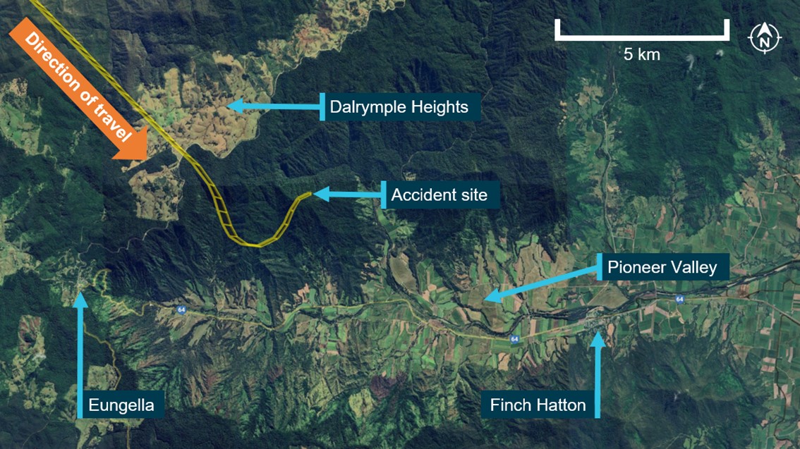
On 26 October 2023 at about 0850 local time, the pilot and sole occupant of a Robinson Helicopter Company R66, registered VH-KFT, departed on a private flight from Cessnock Airport to Wallis Island Airport, New South Wales. The flight initially tracked east toward Newcastle (Figure 1) and onboard video showed the helicopter flying close to the cloud base at heights between 500 ft and 1,000 ft above mean sea level (AMSL). Light rain was visible on the windshield. Small deviations in attitude and heading were also shown in the video, consistent with the presence of light turbulence.
The helicopter’s autopilot system was engaged, with the stability augmentation system (SAS) mode selected for the entirety of the flight (see the section titled Autopilot system). Heading hold and altitude hold modes were also selected. The pilot manually overrode the autopilot heading and altitude hold modes several times between Cessnock Airport and Newcastle to ensure the aircraft remained clear of cloud or to make corrections during turbulence.
Approaching the coast, the pilot requested and received clearance from Williamtown air traffic control (ATC) to transit Williamtown restricted airspace northbound at 500 ft AMSL via the coastal visual flight rules (VFR) route. On reaching Anna Bay, Williamtown ATC provided further clearance for flight below 2,000 ft AMSL for the remainder of the coastal VFR route.
During the flight north along the coastal route, the autopilot maintained about 500 ft AMSL, until Anna Bay, at which time the target altitude was increased to about 900 ft AMSL. The pilot also made several course corrections, using the heading selection knob on the primary multi-function display unit, throughout the transit north to maintain the aircraft close to the coastal VFR route. Indicated airspeed fluctuated between 110–120 kt for the flight north towards Yacaaba Headland. The pilot was occupied with non-flying related tasks for much of this time, specifically, mobile phone use and the consumption of food and beverages. Internal and external visual scanning appeared to be carried out throughout the flight.
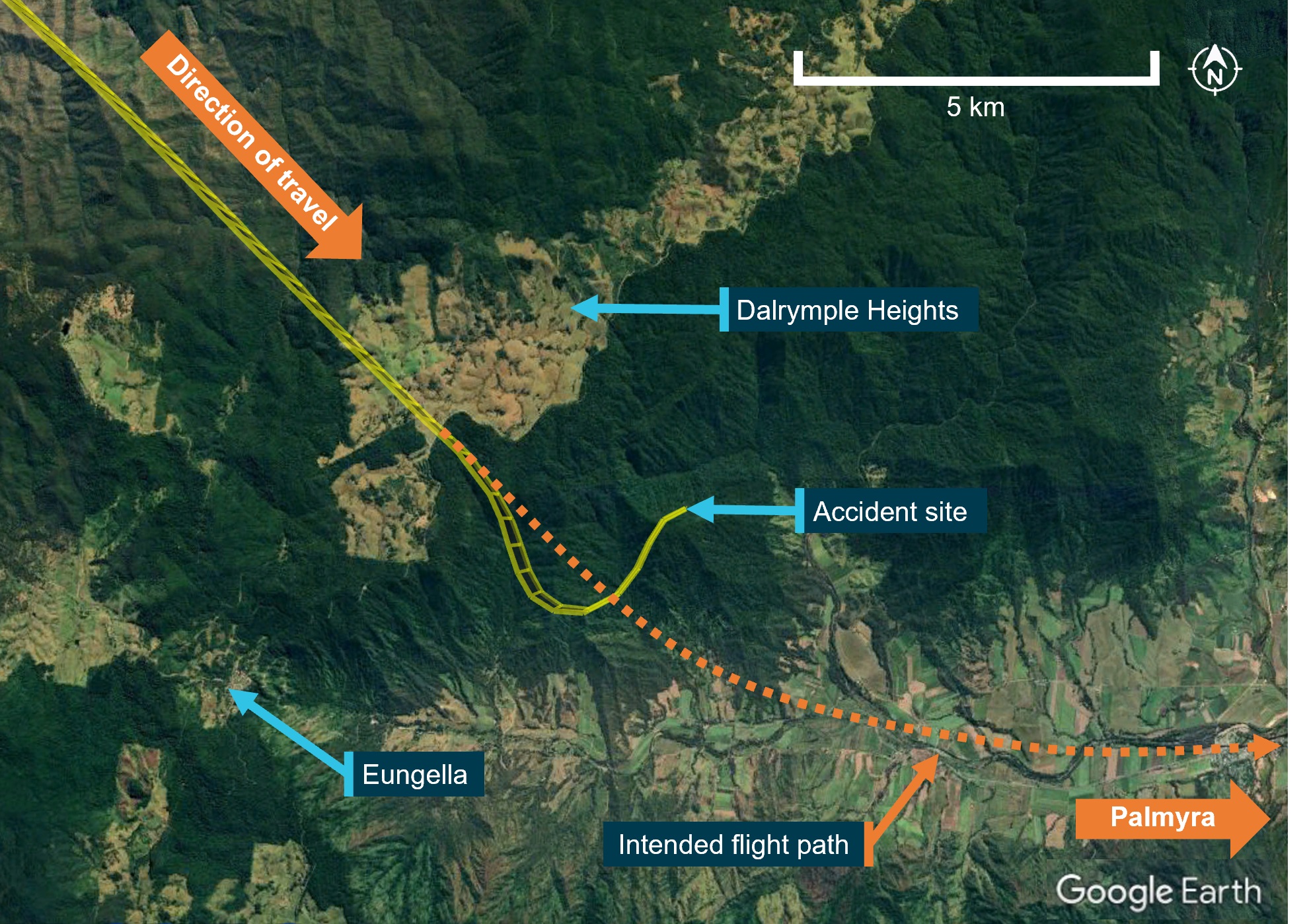
Figure 1: Flight path
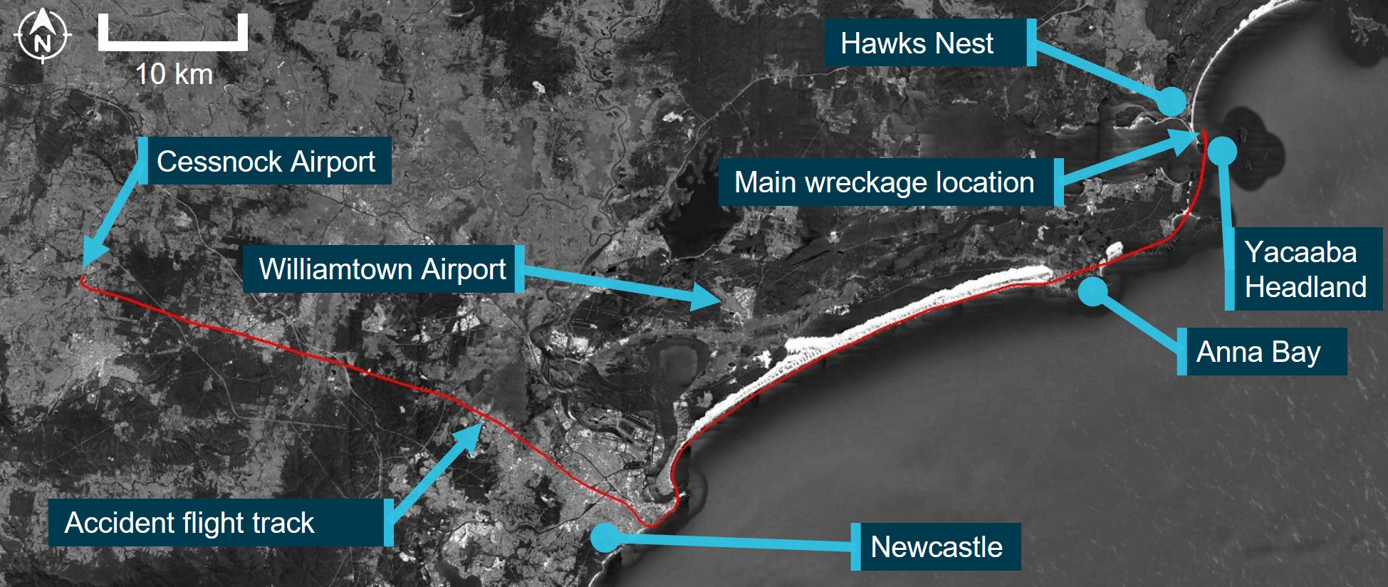
Source: Google Earth and Geoscience Australia, annotated by the ATSB
Accident sequence
The following sequence of events was identified from the onboard video and covers the period from when the helicopter crossed the southern shoreline of Yacaaba Headland until the accident (Figure 2 and Figure 19):
- At 0920:10 the helicopter passed over the southern shoreline of Yacaaba Headland at an altitude of about 900 ft (670 ft above ground level) and 185 ft above and about 600 m to the west of the Mount Yacaaba peak. The indicated airspeed was about 115 kt. The pilot was eating at this time, with the food being held in their right hand.
- Between 0920:12 and 0920:17 the helicopter encountered turbulent air, it rolled right about 4°, pitched nose down, and started to climb. The indicated airspeed increased to about 120 kt. Due to their right hand being occupied, the pilot placed their left hand on the cyclic control cross bar at 0920:17 and began to make cyclic control inputs to counter the uncommanded aircraft attitude movements and continued to make reactionary cyclic inputs for the remainder of the flight. No collective or yaw control inputs were evident for the entirety of the accident sequence.
- Between 0920:17 and 0920:21 the helicopter rolled to 25° left, pitched nose up to about 10°, yawed to the left, and climbed to about 1,000 ft AMSL. The airspeed indicator fluctuated rapidly, indicating between 120–135 kt.
- Between 0920:21 and 0920:26 the helicopter passed north of Yacaaba Headland and over Providence Bay. It rolled right to bank angle of about 10°, before rolling left to about 15°. During this time, the nose remained pitched up at about 6° and the helicopter climbed to about 1,100 ft AMSL. The airspeed indicator continued to fluctuate while reducing to 110 knots.
- Between 0920:26 and 0920:29 the helicopter pitched down to about level and rolled to the right to become completely inverted (180°), then continued to roll right to about 270°. Indicated airspeed dropped from 110 to 100 kt.
As the helicopter reached an excessive roll angle it sustained an in‑flight break‑up and impacted the waters of Providence Bay, near Hawks Nest. The pilot was fatally injured.
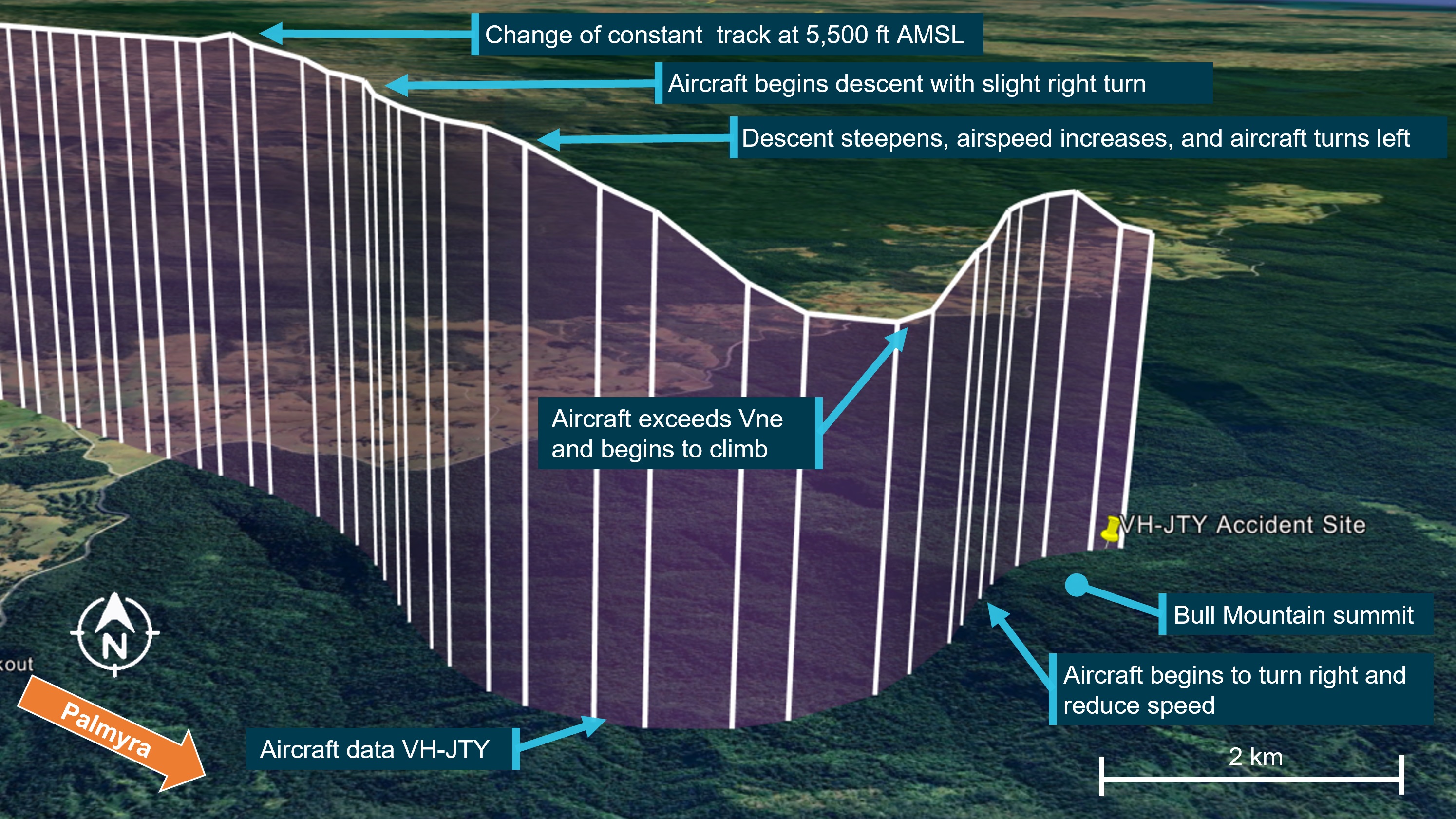
Figure 2: Aircraft attitude and altitude timeline
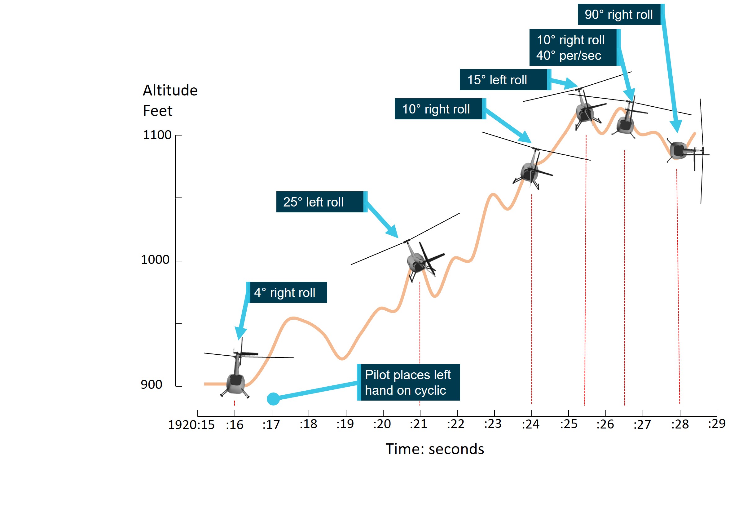
Source: ATSB
Context
Aircraft information
VH-KFT was a Robinson Helicopter Company R66, serial number 1138. It was manufactured in the United States in 2022 and registered in Australia in June 2022. The helicopter was fitted with a Rolls-Royce 250-C300/A1 gas turbine engine. VH-KFT underwent its first 100‑hour/annual inspection on 24 August 2023 at a total time in service of 97.8 hours. At the time of the accident, the hour meter showed a total time in service of 117.6 hours.
Onboard camera
The aircraft was fitted with a factory‑installed, forward‑facing cockpit camera mounted in the roof lining, close to the centre line of the aircraft and behind the cockpit seats (Figure 3).
Figure 3: Cockpit camera location

Source: ATSB
The Robinson Helicopter Company Cockpit camera user guide, stated:
The cockpit camera records 4K video, intercom audio and radio communications, and GPS position both internally and to a removable flash drive inserted in the front of the camera housing. The internal memory retains only the most recent 3 hours of video and is not user accessible. Recording starts automatically when the helicopter battery switch is turned on and stops when it is turned off.
The system also measured and recorded 3‑axis accelerometer and gyroscope data. Vertical accelerometer data recovered from the accident flight identified the existence of a low-G condition prior to the in‑flight break‑up (see the section titled Recovered data).
Autopilot system
The helicopter was fitted with a Genesys Helisas 2‑channel autopilot (AP) system to reduce pilot workload. The system’s primary AP mode, Stability Augmentation System (SAS), maintained a selected aircraft attitude using the aircraft’s pitch and roll flight control channels only. The system did not provide collective or yaw flight control inputs, which were required to be manually controlled by the pilot. Additional AP modes, available at airspeeds above 44 kt, included:
- heading mode
- altitude mode
- navigation mode
- vertical navigation mode
- backcourse mode.
SAS was required to be engaged before these AP modes could be selected.
Cyclic pitch and roll control were provided by 2 electromechanical servo‑actuators connected to the cyclic flight control channels via electro‑magnetic clutches. The direct mechanical connection of the servo‑actuators to the cyclic pitch and roll channels resulted in the pilot’s cyclic control moving with the AP inputs, and therefore could be directly observed by the pilot in flight.
The AP control panel was located in the instrument panel. It consisted of a row of push‑on, push‑off buttons to allow selection of the SAS, and individual modes, with corresponding indicator lights. Further control was provided by a cyclic‑mounted AP DISC/OFF[1] button, and Force Trim Release (FTR)[2] button. Regardless of the selected modes, the system allowed the pilot to override the AP by applying a small force to the cyclic control to fly the aircraft without autopilot influence. If the pilot then released the cyclic control, the autopilot would re‑engage to maintain the original target attitude and/or engaged mode condition provided the FTR button had not also been depressed.
AP mode status was visually indicated by annunciator lights above the mode selection buttons. An unlit light indicated the mode was off, while a white light indicated a mode had been armed but was not engaged. A green light indicated the mode was engaged. An audio chime was provided to the pilot’s headset to notify the pilot of engagement and disengagement of the autopilot system. Both the lights and chime information were present on the recovered flight video (Figure 4).
Figure 4: Autopilot control panel
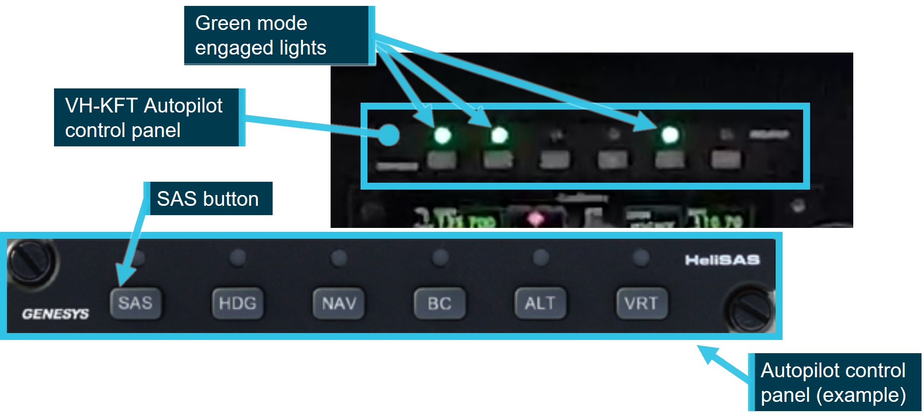
Source: ATSB and Genesys AeroSystems, annotated by the ATSB
On the accident flight the following AP modes were engaged:
- SAS mode. SAS maintained the aircraft attitude at the time it was selected.
- Heading mode. The AP maintained a selected heading, by cyclic roll inputs., Once engaged, the aircraft could be steered by adjusting the heading bug[3] on the primary multi‑function display unit.
- Altitude mode. The AP maintained the aircraft altitude by cyclic pitch inputs. The AP system was not capable of making collective control inputs, therefore any significant cyclic inputs made by the AP to maintain altitude would affect the aircraft airspeed. In those circumstances, the pilot was required to apply collective inputs to control aircraft airspeed.
Rotor system
The Robinson R66 main rotor hub assembly design is a semi‑rigid rotor head, otherwise known as a teetering rotor head. During normal flight, the main rotor blades are free to flap independently via the coning hinges, and the rotor is free to teeter around its designed flight axis via the teeter hinge, while elastomeric teeter stops limit the degree of teetering (Figure 5).
Under certain specific flight conditions, semi-rigid rotor systems are susceptible to extreme teetering where the blades teeter beyond their normal operational range, resulting in what is commonly known as ‘mast bumping’ (see the section titled Low-G mast bumping).
Figure 5: Robinson main rotor head
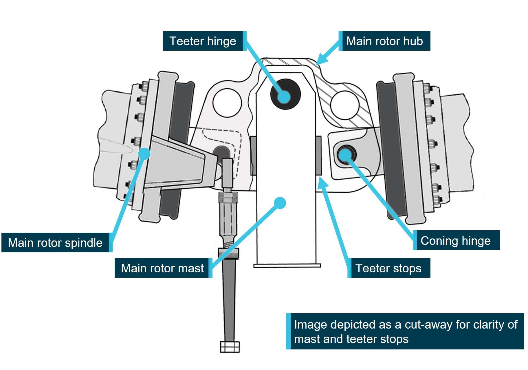
Image modified to remove spindle tusks and droop stop bolt for clarity. Source: Robinson Helicopter Company, modified and annotated by the ATSB
Weight and balance
The pilot filled the aircraft fuel tanks prior to departing Cessnock Airport, and the pilot was the only person aboard the aircraft. A small dog was located on the back seat. Weight and balance calculations were completed by the ATSB using the R66 pilot’s operating handbook (POH), aircraft weight and balance record, pilot’s medical records, and an assumption of 10 kg of cargo.
The estimated aircraft weight when it departed Cessnock was 960 kg. The aircraft would have consumed about 33 kg of fuel[4] in the 30 minutes between departure and the accident, providing an estimated weight of 927 kg at the time of the accident. At both weights the aircraft was within the centre of gravity limitations stated in the POH and below the maximum take‑off weight of 1,225 kg.
Pilot information
The pilot held a private pilot licence (helicopter), with the required ratings and endorsements to operate the helicopter under the visual flight rules[5] (VFR). The pilot also held a current class 2 aviation medical certificate.
Prior to the accident, the pilot had recorded a total flying time of 1,097.6 hours in their logbook, with the last entry recorded on 11 June 2023. Additionally, dated aircraft running sheets were recovered recording an additional 27.7 hours in the accident aircraft, updating the pilot’s total recorded flying time to 1,125.3 hours, last recorded on 20 October 2023 in VH‑KFT, at 112.85 airframe hours.
At the time of the accident, the aircraft hour meter recorded 117.64 hours, including at least 4 hours of factory pre-delivery testing. Assuming that the accident pilot was the only person to fly the accident aircraft, and no other unrecorded flying was completed in another aircraft; a total flying time of 1,130.1 hours was extrapolated. These hours included 117.6 hours in the R66, 1,007 hours in R44 and R22 combined, and 5.5 hours in Bell 206 helicopters. Of these hours, about 14.64 hours were logged in the 30 days prior to the accident, all in VH‑KFT.
The investigation identified a non‑disclosed reportable medical condition, which may have increased the risk of medical impairment in flight. As the pilot was not recovered following the accident, the ATSB was unable to gain any further medical information from a post‑mortem examination or toxicological assessment. However, the recovered video and audio showed no indications of impairment. Further, the pilot’s medical records show that the condition was likely controlled by medication that was unlikely to present a risk to flight safety.
The pilot completed a single engine helicopter flight review in KFT, on 11 September 2022, which was valid until September 2024, and the Robinson Helicopter Company Overseas Helicopter Pilot Safety course on 15 February 2023.
72-hour history
The ATSB was unable to determine the pilot’s activity (including sleep history) in the 72 hours prior to the accident, primarily due to the pilot living alone. However, some information was available, namely:
- On the night of 24 October 2023, the pilot slept well and rose at about 0600 the next morning, which was typical.
- At 2227 on 25 October 2023, the pilot sent a text message.
- 0604 on 26 October 2023 (accident morning), first recorded ADS-B data point recorded north‑east of Jindabyne, New South Wales, likely corresponding to the aircraft departure from Jindabyne.
- At 0900 on 26 October 2023, the pilot sent a text message about the weather conditions.
The pilot’s National Aeronautical Information Processing System login was last accessed on 24 October 2023.
With the limited information available, it was not possible to determine whether, at the time of the accident, the pilot was operating with a level of fatigue known to affect performance. However, from the available history, the pilot had about 6 hours of sleep opportunity the night before the accident.
Wreckage
On 28 October 2023, New South Wales Police divers located the helicopter’s cabin and tail boom on the sea floor of Providence Bay at a depth of about 5 m. The wreckage was recovered to a secure facility in Newcastle for examination by the ATSB. The entire windshield and forward cabin roof section, as well as the main rotor head and both main rotor blades, were not located during the sea search operation (Figure 6).
Figure 6: Recovered fuselage
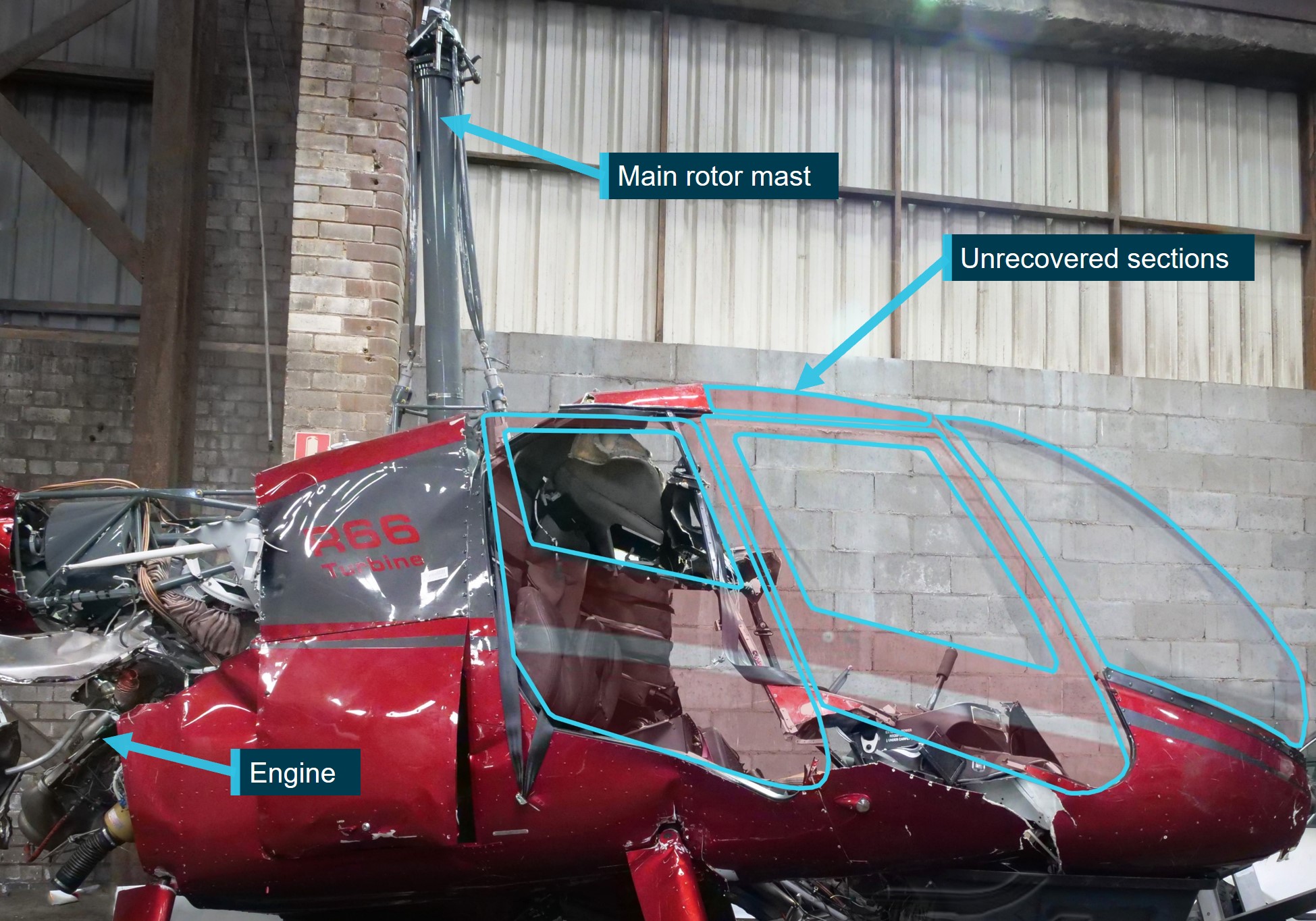
Source: ATSB
The ATSB’s examination of the recovered helicopter structure indicated that a main rotor blade had likely impacted the right side of the cabin. Damage to the fuselage below the pilot’s seat, evidence of main rotor blade paint transfer, and damage to the cyclic control column were all consistent with main rotor blade impact on the right side of the cabin.
Although the main rotor head and blades were not initially[6] recovered, mast bending, cross section ovalisation, impact marks below the fracture surface and fracture surface features (Figure 7), were all consistent with tensile overstress failure due to extreme teetering and mast bumping. No evidence of pre‑existing defects, such as fatigue‑related cracking, were evident on the fracture surfaces.
Figure 7: Main rotor mast fracture surface
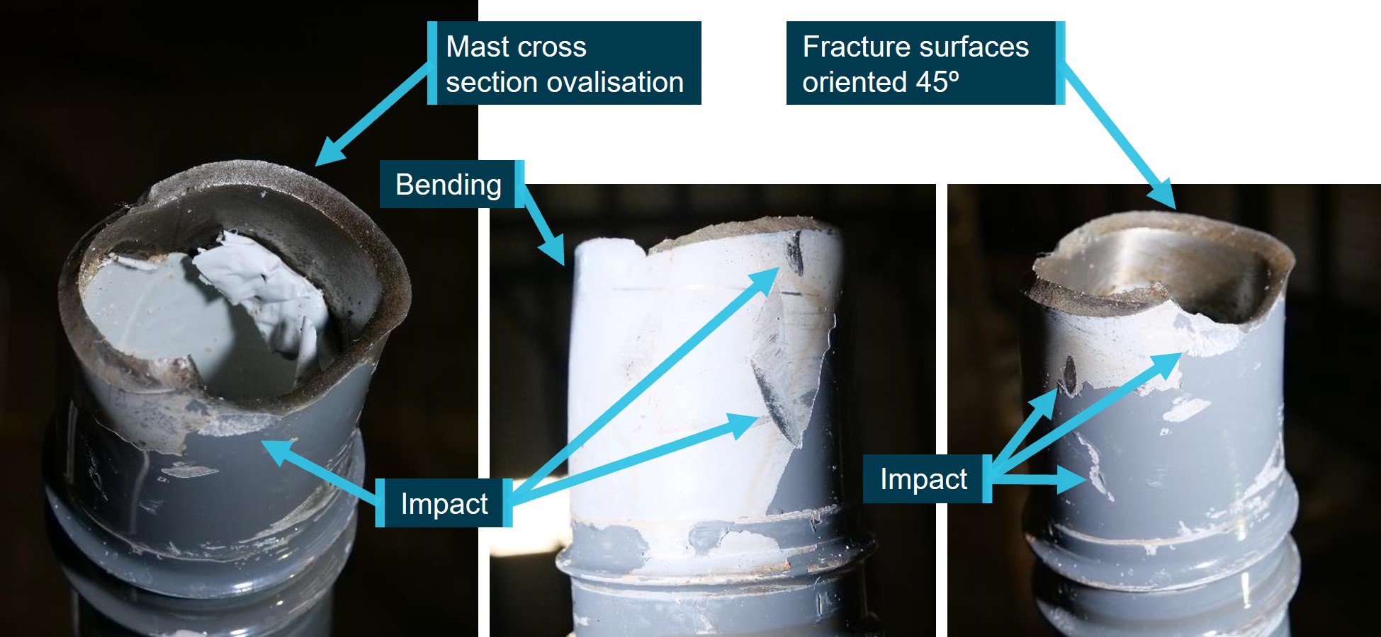
Source: ATSB
The tail boom separated from the fuselage, aft of the engine fairing, from contact with a main rotor, prior to impacting the water. Damage to the fuselage was consistent with the fuselage impacting the water on the left side. No pre‑existing faults or damage were identified.
The aircraft’s cockpit camera (Figure 3) was liberated from the aircraft during the accident sequence. It was found on a beach near to the accident site by a member of the public and handed to local authorities, and subsequently provided to the ATSB for data recovery and analysis.
The 32 GB internal memory SD card was intact and a complete video recording of the accident flight, with audio and data, was recovered from the camera. A 128 GB SD card and USB adapter plugged into the external USB port was also recovered which also contained recorded video of the accident flight (see the section titled Recovered data).
Low-G operation
During flight under normal operating conditions, a helicopter with a semi‑rigid rotor design hangs under the main rotor disc at the teeter hinge under the influence of a combination of gravity (G[7]) and flight manoeuvring loads. The rotor disc provides lift, and can be tilted to allow horizontal movement of the helicopter
An aircraft at rest, or in non‑accelerating flight, is said to be experiencing 1 G. This is due to the force of gravity always acting on the aircraft. An aircraft accelerating through the air is said to be experiencing a G load.[8] During periods of increased G load, above 1 G, such as at initiation of a climb or during a turn, the pilot may experience feeling heavy in their seat.
A low‑G condition describes the reduction in G load below 1 G acting on the fuselage, either due to control inputs, or as a result of turbulence. In a low‑G condition the pilot may experience feeling light, or even weightless, in their seat.
In a helicopter with a teetering rotor design, during periods of low‑G, the main rotor disc is still controlled by pilot flight control inputs and the disc is able to be tilted in pitch or roll, but the ability for the rotor disc to control the movement of the fuselage is reduced. A low‑G condition does not require a completely zero G loading in order to affect control, any reduction from 1 G can affect helicopter controllability, but effects become more severe with a decrease in G loading, and will persist until the main rotor is reloaded, and the normal rotor/fuselage control relationship is restored.
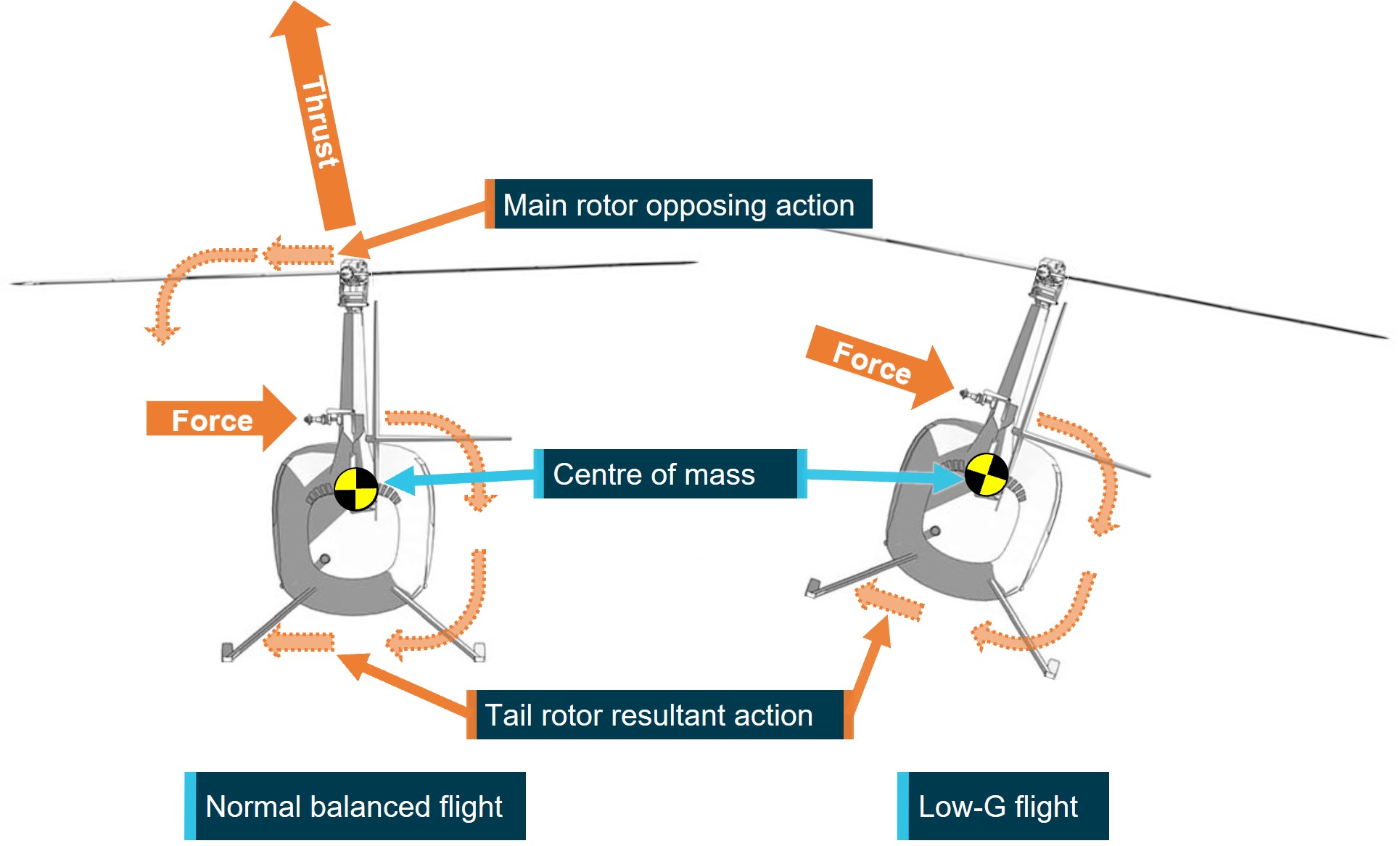
Tail rotor thrust
The purpose of the tail rotor is to provide thrust to counter the torque reaction created by the main rotor. Thrust produced by the tail rotor is modulated to counteract the torque produced by the main rotor. The controllable tail rotor thrust also allows the pilot to rotate the aircraft about the vertical axis, also known as the yaw axis, when hovering and maintaining balanced forward flight.
The tail rotor in Robinson aircraft is located above the aircraft’s centre of gravity, which results in the force from the tail rotor also causing the aircraft to rotate about its horizontal, or roll, axis, in addition to the yaw movement (Figure 8). This rolling force is small and is corrected by main rotor roll inputs.
Figure 8: Tail rotor force in flight and low-G
Source: Robinson Helicopter Company, modified and annotated by the ATSB
Robinson asymmetrical horizontal stabiliser
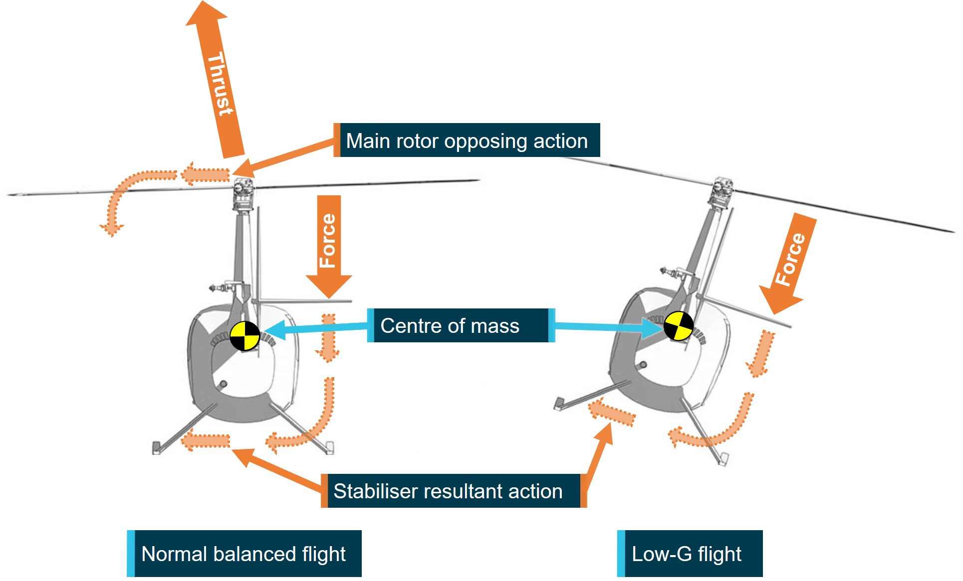
The horizontal stabiliser counters the tendency of the helicopter to adopt a nose down attitude in forward flight, which increases with forward speed. The Robinson horizontal stabiliser is an inverted aerofoil, which produces a downward force by aerodynamic action. An increase in angle of attack amplitude, associated with a helicopter pitching nose down in flight, or an increase in forward airspeed, increases the magnitude of the downward force, and pushes the tail down to maintain a level attitude.
Due to the asymmetric design of the stabiliser on Robinson helicopters, the downward force produced by the stabiliser is offset to the right of the aircraft centre of mass. This offset also creates a right rolling moment on the aircraft fuselage, which increases with airspeed. This tendency to roll right is countered by a left tilt of the main rotor disc that provides an opposing left roll moment on the fuselage to assist the maintenance of level flight (Figure 9).
Figure 9: Stabiliser force in flight and low-G
Source: Robinson Helicopter Company, modified and annotated by the ATSB
Low-G mast bumping
Mast bumping, also known as extreme teetering, is a phenomenon that can occur in helicopters with a semi‑rigid main rotor head design. It describes the condition where the teetering angle of the main rotor disc, relative to the main rotor mast, exceeds the design limits of the system, and the main rotor spindles contact the main rotor shaft.
Robinson helicopters incorporate soft elastomeric teeter stops that allow contact under normal conditions where teetering can be expected, such as landing across a slope. Normal teeter stop contact will be felt by the pilot as a 2-per revolution vibration and serves as a warning of the teeter limit being reached. Extreme teetering under low‑G conditions destroys the teeter stops and results in spindle to mast contact (Figure 10).
Mast bumping can generally be identified by extensive damage to the teeter stops and varying degrees of damage to the main rotor shaft. It can also result in failure of one or both pitch links, allowing uncontrolled pitching of the blade(s), allowing the blade(s) to deviate from their normal path of rotation and contact with the airframe. Severe mast bumping can result in the failure of the main rotor mast, and separation of the main rotor head in flight.
During a low‑G condition the influence of the main rotor forces on the fuselage, which include the right roll countering force are reduced. However, the right rolling moment produced by the asymmetric stabiliser and tail rotor are still present. This results in the fuselage rolling to the right (Figure 8 and Figure 9). At higher airspeeds the right roll rate increases with increasing horizontal stabiliser down force and the pilot’s ability to counteract the roll reduces with reducing G. Reducing airspeed reduces the rolling moment, but reloading the rotor with gentle aft cyclic restores the main rotor force influence and allows the pilot to correct the condition.
The manufacturer reported that the tail rotor thrust contribution to the right roll is minor in comparison to the stabiliser force and therefore is not the primary cause of the uncommanded right roll during a low-G condition in Robinson helicopters with the asymmetric stabiliser fitted.
If the pilot responds to a low‑G/right roll by applying left cyclic input before reloading the disc, the rotor disc will tilt (teeter) left without affecting the roll. The left main rotor tilt without the corresponding fuselage reaction reduces the clearance between the main rotor blade spindle and the main rotor mast. In extreme teetering cases the clearance reduces to zero and destroys the elastomeric teeter stops, resulting in the blade spindle bumping into the mast (Figure 10).
Figure 10: Main rotor mast bump
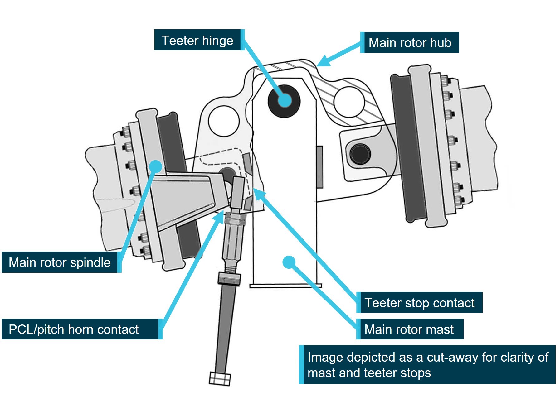
Image modified to remove spindle tusks and droop stop bolt for clarity. Source: Robinson Helicopter Company, modified and annotated by the ATSB
To reduce the risk of mast bumping, Robinson Helicopter Company specifies the correct response to a low‑G induced right roll is to resist the instinctive response of left cyclic, and instead apply gentle aft cyclic, tilting the rotor disc aft. The aft tilt restores the rotor disc/fuselage loading relationship, arresting the right roll and allows the pilot’s lateral control inputs to influence the fuselage. Left cyclic can then be applied to level the helicopter.
Symmetrical stabiliser modification
Robinson Helicopter Company (RHC) has developed a symmetrical stabiliser modification applicable to all Robinson models. The modification alleviates the low‑G/right roll phenomenon associated with the stabiliser by repositioning the horizontal stabiliser aerodynamic downward force in line with the aircraft centre of mass. RHC has stated that, while an uncommanded roll will still develop in a low‑G condition, its rate is greatly reduced, allowing pilots more time to recognise and respond appropriately.
At the time of writing, all models of Robinson Helicopters were being manufactured with the symmetrical stabiliser fitted. RHC has also advised that all asymmetrical stabilisers are being replaced with the symmetrical unit when they are returned to the factory for overhaul or repair. Symmetrical stabilisers were also available directly from RHC for retrofit outside of the factory.
Environmental conditions
Forecasts and observations
The Bureau of Meteorology (BoM) Graphical Area Forecast valid for the airspace surrounding Newcastle, at the time of the accident, forecast broken stratus[9] cloud between 800–2,000 ft AMSL, and overcast Stratocumulus[10] cloud (with implied moderate turbulence) between 2000–6,000 ft AMSL.
Forecast wind data in the Williamtown terminal area forecast (TAF), issued and valid at the time of the pilot’s departure, predicted 16 kt winds from 170° within 9 km of the airport.
Figure 11: Grid point wind temperature forecast
Source: Bureau of Meteorology, annotated by the ATSB
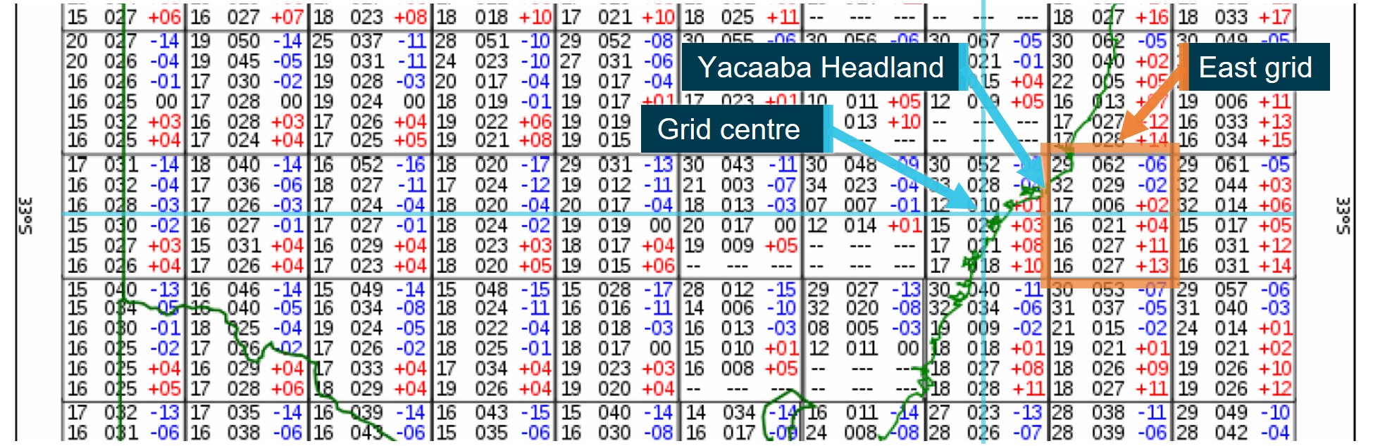
The grid point wind temperature (GPWT) forecast issued and valid at the time of the pilot’s departure predicted 17 kt and 21 kt at 1,000 and 2,000 ft altitudes respectively. Of note, the BoM regional GPWT forecast charts displayed data in a grid of 1.5° latitude by 1.5° longitude, with the data given valid for the mid-point of each square only. The BoM Graphical Area Forecast and AIRMET User Guide, stated:
It should be noted that the GPWT forecast is valid for the centre of the grid box and not necessarily for the … location in that box.
In this instance the centre point of the grid encompassing Yacaaba Headland was about 73 km, south‑west of the headland, and located over land. Wind speed over land is typically lower than the same wind over water, this is due to the land creating friction between the wind and surface. In that context, the GPWT region located over sea to the east of the headland was likely more representative of the actual conditions at Yacaaba Headland at the time of the accident (Figure 11). This grid predicted 27 kt at 1,000 and 2,000 ft.
Table 1: Weather forecast data
| 26 Oct | Wind | Cloud | Temp | |||||
Source | Time | Dir | Speed | Gust | Altitude | Cover | Height | °C |
| TAF Williamtown (Valid 0900–0300) | 0822 | 170 | 16 kt | 26 kt | Surface | 5-7/8 | 2000 ft | 15 |
| GPWT Forecast (Valid 0900–1200)[11] | 0557 | 170 | 18 kt | 1,000 ft | 10 | |||
| GPWT Forecast (Valid 0900-1200) | 0557 | 170 | 21 kt | 2,000 ft | 8 | |||
| GPWT Forecast One Grid East | 0557 | 160 | 27 kt | 1,000 ft | 13 | |||
| GPWT Forecast One Grid East | 0557 | 160 | 27 kt | 2,000 ft | 11 | |||
The closest BoM observation station to the accident site was Nelson Bay, about 4 km south‑west of Mount Yacaaba. However, recorded observations at Nelson Bay were limited in scope and frequency, and the BoM advised that they were not representative of the conditions at Mount Yacaaba at the time of the accident. Therefore weather observation and forecast information was acquired from multiple sources to develop an understanding of the likely conditions in the area at the time of the accident (Table 1 and Table 2).
The surface wind observations for Williamtown recorded surface wind speed of 12 kt from 190° at 0900, and 15 kt from 180° at 0930. The Cessnock Airport data was excluded due to its distance from the accident site. The Nelson Bay data was close to the accident site, but the wind observation was excluded based on advice from the BoM that it was likely unrepresentative.
Table 2: Weather observation data
| 26 Oct | Wind | Cloud | Temp | ||||
Source | Time | Dir | Speed | Gust | Altitude | Cover | Height | °C |
METAR Cessnock | 0900 | 180 | 8 kt |
| Surface | 14 | ||
SPECI Williamtown | 0900 | 190 | 12 kt |
| Surface | 5-7/8 | 1100 ft | 14 |
METAR Williamtown | 0930 | 180 | 15 kt |
| Surface | 3-4/8 | 1000 ft | 15 |
| BoM Williamtown Observation | 0900 | 180 | 12 kt | 16 kt | Surface | 14.3 | ||
0930 | 180 | 15 kt | 23 kt | Surface | 14.7 | |||
BoM Nelson Bay Observation | 0900 | 180 | 8 kt | Surface | 8/8 | 14.4 | ||
Atmospheric Sounding Williamtown | 0900 | 170 | 25 kt | 500 ft | 13 | |||
| 0900 | 170 | 30 kt | 1,500 ft | 10.5 | |||
Doppler wind radar located at Lemon Tree Passage, about 15 km east‑south‑east of Yacaaba Headland, recorded wind speed between 5–22 kt (10–40 km/h), from 150°–170° at 0924, about 4 minutes after the accident (Figure 12). However, doppler wind radar is limited to measuring the radial component of wind only, that is wind heading directly toward or away from the radar. Also, the doppler beam is designed to be emitted at a slightly elevated angle to avoid interference from nearby objects or topography. This results in the beam measuring windspeed at an altitude that increases with the distance from the radar.[12] An additional complication is produced by a beam refraction due to temperature and humidity.
For these reasons the doppler wind data was considered to only be indicative of the wind speed and direction above Yacaaba Headland.
Figure 12: Doppler wind image
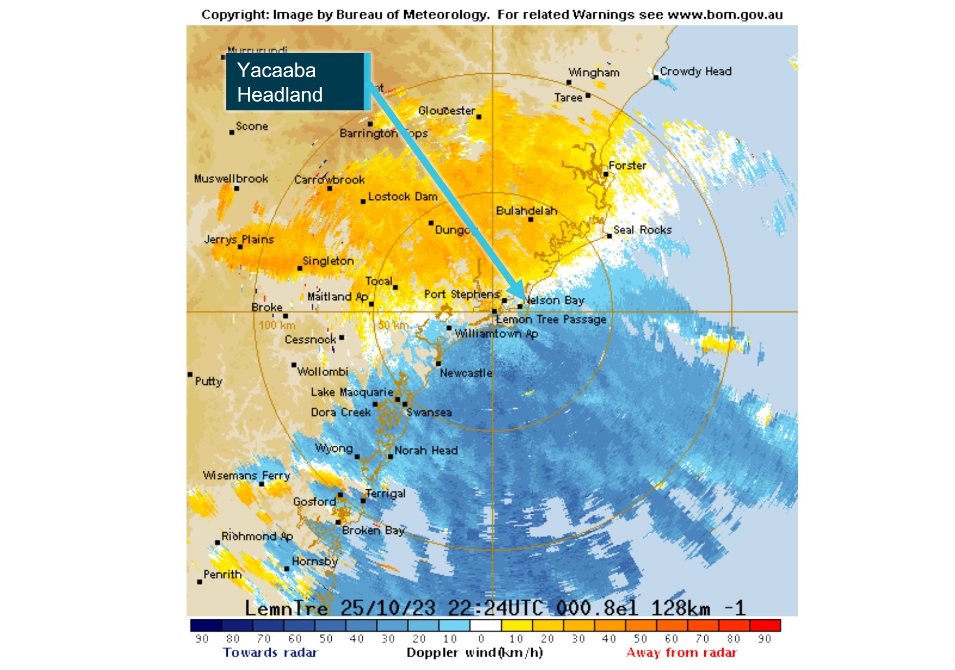
Source: Bureau of Meteorology, annotated by the ATSB
The wind measured by the Williamtown atmospheric sounding showed wind speeds between 25–30 kt at 500 and 1,500 ft respectively, from 170°.
Considering all the sources of data, it was assessed that the wind above Yacaaba Headland was likely between 25–30 kt from 170°.
The Civil Aviation Safety Regulations,[13] regarding pilot access to weather data, required that pilots review weather forecast and observation data within 1 hour of departure. The pilot’s Electronic Flight Bag was not recovered, however their National Aeronautical Information Processing System (NAIPS) account login had not been accessed since 24 October 2023, 2 days prior to the accident flight.
It is possible that the pilot accessed weather forecast and observation data from another source, but the investigation did not find any evidence of this. As such, details of the pilot’s knowledge of the weather immediately prior to departure, including the wind strength and direction, could not be determined.
However, a text message from the pilot’s mobile phone while in flight indicated that the pilot selected the coastal VFR route, rather than heading directly to their destination, to remain below the cloud base. This suggested that the pilot had some awareness of the expected weather conditions prior to departing Cessnock or the direct route was obviously not viable.
Turbulence
The BoM hazardous weather phenomena, turbulence brochure uses the following descriptions for turbulence categories:
Mechanical turbulence occurs due to frictional forces on the surface wind creating turbulent eddies. The intensity of mechanical turbulence is primarily dependent on wind speed, surface roughness and atmospheric stability near the surface. The intensity increases as both overlying wind speed and surface roughness increase, and when air flow is forced by obstacles to diverge around, or converge through gaps in, barriers. Winds over the ocean are subject to less frictional stress than winds over land.
Orographic turbulence is initiated by large-scale displacement of airflow by hills, mountains and islands. In general, upward displacement and consequential gravitational forcing lead to the development of mountain waves, downslope winds and rotors. Mountain waves form above and downwind of topographic barriers when strong winds blow with significant vector component perpendicular to the barrier in a stable environment. If air is being forced over terrain, it will move downward along lee slopes, then obstacle in a series of waves as it moves downstream, sometimes propagating long distances downwind. Aircraft may encounter severe turbulence in the wake of isolated islands when the atmosphere is stable. In these instances, air is forced around the obstacle rather than over them, producing both horizontal and vertical vortices and thereby adding to complex turbulent motions in the obstacles wake. These lee side horizontal disturbances are called von Karman vortices and can rotate both clockwise and anticlockwise directions.
Further reference to turbulence in the report will refer to both mechanical and orographic turbulence.
Figure 13: Schematic representation of turbulent flow
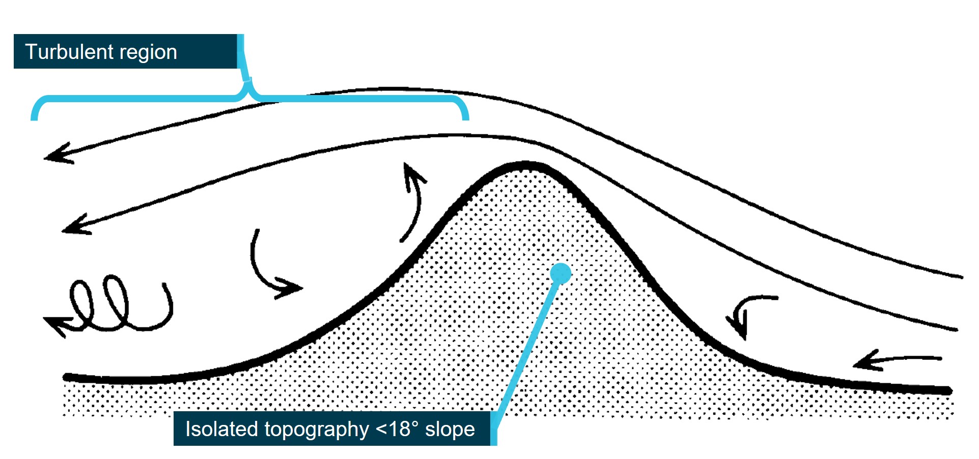
Source: UK Meteorological Office, Handbook of Aviation Meteorology
The effects of terrain on airflow are complex and unpredictable. However, in the case of isolated, small‑scale topography (less than a few kilometres in horizontal extent) simplifications can be made, and turbulence can be assessed using wind speed and topography only (Figure 13). The orientation of the terrain to the relative wind can also introduce complexities, so for the purpose of this discussion we will only consider airflow perpendicular to an obstacle. In these simplified cases, for topography where the slope is greater than about 18°, recirculating eddies can be expected on both the windward and lee sides. Where the slope exceeds about 45°, the turbulent region may extend downwind by trailing vortex circulations. If wind speed exceeds about 20 kt severe turbulence may be present extending some distance downwind, and up to twice the height of the hill (UK MET, 1994).
Figure 14: Turbulent areas over Yacaaba Headland
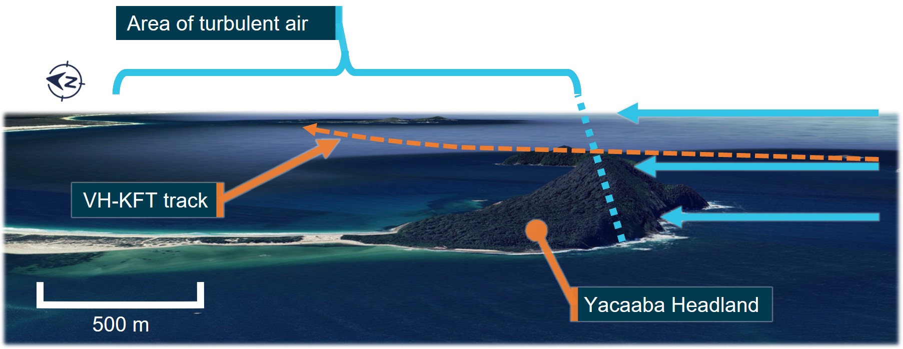
Source: Google Earth, annotated by the ATSB
Yacaaba Headland is connected to the mainland by an isthmus, resulting in the headland peak being surrounded by sea, or low terrain in all directions. The headland measures about 1.8 km from east to west, and about 750 metres north to south. The headland rises steeply from the sea surface to the peak at 218 metres (715 ft), over about 200–250 metres south to north. The peak forms part of a ridge from east to west, reducing in altitude to about 80–100 metres (260–320 ft) at the point where the aircraft crossed, forming a steep scarp (about 45°) on the southern face of the headland (Figure 14 and Figure 15).
Figure 15: Turbulent areas around Yacaaba Headland
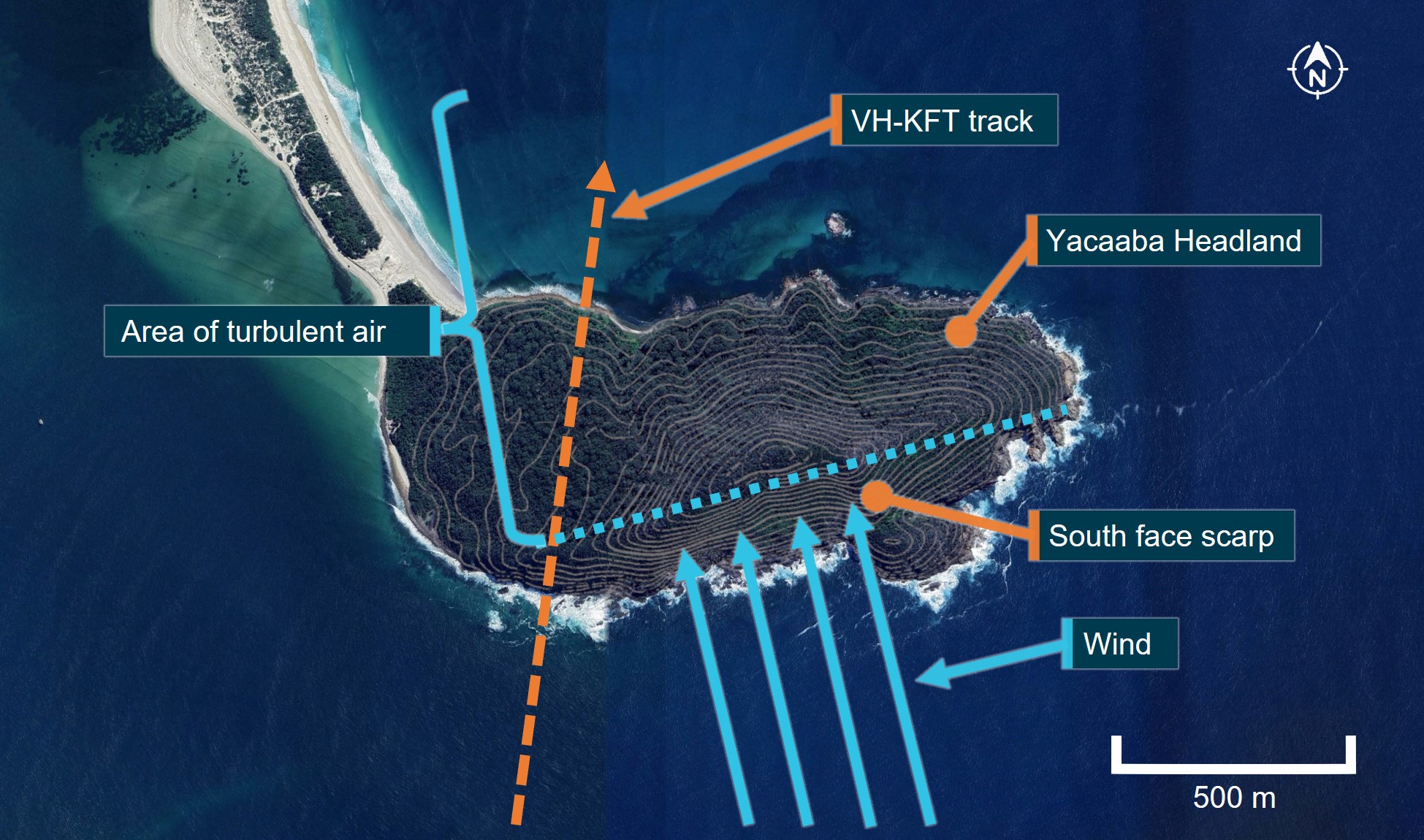
Source: Google Earth and NSW Spatial Services (DCS), annotated by the ATSB
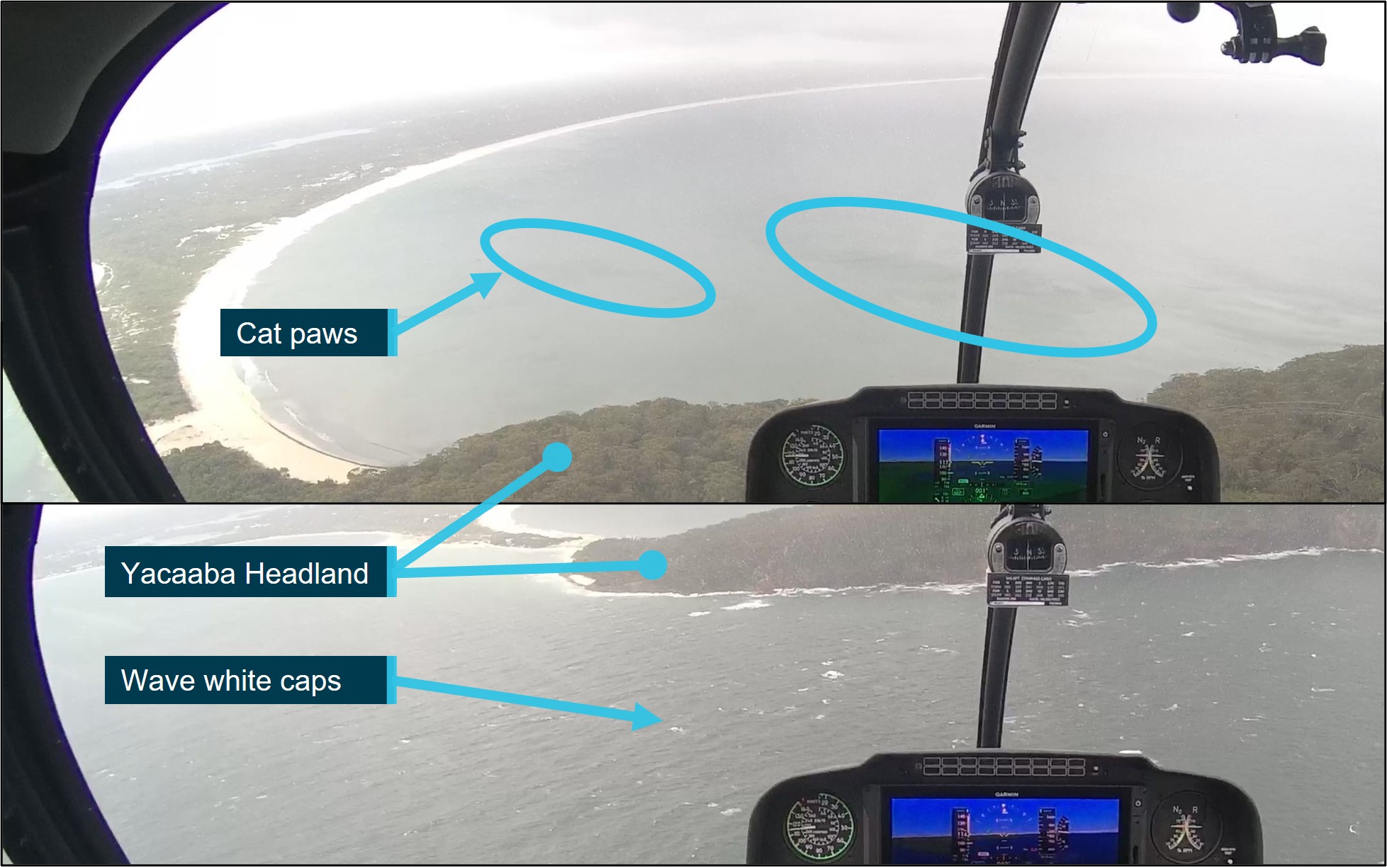
Video footage recovered from the aircraft showed differences between the sea surface conditions on the north and south side of the headland, indicative of the presence of wind and turbulence (Figure 16):
- On the south side of the headland, the surface swell and wave white caps were indicators of south‑easterly surface wind strengths of about 11–21 kt (Table 3).
- On the north side of the headland the sea surface was noticeably calmer, due to the shielding effect of the headland. However, dark patches on the sea surface, known as cat’s paws, indicated the presence of localised gusts accompanied by turbulence. (Marin, 1996).
Figure 16: Sea surface turbulence indicators
Source: ATSB
Table 3: Beaufort wind scale
| Speed (Knots) | Description | Specification |
| 11–16 | Moderate Breeze | Small waves, becoming larger; fairly frequent white horses. |
| 17–21 | Fresh Breeze | Moderate waves, taking a more pronounced long form; many white horses are formed. |
| 22–27 | Strong Breeze | Large waves begin to form; the white foam crests are more extensive everywhere. |
Recovered data
Data was recorded on the recovered cockpit camera internal 32 GB microSD, and external 128 GB card. The camera was dismantled by the ATSB to gain access to the internal microSD card. Data from both cards was extracted using a write‑protected forensic recovery unit. The internal 32 GB microSD card contained GPS and sensor data, video, and audio files, and the external 128 GB card contained video files only.
The internal 32 GB card was not readable by common software due to a data error caused by the sudden loss of power to the unit during the accident sequence. A repair was conducted by the ATSB, with assistance from Robinson Helicopter Company, after which a 30Hz MP4 format video and audio file was recovered and analysed. Also recovered from the internal 32 GB card was GPS and sensor data recording 3-axis aircraft accelerations and rotations at 10Hz fidelity.
Synchronisation of the sensor, video, and audio data was completed using data landmarks over multiple points across the extent of the recovered data, resulting in a high level of confidence in the accurate synchronisation of the data types. An accurate synchronisation provided assurance that the precise sequence of events could be determined to within 0.5 second increments.
Figure 17: Onboard video from VH-KFT, in a 15° left bank (immediately prior to the final right roll)
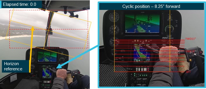
Source: ATSB
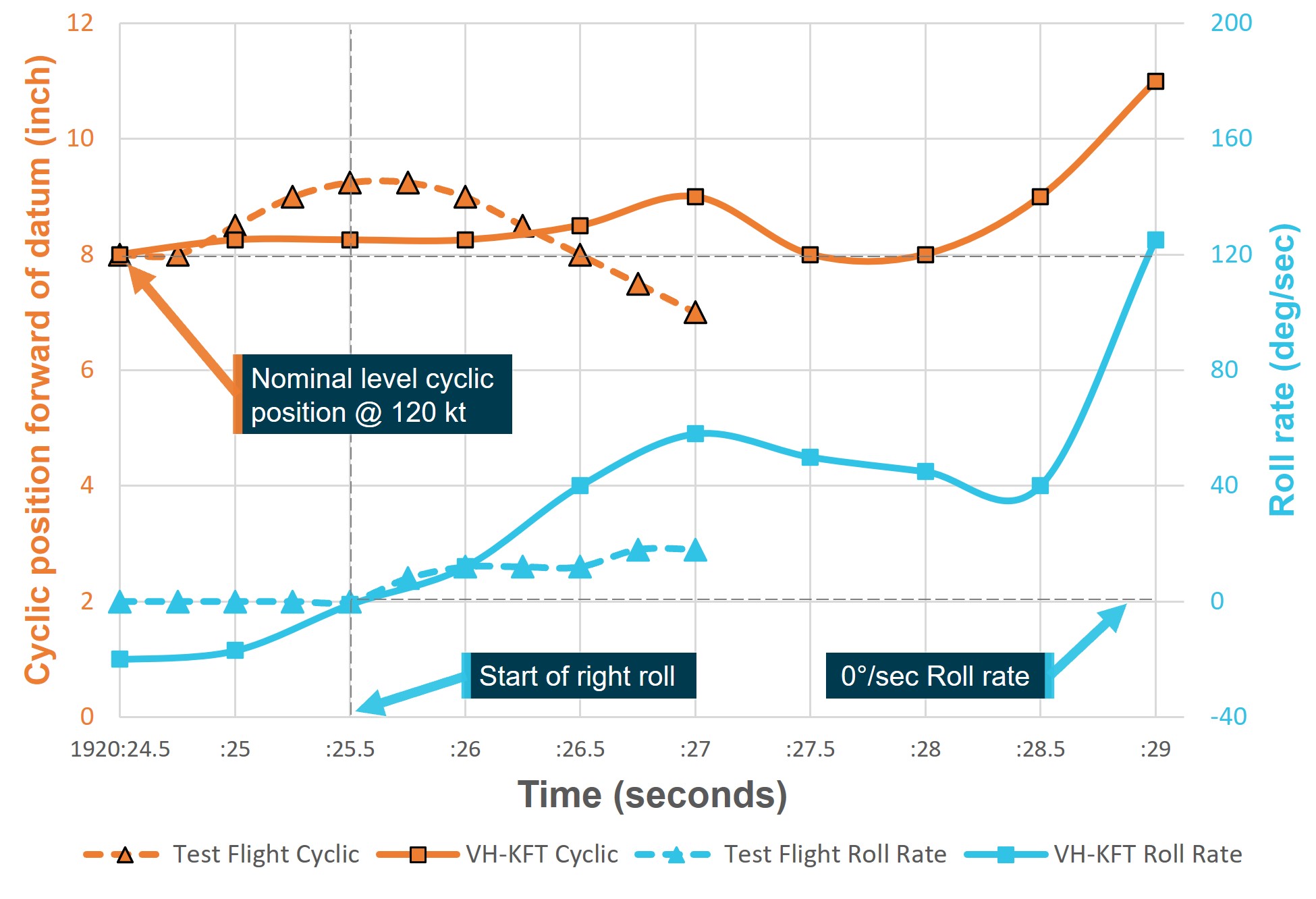
The pilot’s fore and aft cyclic flight control inputs, shown in the accident flight video, were measured. To achieve this, the ATSB used a sample video provided by Robinson Helicopter Company that showed the full range of cyclic motion in an exemplar R66 helicopter. The sample video showed the fore and aft positions of the cyclic measured in 1.0-inch increments on a measuring tape. Each 1.0-inch increment was marked as a red horizontal line in the scale shown in the right image of Figure 17. The scale was overlaid onto the accident flight video frames referencing common fixed locations in the cockpits of the exemplar aircraft and the accident aircraft.
Measurement of the pilot’s fore and aft cyclic flight control inputs, and the aircraft’s roll angle relative to the visible horizon in the final 13 seconds of the accident flight were performed in 0.5 second increments. An instantaneous roll rate was calculated by dividing the change in measured roll angle with the elapsed time.
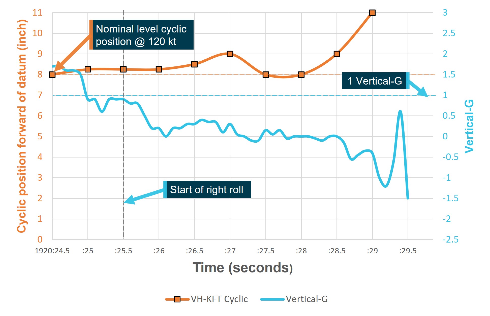
The measured fore-aft cyclic position was compared to instantaneous roll rate and accelerometer data (Figure 18) to assess the potential contribution of the cyclic movement to the recorded low‑G. Lateral cyclic position was observed but not precisely measured.
Figure 18: Vertical-G and cyclic fore/aft inputs
Source: ATSB
Vertical accelerometer data showed significant and variable G loading throughout the final 12 seconds of flight. Between +2 and −0.6 G was recorded prior to the rapid right roll and final rapid reduction to zero G during the final 3.5 seconds (Figure 19). Roll angle data showed the aircraft was subject to roll acceleration throughout the entire final 12 seconds of flight, and the rapid right roll in the final 3.5 seconds coincided with the sharp decrease in vertical G.[14] In the 1 second leading up to the final right roll, vertical G loading decayed rapidly from about +1.6 G, holding briefly at about +0.9 G, before reducing rapidly again to around zero G after the initiation of the right roll.
Indicated airspeed was read directly from the airspeed gauge, visible in the accident flight video. Airspeed varied rapidly and significantly between 100 and 135 kt during the aircraft’s encounter with turbulence (Figure 19). The rapid fluctuations presented on the airspeed gauge were possibly caused by the air pressure or direction fluctuations typical in turbulent air, and not necessarily indicative of ground speed changes. The pilot made no visible attempt to slow the aircraft using coordinated cyclic and collective control inputs during the turbulence encounter.
Figure 19: Vertical-G, roll angle, and indicated airspeed
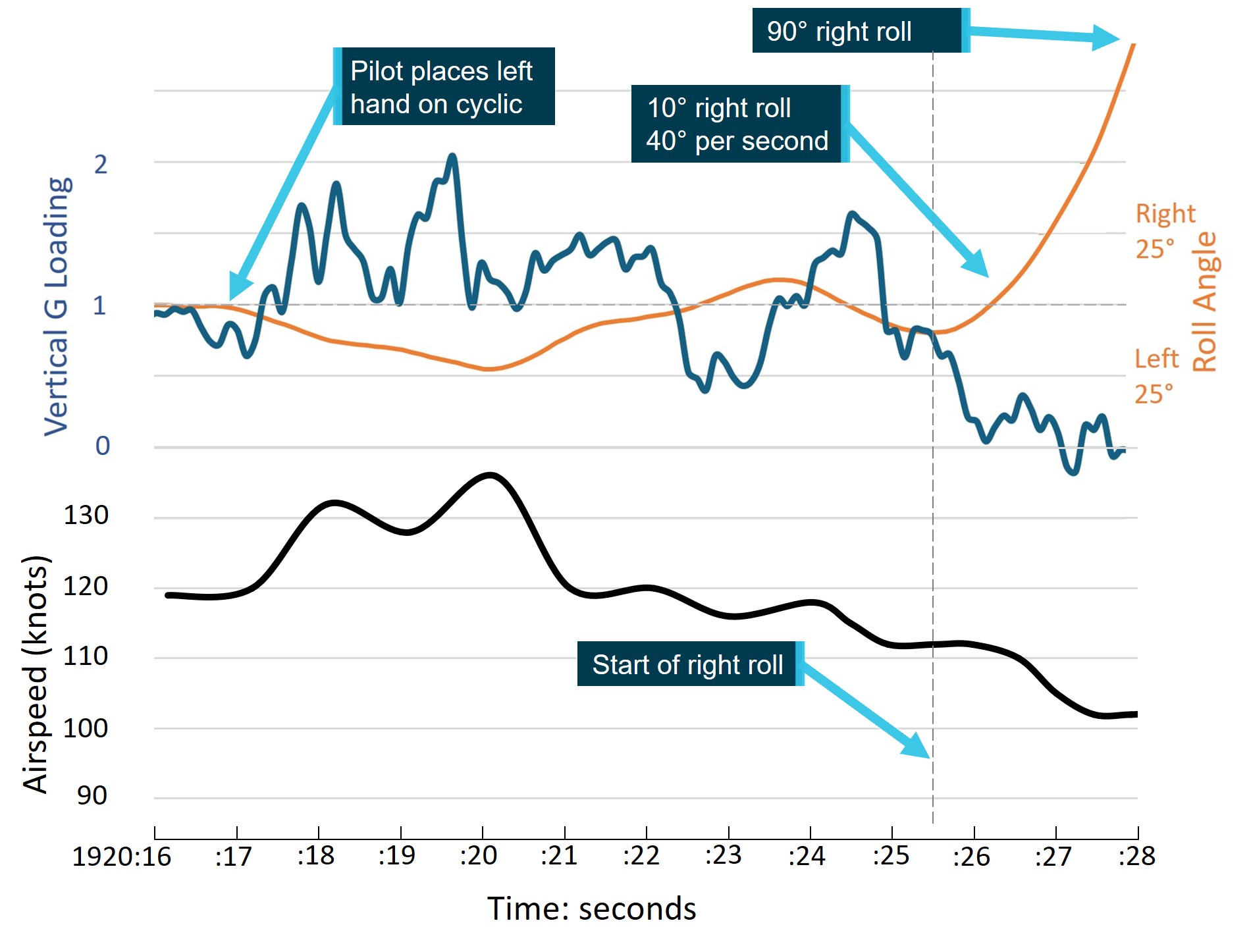
Airspeed smoothed for graph. Last second of flight cropped for clarity. Source: ATSB
Pilot cyclic control inputs
In the 10 seconds leading up to the loss of control, the pilot made smooth, gentle cyclic roll inputs in response to the attitude perturbations caused by turbulence. Additionally, coincident with the time of initiation of the low‑G (about 4 seconds prior to the loss of control), a 0.25 inch forward cyclic movement was initiated and maintained for about 1 second. Over the following 1.5 seconds, the cyclic was moved further forward to about 1 inch forward, before returning to the cruise position. The second forward cyclic input also coincided with the pitch attitude of the helicopter reducing by about 6° to an approximately level attitude.
The second forward cyclic movement was also made in conjunction with a progressively increasing left roll cyclic input and may have been unintentional, consistent with the biomechanical action of using the left hand on the cyclic crossbar. It is also possible that the forward cyclic inputs were intentionally applied to arrest the uncommanded climb in the context of the surrounding low cloud base. A localised peak in the recorded right roll rate was recorded concurrently with the 1 inch forward cyclic movement, the roll rate then progressively reduced from about 50º per second to 40º per second over 1.5 seconds (Figure 20).
Cyclic roll inputs made by the pilot appeared to be in response to the roll moments imparted by the turbulent air and low‑G condition. The cyclic roll inputs were smooth and proportional to the roll angle of the aircraft. As the final right roll developed and passed about 45°, full left cyclic was reached and held for the remainder of the flight.
Low‑G test flight data provided to the ATSB showed a delay of about 0.75 seconds between the initiation of a 1.25 inch, (1.75 second duration) forward/aft cyclic movement and the beginning of a right roll during a test flight at 120 kt[15], in an aircraft fitted with an asymmetric stabiliser.
A similar aircraft reaction delay, of about 0.4 seconds, to aft cyclic movement was also evident in the data which, importantly, arrested the roll rate, but did not stop the roll for at least 1 second. Test flight data analysis was terminated 1.5 seconds after the roll initiation. Data derived from the test flight video was compared to the accident flight data, which showed a 0.5 inch per second forward cyclic movement to 0.25 inch, about 0.5 seconds prior to the initiation of the right roll (Figure 20). The right roll rate accelerated rapidly in the 0.5 seconds prior to the in‑flight break‑up, after it passed through about 90º right roll, peaking at about 125º per second immediately before the break‑up.
Figure 20: Accident and test flight cyclic fore/aft inputs and roll response
Source: ATSB
The pilot’s dog was located in the back seat of the aircraft, and was not observed interfering with the flight controls at any time.
Pilot reaction time
In analysing the pilot’s response throughout this occurrence, several factors relating to reaction time require consideration. Human reaction time can be as fast as 110 milliseconds (0.11 seconds) in response to a tactile stimulus under optimal conditions, involving a practiced, single choice, response (Boff, K.R. et al., 1988). Pilot reaction times are dependent on a range of personal and environmental variables.[16] While studies have been conducted to identify and measure individual factors affecting a pilot’s response to a range of in‑flight events (see the section titled Sources and submissions), real world reaction times are significantly variable and events often have multiple relevant factors. Additionally, the overall result is not a simple addition of individual factors’ reaction times (Boff, K.R. et al, 1988).
Table 4 lists a range of studied effects relevant to the task of piloting an aircraft. The impacts of these effects are not a fixed value and vary subject to the particular situation, pilot arousal, focus and attention, and stress.
The significance of these effects is that the time between an event and a pilot reacting to that event can take a considerable amount of time, which is increased if the event is unexpected, elicits a stress response, or the response is not practiced beforehand.
As all these factors are experienced subjectively, their objective existence and influence are difficult to test outside the laboratory. However, their existence is acknowledged and measures such as:
- specifically-designed aircraft ergonomics
- warning systems
- practical training to prepare the pilot in both recognition and response to a particular event
all reduce the need for the pilot to analyse a situation in an emergency, improving response time.
Table 4: Reaction time factors
| Effect | Description | Relevance | Reaction time |
| Vestibular stimuli reaction time | When reaction is dependent on the vestibular sense, reaction time can be delayed when compared to touch, visual, or audible | The pilot is dependent on their vestibular sense to detect a low-G condition. | Highly variable. Median value ~ 400 milliseconds |
| Stimulus-response compatibility | When the response to a stimulus is not intuitively compatible with the stimuli, reaction time can increase. | To correct the low-G induced right roll, the pilot must apply aft cyclic before left cyclic can be applied. | Depending on degree of incompatibility 280 – 660 milliseconds |
| Multiple response options | If more than one possible response is available, response time can increase. | In a low-G/right roll, the pilot must decide between the intuitive and the recommended response. | Each doubling of alternatives adds ~ 150 milliseconds |
| Practice effect | When multiple possible responses to a stimulus are possible, practice of responses reduces reaction time. This effect is greatest when stimulus-response are incompatible, or options are numerous. | The inability to safely practice the correct response to the low-G condition results in increased reaction time to unexpected in-flight low-G. | Between 1 – 2 seconds |
| Irrelevant stimuli | When irrelevant stimuli are simultaneously present, reaction time can increase. | Aircraft movement due to turbulence, noises, alarms, and warning lights. | <400 milliseconds |
| Surprise effect | The surprise effect is defined as an emotional and cognitive response to an unexpected event that is difficult to explain and requires a person to change their understanding of the situation. Surprise cognitive responses include confusion, loss of situational awareness, interruption of ongoing task (freezing), inability to analyse and remember appropriate operating procedures. | Surprise increases arousal and draws attention to the triggering event. It mobilizes the attentional system on the most salient information, which is not the most important in that moment. This condition can significantly affect decision-making, problem solving, and critical skills in handling complex emergency situations. | Between 2.3 – 4.9 seconds (mean reaction time). 4.42 – 7.79 seconds (90th percentile reaction time). Chappelow, JW, Smith, PR (1999) CAA Paper 99001, Pilot Intervention Times in Helicopter Emergencies. Civil Aviation Authority, London |
| Stress response | Acute stress is a likely result of the surprise effect. Stress is thought to cause a shift from analytical skills toward intuitive judgment, making one susceptible to biases. | In this case it is likely that the pilot's stress increased as a result of the evolving loss of control of the aircraft. That resulted in the incorrect application of a partially fitting solution that was easily retrieved from memory due to recent experiences. | Variable dependent on subjective experience. |
Source: Boff, K. R., & Lincoln, J. E. Engineering Data Compendium 1988 & Diarra M, Marchitto M, Bressolle M-C, Baccino T and Drai‑Zerbib V (2023) A narrative review of the interconnection between pilot acute stress, startle, and surprise effects in the aviation context: Contribution of physiological measurements.
Operational guidance
Pilot operating handbook
The R66 POH contained several limitations, cautions, and notices pertaining to general aircraft flight, flight in turbulence, and the low‑G condition. Relevant to the circumstances of this accident flight, they were:
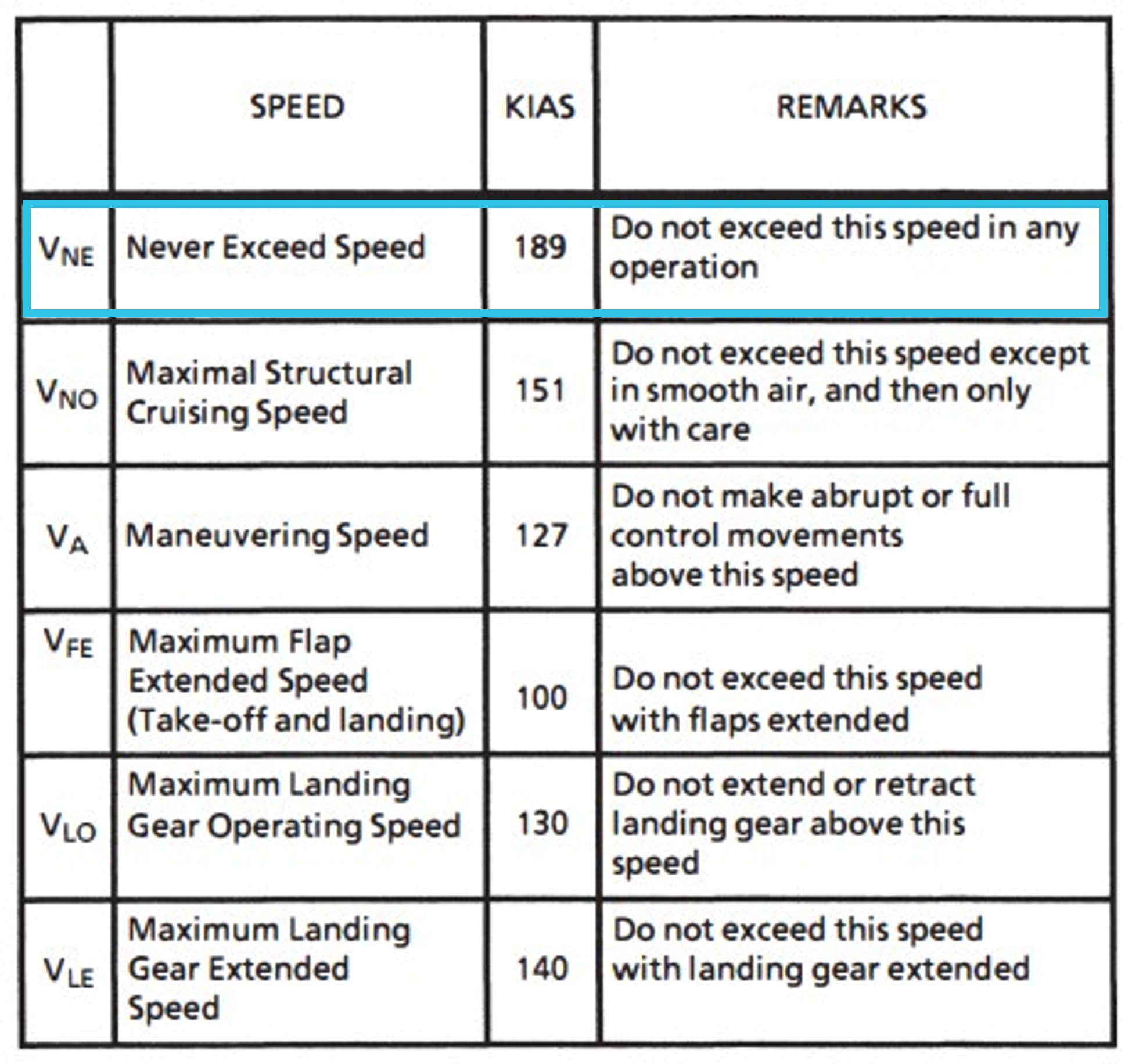
- Section 2 Limitations. AIRSPEED LIMITS.
NEVER EXCEED AIRSPEED (Vne) Below 2200 lb (998 kg) TOGW 140 KIAS - Section 2 Limitations. FLIGHT AND MANEUVER LIMITATIONS.
Low-G cyclic pushovers prohibited CAUTION A pushover (forward cyclic maneuver) performed from level flight or following a pull-up causes a low-G (near weightless) condition which can result in catastrophic loss of lateral control. To eliminate a low-G condition, immediately apply gentle aft cyclic. Should a roll commence during a low-G condition, apply gentle aft cyclic to reload rotor before applying lateral cyclic to stop roll. - Section 2 Limitations. INSTRUMENT MARKINGS.
DO NOT EXCEED 110 KIAS EXCEPT IN SMOOTH AIR - Section 2 Limitations. PLACARDS.
LOW-G PUSHOVERS PROHIBITED - Section 4. NORMAL PROCEDURES.
RECOMMENDED AIRSPEEDS
Maximum Cruise. 110 KIAS (Do not exceed except in smooth air and then only with caution)
Significant turbulence[17]. 60 to 70 KIAS - Section 4. NORMAL PROCEDURES.
CRUISE
2. … Maximum recommended cruise speed is 110 KIAS.
CAUTION Do not exceed 110 KIAS except in smooth air and then only with caution. In turbulence, use lower airspeed. If turbulence is significant or becomes uncomfortable for the pilot, use 60 to 70 KIAS. - Section 9. HELISAS AUTOPILOT
CAUTION The autopilot is intended to enhance safety by reducing pilot workload. It is not a substitute for adequate pilot skill nor does it relieve the pilot of the responsibility to monitor the flight controls and maintain adequate outside visual reference. - Section 10. SAFETY TIPS AND NOTICES
SAFETY TIPS
1. Never push the cyclic forward to descend or to terminate a pull-up (as you would in an airplane). This may produce a low-G (weightless) condition which can result in a main rotor blade striking the cabin. Always use the collective to initiate a descent.
PILOT KNOWLEDGE AND PROFICIENCY
- Low-G and mast bumping (Ref SNs 11, 29, and 32)- Avoidance
- Reduce airspeed in turbulence
- Monitor airspeed when lightly loaded
- Ensure passenger controls are removed
- Recognition and recovery
CAUTION Never practice/demonstrate low-G in flight. Low-G training should be knowledge based only.
- Avoidance
Three safety notices in the Robinson R66 POH were also relevant:
Safety Notice SN-11 LOW-G PUSHOVERS – EXTREMELY DANGEROUS
Pushing the cyclic forward following a pull-up or rapid climb, or even from level flight, produces a low‑G (weightless) flight condition. If the helicopter is still pitching forward when the pilot applies aft cyclic to reload the rotor, the rotor disc may tilt aft relative to the fuselage before it is reloaded. The main rotor torque reaction will then combine with tail rotor thrust to produce a powerful right rolling moment on the fuselage. With no lift from the rotor, there is no lateral control to stop the rapid right roll and mast bumping can occur. Severe in‑flight mast bumping usually results in main rotor shaft separation and/or rotor blade contact with the fuselage.
The rotor must be reloaded before lateral cyclic can stop the right roll. To reload the rotor, apply an immediate gentle aft cyclic, but avoid any large aft cyclic inputs. (The low‑G which occurs during a rapid autorotation entry is not a problem because lowering the collective reduces both rotor lift and rotor torque at the same time.)
Never attempt to demonstrate or experiment with low‑G maneuverers, regardless of your skill or experience level. Even highly experienced test pilots have been killed investigating the low‑G flight condition. Low‑G mast bumping is almost always fatal.
NEVER PERFORM A LOW-G PUSHOVER!!
Safety Notice SN-29 AIRPLANE PILOTS HIGH RISK WHEN FLYING HELICOPTERS
There have been a number of fatal accidents involving experienced pilots who have many hours in airplanes but with only limited experience flying helicopters.
The ingrained reactions of an experienced airplane pilot can be deadly when flying a helicopter. The airplane pilot may fly the helicopter well when doing normal maneuvers under ordinary conditions when there is time to think about the proper response. But when required to react suddenly under unexpected circumstances, he may revert to his airplane reactions and commit a fatal error. Under those conditions, his hands and feet may move purely by reaction without conscious thought. Those reactions may well be based on his greater experience, ie., the reactions developed flying airplanes.
For example, in an airplane his reaction to a stall warning horn (stall) would be to immediately go forward with the stick and add power. In a helicopter, application of forward stick when the pilot hears a horn (low RPM) would drive RPM even lower and could result in a rotor stall, especially if he also “adds power” (up collective). In less than one second the pilot could stall his rotor, causing the helicopter to fall out of the sky.
Another example is the reaction necessary to make the aircraft go down. If the helicopter must suddenly descend to avoid a bird or another aircraft, he rapidly lowers the collective with very little movement of the cyclic stick. In the same situation, the airplane pilot would push the stick forward to dive. A rapid forward movement of the helicopter stick under these conditions would result in a low “G” condition which could cause mast bumping, resulting in separation of the rotor shaft or one blade striking the fuselage. A similar situation exists when terminating a climb after a pull-up. The airplane pilot does it with forward stick. The helicopter pilot must use his collective or a very gradual, gentle application of forward cyclic.
To stay alive in the helicopter, the experienced airplane pilot must devote considerable time and effort to developing safe helicopter reactions. The helicopter reactions must be stronger and take precedence over the pilot’s airplane reactions because everything happens faster in a helicopter. The pilot does not have time to realize he made the wrong move, think about it, and then correct it. It is too late; the rotor has already stalled or a blade has already struck the airframe and there is no chance of recovery. To develop safe helicopter reactions, the airplane pilot must practice each procedure over and over again with a competent instructor until his hands and feet will always make the right move without requiring conscious thought. AND ABOVE ALL, HE MUST NEVER ABRUPTLY PUSH THE CYCLIC STICK FORWARD.
Safety Notice SN-32 HIGH WINDS OR TURBULENCE
Flying in high winds or turbulence should be avoided.
A pilot’s improper application of control inputs in response to turbulence can increase the likelihood of a mast bumping accident. If turbulence is encountered, the following procedures are recommended:
• 1. Reduce power and use a slower than normal cruise speed. Mast bumping is less likely at lower airspeeds.
• 2. For significant turbulence, reduce airspeed to 60 - 70 knots.
• 3. Tighten seat belt and rest forearm on right leg to minimise unintentional control inputs. Some pilots may choose to apply a small amount of cyclic friction to further minimise unintentional inputs.
• 4. Do not over control. Allow aircraft to go with turbulence, then restore level flight with smooth, gentle control inputs. Momentary airspeed, heading, altitude, and RPM excursions are to be expected.
• 5. Avoid flying on the downwind side of hills, ridges, or tall buildings where turbulence will most likely be severe.
The helicopter is more susceptible to turbulence at light weight. Reduce speed and use caution when flying solo or lightly loaded.
ATSB Safety advisory notice to Robinson Helicopter pilots and operators AO-2023-051-SAN-01
Shortly after this accident, the ATSB released the following safety advisory notice that emphasised several of the key points detailed above:
Anticipate turbulence and slow down
Although further analysis is required to establish the contributing factors in this accident, the circumstances as far as they are known at this time suggest that the helicopter encountered turbulence, followed by a low‑G condition immediately prior to the in‑flight break‑up. The ATSB therefore considers it prudent to draw attention to Robinson’s advice regarding flight in turbulent conditions and avoidance/recovery from low‑G flight until such time as the factors that contributed to this accident can be fully established.
Awareness of conditions likely to produce turbulence, and slowing down prior to encountering turbulence, could increase the time available to recognise and respond to a low‑G condition in Robinson Helicopters.
Related occurrences
Between 2014 and 2023, the ATSB recorded 2 (including this event) fatal mast bumping accidents in Robinson aircraft where turbulence was identified as a factor.
In the same 9-year period, the United States (US) National Transportation Safety Board (NTSB) recorded 2 similar occurrences, which were able to be confidently attributed to low-G in‑flight break‑up with a likely environmental contribution. Several other NTSB reports into Robinson accidents were considered in this process, however the publicly available NTSB accident reports into Robinson Helicopter in‑flight break‑ups were often brief, without the detail necessary to assess the contributing factors, and therefore restricted the assessment of similarity to this event. A conservative approach was taken to assess similarity, and it is possible that a greater number of related occurrences exist than are presented here.
The New Zealand (NZ) Transport Accident Investigation Commission (TAIC) recorded 3 related accidents in the period between 2014 and 2023. One 2013 incident was also included in this list as it detailed a rare case of a pilot who encountered a low-G condition, and 360º right roll, and avoided an in‑flight break‑up. In that occurrence sequence no left cyclic input was applied by the pilot.
Australian Transport Safety Bureau AO-2020-061
In December 2020 a Robinson R44, VH-HGU, entered a low‑G condition due to turbulence, inappropriate control inputs, or a combination of both, and experienced an in‑flight break‑up. The ATSB completed an investigation and found:
Wreckage examination indicated that while flying in the vicinity of the valley, the helicopter entered a low‑G condition due to turbulence, inappropriate control inputs, or a combination of both. This condition, probably in combination with inappropriate recovery control inputs resulted in extreme teetering of the main rotor. A mast bump occurred as a result, and the helicopter subsequently broke up in flight.
An intense post-impact fire prevented a complete examination of the wreckage. However, the evidence available gave no indication that the helicopter was operating abnormally prior to the in‑flight break‑up.
The circumstances leading to in‑flight break‑ups from mast bumping and extreme teetering are usually not identified. While the fire would likely have prevented data recovery in this case, the inclusion of readily available cockpit video recorders on helicopters with semi-rigid rotor heads would provide valuable insights into low‑G mast bumping events, which could help to prevent future occurrences.
National Transport Safety Bureau WPR19FA123
In April 2019, a Robinson R44, N808NV, experienced a low‑G condition and an in‑flight break‑up in the US state of Hawaii. The NTSB completed an investigation and attributed the accident to:
The helicopter’s encounter with a strong downdraft or outflow boundary while operating at a higher than recommended airspeed in turbulence which resulted in a low‑G condition, excessive main rotor flapping, and an in-flight breakup when the main rotor contacted the cabin area.
National Transport Safety BureauWPR16FA130
In June 2016, a Robinson R66, N117TW, experienced mast bumping and an in‑flight break‑up in the US state of Arizona. The NTSB completed an investigation and attributed the accident to:
An encounter with turbulence due to updrafts and/or dust devils that resulted in mast bumping and an in‑flight break‑up.
New Zealand Transport Accident Investigation Commission AO-2018-006
In July 2018, a Robinson R44, ZK-HTB, experienced an in‑flight break‑up near Wanaka. The New Zealand TAIC competed an investigation and found:
The helicopter was likely to have encountered unexpected turbulence of a magnitude sufficient to result ultimately in the in‑flight break‑up of the helicopter.
The helicopter’s speed at the last position report likely increased the risk of an adverse outcome in the mountainous operating environment.
The non-standard term ‘significant’, which was used to describe turbulence in the R44 Pilot Operating Handbook, was not defined and pilots may not have watched a Robinson Helicopter Company video regarding Safety Notice 32 and turbulence, and the use of the term ‘significant’.
The lack of reliable evidence on the initiating cause or causes of mast bumping occurrences continues to limit the effectiveness of safety investigations.
The requirement to understand more about the performance of the Robinson Helicopter Company‑designed rotor system, especially in turbulence, remains.
New Zealand Transport Accident Investigation Commission AO-2015-002
In February 2015, a Robinson R44, ZK-IPY, experienced mast bumping and an in‑flight break‑up at Lochy River. The New Zealand TAIC competed an investigation and found:
The helicopter suffered a mast bumping event that resulted in a main rotor blade contacting the cabin area and initiated an in‑flight break‑up.
An examination of the wreckage revealed no pre-existing defects or mechanical failures that would have resulted in mast bumping. However, the damage to the helicopter meant that some kind of mechanical issue contributing to the accident could not be fully excluded.
The weather was generally calm and suitable for the training flight. There were about as likely as not to have been pockets of light to moderate turbulence in the area, but this alone should not have resulted in significant mast bumping.
The airspeed of the helicopter as it flew down the valley returning to Queenstown was as likely as not at least 102 knots when the accident occurred.
The student was about as likely as not to have been flying the helicopter when the mast bumping occurred.
The cause of the mast bumping event that initiated the in‑flight break‑up could not be conclusively determined.
The causes and circumstances of helicopter mast bumping accidents are unlikely to be fully understood until a means of recording cockpit imagery and/or other data is made available.
New Zealand Transport Accident Investigation Commission AO-2014-006
In October 2014, a Robinson R44, ZK-HBQ, experienced mast bumping and an in‑flight break‑up at the Kahurangi National Park, New Zealand. The New Zealand TAIC competed an investigation and found:
A mast-bump occurred, which led to rotor divergence and the in‑flight break‑up.
The in‑flight break‑up was very unlikely to have been caused by low main rotor RPM (revolutions per minute).
An abrupt, inappropriate or inadvertent cyclic control input by the pilot could not be ruled out as having contributed to the in‑flight break‑up.
The actual wind and turbulence at the time and location of the accident were very likely to have been the same as, or stronger than, the forecast conditions.
The helicopter very likely encountered moderate to severe turbulence and an associated severe downdraught in the lee of Mt Arthur, which likely created a prolonged low‑G condition.
Had a previous limitation on maximum wind speeds for inexperienced R44 pilots remained in place, as per that for R22 pilots, the pilot would have been prohibited from flying at the time of the accident due to the forecast strong winds and turbulence.
All three Robinson helicopter models are susceptible to low‑G mast-bumping, and any preventive measures should apply to all of them.
Due to their unique main rotor design, during a prolonged or severe low‑G condition Robinson helicopters can roll rapidly to the right, and likely break up before a pilot can recover.
A pilot’s instinctive reaction to an unexpected right roll, or the unintentional movement of a pilot’s limbs or upper body during severe turbulence or low‑G, could lead to mast-bumping.
Although not an intuitive reaction to a sudden right roll, the aft cyclic technique is the only approved recovery technique, and should be used as soon as low‑G is felt to ‘reload’ the main rotor disc and help reduce any right roll.
New Zealand Transport Accident Investigation Commission AO-2013-005
Although this occurrence happened outside the 10‑year period, and did not result in an in‑flight break‑up, it is included here to demonstrate the uncertainty regarding pilot and aircraft responses during an unexpected low‑G condition.
In March 2013, a Robinson R22, ZK-HIE, experienced a low‑G condition and subsequent right roll at New Plymouth, New Zealand. The pilot did not apply aft cyclic, but was able to regain control of the helicopter after it completed a 360° right roll. The pilot was aware of the potential for mast bumping if he countered the right roll with left cyclic and attempted to keep the rotor disc perpendicular to the mast throughout the roll.
The aircraft descended 800 or 900 feet before control was regained. A post‑flight inspection showed clear evidence of mast bumping, and the main gearbox, driveshaft, and majority of the main rotor head assembly was replaced. The New Zealand TAIC competed an investigation and found:
No environmental condition or helicopter defect caused the un-commanded roll
It was probable that the un-commanded roll was caused by an inadvertent reduction in G during the transition from the flap-forward demonstration to the next exercise, while the engine power was at a relatively high setting
The section of the United States Special Federal Aviation Regulation No. 73, which requires Robinson helicopter pilots to have dual flight instruction in the effects of low‑G manoeuvring, appears to contradict the R22 helicopter flight manual, which prohibits the demonstration of low‑G conditions
The importance of some critical safety information in Robinson flight manuals was likely to have been diminished by Robinson’s use of “Caution”, rather than “Warning”, for operating conditions and practices that involve a risk of personal injury or loss of life.
Safety analysis
Introduction
On 26 September 2023 the pilot of a Robinson R66 helicopter, VH-KFT, departed Cessnock Airport, New South Wales and travelled north along the Williamtown coastal VFR route. After crossing the Yacaaba Headland the aircraft encountered turbulence, and subsequent uncommanded right roll, resulting in an in‑flight break‑up. The aircraft impacted the waters of Providence Bay, near Hawks Nest and the pilot was fatally injured.
No evidence was found of pre-existing mechanical defects. Damage to the main rotor mast and fuselage was consistent with low-G mast bumping leading to an in‑flight break‑up. Cockpit video and data provided a high‑fidelity record of the events leading up to the accident. Analysis of this information identified the presence of turbulence, its effect on the aircraft and the pilot’s response. It also allowed the contribution of the asymmetric horizontal stabiliser to the right roll to be observed in a low‑G condition.
This analysis will discuss the:
- environmental conditions
- pilot’s decision to cross the Yacaaba Headland
- effect of the pilot’s control inputs
- effect of the asymmetric horizontal stabiliser and its contribution to the right roll during the low‑G condition
- Robinson Helicopter Pilot’s Operating Handbook (POH) cautions and notices pertaining to flight in turbulence and low‑G conditions.
Finally, the contribution of the recovered video and data from the Robinson Helicopter Company fitted cockpit camera system to the investigation will be discussed.
Turbulence encounter
Mount Yacaaba peak was about 218 m (715 ft) above sea level, with the peak and ridge line located 200–250 m from the southern shoreline, forming a scarp on the south face of the headland at an average angle of 41–47°. Over small-scale topography exceeding 45,°, wind speeds above 20 kt can result in turbulent air that extends to up to twice the height of the terrain.
Analysis of meteorological observations identified the presence of about 25–30 kt southerly winds at 1,500 ft in the area surrounding Newcastle. This wind likely encountered Mount Yacaaba at an angle almost exactly perpendicular to the face of the scarp and ridgeline. It is likely that these winds combined with the topography of Yacaaba Headland to produce turbulence up to about 1,400 ft AMSL, and for some distance downwind, in the lee of the headland.
The position of VH-KFT, about 900 ft AMSL and 600 m to the west of the peak as it crossed the headland, likely resulted in the aircraft encountering rapidly rising air and turbulence as it moved into the lee of Mount Yacaaba. Although the type, severity, and extent of turbulence produced could not be determined with certainty, the behaviour of the aircraft during the encounter was consistent with an encounter with significant orographic turbulence.
The initial uplift resulted in an increase in altitude of about 200 ft in 10 seconds, a rate of climb over 1,000 ft per minute. Data recovered from the in‑flight camera showed positive G loading greater than +2 G during the climb from about 900 ft to 1,100 ft. Shortly after, the aircraft entered a low-G condition.
The subsequent reduction in vertical-G, from about 1.5 G, to 0.9 G, about 0.5 seconds prior to the initiation of an uncommanded right roll, was coincident with a 0.25 inch forward movement of the cyclic by the pilot. While the encountered turbulence likely contributed directly to the reduction in the G loading, advice in Robinson Helicopter Company’s Safety Notice SN-11 that:
Pushing the cyclic forward following a pull-up or rapid climb, produces a low‑G (weightless) flight condition...
supported a conclusion that the forward cyclic application conducted at relatively high airspeed also contributed.
The 0.25 inch forward position was held for about 1 second, during which vertical-G reduced further to zero G as the right roll started. This further reduction in vertical-G was not accompanied by a further cyclic movement from the pilot, indicating it was likely turbulence-related.
The subsequent forward cyclic input to about 1 inch forward of the cruise position and aft cyclic movement back to around the cruise flight position coincided with the helicopter’s pitch attitude reducing by 6° to approximately level over about 1.5 seconds. The recorded data also showed a correlation between the forward cyclic movement and a localised roll rate peak of about 55° per second, as well as a corresponding gradual reduction in roll rate to about 50° per second coincident with the aft cyclic movement.
That roll behaviour was consistent with the expected effect of the fore/aft cyclic applications on the rolling tendency. However, the data also showed that vertical-G decreased to just above zero G before the second forward cyclic movement, and remained relatively constant until after the cyclic was moved aft to near the cruise position.
It could not be determined whether the forward cyclic inputs were the unintended result of moving the cyclic with the left hand or intentionally applied to arrest the climb rather than lowering the collective. In either event, the turbulence and the pilot’s response to it resulted in the helicopter rapidly entering a low‑G condition followed by a significant uncommanded right roll.
Contributing factor The helicopter crossed the Yacaaba Headland at an altitude and position that resulted in it rapidly entering a low‑G condition due to turbulence and the pilot’s response to it, inducing an uncommanded right roll. |
Airspeed and roll rate
The downward force produced by the asymmetric horizontal stabiliser is the primary contributor to right roll in a low‑G condition. The downward force varies with the airflow over the stabiliser. Therefore, as airspeed increases the downward force and resultant right roll rate will increase in a low‑G condition.
At the time the aircraft crossed the southern shoreline of Yacaaba Headland the autopilot was engaged and the indicated airspeed was 115 kt, 5 kt above the Robinson maximum recommended cruise speed. It was also 45 kt above the maximum recommended speed specified in the pilot’s operating handbook POH and SN-32 for flight in significant turbulence. In the 15 seconds between crossing the southern shoreline and encountering the final low‑G condition the indicated airspeed increased to a maximum of about 135 kt, before decreasing to about 112 kt. During this time the pilot did not attempt to reduce the airspeed using the collective or cyclic.
In the last 3.5 seconds of flight, between the initiation of the low‑G condition and the in‑flight break‑up, the aircraft right rolled about 285°, peaking at about 125° per second immediately prior to the in‑flight break‑up. By the time the aircraft had rolled 10° to the right, about 1 second after the initiation of the roll, the indicated airspeed was about 112 kt, and the roll rate had accelerated to 40° per second. From that point the aircraft reached 90° right roll in 1.5 seconds.
It is possible that the reason the pilot did not slow the aircraft during the encounter with turbulence was due to using their left hand on the cyclic cross bar. It is also possible that the pilot was focused on responding to the turbulence using small, gentle control inputs in accordance with SN‑32, however, SN‑32 also instructed pilots to use slower than normal cruise speed, which was not applied in this case.
Accurate wind forecasts were available to the pilot prior to departing Cessnock, and sea surface indicators on approach to Yacaaba Headland provided an opportunity for the pilot to anticipate impending turbulence. Anticipation of turbulence is a key message of ATSB Safety Advisory Notice AO-2023-051-SAN-001. On this occasion, it would likely have allowed the pilot to slow down to reduce the severity of the encounter or avoid the turbulence by altering course.
Contributing factor The helicopter's airspeed exceeded Robinson Helicopter Company's recommended turbulence airspeed, which significantly increased the uncommanded right roll rate and reduced the time available for the pilot to respond with a gentle aft cyclic input to prevent an in‑flight break‑up. |
Left hand cyclic inputs
Following the encounter with turbulence, about 10 seconds were available for the pilot to lower the collective and slow the aircraft.
The pilot’s use of their left hand on the cyclic cross bar was an unconventional method of cyclic control, and likely resulted from the pilot’s engagement with non‑flight related tasks using their right hand immediately prior to encountering turbulence. A review of the recorded imagery for the accident flight identified that the final 12 seconds of flight was the only occasion where the pilot used their left hand to apply cyclic inputs.
To slow a helicopter in flight without climbing, coordinated collective and cyclic control inputs are required. The pilot’s use of their left hand on the cyclic cross bar prevented them from lowering the collective control without releasing the cyclic. However, as the autopilot was available, the pilot could have released the cyclic and lowered the collective with their left hand, slowing the aircraft.
It could not be determined if the pilot's actions would have been substantively different had the right hand been controlling the cyclic. The possibility remains that the pilot may have not assessed the turbulence as significant, and therefore not attempted to slow the aircraft, in accordance with the advice in SN‑32, prior to encountering the low‑G condition.
Other factor that increased risk At the time the helicopter encountered turbulence, the pilot’s right hand was occupied, resulting in them manipulating the cyclic with their unsupported left hand. This reduced the pilot's ability to slow the aircraft in a timely manner using coordinated flight control inputs. |
Aft cyclic not applied
The risk of mast bumping posed by low‑G flight conditions applies to all helicopters with teetering rotor heads. In Robinson helicopters with asymmetric stabilisers, encountering low‑G results in a powerful right roll, especially at high airspeed, which requires the pilot to reload the main rotor with a gentle aft cyclic before corrective lateral cyclic inputs were applied.
Analysis of the recovered video showed that a brief 1 inch forward and aft cyclic movement was made over about 1.5 seconds after the commencement of the low‑G condition. The data showed a correlation between the forward movement and a localised roll rate peak of about 55° per second, as well as a corresponding gradual reduction in roll rate to about 50° per second coincident with the 1 inch aft cyclic movement. However, the recorded data also showed a slight reduction in G loading after the aft cyclic movement, rather than reloading of the main rotor. While turbulence likely affected the G loading throughout the final flight segment, it was also noted that a sustained aft cyclic movement past the nominal cruise position, as demonstrated in the test flight video, was not applied.
The recovered data also showed that the low‑G condition developed rapidly and left little time for the pilot to recognise and respond. In the first second after the initiation of the roll the aircraft moved from 15° left to 10° right roll and reached a roll rate of 40° per second. About 1.5 seconds after that, the aircraft reached 90° right roll, at 45° per second. One second later the aircraft had rolled past inverted to 270°, and the roll rate had peaked at about 125° per second, immediately prior to an in‑flight break‑up. The total time between initiation of the uncommanded right roll, and the in‑flight break‑up was about 3.5 seconds.
The initiation of the low‑G condition took place during a period of turbulence and, up to that time, the pilot appeared to make a series of smooth and gentle cyclic roll inputs consistent with the advice in safety notice SN‑32. In the 1 second prior to the initiation of the final right roll, the aircraft rolled left to about 15º, and vertical loading reduced from about 1.5 G to about 0.9 G. From this point, vertical-G reduced to zero over about 0.5 seconds as the aircraft rolled right through level.
In that context, it is possible that the first 1 second of the development of the low‑G condition, was perceived as continuing turbulence. The pilot then had 1.5 seconds to recognise and respond to the low‑G before the aircraft reached 90° right roll.
Due to the nature of human reaction times, and the multiple possible effects present during the event, an assessment of the pilot’s reaction time was not possible. That said, it is likely that the 7 reaction time impairment factors listed in Table 4 were present in some capacity in the final 3.5 seconds of flight.
If the pilot had applied a similar immediate aft cyclic input to that conducted in the test flight, it is likely that the low‑G condition would have been corrected before the aircraft reached 90° right roll. However, the pilot’s reactive response to turbulence, and their likely reaction time impairments make it unlikely that the pilot could have recognised and responded to the low‑G condition in time.
Contributing factor After the aircraft entered the low‑G condition and the resultant uncommanded right roll, there was probably insufficient time to recognise and respond with application of aft cyclic, and the roll continued to develop. |
Left cyclic input
Cyclic input in normal conditions, such as in reaction to turbulence, reduces the clearance between the main rotor mast and spindles. However, in low‑G conditions the risk of extreme teetering exists due to the reduced fuselage response to lateral cyclic input, which increases the risk of maximum application of left cyclic input in response to the uncommanded right roll. If the clearance is reduced to zero, mast bumping occurs.
In a low‑G condition, an uncommanded right rolling moment develops due to the downward force produced by the asymmetric horizontal stabiliser and, to a lesser extent, tail rotor thrust. It is a natural tendency for the pilot to attempt to correct this roll by applying left cyclic. However, SN‑11 is clear in its advice, that in response to a low‑G condition the main rotor must be reloaded before applying left cyclic to correct the right roll, or mast bumping can result.
New Zealand (NZ) Transport Accident Investigation Commission (TAIC) investigation AO‑2013‑005 indicated that extreme teetering and mast bumping due to a low‑G right roll was possible without left cyclic input. While in that case the pilot was able to regain control and land, the damage due to mast bumping was significant enough to require replacement of the main rotor gearbox and most of the head.
The accident flight video recorded the pilot making an increasing left cyclic input in response to the developing right roll resulting from a low‑G condition. Full left cyclic was reached as the aircraft passed about 45° right roll. The fracture surface of the recovered mast was consistent with overload failure due to mast bumping. While the application of left cyclic likely increased the chances of an extreme teetering event resulting in mast bumping and an in‑flight break‑up, as the helicopter became inverted, the same result may have occurred without the application of left cyclic.
It is also possible that previous in‑flight break‑ups have occurred because of low‑G conditions without the application of left cyclic. However, there was insufficient evidence to reach a specific conclusion in those instances, with the inclusion of in-flight camera systems only a recent development.
Other factor that increased risk In response to the rapidly developing right roll, progressively increasing left cyclic was applied increasing the risk of an extreme teetering event. |
Asymmetric stabiliser
While tail rotor thrust contributes a right rolling moment in a low‑G condition, the asymmetric stabiliser fitted to R22, R44, and R66 helicopters is a much greater contributor. This effect increases with forward airspeed, and with the increased stabiliser angle of attack associated with a helicopter nose down attitude.
The rapidly developing right roll seen in the recovered accident video was consistent with the manufacturer’s asymmetric stabiliser low‑G test flight video at 120 kt, for the first 0.5 seconds of the roll. After that point the significant acceleration of the accident flight roll can be explained by the absence of the application of aft cyclic to reload the main rotor.
Over the last 10 years, the ATSB identified 7 other in‑flight break‑up accidents, across ATSB, TAIC (NZ) and National Transportation Safety Board (United States) databases. The contribution of the asymmetric horizontal stabiliser to these accidents could not be quantified, however, the damage signatures, such as mast bumping, the presence of turbulence, and in‑flight break‑up, across all the investigations suggested common involved factors.
The right rolling tendency due to low‑G is an inherent characteristic of teetering rotor head helicopters. However, the symmetrical stabiliser modification developed by Robinson Helicopter Company realigns the downward force with the aircraft’s centreline, significantly reducing the right rolling tendency. That allows more time to react appropriately and prevent a loss of control.
However, as a low‑G condition will still induce a right rolling moment due to thrust from the tail rotor, inappropriate flight control inputs can still lead to mast bumping and an in-flight break-up. In this case the pilot had insufficient time to apply effective aft cyclic and it could not be determined if they would have made substantively different control inputs if the symmetric stabiliser was fitted.
Other factor that increased risk The asymmetric horizontal stabiliser design in the Robinson R22, R44 and R66 models significantly contributed to the uncommanded right roll rate during low‑G conditions and the risk of an in‑flight break‑up. (Safety issue) |
Pilot’s operating handbook
The ATSB concluded that the pilot’s response to the turbulence encounter contributed to the development of the low‑G/uncommanded right roll. However, analysis of the recorded flight data also indicated that turbulence directly contributed to the reduced G loading.
Robinson Helicopter Company operational guidance warned pilots of the risk of inappropriate forward cyclic inputs resulting in a low‑G condition but did not identify the potential for a turbulence-induced low‑G condition without forward cyclic input. Throughout the pilot’s operating handbook (POH), several separate sections addressed the low‑G condition, mast bumping, and turbulence in the context of pilot inputs, specifically:
Section 10. SAFETY TIPS AND NOTICES
Never push the cyclic forward to descend or to terminate a pull-up (as you would in an airplane). This may produce a low-G (weightless) condition which can result in a main rotor blade striking the cabin. Always use the collective to initiate a descent.
SN-11 extract (low‑G pushovers – extremely dangerous)
Pushing the cyclic forward following a pull-up or rapid climb, or even from level flight, produces a low‑G (weightless) flight condition.
The main rotor torque reaction will then combine with tail rotor thrust to produce a powerful right rolling moment on the fuselage. With no lift from the rotor, there is no lateral control to stop the rapid right roll and mast bumping can occur
SN-29 extract (airplane pilots high risk when flying helicopters)
Another example is the reaction necessary to make the aircraft go down. If the helicopter must suddenly descend to avoid a bird or another aircraft, he rapidly lowers the collective with very little movement of the cyclic stick. In the same situation, the airplane pilot would push the stick forward to dive. A rapid forward movement of the helicopter stick under these conditions would result in a low “G” condition which could cause mast bumping, resulting in separation of the rotor shaft or one blade striking the fuselage. A similar situation exists when terminating a climb after a pull-up. The airplane pilot does it with forward stick. The helicopter pilot must use his collective or a very gradual, gentle application of forward cyclic.
SN-32 extract (high winds or turbulence)
A pilot’s improper application of control inputs in response to turbulence can increase the likelihood of a mast bumping accident,
Reduce power and use a slower than normal cruise speed. Mast bumping is less likely at lower airspeeds.
Do not over control. Allow aircraft to go with turbulence, then restore level flight with smooth, gentle control inputs. Momentary airspeed, heading, altitude, and RPM excursions are to be expected.,
The individual sections, or the body of the POH text, did not warn pilots of the risk of a low‑G condition developing without inappropriate control inputs, or the specific risk to flight safety if a low‑G condition was encountered at high airspeed.
While SN-32 advises pilots that mast bumping is less likely at lower speeds, it does not elaborate as to the cause of mast bumping in turbulence, or explain why mast bumping is less likely at lower speeds. The wording in SN-32 regarding flight in turbulent air would likely lead pilots to the conclusion that in turbulence, if the guidelines are followed, safety is assured. By extension, the safety notice indicates that mast bumping in turbulence is the result of pilot mishandling or over controlling in reaction to turbulence. Within SN-32, there is no mention of SN-11, low‑G, or the low‑G/uncommanded right roll condition, nor is there guidance on correct actions should low‑G be encountered.
Further, SN-11 specifically states that low‑G is the result of a forward cyclic movement, and does not address the possibility of an uncommanded low‑G condition due to turbulence, or reference SN‑32 (high wind or turbulence). SN‑11 also does not mention the aggravating role airspeed plays in the in the development of the uncommanded right roll, in a low‑G condition.
It is acknowledged that the point of SN‑29 is to specifically warn pilots against improper cyclic inputs, and as such the wording of SN‑29 is appropriate. However, SN‑29 likely further reinforces the notion that low‑G is a consequence of pilot cyclic inputs alone.
Section 10 of the POH advises pilots to reduce airspeed in turbulence to avoid ‘low‑G and mast bumping’. While this associates low‑G and turbulence, in the context of the other warnings in SN‑11, SN‑29, and SN‑32, it could be misunderstood, or overlooked entirely.
Regarding this accident, several sections of the POH warned pilots to slow down in turbulence, yet that did not occur. Therefore, any additional warnings pertaining to turbulence-induced low‑G may not have altered the outcome on this occasion.
Despite that, as outlined earlier, advice to ‘… go with the turbulence, then restore level flight with smooth gentle control inputs.’ presents a risk that uncommanded right roll in low‑G will be mistaken for the effect of turbulence and not promptly responded to.
Other factor that increased risk The Robinson Helicopter pilot’s operating handbook sections for operation in high winds or turbulence did not warn of the potential for turbulence-induced low‑G, and rapid right roll, particularly at high airspeed or provide guidance for appropriate control inputs in response to a turbulence-induced low‑G situation. This increased the risk of pilots encountering low‑G independent of control inputs, and an in‑flight break‑up. (Safety issue) |
In-flight camera
The analysis of information recovered from the factory-installed video and data recorder was invaluable in understanding this accident.
The video and data allowed the ATSB to identify the:
- specific sequence of events
- pilot actions
- circumstances leading to the development of low‑G and uncommanded right roll.
The detail in this report would not have been possible without access to this data. Of particular note was the understanding gained about the significant, rapid uncommanded right roll that can result from low‑G.
The ATSB commends the Robinson Helicopter Company’s installation of recording devices and encourages other manufacturers and owners to consider the ongoing safety benefit of similar devices.
Other finding The recovery of the Robinson Helicopter Company installed cockpit video camera and data was invaluable to the accident investigation. Analysis of the recovered data provided an unprecedented insight into the significant, rapid uncommanded right roll that can result from low‑G. |
Findings
ATSB investigation report findings focus on safety factors (that is, events and conditions that increase risk). Safety factors include ‘contributing factors’ and ‘other factors that increased risk’ (that is, factors that did not meet the definition of a contributing factor for this occurrence but were still considered important to include in the report for the purpose of increasing awareness and enhancing safety). In addition ‘other findings’ may be included to provide important information about topics other than safety factors. Safety issues are highlighted in bold to emphasise their importance. A safety issue is a safety factor that (a) can reasonably be regarded as having the potential to adversely affect the safety of future operations, and (b) is a characteristic of an organisation or a system, rather than a characteristic of a specific individual, or characteristic of an operating environment at a specific point in time. These findings should not be read as apportioning blame or liability to any particular organisation or individual. |
From the evidence available, the following findings are made with respect to the loss of control and in‑flight break‑up involving Robinson R66, VH-KFT near Hawks Nest, New South Wales on 26 October 2023.
Contributing factors
- The helicopter crossed the Yacaaba Headland at an altitude and position that resulted in it rapidly entering a low‑G condition due to turbulence and the pilot’s response to it, inducing an uncommanded right roll.
- The helicopter's airspeed exceeded Robinson Helicopter Company's recommended turbulence airspeed, which significantly increased the uncommanded right roll rate and reduced the time available for the pilot to respond with a gentle aft cyclic input to prevent an in‑flight break‑up.
- After the aircraft entered the low-G condition and the resultant uncommanded right roll, there was probably insufficient time to recognise and respond with application of aft cyclic, and the roll continued to develop.
Other factors that increased risk
- At the time the helicopter encountered turbulence, the pilot’s right hand was occupied, resulting in them manipulating the cyclic with their unsupported left hand. This reduced the pilot's ability to slow the aircraft in a timely manner using coordinated flight control inputs.
- In response to the rapidly developing right roll, progressively increasing left cyclic was applied increasing the risk of an extreme teetering event.
- The asymmetric horizontal stabiliser design in the Robinson R22, R44 and R66 models significantly contributed to the uncommanded right roll rate during low‑G conditions and the risk of an in‑flight break‑up. (Safety issue)
- The Robinson Helicopter pilot’s operating handbook sections for operation in high winds or turbulence did not warn of the potential for turbulence-induced low‑G, and rapid right roll, particularly at high airspeed or provide guidance for appropriate control inputs in response to a turbulence-induced low‑G situation. This increased the risk of pilots encountering low‑G independent of control inputs, and an in‑flight break‑up. (Safety issue)
Other findings
The recovery of the Robinson Helicopter Company installed cockpit video camera and data was invaluable to the accident investigation. Analysis of the recovered data provided an unprecedented insight into the significant, rapid uncommanded right roll that can result from low‑G.
Safety issues and actions
Central to the ATSB’s investigation of transport safety matters is the early identification of safety issues. The ATSB expects relevant organisations will address all safety issues an investigation identifies. Depending on the level of risk of a safety issue, the extent of corrective action taken by the relevant organisation(s), or the desirability of directing a broad safety message to the aviation industry, the ATSB may issue a formal safety recommendation or safety advisory notice as part of the final report. All of the directly involved parties are invited to provide submissions to this draft report. As part of that process, each organisation is asked to communicate what safety actions, if any, they have carried out or are planning to carry out in relation to each safety issue relevant to their organisation. Descriptions of each safety issue, and any associated safety recommendations, are detailed below. Click the link to read the full safety issue description, including the issue status and any safety action/s taken. Safety issues and actions are updated on this website when safety issue owners provide further information concerning the implementation of safety action. |
Pilot’s operating handbook
Safety issue number: AO-2023-051-SI-01
Safety issue description: The Robinson Helicopter pilot’s operating handbook sections for operation in high winds or turbulence did not warn of the potential for turbulence-induced low‑G, and rapid right roll, particularly at high airspeed or provide guidance for appropriate control inputs in response to a turbulence-induced low‑G situation. This increased the risk of pilots encountering low‑G independent of control inputs, and an in‑flight break‑up.
Asymmetric stabiliser contribution to uncommanded right roll
Safety issue number: AO-2023-051-SI-02
Safety issue description: The asymmetric horizontal stabiliser design in the Robinson R22, R44 and R66 models significantly contributed to the uncommanded right roll rate during low‑G conditions and the risk of an in‑flight break‑up.
Safety advisory notice to Robinson Helicopter pilots and operators
| SAN number: | AO-2023-051-SAN-01 |
On 24 March 2024 the ATSB released the following safety advisory notice based on the circumstances of the accident known at the time:
Anticipate turbulence and slow down
Although further analysis is required to establish the contributing factors in this accident, the circumstances as far as they are known at this time suggest that the helicopter encountered turbulence, followed by a low‑G condition immediately prior to the in‑flight break‑up. The ATSB therefore considers it prudent to draw attention to Robinson’s advice regarding flight in turbulent conditions and avoidance/recovery from low‑G flight until such time as the factors that contributed to this accident can be fully established.
Awareness of conditions likely to produce turbulence, and slowing down prior to encountering turbulence, could increase the time available to recognise and respond to a low‑G condition in Robinson Helicopters.
What happened
On 26 October 2023, the pilot of a Robinson R66 helicopter encountered mechanical turbulence flying over Yacaaba Headland, NSW, which resulted in a rapid loss of control and subsequent in‑flight break‑up.
Why did it happen
Prior to encountering turbulence, the aircraft was traveling at an airspeed which may have increased the severity of the aerodynamic effects of the turbulence. This possibly reduced the time available for the pilot to recognise and recover from a low‑G condition, and avoid a loss of control.
Safety advisory notice
AO-2023-051-SAN-001: The ATSB advises all operators of Robinson helicopters to be aware of the possibility of mechanical turbulence and avoid it whenever possible. If it is not possible to avoid flying through an area where mechanical turbulence is anticipated, reduce airspeed to 60–70 kt in accordance with Robinson Safety Notice 32, prior to encountering turbulence.
Slow down prior to suspected turbulence
Robinson Helicopters’ handling characteristics in low‑G and turbulent conditions are well documented and detailed in Robinson Helicopter Safety Notices SN-11 & SN-32 respectively. In both cases an increased airspeed affects the severity of the resulting aircraft response, and increases the likelihood of mast bumping and in‑flight break‑up.
It is possible that, at high airspeeds, an encounter with turbulence may produce a reaction that requires an immediate and decisive response from the pilot to ensure the safety of flight. As outlined in Robinson Safety Notice 11, a low‑G (weightless) condition can result in a powerful right roll. In such circumstances, ‘The rotor must be reloaded before lateral cyclic can stop the right roll. To reload the rotor, apply an immediate gentle aft cyclic, but avoid any large aft cyclic inputs.’
As airspeed increases, the time available for the pilot to recognise and respond to undesirable aircraft states is significantly reduced.
Pilots are reminded to remain vigilant at all times and to continuously assess conditions to identify the possibility for turbulence. Where any doubt exists, pilots should reduce airspeed prior to entering an area with potential for turbulence to reduce the effects of, and increase the available response time to, an upset condition.
Glossary
| AMSL | Above mean sea level |
| AP | Auto pilot |
| ATC | Air traffic control |
| BoM | Bureau of Meteorology |
| CAA | Civil Aviation Authority |
| FTR | Force Trim Release |
| GB | Gigabyte |
| GPS | Global positioning system |
| GPWT | Grid point wind temperature |
| KIAS | Knots indicated airspeed |
| MET | Meteorological |
| METAR | METeorological Aerodrome Report |
| NSW | New South Wales |
| NTSB | National Transportation Safety Bureau |
| POH | Pilot’s operating handbook |
| RHC | Robinson Helicopter Company |
| RPM | Revolutions per minute |
| SAN | Safety advisory notice |
| SAS | Stability augmentation system |
| SD | Secure digital |
| SPECI | SPECIal report of meteorological conditions |
| TAIC | Transport Accident Investigation Commission |
| VFR | Visual flight rules |
Sources and submissions
Sources of information
The sources of information during the investigation included:
- the in-flight video and data recorder
- Williamtown Airport air traffic control
- Civil Aviation Safety Authority
- Bureau of Meteorology
- Airservices Australia
- New South Wales Police Force Marine Area Command
- Robinson Helicopter Company
- the maintenance organisation for VH-KFT
- external video footage of the accident flight taken on the day of the accident
- National Aeronautics and Space Administration
- United States National Transportation Safety Board
- New Zealand Transport Accident Investigation Commission
References
Landman et al. (2017) Landman A, Groen EL, van Paassen MMR, Bronkhorst AW, Mulder M. “Dealing With Unexpected Events on the Flight Deck: A Conceptual Model of Startle and Surprise.” Hum Factors. 2017 Dec;59(8):1161-1172. doi: 10.1177/0018720817723428. Epub 2017 Aug 4. PMID: 28777917; PMCID: PMC5682572.
Chappelow et al. (1999) Chappelow, J. W., P. R. Smith, and Great Britain Civil Aviation Authority. 1999. Pilot Intervention Times in Helicopter Emergencies. London: Civil Aviation Authority.
Marin. C (1996) C.Marin Faure, Flying a Floatplane, 3rd edn, McGraw-Hill, 1996, p. 101-102.
UK MET (1994) UK Meteorological Office, Handbook of Aviation Meteorology, 3rd edn, HMSO, 1994.
Boff, K.R. et al. (1988) Boff, K. R., & Lincoln, J. E. Engineering Data Compendium 1988
Submissions
Under section 26 of the Transport Safety Investigation Act 2003, the ATSB may provide a draft report, on a confidential basis, to any person whom the ATSB considers appropriate. That section allows a person receiving a draft report to make submissions to the ATSB about the draft report.
A draft of this report was provided to the following directly involved parties:
- Robinson Helicopter Company
- Civil Aviation Safety Authority
- United States National Transportation Safety Board
Submissions were received from:
- Robinson Helicopter Company
- Civil Aviation Safety Authority
The submissions were reviewed and, where considered appropriate, the text of the report was amended accordingly.
Purpose of safety investigationsThe objective of a safety investigation is to enhance transport safety. This is done through:
It is not a function of the ATSB to apportion blame or provide a means for determining liability. At the same time, an investigation report must include factual material of sufficient weight to support the analysis and findings. At all times the ATSB endeavours to balance the use of material that could imply adverse comment with the need to properly explain what happened, and why, in a fair and unbiased manner. The ATSB does not investigate for the purpose of taking administrative, regulatory or criminal action. TerminologyAn explanation of terminology used in ATSB investigation reports is available here. This includes terms such as occurrence, contributing factor, other factor that increased risk, and safety issue. Publishing informationReleased in accordance with section 25 of the Transport Safety Investigation Act 2003 Published by: Australian Transport Safety Bureau © Commonwealth of Australia 2025 
Ownership of intellectual property rights in this publication Unless otherwise noted, copyright (and any other intellectual property rights, if any) in this report publication is owned by the Commonwealth of Australia. Creative Commons licence With the exception of the Commonwealth Coat of Arms, ATSB logo, and photos and graphics in which a third party holds copyright, this report is licensed under a Creative Commons Attribution 4.0 International licence. The CC BY 4.0 licence enables you to distribute, remix, adapt, and build upon our material in any medium or format, so long as attribution is given to the Australian Transport Safety Bureau. Copyright in material obtained from other agencies, private individuals or organisations, belongs to those agencies, individuals or organisations. Where you wish to use their material, you will need to contact them directly. |
[1] AP DISC/OFF button: allowed AP disengagement without removing hand from flight controls.
[2] Force Trim Release button: q momentary press button, located on the cyclic control, used to reset the target attitude (to re-trim) when in SAS.
[3] Heading bug: a marking on the heading indicator that could be rotated to a specific heading. Used for reference purposes or to direct the autopilot system.
[4] Based on 22 gallons per hour stated average in Robinson R66 Turbine Estimated Operating Costs, 15 January 2024.
[5] Visual flight rules (VFR): a set of regulations that permit a pilot to operate an aircraft only in weather conditions generally clear enough to allow the pilot to see where the aircraft is going.
[6] Main rotor head, hub and blades were recovered, washed up on Great Mermaid Beach, Hawks Nest on 20 April 2025. Damage caused by long‑term saltwater exposure and erosion prevented a detailed inspection of damage. However, no evidence was found which contradicted the evidence identified during the course of the investigation.
[7] G: an abbreviation for acceleration forces acting on a body with reference to earth’s gravity at sea level. 1 G = 9.8 m/s2. Therefore, a body at rest, or moving at a constant velocity, in relation to the earth is said to be experiencing 1 G.
[8] G load: the nominal value for acceleration. In flight, G loads represent the combined effects of flight manoeuvring loads and turbulence and can have a positive or negative value.
[9] Stratus: found in the lower levels of the atmosphere, tend to produce a light drizzle.
[10] Stratocumulus: found in the lower levels, a blend between stratiform and cumuliform cloud and taking on appearances from both these cloud types, may produce drizzle.
[11] GPWT Forecast (1,000ft – FL140) – NSW. Valid 2100 UTC 25 Oct 2023. Issued 1757 UTC 25 Oct 2023.
[12] Doppler wind radar image from Lemon Tree Passage scans winds above Yacaaba Headland up to an altitude of about 2,057 ft.
[13] MOS 7.02 Federal Register of Legislation - Part 91 (General Operating and Flight Rules) Manual of Standards 2020
[14] Vertical G: acceleration forces applied to the vertical axis of the aircraft with reference to earth’s gravity at sea level. 1 G = 9.8 m/s2. Therefore, an aircraft at rest, or not accelerating along the vertical axis is said to be experiencing 1 vertical G.
[15] Test flights were conducted from straight and level flight at airspeeds of 80, 90, 100, and 120 kt. Increased airspeed in aircraft fitted with the asymmetric stabiliser correlated with increased roll rates and decreased delay between forward cyclic input and aircraft right roll response.
[16] Maximum response times are highly variable and dependent on a range of conditions or individual attributes. In extreme circumstances, cognitive overload can cause temporary paralysis, during which no response is performed.
[17] Significant turbulence was not defined by Robinson Helicopter Company, and was left to the pilot to assess.
Preliminary report
Report release date: 23/01/2024
| This preliminary report details factual information established in the investigation’s early evidence collection phase, and has been prepared to provide timely information to the industry and public. Preliminary reports contain no analysis or findings, which will be detailed in the investigation’s final report. The information contained in this preliminary report is released in accordance with section 25 of the Transport Safety Investigation Act 2003. |
The occurrence
On 26 October 2023 at about 0850 (local), the pilot and sole occupant of a Robinson Helicopter Company R66, registered VH-KFT, departed on a private flight from Cessnock Airport to Wallis Island Airport, NSW. The flight initially tracked easterly toward Newcastle (Figure 1). Onboard video[1] showed the helicopter flying close to the cloud base at heights between 500 ft and 1,000 ft above ground level. Light rain was visible on the windshield. Small deviations in attitude and direction were also shown in the video, consistent with the presence of light turbulence.
On approach to the coast, the pilot requested and received clearance from Williamtown air traffic control (ATC) to transit Williamtown restricted airspace northbound at 500 ft above mean sea level (AMSL) via the coastal visual flight rules (VFR) route until reaching Anna Bay. On reaching Anna Bay, Williamtown ATC provided further clearance below 2,000 ft AMSL for the remainder of the coastal VFR route (Figure 1). At this time the onboard video showed the pilot had the autopilot[2] system engaged, with heading hold, and altitude hold modes selected.
Figure 1: Accident flight of VH-KFT
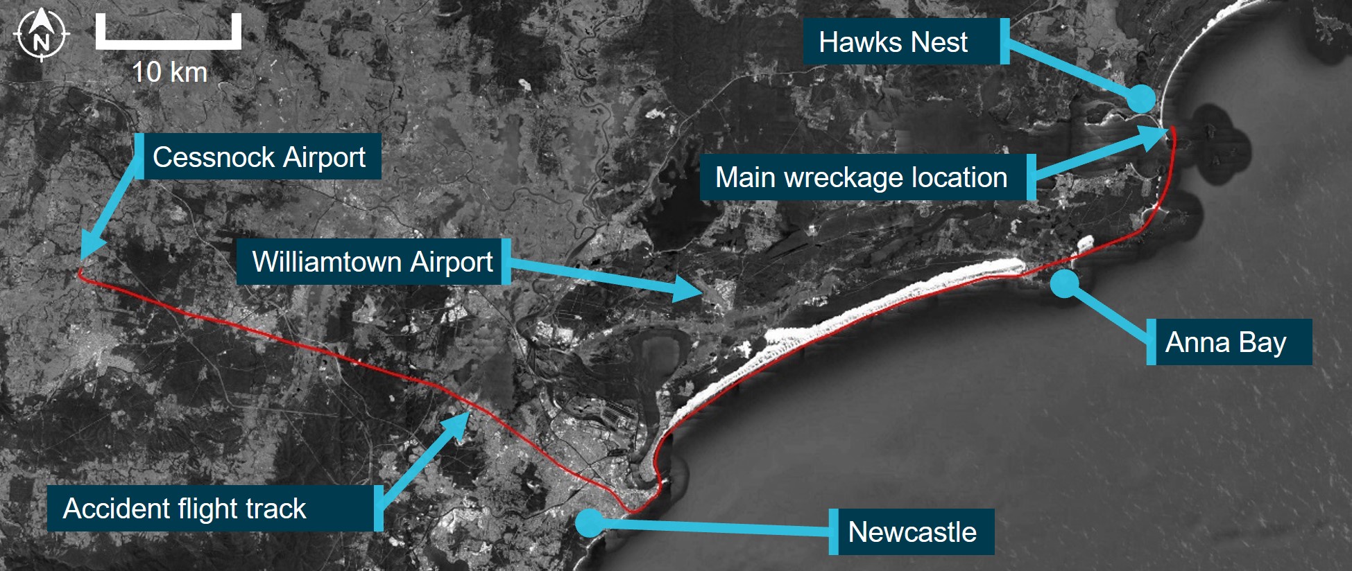
Source: Google Earth and Geoscience Australia. Annotated by the ATSB
The following sequence of events was identified from the onboard video after the helicopter had passed overhead Anna Bay and was tracking toward Hawks Nest (Figure 2):
- At 0920:10 the helicopter passed over the south shoreline of Yacaaba Headland, to the west of Mount Yacaaba, at about 900 ft AMSL.
- Between 0920:12 – 0920:16 the helicopter rolled right about 4 degrees, started to climb, and pitched nose down. From this point on the pilot made several cyclic inputs, overriding the autopilot.
- Between 0920:19 – 0920:21 the helicopter rolled 25 degrees to the left, pitched nose up to about 10 degrees, and yawed to the left. The helicopter then climbed through about 1,000 ft AMSL and rolled to level.
- Between 0920:22 – 0920:26 the helicopter passed north of Yacaaba Headland and over Providence Bay. The helicopter rolled left slightly, then right and left to bank angles of about 10 to 15 degrees. During this time, the nose remained pitched up at about 6 degrees and the helicopter climbed to about 1,100 ft AMSL.
- Between 0920:26 – 0920:29 the helicopter nose had pitched down and it had rolled to the right to become completely inverted (180 degrees), then continued to roll right to about 270 degrees.
The helicopter sustained an in-flight break-up and impacted the waters of Providence Bay, near Hawks Nest. The pilot was fatally injured.
Figure 2: VH-KFT flight path
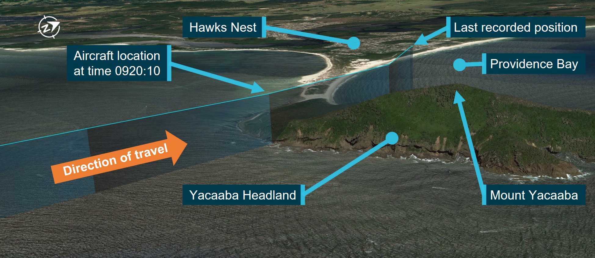
Source Google Earth. Annotated by the ATSB.
Context
Pilot information
The pilot held a private pilot licence (helicopter), with the required ratings and endorsements to operate the accident helicopter. The pilot held a class 2 aviation medical certificate. Prior to the accident, the pilot had a total flying time of 1,119 hours. These hours included 93 hours in the R66 and 1,007 hours in R44 and R22 helicopters.
The pilot had completed a flight review in September 2022, which was valid until September 2024.
Aircraft information
VH-KFT was a Robinson Helicopter Company R66, serial number 1138. It was manufactured in the United States in 2022 and in June 2022 was registered in Australia. The helicopter was fitted with a Rolls-Royce 250-C300/A1 gas turbine engine. VH-KFT underwent its first 100 hour annual inspection on 24 August 2023 at a total time in service of 97.84 hours. At the time of the accident, the hour meter showed a total time in service of 117.64 hours.
The helicopter was fitted with a Genysis Helisas 2 channel autopilot to provide stability augmentation that controlled cyclic pitch and roll with heading, altitude, navigation, vertical navigation, and backcourse modes.[3]
Meteorological information
The closest Bureau of Meteorology (BoM) weather station to the accident site was about 3.9 km to the south-west at Nelson Bay. The observations at 0900 (20 minutes before the accident) showed a southerly wind at 8 knots (kt), an air temperature of 14.4 °C, and 8/8[4] cloud cover.
Selected information from aerodrome weather reports (METAR/SPECI) released for Williamtown at 0900 and 0930 are shown in Table 1.
Table 1: Information from meteorological reports (METAR/SPECI) released for Williamtown at 0900 and 0930 on 26 October 2023
| METAR/SPECI release time | 0900 | 0930 |
| Wind direction and speed | 190°T at 12 kt | 180°T at 15 kt |
| Visibility | 8,000 m | 9,000 m |
| Weather phenomena | Light showers of rain | Light showers of rain |
| Cloud | Broken 1,100 ft, broken 2,500 ft | Scattered 1,000 ft, Broken 2,500 ft |
| Ceiling | 1,100 ft | 2,500 ft |
The BoM weather station at RAAF Base Williamtown, located about 35 km southwest of the accident site, recorded observations every 30 minutes. The weather reported at 0930 (10 minutes after the accident) showed a southerly wind at 15 kt, gusting to 23 kt, an air temperature of
14.7 °C, and a dew point temperature of 13.2 °C. 0.4 mm of rainfall was measured since 0900 that morning.
Wreckage
On 28 October 2023, NSW police divers located the helicopter’s cabin and tail boom on the sea floor in Providence Bay at a depth of about 5 m (Figure 2). The wreckage was recovered to a secure facility in Newcastle for examination by the ATSB. The entire windshield and forward cabin roof section, as well as the main rotor head and both main rotor blades, were not located from the sea search operation (Figure 3).
ATSB’s examination of the recovered helicopter structure indicated that a main rotor blade had likely impacted the right side of the cabin. The examination identified that the tail boom had separated from the fuselage aft of the engine fairing from a main rotor blade contact, prior to impacting the water. Damage to the fuselage was consistent with the fuselage impacting the water on the left side. The on-site inspection of the recovered wreckage did not identify any pre-existing faults or defects.
Figure 3: Wreckage examination
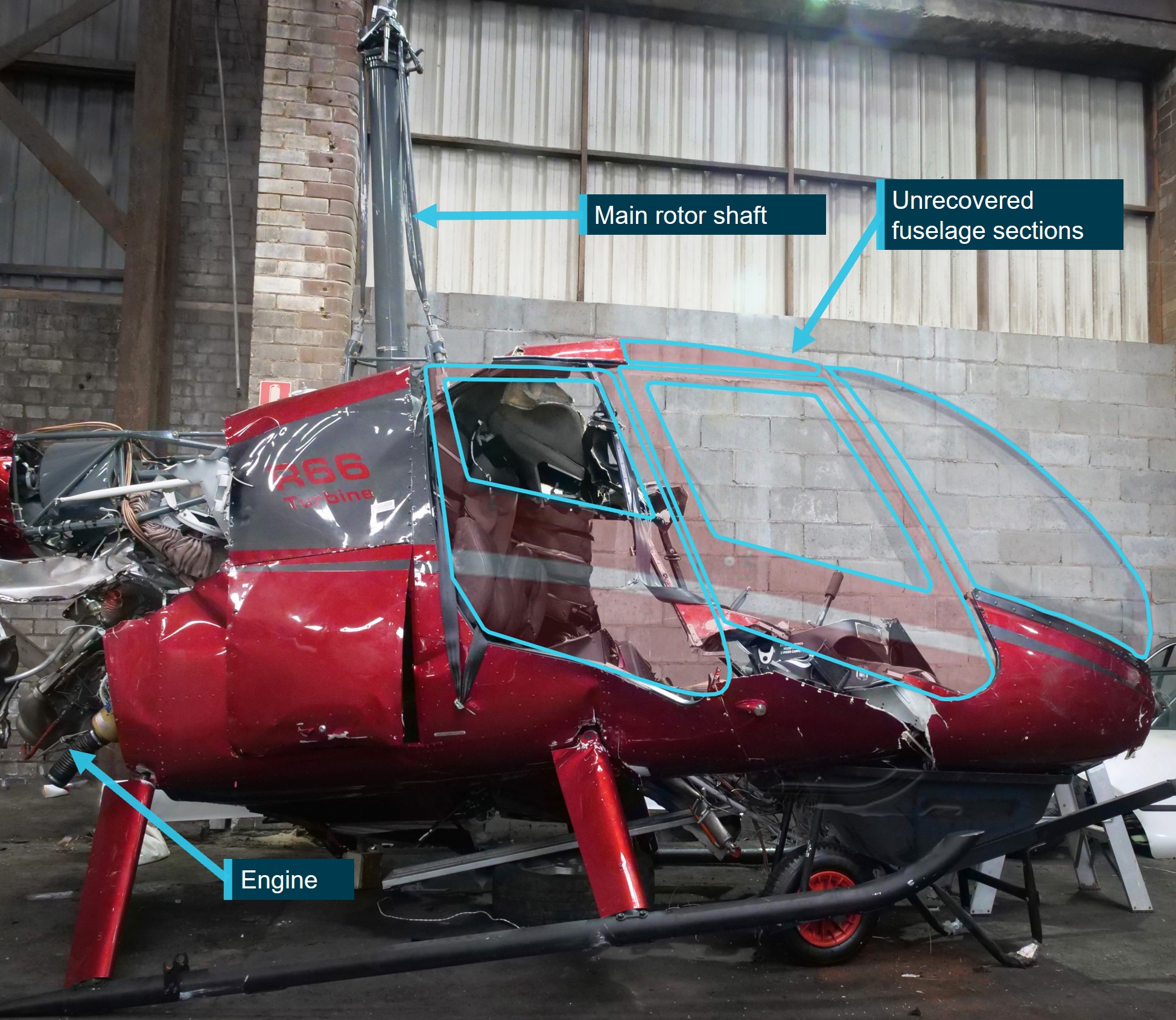
The image has been annotated to highlight areas of missing cabin structure.
Source: ATSB.
Recorded data
The helicopter was equipped with an onboard video camera that was attached to a roof panel inside the cabin. The camera recorded the in-cabin visual and audio environment. Also captured by the system were GPS position, acceleration, and rotational speed. The roof panel and camera were found on the beach near the accident site by a member of the public and provided to the NSW Police.
The video files and other recorded data were subsequently extracted from the camera memory module at the ATSB’s technical facilities in Canberra.
Williamtown air traffic control radar and radio communications between the helicopter have been retained by the ATSB for analysis.
Further investigation
To date, the ATSB has:
- examined the recovered wreckage
- collected meteorological data from the Bureau of Meteorology
- collected pilot and helicopter records
- conducted interviews with relevant parties
- collected recorded data from Williamtown air traffic control
- liaised with the NSW Police Force.
The investigation is continuing and will include consideration of the following:
- analysis of meteorological conditions
- analysis of the recovered onboard video and other recorded data
- flight planning
- helicopter performance
- pilot qualifications, experience, and medical information
- helicopter maintenance
- examination of recovered components.
A final report will be released at the conclusion of the investigation. Should a critical safety issue be identified during the course of the investigation, the ATSB will immediately notify relevant parties so appropriate and timely safety action can be taken.
Acknowledgements
The ATSB gratefully acknowledges the assistance provided by NSW Police Force Marine Area Command in the search and recovery efforts, and subsequent information collection.
Purpose of safety investigationsThe objective of a safety investigation is to enhance transport safety. This is done through:
It is not a function of the ATSB to apportion blame or provide a means for determining liability. At the same time, an investigation report must include factual material of sufficient weight to support the analysis and findings. At all times the ATSB endeavours to balance the use of material that could imply adverse comment with the need to properly explain what happened, and why, in a fair and unbiased manner. The ATSB does not investigate for the purpose of taking administrative, regulatory or criminal action. TerminologyAn explanation of terminology used in ATSB investigation reports is available here. This includes terms such as occurrence, contributing factor, other factor that increased risk, and safety issue. Publishing informationReleased in accordance with section 25 of the Transport Safety Investigation Act 2003 Published by: Australian Transport Safety Bureau © Commonwealth of Australia 2024 
Ownership of intellectual property rights in this publication Unless otherwise noted, copyright (and any other intellectual property rights, if any) in this report publication is owned by the Commonwealth of Australia. Creative Commons licence With the exception of the Coat of Arms, ATSB logo, and photos and graphics in which a third party holds copyright, this publication is licensed under a Creative Commons Attribution 3.0 Australia licence. Creative Commons Attribution 3.0 Australia Licence is a standard form licence agreement that allows you to copy, distribute, transmit and adapt this publication provided that you attribute the work. The ATSB’s preference is that you attribute this publication (and any material sourced from it) using the following wording: Source: Australian Transport Safety Bureau Copyright in material obtained from other agencies, private individuals or organisations, belongs to those agencies, individuals or organisations. Where you wish to use their material, you will need to contact them directly. |
[1] The onboard video camera was a standard factory inclusion for R66 helicopters.
[2] Primary stability augmentation mode from the autopilot system maintains a steady helicopter attitude by applying corrective inputs to the cyclic. Additional modes provide heading hold, altitude, back course, and navigation functionality.
[3] Backcourse mode is a reverse course deviation indicator to enable backcourse approaches.
[4] Cloud cover is measured visually by estimating the fraction (in eighths or oktas) of the dome of the sky covered by cloud. A completely clear sky is recorded as zero okta, while a totally overcast sky is 8 oktas. The presence of any trace of cloud in an otherwise blue sky is recorded as 1 okta, and similarly any trace of blue in an otherwise cloudy sky is recorded as 7 oktas.
Occurrence summary
| Investigation number | AO-2023-051 |
|---|---|
| Occurrence date | 26/10/2023 |
| Location | Near Hawks Nest |
| State | New South Wales |
| Report release date | 30/06/2025 |
| Report status | Final |
| Investigation level | Systemic |
| Investigation type | Occurrence Investigation |
| Investigation status | Completed |
| Mode of transport | Aviation |
| Aviation occurrence category | In-flight break-up |
| Occurrence class | Accident |
| Highest injury level | Fatal |
Aircraft details
| Manufacturer | Robinson Helicopter Co |
|---|---|
| Model | R66 |
| Registration | VH-KFT |
| Serial number | 1138 |
| Sector | Helicopter |
| Operation type | Part 91 General operating and flight rules |
| Departure point | Cessnock Airport, New South Wales |
| Destination | Wallace Island, New South Wales |
| Damage | Destroyed |