Executive summary
What happened
On 14 February 2022, the pilot of a Garlick UH-1H helicopter was supporting the Tasmania Fire Service (TFS) by providing aerial firebombing support to the Lebrina bushfire, in northern Tasmania. The pilot was requested by TFS to provide firebombing assistance to combat a spot fire that had flared up on the western flank of the fireground and at 1509 local time the pilot departed the TFS staging area. After transiting to a nearby dam and loading water into the underslung bucket, the pilot tracked toward the spot fire.
Witnesses observed the unexpected early release of water from the underslung bucket prior to reaching the target, before the helicopter tracked away from the location of the spot fire toward an open paddock. As the helicopter approached the paddock, the helicopter was observed to rotate rapidly before pitching steeply nose-down and descending. The helicopter collided heavily with terrain in a tail low, upright orientation before coming to rest on its left side. A post‑impact fire started in the engine bay, destroying the helicopter. The pilot received fatal injuries.
What the ATSB found
During the conduct of a firebombing operation, the helicopter’s engine-to-transmission main KAflex drive shaft partially failed and entered fail-safe mode. That resulted in the pilot jettisoning the water load from the underslung bucket and diverting toward clear ground. The failure was likely due to the fracture of a flex frame attaching bolt, or a flex frame element during the accident flight.
As the helicopter was slowing during a descent over clear ground, the KAflex subsequently completely failed, resulting in instantaneous loss of drive to the rotor system.
Following loss of drive to the main rotor system, the pilot was unable to complete a survivable autorotative descent and landing, probably due to a critical reduction in main rotor speed.
What has been done as a result
Following the accident, the Civil Aviation Safety Authority released 2 updates to a previously released Airworthiness Bulletin on the subject of pre-flight inspection requirements for the KAflex drive shaft. The Airworthiness Bulletin recommended that maintainers and operators check the condition of all drive shaft hardware in addition to the pre-existing inspection requirements listed in the flight manual. The bulletin also provided further advice to operators and maintainers on potential operational aspects once a KAflex has entered fail-safe mode.
The ATSB released a safety advisory notice (SAN) in June 2022 to all operators of UH-1H helicopters advising of the circumstances surrounding the accident and that it involved failure of the KAflex driveshaft. The SAN advised operators of UH-1H helicopters to note the details of this accident and to look for the presence of red metallic residue or debris at the bolted connections, frame cracking, missing or damaged attaching hardware during all inspections of the KAflex driveshaft. Any identified defects should be notified to the Civil Aviation Safety Authority.
Additionally, the SAN also advised that operators should be aware of the KAflex manufacturer’s (Kamatics) concern regarding shafts for the UH-1H helicopter that may be fitted with legacy attachment hardware. Kamatics should be contacted if a shaft, serial number 0635 and below, is identified.
Richmond Valley Aviation, the maintainer and operator of the accident helicopter, advised that following the accident they removed all KAflex main transmission drive shafts from the helicopters that they maintained and replaced them with an alternate type of shaft that can be greased.
Kamatics advised that for KAflex shafts returned to their factory a teardown inspection will be completed to identify any evidence of fretting, cracked washers or any other undesirable defect in hardware items normally replaced during overhaul.
The Tasmania Fire Service advised that, since the accident they have completed the following agency safety actions in relation to their aviation operations:
- Transitioned to the Tasmanian Government Radio Network to enable direct communications with other emergency service organisations, fire land managers and aircraft operators working at multi-agency incidents.
- Conducted an inter-agency exercise to test the response to a rescue incident in remote and isolated areas. The exercise tested the TFS timelines, incident management command and control, communication links, processes and roles of each agency. A key outcome was that the notification procedures have been improved between TFS, Tasmania Police and the Ambulance Tasmania Air Rescue Aviation Unit.
Safety message
Pilots of UH-1H helicopters should note that if vibrations or noise from the transmission area rapidly increases or becomes severe during flight, it may signify that the KAflex drive shaft has entered fail‑safe mode and could imminently fail.
Significantly, the commencement of a distinct ‘howling’ or ‘shrieking’ noise is a key indication of a developing KAflex failure.
The ATSB strongly recommends that pilots land as soon as possible on detection of such symptoms. Of the UH-1H accidents that have occurred, complete failure of the drive shaft has typically occurred in just a few minutes leading to an emergency landing and significant damage to the helicopter. In addition, pilots should be aware that complete failure of the KAflex can unexpectedly lead to right yaw, which is contrary to indications of a loss of drive to the main rotor system detailed in the flight manual.
The ATSB also reminds UH-1H helicopter pilots, operators, and maintainers that fatigue cracking can occur on critical flight components. Particular vigilance should be applied during the daily or pre-flight inspections of the main transmission driveshaft because it represents an important opportunity to detect for defects such as cracks, and to identify evidence of loose or missing attachment hardware.
The occurrence
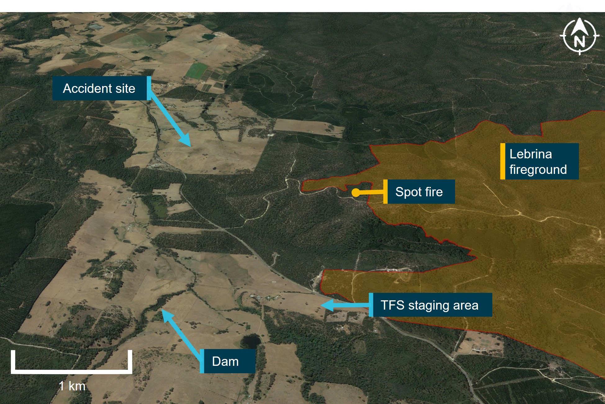
On 10 February 2022, a bushfire developed after a registered burn escaped containment lines near Pipers Brooke Road, north of Launceston, Tasmania (Figure 1). A multi-agency[1] response commenced work to contain the ‘Lebrina’ fire using fire tankers, bulldozers and helicopters performing aerial firebombing. The pilot of a Garlick Helicopters[2] UH-1H, registered VH-UHX, was tasked by the Tasmania Fire Service (TFS) to combat the fire, which by 13 February had burnt 1,662 hectares of bushland and forestry plantations.
Over the period 10–13 February 2022, the pilot flew multiple firebombing sorties over the fireground from a temporary staging area established by TFS on a private field adjacent to Pipers Brook Road. At the conclusion of each day’s activity the helicopter was flown to the south of Launceston and hangared at the pilot’s residence.
Figure 1: Accident location and the Lebrina fireground, Tasmania
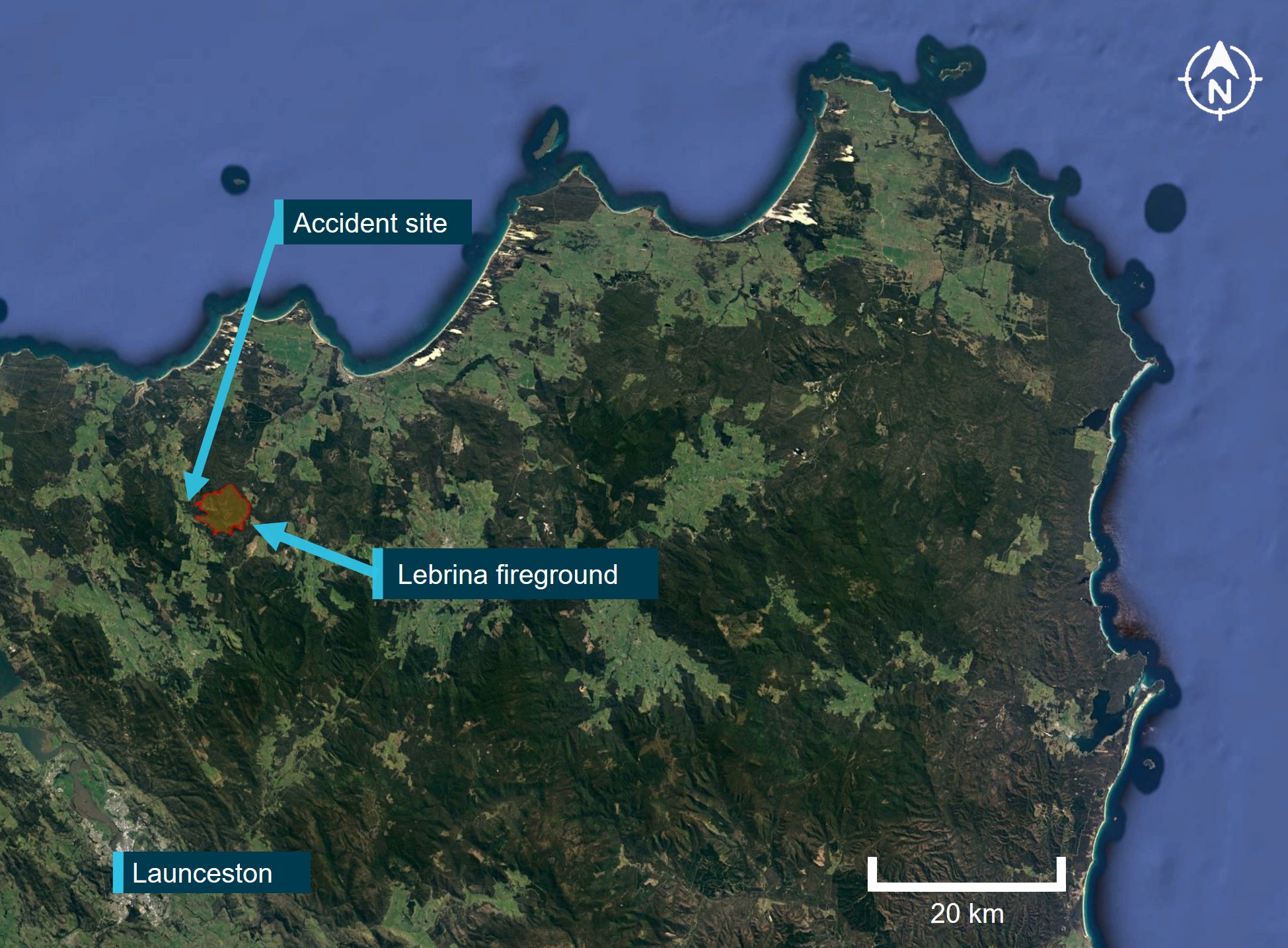
Source: Google Earth, annotated by the ATSB
On 14 February 2022, at about 0833 local time, the pilot departed their residence in VH-UHX and tracked toward the staging area. They then completed firebombing operations in the north‑eastern sector of the fireground. The tasking involved flying circuits between the fire boundary and a nearby dam, where an underslung water bucket was replenished with water. After completing several sorties, the pilot returned to the staging area and landed, shutting down the helicopter at 0929. The pilot remained at the staging area with other helicopter pilots, ground support and firefighting personnel.
At about 1455, 2 fire commanders, a TFS observer, and a pilot departed the staging area in an AS350 helicopter, registered VH-RLR (designated Firebird 460), to provide air attack supervision and to conduct an aerial survey of the fireground. Shortly after 1500, the personnel onboard Firebird 460 observed a rising plume of smoke in a region of unburnt vegetation on the western flank of the fireground. In response, they requested a firebombing helicopter attend the spot fire.
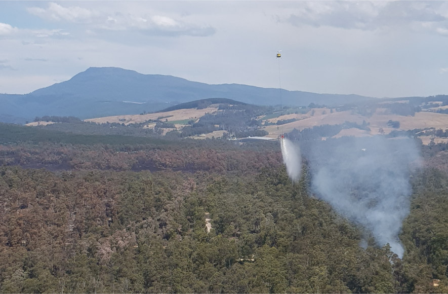
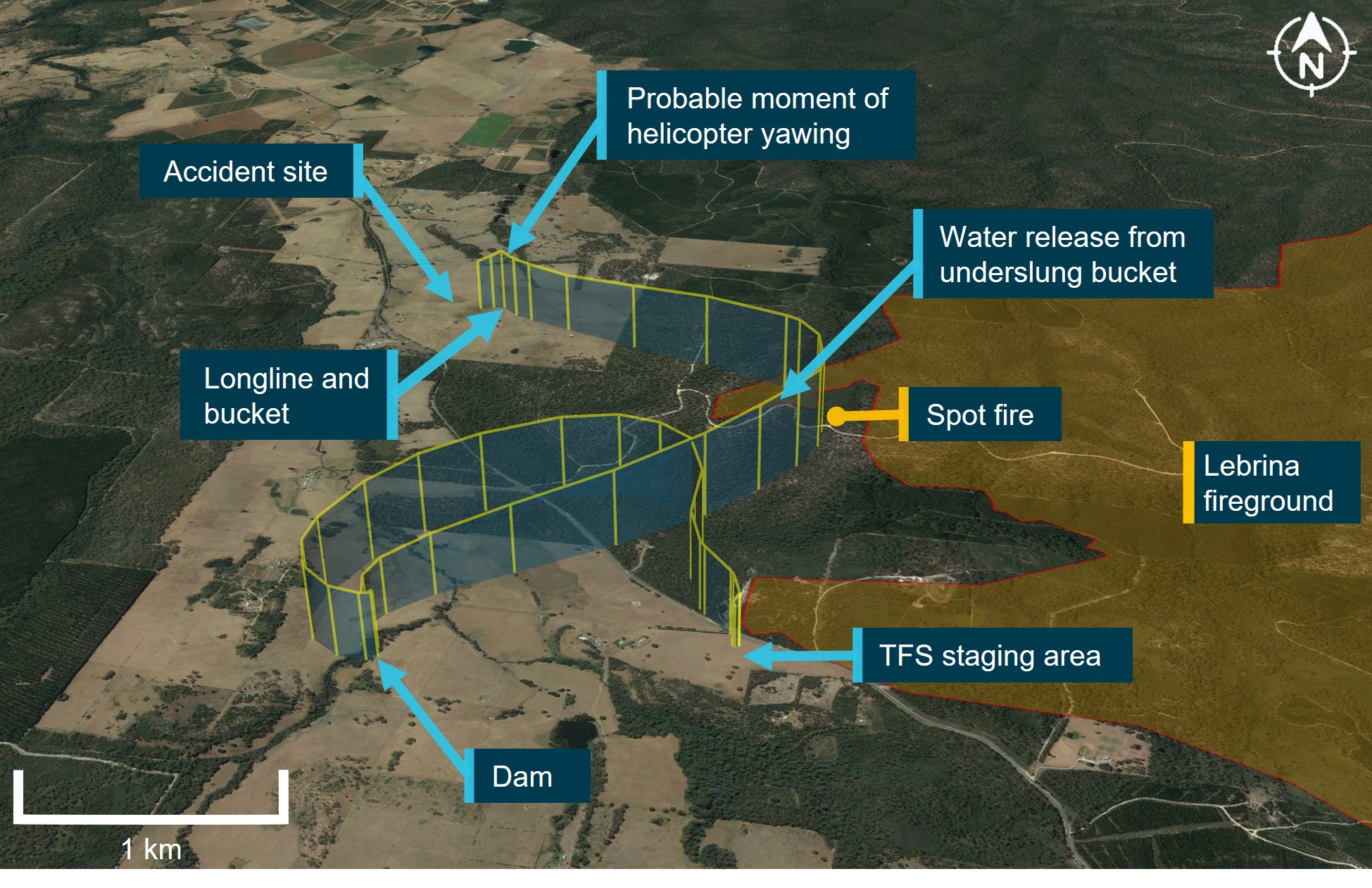
The pilot received the TFS request and, at about 1509, departed the staging area in VH-UHX. Witnesses at the staging area observed VH-UHX proceed to a small dam and hover, while the pilot filled the underslung bucket with water. The helicopter then departed and climbed toward the designated target (Figure 2).
The pilot and TFS personnel within Firebird 460 observed VH-UHX approach the spot fire and the release of the water load from the underslung bucket. The pilot of Firebird 460 recounted that the drop was unusual because they estimated the water had missed the target by ‘hundreds of meters.’ VH-UHX then commenced a gradual climbing turn to the left and tracked to the north‑west. To avoid any potential conflict with the now‑approaching helicopter, the pilot of Firebird 460 initiated a climbing 360° right turn, with those onboard losing sight of VH-UHX during the manoeuvre.
After completing the turn and regaining sight of VH-UHX, the Firebird 460 pilot recalled that the helicopter was now beyond the bushland and above an open paddock. They then witnessed the underslung longline and bucket fall to the ground and the helicopter descend rapidly. The pilot commented that VH-UHX appeared to be ‘diving toward the paddock’, in what they assessed was preparation for an emergency landing. Noting that the airspeed and descent rate for VH-UHX had increased, the pilot in Firebird 460 did not identify any slowing or flaring as the helicopter approached the ground and commented that their attention was also diverted to finding a suitable nearby landing site to provide assistance.
A passenger onboard Firebird 460 recalled irregular side-to-side movement of the tail section and a brief puff of white smoke emanate from the rear area of VH-UHX as it descended, prior to it colliding with terrain. They further commented that there did not appear to be any dust or debris from rotor wash that would normally be expected as VH-UHX approached the ground. Further, the Firebird 460 pilot did not hear any radio calls from the pilot of VH-UHX following the approach to the spot fire.
About 30 seconds after the collision, the pilot of Firebird 460 landed adjacent to the wreckage and alighted along with the TFS personnel. They reported that VH-UHX was on its left side and substantially damaged. Small fires had ignited in the surrounding grass and within the engine bay. The responders from Firebird 460 were unable to suppress the fire using handheld fire extinguishers. A nearby witness attended the site and connected a strap between their vehicle and the right skid of VH-UHX, however the helicopter was unable to be moved. The fire spread quickly and within a few minutes the wreckage was engulfed.
Two other pilots who were positioned with their helicopters at the TFS staging area responded to the emergency and proceeded to the accident site. They deposited multiple loads of water, however the fire was unable to be extinguished. The pilot of VH-UHX sustained fatal injuries and the helicopter was destroyed.
Figure 2: Key areas of the Lebrina fireground relative to the accident site
Source: Google Earth, annotated by the ATSB
Context
Additional witness information
A pilot-witness positioned at the Tasmania Fire Service (TFS) staging area had been monitoring VH-UHX, described seeing the pilot depart in VH-UHX, fill the underslung bucket at a nearby dam and then track toward the spot fire. They further identified that the water drop was conducted too high and too early, significantly missing the target. The helicopter was then observed to slow and commence a descending profile before completely rotating twice to the right about its vertical axis (yawing). The helicopter then pitched up and then down, before rapidly descending with a nose‑low pitch attitude.
Personnel onboard the air attack supervising helicopter (Firebird 460) captured several images and a short video of VH-UHX approaching the designated spot fire. One of the images showed the early release of water from the underslung bucket (Figure 3). The video file recorded by another passenger commenced in the moments after the water had been released and showed VH-UHX in a left turn (Figure 4). The video did not capture the yawing movement reported by the pilot-witness at the TFS staging area.
Another witness who was in their house near to the accident site recalled seeing VH-UHX in a descending approach. In their statement the witness reported hearing a screeching/roaring noise, with the helicopter observed to be descending in a left banking turn before moving out of sight.
Figure 3: VH-UHX releasing the underslung bucket contents at a considerable height and distance away from the spot fire (smoke plume)
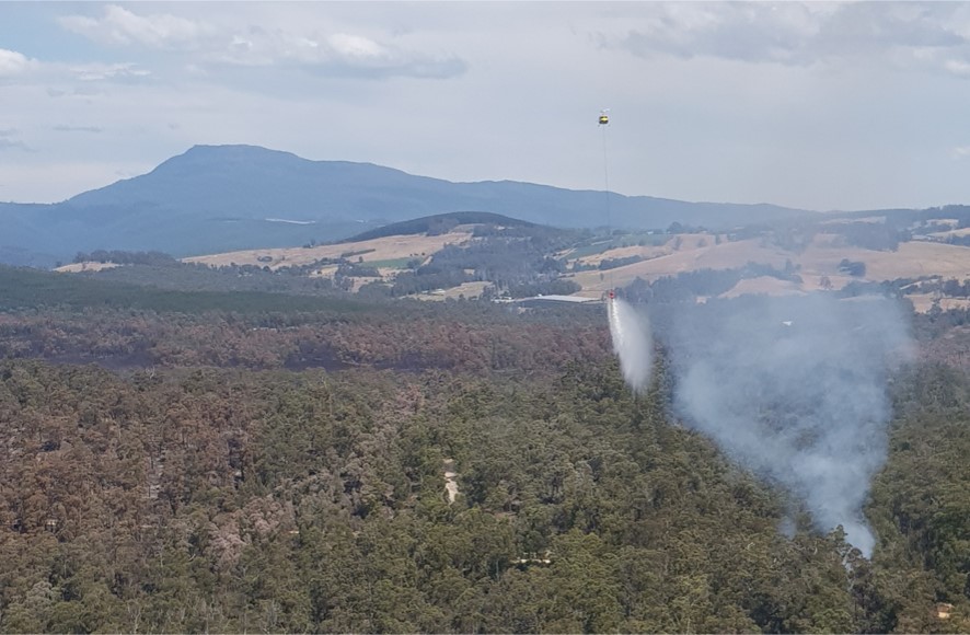
The image was captured by a witness onboard Firebird 460. Metadata identified that the image had been captured at timestamp 1514:42
Source: Rod Sweetnam
Figure 4: VH-UHX in a left turn moments after the water release
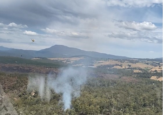
This image is cropped from a video file captured by TFS personnel within Firebird 460 and shows the empty underslung bucket trailing VH-UHX
Source: Tasmania Fire Service, modified by ATSB
Aircraft information
General
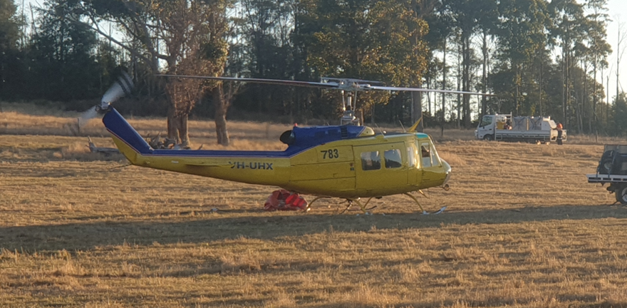
The UH-1H ‘Huey’ helicopter was developed by Bell Helicopters in the 1960s as a military utility helicopter for the United States (US) Army. Records showed that the accident helicopter was manufactured in November 1965 (airframe serial number 64-13865). After ceasing US Army operations, surplus UH-1H helicopters were made available for civilian operations. Several organisations were authorised by the US Federal Aviation Administration (FAA) to convert ex‑military helicopters for civilian use. This included Garlick Helicopters Inc, who was the type certificate holder for this helicopter.
Operational arrangements
In September 2014 the helicopter was listed on the Australian civil aircraft register as VH‑UHX. In October 2014, the Civil Aviation Safety Authority (CASA) issued a special certificate of airworthiness permitting the helicopter to be operated in the restricted category to complete agricultural, forest, wildlife conservation, firefighting, and slinging of external loads. An additional special certificate of airworthiness was issued by CASA in May 2015 for the purpose of conducting adventure flights.[3]
The helicopter was purchased by its last owner in July 2020 to complete firefighting and slinging contracts. A pre-purchase inspection report completed on VH-UHX prior to the sale identified no airworthiness issues. The owner entered a contractual arrangement with Richmond Valley Aviation to operate and maintain the helicopter. Richmond Valley Aviation was in turn contracted to the National Aviation Firefighting Centre to provide on-call aerial firefighting capability using VH‑UHX.
The pilot, who was based in Tasmania, was contracted by Richmond Valley Aviation. The helicopter was re‑positioned to Tasmania in early 2021 where it was operated solely by the accident pilot.
Fuel
A 4,400 litre fuel storage tank was located at the pilot’s property where VH-UHX was hangared. This tank was used to replenish two 1,325 litre fuel storage tanks and four 205 litre drums on a refuelling truck. It was reported that VH-UHX had used drum fuel from the refuelling truck for the entirety of the Lebrina fire campaign tasking.
On the morning of 14 February, VH-UHX was fuelled from the refuelling truck that had been positioned at the TFS staging area. Fuel records indicated that 124 litres were added to the main tank of the helicopter, bringing the total fuel onboard to approximately 700 litres at the time of the final departure.
A sample of this fuel was obtained from the truck. Testing showed the sample was clear and slightly straw-coloured with no visible contaminants or indication of water. A visual inspection of all the fuel storage tanks similarly revealed no visible contaminants.
Water bucket
For firebombing applications, the helicopter used either 1,200 or 1,400 litre flexible buckets. The bucket was attached to the helicopter cargo hook via a 150 ft steel cable (longline). A push button switch mounted on the collective control was electrically connected to an air‑operated valve within the bucket that allowed the pilot to regulate the water release, including complete dumping of the water.
Cargo hook
VH-UHX was fitted with an equipment cargo hook that allowed external cargo to be released via an electrical switch on the pilot’s cyclic control grip. A switch on the forward section of the overhead console enabled the system to be armed and/or isolated. In addition, a foot-activated manual release lever was located between the tail rotor pedals. This release lever was used to jettison cargo in the event of an emergency or failure of the electrical release system. The ATSB was informed that the pilot sometimes isolated electrical control for the cargo hook. With the cyclic switch inoperative, the foot-activated manual lever was the only available option to release the external cargo.
Wreckage and impact information
Accident site
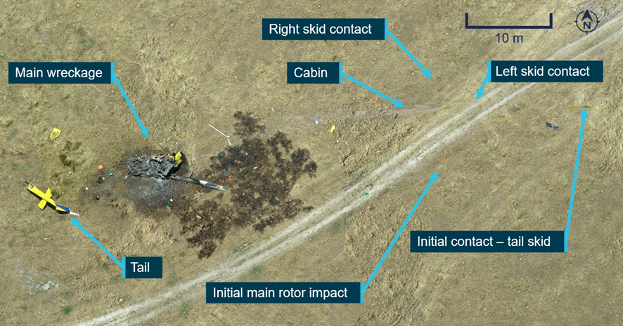
The helicopter wreckage was located in a grassy paddock near Pipers Brook Road, about 2.6 km north of the TFS staging area. The helicopter had been destroyed from ground impact forces and the subsequent fuel-fed fire (Figure 5). A survey of the accident site showed the wreckage to be orientated in a westerly direction (Figure 6).
Ground marks at the site showed that the tubular steel tail skid on the underside of the tail boom first contacted the ground, followed by the landing skids, main rotor blades and the cabin. After the initial ground strike, almost the entire tail section, including the tail rotor gearbox, separated from the fuselage, coming to rest a short distance beyond the main wreckage. Other items that separated from the helicopter included both main rotor blades, the battery and the landing skids. Three distinct ground scars identified where the main rotor blades struck the ground.
Figure 5: View of the fuselage and separated tail section at the accident site
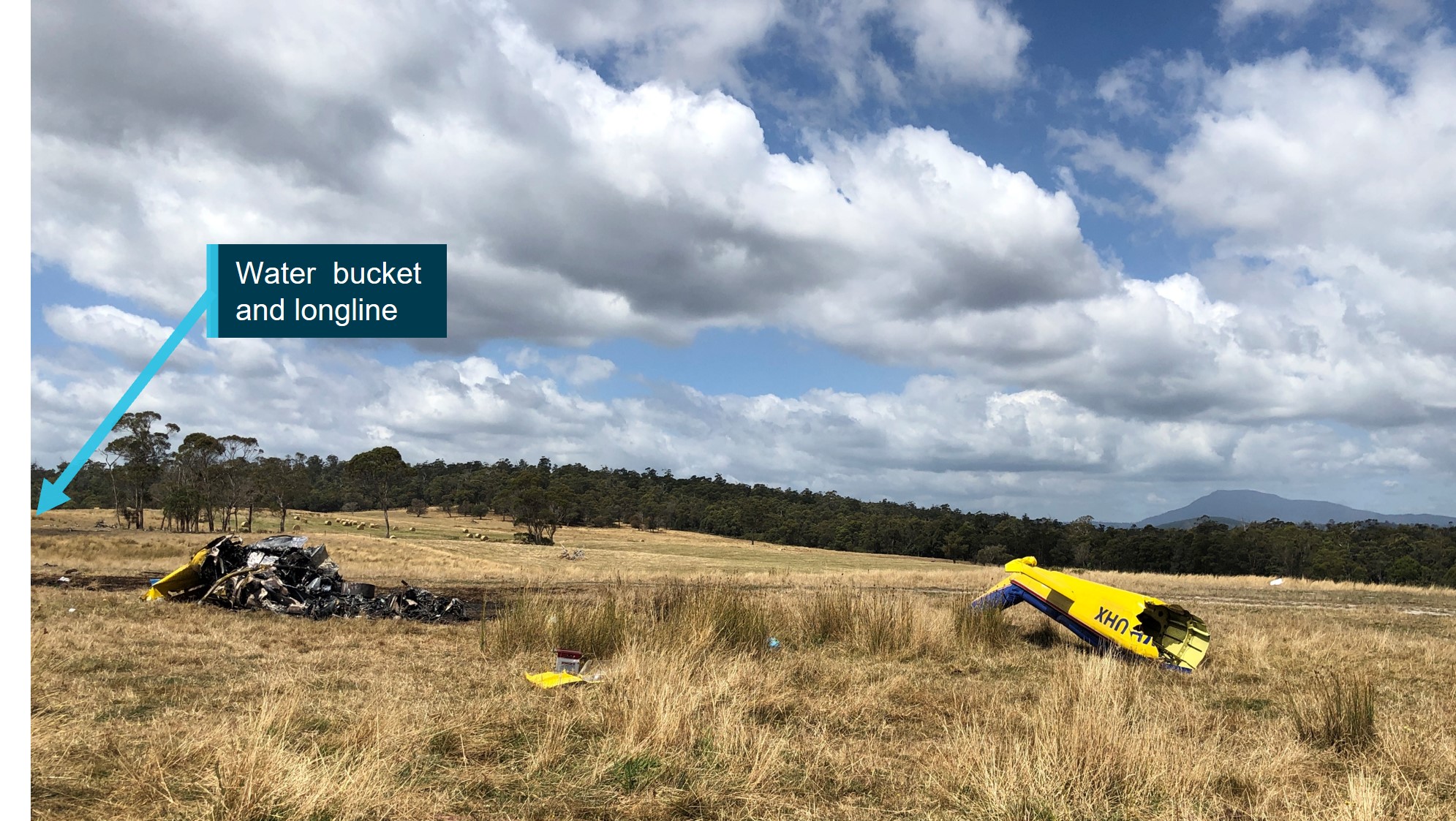
The Lebrina fireground was located beyond the foreground tree line at the perimeter of the paddock. The upper wire cutter guide, longline and water bucket were located further back toward the tree line.
Source: ATSB
Figure 6: Overhead view of the accident site
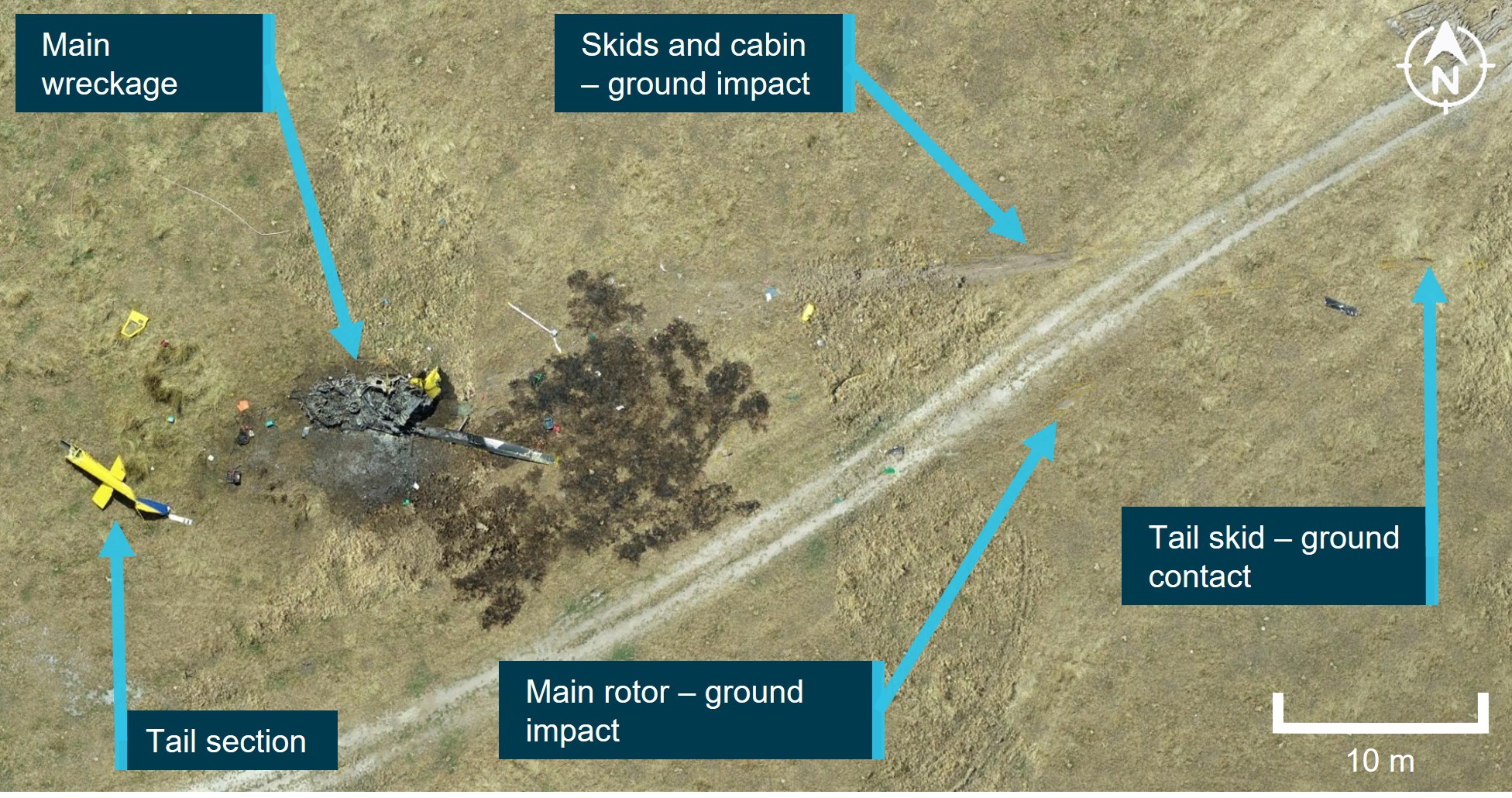
Source: ATSB
The furthest items from the accident site were the tip from the upper wire cutter guide (located 220 m from the wreckage) and the underslung water bucket that remained attached to its longline (located 300 m from the wreckage) (Figure 7). Deformation to the fractured wire cutter guide was consistent with it being struck and projected by a main rotor blade.
Figure 7: Accident site showing the flight track of VH-UHX (red/green shaded area) and items that had liberated from the helicopter
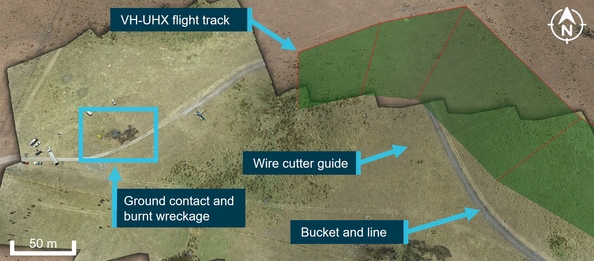
Source: Google Earth, modified by ATSB
Engine examination
The helicopter was fitted with a Lycoming T53-L-703 turboshaft engine. The T53-L-703 consists of a single-spool five-stage axial compressor with the sixth-stage being a centrifugal flow compressor. The high-pressure turbine (gas producer) drives the compressor and accessory gearbox, while the low-pressure turbine (power turbine) drives the output gearbox to the main transmission drive shaft.
Examination of the wreckage identified that the main support mounts and forward trunnion mounts to the engine were still connected, however the supporting tubular frame had torn from the engine bay floor area during the impact. The engine was significantly damaged by the post-impact fire, resulting in destruction to the electrical looms, braided oil lines and the accessory gearbox. The engine fuel filter was removed from the engine and was found to be clear with no visual contaminants.
The power turbine was unable to be rotated. However, metallic material had solidified at numerous locations on the second-stage power turbine aerofoil surfaces indicating that metallic debris had passed through the combustion chamber while the engine was operating. Although absolute engine power levels were not able to be assessed the extent of internal compressor damage in combination with the ingested debris provided evidence that the engine was rotating at high speed during the impact sequence (Figure 8).
Internal inspection[4] of the compressor section identified that the compressor blades had been dislodged and bent against their normal direction of rotation. Debris was found throughout the compressor, including a piece of the main transmission drive shaft (KAflex coupling), multiple blade segments, inlet guide vanes and pieces of airframe structure (Figure 9).
Figure 8: Solidified metallic deposits were identified on the surfaces of the second stage power turbine
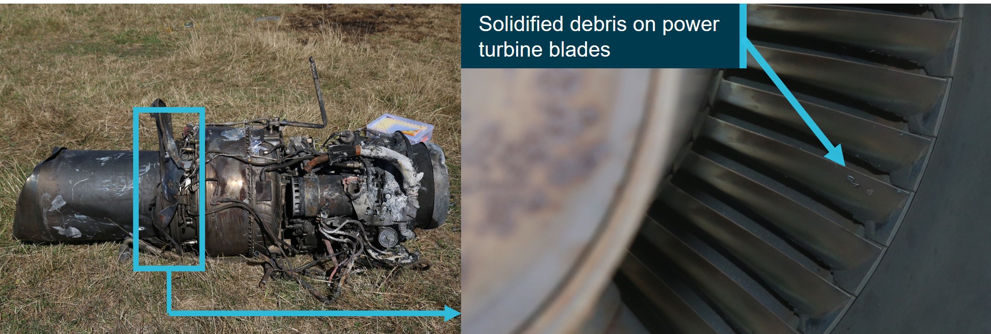
Source: ATSB
Figure 9: Severe disruption occurred to all internal stages of the compressor (left) and the debris that was recovered from within the compressor (right)
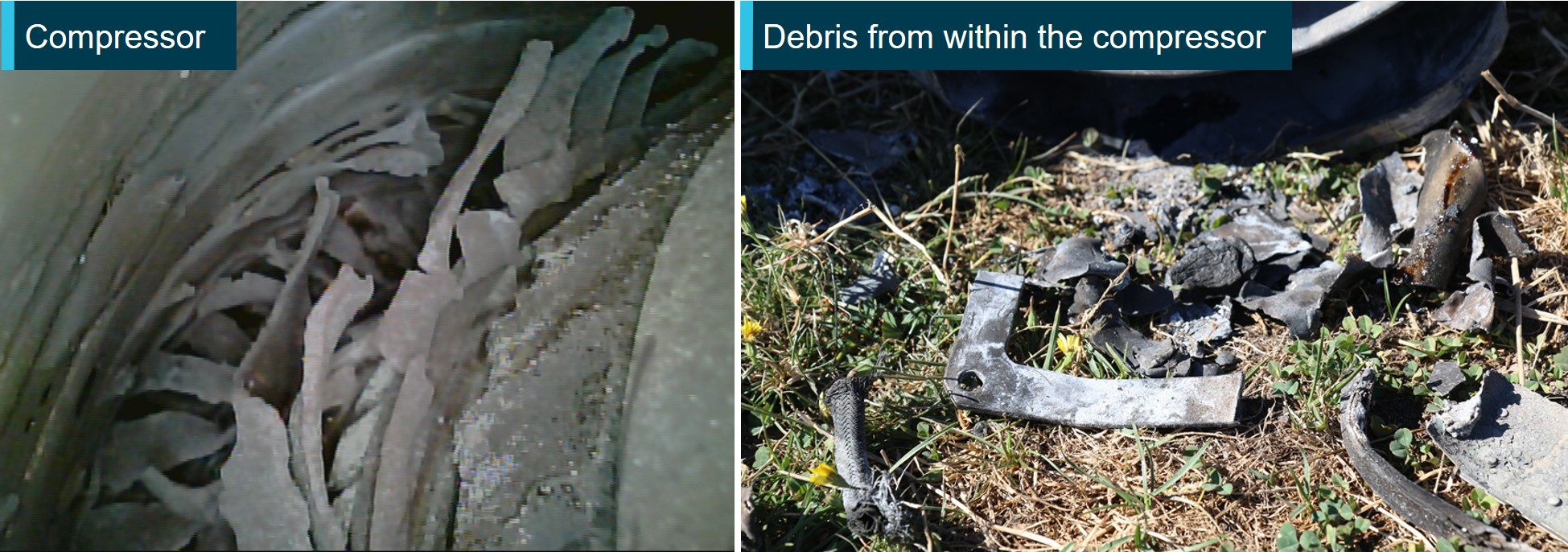
The rectangular item in the right image is a piece from the main transmission drive shaft (KAflex)
Source: ATSB
Flight controls
The UH-1H flight control system is hydraulically assisted and actuated by conventional helicopter controls for both the pilot and co-pilot. Due to the extensive fuel-fed post-impact fire, most of the aluminium flight control components were destroyed leaving behind the steel componentry and connecting hardware. Of the recovered connecting hardware there was no evidence of missing fasteners or disconnections.
Tail rotor control system
VH-UHX was fitted with composite tail rotor blades connected to a common yoke by a grip and pitch change bearings. The hub and blade assembly are mounted on the tail rotor shaft with a delta-hinge trunnion and a static stop to minimize rotor flapping. Heading control is accomplished by movement of the anti-torque pedals which are connected to the pitch control system through the tail rotor (90°) gearbox. A multi-segmented drive shaft provides power from the main transmission to a 42° gearbox then to the 90° tail rotor gearbox.
The tail rotor anti-torque pedals were partially identified; however, the majority of the system had been consumed by fire. Continuity to the extent possible was established through to the tail boom section. The tail rotor drive shaft displayed rotational scoring damage at various locations along its length. The composite tail rotor blades also displayed evidence of impact damage from a ground strike. The tail rotor gearbox had fractured through its mount at the end of the tail boom. There was no evidence of pre-existing damage to the separated tail rotor gearbox with no evidence of binding or internal seizure. Overstress features present on the gearbox mount fracture surfaces were consistent with ground impact.
Hydraulic system
The hydraulic system is used to minimise the force required by the pilot to move the cyclic, collective and pedal controls. Due to the extensive damage sustained to the helicopter from the post-impact fire, a detailed assessment of the hydraulic system components was not possible.
Fuel
Only partial remnants of a flexible fuel cell were identified within the wreckage. No fuel was recoverable from the aircraft for testing.
Transmission
The UH-1H main rotor transmission is mounted forward of the engine and connected to the power turbine shaft at the front end of the engine by the main transmission drive shaft (KAflex). A freewheeling unit (sprag clutch) within the transmission reduces drag on the main rotors following an engine power loss, enabling an autorotative landing.
The wreckage examination identified that the transmission had partially separated from its airframe mounts and was located on its left side. The mast had fractured during the impact sequence, liberating the rotor head and both main rotors. The freewheeling unit within the transmission housing was seized due to the extensive heat damage from the post-impact fire and unable to be moved. The post-impact fire consumed a large section of the transmission housing exposing the main bull gear. There was no observable pre-impact damage to the gear teeth.
Main transmission drive shaft
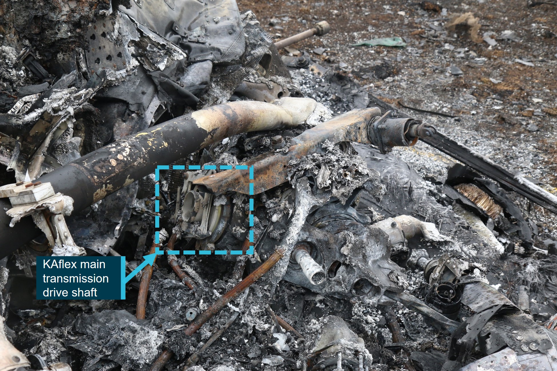
The main transmission drive shaft (KAflex) was identified at the accident site to have fractured into multiple pieces (Figure 10). One of those pieces was found within the compressor section of the engine. Due to the extent of impact and fire damage, several attachment bolts and portions of flexible frame elements from the coupling were unrecoverable. The KAflex components were retained for subsequent examination at the ATSB’s technical facilities in Canberra.
Figure 10: Burnt wreckage noting the forward section of the fragmented KAflex main transmission drive shaft
Source: ATSB
Recorded information
Flight data recorders
The helicopter was not fitted with a flight data recorder or cockpit voice recorder, nor was it required to be.[5]
GPS and other data
The helicopter was equipped with a Tracplus tracking system that recorded GPS positional information at 2-minute intervals. Due to the relatively low sampling rate, the Tracplus data provided general aircraft track information rather than high fidelity information about the accident flight. The Tracplus data identified that for the accident flight, the system had commenced recording at 1508:49, which corresponded with the pilot preparing to depart from the TFS staging area.
A Garmin 296 GPS system was recovered from the accident site. The GPS was retained by the ATSB for data recovery at the ATSB’s technical facilities in Canberra. The device recorded time, position, ground speed and barometric altitude at varying time intervals, ranging between 1‑15 seconds.
Those onboard the Firebird 460, also recorded imagery and video files throughout the flight. Data from those files provided timestamp and georeferenced information. The ATSB completed an analysis of the available recorded data during the accident flight (Figures 11 - 13).
Take-off, water pick-up and climb out
At about 1509, VH-UHX departed the staging area and proceeded to a dam approximately 1 km to the west. At 1512:50, the helicopter was slowed to a hover, indicating the underslung bucket was being filled with water. After about 30 seconds overhead the dam, the helicopter departed and climbed to an altitude of 1,100 ft above mean sea level (AMSL) while transiting to the spot fire.
Water drop
At 1514:11, a left descending turn was conducted toward the spot fire at an average descent rate of about 250 ft per minute. During this time, the helicopter was slowed from a ground speed of about 60 kt to 30 kt. An image taken at 1514:42 by a TFS member onboard Firebird 460 showed water being released from the underslung bucket. GPS data indicated that VH-UHX climbed about 30 feet around that time, consistent with the reducing weight of the underslung load.
Cruise descent, deceleration, and final climb
From 1514:52 to 1515:22 VH-UHX descended at an average rate of 400 feet per minute to an altitude of about 780 ft AMSL, while slowing from about 68 to 55 knots ground speed. The ground speed and the rate of descent of about 400 feet per minute indicated that this was a powered descent, based on the autorotational glide characteristics from the UH-1H helicopter flight manual. Based on the data, about 20 seconds into the descent, VH-UHX was established over open terrain.
Following this, UHX commenced a shallow climb up to an altitude of about 840 feet, with the track changing by about 20° to the right, and the ground speed reducing to about 36 knots. The data did not contain sufficient information to determine the rate of yaw or the pitching movements observed by the pilot-witness at the TFS staging area.
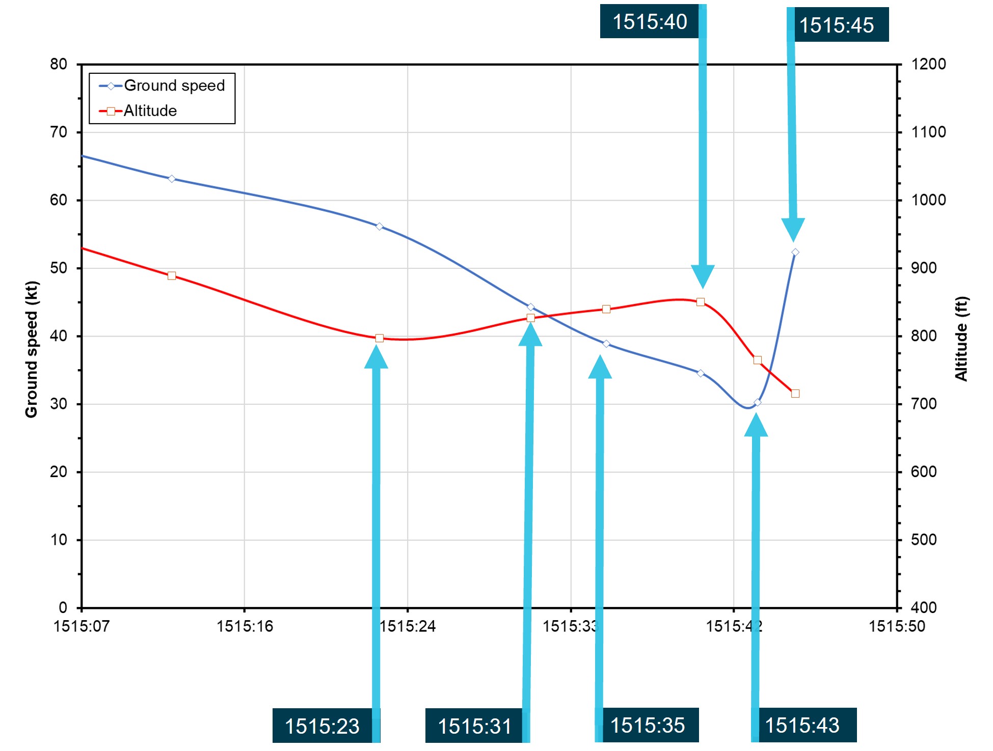
It was not possible to determine the precise location of the helicopter when the bucket was released. However, based on the recorded flight path and the location of the bucket, approximately 300 m to the east of the main wreckage, the ATSB estimated the earliest possible release point of the bucket was at 1515:31, when the helicopter was in a slight climb and the track had altered slightly to the right.
Recorded rapid descent
The final 2 data points (Figure 13) indicated that VH-UHX descended at a mean rate between 1,500 and 1,700 feet per minute, consistent with autorotation. Calculations indicated that the descent commenced at approximately 430 ft above the terrain. During this time, the horizontal ground speed component of the helicopter initially reduced to about 30 kt before increasing to about 50 kt. The final data point from the onboard GPS was recorded at 1515:45. The final data point from the Tracplus was transmitted at 1515:58 and was likely a post-collision system shutdown.
Figure 11: Garmin 296 track data showing the flight path of UHX during the accident flight
Source: Google Earth, annotated by ATSB
Figure 12: Presentation of recorded data plotting altitude and groundspeed against local time
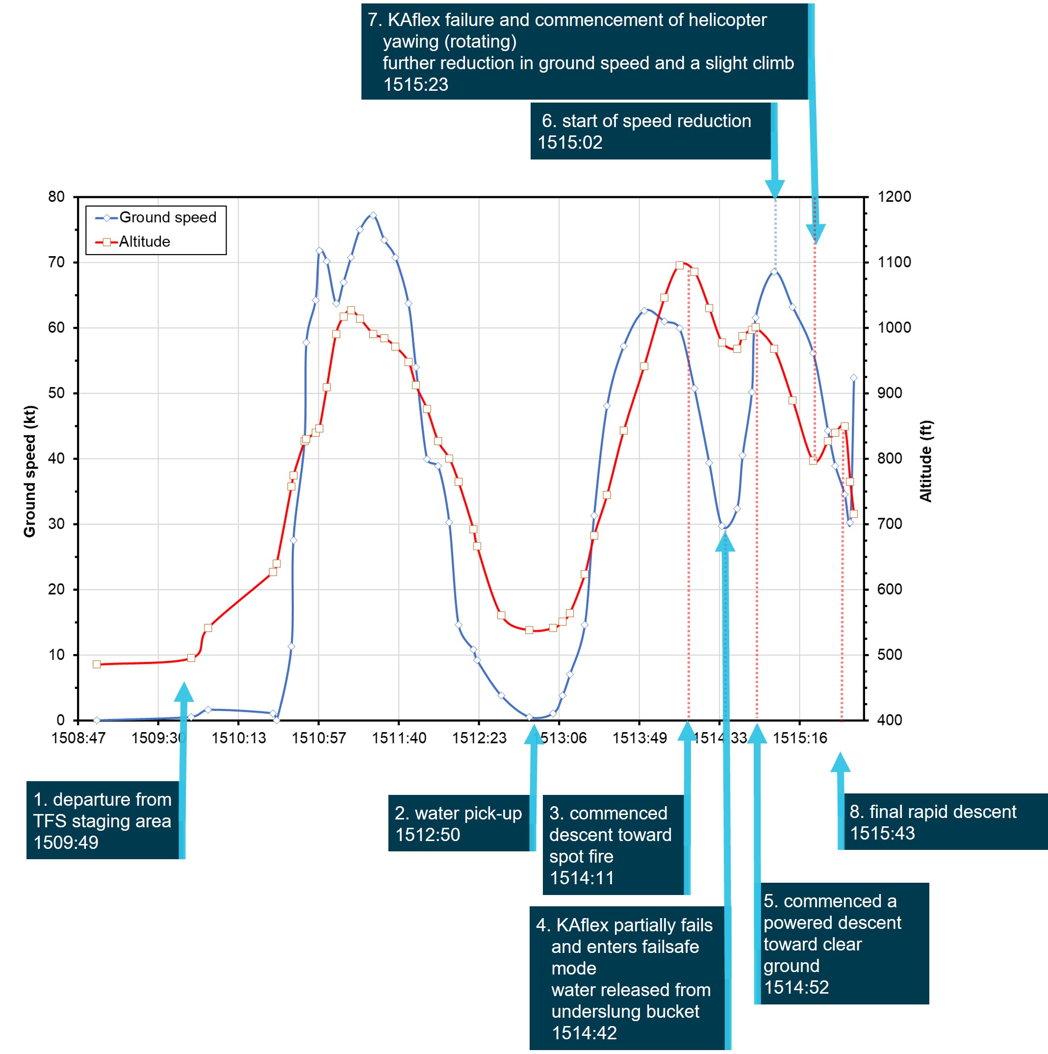
Key moments in the accident flight sequence of events are annotated
Source: ATSB
Figure 13: Presentation of the final GPS data points from the accident flight plotting altitude and ground speed against local time
Source: ATSB
Aircraft performance
Weight and balance
The ATSB evaluated whether VH-UHX was operated within the allowable weight and balance limits during the accident flight. Weights considered for this assessment included the onboard equipment, approximately 700 litres of fuel, pilot weight, and the weight of water contained within the bucket. A load cell and onboard digital gauge allowed the amount of water in the bucket to be monitored and provided a means for the pilot to assure that the helicopter remained within weight limits.
Although it was not possible to determine the precise amount of water transferred into the bucket from the dam, the ATSB concluded that VH-UHX was likely operating below the maximum take-off weight and within the centre of gravity limits throughout the accident flight.
Emergency procedures
Total power loss vs drive shaft failure
Emergency procedures were described in Chapter 9 of the UH-1H Operator’s Manual. For an engine malfunction or complete power loss, the manual stated that:
Additionally, the manual detailed the following indications associated with a drive shaft failure:
Comparing the 2 malfunctions, in the event of a drive shaft failure the helicopter will exhibit some of the symptoms listed above for an engine power loss. Specifically, reduction in rotor RPM, activation of the low RPM audio alarm and illumination of the warning light would be expected. However, there will be no drop in engine RPM. Rather the engine RPM will likely initially increase (with associated noise), due to the sudden unloading from the rotor system.
Contrary to the advice in the Operator’s Manual, in both this occurrence and a past occurrence involving failure of the drive shaft (see the section titled Other occurrences), the helicopter unexpectedly experienced right yaw.
The helicopter manufacturer advised the ATSB that if the transmission RPM decreased, both the main rotor and tail rotor RPM would also decrease. A decrease in tail rotor RPM would result in less tail rotor thrust and therefore a nose-right yaw could occur. They further advised that a reduction in main rotor RPM would result in a corresponding reduction in hydraulic system pressure, which may then result in increasing stiffness through the flight controls (including the hydraulically boosted pedals). An overcontrol application of right pedal could occur due to these changes in control feel.
Forced landing
A successful forced landing in a single-engine helicopter can only be achieved if the helicopter has sufficient energy in the rotor to achieve the required landing deceleration and touch down configuration. For single-engine helicopters, the height-velocity (H/V) diagram is established by the manufacturer at the time of certification. The diagram:
The UH-1H flight manual included the H/V diagram for UH-1H helicopters, including VH-UHX (Figure 14). When operating at low speed in the shaded (or ‘avoid’) area on the left side of the diagram, in the event of a power loss, a pilot may have insufficient height to accelerate to the speed required to autorotate successfully. Above a certain height above the ground, at least 500 ft for the UH-1H depending on the density altitude, it is possible for a pilot to achieve autorotation speed even from a high hover. In the shaded area on the lower right side of the diagram, the combination of faster airspeed and proximity to the ground provides limited reaction time for the pilot in the event of an engine power loss. The FAA Helicopter Flying Handbook (FAA, 2019), stated:
The unshaded region of the diagram shows the combinations of airspeed and height above the ground that allows a pilot to successfully complete a landing in a full autorotation without requiring exceptional skill. At low heights (below about 10 ft) with low airspeed, such as a hover taxi, the helicopter is in a safe part of the H/V diagram. There, a pilot can use the kinetic energy from the rotor disc to cushion the landing with collective, converting rotational inertia to lift. An increase in height without a corresponding increase in airspeed puts the helicopter above a survivable un‑cushioned impact height, until a height is reached from which rotor inertia and gravitational potential energy can be converted to sufficient lift to reduce the vertical velocity at impact to a survivable value (FAA, 2019).
The US Federal Aviation Administration (2019) also stated that:
The ATSB evaluated the likelihood that VH-UHX should have been able to complete a safe landing after an engine failure. Figure 14 and Figure 15 show the recorded heights and speeds of the last 6 data points from the flight path data. This shows that for this phase of the flight, the helicopter was outside the avoid area of the height-velocity curve, indicating that an autorotative glide should have been possible with the nominal helicopter rotor rpm.
Figure 14: Data points from the onboard GPS noting time, airspeed (calculated) and height are overlaid on the UH-1H height-velocity helicopter performance diagram
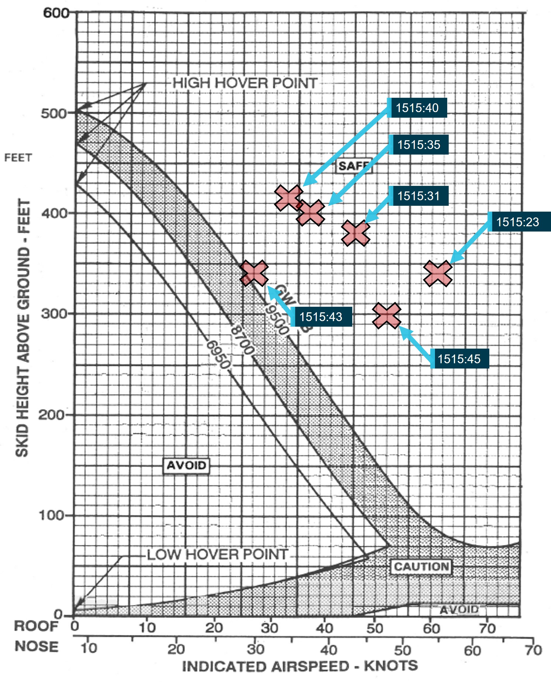
Source: Garlick Helicopters, annotated by the ATSB
Figure 15: The final data points from Figure 14 are overlaid against the final track of the helicopter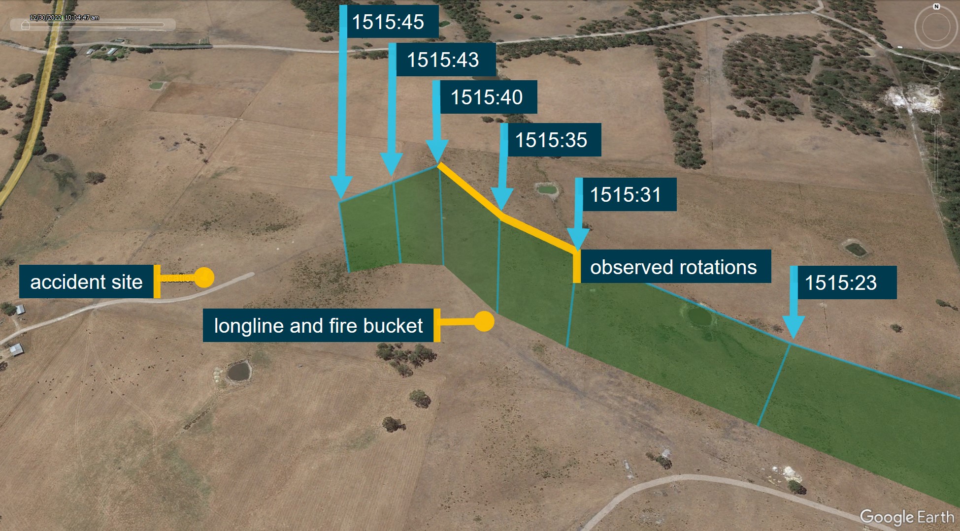
The approximate position of the yawing (rotations), the longline and fire bucket, and the accident site are also shown.
Source: Google Earth, annotated by the ATSB
Autorotative glide
The ATSB evaluated the descent of VH-UHX between the final recorded data points and the accident site for the purpose of establishing if it had entered a stable autorotative glide during the last part of the flight.
The calculated glide ratio from the last 2 flight data points was approximately 1 to 3.6, with a rate of descent of between 1,500 and 1,700 feet per minute and a ground speed of about 50 knots. Published UH-1H autorotational glide characteristics indicated that for an airspeed comparable to 50 knots and main rotor rpm of 314 rpm, a glide ratio of 1 to 3.8 is predicted at a descent rate of 1,600 feet per minute. The actual main rotor rpm was not recorded in the flight data and could not be determined. Further, there were insufficient flight data points to establish if the flight had entered a steady descent at this stage. Therefore, although the actual and published glide characteristics appeared to be comparable for this phase of flight, it was not possible to determine if VH-UHX was in a stable autorotation at the nominal rpm at this point in the flight.
A 1 to 1 glide ratio was estimated between the final recorded flight data point and the initial ground impact location. This ratio was at least 3 times steeper than that indicated by the flight data and published glide characteristics predicted for a stable autorotation noted above. This is consistent with the actual aircraft track, ground speed and vertical trajectory being considerably different to the last 2 flight data points. The most likely explanation for this is that the vertical speed was increasing between the final data point and the collision with terrain.
Personnel information
General
The pilot was an Australian citizen who had flown in several countries and had experience on numerous helicopter types. The pilot held a current commercial pilot licence (helicopter) that was issued on 22 December 2000, and a current Class 1 aviation medical certificate. In addition, the pilot held a low-level operational rating issued on 5 January 2001, with endorsements for helicopter sling-load operations issued on 21 June 2004. All the flight ratings held by the pilot were current and valid at the time of the accident and the pilot had worked with the TFS for several years.
Flying experience
Their logbook showed an accumulation of more than 9,900 hours total aeronautical experience, mostly in helicopters. In the previous 30 and 90 days, the pilot had flown 75 and 146 hours respectively and almost all those hours were accumulated in the accident aircraft.
The pilot attained a type rating for the UH-1H, in addition to the Bell 204 and Bell 205, on 9 July 2014. At the time of the accident the pilot’s total flying experience on the Bell 204, Bell 205 and the UH-1H was approximately 814 hours.
The pilot had about 2,090 hours total experience in aerial firefighting. In the last 90 days, most of the flying performed by the pilot (132 of the 146 hours) related to firefighting activities in the accident aircraft, with 108 hours of firefighting sling load operations recorded.
Proficiency
The pilot’s most recent aircraft flight review was completed in a Bell 505 helicopter on 5 August 2021. The ATSB consulted the flight examiner from an earlier review[6] where the pilot completed their proficiency check in VH-UHX. For the longline operational component of the check, during which the pilot’s control of the aircraft was assessed, the examiner reported requiring the pilot to select a water source, collect the water in the fire bucket and choose a target.
When asked about the pilot’s management of abnormal and emergency situations, the examiner advised that autorotations were conducted at elevations of 500 ft and 1,000 ft. Simulated hydraulic or engine failures were conducted, as well as a jammed flight control (usually the left pedal).
In the event of an emergency, the examiner advised the ATSB that pilots were trained to ‘clean‑up’ the aircraft by jettisoning the longline and bucket. Though it was normal industry practise to release the bucket and longline during an in-flight emergency, the examiner advised that it was up to the pilot’s discretion when to complete that action.
At the conclusion of the proficiency check, the examiner recorded that the accident pilot was of a ‘high standard’ and had no concerns with the accident pilot managing an in-flight emergency.
Fatigue assessment
The ATSB assessed whether the pilot may have been fatigued at the time of the accident. The pilot’s start times, rest time available, accommodation, environmental factors and workload associated with the task were all reviewed.
From the evidence available, while there were some long days of firebombing leading up to the accident, based on the pilot’s sleep obtained and the hours worked on the day and during the 72 hours prior (Table 1), it is unlikely the pilot was experiencing a level of fatigue that would have affected their ability to safely operate the helicopter.
Table 1: 72-hour pilot history
| Duty | 11 February 2022 | 12 February 2022 | 13 February 2022 | 14 February 2022 |
| Flight time | 10 | 10 | 6.5 | 1.0 |
| Duty time | 11.5 | 10 | 11 | 6.5 |
Survival aspects
Medical and pathological information
Post-mortem and toxicology reports were reviewed by the ATSB, with no natural disease or apparent toxicology identified. The post-mortem report concluded that the cause of death was a combination of head and thermal injuries.
Pilot seating
A flight manual supplement allowing the pilot in command to conduct operations from the left seat during external load operations was located in the recovered flight manual. The pilot was known to operate the helicopter from the left seat during firebombing operations. The pilot was located by first responders within their seat harness on the left side of the helicopter and had been wearing a flight helmet and flight suit. The left seat was fitted with a four-point harness, however, first responders were unable to advise whether the shoulder harness had been in use. Due to the significant vertical and horizontal loads, the resulting compression of the fuselage, and the post‑impact fire, the accident was not survivable.
Meteorological information
Meteorological reports and a private weather station within 5 km of the accident site indicated clear sky and light to moderate wind conditions. The air temperature at the accident site was estimated to range between 25°C and 29°C.
A pilot who was situated at the TFS staging area at the time of the accident described the weather as light winds from the east-north-east or the north-east and to be suitable for the helicopter firebombing operations.
Helicopter maintenance information
General
The logbook statement for VH-UHX specified that it was to be maintained in accordance with the Garlick Helicopters Inc. Instructions for Continued Airworthiness (ICA) report GH-H13WE-CA1H. The Garlick ICA report stated that the UH-1H helicopter-type was to be maintained in accordance with the US Army technical publications.
The US Army UH-1H maintenance schedule included a phased program that had a 900-flight hour cycle with intermediate 150-hour phases. There were also 25-hour and daily inspections.
The special certificate of airworthiness for VH-UHX stated:
Recent scheduled maintenance
The helicopter’s maintenance records identified that the helicopter had accrued 6,786 hours total time in service while operated in the US. The records further indicated that by 30 January 2022, the helicopter had accrued a total time in service of 7,746.0 hours.
A scheduled 150-hour airframe and engine inspection was conducted by Richmond Valley Aviation between 26–30 January 2022. An additional inspection of the engine’s axial compressor and stators was performed requiring the removal of the top half of the compressor case. The compressor was washed and a linear actuator for the compressor guide vanes was replaced. In addition, the helicopter’s KAflex main drive shaft was removed and inspected. No defects were detected.
On 13 February 2022, the day prior to the accident, a scheduled 25-hour inspection that included a main rotor blade examination and airframe lubrication was completed by a licensed maintenance engineer at the pilot’s residence. The engineer recalled that no defects were identified during the inspection.
A partly burnt maintenance release was recovered from the wreckage. The document was issued on 30 January 2022 with an expiry of 30 January 2023, or 150 hours of operation from the time of issue, whichever occurred first. A signed entry on the document indicated that the daily inspection had been completed on 14 February 2022. There were no endorsements (defects) annotated on the maintenance release.
Flight time from 30 January 2022 was unable to be established due to fire damage. However, examination of the pilot’s flight records established that the helicopter had operated for 38 hours since the 150-hour phased inspection.
Unscheduled maintenance
In December 2021, while the pilot was completing firefighting operations at Sisters Beach, Tasmania, a defect associated with the 90° tail rotor gearbox was detected by the pilot. An attaching stud had reportedly loosened and contacted the upper part of the tail rotor drive shaft clamp. The helicopter was grounded until the gearbox and several components from the tail rotor drive system were replaced.
Richmond Valley Aviation reported that the KAflex drive shaft was scheduled for replacement due to the release of Federal Aviation Administration airworthiness directive (FAA AD) 2021-26-16, which became effective on 25 February 2022. The operator’s maintenance personnel advised that they had discussed the replacement of the KAflex with another type of greaseable drive shaft with the pilot and scheduled the replacement for the end of February 2022.
KAflex – main transmission drive shaft
General description
The KAflex main drive shaft for the UH-1H was manufactured by Kamatics Corporation (Kamatics). It was initially manufactured for the US Army in 1975 and was utilised as a direct replacement for the original Bell Helicopters driveshaft in their UH-1H fleet. The KAflex drive shaft is a flexible mechanical assembly that transmits torque from the engine output shaft to the input quill of the main rotor transmission. The drive shaft uses plates (flex frames) to accommodate relative movement between the engine and transmission. In normal operation, each flex frame transmits load from one bolt pair to the next bolt pair (Figure 16).
The drive shaft is designed with a fail-safe feature. Should an in-service fracture occur within the flex frame pack, or in the attaching hardware, the interconnect and end fitting are forced together. The resultant friction maintains drive between the engine and transmission. The off-centre and out-of-balance operation of the interconnect shaft causes vibrations, which signals that a partial failure has occurred and fail-safe mode is in operation (Figure 17). A pilot may be alerted to a shaft operating in fail-safe mode by increased noise and vibration.
Kamatics advised the ATSB that during qualification testing to demonstrate the fail-safe feature, a drive shaft demonstrated 21.5 minutes of continued powered operation when a flex-frame had been intentionally failed. The testing involved a short-term high-power operation (such as a climb or to manoeuvre to avoid an obstacle) followed by reduced power operation (such as flight in search of a landing site).
The testing did not consider a bolt failure and Kamatics advised a rapid decline of the shaft would result if a bolt failure were to occur.
KAflex maintenance
Kamatics reported that the US Army developed their own technical manuals and instructions for continued airworthiness for maintaining the KAflex drive shaft. It was to be inspected daily (pre‑flight) and during the phased-maintenance intervals. No life-limits were applied by the US Army to the drive shaft.
The US Army phased maintenance required the KAflex to be visually inspected after every 150 hours of operation. Specifically, the instructions listed the following statement and required maintainers to:
The 150-hour inspection did not explicitly state to check for red metallic residue or debris at the bolted connections. Kamatics advised that a check for fretting material could be an early indicator of a washer failure or joint movement from loose bolts.
The daily inspections were to be completed by the pilot and were listed in the operating procedures and manoeuvres section of the UH-1H flight manual.[7] The VH-UHX flight manual recovered from the accident site was severely damaged. It had been partially burned, and was fuel and water soaked, and was therefore incomplete. An exemplar flight manual was sourced that advised:
Figure 16: KAflex main transmission drive shaft
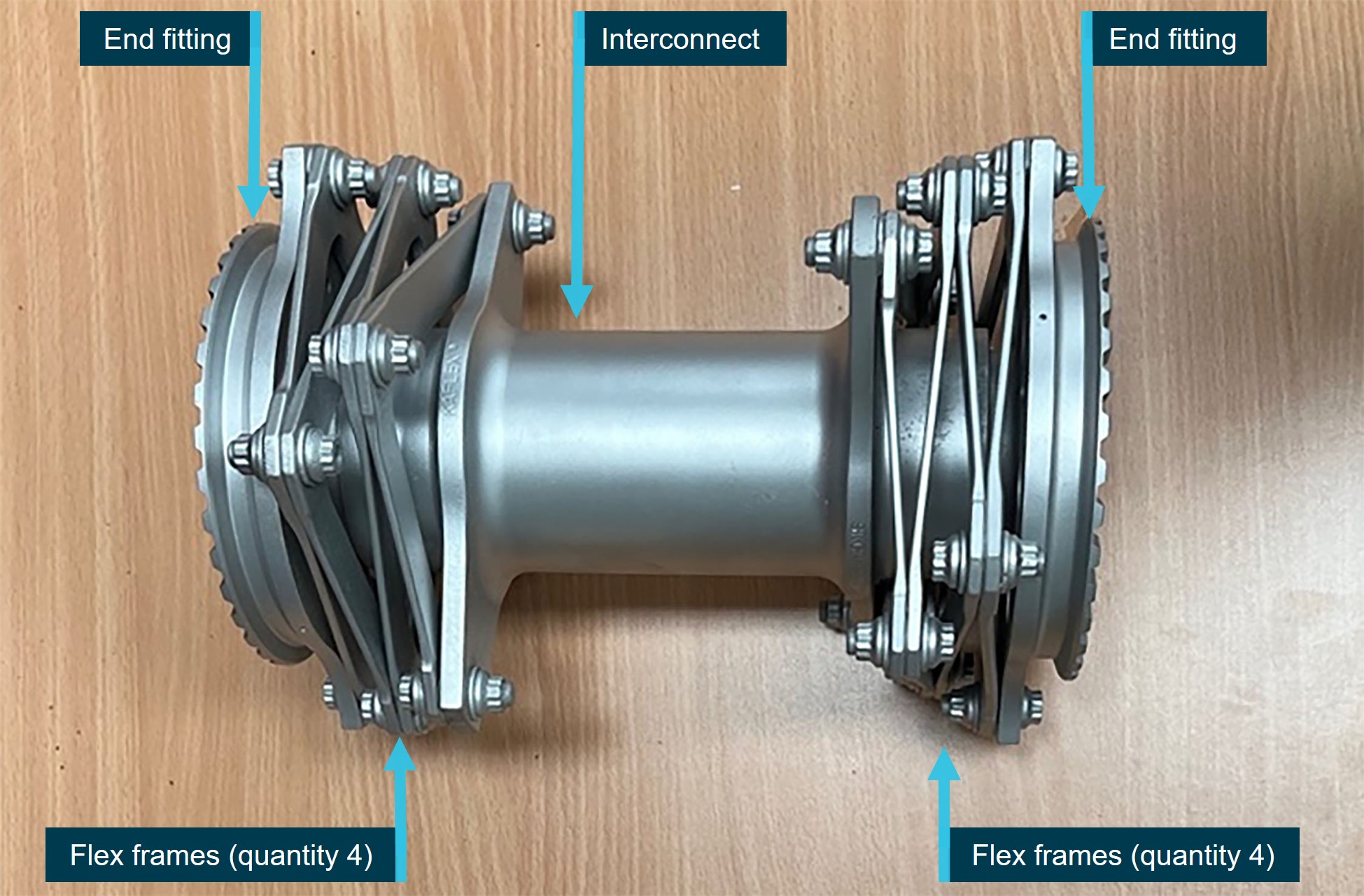
The main components of the drive shaft and their quantity are labelled
Source: CASA, annotated by the ATSB
Figure 17: KAflex – normal operation and fail-safe mode
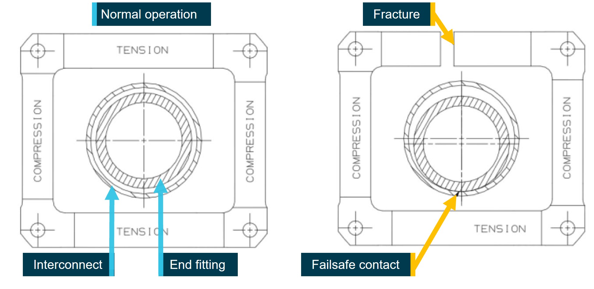
Source: Kamatics Corporation, annotated by the ATSB
KAflex drive shaft part history
Component records for the drive shaft, serial number 0110, were provided by the manufacturer and showed that the KAflex (fitted to VH-UHX) had been released into service in 1978 as part number SKCP2180-1 to be operated and maintained by the US Army. The records further showed that in 1979, it had been returned to Kamatics for disassembly and the connecting hardware was changed over, being released as updated part number SKCP2281-103.
Throughout its history installed within the UH-1H helicopter, there was no specified life-limit or a time-between-overhaul for the KAflex. The shafts were operated and maintained on-condition and this maintenance practice continued when UH-1H helicopters were transferred to the civil register.
The maintenance organisation reported that the drive shaft hours had not been tracked because of the on-condition requirements associated with its service life. The KAflex was removed during the last scheduled phased inspection, approximately 39 hours prior to the accident. During that period of maintenance, the shaft was visually inspected prior to reinstallation into VH-UHX with no identified defects.
United States Federal Aviation Administration airworthiness directive
In 2018, Kamatics reported to the FAA their concern over several KAflex drive shaft failures that had occurred within UH-1H civil-operated helicopters. They identified that several variants of the KAflex were in extended use and had an unknown period of service. Prompted by those safety concerns, on 21 January 2022 the Federal Aviation Administration (FAA) issued airworthiness directive (AD) 2021-26-16, which became effective on 25 February 2022. The FAA AD advised that, if not addressed, an unsafe condition could result in the loss of engine power to the transmission and a subsequent loss of control of the helicopter.
The FAA AD required for operators to check the part number[8] and the total hours time-in-service of fitted drive shafts. A life-limit of 5,000 hours was also introduced by the FAA AD. If the drive shaft hours were unable to be verified through the maintenance records, the FAA AD required helicopter airframe total hours to be used as a measure of the overall drive shaft service life.
The FAA AD instructed that KAflex drive shafts with less than 5,000 hours service were able to be overhauled in accordance with FAA approved procedures. Additionally, shafts were to be removed from service if during visual inspection the following damage was identified:
- broken, loose or missing hardware
- bolt movement
- fretting corrosion and fretting product
- mechanical damage, nicks, indents or corrosion.
Examination of the KAflex from VH-UHX
A detailed metallurgical examination of the failed KAflex was completed at the ATSB’s technical facilities in Canberra. The drive shaft had fragmented into multiple pieces (Figure 18). The end fittings had remained attached to the engine and transmission, respectively, with the separated interconnect tube and fractured pieces of flex frame recovered from the burnt wreckage. As previously indicated, one of the flex frame segments was found in the compressor section of the engine. Several flex frame segments were unable to be located at the accident site.
The intense heat damage sustained from the post-accident fire consumed evidence of markings usually present on KAflex drive shafts, including a factory-applied serial number (ink-stamped onto each end fitting), and the factory-applied torque stripe (for each assembled nut and bolt). A permanent mechanical stamping onto the interconnect ‘SER NO 0110’ identified the drive shaft serial number, confirming its 1978 year of manufacture.
Visual examination of the interconnect identified a portion at the end of the tube that had fractured with associated bell-mouth deformation. The fracture occurred where the transmission end fitting had resided during operation. A lip of material at the end of the interconnect tube had been rolled outward and the fracture surfaces smoothed, likely from sustained metal-to-metal frictional contact. The portion of the end fitting that resided within interconnect exhibited associated severe frictional damage to the shouldered portion of the coupling region (Figure 19). The ATSB noted the distinct similarity between this and other KAflex shafts that had entered fail-safe mode.
Kamatics technical data showed that the attachment hardware comprising the bolts, countersunk washers and the spacers were of the correct type for KAflex part number KCP2281-103. From that data it was established that of the recovered fragments there was 1 missing bolt from the engine portion of the drive shaft, and 3 missing bolts (and their nuts and washers) from the transmission portion of the drive shaft. Breakaway torque values were measured during disassembly of the KAflex for all remaining fasteners. None were shown to meet the assembly specifications, though it was identified that shaft had fragmented and had been exposed to a significant fire.
An additional missing washer from the transmission portion of the drive shaft was identified on an intact attachment bolt associated with a fractured flex frame (Figure 20). A red-coloured substance consistent with fretting product remained on the surfaces of the attachment bolt (associated with the missing washer) and the surrounding flex frame surfaces. Furthermore, 6 other countersunk washers had either radially cracked, or contained circumferential cracks (Figure 21). A metallurgical cross-section through one of the washers showed that angular cracks had initiated at the washer metallic coating, which had then penetrated into the steel substrate.
Detailed examination of the flex frame fracture surfaces was completed using an optical microscope and scanning electron microscope. Evident thermal damage to the surfaces of the damaged flex frames significantly damaged and/or obscured any possible fractographic evidence of the mechanism of failure. Similar thermal damage had occurred to washer / spacer attachment hardware. Many of the finer surface features on the flex frame fractures were completely or partially obscured from that thermal damage.
The results of ATSB’s technical examination were presented to Kamatics, the US National Transportation Safety Board, CASA and the operator’s maintenance personnel. Kamatics advised that the frictional damage sustained to the end fitting and corresponding fracture of the interconnect indicated that the shaft had entered fail-safe mode during operation.
Figure 18: KAflex prior to disassembly at the ATSB’s technical facilities
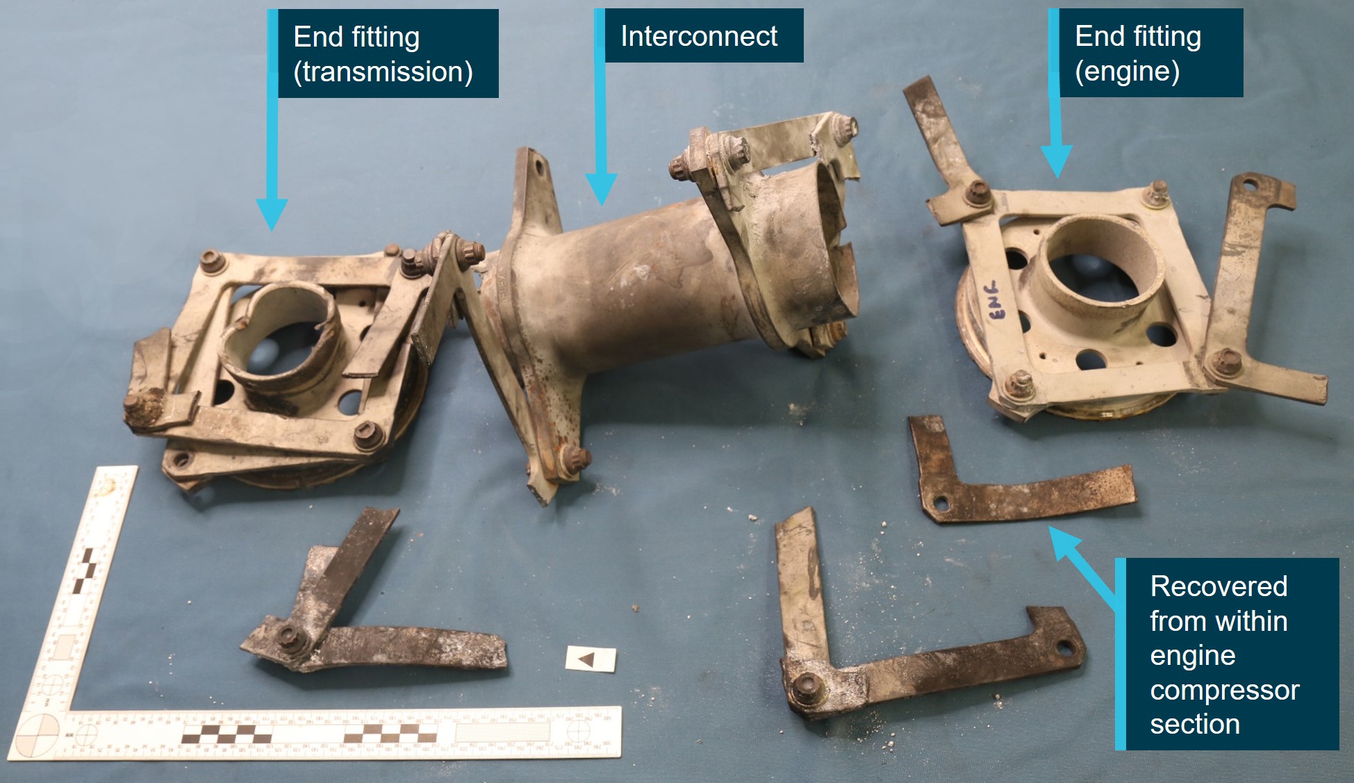
Not all flex frame fragments or their attachment hardware were recovered at the accident site. One flex frame fragment was found in the compressor section of the engine.
Source: ATSB
Figure 19: Photographic montage of the KAflex showing damage sustained upon entering fail-safe mode
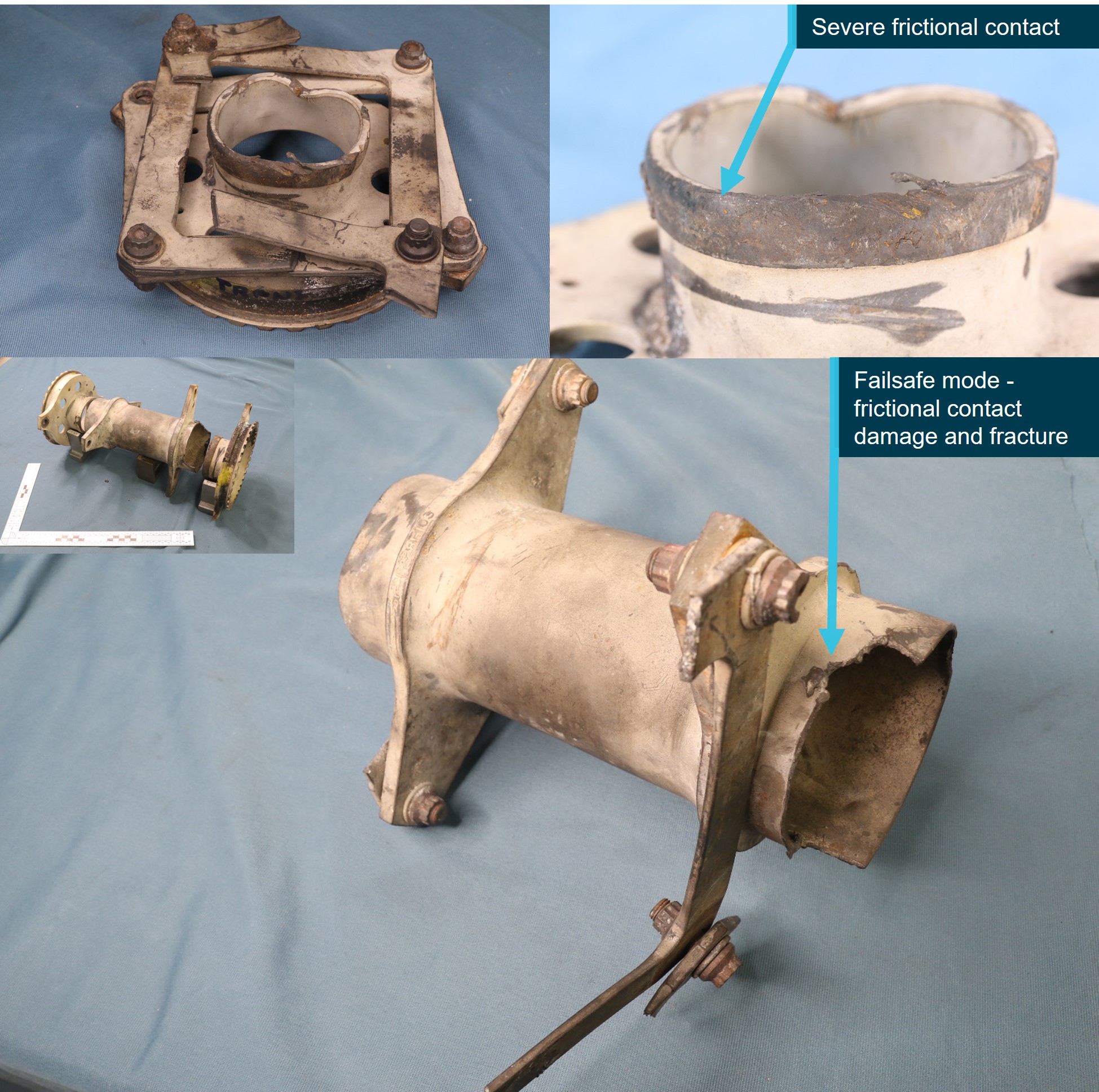
The identification of severe frictional damage and fracture that had occurred to both the interconnect and the end fitting (transmission) indicated the shaft had entered fail-safe mode
Source: ATSB
Figure 20: Photographic montage identifying a missing washer and evidence of fretting product on the associated flex frame and its attachment hardware
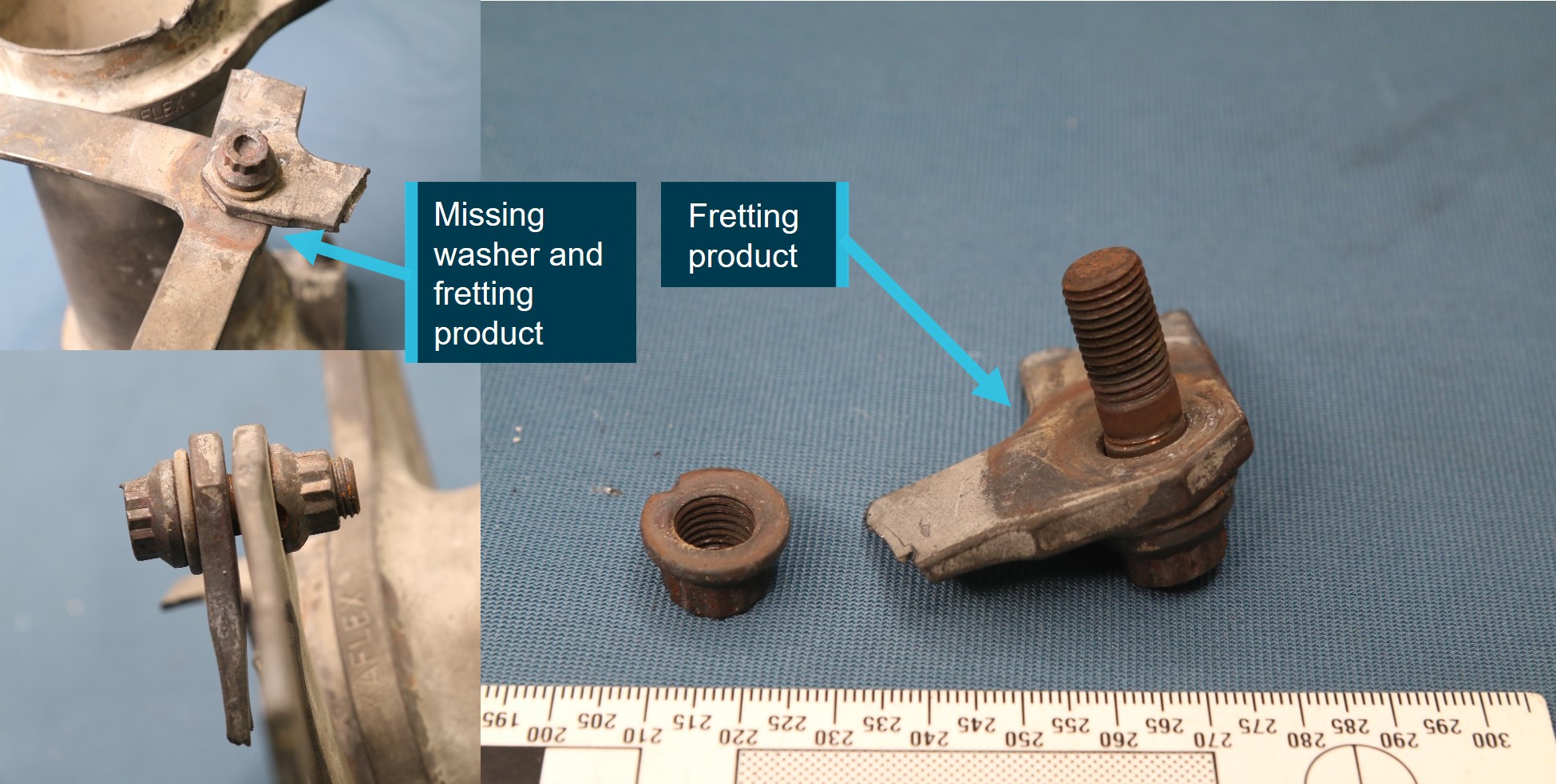
Source: ATSB
Figure 21: Photographic montage of cracks (arrowed) in countersunk washers from the KAlex attachment hardware

The intact washer (left image) displaying a series of cracks (arrowed) was recovered from the flex frame shown at Figure 20
Source: ATSB
Other occurrences
The ATSB identified one occurrence in Australia and 6 in the US with similarities to this accident. Further details of the publicly available accident reports of these occurrences are contained at Appendix A of this report. In all cases, the fail-safe feature of the drive shaft performed as designed after fracture of a flex frame or attachment bolt, allowing continuous operation under load and time for the pilot to commence an emergency landing. Excluding VH‑UHX, the other accidents were non-fatal, however significant damage was sustained during some of the forced landings. To summarise:
- Pilots became aware of a drive system problem due to increased noise i.e. a ‘howling’ or ‘shrieking’ sound and vibrations from the transmission area.
- Once the main drive shaft has failed, stiffness through the flight controls may occur.
- Once in fail-safe mode KAflex drive shafts transmitted operational power for just a few minutes, which was significantly less than the 21.5 minutes established during the Kamatics qualification testing (with the caveat that the testing did not consider a bolt failure and the associated rapid decline in the shaft).
- Failures of the KAflex drive shafts were initiated by the fatigue cracking and eventual fracture of a flex frame, with a single reported instance of an attachment bolt fatigue fracture.
- In each case, unique and deteriorating contact damage occurred to the interconnect and end fitting surfaces once the drive shaft entered fail-safe mode (Figure 22).
- There was one other reported instance of a rapid nose-right yaw (rotation of the helicopter about its vertical axis), and associated loss of directional control prior to impact with the terrain, following the subsequent total failure of the drive shaft. That accident is documented in ATSB investigation AO-2019-070 and is also further discussed in Appendix A of this report.
The contributing factors that have been established from the investigation of other KAflex failures included:
- unauthorised / inappropriate overhaul methods
- operation with sustained misalignment of the helicopter drive system
- drive shaft components being out-of-tolerance
- high-frequency utilisation and heavy lifting operations
- excessive wear due to loose attachment hardware (i.e. bolts).
Figure 22: A KAflex that entered fail-safe mode due to fatigue cracking of a flex frame element
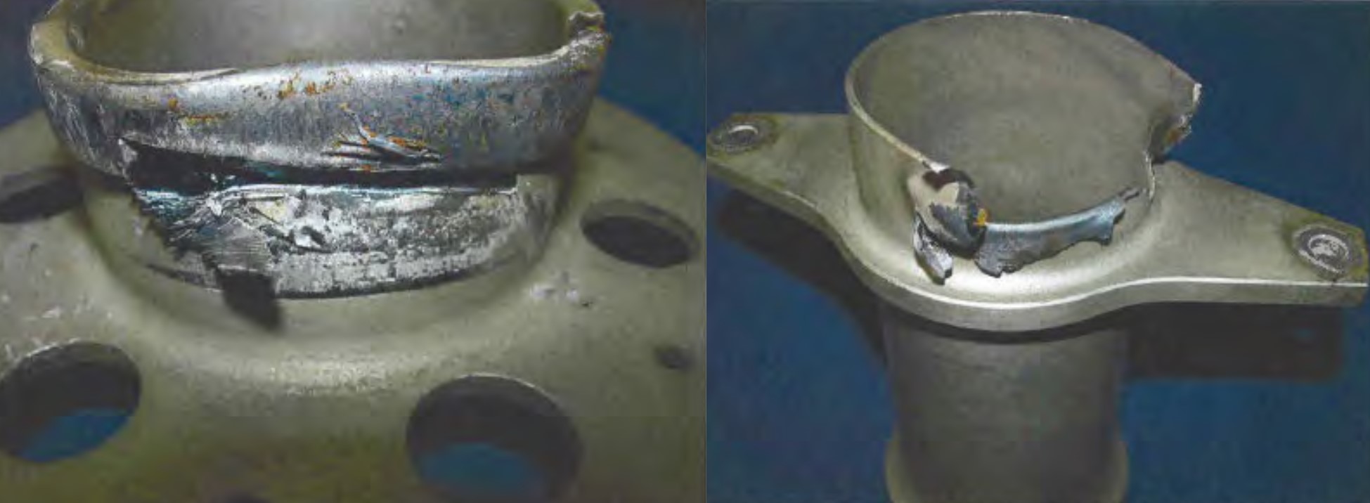
Physical characteristics of fail-safe mode after complete failure of the drive shaft include severe frictional damage and bell-mouth (opening) deformation to the end fitting, along with associated frictional damage, deformation and eventual fracture of the interconnect.
Source: Kamatics Corporation
Safety analysis
Introduction
On 14 February 2022, the pilot of a Garlick UH-1H helicopter was supporting the Tasmania Fire Service (TFS) by providing aerial firebombing support to the Lebrina bushfire, northern Tasmania. At 1509 the pilot departed the local TFS staging area to extinguish a small spot fire in a region of unburnt vegetation on the western flank of the fireground. The helicopter was observed to unexpectedly miss the designated target with the underslung water load. It was then tracked toward an open paddock, losing directional control as it was slowed on approach to the paddock, before pitching steeply nose-down and colliding with terrain.
The following analysis details the factors that prevented the skilled and experienced pilot from conducting a survivable descent and landing.
Technical failure
The ATSB considered possible reasons for the apparent premature release of water from the underslung bucket during the accident flight, which was captured in imagery by personnel onboard a nearby helicopter. Two eyewitnesses, who knew the accident pilot and also conducted aerial firefighting operations, observed the release of the water from an elevated height. Based on their knowledge of the operation and the accident pilot, who was well-regarded for precision water bombing operations, they considered that the off-target release of the water was unlikely to have been accidental.
Technical examination of the KAflex drive shaft identified definitive evidence of the disruption and disconnection of the KAflex coupling that transmitted engine drive torque to the transmission. Further, this disruption was characteristic with a torsional-induced breakout of the transmission‑side interconnect tube and the end fitting. Metallurgical evidence of high contact forces and severe surface friction damage was identified on both transmission coupling and the interconnect bore. This failure mode typically results from fatigue cracking and fracture of an interconnected flex frame or attachment bolt.
Of significance in this occurrence was the presence of fretting product (oxide dust/deposits) over a frame joint at the transmission coupling, together with extensive wear to the plain shank of the associated frame bolt. The attaching bolt was found to be intact but missing one of the washers. It is uncertain when the washer separated, however the presence of the fretting product indicated the flex frame joint at that location had been unstable for a significant period of operation.
The effects of post‑impact fire on the surfaces of the recovered flex frames significantly damaged and/or obscured any possible fractographic evidence of the mechanism of failure. Despite this, the extent of physical evidence around the general failure of the coupling was sufficient to conclude that the shaft had partially failed and entered fail-safe mode.
Considering pilot accounts from previously investigated occurrences, although drive is initially maintained when a KAflex enters fail-safe mode, this malfunction results in significant noise and increased vibration. It was therefore considered likely that the early water release while on approach to the spot fire and the diversion toward clear ground were deliberate actions taken by the pilot in response to activation of the fail-safe mode.
Emergency management
Analysis of the recorded flight data confirmed that, following the water release, an initial powered descent was conducted by the accident pilot toward the open field. However, the analysis also indicated that, as the helicopter was slowed and gently climbed over the open area, complete failure of the KAflex occurred. This resulted in an instantaneous and complete loss of drive to the rotor system. At that time, the helicopter was outside of the avoid area of the height-velocity envelope, indicating that a successful forced landing should have been possible. As the outcome was significantly more severe, the ATSB considered the factors that hampered management of the emergency.
Based on the observations of a pilot positioned at the staging area, the loss of drive to the rotor system was accompanied by an abrupt and significant right yaw. That direction of movement was consistent with the described helicopter behaviour following a previous KAflex drive shaft failure, but contrary to the expected left yaw detailed in the Flight Manual. This indicated that the reduction in rotor RPM following the sudden loss of drive may have disproportionately reduced tail rotor thrust.
In addition, Bell Helicopter reported that as the main transmission slowed, reduced pressure from the hydraulic system would lead to a stiffening of the flight controls, increasing the potential for the pilot to over control the anti-torque pedals to the tail rotor. Alternatively, given their proximity, it is possible that debris from the failing KAflex may have impacted the flight controls and/or the tail rotor drive shaft, and affected their operation. The degree of fire damage prevented an assessment of whether that occurred.
Irrespective of the reason for the right yaw, it may have led to an inappropriate pilot response (at least initially), as uncommanded right yaw is generally associated with a loss of tail rotor thrust, due to either a related mechanical failure or an aerodynamic loss of tail rotor effectiveness.
In addition to any potential uncertainty created by the yaw direction, as the engine was still operating when the KAflex drive shaft decoupled, the pilot was likely presented with unusual indications of simultaneous declining rotor RPM and increasing engine RPM due to the sudden unloading of the transmission and rotor system. Additionally, it was reported that the pilot operated the helicopter with the electrical hook release system deactivated. Therefore, release of the bucket and longline could only be achieved via the foot‑activated pedal, which would probably have delayed the response to the unexpected yaw.
In combination, these factors would have presented the pilot with a significant challenge to both troubleshoot and respond to the emergency.
Analysis of the flight data showed that, during the reported rotations immediately following the failure of the KAflex, VH-UHX continued a shallow climb for an 8 second period. Consequently, as there was no drive being provided to the rotor system during this time, significant drag on the main rotor would have reduced the rotor RPM. The helicopter was then observed to abruptly pitch down (which may have further degraded the rotor RPM) and descend steeply. This was followed by recovery of directional control by the pilot.
Mistiming of collective input by the pilot during the termination and landing was considered unlikely given their flying experience and previous demonstration of competency in conducting autorotative approaches. Further, ground scars showed that the helicopter was oriented in a pitch up attitude and tracking straight, indicating the helicopter was flared by the pilot prior to impact.
The ATSB concluded that, possibly exacerbated by insufficient height, the pilot was unable to recover the low RPM state during the unpowered descent. This limited their ability to decelerate and arrest the descent of the helicopter during the emergency landing, leading to high impact forces, and the subsequent post-impact fire.
Findings
|
ATSB investigation report findings focus on safety factors (that is, events and conditions that increase risk). Safety factors include ‘contributing factors’ and ‘other factors that increased risk’ (that is, factors that did not meet the definition of a contributing factor for this occurrence but were still considered important to include in the report for the purpose of increasing awareness and enhancing safety). In addition ‘other findings’ may be included to provide important information about topics other than safety factors. These findings should not be read as apportioning blame or liability to any particular organisation or individual. |
From the evidence available, the following findings are made with respect to the collision with terrain involving Garlick Helicopters UH-1H, registered VH-UHX, that occurred 36 km north of Launceston, Tasmania on 14 February 2022.
Contributing factors
- During the conduct of firebombing operations, the helicopter’s engine-to-transmission main KAflex drive shaft partially failed due to fracture of a flex frame attaching bolt, or a flex frame element and entered fail-safe mode. It is probable this resulted in the pilot jettisoning the water load from the underslung bucket and diverting toward clear ground.
- As the helicopter was slowed during a descent over clear ground, the main drive shaft decoupled, probably at about the time the longline and underslung bucket were released. The failure resulted in an instantaneous loss of drive to the rotor system.
- Following loss of drive to the main rotor system, the pilot was unable to complete a survivable autorotative descent and landing, probably due to a critical reduction in main rotor speed.
Safety issues and actions
|
Whether or not the ATSB identifies safety issues in the course of an investigation, relevant organisations may proactively initiate safety action in order to reduce their safety risk. The ATSB has been advised of the following proactive safety action in response to this occurrence. |
Proactive safety action taken by Civil Aviation Safety Authority
| Action number: | AO-2022-006-PSA-01 |
| Action organisation: | Civil Aviation Safety Authority |
| Action status: | Closed |
CASA released Issue 3 to Airworthiness Bulletin (AWB) 63-004 Kamatics Corporation KAflex Drive Shafts – UH-1H and Bell 407, on 28 June 2022. The purpose of the AWB was to alert operators and maintainers:
- That the approved Bell 407 Flight Manual did not adequately detail the pre-flight check inspection requirements with regard to checking the KAflex drive shaft for serviceability.
- To alert operators of 2 ATSB investigations involving UH-1H helicopters where the KAflex drive shafts had failed (ATSB investigation number AO-2019-070 and AO-2022-006).
- That the United States Federal Aviation Administration airworthiness directive AD 2021‑26-16 was applicable and imposed a 5,000 hour life-limit on the drive shaft.
Following review of the draft investigation report, on 5 March 2024, CASA released Issue 4 to AWB 63-004. Reflecting the advisory material contained in ATSB’s investigation report, Issue 4 of the AWB contained further advice to operators and maintainers on potential operational aspects once a KAflex has entered fail-safe mode.
Safety advisory notice to operators and maintainers of Garlick UH-1H helicopters
| SAN number: | AO-2022-006-SAN-01 |
| SAN release date: | 15 June 2022 |
On 15 June 2022 the ATSB advised operators of UH-1H helicopters to note the details of this accident and to look for the presence of corrosion, fretting, frame cracking, missing or damaged attaching hardware during all inspections of the KAflex drive shaft. Any identified defects were to be notified to the Civil Aviation Safety Authority.
Additionally, operators should be aware of Kamatics’ concern of shaft serial numbers 0635 and below for the UH-1H helicopter that may be fitted with legacy attachment hardware. Kamatics should be contacted if a shaft in the affected serial number range is identified.
Proactive safety action taken by Tasmania Fire Service
| Action number: | AO-2022-006-PSA-02 |
| Action organisation: | Tasmania Fire Service |
| Action status: | Closed |
- TFS has transitioned to the Tasmanian Government Radio Network to enable direct communications with other emergency service organisations, fire land managers and aircraft operators working at multi-agency incidents.
- In November 2022, TFS conducted an inter-agency training exercise to test the response to a rescue incident in remote and isolated areas. The exercise tested the TFS timelines, incident management command and control, communication links, processes and roles of each agency. A key outcome was that the notification procedures have been improved between TFS, Tasmania Police and the Ambulance Tasmania Air Rescue Aviation Unit.
Proactive safety action taken by Kamatics
| Action number: | AO-2022-006-PSA-03 |
| Action organisation: | Kamatics |
| Action status: | Closed |
Kamatics advised that for KAflex shafts returned to their factory they will complete a teardown inspection to identify evidence of fretting, cracked washers or any other undesirable defect in hardware items normally replaced during overhaul.
Proactive safety action taken by Richmond Valley Aviation
| Action number: | AO-2022-006-PSA-04 |
| Action organisation: | Richmond Valley Aviation |
| Action status: | Closed |
Richmond Valley Aviation, the maintainer and operator of VH-UHX, advised that subsequent to the accident they removed all KAflex drive shafts from service in aircraft that they maintained. Additionally, to mitigate the potential risk of future main transmission drive shaft failures they have elected to use an alternate type of drive shaft that has a 600 hour / 12-month inspection and re‑grease interval.
Glossary
| AD | airworthiness directive |
| AWB | airworthiness bulletin |
| CASA | Civil Aviation Safety Authority |
| CASR | Civil Aviation Safety Regulations |
| CVR | cockpit voice recorder |
| FAA | Federal Aviation Administration |
| FDR | flight data recorder |
| IAS | indicated airspeed |
| ICA | instructions for continued airworthiness |
| NSTB | National Transportation Safety Board |
| RPM | revolutions per minute |
| TFS | Tasmania Fire Service |
Sources of information
The sources of information during the investigation included:
- Richmond Valley Aviation
- the helicopter owner and manufacturer
- Kamatics Corporation
- Bureau of Meteorology
- United States Federal Aviation Administration and National Transportation Safety Board
- Tasmania Fire Service
- Civil Aviation Safety Authority
- witnesses
- the aircraft maintainer
- the pilot’s flight examiner
- onboard recorded GPS data.
Submissions
Under section 26 of the Transport Safety Investigation Act 2003, the ATSB may provide a draft report, on a confidential basis, to any person whom the ATSB considers appropriate. That section allows a person receiving a draft report to make submissions to the ATSB about the draft report.
A draft of this report was provided to the following directly involved parties:
- Richmond Valley Aviation
- the helicopter owner and manufacturer
- Kamatics Corporation
- United States Federal Aviation Administration and National Transportation Safety Board
- Tasmania Fire Service
- Civil Aviation Safety Authority
- the aircraft maintainer
- the pilot’s flight examiner
- witnesses
Submissions were received from:
- Richmond Valley Aviation
- the helicopter manufacturer
- Kamatics Corporation
- National Transportation Safety Board
- Tasmania Fire Service
- Civil Aviation Safety Authority
- the pilot’s flight examiner
- a witness.
The submissions were reviewed and, where considered appropriate, the text of the report was amended accordingly.
Appendix A: Related accidents and other investigations
During the course of this investigation, the ATSB became aware of similar accidents involving failure of KAflex main drive shafts. The United States (US) National Transportation Safety Board (NTSB) investigated and reported on 2 UH-1H accidents and the ATSB has previously investigated one other accident. Kamatics Corporation investigated 4 other failures and they can be contacted for details.
The relevant investigation reports are available at www.ntsb.gov and www.atsb.gov.au.
NTSB accident number SEA97LA126
On June 3, 1997, a Garlick UH-1H helicopter, collided with the terrain during a forced landing near Addy, Washington. The commercial pilot, who was the sole occupant, was not injured, but the aircraft sustained substantial damage. According to the pilot, they were about 30 minutes into the first logging cycle of the day and heading back to pick up another log load when the accident sequence began. The pilot heard a high-speed shredding sound with accompanying high‑frequency vibration.
The pilot immediately lowered the collective and released the underslung 150 foot longline. While transiting away from tall forest trees the sound and vibration rapidly worsened. The pilot heard a second loud noise and identified that the main rotor RPM began to decay, prompting an emergency landing.
The NTSB found that a number of the flex frames on the drive shaft had failed. The KAflex was sent to the NTSB materials laboratory, and their metallurgical examination identified evidence of pre-existing fatigue cracking on the fracture surfaces of a flex frame.
NTSB accident number WPR15LA178
The pilot of a UH-1H helicopter reported that on 31 May 2015, while manoeuvring the helicopter at low altitude during logging operations, a vibration and howling sound was detected coming from the transmission area. In response, the pilot immediately initiated a precautionary landing, however, the flight controls stiffened as the helicopter settled to the ground and the main rotor RPM reduced. The helicopter landed heavily.
The NTSB materials laboratory found multiple fractures had occurred to the KAflex drive shaft assembly. The KAflex failure was initiated by the fatigue cracking and fracture of an attachment bolt that secured the coupling assembly to the transmission shaft flange (Figure A1). No evidence of any material anomalies were found in the fractured bolt.
Figure A1: The KAflex entered fail‑safe mode following fatigue fracture of an attachment bolt, prior to total failure of the drive shaft
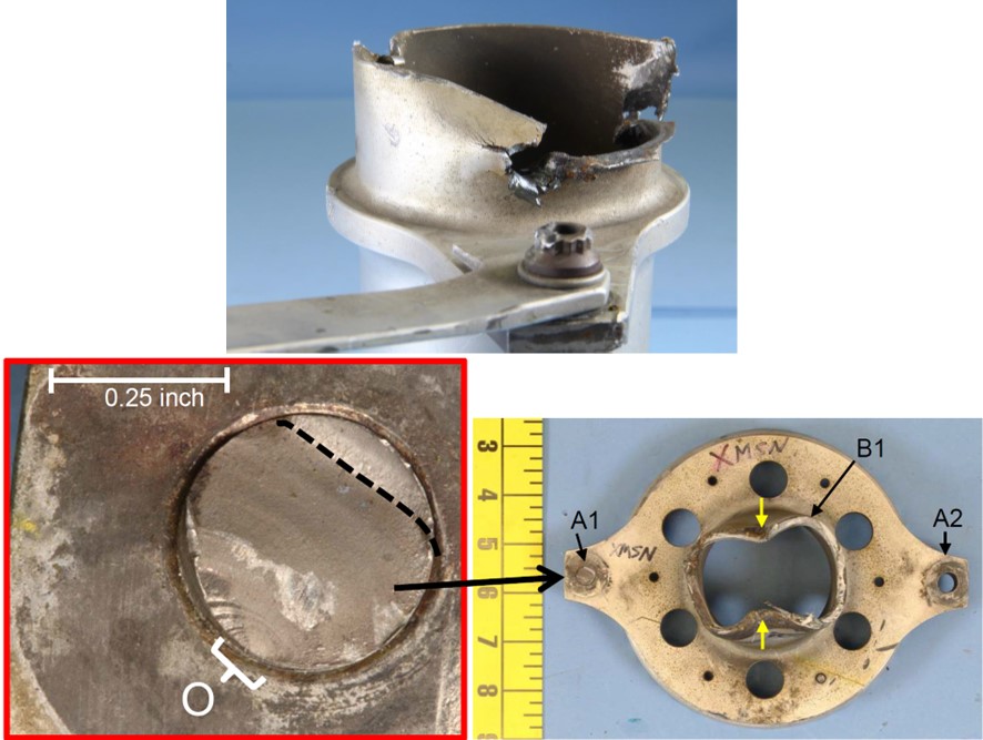
The interconnect and end fitting displayed characteristic contact features from entering fail-safe mode
Source: NTSB
ATSB investigation number AO-2019-070
On 7 December 2019, the pilot of a UH-1H helicopter was completing fire control aerial work. While hovering and preparing to uplift river water into the underslung bucket, the pilot heard a momentary ‘burring’ noise with a ‘buzzing’ vibration through the airframe. The pilot aborted the uplift and started to transition away from the hover when the noise and vibrations resumed. The pilot noted the intensity increased when the collective lever was raised.
The pilot radioed the firefighting personnel of the intention to land, released the bucket and longline, and tracked towards a clear area. The continuing noise indicated to the pilot that the condition of the helicopter was deteriorating. In response, the pilot elected to divert to a small clearing. On approach to the hover, at a height of about 10 ft, the helicopter commenced an uncontrolled rotational yaw to the right, which the pilot was unable to stop. The helicopter rotated about 180° from the approach heading before landing hard.
The ATSB’s metallurgical examination found that the KAflex drive shaft had failed due to the development of a fatigue crack in a flex frame that led to its fracture prior to the hard landing (Figure A2).
Figure A2: Fatigue cracking of a flex frame element led to the shaft entering fail-safe mode prior to total failure during operation
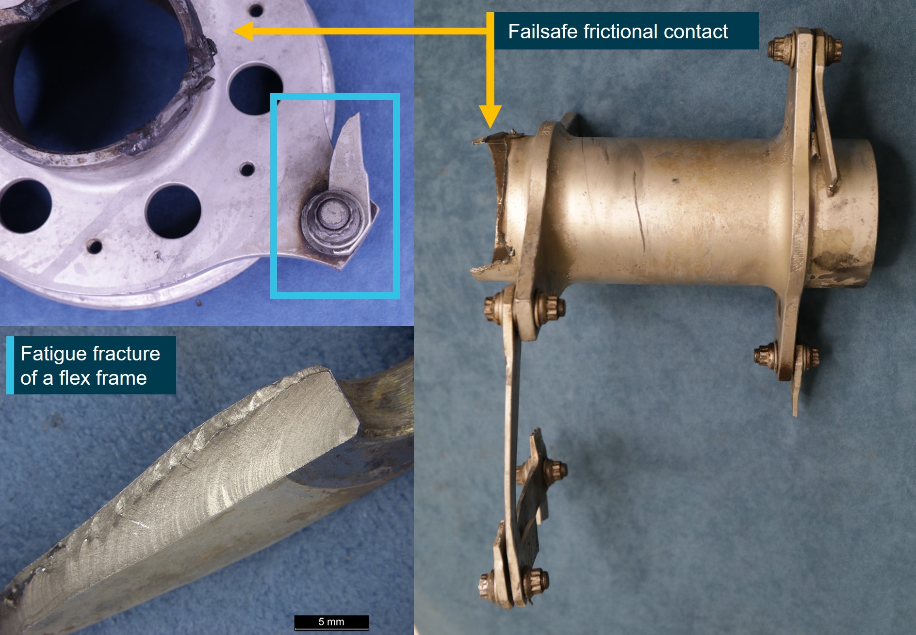
The interconnect and end fitting displayed characteristic contact features from entering fail-safe mode
Source: ATSB
Purpose of safety investigationsThe objective of a safety investigation is to enhance transport safety. This is done through:
It is not a function of the ATSB to apportion blame or provide a means for determining liability. At the same time, an investigation report must include factual material of sufficient weight to support the analysis and findings. At all times the ATSB endeavours to balance the use of material that could imply adverse comment with the need to properly explain what happened, and why, in a fair and unbiased manner. The ATSB does not investigate for the purpose of taking administrative, regulatory or criminal action. TerminologyAn explanation of terminology used in ATSB investigation reports is available here. This includes terms such as occurrence, contributing factor, other factor that increased risk, and safety issue. Publishing informationReleased in accordance with section 25 of the Transport Safety Investigation Act 2003 Published by: Australian Transport Safety Bureau © Commonwealth of Australia 2024
Ownership of intellectual property rights in this publication Unless otherwise noted, copyright (and any other intellectual property rights, if any) in this report publication is owned by the Commonwealth of Australia. Creative Commons licence With the exception of the Coat of Arms, ATSB logo, and photos and graphics in which a third party holds copyright, this publication is licensed under a Creative Commons Attribution 3.0 Australia licence. Creative Commons Attribution 3.0 Australia Licence is a standard form licence agreement that allows you to copy, distribute, transmit and adapt this publication provided that you attribute the work. The ATSB’s preference is that you attribute this publication (and any material sourced from it) using the following wording: Source: Australian Transport Safety Bureau Copyright in material obtained from other agencies, private individuals or organisations, belongs to those agencies, individuals or organisations. Where you wish to use their material, you will need to contact them directly. |
[1] Tasmania Fire Service, Sustainable Timber Tasmania, Parks and Wildlife Service, State Emergency Service and Reliance Forest Fibre responded to the fire.
[2] Formerly a Bell Helicopters UH-1H.
[3] This type of flight uses a range of ex-military, historic and replica aircraft to offer adventure-style flights to the general public for a fee.
[4] The compressor section of the engine was examined using a flexible video borescope.
[5] Requirements relating to the fitment of flight recorders are detailed in Part 91 Manual of Standards (MOS), Division 26.9 Flight recording equipment.
[6] The proficiency check was completed on 11 December 2020.
[7] Department of the Army, Operator’s Manual, Army Model UH-1 H/V Helicopter, UH-1H TM-55-1520-210-10 section 8-19 Area 6 para 2.b
[8] Kamatics Corporation KAflex part number: SKCP2180-1, SKCP2281-1, SKCP2281-1R or SKCP2281-103


