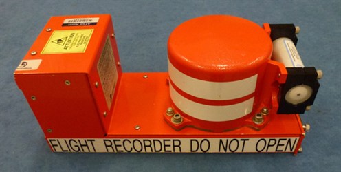
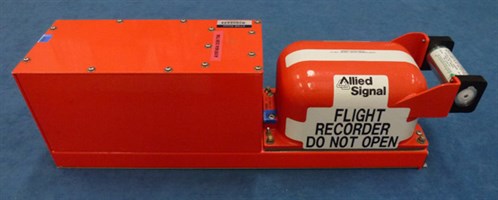
An aircraft’s flight recorders are an invaluable tool for investigators in identifying the factors behind an accident. Recorders usually comprise two individual boxes: the Cockpit Voice Recorder (CVR) and the Flight Data Recorder (FDR). Popularly known as ‘black boxes’, these flight recorders are in fact painted orange to help in their recovery following an accident.
The Cockpit Voice Recorder (CVR)
The CVR would be better named the ‘cockpit audio recorder’ as it provides far more than just the voices of the pilots. In fact, it creates a record of the total audio environment in the cockpit area. This includes crew conversation, radio transmissions, aural alarms, control movements, switch activations, engine noise and airflow noise.
Older CVRs retain the last 30 minutes of an aircraft’s flight. A modern CVR retains the last 2 hours of information. The newest data records over the oldest data (endless-loop principle).
A typical traditional CVR is 16 cm (6.3 in) in height, 12.7 cm (5.0 in) in width and 32 cm (12.6 in) in depth. It weighs 4.5 kg (10 lbs).
Around 80 per cent of aircraft accidents involve human factors, which means that crew performance may have contributed to the events. As a result, the CVR often provides accident investigators with invaluable insights into why an accident occurred.
The Flight Data Recorder (FDR)
The FDR records flight parameters. The data recorded varies widely, depending upon the age and size of the aircraft. The minimum requirement, however, is to record a basic group of five parameters:
- pressure altitude
- indicated airspeed
- magnetic heading
- normal acceleration
- microphone keying.
Microphone keying (the time radio transmissions were made by the crew) is recorded to correlate FDR data with CVR information.
This basic requirement has existed since the 1960s. Today, modern jet aircraft far exceed this, and are fitted with FDRs that can record thousands of parameters covering all aspects of the aircraft operation.
The FDR retains the last 25 hours of aircraft operation and, like the CVR, operates on the endless-loop principle. As FDRs have a longer recording duration than CVRs, they are very useful for investigating incidents and accidents.
A typical FDR is 16 cm (6.3 in) in height, 12.7 cm (5.0 in) in width and 50 cm (19.6 in) in depth. It weighs 4.8 kg (10.6 lbs).
The FDR often tells accident investigators what happened during an accident sequence and the events leading up to it.
Data storage
Older CVRs were analogue recorders which used magnetic tape as the recording medium. Modern solid-state CVRs, however, store the digitized audio information in memory chips.
Older FDRs were mostly digital recorders using magnetic tape as the recording medium. As with CVRs, modern solid-state FDRs store the digitized data in memory chips.
Memory chip recording medium (left) and recording medium (right)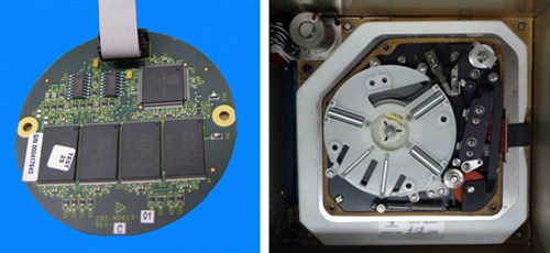
Installation
On 10 June 1960, an accident occurred in which 29 people died in a Fokker F27 aircraft landing at Mackay in Queensland. The subsequent board of inquiry was unable to come to any definite conclusions as to what had caused the accident and recommended that all airliners be fitted with flight recorders. The Federal Government implemented this recommendation the following year.
Australia was one of the first countries to introduce this requirement. Today, all aircraft on the Australian register with a maximum take-off weight less than or equal to 5,700 kg, and which are pressurised and turbine-powered by more than one engine are required to carry a cockpit voice recorder (CVR).
All Australian-registered aircraft with a maximum take-off weight greater than 5,700 kg and turbine powered are required to carry both a CVR and FDR.
Flight recorders are normally located near the aircraft’s tail, as experience has shown that this area generally suffers the least damage during an accident.
Crashworthiness
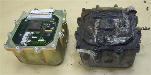
Flight recorders are designed to survive both high-speed impact and post-impact fire. They are, however, not invulnerable and are sometimes destroyed.
The recorder is designed to ensure that data, rather than the recorder itself, survives an accident. The data storage medium (tape or microchips) is mounted inside an impact-resistant and fire-resistant container.
Cockpit voice recorder received by the ATSB showing accident damage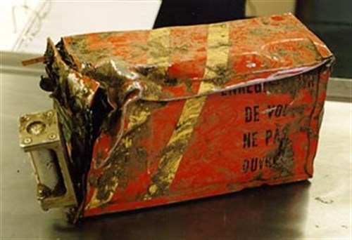
The crashworthiness standards of flight recorders was revised in 2003 by the European Organisation for Civil Aviation Equipment (EUROCAE) committee, an international body on which the ATSB was represented. The recorder’s memory module is now required to withstand:
- an impact producing a 3,400-g deceleration for 6.5 milliseconds (equivalent to an impact velocity of 270 knots and a deceleration or crushing distance of 45 cm)
- a penetration force produced by a 227 kilograms (500 pounds) weight which is dropped from a height of 3 metres (10 feet)
- a static crush force of 22.25 kN (5,000 pounds) applied continuously for 5 minutes
- a fire of 1,100 degrees Celsius for 60 minutes.
Recorder partially dismantled showing protective enclosure
The Underwater Location Beacon
Each recorder is fitted with battery-powered Underwater Location Beacon (ULB) to aid underwater recovery.
When the ULB is immersed in water, it will begin to radiate an acoustic signal which can be received and transformed into an audible signal by a receiver. The ULB is sometimes called a 'pinger' due to the audible signal created by the receiver.
Underwater Location Beacon
The ULB must meet the following requirements:
- nominal operating frequency: 37.5 kHz
- size (typical): 9.95 cm long by 3.30 cm diameter
- operating depth: 0 to 6,096 metres (20,000 feet)
- automatic activation by both fresh and salt water
- minimum operating life of 30 days. The acoustic output will decrease as the battery voltage decreases. It may be possible to still detect the ULB after 60 or more days but the detection range will be decreased.
The ULB can only be detected by a receiver under the surface of the water. The maximum detection range of a ULB is typically up to 2 to 3 kilometres but is dependent on:
- ULB acoustic output level
- receiver sensitivity
- whether the ULB is buried by debris (e.g. aircraft structure and mud)
- the ambient noise level (e.g. sea state, nearby boats, marine animals, gas and oil lines)
- water temperature gradients
- depth difference between the ULB and the receiver.
ATSB capability and facilities
The ATSB’s central office in Canberra includes an audio laboratory and an FDR laboratory. ATSB investigators use these laboratories to perform CVR and FDR readouts for occurrences in Australia and overseas.
Australia is one of a few countries in the Asia-Pacific region to possess these types of labs. The ATSB offers its services and expertise to international investigators. In the past, the ATSB has assisted regional neighbours such as New Zealand, Indonesia, Singapore, Taiwan and Bangladesh with investigation readouts.
The ATSB also uses the labs to certify new recorder-type/aircraft-type combinations.
In addition to its recorder readout capability, the ATSB has advanced computer graphics software which allows data obtained from all available sources to be combined to create a graphical reconstruction or animation of an accident or incident.
These data sources include FDR, CVR, ground-based radar recorders, eye-witness reports, air traffic service communications and wreckage analysis. Videos can also be produced from the computer graphics. Computer graphics are a powerful tool for investigators, being an excellent means of explaining accident scenarios to people unfamiliar with aviation, and also providing a valuable educational tool for pilots and other aviation professionals.
If an accident occurred at night in a remote area or at sea, the flight recorders may be the main, if not only, means of establishing the sequence of events immediately preceding the accident. At the very least, CVR and FDR data can save an investigation team many days or weeks of delay as the team examines the wreckage.
Many accidents have involved aircraft without flight recorders, and despite thorough investigation, the factors underlying these occurrences can remain inconclusive or unknown. As well, accidents leaving very little recoverable aircraft wreckage have, many times, been resolved once the flight recorders were found.
Flight recorders are also useful for cases in which evidence is transitory, e.g. occurrences involving windshear. In such instances, flight recorders will reveal the sudden effects of windshear upon an aircraft’s flight path. The evidence available from flight recording indicates that, prior to flight-parameter recording, the effect of the wind in many aircraft accidents was underestimated.
Flight recorder data recovery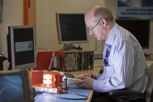
Accident animation
On 22 March 2010, an Embraer S.A. EMB-120ER Brasilia aircraft (EMB-120) crashed moments after take-off at Darwin Airport, Northern Territory. Both pilots died in the accident. The purpose of the flight was to revalidate the command instrument rating of the pilot under check. The aircraft was under the command of a training and checking captain, who occupied the copilot’s seat. The take-off included a simulated engine failure.
The aircraft was equipped with a CVR and an FDR which provided crucial evidence for the investigation. A computer graphics animation was produced based on the FDR data. The investigation report AO-2010-019 and animation are available at: www.atsb.gov.au
Picture of a computer graphics animation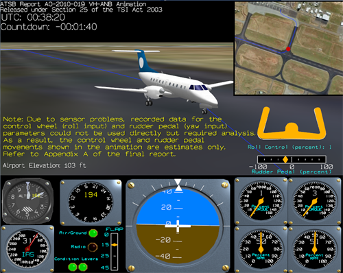
Different types of recorders
Deployable recorders
Deployable recorders incorporate the functions of the Cockpit Voice Recorder, the Flight Data Recorder and an Emergency Locator Transmitter (ELT) into a package that is automatically deployed (released) from the aircraft at the start of an accident sequence.
The deployable package possesses capabilities that enable it to deploy and rapidly establish a flight trajectory that clears the airframe during the accident sequence. The deployable package is designed to float on water after deployment.
After deployment, the deployable package starts transmitting an emergency signal that can be detected by satellite and search aircraft/ships.
Deployable recorders are mainly installed on helicopters operating over water as well as military aircraft. Commercial aeroplanes have not adopted deployable recorders.
Combined recorders
Combined recorders incorporate the functions of the Cockpit Voice Recorder and the Flight Data Recorder in one box.
When combined recorders are used on an aeroplane, two combined recorders are required. One is installed near the cockpit and one installed towards the rear of the aircraft. The forward-mounted recorder has the advantage of shorter cable distances between the cockpit area and the recorder, reducing the chance of the wires being breached during an in-flight fire or breakup. Traditional rear mounted recorders maximize impact survivability.
Image recorders
Image recorders record images of all flight crew work areas including instruments and controls. The image recorder supplements existing information recorded by the Cockpit Voice Recorder and the Flight Data Recorder.
A general view of the cockpit area, instrument and control panel displays provides an insight into the cockpit environment, serviceability of displays and instruments, crew activity, and the human/machine interface.
Image recorders have not been widely adopted due to crew privacy issues and they are not installed in commercial airliners.


