On the afternoon of 29 January 2025 an Avions de Transport Regional GIE ATR-72 was being prepared for an air transport flight from Kalgoorlie-Boulder Airport to Perth Airport, Western Australia (WA). The weather was clear with a temperature of around 38°C. The aircraft had been parked since its arrival that morning at about 0900 local time and the flight crew had fitted the engine air intake covers in anticipation of an extended stop.
The flight crew returned to the aircraft at about 1500 and started preparing for the upcoming flight. The operator had recently emphasised the risk of high cabin temperatures to the passengers, so the flight crew was focused on cooling down the heat-soaked aircraft. As the ATR-72 is not equipped with an auxiliary power unit,[1] the use of the air-conditioning packs required starting the number 2 engine in hotel mode.[2]
After the pilots boarded the aircraft, the first officer started to prepare the flight deck for engine start. The captain disembarked and walked toward the rear of the aircraft to check the airport windsock which was not visible from the cockpit to ensure the correct orientation.[3] The captain then reboarded and joined the first officer for the engine start.
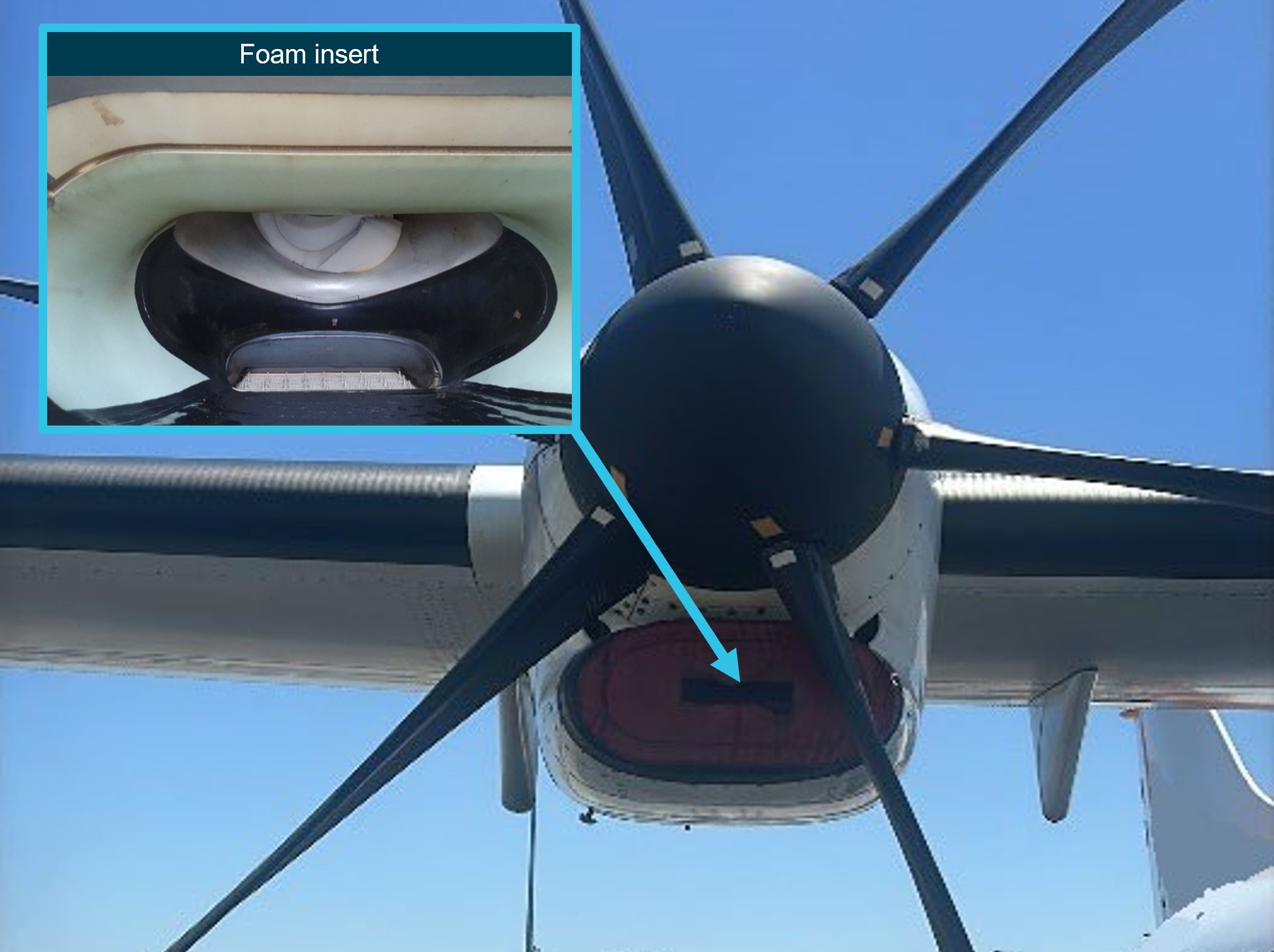
A ground handler was in attendance to make sure the exclusion area around the engine was cleared. After they gave the ‘start-engine’ hand signal, the flight crew started the number 2 engine with the air bleed valve selected ‘off’.[4] The engine start proceeded normally, but when the engine bleed was set to ‘on’ the crew noticed an immediate rise of the inter-turbine temperature. Closing the bleed valve resulted in the temperature dropping back to normal, but another attempt to open the bleed valve saw the temperature rise again. At this point, the first officer realised that the intake covers had not been removed (Figure 1) and they immediately shut down the engine.
The flight crew then disembarked and found that the engine air intake covers had not been removed from either engine. Additionally, the foam insert from the right-side intake cover had separated and was lodged in the intake (Figure 1 inset). They informed the company operations department and after consultation with the approved maintenance organisation, it was decided that the aircraft should not be flown until an engineer could inspect and test run the engine.
Engineers of the operator’s part 145 maintenance organisation attended the aircraft and conducted an inspection of the number 2 engine, followed by a test run at idle and 90% torque. They did not identify any abnormalities, and the aircraft was subsequently released to service.
Source: Operator provided photos, annotated by the ATSB
Further inspection of the covers found that neither had a ‘remove before flight’ streamer attached and that the stitching on both the number 2 and number 1 cover was in poor condition (Figure 2) and partly loose, which allowed the foam insert to separate from the cover.
Figure 2: Engine inlet cover with damaged stitching
Source: Operator provided photo
Safety action
The operator’s internal investigation report recommended fitting warning flags to the intake covers of the incident aircraft and that all intake covers across its fleet be checked to further avoid intake cover internal foam ingestion into engines.
The internal report also recommended that involved pilots are reminded of operator’s external inspection procedures and receive training in human factors.
Safety message
This incident highlights the importance of preparing the aircraft for flight in accordance with the company and manufacturer’s procedures, even when competing priorities exist. Conducting pre‑flight activities out of sequence increases the risk of missing critical steps and should be avoided.
Intake and pitot covers may be hard to see due to their location, lighting and weather conditions. To reduce the risk of them being missed during a pre-flight inspection, they should have a contrasting colour and ‘remove before flight’ flags. Operators should make sure they are periodically inspected as part of their maintenance system, so they remain fit for purpose.
About this report
Decisions regarding whether to conduct an investigation, and the scope of an investigation, are based on many factors, including the level of safety benefit likely to be obtained from an investigation. For this occurrence, no investigation has been conducted and the ATSB did not verify the accuracy of the information. A brief description has been written using information supplied in the notification and any follow-up information in order to produce a short summary report, and allow for greater industry awareness of potential safety issues and possible safety actions.
[1]The auxiliary power unit (APU) is a small gas turbine engine mounted in the tail cone of some larger aircraft to provide autonomous electrical and mechanical power without the use of the engines.
[2]Hotel mode engages the hydraulic propeller brake and allows the turbine to be run to provide auxiliary power and compressed air to the aircraft without the propeller spinning. Compressed air is used to drive the air-conditioning packs which provide cooling to the cabin and cockpit.
[3]The manufacturer’s documentation warns against starting the engine in hotel mode with a significant tailwind, as exhaust gasses being blown back into the engine casing may trigger a (false) fire alarm.
[4]Pressurised air diverted from the engine’s compressor stage is delivered through the bleed valves for air conditioning and pressurisation as well as de-icing.
Occurrence summary
Mode of transport
Aviation
Occurrence ID
AB-2025-009
Occurrence date
29/01/2025
Location
Kalgoorlie Airport
State
Western Australia
Occurrence class
Incident
Aviation occurrence category
Aircraft preparation
Highest injury level
None
Brief release date
24/03/2025
Aircraft details
Manufacturer
ATR-GIE Avions de Transport Régional
Model
ATR72-212A
Sector
Turboprop
Operation type
Part 121 Air transport operations - larger aeroplanes
At 1100 local time on 15 March 2025, Gaschem Homer was departing for sea from its berth in the port of Brisbane, Queensland, under the conduct of a harbour pilot. At 1104, while the ship was being turned towards the port's entrance, it experienced an electrical blackout, resulting in the total loss of propulsion and steering control. About 2 minutes later, the crew restored the electrical power. The incident did not result in damage or injury.
What the ATSB found
The ATSB found that, during departure preparations, the crew had forgotten to switch 2 of the ship’s 3 generators to automatic mode. As a result, the ship’s power management system was unable to automatically distribute electrical load across all generators, restricting generating capacity to only 1 generator. The increased power demand when the bow thruster was operated during departure manoeuvring could not be supported by the single generator and it tripped on overload, causing the blackout.
The investigation also identified a safety issue relating to the shipboard safety management system, which had not identified operational risks associated with Gaschem Homer’s electrical installations and implemented effective controls. Procedures were generic and non-informative and there were no other controls in place to prevent such operational lapses resulting in a power failure.
What has been done as a result
The ship manager, Hartmann Gas Carriers, risk-assessed potential failure modes associated with its ships’ power management systems and established additional controls to prevent total power failures. The shipboard safety management system(s) has been amended to include guidelines for blackout prevention and procedures requiring generators to be set for automatic load sharing before manoeuvring.
Pre-departure and arrival checklists for the engine room and bridge were amended to include verification of generator mode status. To supplement these updates, a power demand matrix has been developed to specify the minimum number of generators required to be online for each operational mode.
In addition, the company has introduced targeted training for watchkeeping engineers on critical power management and monitoring tasks, along with enhanced bridge and engine room information exchange protocols, as further controls against power failures.
The ATSB considers that the safety action adequately addresses the safety issue.
Safety message
This incident highlights the importance of ensuring all risks associated with shipboard operations and critical equipment are identified, assessed and effectively controlled. The safety management system should encompass up-to-date and useable ship-specific procedures, as well as any additional technical controls if procedural barriers alone are insufficient to mitigate risk.
The occurrence
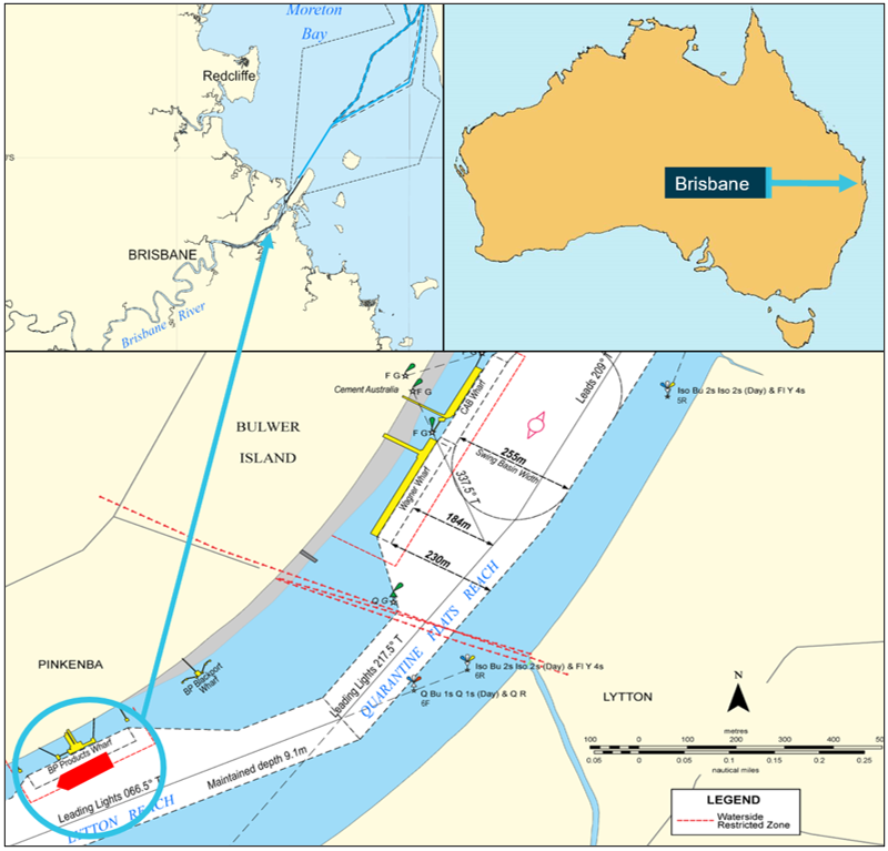
At 1036 local time on 14 March 2025, the 100 m gas tanker Gaschem Homer was made fast, starboard side alongside, at the BP Products berth in the port of Brisbane, located in the Brisbane River, Queensland (Figure 1). The ship had arrived from Westernport, Victoria, to discharge its cargo of propane and butane gas.
One week prior to Gaschem Homer’s arrival, the port had experienced heavy rainfall and river flooding following a significant weather event.[1] Although the associated weather system had dissipated by the time the ship had berthed, its impact had resulted in increased ebb tidal flows and an accumulation of debris along the river.
Figure 1: Gaschem Homer's position at the BP products wharf
Source: Maritime Safety Queensland and Australian Hydrographic Office, annotated by the ATSB
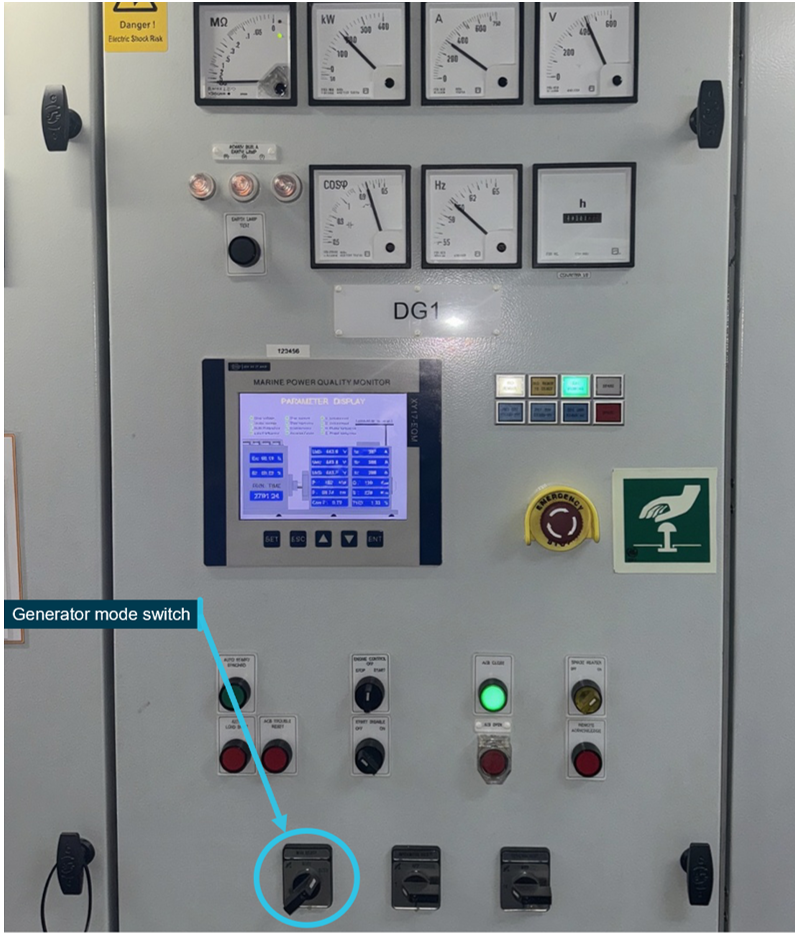
After berthing, the ship’s crew began preparing for cargo operations. Cargo handling increased demand for electrical power, necessitating the operation of at least 2 of the ship’s 3 auxiliary diesel generators in parallel. The ship was fitted with an automated power management system (PMS) designed to optimise and automate the generation and distribution of electrical power. The duty engineer set 2 generators to ‘automatic’ mode using the respective mode selector switches on each generator control panel (Figure 2), enabling the PMS to manage generator synchronisation and load sharing automatically between all three 3 auxiliary generators.
Figure 2: Control panel for diesel generator 1 (DG1)
Source: Hartmann Gas Carriers, annotated by the ATSB
Cargo operations commenced at 1200 with all 3 generators operating and continued until 0424 the following morning. After their completion, the electrical demand was reduced and all generators except diesel generator 3 (DG3) were shut down. The machinery spaces remained unattended[2] until 0800, when the chief engineer, second engineer, and electro-technical officer (ETO) commenced their shift in the engine control room (ECR). With departure from port under the conduct of a harbour pilot scheduled for 1100, the engine room team began standard departure preparations.
At 1001, the engine room team received a one-hour departure notice from the bridge and the second engineer, the duty engineer, initiated the engine room pre-departure checklist. As DG3 was already supplying the main switchboard (MSB), the second engineer started generators 1 and 2 (DG1 and DG2) and set them to ‘automatic’ mode to enable the PMS to synchronise all 3 generators. After synchronisation, DG1 and DG2 were returned to ‘manual’ mode and allowed to warm up under low load. The second engineer then continued with other pre-departure checklist tasks. These included preparing the main engine, starting the bow thruster, and transferring control to the bridge.
At 1012, the pilot boarded and proceeded to the bridge, where the master joined shortly after. A master-pilot information exchange was conducted and the passage plan reviewed. Due to higher ebb river flows following the recent weather event, the regional harbour master had issued temporary restrictions for ship movements. While Gaschem Homer did not normally require tug assistance, the restrictions meant that a single tug was to be allocated for the departure. The plan involved manoeuvring the ship off the berth using the bow thruster and tug assistance before it was to be swung to port in the adjacent channel towards the port entrance for sea.
High water (2.38 m) at Pinkenba was predicted for 1025 with low water (0.53 m) predicted for 1649. While the tidal flow was predicted to be minimal (slack water) during the departure, the pilot observed that the tide had already started to ebb and assessed this was due to high freshwater outflows following the recent weather event. There was a light south-easterly breeze at about 7 knots.
At 1047, after the tug made fast on the port quarter, the main engine and bow thruster were satisfactorily tested from the bridge under the pilot’s advice. The master then ordered mooring parties (fore and aft) to let go the head and stern lines.
During the pre-departure activities, the chief engineer observed a large amount of debris around the ship and berth via the ship’s CCTV[3] system display in the ECR. Concerned that seawater inlets for the main engine and generator cooling systems could be fouled, the chief engineer, second engineer, and ETO began to monitor coolant temperatures and continued to check for debris on the CCTV display.
Meanwhile on the bridge, as mooring lines were being released, the master proceeded to the starboard bridge wing console in preparation for departure. At 1059, after the release of the last line was confirmed, the pilot began giving helm and main engine orders and requested the bow thruster be set to port (bow to port) at half thrust. The pilot then instructed the attending tug to bear weight on its tow line. Once the ship commenced movement off the berth, the pilot instructed the master to increase the bow thruster to 70% thrust. At approximately 1102, the pilot instructed the bow thruster to port at full thrust. As the swing continued, it remained at full thrust while the pilot continued to conduct the pilotage.
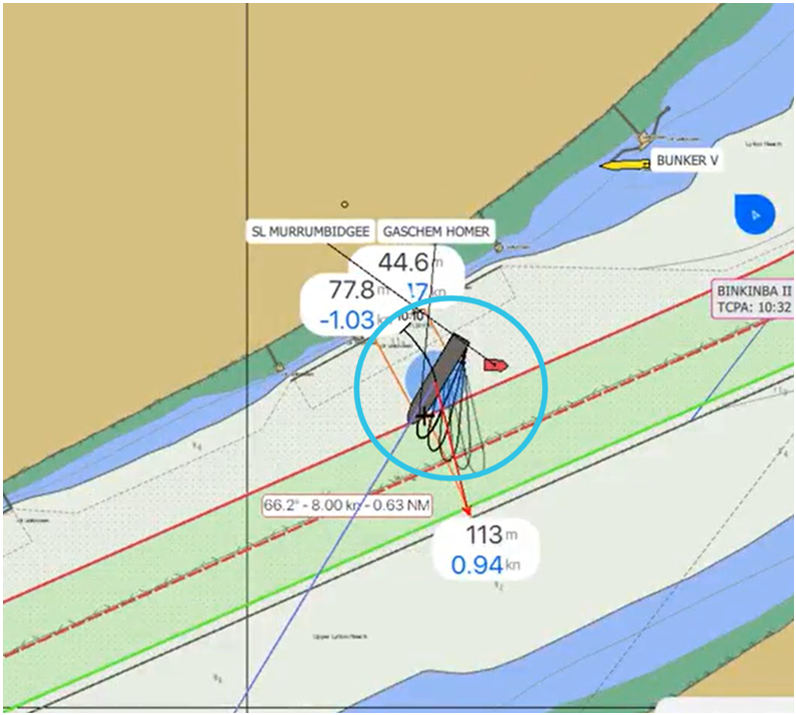
At 1104, while the ship was about one-third of the way through its swing (Figure 3), DG3 tripped on overload. This was immediately followed by a series of secondary power failure alarms for DG1 and DG2. Within 15 seconds, multiple alarms activated both on the bridge and in the ECR, indicating a blackout resulting in a total loss of electrical power, propulsion and steering.
Figure 3: Ship's position at the time of the power failure
Source: Poseidon Sea Pilots, annotated by the ATSB
As soon as the master confirmed the loss of propulsion, the pilot ordered the tug to push up on the port quarter to keep the ship in the centre of the channel. The pilot also advised the master to stand by the anchors. Meanwhile in the ECR, the crew had started the emergency generator, with steering restored. They then restarted DG1 and DG2 and restored power to the MSB. By 1106, the main engine had been restarted.
By the time propulsion was restored, the ship’s swing had been nearly completed, assisted by the tug and river flow. With power now restored, the pilot elected to continue the pilotage. As the cause of the blackout was not known, the pilot retained the tug until the ship had passed the cruise ship terminal near the river mouth. The pilot then radioed Brisbane vessel traffic service (VTS), advising of the blackout and the intention to proceed. Use of the bow thruster was not considered necessary and it remained isolated.
At 1136, after passing the cruise ship terminal, the tug’s line was cast off but retained to escort the ship until clearing the river entrance beacons. The pilotage proceeded without incident with the pilot disembarking off Caloundra at 1454.
Context
Gaschem Homer
Gaschem Homer was a liquefied gas tanker built in 2021 by Nantong CIMC Sinopacific Offshore & Engineering, China. The ship was registered in Liberia and classed with Det Norske Veritas (DNV). At the time of the blackout, it was owned by Sydney Shipping Company (a subsidiary of Hartmann Schiffahrts) and managed by Hartmann Gas Carriers, Germany.
The ship had an overall length of 99.98 m, a moulded breadth of 18 m, and a depth of 11.6 m. At its summer draught of 6.3 m, it had a deadweight of 7,623 tonnes.
Propulsion was provided by a single MAN B&W 5S35ME 2-stroke engine, designed to operate on both marine gas oil and liquid petroleum gas. It delivered 3,240 kW to a controllable pitch propeller, enabling a service speed of 14 knots. The ship was also fitted with an electrically-driven 450 kW bow thruster.
Electrical power for onboard systems was supplied by 3 Caterpillar D13MG-HE medium‑speed diesel generators, each rated at 300 kW, and a shaft generator providing an additional 500 kW.
Gaschem Homer was one of the 3 identical ships chartered to Origin Energy on a long‑term contract, transporting liquid petroleum gas to terminals within the Australia Pacific region. It typically frequented the ports of Westernport, Botany Bay, Brisbane, Gladstone, Cairns, Darwin and Port Moresby.
Crew
At the time of the incident, Gaschem Homer’s crew was comprised of 15 Polish, Filipino, Ukrainian and Latvian nationals.
The master, who held a master’s certificate of competency (CoC), had been with the company for over 19 years and had more than 9 years of experience on gas tankers, including 6 years as master.
The chief engineer possessed a chief engineer CoC and more than 7 years of seagoing experience on gas tankers, over 4 of which were as chief engineer.
The second engineer held a chief engineer CoC and had served over 3 years on gas carriers in the rank of second engineer.
The electro-technical officer (ETO), who held an ETO certificate, had nearly 1 year of seagoing experience on gas tankers and had worked for 2 months in this role.
Pilot
The pilot had worked as a pilot for over 3 years, having trained and qualified as a licensed Brisbane pilot when the pilotage provider (Poseidon Sea Pilots) commenced the provision of pilotage services for the port in January 2022. Prior to joining PSP, the pilot had about 25 years seagoing experience, having worked as a master on various ship types including tankers, ferries, cruise ships, anchor handlers and platform supply vessels.
Electrical distribution system
Main switchboard
Gaschem Homer was equipped with a central main switchboard (MSB), which integrated the ship’s multiple power sources and was capable of operating in manual, semi‑automatic, and fully automatic modes via a power management system (PMS).
The MSB served as the central hub for electrical distribution, ensuring power was supplied to all essential and non-essential systems on board. It included protective devices, synchronising systems, and interlocks to manage generator load sharing, fault isolation and shore power integration. The system included:
automatic and manual generator control, including start/stop sequencing and load transfer capabilities
monitoring of busbar voltage and frequency, with automated responses to abnormal conditions, including preferential tripping to disconnect non-essential loads during overloads
interlocks to prevent concurrent connection of shore power with onboard generators.
The MSB's automatic functions, including generator replacement on fault detection, load shedding, and synchronisation, were designed to maintain continuity of power supply and protect onboard systems.
Any failure in the electrical distribution system, such as an abnormal trip of an air circuit breaker (ACB), failure of automatic synchronisation, or incorrect manual operation, could lead to a loss of power. The MSB's design prioritised manual override capability and system isolation to ensure safety in the event of an automation failure. The system’s multiple layers of protection and redundancy were dependent on proper configuration of control modes and the application of manual override procedures and alarm response protocols.
Power management system
A ship’s PMS is an advanced automation platform that manages and optimises electrical power distribution on board, aiming to enhance stability, efficiency, and safety.
Gaschem Homer’s PMS was a Siemens SIMATIC S7-1200 model programmable logic controller (PLC) system that served as the central automation platform for the ship’s electrical power generation and distribution. The PMS was designed to manage generator operations, load balancing, blackout recovery and protection functions.
A principal component of the system was the synchronising panel (Figure 4), which was critical for ensuring the safe and effective connection of generators to the MSB. The synchronising panel supported both manual and automatic synchronisation, allowing for the alignment of generator voltage, frequency and phase angle with the busbar prior to circuit breaker closure.
Figure 4: Synchronising panel
Source: Hartmann Gas Carriers, annotated by the ATSB
In manual mode, operators used the synchroscope and synchronising lamps to visually confirm synchronisation. Selector switches and pushbuttons allowed for precise control of excitation and breaker operation. In automatic and semi-automatic modes, the PMS used inputs from the synchronising panel to execute synchronisation logic and issue breaker close commands autonomously.
This automation was essential during blackout recovery, load sharing transitions and generator changeovers. Automatic mode was intended to manage most generator operations, unless there was a fault or issue with the automation functions of the PMS, necessitating manual override by the operator.
The synchronising panel was fully integrated with the system’s human-machine interface (HMI), providing real-time feedback and alarm visibility. The system was designed to inhibit breaker closure unless all synchronisation conditions were satisfied and it would trigger alarms upon synchronisation failure. This layered control and monitoring architecture was intended to enhance operational safety and contribute to continuous power supply during varying load and fault conditions.
A key function of the PMS was blackout recovery. In the event of complete power loss, the system automatically initiated the start-up of standby generators and connected them to the MSB once synchronisation was achieved. The PMS also managed load‑dependent generator start/stop logic, automatically bringing additional generators online when the load exceeded 90% of capacity and withdrawing them when the load dropped below 60% (for 2 generators) or 120% (for 3 generators).
For high-demand operations, such as bow thruster engagement, the PMS included a heavy consumer management function to ensure sufficient surplus power was available before large motor starts were permitted. Furthermore, the PMS continuously monitored busbar voltage and frequency, triggering alarms and corrective actions in the event of operational parameter deviations.
Protective features incorporated into the system included reverse power detection, overload protection and preferential tripping of non-essential loads, enhancing generator integrity and maintaining continuous power supply. Collectively, these functions supported the ship’s operational resilience and mitigated the risk of power-related incidents.
System integration and feedback
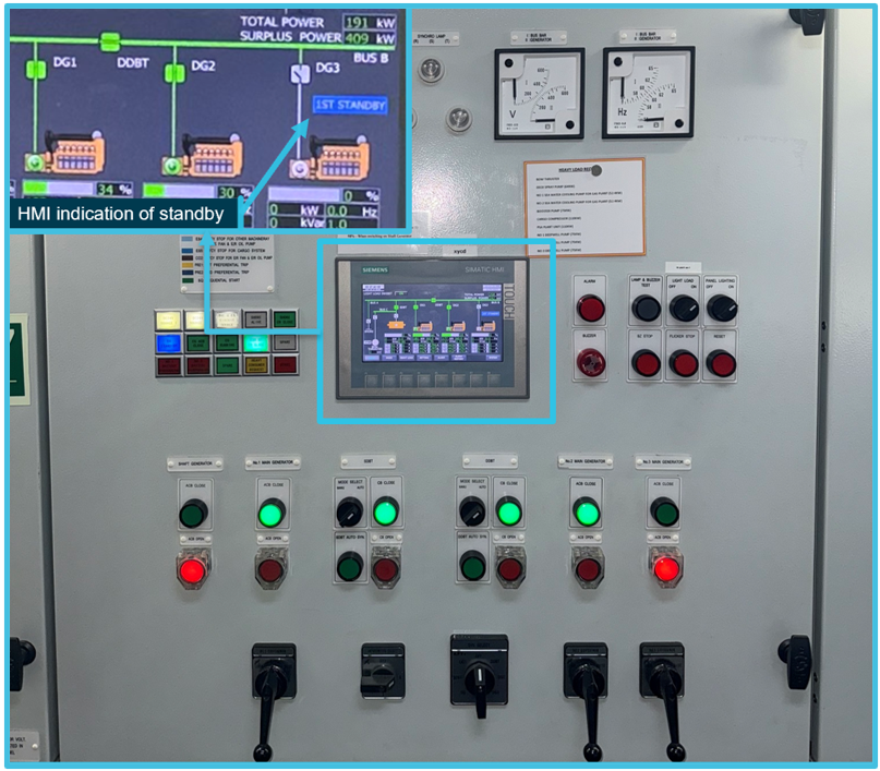
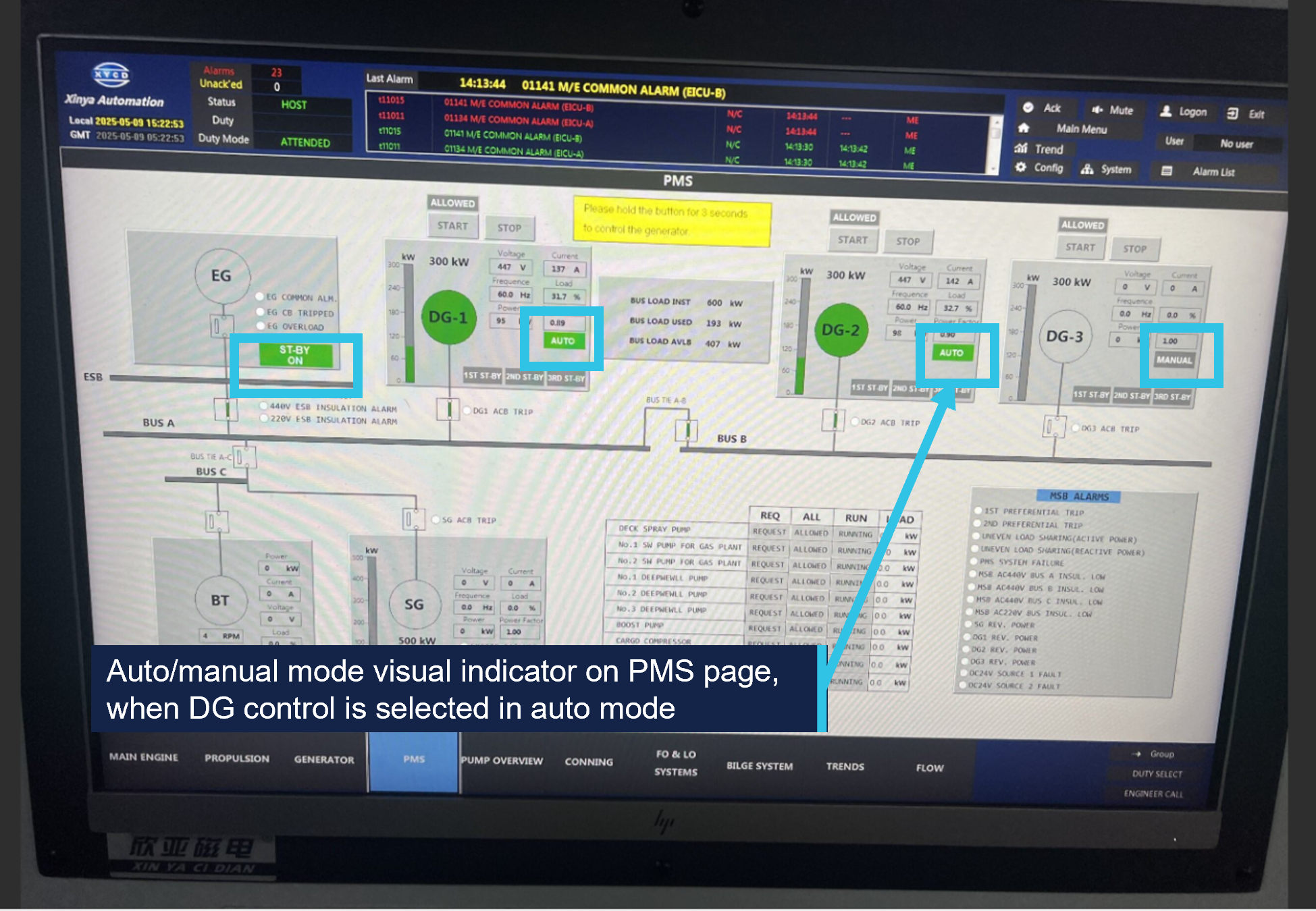
The PMS was configured to display generator status and alarm conditions via a central Siemens KTP700 HMI, integrated into the ship’s machinery and alarm monitoring system. The integration of the HMI with the alarm monitoring system allowed the crew to monitor machinery status in real time from both the engine control room (ECR) and the bridge (Figure 5). The generator interface display featured a line diagram of the electrical system, representing DG1, DG2, DG3, the shaft generator (SG) and associated busbars.
Figure 5: PMS monitoring display
Source: Hartmann Gas Carriers, annotated by the ATSB
A key feature of this integration was the colour-coded mode indication for each generator. When the generator control status was highlighted in green and read ‘AUTO’, the generator was in automatic mode with the PMS autonomously managing generator start/stop, synchronisation, load sharing, and fault recovery. When the status was grey and read ‘MANUAL’, the generator was in manual mode, requiring direct operator control. This visual differentiation enabled the crew to easily determine the operational mode of each generator and respond appropriately during normal or fault conditions. Because the HMI provided monitoring capability for multiple onboard systems, operators were required to manually select the PMS display to view generator status.
Integration of the PMS with the ship’s machinery monitoring and alarm system was designed to support visibility of critical alarms relating to the power supply system. The system was not configured to generate active alerts for generator mode status changes or indicate when generators were in manual mode during high-demand operations, such as bow thruster engagement.
The ship’s operator identified that the blackout was due to DG1 and DG2 not being configured to automatic mode. This prevented the PMS from distributing load across all 3 generators, resulting in DG3 tripping on overload when the bow thruster was operated.
Electrical equipment regulations
The minimum standards for ship construction and equipment, including electrical power installations, machinery and control systems, were prescribed by SOLAS[4] Chapter II-1.[5] Regulations 40 to 44 addressed performance requirements for main and emergency electrical power sources.
These requirements were designed to ensure that a ship’s electrical systems remained reliable and safe, supporting essential functions under both normal and emergency conditions. Key provisions addressed automatic load shedding and the automatic starting of, and switching to, standby generators to safeguard propulsion, steering and other essential services in the event of a generator failure.
Other SOLAS regulations required that ships be designed, constructed and maintained in compliance with the structural, mechanical and electrical requirements of a recognised classification society.
Classification society rules
Classification of a ship verifies the strength, integrity, function and reliability of its structure and systems to maintain essential services on board.[6] This is achieved through the development and application of classification society rules, and by verifying compliance with applicable international and national statutory requirements on behalf of flag State administrations.
Det Norske Veritas (DNV) is an internationally accredited classification society headquartered in Høvik, Norway. The DNV rules for ships[7] set out the technical and procedural requirements used by the society as the basis for ship classification.
Technical requirements and guidance for design, manufacturing and installation of electrical installations on ships, as well as procedures for their operation, were detailed in Part 4, Chapter 8 of the DNV rules.
Generator control, redundancy and load shedding
The DNV rules closely aligned with SOLAS regulations for control, redundancy and load shedding requirements for main sources of electrical power. They provided that generators operating in parallel should be capable of stable load sharing and automatic reconnection following a blackout. For redundancy, the power system was to be arranged such that failure of any one generator did not cause loss of power to essential services. The rules required that in the event of overload or failure of a generator, the system must automatically shed non-essential loads and start a standby generator within 30 to 45 seconds to prevent blackout.
Interlock requirements
The rules stipulated that, if the starting of a motor (such as a bow thruster) required 2 or more generators to operate in parallel, an interlock must be fitted to ensure that the circuit could only be energised when a sufficient number of generators were connected. Alternatively, this requirement could be met by posting operating instructions at the starter panels.
The rationale for this interlock was to prevent hazardous or damaging conditions, such as generator overload or power system failures. By ensuring specific operational criteria were met before a motor was started, the interlock reduced the risk of overloading and tripping the generators.
During the preparations for the Gaschem Homer’s departure, no interlocks acted to prevent the starting of the bow thruster because all 3 generators were operational and connected to the MSB. However, the PMS could not distribute the additional load demand across all 3 generators because DG1 and DG2 were not set to automatic mode. Under these conditions, the interlocks did not prevent generator overload because the actual configuration did not support effective load sharing.
Indication of standby
The rules governing operation of automatic control systems required that when a main source of electrical power was in standby mode, an indication of this status was to be provided on the control panel. The rules did not specify the method by which this indication was to be displayed.
Industry guidance
Blackout prevention
Classification societies frequently publish guidance on a range of operational and safety matters, including blackout prevention. In 2022, DNV published comprehensive guidance[8] on preventing and responding to blackouts. Among other measures, DNV recommended that operators carry out a risk assessment to identify the ship operations for which a blackout would represent a particularly high risk, such as berthing and navigating in high traffic areas. It also recommended that procedures for the identified high-risk ship operations be reviewed to ensure that clear specifications of the required state of machinery and equipment were defined. These specifications were to address:
the number of generators and propulsion units online or in standby
auxiliary system configuration (common or separated) and bus-tie status (closed or open)
crew manning levels across departments and operational stations.
Finally, DNV recommended that clear and straightforward operating procedures improve crew risk awareness and enhance safety during operations where a blackout could have serious consequences. It noted that implementing robust operating procedures and ensuring crews’ risk awareness, in combination with correct maintenance and operation of essential equipment, may have a significant positive impact on ship safety and reliability.
Automated systems
As automation technology becomes more prevalent on ships, several studies have highlighted safety considerations associated with human-machine interaction.
For example, a 2019 Canadian Transport Safety Bureau (TSB) study[9] found that, from 1998 to 2018, 16% of occurrences it investigated involved some form of automated equipment HMI design issue. In 10 cases, ambiguous or inadequate feedback contributed to misinterpretation of system status, delayed crew responses, decreased situational awareness or reduced decision-making effectiveness. Another study[10] found that over‑reliance on automated systems may also foster complacency, causing operators to disengage from active monitoring of system processes.
These studies highlighted a need to consider human factors in the design and operation of shipboard automation to maintain safety and reliability.
Safety management systems
The objective of the SOLAS-mandated International Safety Management (ISM) Code[11] is the prevention of human injury or loss of life and the avoidance of damage to the environment and to property. The ISM Code requires shipping companies to maintain a safety management system (SMS), with instructions and procedures to ensure safe shipboard operations and to prepare for and respond to emergencies. Section 10.3 of the Code provided that:
The Company should establish procedures in its safety management system to identify equipment and technical systems the sudden operational failure of which may result in hazardous situations. The safety management system should provide for specific measures aimed at promoting the reliability of such equipment or systems.
Critical equipment typically includes propulsion, steering and electrical power distribution systems, including generators. Measures to support reliability may include equipment testing, maintenance and engineering controls as well as measures such as crew training and operating procedures intended to serve as barriers to hazardous events.[12] In this context, the SMS should encompass a combination of administrative and technical defences to prevent, control or mitigate risks. Companies are also required to conduct regular audits and reviews of the SMS to ensure its ongoing effectiveness.
Gaschem Homer’s system
To meet its obligations under the ISM Code, Hartmann Gas Carriers maintained a fleetwide SMS. It was intended to provide instructions for key shipboard operations on all company ships and was not specific to Gaschem Homer. It contained a procedure for preparing the engine room for standby condition and a pre-departure checklist, which were both relevant to this incident. At the time of the blackout, the SMS had last been revised in July 2024. Meanwhile, the checklist’s document control information identified it as the first revision in 2020, indicating that it was developed approximately one year prior to the ship’s launch.
The engine room standby procedure included several tasks. It provided for switching on the second generator and second steering pump and changing over to manual steering. The procedure also required that the main engine, steering gear and bow thruster were to be tested and confirmed functional prior to switching to standby condition. The SMS did not contain any specific procedures or guidance for engine room pre-departure preparations other than the pre-departure checklist.
The checklist was a one-page document which listed 26 action items for preparing the main engine and other essential machinery. The items were to be checked as being ‘ready’ or ‘not ready’. A single check covered the ship’s electrical systems, which stated that auxiliary engine generators were to be ‘in operation for sufficient power supply.’
A laminated copy of the checklist was kept in the ECR and reused for each departure after entries for the previous departure had been erased. Before departure on the day of the incident, the second engineer ticked all items as ‘ready’ and signed the form. An entry in the engine room logbook indicated that the checklist was completed at 1100.
Safety analysis
Introduction
At 1100 local time on 15 March 2025, Gaschem Homer was departing its berth in the port of Brisbane under the conduct of a harbour pilot. At 1104, while the ship was being swung to port towards the port's entrance, it experienced an electrical blackout, resulting in the loss of propulsion and steering.
Power management system
Gaschem Homer’s power management system (PMS) was designed to automate processes such as load sharing across the ship’s 3 auxiliary diesel generators (DG1, DG2 and DG3). However, during departure, despite completing the relevant checklist, DG1 and DG2 were incorrectly left in manual mode after being synchronised and connected to the main switchboard (MSB). In this configuration, the PMS was unable to manage automatic load distribution, restricting generating capacity only to DG3. This capacity was insufficient for supporting the anticipated electrical load demand and specifically the operation of the bow thruster.
The PMS featured interlocks intended as a safeguard to prevent bow thruster engagement when available power generation was insufficient. However, because all 3 generators were connected to the MSB, the interlocks were bypassed as the system did not account for the lack of automatic load sharing. As a result, although DG1 and DG2 were operating effectively, they were not available to share the load demand.
The status of each generator’s operating mode could be readily observed by the engine room team via the generator control panels or the PMS interface on the ship’s machinery and alarm monitoring system. However, the team was mainly focused on monitoring the seawater cooling systems due to concerns about potential blockage by debris. In the absence of automated alarms or system warnings for incorrect generator mode selection, their incorrect configuration went undetected.
Consequently, when the bow thruster was engaged during departure, the resultant surge in electrical load was imposed solely upon DG3, leading to its overload and subsequent trip. Without DG1 and DG2 capable of sharing the redistributed load, there was a total loss of power generation, resulting in a blackout and propulsion loss.
Contributing factor
Two of the ship’s 3 auxiliary diesel generators were not configured for automatic load sharing. Therefore, the increased power demand when the bow thruster was operated during departure manoeuvring could only be provided by one generator that tripped on overload, resulting in a power blackout and loss of propulsion.
Risk management
The International Safety Management (ISM) Code required ship operators to establish and maintain a safety management system (SMS) to ensure all operational risks were identified, assessed and effectively controlled. Gaschem Homer’s PMS was specifically designed to prevent hazardous events such as blackouts when it was configured and operated correctly. The effectiveness of this system was therefore dependent on the adequacy of procedures and controls contained within the shipboard SMS.
The ship operator, Hartmann Gas Carriers, had implemented an SMS, which encompassed generic engine room operational procedures across its fleet. As such, the SMS did not take into account specific systems on board Gaschem Homer. Although the SMS contained a general procedure for engine room preparation to standby engines and a pre-departure checklist, these documents contained no process to confirm generator control mode settings.
Industry practice dictates that a procedure should provide sufficient detail as to how a task is carried out, including when and by whom, while a checklist is typically purposed as a memory aid, itemising key actions to ensure nothing is overlooked.[13] In this instance, the pre-departure checklist was purposed as a substitute for a detailed procedure but provided little in the way of specific and usable task descriptions. Consequently, the crew had to rely on memory and experience to complete critical tasks, which increased the likelihood of an oversight.
Further, the ISM Code required operators to systematically identify, evaluate and mitigate risks associated with critical shipboard equipment, which included the implementation and periodic review of both technical and procedural safeguards to guarantee its reliability. The correct operation of the ship’s generators, which was dependent on the PMS, was essential to the ship’s propulsion and steering and, hence, an item of critical equipment. However, comprehensive mitigations, such as tailored, system-specific procedural guidance or integrated system prompts to address the risk of generators remaining in manual mode during critical operations, were not established.
Additionally, the continued use of a generic checklist, unmodified since before the ship’s launch, indicated that the company had not adequately reviewed and verified its SMS controls for operation of the ship’s electrical systems, including the PMS.
Contributing factor
The ship’s safety management system did not have adequate controls to manage the risk of a complete power failure due to generators being inadvertently left in manual mode during manoeuvring operations. (Safety issue)
Findings
ATSB investigation report findings focus on safety factors (that is, events and conditions that increase risk). Safety factors include ‘contributing factors’ and ‘other factors that increased risk’ (that is, factors that did not meet the definition of a contributing factor for this occurrence but were still considered important to include in the report for the purpose of increasing awareness and enhancing safety). In addition ‘other findings’ may be included to provide important information about topics other than safety factors.
Safety issues are highlighted in bold to emphasise their importance. A safety issue is a safety factor that (a) can reasonably be regarded as having the potential to adversely affect the safety of future operations, and (b) is a characteristic of an organisation or a system, rather than a characteristic of a specific individual, or characteristic of an operating environment at a specific point in time.
These findings should not be read as apportioning blame or liability to any particular organisation or individual.
From the evidence available, the following findings are made with respect to the loss of propulsion of Gaschem Homer in the port of Brisbane, Queensland, on 15 March 2025.
Contributing factors
Two of the ship’s 3 auxiliary diesel generators were not configured for automatic load sharing. Therefore, the increased power demand when the bow thruster was operated during departure manoeuvring could only be provided by one generator that tripped on overload, resulting in a power blackout and loss of propulsion.
The ship’s safety management system did not have adequate controls to manage the risk of a complete power failure due to generators being inadvertently left in manual mode during manoeuvring operations. (Safety issue)
Safety issues and actions
Central to the ATSB’s investigation of transport safety matters is the early identification of safety issues. The ATSB expects relevant organisations will address all safety issues an investigation identifies.
Depending on the level of risk of a safety issue, the extent of corrective action taken by the relevant organisation(s), or the desirability of directing a broad safety message to the Marine industry, the ATSB may issue a formal safety recommendation or safety advisory notice as part of the final report.
All of the directly involved parties were provided with a draft report and invited to provide submissions. As part of that process, each organisation was asked to communicate what safety actions, if any, they had carried out or were planning to carry out in relation to each safety issue relevant to their organisation.
Descriptions of each safety issue, and any associated safety recommendations, are detailed below. Click the link to read the full safety issue description, including the issue status and any safety action/s taken. Safety issues and actions are updated on this website when safety issue owners provide further information concerning the implementation of safety action..
Safety issue description: The ship’s safety management system did not have adequate controls to manage the risk of a complete power failure due to generators being inadvertently left in manual mode during manoeuvring operations.
International Safety Management Code – an international standard for the safe management and operation of ships and for pollution prevention.
PMS
Power management system
SOLAS
The International Convention for the Safety of Life at Sea, 1974, as amended.
SMS
Safety management system
VTS
Vessel traffic service. A VTS is any service implemented by a competent authority, designed to maximise the safe and efficient movement of waterborne traffic within the jurisdiction.
Sources and submissions
Sources of information
The sources of information during the investigation included:
Det Norske Veritas (DNV). (2022). Managing the risks of blackouts. Available at www.dnv.com.
DNV Rules for Classification – Ships, Part 4 Systems and Components, Chapter 8 Electrical Installations.
International Maritime Organisation (IMO), 1974, The International Convention for the Safety of Life at Sea, 1974, as amended (SOLAS 1974), IMO, London.
Løvmo, S A. (2016). Analysis of potential critical equipment and technical systems on a modern PSV, Faculty of Science and Technology Department of Engineering and Safety Analysis, University of Norway.
Narlis C. (2019). Control and automation systems onboard the vessel: Lessons in human-centred design learned from 20 years of marine occurrences in Canada, Proceedings of the Human Factors and Ergonomics Society Annual Meeting, Canada.
Parasuraman R, Rile V. (1997). Humans and Automation: Use, Misuse, Disuse, Abuse, Human Factors Jun 1997 39(2) 230-253, United States.
SOLAS Chapter II – 1 Reg 43: Ch II-1 Construction – Structure, subdivision and stability, machinery and electrical installations, Part D Electrical installation, Reg. 43 Emergency source of electrical power in cargo ships.
Submissions
Under section 26 of the Transport Safety Investigation Act 2003, the ATSB may provide a draft report, on a confidential basis, to any person whom the ATSB considers appropriate. That section allows a person receiving a draft report to make submissions to the ATSB about the draft report.
A draft of this report was provided to the following directly involved parties:
the master, chief engineer, second engineer and electro-technical officer of Gaschem Homer
the pilot at the time of the incident
the ship’s managers, Hartmann Gas Carriers
Poseidon Sea Pilots
Australian Maritime Safety Authority
the ship’s flag State Administration, Registry of Liberia
Maritime Safety Queensland.
Submissions were received from:
Hartmann Gas Carriers
Poseidon Sea Pilots.
The submissions were reviewed and, where considered appropriate, the text of the report was amended accordingly.
Purpose of safety investigations
The objective of a safety investigation is to enhance transport safety. This is done through:
identifying safety issues and facilitating safety action to address those issues
providing information about occurrences and their associated safety factors to facilitate learning within the transport industry.
It is not a function of the ATSB to apportion blame or provide a means for determining liability. At the same time, an investigation report must include factual material of sufficient weight to support the analysis and findings. At all times the ATSB endeavours to balance the use of material that could imply adverse comment with the need to properly explain what happened, and why, in a fair and unbiased manner. The ATSB does not investigate for the purpose of taking administrative, regulatory or criminal action.
About ATSB reports
ATSB investigation reports are organised with regard to international standards or instruments, as applicable, and with ATSB procedures and guidelines.
Reports must include factual material of sufficient weight to support the analysis and findings. At all times the ATSB endeavours to balance the use of material that could imply adverse comment with the need to properly explain what happened, and why, in a fair and unbiased manner.
An explanation of terminology used in ATSB investigation reports is available here. This includes terms such as occurrence, contributing factor, other factor that increased risk, and safety issue.
Publishing information
Released in accordance with section 25 of the Transport Safety Investigation Act 2003
Ownership of intellectual property rights in this publication
Unless otherwise noted, copyright (and any other intellectual property rights, if any) in this report publication is owned by the Commonwealth of Australia.
Creative Commons licence
With the exception of the Commonwealth Coat of Arms, ATSB logo, and photos and graphics in which a third party holds copyright, this report is licensed under a Creative Commons Attribution 4.0 International licence.
The CC BY 4.0 licence enables you to distribute, remix, adapt, and build upon our material in any medium or format, so long as attribution is given to the Australian Transport Safety Bureau.
Copyright in material obtained from other agencies, private individuals or organisations, belongs to those agencies, individuals or organisations. Where you wish to use their material, you will need to contact them directly.
[1]Severe Tropical Cyclone Alfred developed off the Australian east coast on 21 February 2025 and made landfall on 8 March, shortly after being downgraded to a tropical low. The weather system brought heavy rainfall and severe flooding to large areas of South East Queensland and northern New South Wales.
[2]Gaschem Homer’s machinery spaces were classified as UMS (Unmanned Machinery Spaces).
[4]International Maritime Organisation (IMO), 1974, The International Convention for the Safety of Life at Sea, 1974, as amended (SOLAS 1974), IMO, London.
[5]SOLAS Chapter II – 1 Reg 43: Ch II-1 Construction – Structure, subdivision and stability, machinery and electrical installations, Part D Electrical installation.
[6]Refer to International Association of Classification Societies (IACS) for additional information.
[7]DNV Rules for Classification – Ships, Part 4 Systems and Components, Chapter 8 Electrical Installations.
[8]Det Norske Veritas (DNV). (2022). Managing the risks of blackouts. Available at www.dnv.com.
[9]Narlis C. (2019). Control and automation systems onboard the vessel: Lessons in human-centred design learned from 20 years of marine occurrences in Canada, Proceedings of the Human Factors and Ergonomics Society Annual Meeting, Canada.
[10]Parasuraman R, Rile V. (1997). Humans and Automation: Use, Misuse, Disuse, Abuse, Human Factors Jun 1997 39(2) 230-253, United States.
[11]International Maritime Organization. (1995). International Management Code for the Safe Operation of Ships and for Pollution Prevention (ISM Code) as amended, IMO, London.
[12]Løvmo, S A. (2016). Analysis of potential critical equipment and technical systems on a modern PSV, Faculty of Science and Technology Department of Engineering and Safety Analysis, University of Norway.
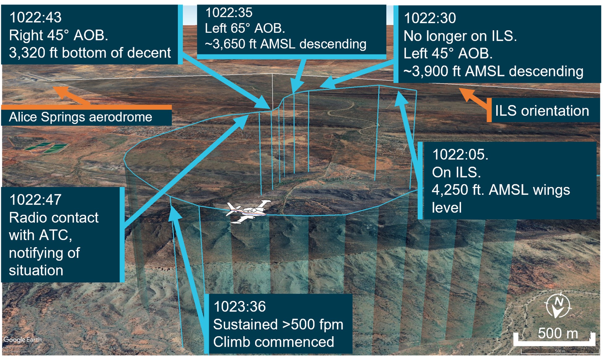
The pilot of a Cessna 310 was likely spatially disoriented when their aircraft diverged from its instrument approach path and flew below the minimum sector altitude near Alice Springs, an ATSB investigation has concluded.
On 1 July 2024, the pilot of the twin-engine Cessna was repositioning the aircraft back to Alice Springs, after conducting an earlier passenger transport flight to Willowra, NT.
During an instrument landing system (ILS) approach to Alice Springs runway 12, while in instrument meteorological conditions (IMC), the pilot reported observing false indications on the attitude indicator and directional gyroscope.
“Testing after the incident found the artificial horizon did exhibit some deviations outside the manufacturer’s tolerances, but not to an extent consistent with the sudden and absolute failure described by the pilot,” ATSB Director Transport Safety Dr Stuart Godley explained.
“Rather, with no visual cues due to the IMC, the pilot likely became spatially disoriented and interpreted real instrument indications as false, as they mismatched the pilot’s sensed orientation.”
Flight data showed the aircraft turned perpendicular to the ILS approach path, travelling outside its tolerances, and therefore below the defined minimum sector altitude (MSA).
During this extended flight below MSA, the aircraft exhibited high angles of bank, and at one point came within 810 ft of terrain.
After the pilot notified air traffic control of their perceived instrument issues, they received clearance to track back to the initial approach fix.
The pilot then conducted an uneventful landing after returning to the start of the ILS approach path.
“Underestimated in both prevalence and severity, spatial disorientation is a very common problem for pilots flying in IMC,” Dr Godley said.
“In this case, the pilot believed the aircraft was under control, and attributed the unusual attitudes indicated on the artificial horizon to an instrument error, rather than the high bank angles evident in the flight data.”
The ATSB investigation also noted the pilot, in their state of urgency, did not broadcast a ‘PAN PAN’ call during the occurrence, and air traffic control (ATC) did not issue a safety alert.
“Pilots should not hesitate to report an urgent condition to ATC, who can provide immediate assistance,” Dr Godley said.
“Pilots should also conduct a missed approach – including an immediate climb to achieve safe altitude – once their aircraft is no longer on the established approach path and doubt exists as to lateral position and location.
“In addition, ATC has a duty of care to provide safety alerts to pilots on becoming aware that an unsafe situation such as proximity to terrain has occurred, or may occur.”
Since the incident, the operator has introduced a policy for the use of autopilot in IMC, and in high workload single-pilot operations.
“In this case, the pilot’s choice not to use autopilot for this approach may have increased their workload, and the subsequent risk of spatial disorientation during the instrument approach procedure,” Dr Godley concluded.
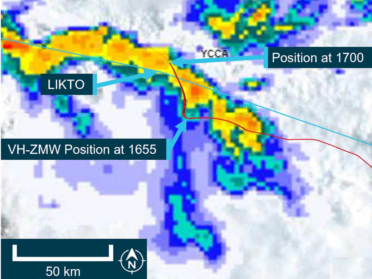
An incorrectly installed weather radar contributed to a King Air charter flight entering a thunderstorm west of Toowoomba, Queensland, an ATSB investigation report details.
The aircraft, operated by Austrek Aviation, had departed Toowoomba for an air transport flight to Normanton, Queensland, with a pilot and five passengers on board, on 9 October 2024.
After encountering the storm 30 minutes into the flight, the pilot diverted to Roma, where the aircraft landed safely.
The ATSB investigation found the aircraft’s airborne weather radar had been incorrectly installed, reducing its effectiveness at detecting cloud, and resulting in it providing misleading information.
“Although the pilot had identified the weather conditions prior to flight, delayed the initial departure, and consulted with more experienced colleagues, the ineffective radar degraded the pilot’s in-flight assessing and planning, and the aircraft entered a thunderstorm,” ATSB Director Transport Safety Stuart Macleod said.
The incorrect installation most likely resulted in the radar beam scanning the tops of the clouds rather than the most reflective areas within the storm. In addition, the outside air temperature of -23°C resulted in less reflective precipitation within the clouds.
“It was likely that the weather radar was over-scanning and the returns presented to the pilot would not have indicated where the most active storms were,” explained Mr Macleod.
“This likely resulted in the severity of the storms in the area not being visible to the pilot.”
While at approximately 26,000 ft, the aircraft entered cloud and began to accumulate ice. The pilot then elected to descend the aircraft. In the increasing turbulence the autopilot disconnected, and the pilot flew the aircraft manually.
“The pilot later reported that between entering cloud at about 1648 and becoming visual at approximately 1705 at 4,000 ft, they encountered turbulence, updrafts, downdrafts and icing, and observed lightning flashes,” noted Mr Macleod.
“The pilot’s recollection of lightning, turbulence and icing, plus the ADS-B flight data overlaid on ground-based radar imagery are both consistent with the aircraft flying into a thunderstorm.”
After landing at Roma, a post flight engineering inspection of the aircraft did not identify any lightning strike damage, however, there was minor damage observed to the leading edges of the wings and the radome.
“This incident highlights how quickly weather conditions can change and that, where possible, remaining visual can provide better identification of the weather,” Mr Macleod said.
“Equipment such as a weather radar can provide better situation awareness, but it must be installed correctly, and the pilot must become knowledgeable in its operation before needing to use it.”
In response to this incident, Austrek Aviation has rectified the incorrect installation of the weather radar, and improved pilot training in its use.
The operator’s flight planning software has also been reviewed to ensure correct parameters, after the ATSB’s investigation identified the software used by the pilot before the flight included a final reserve fuel that was less than that defined in the operator’s exposition.
Finally, the ATSB report credits the pilot contributing to the safety of the passengers by informing them of possible turbulence prior to the flight, and keeping the seatbelt sign on throughout.
At about 1749 local time, train 8076 enroute from Bendigo to Melbourne collided with track maintenance equipment that was foul of the track. A track worker was nearby at the time of the incident but clear of the track.
There was minimal damage to the train and no reported injuries.
Victoria's Chief Investigator, Transport Safety is investigating the incident under the Transport Safety Investigation Act 2003 (Cth) in accordance with a collaboration agreement with the ATSB.
A preliminary report, which details factual information established during the course of the investigation, was released on 29 May 2025 (see below).
The final report will be released at the conclusion of the investigation. Should a critical safety issue be identified during the course of the investigation, the ATSB will immediately notify relevant parties, so that appropriate safety action can be taken.
Last updated:
Preliminary report
Report release date: 29/05/2025
This preliminary report details factual information established in the investigation’s early evidence collection phase, and has been prepared to provide timely information to the industry and public. Preliminary reports contain no analysis or findings, which will be detailed in the investigation’s final report. The information contained in this preliminary report is released in accordance with section 25 of the Transport Safety Investigation Act 2003.
The occurrence
Prior to the incident
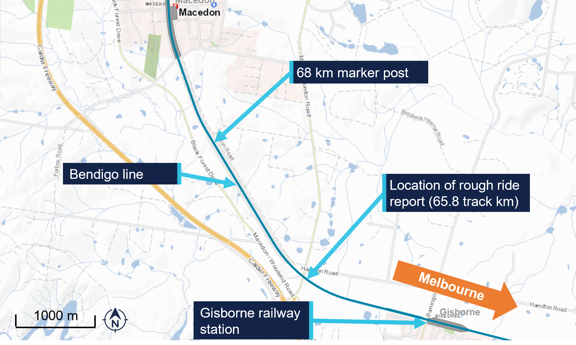
At about 1549 local time on 11 March 2025, the driver of a V/Line passenger service from Bendigo to Melbourne, Victoria reported to V/Line train control (Centrol) that they had experienced a severe rough ride[1] at 65.8 track km[2] on the east track of the Bendigo line (Figure 1). The train was travelling at about 120 km/h when the rough ride was experienced. The maximum permitted track speed at the location was 130 km/h.
Figure 1: Location of rough ride report
Source: Vicmaps, annotated by the Office of the Chief Investigator (OCI)
The V/Line train controller overseeing the Bendigo line at the time reported the fault to the V/Line fault maintenance centre and implemented a 90 km/h speed restriction at the location.
It was common practice for train controllers to notate the train graph when advised of problems with the rail track. This provided train controllers with critical information regarding the state of the track and assisted train controllers when they were required to advise following trains.
At about 1610, the work group supervisor (WGS) of a track maintenance workgroup called the train controller to inform that they were departing Bendigo to attend the rough ride location and a track warrant[3] may be required. The workgroup consisted of the WGS, who was also performing the role of track force protection coordinator[4], and 3 other maintenance staff. The train controller advised the WGS that the rough ride report was for the east track.
At about 1641 the train controller called the WGS to advise that a V/Line train service had passed through the location at the restricted speed of 90 km/h without rough ride. The WGS informed the train controller that they were en route to the location and still intended to inspect the location. The train controller advised the WGS that, if a track warrant was required, there would likely be a 35 to 40 minute period after an ‘up’[5] train had passed.
When the WGS arrived at the rough ride location (65.8 km), they called the train controller to request a track warrant to attend to the track issue. The train controller advised the WGS that a VLocity train would be passing through the section at about 1740 and that a track warrant could be issued once it had been sighted clear of where they were working. In discussion, the WSG and train controller established that the limits of the track warrant would be between 65 km and 68 km. The train controller requested that the WGS call back once they had seen the VLocity go through.
At 1735 the train controller contacted the driver of the Echuca to Melbourne service 8076, to advise of the report of rough ride on the east line at 65.8 km and for the train to travel at no more than 90 km/h from 65.9 km to 65.7 km.
At about 1736 a relief controller took over from the train controller. The train controllers discussed the pending track warrant among other ongoing activities on the Bendigo line.
At 1741 the WGS who was at the 68 km mark called Centrol and advised the relief train controller that they had sighted VLocity train unit number 1291[6] go past. The train sighted was train 8033, the Melbourne to Eaglehawk service, travelling north on the west track. At this time, V/Line passenger train 8076 was on the east track at about 77 km and approaching the worksite.
In response to the sighting of 8033 the relief train controller issued the WGS a track warrant to occupy the east line between 65 km and 68 km from 1745 to 1815. Once the track warrant was issued, the WGS agreed with the relief train controller that traffic could continue on the west track.
At about 1745 the WGS informed the workgroup that a track warrant had been issued and that they could begin work. The WGS then began to drive from the 68 km mark to the worksite.
The incident
At about 1749, the driver of train 8076 sighted the workgroup about 240 m ahead, working at about 65.8 km. In response the driver sounded the horn and applied the emergency brake. The train was travelling at 80 km/h when the emergency brake was applied.
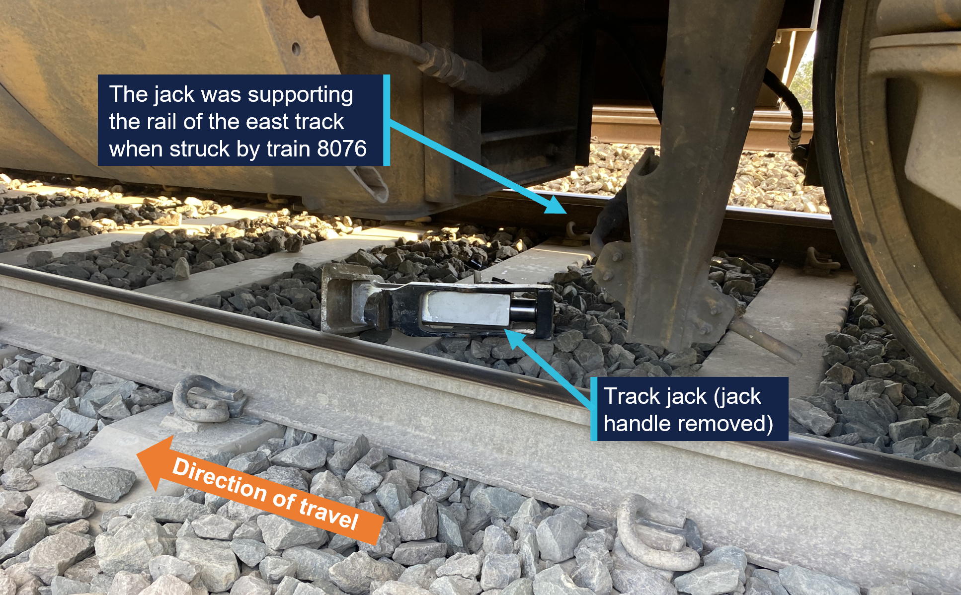
The workgroup cleared the track as the train approached. A track jack, being used by the workgroup, remained under one of the rails and was struck by the train. The train came to a stand about 70 m past the worksite. There were no injuries and the train remained on the rails. There was minor damage to the underside of the train.
Figure 2: Track jack under train 8076
Source: V/Line, annotated by the Office of the Chief Investigator (OCI)
After an initial inspection by the driver, train 8076 was driven at about 10 km/h to Gisborne Station where the passengers left the service.
Services on the east track resumed later that evening with an 80 km/h speed restriction between 64 km and 66 km.
Context
Location and rail infrastructure
Gisborne railway station is 64.2 km northwest of Melbourne. The worksite was 1.6 km west of the station (Figure 1).
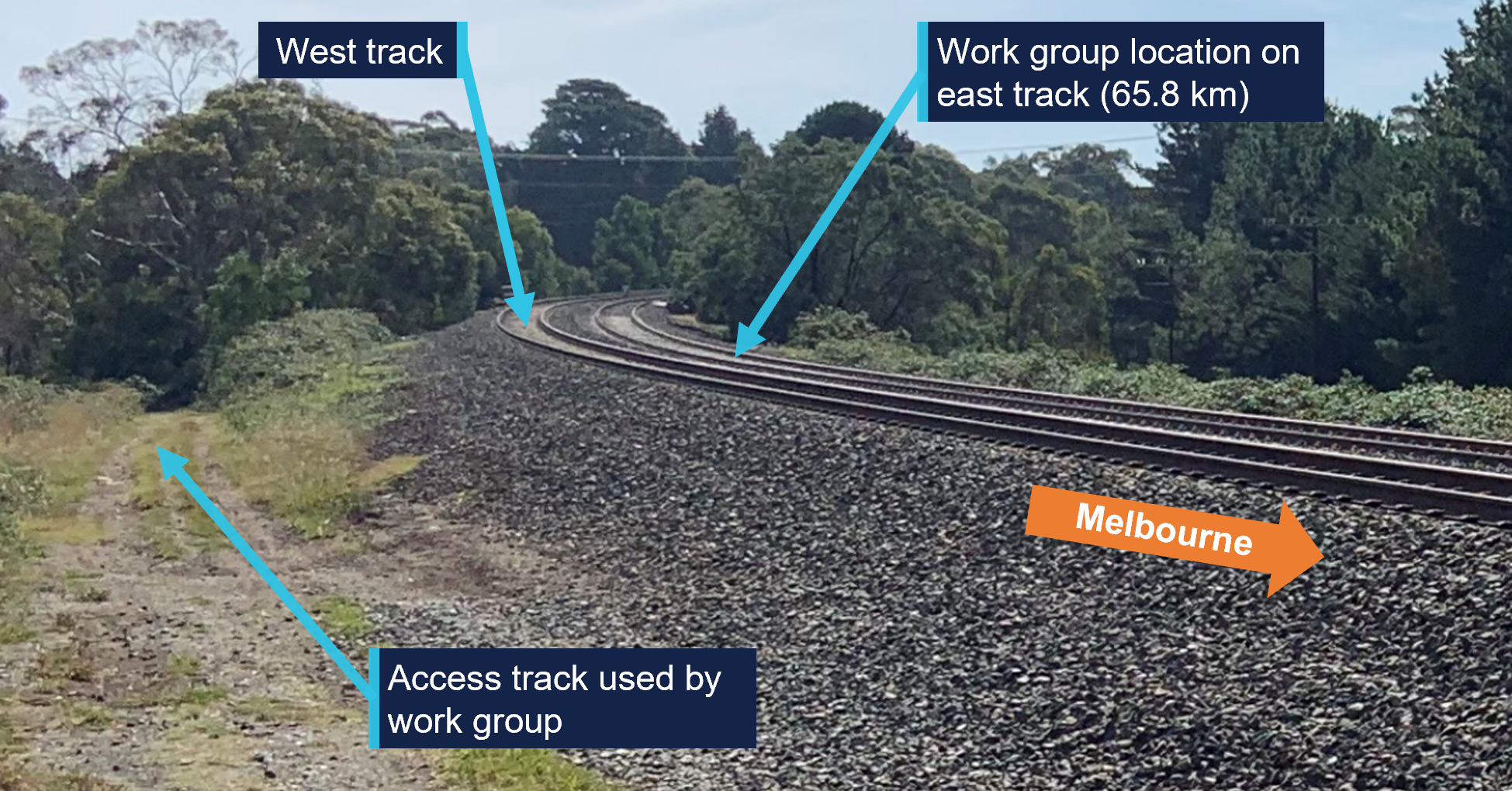
The railway at the incident location consisted of 2 adjacent lines, referred to as the east and west tracks, both permitted bi‑directional running. The maximum permitted speed for VLocity passenger trains travelling along the east track was 130 km/h and on the west track was 160 km/h. The worksite was located on a track curve (Figure 3).
The rail land was leased by VicTrack[7] to Transport for Victoria[8] and sub‑leased to V/Line. V/Line maintained the track and managed train operations on the Bendigo line.
Figure 3: Work site location
Source: OCI
Centrol
Centrol was the train network control centre for V/Line services. Train controllers at Centrol were responsible for the safe running of trains and providing track access for infrastructure maintenance staff.
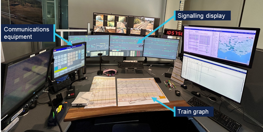
The room at Centrol used to oversee operations on the Bendigo line was equipped with signal panels that allowed train controllers to set signals and identify the approximate location of trains. Communication equipment in the room allowed train controllers to communicate with train and infrastructure maintenance staff. Train controllers used paper train graphs to record the location of trains and infrastructure maintenance staff (Figure 4).
Figure 4: Centrol train control room for the Bendigo line
Source: OCI
Further investigation
To date the following investigation activities have been completed:
inspection of the occurrence location
examination of train operational information
interview of several parties
collection of other relevant information.
The investigation is continuing and will include review and examination of:
safeworking systems
communication procedures
risk management practices.
A final report will be released at the conclusion of the investigation. Should a critical safety issue be identified during the course of the investigation, the ATSB will immediately notify relevant parties so appropriate and timely safety action can be taken.
Purpose of safety investigations
The objective of a safety investigation is to enhance transport safety. This is done through:
identifying safety issues and facilitating safety action to address those issues
providing information about occurrences and their associated safety factors to facilitate learning within the transport industry.
It is not a function of the ATSB to apportion blame or provide a means for determining liability. At the same time, an investigation report must include factual material of sufficient weight to support the analysis and findings. At all times the ATSB endeavours to balance the use of material that could imply adverse comment with the need to properly explain what happened, and why, in a fair and unbiased manner. The ATSB does not investigate for the purpose of taking administrative, regulatory or criminal action.
Rail safety investigations in Victoria
Most transport safety investigations into rail accidents and incidents in Victoria and New South Wales (NSW) are conducted in accordance with the Collaboration Agreement for Rail Safety Investigations and Other Matters between the Commonwealth Government of Australia, the State Government of Victoria and the State Government of New South Wales. Under the Collaboration Agreement, rail safety investigations are conducted and resourced in Victoria by the Chief Investigator, Transport Safety (OCI) and in New South Wales by the Office of Transport Safety Investigations (OTSI), on behalf of the ATSB, under the provisions of the Transport Safety Investigation Act 2003.
The Chief Investigator, Transport Safety(OCI) is a statutory position established in 2006 to conduct independent, no-blame investigation of transport safety matters in Victoria. OCI has a broad safety remit that includes the investigation of rail (including tram), marine and bus incidents.
Terminology
An explanation of terminology used in ATSB investigation reports is available here. This includes terms such as occurrence, contributing factor, other factor that increased risk, and safety issue.
Publishing information
Released in accordance with section 25 of the Transport Safety Investigation Act 2003
Ownership of intellectual property rights in this publication
Unless otherwise noted, copyright (and any other intellectual property rights, if any) in this report publication is owned by the Commonwealth of Australia.
Creative Commons licence
With the exception of the Commonwealth Coat of Arms, ATSB logo, and photos and graphics in which a third party holds copyright, this report is licensed under a Creative Commons Attribution 4.0 International licence.
The CC BY 4.0 licence enables you to distribute, remix, adapt, and build upon our material in any medium or format, so long as attribution is given to the Australian Transport Safety Bureau.
Copyright in material obtained from other agencies, private individuals or organisations, belongs to those agencies, individuals or organisations. Where you wish to use their material, you will need to contact them directly.
[1]The response of the vehicle to the physical geometry of track that is felt by the train driver.
[2]Track kilometre (track km) refers to the distance along a track from a known location. On the Victorian broad gauge network, the 0 km reference is Southern Cross Station in Melbourne. All references to km in this report are track km.
[3]A track warrant is an authority for unplanned infrastructure work activities.
[4]The person appointed to assess and implement worksite protection arrangements on site.
[6]The train’s lead unit number, used to visually identify the train. Other train numbers quoted in the report are train describer (TD) numbers, which are 4 digit numbers unique to every journey a train makes in a day. Unit number 1291 was part of train 8033.
[7]VicTrack was a Victorian government owned organisation which owns Victoria’s rail land, buildings, infrastructure and rolling stock and leases those assets to the Department of Transport and planning (a Victorian government department). Those assets were then sub-leased to rail companies.
[8]Head Transport for Victoria was a statutory office established under the Transport Integration Act 2010.
Occurrence Briefs are concise reports that detail the facts surrounding a transport safety occurrence, as received in the initial notification and any follow-up enquiries. They provide an opportunity to share safety messages in the absence of an investigation. Because occurrence briefs are not investigations under the Transport Safety Investigation Act 2003, the information in them is de-identified.
What happened
On 24 January 2025, the pilot of a Piper PA-28-181 aircraft was conducting a flight between Bankstown Airport and Mudgee Airport, New South Wales, under visual flight rules.[1] The pilot held a private pilot licence (aeroplane) and was conducting the flight for the purpose of building the command flight experience required for a commercial pilot licence (aeroplane).
Prior to departure, the pilot and a senior flight instructor reviewed the Bureau of Meteorology graphical area forecast, which was valid between 0400 and 1000 local time. For the planned flight, the forecast showed cloud between 1,500 ft and 10,000 ft above mean sea level.
After departing, the pilot received a clearance from air traffic control (controller) to climb to 6,500 ft, in controlled airspace, while maintaining their track to Mudgee. At approximately 0922 local time, the pilot requested a deviation to avoid cloud, and the controller asked the pilot to standby. Fourteen seconds later, the pilot informed the controller they no longer required the deviation and were clear of cloud. The aircraft did not enter cloud during this stage of the flight.
The pilot later reported to the ATSB that, while climbing, they observed a thin layer of stratus cloud ahead of the aircraft track. They believed they could avoid the cloud by climbing above it. However, as they flew over the top of the initial layer, a thicker and taller cloud was hidden above, which they were unable to avoid.
At approximately 0923, while passing 4,800 ft, the aircraft deviated from its flight plan track and began a right turn. The controller advised the pilot that they appeared to be in a right turn and the pilot informed the controller they had entered cloud (instrument meteorological conditions).[2]
The pilot’s initial instinct was to pitch up to increase their climb, which reduced the aircraft’s airspeed to approximately 65 kt and inadvertently started the right turn. After their initial reaction, the pilot focused on scanning their instruments and levelled the aircraft wings. At 0925, passing 5,200 ft, the pilot reported to the controller they were again clear of cloud, and the flight continued to Mudgee Airport.
Although the aircraft was equipped with a serviceable autopilot, the pilot had not received training in its use. Therefore, they were unable to use its functionality to reduce their workload, maintain desired attitude and heading, or maintain their cleared track through controlled airspace while in cloud.
Safety message
When flying under the visual flight rules, pilots should maintain a safe distance from cloud in accordance with their altitude and airspace type. When flying in controlled airspace, requesting deviations around cloud from air traffic control early will assist in avoiding cloud and maintaining separation with other traffic. If entering cloud becomes unavoidable, the use of an autopilot by a suitably trained pilot can assist with maintaining the desired flight path and remove inadvertent inputs.
ATSB booklet Accidents involving Visual Flight Rules pilots in Instrument Meteorological Conditions (AR-2011-050, revised 2019) provides for guidance on avoiding VFR into adverse weather. Further resources for preventing VFR into IMC can also be found on the Civil Aviation Safety Authority’s website.
About this report
Decisions regarding whether to conduct an investigation, and the scope of an investigation, are based on many factors, including the level of safety benefit likely to be obtained from an investigation. For this occurrence, no investigation has been conducted and the ATSB did not verify the accuracy of the information. A brief description has been written using information supplied in the notification and any follow-up information in order to produce a short summary report, and allow for greater industry awareness of potential safety issues and possible safety actions.
[1]Visual flight rules (VFR): a set of regulations that permit a pilot to operate an aircraft only in weather conditions generally clear enough to allow the pilot to see where the aircraft is going.
[2]Instrument meteorological conditions (IMC): weather conditions that require pilots to fly primarily by reference to instruments, and therefore under instrument flight rules, rather than by outside visual reference. Typically, this means flying in cloud or limited visibility.
Occurrence summary
Mode of transport
Aviation
Occurrence ID
AB-2025-007
Occurrence date
24/01/2025
Location
16.4 km south-south-east of Richmond Airport
State
New South Wales
Occurrence class
Serious Incident
Aviation occurrence category
VFR into IMC
Highest injury level
None
Brief release date
21/03/2025
Aircraft details
Manufacturer
Piper Aircraft Corp
Model
PA-28-181
Sector
Piston
Operation type
Part 141 Recreational, private and commercial pilot flight training
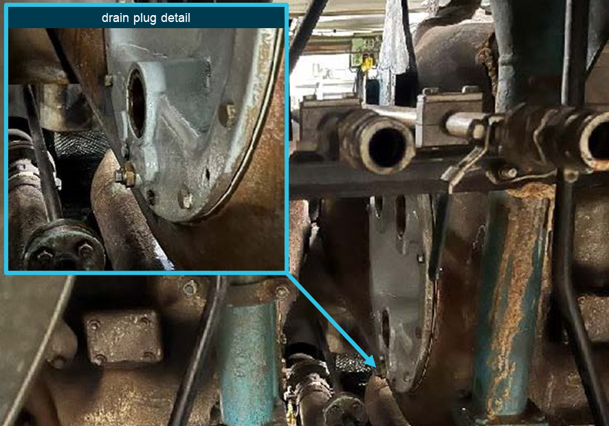
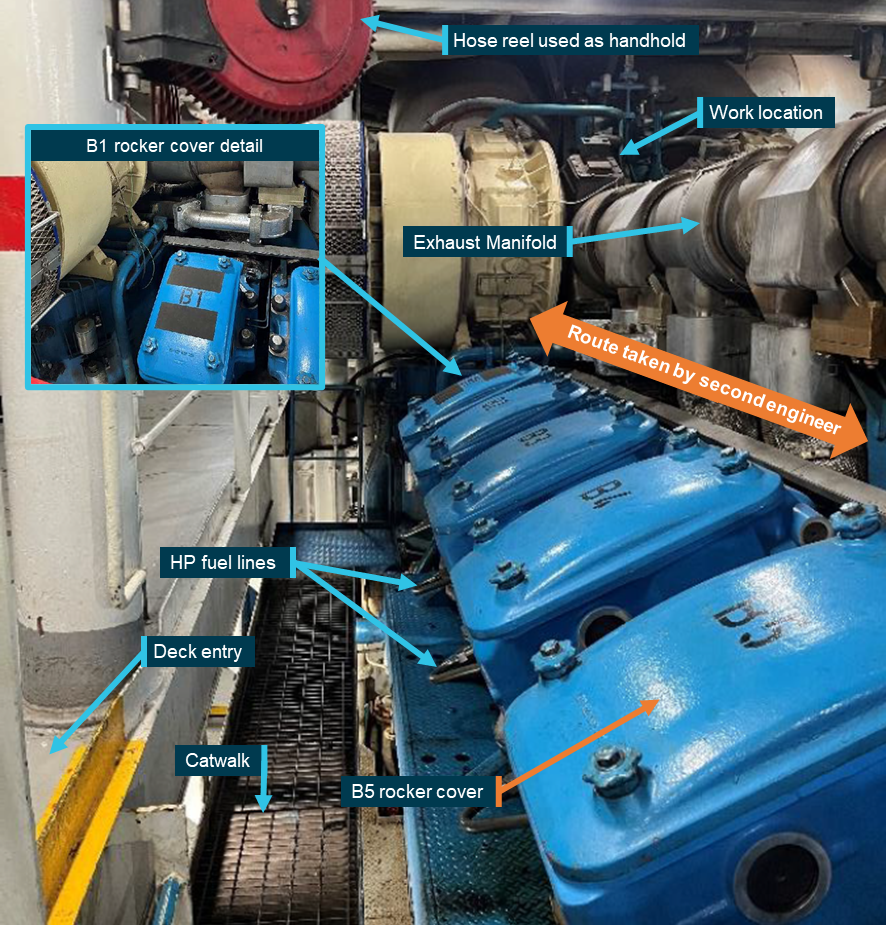
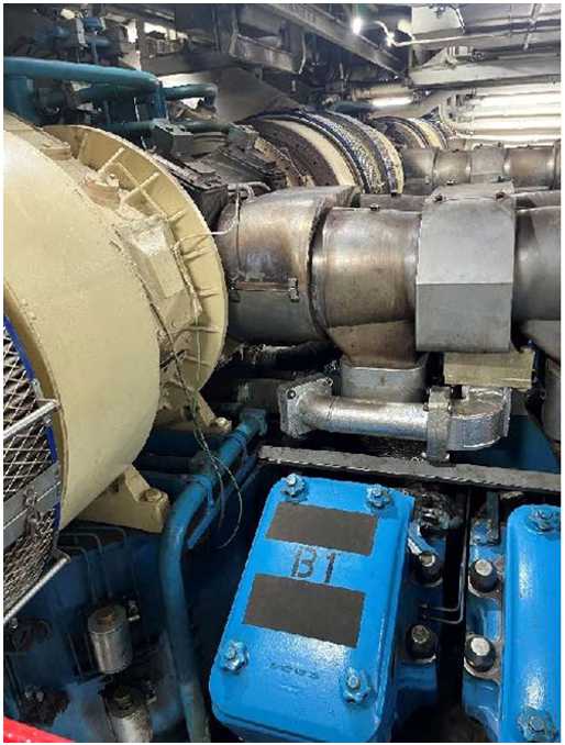
At about 0600 on 6 March 2025, the second engineer of Spirit of Tasmania I began a routine oil change on one of the ship’s main engine turbochargers. Problems were encountered during the oil change, and it was decided to replace the turbocharger’s bearing housing cover plate. This significant change to the scope of work required access to the top of the engine.
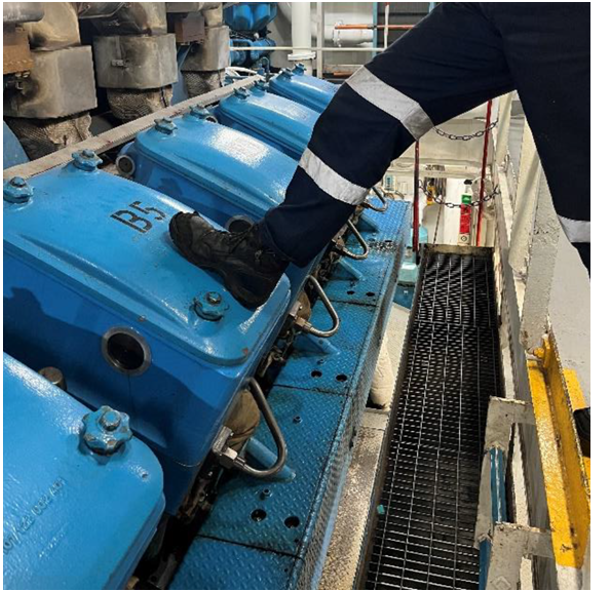
The second engineer and another engineer on duty then carried out the work, which took longer than expected and required both to climb on and off the engine top several times. At 0815, while climbing off the engine, the second engineer slipped and fell heavily, resulting in serious injury.
What the ATSB found
The ATSB investigation found that, while access to the top of the engine was regularly required, there was no access ladder or platform nor was a standard safe route defined or used. Consequently, the injured second engineer used an unsafe access route along the engine rocker covers at the time of the accident.
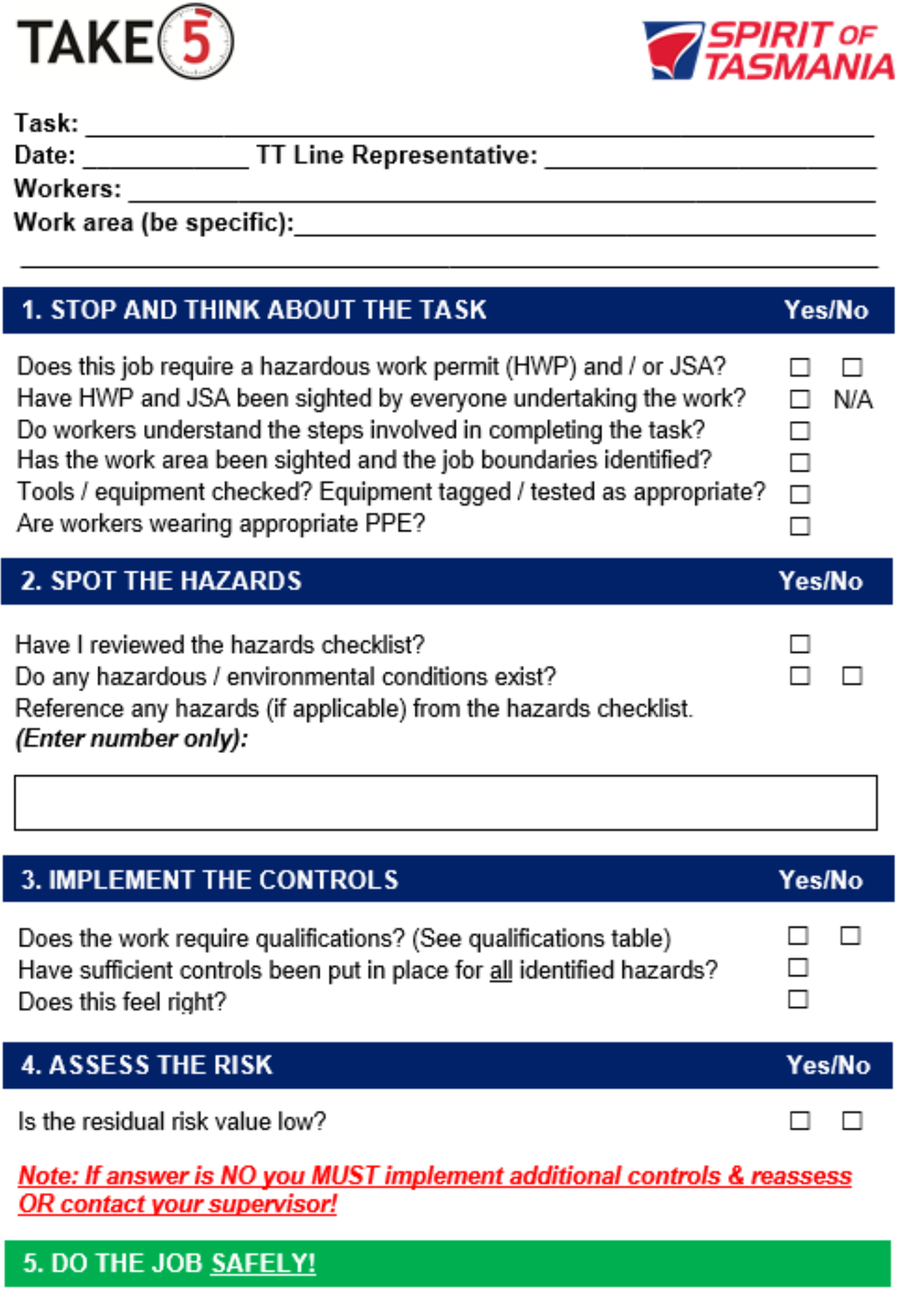
The investigation also identified that although the shipboard safety management system required that the change of work scope necessitated a review of the Job Safety Analysis (JSA) and/or completing a new prestart safety checklist (Take 5), neither was undertaken due to perceived time pressure and a perception that the work was low risk, resulting in the risk of a fall not being properly considered.
In addition, the ATSB found that the JSA procedure was not effectively implemented on board. This resulted in there being no JSA in place for the work being done at the time of the incident. Further, the JSAs covering other work on top of the engine did not address the risks involved in accessing the engine top.
What has been done as a result
The ship’s managers, TT-Line Company (TT-Line), reacted proactively to the accident and put in place several engineering and procedural measures to reduce the risk of falls from the engine top and general access risks.
TT‑line has provided a removable work platform for safe access to the top of the engines for both sister ships, Spirit of Tasmania I and II. The JSAs related to work on turbochargers and the exhaust manifold have been updated to include the access risk. The updated JSA also includes a restriction on routine maintenance of critical equipment during short duration port calls, reducing time pressure constraints in case of unforeseen problems.
Additionally, modifications have been made to the bearing housing cover plates, reducing the need for personnel to access the engine top for ad hoc repairs.
Safety message
The ATSB has investigated numerous occurrences involving unsafe working practices on board ships. Many of these resulted in serious or fatal injury(s) due to falls from height, machinery or equipment falling, explosions and other hazardous occurrences. A recurring factor in such incidents is the people involved in the work not recognising the hazards involved and/or they considered the work routine and low risk. In addition, risk assessment and mitigation are often not done or ineffective.
This investigation highlights the importance of effective risk controls, which requires staff at all levels on board and ashore to contribute towards the effective implementation of the shipboard safety management system.
The occurrence
At 0600 local time on 6 March 2025, the passenger ship Spirit of Tasmania I berthed in Geelong, Victoria, following a routine overnight voyage from Devonport, Tasmania. The ship was expected to sail at about 0830 on its normal schedule for a double sailing.[1]
After shutting down the main engines at about 0630, the second engineer (the senior engineer on watch), decided to complete a scheduled oil change on one of number 1 main engine’s turbochargers. This regular scheduled maintenance job was performed frequently and usually took one hour, which left sufficient time to prepare the engines for departure.
The job required removing the drain and air plugs from the turbocharger’s bearing housing cover plate to drain the oil (Figure 1), then refitting them and refilling the housing with about 1.5 litres of oil. As there had been issues in the past with the steel plug damaging the thread in the aluminium cover plate, the drain plug was fitted into a steel threaded insert installed in the cover plate, rather than directly screwed into the cover plate. However, when the second engineer removed the drain plug, the insert rotated and started unscrewing from the cover plate. In response, they fixed the insert back into the aluminium cover plate using a specialised adhesive, reasoning that this would hold until the next port call when more time would be available to allow for a permanent repair.
Figure 1: Turbocharger cover plate
Source: TT-Line, annotated by the ATSB
At around 0700 the first engineer arrived in the engine room and was advised that the insert had been secured with the adhesive applied. Concerned that the drain plug might come undone during operation, the first engineer asked the second engineer to replace the bearing housing cover with a spare. The drain plug problem was known and several spare plates were available to resolve the problem. With the upcoming departure in mind, the second engineer immediately went about this task with the third engineer (the junior engineer on watch) assisting.
While the oil change could be done by a person standing on the deck aft of the engine between the turbocharger bearing assemblies, replacing the housing cover required access from above the engine near the exhaust gas manifold. This location could be accessed by climbing over the rocker covers on the ‘B’ cylinder bank (Figure 2). The cover closest to the turbocharger (B1) had 2 strips of anti-slip material attached to the blue gloss paint (there were no steps or other permanent means of access).
Figure 2: Access to top of engine (looking aft)
Source: TT-Line, annotated by the ATSB
The second engineer had accessed the same location on top of the engine many times in the past 12 years working on board the ship. The engineer considered the best way to access this location was to step straight from the deck across the lower catwalk onto the B5 rocker cover and then walk along the exhaust manifold (Figure 2). This route avoided the high-pressure fuel pipes at the bottom of the cylinder heads.
The second and third engineers started replacing the cover, with both climbing up and down from the engine by stepping from the deck directly onto the rocker covers and back. After replacing the bearing cover, they found that it was leaking and decided to fit another spare cover. At 0800 their watch ended and the third engineer left the engine room, but the second engineer felt responsible for completing the work and decided to continue working, so that the engine would be available for the scheduled departure at 0830.
At 0816, while working to replace the bearing cover, the second engineer walked aft over the rocker covers, using the exhaust manifold for support (Figure 2). At the B5 rocker cover, the engineer let go of the exhaust manifold and reached across the gap to a swivelling air hose-reel for support but slipped off the rocker cover and struck its corner before falling heavily onto the catwalk grating.
After falling, the second engineer took a short while to check for injuries before standing up. Deciding no major injury had resulted, the engineer completed the remaining work, which involved climbing up and down via the B5 rocker cover to secure components on top of the turbocharger. The engineer then went to the engine control room (ECR) and removed the engine isolation to allow it to be started for departure.
While in the ECR, the second engineer reported their fall to the first engineer who called the ship’s medic to assess the second engineer. The medic’s assessment resulted in a referral to a doctor ashore.
On the following day, 7 March, a doctor diagnosed the second engineer as having suffered a serious knee injury, which required surgery and an extended recovery period of many weeks.
Context
Spirit of Tasmania I
Spirit of Tasmania I (IMO No 9158446) is a passenger/Ro-Ro[2] ship which was built in 1998. It is one of 2 sister ships operated by TT-Line Company (TT-Line), Australia, that provide a daily passenger/vehicle service between Devonport, Tasmania, and Geelong, Victoria.
The ship has an overall length of 194.33 m and a beam of 25.0 m. It can carry a maximum of 1,400 passengers in a variety of cabin and seated accommodation and has 2,565 lane metres of vehicle space.
Depending on demand (passengers, vehicles and cargo), Spirit of Tasmania I and its sister ship operate a single or double sailing schedule. On the single sailing schedule, the ships depart Geelong or Devonport in the evening to complete the voyage the next morning. On double sailings, there is a night‑time as well as a daytime sailing for a 9‑hour voyage, with the ship operating at a higher speed using all 4 of its main engines.
Propulsion
Spirit of Tasmania I’s main propulsion consists of twin controllable pitch propellers (CPP) driven through 2 gearboxes by 4 Wartsila 16ZA40S V-type diesel engines with a total power output of 42,240 kW.
Depending on requirements, the ship can be safely operated with 2, 3 or 4 engines online. This configuration allows the ship to be operated efficiently at both high and low speeds, and engines can be started and clutched into the gearbox with the ship underway.
Engine room crew
At the time of the incident, Spirit of Tasmania I’s engine room crew comprised a chief engineer, first engineer, 2 second engineers, 4 third engineers, 2 electrical engineers and 3 integrated ratings (IR).
The first engineer had worked on board Spirit of Tasmania I and 2 for a total of about 22 years, initially as third engineer for a couple of years and then as a second or first engineer.
The injured second engineer joined the ship 3 days before the incident but had worked on board for the past 12 years, usually as a second engineer and sometimes as the first or third engineer. The second engineer’s work and rest hours leading up to the incident complied with prescribed requirements for seafarers and reported having adjusted to their watchkeeping schedule. The second engineer reported feeling under pressure to replace the cover plate before the ship’s departure to ensure the engine was available as the main engines were their specific area of responsibility.
Watchkeeping
Engine room watches were kept by the second and third engineers and the IRs across a standard watchkeeping schedule of 4 hours on followed by 8 hours off. Each watch comprised a senior and a junior engineer and one IR.
The chief, first and electrical engineers were not assigned to a watch and worked standard daywork hours and other work when required by the ship’s operations. The first engineer’s work mainly involved planning and supervising engine room maintenance.
Maintenance planning
Planned maintenance was based on defined calendar time or running hour intervals with the ships planned maintenance system (PMS) generating a list of scheduled jobs for the week ahead. This list was posted in the engine control room (ECR) for the planning of maintenance work around the ship’s operations.
In addition to watchkeeping duties, each engineer carried out scheduled routine maintenance as per the PMS on their assigned machinery item(s). The second engineer was responsible for the main engines and, with extensive experience in a senior position on board, had significant autonomy to plan and carry out routine work without the first or chief engineer’s direct involvement or supervision.
Incident location
The second engineer fell while working on a main engine and there were many routine maintenance and repair jobs that required crew to access the top of the main engine(s). There were no permanent ladders or access platforms for access. Instead, the crew accessed the engine top by stepping on the rocker covers (Figure 2).
Due to their V-type design, the rocker covers were angled at about 25° from the vertical. Anti-slip tape had been applied to the painted surface of the B1 rocker cover for safer access to the turbochargers (Figure 3).[3]
Figure 3: B1 cylinder rocker cover
Source: TT-Line
According to the first engineer, the top of the engine was accessed by walking along the catwalk adjacent to the cylinder heads and then up and over the B1 rocker cover, holding the pipes there for 3 points of contact. The first engineer also noted that work there often involved leaking cooling water or oil that made the rocker covers slippery and access via the B1 cover provided better footing (anti-slip tape) and handholds while avoiding the potentially hot exhaust manifold.
By contrast, the second engineer regularly used the route that involved walking along the top of the rocker covers while holding exhaust manifold to avoid the fuel pipes below B1 cylinder head and then stepping across the access gap in the railing (Figure 4). The air hose reel near the gap provided a handhold but it also swivelled.
Figure 4: B5 cylinder across catwalk
Source: TT-Line
Recorded video
The engine room was fitted with a closed-circuit television (CCTV) system with cameras in critical areas, including the incident location, to allow for remote monitoring and supervision. The ATSB obtained recorded video footage covering the period of the incident for its investigation analysis.
The video footage showed the second and third engineers accessing the top of the engine a total of 9 times on the accident morning. They stepped directly between the deck and the rocker covers on all occasions, except once when they used the route via the catwalk and climbed up over the B1 rocker cover.
The sequence of the second engineer’s slip and heavy fall was also recorded.
Safety management system
The International Safety Management (ISM) Code provides the international standard for the safe operation of ships.[4] The objective of the ISM Code is the prevention of human injury or loss of life and the avoidance of damage to the environment and property. To achieve this objective, companies are required to develop, implement and maintain a shipboard safety management system (SMS) that provides policies, procedures, instructions and guidance for all shipboard operations.
Spirit of Tasmania I’s shipboard SMS implemented by TT-Line included a ‘vessel operations manual’ for the effective identification and management of hazards to prevent accidents and environmental damage. The manual documented several procedures and processes related to risk management, including:
hazard identification and risk management
daily works committee
Job Safety Analysis
Take 5.
Risk management
The ‘hazard identifications and risk management’ procedure in the SMS provided guidance in assessing and managing safety risk for all shipboard operations. The procedure assigned responsibilities, documented the hierarchy of risk controls and provided various forms and tools that were to be used to comply with various procedures to manage risk.
Works committee
As part of its safety management, TT-Line had identified the need for high level control of ongoing work across shipboard departments, including engine room operations. This was done through a works committee on each ship. The works committee on Spirit of Tasmania I comprised the chief officer, first engineer and hotel manager as the heads of their respective departments, and the chief integrated rating (CIR)[5], shipwright and the safety and environment officer.
The works committee met every day and compiled a daily work schedule listing all planned work for each department. The committee was required to consider the ‘entire scope of proposed work’, assess the risks involved in each job using the risk assessment form and log the outcome on the daily work schedule. Where work consisted of multiple parts, each part had to be assessed individually. In addition, the committee had responsibility for preventing simultaneous operations conflicting with each other and in managing risk and supervising contractors working on board.
Hazards for each job were to be identified based on a ‘hazard identification table’, which listed the general categories of hazards. Based on these categories, each job was assigned an initial ‘raw risk score’ or rating, which, after application of existing controls and additional personal protective equipment (PPE), resulted in final risk score (that is, the residual risk).
Any jobs with an initial risk score higher than ‘low’ in the risk assessment matrix (Appendix A – Risk Assessment Matrix) required the application of additional controls, including extra PPE, a permit to work or other administrative or technical controls. These controls were then to be documented and implemented through a Job Safety Analysis (JSA).
On 6 March (the accident date), the works committee’s daily work schedule form listed 6 jobs in the engine department, all 6 related to a category of work rather than specific jobs. All planned maintenance work on the engines was captured in one line as ‘Aux eng / ME AMOS routines and service’. The form identified ‘physical’ and ‘mechanical’ hazards under the ‘personal injury/death’ general category. The initial risk score was assessed as 3D or ‘moderate’. To mitigate this risk the form noted that a number of controls were in place, these included the use of personal protective equipment (PPE), lock-out/tag-out (LOTO) procedures and Job Safety Analysis. These reduced the final risk score on the form to 3E or ‘low’.
Job Safety Analysis
Spirit of Tasmania I’s SMS included a procedure for conducting Job Safety Analysis (JSA). This procedure defined the responsibilities for implementation, guidance on risk assessment and mitigations as well as the administrative requirements.
JSAs were normally completed by the works committee in the planning stage of a job during their daily meeting. However, for unexpected work the supervisor in charge would assess the need for a JSA and complete one if required.
Additionally, if during a task a situation occurred that had not been contemplated and planned for in the JSA, the risks were to be reassessed to determine whether a new JSA was required. If the change did not warrant a new or updated JSA, the procedure required that a ‘Take 5’ be completed (see the following section).
The JSA process required breaking down the work into its component steps and assessing the potential hazards involved in each. The initial or ‘raw’ risk score was then calculated by assessing the risk without controls in place. The risks could then be mitigated based on the hierarchy of controls, reducing the final or ‘residual’ risk score to an acceptable level.
After completion, the JSAs were to be approved by either the master, chief engineer, Health Safety & Environment committee[6] or the marine manager ashore. The person supervising the work was then required to ensure that everyone involved was familiar with the JSA and sign the form before starting the work.
Approved JSAs were filed electronically and a JSA for the same (or effectively the same) job that was regularly performed could be re-used without further approval. Any changes to such JSAs, however, required another approval process.
A JSA covering the initial oil change had identified ‘slips and fall’ as a hazard but was mostly concerned with the cleanup of oil spills. As the oil change could be completed from deck level access the engine top was not required.
While both the first and second engineers stated that a JSA covering the exchange of the cover plate ‘should’ have been filed, no attempt was made to review this JSA. In any case, there was no such JSA in the files.
Two JSAs had been documented for work that required access to the top of the main engine. One JSA covered replacement of the ‘turbo exhaust gasket’ and the other covered the exchange of ‘exhaust expansion bellows’. Both JSAs identified the risk of falls when applying force to undo fasteners while standing on the engine (as opposed to the risks involved in getting to and from the top of the engine). The control measures to mitigate the risk when removing fasteners were ‘tools in good order’, ‘maintain good footing’ and ‘clean up any spills’.
Take 5
The ‘Take 5’ checklist (Appendix B – Take 5 checklist) provided an additional layer to mitigate risk. This lower level control was implemented at the worksite, with all the crew involved discussing the requirements of the job to ensure a shared mental model and as a final check of the hazards/risks that were unforeseen during the JSA planning process. This process was intended to complement any works committee standard protocols already in place, including but not limited to formal risk assessments, JSAs, and hazardous work permits.
The checklist was required to be used for all on board work other than a limited number of specified jobs deemed to be ‘standard shipboard practice’, which for the engineering department were defined as ‘standard engineering watchkeeping routines’.
The Take 5 process specified the following 5 steps:
Stop and Think about the Task: When a “no” response is not shown on the checklist, it indicates that the work can only proceed if the “yes” response is ticked. A question is only not applicable (N/A) if that response is shown.
Section 2 – Spot the Hazards: All workers must assess the worksite together to identify any hazards. To facilitate this, workers should utilise the hazards checklist on the reference page. The corresponding number for each hazard must be entered in the space provided in section 2 of the Take 5 checklist.
Section 3 – Implement the Controls: Any qualifications required to undertake the work should be checked according to the qualifications table on the information page. Control measures then need to be implemented to mitigate all hazards identified in section 2.
Section 4 – Assess the Risk: The risk should be assessed using the risk matrix on the reference page. The residual risk value must be Low for any given hazard. If the residual risk is moderate, additional controls should be implemented, and the risk reassessed. If the residual risk is high or extreme or you are in doubt, you must seek assistance from a TT‑ Line supervisor.
Section 5 – Do the Job Safely: Once the Take 5 checklist has been completed, work can proceed if assessed as safe to do so.
The procedure stated that the checklists were to be retained on board for one month, and that supervisors should randomly review 5 of them every month to verify compliance. After one month, the checklists were to be retained in the company’s records ashore for at least 6 months.
No Take 5 form covering the work was found and interviews with the involved crew confirm that a Take 5 was not completed before the replacement of the cover plate.
Previous incidents
In 2011, an engineer was seriously injured after falling through an open grating in the engine catwalk in the engine room of Spirit of Tasmania I. The ATSB investigation into that incident concluded that the personnel involved had not taken the time to (informally) assess the risks involved, which meant that no barriers were in place.
In 2022, a contractor working in the ship’s engine room was seriously injured due to the uncontrolled movement of a suspended load. The work was being supervised by the ship’s engineers under the shipboard SMS procedures, which were later amended to reflect the lessons learned. That incident was investigated by WorkSafe Victoria.
Safety analysis
Work site
Access
Although access to the top of the engine was regularly required for maintenance and was not straightforward, a dedicated ladder or platform was not fitted to provide safe access. Instead, the aft most rocker cover (B1) had been fitted with anti-slip material, which some crewmembers considered the ‘normal’ route to climb on or off the engine (Figure 2).
However, other crewmembers used different access routes which they considered better, convenient or safer. There were no standard procedures or practices to control access via a defined route(s). Consequently, different routes were used with the one used at the time of the accident having a high fall risk.
Contributing factor
A standard safe route to access the top of the main engine was not defined or used. As a result, crewmembers used different routes, with the injured engineer using an unsafe route.
Risks
Recorded video footage from the morning of 6 March shows that the 2 engineers on watch climbed on or off the engine a total of 18 times. On 16 occasions, they did so by walking along the rocker covers and stepping over the catwalk (Figure 2). Both engineers climbed up via the B1 rocker cover on one occasion.
Access via the B1 rocker cover had the advantage of the anti-slip tape on the cover and the cooling water pipes there providing a handhold for three points of contact. This reduced but did not eliminate the risk of a slip and fall.
On the other hand, walking along the gloss painted, inclined rocker covers did not provide safe footing which meant a high risk of slips and falls. While the exhaust manifold provided a handhold, a good handhold was not available when stepping across to (or from) the deck. Further, the higher drop from the B4-5 covers to the catwalk increased the risk of injury, which was realised when the engineer slipped and fell.
Contributing factor
After working on top of the main engine, the second engineer walked along its rocker covers before stepping across to the opening in the railing, slipping off the cover and falling, resulting in serious injury.
Risk controls
Work scope change
Spirit of Tasmania I’s shipboard safety management system (SMS) procedures required any significant change in the scope of the work being carried out to be reassessed for additional hazards. Such reassessment could result in changes to the applicable risk controls. In general, this would lead to either updating the existing job safety analysis (JSA) or, if that was not deemed necessary, conducting another ‘Take 5’.
On 6 March, the oil change being carried out was rescoped and the job was changed to the replacement of the bearing housing covers. This significant change in scope should have resulted in the engineers conducting another Take 5 before starting the job. This Take 5 would have provided the opportunity to assess safe access to the top of the engine, which in turn would have flagged the need for a JSA.
The engineers were aware of the need to conduct a Take 5. While it was possible to depart with number 1 engine off-line, the second engineer felt self-imposed pressure to complete the work before the planned departure. This probably resulted in the engineers that were replacing the cover not conducting a Take 5. The first engineer’s perception was that it was low risk work because it was regularly done and therefore they had not considered that another risk assessment or JSA was necessary.
Contributing factor
Although the engineers knew that replacing the bearing housing cover was a change to work scope and that this required reviewing the existing Job Safety Analysis and/or conducting a Take 5, neither was undertaken due to perceived time pressure and a perception that the work was low risk. Consequently, the risk of slips and falls involved in the work was not properly considered.
Job Safety Analysis
The evidence showed that main engine turbocharger bearing housing cover plates had been regularly replaced for many years. Replacing the cover plates meant accessing the top of the engine and SMS procedures required appropriate risk controls in place, based on a risk assessment documented in a JSA. All JSAs were to be filed in an electronic system for later use.
However, no JSA for replacing cover plates was found in the system. Both engineers that replaced the cover plate stated that a JSA ‘should’ have existed but made no attempt to access it. Regardless, a JSA to safely complete this job was not in place at the time of the incident. Further, given the absence of a JSA in the system, it is very likely that this job was undertaken many times in the past without proper consideration of the involved risk.
The ATSB investigation also reviewed risk assessments for various jobs involving work on top of the engines that were filed in the ship’s records. In every case, the risk was assessed as ‘medium’, which required a corresponding JSA to be completed, identifying the risk controls specific to the job, including those relevant to accessing the engine top. There were 3 JSAs for work on the turbocharger and exhaust system. Each identified slip and trip hazards when dismantling parts while standing on top the engine. Measures to mitigate these hazards focused on cleaning up spills and maintaining footing when using force to undo fasteners (bolts). None of the JSAs identified the hazards and risks involved in accessing the top of the engine.
Other factor that increased risk
Spirit of Tasmania I’s safety management system procedure for Job Safety Analyses (JSA) was not effectively implemented. As a result, the JSA required for replacing the main engine turbocharger bearing housing cover plate was not in place. In addition, JSAs covering other work on top of the engine did not address the risks involved in accessing the work site. (Safety issue)
Findings
ATSB investigation report findings focus on safety factors (that is, events and conditions that increase risk). Safety factors include ‘contributing factors’ and ‘other factors that increased risk’ (that is, factors that did not meet the definition of a contributing factor for this occurrence but were still considered important to include in the report for the purpose of increasing awareness and enhancing safety). In addition ‘other findings’ may be included to provide important information about topics other than safety factors.
Safety issues are highlighted in bold to emphasise their importance. A safety issue is a safety factor that (a) can reasonably be regarded as having the potential to adversely affect the safety of future operations, and (b) is a characteristic of an organisation or a system, rather than a characteristic of a specific individual, or characteristic of an operating environment at a specific point in time.
These findings should not be read as apportioning blame or liability to any particular organisation or individual.
From the evidence available, the following findings are made with respect to the serious fall injury in the engine room of Spirit of Tasmania I, Geelong, Victoria, on 6 March 2025.
Contributing factors
A standard safe route to access the top of the main engine was not defined or used. As a result, crewmembers used different routes, with the injured engineer using an unsafe route.
After working on top of the main engine, the second engineer walked along its rocker covers before stepping across to the opening in the railing, slipping off the cover and falling, resulting in serious injury.
Although the engineers knew that replacing the bearing housing cover was a change to work scope and that this required reviewing the existing Job Safety Analysis and/or conducting a Take 5, neither was undertaken due to perceived time pressure and a perception that the work was low risk. Consequently, the risk of slips and falls involved in the work was not properly considered.
Other factors that increased risk
Spirit of Tasmania I’s safety management system procedure for Job Safety Analyses (JSA) was not effectively implemented. As a result, the JSA required for replacing the main engine turbocharger bearing housing cover plate was not in place. In addition, JSAs covering other work on top of the engine did not address the risks involved in accessing the work site. (Safety issue)
Safety issues and actions
Central to the ATSB’s investigation of transport safety matters is the early identification of safety issues. The ATSB expects relevant organisations will address all safety issues an investigation identifies.
Depending on the level of risk of a safety issue, the extent of corrective action taken by the relevant organisation(s), or the desirability of directing a broad safety message to the Marine industry, the ATSB may issue a formal safety recommendation or safety advisory notice as part of the final report.
All of the directly involved parties were provided with a draft report and invited to provide submissions. As part of that process, each organisation was asked to communicate what safety actions, if any, they had carried out or were planning to carry out in relation to each safety issue relevant to their organisation.
Descriptions of each safety issue, and any associated safety recommendations, are detailed below. Click the link to read the full safety issue description, including the issue status and any safety action/s taken. Safety issues and actions are updated on this website when safety issue owners provide further information concerning the implementation of safety action.
Safety issue description:Spirit of Tasmania I’s safety management system procedure for Job Safety Analyses (JSA) was not effectively implemented. As a result, the JSA required for replacing the main engine turbocharger bearing housing cover plate was not in place. In addition, JSAs covering other work on top of the engine did not address the risks involved in accessing the work site.
Safety action not associated with an identified safety issue
Whether or not the ATSB identifies safety issues in the course of an investigation, relevant organisations may proactively initiate safety action in order to reduce their safety risk. All of the directly involved parties are invited to provide submissions to this draft report. As part of that process, each organisation is asked to communicate what safety actions, if any, it has carried out to reduce the risk associated with this type of occurrence in the future. The ATSB has so far been advised of the following proactive safety action in response to this occurrence.
Additional safety action by TT-Line Company
Action number:
MO-2025-002-PSA-02
Action organisation:
TT-Line Company
Action status:
Closed
In order to address the tendency for the Turbo Charger (TC) drain plug to become damaged during removal for oil change, TT-Line implemented a redesign and modification of the internal thread, which should eliminate the need for urgent replacements of the turbocharger bearing cover plate.
Glossary
CCTV
Closed-circuit television
CIR
Chief integrated rating
CPP
Controllable Pitch Propeller
HS&E
Health Safety & Environment Committee
IMO
International Maritime Organization
IR
Integrated rating
ISM
International Management Code for the Safe Operation of Ships and for Pollution Prevention, 1995, as amended
JSA
Job Safety Analysis
SMS
Safety management system
Sources and submissions
Sources of information
The sources of information during the investigation included:
the chief, first and second engineers of Spirit of Tasmania I
TT-Line Company (TT-Line)
WorkSafe Victoria.
References
International Maritime Organization. (1995). International Management Code for the Safe Operation of Ships and for Pollution Prevention (ISM Code) as amended, IMO, London.
Submissions
Under section 26 of the Transport Safety Investigation Act 2003, the ATSB may provide a draft report, on a confidential basis, to any person whom the ATSB considers appropriate. That section allows a person receiving a draft report to make submissions to the ATSB about the draft report.
A draft of this report was provided to the following directly involved parties:
the master of Spirit of Tasmania I
the chief, first and second engineers of Spirit of Tasmania I
TT-Line
Australian Maritime Safety Authority (AMSA)
A submission was received from:
TT-Line
The submission was reviewed and, where considered appropriate, the text of the report was amended accordingly.
Appendices
Appendix A – Risk Assessment Matrix
Appendix B – Take 5 checklist
Purpose of safety investigations
The objective of a safety investigation is to enhance transport safety. This is done through:
identifying safety issues and facilitating safety action to address those issues
providing information about occurrences and their associated safety factors to facilitate learning within the transport industry.
It is not a function of the ATSB to apportion blame or provide a means for determining liability. At the same time, an investigation report must include factual material of sufficient weight to support the analysis and findings. At all times the ATSB endeavours to balance the use of material that could imply adverse comment with the need to properly explain what happened, and why, in a fair and unbiased manner. The ATSB does not investigate for the purpose of taking administrative, regulatory or criminal action.
About ATSB reports
ATSB investigation reports are organised with regard to international standards or instruments, as applicable, and with ATSB procedures and guidelines.
Reports must include factual material of sufficient weight to support the analysis and findings. At all times the ATSB endeavours to balance the use of material that could imply adverse comment with the need to properly explain what happened, and why, in a fair and unbiased manner.
An explanation of terminology used in ATSB investigation reports is available here. This includes terms such as occurrence, contributing factor, other factor that increased risk, and safety issue.
Publishing information
Released in accordance with section 25 of the Transport Safety Investigation Act 2003
Ownership of intellectual property rights in this publication
Unless otherwise noted, copyright (and any other intellectual property rights, if any) in this report publication is owned by the Commonwealth of Australia.
Creative Commons licence
With the exception of the Commonwealth Coat of Arms, ATSB logo, and photos and graphics in which a third party holds copyright, this report is licensed under a Creative Commons Attribution 4.0 International licence.
The CC BY 4.0 licence enables you to distribute, remix, adapt, and build upon our material in any medium or format, so long as attribution is given to the Australian Transport Safety Bureau.
Copyright in material obtained from other agencies, private individuals or organisations, belongs to those agencies, individuals or organisations. Where you wish to use their material, you will need to contact them directly.
[1]The Spirit of Tasmania passenger/Ro-Ro ships operate either on a single (overnight) sailing or double sailing, on which they provide both a day and a night‑time voyage between Geelong and Devonport.
[2]Ro-Ro or ‘Roll-on Roll-off’ ships carry wheeled cargo that is loaded and unloaded via ramps onto vehicle decks.
[3]Anecdotal accounts from the crew indicated that the anti-slip tape was applied after a previous fall but the ATSB found no record of that incident or any information about the application of the anti-slip tape.
[4]International Maritime Organization, 2018, International Management Code for the Safe Operation of ships and for Pollution Prevention (ISM Code) as amended, IMO, London.
[5]The chief integrated rating is the lead rating on board, comparable to the function of Bosun on international ships.
[6]TT-Line procedures included a Health Safety and Environment committee, to satisfy the requirement for a Health and Safety committee under the “Occupational Health and Safety (maritime industry) Act of 1993.
On 4 March 2025, the livestock carrier Al Messilah experienced a loss of main engine propulsion while under pilotage into the Port of Fremantle, Western Australia. An initial loss of propulsion occurred near the entrance to the Inner Harbour and was temporarily resolved. However, the engine failed again shortly after, leaving the ship without propulsion while transiting the Inner Harbour. With tug assistance, the ship was manoeuvred safely to berth.
What the ATSB found
The ATSB found that the main engine failures were caused by a malfunction of the main air distributor’s servo piston within the engine’s pneumatic control system.
The ATSB also found that the ship’s planned maintenance system did not provide enough detail to track maintenance schedules, and did not have a specific maintenance item to record the maintenance activities on the main engine pneumatic system. In addition, the main air distributor components, the main engine pneumatic system, and the engine control air system dryer were not maintained in accordance with the manufacturer's guidelines.
The ATSB also identified that the Fremantle Pilots’ operational practice of using very high frequency (VHF) channel 8 for communication with Fremantle vessel traffic service (VTS) during Inner Harbour transits was not consistent with the port procedures and prevented effective radio communication.
What has been done as a result
Following the incident, the ship’s manager arranged for the engine manufacturer’s service team to attend the ship during its subsequent port call at Khor Fakkan anchorage, United Arab Emirates, where a full overhaul of the main engine pneumatic manoeuvring system was completed. In addition, a comprehensive review of the ship’s planned maintenance system was initiated, with 27 corrective actions identified and prioritised for implementation.
Fremantle Pilots endeavoured to improve communication protocols and is actively working with Fremantle Port Authority to review and update existing practices. This includes benchmarking against best practices at other Australian ports and providing feedback on the port information guide.
Safety message
This occurrence highlights the importance of a comprehensive and well-documented planned maintenance system (PMS) to ensure the reliability of critical machinery, particularly systems that directly affect a ship’s manoeuvrability and safety.
Ship managers and operators are reminded to:
regularly update PMS documentation to reflect manufacturer-recommended service intervals and procedures, with complete and traceable maintenance records.
provide appropriate training to ensure crew competency in the operation and maintenance of critical systems, including pneumatic controls.
The incident also highlights the need to follow established communication protocols during emergencies to support timely and effective coordination.
The occurrence
On the morning of 4 March 2025, the livestock carrier Al Messilah was waiting to enter the Port of Fremantle, Western Australia, after departing from Shuwaikh, Kuwait on 2 February 2025.
The ship was boarded by a pilot at the inner pilot boarding ground to guide the ship to North quay berth 2 in the Fremantle Inner Harbour for loading operations (Figure 1). The master‑pilot exchange was completed with no defects reported regarding the main engine. During the transit 2 tugs, Svitzer Redhead and Svitzer Falcon, were in attendance, with Svitzer Redhead made fast at the port quarter and Svitzer Falcon at the port shoulder.
The pilotage proceeded routinely until 0741 local time,[1] when the ship's stern was abeam 1/A buoys at the Inner Harbour entrance channel. At this point, with the ship travelling at 10 knots and heading 084° true course, the main engine stopped while running at slow AHEAD. The pilot alerted both tugs, ordering Svitzer Redhead to shorten up (to prepare to push on the ship) and Svitzer Falcon to stand by to lay back.
Figure 1: Inner Harbour Fremantle
Source: Google maps, annotated by the ATSB
Meanwhile, the master coordinated with the engine control room to restart the main engine. The chief engineer, who was in the engine control room at the time, observed that just prior to the engine stopping, the AHEAD and ASTERN indicator light began flickering between directions. They then took manual control of the engine from the bridge to the engine control room and attempted to restart it in both AHEAD and ASTERN directions. After initial checks, the engine was started in AHEAD and the pilot was advised to only use the engine in the AHEAD direction.
At 0744, after passing South Mole and prior to reaching the wheel-over point (Figure 1), the main engine was back online with slow AHEAD engaged. The pilot attempted to contact vessel traffic service (VTS) on channel 8 to provide detail of the engine stoppage, but received no response. The pilot then contacted VTS on channel 12 and asked the VTS operator to switch to channel 8. On channel 8, the pilot notified VTS of the main engine issues and requested monitoring, subsequently advising VTS, ‘we’re all good’.
As they were saying this to VTS, the engine failed a second time and could not be restarted. With the ship continuing under its own momentum, the pilot gave instructions to the helmsman to ensure the ship turned to enter the Inner Harbour. The pilot also instructed Svitzer Redhead, which remained connected at the port quarter, to push at minimum power to assist the turn and to maintain the ship in the centre of the harbour.
With the engine still failed, the pilot attempted to contact VTS on channel 8 twice at 0752, to inform them of the engine failure and discuss contingency berthing options but received no response. A follow-up call was made to VTS via mobile phone, which also went unanswered. The pilot then contacted the mooring team leader on channel 8 to enquire about available berths, but the call could not be established.
The pilot subsequently established contact with the team leader via mobile phone and advised them that the engine had failed, and they may need to berth where they could. The team leader confirmed that D and F berths were vacant but advised against berthing between them due to a known misalignment of the wharf.
By 0757, as the ship passed north quay berth 2 (Figure 1), the crew were able to restart the main engine with dead slow AHEAD engaged. The ship then continued to F berth with the engine at dead slow AHEAD with no further issues. The ship was all fast at 0835.
Context
Al Messilah
The ship Al Messilah was built by the Hashihama Shipbuilding Company in Japan in 1980. It was converted into a livestock carrier in 1997 by Meyer Werft in Germany. At the time of the incident, it was owned, managed, and operated by the Kuwait Livestock Transport & Trading Company, and was classed with Lloyd's Register. The ship regularly traded between Fremantle, Australia, and Shuwaikh, Kuwait.
The ship had an overall length of 185.85 metres and a beam of 32.0 metres. It had a gross tonnage of 38,988 and a deadweight of 12,900 tonnes at a draught of 9.024 metres.
The ship was equipped with a Mitsui B&W 9L67GFC main engine that delivered 12,356 kW through a fixed pitch propeller. In ballast condition, the ship's manoeuvring speeds were 6.2 knots at dead slow AHEAD and 8.2 knots at slow AHEAD.
Crew
Al Messilah was manned with 57 personnel and all crew members held the required qualifications and endorsements for their respective positions.
The deck department comprised the master and 5 officers, including 2 chief mates, a second mate, a third mate and a radio officer. The master held an Egyptian master's certificate of competency re-issued in 2023 and had 6 years experience in the rank, including 14 months on board Al Messilah. The chief officer had 11 years of experience in the rank and had served on board for 3 months.
The engineering department included the chief engineer, a second engineer and 2 third engineers. The chief engineer held a Singapore‑issued certificate of competency as a marine chief engineer, issued in 2021, and had previously served on the ship on multiple occasions, completing 6 months on board during the current tenure. The second engineer held an Egyptian certificate of competency re‑issued in 2024, with 9 years experience in the rank and a total of 27 months served on the ship.
Fremantle Pilots
Fremantle Pilots (FP) was a privately owned company that had provided continuous contracted pilotage services within the Port of Fremantle since 1994. FP was reported to pilot about 3,500 ship movements annually.
The experienced pilot assigned to Al Messilah held an unrestricted licence as a port pilot, issued by Fremantle Ports, and a master mariner’s certificate of competency issued by the Australian Maritime Safety Authority (AMSA). They had been on this ship for pilotage on multiple occasions in the past.
Main engine control and starting sequence
Control of the main engine was available from the bridge using the engine order telegraph (telegraph) handle[2] on the bridge manoeuvring console, from the engine control room, and locally at the engine. The engine was directly coupled to a fixed‑pitch propeller. To reverse the direction of propeller thrust, the engine was required to be stopped and then restarted in the opposite direction.
When this was required, after the engine was stopped, the engine telegraph was moved to the AHEAD or ASTERN position. Valve 87 (see the section titled Pneumatic system and Figure 2) then directed control air though the appropriate line (AHEAD or ASTERN) to the main air distributor (see the section titled Main air distributor). It also provided air to the intensifier booster of the camshaft reversing mechanism (see the section titled Camshaft reversing mechanism booster), positioning them for the commanded operation.
To start the main engine, it was initially turned using starting air. Once the engine speed reached a predefined threshold, the starting air was stopped and fuel introduced. The engine speed automatically adjusted to match the speed set by the bridge controls.
Pneumatic system
The main engine’s pneumatic system (Figure 2) used compressed air, referred to as control air, at a working pressure of 7 kg/cm². This air came from the main air bottles, which store air at 30 kg/cm². A pressure‑reducing valve lowered the pressure to the required level. To meet the manufacturer’s air quality standards, the system also included a control air dryer.
Figure 2: Pneumatic system
The blue line is showing the path of the control air in the AHEAD line and the red line is showing the path of the control air in the ASTERN line. Source: Ship’s manager, annotated by the ATSB
Components
Main air distributor
Control air supplied through valve 87 was directed to either the AHEAD or ASTERN line and acted on the servo piston (Figure 3). This piston moved the main engine air distributor into the correct position for the selected direction. The distributor then directed high-pressure air to each cylinder’s start air valve to initiate engine rotation. By adjusting the firing order (timing and sequence of air delivery to the cylinders), the distributor ensured the engine was started and rotated in the intended direction.
Figure 3: Main air distributor
Source: Ship’s manager, annotated by the ATSB
Camshaft reversing mechanism booster
At the same time as being directed to the distributor, the control air acted on the camshaft reversing mechanism intensifier booster (Figure 2) to change the camshaft’s position to match the selected engine direction. This resulted in a change to the timing of the fuel injection and exhaust valve operation, allowing the engine to run in the required direction.
Shipboard maintenance procedures
As part of its safety management system, the ship manager advised that they implemented standard procedures across all ship and shore operations. This included manuals covering company procedures, fleet instructions, and safety management. The system included general procedures, with the key procedure for main engine maintenance summarised as follows:
The company maintains machinery and equipment according to rules, manufacturer guidance, and risk assessments. If needed, stricter internal standards are applied.
Spare parts and tools are provided promptly. Maintenance records are kept up to date and checked both on board and ashore. Senior staff carry out regular inspections, and critical equipment is maintained.
Planned maintenance system
The fleet instructions manual on board Al Messilah included the procedures for planned maintenance, including key steps for maintaining the main engine, summarised as follows:
Before starting any maintenance or repair work, crew must carry out a risk assessment and record it in the maintenance workbook. They must follow the manufacturer’s instructions for all machinery, equipment, and systems. If needed, planned maintenance can be done earlier than scheduled, but it should not be delayed beyond the recommended time.
Planned maintenance is to be carried out as per the schedule laid out by the company for each ship. The chief engineer must closely monitor the system and report the status to head office on a monthly basis.
Any main engine maintenance to be carried out must first be discussed at the shipboard management meetings, where the decision will be made as to when the work will be undertaken. Hours between checks/overhaul of main engine and auxiliary engine components should be reported from the month‑ending statement of main engine and auxiliary engine running hours forms.
On board maintenance practices and records
The ship’s planned maintenance system (PMS) was monitored using a PMS form that referenced various main engine components (Figure 4). The maintenance tasks were scheduled at predefined intervals, as shown in the PMS form.
While the PMS identified the required maintenance tasks, there were no accompanying task‑specific job cards or procedural breakdown guides available to guide crew through each activity. Instead, records of completed maintenance were kept in a handwritten logbook, which did not include detailed descriptions of the condition of the component, work performed, or parts replaced.
As of the end of February 2025, the main engine had accumulated 259,438.5 running hours, with 298.5 hours recorded during that month.
Figure 4: Planned maintenance system for main engine
Source: Ship’s manager, annotated by the ATSB
On board maintenance
Pneumatic system maintenance requirements
The engine manufacturer initially recommended overhauling the pneumatic control system every 8,000 hours of engine operation. However, in 2001 this guidance was superseded by a service letter, introducing a time-based maintenance approach.
This updated maintenance guidance required that all non-metallic components and O‑rings in the pneumatic system’s valves were to be renewed every 2 years.
The ATSB did not identify any evidence that the maintenance of the pneumatic system was recorded in the PMS or that the updated time-based maintenance requirement had been included.
Control air dryer maintenance requirements
The maintenance procedures for the control air dryer stated that the unit must be kept clean and that the filter of the automatic condensate drain should be cleaned monthly under normal conditions and weekly in dusty environments.
The control air dryer was replaced in 2021, however no further related maintenance records were provided.
Engine manoeuvring system
The operator had one record of maintenance conducted on the engine manoeuvring and control system, which included part of the pneumatic system. This was done on 14 September 2024 and showed that the following work was completed:
pneumatic vales 91, 92 and 93 overhauled and refitted
pneumatic valves 166 and 87 renewed
turning gear and local manoeuvring stand valves – O-rings replaced
main engine stop cylinder overhauled
limit switches lubricated
grease points regreased
7 bar and 30 bar line filters opened.
The last recorded maintenance by the part manufacturer was in 1994, the year prior to the current owner purchasing the ship. Following the occurrence, the ATSB contacted the main engine manufacturer to clarify the maintenance requirements for components of the engine’s pneumatic system. The manufacturer advised that there were no formal maintenance recommendations for these components, and that maintenance practices were left to the discretion of the ship’s management.
Maintenance training standards
The ship’s master reported that the engineering crew on board had not received training specific to the maintenance of the main engine pneumatic systems.
Post‑incident engine inspection
During maintenance conducted after the incident, it was identified that the seals on the servo piston of the main air distributor reversing cylinder had disintegrated.
The affected seals were subsequently replaced by shipboard personnel once the ship was safely moored alongside (Figure 5).
Subsequent to notification of the incident by the ship’s master, the Australian Maritime Safety Authority (AMSA) boarded the ship and issued a deficiency under the Navigation Act 2012. In response, the ship’s management arranged for the attendance of the engine manufacturer to repair and verify the integrity of the main engine control system while the ship remained berthed.
Verification of the repairs and functionality of the main engine control system was conducted by the ship’s classification society.[3] At the end of this process, the classification society issued an actionable item requiring the main engine manoeuvring system to be serviced in accordance with the manufacturer’s recommendations at the earliest opportunity. A due date of 6 June 2025 was assigned for completion of this action.
AMSA subsequently closed the deficiency prior to the ship’s departure from port on 6 March 2025. No further deficiencies were issued at that time, as the classification society committed to ongoing monitoring of the outstanding item.
When the ship arrived at Khor Fakkan anchorage in the United Arab Emirates, the ship manager arranged for a complete overhaul of the main engine pneumatic system. The engine maker’s service team attended the ship on 11 April 2025, inspected, and overhauled the entire pneumatic manoeuvring system, including all of the pneumatic valves.
Figure 5: Main air distributor reversing cylinder/servo piston with new seals
The image shows the piston after the seals had been replaced. Source: Ship’s manager, annotated by the ATSB
Communication protocols at Fremantle Ports
Fremantle Ports’ communication protocols, as outlined in the Port Information Guide (2018), Harbour Master’s Instruction HM02/18, and the VTS Operational Procedures (2022), designated very high frequency (VHF) channel 12 as the primary channel for VTS communications, with channel 8 reserved for tug operations.
Fremantle Pilots advised that during pilotage, it was standard practice to use channel 8 in the Inner Harbour and it expected this channel to be monitored by pilots, tugs, line boats mooring teams and VTS. It further stated that, while channel 12 was monitored continuously on the ship’s VHF radio, the communications specific to the ship movement and pilotage were carried out on the dedicated channel 8, to which the pilot’s VHF was switched during transit through the Inner Harbour. They advised that the use of channel 8 ‘avoids the need for parties (particularly the pilots, the tugs and VTS) to have to switch between channels during operation’.
Subsequent incidents
Following this incident, during the ship’s next port visit in April 2025, there was a complete electrical power loss and black smoke emission from the engine room. It was revealed that the generator had failed. This was likely due to the degradation of the electrical cable insulation due to continuous relative movement caused by poor securing, leading to a short circuit in the system.
Additionally, multiple safety-related deficiencies were identified during a harbour master inspection on 28 April 2025, including:
unsafe mooring arrangements
corroded and unserviceable equipment
poor housekeeping and safety protocols.
These systemic shortcomings, along with the failure to report key incidents such as a mooring line parting and onboard fire, led the harbour master to deem the ship unfit for further port calls. As a result, Al Messilah was officially banned from returning to the Port of Fremantle by the harbour master until a satisfactory corrective action plan with objective evidence is presented to Fremantle Ports for review. As the ship only transits through the Port of Fremantle, this effectively banned it from entering Australia.
Safety analysis
Introduction
On 4 March 2025, the livestock carrier Al Messilah lost propulsion while entering the Port of Fremantle with a pilot on board. The main engine stopped once while the ship was entering the harbour and failed a second time as the ship entered the Inner Harbour.
This analysis focuses on the circumstances of the incident, specifically examining the cause of the engine failures, the ship’s planned maintenance system (PMS) and the operator’s maintenance practices. It will also discuss the communication issues encountered during the emergency.
Engine failures
The investigation found that degraded seals inside the servo piston allowed control air to leak between the AHEAD and ASTERN chambers of the reversing air cylinder. This leakage introduced air into the ASTERN line of the camshaft reversing mechanism. This likely resulted in the system not being able to maintain the control air pressure needed to fully actuate and hold the camshaft in the AHEAD position. The camshaft then likely moved to an indeterminate position, which misaligned the fuel injection and exhaust valve timing. The resulted in the engine misfiring and stopping.
After the failure, the engine could only be restarted in the AHEAD direction. The position of the degraded seals at the time likely allowed sufficient pressure in the AHEAD line to enable this.
Contributing factor
While entering the Port of Fremantle, the main engine failed twice, most likely due to a failure of the seals in the servo piston of the main air distributor.
Ship manager’s planned maintenance system
The planned maintenance system (PMS) was contained on a form which listed the required intervals between maintenance activities. However, the PMS did not include job instructions or inspection criteria. In addition, there was no documentation of the condition of the component, nor the spares consumed during inspections or overhauls.
As a result, the PMS system lacked the detail required to track maintenance of critical components. On a ship, where there is a changeover of personnel, it is essential that maintenance systems have enough information to ensure the oncoming crew know what maintenance has been completed.
The ATSB could find no records of the maintenance activities on the main engine pneumatic system.
Contributing factor
The Kuwait Livestock Transport & Trading Company's planned maintenance system did not provide enough detail to track maintenance schedules, and did not have a specific maintenance item to record the maintenance activities on the main engine pneumatic system. (Safety issue)
Preventive maintenance of main engine pneumatic components
In addition, the PMS had not incorporated the engine manufacturer’s service letter for the pneumatic system. This likely led to the manufacturer’s recommendation for biennial servicing of non-metallic components and pneumatic control elements not being completed. There was also no evidence that the ship’s maintenance crew had been trained in how to maintain the system. In addition, the engine maker or its authorised service engineers had not attended the ship to service the pneumatic manoeuvring system since before the ship ownership was transferred to the current owner.
The records provided by the ship’s manager also contained no entries for maintenance of the reversing air cylinder main air distributor.
A new control air dryer had been installed in 2022. However, there were no records to indicate that the crew had maintained or inspected the dryer in accordance with the manufacturer’s instructions since that date. Given the ship’s regular trade between Fremantle and ports in Kuwait with consistently high humidity, failure to maintain the air dryer increased the risk of moisture ingress. Moisture in the control air can cause internal corrosion, degrade seals and impair valve performance, particularly during frequent directional changes.
Following the incident, the engine maker’s service team inspected and overhauled the complete pneumatic manoeuvring system, including all of the pneumatic valves.
Contributing factor
The main air distributor components, the main engine pneumatic system, and the engine control air system dryer were not maintained in accordance with the manufacturer's guidelines.
Communication protocols at Fremantle Ports
Fremantle Ports’ formal protocols designated VHF channel 12 as the primary channel for vessel traffic service (VTS) communications, with channel 8 reserved for towage operations. However, Fremantle Pilots routinely use channel 8 for pilotage communications during Inner Harbour transits, expecting it to be monitored by all involved parties, including VTS.
During the Al Messilah incident, the pilot switched VTS communications from channel 12 to channel 8 to report a main engine failure. However, as channel 8 was not formally designated or assured for continuous VTS monitoring, the pilot’s subsequent attempts to contact VTS on channel 8 during the engine failure were unsuccessful. This in turn led to delayed emergency coordination.
This deviation from established protocol reduced communication reliability at a time when radio communication was essential.
Other factor that increased risk
The Fremantle Pilots’ operational practice of using VHF channel 8 for communication with Fremantle VTS during Inner Harbour transits was not consistent with the port procedures and prevented effective communication. (Safety issue)
Findings
ATSB investigation report findings focus on safety factors (that is, events and conditions that increase risk). Safety factors include ‘contributing factors’ and ‘other factors that increased risk’ (that is, factors that did not meet the definition of a contributing factor for this occurrence but were still considered important to include in the report for the purpose of increasing awareness and enhancing safety). In addition, ‘other findings’ may be included to provide important information about topics other than safety factors.
Safety issues are highlighted in bold to emphasise their importance. A safety issue is a safety factor that (a) can reasonably be regarded as having the potential to adversely affect the safety of future operations, and (b) is a characteristic of an organisation or a system, rather than a characteristic of a specific individual, or characteristic of an operating environment at a specific point in time.
These findings should not be read as apportioning blame or liability to any particular organisation or individual.
From the evidence available, the following findings are made with respect to the loss of propulsion while entering the Port of Fremantle involving Al Messilah, 2 km from Fremantle, Western Australia, on 4 March 2025.
Contributing factors
While entering the Port of Fremantle, the main engine failed twice, most likely due to a failure of the seals in the servo piston of the main air distributor.
The Kuwait Livestock Transport & Trading Company's planned maintenance system did not provide enough detail to track maintenance schedules, and did not have a specific maintenance item to record the maintenance activities on the main engine pneumatic system. (Safety issue)
The main air distributor components, the main engine pneumatic system, and the engine control air system dryer were not maintained in accordance with the manufacturer's guidelines.
Other factors that increased risk
The Fremantle Pilots’ operational practice of using VHF channel 8 for communication with Fremantle VTS during Inner Harbour transits was not consistent with the port procedures and prevented effective communication. (Safety issue)
Safety issues and actions
Central to the ATSB’s investigation of transport safety matters is the early identification of safety issues. The ATSB expects relevant organisations will address all safety issues an investigation identifies.
Depending on the level of risk of a safety issue, the extent of corrective action taken by the relevant organisation(s), or the desirability of directing a broad safety message to the Marine industry, the ATSB may issue a formal safety recommendation or safety advisory notice as part of the final report.
All of the directly involved parties are invited to provide submissions to this draft report. As part of that process, each organisation is asked to communicate what safety actions, if any, they have carried out or are planning to carry out in relation to each safety issue relevant to their organisation.
Descriptions of each safety issue, and any associated safety recommendations, are detailed below. Click the link to read the full safety issue description, including the issue status and any safety action/s taken. Safety issues and actions are updated on this website when safety issue owners provide further information concerning the implementation of safety action.
Safety issue description: The Kuwait Livestock Transport & Trading Company's planned maintenance system did not provide enough detail to track maintenance schedules, and did not have a specific maintenance item to record the maintenance activities on the main engine pneumatic system.
Safety issue description: The Fremantle Pilots’ operational practice of using VHF channel 8 for communication with Fremantle VTS during Inner Harbour transits was not consistent with the port procedures and prevented effective communication.
Glossary
AMSA
Australian Maritime Safety Authority
FP
Fremantle Pilots
FPA
Fremantle Port Authority
PMS
Planned maintenance system
PPU
Portable pilot unit
SMS
Safety management system
VHF
Very high frequency
VTS
Vessel traffic service
Sources and submissions
Sources of information
The sources of information during the investigation included the:
pilot of the ship at the time of incident
operator and the ship staff of ship Al Messilah
Fremantle Pilots
service engineer
recorded data from the portable pilot unit
Fremantle Ports.
Submissions
Under section 26 of the Transport Safety Investigation Act 2003, the ATSB may provide a draft report, on a confidential basis, to any person whom the ATSB considers appropriate. That section allows a person receiving a draft report to make submissions to the ATSB about the draft report.
A draft of this report was provided to the following directly involved parties:
Kuwait Livestock Transport & Trading Company
Fremantle Pilots
Fremantle Ports harbour master
operating crew on board Al Messilah
Kuwait Marine Investigation Department
Lloyd’s register of shipping
Australian Maritime Safety Authority.
Submissions were received from:
Kuwait Livestock Transport & Trading Company
Fremantle Pilots
Fremantle Ports harbour master
Australian Maritime Safety Authority.
The submissions were reviewed and, where considered appropriate, the text of the report was amended accordingly.
Purpose of safety investigations
The objective of a safety investigation is to enhance transport safety. This is done through:
identifying safety issues and facilitating safety action to address those issues
providing information about occurrences and their associated safety factors to facilitate learning within the transport industry.
It is not a function of the ATSB to apportion blame or provide a means for determining liability. At the same time, an investigation report must include factual material of sufficient weight to support the analysis and findings. At all times the ATSB endeavours to balance the use of material that could imply adverse comment with the need to properly explain what happened, and why, in a fair and unbiased manner. The ATSB does not investigate for the purpose of taking administrative, regulatory or criminal action.
Terminology
An explanation of terminology used in ATSB investigation reports is available here. This includes terms such as occurrence, contributing factor, other factor that increased risk, and safety issue.
Publishing information
Released in accordance with section 25 of the Transport Safety Investigation Act 2003
Ownership of intellectual property rights in this publication
Unless otherwise noted, copyright (and any other intellectual property rights, if any) in this report publication is owned by the Commonwealth of Australia.
Creative Commons licence
With the exception of the Commonwealth Coat of Arms, ATSB logo, and photos and graphics in which a third party holds copyright, this report is licensed under a Creative Commons Attribution 4.0 International licence.
The CC BY 4.0 licence enables you to distribute, remix, adapt, and build upon our material in any medium or format, so long as attribution is given to the Australian Transport Safety Bureau.
Copyright in material obtained from other agencies, private individuals or organisations, belongs to those agencies, individuals or organisations. Where you wish to use their material, you will need to contact them directly.
[1]Local time was Western Standard Time (WST), which is Coordinated Universal Time (UTC) +8 hours. It was noted that discrepancies existed between the ship’s bell book, engine movement log, and time stamp on portable pilot unit (PPU) recording provided by Fremantle Pilots.
[2]An engine order telegraph is a communications device on the ship’s bridge used to generate a change in engine speed or direction.
[3]A ship classification society is an organisation that establishes and maintains technical standards for the construction and operation of ships.
The ATSB is conducting a safety study into survivability aspects of accidents involving powered fixed and rotary wing aircraft.
The initial scope is to review available evidence for all accidents and for incidents involving injuries, over the period 2015-24 (the study period may be expanded depending on data), including but not limited to:
occupant injuries and mechanism of injury
aircraft damage description
impact attitude and velocities
survivable space
restraints fitted and worn
medical information
post-accident aspects.
The ATSB is planning to produce multiple reports into these different aspects of survivability.
Should any safety critical information be discovered at any time during the study, the ATSB will immediately notify operators and regulators so appropriate and timely safety action can be taken.
A skydiving aircraft operator, the Civil Aviation Safety Authority, and the Australian Parachuting Federation have committed to a range of safety actions in the wake of an accident in which 15 people were injured.
On 20 October 2023a modified Cessna 208 Caravan took off from Barwon Heads Airport, Victoria, for a planned skydiving jump from 15,000 ft. On board were the pilot and 16 parachutists.
Passing about 500 ft on climb, the pilot detected a partial power loss, which they considered consistent with a transient activation of the aircraft’s torque and temperature limiter (TTL), encountered on the aircraft previously.
Expecting power to return immediately, as it had in past instances, the pilot did not lower the aircraft’s nose to maintain airspeed, and instead reduced thrust slightly, to prevent the engine surging when power was restored.
“As a result, airspeed continued to reduce until the stall warning horn sounded,” ATSB Chief Commissioner Angus Mitchell explained.
“Due to the low height, low power and low airspeed, the pilot searched for a suitable location for a forced landing, selecting a clearing beyond the Barwon River.
“Less than a minute after becoming airborne, the aircraft impacted the water short of the clearing, resulting in water entering the cabin.”
The aircraft continued onto the riverbank, where the main landing gear detached. The aircraft then travelled along the ground for about 50 m before coming to rest.
Six of the parachutists sustained serious injuries, and the pilot and eight parachutists sustained minor injuries in the accident. The aircraft was substantially damaged.
The ATSB’s investigation found the partial loss of engine power was likely due to an abnormal activation of the TTL, as identified by the pilot.
However, it notes the operator, Experience Co’s engine power loss checklist instructed pilots to significantly reduce power in preparation for deactivating the TTL, but did not specify a minimum safe height at which to do so, increasing the risk of a loss of control at low altitude.
The investigation also identified a number of issues associated with the loading of the aircraft and its conversion and use for parachuting operations, although these were not found to have contributed to the accident.
“The software used to calculate weight and balance did not provide a warning if individual zones were overloaded, and the operator’s weight and balance calculation for the accident flight was inaccurate,” Mr Mitchell explained.
The investigation also identified Experience Co did not ensure parachutists received essential safety information about emergency exits, restraints and brace position, prior to take-off.
“While parachutists accept some risk associated with their sport, this does not mean they should be exposed to additional risk in the operation of parachute drop flights,” Mr Mitchell said.
“To maximise survivability in the event of an emergency, pilots are required to ensure aircraft occupants receive a safety briefing and instructions, including in the correct use of restraints, emergency exits, and adopting the brace position.”
Experience Co has subsequently taken safety action to address weight and balance issues, and has made an annual requirement for sport skydivers to take part in briefings covering essential safety information.
While not identified as a safety factor in this investigation, the ATSB’s final report also notes the accident aircraft had been converted to carry up to 17 parachutists, and the operator routinely conducted such parachuting operations based on the CASA-accepted Australian Parachute Federation Jump Pilot Manual.
However, the aircraft’s amended configuration for this purpose was not formally documented in the aircraft flight manual or a supplement.
“Under CASA guidance, increasing the number of people carried above that stated on an aircraft’s type certificate data sheet requires a supplemental type certificate (STC),” Mr Mitchell explained.
During an STC application made by the design engineer in 2017, CASA questioned the potential impact on emergency egress of the increased number of passengers enabled by the modifications, but this application was never finalised.
“Although the parachuting configuration was assessed as compliant with the required airworthiness standards, parachutists were exposed to greater risk of harm than if they were passengers in certified seats with adequate restraints,” Mr Mitchell said.
“Those seated on the floor did not have the benefit of a seat to absorb impact forces and the bench seating had not been shown to optimally absorb impact forces.”
In response to this accident, the Australian Parachuting Federation examined aircraft flight manual wording across its members’ fleets, and found 22 aircraft, across 5 operators, capable of carrying more passengers than could normally be carried under normal seating configurations.
CASA subsequently told the ATSB an exemption is being developed for such aircraft, expected to be completed by mid-2025. In the interim, CASA said it was satisfied reasonable steps have been taken by the Parachuting Federation to ensure a level of safety commensurate with the risks involved in parachuting.