On 15 April 2025, an Embraer ERJ 190-100, registered VH-UZD, was conducting a passenger transport flight from Sydney, New South Wales, to Launceston, Tasmania. After commencing approach to Launceston, the flight crew received multiple caution messages including a SLAT FAIL caution. The flight crew discontinued their approach and after completing the relevant checklists elected to divert to Melbourne, Victoria, as it was the longest available runway in the region. The remainder of the flight was uneventful, and the aircraft landed safely.
Post-flight troubleshooting determined that a torque tube in the left wing slat drive system had disconnected as it had been incorrectly assembled when it was last refitted.
What the ATSB found
The ATSB identified a similar occurrence with another of the operator’s Embraer ERJ 190‑100 aircraft, VH-UYB, where a torque tube in the left wing flap drive system had disconnected as it had been incorrectly assembled when it was last refitted.
The occurrences were similar in that the locking bolts that secured the torque tubes to their actuators had not been fitted correctly into the holes of the splined shafts, since the torque tubes had been incorrectly positioned during installation.
In both occurrences, those carrying out and certifying for the torque tube installations did not identify that they had been incorrectly assembled.
These errors occurred at different maintenance providers, and reportedly from January 2005–August 2011 in the worldwide fleet of Embraer 170, 175, and 190 aircraft (all sharing similar componentry), there have been 5 similar occurrences related to incorrect torque tube installation.
What has been done as a result
The operator, Alliance Airlines, issued a maintenance notice that detailed the flap torque tube disconnect affecting VH-UYB and the slat torque tube disconnect affecting VH-UZD. This notice reiterated the aircraft maintenance manual information for the correct installation of flap and slat torque tubes.
The maintenance organisation added an additional task card that is automatically issued when work is scheduled on the E190 slat system torque tubes that provides guidance in addition to the aircraft maintenance manual to mitigate the incorrect assembly of torque tubes on their splines. A similar additional task card was being developed for the E190 flap system torque tubes.
Safety message
Historical occurrence and technical information provide an opportunity to review known errors prior to commencing particular maintenance activities, thereby reducing the possibility of further errors occurring. When an error does occur, this information also provides a means to bolster the actions taken to prevent re-occurrences.
This information can be available from multiple sources including the manufacturer, national aviation authorities (such as CASA or the FAA), accident investigation authorities, and the safety management systems of operators and maintenance organisations.
The investigation
The ATSB scopes its investigations based on many factors, including the level of safety benefit likely to be obtained from an investigation and the associated resources required. For this occurrence, the ATSB conducted a limited-scope investigation in order to produce a short investigation report, and allow for greater industry awareness of findings that affect safety and potential learning opportunities.
The occurrence
Previous maintenance
In November 2024, an Embraer ERJ 190-100 aircraft, registered VH-UZD and operated by Alliance Airlines, commenced a heavy maintenance[1] check by Rockhampton Aviation Maintenance in Rockhampton, Queensland. A team comprising 2 aircraft maintenance engineers (AMEs) was tasked with inspecting and lubricating the leading-edge slat drive system (see Embraer E190 slats and flaps). This involved removing, cleaning, lubricating, and refitting each slat torque tube in turn. A licensed aircraft maintenance engineer (LAME) briefed the AMEs on what was required.[2] The LAME was familiar with the task but was unaware of any historical issues with the task (see Maintenance requirements). The work was carried out in a new facility with good lighting. Access to the components was good, and a purpose-built platform allowed the work to be carried out with the relevant components at eye level.
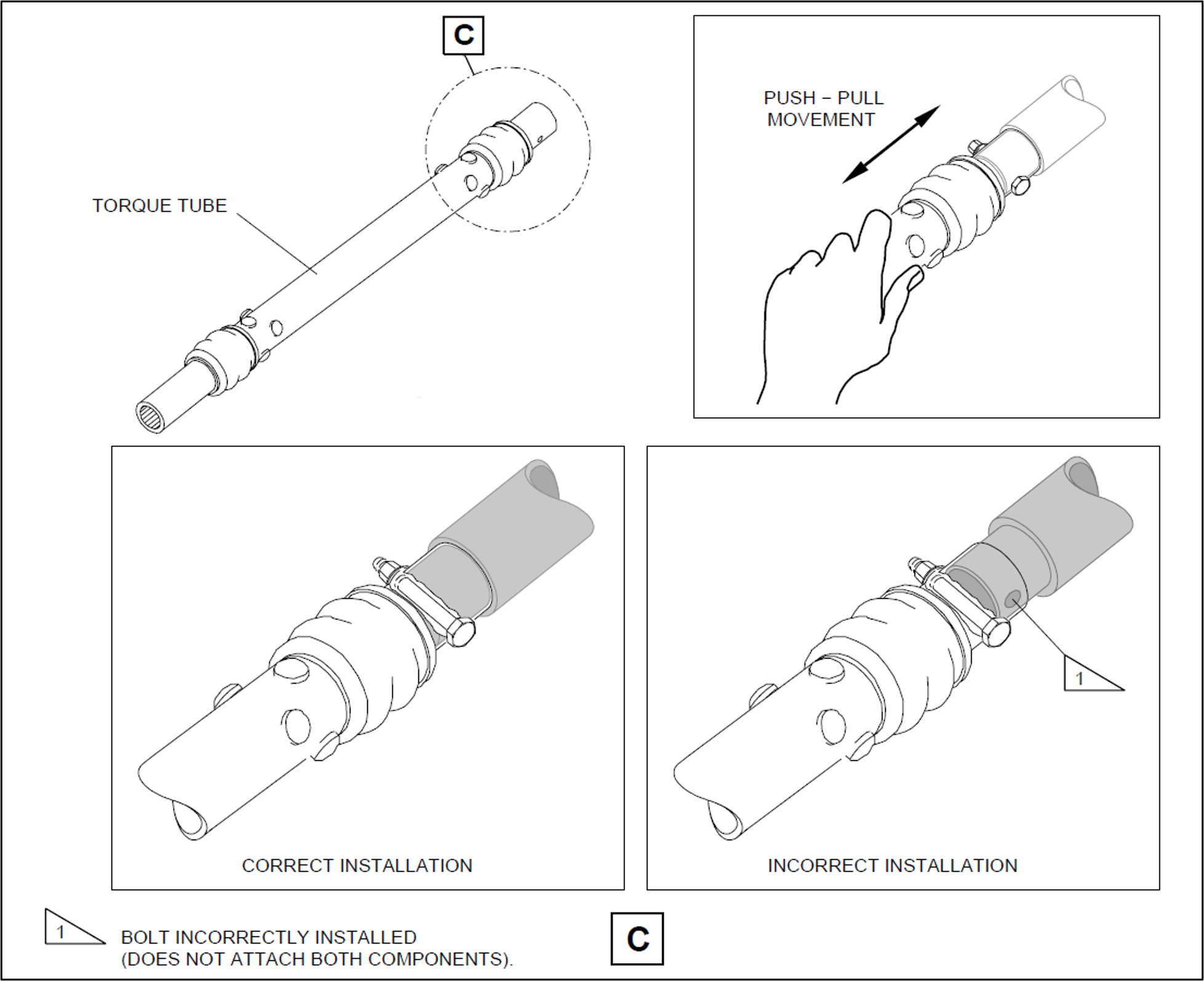
Prior to commencing work, brakes internal to the power drive units (PDUs) (which drive the flap and slat torque tubes) were electrically released as required by the aircraft maintenance manual (AMM) procedure. The AMEs printed a copy of the relevant AMM procedure, and worked together on the torque tube driving the left-wing outboard actuator for slat number 4. The PDU brakes were also required to be released prior to installing the torque tubes, however, it could not be established whether this took place (the PDU brakes reapply when power is removed). After refitting the outboard actuator torque tube, a push-pull check was carried out to ensure it was locked in place, as required by the AMM. Unknown to the AMEs, when this torque tube was refitted, it had not been positioned far enough onto the actuator’s splined shaft for the locking bolt to secure it (Figure 1, lower right). The locking bolt was inadvertently installed beyond the end of the spline (shown in grey) rather than through the hole as required.
One AME then continued work on the left wing and the other moved to the right wing slat drive system to work alone. The remaining slat torque tubes were correctly fitted.
After this work was completed, the LAME inspected the installation of the torque tubes and their locking bolts, and a second LAME carried out an independent inspection[3] of the work. The heavy maintenance check was completed in March 2025, and the aircraft was returned to service.
On 15 April 2025, 50 flights after returning to service from heavy maintenance, the aircraft was being operated on a passenger transport flight from Sydney, New South Wales, to Launceston, Tasmania, by Alliance Airlines for QantasLink. After commencing approach to Launceston, the flight crew received multiple caution messages[4] on the aircraft’s engine indicating and crew alerting system (EICAS) including a SLAT FAIL caution. The flight crew discontinued the approach and requested clearance from air traffic control for vectors[5] so they could action the relevant quick reference handbook (QRH) checklists for the caution messages.
The flight crew completed the QRH checklist. As the slat failure would require landing with the slats and flaps up, the flight crew elected to divert to Melbourne Airport, Victoria, as it had the longest available runway in the region. The flight crew declared a PAN PAN[6] and commenced the diversion to Melbourne. After climbing to 19,000 ft the aircraft was flown to Melbourne at 220 kt as required by the QRH because of the slat failure. The aircraft landed at Melbourne without further incident.
Post-flight inspection
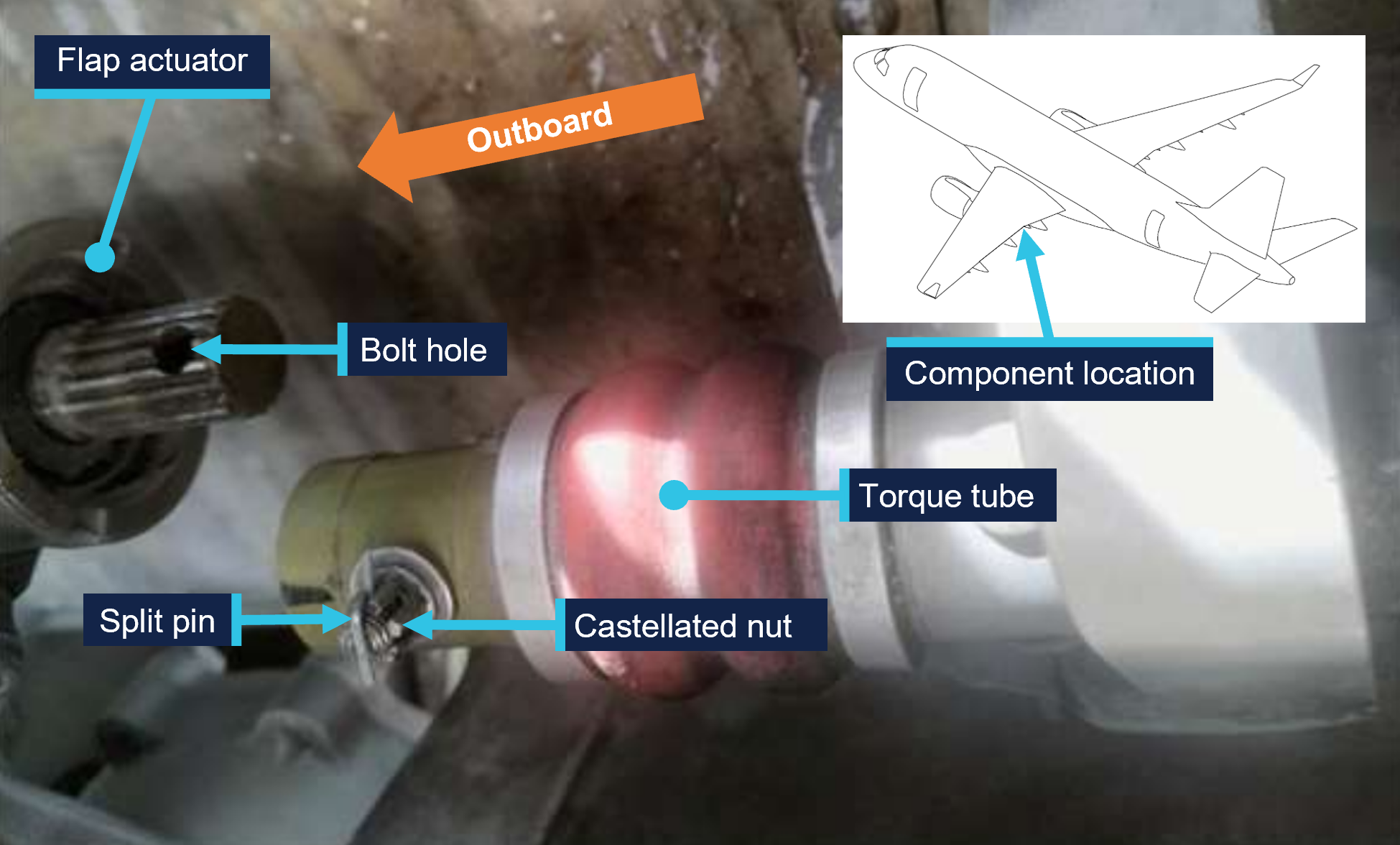
Post-flight inspection determined that the torque tube for the left wing slat number 4 outboard actuator had disconnected as the locking bolt fitted to the torque tube had not passed through the corresponding hole in the actuator’s splined shaft when it was last refitted (Figure 2).
Figure 2: VH-UZD left wing outboard actuator for slat number 4 and torque tube, shown disconnected after the occurrence flight
Source: Alliance Airlines, annotated by the ATSB
Context
Aircraft information
The Embraer ERJ 190-100 IGW (E190) is a narrow-body aircraft used for air transport operations and powered by 2 General Electric CF34-10E5 turbofan engines. VH-UZD was manufactured in Brazil in 2008 and registered in Australia on 31 January 2022.
Embraer E190 slats and flaps
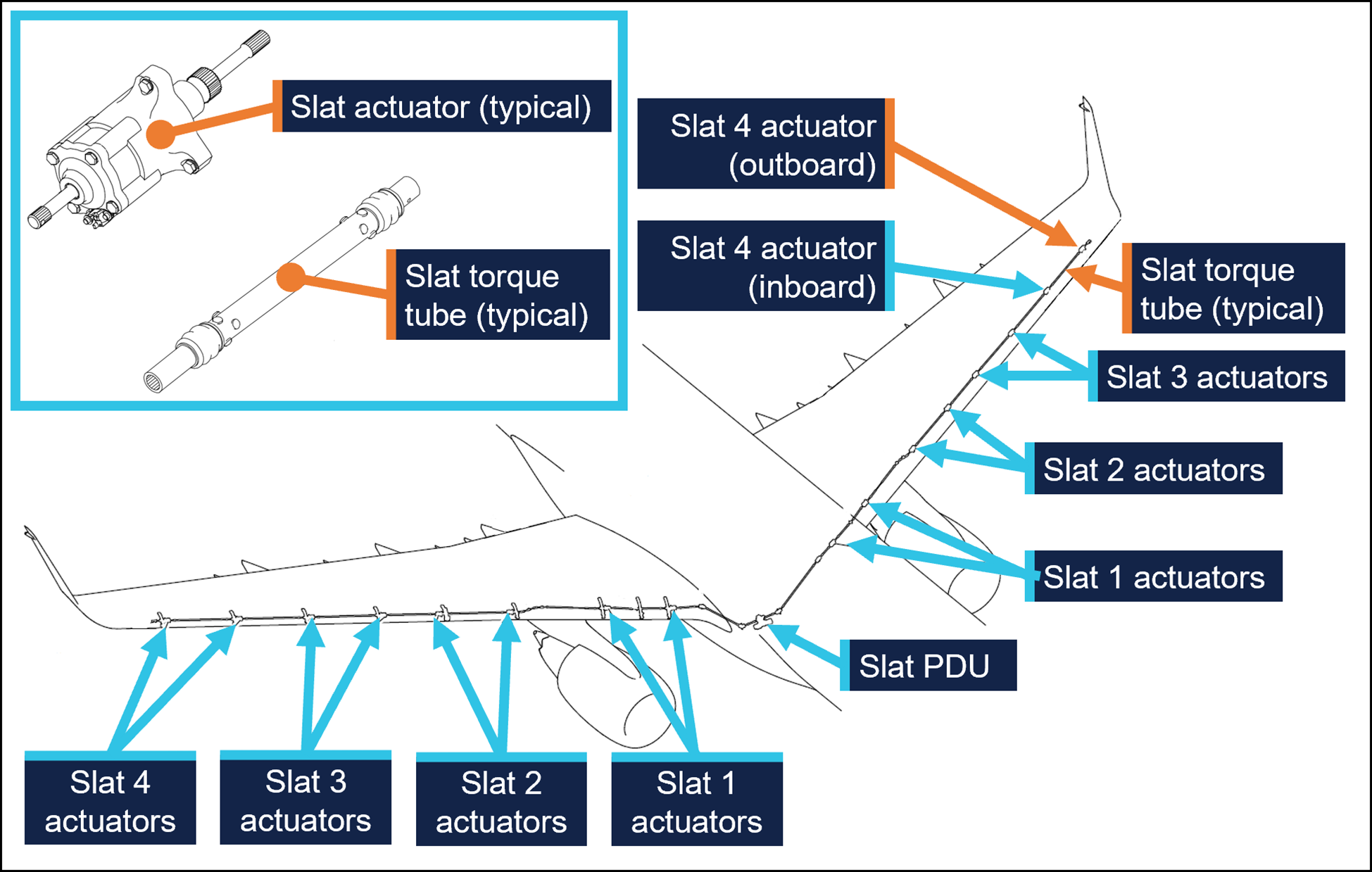
The E190 is fitted with devices to increase the lift produced by its wings during take-off and landing. On the leading edges of the wings there are 8 slat panels and on the trailing edges of the wings there are 4 flap panels (Figure 3), where each set (slats/flaps) extends and retracts together.
Figure 3: Embraer E190 slats and flaps
Source: Embraer, annotated by the ATSB
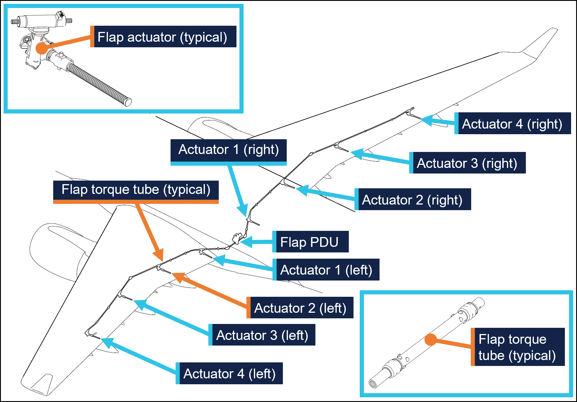
Slat and flap extension and retraction is controlled from the cockpit by using the slat/flap control lever (SFCL). When the SFCL is moved from its 0 (up) position,[7] the flap and slat power drive units (PDUs) drive torque tubes which in turn drive actuators, transferring the rotary motion of the torque tubes to linear motion that extends the slats and flaps (Figure 4 and Figure 5).
Each PDU has 2 internal brakes that are engaged under spring force and released electrically, such that the brakes would re-engage when power is removed. There are 26 torque tubes in the slat drive system and 22 torque tubes in the flap drive system.
In the event of a slat or flap failure, redundant detection and protection systems prevent them operating in such a way that may compromise safety of flight.
Figure 4: Embraer E190 slat drive system
Source: Embraer, annotated by the ATSB
Figure 5: Embraer E190 flap drive system
Source: Embraer, annotated by the ATSB
Maintenance requirements
The slat and flap torque tubes are removed periodically for the actuator splines to be lubricated with grease. They may also need to be removed to replace associated components. A detailed visual inspection of the slat and flap drive system is also carried out periodically and includes a requirement to check that the torque tubes are correctly secured in place by their locking bolts. No detailed visual inspections of the slat system had been required between the heavy maintenance in November 2024 and the occurrence flight.
The procedure to remove and install the slat and flap torque tubes is detailed in the aircraft maintenance manual (AMM). As part of this procedure, the slat or flap PDU brakes are disengaged electrically to eliminate any residual torque in the system that may impede (through friction) the removal of the torque tubes. For the same reason, the brakes must also be disengaged for their installation.[8] Embraer advised the ATSB of the importance of removing residual torque for the installation.
Rockhampton Aviation Maintenance noted during its investigation into the occurrence that excessive amounts of grease on the actuator splines can produce hydraulic resistance to re-assembly of the torque tube and therefore no more than what is required to lubricate the splines should be applied. It could not be determined whether this occurred during the maintenance of VH-UZD. The installation procedures for torque tubes in the AMM requires the old grease to be removed, new grease to be applied, and any unwanted grease to be removed prior to assembly.
The torque tubes interface with other components via splined shafts and are secured by locking bolts in conjunction with castellated nuts and split pins to prevent their inadvertent disconnection. There are 24 locking bolts in the slat drive system and 18 locking bolts in the flap drive system, all with this configuration.
The AMM describes and illustrates a ‘push-pull’ check to determine the locking bolt has been correctly installed and had showed representative examples of correct and incorrect installation (Figure 1).
The torque tube locking bolts pass through holes close to the end of each actuator’s splined shaft. A correctly installed torque tube is visually apparent by less exposed splines (Figure 6). If a slat torque tube is incorrectly positioned[9] on a slat actuator the locking bolt will not capture the splined shaft and can lead to the torque tube disconnecting and slat failures.
Figure 6: Exemplar slat torque tube correctly fitted (upper image) and incorrectly fitted (lower image) to a slat actuator
A slat actuator and torque tube were correctly and incorrectly assembled on a workbench to create these images. Source: The maintenance organisation, annotated by the ATSB
Actions taken to prevent installation errors
In 2010 the AMM was amended to include the previously mentioned illustration (Figure1) showing the correct and incorrect installation of slat and flap torque tubes along with the push-pull test. This revision also added the requirement to release the PDU brakes.
Embraer communicated these changes by publishing a service newsletter SNL 190‑27‑0050 noting reports of incorrect slat or flap torque tube installation, advising that the AMM had been revised to mitigate future occurrences, and provided an overview of the revisions. This information was also published in Embraer’s safety magazine[10] (available to operators of E190s) and was contained in a document[11] published by the National Civil Aviation Agency of Brazil.
In October 2017 Embraer published an update on the issue in a document[12] that reiterated the previous actions taken to mitigate these occurrences. This document noted that from January 2005–August 2011 in the worldwide fleet of Embraer ERJ170, 175, 190, and 195 aircraft[13] there were 483 reports of slat or flap system failures. Of these, 5 were occurrences related to incorrect torque tube installation. Additionally, the document stated that the subject of incorrect torque tube installation was presented to civil aviation authorities in Europe and the Americas. It was concluded that no additional actions were required, as there were a small number of exposed aircraft, and there had been no reported events since the AMM was revised in 2010, and the manufacturer considered the issue closed.
Related occurrences
Incorrect flap torque tube installation
In late 2024, an Embraer ERJ 190-100 aircraft, registered VH-UYB and operated by Alliance Airlines for QantasLink, commenced a heavy maintenance check at a facility in Singapore. The torque tube driving the left wing flap actuator number 2 (see Embraer E190 slats and flaps) was removed to carry out flap actuator torque limiter checks. When fitted, the torque tube had not been positioned far enough onto the actuator’s splined shaft for the locking bolt to secure it.
On 10 November 2024, 35 flights after returning to service from heavy maintenance, the aircraft departed for a passenger transport flight. After take-off, the flight crew received a FLAP FAIL caution on the EICAS as the flaps were retracting. The flight crew initiated a turnback and the aircraft landed safely.
Engineering personnel later found that the locking bolt for the left wing flap actuator number 2 torque tube had not passed through the corresponding hole in the actuator splined shaft when it was last refitted (Figure 7).
Figure 7: VH-UYB left wing flap actuator 2 and torque tube
Source: Alliance Airlines, annotated by the ATSB
Other flight control event involving VH-UZD
On 18 April 2025, VH-UZD was operating from Adelaide, South Australia, to Canberra, Australian Capital Territory. When flaps were selected down, the slats began to extend but the flaps did not deploy, and the crew received multiple failure warnings. The flight crew diverted to Melbourne. Post-flight troubleshooting determined that the flap power drive unit (PDU) torque limiter had tripped, which is a problem unrelated to the investigation occurrence or the recent heavy maintenance check.
Safety analysis
Incorrect fitment of actuator torque tubes
When the torque tube for the left wing slat number 4 outboard actuator was refitted to VH-UZD in November 2024, it had not been positioned far enough onto the actuator’s splined shaft for the locking bolt to secure it in place. After re-entering service and conducting 50 flights, the torque tube disengaged from the actuator, and the slat system failed. Protection systems ensured the safety of flight was minimally affected.
Similarly, when another E190, VH-UYB, was under heavy maintenance at a different facility at around the same time, the torque tube driving the left wing flap actuator number 2 was incorrectly assembled in that the locking bolt had not passed through the hole in the actuator’s splined shaft. The torque tube disengaged 35 flights after the aircraft re-entered service and the flap system failed.
Non-detection of the error
The 2 AMEs who fitted the torque tube in VH-UZD did not identify that the torque tube had been incorrectly fitted. Further, the LAME checking this work and the second LAME carrying out the independent inspection of this work did not identify that it had been incorrectly assembled. The similar error affecting VH‑UYB also apparently remained undetected by those carrying out and certifying for the work.
As far as could be established, there were no physical or environmental factors that may have influenced the incorrect assembly of the torque tube. The work on VH-UZD was carried out in a new facility with good lighting, and access to the work area was good and could be carried out with the relevant components at eye level.
Ultimately, it is likely that not knowing the subtle difference in appearance of an incorrectly assembled slat torque tube (that is, as little as about 6.35 mm more of the actuator spline visible) contributed to the error not being detected by the 2 AMEs and the 2 LAMEs involved. Further, the remaining torque tubes in the slat drive system were correctly assembled, however their subtly different appearance did not trigger recognition that the original torque tube had been incorrectly assembled.
Available relevant information
Installation of the slat and flap drive system torque tubes is a simple task, but errors have occurred. Embraer noted that from January 2005–August 2011 in the worldwide fleet of Embraer 170, 175, 190 aircraft (all sharing similar componentry) there were 5 occurrences related to incorrect torque tube installation. The Embraer 190 has 24 locking bolts in the slat drive system and 18 in the flap drive system representing a total of 42 opportunities to incorrectly secure the torque tubes.
In 2010, Embraer made amendments to the aircraft maintenance manual to reduce the possibility of assembly errors. These were intended to remove any residual torque loads during removal and installation (by releasing the PDU brake), highlight the possibility of error with an illustration, and through the addition of the push-pull check, provide a means to detect an installation error.
These changes were communicated in multiple documents, such as a service newsletter, that were available to operators and maintainers of E190s. Review of such documents can assist in highlighting known issues and thereby prevent reoccurrence.
Findings
ATSB investigation report findings focus on safety factors (that is, events and conditions that increase risk). Safety factors include ‘contributing factors’ and ‘other factors that increased risk’ (that is, factors that did not meet the definition of a contributing factor for this occurrence but were still considered important to include in the report for the purpose of increasing awareness and enhancing safety). In addition ‘other findings’ may be included to provide important information about topics other than safety factors.
These findings should not be read as apportioning blame or liability to any particular organisation or individual.
From the evidence available, the following findings are made with respect to the flight control event involving Embraer E190, VH-UZD, 29 km south-east of Launceston Airport, Tasmania, on 15 April 2025.
Contributing factors
During scheduled maintenance, the locking bolt for the left outboard slat torque tube was not passed through the hole in the actuator’s splined shaft as the torque tube had been incorrectly positioned. The aircraft was released from maintenance, and 50 flights later, the torque tube disconnected, causing the slat system to fail.
Both licensed aircraft maintenance engineers inspecting the left outboard slat torque tube did not identify that it had been incorrectly assembled.
Safety actions
Whether or not the ATSB identifies safety issues in the course of an investigation, relevant organisations may proactively initiate safety action in order to reduce their safety risk. The ATSB has been advised of the following proactive safety action in response to this occurrence.
Safety action taken by Alliance Airlines
On 17 April 2025, Alliance Airlines issued a maintenance notice that detailed the flap torque tube disconnect affecting VH-UYB on 11 November 2024 and the slat torque tube disconnect affecting VH-UZD on 15 April 2025. This notice reiterated the aircraft maintenance manual information for the correct installation of flap and slat torque tubes.
Safety action taken by Rockhampton Aviation Maintenance
The maintenance organisation added an additional task card that is automatically issued when work is scheduled on the E190 slat system torque tubes. This task card provides guidance in addition to the aircraft maintenance manual to highlight the possibility of hydraulic lock caused by lubricant and the importance of releasing the PDU brake. Additionally, this task details a dimensional check to confirm the correct installation of torque tubes on their splined shafts. A similar additional task card was being developed for the E190 flap system torque tubes.
Sources and submissions
Sources of information
The sources of information during the investigation included:
Alliance Airlines
Centro de Investigação e Prevenção de Acidentes Aeronáuticos (Brazil)
Civil Aviation Safety Authority
Embraer
Rockhampton Aviation Maintenance
licenced aircraft maintenance engineer that made the final certification of the work
both aircraft maintenance engineers.
Submissions
Under section 26 of the Transport Safety Investigation Act 2003, the ATSB may provide a draft report, on a confidential basis, to any person whom the ATSB considers appropriate. That section allows a person receiving a draft report to make submissions to the ATSB about the draft report.
A draft of this report was provided to the following directly involved parties:
Alliance Airlines
Centro de Investigação e Prevenção de Acidentes Aeronáuticos (Brazil)
Civil Aviation Safety Authority
Embraer
Rockhampton Aviation Maintenance
licenced aircraft maintenance engineer that made the final certification of the work
both aircraft maintenance engineers.
Submissions were received from:
Embraer
Rockhampton Aviation Maintenance.
The submissions were reviewed and, where considered appropriate, the text of the report was amended accordingly.
Purpose of safety investigations
The objective of a safety investigation is to enhance transport safety. This is done through:
identifying safety issues and facilitating safety action to address those issues
providing information about occurrences and their associated safety factors to facilitate learning within the transport industry.
It is not a function of the ATSB to apportion blame or provide a means for determining liability. At the same time, an investigation report must include factual material of sufficient weight to support the analysis and findings. At all times the ATSB endeavours to balance the use of material that could imply adverse comment with the need to properly explain what happened, and why, in a fair and unbiased manner. The ATSB does not investigate for the purpose of taking administrative, regulatory or criminal action.
About ATSB reports
ATSB investigation reports are organised with regard to international standards or instruments, as applicable, and with ATSB procedures and guidelines.
Reports must include factual material of sufficient weight to support the analysis and findings. At all times the ATSB endeavours to balance the use of material that could imply adverse comment with the need to properly explain what happened, and why, in a fair and unbiased manner.
An explanation of terminology used in ATSB investigation reports is available here. This includes terms such as occurrence, contributing factor, other factor that increased risk, and safety issue.
Publishing information
Released in accordance with section 25 of the Transport Safety Investigation Act 2003
Ownership of intellectual property rights in this publication
Unless otherwise noted, copyright (and any other intellectual property rights, if any) in this report publication is owned by the Commonwealth of Australia.
Creative Commons licence
With the exception of the Commonwealth Coat of Arms, ATSB logo, and photos and graphics in which a third party holds copyright, this report is licensed under a Creative Commons Attribution 4.0 International licence.
The CC BY 4.0 licence enables you to distribute, remix, adapt, and build upon our material in any medium or format, so long as attribution is given to the Australian Transport Safety Bureau.
Copyright in material obtained from other agencies, private individuals or organisations, belongs to those agencies, individuals or organisations. Where you wish to use their material, you will need to contact them directly.
[1]Heavy maintenance is typically when an aircraft is removed from service for a period of time for more extensive inspections, checks, servicing, and modifications to be carried out.
[2]One of the AMEs had carried out this task previously. The other had experience maintaining E190s including slat and flap drive systems however had they had not previously removed and installed slat and flap torque tubes.
[3]Civil Aviation Regulation (CAR) 42G required independent inspections to be carried out on flight control systems when they were disturbed during maintenance.
[4]The caution messages presented were SLAT FAIL, SHAKER ANTICIPATED, and AOA [angle of attack] LIMIT FAIL.
[5]In this context, a vector is a heading given by air traffic control to a flight crew for navigation guidance.
[6]PAN PAN: an internationally recognised radio call announcing an urgency condition which concerns the safety of an aircraft or its occupants but where the flight crew does not require immediate assistance.
[7]The SFCL has 7 positions ranging from up (retracted) to fully extended slats and flaps.
[8]Embraer advised the ATSB that in a scenario where the PDU brakes had been released, and power was subsequently removed from the aircraft (thus reapplying the PDU brakes) this would not be expected to generate any residual torque in the slat or flap drive system. However, Embraer reiterated the importance of the PDU brakes being released when carrying out these tasks.
[9]These dimensions are for the slat actuator and torque tube interface. Dimensions vary for other components in the slat and flap systems.
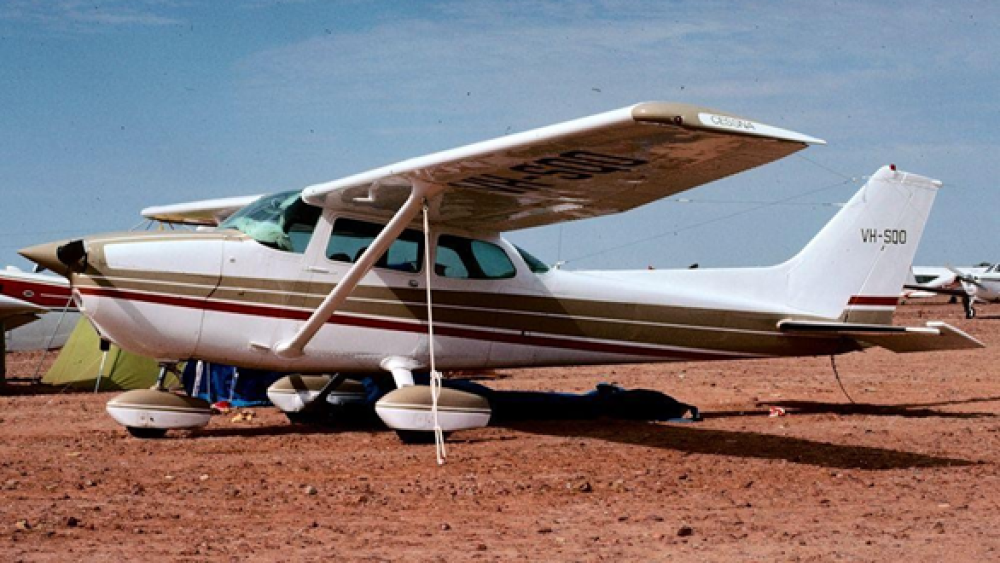
A Cessna 172 aerodynamically stalled while climbing out of a dive during mustering at Mulgathing Station in central South Australia on 27 June 2024,an ATSB investigation report details.
The aircraft was observed diving towards a group of sheep before pulling out of the dive, rolling to the left, and descending towards and impacting the ground.
The pilot, the sole occupant, was fatally injured, and the aircraft was destroyed.
No evidence indicated any issues with the aircraft’s engine, control systems or fuel prior to the accident, and incapacitation was unlikely given the pilot’s age and medical history, the investigation report notes.
“Witness reports and the position and condition of the wreckage were consistent with the aircraft aerodynamically stalling and entering a left spin at an altitude too low for recovery,” ATSB Chief Commissioner Angus Mitchell said.
The ATSB report notes the pilot held a commercial pilot licence and was endorsed for low-level flying, but not aerial mustering.
“The operator did not require an aerial mustering endorsement as the role was intended to only involve aerial spotting of livestock, to assist staff on the ground with mustering activities,” Mr Mitchell explained.
Aerial spotting activities only require a low-level endorsement, but the aircraft was observed diving towards what was believed to be a flock of sheep prior to the stall, which would constitute aerial mustering.
“This accident demonstrates the importance of pilots staying within the boundaries of their training and qualifications, to ensure an adequate margin of safety,” Mr Mitchell noted.
“It also highlights to pilots the importance of managing airspeed and bank angle to minimise the risk of an aerodynamic stall, particularly close to the ground.”
Since the accident, the station operator (also the aircraft owner and operator) has initiated a third‑party safety audit, and implemented a pilot mentoring program.
The operator is also preparing a manual for pilots on safe aerial spotting, and is undertaking a review of its safety and training standards for pilots, and its operations to ensure compliance with Civil Aviation Safety Authority regulations.
Separately, while it was unlikely it would have improved survivability in this accident, the pilot was found to not have been wearing the upper torso restraint of the lap-sash seatbelt during the accident flight.
“While not the case here, several ATSB investigations have found injuries to aircraft occupants may have been avoided, or made less severe, through the appropriate use of multipoint harnesses,” Mr Mitchell observed.
In August 2024, a Saab 340B aircraft was being operated on a scheduled air passenger transport flight from Canberra, Australian Capital Territory, to Sydney, New South Wales.
During the approach to Sydney, the flight crew reported hearing a sound consistent with a pressurisation issue and detected an increase in cabin pressure. A normal approach and landing was conducted. Post-flight inspection found a VHF antenna had separated from the fuselage with an associated fracture of the fuselage skin. The antenna remained attached to the aircraft by its cabling.
The ATSB received a request for assistance from the Civil Aviation Safety Authority (CASA) to conduct a technical examination of the antenna installation. The ATSB commenced an external investigation under the provisions of the Transport Safety Investigation Act 2003.
The ATSB has concluded the examination of the installation of the antenna and provided CASA with an examination report.
Any enquiries relating to the investigation should be directed to CASA.
Aircraft details
Manufacturer
Saab Aircraft Co.
Model
Saab 340B
Registration
VH-VEA
Serial number
340B-406
Aircraft operator
Vee H Aviation Pty Ltd
Sector
Turboprop
Operation type
Part 121 Air transport operations - larger aeroplanes
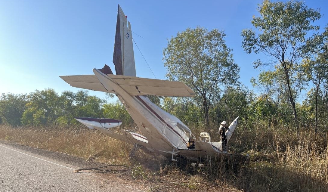
The ATSB’s investigation of a Cessna 310 forced landing accident on a highway in Western Australia’s Kimberley has identified concerns regarding operator and regulator oversight.
On 20 June 2023, a Broome Aviation operated twin-engined Cessna 310R was being used on a series of air transport flights with a pilot and passenger on board.
The planned trip was from Broome to Turkey Creek and return, with a stop during the return leg to refuel at Derby.
Before leaving Broome, the pilot had used software provided by the operator to calculate the projected fuel consumption, but they did not know how to input forecast winds into the software. In addition, the pilot did not intend to use all the available fuel in the aircraft’s auxiliary tanks and did not take this into consideration in their planning.
ATSB calculations, which included wind considerations, found the pilot’s planned route from Broome to Turkey Creek to Derby could not be achieved while maintaining fixed reserve and contingency fuel.
Further, the investigation found that the pilot did not monitor or manage fuel correctly during the flights, resulting in the depletion of fuel in the main tanks.
Unable to maintain altitude, the pilot conducted a forced landing on a highway, about 5 km short of Derby Airport, during which the aircraft struck a tree and came to rest off the side of the road
ATSB Chief Commissioner Angus Mitchell noted the preventable nature of fuel mismanagement, a regular contributing factor in aviation accidents.
“Pilots are responsible for ensuring there is sufficient fuel prior to flight, and that they are familiar with their aircraft’s fuel system,” he said.
“In this case, the ATSB found the pilot’s lack of understanding of the fuel system was not detected by the operator due to a lack of consolidation training, and limited to no operational oversight.”
In the eight months prior to this accident, the operator transitioned its pilots to the Cessna 310, which has a relatively complex fuel system, with limited supervision, guidance and support.
Mr Mitchell said it was best practice for operators to provide its pilots the opportunity for skill consolidation during and following the initial training on a new aircraft type.
“The investigation also found that current and former Broome Aviation pilots reported experiencing pressure not to report aircraft defects on maintenance releases, and pilots experienced or observed pressure from management to fly aircraft they considered unsafe,” he continued.
“A reporting culture – where employees are comfortable to report all safety concerns and maintenance issues – is a safe culture.”
Mr Mitchell urged pilots to report maintenance issues through the appropriate channels within their operation, and to take action if they are pressured not to.
The ATSB’s investigation also identified a number of findings relating to CASA’s oversight of Broome Aviation before and after the accident.
Prior to the accident, CASA conducted a level 2 surveillance activity on Broome Aviation in response to a complaint from a former pilot. After the accident, it conducted a level 1 surveillance activity in response to further complaints.
“In both cases, the subjects of these complaints were not properly considered by the CASA surveillance activities,” Mr Mitchell explained.
The investigation also identified CASA had approved a head of flying operations (HOFO) for Broome Aviation six months before the accident via an abbreviated assessment, due to the expectation it was an interim appointment.
“However, when the HOFO subsequently remained in the position for much longer than expected, including staying on in the role when they returned to work as a pilot and alternate HOFO at their former operator, CASA did not fully assess the HOFO’s ability to do this.”
Broome Aviation has taken a range of safety actions in response to the accident, the ATSB’s investigation, and CASA’s audits.
These include updating its operations manual, incorporating an in-flight fuel management procedure, and appointing a full time HOFO and alternative HOFO.
It has also modified its check and training system, changed processes to ensure all defects are reported, and has implemented a safety management system in line with the current regulations, with monthly safety meetings now being held to address safety concerns.
CASA has also advised it will consider the issues of organisational pressure when it conducts its next surveillance event on the operator.
Finally, Mr Mitchell said the accident again demonstrated the importance of pilots and passengers wearing all available restraints.
The pilot, who was not wearing their sash-type upper torso restraint, sustained avoidable head injuries during the collision.
The passenger sustained minor injuries, and the aircraft was substantially damaged.
“It was very likely the severity of the pilot’s head injuries would have been reduced if they had been wearing the available upper torso restraint,” Mr Mitchell concluded.
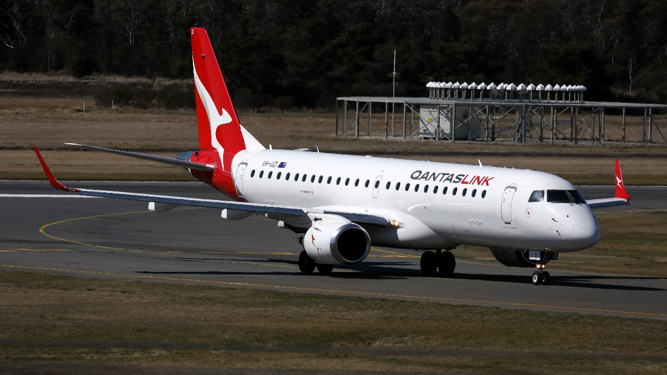
An E190 airliner’s approach became unstable after the flight crew inadvertently disengaged the desired approach mode, and then did not effectively monitor the aircraft’s flight path.
On 9 May 2024, an Alliance Airlines-operated Embraer E190 was stabilised on the Brisbane runway 19L instrument landing system (ILS) approach, in darkness, with 2 flight crew and 29 passengers on board, an ATSB investigation report details.
The captain, who was pilot flying, disconnected the autopilot and enabled the flight path reference line on their primary flight display in order to assist with manually flying the approach.
The captain then asked the first officer, who was pilot monitoring, to adjust this reference line to the ILS glideslope angle for runway 19L.
“The first officer had a correct understanding of the situation, but inadvertently pushed the flight path angle button – a ‘slip’ type error, which unintentionally disengaged the ILS approach mode,” ATSB Director Transport Safety Stuart Macleod explained.
Surprised by the mode change, over the next 10 seconds the flight crew focused on resolving it, rather than conducting a go-around.
“During this time, the pilots were not effectively monitoring the aircraft’s flight path, and it exceeded the glideslope limit requirement of the operator’s stabilised approach criteria,” Mr Macleod observed.
Once the captain identified the aircraft was low, they began to increase pitch, but at this time, the enhanced ground proximity warning system (EGPWS) generated a glideslope warning, in response to which, as it was night, the operator’s procedures required the flight crew to perform the operator’s terrain avoidance manoeuvre.
Subsequently, the flight crew instead continued the approach and landing.
Mr Macleod said the incident highlights how quickly a disruption can result in an aircraft transitioning from a stable to unstable approach.
“When pilots are faced with unexpected events, effective crew resource management, with each crewmember performing their procedurally assigned roles of flying and monitoring, is essential to ensuring the continued safety of flight while the disruption is investigated and managed,” he added.
“Early recognition of an unstable approach and prompt execution of a go around, rather than continuing the approach, significantly reduces the risk of approach and landing accidents.
“Further, flight crews must also execute the correct response to ground proximity warning systems alerts without hesitation to ensure obstacles or terrain are avoided.”
In response to the incident, Alliance Airlines has amended its cyclic training program, issued a relevant Operational Notice, and conducted a thematic review of unstable approaches, analysing data for further review.
Occurrence Briefs are concise reports that detail the facts surrounding a transport safety occurrence, as received in the initial notification and any follow-up enquiries. They provide an opportunity to share safety messages in the absence of an investigation. Because occurrence briefs are not investigations under the Transport Safety Investigation Act 2003, the information in them is de-identified.
What happened
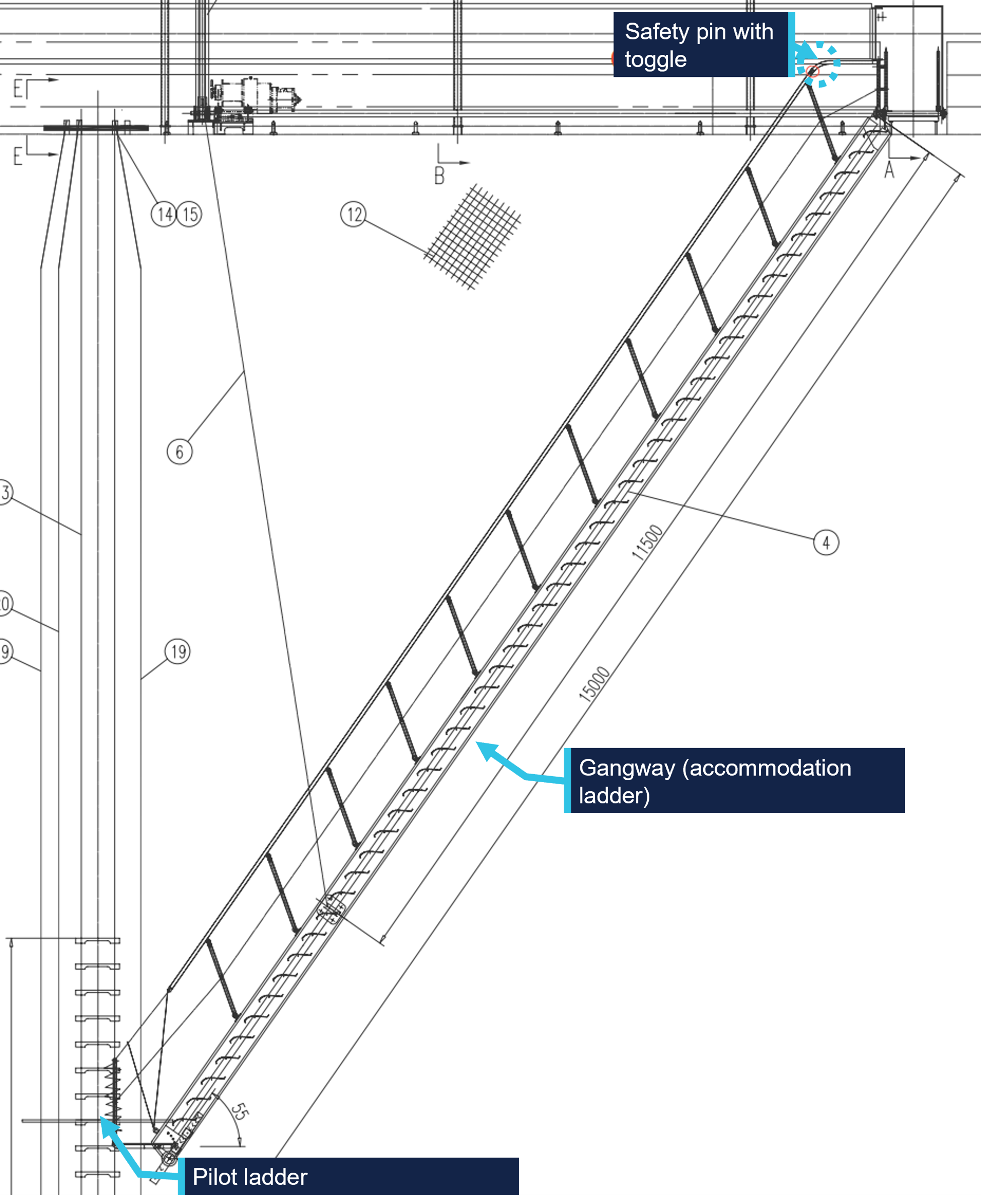
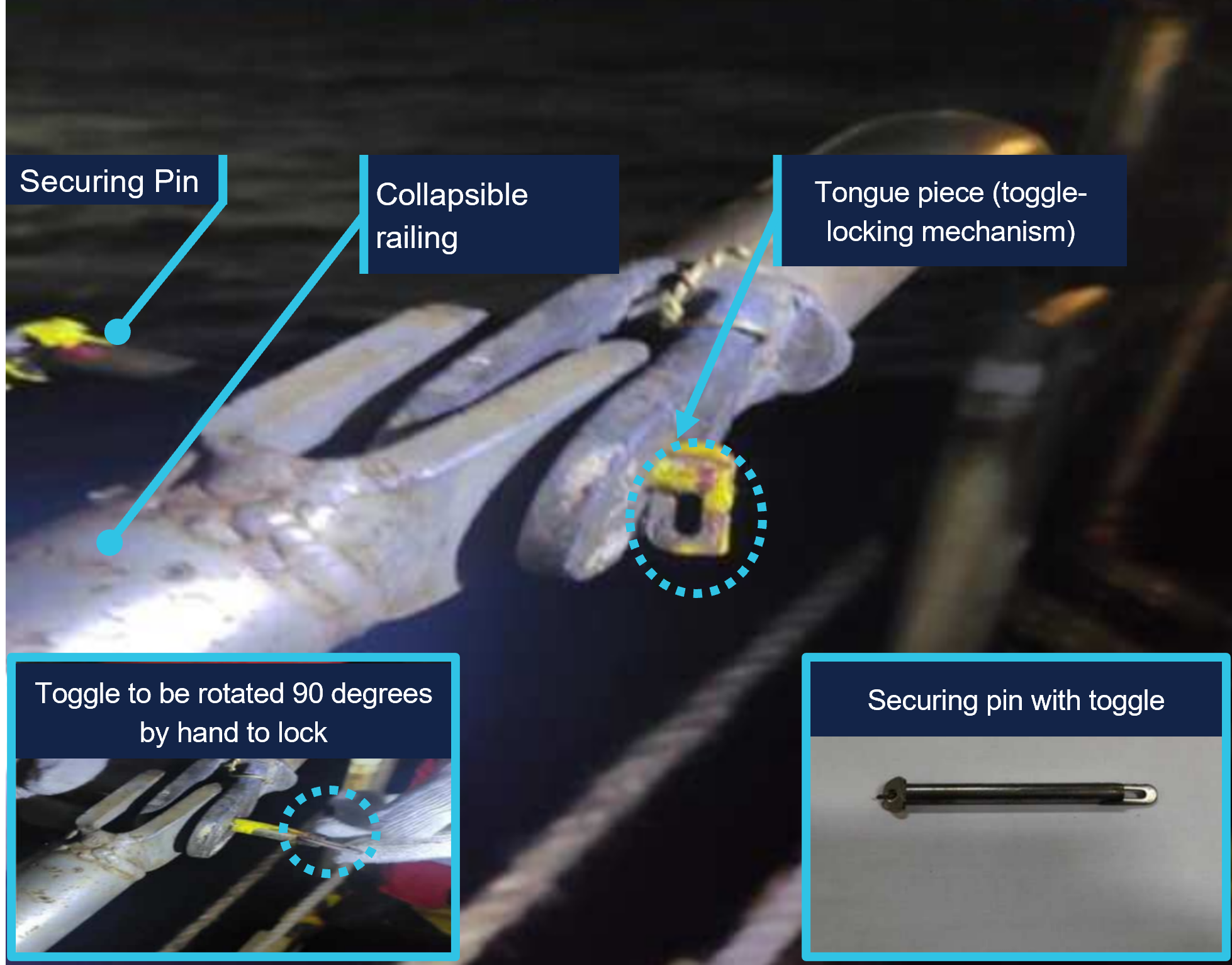
At about 1920 local time on 4 March 2025, a cargo ship arrived at the pilot boarding ground for the port of Gladstone, Queensland to board a harbour pilot. The harbour pilot had travelled to the boarding ground by boat and was planning use the pilot ladder to board the ship. The ship’s crew rigged the pilot ladder in combination with the gangway (combination ladder)[1] (Figure 1) on the starboard side following shipboard procedures.
Figure 1: Combination ladder schematic diagram
Source: Ship’s manager, annotated by the ATSB
The gangway has an inboard and outboard railing. During the rigging process for pilot embarkation, the gangway is lowered, and the railing latched securely. However, on this occasion the tongue piece on the safety latch on the outboard railing was not rotated to lock the tongue at the required 90° angle (Figure 2), resulting in the securing pin not being correctly inserted. As the ship rolled and vibrated, the securing pin gradually worked its way loose. This movement eventually caused the pin to completely dislodge from its position, compromising the stability of the outboard railing.
The pilot began boarding the ship at 1925 local time. When they grasped the handrail while transitioning from the pilot ladder to the gangway, the gangway railing on outboard side partially collapsed when the locking pin dislodged. The pilot was not injured.
Figure 2: Securing pin arrangements
Source: Ship’s manager, annotated by the ATSB
Safety action
Following the occurrence, the ship’s manager advised that the following safety actions had been taken:
Crew members have received extra training to ensure they fully understand the importance of properly engaging the securing pin's safety latch, with a focus on the correct procedure for rotating the tongue to the required angle to engage the locking mechanism. Additionally, a comprehensive review of the combination ladder securing arrangements has been started, including verification procedures for securing pins and further crew training on proper locking mechanisms.
The ship's maintenance schedule now includes more frequent and thorough inspections of all securing mechanisms, including the securing pins of the pilot ladder and gangway. These inspections aim to identify and fix any potential issues before they lead to incidents.
A new protocol has been implemented requiring a double-check of all securing mechanisms before use. This protocol mandated that 2 crew members independently verified that the securing pins were properly locked and secure.
Pre-use inspection checklists have been updated to ensure securing pins are correctly engaged before pilot transfers.
The lessons from this incident have been shared with all ships managed by the ship manager, including training on how to correctly insert the securing pin in the locked position.
Safety message
This occurrence highlights the importance of properly securing pilot transfer arrangements, particularly ensuring that all locking mechanisms, including securing pins, are fully engaged. Ship operators, masters, and crew should perform thorough pre-use checks to verify the correct engagement of safety mechanisms before personnel transfers. Compliance with SOLAS[2] Chapter V, Regulation 23 and ISO 799-1 standards (industry best practices) assists preventing similar failures in the future.
About this report
Decisions regarding whether to conduct an investigation, and the scope of an investigation, are based on many factors, including the level of safety benefit likely to be obtained from an investigation. For this occurrence, no investigation has been conducted and the ATSB did not verify the accuracy of the information. A brief description has been written using information supplied in the notification and any follow-up information in order to produce a short summary report, and allow for greater industry awareness of potential safety issues and possible safety actions.
[1]The use of a ship’s pilot ladder in conjunction with the ship’s accommodation ladder is also referred to as a combination ladder.
[2]International Maritime Organisation (IMO), 1974, The International Convention for the Safety of Life at Sea, 1974, as amended (SOLAS 1974), IMO, London.
Action has been taken to improve the identification of track misalignment and geometry defects on Australia’s federally managed railways, after a passenger train impacted part of a derailed freight train in Victoria.
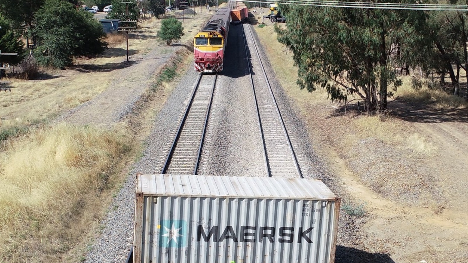
On 29 January 2020, several of a Pacific National freight train’s wagons derailed and it parted into three sections near Barnawartha, in northern Victoria, while travelling on the Australian Rail Track Corporation (ARTC) interstate rail network towards Albury, New South Wales.
A final report from an investigation by Victoria’s Office of the Chief Investigator (OCI), which investigates rail occurrences in Victoria under a collaboration agreement with the ATSB, notes the front section of the freight train, including three derailed wagons, continued after the initial incident.
“A short time later, the driver of a V/Line passenger train, approaching from the opposite direction on adjacent track, observed dust and the approaching freight train, and applied the brake on their train,” OCI Director Investigations Sri Ranasingha said.
At about the same time, the drivers of the freight train reported seeing the passenger train and observing a brake pipe airflow indication, and the freight train began slowing.
“However, the trains could not be stopped before passing, and the passenger train hit a shipping container on a derailed wagon of the freight train, resulting in minor damage.”
Fortunately, the passenger train stopped about 50 m short of another shipping container, which had fallen from the freight train and was resting across both tracks. No injuries were reported.
The OCI transport safety investigation found the derailment had occurred as the wagons travelled over a vertical track geometry defect and a probable lateral track misalignment. The vertical track geometry defect was present immediately prior to the derailment location and the lateral track misalignment probably formed under train 4MC2.
“This defect was not identified in ARTC's exceedance report, as track geometry was being assessed against incorrect limits,” Mr Ranasingha said.
“Furthermore, the investigation identified ARTC’s system for reducing the risk of track misalignment, and its associated procedures, did not lead to locations at or adjacent to the derailment being identified as special locations potentially vulnerable to track instability.”
In response to the incident, ARTC has made several changes to procedures and standards relating to track misalignment, track geometry defects and mud hole management.
These targeted safety actions aim to improve ARTC’s capacity to identify locations that may become vulnerable to track instability.
“In addition, ARTC has undertaken to review available technology to improve its stress-free temperature testing capability,” Mr Ranasingha noted.
This is relevant to the incident, as the extent that changes to rail stress may have contributed to the lateral misalignment could not be assessed as the stress-free temperature was not being measured.
Mr Ranasingha said the incident highlighted the potential roles of track geometry and instability in derailment.
“Track managers are encouraged to ensure standards and processes are effective at identifying and rectifying geometry and stability issues, to ensure derailment risk is managed.”
On 11 March 2025 a Bell Helicopter 412EP was conducting a flight from a hospital in Hobart, Tasmania to another hospital in Latrobe, Tasmania. In addition to the pilot, there was an aircrew officer (ACO) and 2 medical personnel on board. At about 1430, the pilot flew downwind adjacent to the helicopter landing site (HLS) and checked the area around it, paying particular attention to a construction site within the hospital grounds. Visibility in the area was good.
After turning and commencing their approach to the HLS, the pilot noticed a temporary roadworks sign beginning to move. The sign had been positioned outside the hospital grounds on a nearby road. The pilot, ACO and the medical personnel on board the helicopter later recalled that they did not detect the sign until it began to move. The pilot considered that the application of power required for a go‑around would exacerbate the movement of the sign, and continued their approach to the HLS without delay. The helicopter landed safely and there were no injuries or property damage from the sign’s movement, which had been blown about 15 m from its original position.
It was later determined that the temporary roadworks sign was of the corrugated plastic ‘corflute’ type and was not secured or weighted to prevent movement.
Arrivals to the HLS are normally communicated to ground staff 45 minutes and 10 minutes prior. At these times ground staff inspect the area around the HLS and inform any staff that may be working there. On the day of the occurrence, the presence of the sign was not detected by ground staff during their inspections.
Safety action
The operator established contact with the roadworks contractor to inform them of the hazards associated with helicopter operations around the HLS and to request that the contractor take action to prevent further occurrences. Acting on the operator’s request, the contractor took actions to prevent the movement of its signs in the future. Additionally, the operator communicated the occurrence to its pilots and crewmembers and reiterated existing procedures.
Safety message
To advise helicopter medical transport operators and hospital helicopter landing site operators of the hazards associated with helicopter rotor downwash, the ATSB published aviation data and analysis report Safety risks from rotor wash at hospital helicopter landing sites (
) on 27 September 2023. While this report was primarily focused on incidents that occurred after the introduction of AgustaWestland AW139 helicopters for medical transport, the report provides strategies to manage the risk of rotor downwash at hospital HLS. From the air, pilots operating into hospital HLS may not be able to see hazards in the vicinity that could be affected by the helicopter’s rotor wash during approach or departure. Hospital HLS operators should ensure these hazards are mitigated by implementing ongoing risk controls, such as ensuring that a comprehensive inspection of the surrounding area is conducted prior to a helicopter’s arrival or departure.
About this report
Decisions regarding whether to conduct an investigation, and the scope of an investigation, are based on many factors, including the level of safety benefit likely to be obtained from an investigation. For this occurrence, no investigation has been conducted and the ATSB did not verify the accuracy of the information. A brief description has been written using information supplied in the notification and any follow-up information in order to produce a short summary report, and allow for greater industry awareness of potential safety issues and possible safety actions.
An ATSB investigation interim report outlines the sequence of events leading up to the collision of a container ship with the berthed tall ship STS Leeuwin II in Fremantle last August.
The 333 m, Singapore-flagged container ship Maersk Shekou was being piloted towards its assigned berth in Fremantle’s inner harbour when it collided with and substantially damaged STS Leeuwin II alongside Victoria Quay on the morning of 30 August 2024.
The ATSB’s interim report, which contains no findings or analysis, notes the container ship had arrived off Fremantle eight days prior to the accident.
The vessel and its crew waited a week offshore, first due to industrial action at the port and then due to unfavourable weather, before two harbour pilots boarded just before 5am on the day of the accident.
“During the initial southerly transit, wind gusts of up to 50 knots from the south-west, almost on the bow of the vessel, were being encountered,” explained ATSB Chief Commissioner Angus Mitchell.
“Around an hour later, as the ship entered port, three tugs were connected but with persistent winds now on the starboard quarter, up to 30° of port helm was required to maintain the course.”
As the Shekou’s bow was in line with South Mole, the pilot ordered a course of 083° as the last tug was being made fast on the starboard shoulder and the vessel was making good around 7.5 knots. Despite carrying hard port rudder, the vessel was experiencing a 1°/min rate of turn to starboard and struggling to maintain the entry course of 083°.
In a further attempt to bring the vessel’s head to the ordered course, the pilot ordered full ahead on the main engine. This action combined with the tugs eventually brought the course from 087° to 086°, when the helmsman, without positive oversight of the pilot, then applied 30° of opposite starboard helm to stop the turn and steady on the previously ordered course of 083°.
“Fifteen seconds later, the primary pilot realised they were in trouble with the Leeuwin now almost right ahead, and the ship’s heading was no longer continuing to turn to port as expected, and as required to navigate the bend,” Mr Mitchell explained.
The tug on the starboard shoulder then had to abandon its position due to the danger of being crushed between the quay and the closing hull of the Shekou.
“Moments later, the starboard bow collided with the Leeuwin, dismasting it, with the two crew members onboard escaping via the gangway just on impact,” Mr Mitchell said.
“The outermost stack of the containers onboard the Shekou then collided with the roof of the WA Maritime Museum as the vessel’s starboard quarter continued to swing around and contact the wharf.”
The ship was subsequently brought back under control in the inner harbour, and conducted to its berth.
To date, the ATSB has interviewed the vessel’s master and crew, along with both pilots, tug skippers, and port operational staff.
It has also reviewed relevant communications, bridge recordings, port procedures, weather data, and the vessel’s logs and records.
As the ATSB investigation continues, it will review and examine pilot and crew actions including bridge resource management, the ship’s safety management system, weather information and port and pilotage procedures for inbound vessels at Fremantle.
Mr Mitchell said a final report, with safety analysis and findings, would be released at the conclusion of the investigation.
“Should a critical safety issue be identified during the course of the investigation, the ATSB will immediately notify relevant parties so appropriate and timely safety action can be taken,” he concluded.
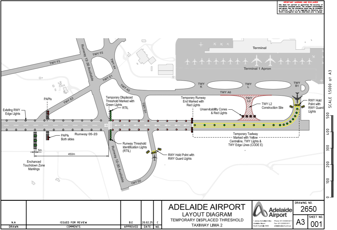
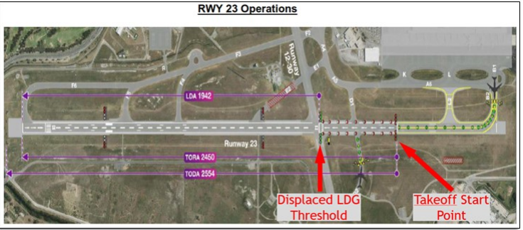
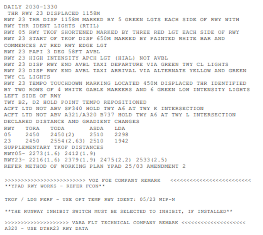
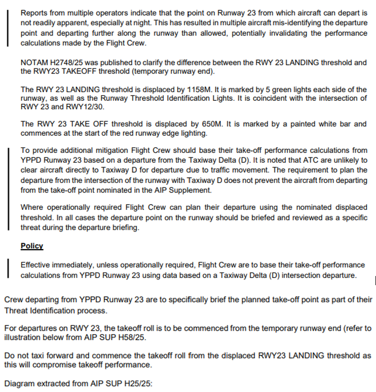
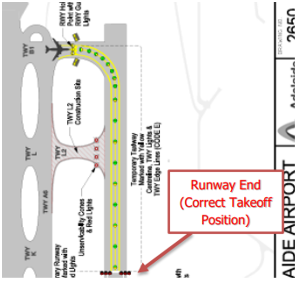
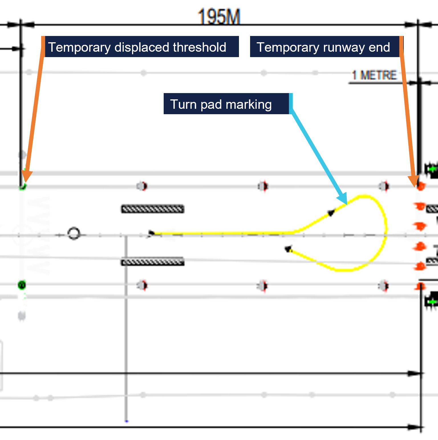
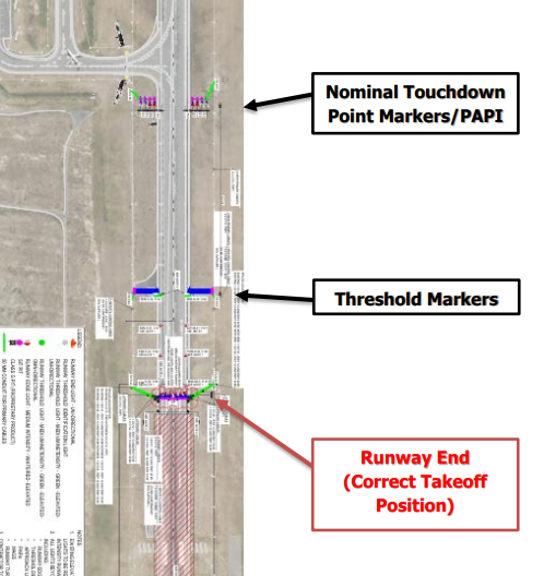
From 31 March to 20 May 2025, taxiway construction works were carried out at Adelaide Airport, South Australia. To accommodate the works, the runway 23 start of take-off (SOT) position was temporarily displaced 650 m beyond the normal runway start, with the runway 23 landing threshold displaced a further 508 m beyond the temporary SOT position.
Subsequently, 13 occurrences were identified (during both daylight and night‑time), in which aircraft commenced the take-off from the displaced threshold, instead of the intended SOT position. As the flight crews had used take-off performance data based on commencing the take-off from the SOT position, this increased the risk of a runway overrun, especially if a high speed rejected take-off had been required.
What the ATSB found
The ATSB found that the flight crews of multiple aircraft misidentified the start of runway 23 due to confusing temporary markings and lights. This resulted in several take‑offs commencing from the displaced threshold using performance parameters for a longer runway.
The ATSB also found that lights and markings in accordance with the Civil Aviation Safety Regulations Part 139 Manual of Standards (MOS) did not recommend or provide standardised options for movement area guidance signs or other visual aids to draw flight crew attention to the SOT position, especially those distant from a displaced threshold and not coincident with a taxiway/runway intersection.
Additionally, the ATSB found that the initial NOTAM released at the start of the runway works used inconsistent terminology for the runway end, did not refer to the white line marking the SOT position, and referred to red runway end lights not visible to pilots departing on runway 23.
For one of the reported occurrences, the ATSB found that the aerodrome controller did not challenge 2 incorrect readbacks of displaced threshold instead of displaced runway end, which likely contributed to the flight crew commencing the take-off from the displaced threshold instead of the SOT position.
The ATSB also found that proactive action taken by aircraft operators to highlight the SOT position, and require use of performance data and/or take-off from a runway intersection where possible, probably reduced the total number of occurrences. Similarly, air traffic control interventions likely reduced the total number of occurrences.
What has been done as a result
The Civil Aviation Safety Authority (CASA) intends to publish an updated Part 139 MOS in quarter 4 of 2025 to incorporate Amendment 15 to Annex 14 Volume1. CASA is considering Amendment 18 to Annex 14 Volume I for future incorporation in the MOS.
CASA is also considering visual aids to mark a temporary start of take-off run position (SOT), where SOT is not collocated with the permanent runway end, or a temporary displaced threshold, as part of the development of Advisory Circular (AC) 139.C-15 Safe planning and conduct of aerodrome works. A report will be submitted for consideration to the National Runway Safety Group in November 2025. To assist in the development of method of working plans, the AC includes a sample list of stakeholders and purposes for airports to consider. CASA intends to publish AC 139.C-15 in quarter 4 of 2025.
Safety message
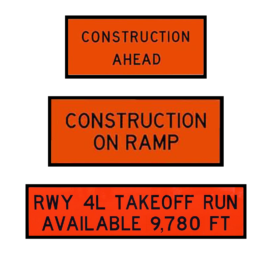
The International Civil Aviation Organization (ICAO) Annex 14 – Aerodromes, Volume I Aerodrome Design and Operations, detailed standards for aerodrome markings, lights and signs. Although this included standards for a displaced threshold and a displaced runway end, different countries implemented varying lights and markings, and none were specific for highlighting a displaced start of take-off position. However, the United States Federal Aviation Administration had implemented construction signage, including one for the start of take-off position, showing the start of take-off run distance available. That signage was scheduled to be incorporated in the next amendment to Annex 14.
The standards also differed depending on whether the displacement was permanent or temporary. Mitigation of the elevated risks associated with aerodrome works and displaced thresholds, to as low as reasonably practicable, requires use of best practice markings and lights. This should therefore be incorporated in the regulations and standards such that when aerodrome operators comply with the standards, the visual cues are unlikely to be confusing for pilots.
It is also essential that pilots review all available information to understand the visual cues necessary to identify both the threshold and the start of take-off positions. This investigation highlights that the visual cues for the SOT position may be more difficult to identify than those for aircraft landing on a displaced threshold. The risks for departing aircraft in using the incorrect start of take-off position include becoming airborne closer to the (far) runway end than expected, or a runway excursion if a rejected take-off is conducted.
The ICAO Global Aviation Safety Plan identified runway safety as a global safety priority. Analysis of international runway safety accidents and incidents found runway excursions to be the highest risk category. Management of airport works was identified as a key contributing factor to runway excursions. Runway safety during runway works requires a system-wide approach including:
flight crew: reviewing all available documentation and information, and asking air traffic control if they are unsure
airport operators: ensuring visual aids are in accordance with the standards, and where necessary, using additional conspicuous visual cues such as construction signage soon to be incorporated in ICAO Annex 14 to ensure visual cues are not confusing for flight crew
aircraft operators: disseminating information to flight crew that clearly identifies key visual cues; monitoring flight data analysis programs to identify runway events and applying appropriate risk management
air traffic service providers: using clear plain language when no standard phraseology applies, and assisting flight crews by providing timely information when requested or when they identify a threat to safety
regulators: ensuring effective safety management; establishing and maintaining best practice standards.
The occurrences
Adelaide Airport runway 23 temporary layout
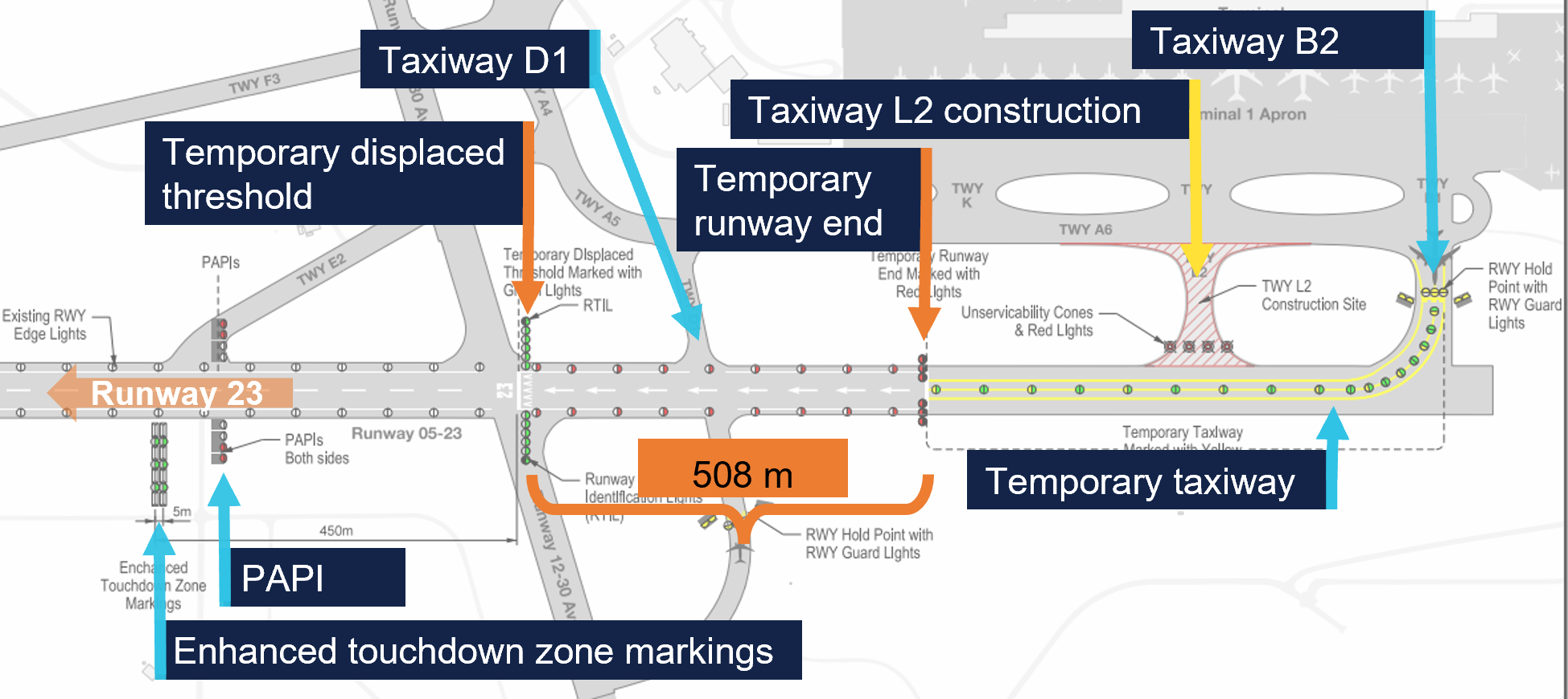
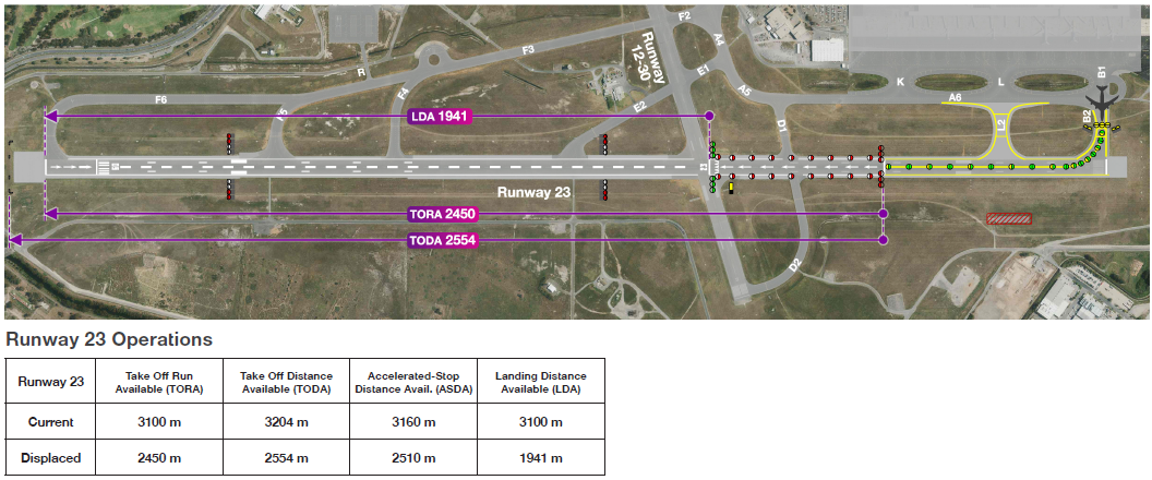
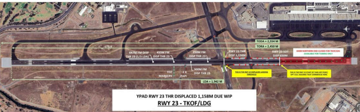
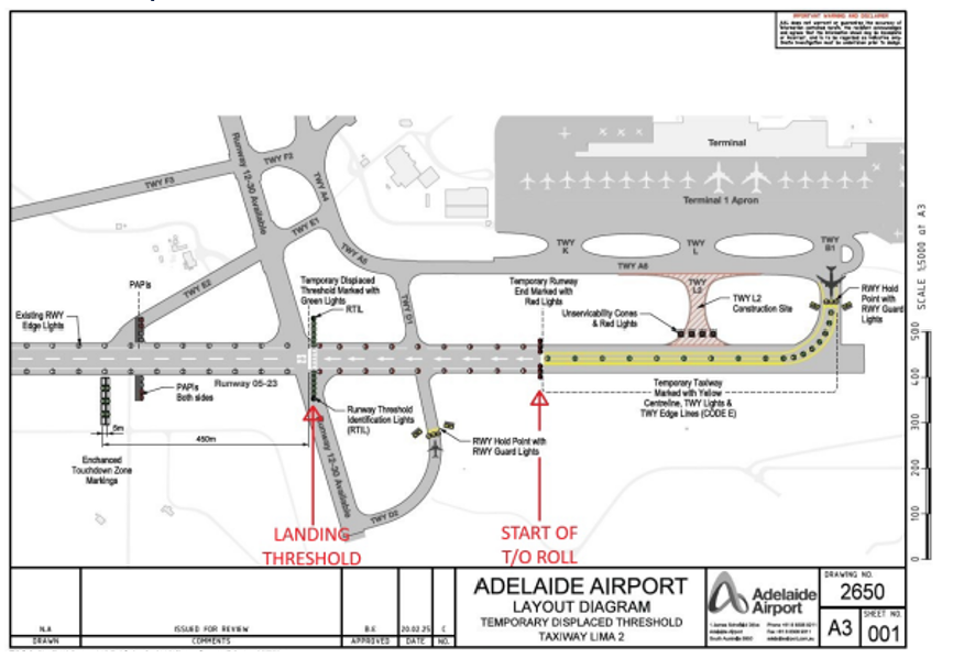
From 31 March to 20 May 2025, Adelaide Airport Limited (AAL) conducted aerodrome works, involving the construction of taxiway Lima 2 (L2) (Figure 1). L2 extended from the apron to runway 05/23[1] between taxiways Bravo 2 (B2) and Delta 1 (D1). The construction occurred between 2300 and 0600 local time, during which runway 05/23 was closed. Outside of those hours, runway 23 operated with a displaced threshold and a displaced start of take-off (SOT) position, which was the displaced end of runway 05.
Outside of the work period, the north-eastern portion of the runway beyond the 05 temporary runway end was available as a taxiway only. The temporary taxiway was marked with a yellow centreline and double lines on either edge, and lit with centreline lighting that was green for aircraft departing on runway 23 and alternating green and yellow for aircraft landing on runway 05.
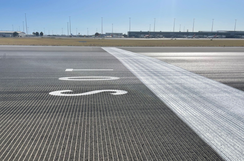
The end of runway 05 was displaced 650 m from its normal location at the taxiway B2 intersection and marked with a 1.2 m-wide white line spanning the runway. This was the SOT position, and the maximum take-off run available for runway 23. Three red unidirectional lights either side of the temporary runway end were visible to pilots of aircraft landing on runway 05 but not for aircraft taking off on runway 23.
From the SOT to the displaced threshold, white arrows painted on the runway centreline directed landing aircraft to the displaced threshold, and runway edge lights showed red to aircraft departing on runway 23 and white to aircraft landing on runway 05.
The runway 23 displaced threshold was 508 m beyond the SOT (1,158 m beyond the collocated permanent threshold and runway end), and marked by white arrowheads, a white line, and the numerals 23. There were 5 green lights and one flashing white runway threshold identification light (RTIL) either side of the displaced threshold.
The precision approach path indicator (PAPI) was temporarily relocated 450 m beyond the displaced threshold. Additionally, AAL trialled enhanced touchdown zone markings (ETZM) beyond the PAPI, to the left of runway 23, comprising 4 pairs of white gable markers with green lights positioned between them.
Figure 1: Adelaide runway 05/23 showing temporary displaced threshold and runway end
Source: Adelaide Airport Limited’s method of working plan, annotated by the ATSB
Start of take-off position terminology
The term ‘runway end’ was not defined in the Civil Aviation Safety Regulations (CASR) Part 139 – Aerodromes, Manual of Standards (MOS) or the International Civil Aviation Organization Annex 14 – Aerodromes, or the Aeronautical Information Publication (AIP).[2]Although a runway technically has 2 ends, the term ‘runway end’ usually refers to the far (departure) end of the runway in the landing direction. The AIP included the abbreviation ‘DER – departure end of runway’, but nothing for the start of the runway.
The MOS referred to the beginning of a runway in the take-off direction as the reciprocal runway end. For example, the MOS 8.16 Pre-threshold area markings included:
…an area before the non-displaced threshold, or the runway end in the reciprocal direction…
The MOS did not define the SOT position, but the abbreviation SOT was defined in the AIP as ‘start of TORA[3] (take-off)’ but noted that the abbreviation was not included in Doc 8400 – Procedures for Air Navigation Services: [International Civil Aviation Organization] ICAO Abbreviations and Codes and ‘must not be used in international NOTAM’.[4]
The MOS provided the following definitions:
threshold means the beginning of that portion of the runway usable for landing
displaced threshold means a threshold not located at the extremity of a runway.
In the evidence obtained for this investigation, the runway 23 SOT position was variously referred to as the:
runway 23 runway end
runway 05 end
temporary runway end
temporary displaced runway end
displaced runway end
displaced take-off threshold
The runway 23 displaced threshold was referred to as the:
temporary displaced threshold
displaced threshold
displaced landing threshold
landing threshold.
In describing these runway 23 positions during the works period, the ATSB has respectively referred to them as the SOT position and the displaced threshold throughout the report.
Pre-works communications
Late in 2024, AAL commenced notifying aircraft operators of the planned works, alerting them to the reduced runway length, which would potentially limit the maximum operating weight at which aircraft could safely land and take off. AAL also provided aircraft operators with a briefing package detailing the runway lighting and markings, and the relevant take-off and landing distances. Feedback received from 4 operators was considered by AAL.
On 3 March 2025, as required under CASR Part 139, AAL issued a method of working plan (MOWP) YPAD 25/03 Construction of taxiway L2 pavement adjacent to runway 05/23.[5] The MOWP described the respective positions of the displaced threshold and SOT position (temporary runway 05 end) throughout the document, as the:
Runway 23 displaced threshold
Runway 23 displaced end.
The MOWP was distributed, with a request for feedback, to stakeholders including:
aircraft operators
ground handling personnel
Airservices Australia (Airservices)
Civil Aviation Safety Authority (CASA).
The following day, AAL also submitted a safety case to CASA for approval to use ETZM for runway 23 during the works period. This approval was required as the ETZM was not included in the Part 139 MOS.
AAL also drafted an AIP Supplement (SUP),[6] which was first published by Airservices on 5 March, then republished with a minor amendment on 11 March. The same minor amendment was incorporated into the MOWP as, amendment 1, on 17 March. Those 2 versions of the published SUP included:
4. RWY 05/23 DETAILS
4.1 RWY 23 threshold displaced 1,158M.
4.2 RWY 23 runway end displaced 650M.
On 19 March, the CASA aerodromes inspector assessing the ETZM safety case, sent it to a CASA flight operations inspector (FOI) for review. The FOI responded with no issues with the ETZM, but identified an error in the AIP SUP, in that it was the runway 05 end not the runway 23 end that was temporarily displaced. The aerodromes inspector then liaised with AAL, who amended the SUP, which was published on 20 March, amending ‘RWY 23 end’ to ‘RWY 23 SOT’, and highlighting the runway 05 shortened take-off in section 4:
4. RWY 05/23 DETAILS
4.1 RWY 23 threshold displaced 1,158M.
4.2 RWY 23 SOT displaced 650M.
4.3 RWY 05 takeoff shortened by 650M.
No changes were made to 3 other references to the displaced runway 23 end in section 3 of the SUP.
AAL then forwarded the updated SUP to CASA to show the inclusion of the suggested amendment. CASA replied to that email on 24 March, asking whether the ETZM lights were hardwired. AAL replied that they were solar-powered and not hardwired. AAL subsequently hardwired the lights and advised CASA on 8 April that this had been completed.
Amendment 2 of the MOWP was issued on 25 March, in which section 2.2.1 was amended consistent with the change to the SUP, to:
The Runway 23 threshold will be displaced by 1158m.
The Runway 23 start of takeoff will be displaced by 650m.
The Runway 05 takeoff shortened by 650m.
However, 5 other references to the ‘Runway 23 displaced runway end’ were not amended to ‘runway 23 start of take-off’ or ‘runway 05 end’.
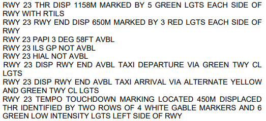
The MOWP included draft NOTAMs, which were published by Airservices prior to commencement of the works. The relevant NOTAM included:
31 March 2025 occurrences
31 March 2025 was the first day of the airport operating with the runway 23 displaced threshold and SOT position. On that day, CASA approved the safety case for the ETZM and subsequently a task was allocated to a CASA officer to draft an instrument for AAL’s ‘Use of Gable Markers and Portable Green Lights in a Non-standard Manner due to Runway Works’, which CASA had previously done for Hobart Airport (Tasmania). However, although a drafter was allocated, the instrument for AAL was not issued during the works period or prior to expiration of the MOWP on 17 June 2025.
CASA issued an instrument for use of ETZM on 4 September 2025, which referenced ‘the method of working plan presented in relation to the relevant works, as it exists at the time this instrument commences’. The instrument conditions did not require the green lights to be hardwired. However, the MOWP had expired 10 weeks earlier and CASA advised the ATSB that the instrument did not apply retrospectively.
Through its flight data analysis program (FDAP),[7] Qantas identified 2 instances during daylight on 31 March, in which flight crews inadvertently commenced the take-off from the displaced threshold instead of the SOT position, having selected take-off performance data based on the SOT. This meant there was 508 m less runway available than planned for.
On the evening of 31 March, an Airbus A350-900 aircraft, registered A7-ANH and operating Qatar flight 915, was being prepared for a flight from Adelaide Airport to Hamad International Airport, Doha, Qatar. The flight crew selected take-off performance data for the reduced length runway, which they believed to be for a take-off commencing at the displaced threshold.
Having received air traffic control (ATC) clearance, the flight crew taxied the aircraft to holding point B2 where they contacted the aerodrome controller (ADC) on the Tower frequency. Table 1 details the recorded transmissions between the flight crew and ADC.
Table 1: Recorded transmissions on Adelaide Tower frequency (1)
Heading 225 clear for take-off runway 23 Qatari Niner Quebec.
About 2.5 minutes later, the ADC observed the aircraft taxiing beyond the SOT position and towards the displaced threshold of runway 23. Table 2 details the resulting radio exchange.
Table 2: Recorded transmissions on Adelaide Tower frequency (2)
Time (CDT)
Station
Transcript
2145:11
Tower
Niner Quebec, you have passed the runway end you can, cleared for take-off.
2141:33
QTR-9Q
Clear for take-off 23 Qatari Niner Quebec
The flight crew reported that having acknowledged the clearance, they applied take-off thrust before the displaced threshold, consistent with the recorded data showing this occurred about 40 m prior to the threshold. As the aircraft rotated, the flight crew observed there was less runway remaining than expected. In later reviewing the occurrence, the flight crew assessed they had used performance data for commencing the take-off from the SOT position, not the displaced threshold, where they thought they had been cleared to take off from. Recorded automatic dependent surveillance‑broadcast (ADS-B) data showed the aircraft was still at 0 ft altitude approaching the departure end of the runway.
2 April 2025 occurrences
Airservices reported that at 1008 local time on 2 April 2025, a Qantas pilot phoned Adelaide Tower to request clarification of where to commence the take-off roll on runway 23. The pilot stated that the NOTAM was unclear as to where the take-off roll should commence.
Two occurrences during daylight hours on 2 April, involving Virgin Australia and Qantas aircraft, were identified via FDAP. In both instances the aircraft commenced the take-off from the displaced threshold, while using performance data based on the SOT position.
3 April 2025 occurrences
At 1330 on 3 April 2025, the Adelaide Tower ATC manager emailed Airservices’ safety team and AAL, stating that there was ‘a LOT of confusion with pilots as to where the take-off commences’. As a result, controllers were frequently having to explain where the start of take-off position was, as opposed to the displaced threshold. This was taking time and affecting the sequencing of aircraft.
The following day, email communications between AAL and ATC resulted in AAL amending the key text in the NOTAM from:
RWY 23 RWY END DISP 650M MARKED BY 3 RED LIGHTS EACH SIDE OF RWY
to
RWY 23 START OF TKOF DISP 650M MARKED BY PAINTED WHITE BAR AND COMMENCES AT RED RWY EDGE LGT
Additionally, ATC agreed to leave the runway lights on day and night to provide additional visual cues to assist pilots in identifying the SOT position.
A review of FDAP data identified one incorrect take-off position occurrence involving an Alliance Airlines aircraft and one involving a Virgin Australia aircraft, both during daylight on 3 April.
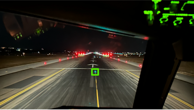
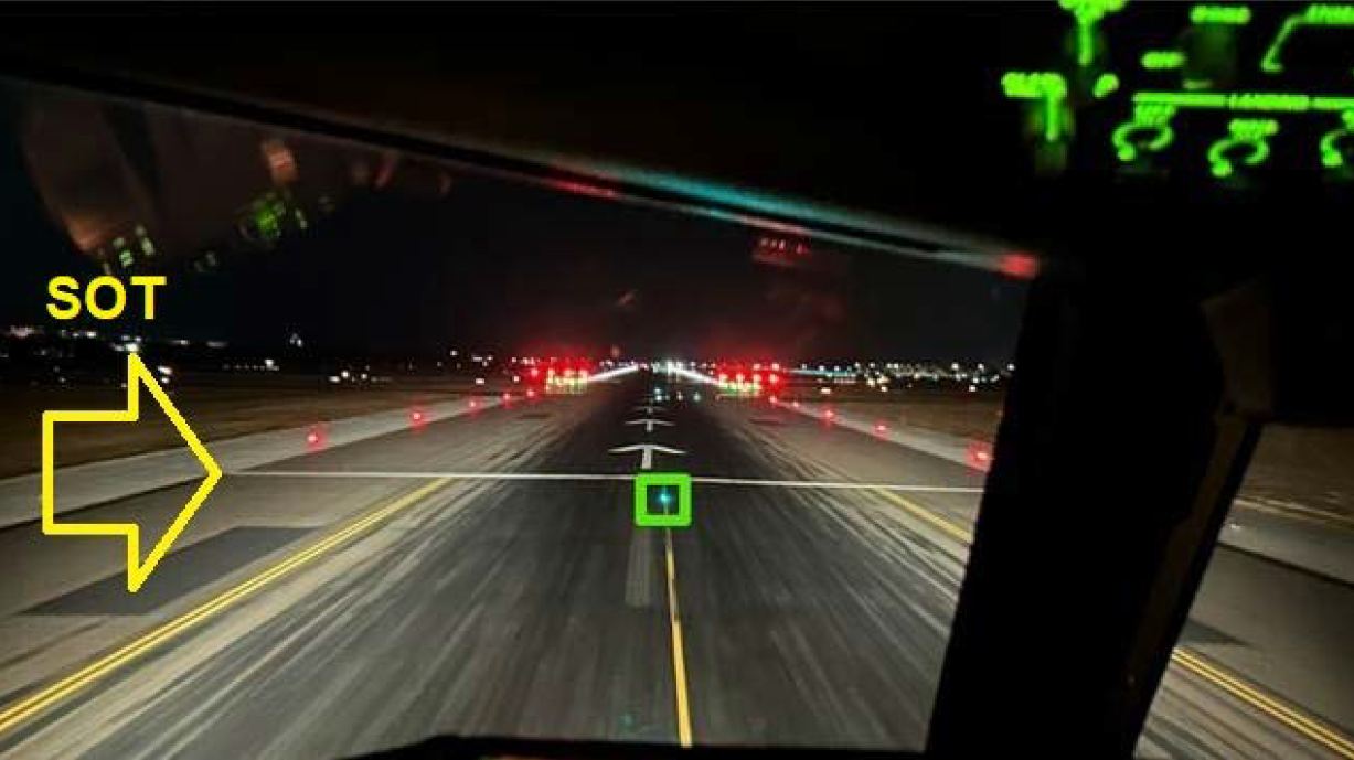
Later that day, Emirates personnel emailed AAL requesting clarification of the lights visible to flight crew at night to depict the SOT position, as the red runway end lights were not visible to flight crew departing on runway 23. The email included a photo taken from the cockpit of a Boeing 777 aircraft, with a box marked around the last green taxiway light to confirm that it was the correct cue for the SOT position (Figure 2).
Figure 2: Photo taken from an Emirates Boeing 777 cockpit highlighting the last green taxiway light as the cue for the runway 23 SOT position
Source: Emirates, provided to the ATSB by Adelaide Airport Limited
5 April 2025 occurrence
During daylight on 5 April 2025, a Qantas aircraft taxied beyond the SOT position while positioning for a departure from runway 23. The ADC alerted the flight crew, who elected to exit the runway and reposition the aircraft behind the SOT position prior to take-off.
7 April 2025
On 7 April 2025, AAL issued amendment 3 of the MOWP, which incorporated the 3 April changed NOTAM text.
11 April 2025 occurrences
An AAL Apron Safety Committee Meeting was held on 11 April 2025, during which it was discussed that there had been incidents in which aircraft started the take-off run at the displaced threshold instead of the SOT position. Notes from the meeting included that ‘AAL has modified the NOTAM and sent additional communication’.
Through its FDAP, Jetstar identified that a Jetstar Airbus A320 operating flight JQ 801 on 11 April, commenced take-off from the displaced threshold instead of the SOT position.
Virgin Australia occurrence 1
On the same day, Boeing 737-800 VH-VOL was operating Virgin Australia flight VA 413 (callsign ‘Velocity 413’) from Adelaide, South Australia, to Sydney, New South Wales. The captain was the pilot flying (PF), and the first officer (FO) was the pilot monitoring (PM).[9] For both flight crewmembers, this was their first time operating to Adelaide Airport since aerodrome works started on 31 March 2025.
Prior to approaching Adelaide on the previous sector, the flight crew had conducted the approach briefing, which included reviewing the relevant Virgin Australia flight crew operational notice (FCON)[10] and AIP SUP regarding the displaced threshold and SOT position.
During the 35-minute turnaround in Adelaide, the flight crew conducted pre-flight briefings, during which they identified the displaced threshold as a ‘threat’ and reviewed the relevant information. The flight crew confirmed they had selected the correct runway 23 ‘works in progress’ (WIP-N) take-off position for the take-off run available (TORA) data in the onboard performance tool (OPT).[11] The flight crew also discussed the expected end of green centreline lights and start of red runway edge lights indicating the SOT position, as outlined in the NOTAM and FCON. The captain then used the Jeppesen[12] aerodrome chart, which did not depict the temporary changes due to aerodrome works, to brief the expected taxi route to holding point B2 and from there to taxi along the runway and line up.
At 0950 local time, the PM contacted the Adelaide surface movement controller (SMC), advised they had received automatic terminal information service (ATIS)[13]‘Oscar’ and requested a taxi clearance. The controller cleared the flight crew to taxi via taxiway Tango and initially hold short of taxiway Lima, then one minute later, to taxi via Lima to holding point B2.
At B2 at 0953, the PM advised the ADC that they were ready (for take-off). The flight crew observed a Jetstar Airbus A320 aircraft ahead taxi to the displaced threshold and commence take-off from there, which the captain assessed must be the correct take-off position. After another aircraft landed, the flight crew were cleared to taxi and line up on runway 23. About 80 seconds later, they were cleared for take-off.
After issuing the take-off clearance, the ADC commenced a handover to an oncoming controller. During the handover, the ADC looked out the tower window and was unsure whether the aircraft had commenced the take-off roll. The ADC asked the oncoming controller ‘is Velocity rolling?’. The oncoming controller replied, ‘they’re rolling’, and, assessing that the aircraft was in the take-off roll, no action was needed, and the handover continued.
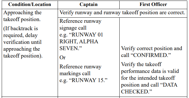
The flight crew’s normal runway verification procedure included confirming the runway signage or markings with their take-off and landing data card[14] (Figure 3). In this case, there was no intersection at the SOT position and no sign indicating the position or runway number painted on that part of the runway.
Figure 3: Extract of the Virgin Australia Boeing 737 Flight Crew Operations Manual
Source: Virgin Australia
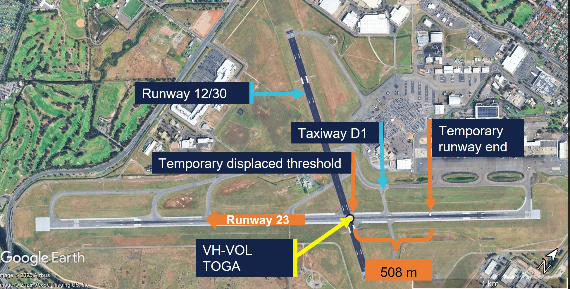
The flight crew reported that as the aircraft taxied along the runway at about 30 kt, they missed identifying the briefed change from green centreline to red edge lights, which were not distinct in the bright sunshine, and reported that the displaced threshold was much more prominent. Additionally, they reported that, while the centreline arrows had not been part of their briefing, they seemed to indicate to keep moving forward. The captain recalled setting take-off thrust passing approximately the Delta 1 (D1) taxiway and the recorded flight data showed the take-off go-around (TOGA) button/switch was pressed at the temporary displaced threshold (Figure 4).
Figure 4: VH-VOL TOGA position at the displaced threshold
Source: Virgin Australia flight data overlaid on Google Earth and annotated by the ATSB
The flight crew later reported that the take-off did not look unusual because they knew the runway was short and therefore did not take any action (such as to increase thrust). The flight continued without incident.
At the end of the day’s flying, the flight crew reviewed the documentation and realised they had commenced the take-off from an incorrect position. The captain reported the incident to the Virgin Australia safety team. By that time, Virgin Australia had already issued a safety alert and revised FCON due to another reported incident. The captain assessed using the OPT that there would have been sufficient runway to commence the take-off at the D1 intersection. However, Virgin Australia advised that having pressed TOGA at the displaced threshold, there would probably have been insufficient runway remaining to stop the aircraft on the remaining runway had the flight crew been required to abort the take-off near V1.[15]
Virgin Australia occurrence 2
On 11 April 2025, Boeing 737-800 VH-IJR was being operated as Virgin Australia flight VA 222 from Adelaide, South Australia, to Melbourne, Victoria. It was the FO’s first time operating to Adelaide Airport during the period of the aerodrome works, and the captain’s second, having been there the previous day. On that flight, the captain had been PF for the landing on runway 05 and PM for the take-off from runway 23, which had been without incident.
The FO and captain reported reviewing the documents the night before the flight, including FCON and NOTAM. The FO then re-read the FCON and NOTAM and the weather forecast in the morning about 2 hours before sign-on to conduct the flight to Adelaide that preceded VA 222, and described it as a ‘beautiful CAVOK[16] day’.
Before commencing the approach to Adelaide Airport, the flight crew briefed the threats for their arrival and discussed the touchdown area. The FO, who was PF for that sector, reported being focused on ensuring the aircraft did not touch down too early with the displaced threshold, identified the latest point of touchdown (ETZM), and taxied the aircraft to the bay.
During the turnaround, the flight crew reviewed the AIP SUP and FCON and assessed that the works were the main threat for departure. They confirmed that the take-off performance was calculated from the temporary runway end using nil wind. The captain reported noting the FCON’s reminder to flight crew not to commence the take-off too early. They briefed the procedure for taxiing along the start of the runway and commencing take-off from the temporary runway end. The flight crew reported that there was no time pressure, with about 5 minutes until their calculated off block time (COBT).[17]
At 1305, the FO, who was the PM for the sector, contacted the SMC, reported having received ATIS ‘Sierra’ and requested taxi clearance. The controller cleared the flight crew to taxi via taxiways Tango and Lima to holding point B2.
At 1309, from holding point B2, the PM contacted the ADC, advising that they were ready for take-off. The flight crew were then cleared to enter runway 23 at B2 and line up at the runway end, which the PM read back. The flight crew confirmed they were at B2, had selected the correct take-off data, and called ‘confirm data checked’, before they entered the runway. They received a take-off clearance one minute later.
The ADC then observed the aircraft continue taxiing beyond the start of the runway and stated, ‘Velocity 222 clear for take-off?’, which the PM read back. At the time, the PM assumed the controller had forgotten they had already issued the take-off clearance, but later reflected that this may have been a ‘subtle prompt’ to commence take-off.
The captain, who was the PF, reported that as they got to the runway start, they could see the green (threshold) lights in the distance and assumed that was where they were to commence the take-off. The captain observed that the aircraft lifted off further down the runway than expected, but assessed that the take-off was normal.
After departure, the flight crew reviewed the FCON and AIP SUP and realised that they had commenced the take-off from the incorrect position (Figure 5). The Virgin Australia safety department assessed that had the flight crew been required to reject the take-off just before V1, there may not have been adequate runway remaining to stop.
Figure 5: VH-IJR TOGA position at the displaced threshold
Source: Virgin Australia flight data overlaid on Google Earth and annotated by the ATSB
13 April 2025 occurrence
Virgin Australia FDAP identified one flight that erroneously commenced take-off from the displaced threshold at night.
14 April 2025 occurrence
Qantas FDAP identified one inadvertent take-off from the displaced threshold at night.
ATC and AAL met and agreed that ATC would issue instructions to pilots entering runway 23 at B2 to taxi to the SOT position for runway 23 marked with a white bar. When an aircraft arrived at the SOT position, ATC would then give the flight crew clearance to take off.
Virgin Australia changed its procedures to require flight crew to use the D1 intersection for take-off on runway 23, unless operationally required to commence at the SOT position.
17 April 2025
Qantas changed its procedures to require flight crew to use the D1 intersection for take‑off on runway 23, unless operationally required to commence at the SOT position.
20 April 2025 occurrence
Alliance Airlines’ FDAP identified one occurrence of flight crew inadvertently commencing take-off from the displaced threshold at night.
23 April 2025
A CASA senior aerodrome inspector provided the CASA team leader (aerodromes) with some notes ‘having read the MOWP’ for the latter’s planned discussion with the AAL head of operations. During that conversation, the team leader was advised of an occurrence involving the inadvertent commencement of a take-off run from the displaced threshold.
7 May 2025
AAL commenced an investigation in accordance with its safety management system requirements following a reported incident related to the inadvertent take-off from the displaced threshold rather than the SOT position.
8 May 2025
AAL doubled the width of the painted white runway end line (from 1.2 to 2.4 m) and painted ‘SOT’ just beyond the line (Figure 6). The same day, CASA provided AAL with feedback on the MOWP, including that there were ‘insufficient visual cues for the SOT’ and suggested signage.
Figure 6: Runway 23 enhanced start of take-off position marking
Source: Adelaide Airport Limited
Following that action, there were no subsequent occurrences reported to the ATSB of flight crews inadvertently commencing the take-off from the displaced threshold instead of the SOT position.
Context
Runway excursions
Accidents and contributing factors
The International Civil Aviation Organization (ICAO) Global Aviation Safety Plan identified runway safety as a global safety priority. Analysis of international runway safety accidents and incidents found runway excursions to be the highest risk category. Management of airport works was identified as a key contributing factor to runway excursions (a veer off or overrun of the runway surface).
The Flight Safety Foundation report, Reducing the risk of runway excursions, analysed accidents involving commercial transport aircraft from 1995 to 2008. The report identified 417 runway excursion accidents, accounting for 83% of fatal runway-related accidents.
Although most occurred during landing, 21% of the runway excursion accidents occurred during take-off. Rejecting the take-off after reaching decision speed (V1) was the most common factor contributing to take-off excursions. Incorrect performance calculations for decision speed and/or runway length was also a key contributing factor. In addition to risk factors relating to flight operations, other risk factors for runway excursions related to:
air traffic management, for example, late runway changes, or not providing timely wind/runway condition information to flight crews
airport, for example, incorrect or obscured runway markings, or inadequate runway end safety areas
aircraft manufacturers, for example, a lack of performance information for certain runway conditions
regulators, for example, a lack of regulatory requirement to provide consistent take-off and landing data.
Take-off performance data
Flight crew of large aircraft usually use an onboard performance tool (OPT)[18] to calculate take-off performance data. Based on the aircraft weight, runway distances available, runway elevation, outside air temperature and configuration, key speeds are calculated for the take-off, including V1[19] and rotate speed (VR).
When the thrust required for take-off is less than the maximum available, reduced thrust is often used to increase engine life and reduce overhaul costs and aircraft noise. A reduced thrust take-off will result in slower acceleration along the runway, a longer take‑off roll, and a reduced initial climb rate. For many large aircraft, the flight crew will set the relevant take-off thrust position, then press the take-off/go-around (TOGA) button or switch to commence the take-off roll. If required, flight crew can increase to the maximum TOGA thrust available by moving the thrust levers forward.
However, in the event of an engine failure or other malfunction that requires the flight crew to abort the take-off when below V1, a runway overrun can result if the:
incorrect available runway length is used when conducting take-off performance calculations
take-off commences from a position with less runway remaining than used for the take-off performance assessment.
Personnel information
VH-VOL (VA 413) 11 April 2025
The captain had accrued 13,933 hours total flying time, 4,090 of which were on Boeing 737 (B737) aircraft. The first officer (FO) had accrued 13,170 hours total time, 6,365 of which were on B737 aircraft. The captain’s self-assessed fatigue was 1/7 and the FO’s was 2/7.[20] There was no evidence that inexperience or fatigue were factors in this occurrence.
Although both flight crewmembers had significant flying experience, neither could recall having previously operated with a displaced runway start that did not coincide with a taxiway or runway intersection. They noted that the start of take-off (SOT) position did not have such a reference point at which to cross-reference the starting position with the take-off data, and no signage showing take-off run available at the take-off position.
The captain reported that, in hindsight, they should have briefed the taxi from the Aeronautical Information Publication (AIP)[21] Supplement (SUP)[22] rather than the Jeppesen chart, which did not include the SOT position. Additionally, they considered that the ability to incorporate the aerodrome works information in the Jeppesen aerodrome chart, or a link to that information, would have improved the briefing.
The flight crew commented that there was some ambiguity in the terms used, including displaced runway end and temporary runway end to mean the same position.
Additionally, the crew identified that there were different meanings for the lights and markings for landing and departing aircraft. The flight crew described the arrows as a good visual cue, in that they stood out, but it had not been highlighted that the start of the arrows was where to press the TOGA switch, rather than continue taxiing. For the landing, the arrows indicated to continue to the displaced threshold, but for take-off they were an indication the aircraft was beyond the start of take-off position. Further, for the landing, the red runway edge lights indicated to continue to the green displaced threshold lights, but for take-off, the green centreline lights were for taxiing, the start of the red runway edge lights were to indicate start of take-off, and the green displaced threshold lights were over 500 m beyond the start of take-off position.
VH-IJR (VA 222) 11 April 2025
The captain had 14,099 hours total flying time, 5,445 of those on Boeing 737 aircraft. The FO had 6,325 hours total flying time, 861 of those on Boeing 737 aircraft, and had been with Virgin Australia for about 1 year. The captain self-assessed their fatigue as 1/7 and the FO as 2/7. There was no evidence that inexperience or fatigue were factors in this occurrence.
Regarding the aerodrome works information, the FO stated that the flight crew operational notice (FCON) was simplified and more useful than the NOTAM. It described lights, which the flight crew did not notice in the daylight. The captain reported that on a blue-sky day, the runway end and edge lights were less prominent than the displaced threshold lights, markings and the large white arrows pointing to it, which were not mentioned in the documents. Additionally, they noted that the green displaced threshold and touchdown zone lights were very visible, but the red runway 05 end lights were not visible to flight crew departing on runway 23.
The captain also reported that they were used to seeing green lights indicating where to go, instead of red lights, and they were conditioned to ‘think red means stop or you’re too low on the [precision approach path indicator] PAPI’. During the departure briefing, they did not identify the visual cue to take off where the red edge lights start and green taxi lights stop. The FO had been the pilot flying (PF)[23] on the previous sector and reported that they were focused on ensuring the aircraft did not touch down too early on landing, which may have also carried over to taxiing too far before pressing the TOGA switch.
The flight crew reported that the FCON and runway image noted different take-off and landing positions but did not highlight the visual cues to identify them. The captain later reported that they understood that the take-off and landing were 2 different positions but did not ‘dwell enough’ on the differentiating cues between them during the briefing.
The captain also made the same observation as the VA 413 crew that the SOT position was not as salient as others they had encountered. The captain also reported that in hindsight the location of taxiway D1 between the start of take-off and displaced threshold provided a cue that the aircraft was beyond the SOT position.
The flight crew reported that the revised FCON and linked image published after the incident were clearer and more obvious. The captain reported that the SUP was the only one with a picture showing the aerodrome works and therefore was their primary reference (over the NOTAM and FCON).
The flight crew also reported that the airport operator subsequently distributed a photo of a ‘pilot’s eye view’ from the cockpit, which clearly showed the cues for the start of runway.
Adelaide Airport information
Adelaide Airport was a certified aerodrome[24] operated by Adelaide Airport Limited (AAL). It had scheduled international and domestic air transport operations, with restricted aircraft movements during curfew hours from 2300–0600 local time. The airport had 2 intersecting runways:
The 4 required declared distances to be available for each runway direction were:
take-off run available (TORA)
take-off distance available (TODA)
accelerate-stop distance available (ASDA)
landing distance available (LDA).
AAL’s briefing to aircraft operators included a diagram and figures for runway 23 during the works period (Figure 7).
Figure 7: Runway 23 declared distances during displaced threshold operations
Source: Adelaide Airport Limited
Civil Aviation Safety Regulations Part 139 (Aerodromes) Manual of Standards
Markings and lights
Part 139 of the Civil Aviation Safety Regulations (CASR) set out requirements and standards for aerodromes with published instrument flight procedures, such as Adelaide Airport. These were detailed in the Part 139 Manual of Standards (MOS).
The key features of the markings and lights specified in the MOS relevant to runway 23 for the aerodrome works at Adelaide were:
runway end marking: a 1.2 m-wide white line extending the full width of the runway (MOS 8.20)
temporarily displaced threshold markings – more than 30 days (MOS 8.28):
1.2 m‑wide white line marked across the full width of the runway at the displaced threshold, with adjacent 10 m‑long white arrowheads each 1 m wide
existing centreline markings between the reciprocal runway end and displaced threshold converted to arrows
the permanent threshold and runway number obscured, and a temporary runway number painted 12 m beyond the displaced threshold
temporarily displaced threshold lights: 5 green (in the direction of the runway) lights either side of and perpendicular to the runway centreline were required at night (MOS 9.60–9.62)
runway threshold identification lights (RTIL): one flashing white light each side of the runway required by day to mark a temporarily displaced threshold of a runway serving scheduled international air transport operations, ‘should have an acquisition of approximately 7 km in bright sunlight’ (MOS 8.27 and 9.59)
runway edge lights before the displaced threshold: red in the direction approaching the displaced threshold and white in the opposite direction (MOS 9.63)
runway end lights: at least 6 high intensity inset unidirectional red lights for aircraft landing in the direction of the runway, perpendicular to the runway, such that an aircraft does not cross the row of red lights (MOS 9.64–9.66)
touchdown markings and lights were not required as high intensity approach lighting (HIAL) was unavailable (as the instrument landing system was unavailable due to the displaced threshold). The enhanced touchdown zone markers (ETZM) and lights in use by AAL were not included in the MOS.
The MOS defined a runway starter extension as:
an additional length of pavement that:
(a) is immediately before the runway threshold; and
(b) increases the distance available for take-off; but
(c) must not be used for landing.
As the area between the SOT position and displaced threshold was available for aircraft landing on the reciprocal runway, it did not meet the definition of a runway starter extension.
AAL assessed that the aerodrome layout was in accordance with the MOS, other than the ETZM, for which AAL had requested the Civil Aviation Safety Authority’s (CASA) approval. Additionally, a CASA-authorised check pilot had certified on 31 March 2025 that they had flight checked the aerodrome lighting system and ‘it met the relevant operational requirements’.
Movement area guidance signs
The Part 139 MOS Division 6 stated that mandatory instruction movement area guidance signs (MAGS) (white lettering on red background) must be provided at international aerodromes with scheduled air transport operations and at any aerodrome with air traffic control (ATC). It further stated that information only MAGS (black letters on yellow background or vice versa) must be provided where taxiway intersection departures are promulgated in the AIP. MAGS were also required to be illuminated at aerodromes with scheduled international air transport operations.
Mandatory instruction MAGS included:
(a) runway designation signs;
(b) CAT I, II or III holding position signs;
(c) runway holding position signs;
(d) aircraft NO ENTRY signs;
(e) vehicular STOP signs;
(f) runway/runway intersection signs.
Information MAGS included:
(a) taxiway location signs;
(b) direction signs;
(c) destination signs;
(d) take-off run available signs;
(e) runway exit signs;
(f) distance-to-go signs;
(g) LAHSO distance-to-go signs.
MOS 8.97 Take-off run available signs included:
Departures from the runway 23 SOT position did not represent an intersection departure and therefore did not require a take-off run available (TORA) MAGS, nor was one in place. MOS 8.87 required that the TORA MAGS be in place at the taxiway/runway intersection, which were the B2 and D1 holding points. For temporary displacement, the MOS 8.27(4) stated:
A MAGS displaying the full runway 23 TORA was ordinarily present at the taxiway B2 holding point. At the time of the works, this had been obscured as it displayed incorrect declared distance information, albeit it due to the temporary displacement of the runway end, rather than the threshold as described in the MOS.
Method of working plan feedback
The MOS Chapter 15 Aerodrome works stated that:
The operator of a certified aerodrome must make all necessary arrangements to ensure that aerodrome works do not create a hazard to aircraft or cause confusion to pilots.
Chapter 15 also specified the conditions under which a method of working plan (MOWP)[27] was required, and referred to chapter 16 of the MOS for the details of the MOWP layout and contents. Subsection 15.02 included:
(2) When preparing a MOWP, an aerodrome operator must consult:
(a) air transport operators using the aerodrome; and
(b) operators of emergency services aircraft that are likely to operate at the aerodrome during the works period; and
(c) ATC (if applicable); and
(d) if the MOWP is likely to affect the unit’s ability to ensure the safety of aircraft operations at the aerodrome — the ARFF unit at the aerodrome (if any); and
(e) if any communications, navigation, surveillance or meteorological infrastructure or equipment would otherwise be affected by the works — the provider of that infrastructure or equipment.
Note Consultation with other fixed-base operators at the aerodrome such as flight training organisations, sport aviation organisations, aerial application operators etc. is also recommended.
(3) Not less than 14 days before works commence, the aerodrome operator must supply a copy of the MOWP to:
(a) each operator or organisation mentioned in paragraphs (2) (a) to (e); and
(b) the relevant CASA aerodrome inspector (where known), or the local CASA office marked for the attention of an aerodrome inspector.
AAL prepared the MOWP in accordance with the MOS, and distributed it to the operators and organisations for feedback as required. Additionally, AAL distributed copies of the following versions of the MOWP to all stakeholders including CASA:
issue 1, issued 3 March
amendment 1, issued 17 March
amendment 2, issued 26 March
amendment 3, issued 7 April 2025.
Apart from the error identified by CASA in the AIP SUP on 19 March, which was reflected in amendment 2 of the MOWP (in section 2.2.1 ‘runway end’ was amended to ‘start of takeoff’), there was no feedback to AAL to indicate anything was contrary to the MOS prior to 8 May 2025.
Although a mandatory recipient of the MOWP, CASA advised that there was no legislative requirement for CASA to approve a MOWP. This was consistent with the standards and recommended practices set out in the International Civil Aviation Organization (ICAO) Annex 14 – Aerodromes. Further, CASA advised that:
CASA does not complete a formal review for any Method of Works Plan (MOWP) issued by an aerodrome operator, prior to their issue and use.
Under the Part 139 rules, the certified aerodrome operator is fully responsible for implementing and maintaining the required systems and processes for aerodrome works.
In accordance with CASA’s surveillance program, MOWPs are recorded on file, and the assigned aerodrome inspector may conduct a ‘sampling activity’[28] at that time, or closer to a surveillance event. CASA further detailed that this would involve potentially choosing at random a portion of the MOWP and if any anomalies with the MOS were identified, this would inform appropriate CASA action.
In contrast, in the United States (US) (also an ICAO contracting State), an aerodrome operator’s Construction safety and phasing plan (equivalent to a MOWP) is subject to review and approval under the Federal Aviation Administration’s (FAA) safety risk management procedures (FAA, 2017). CASA advised that the context of the aerodrome regulations and the US funding model differed substantially from Australia’s. CASA issued aerodrome operators a certificate and then monitored their performance and compliance under ongoing surveillance/regulatory oversight, using sampling methods. Unlike the FAA, CASA did not approve MOWPs or funding arrangements.
In 2024, CASA received 119 MOWPs, 6 of which involved a displaced threshold. From January to July 2025, CASA received 73 MOWPs, 8 of which involved a displaced threshold. Eleven of the 14 plans involved a displaced threshold that was not coincident with the displaced reciprocal runway end. CASA aerodromes inspectors reported that in conducting sampling activities there was a focus on works that resulted in displaced thresholds. They also assessed that AAL was very thorough, had a mature safety management system and generally went above and beyond the MOS requirements.
On 17 April 2025, CASA was advised of one occurrence from 11 April 2025, and the CASA manager aerodromes unsuccessfully attempted to contact AAL. CASA reported that on 22 April 2025, the aerodromes team leader conducted a ‘sampling activity’ of the MOWP and provided feedback over the phone to AAL. On 8 May 2025, CASA provided AAL comments and clarification requests of the MOWP, including that:
Unserviceability cones and lights were not depicted in the diagram (Figure 1) at the taxiway A end of the L2 construction. AAL responded that these were in place.
Gable markers showing the displaced runway 05 strip were not evident on the drawings (MOS 8.11). AAL responded that they had not interpreted this requirement from the MOS.
‘Runway 23 start of take-off – visual indication for pilots is not clear’. AAL responded that it was marked with a white line in accordance with the MOS, and at the commencement of the red runway edge light. Further, that AAL had subsequently doubled the width of the white line and painted ‘SOT’ on the pavement.
‘Provision of MAGS with information’. AAL noted that in hindsight it could have used a ‘START OF TAKE OFF’ MAGS, also noting that there was a long lead-in time (4–6 weeks) for the manufacture and delivery of MAGS.
Confirmation was sought, and received from AAL, that the runway 23 designator and piano keys had been obscured, along with the MAGS.
Addressing pilot confusion
Having identified that the SOT position was confusing to pilots despite being marked and lit in accordance with the MOS, CASA advised the ATSB that this should have been addressed through the aerodrome operator’s safety management system (SMS) or risk management plan (RMP) as applicable based on the MOS. ‘Appropriate control measures can then be implemented if required, or the risk otherwise accepted by the responsible party’. Mitigation measures outside of the MOS requirements ‘can be implemented freely, unless there is a regulatory conflict’. CASA advised that in the case of a conflict, the operator could submit a safety case, as AAL did for the ETZM, for approval.
Other options for depicting the start of take-off position
ICAO Annex 14, Volume I – Aerodrome Design and Operations (ICAO July 2022) provided Standards and Recommended Practices for Aerodromes for ICAO Contracting States, which included Australia. Annex 14 did not include a standard for runway end markings but provided a standard for (red) runway end lights. The annex also described a white ‘transverse stripe’ at least 1.8 m wide to be added to the threshold marking when the threshold was displaced from the runway extremity. This was wider than the 1.2 m white threshold line in Australia’s MOS. In comparison, the US FAA’s white threshold bar was 3 m wide.
In the absence of an international standard, the US FAA and Transport Canada incorporated a 0.9 m-wide yellow runway demarcation bar marking, which, according to the FAA Advisory Circular (AC) 150/5340-1M Standards for Airport Markings:
Delineates a runway with a displaced threshold from a blast pad, stopway or an aligned taxiway that precedes the runway…the portion of the aligned taxiway before the demarcation bar is not part of the usable runway for takeoff or for landing from the opposite direction.
Described as the ‘rare case in which a displaced threshold is preceded by an aligned taxiway’, the AC depicted a yellow demarcation bar (Figure 8).
Figure 8: Extract from Federal Aviation Administration Advisory Circular 150/5340-1M Figure A-10 showing yellow demarcation bar
Source: Federal Aviation Administration AC 150/5340-1M
The AC included a note that aligned taxiways were ‘prohibited for new construction or reconstruction of existing aligned taxiways’, and referenced FAA AC/150-5300-13B Airport Design, which included that aligned taxiways, defined as one whose centreline coincides with the runway centreline:
represent an elevated hazard risk due to the potential for taxiing aircraft to take a position in direct line with departing or landing aircraft. Aligned taxiways also contribute to a pilot’s loss of situational awareness.
Note.— If the runway threshold is displaced from the extremity of the runway, a sign showing the designation of the runway may be provided for aeroplanes taking off.
In 2010, the US FAA initiated the Airport Construction Advisory Council (ACAC),[29] which was a collaborative working group of industry stakeholders. The ACAC’s aim was to help identify hazardous situations during runway and taxiway construction projects, and to mitigate the associated risk. Through the ACAC, the FAA introduced additional risk controls for aircraft operations during aerodrome works and/or with reduced runway length. One risk control was the introduction of construction signage.
The FAA AC 150/5370 Operational safety on airports during construction provided guidance for airport operators to comply with Title 14 Code of Federal Regulations (CFR) Part 139, Certification of Airports. Since December 2017, the FAA AC included guidance for the optional use of temporary orange construction signs to increase pilot situational awareness of changed conditions on the movement area. The AC included 3 permissible sign legends (Figure 9).
Figure 9: Federal Aviation Administration approved construction sign legends
Source: Federal Aviation Administration AC 150/5370-2G
In May 2023, the ICAO Air Navigation Commission (ANC), distributed State letter AN 4/1.159-23/33 to member states for comment on proposed amendments to Annex 14 – Aerodromes, Volume I – Aerodrome Design and Operations, and the Procedures for Air Navigation Services (PANS) – Aerodromes. One proposed amendment was the inclusion of orange ‘unserviceability signs’, in line with the FAA’s construction signs, to indicate temporary changes to runway declared distances. The proposed applicability date for the amendment is 27 November 2025. The ANC included the following rationale for introduction of the signs:
Unserviceability signs as means of risk mitigation during temporary changes to the movement area (reduction in the runway length, reduction in the maximum allowable wingspan, taxiway closure or any other closure to the movement area) was assessed on several airports in Europe and in the United States. The results showed acceptance and comprehension by pilots, while also portraying safety benefits (decrease in the rate of misleading operations).
The new Standard pertaining to unserviceability signs, where there is an operational need to indicate temporary changes to runway declared distances, strongly mitigates the risk of using the wrong TORA value for take-off.
The provision of unserviceability signs where there is an operational need to indicate temporary changes to taxiways and aprons, is only a recommendation as the safety impact of such a change may not be as high as that of the use of a wrong TORA value.
Existing signs providing inadequate or misleading information as a consequence of temporary changes to the movement area shall be removed or obscured in order to avoid any confusion with the appropriate messages conveyed by unserviceability signs.
In July 2025, CASA published proposed amendments to Part 139 MOS, to incorporate amendments to Annex 14 Volume1 (Amendment 15), introduced by ICAO in 2020. This did not include the proposed Annex 14 Volume 1 (Amendment 18) due to be implemented in November 2025.
Air traffic services
Air traffic services objectives
The Australian Manual of Air Traffic Services(MATS)[30] outlined requirements, procedures and standards for the provision of air traffic services. The listed air traffic services objectives included to:
- prevent collisions between aircraft on the manoeuvring area and obstructions on that area
- provide advice and information useful for the safe and efficient conduct of flights.
Temporary local instructions
In preparation for the works, on 24 March, Airservices Australia issued Adelaide Airport temporary local instruction[31] (TLI) TLI_25_0064 – Taxiway L2 works temporary restrictions. The TLI described the aerodrome works layout and the facilities that would be unavailable during the period. It included the MOWP Drawing 3 (Figure 10).
Figure 10: Adelaide Airport layout diagram as printed in the AIP Supplement
Source: Airservices Australia
The TLI also instructed controllers not to permit an aircraft to land on runway 23 when an aircraft was stationary:
Also:
The TLI also included suggested phraseology for runway 23:
On 8 April 2025, a minor amendment clarifying precision approach path indicator (PAPI) selection and aircraft holding requirements on taxiway A6, was published as TLI_25_0093.
Commencing take-off from D1
Following multiple occurrences of flight crew incorrectly commencing take-off from the displaced threshold, on 14 and 17 April 2025 respectively, Virgin Australia and Qantas implemented a requirement for flight crew to commence the take-off from D1 intersection unless operationally required to use the runway 23 SOT position. There was 1,280 m take-off run available from D1. However, as documented in the SUP and the TLI, due to obstacle clearance requirements for aircraft landing on the displaced runway 23 threshold, aircraft larger than a Saab 340 could not be held stationary at D1, or the landing aircraft would be required to conduct a go-around.
This meant possible extended delays for aircraft waiting to depart via D1. Instead, the surface movement controller (SMC) would usually instruct pilots to taxi to B2, then contact the aerodrome controller (ADC) and request taxiway Delta for their start of take‑off position. The SMC would then advise the ADC, who would instruct the pilot to line up adjacent to the D1 taxiway prior to receiving a take-off clearance.
Automatic terminal information service
MATS included examples of standard phraseology for the provision of essential aerodrome information through the automatic terminal information service (ATIS),[32]including for reduced runway lengths and a displaced threshold (Table 4). There was no standard phraseology for a displaced runway end or SOT position.
Table 4: MATS standard ATIS phraseology
Content
Phraseology
During runway work resulting in reduced runway lengths
REDUCED RUNWAY LENGTH(S) IN OPERATION
ATIS may include:
RUNWAY (number), TORA (or LANDING DISTANCE AVAILABLE) (number) METRES
Other essential operational information
RWY 21 DISPLACED THRESHOLD SOUTH OF RWY 24 INTERSECTION
For Virgin Australia flight VA 413 on 11 April, ATIS ‘Oscar’ was current:
runway 23 and runway 12 for arrivals, runway 23 for departures
runway 23 displaced threshold
take-off run available 2,450 m, landing distance available 1,942 m
For Virgin Australia flight VA 222 on 11 April, ATIS ‘Sierra’ was current:
runway 23
runway 23 displaced threshold
take-off run available 2,450 m, landing distance available 1,942 m
taxiway E2 closed
wind 230° 10 kt
CAVOK
temperature 23°
QNH 1,023.
Controller comments
Tower manager
The Adelaide tower manager at the time of the 2 Virgin Australia occurrences reported that pilots were ‘finding it very difficult’ to clearly identify the SOT position. They reported that if controllers used the phrase ‘runway end’, pilots would read back ‘displaced threshold’. After AAL revised the NOTAM to use ‘start of take-off’, ATC phraseology included advising pilots that ‘you have now passed your start of take-off … take-off run available at D1 is … and take-off run available at the displaced threshold is …’
The manager reported that the impact on controllers was that it was quite workload intensive; pilots were not sure where to go. The controllers needed time to have a conversation with the pilot, which slowed things down. Because of pilots’ uncertainty, aircraft were being taxied at varying speeds, some very slowly to try to identify the SOT position.
Aerodrome controller for VA 413 on 11 April
The ADC for Virgin Australia flight VA 413 on 11 April did not identify that the aircraft started the take-off from the incorrect position. The controller had been an air traffic controller since 2004 and at Adelaide Airport since 2010 and provided the following comments regarding operations with the displaced runway end:
The ADC was using the phrase ‘displaced runway end’ and estimated about half the pilots read back ‘displaced threshold’. The ADC would respond 'just confirm it's taxi and hold short of the displaced runway end’.
Some aircraft were taxiing quite slowly after entering the runway at B2.
The white runway end line was not obvious at night, and the pilots would continue taxiing beyond the runway end lights.
The ADC suggested to their domain support specialist that they liaise with the airport operator to position a MAGS at the SOT position.
The ADC would often clear pilots for take-off when the aircraft was about 100 m from the SOT line to prompt commencement of the take-off.
The displaced threshold was not visible from the tower. At night, the touchdown markings were visible but the red runway end lights at the SOT were very difficult to see.
Individual controllers adopted their own solutions.
Aerodrome controller 2 for VA 222 on 11 April
The ADC for Virgin Australia flight VA 222 on 11 April was an experienced controller who had been endorsed as an Adelaide ADC on 4 April 2025, after the aerodrome works started. The controller could not recall the specific occurrence, but provided the following comments:
There had been a few instances where the ADC had been required to re-specify the take-off clearance, with confusion between the SOT position and the displaced threshold.
Standard phraseology was used where possible.
Pilots were commonly issued an instruction to enter the runway and line up, before being cleared for take-off.
Notice to Airmen
Airservices Australia’s NOTAM Data quality requirements for aerodrome operators, document stated:
NOTAM should be originated, issued, and distributed promptly when:
- information is of a temporary nature, unplanned, and of short duration
- operationally significant permanent changes, or temporary changes of long duration, are made at short notice.
Information that is of short duration, but which contains extensive text and/or graphics, is to be published as an AIP Supplement (SUP).
Included in the listed NOTAM promulgation criteria was:
- establishment, closure, or significant changes in operation of aerodrome(s) or heliport(s) or runways
The document provided examples of how to format NOTAM text (item E of a NOTAM). These included the following for a displaced threshold:
For aerodrome works where a MOWP was issued, the Part 139 MOS required that:
…a NOTAM giving the time and date of the planned commencement of the works, or a planned change in works stage, must be requested as early as possible but not less than 48 hours before commencement of the works or works stage.
AAL drafted 3 NOTAMs that were promulgated by Airservices to cover the operational changes to the aerodrome during the works. These were for:
runway 05/23 closure during night works
nighttime taxiway closures/unserviceabilities
the displaced runway 23 threshold.
The displaced threshold NOTAM issued just prior to commencement of the works included the following text:
E) THR RWY 23 DISPLACED 1158M
REFER METHOD OF WORKING PLAN YPAD 25/03 AMENDMENT 2 RWY 23 THR DISP 1158M MARKED BY 5 GREEN LGTS EACH SIDE OF RWY WITH RTILS RWY 23 END DISP 650M MARKED BY 3 RED LGTS EACH SIDE OF RWY RWY 23 PAPI 3 DEG 58FT AVBL RWY 23 HIAL U/S RWY 23 DISP RWY END AVBL TAXI DEPARTURE VIA GREEN TWY CL LGT RWY 23 DISP RWY END AVBL TAXI ARRIVAL VIA ALTERNATE YELLOW AND GREEN TWY CL LGT RWY 23 TEMPO TOUCHDOWN MARKING LOCATED 450M DISPLACED THR IDENTIFIED BY TWO ROWS OF 4 WHITE GABLE MARKERS AND 6 GREEN LOW INTENSITY LGTS LEFT SIDE OF RWY TWY B2, D2 HOLD POINT TEMPO REPOSITIONED ACFT LTD NOT ABV SF340 HOLD TWY A6 AT TWY K INTERSECTION ACFT LTD NOT ABV A321/A320 B737 HOLD TWY A6 AT TWY L INTERSECTION DECLARED DISTANCE AND GRADIENT CHANGES
RWYTORATODAASDALDA
0524502450(2)25102298
2324502554(2.63) 25101942
SUPPLEMENTARY TKOF DISTANCES
RWY05- 2273(1.6) 2412(1.9)
RWY23- 2216(1.6) 2379(1.9) 2475(2.2) 2533(2.5)
This was amended on 4 April to:
E) THR RWY 23 DISPLACED 1158M
REFER METHOD OF WORKING PLAN YPAD 25/03 AMENDMENT 2 RWY 23 THR DISP 1158M MARKED BY 5 GREEN LGTS EACH SIDE OF RWY WITH RTILS RWY 05 RWY TAKE OFF SHORTENED MARKED BY 3 RED LGTS EACH SIDE OF RWY RWY 23 START OF TAKE OFF DISP 650M MARKED BY PAINTED WHITE BAR AND COMMENCES AT RED RWY EDGE LGTS RWY 23 PAPI 3 DEG 58FT AVBL RWY 23 HIAL U/S RWY 23 DISP RWY END AVBL TAXI DEPARTURE VIA GREEN TWY CL LGT RWY 23 DISP RWY END AVBL TAXI ARRIVAL VIA ALTERNATE YELLOW AND GREEN TWY CL LGT RWY 23 TEMPO TOUCHDOWN MARKING LOCATED 450M DISPLACED THR IDENTIFIED BY TWO ROWS OF 4 WHITE GABLE MARKERS AND 6 GREEN LOW INTENSITY LGTS LEFT SIDE OF RWY TWY B2, D2 HOLD POINT TEMPO REPOSITIONED ACFT LTD NOT ABV SF340 HOLD TWY A6 AT TWY K INTERSECTION ACFT LTD NOT ABV A321/A320 B737 HOLD TWY A6 AT TWY L INTERSECTION DECLARED DISTANCE AND GRADIENT CHANGES
RWYTORATODAASDALDA
0524502450(2)25102298
2324502554(2.63) 25101942
SUPPLEMENTARY TKOF DISTANCES
RWY05- 2273(1.6) 2412(1.9)
RWY23- 2216(1.6) 2379(1.9) 2475(2.2) 2533(2.5)
Subsequent versions of the NOTAM were also issued, but they contained only minor changes to the abbreviations/contractions.
NOTAMs have known limitations that can hamper the identification of safety-critical information, including:
the large volume that are produced
formatting limitations – capitalised text with multiple abbreviations/contractions.
NOTAMs have previously been identified as contributing factors to accidents. As detailed in the 2020 Flight Safety Australia article, Missing the message,[35] the US FAA identified NOTAMs in its top 5 hazards in the airspace system. Additionally, the US National Transportation Safety Board’s investigation of a near-landing on a closed runway in 2017 identified the ‘need for more effective presentation of flight operations information to optimise pilot review and retention of relevant information’. International working groups have been collaborating for decades to improve the NOTAM system.
Aeronautical Information Publication Supplement
Due to the need for ‘extensive text and/or graphics’, AAL drafted an AIP SUP[36] – Adelaide aerodrome (YPAD) operational restrictions: Taxiway L2 construction project. The SUP comprised the following sections:
Introduction
References: to the MOWP and an associated SUP for temporary approach procedures
Works: included similar information to the NOTAM, but without most of the abbreviations/contractions. Of relevance, it included:
3.9 RWY 23 displaced runway end will be marked with three (3) red lights each side of RWY 23.
3.10 Aircraft will taxi for departure to the RWY 23 displaced runway end via green TWY centreline lighting.
3.11 Aircraft will taxi on arrival from the RWY 23 displaced runway end via alternating yellow and green TWY centreline lighting.
RWY 05/23 details: changed on 20 March 2025 (before works commenced) from:
4.1 RWY 23 threshold displaced 1,158M.
4.2 RWY 23 runway end displaced 650M.
to:
4.1 RWY 23 threshold displaced 1,158M.
4.2 RWY 23 SOT displaced 650M.
4.3 RWY 05 TO shortened by 650M.
(included a table of declared distances for TORA, TODA, ASDA and LDA)
Although CASA advised AAL that section 4.2 of the SUP should replace reference to ‘runway end’ with ‘SOT’, this was not similarly amended in section 3.9 of the SUP.
Supplementary [take-off] TKOF distances
Cancellation (date)
Distribution (Airservices Australia website only)
Appendix – Adelaide Airport Layout diagram (Drawing 3 from the MOWP) (Figure 10).
Aircraft operator information
Qatar special crew briefing
In response to the occurrence on 31 March 2025, Qatar flight safety office amended the associated special crew briefing with an image highlighting the take-off start point and landing threshold for runway 23 operations (Figure 11) and published a company NOTAM for pilot awareness.
Figure 11: Extract from Qatar Special Crew Briefing 275 showing displaced threshold and take-off start point
Source: Qatar Airways
Virgin Australia information
Dispatcher notes
The dispatch package for VA 413 (YPAD–YSSY) on 11 April was 30 pages long and the dispatcher notes to crew included the required take-off performance data ‘WIP-N’. It also referenced the flight crew operational notice (FCON) for information about use of the inhibit switch (Figure 12).
Figure 12: Dispatcher notes – VA 413
Source: Virgin Australia, modified and annotated by the ATSB
The 27-page dispatch package for VA 222 on 11 April included the same reference to the FCON, but the performance data information was presented differently (Figure 13).
Figure 13: Dispatcher notes – VA 222
Source: Virgin Australia, annotated by the ATSB
NOTAM and company remarks
Both dispatch packages included the NOTAM YPADC0290/25, which referenced the MOWP. Beneath the NOTAM was a flight operations engineering (FOE) note that referred to the FCON and the use of WIP-N OPT data, and a fleet technical company remark for A320 aircraft to use ‘DTHR23 RWY DATA’:
Flight crew operational notices
The Virgin Australia FCON (25) current at the time of the 2 occurrences on 11 April provided:
summary points about the works at Adelaide Airport
specific information for use of runway 23 and runway 05
links to the AIP SUP, diagrams of the works, and ‘further operational information’.
The summary points included:
CAUTION: Reduced runway length 05/23, north-eastern end displaced 1158m.
While the runway 23 (north-eastern) threshold was displaced 1,158 m, the north-eastern runway end (SOT) was only displaced 650 m.
The runway 23 departure information stated:
The FCON was updated on 11 April after the 2 occurrences. The summary information was unchanged, but the departure information was amended. For runway 23, the term ‘displaced RWY 23 end’ was amended to ‘RWY 23 displaced takeoff threshold’, and the requirement to confirm having passed the displaced runway end was removed:
On 14 April, Virgin Australia issued an updated FCON (version 31). The reference to 1,158 m was removed from the summary information. Additionally, the departure information for runway 23 was amended to use the term ‘RWY 23 Start of Takeoff (SOT)’. Virgin Australia also required aircraft to depart from intersection D1 unless operationally required:
The FCON linked to the photo taken from a cockpit facing the start of take-off position, which had been provided to AAL, with the SOT position indicated (Figure 14).
Figure 14: Virgin Australia’s annotated cockpit image provided by AAL
Source: Emirates, provided to the ATSB by Virgin Australia
Safety alert
On 11 April, Virgin Australia issued a flight operations safety alert advising that a take-off had been initiated from the ‘RWY 23 Landing Threshold instead of the RWY 23 takeoff threshold’. It advised crew to read the FCON and works diagram together, and ensure they were familiar with the ongoing works. The safety alert included a runway diagram, which was also accessible via a link from the FCON, with 2 yellow labels that read (Figure 15):
‘THIS IS THE RWY 23 DISPLACED LANDING THRESHOLD’
‘THIS IS THE RWY 23 START OF TAKE-OFF POINT. OPT CALC ASSUMES TKOF COMMENCES HERE’.
Figure 15: Runway 23 image with yellow labels showing start of take-off and displaced landing threshold positions
Source: Virgin Australia
Qantas information
NOTAM, topnote and INTAM
Qantas added a ‘topnote’ to the aerodrome works NOTAM that provided additional information. At the commencement of works on 31 March 2025, the topnote referred flight crew to an internal NOTAM (INTAM) and the use of ‘23_MOWP’ for performance data for runway 23:
The topnote was modified on 1 April 2025 to highlight the ‘starter extension’ (see the section titled Civil Aviation Safety Regulations Part 139 (Aerodromes) Manual of Standards):
Qantas INTAM, effective 29 March 2025, detailed the aerodrome works, displaced threshold, and referred flight crew to diagrams, the AIP SUP and additional information:
The INTAM was modified on 2 April 2025 to include:
Flight standing orders
On 14 April 2025, following the fifth event involving a Qantas aircraft, flight standing order (FSO) FSO029 was issued. The FSO included a link to the amended AIP SUP (H58/25) and stated:
The FSO included the Adelaide Airport layout diagram with the start of take-off roll and landing threshold positions labelled (Figure 16).
Figure 16: Qantas’ Adelaide Airport layout diagram with the landing threshold and start of take-off roll positions labelled
Source: Qantas
A replacement Qantas FSO (FSO032) was issued on 17 April 2025, introducing the policy to plan their take-off performance using the D intersection:
Jetstar flight standing order
Jetstar issued flight standing order FSO 072/25 on 9 May 2025, which stated that:
Industry has identified there may be a risk of misidentification of the correct take off point associated with the current Adelaide Airport (YPAD) Runway 23 and Hobart Airport (YMHB) Runway 30 Displaced Thresholds.
In these instances, the temporary displaced ‘Runway End’ (which is where the Takeoff is to commence) may have been misidentified as the temporary displaced ‘Threshold’ for takeoff which is significantly further down the runway.
Misidentification of the correct takeoff point could result in takeoff with less Take off Distance than that calculated in Flysmart. This could lead to a potential runway overrun during Take-off or during an RTO.
…
The subsequent diagram (Figure 17) from AIP SUP H58/25 depicts the ‘Displaced Runway End’ which is marked by temporary RED runway ‘end’ lights. This relates to performance data associated with Flysmart Takeoff position ‘RWY 23 N1 158 All’ and is the point at which take off should be commenced when utilising the displaced threshold.
Crew should be aware that the ‘Temporary Displaced Threshold’ is marked by GREEN threshold identification lights. This runway position should only be referenced for landing on Runway 23. Intersection departure from TWY D1 remains available and is unaffected by markings associated with the runway displacement.
AAL had a safety management system (SMS) as required by CASR 139.095, which met the requirements of the Part 139 MOS Chapter 25 and CASA Advisory Circular 139.C‑26 (1) – Safety management systems for aerodromes. The SMS sat within AAL’s enterprise risk management framework. AAL conducted a risk assessment prior to commencement of the aerodrome works and revisited the assessment following reports of pilot confusion.
The initial risk assessment was compiled on 14 March 2025 and finalised on 26 March. Two risks relevant to the pilot confusion occurrences were:
Pilot confusion – Pilots may become confused about the markings and lighting and misinterpret their meaning.
Runway excursion – Insufficient guidance on runway to prevent an excursion.
Each had a list of causes and consequences. Pilot confusion was listed as a potential cause of a runway excursion and ‘aircraft excursion’ was listed as a potential consequence of pilot confusion. Most causes and consequences were listed for both risks, and some (but not all) of the causes and controls could be directly correlated. For example:
Cause: ‘Details not included in AIP-SUP’.
Control: ‘Documented in AIP-Supplement’.
Although the lighting, markings, and unusual position of the SOT had not been identified as potential causes of confusion, the related controls were that these had been:
documented in the MOWP and AIP SUP
described in the NOTAMs
laid out correctly (in accordance with the MOS) and operational
described with adequate timely communication, including with:
aircraft operators
Air Traffic Services
AAL personnel
Apron Safety Committee.
Both risks had the same ‘unmanaged’ risk rating of extreme, with:
likelihood as ‘likely’: ‘is likely to occur during the project period’ (50–75% probability)
consequence as ‘major’: $5–20 million and significant damage to aircraft including potential for major injury/fatality.
With the listed controls ‘currently in place’, both had the same ‘current’ risk of ‘high’, with:
likelihood as ‘unlikely’: ‘is unlikely but possible to occur during the project period’ (5–25%)
consequence as ‘major’.
The current risk was assessed to be ‘as low as reasonably practicable’ (ALARP). The AAL risk tolerance levels defined in the SMS stated that ‘high’ was ‘tolerable’ with ‘risk reduction action and continuous review required’.
The risk assessment spreadsheet included a risk appetite statement, which included:
Very low appetite for risk impacting on aviation safety and security outcomes which could result in crash, loss of life, loss or significant damage to an aircraft and/or airport or other infrastructure.
Very low appetite was defined as:
We will not follow a course of action that may expose AAL to risk unless it is essential.
Risk exposures will be avoided as any incidents arising would be outside of appetite.
Following the report from Airservices regarding ‘a lot of pilot confusion’ on 4 April, AAL reviewed the risk assessment. The following causes and controls were added to the risks of pilot confusion and runway excursion. The existing unmanaged and current risk ratings remained the same.
Table 5: Additional causes and controls
Risk
Causes
Controls
Pilot confusion
Runway 23 temporary end not marked with lights only the white bar with the location defined by the start of the red runway edge lights and the last green taxiway light only.
Additional communication to airlines regarding visual cues for Runway 23 end SOT.
NOTAM describes the Runway 23 end SOT and the threshold clearly.
Runway lighting is activated whenever Runway 23 is operational.
Runway excursion
Runway 23 temporary end not marked with lights only the white bar with the location defined by the start of the red runway edge lights and the last green taxiway light only.
Aircraft take off length not sufficient if SOT is missed.
NOTAM describes the Runway 23 end SOT and the threshold clearly.
Runway lighting is activated whenever Runway 23 in operational.
The risk assessment was not subsequently revisited. However, on 17 April, AAL was notified of the Virgin Australia occurrences (from 11 April 2025) and met with representatives from the airline and Adelaide ATC. AAL documented that ATC had agreed to only issue a take-off clearance once an aircraft was observed at the correct runway 23 start of take-off position.
In accordance with its standard operating procedures, on 7 May 2025, AAL initiated an investigation in response to 3 reported incidents, due to their ‘potential consequence rating of high or above’.[37]
The AAL investigation assessed that the incident ‘was not preventable’ from an AAL perspective. The investigation identified several contributing factors, summarised as follows:
Pilot confusion due to the misidentification of the runway threshold for the start of take-off position.
ATC not identifying aircraft having taxied beyond the SOT.
No documented temporary ATC instructions to pilots regarding the SOT, prior to being issued a take-off clearance.
Due to the unusual layout with the runway being used as a taxiway, and the distance between the SOT and the displaced threshold, consideration could have been given to non-standard signage, markings and lighting, such as:
SOT being painted adjacent to the white bar (AAL painted SOT and doubled the width of the white bar on 8 May)
MAGS adjacent to the start of take-off position
the runway lights remaining on in daylight hours to provide additional visual cues (implemented on 3 April).
Although CASA provided feedback regarding the AIP SUP as part of its response to the ETZM safety case before works commenced, it did not provide feedback on the MOWP until 8 May.
AAL’s stated actions identified during its investigation were:
For future displaced thresholds where the start of take-off may be confused with the displaced runway threshold consideration for the installation of MAG signs identifying the Runway start of take-off location and the Take off distance available.
Ensure that this risk is included in any future displaced threshold risk assessments.
The Head of Airside Operations will be involved in reviewing the visual aid and marking standards for displaced thresholds as part of the National Runway Safety Group - Displaced Thresholds Runway Works Working Group.
CASA surveillance activity
CASA conducted a Level 1 systems audit at Adelaide Airport on 23–26 June 2025. CASA made 7 safety findings and 7 safety observations, including one safety finding on AAL’s SMS:
The current version of the Adelaide Airport Safety Management System Manual (SMS) was dated March 2024. The document’s amendment record indicated that the last review occurred outside of the 12 month scheduled requirement.
Hobart Airport aerodrome works
Runway 30 displaced threshold
The operator of Hobart Airport, Hobart International Airport (HIA), conducted aerodrome works from 11 September 2024 to 24 July 2025. According to HIA’s MOWP, the stage 3C works commenced on 15 April 2025, and included removal and reconstruction of the runway 12/30 pavement, installation of ground lighting, and drainage works at the southern end of the runway.
Stage 3C was expected to take 7 weeks and the MOWP stated that the works required 829 m displacement of runway 30 threshold. This reduced the operational length by 634 m at the southern end, and 195 m between the displaced runway end and threshold (Figure 18). Runway lights were extinguished from the displaced threshold to the runway end. The relevant information was also published in an AIP SUP.
Figure 18: Hobart Airport runway 30 temporary displaced threshold and runway end
Source: Hobart International Airport, annotated by the ATSB
Although the markings referred to the temporary runway end (of runway 12), the MOWP also included a draft NOTAM with the following information referring to the runway 30 start of take-off position:
RWY 30 TKOF TO COMMENCE AT WHITE TH LINE HJ AND RED LGTS HN
This was amended on 17 April, after discussion with aircraft operators and ATC, to include:
RWY 30 TKOF TO COMMENCE AT THE RUNWAY END WHITE LINE HJ CO LOCATED WITH RED LGTS HN
HIA advised that the turn pad marking was installed, along with the remainder of the displaced threshold markings and lights, on 15 April 2025. The turn pad markings were required as per paragraph 8.33(1) of the Part 139 MOS and Figure 8.33(1) (Figure 19):
Figure 19: Part 139 MOS Figure 8.33(1) showing turn pad marking (yellow)
Source: CASA
Hobart occurrences
During the investigation into the occurrences at Adelaide Airport, the ATSB was advised of 4 similar occurrences at Hobart Airport while operating with a temporarily displaced threshold. In those instances, pilots commenced the take-off from, or close to, the displaced threshold instead of the SOT position, having used performance data for the SOT position. Two of the occurrences (22 April 2025 and 24 April) involved Virgin Australia aircraft.
In response, on 29–30 April 2025, HIA:
updated the MOWP and SUP to include a new drawing and a label indicating where RWY 30 TORA/TODA commences
distributed an amended diagram, depicting the runway end lights, yellow turn pad line, displaced threshold lights and PAPI (Figure 20)
amended the turn pad marking to include direction arrows.
Figure 20: Extract of revised diagram depicting turn pad marking, displaced threshold and runway end
Source: Hobart International Airport, annotated by the ATSB
Routine analysis of recorded flight data by Jetstar identified 2 other occurrences in which the take-off commenced close to the displaced threshold instead of the SOT position. One of those occurred in wet weather with low light conditions and the flight crew reported being unable to see the yellow turn line.
In response, on 9 May 2025, Jetstar issued the FSO 072/25 (see the section titled Jetstar Flight Standing Order), applicable to Adelaide and Hobart airports. Following completion of the Adelaide Airport works, the FSO was reissued as FSO 082/25 on 21 May, only applicable to Hobart. The FSO included the following information and diagram (Figure 21) for Hobart:
The subsequent diagram from AIP SUP H87/25 depicts the ‘Displaced Runway End’ which is marked by temporary RED Runway ‘end’ lights. This relates to the performance data associated with Flysmart Takeoff position ‘RWY 30 S829 NON/SHK’ and is the point at which take off should be commenced when using the displaced threshold.
Crew should be aware that the ‘Temporary Displaced Threshold’ is marked by GREEN threshold identification lights. This runway position should only be referenced for landing on Runway 30. Nominal Touchdown Markers and Lights are also located further down the runway.
Crew should be mindful when back tracking the runway the aircraft will pass two sets of markers (the nominal touch down point markers, and the threshold markers). The aircraft must continue to the red ‘runway end markers’ to commence the 180 degree turn for takeoff.
…
Figure 21: Jetstar’s annotated Hobart International Airport diagram
Source: Jetstar
Similar occurrence
On 28 March 2018, a Boeing 787 being operated by Norwegian airlines on a scheduled passenger flight from London Gatwick Airport, United Kingdom (UK), to Buenos Aires, Argentina, at night, was observed by ATC to only just get airborne before reaching the end of the runway. An investigation by the UK Air Accident Investigation Board found that the aircraft began its take-off roll from the displaced threshold of runway 26 Right instead of the beginning of the runway. The investigation identified the unusual runway configuration with the taxiway leading to the runway on the same heading, with no turn required to enter the runway.
The flight crew did not identify the beginning of the runway, instead taxied the aircraft forward to the landing threshold. A combination of an unusual straight-line runway entry, a perceived lack of lighting in the pre-threshold area and the bright threshold lights ahead contributed to the crew not identifying the beginning of the runway.
From the point at which the aircraft began its take-off roll, its performance did not meet regulatory requirements for both stopping and continuing should an engine have failed close to V1. The risks in both cases were significant to the aircraft and its occupants.
Safety analysis
Introduction
From 31 March to 20 May 2025, taxiway construction works were carried out at Adelaide Airport, South Australia. To accommodate the works, the runway 23 start of take-off (SOT) position was temporarily displaced 650 m beyond the normal runway start, with the runway 23 landing threshold displaced a further 508 m beyond the temporary SOT position.
Subsequently, 13 occurrences were identified in which aircraft commenced the take-off from the displaced threshold, instead of the intended SOT position. As the flight crews had used take-off performance data based on commencing the take-off from the SOT position, this increased the risk of a runway overrun. The occurrences took place during both daylight and night‑time hours, and involved several aircraft operators, with the first incident on 31 March 2025 and the last on 20 April 2025. Several more occurrences were prevented either by intervention from air traffic control (ATC), or by flight crews contacting ATC or their flight operations support personnel prior to departure to confirm the correct SOT position.
This analysis will discuss the effectiveness of the works information provided to flight crews, including aerodrome works lights and markings, and the required aerodrome standards. It will also review the contents of the NOTAM and its effectiveness in describing the SOT position. ATC phraseology will also be discussed, along with strategies used by controllers to assist pilots in identifying the SOT position. Finally, the Civil Aviation Safety Authority’s (CASA) review of the method of working plan and the timeliness of that review will be analysed.
Lights and markings confusion
The 2 flight crews interviewed by the ATSB had read the available documentation regarding the aerodrome works and received the automatic terminal information service (ATIS) prior to taxiing to depart from runway 23. They had also identified the works and displaced threshold as threats, and were aware there were different runway positions for landing and take-off. Additionally, they had landed on the runway less than 35 minutes earlier, having successfully identified the displaced threshold. The flight crews also noted a reminder in the operational documentation not to commence the take-off before passing the runway end.
However, having received clearance to enter the runway at the B2 holding point and taxi to the displaced runway end (SOT position), the flight crews did not identify the white line indicating the SOT position as stated in the revised NOTAM (and elsewhere). As it was a bright sunny day, they also did not see the start of red edge lights (specified to be visual cues for night and low visibility conditions), which commenced at the SOT position. As a result, the flight crew taxied to the displaced threshold before commencing the take-off. In one of the incidents, this was also likely influenced by observing an aircraft ahead commence the take-off from the displaced threshold. The flight crews later realised the error and reported the occurrences.
For the 11 other occurrences, identified by aircraft operators’ analysis of their recorded flight data, it was unknown how much of the related documentation flight crews had been reviewed, or whether they were aware that the aircraft had departed from the incorrect position. As the ATIS did not contain any information relating to the SOT position, other than a difference between the stated take-off and landing distances, it did not offer a means to correct an incorrect understanding of its location.
Given the high number of occurrences, both day and night involving different aircraft operators, and the combined significant experience of the involved flight crews, the visual cues for the SOT position were almost certainly confusing.
By day, the white arrows and threshold lights were more prominent than the white runway end line designating the SOT position. However, there was no mention in the documentation of the white arrows, which pointed towards the displaced (landing) threshold. Flight crews found that these indicated to continue moving forwards before commencing take-off.
The red runway edge lights were illuminated day and night from 4 April 2025, but not readily visible in daylight. At night, the start of runway being a transition from green taxiway lighting to red edge lighting was insufficiently distinct. Additionally, being red as they were intended to indicate to pilots of landing aircraft not to land before the displaced threshold, the edge lights did not intuitively indicate the start position for take-off (or 'go'). The runway end line, while perceptible, did not identify the line as an indication of the start of runway position to many of the flight crew. It also had the same characteristics as the white displaced threshold line.
In addition to the reported occurrences and those identified by aircraft operators’ analysis of their flight data, many pilots queried ATC as to the correct SOT position, taxied very slowly to identify the SOT, and some were advised by ATC when they had missed the SOT and obtained clearances to re-taxi to the runway. Having observed aircraft pass the SOT position at slow speed, some controllers also reiterated the take-off clearance. While well intended, it was ineffective at alerting crews that they had commenced the take-off beyond the position used for take-off performance calculations.
Although the Civil Aviation Safety Regulations Part 139 Manual of Standards (MOS) required movement area guidance signs (MAGS) showing the take-off run available from an intersection, this did not apply for a temporary SOT position that was not at a taxiway or runway intersection.
In the absence of any signage, holding point or runway/taxiway intersection at the SOT, there was no reference for flight crews to crosscheck the aircraft’s position before commencing the take-off, in accordance with standard operating procedures. To mitigate this absence of MAGS during aerodrome works with reduced runway length, based on research conducted by the Airport Construction Advisory Council, the United States Federal Aviation Administration (FAA) introduced black and orange construction signage, one of which stated the take-off run available from the SOT position.
The ineffective visual cues resulted in multiple take-offs from the displaced threshold instead of runway start by flight crew. These resulted in reduced safety margins and increased the risk of a runway overrun. In at least 3 of these occurrences, there would likely have been insufficient runway remaining had the flight crew been required to reject the take-off near the decision speed (V1).
Contributing factor
The flight crews of multiple aircraft misidentified the start of runway 23 due to confusing temporary markings and lights. This resulted in several take-offs commencing from the displaced threshold using performance parameters for a longer runway.
Civil Aviation Safety Regulations Part 139 Manual of Standards requirements
The Civil Aviation Safety Regulations Part 139 MOS prescribed a 1.2 m-wide white line across the runway marking the runway end, the same characteristics as the white line marking the displaced threshold. Additionally, the red runway end lights prescribed in the MOS were unidirectional and therefore not visible to aircraft departing from that end of the runway. In daylight, the threshold lights and white arrows leading to them, provide useful advice for landing aircraft, but conflicting information to departing crew commencing the take-off before that position. At night, the green threshold lights are cues for landing aircraft, but as discussed above, red edge lights provide limited cues for commencing take-off.
There was nothing in the MOS to assist identification of the SOT position when the start of runway (as in this case) was not coincident with a taxiway or runway intersection, or an obvious end of pavement that would normally provide key visual cues for flight crews.
The MOS permitted, but did not require, MAGS to indicate the SOT and take-off run available. The only MOS requirement was to cover up existing MAGS that were incorrect during runway works, which AAL reported was done.
Although already in use by the FAA, and scheduled to be incorporated in the International Civil Aviation Organization (ICAO) Annex 14 Volume 1 Amendment 18 in November 2025, orange and black construction/unserviceability signs had not been incorporated in the MOS. Additionally, in July 2025, the Civil Aviation Safety Authority (CASA) released its notice to amend the MOS to align with Amendment 15 (from 2020). That proposed amendment did not include the introduction of such signs, to provide a visual cue for the SOT position during the Adelaide and Hobart works.
Annex 14 did not include a marking standard for the runway end, but used a white line across the runway for a displaced threshold, which was required to be at least 1.8 m wide. In the absence of an ICAO standard, the FAA had implemented a yellow 0.9 m‑wide ‘demarcation bar’ to depict a displaced runway end, consistent with the use of yellow for taxiway markings and white for markings within the runway. Such marking would also likely have provided a distinct visual cue for the SOT position at both Adelaide and Hobart.
Adelaide Airport Limited (AAL) assessed that the risk of pilot confusion was adequately managed, as the lights and markings were compliant with the MOS, other than the CASA-approved enhanced touchdown zone markings. Additionally, AAL assessed that the incidents were not AAL-attributable, primarily due to MOS compliance. Therefore, when pilots found it confusing, AAL amended the documentation, engaged with ATC and airlines, but did not change the lights (other than illuminating the runway lights in daylight) and markings until about one week before the works ended.
Contributing factor
The Civil Aviation Safety Regulations Part 139 Manual of Standards did not recommend or provide standardised options for movement area guidance signs or other visual aids to draw flight crew attention to the start of take-off position, especially those distant from a displaced threshold and not coincident with a taxiway/runway intersection. (Safety issue)
NOTAM clarity
The initial NOTAM released at the start of the runway works (and repeated in the Aeronautical Information Publication Supplement (AIP SUP) stated that the ‘Runway 23 displaced runway end will be marked with 3 red lights each side of runway 23’. This was referring to what is defined as the reciprocal (05) runway end, not the collocated SOT position. While the AIP included the abbreviation ‘SOT’ as the start of take-off run available (TORA) position, it was not well known, nor an international standard.
Being unidirectional, the red runway end lights were visible to aircraft landing on runway 05, but not visible to aircraft departing on runway 23. As such, the initial NOTAM wording did not assist clear identification of the SOT position for runway 23 and used inconsistent terminology for the runway end. Recognising that the NOTAM was not the sole source of information, it probably contributed to flight crew confusion and the subsequent occurrences.
The NOTAM text was included in the method of working plan (MOWP) and referred to the MOWP for more detailed information. The AIP SUP was published as required for more complex information. Although one reference to the runway 23 end was amended to the runway 23 SOT in the AIP SUP and MOWP before works commenced, that was not reflected in the NOTAM until after the works commenced and pilot confusion had occurred. The amended version of the NOTAM gave the white line and red edge lights as cues for the start of take-off, but it was not sufficient to prevent further occurrences.
In general, NOTAMs present summary abbreviated information and do not distinguish between operationally critical and less relevant information for flight crew. The works NOTAM had typical limitations including a large block of capitalised text with no prioritisation of key information and no obvious way to identify key information for aircraft departing on runway 23.
Contributing factor
The initial NOTAM released at the start of the runway works used inconsistent terminology for the runway end, did not refer to the white line marking the start of take‑off position, and referred to red runway end lights not visible to pilots departing on runway 23.
Air traffic control phraseology and intervention
Prior to commencement of the works, based on the information provided by AAL, Adelaide Tower ATC issued a temporary local instruction with suggested phraseology for controllers to clear flight crew to line up at, or take-off from, the ‘displaced runway end’. However, flight crews found the use of 'displaced' for both the landing threshold and runway end confusing.
On the first night of the works, the aerodrome controller did not challenge the flight crew of a Qatar Airbus A350 incorrectly reading back ‘displaced threshold’ twice, when issued instructions about the ‘displaced runway end’. This likely contributed to the aircraft taking off from the displaced threshold instead of the SOT position.
In the absence of standard phraseology, individual controllers used different approaches and phrases to assist pilots identify the correct SOT position. Controllers raised the issues through available channels, including:
advising AAL that pilots found it confusing
suggesting amendments to the NOTAM
suggesting MAGS be installed at the SOT position.
Additionally, controllers took action to mitigate the risk of pilot confusion, such as:
leaving the runway lights on day and night
using plain English to communicate the visual cues (white line) for the SOT position
sequencing aircraft movements in anticipation of slower taxi and more time occupying the runway.
Contributing factor
In one occurrence, the aerodrome controller did not challenge 2 incorrect readbacks of displaced threshold instead of displaced runway end, which likely contributed to the flight crew commencing the take-off from the displaced threshold instead of the start of take-off position.
Other finding
Air traffic control interventions to mitigate the risk of pilot confusion likely reduced the number of occurrences.
Civil Aviation Safety Authority method of working plan review
Although not required under legislation to approve a MOWP, CASA received copies of AAL’s MOWP and its 3 subsequent amendments.
CASA advised that it did not review MOWPs except as part of its surveillance sampling process. That involved random selection of a page/pages of a MOWP, assessment against the MOS and incorporation of any findings in future surveillance activities. CASA aerodromes inspectors also reported prioritising works that resulted in displaced thresholds. They also stated that AAL was very thorough, had a mature safety management system and generally went above and beyond the MOS requirements.
In response to notification of an occurrence from 11 April 2025, CASA reviewed the MOWP and provided comments to AAL on 8 May 2025. Of note, these comments included an assessment that the SOT ‘visual indication for pilots is not clear’ and suggested provision of MAGS with information. AAL had that day painted ‘SOT’ on the runway and doubled the width of the runway end line (compared with what the MOS required), but had not erected MAGS as this required a significant lead time.
Although only required to randomly sample MOWPs for surveillance activities, CASA’s review of the AAL MOWP during the works period provided AAL with useful feedback to assist AAL in mitigating risks associated with runway works. As the author of the MOS, CASA was the best placed authority to provide feedback where an aerodrome operator attempted to comply with the MOS but misinterpreted its intent, or where the MOS did not include a standard, such as for the start of take-off position.
Had CASA reviewed the initial MOWP upon receipt and provided its subject matter expertise earlier, AAL would almost certainly have provided additional visual cues for the SOT sooner and rectified other minor inconsistencies with the MOS. As such, CASA’s delayed review of the MOWP was a missed opportunity to have reduced the total number of occurrences.
Additionally, although also not formally required to review the AIP SUP, CASA’s review of the AIP SUP identified the incorrect use of the term ‘runway 23 end’. Had CASA reviewed the MOWP at that time, it would have been an opportunity to replace ‘runway 23 end’ with SOT position throughout the MOWP and the included NOTAM.
Flight crew notice effectiveness
Operational information, including safety notices, proactively provided to flight crew was effective at highlighting the distinct positions of the SOT and the displaced threshold. Of note, dissemination of a photograph showing a cockpit view of the SOT position at night, highlighting the last green taxiway light as the cue for the SOT position, likely reduced the number of occurrences.
Additionally, implementation of the requirement by some operators for flight crews to commence take-off from the D1 intersection instead of the SOT position where possible, also probably contributed to a reduction in occurrences.
Other finding
Proactive action taken by aircraft operators to highlight the start of take-off position, and require take-off from the D1 intersection where possible, probably reduced the number of occurrences.
Findings
ATSB investigation report findings focus on safety factors (that is, events and conditions that increase risk). Safety factors include ‘contributing factors’ and ‘other factors that increased risk’ (that is, factors that did not meet the definition of a contributing factor for this occurrence but were still considered important to include in the report for the purpose of increasing awareness and enhancing safety). In addition, ‘other findings’ may be included to provide important information about topics other than safety factors.
Safety issues are highlighted in bold to emphasise their importance. A safety issue is a safety factor that (a) can reasonably be regarded as having the potential to adversely affect the safety of future operations, and (b) is a characteristic of an organisation or a system, rather than a characteristic of a specific individual, or characteristic of an operating environment at a specific point in time.
These findings should not be read as apportioning blame or liability to any particular organisation or individual.
From the evidence available, the following findings are made with respect to the multiple misidentified runway start occurrences during aerodrome works at Adelaide Airport, South Australia, between 31 March and 20 May 2025.
Contributing factors
The flight crews of multiple aircraft misidentified the start of runway 23 due to confusing temporary markings and lights. This resulted in several take-offs commencing from the displaced threshold using performance parameters for a longer runway.
The Civil Aviation Safety Regulations Part 139 Manual of Standards did not recommend or provide standardised options for movement area guidance signs or other visual aids to draw flight crew attention to the start of take-off position, especially those distant from a displaced threshold and not coincident with a taxiway/runway intersection. (Safety issue)
The initial NOTAM released at the start of the runway works used inconsistent terminology for the runway end, did not refer to the white line marking the start of take-off position, and referred to red runway end lights not visible to pilots departing on runway 23.
For one of the reported occurrences, the aerodrome controller did not challenge 2 incorrect readbacks of displaced threshold instead of displaced runway end, which likely contributed to the flight crew commencing the take-off from the displaced threshold instead of the start of take-off position.
Other findings
Proactive action taken by aircraft operators to highlight the start of take-off position and require use of performance data and/or take-off from the D1 intersection where possible, probably reduced the number of occurrences.
Air traffic control interventions to mitigate the risk of pilot confusion likely reduced the number of occurrences.
Safety issues and actions
Central to the ATSB’s investigation of transport safety matters is the early identification of safety issues. The ATSB expects relevant organisations will address all safety issues an investigation identifies.
Depending on the level of risk of a safety issue, the extent of corrective action taken by the relevant organisation(s), or the desirability of directing a broad safety message to the aviation industry, the ATSB may issue a formal safety recommendation or safety advisory notice as part of the final report.
All of the directly involved parties were provided with a draft report and invited to provide submissions. As part of that process, each organisation was asked to communicate what safety actions, if any, they had carried out or were planning to carry out in relation to each safety issue relevant to their organisation.
Descriptions of each safety issue, and any associated safety recommendations, are detailed below. Click the link to read the full safety issue description, including the issue status and any safety action/s taken. Safety issues and actions are updated on this website when safety issue owners provide further information concerning the implementation of safety action.
Civil Aviation Safety Regulations Part 139 Manual of Standards requirements
Safety issue description:The Civil Aviation Safety Regulations Part 139 Manual of Standards did not recommend or provide standardised options for movement area guidance signs or other visual aids to draw flight crew attention to the start of take-off position, especially those distant from a displaced threshold and not coincident with a taxiway/runway intersection.
Glossary
AAL
Adelaide Airport Limited
AC
Advisory circular
ACAC
Airport Construction Advisory Council
ADC
Aerodrome controller
ANC
Air Navigation Commission
AIP
Aeronautical information publication
ASDA
Accelerate stop distance available
ATC
Air traffic control
ATIS
Automatic terminal information service
CASA
Civil Aviation Safety Authority
CASR
Civil Aviation Safety Regulations
CAVOK
Visibility, cloud and present weather better than prescribed values or conditions
COBT
Calculated off block time
ETZM
Enhanced touchdown zone markings
FAA
Federal Aviation Administration
FCON
Flight crew operational notice
FDAP
Flight data analysis program
FO
First officer
FOE
Flight operations engineering
FSO
Flight standing order
ICAO
International Civil Aviation Organization
LDA
Landing distance available
MAGS
Movement area guidance sign
MATS
Manual of Air Traffic Services
MOS
Manual of Standards
MOWP
Method of working plan
NOTAM
Notice to Airmen
OPT
Onboard performance tool
PAPI
Precision approach path indicator
PF
Pilot flying
PM
Pilot monitoring
RMP
Risk management plan
RTIL
Runway threshold identification lights
SMC
Surface movement controller
SMS
Safety management system. A systematic approach to organisational safety encompassing safety policy and objectives, risk management, safety assurance, safety promotion, third party interfaces, internal investigation and SMS implementation.
SOT
Start of take-off (TORA)
SUP
Supplement
TLI
Temporary local instruction
TODA
Take-off distance available
TOGA
Take-off/go-around
TORA
Take-off run available
US
United States
V1
Decision speed
VR
Rotation speed
Sources and submissions
Sources of information
The sources of information during the investigation included:
Adelaide Airport Limited
Hobart Airport
Virgin Australia
Qantas
Qatar Airways Company
Jetstar Airways
Alliance Airlines
Emirates
Civil Aviation Safety Authority
Airservices Australia
recorded flight and air traffic control data.
References
Federal Aviation Administration (FAA) Advisory Circular (AC) 150/5370-2G – Operational safety on airports during construction (2017)
Federal Aviation Administration (FAA) Advisory Circular (AC) 150/5340-1M – Standards for airport markings (2020)
Flight Safety Australia, Missing the message (2020)
The Flight Safety Foundation, Reducing the risk of runway excursions (2009)
International Civil Aviation Organization (ICAO) Annex 14, Volume I – Aerodrome design and operations (2022)
International Civil Aviation Organization (ICAO), Runway Safety Programme – Global runway safety action plan, Second edition, February 2024
International Civil Aviation Organization (ICAO) Air Navigation Commission (ANC), State letter AN 4/1.159-23/33
Submissions
Under section 26 of the Transport Safety Investigation Act 2003, the ATSB may provide a draft report, on a confidential basis, to any person whom the ATSB considers appropriate. That section allows a person receiving a draft report to make submissions to the ATSB about the draft report.
A draft of this report was provided to the following directly involved parties:
Adelaide Airport Limited
Hobart Airport
Virgin Australia
Qantas
Qatar Airways Company
Jetstar Airways
Alliance Airlines
Emirates
Civil Aviation Safety Authority
Airservices Australia.
Submissions were received from:
Adelaide Airport Limited
Virgin Australia
Qantas
Airservices Australia
Emirates
Civil Aviation Safety Authority
Alliance Airlines.
The submissions were reviewed and, where considered appropriate, the text of the report was amended accordingly.
Purpose of safety investigations
The objective of a safety investigation is to enhance transport safety. This is done through:
identifying safety issues and facilitating safety action to address those issues
providing information about occurrences and their associated safety factors to facilitate learning within the transport industry.
It is not a function of the ATSB to apportion blame or provide a means for determining liability. At the same time, an investigation report must include factual material of sufficient weight to support the analysis and findings. At all times the ATSB endeavours to balance the use of material that could imply adverse comment with the need to properly explain what happened, and why, in a fair and unbiased manner. The ATSB does not investigate for the purpose of taking administrative, regulatory or criminal action.
About ATSB reports
ATSB investigation reports are organised with regard to international standards or instruments, as applicable, and with ATSB procedures and guidelines.
Reports must include factual material of sufficient weight to support the analysis and findings. At all times the ATSB endeavours to balance the use of material that could imply adverse comment with the need to properly explain what happened, and why, in a fair and unbiased manner.
An explanation of terminology used in ATSB investigation reports is available here. This includes terms such as occurrence, contributing factor, other factor that increased risk, and safety issue.
Publishing information
Released in accordance with section 25 of the Transport Safety Investigation Act 2003
Ownership of intellectual property rights in this publication
Unless otherwise noted, copyright (and any other intellectual property rights, if any) in this report publication is owned by the Commonwealth of Australia.
Creative Commons licence
With the exception of the Commonwealth Coat of Arms, ATSB logo, and photos and graphics in which a third party holds copyright, this report is licensed under a Creative Commons Attribution 4.0 International licence.
The CC BY 4.0 licence enables you to distribute, remix, adapt, and build upon our material in any medium or format, so long as attribution is given to the Australian Transport Safety Bureau.
Copyright in material obtained from other agencies, private individuals or organisations, belongs to those agencies, individuals or organisations. Where you wish to use their material, you will need to contact them directly.
[1]Runway number: the number represents the magnetic heading of the runway. Runway 05 was on heading 042° and runway 23 was on heading 222°.
[2]AIP Australia consists of a package of documents which provides all of the operational information necessary for the safe and efficient conduct of domestic and international air navigation throughout Australia.
[4]NOTAM: A notice concerning the establishment, condition or change in any aeronautical facility, service, procedure or hazard, the timely knowledge of which is essential to personnel concerned with flight operations.
[5]The Civil Aviation Safety Regulations Part 139 Manual of Standards defined the MOWP as: a plan to ensure that aerodrome works do not present a hazard to aircraft operations.
[6]AIP SUP include operational information appropriate to the AIP. SUP are published when the information is of a temporary nature and requires advanced notification.
[7]Flight data analysis: a process of analysing recorded flight data to improve the safety of flight operations.
[8]Central Daylight-saving Time (CDT): UTC + 10.5 hours
[9]Pilot Flying (PF) and Pilot Monitoring (PM): procedurally assigned roles with specifically assigned duties at specific stages of a flight. The PF does most of the flying, except in defined circumstances, such as planning for descent, approach and landing. The PM carries out support duties and monitors the PF’s actions and the aircraft’s flight path.
[10]Virgin Australia Flight Crew Operational Notice (FCON) 25, issued 1 April 2025.
[11]Onboard performance tool (OPT): enables flight crew and ground personnel to perform real-time weight and balance and take-off and landing calculations.
[12]Jeppesen is an approved data service provider (as is Airservices Australia).
[13]Automatic Terminal Information Service (ATIS): The provision of current, routine information to arriving and departing aircraft by means of continuous and repetitive broadcasts during the hours when the unit responsible for the service is in operation.
[14]Take-off and landing distance (TOLD) card: a quick reference for essential take-off and landing parameters.
[15]V1 is the critical engine failure speed or decision speed. Engine failure below this speed shall result in a rejected take‑off; above this speed the take-off run should be continued.
[16]CAVOK: Visibility, cloud and present weather better than prescribed values or conditions.
[17]Calculated off block time (COBT): a time calculated and issued by Air Traffic Flow Management Unit, as a result of tactical slot allocation, at which a flight is expected to push back/vacate parking position to meet a calculated take-off time (CTOT) taking into account start and taxi time.
[18]Onboard performance tool (OPT): enables flight crew and ground personnel to perform real-time weight and balance and take-off and landing calculations.
[19]V1 is the critical engine failure speed or decision speed. Engine failure below this speed shall result in a rejected take‑off; above this speed the take-off run should be continued.
[21]AIP Australia consists of a package of documents which provides all of the operational information necessary for the safe and efficient conduct of domestic and international air navigation throughout Australia.
[22]AIP SUPs include operational information appropriate to the AIP. SUPs are published when the information is of a temporary nature and requires advanced notification.
[23]Pilot Flying (PF) and Pilot Monitoring (PM): procedurally assigned roles with specifically assigned duties at specific stages of a flight. The PF does most of the flying, except in defined circumstances; such as planning for descent, approach and landing. The PM carries out support duties and monitors the PF’s actions and the aircraft’s flight path.
[24]The aerodrome meets the requirements set out in the Civil Aviation Safety Regulations Part 139 Manual of Standards
[27]The Civil Aviation Safety Regulations Part 139 Manual of Standards defined the MOWP as: a plan to ensure that aerodrome works do not present a hazard to aircraft operations.
[28]The CASA Surveillance Manual stated that sampling was ‘done by examining a representative portion of the total population of items available for review’.
[30]Jointly owned by Airservices Australia and the Department of Defence.
[31]TLIs are additional to the instructions contained in MATS, and are a local rule-set applying to specific Airservices or RAAF unit(s) or group(s).
[32]Automatic Terminal Information Service (ATIS): The provision of current, routine information to arriving and departing aircraft by means of continuous and repetitive broadcasts during the hours when the unit responsible for the service is in operation.
[33]Visibility, cloud and present weather better than prescribed values or conditions.
[34]QNH altimeter setting: the pressure setting which, when placed on the pressure setting sub-scale of a sensitive altimeter of an aircraft located at the reference point of an aerodrome, will cause the altimeter to indicate the vertical displacement of the reference point above mean sea level.
[36]Temporary changes to information contained in the AIP, which are published by means of a supplement.
[37]AAL defined an incident as: any unplanned event resulting in, or having a potential for injury, illness, death, damage, disruption to operations, reputation or brand damage, harm to the environment or other adverse impact.
Occurrence summary
Investigation number
AO-2025-020
Occurrence date
11/04/2025
Location
Adelaide Airport
State
South Australia
Report release date
25/11/2025
Report status
Final
Investigation level
Defined
Investigation type
Occurrence Investigation
Investigation status
Completed
Mode of transport
Aviation
Aviation occurrence category
Runway - Other
Occurrence class
Incident
Highest injury level
None
Aircraft details
Manufacturer
Airbus
Model
A350
Registration
A7-AMH
Serial number
211
Aircraft operator
Qatar Airways Company
Sector
Jet
Operation type
Part 129 Foreign air transport operators
Departure point
Adelaide Airport, South Australia
Destination
Hamad International Airport, Qatar
Damage
Nil
Aircraft details
Manufacturer
The Boeing Company
Model
737-8SA
Registration
VH-IJR
Serial number
44219
Aircraft operator
Virgin Australia Airlines Pty Ltd
Sector
Jet
Operation type
Part 121 Air transport operations - larger aeroplanes
Departure point
Adelaide Airport, South Australia
Destination
Melbourne Airport, Victoria
Damage
Nil
Aircraft details
Manufacturer
The Boeing Company
Model
737-8FE
Registration
VH-VOL
Serial number
33759
Aircraft operator
Virgin Australia Airlines Pty Ltd
Sector
Jet
Operation type
Part 121 Air transport operations - larger aeroplanes