Section 21 (2) of the Transport Safety Investigation Act 2003 (TSI Act) empowers the ATSB to discontinue an investigation into a transport safety matter at any time. Section 21 (3) of the TSI Act requires the ATSB to publish a statement setting out the reasons for discontinuing an investigation. The statement is published as a report in accordance with section 25 of the TSI Act, capturing information from the investigation up to the time of discontinuance.
Overview of the investigation
The occurrence
On 18 February 2025, the ATSB was notified of and subsequently commenced an investigation into a level crossing collision between a road vehicle and a track machine consist at Dalby, Queensland.
Just before midday, a self-propelled track machine consist was being operated between Dalby and Meandarra. This rail vehicle, number ZG86 and operated by Queensland Rail, consisted of a split head ballast tamper and a ballast regulator. It departed the Angle Siding in Dalby Yard at around 1152 local time. After several minutes of shunting to reach the western yard limit,[1] the track machine consist was granted a proceed authority[2] to depart Dalby Yard at 1200.
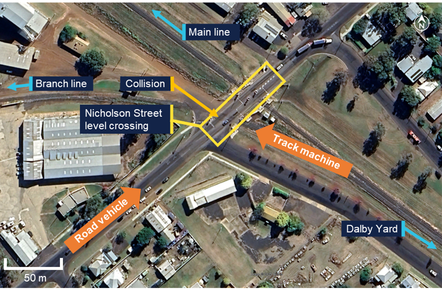
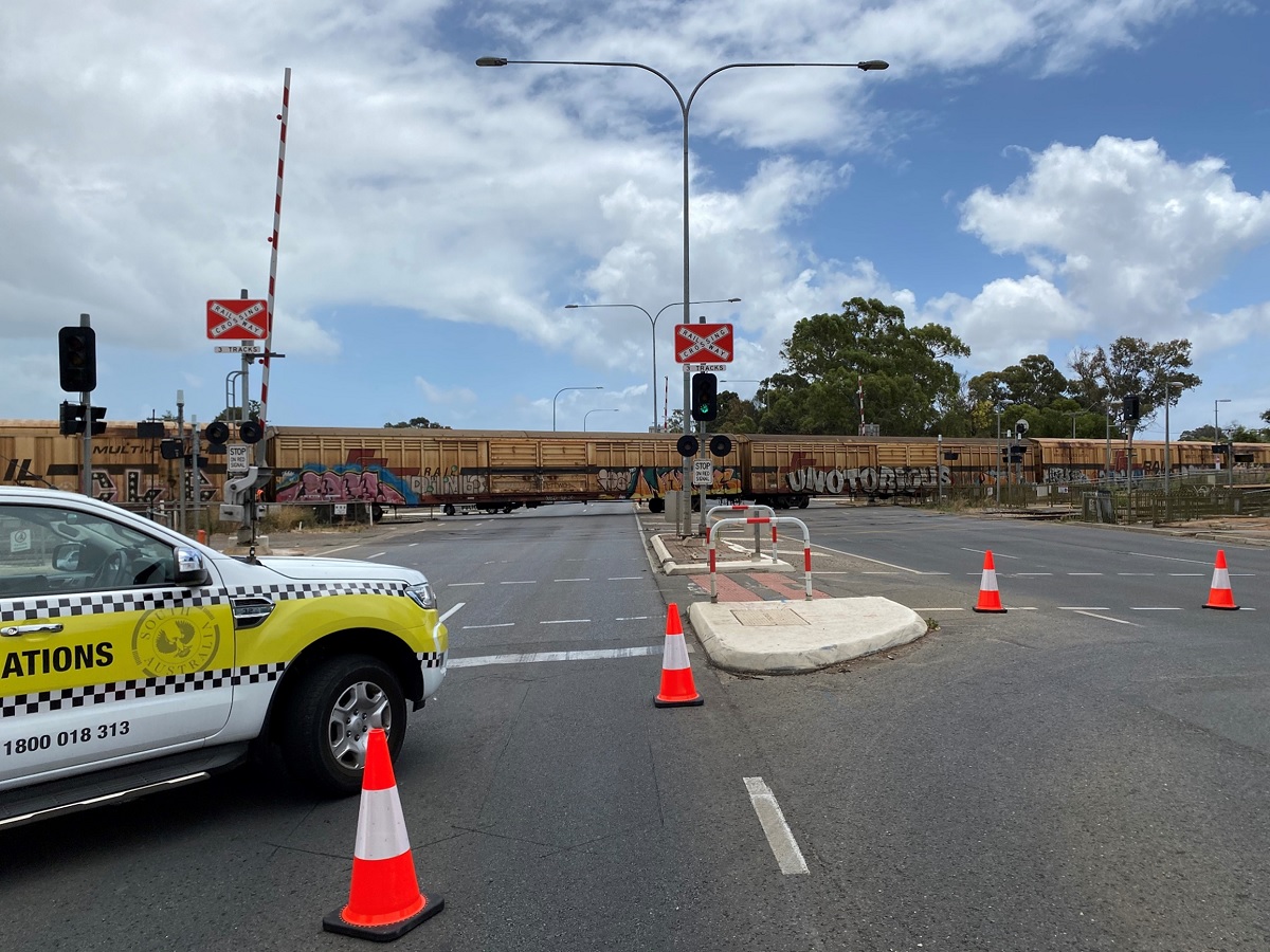
The track machine consist then travelled north-west through a dual-track active level crossing with Cunningham Street, and a single-track active level crossing with the Bunya Highway. A third active level crossing with Nicholson Street was located around 450 m further along the line. The Nicholson Street level crossing had a different layout to nearby level crossings, as it consisted of dual single-track active level crossings 30 m apart in the same crossing square (Figure 1).
Figure 1: Layout of the Nicholson Street level crossing
Source: Google Earth, annotated by the ATSB
To reach Meandarra, the track machine consist had to travel on the Glenmorgan branch line. Just after it turned out onto the branch line, the flashing red warning lights for the branch line crossing at Nicholson Street automatically activated. The track machine consist then entered the Nicholson Street level crossing at 1204.
At the same time, a road vehicle was also approaching the Nicholson Street level crossing from the south‑west. The driver of the road vehicle reported they were experienced and familiar with the area and the Nicholson Street level crossing.
The most recent Australian Level Crossing Assessment Model assessment from November 2024 noted that the minimum warning time for road users of an approaching train on the branch line was 23 seconds. The speed limit for rail vehicles through the Nicholson Street level crossing was 25 km/h. The assessment also reported that the level crossing and its associated controls were visible to road users from up to 500 m away.
As the track machine consist approached the Nicholson Street level crossing, it was travelling at an average speed of around 18 km/h. At this lower speed, the available warning time to road users to slow down and stop once the level crossing lights activated increased to over 30 seconds.
The track machine consist was equipped with forward‑facing video cameras and equipment that recorded its position The onboard video from the track machine captured the road vehicle as it approached the level crossing, and showed that the vehicle was not slowed sufficiently to stop at the stop line adjacent the flashing lights.
From the video evidence, the vehicle was calculated to have been travelling near the speed limit of 60 km/h as it approached and crossed the level crossing stop line.
At this moment, the track machine consist was already halfway across Nicholson Street and about to pass in front of the road vehicle. The video showed the road vehicle slowing down significantly after crossing the stop line, however, it did not stop and consequently collided with the track machine.
The front of the road vehicle sustained significant damage from impacting the front left side of the track machine. The split head tamper at the front of the consist sustained minor damage and the operating crew were uninjured. The driver of the road vehicle was also uninjured.
Level crossing information
The split level crossings at Nicholson Street were a consequence of the track layout. A branch line to Glenmorgan deviated from the mainline around halfway between the Bunya Highway and Nicholson Street level crossings, and both tracks then crossed Nicholson Street separately.
The mainline crossing on Nicholson Street had flashing warning lights and half-boom barriers as active protection, whereas the branch line crossing only had flashing warning lights and did not have booms.
The difference in active controls between the mainline and branch line crossings was likely due to:
the proximity of the side streets which intersected with Nicholson Street near the level crossing
the lower frequency of trains on the branch line compared to the mainline
the direct traffic control[3] safeworking system, which prevented more than one train movement in any direction across Nicholson Street at any one time.
As a result, only one of the 2 level crossings would activate with the presence of a train, and the other crossing would remain open for road traffic.
ATSB observations
Following the collision, the ATSB spoke with the involved parties, reviewed operational information from the rail infrastructure manager, reviewed recorded data and video recordings from the track machine consist, and assessed the design, condition, and operation of the level crossing. The ATSB’s review of the evidence collected identified that:
For undetermined reasons, the road vehicle driver did not respond to the active controls as they approached the crossing.
The road vehicle driver braked heavily upon seeing the rail vehicle but was unable to stop in time.
The rail vehicle driver did not mishandle or overspeed the track machine consist.
There were no mechanical factors which influenced the operation of either vehicle.
There were no environmental factors which influenced the operation of either vehicle.
The lights on the front of the track machine consist were turned on before the consist departed the siding.
The horn on the track machine consist was sounded when it entered each level crossing.
The ATSB’s analysis of the Nicholson Street level crossing found that:
The level crossing operated normally prior to the collision.
The warning lights for the Glenmorgan branch line were activated and visible at the time of the collision.
The design and operation of the level crossing eliminated the risk of short stacking[4] and road vehicle encroachment, with the 2 level crossings unable to be activated simultaneously.
The active controls at the level crossing were compliant with the relevant Australian Standards.
There was no evidence of the level crossing being poorly maintained.
There were no obstructions to visibility or sightlines along the road corridor, which prevented road users from seeing, interpreting, and responding to the active level crossing controls.
Reasons for the discontinuation
Based on a review of the available evidence, the ATSB considered it was unlikely that further investigation would identify any systemic safety issues or important safety lessons. Consequently, the ATSB has discontinued this investigation.
The evidence collected during this investigation remains available to be used in future investigations or safety studies. The ATSB will also monitor for any similar occurrences that may indicate a need to undertake a further safety investigation.
Purpose of safety investigations
The objective of a safety investigation is to enhance transport safety. This is done through:
identifying safety issues and facilitating safety action to address those issues
providing information about occurrences and their associated safety factors to facilitate learning within the transport industry.
It is not a function of the ATSB to apportion blame or provide a means for determining liability. At the same time, an investigation report must include factual material of sufficient weight to support the analysis and findings. At all times the ATSB endeavours to balance the use of material that could imply adverse comment with the need to properly explain what happened, and why, in a fair and unbiased manner. The ATSB does not investigate for the purpose of taking administrative, regulatory or criminal action.
Terminology
An explanation of terminology used in ATSB investigation reports is available here. This includes terms such as occurrence, contributing factor, other factor that increased risk, and safety issue.
Publishing information
Released in accordance with section 25 of the Transport Safety Investigation Act 2003
Ownership of intellectual property rights in this publication
Unless otherwise noted, copyright (and any other intellectual property rights, if any) in this report publication is owned by the Commonwealth of Australia.
Creative Commons licence
With the exception of the Commonwealth Coat of Arms, ATSB logo, and photos and graphics in which a third party holds copyright, this report is licensed under a Creative Commons Attribution 4.0 International licence.
The CC BY 4.0 licence enables you to distribute, remix, adapt, and build upon our material in any medium or format, so long as attribution is given to the Australian Transport Safety Bureau.
Copyright in material obtained from other agencies, private individuals or organisations, belongs to those agencies, individuals or organisations. Where you wish to use their material, you will need to contact them directly.
[1]Yard Limit: a defined area of track where rail traffic movements are authorised and managed by a nominated network control officer or other suitably qualified employee, and whose boundaries are marked by trackside signage and, where relevant, labelling on signal panel displays. Train movements in these areas can be co-ordinated through fixed signal routes, hand signals, or verbal/written authorities.
[2]Proceed Authority: authorises rail traffic to enter and occupy a section or block and proceed in the forward direction.
[3]Direct traffic control: an absolute block safeworking system used to control the movement of trains in non-signalled territory. This prevents more than one train being authorised into a defined section or block at any one time.
[4]Short stacking: when part of a vehicle, which is legally permitted to use the road, remains on the crossing while stopped at an intersection to give way to traffic on a priority road located beyond the crossing.
On 14 February 2025, a Fairchild SA227-DC (Metro) operating as a single-pilot cargo flight was scheduled to depart Mackay Airport, Queensland at 0745 local time for a flight to Mount Isa, Queensland. As the aircraft taxied toward the runway, the air traffic control aerodrome controller (ADC) received multiple calls from ground staff that the forward cargo door of the aircraft was open. The ADC contacted the pilot and instructed them to taxi back to a designated parking bay to check the aircraft. The aerodrome’s aviation safety officer (ASO) conducted an inspection of the taxiway to check for fallen cargo, however reported that none was located. A subsequent aircraft check was made by the pilot and the cargo doors were secured. The aircraft then departed to Mount Isa as scheduled.
Following the incident the operator contacted the pilot. The operator reported that due to the amount of freight being carried a portion of it was loaded within the nose section of the aircraft accessed by two cargo doors. The pilot reported to the operator that they were certain that when the final walk-around[1] was conducted that the cargo doors were closed. However, the pilot noted that the aircraft did not have a strut on the right door and that it was not easily discernible between open or closed as it ‘sat’ flush with the airframe when closed, therefore although both the doors appeared closed, the latches were not properly secured on the right forward door.
The operator reported that the pilot had not effectively completed the pre-departure procedures and had been distracted during the freight‑loading task. The operator noted that time pressure, due to a delay on the previous sector, may have contributed to the pilot’s procedural lapse.
Safety message
Ensuring aircraft doors are properly secured before departure is a vital step to avoid in-flight emergencies. Relying on visual appearance alone makes it difficult to detect an unsecured door, therefore pilots are advised to physically verify all aircraft doors and aircraft hatches are secured prior to departure.
Pilots and operators are further reminded that prioritisation of schedule deadlines can erode aviation safety and can lead to increased risk‑taking and that clear articulation of company safety policy to staff may reduce self-imposed pressure on staff towards maintaining efficiency over the schedule.
About this report
Decisions regarding whether to conduct an investigation, and the scope of an investigation, are based on many factors, including the level of safety benefit likely to be obtained from an investigation. For this occurrence, no investigation has been conducted and the ATSB did not verify the accuracy of the information. A brief description has been written using information supplied in the notification and any follow-up information in order to produce a short summary report and allow for greater industry awareness of potential safety issues and possible safety actions.
[1] Walk-around is the procedure for a visual inspection of an aircraft by the pilot before flight to ensure no obvious problems.
Occurrence summary
Mode of transport
Aviation
Occurrence ID
AB-2025-012
Occurrence date
14/02/2025
Location
Mackay Airport
State
Queensland
Occurrence class
Incident
Aviation occurrence category
Airframe - Other
Highest injury level
None
Brief release date
12/03/2025
Aircraft details
Manufacturer
Fairchild Industries Inc
Model
SA227-DC
Sector
Turboprop
Operation type
Part 121 Air transport operations - larger aeroplanes
On 12 February 2025, Alliance Airlines Embraer E190, VH-UYO, was operating Qantas flight QF1888 from Cairns, Queensland to Darwin, Northern Territory. At 1634 local time, passing the initial approach fix for the instrument landing system (ILS) approach to Darwin Airport’s runway 29, the auto‑flight system approach mode unexpectedly disarmed and reverted to basic flight director modes. The aircraft then deviated right and then left of the ILS course, before intercepting the lateral course at about the final approach fix.
Passing 1,000 ft above aerodrome elevation, the aircraft was above the glideslope, at a high rate of descent and high airspeed. The flight crew elected to continue the approach, as the aircraft was then in visual meteorological conditions. Passing 500 ft, the flight crew assessed that the aircraft was stabilised, although still too fast. The pilot monitoring subsequently identified that the flaps were not in the landing configuration and selected the correct position. The flight crew continued the approach and conducted an uneventful landing.
What the ATSB found
The ATSB found that on crossing the initial approach fix for the ILS approach, due either to a system synchronisation issue or the pilot flying inadvertently disarming the approach mode, the aircraft’s auto‑flight system reverted to roll and flight path angle modes.
Following the unexpected mode change, the pilot flying did not reengage approach mode or disconnect the autopilot. This likely contributed to the aircraft deviating outside the required lateral tolerance of the approach below the minimum safe altitude while in instrument meteorological conditions.
Additionally, the ATSB found that the flight crew did not discontinue the approach when the aircraft was unstable at the 1,000 ft stabilisation height as they incorrectly assessed that they could continue to 500 ft in visual meteorological conditions with multiple stabilised approach criteria unmet.
In the limited time available to stabilise the aircraft by 500 ft, the flight crew incorrectly assessed that the aircraft was stable and continued the approach, unaware that the pilot monitoring had inadvertently selected an incorrect flap configuration.
Finally, the ATSB found that Alliance Airlines' standard operating procedures were unclear about the criteria for continuing an unstable instrument approach to 500 ft when aircraft entered visual conditions.
What has been done as a result
Following this incident, Alliance Airlines issued an operations notice ‘to improve clarity and compliance’ with the stabilised approach criteria. The notice detailed the stabilised approach policy. It also amended the stabilisation height such that for 3‑dimensional and 2‑dimensional instrument approaches, and straight‑in visual approaches, the stabilised criteria were to be met by 1,000 ft above aerodrome elevation. The 500 ft stabilisation height applied only to a visual circuit or circling manoeuvre approaches. The notice reminded flight crew of Alliance’s ‘non punitive go‑around policy’ and required all unstable approaches to be reported. Finally, Alliance Airlines conducted a flight data review of unstable approaches over the previous 6 months operations to identify similar occurrences.
Safety message
The Flight Safety Foundation’s (FSF) Reducing the risk of runway excursions report found that, in the 16 years to 2009, the most common accident was a runway excursion, accounting for 33% of all aircraft accidents. The highest risk factor for runway excursions was identified as an unstable approach. Further, an FSF survey (Normalization of Deviance) identified that only 3–4% of approaches were unstable but that in over 97% of those, the flight crews did not conduct a go-around. It stated:
Noncompliance with standard operating procedures (SOPs) — especially tolerance of unstabilized approaches — is a serious impediment to further reduction of accident risk.
Guidance from the International Air Transport Association for preventing unstable approaches stated that pilots must be trained to understand the risks of an unstable approach, because an unstable approach can be completed successfully, which may reinforce bad practice.
Additionally, this incident highlights how important continuous attention to automatic flight system modes displayed on the primary flight display is to the maintenance of situation awareness.
This incident also illustrates the need for effective flight crew monitoring. The Flight Safety Foundation identified that monitoring can be improved by standard operating procedures, increased emphasis and practice, and stated:
One of the most important aspects of a safe flight operation is the requirement for crewmembers to carefully monitor the aircraft’s flight path and systems, as well as actively cross-check each other’s actions.
The investigation
The ATSB scopes its investigations based on many factors, including the level of safety benefit likely to be obtained from an investigation and the associated resources required. For this occurrence, the ATSB conducted a limited-scope investigation in order to produce a short investigation report, and allow for greater industry awareness of findings that affect safety and potential learning opportunities.
The occurrence
On the afternoon of 12 February 2025, Alliance Airlines (Alliance) Embraer ERJ 190‑100 IGW (E190), registered VH‑UYO, was operating Qantas flight QF1888 from Cairns, Queensland to Darwin, Northern Territory. On board were 2 flight crew, 2 cabin crew and 49 passengers. The captain was the pilot flying (PF), and the first officer was the pilot monitoring (PM).[1]
After departing Cairns, the aircraft climbed to cruise at flight level (FL) 340.[2] En route the flight crew obtained air traffic control (ATC) clearances, first to deviate up to 30 NM (56 km) left, and later up to 50 NM (93 km) right of the planned route to avoid hazardous weather. At 1614 Darwin local time the flight crew received clearance to descend to FL 120. Just over 2 minutes later they requested a further clearance to deviate up to 60 NM (111 km) right to avoid weather.
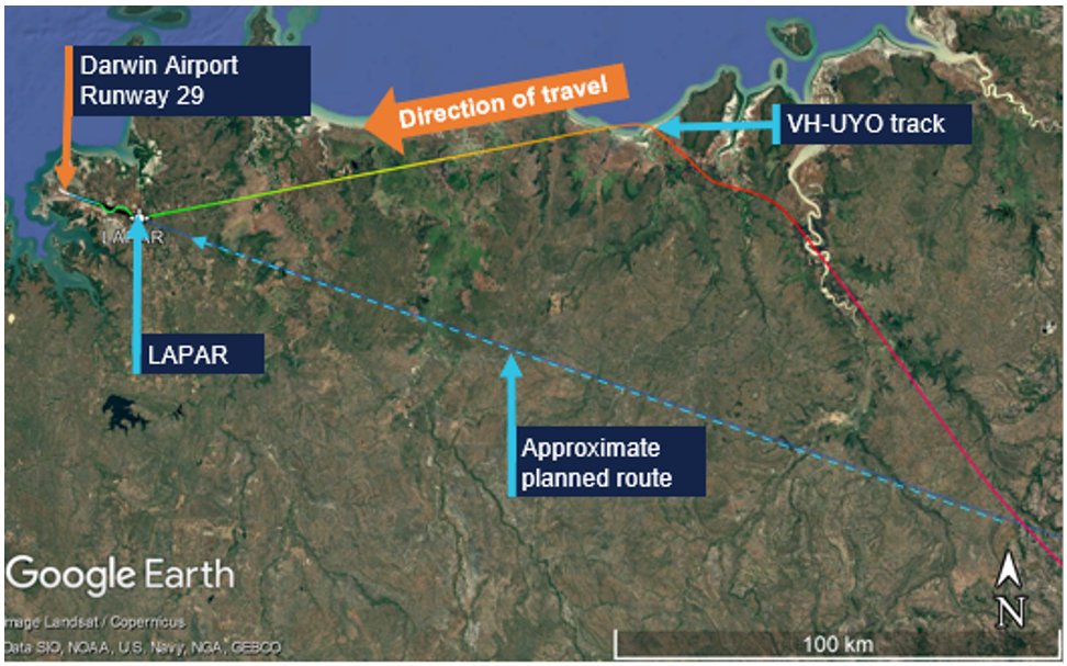
At 1619 the flight crew requested, and received, a clearance to deviate up to 70 NM (130 km) right of route and to track direct to waypoint LAPAR, once clear of the weather. About 2 minutes later, descending through FL 190, the aircraft turned left from a position about 30 NM (56 km) right of the planned route, to track 60 NM (111 km) direct to LAPAR (Figure 1).
Figure 1: VH-UYO recorded flight data showing weather diversion and tracking to LAPAR
Source: Google Earth overlaid with FlightRadar24 data, annotated by the ATSB
At 1622 the PM contacted Darwin Approach ATC, advised they were descending to FL 120, had received automatic terminal information service (ATIS) X‑ray (X), and were tracking direct to LAPAR. ATIS X included advice of:
the expectation of an instrument approach
wet runways
wind from 340° at 15 kt, with a maximum 15 kt crosswind on runway 29
visibility of 2,000 m
showers of rain
scattered[3] cloud 1,200 ft above aerodrome elevation.
The PM advised the approach controller when the aircraft was approaching FL 120, and received further clearance to descend to 9,000 ft and, 2 minutes later, to 7,000 ft. At 1629, as the aircraft descended through about 8,000 ft, the controller requested a reduction to ‘minimum clean speed’, as by radar VH‑UYO was showing a groundspeed of 270 kt, which exceeded the 250 kt maximum indicated airspeed below 10,000 ft. Although the aircraft’s airspeed at that time was 250 kt, the flight crew actioned the request to reduce speed, advised that they were approaching 7,000 ft, and were then cleared to descend to 5,000 ft.
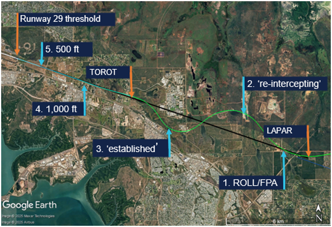
At 1631, the approach controller cleared the flight crew to descend to 3,000 ft and conduct the instrument landing system (ILS)[4] -Z approach to runway 29. LAPAR was the initial approach fix[5] for the ILS and was aligned with the runway centreline (Figure 2).
Source: FlightRadar24 data overlaid on Google Earth, annotated by the ATSB
The PM selected flap 1 as the aircraft descended through about 4,600 ft. About 30 seconds later, the approach controller instructed the PM to contact the tower controller when leaving 3,000 ft. In preparation for the ILS, the PF then pressed the approach (APP) pushbutton on the aircraft’s guidance panel, arming the approach mode. This also armed flight director (FD) localiser (LOC) lateral and glideslope (GS) vertical modes. With approach mode armed, when the aircraft intercepted the localiser (at LAPAR), LOC should become the active lateral mode and when it subsequently intercepted the glideslope, GS should become the active vertical mode.
As LAPAR was a ‘fly-by’ (rather than a ‘flyover’) waypoint, the aircraft’s flight guidance and control system (FGCS) pre‑empted the turn and passed by LAPAR at 1634:51, at 183 kt airspeed and at the selected altitude of 3,000 ft. The selected altitude was then wound down to 2,200 ft and 2 seconds later, the FGCS captured the localiser and the recorded flight data showed LOC and flight path angle (FPA) modes became active. One second later, the lateral mode reverted to the basic FD ROLL mode (Figure 2 No 1 and Figure 3).
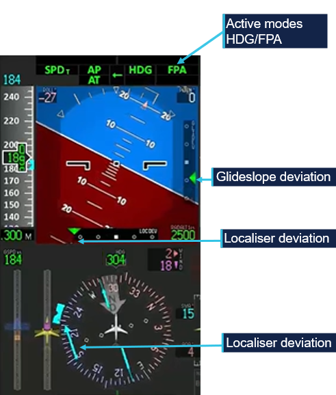
Figure 3: Flight mode annunciation display showing localiser (LOC) capture followed by reversion to basic modes (ROLL/FPA)
Recorded flight data showed LOC mode became active and then disarmed within 1 second. The active mode was recorded every second, but the armed mode was recorded every 2 seconds. Hence at 1634:56, the recorded data showed LOC as both the armed and active mode. Source: Embraer animation of recorded flight data, annotated by the ATSB
The FO recalled being very surprised seeing the ROLL/FPA modes. In those modes, the aircraft captured and maintained the roll angle and flight path angle it was in at the time of activation. At that time, the aircraft was:
aligned with the localiser
at a flight path angle of approximately 0°
half a dot above the glideslope
banked 20° right.
After intercepting the localiser, the ILS frequency became the active navigation source for the aircraft’s primary flight display (PFD), for the remainder of the flight. As such, lateral deviation from the localiser and vertical deviation from the 3° glideslope would be depicted on the PFD with 2 dots in each direction (left‑right/up‑down), with 2.5 dots representing full‑scale (or greater) deviation. Localiser deviation was also depicted by a course deviation indicator (CDI) and dots either side of the course on the compass instrument on the lower part of the PFD (Figure 4).
Figure 4: Compass instrument course deviation indicator aligned with the localiser at 1634:56
Source: Embraer animation of recorded flight data, annotated by the ATSB
Following activation of the ROLL/FPA modes, the aircraft deviated right of the localiser, maintaining approximately 20° roll for about 20 seconds, as it descended. After 14 seconds, the PM selected the landing gear down and the PF moved the heading bug and selected heading (HDG) mode to command the aircraft to turn left towards the localiser.
The CDI exceeded half scale deflection (1.5 deviation dots) at 1635:16. The aircraft was then outside the lateral flight tolerance for the ILS and below the 10 NM minimum safe altitude of 3,000 ft.
At 1635:30, the PM contacted the Darwin aerodrome (tower) controller and advised that they were ‘just slightly right of the localiser and re‑intercepting’ (Figure 2 No 2). The controller responded with the instruction to ‘maintain 2,000 [ft] until glidepath interception’. The PM read back ‘maintain 2,000’, but not ‘until glidepath interception’. The controller then stated: ‘once you’ve intercepted the glidepath, cleared the ILS’. The PM did not respond.
The controller later advised the ATSB that 2,000 ft was the highest minimum vector altitude around Darwin Airport, which assured terrain separation, and there was no conflicting traffic. The controller reported that although the PM did not complete the readback, they had read back the safe altitude. The controller assessed that the flight crew were ‘working really hard’ to get back onto the ILS and would let ATC know when they wanted further descent or commenced a missed approach. The captain reported that they wanted to get re‑established on the localiser so they could conduct the published missed approach under automation if required. On reaching the maximum deviation to the right of the localiser, the aircraft was (Figure 5):
banked 27° left
at full scale localiser deflection
one dot above the glideslope
at 2,470 ft above mean sea level (AMSL)
descending at 1,254 ft/minute (fpm).
Figure 5: Primary flight display at 1635:30 showing full‑scale localiser deviation (localiser left of the aircraft)
Source: Embraer animation of recorded flight data, annotated by the ATSB
Flap 2 was selected at 1635:55, at about 2,200 ft AMSL. The active lateral mode automatically changed from HDG to LOC mode one second later, but because the APP mode was not armed, GS mode did not become active although the aircraft was within one dot of the glideslope. The aircraft then passed through the localiser 52° off the runway heading, before entering a right turn, as the FGCS commanded re‑interception of the localiser course.
At 1636:22, 177 kt airspeed and 2,000 ft, the PF advised the controller that ‘Qantas 1888 is established’ (Figure 2 No 3). Established was defined as being within half full‑scale deviation of the specified track.[6] The aircraft was then (Figure 6):
at full-scale localiser deviation
banked 33° right
nearly 2 dots above the glideslope.
Figure 6: Primary flight display at 1636:22 showing full‑scale localiser deviation (localiser right of the aircraft) and nearly 2 dots glideslope deviation (glideslope below the aircraft)
Source: Embraer animation of recorded flight data, annotated by the ATSB
The PM then requested further descent, to which the controller replied, ‘cleared ILS runway 29’, and just below 2,000 ft, the PM selected flap 3.
At 1636:51, the aircraft passed the final approach fix (FAF) TOROT (Figure 2). At the FAF, the PM was required to call out ‘FAF, height checked, missed approach altitude set’. At that time:
the FAF procedure height was 1,330 ft and the aircraft was at 1,695 ft (AMSL)
the aircraft was at full‑scale deviation above the glideslope and descending at 1,331 fpm
the set altitude was 800 ft, and the missed approach altitude was 3,000 ft.
After the FAF, Alliance’s standard operating procedures required the aircraft to be within one dot of the localiser and glideslope. The procedures also stated that the aircraft should regain the 3° profile no later than 1,500 ft above aerodrome elevation. However, passing 1,500 ft, the aircraft was full‑scale deviation above the glideslope and descending at over 1,500 fpm.
Passing about 1,100 ft AMSL, the PM intended to select flap 5, but inadvertently selected flap 4. Flap 4 had the same flap and slat extension as flap 5, but flap 4 was a take‑off configuration not a landing configuration (see the section titled Flap configuration).
At 1637:16, the aircraft passed 1,000 ft radio altitude,[7] which coincided with Alliance’s stabilisation height of 1,000 ft above aerodrome level (AAL) for conducting an instrument approach. Contrary to the stabilised approach criteria, the:
airspeed was 162 kt, 29 kt above approach speed (VAP) – faster than the permitted VAP + 10
flap setting was 4 instead of flap 5 – not in the landing configuration
before landing checks had not been completed
aircraft was 1.4 dots above the glideslope – not within the allowable 1 dot of the glideslope
descent rate was 1,582 fpm – higher than the allowable rate of descent than 1,000 fpm.
Providing all other stabilisation criteria were met, Alliance permitted the airspeed to be higher than VAP + 10 until 500 ft in visual meteorological conditions (VMC)[8] by day.
The captain recalled that the aircraft entered VMC at about 2,500 ft. However, the FO reported that just prior to 1,000 ft, they were ready to call out ‘unstable’ approach, when the captain stated that they were now ‘visual’ and could therefore continue the approach and be stabilised by 500 ft. The captain later reported that the lower stabilisation height of 500 ft in VMC was the approved procedure at their previous company. The FO reported being uncertain about Alliance’s policy and deferred to the captain.
Alliance procedures stated that below 1,000 ft AAL, the descent rate ‘shall not normally’ exceed 1,000 fpm. The descent rate exceeded 1,000 fpm until 1637:29, when passing 723 ft radio altitude, with the PF arming the APP mode 3 seconds later and LOC/GS becoming the active modes. The selected altitude was then set to the missed approach altitude of 3,000 ft.
At 1637:42 and 500 ft radio altitude, contrary to the stabilisation criteria in VMC, the:
airspeed was 17 kt above VAP, with a maximum of VAP + 10 permitted
aircraft was not in the landing configuration (flap 4 was a take‑off setting).
The PM observed that although slightly fast, the speed was trending down, and the flight crew reported thinking the aircraft met the stabilised approach criteria at 500 ft. The PM reported having completed the before landing checklist (gear and flaps) at about 800 ft, but at 411 ft radio altitude, identified that the flap lever was in the flap 4 detent and quickly moved it to the flap 5 position. The flap transitioned to the flap 5 position at 345 ft radio altitude.
The aircraft decelerated to the target approach speed VAP (133 kt) at 264 ft radio altitude. The captain disconnected the autopilot at 212 ft radio altitude and manually flew the aircraft to an uneventful landing at 1638:32.
Context
Flight crew information
The captain and first officer each held an air transport pilot licence (aeroplane), Embraer E190 type rating and a class 1 aviation medical certificate.
The captain had a total flying time of 7,100 hours, 4,000 of which were on Embraer E190 aircraft, and 150 of those were accrued in the last 90 days. The captain had previously flown Embraer E120 aircraft for about 6 years and E190 aircraft for another 4–5 years with a different operator. As a direct entry captain to Alliance, the captain conducted 6 sectors and then a line check before operating for about 2 years with Alliance on the E190 aircraft. The captain was a training captain at their base and had conducted some of the first officer’s training.
The first officer had a total flying time of 16,325 hours, 274 of which were on the Embraer E190, and 130 of those were accrued in the last 90 days. The FO commenced ground training for the Embraer E190 type rating with Alliance in May 2024 and started operating for Alliance in late September 2024.
The captain reported having slept 7 hours the previous night, 6 hours the night before that, and assessed their fatigue as ‘Okay, somewhat fresh’. The FO reporting having slept 8.5 hours on each of the previous 2 nights and assessed their fatigue as ‘Very lively, responsive, but not at peak’.[9] There was no evidence that fatigue was a factor in this occurrence.
The captain assessed their workload during the approach as 8/10. Their workload was increased by diverting around weather and a thunderstorm building in the vicinity of the airport, flying the descent in manual speed mode and the approach in manual modes. The FO assessed their workload during the approach as 10/10, in attempting to achieve the stabilised approach criteria.
Approach mode disarming
VH-UYO had Load 27 Honeywell flight management system (FMS) software, which used flight director (FD) modes and non‑FMS navigation for the ILS approach. Provided the ILS approach was part of the flight plan and NAV 1 and 2 were in AUTO FMS mode, the system would transition from FMS navigation to ILS approach through the preview mode at 150 NM. The recorded flight data showed that both NAV 1 and 2 frequencies were selected to the Darwin runway 29 ILS‑Z, and the PM reported that preview mode selected as expected.
The transition from FMS to FD navigation could also be done manually by pressing the VOR/LOC (V/L) button on the guidance panel. The V/L button selects VOR or LOC as the primary navigation source for the on‑side PFD and toggles between VOR/LOC1 and VOR/LOC2. The recorded data showed that the primary navigation source was FMS1 until it changed to VOR/LOC1 at 1634:57, less than one second after LOC became active before dropping out, and remained VOR/LOC1 until after landing.
Embraer analysed the recorded flight data and identified that when the auto‑flight control system (AFCS) captured LOC mode, the display systems had not transitioned to the LOC navigation source. In that situation, the localiser capture is invalidated, and the autopilot reverts to ROLL/FPA. Although the navigation source only recorded every 4 seconds, Embraer advised that this was the most likely reason for the mode reversion. Honeywell advised that as the recorded data rate was less than the system update rate, there was insufficient information to assess whether a synchronisation issue existed. However, Honeywell will assess whether aircraft operators have reported any similar events.
Pressing the approach (APP) pushbutton arms approach mode if it is not armed or active, and disengages or disarms approach mode if it is armed or active. In interview several weeks after the incident, the captain reported that they pushed the APP button once to arm the approach mode after receiving ATC clearance for the ILS, and probably inadvertently pushed it again, disarming the mode, on receiving a second clearance for the ILS.
However, ATC recordings showed that the second ILS clearance was received about 50 seconds after the mode reversion and a third clearance 40 seconds later. The captain also reported having re‑armed approach mode as soon as they selected heading mode after the reversion (at about 2,700 ft), but a review of flight data identified that the approach mode was not re‑armed until 620 ft AAL.
The approach mode armed status was recorded every 2 seconds in the flight data and was armed 1 second before LOC captured and not armed (just less than) 1 second after LOC capture. Therefore, the possible second press of the APP button would have to have occurred within 1 second of the LOC capture.
Mode reversion
The E190 Aircraft Operations Manual described roll hold (ROLL) mode as the basic lateral mode. Depending on the bank angle at the moment of ROLL activation, the autopilot (AP) will maintain the following bank angles until another lateral mode is selected:
bank angle at 6° or below: AP levels the wings
bank angle above 6° and below 35°: AP holds the present bank angle
bank angle at or above 35°: AP maintains a bank angle of 35°
Relevant to this occurrence, roll mode is activated:
when there is no lateral mode active and a vertical mode is selected
by deselecting an active lateral mode.
Roll mode is deactivated when another lateral mode is activated.
Flight path angle (FPA) is the basic vertical mode, except during take‑off. The FPA can be used for vertical navigation by selecting a higher or lower altitude and then pressing the FPA button.
Alliance’s procedures required changes in lateral and vertical engaged modes to be announced by the pilots:
the pilot who changes the flight mode checks on the flight mode annunciator (FMA) and verbally confirms the selected mode
the other pilot verbally confirms the new flight mode.
The procedures also stated that:
When the aircraft does not perform as expected, the autopilot must be disconnected and manual flight promptly established.
Flap configuration
The E190 has slats on the leading edge of the wing and flaps on the trailing edge. There are 7 slat/flap control lever positions: up, 1–5 and full. Flap 4 is a take‑off configuration, and normal landing configurations are flap 5 or full. In flap 4 and flap 5 positions, the flaps extend to 20° and slats to 25°. Although the physical positioning of the flaps and slats is identical, the flight system logic triggers different warnings based on the selected position as follows:
Retard mode reduces the thrust levers to idle during flare on landing. This only occurs when the slat/flap lever position is at 5 or full and landing gear is down.
Enhanced ground proximity warning system (EGPWS) mode 2 – excessive terrain closure rate operates mode 2A when flaps are not in the landing position and 2B with flaps down and in the landing position. Violations of the alert envelopes produce aural ‘TERRAIN TERRAIN’ and ‘PULL UP’ alerts. Mode 2B has a desensitized alert envelope with a reduced upper height limit and a higher closure rate when:
flaps are in the landing position
on an ILS, the aircraft is within +/- 2 dots of the localiser and glideslope
within 5 NM and 3,500 ft of the runway (and terrain awareness is functioning)
during the first 60 seconds after take‑off.
EGPWS mode 3 alerts if a decrease in altitude occurs immediately after take‑off or during a go‑around when the flaps are not in a landing configuration (‘DON’T SINK’ aural and GND PROX PFD alerts).
EGPWS mode 4 unsafe terrain clearance depends on radio altitude, airspeed, landing gear and flap position. In mode 4B, with landing gear down and flaps not in the landing configuration, pilots hear a ‘TOO LOW, FLAPS’ alert and see a GND PROX alert on the PFD, when below 159 kt airspeed and 245 ft radio altitude. Mode 4C operates when the landing gear or flaps are not in the landing configuration and will trigger a ‘TOO LOW, TERRAIN’ aural alert.
On this occasion, had the flight crew continued towards landing with flap 4 configured, they would likely have received any or all of ‘TERRAIN TERRAIN’, ‘PULL UP’, ‘TOO LOW FLAPS’, and ‘TOO LOW TERRAIN’ aural alerts.
Threshold and approach speeds
The aircraft’s reference speed (VREF) is 1.3 times the stalling speed (VS) and is the minimum recommended speed at 50 ft over the threshold. It is used for landing distance calculation and is the speed to which the airspeed reference bugs are set before an approach. The approach speed (VAP) exceeds the reference speed to account for gusts or windshear. Alliance’s E190 standard procedures defined VAP = VREF = + 1/2 steady headwind component + gust increment, limited to a minimum of VREF + 5 kt and maximum VREF + 20 kt.
Meteorological conditions
Forecast
The Bureau of Meteorology (BoM) graphical area forecast encompassing the Darwin area, issued at 1359 and valid between 1430–2030 local time, stated:
visibility greater than 10 km, scattered cumulus/stratocumulus clouds with bases 4,000 ft above mean sea level and tops above 10,000 ft, and bases from 2,000 ft over sea to 30 NM (56 km) inland
1,000 m visibility in scattered heavy showers of rain, occasional towering cumulus clouds with bases at 2,000 ft and tops above 10,000 ft
500 m visibility in occasional heavy thunderstorms with rain, occasional cumulonimbus clouds with bases from 2,000 ft and tops above 10,000 ft, broken stratus between 500 and 1,500 ft
moderate turbulence below 400 ft in smoke and thermals over land until 1830.
There was a tropical cyclone off the northern coast of Western Australia but no SIGMET[10] for the Northern Territory.
The Darwin Airport forecast (TAF)[11] issued at 0851 was valid for 30 hours from 0930 on 12 February until 1530 on 13 February. Two subsequent TAF amendments were issued before the occurrence, one at 1148 and another at 1452. All TAF cloud heights are above aerodrome elevation. All had the same forecast for:
wind from 340° (True) at 12 kt
visibility greater than 10 km
light showers of rain
scattered cloud at 2,000 ft.
For the period of the aircraft’s approach, 1614–1638, the forecast and amendments included (intermittent) periods of up to 30 minutes of:
visibility reducing to 1,000 m in heavy showers of rain
broken cloud at 500 ft
scattered towering cumulus with bases at 2,000 ft.
Forecast to occur from 2330 on 11 April to 1330 on 12 April, there was a 30% probability of thunderstorms for periods up to 1 hour with:
variable direction winds of 15 kt winds gusting to 30 kt
visibility reducing to 500 m in thunderstorms and heavy rain
broken cloud at 400 ft
scattered cumulonimbus clouds with bases at 2,000 ft.
A third TAF amendment was issued at 1642 (4 minutes after the aircraft landed), which included an additional intermittent period lasting up to 30 minutes of:
visibility reducing to 500 m in thunderstorms and heavy rain
broken cloud at 400 ft
scattered cumulonimbus clouds with bases at 2,000 ft.
Observations
The following weather observations at Darwin Airport occurred during the time of the aircraft’s approach.
At 1617, a special report of meteorological conditions (SPECI)[12] was issued, which included:
3,000 m visibility
thunderstorms in the vicinity (lightning detected outside the 8 km radius of the airport)
few cloud at 1,500 ft
broken cloud at 2,600 ft
few cumulonimbus clouds at 2,000 ft.
At 1630, a SPECI was issued that included:
4,000 m visibility
heavy showers of rain
few cloud at 1,500 ft
scattered cloud at 1,900 ft
broken cloud at 4,000 ft
detail that 2 mm of rain had fallen in the previous 10 minutes.
At 1637, one minute prior to landing, a SPECI was issued that included:
8,000 m visibility
thunderstorms and rain
scattered cloud at 1,300 ft
broken cloud at 3,600 ft
few cumulonimbus clouds with bases at 2,000 ft
advice that 0.6 mm of rain had fallen in the previous 10 minutes.
Radar imagery
The BoM Darwin/Berrimah radar was located 7 km south‑east of Darwin Airport.
Radar images showed moderate rain in the Darwin Airport area at 1614, that reduced to light to no rain around the time of the approach. The associated cloud/cell was stationary, and according to the BoM, it was not unusual to have a stationary rain/storm sitting over the airport in the wet season. The BoM information about that radar included:
Heavy rain over the radar site will cause attenuation of all signals. Path attenuation also occurs when the radar beam passes through an intense thunderstorm cell; the returned signal from cells further along that path will be reduced...it may 'undershoot' high level storms and rain echoes may appear less intense than actual rainfall rate.
The BoM advised that due to attenuation, the light rainfall indicating on the radar image at 1634, may have been less intense than the actual rainfall rate.
Webcam
The BoM provided webcam images for each minute from 1634–1638 facing north and east.
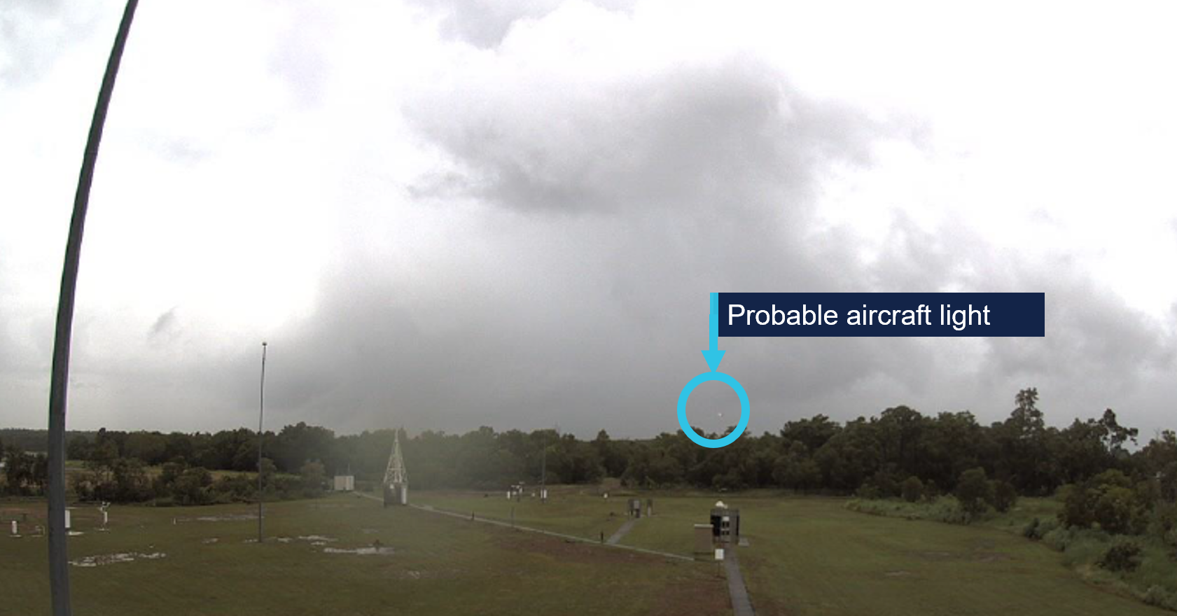
At 1638, the aircraft would have been due east of the webcam on final approach, at about 300 ft, probably the light visible in the east view at 1638 (Figure 7).
Figure 7: BoM webcam image facing east at 1638 and probable aircraft light
Source: Bureau of Meteorology, annotated by the ATSB
The cell with heavier rain to the north was evident in the north view at 1638 (Figure 8).
Figure 8: BoM webcam image facing north at 1638
Source: Bureau of Meteorology
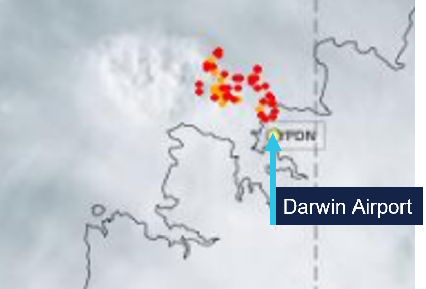
Figure 9 shows satellite imagery of cloud cover at Darwin Airport at 1640, and lightning strikes that occurred in the 10 minutes prior (red) and during the period 10–30 minutes prior (orange).
Figure 9: Cloud cover at 1640 and recorded lightning strikes
Source: Satellite image originally processed by the Bureau of Meteorology from the geostationary meteorological satellite Himawari-9 operated by the Japan Meteorological Agency. Lightning data sourced from Weather Zone Lightning Network
Automatic terminal information service
The Royal Australian Air Force’s Darwin Airport automatic terminal information service (ATIS)[13] X‑ray (X) was issued at 1610 and included advice to expect an instrument approach and that runways 29 and 36 were active for arrivals, with runway 29 in use for departures. The runways were wet, with surface condition code 555. ATIS X‑ray also detailed the following weather conditions:
wind from 340° at 15 kt, maximum 15 kt crosswind on runway 29
ATIS Yankee (Y) came into effect at 1624, with the only change being a temperature reduction to 27°C.
Based on the forecast and observed weather conditions at the time of the approach, the flight crew could not have anticipated VMC or expected to remain clear of cloud until below about 1,200 ft.
Recorded data
Flight data from the aircraft’s quick access recorder (QAR) for the incident flight was analysed by the ATSB and Embraer.
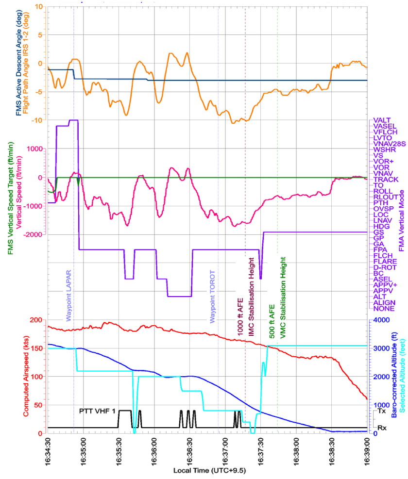
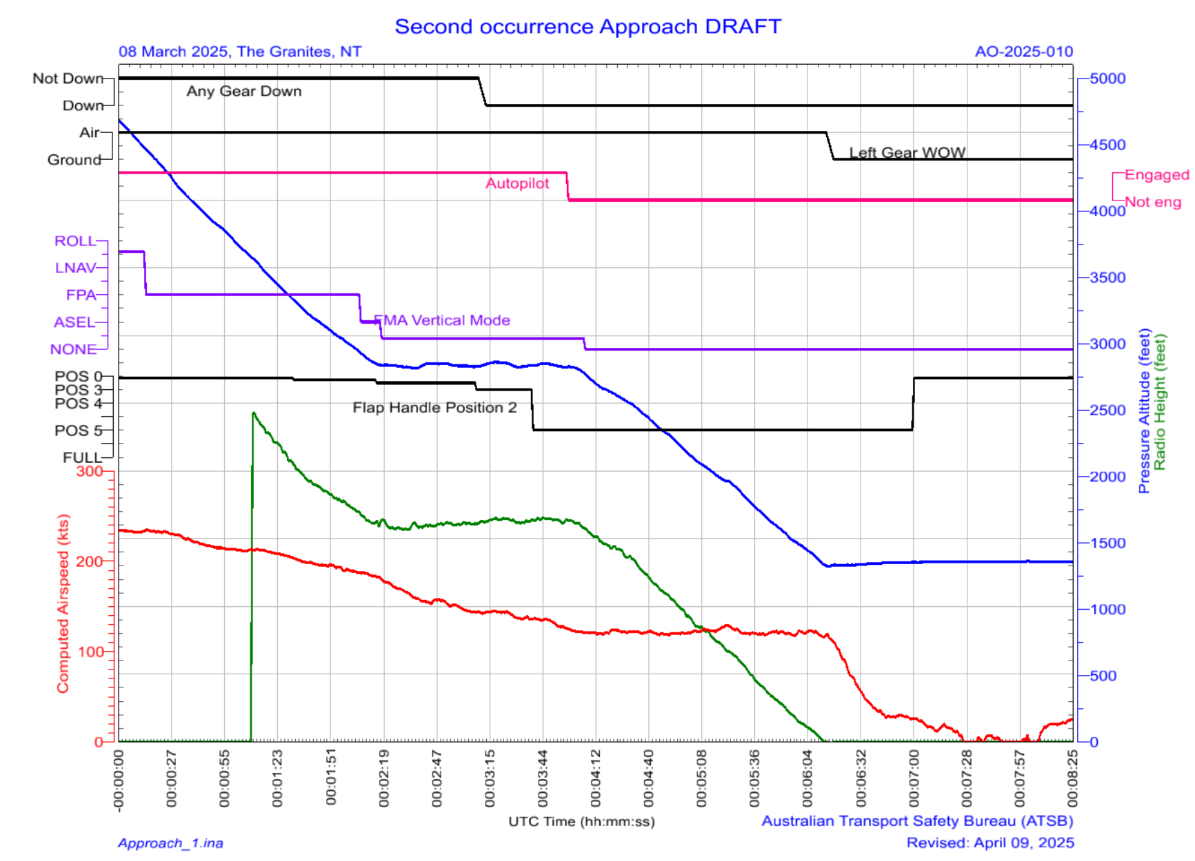
Key parameters in the vertical flight path, depicted in Figure 10, identified that between LAPAR and about 600 ft AAL, there were:
7 vertical mode changes (purple)
11 selected altitude changes (cyan)
significant variations in flight path angle (orange)
significant variations in vertical speed (pink) and rates of descent exceeding 1,600 fpm including below 1,000 ft AAL.
Figure 10: QAR data including key vertical flight path parameters
Source: Alliance Airlines QAR data, analysed by the ATSB
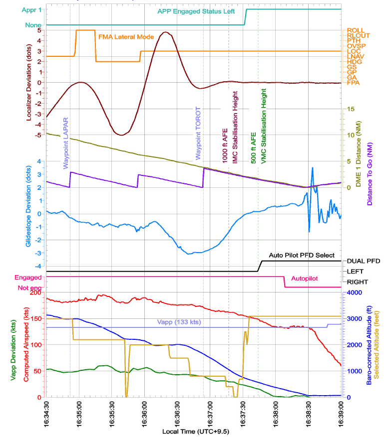
Although cockpit localiser and glideslope indications showed full‑scale deviation of 2.5 dots on the primary flight display and compass instrument, the recorded QAR data captured up to 5 dots deviation. Key parameters depicted in Figure 11 showed:
airspeed (red) remained above the target approach speed of 133 kt (VAP) (purple) until 1638 (deviation in kt – green)
5 dot left and right deviations from the localiser course between LAPAR and TOROT
3 dot deviation above the glideslope approaching TOROT.
Figure 11: QAR data depicting speeds and key lateral flight path parameters
Source: Alliance Airlines QAR data, analysed by the ATSB
Approach briefing
Alliance procedures required flight crew to conduct a briefing before commencing an approach. It detailed the requirements for an instrument approach briefing and a visual approach briefing. There was no policy on re‑briefing during an instrument approach if a transition to a visual approach occurred. Alliance advised that the expectation was for flight crew to continue an instrument approach even if visual reference was established.
Descent below lowest/minimum safe altitude
Alliance’s Operations Policy and Procedures Manual (OPPM) required all flights to be planned and conducted under instrument flight rules (IFR).[15] Company policy allowed the use of visual approaches and departures, but pilots were not permitted to downgrade to visual flight rules.
The OPPM section 7.4.11.1 stated that operation below the lowest/minimum safe altitude (LSALT/MSA) was permissible only when:
• under radar control;
• in accordance with a published [distance measuring equipment] DME arrival instrument approach or holding procedure;
• when necessary during climbing after departure from an airport, or
• when flying in VMC by day.
CASR Part 91 Plain English Guide stated that in accordance with sub‑regulation 91.305 Minimum heights – IFR flights, aircraft must not be flown below the lowest/minimum safe altitude except when taking off or landing in VMC by day, or in accordance with:
a published visual or instrument approach or departure procedure
an air traffic control clearance.
Instrument landing system approach
Darwin Airport runway 29 ILS-Z approach is depicted in Figure 12.
Figure 12: Darwin ILS-Z approach
Source: Jeppesen
The Aeronautical Information Publication (AIP)[16] stated that:
Unless authorised to make a visual approach, an IFR flight must conform to the published instrument approach procedure nominated by ATC.
During an instrument approach, flight crew were required to maintain the aircraft’s flight path within certain flight tolerances. For an ILS approach the AIP stated:
Pilots must conform to the following flight tolerances:
a) To ensure obstacle clearance, both [localiser/Ground based augmentation system (GBAS) landing system] LOC/GLS final approach course and glideslope should be maintained within half scale deflection (or equivalent on expanded scale).
b) If, at any time during the approach after the [final approach point] FAP, the LOC/GLS final approach or glideslope indicates full scale deflection, a missed approach should be commenced.
Although the AIP wording combined the terms ‘must’ and ‘should’, Airservices Australia confirmed that aircraft were required to comply with the vertical guidance of the glideslope when conducting an ILS approach, and that descent outside this vertical guidance could be safety critical.
Alliance’s Standard Operating Procedures Manual (SOPM) detailed the procedure for conducting an ILS approach. This included:
The standard profile assumes the aircraft will approach 3,000 ft AFE [above field elevation] with Flap 1 selected and will be configured with landing flap with checklists complete prior to stabilization altitude.
Standard calls were documented in the Alliance SOPM, which stated:
Deviation calls are to be made if the listed deviation limit is exceeded and no corrective action has been observed. Upon acknowledgement of a deviation, corrective action must be taken.
Table 1 is an extract of the standard calls relevant to this approach.
Any time the PNF [pilot not flying]/PM calls deviations from 'on slope' the PF should make corrections to avoid flight path excursions towards full scale.
The PNF/PM should continue slope deviation calls until the glideslope indicator stops moving toward full scale and whenever the indicator is at full scale.
…
When continuing the approach, continually cross-check visual profile indications against glideslope profile indications down to 100 ft AGL…Duties of the PNF/PM apply on all instrument approaches through to 100 ft above threshold height, even if visual flight conditions are encountered before reaching the minimum.
The same section stated:
During a visual approach using the ILS, the glideslope calls do not need to be given.
Visual approaches
The term ‘visual’ was used by:
ATC to instruct a pilot
a pilot to accept responsibility
to see and avoid obstacles while operating below the minimum vector altitude or minimum/lowest safe altitude.
Alliance permitted flight crew to conduct visual approaches by day and night in accordance with AIP requirements. The AIP required an IFR flight to conform to the published instrument approach procedure unless they were authorised by ATC to make a visual approach. By day, ATC could authorise an IFR aeroplane to conduct a visual approach when:
the aircraft is within 30 NM of the aerodrome
the pilot has established and can continue flight to the aerodrome with continuous visual reference to the ground or water
visibility along the flight path is not less than 5,000 m or the aerodrome is in sight.
If these conditions existed, the AIP stated:
the pilot need not commence or may discontinue the approved instrument approach procedure to that aerodrome…
In controlled airspace, an ATC clearance was required to conduct a visual approach. The pilot was required to report ‘visual’ to signify to ATC that the visual approach requirements could be met and maintained as part of any request for a visual approach. The pilot was then required to maintain the track or heading authorised by ATC until (by day) within 5 NM (9 km) of the aerodrome.
The Alliance OPPM stated that in VMC on a visual approach, the aircraft must join the circuit on the upwind, crosswind or downwind leg, or make a straight-in approach after establishing on final approach by 5 NM. During this occurrence, when 5 NM from the airport, the aircraft was about 1 km left of the extended runway centreline.
The required visual approach callouts at 500 ft stabilisation height were:
if stabilised criteria satisfied: PM verifies or calls out ‘500 STABLE’
otherwise: PM verifies or calls out ‘500 NOT STABLE’ and the PF initiates a go‑around.
The flight crew had not briefed for a visual approach, advised ATC they were visual or received clearance to conduct a visual approach.
Go-around and discontinued approach
The Alliance OPPM included Non punitive go around policies, and listed conditions which, if encountered, the PF should consider carrying out a go‑around. The conditions included those that could lead to stabilised approach requirements not being adhered to. The Alliance SOPM distinguished between a discontinued approach and a go‑around in which take‑off/go‑around (TOGA) thrust was applied.
SOPM 5.20.4 Discontinued approach included:
During the initial phase of the approach, there may be a situation where the approach needs to be discontinued. If the aircraft is at or near the missed approach altitude, far from the missed approach point and not fully configured for landing, a go around procedure may not be appropriate. The go around can lead to an excess thrust that may result in overshooting the missed approach altitude. For this situation, a discontinued approach is recommended.
NOTE
❖ A Go-around should be conducted:
o In Day VMC below 500FT AFE,
o In [instrument meteorological conditions] IMC[17] or at night below 1000ft AFE.
SOPM 5.20.3 Go-around included:
No approach should be initiated unless the prevailing conditions have been understood and the crew found that landing is acceptable without undue risk. Philosophically all approaches should be treated as approaches followed by missed approaches, and landing should be treated as the alternate procedure. This mindset depends on a good approach briefing, on the knowledge of the missed approach procedure and on proper programming of the FMS.
Alliance advised that in this incident, a discontinued approach at 3,000 ft (when the approach mode disarmed) would have been appropriate.
Stabilised approach criteria
A stabilised approach is one where an aircraft maintains a constant angle descent to the runway while other key flight parameters such as airspeed and aircraft configuration are controlled within specific ranges. An approach is stable when all the stabilisation criteria specified by the operator are met.
According to an International Air Transport Association report Unstable approaches: risk mitigation policies, procedures and best practices (IATA, 2017), historical commercial aviation accident data indicated that many accidents occurred during the approach and landing phases of flight. Frequent contributing factors were an unstable approach and subsequent failure to initiate a go‑around. Failure to maintain a stable approach could result in landing too fast or too far down the runway, a hard landing, runway excursion, loss of control, or collision with terrain. The report also highlighted the importance of callouts in enhancing situational awareness and encouraging rapid error correction.
The report described an operator’s minimum stabilisation height as a ‘gate’ at which if the aircraft was not stable on the approach path in the landing configuration, a go‑around must be executed. Additionally, although many operators have one gate for IMC and a lower gate for VMC, variations in stabilisation heights between operators, approach types and meteorological conditions (VMC/IMC) could cause confusion. As a result, many airlines implemented a single set of criteria and one gate for a particular approach type, such as 1,000 ft for an instrument approach, and 500 ft for visual circuit or circling approaches. Having a single gate also makes it easier for an operator to track compliance using flight data monitoring programs.
The Flight Safety Foundation’s Approach and landing accident reduction briefing note 7.1 – Stabilized Approach described the benefits of a stabilised approach as:
increasing the flight crew’s situational awareness of the:
horizontal
vertical
airspeed
energy state
more time and attention for monitoring communications, weather and aircraft systems
more time for monitoring by the PM
defined criteria to support land or go‑around decision‑making
consistent landing performance.
Alliance’s standard operating procedures required all flights conducting instrument approaches to be stabilised by 1,000 ft above aerodrome level, and an immediate go‑around was required for any approach that did not meet the following stabilised approach criteria:
a) the correct flight path;
b) only small changes in heading/pitch are required to maintain the correct flight path;
c) the aircraft speed is not more than VAPP + 10 knots indicated airspeed and not less than VREF;
d) the aircraft is in the correct landing configuration;
e) sink rate is no greater than 1,000 feet per minute
f) thrust or power setting is appropriate for the aircraft configuration;
g) all briefings and checklists have been completed;
h) specific types of approaches are stabilized if they also fulfil the following
i. instrument landing system (ILS) approaches must be flown within one dot of the glideslope and localizer
ii. a Category II or Category III ILS approach must be flown within the expanded localizer band
i) unique approach procedures or abnormal conditions requiring a deviation from the above elements of a stabilized approach require a special briefing to have been completed prior to beginning the approach.
• Note 1: A momentary excursion is permitted for points (c) & (e). A momentary excursion is defined as a deviation lasting only a few seconds and where every indication is that it will return to the stabilised criteria as listed in points (c) & (e).
• Note 2: Where the nominal descent path for a particular approach requires a descent rate greater than 1000 fpm. This is only permitted when expected rates of descent have been briefed prior to the approach being commenced.
Stabilized Heights
All flights shall meet all of the above stabilized approach criteria by 1,000 feet above aerodrome level except under the following circumstances:
Visual approach:
Speed may be higher than VAPP + 10, provided it is within limits and expected to reduce to Vapp+10 or below by no later than 500ft AAL.
Note 3: Visual conditions as defined by Jeppesen AUS or AIP - the pilot has established and can continue flight to the airport with continuous visual reference to the ground or water; and visibility along the flight path is not less than 5000m.
…[followed by Visual circuit, Circling approach and RNP-AR approach]
An approach that does not meet, or subsequently exhibits sustained deviations outside of these criteria requires an immediate go-around.
Alliance advised that the Note 3 under the Visual approach heading was supposed to clarify that the term ‘visual approach’ and the associated policy was not only for the situation where flight crew were cleared for a visual approach, but included when they encountered visual conditions during an instrument approach.
Alliance SOPM section Intercepting glideslope from above, included:
Several different situations, such as ATC restriction, may lead to a glideslope interception from above. If that happens, the pilots must take the appropriate actions to guarantee a stabilized approach. If the stabilized approach criteria are not met, the PF must initiate a Go Around. The approach must be stable before reaching 1000 ft AGL (IMC), 500 ft (VMC), or other altitude in accordance with company policies.
Alliance’s SOPM (5.16.7) Stabilised approach stated that the aircraft must meet the stabilised approach criteria in the OPPM, and included:
For a 3D instrument approach or a visual approach (except for a visual circuit or circling approach) the aircraft should be established on profile by 3000ft AFE. If, due to operational circumstances the aircraft is not on a 3° profile, an acceptable flight path should be maintained to regain profile no later than 1500ft AFE. Descent rate limits are outlined in the OPPM.
The OPPM specified ‘Descent rate limits’:
The following values for the rate of descent below the transition altitude shall not normally be exceeded:
• 3000 fpm down to an altitude of 3000 ft above aerodrome level (AAL).
• 2000 fpm down to an altitude of 2000 ft AAL transitioning to 1000 ft AAL
• 1000 fpm below 1000 feet AAL
The SOPM (5.16.7) Stabilised approach also stated:
On the normal profile, the aircraft should approach 3,000 ft AFE with Flap 1 selected. Flap 2 should be selected leaving 3000ft. The landing gear should be selected down and flap 3 selected no later than 2000ft AFE. Final landing flap should be selected such that all stable approach criteria can be satisfied.
Alliance advised that in the previous 4 years, almost all their approach incidents occurred following selection of flap 2 below the prescribed 3,000 ft. They reported that delayed selection of flap 2 ‘then compresses everything’.
Guidance material for Part 121.200 from CASR Part 121 Acceptable means of compliance/guidance material - Australian air transport operations—larger aeroplanes included discontinuing an approach to continue in VMC as one situation that reduced the likelihood of a stabilised approach and should be avoided where not operationally necessary.
Crew coordination
The captain reported being aware when the aircraft was outside half scale deflection of the localiser and more than half scale deflection above the glideslope, which was why they advised ATC and were cleared to maintain the minimum vector altitude. The captain could not recall whether they had advised ATC they were visual but assessed that they could continue the unstable approach below 1,000 ft as they were in visual conditions. The captain reported that there were no callouts from the PM and if they were not stable at 500 ft, the captain would have expected an ‘unstable’ callout from the PM and would have conducted a go‑around.
The FO (PM) reported that normally they would aim to be fully configured and stable by 1,500 ft and the ‘absolute latest’ by 1,000 ft for an instrument approach. In this case they were not, which is why the captain called ‘visual’ and said they would use the visual approach ‘gate’ of 500 ft. The FO reported that in that split second (passing 1,000 ft), they agreed with the captain to continue because they were visual, although the aircraft was above the glideslope and ‘slightly’ fast, the speed was trending down, and the FO thought that the aircraft was fully configured for landing. The FO assessed that the aircraft was stable at 500 ft, unaware that the flaps were incorrectly configured, and had they called ‘unstable’ at 500 ft, the captain would have been obliged to conduct a go‑around.
The FO also reported that the en route diversions and storms near the airport may have resulted in perceived time pressure to continue the landing. They had sufficient fuel to discontinue the approach and make a second attempt.
The cockpit voice recording was not retained for the investigation. The flight crew could not recall whether the PF called out mode changes after the mode reversion. The PM reported calling distance and heights for the profile, but did not make speed, slope or track deviation calls because the PF was taking corrective action.
The Alliance OPPM detailed task sharing and the responsibilities of the PF and PM and noted that this was particularly important in high workload phases of flight, including approach and landing. It also stated that the PM should:
query the PF actions that are not understood or considered inappropriate. He/she should also demonstrate assertiveness and express advocacy to share any concern on the flight progress.
Alliance OPPM defined authority gradient as ‘the relative authority of air crew in the chain of command … if the gradient is too steep, air crew may be unwilling or unable to express their beliefs to those in higher authority’.
Similar occurrences
Unstable approach involving Embraer 190, VH‑UZI, about 4 km north‑east of Brisbane Airport, Queensland, on 9 May 2024 (AO‑2024‑030)
During approach to Brisbane Airport, the aircraft automated ILS flight mode unexpectedly disengaged. The flight crew focused on troubleshooting the unexpected change and recapturing the ILS flight director mode, rather than conducting a go‑around. During that time, the flight crew did not effectively monitor the aircraft's flight path, and the aircraft exceeded the stabilised approach criterion of one dot glideslope deviation.
After recognising that the aircraft was low, the captain increased the aircraft pitch, resulting in an enhanced ground proximity warning system (EGPWS) glideslope warning. The flight crew did not perform the required terrain avoidance manoeuvre, instead continued the approach. The captain arrested the aircraft’s descent and re‑established the aircraft on the glidepath, before continuing the approach and landing.
Alliance took safety action in response to that occurrence including issuing an operational notice to remind flight crew of the stabilised approach criteria and go‑around requirements.
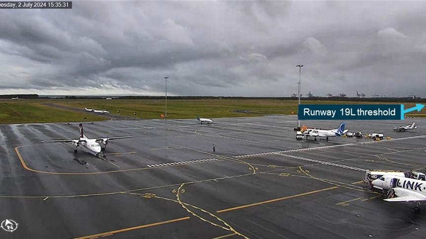
Descent below glideslope involving Fairchild SA227, VH‑VEU, about 17 km north‑east of Brisbane Airport, Queensland, on 2 July 2024 (AO‑2024-040)
During the ILS approach, the aircraft descended below the 3° glideslope, triggering an air traffic control ATC minimum safe altitude warning about 8 NM (14 km) from the runway. ATC advised the crew that they were observed below the glideslope, however the aircraft continued descent below the glideslope until 3 NM (6 km) when the descent rate was reduced. The aircraft then passed above the glideslope before the rate of descent increased again and subsequently the glideslope was re‑intercepted from above 1 NM (2 km) from the runway at 500 ft. The aircraft then followed a stabilised flight path to landing.
The investigation found that the pilot monitoring was not monitoring the glideslope and did not challenge the pilot flying to correct the deviation and reduce the aircraft’s descent rate.Additionally, the operator's standard operating procedures contained areas of inconsistency when an aircraft entered visual conditions during an instrument approach, and that the AIP was unclear as to whether pilots were required to comply with precision approach flight tolerances.
The aircraft operator subsequently amended its standard operating procedures as follows:
the instrument approach procedure has been updated:
the approach brief now requires discussion of expectations if visual conditions arise
the statement that ‘during a visual approach using the ILS, the glideslope calls do not need to be given’ has been removed
a requirement to make callouts using reference to visual slope indications has been added.
a note has been added to the visual approach procedures stating that crew require a clearance to discontinue an instrument approach in controlled airspace
increased focus on pilot monitoring skills during:
proficiency checks, which will now include standard instrument departure and standard arrival routes
line training for new flight crew
addition of a pilot monitoring sector to the annual line check.
Safety analysis
Mode reversion
Nearing the initial approach fix (LAPAR) for the Darwin Airport runway 29 instrument landing system (ILS)‑Z approach, the aircraft’s approach, localiser and glideslope modes were armed, with the correct ILS frequency set as the armed navigation source. As the aircraft flew by LAPAR, the localiser mode engaged for one second before the auto‑flight system reverted to lateral roll and vertical flight path angle modes.
It is possible that this occurred due to the captain inadvertently pressing the approach pushbutton at the same time the localiser captured. The captain recalled that this occurred because they received a second ATC clearance for the ILS, however, at that time, they had only been cleared for the ILS once. They received a second clearance about 50 seconds later and a third clearance 40 seconds after that. The pushbutton was not recorded in the data but pressing it when approach mode was armed would disarm approach mode consistent with the mode reversion.
Embraer's analysis of the recorded data found that the ILS navigation display source had not engaged at the time localiser mode became active. Therefore, it was most likely that this non‑synchronisation led the flight control and guidance system to invalidate the capture and revert to basic modes. The avionics manufacturer, Honeywell, advised that as the recorded data did not update as frequently as the system status, it was not possible to determine whether a synchronisation issue existed.
The mode reversion resulted in the aircraft maintaining the 20° right bank and approximately level flight path angle that were present at the time of the mode reversion.
Automation and approach continuation
Alliance’s procedures stated that if the auto‑flight system was not doing what the pilot expected, they were to disconnect the autopilot and manually fly the aircraft. However, following the unexpected mode change, the captain, who was the pilot flying (PF), did not re‑engage approach mode or disconnect the autopilot until about 200 ft above the aerodrome elevation, in accordance with normal landing procedures. This resulted in the aircraft deviating beyond the permitted tolerance from the localiser course and above the glideslope.
It took less than 3 minutes from the mode reversion at 3,000 ft, to the aircraft being established on the ILS and in the landing configuration, about 400 ft above aerodrome elevation. During that time, there were several changes to the lateral and vertical modes, selected heading and altitude, and significant variations in vertical speed, as the PF manipulated the auto‑flight system to recapture the localiser and glideslope.
There were also several triggers for the flight crew to discontinue the approach. The flight crew reported that their en route weather deviations and thunderstorms in the vicinity of the airport may have led to perceived pressure to continue the approach, but that there was adequate fuel on board to discontinue and conduct a second approach.
Once outside the lateral tolerance of the approach, the aircraft was operating contrary to the air traffic control (ATC) clearance and descended below the minimum safe altitude, likely while in instrument meteorological conditions (IMC). The pilot monitoring (PM) reported that they did not call out the course deviations, as the PF was actively working to correct them. Instead, after descending about 500 ft, the PM advised ATC they were re‑intercepting the localiser and was assigned the minimum vector altitude to ensure terrain separation. As a result, the aircraft then maintained altitude, while the glideslope diverged beneath the flight path.
The PM did not read back the ATC clearance to descend once they had intercepted the glideslope, consistent with being focused on monitoring tasks and their self‑assessed 10/10 workload during the approach. The PM selected flap 2 as the aircraft captured the localiser, about 800 ft below the normal (but not mandatory) 3,000 ft flap 2 selection height. Alliance reported that this late selection had a similar effect to other recent approach incidents, where the associated delayed speed reduction reduced the time available to stabilise the approach.
As the aircraft passed the final approach fix (FAF) and then descended through 1,500 ft, it was established on the localiser but 3 dots above the ILS glideslope. Alliance’s procedures required the ILS to be flown within 1 dot of the glideslope, and stated that aircraft ‘should be’ on the 3° glideslope no later than 1,500 ft.
The PF reported stating to the PM that they were visual at about 2,500 ft, but the PM reported this occurred just as the aircraft approached 1,000 ft. Without a cockpit voice recording, it could not be determined when visual flight conditions were established.
At 1,000 ft, which was the stabilisation height for an instrument approach, the PF incorrectly assessed that although several stabilised criteria were not met, as they were then in visual conditions, they could continue (unstable) to 500 ft. Although this had been the procedure at the PF’s former company, Alliance required all stabilised approach criteria, other than airspeed, to be met at 1,000 ft. The PM was sufficiently unsure of Alliance’s policy to defer to the captain’s experience, as the senior base training captain who had conducted some of the PM’s training.
At 500 ft, the PM assessed that the stabilised approach criteria were met as, although the airspeed was still slightly fast, it was trending down, and they continued the approach. Although the flight crew reported having completed the before landing checks prior to 500 ft, shortly afterwards, the PM identified that they had inadvertently selected a take‑off flap setting (passing about 1,100 ft) instead of a landing setting, which they had not detected earlier. The PM rectified the flap setting and an uneventful landing followed.
Although the landing was uneventful, had the incorrect flap setting not been rectified, thrust retard mode would not have engaged during the landing flare, and EGPWS warnings would have been triggered by the use of different tolerances than with the aircraft configured for landing. The use of selected heading and selected altitude to drive the aircraft’s trajectory meant that these may not have been set correctly had a go‑around been initiated either by the flight crew or ATC.
A coupled ILS approach should require minimal flight crew intervention other than monitoring. Continuing an approach using inappropriate modes increased the likelihood of an unstable approach. International research showed that unstable approaches and failure to initiate a go-around could result in landing too fast or too far down the runway, a hard landing, runway excursion, loss of control, or collision with terrain. Although visual conditions reduce the risk of collision with terrain, they do not mitigate against landing incidents resulting from poor energy management.
Alliance stabilisation heights
Alliance provided stabilised approach criteria consistent with international and Civil Aviation Safety Authority guidance, including airspeed, flight path and energy management parameters, to reduce the risk of landing accidents. However, Alliance’s minimum stabilisation heights at which these criteria were required to be met, varied between approach types and meteorological conditions, and were not clearly documented.
Alliance specified a stabilisation height of 1,000 ft for instrument approaches, but under the heading Visual approach, permitted a 500 ft stabilisation height for an instrument approach in VMC, provided only the airspeed exceeded the stable speed criterion, and all other stabilised approach criteria were met. Additionally, elsewhere in the procedures for intercepting a glideslope, it stated that an approach must be stable before reaching 1,000 ft in IMC, 500 ft in VMC ‘or other altitude in accordance with company policies’. Alliance did not have a policy for transitioning from an instrument approach to a visual approach and advised that its expectation was for flight crew to continue an instrument approach even when entering VMC.
In this incident, the lack of clarity regarding which of the stabilised approach criteria were not required before continuing to 500 ft, resulted in the flight crew incorrectly assessing that they could continue to 500 ft in VMC while the criteria were not met for:
speed
rate of descent
glideslope
landing configuration
before landing checks complete.
International Air Transport Association guidance stated that using a single stabilisation height for one type of approach, regardless of weather conditions, can reduce confusion and make it easier for operators to track stabilised approach compliance using flight data monitoring. Clear stabilisation heights also support flight crew decision-making to initiate a go‑around.
Findings
ATSB investigation report findings focus on safety factors (that is, events and conditions that increase risk). Safety factors include ‘contributing factors’ and ‘other factors that increased risk’ (that is, factors that did not meet the definition of a contributing factor for this occurrence but were still considered important to include in the report for the purpose of increasing awareness and enhancing safety). In addition ‘other findings’ may be included to provide important information about topics other than safety factors.
These findings should not be read as apportioning blame or liability to any particular organisation or individual.
From the evidence available, the following findings are made with respect to the unstable approaching involving Embraer E190, VH-UYO, near Darwin Airport, Northern Territory, on 15 February 2025.
Contributing factors
On crossing the initial approach fix for the instrument landing system (ILS) approach, due either to a system synchronisation issue or the pilot flying inadvertently disarming the approach mode, the aircraft’s auto‑flight system reverted to roll and flight path angle modes.
Following the unexpected mode change, the pilot flying did not re‑engage approach mode or disconnect the autopilot. This likely contributed to the aircraft deviating outside the required lateral tolerance of the approach below the minimum safe altitude while in instrument meteorological conditions.
The flight crew did not discontinue the approach when the aircraft was unstable at the 1,000 ft stabilisation height as they incorrectly assessed that they could continue to 500 ft in visual meteorological conditions, with multiple stabilised approach criteria unmet.
In the limited time available to stabilise the aircraft by 500 ft, the flight crew incorrectly assessed that the aircraft was stable and continued the approach, unaware that the pilot monitoring had inadvertently selected an incorrect flap configuration.
Alliance Airlines' standard operating procedures were unclear about the criteria for continuing an unstable instrument approach to 500 ft when aircraft entered visual conditions.
Safety actions
Whether or not the ATSB identifies safety issues in the course of an investigation, relevant organisations may proactively initiate safety action in order to reduce their safety risk. All of the directly involved parties are invited to provide submissions to this draft report. As part of that process, each organisation is asked to communicate what safety actions, if any, they have carried out to reduce the risk associated with this type of occurrences in the future. The ATSB has so far been advised of the following proactive safety action in response to this occurrence.
Safety action by Alliance Airlines
Alliance Airlines issued an operations notice ‘to improve clarity and compliance’ with the stabilised approach criteria. It detailed the stabilised approach policy. It also amended the stabilisation height such that for 3‑dimensional and 2‑dimensional instrument approaches, and straight‑in visual approaches, the stabilised criteria were to be met by 1,000 ft above aerodrome elevation.
The 500 ft stabilisation height applied only to visual circuit or circling manoeuvre approaches. The notice reminded flight crew of Alliance’s ‘non punitive go around policy’ and required all unstable approaches to be reported.
Alliance Airlines also conducted a flight data review of unstable approaches over the previous 6 months to identify similar occurrences.
Sources and submissions
Sources of information
The sources of information during the investigation included:
Civil Aviation Safety Authority (2025, January). CASR Part 91 Plain English Guide version 4.2. Retrieved May 15, 2025, from Part 91 plain English guide version 4.2
Flight Safety Foundation (2000). Approach and landing accident reduction Briefing Note 7.1: Stabilized Approach. Retrieved May 15, 2025, from FSF ALAR Briefing Note 7.1: Stabilized Approach
Under section 26 of the Transport Safety Investigation Act 2003, the ATSB may provide a draft report, on a confidential basis, to any person whom the ATSB considers appropriate. That section allows a person receiving a draft report to make submissions to the ATSB about the draft report.
A draft of this report was provided to the following directly involved parties:
the flight crew and air traffic controllers
Alliance Airlines
Airservices Australia
Civil Aviation Safety Authority
Bureau of Meteorology
Embraer
Honeywell
United States National Transportation Safety Board
Brazil Aviation Accident Investigation and Prevention Center.
Submissions were received from:
Airservices Australia
Alliance Airlines
the first officer
Embraer.
The submissions were reviewed and, where considered appropriate, the text of the report was amended accordingly.
Purpose of safety investigations
The objective of a safety investigation is to enhance transport safety. This is done through:
identifying safety issues and facilitating safety action to address those issues
providing information about occurrences and their associated safety factors to facilitate learning within the transport industry.
It is not a function of the ATSB to apportion blame or provide a means for determining liability. At the same time, an investigation report must include factual material of sufficient weight to support the analysis and findings. At all times the ATSB endeavours to balance the use of material that could imply adverse comment with the need to properly explain what happened, and why, in a fair and unbiased manner. The ATSB does not investigate for the purpose of taking administrative, regulatory or criminal action.
Terminology
An explanation of terminology used in ATSB investigation reports is available here. This includes terms such as occurrence, contributing factor, other factor that increased risk, and safety issue.
Publishing information
Released in accordance with section 25 of the Transport Safety Investigation Act 2003
Ownership of intellectual property rights in this publication
Unless otherwise noted, copyright (and any other intellectual property rights, if any) in this report publication is owned by the Commonwealth of Australia.
Creative Commons licence
With the exception of the Commonwealth Coat of Arms, ATSB logo, and photos and graphics in which a third party holds copyright, this report is licensed under a Creative Commons Attribution 4.0 International licence.
The CC BY 4.0 licence enables you to distribute, remix, adapt, and build upon our material in any medium or format, so long as attribution is given to the Australian Transport Safety Bureau.
Copyright in material obtained from other agencies, private individuals or organisations, belongs to those agencies, individuals or organisations. Where you wish to use their material, you will need to contact them directly.
[1]Pilot Flying (PF) and Pilot Monitoring (PM): procedurally assigned roles with specifically assigned duties at specific stages of a flight. The PF does most of the flying, except in defined circumstances, such as planning for descent, approach and landing. The PM carries out support duties and monitors the PF’s actions and the aircraft’s flight path.
[2]Flight level: at altitudes above 10,000 ft in Australia, an aircraft’s height above mean sea level is referred to as a flight level (FL). FL 340 equates to 34,000 ft.
[3]Cloud cover: in aviation, cloud cover is reported using words that denote the extent of the cover – ‘few’ indicates that up to a quarter of the sky is covered, ‘scattered’ indicates that cloud is covering between a quarter and a half of the sky, ‘broken’ indicates that more than half to almost all the sky is covered, and ‘overcast’ indicates that all the sky is covered.
[4]Instrument Landing System (ILS): a 3-dimensional precision instrument approach system comprising a VHF localiser providing horizontal guidance and a UHF glideslope providing vertical guidance.
[5]Initial approach fix (IAF): the commencement of an instrument approach.
[6]Airservices Australia’s Aeronautical Information Publication ENR 1.22.2.
[7]Radio altitude is the height of the aircraft above terrain immediately below the aircraft measured by a radio altimeter.
[8]The pilot has established and can continue flight to the airport with continuous visual reference to the ground or water; and visibility along the flight path is not less than 5,000 m.
[10]A SIGMET provides a concise description of the occurrence or expected occurrence of en route weather phenomena that are potentially hazardous to aircraft, in areas over which meteorological watch is being maintained.
[11]A TAF is a coded statement of meteorological conditions expected at an aerodrome and within a radius of five nautical miles (8 km) of the aerodrome reference point.
[12]SPECI is used to identify reports of observations when conditions are below specified levels of visibility and
cloud base, certain weather phenomena are present, or temperature, pressure or wind change by defined
amounts.
[13]The provision of current, routine information to arriving and departing aircraft by means of continuous and repetitive broadcasts during the hours when the unit responsible for the service is in operation.
[14]QNH: the altimeter barometric pressure subscale setting used to indicate the height above mean seal level.
[15]Instrument flight rules (IFR): a set of regulations that permit the pilot to operate an aircraft in instrument meteorological conditions (IMC), which have much lower weather minimums than visual flight rules (VFR). Procedures and training are significantly more complex as a pilot must demonstrate competency in IMC conditions while controlling the aircraft solely by reference to instruments. IFR-capable aircraft have greater equipment and maintenance requirements.
[16]Aeronautical Information Publication (AIP): A publication issued by or with the authority of a State and containing aeronautical information of a lasting character essential to air navigation.
[17]Instrument meteorological conditions (IMC): weather conditions that require pilots to fly primarily by reference to instruments, and therefore under instrument flight rules (IFR), rather than by outside visual reference. Typically, this means flying in cloud or limited visibility.
Occurrence summary
Investigation number
AO-2025-012
Occurrence date
12/02/2025
Location
Near Darwin Airport
State
Northern Territory
Report release date
26/08/2025
Report status
Final
Investigation level
Short
Investigation type
Occurrence Investigation
Investigation status
Completed
Mode of transport
Aviation
Aviation occurrence category
Incorrect configuration, Unstable approach
Occurrence class
Incident
Highest injury level
None
Aircraft details
Manufacturer
Embraer-Empresa Brasileira De Aeronautica
Model
ERJ 190-100 IGW
Registration
VH-UYO
Serial number
19000098
Aircraft operator
Alliance Airlines Pty Limited
Sector
Jet
Operation type
Part 121 Air transport operations - larger aeroplanes
The Australian Transport Safety Bureau (ATSB) is committed to the safe, responsible, and ethical use of artificial intelligence (AI) technologies. Our AI systems will be developed and deployed with fairness, accountability, privacy, security, reliability, and transparency in mind.
We will use our AI systems to enhance, not replace, human decision-making. Human-in-the-loop will ensure all critical decisions are reviewed and approved by qualified public officials to ensure accuracy and accountability.
We are transparent about our AI use and its impact. We will regularly update this statement on our AI initiatives and their outcomes.
Transparency statement
This transparency statement is reviewed at least annually, or whenever there is a significant change to the ATSB’s approach to AI.
First published:March 2025Last updated: 12 May 2026
Why we use AI
ATSB recognises the value in using modern technology, including AI, to improve our workplace efficiency and effectiveness and assist with quality control and accuracy.
We see AI as an opportunity to reduce administrative burden on our staff, allowing them to focus on areas of their work that best use their experience, expertise, and judgement.
How we use AI
The ATSB’s current AI focus is on improving workplace productivity and information discovery.
Productivity: Assisting with administrative tasks, summarising and drafting documents, drafting emails and managing inboxes, transcribing interviews, note taking in meetings.
Information discovery: Search tools and chat bots to assist with finding and retrieving information across various internal repositories, as an alternative to traditional search.
Data analytics and coding: Analysis of datasets, development of scripts and code for data analytics and software systems.
Training materials and research: Developing internal training materials and explanatory guides, assisting with policy development and research.
What we do not use AI for
Investigative decision-making: The ATSB does not use AI to make decisions or findings in the course of transport safety investigations. All investigative conclusions remain the result of human analysis.
Employee relations: AI is not used for HR recruitment, hiring decisions, performance management, or other areas with direct human impact.
Public interaction: We do not use AI for any direct service delivery or as a primary point of contact for external stakeholders.
Monitoring and safeguards
All AI outputs are subject to human review. The ATSB adheres to the principle that AI assists, but does not replace, human judgment. Before any AI-generated content is used in an official capacity, it must be verified by a staff member for accuracy, fairness, and compliance with our standards. All decisions, outcomes, and work products are reviewed, owned and managed by a human.
We operate AI within secure, controlled environments to ensure that sensitive and personal information is protected in accordance with the Privacy Act 1988 and other relevant legislation and frameworks.
Governance and accountability
The ATSB has established governance frameworks to oversee the adoption of AI:
Accountable official: The Chief Operating Officer is the accountable official for AI.
Internal oversight: We utilise internal governance processes to assess the opportunities and risks associated with new AI use cases before deployment.
Training: All staff undertake mandatory AI fundamentals training, and staff using key AI tools are provided with additional training and guidance on the responsible and ethical use of these technologies, including awareness of bias and data security.
Contact us
For questions or further information about our AI usage contact ai@atsb.gov.au.
A late addition to a signal team’s daily work plan, unnecessary complexity, and insufficient inspection and testing contributed to a freight train travelling through a busy Adelaide level crossing without boom gates active, an ATSB investigation has found.
During trackwork as part of the electrification of Adelaide’s Gawler rail line, a subcontracted signal team was tasked with temporary alterations at a number of level crossings, including the installation of jumper cables to ensure protections – boom gates and lights – still activated when required.
Midway through the day on 7 December 2020, having already actioned work on two planned level crossings, the signal team was asked to perform work at the Torrens Road crossing.
“This was an unplanned addition to what was discussed in the pre-work briefing that day, placing additional demands on the signal team with short notice,” ATSB Director Transport Safety Kerri Hughes said.
“Notably, the required work at Torrens Road also included two superfluous temporary jumper wires, unnecessarily increasing the complexity of the task and placing further work demand on the signal team, who then inadvertently installed one end of a jumper wire into the incorrect terminal.”
Testing did not identify the error and this, combined with other signal works, meant the boom gates and warning lights did not activate when a containerised freight train travelled towards the level crossing a short time later.
“The freight train’s driver saw the boom gates still open, and traffic on the road ahead, but was unable to stop the train before entering the level crossing, only narrowly missing a number of road vehicles,” Ms Hughes said.
In addition to the factors which contributed to the incorrect installation of the jumper cable, the ATSB’s final report also notes the methodology adopted by the signal team when implementing the Torrens Road inspection and test plan did not ensure independence between the installation and verification tasks.
“This resulted in the wiring error not being corrected and remaining in the control circuit, potentially affecting the correct operation of the level crossing warning equipment,” Ms Hughes said.
In response to the incident, the principal contractor for the Gawler Rail Electrification Project, Acciona, undertook a risk assessment of the level crossing alteration works in consultation with the project stakeholders.
This resulted in new controls being incorporated into the work method.
“These controls include the potential for road closures when wiring alterations are required to facilitate trackwork,” Ms Hughes said.
In addition to the specific factors contributing to the incident, the ATSB’s investigation found the South Australian Passenger Transport Authority approved a package of inspection and test plan procedures that did not specify any requirement for testing to verify and validate the safety integrity of the altered level crossing control circuits.
“The effectiveness of any testing undertaken to control risk and assure the safety integrity of the rail infrastructure for trains operating on the ARTC network – like the one involved in this incident – relied solely on the methodology adopted by the subcontracted signal team on the day,” Ms Hughes said.
In response, South Australia’s Rail Commissioner has amended work instructions relating to work such as that involved in this incident.
“When a level crossing has active warning equipment, that forms the primary engineered risk control for managing safety at the road-rail interface, and it must operate correctly,” Ms Hughes summarised.
“Any installation or alteration of a signalling system introduces the potential risk of this not happening. This risk must be managed appropriately.
“It is essential that rail transport operators and rail safety workers plan, document and implement effective testing systems and auditable practices to ensure that new or altered safety-critical railway infrastructure is rigorously verified and validated to assure the safety integrity of the infrastructure.”
A Fairchild Metro aircraft was flown below the glideslope during an approach into Brisbane when the pilot flying transitioned to a visual approach despite briefing and receiving clearance from air traffic control (ATC) for an instrument landing system (ILS) approach.
An ATSB investigation report details that the Corporate Air operated aircraft, with two pilots and 10 passengers on board, was conducting a charter flight from Cobar on the afternoon of 2 July 2024.
“Shortly after commencing the ILS approach, the crew reported that the aircraft became visual with the water and clear of cloud,” ATSB Director Transport Safety Stuart Macleod said.
“However, no request was made to ATC to transition to a visual approach, and shortly afterwards, the pilot flying descended the aircraft below the ILS glideslope.”
As this occurred, the approach controller observed an ATC minimum safe altitude warning due to the aircraft’s descent rate. They assessed the aircraft was above the minimum altitude on the radar terrain clearance chart, and not in unsafe proximity to terrain, and so did not issue a safety alert.
However, this information was passed on to the aerodrome controller, who advised the flight crew they were below the glideslope.
Approximately 3 NM from the runway the rate of descent reduced and the aircraft passed back above the glideslope, before descent increased again and the glideslope was re-intercepted, 1 NM from the runway, at 500 ft.
The aircraft then followed a stabilised flight path to landing.
“Although the crew had briefed and were cleared to fly the ILS approach, the pilot flying descended the aircraft significantly below the 3° glideslope,” Mr Macleod said.
The pilot monitoring reported they stopped monitoring the glideslope after the aircraft became visual.
“The change to a visual approach required a clearance from ATC which was not obtained, and the operator also required a brief to be conducted prior to the commencement of a visual approach, which neither crew reported having occurred.”
Mr Macleod noted that this incident highlights how effective monitoring in a multi-crew environment is paramount to aircraft safety.
“Bringing deviations to the attention of the pilot flying, whether in instrument or visual meteorological conditions, ensures the aircraft remains on a safe flight path and receiving confirmation from the pilot flying can assist in early detection of incapacitation,” he said.
“When an approach has been briefed, flight crew share the same mental model of the expected flight path and deviations can be readily identified, advised and corrected.
“If the approach type changes without further briefing, both crew members are unlikely to have the same expectations, making it difficult for the pilot monitoring to identify and advise the pilot flying of deviations.”
The ATSB’s investigation also determined there were areas of inconsistency within the operator’s standard operating procedures (SOPs) relating to approach procedures in visual conditions.
Additionally, the investigation determined the section of the Aeronautical Information Package (AIP) regarding flight tolerances when conducting a precision approach was unclear as to whether the tolerances were a requirement or a recommendation.
“Corporate Air has since made a number of changes to its SOPs including to its instrument approach procedure,” Mr Macleod noted.
“In addition, CASA has advised it will be amending the AIP to include clearer links to existing legislative requirements, and the use of defined terms.”
On the morning of 25 February 2025, an Agusta A109E helicopter was conducting a marine pilot transfer operation on the inbound bulk carrier Star Coral at Blossom Bank pilot boarding ground, about 200 km north‑east of Mackay, Queensland.
At 0901 local time, during take‑off from the ship with 2 pilots on board, the helicopter developed severe vibrations. The pilots discontinued the take-off but their attempts to recover control of the helicopter were unsuccessful. The helicopter came to rest in an upright position on the helideck, having spun more than 90° counterclockwise from its initial heading, and sustaining substantial damage. The pilots and ship’s crew were unharmed.
What the ATSB found
The investigation did not identify any airworthiness issues with the helicopter and it was considered that the loss of control was not attributable to a mechanical issue.
The ATSB found that the vibration was likely the result of the helicopter entering ground resonance, a phenomenon that dissipates when airborne, while it was in the process of departing from the ship. The discontinuation of the take‑off, after the onset of the vibration, probably resulted in the loss of control and subsequent damage to the helicopter.
What has been done as a result
The operator has added new guidelines on ground resonance to its procedures. The guidelines include procedures for recognising and recovering from ground resonance and feature case studies and video resources for training purposes.
The operator has also developed an updated procedure for training and checking flight briefings that will include confirming the roles of each pilot, procedures for transferring aircraft control between pilots, and actions to be followed in the event of an actual emergency.
Safety message
The occurrence highlights the dangers of ground resonance, a potentially catastrophic phenomenon that can occur in helicopters with fully articulated rotor systems. Typically, the onset of ground resonance is sudden and if the pilot does not take immediate corrective action, a loss of control can rapidly occur.
The occurrence also highlights the importance of proper coordination between a helicopter’s pilots when responding to abnormal or emergency situations. This is particularly pertinent for situations where the pilot flying is not the pilot in command. Ideally, the pilots’ individual roles and responsibilities for emergency response and flying duties should be well established prior to the flight.
The investigation
The ATSB scopes its investigations based on many factors, including the level of safety benefit likely to be obtained from an investigation and the associated resources required. For this occurrence, the ATSB conducted a limited-scope investigation in order to produce a short investigation report, and allow for greater industry awareness of findings that affect safety and potential learning opportunities.
The occurrence
At about 0730 local time on 25 February 2025, the 229 m bulk carrier Star Coral arrived at the Blossom Bank pilot boarding ground, about 200 km north‑east of Mackay, Queensland (Figure 1). The ship waited to embark a coastal marine pilot by helicopter for its inbound transit of the Great Barrier Reef via Hydrographers Passage.[1] It was in ballast and bound for Hay Point to load coal.
Figure 1: Blossom Bank pilot boarding ground and Hydrographers Passage
Source: Australian Hydrographic Office, annotated by the ATSB
Meanwhile, at Mackay Airport, a twin‑engine Agusta A109E helicopter, operated by Flyon Helicopters and registered VH‑XUM (XUM), with 2 pilots on board, embarked the marine pilot scheduled to conduct the ship’s pilotage. The marine pilot transfer (MPT) flight to Star Coral was the first scheduled for the helicopter and its pilots that day. These flights were normally conducted as a single‑pilot operation. However, on this occasion, the pilot flying, a pilot recently engaged by the operator under its ‘in‑command‑under supervision’ (ICUS)[2] program, was under the supervision of a company check pilot (pilot supervising).
The pilots’ plan was to transfer Star Coral’s marine pilot and then proceed to a nearby outbound ship to collect its marine pilot for return to Mackay.
At 0759, the helicopter departed Mackay Airport under the control of the pilot flying. En route, the pilots established communication with Star Coral’s master via VHF[3] radio. The master advised that the ship was rolling about 3° on its inbound heading due to a 2 m south‑easterly swell. Subsequently, the pilots requested the master to reposition the ship on a heading[4] of 270° to reduce rolling. At 0853, the pilot flying landed the helicopter on the ship’s helideck, situated on the number 5 cargo hold hatch cover (Figure 2). The marine pilot exited the helicopter and proceeded to the ship’s bridge.
Figure 2: Landing position of VH-XUM aboard Star Coral
This figure is a representation of the helicopter’s orientation relative to the wind during the take‑off. Source: Flyon Helicopters and Star Coral, annotated by the ATSB
Meanwhile, the helicopter remained on the helideck at flight idle[5] while its pilots radioed the outbound ship’s pilot to coordinate the transfer. After some discussion, the pilots elected to keep the helicopter on the deck of Star Coral until the outbound ship had departed the compulsory pilotage area.
After about 5 minutes, as the 2 ships were about to pass each other, the helicopter pilots began conducting their pre‑take‑off checks. The pilots observed a 20 to 28 knot headwind (relative to the helicopter) and noted that the ship was rolling less than 2°. The pilot flying conducted a brief for a performance category 1[6] take‑off, which involved establishing the helicopter in a hover 35 ft above deck height before departing. Both pilots later recalled that everything seemed normal as the take‑off checks were completed.
At about 0900, the pilot flying raised the collective[7] and observed the engine torques increasing through 50%. The pilot flying recalled the aircraft became light on its oleos as though it was ‘right at the point of lifting off’. Meanwhile, the pilot supervising was observing the outbound ship passing. A few seconds later, both pilots felt a sudden and substantial vibration.
The pilot supervising immediately looked down at the controls and recalled that the pilot flying was holding the cyclic[8] in an abnormally aft position. Concerned that the main rotor might have struck the tail boom, the pilot supervising decided to assume control of the helicopter and took hold of the cyclic and collective unannounced. Meanwhile, the pilot flying was still attempting to lift off, unaware of the pilot supervising’s decision to take control. The pilot supervising recalled that the pilot flying had centred the cyclic and ‘must have’ lowered the collective by the time the pilot supervising took hold of the controls. In contrast, the pilot flying stated that the pilot supervising rapidly lowered the collective after the vibration started, causing the aircraft to descend from being light on its oleos and bounce heavily on the helideck.
Moments later, the cyclic became uncontrollable as the vibrations suddenly worsened into a violent, vertical oscillation of the airframe. The pilot supervising tried to stabilise the helicopter but was unable to control the cyclic movement. Subsequently, the pilot supervising elected to shut down the engines.
The pilot supervising initially struggled to reach the engine mode switches (located on the centre console) due to the severe vibrations but subsequently managed to shut down engine number 2. The vibrations slightly eased and moments later, they were able to also shut down engine number 1. The vibration dissipated and the helicopter came to rest in an upright position on the helideck, having spun more than 90° counterclockwise from its initial heading. The sequence, from the attempted take‑off to shut‑down occurred within a period of about one minute.
Soon after, the pilots exited the wreckage and inspected the damage. The tail rotor was separated from the helicopter and had come to rest on the main deck between cargo hatches 4 and 5. Items of debris, including main rotor fragments, laid scattered on the deck along with some hydraulic fluid pooled beneath the substantially damaged fuselage (Figure 3).
Figure 3: Helicopter wreckage
Source: Star Coral
Apart from a thumb sprain to the pilot supervising and some bruising to both pilots’ upper leg areas, where they had been struck by the cyclic, neither were significantly injured and no‑one on board Star Coral was injured.
Context
Helicopter information
The helicopter was an Agusta A109 E variant, manufactured in 2006 and issued serial number 11684. It was registered in Australia in 2006 and began services under the operator’s Air Operator’s Certificate (AOC) in 2023.
The Agusta A109E is a multipurpose helicopter equipped with 2 Pratt & Whitney PW206‑C turbine engines. It has a fully articulated 4‑blade main rotor system, a 2‑blade tail rotor and retractable tricycle landing gear. Able to carry up to 7 occupants, it has a maximum allowable take‑off weight of 2,850 kg.
The helicopter was able to perform flight performance class 1 operations by adherence to Category A procedures[9]. While the helicopter was normally operated from the right crew seat, it was fitted with dual controls. A left seat‑approved pilot in command (PIC) was permitted to occupy either seat during training flights. Each set of controls could not be operated independent of the other.
The helicopter’s wreckage was recovered from the ship 2 days after the incident and transported to a secure hangar at Mackay Airport. Prior to its removal, photographs of the wreckage and the accident area were taken. There were no indications that the main rotor or tail rotor had struck any part of the ship during the accident.
Based on its inspections, the operator advised that no engine faults or exceedance alarms had been recorded by the helicopter’s electronic engine management systems. Additionally, no faults or defects had been reported by any of XUM’s pilots or maintainers leading up to the occurrence flight.
Post-accident activities
There was no recorded flight data available to determine the flight control inputs and their effect on the motion of the helicopter during the occurrence.[10] The pilots’ accounts, a witness statement from the master of Star Coral and photographs of the wreckage were the main sources of evidence.
The ATSB also sought the manufacturer’s input for this occurrence. The manufacturer advised that its preliminary assessment of the available evidence suggested that the helicopter damage appeared consistent with a ground resonance phenomenon (see the section titled Ground resonance).
The licenced maintenance organisation for XUM carried out an examination of the wreckage at the Mackay hangar. On advice from the manufacturer, the examination included inspection of specific components commonly associated with ground resonance. These included main rotor dampers, landing gear struts and tyres. The operator advised the ATSB that the inspection did not identify any airworthiness issues that may have contributed to the occurrence. The operator did not provide the inspection report or findings to the manufacturer for its assessment.
Pilot flying
The pilot flying obtained a New Zealand commercial helicopter licence (CPL) in 2011 and started flying commercially in 2014. They converted their CPL over to an Australian CPL in 2016 and held a grade 2 flight instructor rating and a class 1 aviation medical certificate. They had experience flying both single and twin-engine helicopters in various operations. Prior to joining the operator’s in‑command‑under‑supervision (ICUS) program in September 2024, they had no previous experience on the A109E, or with marine pilot transfers (MPT).
Under the ICUS program, the pilot was required to accrue 200 hours on the A109E before they could be assessed to fly the helicopter unsupervised on daytime VFR[11] MPT operations. At the time of the occurrence, the pilot had completed the operator’s training requirements and accrued around 50 hours flight time on the A109E. They had also been cleared to conduct unsupervised MPT operations on single‑engine Eurocopter AS350 helicopters.
Pilot supervising
The pilot supervising was the operator’s head of flying operations and held an air transport pilot (helicopter) licence, issued in 2014, and a class 1 aviation medical certificate. They were approved under the operator’s training and checking system to conduct check and supervision flights on the A109E.
The pilot supervising had been flying helicopters for 26 years in various operations and had accumulated over 10,000 hours flying time, including 3,800 hours in the A109E. They first started MPT operations in 2007 and commenced working with the operator in December 2016.
Star Coral
Star Coral was built in 2009 by Jansu Newyangzi Shipbuilding, China, registered in The Bahamas and classed with Bureau Veritas. The ship was owned by Panormos Shipping, The Bahamas, and managed and operated by Charterwell Maritime, Greece.
At the time of the occurrence, the 229 m ship had a mean draught of 6.51 m and the helideck height was about 18 m above the waterline.
In a written witness statement, the master reported that:
• shortly after the helicopter started to take off, it began to pound on the helideck before it spun and the tail rotor separated
• during the sequence, the helicopter became airborne for no more than 2 seconds.
Ground resonance
Ground resonance can be defined as a vibration of large amplitude resulting from a forced or self‑induced vibration of a helicopter in contact with the ground.[12] The phenomenon is normally associated with helicopters equipped with fully articulated main rotor systems consisting of 3 or more rotor blades. It is more common on helicopters with sprung landing gear than those with skids. Typically, ground resonance occurs during landing, take‑off and ground manoeuvres.[13]
In fully articulated rotor systems, drag hinges allow each blade to advance or lag in the plane of rotation to compensate for the stresses caused by the acceleration and deceleration of the rotor hub. Such rotor systems are typically fitted with lead‑lag dampers to limit the extent of this movement and help prevent excessive vibrations. However, if for any reason one or more of the blades assumes a dragged position different to the others, the blades will move out of phase and the rotor will become imbalanced, transmitting an oscillation throughout the entire airframe.[14]
The risk of ground resonance arises when the unbalanced forces in the rotor system cause the fuselage to oscillate on its landing gear at or near its natural frequency. Ground resonance will occur if the helicopter’s damping systems are unable to compensate for the oscillation.[15] Unless corrective action is taken, the amplitude of the oscillation will increase until the helicopter becomes uncontrollable.[16] Ground resonance can also be induced when the helicopter is in light contact with the ground, if the landing gear oscillation frequency is in sympathy with the rotor head vibration.[17]
Ground resonance is commonly precipitated by the helicopter making hard or asymmetric contact with the ground, landing on a slope or sudden control movements by the pilot.[18] It can also result from other factors such as improper blade balancing and tracking, or damage to any of the blades.[19] Hard contact with the ground by some part of the landing gear when the main rotor is in an unbalanced state can further aggravate the condition.[20]
Additionally, improper maintenance of the helicopter’s main rotor and fuselage damping systems, or incorrect tyre pressures, can induce or worsen ground resonance.[21]
Flight control inputs that may induce ground resonance typically involve sudden control movements or a mishandling of the cyclic that causes the fuselage to bounce.[22]
The helicopter manufacturer advised that the application of certain cyclic commands, such as extreme aft cyclic input, could theoretically reduce the main rotor damper effectiveness in respect to the damping action on the blades’ regressive lead‑lag dynamic.
Recovery technique
The onset of ground resonance can be recognised by a rocking motion or oscillation of the fuselage while on the ground.[23] The United States Federal Aviation Administration (FAA) Helicopter Handbook[24] documented 2 widely accepted recovery techniques:
• if the condition arises when there is insufficient rotor speed for take‑off, the only option is to lower the collective to reduce the pitch of the blades. The rotor rpm[25] should also be reduced as soon as possible.[26]
• If the rotor speed is in the normal operating range for flight, the Helicopter Handbook recommends lifting the helicopter off the ground to allow the rotor blades to rephase themselves automatically.
Additionally, the FAA cautioned that:
If a pilot lifts off and allows the helicopter to firmly re‑contact the surface before the blades are realigned, a second shock could move the blades again and aggravate the already unbalanced condition. This could lead to a violent, uncontrollable oscillation.
In practice, a pilot experiencing ground resonance typically has seconds to identify the condition and take corrective action.
Similar occurrences
The ATSB reviewed several investigation reports relating to previous A109E accidents attributed to ground resonance. The incidents reviewed occurred outside of Australia between 2006 and 2025 and the contributing factors were found to be operational. Technical factors which may have caused or exacerbated ground resonance were not identified.
Details of the previous incidents bear similarity to the occurrence involving XUM, particularly in respect to subsequent damage to the helicopter (Figure 4).
Figure 4: Previous occurrences of ground resonance involving the Agusta A109E
Source: Leonardo Helicopters
Flight manual procedures
The A109E rotorcraft flight manual (RFM) listed fault conditions and corrective actions for emergencies and malfunctions that might occur during take‑off.
The RFM included the caution below for ground resonance within the normal flight procedure for take‑off. This was not part of the emergency and malfunction procedures.
The RFM procedure for ground resonance was consistent with recovery techniques published by the FAA. The RFM reference to the helicopter being ‘free of ground resonance’ was intended to indicate that, like all helicopters, the A109E was designed and certified to applicable standards so that the rotor and fuselage systems do not vibrate at the same frequency under normal conditions.
Operator procedures
As an AOC holder, the operator maintained a CASA‑approved[27] operations manual/exposition[28] to promulgate general policy and standardised procedures for MPTs on the A109E. The version of the operations manual current at the time of the occurrence was issued by the operator in November 2023.
Ground resonance
The operator’s normal procedures and emergency checklists for the A109E were derived from the RFM and did not contain any procedures related to ground resonance.
Crew coordination in response to abnormal situations
While MPT flights were predominantly conducted by a single pilot, the helicopter was certified for operations with either a single pilot or 2 pilots. In either case, the normal procedure and emergency checklists remained the same, except that 2‑pilot checklist procedures were to be based on challenge and response.
Normal handover and takeover procedures provided that:
In the case where the pilot flying (PF) is not the PIC and the PIC determines that the PF is not maintaining adequate control of the aircraft, the PIC may elect to take control, in which case they will signal their intention by saying ‘I have control’ upon which the PF will immediately relinquish control and the roles will reverse.
In abnormal or emergency situations, the PIC was responsible for ensuring the aircraft was flown and kept under control. The operations manual emphasised the importance of cockpit resource management (CRM) standards throughout the situation, in accordance with the below procedure:
Note: In the above procedures PM stands for ‘pilot monitoring’, NR refers to main rotor speed and IAS means indicated airspeed.
In the context of rapidly escalating emergencies such as ground resonance, pilots have limited time to perform the procedure.
Pilot in command responsibility during training flights
As the holder of a certificate that authorised air transport and aerial work operations, the operator was required to have in place a training and checking system (TACS). A training and checking manual (TACM) sets out policies and procedures for conducting training flights. It provided that a check pilot supervising ICUS training was to be the PIC. Check pilots were to ensure that pilots involved in training exercises were made aware of who was acting as the PIC through proper handover of control procedures.
While an ICUS pilot might be considered the PIC for flight‑time logging purposes, the pilot supervising was deemed the PIC and responsible for the safety of the flight. The TACM stated that in the event of an actual emergency during flight training:
If the flight examiner or check pilot deems it necessary to take physical control of the aircraft at any stage after the occurrence of the emergency, then they shall do so in accordance with the hand‑over and take‑over procedures specified in the Operations Manual - Hand over and take‑over procedures.
The flight examiner or check pilot must be prepared and ready to assume physical control of the aircraft at any stage, particularly during critical manoeuvres such as during take‑off and landing.
As such, beyond the normal handover of control procedures, there were no special provisions in the TACM for the allocation of PIC responsibility and PF duties during ICUS flights.
Briefings
For 2‑pilot operations or training flights, the operator’s procedures did not require pilots to brief who would assume PF duties in the event of an abnormal or emergency situation during critical phases of flight.
Operational limits
Under the operator’s operations manual, the A109E was permitted to conduct daytime MPT operations up to a wind strength of 30 knots, with a maximum crosswind of 20 knots. The operational limit for ship’s pitch was 4° up and 2° down while the maximum permissible roll was 4°. The manufacturer did not have input into these operator‑defined limits.
The pilots reported that the conditions at the time of the occurrence (20–28 knot headwind, 2° roll and minimal pitching) were within the operator’s limits for MPTs.
Safety analysis
Prior to the accident, VH‑XUM (XUM) made an uneventful landing on Star Coral and remained on the deck for several minutes without incident. There was no evidence that the helicopter was operating abnormally or experienced any instability during this period.
Examination of the accident site did not reveal any evidence to suggest that the occurrence resulted from the main rotor or tail rotor striking the ship. Star Coral’s master reported that the tail rotor separated after the helicopter started contacting on the deck, indicating that contact with the tail boom by the main rotor was a consequential rather than causative factor.
In that context, it is most likely that the helicopter encountered ground resonance. Assessment of the damage to the helicopter following the occurrence revealed significant similarities to that seen in previous A109E incidents attributed to this phenomenon.
It is well established that ground resonance only arises when the helicopter is in contact with the ground. Both pilots asserted that the helicopter did not become airborne prior to the vibrations while the master reported that it became airborne for about 2 seconds. However, it is more likely this occurred after the vibration worsened and the helicopter started rebounding on the helideck.
The exact cause of the vibration could not be determined. The possibility of causative operational factors such as flight control inputs or environmental factors could not be ruled in or out.
Similarly, while the operator’s post‑accident inspection of the helicopter (including examination of its rotor and fuselage damping systems) did not reveal any apparent defects, causative technical factors could not be discounted.
However, the sudden lowering of the collective after the onset of the vibration likely aggravated the situation. The helicopter was almost certainly light on its oleos when the vibration began. Therefore, a sudden lowering of the collective would have caused the helicopter to come down firmly on the helideck. The United States Federal Aviation Administration (FAA) Helicopter Handbook describes that such an impact when the rotor is already in an unbalanced state can cause the rotor blades to move further out of phase, resulting in violent uncontrollable oscillations. This description is consistent with the occurrence sequence described by the pilots and the master.
The pilots’ accounts of who lowered the collective differed. The recollection of the pilot flying that their intention was to lift the helicopter off the deck in response to the vibration was not consistent with a lowering of the collective. In contrast, the pilot supervising did not immediately identify the source of the vibration and later shut down the engines, believing the main rotor may have struck the tail boom. In this context, lowering of the collective would be a natural and expected response. Therefore, it is most likely that the pilot supervising lowered the collective while the pilot flying was attempting to lift the helicopter off the helideck.
In isolation, the immediate responses taken by each pilot following the sudden onset of the significant vibration were understandable. However, since the helicopter’s rotor speed was in the normal operating flight range, continuation of the take‑off would probably have resulted in the vibration dissipating (as detailed in the FAA Helicopter Handbook).
The operator had adequate procedures for responding to abnormal and emergency situations. However, the rapidly escalating nature of this occurrence meant that there was virtually no time to implement them. There was no requirement for the pilots to conduct a pre‑flight or pre‑take‑off brief about who would assume flying duties in the event of an emergency on take‑off. Therefore, the normal procedures for handover and takeover of control were assumed to apply.
However, the time between observing the vibrations and the loss of control severely limited the time available for a formal transfer of control between the pilots. As a result, neither of these procedures were followed and each pilot responded to the situation separately.
Findings
ATSB investigation report findings focus on safety factors (that is, events and conditions that increase risk). Safety factors include ‘contributing factors’ and ‘other factors that increased risk’ (that is, factors that did not meet the definition of a contributing factor for this occurrence but were still considered important to include in the report for the purpose of increasing awareness and enhancing safety). In addition ‘other findings’ may be included to provide important information about topics other than safety factors.
These findings should not be read as apportioning blame or liability to any particular organisation or individual.
From the evidence available, the following findings are made with respect to the loss of control during marine pilot transfer operations, involving an Agusta A109E, VH‑XUM and bulk carrier Star Coral, about 200 km north‑east of Mackay, Queensland, on 25 February 2025.
Contributing factors
During take‑off, the helicopter likely experienced ground resonance, resulting in the rapid onset of significant vertical oscillations through the airframe.
Discontinuing the take‑off after the onset of the vibration, with the rotor speed in the flight range, probably resulted in the loss of control and substantial damage to the helicopter.
Safety actions
Whether or not the ATSB identifies safety issues in the course of an investigation, relevant organisations may proactively initiate safety action in order to reduce their safety risk. The ATSB has been advised of the following proactive safety action in response to this occurrence.
Safety action by Flyon Helicopters
Following this occurrence, the helicopter’s operator, Flyon Helicopters, established ground resonance guidelines for its pilots. Forming part of its exposition, the guidelines were purposed to raise awareness of ground resonance and provide information about how to recognise and respond to the phenomenon. They included response procedures and featured case studies and video resources. The procedures were to be implemented into the operator’s training framework for new and current pilots.
Flyon Helicopters advised the ATSB that it also planned to implement an additional briefing procedure in its training and checking manual (TACM). The briefing is to be conducted by the training or checking pilot prior to any training or checking flight. It will include:
the objectives and scope of the flight, including the intended lesson plan or sequence
the training/checking outcomes
the roles of each pilot, including the allocation of aircraft command responsibility
procedures for transferring aircraft control between pilots
actions to be followed in the event of an actual emergency
procedures to be used in the simulation of emergencies
procedures for the conduct of unusual operations
the method to be used to simulate instrument flight conditions, if required
human factors/non‑technical stills and threat and error management.
Sources and submissions
Sources of information
The sources of information during the investigation included:
the pilots and operator of VH-XUM
the master and manager of Star Coral
the helicopter manufacturer, Leonardo Helicopters
References
Lemmens Y, Troncone E, Dutré S, Olbrechts T. (2012). Identification of Helicopter Ground Resonance with Multi-body Simulation, 28th International Congress of the Aeronautical Sciences
United Kingdom Ministry of Defence, AP3456 Central Flying School Manual of Flying Vol 12 - Helicopters
Salini S N, Haradev G S, Ranjith M. (2020). Ground Resonance: Nonlinear Modelling and Analysis, 6th Conference on Advances in Control and Optimization of Dynamical Systems (ACODS), India
United States Federal Aviation Administration. (2019). Helicopter Flying Handbook
Schafer J. (1980). Helicopter Maintenance
Submissions
Under section 26 of the Transport Safety Investigation Act 2003, the ATSB may provide a draft report, on a confidential basis, to any person whom the ATSB considers appropriate. That section allows a person receiving a draft report to make submissions to the ATSB about the draft report.
A draft of this report was provided to the following directly involved parties:
the pilots and operator of VH-XUM
the master and manager of Star Coral
the ship’s flag State administration, The Bahamas
the helicopter manufacturer, Leonardo Helicopters
Agenzia Nazionale per la Sicurezza del Volo (ANSV)
Civil Aviation Safety Authority
Australian Maritime Safety Authority
Submissions were received from:
the pilots of VH-XUM
the ship’s flag State administration, The Bahamas
the helicopter manufacturer, Leonardo Helicopters
Agenzia Nazionale per la Sicurezza del Volo (ANSV)
The submissions were reviewed and, where considered appropriate, the text of the report was amended accordingly.
Purpose of safety investigations
The objective of a safety investigation is to enhance transport safety. This is done through:
identifying safety issues and facilitating safety action to address those issues
providing information about occurrences and their associated safety factors to facilitate learning within the transport industry.
It is not a function of the ATSB to apportion blame or provide a means for determining liability. At the same time, an investigation report must include factual material of sufficient weight to support the analysis and findings. At all times the ATSB endeavours to balance the use of material that could imply adverse comment with the need to properly explain what happened, and why, in a fair and unbiased manner. The ATSB does not investigate for the purpose of taking administrative, regulatory or criminal action.
Terminology
An explanation of terminology used in ATSB investigation reports is available here. This includes terms such as occurrence, contributing factor, other factor that increased risk, and safety issue.
Publishing information
Released in accordance with section 25 of the Transport Safety Investigation Act 2003
Ownership of intellectual property rights in this publication
Unless otherwise noted, copyright (and any other intellectual property rights, if any) in this report publication is owned by the Commonwealth of Australia.
Creative Commons licence
With the exception of the Commonwealth Coat of Arms, ATSB logo, and photos and graphics in which a third party holds copyright, this report is licensed under a Creative Commons Attribution 4.0 International licence.
The CC BY 4.0 licence enables you to distribute, remix, adapt, and build upon our material in any medium or format, so long as attribution is given to the Australian Transport Safety Bureau.
Copyright in material obtained from other agencies, private individuals or organisations, belongs to those agencies, individuals or organisations. Where you wish to use their material, you will need to contact them directly.
[1]Hydrographers Passage provides a deep-water shipping route through the Great Barrier Reef between Blossom Bank pilot boarding ground, near the entrance to the passage, and the Cumberland Islands, north-east of Mackay. Pilotage is compulsory through Hydrographers Passage for ships over 70 m, as well as for loaded oil and chemical tankers and gas carriers, irrespective of size.
[2]In-command-under-supervision (ICUS) generally refers to a pilot who is acting as the pilot in command (PIC) for a flight under the supervision of a more experienced pilot.
[4]All ship’s headings are reported in degrees true.
[5]Flight idle refers to the lowest engine power setting that allows the aircraft to maintain stable operations during flight. A flight idle setting when the helicopter is on the ground allows for the engine(s) to go to higher power settings faster and facilitate take-off when collective pitch is raised.
[6]Performance Class 1 (PC1) refers to operations for which, in the event of a critical engine failure, performance is available to enable the helicopter to safely continue the flight to an appropriate landing area.
[7]Collective: a primary helicopter flight control that simultaneously affects the pitch of all blades of a lifting rotor. Collective input is the main control for vertical speed.
[8]Cyclic: a primary helicopter flight control that is similar to an aircraft control column. Cyclic input tilts the main rotor disc, varying the attitude of the helicopter and hence the lateral direction.
[9]Category A (CAT A) operations were those where, in the event of an engine failure, the helicopter has adequate performance to safely continue or reject the take-off or landing.
[10]The aircraft type involved was not required under regulations to carry a cockpit voice recorder (CVR) or flight data recorder (FDR).
[12]United Kingdom Ministry of Defence, AP3456 Central Flying School Manual of Flying Vol 12 – Helicopters.
[13]Lemmens Y, Troncone E, Dutré S, Olbrechts T. (2012). Identification of Helicopter Ground Resonance with Multi-body Simulation, 28th International Congress of the Aeronautical Sciences.
[14]United Kingdom Ministry of Defence, AP3456 Central Flying School Manual of Flying Vol 12 – Helicopters.
[15]Salini S N, Haradev G S, Ranjith M. (2020). Ground Resonance: Nonlinear Modelling and Analysis, 6th Conference on Advances in Control and Optimization of Dynamical Systems (ACODS), India.
[16]United States Federal Aviation Administration. (2019). Helicopter Flying Handbook.
[17]United Kingdom Ministry of Defence, AP3456 Central Flying School Manual of Flying Vol 12 – Helicopters.
[28]‘Exposition’ is a term used in some regulatory domains for a document or set of documents that describe how an organisation will comply with all applicable legislative requirements, and how they will manage the safety of their operations. An exposition is broadly equivalent to an operations manual in other domains.
Two separate Alliance Airlines crews operating Load 25 flight software Embraer ERJ 190‑100 IGW (E190) aircraft intended to land with the less commonly used full flap setting and entered that configuration, and the associated airspeeds, into the flight management system during the approach briefing prior to top of descent.
In both incidents, the crewmembers forgot that full flap had been briefed 25 minutes earlier, and with no requirement to crosscheck the flap setting, subsequently configured the aircraft for a flap 5 landing. This resulted in the aircraft targeting a slower airspeed than that required for a flap 5 landing.
What the ATSB found
Neither set of flight crew recalled briefing for the less common full flap configuration when actioning the before landing checklist, resulting in them landing with an incorrect flap setting. Although the landing flap setting briefed prior to commencing descent was entered into the flight management system, there was no requirement to crosscheck the briefed setting with the actual configuration selected during the before landing checklist.
What has been done as a result
Alliance Airlines has amended its Operations Policy and Procedures Manual to mandate that the before landing checklist includes a confirmation that the actual landing flap setting aligns with the planned flap configuration. Additionally, in E190 aircraft, the multifunction control and display unit page displaying required landing flap should be selected on the pilot flying side before the approach commences.
Finally, Alliance Airlines conducted a flight data review of unstable approaches over the previous 6 months operations to identify similar occurrences.
Safety message
These incidents highlight the importance in multi-crew operations of the role of the pilot monitoring in identifying if, and intervening when, the other flight crew member deviates from the briefed plan. It also illustrates the risk of reversion to routinely conducted actions, despite the intention to use a less-common configuration.
On 4 February 2025, an Alliance Airlines Embraer ERJ 190‑100 IGW aircraft, registered VH‑A2T, was operating scheduled passenger flight QQ3120 from Adelaide to Olympic Dam, South Australia. On board were the captain as pilot flying (PF), first officer as pilot monitoring (PM),[1] 2 cabin crew and 90 passengers.
Consistent with the operator’s standard operating procedures manual, the flight crew conducted their approach briefing prior to commencing the descent into Olympic Dam Airport. Due to the turbulent and windy conditions, the captain elected to use full flap[2] during the landing. The crew used the ePERF[3] tablet application and the PF entered the performance figures and associated speeds for a landing using full flap into the Landing page of the flight management system (FMS), which was crosschecked by the PM.
Around 25 minutes after the approach briefing, as the crew were configuring the aircraft for landing, the PF called for flap 5[4] rather than the previously briefed full flap, which was actioned by the PM. There was no crosscheck requirement to confirm the flap setting during the before landing checklist. At the time, neither flight crewmember recalled that the less-common full flap configuration had been briefed, nor identified that the landing speeds entered into the FMS were now incorrect (slower than required) for the selected flap setting.
During the later stage of the approach, the PF was required to manually override the auto thrust at times to keep the aircraft on profile. Both flight crewmembers later recalled that the pitch attitude on final seemed slightly high at times. They also stated that during the flare,[5] the aircraft encountered sink,[6] which the PF corrected with the appropriate control inputs. Both flight crewmembers reported recognising the profile, speed and thrust were not as expected, but assessed that this was due to the hot and turbulent conditions.
Following an uneventful landing, as the crew were completing the after‑landing flow, the captain realised that they had landed with flap 5 rather than full flap. Both crewmembers later reported having forgotten that full flap had been briefed.
Occurrence 2
On 8 March 2025, an Alliance Airlines Embraer ERJ 190‑100 IGW aircraft, registered VH‑A2V, was operating scheduled passenger flight QQ4801 from Alice Springs to The Granites, Northern Territory. The captain was PF, and the first officer was PM.
On the previous day, the threshold of runway 11[7]at The Granites Airport had been repaired. While there was no NOTAM[8] in place, the airport operator had requested that if an aircraft landed on runway 29, they try to stop by taxiway alpha (which led to the apron) if safe to do so. This was to avoid turning the aircraft on the newly repaired surface at the runway 11 threshold turning node. The captain had received an email from the operator the night prior to the flight requesting that they comply with the above request if possible.
Consistent with the operator’s procedures, prior to commencing their descent, the crew conducted their approach brief. The aerodrome weather information service (AWIS) indicated a 5 kt tailwind for runway 11, which was less than the maximum permitted of 10 kt. As the aircraft could not stop prior to taxiway alpha when landing on runway 29, and to avoid the repaired area, the flight crew elected to use runway 11 and full flap for the landing. The PM entered the performance figures and associated speeds for landing using full flap into the FMS Landing page and the PF crosschecked them.
During the approach, the PM was communicating with air traffic control via HF radio and making the required broadcasts on the common traffic advisory frequency. Additionally, they were regularly checking for updated AWIS information to ensure the tailwind remained within limits. The AWIS changed 3 times during the approach, with the tailwind component reaching 9 kt before dropping back to 8 kt.
The flight crew conducted a visual approach to runway 11 without incident. The operator’s flight data analysis program later detected that the aircraft had landed with flap 5, with full flap entered in the FMS. Both crewmembers later reported that they had forgotten that the use of full flap was briefed prior to top of descent.
Context
Flight crew information
Occurrence 1 crew
The captain and first officer both held an air transport pilot licence (aeroplane) and a class 1 aviation medical certificate. The captain had accumulated over 14,000 flight hours, including 1,500 on the Embraer E190, and the first officer had about 7,000 flight hours, including 800 on the E190.
Both flight crewmembers reported feeling well rested prior to the flight.
Occurrence 2 crew
The captain and first officer both held an air transport pilot licence (aeroplane) and a class 1 medical certificate. The captain had accumulated over 13,000 flight hours, including 1,500 on the Embraer E190. The first officer had about 4,000 flight hours, including 600 hours on the Embraer E190.
On the day of the incident, both flight crewmembers reported having sufficient sleep the night prior; however, both felt a little tired, having woken at approximately 0345 to commence duty at 0445.
Aircraft
Occurrence 1
The aircraft was an ERJ 190‑100 IGW, manufactured in Brazil in 2008 and issued serial number 19000179. It was registered in Australia as VH-A2T on 19 July 2024. The aircraft was fitted with 2 General Electric Company CF34-10E5 turbofan engines. It had an integrated avionics system with load 25 software installed.
Occurrence 2
The aircraft was an ERJ 190-100 IGW, manufactured in Brazil in 2009 and issued serial number 19000249. It was registered in Australia as VH-A2V on 29 April 2024. The aircraft was fitted with 2 General Electric CF34-10E6 turbofan engines. It had an integrated avionics system with load 25 software installed.
Software – Load 25 v Load 27
The operator operated Embraer E190 aircraft, most of which had Load 27 software installed. The remainder, primarily used for mining air transport operations, had Load 25 software installed.
For both software systems, flight crews would enter the relevant landing performance data into the landing page of the FMS during the approach briefing, prior to top of descent.
For E190s fitted with Load 25 software, crews were required to select manual speed mode when passing the final approach fix. In manual speed mode, the crew would manually enter the approach speeds, calculated on the ePERF tablet, into the flight management guidance control system (FMGCS), and the autopilot would target those manually entered speeds when active.
In Load 27 aircraft, flight crew would normally use FMS speed mode on approach. In this mode, the FMGCS would automatically target the appropriate speed for the aircraft’s configuration. In addition, in Load 27 aircraft, a CHECK LANDING FLAP message would appear on the FMS scratchpad[9] if there was a discrepancy between the flap position entered into the FMS landing page and the selected flap lever position in the landing configuration.
Standard operating procedures
Flap settings
The operator’s standard operating procedures manual stated that flap 5 was the preferred setting for landing as follows:
The use of flap 5 provides lower fuel consumption and reduced approach noise levels… Consider using flap full when the field length requires its use. Additional runway limitations, such as known slippery conditions may require its use.
The occurrence 2 captain stated that flap 5 was used around 90% of the time, and one of the FO’s stated that the only time they had ever used full flap was during training.
Relevant speeds
VREF
The landing reference speed (VREF) is the speed at 50 ft above the runway threshold in a normal landing configuration (thrust levers at idle, gear down and landing flaps). VREF is used for landing distance calculations and the operator’s crews used the ePERF iPad applications for calculating landing speeds.
The Embraer Airplane Operations Manual provided VREF speeds with flap 5 and full flap, for weights between 28–52 t. Because VREF is proportional to stall speed, and therefore aircraft weight:
For occurrence 1, VREF was 123 kt for full flap, aircraft weight 43 t.
For occurrence 2, VREF was 115 kt for full flap, aircraft weight 37.5 t.
From the reference speeds table:
at 43 t – VREF flap 5 = 131 kt
at 37.5 t – VREF flap 5 = 123 kt.
In both occurrences the flap 5 VREF was 8 kt higher than the full flap VREF.
Target approach speed
Target approach speed, VAPP, is the speed on the final approach in the landing configuration. The recommended method for approach speed calculation was to add one half of the steady headwind component plus the gust increment above the steady wind to the reference speed (VREF), with a minimum of +5 kt and a maximum +20 kt.
For occurrence 1, VAPP was 128 kt.
For occurrence 2, VAPP was 120 kt.
Before landing checklist
According to the operator’s procedures, by 1,500 ft above aerodrome elevation (AAL) the aircraft should be in a stable configuration with the landing gear extended, ready to configure for the final landing flap and configured for landing by 1,000 ft AAL. Consistent with this, both sets of flight crew stated that their preference, and usual practice, was to have the aircraft fully configured by 1,500 ft, to avoid rushing or if they encountered any distractions from air traffic control.
Once configured, including selection of landing flaps, the PF would call for the Before landing checklist. The before landing checklist comprised crosschecking the landing gear was down, and flaps were set.
This did not include checking the flap selected was the same as the flap setting entered into the FMS.
Stabilised approach criteria
According to the operator’s Operations Policy and Procedures Manual (OPPM):
Stabilised Approach Criteria:
a) the correct flight path
b) only small changes in heading/pitch are required to maintain the correct flight path
c) the aircraft speed is not more than VAPP + 10 knots indicated airspeed and not less than VREF
d) the aircraft is in the correct landing configuration
e) sink rate is no greater than 1,000 feet per minute
f) thrust or power setting is appropriate for the aircraft configuration
g) all briefings and checklists have been completed
Note 1: A momentary excursion is permitted for points (c) & (e). A momentary excursion is defined as a deviation lasting only a few seconds and where every indication is that it will return to the stabilised criteria as listed in points (c) & (e).
Flight data
Data from both aircraft’s quick access recorders (Figure 1 and Figure 2) was analysed by the ATSB.
Occurrence 1
Figure 1: QAR data from event 1
Source: ATSB
In the first occurrence, the aircraft was VAPP + 13 kt at 500 ft, which was 3 kt above the stabilised approach criterion at 500 ft (stabilised approach requirement in VMC). However, the speed was trending downwards and VAPP + 10 kt was achieved 1 second later. This exceedance was unlikely to be readily detected by the PF during a visual approach, when their focus would be outside.
Occurrence 2
Figure 2: QAR data from event 2
Source: ATSB
In the second occurrence, the aircraft met all stabilised approach criteria, other than flap 5 being set rather than full flap.
Memory
Memory is fallible, particularly when a given task is not practiced often or recently completed. Memory failures (lapses) often appear as omitted items in a checklist or forgotten intentions.
Procedural memory is a specific type of implicit memory for the process involved in completing an action. It is when individuals no longer need to consciously remember to perform an action they have performed many times before, instead they do so automatically. Each time you retrieve a memory and perform an action, the more easily and readily you will recall it next time, a phenomenon called the retrieval practice effect (Pyc & Rawson, 2009).
Prospective memory, or ‘remembering to remember’, is an intention to perform an action in the future. However, an individual is unlikely to remember do so unless they get a timely retrieval cue from the environment (Dismukes 2010). In situations of high workload (such as approach), memory performance is reduced (Van Benthem et al, 2015) meaning without a cue such as a checklist, individuals are more likely to revert to actions they have performed previously instead of the intended task. This tendency is associated with prospective memory (Nowinski et al, 2003).
Safety analysis
Introduction
In both occurrences, both sets of crewmembers intended to use the less commonly used full flap for landing and entered that configuration and the associated VREF and VAPP speeds into the flight management system (FMS). Subsequently, when configuring the aircraft for landing, both sets of crewmembers forgot that full flap had been briefed some 25 minutes earlier, with both crews selecting flap 5 for the landing.
While operating with a different configuration to what was planned can result in reduced margins for landing speeds, in both these occurrences there were still sufficient margins to safely complete the landing.
Aircraft configuration
As the landing reference speed (VREF) is dependent on flap setting, when full flap is used, VREF, and VAPP, are slower than if using flap 5. If the aircraft is then configured to land with flap 5, and the aircraft is flown using the VAPP for full flap, the aircraft would be slower than it should be for the configuration. In both incidents, VAPP was 8 kt slower than the speed required for a flap 5 landing.
Both sets of crewmembers rarely, if ever, operated Load 25 aircraft, and in both incidents, the crews reverted to setting the flaps to flap 5, an action they had performed many times previously (procedural memory), most likely as they did not have a retrieval cue to recall what they had briefed approximately 25 minutes prior (prospective memory).
Contributing factor
Neither sets of flight crew recalled briefing for the less commonly used full flap configuration when actioning the before landing checklist, resulting in them landing with an incorrect flap setting.
Configuration error defences
In aircraft fitted with Load 25 software, crew were required to manually set the calculated approach speed, and the aircraft would target that speed regardless of the flap configuration. So having the incorrect flap setting resulted in the incorrect approach speed for the configuration.
In addition, in contrast to the Load 27 aircraft, Load 25 aircraft had no ‘check landing flap’ message when a different flap setting was configured to what was entered into the FMS. As such, an incorrect flap setting was more likely to occur in a Load 25 aircraft.
The procedures in place at the time of both occurrences required crew to brief the landing flap setting prior to top of descent, and there was no further prompt or crosscheck to ensure that the briefed flap settings were selected when configuring the aircraft for landing, around 25 minutes later.
Flight crew write down important information such as the automatic terminal information service (ATIS) or aerodrome weather information service (AWIS). However, there was no requirement to write down a less commonly used flap setting or to crosscheck that the flap setting was as previously briefed, in the before landing checklist. Although the flap setting was entered into the landing page in the FMS, crews normally did not have that page selected prior to the before landing checklist to cross-reference the flap selection.
Contributing factor
Alliance Airlines had no procedure for flight crews to crosscheck the briefed flap setting entered into the flight management system with the actual configuration selected during the before landing checklist. (Safety issue)
Findings
ATSB investigation report findings focus on safety factors (that is, events and conditions that increase risk). Safety factors include ‘contributing factors’ and ‘other factors that increased risk’ (that is, factors that did not meet the definition of a contributing factor for this occurrence but were still considered important to include in the report for the purpose of increasing awareness and enhancing safety). In addition ‘other findings’ may be included to provide important information about topics other than safety factors.
Safety issues are highlighted in bold to emphasise their importance. A safety issue is a safety factor that (a) can reasonably be regarded as having the potential to adversely affect the safety of future operations, and (b) is a characteristic of an organisation or a system, rather than a characteristic of a specific individual, or characteristic of an operating environment at a specific point in time.
These findings should not be read as apportioning blame or liability to any particular organisation or individual.
From the evidence available, the following findings are made with respect to the incorrect configuration occurrences involving Embraer E190s, VH-A2T and VH-A2V, Olympic Dam Airport, South Australia, on 4 February 2025 and The Granites Airport, Northern Territory, on 8 March 2025.
Contributing factors
Neither sets of flight crew recalled briefing for the less commonly used full flap configuration when actioning the before landing checklist, resulting in them landing with an incorrect flap setting.
Alliance Airlines had no procedure for flight crews to crosscheck the briefed flap setting entered into the flight management system with the actual configuration selected during the before landing checklist. (Safety issue)
Safety issues and actions
Central to the ATSB’s investigation of transport safety matters is the early identification of safety issues. The ATSB expects relevant organisations will address all safety issues an investigation identifies.
Depending on the level of risk of a safety issue, the extent of corrective action taken by the relevant organisation(s), or the desirability of directing a broad safety message to the Aviation industry, the ATSB may issue a formal safety recommendation or safety advisory notice as part of the final report.
All of the directly involved parties are invited to provide submissions to this draft report. As part of that process, each organisation is asked to communicate what safety actions, if any, they have carried out or are planning to carry out in relation to each safety issue relevant to their organisation.
Descriptions of each safety issue, and any associated safety recommendations, are detailed below. Click the link to read the full safety issue description, including the issue status and any safety action/s taken. Safety issues and actions are updated on this website when safety issue owners provide further information concerning the implementation of safety action.
Safety issue description: Alliance Airlines had no procedure for flight crews to crosscheck the briefed flap setting entered into the flight management system with the actual configuration selected during the before landing checklist.
Whether or not the ATSB identifies safety issues in the course of an investigation, relevant organisations may proactively initiate safety action in order to reduce their safety risk. All of the directly involved parties are invited to provide submissions to this draft report. As part of that process, each organisation is asked to communicate what safety actions, if any, it has carried out to reduce the risk associated with this type of occurrence in the future. The ATSB has so far been advised of the following proactive safety action in response to this occurrence.
Additional safety action by Alliance Airlines
Alliance Airlines advised that the flight crew received retraining in the simulator on energy management and cross reference techniques.
In addition, Alliance Airlines conducted a flight data review of unstable approaches over the previous 6 months operations to identify similar occurrences.
Glossary
AWIS
Automated weather information service
ePERF
A tablet application designed by Embraer that calculates take-off and landing performance
FMGCS
Flight management guidance computer system
FMS
Flight management system
HF
High frequency is the designation for the band of radio waves with frequency between 3 and 30 megahertz (MHz)
MCDU
Multifunction control and display unit
NOTAM
Notice to airmen
PF
Pilot flying
PM
Pilot monitoring
VAPP
Target approach speed
VREF
Landing reference speed
Sources and submissions
Sources of information
The sources of information during the investigation included:
flight crew of both incident flights
the operator
recorded data from the incident flights
meteorological information provided by the Bureau of Meteorology
the aircraft manufacturer.
References
Alliance Airlines, ‘E190 standard operating procedures manual’, Issue 1.3, March 2024.
Alliance Airlines, ‘Operations policy and procedures manual’, v2.16, 1 September 2024
Dismukes, R.K. (2010) ‘Remembrance of things future: prospective memory in laboratory, workplace and everyday settings’
Embraer S.A., ‘Embraer E190 Airplane Operations Manual, Volume 1, AOM-1502-047, November 27 2020, Revision 5 – January 31, 2024
Van Benthem, K.D., Herdman, C.M., Tolton, R.G., & LeFevre, J.A. (2015), ‘Prospective memory failures in aviation: Effects of cue salience, workload, and individual differences.’ Aerospace Medicine and Human Performance, 86(4)
Submissions
Under section 26 of the Transport Safety Investigation Act 2003, the ATSB may provide a draft report, on a confidential basis, to any person whom the ATSB considers appropriate. That section allows a person receiving a draft report to make submissions to the ATSB about the draft report.
A draft of this report was provided to the following directly involved parties:
flight crews of the incident flights
Alliance Airlines
Civil Aviation Safety Authority
Brazilian Aeronautical Accidents Investigation and Prevention Center (CENIPA)
Embraer
A submission was received from Alliance Airlines. The submission was reviewed and, where considered appropriate, the text of the report was amended accordingly.
Purpose of safety investigations
The objective of a safety investigation is to enhance transport safety. This is done through:
identifying safety issues and facilitating safety action to address those issues
providing information about occurrences and their associated safety factors to facilitate learning within the transport industry.
It is not a function of the ATSB to apportion blame or provide a means for determining liability. At the same time, an investigation report must include factual material of sufficient weight to support the analysis and findings. At all times the ATSB endeavours to balance the use of material that could imply adverse comment with the need to properly explain what happened, and why, in a fair and unbiased manner. The ATSB does not investigate for the purpose of taking administrative, regulatory or criminal action.
Terminology
An explanation of terminology used in ATSB investigation reports is available here. This includes terms such as occurrence, contributing factor, other factor that increased risk, and safety issue.
Publishing information
Released in accordance with section 25 of the Transport Safety Investigation Act 2003
Ownership of intellectual property rights in this publication
Unless otherwise noted, copyright (and any other intellectual property rights, if any) in this report publication is owned by the Commonwealth of Australia.
Creative Commons licence
With the exception of the Commonwealth Coat of Arms, ATSB logo, and photos and graphics in which a third party holds copyright, this report is licensed under a Creative Commons Attribution 4.0 International licence.
The CC BY 4.0 licence enables you to distribute, remix, adapt, and build upon our material in any medium or format, so long as attribution is given to the Australian Transport Safety Bureau.
Copyright in material obtained from other agencies, private individuals or organisations, belongs to those agencies, individuals or organisations. Where you wish to use their material, you will need to contact them directly.
[1]Pilot Flying (PF) and Pilot Monitoring (PM): procedurally assigned roles with specifically assigned duties at specific stages of a flight. The PF does most of the flying, except in defined circumstances, such as planning for descent, approach and landing. The PM carries out support duties and monitors the PF’s actions and the aircraft’s flight path.
[2]Full flap on E190 is 37° of flap and 25° slat extension.
[3]ePERF: a tablet application designed by Embraer that calculates take-off and landing performance.
[4]Flap 5 on E190 is 20° of flap and 25° of slat extension.
[5]Flare: the final nose-up pitch of a landing aeroplane used to reduce the rate of descent to about zero at touchdown.
[7]Runway number: the number represents the magnetic heading of the runway. Runway 11 has a magnetic heading of 114 degrees.
[8]NOTAM (notice to airman): a notice issued by an aviation authority to alert pilots and other flight personnel to potential hazards or changes that may affect flight operations.
[9]FMS scratchpad: scratchpad messages generated by the FMS at the bottom of the FMS screen.
Occurrence summary
Investigation number
AO-2025-010
Occurrence date
04/02/2025
Location
Olympic Dam Airport, South Australia, and The Granites Airport, Northern Territory
Report release date
02/09/2025
Report status
Final
Investigation level
Defined
Investigation type
Occurrence Investigation
Investigation status
Completed
Mode of transport
Aviation
Aviation occurrence category
Incorrect configuration
Occurrence class
Incident
Highest injury level
None
Aircraft details
Manufacturer
Embraer S.A.
Model
ERJ 190-100 IGW
Registration
VH-A2T
Serial number
19000179
Aircraft operator
Alliance Airlines
Sector
Jet
Operation type
Part 121 Air transport operations - larger aeroplanes
Departure point
Adelaide Airport, South Australia
Destination
Olympic Dam Airport, South Australia
Damage
Nil
Aircraft details
Manufacturer
Embraer S.A.
Model
ERJ 190-100 IGW
Registration
VH-A2V
Serial number
19000249
Aircraft operator
Alliance Airlines
Sector
Jet
Operation type
Part 121 Air transport operations - larger aeroplanes
Pilot assessment of sea and weather conditions, operator risk controls, and assessment and approval for floatplane operations are among a range of factors the ATSB will consider as it continues its investigation of a fatal floatplane accident off Rottnest Island, Western Australia.
The ATSB’s preliminary report from its ongoing investigation details that on the morning of 7 January 2025, the Cessna Caravan with a pilot and 10 passengers on board operated on a passenger flight from South Perth to Rottnest Island, landing on the water at Thomson Bay.
Later that day, the pilot and six of the passengers returned to the aircraft for the return flight to South Perth.
The take-off commenced at about 4pm, on an easterly track towards Phillip Rock, a rocky outcrop at the southern end of Thomson Bay. About 32 seconds later and 600 m from the start of the take-off run, the aircraft became airborne with a high nose attitude, before it rolled rapidly to the left and impacted the water.
Immediately after the collision, the aircraft remained partially afloat, and four surviving passengers moved into a small pocket of air in the rear of the cabin. One passenger opened the top part of the rear right door, through which they and one other passenger escaped.
Another passenger was rescued by a witness, who broke the rear left cabin window and pulled the passenger out of the aircraft, while the fourth passenger also escaped through the window.
The pilot and remaining two passengers were fatally injured.
“This preliminary report has been released to provide timely factual information as to the nature of the accident and updates on where the investigation is likely to focus,” ATSB Chief Commissioner Angus Mitchell emphasised.
“As the investigation continues investigators will continue to gather, review and examine evidence, in order to develop our analysis to identify those factors that contributed to the accident, as well as any factors that increased safety risk.”
The preliminary report describes events on Rottnest Island prior to the accident flight, including that the pilot exchanged texts with the chief pilot of the operator, Swan River Seaplanes, about sea and wind conditions.
“This included a forecast noting strong and gusting winds, and consideration of an early return to South Perth,” Mr Mitchell noted.
“The pilot then boarded a small boat to assess conditions in Thomson Bay, and subsequently elected for a take-off in a different direction to take-offs conducted on prior trips.”
The ATSB’s subsequent examination of the aircraft wreckage did not identify any damage consistent with the aircraft having struck an underwater landmass or object, while a specialist borescope examination of the engine did not identify evidence of pre-accident damage.
“The engine will be subject to a tear down by the manufacturer Pratt & Whitney Canada, the results of which will be provided to the investigation, and we will also continue our analysis of the aircraft’s recorded flight data” Mr Mitchell said.
“The investigation will include analysis of flight data from previous flights, and will seek to understand the handling of the aircraft, particularly in the context of the conditions in Thomson Bay on the afternoon of the accident.”
Bureau of Meteorology data, as well as video captured by witnesses and others, showed that conditions on the afternoon were windy with some waves in Thomson Bay.
“The investigation will consider the information the pilot had access to for assessing these conditions, and the procedures and other risk controls used by the operator for assessing and planning take-offs from Thomson Bay,” Mr Mitchell said.
“We will also consider the system used by the operator to identify and analyse the risks associated with operating from this location, and the approvals for floatplane operations”.
The investigation will also give further consideration to recent maintenance history of the aircraft, which had entered service with the operator on 2 January (having been in storage since March 2024), and to the assessment and approval processes for floatplane operations at Rottnest Island.
“The investigation will seek to uncover and identify systemic safety risk factors. Should any critical risks be identified, we will immediately notify relevant parties so they can take safety action,” Mr Mitchell concluded.
Following the grounding of one of its pilot transfer launches in Port Phillip Heads, a Port of Melbourne pilotage services provider has developed additional operational guidance on the use of launch equipment and crew resources.
On the evening of 5 October 2023, the pilot launch Corsair was returning through the entrance of Port Phillip after collecting a pilot from an outbound container ship, when it ran aground on Point Lonsdale Reef travelling at about 24 knots.
The coxswain, deckhand and pilot were able to abandon the disabled launch onto the flat-top reef and were later rescued by one of a number of attending rescue vessels. Corsair was wrecked during the night by the effect of the sea and the reef.
An investigation into the grounding was conducted by the Victoria state government’s Office of the Chief Investigator (OCI), under the Commonwealth Transport Safety Investigation Act 2003, on agreement with the Australian Transport Safety Bureau.
Chief Investigator Mark Smallwood said the investigation found the coxswain of the pilot launch had misinterpreted the aids to navigation on Shortland Bluff and navigated to the west of their intended course through the entrance to Port Phillip.
“The incidence of human error can be reduced through effective use of available resources including a vessel’s equipment and crew,” Mr Smallwood said.
“In this case, the coxswain relied on visual observations, and did not make effective use of available on-board navigational equipment.”
While not found to have contributed to the grounding, the OCI investigation made a number of findings relevant to Corsair’s operator, Port Phillip Sea Pilots. It was found that the pilot launch safety management system and procedures could be improved with guidance to the launch crew on operational practices and the effective use of the launch’s equipment and second crew member.
In addition, documentation supporting the training and competency assessment of launch coxswains was limited in detail and training records were incomplete.
In response, Port Phillip Sea Pilots has developed additional guidance material for pilot launch operations and the effective use of launch equipment and crew resources. This includes the review of risks associated with single person error and the updating of safety management systems.
Training of launch coxswains and deckhands in crew resource management has commenced and annual crew verification (check trips) are planned.