Executive summary
What happened
At about 0311 local time on 4 May 2022, the 225 m bulk carrier Rosco Poplar was transiting the Great Barrier Reef via Hydrographers Passage under the conduct of a coastal pilot. Upon suddenly noticing that a reef sector light was indicating red, the pilot ordered a course correction. This was followed almost immediately by the activation of an alert from the ship’s electronic navigational equipment indicating that the ship was passing less than 200 m from Bond Reef (normal clearance was about 1,500 m). The ship's course was corrected and the remaining pilotage was conducted uneventfully.
What the ATSB found
The ATSB found that during the early stages of the pilotage, one of the ship’s 3 GPS units began outputting incorrect positional data, likely due to an antenna malfunction. Because the bridge navigational equipment, including the electronic chart display and information system (ECDIS), radars and automatic identification system (AIS), were receiving a single position input from the same GPS unit, the ship’s position was incorrectly displayed on all these systems. However, no alarms were triggered from the failure because the GPS unit incorrectly indicated that position accuracy was within acceptable limits.
The investigation found that the pilot and bridge team solely relied on GPS positioning to monitor the ship’s progress and did not maintain a proper lookout through use of radar and visual observations. As a result, they did not identify that the position reported on the ECDIS units was incorrect and that the ship had deviated significantly from the planned track.
It was also identified that the pilot had not correctly configured their portable pilot unit (PPU) to be independent of the ship’s position sensors. This resulted in the PPU displaying the same incorrect position as the ship’s ECDIS units.
Additionally, ineffective pilotage and bridge resource management (BRM) contributed to the occurrence. An inadequate master-pilot information exchange did not establish individual roles and responsibilities for watchkeeping and communication, while the second mate was given tasks which distracted them from their duties for monitoring the passage plan and maintaining a proper lookout. As a result, the pilot and bridge team’s situation awareness progressively declined in the absence of adequate communication and a shared mental model of the pilotage.
The ATSB also identified that, following receipt of an unusual grounding alert display associated with the Rosco Poplar’s GPS malfunction, the vessel traffic services operator assessed it as erroneous. Consequently, the pilot and ship’s crew were not provided with timely advice of the indicated proximity to Bond Reef.
Finally, the ATSB identified that the check pilot system implemented by the Australian Maritime Safety Authority (AMSA) did not provide the intended competency assurance. The investigation identified significant variations in the application of assessment standards between individual check pilots, indicating that assessment outcomes were not a valid and reliable indicator of competency. Further, due to the absence of any processes for analysing assessment results, AMSA had not identified these inconsistencies.
What has been done as a result
While in Australia, the ship’s bridge navigational system was updated by shore technicians with new GPS units and a reconfigured wiring system to interconnect the electronic navigational aids. The update facilitated multiple GPS inputs for the different aids, providing greater redundancy in the event of single GPS unit failures.
AMSA advised that a review of coastal pilotage under the current legislation was underway. As part of this review, AMSA intended to review the effectiveness and assurance provided through the check pilot framework with a view to making recommendations for improvements.
The ATSB issued a safety recommendation to AMSA to address factors limiting the effectiveness of its check pilot framework as a system for coastal pilot competency assurance.
Safety message
The occurrence highlights that the various concepts, techniques, and attitudes that together comprise bridge resource management are essential defences against human error. In confined waters such as compulsory pilotage areas, the margins for navigation errors are significantly reduced. Effective communication and coordination between the pilot and bridge team are necessary requirements for establishing a shared mental model of the pilotage so that evolving and critical situations can be identified and appropriately managed.
Compulsory coastal pilotage remains an essential defence against serious shipping accidents in the Great Barrier Reef. It is therefore important that coastal pilots meet necessary competency and performance standards. Furthermore, any assessment system that assures those standards must produce consistent and accurate outcomes. If sufficient measures are not implemented to ensure assessment standards are interpreted and applied consistently irrespective of the assessor, the outcomes are unreliable.
The occurrence
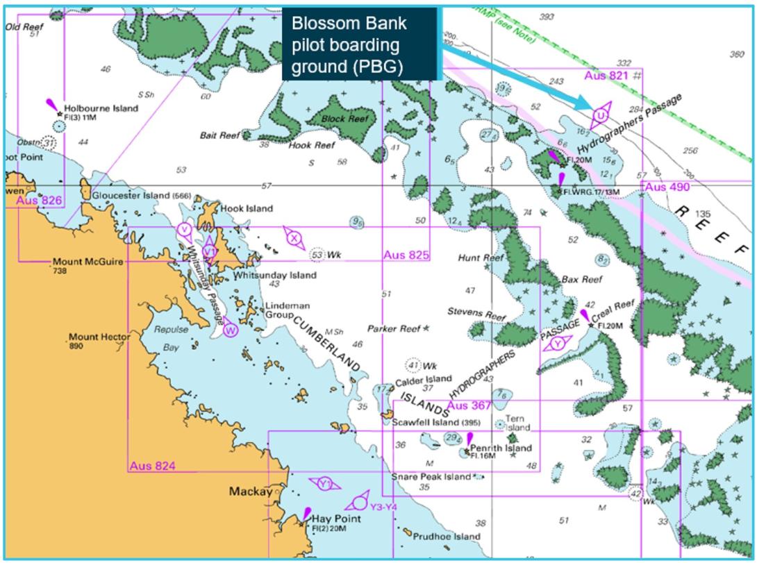
On the evening of 3 May 2022, the 225 m bulk carrier Rosco Poplar arrived off Blossom Bank pilot boarding ground to embark a coastal pilot by helicopter for its transit of the Great Barrier Reef via Hydrographers Passage (Figure 1). The ship was in ballast and bound for Hay Point to load coal.
Figure 1: Navigational chart showing Blossom Bank pilot boarding ground
Source: Australian Hydrographic Office, annotated by ATSB
At 2300 local time, Rosco Poplar’s master arrived on the navigation bridge (bridge) and discussed preparations for the pilotage with the officer of the watch (second mate). Checks of the ship’s main engine, steering gear and navigational equipment were conducted. Meanwhile, crewmembers on the main deck prepared for the helicopter’s arrival.
The ship was equipped with 2 electronic chart display and information system (ECDIS) units. Global positioning system (GPS) data for both ECDIS units and the radars was provided by one of the 3 GPS units.
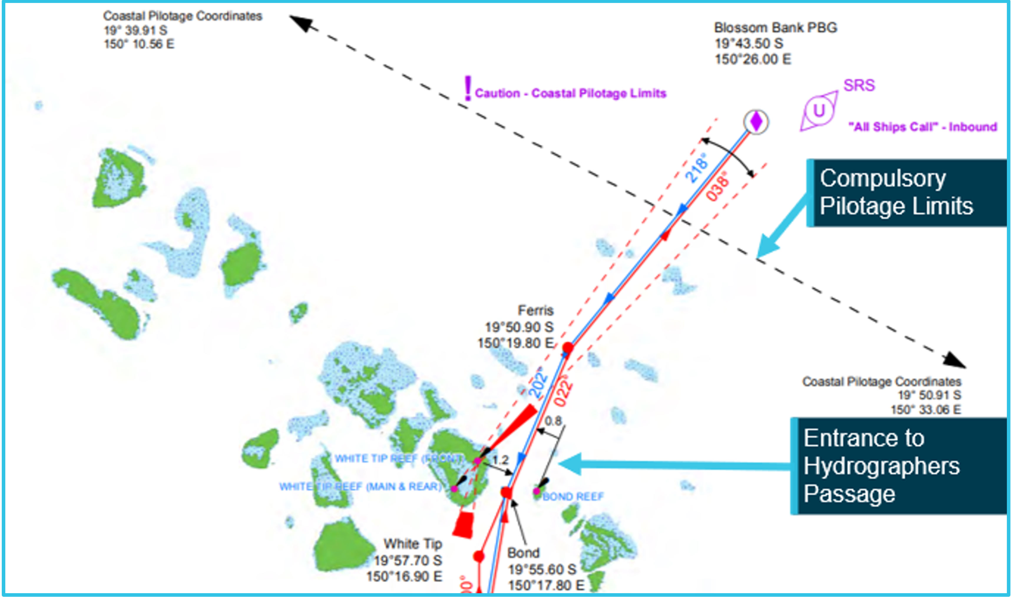
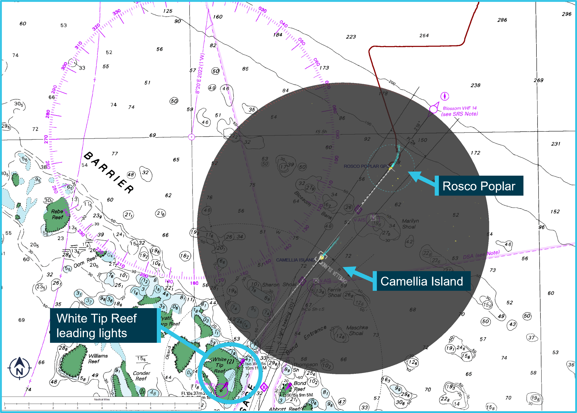
At 0140 on 4 May 2022, pilot helicopter landed on the ship’s helicopter landing cargo hold hatch cover and the pilot disembarked. By 0145, the pilot had joined the bridge team, which included the master, second mate and an able seaman at the helm. The pilot ordered ‘maximum speed’[1], then checked the ship’s position and course on the ECDIS and gave helm orders to take it towards the compulsory pilotage limits and join the 218° (T) course inbound for Hydrographers Passage (Figure 2). Visibility was clear, with the only other traffic in the area being another inbound ship, Camellia Island, about 6 nautical miles (miles)[2] ahead (Figure 3). The tide was ebbing with high water at Bugatti Reef having occurred at 2355 on 3 May, with a height of tide of 2.72 m above chart datum.[3] Tidal stream data[4] indicated that the strongest predicted tidal stream would be about 5.4 knots setting in a 016° (T) direction in the vicinity of Bond Reef at 0255.
Figure 2: Entrance to Hydrographers Passage
Source: Australian Maritime Safety Authority, annotated by ATSB
At 0149, the pilot identified that the waypoints for the planned route had been input into the ECDIS units but not the radars or the GPS units. The pilot then told the master that the passage plan required the route to be programmed into all of the ship’s navigational systems and asked for the waypoints to be entered into both radars.
The pilot then connected his portable pilot unit (PPU) to the automatic identification system (AIS) pilot plug, located at the forward part of the bridge. After connecting the PPU, the pilot set up a tablet device (iPad) next to the secondary ECDIS console on the chart table, located in the aft part of the bridge. The PPU connected wirelessly to the iPad, which displayed GPS and AIS information on electronic navigation chart (ENC) software installed on it (see the section titled Portable pilot unit).
While setting up the PPU, the pilot became aware that the master had not previously transited Hydrographer’s Passage so he advised the master that there was a 7-8 knot opposing current and reiterated the ‘maximum speed’ requirement.
Meanwhile, the master and second mate determined that the waypoints would need to be manually entered for each radar. The second mate began the task, starting with the s-band radar, located on the starboard side of the bridge.
At 0158, the pilot asked the master if the pilotage provider company’s standard master-pilot information exchange (MPX) checklist had been received. When the master advised that it had not, the pilot told the master that all bridge team members had to read and sign the checklist. The pilot then produced a copy of the checklist and conducted an MPX with the master confirming that all the ship’s machinery and equipment was in working order and there were no defects. When the MPX concluded at about 0204, the pilot asked the master to make a hard copy of the checklist after it had been signed.
At 0215, the second mate informed the pilot that the waypoints had been input into the s-band radar. Shortly after, as the ship approached the compulsory pilotage limit near Blossom Bank, the pilot ordered a heading[5] of 218° to line up the ship along the 218° (T) leading line indicated by the White Tip Reef lights ahead (Figure 3). At 0218, the pilot made a ‘pilot commencing duties’ report to the coastal vessel traffic service (REEFVTS) via VHF radio and advised the master that he was taking over the conduct of the ship.
Figure 3: Navigational chart with Rosco Poplar’s radar display overlaid (grey) at 0217
Source: Australian Hydrographic Office, annotated by ATSB
At about the same time, the second mate moved to the x-band radar to input waypoints. The pilot reported that at this time, he was monitoring the ship’s progress visually and on the 2 ECDIS displays, which the pilot compared to the position displayed on the PPU. At 0234, the second mate completed the waypoint input for the x-band radar and returned it to operational mode.
At 0239, the master alerted the second mate to discrepancies between the ship’s heading displayed on the radar and ECDIS units. They discussed those discrepancies in their native language (Mandarin) over the next 20 minutes with no resolution. During this discussion, the master recalled experiencing a similar error on board the ship on a previous voyage. Neither raised any concern with the pilot, nor did he ask them what they were discussing.
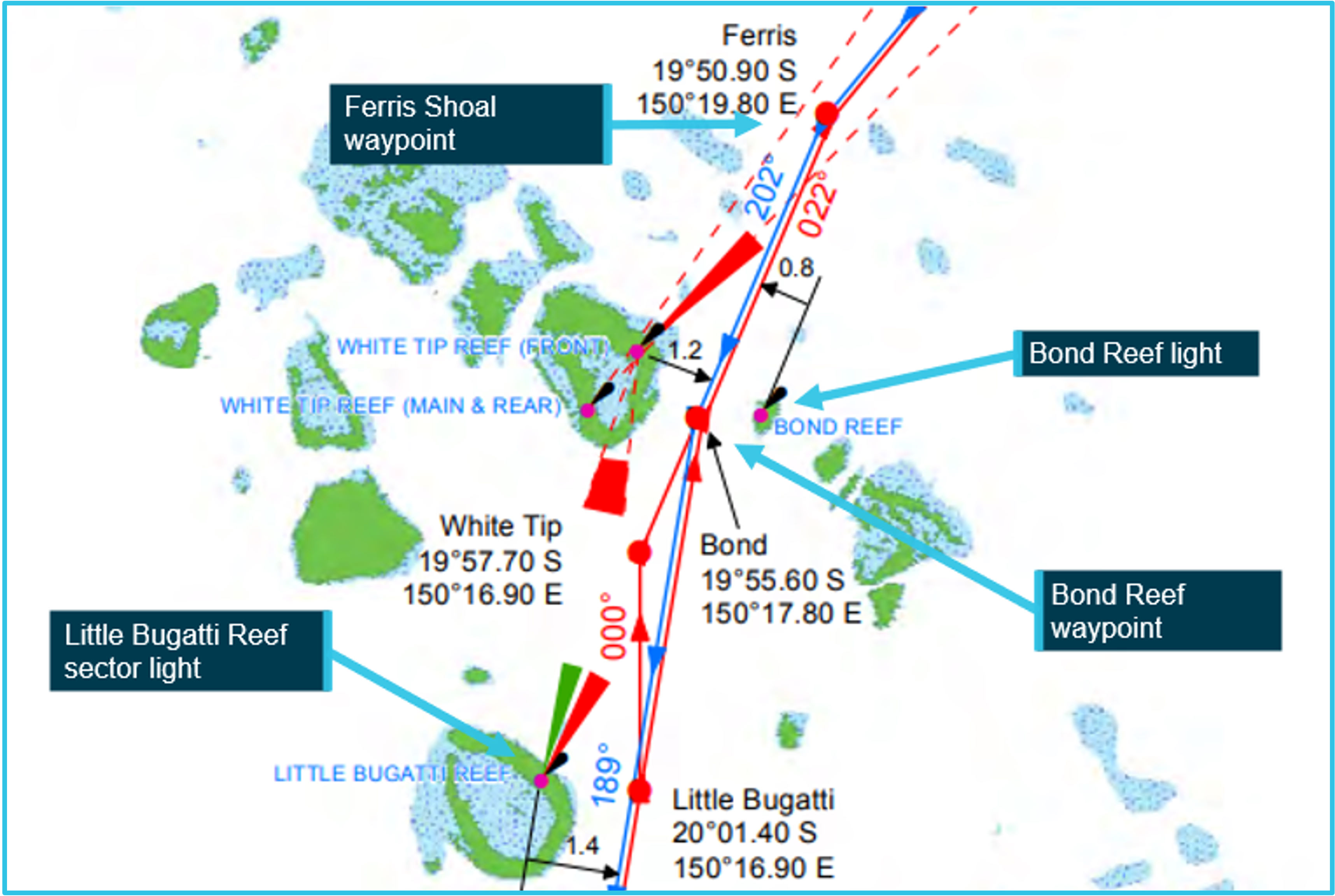
As the ship passed the Ferris Shoal waypoint at 0246, the pilot ordered a 202° heading towards the next waypoint to track the ship 0.8 miles to the west of Bond Reef light beacon (Figure 4). According to the pilot, he saw that Little Bugatti Reef sector light was white at the time (the white and red sectors indicate safe and unsafe waters, respectively).
Figure 4: Standard planned routes near Bond Entrance (inbound tracks are blue)
Source: Australian Maritime Safety Authority, annotated by ATSB
About 2 minutes later, the pilot ordered a heading of 195°and over the following 20 minutes, continued to give heading orders ranging from 193° to 202°. Meanwhile, at 0301, the second mate carried out a position crosscheck by using the line of position (LOP) function on the ship’s ECDIS, using the range and bearing of Little Bugatti Reef sector light directly from the ECDIS, which indicated the ship was on the planned track. During this period, the master observed that the flashing white light fine on the port bow had closed until it was almost directly ahead of the ship. The master did not query the pilot to identify the light and assumed it was not Bond Reef beacon but some other light.
At 0307, the pilot ordered a heading of 190°. Then, at 0311, having suddenly noticed that the Little Bugatti Reef sector light was indicating red, the pilot ordered 205°.
About 1 minute later, multiple GPS and AIS status alarms sounded and the GPS input source displayed on the ECDIS briefly changed from ‘GPS1’ to ‘DR’ (dead reckoning[6]) mode. Camellia Island’s AIS return also disappeared from the radar and ECDIS displays. While these alarms were sounding, the pilot repeated the previous 205° heading order. At 0313, when Rosco Poplar’s GPS position reappeared on the ECDIS and the PPU displays, it was 1 cable (185 m) west of Bond Reef beacon - the ship’s indicated GPS position had almost instantaneously moved about 0.92 of a mile (1,704 m) to the east (Figure 5). As the ship passed abeam of Bond Reef, the pilot and bridge team saw its light very close to port.
Figure 5: Rosco Poplar’s track, as displayed on the ship’s ECDIS
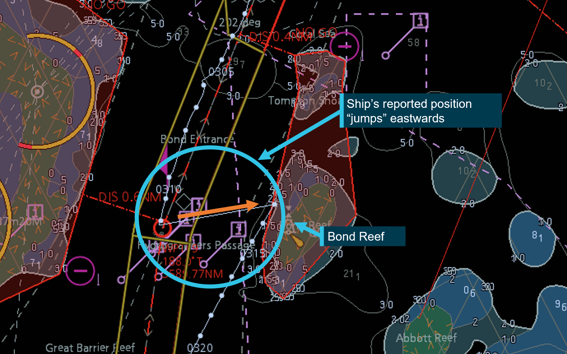
Source: RP ECDIS, annotated by ATSB
The pilot noted that the PPU and ECDIS displays both showed that the indicated position had suddenly shifted and said to the master ‘captain, your waypoint is off; we were here, now suddenly we are here – that’s why we were looking at this light’. While the ship remained on a heading of 205° to return to the planned route, the pilot, master and second mate discussed the error.
Meanwhile, at 0313 a series of alerts, including a potential grounding alert, were generated by the REEFVTS decision support tool (DST)[7]. The duty vessel traffic service operator (VTSO) noted that these alerts were associated with multiple dead reckoning (DR) targets for Rosco Poplar (Figure 6). The VTSO assumed this was due to a DST system error. The VTSO checked the ship’s displayed position and track to determine if intervention was required.
Figure 6: Rosco Poplar's track information at 0313, as displayed at REEFVTS
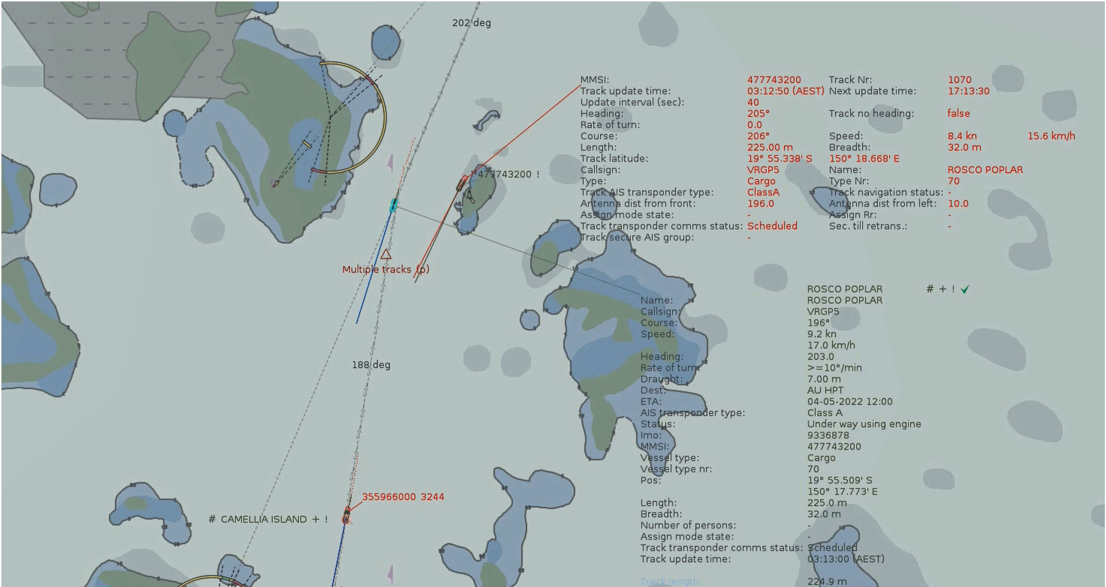
Source: Australian Maritime Safety Authority
At 0313, the VTSO noted that the ship’s position had suddenly shifted close to Bond Reef, after which it had started tracking away from the reef. The VTSO decided against calling the pilot/ship’s crew and began investigating the suspected DST system error. From about 0321, the VTSO made several internal calls to Gladstone VTS and others, which seemed to confirm a possible system error. At 0330, the VTSO started calling the ship (on VHF channel 11) but could not establish contact until 0336 (on VHF channel 14). In the subsequent discussion with the pilot, it was confirmed that the ship had in fact passed close to Bond Reef.
The pilotage continued uneventfully until its conclusion at 0836, when the ship departed the compulsory pilotage limit near Tern Island (Figure 1). The pilot made a ‘ceasing pilot duties report’ to REEFVTS before departing the ship by helicopter at 0854. The ship proceeded to the anchorage area off Hay Point where it anchored at 1230.
Events following the pilotage
Following the pilotage, the master and REEFVTS submitted incident reports for the near-miss grounding to the Australian Maritime Safety Authority (AMSA). Rosco Poplar remained at anchor over the following days where 2 obsolete GPS units and their antennas were replaced by shore technicians (this work had been scheduled a few weeks earlier).
On 31 May 2022, AMSA conducted a port state inspection and detained the ship on the grounds that the master and mates demonstrated inadequate operational proficiency with respect to safe navigation.
On 9 June 2022, following remedial training of the officers to the satisfaction of AMSA and the ship’s classification society, the ship was released from detention. The following day, the ship berthed at Hay Point coal terminal and began cargo operations. While it was berthed, ATSB investigators attended the ship to collect evidence for its investigation.
On 10 June, after completing loading its cargo of coal, the ship sailed and transited Hydrographers Passage outbound uneventfully.
Context
Rosco Poplar
Rosco Poplar was built in 2008 by Oshima Shipbuilding, Japan, registered in Hong Kong and classed with China Classification Society (CCS). At the time of the occurrence, the ship was owned by the Poplar Shipping Company, Hong Kong and managed and operated by Bernhard Schulte Shipmanagement, China.
Rosco Poplar had an overall length of 225 m, a moulded breadth of 32.26 m and a depth of 20.05 m. At its summer draught of 14.43 m, the ship had a deadweight of 82,331 tonnes. Propulsive power was provided by a single Kawasaki Heavy Industries 2‑stroke, single‑acting diesel engine that developed 9,373 kW at 88 rpm. The main engine drove a single, fixed-pitch propeller, which gave the ship a service speed of 14.5 knots.
Crew
Rosco Poplar had a crew of 21 Chinese and Burmese nationals, including the master.
The master had 16 years of seagoing experience and held a master’s certificate of competency, issued in 2017. The master’s seagoing experience had primarily been on container ships, having transitioned to bulk carriers in 2020. The master gained their first command in 2021 and had joined Rosco Poplar in March 2022.
The second mate had over 10 years of seagoing experience, with 4 years at that rank. The second mate had previously worked on container ships and bulk carriers, served on Rosco Poplar in 2017 as third mate and joined the ship as second mate in March 2022.
The able seaman had over 10 years seagoing experience and joined Rosco Poplar in late 2021.
Bridge equipment layout and configuration
Rosco Poplar was equipped with 2 Furuno EC3000 electronic chart display and information system (ECDIS) units. The primary unit was situated on the starboard side of the bridge, between the s-band and x-band radar units (Figure 7). The secondary ECDIS unit was fitted on the chart table behind the primary unit and radars. The automatic identification system (AIS) unit was located beneath the bridge window panels, forward of the primary ECDIS unit.
Figure 7: Rosco Poplar's navigational equipment
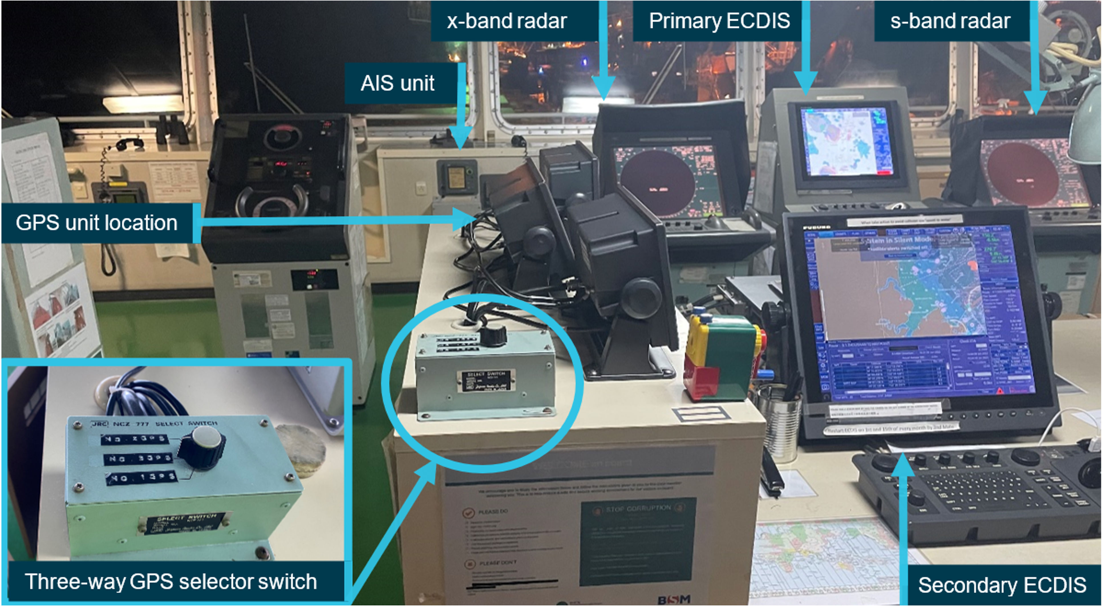
Source: ATSB
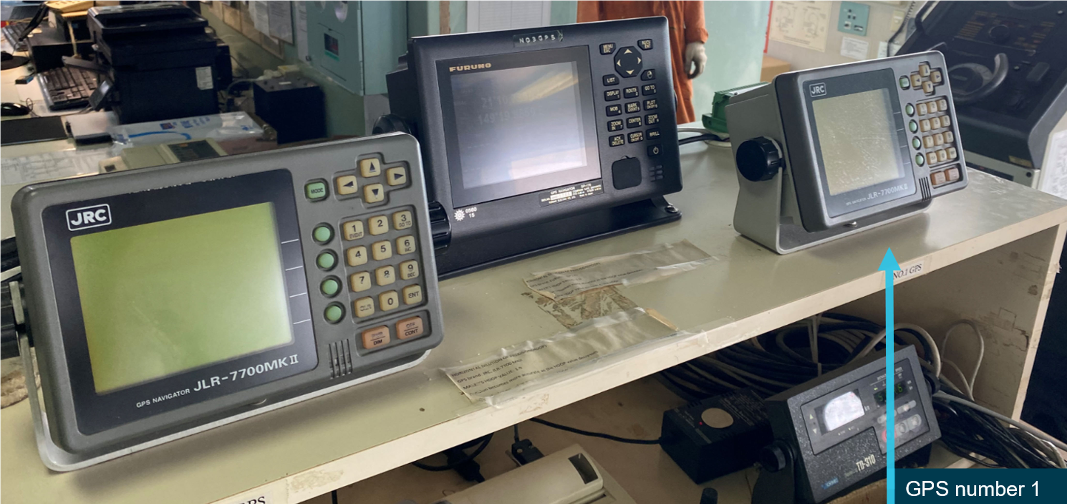
At the time of the occurrence, 2 Japan Radio Company (JRC) differential[8] GPS units and a Furuno GPS unit were installed on the chart table near the secondary ECDIS unit. The data output feed from each GPS unit was connected to a 3-way selector switch, adjacent to the units (Figure 7 and Figure 8). A single output feed from the selector switch was connected via a JRC data buffer to a secondary buffer which distributed the data to the navigational equipment, including both ECDIS units, both radars, AIS unit and the voyage data recorder (VDR). The JRC JCY 1800 type VDR recorded bridge and communication audio, radar images and various other navigational data.
Figure 8: Diagram of bridge equipment configuration
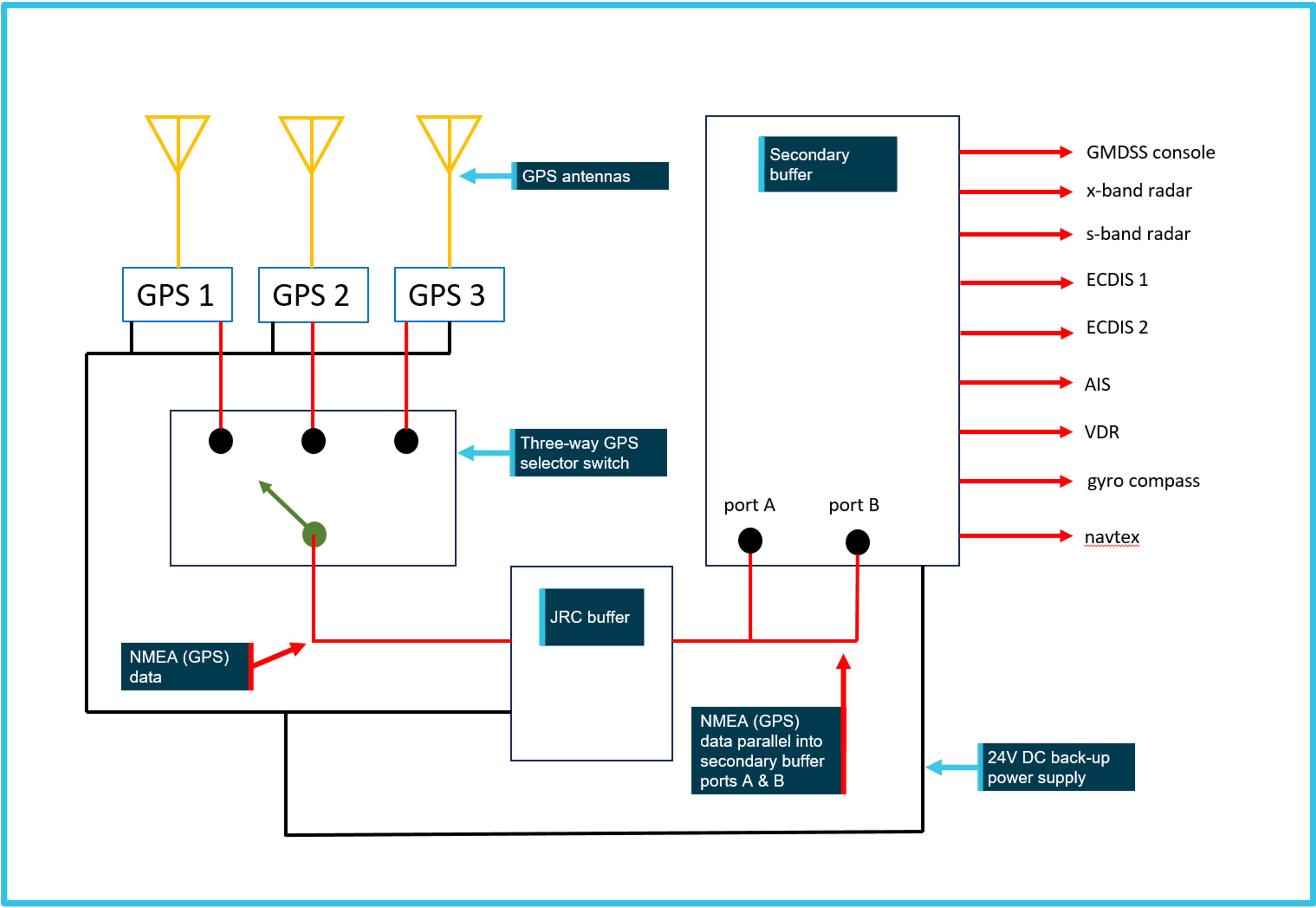
Source: ATSB (adapted from Taylor Marine)
While the secondary buffer was equipped with dual data input ports, the single data output from the JRC buffer had been split into 2 parallel outputs, which were then connected to each port. This configuration meant that all the ship’s navigational equipment derived a single source of positional data from the GPS unit selected via the 3-way switch at that time.
The antennae for the JRC GPS units were located on the ship’s monkey island, on top of the bridge. They were slightly to starboard of the ship’s centreline and in line with the forward part of the bridge structure. The Furuno GPS antenna was fitted to the port side upper railing of the monkey island and positioned aft of the JRC antennae.
Global positioning system
The master and second mate both reported that ‘GPS 1’ was selected during the pilotage, this being one of the JRC units (Figure 9). Due to the location of the 3-way switch, files obtained from the VDR and ECDIS following the occurrence were unable to provide GPS source information necessary for confirming which of the 3 GPS units was selected during the pilotage.
Figure 9: Arrangement of the GPS units
Source: Taylor Marine, annotated by ATSB
The JRC units consisted of a JLR 7700MKII differential GPS, paired with a JLR 4331 differential GPS‑capable antenna. The manufacture of both the GPS and antenna were discontinued in 2012, and with spare parts no longer available for some time before the occurrence, were considered obsolete. In January 2022, the ship’s management company decided to replace the JRC units during the ship’s call at Hay Point.
The antenna contained the GPS module, which output pre-processed positional data to the bridge equipment. The output data included time and date, ship’s position, position type and accuracy information, set datum information and the GPS-calculated speed over ground (SOG) and course over ground (COG).
The last date rollover[9] for the JRC units occurred in April 2019 and both had been appropriately adjusted by the ship’s crew in accordance with the manufacturer’s operating manual.
Automatic identification system
The AIS unit was a JRC JHS-182 model. While the transponder for the AIS unit contained its own GPS sensor, the unit had an optional input for an external position sensor. The data for this external input was supplied from the secondary buffer. The AIS unit had been programmed to reference the Furuno antenna location to accurately indicate the ship’s position. This meant that whenever either of the JRC GPS units were selected via the 3-way switch, there was an offset to the ship’s indicated position by about 10 m to starboard and 6 m forward of its actual position, reflective of the distance between the JRC unit and Furuno antenna locations.
Electronic chart display and information system (ECDIS)
An ECDIS is a type or class of electronic chart display system. The International Hydrographic Organization (IHO) stated that an electronic chart display system is a ‘general term’ for a configuration of electronic equipment, software, and nautical chart data capable of integrating position, speed and heading data to display the vessel’s position and movement through the water, superimposed on an electronic chart.[10] The 2 classes of electronic chart display systems comprise ECDIS and electronic chart systems (ECS). A key distinction between them is that while ECDIS can be used to meet SOLAS[11] chart carriage requirements, ECS cannot and is only to be used to assist navigation.
Rosco Poplar was equipped with ECDIS as its primary means of navigation. An ECDIS was first recognised as being able to meet the SOLAS chart carriage requirements in 2002 and by July 2018, the fitting of ECDIS became mandatory for almost all ships. An ECDIS, as defined in the IMO ECDIS performance standards,[12] means:
a navigation system which, with adequate back-up arrangements, can be accepted as complying with the up-to-date chart required by regulations V/19 and V/27 of the 1974 SOLAS convention, as amended, by displaying selected information from a system electronic navigational chart (SENC) with positional information from navigation sensors to assist the mariner in route planning and route monitoring, and if required display additional navigation-related information.
Since electronic systems cannot be considered completely failsafe, IMO performance standards for ECDIS require that the ‘overall system’ includes both a primary ECDIS and an adequate, independent back-up arrangement that provides:
- independent facilities enabling a safe takeover of the ECDIS functions to ensure that a system failure does not result in a critical situation
- a means to provide for safe navigation for the remaining part of the voyage in case of ECDIS failure.
The performance standards allow for considerable flexibility in respect to how the ECDIS is integrated on board the ship to meet the back-up requirements. The IHO identifies 2 common interpretations in respect to the minimum functional requirements and what constitutes ‘adequate’ back-up arrangements:
- a second ECDIS, connected to an independent power supply and a separate GNSS[13] position input
- up to date paper nautical charts sufficient for the intended voyage.
Rosco Poplar was equipped with 2 ECDIS units with independent power supplies and 3 GPS units available to provide data to the ECDIS units. While this may have satisfied the IMO performance standards with respect to back-up arrangements, the configuration of the installation meant that only one GPS unit could provide a single source of positional information to both ECDIS units at any one time and selection between each GPS unit required manual input using the 3-way selector switch.
The pilot
Rosco Poplar’s pilot became a coastal pilot in 2009, following a long career as a merchant seafarer, including 24 years as master on ships trading in Australia and New Zealand. The pilot had worked exclusively in Hydrographers Passage and held an unrestricted pilot licence for this pilotage area.[14] The pilot had conducted 1,684 pilotages through Hydrographers Passage, including 840 inbound voyages, before the occurrence.
Since 2015, the pilot had undertaken 4 pilot check voyages[15] in Hydrographers Passage, each assessed by a different check pilot. On each occasion, no deficiencies were identified with respect to the pilot’s performance.
Auriga
Under the Australian Maritime Safety Authority’s (AMSA) Marine Order 54 (Coastal pilotage) (MO54), coastal pilots must be engaged through AMSA-licenced pilotage providers. The duty of a licensed pilotage provider is to provide pilots and pilot transfers to ships and maintain a safety management system to ensure the safe navigation of the ships in compulsory pilotage areas.[16]
Rosco Poplar’s pilot at the time of the occurrence had been engaged through Auriga, one of 2 private companies which provided coastal pilotage services throughout the Great Barrier Reef (GBR). Auriga was formed in 2021 when the Western Australia-based marine pilotage and logistics services provider, Argonaut Marine Group, merged with Australian Reef Pilots (ARP). At the time of the merger, ARP was an established pilotage provider in the GBR, having formed in 1993 when the provision of Queensland coastal pilotage services was privatised. Auriga employed about 40 pilots for its pilotage operations in the GBR.
Auriga had in place a pilotage operations safety management system (SMS), designed to meet the regulatory standards necessary for the company to hold its licence. The SMS had last been revised in June 2020, when the company traded as ARP. It contained a set of standard operating procedures to assist and guide pilots in their daily practical pilotage tasks. A key objective of the SMS was to minimise the risk of a major accident resulting in personal injury, environmental harm or property damage or loss.
Great Barrier Reef Marine Park
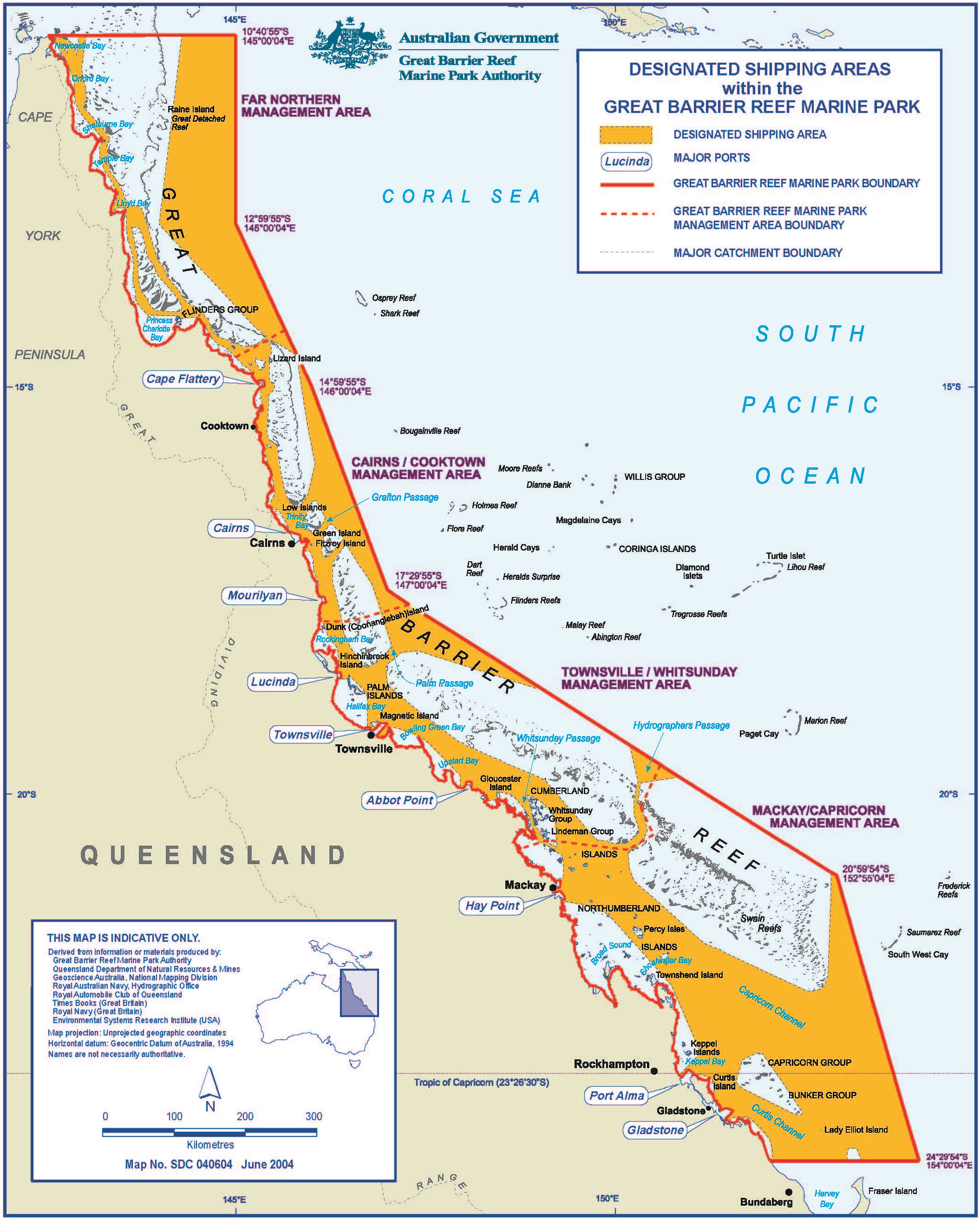
The Great Barrier Reef is a vast network of coral reefs, shoals and islands off Australia’s north‑east coast, stretching for over 1,200 miles from Bundaberg in the south to Cape York in the north (Figure 10). It is the world’s largest and most diverse reef ecosystem, internationally renowned for its scientific, cultural and environmental importance. In 1981, the GBR was inscribed on the United Nations Educational, Scientific and Cultural Organization (UNESCO) world heritage list for its outstanding universal value.
Figure 10: The Great Barrier Reef region (Designated Shipping Areas are highlighted)
Source: Great Barrier Reef Marine Park Authority
The GBR region has been protected as a multi-use marine park since the enactment of the Great Barrier Reef Marine Park Act 1975. The legislation established the Great Barrier Reef Marine Park Authority (GBRMPA) and provided a framework for the long-term protection and conservation of the marine park, including management of the various activities that occur within it. The authority carries out its function through the formulation of policies, enforcement of regulations, education initiatives, establishment of partnerships, research, monitoring and reporting.
Of necessity, ships must travel through navigationally complex channels within the marine park to gain access to 11 regional ports situated along the Queensland coast. The local and Australian economies are heavily dependent on the considerable volume of trade conducted through these ports, particularly the export of bulk cargoes.
In 1990, the IMO declared the GBR region as the world’s first particularly sensitive sea area (PSSA)[17] in recognition of the environmental importance of the GBR and the need for special measures to protect it against pollution from ships. These measures include restrictions on discharges from ships, ship routeing practices, compulsory pilotage, mandatory ship reporting and monitoring, coastal vessel traffic services and an extensive network of visual and electronic navigation aids.
Designated Shipping Areas (DSA) in the marine park were established by GBRMPA as shown in Figure 10. The DSAs are designed to help minimise environmental impacts from shipping, while having regard for the shipping industry and Australia’s international maritime obligations. The total area available for ship navigation is approximately 80% of the marine park. Additionally, the Australian Government introduced the Marine Parks (Great Barrier Reef Coast) Zoning Plan in 2003 to complement existing protection mechanisms. The plan divides the marine park into areas that fall into one of 8 zones, with different activities allowed and/or prohibited in each zone. Ships are only permitted in the ‘general use’ zones which, in addition to the DSA, makes up the area within which navigation through the marine park is allowed.
Hydrographers Passage falls within the DSA and ships seeking to transit the area are subject to the rules and regulations made under both international and domestic regulatory instruments.
Hydrographers Passage
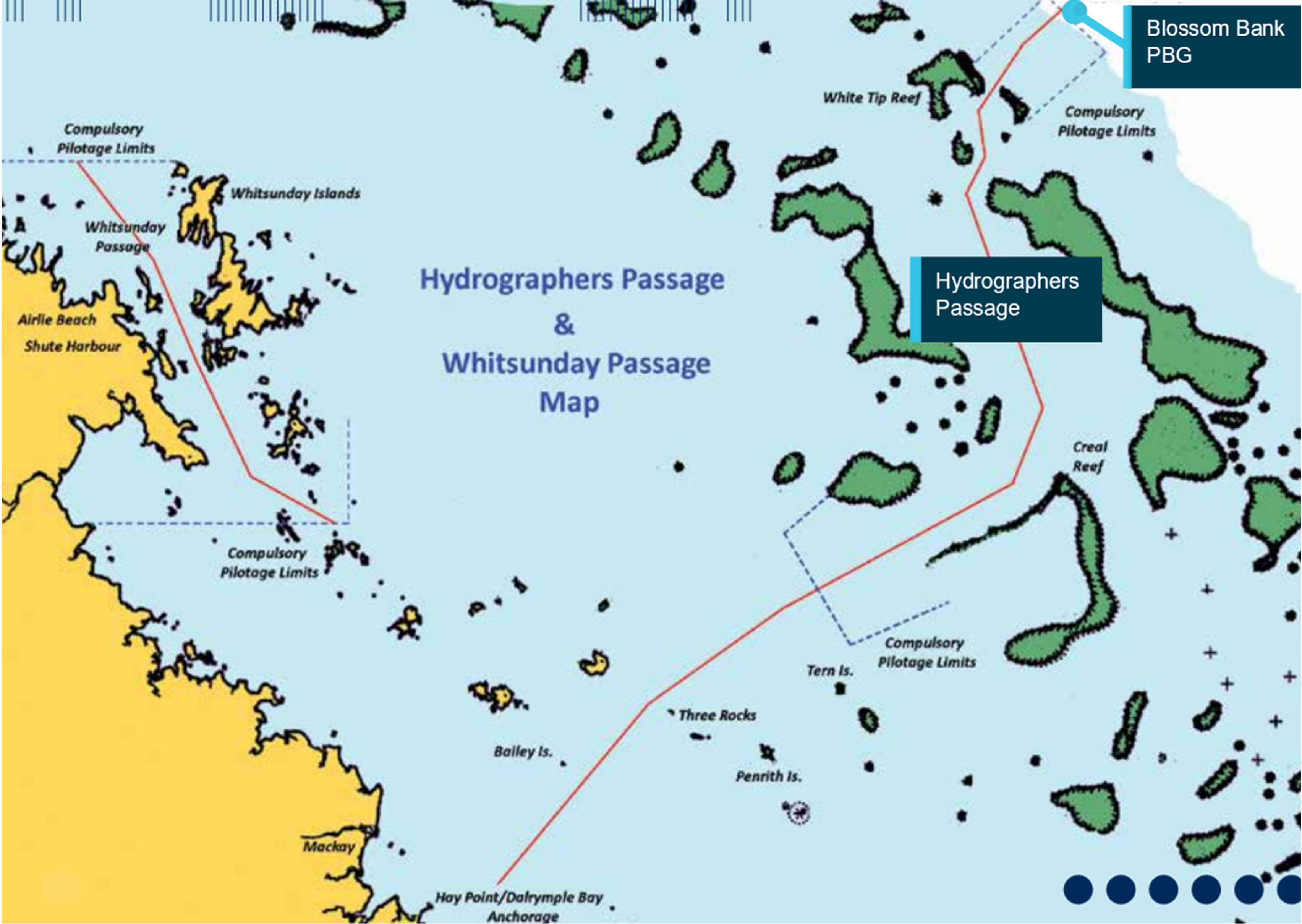
Hydrographers Passage provides a deep-water shipping route through the GBR between Blossom Bank pilot boarding ground (PBG), near the entrance to the passage, and the Cumberland Islands, northeast of Mackay (Figure 11). It is the shortest route to the Coral Sea from ports located on the coast of central and southern Queensland, including those at Mackay and Hay Point. Hence, most of the seaborne trade between these ports and ports abroad, particularly the export of coal from Hay Point, passes through Hydrographers Passage.
Figure 11: Map showing Hydrographers Passage (shipping route is indicated in red)
Source: Australian Reef Pilots, annotated by ATSB
The distance along the route from Blossom Bank to the port limits of Mackay and Hay Point is about 115 miles. At its narrowest point, the route is about 1 mile wide and has a minimum charted depth of 25 m. It is navigable by any size of ship visiting the region’s ports.
Ships passing through Hydrographers Passage can encounter strong currents which interact with the geography of the reefs on either side of the route. The flood tide sets south‑south‑west and the ebb tide sets north‑north‑east, the rate varying between spring and neap tides. Between Ferris Shoal and Bond Reef, streams of over 5 knots during spring tides can be encountered, with sets across the track occurring near the time of high and low water. As navigation through the narrow Hydrographers Passage can be challenging, AMSA provides an integrated network of fixed and floating visual and electronic aids in the area, which is also covered by a coastal vessel traffic service.
Pilotage is compulsory through Hydrographers Passage for ships over 70 m, as well as for loaded oil and chemical tankers and gas carriers, irrespective of size. The compulsory pilotage area extends from Blossom Bank PBG to the vicinity of Tern Island. The distance along the shipping route between these two locations is about 80 miles and the pilotage typically takes 5 to 7 hours. Pilot transfers usually occur in the vicinity of Blossom Bank PBG and Tern Island and are conducted by helicopters operating from Mackay Airport.
The pilotage
Global positioning system failure
Mode and accuracy
The GPS data recorded by the Rosco Poplar’s VDR included accuracy as a parameter, displayed as a horizontal dilution of precision (HDOP) value. If the HDOP was reported in the data sentence as having a value greater than 4, this would trigger a visual alert on the radar and ECDIS units, indicating insufficient accuracy for navigation. Additionally, these data sentences would report the GPS mode that was displayed on the radar and ECDIS.
During the pilotage, prior to the time of failure, the HDOP value varied between 1 and 7 and HDOP alerts were displayed on the radar units. The GPS mode alternated between differential GPS and standard GPS (values 2 and 1 respectively), until changing to 0 (invalid fix) at 0312:15 local time.
Time of failure
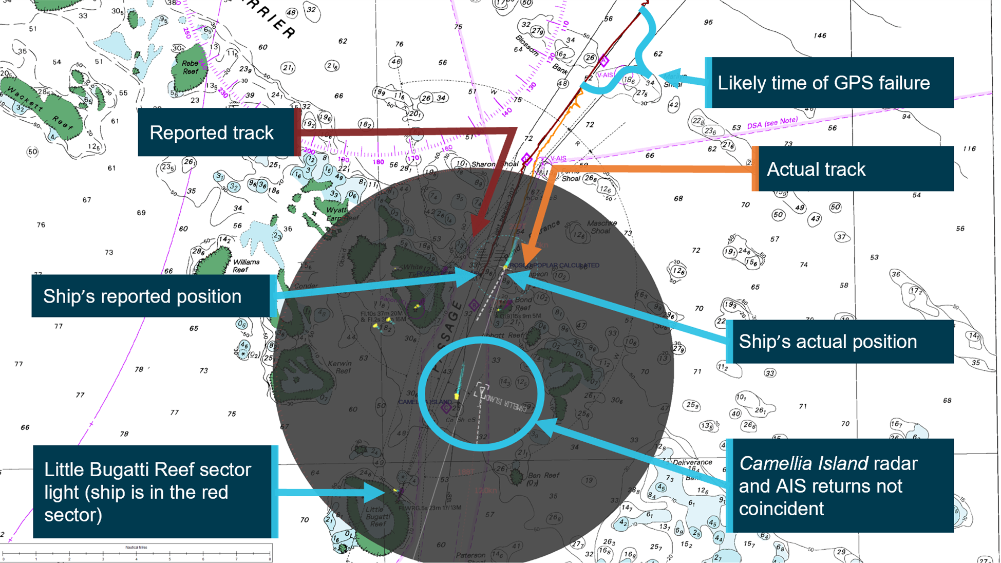
Following the occurrence, the ATSB reconstructed Rosco Poplar’s actual track during the approach to Bond Reef using the ship’s x-band radar display images recorded by the VDR with corresponding navigational chart features in the vicinity (Figure 12).
Figure 12: Position indicated by GPS at 0305 vs actual position (radar overlaid in grey)
Source: Australian Hydrographic Office, annotated by ATSB
The x-band radar display images captured by the VDR indicated that at 0218, the radar was switched to standby mode when the route waypoint input task was commenced. At 0218:07, the last captured image of the radar screen prior to the waypoint input displayed 2 AIS virtual aid‑to‑navigation returns, and the nearby ship Camellia Island, and each had coincident radar and AIS returns. This indicated that the GPS position input to the radar was accurate at that time. Just prior to this, at 0217:40, the HDOP value changed from 5 to 1, with a change in satellites-in-view also recorded. After 0217:40, no further changes to the HDOP value and satellite-in-view were recorded until the GPS position was lost at 0312:15.
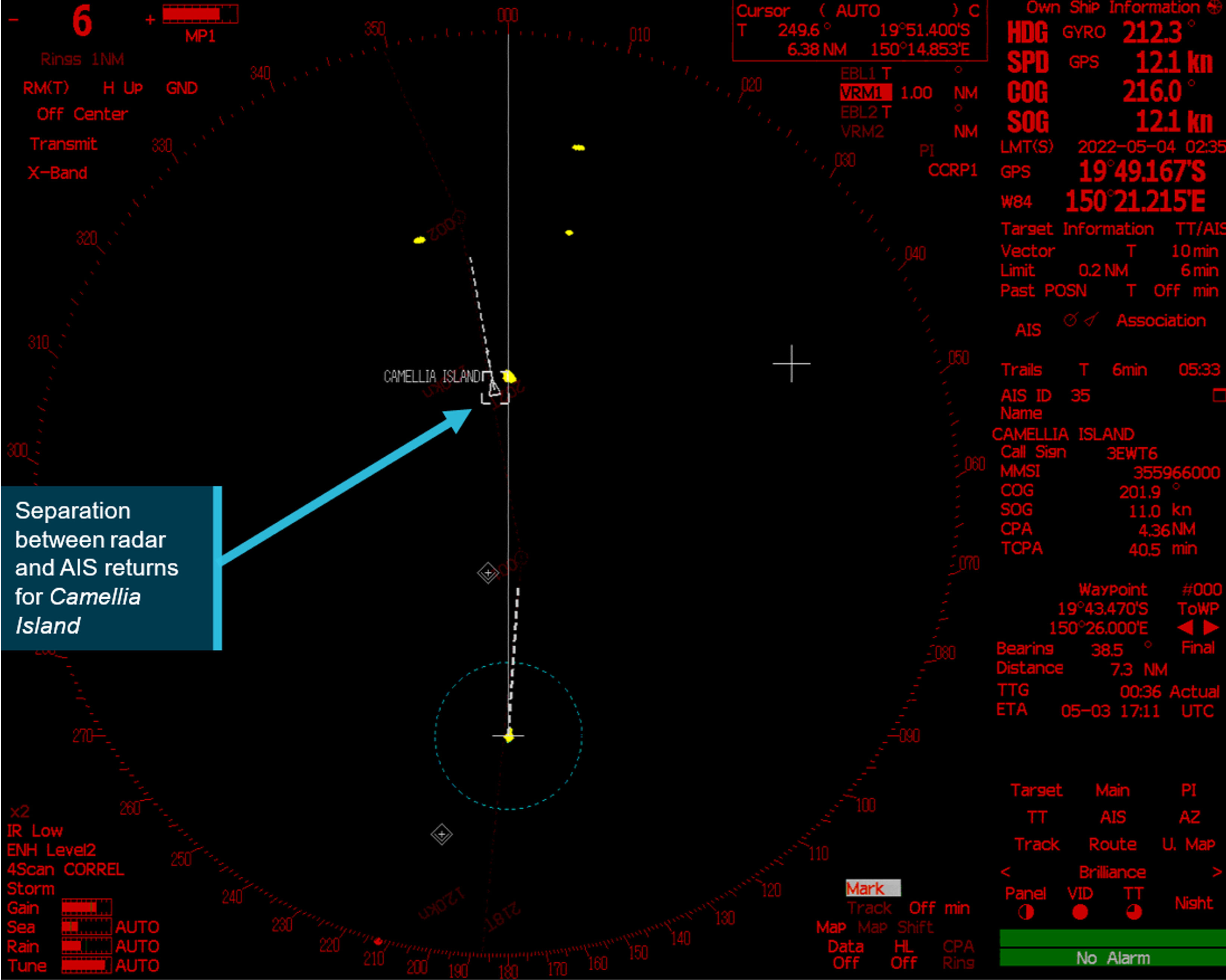
Following the completion of the waypoint input, and returning the radar to active mode, the radar image captured at 0234:52 showed a separation of Camellia Island’s radar return from its reported AIS position, indicating that the selected GPS unit was no longer providing an accurate position (Figure 13). This separation gradually increased and the ship began to deviate from the planned route towards Bond Reef beacon (visible on the radar display) as the pilot’s heading orders were based on the erroneous position and track displayed on the ECDIS and PPU. Assessment of the ship’s reconstructed actual track indicates that by about 0256, it had deviated far enough from its planned track to be within the red zone of Little Bugatti reef sector light ahead.
Figure 13: Radar image at 0235
Source: Rosco Poplar, annotated by ATSB
From the approximate time at which the GPS unit began providing inaccurate positional data, until the loss of GPS signal altogether at 0312:15, the ship’s actual position deviated approximately 0.92 miles (1,704 m) from the position indicated by its GPS. The invalid position placed the ship on the planned 202° (T) track rather than indicating its actual position, with the deviation gradually increasing over this period as the ship actually made good a course of approximately 195° (T) (Table 1).
Table 1: Deviation distance of ship from reported position
|
Time |
Deviation of ship from reported position (nautical miles) |
|
2:52:07 |
0.54 (1,000 m) |
|
2:54:07 |
0.56 |
|
2:56:07 |
0.59 |
|
2:58:07 |
0.64 |
|
3:00:07 |
0.67 |
|
3:02:07 |
0.72 (1,333 m) |
|
3:04:07 |
0.75 |
|
3:06:07 |
0.81 |
|
3:08:07 |
0.83 |
|
3:10:07 |
0.89 |
|
3:11:07 |
0.92 (1,704 m) |
Failure mode
The ATSB attended the ship after the scheduled removal and replacement of the JRC GPS units and their antennae was completed. As a result, inspection and testing of the GPS units to determine the exact cause of the failure was not possible.
The GPS units’ manufacturer, JRC, advised that the likely cause of the error was an internal failure related to the antenna of the selected GPS unit. From the time the GPS unit began to malfunction until 0312:15, when the GPS position was lost, the unit continued to send processed data of invalid position, without updating the accuracy information. Hence, the invalid position data did not generate any positional error alerts on the GPS unit, which would also have triggered alerts on connected navigational aids. It was not until the GPS position was lost that the ECDIS units started displaying that the GPS unit had regressed to dead reckoning mode (to indicate that it had reverted to estimating position based on the ship’s heading and log speed). The exact reason why the GPS unit did not detect the positional error could not be determined due to the limited available data.
While the manufacturer noted that spoofing or jamming were potential sources of interference in older model GPS units, no other vessels in the area at the time of the pilotage reported an error.
There were no potential interactions identified between the crew and the ship’s navigational aids that could be considered to have led to the gradual degradation of the GPS position accuracy.
Correction of position
Data from the ship’s VDR indicated that, after the GPS status changed from 1 to 0 at 0312:15, the GPS provided blank data sentences containing no data for a period of about 36 seconds. This resulted in multiple audible bridge alarms being triggered, which were also displayed on the ship’s radar and ECDIS units. The invalid position indicated by the GPS aligned with the time at which these alarms were triggered. At 0312:51, the GPS status changed from 0 to 1 and the GPS position of the ship began displaying accurately on the ECDIS units and PPU, indicating it was 0.92 of a mile (1,704 m) to the east of its previously indicated position.
The cause of this reset could not be determined. The GPS unit may have performed an internal correction and reset itself or alternatively, someone on the bridge may have reset the unit or used the 3-way GPS selector switch to change over to a different GPS unit to provide input to the ECDIS units and other navigational equipment.
The master reported to AMSA that they switched over to a different GPS unit when they realised the ship was perilously close to Bond Reef, but this could not be confirmed when ATSB investigators interviewed the master later. While selection to a different GPS unit would usually result in the GPS signal being continual, a reset would normally take approximately 30 to 60 seconds to complete.
Bridge resource management
Bridge resource management (BRM) can be defined as the effective management and utilisation of all resources, human and technical, available to the bridge team to ensure the safe completion of the vessel’s voyage.[18]
Effective BRM facilitates communication, cooperation and coordination among the individuals involved in a ship’s navigation to counter the risks associated with single-person errors. Features of effective BRM include, but are not limited to, passage planning, appropriate information exchange, delegation of duties, situation awareness and effective communication.
Ships are generally exposed to higher risks in pilotage areas because of the smaller margins of safety due to factors which include the reduced depth and width of fairways, increased traffic, tidal variations and stronger currents. Despite the duties and obligations of a pilot, their presence on board does not relieve the master or officer of the navigational watch from their duties and obligations for the safety of the ship.[19] It is essential that pilots and bridge team members observe effective BRM practices and work closely together to execute the passage plan and actively monitor the ship’s progress.
It is a requirement of the STCW that deck officers be competent in BRM principles. Similarly, MO54 required coastal pilots to undertake BRM training every 4 years as part of their continual professional development.
Many serious maritime accidents during pilotage have been attributed to ineffective BRM and in many such incidents, it was found that the master and deck officers ceased to monitor the navigation and position of the ship once the pilot had boarded.
Passage plan
The agreed passage plan, its understanding and the establishment of a ‘shared mental model’ by the entire bridge team forms the basis of a safe voyage under pilotage conditions.
Rosco Poplar’s passage plan for the pilotage followed the Queensland Coastal Passage Plan (QCPP). The QCPP was first developed in 2011 as the standard industry passage plan by AMSA and the coastal pilot working group (CPWG) under a different title and updated and renamed in 2013. Under MO54, the QCPP is the approved passage plan for pilots and ship masters.
A key aim of the QCPP is to improve the readiness of ships transiting coastal pilotage areas by ensuring that passage plans, waypoints and other planning is completed in a standardised manner. The QCPP provides detailed guidance for:
- standard routes (a set of relevant waypoints) and planning chartlets
- REEFVTS and reporting requirements
- preparation for pilot boarding
- master-pilot information exchange
- under-keel clearance (UKC) and draught restrictions
- bridge resource management.
In the days prior to Rosco Poplar’s arrival at Blossom Bank PBG, Auriga provided the master (via email) the passage plan waypoints and information to assist with preparation for the pilotage passage. When the pilot boarded, the waypoints had been input into the ECDIS units, but not into the radars and GPS units, as required by the passage plan.
Position and track monitoring
When navigation is planned through coastal or restricted waters, the ship’s progress along the planned track must be continuously monitored.
While the introduction of modern electronic aids for real-time position monitoring such as ECDIS and PPUs enhance situation awareness and provide multiple monitoring tools, their effectiveness depends on the accuracy of the sensors providing heading, position, and speed data. Traditional navigation methods involving visual transits, clearing ranges and techniques, such as parallel indexing (PI) in particular, provide real-time position and cross-track monitoring, independent of these GPS position sensors. Therefore, the effective use of these techniques remains essential for navigation within coastal or confined waters and are required competencies for coastal pilots under AMSA’s check pilot assessment framework (see the section titled Check pilot system).
The Auriga pilotage operations safety management system (SMS) required its pilots to use visual observation of transits and radar techniques, including PI and clearing ranges to complement a PPU and ECDIS. Accordingly, the company’s standard passage plan for Hydrographers Passage included details of the specific transits, PI and clearing ranges for each leg of the route.
Rosco Poplar’s SMS also included guidance for position monitoring and crosschecks by fixing the ship’s position at regular intervals using radar and visual observations to confirm the accuracy of the ECDIS. The prescribed frequency of crosschecks depended on the ship’s area of operation. For inland navigation, including navigation in confined, restricted and pilotage waters, the procedure recommended a crosscheck at least every 30 minutes. The SMS provided that if there were any doubts regarding GPS position accuracy, then more frequent crosschecks were to be carried out.
Master-pilot information exchange
The early exchange of information between the pilot, master and bridge team should ensure that all personnel have a common understanding of the passage plan and their individual roles and responsibilities for executing it. An aim of the exchange is to bring the resources of the pilot together with those of the ship’s bridge team in a structured and team-orientated way. This ensures that all personnel maintain a shared mental model of the pilotage, during which critical decisions and actions are based on accurate information and challenged where necessary to elicit appropriate responses.
Auriga had implemented a master-pilot information exchange (MPX) checklist and aide memoire, which were specific to its coastal pilotage operations and adopted from standardised procedures promulgated by AMSA. The checklist was designed to prompt the pilot and master to agree on the passage plan and discuss important information about the ship and its equipment to ensure all systems were in working order and appropriately configured for the pilotage. The accompanying aide memoire document included discussion topics relating to BRM principles, including bridge organisation, watchkeeping and communication requirements during the pilotage, including challenge and response. Under Auriga’s pilotage operations SMS, a key aim of the MPX was to clarify each bridge team member’s roles and responsibilities for the pilotage.
Prior to taking over the conduct of Rosco Poplar, the pilot used the checklist to verify some aspects of the ship’s preparedness for the pilotage. Bridge audio obtained from the VDR captured the MPX conversation. The master informed the pilot of the gyro error and advised that the ECDIS was operating normally with appropriately updated charts. The pilot checked the rudder indicator and noted that the bridge was not equipped with a functional rate of turn (ROT) indicator. The master informed the pilot that the main engine and steering gear were in working order and advised that both anchors were available and ready for emergency use.
After establishing that the master had made the mandatory ‘pre-entry report’ to REEFVTS, the pilot checked that the magnetic compass light was functional and verified the ship’s draught of 7 m, thereby concluding the MPX.
While the aide memoire was signed by both the pilot and master, its contents were not referred to during the exchange. Significantly, the MPX had not established each bridge team member’s roles and responsibilities in respect to monitoring the ship’s progress.
Situation awareness and distraction
Situation awareness may be defined as the ability of an individual to possess a mental model of what is going on at any one time and to make projections as to how the situation will develop.[20] Situation awareness provides the foundation for effective decision‑making and response measures in the event of the situation changing. In team environments where individuals are required to perform different, interdependent tasks essential for accomplishing a common goal, effective collaboration and coordination between the individuals are critical factors for the acquisition and maintenance of situation awareness.
Situation awareness on ships can be degraded by distractions, which interrupt an individual from their primary tasks, increasing the likelihood for error. Distractions may be related to the task or from some external, unrelated source or event. While distractions may be commonplace and can usually be managed, it is easy to become drawn into a distraction and overlook much more critical events with serious implications for the safety of the ship.[21]
While modern ships are equipped with multiple technical information sources aimed at reducing human error, these systems can also increase workload and create distractions when not managed effectively.
Lookout
The International Regulations for Preventing Collisions at Sea, 1972, as amended (COLREGs) provide internationally agreed rules and measures to prevent collisions. The COLREGs generally apply to all vessels at sea. With respect to keeping a lookout, Rule 5 of the COLREGs (Look-out), stated:
Every vessel shall at all times maintain a proper look-out by sight and hearing as well as by all available means appropriate in the prevailing circumstances and conditions so as to make a full appraisal of the situation and of the risk of collision.
In this context, available means included radar and AIS.
The International Convention of Standards for Training, Certification and Watchkeeping[22] (STCW) also provided that the lookout must be able to give full attention to the keeping of a proper lookout and no other duties shall be undertaken or assigned, which could interfere with that task.
Rosco Poplar’s SMS included procedures for keeping a proper lookout, which were consistent with the COLREGS and STCW requirements. Auriga’s pilotage SMS contained similar provisions with respect to keeping a lookout during pilotage, including emphasis on the STCW guidance that the lookout is not given tasks which could interfere with their lookout duties. The procedure also required that the pilot’s PPU was not to be used to the exclusion of other navigational aids, and that keeping a proper lookout through visual observations and proper use of radar were the primary means for maintaining a proper lookout.
Communication
Recorded bridge audio data indicated that, after the early exchanges between the pilot and bridge team, there was no further communication regarding the ship’s progress until immediately after its near grounding. Following the MPX, the pilot had continued to give helm orders while the second mate and master discussed discrepancies between the ship’s heading displayed on the radar and ECDIS units.
When interviewed by the ATSB after the occurrence, the master stated that as the ship proceeded from Ferris Shoal, he observed that the relative bearing of a flashing white light had been closing on the port bow and was almost directly ahead of the ship. Being unfamiliar with the area, the master did not query the pilot to identify the light and assumed it was not Bond Reef beacon but some other light.
Bridge audio data indicated that at 0311, the pilot ordered a course change to 205° after sighting the red sector light on Little Bugatti Reef. It was not until 0313, after the GPS position had reset and started indicating that the ship was significantly off the planned track that the pilot discussed the event with the master.
Portable pilot unit
A PPU is an aid to pilotage operations with the intent to improve safety and efficiency of the operation. Its primary use is to provide independent, accurate GPS position, course and speed information. A PPU also provides other information such as charts, passage plan and AIS information.
While PPU technology continues to become more sophisticated, a basic PPU typically consists of a tablet or laptop device loaded with electronic chart software, and a sensor to provide GNSS positional and AIS data. The sensor may have its own independent antenna to obtain the data, or it may connect to the ship’s pilot plug to obtain positional, heading and AIS data from its navigational equipment.
The use of these units during pilotages can provide an additional level of information to the pilot, aiding situation awareness. While PPU use is broadly encouraged by pilotage associations worldwide, several guidelines have been published to inform pilots on best practice for PPU use and highlight the potential risks involved with their improper set-up and use.[23]
Set-up and use
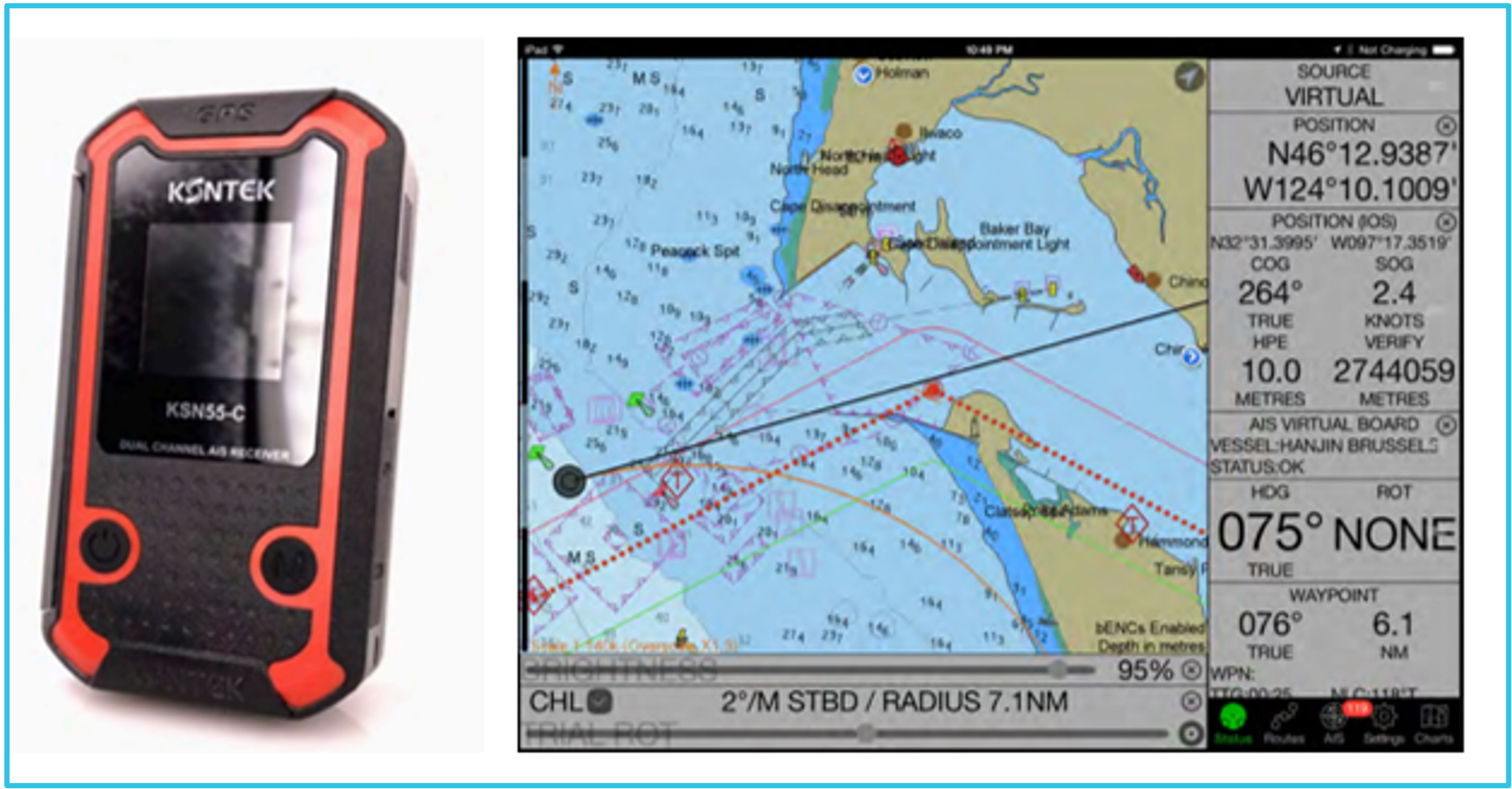
The PPU used by the pilot at the time of the occurrence was a KSNTEK brand, model number KSN55-C (Figure 14). The unit was a dual-channel AIS receiver, with in‑built GNSS and rate of turn (ROT) capability. The unit could operate independently or be connected to the ship’s navigational systems via the pilot plug. The unit displayed position, speed, course, heading and ROT information on its own LCD screen and was also capable of displaying that information on a tablet or computer device equipped with electronic navigational charts (ENC). Auriga provided its pilots with tablet devices and SEAiq Pilot software.[24]
Figure 14: KSN55-C model PPU and example SEAiq chart display on a tablet device
Source: Auriga
When connected via the ship’s AIS pilot plug, the PPU’s inbuilt AIS receiver was designed to automatically switch off and the unit would then receive data from the ship’s AIS unit. This data included position, speed over ground (SOG), course over ground (COG), heading, and, if available, ROT information. In addition, AIS data for other ships in the area could also be displayed. After connection to the pilot plug, there was an option to continue transmitting and displaying positional data derived from the PPU. The selection could be made through the unit’s display menu.
These settings allowed the user to determine the source of each parameter for the ship (position, SOG, COG, heading and ROT), which was displayed via a status bar on the pilot’s tablet device. The PPU instruction manual stated that the PPU heading was not recommended for use, with a preference for the ship’s AIS unit data for this parameter, but that the ROT from the PPU should be used.[25]
The pilot stated that the PPU was connected to the ship’s AIS plug. The pilot incorrectly believed the PPU’s GPS data was independent of the ship’s GPS input with only AIS data sourced from the ship’s unit. The pilot also stated that they were unaware of the ability to change these settings.
Following the occurrence, neither the pilot nor Auriga were able to provide raw PPU data files for the pilotage. Therefore, the specific settings used by the pilot could not be determined. However, SEAiq data provided by Auriga for the time of the occurrence included the same positional data recorded by the ship’s VDR and communicated via the AIS to REEFVTS.
Alarms
The SEAiq pilot software included alarm and data verification options. These included a ‘show device GPS’ option, which displayed the pilot’s tablet device’s internal GPS position along with the position from the selected PPU or AIS source. The option, if enabled, was intended to be used to help validate information reported from independent sources.
Separately, the software also included a verification alarm. If enabled, an alarm would sound if the PPU internal GPS position differed by more than 100 m from the position derived via the AIS pilot plug. The alarm could be silenced by the pilot, however, it would only remain disabled for one minute if the condition continued to exist.
Training and procedures
The Auriga pilotage operations SMS provided that the PPU was a supplementary aid to be used in conjunction with traditional pilotage methods and ship navigational equipment. It also emphasised that because the accuracy and reliability of ships’ position sensors cannot be easily verified, the PPU should be configured to utilise its own independent position sensor. A further requirement was that the pilot regularly check the positional accuracy of the PPU by comparing its position with leading and sector lights and radar ranges of charted features.
Auriga also trained pilots in the use of the PPU and SEAiq software, including implementation of an induction presentation. This presentation emphasised the importance of ensuring that the unit’s internal GPS be used to avoid ship system errors. While the presentation contained detailed information about using the software, it did not contain information about multiple PPU settings and how these were selected during set-up.
Vessel traffic service
Vessel traffic service (VTS)[26] providers in Australia are authorised and appointed by AMSA in accordance with its obligations as a competent authority under SOLAS Chapter V/12 and IMO Resolution A.1158.32 (20). Additionally, AMSA is responsible for ensuring any VTS provider it authorises complies with the relevant requirements of the Navigation Act 2012 and Marine Order 64 – Vessel Traffic Services, especially in relation to the conditions imposed on its authorisation.
The Great Barrier Reef and Torres Strait vessel traffic service (REEFVTS) is a coastal VTS provided by Queensland’s maritime safety regulator, Maritime Safety Queensland (MSQ). As the appointed VTS authority, MSQ is responsible for its day-to-day operation and delivery. While AMSA has no direct involvement in the day-to-day operations of REEFVTS, it maintains a high‑level strategic role for service provision. The respective responsibilities of AMSA and MSQ, as well as their joint arrangements for REEFVTS governance and funding, are set out in a memorandum of understanding between the 2 organisations.
The traffic service had VTS centres at Townsville and Gladstone, which were manned 24 hours a day by vessel traffic service operators (VTSOs). The declared objectives of REEFVTS were to enhance navigational safety in the area by interacting with shipping, to minimise the risk of a ship‑related incident, environmental damage and pollution and to provide the ability for a quicker response to an incident. Unlike air traffic control in the aviation industry, REEFVTS does not control or direct traffic. The service’s main role is to assist shipping by providing relevant information and advice.
The 2 major components of REEFVTS are a ship reporting system and monitoring and surveillance systems incorporating the use of AIS, automated position reporting via Inmarsat‑C[27] polling, VHF radio reports and radar. These monitoring and surveillance systems were integrated into a decision support tool (DST) known as maritimeCONTROL, implemented in 2020 to replace and improve on the previous system.
The DST traffic image display used ENCs on which ship position and track information was displayed in real time using data from AIS and, where available, radar, in addition to Inmarsat‑C polling reports. The DST allowed for the configuration of boundaries to areas of critical interest, including potential grounding locations, unplanned route deviations and critical turn locations. The establishment of the boundaries enabled the DST to generate visual and audible alerts to notify the duty VTSO of developing situations potentially dangerous to navigation. These automatic alerts were intended to enhance the duty VTSO’s situation awareness and enable timely interaction with a ship if necessary.
Procedures were established by REEFVTS for responding to DST alerts and assessing whether an unsafe situation was developing. While these provided that a ship’s unplanned deviation from its planned route or proximity to shallow water could be indicative of an unsafe situation, the duty VTSO was to use their professional judgment in deciding whether to interact with the ship, such as instances where the ship’s current track indicated a risk of grounding. This reflected guidance from the International Association of Marine Aids to Navigation and Lighthouse Authorities (IALA) which provided that ‘before navigational support is provided and if time permits, a VTS should make an assessment of capabilities and conduct other relevant checks’.[28]
The primary technology used by the DST to track ships in real time was AIS, the carriage of which is mandatory on all international-voyaging ships over 300 gross tons and all passenger ships. A ship’s AIS transponder contains a VHF transmitter which automatically broadcasts information such as its position, speed, and navigational status. This information is electronically exchanged with that of other nearby ships, as well as with AIS base stations that relay the information to the relevant VTS provider. As such, the effectiveness of AIS as a tool for VTS monitoring purposes depends on the accuracy of the transmitted information, such as GPS data, and the ship’s compliance with reporting procedures including static data, such as voyage details. While AIS transmissions can be vulnerable to different sources of interference, advancements since its introduction in the early 2000s have resulted in it being widely used for VTS traffic monitoring.
Unlike AIS, shore-based radar stations allow for independent traffic surveillance and monitoring by VTS. Radar coverage is generally limited by weather conditions and the number and range of radar stations. Additionally, it does not provide information about the identity of a ship, its particulars or planned route, and a VTS needs to obtain such information from other sources. Some DST systems, such as the one used at REEFVTS, can combine both AIS and radar information to provide greater accuracy and certainty in respect to a ship’s position and progress.
Before 2015, REEFVTS operated 5 radar stations positioned at significant locations across the Great Barrier Reef region, such as DSAs. Each radar station had an effective operational range of 36 miles, which resulted in an effective radar coverage of less than 20% of the REEFVTS area.
In 2015, the REEFVTS Management Group, consisting of AMSA and MSQ personnel, decided to decommission all radar stations, except the one at Hammond Island covering part of the Torres Strait. The group reasoned that AIS had proven sufficiently reliable as REEFVTS’ primary real‑time monitoring technology, while radar use was mostly limited to detecting ships not reporting via AIS, which had become increasingly infrequent (although less so in the Torres Strait).
By June 2017, 4 radar stations had been decommissioned, including the one located at Penrith Island in 2015. This radar station was some 70 miles from the outer reaches of the Hydrographers Passage and slightly less from its entrance (Bond Entrance, where this incident occurred), which meant those parts of the pilotage area were outside its effective 36 mile radar coverage.
Regulation of coastal pilotage
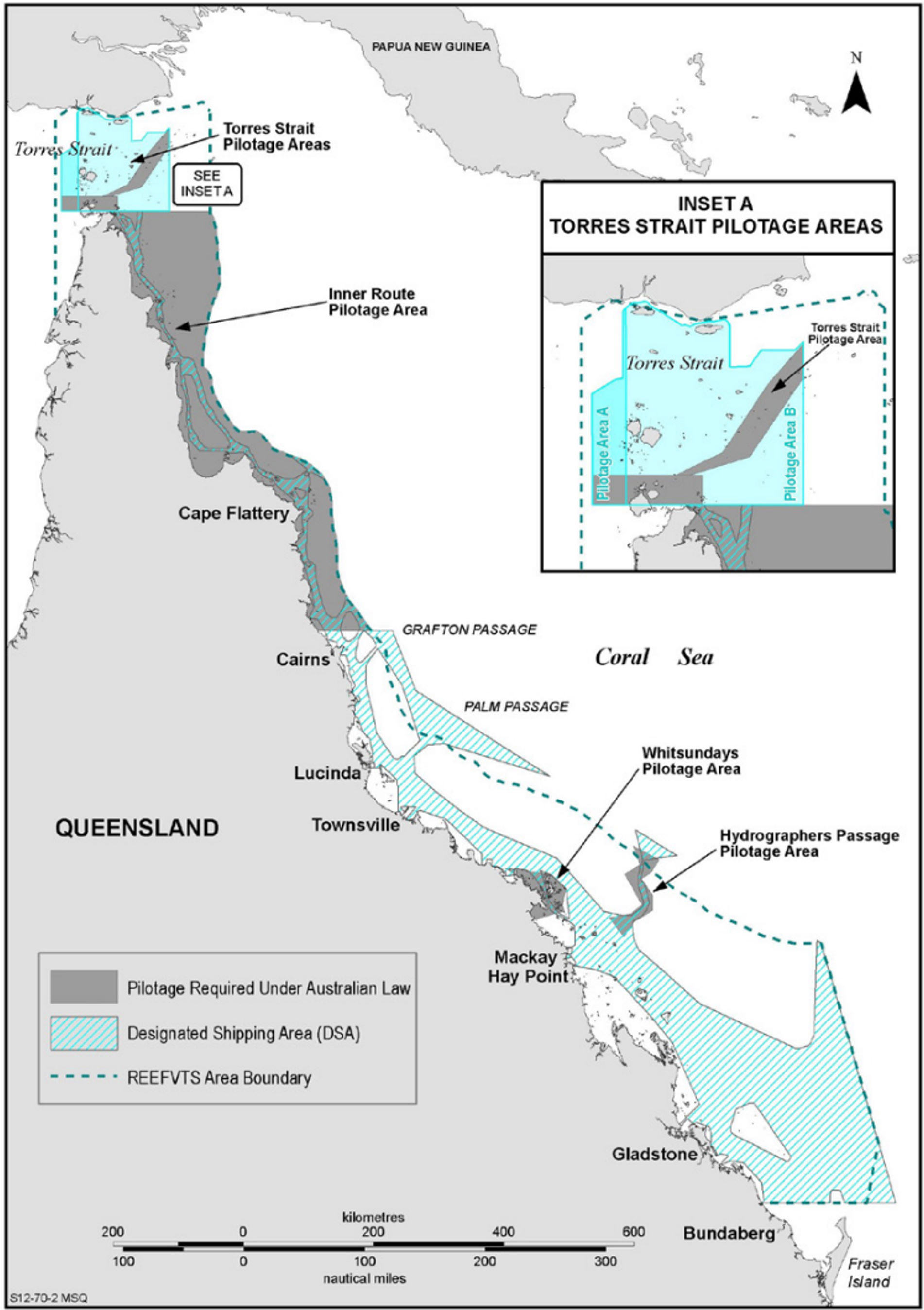
Compulsory pilotage requirements for the Inner Route of the GBR north of Cairns and Hydrographers Passage were established in 1991 and later extended to areas of the Whitsundays and Torres Strait (Figure 15).
Figure 15: Great Barrier Reef and Torres Strait compulsory pilotage areas
Source: Australian Maritime Safety Authority
Although complemented by measures, such as REEFVTS and a comprehensive system of navigational aids, coastal pilotage is a key defence against shipping incidents within the GBR and Torres Strait. Ships are generally exposed to higher risks in these confined waterways, where factors such as the reduced depth and width of fairways, increased traffic, tidal variations and stronger currents leave little margin for navigational errors. Therefore, it is essential that the service provided by coastal pilots are as safe and effective as possible.
Since 1993, AMSA has been responsible for the regulation of coastal pilotage. In carrying out this function, AMSA has implemented a regulatory framework for coastal pilotage operations under MO54. Its provisions set out the licence requirements for pilots and pilotage providers, the performance of pilot duties and safe operating standards for both pilots and providers. The check pilot system is a core component of the regulatory framework.
Check pilot system
In 2003, AMSA implemented the check pilot system declaring it an important initiative for the ongoing professional development of coastal pilots and a tool for maintaining pilot competency.[29] Under the system, all coastal pilots are required to undertake a check pilot voyage in the area, or areas, for which they are licensed, at least every 2 years. A check pilot voyage is defined by MO54 as ‘a voyage on which a pilot’s competency is being assessed by a check pilot’. While the assessments are conducted on behalf of AMSA, the check pilots conducting assessments are current pilots employed by either of the 2 pilotage providers. Usually, the check pilot and the pilot being assessed are from the same provider.
Check pilot concept and reliability challenges
The check pilot concept has its origins in the aviation industry. Since 1999, check pilot systems in the Australian aviation sector have been underpinned by a competency-based training and assessment (CBTA) framework.[30] Under a CBTA approach, a person is trained to meet specified standards that define the skills, knowledge and behaviours required to safely and effectively perform a task in a particular context and is then assessed for competence against those standards.[31] Australian vocational education and training (VET) has been ‘competency-based’ since the late 1980s and is built upon the Australian Qualifications Framework (AQF), which forms the basis for educational and professional assessment requirements.[32] In the context of coastal pilotage, the AMSA check pilot system was developed to reflect applicable AQF competency level criteria[33] and established CBTA principles.[34]
The specific competency standards used for assessing coastal pilot competency were captured in the AMSA Form 15 checklist titled ‘Check voyage / assessment transit details’ (Appendix A). The checklist contained 79 performance elements under 10 different performance criteria, developed to reflect best coastal pilotage practice. The criteria covered:
- personal safety
- master and pilot information exchange (MPX)
- passage planning and execution
- availability of nautical charts and publication
- VHF radio use
- bridge resource management (BRM)
- rest management
- contingency planning
- navigation and electronic equipment use
- pilot licencing and legal requirements.
The Form 15 criteria were similar to standards used for assessing pilot proficiency in aviation in that they consisted of both technical skills, such as knowledge and equipment use, and non‑technical skills (NTS).[35] The NTS were most prevalent in criteria relating to BRM and MPX, which incorporated performance elements involving situation awareness, decision-making, communication and teamwork.
A guidance document supplemented the checklist with rules and principles for check voyages assessments. This document contained information about how assessments were to be conducted, the construct of performance elements and the prescribed remedial actions if significant deficiencies were identified.
Generally, assessment of the human factors inherent in NTS performance relies on the observation of behaviours which contribute as evidence of competency.[36] In the aviation industry, this requirement has led to the development of comprehensive training and assessment systems which typically provide a framework of behavioural markers. These are aimed at assisting assessors to make valid and reliable judgements regarding competency and performance, particularly in respect to NTS.
Consistent and accurate application of assessment standards is fundamental to ensuring the quality of any assessment system. If assessors cannot be trained to be interchangeable, then assessment outcomes will depend more on the assessor than the behaviours of those being observed.[37] Overly harsh applications of assessment standards may give rise to needless additional training and costs, while having a negative effect on the career and motivation of the person being assessed. Alternately, assessing a person as competent when they have in fact underperformed could have serious safety implications.
Research indicates that reliable assessment of airline pilots’ NTS has at times proven difficult, with some studies revealing unacceptably low inter‑rater reliability (IRR)[38] in the assessment of flight crew performance.[39] In one 2013 study it was observed that assessors of the same performance often applied the same or similar reasons to arrive at different assessment outcomes or used different reasons to arrive at the same outcome.[40] Such variability in the application of standards poses a risk to the desired competency assurance objectives of the assessment process.
Factors which may influence IRR can be complex and include the experience, biases, motivations and perceptions of the assessor, the nature of the task or scenario and the particular dimension being observed, such as factors involving cognitive and social performance.[41] Variation between assessors in respect to cognitive criteria including situation awareness may also arise due to the unspecific construct of the assessment criteria, requiring them to speculate about what is going on in the mind of the person being assessed instead of focusing on observable performance.[42]
In recognition of the importance of IRR, aviation regulators have sought to ensure it is considered in the development and monitoring of operators’ training and assessment systems. In a 2011 advisory publication concerning non‐technical skills training and assessment[43], the Civil Aviation Safety Authority (CASA) advised:
Any behavioural rating system must be underpinned by adequately trained assessors. The training of raters is quite a complex undertaking. Instruction should develop thorough understanding of the science of rating scales, the characteristics of the actual rating system used, sources of rater bias, the concept of inter-rater reliability, debriefing skills, and procedures to calibrate and optimise the accuracy of observations and ratings.
In the maritime industry, research concerning how NTS are assessed, particularly in respect to pilotage, has been relatively limited. The Australian Marine Pilots Institute (AMPI) developed a code of good practice for pilot competency and performance.[44] Last revised in 2020, it is noted within the document that:
AMPI has identified the need to develop better processes for assessing the performance of marine pilots. The intent is to offer support and remediation to pilots where this is appropriate.
This AMPI Code identified 9 competencies representing pilot best practice and 25 associated behavioural markers which AMPI has used for its competence and performance guide. The Code identifies behavioural markers indicative of both good and bad performance for each competency. AMPI notes that:
Markers of good behaviour can provide guidance to pilots regarding exemplary behaviour whereby they may be seen as a role model for trainees or other pilots. Markers of poor behaviour may help to identify early evidence of underperformance and provide a basis for support and remediation of underperforming pilots before safety or standards are compromised. It should be noted that the good and poor behavioural markers represent the extremes of pilot performance. There is a wide spectrum of normal and appropriate pilot behaviour between these extremes – the ‘shades of grey’ of pilotage practice. Patterns of behaviour, behavioural markers, performance measures, resources and supports are identified for each of the AMPI Competencies. The behavioural markers do not represent an exhaustive list but are examples of what may be considered in ‘good’ and ‘poor’ behaviour.
Like the studies conducted in the aviation industry, the AMPI guidance highlights the complexity of assessing NTS aspects of pilot competency and performance. The AMSA check pilot system, which comprised the Form 15 checklist and accompanying guidance, did not feature a framework of behavioural markers to guide check pilots in interpreting the performance elements contained within the checklist.
For a competency-based assessment system to be a valid and reliable measure of competency, assessors must be provided with adequate training, instruction and guidance to ensure assessment standards are consistently interpreted and applied, irrespective of the assessor conducting the assessment. In practice, achieving this consistency can be a complex and difficult undertaking requiring appropriate consideration of all the various factors, which have the potential to limit the effectiveness of the system overall.
Check pilot licencing and training
According to AMSA,[45] check pilot licence eligibility requirements under MO54 were intended to ensure coastal pilots with extensive operational experience were engaged to assess coastal pilot performance. Applications for a check pilot licence were endorsed and submitted to AMSA by the respective pilotage provider on behalf of the pilot.
Applicants were required to hold an unrestricted coastal pilot licence and to have performed the duties of a licenced pilot during a sufficient number of transits of the relevant pilotage area, as specified under MO54. Additionally, applicants were required to undertake an oral examination, an AMSA-approved psychometric assessment and a workplace assessment training course from an approved training provider.
The workplace assessment training consisted of 4 assessment-specific units from a certificate IV level course in workplace training and assessment, accredited under the Australian qualifications framework. The course content was designed to be generic for all VET purposes and applicable to many professions and industries. As such, it did not include specific training for assessing any of the competencies, skills or behaviours unique to coastal pilotage. However, from 2020, as an alternative to the workplace assessment training course, AMSA began accepting the completion of a more specific ‘Assess Competency as a Marine Check Pilot’ course. This course was delivered by a Queensland-based maritime training provider and was designed to include training for assessing competencies, skills and behaviours for all maritime pilots, including coastal pilots.
Previous ATSB findings relating to pilot checking
In February 2009, the oil tanker Atlantic Blue grounded on Kirkcaldie Reef in the Torres Strait while a coastal pilot was conducting it. A subsequent ATSB investigation (report MO-2009-001) found that, in addition to other contributing factors, the pilot’s passage plan and piloting system, did not define off-track limits or make effective use of recognised BRM tools (the pilot was also a licensed check pilot). More importantly, that investigation found that regular assessments of the pilot’s procedures and practices under the check pilot system, conducted over several years, had not resolved these apparent deficiencies.
Following the release of the ATSB’s findings in the Atlantic Blue investigation, the ATSB was advised that AMSA, AMPI and a number of coastal pilots held concerns that systemic issues, which could impact on the safe operation of coastal pilots and the ability to fully develop a safety culture, may exist. Consequently, the ATSB initiated a broad scope systemic safety issue investigation into coastal pilotage, which also examined the check pilot system. During this investigation (report MI-2010-011), the ATSB reviewed all 550 check voyage assessments conducted since the system’s introduction, interviewed a number of industry stakeholders and surveyed all 82 pilots to analyse potential safety issues.
Analysis of the 550 check voyage assessments and supporting evidence identified a significant safety issue. No pilot had ever been deemed unsatisfactory, with a 100% pass rate since the introduction of the check pilot system. The ATSB concluded that the system was ineffective as a measure to assess the adequacy of the individual systems of coastal pilotage and pilot competency, with the following factors limiting the effectiveness of the system:
- absence of uniform assessment standards against which to make an objective assessment because there is no pilotage safety management system with standard, risk-analysed pilotage procedures and practices;
- conflicts of interest as a result of the check pilot being remunerated by the pilotage provider to assess a peer on behalf of AMSA;
- conflicts of interest as a result of the working relationships between the pilots and between pilots and their provider; and
- lack of a formal review process for each assessment to ensure corrective action is taken and for continuous improvement.
Over the next few years, AMSA provided the ATSB 6 updates on the progress of safety action that it was undertaking to address the safety issue. In October 2012, AMSA advised that it had developed a common industry passage plan (the QCPP) and standard operating procedures for coastal pilots. It also stated that it was conducting a review into check pilotage and training requirements, including an investigation into the potential use of simulators for training purposes. The issue relating to independence of check pilots, including how they were engaged and remunerated was to also feature in AMSA’s review.
In 2013, AMSA further advised it had implemented an electronic process to track and develop reports based on check pilot assessments, providing it with the means to identify potential trends and then work to address those trends. In the same update, AMSA stated that it was also seeking to improve the check pilot system through successive meetings with the coastal pilot training working group (CPTWG) that included coastal pilots and representatives from pilotage providers and AMSA.
In subsequent updates, AMSA advised that the check pilot framework was considered an item for ongoing review and that it continued to work with the CPTWG to make improvements. It also stated that ‘the check pilot framework, incorporating aspects related to check pilot selection, training, check runs, check assessment criteria and the use of simulation, has been agreed by the CPTWG as one of the key areas of the group’s future work and focus.’
In 2015, a new requirement was introduced for pilotage providers to endorse, via nomination, prospective check pilot applicants to AMSA (as opposed to individual pilots nominating themselves). This requirement was to ‘address inconsistencies between the aspirations of individual pilots, and the commercial ramifications related to internal remuneration arrangements for check pilots.’
In February 2016, AMSA provided its last update and advised that it had reviewed the contents of the guidance notes for check pilot assessment voyages and the Form 15 checklist. The review resulted in incremental and relatively minor changes to the checklist, considered to improve the form by simplifying the completion requirements and removing duplication of information. This update stated that assessments were ‘registered and reviewed in full by AMSA for consistency, detection of any trends and/or behaviours and whether any further action may be required.’
In March 2016, after assessing the residual risk from the safety issue taking into account the various safety actions that AMSA advised had been taken, the ATSB closed the safety issue as having been adequately addressed.
In March 2023, during the course of this investigation, AMSA advised that no trend analysis of assessment outcomes had been conducted, citing the extremely low frequency of deficiencies identified in assessments as the principal reason for not doing so. The ATSB obtained check voyage assessment records since 2017 to analyse and verify this claim (see the section titled Assessment outcomes since 2017).
Check voyage assessment construct
For each of the 79 performance elements contained in the Form 15 checklist, of which 37 were denoted as safety critical, pilots were to be assessed as either ‘satisfactory’ (S), ‘satisfactory with deficiencies’ (SWD) or ‘unsatisfactory’ (U). A pilot would receive an overall U assessment if they were assessed as U in any safety critical performance element. An overall SWD assessment would result if the pilot was assessed as U in any element that was not safety critical, or if assessed as SWD in more than 25% of the elements in any single performance criteria.
When completing the checklist, a check pilot could include optional notes in a section provided for each of the 10 performance criteria, where considered necessary. Assessment outcomes were documented in the Form 15 checklist and submitted to the pilotage provider and AMSA. Completed assessments were to be reviewed by AMSA to determine if any remedial action was required.
If a pilot received an overall assessment result of U, they were required to cease pilotage duties until they completed an AMSA-approved remedial training program and successfully performed an additional check pilot voyage. If a pilot received an SWD overall assessment, they could continue pilotage duties but were required to complete remedial training, with another check voyage recommended within 3 months of the initial assessment. Digital copies of completed assessments were retained by AMSA in its electronic Certification and Pilotage System (CPS) database.
Assessment outcomes since 2017
The ATSB reviewed 490 check voyage assessments conducted between 2017 and 2023 across all compulsory pilotage areas, including Hydrographers Passage. These assessments related to 103 individual pilots from the 2 pilotage providers and had been conducted by 30 individual check pilots.
The review identified that no pilot had ever been assessed as U for any performance element, criteria or overall assessment. An overall SWD assessment occurred on one occasion. Sixty‑two assessments contained one or more SWD scores under various performance elements, which translated to 13% of the assessments identifying any deficiencies or areas for improvement. Of the 103 pilots assessed, 47 (46%) received at least one SWD score for a performance element on at least one check voyage.
Of the 62 check voyage assessments that contained one or more SWD scores, a total of 159 SWD scores were recorded against individual performance elements, with some assessments recording multiple SWDs. This number represented 0.41% of the total number of elements that were assessed across all 490 check voyages conducted during the period (Table 2). Additionally, for each of the 10 performance criteria, the number of SWD scores recorded against elements in each criteria did not exceed 0.69% of the total number of elements assessed during the period.
Table 2: Percentage of SWD scores identified in all check voyage assessments
|
Performance criteria (# of performance elements) |
Total number of times elements were assessed in 490 check voyages |
Number of elements marked as SWD |
% of total elements in all assessments marked SWD |
|---|---|---|---|
| PC 1: Personal Safety (2) |
980 |
0 |
0% |
| PC 2: Master/Pilot Exchange (MPX) (2) |
980 |
2 |
0.20% |
| PC 3: Passage Planning & Execution (18) |
8,820 |
37 |
0.42% |
| PC 4: Availability of Nautical Charts & Publications (5) |
2,450 |
13 |
0.53% |
| PC 5: VHF Radio Usage (7) |
3,430 |
7 |
0.20% |
| PC6 - Bridge Resource Management (BRM) (9) |
4,410 |
20 |
0.45% |
| PC7 - Rest Management (11) |
5,390* |
1 |
0.09% |
| PC8 - Contingency Planning (3) |
1,470 |
6 |
0.41% |
| PC9 - Navigational and Electronic Equipment Usage (12) |
5,880 |
41 |
0.69% |
| PC10 - Pilot Licence Conditions and Legal Requirements (10) |
4,900 |
32 |
0.65% |
| PC 1 – PC 10 (79) |
38,710 |
159 |
0.41% |
* It was noted that on shorter check pilot voyages, such as those through Hydrographers Passage, ‘rest management’ criteria were assessed as ‘not applicable’ since pilots were not required to take rest breaks on these voyages.
Source: Australian Maritime Safety Authority, as assessed by ATSB
In order to better understand the extremely low numbers/proportion of deficiencies indicated by the data, the ATSB reviewed the number of deficiencies identified by each check pilot. A significant difference in the application of assessment standards between individuals was identified (Figure 16), which was characterised by the following notable features:
- Two (2) check pilots (from different pilotage providers) conducted 7.7% of the total number of assessments and accounted for 58% of the total deficiencies identified.
- Eight (8) check pilots conducted 25% of the total number of assessments and accounted for 90% of the total deficiencies identified
- Twelve (12) check pilots conducted 32% of the total number of assessments and never identified any deficiencies
Figure 16: Proportion of deficiencies identified by each check pilot
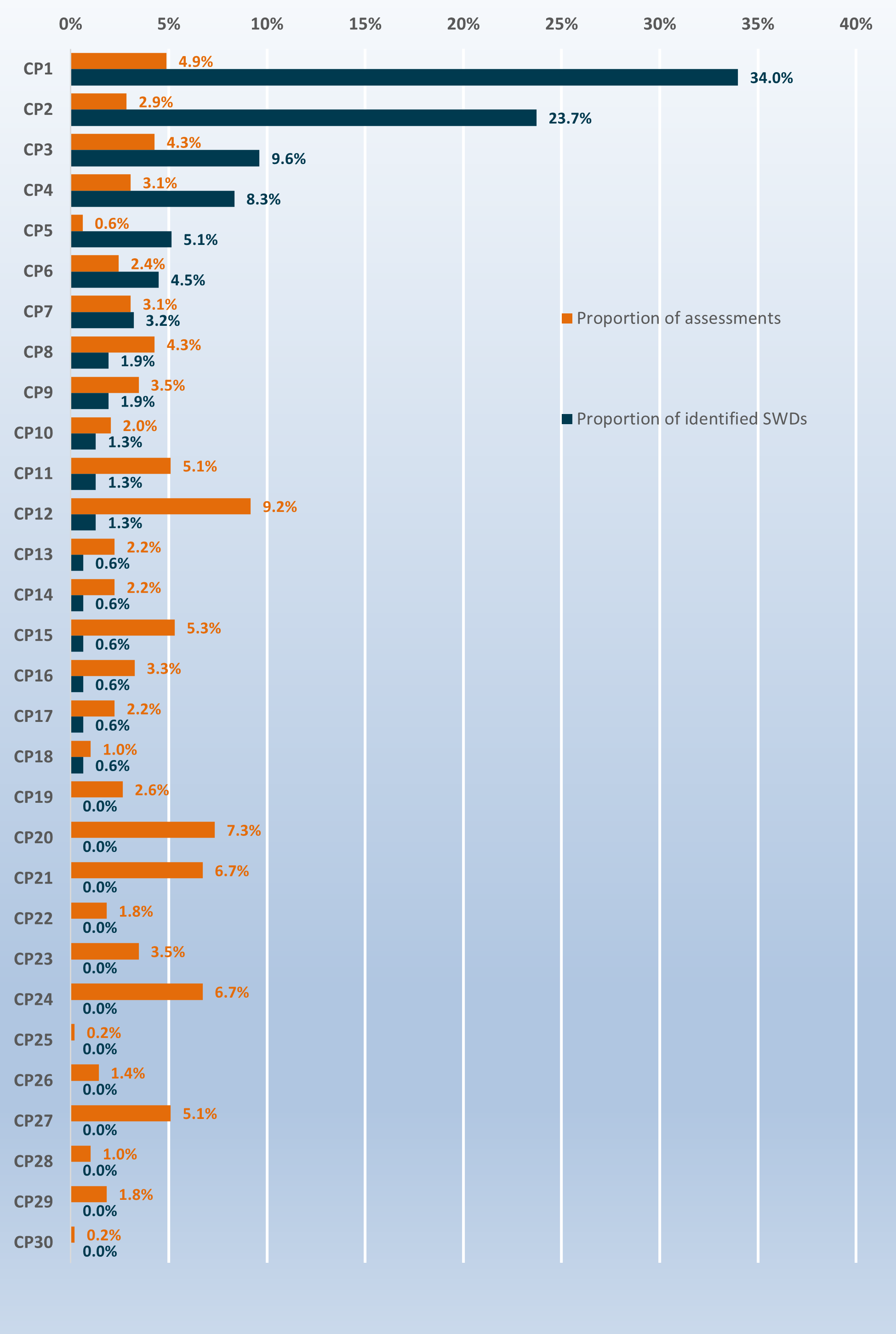
Source: ATSB
The ATSB applied the Kruskal-Wallis[46] test to the data to determine whether there was a statistically significant difference between the application of assessments between individual check pilots. This test showed that the probability of obtaining the distribution of such assessment results by random chance alone would be less than 1 in 10,000. That is, the distribution was likely influenced by differences in how individual check pilots conducted their assessments.
Further, data analysis indicated that the rate of deficiencies identified per check voyage did not vary significantly between individual pilots being assessed, or which pilotage provider they were from. The check voyage assessment outcomes were predominantly a function of the individual check pilot conducting the assessment, regardless of which provider they worked for.
Safety analysis
Introduction
At about 0313 local time on 4 May 2022, the 225 m bulk carrier, Rosco Poplar, came within 200 m of grounding on Bond Reef while under pilotage through Hydrographers Passage, in the Great Barrier Reef. At about the same time, the ship’s 2 electronic chart display and information system (ECDIS) units that displayed its position suddenly shifted 0.92 miles (1,704 m) from the last displayed position, which had been on the planned track. The pilot and bridge team visually verified that the ship had narrowly missed Bond Reef. The pilot then conducted the ship back towards the planned track and completed the pilotage without further incident.
The ATSB investigation found that the ship had been deviating from its planned track for a significant period without the navigational error being detected by anyone on the bridge, or by the coastal vessel traffic service monitoring its progress. This analysis examines the factors and circumstances leading up to the near grounding, including the malfunction of the global position system (GPS) unit and the installation configuration of the ship’s electronic bridge navigational equipment. Factors relating to the effectiveness of bridge resource management (BRM) and the pilotage, including use of the pilot’s portable pilot unit (PPU) are also discussed. Additionally, the effectiveness of the Australian Maritime Safety Authority’s (AMSA) check pilot system as a framework for providing pilot competency assurance is analysed.
GPS antenna fault
The GPS unit providing positional data to the ship’s electronic bridge navigation equipment, including both ECDIS units, radars and automatic identification system (AIS), malfunctioned and began sending invalid positional data. The error gradually increased as the pilotage progressed, however, no alarms were communicated as the unit also incorrectly reported that position accuracy was within acceptable limits.
Analysis of the available data identified that the fault occurred between 0218 and 0235. During that period, the ship was approaching the entrance to Hydrographers Passage and was at a critical stage of the pilotage. While the exact error mode could not be determined, it was most likely caused by a GPS antenna fault and not by any external GPS interference or intervention by a bridge team member.
The correction of the GPS position observed at 0313 was most likely a result of the GPS unit resetting automatically or being manually reset by the master.
Sole reliance on GPS positioning
The pilot and bridge team placed sole reliance on GPS positional data to monitor the ship’s progress exclusively using the ECDIS and PPU displays without anyone verifying this information via radar and/or visual observations and position fixing. The pilot gave heading orders solely based on incorrect information from these displays, assuming that a strong ebb tidal stream was setting the ship across the track. The predicted stream was actually setting in a 016° direction nearly reciprocal to the ship’s heading. As a result, the inaccuracy of the GPS position and subsequent deviation from the planned track was not identified.
During the pilotage, the second mate was distracted from their lookout duties after being tasked by the pilot to input waypoints into the ship’s 2 radars. The master was also intermittently distracted by this task, which took some 45 minutes to complete, concluding at 0234. As the second mate occupied one radar unit at a time during this period to complete the task, a radar unit was always available to monitor the ship’s progress and verify its position. However, since neither the pilot nor any bridge team member was using radar to monitor the position, they did not identify that the AIS and radar returns for the nearby ship, Camellia Island, were diverging increasingly apart (indicating a discrepancy with the ship’s plotted AIS position), or that the ship was deviating from the planned track and towards the radar return of Bond Reef light.
Similarly, adequate visual observation of Bond Reef light and the sector light at Little Bugatti Reef would have provided a clear indication that the ship was deviating from the planned track. However, as this means was also not used, it was not until at least 37 minutes after the ship began deviating off course that the pilot visually identified that the ship was displaced to the east of the planned track.
Configuration of the ship’s navigational equipment
While Rosco Poplar’s electronic navigation system configuration complied with the relevant International Maritime Organization requirements and performance standards, it was inherently vulnerable to single GPS unit failures. Because the ECDIS units, radars, AIS and Global Maritime Distress Safety System (GMDSS) were only able to receive the same single GPS data input from either of the 3 GPS units at any one time, the invalid position output from the malfunctioning GPS unit was received and displayed by all these navigational aids.
If multiple GPS outputs had been available to each navigational aid, with alternate GPS units selected on each aid, it is likely that one of them would have displayed the ship’s position accurately and the discrepancy would have been identifiable. Further, most modern ECDIS units facilitate multiple position sensor inputs. These can be configured to cross reference positional data inputs and trigger alarms in the event of a deviation between those inputs. Such set-ups provide a defence against navigational errors resulting from single GPS failures.
Vessel traffic service surveillance
The coastal vessel traffic service (REEFVTS) decision support tool (DST) was dependent on ships’ AIS information to monitor traffic in real time. Rosco Poplar’s AIS-transmitted position continued to incorrectly show the ship was near the planned track after the GPS unit malfunctioned and, therefore, REEFVTS remained unaware of its deviation from the track. When the GPS unit reset, the transmitted position correctly indicated that the ship was about 200 m from Bond Reef. This resulted in the decision support tool (DST) triggering alerts, including a potential grounding alert.
The unusual nature of the ship’s AIS-transmitted GPS position error and the associated series of alerts resulted in the VTSO thinking they were due to a DST system error. They therefore decided to investigate the assessed error (no other position sensor, such as radar, was available to crosscheck) and this consumed significant time. Consequently, about 23 minutes elapsed before the VTSO contacted the ship and was advised that the ship had actually come close to grounding and the associated alert had been correctly generated.
While REEFVTS procedures allow reasonable flexibility for VTSOs to appraise the situation before intervening, and while the observed unusual alerts, ship position and tracking information may have been associated with a system error, checking with the pilot/ship’s crew is always the safest and most efficient course of action when the alert could be legitimate. In this instance, the closest point of approach to Bond Reef had already been passed by the time the alert was received, and so a dangerous navigational situation was not imminent. However, in order to maximise the safety benefit from vessel traffic services, prompt contact with the ships’ crew whenever there is doubt about the validity of an alert could avoid a future serious occurrence, such as a grounding.
Conduct of the pilotage
Bridge resource management
The prevention of errors during pilotage is primarily dependent on effective BRM to establish coordination between the pilot, master and bridge team, taking due account of the ship's systems and the equipment available to the pilot. However, BRM during this pilotage was ineffective. The master-pilot information exchange (MPX) did not establish adequate coordination between the pilot, master and second mate and communication on the bridge was minimal. As a result, the situation awareness of the pilot and bridge team progressively declined in the absence of a shared mental model.
While a key aim of the MPX was to establish individual roles and responsibilities for watchkeeping and expectations for communication during the pilotage, these requirements were neither discussed nor implemented. The subsequent lack of coordination on the bridge meant that greater priority was given to the task of inputting waypoints into the radars as instructed by the pilot without any mutual understanding as to who was doing what in respect to the more critical task of monitoring the ship’s progress. Neither the pilot nor the ship’s bridge team used either radar for parallel indexing and other monitoring techniques, such as clearing ranges or visual transits. As a result, when the GPS unit malfunctioned, no-one had sufficient situation awareness to identify the error.
The master had doubts regarding the position of the ship and the accuracy of its navigational equipment, but these were not communicated to the pilot. Had the master raised these concerns, a subsequent appraisal of the situation might have identified the erroneous GPS position. If the expectations for challenge and response had been established during the MPX, the master might have felt more inclined to voice concerns to the pilot. Similarly, had the pilot alerted the bridge team after identifying at 0311 that the ship was displaced to the east of the planned track, a more urgent appraisal of the situation might have been undertaken.
Configuration of the portable pilot unit
The use of portable pilot units (PPU) is widely encouraged as an additional source of information to improve safety, efficiency and situation awareness during pilotage. However, the improper set‑up of the pilot’s PPU at the time of the occurrence likely compounded the pilot’s degraded mental model of the pilotage.
Contrary to industry guidance and Auriga’s pilotage operations safety management system, the pilot did not ensure the GPS output from their PPU was independent of the ship’s navigation equipment once it was connected to the AIS pilot plug. As a result. both the ECDIS units and the PPU displayed the same invalid positional data from the ship’s malfunctioning GPS unit. Believing that the PPU was independently reporting its position, the pilot may have been misled into believing the PPU and ECDIS units were accurate.
If the PPU had been configured by the pilot as intended, the use of the independent PPU GPS would have identified a difference in the location between the PPU and the incorrect position reported via the AIS. Additionally, had alarm systems on the PPU been enabled, these may have alerted the pilot to the invalid GPS position. However, in the absence of sound pilotage practise and effective BRM, the incorrect configuration of the PPU was not identified.
Check pilot system
The construct of the AMSA check pilot system and its accompanying guidelines indicate that it was a competency-based assessment framework, intended to provide assurance of coastal pilot competency. However, analysis of 490 assessment outcomes for check voyages conducted between 2017 and 2023 revealed that the system did not provide such assurance. Of note, significantly inconsistent application of assessment standards between individual check pilots was evident. The extent of this inconsistency indicates that varying assessment outcomes were dependent on the individual check pilot conducting the assessment rather than being reflective of pilot competency.
Throughout the period in which the 490 check voyages were conducted, the system produced a near 100% pass rate, with no ‘unsatisfactory’ results recorded. A negligible fraction of the total performance elements assessed were recorded as ‘satisfactory with deficiencies’ and there were no instances where formal remedial actions under the system were triggered and initiated. A previous ATSB systemic investigation (MI-2010-011) had also identified the check pilot system’s unrealistic 100% pass rate. That investigation’s finding was based on all 550 check voyage assessments conducted since the system’s introduction.
Overall, the results of analysis of the large amount of check pilot data showed that the check pilot system had not resulted in any significant benefit to coastal pilot competency by way of formalised corrective action and continual improvement. As AMSA has never conducted any trend analysis of the check voyage assessments, stating that this was primarily due to the low number of deficiencies identified overall, it did not identify the inconsistent application of assessment standards by individual check pilots. In the absence of sufficient monitoring of check pilot practices, factors which may have limited the system’s effectiveness such as assessor bias, unclear assessment standards and insufficient training and guidance for assessors, had not been identified and corrected.
Findings
|
ATSB investigation report findings focus on safety factors (that is, events and conditions that increase risk). Safety factors include ‘contributing factors’ and ‘other factors that increased risk’ (that is, factors that did not meet the definition of a contributing factor for this occurrence but were still considered important to include in the report for the purpose of increasing awareness and enhancing safety). In addition, ‘other findings’ may be included to provide important information about topics other than safety factors. Safety issues are highlighted in bold to emphasise their importance. A safety issue is a safety factor that (a) can reasonably be regarded as having the potential to adversely affect the safety of future operations, and (b) is a characteristic of an organisation or a system, rather than a characteristic of a specific individual, or characteristic of an operating environment at a specific point in time. These findings should not be read as apportioning blame or liability to any particular organisation or individual. |
From the evidence available, the following findings are made with respect to the near grounding of Rosco Poplar off Bond Reef, Hydrographers Passage, Queensland on 4 May 2022.
Contributing factors
- Rosco Poplar’s GPS unit probably malfunctioned due to a fault with its antenna, resulting in erroneous ship’s position data. This incorrect data was then provided to all navigational aids, including both electronic chart display and information system (ECDIS) units, automatic identification system (AIS) and the pilot’s portable pilotage unit (PPU).
- The PPU had not been configured as required to source position data independent of the ship’s GPS unit.
- The pilot and the ship’s bridge team were relying solely on the PPU and ECDIS units to monitor the ship's progress. Consequently, they did not identify that the ship had deviated from the planned track until the GPS unit reset and began indicating the correct position, which was about 200 m from Bond Reef.
- The pilotage was not conducted appropriately, including effective track monitoring and proper bridge resource management, due to a combination of:
- an inadequate master and pilot information exchange
- roles and responsibilities not being properly defined
- an absence of monitoring using visual bearings and radar, including parallel indexing
- non-essential tasks for the pilotage phase that distracted the bridge team
- the absence of a shared ‘mental model’ of the pilotage.
Other factors that increased risk
- The configuration of Rosco Poplar's electronic navigation equipment was vulnerable to single GPS unit errors because, at any given time, only one of the ship’s 3 GPS units could be selected to provide positional data to all the ship's navigational equipment.
- Following receipt of an unusual grounding alert display associated with the Rosco Poplar’s GPS malfunction, the vessel traffic service operator assessed it as erroneous. Consequently, the pilot/ship’s crew were not provided with timely advice of the indicated proximity to Bond Reef.
- The check pilot system was ineffective in providing the Australian Maritime Safety Authority (AMSA) assurance of the competency of coastal pilots, mainly due to the inconsistent and unreliable application of assessment standards between different check pilots. Further, AMSA had not implemented a system to identify the inconsistent application of standards or the trends in assessment outcomes readily apparent in the data that it had held for many years. (Safety issue)
Safety issues and actions
|
Depending on the level of risk of a safety issue, the extent of corrective action taken by the relevant organisation(s), or the desirability of directing a broad safety message to the marine industry, the ATSB may issue a formal safety recommendation or safety advisory notice as part of the final report. All of the directly involved parties were provided with a draft report and invited to provide submissions. As part of that process, each organisation was asked to communicate what safety actions, if any, they had carried out or were planning to carry out in relation to each safety issue relevant to their organisation. Descriptions of each safety issue, and any associated safety recommendations, are detailed below. Click the link to read the full safety issue description, including the issue status and any safety action/s taken. Safety issues and actions are updated on this website when safety issue owners provide further information concerning the implementation of safety action. |
Effectiveness of the check pilot system
Safety issue number: M0-2022-005-SI-01
Safety issue description: The check pilot system was ineffective in providing the Australian Maritime Safety Authority (AMSA) assurance of the competency of coastal pilots, mainly due to the inconsistent and unreliable application of assessment standards between different check pilots. Further, AMSA had not implemented a system to identify the inconsistent application of standards or the trends in assessment outcomes readily apparent in the data that it had held for many years.
Safety recommendation description: The Australian Transport Safety Bureau recommends that the Australian Maritime Safety Authority takes safety action to identify and address factors limiting the effectiveness of its check pilot framework as a system for coastal pilot competency assurance.
Glossary
| AIS | Automatic Identification System |
| AMSA | Australian Maritime Safety Authority |
| CASA | Civil Aviation Safety Authority |
| CBTA | Competency Base Training and Assessment |
| COLREG | Convention on the International Regulations for Preventing Collisions at Sea |
| ECDIS | Electronic Chart Display and Information System |
| ECS | Electronic Chart System |
| ENC | Electronic Navigational Chart |
| GBRMPA | Great Barrier Reef Marine Park Authority |
| GMDSS | Global Maritime Distress Safety System |
| GNSS | Global Navigation Satellite System |
| GPS | Global Positioning System |
| IMO | International Maritime Organisation |
| MPX | Master and pilot information exchange |
| MSQ | Maritime Safety Queensland |
| NSCV | National Standard for Commercial Vessels |
| OOW | Officer of the Watch |
| PPU | Portable Pilot Unit |
| PSSA | Particularly Sensitive Sea Area |
| QCPP | Queensland Coastal Passage Plan |
| REEFREP | Great Barrier Reef and Torres Strait Ship Reporting System |
| REEFVTS | Great Barrier Reef and Torres Strait Vessel Traffic Service |
| SMS | Safety management system |
| SOLAS | The International Convention for the Safety of Life at Sea, 1974, as amended. |
| STCW | Standard for Training Certification and Watchkeeping |
| VDR | Voyage Data Recorder |
| VTSO | Vessel Traffic Service Operator |
Sources and submissions
Sources of information
The sources of information during the investigation included:
- the pilot of Rosco Poplar
- the master, second mate and able seaman on board Rosco Poplar
- records, documents, manuals, and logbooks from Rosco Poplar
- records, documents and manuals from Auriga
- Australian Maritime Safety Authority
- Maritime Safety Queensland
- Great Barrier Reef and Torres Strait Vessel Traffic Service
- Bernhard Schulte Shipmanagement China
- recorded information from Rosco Poplar’s voyage data recorder
- Japan Radio Company
References
International Hydrographic Organization, 2018, Publication S-66, Facts about electronic charts and carriage requirements, Edition 1.1.0, IHO, Monaco. Available at https://iho.int/.
International Maritime Organization, 2006, Revised performance standards for electronic chart display and information systems (ECDIS), Resolution MSC.232 (82), IMO, London.
Australian Maritime Safety Authority, 2014, Marine Order 54 – Coastal pilotage, AMSA, Canberra.
Focus on Bridge Resource Management, Washington State Department of Ecology, 2007.
International Association of Marine Aids to Navigation and Lighthouse Authorities, January 2022, Guideline G1089; Provision of a VTS, Ed 2.0.
International Maritime Organisation, Recommendations on training and certification and on operational procedures for maritime pilots other than deep-sea pilots, Resolution A.960 (23).
International Maritime Organisation, The International Convention on Standards of Training, Certification and Watchkeeping for Seafarers 1978, as amended, IMO, London.
Australian Maritime Safety Authority, 2014, Marine Order 54 – Coastal pilotage, AMSA, Canberra.
Alexander L, Casey M J 2008, Use of Portable Piloting Units by Maritime Pilots, Canadian Hydrographic Conference.
Civil Aviation Safety Authority, Advisory Circular AC 61-09 v1.0, Competency-based Training and Assessment for Flight Crew, April 2002.
Professional Standards Councils, Competency-based Frameworks and Assessment.
International Marine Pilots Association, Guidelines on the Design and Use of Portable Pilot Units, 2016.
Australasian Marine Pilots Institute, PPU Code of Good Practice – For the Implementation and Use of Portable Piloting Units, 2nd Ed. 2020.
Australian Maritime Safety Authority, 2019, Marine Order 63 (Vessel reporting systems) 2019, AMSA, Canberra.
Australian Maritime Safety Authority, Pilot Advisory Notes 10/03 and 01/04, Check Pilots and Check Pilot Voyages.
Civil Aviation Safety Authority, Advisory Circular AC 61-09 v1.0, Competency-based Training and Assessment for Flight Crew, April 2002.
Flin R, Martin L 2001, Behavioural Markers for Crew Resource Management: A Review of Current Practice, The International Journal of Aviation Psychology, 11(1), 95–118.
Franks P, Hay S, Mavin T 2014, Can Competency-based Training Fly?: An Overview of Key Issues for Ab Initio Pilot Training, International Journal of Training Research 12(2): 132–147.
Weber D E, Mavin T J, Roth W M, Henriqson E, Dekker S W A (2014), Exploring the Use of Categories in the Assessment of Airline Pilots’ Performance as a Potential Source of Examiners’ Disagreement, Journal of Cognitive Engineering and Decision Making, 8(3), 248–264.
Weber D E, Roth W M, Mavin T, Dekker S W A 2013, Should we Pursue Inter-rater Reliability or Diversity? An Empirical Study of Pilot Performance Assessment, Aviation in Focus – Journal of Aeronautical Sciences, 4. 34-58.
Gontar J, Hoermann H J 2015, Inter-rater Reliability at the Top End: Measures of Pilots’ Non‑Technical Performance, The International Journal of Aviation Psychology, 25(3/4), 171-190.
Civil Aviation Safety Authority, CAAP SMS-3(1): Non-Technical Skills Training and Assessment for Regular Public Transport Operations.
Australasian Marine Pilots Institute, Code of Good Practice – Marine Pilot Competence and Performance, 2nd Ed. 2020.
Submissions
Under section 26 of the Transport Safety Investigation Act 2003, the ATSB may provide a draft report, on a confidential basis, to any person whom the ATSB considers appropriate. That section allows a person receiving a draft report to make submissions to the ATSB about the draft report.
A draft of this report was provided to the following directly involved parties:
- Australian Maritime Safety Authority
- Maritime Safety Queensland
- The pilot of Rosco Poplar
- Auriga
- the master, second mate and able seaman of Rosco Poplar
- Bernhard Schulte Shipmanagement China
Submissions were received from:
- Australian Maritime Safety Authority
- Maritime Safety Queensland
- Auriga.
The submissions were reviewed and, where considered appropriate, the text of the report was amended accordingly.
Appendices
Appendix A
Check Voyage / Assessment Transit Details (AMSA Form 15)
An extract (first 3 pages) from the Australian Maritime Safety Authority Form 15 pilot check voyage checklist used by check pilots to assess and record coastal pilot competency.
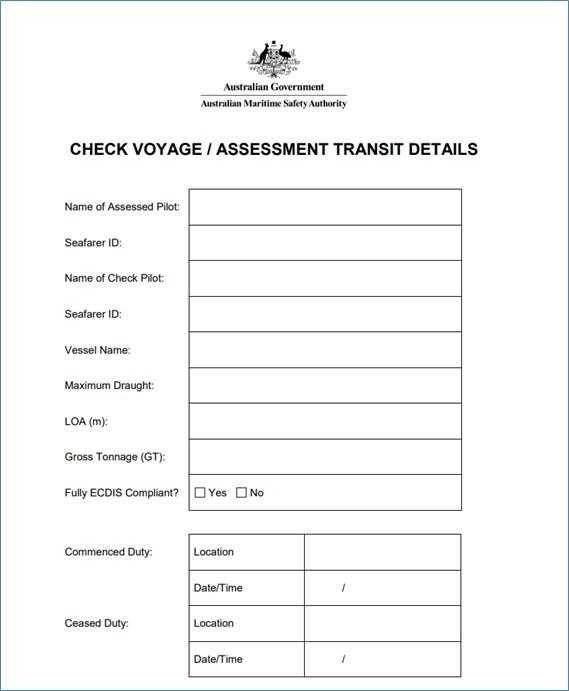
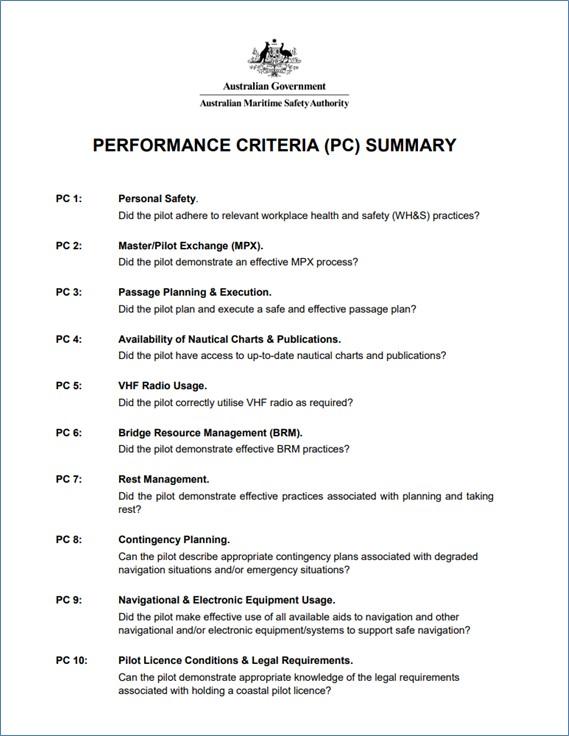
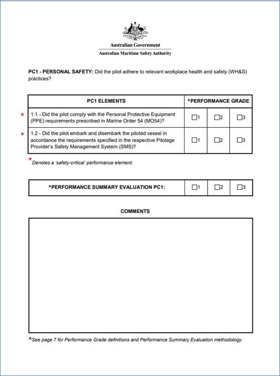
Purpose of safety investigationsThe objective of a safety investigation is to enhance transport safety. This is done through:
It is not a function of the ATSB to apportion blame or provide a means for determining liability. At the same time, an investigation report must include factual material of sufficient weight to support the analysis and findings. At all times the ATSB endeavours to balance the use of material that could imply adverse comment with the need to properly explain what happened, and why, in a fair and unbiased manner. The ATSB does not investigate for the purpose of taking administrative, regulatory or criminal action. TerminologyAn explanation of terminology used in ATSB investigation reports is available here. This includes terms such as occurrence, contributing factor, other factor that increased risk, and safety issue. Publishing informationReleased in accordance with section 25 of the Transport Safety Investigation Act 2003 Published by: Australian Transport Safety Bureau © Commonwealth of Australia 2024
Ownership of intellectual property rights in this publication Unless otherwise noted, copyright (and any other intellectual property rights, if any) in this report publication is owned by the Commonwealth of Australia. Creative Commons licence With the exception of the Coat of Arms, ATSB logo, and photos and graphics in which a third party holds copyright, this publication is licensed under a Creative Commons Attribution 3.0 Australia licence. Creative Commons Attribution 3.0 Australia Licence is a standard form licence agreement that allows you to copy, distribute, transmit and adapt this publication provided that you attribute the work. The ATSB’s preference is that you attribute this publication (and any material sourced from it) using the following wording: Source: Australian Transport Safety Bureau Copyright in material obtained from other agencies, private individuals or organisations, belongs to those agencies, individuals or organisations. Where you wish to use their material, you will need to contact them directly. |
[1] The pilot’s pilotage plan stated the transit would be at full sea speed, which is the speed when on passage at sea.
[2] A nautical mile is 1,852 m.
[3] Predicted low water was at 0612 with a height of tide of 1.23 m above chart datum.
[4] Nautical chart Aus 802, Australian Hydrographic Office.
[5] All ship’s headings are reported in degrees true unless specified otherwise.
[6] Dead reckoning (DR) is a method for determining the estimated position of a ship by advancing from a known fix of position along the ship’s ordered course and speed.
[7] Decision support tools (DST) are used by VTS providers to help enhance situation awareness and the decision‑making process of VTS personnel by providing analysis and insight to developing or emergency situations, in real time, near real time and for long-term planning (see the section titled Vessel traffic service).
[8] Differential GPS utilises a network of fixed ground stations to enhance the accuracy of location data collected by a GPS.
[9] GPS units calculate dates utilising a week counter. In older systems, the counter resets after every 1,024 weeks (referred to as ‘GPS rollover’, and systems need to be manually adjusted, usually via a software upgrade, when the rollover occurs so that they remain accurate.
[10] International Hydrographic Organization, 2018, Publication S-66, Facts about electronic charts and carriage requirements, Edition 1.1.0, IHO, Monaco.
[11] The International Convention for the Safety of Life at Sea (SOLAS) 1974, as amended.
[12] International Maritime Organization, 2006, Revised performance standards for electronic chart display and information systems (ECDIS), Resolution MSC.232 (82), IMO, London.
[13] Global Navigation Satellite System (GNSS) is a broad term encompassing the various types of satellite-based positioning, navigation and timing (PNT) systems used globally, of which GPS is one such type.
[14] For Hydrographers Passage, an unrestricted pilot licence issued under coastal pilotage regulations permitted the licensee to pilot all types of ships through the pilotage area with no restrictions in respect to draught or type of ship. Pilots may obtain an unrestricted licence once they have accrued the necessary experience and training while holding a trainee licence and a restricted licence, which precluded them from piloting certain types of ships.
[15] The Australian Maritime Safety Authority Marine Order 54 (Coastal pilotage) stated ‘a pilot check voyage is a voyage on which a pilot’s competency is being assessed by a check pilot’.
[16] AMSA, 2014, Marine Order 54 – Coastal pilotage, Canberra.
[17] An area of the marine environment that needs special protection through action by the International Maritime Organization (IMO) because of its significance for recognised ecological, socio-economic or scientific attributes where such attributes may be vulnerable to damage by international shipping activities.
[18] Focus on Bridge Resource Management. Washington State Department of Ecology, 2007.
[19] IMO, Recommendations on training and certification and on operational procedures for maritime pilots other than deep‑sea pilots, Resolution A.960 (23).
[20] Hetherington C 2006, Safety in Shipping: The Human Element, Journal of Safety Research vol. 37, 401–411.
[21] United Kingdom Maritime and Coastguard Agency, Marine Guidance Note 520 (M).
[22] IMO, The International Convention on Standards of Training, Certification and Watchkeeping for Seafarers 1978, as amended, IMO, London.
[23] See for example, International Marine Pilots Association, Guidelines on the Design and Use of Portable Pilot Units, 2016, and, Australasian Marine Pilots Institute, PPU Code of Good Practice – For the Implementation and Use of Portable Piloting Units, 2nd Ed. 2020.
[24] SEAiq Pilot is a software application designed specifically for use by pilots in navigating ports and pilotage areas. It provides navigation tools, position information of own and other vessels, with information displayed over nautical charts.
[25] Heading from ship source will be more accurate; ROT is not always available in AIS transmissions.
[26] IMO Resolution A.1158.32 (20) defines a vessel traffic service (VTS) as a service implemented by a Government with the capability to interact with vessel traffic and respond to developing situations within a VTS area to improve safety and efficiency of navigation, contribute to the safety of life at sea and support the protection of the environment.
[27] Inmarsat-C is a two-way store and forward communication system transmitting messages from ship-to-shore, shore‑to‑ship and ship-to-ship, operated by telecommunications company Inmarsat.
[28] International Association of Marine Aids to Navigation and Lighthouse Authorities, January 2022, Guideline G1089; Provision of a VTS, Ed 2.0.
[29] AMSA, Pilot Advisory Notes 10/03 and 01/04, Check Pilots and Check Pilot Voyages.
[30] Franks P, Hay S, Mavin T 2014, Can Competency-based Training Fly?: An Overview of Key Issues for Ab Initio Pilot Training, International Journal of Training Research 12(2): 132–147.
[31] Civil Aviation Safety Authority, Advisory Circular AC 61-09 v1.0, Competency-based Training and Assessment for Flight Crew, April 2002.
[32] Professional Standards Councils, Competency-based Frameworks and Assessment.
[33] AQF levels and the AQF levels criteria are an indication of the relative complexity and/or depth of an achievement and the autonomy required to demonstrate it.
[34] AMSA 15 (07/19), Guidance Notes for Check Pilot Assessment Voyages.
[35] Non-technical skills are interpersonal skills which include communication skills, leadership skills, teamwork skills, decision-making skills and situation awareness skills.
[36] CASA, Advisory Circular AC 61-09 v1.0, Competency-based Training and Assessment for Flight Crew, April 2002.
[37] Flin R, Martin L 2001, Behavioural Markers for Crew Resource Management: A Review of Current Practice, The International Journal of Aviation Psychology, 11(1), 95–118.
[38] Inter-rater reliability (IRR) is a sensitivity measure of how closely a group of raters agree with each other. This does not refer to a standard grading but measures the results of the assessors’ gradings against one another.
[39] Weber D E, Mavin T J, Roth W M, Henriqson E, Dekker S W A 2014, Exploring the Use of Categories in the Assessment of Airline Pilots’ Performance as a Potential Source of Examiners’ Disagreement, Journal of Cognitive Engineering and Decision Making, 8(3), 248–264.
[40] Weber D E, Roth W M, Mavin T, Dekker S W A 2013, Should we Pursue Inter-rater Reliability or Diversity? An Empirical Study of Pilot Performance Assessment, Aviation in Focus – Journal of Aeronautical Sciences, 4. 34-58.
[41] Gontar J, Hoermann H J 2015, Inter-rater Reliability at the Top End: Measures of Pilots’ Non-Technical Performance, The International Journal of Aviation Psychology, 25(3/4), 171-190.
[42] Weber D E, Mavin T J, Roth W M, Henriqson E, Dekker S W A (2014), Exploring the Use of Categories in the Assessment of Airline Pilots’ Performance as a Potential Source of Examiners’ Disagreement, Journal of Cognitive Engineering and Decision Making, 8(3), 248–264.
[43] Civil Aviation Safety Authority, CAAP SMS-3(1): Non-Technical Skills Training and Assessment for Regular Public Transport Operations.
[44] Australasian Marine Pilots Institute, Code of Good Practice – Marine Pilot Competence and Performance, 2nd Ed. 2020.
[45] AMSA, www.amsa.gov.au/qualifications-training/safety-and-navigation-training/check-pilots, 4 March 2022.
[46] The Kruskal-Wallis test is a rank-based nonparametric test that can be used to determine if there are statistically significant differences between 2 or more groups.


