
Investigation summary
What happened
On 29 January 2020, Pacific National freight train 4MC2 was approaching Barnawartha in northern Victoria when several wagons derailed and the train parted into 3 sections. It had been traveling toward Albury, New South Wales on the interstate rail network managed by the Australian Rail Track Corporation (ARTC).
The front section, which included 3 derailed wagons, continued until V/Line passenger train 8630 became visible, approaching from the opposite direction, traveling on the adjacent track. The drivers of the freight train reported that they observed a brake pipe airflow indication at about the same time as the passenger train came into view and their train had begun slowing. The driver of the passenger train observed dust ahead and the approaching freight train and responded by applying the brake on their train.
The trains could not be stopped prior to passing which resulted in passenger train 8630 impacting a shipping container on a derailed wagon of 4MC2, sustaining minor damage. There were no injuries to passengers or crew. The passenger train stopped about 50 m short of another container that had fallen from the freight train and was obstructing both tracks.
What the ATSB found
Mid-consist wagons of freight train 4MC2 derailed in response to the geometry of the track. A vertical track geometry defect was present immediately prior to the derailment location and a lateral track misalignment probably formed under train 4MC2.
The vertical track geometry defect was associated with a mud hole. The defect was not identified in the exceedance report generated from ARTC code of practice criteria due to track geometry being assessed against incorrect limits. When assessed against the correct limits, the geometry exceeded defect levels and required a maintenance response.
A lateral misalignment was present in the track following the derailment although not prior to the passage of the train. The most likely scenario is that a lateral misalignment formed under the train. However, the factors contributing to this probable misalignment could not be fully determined. The extent that rail stress condition may have contributed could not be assessed as ARTC was not monitoring rail stress at this location.
ARTC was applying a system for reducing the risk of track misalignment. This system and its associated procedures did not lead to locations at or adjacent to the derailment being identified as special locations potentially vulnerable to track instability.
What has been done as a result
ARTC has made several changes to procedures and standards relating to track misalignment, track geometry defects and mud hole management. These safety actions seek to improve ARTC’s capacity to identify locations that may become vulnerable to track instability. In addition, ARTC has undertaken to review available technology to improve its stress‑free temperature testing capability. ARTC has also changed its processes relating to the selection of track speed used to set the appropriate limits for track geometry assessment.
Safety message
This and other occurrences highlight the potential roles of track geometry and instability in derailment. Track managers are encouraged to ensure standards and processes are effective at identifying and rectifying geometry and stability issues to ensure derailment risk is managed.
The occurrence
Introduction
On 29 January 2020, Pacific National freight train 4MC2 was operating on the standard gauge interstate rail network traveling from Melbourne, Victoria to Griffith (via Cootamundra), New South Wales. It had departed Melbourne at 1355 and passed through Wangaratta, Victoria at about 1716 travelling towards Albury, New South Wales (Figure 1). On the same afternoon, V/Line passenger train 8630 departed Albury at 1720 travelling to Melbourne.
Figure 1: Freight train route from Wangaratta (Victoria) to Albury (NSW)
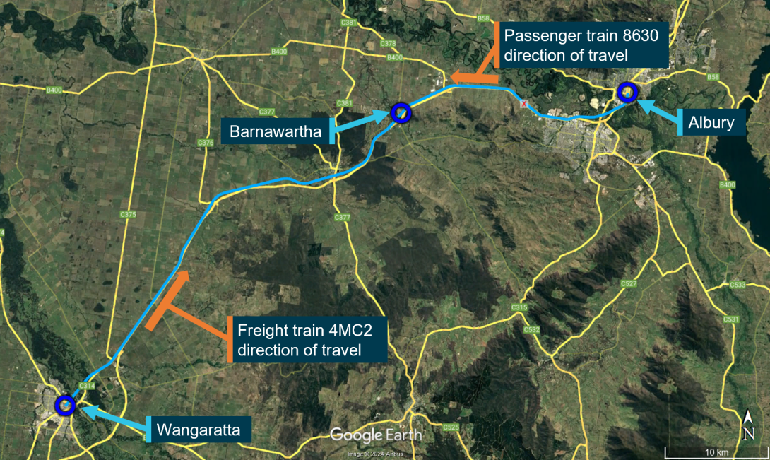
Source: Google Earth, annotated by the Office of the Chief Investigator (OCI)
Derailment of freight train 4MC2
Train 4MC2 was operated by 2 drivers and consisted of 4 locomotives hauling 46 container wagons. From Wangaratta, 4MC2 was travelling on the East Track. At about 1740, it was approaching Barnawartha travelling on tangent (straight) track and descending a moderate downgrade.
On the descent, the driver in control was managing the train’s speed between about 114 km/h and 117 km/h with a series of brake applications. Neither member of the locomotive crew recalled observing any track misalignment ahead of their train and front-of-train camera footage similarly did not show any signs of track misalignment.
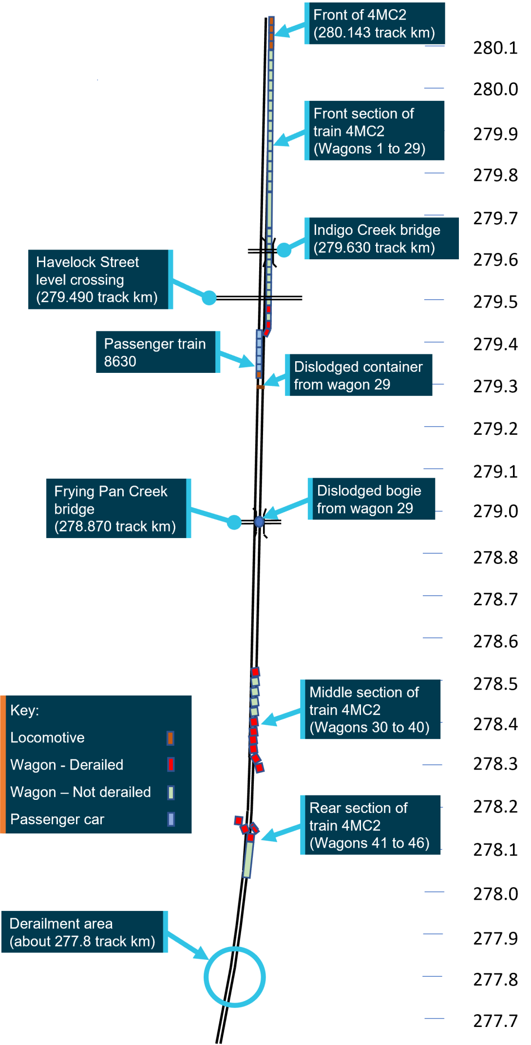
Several wagons of 4MC2 derailed commencing at about 277.8 track km.[1] The train parted into 3 sections: the locomotives and wagons 1 to 29 (front), wagons 30 to 40 (middle), and wagons 41 to 46 (rear). The trailing wagon in the rear section came to a stand about 120 m past the derailment location. A schematic of the sections of the separated freight train, derailed wagons and the passenger train is provided in Appendix A.
Figure 2: The middle and rear separated sections of freight train 4MC2
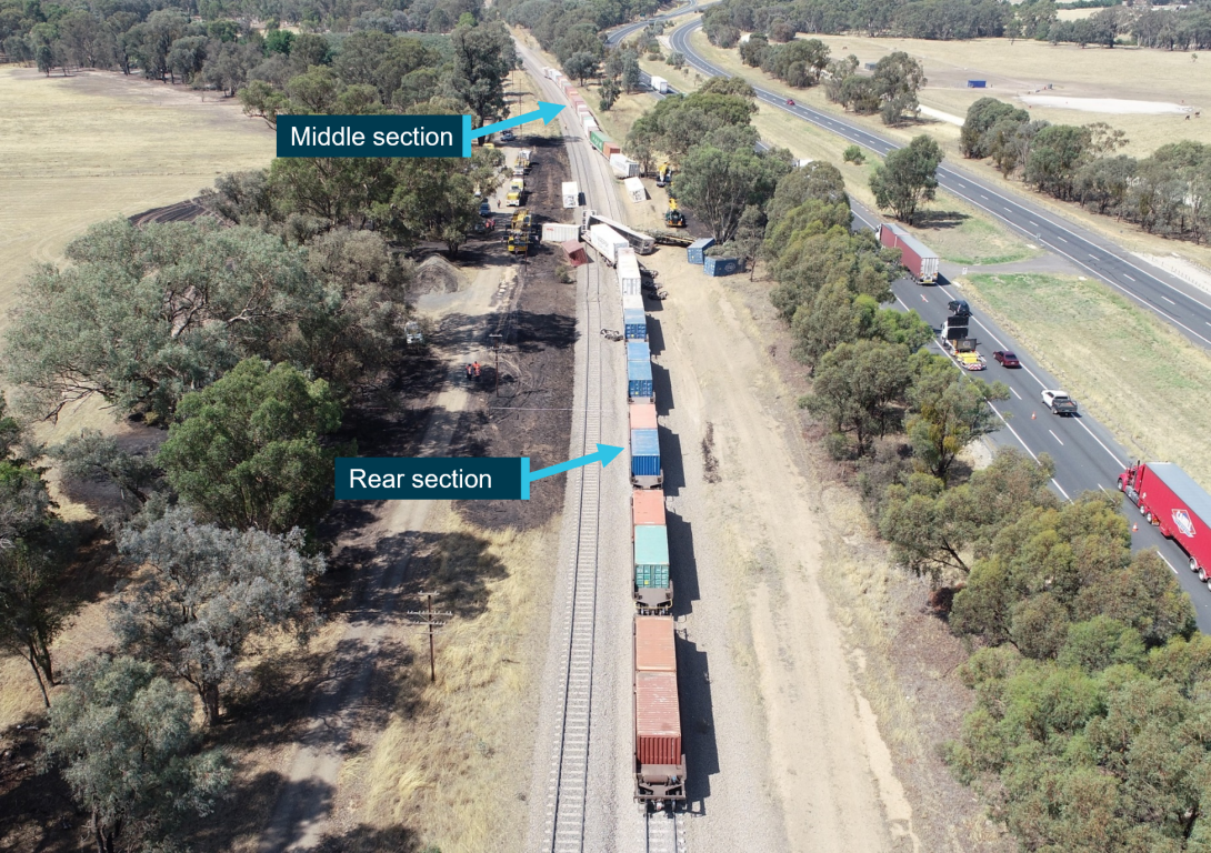
Source: ATSB
The locomotives with wagons 1 to 29 attached initially continued for over a kilometre. In this front section of the train, the trailing bogie of wagon 26 and the leading bogie of wagons 28 and 29 were derailed to the left in the direction of travel. It is likely that the trailing bogie of wagon 29 also derailed to the left before it then separated from its wagon at Frying Pan Creek bridge and the rear container from this wagon subsequently fell across both tracks (Figure 3).
Figure 3: Separated trailing bogie from wagon 29 and dislodged container in distance
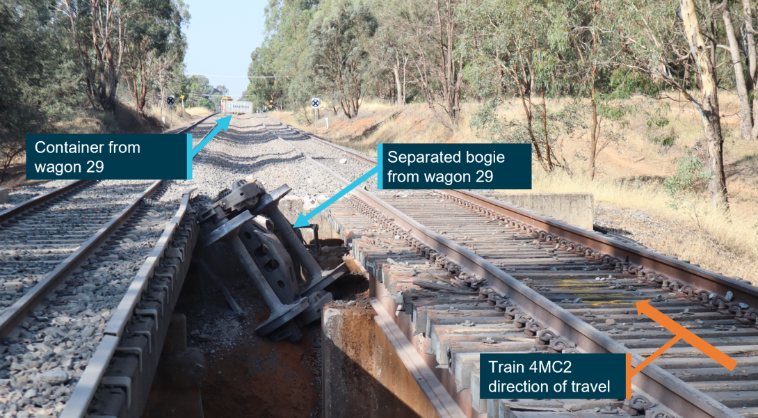
Source: OCI
The locomotive drivers on 4MC2 reported that they were alerted to an issue by a brake pipe airflow indication. At about the same time they observed the approaching passenger train 8630. They recalled that they made attempts to contact the passenger train by radio.
Passenger train 8630 impact with derailed wagon of 4MC2
Train 8630 had departed Albury on schedule. The train consisted of an N-Class locomotive (N474) and 4 passenger cars. Train crew comprised 2 locomotive drivers and 2 conductors, and there were a reported 17 passengers on board.
Approaching Barnawartha, train 8630 was travelling on the parallel West Track at about 104 km/h. The driver in control recalled observing dust ahead and then train 4MC2. They responded by applying the brake on their train at about 1742 and reported attempting to contact the freight train by radio. The driver estimated their train impacted one derailed container wagon at about 25 to 35 km/h.
When both trains stopped, at about 1743, the container connected to the last wagon of the front section of 4MC2 was against the end carriage of 8630 and the fallen container was about 50 m in front of the locomotive (Figure 4). The impacted container did not penetrate the passenger compartment and there were no injuries.
Communication was established between the trains, although it is not clear which communication attempt was ultimately successful, or when it occurred as the radio communication was not recorded.
Figure 4: Train 8630 passenger car in contact with container of derailed wagon of 4MC2
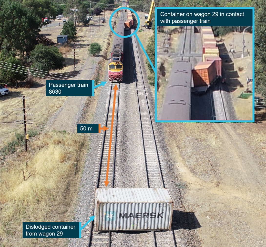
Source: ATSB
Context
Track information
Overview
The derailment occurred within the Seymour to Albury section of the standard gauge interstate rail network managed by the Australian Rail Track Corporation (ARTC). In the area of the derailment, there were parallel tracks, referred to as the East and West Tracks, both bidirectional. Freight train 4MC2 was travelling on the East Track northbound towards Albury.
The maximum permitted train speeds in the area of the derailment were:[2]
- 115 km/h for freight trains (with axle load up to 20 t)
- 130 km/h for passenger trains (with axle load up to 19 t)
There were no Temporary Speed Restrictions (TSR) in force proximate to the derailment location, nor any speed restrictions activated due to heat.
The East Track, in the direction of travel for train 4MC2, leading up to and through the derailment area was tangent (straight) with a moderate downhill grade.[3] There was a turnout about 300 m prior to the derailment location and a 2,400 m radius curve to the left about 200 m beyond it. The curve was about 650 m long, after which the track was straight. There were no other significant track features near to the derailment location.
Track construction
The East Track utilised continuously welded[4] 60 kg/m rail affixed to concrete sleepers with resilient fasteners. For track with concrete sleepers, ARTC used a nominal sleeper spacing of 667 mm.[5] The engineering code specified 300 mm wide ballast shoulders to either side of the sleeper and ballast height in line with the top of the sleeper (Figure 5Figure 6).[6] Ballast shoulders that conformed to these dimensions were considered ‘full’. Ballast provides support for the sleepers and distributes the loads from the sleepers to the formation to maintain track geometry under vertical, lateral and longitudinal loads.
Figure 5: Ballast shoulder dimensions
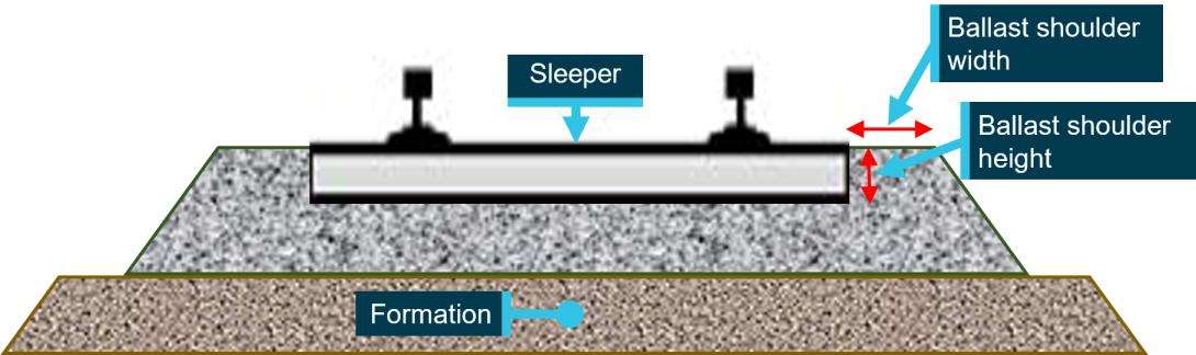
Source: OCI
Track inspection
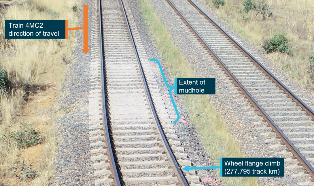
The track at the derailment location was inspected the day after the derailment. A mud hole was observed within about 10 m of track between 277.780 track km to about 277.790 track km where there was contamination of ballast, a loss of ballast between sleepers, and loss of ballast profile at sleeper ends (Figure 6). A lateral track misalignment was also present, beginning at about the same location as the northern extent of the mud hole (277.790 track km). The visible length of misaligned track was about 65 m although the full extent of the misalignment was likely obscured by subsequent damage from derailed wagons. The misalignment was predominantly toward the left in the direction of travel and the greatest measured lateral deviation was about 0.7 m. Several sets of witness marks from the passage of wheels were identified on the rail head in the section of misaligned track.
Figure 6: Overview of derailment area
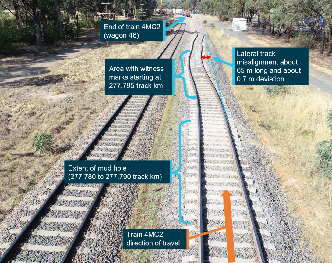
Source: ATSB, annotated by OCI
The witness marks consistently indicated that left wheels had ridden up and over the left rail (Figure 7). Related marks were also observed where the corresponding right wheels had dropped between the rails, and where both wheels began contacting sleepers. It was not possible to ascertain which marks were associated with the first derailed wheelset.
Figure 7: Witness mark from a wheel flange climb
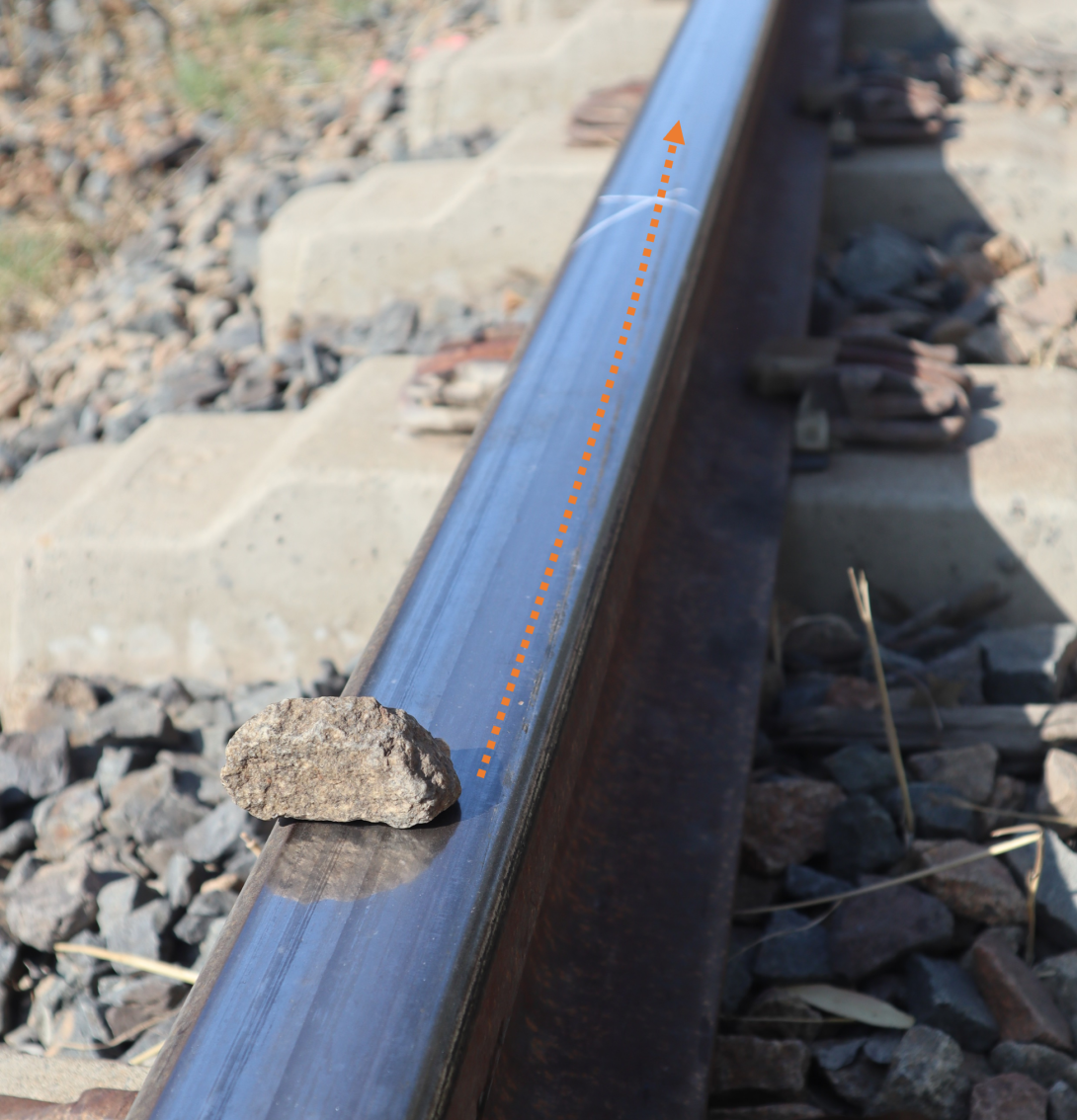
Source: OCI
Within the length of the track misalignment, the ballast had been disturbed by sleeper movement and the impact of derailed wheels. Therefore, the condition of the ballast shoulder could not be assessed. Undisturbed track was inspected at about 277.770 track km. In this area sleeper ends were visible, suggesting that ballast shoulders were less than full (Figure 8).
Figure 8: Sleeper ends protruding from ballast (about 277.770 track km)
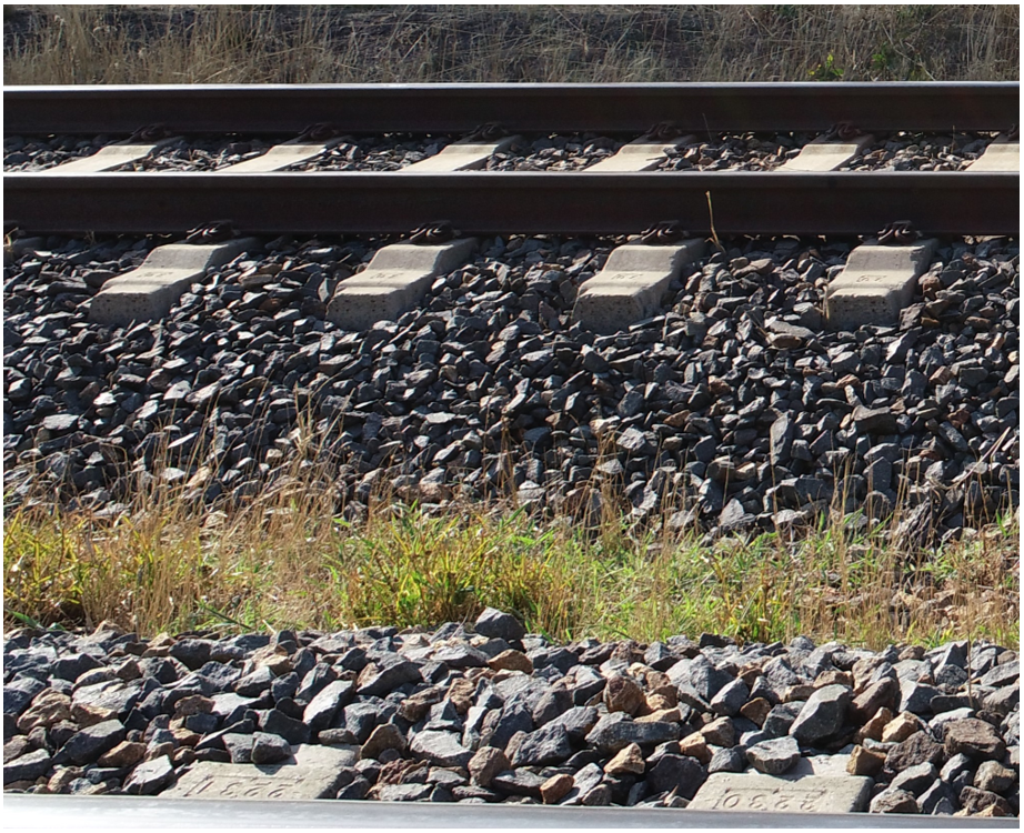
Source: ATSB
Track condition monitoring
Track patrols and inspections
ARTC specified that track patrols were to be conducted every 7 days or as specified in a Track Maintenance Plan. Unscheduled inspections were also carried out in response to ‘defined or abnormal events’ and included those required at special locations where defects were more likely.
ARTC conducted a range of other general and detailed track inspections to monitor the condition of track infrastructure, ranging in frequency from 6 to 24 months. ARTC standards specified that a general inspection of track stability was required as temperatures started to increase after the cold season, normally the end of August, and as close as possible to, or in conjunction with, the ballast general inspection.
A mud hole had been identified during inspection and was recorded in ARTC’s Ellipse maintenance system. It was first identified in 2014 when it was 1 m long and was monitored intermittently through track inspection. The most recent update was on 8 February 2019, at which time the mud hole was listed as a P4 priority defect between 277.780 track km and 277.790 track km (10 m). A defect assigned a P4 priority was to be addressed within 12 months.[7] At the time of the derailment the defect was less than 2 weeks from exceeding this but had not yet been addressed.
Track geometry measurement
Background
The AK car inertial measurement system[8] was utilised by ARTC to measure track geometry without obstructing normal railroad operations. The AK car utilised various sensors to record the lateral and vertical position of the rails at locations along the track. The system processed the information to produce track geometry data for assessment against applicable limits.
ARTC’s Code of Practice (CoP) for track geometry[9] contained the limits applicable for track geometry measurements. It specified that measurements be conducted at least every 4 months by the geometry car (the AK car). The measurements were to be assessed against the CoP limits and the type, size and location of any defects recorded (defects referred to locations where measured track geometry exceeded the relevant limit).
An initial review identified that the measured vertical geometry contained significant variations around the derailment location. Other geometry parameters measured by the AK car were also reviewed but the maximum values proximate to the derailment location were well below CoP defect limits. In some cases, vertical geometry defects may result in elevated track twist.[10] However, that did not occur at the defect location. The vertical geometry values for both rails increased evenly, therefore, no significant twist was present.
Assessment of vertical geometry
Top is a term commonly used to describe variations in the vertical position of an individual rail. The CoP specified three different top parameters, 20 m inertial, Long 20 m chord and Short 4 m chord (Table 1). Notes accompanying the CoP indicated that only the 20 m inertial parameter was applicable to geometry measured by the AK car.
The maintenance response required when a defect level was exceeded changed depending on the speed permitted in a track section. The permitted speeds on this track section were 115 km/h for freight trains and 130 km/h for passenger trains. Therefore, the appropriate speed band reference for geometry limits and corresponding response categories was referred to in the CoP as the 115/160 (freight/passenger) band. This was the highest speed band listed by the CoP and correspondingly had the strictest requirements for defect response.
Table 1: Vertical geometry defect limits and maintenance response categories
| Measured parameters in mm under loaded track | Max. speed (Freight/Passenger) | |||
| Top | 100/115 | 115/160 | ||
| 20 m inertial | Long 20 m chord | Short 4 m chord | ||
| >42 | >90 | >23 | E1 | E1 |
| 40-42 | 72-90 | 20-23 | E1 | E1 |
| 36-39 | 67-71 | 17-19 | E1 | E1 |
| 33-35 | 57-66 | 15-16 | E2 | E1 |
| 29-32 | 52-56 | 13-14 | P1 | E2 |
| 27-28 | 47-51 | 11-12 | P2 | P1 |
| 24-26 | 38-46 | 9-10 | N | P2 |
| Note: The information presented is an extract from the relevant table in the ARTC CoP. Parameters not relevant to the derailment have been removed. | ||||
Where the measured geometry exceeded a limit, it was considered a defect and a response category was assigned that determined what response was required. The responses for each defect response category were provided in the CoP (Table 2).
Table 2: Defect response category and action
| Response category | Inspect | Repair |
| E1 (Emergency class 1) | Prior to next train | Prior to next train |
| E2 (Emergency class 2) | Within 2 hours or prior to the next train, whichever is greatest | Within 24 hours |
| P1 (Priority class 1) | Within 24 hours | Within 7 days |
| P2 (Priority class 2) | Within 7 days | Within 28 days |
| N | Normal scheduled inspection regime | Normal scheduled inspection regime |
| Note: The information presented is an extract from the relevant table in the ARTC CoP. | ||
ARTC provided 2 exceedance reports for a section of the East Track that included the derailment location. They were generated from track geometry data recorded on 9 October 2019. The exceedance reports identified locations where the measured geometry had exceeded the relevant limit and were therefore considered defects.
Geometry exceedance report 1
Exceedance report 1 was the result of an assessment of measured data against the CoP ‘20 m inertial’ limits. It did not identify any defects close to the identified derailment site (277.795 track km). Information contained within the report indicated that the measured geometry had been assessed against the 100/115 km/h speed band. However, the speed band that should have been applied in this assessment was 115/160 km/h, consistent with the permitted track speeds and as used in a previous assessment.
ARTC advised that the speed band used for assessment had been manually adjusted on the AK car in order to produce reports required for a track upgrade program.[11] This change was still in place when the assessment for geometry exceedance report 1 was undertaken, resulting in the wrong speed band being used.
ARTC also provided an extract from the measured data. It advised that the surface (top) parameter provided in the extract was directly comparable to the ‘Top 20 m inertial’ limits prescribed in the CoP. The local maximum values (at 277.792 track km) were 25.9 mm on the left rail and 24.3 mm on the right rail. Both values exceeded the P2 limit for the 115/160 km/h speed band and were therefore defects at the time of the measurement on 9 October 2019. The CoP required inspection within 7 days and repair within 28 days for a P2 level defect.
Geometry exceedance report 2
A second exceedance report identified a vertical geometry defect at about 277.792 track km. The report was an assessment of the measured data against a 6 m chord top criteria that was not listed in the CoP. ARTC advised that this criteria was to be actioned by local teams as agreed with their managers. Although the defect was recorded in ARTC’s Ellipse maintenance system, there were no records of actions taken in response.
Defect growth
ARTC provided an extract of measured vertical geometry data from the previous AK car measurement run that occurred on 12 June 2019. Local maxima were present at 277.792 km on both rails, albeit that these maxima were less than the lowest defect limit for the 115/160 speed band in the CoP.
The data from the 12 June 2019 measurement was compared to the 9 October 2019 measurement (Figure 9). The comparison showed consistent waveforms between the two sets of measurements and significant growth (38% on the left rail and 48% on the right rail) at the 277.792 km location.
Figure 9: Surface (top) deviation, between June and October 2019 measurements
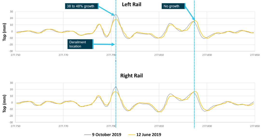
Source: ATSB, generated from ARTC data
The growth of the irregularity in the preceding 4 months (120 days) suggested that it was likely that the defect would have continued to grow in the subsequent period up to the occurrence date (113 days). However, the size of the defect at the time of the occurrence cannot be inferred from this as the growth rate is unlikely to be linear, instead dependent on several factors including prevailing weather and traffic density.
Other geometry standards
The measured vertical track geometry was assessed against the defect severity and maintenance response criteria of other track geometry standards. The standards assessed were:
- Rail Industry Safety Standards Board (RISSB) AS 7635[12]
- RailCorp engineering manual TMC 203[13]
- V/Line network infrastructure standard NIST-2706.[14]
Unlike the CoP, the 3 standards did not use an inertial measurement-based criteria. Instead, they prescribed defect limits for surface geometry irregularities using chord offset measurements. The length of the chord and the offset varied between the standards.
The inertial vertical geometry measured on 9 October 2019 was reprocessed into the chord offsets relating to each standard. Each result was compared to the defect limit and maintenance response criteria of the applicable standard. Further detail is provided in Appendix B. In all cases this resulted in a defect at the 277.792 track km location with a required response that was more urgent than that required by the ARTC CoP (inspection within 7 days and repair within 28 days). The responses required by each standard are listed below:
- The long chord criteria in AS 7635 required action (repair or further assessment) within 24 hours.
- The short chord criteria in AS 7635 required action (repair or further assessment) prior to the passage of the next train.
- The RailCorp standard required action (repair or further assessment) within 24 hours for both long and short chords.
- The V/Line standard required an immediate speed restriction and repair within 7 days.
Since the derailment occurred, an updated (2023) version of RISSB AS 7635 has been issued. The new edition emphasised that the table of geometry limits was informative rather than a requirement of the standard. The standard suggests that infrastructure managers:
Should develop appropriate geometry defect limits and intervention thresholds that are appropriate for the class of traffic, infrastructure, configuration, and risk appetite.
Track lateral stability
Introduction
Track lateral stability is the general term used to describe whether a track is sufficiently restrained against moving sideways under an applied load. The load may be applied in various ways, one significant source being by thermally induced stress in the rails. In ballasted track, the resistance to lateral movement is provided by the ballast, including the shoulder ballast at the ends of the sleepers. A track buckle[15] occurs when stress in the rail overcomes the track structures’ resistance to lateral movement. Therefore, managing track lateral stability involves both the management of rail stress, and the maintenance of track support structures that resist buckling, including ballast.
Rail stress and buckling resistance
Rail stress and stress‑free temperature
Steel rails expand when heated and contract when cooled. In the vertical and lateral directions these changes are small and without consequence. However, in the longitudinal direction, expansion and contraction of continuously welded rail (CWR) is restricted. Instead, changes in temperature cause stress within the rail. If the stress becomes excessive it can cause buckled rail (compressive stress when the temperature is high) or broken rail (tensile stress when the temperature is low).
At a certain temperature the rail is neither in tension nor in compression, this is its stress‑free temperature (SFT). Rail stress is managed by controlling the temperature at which the rail is stress‑free. ARTC specified a rail SFT of 38°C in track with CWR. The SFT may change with time due to lateral, longitudinal and vertical movement of the track structure. Train forces such as braking and traction create longitudinal movements (creep) in the rail which may also change the in-service SFT (Kish and others 2013).
The ARTC CoP specified that rail creep monitoring and control measures would not usually be necessary at locations with CWR, concrete sleepers and resilient fastenings. The CoP noted that this type of track structure was known to provide good resistance to longitudinal rail movements, but that ‘practices for the measurement of rail creep should be considered and take into account the influence of fixed points in the track’. There were no creep monitoring facilities through the Barnawartha location.
Changes in a rail SFT are not easily observed in CWR.[16] ARTC did not measure changes to the SFT in CWR affixed to concrete sleepers unless it was identified during inspection that there was a risk that the SFT may have lowered. When identified as being required, ARTC measured rail SFT using VERSE testing.[17] This testing involved unfastening 30 m of rail and lifting it by hydraulic jack. The force required to lift the rail, and the rail temperature at the time was used to calculate the SFT. ARTC had not conducted VERSE testing at the derailment location at any time since it had been rerailed (circa 2010-2011). Subsequently, the SFT of the rails at the time of the derailment and any change in SFT were unknown.
Buckling resistance (ballast)
The Code of Practice (CoP) for ballast[18] specified the required ballast profile, and the corrective action where it was deficient. The response code table notes[19] stated that ‘in concrete sleepers the responses apply where height and width deficiencies occur over 10 m or greater’.
The track proximate to the derailment had not been identified by ARTC as a location requiring ballast rectification. A mud hole was observed in post‑derailment inspections that included sections with deficient ballast (Figure 10). The mud hole was about 10 m long, sufficient length for the CoP to require a response due to ballast deficiency.
Figure 10: Extent of mud hole and light-coloured ballast
Source: ATSB
System for managing track lateral stability
Overview
The system ARTC used for managing track lateral stability was described across multiple documents. Relevant documents included:
- the ARTC Code of Practice for track lateral stability
- related procedure ETM-06-08 – Managing track stability
- reference document ETGN-06-01 – Track stability handbook
Code of Practice for track lateral stability
The Code of Practice (CoP) for track lateral stability[20] specified the design, maintenance, and inspection actions required in order to provide sufficient lateral stability of the track.
The only applicable design requirement was to install (or adjust) the rail at the target stress‑free temperature. There were no requirements for maintaining concrete sleepered track, though the CoP did suggest that measurement of rail creep should be considered.
The CoP requirements for inspection included:
- identification of special locations
- scheduled inspections
- unscheduled inspection, including:
- when a temperature threshold was exceeded
- when a defect was suspected or reported
- assessment and actions following inspection to verify the track’s capacity to provide adequate lateral stability
The CoP described reasons why track sections should be managed as special locations, including where:
- reduced lateral stability had been identified (through inspection)
- a history of lateral track instability existed.
The requirements for assessment and actions included that identified conditions affecting track stability were to be controlled with practices described in other sections of the CoP including ballast (Section 4) and track geometry (Section 5).
Procedure for managing track stability
A procedure for managing track stability[21] contained further requirements and related contextual information. It identified that maintenance of track stability required both management of buckling force (through management of rail stress) and buckling resistance (through maintenance of ballast profile). It described that management of buckling force involved monitoring of changes to stress‑free temperature. The guidance relating to management of buckling resistance focused on identification and assessment of failure or poor condition of components which impact on lateral resistance.
The procedure required a track stability management plan (TSMP) for ‘each section of track’. TSMP’s were to be reviewed at least twice annually (once prior to the onset of hot weather season and once after its conclusion). A TSMP was described as a concise plan of all activities associated with inspecting and managing track to ensure lateral stability that included:
- requirements for managing buckling force
- requirements for managing buckling resistance
- a register of identified special locations.
The procedure described special locations as areas potentially vulnerable to instability, with a history of instability or where stress‑free temperature was suspect. It gave a list of examples that could be special locations that included areas with non-conforming ballast profile and mud holes. A separate list gave examples of mandatory special locations, it included sites with multiple concurrent initiator defects and sites that had previously buckled (where risk of further instability remained).
Information relating to inspection and assessment were contained in the procedure and were largely aligned with the CoP. Inspection to identify and assess localised initiators, including vertical geometry and pumping sleepers[22] (that occur at mud holes) was required at locations that had been identified as special locations. Though not required by either document, the CoP had indicated detailed inspection ‘may be necessary’ for sections of track where reduced lateral stability had been identified. The procedure described that detailed inspections could include measurement of stress‑free temperature or rail creep.
Track stability handbook
The track stability handbook[23] was referenced within the procedure for managing track stability and contained related guidance material. While the handbook addressed special locations, it did so in the context of things to do at identified special locations. It did not provide guidance on the identification of special locations.
The handbook identified that inspection and assessment of track with continuously welded rail, including measurement of stress‑free temperature, could reduce the likelihood of buckles occurring in the hotter months of the year.
Track stability management plan
A track stability management plan (TSMP) existed for the 2019–2020 high temperature season and was last reviewed in November 2019. The TSMP covered multiple track sections including a section of the East Track that contained the derailment location.
The list of stress‑free temperature test locations within the TSMP did not include any within 2 km of the derailment. Several included locations listed vertical geometry or mud holes as reasons for inclusion, but only where lateral geometry, ballast deficiency, or generic ‘rough track’ were also listed.
The TSMP identified that no creep measurements were planned ‘as there is no creep monuments currently installed’. This was justified on the basis that ‘there has been little or no evidence of creep found’ and that tracks ‘have been consolidated and been stable for several years… stress‑free temperature measurements are taken in suspect locations each year’.
With regard to ballast condition, the TSMP required locations with ballast deficiency to be monitored during track patrol for evidence of movement. It instructed inspectors to refer to the Ellipse defect management system for a list of ballast deficient locations. Although a 10 m mud hole had been recorded in the management system, the entry did not reference a ballast deficiency and it was not included in a list of ballast deficient locations provided by ARTC.
Several mud holes and ballast deficient locations were included on the special locations register associated with the TSMP. However, the mud hole proximate to the derailment location was not. The only locations listed with a vertical geometry defect had other defects in combination (e.g. vertical and lateral geometry together, or with an associated ballast deficiency).
Related inspections
Several inspections of the track were conducted in the 6 months prior to the derailment including:
- inspection for conditions affecting stability (August 2019)
- 3‑monthly mud hole inspection (October 2019)
- a 40°C heat patrol inspection (November 2019)
- a heat patrol inspection after three consecutive 38°C days (December 2019)
- a front of train inspection (15 January 2020)
- a track patrol (28 January 2020).
No inspections identified the derailment location as being vulnerable to track instability.
Train information
Freight train 4MC2
Train 4MC2 consisted of 4 locomotives and 46 wagons. The leading locomotive was NR71, followed by a G class locomotive, then 2 further NR class locomotives. 44 of the wagons were single platform container wagons each capable of carrying three 20 ft shipping containers. Wagons in positions 15 and 46 were multi-platform well wagons that had 5 wells each. Each well was able to carry two 20 ft shipping containers on this corridor.
Most wagons were lightly loaded, with axle loads between 5 t and 7.2 t. The wagons with higher loading were well in front of the first derailed wagon. The axle loading for 5 wagons either side of position 26 (the forward-most derailed wagon) was between 6.7 t and 7.2 t.
Empty or lightly‑loaded wagons positioned between fully‑loaded wagons within a train consist can increase derailment risk (ATSB 2020). However, as the wagons close to position 26 were all lightly‑loaded, the marshalling of wagons (their order) was unlikely to have contributed to this derailment.
Recorded information
Key events
Information from the event recorders on the leading locomotive of train 4MC2 and the locomotive of train 8630 was reviewed. A table of events in chronological order is provided in Appendix C. Key events included:
- The driver of freight train 4MC2 briefly released and reapplied the dynamic brake as the train transitioned the derailment area. Observation of the train speed during this period suggests they were using the dynamic brake to control the train’s speed down a grade.
- Wagon 26, the forward-most derailed wagon, transitioned the derailment location about 10 s before the first reduction in brake pipe air pressure, this was consistent with a loss of brake pipe air as a result of brake lines parting during the derailment.
- In response to the speed of train 4MC2 decreasing, the driver of the freight train released the dynamic brake and applied the throttle in an effort to maintain speed.
- The brake application on passenger train 8630 occurred at about 280 track km. This is before the location where 8630 and 4MC2 crossed and is consistent with the driver of 8630 applying the brakes promptly after observing dust from the freight train in the distance.
Freight train dynamic braking
The driver of train 4MC2 was utilising dynamic brake applications to control train speed on a descending grade. The dynamic brake slows only the locomotives, therefore when it is used, buff (compressive) force is induced between the locomotives and the trailing wagons slowing them in turn. In the vicinity of the derailment, the dynamic brake was released then reapplied 13 seconds later.
Repeated application and release of dynamic brake may contribute to in-train forces[24] that vary in magnitude along the length of the train. However, there was insufficient evidence to support this having contributed to the derailment.
Freight train emergency braking
When a brake pipe parts on a train the pressurised air rapidly vents. It is expected that this reduces brake pipe pressure and results in an automatic emergency brake application. However, in this instance the brake pipe pressure at the lead locomotive did not reduce sufficiently to cause an automatic brake application.[25] This was possibly due to the air volume available from the compressors and main reservoirs on all 4 locomotives being able to supply a sufficient volume of air into the brake pipe to maintain the pressure at the lead locomotive above the automatic brake application pressure while air was venting further along the train. This allowed the front section of the train to continue, and for the driver to apply traction power, after sections of the train and the brake pipe parted.
When the air brake system supplies air to the brake pipe, an airflow meter measures and displays to the driver the amount of airflow. However, the airflow measurement was not recorded by the NR class locomotive event recorder. Therefore, it was not possible to assess whether airflow into the brake pipe was the reason that an emergency brake application did not occur when the brake pipe parted in the derailment.
Wagon inspections
Overview
Wagons 26 and 28 were identified for further inspection. The inspected wagons used the ‘three‑piece’ bogie which is the standard freight bogie in Australia. It consists of 2 side frames and a bogie bolster spanning them. Two side bearers are located on the bogie bolster roughly half-way between the centre and each end. Side bearers provide a degree of control over wagon roll motion (side-to-side tilt) and bogie rotational movement. The inspected wagons utilised constant contact side bearers (CCSBs). As the name implies, when correctly configured, CCSBs are in contact with the wagon body at all times.
Wagon 26
Wagon 26 was found to be in good condition with no items identified that might have contributed to the derailment. There was no indication of improper maintenance, excessive wear or signs of hunting oscillation (cyclic lateral motion).
Wagon 28
The inspection of wagon 28 identified that there was a gap between the side bearer on the left side (in the direction of travel) and the wagon body of the leading bogie. Shims were missing from above the side bearer wear plate creating the gap. Missing side bearer shims could reduce the speed at which the wagon was susceptible to hunting. However, it was not determined whether the shim was missing before the derailment and other indicators of hunting were not present, such as wear on gib[26] contact surfaces (Figure 11).
Figure 11: Wagon 28 lead bogie gib condition
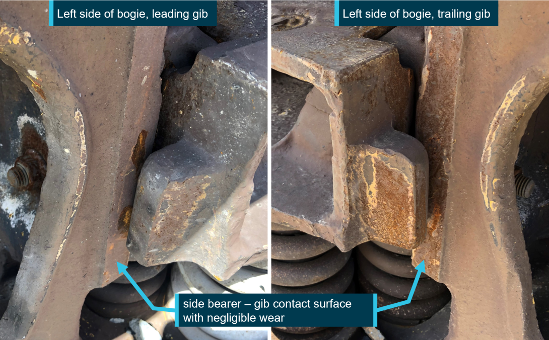
Source: OCI
Environmental conditions
Around the time of the derailment, the air temperature measured at the Bureau of Meteorology weather station at Wangaratta, Victoria, was about 36°C. It was clear and dry with SSW wind speeds of around 17 km/h. It is probable that conditions at Barnawartha, located about 45 km from Wangaratta, were similar.
When exposed to direct sunlight rail reaches temperatures considerably higher than the ambient. Published literature suggests that rail temperature can be 50% above the air temperature in direct sunlight (Wu and others, 2010). Using this relationship and the ambient temperature recorded at Wangaratta, the rail temperature was probably about 54°C. This is 16°C above the nominal design stress‑free temperature.
Similar occurrences
Several investigation reports have been published into occurrences relating to track lateral stability and vertical alignment on Australian railways. Key information from selected reports relevant to this occurrence, including other events on this corridor, is presented below:
On the ARTC network
- Creighton, Victoria, 21 January 2019: Track lateral instability contributed to a lateral misalignment resulting in a derailment. Mud holes present at the derailment location reduced the track’s resistance to movement. Additionally, the investigation identified that ARTC’s systems for managing track lateral stability did not lead to the location being managed as a special location potentially vulnerable to instability (ATSB investigation RO-2019-003).
- Locksley, Victoria, 12 February 2013: Track disturbing maintenance activities and a track structure that had reduced capacity to withstand lateral forces (due to ballast fouling) probably contributed to a track misalignment and subsequent derailment. Additionally, the investigation found that despite the location having characteristics consistent with the criteria for a ‘Special Location’ no action had been taken to manage the increased risk (ATSB investigation RO‑2013-006).
- Ararat, Victoria, 28 November 2003: A small buckle became progressively worse as a train passed over it, resulting in the derailment of 2 wagons. Track disturbing works that had occurred a week prior had probably reduced the lateral resistance provided by the ballast and likely reduced the stress‑free temperature of the rail, although this was not monitored. Additionally, the investigation recommended that ARTC review track maintenance procedures to ensure track geometry and stress‑free temperature were within specified standards (ATSB investigation 2003-006).
On other networks
- Duaringa, Queensland, 24 January 2018: The driver of a loaded coal train observed a track buckle form as their train approached. It subsequently derailed multiple wagons as it passed over the buckle. Several factors were identified that contributed to the buckle, including track disturbing works and local fixed points. The report also found that a Hazard Location Register was being used as a record of past occurrences rather than as a tool to proactively identify hazard locations (ATSB investigation RO-2018-005)
Summary of similar occurrences
Although each reviewed occurrence investigation report involved unique aspects, thematic similarities included:
- the formation of lateral track misalignments under (or in one case immediately in front of) the passage of a train
- locations not being identified on relevant hazard registers
- track disturbing works occurring prior to the lateral track misalignment occurring
- an absence of stress‑free temperature monitoring.
Safety analysis
Introduction
Initially, the front section of the freight train continued for over a kilometre before being slowed by its driver when alerted to an issue. Concurrently, passenger train 8630 was approaching Barnawartha from the opposite direction on a parallel track. The driver of 8630 observed dust and the headlights of 4MC2 and applied their train’s brakes in response. The trains came together at slowing speeds, with the passenger train impacting a container on derailed wagon 29 of the freight train.
This analysis discusses:
- factors associated with the derailment of freight train 4MC2
- management of track geometry
- management of track lateral stability
- the passenger train collision with the derailed freight train.
Derailment of freight train 4MC2
Background
Post‑derailment inspection identified several locations of wheel flange climb over the rail head of the left rail in the direction of travel. Subsequent damage to sleepers was consistent with full wheelset derailment, the furthest south location identified was at 277.795 track km, about 5 m past an observed mud hole. The flange climb marks were consistent with the derailed states of wagons 26 (trailing bogie), 28 (leading bogie) and 29 (both bogies) being toward the left in the direction of travel. While it was not possible to conclusively determine which marks were associated with which wheel derailments, the observation of flange climb marks on the rail head indicate that the initial derailment was probably by the action of a flange climb.
Flange climb occurs when lateral forces between the wheel and the rail exceed the capacity for vertical forces to restrain, either through excessive lateral force alone, or a combination of increased lateral force and reduced vertical force.
The presence of wagon hunting was considered as it may affect wheel to rail forces. While higher speed generally increases the potential for hunting, and the derailed train was traveling at or near the maximum speed for this track, there was insufficient evidence to conclude that hunting was occurring in this case.
The features identified that could contribute to flange climb in this instance were:
- the vertical geometry defect at 277.792 track km
- the lateral track misalignment.
Derailment mechanism
Contribution of vertical track geometry defect
The vertical geometry defect was in close proximity (and prior) to the derailment location. When a wagon’s wheels pass over an upward vertical geometry defect at speed there is initially an increase in the vertical force between wheels and rails, above the static load value. The load then decreases to below the static force once the wheel is past the highest point of the track geometry defect. This may induce a vertical dynamic response of the wagon body, which in turn can cause further fluctuation in the vertical force between wheels and rails. Therefore, the vertical geometry defect contributed to locations of reduced vertical force in the vicinity where the derailment occurred.
There was no evidence identified that indicated that wheels passing over the vertical geometry defect contributed to an increased lateral force between wheel and rail. The recorded track geometry did not include significant lateral (when both rails move to one side) or twist (where one rail is higher than the other) defects present alongside the vertical defect to initiate lateral motion of the wagons. Therefore, the evidence did not suggest that the wagon transitioning the vertical track geometry defect was sufficient to initiate the derailment on its own but contributed by reducing the vertical force present between wheels and rails.
Contribution of lateral track misalignment
A lateral track misalignment was present after the derailment. It was not present in footage obtained from the forward-facing camera on train 4MC2. The misalignment therefore either occurred during the passage of the train or as a consequence of the derailment. Lateral track misalignments often occur under, and in response to, the passage of a train, as supported by the findings of previous occurrence investigation reports.
When a train is in normal straight running, there is a gap present between the wheel flanges and the side face of the rails. This and the guidance afforded by conical railway wheelsets (steering of the wheels) mean that small lateral misalignments of the rail are overcome without flange contact and large lateral forces. However, when the lateral misalignment is large, the wheel flange contacts the rail. Although other factors are involved, the magnitude of the resulting lateral force is related to the size of the misalignment.
As a lateral track misalignment forms under a train, it creates increasing lateral wheel to rail forces as it grows. It may also induce a lateral (roll) response of the wagon bodies which can contribute to further high lateral forces as well as affecting vertical force between the wheels and rails.
While it is possible that the lateral track misalignment formed as a consequence of the derailment, there was an absence of evidence of other mechanisms for generating lateral force or otherwise initiating the derailment. Therefore, it was probable that the lateral track misalignment formed under the passage of the train and contributed to the derailment by increasing the lateral force present between wheels and rails.
Examining possible causes of lateral track misalignment
Severe lateral track misalignments (commonly referred to as track buckles) occur when longitudinal compressive forces in the rails cause lateral buckling forces to exceed the restraint offered by the track structure. Managing the risk of lateral misalignment therefore requires both the management of longitudinal compressive forces in rails and the maintenance of track ballast that provides restraint.
The hot, sunny condition at the time of the derailment meant that it was almost certain that some longitudinal compressive force was present in the rails at the derailment location. However, the severity of the force and the increase in risk of lateral misalignment are not known as ARTC was not monitoring changes to the stress‑free temperature (SFT) of the rail at the derailment location.
ARTC’s procedure for managing track stability listed locations with increased risk of lateral instability, including locations with:
- a history of instability
- bunching points
- areas with non-conforming ballast profile
- track disturbing works (such as tamping)
- localised initiators (including mud holes).
There was no recent history of instability in the vicinity of the lateral track misalignment or record of recent track disturbing works.
Rail bunching occurs when the rails move toward fixed points in the track, typically as a result of train braking and acceleration forces. Bunching results in rails having a reduced SFT. In such circumstances, higher than anticipated longitudinal compressive stresses occur during hot weather at bunching points, which increases the risk of track instability. Turnouts, road crossings and bridge decks are commonly identified as bunching points. The closest turnout was about 300 m south of the derailment and the closest bridge deck was 1075 m to the north, making them both unlikely to have contributed to the misalignment. The mud hole near the derailment was also unlikely to have been a bunching point relevant to this occurrence given the down grade of the track and the location of the buckle after the mud hole (in the direction of travel of train 4MC2).
Although the mud hole was identified as having deficient (non-conforming) ballast profile, it did not shift laterally. It is possible that some of the section of track that moved laterally had less than full shoulder ballast, consistent with observations of track further south. However, this had not been recorded by ARTC as deficient prior to the derailment, nor was it to the extent of the deficiency present at the mud hole location.
ARTC described localised initiators as ‘additional conditions present that will increase the locations vulnerability to instability’. Track geometry defects and pumping sleepers (that occur at mud holes) were identified as potential localised initiators. However, the mud hole and track geometry defect present at the time of the derailment were at one end of the lateral track misalignment, rather than within the section that had substantially moved. It is therefore unclear whether these contributed to the initiation of lateral track misalignment in this case.
The high rail temperature on the day of the derailment did contribute to the probable lateral track misalignment, by inducing a level of compressive force in the rails. However, if the rails had the nominal SFT and were in track with normal levels of lateral stability, this increased temperature would not have been sufficient to induce misalignment on its own. Whether the SFT had reduced was not known and, of the factors that had been associated with increased risk of lateral instability, several were not present. The presence and contribution of other factors was not known. Therefore, the factors contributing to the track misalignment could not be comprehensively determined based on the available evidence.
|
Contributing factor The dynamic motion of wagons as they transitioned a vertical track geometry defect and a probable lateral track misalignment led to the derailment of train 4MC2. The factors contributing to the probable lateral track misalignment could not be fully determined. |
Train condition
Wagon 26 was the furthest forward in the train consist to have derailed, with the trailing bogie derailed to the left side in the direction of travel. Its position within the train suggested that it was probably the first wagon to derail. The wagon was inspected post-derailment and no indication of improper maintenance, excessive wear or signs of cyclic dynamic motion (hunting) that may have contributed to the derailment were observed.
The train consist indicated that this wagon was lightly loaded. Wagons adjacent to it were similarly loaded indicating that derailment risk due to in-train forces that exists for lightly loaded wagons adjacent to heavily loaded wagons was not present in this occurrence.
Track geometry
Mud hole
Ballast fouling, associated with a mud hole was present immediately before the derailment location, the northern extent was at 277.790 track km. The ballast profile in the area of the mud hole was deficient, with sleeper ends protruding, indicating that the track support was reduced.
A vertical geometry defect existed at 277.792 track km on both rails. The defect was within 2 m of the northern extent of the mud hole, which indicated that it was associated with the mud hole. The defect was a result of the track level within the mud hole being lower, then rising up at the defect location. The magnitude of the measured geometry rise had grown in 4 months preceding the October 2019 measurement and would have likely continued to grow up to the occurrence date.
|
Contributing factor A mud hole resulted in a vertical track geometry defect and localised reduction in track support immediately prior to the derailment location. |
Identification of vertical geometry defect
Vertical track geometry defects existed in both rails at 277.792 track km in October 2019 that exceeded ARTC’s P2 level. However, they were not included in the exceedance report generated for this date as it was based on an assessment against limits applicable for a lower speed track. Had this been detected, additional management would have been required as the ARTC CoP required that a P2 severity defect be inspected within 7 days and repaired within 28 days.
A second exceedance report was generated from the track geometry recorded on the same day. It identified a defect at about 277.792 track km. However, this exceedance report was generated from an assessment against a parameter that was not listed in the CoP. There was no requirement for inspection or maintenance to be performed other than at the discretion of the maintenance team.
|
Contributing factor ARTC did not identify and manage the vertical track geometry defect in accordance with its Code of Practice for track geometry. For the October 2019 measurement, track geometry was assessed against limits for the wrong speed band.
|
Comparison with other geometry standards
The measured vertical track geometry was evaluated against other standards. The standards chosen for assessment were the Australian Standard, New South Wales RailCorp standard, and Victorian V/Line standard. The standards used for assessment were those versions current at the time of the derailment. In all cases, the response required was more urgent than required by the ARTC CoP.
Based on the assessment of this defect, the limits prescribed in the CoP for inertial measurement permitted larger defects than comparable chord-based standards for vertical geometry defects. None of the standards provide a methodology detailing how their limit or response levels have been established, nor does the CoP.
A broader assessment of a large sample of possible and actual track recordings against objective safety criteria would be required to establish whether the limits and responses prescribed in the CoP provide a suitable level of safety. Such an assessment would be broadly aligned with the guidance offered by the 2023 update of the Australian Standard.
|
Other finding For the track geometry that existed at 277.792 track km, ARTC’s Code of Practice for track geometry was less restrictive in managing vertical geometry than other comparable standards. The suitability of the limits and responses prescribed in the ARTC Code of Practice was not established. |
Management of track lateral stability
ARTC’s system for managing track lateral stability was being applied at the time of the derailment. A track stability management plan had been created for the relevant track section. Inspections and stress‑free temperature measurements were occurring at identified special locations and additional general inspections were also occurring. However, no location at or adjacent to the location of the probable lateral track misalignment were identified as a special location or had stress‑free temperature measured. In other words, a location that was potentially vulnerable to track instability was not identified.
The proximity of the mud hole to the derailment appeared to provide the greatest opportunity for the location to be identified as a special location. It is unclear why the mud hole was not identified as a special location given that it had been recorded in ARTC’s maintenance system and had ballast deficiency. Other locations of mud holes and ballast deficiency were identified as special locations.
A vertical track geometry defect also provided an opportunity for identification as a special location. However, both the error that caused it not to be detected, and the lack of other examples of isolated vertical geometry defects (where no lateral defect, ballast deficiency or general rough track were present) being included as special locations, limited the likelihood of this mechanism being useful for the identification of a special location.
The inclusion of a location proximate to the derailment location on the special location register would not guarantee that lateral track misalignment would be prevented. However, it would have provided the opportunity to carry out stress‑free temperature measurement, providing information that was otherwise missing relating to the risk of track instability.
The investigation into a derailment at Creighton, Victoria in 2019 identified that ARTC’s systems for managing track lateral stability did not lead to the location being managed as a location potentially vulnerable to instability. Safety action taken by ARTC at the time did not include changes to improve the system’s ability to prospectively identify vulnerable locations.
|
Other factor that increased risk ARTC’s systems for management of track lateral stability did not lead to identification of the location as a special location potentially vulnerable to track instability. (Safety issue) |
Passenger train impact
At about the same time that the driver of freight train 4MC2 reported observing a brake pipe airflow indication, V/Line passenger train 8630 approached Barnawartha from the other direction, heading toward Melbourne on the West Track. The driver of 8630 applied the brakes promptly after observing dust from 4MC2 in the distance. Despite this, the distance remaining when the brake application occurred was less than the stopping distance required.
The drivers of both trains described attempting to provide advanced warning by radio to the opposing train. However, it is not clear which communication attempt was ultimately successful, or the exact timing of communication attempts, as the radio channel used was not recorded. It was consistently described that all communication attempts occurred after the trains were first in view of each other and the brake applied on the passenger train. In this scenario, radio communication would not have influenced the outcome as the brake application had already occurred.
The passenger train could not stop in time and impacted a shipping container on derailed wagon 29 of train 4MC2 at a low speed. The passenger train stopped about 50 m short of another container that had fallen from wagon 29 and was obstructing both tracks. There was very little opportunity for any further actions to reduce the risk to safety in this occurrence by stopping passenger train 8630 prior to collision.
Findings
|
ATSB investigation report findings focus on safety factors (that is, events and conditions that increase risk). Safety factors include ‘contributing factors’ and ‘other factors that increased risk’ (that is, factors that did not meet the definition of a contributing factor for this occurrence but were still considered important to include in the report for the purpose of increasing awareness and enhancing safety). In addition ‘other findings’ may be included to provide important information about topics other than safety factors. Safety issues are highlighted in bold to emphasise their importance. A safety issue is a safety factor that (a) can reasonably be regarded as having the potential to adversely affect the safety of future operations, and (b) is a characteristic of an organisation or a system, rather than a characteristic of a specific individual, or characteristic of an operating environment at a specific point in time. These findings should not be read as apportioning blame or liability to any particular organisation or individual. |
From the evidence available, the following findings are made with respect to the derailment of freight train 4MC2 and subsequent impact with passenger train 8630, at Barnawartha, Victoria on 29 January 2020.
Contributing factors
- The dynamic motion of wagons as they transitioned a vertical track geometry defect and a probable lateral track misalignment led to the derailment of train 4MC2. The factors contributing to the probable lateral track misalignment could not be fully determined.
- A mud hole resulted in a vertical track geometry defect and localised reduction in track support immediately prior to the derailment location.
- ARTC did not identify and manage the vertical track geometry defect in accordance with its Code of Practice for track geometry. For the October 2019 measurement, track geometry was assessed against limits for the wrong speed band.
Other factors that increased risk
- ARTC’s systems for management of track lateral stability did not lead to identification of the location as a special location potentially vulnerable to track instability. (Safety issue)
Other findings
- For the track geometry that existed at 277.792 track km, ARTC’s Code of Practice for track geometry was less restrictive in managing vertical geometry than other comparable standards. The suitability of the limits and responses prescribed in the ARTC Code of Practice was not established.
Safety issues and actions
|
Depending on the level of risk of a safety issue, the extent of corrective action taken by the relevant organisation(s), or the desirability of directing a broad safety message to the Rail industry, the ATSB may issue a formal safety recommendation or safety advisory notice as part of the final report. All directly involved parties were provided with a draft report and invited to provide submissions. As part of that process, each organisation was asked to communicate what safety actions, if any, they had carried out or were planning to carry out in relation to each safety issue relevant to their organisation. Descriptions of each safety issue, and any associated safety recommendations, are detailed below. Click the link to read the full safety issue description, including the issue status and any safety action/s taken. Safety issues and actions are updated on this website when safety issue owners provide further information concerning the implementation of safety action. |
Special location not identified
Safety issue number: RO-2020-001-SI-01
Safety issue description: ARTC’s systems for management of track lateral stability did not lead to identification of the location as a special location potentially vulnerable to track instability.
Safety action not associated with an identified safety issue
| Whether or not the ATSB identifies safety issues in the course of an investigation, relevant organisations may proactively initiate safety action in order to reduce their safety risk. All of the directly involved parties are invited to provide submissions to this draft report. The ATSB has been advised of the following proactive safety action in response to this occurrence |
Additional safety action taken by ARTC
ARTC has made several changes in response to this derailment including:
- The Code of Practice for track geometry has been updated to include a 6 m chord top criteria in addition to the 20 m inertial criteria. If assessed against the 6 m chord criteria in the updated standard, the vertical geometry identified in this investigation would have been classified as an E2 level defect (requiring inspection within 2 hours and rectification within 24 hours, or a significant reduction in speed).
- The mud hole management guideline has been updated to incorporate significant guidance on the identification, assessment and management of mud holes.
- In response to the use of an incorrect speed band for geometry assessment, ARTC has changed its process regarding the creation of additional reports. This is now achieved as a post-process rather than changing the speed in configuration files used on the AK car. In addition, ARTC is transitioning to a process that automatically assigns speed bands based on a linear referencing system, removing the need for manual configuration of speeds and allowing cross-checking by AK car operators. The automatic assignment of speed bands has been implemented in South Australia, Western Australia and Victoria and is scheduled to be completed in New South Wales by December 2025.
Glossary
| ARTC | Australian Rail Track Corporation |
| CCSB | Constant contact side bearer |
| CoP | The ARTC Track and Civil Code of Practice. Comprised of sections related to specific topics. Sections referenced in this report include: Section 2 – Sleepers and fastenings, Section 4 – Ballast, Section 5 – Track geometry, Section 6 – Track lateral stability |
| CWR | Continuously welded rail |
| RISSB | Rail Industry Safety Standards Board |
| SFT | Stress‑free temperature |
| TSMP | Track stability management plan |
| TSR | Temporary speed restriction |
Sources and submissions
Sources of information
The sources of information during the investigation included:
- Australian Rail Track Corporation
- Pacific National
- V/Line
- the drivers of both involved trains (4MC2 and 8630)
- data from locomotive event recorders.
References
- ATSB. (2020). Derailment and collision between coal trains, Ravenan (25km from Muswellbrook), New South Wales, on 26 September 2018 (RO-2018-017)
- Wu Y., Munro P., Rasul M.G., Khan M.M.K., A review of Recent Developments in Rail Temperature Prediction for use in Buckling Studies, RTSA Conference on Railway Engineering, Wellington, 2010
- Kish A, Mui W, Track Buckling Research, John A. Volpe National Transportation Systems Centre (U.S.) 2013., https://rosap.ntl.bts.gov/view/dot/11985.
Submissions
Under section 26 of the Transport Safety Investigation Act 2003, the ATSB may provide a draft report, on a confidential basis, to any person whom the ATSB considers appropriate. That section allows a person receiving a draft report to make submissions to the ATSB about the draft report.
A draft of this report was provided to directly involved parties and other relevant organisations. Submissions received were reviewed and, where considered appropriate, the text of the report was amended accordingly.
Appendices
Appendix A – Post derailment location of trains
Appendix B – Comparison of standards for vertical geometry
Introduction
Maintenance response criteria for vertical geometry from the Rail Industry Safety Standards Board (RISSB) AS 7635, RailCorp Engineering Standard ESC 210 and the V/Line Network Infrastructure Standard NIST-2706 were compared with the criteria in the ARTC Code of Practice.
The length of the chord and the offset used in evaluation (including whether it was symmetric or asymmetric) varied between the standards. The chord offsets[27] used by the selected standards were:
- 10 m / 1.8 m (AS 7635 and RailCorp)
- 5 m / 2 m (AS 7635)
- 6 m / 3 m (RailCorp)
- 10 m / 5 m (V/Line)
As the limits nominated for vertical geometry (top) in the 3 standards relate to specific nominated chord lengths, these limits couldn’t be directly compared to ones used with other measurement systems.[28] While it is possible to calculate the geometry for one chord offset from a measurement using a different chord offset, some information is lost in this process meaning it may not closely reflect the results of a direct measurement. However, the inertial measurement generated by the AK car is an estimate of the ‘true’ vertical geometry. Therefore, chord offsets can be calculated from the inertial measurement data without loss of information (providing the chord is of a reasonable length). It is understood that ARTC used this method to generate their 6 m exceedance report.
Results
Results for the vertical geometry using each of the 4 chord offsets were generated from the inertial data provided for the measurement undertaken on 9 October 2019 (Figure B1) The calculation used ARTC supplied formulae. The results vary substantially from the inertial value.
Figure B1: Comparison of vertical geometry results – Left rail
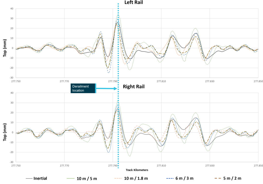
Source: ATSB, generated from ARTC data
The local maxima that occurred near the existing defect location at 277.792 track km were identified for each chord offset approximation. Table B1 presents the maximum value obtained for each rail and the corresponding defect response level based on the limits prescribed in the relevant standard. The defect response level may be different for each rail; when this occurred, the higher response was applied at the location.
Table B1: Summary of maximum value and corresponding response category
| Method | Left (mm) | Left (category) | Right (mm) | Right (category) | Standard |
| Inertial | 25.9 | P2 | 24.3 | P2 | ARTC |
| 10 m / 5 m | 33.7 | A-H | 32.3 | A-H | V/Line[1] Class 2[2] |
| 10 m / 5 m | 33.7 | A-H | 32.3 | A-H | V/Line[1] Class 2M[2] |
| 10 m / 1.8 m | 23.3 | E2 | 20.4 | P1 | AS 7635 / RailCorp[3] |
| 6 m / 3 m[4] | 29.4 | E2 | 28.2 | E2 | RailCorp |
| 5 m / 2 m | 23.3 | E1 | 23 | E1 | AS7635 |
|
|||||
Summary
The method used for categorisation of responses varied between the standards. However, the response actions associated with the categories could be compared. The response categories and actions are listed below:
- The ARTC standard categorised the vertical geometry as P2 level defects on both rails, requiring action in 28 days.
- The V/Line standard (class 2 and 2M) categorised the vertical geometry as class A-H defects for both rails, requiring immediate application of an 80 km/h speed restriction and repair within 7 days.
- The AS 7635 10 m / 1.8 m method categorised the vertical geometry as an E2 defect on the left rail and a P1 defect on the right rail. This required action within 24 hours and 7 days respectively or application of appropriate speed restrictions.
- The RailCorp standard 10 m / 1.8 m method categorised the vertical geometry as an E2 defect on the left rail and a P1 defect on the right rail. This required action within 24 hours and 7 days respectively or application of appropriate speed restrictions.
- The RailCorp standard 6 m / 3 m method categorised the vertical geometry as E2 defects on both rails, requiring action within 24 hours.
- The AS 7635 5 m / 2 m method categorised the vertical geometry as E1 defects on both rails, requiring action or application of appropriate speed restrictions prior to the passage of the next train.
There is difference in the maintenance responses triggered by the same vertical geometry when assessed against the different standards. Assessment against the three chord-based standards (V/Line, RailCorp, and AS 7635) all resulted in a more urgent response than required by the ARTC CoP. Based on the assessment of this defect, the limits prescribed for the CoP permit larger defects than comparable chord-based standards for vertical geometry defects.
Appendix C – Analysis of recorded information
Introduction
Information recorded on the event recorders from the leading locomotive of train 4MC2 and the locomotive of train 8630 was reviewed. The times recorded on both were compared to times recorded for key events recorded by the ARTC signalling system. Corrections were applied to align the recordings.
No correction was applied to the recorded speed or distance. All positions (track km values) were calculated based on the distance from the position that each train stopped relative to Havelock Street level crossing at 279.490 track km.
Table of events
Table C1 below provides contextual events identified from both trains in chronological order.
Table C1: Recorded events in chronological order
| Train | Time | Speed (km/h) | Front of train (track km) | Wagon 26 (track km) | Comment |
| 8630 | 17:29:21 | 0 | 299.350 | Departs Wodonga | |
| 4MC2 | 17:39:41 | 115 | 275.616 | 274.947 | Initial dynamic brake application on approach to the derailment location |
| 4MC2 | 17:40:49 | 116 | 277.800 | 277.131 | Initial dynamic brake release and front of train 4MC2 closest to derailment location |
| 4MC2 | 17:41:02 | 116 | 278.218 | 277.549 | Second dynamic brake application |
| 4MC2 | 17:41:03 | 117 | 278.251 | 277.582 | Maximum speed |
| 4MC2 | 17:41:10 | 116 | 278.478 | 277.809 | Time when wagon 26 is closest to derailment location |
| 4MC2 | 17:41:20 | 111 | 278.797 | 278.128 | Brake pipe pressure reduced from 496 kPa to 489 kPa |
| 4MC2 | 17:41:21 | 112 | 278.829 | 278.160 | Second dynamic brake release |
| 4MC2 | 17:41:27 | 108 | 279.012 | 278.343 | Throttle on |
| 8630 | 17:41:57 | 104 | 280.032 | Brake pipe pressure decrease and brake cylinder pressure increase (likely brake applied by driver of 8630) | |
| 4MC2 | 17:42:03 | 65 | 279.870 | 279.201 | Throttle off |
| 8630 | 17:42:09 | 88 | 279.704 | Power knock‑out switch activates, a likely indication that the brake application was an emergency application | |
| 4MC2 | 17:42:10 | 54 | 279.984 | 279.315 | Locomotive brake pipe pressure decreases (from 475 kPa to 399 kPa within 2 seconds) and cylinder pressure rise (likely brake applied by driver of 4MC2) |
| 4MC2 | 17:42:31 | 0 | 280.143 | 279.474 | 4MC2 stops |
| 8630 | 17:43:09 | 0 | 279.269 | 8630 stops |
Purpose of safety investigationsThe objective of a safety investigation is to enhance transport safety. This is done through:
It is not a function of the ATSB to apportion blame or provide a means for determining liability. At the same time, an investigation report must include factual material of sufficient weight to support the analysis and findings. At all times the ATSB endeavours to balance the use of material that could imply adverse comment with the need to properly explain what happened, and why, in a fair and unbiased manner. The ATSB does not investigate for the purpose of taking administrative, regulatory or criminal action. TerminologyAn explanation of terminology used in ATSB investigation reports is available here. This includes terms such as occurrence, contributing factor, other factor that increased risk, and safety issue. Publishing informationReleased in accordance with section 25 of the Transport Safety Investigation Act 2003 Published by: Australian Transport Safety Bureau © Commonwealth of Australia 2025
Ownership of intellectual property rights in this publication Unless otherwise noted, copyright (and any other intellectual property rights, if any) in this report publication is owned by the Commonwealth of Australia. Creative Commons licence With the exception of the Commonwealth Coat of Arms, ATSB logo, and photos and graphics in which a third party holds copyright, this report is licensed under a Creative Commons Attribution 4.0 International licence. The CC BY 4.0 licence enables you to distribute, remix, adapt, and build upon our material in any medium or format, so long as attribution is given to the Australian Transport Safety Bureau. Copyright in material obtained from other agencies, private individuals or organisations, belongs to those agencies, individuals or organisations. Where you wish to use their material, you will need to contact them directly. |
[1] Track kilometre (track km): refers to the distance along a track from a known location. On the Victorian section of the Interstate Rail Network the 0 km reference is Southern Cross Station in Melbourne.
[2] ARTC, Route access standard, D53 Albury – Somerton, Version 2
[3] The track gradient was 1:137 from about 277.4 track km extending through the derailment area to 278.5 track km. Gradient and curve data from PASS Assets XBC Public Transport Victoria (PTV)
[4] Continuously welded rail (CWR): Rail lengths welded end-to-end into strings greater than 400 m.
[5] ARTC, Engineering (Track & Civil), Code of Practice, Section 2, Sleepers and fastenings, Version 2.0
[6] ARTC, Engineering (Track & Civil), Code of Practice, Section 4, Ballast, Version 2.4
[7] ARTC procedure EGP-10-01 Enterprise Asset Management System contained the definition for these priority codes.
[8] Proprietary measurement system of Vista Instrumentation LLC
[9] ARTC, Engineering (Track & Civil), Code of Practice, Section 5, Track Geometry, Version 2.12
[10] Twist: the change in cross-level (the height difference between two rails) measured over a fixed distance. ARTC specify long (14 m) and short (2 m) twist measurement distances.
[11] The North East Line upgrade was a project undertaken by ARTC to improve the rail line and passenger rail services between Melbourne and Albury. The project was to upgrade the track to a standard consistent with other regional long‑distance rail lines in Victoria.
[12] RISSB AS 7635 Track Geometry – Appendix B (2013)
[13] RailCorp Engineering Manual TMC 203 Track inspection – Chapter 5 (version 5.3 - 2013)
[14] V/Line Network infrastructure standard NIST-2706 – Inspection and assessment: Track geometry. Attachments 2, 3 and 9 (Rev 3 – 2018)
[15] Buckling is the sudden change of shape of an object when a critical load is exceeded. In the case of long slender beams, such as rails, buckling occurs when compressive force exceeds a critical value. For track, buckling is delayed beyond the critical value for the individual rails by the resistance forces exerted by the sleepers and ballast.
[16] By comparison, in jointed track, the expansion and contraction of rail can be observed and simple measurements taken at joints to estimate the stress condition of the rail at temperature extremes.
[17] VERSE is a proprietary device used for non-destructively measuring the stress‑free temperature in rail.
[18] ARTC, Engineering (Track & Civil), Code of Practice, Section 4, Ballast, Version 2.4
[19] ARTC, Engineering (Track & Civil), Code of Practice, Section 4, Ballast, Version 2.4 - Note 2 relating to tables 4.3, 4.4 and 4.5.
[20] ARTC, Engineering (Track & Civil), Code of Practice, Section 6, Track lateral stability Version 2.5
[21] ARTC, Track & Civil, Procedure, ETM-06-08 - Managing track stability, Version 1.2
[22] Pumping sleepers refers to sleepers that move up and down significantly more than intended when trains pass over. In locations where water is present (i.e. where drainage is not sufficient), this action can pump fine soil particles from the formation below up through the ballast to the surface. This is commonly observed where mud holes have formed.
[23] ARTC, Track & Civil, Guideline, ETN-06-01 - Track stability handbook, Version 1.
[24] In-train force: forces propagated longitudinally along a train due to changes in relative speed and acceleration of adjacent locomotives and wagons. These forces occur during braking (run-in or buff), where the rear of the train may compress toward the front, or acceleration (run-out or draft), where the front stretches away from the rear of the train.
[25] The brake pipe pressure was only recorded at the locomotives. It is likely that the brake pipe pressure did reduce sufficiently to apply the brakes in wagons further back in the front section (closer to the parted location).
[26] Gibs are lugs on each end of a bolster which face a mating surface on each side frame. The space between these is a contact area between bolster and side frames that limits lateral movement of the bolster within the bogie side frames and inhibits bogie over-rotation.
[27] The format used describes the chord first and then the offset, which is the distance of the measurement point from one end of the chord. For example: a 5 m / 2 m chord offset uses a 5 m chord, with the measurement point offset from one end of the chord by 2 m.
[28] Note 2, Table 5-11 – Geometry Defects, ARTC Code of Practice, Track Geometry, Section 5, Version 2.12, reviewed 26 July 2019