
Safety summary
What happened
On 11 June 2015, four Rhomberg Rail Australia track machines were travelling in convoy on the Australian Rail Track Corporation Hunter Valley (NSW) corridor between Maitland and Scone. The vehicles travelled coupled in two pairs as train 5M71N.
To allow a passenger train to pass en route, 5M71N was required to leave the Down main line and enter a siding at Singleton. After arriving at Singleton, the Traffic Officer travelling with 5M71N accessed a local control panel to operate a crossover from the down main line to the siding. The points at each end of the crossover appeared to operate but the indication light on the panel did not illuminate to confirm detection of the points in the required position. The Traffic Officer visually inspected the position of the points from a location adjacent the control panel.
As the points appeared to be set, the Traffic Officer concluded there was likely a fault with the indicator light. The Traffic Officer contacted the Australian Rail Track Corporation Network Control Officer for authority to enter the siding but did not mention that the indication lamp had not illuminated.
At about 0823, as the convoy entered the turnout from the main line, the operator on the lead vehicle saw that the swing-nose crossing in the turnout ahead was not in the correct position. The vehicles were travelling at about 15 km/h and the operator was unable to stop before passing over the crossing - derailing the lead vehicle, M395, and the leading axle of the trailing vehicle, M2256. There were no injuries, but the derailed vehicles obstructed the Down main line.
What the ATSB found
The ATSB found that the machine driving the swing-nose crossing on the Down main line turnout had not operated in conjunction with the companion point machines of the crossover. An internal electrical fault likely resulted in the machine failing to move to the required position. As designed, the E Frame local control panel reverse lamp did not illuminate to confirm the correct operation of the crossover.
The Traffic Officer did not notice the swing-nose point machine failed to operate. As the route appeared to be set correctly, the Traffic Officer concluded that the reverse indication lamp on the E Frame local control panel was faulty. The Traffic Officer did not report the lack of a reverse indication to the NCO and a systematic examination of the crossover was not undertaken before advancing the track machines.
The ATSB also found the operating method and indications displayed were unique for both the E Frame field equipment and the control centre. The Australian Rail Track Corporation procedures did not effectively explain the current operational arrangements for this equipment.
What's been done as a result
The Australian Rail Track Corporation (ARTC) issued an Incident Notice, instructing the Network Control Officers not to authorise passing signals at stop for the turnout route if the REV indication or panel light did not display. Additionally, new Network Information Books and revised guidance documentation for the operation of the E Frame panel were developed.
Rhomberg Rail Australia implemented actions to ensure track personnel are familiar with the operation of the E Frame and the implementation of the ARTC Network Rules.
Safety message
Rail safety workers must fully implement and adhere to the applicable network operational procedures in response to any abnormality observed when operating rail infrastructure. Rail infrastructure managers must ensure that operating procedures and instructions for track equipment are maintained and fully representative of the equipment installed.
At about 0648[1] on 11 June 2015, a convoy of four Rhomberg Rail Australia (RRA) track vehicles departed Maitland travelling toward Scone in NSW (Figure 1). The vehicles travelled coupled in pairs as train movement 5M71N. As 5M71N approached Whittingham, the RRA Traffic Officer travelling aboard contacted the ARTC Network Control Officer (NCO) at the Broadmeadow control centre to obtain the next authority to proceed.
Figure 1: Locations Maitland to Scone
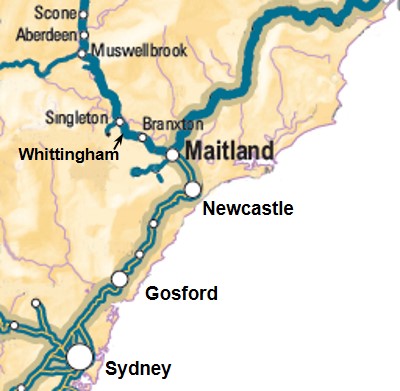
Map showing the rail line taken by 5M71N from Maitland toward Scone. Source: Geoscience Australia annotations by ATSB
The NCO advised that 5M71N was required to leave the Down main line and enter the Down siding at Singleton to allow a passenger train to pass. The NCO then issued a verbal authority (Track Occupancy Authority) for 5M71N to travel from Whittingham to signal 148.9 at Singleton. The NCO also instructed the RRA Traffic Officer to check that all points in the track were set correctly before proceeding over them.
The NCO told the RRA Traffic Officer to enter the siding at Singleton via the ‘E Frame’ at the northern end of the yard, because the ‘B Frame’ was out of service. The NCO remotely operated the ‘release’ for the E Frame control panel to allow the local operation of the crossover by the RRA Traffic Officer following arrival at signal 148.9.
The E Frame control panel operated motorised point machines in the crossover for access to the Down siding. To enable the RRA Traffic Officer to operate the point machines, all vehicles in 5M71N had to pass signal 78. (Figure 2)
Figure 2: Singleton yard simplified track and signal layout
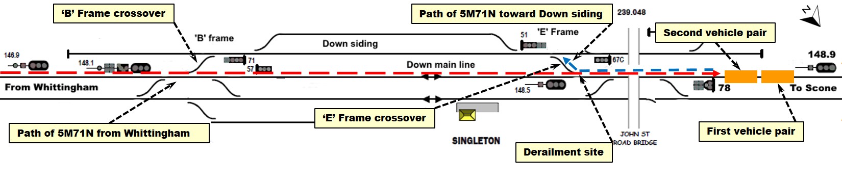
Simplified track layout of Singleton yard showing path of 5M71N. The two pairs of vehicles entered from Whittingham and stopped between signals 78 and 148.9. Once the points in the E Frame crossover were set, the vehicles reversed direction of travel to enter the Down siding via the crossover. Source: Graham Vincent, Track and Signal, annotations by ATSB
After arriving at Singleton, all vehicles in 5M71N stopped clear of 78 signal. The RRA Traffic Officer accessed the E Frame control panel, and as the release was already set, operated the release switch and pushed the points reverse button for access to the siding.
The motorised point machines in the crossover should then move the points to the selected position and the reverse (REV) indication lamp on the panel should illuminate. When illuminated, the reverse indication lamp provides confirmation to the operator that all points had operated correctly.
On this occasion, one of the motorised point machines in the crossover did not move to the reverse position in conjunction with the other machines on the crossover. As designed, the reverse indication lamp on the E Frame panel did not illuminate, indicating a failure had occurred and the points may be in an unsafe condition.
Figure 3: Location E Frame control panel
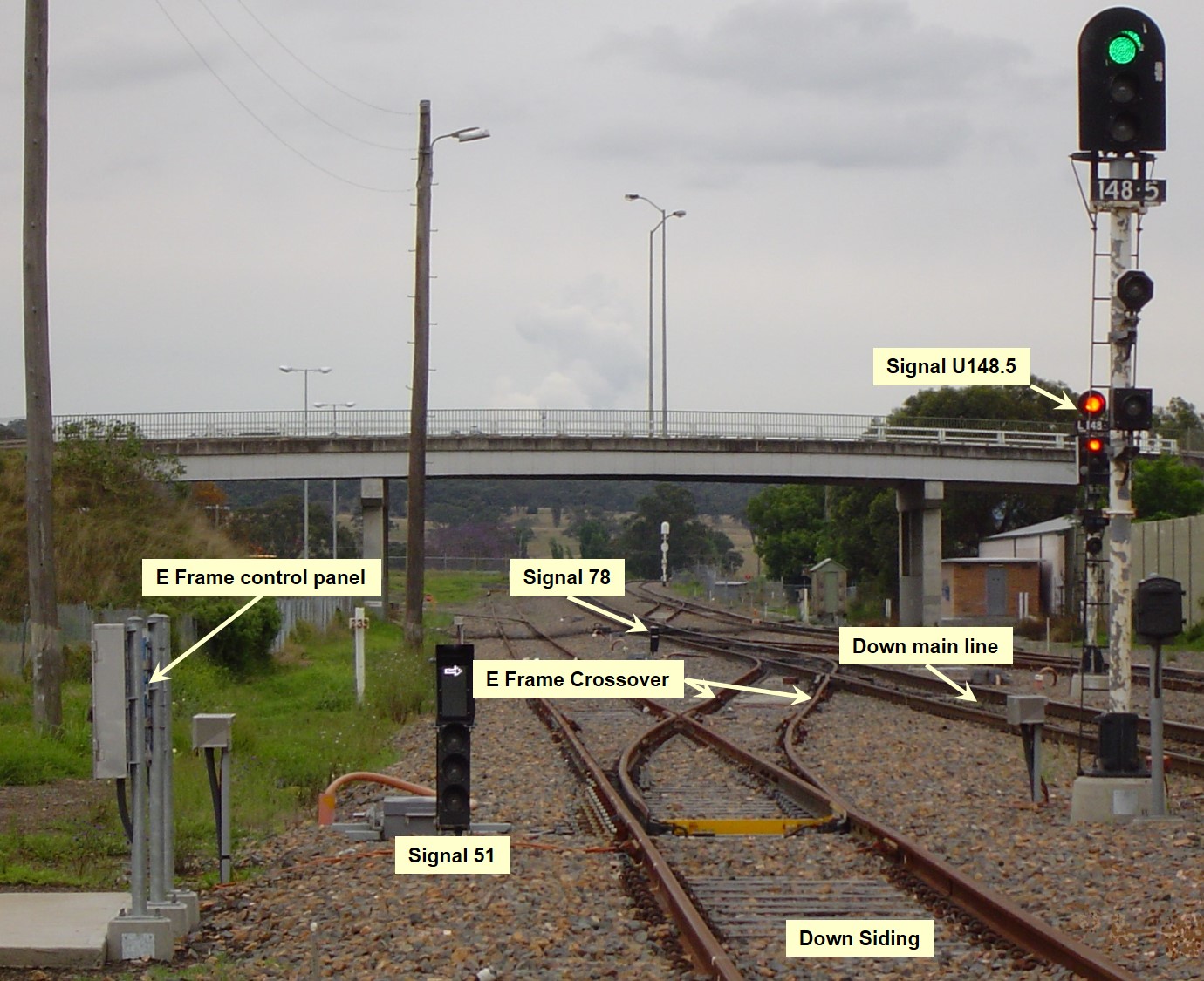
View looking North along the Down Siding toward signal 78 showing position of the E Frame control panel relative to the E Frame crossover. Source: Australian Rail Track Corporation, annotations by ATSB
Responding to the absence of the REV indication, the RRA Traffic Officer visually inspected the orientation of the points from a location adjacent the E Frame control panel (Figure 3).
Perceiving the alignment was correct, the RRA Traffic Officer discussed the indication lamp anomaly with a co-worker travelling with 5M71N. As the points appeared to have operated, they concluded there was likely a fault with the indication lamp and the crossover was correctly set to proceed.
The RRA Traffic Officer did not inspect the lie of each point on the crossover to confirm whether the corresponding machine had operated to the required position and the locking mechanism had engaged correctly.
The RRA Traffic Officer then contacted the NCO for authority to pass signal 78 at stop and enter the siding, but did not mention that the reverse indication lamp had not illuminated. The NCO, unaware of the points failure, provided a ‘signalman’ authority to pass signal 78, which the Traffic Officer subsequently relayed to the operator of the lead vehicle of 5M71N.
At about 0823, as the lead vehicle traversed the turnout from the Down main line the operator saw the swing-nose crossing ahead was not in the correct position. The vehicle was travelling at about 15 km/h but the operator was unable to stop before passing over the swing-nose crossing.
The leading vehicle (M395) and the leading axle of the trailing vehicle (M2256) derailed as they passed over the swing-nose crossing that had failed to operate in conjunction with the other machines in the crossover (Figure 4). The lurching of the vehicles following the derailment impeded the ability of M395’s driver to operate the brake or other controls until the vehicles had stopped. The derailment obstructed the Down main line and resulted in minor damage to the track vehicles. There were no injuries.
Figure 4: Derailed track vehicles M2256 and M395
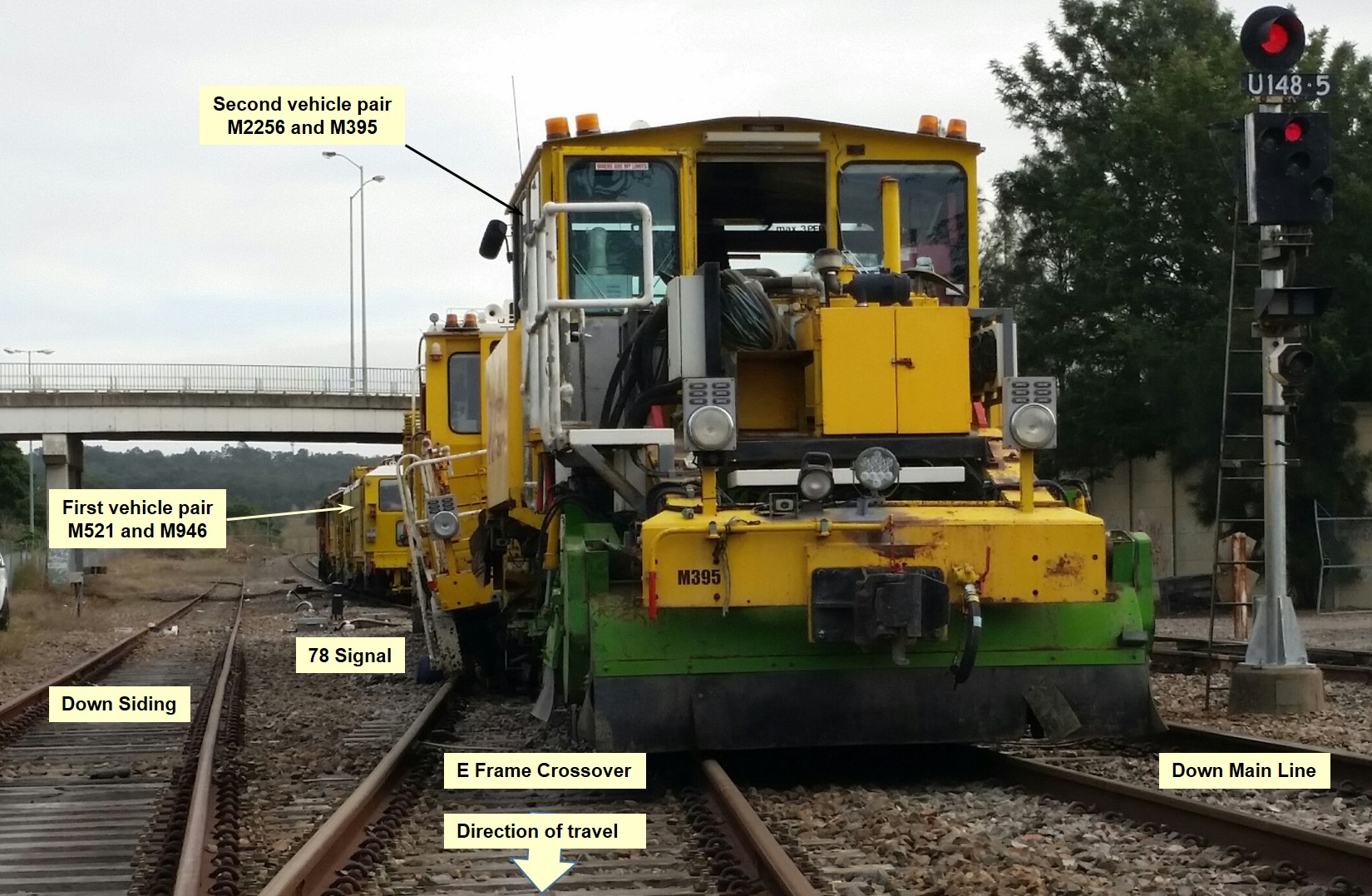
View from the Down Siding of the derailed vehicles on the crossover. The vehicles M2256 and M395 (in foreground) were the first to pass signal 78 for entry into the Down Siding. The vehicles derailed at the swing-nose crossing that is located at the junction of the E Frame Crossover and Down Main Line rails. Source: Australian Rail Track Corporation, annotations by ATSB
Post-incident, ARTC representatives inspected the crossover; finding that it was likely that the motorised machine that was part of the swing-nose crossing in the turnout on the Down main line had failed to properly operate – rendering the points unsafe. At about 1900 that day, the recovery of the derailed track vehicles and repair to the E Frame points was completed.
__________
Location
Singleton is located at the 238.9 km mark[2] on the Australian Rail Track Corporation (ARTC) Hunter Valley corridor in New South Wales. It is about 46.4 track-km from Maitland and 75.8 track-km from Scone. The Down siding at Singleton was accessible via a crossover at either end of the Singleton yard. A Lever Ground Frame and Control panel, designated ‘B Frame’ and ‘E Frame’ respectively, enabled a qualified worker to locally operate the adjacent crossover after obtaining a release from the NCO.
Train 5M71N
The convoy of track vehicles were transferring from Maitland to Scone under ARTC timetable No 046-2015 and designated as train movement 5M71N.
The convoy comprised four track maintenance vehicles coupled in pairs. The first pair consisted of a Plasser SSP–303 Ballast Regulator (M521) and a Plasser Unimat 08-475/4s Tamper (M946). The second pair consisted of a Plasser 09-32 Tamper (M2256) and a Plasser SSP–100 Ballast Regulator (M395). The first pair of vehicles led the convoy when it departed Maitland and up to the limit of its current authority at Singleton. After the convoy stopped, it was required to reverse the direction of travel in preparation to access the Down siding via the E Frame crossover. The second pair then became the lead vehicles of 5M71N.
Traffic Officer
The RRA Traffic Officer travelling in the second pair of vehicles was the qualified worker in charge of movement 5M71N. The RRA Traffic Officer performed the role of Protection Officer, responsible for the co-ordination of all safeworking arrangements for 5M71N with the NCO.
Safeworking arrangements for Train 5M71N
The ARTC Network Rules required that, in track-circuited territory[3], the vehicles of 5M71N were block worked[4] or authorised for travel under a Track Occupation Authority. This was because the track vehicles were not authorised in the ARTC Train Operating Conditions manual as operating track–circuits reliably. In this case, the NCO managed the progress of 5M71N toward Singleton through the issue of a Track Occupation Authority (TOA) for the required section of track, rather than implementing block working or the remote operation of lineside signals as would be the case for authorised rail traffic such as a passenger train.
The NCO issued a TOA up to signal 148.9 in Singleton, advising the Traffic Officer to enter the Down siding via the ‘E’ Frame. This was because the ‘B’ Frame, which was the first access point to the siding in the direction of travel, was temporarily booked out of use under an Infrastructure Booking Authority (IBA). An IBA is used to tell Train Controllers and Signallers [NCOs] that infrastructure equipment is temporarily or permanently removed from service (booked out of use) or installed/returned to service (booked into use).
E Frame crossover
The crossover from the Down main to the Down siding comprised motorised point machines at each end and a motorised swing-nose at the “V” crossing of the turnout on the Down main line. The “V” crossing of the turnout on the Down siding was of a non-movable compound type (Figure 5).
Figure 5: Singleton yard E Frame Crossover
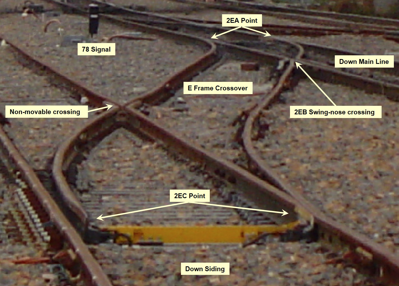
The E Frame Crossover showing 2EA and 2EC points at each end of the crossover and the 2EB swing-nose crossing at the junction of the Down main line and crossover rail. The points illustrated are set for the normal (straight through direction). The vehicle pair (M395 and M2256) derailed at the 2EB swing-nose crossing that did not operate to reverse. Source: Australian Rail Track Corporation, annotations by ATSB
E Frame control panel operation
The operation of E Frame was unique due to its configuration as a ‘ground frame operated by a local control panel’ and the separation of signal and point controls between the Broadmeadow control centre and the local control panel. That is, only local control from E Frame was available for the crossover, and only remote control from the control centre was available for the signal.
Operation of the E Frame required a release from Broadmeadow control centre for the qualified worker to operate a push button to motor the point machines to the reverse position. A light on the control panel (Figure 9) would illuminate to indicate the crossover had operated correctly. The NCO could then give authority to access the Down siding, through the clearance of a fixed signal or other form of authority as required.
A typical local panel configuration provides indicator lights to show that the points are responding to the operation of the point-setting controls and, once operated, are set in the required position. The point indicator lights will also typically display a ‘flashing point transit indicator’ to show that the relevant points are either not in position, the locking not engaged, or the points are in the process of changing position.
The design of the indication lights on the E Frame control panel in this instance, did not include the functionality to display a flashing indication to the operator as the points transitioned. Following selection of the required point-setting control, the corresponding indicator light would extinguish and only illuminate following detection of the points in the correct position. Of note, the panel operation procedure did not document this behaviour.
In this instance, after the Traffic Officer commanded the points to move for access to the Down siding, the reverse light did not illuminate to indicate all motorised machines were in the correct position for safe access the siding. Post-incident, ARTC engineering staff inspected the E Frame and points machines; finding that the E Frame control panel operated correctly but the swing-nose machine did not operate. A motor start capacitor terminal had disconnected in the machine due to a broken mounting plate. While this would have prevented the motor from operating, it could not be conclusively determined if this damage was pre-existing or a consequence of the derailment.
Broadmeadow Phoenix control system
The Phoenix control system at Broadmeadow provided the control and indication functions for the associated signalling infrastructure. The indications provided to the NCO would change dependent on the configuration of the associated field equipment. The screens typically displayed a point (track) indication corresponding to the detected position. The indication would also typically flash to show that the relevant points were not detected in position, the locking not engaged, or the points were changing position.
The segregation of control between Broadmeadow control centre and the local E Frame control panel meant the indications for E Frame points displayed on the Broadmeadow control screens were also unique.
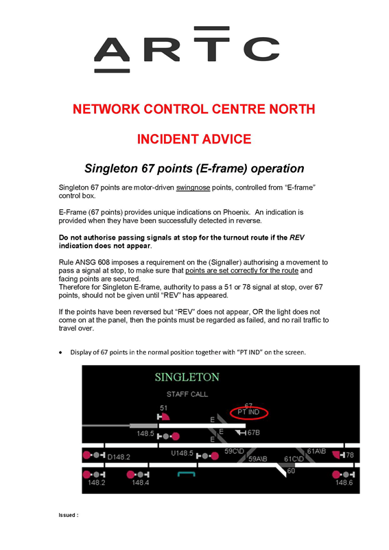
Normally, the track indication for the E Frame points showed them as set for straight-through on the Down main line (Figure 6) and the text ‘PT IND’ was displayed. This indicated to the NCO that the points were set and detected in the normal position.
Figure 6: Phoenix screen extract showing E Frame points detected normal
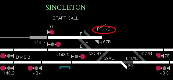
The E Frame indication (circled) seen by the NCO when the E Frame points were in the normal position. The indications of the tracks over the points show as straight through. This corresponds to the position of the E Frame points. Source: Australian Rail Track Corporation
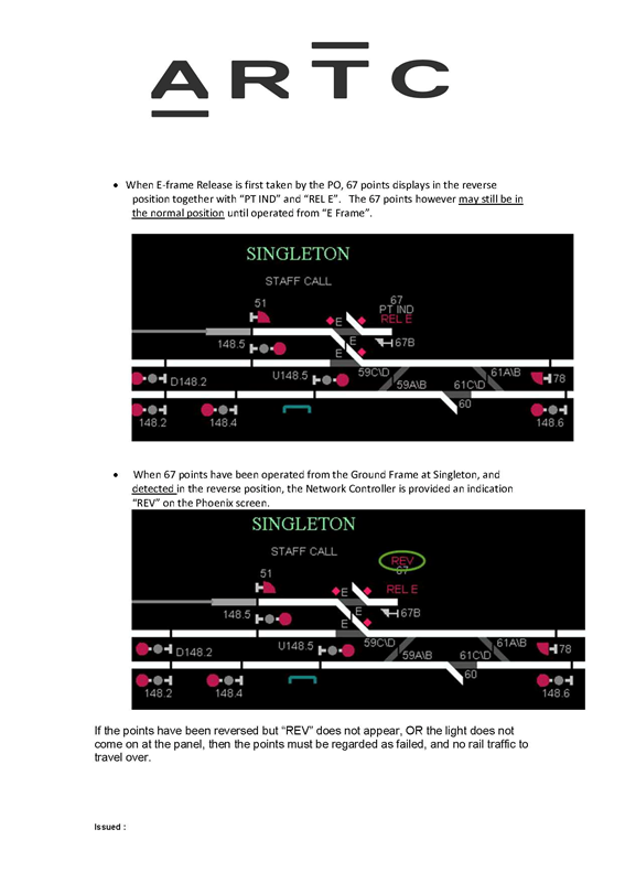
When the NCO provides a ‘release’ for the operation of the E Frame by a qualified worker at Singleton, the track indication for the E Frame points changes to show them released for movement to access the Down siding, and the text ‘REL E’ is displayed (Figure 7). This indicates to the NCO that the points release has been set. Although the Phoenix graphic for the E Frame points was now orientated to represent the points in the reverse position, a qualified worker (at Singleton) may be yet to actually move the points to the reverse position (via the local E Frame panel). That is, when the points release is set, the Phoenix track display graphic at the control centre shows the E Frame crossover in the reverse orientation – regardless of their actual position at Singleton.
Figure 7: Phoenix screen extract showing E Frame released
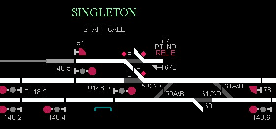
The ‘REL E’ indication displayed to the NCO after setting the control that allows the qualified worker at Singleton to operate the E Frame. The indications of the tracks over the points show as set for the crossover but the E Frame points may still be set as straight through. Source: Australian Rail Track Corporation
After receiving the release, the qualified worker at Singleton could then operate the points reverse pushbutton. The E Frame points should then travel to the reverse position. Once detection for the reverse position was correct, the text ‘PT IND’ was replaced by ‘REV’ on the Phoenix display (Figure 8). This indicated to the NCO that the points had operated correctly and an authority could be issued for vehicle movement to the Down siding.
Figure 8: Phoenix screen extract showing E Frame points detected reverse
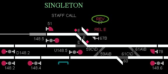
The REV indication (circled) seen by the NCO after detection of E Frame points in reverse following the operation by the qualified worker at Singleton. The E Frame points are set for the crossover. Source: Australian Rail Track Corporation
The indications provided to display to the NCO the orientation of the E Frame points are not consistent with those typically displayed for other points within the Phoenix system. This variability in the representation of point positions may result in the NCO misinterpreting the information presented; increasing the risk of a verbal movement authority being provided before it was safe to do so.
The ARTC published, post-incident, an Incident Advice Notice (Appendix A – ARTC Incident Advice) to the NCO’s at Broadmeadow – clarifying the ‘REV’ indication on the Phoenix display for the Singleton E Frame, and procedures for authorising of a movement to pass a signal at stop.
Authorising rail traffic to pass an absolute signal
The method of E Frame operation at Singleton required the qualified worker onsite to coordinate with the NCO to operate the points, before receiving authority from the NCO to pass a signal. If the NCO used a fixed signal to communicate a proceed authority, the signal interlocking would require detection of the correct points position before allowing the signal to clear. If the NCO provided authority without the use of a fixed signal, the NCO was reliant on visually checking the correct indications displayed on the Broadmeadow control panel (Phoenix display) and the qualified worker confirming the correct operation of the points – before the authority could be issued.
Within yard limits, the ARTC Network Rules[5] stipulate the conditions that track vehicles must be worked. These conditions allow travel on the authority of fixed signals or on the Signaller’s (NCO’s) verbal authority. In this case, fixed signal 78 was not available for use as it was booked out of use due to the extended time following the previous rail movement[6] The NCO therefore gave the RRA Traffic Officer a ‘Signallers’ verbal authority to pass 78 signal.
When providing an authority to pass a signal at stop, drivers or track vehicle operators and signallers use a specific form of words. This is to ensure that drivers and track vehicle operators clearly receive and understand the authority to pass an absolute signal at stop.[7] A review of the voice logs from the Broadmeadow network control centre found that the NCO and RRA Traffic Officer did not implement the required communication protocols during the request or provision of the authority to pass 78 signal. While this instance of compliance with the communication protocol was deficient, it was not a contributing factor in the subsequent derailment of the track vehicles.
__________
- All track distances in this report are referenced from the Sydney Central Station.
- The portions of line where electrical track-circuits are used for the Rail Vehicle Detection system of Safeworking.
- A method of special working which ensures sole occupancy by manually maintaining the block behind a rail traffic movement.
- Australian Rail Track Corporation Network Rules - ANWT 316 Track Vehicles, May 2007 Issue 2 Rev 2
- Australian Rail Track Corporation Network Rules – ANGE 220 Unreliable track-circuit operation, November 2008 Issue 2 Rev 0 - Network Control Officers must treat the operation of track-circuits that have not been travelled over by rail traffic for 72 hours or more as unreliable.
- Australian Rail Track Corporation Network Rules – ANPR 746 Authorising rail traffic to pass an absolute signal at STOP.
E Frame local panel operational procedures
An instruction sheet describing the method of operation for the panel was located within the E Frame’s local control cabinet. This instruction and the local control panel faceplate however, contained various hand written corrections and supplementary advisory instructions for the qualified worker operating the panel (Figure 9).
Figure 9: E Frame local panel faceplate and instruction sheet
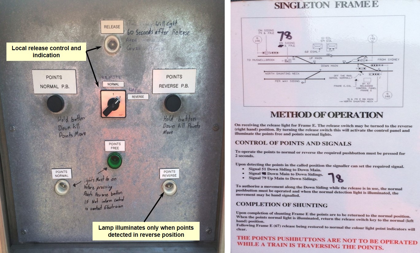
The switches and lamps on the E Frame panel used to set and indicate the position of the E Frame points. Each switch and lamp had a permanent label to identify its function. Users had added additional handwritten instructions to clarify the operation and meaning of the various labels and contents of the instruction sheet. Source: Australian Rail Track Corporation, annotations by ATSB
None of the instructions referred to the unique arrangement for the Points Normal or Points Reverse lamps displaying only a steady indication when the points were set in the required position. The absence of a flashing indication during the transition of the points to the reverse position likely contributed to the Traffic Officers perception that the lack of the Points Reverse indication was due to a lamp fault.
In addition to the sheet affixed to the E Frame, instructions for the operation of rail infrastructure are contained in the ARTC NSW Network Rules & Procedures and the ARTC Local Appendix Units. Neither of these documents contained information that reflected the particular method of operation of the Singleton E Frame. Instruction in the ARTC Local Appendix Units applicable to Singleton referenced a different (redundant) arrangement for the operation of E Frame.
It was evident that, at the time of the derailment, the ARTC had not updated all relevant operating procedures/local appendix units to reflect the unique arrangements for the E Frame local control panel. This departure of the equipment arrangements and operational behaviours from documented procedures, may result in a qualified worker misinterpreting the information presented by the indicator panel lights.
Responding to faulty points
The ARTC Network Rules[8] require a qualified worker to respond to an anomaly in the operation of point machines by reporting the occurrence to the Signaller (NCO). The NCO and qualified worker then coordinate to undertake a systematic inspection of the points to diagnose the fault. If the fault cannot be readily rectified the qualified worker may be instructed to operate the points manually and apply additional mechanical locks to prevent unintended operation.
In this instance, the RRA Traffic Officer discussed the E Frame indication anomaly with co-workers, but did not report the issue to the NCO. The RRA Traffic Officer undertook a brief visual inspection of the points, but did not continue to apply the required procedure for responding to faulty points. Based on the sequence of events in this occurrence, the correct implementation of the ARTC Network Rules may have prevented the subsequent derailment of 5M71N.
Following the derailment, Rhomberg Rail Australia developed the following safety actions to ensure their track personnel correctly implement the ARTC Network Rules:
- Conduct a full review of the Network Rules with all employees
- Develop flow charts to identify the process flow for critical operations of points/transfers.
- Complete a ‘standard setting’ workshop with all Resurfacing employees
- Update Network Rule folders on all the machines
- Create a network rule register
- Recertify employees involved in the incident in their respective highest level of safe working
- Management observation of Network Rule compliance.
Passing signals at stop
The ARTC Network Rules[9] require a Signaller (NCO) to get available information about the condition of the block ahead, using:
- The track indicator diagram
- Records of previous rail traffic movements
- Work on track authority records
- Reports about the location of the last rail traffic to enter the block, or
- The signaller at the other end of the section
In this instance, relevant information was obtainable from indications displayed on the Phoenix screen and the RRA Traffic Officer operating the E Frame at Singleton. Using this information the Network Rule required the NCO, before providing authority to pass a signal at stop, to make sure that the:
- Points are set correctly for the route, and
- Points that are facing points, or become facing points, are secure.
The NCO did not identify the points were correctly set using the indications displayed on the Phoenix screen or confirm with the RRA Traffic Officer that conditions of the track ahead were correct and the points in the crossover secured. Again, the correct implementation of ARTC Network Rules may have prevented the subsequent derailment of 5M71N.
__________
From the evidence available, the following findings are made with respect to the derailment of track vehicles M395 and M2256 at the E Frame swing-nose crossover in Singleton on 11 June 2015. These findings should not be read as apportioning blame or liability to any particular organisation or individual.
Safety issues, or system problems, are highlighted in bold to emphasise their importance. A safety issue is an event or condition that increases safety risk and (a) can reasonably be regarded as having the potential to adversely affect the safety of future operations, and (b) is a characteristic of an organisation or a system, rather than a characteristic of a specific individual, or characteristic of an operating environment at a specific point in time.
Contributing factors
- A swing-nose point machine in the Down main line turnout did not operate to reverse in conjunction with companion point machines of the crossover.
- The point indication functionality on the E Frame local panel was unique, in that it did not include a ‘flashing point transit indicator’ in the absence of reverse detection.
- The Traffic Officer perceived the indicator to be faulty and concluded that all points in the E Frame crossover were set correctly.
- The Traffic Officer did not report the (perceived) faulty point indication to the Network Control Officer.
- The Traffic Officer did not implement existing network procedures for responding to the (perceived) faulty point indication.
- The Network Control Officer did not observe the available Phoenix display information, regarding the condition of the E Frame crossover prior to authorising the passing signal 78 at stop.
Other factors that increased risk
- The ARTC Network Control centre procedures did not address the unique operation of the Singleton E Frame equipment to ensure correct and consistent interpretation of the indications provided on the Phoenix display. [Safety issue]
- The ARTC Local Appendix Unit North – Volume 3 did not reflect current equipment installation arrangements for E Frame at Singleton. [Safety issue]
Other findings
- Local operating instructions and panel for E Frame contained hand-written amendments.
- The Network Control Officer and Traffic Officer did not follow the required Network communication protocols when authorising 5M71N to pass 78 signal at stop.
The safety issues identified during this investigation are listed in the Findings and Safety issues and actions sections of this report. The Australian Transport Safety Bureau (ATSB) expects that all safety issues identified by the investigation should be addressed by the relevant organisation(s). In addressing those issues, the ATSB prefers to encourage relevant organisation(s) to proactively initiate safety action, rather than to issue formal safety recommendations or safety advisory notices.
All of the directly involved parties were provided with a draft report and invited to provide submissions. As part of that process, each organisation was asked to communicate what safety actions, if any, they had carried out or were planning to carry out in relation to each safety issue relevant to their organisation.
The initial public version of these safety issues and actions are repeated separately on the ATSB website to facilitate monitoring by interested parties. Where relevant the safety issues and actions will be updated on the ATSB website as information comes to hand.
Unique indications for E Frame on Network control system screens
The ARTC Network Control centre procedures did not address the unique operation of the Singleton E Frame equipment to ensure correct and consistent interpretation of the indications provided on the Phoenix display.
Rail Safety Issue No: RO-2015-010-SI-01
Local Appendix Unit – North V3
The ARTC Local Appendix Unit North – Volume 3 did not reflect current equipment installation arrangements for E Frame at Singleton.
Rail Safety Issue No: RO-2015-010-SI-02
Sources of information
The sources of information during the investigation included the:
- Australian Rail Track Corporation
- Rhomberg Rail Australia
References
Australian Rail Track Corporation Network Rules & Procedures – NSW
Australian Rail Track Corporation Local Appendices North Volume 3 Maitland to Muswellbrook 10 August 04 Version 1.0
RISSB Glossary of Railway Terminology – Guideline Version 1, December 2010
Rhomberg Rail Australia Incident Investigation report ARTC – Singleton Yard [Draft]
Submissions
Under Part 4, Division 2 (Investigation Reports), Section 26 of the Transport Safety Investigation Act 2003 (the Act), the Australian Transport Safety Bureau (ATSB) may provide a draft report, on a confidential basis, to any person whom the ATSB considers appropriate. Section 26 (1) (a) of the Act allows a person receiving a draft report to make submissions to the ATSB about the draft report.
A draft of this report was provided to the Australian Rail Track Corporation, Rhomberg Rail Australia, the Office of the National Rail Safety Regulator and the relevant crewmembers of 5M71N.
Submissions were received from Australian Rail Track Corporation, Rhomberg Rail Australia, the Office of the National Rail Safety Regulator and one crewmember of 5M71N. The submissions were reviewed and where considered appropriate, the text of the report was amended accordingly.
Appendix A – ARTC Incident Advice
Purpose of safety investigationsThe objective of a safety investigation is to enhance transport safety. This is done through:
It is not a function of the ATSB to apportion blame or provide a means for determining liability. At the same time, an investigation report must include factual material of sufficient weight to support the analysis and findings. At all times the ATSB endeavours to balance the use of material that could imply adverse comment with the need to properly explain what happened, and why, in a fair and unbiased manner. The ATSB does not investigate for the purpose of taking administrative, regulatory or criminal action. TerminologyAn explanation of terminology used in ATSB investigation reports is available here. This includes terms such as occurrence, contributing factor, other factor that increased risk, and safety issue. Publishing informationReleased in accordance with section 25 of the Transport Safety Investigation Act 2003 Published by: Australian Transport Safety Bureau © Commonwealth of Australia 2016
Ownership of intellectual property rights in this publication Unless otherwise noted, copyright (and any other intellectual property rights, if any) in this report publication is owned by the Commonwealth of Australia. Creative Commons licence With the exception of the Coat of Arms, ATSB logo, and photos and graphics in which a third party holds copyright, this publication is licensed under a Creative Commons Attribution 3.0 Australia licence. Creative Commons Attribution 3.0 Australia Licence is a standard form licence agreement that allows you to copy, distribute, transmit and adapt this publication provided that you attribute the work. The ATSB’s preference is that you attribute this publication (and any material sourced from it) using the following wording: Source: Australian Transport Safety Bureau Copyright in material obtained from other agencies, private individuals or organisations, belongs to those agencies, individuals or organisations. Where you wish to use their material, you will need to contact them directly. |