1 FACTUAL INFORMATION
1.1 Sequence of events1
At about 1100 Central Standard Time on 30 May 2004, a Robinson R22 Mariner II helicopter, registered VH-MIB, crashed and caught fire while being operated on a fence inspection flight at Tobermorey Station, NT. The pilot sustained fatal injuries, and the passenger was seriously injured.
The passenger reported that the purpose of the flight was to inspect a fence line bordering the property and then to conduct cattle mustering operations. The helicopter was refuelled to full tanks prior to departure. The weather was fine and sunny, with a slight breeze from the south-east.
The passenger reported that while overflying a section of the fence line about 45 km south of the homestead at 30 to 40 ft above ground level, the pilot initiated a turn back to the left to enable a closer look at a particular section of fence. Part way through the turn there was a loud bang from behind the cabin, followed by "horrendous vibration" and the helicopter immediately began to yaw left and descend. The ground marks showed that the tail rotor blades contacted the ground first and then the forward section of the helicopter's right skid struck the ground, disrupting the front section of the cabin. The helicopter then came to rest on its right side and fire rapidly spread to engulf the cabin area.
The pilot was able to free himself from the helicopter through the broken front section of the cabin, but the passenger experienced difficulty undoing his safety harness and remained trapped. He was eventually able to free himself and joined the pilot at some distance from the wreckage. The passenger reported that he assessed the pilot to be badly injured and directed him to a nearby water hole. The passenger then walked to a water bore approximately 8 km from the accident site, where he met other station personnel. The pilot was deceased when medical assistance arrived at the accident site some hours later.
The passenger reported that he had flown in the helicopter several times. During the last few flights before the accident, and during the accident flight itself, he had detected a vibration that he considered abnormal. The passenger advised the investigation that he had conveyed these concerns to the pilot, who advised that he conducted a good check of the helicopter and was satisfied that there were no problems.
1.2 Wreckage examination
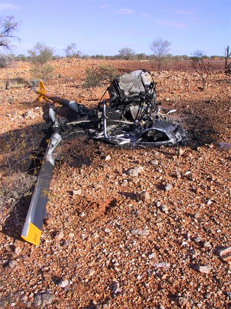
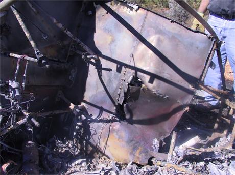
Examination of the wreckage by the Australian Transport Safety Bureau (ATSB) investigation team at the accident site (Figure 1) confirmed that the helicopter was yawing left and moving forward when it struck the ground. The tail rotor blades contacted the ground first. The helicopter then contacted the ground slightly nose down and heavily onto the right skid, causing it to separate from the helicopter. The ground impact marks showed that the helicopter continued to yaw left though about 180 degrees after it struck the ground, before coming to rest on its right side. The majority of the cabin and engine bay, including the entire floor area and cabin structure beneath the pilot and passenger seat positions were destroyed by fire.
Figure 1: Helicopter wreckage (arrow indicates bulkhead deformation behind pilot seat position)
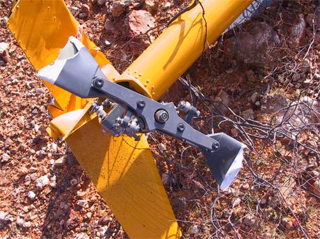
The extent of fire damage meant that a complete examination of the helicopter was not possible. Some aluminium components such as tubing in the flight control system had been destroyed. However, all steel components in the control systems for the main and tail rotor were identified and damage to all of these components was consistent with impact forces or fire. The main rotor blades exhibited damage consistent with low rotor energy at impact. Both tail rotor blades had fractured approximately 1/4 span outboard of the rotor hub centre drive (Figure 2). The failed section of one blade was found adjacent to the main wreckage. The failed section of the other blade was found subsequently about 70 m from the main wreckage. Both blade sections were taken to the ATSB laboratories for further examination.
Figure 2: Tail rotor damage
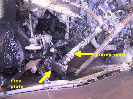
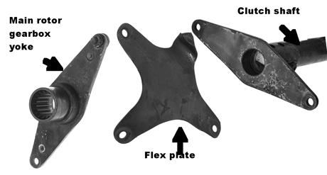
All of the engine drive system components were identified within the wreckage. The flex plate for the forward flexible coupling of the main rotor drive system was fractured at one of the two attachment points to the main rotor gearbox yoke (Figure 3 and 4). The flex plate, including the clutch shaft, were retrieved from the accident site, for further examination. The flex plate for the intermediate flexible coupling was intact and showed evidence of rotational damage consistent with partial drive system power at impact. The rear flex plate and coupling components were also found intact.
Figure 3: Forward flexible coupling as found in wreckage
Figure 4: Components of failed forward flexible coupling
The fuel system and engine ancillaries were destroyed by the fire. There were vertical cuts puncturing the inside wall of the right fuel tank and the horizontal stainless-steel firewall above the engine. The cuts in the right tank and the firewall aligned with the forward flex plate plane of rotation (Figure 5). The left fuel tank was destroyed by fire.
Figure 5: Flex plate puncture of stainless-steel firewall above engine.
1.3 Personnel information
The pilot held a commercial pilot (helicopter) licence and was appropriately endorsed on the R22. He was issued with a private pilot (aeroplane) licence in 1974 and a commercial pilot (helicopter) licence in 1990. The pilot was issued with a commercial pilot (aeroplane) licence in 1995. He held a stock mustering rating and a valid class 1 medical certificate. He completed a flight review in the occurrence helicopter on 19 April 2004. At the time of the accident, the pilot had approximately 10,400 hours aeronautical experience. He flew 31 hours in the occurrence helicopter between 17 and 30 May 2004.
1.4 Medical and pathological information
Postmortem and pathology reports did not indicate that the pilot was suffering from any condition that might have affected his performance during the flight. The most significant injuries sustained by the pilot were the result of impact forces rather than fire.
1.5 Fire
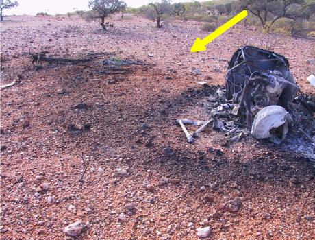
There was a fire affected area (sooting) on the ground that extended up-slope from the wreckage (Figure 6). The sooting formed a swirl pattern of decreasing radius in the direction the helicopter was yawing when it contacted the ground.
Figure 6: Sooting pattern adjacent to wreckage (arrow indicates approximate direction of flight at impact)
1.6 Survival aspects
Three-point lap/sash type safety harnesses were fitted to both seating positions in the helicopter. The passenger reported that both he and the pilot had their harnesses fastened during the flight. Fire damage precluded a detailed assessment of the seats and performance of the crush zones beneath them as well as the seat belt harnesses.
Severe crush damage to the lower cabin bulkhead was evident immediately behind the pilot's seat. (Figure 1).
Following the accident, no Emergency Locator Transmitter signal was received (refer section 1.7.6). There was no mobile telephone coverage in the area and the passenger reported that they did not carry any other communications aids, such as a portable satellite telephone.
1.7 Helicopter information
1.7.1 Helicopter data
The helicopter was manufactured in August 2002 as Serial No 3357M. The most recent maintenance release for the helicopter could not be located. It was reported to have been kept in the helicopter. If so, the maintenance release would have been destroyed in the post-impact fire. Based on other maintenance records and information contained in the pilot's personal diary, the total time in service of the helicopter on 30 May 2004 was estimated to have been 506 hours.
1.7.1 Main and tail rotor drive system
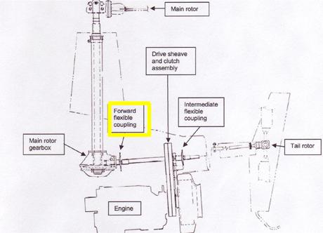
In the R22 helicopter, power to drive the main and tail rotors was transmitted from the engine to the rotor drive train via a multiple Vee belt drive and clutch system. A shaft transmitted power forward from the clutch to the main rotor gearbox and aft to the tail rotor gearbox (Figure 7).
Figure 7: Main components of main and tail rotor drive systems2
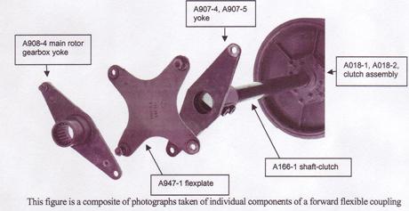
A forward flexible coupling, which includes a flex plate, connected the drive shaft to the main rotor gearbox. The tail rotor drive system also included an intermediate and a rear flexible coupling. Yoke assemblies at the end of each drive shaft section connected the shaft to the flex plate via bolted joints (Figure 8). The purpose of these flex plates was to accommodate small differences in shaft axial alignment during drive shaft rotation. The flex plates and the bolted joints were critical elements in drive system integrity.
Figure 8: Components of the forward flexible coupling
The helicopter manufacturer published procedures for assembling and aligning the drive system components, including the allowed tolerances. The design loads of components could be exceeded if those tolerances were not met.
1.7.3 Helicopter manufacture
The helicopter arrived in Australia partly disassembled for ease of shipment. The main drive system components within the engine compartment were assembled during manufacture and not subsequently disturbed for this method of international shipment.
In order to assist the investigation, the manufacturer supplied the investigation with the itemised build records, which included digital photographs of the rotor drive system, for the occurrence helicopter. Those records were reviewed as part of the laboratory analysis of the flexible coupling failure. The review of the build records and photographs for the forward flexible coupling in the occurrence helicopter showed that NAS6605-6 bolts had been used, and a spacer washer had been included in each bolted joint and one thin washer had been installed under the nut, with a palnut (locking nut) fitted to each. The build records showed that the build-up of the bolted joint at the time of manufacture of the helicopter was correct and in accordance with the assembly procedures.
The 'Daily or Preflight Checks' section 4-2 and 4-3 of the manufacturers Pilot's Operating Handbook identified the requirement for a visual check of the flex coupling to ensure there are 'No cracks and 'Nuts tight'. Also required is a check of the yoke flanges for cracking. It further advised, in part, that 'During the following inspection, check the general condition of the aircraft and also look for any evidence of leakage, discolouration due to heat, dents, chafing, galling, nicks, corrosion and especially for cracks. Also check for fretting at seams where parts are joined together. Fretting of aluminium parts produce a fine black powder, while steel produces a reddish brown or black residue'.
1.7.4 Maintenance history
Maintenance records indicated that an Australian certificate of airworthiness for the helicopter was issued on 11 October 2002, after assembly in Australia, following manufacture and acceptance flights in the US. At that time, the total time in service was 5.1 hours. A summary of subsequent maintenance conducted on the helicopter is as follows. All references to drive system adjustments and/or maintenance have been included.
- 11 March 2003. Total time in service 55.1 hours. 50 hourly engine inspection
- 27 March 2003. Total time in service 98.5 hours. 100 hourly inspection. Maintenance carried out included adjustment of the engine sheave alignment.3
- 30 June 2003. Total time in service 198.2 hours. 100 hourly inspection. Maintenance carried out included checking and adjustment of the engine sheave alignment and intermediate flex plate shimming to within limits.
- 15 September 2003. Total time in service 296 hours. 100 hourly inspection.
- 17 February 2004. Total time in service 384.1 hours. Civil Aviation Safety Authority Airworthiness Directive (AD) R22/51 'Main Rotor Clutch Shaft', dated 12 November 2003, was incorporated. AD/R22/51 was applicable to all R22 helicopters. It required disassembly of the main rotor yoke (A907) to the clutch shaft joint (A166) (see Figure 6) and inspection of the shaft and yoke for damage including fretting4 of bolt holes, cracking in the area of the bolt holes, and the presence of an unapproved jointing compound in the mating surfaces. The helicopter maintenance worksheet indicated that no fretting was evident but that the incorrect jointing compound had been used. The worksheet stated that the AD had been complied with and that the clutch shaft and yoke were reassembled in accordance with the maintenance manual. The worksheet also recorded that a duplicate inspection of the clutch shaft installation and the yoke (A907) assembly had been performed. The licensed aircraft maintenance engineer who carried out the AD reported that he disconnected the yoke (A907) from the forward flex plate, but did not disconnect the flex plate from the main rotor gear box yoke (A908). He stated that he did not perform any maintenance on the bolted joints at the connection between the main rotor gear box yoke and the flexible coupling.
- 27 March 2004. Total time in service 396 hours. 100 hourly inspections. Maintenance carried out included engine sheave alignment.
- 12 May 2004. Total time in service 476.1 hours. 100 hourly inspections.
The documentation showed that maintenance had been performed on 27 March 2003, 30 June 2003, and 17 February 2004 in the vicinity of the forward flexible coupling that, while it did not specifically necessitate bolt removal, provide opportunities for the forward flexible coupling bolts to be disturbed.
1.7.5 Forward flex plate bolted joint component specification
A review of the diagrams contained in the manufacturer's Maintenance Manual and the Illustrated Parts Catalogue (IPC) revealed a difference in the specifications of the parts in the bolted joints. Notes contained within the IPC explained that bolts of different grip lengths and washers of different thickness were to be used in the flex plate bolted joints to expose between two and four threads beyond the end of the nut. A table comparing the different specifications between the Maintenance Manual table and the IPC is provided in section 4.1.3 of the ATSB technical analysis report attached as Appendix 1.
The manufacturer advised that the bolt length identified in the Maintenance Manual was for use in an earlier version of the manual and was out of date. Corrective action to update this information was scheduled by the company for November 2005, but at the time of writing of this report had not been accomplished.
The manufacturer advised that the company did not publish any warning to maintenance organizations about the discrepancy in bolt length between the Maintenance Manual and the Illustrated Parts Catalogue. The discrepancy was not considered by the manufacturer to be critical in that the use of either a NAS6605-5 or a NAS6605-6 bolt with the appropriate combination of spacer and washers would give the correct clamp up for proper joint integrity. In the few cases where the -5 bolt did not allow proper installation of the B330-16 palnut, the problem would be self-evident. The manufacturer believed that any engineer performing the installation where the bolt was too short to install a palnut would install a longer bolt or make inquiries to resolve the problem.
1.7.6 Emergency locator transmitter
The maintenance records indicate that the helicopter was imported from the US and subsequently operated by various owners without a fixed Emergency Locator Transmitter (ELT) unit being fitted. This fact was noted on the maintenance releases issued at 5.1 airframe hours total time in service (TTIS) on 11 October 2002 and 98.5 hours TTIS on 27 May 2003, which required the pilot to observe the requirements of CAR 252 and carry a personal ELT. No further entries of this nature were found on maintenance releases issued after this date, nor could evidence be found in the aircraft logbooks that an ELT had been fitted. A search for both a fixed and personal ELT within the wreckage and surrounding accident site was conducted but nothing was found.
The passenger stated that the pilot normally carried a personal ELT on him. No personal ELT was identified among the pilots clothing or personal effects and no emergency signal was received by AusSAR from that location on the day.
1.8 Specialist examination of the failed components
The forward flex plate and the broken sections of the tail rotor blades were subject to detailed examination by the ATSB. The report on those examinations and analysis of the failures is attached as Appendix 1.
The metallurgical evidence confirmed that the failure mode of both tail rotor blades was very similar and was the result of contact with the ground during the impact sequence. The rocky material embedded in the blade tips provided clear evidence that the blades had struck the ground while rotating. The blade that was found about 70 m from the wreckage was thrown that distance as the result of tail rotor rotational energy.
The specialist examination found that the flex plate in the forward flexible coupling fractured as a result of the propagation of a fatigue crack at one of the bolted connections between the plate and main rotor gearbox yoke. Final fracture of the flex plate occurred during operation and not as a result of the collision with the ground. No crack growth or wear damage was observed at the three remaining boltholes. Examination of the bolt installed at the failure location revealed that extensive fretting wear had occurred around the entire circumference of the bolt, in the region adjacent to the flex plate and the regions adjacent to the reinforcing plates. Fretting wear was also evident on the washer surface adjacent to the bolt head.
The bolted joint at the flex plate failure location was found to have a single thin washer under the bolt head and nut, and no spacer washer between the yoke and flex plate. This spacer and washer combination was different from that specified by the manufacturer for use with a NAS6605-6 bolt.
- Only those investigation areas identified by the headings and subheadings were considered to be relevant to the circumstances of the accident.
- Diagram with permission of Robinson Helicopter Company.
- Drive Vee belts sometimes stretch when new and adjustments are then necessary to maintain the correct drive system alignment. Engine sheave alignment is part of that adjustment process.
- The AD defined major fretting as 'any evidence of the machining marks in any of the bolt holes being partly or fully obliterated'.


