

Final report
Report release date: 29/04/2026
Investigation summary
What happened
On 8 November 2024, a Boeing 737-838 aircraft, registered VH-VYH and operated by Qantas Airways, commenced take-off from runway 34R at Sydney Airport, New South Wales, en route to Brisbane, Queensland. As the aircraft reached V1 – the speed beyond which a take-off should be continued rather than aborted in the event of an emergency – the flight crew heard a loud bang and the right engine failed. Fragments of the engine landed on the grass adjacent to the runway, igniting a grass fire. The flight crew continued with the take-off, declared an emergency and began working through the relevant checklists for the engine failure, planning a return to Sydney Airport.
The crew performed a single-engine landing on runway 34L, 30 minutes after take-off. The Aviation Rescue Fire Fighting Service (ARFFS) inspected the failed right engine for any signs of fire, after which the aircraft was cleared to return to the gate. Passengers then disembarked via standard procedures.
What the ATSB found
Although the emergency occurred at the worst possible moment, the flight crew responded quickly and decisively in continuing the take-off. All parties involved in the emergency worked together effectively, allowing a safe and uneventful return to Sydney Airport.
An engine teardown by the manufacturer revealed that the right engine failed due to a fatigue crack in one of its high-pressure turbine (HPT) blades. The blade was liberated from the HPT disc during take-off, damaging other components in the flow path of the engine and ultimately resulting in a contained engine failure.
The engine had been scheduled for removal on 21 November 2024 due to it nearing the manufacturer’s recommended removal threshold (RRT). Previous engines of this type had experienced failures due to the same kind of fatigue cracking, and the engine manufacturer had previously lowered the RRT to reduce the likelihood of HPT blade liberations in service. Newer HPT blade configurations had also previously been introduced, with improved failure rates.
What has been done as a result
The manufacturer performed an analysis of the engine fleet and found that although there had been several previous blade liberation events due to this kind of fatigue cracking, this engine’s HPT blade configuration (2403M91P02) still met internal reliability targets and relevant regulatory guidelines and rules.
Safety message
This incident provides a positive example of effective training and procedures, highlighting their importance within the aviation safety framework. In this instance, faced with an emergency during a critical phase of flight, the flight crew responded decisively and appropriately in accordance with their training and procedures.
Summary video
The investigation
The occurrence
On the afternoon of 8 November 2024, a Boeing 737-838 aircraft, registered VH-VYH and operated by Qantas Airways, was being prepared for a scheduled passenger air transport operation from Sydney, New South Wales, to Brisbane, Queensland. On board were 2 flight crew, 4 cabin crew and 175 passengers.
At 1234:35 local time, the flight crew began the take-off roll on runway 34R. At 1235:20, at the same time as the first officer (FO) called ‘V1’ to indicate that the aircraft had reached its decision speed (see Take-off reference speeds), a loud bang was heard in the flight deck, accompanied by a shudder through the airframe. The aircraft reached the rotation speed, VR, 3 seconds later, and the captain pulled back on the control column to pitch the aircraft up.
The flight crew immediately identified the engine failure based on caution lights and indications. After lift-off, the captain continued along the runway heading and requested that the FO declare a PAN PAN call[1] when possible. The FO broadcast the call to air traffic control (ATC) 28 seconds after lift-off.
The flight crew then briefly discussed the engine indications they observed, determined that the right engine had experienced severe damage, and began to action the Engine fire, severe damage or separation checklist and commenced planning a return to Sydney Airport. The flight crew then requested an inspection for runway 34R. The controller reported:
…much FOD [foreign object debris], there’s now fire so it looks like there has been an explosion and there are bits all over the runway, so I would suggest the engine is gone.
The flight crew requested a return to Sydney Airport and ATC directed the flight accordingly. The aircraft was slightly over its maximum landing weight due to unspent fuel, and the expected landing distance was higher for a single engine landing. The flight crew therefore planned to land on runway 34L, which was longer than runway 34R (3,962 m vs. 2,438 m). In addition, ATC closed runway 34R, due to fragments from the engine, which ignited a grass fire next to the runway (Figure 1).
Figure 1: Grass fire next to runway 34R
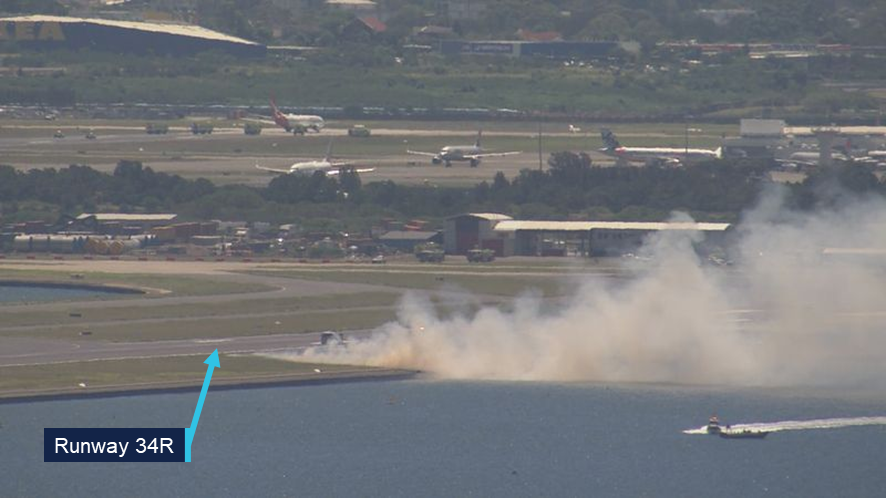
Source: Nine Network Australia, annotated by the ATSB
At 1251, while the aircraft was in a holding pattern at a waypoint south of Sydney Airport, the captain provided a briefing to members of the cabin crew, followed by an announcement to passengers in the cabin, informing them of the situation. Because the right engine could not be clearly seen from the flight deck, the flight crew also requested that the cabin service manager (CSM) have an off-duty pilot on board the flight photograph the right engine. Based on the photograph, the flight crew determined that the engine failure was likely contained,[2] and the FO could not see any damage to the aircraft’s right wing.
At 1301, once the relevant checklists were completed, the flight crew advised ATC that they were ready to commence the approach. ATC subsequently cleared the aircraft for landing on runway 34L, and the aircraft landed safely at 1305:50. The aircraft was cleared to roll through to the end of the runway where it could be inspected by the Aviation Rescue Fire Fighting Service (ARFFS) personnel. When ARFFS was confident that there was no risk of fire from the engine, the aircraft was clear to return to the gate, where passengers disembarked via standard procedures.
The failed right engine was inspected for damage by Qantas engineering personnel. Examination of the engine confirmed that the engine failure was contained. Borescope imagery found that 2 high-pressure turbine (HPT) blades had undergone a below‑platform separation from the HPT disc (Figure 2).
The engine was removed from the aircraft and sent to the engine manufacturer, CFM International, for further examination. The ATSB did not attend either of these examinations.
Figure 2: Below-platform separation of 2 HPT blades
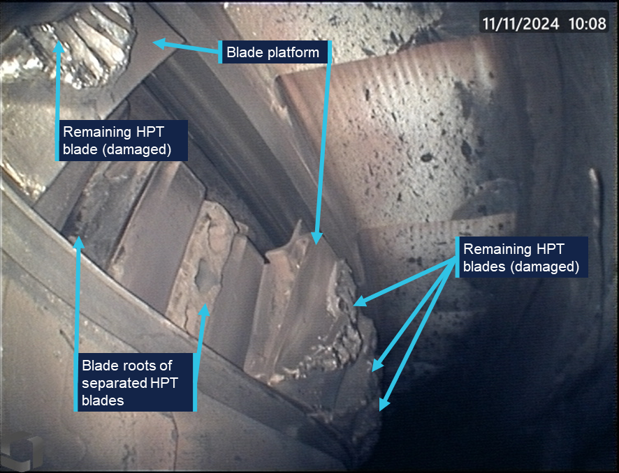
Source: Qantas Airways, annotated by the ATSB
Context
Pilot information
The captain held an Air Transport Pilot (Aeroplane) Licence, a current class 1 aviation medical certificate, and had accrued 17,554 hours of aeronautical experience. Of this, about 4,578 hours were on the Boeing 737, including 251 hours in the previous 90 days.
The FO held an Air Transport Pilot (Aeroplane) Licence, a current class 1 aviation medical certificate, and had accrued 14,809 hours of aeronautical experience. Of this, about 3,832 hours were on the Boeing 737, including 216 hours in the previous 90 days.
The captain’s most recent simulator training was in June 2024. The captain was assessed as proficient at the manoeuvre ‘Engine out between V1 & V2’. This manoeuvre simulated an engine failure after the decision speed was reached, but before the aircraft attained the speed required to climb on one engine. The first officer was marked proficient at the same procedure during simulator training in October 2024.
Aircraft and engine information
VH-VYH was a Boeing Company 737-838 aircraft, powered by 2 CFM56-7B24E high bypass turbofan engines. The engine is a dual-rotor, axial-flow turbofan. A cross-section of the engine is illustrated in Figure 3.
Figure 3: CFM56-7B engine cross-section
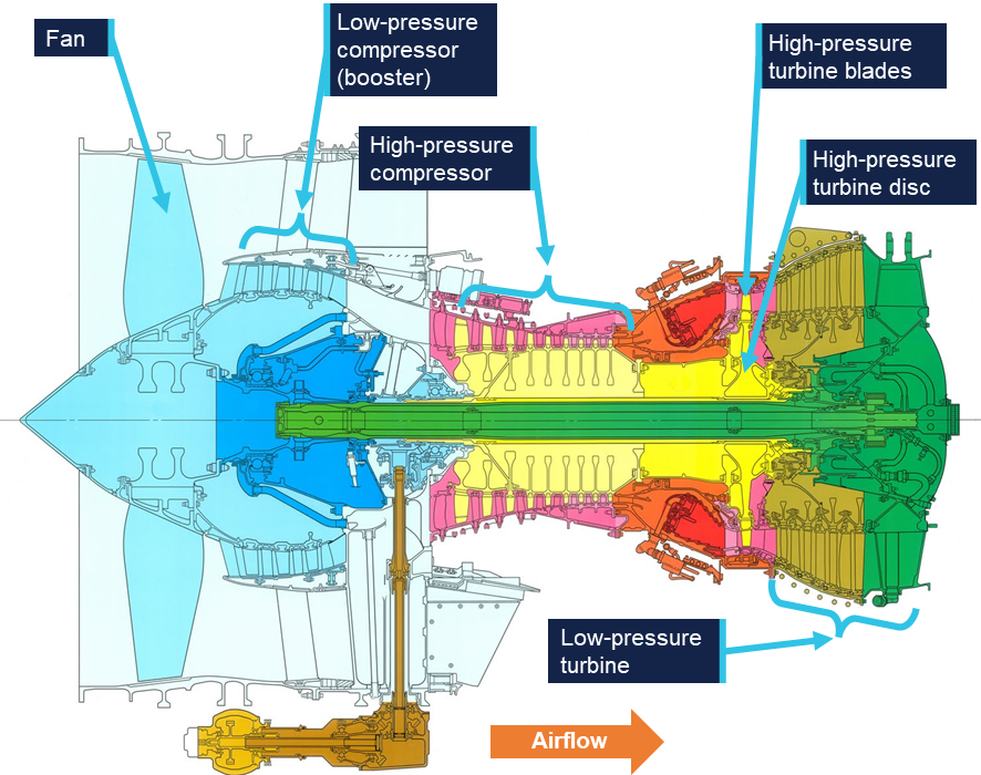
Source: CFM International, annotated by the ATSB
One rotor consisted of a 9-stage high-pressure compressor driven by a single‑stage high‑pressure turbine (HPT), highlighted in Figure 4. The other rotor consisted of a 3‑stage low‑pressure compressor and fan, driven by a 4‑stage low‑pressure turbine.
Figure 4: Cutaway model of a CFM56 engine
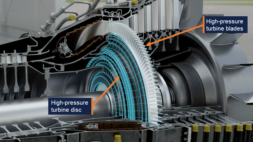
Source: ATSB
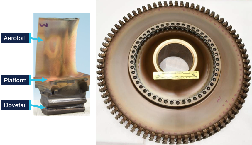
The HPT was made up of 76 turbine blades, each consisting of an aerofoil, platform and dovetail (photographs of an exemplar blade and disc are shown in Figure 5). The dovetail of each blade was secured within the HPT disc, making the platform a continuous surface around the HPT’s circumference, with the blades radiating outward. Various iterations of HPT blade were used throughout the global fleet of CFM56-7B engines due to updated blade designs. VH-VYH’s failed right engine was fitted with the 2403M91P02 configuration of HPT blades.
Figure 5: CFM56-7B HPT blade (left) and disc (right)
Source: CFM International, annotated by the ATSB
Aircraft maintenance
The most recent maintenance release for VH-VYH was issued on 7 November 2024. There were no issues listed, unresolved or otherwise, relating to operation of the right engine.
The area around the HPT was last inspected via borescope on 25 September 2024. This inspection included the combustion chamber, HPT blades and adjacent nozzle guide vanes. There were no significant findings, although it is important to note that these borescope inspections were not capable of examining below-platform areas of the blades, which could only be inspected when they were removed from the disc. This required removal of the engine’s core and disassembly of the HPT system. For this engine, HPT disassembly would only be expected to occur when HPT blades were due for replacement.
The right engine had completed 17,656 flight cycles, and the HPT blades were original to the engine. The engine was scheduled to be removed from the aircraft on 21 November 2024 due to a service bulletin (SB 72-1082) issued by the manufacturer in April 2023 which imposed a recommended removal threshold (RRT) of 17,900 cycles on this engine’s blade configuration (2403M91P02).
Engine examination
An engine teardown inspection was conducted by CFM International at its technical facility in Malaysia. This was a multi-day process, with the ATSB remotely evaluating the inspection progress and observations. The examination confirmed that 2 of the 76 HPT blades had been liberated due to below-platform fractures in the dovetails. All of the remaining HPT blades had fractured at the base of the aerofoil, above the blade platform. Damage was also observed on components elsewhere in the engine, almost all found to be consequent to the HPT blade failures. The exception was evidence of birdstrike observed on the fan and low‑pressure compressor. However, there was no evidence to indicate that the bird ingestion was relevant to the HPT blade separation.
CFM International conducted further metallurgic examination on the HPT blades and disc. Evidence of fatigue cracking was found in 28 blades, originating in the region described as the ‘min-neck’ of the blade dovetails. This was the area on the blade where the dovetail cross-section was at its thinnest point. The fatigue cracks originated on the ‘convex side’ of the blade, which is the face visible in Figure 5.
Blade number 50 was one of the 2 blades that experienced a below-platform failure. It exhibited the most extensive fatigue cracking. Conversely, the other blade with a below‑platform failure, blade 51, exhibited no evidence of fatigue, failing purely due to tensile overstress. The manufacturer noted that there had been previous occurrences involving a below‑platform fatigue failure where the adjacent blade failed in the dovetail due to tensile overstress resulting from contact with the liberated blade. The remaining 74 blades failed due to overstress fractures at the base of each aerofoil.
The fracture morphology of blade number 50 was examined to determine how the cracking progressed. The dovetail recovered from the HPT disc is shown in Figure 6.
Figure 6: Dovetail of blade 50 recovered from the HPT disc
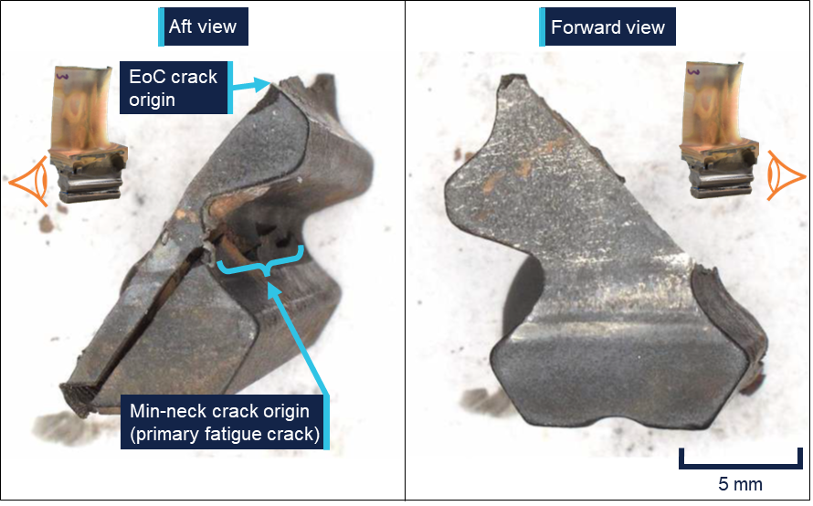
The edge-of-contact (EoC) crack originated where the blade made contact with the HPT disc during normal operation. The min-neck crack originated where the dovetail’s cross‑section was at its thinnest. Source: CFM International, annotated by the ATSB
There were 2 fatigue cracks observed, propagating in a diagonally downward direction on parallel planes. These cracks initiated with small regions of low-cycle fatigue[3] (LCF) which transitioned to a larger high-cycle fatigue[4] (HCF) region. One crack originated at what the manufacturer described as the ‘edge-of-contact’ or ‘EoC’, where the blade contacted the HPT disc during normal operation. This crack propagated through approximately 70% of the dovetail cross-section. This resulted in an overstress failure of the remaining 30%, liberating the top section of the blade, including the platform and aerofoil, from the HPT disc. The edge‑of‑contact fracture as viewed from the concave side of the blade is shown in Figure 7.
Figure 7: Concave view of the edge-of-contact fracture surface
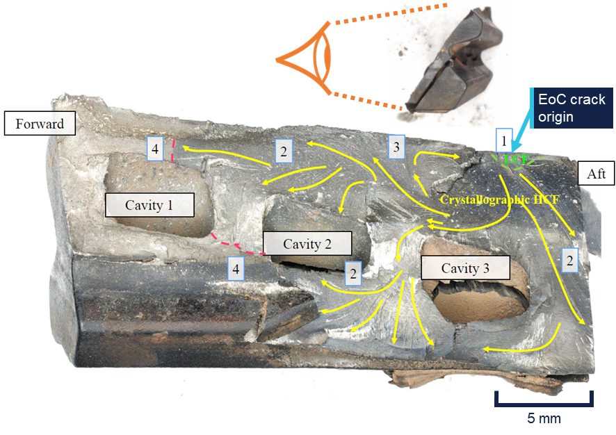
From the crack origin, LCF cracking propagated to the green dashed line. The fracture morphology then transitioned to HCF, which propagated along crystal planes within the material until it reached the red dashed lines. The remaining material then failed in overstress, resulting in the top section of the blade becoming liberated form the HPT disc. Source: CFM International, modified by the ATSB
The other crack originated in the min-neck region of the dovetail. This crack propagated through approximately 80% of the dovetail’s cross-section. The remaining cross-section was still intact when the blade separated. As part of the manufacturer’s examination, the remaining material was fractured in the laboratory, and the crack opened for inspection (Figure 8).
Figure 8: Convex view of the min-neck fracture surface
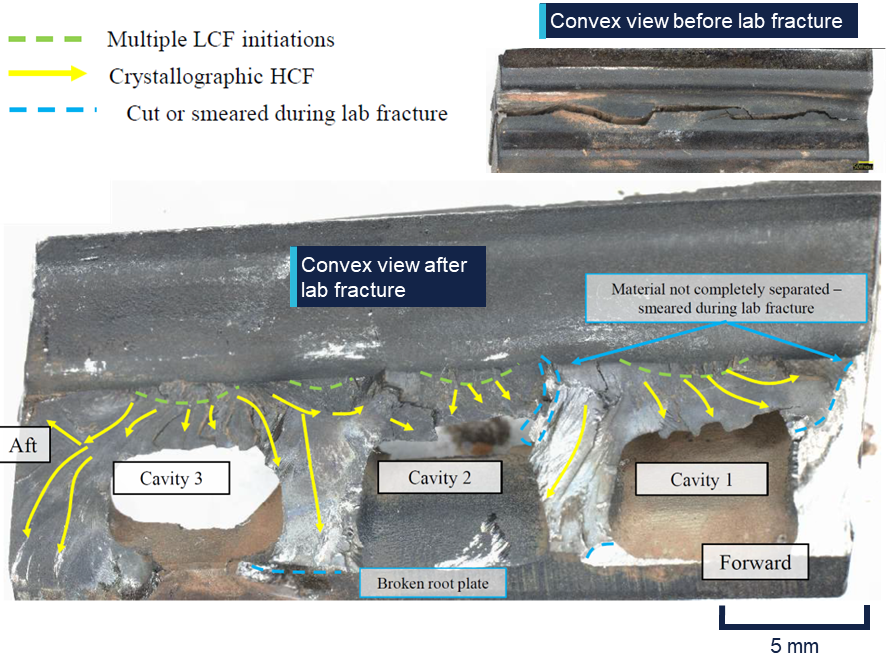
Multiple crack origins were observed, from which LCF propagated in small thumbnails. These fatigue cracks transitioned to HCF travelling along crystal planes within the material, consuming approximately 80% of the dovetail’s cross-section. Source: CFM International, annotated by the ATSB
The manufacturer’s analysis found that the min-neck cracking observed in blade 50 was the primary fracture within the blade. As the cracking propagated downward through the blade, tensile forces from disc rotation could no longer be effectively transmitted to the bottom half of the dovetail. Consequently, excessive force was placed on the top half, resulting in the propagation of the edge-of-contact crack and eventual separation of the blade.
HPT service performance
The failure mechanism in this occurrence (a min-neck fatigue crack and subsequent below platform liberation of an HPT blade) had been observed in other engine failures within the CFM56-7B fleet. At the time of writing, there were 86 events reported to the manufacturer over the course of 115 million flight hours. The majority of these engine failures occurred in 2403M91P02 and 2403M91P03 blade configurations.
CFM International’s fleet analysis found that accounting for all failures including min-neck cracks, these blade configurations remained within internal fleet reliability targets and were well within regulatory limits and guidance, including the continued operational safety guidance described by the US Federal Aviation Administration, as well as an Acceptable Means of Compliance outlined by the European Aviation Safety Agency.
Because below-platform cracks could not be inspected without complete disassembly of the engine, the manufacturer’s primary method for reducing below-platform separations was by imposing recommended removal thresholds (RRTs) on blade configurations susceptible to min-neck cracking. The purpose of the service bulletin issued in April 2023 was to mitigate the risk of HPT blade failure by reducing the RRT from 20,000 cycles to 17,900 cycles for 2403M91P02 and 2403M91P03 blade configurations.
In March 2025, as a result of its ongoing reliability monitoring, the engine manufacturer published a revised RRT for 2403M91P03 blade configurations, reducing it to 17,200 cycles. The 2403M91P02 fleet reliability was found to be consistent with existing reliability targets and was not adjusted. The more recent 2403M91P06 blade design included an adjusted dovetail geometry in order to reduce instances of min-neck fatigue cracking.
Take-off reference speeds
Take-off reference speeds, commonly referred to as V speeds, are provided by aircraft manufacturers to assist pilots in determining when a rejected take-off should be initiated, and when the aircraft can rotate, lift-off and climb away safely given the existing flight conditions. They are defined as follows:
- V1: Decision speed – the maximum speed at which a rejected take-off can be initiated. In the event of an engine failure below V1, there is enough remaining runway distance for the aircraft to stop safely, and the take-off should be aborted. Conversely, if an engine failure occurs after V1 is reached, the take-off should be continued. It can be said that V1 is the ‘commit to fly’ speed. It is calculated for every take-off as it is based on aircraft available thrust, aircraft weight, flap setting, runway length and slope, wind conditions, and airport density altitude.
- VR: Rotation speed – the speed at which the aircraft rotation is initiated by the pilot. This speed ensures that, in the event of an engine failure, lift-off is achievable and the take‑off safety speed (V2) is reached at no higher than 35 ft above ground level.
- V2: Take-off safety speed – the minimum speed at which the aircraft complies with the handling criteria associated with climb following an engine failure. V2 is normally obtained by factoring the stalling speed or minimum control (airborne) speed, whichever is the greater, to provide a safe margin.
Safety analysis
Engine failure
During the take-off roll, one of the right engine’s HPT blades was liberated from the HPT disc due to pre-existing fatigue cracks in the blade’s dovetail. This region was prone to fatigue cracking in the 2403M91P02 blade configuration. The HPT blades had been scheduled to be removed from the engine 13 days later, in accordance with a service bulletin that was intended to reduce instances of such blade liberations. Due to contact with the liberated blade, the adjacent blade 51 failed through the dovetail and was also liberated from the disc.
The 2 liberated blades were thrown into the engine shroud and likely made contact with adjacent HPT blades still fitted in the rotating disc. As a result of this contact, all of the remaining 74 blades experienced overstress failure through their aerofoils, liberating additional blade fragments from the HPT disc.
The liberated blades and other debris then travelled rearward through the low-pressure turbine and were ejected out the rear of the engine. With no torque being produced by the HPT, and debris obstructing and damaging the low-pressure turbine, the right engine failed. The flight crew observed a single loud bang and a shudder, indicating that the liberation of all HPT blades and subsequent engine failure occurred extremely rapidly.
Given the location of the blade failure, it is likely that there was no opportunity to detect the crack during the engine’s lifespan. The removal thresholds put in place by the engine manufacturer, CFM International, did not completely prevent blade liberation events. Nevertheless, the manufacturer’s fleetwide analysis found that the CFM56-7B fleet remained within its defined reliability targets as well as airworthiness guidelines set by relevant regulators.
Flight crew response
The decision speed, V1, is the critical point between a take-off that should be aborted and one that should be continued. This is the worst possible time for a multi-engine aircraft to experience an engine failure during take-off, because safety margins are at a minimum whether the take-off is aborted (minimum remaining runway distance available) or continued (minimum airspeed available). When the engine failure occurred, the aircraft had reached V1, meaning any attempt to abort the take-off would have occurred beyond the point when it was safe to do so.
Confronted with this situation, the flight crew responded quickly and decisively in continuing the take-off, declaring an emergency, identifying the problem and then working through the appropriate procedures. The flight crew, cabin crew, ATC and ARFFS all worked together effectively to enable the aircraft’s safe return to Sydney Airport.
Findings
ATSB investigation report findings focus on safety factors (that is, events and conditions that increase risk). Safety factors include ‘contributing factors’ and ‘other factors that increased risk’ (that is, factors that did not meet the definition of a contributing factor for this occurrence but were still considered important to include in the report for the purpose of increasing awareness and enhancing safety). In addition ‘other findings’ may be included to provide important information about topics other than safety factors. These findings should not be read as apportioning blame or liability to any particular organisation or individual. |
From the evidence available, the following findings are made with respect to the engine failure involving Boeing 737, VH-VYH, at Sydney Airport, New South Wales, on 8 November 2024.
Contributing factors
- During take-off, a high-pressure turbine blade failed due to a fatigue crack that had developed prior to the flight, and the blade was liberated from the high-pressure turbine disc. Engine damage from the liberated blade resulted in a contained engine failure.
Other findings
- The flight crew responded quickly and appropriately to an engine failure at V1, a critical time during take-off.
Safety actions
Safety action from CFM International
Based on the number of previous engine events involving min-neck fatigue cracking of high‑pressure turbine blades, and projected events in future, CFM International reviewed its recommended removal thresholds for HPT blades on CFM56-7B engines. The review found that 2403M91P02 blade configurations were not projected to exceed reliability targets and so thresholds were not adjusted.
Sources and submissions
Sources of information
The sources of information during the investigation included:
- flight crew
- cabin crew
- Airservices Australia
- Qantas Airways
- CFM International
- The Boeing Company
- Civil Aviation Safety Authority
- recorded data from the aircraft.
Submissions
Under section 26 of the Transport Safety Investigation Act 2003, the ATSB may provide a draft report, on a confidential basis, to any person whom the ATSB considers appropriate. That section allows a person receiving a draft report to make submissions to the ATSB about the draft report.
A draft of this report was provided to the following directly involved parties:
- flight crew
- Airservices Australia
- Qantas Airways
- CFM International
- Civil Aviation Safety Authority.
Submissions were received from:
- Qantas Airways
- CFM International.
The submissions were reviewed and, where considered appropriate, the text of the report was amended accordingly.
Purpose of safety investigationsThe objective of a safety investigation is to enhance transport safety. This is done through:
It is not a function of the ATSB to apportion blame or provide a means for determining liability. At the same time, an investigation report must include factual material of sufficient weight to support the analysis and findings. At all times the ATSB endeavours to balance the use of material that could imply adverse comment with the need to properly explain what happened, and why, in a fair and unbiased manner. The ATSB does not investigate for the purpose of taking administrative, regulatory or criminal action. About ATSB reportsATSB investigation reports are organised with regard to international standards or instruments, as applicable, and with ATSB procedures and guidelines. Reports must include factual material of sufficient weight to support the analysis and findings. At all times the ATSB endeavours to balance the use of material that could imply adverse comment with the need to properly explain what happened, and why, in a fair and unbiased manner. An explanation of terminology used in ATSB investigation reports is available here. This includes terms such as occurrence, contributing factor, other factor that increased risk, and safety issue. Publishing informationReleased in accordance with section 25 of the Transport Safety Investigation Act 2003 Published by: Australian Transport Safety Bureau © Commonwealth of Australia 2026 
Ownership of intellectual property rights in this publication Unless otherwise noted, copyright (and any other intellectual property rights, if any) in this report publication is owned by the Commonwealth of Australia. Creative Commons licence With the exception of the Commonwealth Coat of Arms, ATSB logo, and photos and graphics in which a third party holds copyright, this report is licensed under a Creative Commons Attribution 4.0 International licence. The CC BY 4.0 licence enables you to distribute, remix, adapt, and build upon our material in any medium or format, so long as attribution is given to the Australian Transport Safety Bureau. Copyright in material obtained from other agencies, private individuals or organisations, belongs to those agencies, individuals or organisations. Where you wish to use their material, you will need to contact them directly. |
[1] PAN PAN: an internationally recognised radio call announcing an urgency condition which concerns the safety of an aircraft or its occupants but where the flight crew does not require immediate assistance.
[2] A contained engine failure is one in which components within the engine might separate but either remain in the engine’s cases or exit the engine with comparatively low energy through the tailpipe.
[3] Low-cycle fatigue cracking is associated with cyclic loading of a magnitude that produce elastic strain as well as plastic strain during each cycle. Fracture due to low-cycle fatigue is typically fewer than 10,000 cycles.
[4] High-cycle fatigue cracking is associated with cyclic loading of a magnitude that produces deformation that is primarily elastic. Fracture due to high-cycle fatigue is typically greater than 10,000 cycles.
Occurrence summary
| Investigation number | AO-2024-057 |
|---|---|
| Occurrence date | 08/11/2024 |
| Occurrence time and timezone | 1235 EDT |
| Location | Sydney Airport |
| State | New South Wales |
| Report status | Final |
| Investigation level | Short |
| Investigation type | Occurrence Investigation |
| Investigation phase | Final report: Dissemination |
| Investigation status | Completed |
| Mode of transport | Aviation |
| Aviation occurrence category | Diversion/return, Engine failure or malfunction |
| Occurrence class | Serious Incident |
| Highest injury level | None |
Aircraft details
| Manufacturer | The Boeing Company |
|---|---|
| Model | 737-838 |
| Registration | VH-VYH |
| Serial number | 34180 |
| Aircraft operator | Qantas Airways Limited |
| Sector | Jet |
| Operation type | Part 121 Air transport operations - larger aeroplanes |
| Activity | Commercial air transport-Scheduled-Domestic |
| Departure point | Sydney Airport, New South Wales |
| Destination | Brisbane Airport, Queensland |
| Injuries | None |
| Damage | Minor |