Safety summary
What happened
On 5 November 2018, train M02712, loaded with iron ore, was being operated by BHP on its Newman to Port Hedland railway, Western Australia. The train consisted of 2 locomotives, a rake of 134 wagons, 2 remote locomotives and a second rake of 134 wagons. It was fitted with an electronically controlled pneumatic braking (ECPB) overlay system.
At about 0337, M02712 was travelling at 60 km/h on a downhill grade on the west track, approaching the BHP access road level crossing at the 211.6 km mark. Shortly after, trainline communication between the lead locomotive and the combined end of train monitor was lost, triggering an automated 120% ECPB emergency brake command, stopping the train as it approached Garden South.
Following confirmation with train control of the location of the train and receiving instruction on the number of handbrakes required to secure the loaded train on the falling track grade at Garden, the driver left the locomotive cab to commence applying the brakes from the front of the train. The controller also tasked a support team to attend M02712 and help the driver with applying the handbrakes.
About 60 minutes after the loss of trainline communication, as the driver continued to apply handbrakes to the first rake of ore cars, the train began to move forward. Shortly after, train control received an emergency call from the driver of M02712 alerting that the brakes had ‘bled off’ and the train was now a ‘runaway’.
Train M02712 continued, reaching a speed of 162 km/h before slowing on the rising grades toward Woodstock. After Woodstock, the track grade again began to fall toward Port Hedland and M02712 gained speed to about 130 km/h approaching Abydos.
At about 0520, Hedland control set the crossovers at Turner South and Turner North to switch train M02712 between adjacent tracks to derail the train as it traversed the crossover at speed. About 6 minutes later, the head end locomotives travelling at 144 km/h traversed the crossover at the 119.4 km mark at Turner South.
The locomotives and the first ore car separated from the rest of the train but remained coupled, travelling about 1.6 km further before stopping. The derailment destroyed the 2 remote locomotives, 245 ore cars and 2 km of track infrastructure at Turner South. There was no injury to any person from the runaway or derailment.
What the ATSB found
Between 2011 and 2015, BHP implemented an ECPB system as an overlay to the conventional pneumatic train braking system and undertook an associated modification to the automatic train protection (ATP) system. It predominantly managed the implementation of these changes at an individual system level rather than through the application of a structured engineering approach. BHP did not subsequently identify and manage significant characteristics of how the ECPB, ATP and conventional pneumatic braking systems interacted in response to certain fault conditions. As a result, BHP’s trains configured for ECPB operation were potentially vulnerable to a runaway event should a unique combination of events and conditions occur.
The BHP risk assessment associated with a rail-mounted equipment interaction incident was broad in scope and had limited focus on the causes and critical controls of a train runaway event. In addition, the risk assessment did not include the procedure for responding to brake pipe emergencies and penalties as a critical control. BHP’s material risk control assessments (MRCAs) did not then test the effectiveness of this procedural control for preventing an uncommanded movement of a train during main line operations.
The procedure for responding to brake pipe emergencies and penalties relied extensively on a driver’s memory, with limited processes in place to facilitate or cross-check a driver’s performance to ensure all safety-critical actions were completed. Although the procedure contained a safety-critical action (to apply the automatic brake handle to the pneumatic emergency position), BHP did not clearly communicate the importance and reasons for this action to drivers, reducing the potential for the drivers to correctly recall this action
As M02712 approached Garden on 5 November 2018, one of the 12 trial inter-car connectors disconnected. This caused a loss of ECPB trainline communication and power supply continuity affecting most of the train and triggering an automatic emergency ECP brake application. The driver responded to the ECPB system’s emergency brake application by commencing the brake pipe and penalties and emergencies procedure, but exited the locomotive cab to apply handbrakes to the ore cars without placing the automatic brake handle in the pneumatic emergency position. Without this safety-critical action being done, the brake pipe air pressure was not vented to atmosphere to hold the ore cars brake application via the pneumatic system.
The car control devices (CCDs) on the disconnected ore cars and the end of train monitor continued to run using the internal battery power of each device to hold the brake application. Consistent with how they were designed however, the CCDs released their ECP brake application on shut down after 60 minutes. At this time, while the driver was applying handbrakes, M02712 began to roll away.
The ATP system detected the rollaway and other events, with each generating a penalty brake request to the ECPB system. However, the requests had no effect as the ATP and ECPB systems could not interface to dump brake pipe pressure if an ECPB application became ineffective in arresting an uncommanded train movement.
The ATSB also identified that the response crew tasked to aid the driver did not confirm whether the driver had implemented the BHP three-step protection process prior to approaching a train to begin the application of handbrakes. This increased the risk of injury to personnel working on the rolling stock. Additionally, following becoming aware of the runaway, the BHP emergency response procedures did not ensure rail infrastructure managers that interfaced with the BHP rail network were alerted to an emergency event that could affect safety at the interface.
Given that the train stopped at 0340 and the driver was conducting a series of 7 night shifts, the ATSB examined BHP’s processes for managing train driver fatigue. The ATSB found that the BHP roster patterns for fly-in fly-out train drivers were conducive to result in cumulative sleep restriction and levels of fatigue likely to adversely influence performance on a significant proportion of occasions, and BHP had limited processes in place to ensure that drivers actually obtained sufficient sleep when working these roster patterns. Due to cumulative sleep restriction over several days of night shifts, the time of day (0340) and other factors, the driver of M02712 was probably experiencing a level of fatigue known to adversely influence performance. However, based on the available evidence, the ATSB did not conclude that fatigue contributed to the runaway of M02712.
What has been done as a result
Following the runaway and derailment accident involving M02712, BHP reviewed the risk management framework associated with rail-mounted equipment interaction, updated the risk assessment, and added additional controls related to potential train runaway events. Additionally, BHP implemented a systems engineering and assurance framework to manage the future integration of systems utilised within the BHP rail system.
With regard to procedural controls, BHP revised its operating instruction for responding to brake pipe emergencies and procedures by requiring the driver to complete a form confirming the actions undertaken in response to an emergency ECPB application and confirming these actions with train control prior to leaving the locomotive cab. In addition, the operating instruction was amended to clearly advise the importance and rationale for drivers to place the automatic brake handle in the pneumatic emergency position in response to an emergency ECP brake application with the end of train monitor displaying ‘off’ or ‘?’.
BHP also revised the work instruction associated with handbrake application and release during main line recovery to require that a work group supervisor be appointed to communicate directly between the driver and the work group tasked to render assistance.
BHP has commissioned external fatigue subject matter experts to undertake a range of evaluation and development activities. BHP has recognised that its roster design was not conducive to minimising fatigue and has formed a working group to optimise rosters. It has also undertaken additional work to improve fatigue training and fatigue monitoring of drivers.
Safety message
A train runaway can cause injury or loss of life, substantial damage to rolling stock and infrastructure, and disrupt rail operations for an extended period. Rail transport operators should therefore ensure that they conduct thorough risk assessments to ensure that relevant causes and hazards associated with runaway events are identified and managed.
In addition, rail transport operators considering changes involving the integration of complex systems should utilise a systems engineering approach to identify hazards and then manage risk to ensure that the railway’s operations remain safe, so far as is reasonably practicable. Rail transport operators must then ensure the preventative controls mitigating the hazards will be effective in managing the risk. They also need to place adequate emphasis on critical controls to signify their importance and ensure that the rail safety workers who are required to implement procedural controls clearly understand why the specified actions are required.
Emergency procedures communicate critical tasks that must be fully actioned by rail safety workers responding to atypical or unexpected situations. Rail safety workers must therefore ensure they take sufficient time to methodically perform and verify the effectiveness of each required action.
Overview
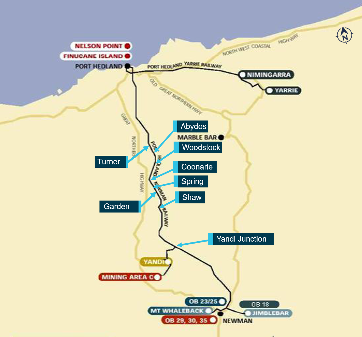
On 5 November 2018, train M02712, loaded with iron ore, was being operated by BHP on its Newman to Port Hedland railway, Western Australia, from Mining Area C to Nelson Point (Figure 1).
At about 0340,[1] the train stopped at the 210.7 km mark near Garden South due to a loss of trainline communications. As part of the response to this fault, and in discussion with network control, the driver exited the locomotive and commenced applying the handbrake on each ore car. At approximately 0440, with the driver still applying handbrakes, the train rolled away. There was no driver on board the train at the time.
The train travelled uncontrolled on the west track for about 91 km before Hedland train control derailed the train by routing it from the west track to the east track at a crossover located at Turner South. At about 0526, the head end locomotives traversed the crossover. Shortly after, 245 ore cars and the 2 remote locomotives, positioned mid train, derailed while travelling at 144 km/h.
Figure 1: Map of BHP’s Newman to Port Hedland railway

Source: BHP, annotated by the ATSB
Events prior to loss of trainline communications
At about 2300 on 4 November 2018, train M02712 departed Mining Area C (Figure 1) for the driver exchange point, M308 (308 km mark). It consisted of 2 locomotives leading, a unit rake of 134 ore cars, 2 remotely-operated locomotives located mid train, and a second unit rake of 134 ore cars. The trains brake control system was set to enable electrically controlled pneumatic brake (ECPB) operation.
Following arrival at M308, the next rostered driver for the train boarded and took over control of M02712. The train departed the driver exchange point at about 0115, crewed in a driver-only configuration.
At about 0337 on 5 November 2018, M02712 was travelling at 60 km/h on a downhill grade on the west track, approaching the BHP access road level crossing at the 211.6 km mark. The driver had set the throttle control for maximum dynamic braking to control train speed for descending the grade and began moving the automatic brake handle toward a 39% train brake command (TBC).
At about 0338, electrical communication via the trainline between the lead locomotive (4420) and the end of train monitor (EOTM) was lost, triggering an automated emergency brake application (120% TBC), stopping the train at about 0340 as it approached Garden South.
Response to loss of trainline communications
In response to the loss of trainline communications, the driver fully applied the locomotive independent brake. The driver made an emergency radio call to Hedland train control to report the occurrence, the location (at the 210.737 km mark between Shaw and Garden), and the detail of the alert messages displayed on the locomotive onboard systems.
The train controller placed blocks to the trackside signals on the adjacent east track between Garden South and Shaw North[2] to protect the train from other rail movements, and contacted personnel from the Redmont[3] maintenance gang to assist the driver. The controller told the driver that help was on the way and requested the driver to confirm the train’s location from a kilometre mark on the ground closest to the lead locomotive. The driver advised the controller that the FIRE[4] system displayed 210 km but they would detrain and check the kilometre mark to confirm.
At about 0350, the driver confirmed to the controller that the train was stopped at the 210.7 km mark. The controller then instructed the driver to apply 101% handbrakes[5] to secure the loaded train on the falling track grade at Garden. The controller asked if the driver wanted to start applying them now or wait in the locomotive for the arrival of personnel from the Redmont gang (who had been tasked by the controller to check the rear of the train before starting to apply the handbrakes from that end). The driver advised that they would start applying the handbrakes to the first rake of 134 ore cars rather than wait for the Redmont gang to arrive.
At about 0351, the driver placed the reverser[6] control to the centre (neutral) position and turned the generator field[7] off before preparing to exit the cab of locomotive 4420. The 120% emergency TBC was still active and the automatic brake handle remained set at the position equating to a 39% ECPB TBC.[8] The driver was aware the emergency ECPB interlock[9] would maintain the ECPB application and had applied the independent brake to secure the train. Additionally, by placing the reverser to the centre position and turning the generator field off, the driver had set up the locomotive rollaway protection provided by the on-board automatic train protection (ATP) system.
However, the driver did not place the automatic brake handle in the pneumatic emergency position to vent the train brake pipe pressure to atmosphere. This meant an additional braking control via the conventional pneumatic train brake system was not activated, and the emergency brake application was maintained by the ECPB system only.
Application of handbrakes
At about 0353, the driver exited the locomotive and commenced applying handbrakes to the ore cars, starting from the front of the train.
Soon after starting to apply the handbrakes, the driver identified that one of the inter-car trainline cable connectors near the front of the train had detached. The trainline was located on the opposite side of the train to the handbrake controls. As required by the operator’s procedures, the driver continued applying handbrakes to the remaining ore cars. The driver recalled that the process of applying handbrakes was relatively slow due to the difficulty climbing up and down the steep-sided ballast formation next to each ore car in the dark.
Train control continued to keep in contact with the driver of M02712 via the driver’s handheld radio at 10-minute intervals. During the first of these scheduled calls, the driver advised of finding the disconnection in the trainline cable.
At about 0422, personnel from the Redmont gang informed Hedland train control of their arrival at the 210 km mark to aid the driver of M02712 with applying handbrakes. The controller tasked the gang to start applying handbrakes from the rear of the train and continue toward the driver, who was working from the front. The controller also requested that, when the Redmont gang reached the rear of the train, they provide a report on the integrity of the rear of the train.
During a subsequent scheduled 10-minute call with train control, the driver reported to the controller that the application of handbrakes was progressing well, despite having trouble walking along the elevated ballast shoulder next to the stationary train. The driver stated they were about ‘three quarters’ of the way toward the remote locomotives in the middle of the train. They also reported being aware that the Redmont gang would check the integrity of the rear of the train and start applying handbrakes from there. The driver advised the controller that they intended to continue working toward the remote locomotives in the middle of the train, report to train control, and then return to reinstate the break in the trainline cable. The controller stated that, as the driver and maintenance gang were now ‘both on the ground’, they could communicate with each other.
The driver later advised they had formulated their plan to apply handbrakes on the first rake and then go fix the connector on the assumption that the personnel in Redmont gang, sharing the task of applying handbrakes, would be able to move at a faster rate; meaning that they would arrive at the remote locomotives at about the same time as the driver.
The runaway
At 0438, 60 minutes after the loss of trainline communications, the brakes released on most of the ore cars in the train. At this time, the driver was still applying handbrakes to the first rake of ore cars, and they recalled that they were about 20–30 ore cars from the rear of the first rake. The driver initially heard air venting from the ore car brakes and shortly after noticed the train lurch forward and start to roll away. The driver recalled that they tried to radio the Redmond gang and alert them that the brakes had ‘bled off’ but there was no response.
Shortly after train M02712 began to roll away, the ATP system detected the movement and requested a penalty brake application, but it was ineffective in stopping the train.
Previously, at about 0355, an empty ore train (M02727), travelling on the adjacent east track toward Yandi Junction, stopped at Garden South due to the blocking protections set up previously. At about 0444, the driver of this empty ore train contacted Hedland train control to advise that M02712 was moving and had passed Garden South at an estimated speed of about 50 km/h with brakes dragging.[10]
At 0446, train control received an emergency call from the driver of M02712, stating that the brakes had bled off and the train was now a ‘runaway’. The driver of M02712 had lost their footing when the train began to move, slipping on the ballast formation and knocking their radio off channel. After resetting the radio, the driver contacted the train controller, declaring an emergency and notifying of the runaway. Train control acknowledged the emergency call and advised that signal GNN4 at Garden North was set to red, in order to stop the train by triggering the locomotive onboard ATP system.
Train M02712 passed signal GNN4 at about 80 km/h and continued to increase speed. Although the ATP system requested a penalty brake application in response to signal GNN4 at red and to an overspeed condition, these penalty requests were also ineffective in stopping the train.
About 80 km ahead, another train (M02728) travelling on the eastern track was approaching Abydos North. Hedland train control contacted its driver, instructing the driver to stop, detrain and move to a safe place. Train control also contacted the drivers of the 2 other trains (M02729 and M02710) working between Garden North and Port Hedland, instructing them to also stop, detrain and move to a safe place. Trains M02729 and M02710 stopped at locations north of Turner (Figure 1).
At about 0502, the driver of the empty ore train stopped at Garden South (M02727) contacted train control to advise that the Redmont gang had mistakenly started applying handbrakes to their train rather than to M02712.
Train M02712 continued through Spring and Coonarie. It reached a speed of 162 km/h before slowing on the rising grades toward Woodstock (Figure 1).
At about 0509, M02712, travelling at about 128 km/h, passed over the active level crossing at the 154.3 km mark before Woodstock South. After Woodstock, the track grade again began to fall toward Port Hedland and M02712 gained speed to about 130 km/h as it passed M02728 stopped at the 130.5 km mark on the eastern track north of Abydos.
The derailment
At about 0520, Hedland train control set the crossovers at Turner South and Turner North to switch the runaway train M02712 between adjacent tracks to derail it as the train traversed the crossovers at speed.
About 6 minutes later, the head end locomotives, travelling at 144 km/h, traversed the crossover at the 119.4 km mark at Turner South. Locomotives 4420, 4434 and the first ore car separated from the rest of the train but remained coupled, travelling about 1.6 km further before stopping (Figure 3). The first ore car had derailed.
Ore cars in position 2 to 134 of the first unit rake, the remote locomotives 4472 and 4440 and ore cars one to 112 from the second unit rake derailed near the crossover (Figure 3). The last 22 ore cars of the second unit rake remained coupled and on track.
The derailment destroyed the 2 remote locomotives, 245 ore cars and about 2 km of track infrastructure at Turner South (Figure 4). There was no injury to any person from the runaway or derailment.
Figure 2: Locomotives 4420, 4434 and first ore car at Turner South

Image viewed in a southerly direction of locomotives and ore car at Turner South. The lead locomotives 4420 and 4434 and one ore car remained upright, however the ore-car had derailed.
Source: BHP, annotated by the ATSB
Figure 3: Train M02712 wreckage near the crossover at Turner South

Aerial image viewed in a southerly direction of train wreckage and track damage at Turner South. The lead locomotives 4420 and 4434 remained on track and were coupled with one ore car that had derailed (out of frame in the foreground).
Source: BHP, annotated by the ATSB
Figure 4: Ore cars and remote locomotive 4427 wreckage at Turner South

Wreckage of remote locomotive 4472 and ore cars from rakes A and B viewed in a south-westerly direction at Turner South.
Source: BHP, annotated by the ATSB
- All time references in this report are local time (Western Standard Time).
- The trackside signals displayed a red (stop) indication.
- Redmont was a remote maintenance camp accommodating track workers. It was located near Garden South.
- Functionally integrated railroad electronics (FIRE) system: forms the interface between the operating crew and locomotive computer systems.
- The controller used a handbrake calculator tool to determine the number of handbrakes required based on track grade and loaded/empty state of the train.
- Reverser control: lever in locomotive cab to select ‘forward’ ‘centred/handle-out’ or ‘reverse’ for the direction of operation.
- Power source for generator field excitation.
- An automated ECP penalty brake application overrides manual setting of the automatic brake handle.
- For a system initiated emergency brake application, the 120% TBC brake interlock feature maintained a full air brake application to the train, but the brake pipe air pressure remained fully charged at 600 kPa (see ECPB codes of practice and standard)
- Brakes applied on head end locomotives and a number of ore cars from the first rake.
Track information
BHP was the rail infrastructure manager for the Newman to Port Hedland railway, which it used to transport iron ore. The railway was a standard gauge track structure constructed with continuously welded 68 kg/m rail, fastened with resilient clips to concrete sleepers bedded in crushed rock ballast. The track structure configuration enabled the operation of rolling stock with a 40-t axle load.
In the direction of travel, the track gradient from Mining Area C was primarily a rising grade approaching Shaw in the Chichester Range, before transitioning to a mainly falling grade toward Nelson Point (Figure 1). The M02712 runaway started between Shaw North and Garden South where the track gradient was -1.5%, the steepest track gradient of the track section between Yandi Junction and Nelson Point.
An automatic train protection (ATP) system governed the maximum permissible track speed for the various sections dependent on the mode of operation (loaded or unloaded), with the target speed displayed to a driver via the FIRE system. The maximum track speeds for the Newman to Port Hedland railway were 60 km/h for a loaded and 75 km/h for an unloaded ore train.
Train control information
BHP managed train movements remotely from a train control centre located in its integrated remote operations centre in Perth. The train control centre had 5 operational control areas (desks): Hedland, Newman, 6PG, Hub control and Yard control. All communications between the Perth control centre, train movements, control systems and wayside equipment was via a dedicated VHF radio system.
The runaway occurred within the operational area managed by Hedland train control, which extended from the 67 km mark south of Walla to the 260 km mark south of Cowra (Figure 1).
Train crew information
Qualifications and experience
The driver of train M02712 began employment with BHP in 2008, operating ore trains from Port Hedland and later the Yandi depot. The driver had recently completed the BHP driver reaccreditation in driver safeworking, locomotive system theory and in-field training courses, and held the required competencies for the tasks performed (see also Driver competency assessment related to rules and procedures).
Medical information
The driver underwent their last medical assessment (category 1) on 9 May 2018 and was assessed as fit for duty as per the requirements of the National Standard for the Health Assessment of Rail Safety Workers.
Following the occurrence, BHP initiated screening tests on the driver for the presence of an illicit drug or alcohol, which provided a negative result (that is, no alcohol or drugs were detected).
Recent history
The driver was employed under a fly-in fly-out (FIFO) arrangement. BHP’s train drivers working on a FIFO arrangement typically worked a roll-over roster pattern or ‘swing’ that included 7 12-hour shifts (each starting at the same time of day), a 24-hour recovery break, 7 12-hour shifts (each starting at the same time of day), and 12 days off duty.
The driver commenced a roll-over swing on 31 October 2018, as outlined in Table 1. This involved commuting to Adelaide on 29 October, staying overnight in Adelaide, then commuting during the day from Adelaide to Yandi on 30 October. The driver recalled waking at about 0230 Western Standard Time[11]to make an early flight to Perth, then catching an afternoon flight to Newman (during which they had a short nap) and arriving at the Yandi depot at about 1700. They had 4–5 hours after arriving at Yandi to allow for unpacking, getting a meal, going back to their accommodation, checking in with family and obtaining some rest prior to preparing for work.
The driver then commenced the series of 12-hour night shifts, each starting at 2200. Each shift generally involved taking a loaded train from Yandi to Port Hedland or taking an empty train from Port Hedland to Yandi.
Table 1: Scheduled and actual duty times for the driver of M02712
| Date | Work activity | Duty start | Duty end | Duty time | Time free (of duty) |
| 28 Oct 2018 | Day off (11th day free of duty) | ||||
| 29 Oct 2018 |
Day off Commute to Adelaide (1600–2000) |
||||
| 30 Oct 2018 |
Commute Adelaide – Yandi depot (0230–1700) Yandi–Port Hedland |
2200 |
1000 |
12 hours |
12 hours |
| 31 Oct 2018 | Port Hedland–Yandi | 2200 | 1000 | 12 hours | 12 hours |
| 1 Nov 2018 | Yandi–Port Hedland | 2200 | 1000 | 12 hours | 12 hours |
| 2 Nov 2018 | Port Hedland–Yandi | 2200 | 1000 | 12 hours | 12 hours |
| 3 Nov 2018 | Yandi train load out | 2200 | 1000 | 12 hours | 12 hours |
| 4 Nov 2018 | Yandi–Port Hedland (train stopped at 0340) | 2200 | 1000 | 12 hours | 12 hours |
| 5 Nov 2018 | Night shift (planned, not worked) | 2200 | 1000 | 12 hours | 24 hours |
| 6 Nov 2018 | (Finish duty at 1000) | ||||
| 7 Nov 2018 | Day shift (planned, not worked) | 1000 | 2200 | 12 hours | 12 hours |
| 8 Nov 2018 | Day shift (planned, not worked) | 1000 | 2200 | 12 hours | 12 hours |
| 9 Nov 2018 | Day shift (planned, not worked) | 1000 | 2200 | 12 hours | 12 hours |
| 10 Nov 2018 | Day shift (planned, not worked) | 1000 | 2200 | 12 hours | 12 hours |
| 11 Nov 2018 | Day shift (planned, not worked) | 1000 | 2200 | 12 hours | 12 hours |
| 12 Nov 2018 | Day shift (planned, not worked) | 1000 | 2200 | 12 hours | 12 hours |
| 13 Nov 2018 | Day shift (planned, not worked) | 1000 | 2200 | 12 hours | 12 hours |
All times in the table are in Western Standard Time (UTC + 8 hours). The driver commenced commuting on 30 October from Adelaide, which was 2.5 hours ahead of WST.
The driver signed on for their sixth night shift on 4 November at about 2200 after a short (10–15 minutes) commute. The driver recalled that there was a delay in their loaded train being ready for departure. They eventually departed the driver exchange point, M308, at about 0115. They were running behind another train and experienced some yellow signals and reduced speeds, but had no stoppages until the train stopped near Garden at 0340.
Drivers were entitled to a 30-minute ‘crib’ break (or meal break) each shift, and the driver expected to get their break at about 0430–0500 due to the late departure (and breaks normally being taken with a train on a flat gradient). The driver reported that, in the period leading up to the train stopping, the workload and complexity were both moderate (which was normal for that location).
The driver stated that, after stopping work at 1000 following a night shift, they would go back to their accommodation and normally slept for about 4–5 hours. They then had a meal when the kitchen opened at about 1700, watched television, made a call home and then dozed or napped (if sleep occurred). Overall, they would normally get about 5–6 hours sleep each break following a 2200–1000 shift, with some of this being broken sleep and sometimes sleep being difficult to obtain. This contrasted with 7 plus hours of good quality sleep from about 2200 to 0630–0700 when they were at home.[12]
The driver reported that they found swings commencing at 2200 the most difficult for obtaining sleep. The first few days were particularly difficult, and they would get more sleep later in the week. However, they would continue to get less sleep each rest period than they would at home.
The driver self-rated their fatigue level at the time of the occurrence as 4 out of 7 (‘a little tired’) [13]but also noted that a person usually feels better than they actually are. The driver also commented that, after the train stopped, they felt ‘deflated’ when they realised they had to walk alongside the train to secure the handbrakes.
In terms of strategies to maintain alertness, the driver stated they drank some coffee each day during a swing, mainly while waiting for their train to be ready rather than on the train. They would also listen to music when in the train. They did not take any medications to maintain alertness or drink alcohol during a swing.
Further information regarding BHP’s fatigue management procedures are provided in Fatigue management.
Train information
General information
BHP’s ore trains ran as unit trains.[14] Train M02712 consisted of 2 SD70ACe type locomotives (4420, 4434) leading, a unit rake of 134 ore cars, 2 remotely-operated SD70ACe type locomotives (4472, 4440) located mid train, and a second unit rake of 134 ore cars. It weighed approximately 42,500 t and was 2,860 m long.
The ore train was working between the loading facility at Mining Area C, situated on the spur line extension from Yandi, and the unloading facility at Nelson Point, Port Hedland (Figure 1).
SD70ACe type locomotive
BHP’s SD70ACe diesel electric locomotives were equipped with a microprocessor-based computer control system (EM2000). This control system monitored and controlled locomotive traction power, braking and other interfacing systems. The control system detected fault conditions and allowed diagnostic testing of associated systems. The interface between the locomotive control system and driver was through the functionally integrated railroad electronics system (FIRE).
The FIRE display panel (or integrated functional display) was located in the driver console. The FIRE system replaced most of the driver control switches, gauges and indicators with a display panel graphic user interface. The display screens provided an interactive system that allowed viewing of pertinent data and provided input signals to the locomotive control and air brake systems for set-up and diagnostic tasks. The system also displayed information on an event basis, such as alarms and operator crew messages. ECPB set-up and other functions were performed using various ECPB menus on the display panel.
Some locomotive control functions that previously operated independently through their own display screens were integrated into the FIRE display console. Such functions included those associated with the:
- EP-60 brake controller
- ATP system
- locomotive microprocessor control system
- ECPB system.
Overview of BHP ore car braking system
The braking application on a conventional pneumatically-braked ore car relied on the driver operating the automatic brake handle in the locomotive to generate a reduction in brake pipe pressure (pressure wave) within the brake pipe. The pressure wave propagated along the brake pipe (through each ore car) for the length of the train. This pressure wave actuated a pneumatic brake control valve in each ore car, applying the ore car’s brakes. The ore car brake applications occurred sequentially along the train, with the magnitude of the brake effort determined by the reduction in brake pipe pressure made by the driver.
Conventional pneumatic braking systems therefore allowed the driver to graduate the application of braking effort on the train. These systems required the brake pipe to be fully charged before the pneumatic valves in each ore car would release the brake application. This meant that the driver could not graduate the release of a brake application.
In contrast to conventional pneumatic-braking systems, an electronically controlled pneumatic braking (ECPB) system used electronic signals that made it possible to activate the air-powered brakes on each ore car. To facilitate this, the ore cars were equipped with a trainline cable that ran parallel to the brake pipe along the length of the train. The cable supplied power to the electronic components installed on each ore car. The cable also served as a communication medium that allowed the locomotive control system to send commands and receive feedback from the ore cars and the end of train monitor (EOTM).
ECPB provided benefits over the conventional pneumatic braking system. For example:
- Since all the ore cars received the brake command at the same time, the brakes were applied uniformly and instantaneously. This minimised in-train forces and provided better train control, shortened the stopping distance, and reduced risk of derailment or of coupling breakage.
- The brake pipe remained charged during a brake application. This allowed the reservoirs on the ore cars to continuously charge with air.
- As the ore cars could send their status to the locomotive at the front, ECPB provided better diagnostic capabilities and enabled the train crew to better monitor the state of the train and its braking capabilities.
ECPB trains could take 2 forms: stand-alone or overlay. With a stand-alone system, braking controls on the ore cars would only operate electrically and there was no pneumatically-operated valve installed on the ore car. An overlay system essentially retained the pneumatic valve and added the electronic car control device (CCD), electronically-controlled valve and adapter air manifold (Figure 5).
Figure 5: Typical ore car air brake system with ECP brake overlay

ECPB system highlighted in green.
Source: BHP, annotated by the ATSB
BHP selected an overlay option to provide operational flexibility in mitigating delays to production should an ECPB train experience a fault that could not be recovered in a timely manner. The overlay system allowed BHP to operate trains as either a conventional pneumatically-braked train or as an ECPB train.
In 2011, BHP commenced a management of change process for the introduction of the ECPB system to its mainline operations (Management of change). It then progressively implemented the ECPB system throughout its fleet.
Braking and distributed power systems on train M02712
Train M02712 was equipped with an EP-60 New York Air Brake (NYAB) ECPB system. The system consisted of locomotive equipment, ore car braking control equipment, an EOTM, and a power and communications distribution system.
Locomotive equipment included a trainline communications controller, power supply and identification module. The head end unit (HEU) locomotive communicated with each of the 268 CCDs and remote locomotives via embedded transmissions in the trainline cable, comprised of a single pair of wires forming the intra-train power and communications network. The trainline cable between each rail vehicle (locomotive or ore car) was joined using a connector (see also Trial trainline inter-car connectors). Each CCD unit used 230 V direct current power from the trainline cable to charge its batteries and supply power to its electronics.
The EOTM installed on the last ore car coupler marked the end of the train. It also provided a termination point for the trainline cable and a transducer for end of train information, such as brake pipe pressure, back to the HEU to establish the integrity of the trainline and train consist. The EOTM used 230 V direct current power from the trainline cable to charge its batteries and supply power to its electronics.
If the power from the trainline cable was lost, the CCDs and EOTM each continued to operate on battery power until a 60-minute time period elapsed (shut-down mode or battery conservation mode – refer to ECPB codes of practice and standards) or the battery charge ran low and the CCD cut out. The CCDs and EOTM then respectively entered the shut-down mode or cut out. When a CCD shut down or cut out, it released its ECPB application and relinquished control of brake cylinder pressure to the conventional pneumatic braking system of the ore cars. If the brake pipe was charged and a pneumatic application was not in effect, the brake cylinder pressure released.
BHP was not able to advise on the average battery life of a CCD or EOTM battery, but it was understood to be substantially longer than 60 minutes.
The BHP locomotive fleet was equipped to enable control of multiple distributed power units within the train. Communication of synchronous control and indication signals between the HEU, trailing and remote locomotives also occurred via the trainline system.
As a contingency, the ECPB overlay system and trainline could be shut down and the HEU configured to communicate power and brake commands via UHF radio communications to the remote locomotives. This configuration disabled ECPB, and train braking reverted to conventional pneumatic operation via the train brake pipe. The HEU configuration also set up communication with the EOTM by radio.
The FIRE system displayed braking parameters related to the ECPB system mode, alarms, diagnostic messages, and brake command input (Figure 6). The system displayed the level of train brake command (TBC) input as a percentage, typically between 0% and 100% or as 120%. Various values meant:
- 0% = release
- 10% = minimum service
- 100% = full service / penalty application
- 120% = emergency.
Figure 6: Typical FIRE system display

Typical parameters displayed on FIRE system display monitor. Details shown were not those present on locomotive 4420 at the time of the M02712 runaway.
Source: BHP
Driver electronic brake control unit
The driver could manually control braking applications through the electronic brake control unit located on the driver’s console. The control unit included the automatic and independent brake handles. Each of these handles provided independent electrical signals to the EP-60 brake controller (Figure 7).
Figure 7: Drivers electronic brake control unit

Position of the automatic brake handle equates to a 39% TBC brake application.
Source: BHP, annotated by the ATSB
The automatic brake handle had the following detent positions for driver control:
- REL (release) – charged air brake and releases locomotive and train brakes
- MS (minimum [service] reduction) – first detent in service zone to apply minimum braking
- Service zone – between MS and FS applying graduated service braking effort
- FS (full service) – position in service zone to apply full-service braking effort
- SUP (suppression) – second detent position applying full-service braking effort and suppression to safety control applications
- HO (handle off) – third detent position used when driving station is not active (handle is not removable) or 120% TBC when driving station is occupied and operating in ECPB mode
- EMER (emergency) – fourth detent position, brake pipe pressure reduced to 0 kPa at a rapid rate and when configured to ECPB mode applied 120% TBC.
In addition to the driver controlling braking to the train (locomotives and ore cars) via operating the automatic train brake handle, the driver could control braking to the locomotives via operating the independent brake handle. The independent brake handle was directly below the automatic brake handle and controlled the HEU locomotive’s braking independently of the automatic train brake (Figure 7). It also applied the brakes on other locomotives in the train (lead and trail) but it did not apply brakes on the ore cars or remote locomotives. The independent brake control applied brakes pneumatically, irrespective of the HEU configuration.
The independent brake control handle could be positioned to:
- REL (release) – released the locomotive brakes, if the automatic brake handle was also in the REL position
- SERVICE – moving the handle through the service zone increased locomotive braking effort
- FULL – applied full braking effort on the locomotive(s)
- bail off function – depressing the handle in either the REL position or SERVICE zone suppressed any automatic train brake application in progress on the locomotive(s).
Figure 7 shows the position of the brake handles at the time of the runaway and derailment. The driver positioned the automatic brake handle in the service zone to the position equating to a 39% ECPB TBC at 0337, prior to the loss of trainline communications at 0338. The independent brake handle was moved to the FULL position at 0353.
ECPB codes of practice and standards
The Rail Industry Safety and Standards Board (RISSB) Code of Practice for ECP braking (released in 2017) described the configuration and operation of trains fitted with ECPB for use in the Australian rail industry. The practices described in the code were recommendations to the rail industry but excluded captive unit train operations[15]or situations where rolling stock operators, vehicles or locomotives did not interchange across functional boundaries.
The code referred to content from the suite of documents published by the Association of American Railroads (AAR) under Section E-II - Manual of Standards and Recommended Practices - Electronically Controlled Brake Systems. The AAR adopted the S-4200 standard in 1999 with later revisions in 2002, 2004, 2008 and 2014. The standard defined the requirements to ensure the functionality, performance and interoperability for an approved freight train power brake using ECPB systems.
The standard specified the normal operation functions of an ECPB system (including an overlay system) and addressed the effect of the CCDs or EOTM entering the shut-down mode following loss of trainline power. Section 4.3.17 stated:
Shutdown mode (or “battery conservation” mode) shuts off the CCD or EOT to minimize battery drain. When shut down, the CCD or EOT is turned off. When a CCD shuts down, it releases its ECP brake application and relinquishes control of brake cylinder pressure to the pneumatic backup. If the brake pipe is charged and a pneumatic application is not in effect, brake cylinder pressure will release; otherwise it will remain at the level commanded by the pneumatic backup. When an EOT shuts down, it stops transmitting EOT beacons.
Once train line power is lost, the CCD or EOT either continues to operate off of battery power until its battery runs low or enters into a timed shutdown mode. The intent of this logic is to allow the train to operate as long as possible after a loss of train line power and to conserve batteries if the device is disconnected from the train line, the train is parked, or the ECP brake system is CUTOUT.
The CCD or EOT shall shutdown 1 hour after both train line power is lost and no HEU beacon has been received. The CCD or EOT shall shut down after the train line power is lost and the train operating mode is set to CUTOUT.
The standard detailed conditions that triggered the designed shut-down mode of operation. Although the functionality supplied flexibility in operation and protected battery condition under certain circumstances, such as shunting operations utilising switch mode,[16] the conditions also existed following an interruption to the trainline during main line operations.
The standard stated that the CCD on each ore car downstream from a trainline interruption would release the ECP brake application and relinquish control to the pneumatic backup system 60 minutes after a loss of trainline continuity. If the CCDs were shut down with the brake pipe air pressure charged, the brake cylinder pressure on the affected ore cars would release and the braking effort would be lost.
In summary, the operation of the ECPB system outlined in the S–4200 standard included a 60-minute shut-down feature of the CCDs in certain conditions, which introduced a potential risk exposure for a runaway event that needed to be managed. The ECPB system on BHP’s trains was designed consistent with the standard.
ECPB emergency brake conditions
In the ECPB mode of operation, the initiation of an emergency braking application could occur:
- automatically in response to various system-detected conditions
- manually by the driver moving the automatic brake handle to the ‘handle-out’ or pneumatic ‘emergency’ positions.
If the system detected an emergency brake condition, such as a critical loss of trainline communications, the EP-60 manual described the system response as:
Emergency (120%) brake command, an emergency brake (120%) brake interlock, locomotive power knock-down (PCS) and corresponding crew message(s). The 120% emergency brake interlock will remain in effect for a minimum of 2 minutes since the emergency condition occurred. The interlock can then be reset once the condition that caused the emergency has been corrected.
If a driver triggered the emergency application by moving the automatic brake handle to the pneumatic ‘emergency’ position, the EP-60 manual described the functionality:
In this position brake pipe is vented to zero and a 120% TBC train brake command is provided.
If the driver moved the automatic brake handle to the ‘handle-out’ position, the braking response would be the same as for the system-initiated emergency (120%) brake command. As stated in the EP-60 manual:
If the automatic handle is moved to the “handle-out/continuous service” position, the brake pipe will continue to charge but a 120% TBC train brake command is provided.
In ECPB mode, for a system-initiated emergency brake application or when a driver moved the automatic brake handle to the ‘handle-out’ position, the 120% TBC brake interlock feature maintained a full air brake application to the train, but the brake pipe air pressure remained fully charged at 600 kPa. For a driver-initiated emergency application where the driver moved the automatic brake handle to the pneumatic emergency position, both the 120% TBC brake interlock and the discharged brake pipe maintained a full air brake application on the train.
Emergency brake application on train M02712
In the case of M02712 approaching Garden on 5 November 2018, the driver had positioned the automatic brake handle for a 39% train brake call to the EP-60 brake controller, prior to the emergency (Figure 7).
About 30 seconds later, at 0338, the interruption in trainline continuity caused several critical alarm conditions in the HEU locomotive’s onboard systems. The loss of trainline communications between the EOTM and HEU beacon triggered a system-initiated emergency application of 120% TBC to lead locomotives and operative CCDs that remained in communication with the HEU (Figure 8).
Figure 8: Event logger extract from locomotives 4420 and 4472, locomotive 4420 (HEU) brake control applications

Source ATSB
The CCDs, remote locomotives and EOTM beacon that could not detect the HEU beacon via the trainline cable subsequently broadcasted an exception message, which was received by the other devices along that portion of the trainline. As each device received more than one exception message within 5 seconds, all operative CCDs and remote locomotives self-initiated an emergency ECPB brake application to stop that part of the train. As this was a system-initiated application and only the trainline communication was interrupted, the brake pipe remained intact and fully charged (Figure 9).
Figure 9: Event logger extract from locomotives 4420 and 4472, locomotive 4472 (remote) and ore car CCD brake application

Source ATSB
Following the triggering of the 120% TBC application, the brake interlock feature held the brake application on the lead locomotives and CCDs in communication with the HEU. The interlock remained active, maintaining this brake application, as the driver had not reset the ECPB emergency condition.
The self-initiated emergency applications on the remote locomotives and associated ore car CCDs maintained brake application on the respective vehicles. Communication with the HEU was interrupted, so power and control commands (reset) were not available. Consequently, the CCDs relied on sufficient battery charge, and the 60-minute shut-down feature, to keep the brakes applied.
As indicated in Figure 8, the independent brake was fully applied at 0353.
For train M02712 the operative CCDs, remote locomotives and EOTM that were not in contact with the HEU beacon shut down about 60 minutes after the loss of power supplied by the trainline cable (that is, at about 0438). As the brake pipe remained charged, the air brakes released on these ore cars and the remote locomotives. The release of these air brakes and the incomplete application of handbrakes on train M02712 resulted in the train commencing to roll away at about 0440 (Figure 10).
Figure 10: Event logger extract locomotives 4420 and 4472, locomotive 4472 (remote) and ore car CCD brake release

Automatic train protection system
The 4 locomotives on train M02712 were each equipped with an Alstom Ultra-Cab II (UCII) microprocessor-controlled automatic train protection (ATP) system. The UCII system was not a standalone system; it interfaced electronically with other onboard equipment including the FIRE system, ECPB system, wayside transponders and other control systems that combined to provide for the safe operation of the train within the parameters defined in BHP’s rules and procedures.
The ATP functions included checking the locomotive speed and supervising its operation within the limits imposed for the track section. If the locomotive exceeded the target speed limit, alarms would sound to prompt the driver to reduce speed.
The locomotives carried a radio transmitter, transponder reader and antenna. The equipment relayed transmissions between the locomotive and transponders fastened to the track crossties (sleepers) at key locations, such as ATP entry and exit points and interlocked wayside signals along the railway. Track-mounted transponders relayed unique location identification and target speed data to the locomotive UCII microprocessor.
The driver had to reduce speed to the target limit within a predetermined time. If this did not occur, the ATP system automatically communicated with the braking system to request a brake application to stop the train. The type of brake application depended on the setup of the locomotive at the time of the command:
- If the locomotive was configured for conventional pneumatic braking, the ATP triggered a service braking application. If this was ineffective in slowing the train, the ATP then triggered a penalty braking application.
- If the locomotive was configured for ECPB, the ATP requested a penalty braking application only.
Additionally, when the locomotive was stationary with its reverser in the neutral (centre) position and the ATP detected a train movement of more than 0.5 m, the ATP requested a penalty braking application to prevent a potential locomotive runaway.
Each locomotive’s ATP system automatically configured to mirror the ECPB brake setup for that locomotive, either as a HEU, trail unit or remote unit. The ATP would not enforce target speed limits or runaway protection on locomotives configured as either a trail or remote unit.
The way the brake controller actioned the ATP’s request for a braking differed depending on whether the train was configured for conventional pneumatic mode or ECPB mode:
- In conventional pneumatic mode, braking signals from the HEU brake controller were propagated to the remote locomotives and ore car pneumatic valves via a reduction in brake pipe pressure. A penalty brake request by the ATP system caused the brake controller to vent the brake pipe pressure to apply and hold the brake application on the locomotives and ore cars, until actioned by the driver.
- In ECPB mode, braking signals from the HEU brake controller propagated to the remote locomotives and ore cars electrically via the trainline. The brake pipe remained charged with air. A penalty brake request by the ATP system caused the HEU brake controller to apply the brakes on the lead locomotives. The controller also transmitted an electric signal via the trainline to the remote locomotives and CCDs in each ore car to apply the brakes. An interlock feature in the brake controller then maintained the brake application until actioned by the driver.
In other words, the ATP did not directly integrate with the pneumatic braking system and could not operate a valve to dump brake pipe pressure. Accordingly, if a train was being operated in ECPB mode and there was an ECPB emergency/penalty braking application, and the train then commenced rolling away, subsequent penalty requests by the ATP system would be ineffective when the brake pipe remained charged.
BHP advised the ATSB that implementation of the ATP system in this configuration was historical and done to manage other operational issues such as derailment and ATP override.
The ATP in each of the 4 locomotives in train M02712 functioned respectively as a HEU (4420), trail unit (4434) and 2 remote units (4472 and 4440). When train M02712 started to roll away, and when later passing signals set to red or attaining an overspeed condition, the ATP system in the HEU triggered a penalty command (100% TBC) to the brake controller. In each instance, the ATP system penalty commands to the ECPB system were ineffective in stopping the train.
The brakes on the lead locomotives and the ore cars in communication with the HEU had already applied in response to the first 120% TBC (due to loss of trainline communications) and remained applied due to the brake interlock feature. Later ATP system calls to the EP-60 brake controller and responding ore cars had no material effect in mitigating the runaway of train M02712.
Vigilance control
The train’s vigilance control system checked for driver activity and automatically stopped the locomotive/train when there was no driver-initiated control input or response from the driver to aural and visual warnings displayed via the FIRE system. The vigilance system used random timing and task linking to check for driver activity.
The vigilance system was active when the locomotive air brake was set as the HEU and the locomotive air brake cylinder pressure was less than a predetermined level (independent brake released). The vigilance system was suppressed when any of the following occurred:
- the locomotive air brake cylinder pressure was greater than a predetermined level (independent brake applied)
- the locomotive’s braking system was set to trail or remote
- the reverser was in the neutral (centre) position
- the locomotive configuration was set for operation at a defined slow speed.
Prior to exiting the locomotive cab to apply handbrakes, the driver of M02712 applied the independent brake fully (increasing the air brake cylinder pressure above the predetermined level) and placed the reverser in the neutral (centre) position. These actions formed part of the ‘three-step process’ that the driver was to action when securing a locomotive (see Rules and procedures for securing trains before conducting work). The implementation of these actions had the effect of supressing the vigilance system, so the system had no effect during the runaway.
Risk management
Risk assessments for material risks
BHP’s Rail Safety Management Plan stated that the risk profile of BHP’s rail operations was determined by its risk management procedures. Different procedures were used for ‘material’ and ‘non-material’ risks. Material risks typically related to fatal accidents and significant operational or catastrophic events. Non-material risks related to task-based hazards and events with less severe consequences, and such risks were typically managed through BHP’s health, safety and environment (HSE) risk management processes.
BHP’s Risk Management Procedure provided guidance to the managers (risk owners) responsible for managing material risks in their area of responsibility. It outlined a series of phases, which included establishing the context, risk assessment (including risk identification, analysis and evaluation), risk treatment, and monitoring and review.
The procedure stated:
A formal risk assessment is a team-based, risk assessment process which provides an efficient and effective method of risk identification, risk analysis, assigning controls and developing risk remediation plans...
It involved relevant subject matter experts and the potential control owners identifying and agreeing on (material) risk events, and then:
For each risk event, identify potential causes and impacts. When assessing risk, normal operating conditions, abnormal operating conditions, start-up and shutdown activities and potential emergency situations shall be considered…
Based on the causes and consequences, the team must identify credible controls that will prevent, detect or mitigate the risk event and associated causes and consequences. The controls identified must be based on the hierarchy of controls[17]… The controls will be either preventive or mitigating controls.
A bowtie was used as the data capture tool for material risk controls. The procedure stated that:
…A bowtie is developed in a workshop with the relevant subject matter experts, risk owner and potential control owners.
Once the risk event, causes and impacts have been agreed, the critical controls are identified. A critical control is a control that significantly reduces the likelihood and / or impact of a material risk. The number of risk controls must be appropriate to the risk event and must play a key role in achieving the business objective…
A material risk required a control design assessment (CDA) occur to ensure the critical control were suitable following their creation and when changed. The assessment test varied dependent on whether the critical control was a procedural (administrative) or an engineering solution. Additionally, critical controls underwent a unique control effectiveness test (CET) to give assurance that each control was in place and effective in managing the material risk to an acceptable level.
In other words, the identification of a material risk event supplied a method for focusing management oversight on the critical controls preventing or mitigating the risk from such events.
Rail-mounted equipment interaction incident
BHP had identified a material risk event titled ‘Rail Mounted Equipment (RME)[18]Interaction Incident’, which referred to events involving an uncontrolled interaction between RME and people and RME and RME. The risk assessment was initially developed circa 2013, with numerous changes made in July 2016.
A range of scenarios were included, which considered the likelihood and consequence of interactions between RME/RME, RME/road vehicles and RME/track worker(s) resulting in the potential for single or multiple fatalities. The maximum foreseeable loss scenario involved a hi-rail vehicle (not covered by ATP) striking maintenance workers. Other worst plausible scenarios included shunting activities, driver walking around the locomotive at night, track workers working on an adjacent line, workers within the 3 m zone.
The bowtie identified the following 12 ‘causes’ that could lead to such an event:
- at risk behaviour of personnel, working outside rules/procedures/instructions
- failure of or poor communications, radio protocols not followed or equipment failure
- ATP system failure or overridden
- ineffective track protection applied
- limit of authority terminals / operator error for road-rail vehicles or track machines
- uncontrolled or uncommanded movement of RME (workshops and main line)
- exceed limit of authority (or no authority)
- non-compliant track design
- signal system ineffective
- ineffective train control management
- operator ignores derailer at active car dumper or train load out
- derailment resulting in fouling of adjacent line.
The uncontrolled or uncommanded cause included the following types or examples:
- brake isolation / failure
- failure of tower control in non-safe state (J-Hub facility)
- malicious damage (vandalism)
- failure to secure vehicle against movement (braking and chocks).
It is not clear if the ‘failure to secure vehicle against movement (braking and chocks)’ related only to RME/trackworker(s) situations where maintenance personnel required access to work on rolling stock, or it was also intended to include securing a train against a runaway event on the main line involving a service train.
A matrix within the bowtie then linked each of the 12 causes to one or more preventative critical risk controls. The following 7 critical preventative risk controls were identified for an RME interaction incident caused by the uncontrolled or uncommanded RME movement:
- radio communication - the protocols to enable clear verbal communication between train control and/or workgroups to confirm and acknowledge authorities to proceed with the related activity
- rolling stock (excluding ore cars) maintenance - the asset management plans for RME to prevent derailment from equipment failure
- signalling systems - the systems and procedures to positively locate and provide safe separation between RME
- isolation protection - the procedures for the isolation and protection of RME against unintended movement (hand brakes and roll away protection)
- trained and competent - requirement for the engineering and operational personnel to have the correct competencies for the rail-related tasks being carried out
- three-step protection - the rules and procedures applicable to all personnel entering the profile of an RME to protect against the unauthorised movement of rolling stock
- interface coordination - the agreements to clearly delineate the responsibilities of each party or functional area to facilitate the interaction between those parties and rail operations at each interface point.
The mitigating (or recovery) control listed for this cause was ‘corporate affairs and legal support’.
The preventative controls that were identified within the bowtie for other causes also included the ATP system. The documented aim of the ATP system control was to ensure trains did not exceed permitted speeds and/or levels of authority (that is, passing a signal at stop). The ATP system was stated as meeting the objective through monitoring target speeds and location information to provide warning to the driver if they were likely to exceed a defined speed profile or a braking curve profile for a limit of authority. The control specified that the ATP system would apply the brakes (penalty) if the driver did not respond to the warnings.
The matrix within the bowtie linked ATP as a preventative control measure to the causes on:
- ATP system failure or overridden - poor maintenance of onboard or way side system
- Limit of authority (LOA) terminals - failure or operator error for road rails vehicles/or trackside machines; GPS failure in non ATP RME (equipped with back box) or not displaying correct location
- Non-compliant track design - construction, renewals and/or maintenance, RME operating outside of safe envelope (out of gauge), incorrect placement of Insulated rail joints (or misalignment to ATP map), parking of RME beyond fouling points, out of gauge vehicle
The bowtie risk assessment did not link ATP as a preventative control against the uncontrolled or uncommanded movement of RME and it did not link ATP as a mitigating control for any of the causes of an RME interaction incident.
Evaluation of critical controls
Each critical control listed in a bow tie linked to various design and operating standards, together with the criteria used to verify the control’s overall effectiveness. The design and operating standards for the controls relevant to securing a vehicle (train) against an uncontrolled or uncommanded movement linked to the content of relevant modules within the rail rule book, procedures, worker competency programs, asset management plans, interface coordination plans and emergency response plans. Their effective implementation was dependent on the qualified workers undertaking the related task described within the documents.
The scope and design standards for each critical control primarily addressed material risk associated with personnel accessing the profile of rolling stock to undertake maintenance or recovery tasks. Apart from a reference to drivers keeping an awareness of current operating instructions, the critical controls contained no reference to the risk of a significant or catastrophic event arising from an RME main line runaway, such as M02712.
The methods used in a critical control verification (CCV) included the scheduled inspection of records, auditing and observation of behaviours targeting representative samples of the workforce. Results from the CCVs and review of the CDA additionally fed into a test plan used to review periodically the significance of key changes to associated procedures, standards and permits or those triggered by significant events or audit findings since the last CDA and CET if applicable.
The outcome from the review processes (CCV, CDA and CET) formed the material risk control assessment (MRCA), where a rating was assigned to the material risk event’s critical controls of either ‘well controlled’, ‘requires some improvement’, ‘requires significant improvement’ or uncontrolled’.
The MRCA of the RME interaction incident risk event undertaken in September 2017 found that, although the majority of critical controls were ‘acceptable’, the risk of an RME interaction with people rated overall as ‘requires some improvement’. The bowtie version date recorded another review and update occurred on the 14 February 2018. Records of tracked changes for the MRCA’s indicated changes occurred in the bowtie on 16 November 2017 and 8 January 2018 respectively to the preventative controls trained and competent and rolling stock [excluding ore cars] maintenance. There was no record of the changes to the bowtie associated with the update conducted on the 14 February 2018.
CCD shutdown event in March 2017
On 27 March 2017, the driver of a loaded ore train reported an ECPB 120% penalty brake application that occurred at Garden (205 km). The driver reported the condition of ‘EOT off’, ‘power off’ and ‘communication loss’ to remote locomotives. The driver also reported placing the automatic brake handle in the full ECPB service position before disembarking to apply handbrakes to the train. The brake pipe remained charged at 600 kPa.
On returning to the locomotive cab, the driver reported noticing a ‘?’ symbol displayed for the remote locomotives on the FIRE screen. After consulting with the maintenance centre staff about the symbol, the driver reverted the configuration of the train from ECPB to pneumatic operation and then continued the journey to Port Hedland without further incident.
On the 28 March 2017, BHP maintenance centre staff conducted tests to repeat the conditions of the reported event while watching the ECPB system response. The testing found that, after a disconnection of the trainline cable interrupting power to the CCDs and EOTM, the ECPB application released when the CCD batteries started to fail. They also noted that they now required drivers to ‘dump their trains’ (vent train brake pipe to atmosphere) in the case that there was a loss of trainline communications and there was no EOTM brake pipe reading.
BHP’s enquiries with the ECPB vendor (NYAB) later that day confirmed that, after a break in the trainline cable, the trainline power would shut down for the entire train. In addition, the vendor advised:
- Ore car CCDs to the rear of the point of break, with brake pipe charged and no HEU beacon detected, would cut out and shut down after 60 minutes.
- Ore car CCDs in front of the point of break, with brake pipe charged and HEU beacon detected, would maintain ECPB brake application until the internal battery charge depleted. The CCDs would then release the brake application, regardless of the detection of the HEU beacon.
The vendor agreed with BHP staff that the above conditions meant that dumping the brake pipe pressure through a driver-initiated application of the automatic brake handle to the pneumatic emergency position, together with applying handbrakes (the number dependent on track grade), was necessary to avoid the possibility of a train roll away.
The operating instruction containing procedures for responding brake pipe emergencies was amended on 5 April 2017 (see Operating instruction 17-11). No addition was made to the RME interaction incident risk assessment to include a brake pipe emergency as a cause of an uncommanded train movement, and the procedure for responding to a brake pipe emergency was not included as a critical control. In addition, the effectiveness of the control was not examined by an MRCA or related processes.
Management of change
BHP management of change process
BHP’s Rail Safety Management Plan stated:
BHPIO Rail employs a management of change process which deals with permanent, temporary or incremental changes, to organisation, plant, equipment, materials, standards or procedures, and changes associated with laws and regulations in relation to BHPIO rail activities.
The process is used to manage the changes which may have a health and safety impact to identify and control potential risks associated with the change. Activities requiring change management are identified via the BHPIO Management of Change procedure where actions are assigned to the relevant departments and managed in 1SAP.[19]
BHP’s Management of Change Procedure stated the overall purpose of the procedure was:
… define the process for managing risk associated with change by ensuring the appropriate process steps are followed and recorded.
Change could be an engineering or non-engineering change. This includes alterations to plant, infrastructure, equipment, products, materials, process systems, management systems, standards, procedures, removal or introduction of people or a change to the environment.
The scope of the procedure included changes of either a permanent, temporary, or emergency nature, or where the untreated risk score exceeded a defined value.
The 5 steps forming the management of change process comprised of:
- initiate / design - document the reason / basis for the change, engage stakeholders and prepare the proposed change with sufficient detail for the formal review process (including identify subject matter experts, conduct a risk assessment, identify impacted areas and associated actions to manage the risk)
- review - assess and accept risks and controls associated with the proposed change
- approve - approve risk assessments, check the right people and reviewers have been engaged and accept accountability for the change
- implement - confirm / validate the controls to manage risk are in place
- closeout - verify changes implemented.
BHP’s introduction of the ECPB system to main line operations
On the 3 June 2011, BHP Iron Ore started a management of change process for the introduction of the ECPB system to main line operations, including the Yarrie line.[20] The change was part of a broader project to increase rail capacity.
The management of change assessment presented a series of questions guiding the change originator through the process steps and various topics for consideration. Fields enabled the recording of relevant responses, comments, supporting documentation and details of the risk ranking before and after the change. The risk assessment linked to the HSE risk management procedure used to assess non-material risk related to task-based hazards and events. The assessment had no entry detailing the risk scenarios assessed or their resultant ranking.
The assessment listed supporting documentation that recorded processes undertaken by BHP when introducing ECPB. The documentation included risk assessments, change plans and communication plans. BHP was unable to retrieve and supply any of the listed documents for review by the ATSB.
In April 2012, BHP engaged an external provider to undertake a study[21]verifying the benefits of converting the existing fleet of conventional pneumatically-braked rolling stock to ECPB operation, and the potential for increasing train length. The study utilised instrumented ore cars in rakes with both ECPB and standard pneumatic brake capability and compared the braking performance of each configuration with an emphasis on coupler forces and stopping distances. The study identified key observations related to in train forces, stopping distances and section running times, concluding that although some problems and delays associated with brake equipment failure occurred during the study, the actual performance of the ECP brakes was assessed as very good.
In December 2013, BHP completed a report on the selection phase, which built on the previous work that investigated avenues to increase rail capacity through initiatives such as operating longer and heavier trains. The report identified that the BHP fleet now operated a mixture of ECPB capable and non-ECPB capable locomotives and ore cars. The report quantified the scope of rolling stock that needed to be converted together with a project proposal for the conversion of the ore-cars and locomotives as part of the ECPB project, in order to complete the transition and commence ECPB operation across the fleet.
The report noted that operational trials conducted in 2013 placed greater emphasis on quantifying the benefits of ECPB in terms of cost savings, mitigation of production losses and sectional cycle time improvements. The report then detailed further work required, which included:
- retrofit all non-ECPB ore cars and locomotives with ECPB
- train and certify all locomotive drivers in ECPB
- ATP analysis and updates, focusing on amended braking distances for ECPB-equipped trains.
- signalling updates (if required) based on revised braking curve analysis.
At that stage it was intended to complete the training of drivers and commissioning of the ore cars and locomotives by mid 2015.
In May 2014, BHP completed a report on the definition phase of the project. The scope included the retro fitment and/or commissioning of ECPB to all mainline rolling stock with the following specific objectives:
- retrofit ECPB equipment to locomotives and ore cars
- train locomotive drivers in the operation of ECPB rolling stock
- train rail workshop and yard maintenance personnel in the repair, replacement and troubleshooting of ECPB and ECPB related systems
- commission existing ECPB locomotives and ore cars
- update network ATP maps to ensure safe operating conditions in operating 40 t axle loads
- upgrade relevant train-load outs to high accuracy track scales to reduce loading variability to prevent exceedance of bridge overloading parameters at 40 t axle loads.
The report included detailed explanation of the planning and processes implemented to modify the rolling stock for installation of the ECPB equipment and the arrangements to ensure the reliability and integrity of the ECPB system within the BHP rail network.
To facilitate the latter, BHP proposed the ECPB operations team design a validation program in consultation with the rail operations group considering:
- identification of potential issues (including starting testing and validation activities in the definition phase rather than wait until the commissioning period)
- industry knowledge and learnings from other sources who were using ECPB
- operational engagement.
The validation scope also documented the testing of a range of functions, including:
- emergency and penalty recovery – testing procedures using the ECPB interlock feature to recover trains (as existing recovery procedures only related to conventional pneumatic braked trains)
- securing of trains – following the failure of either the pneumatic or ECPB systems, securing trains by the application of handbrakes (with procedures to be reviewed in conjunction with the ECPB interlock functionality trials)
- ECPB interlock – using the interlock to secure the train instead of applying handbrakes
- handbrake tables – undertaking static and dynamic handbrake trials to demonstrate the potential of reducing the amount and times that handbrakes needed to be applied and updating the handbrake chart accordingly.
With respect to the identification of potential issues, the definition phase report noted that twice during the main line trials, it was observed that a percentage of operable brakes in a train decreased for no apparent reason. This observation was reported to the supplier, and it was concluded that the low percent of operable CCDs was due to the large number of ore cars with low batteries. The events related to situations where the driver turned off the trainline power, but left the ECPB active, forcing the CCDs to run on battery power to maintain the ECP brake application. It was observed that after around 11 hours, the CCDs gradually started to cut out due to low battery. The system was left in this state for about 23 hours before the operator turned the trainline power back on. This left all CCDs in the train with depleted batteries.
The conditions present in the train for the above 2 events differed from those observed in the March 2017 event (that is, the CCDs maintained communication with the HEU). However, these events demonstrated that, in the absence of trainline power, the CCDs battery charge could be depleted to a level where the CCD would cut out and either not apply or maintain an ECP brake application. As a result of these events during trials, BHP required that, for main line operations, the number of operable brakes in an ECPB-configured train must be above 93%. If this level could not be achieved, the driver was to revert the train to conventional pneumatic braking, after informing train control.
The report summarised other actions undertaken by BHP, including risk assessments for the transition to 40 t axle loads and the ECPB conversion process for the introduction of longer and heavier trains, and an FMEA for the transition to 40 t axle loads. BHP was unable to retrieve and supply these documents for review by the ATSB.
Overall, the definition phase report noted that the project was expected to be completed in the third quarter of 2015.
Systems engineering processes
Risk management and management of change are closely-related functions and processes within a safety management system, and they both interact with many other organisational processes. When developing and implementing a new physical system or product, there are also a range of engineering processes that can be applied.
Systems engineering is a way to manage complexity in the development of a product or engineered system. It is a concept that began to form in the 1940s and was later given impetus by the United States National Aeronautics and Space Administration as well as the United States military as a way to manage system complexity through control of the development process (Leveson, 2016). The process can be applied to the development of any product.
As noted by Kusumo (2019):
Given the increasing complexity of railway systems, the integration of a system with new or legacy systems may cause unintended behaviour of any of the systems, as well as the whole integrated system. As such, the traditional approach to delivering major rail projects where each railway system is designed, implemented and tested in isolation of other interconnected systems is no longer sufficient to ensure that the rail network can be operated safely.
A systems approach to implementing change in the railways, especially in integrating multiple new or legacy rail systems is required to ensure that the railway’s operations remain safe, so far as is reasonably practicable. This approach needs to cover the system life cycle: including requirements analysis, system design, system implementation, testing and commissioning, service operation and maintenance, as well as decommissioning.
The V-model is commonly used to describe the systems engineering process (for example, see Figure 11). In this model, the product’s user defines a concept of operations or broad set of requirements that describe what the product should do. This description is broken down into a progression of increasingly detailed sets of sub-requirements. The higher-level requirements describe all aspects of what a product should do and how well it should do them, and the lower-level requirements describe the product’s architecture and other detailed elements of design. The requirements drive the design; that is, design elements are chosen based on the best way to meet the requirements. The designers also need to devise ways to prove that the requirements have been met, which forces them to make the requirements verifiable. Safety can be, and often is, among the design objectives.
Figure 11: Systems engineering lifecycle V-model

Source: Systems Safety Assurance Guideline – RISSB, 18 September 2018
Once a design is finalised, the design and product passes through increasingly broader sets of verification and validation activities (such as testing) to show that the design does meet the requirements. Verification is the process of showing the final product meets the requirements (that is, the product was built correctly). Validation is the process of showing that the requirements met the user’s needs (that is, the right product was built). If the requirements definition and design process are conducted well, there should be few or no ‘unpleasant surprises’ throughout the verification and validation process.
System integration refers to the progressive assembling of subsystems so that the broader system, as an integrated whole, is able to deliver the overarching functionality. A key component of system integration is defining system interfaces and assessing identified hazards associated with those interfaces. More specifically, as stated by Kusumu (2019):
To ensure safe integration, the SRS [system requirements specification] for a system needs to consider the interface requirements between it and any subsystems and between it and any existing or legacy systems. In addition, these interface requirements for the new system need to include any Safety Related Application Conditions (SRACs) on the existing railway systems that will impact the new system…
A system approach to designing railway systems that will ensure safe system integration involves a systematic analysis of the following:
- Interface compatibility between connected railways systems (data, power and signal, etc.);
- Risks associated with failures of interface between interconnected systems;
- Risks of system failure which may compromise the overall safety of the railway operations;
- Compliance with …SRACs from any existing or legacy systems; and
- Verification that the identified risk controls have been incorporated in the system design.
Hazard identification and risk analysis is an ongoing and iterative process that is relevant to multiple phases of the lifecycle model. A range of safety assessment techniques can be used to identify problems with the product design, such as interface hazard analysis, functional hazard assessment, fault tree analysis and failure mode effects analysis (FMEA).
A wide variety of standards and guidance documents on systems engineering processes have been published in recent decades, both generic and tailored for specific industries. In 2013, system safety guidance material specific to the rail industry was collated into an International Engineering Safety Management Handbook,[22] which was aimed at ‘clearly outlining the activities involved in making a system or product safe and providing the evidence that it is safe.’ The extent to which this and other guidance reached the Australian rail industry is unclear. A paper published in February 2021 concluded that the Australian transport sector lacked national direction in the application of systems engineering compared to the defence sector or that provided in other countries (Welschen and others 2021). Nevertheless, the application of systems engineering principles has gradually increased through ONRSR safety messaging and publication of guidance material by RISSB.
BHP application of system engineering processes
BHP’s internal investigation into the runaway and derailment of M02712 included a range of internal rail operations and engineering specialists. The investigation report defined a ‘systems engineering framework’ as:
A structured engineering process which applies, in alignment with ISO 15288,[23] a systems engineering approach to the management of risks associated with the introduction of changes to complex systems over their life cycle.
The report concluded that BHP’s WAIO rail network did not have a systems engineering framework in place for the introduction of ECPB into its existing braking systems. It also noted that:
- there was no formal system assurance process in place to identify and address safety-related matters that were an outcome of system integration activities.
- when ECPB was introduced and modifications were made to the existing ATP system, they were largely managed on an individual system level, rather than giving full consideration to the aggregate function required to be performed by the braking system as a whole
- there was insufficient focus on system integration in the risk assessment phase of the ECPB project, particularly on critical controls that were reliant on system integration for safety functions (such as the ability of ATP to effectively intervene).
In 2013, the vendor modifying the ATP system software to facilitate yard auto mode of a loaded consist, controlled by the dumper automated spotting of locomotives (DASL) system, identified 13 safety-related application conditions (SRACs).[24]The vendor communicated to BHP that the conditions listed were outside the scope of work and therefore required BHP to evaluate and mitigate the conditions to a risk level acceptable to BHP. The SRACs included several system conditions that, if present, could result in an unintended train movement that could result in derailment, collision, or runaway event.
Another vendor undertaking later modifications to the ATP software in 2015 and 2016 again raised the SRACs with BHP.
BHP provided no record to the ATSB of its review of the information provided by the vendors or its assessment of the identified risk associated with each SRAC, or of subsequent changes to procedures or systems to address the safety-related information provided by the vendors. There was no indication in the BHP risk assessment for an RME interaction incident risk event that information from the SRACs was included in consideration of reasons for (or controls for) an unintended train movement. In addition, BHP’s internal investigation into the runaway and derailment of M02712 found that there was no formal system assurance process for addressing safety-related information provided by vendors (including SRACs).
Trial trainline inter-car connectors
A trainline interconnection between rail vehicles (that is, locomotives or ore cars) was via an inter-car cable assembly. The assemblies terminated at a junction box located at the end of each rail vehicle and were joined using a connector. BHP’s ore trains used polarised NYAB Freight Mate connectors (also known as Tri Star connectors) (Figure 12).
Figure 12: NYAB Freight Mate inter-car connector

Image showing typical plug-type device connecting the trainline cable between ore cars.
Source: BHP, annotated by the ATSB
In mid-2018, BHP initiated a trial of a Wabtec type connector (Figure 13) to address repeated service delays associated with trains receiving a 120% TBC brake application due to a loss of trainline power and communications from continuity faults within the existing connector. Associated with the service delays, BHP also noted that, depending on the track location, the failure required the application of handbrakes to secure the train. Undertaking this task increased exposure of the train crew and support personnel to a potential injury.
BHP managed the trial through the implementation of its management of change (MoC) process and supplied advice of the change to the ONRSR through a notification of change to railway operations (associated with a ‘change to a safety critical element of existing rolling stock’). The proposed commencement date was 12 September 2018.
The risk assessment undertaken in conjunction with the MoC process primarily targeted the identification and management of work health and safety considerations that could arise during the initial installation or follow-up monitoring work on the connectors. In addition, one operational risk related to the failure of a Wabtec connector causing a communication loss through the trainline cable. The consequence assessed was a potential financial loss due to service disruptions of main line operations when responding to and recovering from the fault.
The trial involved installing 12 Wabtec inter-car connectors to a combination of 7 recently overhauled Brakden QRRS and Golyns type ore cars. Train M02712 was the only train fitted for the trial, with the 7 ore cars found from positions 2 to 8 inclusive in the first rake.
Rail operations personnel received an operations notice that the trial would begin on 1 November 2018. During the 3-month trial period, BHP planned to check the performance of the inter-car connector at 2-weekly intervals to find potential faults related to the performance of the connector. BHP stipulated criteria whereby any failures related to a loss of EOT communications resulting from the assembly failing, connector pulling apart or premature wear under normal operations would result in the immediate termination of the trial and reinstatement of the NYAB inter-car connectors.
The driver of M02712 recalled that the loss of trainline communications occurred as the train was passing over a level crossing. They also stated that, while applying handbrakes to the ore cars, they saw a detached or disconnected inter-car connector. The driver recalled the position was at about ore car 10 in the first rake and the connector did not appear damaged, just disconnected with both ends hanging down. The driver recounted that it was a larger new type of twist connector of a type that the driver was not familiar, rather than the rectangular type of connector with which they were familiar.
During the runaway occurrence involving M02712, dragging equipment detectors placed on the track next to signals GNN3, 202W and 199W recorded strikes from dragging equipment. It is likely the strikes were from the trailing ends of the disconnected inter-car connector.
BHP recovered only one of the 12 trial Wabtec type inter-car connectors from the wreckage of train M02712. The exact position where the break in trainline communications occurred or the location of the recovered connector in the trial ore cars was unknown.
The management of change records confirm that on the 28 December 2018, BHP ceased the trial of the Wabtec connectors because of the runaway of train M02712 on 5 November 2018. BHP cited the reason as:
Trial was aborted due to an alleged cable striking a crossing and having an emergency brake application. When the cables were installed the car was empty however when loaded the cable may have been hanging low. Trial will have to be repeated with checks conducted to ensure cables on all types of ore cars are not hanging too low allowing them to make contact with infrastructure.
Figure 13: Wabtec inter-car connector

Image showing the trial plug type device connecting the trainline cable between ore cars.
Source: BHP, annotated by the ATSB
Rules and procedures for brake pipe emergencies and penalties
Overview of manuals and instructions
The BHP Rail Rule Book included 16 modules outlining procedures related to rail operations. BHP sent a revised version of the rule book to the Western Australia Office for Rail Safety[25] (ORS) for endorsement on 15 April 2013. References to ECPB operations were not included at that time, as BHP did not anticipate introducing ECPB into service in the current hard-wired format prior to the release of the revised rule book.
Delays from the ORS in assessing the rule book resulted in the final endorsement not occurring until 22 August 2014. Following receipt of the ORS endorsement, BHP developed training and awareness packages, publishing the rule book ‘as endorsed’ in February 2015.
During the endorsement period, BHP also began arrangements to modify the ore train fleet from pneumatic braking to an ECPB overlay system. Although the recently published rules and procedures addressed conventional pneumatic operation only, BHP managed the changes to the operational rules for the implementation of ECPB through the issue of a series of operating instructions to rail workers.
The rule book Module 1: General rail rules and procedures, sections R1-1.2 and R1-1.3, defined the compliance responsibilities of all workers/persons in relation to the rules and procedures as:
R1-1.2 Application of rules
The compliance with the BHP Billiton Iron Ore Rail rules and procedures is mandatory for:
- all workers engaged in the operation of the rail;
- all workers working within the Danger Zone; and
- all persons entering on to the rail premises other than any areas to which public have unrestricted access.
All persons to whom these rules and procedures apply are responsible for ensuring that they remain familiar with these rules and procedures, including any amendments issued.
R1-1.3 Operating Instructions, Notices and General Alerts
All persons to whom these rules and procedures apply shall familiarise themselves with all current applicable Operating Instructions, Operating Notices, Safety Notices and General Alerts upon commencing duty.
BHP confirmed these statements meant an issued operating instruction was effectively an update/amendment to the applicable rule. All persons associated with rail operations were then responsible for ensuring they remained familiar with the rules and procedures, including any amendments (operating instructions) issued.
Process for issuing and receiving operating instructions
BHP’s procedure 0119630 (Issuing and receiving operating instructions) stated:
Operating Instructions are a notification to rail personnel of relevant information about changes to safeworking procedures, work instructions and safeworking infrastructure changes which alter their work duties and responsibilities. They are not a means of facilitating operational or temporary change that would in the daily course of business be distributed by the issuing of memorandums from the various supervisors or line managers within BHP Iron Ore Rail.
The procedure stipulated that the following processes were applicable for issuing an operating instruction related to changes to safeworking procedures, work instructions or the rule book:
- review session involving key stakeholders / representatives affected by proposed changes are to be held, minutes taken and documented attendance records completed;
- a risk assessment by representatives of key stakeholders impacted by the change is to be conducted and incorporated as part of the Change Management Process;
- Change Management Process is to be applied in line with BHP Iron Ore Change Management Procedure…;
- Rail Operations Safeworking team is to be supplied with a signed copy of the Change Management and Risk Assessment; and
- an information package for all complex changes to rail rules, work instructions and safe working procedures to be presented to relevant stakeholders prior to implementation.
BHP confirmed that, although a new rule implemented via an operating instruction should be subject to the processes detailed above, the adoption of the processes could vary when an operating instruction was re-issued following minor changes, such as rewording based on feedback from end users or when updated. This practice was accepted so long as the intent of the rule remained unchanged. When a change or amendment occurred to a rule contained in the rule book, the procedure also triggered the submission of a notification of change to the rail safety regulator.
An amendment to alter an operating instruction related to the rule book did not have an expiry date or period specified where it could remain in circulation before incorporation into the relevant module of the rule book. Instead, an amendment required the issue of a new operating instruction, which rescinded the original instruction. This was in contrast to instructions unrelated to the rule book, which required a review to occur before the end of a 6-month period to decide if the content was still applicable and required on an ongoing basis. If considered required, the operating instruction would transition into an amendment to the rule book or a work instruction document.
However, BHP confirmed there was a program underway to review published operating instructions and incorporate relevant changes into the associated modules in the rule book. The safety specialists undertaking the review prioritised their work by focusing on the modules that had the most operating instructions published. At the time of the runaway of M02712, safety specialists had reissued 11 modules of the rule book. The review of module 6, relevant to brake pipe emergencies and penalties, had not begun at that time.
There was no requirement or guidance in the procedure for issuing operating instructions to require that the reason for a change (or consequences of not following the amended procedure) be provided. In addition, there was no stated requirement for new or important information to be presented in any particular format (see also Formatting of rules and instructions). In contrast, the equivalent procedure for issuing operating notices required that when replacing an operating notice the content changes were to be ‘highlighted’.
BHP publicised changes to operating instructions through safe start rail briefings conducted for drivers each day. Operating instructions and other notices were also available on the BHP intranet for review by drivers.
Rule book procedures for responding to brake pipe emergencies and penalties
The rule book Module 6: Rail operations, section R6-3.0, supplied instructions to drivers responding to brake pipe emergencies and penalties[26]on trains with conventional pneumatic braking systems. It stated:
When an emergency brake application (dump) has occurred either initiated or uninitiated by the driver:
a) Duplicated lines [such as at Garden]
Driver
- carry out emergency radio procedures;
- check if adjacent track/s is fouled; and
- where necessary, provide train protection.
b) Single line
- advise the train controller.
For calculating the number of handbrakes to be applied to a train, the train controller shall utilise the Handbrake Calculator (electronic)…
Section P6-4.0 supplied added procedural instruction for drivers to follow dependent on the conditions present when an emergency pneumatic brake application occurred. More specifically, separate instructions were provided for:
- emergency brake application when train moving initiated by the driver
- emergency brake application when train moving not initiated by the driver
- emergency brake application when at a stand (not moving)
- penalty brake application on empty train travelling more than 5 km/h
- penalty brake application on loaded train traversing specific locations
- penalty brake application on loaded train traversing other locations.
For the condition where the driver did not initiate the emergency application on a moving train, the procedures stated:
Driver:
- carry out emergency radio procedures (duplicated lines or where deemed necessary);
- advise train control;
- check if adjacent track/s is fouled;
- where necessary, provide train protection;
- employ train walk procedures during inspections;
- secure all portions of the train by application of the independent brake and handbrakes (as per handbrake chart);
- check for the cause of the air loss, or other indications;
- maintain radio contact with the train controller during inspections...
The procedures did not refer to the application of the automatic brake. For trains with a conventional pneumatic braking system, an uninitiated emergency brake application (brake pipe dump), whether initiated by the ATP system or a break in the brake pipe continuity, reduced the brake pipe pressure to atmosphere level, subsequently applying full braking effort to the locomotives (unless bailed off) and the trailing ore cars. If the brake pipe remained discharged, air pressure in the auxiliary reservoir on each ore car kept the brake application on that ore car while the reservoir kept sufficient pressure.
In other words, for a train with a pneumatic braking system, with the brake pipe discharged, the driver did not need to place the automatic brake handle to the emergency position to keep an emergency brake application.
With the train held by the emergency brake application, the rule book procedure required drivers to secure all portions of the train by fully applying the locomotive independent brake and the handbrakes on the ore cars[27]in accordance with instructions from the train controller (or in accordance with the handbrake chart if the driver could not contact the train controller). For the Garden location, where the track grade was around -1.5%, a loaded train with locomotive independent brakes applied required the application of the handbrakes to 100% of the ore cars.
Although the procedures referred to the application of handbrakes to secure the train, they did not refer to the associated three-step protection process (see Rules and procedures for securing trains before conducting work).
Operating instructions related to ECPB brake pipe emergencies and penalties
To facilitate the trial and introduction into service of the ECPB overlay system, BHP issued a series of operating instructions to supplement or modify the requirements of module 6 of the rail rule book related to brake pipe emergencies and penalties (Table 2).
Table 2: List of operating instructions related to brake pipe emergencies and penalties
| Number | Title / purpose | Effective date |
| OI 14-14 | Brake pipe dumps and penalties | 21 February 2014 |
| OI 14-18 | Brake pipe dumps and penalties | 14 March 2014 |
| OI 15-35 | Trial recovery process for ECPB trains after brake pipe dump or penalty | 29 July 2015 |
| OI 15-41 | Brake applications – Mainline loaded trains | 3 September 2015 |
| OI 15-42 | Reverting from ECPB to conventional pneumatic mode | 4 September 2015 |
| OI 15-43 | Penalty brake application – Empty train | 7 September 2015 |
| OI 15-45 | Penalty brake application – Empty train | 8 September 2015 |
| OI 15-46 | Penalty brake application – Empty train | 9 September 2015 |
| OI 15-49 | ECPB recovery process | 30 September 2015 |
| OI 15-53 | Trial recovery process for ECPB trains after brake pipe dump or penalty | 4 November 2015 |
| OI 16-16 | Brake pipe emergencies and penalties | 17 March 2016 |
| OI 17-09 | Brake pipe emergencies and penalties | 28 February 2017 |
| OI 17-11 | Brake pipe emergencies and penalties | 5 April 2017 |
| OI 18-72 | Brake pipe emergencies and penalties | 3 November 2018 |
Early versions of the operating instruction related to trial recovery processes following a brake pipe dump or penalty on ECPB trains. The trial categorised trains into the following 2 groups:
- Trains operating as conventional pneumatic only trains or trains operating in ECPB mode with EOT brake pipe displaying ‘off’
- Trains Operating in ECPB mode with EOT brake pipe displaying 0 kpa or above.
For ECPB trains with EOT brake pipe displaying ‘off’, the response from drivers to an uninitiated emergency brake application (referred to as ‘dump’) remained as per a train with a conventional pneumatic braking system (that is, rule book sections R6-3.0 and P6-4.0). The early versions of the operating instruction did not differentiate the required driver response between an emergency resulting in a dump of brake pipe pressure and the ECPB emergency brake application with EOT displaying ‘off’, where the brake pipe remained charged.
For trains in the second category, drivers were able to secure the train against unintended movement using the ECPB interlock feature.[28] In both cases, the driver had access to an ECPB support team via radio to assist in stepping the driver through the recovery process.
Operating instruction 16-16
The publishing of operating instruction (OI) 16-16, dated 17 March 2016, rescinded a series of earlier instructions related to brake pipe emergencies and penalties and replaced, in total, section P6-4.0 of the rule book. Although the operating instruction replaced a module in the rule book, BHP were unable to retrieve records of the consideration or implementation of procedures for issuing and receiving operating instructions, or a notification of change to the ONRSR.
In contrast to the rule book, procedures were now organised with separate instructions provided for:
- emergency brake applications – ECPB trains
- when train moving or not initiated by the driver with EOT displaying ‘off’
- when train moving or not initiated by the driver with EOT displaying ‘0’ or above
- when train at a stand initiated by the driver with EOT displaying ‘0’ or above
- emergency brake applications – conventional pneumatic trains
- when train moving or not initiated by the driver
- when train at a stand initiated by the driver
- penalty brake applications – ECPB trains
- empty train travelling less than 50 km/h
- empty train travelling 50 km/h or more
- loaded train and EOTM displaying ‘0’ or above within specific locations
- loaded train and EOTM displaying ‘off’
- penalty brake application – pneumatic trains
- empty train travelling less than 50 km/h
- empty train travelling 50 km/h or more
- loaded train within specific locations
- loaded train in other locations.
Requirements in the instruction for drivers to secure an ECPB train following an emergency application with EOT brake pipe displaying ‘off’ were the same as previously for a conventional pneumatic train; that is, they still required the driver to:
- secure all portions of the train by application of the independent brake and handbrakes (as per handbrake chart)
OI 16-16 removed reference to the ECPB support team but included additional instruction to the driver on the procedure to recover from the emergency brake application. If the driver was unable to rectify the ECPB problem, these additional processes required a driver to place the automatic brake handle in the emergency position and reduce the brake pipe pressure to zero before conditioning the train for pneumatic operation.
A note at the end the procedure specified that drivers could not use the ECPB interlock to secure any train when reverting from ECPB to conventional pneumatic operation.
OI 16-16 included an expiry date of 17 September 2016. The reason for inclusion of an expiry date on an operating instruction related to a rule change was unknown and the instruction remained applicable until the issue of the next instruction on 28 February 2017.
Operating instruction 17-09
On 28 February 2017, BHP published OI 17-19, rescinding OI 16-16. To prepare for the changes, BHP implemented the processes detailed in the procedure for issuing and receiving operating instructions. BHP developed a management of change proposal that encompassed evidence of stakeholder consultation, risk assessments and testing of train dynamics under penalty and emergency braking conditions, and the proposal was submitted to ONRSR.
The objective of the change was to reduce complexity of the processes contained within the instruction, and the mitigation of work health and safety risk to drivers arising from exposure to various environmental hazards while undertaking a walk/inspection of their train. More specifically, the changes removed the requirement to inspect (walk) an ECPB train to confirm it was intact following certain types of penalty or emergency brake applications.
Overall, the structure of the operating instruction now included separate instructions for:
- emergency brake applications – ECPB trains (TBC = 120%)
- when train moving with EOT displaying ‘off’
- when train moving with EOT displaying ‘0’ or above
- when train at a stand with EOT displaying ‘0’ or above
- emergency brake applications – conventional pneumatic trains
- when train moving
- when train at a stand
- penalty brake applications – ECPB trains (empty or loaded)
- penalty brake application – pneumatic trains
- loaded train within loss of brake pipe below 425 kPa at specific locations
- empty train travelling 50 km/h or more
- all other cases of pneumatic train penalty brake applications.
In addition, a flow chart was included at the back of the document to help drivers select the appropriate procedure.
OI 17-09 also included several changes to address misunderstandings or misinterpretations that had arisen between operations personnel on the meaning of some steps. The requirement to secure all portions of the train with the independent brake and manually apply handbrakes following an emergency brake application with EOT brake pipe displaying ‘off’ remained unchanged.
The publication of OI 17-09 featured in the safe start rail briefing on 1 March 2017. The advice to drivers contained in the briefing stated:
Please familiarise yourselves with OI 17-09 Brake Pipe Emergencies and Penalties, as there has been some changes.
No information was available of the details provided in the associated briefing undertaken by the supervisor and co-ordinator team as part of the safe start briefing. However, the requirement of the rule book module 1 still placed responsibility on persons to whom the rules and procedures applied (drivers) to ensure they were familiar with the instruction upon starting duty.
Operating instruction 17-11
Following an event on 27 March 2017, BHP identified a condition where the ore car brakes would release and, if not otherwise secured against movement, could introduce the potential for a train to roll away (see CCD shutdown event in March 2017).
On 5 April 2017, OI 17-11 became effective, rescinding OI 17-09. The new instruction changed the rule for securing an ECPB train with an emergency brake application (TBC = 120%) with the EOTM displaying ‘off’ (section P6-4.1.1) to include placing the automatic brake handle in the pneumatic emergency position (Figure 14). The instruction, presented in a red font, required drivers to:
Secure all portions of the train by placing the Automatic Brake Handle in the full Emergency Position (dump BP [brake pipe] air), fully applying independent brakes and manually applying handbrakes as confirmed by Train Control.
BHP were unable to retrieve records of the consideration or implementation of procedures for issuing and receiving operating instructions, or a notification of change to ONRSR.
The publication of OI 17-11 may have featured in a safe start rail briefing following the publication of the instruction. However, BHP was unable to retrieve records of the briefing detailing the information provided to drivers following the release of the operating instruction. BHP provided the ATSB a Rail Operations Personnel Signing Sheet that showed that the driver of M02712 had signed for the receipt of OI 17-11 on 4 April 2017.
Figure 14: Extract from BHP OI 17-11

Extract illustrating formats used to highlight key sections of instruction. Highlighted text in the original. This extract does not include all of the content of P6-4.1.1.
Source: BHP
Operating instruction 18-72
On 3 November 2018, OI 18-72 (see) became effective, rescinding OI 17-11. A full copy of OI 18-72 is provided in Appendix A.
The rule applicable to an ECPB emergency brake application (TBC = 120%) with the EOTM displaying ‘off’ (section P6-4.1.1) was unchanged. The step for securing the train was still presented in a red font and it still included the requirement to place the automatic brake handle in the pneumatic emergency position to dump the brake pipe pressure.
The primary change in content of the new operating instruction related to the communication of information to train control. In particular, the rule applicable to an ECPB emergency brake application (TBC = 120%) with the EOTM displaying ‘0’ or above (section P6-4.1.2) was modified to include a new requirement for the driver to ‘Call EMERGENCY on duplicated lines or where deemed necessary’, before advising train control of other relevant details. This change was highlighted in yellow. There was no requirement for the driver to place the automatic brake handle in the pneumatic emergency position for this fault condition, unless the ECPB fault was unable to be rectified and the driver intended to condition the train for conventional pneumatic brake operation.
The notification of OI 18-72 to operational personnel was via the safe start rail briefings. The safe start rail briefing dated 4 November 2018 referenced OI 18-72, and it stated:
28/10/18 - Can all drivers please re-familiarise themselves with ON 18-72 Brake Pipe Emergencies and Penalties. Please ensure you are providing the correct information to Train Control 120% Emergency, 100% Penalty. This is essential to ensure Train Control employ the right level of protection to the train – 120% - no trains can cross or pass the location, whereas with a Penalty - trains can continue past.[29]
On the morning of 4 November 2018, prior to the completion of their night shift, the driver of M02712 became aware of the recent publication of OI 18-72 through a briefing conducted by a supervisor at the Yandi depot office. The driver recalled the supervisor approached them and a small group of other drivers in the office at about 0800 that morning. The supervisor had a printed copy of the operating instruction and took the opportunity to discuss the content and various ‘pick points’ with the drivers present. The supervisor encouraged drivers to get an individual copy of the instruction to read.
The driver of M02712 recollected discussion on the requirement for drivers to contact train control and call an ‘EMERGENCY’ in the case of a brake penalty (section P6-4.1.2). The emphasis placed on the emergency call resonated with the driver, as previously (OI 17-11) there had not been a requirement to call an emergency in response to that ECPB condition; they just needed to advise train control of the penalty and provide pertinent details. The driver recalled no discussion or reminders regarding the automatic brake handle position.
The driver of M02712 did not receive or download a copy of OI 18-72 before starting their next night shift during the evening of 4 November 2018.
Formatting of rules and instructions
With regard to the presentation of the procedural steps and other information, the rule book included a small number of notes throughout. Some were surrounded by a box with a thin red line, some surrounded by a box with a thick red line, and some surrounded by a box with a thick red line together with a yellow caution symbol. Caution and warning symbols were commonly used in other BHP manuals and instructions (see also Procedures for handbrake application and release).
With regard to the operating instructions relating to brake pipe emergencies:
- OI 16-16 included some notes in boxes with a thin red line. One of the notes stated that it was ‘essential that the train is secured against movement before repairs are carried out’, and none of the other notes specifically related to the circumstances of the M02712 runaway. A small number of the procedural steps throughout were presented in bold text.
- OI 17-09 included some notes in boxes with a thick red line. These boxes contained some additional content relative to the notes in OI 16-16, and they were now all highlighted in yellow. A small number of the procedural steps, and parts of some other procedural steps, were presented in bold text. This included the requirement for a driver to ‘call emergency’ in the case of an ECPB train following an emergency application with EOT brake pipe displaying ‘off’. Red text was now used throughout to refer to TBC values of 120% (consistent with how that information was displayed on the FIRE screen).
- OI 17-11 was in a similar format to OI 17-09, with the only change associated with the procedural step in P6-4.1.1 relating to securing all portions of the train. This step was presented in red font, including the parts that were new (automatic brake handle position) and the parts that were unchanged relative to the previous instruction (locomotive brake and handbrakes). The context of the red boxes was unchanged, and they were no longer highlighted in yellow. Underlining was now used for one phrase in one of the boxes.
- OI 18-72 was in a similar format to OI 18-72, although section headings were now in dark blue text (as opposed to black) and had slightly different wording. Most of the red boxes were again highlighted in yellow, although the content had not effectively changed (other than changing some words to capitals in some cases). As previously noted, the primary change of content was in P6-4.1.2, where the first step was changed from advising train control to calling emergency. This step was highlighted in yellow. In addition, the equivalent steps in P6-4.1.1 and in a later section relating to pneumatic trains, which were unchanged, were also now highlighted in yellow. A procedural step in P6-4.1.2 relating to positioning of the automatic brake handle to the pneumatic emergency position (if the ECPB was unable to be rectified) was now presented in red text. This was not a new requirement, but the wording had been changed to make it consistent with the wording in P6-4.1.1. Some other minor changes in the text of procedural steps throughout were not highlighted in any manner.
- No caution or warning symbols were used in any of the operating instructions. The nature of the changes in each instruction were not summarised within the instruction (like a version history), and no standard symbology, such as a line down the side of an instruction, was used to indicated changes to a previous version.
Operator manuals and instructions
In addition to the rule book and operating instructions, BHP published a suite of operator manuals and instruction sheets for wired distributed power (WDP) operation and the WABTEC/NYAB type ECPB systems. The documentation contained information on the setup/shutdown parameters and trouble-shooting guides for drivers to action in response to various fault conditions.
The ECPB – WDP – Leader Operator’s Manual provided detailed information and flowcharts describing the required actions by a driver in response to an uncommanded ECPB emergency brake application with EOT brake pipe displaying ‘off’. The manual instructed a driver responding to this condition to ‘secure all portions of the train with the independent brake and manually apply handbrakes as confirmed by train control’.
Although the ECPB – WDP – Leader Operator’s Manual was provided by BHP as the latest version, the general information, flowcharts and clauses relevant to brake pipe emergencies and penalties extracted from the rule book did not consistently reflect the amendments detailed in later versions of the operating instruction (that is, OI 17-11 and OI 18-72).
Driver competency assessment related to rules and procedures
According to BHP records, the driver of M02712 underwent training and assessment for ECPB and WDP systems in January 2015, and also subsequently underwent an on-the-job assessment in June 2016.
BHP managed train driver competencies for rail operations through training and assessment processes aligned to the requirements of the Australian Qualification Training Framework unit of competency TLI42615 Certificate IV Train Driving qualification. Any person required to access the rail network received an induction and, where appropriate, additional training in relation to the rail operations safeworking rules, procedures and work instructions. Qualified train drivers underwent scheduled driver reaccreditations (typically at 3-year intervals) to assess their ongoing level of competency related to safeworking and locomotive systems.
The driver of M02712 last underwent the reaccreditation assessment on 25 August 2018 and was assessed as competent. The written (theory) assessment at that time consisted of a number of sections addressing various functions of rail operations, including aspects associated with ECPB. Each section had a series of multiple choice and short answer questions that a driver undergoing accreditation was to complete.
The written assessment included questions associated with the position of controls to set up rollaway protection in the ATP system and the positioning of the automatic brake handle in response to an ECPB-related emergency condition. In relation to these questions:
- The ATP rollaway question tested the driver’s knowledge of how they set up the rollaway protection on a locomotive. The driver’s response was to turn the generator field off and centre the reverser. A following question tested the driver’s understanding of when the ATP rollaway penalty would occur, and the driver answered that it would occur if the locomotive unintentionally moved more than 0.5 m. Both of the driver’s responses were assessed as correct.
- In relation to the ECPB system, under the section related to rail operations, a question asked the driver ‘In what position does the Automatic Brake handle need to be placed in when performing a walking inspection of an ECPB train with the EOT BP [brake pipe] showing “OFF”?’ The driver’s response stated ‘emergency’, which was assessed as correct.
- The next question asked the driver ‘When an ECPB train is required to be secured after an Emergency brake application and the EOT BP is showing 0 or above, the train shall be secured by…?’ The driver’s response stated ‘interlock’ and ‘independent’, which was assessed as correct.
- Later in the assessment, in a section related to ECPB and WDP, a series of questions were included that related to a case study involving ECPB where a driver’s loaded train had come to a stand ‘on a grade due to a loss of EOT Beacon Emergency’ with the EOTM displaying ‘off’ on the FIRE screen. In contrast to the emergency involving M02712, the context of the case study was that the driver could not restore ECPB and decided to convert the train to conventional pneumatic braking mode to continue the journey. One question asked what position the automatic brake handle should be placed in before walking the train, and the driver stated ‘emergency’. A follow-up question asked what event this action was to prevent, and the driver stated a ‘runaway’. Both of the driver’s responses were assessed as correct.
Driver experience of brake pipe emergencies and penalties
The driver of M02712 recalled experiencing penalty brake applications on other train services that brought the train to a stand. On those occasions, the fault conditions were different to that involving M02712, and the driver was able to readily recover the penalty application and continue the journey.
The driver could not recall having previously experienced a brake penalty with a complete loss of trainline communications or having to implement the procedures related to a 120% TBC and EOT ‘off’ condition. BHP kept records of reported ECPB-related failures and the associated BHP investigations. For the period October 2014 to 4 November 2018, there was no record of the driver of M02712 previously experiencing an ECPB-related occurrence.[30]
During interview, the driver stated:
- Their understanding was that ECPB set to 120% TBC with the interlock on would hold the train in position.
- In addition to the interlock, the driver’s understanding was that, by placing the reverser to the centre position and turning the generator field off, they had set up the locomotive rollaway protection provided by the on-board ATP system.
- BHP had provided drivers with numerous new operating instructions related to brake pipe emergencies and penalties in recent years, many with only minor or subtle wording changes.
- With the change to the operating instructions to require the automatic brake handle to be set in the pneumatic emergency position, there was no explanation provided regarding the reason for the change or why this action was important. They recalled becoming aware of the reason for, and importance of, this action after the occurrence.
- There was also no information provided to drivers regarding the ECPB system’s 60-minute shutdown feature.
In relation to the events involving M02712 on 5 November 2018, the driver also stated:
- When conducting the tasks associated with the operating instruction, the driver relied on their memory of the required tasks. They did not have a copy of the operating instruction, and there was no process in place for another person to verify that the required actions were conducted.
- Due to the nature of the brake pipe emergency and the location, the driver knew before talking to train control that they would need to secure the train and apply handbrakes to the whole train. They also knew that this would take a significant amount of time to achieve.
- The driver wanted to expedite the rectification of the loss of trainline communications problem as soon as possible. After reboarding the train to give the train controller the train’s exact position and waiting for their advice regarding handbrakes, the driver was putting on their gloves and getting ready to exit the train to start applying the handbrakes. Accordingly, they did not spend much time checking that they had completed all their required tasks. However, given their knowledge of the ECPB system at the time, the driver believed that taking more time would probably not have resulted in changing their actions to include moving the automatic brake handle to the pneumatic emergency position.
Related occurrences involving brake pipe emergencies and penalties
Following the runaway occurrence involving M02712, BHP audited records of ECPB emergency and penalty events reported between June 2017 and November 2018, finding events where a 120% TBC occurred with a loss of EOT beacon and EOTM displaying ‘off’. The audit selected 63 events (including the occurrence involving M02712) for further analysis.
From those 63 events, BHP focused on occasions when the reported duration to recover the fault exceeded 60 minutes. Of those events, BHP reviewed the degree of compliance with the operating instruction requirement to place the automatic brake handle in the pneumatic emergency position.
Of the 14 events selected, BHP found that for 5 events the driver had applied the emergency brake as per the operating instruction (by placing the automatic brake handle to the pneumatic emergency position). For the remaining 9 events, the driver had not placed the automatic brake handle in the emergency position. Six of these 9 events (including that involving M02712) occurred at a location where the potential for a runaway was present and the risk of a derailment of the train increased.
The BHP database entries against the 6 ECPB emergency and penalty events included details of the follow-up investigation/enquiries that occurred following each event. Other than for the M02712 occurrence, each entry documented a check of the locomotive event recorder logs, finding that a loss of EOT occurred and noting no further action (NFA). The database field for documenting the findings from the investigation/enquiries had no information entered. There was no indication that the extent to which the driver complied with the relevant procedure was examined during the investigations.
BHP’s internal investigation report into the M02712 runway occurrence concluded that there was ‘a perception [in the organisation] that the ECPB interlock will hold the train secure’. The report also noted that the importance and criticality of placing the automatic brake handle into the pneumatic emergency position when responding to a 120% TBC with EOT displaying ‘off’ was not understood as a safety-critical task by all relevant employees.
At the time of the occurrence, the event recorders on BHP’s locomotives recorded parameters related to brake operation and the position of the automatic brake handle. However, information from the recorded data was not being extracted and examined in a systemic way to monitor compliance with the requirements of the braking procedures on OI 17-11 or OI 18-72.
Rules and procedures for securing trains before conducting work
Three-step protection process
In addition to the procedures for responding to brake pipe emergencies and penalties, BHP also had other procedures for securing a train prior to commencing work on the train.
In particular, the Rail Rule Book module 1 contained rules and procedures for a three-step protection process. This process was designed to minimise the risk of injury to workers conducting work on a train or rail vehicle by conditioning the train/vehicle to prevent any unintended movement.
The general rule stipulated:
Before any worker/s enter the profile of stationary rolling stock to perform a task (e.g. handbrake application, inspection, adjustment etc.) except in controlled workshop conditions, the worker/s shall ensure that Three Step Protection has been applied.
The general procedure provided additional information detailing the respective responsibilities of drivers in conditioning the locomotive, and a worker or work team when entering the profile of the rolling stock. The procedure stipulated that the driver was required to:
- apply independent brakes and where required apply the train [automatic] brakes to ensure rolling stock remains stationary;
- place the reverser lever in the neutral position;
- open the generator field switch;
- where the gradient of the track and/or weight of the train may allow the vehicles to move, the train [automatic] brake shall be applied.
The first 3 dot points represented the 3 steps, with the last dot point being an additional action required in some cases.[31]As previously stated, centring the reverser and opening the generator field switch (or turning it off) applied the ATP system’s rollaway protection.
A single worker intending to enter the profile was required to:
- contact driver and verbally request Three Step Protection to be applied; and
- do not enter the profile of the rolling stock until receiving verbal confirmation from the driver that Three Step Protection has been applied.
Where 2 or more workers were required to access the rolling stock profile, the worker responsible for the workgroup needed to perform the above tasks before allowing other members of the group to enter the rolling stock profile.
Application of three-step protection for M02712
After M02712 stopped at Garden, the train controller instructed the driver to apply 101% handbrakes to secure the train against the grade. They also advised the driver that the Redmont maintenance gang would attend to aid the driver. The application of handbrakes by the driver and the group of workers from the Redmont gang required them to enter the rolling stock profile, and therefore apply three-step protection.
After the Redmont gang arrived at the 210 km mark, communications between train control and the gang centred on formulating a plan for the gang to commence at the rear of the train to confirm its integrity, and then commence applying handbrakes from the rear. Subsequent communications between the train controller and driver indicated that the driver was aware the gang had arrived and that the driver agreed with the plan. The train controller instructed the gang and driver to liaise directly with each other.
There was no radio contact made between the driver of M02712 and the gang to confirm the application of the protection. The driver later stated that they had applied the protection anyway, by applying the independent brakes, placing the reverser in the neutral position, and opening the generator field switch. In addition, they also had an automatic brake application due to the ECPB 120% TBC.
The event logger extract for locomotives 4420 and 4472 (Figure 8) recorded the driver’s operation of the independent brake handle at 0340 and positioning the reverser lever into neutral on locomotive 4420 at 0351, prior to the driver starting to apply handbrakes.
The three-step protection process also included the requirement to apply the train (automatic) brake where the gradient of the track and/or weight of the train may allow the vehicles to move. The application of the automatic brake would typically involve the driver moving the handle to a location within the service brake zone. With the train configured in ECPB mode, the operation of the automatic brake handle would result in a 10 to 100% TBC being applied. The level of brake application would likely be determined by the driver dependent on the track grade at that location. For any service brake application with the train configured for ECPB operation, the brake pipe would remain charged.
In the context of M02712, the driver had positioned the automatic brake handle to provide a 39% TBC braking effort along the train. The subsequent disconnection of the trainline cable and resultant emergency 120% TBC response essentially applied full (100%) ECPB effort along the train. With the 120% TBC and emergency interlock active, the driver moving the handle further within the service zone would have had no effect on the braking effort applied to M02712 at the time the driver started applying the handbrakes.
Audits of three-step protection
BHP audited its workers’ implementation of the three-step protection process on rolling stock at various sidings and yards. Auditors recorded findings against requirements detailed in the related audit form. An audit tested workers’ compliance with wearing appropriate personal protective equipment and their fitness for work, and posed a series of questions to workers directly involved in a task to determine their understanding of the process. The audit could also involve a review of downloaded train control radio voice recordings and locomotive event logger data to show the correct application of processes.
In conjunction with the review process for BHP material risks, such as the RME interaction with people, auditors (usually front-line supervisors) also undertook critical control observations to assess workers’ understanding of the hazard present and the effectiveness of the associated critical control, such as the three-step protection process.
BHP provided records of various audits and critical control observations undertaken in 2017 and 2018. Each audit and observation recorded that the associated workers had complied with the requirements of the three-step protection process.
Procedures for handbrake application and release
The BHP work instruction 0105931 (Handbrake application and release mainline recovery) provided information for the safe application or release of handbrakes on trains working on the main line. The instruction cross-referenced critical controls contained in related rules in the rule book, together with information published in operating notices and operating instructions, as well as other work instructions.
The work instruction included the mandatory requirement for the person responsible for the worksite to contact the driver to obtain three-step protection before approaching rolling stock to commence work.
Version 2.0 of the instruction, issued in August 2018, also included a caution for the driver of an ECPB train with the EOTM displaying ‘off’ that, before implementing the three-step process, the automatic brake handle was to be set to the emergency position. The warning, highlighted in yellow and marked by a caution sign symbol, stated:
If the train is conditioned for ECPB operations and the EOTM is ‘off’ or has to be returned to pneumatic brake operations the train driver shall place the automatic brake handle to ‘emergency’ prior to the application of the three step process.
The caution reflected the requirement published in OI 17-11 when responding to brake pipe emergencies and penalties.
Prior to the runaway of M02712 on 5 November 2018, the Redmont gang attended at Garden to aid its driver in applying handbrakes to secure the train. The Redmont gang communicated with train control on arrival but not directly communicate with the drivers of either train M02712 or M02727 to confirm that the driver of the train they were meant to be attending (that is, M02712) had applied three-step protection.
Responders from the Redmont gang consequently entered the rolling stock profile and commenced applying handbrakes to M02727 without confirming the correct application of the three-step protection, potentially exposing themselves to an increased risk of injury.
The M02712 loss of trainline communications occurred at 0338 and the Redmont gang advised train control at 0422 that they had arrived at the (incorrect) train. BHP personnel advised that, even if the Redmont gang had attended the correct train and started applying handbrakes soon after, they would not have had time to apply sufficient handbrakes to secure the train within the ECPB system’s 60-minute shut-down period for the ore cars rear of the point of break in the trainline (that is, prior to 0438).
Emergency management of a runaway train or rail vehicle
Procedures for notifying a runaway
The rule book module 6, section P6-7.0, detailed the actions required from workers and the train controller in response to a runaway of a train or rail vehicle. The worker noticing the runaway was required to:
- transmit an emergency radio message;
- inform the following staff,
- train controller
- any train in the area
- workers working in the area
- take any action necessary to protect trains, other workers and members of the public provided it can be done without further increasing risk to self and / or others.
The procedure for a runaway addressed an event associated with an uncontrolled or uncommanded movement. Although pertinent to a critical control for emergency response following such an event, the procedure was not referenced within the mitigating controls linked to the material risk of rail mounted equipment interaction or other material risk identified within the BHP risk management system.
When train M02712 commenced to roll away at 0440, the train controller became aware of the movement through observing track occupancy indications displayed on the train control monitor, as well as radio communication with the driver of the empty east-bound train M02727 at 0444.
As noted in The occurrence, the driver of M02712 notified the controller of the runaway at 0446. The driver had lost their footing when the train began to move, slipping on the ballast formation and knocking their radio off channel. After resetting the radio, the driver contacted the train controller, declaring an emergency and notifying of the runaway.
Train control response to emergencies
Following receipt of an emergency radio message from a worker alerting a train controller of a runaway involving a train or other rail vehicle, the rule book module 6 procedure required the train controller to take any necessary action to protect trains, other workers and members of the public.
The train control incident and emergency response procedure[32] further outlined the role and responsibility of the train controller in undertaking the initial response and management of an incident or emergency that occurred on or in the proximity of the BHP rail network.
The procedure addressed responses to an incident or emergency involving injury to a person on the BHP rail network, at an interface point with a third party such as a level crossing, or between BHP and another rail transport operator’s network. For incidents or emergencies involving BHP rail operations, the procedure required the train controller to implement a multi-step process involving the:
- exclusion of rail traffic
- gathering of relevant information
- recording of details on the Train Control Graph
- implementing processes to protect the sites and assist field staff
- completion of the rail safe working notification form.
For defined types of events, the procedure included an escalation protocol matrix for notifying supervisors or superintendents as required. An escalation event included:
- any event that was classified as Category A reportable incident to ONRSR
- any accidents, incidents or near misses that occurred at a rail interface with a third party, or the area within 5 m either side of the applicable railway tracks and associated track structures, irrespective of whether injury to a person or damage to property or equipment resulted.
An event such as the runaway of train M02712 therefore required immediate escalation to a superintendent level.
The emergency response procedure also linked to the two-part emergency management plan,[33] which described the arrangements BHP iron ore operations put in place to prepare, respond and recover from an emergency event. These plans defined the arrangements for various field response and corporate support teams based on the location and type of event.
In responding to the notification of the runaway of train M02712, the train controller excluded trains approaching the location of M02712 on the adjacent track, gathered relevant details of the event and arranged for resources to assist the driver. The train controller also placed trackside signals immediately in front of M02712’s movement at stop in an attempt to trigger ATP and stop the train.
The train controller based the initial response on the principle that the ATP system would stop the movement of M02712. When this did not occur, train control formed an understanding (in conjunction with advice from other drivers) that M02712 would slow and come to a stand on the rising grades approaching Woodstock (approximately 154 km from Port Hedland). The controller continued to manage the safety of the affected train on the adjacent track and the welfare of the driver of M02712.
About 30 minutes later, when it became evident to train control that M02712 was not stopping, the train controller contacted the drivers of the other trains operating ahead of M02712, instructing them to also stop, secure their trains and move to a position of safety.
Interface coordination plans
The Newman to Port Hedland railway was located predominately within pastoral leases, local government and BHP property. A number of interfaces existed between BHP and adjoining rail infrastructure managers (RIMs), pastoralists/local government and road managers of public and private roads crossing the railway. The interface agreements defined the respective roles and responsibilities of each party and the provisions put in place to manage risks to safety identified at the various infrastructure or operational interfaces.
The section of the railway between the Garden (211 km) and Turner South (119 km) contained the following infrastructure interface points:[34]
- rail/rail interfaces
- Fortescue Metals Group 148.8 km, Cloudbreak rail overpass
- Fortescue Metals Group 186.75 km, Solomon rail overpass.
- rail/road interfaces
- 2 km, passive level crossing
- 4 km, active level crossing – Roy Hill to Munjina Road, public access
- 45 km, passive level crossing (wide load bypass, BHP-controlled locked gates)
- 5 km, passive level crossing (wide load bypass, BHP-controlled locked gates)
- 9 km, active level crossing – Roy Hill access.
The interface agreement for the overpasses at Cloudbreak and Solomon involved 2 other RIMs. The agreement detailed the parties’ responsibilities and the agreed arrangements for notification and management of risk associated with inspection or maintenance activity and in response to an incident or emergency.
The risk assessments identified the potential for damage to the rail overpass abutments (and potentially the integrity of the track above) arising from various factors, including derailment of a BHP train due to an overspeed. The risk assessments also identified various BHP controls to mitigate the risk, with the residual risk assessed as high.
The interface agreement stipulated that parties immediately report to each other any accident, incident or a near miss that occurred at the interface, irrespective of whether injury to a person or damage to property or equipment resulted. Similarly, following the receipt of an emergency notification from operational staff, the respective train control personnel were to advise the other parties train control personnel immediately in accordance with an activity and notifications table included in the agreement. The notification table identified a life threatening or operational disruption event, such as train derailment, track obstruction, level crossing or infrastructure damage. The description did not define the notification required in response to an emergency involving an uncontrolled train movement (or runaway).
With regard to the occurrence involving M02712, BHP staff at the integrated remote operations centre in Perth communicated with affected BHP staff to manage the event. Although relevant contact details were included in the train control and emergency response procedure, BHP staff did not contact representatives of the RIMs that had interfaces with BHP to warn of the potential risk at the interfaces from the runaway of M02712.
Fatigue management
Regulatory requirements and guidance
Given that the train stopped at 0340 and the driver was conducting a series of 7 night shifts, the ATSB examined BHP’s processes for managing train driver fatigue.
BHP developed its fatigue management procedures to be consistent with the Code of practice: Working hours, issued by the Western Australia Commission of Occupational Safety and Health and its Mining Industry Advisory Committee in 2006.[35]The code stated that it addressed:
… issues that might potentially arise in some working hours arrangements, for example extended hours, shiftwork and on call work. It brings together a range of recognised workplace hazard factors that must already be addressed, as far as practicable, where there are occupational safety and health risks…
As individual workplaces and industries have different working hours arrangements, this code of practice provides high level general guidance and recommendations on risk management. It is suggested that the risk management approach is tailored specific to the unique demands of each workplace and/or industry.
The code provided guidance for employers to identify fatigue-related hazards, assess their risk and implement risk control measures. It outlined a significant number of potential hazard factors to consider. The guidance indicated that factors associated with higher risk for shiftwork, such as fly-in fly-out (FIFO) working arrangements, included 12-hour shifts, night shifts, backwards rotation, slower rotation (such as weekly), 7 sequential 12-hour night shifts and extended travel prior to starting a FIFO shift pattern. There were no specific requirements or minimum standards for roster arrangements.
From November 2015, the Office of the National Rail Safety Regulator (ONRSR) administered the Rail Safety National Law (WA) Act (2015). The Act stated that a duty of a rail transport operator included ensuring that:
…rail safety workers who perform rail safety work in relation to the operator’s railway operations do not carry out rail safety work while impaired by fatigue or if they may become so impaired
Operators were also required to have a safety management system that included a fatigue risk management program. The Rail Safety National Law (WA) regulation 29 stated a range of things an operator had to take into account when preparing a fatigue risk management program. These included (but were not limited to) the scheduling of work and non-work periods, the time when work was undertaken, the length and frequency of rest breaks, circadian effects, chronic sleep loss effects, the types of rail safety work being performed, the suitability of rest environments, the physical environment, and relevant developments in research related to fatigue. There were no specific requirements or guidance regarding the design of shifts and rosters.
ONRSR advised that, for the period from November 2015 until November 2018, it had no records of any notifications of change, variation to accreditation or any regulatory oversight activity conducted in relation to train driver rostering practices for the operator.
Overview of operator’s procedures
The BHP Western Australia Iron Ore (WAIO) fatigue management procedure (SPR-IHS-SAFOH-004) outlined BHP’s approach to controlling the risks associated with fatigue. It applied to all BHP iron ore employees and contractors, including train drivers.
The scope section of the procedure stated:
Fatigue presents a material risk in Iron Ore. This procedure is founded on the WA Code of Practice and Working Hours, which itself is based on extensive studies in the field of fatigue risk management and control. As a result there is a significant base of science underpinning BHPBIO fatigue risk management requirements.
Causes of fatigue include but are not limited to:
- Roster design and working hours
- Work tasks and environment
- Amount and Quality of sleep
- Sleeping environment
- Sleep disorders and other health issues….
Fatigue should be managed at the following levels and in the following order:
- Self-Management
- Peer Management
- Supervisor Management
It must be recognised that the individual has the greatest amount of control over their own fatigue and as such the primary accountability for managing personal fatigue risk resides with the employee.
In addition to the fatigue management procedure, additional requirements and guidelines were outlined in related documents. In particular, the WAIO approved rosters procedure provided requirements for planned rosters. It also noted that fatigue could occur due to:
- Too little or poor quality sleep;
- Working during normal ‘sleep’ times;
- Carrying out mentally or physically demanding activities; or
- Other health factors.
Rostering rules/principles
The WAIO fatigue management procedure stated:
The following key fatigue risk factors are relevant to day to day operations and represent the threshold conditions, beyond which additional controls may be required to manage fatigue risks.
3.2.1 Maximum working time per 24 hours will not exceed 14 hours, inclusive of travel time.
3.2.2 Maximum of 14 consecutive dayshifts
3.2.3 Minimum time between shifts to not be less than 10 hours.
3.2.4 When rotating shifts, they are to rotate from day to night.
3.2.5 When rotating from day shift to night shift, the minimum time between shifts is not less than 23 hours. For avoidance of doubt, the transport time to and from the point where work commences can be within the 23-hour period
3.2.6 Maximum of 7 consecutive nightshifts for FIFO, 4 consecutive nightshifts for residential.
3.2.7 Where a roster starts on nightshift, flight arrangements will ensure that individuals have the opportunity for 4 hours sleep at their site accommodation before the start of their first night shift.
The WAIO approved rosters procedure also specified a set of ‘fatigue rules’, against which planned rosters were required to be assessed prior to approval. For FIFO operations, these rules included:
- maximum normal shift length – 12 hours (excluding shift handover)
- maximum shift handover – 30 minutes
- maximum number of consecutive shifts – 14
- maximum consecutive night shifts – 7
- rotation of roster – forwards (day shift followed by night shift)
- minimum rest period between shifts – 10 hours
- break between day and night shift (or night and day shift) – at least 23 hours.
A night shift for rail operations (with continuous rolling roster patterns) was defined as working more than 3 hours between the hours of 2300 and 0600 (that is, any 12-hour shift starting between 1500 to 0200).
Specific management approval was required for rosters that exceeded any of the ‘threshold conditions’ or ‘rostering rules’. With regard to FIFO train drivers, an approved exemption had been in place since August 2013 that allowed for roster patterns or ‘swings’ to start with night shifts followed by day shifts.
The operator’s FIFO train drivers typically worked swings that consisted of 7 12-hour shifts (each starting at the same time), a 24-hour recovery break, 7 12-hour shifts (each starting at the same time) and then 12 days off duty. The start time of the first shift would vary for each swing. For example, for the driver of M02712 during 2018, the first shift of their swings started at the following times: 0300, 0600, 0200, 2200, 0500, 0200, 0600 (training), 2100, 0400, 0000 and 2200. The swings commencing at 2100 to 0200 were classified as starting with night shifts, whereas the swings commencing at 0300 to 0600 were classified as starting with day shifts.
Fatigue monitoring
BHP provided operational staff and their managers with a ‘fatigue assessment tool’. The tool asked a worker to provide answers to a series of 8 questions related to sleep and alertness, including: hours sleep in the last 24 hours, hours sleep in the last 48 hours, hours awake at the end of the shift, perceived level of alertness, use of alcohol or medications that could cause drowsiness, and health or personal problems that could influence concentration or sleep.[36]
The answer to each question could be assessed as low (0 points), medium (1 point) or high (2 points) risk, and the overall score across the 8 questions could be then assessed as low risk (0–2 points), medium risk (3–7 points) or high risk (8 or more points). For example, low-risk scores for sleep included at least 7 hours sleep in the last 24 hours and at least 14 hours sleep in the last 48 hours, and high-risk scores included less than 5 hours sleep in the last 24 hours and less than 12 hours sleep in the last 48 hours.
In the case of an overall medium-risk score, the recommended actions for supervisors included rotating tasks, encouraging the use of alertness strategies, providing opportunity for short breaks, having personnel work together, or removing the person from safety-sensitive work. In the case of an overall high-risk score, recommended actions included immediately preventing the person from working and determining if the individual could be placed on alternative duties.
The fatigue assessment tool was required to be used when a worker reported they were ‘fatigued’, a supervisor or peers observed signs of fatigue, or other situations ‘where there may be fatigue risk’. FIFO train drivers were also required to complete the tool prior to their second shift and their ninth shift on each roll-over swing.
An independent review of fatigue management at BHP WAIO rail operations completed in February 2020 (see also Sleep studies, surveys and other assessments) noted that the way BHP’s tool derived an overall risk score could underestimate the level of risk because a high score on multiple questions could still result in only a medium-risk score overall.
In addition, the review noted that a number of people interviewed had stated workers were reluctant to self report fatigue, and few workers were willing to complete the fatigue assessment tool accurately or provide responses that would raise a supervisor’s concern about their fitness for work. Concerns were also raised about how workers who self reported fatigue were managed.
BHP advised that, during 2018, 12,860 fatigue assessments were completed. The vast majority (97.6%) resulted in low-risk scores, with 297 (2.3%) resulting in a medium-risk score and 6 (0.04%) resulting in a high-risk score.
The driver of M02712 completed a fatigue assessment tool prior to commencing their second night shift on 31 October 2018. Only summarised information from completed forms was stored by BHP, and the result for 31 October indicated a low risk. BHP reported that the driver’s other assessments for 2018 also produced low-risk scores.
The driver stated that they had never self reported being fatigued while working at BHP. They also noted that when a driver did not pass the fatigue assessment tool they were not allowed to drive a train; instead they were generally kept around the office to do administrative tasks (including driving other drivers to their trains), which was perceived negatively by the drivers.
Fatigue management training
BHP’s fatigue management procedure stated that ‘Appropriate education and training shall be provided to assist in the prevention and management of fatigue.’
The independent review of fatigue management completed in February 2020 stated areas of concern regarding fatigue management training. It noted that individuals who had recently conducted induction training reported that the content on fatigue was basic in nature. The review also noted that, according to a BHP manager, courses on ‘fatigue education’ and ‘night shift and fatigue management’ were available on the BHP’s learning management system: however, a sample of employees and supervisors appeared to be unaware of these courses or whether they were mandatory, and none had undertaken such a course recently.
The driver of M02712 completed fatigue awareness training course in May 2009. They also completed an on-line recurrent training course in February 2017 that covered fatigue awareness aspects (amongst other safety topics). The content of the 2017 training including advice on techniques to minimise fatigue and assist with sleep. It also stated that ‘you have to rest for at least 10 hours between shifts, so you have a chance of sleep’. The training did not provide advice on the minimum amount of sleep required between shifts, but noted that if a worker was worried about their level of fatigue they could use the fatigue assessment tool to determine their level of fatigue.
Accommodation on site
FIFO train drivers were provided with airconditioned accommodation in a unit having its own bathroom. The rooms were described as providing good control over noise, light and temperature.
The driver of M02712 reported the sleeping accommodation was suitable. The driver also noted that the set meal times and meals at the depot were not conducive to a night shift roster, with options available at 1730–1800 being more traditional dinners rather than being the sort of meals people would normally eat for breakfast.
Additional fatigue risk controls and mitigators
As part of its risk management process, BHP had first level supervisors conduct critical control observations (CCOs) related to fitness for work and fatigue management. These involved a front-line supervisor asking a worker 3 questions about fatigue management aspects (including the process for reporting fatigued and the tool available for assessing fatigue). Overall, 4 CCOs were conducted in 2018 on BHP’s train drivers. No problems were noted in the drivers’ understanding of the matters assessed.
BHP also conducted one internal audit of fatigue management aspects within its rail operations in 2018. The audit primarily assessed workers’ awareness of (and compliance with) requirements related to not exceeding 14 hours work a day.
With regard to FIFO travel, as noted in the rostering rules, a worker was required to have a 4-hour sleep opportunity after arriving at camp and prior to commencing their first night shift. The fatigue management procedure also stated that:
It is an individual’s responsibility and duty of care to manage their own fatigue and their commute arrangements to the airport in order to safely work their full first shift…
Reasonable flight arrangements will be scheduled to enable individuals to manage fatigue.
The fatigue management procedure and the fatigue rules did not specify any minimum requirements regarding rest breaks within a rostered work period. FIFO train drivers were permitted to stop for a 30–minute ‘crib’ break (or meal break) between 4 to 7 hours into each shift. A review of the train control diagram for the morning of the accident noted that drivers departing from Yandi typically took a 30-minute rest break at Coonarie or Woodstock after conducting about 6.5 hours duty (ranging from 5.5 to 7.3 hours prior to the break).
The driver of M02712 stated that, during a crib break, they either sat inside the locomotive and opened up the window for fresh air or stood on the nose or side of the locomotive, had a meal, then grabbed a fresh bottle of water when resuming driving duties.
BHP procedures and practices included a range of additional process to help minimise the risk of fatigue. These included monitoring of fatigue effectiveness management by supervisors, employee assistance programs, drug and alcohol testing, and inclusion of sleep-related items on annual medical examinations (in accordance with the National Standard for Health Assessment for Rail Safety Workers).
Use of biomathematical models of fatigue
A biomathematical model of fatigue (BMMF) uses mathematical algorithms to predict the effect of different patterns of work on measures such as subjective fatigue, sleep or the effectiveness of performing work. Each model uses different types of inputs and produces different types of outputs, and each model is based on many assumptions and has limitations.
In particular, the models are based on group-averaged data, and it is widely agreed that the models are not well suited for predicting a specific individual’s level of fatigue. In addition, none of the models consider all of the factors that can influence fatigue. The models are designed to be one element of a system for evaluating and comparing work rosters (see Civil Aviation Safety Authority 2014, Dawson and others 2011, Gander and others 2011, Independent Transport Safety Regulator 2010).
BHP used the BMMF known as ‘FAID’[37] to conduct assessments of some of its rosters. FAID has been widely used in the Australian rail and aviation industries since the early 2000s. It uses hours of work (start time and end time) as its inputs, and it produces a score based on an algorithm that considers the effects of the length of the duty periods, time of day of the duty periods and the amount of work over the previous 7 days (Roach and others 2004). The more recent the duty period, the more effect the duty period has on the resulting score. The higher the FAID score, the higher the potential for fatigue.
FAID documentation stated scores of 40–80 were broadly consistent with a safe system of work. However, the threshold for deciding the acceptability of a roster needed to be set by the operator based on a fatigue hazard assessment, taking into account the fatigue-related hazards specific to the role or task, and determining the acceptable level of fatigue tolerance for that role or task. Without this assessment, the FAID program defaulted to a fatigue tolerance level (FTL) of 80.
The ATSB requested BHP to provide any fatigue modelling assessments of FIFO train driver rosters. It provided documents that summarised various assessments conducted in 2011–2013. Key points stated in these documents included:
- BHP set the FAID FTL at 90 due to ‘the use of WAIO fatigue procedures and controls’.
- FAID was not a ‘yes/no’ tool and scores greater than the FTL did not prevent work from occurring. Rather, FAID was a risk predictive tool and when high scores were identified then suitable controls needed to be established and monitored.
- FAID identified night shifts as a significant risk and the greater the number of consecutive night shifts then the higher the scores. In comparison, afternoon shifts had lower scores (particularly for shifts ending before or about 0000).
- The WA Code of Practice noted a key risk with night shift, specifically during 0200–0600, and ‘any use of targeted or strategic risk controls during this period is recommended’.
The documents included assessments of actual or proposed FIFO swings (with 7 12-hour shifts, 24-hour break and 7 12-hour shifts) with various start times. Results included:
- For a typical series of 4 swings with different start times, 23% of the duty time exceeded a FAID score of 90.
- All of the swings had multiple shifts with peak FAID scores exceeding 100, and many had multiple shifts with peak scores exceeding 120 (usually on night shifts).
- Many of the swings had peak FAID scores in the range of 140–149, with the peak score occurring towards the end of the seventh night shift. Shift start times associated with peak FAID scores of 148–149 included 2000, 2130 and 2200.
- Most of the swings were evaluated as meeting the current requirements of the fatigue management procedure and the fatigue rules. Some of the proposed swings, with night shifts followed by day shifts, were identified as not meeting BHP’s procedural requirements and therefore needed a risk assessment and approval before implementation (see next section).
A review of the fatigue modelling documents provided by BHP to the ATSB noted that:
- When evaluating new proposed shift times, the documents normally stated that the scores were similar to those found for previous FIFO rosters (rather than state their overall level of risk).
- Travel times for FIFO workers prior to their first shift were not included in the modelling. Including travel time would increase the scores in the first few shifts by a small amount.
- The shift patterns being modelled had no work hours for at least 7 days prior to the first shift. A key feature of FAID is that it only considers the duty periods over the previous 7 days, with the influence of a duty period decaying over the 7 days. If there were no duty periods in the previous 7 days, then there was a lag as the score in the next duty periods accumulated. Accordingly, FAID scores for the first few shifts after 7 or more days of no duty time will underestimate fatigue levels.[38]
The ATSB notes that FAID scores (and the scores from any BMMF) need to be interpreted with caution. The Independent Transport Safety Regulator of New South Wales (2010) stated that, due to various factors associated with the model, ‘a FAID score of less than 80 does not mean that a work schedule is acceptable or that a person is not impaired at a level that could affect safety’. In addition, the US Federal Railroad Administration (2010) concluded that in some situations FAID scores between 70 and 80 can be associated with ‘extreme fatigue’.
Fatigue risk assessments
A risk assessment was conducted in August 2013 by BHP for the exemption to the threshold conditions and rostering rules that allowed FIFO train drivers to work a roll-over swing with 7 12-hour night shifts followed by 7 12-hour day shifts. The list of ‘current controls’ for this arrangement included:
- vigilance control and ATP (on board a train)
- fatigue management procedure
- fatigue assessments (as per the fatigue assessment tool)
- fatigue management training for drivers and supervisors
- medical assessments
- drug and alcohol testing
- employee assistance program
- airconditioned accommodation
- fatigue breaks
- FIFO travel commute plans.
These controls reduced the level of raw risk from ‘extreme’ to a residual risk of ‘high’. No additional risk controls were added to reduce the risk, other than to ensure the roster was approved.
Sleep studies, surveys and other assessments
BHP was asked to provide evidence of any sleep studies, surveys, expert reviews or other reviews conducted for the FIFO train driving rosters (prior to 4 November 2018). No evidence of any sleep studies or surveys associated with the FIFO train drivers was provided.[39]
In August 2018, at the request of BHP, an independent organisation completed a review of WAIO train driver rosters. The review used different criteria to assess residential versus FIFO rosters, noting that FIFO workers generally had a more controlled sleeping environment, reduced domestic and family demands, less competition for sleep times from leisure and domestic pursuits, and reduced daily commute times.
The report concluded that, while 7 consecutive night shifts and 14 consecutive shifts was still very common in the Western Australian mining industry, BHP’s roll-over roster patterns for FIFO train drivers had several significant additional risk factors. High-risk aspects included day shift early start times of between 0000–0300, night shift finish times between 0800–1400, the change from nights to days within a roster pattern (compared to the reverse direction), and the short length of the recovery break (24 hours) between night shifts and day shifts.
Early start times were considered problematic because many employees would find it difficult to get 8 hours sleep due to 1600–2000 being a period of high natural alertness. The late night shift finish times were considered problematic due to environmental and bodily conditions making it difficult for employees to fall asleep and stay asleep during the day. The review also stated that other aspects, such as 7 consecutive night shifts, were considered a medium risk. The report noted that, in combination with the high-risk factors, ‘many individuals are likely to build up a significant sleep debt over these 7 night shifts’.
The August 2018 review outlined several recommendations. These included ensuring that BHP provided recent and comprehensive education to drivers and supervisors and to review whether the additional risks posed by working night shifts prior to day shifts was adequately mitigated by the stated control measures.
The same organisation completed a review of fatigue management at BHP WAIO rail operations in February 2020. That review noted that the exemption which permitted swings with night shifts followed by day shifts did not appear to include the involvement of a fatigue subject matter expert. The review stated that the roster pattern contained ‘a very high risk of fatigue’ and that most of the controls specified in the exemption were administrative in nature and were already in place for approved rosters.
The February 2020 review further stated that commencing with night shifts was problematic as the fatigue accumulated over 7 night shifts was carried over into the day shifts. It was also problematic as it could lead to workers travelling in on the day prior to their first shift and not getting any sleep in the afternoon or evening prior to that first shift, resulting in them being awake for an extended period (more than 24 hours) prior to the end of their first shift. In addition, the review acknowledged that drivers preferred the roster patterns with nights followed by days as it meant that they ended up with an additional day at home.
Information about research into the effects of night shifts and roll-over roster patterns on sleep is provided in Appendix B.
Additional fatigue modelling
The ATSB applied 3 different BMMFs used in the rail industry to a roll-over roster pattern with 7 12-hour night shifts starting at 2200 followed by 7 12-hour day shifts starting at 1000, with no work in the previous 7 days. The purpose of the applications was to understand the nature of the results such models would provide if they had been used by an operator to examine such a roster pattern. More specifically:
- FAID was applied using the BHP FAID score threshold of 90. It resulted in 22% of scores above 90 and a peak score of 148. All of the scores above 90 occurred on the night shifts, with the amount of time above 90 increasing from 0.8 hours on the third shift, 7.9 hours on the fifth shift, 9.8 hours on the sixth shift and all of the seventh shift. The highest scores each shift occurred between 0300–0800, and particularly between 0500–0700. The scores between 0300 and after 0800 on the sixth shift exceeded 115, and for the same period on the seventh shift they exceeded 120.
- FAID Quantum (available since 2016) was applied using the default threshold Karolinska sleepiness scale (KSS) score of 7 (out of 9).[40] It resulted in 24% of KSS scores above 7 and a peak KSS score of 8.2. All the scores over 7 occurred on the night shifts, with the amount of time above 7 increasing from 6.5 hours on the third shift to 7.5 hours on the fifth shift and 7.8 hours on the seventh shift. The scores passed 7 at about 0300 on each of these shifts and reached a peak shortly after 0600. The model also predicted 4.5 hours sleep following each night shift. This is broadly consistent with available research on the average amount of sleep workers obtain with multiple 12-hour shifts starting at 2200 (Roach and others 2003, Paech and others 2014; see Appendix B).
- The fatigue avoidance scheduling tool (FAST) was applied using a no-sleep zone of 1600–1900 (recommended for regular night shift workers) and a commute time of 60 minutes, resulting in 5-hour sleep periods following each night shift. This resulted in performance effectiveness scores[41] that gradually decreased over the 7 night shifts, with the lowest scores in each shift occurring at about 0600. Significant portions of the night shifts were below the criterion line (77.5% effectiveness) and notable amounts were in the red zone (below 65% effectiveness). The percentage of time below the criterion line increased from 66% for the first night shift to 79 % for the last 3 night shifts. The average effectiveness score decreased from 77 for the first night shift to about 64% for the last 3 night shifts.
As indicated previously, BMMFs are not well suited for predicting a specific individual’s level of fatigue at a specific point in time. For the purposes of comparison with the other results above, the score from the various models (using default inputs) for 0345 on the sixth night shift were a FAID score of 120, a FAID Quantum KSS score of about 7.5, and a FAST performance effectiveness score of about 60.
In January 2021, a consultancy organisation provided a report to BHP regarding its rail operations rosters. The review used FAST to conduct modelling of BHP’s current FIFO rosters and some proposed alternatives. With regard to the type of swings being used at the time of the 18 November 2018 accident, the report noted that each swing, regardless of the initial sign-on time, would produce an overall average score (across the 14 shifts) that could be considered ‘extreme risk’ or ‘high risk’. Initial sign-on times associated with the worst average scores were from 2100–0300, with the highest scores being from 0000–0100.
- At the time of the accident, Adelaide was on Central Daylight-savings Time (CST), which was 2.5 hours ahead of Western Australia.
- A No sleep-related problems were noted on the driver’s last medical assessment. The driver also stated that they had previously undertaken a sleep apnoea test administered by BHP and this test did not identify that they had a sleep disorder.
- A The Samn-Perelli scale for self evaluating fatigue ranges from 1 (fully alert) to 7 (completely exhausted). A rating of 4 indicates ‘a little tired; less than fresh’.
- Unit train: freight train composed of cars carrying a single type of commodity
- Captive unit train operations: train operations where rakes of wagons do multiple return trips as a complete unit. These rakes of wagons are shunted infrequently and rarely travel outside a defined area of operation.
- Switch mode is used during shunting operations where use of the EOT device is not practical.
- The hierarchy of controls is an industry wide accepted practice used when evaluating ways to reduce risk to a level so far as is reasonably practical. An associated BHP procedure stated that the following hierarchy should be used when risk reduction measures were being considered: elimination, substitution, engineering control, separation, administration (including procedures and training) and personal protective equipment.
- Rail-mounted equipment (RME) was defined as including locomotives, ore cars, track mobile machines, fuel trains, hi-rail vehicles, ballast wagons, tamper trains, track geometry recording vehicles, flat bed (wagons), steel trains, flashbutt welders, excavators, pettitbones and grinders.
- The 1SAP system was the key database used by BHP for hazard and event management and reporting.
- BHP Iron Ore management of change assessment, form #TFAAEBN1106002562, dated 03 June 2011.
- Testing of ECP brakes for BHPB-IO, Report 2012/657, April 2012
- Available at https://www.intesm.org/.
- International Organization for Standardization (ISO) 15288, Systems and software engineering ¬ System life cycle processes. Versions were published in 2002, 2008 and, 2015.
- The SRACs communicated conditions to BHP that were identified by the vendor during a safety analysis performed on an earlier version of the ATP executive software.
- Western Australia Office of Rail Safety administered the Western Australia Rail Safety Act until 2 November 2015.
- On pneumatically braked trains the brake pipe pressure is dumped to atmosphere or alternatively reduced by an amount equating to a full-service brake application in response to an emergency or penalty condition respectively.
- This procedure is undertaken to back up the pneumatic brake application to secure the stationary train against a potential loss of brake cylinder air pressure.
- An emergency brake interlock will remain in effect for a minimum of 120 seconds following detection of an emergency condition. The brake interlock reset can occur following correction of the condition that caused the emergency.
- The same information was included in the rail safe start briefings on previous days, but with OI 17-11 referred to instead of OI 18-72.
- The data field related to driver name was blank or recorded as ‘unknown’ for a number of recorded occurrences.
- In the driver’s last reaccreditation assessment (conducted in August 2018), a question asked a driver to list the 3 steps required for three-step protection. The correct answer was applying the locomotive brake, centring the reverser and opening the generator field switch.
- BHP Train Control Incident and Emergency Response Procedure, 0090625, version 8, dated August 2018.
- BHP Emergency Management Plan - Part 1, Procedure
- BHP interfaces with pastoralists and local government parties not detailed.
- The code was issued under the provisions of the Western Australian Occupational Safety and Health Act 1984 and Mines Safety and Inspection Act 1994.
- Such a tool is sometimes called a ‘fatigue calculator’ or ‘fatigue likelihood scale’ and they are used by many organisations in Australia, with each organisation generally customising it to its own context and having different triggers for requiring it to be completed. The basic concept behind the criteria used for recent sleep and hours awake were derived from the prior sleep wake model (Dawson and McCullough 2005).
- FAID was initially known as ‘Fatigue Audit InterDyne’. It was subsequently renamed the Fatigue Analysis Tool by InterDynamics.
- In October 2017, following the release of ATSB investigation AO-2019-072 (reopened), InterDynamics issued a ‘BMM Warning’ advising users that a weakness of FAID was that work periods immediately following a long break will have a low score.
- In this report, a sleep study refers to an activity to measure the quantity (and potentially the quality) of sleep obtained by a sample of workers, using techniques such as sleep diaries, surveys or preferably actigraphs or similar devices. It may also involve obtaining self ratings of fatigue or alertness at different times. This type of study is distinct from an evaluation of a specific individual’s sleep for the purposes of evaluating whether that person has a sleep disorder or medical condition. A survey of workers could examine their estimated sleep patterns and alertness levels in different situations or a range of other topics related to fatigue and fatigue management.
- The KSS scale uses subjective ratings of fatigue, ranging from 1 (extremely alert) to 9 (extremely sleepy, fighting sleep). A score of 7 corresponds to a rating of ‘sleepy, but no difficulty remaining awake’.
- An effectiveness score of 90 corresponds to a person getting normal sleep periods of 2300–0700 being awake at 2300 (awake for 16 hours). The criterion line (77.5) corresponds to the person being awake at 0700 (awake for 24 hours). The start of the red zone (65) corresponds to being still awake at 2300 (awake for 40 hours).
Introduction
On 5 November 2018, a BHP loaded ore train M02712 was approaching an access road level crossing near Garden South. Shortly after, there was an unplanned interruption of trainline communications, which triggered an emergency brake command to the electronically controlled pneumatic braking (ECPB) system.
The train came to a stop on the -1.5% falling track grade approaching Garden South. The train was subsequently not effectively secured on the falling grade and, about 60 minutes after the ECPB’s system-initiated brake command, the train started rolling away without the driver on board. M02712 travelled for about 91 km before Hedland train control purposely derailed the train at Turner South. The derailment destroyed the 2 remote locomotives, 245 ore cars and 2 km of track infrastructure. There was no injury to any person from the runaway or derailment.
A train runaway can cause injury or loss of life, substantial damage to rolling stock and infrastructure, and disrupt rail operations for an extended period. Accordingly, rolling stock operators and rail infrastructure managers need to implement sufficient preventative and mitigating controls to manage this hazard.
In this case, a number of safety factors contributed to train M02712 not being effectively secured. This analysis will initially discuss some limitations in BHP’s initial integration of the ECPB system with related systems and its subsequent risk assessment of the potential for a runaway event to occur. It will then discuss limitations with the design and introduction of the emergency procedure for responding to a loss of trainline communications, before discussing the loss of trainline communications involving M02712, the driver’s response to the emergency, and the inability of the automatic train protection (ATP) system to stop a runaway train in this situation. The analysis will then discuss a number of other factors that increased safety risk identified during the investigation, including the use of three-step protection, emergency response arrangements and fatigue management.
ECPB system integration
In 2011, BHP commenced the process to implement ECPB on its main line operations due to its many advantages over conventional pneumatically-braked trains, and it elected to implement it as an overlay system in order to provide operational flexibility. The implementation involved integrating the ECPB system with other onboard systems, including the pneumatic braking system and the ATP system.
BHP’s introduction of ECPB involved numerous assessments, trials and other activities over an extended period prior to commencing main line operations with ECPB overlay trains in 2015. However, during this period it did not identify and manage 2 significant characteristics that affected how the ECPB system integrated with these other systems. More specifically, when a train was in service, operating in ECPB mode, and there was a break in the trainline resulting in the end of train monitor (EOTM) displaying ‘off’:
- The car control devices (CCDs) rear of the point of break in the trainline would shut down and release their brake application 60 minutes after the loss of communications with the head end unit (HEU) locomotive.
- In the event the CCDs shut down, and the train was not effectively secured against unintended movement, any subsequent automatic train protection (ATP) penalty requests to the ECPB system would be ineffective in stopping the uncommanded movement. In ECPB mode, the ATP system detecting the on-going movement could not then cause a dump of brake pipe pressure to initiate a brake application to the train via the brake pipe.
Consequently, BHP’s trains configured for ECPB operation were potentially vulnerable to a runaway event should the following combination of events and conditions occur:
- The train was on a descending or ascending grade (which existed at various locations within the BHP Pilbara iron ore rail network).
- There was a loss of trainline communications, resulting in the EOTM displaying ‘off’.
- The loss of trainline communications occurred towards the front of the train, meaning a greater proportion of the CCDs in the train would shut down after 60 minutes.
- The train pneumatic brake pipe remained intact and charged.
- The driver did not place the automatic brake handle in the pneumatic emergency position (to dump the brake pipe air).
- There was insufficient time for the driver and other personnel to apply the required number of handbrakes to secure the train.
- The driver (or other rail safety worker) was not on board the train and able to apply emergency braking pneumatically when the train started rolling away.
This scenario was effectively what occurred on 5 November involving M02712, as will be outlined in more detail below in later sections.
The only control preventing this scenario resulting in a runaway was if the driver, in response to the emergency, placed the automatic brake handle in the pneumatic emergency position. However, up until April 2017 (see next section), this action was not a required part of BHP’s procedure for responding to this type of emergency. Even after the procedure was amended to include this action, the system was still vulnerable as it relied on the effectiveness of a single administrative (procedural) control, and a simple omission by a driver of one action in the procedure could still result in a runaway event.
The specific reasons why the 2 significant characteristics were not effectively identified and/or managed during BHP’s implementation of ECPB were not able to be determined. However, as recognised by BHP itself, the rolling stock operator did not have a systems engineering framework in place during the introduction of ECPB and the integration of ECPB with other related systems. Instead, BHP predominately managed the implementation of its electrically controlled pneumatic brake (ECPB) overlay and modification of automatic train protection (ATP) systems at an individual system level. The use of a systems engineering framework provides a structured approach to manage the risk of designing and implementing complex systems, and increases the likelihood that hazards associated with the integration of a new system with other systems will be effectively identified and managed.
Application of risk management processes
Risk assessment of train runaway events
Although BHP did not effectively use a systems engineering framework during the implementation of the ECPB overlay system to manage the potential risks associated with using that system, it did have established risk management and associated management of change procedures in place as part of its safety management system. These processes involved identifying, assessing and managing ‘material’ (or significant) risks in its operations. As part of this process, critical preventative and mitigating controls for each risk event were identified, which then enabled management to focus oversight on these controls to prevent or mitigate the potential consequences from the risk event.
BHP had identified a rail-mounted equipment (RME) interaction incident as a risk event, and the associated risk assessment (presented in a bow-tie format) showed that one of the potential causes of such an incident was an uncontrolled or uncommanded movement of a train or other RME. Although this risk assessment process provided the opportunity to identify a loss of trainline communications and its response to be a cause of an RME interaction incident, this did not occur. Overall, there were several limitations with the overall nature of the resulting risk assessment. More specifically:
- The range of events covered by an RME interaction incident was very broad, including events associated with shunting in yards, conducting maintenance on rolling stock, and operation of hi-rail and maintenance vehicles as well as main line train operations. Such a broad scope increased the potential that insufficient focus would be placed on some specific types of events (such as a train runaway event).
- The risk assessment (and the risk assessment process) generally focused on health and safety considerations. Although preventing fatalities is paramount, this focus likely biased the identification and assessment of preventative controls toward addressing the risk of a worker fatality during rolling stock maintenance and repair activities, and limited the focus on a range of other operational circumstances that could give rise to the potential for a train runaway event on the main line.
- The range of failures and events that could lead to an uncontrolled or uncommanded train movement was not articulated in any meaningful detail. Although ‘brake failure’ and ‘failure to secure vehicle against movement’ were listed, a wide range of scenarios could result in either, many of which would require different sets of critical controls.
- A set of critical controls was identified for the uncontrolled or uncommanded movement of a rail vehicle, and these focussed on the competence of the workers involved, the three-step protection process and rolling stock maintenance. However, there was no reference to the procedures associated with responding to a brake pipe emergency or penalty. In addition, none of the controls appeared to specifically focus on preventing a train runaway on the main line.
- None of the causes or critical controls focussed on the ECPB system or the integration of this system with other related systems, such as the ATP system.
- The ATP system failing or being overridden was listed as one of the potential causes of an RME interaction incident, but there was no reference to potential conditions where the ATP would operate as designed but be ineffective. ATP was also included as a critical preventative control, but not for the prevention or mitigation of an uncontrolled or uncommanded rail movement. Overall, ATP appeared to be treated as an individual system, and potential limitations in its interaction with other systems were not articulated.
- Vendors modifying the ATP system for the dumper automated spotting of locomotives (DASL) system project submitted a series of safety-related application conditions (SRACs) to BHP in 2013, 2015 and 2016, which included reference to various conditions that could potentially lead to unintentional train movement. There was no indication that this safety-related information was integrated into the risk assessment.
Ultimately, the risk assessment served an important role in identifying important critical controls and ensuring appropriate management attention was focussed on verifying the integrity of these controls. However, the broad scope and general nature of the risk assessment in this case was not well suited for identifying and managing risk associated with the integration of complex systems, and it was not well suited for managing the risk of an ECPB train runaway.
Management of critical controls for responding to brake pipe emergencies
On 27 March 2017, the driver of another loaded ore train reported an ECPB 120% penalty brake application at Garden with the EOTM displaying ‘off’. The driver responded to the event by generally following the procedure for responding to brake pipe emergencies and penalties that was applicable at that time, contained in operations instruction OI 17-09.
Although a runaway did not occur on that occasion, later investigation by BHP maintenance personnel found that ore car CCDs would release their brake application under certain conditions. Information about the 60-minute shut-down feature of the CCDs, and the need to either secure the train or cut out the ECPB system during this period, had been available in sources such as the applicable Association of American Railroad (AAR) standard (S-4200). However, BHP personnel only appeared to recognise the potential significance of this designed characteristic following the March 2017 event.
After consultation with the equipment supplier, BHP personnel concluded that an added procedural control was essential in such situations to prevent the potential for a runaway to occur (that is, moving the automatic brake handle to the pneumatic emergency position to dump the brake pipe air). This learning resulted in BHP publishing OI 17-11 on 5 April 2017. The instruction contained the new requirement for drivers to secure all portions of the train by placing the automatic brake handle in the pneumatic emergency position, in conjunction with fully applying the independent brake and then manually applying handbrakes.
In effect, BHP was now aware of another ‘cause’ that could lead to an uncontrolled or uncommanded train movement, and it had also identified a critical preventative control to reduce the risk. Although published in OI 17-11 however, this critical control was not subsequently incorporated into the risk assessment for an RME interaction incident. Consequently, the effectiveness of the control was not evaluated as part of BHP’s normal risk management processes, including a control design assessment (CDA) and the verification activities associated with a material risk control assessment (MRCA).
Following OI 17-11 being published (5 April 2017), 2 scheduled MRCAs for the RME interaction incident risk event occurred in September 2017 and February 2018. Although records showed the assessment of various factors, there was no record showing consideration of the effectiveness of OI 17-11 in managing the associated risk during these activities.
A systematic assessment of the critical control associated with the procedure in OI 17-11 would have provided an opportunity to review relevant ECPB-related failures, and the associated BHP investigations and/or event recorder data, to determine the degree of driver compliance and overall understanding of the criticality of complying with the procedural controls in the instruction. However, such an assessment was not done at the time.
Following the runaway of M02712, BHP selected and reviewed 14 related events (including that involving M02712), finding 9 occasions where the driver had not followed the procedure and placed the automatic brake handle in the pneumatic emergency position. This included 6 events at locations with the potential for a runaway. By not examining these previous 13 events in a systematic manner at the time, a significant opportunity was missed to identify problems with the application of the critical control and take action to ensure it was being implemented more effectively prior to the 5 November 2018 runaway occurrence.
Summary
Although BHP’s risk assessment for an RME interaction incident identified numerous causes and critical controls for such an incident, it was broad in scope and had limited focus on the causes and critical controls for a train runaway event. In addition, it did not include the procedure for responding to brake pipe emergencies and penalties as a critical control, and its MRCAs did not test the effectiveness of this procedural control for preventing an uncommanded movement of a train on the main line.
The March 2017 event provided a valuable opportunity for BHP to identify the vulnerability to a runaway event associated with the ECPB overlay system’s integration with other systems. BHP used this opportunity to identify a missing critical (procedural) control and implement that control. However, it had not ensured that the control was effectively implemented (see also next section).
In addition, BHP did not effectively use the opportunity from the March 2017 to revisit the ECPB system’s integration with related systems to assure itself that it had effectively controlled the risk of a runaway event involving an ECPB train. The use of conventional risk assessment processes to identify problems in the integration between complex systems would probably been of limited effectiveness for this purpose. However, using a systems engineering approach (and methods) at this point would have increased the likelihood for identifying situations where the ATP system would be an ineffective control for stopping a train that had commenced rolling away following an ECPB emergency braking application.
Prior to the March 2017 event, the potential of a risk assessment using a conventional risk assessment approach to identify problems with the integration between complex systems would probably also have been limited, particularly when the risk assessment for RME interaction incident was so broad in nature. The use of a systems engineering approach (and methods) as part of the risk assessment process, particularly if the risk assessment was more focussed on the conditions or sequence of conditions that may cause runaway events, may have increased the potential to identify system limitations during that period.
Design and introduction of procedures for responding to brake pipe emergencies
Overview
In addition to the procedure for responding to brake pipe emergencies and penalties not being included in the risk assessment for an RME interaction incident, there were other problems with the way OI 17-11 was designed and introduced in April 2017. These included the application of processes for making the change, the resulting format of the change or design of the instruction, and the way the change was communicated to drivers. In addition, there were problems with the frequency of procedural changes and the design of the overall task of responding to brake pipe emergencies and penalties.
Application of processes for changing operating instructions
When issuing an operating instruction that made changes related to BHP’s rail rule book, the initiator was required to involve stakeholders, undertake a risk assessment and apply the management of change (MoC) procedure. For complex changes, relevant stakeholders were also required to be provided with an information package about the change.
BHP acknowledged a new rule implemented via an operating instruction would typically involve these processes, but it had allowed flexibility in the adoption of the processes, dependent on the extent or intent of the change. A determination not to implement the required processes would probably be reasonable when undertaking minor wording changes to an existing process to improve clarity.
As noted in the previous section, OI 17-11 introduced a new action requiring drivers of an ECPB train who experienced a loss of trainline communications with the EOTM displaying ‘off’ to move the automatic brake handle to the pneumatic emergency position. Although the change involved amending a single procedural step (or dot point), it introduced a safety-critical action, and therefore should not have been considered as a minor change.
However, BHP were unable to provide documentation that showed a risk assessment or change management process. Similarly, BHP were unable to provide a record of a determination of the extent or intent of the change that led to a decision not to adopt the required processes. A similar situation had also occurred with the introduction of OI 16-16, which replaced the applicable rule book procedure in full to include ECPB trains.
Design or format of the operating instruction
With regard to the resulting format of the change introduced in OI 17-11, and the way the change was communicated within the instruction:
- No note with warning or caution information (using an appropriate symbol) was included in the instruction to indicate the importance of the new action, or the criticality of the consequences if the action was not completed. Such information can help focus attention on, and ensure better recall of, a procedural change.
- No information was provided in the instruction regarding the reason for the change. Explaining why a change has been made is widely regarded as an essential part of implementing procedural changes (Barshi and others 2016, Degani and Weiner 1994). In addition, having a detailed mental model or understanding of a system facilitates better performance in a range of situations (Wickens and others 2015), including better recall of procedures (Kieras and Bovair 1984). For example, including information about the CCDs’ 60-minute shut-down feature would have highlighted the feature and enabled drivers to incorporate this information into their mental model of how the system worked and needed to be managed when responding to emergency situations.
- The amended procedural step was presented in a red font. Although this colour increased the text’s potential salience relative to other procedural steps, the use of red font in this way was not consistent with how changes were indicated in previous operating instructions (normally in yellow highlight), and it was not consistent with how important procedural steps were indicated in previous operating instructions (normally in bold). Red font was also used elsewhere in the instruction for other purposes.
- The amended procedural step included 3 actions: moving the automatic brake handle to the pneumatic emergency position, fully applying the independent brake, and manually applying the required handbrakes. The second 2 actions had not changed from previous versions of the instruction, yet they were also presented in red font; this reduced the potential salience of the new required action.
- Although all 3 actions were associated with securing a train, they were distinct actions and could have been more usefully presented as separate procedural steps (or dot points). Guidelines for writing procedures include keeping sentences short and presenting each action on a separate line (for example, Barshi and others 2016).
In summary, although the new action in the procedure was presented in red font, it was not necessarily salient, and the instruction did not clearly state the importance of the new action and the reasons why it was introduced or important.
Other communication processes
In addition to the dissemination of the operating instruction itself, BHP communicated information about changes to procedures or instructions through supervisors providing safe start briefings. The extent to which the change introduced with OI 17-11 was discussed in safe start briefings was not able to be determined as BHP was unable to provide a copy of the relevant briefing sheet. However, based on the nature of the information in the safe start briefing sheets following other changes to the operating instruction (such as OI 17-09 or OI 18-72), it is unlikely there was any information provided to drivers that was not contained in the instruction itself.
Although it was a supervisor’s responsibility to ensure drivers receiving the information in a safe start briefing understood its content, the practice of disseminating information through the briefings did not address how the supervisor would satisfy themselves of the drivers’ level of understanding of the information, other than obtaining a signature from the recipients acknowledging receipt of the information.
As well as safe start briefings, BHP also conducted driver reaccreditation training and assessment at regular intervals. This provided an opportunity to undertake structured training and assessment of drivers’ understanding of operational rules and procedures that had changed during the accreditation period. The most recent reaccreditation assessment undertaken by the driver of M02712 (in August 2018) included questions related to ECPB operation and the required response to various fault conditions, including that associated with the EOT ‘off’. Although the driver answered that question correctly, it is noted that the question did not refer specifically to an emergency brake application or securing the train, and the nature of any associated classroom discussion on the topic prior to the assessment could not be determined.
Overall, it is unclear to what extent BHP’s drivers were provided with information about the procedural change introduced in OI 17-11 other than what was in the instruction itself. However, the fact that 9 of 14 drivers who were required to use the procedure did not move the automatic brake handle to the pneumatic emergency position is consistent with many drivers not being provided with clear and relevant information about the importance and reasons for the change.
Frequency of procedural changes
BHP used operating instructions to communicate new and amended procedures to drivers during and following the commencement of ECPB operations rather than update the relevant module in the rail rule book. Overall, 13 separate instructions relating to brake pipe emergencies and penalties were issued in the 3 years between February 2014 and April 2017, with a further revision issued with OI 18-72 just prior to the 5 November 2018 occurrence. The only operating instruction that was subjected to assessment under the BHP management of change procedures was OI 17-09.
Frequent procedural changes can increase memory demands when trying to correctly recall the latest version and not confuse some of the steps with previous versions. When under stress, people can also revert to previously learned skills or versions of a procedure (Barshi and others 2016). In addition, frequent changes to procedures can lead to personnel believing their operator’s system is unstable, which may diminish the importance they attribute to any changes (Degani and Weiner 1994).
Design of the task for responding to brake pipe emergencies
The overall design of the task of responding to brake pipe emergencies and penalties also placed significant memory demands on a driver and increased the likelihood of them not correctly remembering all of the required procedural steps. More specifically:
- The task required drivers to remember a different set of procedural steps for several different situations – depending on whether it was an ECPB or pneumatic train, whether it was a brake pipe emergency or a penalty, the extent of the train brake command (TBC), and whether the train was moving or at a stand. Although drivers were required to familiarise themselves with the procedure (and any changes as they were issued), they were not required to carry a copy with them and a copy was not provided on each train.[42] Referring to a procedure, checklist or job aid is a very well-known and reliable method for minimising errors of omission, particularly for rarely-performed tasks that do not need an immediate response (Wisher and others 1999, Sanli and Carnahan 2018, Barshi and others 2016).
- Drivers were rarely required to conduct the task while operating a train and they were not provided with opportunities to practice the task. The term ‘skill decay’ (or skill fade) refers to the loss of trained or acquired skills or knowledge following periods of non-use (Arthur and others 1998). Skill decay increases as the retention interval (or time since learning) increases, and it also increases depending on the quantity and quality of the initial and recurrent training and the amount of on-the-job exposure (Arthur and others 1998, Sanli and others 2018, Vlasblom and others 2020).
- The procedure required a set of discrete actions, many of which did not provide meaningful cues or feedback to prompt the next action in the procedure (including the application of the automatic brake). This type of procedural task is more likely to be associated with skill decay than many other types of tasks (Goodwin 2006, Sothard and Nicholson 2001, Wisher and others 1999).
- There was no process in place to cross-check the performance of a driver who was conducting the task. Research has shown that errors of omission are often difficult to detect by the people who make them (Sarter and Harrison 2000). In safety-critical systems, human error will occur and such systems need processes in place to not only reduce the likelihood of errors but also detect and recover from them. This would ideally involve some form of engineered risk control providing feedback to indicate that an important action had not been completed. Alternatively, the task could have been designed to require another person to cross-check a driver’s performance. In the case of responding to a brake pipe emergency, the train controller was the person best placed to ensure specific actions were completed, as they were already involved in communications with the driver and determining the number of handbrakes required.
Summary
OI 17-11 introduced a simple yet safety-critical action for drivers to complete in the event of a loss of trainline communications resulting in the EOTM displaying ‘off’. However, BHP did not follow its defined processes for making the procedural change, and the extent to which the resulting OI 17-11 was reviewed or assessed prior to being issued was not able to be determined.
Overall, the task of responding to brake pipe emergencies and penalties relied extensively on a driver’s memory, with limited processes in place to facilitate or cross-check a driver’s performance to ensure all safety-critical actions were completed. In addition, although OI 17-11 (and subsequently OI 18-72) contained a safety-critical action (to apply the automatic brake handle to the pneumatic emergency position), BHP did not clearly communicate the importance and reasons for this action to drivers, reducing the potential for drivers to correctly recall the action, particularly given the context of many previous changes to operating instructions and the low frequency with which the task was required to be conducted.
Loss of trainline communications on M02712
As previously noted, a loss of trainline communications resulting in the EOTM displaying ‘off’ was a fault condition (in combination with other events and conditions) that could result in a runaway event involving an ECPB train. A break in the trainline could occur due to a variety of reasons at any connection point along the train and at any time.
In the case of M02712, recorded information showed that the loss of trainline communications occurred at 0338 as the train was approaching Garden. The communications loss was due to a problem with one of the inter-car connectors towards the front of the train. The driver recalled seeing a disconnected inter-car connector at about ore car 10 in the first rake. Train M02712 had primarily NYAB (square type) connectors installed but it also had 12 WABTEC (round type) connectors installed, which were under trial on ore cars 2 to 8 in the first rake. The driver’s description of the connector, and its relative location in the first rake of ore cars, was consistent with the disconnection involving a WABTEC type connector.
Based on the available information, the exact mechanism that led to the disconnection could not be determined. The driver’s description was consistent with the connector simply disconnecting. The event occurred as the train passed over an access road level crossing, and it is possible that the connector was hanging too low after the ore car was loaded, and it contacted infrastructure at the level crossing, resulting in the disconnection.
Consistent with the ECPB system’s design, the loss of trainline communications triggered a 120% train brake command (TBC) emergency brake application, applied the emergency brake interlock, and disconnected the trainline power feed. The automatic brake was then held by the interlock but only for a limited time period. For the ore cars rear of the point of break (in this case most of the train), the CCDs shut down after 60 minutes and released their brake application.
The loss of trainline communications occurred at Garden South and the track gradient was -1.5%, the steepest gradient of the section between Yandi Junction and Nelson Point. This meant that to secure the train using handbrakes, which was required before commencing work to repair the train, the handbrakes on all 268 ore cars had to be applied, which would take much longer than 60 minutes. Consequently, unless the driver moved the automatic brake handle to the pneumatic emergency position, the train would commence rolling away.
In summary, while train M02712 was approaching Garden and on a descending grade, one of 12 inter-car connectors undergoing a trial near the front of the train disconnected. This caused a loss of trainline communications and an emergency brake application. It also resulted in the CCD on each of the ore cars rear of the break in the trainline initiating an in-built 60-minute shut-down feature.
In addition to limitations related to the introduction of ECPB overall, there were also related limitations with the introduction of the trial connectors. BHP managed the introduction of the WABTEC type connectors in 2018 through its management of change process, with the trial commencing on 1 November 2018. The management of change process included a risk assessment, which considered the potential for adverse operational outcomes from the failure of a trial connector. This was likely in recognition of the unknown performance characteristics of the connector when fitted to the BHP ore cars at that time. The forecast consequence from the assessment was principally a financial loss arising from main line service interruptions while recovering from the failure.
The risk assessment for the trial did not consider other potential operational risk factors, such as an RME interaction incident (or train runaway), that could potentially arise from a loss of trainline communications. It also did not consider the relative risk of a failed connector at the front of the train compared to at the rear of the train.
It is likely that locating the ore cars with the trial connectors toward the front of the train was either to provide ready access for the driver to repair a connector fault if it occurred (after securing the train), or as a consequence of shunting the 7 ore cars into a 134 ore car rake and then marshalling the rake for introduction into the train service. Regardless of the reason, the location of the trial inter-car connectors at the front of train M02712 introduced an unrecognised hazard, as it meant that if there was a problem with one of the connectors almost all of the train would not be in communication with the HEU and the CCDs would shut down after 60 minutes. Overall, the absence of a documented consideration of this issue in the trial’s risk assessment was consistent with BHP personnel still not fully understanding the limitations and constraints associated with the integration of the ECPB system with other systems.
Driver response to the loss of trainline communications
In response to an ECPB emergency brake application when moving, with the EOTM displaying ‘off’, the applicable operating instruction required a driver to follow a number of procedural steps prior to commencing an inspection to identify and rectify the fault condition. From April 2017 (in OI 17-11 and subsequently in OI 18-82), these steps included:
- declare an emergency
- advise train control of relevant details (including location)
- request protection of adjacent tracks
- secure all portions of the train by placing the automatic brake handle in the pneumatic emergency position, applying the independent (locomotive) brakes, and manually applying handbrakes as confirmed by train control.
On the 5 November 2018, the driver of M02712 contacted train control to declare an emergency and provided relevant details. The driver also applied the locomotive independent brake. The controller placed blocks of the adjacent track for protection, and the controller and driver then had discussions to determine the exact location of the train and therefore the amount of handbrakes required, after which the driver centred the reverser and turned the generator field off before leaving the locomotive to commence applying the handbrakes to the first rake of ore cars.
As already noted, a critically-important action for responding to this type of fault condition was to move the automatic brake handle to the pneumatic emergency position (to dump the brake pipe air). As evidenced by the recorded data, the driver omitted this action, and therefore the critical control in the procedure was not implemented. Accordingly, following the CCDs on most of the ore cars shutting down after 60 minutes (consistent with the way they were designed) and insufficient handbrakes having been applied at that time, the train commenced rolling away on the descending grade.
In effect, the driver omitted one action in one step in the procedure. Omitting a step or an action is one of the most common forms of human error (Reason 2002), and it can occur due to a wide variety of reasons. In this case the omission was likely associated with the inherent limitations of long-term memory, the driver’s understanding of the relevant systems and the way the procedural change introduced in OI 17-11 was communicated to drivers.
More specifically, although the driver had received OI 17-11 and OI 18-72, and was required to familiarise themselves with the contents, the driver had not had to apply the procedure for this type of emergency fault condition before and had no previous opportunity to practice the required response, increasing the likelihood of skill (or knowledge) decay. The driver also did not have a copy of the procedure to refer to when doing the task, and the instruction itself did not clearly indicate the importance of the action or the reasons why it was introduced, reducing the potential for correct recall. In addition, the driver stated they were not made aware of the ECPB system’s 60-minute shut-down feature. As previously discussed, the frequency of procedural changes and the overall design of the task also placed significant memory demands on a driver.
The ATSB considered a range of other explanations for the driver’s omission, including fatigue (see Driver fatigue), time pressure and distraction. Applying the automatic brake at the same time as the locomotive brake would be consistent with the design of the procedure (that is, both actions were contained in the same procedural step). At that time, it is unlikely that time pressure or distraction was a factor. However, the driver also had subsequent opportunities to place the automatic brake handle into the pneumatic emergency position when waiting for advice from train control and when completing the tasks within the three-step protection process. During that period, the driver’s attention may have been distracted by communications with train control and the additional task of obtaining an exact marker for the train’s position. It is also possible the driver was experiencing a degree of perceived time pressure to start resolving the situation. However, without having the appropriate knowledge of the 60-minute shut-down feature, it is unclear whether the driver spending additional time reviewing the situation and their actions would have led to them identifying the need to move the automatic brake handle to the emergency position.
In summary, when applying the emergency procedure for responding to a loss of trainline communications with the end of train monitor displaying ‘off’, the driver did not place the automatic brake handle into the pneumatic emergency position, which would have vented the brake pipe pressure to zero and applied the train brakes via the pneumatic system in addition to the system-initiated ECPB application.
The driver was conducting the procedure from memory, and their memory of the procedure could have decayed or been affected due to a range of factors associated with the way the overall task was designed and the way the change in the operating instruction was designed and introduced. As noted in Design of the task for responding to brake pipe emergencies, for rarely-performed tasks that do not need an immediate response, being provided with a copy of the procedure or a checklist and being required to use it, or having another person review their actions, would have been effective ways of ensuring that the driver did not omit any critical actions when performing the procedure.
Recovery controls – integration between ATP and ECPB
After M02712 commenced rolling away at 0440, without the driver on board, there was no recovery control available to stop the train in this specific situation, other than forcing a derailment.
As already noted, BHP’s trains were fitted with an automatic train protection (ATP) system. This system was designed to apply penalty braking to a train in certain conditions, such as if there was an uncontrolled / uncommanded roll away of the train. More specifically, when a locomotive was stationary with its reverser in the neutral (centre) position and the ATP detected a movement of more than 0.5 m, the ATP requested a penalty braking application to stop the rollaway. In addition, If the locomotive exceeded the target speed limit, alarms would sound to prompt the driver to reduce speed. If this did not occur (such as if there was no driver on board), the ATP system automatically communicated with the braking system to request a penalty brake application to stop the train.
For train M02712, the ATP system functioned as designed, and it made the appropriate requests for penalty braking after it started rolling away and then when it exceeded the relevant speed limits. However, given the situation that existed for M02712 on 5 November 2018, these requests from the ATP system were ineffective in initiating any braking.
As discussed earlier, this was associated with the way the ECPB system was integrated with the ATP system. In the event the CCDs shut down, and a train was not effectively secured against unintended movement, any subsequent ATP penalty commands to the ECPB system would be ineffective in stopping the uncommanded movement. In other words, the ATP system and the ECPB system on BHP’s trains could not interface to dump brake pipe pressure if an ECPB emergency or penalty brake application became ineffective in arresting an uncommanded train movement.
BHP had likely weighted the ATP system heavily as an engineered control that would prevent or recover events where a train moved uncommanded, travelled at excessive speed or outside the limit of authority. However, as discussed in earlier sections, BHP had not identified the limitation with the integration between the ATP and ECPB systems during its implementation of the ECPB overlay system, and its investigation into similar events involving drivers response to a 120% brake pipe emergency with EOT off, or in association with subsequent risk assessments for an RME interaction incident.
Three-step process for accessing rail-mounted equipment
BHP’s three-step protection process was required to be applied before conducting work on any train, and it provided another control against an uncommanded or uncontrolled train movement. The driver of M02712 applied the three-step protection tasks shortly after the train stopped at Garden, initially applying the independent brake, then later placing the reverser to the neutral position and opening the generator switch.
The instructions in the Rail Rule Book module 1 included an additional requirement for the driver to apply the train brake (automatic brake) where the gradient of the track and/or weight of the train may allow the vehicles to move. However, this requirement likely related to the context of securing the train when undertaking tasks such as train crew changeover or rolling stock inspection, and not specifically in response to a brake pipe emergency and penalty (where the applicable procedure was published separately in a series of operating instructions). In addition, in the case of M02712, the driver was aware that the ECPB interlock was already applying a 120% TBC or maximum braking effort.
The three-step protection process not only involved the driver, but also placed responsibilities on the workers seeking to access the rolling stock profile. In this case, the responsible person for the worksite was required to contact the train driver to request and confirm the application of three-step protection before entering the rolling stock profile to apply handbrakes. The Redmont maintenance gang arrived at the 210 km mark and the driver of M02712 was some distance away, already applying handbrakes near the front of the train. There were radio communications between the controller and the maintenance gang, and communications between the controller and the driver, and the controller had advised the gang and the driver to contact each other. However, at no stage did the gang directly communicate with the driver to confirm the application of three-step protection.
On arrival, the gang mistook the rear of an unloaded train (M02727), which was stopped on the eastern track at Garden South, to be the loaded train M02712, which was stopped further south on the western track, and the gang started applying the handbrakes on the wrong train. Ultimately, this error did not contribute to the runaway of M02712, as the gang would not have had time to apply sufficient handbrakes prior to the end of the 60-minute period after the loss of trainline communications. Nevertheless, applying handbrakes to the incorrect train increased the risk of injury to personnel working on the rolling stock.
The train controller tasked the Redmont gang to attend M02712 at Garden South. There is no record of the train controller advising the gang of the later arrival of the second train at Garden south (M02727), which was coincidentally stopped at that location due to the protections placed by the controller. Therefore, it is likely the gang were unaware that a second train was at Garden south. However, direct communication between the gang and driver in relation to the application of three-step protection and arrangements for the application of handbrakes would have provided an opportunity to identify the error made by the gang.
Emergency response – interface coordination
Following the notification by the driver of M02712 of the emergency braking event, the train controller coordinated the internal arrangements for protecting the train, dispatching other support personnel and communicating with the driver at 10-minute intervals. After notification by drivers that M02712 had run away, the controller continued to monitor the welfare of the driver and support personnel. In addition, the controller applied additional protections in an attempt to stop the movement of train M02712, and alerted the drivers of other trains ahead of the evolving situation before instructing them to stop and move to a position of safety.
In general, the train controller’s actions were consistent with the requirements of the rules and procedures for responding to an emergency of this type. The ensuing internal communications between the controller and field personnel supported the safety of BHP operational personnel who were or had the potential to be affected.
In addition to communicating internally within BHP’s operations, there was also a requirement to communicate with external parties. The Newman to Port Hedland railway had several locations where an interface occurred between BHP and an adjoining rail infrastructure manager (RIM), pastoralist/local government, or a manager of a public or private road. The associated interface agreement with each party detailed the responsibilities for the notification of accidents, incidents or near misses that occurred which had the potential to increase risk to either party at the interface. However, the agreements did not include requirements related to notifying the other parties, including other RIMs’ train control, of an event in progress on the network that had the potential to increase risk at an interface, such as a runaway.
Train M02712 travelled uncontrolled and at speed for about 91 km, traversing several locations where BHP’s railway interfaced with other parties. Two of these locations interfaced with another RIM, where a similar heavy-haul railway passed over the BHP’s railway via bridge infrastructure. BHP risk assessments identified the potential for damage to rail overpasses arising from the derailment of a BHP train due to an overspeed. Neither the train controller or a BHP supervisor or superintendent contacted the parties that interfaced with the section of the railway affected by the runaway of train M02712. Had they been informed, the other RIMs’ train control could have ensured that ensured that rail vehicles and personnel on their networks were positioned away from potential risk associated with the runaway train.
Fatigue and fatigue management
Driver fatigue
Determining whether a person is experiencing a level of fatigue that is likely to adversely influence performance involves considering the amount of recent sleep and work and a range of other factors. With regard to M02712:
- The driver was conducting the sixth of 7 12-hour night shifts from 2200–1000. They recalled getting about 4–5 hours sleep following each night shift, and overall about 5–6 hours sleep in total during each break between night shifts. This appeared to be consistent with, or slightly more than, what would be expected based on the available research for this type of shift (see Appendix B). Most people need at least 7–8 hours of sleep each day to achieve maximum levels of alertness and performance, and research has shown that restricting sleep to 6 hours or less a night over several nights will result in significant performance decrements (Banks and Dinges 2007, Watson and others 2015).
- The train stopped at Garden at about 0340 in the morning, which is during the window of circadian low (0200–0600) for a person with a normal sleep-wake cycle. Although the driver was completing their sixth night shift, it is unlikely that their sleep-wake cycle had significantly adapted during this period. People exposed to a significant amount of sunlight each morning are unlikely to shift their sleep-wake cycle (Smith and Eastman 2012), and in this case sunrise in the Yandi to Port Hedland area was occurring at about 0715 in the morning and the driver was probably getting to bed at about 1100 following each night shift.
- The driver had risen early (about 0230 in their established sleep-wake cycle) to travel from Adelaide to the Yandi camp prior to their first night shift. Although they were provided with 5 hours opportunity to settle in upon arrival at the camp, it is unlikely that they would have obtained sufficient sleep to overcome their initial sleep debt prior to the first night shift.
- The driver reported that they found a roster pattern with night shifts commencing at about 2200 the most difficult for obtaining sleep. This pattern equated to a start time of 2330–0030 in their established sleep-wake cycle when they first arrived at the camp.
- The driver reported that they were ‘a little bit tired’, but research indicates that people will generally underestimate their level of fatigue (Battelle Memorial Institute 1998). In addition, people underestimate the impact of several days of sleep restriction (Banks and Dinges 2007, Watson and others 2015).
- The driver was conducting a single-driver operation, and would normally expect to have a 30-minute rest break after about 6 hours. On the day of the accident, the rest break had not yet occurred and would not have occurred until about 0500 as there was a delay before train M02712 became available.
- Biomathematical modelling, using 3 different models, indicated that an average person working the driver’s roster pattern would have a significant level of fatigue during the last 3 of the 7 night shifts. All models have assumptions and limitations and use different inputs, and they do not consider all the factors that can influence fatigue. However, in this case it is noteworthy that the indicated levels of fatigue were significant and consistent across the 3 models.
- In a FIFO work environment, workers generally have less domestic demands and distractions and need to conduct fewer non-work tasks. In this case, it is also unlikely the driver’s sleep was disrupted by the quality of the accommodation or other local factors. In addition, the driver only had short commute times between the accommodation and signing on for work. Although these contextual factors will have facilitated the driver’s ability to utilise their available sleep opportunities, they will not have been sufficient for most people to overcome the fundamental problems associated with restricted sleep and related factors, such as the time of day.
In summary, due to cumulative sleep restriction over several days of night shifts, the time of day (0340) and other factors, the driver was probably experiencing a level of fatigue known to adversely influence performance when the train came to a stop at Garden.
Fatigue can have a wide range of impacts on human performance, and the driver’s level of fatigue would have increased the likelihood of making errors when performing many types of tasks, including those involving the use of working memory (Goel and others 2009). However, although some research has shown that fatigue can increase errors associated with retrieval from long-term memory, the results are inconsistent (Alhoha and Polo-Kantola 2007).
Overall, the extent to which fatigue contributed to the driver’s error of not moving the automatic brake handle to the pneumatic emergency position could not be determined. As previously discussed, that error was likely related to the driver’s understanding of the relevant systems and the manner in which the operating instructions were presented. It is also noted that a number of other drivers had made a similar error, and the extent to which they may have been experiencing fatigue was unknown. In other words, although fatigue increased the likelihood of making an error, it is unclear from the evidence available whether the driver’s error would still have occurred on this occasion if the driver had been experiencing a lower level of fatigue.
Management of rosters and fatigue risk
BHP's fatigue management processes required its train drivers to be rostered on 7 12-hour shifts, followed by a 24-hour break and then 7 12-hour shifts, with the roster pattern commencing at all times of the day. As previously noted, research has shown that roll-over roster patterns or swings that include 7 consecutive 12-hour night shifts present an elevated risk of fatigue, particularly in environments where it is unlikely that workers will adapt their sleep-wake cycles. This risk is further exacerbated depending on the timing of the shifts, with night shifts ending in the late morning likely to lead to the least amount of sleep.
Given this fatigue risk potential, BHP needed to have processes in place to provide assurance that its drivers could actually obtain sufficient sleep between shifts (as well as obtain sufficient rest during shifts) to maintain adequate levels of alertness when carrying out their safety-critical tasks. BHP had recognised that its roll-over roster patterns for WAIO train drivers were problematic and, even with a set of control measures, assessed the associated risk level was ‘high’ (compared to a raw risk level before treatment of ‘extreme’).
Some of the specified control measures were clearly important for minimising potential fatigue-related problems (such as providing suitable air-conditioned accommodation and a 4-hour sleep opportunity prior to commencing the first night shift, as well as ensuring trains were fitted with ATP for single-driver operations). However, given the realistic potential for many drivers to not be able to obtain sufficient sleep on some of their roster patterns (depending on their start time), there needed to be robust processes in place to ensure that sufficient sleep was actually being obtained.
The primary control in place to assess the amount of sleep being obtained by drivers was the fatigue assessment tool. This short questionnaire was required to be completed by a driver twice each swing, and as required if a driver felt fatigued. However:
- Although this tool contained relevant questions, there were limitations with how the overall score was derived. A driver could have an overall low-risk score yet one of the sleep criteria (such as sleep in the last 24 hours or sleep in the last 48 hours) could have been significantly affected; they could also have an overall medium-risk score but have high risk associated with multiple criteria.
- Drivers were required to complete the tool prior to the second shift and prior to the ninth shift of each swing. Completing it prior to the second shift would include the last sleep prior to commuting to the camp, sleep after arriving at the camp and sleep after the first shift, and completing it after the ninth shift would include the sleep during the 24-hour recovery break at the end of the first week and sleep after the next shift. Depending on the initial sign-on time, such scores would often be better than if they were completed after multiple night shifts.
- Concerns about self-reporting fatigue are commonly perceived amongst train crew in the rail industry (for example, Fitness and Naweed 2017), and anecdotal evidence indicated that BHP’s drivers may also have been unlikely to complete the fatigue assessment tool accurately or report being fatigued. In addition, the overall proportion of BHP’s completed fatigue assessments that resulted in low-risk scores (97.6%) was unrealistic, and much higher than would be expected given the results of research associated with night shifts and roll-over roster patterns.
- One of the key questions on the tool was a self-rating of alertness; as already noted, people will generally underestimate their level of fatigue or the influence of cumulative sleep restriction.
- The importance of providing realistic answers for each of the questions could have been reinforced through detailed fatigue awareness training. However, recent training material did not emphasise the amount of sleep required each day to maximise alertness and performance.
- BHP had not conducted any sleep studies, surveys or similar research to determine how much sleep its train drivers were actually obtaining during swings starting at different times of day.
- BHP had applied the FAID biomathematical model of fatigue (BMMF) to some of its FIFO train driver swings. Although these applications had indicated the swings had very high scores (related to most normal work rosters), and scores that significantly exceeded the nominated fatigue tolerance threshold, this did not appear to generate any additional controls or treatments. The results were compared relative to other swings that had very high scores rather than treated as potential problems that needed further assessment.
- BHP had conducted a limited number of critical control observations and audits, but these were very limited in scope. It had not conducted any independent or detailed reviews of its train driver rosters or fatigue management system until August 2018. That review, and a related review in February 2020, outlined a range of potential concerns and recommendations.
In summary, BHP's fatigue management processes required its train drivers to be rostered on 7 12-hour shifts, followed by a 24-hour break and then 7 12-hour shifts, with the roster pattern commencing at a wide variety of times of day. Such roster patterns were conducive to result in cumulative sleep restriction and levels of fatigue likely to adversely influence performance on a significant proportion of occasions, and BHP had limited processes in place to ensure that drivers actually obtained sufficient sleep when working these roster patterns.
|
ATSB investigation report findings focus on safety factors (that is, events and conditions that increase risk). Safety factors include ‘contributing factors’ and ‘other factors that increased risk’ (that is, factors that did not meet the definition of a contributing factor for this occurrence but were still considered important to include in the report for the purpose of increasing awareness and enhancing safety). In addition ‘other findings’ may be included to provide important information about topics other than safety factors. Safety issues are highlighted in bold to emphasise their importance. A safety issue is a safety factor that (a) can reasonably be regarded as having the potential to adversely affect the safety of future operations, and (b) is a characteristic of an organisation or a system, rather than a characteristic of a specific individual, or characteristic of an operating environment at a specific point in time. These findings should not be read as apportioning blame or liability to any particular organisation or individual. |
From the evidence available, the following findings are made with respect to the runaway and derailment of loaded ore train M02712 that occurred on the 5 November 2018 near the 211 km mark south of Port Hedland, Western Australia.
Contributing factors
- BHP predominately managed the implementation of its electrically controlled pneumatic brake (ECPB) overlay and modification of automatic train protection (ATP) systems in 2011–2015 at an individual system level rather than through the application of a structured engineering approach. In the absence of a systems engineering framework, BHP did not identify and manage significant characteristics of how the ECPB, ATP and conventional pneumatic braking systems interacted in response to certain fault conditions.
- Although BHP’s risk assessment for a rail-mounted equipment interaction incident identified numerous causes and critical controls for such an incident, it was broad in scope and had limited focus on the causes and critical controls for a train runaway event. In addition, the risk assessment did not include the procedure for responding to brake pipe emergencies and penalties as a critical control and BHP’s material risk control assessments (MRCAs) did not test the effectiveness of this procedural control for preventing an uncommanded movement of a train during main line operations. (Safety issue)
- The task of responding to brake pipe emergencies or penalties relied extensively on a driver’s memory, with limited processes in place to facilitate or cross-check a driver’s performance to ensure all safety-critical actions were completed. (Safety issue)
- Although operating instructions OI 17-11 (5 April 2017) and then OI 18-72 (3 November 2018) contained a safety-critical action (to apply the automatic brake handle to the pneumatic emergency position), BHP did not clearly communicate the importance and reasons for the safety-critical action to drivers, reducing the potential for the drivers to correctly recall this procedural action. (Safety issue)
- Approaching Garden and on a descending grade, one of 12 inter-car connectors undergoing a trial near the front of the train disconnected. This caused a loss of trainline communications, resulting in the car control device (CCD) on each of the ore cars rear of the break in the trainline initiating an in-built 60-minute shut-down feature.
- During implementation of the emergency procedure for responding to a loss of trainline communications with the end of train monitor displaying ‘off’, the driver did not place the automatic brake handle into the pneumatic emergency position, which would have vented the brake pipe pressure to zero and applied the train brakes via the pneumatic system.
- The automatic train protection (ATP) and electronically controlled pneumatic braking (ECPB) systems on BHP’s trains could not interface to dump brake pipe pressure if an ECPB emergency or penalty brake application became ineffective in arresting an uncommanded train movement. (Safety issue)
Other factors that increased risk
- On arrival at the 210 km mark, the Redmont maintenance gang did not directly communicate with the driver of M02712 and did not confirm the driver had implemented the BHP three-step process. The gang subsequently started applying handbrakes to another train (M02727), without three-step protection being applied on that train, which increased the risk of injury to personnel working on the rolling stock.
- BHP’s emergency response procedures did not ensure rail infrastructure managers that interfaced with BHP's rail network were alerted to the emergency that could affect safety at the interface.
- Due to cumulative sleep restriction over several days of night shifts, the time of day (0340) and other factors, the driver of MO2712 was probably experiencing a level of fatigue known to adversely influence performance.
- BHP's fatigue management processes required its train drivers to be rostered on 7 12‑hour shifts, followed by a 24-hour break and then 7 12-hour shifts, with the roster pattern commencing at a wide variety of times of day. Such roster patterns were conducive to result in cumulative sleep restriction and levels of fatigue likely to adversely influence performance on a significant proportion of occasions, and BHP had limited processes in place to ensure that drivers actually obtained sufficient sleep when working these roster patterns. (Safety issue)
|
Central to the ATSB’s investigation of transport safety matters is the early identification of safety issues. The ATSB expects relevant organisations will address all safety issues an investigation identifies. Depending on the level of risk of a safety issue, the extent of corrective action taken by the relevant organisation(s), or the desirability of directing a broad safety message to rail industry, the ATSB may issue a formal safety recommendation or safety advisory notice as part of the final report. All of the directly involved parties were provided with a draft report and invited to provide submissions. As part of that process, each organisation was asked to communicate what safety actions, if any, they had carried out or were planning to carry out in relation to each safety issue relevant to their organisation. Descriptions of each safety issue, and any associated safety recommendations, are detailed below. Click the link to read the full safety issue description, including the issue status and any safety action/s taken. Safety issues and actions are updated on this website when safety issue owners provide further information concerning the implementation of safety action. |
Risk assessment for a rail-mounted equipment interaction incident
Safety issue number: RO-2018-018-SI-01
Safety issue description: Although BHP’s risk assessment for a rail-mounted equipment interaction incident identified numerous causes and critical controls for such an incident, it was broad in scope and had limited focus on the causes and critical controls for a train runaway event. In addition, the risk assessment did not include the procedure for responding to brake pipe emergencies and penalties as a critical control and BHP’s material risk control assessments (MRCAs) did not test the effectiveness of this procedural control for preventing an uncommanded movement of a train during main line operations.
Task design – brake pipe emergencies and penalties
Safety issue number: RO-2018-018-SI-02
Safety issue description: The task of responding to brake pipe emergencies or penalties relied extensively on a driver’s memory, with limited processes in place to facilitate or cross-check a driver’s performance to ensure all safety-critical actions were completed.
Operating instructions – brake pipe emergencies and penalties
Safety issue number: RO-2018-018-SI-03
Safety issue description: Although operating instructions OI 17-11 (5 April 2017) and then OI 18-72 (3 November 2018) contained a safety-critical action (to apply the automatic brake handle to the pneumatic emergency position), BHP did not clearly communicate the importance and reasons for the safety-critical action to drivers, reducing the potential for the drivers to correctly recall this procedural action.
Recovery controls – ATP/ECPB interaction
Safety issue number: RO-2018-018-SI-04
Safety issue description: The automatic train protection (ATP) and electronically controlled pneumatic braking (ECPB) systems on BHP’s trains could not interface to dump brake pipe pressure if an ECPB emergency or penalty brake application became ineffective in arresting an uncommanded train movement.
Fatigue management of train drivers
Safety issue number: RO-2018-018-SI-05
Safety issue description: BHP's fatigue management processes required its train drivers to be rostered on 7 12-hour shifts, followed by a 24-hour break and then 7 12-hour shifts, with the roster pattern commencing at a wide variety of times of day. Such roster patterns were conducive to result in cumulative sleep restriction and levels of fatigue likely to adversely influence performance on a significant proportion of occasions, and BHP had limited processes in place to ensure that drivers actually obtained sufficient sleep when working these roster patterns.
Safety action not associated with an identified safety issue
|
Whether or not the ATSB identifies safety issues in the course of an investigation, relevant organisations may proactively initiate safety action in order to reduce their safety risk. The ATSB has been advised of the following proactive safety action in response to this occurrence. |
Additional safety action by BHP
Following the runaway and derailment accident involving of M02712, BHP leadership teams of the involved parties met to find the ‘root cause’ of the process noncompliance. BHP subsequently implemented additional controls via the issue of operating notice 18-216[43] requiring that any person responding to an event was to meet the driver of the affected train in person upon arrival. The following day BHP published operating notice 18-219[44] superseding notice 18-216.
Operating notice 18-219 included added detail on the requirement for support personnel to liaise with both the train control and the locomotive driver to:
- determine the location and lead locomotive of the train requiring assistance
- establish communication with the train driver
- confirm lead locomotive and location
- meet the train driver at an agreed location
- confirm three step protection is applied
- work under the direction of the train driver.
The notice reinforced that accessing rolling stock had to be conducted per Rail Rule Book Module 1: General Rail Rules and Procedures (section P1-5.0 regarding three step protection).
Operating notice 18-219 expired on 11 April 2019.
On 31 January 2022, BHP updated the above proactive action, advising:
The requirement for a work group to meet with the lead locomotive was included in work instruction 0105931 from version 3.0 (Oct 2019).
In 2021, as part of BHP’s work instruction uplift project (which was aimed at simplifying content) this requirement was reviewed and deemed to not be practical because the driver would not always be at the lead locomotive of the train. The requirement was also obscure to all potential stakeholders that could render assistance in similar scenarios. Accordingly, the requirement was removed from work instruction 0105931, and a new requirement was inserted for a work group supervisor to be appointed to communicate directly with the driver and the work group.
BHP is currently updating and simplifying our Rail rule book to further improve on the safe operation of our rail network. This will include a new digital portal that is designed to make documentation relevant to the task more easily accessible to the end user.
Additional safety action by the Office of the National Rail Safety Regulator
On 20 November 2018, post the runaway of M02712, the Office of the National Rail Safety Regulator (ONRSR) issued safety alert number RSA-2018-002 to rail transport operators in relation to the use of electronically controlled pneumatic braking (ECPB) and automatic train protection (ATP) systems (Appendix C). The alert encouraged operators to:
- conduct an assessment of the interaction between the ECP braking system and the mechanical pneumatic braking system following an unexpected (penalty) braking intervention on a train configured for ECP braking.
- determine whether the ECP braking system is designed to the AAR S-4200 standard
- determine whether the 60-minute release has been programmed within the ECP braking software
- conduct a risk assessment on the use of ECP braking for the prevention of the event of a rollaway incident
- conduct a risk assessment on the effectiveness of the ATP system in the event of an ECP braking system failure.
Following the issue of the safety alert, ONRSR identified rail transport operators that may use ECPB in their railway operations. The regulator liaised with identified operators and ensured those that were affected undertook the actions as outlined in the safety alert. ONRSR also liaised with industry vendors of ECPB systems to obtain assurance of corrective actions following the accident.
In March 2019, ONRSR published a safety message titled Importance of a System Engineering Approach, which stated:
Following recent incidents and observations the Office of the National Rail Safety Regulator (ONRSR) is reminding all operators of the importance of a system engineering approach.
With various subsystems - such as track, signalling, rolling stock, electrification, stations, depots, and control centres - closely interlinked, any change in one may affect the operation of another. As such, it is important to carefully consider the interfaces and how the subsystems interact with each other (including how these systems work together with people).
It is essential to understand the hazards when making system changes or introducing new products into a system and the effect such a change will have on the overall risk profile of the railway.
One particular area operators should pay attention to is the acceptance of products or systems based on cross-acceptance. That is, where a product or system is deemed safe because it has been applied safely on another railway or because it is compliant with appropriate standards.
Whilst cross acceptance can be an indication of performance, it cannot be taken as evidence that a product will perform safely in the particular railway system it is introduced to. As part of a robust engineering change process it is, therefore, important to understand the potential hazards a product or system may present in the environment it is introduced to - and the effects it might have on the overall safety risk of the railway.
Operators should demonstrate that they use appropriate systems engineering processes and safety assurance processes (e.g. EN50126/8/9 for complex systems) in their design and procurement approach. This can be achieved through the creation of a systems engineering management plan which specifies the procedures to identify and record stakeholders, system requirements and safety needs.
On 3 August 2020 ONRSR published two related fact sheets:
The Safety Critical Software Assurance fact sheet is designed to help rail transport operators ensure their safety management systems address the complexity of software systems along with its compliance and safety risk. It features a series of international lessons learned to illustrate key points.
The Systems Integration fact sheet focuses on the importance of a robust approach to systems integration in the context of major projects and other initiatives that are delivering complex and/or multifaceted safety systems. The aim of the resource being to ensure new technologies work together safely with existing railway infrastructure and rolling stock.
Additional safety action by the Rail Industry Safety and Standards Board
In January 2019, the Rail Industry Safety and Standards Board (RISSB) issued the Rolling Stock Safety Assessment Guideline as ‘an aid to rail industry describing common practice for the safety assessment of rolling stock and approvals.’ It set guidance for:
- providing rolling stock safety assessment awareness in rolling stock lifecycle,
- preparing and undertaking a safety assessment and safety assurance case toward regulatory compliance,
- addressing stakeholder responsibilities for safety in the rolling stock lifecycle.
The Rolling Stock Safety Assessment Guideline listed several systems and safety engineering standards, including EN 50126-1, as normative references.
In June 2020, the RISSB-developed Australian Standard (AS) 7473 Complex system integration in railways was issued. The standard is freely available to RISSB member organisations. It stated:
The objective of this Standard is to establish an industry approach for managing:
a. the risks associated with integrating complex systems;
b. the design and implementation of complex system interfaces; and,
c. the planning, conducting and reporting on system integration testing (SIT).
This Standard defines an approach to support the preparation and execution of system integration for rail projects in Australia. It provides processes to support the definition, control and optimization of integration processes used within an organization or project that can be applied by the adopter when delivering railway systems.
This Standard is targeted at railway systems integrators such as operators, delivery authorities, prime contractors and alliances, or other bodies involved in integrating systems for or into a railway environment. Specifically, activities that result in changes or creation of railway configuration or operation.
AS 7473 listed two systems and safety standards as normative references: British Standard (BS) EN 50126 and ISO/IEC 15288.
|
AAR |
Association of American Railroads |
|
ATP |
Automatic train protection |
|
ATSB |
Australian Transport Safety Bureau |
|
BMMF |
Bio-mathematical model of fatigue |
|
BHP |
Broken Hill Proprietary Ltd. |
|
CASA |
Civil Aviation Safety Authority |
|
CCD |
Car control device |
|
CCV |
Critical control verification |
|
CDA |
Control design assessment |
|
CET |
Control effectiveness test |
|
ECP |
Electronically controlled pneumatic |
|
ECPB |
Electronically controlled pneumatic braking |
|
EOTM |
End of train monitor |
|
EOT |
End of train |
|
FAID |
Fatigue Audit InterDyne |
|
FIRE |
Functionally integrated railroad electronics |
|
FIFO |
Fly-in fly-out |
|
FAST |
Fatigue avoidance scheduling tool |
|
FRA |
Federal Railroad Association |
|
FTL |
Fatigue tolerance level |
|
GPS |
Global position satellite |
|
HEU |
Head end unit |
|
KSS |
Karolinska sleepiness scale |
|
LOA |
Limit of authority |
|
MRCA |
Material risk control assessment |
|
NYAB |
New York Air Brake |
|
ORS |
Western Australia Office of Rail Safety |
|
ONRSR |
The Office of the National Rail Safety Regulator |
|
OI |
Operating instruction |
|
ON |
Operating notice |
|
RME |
Rail mounted equipment |
|
SARC |
Safety-related application condition |
|
TBC |
Train brake command |
|
UCII |
Alston Ultra-Cab II |
|
WAIO |
West Australian Iron Ore |
|
WA |
Western Australia |
|
VHF |
Very high frequency |
Sources of information
The sources of information during the investigation included:
- the driver of M02712
- BHP Iron Ore Pty Ltd
- recorded data from the event loggers of locomotives 4420, 4440 and 4472
- recorded data from BHP’s train control centre.
References
Association of American Railroads, S-4200, Electronically Controlled Pneumatic (ECP) Cable-Based Brake Systems - Performance Requirements, 2014.
BHP Billiton Iron Ore Railroad Operations 3-Step Protection Audit Form, 0057320, version 2.0.
BHP Driver Safeworking and Locomotive System Theory and In Field Training, RALSWSDACC, Version 7.0.
BHP Rail Safety Management Plan, PRC-RRO-PLN-023, Version 6.0, June 2019.
BHP Operating Notice 18-208, 31 October 2018.
BHP Iron Ore, Rail Rule Book, Rail Operations Rules and Procedures, Module 6, Rail Operations, Document 0119119, Version 1.1, January 2015.
BHP Handbrake Application and Release Mainline Recovery 0105931, version 2.0, August 2018.
BHP Issuing and Receiving Operating Instructions Procedure, Document number 0119630, Version 2.0, reviewed August 2018.
BHP Emergency Management Plan – Part 1, Procedure, Document 0095982, Version 9.0, September 2018.
BHP Iron Ore Railroad Incident and Emergency Response, Train Controller, Document 00996525, Version 8.0.
BHP Operating Notice 18-216, Assisting and Applying or Releasing Train Handbrakes, 10 November 2018 (superseded).
BHP Operating Notice 18-219, Assisting and Applying or Releasing Train Handbrakes, 11 November 2018.
BHP Iron Ore, Management of change procedure, SPR-IHS_SAF-028, October 2019.
BHP ECPB-WDP-Leader Operators manual, Document 0117864, V3.0_01_16, reviewed 11 February 2016.
BHP Train Control Incident and Emergency Response Procedure, 0090625, version 8, August 2018.
BHP Electronically Controlled Pneumatic Braking (ECPB) Project, Definition Phase Study Report, Version 1.0, May 2014.
BHP Electronically controlled pneumatic braking (ECPB) project, Selection phase to definition phase IPR version 1.2, 6 December 2013.
BHP - Testing of ECP brakes for BHPB-IO, Report 2012/657, April 2012.
Minerals Australia, Western Australia Iron Ore, Risk Management Procedure, Document 0126027, Version 4.0, February 2018.
New York Air Brake, Maintenance and Repair, EP-60 Freight Car Integrated Brake Control System, IP – 234 Rev (3/17/17) – en.
Vlasblom JID, Pennings HJM, Van der Pal J and Oprins EAPB (2020) ‘Competence retention in safety-critical professions: A systematic literature review’, Educational Research Review, 30:10.1016.
Watson NF, Badr MS, Belenky G, Bliwise DL, Buxton OM, Buysse D, Dinges DF, Gangwisch J, Grandner MA, Kushida C, Malhotra RK, Martin JL, Patel SR, Quan SF, Tasali E (2015) ‘Joint consensus statement of the American Academy of Sleep Medicine and Sleep Research Society on the recommended amount of sleep for a healthy adult: methodology and discussion’, Journal of Clinical Sleep Medicine, 11:931-952.
Welschen R, Bellon E, Brown C, Fullalove R, Kennedy G, Irvine K, Mumford N, Nadeem M, Nasr J, Tildesley E, Patel H, Roodt D (2021) An overview of systems engineering in the Australian transport sector, Systems Engineering Society of Australia, version 5.0.
Wickens CD, Hollands JG, Banbury S and Parasuraman R (2013) Engineering psychology and human performance, 4th edition, Pearson Boston, MA.
Wisher RA, Sabol MA and Ellis JA (1999) Staying sharp: Retention of military knowledge and skills, US Army Research Institute, Special Report 39.
Submissions
Under section 26 of the Transport Safety Investigation Act 2003, the ATSB may provide a draft report, on a confidential basis, to any person whom the ATSB considers appropriate. That section allows a person receiving a draft report to make submissions to the ATSB about the draft report.
A draft of this report was provided to the following directly involved parties:
- BHP Billiton Iron Ore Pty Ltd
- Office of the National Rail Safety Regulator
- the driver of M02712.
Submissions were received from:
- BHP Billiton Iron Ore Pty Ltd
- the Office of the National Rail Safety Regulator.
The submissions were reviewed and, where considered appropriate, the text of the report was amended accordingly.
Appendix A – Operating Instruction 18-72


Appendix B – Research associated with various roster patterns
Research associated with night shifts
Shift work is an inevitable part of commercial transport. However, night shifts will generally have a negative effect on a person’s amount of sleep, sleepiness and performance (Akerstedt and others 2009, Sallinen and Kecklund 2010). The primary reason is that people are generally adapted to a normal sleep-wake cycle (with sleep at night), and a night shift forces people to work and sleep at the physiologically least suitable times of day.
A range of factors can influence the severity of problems associated with night shifts. Although some concern has been expressed about the length of shifts (such as 12-hour shifts versus shorter shifts), research has shown that the length of a shift itself is not necessarily as problematic as other features of roster patterns, the nature of the work and the frequency of rest breaks (Ferguson and Dawson 2012). Tucker and Folkard (2012) stated:
Work schedules that conflict with the normal sleep-wake cycle can result in considerable cumulative fatigue that can only be dissipated if the timing of rest periods allows adequate sleep… although it is clearly possible to make recommendations for each specific feature, the impact of the features of any given work schedule really need to be considered in combination with one another. For example, a span of five successive 12-hour shifts might be perfectly acceptable if there are frequent rest breaks and they are worked during the day, but totally unacceptable if there are no rest breaks and they are worked at night.
One significant feature is the number of consecutive night shifts. Research has shown that most people will generally not adapt their sleep-wake cycle while on night shifts, and therefore, as the number of consecutive night shifts increases, the more problematic the effects associated with the reduced amount of sleep each day (Tucker and Folkard 2012). Ferguson and Dawson (2012) cited studies showing people on 12-hour night shifts get between 5 and 6.5 hours sleep.
Another significant feature is the timing of the recovery break between consecutive night shifts. As noted by Tucker and Folkard (2012):
…night-shift workers experience greater sleep problems when they go to bed in the relatively "late" morning, after returning home from the night shift... Sleep propensity falls rapidly from its peak between 4 and 6 a.m. until about 1 p.m., implying that the later nightworkers go to bed following a night shift, the more difficulty they may have in falling asleep. They may also find it difficult to stay asleep long enough to recover adequately.
Roach and others (2003) found that train drivers with a 12-hour break between 2 shifts had an average of 5.2 hours sleep, but the amount of sleep significantly varied depending on the start time of the break. Breaks beginning at 0800–1000 had the lowest amount of sleep (3.1 hours), and breaks starting from 0400–1400 had less than 5 hours sleep. Other research has also noted a similar relationship between the time of a recovery period and the amount of sleep obtained (Spencer and others 2006).
Shifts that begin in the early morning can also be problematic as people generally go to bed at (or cannot get to sleep until) their normal bedtime and they get less than their normal amount of sleep (Tucker and Folkard 2012). Research has shown that early morning shifts are associated with elevated levels of fatigue risk and higher self-ratings of fatigue compared to day shifts (Sallinen and Hublin 2015).
Some researchers have stated that the number of consecutive night shifts or early shifts be limited to a maximum of 3 in a row (Tucker and Folkard 2012). Others have recommended that rosters with several consecutive early morning starts be avoided where possible (Roach and others 2011).
Research associated with roll-over roster patterns
A significant amount of research has been conducted on the effects of roll-over roster patterns in FIFO work in the offshore oil and gas industry, primarily in the North Sea (Fossum and others 2013, Parkes 2012, Parkes 2015). For these environments:
- Shifts generally started at about 1800–1900 (night shift) or 0600–0700 (day shift).
- Roll-over patterns starting with night shifts typically resulted in an average of 6.5 hours sleep after each night shift.
- Many workers started adapting their sleep-wake cycle to the night shift after 5–6 nights. The adaptation generally occurred in these environments because much of the work was indoors and there was limited exposure to sunlight. After rolling over to the day shifts the workers then had to re-adapt to day shifts, which led to further sleep restrictions.
- Roll-over patterns starting with night shifts were found to lead to less sleep over the fortnight than roll-over patterns starting with day shifts or roster patterns with 14 night shifts. However, workers generally preferred roll-over patterns commencing with night shifts because they were adapted to a normal sleep-wake cycle when they went home.
A recent guidance document on FIFO work for the oil and gas industry (IPIECA 2015) discussed a number of risk factors. It recommended avoiding rotating from nights to days during the middle of a 14-day roster pattern. It also stated that ‘Long tours of night shifts are associated with cumulative fatigue due to a lack of restorative sleep.’ Recommended control measures included ‘adequate and regular breaks’ within each shift, and to avoid scheduling safety-critical work during 0200-0600.
There has been less research conducted into roll-over roster patterns in onshore environments. Ferguson and others (2010, 2012) examined FIFO roll-over roster patterns in a Western Australia mining environment with day shifts 0545–1800 followed by night shifts 1745–0600. The average amount of sleep following a day shift (6.1 hours) was less than following a night shift (5.7 hours).[45]The amount of sleep did not increase over the week of night shifts, and various measures indicated that the workers’ sleep-wake cycles did not adapt during the week of night shifts. Performance on reaction time tasks also decreased over the week of night shifts. The authors noted that the workers were exposed to a significant amount of sunlight after completing their night shifts and before getting to bed, whereas workers in the North Sea environment would have less exposure to sunlight.
Very little research has examined the influence of different start times for roll-over roster patterns. Paech and others (2014) examined the influence of start times for FIFO train drivers at a Western Australia mining site. All the swings started with morning shifts (that is, starting from 0100–1200) followed by afternoon shifts (starting from 1300 to 0000). Workers obtained an average of 6.1 hours sleep each break between shifts, with the amount of sleep varying depending on the start time of the break. Breaks beginning from 1000 to 1200 were associated with 4.4 hours sleep and breaks starting from 0100 to 0300 were associated with 6.8 hours sleep. Overall, breaks starting from 0400 to 1200 were associated with less than 6 hours sleep whereas breaks starting from 1300 to 0300 were associated with more than 6 hours sleep.
Summary
In summary, roll-over roster patterns that include 7 consecutive 12-hour night shifts present an elevated risk of fatigue, particularly in environments such as Australian mining sites where it is unlikely that workers will adapt their sleep-wake cycles during a week of night shifts due to exposure to sunlight. This risk is further exacerbated depending on the start and end time of the shifts, with night shifts ending in the late morning likely to lead to the least amount of sleep.
Appendix C – ONRSR Safety Alert


__________
Purpose of safety investigationsThe objective of a safety investigation is to enhance transport safety. This is done through:
It is not a function of the ATSB to apportion blame or provide a means for determining liability. At the same time, an investigation report must include factual material of sufficient weight to support the analysis and findings. At all times the ATSB endeavours to balance the use of material that could imply adverse comment with the need to properly explain what happened, and why, in a fair and unbiased manner. The ATSB does not investigate for the purpose of taking administrative, regulatory or criminal action. TerminologyAn explanation of terminology used in ATSB investigation reports is available here. This includes terms such as occurrence, contributing factor, other factor that increased risk, and safety issue. Publishing informationReleased in accordance with section 25 of the Transport Safety Investigation Act 2003 Published by: Australian Transport Safety Bureau © Commonwealth of Australia 2022
Ownership of intellectual property rights in this publication Unless otherwise noted, copyright (and any other intellectual property rights, if any) in this report publication is owned by the Commonwealth of Australia. Creative Commons licence With the exception of the Coat of Arms, ATSB logo, and photos and graphics in which a third party holds copyright, this publication is licensed under a Creative Commons Attribution 3.0 Australia licence. Creative Commons Attribution 3.0 Australia Licence is a standard form licence agreement that allows you to copy, distribute, transmit and adapt this publication provided that you attribute the work. The ATSB’s preference is that you attribute this publication (and any material sourced from it) using the following wording: Source: Australian Transport Safety Bureau Copyright in material obtained from other agencies, private individuals or organisations, belongs to those agencies, individuals or organisations. Where you wish to use their material, you will need to contact them directly. |