Safety summary
What happened
On the night of 28 September 2017, train 9T90 carrying about 1.67 million litres of sulphuric acid in GATX freight tanker wagons, derailed near Kimburra, Queensland. The train crew were initially unaware of the derailment as it had no noticeable effect on the performance of the train. Upon seeing sparks emanating from the derailed wagon, the driver applied the brake to stop the train gradually. The train stopped about 2,028 m from the derailment point. There were no injuries or sulphuric acid spill and the track and rolling stock sustained minor damage. The train was repaired and the rail line was reopened at about 1630 the following day.
On 15 August 2018, a second derailment involving the same type of train, train 9T92, occurred. The ATSB analysed evidence from the second derailment as part of the investigation. Both derailments were found to be the result of axle failure. The failed axles in both instances were of the same type (840P1), being used for the same operation and had similar failure locations on the axle shaft.
What the ATSB found
Detailed metallurgical examination of the failed axle identified that in‑service impact damage to the axle surface created a notch that led to the initiation of a fatigue crack. That crack propagated undetected until it reached a critical size, resulting in an overstress fracture of the axle. Fracture of the axle led to the separation of the axle halves and subsequent derailment of train 9T90.
The ATSB also identified that the fatigue crack existed and was of a detectable size at the time of the previous routine axle inspection. However, anomalies in the inspection procedures likely led to the crack not being identified prior to failure.
Finally, a review of past axle failures and in‑service defects identified that the GATX 840P1 axle was susceptible to fatigue cracking due to relatively minor damage that was not reliably detected prior to failure.
What's been done as a result
The organisation responsible for routine axle inspection advised that it had reviewed the inspection practices in all of its maintenance facilities, and raised awareness across its staff. The ATSB acknowledges the safety action taken to improve the effectiveness of the axle inspection however it was assessed that more could be done to ensure best practice. Consequently, a related safety recommendation was issued to the inspecting organisation.
Safety action was also taken to conduct more regular axle inspections while the axles are gradually replaced with an improved version. The ATSB will continue to monitor occurrences involving the GATX 840P1 axle but believes that, once fully implemented, this safety action will address the safety issue.
Safety message
Axles with undetected fatigue cracks that propagate to failure will usually result in a derailment. Recognising that axles should be resilient to fatigue cracking from in-service damage, effective axle inspection techniques that detect cracking prior to failure are fundamental to rail safety.
On the evening of 28 September 2017, train 9T90 carrying about 1.67 million litres of sulphuric acid in GATX freight tanker wagons, was travelling within Queensland, west from Townsville to Phosphate Hill, on the Great Northern Railway (Figure 1). At 2307 Eastern Standard Time,[1] the leading wheel set of the trailing bogie of the fourteenth wagon in the consist (OSZY44795) failed and derailed, at a recorded speed of 72 km/h, near Kimburra in the Charters Towers to Pentland section. Evidence of wheel strikes to the track infrastructure were found west from the 216.460 km mark, measured from Townsville. The train crew were initially unaware of the axle failure and derailment as it had no noticeable effect on the performance of the train.
Figure 1: Derailment location

Source: Geoscience Australia, annotated by ATSB.
Consequently, the train travelled about 1,300 m further at up to 75 km/h. At 2308, just after passing the Campaspe River Bridge, the driver looked in the rear vision mirror and saw sparks emanating from the derailed wagon. The driver applied the brake to stop the train gradually. The train stopped at about 2309, about 685 m after brake application (and 2,028 m after the derailment).
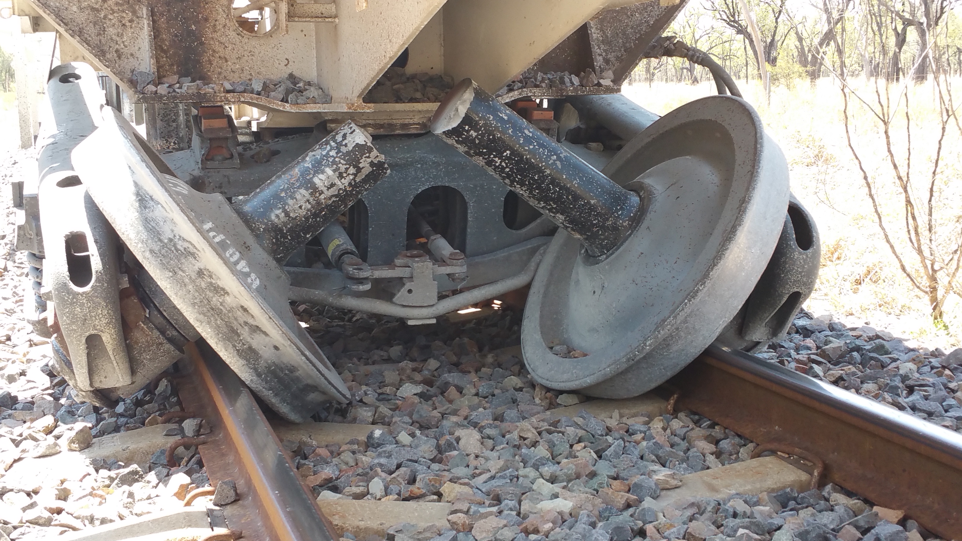
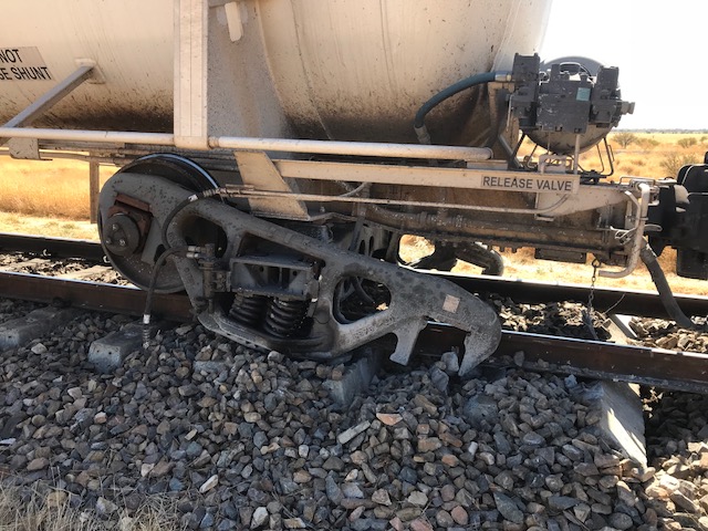
At 2310, the driver contacted the network control centre (NCC) in Townsville to report the train had stopped. He also advised that the other driver had exited the locomotive to inspect the train and determine the source of the sparks. A short time later, the driver confirmed to the NCC that an axle on the train had fractured, allowing one wheel set on the fourteenth wagon to derail (Figure 2).
Figure 2: Failed axle in-situ from train 9T90

Source: Incitec Pivot Limited
There were no injuries or sulphuric acid spill. The track and rolling stock sustained minor damage. The train was repaired and the Mount Isa line was reopened at about 1630 the following day.
__________
Track information
Queensland Rail (QR) managed the railway where the derailment occurred, with the movement of rail traffic controlled from the QR Control Centre located at Townsville in Queensland.
The narrow gauge (1,067 mm) track at the derailment location consisted of 47 kg/m rail fastened to concrete sleepers by resilient clips with ballast to a nominal design depth of 200 mm. Heading west, approaching the derailment site, the track was largely tangent over undulating terrain.
Track condition
QR inspected the track regularly as part of its maintenance regime and no track anomalies were found that might have contributed to the broken axle.
QR applied a standard formula, known as track condition indices (TCI), to determine the overall condition of the track. The TCI was calculated by adding the condition index values of four track geometry parameters - top, twist, gauge and versine.[2] The resultant number represents the condition of one length of track. Weighted averages for all TCIs over a line section are known as overall track condition index (OTCI). Figure 3 shows the OTCI for the line between Charters Towers and Pentland. The lower the score, the better the general condition of the track. The figure shows a consistently low index, below the designated maintenance intervention level of 58 (red line).
Figure 3: Charters Towers to Pentland section OTCI

Source: Queensland Rail
The OTCI of the Mount Isa line, (Figure 4) from June 2011 until December 2017 similarly identified that the general condition of the track was below the intervention level.
Figure 4: Mt Isa line OTCI

Source: Queensland Rail
Train and crew information
Train 9T90 was a freight service operated by Australia Eastern Railroad (Aurizon) between Sun Metals Townsville and Phosphate Hill. It consisted of Aurizon locomotives (2832 leading) hauling 52 freight tanker wagons (GATX strings 6, 8, 11, 10). Incitec Pivot Limited (IPL) owned the GATX freight tanker wagons and the consignment. The train was about 730 m in total length and had a mass of about 4296 t. The consignment contained dangerous goods, including about 1.67 million litres of sulphuric acid.
The train was crewed by two drivers. Both drivers commenced work at Townsville at about 0245 on 28 September 2017. They were to take control of train 9T90 at Townsville and drive through to Hughenden (Figure 1), where they would finish their shift. After the incident, the train crew submitted to drug and alcohol testing and returned zero readings.
Rolling stock – locomotives
Aurizon was an accredited Queensland rolling stock operator. It owned and operated the diesel electric locomotives hauling train 9T90. Aurizon was providing a hook and pull service[3] to IPL for train 9T90 at the time of the derailment.
The locomotive was fitted with Ultra High Frequency (UHF) train control radio and a GPS. The GPS system enabled the monitoring of the locomotive location and speed by the NCO at the QR train control centre in Townsville. The following driver aids were also available:
- station protection device
- vigilance control system
- automatic train protection
- direct traffic control system.
Locomotive 2832 was also fitted with a data logger, which recorded various parameters including:
- time
- GPS position, speed and distance travelled
- throttle position
- driver vigilance
- motor current
- air reservoir/brake cylinder pressures.
There were no anomalies identified in the train speed, handling, or operational performance leading up to the derailment.
Rolling stock – tanker wagons
IPL was an accredited Queensland rolling stock operator and operated the United States‑designed, Australian‑made, GATX tanker wagons.
The tanker fleet comprised 145 wagons, classified as OSZY class wagons. The fleet operated as 11 13-wagon strings plus two spare wagons. A product hose interconnected each tanker wagon within a string. This configuration enabled the stabling of the strings at Phosphate Hill and decanting of product as required.
Each wagon, including the subject wagon OSZY44795, consisted of a tank mounted on two bogies with tare weight 22.26 t, gross weight of 80.66 t, and 12.9 m overall length. Each bogie consisted of two wheel sets. A wheel set was made up of two wheel discs, two roller bearings, and a solid axle shaft. The wheel discs were pressed onto the axle wheel seats and retained by an interference fit. Similarly, the bearings were pressed onto the axle bearing journals and retained by an interference fit.
Axles
The solid steel axles of the GATX fleet, designated as 840P1, are 1,879 mm long with a central barrel tapered from 154 mm in the centre to 170 mm towards the wheel seats, (Figure 5). Other operators also used rolling stock configurations with 840P1 axles.
The 840P1 axles are designed in accordance with Australian Standard AS1448, Carbon steel and carbon-manganese steels—Forgings (ruling section 300 mm maximum). The standard specifies minimum requirements in terms of chemical and mechanical properties of the steel.
Figure 5: 840P1 axle

Source: Incitec Pivot Limited, annotated by ATSB.
Wayside equipment
Wayside equipment was installed at several locations on the occurrence line. The equipment included dragging equipment detectors, overload imbalance load detectors, hot wheel and hot bearing detectors.[4]
A review of data sourced from those detectors did not reveal a condition with wagon OSZY44795 that contributed to the axle failure, or subsequent derailment.
GATX fleet maintenance
The IPL maintenance program included three levels of periodic wagon inspection:
- Level one – a basic walk-around inspection that occurred at Mount Isa, Phosphate Hill and Townsville
- Level two – An annual visual inspection undertaken at the maintenance facility in Townsville
- Level three – a seven yearly inspection, including reline, undertaken at the maintenance facility in Townsville.
IPL engaged United Group Limited (UGL) to perform certain maintenance on the GATX fleet, which in turn engaged Aurizon for wheel set maintenance.[5] IPL provided the ATSB with records detailing the inspections undertaken for the previous 12 months. There were no defects noted by IPL that may have contributed to the axle failure.
Wheel sets
In addition to the periodic inspections, IPL had a planned maintenance program for the GATX fleet. This program included procedures for operation and maintenance of wheels sets, axles, and bearings.[6] In particular, the procedure detailed the operation and maintenance of axles, the relevant section being:
4 Operation and Maintenance - Axles
• Magnetic particle inspection of axle wheel seats and bearing journals including transition radii shall be performed whenever the wheels are removed from the axle.
• More frequent visual and ultrasonic inspection shall be carried out if necessary due to service conditions and axle designs.
• Axle wheel seats found to contain cracks less than 3mm long may be reclaimed by machining. Otherwise, cracked axles shall be scrapped.
• Visual inspection of the bearing journal fillets for corrosion, dents and cracking shall be performed whenever bearings are removed from the axle.
• Prior to inspection, axles must be cleaned and particular care should be taken when inspecting the critical zone, 300mm either side of the centreline. Axles grooved or gouged more than 3mm in depth must be condemned. All nicks, scratches or stampings, less than 3mm in depth must be machined or ground to a smooth contour.
Aurizon, the contracted wheelset maintainer, inspected and overhauled the GATX wheel sets at their wheel shop facility in Rockhampton, Queensland. Aurizon used their standards, procedures, and work instructions detailed in the Aurizon Incoming Inspection Work Instruction, in conjunction with IPL requirements, to inspect and overhaul wheel sets.
The Aurizon inspection process required wheel sets to be:
- cleaned
- inspected, measured, tested, and recorded
- components repaired / replaced (if required)
- machined (if required)
- reassembled
- condemned (if required).
Aurizon last inspected and overhauled the failed wheel set on 7 and 8 June 2017. The inspection included ultrasonic and magnetic particle inspection of the axle. During the inspection process, observations were noted on the Wheelset Incoming Inspection Form. The form noted that the axle passed both ultrasonic and magnetic particle inspections. The form also noted that the wheel set had new bearings fitted and both wheel treads machined. The wheel set was certified to re-enter service and subsequently installed under wagon OSZY44795. Wagon OSZY44795 travelled about 32,000 km prior to the axle failure.
Post incident examination
Material failure analysis
Failure analysis of both parts of the wheel set was conducted at the Queensland University of Technology (QUT) Central Analytical Research Facility in Brisbane under the supervision of the ATSB.
That examination identified that the axle fractured about 341 mm and 526 mm from the in-board side of each wheel disc, (Figure 6).
Figure 6: Fracture location on axle barrel

Source: QUT Central Analytical Research Facility.
QUT noted that the fracture surfaces were intact with minimal secondary damage. There was a 70-mm long fine circumferential white line present at the fracture initiation region at a depth of up to about 3 mm (Figure 7).
Figure 7: White paint on fracture surface near origin

Source: QUT Central Analytical Research Facility.
A scanning electron microscope (SEM) with an energy dispersive spectrometer (EDS) was used to determine the elemental composition of the white line. The SEM EDS analysis indicated the white line residue was rich in titanium, a pigment used in white paint. During the magnetic particle inspection process, white paint is applied to the axle barrel.
Both bearings, from the failed axle, appeared to be in a similar condition with their outer races having sustained secondary damage, most likely as the result of axle failure. The raceways and roller surfaces of the bearings displayed minimal operation-related damage. It was therefore considered likely that the condition of the bearings did not contribute to the axle failure.
Examination of the axle fracture surfaces also identified a single, distinct mechanical notch on the surface of the axle from which faint beach[7] marks originated (Figure 8).
Figure 8: Fatigue origin

Source: QUT Central Analytical Research Facility.
These beach marks indicated propagation of a fatigue crack. The fracture surface was flat and almost perpendicular to the axle barrel’s longitudinal axis. The fatigue fracture face displayed smooth texture indicating fatigue propagation. The fatigue area was relatively large, about 74 per cent of the fracture surface area, penetrating to a critical depth of about 94‑110 mm. Once the crack propagated that far, the remaining section could not support the load and failed rapidly due to overstress.
The mechanical notch measured about 1 mm in length and about 0.2 mm in depth (Figure 9). For this type of axle, the condemning limit is damage extending 3 mm deep or greater. IPL and Aurizon permitted repairs on notches up to 1.5 mm deep in the axle central area, and up to 2 mm deep elsewhere. There was no evidence that the coincident mechanical notch was detected or repaired during the last inspection on 7 June 2017. Although, given the shallow notch depth (0.2 mm), it may have been assessed as not requiring repair.
Figure 9: SEM image showing the initiating notch at the fatigue crack origin

Source: QUT Central Analytical Research Facility.
The microstructure of the axle material appeared banded and consisted predominantly of equiaxed pearlite and ferrite, indicating that it was likely in a normalised condition (correctly manufactured). Manganese sulphide inclusion stringers were observed in the sample. These stringers can contribute to corrosion fatigue, but would have a negligible effect on normal fatigue crack growth.
Non-destructive testing, consistent with the relevant Australian Standards, was conducted on the axle sections. Ultrasonic examination did not detect any major discontinuities within the axle body. Fluorescent magnetic particle inspection found small, isolated inconsequential surface flaws.
Samples taken from the axle were chemically analysed and found to be largely consistent with Australian Standard AS1448/K5.[8] These results were compared to the manufacturer’s test certificate for axle steel batch used during its manufacture in July 1999 (Table 1).
Table 1: Chemical analysis
|
C |
Si |
Mn |
P |
S |
Ni |
Cr |
Mo |
Cu |
|
|
AS1448/K5 |
.35-.45 |
.1-.35 |
.5-1.0 |
<.05 |
<.05 |
<.35 |
<.3 |
<.1 |
.35 |
|
Batch records |
.37 |
.23 |
.69 |
.013 |
.02 |
.09 |
.1 |
.02 |
.26 |
|
Failed axle |
.34 |
.23 |
.38 |
.01 |
.02 |
.08 |
.1 |
.03 |
.25 |
(C) Carbon, (Si) Silicon, (Mn) Manganese, (P) Phosphorus, (S) Sulphur, (Ni) Nickel, (Cr) Chromium, (Mo) Molybdenum, (Cu) Copper
The results showed that carbon was slightly low (0.34 per cent rather than 0.37 per cent) and manganese was low (0.38 per cent rather than 0.69 per cent) in the axle sample. The low carbon reading was negligible and likely did not affect the overall mechanical strength of the axle or notch resistance. Similarly, there is no evidence that the low manganese reading affected the mechanical strength of the axle, (Table 2).
Samples from the failed axle were also mechanically tested and found to meet, or exceed, the minimum mechanical property requirements of the Australian Standard AS1448/K5 (Table 2).
Table 2: Mechanical analysis
|
Australian Standard AS1448/K5 |
Failed axle |
|
|
Yield (MPa) |
270 |
370 |
|
Tensile (MPa) |
540 |
574 |
|
Elongation (%) |
16 |
23 |
Magnetic particle inspection
Magnetic particle inspection (MPI) is a non-destructive testing process widely used to inspect ferromagnetic materials for surface cracks. The rail industry commonly uses MPI to inspect axles for cracks. IPL specified the use of applicable standards, including the Aurizon standards and work instructions. The Aurizon document suite also referred to the relevant Australian standards for axles and MPI, which included rail‑related standards.
The Rail Industry Safety and Standards Board is responsible for the development and management of rail‑related Australian Standards, rules, codes of practice and guidelines, all of which have national application. The Australian Standard AS7515:2014 Axles described the requirements for the design, manufacture and maintenance of rolling stock axles to prevent derailments caused by axle failures.
Part 7 of AS7515:2014 described the use of MPI during axle inspection and referred to Australian Standard AS1171:1998 Non-destructive testing – Magnetic particle testing of ferromagnetic products, components and structures. AS7515 stated that a risk‑assessed consideration of:
- previous failures
- service conditions
- high failure consequences
- axle designer recommendations.
may indicate that more frequent inspections were required.
AS1171 specified the requirements of magnetic particle testing for the detection of surface and near-surface discontinuities in ferromagnetic products, components and structures. The standard provided detail on:
- testing personnel requirements
- equipment and materials
- methods of test
- process control procedure and requirements
- test records and reports.
Qualifications
The effectiveness of magnetic particle testing depends on the technical competence of the personnel performing the tests and on their ability to interpret indications, as specified in AS 1171. The testing personnel at Rockhampton were appropriately qualified and medically fit, including meeting the visual acuity requirements, for the task.
Equipment testing
Before use, the alternating current electromagnetic yoke (AC yoke) used for the magnetic particle testing was required to be performance checked using Aurizon Work Instruction – Inspection and Reconditioning of Wheelsets WI/2016017. The work instruction reflected the testing requirements contained in AS1171, which stated that a dead weight and standard test piece were to be used. The dead weight test involved the use of not less than a 4.5 kg sample of mild steel with the AC yoke pole spacing between 75 and 300 mm. A standard test piece with known discontinuities was also specified.
Equipment testing in practice
During a site visit to the Aurizon Rockhampton wheel shop, the ATSB observed that only the dead weight test was conducted. A standard test piece with known discontinuities was not used. Additionally, the local work instructions did not reflect the Aurizon and AS1711 requirements to performance check the AC yoke using the standard test piece.
Figure 10: AC yoke

Source: AS1171 Figure 3.2 (b).
Process
Maintenance personnel at the Rockhampton wheel shop had access to the following documents when conducting MPI:
- Aurizon Heavy Maintenance – Rockhampton, In coming Inspection Work Instruction WI‑RO‑WAB-10-001
- Aurizon Rockhampton Work Instruction – Wheel Shop work instruction for MPI of axles WI‑RO-WAB-10-014
- Aurizon Inspection and Reconditioning of Wheelsets WI/2016017
- Australian Standard AS1171:1998 Non-destructive testing – Magnetic particle testing of ferromagnetic products, components and structures
- Australian Standard AS7515:2014 Axles.
Process in practice
During a site visit to the Rockhampton wheel shop, the ATSB noted that during the inspection/testing process, the magnetic ink media (Ardrox 800/3) was not reapplied in between AC yoke placements, nor was there the positional overlap between each test. Both of these processes were required and detailed in Australian Standard AS1171.
Figure 11: AC yoke measurement

The measured width of the AC yoke on the day of the site visit. Source: ATSB
The AC yoke poles are adjustable and the yoke used at the wheel shop had been set to a distance of about one third the length of the axle shaft. The AC yoke was placed on one end of the axle (perpendicular to the centre line), energy applied to create magnetic flux, checked for potential indications, and then moved to the next third and the process repeated. There was no overlap between consecutive tests observed during the ATSB site visit. Once one side of the axle was inspected, the work instruction specified that axle be rotated through 90° and the process repeated until the entire axle was tested (Figure 12). During the site visit, the ATSB noted that the axle was rotated 120° rather than 90°. This equated to nine tests for the axle instead of the required 12.
Figure 12: AC yoke placement

Source: Aurizon Heavy Maintenance – Rockhampton
Axle failures on the Mount Isa line
Between 2008 and 2013, 41 main line derailments occurred on the Mount Isa line. Due to the significant number of derailments, the then-rail regulator, Queensland Department of Transport and Main Roads (TMR) rail regulation unit, undertook a study titled Mount Isa Derailment Analysis 2008 -2013.[9] The study examined the causes with the aim of reducing their frequency and increasing the availability and capacity of the corridor. In October 2015, the rail regulation unit published the report.
The report focused on the operating practices of the:
- rail infrastructure manager in terms of incident prevention, maintenance, repair and upgrade
- rolling stock operators who used the Mount Isa line with respect to the age and suitability of rolling stock, inspection, maintenance practices and incident investigation.
The examination of the 41 derailments relevant to the scope of the report found 35 of these occurred on the main line, five when travelling through passing loops, and one when traversing a yard.
The rail regulation unit assessed each derailment to identify the principal causal factor, identifying rolling stock as the most frequent contributor, followed by track‑related defects (Figure 13).
Figure 13: Principal causal factors

Source: Queensland Department of Transport and Main Roads. Mount Isa Derailment Analysis 2008 -2013 report attachment B
The number of rolling stock-related causal factors was broken down into occurrence and train types (Figure 14).
Figure 14: Defect by train type

Source: Queensland Department of Transport and Main Roads. Mount Isa Derailment Analysis 2008 -2013 report attachment B
The rail regulation unit cited legacy issues associated with rail infrastructure and rolling stock, together with loading irregularities, and identified a series of recommendations to the rolling stock and rail infrastructure managers for consideration.
In response to the identified rolling stock defects/failures, it was recommended that rolling stock operators should:
- improve record keeping and reporting of wheel set and bearing faults, including wayside alarms and derailment history
- review the process for disseminating information regarding the service history of wheel sets to the staff that undertake non-destructive testing of the wheel sets
- review their investigation practices and reporting to capture the history and types of wheel sets involved in catastrophic failures and derailments.
Following the release of the report, TMR established the Mount Isa Line Safety Working Group (SWG) in March 2016. A key objective of the SWG was to provide a platform to rail transport operators for jointly addressing specific recommendations. The SWG incorporated representatives from TMR and the rail transport operators that conducted rail safety work on the Mount Isa railway.
GATX axle failure analysis
In addition to this occurrence, IPL experienced four axle failures on the GATX fleet. Following each axle failure, IPL engaged a specialist consultant to determine the reason for each failure (Table 3).
Table 3: Axle failures, findings, and recommendations
|
Date |
Finding of investigation |
Recommendation from investigation |
|
July 2012 |
Axle contained large fatigue cracks and failed near the centre. Although the fracture surface was damaged obscuring the exact location, the fatigue crack originated from a single point fatigue crack initiation site. (similar to this incident) |
Investigate the cause of impact damage and corrosion damage on the outer surface of the axle/shaft especially adjacent to the fracture initiation area. |
|
November 2014 |
Axle contained large fatigue cracks and failed near the centre. Although the fracture surface was damaged obscuring the exact location, the fatigue crack originated from a single point fatigue crack initiation site. (similar to this incident) |
Conduct root cause analysis covering handling, storage, design, maintenance, and in-service damage. |
|
July 2016 |
Axle contained large fatigue cracks and failed near the centre. Although the fracture surface was damaged obscuring the exact location, the fatigue crack originated from a single point fatigue crack initiation site. (similar to this incident) |
Improving visual inspection of wagons, axle design, wayside detection, auditing wheel set maintenance procedures. Finite element analysis on axles. |
|
August 2018 |
No report produced. The ATSB obtained evidence from this derailment to analyse it as part of the investigation. The failed axles were the same type (840P1), same operation, and similar failure location. |
No report produced. |
Following the recommendations of each report, IPL implemented actions to address the failing axles. Notably, IPL commissioned a finite element analysis (FEA) of the 840P1 axle design.[10] The organisation that conducted the FEA detailed the fatigue assessment in the 840P1 axle and proposed a new axle design ‑ 840P2. The new axle design had a central barrel tapered from 165 mm in the centre to 174 mm towards the wheel seats. The FEA, suggested the maximum von-Mises[11] stresses at the centre of the axles were 28.26 and 15.45 MPa for the existing and proposed axles respectively. [12]
The stresses experienced by the axles were significantly lower than the 370 MPa yield strength of the material and the tensile strength of 574 MPa shown in Table 2. The endurance limit of steels is generally accepted to be 40 per cent of the tensile strength of the material. In this case, the calculated stresses were well below the endurance level for the material. Consequently, by that measure the axles had been designed appropriately and should have infinite life.
Fatigue crack size and growth rate
Based on the FEA report, the computed critical crack sizes[13] at the centre of both axles was:
- existing 840P1 - 110 mm (consistent with the failed axles)
- proposed 840P2 - 130 mm.
The critical crack size for the existing axle design correlated with the observed crack sizes in failed axles. Additionally, the FEA report performed fatigue analysis using software based on fracture mechanics idealisation and Paris’ Law.[14] The resulting fatigue lives are shown in Table 4.
Table 4: Computed fatigue lives
|
Life to grow crack to critical depth (cycles) |
Life to grow crack to critical depth (hours)# |
|
|
Existing 840P1 axle ^ |
19,660,018 |
612 |
|
Proposed 840P2 axle * |
78,755,984 |
2,454 |
Notes: # Based on the assumption that the tanker wagon is travelling at 80 km/h and the wheel diameter is 800 mm.
^ Initial crack depth was 2 mm. Below this value resulted in no crack growth.
* Initial crack depth was 5 mm. Below this value resulted in no crack growth.
Based on the FEA report, and the average of two return trips per week, the existing axle design (840P1) with a 2 mm deep notch would be theoretically at critical risk of failure at 612 hours (26 weeks) of loaded operation. Additionally, the proposed axle design (840P2) with a 5 mm deep notch would be theoretically at critical risk of failure at 2,454 hours (100 weeks) of loaded operation.
The FEA report commented:
It has been shown that under normal operating loads the stress-levels in the axles (both the existing and proposed designs) are relatively low and indicate the axles are adequately designed. Therefore in an ideal environment these axles would not be expected to initiate defects, and therefore would not be expected to fail in the manner in which they have in the field.
Post-incident fleet-wide inspection
Following the derailment of train 9T92 at Hughenden on 15 August 2018, IPL performed in-situ MPIs on the entire GATX wagon fleet. By the end of September 2018, it had detected 17 cracked axles and removed them from service. IPL observed that the initiating notch in those instances was minimal (less than 2 mm) in depth.
Summary
In an operational environment, ballast and other objects can strike an axle possibly forming a notch. If the notch is more than 2 mm deep, it will likely initiate a fatigue crack and propagate to the critical size and fail, unless detected earlier. Conversely, based on the FEA report, notches less than 2 mm deep may not propagate. However, based on the results of fleet‑wide inspections, and given the depth of the coincident notch on the failed axle being 0.2 mm, it appears that in practice other stressors allow a notch less than 2 mm to initiate a crack and propagate until failure.
__________
- Top is the vertical alignment of rails. Twist is the variation in the cross-level between two track locations. Gauge is the distance between the inside running faces of the two rails. Versine is a trigonometric function used to measure and calculate curvature.
- Provision of the locomotive(s) and operating crew.
- These detectors are not designed to, or capable of, detecting cracked axles.
- The contract between UGL and Aurizon for wheel set services subsequently ended with the closure of Townsville, Redbank and Rockhampton Aurizon workshops.
- GATX Acid Transport Wagons: Procedure for Operation and Maintenance For Wheel Sets, Axles And Bearings (79975 v4) 16/4/15.
- Beach marks, or striations, are macroscopic features used to identify fatigue fractures and may be used to estimate the number of fatigue cycles.
- Current at the time of the occurrence.
- Mount Isa Line Derailment Analysis 2008 – 2013, Transport and Main Roads.
- Quest Integrity Sulphuric Acid Wagon Axle FEA and Fatigue Assessment 110274 issued 31 October 2016.
- Equivalent tensile strength.
- The stresses at the centre of the existing and proposed axle designs when under self-weight (full tanker) and centrifugal loading.
- The size of a crack in which propagation transitions to rapid overstress failure of the remaining material.
- Paris’ Law is the relationship between the crack growth rate during cyclic loading and the range of the stress intensity factor.
Train 9T90 derailed near Kimburra, as a result of a failed axle. There was no evidence that train speed, handling, or operational performance contributed to the derailment. Similarly, there was no indication that track condition played a part in the incident.
Incitec Pivot Limited (IPL) had four GATX axle failures in addition to this occurrence. Following each occurrence, IPL incrementally implemented safety actions. The following safety analysis will consider the axle failure mechanism, the susceptibility of the axle type to fatigue cracking and the effectiveness of risk controls to detect such cracks prior to failure.
Development of the occurrence
Failure mechanism
Detailed metallurgical examination of the failed axle identified that in-service impact damage to the axle surface created a notch that led to the initiation of a fatigue crack. That crack propagated undetected until it reached a critical size, resulting in an overstress fracture of the axle. Fracture of the axle led to the separation of the axle halves and subsequent derailment of train 9T90.
Fatigue crack detection
A magnetic particle inspection (MPI) was carried out on the axle three months prior to the failure/derailment. As part of that inspection, white paint containing titanium oxide was applied to the surface of the axle. Examination of the axle fracture surface found titanium oxide residue at a depth within the fatigue crack. That physical evidence indicated that the paint seeped into the fatigue crack during the last MPI and that therefore the fatigue crack was present at the time of the testing. Additionally, the length of the paint residue indicated that the size of the fatigue crack present at the time of the inspection should have been detectable under the MPI process.
A review of the magnetic particle procedure and practice found the following anomalies that likely led to the crack not being identified during the last axle inspection:
- non-overlap of the yoke pole placement
- non‑use of a standard test piece
- non-reapplication of the ink.
There were no work instructions detailing where to place the yoke during the inspection and the adjustable alternating current (AC) yoke was set for one-third the width of the axle. The observed practice was that there was no overlap between the pole arms from one yoke placement to another. This meant that potential indications near or beneath the AC yoke poles may not be sufficiently energised to create enough magnetic flux to accurately and reliably indicate a potential crack. Furthermore, the AC yoke pole placement may also have physically obscured or masked potential crack indications. In the case of the failed axle, the location of the fracture closely correlated with the overlap point of the AC yoke poles.
Although the lift test was performed, the omission of the standard test piece during the equipment testing did not adequately verify the overall system performance. As a result, a defect that may have affected the ability to observe the crack would have been more difficult to identify.
The magnetic ink media was not re‑applied between tests. This increased the risk that the media may become diluted and not indicate a potential crack as obviously as it would with a higher magnetic ink concentration. Consequently, the tester may overlook inconspicuous indications and not detect a crack.
Axle fatigue susceptibility
Rail axles are designed to have an infinite life, with peak stress loading remaining below the endurance limit of material. In the absence of damage that increases localised stresses above that limit, fatigue cracking should not occur.
The finite element analysis commissioned by IPL prior to this occurrence indicated that a notch at least 2 mm deep was required to initiate fatigue cracking. In this occurrence, the initiating notch was only 0.2 mm deep. Furthermore, since 2012, there have been five GATX 840P1 axle fatigue failures that have resulted in a derailment. Following the last of these derailments, at Hughenden in August 2018, IPL conducted an accelerated fleet wide inspection of GATX axles. Those inspections found 17 axles with fatigue cracks. The crack sizes varied but the initiating notch was usually less than 2 mm deep.
That analysis of past derailments and in‑service defects identified that the GATX 840P1 axle was susceptible to fatigue cracking due to relatively minor damage that was not reliably detected prior to failure.
From the evidence available, the following findings are made with respect to the derailment of train 9T90 near Kimburra, Queensland, on 28 September 2017. These findings should not be read as apportioning blame or liability to any particular organisation or individual.
Safety issues, or system problems, are highlighted in bold to emphasise their importance. A safety issue is an event or condition that increases safety risk and (a) can reasonably be regarded as having the potential to adversely affect the safety of future operations, and (b) is a characteristic of an organisation or a system, rather than a characteristic of a specific individual, or characteristic of an operating environment at a specific point in time.
Contributing factors
- In‑service impact damage to the axle initiated a fatigue crack that propagated until failure and resulted in the derailment of train 9T90.
- Anomalies in the magnetic particle inspection procedures likely led to the crack not being detected. [Safety issue]
- The GATX 840P1 axle was susceptible to fatigue cracking due to relatively minor damage that was not reliably detected prior to failure. [Safety issue]
Other finding
- The fatigue crack existed and was of a detectable size at the time of the previous routine magnetic particle inspection.
The safety issues identified during this investigation are listed in the Findings and Safety issues and actions sections of this report. The ATSB expects that all safety issues identified by the investigation should be addressed by the relevant organisation(s). In addressing those issues, the ATSB prefers to encourage relevant organisation(s) to proactively initiate safety action, rather than to issue formal safety recommendations or safety advisory notices.
Depending on the level of risk of the safety issue, the extent of corrective action taken by the relevant organisation, or the desirability of directing a broad safety message to the rail industry, the ATSB may issue safety recommendations or safety advisory notices as part of the final report.
Descriptions of each safety issue, and any associated safety recommendations, are detailed below. Click the link to read the full safety issue description, including the issue status and any safety action/s taken. Safety issues and actions are updated on this website when safety issue owners provide further information concerning the implementation of safety action.
Magnetic particle inspection
Safety issue number: RO-2017-013-SI-01
Safety issue description: Anomalies in the magnetic particle inspection procedures likely led to the crack not being detected.
Safety recommendation description: The Australian Transport Safety Bureau recommends that Aurizon addresses the non-use of standard test pieces during magnetic particle inspection.
Axle fatigue susceptibility
Safety issue number: RO-2017-013-SI-02
Safety issue description: The GATX 840P1 axle was susceptible to fatigue cracking due to relatively minor damage that was not reliably detected prior to failure.
Sources of information
The sources of information during the investigation included the:
- Incitec Pivot Limited
- Aurizon
- Queensland Rail
- Office of the National Rail Safety Regulator
- Queensland Department of Transport and Main Roads (Rail Regulation)
- train crew of 9T90
- Queensland University of Technology Central Analytical Research Facility.
Submissions
Under Part 4, Division 2 (Investigation Reports), Section 26 of the Transport Safety Investigation Act 2003 (the Act), the ATSB may provide a draft report, on a confidential basis, to any person whom the ATSB considers appropriate. Section 26 (1) (a) of the Act allows a person receiving a draft report to make submissions to the ATSB about the draft report.
A draft of this report was provided to Incitec Pivot Limited, Aurizon, Queensland Rail, Office of the National Rail Safety Regulator, Queensland Department of Transport and Main Roads (Rail Regulation), and the train crew of 9T90.
Submissions were received from Incitec Pivot Limited, Aurizon, Queensland Rail, and the Office of the National Rail Safety Regulator. The submissions were reviewed and where considered appropriate, the text of the report was amended accordingly.
Purpose of safety investigationsThe objective of a safety investigation is to enhance transport safety. This is done through:
It is not a function of the ATSB to apportion blame or provide a means for determining liability. At the same time, an investigation report must include factual material of sufficient weight to support the analysis and findings. At all times the ATSB endeavours to balance the use of material that could imply adverse comment with the need to properly explain what happened, and why, in a fair and unbiased manner. The ATSB does not investigate for the purpose of taking administrative, regulatory or criminal action. TerminologyAn explanation of terminology used in ATSB investigation reports is available here. This includes terms such as occurrence, contributing factor, other factor that increased risk, and safety issue. Publishing informationReleased in accordance with section 25 of the Transport Safety Investigation Act 2003 Published by: Australian Transport Safety Bureau © Commonwealth of Australia 2019
Ownership of intellectual property rights in this publication Unless otherwise noted, copyright (and any other intellectual property rights, if any) in this report publication is owned by the Commonwealth of Australia. Creative Commons licence With the exception of the Coat of Arms, ATSB logo, and photos and graphics in which a third party holds copyright, this publication is licensed under a Creative Commons Attribution 3.0 Australia licence. Creative Commons Attribution 3.0 Australia Licence is a standard form licence agreement that allows you to copy, distribute, transmit and adapt this publication provided that you attribute the work. The ATSB’s preference is that you attribute this publication (and any material sourced from it) using the following wording: Source: Australian Transport Safety Bureau Copyright in material obtained from other agencies, private individuals or organisations, belongs to those agencies, individuals or organisations. Where you wish to use their material, you will need to contact them directly. |