
What happened
On 13 May 2017, a Jetstar Airways Boeing 787-8 aircraft, registered VH-VKA, was being operated on a scheduled passenger service from Singapore Changi Airport, Singapore to Melbourne, Victoria. There were two flight crew, nine cabin crew and 231 passengers on board. The captain was designated as the pilot monitoring and the first officer (FO) was the pilot flying.[1]
At about 1325 Coordinated Universal Time (UTC),[2] the aircraft was pushed back from the departure gate at Singapore and the flight crew received taxi instructions for a departure from runway 20 Centre (20C). After a short taxi, the aircraft was lined up for departure at about 1332. The flight crew had set flaps 5 for departure with a calculated rotation speed (VR) [3] of 169 kt at the take-off weight of 191 t. Their planned acceleration altitude was 3,000 ft (the altitude at which the flaps would be retracted from flaps 5 to flaps 1).
The flight crew received air traffic control instructions for a standard instrument departure and the aircraft departed. At about 3,000 ft the FO called for flaps 1 and the captain set the flap lever to the flaps 1 setting. The flight crew then received an engine-indicating and crew-alerting system caution for FLAPS DRIVE, which indicated a fault with the wing flaps. The captain notified air traffic control of the fault, received a clearance to level the aircraft at 6,000 ft and completed the FLAPS DRIVE fault checklist actions. The aircraft entered a holding pattern at 6,000 ft and the captain elected to assume the role of pilot flying after the decision was made to return to Singapore.
While in the holding pattern, the flight crew completed their failure management briefing and briefed the cabin crew manager about the occurrence and their plan. The captain then made a public address to the passengers to inform them of the need to return to Singapore due to a technical issue with the flaps. The FO contacted the company to report their intentions, calculated the reference landing speed (VREF)[4] as 195 kt[5] at about 188 t[6] with flaps 1 selected and briefed the arrival procedure. The captain elected not to jettison excess fuel due to their proximity to other aircraft in the holding pattern, the landing distance required provided a sufficient safety margin, and the fact that the checklist did not require it.
The aircraft landed without incident and was taxied to the gate with emergency service vehicles in attendance. The captain noted on the engine-indicating and crew alerting system that there was a high brake temperature on one of the right landing gear brakes after landing and reported this to the engineering staff after shutdown. Before the flight crew exited the aircraft an engineering staff member entered the flight deck to report that they found damage to the left wing. This was followed by a report from a ground handling staff member that rubber debris was found on runway 20C (Figure 1). The captain annotated the FLAPS DRIVE fault and overweight landing with a ‘positive’[7] touchdown in the aircraft technical log.
Figure 1: Tyre debris on runway 20C
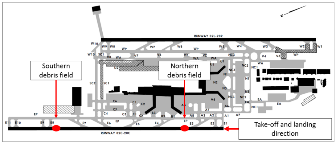
Source: ATSB (debris field locations courtesy Transport Safety Investigation Board, Singapore)
Aircraft flaps
The aircraft is fitted with inboard and outboard trailing edge flaps, and leading edge slats on each wing (Figure 2). The trailing edge flaps are used in conjunction with the leading edge slats to increase lift at lower speeds. The flap positions for the 787-8 are 0, 1, 5, 15, 20, 25 and 30 units. Take-off settings are 5, 15 and 20. Normal landing settings are 25 and 30.
Figure 2: Boeing 787 flap and slat system
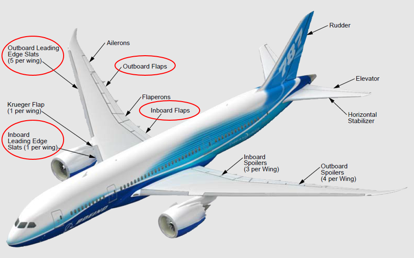
Source: Copyright © Boeing. Reprinted with permission of The Boeing Company, modified by the ATSB
Power to move the flaps is provided by hydraulic or electric motors on a power drive unit (PDU), which turns flap torque tubes, which in turn operate geared rotary actuators (Figure 3). The geared rotary actuators extend or retract the flaps with their drive arms. The aircraft’s flight control electronics cabinets monitor the position of each section of flap for misalignment using four flap skew sensors. The flight control electronics cabinets shut down the flap drive system and send an engine-indicating and crew-alerting system message (FLAPS DRIVE) if a flap asymmetry is detected.
Figure 3: Boeing 787 flap drive system
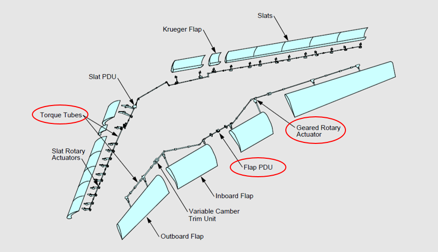
Source: Copyright © Boeing. Reprinted with permission of The Boeing Company, modified by the ATSB
Flaps drive fault procedure
The Boeing 787 flight crew operations manual indicated that the annunciation of FLAPS DRIVE is for a flap drive mechanism failure. Alternate flaps should not be used as asymmetry protection will not be provided. The ground proximity warning system should be set to flap override (to prevent nuisance warnings of incorrect flap configuration during the approach). The manual also stated that the flight management computer fuel predictions should not be used in this condition. If the fault occurred at flaps 5 or less, then the flap lever should be set to flaps 1 to ensure the slats are extended (Figure 2 and 3) and use the VREF for flaps 30 plus 40 kt for landing.
Flight data recorder
The flight data recorder provided the following key events (Table 1).
Table 1: Key events from the flight data recorder
| Time | Event |
| 13:35 | Aircraft became airborne at about 180 kt |
| 13:36 | Flap lever set in flaps 1 detent – flaps not in commanded position – leading edge/trailing edge surfaces in motion (about 3,500 ft pressure altitude) |
| 13:36 | Flap asymmetry detected – flap drive system shutdown |
| 13:36 | Flaps drive fault message (flap lever remains in flaps 1 position until after landing) |
| 13:38 | Ground proximity warning system flap override set |
| 14:16 | Touchdown at about 190 kt |
Aircraft damage
Inspection of the aircraft found the number 6 wheel tyre tread had delaminated (Figure 4). Damage to the airframe included the left inboard wing panel (above the number 6 wheel) was punctured (Figure 5 left), an area of the trailing edge of the left inboard flap was cracked, and the left inboard flap torque tube was broken (Figure 5 right). A broken torque tube will interrupt the flap drive system for flaps outboard of the break. Consequently, a change in the flap setting will trigger a misalignment between the flap skew sensors.
Figure 4: Number 6 wheel tyre (left picture looking forward and the right looking rearwards)
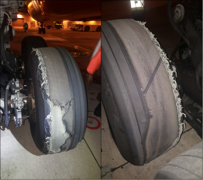
Source: Operator
Figure 5: Punctured panel (left) and broken flap torque tube (right) (panel removed)
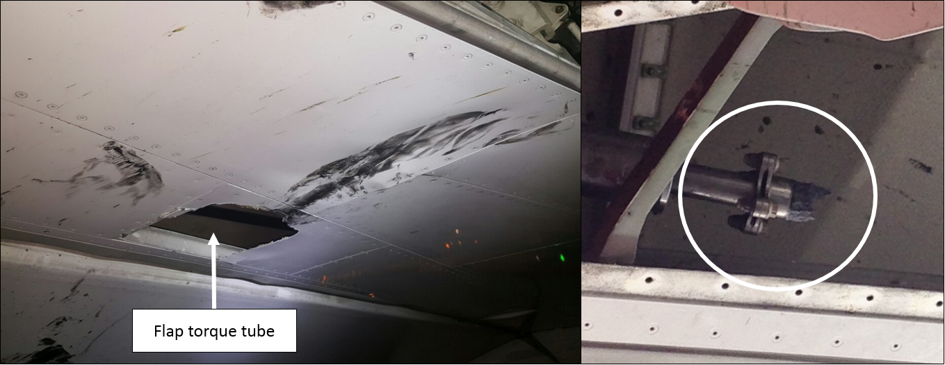
Source: Operator, modified by the ATSB
Forces on an aircraft tyre
Aircraft tyres are designed for intermittent operation in which they are accelerated to high speeds in short periods of time. While the acceleration of the tyre is higher on landing, the take-off speed is usually higher compared to landing. The sudden periods of acceleration generate high temperatures and centrifugal forces, and, because the tyre is pneumatic, this leads to compression, tensile and shear forces. Deflection of the tyre tread from contact with the runway surface distorts the tyre from the normal shape and sets up a traction wave in the tread. This leads to higher tensile forces on the outer plies than on the inner plies, which generates shear forces between the layers of ply (Figure 6). Aircraft tyres have a groundspeed rating, which was 235 MPH (about 204 kt) for the occurrence aircraft tyre.
Figure 6: Generic tyre construction
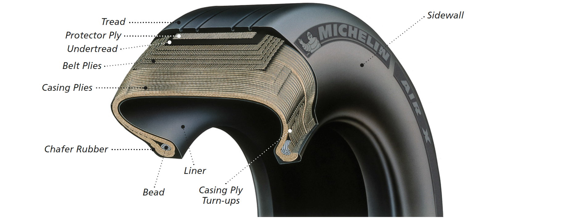
Source: Michelin
Damaged tyre
The damaged tyre was Michelin part number M42202 for the Boeing 787, which was a replacement for the previous M42201. The damaged tyre and the number 5 wheel tyre (mate tyre) were returned to the tyre manufacturer for tyre analysis. The manufacturer’s report noted that 360° of tread was missing and the reinforcing plies were exposed and abraded in areas (Figure 7 left). There was shoulder step-wear and a crack along the serial side[8] shoulder (outboard of main landing gear truck) that had propagated through the tread reinforcing ply. There were no indications of rolling under low pressure.
Figure 7: Number 6 wheel tyre (left) and number 5 wheel tyre (right)
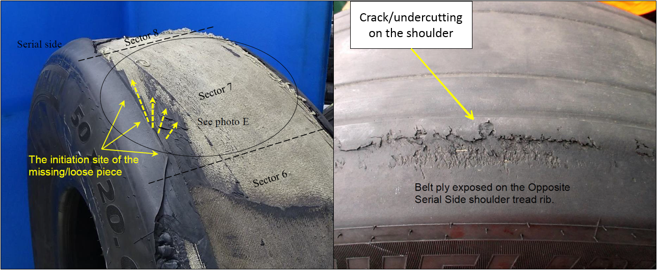
Source: Michelin, modified by the ATSB
The manufacturer’s report concluded that the shoulder step-wear allowed for a raised tread rib, which was subjected to a lateral force strong enough to tear the tread rubber with continued use. The cracking ‘propagated through the tread reinforcing ply and generated the thrown tread as the consequence’ (Figure 7 left). The number 5 wheel tyre was found with cracking on the opposite serial side shoulder (inboard of main landing gear truck), which had started to propagate through the tread reinforcing ply (Figure 7 right). They concluded that chevron cutting around the tread of both tyres indicated that they had been operated on an aggressive runway surface.
When asked to clarify the reference to an ‘aggressive runway surface’, the manufacturer indicated that chevron cutting is linked to grooved runways. The forces required to accelerate the tyre to ground speed during the touchdown phase generate a tearing action, which results in the chevron cutting damage.
Tyre maintenance
The number 6 wheel tyre was received by the operator as a new tyre with a Civil Aviation Safety Authority authorised release certificate, dated 30 November 2016. The wheel assembly was installed on VH-VKA on 9 December 2016 and had accumulated 302 cycles at the time of the failure. The maintenance program inspection interval for the tyres included a general visual inspection on each arrival. The replacement interval for the tyre was ‘on-condition’.[9] The number 5 wheel tyre had accumulated 307 cycles at the time of the incident. Both tyres were below the average life for the operator’s use of these part numbers. The operator reported that this was their first occurrence of a tyre delamination on its 787 fleet.
On arrival at Singapore Changi Airport from the previous flight, the aircraft was subjected to an arrival check and a pre-departure service check. The checks were certified as satisfactory and completed at 1145 UTC. Item 1.2 on the arrival check included:
Inspect (General Visual) the Nose and Main Wheel Tyres IAW DMC-B787-A-32-45-04-00B-311A-A
Note: Ensure tyres have a sufficient life remaining for the intended flight/s, including the return to an Australian Port.
Item 1.1 of the pre-departure service check included an inspection of the nose and main wheels and tyres. However, this check was not required to be performed if the same maintenance person performed the arrival check within the previous 120 minutes and was certifying for both checks. Both checks had the same certifying person’s signature and stamp. The operator reported that the certification for the pre-departure service check was likely an acknowledgement that the tyre check was not required, rather than that it was performed.
The checks took place between 0910 and 1145. Sunset in Singapore on 13 May 2017 was about 1106.
The aircraft maintenance manual task (DMC-B787-A-32-45-04-00B-311A-A) for the general visual inspection of the tyres included the following instructions:
1. C. (1) (a) Examine the tyres for air leaks, abrasions, unusual worn areas, cuts, and flat spots.
1. C. (1) (c) Remove tyres that have the conditions that follow:
- 1) Cuts or weather cracks in the grooves, the tread, shoulders or sidewalls that exceed the limits shown in Figure 2, Tyres General Visual Inspection.
- 2) Blisters, bulges, or other signs of ply separation in the tread, shoulder or the sidewall area.
Michelin’s care and service instructions
Michelin’s aircraft tyre care and service manual, chapter 5, section 8.17 described a ‘thrown tread’ as the ‘partial or complete loss of the tread rubber.’ Potential causes include cuts. The manual stated:
Early signs of separations of internal components may appear as bulges, uneven wear, or localised rubber splits. It is important to remove tyres from service when any evidence of separation is first seen. During high-speed rotation, even small areas of separation can grow into partial or full tread rubber loss.
Chapter 5, section 7.2 indicated ‘removal criteria for normal wear is based on remaining tread rubber as determined by groove depth or exposure of textile/steel ply material’.
Operator’s flight data review
A comprehensive review of flight data was conducted to determine if operational techniques, such as lateral acceleration on take-off and touchdown, may have exposed the tyre to increased side load. No occurrences were noted for any of the operator’s aircraft in the 787 fleet.
Safety analysis
The flap drive fault the flight crew received on departure from Singapore Changi Airport was the result of the delamination of the number 6 wheel tyre tread during take-off. The airport operator found two debris fields on runway 20C, which was used for the take-off and landing. The delamination on take-off likely occurred at the southern end of the runway, when the tyre was at high speed, which provided sufficient energy for the tread to penetrate the left under wing panel and break a flap torque tube. The runway 20C northern debris field was likely the result of further tyre delamination on landing as a result of the touchdown and wheel acceleration.
The tyre manufacturer concluded that the tyre had operated over its life on a grooved runway surface, which generated chevron cutting damage. Before departure the aircraft tyres were certificated as inspected in accordance with the aircraft manufacturer’s general visual inspection requirements. While no faults were recorded for the arrival and pre-departure service checks, it was possible that the tyre shoulder was already subject to undercutting of the tread before departure. The arrival inspection likely occurred during daylight hours, but the aircraft may have been parked with the tyre tread positioned such that the initiation site was not visible to the inspector. However, this was not confirmed by the ATSB. However, the certification for the pre-departure service check was likely an acknowledgement that the tyre check was not required, rather than that it was performed.
When the flight crew moved the flap selector from the flaps setting of 5 to 1, the left inboard and outboard flaps were unable to move, due to the broken torque tube. The right flaps started to move, which generated a flap misalignment signal. The flight control electronics cabinets shut down the flap drive system in response to the misalignment and generated the FLAPS DRIVE fault message. The flight crew then completed the FLAPS DRIVE checklist. While the crew did not know about the tyre damage, the aircraft protective systems and crew actions allowed for a safe return and landing, despite the aircraft being overweight and at a higher-than-normal landing speed.
Findings
These findings should not be read as apportioning blame or liability to any particular organisation or individual.
- The number 6 wheel tyre experienced shoulder step-wear, which led to cracking and undercutting of the tyre tread and a subsequent delamination of the number 6 tyre, which occurred in less than the normal average life cycles.
- Debris from the delaminated tyre penetrated the left under wing panel and damaged the flap torque tube, resulting in an asymmetric flap condition when the flaps were commanded to retract.
- When retracting the wing flaps, the crew received a flap drive fault indication, which resulted in a return to the departure airport and a high-speed overweight landing.
- Following the damage to the flap torque tube, the aircraft protective systems operated as designed and the flight crew completed the checklist as published.
Safety action
Whether or not the ATSB identifies safety issues in the course of an investigation, relevant organisations may proactively initiate safety action in order to reduce their safety risk. The ATSB has been advised of the following proactive safety action in response to this occurrence.
Aircraft operator
As a result of this occurrence, the aircraft operator has advised the ATSB that they have taken the following safety action:
Quality notice
The operator issued a quality notice to their maintenance line stations and external maintenance organisations on the subject 787 Main Landing Gear Tyre Inspections (Shoulder Wear). The notice explained the incident and highlighted the inspection and tyre replacement requirements for tyre shoulder damage.
Flight standing order
The operator issued a flight standing order to their 787 pilots on the subject of Tyre Wear to highlight the shoulder area of the tyre as requiring extra attention during pre-flight inspections.
Safety message
Following the flaps drive fault message, the flight crew completed the appropriate checklist and landed at the nearest suitable airport without further incident. While the condition of the tyre and the exact fault with the flaps were unknown to the flight crew at the time of their decision-making, this occurrence highlights the importance of following failure management procedures.
Purpose of safety investigationsThe objective of a safety investigation is to enhance transport safety. This is done through:
It is not a function of the ATSB to apportion blame or provide a means for determining liability. At the same time, an investigation report must include factual material of sufficient weight to support the analysis and findings. At all times the ATSB endeavours to balance the use of material that could imply adverse comment with the need to properly explain what happened, and why, in a fair and unbiased manner. The ATSB does not investigate for the purpose of taking administrative, regulatory or criminal action. TerminologyAn explanation of terminology used in ATSB investigation reports is available here. This includes terms such as occurrence, contributing factor, other factor that increased risk, and safety issue. Publishing informationReleased in accordance with section 25 of the Transport Safety Investigation Act 2003 Published by: Australian Transport Safety Bureau © Commonwealth of Australia 2017
Ownership of intellectual property rights in this publication Unless otherwise noted, copyright (and any other intellectual property rights, if any) in this report publication is owned by the Commonwealth of Australia. Creative Commons licence With the exception of the Coat of Arms, ATSB logo, and photos and graphics in which a third party holds copyright, this publication is licensed under a Creative Commons Attribution 3.0 Australia licence. Creative Commons Attribution 3.0 Australia Licence is a standard form licence agreement that allows you to copy, distribute, transmit and adapt this publication provided that you attribute the work. The ATSB’s preference is that you attribute this publication (and any material sourced from it) using the following wording: Source: Australian Transport Safety Bureau Copyright in material obtained from other agencies, private individuals or organisations, belongs to those agencies, individuals or organisations. Where you wish to use their material, you will need to contact them directly. |
__________
- Pilot flying (PF) and Pilot monitoring (PM): procedurally assigned roles with specifically assigned duties at specific stages of a flight. The PF does most of the flying, except in defined circumstances; such as planning for descent, approach and landing. The PM carries out support duties and monitors the PF’s actions and the aircraft’s flight path.
- Coordinated Universal Time (UTC): the time zone used for aviation. Local time zones around the world can be expressed as positive or negative offsets from UTC.
- VR: the speed at which the rotation of the aircraft is initiated to take-off attitude. This speed cannot be less than V1 or less than 1.05 times VMCG. With an engine failure, it must also allow for the acceleration to V2 at a height of 35 ft at the end of the runway.
- The reference landing speed of an aircraft is that which it attains in a specified landing configuration during a stabilised approach to a screen height of 50 ft and is used to determine the landing distance for a manual landing.
- The captain commented that a typical VREF was about 145 kt.
- Maximum landing weight is 172 t.
- Following an overweight landing the captain is required to make an entry in the technical log to describe the touchdown as ‘smooth’, ‘positive’, ‘firm’, or ‘hard’, based on their own judgement.
- Serial side refers to the side with the tyre serial number.
- On-condition maintenance means an inspection/functional check that determines an item's performance and may result in the removal of an item before it fails in service.