What happened
At 1748 Australian Eastern Daylight-saving Time on 29 December 2014, a Cessna 172S aircraft, registered VH‑PFT, departed Cambridge Airport, Tasmania to photograph yachts participating in the 2014 Sydney Hobart race as they made their way around the southern coast of the Tasman Peninsula. On board the aircraft were the pilot and a photographer.
At about 1815 the aircraft commenced low-level photographic runs on yachts to the east of Cape Raoul. Shortly after completing a run on one yacht at a height of about 50 ft, the aircraft entered a steep climbing turn. The aircraft had almost completed a 180° turn when the upper (right) wing dropped sharply while the aircraft’s nose pitched down to almost vertical. The aircraft impacted the water’s surface in an almost vertical nose down attitude with wings about level. Both aircraft occupants were fatally injured, and the aircraft was seriously damaged.
What the ATSB found
As a result of the steep climbing turn, the aircraft’s upper wing aerodynamically stalled, resulting in a rapid rotation out of the turn. The steep pitch attitude indicated that, because of the stalled upper wing, the aircraft entered a spin. There was insufficient height for the pilot to recover the aircraft. The steep climbing manoeuvre was not in accordance with the pilot’s training for low-level flight. Cessna identified that any C172 type aircraft that enters a stall/spin condition will require significant height to recover.
The Civil Aviation Safety Authority had issued the operator with a dispensation that permitted low-level flight down to 150 ft above obstacles. Low-level photographic operations on yachts conducted by the operator had been consistently flown at heights down to 50 ft. Although the aircraft was being operated at a height lower than that authorised by the dispensation, that in itself was not likely to have contributed to the accident.
The ATSB examined the role of the operators’ Safety Management System (SMS). While it was not established that the safety risk management processes and practices directly contributed to the occurrence, there were aspects that the operator could consider working towards to more effectively identify all key operational risks.
What's been done as a result
The operator advised that it has ceased low-level photography flights.
Safety message
Turning manoeuvres at or close to the aircraft’s critical angle of attack, or stall speed, if poorly handled, can result in a stall that will probably result in the aircraft entering a spin. This is particularly true for aircraft under 5,700 kg. The normally benign stalling characteristics of these aircraft types are exacerbated by the spin entry, which results in a steep pitch down and rotation towards the stalled wing. Recovery from this condition will take a considerable amount of altitude, dependant on the speed of response by the pilot and the use of appropriate control inputs.
Photograph of VH-PFT
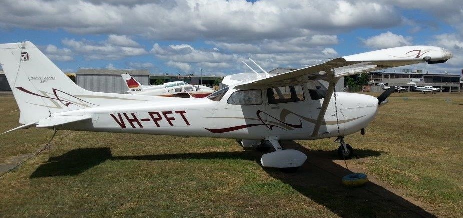
Source: Aircraft operator
At 1748 Australian Eastern Daylight-saving Time[1] on 29 December 2014, a Cessna 172S aircraft, registered VH-PFT, departed Cambridge Airport, Tasmania on an aerial work flight. On board the aircraft were the pilot and a photographer. The purpose of the flight was to photograph yachts participating in the 2014 Sydney Hobart Yacht Race as they sailed around the southern coast of the Tasman Peninsula and into Storm Bay en route to Hobart. This was the third photographic flight conducted by this pilot and photographer that day.
The aircraft transited from Cambridge Airport to Clifton Beach and then, at about 1757, descended from around 1,500 ft down to a height below 500 ft at a position about 8 km to the north-west of Wedge Island (Figure 1). At about 1800, the aircraft commenced low-level photographic passes (photographic run) on yachts to the west of Wedge Bay. It then tracked to the south-east towards Cape Raoul and after passing Cape Raoul tracked in an easterly direction, while continuing to conduct photographic runs on yachts.
Figure 1: Maritime map of the southern Tasman Peninsula coast, with Wedge Island, Cape Raoul and the location of the wreckage highlighted
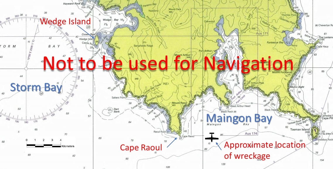
Source: Australian Hydrographic Service, modified by ATSB
About 25 minutes into the flight, the aircraft commenced photographic runs on a number of yachts that were becalmed to the south of Maingon Bay. At about 1815, it commenced a photographic run on the yacht Mistraal, which was transiting Maingon Bay under power. Witnesses stated that, during that photographic run, the aircraft was tracking in a north-westerly direction and passed close to Mistraal’s port side bow at about mast height. The pilot had positioned the aircraft so that Mistraal passed down the aircraft’s starboard side. After passing abeam Mistraal, the aircraft continued on its north-westerly track for about 20 seconds and then commenced a steep left turn.
A witness to the full accident sequence, who was about 500 m to the south-west of Mistraal, stated that the aircraft:
- appeared to pitch up and climb about three to four aircraft lengths while simultaneously banking sharply to the left
- had almost completed a 180° turn when the upper (right) wing dropped sharply and the aircraft’s direction of turn reversed
- was at an estimated height above the water’s surface, at that time, of about two to three times the mast height of Mistraal
- pitch attitude dropped sharply and the aircraft descend rapidly in a steep nose-down attitude.
The observations of a second witness, who was about 3 NM (5 km) to the south of Mistraal, supported the observations of the first witness, but this witness stated that the turn appeared to be made at a level height.
The aircraft impacted the water’s surface in an almost vertical nose-down attitude with wings about level, approximately 4 km to the east of Cape Raoul.
Mistraal, and a number of other yachts in the vicinity, turned towards the aircraft to give aid. Witnesses stated that the aircraft could be seen mostly submerged with the tail section protruding above the surface of the water. As Mistraal approached the aircraft, it submerged and sank. The location of the aircraft was marked by Mistraal using its global positioning system.
Both aircraft occupants were fatally injured and the aircraft seriously damaged.
__________
Personnel information
The pilot
The pilot was issued with a Private Pilot (Aeroplane) licence in April 2010 and a Commercial Pilot (Aeroplane) Licence in January 2012. The licence included the following endorsements and ratings:
- manual propeller pitch control
- single-engine aircraft under 5.7 tonnes maximum take-off weight
- retractable undercarriage
- aerobatics
- a low-level flight rating
- a multi-engine BN2 Britten-Norman Islander rating
- a multi-engine BE76 Beechcraft Duchess rating
- a command instrument rating for multi-engine aircraft, issued in August 2014.
A summary of the pilot’s flight experience is at Table 1.
Table 1: Summary of flight hours
| Flying Time | Cessna 172 | Other Single Engine | Multi Engine | |
| Last 90 days | 65 | 10 | 55 | |
| Total | 820 | 275 | 310 | 235 |
The pilot completed a flight review and a renewal of the low-level rating on 19 December 2014. That low-level rating renewal was conducted in a Cessna 172. The record of the flight review included a number of relevant observations:
- a stall recovery was demonstrated, and that the pilot recovered the aircraft from the stall with a 100 ft altitude loss
- the pilot displayed good stall awareness
- the pilot demonstrated 45° angle of bank turns at 150 ft above ground level to a satisfactory standard
- during low-level turning around a point, the pilot had a tendency to climb as the turns progressed.
With respect to the pilot’s low-level flying, records indicated that the pilot:
- obtained the low-level rating in August 2011
- had accrued about 18 hours of low-level flight experience
- had conducted 3 days of low-level over water flights for the purpose of photographing yachts during the 2013 Sydney Hobart race, with a total flight time of about 6 hours
- had completed two low-level overwater flights for the purpose of photographing yachts during the 2014 Sydney Hobart race. These flights were completed earlier in the day on 29 December 2014.
The pilot held a valid Class 1 medical certificate that was renewed in November 2014.
Fatigue
The pilot’s duty and flight hours were within the limits prescribed under Civil Aviation Order 48.1. The first flight of the day conducted by the pilot departed Cambridge at 0608 and landed at 0817; the second flight departed Cambridge at 1320 and landed at 1511. Witnesses reported that in the period between the second and third flight, the pilot did not appear to be fatigued.
The investigation included an assessment of whether the pilot may have been experiencing a level of fatigue known to have an effect on performance. Consideration was made of the pilot’s early start, time awake at the time of the occurrence, potential workload associated with the task, environmental factors, and organisational support; however, the limited data available regarding the pilot’s activities on the day meant there was insufficient evidence to determine whether fatigue was contributory to this occurrence.
The photographer
The photographer’s first experience in aerial photography of yachts was during the 2013 Sydney Hobart race. Those low-level photographic flights were conducted exclusively with the accident pilot. The photographer had requested, and was assigned the same pilot for the photography flights for the 2014 Sydney Hobart race.
Aircraft information
General
The Cessna Aircraft Company 172S (C172S) is a four seat, high wing, all metal, unpressurised, fixed undercarriage aircraft with a single reciprocating engine. It was certified in the Normal and Utility aircraft categories.
VH-PFT
VH‑PFT (PFT) held a current certificate of airworthiness and certificate of registration. The aircraft had a current maintenance release with no noted defects. The last periodic maintenance inspection on PFT was conducted on 24 December 2014, at which time the aircraft had logged about 2,265 hours.
The operator’s Operations Manual did not require a calculation of the aircraft’s weight and balance for the accident flight, and there was no record of a weight and balance for that flight. A post‑accident analysis of the aircraft’s weight and balance indicated that the aircraft was most likely within limits during the entire flight. Records indicate that the aircraft departed with full fuel.
Figure 2: The C172S aircraft registered as VH-PFT
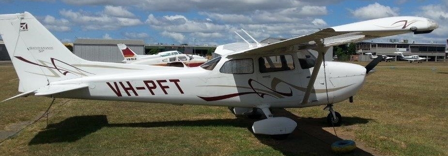
Source: Aircraft operator
The C172S Stall Speed
The stall speeds for the C172S are contained within the C172S Pilot Operating Handbook (POH). For the C172S:
- The stall speeds are quoted at the aircraft’s maximum certified take-off weight of 2,550 pounds (1,157 kg).
- Variation in the aircraft’s centre of gravity can result in minor changes in the aircraft’s stall speed.
- The selection of flap changes the shape of the aircraft’s wing, lowering the stall speeds.
- When banking an aircraft, it is necessary to increase the amount of lift generated to ensure that the aircraft does not descend. The effect is to increase the stall speed as the angle of bank increases.
The relevant stall speeds listed in the C172S POH are listed in Table 2. The POH noted that the speeds were for the aircraft with power at idle, and that the indicated airspeeds (KIAS) quoted were approximate.
Table 2: C172S stall speeds in KIAS
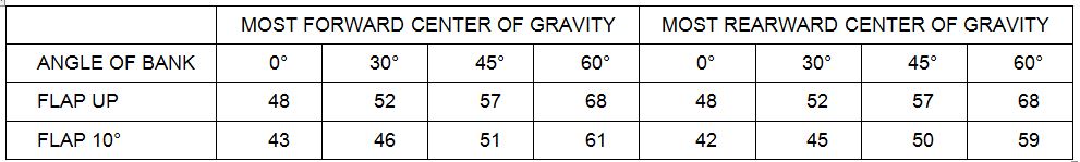
Source: Cessna
The POH also noted that the altitude loss during a stall recovery could be as much as 230 ft.
Instruments and avionics
The C172S is fitted with a pneumatic-type stall warning system. It consists of an inlet in the leading edge of the left wing and a warning horn in the upper left corner of the windshield. The inlet and horn are connected by tubing. As the aircraft approaches the stall, the low pressure on the upper surface of the wings moves forward around the leading edge of the wing. This low pressure creates a differential pressure in the stall warning system that draws air through the warning horn, resulting in an audible warning. The stall warning system was set to produce a stall warning between 5 and 10 kt above the stall speed in all configurations.
PFT was fitted with a Garmin G1000 avionics system. The G1000 used two Garmin Display Units (GDU), the left GDU being the Primary Flight Display (PFD) and the right GDU a Multi-Function Display (MFD) (Figure 3). The G1000 system is capable of storing critical flight and engine data on a memory card, which is inserted into the lower card slot of the MFD. Data is logged in a new file that is created each time the MFD is powered on.
Figure 3: Garmin G1000 avionics system showing normal location of the memory card, as well as the recovered memory card
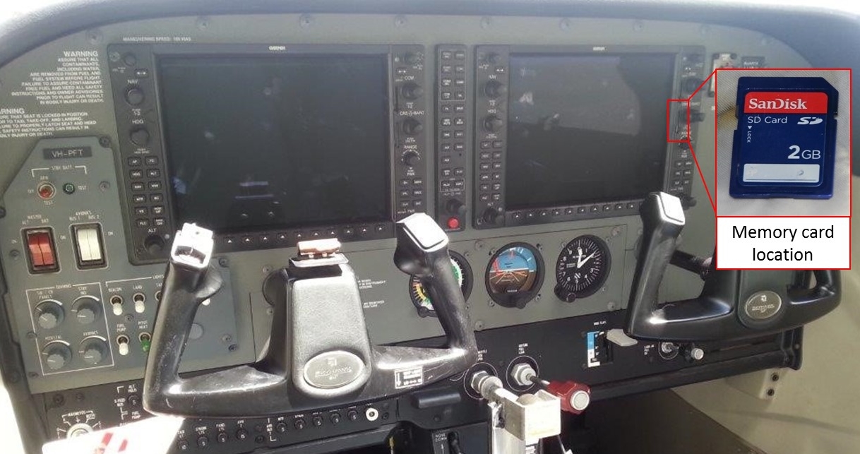
Source: Aircraft operator
Operational information
Low-flying regulations
The conduct of low-level flying was regulated under Civil Aviation Regulations 1988 (CAR), r. 157. This regulation had two relevant parts:
- Flight must not be conducted below a height of 500 ft.[2]
- This height is in relation to the highest point of terrain or any object on that terrain within a radius of 600 m of the aircraft.[3]
CAR r. 157 (4) enabled the Civil Aviation Safety Authority (CASA) to issue a permit for aerial work operations where there was a requirement to operate below the minimum height identified in CAR r. 157. CASA issued the operator with a ‘Low Flying Permission’ under Instrument SR 268/12 dated November 2012. The permission set up a system of conditions required for low flight operations, including oversight and training requirements. The conditions included a requirement that the aeroplane not be flown at a height below 150 ft above obstacles. While not stated explicitly within the instrument, r. 157’s requirement that the lowest height for flight relates to ‘the highest point of terrain or obstacles on that terrain within a 600 m radius of the aircraft’ still applied.
The operator’s Operations Manual
The operator’s Operations Manual (OM) included a requirement for specific approval to be obtained before the conduct of operations below the minimum height requirement of CAR r. 157. The OM identified that SR 268/12 provided that specific approval. SR 268/12 was contained within the appendices to the OM.
The OM also included a section specific to low-level flight, which contained all procedures applicable to the conduct of low-level flight. This section included the following requirements:
- Except for emergency avoidance of hazards, the maximum angle of bank during flight below 500 ft is 45°.
- The minimum horizontal distance to be maintained from buildings when operating below 500 ft above ground level (AGL) or above mean sea level (AMSL) is 600 m.
- The minimum indicated airspeed while flying below 500 ft AGL/AMSL is to be 1.5 times the stall speed (Vs) in the low flying configuration.
- When flying below 500 ft AGL/AMSL the maximum flap setting to be used during level and climbing flight is the maximum take-off flap setting listed in the pilot’s notes or aircraft flight manual.
The C172S POH stated that flap settings greater than 10° are not approved for take-off. Therefore, the maximum flap setting for low-level operations was 10°.
The training syllabus for low-level operations was also contained within the OM. The training syllabus included specific flight sequences and required manoeuvres that were to be demonstrated during low-level flying endorsement training. The training section of the OM did not contain information regarding any methods and skills (techniques) specific to low-level flying.
Low-level flight training
The operator had a number of pilots responsible for low-level flight training and checking (check pilots). They reported that there were a number of techniques specific to the Cessna 172 (C172) type that were emphasised during training for low-level flight. They identified that it was critical to maintain the aircraft in a stable energy state while operating at low level. In doing so, the emphasis was not to perform manoeuvres with large pitch attitude changes, nor to perform radical manoeuvres. These techniques were not included within the operator’s OM.
Stall/spin training and familiarity with the stall/spin
The pilot was familiar with the stalling characteristics of the C172 and with the activation of the stall warning. During the recent flight test, the pilot had demonstrated an ability to recover from the stall with a 100 ft altitude loss.
The pilot’s low-level flight training included emergency manoeuvring sequences that required the pilot to demonstrate maximum rate turns for emergency purposes. The emergency manoeuvre involved the application of backpressure on the control column to attain the maximum lift, which placed the aircraft wing very close to the stall angle. In these circumstances, the pilot was trained to maintain the airspeed for maximum lift by adjusting pitch attitude so that the stall warning activation was intermittent.
When conducting photographic flights, the passenger side cabin window was open to enable clear photography. A test flight by the operator confirmed that the stall warning system was clearly audible when flying with a cabin window open.
Meteorological information
Weather information reported by yachts in the vicinity of the accident identified that the conditions were as follows:
- about 30 minutes before the accident, a squall line passed through the area to the south and east of Cape Raoul
- after the squall line the weather conditions were benign
- at the time of the accident, the wind was 210° at 3.5 kt and there was some low cloud in the area. There was no low cloud in the area where the aircraft was operating at the time of the accident
- about 30 minutes after the accident another squall line passed through the area.
The images recovered from the photographer’s camera and other photography from the yachts in the area confirm these observations.
The Bureau of Meteorology aviation forecast for the Hobart area issued at 1540, covering the period 1600 to 0400 on 30 December, stated that a cold front was expected to pass through Hobart at about 1600 and to continue in an easterly direction, passing through the eastern maritime area at about 1800. East of the front, the winds at 2,000 ft were forecast to be northerly at 35 kt, while to the west of the front the winds would back to westerly at 35 kt. The forecast also included a severe low-level turbulence warning. The bureau provided actual wind recordings from a number of automated weather stations in the Storm Bay area. Detailed records from these weather stations indicated that the wind was generally westerly at about 25 kt at the time of the accident. These records identify that the cold front probably passed through the Maingon Bay area about 1805.
Bureau of Meteorology wind data from a number of automated weather stations in the Storm Bay area is listed in appendix A.
Communications
At the time of the accident, there were no communications from PFT recorded on local air traffic control frequencies. At 1817, when Mistraal turned towards the aircraft to provide assistance, the yacht’s crew notified the yacht race controllers of the accident by marine band radio.
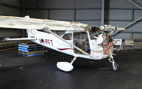
Wreckage information
Recovery of the wreckage
The crew of Mistraal provided their recorded GPS position of the accident location to the Tasmanian Police. A search for, and recovery of, the aircraft wreckage commenced on 31 December 2014. A Tasmanian Water Police vessel was to perform the recovery of the wreckage. To assist with the search and recovery, the Tasmanian Police contracted a Remotely Operated Vehicle (ROV) operator. The ROV was fitted with sonar equipment to aid in locating the aircraft wreckage.
The ROV located the aircraft wreckage at the position provided by Mistraal. Before commencing the recovery, the ROV conducted a survey of the aircraft wreckage using a recorded video link (Figure 4). The survey:
- identified that the aircraft was at a depth of about 90 m
- identified that the aircraft had remained relatively intact and had come to rest upside down
- provided an accurate record of the damage to the aircraft
- identified and recovered the photographer’s camera
- established that the photographer’s seat was at around the fully aft selectable position, indicating that it was unlikely that the passenger could have interfered with the flight controls in flight
- established that the pilot’s seat appeared to be in a normal position.
Figure 4: Image taken from the ROV video recording during the survey of the aircraft on the first recovery operation. The aircraft was lying inverted on the seabed
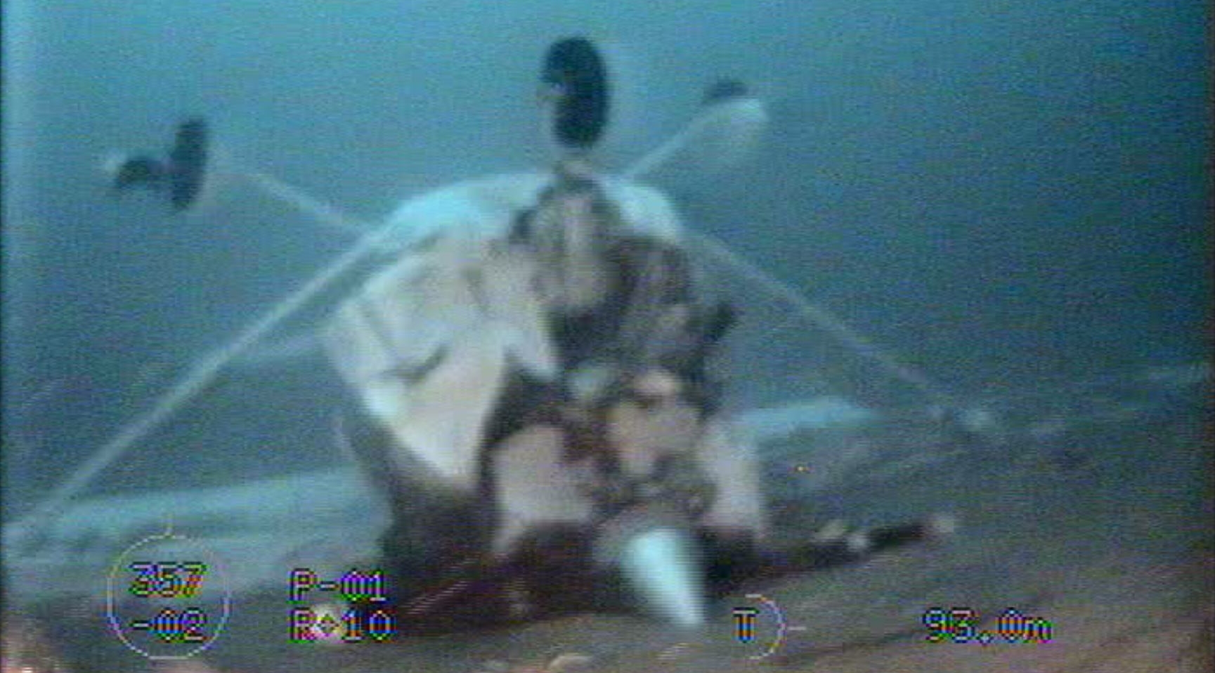
Source: Tasmania Police
The first attempt to recover the aircraft was unsuccessful. The recovery vessel’s winch raised the aircraft to within 15 m of the surface when the rope securing the aircraft broke. The aircraft returned to the ocean floor and came to rest upside down. Due to the weather and ROV availability there was a delay in a second attempted recovery.
On 6 January 2015, a second attempt to recover the aircraft was made utilising the same ROV operator and a locally contracted barge. The barge had specially designed lifting equipment that was not available during the first recovery. The ROV secured that equipment to the aircraft structure (Figure 5) and all of the aircraft was recovered, with the exception of the engine cowling.
Figure 5: Wreckage immediately before the second, successful recovery onto the barge

Source: ATSB
Wreckage inspection
Inspection of the wreckage (Figure 6) and video footage from the ROV identified that:
- the wing leading edges had been forced rearwards to a relatively flat position on the front wing spars
- the nose of the aircraft had been forced rearwards and upwards
- the aircraft’s forward and rear windshields were destroyed as a result of the impact.
- the main structure of the aircraft had remained intact
- all flight controls were still connected and no anomalies identified. The elevator trim was in about the neutral position
- the flap actuator position indicated that the flaps were between the 10° and 20° selectable positions
- the engine mount frames were broken, but the engine was still attached to the fuselage by control cables and fluid carrying lines
- both aircraft doors could not be opened by normal means. The doors were found to be in a latched shut position and were also jammed due to accident damage
- the cabin area maintained its structural integrity
- there were no anomalies identified with the engine; however, salt water immersion precluded component testing for function
- there were no pre-accident defects identified
- the aircraft’s stall warning system was considerably damaged by the impact with the water, and therefore the serviceability of the system was unable to be determined.
A data card was recovered from the aircraft wreckage. It had become dislodged and was located behind the MFD.
Figure 6: Aircraft wreckage after recovery
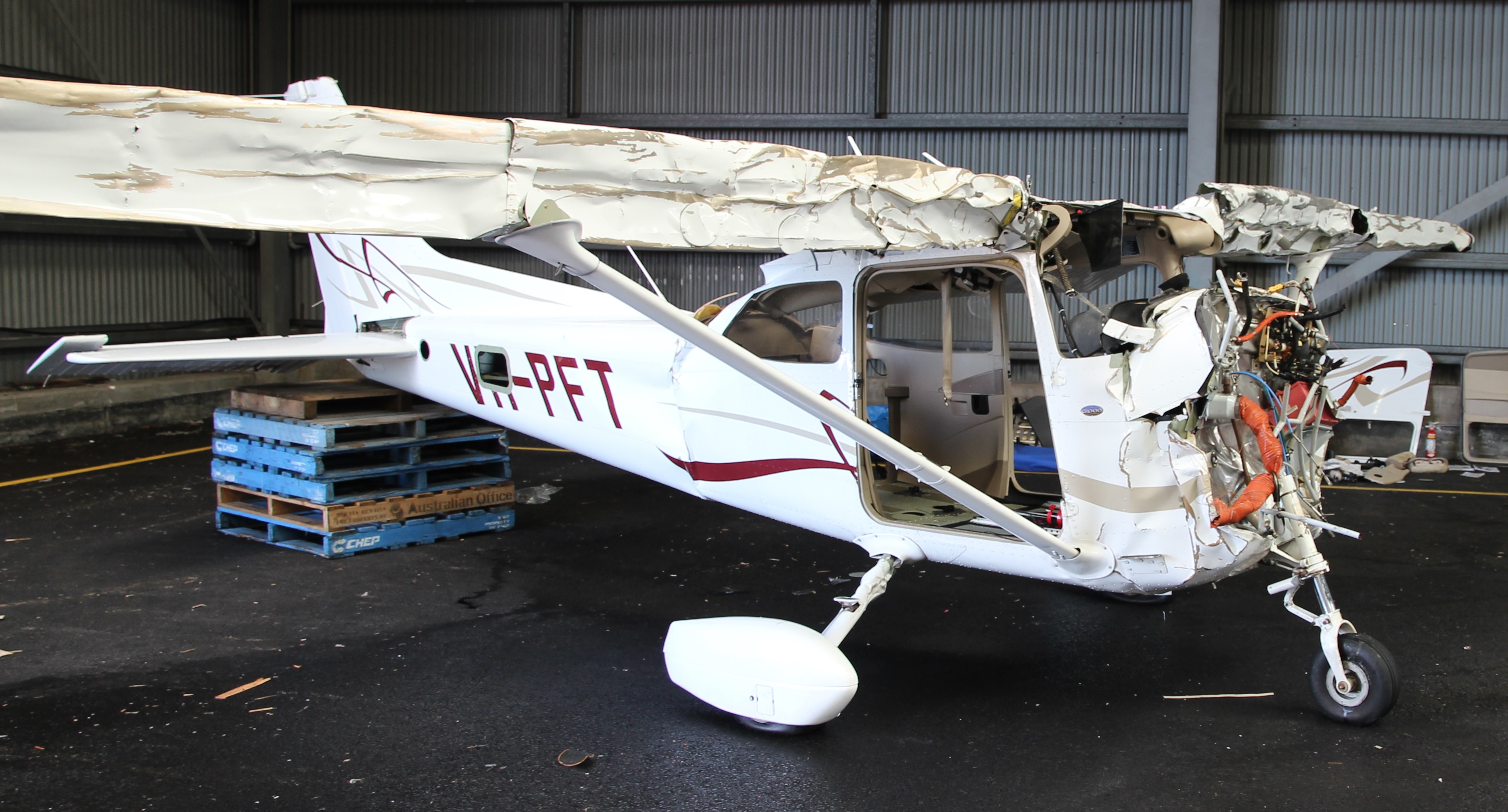
Source: ATSB
The operator advised that the stall warning system in PFT was regularly utilised during their flight training school activities. The stall system was inspected and signed off as serviceable during a CASA Maintenance Schedule 5 inspection completed on 24 December 2014. The POH also included an inspection and function test for the stall system during a pre-flight inspection. The aircraft’s stall warning system was most likely serviceable when the aircraft departed on the accident flight.
The significant damage to the underside of the fuselage engine area and the type of damage to the aircraft’s leading edges indicate a very steep impact angle. The flap being between selectable positions indicates possible inadvertent movement of the flap selector when the aircraft impacted the water.
Recorded data
The recovered data card appeared to be in a good condition. The card was cleaned, dried, and sent to the Tasmanian Police forensic unit for data recovery. The forensic unit was unable to recover any data from the card. The card was then then transferred to the ATSB, where a more detailed forensic examination was conducted. This examination identified that the memory chip on the card was cracked through its centre, rendering the memory card unserviceable and any data contained in the chip unrecoverable.
Pathological information
Post-mortem examination identified that both the pilot and the photographer sustained multiple fatal injuries consistent with an aircraft impacting water.
Survival aspects
The accident impact forces imparted on the aircraft’s occupants was considered by the ATSB to be unsurvivable.
ELT
A fixed 406 MHz emergency locator transmitter (ELT) was fitted to the aircraft. The ELT was inspected and signed off as serviceable during a CASA Maintenance Schedule 5 inspection completed on 24 December 2014. That inspection consisted of an inspection of the ELT batteries for electrolyte leakage and that the battery life had not expired. The transmitter was found securely located in its mounting, and appeared undamaged externally. It was set to the auto position and the activation light was not illuminated, most likely due to being submerged. The ELT was registered with the Australian Maritime Safety Authority (AMSA). AMSA advised that there was no record of that ELT being detected at around the date and time of the accident.
Seatbelt mounted airbags
The original manufacturer’s design for the C172S did not include seatbelt airbags. They were fitted under a United States (US) Supplemental Type Certificate (STC)[4] and as a result PFT was originally equipped with seatbelt airbags. The operator removed the seatbelt airbags in accordance with the C172 Maintenance Manual and replaced them with seatbelts that met the aircraft’s original certification status. The operator reported that this was for fleet commonality purposes.
Life jackets
There were life jackets under each of the pilot seats. Both occupants were also wearing waist‑mounted life jackets. These waist-mounted units stored the life jacket in a pocket attached to a belt. Attaching this unit to the occupant enabled easy access to a life jacket if required. Examination of the life jackets identified that none had been inflated by the aircraft occupants.
The operator’s Safety Management System
The operator’s Air Operations Certificate (AOC) included authorisation for Regular Public Transport (RPT) operations using aircraft that were not high capacity. Therefore, under the requirements of Civil Aviation Order (CAO) 82.3 Conditions on Air Operators’ Certificates authorising regular public transport operations in other than high capacity aircraft, the operator was required to implement a Safety Management System (SMS).
At the time, guidance for the implementation of the CAO 82.3 SMS requirement was provided in Civil Aviation Advisory Publication (CAAP) SMS-1(0) Safety Management Systems for Regulator Public Transport Operations. This document defined an SMS as ‘a systematic approach to managing safety, including the necessary organisational structures, accountabilities, policies and procedures.’ The CAAP also stated that ‘[a] successful SMS provides…a systematic, explicit and comprehensive process for identifying hazards and the risks they bring, and for minimising those hazards.’ The CAAP details key components and elements for delivering a successful SMS. These components include:
- Safety policy and objectives, and planning. This includes the appointment of key safety personnel and the conduct of safety committees.
- Safety risk management. This requires hazard identification (inclusive of safety reporting), and risk assessment and mitigation processes.
The operator’s safety management system
The content of this section outlines key elements of the operator’s SMS in accordance with the CAAP. It was also developed with consideration of the SMS hierarchy of influences, which includes reviewing an organisation’s safety philosophy, policies, procedures and practices (Degani and Weiner, 1994).
CASA approved the operator’s SMS for their RPT operation in July 2014. The SMS was designed to be implemented across the various operations conducted by the organisation, including their charter operations and aerial work. Throughout 2014, the operator was also required to maintain a separate SMS specific to their Part 145 maintenance operations. At the time of the occurrence, the evidence gathered as part of the investigation indicated that the operator’s SMS complied with the applicable regulatory requirements.
Appointment of key safety personnel
The CAAP specifies that the organisation’s Chief Executive Officer (CEO) maintains accountability for the SMS, that a safety manager (SM) be appointed, and that the SM should report directly to the CEO. Depending on the size of an organisation, the SM should possess operational management experience, an adequate technical background to understand the context in which they are working, and a sound understanding of safety management principles. Safety managers should be responsible for promoting safety, reporting safety performance to the CEO and ensuring the SMS is implemented and maintained.
Towards the end of 2013, the operator’s Chief Flying Instructor (CFI) was appointed as the SM. The CFI was typically only able to allocate about one day a week to SMS-related activities. The operator’s SMS manual documented that the SM position reported to the CEO, to ensure independence to the role. During the year, in response to a growing workload within the SM role, the safety committee discussed plans to introduce a deputy SM, with the intention that the person appointed to this role would take over as a full time SM in 2015.
Safety committee
The CAAP encourages organisations to hold safety committee meetings, the objective of which is to ‘provide a forum to discuss safety issues and the overall health and direction of the SMS’. These meetings should include the accountable manager, the SM, and other senior management. It can be a key source of risk information and assist with the treatment of safety risks. The operator conducted quarterly safety committee meetings. Points of discussion included:
- review of new and active hazard reports
- operational safety and security issues
- risk assessments for operational and commercial changes
- results of the annual SMS review.
Meeting minutes included no record of discussions regarding key areas of safety risk for the operation overall, or safety issue trends. However, the CEO was satisfied that the safety committee meetings were effective in contributing to the operations’ overall risk picture.
Safety Risk Management
The CAAP outlined the following guidance on the risk management process:
the process of risk management involves…applying a logical and systematic method of establishing the context, identifying, analysing, evaluating, treating, monitoring and communicating risks associated with any activity, function or process...at the strategic or operational levels.
The CAAP identifies that the safety risk management component includes the implementation of a risk management process and associated risk criteria, internal reporting and auditing. With respect to risk identification, an organisation ‘should identify sources of risk, areas of impact…and their causes and their potential consequences’ (ISO, 2009). Processes and tools to be used to achieve an effective outcome include (but are not limited to) the following:
- discussions (including brainstorming)
- hazard and occurrence reporting
- employment of the risk management process
- monitoring of normal operations
- trend analysis
- development of risk scenarios
- information exchange.
The CAAP also identifies change within an organisation as a possible source of hazards. The management of change should therefore include a formal application of risk management processes.
The operator’s SMS Manual documented the processes and tools to conduct risk assessments. It included a risk matrix and descriptors to facilitate the prioritisation of risks. Additionally, records and interviews with relevant managers established the following with respect to the operator’s safety risk management processes and practices:
The risk assessment process was mostly applied to organisational changes affecting operations, or for regulatory requirements.
The risk management process predominantly relied upon content from hazard reports, topics discussed at safety committees and informal discussions amongst the managers, as it was a small organisation.
The organisation maintained both a risk register and a hazard register. The risk register included some of the overall risks that the organisation may face. A new risk could be added to the risk register if it appeared as a report multiple times in the hazard register (see safety reporting).
The SM reported that the risk register was updated when a new activity or task was started. The risks included in the register were general issues common to aviation operations including bird strikes, dangerous goods, fatigue and non-compliance. No risks specific to low‑level flying were included in the register.
A stand-alone risk assessment on low-level flying was completed in April 2012 to meet regulatory requirements as part of its introduction onto the operator’s AOC. It included a limited number and scope of risks; the five key risks were recorded as follows
- controlled flight into terrain
- bird hazard
- turbulence hazard
- public complaints
- engine/aircraft emergency at low level.
Treatment options included ensuring that pilots went through an ‘approved training program’ and reducing the likelihood of aircraft emergencies at critical stages, including low level, through ‘specialised procedures’.
Internal reporting
The CAAP stated that ‘to enable analysis and organisational learning, the organisation should maintain procedures for the internal and external reporting … on incidents, hazards and other safety-related issues’ and should encompass elements such as collecting, storing and distributing data, and documenting and determining the effect of corrective action. ICAO (2013) adds that an effective safety reporting database should include input from multiple sources including crew reports, investigation data, audit findings, and risk assessment outcomes.
The operator’s SMS manual stated that the primary method for hazard identification was through the safety reporting system. A hazard register was used to capture all safety reports received from crew and staff. The manual also documented a just culture policy designed to encourage reporting. Interviews with relevant managers and examination of records identified that:
- The type of the reports in the hazard register included issues about operations, training, maintenance and personal safety. There were no reports specifically about low-level flying.
- The rate of reporting into the safety report system increased from about two reports per quarter in 2012 to about six in 2014. This was in response to management efforts to improve reporting through the introduction of the just culture policy, and promotion of proactive safety reporting amongst the crew.
No other sources of information were used to populate the hazard register.
Additional information
In-flight photography
Determination of aircraft altitude from in-flight photography
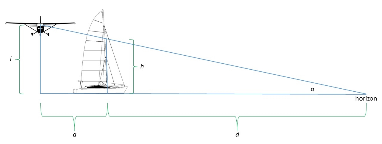
When a photograph of a yacht is taken from an aircraft, and that image includes the horizon, the height of the aircraft above the surface of the water may be estimated if the yacht’s air draft is known. The air draft of a yacht is the distance from the surface of the water to the highest point on the yacht. Figure 7 depicts this situation.
Figure 7: Air photography height calculation, where i = camera height, h = height where the horizon intersects the yacht’s mast, d = distance from the yacht to the horizon, a = distance from the aircraft to the yacht
Source: ATSB
The height of the point at which the horizon intersects the yacht’s mast is determined by the equation:
![]()
The height of the camera i (or the camera operator’s sight axis) is determined by the equation:
![]()
Where the distance a is of a significant order of magnitude less than d, then i ≈h. That is, the point where the horizon intercepts the mast approximates the height of the camera recording that image.
Photography from 29 December 2014
The photographer’s camera was recovered from the seabed and contained a number of images of yachts taken during the accident flight. These images included an image of Mistraal taken immediately before the accident. Mistraal’s air draft was reported to be 24 m. Therefore, the lens height at the time of the photograph was about 50 ft (Figure 8). This is also the approximate height of the aircraft.
Figure 8: An image of the yacht Mistraal, taken by the photographer immediately prior to the accident, with the air photography height calculation overlaid
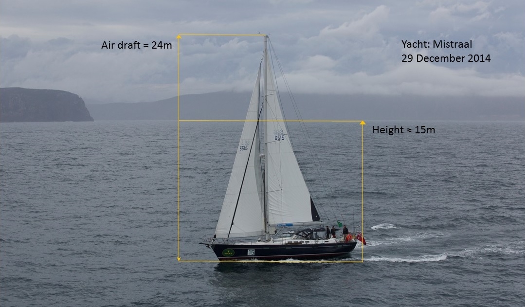
Source: The photographer’s camera, recovered from the aircraft wreckage
Images of yachts taken before Mistraal were examined to determine the aircraft altitude for those particular photographic runs. These images identified that the aircraft was regularly at a height of about 50 to 60 ft when those images were taken.
Other photography of Sydney Hobart yachts taken around Hobart
The investigation obtained other photographs taken by the photographer during previous flights of Sydney Hobart yachts during 2013 and 2014. Those photographs identified a trend for the aircraft to be regularly flown at a height well below 150 ft during photographic runs.
The investigation also examined other publicly available images of Sydney Hobart yachts taken in the Hobart region during the 2013 and 2014 races, as well as from before 2013. These images also recorded a consistent trend of the aircraft regularly being at a height well below 150 ft above the water’s surface. For the years 2013 and 2014, these publicly sourced images were also taken from the operator’s aircraft.
The stall/spin condition
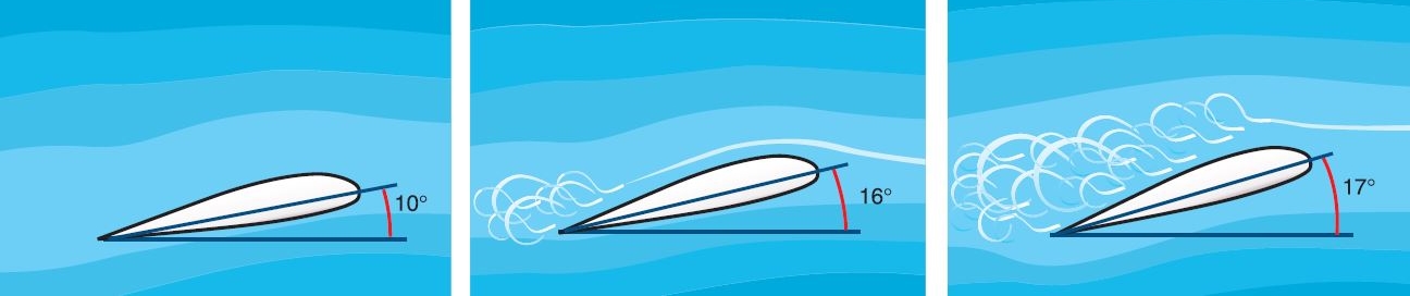
A wing develops lift as a result of the pressure differential created by airflow over the wing’s surface. The amount of lift generated by the wing is proportional to the direction of the airflow relative to the wing, known as the wing’s angle of attack. As the angle of attack increases, lift increases, until at a particular angle the flow over the upper wing separates from the surface (Figure 9). This condition is known as the aerodynamic stall (or simply stall) and results in a rapid reduction in the lift generated. The stall may occur at any pitch attitude or airspeed. Most aircraft do not have an instrument that indicates the aircraft’s angle of attack; however, the angle of attack at which the stall occurs may be referenced to an airspeed (the stall speed or VRsR). The quoted stall speed relates to the aircraft in a particular flight configuration, normally wings level, zero rate of descent and a predetermined rate of deceleration.
Figure 9: Increasing angle of attack increases lift, until at the critical angle disrupted airflow and the stall occurs
Source: United States Federal Aviation Authority publication FAA-H-8083-3A
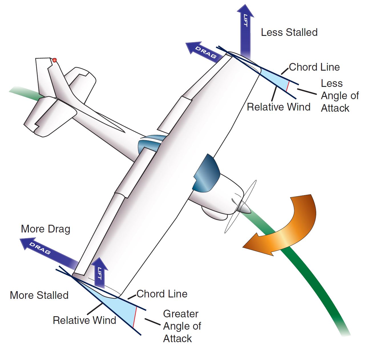
The spin is often described as an aggravated stall. When a pilot is training for spin recovery, the normal method of entry into the spin is to yaw the aircraft while approaching the stall. This unbalanced[5] flight condition causes the wing that the aircraft is yawing towards to stall before the other wing. The example presented in Figure 10 shows an aircraft yawing to the right while stalled. The right wing has stalled more than the left, and in association with the increased drag resultant from the more stalled wing, the aircraft will roll and yaw towards the right. The nose of the aircraft will also probably drop. In aircraft such as the Cessna 172 type (C172), the aircraft will recover if pro-spin flight control inputs are not maintained.
Figure 10: A C172 entering a spin while yawing to the right
Source: Federal Aviation Authority publication FAA-H-8083-3A
The stall leading into a spin manoeuvre discussed above is a deliberate manoeuvre. Accidents involving low-level stalling of general aviation type aircraft often involve an unintended stall while the aircraft is turning and in unbalanced flight.[6] The result is often a rapid wing drop and steep pitch down as the aircraft enters the stall/spin condition. There are two types of stall/spin conditions:
- the stall resulting in an into turn spin
- the stall resulting in an out of turn spin.
The into turn stall/spin is discussed in FAA (2004)[7] under the description of a cross-control stall. It often involves the pilot maintaining bank angle while attempting to increase the rate of heading change by introducing extra rudder (yaw) into the turn. This results in unbalanced flight. If the airspeed is close to the stall and the pilot increases elevator backpressure, the conditions are right for the low wing to stall before the other wing. This is a condition equivalent to that shown in Figure 10, and will result in the onset of an into turn spin, with steep pitch down.
The out of turn stall/spin is described in The Aerial Mustering Code of Practice.[8] This publication included a discussion on a specific stall/spin type of accident that had been observed in a number of low-level fatal accidents involving mustering operations. The common theme was a stall leading to the aircraft impacting terrain in a steep nose down pitch attitude. The sequence of events in these type of accidents followed a similar path to the stall/spin conditions above:
- Before entering the stall the aircraft was in a steep turn with a nose high attitude.
- During the turn the airspeed dropped to near the stall speed, while the pilot continued to hold or increase back pressure on the elevator.
- In this configuration the upper wing stalled and the aircraft would flick out of the turn into a steep turn in the other direction, and the onset of an out of turn spin.
- At the same time the nose would fall away to a steep pitch down attitude.
Recovery from these stall/spin conditions required significant altitude. A figure of about 400 ft or more is often quoted. From an accident perspective, the strongest indication of a stall/spin is the steep nose down attitude, particularly when the aircraft was operating at low altitude. Without the spin entry, a Cessna stall typically will not drop the nose to a steep pitch down attitude.
Related/previous occurrences
The ATSB has investigated a number of accidents where a Cessna 172 type aircraft has stalled and impacted terrain in a steep nose down pitch attitude. A summary of 6 of these investigations, as well as a Cessna 150 and Socata TB 20 accident that have similar signatures, are at appendix B. Each of these accidents identify that, while the stalling characteristics of these aircraft types is benign, the stall condition is exacerbated through mishandling of the aircraft during the stall, which can result in entry into a spin. The stall/spin will result in a steep pitch down and rotation towards the stalled wing. Recovery from this condition will take a considerable amount of altitude, the magnitude of which is dependent on the speed of response by the pilot and the use of appropriate control inputs.
__________
- The height restriction increased where flight was to be conducted over a city, town or populous area, and were excluded in particular circumstances identified in CAR r. 157(4).
- A different radius of objects and terrain applied to helicopters.
- A form of airworthiness approval issued by a National Airworthiness Authority that permits modification of an aircraft, engine or propeller operating under an approved type certificate.
- Balanced flight is best considered from the pilot’s perspective. An aircraft is in balanced flight is when the pilot does not feel any sideways force. This is most relevant during a turn. In a co-ordinated, or balanced turn, the force that the pilot feels is straight down into the seat. This is the result of properly co-ordinated aileron and rudder input during the turn. An unbalanced turn, however, will be the result of:
- insufficient rudder input leading to the aircraft slipping out of the turn and the pilot feeling a force sideways into the turn, or
- too much rudder input leading to the aircraft skidding into the turn and the pilot feeling a force sideways out of the turn.
See FAA (2004) Chapter 3 pp 3-8 to 3-9. - See The Aircraft Owners and Pilots Association (AOPA) website, which publishes a safety pamphlet titled Stall/Spin: Entry point for crash and burn? and provides a database listing Stall/Spin accidents published by the US National Transportation Safety Board. Available at http://www.aopa.org/
- Chapter 4 pages 4-10 to 4-11.
- PGA pp 34-35. The Code was sponsored by the Royal Aero Club of WA, and CASA.
Introduction
This analysis will examine the operational factors surrounding the accident involving VH-PFT (PFT). Evidence from the witnesses to the accident and inspection of the aircraft wreckage indicate that the pilot most likely lost control of the aircraft while executing a climbing steep turn. The witnesses’ descriptions of a rapid pitch down and simultaneous rotation away from the turn, and the almost vertical attitude of the aircraft on impact with the water, are consistent with the aircraft entering an aerodynamic stall and subsequent spin. Examination of the aircraft wreckage also confirmed the steep angle that the aircraft impacted the water. The analysis will consider the development of circumstances that preceded that event.
Unstable flight while at low level
The training provided to the pilot included instruction that, when conducting low-level operations in a Cessna 172 (C172) type aircraft:
- the principal consideration was stable flight
- manoeuvring was to be conducted at a level height and radical manoeuvres were to be avoided
- manoeuvres involving large pitch attitude changes should not be performed at low level.
The type of manoeuvre that led to the loss of control of the aircraft could not be precisely ascertained. Witness statements indicated that the bank angle was steep, but the pilot was authorised and required to demonstrate 45° banking turns at low level. The altitude gain identified by the closest witness was not in accordance with training and procedural practice; however, this may have been due to another unknown reason. The manoeuvre described by witnesses indicates vertical altitude and pitch attitude changes inconsistent with the principal consideration of stable flight.
Information provided by Cessna concerning the witness descriptions of the final uncontrolled manoeuvre indicates that the aircraft entered a stall/spin combination. The rapid drop of the upper wing, the turn reversal and the sudden and dramatic pitch down indicates a stall of the upper wing that led to a spin entry. This loss of control may have been the result of a combination of the aircraft having a nose high attitude during the turn, and/or the pilot applying too much back pressure, and/or the turn being unbalanced.
The local weather conditions reported by the yachts in the immediate vicinity of the accident, as well as photography of those yachts from the aircraft in the period leading up to the accident, indicate that the surface wind was calm. While the surface wind conditions at the accident site contrast with the automated weather station records, a stall resultant from changing wind conditions would be expected to stall both wings. Further, due to the extremely low altitude of the aircraft, it is most likely that the aircraft would have experienced the same wind conditions as that recorded by the yachts. Therefore, the wind is not considered to have contributed to the accident.
The height of the aircraft above the surface of the water was insufficient for the pilot to recover control of the aircraft prior to the aircraft impacting the water’s surface. Cessna identified that the height required to recover the aircraft from the stall/spin condition is significant, and at least in the order of 400 ft. This factor alone strongly supports the importance placed on the requirements for stable flight, no radical manoeuvres and no manoeuvres involving large pitch changes while conducting low-level flight in a C172 type aircraft.
Flight at exceptionally low level
Images recovered from the photographer’s camera identified that, immediately prior to entering the climbing steep turn, the aircraft was operating at an exceptionally low height of about 50 ft above the water’s surface. This height was significantly lower than the authorised height of 150 ft above obstacles. Even if the aircraft had been operating at the authorised height, given the resultant stall/spin condition it is unlikely that the pilot would have been able to recover control of the aircraft before impacting the water’s surface. It is for this reason that the exceptionally low level of flight is not considered to have contributed to the accident.
The purpose of the aerial photography was to capture the yachts and their crews as they participated in the final stages of the yacht race, which would then be offered for sale to the yachtsmen and the public. The desired framing of the yacht for those photographs required the aircraft to be flown at an exceptionally low height. Historical records of photography conducted on Sydney Hobart yachts identified a significant proportion of images where the aircraft was being operated at an exceptionally low height. The exceptionally low height of the accident flight was not an unusual occurrence, but in fact more the norm for the conduct of this photography. The exceptionally low height at which airborne photography on yachts was routinely being conducted was contrary to the CASA low flying regulations, and the operator’s procedures.
The operator was not aware that the low-level flights being conducted for photography on Sydney Hobart yachts were being flown at exceptionally low levels. Also, company documentation had misidentified the limitations on low-level flight and had failed to identify that the clearance to 150 ft was in relation to obstacles. Obstacles would include the masts of yachts.
The operator’s safety management system
The ATSB examined the role of the operators’ Safety Management System (SMS). While it was not established that the safety risk management processes and practices directly contributed to the occurrence, there were aspects that the operator could consider working towards to more effectively identify of all key operational risks.
The International Standard ISO31000:2009 Risk Management – Principles and guidelines defines risk as ‘the effect of uncertainty on objectives’, and risk management as ‘coordinated activities to direct and control an organization with regard to risk.’ ICAO (2013) further outlines that ‘the objective of safety risk management is to assess the risks associated with identified hazards and develop and implement effective and appropriate mitigations’.
In the context of this investigation, the operator’s objective was to conduct safe and effective yacht photography flights during the Sydney Hobart event. In reviewing components of the operator’s SMS, it was evident that the ability to identify operational risks associated with this type of flight was affected by the following factors:
The main source of safety risk information were safety reports submitted by crew, in an environment where the reporting culture had only recently improved amongst the small flight crew workforce.
The risk management process was only utilised for managing operational or organisational changes, which precluded the proactive identification of risks in existing operational activities such as low-level flying.
The ability for managers to be aware of existing operational risks was reduced due to the narrow application of documented risk management processes and tools (including the risk register).
The resources to facilitate the implementation and improvement of the SMS were limited to the time that the CFI could spend in the role of safety manager. This reduced the opportunity to implement the operators’ risk management processes and tools more extensively.
Given the above factors, at the time of the occurrence, the operator's safety risk management processes and practices were not sufficient to facilitate the identification of all key operational risks associated with low-level flying that was being conducted on Sydney Hobart race yachts.
From the evidence available, the following findings are made with respect to the loss of control and impact with terrain involving the Cessna Aircraft Company 172S (C172S), registered VH-PFT, that occurred in Storm Bay (near Port Arthur), Tasmania on 29 December 2014. These findings should not be read as apportioning blame or liability to any particular organisation or individual.
Contributing factors
- The aircraft’s final manoeuvre prior to impact with the water resulted in a stall/spin condition, an uncontrolled aircraft state from which there was insufficient altitude to recover before impacting terrain.
Other factors that increased risk
- The exceptionally low height at which airborne photography of yachts was routinely being conducted at was contrary to the Civil Aviation Safety Authority low-flying regulations, and the operator’s procedures.
- The operator's safety risk management processes and practices were not sufficient to facilitate the identification of all key operational risks associated with low-level flying that was being conducted on Sydney Hobart race yachts.
Sources of information
The sources of information during the investigation included the:
- aircraft operator
- Tasmania Police
- Civil Aviation Safety Authority
- Cruising Yacht Club of Australia and participants in Sydney Hobart 2014
- Bureau of Meteorology
- Australian Maritime Safety Authority.
References
Aircraft Owners and Pilots Association 2003, Stall/Spin: Entry point for crash and burn? Available at Aircraft Owners and Pilots Association (AOPA) website.
Aviation Safety Investigations and Reports (ASIR) 1999, Investigation Number 199905698, Australian Transport Safety Bureau (ATSB), Canberra. Available at ATSB website.
Aviation Research and Analysis Report (ASAR) – B2005/0055 September 2006, Wire-strike Accidents in General Aviation: Data Analysis 1994 to 2004, Australian Transport Safety Bureau, Canberra. Available at ATSB website.
Degani, A., & Weiner, E. L. (1994). On the design of flight-deck procedures (NASA Contractor Report 177642). Moffett Field, CA: NASA-Ames Research Center.
ICAO (2013). Doc, 9859–Safety Management Manual.
ISO, I. (2009). 31000: 2009 Risk management–Principles and guidelines. International Organization for Standardization, Geneva, Switzerland.
Federal Aviation Administration (FAA) 2004, Airplane Flying Handbook FAA-H-8083-3A. Available at FAA website.
Pastoralists & Graziers Association (PGA) of WA (Inc), Aerial Mustering Code of Practice, West Perth, Western Australia. Cited in ATSB B2005/0055.
Submissions
Under Part 4, Division 2 (Investigation Reports), Section 26 of the Transport Safety Investigation Act 2003 (the Act), the ATSB may provide a draft report, on a confidential basis, to any person whom the ATSB considers appropriate. Section 26 (1) (a) of the Act allows a person receiving a draft report to make submissions to the ATSB about the draft report.
A draft of this report was provided to the Civil Aviation Safety Authority and the aircraft operator.
Submissions were received from the aircraft operator. The submissions were reviewed and where considered appropriate, the text of the report was amended accordingly.
Appendix A – Bureau of Meteorology wind data
The Bureau of Meteorology provided wind data for a number of automated weather stations in the Storm Bay area (Figure A1).
Figure A1: Map of the Storm Bay area showing the location of the Automated Weather Stations, the accident location, and the reported winds at 1815
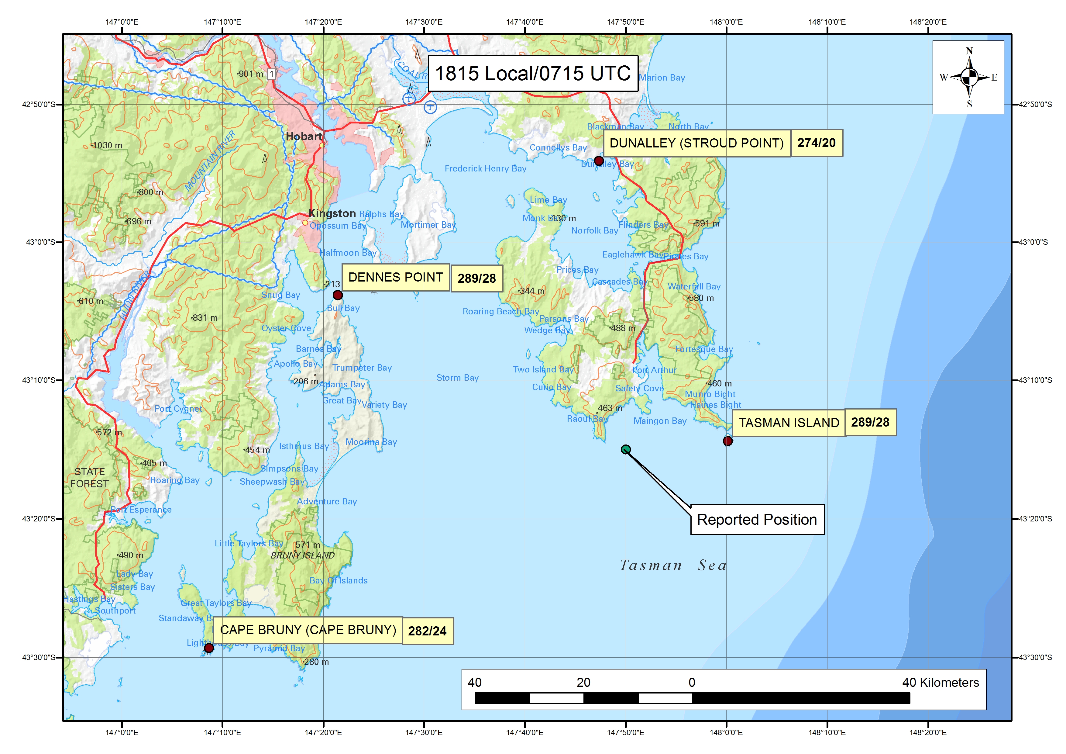
Source: Basemap - Geoscience Australia, additional data - Bureau of Meteorology, modified by ATSB
A record of winds taken at 5-minute intervals for each of these weather stations is at Table 3.
Table 3: Automated Weather Data
| Time | Wind direction (degrees true) | Wind speed (kt) | Maximum wind gust (kt) |
| Cape Bruny | |||
| 1800 | 277 | 25 | 29 |
| 1805 | 280 | 23 | 28 |
| 1810 | 282 | 25 | 30 |
| 1815 | 282 | 22 | 24 |
| 1820 | 278 | 29 | 35 |
| 1825 | 284 | 29 | 34 |
| 1830 | 282 | 31 | 34 |
| Denes Point | |||
| 1800 | 290 | 11 | 13 |
| 1805 | 294 | 12 | 14 |
| 1810 | 280 | 26 | 30 |
| 1815 | 289 | 24 | 28 |
| 1820 | 282 | 19 | 23 |
| 1825 | 270 | 25 | 29 |
| 1830 | 273 | 21 | 23 |
| Dunalley (Stroud Point) | |||
| 1800 | 272 | 19 | 22 |
| 1805 | 281 | 13 | 16 |
| 1810 | 279 | 16 | 18 |
| 1815 | 274 | 17 | 20 |
| 1820 | 275 | 15 | 19 |
| 1825 | 273 | 11 | 13 |
| 1830 | 278 | 12 | 14 |
| Tasman Island | |||
| 1800 | 290 | 11 | 13 |
| 1805 | 294 | 12 | 14 |
| 1810 | 280 | 26 | 30 |
| 1815 | 289 | 24 | 28 |
| 1820 | 282 | 19 | 23 |
| 1825 | 270 | 25 | 29 |
| 1830 | 273 | 21 | 23 |
Appendix B – Related/previous occurrences
The following ATSB accident investigations are drawn from investigation reports published post 2000. The common theme from these investigations is the loss of control of the aircraft following an aerodynamic stall, with a resultant steep pitch attitude and insufficient altitude to enable recovery before impacting terrain.
ATSB investigation ASIR 199905698[9]
The aircraft, a Cessna 172 (C172), was reported to be operating between 500 and 900 ft AGL. It was observed heading north with a nose-high attitude before entering a steep left turn. Witnesses stated that aircraft's bank angle steepened as it passed a westerly heading and then the nose dropped such that the aircraft was heading approximately south in a near vertical, nose-down attitude. The manoeuvre was consistent with the aircraft stalling during the steep left turn. The aircraft impacted the ground heading approximately south and in a nose-down, right wing low attitude. At the time of the impact, the aircraft’s engine was producing power and that the flaps were extended to approximately 10 . The report concluded that the pilot lost control following a stall, and failed to recover control in the height available was consistent with the stall occurring during unbalanced flight. The report included the following information.
Coordinated use of aileron, elevator and rudder controls will ensure that an aircraft maintains balanced flight. Discussions with the US Federal Aviation Authority (FAA) indicated that the Cessna 172 aircraft will exhibit mild stall characteristics if the aircraft stalls during balanced flight, and a pilot can regain control of the aircraft with a minimal loss of height. Balanced flight requires the use of coordinated aileron, elevator and rudder controls. Most aircraft would require significantly more height above the ground to allow a pilot to recover control following a stall during unbalanced flight.
The Cessna Integrated Flight Training System Manual of Flight stated that a stall during a steep turn will result in a sharp nose and wing drop and that recovery actions must be prompt and precise.
ATSB investigation ASIR 199903463[10]
A C172 was being used to assist with the mustering of sheep. It was being operated below 500 ft AGL and had just completed a pass over witnesses when they reported hearing the sound of the aircraft impacting terrain. Damage to the aircraft was consistent with the aircraft having impacted the ground in a near vertical attitude at a low forward speed.
ATSB investigation ASIR 200001153[11]
A C172 on a private flight was attempting to land in moderate crosswinds. After initiating a go-around, the aircraft made a sharp left turn downwind at low altitude in an apparent attempt to avoid trees. Witness stated that during the turn the wings were rocking and the aircraft had a pronounced nose high attitude. Its nose then suddenly dropped and it adopted a steep nose-down attitude before impacting the ground. The aircraft impacted the ground in a steep, nose-down, almost wings-level attitude with little forward velocity. The investigation concluded that the pilot probably retracted flap during the go-around, which, with a high nose attitude and the turn downwind probably reduced the aircraft's speed such that the wings stalled at a height that was insufficient to allow recovery before the aircraft impacted the ground.
ATSB investigation ASIR 200506306[12]
A Cessna 150 (C150) was conducting aerial mustering operations during the early morning. The aircraft was observed to circle some sheep at about 250 ft AGL. Shortly after, witnesses noticed smoke nearby, and found that the aircraft had impacted terrain. The aircraft wreckage was upright with evidence of severe impact damage to the left wing, nose section and rear fuselage. The steepness of the angle of bank and the nose-down pitch attitude at the aircraft's point of ground impact indicated that the aircraft was in a steep left turn at impact. Those indications and the minimal forward movement of the aircraft after ground contact were consistent with the aircraft having stalled and slipped out of the turn. The lack of aircraft rotation at impact indicated that there had been insufficient time for the stall to develop into a spin, consistent with it occurring at low level.
ATSB investigation AO-2010-047[13]
A C172 was engaged in cattle spotting and was orbiting at about 500 ft AGL when the pilot lost control of the aircraft. Damage to the aircraft was consistent with the right wing colliding with a tree branch, followed by the aircraft impacting the ground inverted, with a steep nose-down attitude. The pilot reported that the most likely reason for the accident was an inadvertent stall due to distraction while performing a steep turn.
ATSB investigation AO-2010-079[14]
A C172 was operating at low level to assist a ground party locate two horses. The aircraft was seen manoeuvring at low level before radio and visual contact was lost. A search found that the aircraft had impacted terrain near a dry creek bed. Inspection of the wreckage indicated that the aircraft’s attitude at impact was about 55° nose-down, and that the right wing impacted the ground before the left wing. This was consistent with a loss of control following aerodynamic stall at an altitude where a ground collision was unavoidable.
ATSB investigation AO-2012-059[15]
A C150 was engaged in aerial stock mustering. Witnesses observed the aircraft circling, and then in a steep descent followed by the sound of an impact. The report concluded that, while manoeuvring at low level, the pilot inadvertently allowed the aircraft to aerodynamically stall, resulting in a high rate of descent and collision with terrain. There was insufficient information about pilot control inputs to establish the factors that precipitated the stall.
ATSB investigation AO-2012-149[16]
A SOCATA TB 20 on a training flight was conducting circuit training when, while making a left turn from downwind to base, the aircraft aerodynamically stalled and the left wing dropped steeply. A recovery was commenced, but the aircraft collided with terrain in a paddock. The report concluded that, while making a left turn in the circuit, an aerodynamic stall occurred, resulting in a significant left-wing low and nose-down attitude in close proximity to the terrain. Although it appeared that a stall recovery was commenced, the aircraft stalled at an altitude from which a full recovery to controlled flight was unable to be achieved before the aircraft collided with the terrain.
__________
- ATSB Investigation report ASIR 199905698 Cessna Aircraft Company 172R; VH-EWO, published 5 April 2000.
- ATSB Investigation report ASIR 199903463 Cessna Aircraft Company 172H; VH-RLO, published 8 August 2000.
- ATSB Investigation report ASIR 200001153 Cessna Aircraft Company 172M; VH-SXK, published 24 July 2001.
- ATSB Investigation report ASIR 200506306 Cessna Aircraft Company, 150G; VH-KPQ, published 5 June 2006.
- ATSB Investigation report AO-2010-047 Loss of control – Cessna 172H, VH-RZV, near Cunnamulla Aerodrome Qld, 30 June 2010, published on 28 January 2011.
- ATSB Investigation report AO-2010-079 Collision with terrain – Cessna 172S, 2 km NNE Durham Downs, Qld, 18 October 2010, published 4 November 2011.
- ATSB Investigation report AO-2012-059 Collision with terrain involving Cessna 150, VH-UWR, 55 km NE of Bourke, NSW, 29 April 2012, published 18 June 2013.
- ATSB Investigation report AO-2012-149 Loss of control involving SOCATA TB 20, VH-HBB, 3 km south of Lismore Airport, NSW on 9 November 2012, published 11 March 2014.
Purpose of safety investigationsThe objective of a safety investigation is to enhance transport safety. This is done through:
It is not a function of the ATSB to apportion blame or provide a means for determining liability. At the same time, an investigation report must include factual material of sufficient weight to support the analysis and findings. At all times the ATSB endeavours to balance the use of material that could imply adverse comment with the need to properly explain what happened, and why, in a fair and unbiased manner. The ATSB does not investigate for the purpose of taking administrative, regulatory or criminal action. TerminologyAn explanation of terminology used in ATSB investigation reports is available here. This includes terms such as occurrence, contributing factor, other factor that increased risk, and safety issue. Publishing informationReleased in accordance with section 25 of the Transport Safety Investigation Act 2003 Published by: Australian Transport Safety Bureau © Commonwealth of Australia 2016
Ownership of intellectual property rights in this publication Unless otherwise noted, copyright (and any other intellectual property rights, if any) in this report publication is owned by the Commonwealth of Australia. Creative Commons licence With the exception of the Coat of Arms, ATSB logo, and photos and graphics in which a third party holds copyright, this publication is licensed under a Creative Commons Attribution 3.0 Australia licence. Creative Commons Attribution 3.0 Australia Licence is a standard form licence agreement that allows you to copy, distribute, transmit and adapt this publication provided that you attribute the work. The ATSB’s preference is that you attribute this publication (and any material sourced from it) using the following wording: Source: Australian Transport Safety Bureau Copyright in material obtained from other agencies, private individuals or organisations, belongs to those agencies, individuals or organisations. Where you wish to use their material, you will need to contact them directly. |