
What happened
At about 0600 Central Daylight-saving Time (CDT) on 7 November 2014, a Boeing 737-800, registered VH-VUR and operated by Virgin Australia, departed Adelaide, South Australia, on a scheduled service to Brisbane, Queensland. The captain was the pilot flying and the first officer was the pilot monitoring.
The crew were cleared via the SEDAN 9 Standard Instrument Departure (SID). As the aircraft climbed through about 4,400 ft during the SID, air traffic control re-cleared the aircraft to track direct to waypoint UVUPU (north-east of Mildura, Victoria), and cancelled the standard airspeed restriction of 250 kt below 10,000 ft. The crew made appropriate changes in the Flight Management Computer (FMC),[1] following which the captain selected Lateral Navigation (LNAV)[2] and Vertical Navigation (VNAV) auto-flight modes (see VNAV mode). In these modes, the aircraft commenced tracking directly to waypoint UVUPU, and accelerated to the FMC-programmed airspeed of 280 kt.
The climb proceeded normally until the aircraft was passing about flight level (FL) 250[3] when the captain selected Level Change (LVL CHG) vertical auto-flight mode (see LVL CHG mode), and commanded a continued climb at the existing airspeed of 280 kt. The captain recalled that LVL CHG mode may have been selected to manage continued climb through a layer of turbulence. The crew intended to re-select VNAV mode when LVL CHG mode was no longer required, but inadvertently overlooked that selection, and the climb continued in LVL CHG mode at 280 kt.
Soon after the selection of LVL CHG mode, as the aircraft climbed through about FL 265, the auto-flight system sequenced automatically from climb at a constant airspeed, to climb at a constant Mach number,[4] consistent with normal system behaviour. Climb then continued above FL 265 at a constant Mach number of 0.69, which was the Mach number corresponding to 280 kt at the time the changeover occurred. As the aircraft continued to climb at the constant Mach number, the airspeed slowly reduced (as a function of the characteristics of the atmosphere and the relationship between Mach number and airspeed).
The slowly reducing airspeed went unnoticed by the crew until the auto-flight system was levelling the aircraft at the planned cruise altitude of FL 390. At about that time, the captain noticed that the magenta airspeed bug[5] on the primary flight display (PFD) airspeed indicator was at the top of the minimum manoeuvre airspeed amber bar. At that point, the top of the amber bar corresponded to an airspeed of about 216 kt. The crew also noticed a ‘buffet alert’ advisory message appear in the scratchpad of Control Display Unit (CDU).[6]
In response to the low airspeed condition, the captain selected Mach 0.77 on the Mode Control Panel (MCP)[7] to initiate acceleration towards the FMC-programmed cruise Mach number. As the aircraft accelerated through about Mach 0.74, the captain selected VNAV and the auto-flight system engaged in VNAV Path (VNAV PTH) (see VNAV mode), allowing the aircraft to continue accelerating to the FMC-programmed cruise Mach number of Mach 0.77 while maintaining FL 390. Under the existing conditions, a Mach number of 0.77 corresponded to an airspeed of about 240 kt. Having accelerated to Mach 0.77, the flight continued to Brisbane without further incident.
Figure 1 provides a graphical illustration of some relevant flight parameters and auto-flight system vertical modes from FL 200 until the aircraft had accelerated to Mach 0.77 in cruise flight at FL 390. Of particular note is the change from VNAV mode to LVL CHG mode soon after 1952 UTC.[8] The figure also shows the near constant Mach number and gradually decreasing airspeed from about 1953 UTC, until the aircraft reached the planned cruise altitude soon after 2001 UTC. The airspeed dips beneath the minimum manoeuvre airspeed for a short time as the crew initiated acceleration, reaching a minimum recorded airspeed of about 211 kt. From that point, the aircraft accelerates to the planned cruise Mach number of Mach 0.77, with VNAV re-engaged just before 2004 UTC. Note that the minimum operating airspeed referred to in Figure 1 is the same as the minimum manoeuvre airspeed (see below). The computed airspeed referred to in Figure 1 is the same airspeed that would have been displayed on the captain’s PFD.
Figure 1: Selected flight parameters and auto-flight system modes
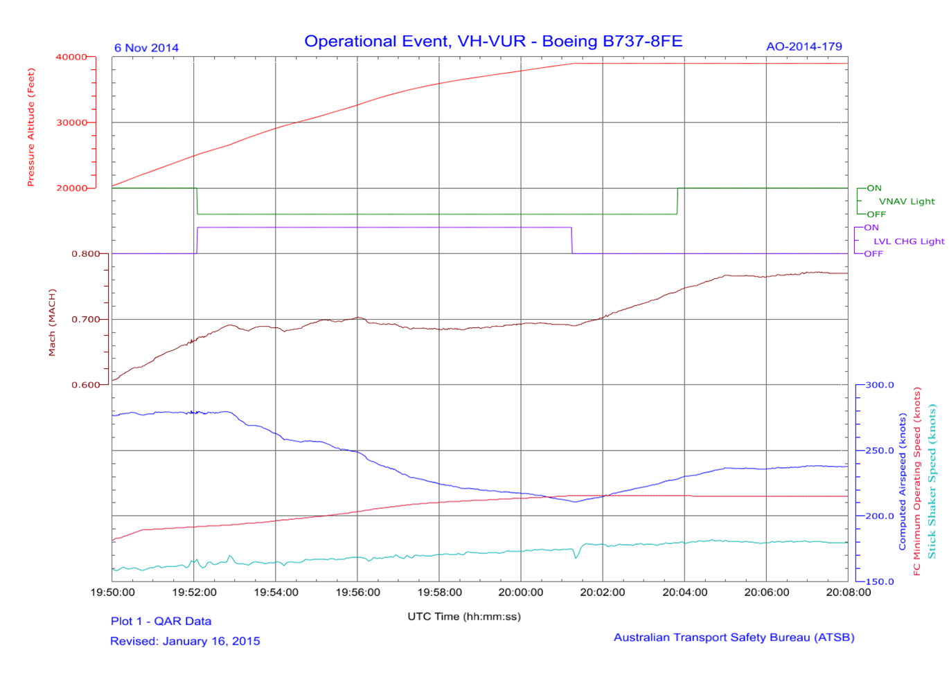
Source: ATSB
Relevant technical information
The auto-flight system consists of an auto-pilot flight director system (AFDS) and an auto-throttle system. The AFDS and auto-throttles are controlled using the FMC and the MCP. The auto-flight system operates in various vertical modes according to the phase of flight, operating environment and crew requirements. Two commonly used vertical modes relevant to this occurrence are VNAV mode and LVL CHG mode.
VNAV mode
During a climb in VNAV mode, the auto-flight system guides the aircraft along the FMC-programmed vertical profile, at the speed (airspeed or Mach number) computed by the FMC, modified and selected by the crew as required according to operational circumstances. During normal operations, the FMC speed profile holds the airspeed at 250 kt up to 10,000 ft (normal procedural requirement in Australian airspace) followed by acceleration to the FMC-programmed climb airspeed (commonly the economy-optimised speed schedule computed by the FMC). As climb continues at a constant airspeed, Mach number increases as a function of the characteristics of the atmosphere and the relationship between Mach number and airspeed. Climb continues at the FMC-programmed airspeed until the Mach number reaches the FMC-programmed Mach number, from which point climb continues at that Mach number. The crew can change FMC-programmed climb speeds as required, by making the required changes on the appropriate page of the CDU. During this occurrence, the recorded data indicates that, had the crew continued to climb in VNAV mode (rather than selecting LVL CHG), the aircraft would have maintained 280 kt to about FL 320, from which point climb would have continued at a constant Mach 0.77.
VNAV mode is selected by pressing the VNAV pushbutton on the MCP. When selected, a green bar on the VNAV pushbutton illuminates. During a climb in VNAV mode, the flight mode annunciator (FMA)[9] indication at the top of each pilot’s PFD indicates N1[10] as the auto-throttle mode and VNAV SPD (speed) as the vertical auto-flight mode (Figure 2). During a climb in VNAV mode, the FMC-programmed speed is displayed on the PFD, and the indicated airspeed/Mach number (IAS/MACH) window on the MCP is blank.
When the aircraft levels at the FMC-programmed cruise altitude, the auto-flight system vertical mode sequences to VNAV PTH (path) to maintain the cruise altitude, and the auto-throttle mode sequences to FMC SPD (speed) to hold the FMC-programmed cruise speed (Mach number). Similar annunciations appear when the auto-flight system levels the aircraft temporarily at an intervening FMC-programmed altitude constraint (there were no intervening altitude constraints relevant to this occurrence).
LVL CHG mode
During a climb in LVL CHG mode, the auto-flight system controls the aircraft pitch attitude in a manner that maintains the speed selected by the crew on the MCP. LVL CHG mode is sometimes used during a climb to allow a more active and typically short-term approach to vertical profile management. For example, rather than allowing the aircraft to accelerate in VNAV mode in accordance with the FMC-programmed speed profile, the crew may elect to temporarily retard acceleration or reduce speed using LVL CHG mode. Temporarily retarding acceleration or reducing speed may generate a higher short-term rate of climb, thereby facilitating an expedited climb through a layer of cloud or turbulence.
LVL CHG mode is selected by pressing the LVL CHG pushbutton on the MCP. Like the VNAV pushbutton, a green bar illuminates on the pushbutton when LVL CHG is selected. The speed control knob on the MCP is then used to select the required climb airspeed or Mach number, which is displayed in the corresponding IAS/MACH window. When LVG CHG mode is selected, the FMA indicates N1 as the auto-throttle mode and MCP SPD (speed) as the vertical auto-flight mode (Figure 2).
Figure 2: Relevant example FMA annunciations (VNAV upper example and LVL CHG lower example)
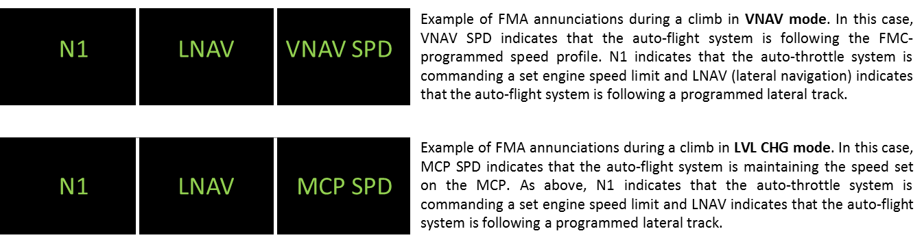
Source: ATSB
Minimum manoeuvre airspeed
The minimum manoeuvre airspeed is represented as the top of an amber bar on the PFD airspeed indicator. Minimum manoeuvre airspeed is defined in the operator’s Flight Crew Operations Manual (FCOM) as the airspeed that provides:
- 1.3g[11] manoeuvre capability to the stick shaker below approximately 20,000 ft.
- 1.3g manoeuvre capability to the low airspeed buffet (or an alternate approved manoeuvre capability entered into the FMC maintenance pages) above approximately 20,000 ft.
The FCOM adds the following caution:
Reduced maneuver capability exists when operating within the amber regions below the minimum maneuver speed or above the maximum maneuver speed. During non-normal conditions the target speed may be below the minimum maneuver speed.
During this occurrence, the crew noticed that the airspeed was near the minimum manoeuvre airspeed on the PFD, and noticed the ‘buffet alert’ message on the CDU scratchpad, and responded accordingly. Other more salient system alerts and levels of protection were available had the crew not responded when they did, and the airspeed had continued to reduce. These include an aural ‘airspeed low’ alert and, following further airspeed reduction, a stick-shaker system.[12] Under some conditions the auto-flight system may also command a reduction in the aircraft pitch attitude (accepting a reduction in the rate of climb in return for airspeed management), if the airspeed reaches the minimum manoeuvre airspeed.
Crew comments
During the operator’s investigation into the incident, the crew commented that a number of distractions may have contributed to the incident. The crew commented that sun glare was particularly problematic – the glare was directly through the windscreen for the duration of the climb. The crew also commented that they may also have been distracted by air traffic control and cabin-related communication requirements, and other air traffic in their vicinity. Additionally, both pilots consumed breakfast during the climb (at separate times), which may have provided a source of distraction.
ATSB comment
In a similar occurrence involving the same aircraft type, the crew inadvertently allowed the aircraft to continue to climb in LVL CHG mode at a constant Mach 0.62. On that occasion, the crew noticed the ‘buffet alert’ message and a small pitch attitude reduction as the aircraft climbed through about FL 350 and the airspeed neared the minimum manoeuvre airspeed. A copy of the report associated with that incident is available on the ATSB website.
A recent report by the FAA Performance-based Operations Aviation Rulemaking Committee, (Commercial Aviation Safety Team Flight Deck Automation Working Group) titled Operational Use of Flight Path Management Systems made a number of findings and recommendations dealing broadly with vulnerabilities associated with flight crew management of automated systems. Further to a 1996 FAA report titled The Interfaces Between Flightcrews and Modern Flight Deck Systems, the more recent report commented that ‘…autoflight mode selection, awareness and understanding continue to be common vulnerabilities’. Both the 1996 report and the later Automation Working Group report are available on the FAA website.
ATSB Research Investigation B2004/0324 titled Dangerous Distractions found that pilot distraction contributed to 325 occurrences involving Australian-registered aircraft between 1997 and 2004. The report concluded:
… the findings have shown that distractions have the potential to significantly threaten flight safety across all sections of the industry and during all phases of flight. Clearly, strategies to minimise pilot distraction need to be developed and designed with particular attention to the operations being undertaken.
The report, which includes some strategies for reducing pilot distraction, is available on the ATSB website.
Safety action
Whether or not the ATSB identifies safety issues in the course of an investigation, relevant organisations may proactively initiate safety action in order to reduce their safety risk. The ATSB has been advised of the following proactive safety action in response to this occurrence.
Aircraft operator
As a result of this occurrence, the aircraft operator intended to highlight relevant human factors issues, such as the potential distractions associated with sun glare and communications, in future training programs.
Safety message
For flight crew, this incident highlights the importance of continued auto-flight system mode and aircraft energy state awareness. The incident also highlights the manner in which various distractions have the potential to adversely affect such awareness. For operators, the incident highlights the importance of robust auto-flight management procedures, supported by appropriately focussed crew training and standardisation.
In 2010, the European Aviation safety Agency issued a Safety Information Bulletin on the subject of Flight Deck Automation Policy – Mode Awareness and Energy State Management. The bulletin included a number of recommendations to operators addressing automation policies, procedures and training. A copy of the bulletin is available at European Aviation Safety Agency. Operators of highly automated aircraft are encouraged regularly review their own automation policies, procedures and training in the context of the recommendations included in the bulletin, and with the benefit of lessons learned from this and similar incidents.
Aviation Short Investigations Bulletin - Issue 41
Purpose of safety investigationsThe objective of a safety investigation is to enhance transport safety. This is done through:
It is not a function of the ATSB to apportion blame or provide a means for determining liability. At the same time, an investigation report must include factual material of sufficient weight to support the analysis and findings. At all times the ATSB endeavours to balance the use of material that could imply adverse comment with the need to properly explain what happened, and why, in a fair and unbiased manner. The ATSB does not investigate for the purpose of taking administrative, regulatory or criminal action. TerminologyAn explanation of terminology used in ATSB investigation reports is available here. This includes terms such as occurrence, contributing factor, other factor that increased risk, and safety issue. Publishing informationReleased in accordance with section 25 of the Transport Safety Investigation Act 2003 Published by: Australian Transport Safety Bureau © Commonwealth of Australia 2015
Ownership of intellectual property rights in this publication Unless otherwise noted, copyright (and any other intellectual property rights, if any) in this report publication is owned by the Commonwealth of Australia. Creative Commons licence With the exception of the Coat of Arms, ATSB logo, and photos and graphics in which a third party holds copyright, this publication is licensed under a Creative Commons Attribution 3.0 Australia licence. Creative Commons Attribution 3.0 Australia Licence is a standard form licence agreement that allows you to copy, distribute, transmit and adapt this publication provided that you attribute the work. The ATSB’s preference is that you attribute this publication (and any material sourced from it) using the following wording: Source: Australian Transport Safety Bureau Copyright in material obtained from other agencies, private individuals or organisations, belongs to those agencies, individuals or organisations. Where you wish to use their material, you will need to contact them directly. |
__________
- The FMC uses information entered by the crew, aircraft systems data, and navigation and performance databases, to provide auto-flight and auto-throttle guidance and control.
- In LNAV mode, the auto-flight system guides the aircraft along the FMC-programmed lateral track.
- At altitudes above 10,000 ft in Australia, the height of an aircraft above mean sea level is referred to as a flight level (FL). FL 250 equates to 25,000 ft.
- Mach number is the ratio of true airspeed to the speed of sound in the surrounding air.
- In LVL CHG mode, the magenta airspeed bug on the PFD airspeed indicator points to the speed selected by the crew in the Indicated Airspeed (IAS)/Mach number (MACH) window on the Mode Control Panel (see later description).
- Two identical CDUs (one available to each pilot) are used by the flight crew to enter data and control the FMC, and to display FMC data and messages. The scratchpad refers to the bottom line of the CDU screen, used among other things to display FMC advisory messages. When an advisory message such as ‘buffet alert’ appears, a message light on both CDUs also illuminates to draw attention to the CDU message. The operator’s Flight Crew Operations Manual states that the ‘buffet alert’ message appears when the manoeuvre margin is ‘less than specified’.
- The MCP is used by the crew to control flight parameters such as altitude, speed and heading, and to select auto-flight and auto-throttle system operating modes.
- UTC refers to Coordinated Universal Time. UTC is the time zone used for civil aviation. Local time zones around the world can be expressed as positive or negative offsets from UTC. At the time of this occurrence, CDT was UTC plus 10 hours and 30 minutes. For example, 1952 UTC on 6 November 2014 was 0622 CDT on 7 November 2014.
- Auto-flight modes are displayed on the FMA at the top of the PFD. Engaged modes are displayed at the top of the FMA in green letters. Armed modes are displayed in smaller white letters beneath the engaged modes. The mode annunciations, from left to right, are auto-throttle, roll (or lateral) mode, and pitch (or vertical) mode.
- N1 auto-throttle mode engages automatically when LVL CHG or VNAV modes are engaged during climb. The auto-throttles then maintain engine speed at the N1 limit selected on the CDU.
- 1.3g represents 1.3 times the force of gravity. In this context, 1.3g means that the aircraft can be manoeuvred at up to 1.3g without activating the stick shaker or generating a low airspeed buffet. Approximately 1.3g will be experienced during a level turn at 40 degrees angle of bank.
- A stick-shaker is a device that physically shakes the control column through a small angle in the fore and aft plane, providing an artificial warning of an approaching aerodynamic stall.