Report No. 24/05
Task No. BE/200500003
Occurrence No. BO/200500620
Examination of failed thrust bearings from a Teledyne Continental Motors GTSIO520M engine
Factual Information
1.1 Examination brief
The Australian Transport Safety Bureau (ATSB) was requested by officers from the Civil Aviation Safety Authority (CASA) to conduct an examination and analysis of several damaged thrust bearing elements from the propeller drive shaft of a Teledyne Continental Motors model GTSIO520M aircraft engine (serial number 810712). Information received indicated that the bearings and accompanying propeller shaft were removed from service during maintenance activities; the discovered damage prompting the aircraft operator to submit a defect report / service difficulty report (SDR) to CASA. A second similar instance of bearing failure and shaft damage was also reported, having occurred on a similar engine (serial number 239168R) approximately one month previously.
The assessment of bearing compliance with the manufacturer's specifications or the direct applicability of the particular bearing part to the engine within which they were installed was not within the scope of the investigation.
1.2 Items received
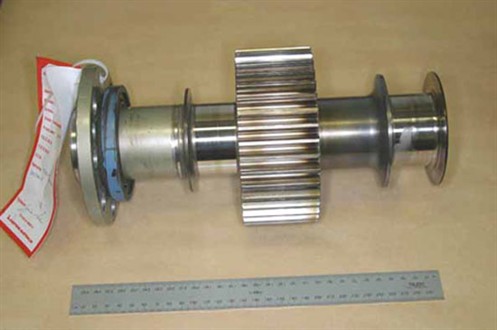
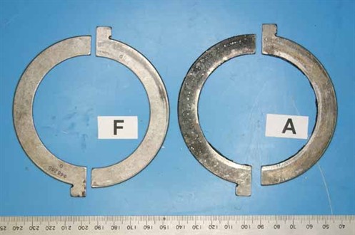
The ATSB received the full set of thrust bearing elements and the propeller shaft from engine serial number (ESN) 810712 (figure 1). The propeller shaft from the earlier occurrence was also provided (figure 2), however the associated thrust bearing set was not available.
Figure 1. Propeller shaft and thrust bearings from engine serial number 810712.
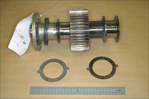
Figure 2. Propeller shaft from engine serial number 239168R.
As installed, the thrust bearings comprised two sets of semicircular opposing plates, located against flange elements at the rear of the propeller shaft (figure 3 ). The rear bearings, carrying the primary propeller thrust loads, had sustained extensive mechanical and thermal damage, whereas the forward bearings showed little evidence of abnormal service and were visibly sound (figures 4, 5). The undamaged (forward) bearing set carried the rear surface identification '646260 G'. Damage to the rear bearings prevented the recognition of any similar markings on those items.
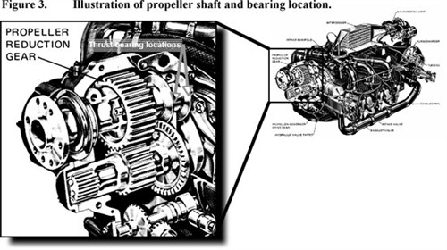
Figure 4. Contact (bearing) surfaces of thrust bearings as-received.
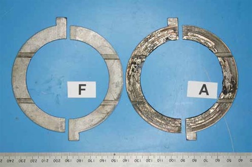
Figure 5. Rear (backing) surfaces of thrust bearings as-received.
The thrust bearings were understood to be of tri-metal construction, comprising a surface layer of lead-tin babbit, over a copper-lead intermediate layer on a steel backing. The SDR document indicated the bearing set had operated for 433.4 hours since new installation (TSN).
1.1 Examination findings
1.1.1 Rear thrust bearings
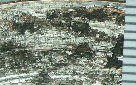
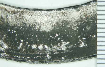
Close visual examination of the set of failed bearings (attachments A - D) showed heavy scoring, gross disruption and partial loss of the bearing alloy from the bearing running (contact) surfaces (figure 6). Partial melting of the surface alloys and other evidence of elevated temperatures was prevalent, as was the blackening and discolouration of the surfaces where alloy loss had occurred. The rear (back) faces of the bearings also showed blackening and the accumulation of melted alloy (figure 7). The lubrication channels on one bearing were partially filled with transferred material that had been melted and dislodged from adjacent areas.
Figures 6 and 7. Low-power microscopic view of a damaged area on the contact and backing surfaces of a damaged thrust bearing.
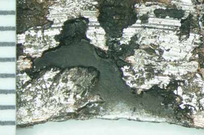
In isolated regions, the bearing alloy had completely separated from the steel backing, with the affected areas characterised by exposure of the comparatively flat, featureless interfacial surfaces (figure 8).
Figure 8. Area on a damaged bearing showing complete separation of the bearing alloy from the steel backing.
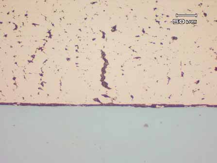
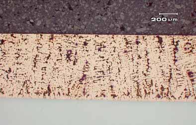
Several metallographic sections taken transversely through one bearing confirmed the basic tri-metal construction, with the intermediate layer presenting as a coarse intermittent network of lead within a copper alloy matrix. In numerous areas, the lead network had interconnected, creating filled fissures (figure 9), the larger of such broaching the external surface. Evidence of lead migration to the steel backing interface was observed at and adjacent to the areas of alloy separation, creating a continuous lead boundary layer approximately 5-10 �m thick.
Figure 9. Cross-sectional microstructure of a damage bearing, showing the agglomeration of lead (dark phase) within the copper bearing alloy and along the backing interface. Unetched.
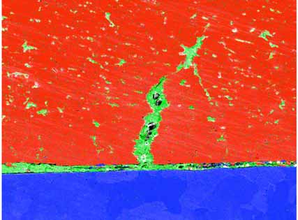
Scanning electron microscopy of the prepared sections confirmed the metallographic observations, with back-scattered electron imaging (figure 10) and x-ray dot mapping (figure 11) graphically illustrating the lead agglomeration and migration to the backing interface.
Figure 10. SEM image of the metallographic section, illustrating the lead migration.
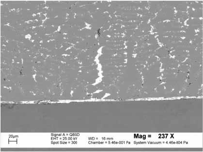
Figure 11. SEM X-ray map confirming the lead migration (green phase) within the copper alloy (red phase) and at the steel (blue phase) interface.
1.2.1 Forward thrust bearings
In contrast with the rear elements, the forward bearings presented in an essentially undamaged condition (figure 12), with very little evidence of metal-to-metal surface contact and no evidence of thermal distress, overheating or physical degradation. The rear surfaces were not fretted or rubbed to any significant extent and showed no indication of improper seating, movement or miss-installation.
Several metallographic sections, taken in a similar sense to those from the rear bearings, presented a similar general microstructure, with the intermediary alloy layer showing a distinct as-cast (dendritic) distribution of lead within the copper alloy matrix (figure 13). No evidence of fissuring or lead migration to the backing interface was observed within the cross-sections studied.
Typical thicknesses of the bearing component layers and backing were established by measurement under the SEM, i.e.
Surface Pb-Sn babbit: 7 - 10 �m (0.007 - 0.010 mm)
Intermediate Cu-Pb alloy: 715 - 725 �m (0.715 - 0.725 mm)
Steel backing: 1,650 �m (1.65 mm)
Figure 12. Undamaged running surfaces of the forward bearing set.
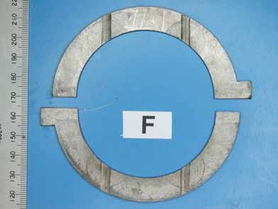
Figure 13. Metallographic cross-section through an undamaged bearing - no lead migration to the alloy interface.
1.2.2 Propeller shafts
Both propeller shafts showed distinct discolouration and evidence of localised heating in a band around the back face of the rear thrust flange (figure 14). Similar discolouration was also noted in a band around the rearmost ends of the reduction gear teeth (figure 15), however the tooth contact surfaces themselves showed no evidence of distress, uneven wear or excessive localised friction.
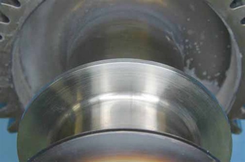
The inside (bearing) surfaces of the rear shaft flanges (those working against the failed bearing elements) showed heavy wear and circumferential scoring around the contact path (figure 16). In contrast, the opposite flange faces (figure 17) showed little if any physical manifestation of service - abnormal or otherwise.
Figure 14. Discolouration of the rear thrust flange surface typifying the localised overheating.
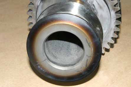
Figure 15. Discolouration (similar to figure 12) evident on the ends of the reduction gear teeth.
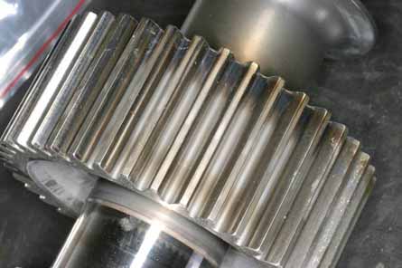
Figure 16. Appearance and extent of scoring and wear sustained by the propeller shaft rear thrust flange contact surface.
Figure 17. Forward thrust flange (opposite that shown above), presenting in sound condition.
Analysis
Damage to the propeller shaft thrust bearing assembly was limited to the rear bearings and shaft flanges, those being the components carrying the primary propeller thrust loads when under power. The forward bearings and shaft flanges were undamaged and showed no indication of anomalous service.
The rear propeller shaft thrust bearings from ESN 810712 had failed as a result of gross localised overheating. The local discolouration of the shaft flanges and adjacent surfaces and the partial melting and microstructural changes within the bearing alloy attested to the excursion in temperatures to a level well above the normal component operating range. The physical loss of sections of bearing alloy from the backing material was a direct manifestation of the overheating, with the elevated temperatures causing the lower melting point lead alloy to agglomerate and migrate to the steel interface, where it weakened the normal bond and allowed the break-up and separation of the bearing material. There was no evidence of a deficiency within the construction or make-up of the bearings examined, nor was there any evidence that the bearings had been improperly installed.
In a general sense, the overheating of bearings results from the generation of frictional heating at a rate greater than the assembly and environment is able to conduct it away. Heating, from surface and lubricant frictional effects, is a function of numerous interrelated factors including:
- bearing operating (transmitted) loads
- clearances
- lubricant properties
- lubricant quantities and flow rates
- relative surface speeds
- surface conditions and finishes
- bearing materials
The investigation was not able to directly identify which of the identified factors were contributory to the failures sustained, however it is suggested that issues relating to the initial bearing clearances, lubricant and operating (thrust) loads would be the most likely in terms of the general nature and function of the assembly.
Conclusions
The following conclusions, in terms of the bearing failures, were drawn from the examination of the supplied components:
- The bearings from ESN 810712 had failed as a result of gross, localised frictional overheating, resulting in the physical and microstructural degradation of the bearing alloy.
- There was no evidence that a manufacturing defect, material anomaly or other deficiency within the bearing components themselves had contributed to the failure.
- There was no evidence found to suggest that the bearings had been improperly installed.
- The investigation was not able to directly identify the proximate cause/s of bearing failure, however it is suggested that initial bearing clearances, lubrication and loading were most likely in terms of the nature of the failure and the general function of the assembly.