Loss of separation assurance involving Airbus A330, 9V-STQ, and Airbus A320, VH-VFH, near Tindal, Northern Territory, on 24 April 2014

Final report

Report release date: 13/05/2016

Safety summary

What happened

On 24 April 2014, an Airbus A330 en route from Brisbane, Queensland to Singapore was maintaining 36,000 ft when the air traffic controller cleared an Airbus A320 on a reciprocal track en route from Darwin, Northern Territory (NT) to Brisbane, to climb through the A330's level. This resulted in a loss of separation assurance about 73 km east-south-east of Tindal, NT.

Recorded data from the two aircraft showed that the minimum vertical separation was 224 ft at 0249:04 Eastern Standard Time, when the two aircraft were 9.96 NM (18.45 km) apart horizontally. The minimum horizontal separation was 2.21 NM (4 km) at 0249:40, when the aircraft were 1,720 ft apart vertically. There was no loss of separation as the surveillance separation standard of 5 NM (9.26 km) was maintained when the 1,000 ft vertical separation standard did not exist. In addition, the vertical separation standard re-established before the surveillance separation standard was compromised.

What the ATSB found

The ATSB determined that the en route controller did not identify the potential confliction and assigned direct tracking and climb to the southbound A320 aircraft. The controller had occupied an active air traffic control position for a period of about 3 hours and 55 minutes during a night shift, without a formal rest break, and was likely experiencing the effects of fatigue at the time of the occurrence.

The ATSB identified safety issues relating to Airservices Australia’s utilisation of shift sharing practices for the Tops controllers resulting in them sustaining a higher workload over extended periods without a break, during a time of day known to reduce performance capability. The requirement for skills-based training for effective compromised separation recovery actions was also identified.

What's been done as a result

Airservices Australia has undertaken a number of safety actions relating to compromised separation recovery training. In addition, Airservices reported that they were reviewing the application of published fatigue risk management system guidelines for air traffic control staff undertaking night shift duties.

Safety message

This occurrence is a reminder of the potential for errors to occur when experienced personnel are working for extended periods during periods of circadian low without effective risk mitigators to manage fatigue induced error or consideration of traffic volume and complexity.


The occurrence

On 24 April 2014, a loss of separation assurance (LOSA)[1] occurred between:

  • an Airbus A330 (A330) aircraft, registered 9V-STQ, operating a scheduled passenger service from Brisbane, Queensland to Singapore, and
  • an Airbus A320 (A320) aircraft, registered VHVFH, operating a scheduled passenger service from Darwin, Northern Territory, to Brisbane.

Both aircraft were under air traffic control (ATC) radar surveillance coverage at the time of the occurrence, on reciprocal tracks.

An Airservices Australia (Airservices) air traffic controller in Brisbane Centre was working a night shift on the Tops Group. Their shift commenced at 2300 Eastern Standard Time[2] on 23 April 2014 and ceased at 0615 the following morning. For about the first 3 hours of the shift, the controller (Controller 1) had jurisdiction of all Tops Group airspace sectors until a handover/takeover at 0158 on 24 April 2014. Jurisdiction for the eastern sectors of the group was then assumed by another controller (Controller 2) at an adjacent console. That was normal practice on the night shift, due to increasing traffic levels at that time.

Controller 1 maintained jurisdiction of the Territory, Coburg and Katherine sectors, which were referred to as Tops Central (Figure 1).

Figure 1: Territory, Coburg and Katherine airspace sectors (Tops Central) map showing air route A464
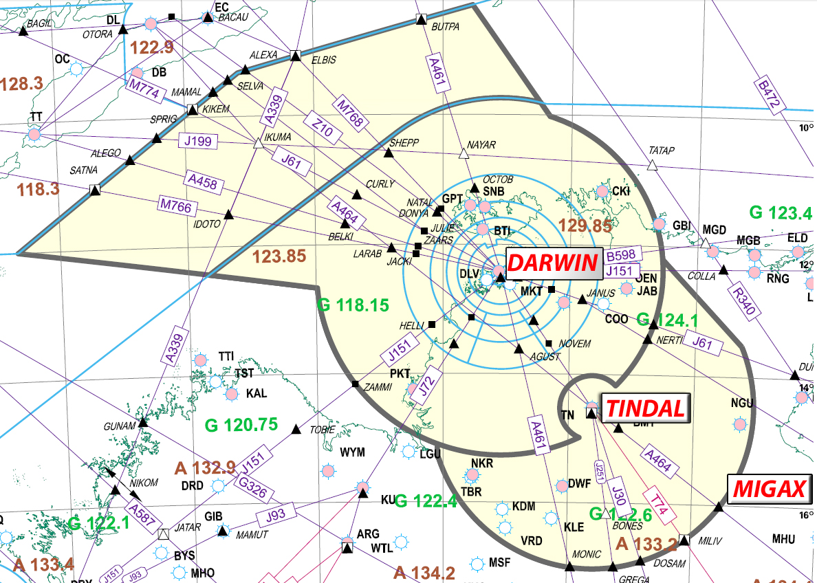
Figure 1: Territory, Coburg and Katherine airspace sectors (Tops Central) map showing air route A464

Source: Airservices Australia. Image modified by the ATSB.

At that time, Controller 1 had a number of aircraft on frequency, including a southbound A330 tracking via overhead Darwin for Melbourne, Victoria, at flight level (FL)[3] 370. They were also aware of two A330 aircraft tracking northbound at FL 380 and FL 360 respectively. Those aircraft would later transit through the Territory sector but were presently located in a southern sector. The controller reported that they considered that both northbound A330s were tracking via the standard published two-way air route A464, via position MIGAX, which was a waypoint positioned on the southern boundary of the Territory sector (Figure 1). Controller 1 reported that the factors contributing to that conclusion included:

  • the position of the aircraft on their air situation display (ASD)
  • the large display scale
  • the expectation that those aircraft would track as they did on most nights.[4]

At 0215, the flight crew of the first northbound A330 contacted Controller 1 and reported maintaining FL 380 as the aircraft tracked via air route A464, approaching MIGAX and the Territory sector boundary.

At 0222, after observing indications that the radar at Tindal was briefly unavailable then appeared serviceable again, Controller 1 contacted the Systems Supervisor.[5] They were located at the front desk in the Operations Room and had operational command authority for the Brisbane Flight Information Region. The Systems Supervisor advised that they were not aware of a reported problem and though it appeared that the radar had returned to service, they would follow up with the technicians. The radar remained serviceable for the rest of Controller 1’s shift.

At 0226, Controller 1 was contacted by the A320 flight crew on climb out of Darwin and tracking as per their flight plan to overhead Tindal, Northern Territory, then via air route A464 to MIGAX. The controller assigned further climb to their flight planned altitude of FL 350.

The flight crew of a Boeing 737 (737), positioned about 10 NM (18.5 km) behind the A320 and also climbing out of Darwin, contacted Controller 1. The controller assigned climb to amended FL 350 and advised that further climb for their flight planned altitude of FL 370 would be provided later if available.

About 1 minute later, the A320 flight crew requested climb to an amended altitude of FL 370. Controller 1 responded that they would advise. They then cleared the aircraft direct to MIGAX, which would re-position it to the east of air route A464 and provide lateral track segregation with the following 737. Controller 1 rerouted the aircraft’s flight data record in the ATC computer system. That resulted in the automatic display of the aircraft’s route on the controller’s ASD for 2 seconds.

At that time (0228), the positions of the aircraft were (Figure 2):

  • The A320 was south of Darwin was passing FL 130 on climb to FL 350, with a groundspeed of 370 kt.
  • The 737 was about 14 NM (26 km) behind the A320, passing 9,600 ft on climb to FL 350 with a groundspeed of 280 kt.
  • A southbound A330 maintaining FL 370 was about 3.8 NM (7 km) behind the 737, with a groundspeed of 570 kt.
  • The first northbound A330 was midway between MIGAX and Tindal.
  • The second northbound A330 at FL 360 was in the still in the adjoining southern sector, about 40 NM south-east of MIGAX.

Figure 2: Proximity of aircraft in Tops Central airspace at 0228:10
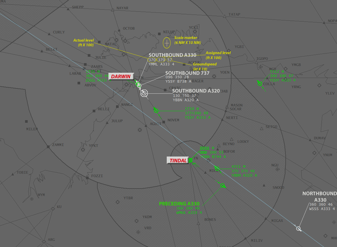
Figure 2: Proximity of aircraft in Tops Central airspace at 0228:10

Source: Airservices Australia. Image modified by the ATSB.

Note: The scale used in this figure is smaller than that set on the controller’s air situation display.

  • The southbound A330 was the vertical limitation for the southbound A320 and 737 out of Darwin and resulted in those aircraft being assigned the conforming and vertically separated altitude of FL 350.

Controller 1 expected another controller (Controller 3), to relieve them from duty at 0230, but that controller did not arrive. Controller 3 had commenced their night shift at the same time and slept for the first part of the shift in the Centre’s stand-down room facilities, as was normal practice. Controller 1 asked other controllers in the vicinity, after completion of their handover/takeovers for other sectors, to try to locate Controller 3.

At 0233, a controller from the international airspace sector adjoining the Territory sector boundary to the north called Controller 1. They reported that they were experiencing problems with their ATC computer system, which resulted in the automatic cross-boundary messaging between the two systems no longer functioning.

Shortly after, Controller 1 accepted jurisdiction of the second northbound A330, which was positioned abeam MIGAX. On accepting jurisdiction, the aircraft’s route automatically displayed on the controller’s ASD for 2 seconds.

At 0234, the second northbound A330 flight crew transferred to Controller 1’s frequency. The A330 was maintaining FL 360 and operating on a flex track[6] that was displayed on the controller’s ASD as a light blue line. At that time, the A320 was positioned to the north-north-west of Tindal, climbing through FL 218 and there was 244 NM (452 km) between the aircraft (Figure 3).

Figure 3: Proximity and positions of aircraft at 0233:37
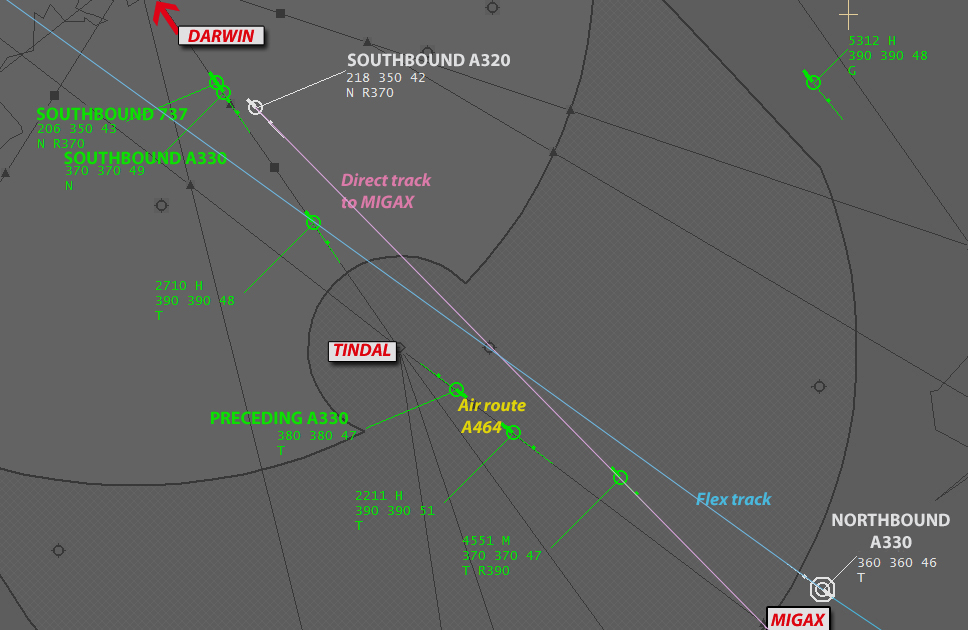
Figure 3: Proximity and positions of aircraft at 0233:37

Source: Airservices Australia. Image modified by the ATSB.

Note: The scale used in this figure is smaller than that set on the controller’s air situation display.

Loss of separation assurance

At 0241, the controller issued the A320 flight crew with clearance to climb to FL 370. This resulted in a LOSA between the A320 and the northbound A330. There was no assurance that the vertical separation standard of 1,000 ft would exist when the aircraft passed on their reciprocal tracks, at a point where there could be less than the required radar separation standard distance laterally of 5 NM (9.26 km).

At 0245, the controller transferred the A320 flight crew to another control frequency in their airspace, due to coverage limitations. There was 74.4 NM (138 km) and 3,500 ft between the occurrence aircraft, as the A320 climbed through FL 325 and the northbound A330 maintained FL 360.

By 0247, Controller 3 arrived at the console and the handover/takeover commenced. At about 0248:25, during the handover/takeover with Controller 1 still responsible for the airspace, the ATC system’s Short Term Conflict Alert (STCA) activated. It alerted the controllers to a potentially imminent loss of separation (LOS)[7] between the A320 and northbound A330, which were about 20 NM (37 km) and 700 ft apart, with a closing speed of about 920 kt.

Compromised separation recovery

At 0248:33, Controller 1 initiated compromised separation recovery actions. They instructed the A320 flight crew to turn left onto a heading of 150° (which would have been a right turn). The controller then instructed the A330 flight crew to turn right onto a heading of 360°.

Both crews acknowledged the instructions, with the A330’s traffic collision avoidance system (TCAS)[8] being heard over the ATC frequency to have generated a traffic advisory (TA)[9] at the time of that crew’s acknowledgement.

Controller 1 then instructed the A320 flight crew to descend to FL 350 due to traffic. The crew responded shortly after that they had a TCAS resolution advisory (RA).[10] The controller instructed the A330 flight crew to turn right onto a heading of 360° immediately, due to traffic. The crew responded that they were established on that heading already and had a TCAS RA.

The A330 TCAS RA instructed the flight crew to climb, with the aircraft reaching 37,336 ft before the crew commenced descent back to FL 360. The A320 TCAS RA instructed a rate of descent in excess of 1,000 ft per minute and the crew descended the aircraft from 35,748 ft to 34,980 ft, before returning to the ATC assigned altitude of FL 350.

At 0249:45, the A330 flight crew advised Controller 1 that they were descending back to FL 360. The A320 flight crew then reported that they were clear of the traffic and descending to FL 350.

Recorded data from the two aircraft showed that the minimum vertical separation was 224 ft at 0249:04, when the two aircraft were 9.96 NM (18.45 km) apart horizontally. The minimum horizontal separation was 2.21 NM (4 km) at 0249:40, when the aircraft were 1,720 ft apart vertically. There was no loss of separation as the surveillance separation standard of 5 NM (9.26 km) was maintained when the 1,000 ft vertical separation standard did not exist. In addition, the vertical separation standard reestablished before the surveillance separation standard was compromised.

__________

  1. Loss of separation assurance describes a situation where a separation standard existed but planned separation was not provided or separation was inappropriately or inadequately planned.
  2. Eastern Standard Time (EST) was Coordinated Universal Time (UTC) + 10 hours.
  3. At altitudes above 10,000 ft in Australia, an aircraft’s height above mean sea level is referred to as a flight level (FL). FL 370 equates to 37,000 ft.
  4. Airservices Australia’s internal investigation report stated that the pairing of the two A330 aircraft tracking northbound had operated on the same route on four out the last five shifts worked by Controller 1.
  5. The primary role of a Systems Supervisor was the oversight and management of all operational facilities that support air traffic service delivery. That task required the general supervision of operational staff to ensure a safe and efficient air traffic service. A Systems Supervisor was required to be on duty at all times and held operational command authority for their respective Flight Information Region outside of the duty hours of the Operations Room Manager.
  6. A non-fixed air traffic services route calculated on a daily basis to provide the most efficient operational flight conditions between specific city pairs.
  7. Controlled aircraft should be kept apart by at least a defined separation standard. If the relevant separation standard is infringed, this constitutes a loss of separation (LOS).
  8. Traffic collision avoidance system (TCAS) is an aircraft collision avoidance system. It monitors the airspace around an aircraft for other aircraft equipped with a corresponding active transponder and gives warning of possible collision risks.
  9. Traffic Collision Avoidance System Traffic Advisory, when a TA is issued, pilots are instructed to initiate a visual search for the traffic causing the TA.
  10. Traffic Collision Avoidance System Resolution Advisory, when an RA is issued pilots are expected to respond immediately to the RA unless doing so would jeopardise the safe operation of the flight.

Context

Airspace information

Tops Group

When Controller 1 commenced the occurrence shift they had jurisdiction of the group of airspace sectors referred to as Tops East, in addition to Tops Central. Tops East consisted of five sectors and was positioned abutting the Tops Central sectors, from the east of Darwin, down to south of Tindal, over the Gulf of Carpentaria and Cape York Peninsula to the Coral Sea (Figure 4). Controller 1 handed over jurisdiction for the Tops East sectors to another controller (Controller 2) at 0158.

Figure 4: Tops East airspace sectors
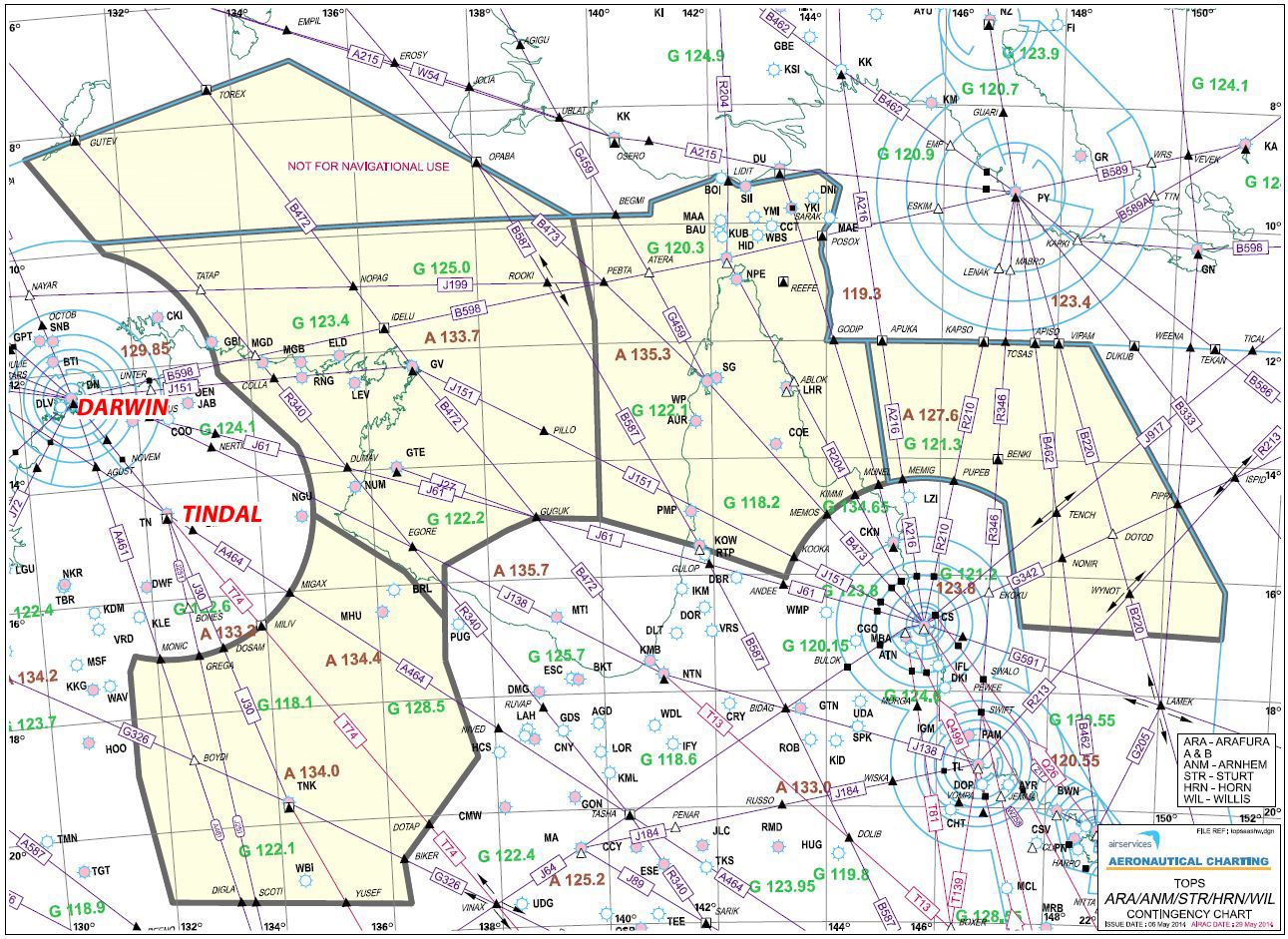
Figure 4: Tops East airspace sectors

Source: Airservices Australia. Image modified by the ATSB.

The loss of separation assurance (LOSA) occurred within the Territory (TRT) airspace sector. At the time of the occurrence, the TRT sector was combined with the Coburg (COG) and Katherine (KTN) sectors. Collectively the TRT, COG and KTN sectors were referred to as Tops Central (Figure 1).

The TRT sector was a high-level procedural/surveillance sector that provided air traffic services (ATS) to aircraft operating from flight level (FL) 285 to FL 600 over the Northern Territory (NT) and north over the Arafura Sea. The provision of ATS included processing overflying international aircraft to neighbouring air navigation service providers and aircraft arriving to, and departing from, Darwin, NT.

COG sector was a surveillance sector that provided ATS to aircraft operating from the base of control area to FL 285, to aircraft primarily arriving to, and departing from, Darwin. KTN sector was a procedural/surveillance sector that provided ATS to aircraft operating in the Darwin and Tindal, NT area. It had an upper limit of FL 285 where it was positioned below the TRT airspace volume and an upper limit of the base of the control area where it was positioned below the COG airspace volume.

Australian Organised Track Structure

The Australian Organised Track Structure (AUSOTS) commenced in 2005. It was a collection of daily generated flex tracks in both directions between South East Asia and Brisbane, Sydney and Melbourne.

A flex track was defined as a non-fixed ATS route calculated on a daily basis to provide the most efficient operational flight conditions between specific city pairs. Flex tracks were designed to provide cost saving opportunities for airlines and benefits to the environment through significant reduction in fuel burn. They originated and finished at published waypoints, known as ‘gates’. All users were required to fly the complete flex track from gate to gate.

Flex tracks were created by Airservices Australia (Airservices) by ‘Trackmasters’ who were personnel based in the organisation’s National Operations Centre in Canberra. Airservices documented that:

Airservices Australia facilitates the development and design of each individual Flex Track. This input ensures the integrity of the air route system is maintained and permits the provision of separation with existing ATC system tools and standards.

Flex track planning criteria was documented in Airservices’ Off Air Routes Planning Manual (OARP). The flex track designator for the city pair of Brisbane to Singapore was BY1. A flex track for flights operating from Singapore to Brisbane was designated as YB1. The A330 involved in the occurrence was operating on a BY1 flex track. The documented validity period for the BY1 flex track was from 2100-0800.

Flex tracks were published to industry in three ways:

  • via the Aeronautical Fixed Telecommunications Network to airlines that requested the associated Track Definition Messages
  • via Notices to Airmen (NOTAM)[11]
  • on the Airservices website, which provided the AUSOTs picture which provided a visual representation of the flex tracks for each day (Figure 5).

Figure 5: AUSOTS picture showing flex tracks for period of the occurrence
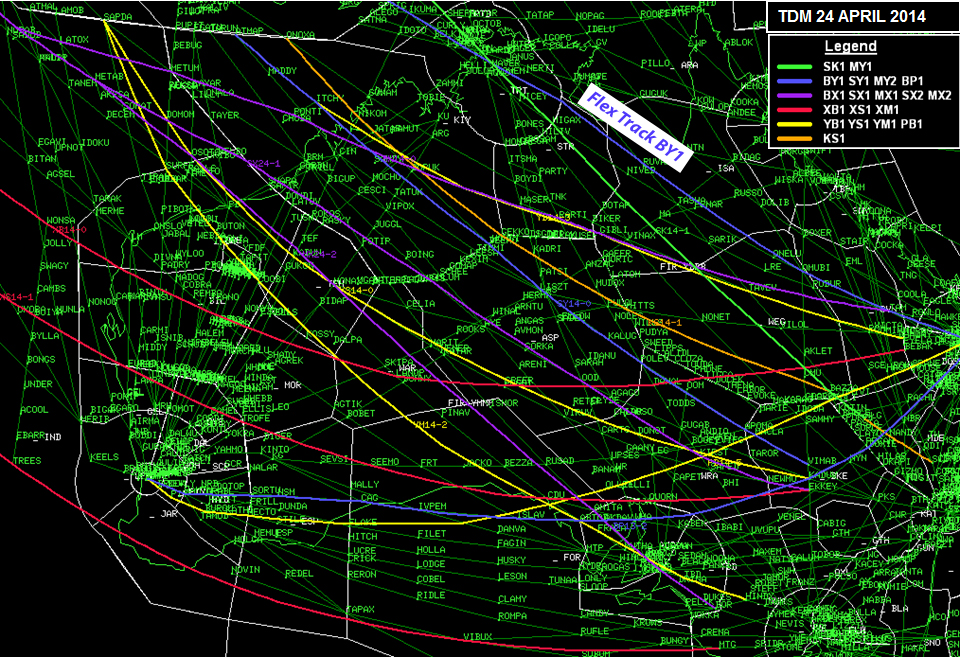
Figure 5: AUSOTS picture showing flex tracks for period of the occurrence

Source: Airservices Australia. Image modified by the ATSB.

The flight plans of the aircraft operating on flex tracks outlined the tracking points defined by the associated Track Definition Message but did not include the numbering of the associated track or any other indication for controllers that the aircraft was operating via a Flex Track. The OARP stated that:

Flex Track designators and ATS route designators (within the Flex Track area) shall not be shown in the filed Flight Plan.

Flex tracks were published to operational controllers via NOTAM. Controllers on the Tops Group reported that the first graphic indication of flex tracks in their airspace sectors was when the tracks appeared on their air situation display (ASD) as light blue lines, with text designation (Figure 6) at about 1400 each day.

Information display

Separation between aircraft under surveillance coverage was applied based on the distance between the centres of position symbols on the ASD. Controllers were required to ensure that the edges of position symbols did not touch or overlap unless vertical separation was applied between aircraft.

On the large range scale required to display the TRT Central and East sectors combined, a surveillance track symbol representative of an aircraft was about 15 NM (27.8 km) wide on the ASD. There was about 20 NM (37 km) between the standard air route A464, on which the preceding A330 was operating, and the flex track BY13 on which the occurrence A330 was operating.

The flex track was illustrated on the ASD as a light blue line with positions on the track and the flex track designator ‘TRKBY13’ marked at points along the track in light blue. Standard air routes were displayed in light grey (Figure 6).

Figure 6: Air situation display image of track positions at the time of the occurrence showing flex track labels and involved tracks and routes
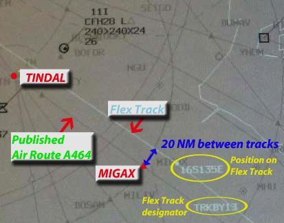
Figure 6: Air situation display image of track positions at the time of the occurrence showing flex track labels and involved tracks and routes

Source: Airservices Australia. Image modified by the ATSB.

Note: The scale used in this image is smaller than that set on the controller’s air situation display.

When a controller accepted jurisdiction of a track, the aircraft’s route would automatically display on the ASD in pink for a period of 2 seconds. There were no faults with the automatic route display function during the occurrence shift.

Organisational fatigue management processes and practices

Fatigue Risk Management System

In September 2004, Airservices published a report to the National Consultative Council Occupational Health and Safety Sub Committee on Fatigue Management within Airservices Australia Air Traffic Services (ATS) (referred to as the ATS Fatigue Management Report. The report outlined results from an internal Fatigue Management Working Group supported by external subject matter experts. The study was conducted through audits of ATC rosters, a review of fatigue management research and literature and through a risk assessment workshop process. A total of 54 recommendations were made to industry relating to fatigue and the impact of shift work on performance, some of which have been referenced within this report.

Airservices Fatigue Risk Management requirements were first introduced in 2005. The requirements were significantly revised in 2012 and published as part of the Airservices Safety Management System documentation in July 2012. Its purpose was defined in 2012 as follows:

The standard defines the minimum requirements for the management of oversight of fatigue-related risk…these requirements form the scope of a Fatigue Risk Management System (FRMS). The purpose of an FRMS is to…ensure that workers are sufficiently alert when at work so that they operate at a satisfactory level of performance and safety, [and] prevent or minimise the risk of a fatigue-related occurrence by giving due consideration to all aspects of work-related fatigue.

The requirements advocated a shared model of responsibility for fatigue management between workers and the organisation. Workers were responsible for ‘ensuring they make appropriate use of rest periods between shifts…[and] are adequately rested and recovered for the shift ahead (i.e. fit for duty)’. In turn, the organisation was responsible for managing fatigue-related risk through ‘rostering practices, working arrangements, education and working conditions’. It also documented Airservices’ policies relating to planned rosters and work cycles, risk controls, methods for instigating changes to rosters, education requirements and assurance mechanisms.

The following documents also related to Airservices’ Fatigue Risk Management System (FRMS) policies and processes:

  • The Fatigue Assessment and Control Tool (FACT) Guide governed risk assessments relating to roster changes
  • The Fatigue Risk Management Air Traffic Service Procedure defined how fatigue-related risk (primarily through work scheduling and education) was to be managed in accordance with the Requirements.
  • The Brisbane Centre Local Instructions included a section called Rest Management. ‘Rest’ referred to time on shift away from the console, and ‘napping’ related to sleeping, conducted in the stand down rooms.
  • The Local Instructions for Brisbane Centre Shift Managers and Systems Supervisors provided guidelines for night shift operations. It outlined the night staffing arrangements and break directions and considerations for each ATC Group.
Rest breaks from duty during night shifts

The Airservices FRMS Fatigue Assessment and Control Tool (FACT) Guide stated that:

As a general practice, rest breaks should be provided approximately every two hours. Operational managers and supervisors who have the responsibility for managing rest breaks will need to consider a range of factors which may impact on the particular situation, including extremes of workload (be it very high or very low). The period between rest breaks should not be more than four hours.

A short rest break should last at least 15 minutes and a long rest break at least 30 minutes. From a practical sense, we are looking for opportunities for workers to consume a quick snack and/or have a drink, go to the toilet and attend to any urgent personal matter(s). At other times in the shift, a break long enough for a person to prepare and consume a meal and have time to refresh their mind and body should be provided.

Additionally, to alleviate long periods on a console, Airservices had implemented a short break procedure. A short break was defined as a period away from the console not expected to exceed 20 minutes. Controllers could ask the Systems Supervisor or another controller who was not endorsed for the position/function to maintain a listening watch and/or relay to an aircraft verbatim recorded instructions, issued by an appropriately endorsed controller for that console or position. Some controllers reported that they did not favour the short break procedure as they considered it preferable for only a controller who held current endorsements to monitor their airspace during a break.

For the Tops Group, the night staffing was documented as five controllers, 7 days per week (3 for Tops East and Tops Central, and 2 for Tops West). The rest break directions were for ‘tactical break management as endorsement mix permits’.

Sleep/napping during rest breaks

Airservices’ Brisbane Centre Local Instructions stated that staff must be present at work at shift commencement, and that the approval or anticipation of napping does not allow ATS staff to present for work unfit for duty. When napping during a rest break was approved, staff must:

  • ensure the Shift Manager and other relevant controllers were advised of their whereabouts
  • wake in sufficient time to compensate for the effects of sleep inertia.
Workload for Tops controllers

Airservices Australia used the practice of combining and de-combining sectors to distribute workload.

Supervision

At the time of the occurrence, Operational Command Authority for the Brisbane Operations Room was exercised by the Systems Supervisor (SS). That position was responsible for system oversight and the supervision of the operations room, including monitoring air traffic and staff.

The SS was based at the main desk at the front of the Operations Room and could be contacted by controllers through the console communications system. The SS was also responsible for the administration of the stand-down rooms and held a second set of keys to each room in case of emergency.

The Aisle Shift Managers and Operations Room Manager positions were not manned, nor were they required to be under organisational policy and procedures. The Aisle Shift Manager position for the location of the Tops Central and East sectors was manned until 2000, with the SS responsible for supervision during the night shift.

Airservices Australia reported in their internal investigation report that the shift sharing prearrangement for Tops Group controllers on the night shifts was a routine, standing situation known and accepted by operational management. The Tops Group was not the only ATC Group in Brisbane Centre to have such an arrangement when two or more controllers were rostered for a night shift on the same sectors/positions.

Personnel information

Controller 1

Controller 1 was an experienced fully endorsed controller who held endorsements and worked on the Tops Group, and former equivalent airspace sectors, for over 20 years. In addition to having worked in the Group Training Specialist role for the group and periodically performed a check controller role, they were also an on-the-job training instructor and workplace assessor.

Controller 1 was not working their normal rostered shift at the time of the occurrence due to a shift swap with another controller. That swap resulted in Controller 1 working a single night shift on the second of three rostered days off in their roster pattern.

They reported that they were fit for duty at the commencement of the shift and had prepared for the duty by sleeping for about 4 hours at home in the evening, before driving to work for the duty. Controller 1 had a number of strategies to assist with managing fatigue experienced during night shifts, including drinking coffee. They reported that it could be difficult to remain alert during the circadian low associated with the early hours of the morning and would look forward to their break at about 0230.

Controller 1 stated that they first viewed the two northbound A330s while working all of the Tops Central and East airspace sectors combined. Their air situation display (ASD) was set at a very large range scale to present all of the airspace under their jurisdiction on the one screen.

At that time, the two A330s were in a southern sector, both appearing to track via standard air route A464 and not yet in Controller 1’s airspace. Controller 1 reported that the proximity and tracking of two A330s, with those particular flight number call signs, was a situation that they observed regularly on the night shift. Both flights usually tracking via A464 through the Tops Central airspace.

Controller 1 reported that later on, when they accepted jurisdiction for the second A330, the route of the second aircraft automatically displayed on their ASD for a period of 2 seconds, as was the normal system process. The controller did not identify that the aircraft was operating on a flex track. They maintained the expectation that it was tracking via A464, as was the preceding A330. In addition, Controller 1 stated that the large range scale required to display the combined air traffic sectors, on their ASD, resulted in the second A330’s operation on a flex track being indistinguishable from the standard air route A464 located in close proximity.

Controller 1 stated that the standard practice to achieve strategic separation assurance with northbound aircraft, and unrestricted climb, was to track aircraft climbing out of Darwin direct to a waypoint on their flight plan on the 150 NM (278 km) Tindal range ring. That practice was taught to trainees during simulator and on-the-job training for the Tops Central endorsements. The controller also reported that procedural separation, such as the application of the 1,000 ft vertical standard, were easier to apply and monitor during the night shift. However, in the absence of a procedural separation standard, the application of radar separation requires that controllers observe the relative positions pf aircraft on their display to ensure the minimum radar standard is established and maintained. On the larger ASD range scale such as was being used in this particular occasion, a surveillance standard would require close monitoring in its application and a smaller ASD range scale may be needed.

Controller 1 recalled that in issuing climb to FL 370 for the southbound A320, they had considered that the aircraft was strategically separated. The northbound A330 was at FL 360 and tracking on what the controller thought was A464, which they believed separated it from the A320 tracking direct to MIGAX.

Controller 1 reported that there were a number of distractions during the shift, particularly in the period leading up to the occurrence. These included intermittent failures of the primary Tindal radar and unserviceability of the ATC computer system of the foreign air traffic services provider adjoining the sector boundary to the north. The computer system unserviceability increased Controller 1’s workload as automated coordination messages were no longer functioning.

Controller 2 was newly rated and endorsed on the Tops East sectors. In the absence of an Aisle Supervisor during the night shift, Controller 1 considered that they had a duty of care to monitor and support Controller 2, which required a level of attention.

When Controller 3 did not arrive at 0230 for a handover, Controller 1 was required to also divert their attention from ATS tasks to ask another controller, who was about to commence their break, to try to locate the incoming controller. It was not known by Controller 1 if they were in the building. While some controllers would advise colleagues of their presence on arrival at the commencement of the shift, it was not standard practice and there was an assumption that the SS would know and advise of any absences.

When Controller 3 arrived at the console and reported ready to accept responsibility for Tops Central, Controller 1 commenced the handover using the standard handover/takeover checklist.

Just as Controller 1 reached the section of the handover in which the traffic situation was to be conveyed, the ATC computer system’s Short Term Conflict Alert (STCA) activated. Controller 1 reported their first assessment of the confliction was that the northbound A330 was incorrectly positioned to the right of the standard air route A464 and the occurrence was not controller attributable. They commenced compromised separation recovery actions using the existing range display scale and did not change the ASD display settings to enable viewing of the confliction on a smaller scale. Controller 1 reported that they had not been taught during compromised separation recovery training to zoom in on a confliction on their ASD.

Following the occurrence, Controller 1 reported that they were shaken by the conflict and already felt tired at that time. This was in part due to the expectation that they would have been on a rest break by then. They recognised that their compromised separation recovery actions were ineffective.

Controller 1 last completed compromised separation recovery simulator training on 16 April 2013 and compromised separation recovery computer based training (CBT) on 18 February 2014, followed by a newly developed CBT package less than 1 month prior to the occurrence on 25 March 2014.

Controller 2

Controller 2 received their initial ATC ratings and endorsements on the Tops East sectors on 31 March 2014. On the 23 April 2014 night shift, they assumed responsibility for the Tops East airspace sectors from Controller 1 at 0158.

Controller 3

Controller 3 received their initial ATC ratings and endorsements on the Tops East airspace sectors in October 2012 and gained their Tops Central endorsements in February 2014, becoming a fully endorsed controller.

On arrival at work on 23 April 2014 for the first of two night shifts in their roster pattern, Controller 3 reported to the SS to obtain the key to their allocated stand-down room. They then went to have a sleep prior to working the second half of the shift. They did not advise Controller 1 that they were in the building as there was an expectation that reporting to the SS to pick up their key was adequate notification that they had arrived for the shift.

Controller 3 used their mobile phone to set an alarm to wake at 0215 for a 0230 handover in the Operations Room. For an undetermined reason, the alarm did not operate or Controller 3 slept through the alarm, which they reported had not occurred previously. In response to a controller knocking on the stand-down room door at about 0240, Controller 3 woke, apologised and advised that they would be in the Operations Room shortly. The other controller advised that the situation was managed and not to rush.

Controller 3 quickly prepared to go into the Operations Room. They arrived at the console where Controller 1 was located at about 0245. Controller 3 reported that they were fit for duty and felt very alert. They later reported that they were aware of possible sleep inertia through Airservices’ fatigue risk management system training but as they were not feeling any adverse effects, they made a considered decision that they were ready to accept a handover.

As Controller 1 conducted the handover using the checklist and commenced the traffic segment, the Short Term Conflict Alert activated. From where Controller 3 was sitting, they could not see the levels of the aircraft concerned but could identify that the confliction involved opposite direction traffic, with one aircraft climbing through the level of the other.

Controller 3 reported that although the compromised separation recovery actions used by Controller 1 did not appear to be effective, they felt unable to intervene or assist as Controller 1 was the jurisdiction controller, and also highly experienced.

Following the flight crews’ reports of traffic collision avoidance system (TCAS) resolution advisories (RAs), Controller 3 advised Controller 1, who was shaken by the occurrence, that they would assume jurisdiction of the airspace. Controller 1 unplugged from the console.

Controller 3 last completed compromised separation recovery simulator training on 28 July 2012 and compromised separation recovery CBT on 17 October 2013. They completed the newly developed CBT package after the occurrence, on 29 April 2014.

Compromised separation recovery

Separation is considered to be compromised when separation standards have been infringed, or where separation assurance is absent to the extent that a breakdown of separation is imminent.

In accordance with the Manual of Air Traffic Services, controllers were required to issue safety alerts to pilots of aircraft as a priority, when they became aware that aircraft were in a situation considered to be in unsafe proximity to other aircraft, unless a pilot had advised that action was being taken to resolve the situation or that the other aircraft was in sight.

ATC provided avoiding action advice in critical situations if aware that there was a collision risk, and only to aircraft in receipt of an air traffic surveillance service. Avoiding action advice was prefixed with the term ‘AVOIDING ACTION’ and included instructions to the pilot for avoiding the other aircraft. The phraseology to be used by ATC when providing safety alerts and avoiding action was contained in the Australian Aeronautical Information Publication.

Airservices documented that the Executive General Manager of Air Traffic Control (ATC) had determined that ‘all operational staff must successfully complete annual training and assessment in compromised separation recovery training’. The training was required to assess a controller’s knowledge and/or skills in the following areas:

  • Pilot actions and aircraft performance
  • ACAS and TCAS
  • ATS systems and alerts (STCA)
  • Controller actions.

All controllers that completed compromised separation recovery training were assessed for competency and it was to be recorded on each controller’s file.

The ATC Line Manager (ALM) who held the Training Portfolio for the ATC Group was accountable for developing local specific scenarios to support the classroom and online training, and for the ‘development of appropriate simulator exercises for skills-based training and assessment’. That requirement was documented in the ATS Training Operations Manual.

There was no documented requirement for compromised separation recovery training to include a team resource management[12] component.

Compromised separation recovery training was required to be included in all ATC endorsement training courses, with particular emphasis on skills-based training in the simulator. It was a mandatory requirement that ‘all controllers are assessed in skills-based simulator Compromised Separation Recovery training at intervals not exceeding three years’.

Similar occurrence

On 22 December 2009, at 0253 Central Standard Time, an air traffic controller took action to resolve a loss of separation assurance that occurred on airway route J30, 222 km north-west of Tennant Creek, Northern Territory between an Airbus A330-300 (A330) aircraft, registered B-HLV, and a Boeing Company B737-800 aircraft, registered VH-VUJ.[13]

The aircraft were approaching each other at FL 370 while tracking in opposite directions on the same airway route. The air traffic controller managing the airspace did not effectively control the resolution of the developing confliction. The flight crews of both aircraft identified the traffic confliction and initiated avoidance action to maintain separation.

The investigation found that the controller did not implement a separation plan when the confliction was first identified. Action by the A330 flight crew prompted the controller to take action to re-establish separation assurance. In addition, a number of safety issues were identified, including:

  • the controller had not received training in compromised separation recovery techniques
  • the controller attempted to monitor the resolution of the traffic confliction using an inappropriate control screen range display
  • there was no dedicated control room aisle supervisor during the then peak traffic period.

In response to that occurrence, Airservices conducted an internal investigation, which recommended a number of actions to address the safety factors and issues that were identified during their investigation. These included the recommendation that appropriate supervision within the air traffic control group’s location in the Operations Room is provided on night shifts.

__________

  1. A Notice To Airmen advises personnel concerned with flight operations of information concerning the establishment, condition or change in any aeronautical facility, service, procedure, or hazard, the timely knowledge of which is essential to safe flight.
  2. Team resource management (TRM): strategies for the best use of all available resources – information, equipment and people – to optimise the safety and efficiency of Air Traffic Services.
  3. ATSB investigation AO-2009-080, see www.atsb.gov.au

Safety analysis

Introduction

A loss of separation assurance occurred when the Tops Central controller cleared the flight crew of a southbound Airbus A320 (A320), registered VH-VFH, to climb through the level maintained by a northbound Airbus A330 (A330), registered 9V-STQ, on a reciprocal track.

There are multiple risk controls in place to reduce the likelihood that safety-critical air traffic control (ATC) personnel would make an error resulting in aircraft coming within close proximity and other system defences designed to reduce collision risk if a controller error resulted in an undesired state. However, in this occurrence, some of the risk controls did not work effectively.

This analysis discusses the relevant controller actions, local conditions, risk controls in terms of flex track design and implementation, shift and fatigue management and compromised separation recovery.

Aircraft processing

Due to the large range scale required to display Controller 1’s jurisdiction airspace, the track symbol representative of an aircraft was 15 NM (27.8 km) wide on the air situation display (ASD). In consideration of the 5 NM (9.26 km) surveillance standard and requirement for the symbols to never touch or overlap unless vertically separated, separation with the A320 would have been maintained if the northbound A330 was operating on standard air route A464. As A464 was about 20 NM (37 km) south-west of the flex track, at the position where the aircraft’s tracks crossed, the distance between the edges of the symbols would have about the minimum 5 NM requirement at the time of passing. That distance was enough to visually discern on the ASD that the symbols would not touch, maintaining the requirement.

Controller 1’s plan to establish separation assurance between the A320 and A330, by tracking the A320 out of Darwin direct to the waypoint MIGAX, was based on an incorrect assessment of the traffic picture. They did not identify that the aircraft’s tracks were in conflict and therefore could not effectively assess a situation which they did not fully comprehend. As such, the controller did not use the traffic assessment stools available to evaluate the separation between the occurrence aircraft. The available system tools included:

  • the graphic route function
  • velocity vectors on a larger setting
  • the time of passing function.

While the ATC computer system’s automatic route display functioned as designed, it did not act a prompt for Controller 1 to identify the tracking of the northbound A330.

It is also likely that the direct tracking decision may have been influenced by the restrictions for further climb presented by the overflying southbound A330 at FL 370, and the following Boeing 737 (737) out of Darwin. At the time that further climb to FL 370 was issued to the A320 flight crew, Controller 1 did not consider the northbound A330 as a potential conflict, although in the absence of a prescribed procedural separation standard, separation between the aircraft was contingent upon the application of a radar standard that required the controller to observe and monitor the displayed positions of the aircraft to ensure that the radar standard would be achieved and maintained at all times. Given that the scale in use on the ASD was such that the air route and flex track were indistinguishable, it is difficult to reconcile how the controller intended to establish and ensure the maintenance of radar separation

While controllers do incorporate their mental model of a traffic situation into decision making, the process of assessing traffic for potential conflictions before issuing an instruction, remains an integral requirement and defence in assuring separation. Additionally, fatigue and distraction can adversely affect a controller’s decision making and effective assessment of potential conflictions. These issues should be considered by controllers both at the time a control instruction is issued and as they periodically scan and review the traffic situation.

Controller fatigue

Defining fatigue

Air traffic control is a 24-hour activity, and consequently there will always be some level of fatigue associated with controllers conducting shift work. The International Civil Aviation Organization (ICAO 2012) defined fatigue as:

A physiological state of reduced mental or physical performance capability resulting from sleep loss or extended wakefulness, circadian phase, or workload (mental and/or physical activity) that can impair a crew member’s alertness and ability to safely operate an aircraft or perform safety related duties.

Effects of fatigue

Fatigue can have a range of adverse influences on human performance, such as slowed reaction time, increased variability in work performance, and more lapses or errors of omission (Battelle Memorial Institute 1998). Studies relating to ATC operations also noted that the skills affected included the following:

  • attending to complex information while filtering out distractions
  • following a situation and recognising the need to apply new strategies,
  • lateral thinking and innovation
  • the ability to self-monitor performance
  • the ability to communicate effectively (Signal 2000)

In this case, controller 1 did not identify the imminent loss of separation (which could be considered as needing to attend to ‘complex information’) until the STCA sounded. Controller 1 also reported that his compromised separation recovery actions were ineffective and he was disappointed with his performance (which could be considered to be following a situation that needed a new strategy).

Earlier on during the handover/takeover, Controller 3 reported identifying outstanding actions when they assumed responsibility for Tops East, such as revised operational information that had not been entered into the ATC computer system, and a revised boundary estimate required to be advised to the adjoining foreign ATS provider.

Time of day and shift work

Time of day can be important for determining whether an individual is in a circadian low or high. The Civil Aviation Safety Authority (2012) outlines the following:

The circadian cycle has two periods of sleepiness, known as the circadian trough and the circadian dip. The circadian trough occurs typically between 0200 and 0500 hours (or dawn). During the circadian trough the body’s temperature is at its lowest level and mental performance, especially alertness, is at its poorest.

Shift work, by its nature, is scheduled outside of normal daytime hours. There is significant and long-standing research conducted into the effects of working night shifts, particularly those that span the circadian low. High levels of performance cannot be sustained for as long on night shifts as they can during the day’ (Spencer and others 1997).

Around the time of the occurrence (0230), Controller 1 reported feeling tired. This was in a timeframe consistent with a known circadian low, during a night shift. It was therefore considered likely that the time of day negatively impacted on Controller 1’s level of fatigue.

Workload

Workload can also impact on fatigue levels. The relationship between workload and fatigue can be complex, predominantly as both underload and overload can contribute to fatigue (Grech and others 2009). Performance on a complex task involving both vigilance and the need to multi-task declined significantly across night shifts (Signal and Gander 2007). Workload is experienced differently from one controller to another, depending on experience, skills, motivation and tiredness (Transport Canada citing Hopkin, 1995).

Around the time of the occurrence, Controller 1’s workload included control of Tops Central, the attention paid to overseeing Controller 2 on Tops East, and the supplementary tasks resulted from an issue with Ujung ATC and the Tindal radar outage. Controller 1 also reported that the busiest traffic period on the Tops Central airspace is usually between 0200 and 0430. Additionally, from 0230 to 0235 Controller 1 was also focused on the whereabouts of Controller 3 who had not yet arrived to take over the Tops Central duty.

In summary, the workload of Controller 1 appeared to have been elevated by a number of factors, which in turn may increase the risk of fatigue. However, given the complex and individualistic nature of workload on fatigue, the extent of this increased risk cannot be quantified.

Breaks from duty

One method to alleviate fatigue includes taking breaks from duty. During a period of work, a 10-15 minute break has been shown to be sufficient to overcome performance deficits associated with 75 minutes (or more) of high workload activity. The number and duration of breaks should ideally be linked to the nature of the workload. Longer breaks have a more sustained effect than shorter breaks, and the more frequent the break, the greater their effectiveness in reducing fatigue as well (Spencer and others, 1997).

Controller 1 reported that they were only able to leave the console for a few short breaks of a couple of minutes each. They were therefore occupying an active ATC position for 3 hours and 55 minutes without an adequate break. This was beyond the recommended Airservices’ FRMS break requirements, and it was likely to significantly increase the risk of fatigue.

Summary

The errors made by Controller 1 were consistent with the effects of fatigue, and were not explained by any other factors. Therefore, based on the nature of the errors, time of day and extended time on task, controller 1’s performance was likely to have been fatigue impaired.

The effect of shift sharing on fatigue management for Tops controllers

The pre-arranged sharing night shifts was reportedly favoured amongst controllers and condoned by management. It also facilitated an extended rest break for controllers during their shift, whereby sleep could be obtained. However, it also created residual fatigue-related risks, including the following:

  • The ability for the Tops controllers actively occupying the ATC position to take a break of more than a few minutes was limited by the availability of the other rostered and appropriately endorsed controllers to cover the sector in their absence, because the third controller was on an extended rest break and therefore not readily available.
  • From 2300 to 0200 the workload of the active Tops controller included control of both Central and East sectors. The availability of all three Tops controllers would facilitate more flexible options in managing workload, particularly with the increase in traffic volume that occurs after about 0200.
  • The pre-arranged nature of shift sharing increases the risk that controllers commence their shift not ‘fit for duty’, in anticipation of sleeping during the extended rest period. This was raised as part of the ATS Fatigue Management Report (2004), whereby it was cautioned that if napping opportunities are routinely provided, the expectation of them could lead to controllers coming to work tired. In the case where the extended break cannot be given, this controller may have a level of fatigue that affects their performance.

In summary, the utilisation of shift sharing practices on the night shift likely resulted in Tops controllers sustaining a higher workload over an extended period with an inability to take a break, during a time of day known to reduce performance capability, as it did in this case.

Compromised separation recovery training

Compromised separation situations can be for a number of reasons, not only air traffic services attributable. Controllers need to be adequately equipped to deal with such situations regardless of how they occurred. Arguably, the most important defence against a mid-air collision when a separation standard is lost is an air traffic controller, who is trained and experienced at resolving such situations.

Simulator based training

Compromised separation recovery actions are important, emergency response actions that need to be implemented by controllers promptly and accurately.

It is widely recognised that to ensure emergency response actions are conducted effectively, they need to be regularly practiced. Skill decay is more likely to occur when tasks are rarely performed (Arthur and others 1998), as is the case for compromised separation recovery actions during actual controlling. It is also more likely to occur for procedural tasks rather than hand-eye coordination tasks (Casner and others 2014, Wisher and others 1999), and for tasks that are only learned to a proficiency level, rather than over-learned or practiced significantly after reaching a proficiency level (Arthur and others 1998). As noted by Casner and others (2013), emergency training also needs to be carefully designed to ensure that the nature and context of the abnormal events vary so that they are not predictable.

Mandatory skills-based simulator compromised separation recovery training, ‘at intervals not exceeding three years’ for Airservices’ controllers, did not provide a regular opportunity for controllers to practice their skills. It also limited the opportunity for controllers to refresh their knowledge of recovery actions and required phraseology in a practical context.

Flight crews of high-capacity regular public transport (RPT) aircraft are required to conduct simulator training at intervals not exceeding 6 months, during which they practise a range of scenarios, including emergency response procedures. However, controllers responsible for the provision of separation between high capacity RPT aircraft may only be provided practical refresher training in compromised separation recovery techniques at prolonged intervals.

As identified by Airservices in their investigation report for the occurrence, the computer based training package for compromised separation recovery may have been useful for the revision of knowledge related to recovery of the situation. However, it did not provide an opportunity for skills rehearsal and so ‘was of little benefit in assisting Controller 1 maintain overall competency required to execute an effective recovery from compromised separation’. This was further evidenced by Controller 1 not using the standard safety alerting phraseology in their state of shock and surprise. In addition, the required phraseology was unfamiliar as it was last practiced in the simulator about 1 year prior.

There are opportunities for simulator based compromised separation recovery training to be enhanced and provide controllers with more effective resolution techniques for application in the operational environment.

Controller 1 did not change the display settings on their air situation display (ASD) to enable closer viewing of the confliction. They reported that during compromised separation recovery training they had not been taught to adjust the ASD scale to zoom in on a confliction. Other controllers reported that they would likely zoom in a conflict to assist with the effectiveness of their compromised separation recovery instructions, but could not recall if they had been taught that technique in training. Such a technique may assist in the effectiveness of compromised separation recovery instructions issued by a controller. It may provide a larger, clearer presentation of the situation and make it easier to see and evaluate the conflict.

There are a number of potential benefits in providing sector specific compromised separation simulator training. It could provide a valuable opportunity for controllers to apply and trial compromised separation recovery techniques, in a controlled training environment, for the airspace on which they are endorsed, with aircraft types and flight number call-signs with which they are familiar.

Scenarios involving known potential confliction points, in addition to unexpected locations, may be considered more relevant by controllers and be more easily recalled in the event of a real conflict. Emergency training for flight crews in a simulator environment is usually tailored to their aircraft type, rather than a generic model and provides them opportunities to apply emergency procedures in a relevant, familiar aircraft, which may assist recall in the event of a real emergency.

Team Resource Management

Team Resource Management (TRM) is defined by Eurocontrol[14] as ‘strategies for the best use of all available resources – information, equipment and people – to optimise the safety and efficiency of Air Traffic Services’. Eurocontrol developed one of the first TRM training programs with modules covering teamwork, roles, communication, situation awareness, decision making and stress. Additional modules were added later to cover the management of error and violation and the impacts of automation. Eurocontrol stated that:

Effective TRM in ATC requires the best use of all available resources in support of a safe and efficient operation which reduces both the incidence of error and the consequences of residual error. A focus on TRM is especially designed to improve the functioning of air traffic control teams. It does this by increasing the awareness and understanding of interpersonal behaviour and human factor capabilities as they are likely to affect operational safety.

There is also evidence to show that CRM [Crew Resource Management] principles can be successfully applied to air traffic management. TRM training can reduce teamwork-related incidents and enhanced task efficiency.

While crew resource management is an established training requirement for flight crews, the corresponding concept of TRM for ATC was not an established training course for Airservices’ controllers at the time of the occurrence.

The provision of TRM training may assist controllers in effectively managing compromised separation recovery actions. Through an integrated understanding that human performance elements may affect controller actions, the application of TRM skills in a stressful situation may enhance conflict resolution instructions, regardless of controller experience or perceived hierarchy.

In this occurrence, Controller 1’s compromised separation recovery actions were not effective. That situation was identified by Controller 3 at the time, but they felt it inappropriate to assist the more experienced controller or intervene with the provision of more effective conflict resolution techniques. In this instance, TRM skills may have assisted Controller 3 to successfully intervene earlier.

__________

  1. European Organisation for the safety of air navigation.

Findings

From the evidence available, the following findings are made with respect to the loss of separation assurance involving between an Airbus A330, registered 9V-STQ, and an Airbus A320, registered VH-VFH that occurred near Tindal, Northern Territory on 24 April 2014. These findings should not be read as apportioning blame or liability to any particular organisation or individual.

Safety issues, or system problems, are highlighted in bold to emphasise their importance. A safety issue is an event or condition that increases safety risk and (a) can reasonably be regarded as having the potential to adversely affect the safety of future operations, and (b) is a characteristic of an organisation or a system, rather than a characteristic of a specific individual, or characteristic of an operating environment at a specific point in time.

Contributing factors

  • Controller 1 assigned climb to the southbound A320 through the level of the northbound A330 without ensuring separation between the aircraft would exist at all times.
  • Controller 1’s mental model was influenced by a commonly used practice within the Tops Group to achieve lateral segregation between north and southbound aircraft. However, where no procedural separation standard existed, controllers were still required to establish and maintain radar separation through observation of the relative position of aircraft on the Air Situation Display.
  • The large Air Situation Display range scale in use did not allow for adequate monitoring of the relative positions of the two aircraft and adversely affected the controller’s conflict detection and resolution opportunities.
  • The large Air Situation Display range scale in use adversely impacted on the controller’s ability respond to the Short Term Conflict Alert and apply effective compromised separation recovery techniques.
  • At the time of the occurrence, Controller 1 was likely experiencing a level of fatigue known to have a demonstrated effect on performance, predominantly due to the time of day combined with an extended time on task.

Other factors that increased risk

  • The utilisation of shift sharing practices for the Tops controllers resulted in them sustaining a higher workload over extended periods without a break, during a time of day known to reduce performance capability. [Safety issue]
  • Airservices Australia had not provided en route air traffic controllers with effective simulator-based refresher training in identifying and responding to compromised separation scenarios, at intervals appropriate to ensure that controllers maintained effective practical skills. [Safety issue]

Safety issues and actions

The safety issues identified during this investigation are listed in the Findings and Safety issues and actions sections of this report. The Australian Transport Safety Bureau (ATSB) expects that all safety issues identified by the investigation should be addressed by the relevant organisation(s). In addressing those issues, the ATSB prefers to encourage relevant organisation(s) to proactively initiate safety action, rather than to issue formal safety recommendations or safety advisory notices.

All of the directly involved parties were provided with a draft report and invited to provide submissions. As part of that process, each organisation was asked to communicate what safety actions, if any, they had carried out or were planning to carry out in relation to each safety issue relevant to their organisation.

Descriptions of each safety issue, and any associated safety recommendations, are detailed below. Click the link to read the full safety issue description, including the issue status and any safety action/s taken. Safety issues and actions are updated on this website when safety issue owners provide further information concerning the implementation of safety action.

Air traffic control shift management practices

Safety issue number: AO-2014-074-SI-01

Safety issue description: The utilisation of shift sharing practices for the Tops controllers resulted in them sustaining a higher workload over extended periods without a break, during a time of day known to reduce performance capability.

Compromised separation recovery training

Safety issue number: AO-2014-074-SI-02

Safety issue description: Airservices Australia had not provided en route air traffic controllers with effective simulator-based refresher training in identifying and responding to compromised separation scenarios, at intervals appropriate to ensure that controllers maintained effective practical skills.

Additional safety action 

Whether or not the ATSB identifies safety issues in the course of an investigation, relevant organisations may proactively initiate safety action in order to reduce their safety risk. The ATSB has been advised of the following proactive safety action in response to this occurrence. 

Team Resource Management

Proactive safety action taken by Airservices Australia

In relation to there being no documented requirement for compromised separation recovery training to include a team resource management (TRM) component, Airservices Australia reported in March 2016 that Non-Technical Skills (NTS) training is currently being developed and will cover TRM.

Sources and submissions

Sources of information

The sources of information during the investigation included the:

  • involved air traffic controllers
  • Airservices Australia
  • aircraft operators
  • Manual of Air Traffic Services
  • Australian Aeronautical Information Publication

References

Arthur, W., Bennett, W., Stanush, P.L. & McNelly, T.L. 1998, ‘Factors that influence skill decay and retention: A quantitative review and analysis’, Human Performance, vol. 11, pp.57-101.

Battelle Memorial Institute 1998, An Overview of the scientific literature concerning fatigue, sleep, and the circadian cycle, Report prepared for the Office of the Chief Scientific and Technical Advisor for Human Factors, US Federal Aviation Administration.

Casner, S.M., Geven, R.W., Recker, M.P. & Schooler, J.W. 2014, ‘The retention of manual flying skills in the automated cockpit’, Human Factors: The Journal of the Human Factors and Ergonomics Society, published online 16 May 2014.

Casner, S.M., Geven, R.W. & Williams, R.T. 2013, ‘The effectiveness of airline pilot training for abnormal events’, Human Factors: The Journal of the Human Factors and Ergonomics Society, vol. 55, pp.477-485.

Chabris, C., & Simons, D. 2010, The invisible gorilla and other ways our intuition deceives us, HarperCollins, Hammersmith UK.

Grech, MR, Neal, A, Yeo, G, Humphreys, M and Simon, S (2009), An examination of the relationship between workload and fatigue within and across consecutive days of work: Is the relationship static or dynamic? Journal of Occupational Health Psychology, 14(3), pp. 231-242.

Harrison, Y & Horne, J.A. 2000, The impact of sleep deprivation on decision making: A review. Journal of Experimental Psychology: Applied, vol. 6, issue 3 pp.236-249.

International Civil Aviation Organization (2012), Fatigue Risk Management Systems: Manual for Regulators, 1st edition, Montreal, Canada.

Marcil, I, Vincent, A, (2000), Fatigue in Air Traffic Controllers: Literature Review, prepared for the Transport Canada Air Navigation Services and Airspace, Montreal, Quebec

Neally, M.A. & Gawron, V.J. 2015, The effect of fatigue on air traffic controllers, The International Journal of Aviation Psychology, vol. 25, pp. 14-47.

Signal, TL, Gander, PH, Anderson H and Brash S, (2000) Scheduled napping on the night shift: consequences for the performance and neurophysiological alertness of air traffic controllers, Journal of Sleep Research, vol. 18, issue 1, pp.11-19.

Signal, T.L. & Gander, P. 2007, Rapid counterclockwise shift rotation in air traffic control: Effect on sleep and night work, Aviation, Space and Environmental Medicine, vol. 78, pp. 878-885.

Spencer, M, Rogers A. and Stone, B. 1997, A Review of the current Scheme for the Regulation of Air Traffic Controllers Hours (SRATCOH). Applied Physiology Department, DERA Farnborough UK.

Staal, M. A. 2004, Stress, cognition, and human performance: A literature review and conceptual framework, NASA/TM – 2004-212824.

Wickens, CD & Hollands, JG 2000, Engineering psychology and human performance, 3rd edition, Prentice-Hall International, Upper Saddle River, NJ.

Submissions

Under Part 4, Division 2 (Investigation Reports), Section 26 of the Transport Safety Investigation Act 2003 (the Act), the Australian Transport Safety Bureau (ATSB) may provide a draft report, on a confidential basis, to any person whom the ATSB considers appropriate. Section 26 (1) (a) of the Act allows a person receiving a draft report to make submissions to the ATSB about the draft report.

A draft of this report was provided to the involved air traffic controllers, Airservices Australia, the aircraft operators and the Civil Aviation Safety Authority.

A submission was received from Airservices Australia. The submission was reviewed and where considered appropriate, the text of the report was amended accordingly.

Purpose of safety investigations

The objective of a safety investigation is to enhance transport safety. This is done through:

  • identifying safety issues and facilitating safety action to address those issues
  • providing information about occurrences and their associated safety factors to facilitate learning within the transport industry.

It is not a function of the ATSB to apportion blame or provide a means for determining liability. At the same time, an investigation report must include factual material of sufficient weight to support the analysis and findings. At all times the ATSB endeavours to balance the use of material that could imply adverse comment with the need to properly explain what happened, and why, in a fair and unbiased manner. The ATSB does not investigate for the purpose of taking administrative, regulatory or criminal action.

Terminology

An explanation of terminology used in ATSB investigation reports is available here. This includes terms such as occurrence, contributing factor, other factor that increased risk, and safety issue.

Publishing information 

Released in accordance with section 25 of the Transport Safety Investigation Act 2003

Published by: Australian Transport Safety Bureau

© Commonwealth of Australia 2016

image_5.png

Ownership of intellectual property rights in this publication

Unless otherwise noted, copyright (and any other intellectual property rights, if any) in this report publication is owned by the Commonwealth of Australia.

Creative Commons licence

With the exception of the Coat of Arms, ATSB logo, and photos and graphics in which a third party holds copyright, this publication is licensed under a Creative Commons Attribution 3.0 Australia licence.

Creative Commons Attribution 3.0 Australia Licence is a standard form licence agreement that allows you to copy, distribute, transmit and adapt this publication provided that you attribute the work.

The ATSB’s preference is that you attribute this publication (and any material sourced from it) using the following wording: Source: Australian Transport Safety Bureau

Copyright in material obtained from other agencies, private individuals or organisations, belongs to those agencies, individuals or organisations. Where you wish to use their material, you will need to contact them directly.

Occurrence summary

Investigation number AO-2014-074
Occurrence date 24/04/2014
Location Near Tindal
State Northern Territory
Report release date 13/05/2016
Report status Final
Investigation level Defined
Investigation type Occurrence Investigation
Investigation status Completed
Mode of transport Aviation
Aviation occurrence category Loss of separation assurance
Occurrence class Incident
Highest injury level None

Aircraft details

Manufacturer Airbus
Model A330-343
Registration 9V-STQ
Serial number 1149
Aircraft operator Singapore Airlines
Sector Jet
Operation type Air Transport High Capacity
Departure point Brisbane, Queensland
Destination Singapore
Damage Nil

Aircraft details

Manufacturer Airbus
Model A320-232
Registration VH-VFH
Serial number 5211
Aircraft operator Jetstar Airways
Sector Jet
Operation type Air Transport High Capacity
Departure point Darwin, Northern Territory
Destination Brisbane, Queensland
Damage Nil

In-flight engine fire involving AVRO 146-RJ100, VH-NJI, departing Perth Airport, Western Australia, on 29 April 2014

Final report

Report release date: 02/05/2016

Safety summary

What happened

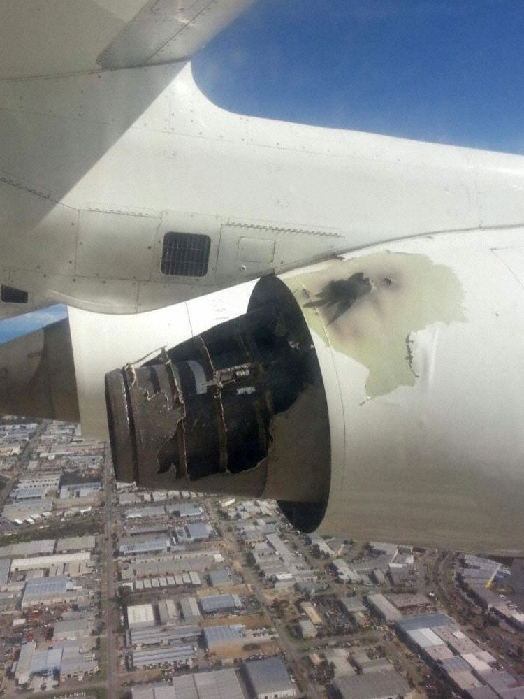
On 29 April 2014 an AVRO 146-RJ100 aircraft, registered VH-NJI and operated by Cobham Aviation Services Australia (Cobham), was on a charter flight to Barrow Island Airport from Perth Airport, Western Australia. The aircraft sustained a mechanical failure of the No. 2 engine shortly after take-off that resulted in an in-flight fuel-fed engine fire.

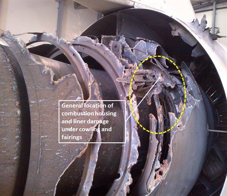
The flight crew extinguished the engine fire by shutting down the No. 2 engine and activating the fire suppression system. The aircraft was flown back to Perth Airport, having sustained significant damage to the No. 2 engine and cowling. There were no injuries.

What the ATSB found

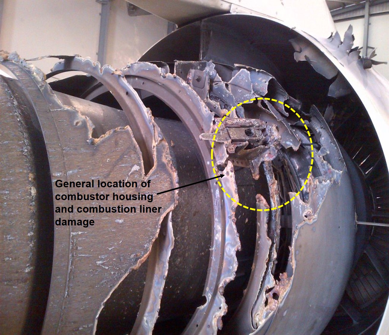
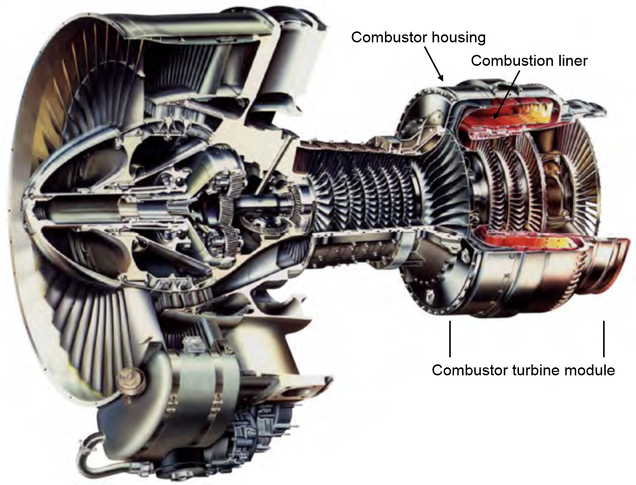
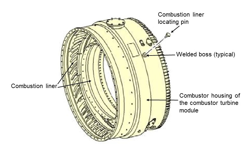
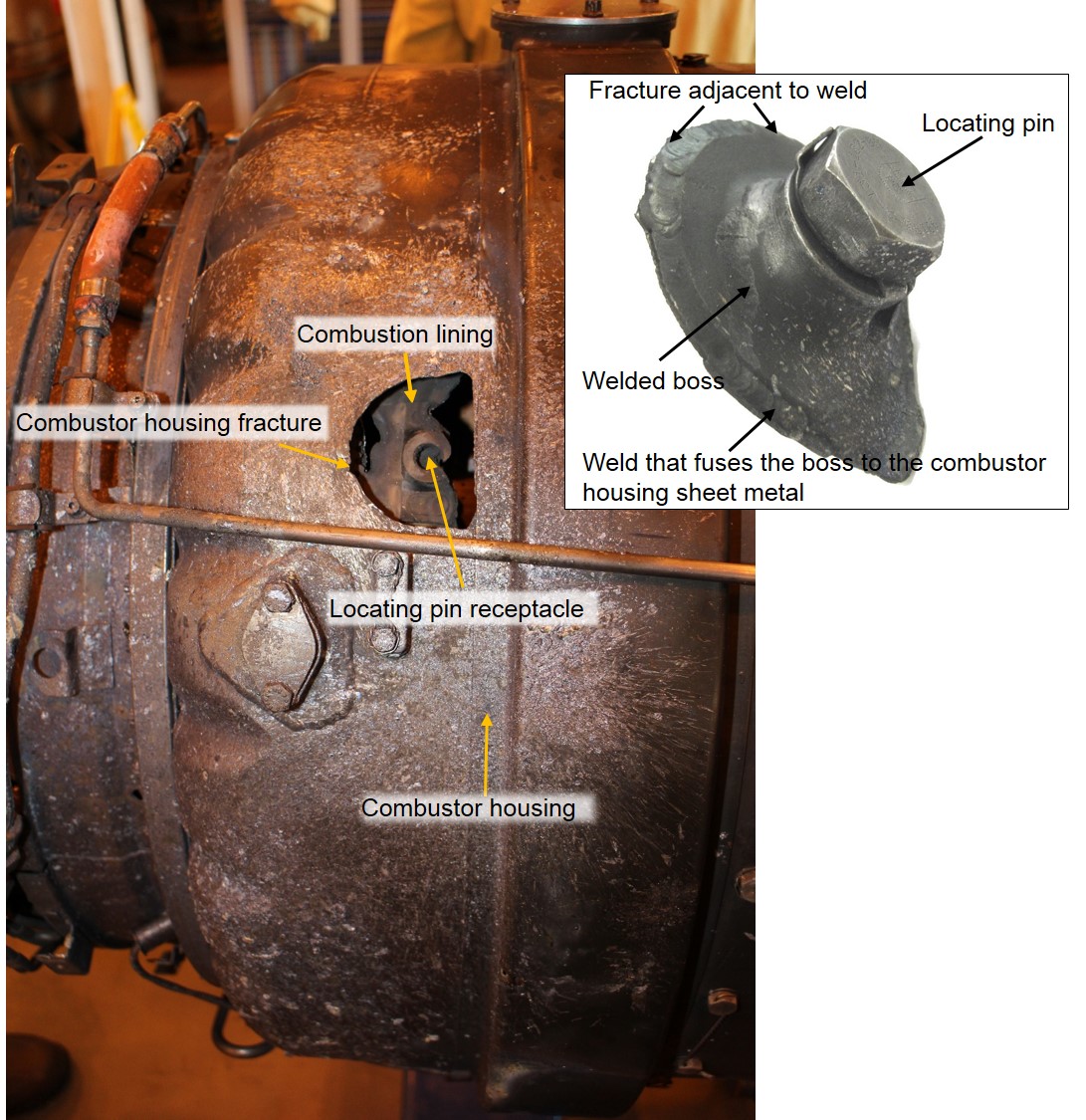
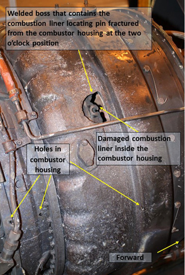
The Honeywell International Inc (Honeywell) LF507-1F (LF507) engine has four combustion liner locating pin welded bosses (welded boss) in the combustor turbine module (CTM) combustor housing (housing). The ATSB found that the welded boss located at the 2 o’clock position had cracked and fractured adjacent to the weld as a result of fatigue. The boss separated from the housing, allowing high-pressure combusting fuel to escape radially through the CTM housing, burning through the engine cowling.

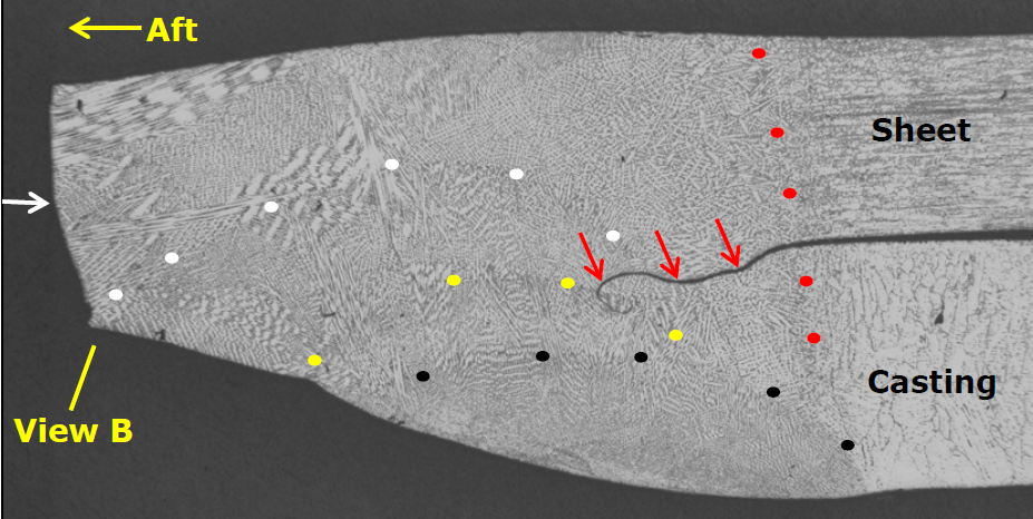
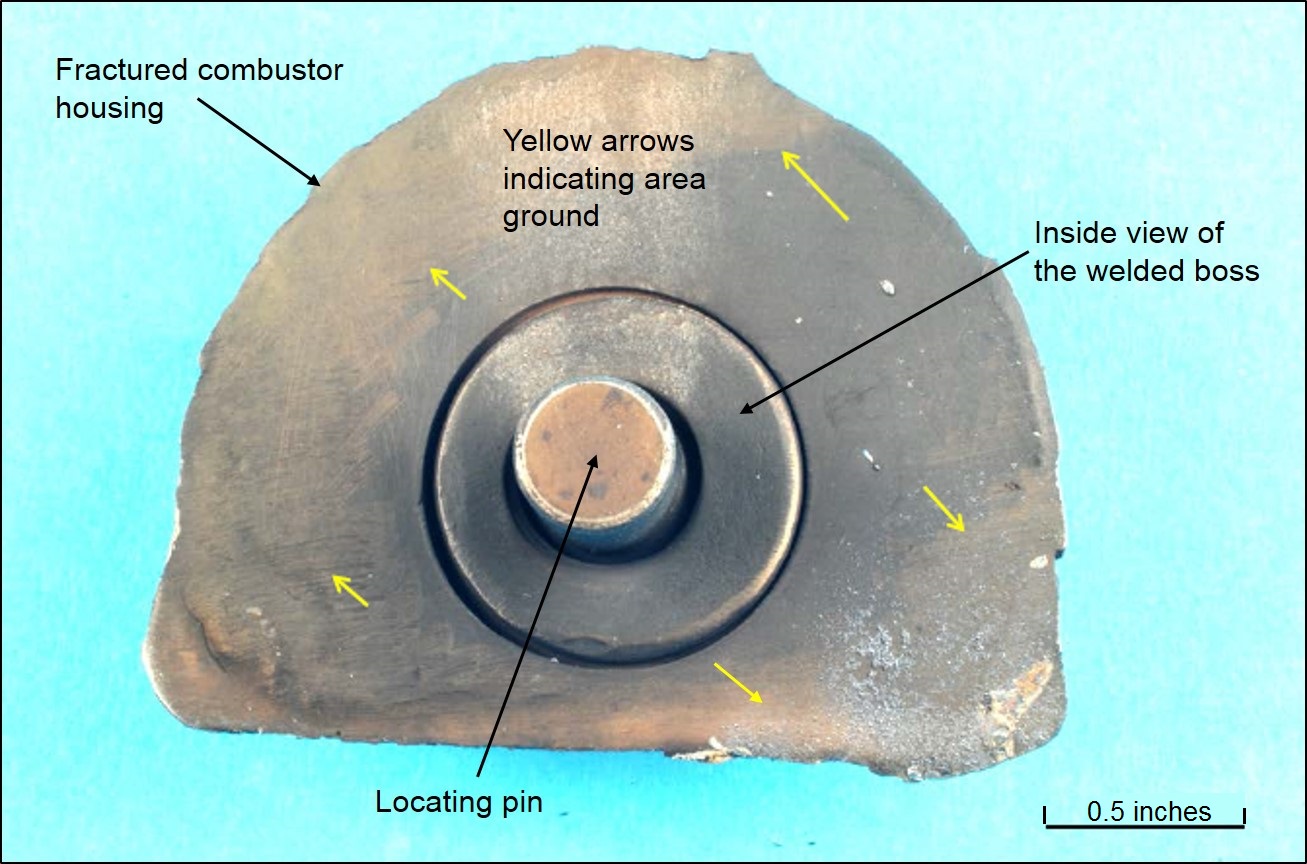
The ATSB also found that localised grinding of the inner and outer surfaces of the CTM housing, adjacent to the welded boss, had reduced its wall thickness from 0.050 to 0.035 inches. The reduced wall thickness increased local stresses and hence the likelihood of crack formation. The crack accelerated at an unpredictable rate until penetrating the full thickness of the housing. It is likely that the grinding was associated with a weld repair conducted during a CTM heavy maintenance visit. The grinding repair was not an acceptable repair to Honeywell for returning the component to the original design strength.

Finally, the ATSB found that the normal scheduled visual inspection of the housing, which was designed to find cracks before they developed into a fracture, was ineffective in this case. This was because the reduced wall thickness invalidated the original crack growth rate predictions.

What's been done as a result

In response to this occurrence Cobham proactively inspected all of their LF507 engines, focusing on the welded bosses. Of those engines, one spare engine had grinding at one of the welded bosses, similar to the occurrence engine, and was withdrawn from the availability pool. Although no cracking was found at the combustion liner location pin welded bosses, Cobham did find seven cracks at the location of the ignition bosses that had not been previously identified. These cracks were managed in accordance with the Honeywell maintenance manual.

Honeywell also instigated several actions in response to this occurrence. These included amendment of the LF507 engine maintenance and overhaul manuals to address crack limits and weld repair specifications, and the issue of a Service Bulletin to alert operators of possible welded boss cracking.

Safety message

This occurrence highlights the importance of repairing aircraft components in accordance with the manufacturer’s specifications and ensuring that the repair meets the design intent of the manufacturer.

VH-NJI in-flight fire damage

VH-NJI in-flight fire damage


Source: Jason Grimmett


The occurrence

On 29 April 2014 an AVRO 146-RJ100 aircraft, registered VH-NJI and operated by Cobham Aviation Services Australia (Cobham), departed Perth Airport on a charter flight to Barrow Island Airport, Western Australia. Shortly after take-off, at about 1045 Western Standard Time[1] as the aircraft climbed through about 400 ft, the flight crew were alerted to an emergency situation by the cabin crew. During this inter-crew communication the flight crew could hear passengers shouting in the cabin. About the same time, the flight deck master warning panel light illuminated and the No. 2 engine thrust lever fire warning and fire handle illuminated, and the associated warning bell sounded. The flight crew reported that, prior to the fire warning, engine operations were normal.

The flight crew shut down the No. 2 engine, activated the fire suppression system for that engine and declared a PAN[2] requesting immediate return to Perth Airport. Full emergency procedures for Perth Airport were activated and the aircraft landed at 1055.

Technical inspection of the aircraft after landing found that the No. 2 engine sustained an in-flight fuel-fed engine fire that significantly damaged the engine and its cowling (Figure 1).

Figure 1: Right side of the No.2 engine showing the fire damage to the combustor housing and liner (looking forward)


Figure 1: Right side of the No.2 engine showing the fire damage to the combustor housing and liner (looking forward)

Source: Cobham, modified by the ATSB

__________

  1. Western Standard Time (WST) was Coordinated Universal Time + 8 hours.
  2. An internationally-recognised radio call announcing an urgency condition that concerns the safety of an aircraft or its occupants but where the flight crew does not require immediate assistance.

Context

Engine information

The aircraft was powered by four Honeywell International Inc (Honeywell) LF507-1F (LF507) dual-spool, high-bypass turbofan engines. For maintenance and serviceability, the LF507 engine is divided into four modules: the fan assembly, gas producer, combustor turbine and accessory gearbox. This occurrence related to the combustor section of the combustor turbine module (CTM) (Figure 2).

The CTM consists of the combustor and the low-pressure turbine that are retained within the combustor housing (housing). The housing has four welded bosses located at the two, four, eight and ten o’clock positions (looking forward from the rear of the engine). A spigot pin is screwed into each welded boss to locate and retain the combustion liner. During normal operation, the fuel/air mixture is ignited in the combustion liner and supplies energy to the low-pressure turbine.

Figure 2: Left-side cut-out view of an exemplar LF507 engine showing the locations of the combustor housing, combustion liner and combustor turbine module

Figure 2: Left-side cut-out view of an exemplar LF507 engine showing the locations of the combustor housing, combustion liner and combustor turbine module

Source: Honeywell, modified by the ATSB

VH-NJI (NJI) was introduced into Australian service in 2012 with engine serial number LF07405, CTM serial number 93K004 and the occurrence combustor housing (serial number 363) fitted. The engine and these components were subsequently operated in the No. 2 engine position on NJI until the occurrence in April 2014. In the intervening period, the combustor housing accumulated 1,319 engine cycles in service since its last heavy maintenance inspection.

Engine examination

Examination of the engine found that the combustion liner welded boss (welded boss) at the two o’clock position had fractured and separated from the housing (Figure 3).

Figure 3: Exemplar LF507 engine showing the combustor housing and combustion liner highlighting a typical welded boss and combustion liner locating pin

Figure 3: Exemplar LF507 engine showing the combustor housing and combustion liner highlighting a typical welded boss and combustion liner locating pin

Source: Honeywell, modified by the ATSB

A portion of the combustion liner, a separate component that normally contains the combusting fuel/air mixture gases, fractured adjacent to the 2 o’clock welded boss and sustained significant fire damage (Figure 4). The breached combustor housing and combustion liner created a radial escape path for the high-pressure combusting fuel, which quickly burnt through the engine cowling support structure and engine cowling in that location.

A review of the Engine Condition Trend Monitoring[3] data for the engine was conducted by the ATSB and Cobham Aviation Services (Australia) (Cobham) several days after the occurrence. The review confirmed that there were no air leakage indications or parameter shifts prior to the occurrence that may have alerted maintenance staff of a pending defect or failure.

The engine was removed from the aircraft and dispatched to an engine overhaul facility in the United Kingdom (UK) for technical examination. This disassembly and inspection was carried out under the supervision of the UK Air Accidents Investigation Branch, with assistance from Honeywell. Components that were relevant to the investigation, including the combustor housing, combustion liner and the four combustion liner locating pins, were dispatched to the United States (US) for detailed examination.

Detailed examination of the housing, combustion liner and the four locating pins was conducted by Honeywell under the supervision of the US National Transportation Safety Board. The fractured welded boss, which was subsequently found in the engine cowling and recovered by Cobham, was initially examined by the ATSB before also being sent to Honeywell in the US for further detailed examination.

Figure 4: No. 2 engine showing the combustor housing, combustion liner (seen internal to the combustor housing) and insert image showing the locating pin secured in the fractured welded boss

Figure 4: No. 2 engine showing the combustor housing, combustion liner (seen internal to the combustor housing) and insert image showing the locating pin secured in the fractured welded boss

Source: ATSB

Results of the detailed component examination in the US

The detailed examination in the US identified an area of the combustion liner that had thermal damage and was fractured adjacent to the two o’clock welded boss position. That damage was consistent with the effect of temperature and pressure variations between the combustor housing and the combustion liner once the welded boss fractured from the housing (Figure 4).

Honeywell conducted a detailed metallurgical examination of the combustor housing and the recovered welded boss. It was determined that the sheet metal of the combustor housing fractured as a result of fatigue cracking adjacent to the boss weld line (Figure 5). In addition, weld repairs were identified on cross-sectional samples taken through the joints surrounding the recovered welded boss.

Honeywell advised that the fatigue fracture was consistent with low cycle fatigue and did not appear to be associated with the weld repairs.

A non-penetrating crack, a crack that did not penetrate through the full thickness of the housing sheet metal, had propagated over a period of about 2,680 load cycles. Each load cycle on the affected components was considered by Honeywell to be associated with pressure variations within the engine. Pressure variations can be caused by engine power level changes, compressor stalls, combustion rumble and temperature variations that lead to expansion and contraction of the housing. Numerous load cycles can occur during normal flight.

Engine maintenance is based on engine hours, cycles[4] or calendar days, depending on the type of component. Engine maintenance is not based on load cycles as each flight can produce a significant variation due to conditions at that time.

The examination of the fractured welded boss identified three separate weld repairs. These were identified on cross-sectional samples taken through the joints surrounding the recovered welded boss (Figure 5). Honeywell concluded that the fatigue cracking was not directly associated with the weld. Hardness measurements taken from the housing sheet metal, boss casting, and weld indicated that heat treatment was performed on the assembly subsequent to weld repair, as specified by Honeywell.

Figure 5: Metallographic image of a cross section of the fractured welded boss. The red dots likely indicate the original weld. The white, yellow and black dots likely indicate subsequent weld repairs. The red arrows indicate a crack emanating from the forward side of the weld at the housing/casting interface. The white arrow is the fracture surface, where the boss separated from the combustor housing. The fracture initiated at the outside diameter of the welded boss

Metallographic image of a cross section of the fractured welded boss. The red dots likely indicate the original weld.


Source: Honeywell

Further examination of the combustor housing in the location of the fractured welded boss found that a section of the combustor housing sheet metal had been thinned at the inside and outside surfaces by grinding (Figure 6). This grinding was associated with a weld repair where the boss was weld fused to the sheet metal. Thicknesses of 0.035 inches–0.040 inches were measured at the CTM housing adjacent to the two o’clock welded boss.

The thickness of the combustor housing sheet metal was specified by Honeywell as nominally 0.049–0.050 inches thick. This indicated that during a repair, about 20–30 per cent of the housing thickness had been removed. In this regard, the combustor housing is a pressure vessel. Honeywell does not approve the removal of material leading to a reduction of housing wall thickness.

Removal of material, as in this case, created an area of increased local stress.

The other three welded bosses also exhibited hand finishing, indicating that material removal took place in those locations.

Figure 6: Image of the inner side of the fractured combustor housing and the locating pin protruding through the welded boss. Areas that have been ground are identified by yellow arrows

Figure 6: Image of the inner side of the fractured combustor housing and the locating pin protruding through the welded boss.


Source: Honeywell, modified by the ATSB

Repair of ignition or liner welded bosses

During normal engine operation, expansion and contraction of the combustor housing can contribute to the welds at the bosses fatiguing and cracking. Such cracking is predictable and can be monitored during scheduled maintenance.

Honeywell published a system of maintenance where cracks, under a specific criteria, could be monitored during normal operation or repaired during heavy maintenance. Repairs depended on the length of the crack and the measured growth rate. The repair consisted of grinding the cracked boss weld, chemically cleaning the component and then re-welding the area.

In respect of the repair to the No. 2 engine in NJI, the grinding of the combustor housing sheet metal significantly reduced the housing thickness. Such grinding was not part of the Honeywell approved repair and crack repairs that extended into the sheet metal housing were not approved. Cracks extending into the combustor housing necessitated replacement of the housing.

The repair to the combustor housing of the No. 2 engine in NJI was an unapproved repair.

Blending of minor blemishes, scratches and nicks

Honeywell advised that the polishing and blending of minor blemishes, scratches and nicks was permitted. However, the use of power tools, or the reduction of housing thickness, was not permitted under the approved repair scheme.

In respect of blend repairs, the Honeywell maintenance manual, section 70-25-01, p.1 of 31 March 2006 stipulated:

  1. Blend repair such defects as follows:
  • Repair using small diesinker type file and india or carborundum stone. Use crocus cloth (05-07, 70-80-01) or rubberised abrasive block (ST-20-ALO-88X, 06-09, 70-80-01) for final polishing.
  • Blend all repairs and finish smoothly. Lines, scratches, or sharp edges that might cause concentration of stress are not permitted.

At the time of the occurrence, Honeywell had not published any combustor housing wall thickness limits in respect of the amount of material that could be removed during blending. Maintenance personnel performing blending repairs, in the absence of manufacturer’s limitations, were required to make their own judgement as to the amount of material that could be removed.

The reduction in housing wall thickness in the No. 2 engine in NJI was most likely a product of a nonstandard weld repair, as opposed to a blend of a blemish, nick or scratch. In any case, the housing at the welded boss had been ground, removing 20–30 per cent of the material thickness.

Engine maintenance schedule

LF507 engine modules can be separated and moved between engines. Engines are often swapped from engine position, aircraft-to-aircraft or to spare. Numerous components on a turbine engine have operational limits measured in hours, cycles and/or calendar days. Modules are frequently removed earlier than the manufacturer stipulates, often as a result of:

  • foreign object damage
  • to accommodate other required maintenance
  • preventive maintenance that may be deemed more economical to perform at that time.

Prior to the occurrence, the CTM was removed from and reinstalled in a number of engines on six separate occasions, including the No. 2 engine in NJI. This included for:

  • 6,000-cycle Hot Section Inspections
  • non-scheduled shop visit maintenance and modifications that necessitated significant disassembly, maintenance and detailed inspections.

That maintenance activity took place in 1999, 2001, 2005, 2006, 2008, and 2009.

Heavy maintenance was completed on the CTM in 2005 by a European workshop. With assistance from Honeywell, archived records for that shop visit were recovered and examined. The records, dated January 2005, showed that the previously-installed CTM housing, serial number 395, was removed and replaced with the occurrence housing. In the absence of additional data, it is likely that this housing was an exchanged item.

The serviceability of the CTM housing is based on its condition meeting Honeywell’s service limitations. It does not have a critical life limit based on hours, cycles or calendar days. Therefore, the housing’s hours, cycles and/or calendar days were not tracked, nor were they required to be. The release certificate for the occurrence CTM housing when fitted in 2005 stated that the housing was:

Inspected and repaired in accordance with the LF507-1F engine manual section 72-41-03, repairs SP R401, 08, 09, 10, 12 (repair 12 repaired in accordance with the ALF502R engine manual 724104).

According to Honeywell, repair 12 has a different application depending on the model of engine being repaired. In respect of Honeywell engines an:

  • ALF502 engine repair 12 is a diagnostic plate weld repair
  • LF507 engine repair 12 is a repair of cracks in the weld of the ignitor boss or a repair of cracks in the weld of the liner retention welded boss.

In this occurrence, the CTM housing was fitted to an LF507 engine and, according to the release to service document, was repaired in accordance with the ALF502 engine manual. According to Honeywell, at that time the ALF502 engine manual was the appropriate document with which to repair that model housing.

The hours, cycles, or previous work conducted on the occurrence CTM housing could not be established prior to its installation in 2005. The European maintenance organisation that conducted the heavy maintenance on the CTM in 2006, 2008 and 2009 was no longer operating. Records recovered from that period showed that visual inspections were conducted on the CTM housing during that maintenance with no repairs to the housing recorded. The last heavy maintenance inspection and disassembly of the CTM was in 2009, about 3,438 engine cycles prior to the occurrence.

In addition to the scheduled heavy maintenance inspections of the engine modules, the aircraft maintenance system called for an ‘on-wing’ general visual inspection of the engine(s), including the CTM combustor housing, every 500 flight cycles or 6 months. The intent of that inspection was to identify abnormalities associated with the engine’s exterior surfaces. The inspection allocated 2 hours to inspect the front, centre and rear sections of engine Nos. 1, 2, 3 and 4. This included the housing, fittings, plumbing and associated accessories without removal of components.

Honeywell defined a visual inspection as:

An examination of an interior or exterior area, installation or assembly to detect obvious damage, failure or irregularity. This level of inspection is made from within touching distance unless otherwise specified. A mirror may be necessary to enhance visual access to all exposed surfaces in the inspection area. This level of inspection is made under normally available lighting conditions such as daylight, hanger lighting, flashlight or droplight and may require removal or opening of access panels or doors. Stands, ladders or platforms may be required to gain proximity to the area being checked.

No special or detailed inspections were stipulated by Honeywell or the Civil Aviation Safety Authority for the combustor housing when on-wing. No cracks in the combustor housing were recorded by Cobham as a result of its two on-wing inspections of the engine during its service with Cobham. However, non-penetrating cracks that do not show gas leakage, fretting or discolouration are difficult to identify using visual inspection techniques.

Commonly-used documents such as US Federal Aviation Administration Advisory Circular AC43.13 described the equipment and techniques that, when used, may detect cracks when performing non-destructive testing through visual inspection. According to AC43.13, the key to performing a visual inspection is to direct a suitable torch beam, at a 5°–45° angle to the inspection surface, and direct the beam towards the face. Cracks are identified as a shadow or reflected light beam. Use of a 10 times magnifying glass can confirm the existence of a suspected crack. If this is assessed as inadequate, use of other non-destructive testing techniques, such as penetrant or eddy current inspection, can be performed to verify cracks.

Previous similar occurrences

A search of historic records by Honeywell did not identify the CTM housing as having a high failure rate. In that respect, one other CTM housing welded boss fracture was recorded, 10 years prior to this occurrence.

A major United Kingdom engine overhaul facility for the LF507 engine reported that about 40 per cent of the LF507 engines presented to their facility for maintenance were cracked at other than CTM housing welded boss locations. Those cracks were reported repaired in accordance with the Honeywell maintenance instructions and did not develop into a fracture.

Subsequent occurrence

During finalisation of this investigation report, on 10 March 2016 the ATSB was notified that a Swiss Global Air Lines Avro 146-RJ100 aircraft, which was powered by LF5071F engines, had sustained a No. 2 engine fire during take-off. The aircraft, registered HBIYT, was on departure from Zurich Airport, Switzerland when the take-off was rejected due to sparks observed from the engine. The Swiss Transport Safety Investigation Board (STSB) is responsible for investigating this occurrence.

The STSB is responsible for the release of the final investigation report into the occurrence involving HB-IYT. Any enquiries in respect of the ongoing STSB investigation, or release of their investigation report should, in the first instance, be directed to the:

Swiss Transportation Safety Investigation Board
Aviation division
Aéropôle 1
CH-1530 Payerne

Email: info@sust.admin.ch

__________

  1. Engine Condition Trend Monitoring: A process in which changes in certain engine performance parameters are analysed to identify engine performance deterioration and malfunction of engine components and accessories.
  2. One engine cycle is the complete sequence of an engine start, followed by continued operation and ends with shutdown of the engine.

Safety analysis

In-flight engine fire

At a high engine power setting during the climb, the welded boss at the two o’clock position of the No. 2 Honeywell International Inc (Honeywell) LF507-1F engine fractured and separated from the combustor turbine module (CTM) combustor housing (housing). This led to the fracture of the combustion lining and allowed high-pressure combusting fuel and gases to escape radially from the engine. The engine cowling was weakened and melted from the resulting in-flight engine fire.

The engine fire detection and suppression system was effective in alerting the crew to the situation. The crew extinguished the fire using normal operating procedures and returned the aircraft to Perth Airport for landing.

Non-approved repairs

Metallurgical examination of the fractured welded boss found that it had been weld-repaired on three separate occasions. The only recorded weld repair to the CTM housing was in 2005 although, as the CTM housing was an exchanged unit, its history could not be established. Therefore, either the CTM housing was repaired at or prior to 2005, or the housing was repaired after 2005 and the repair was not recorded. From the evidence available, the ATSB could not determine which was the case. In any event, the housing had been ground adjacent to the welded boss, reducing the housing wall thickness by 20–30 per cent. Grinding of the housing was not in accordance with Honeywell’s approved repair scheme, and the non-approved repair was not identified in any of the subsequent heavy maintenance inspections.

The reduction in the housing wall thickness increased the operational stresses at that location. This would have affected the initiation of the fatigue crack and increased its rate of propagation during normal engine operation.

Limitations in the manufacturer’s blending process

The standard practices section of the Honeywell maintenance manual referred to blending as a means of reducing induced metal stress by removing scratches or nicks in the metal. That reference did not limit the amount of material able to be removed during the blending process. According to Honeywell, it was not the intent of the process to remove metal or reduce a combustor housing’s wall thickness when blending. In the absence of any limitation, the amount of material that could be removed during the process was open to interpretation by maintenance personnel.

It was possible for the blending process to be applied during a weld repair, where the repairer believed that, despite it not being part of the repair, it was necessary to remove stress raisers. However, this was inconsistent with the grinding evident on the fractured components. That grinding was likely achieved using power tools, as opposed to the Honeywell-defined hand blending process.

Scheduled maintenance inspections

The rate of cracking around the welded boss was reported to occur in about 40 per cent of the engines introduced into one of the approved engine repair facilities. However, Honeywell was only aware of one other event where the cracking had progressed to catastrophic failure. This indicated that this occurrence, where the fatigue crack developed into a fracture, was very rare. Honeywell considered that, when repaired in accordance with the current repair scheme, the repair specifications were generally adequate. The associated visual inspections were historically effective in detecting cracks around the welded boss prior to catastrophic failure.

The reduction in material thickness and corresponding increase in local stresses may have increased the rate of crack initiation and propagation. The increased cracking rate and resulting stresses meant that a crack might initiate, and the CTM housing ultimately fail, between scheduled inspections. Alternatively, the crack may have existed but remained undetected, or not existed at the previous inspection.

In terms of Cobham Aviation Services Australia’s conduct of the most recent 500hourly on-wing engine inspection, it was reasonable that, if the crack existed at that time, it was not visually identified as:

  • the crack was non-penetrating, meaning that it would probably have only been identifiable when the CTM was fully-disassembled (such as at a scheduled heavy maintenance inspection)
  • there were no other, more usual, indications of a crack in the CTM, such as:
  • increases in the engine condition trend monitoring data parameters
  • blacking around any crack edges due to combusted gas leakage or fretting.

In addition to the lack of visual clues, the maintenance personnel were probably not expecting to find a crack. Human attention is guided by two factors:

  • expectancy, where an individual will look where they expect to find information
  • relevance, where an individual will look to information sources relevant to the important tasks and goals they need to carry out.

The key factor is expectancy. It is well demonstrated that people are more likely to detect targets when expected, and less likely to detect targets that are not expected (Wickens and McCarley, 2008). This occurs even when the targets are salient, potentially important and in an area to which the person is looking (Chabris and Simon, 2010).

Findings

From the evidence available, the following findings are made with respect to the in-flight engine fire involving AVRO 146-RJ100, registered VH-NJI and operated by Cobham Aviation Services Australia as it departed Perth, Western Australia on 29 April 2014. These findings should not be read as apportioning blame or liability to any particular organisation or individual.

Contributing factors

  • A repair to the two o’clock combustion liner retention boss of the No. 2 engine combustor turbine module housing was not performed in accordance with the manufacturer’s repair specification, resulting in a thin-walled housing that increased local stresses in that location.
  • As a result of fatigue, the No. 2 engine combustor turbine module housing cracked, then fractured adjacent to the two o’clock combustion liner retention boss weld, propagating at an unpredictable rate as a result of the non-approved repair.
  • High-temperature combusting fuel and gases escaped radially from the fracture in the No. 2 engine combustor turbine module housing, leading to an in-flight engine fire.

Other factors that increased risk

  • The Honeywell International Inc documentation for blending did not limit the amount of material that could be removed from the combustor housing.

Other findings

  • The Honeywell International Inc LF507-1F heavy maintenance schedule was adequate to identify and repair cracks in the combustor turbine module housing combustion liner retention boss weld.

Safety issues and actions

Additional safety action

Whether or not the ATSB identifies safety issues in the course of an investigation, relevant organisations may proactively initiate safety action in order to reduce their safety risk. The ATSB has been advised of the following proactive safety action in response to this occurrence.

Cobham Aviation Services Australia

As a result of this occurrence, Cobham Aviation Services Australia (Cobham) undertook a number of safety actions to identify and capture defects of a similar type prior to their developing into an incident or accident. In addition, Cobham issued the following Technical Service Instructions (TSI):

  • TSI-146-72-0015, issue 1 on 17 September 2014. This TSI stated that a detailed visual inspection for cracks was to be performed on each of the four combustion housing welded bosses across the Cobham fleet of ALF502R, LF507-1H and LF507-1F engines. The compliance date for this TSI was 7 October 2014.
  • TSI-146-72-0017, issue 1 on 21 April 2015. This TSI required a non-destructive Fluorescent Penetrant Inspection for cracks on each of the combustion housing welded bosses. This included the four combustion housing welded bosses, two drain valve bosses and the four ignitor bosses on all of Cobham’s ALF502R, LF507-1H and LF507-1F engines. The compliance date for this TSI was 1 June 2015.

Cobham reported that of the 53 engines inspected, none had cracks in the location of the combustor housing combustion liner locating pin welded boss welds. However, seven previously unidentified cracks were identified at the location of the ignition boss, which is also part of the combustor housing. Those cracks were routinely-managed in accordance with the manufacturer’s maintenance manual.

Honeywell International Inc

As a result of this occurrence and investigation, Honeywell undertook several safety actions that were designed to identify and capture defects of a similar type prior to their developing into an incident or accident. Honeywell has also proposed amendments to their engine maintenance system, including:

  • Chapter 72-41-01 of the maintenance manual, where weld repair of the welded boss was deleted in repair scheme 12. With effect 3 March 2015, repair of a cracked welded boss is achieved by replacing the housing.
  • Overhaul/repair instructions P35242, Revision E, changed the allowable crack limitations of the combustor housing welded boss. The changed instructions do not permit continued operation when cracks are identified in the weld.
  • Drafting Service Bulletin ALF/LF-72-1119 of 9 January 2015, which affects all Challenger 600, BAe 146 and AVRO RJ aircraft fitted with specific engine part and model numbers. The Service Bulletin states:

C. (1) Cracks in the combustion liner retention bosses have led to separation and have resulted in an engine fire and in-flight shutdown.

Honeywell recommend that a detailed visual inspection be conducted of the weld between the boss and the combustor housing parent material using a 7x power magnifying glass or non-destructive dyepenetrant inspection method within the first access to the affected part or within 500 cycles after the Service Bulletin becomes effective.

  • The Standard Practice Manual, in order to highlight the intent of, and processes associated with blending. This includes that:

Blend repairs on static structural components prior to or after weld repairs should not thin the parent metal and provide a smooth transition to the existing surface. Refer to the applicable repair manual/specific repair instruction for minimum wall thickness requirements.

Sources and submissions

The sources of information during the investigation included:

  • Honeywell International Inc
  • Cobham Aviation Services Australia
  • the flight crew.

References

Chabris, C.F. and Simons, D.J. (2010). The invisible gorilla and other ways our intuitions deceive us. New York, NY: Random House.

Wickens, C.D. and McCarley, J.S. (2008). Applied attention theory. Boca Raton, FL: CRC Press.

Submissions

Under Part 4, Division 2 (Investigation Reports), Section 26 of the Transport Safety Investigation Act 2003 (the Act), the ATSB may provide a draft report, on a confidential basis, to any person whom the ATSB considers appropriate. Section 26 (1) (a) of the Act allows a person receiving a draft report to make submissions to the ATSB about the draft report.

A draft of this report was provided to the flight crew, Cobham Aviation Services Australia, Honeywell International Inc and the Civil Aviation Safety Authority.

No submissions were received from those parties.

Purpose of safety investigations

The objective of a safety investigation is to enhance transport safety. This is done through:

  • identifying safety issues and facilitating safety action to address those issues
  • providing information about occurrences and their associated safety factors to facilitate learning within the transport industry.

It is not a function of the ATSB to apportion blame or provide a means for determining liability. At the same time, an investigation report must include factual material of sufficient weight to support the analysis and findings. At all times the ATSB endeavours to balance the use of material that could imply adverse comment with the need to properly explain what happened, and why, in a fair and unbiased manner. The ATSB does not investigate for the purpose of taking administrative, regulatory or criminal action.

Terminology

An explanation of terminology used in ATSB investigation reports is available here. This includes terms such as occurrence, contributing factor, other factor that increased risk, and safety issue.

Publishing information 

Released in accordance with section 25 of the Transport Safety Investigation Act 2003

Published by: Australian Transport Safety Bureau

© Commonwealth of Australia 2016

image_5.png

Ownership of intellectual property rights in this publication

Unless otherwise noted, copyright (and any other intellectual property rights, if any) in this report publication is owned by the Commonwealth of Australia.

Creative Commons licence

With the exception of the Coat of Arms, ATSB logo, and photos and graphics in which a third party holds copyright, this publication is licensed under a Creative Commons Attribution 3.0 Australia licence.

Creative Commons Attribution 3.0 Australia Licence is a standard form licence agreement that allows you to copy, distribute, transmit and adapt this publication provided that you attribute the work.

The ATSB’s preference is that you attribute this publication (and any material sourced from it) using the following wording: Source: Australian Transport Safety Bureau

Copyright in material obtained from other agencies, private individuals or organisations, belongs to those agencies, individuals or organisations. Where you wish to use their material, you will need to contact them directly.

Preliminary report

Report release date: 05/12/2014

This preliminary report details factual information established in the investigation’s early evidence collection phase and has been prepared to provide timely information to the industry and public. Preliminary reports contain no analysis or findings, which will be detailed in the investigation’s final report. The information contained in this preliminary report is released in accordance with section 25 of the Transport Safety Investigation Act 2003.

The occurrence

On 29 April 2014 an AVRO 146-RJ100 aircraft, registered VH-NJI and operated by Cobham Aviation Services Australia (Cobham) on a on a charter flight from Perth Airport to Barrow Island, Western Australia, sustained an in-flight fuel-fed fire in the No. 2 engine during or shortly after take‑off (Figure 1). The flight crew shut the engine down and activated the fire suppression system before returning to Perth for landing.

Figure 1: No. 2 engine showing fire damage (looking forward)

No 2 Engine Fire Damage


Source: Cobham (edited by the ATSB)

Initial examination

Engine damage

Initial examination by the Australian Transport Safety Bureau (ATSB) found that a portion of the Honeywell ALF‑507-1F engine’s combustor housing fractured at about the two o’clock position, looking forward, and was ejected from the engine. The fracture occurred at a welded boss that facilitated one of four combustion liner locators per engine. A portion of the combustion liner adjacent to the damaged area of the combustor housing also failed (Figure 2).

Figure 2: No. 2 engine showing combustor housing and combustion liner (looking forward)

No. 2 engine showing combustor housing and combustion liner


Source: Cobham (edited by the ATSB)

The breach of the combustion liner and engine combustor housing created a radial escape path for the fuel–fed, high pressure combusting gases. These gases quickly burnt through the engine cowling in that location.

Engine and other recorded information and documentation

Recording devices that captured the No. 2 engine parameters prior to and during the occurrence were retained for further analysis. All of the operator’s maintenance documentation related to the No. 2 engine, including its overhaul and engine trend condition monitoring records, have been secured for further analysis.

In addition, the cockpit voice recordings have been reviewed and the flight crew interviewed. At this stage, no operational factors have been identified that may have contributed to the occurrence.

Failed components

The ejected section of the engine combustor housing was recovered from inside the No. 2 engine cowling for technical examination at the ATSB’s facilities in Canberra, Australian Capital Territory.

The engine was removed from the aircraft and sent to an approved maintenance repair and overhaul facility in the United Kingdom (UK) for technical examination under the supervision of the UK Air Accidents Investigation Branch. This disassembly and subsequent examination of the engine’s ‘hot section’ found that, in addition to the fractured welded boss in the combustor housing, there were three other areas of damage on the housing. The combustion liner was also found to have failed in several locations. Further analysis is planned to establish if the damage to the hot section was a result of the failure, or contributed to the failure.

A number of components from the engine hot section, together with the ejected section of the engine combustor housing have been shipped to the engine manufacturer’s facilities in the United States for further analysis under the supervision of the National Transportation Safety Board. This will include destructive testing of a number of components.

The forward, section of the engine has been quarantined in the UK for possible further analysis.

Safety action

Cobham Aviation Services Australia

At this stage of its investigation, the ATSB has not identified any organisational or systemic issues that might adversely affect the future safety of aviation operations. However, Cobham has advised that it has inspected all combustor housings in their ALF‑507-1F engine fleet in the area of the combustion liner locating pin boss welds.

No other cracks in the welds in this area were identified in any of the engines.

Ongoing investigation

The investigation is continuing and will include examination of the:

  • recorded data
  • No. 2 engine maintenance documentation
  • No. 2 engine trend condition monitoring records
  • history of the ALF‑507-1F engine for previous similar occurrences
  • recovered hot end components and ejected section of the combustor housing.

Purpose of safety investigations

The objective of a safety investigation is to enhance transport safety. This is done through:

  • identifying safety issues and facilitating safety action to address those issues
  • providing information about occurrences and their associated safety factors to facilitate learning within the transport industry.

It is not a function of the ATSB to apportion blame or provide a means for determining liability. At the same time, an investigation report must include factual material of sufficient weight to support the analysis and findings. At all times the ATSB endeavours to balance the use of material that could imply adverse comment with the need to properly explain what happened, and why, in a fair and unbiased manner. The ATSB does not investigate for the purpose of taking administrative, regulatory or criminal action.

Terminology

An explanation of terminology used in ATSB investigation reports is available here. This includes terms such as occurrence, contributing factor, other factor that increased risk, and safety issue.

Publishing information 

Released in accordance with section 25 of the Transport Safety Investigation Act 2003

Published by: Australian Transport Safety Bureau

© Commonwealth of Australia 2014

image_5.png

Ownership of intellectual property rights in this publication

Unless otherwise noted, copyright (and any other intellectual property rights, if any) in this report publication is owned by the Commonwealth of Australia.

Creative Commons licence

With the exception of the Coat of Arms, ATSB logo, and photos and graphics in which a third party holds copyright, this publication is licensed under a Creative Commons Attribution 3.0 Australia licence.

Creative Commons Attribution 3.0 Australia Licence is a standard form licence agreement that allows you to copy, distribute, transmit and adapt this publication provided that you attribute the work.

The ATSB’s preference is that you attribute this publication (and any material sourced from it) using the following wording: Source: Australian Transport Safety Bureau

Copyright in material obtained from other agencies, private individuals or organisations, belongs to those agencies, individuals or organisations. Where you wish to use their material, you will need to contact them directly.

Occurrence summary

Investigation number AO-2014-076
Occurrence date 29/04/2014
Location Perth Airport
State Western Australia
Report release date 02/05/2016
Report status Final
Investigation level Systemic
Investigation type Occurrence Investigation
Investigation status Completed
Mode of transport Aviation
Aviation occurrence category Engine failure or malfunction
Occurrence class Serious Incident
Highest injury level None

Aircraft details

Manufacturer British Aerospace
Model AVRO 146-RJ100
Registration VH-NJI
Serial number E3265
Aircraft operator National Jet Express
Sector Jet
Operation type Air Transport High Capacity
Departure point Perth, Western Australia
Destination Barrow Island, Western Australia
Damage Substantial

Runway incursion involving Bombardier DHC-8-402, VH-QOP, Gladstone Airport, Queensland, on 17 April 2014

Final report

Report release date: 15/10/2014

What happened

On 17 April 2014 at about 1705 Eastern Standard Time, the crew of a Bombardier DHC-8, registered VH-QOP, were taxiing at Gladstone Airport, Queensland, for a scheduled passenger service to Sydney, New South Wales. There were heavy showers in the vicinity of the airport at the time.

The crew reported taxiing for runway 10, which was soon followed by a report from the crew of an ATR-72 that they were 5 NM from Gladstone, on final approach to runway 10. Noting the position of the ATR-72, the crew of VH-QOP elected to taxi in a westerly direction along taxiway A (parallel to the runway), planning to enter the runway via taxiway A1 after the ATR-72 had landed. The crew were not particularly familiar with Gladstone Airport, and even less familiar with taxiway A and A1. The crew commented that, subject to traffic conditions, it was more common to enter the runway using other taxiways leading directly from the terminal area.

As they taxied, the crew contemplated switching to runway 28 for departure because weather surrounding the airport appeared to be less intense to the west. The crew discussed departure options and reviewed aircraft performance information as they taxied. At the same time, they remained mindful of the ATR-72 on final approach to runway 10.

The crew of VH-QOP made a right turn from taxiway A onto taxiway A1 as the ATR-72 was on late final approach. As they entered taxiway A1, the crew inadvertently continued over the holding point line before coming to a stop. The main wheels of the aircraft were just beyond the holding point line as the ATR-72 landed. Although the crew of VH-QOP stopped well short of the runway surface and were aware of the ATR-72 on final approach, the incident still falls within the definition of a runway incursion given the ‘incorrect presence’ of the aircraft within the runway flight strip as another aircraft was landing.

This incident highlights the importance of careful attention to airfield markings during ground manoeuvring, especially when crew workload is elevated, and when a crew is unfamiliar with the airport layout. This message applies equally to all airside vehicle operators.

Aviation Short Investigations Bulletin - Issue 35

Occurrence summary

Investigation number AO-2014-073
Occurrence date 17/04/2014
Location Gladstone Airport
State Queensland
Report release date 15/10/2014
Report status Final
Investigation level Short
Investigation type Occurrence Investigation
Investigation status Completed
Mode of transport Aviation
Aviation occurrence category Runway incursion
Occurrence class Incident
Highest injury level None

Aircraft details

Manufacturer Bombardier Inc
Model DHC-8-402
Registration VH-QOP
Serial number 4238
Aircraft operator Sunstate Airlines
Sector Turboprop
Operation type Air Transport High Capacity
Departure point Gladstone, Queensland
Destination Sydney, New South Wales
Damage Nil

Fuel starvation event involving an Osborne Aviation OH-58A, VH-OSQ, Coffs Harbour Airport, New South Wales, on 17 April 2014

Final report

Report release date: 14/07/2014

What happened

On 17 April 2014, the pilot of an Osborne Aviation OH-58A helicopter, registered VH-OSQ, conducted a pre-flight inspection for a planned private ferry flight from Coffs Harbour to Port Macquarie, New South Wales, with one passenger.

At about 0700, the pilot conducted the pre-start checks and started the engine. He carried out the after-start checks and confirmed all engine indications were normal, and ran the engine for about 10 minutes to recharge the new battery following start-up. He then shut the helicopter down, conducted the shut-down checks and the pilot and passenger exited the helicopter. The pilot added 0.5 L of oil. After a brief return to the terminal building, the pilot and passenger reboarded the helicopter.

The pilot selected the master switch on, confirmed all indications were normal and started the engine. The pilot lifted the helicopter off into the hover, climbed to about 35-50 ft above ground level and commenced the transition to forward flight. He then heard the turbine engine wind down, the red engine out warning light illuminated and the helicopter descended in an autorotation.

The pilot attempted to run the helicopter onto the ground, however, the helicopter touched down on soft grass and the landing skids detached. The main rotor blades chopped the tail boom, and the helicopter landed heavily, resulting in substantial damage. The pilot observed that the fuel valve was selected to ‘OFF’.

The pilot reported that this incident provided a reminder of the effect a change in routine can have, particularly on completing checklists.

Aviation Short Investigations Bulletin - Issue 32

Occurrence summary

Investigation number AO-2014-071
Occurrence date 17/04/2014
Location Coffs Harbour Airport
State New South Wales
Report release date 14/07/2014
Report status Final
Investigation level Short
Investigation type Occurrence Investigation
Investigation status Completed
Mode of transport Aviation
Aviation occurrence category Engine failure or malfunction
Occurrence class Accident
Highest injury level None

Aircraft details

Manufacturer Osbourne Aviation Services Pty Ltd
Model OH-58A
Registration VH-OSQ
Serial number 44070
Sector Helicopter
Operation type Private
Departure point Coffs Harbour, New South Wales
Damage Substantial

Flight instrument issue in IMC involving a Piper PA-27, VH-DTL, near Flinders Island Airport, Tasmania, on 18 April 2014

Final report

Report release date: 14/07/2014

What happened

On 18 April 2014, a Piper PA-27 aircraft, registered VH-DTL, departed Moorabbin, Victoria for Flinders Island, Tasmania, under the instrument flight rules (IFR), with five passengers and the pilot on board.

During climb, the aircraft entered cloud. When the aircraft momentarily exited cloud, the pilot observed the primary artificial horizon (AH) indicated level flight, while the aircraft was in a descending turn. The primary AH then settled and accurately reflected the aircraft state.

The aircraft was in cloud throughout the cruise and severe turbulence intermittently caused both AH’s to provide unstable indications. The pilot set up the GPS to track for the runway 05 RNAV (GNSS) approach to Flinders Island, via waypoint ‘FLIWC’.  

After passing the waypoint, the GPS did not sequence to the next waypoint. He then continued to fly the approach using AvPlan. When at about 1,000 ft AGL, the aircraft encountered heavy rain, the pilot was unable sight the runway and commenced a left turn to circle back to approach the runway.

When at about 500 ft AGL, the aircraft encountered severe turbulence, which resulted in a high angle of bank and the stall warning horn activating. With both AH’s not providing accurate information, the aircraft entered cloud.

The pilot contacted ATC and reported that the aircraft was in cloud with unreliable AH’s, GPS and ADF. The controller advised the pilot to turn onto a heading of 150° and climb to 8,000 ft AMSL to fly clear of the cloud. After about 20 minutes, the pilot observed the coastline, and elected to divert to Saint Helens aerodrome, Tasmania.

This incident highlights how unreliable or unserviceable instruments can increase pilot workload, particularly when in instrument meteorological conditions (IMC).

Aviation Short Investigations Bulletin - Issue 32

Occurrence summary

Investigation number AO-2014-072
Occurrence date 18/04/2014
Location Near Flinders Island Airport
State Tasmania
Report release date 14/07/2014
Report status Final
Investigation level Short
Investigation type Occurrence Investigation
Investigation status Completed
Mode of transport Aviation
Aviation occurrence category Avionics/flight instruments
Occurrence class Serious Incident
Highest injury level None

Aircraft details

Manufacturer Piper Aircraft Corp
Model PA-23-250
Registration VH-DTL
Serial number 27-4033
Sector Piston
Operation type Private
Destination Flinders Island, Tasmania
Damage Nil

Landing on a closed runway involving PA28, VH-FEZ, Wangaratta Airport, Victoria, on 12 April 2014

Final report

Report release date: 06/08/2014

What happened

On 12 April 2014, a PA-28 aircraft registered VH-FEZ (FEZ) departed Mangalore airport, Victoria, on a dual navigation training exercise in central Victoria.

During the Shepparton to Tocumwal sector, the instructor requested that the student divert directly to Wangaratta Aerodrome.

At the time, a jet model aircraft group event was in progress at Wangaratta, and the aerodrome was closed. This closure had been advised by NOTAM. A white cross had been placed near the primary windsock, also indicating the closure.

Although the student had broadcast all mandatory CTAF calls, the model aircraft ground controller monitoring the UNICOM did not hear them. He did hear the engine sound as FEZ approached the circuit, and watched it continue to the east. He assumed it had departed the area. Shortly after, he was advised the aircraft was on final approach for runway 18. He quickly organised the clearing of the runway, and the movement of the 3 airborne model aircraft away from the area.

As the student had been having difficulty with directional control during landings, the instructor was focussed on this aspect during the circuit. Neither of them noticed the displayed white cross, or the activity on the ground.

The aircraft touched down, and as it became airborne again, the instructor noticed the barricades, took control of the aircraft, and departed the area.

The instructor had a full day scheduled. The student had been delayed in his flight plan preparation. By trying to remain punctual and efficient, the instructor had checked the weather and the student’s flight plan, but not the NOTAMS. He had also had disrupted sleep for the last few nights, due to a sick family member.

Before commencing a flight, the pilot in command should review all available information appropriate to the intended operation, including current weather reports and forecasts, and the condition and suitability of the selected landing area/s. This occurrence also highlights the need to check for any operational markers.

Aviation Short Investigations Bulletin - Issue 33

Occurrence summary

Investigation number AO-2014-069
Occurrence date 12/04/2014
Location Wangaratta Airport
State Victoria
Report release date 06/08/2014
Report status Final
Investigation level Short
Investigation type Occurrence Investigation
Investigation status Completed
Mode of transport Aviation
Aviation occurrence category Depart/app/land wrong runway
Occurrence class Incident
Highest injury level None

Aircraft details

Manufacturer Piper Aircraft Corp
Model PA-28-161
Registration VH-FEZ
Serial number 28-8016055
Sector Piston
Operation type Flying Training
Departure point Shepparton, Victoria
Destination Wangaratta, Victoria
Damage Nil

Wirestrike involving Maule M-5, VH-HOG, 50 km west-south-west of Casino, New South Wales, on 12 April 2014

Final report

Report release date: 29/01/2015

Safety summary

What happened

On 12 April 2014, a Maule M-5 aircraft, registered VH-HOG, collided with a powerline spanning the Clarence River, approximately 50 km west-south-west of Casino, New South Wales. The pilot was accompanied on the private category flight by two passengers, an adult and a child. The aircraft departed controlled flight after the wirestrike and impacted the water, coming to rest inverted with the cabin submerged.

The pilot and front-seat adult passenger escaped the cockpit through one of the forward doors and attempted to free the rear-seat child passenger from the flooded cabin. After repeated attempts by the pilot to open the rear-right cabin door, the rear-seat passenger was recovered through a cockpit door. Sustained attempts to resuscitate the rear-seat passenger were unsuccessful.

What the ATSB found

The aircraft was capable of normal operation prior to the wirestrike. The weather conditions in the vicinity were suitable for visual flight.

The wirestrike and resulting loss of aircraft control was an unintended consequence of the pilot’s spur of the moment decision to fly at very low level along the river, in an unfamiliar environment and below the minimum stipulated height for flights over unpopulated areas. The pilot reported seeing the powerline cables just before the collision, but with insufficient time to avoid a wirestrike. The pilot did not hold an approval to conduct low-flying operations and had not completed any training to identify the hazards associated with such operations. The powerline was not fitted with visual warning markers, nor was there any requirement for such markers in this case.

The submerged, flooded and inverted cabin increased the difficulty experienced by the occupants in exiting the aircraft. Furthermore, impact damage sustained by the right wing likely rendered the rear-right cabin door unusable as an emergency exit, delaying the recovery of the rear-seat passenger.

Safety message

This accident reaffirms the risk of unnecessary and unauthorised low flying.

Operations at low altitude expose an aircraft and its occupants to a number of environment‑specific hazards and result in significantly reduced safety margins. Powerline cables and other wires, which can be encountered even in relatively remote locations, are typically very difficult to see and present a critical hazard to any low-flying aircraft. In recognition of these and the other specific risks and hazards of low-level flying, the Civil Aviation Safety Authority requires pilots to receive special training and endorsements before conducting low-level operations.

The operation of an aircraft in close proximity to terrain or water limits the opportunity to recover from any loss of control or respond to any in-flight emergency when compared to flight at higher altitudes.

Occurrence summary

Investigation number AO-2014-068
Occurrence date 12/04/2014
Location 50 km WSW of Casino
State New South Wales
Report release date 29/01/2015
Report status Final
Investigation level Defined
Investigation type Occurrence Investigation
Investigation status Completed
Mode of transport Aviation
Aviation occurrence category Wirestrike
Occurrence class Accident
Highest injury level Fatal

Aircraft details

Manufacturer Maule Aircraft Corp
Model M-5-235C
Registration VH-HOG
Serial number 7322C
Sector Piston
Operation type Private
Departure point Tenterfield, New South Wales
Destination Ballina, New South Wales
Damage Substantial

Derailment of freight train 3MP9, near Malbooma, South Australia, on 10 April 2014

Final report

Report release date: 25/03/2015

Safety summary

What happened

At about 0011 on 10 April 2014, SCT Logistics train 3MP9 derailed after travelling over track that had been undercut by floodwaters near a culvert at the 535.150 km mark between Tarcoola and Malbooma, South Australia. The floodwaters caused scouring of the track formation, compromising its capacity to support the train.

About 300 metres behind the lead locomotive, the first of 18 wagons derailed including eight that rolled onto their sides.

There were no injuries to the train crew however there was significant damage to the track, rolling stock and freight goods.

What the ATSB found

The ATSB determined that runoff from the heavy rain that had fallen in the catchment area adjacent to Malbooma on 9 April 2014 caused a flash flood event. The volume of floodwater exceeded the capacity of a double drainage culvert designed for a 1:50 year average flood recurrence interval. This resulted in water overtopping the track formation with ballast and sub-grade scouring on the south side of the track.

The magnitude of the scouring meant that the track could not support the weight of train 3MP9 as it passed over the affected areas. The resulting deformation in the alignment of the track initiated the derailment.

From a risk control perspective, the ATSB found that the Australian Rail Track Corporation’s (ARTC) processes were ineffective in developing and implementing changes to operational procedures from the findings of previous incident investigations. The ARTC did not have a comprehensive system in place to identify and actively manage the risks to their network from severe weather events, and had not established a register for recording ‘special locations’ for the management of track infrastructure prone to flooding.

There were no anomalies found with the operation of the train or the condition of rolling stock before the derailment.

What's been done as a result

The ARTC has implemented Operational Procedure OPP-01-05 ‘Monitoring and Responding to Extreme Weather Events in the East-West Corridor’ and has purchased and installed remote weather monitoring and recording stations at Barton, Cook, Rawlinna and Zanthus. The weather station data will be linked to the Early Warning Network to provide automated alerts. Four water flow monitors have been installed at culverts identified through a hydrology study of the Trans Australia Railway. Field evaluation of this equipment is being undertaken.

Upgrades of the ARTC’s electronic asset management system are underway to optimise inspection and maintenance activities, including recording of ‘special locations’ affected by severe weather events.

Safety message

To ensure that the safety of rail operations is not compromised during severe weather events, it is essential that rail transport operators have robust and responsive systems in place to actively monitor and manage the foreseeable risks.

Preliminary report

Report release date: 29/07/2014

This preliminary report details factual information established in the investigation’s early evidence collection phase and has been prepared to provide timely information to the industry and public. Preliminary reports contain no analysis or findings, which will be detailed in the investigation’s final report. The information contained in this preliminary report is released in accordance with section 25 of the Transport Safety Investigation Act 2003.

In early April 2014, a slow-moving low-pressure trough generated a broad rainband across the Northern Territory and South Australia. The Bureau of Meteorology (BoM) forecast heavy rainfall and issued flood warnings for various areas of the South Australia, including locations around the Malbooma region.

At about 1742 on 9 April, Specialized Container Transport train 3MP9 departed Port Augusta. It was raining on departure and continued to rain as the journey progressed. At Kultanaby, a crew change occurred. The new driving crew travelled toward Tarcoola with rain continuing to fall.

At 2350, when train 3MP9 departed Tarcoola, there was only intermittent rain falling. As the train travelled downhill towards the base of a grade near the 532 km post, the crew observed water running swiftly in the cess drain down the south side of the track.

As the train climbed the next grade, the driver slowed the train in preparation for entering the crossing loop at Malbooma. The train crew then saw water overtopping the track ahead, so the second driver contacted the network control officer (NCO) to advise that the train had encountered a lot of water flowing down the south side and across the track and suggested that all trains be held until the track was inspected for damage.

Soon after, at about 0006 on 10 April, and shortly after the train crossed a culvert at the 535.150 km mark at speed of about 90 km/h, the crew heard a 'big bang' and felt the locomotive pitch sharply. Soon thereafter, the train’s brakes were automatically applied and the lead locomotive came to a stop near the 536.035 km mark.

The second driver alighted from the locomotive and walked back along the northern side of the train to check for damage. He found that the air line and jumper cable between the trailing locomotive and the refuelling tanker were uncoupled. He reconnected the couplings, but the train brake system did not re-establish a reading from the end of train monitoring system (ETMS).

The second driver, accompanied by another driver who had been resting in the crew van, then walked further back along the train and found another separation between wagons and a wagon that had derailed a wheel. In the distance, they could also see a further series of wagons lying on their sides to the north of the track.

At about 0014, the crew of train 3MP1 contacted the NCO to report their departure from Lyons (about 30 km west of the derailment location). The NCO asked if the crew had observed water near the track at the 535 km post when they passed that area. The driver replied ‘…water was encroaching on the ballast but it wasn’t up to the ballast to wash it away’.

At about the same time, the drivers of 3MP9 returned to the front of the train and reported to the NCO that train 3MP9 had derailed and provided details of the known damage.

Occurrence summary

Investigation number RO-2014-006
Occurrence date 10/04/2014
Location Near Malbooma
State South Australia
Report release date 25/03/2015
Report status Final
Investigation level Systemic
Investigation type Occurrence Investigation
Investigation status Completed
Mode of transport Rail
Rail occurrence category Derailment
Occurrence class Accident
Highest injury level None

Train details

Train operator Specialized Container Transport
Train number 3MP9
Type of operation Mixed Freight
Departure point Melbourne, Victoria
Destination Perth, Western Australia
Train damage Substantial

Near collision involving a Piper PA-31, VH-XGW, and a Piper PA-28, VH-IBX, 13 km west of Bankstown Airport, New South Wales, on 1 April 2014

Final report

Report release date: 14/07/2014

What happened

On 1 April 2014, a Piper PA-31 aircraft, registered VH-XGW (XGW), departed Canberra, Australian Capital Territory, on an aeromedical flight to Bankstown, New South Wales, under the instrument flight rules (IFR). The pilot conducted a WATLE Five Arrival to Bankstown.

At about 1940 Eastern Daylight-savings Time (EDT), a Piper PA-28 aircraft, registered VH-IBX (IBX) departed Bankstown on a training flight to Orange, New South Wales, under the night visual flight rules (NVFR), with a pilot-under-instruction and a flight instructor on board. IBX took off from runway 11 and climbed to 1,500 ft AMSL before departing the Bankstown zone at 3 NM, on climb to 2,300 ft AMSL. The pilot took up a heading to intercept the 275 radial from Sydney.

Sydney ATC advised the pilot of XGW that a VFR aircraft had departed Bankstown and was about 5 NM away and at 1,600 ft AMSL. The pilot responded that he had the aircraft in sight. At about 1944 the pilot of XGW contacted the Bankstown Tower controller who instructed the pilot to join final for a straight in approach to runway 11 and advised that departing traffic was a Cherokee in his ‘1 o’clock, becoming 12 o’clock’ about 2 NM away, and at 2,300 ft AMSL. The pilot of XGW replied that he had the traffic sighted.

When at 2,300 ft AMSL and about 6 NM from Bankstown, the instructor of IBX heard the controller give XGW the traffic and sighted XGW. The instructor of IBX then observed the landing light of XGW come on, immediately took control of IBX from the pilot-under-instruction, and conducted a climbing turn to the left. XGW passed about 200 ft below IBX.

This incident highlights the need for pilots operating under the visual flight rules (VFR) to maintain adequate separation from other aircraft.

Aviation Short Investigations Bulletin - Issue 32

Occurrence summary

Investigation number AO-2014-067
Occurrence date 01/04/2014
Location 13 km W of Bankstown Airport
State New South Wales
Report release date 14/07/2014
Report status Final
Investigation level Short
Investigation type Occurrence Investigation
Investigation status Completed
Mode of transport Aviation
Aviation occurrence category Near collision
Occurrence class Serious Incident
Highest injury level None

Aircraft details

Manufacturer Piper Aircraft Corp
Model PA-28
Registration VH-IBX
Serial number 28-7615098
Sector Piston
Operation type Flying Training
Departure point Bankstown, New South Wales
Destination Orange, New South Wales
Damage Nil

Aircraft details

Manufacturer Piper Aircraft Corp
Model PA-31
Registration VH-XGW
Serial number 31P-8414001
Sector Piston
Operation type Medical Transport
Departure point Canberra, Australian Capital Territory
Destination Bankstown, New South Wales
Damage Nil

Assistance to Malaysian Ministry of Transport in support of missing Malaysia Airlines flight MH370, on 7 March 2014 UTC

Overview

On 8 March 2014, a Boeing 777 aircraft, operated as Malaysia Airlines flight 370 (MH370), was lost during a flight from Kuala Lumpur in Malaysia to Beijing in the People’s Republic of China, carrying 12 crew and 227 passengers.

Under Annex 13 to the Convention on International Civil Aviation “Aircraft Accident and Incident Investigation”, Malaysia, as the state of registry and operation of MH370, had investigative responsibility for the missing aircraft. At the request of the Malaysian Government, the Australian Government accepted responsibility for initial search and recovery operations in the southern part of the Indian Ocean on 17 March 2014.

In accordance with paragraphs 5.23 and 5.24 of Annex 13, on 1 April 2014, the ATSB appointed an accredited representative to the investigation, along with a number of advisors (ATSB investigators). These investigators’ work was undertaken as part of an External Investigation (AE-2014-054) under the provisions of the Australian Transport Safety Investigation Act 2003. The ATSB accredited representative and advisors provided support to the Malaysian ICAO Annex 13 Safety Investigation Team for MH370 (MIASIT).

On 31 March 2014, the Malaysian Government accepted the Government of Australia’s offer to lead the search and recovery operation in the southern Indian Ocean in support of the Malaysian accident investigation. On 28 April 2014, the surface search for MH370 coordinated by the Australian Maritime Safety Authority (AMSA) was concluded and the Australian Transport Safety Bureau (ATSB) assumed responsibility for conducting the underwater search for the aircraft.

ATSB assistance and expertise was provided through the accredited representative mechanism of Annex 13, under AE-2014-054.

On 2 July 2018, the MIASIT submitted its investigation report to the Malaysian Ministry of Transport (MOT). It was released on 30 July 2018, at which point the ATSB’s work in support of Malaysia’s Annex 13 investigation was finalised.

The sections on this webpage below detail ATSB reports and updates publicly released as part of AE-2014-054.

Operational search for MH370 final report

Report release date: 03/10/2017

Executive summary

On 8 March 2014, a Boeing 777 aircraft operated as Malaysia Airlines flight 370 (MH370) was lost during a flight from Kuala Lumpur in Malaysia to Beijing in the People’s Republic of China carrying 12 crew and 227 passengers. The search for the missing aircraft commenced on 8 March 2014 and continued for 1,046 days until 17 January 2017 when it was suspended in accordance with a decision made by a tripartite of Governments, being Malaysia, Australia and the People’s Republic of China.

The initial surface search and the subsequent underwater search for the missing aircraft have been the largest searches of their type in aviation history. The 52 days of the surface search involving aircraft and surface vessels covered an area of several million square kilometres. A sub surface search for the aircraft’s underwater locator beacons was also conducted during the surface search.

The underwater search started with a bathymetry survey which continued as required throughout the underwater search and has mapped a total of 710,000 square kilometres of Indian Ocean seafloor, the largest ever single hydrographic survey. The high resolution sonar search covered an area in excess of 120,000 square kilometres, also the largest ever search or survey of its kind. Despite the extraordinary efforts of hundreds of people involved in the search from around the world, the aircraft has not been located.

Regardless of the cause of the loss of MH370, there were no transmissions received from the aircraft after the first 38 minutes of the flight. Systems designed to automatically transmit the aircraft’s position including the transponder and the aircraft communications addressing and reporting system failed to transmit the aircraft’s position after this time period. Subsequent analysis of radar and satellite communication data revealed the aircraft had actually continued to fly for a further seven hours. Its last position was positively fixed at the northern tip of Sumatra by the surveillance systems operating that night, six hours before it ended the flight in the southern Indian Ocean.

The challenge which faced those tasked with the search was to trace the whereabouts of the aircraft using only the very limited data that was available. This data consisted of aircraft performance information and satellite communication metadata initially, and then later during the underwater search, long-term drift studies to trace the origin of MH370 debris which had been adrift for more than a year, and in some cases, more than two years. The types of data, and the scientific methods used for its analysis, were never intended to be used to track an aircraft or pin point its final location.

On 28 April 2014, the surface search for MH370 coordinated by the Australian Maritime Safety Authority (AMSA) was concluded and the Australian Transport Safety Bureau (ATSB) assumed responsibility for conducting the underwater search for the aircraft. The underwater search area was initially defined at 60,000 square kilometres, and was increased in April 2015 when the Tripartite Governments (Malaysia, Australia and the People’s Republic of China) agreed to expand the search area to 120,000 square kilometres. The primary objective of the underwater search was to establish whether or not the debris field of the missing aircraft was in the area of seafloor defined by expert analysis of the aircraft’s flight path and other information. If a debris field was located, the search needed to confirm the debris was MH370 by optical imaging, and then map the debris field to enable planning for a subsequent recovery operation.

Once underwater search operations commenced in October 2014, the MH370 debris field could potentially have been located at any time. A recovery operation would need to have commenced as soon as possible after the debris field was located and the Tripartite governments had agreed on the next steps. The ATSB's role was therefore to also put in place the arrangements and plans necessary for a rapid recovery operation to occur at short notice.

The underwater search applied scientific principles to defining the most probable area to be searched through modelling the aircraft’s flight path and behaviour at the end of the flight. The flight path modelling was based on unique and sophisticated analysis of the metadata associated with the periodic automated satellite communications to and from the aircraft in the final six hours of the flight. The end-of-flight behaviour of the aircraft, when MH370 was considered to have exhausted its fuel, has been analysed and simulated.

In 2015 and 2016, debris from MH370 was found on the shores of Indian Ocean islands and the east African coastline. The debris yielded significant new insights into how and where the aircraft ended its flight. It was established from the debris that the aircraft was not configured for a ditching at the end-of-flight. By studying the drift of the debris and combining these results with the analysis of the satellite communication data and the results of the surface and underwater searches, a specific area of the Indian Ocean was identified which was more likely to be where the aircraft ended the flight.

The understanding of where MH370 may be located is better now than it has ever been. The underwater search has eliminated most of the high probability areas yielded by reconstructing the aircraft’s flight path and the debris drift studies conducted in the past 12 months have identified the most likely area with increasing precision. Re-analysis of satellite imagery taken on 23 March 2014 in an area close to the 7th arc has identified a range of objects which may be MH370 debris. This analysis complements the findings of the First Principles Review and identifies an area of less than 25,000 square kilometres which has the highest likelihood of containing MH370.

The ATSB’s role coordinating the underwater search involved the procurement and management of a range of sophisticated and highly technical services. Management of the underwater search was aimed at ensuring high confidence in the acquisition and analysis of the sonar search data so that areas of the seafloor which had been searched could be eliminated. A comprehensive program was implemented to ensure the quality of the sonar coverage. A thorough sonar data review process was used to ensure areas of potential interest were identified and investigated.

During the early stages of the procurement, careful consideration was given to the methods available for conducting a large scale search of the seafloor. Water depths were known to be up to 6,000 m with unknown currents and unknown seafloor topography. Search operations would also have to be conducted in poor weather conditions and in a very remote area far from any land mass. Planning focused on selecting a safe, efficient and effective method to search the seafloor in an operation with an indeterminate timeframe.

The mapping of the seafloor in the search area revealed a challenging terrain for the underwater search which used underwater vehicles operating close to the seafloor. While the deep tow vehicles selected as the primary search method proved to be very effective, the seafloor terrain necessitated the use of a range of search methods including an autonomous underwater vehicle to complete the sonar coverage.    

The underwater search area was located up to 2,800 km west of the coast of Western Australia and the prevailing weather conditions in this area for much of the year are challenging. Crews on the search vessels were working for months at a time in conditions which elevated the operational risks. The ATSB ensured that these risks to the safety of the search vessels and their crews were carefully managed.

At the time the underwater search was suspended in January 2017, more than 120,000 square kilometres of seafloor had been searched and eliminated with a high degree of confidence. In all, 661 areas of interest were identified in the sonar imagery of the seafloor. Of these areas, 82 with the most promise were investigated and eliminated as being related to MH370. Four shipwrecks were identified in the area searched.

The intention of this report is to document the search for MH370, in particular, the underwater search including; where the search was conducted (and why), how the search was conducted, the results of the search and the current analysis which defines an area where any future underwater search should be conducted. The report also includes a safety analysis which is focused on the search rather than on discussing the range of factors which may have led to the loss of the aircraft.

The Government of Malaysia is continuing work on their investigation of the facts and circumstances surrounding the loss of MH370 aircraft consistent with their obligations as a member State of ICAO. The Malaysian investigation is being conducted in accordance with the provisions of ICAO Annex 13, Aircraft Accident and Incident Investigation.  

The search, recovery and investigation of the loss of Air France flight AF447, in the South Atlantic Ocean in 2009, and the loss of MH370 have led to some important learnings related to locating missing aircraft on flights over deep ocean areas. Requirements and systems for tracking aircraft have been enhanced and will continue to be enhanced. Steps are being taken to advance other aircraft systems including emergency locator transponders and flight recorder locator beacons.

The ATSB acknowledges the extraordinary efforts of the hundreds of dedicated professionals from many organisations in Australia and around the world who have contributed their time and efforts unsparingly in the search for MH370.  

The reasons for the loss of MH370 cannot be established with certainty until the aircraft is found. It is almost inconceivable and certainly societally unacceptable in the modern aviation era with 10 million passengers boarding commercial aircraft every day, for a large commercial aircraft to be missing and for the world not to know with certainty what became of the aircraft and those on board.

The ATSB expresses our deepest sympathies to the families of the passengers and crew on board MH370. We share your profound and prolonged grief, and deeply regret that we have not been able to locate the aircraft, nor those 239 souls on board that remain missing.

Download the report PDF to read the report in full. See link in sidebar.

First principles review

Report release date: 20/12/2016

Executive summary

This report documents the proceedings and outcomes of the First Principles Review meeting on the search for missing Malaysia Airlines flight MH370 held in Canberra from 2 to 4 November 2016. Participants consisted of experts in data processing, satellite communications, accident investigation, aircraft performance, flight operations, sonar data, acoustic data and oceanography. The purpose of the meeting was to reassess and validate existing evidence and to identify any new analysis that may assist in identifying the location of the missing aircraft.

Throughout the search, the ATSB has issued several reports updating the definition of the search area based on analysis progressively refined, or when new information has come to light. This document complements those reports and provides a summary of the detailed analysis of the satellite data combined with new evidence derived from the modelling of the drift of debris from the aircraft.

The experts attending the meeting considered:

  • The results of the search to date.
  • Satellite communication metadata and its analysis including methodology, assumptions, limitations, the probability distributions of possible flight paths, and validation results.
  • Results from simulations and the aircraft manufacturer’s analysis of aircraft performance.
  • The width of the search area based on what is known about the end of the flight.
  • Hydro-acoustic analysis potentially relevant to the search.
  • Failure analysis of recovered debris.
  • Drift analysis of aircraft debris.  

For background information, please refer to the previous ATSB publications available online at www.atsb.gov.au/mh370

The updated independent analysis of the satellite data and the drift analysis consistently identified the most likely impact location of MH370 as being close to the 7th arc[1] (within ~25 NM) and bounded by latitudes of approximately 33°S to 36°S.

There is a high degree of confidence that the previously identified underwater area searched to date does not contain the missing aircraft. Given the elimination of this area, the experts identified an area of approximately 25,000 km² as the area with the highest probability of containing the wreckage of the aircraft. The experts concluded that, if this area were to be searched, prospective areas for locating the aircraft wreckage, based on all the analysis to date, would be exhausted.

------

[1]     The 7th arc is an arc of possible aircraft positions, equidistant from Inmarsat’s Indian Ocean Region satellite, where the accident aircraft made the final series of satellite communications transmissions. It is the key datum in the search for MH370 and its derivation is described in previous ATSB search area definition reports.  

Download the report PDF to read the report in full. See link in sidebar.


Search and debris examination update

Report release date: 02/11/2016

Executive summary

This report provides an update to the MH370 search area definition described in previous ATSB reports. It comprises further analysis of satellite data, additional end of flight simulations, a summary of the analysis of the right outboard wing flap, and preliminary results from the enhanced debris drift modelling.

For background information, please refer to the ATSB publications available online at www.atsb.gov.au/mh370:

  • Definition of underwater search areas, 18 August 2014
  • Flight Path Analysis Update, 8 October 2014
  • Definition of Underwater Search Area Update, 3 December 2015.

The Australian Defence Science and Technology (DST) Group[1] conducted a comprehensive analysis of the Inmarsat satellite communications (SATCOM) data and a model of aircraft dynamics. The output of the DST Group analysis was a probability density function (PDF) defining the probable location of the aircraft’s crossing of the 7th arc.

Details of this analysis and the validation experiments are available in the open source published book here: http://link.springer.com/book/.

Additional analysis of the burst frequency offsets associated with the final satellite communications to and from the aircraft is consistent with the aircraft being in a high and increasing rate of descent at that time. Additionally, the wing flap debris analysis reduced the likelihood of end-of-flight scenarios involving flap deployment.

Preliminary results of the CSIRO’s drift analysis indicated it was unlikely that debris originated from south of the current search area. The northernmost simulated regions were also found to be less likely. Drift analysis work is ongoing and is expected to refine these results.

__________

  1. Formerly the Defence Science and Technology Organisation (DSTO)


7th arc burst frequency offset (BFO) analysis

The final satellite communication (Satcom) transmissions between the Inmarsat Ground station and 9M-MRO occurred at 00:19 on the 8th March 2014. These transmissions were the aircraft logging on to the Satcom system, likely after an interruption to the power that supplies the satellite data unit (SDU) – an integral part of the Satcom system.

The Use of Burst Frequency Offsets in the Search for MH370 – Defence Science and Technology (DST) Group paper.

The ground station Satcom logs recorded the burst timing offset (BTO) and the burst frequency offset (BFO) for each received message. A complete explanation of the BTO and BFO is provided in the ATSB publication, 

.

The BFO is a function of the Doppler shifts imparted on the communication signal due to the motion of the satellite and the aircraft. The relationship is more complicated than a direct Doppler calculation because the aircraft software contains Doppler compensation that offsets the Doppler shift due to the aircraft motion. Although the aircraft attempts to compensate for its own motion, it does this under the assumption that the communications satellite is in notional geostationary orbit and it does not include the vertical component of the aircraft velocity.

Analysis of the BFO value can provide information about the relative motion between the satellite and the aircraft. Figure 1 shows all the BFO recordings from 9M-MRO. The comprehensive analysis provided by the Defence Science and Technology (DST) Group (Bayesian Methods in the Search for MH370) indicated that the aircraft was likely on a southerly heading at 18:39. From that point until 00:11, all the solutions of the analysis showed a continuing southerly track.

Figure 1: Recorded BFO values throughout the flight

Figure 1: Recorded BFO values throughout the flight

Source: ATSB

This graph illustrates the measured BFO recordings throughout the flight with the appropriate error bars on the measurements. After 18:39 the BFO values follow an approximately linear trend until the final two values at 00:19.

The trend of the BFO values from 18:39 until the 6th arc (00:11) is due to the change in location of the aircraft and can be linearly approximated (Figure 2). If this linear approximation is extrapolated to 00:19, and if neither the Satcom system nor the aircraft flight path were altered after 00:11, a BFO value of approximately 260 Hz would have been expected.

Figure 2: Linear approximation of the BFO values between 18:39 and 00:11

Figure 2: Linear approximation of the BFO values between 18:39 and 00:11

Source: ATSB

This graph illustrates 5 BFO values recorded between 18:39 and 00:11 and the linear approximation of the BFO at 00:19. The first 5 values correspond to the 2nd-6th arcs. During this time the aircraft is likely to be following a relatively constant southerly track. Continuing this linear trend to 00:19, a value of 260Hz would be expected.

The recorded values of the BFO for the two messages at 00:19 were the following:

Table 1: Recorded BFO values at 00:19

TimeBurst Frequency Offset
00:19:29     182 Hz
00:19:37 -2 Hz

To explain this difference between the expected BFO value (260 Hz) and the recorded BFO values (Table 1), an examination was undertaken of the elements that contribute to the BFO.

This analysis includes a number of approximations, and the results should be interpreted as an approximate guide on the range of possible descent rates at the time of the last two SATCOM messages that were sent from 9M-MRO. DST Group intend to publish a more detailed version of the analysis in the near future. It should be noted that small refinements in the analysis may result in descent rate calculations that differ slightly from the values published here.

In the analysis it is assumed that there were no major changes to the satellite system between 00:11 and 00:19. Therefore the contributing elements consist of the:

  • tolerance or error of the BFO
  • direction of travel of the aircraft
  • oven-controlled oscillator warm-up drift
  • descent rate of the aircraft.

BFO tolerance or error

A statistical analysis of the BFO error from all the 20 previous flights of 9M-MRO identified that the distribution was approximately Gaussian (see DST Group book – link above) with a standard deviation of 4.3 Hz. ±3 standard deviations (12.9 Hz) is a conservative choice for the error.

Direction of flight

For any given speed, the estimated BFO differences can be plotted against the predicted heading of the aircraft (Figure 3). The maximum variation in the BFO differences based solely on change in direction is approximately 20 Hz.

Figure 3: Variation in estimated BFO differences at 00:19 for given track angles and groundspeed

Figure 3: Variation in estimated BFO differences at 00:19 for given track angles and groundspeed

Source: DST Group

This graph indicates that the lowest BFO differences, and therefore the closest to our measured values, would be attained for any given speed by continuing in a southerly direction.

Oscillator warm-up drift

The oven-controlled crystal oscillator (OCXO) maintains the oscillator in the satellite data unit (SDU) at the design temperature. The performance of the OCXO in maintaining the correct temperature directly affects the transmitted frequency. When power is first applied to the SDU, the transient temperature variation associated with the OCXO warming-up causes a variation in the output frequency. This is referred to as warm-up drift.

To further understand this behaviour, the manufacturer of the SDU performed multiple power-up tests on several SDUs. It was observed that individual SDUs exhibit different warm-up drift characteristics. The differences were the magnitude of the frequency deviation, the time to reach steady state as well as the general shape of the curve.

Variations in the time in which the SDU (and OCXO) was not powered, prior to powering on, affected both the magnitude of the drift and the time taken for the frequency to stabilise, however the characteristic (or general shape of the curve) was not affected.

All available information indicated that, after power-up, the SDU in 9M-MRO exhibited a decay characteristic, represented in Figure 4. The values recorded shortly after power up would therefore be greater than the steady state value.

Figure 4: Representation of 9M-MRO SDU decaying warm-up characteristic (not to scale)
 

Figure 4: Representation of 9M-MRO SDU decaying warm-up characteristic (not to scale)

Source: ATSB

This graph illustrates the warm-up characteristic of the 9M-MRO SDU. After power is restored to the SDU, the OCXO drift results in BFO value being above the steady state value until the OCXO has stabilised.

The maximum OCXO drift value observed in the previous data of 9M-MRO was around 130 Hz and if the power interruption was sufficiently short, the OCXO drift could be negligible.

Descent rate

The remaining element to explain the difference in the predicted BFO value and the recorded BFO value is the descent rate of the aircraft. Analysis shows that at locations consistent with the search area and at the time of the last transmission, the descent rate affects the BFO value at -1.7 Hz per 100 ft/min.

Results of analysis

Due to the uncertainties associated with the end-of-flight scenario, it is not possible to define a specific descent rate from the recorded BFO values. Instead, using the limits of each contributing element, a range of possible descent rates, consistent with the recorded BFO values can be determined.

Case A and Case B below represent the boundary cases for the minimum descent rate and the maximum descent rate respectively. For each transmission at 00:19, Case A applies assumptions that reduce the required rate of descent to match the recorded BFO. Case B does the opposite and applies assumptions which increase the required rate of descent.

A. Minimum Descent Rate

  • Southerly direction,
  • Maximum positive error of measured BFO for 00:19:29 and 00:19:37 (~ 13 Hz),
  • No OCXO drift – very short duration power interruption.

B. Maximum Descent Rate

  • Northerly direction,
  • Maximum negative error on measured BFO at 00:19:29 and 00:19:37 (~ -13 Hz),
  • Maximum OCXO drift – 130 Hz (as observed in other power-up logons of 9M-MRO).

Table 2 and Figure 5 following provide the resulting descent rates based on cases above for the log-on request at 00:19:29 and the log-on acknowledge at 00:19:37.

Table 2: Derived descent rate boundary cases

00:19:29 log-on request 
 
Case A (minimum)Case B (maximum)
Predicted BFO level flight 
 
260 Hz280 Hz
Measured BFO182 Hz182 Hz
Possible error (3 std dev.)  
 
13 Hz-13 Hz
OCXO Drift0 Hz130 Hz
Derived descent rate 
 
260- (182+13) = 65 Hz(65 / 1.7) *100 ≈ 3,800 ft/min280 - (182 - 13 - 130) = 241 Hz(241 / 1.7) *100 ≈ 14,200 ft/min


00:19:37 log-on ACK       
 
Case A (minimum)Case B (maximum)
Predicted BFO level flight260 Hz280 Hz
Measured BFO-2 Hz-2 Hz
Possible error (3 std dev.)13 Hz-13 Hz
OCXO Drift0 Hz130 Hz
Derived descent rate260-(-2+13) = 249 Hz(249 / 1.7) *100 ≈ 14,600 ft/min280 - (-2 - 13 - 130) = 425 Hz(425 / 1.7) *100 ≈ 25,000 ft/min

Figure 5: Association of BFO differences to descent at 00:19

Figure 5: Association of BFO differences to descent at 00:19

Source: ATSB

End of flight simulations

The ATSB report 

outlined the previous simulations that the manufacturer had undertaken to assist in determining the aircraft’s behaviour at the end of the accident flight.

In April 2016, the ATSB defined a range of additional scenarios for the manufacturer to simulate in their engineering simulator. Reasonable values were selected for the aircraft’s speed, fuel, electrical configuration and altitude, along with the turbulence level.

The results of the simulation are presented in Figure 6. The results have all been aligned to the point two minutes after the loss of power from the engines. This is the theorised time at which the 7th arc transmissions would have been sent.

Figure 6: Results from simulated scenarios

Figure 6: Results from simulated scenarios


Source: ATSB

This figure illustrates the resulting flight paths from the simulations performed by the manufacturer and aligned at a point consistent with when the final BTO transmission may have occurred.

The simulations were completed in the manufacturer’s engineering simulator. The engineering simulator uses the same aerodynamic model as a Level D simulator used by the airlines. The simulator is not a full motion simulator but instead is used when a high level of system fidelity is required. The appropriate firmware and software applicable to the accident aircraft can be loaded.

The results of the simulations were that:

  • The aircraft was capable of travelling rearwards (from the direction of travel) approximately 21 NM.
  • Simulations that experienced a descent rate consistent with the ranges and timing from the BFO analysis generally impacted the water within 15 NM of the arc.
  • In some instances, the aircraft remained airborne approximately 20 minutes after the second engine flameout.
  • In an electrical configuration where the loss of engine power from one engine resulted in the loss of autopilot (AP), the aircraft descended in both clockwise and anti-clockwise directions.
  • In some simulations, the aircraft exhibited phugoid motion[2] throughout the descent.
  • Simulations that exhibited less stable flight resulted in higher descent rates and impact with water closer to the engine flameout location. In some simulations, the aircraft’s motion was outside the simulation database. The manufacturer advised that data beyond this time should be treated with caution.
  • Some of the simulated scenarios recorded descent rates that equalled or exceeded values derived from the final SATCOM transmission. Similarly, the increase in descent rates across an 8 second period (as per the two final BFO values) equalled or exceeded those derived from the SATCOM transmissions. Some simulated scenarios also recorded descent rates that were outside the aircraft’s certified flight envelope.
  • The results of the scenarios, combined with the possible errors associated with the BTO values indicate that the previously defined search area width of ±40 NM is an appropriate width to encompass all uncontrolled descent scenarios from the simulations.

The simulated scenarios do not represent all possible scenarios, nor do they represent the exact response of the accident aircraft. Rather, they provide an indication as to what response the accident aircraft may have exhibited in a particular scenario. As such, the results are treated with caution, and necessary error margins (or safety factors) should be added to the results.

It was not possible to simulate all likely scenario conditions due to the limitations of the simulator. Specifically, flight simulators are unable to accurately model the dynamics of the aircraft’s fuel tanks. In the simulator, when the fuel tank is empty, zero fuel is available to all systems fed from the tank. However, in a real aircraft, various aircraft attitudes may result in unusable fuel (usually below engine/APU inlets) becoming available to the fuel inlets for the APU/engines. If this resulted in APU start-up, it would re-energise the AC buses and some hydraulic systems. This could affect the trajectory of the aircraft. Similarly, the left and right engines may also briefly restart, affecting the trajectory.

__________

  1. A long-period oscillation of pitch axis, perpetually hunting about level attitude and trimmed speed.

Drift modelling update

To assist with the underwater search for 9M-MRO, the Commonwealth Scientific and Industrial Research Organisation (CSIRO) undertook an analysis of existing ocean data from the Global Drifter Program[3]. The analysis used the behaviour of drogued and undrogued drifters[4], as well as numerical simulations using ocean models. The purpose of this work was to trace any recovered debris to its likely point of origin. However, a drifter’s geometry and buoyancy is not generally representative of aircraft debris and it was considered that the drift characteristics might also be different. To account for this difference, the CSIRO engaged in field work, studying how aircraft debris moves through the water compared to drifters, with regard to wind and ocean currents. This data was incorporated into numerical simulations in order to predict the drift behaviour of aircraft debris with more confidence.

As part of the ongoing field testing, the drift behaviour of replica flaperons and other recovered aircraft parts is being assessed. Replica flaperons were constructed with dimensions and buoyancy approximately equal to that of the recovered flaperon (Figure 7), which was float-tested during the detailed examinations in France. The replica flaperons were deployed into a bay for short term tests during various weather conditions. Longer term tests were then performed in the open ocean. For comparison, undrogued drifters were deployed alongside the flaperons. Drogued drifters were also used, because they move predominantly with the currents, as opposed to wind and waves. Data for currents was then able to be subtracted from the flaperons’ drift data so that wind and wave behaviour could be assessed in isolation.

Figure 7: Flaperon recovered from Reunion Island on 29 July 2015
 

Figure 7: Flaperon recovered from Reunion Island on 29 July 2015


Source: Bureau d’Enquetes et d’Analyses (BEA)

Field tests demonstrated that the replica flaperons drift similarly to undrogued drifters:

  • In low wind conditions, the flaperons move slightly faster than undrogued drifters due to the energy absorbed from waves.
  • In higher winds, the energy absorbed from waves was less significant, and the flaperons’ behaviour was analogous to the undrogued drifters’.

The replica flaperons presented their raised trailing edge to the wind, allowing waves to propel them in the wind direction. If waves tipped or turned the flaperons, the wind quickly reoriented them, so the direction of movement remained consistent.

Replicas of two other recovered items of debris drifted at a rate that was practically indistinguishable from undrogued oceanographic drifters in all wind conditions. Therefore, the trajectories of undrogued oceanographic drifters were valid for use in the analysis.

Preliminary results from the updated drift analysis indicated that the current search area was a possible origin for the recovered debris.

Using the collected field data, a new forward-tracking numerical simulation was performed. Within the simulation, flaperons were deployed on and around the current search area and allowed to drift freely. Results after 500 days of simulated drift are presented in Figure 8. For comparison, Figure 9 shows the results of a simulation where the original undrogued drifter model was used. By comparing the two figures, it can be seen that the flaperons generally moved further west within 500 days due to the extra speed at low winds.

Figure 8: Simulated location of flaperon-type drifters after 500 days
 

Figure 8: Simulated location of flaperon-type drifters after 500 days


Source: CSIRO

Figure 9: Simulated location of undrogued drifters after 500 days
 

Figure 9: Simulated location of undrogued drifters after 500 days


Source: CSIRO

Small errors in the simulation can result in large divergences over time. As such, an examination of the debris behaviour in the first months after the accident was conducted.

Figure 10 illustrates the starting location of the simulated drifters along the 7th arc. After eight months of simulated drift (Figure 11), some initial conclusions can be drawn about the drifter’s path with respect to debris discovered to date. A significant number of drifters arrived on the coast of Western Australia. Similarly, a number of drifters had arrived on the coast of Africa. The colour of each drifter identifies its starting location as marked along the arc.

  • Drifters starting in the southern half of the current search area or below (dark blue, green, light blue) can be observed on and around the coast of Western Australia, with many drifting towards Tasmania. No debris has been discovered on the Australian coast. This indicates that a starting location within the current search area, or further north, is more likely.
  • A significant number of red drifters have already reached the coast of Madagascar and mainland Africa. This is not consistent with the time at which debris was discovered. The first item of debris was not discovered on Reunion Island until 16 months after the accident. This suggests a reduced likelihood of debris originating from the northernmost areas shown in Figure 10 (red and white coloured regions).

Refinement of the drift analysis is continuing. Flaperon replicas are currently deployed in the open ocean along with drogued and undrogued drifters, and replicas of smaller debris. This is to study the longer-term drift behaviour of the parts in conditions similar to those expected in the Indian Ocean. The long-term tests may provide additional improvement to the simulations and confidence in the backtracking results.

Figure 10: Simulated starting location of undrogued drifters
 

Figure 10: Simulated starting location of undrogued drifters


Source: CSIRO

Figure 11: Simulated location of undrogued drifters after 8 months
 

Figure 11: Simulated location of undrogued drifters after 8 months


Source: CSIRO

A significant number of drifters from the light blue and green areas have made landfall on the West Australian coast. Similarly, drifters from the red and white areas have begun to make landfall on the African coastline. Neither are consistent with times and/or locations at which MH370 debris was discovered, therefore reducing the likelihood of debris originating from these locations.

Debris summary and analysis

Currently, more than 20 items of debris have been brought to the attention of and are of interest to the investigation team. The items have been located along the east and south coast of Africa, the east coast of Madagascar and the Islands of Mauritius, Reunion and Rodrigues in the Indian Ocean. A list of items recovered was published by the Malaysian investigation team and can be found at www.mh370.gov.my/index.php/en/.

The right flaperon has been examined by the French Judiciary and confirmed to have originated from 9M-MRO. Six further items of debris have previously been examined by the ATSB, comprising a:

  • section of the right outboard flap fairing
  • panel section from the right horizontal stabiliser
  • piece of engine cowling
  • closet panel section from the closet adjacent to door R1
  • inboard section of the right outboard flap
  • trailing edge section of the left outboard flap.

Both flap sections had unique identification numbers that were able to be linked, through manufacturing records, to 9M-MRO. The remaining examined items were confirmed as Boeing 777 parts and had identifying features linking them to a Malaysian Airlines origin, however there were no unique identifiers to link the parts directly to 9M-MRO. The parts were therefore determined to have almost certainly originated from 9M-MRO, given that the likelihood of originating from another source is very remote. The ATSB debris examination reports are available at www.atsb.gov.au/mh370-pages/updates/reports/.

Outboard flap failure analysis

The recovered right, outboard wing flap section (Figures 12, 13 and 14) was examined for any evidence of interaction with mechanisms, supports and surrounding components that may indicate the state of flap operation at the time of fracture and separation from the wing. The purpose of the examination was to inform the end-of-flight scenarios being considered by the search team. The most significant items of evidence in relation to this are documented below.

Figure 12: Location of recovered outboard flap section
 

Figure 12: Location of recovered outboard flap section


Source: DST Group (Modified by ATSB)

Figure 13: Inboard section of outboard flap
 

Figure 13: Inboard section of outboard flap


Source: ATSB

Figure 14: Inboard section of outboard flap (inverted)
 

Figure 14: Inboard section of outboard flap (inverted)


Source: ATSB

Flap position

The trailing edge outboard wing flaps form part of the aircraft’s high-lift control system and are deployed to alter the shape of the aircraft wing, improving lift at lower aircraft speeds during takeoff, approach and landing. The outboard wing flaps have defined stages of flap deployment between ‘up’ (retracted / cruise position) and 30-units of extension (landing position).

A fibreglass and aluminium seal pan is located at the inboard end of the outboard flap. It houses the inboard auxiliary support, comprising a deflection control track (support track) and carriage assembly. The support track is affixed to the rear of the wing. Using rollers in the carriage assembly, the inboard end of the flap is guided along the support track as the flap moves through its deflection range. The track is fully inserted into the flap in the ‘up’ position and progressively withdrawn from the flap as the flaps are deployed (Figure 15). The inboard auxiliary support track and carriage assembly were not present with the recovered debris.

Two adjacent aluminium stiffeners within the inboard seal pan area exhibited impact damage. The damage was significant because it was indicative of impact damage and the only component in the vicinity of the stiffeners, capable of independent movement within the seal pan, was the support track. Measurements of the support track position at the various stages of flap deployment, indicated that the track would have to be fully inserted into the flap in the retracted position to be adjacent to the damaged stiffeners (Figures 16, 17 and 18).

An outwards-fracture of the fibreglass seal pan initiated at a location adjacent to the damaged aluminium stiffeners (Figure 19). The damage was most likely also caused by impact from the support track. That damage provided further evidence of the support track position within the flap seal pan cavity, indicating that the flaps were retracted at the point of fracture and separation from the wing.

Figure 15: Outboard flap, inboard auxiliary support
 

Figure 15: Outboard flap, inboard auxiliary support


Source: Boeing (modified by ATSB)

Figure 16: Outboard flap location of damaged stiffeners within the seal pan cavity

Figure 16: Outboard flap location of damaged stiffeners within the seal pan cavity


Source: Boeing (modified by ATSB) / ATSB

Figure 17: Outboard flap, damaged stiffeners within the seal pan cavity

Figure 17: Outboard flap, damaged stiffeners within the seal pan cavity


Source: ATSB

Figure 18: Outboard flap, damaged stiffeners within the seal pan cavity

Figure 18: Outboard flap, damaged stiffeners within the seal pan cavity


Source: ATSB

Figure 19: Outboard flap, fractured seal pan (forward)
 

Figure 19: Outboard flap, fractured seal pan (forward)


Source: ATSB

Contact damage between the flaperon and outboard flap

The flap seal pan was also fractured adjacent to the rear spar. The fracture resulted from external impact, puncturing the fibreglass and plastically deforming the supporting aluminium structure within the seal pan cavity (Figure 20). Comparable damage was noted at the outboard, rear spar and surrounding structure of the adjacent flaperon (Figure 21). It was noted that the two areas in question are aligned when the flaps are in the retracted position, with a significant offset existing at other stages of flap extension (Figure 22).

Figure 20: Outboard flap, fractured seal pan (aft)
 

Figure 20: Outboard flap, fractured seal pan (aft)


Source: ATSB

Figure 21: Flaperon, outboard side damage
 

Figure 21: Flaperon, outboard side damage


Source: Direction générale de l'armement / Techniques aéronautiques (modified by ATSB)

Figure 22: Flaperon and outboard flap from below, showing relative alignment of rear spar rivet line (highlighted) in the flaps retracted (left) and extended position (right)
 

Figure 22: Flaperon and outboard flap from below, showing relative alignment of rear spar rivet line (highlighted) in the flaps retracted (left) and extended position (right)


Source: ATSB

Analysis

Damage to the internal seal pan components at the inboard end of the outboard flap was possible with the auxiliary support track fully inserted into the flap. That damage was consistent with contact between the support track and flap, with the flap in the retracted position. The possibility of the damage originating from a more complex failure sequence, commencing with the flaps extended, was considered much less likely.

With the flap in the retracted position, alignment of the flap and flaperon rear spar lines, along with the close proximity of the two parts, indicated a probable relationship between two areas of damage around the rear spars of the parts. This was consistent with contact between the two parts during the aircraft breakup sequence, indicating that the flaperon was probably aligned with the flap, at or close to the neutral (faired) position.

Numerous other discrete areas of flap damage were analysed. Some of the damage was consistent with the flaps in the retracted position, while other areas did not provide any useful indication of the likely flap position. It was therefore concluded that:

  • The right outboard flap was most likely in the retracted position at the time it separated from the wing.
  • The right flaperon was probably at, or close to, the neutral position at the time it separated from the wing.

__________

  1. Visit www.aoml.noaa.gov/phod/dac/ for further details.
  2. A drifter is a satellite-tracked buoy which either has a subsurface sea anchor attached (drogued) or not (undrogued).

Acknowledgements

The ATSB would like to acknowledge the following organisations for their input and continued assistance with the analysis:

  • Air Accidents Investigation Branch (UK)
  • Australian Bureau of Meteorology
  • Australian Defence Science and Technology Group
  • Boeing
  • Commonwealth Scientific and Industrial Research Organisation
  • Department of Civil Aviation, Malaysia
  • Inmarsat
  • Malaysian Airlines Berhad
  • Malaysian Ministry of Transport
  • National Transportation Safety Board (US)
  • Thales.

Those involved have dedicated many hours outside of normal duties to advance the collective understanding of the event. The main focus has always been in finding the aircraft to assist the Malaysian investigation team and to bring closure to the families of the passengers and crew of MH370.

Debris reports

These debris examination reports were released with the concurrence of the Malaysian ICAO Annex 13 Safety Investigation Team for MH370.

Debris report 1

Published: 19 April 2016 (amended 17 August 2017)

Download PDF: 

Debris report 1 (378.15 KB)


Debris report 2

Published: 12 May 2016 (amended: 24 May 2016 and 17 August 2017)

Download PDF: 

Debris report 2 (1.15 MB)


Debris report 3

Published: 15 September 2016 (amended 17 August 2017)

Download PDF: 

Debris report 3 (240.9 KB)


Debris report 4

Published: 22 September 2016

Download PDF:

Debris report 4 (559.34 KB)


Debris report 5

Published: 7 October 2016 (amended 17 August 2017)

Download PDF: 

Debris report 5 (206.27 KB)

Definition of underwater search areas - December 2015

Report release date: 03/12/2015

Executive summary

This report provides an update to the MH370 search area definition, described in previous ATSB reports. For background information, please see the ATSB publications MH370 - Definition of underwater search areas, 18 August 2014 and Flight Path Analysis Update, 8 October 2014 under the tabs on this web page.

Analysis of available data has been ongoing since the search for MH370 commenced. Initial results assisted the search and rescue mission, and later refinements have formed the basis for the underwater search areas.

The Australian Defence Science and Technology (DST) Group conducted a comprehensive analysis of the available data. The analysis used models of the Inmarsat satellite communications (SATCOM) data and a model of aircraft dynamics. Recorded meteorological data (wind and air temperature) were also modelled in the analysis. The SATCOM model was calibrated using SATCOM data and flight data from B777 flights including previous flights of the accident aircraft.

Validation experiments were conducted to ensure that predictions aligned with actual flight data. The output of the DST Group analysis was a probability density function (PDF) defining the probable location of the aircraft’s crossing of the 6th arc. These results were then extrapolated to the 7th arc. The analysis indicated that the majority of solutions only contained one significant turn after the last recorded radar data. DST Group have written a book called 

detailing the entire analysis.

Performance analysis by Boeing produced a series of achievable ranges, with time intervals, for different cruise altitudes. It was noted that maintaining a constant altitude of FL350 or higher gave range values that closely matched the region on the arc corresponding to the DST Group analysis results. The DST Group and Boeing results were obtained independently, and it is significant that they were in general agreement.

In contrast to the series of data points that were recorded from the SATCOM system, only the following indirect information was available to assist the ATSB in determining the end-of-flight scenario and therefore determine a search area width:

  • probable aircraft systems status
  • simulator results
  • review of previous accidents
  • glide distance.

The original ATSB underwater search area definition report published in August 2014 identified a width of 20 NM behind the arc and 30 NM forward of the arc as the priority search area width. This primary priority width has been adjusted to make it symmetrical about the arc (20 NM on both sides). The ATSB has also defined and prioritised additional search area widths.

The probability distribution of the location of the aircraft is shown in Figure 1.

Figure 1: Probability distribution of the location of MH370

Probability distribution of the location of MH370: Figure 1 is a graphical representation of the results from the DST Group analysis combined with the ATSB end-of-flight scenario. The colours in the area represent the different location probabilities as follows:  Low probability - Highest probability The yellow and pink lines are the 6th and 7th arcs respectively. The green line outlines the main area of interest representing approximately 90% of the PDF.

Ongoing work:

Any further evidence that becomes available, and may be relevant to refining the search area, will be considered.

Download the final report PDF to read the report in full. See link in sidebar.

Flight path analysis

Report release date: 08/10/2014

Executive summary

On 8 March 2014, flight MH370, a Boeing 777- 200ER registered 9M-MRO, lost contact with Air Traffic Control during a transition between Malaysian and Vietnamese airspace. An analysis of radar data and subsequent satellite communication (SATCOM) system signalling messages placed the aircraft in the Australian search and rescue zone on an arc in the southern part of the Indian Ocean. This arc was considered to be the location close to where the aircraft’s fuel was exhausted.

Refinements to the analysis of both the satellite and flight data have been continuing since the loss of MH370. The analysis has been undertaken by a team from the UK, US, Australia and Malaysia working both independently and collaboratively. Priority, medium and wide search areas were provided in the ATSB’s MH370 – Definition of Underwater Search Areas (June report).

The latest analyses indicate that the next, underwater, phase of the search should be prioritised further south within the wide search area. Work is continuing with refinements to the analysis of the SATCOM data.

This ongoing work may result in changes to the prioritisation and locale of search activity over the period of the underwater search.

Download the final report PDF to read the report in full. See link in sidebar.

Definition of underwater search areas - June 2014

Report release date: 26/06/2014

Executive summary

Published 26 June 2014: On 8 March 2014, flight MH370, a Boeing 777-200ER registered 9M-MRO, lost contact with Air Traffic Control during a transition of airspace between Malaysia and Vietnam. An analysis of radar data and subsequent satellite communication (SATCOM) system signalling messages placed the aircraft in the Australian search and rescue zone on an arc in the southern part of the Indian Ocean. This arc was considered to be the location where the aircraft’s fuel was exhausted.

A surface search of probable impact areas along this arc, coordinated by the Australian Maritime Safety Authority, was carried out from 18 March – 28 April 2014. This search effort was undertaken by an international fleet of aircraft and ships with the search areas over this time progressing generally from an initial southwest location along the arc in a north-easterly direction. The location of the search areas was guided by continuing and innovative analysis by a Joint Investigation Team of the flight and satellite-communications data. This analysis was supplemented by other information provided to ATSB during this period. This included possible underwater locator beacon and hydrophone acoustic detections.

No debris associated with 9M-MRO was identified either from the surface search, acoustic search or from the ocean floor search in the vicinity of the acoustic detections. The ocean floor search was completed on 28 May 2014.

Refinements to the analysis of both the flight and satellite data have been continuous since the loss of MH370. The analysis has been undertaken by an international team of specialists from the UK, US and Australia working both independently and collaboratively. Other information regarding the performance and operation of the aircraft has also been taken into consideration in the analysis.

Using current analyses, the team has been able to reach a consensus in identifying a priority underwater search area for the next phase of the search.

The priority area of approximately 60,000 km2 extends along the arc for 650 km in a northeast direction from Broken Ridge. The width of the priority search area is 93 km. This area was the subject of the surface search from Day 21-26.

Work is continuing with refinements in the analysis of the satellite communications data. Small frequency variations can significantly affect the derived flight path. This ongoing work may result in changes to the prioritisation and locale of search activity.

Updated: 18 August 2014: Following the public release of this report on 26 June 2014, the ATSB received a number of queries about some of the technical details contained in the report. As a result of the queries, the ATSB released an updated version of the report on 18 August 2014 to clarify a number of technical aspects. The changes to the report are detailed in the Addendum on the inside cover.

Download the report PDF to read the report in full. See link in sidebar.

Occurrence summary

Investigation number AE-2014-054
Occurrence date 08/03/2014
Location Southern Indian Ocean
State International
Report release date 03/10/2017
Report status Final
Investigation level Systemic
Investigation type External Investigation
Investigation status Completed
Mode of transport Aviation
Aviation occurrence category Missing aircraft
Highest injury level Fatal

Aircraft details

Model 777-200ER
Registration 9M-MRO
Aircraft operator Malaysia Airlines
Sector Jet
Operation type Air Transport High Capacity
Departure point Kuala Lumpur, Malaysia
Destination Beijing, China