On 23 May 2014, at about 0855 Eastern Standard Time, a Bell 412 helicopter, registered VH-ESD, conducted a winching operation about 72 km WNW of Townsville, Queensland. The crew consisted of a pilot, an air crew officer (ACO), a rescue crew officer (RCO), a paramedic and a doctor.
The pilot established the helicopter in a hover about 100 ft above the ground facing down the slope. The ACO directed the pilot to manoeuvre the helicopter to perform the operation and remain clear of all obstacles. The doctor and RCO were winched down to the site together, and subsequently the paramedic was lowered. The pilot conducted an orbit before returning to winch the stretcher and rescue equipment down.
The pilot and ACO then departed and after about 15 minutes, returned to commence the winch recovery. The ACO directed the pilot to manoeuvre the helicopter and winched up the doctor and the stretcher. The ACO handed the visual reference over to the pilot, while his attention was focused on securing the stretcher inside the cabin.
About 1 minute later, the ACO returned to the door and observed that the helicopter had drifted back and left and he immediately directed the pilot to manoeuvre up and to the right, however the tail rotor collided with some foliage. The ACO advised the pilot. The pilot had not detected any strike, there were no abnormal indications or vibrations and the helicopter was operating normally.
The RCO and paramedic were then winched into the helicopter and the ACO returned to the front seat. After landing, the pilot observed some ripples on the tail rotor blades.
This incident highlights to helicopter pilots the importance maintaining a good reference point when operating in confined areas.
On 23 May 2014, at about 1100 Eastern Standard Time, the pilot of a Robinson R22 helicopter, registered VH-WDB, conducted a local flight on a property about 90 km north of Bourke, New South Wales. The pilot flew the helicopter to a cleared landing area adjacent to a stock yard. From about 600 ft above ground level (AGL), he commenced the descent to the landing site, aiming to approach quietly and slowly to minimise disturbance to stock grazing nearby. When at about 9-15 ft AGL, he commenced a left turn into a light breeze, then at his 11 o’clock position, and entered the hover.
As the helicopter turned left, the pilot felt a violent shudder through the cyclic control. The pilot reported that the helicopter continued to yaw and he applied opposite pedal in attempt to counteract the yaw, however the pedal was ineffective and the yaw accelerated. The pilot rolled the throttle off, moved the cyclic forward and lowered the collective. As the helicopter descended rapidly, the pilot then raised the collective to cushion the landing. The right skid touched down first and the helicopter rolled to the right, coming to rest on the right side.
No aircraft unserviceabilities, including in the tail rotor control system were found other than those sustained in the accident. The drive belts were found intact and had moved forward one groove on the upper sheave consistent with a power-on main rotor strike.
The helicopter was substantially damaged, and the pilot was uninjured.
On 19 May 2014, at about 0705 Eastern Standard Time, a Kavanagh Balloons D-84, registered VH-YPI, departed from a site 1.5 km west of Canowindra Aeroplane Landing Area (ALA), New South Wales, on a training flight, with an instructor and student pilot on board. The flight was conducted in visual meteorological conditions.
During the flight the student conducted a number of approaches to land, which were levelled out with intentional overshoot just above ground level. About 50 minutes into the flight, possible landing areas were selected. The balloon flew low and level and the landing area that favoured the surface wind conditions was selected. A normal approach was made using windy landing procedures, in about a 10 kt wind. The balloon flew over a line of trees on the eastern side of the landing area and descended.
At about 0805 and 10 km south-south-west of Canowindra ALA, and about 30 ft above the ground the student indicated to the instructor that they would be landing and turned out the pilot lights. At about 6 ft above the ground the student pulled the smart vent to land. The basket contacted the ground, and the instructor was thrown forward and out of the basket while the student remained in the basket. The basket hit the instructor who was lying on the ground and the basket was dragged over him. The student continued to vent the balloon and it stopped a further 20 m downwind.
The instructor was seriously injured and transported to hospital, the student pilot was uninjured, and the balloon was not damaged.
The accident highlights that it is important for everyone in the balloon basket to assume and maintain the landing position and to hold on tight until the balloon fully stops.
At about 0700[1] on 20 May 2014, the 184 m general cargo roll-on/roll-off ship Tasmanian Achiever (cover) berthed at Webb Dock, Melbourne. Cargo discharge began shortly afterwards and was completed at about 1200. Back loading of the ship’s main vehicle deck began shortly afterwards.
At about 1230, loading of the after section of the weather deck began. Loading operations then moved to the forward end of the weather deck.
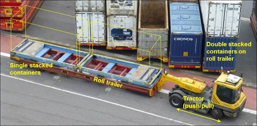
Figure 1: Roll trailer and tractor configuration
Source: ATSB
Three single stacked roll trailers (Figure 1) were loaded at the port forward end of the weather deck via the aft port side ramp. Each was driven into position by a rear mounted prime mover (tractor).
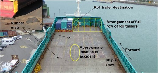
A stevedore was on the deck during loading, assisting with loading operations and positioning rubber mats under the steel foot of the loaded roll trailers. The stevedore carried a UHF radio which could be used to talk to the tractor driver when positioning the trailers. Three ship’s crew members were also on deck assisting with lashing of the loaded trailers, as was a refrigeration mechanic who was checking loaded refrigeration containers.
As the next roll trailer was driven up the ramp to the weather deck, the stevedore picked up some mats that he needed to position on the deck. Then, as the trailer came on the deck and aligned with the next vacant slot alongside the already loaded trailers (Figure 2), the stevedore moved towards the area in which he was going to position the mats. This location was in the path of the trailer and not visible to the tractor driver.
The ship’s crew members could see the stevedore moving towards them and assumed that he saw the approaching trailer. When they realised that the stevedore was in the direct path of the trailer, they attempted to warn him and the tractor driver, but their calls went unheard. The trailer then struck the stevedore and travelled about 13 m before the driver was advised of what had happened and he stopped the tractor.
The ship’s master and shore management were advised of the accident and, at 1337, a call was made to ‘triple zero’[2] to advise the emergency services. When the supervising stevedore arrived on board, he provided the injured stevedore with first aid following the advice of the ‘triple zero’ operator.
By about 1355, paramedics and officers from the police and the fire brigade had arrived on the scene. The paramedics were unable to revive the stevedore and he died as a result of the injuries he had sustained.
Figure 2: Weather deck layout at time of accident (inset showing use of rubber mats under roll trailer foot)
Source: ATSB
Visibility limitation
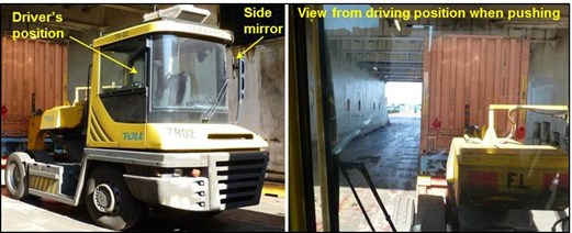
It was normal for loaded roll trailers to be pushed by the tractor onto the ship for loading onto the forward end of the weather deck. In this configuration, the driver’s view ahead was restricted by the containers on the trailer (Figure 3). The driving position allowed for a clear view along the left hand side of the load but almost no visibility down the right had side. The tractor was fitted a rear-view mirror, but in the push configuration this mirror was positioned behind the driver and, hence, provided no assistance.
Figure 3: Tractor and driver's perspective
Source: ATSB
ATSB comment
Decisions regarding whether to conduct an investigation, and the scope of an investigation, are based on many factors, including the involvement of other safety bodies such as workplace health and safety organisations and the level of safety benefit likely to be obtained from an investigation.
In this case, Victorian Workcover Authority[3] carried out an investigation of this accident and a thorough analysis of the safety factors that contributed to it. Victorian Workcover Authority continues to work with the involved parties to ensure that effective safety actions are appropriately implemented. As a result, the ATSB only carried out a limited-scope, fact-gathering investigation in order to produce a short summary report, and allow for greater industry awareness of potential safety issues and safety actions.
Safety action
Whether or not the ATSB identifies safety issues in the course of an investigation, relevant organisations may proactively initiate safety action in order to reduce their safety risk. The ATSB has been advised of the following safety actions.
Toll Shipping
Toll Shipping has advised that, as a result of this accident, discussions with its workforce and Victorian Workcover Authority they have taken the following interim safety actions:
a review of ship loading operations to improve control of the types and flow of cargo onto and off the ship
placed an additional stevedore on deck to improve coordination of personnel and traffic
provided additional radios for stevedores and ship’s crew
implemented clearly defined traffic control for vehicle entry onto deck
The company has further advised that it will continue to review these safety actions with the workforce and the Victorian Workcover Authority.
Safety message
Cargo operations on board ships are an inherently dangerous task. Therefore, it is important that hazard identification and risk analysis processes are a continual part of doing business. Known risks should be regularly reassessed in light of continued operations, experience and changing technologies to ensure the most appropriate risk controls are in place and being implemented.
The ATSB SafetyWatch highlights the broad safety concerns that come out of our investigation findings and from the occurrence data reported to us by industry. One of the current safety concerns is marine work practices www.atsb.gov.au/safetywatch/marine-work-practices.aspx.
About this report
Decisions regarding whether to conduct an investigation, and the scope of an investigation, are based on many factors, including the level of safety benefit likely to be obtained from an investigation. For this occurrence, a limited-scope, fact-gathering investigation was conducted in order to produce a short summary report, and allow for greater industry awareness of potential safety issues and possible safety actions.
Publishing information
Released in accordance with section 25 of the Transport Safety Investigation Act 2003
Ownership of intellectual property rights in this publication
Unless otherwise noted, copyright (and any other intellectual property rights, if any) in this report publication is owned by the Commonwealth of Australia.
Creative Commons licence
With the exception of the Coat of Arms, ATSB logo, and photos and graphics in which a third party holds copyright, this publication is licensed under a Creative Commons Attribution 3.0 Australia licence.
Creative Commons Attribution 3.0 Australia Licence is a standard form licence agreement that allows you to copy, distribute, transmit and adapt this publication provided that you attribute the work.
The ATSB’s preference is that you attribute this publication (and any material sourced from it) using the following wording: Source: Australian Transport Safety Bureau
Copyright in material obtained from other agencies, private individuals or organisations, belongs to those agencies, individuals or organisations. Where you wish to use their material, you will need to contact them directly.
[1] All times referred to in this report are local time, Coordinated Universal Time (UTC) + 10 hours
[2] Triple zero (000) is the telephone number for a single point of contact for all emergency services that can be used anywhere in Australia.
[3] As 1 July 2014 WorkSafe Victoria changed its name to the Victorian Workcover Authority.
On 18 May 2014 a Robinson Company R22 Beta aircraft was conducting cattle mustering on GoGo Station near Fitzroy Crossing, Western Australia.
Late in the afternoon, as the pilot was manoeuvring the helicopter at low level, the tail rotor struck the ground.
The helicopter commenced a severe right yaw. The pilot kept the helicopter in a clear area, while it rapidly completed about four full rotations to the right.
To arrest the yaw, the pilot immediately closed the throttle which resulted in a rapid rate of descent. In an attempt to lessen the rate of descent, the pilot raised the collective. The helicopter struck the ground heavily, and then rolled onto the right side.
The pilot sustained serious injuries and the helicopter was substantially damaged.
The risks in low level mustering are well known. Low level operations leave little margin for error. The added risk factors of operating in a dusty environment, and in the hour before last light would have reduced that margin.
On 9 May 2014, a Qantas Boeing 737 aircraft, registered VH-VZO and, operating a flight from Canberra, Australian Capital Territory, to Perth, Western Australia, was prepared for departure. On board the aircraft were the crew and 150 passengers, including a group of 87 primary school children. The group of children was seated together at the rear of the cabin and all had been assigned the standard adult weight of 87 kg during check-in.
The captain and first officer conducted the pre-flight checks and waited some time for the final load sheet to be delivered. The load sheet stated the take-off weight as 76,800 kg and the stabiliser trim figure as 5.5 units.
During take-off, the aircraft appeared nose-heavy. To rotate the aircraft and lift off from the runway, the captain found that significant back pressure was required. Conscious of the potential threat of striking the aircraft tail on the runway if too much back pressure was applied to the controls, the captain maintained steady back pressure to ease the aircraft into the air. The aircraft exceeded the calculated take-off safety speed (V2) by about 25 kt. The aircraft climbed at a higher initial climb speed than normal, which resulted in a slightly reduced climb gradient, but the crew did not receive any terrain or other warnings.
The crew did not experience any further issues during the flight. It was subsequently determined that the final load sheet overstated the aircraft take-off weight by about 3.5 to 5 tonnes and the stabiliser trim was out about 1 unit.
Determining accurate weight and balance is required for all aircraft prior to flight. Use of a trim setting that is inappropriate for the aircraft’s actual weight and balance may adversely affect the aircraft’s controllability at any stage of flight.
On 16 May 2014, a DA40 aircraft, registered VH-CGT departed Bankstown Airport, New South Wales, for the local training area. On board the aircraft were an instructor and student.
Once the training area exercises had been completed, CGT returned to Bankstown, with the student conducting the landing. The instructor reported the landing as satisfactory, but felt the student was still not flaring the aircraft sufficiently, prior to touchdown. He authorised the student to conduct four practice solo circuits.
With the weather CAVOK and minimal wind, the student commenced the first solo circuit. The initial, crosswind and downwind legs were reported as normal. Maintaining 80 knots on base, the turn onto final was between 600 and 700 ft.
The approach was steeper than usual, and as the student commenced the flare, it was evident that the aircraft was still too high above the ground. The student initiated a go-around. Almost immediately, the aircraft tail struck the runway. The aircraft rolled rapidly to the left and stalled. It then turned further left and continued across the taxiway and through a wire perimeter fence. The student was uninjured but the aircraft sustained substantial damage.
The flying school has reviewed the training emphasis related to control input during go-around procedures, and stabilised approaches. It is also amending the selection process for intake to the flying program.
At about 2355 on 22 February 2014, an 18 year old male was fatally injured at Heyington Railway Station in Toorak, Victoria when he fell between a moving train and the platform. He was running alongside the moving train when he fell attempting to board it, while passengers inside the train were forcibly holding the carriage doors open.
What the ATSB found
The train was equipped with a traction interlocking device to prevent the train from moving while its carriage doors were open. The device, as designed, deactivated after a period of time and allowed the train to depart with the doors held open.
Due to the curvature of the track, a wide gap existed between the mid-body of the carriage and the platform.
What's been done as a result
Metro Trains Melbourne (MTM) has commenced a risk review of the door open traction interlock timing on their rolling stock.
In order to minimise the gap between the train and platform, MTM has realigned the track at Heyington railway station and a rubber finger coping has been installed along the entire edge of the platform face. Further, a barrier has been constructed at the platform entrance to deter passengers from running for the train.
MTM has also completed a survey of all the stations with curved track and platforms of higher risk have been identified. In the short term these platforms have had ‘Mind the Gap’ signs painted on them. Announcements are also made to warn passengers of the gap. Works plans have been developed to institute further risk measures in the long term.
Safety message
Rail operators should ensure that safety systems fitted to passenger trains are designed and operate to ensure the safety of patrons in the event of interference with the normal operation of train doors.
The occurrence
On 22 February 2014, a Metro Trains Melbourne (MTM)[1] passenger train was operating the scheduled 2328 service TD2100 from Glen Waverley Railway Station to Flinders Street Station.
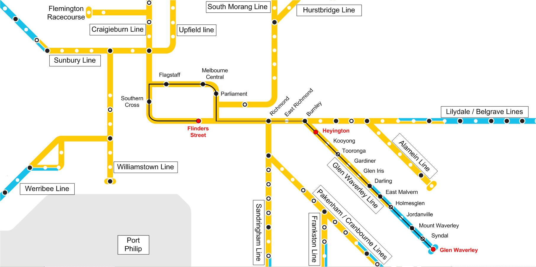
Figure 1 – Extract of Melbourne metropolitan rail network depicting Glen Waverley line
Source: Copyright Metro Trains Melbourne with annotations by Chief Investigator, Transport Safety (Vic)
The 6-car[2] X’Trapolis Electrical Multiple Unit (EMU) train was operated on the Melbourne metropolitan rail network by a single driver. The driver signed on at about 1400 and after operating several services took a meal break between 1730 and 1830 before resuming his driving duties. After operating several other services, the driver took over the service from Glen Waverley to Flinders Street Station at about 2320. He conducted the prescribed safety checks and departed the Glen Waverley Railway Station at about 2328. The train stopped at several railway stations before arriving at the Heyington Railway Station, Toorak at about 2351.
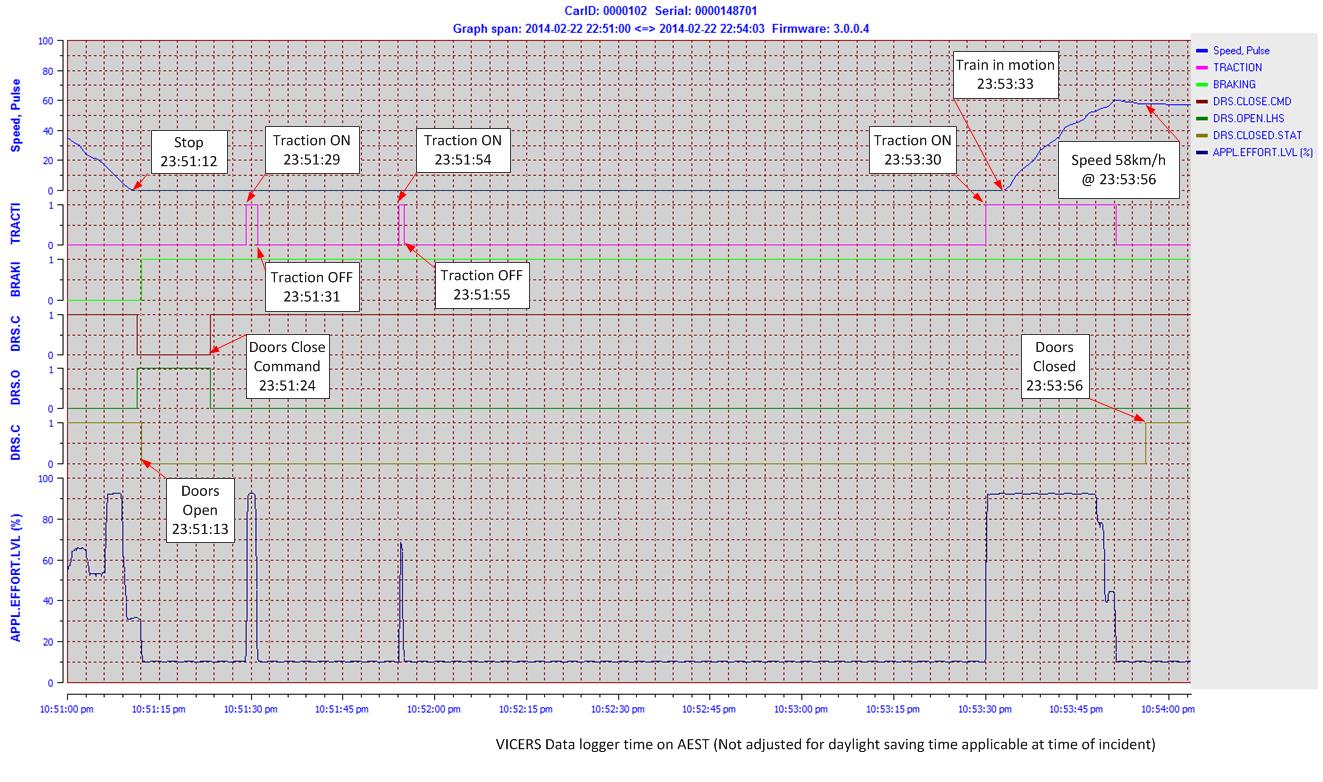
Shortly after arrival, the train driver activated the left side door open command and the doors[3] opened at 23:51:13. Passengers boarded the train, including a group of youths who boarded through the centre door of the fourth car (162M). This door was located approximately in line with the platform entrance. After boarding, several youths stood in and around the doorway, with two youths standing on either side of the door opening.
The driver activated the door close command at 23:51:24 and shortly after made two attempts to apply traction. The train did not move as the traction interlock system had detected the open door and inhibited the application of power to the motors. The end doors of the fourth car and the doors on all the other cars had closed, but the centre doors of the fourth car were held open by the two youths. After a short delay, the driver made an announcement for passengers to keep the doors clear. During this period, as designed, the doors attempted to close several times, but were held open.
The driver then applied traction again at about 23:53:30 and the train commenced moving along the platform with the doors held open, as the traction interlock system had timed out as designed.
The train had travelled about 20 metres when another group of youths entered the platform. One member of the group successfully boarded the now moving train through the doors being held open. A second young male ran alongside the train and subsequently fell between the train and platform, sustaining fatal injuries. The doors were released by the youths and they closed at 23:53:56. The train was travelling at about 58 km/h at the time the doors closed. The passenger emergency intercom (PEI) devices in the carriage were not activated by the passengers.
At the time of the incident the station was unmanned. At about 2355 a member of the public made a call on the platform emergency intercom to the MTM Glen Waverley Control Centre reporting the accident and requesting emergency services. A second call was made by the same person to the control centre at about 2357 seeking confirmation that services on the rail line had been terminated. The operator confirmed that the services on the Glen Waverley line had been terminated.
Train TD 2100 continued to Flinders Street Station and arrived at about 0010 on 23 February 2014 without further incident. At this time, the driver of the train was informed of the accident.
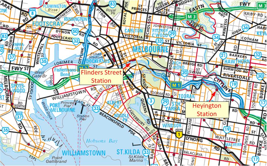
The incident occurred at Heyington Railway Station, Toorak, located approximately seven km from Flinders Street Station, Melbourne (Figure 2).
Figure 2 – Location of Heyington Railway Station
Source: Copyright Melway Publishing 2014, with annotations by the Chief Investigator, Transport Safety (Vic)
Heyington Railway Station
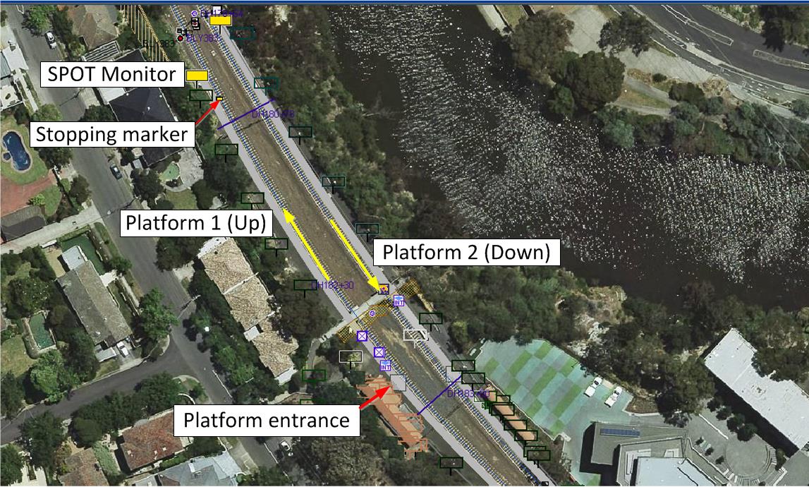
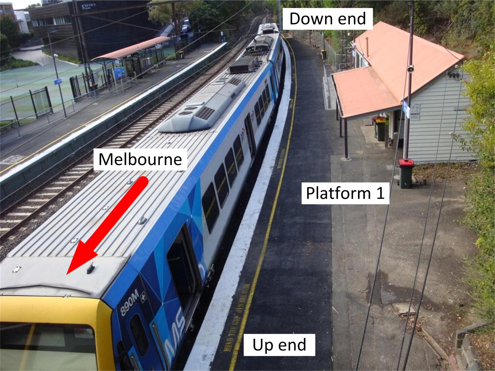
Heyington Railway Station is on the Glen Waverley Line and is located in a cutting (Figures 3 & 4). The station was opened in 1890 and has two side platforms connected by a footbridge. Access to the platforms was via stairs and the footbridge. Both the Up[4] and Down[5] platforms were about 158 m in length. The height of platform 1 from the design rail level ranged from 1070 mm to about 1140 mm.
The Up line track followed the curve of the concave platform 1 and transitioned into the straight section at the Up end of the platform (Figures 3 & 4). The curve of platform 1 had a radius of approximately 380 m.
Single Person Operations Television (SPOT) monitors were located about 1.3 m from the end of the platform. The 6-car stopping marker was about 6.0 m before the SPOT monitors. The passenger entrance to the platform was about 93 m from the Up end of the platform.
Figure 3 – Heyington Railway Station platform configuration
Source: PASS Assets Public Transport Victoria – Annotations by the Chief Investigator, Transport Safety (Vic)
Figure 4 – Platform 1 of Heyington Railway Station (3–car set at platform)
Source: Chief Investigator, Transport Safety (Vic)
Sighting of platform from front of train
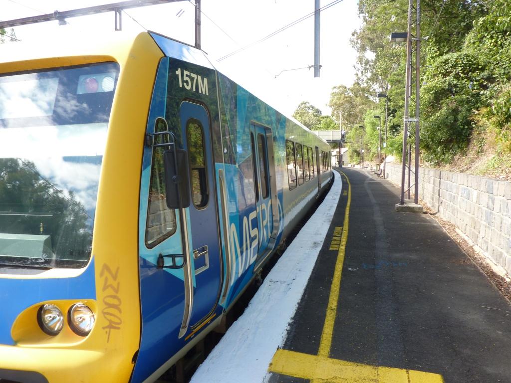
Platform 1 at Heyington Railway Station is a concave platform and the driver is unable to view the platform in its entirety along the length of the train using the train mirrors (Figure 5). This platform was equipped with four CCTV cameras that displayed sectors of the platform on four SPOT monitors. The SPOT monitors are located on the platform such that the driver is able to view the four monitors when stopped at the 6-car stopping marker. SPOT Monitor cameras were located to show the view along the train/platform length, on curved platforms rather than individual doors.
Figure 5 – Sighting of platform from front of train
Source: Chief Investigator, Transport Safety (Vic)
The train
The X’Trapolis EMU is operated as a 3 or 6-car set. TD 2100 was a 6-car set and consisted of 102M-1351T-101M-162M-1381T-161M passenger cars[6]. The car body modules were designed and constructed in France and assembled at Alstom Australia, in Ballarat, Victoria. The M cars are 24.46 m in length, 4210 mm in height and 3046 mm in width. The nominal floor height of the car is 1190 mm above top of the rail. Each car has three entrances, located at the front, middle and rear of the cars. The EMU is capable of a maximum speed of 130 km/h.
Traction and brake control
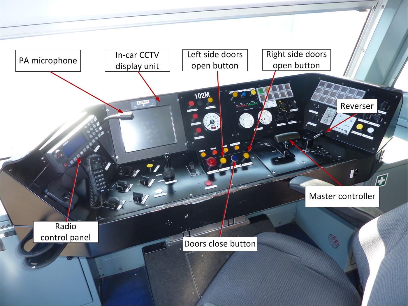
The Master controller is operated by moving the handle back and forth between four positions– motor, coast, brake and emergency brake. The reverser is a three positon switch that can be moved to forward, neutral and reverse positions. In order to get forward traction, the Reverser must be moved to the forward position and the Master controller moved from the brake to the motor position. The position of the Master controller between the coast and motor positions dictates the tractive effort.
Figure 6 – Driver control console of X’Trapolis EMU
Source: Chief Investigator, Transport Safety (Vic)
Door operation
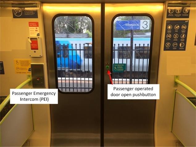
The driving cab at each end of the EMU contains the equipment and devices to enable the driver to operate and monitor the train doors. Located on the driver’s control console are two yellow pushbuttons that open the left and right hand side doors respectively and a blue pushbutton that closes doors on both sides (Figure 6). Further, each carriage door has a passenger operated door open button (Figure 7). All of these pushbuttons incorporate indicator lamps that illuminate and extinguish according to their activation status.
When the train doors are closed and locked the blue pushbutton lamp is illuminated, displaying a steady light. The two yellow pushbutton lamps on the console are not illuminated, nor are the pushbutton lamps on both the inside and outside of the passenger car doors.
According to the platform location the driver will apply the appropriate side ‘door opening authorisation’ by pushing the yellow pushbutton, which will then display a steady light. When the train speed drops below three km/h, the door opening system is activated. The blue pushbutton lamp flashes three times and turns off to indicate that doors may be operated by passengers. The passenger car door control units (DCU) located at the carriage doors emit a beep for 1.5 seconds and the passenger operated door pushbutton indicator lamp (Figure 7) illuminates in green, to indicate that passengers may now open the door. When the door pushbutton is activated by passengers entering or exiting the carriage, the DCU is activated and the passenger operated door pushbutton lamp illuminates red and the doors open.
To close the doors, the driver presses the blue pushbutton on the console. An intermittent beep sounds at the DCU for three seconds to warn passengers of imminent door closure. The yellow pushbutton lamp at the control console is extinguished and the doors close while emitting an intermittent beep at the doors. When the doors are successfully closed, the beep ceases and the pushbutton lamp on the door is extinguished. The blue pushbutton lamp on the console illuminates and flashes continuously until the doors are detected closed and then displays a steady blue light.
Figure 7 – X’Trapolis doors
Source: Chief Investigator, Transport Safety (Vic)
Door operation with obstruction
Each door is equipped with an obstacle/obstruction detection device. During the door closing sequence if an obstruction is detected, the doors will open once and then make three further attempts to close at three second intervals. If unable to close, the doors will then revert to the obstructed/open position. The blue pushbutton lamp on the driver’s console will continue flashing, to indicate to the driver that a door is detected open and unlocked. The yellow pushbutton lamp stays extinguished during this sequence.
Traction interlocking system
Pressing the blue pushbutton at the console initiates door closing and a 60 second time delay for traction authorisation. Detection of all doors closed and locked before the 60 seconds elapse, activates traction authorisation. Should the doors fail to close and lock after 60 seconds, the system is designed such that traction is authorised, despite the possibility that the doors have not closed. Once traction is authorised and applied the train will move. In this situation the blue pushbutton lamp will continue to flash. When the train speed exceeds three km/h and should the door obstruction be removed, the door closing mechanism activates and the doors will close, with the blue pushbutton lamp then displaying a steady blue light.
Detection of flashing light indicators
The flash rate for the door open button on the X’Trapolis locomotive was one flash per second, with a duration of 0.5 seconds resulting in a duty cycle of 50 per cent. That is, the time the light was ‘on’ was equal to the time ‘off.’
The Australian Standard for Ergonomics[7] recognises two acceptable flash rates, being 0.4 to 0.8 flashes per second for a slow flash rate, and 1.4 to 2.8 flashes per second for normal flash rate[8]. The X’Trapolis door open button’s flash rate was therefore within the range of acceptable rates. Further, the 50 per cent duty cycle is consistent with research.[9][10] People start to experience difficulty distinguishing a flashing light from a steady light when the flash rate reaches 30 per second, (known as the flicker-fusion frequency).[11]
On-board passenger emergency intercom (PEI) and CCTV systems
The interior of the carriages of the train can be observed by the driver using the on-board CCTV system (Figure 7). A selector switch on the driver’s control console permits the driver to select vision of each carriage. CCTV cameras are located at the front, middle and rear of each carriage. Vision of the carriage doors can be observed on the CCTV display unit on the driver’s control console. CCTV vision is available to the train driver when the train is stationary or moving at up to eight km/h. Above this speed the vision automatically cuts out unless a PEI call is made.
An on-board surveillance recording function operates automatically and continuously without the need for driver intervention.
Passenger emergency contact with the train driver is available via three PEI units situated in each car; each unit consisting of a microphone, speaker, and indicator. When a PEI call button is pressed the associated camera switches to recording at the rate of eight frames per second for a two-minute period, and displays on the driver console.
Train Driver
The train driver was qualified to drive EMUs from July 2012. His driving performance was audited regularly by MTM driver supervisors and was last audited in January 2014. No non-conformances were recorded during these audits. Medical certification for the driver was valid and current at the time of the incident. No alcohol or drugs were detected during post incident tests conducted on the driver.
Platform departure procedures and driver training
The MTM platform departure procedure requires train drivers to ensure that a steady indication of the blue pushbutton lamp on the driver’s console is observed and to check that passengers and articles are clear of the saloon doors, prior to the application of traction power and releasing the brake. Further, in the case of a door fault, a procedure outlines specific requirements that drivers are required to follow, in order to rectify the door fault or temporarily secure the door in a closed position, prior to the application of traction. Although the driver training manual includes a section ‘Door Closing Obstacle’ which states that a one-minute time delay is initiated when the door close pushbutton is activated, there is no specific reference to the time delay being in relation to the door open traction interlock.
In this incident a young male person ran alongside the moving train in an attempt to board it and fell between the train and platform, sustaining fatal injuries. He was encouraged by passengers in the train who held the carriage doors open. Forcibly holding the train carriage doors open was both reckless and unsafe.
Door open traction interlock
MTM operates Comeng, X’Trapolis and Siemens trains on its network. The traction interlocking systems on the Comeng and X’Trapolis trains in Melbourne are designed such that the interlocking system is deactivated automatically after a period of time. MTM advised that the train’s traction interlock system was designed to deactivate to enable trains to be moved in case of door faults. In cases where door faults were identified, MTM operational procedures required the driver to manually secure the faulty doors before moving the train. In this instance the deactivation of the traction interlock permitting the movement of the train with the doors open, increased risk and was contributory to this accident.
Post incident testing found that the door open indication light on train TD 2100 functioned as designed and changed from ‘flashing’ to ‘steady’ only when the doors were closed. Although the flashing state of the indication light identified that the doors may be open it did not provide warning to the driver of the deactivation of the traction interlock control. Where the design of a safety system such as a traction interlock times out automatically, it would be prudent to have additional indications/alarms to warn a driver of a change of state in the vehicle controls, particularly during passenger boarding at a station. Further, formally documenting the operation of the traction interlock override systems in the MTM training manuals would increase driver awareness of the risks associated with these systems.
The traction interlocking system on the Siemens type trains, also operated in the MTM fleet, would not allow the train to move with the doors open without driver intervention to override the interlock. Traction override systems on similar types of passenger rolling stock managed by other operators also required drivers to intervene and operate a switch if they are required to override a traction interlock. In most cases, procedures require the use of the override when there is a failure of the door closed detection equipment or electrical circuitry. Prior to operating the manual override, drivers are required to follow procedures to ensure doors are closed and locked, and to verify this action by seeking authority from a train control centre. Further, to deter unauthorised or accidental usage, the train data recorder logs the time and duration of the override selection. This type of traction interlock system improves passenger safety through the provision of an increased defence against human error.
Factors affecting the actions of the train driver
Human performance is highly variable and subject to a number of influencing factors. Unlike services where the driver is assisted by a guard for passenger boarding and exiting the train, for driver only operations, the driver is responsible for not only the safe operation of the train but must also attend to passenger safety and security issues.
Interview evidence indicated that the driver had regularly experienced incidents of passengers forcibly holding carriage doors open during his employment at MTM. He reported that on previous occasions he had resolved this issue via an announcement instructing passengers to move away from the doors, which normally resulted in compliance. He had also experienced issues where doors were obstructed and he had been required to leave the cab to manually inspect and remove obstructions to close the doors.
The driver recalled that in this instance, he had made an announcement to passengers to move away from the door, but that the passengers holding the door open had not complied. The driver recalled that he had been about to make a call to the Metropolitan Train Control Centre (METROL)[12] to inform them of the delay, after which he intended to leave the cab to speak to the passengers face to face and close the door so that the train could depart the station. However, it was his recollection that during this time, he observed a steady light on the blue pushbutton, indicating that the door was now closed. He then applied traction power and departed Heyington Railway Station. It was not until the train arrived at Flinders Street station, that the driver was made aware of the accident.
Driver’s mental model[13] of the door-open traction interlock
There was no in-cab camera fitted to the train to confirm the indications displayed on the driver’s console on this occasion. However, post-accident testing did not reveal any technical faults in the operation of the train’s door open traction interlock and associated displays at the driver console. Based on the evidence available, the ATSB concluded that the display was functioning correctly.
During the interview, it became evident that the driver’s understanding of the traction interlock was that it would not permit the train to be moved if the doors were open. He was not aware of the design feature which would, after 60 seconds, authorise traction despite the doors remaining open. The data recorder indicated (Appendix A) that the driver had moved the master controller to the ‘motor’ position five seconds after initiating the door close command and, as the traction interlock was active, he did not get traction. After another 25 seconds the driver applied traction again and once again the interlock prevented traction. Two minutes and six seconds after activating the door close command he applied traction for the third time and, as the interlock had now timed out, got traction. It is possible that the driver’s recollection of his observation of the steady light was influenced by his mental model of the operational parameters of the interlocking system.
During the period in which the driver made the second and third attempt at applying traction, he also made the announcement to the passengers to keep the doors clear and visually checked the in-car CCTV and SPOT monitors. He stated that he attempted to observe the door that was being held open utilising the in-car CCTV, but the vision was unclear due to the group of people standing near the door. Further, the driver’s vision of the platform via the SPOT monitors was unavailable as soon as the train commenced departure, preventing him from observing passengers on the platform as the train departed the station, which was the time when the youth attempted to board the moving train. The in-car CCTV also cut out as soon as the train started moving. With an inaccurate understanding of the parameters of the interlocking system’s override mechanism, and with limited information to dispel his view that the train could proceed, the driver departed Heyington station.
Fatigue
In the context of human performance, fatigue is a physical and psychological condition which can arise from a number of different sources, including time on task, time awake, acute and chronic sleep debt, and circadian disruption (disruption to normal 24-hour cycle of body functioning). Fatigue can have a range of influences on performance, such as decreased short-term memory, slowed reaction time, decreased work efficiency, reduced motivational drive, increased variability in work performance, and increased errors of omission.[14] Fatigue impairment has been identified as contributory in a significant number of rail accidents and incidents. Research has indicated that anything less than 5 to 6 hours sleep in 24 hours and 12 hours sleep in 48 hours is likely to lead to fatigue impaired performance.[15][16] Based on the evidence provided to the ATSB, the driver of the train obtained about 7-8 hours of sleep in the 24 hours leading up to the occurrence (from 2355 on 21 Feb 2014) and about 16-18 hours of sleep in the 48 hours prior (from 2355 on 20 February 2014). If the driver awoke at 1000 on 22 February, his period of wakefulness at the time of the occurrence would have totalled approximately 14 hours. There was no evidence to suggest that the quality of the driver’s sleep in the preceding days had been compromised. Further, the sleep opportunity periods provided while driving the afternoon shift had significant overlap with the circadian trough (around 0200 to 0600), when sleep is generally at its most restorative.
As a supplement to the above fatigue likelihood analysis, the ATSB also conducted fatigue modelling, incorporating the driver’s rostered work hours, as well as his reported obtained sleep for the days leading up to the accident.[17][18] Modelling indicated that during the latter part of the driver’s shift on 22 Feb 2014, and thus at the time of the occurrence at Heyington Station, the driver’s alertness was likely to have dropped to a level at which his performance was at least at mildly increased risk for fatigue impairment. The biomathematical modelling indicated that this was due mainly to time-of-day effects. Notably, it is difficult to avoid this increased fatigue risk during the early morning hours, and this prediction was understandably also a feature of the modelling for each of the shifts on 17 February 2014 and 21 February 2014, despite the driver having reported obtaining solid 8-9 hour sleep periods preceding these shifts.
Considering all of the available evidence in regard to quantity and quality of sleep obtained and reported alertness on duty, as well as the outcomes of the fatigue modelling, the driver’s cognitive performance was likely to have been at a manageable level at the time of the event. The available evidence did not support a contention of fatigue impairment as contributory to this accident.
Platform-train interface
The Victorian Rail Industry Operators Group[19] (VRIOG) standards apply to the upgrading and maintenance of structures and facilities of the metropolitan railway stations. Public Transport Victoria (PTV)[20] requires transport operators to comply with the Victorian Rail Industry Operators Group[21] (VRIOG) Standards for the maintenance and upgrade of rail infrastructure.
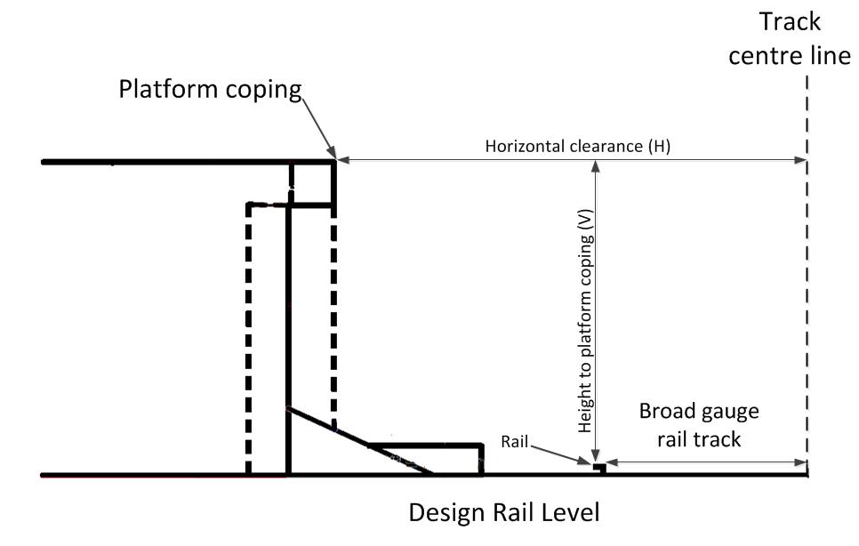
The VRIOG standard VRIOGS 001 - Structure Gauge Envelopes issued in June 2012 specifies the minimum clearances required to safely separate rolling stock from trackside infrastructure. The standard specifies the horizontal distance from the track centre line to the platform edge (H) and the vertical height from the design rail level to the top of the platform edge (V) [Figure 8]. For existing track infrastructure the standard specifies a horizontal distance of 1550 mm with a construction tolerance of +10 mm and vertical height of 1043 mm for tangent track.[22]
Figure 8 – Horizontal and vertical clearances between platform and track
Source: VRIOGS 001, modified by Chief Investigator, Transport Safety (Vic)
Where a platform is curved, extra horizontal clearance is required to allow for:
the end throw of rolling stock
the dynamic effects such as car body roll
body displacement due to lateral deflection of suspension and wheel flange wear.
Further, track centre misalignment, gauge variations and rail wear are other factors that have to be allowed for during platform design and installation.
For curved track, the VRIOG Standard[23] requires that an additional standard clearance be added to the horizontal clearance stipulated for tangent track (1550 mm). The curve radius of Platform 1 of Heyington railway station was 380 m, and the applicable increase to the required clearance is 135 mm[24] giving a required standard horizontal clearance of 1685 mm.
The standard also provides an equation[25] for deriving an absolute minimum clearance. The applicable increase to the required clearance using this method is 85 mm. This gives a total minimum required horizontal clearance of 1635mm.
The VRIOG Standard only specifies the minimum clearance required and does not specify a maximum clearance between a platform and the train as its purpose is to ensure a clear operating envelope is provided for rolling stock on the network.
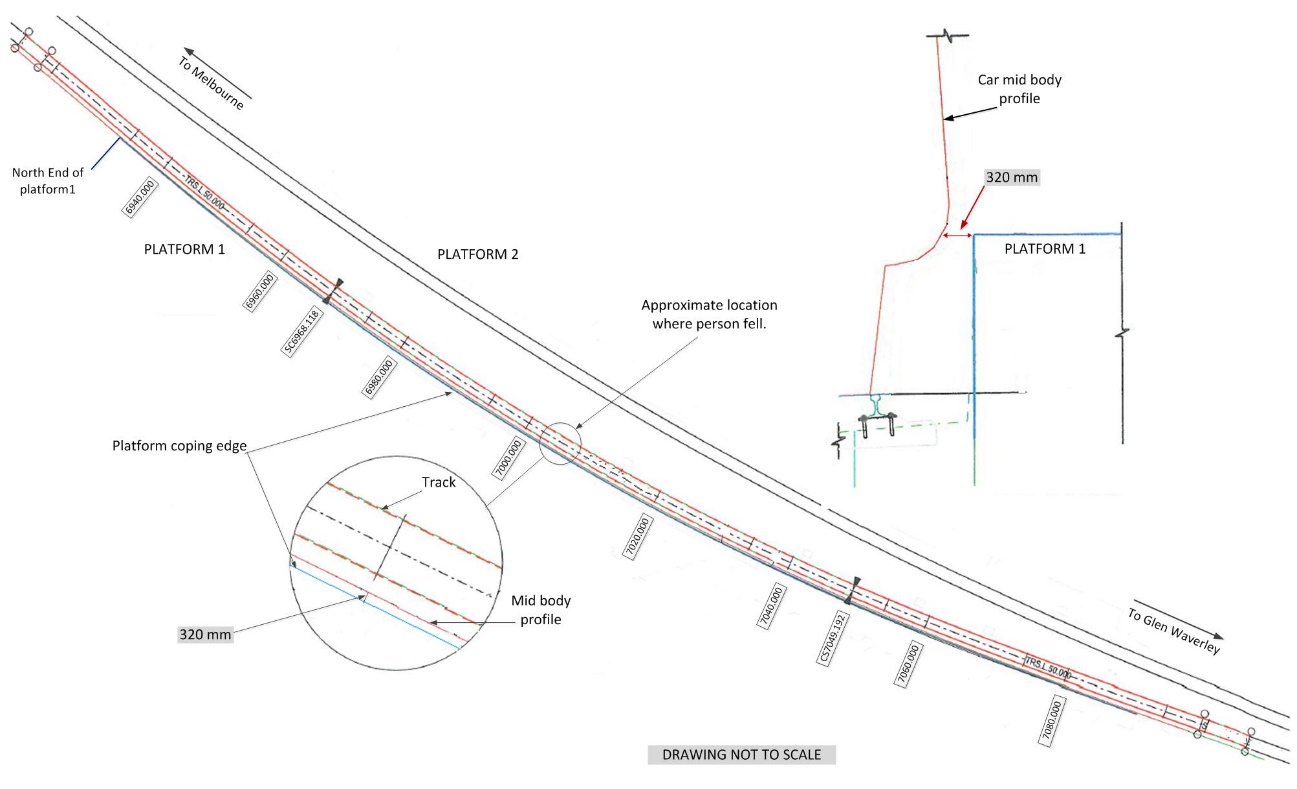
At the absolute minimum horizontal clearance required by the VRIOG Standard (1635 mm) and a construction tolerance (+10 mm), a gap of 297 mm would exist between the X’Trapolis car mid-body and the platform. At the standard horizontal clearance required by the VRIOG standard (1685 mm) and the construction tolerance, a gap of 347 mm would exist between the mid-body and the platform. The largest measured gap between platform 1 and the X’Trapolis car mid-body was about 390 mm at the station entrance. The gap in the area that the person fell between the platform and train was about 320 mm. This gap lies between the two gaps (297 mm and 347 mm) derived using the absolute minimum clearance and the standard clearance.
From 2013, the Structures and Facilities Standard developed by MTM defined the requirements for the design and construction of stations for the suburban metropolitan railway. This standard required that all new platforms be either tangent or convex with a radius of not less than 1000 m. The standard did not provide for the construction of concave platforms. For existing platform renewal, MTM developed a ‘design practice note’ (DPN) effective from January 2014. This document provides guidelines on the permissible construction tolerances applicable to platform renewal works.
Figure 9 – Schematic showing clearance between platform and train
Source: Metro Trains Melbourne with annotations by Chief Investigator, Transport Safety (Vic)
The following findings are made with respect to the incident involving a young male person, who sustained fatal injuries when attempting to board the Glen Waverley train to Flinders Street Station. These findings should not be read as apportioning blame or liability to any particular organisation or individual.
Safety issues, or system problems, are highlighted in bold to emphasise their importance. A safety issue is an event or condition that increases safety risk and (a) can reasonably be regarded as having the potential to adversely affect the safety of future operations, and (b) is a characteristic of an organisation or a system, rather than a characteristic of a specific individual, or characteristic of an operating environment at a specific point in time.
Contributing factors
An individual attempted to board the moving train and fell between the train and the platform.
The train doors were held open by a group of passengers.
As designed, the traction interlock automatically deactivated after a period of time. This allowed traction to be applied and the train to depart with the carriage doors open. (Safety Issue)
Due to the curvature of the track, a wide gap existed between the platform and train at the Heyington Railway Station. There are several stations on the Melbourne metropolitan rail network where wide gaps exist between platforms and trains due to track curvature. These gaps pose a risk to passengers. (Safety Issue)
Other factors that increased risk
The train door open/close indicator on the driver’s control console was inadequate as a warning device once the traction interlock had deactivated. (Safety Issue)
The existing standards stipulated minimum clearances between trains and platforms but did not consider the effect of the resulting gaps with respect to safe accessibility. (Safety Issue)
Safety issues and actions
The safety issues identified during this investigation are listed in the Findings and Safety issues and actions sections of this report. The Australian Transport Safety Bureau (ATSB) expects that all safety issues identified by the investigation should be addressed by the relevant organisation(s). In addressing those issues, the ATSB prefers to encourage relevant organisation(s) to proactively initiate safety action, rather than to issue formal safety recommendations or safety advisory notices.
All of the directly involved parties were provided with a draft report and invited to provide submissions. As part of that process, each organisation was asked to communicate what safety actions, if any, they had carried out or were planning to carry out in relation to each safety issue relevant to their organisation.
The initial public version of these safety issues and actions are repeated separately on the ATSB website to facilitate monitoring by interested parties. Where relevant the safety issues and actions will be updated on the ATSB website as information comes to hand.
The train could be moved with the carriage doors open
As designed, the traction interlock automatically deactivated after a period of time. This allowed traction to be applied and the train to depart with the carriage doors open.
The existing standards stipulated minimum clearances between trains and platforms but did not consider the effect of the resulting gaps with respect to safe accessibility.
Due to the curvature of the track, a wide gap existed between the platform and train at the Heyington Railway Station. There are several stations on the Melbourne metropolitan rail network where wide gaps exist between platforms and trains due to track curvature. These gaps pose a risk to passengers.
The sources of information during the investigation included:
Metro Trains Melbourne
Public Transport Victoria
Transport Safety Victoria
Train driver
Witnesses.
References
Battelle Memorial Institute (1998). An Overview of the scientific literature concerning fatigue, sleep, and the circadian cycle.Report prepared for the Office of the Chief Scientific and Technical Advisor for Human Factors, US Federal Aviation Administration.
Dawson, D. & McCulloch, K. (2005). Managing fatigue: It’s about sleep. Sleep Medicine Reviews, 9, 365-380.
Flin, R., O’Connor, P & Crichton, M. (2008). Safety at the Sharp End. A guide to nontechnical skills. Ashgate: Aldershot.
Thomas, M.J.W. & Ferguson, S.A.. (2010). Prior sleep, prior wake, and crew performance during normal flight operations. Aviation, Space, and Environmental Medicine, 81 (7), 665-670.
Submissions
Under Part 4, Division 2 (Investigation Reports), Section 26 of the Transport Safety Investigation Act 2003, the ATSB may provide a draft report, on a confidential basis, to any person whom the ATSB considers appropriate. Section 26 (1) (a) of the Act allows a person receiving a draft report to make submissions to the ATSB about the draft report.
A draft of this report was provided to Metro Trains Melbourne, Public Transport Victoria, Transport Safety Victoria, Office of the National Rail Safety Regulator and the train driver.
Submissions were received from Metro Trains Melbourne, Public Transport Victoria, Transport Safety Victoria and the Office of the National Rail Safety Regulator. The submissions were reviewed and where considered appropriate, the text of the draft report was amended accordingly.
Appendices
Appendix A – VICERS Data logger analysis
Source: Chief Investigator, Transport Safety (Vic)
Purpose of safety investigations
The objective of a safety investigation is to enhance transport safety. This is done through:
identifying safety issues and facilitating safety action to address those issues
providing information about occurrences and their associated safety factors to facilitate learning within the transport industry.
It is not a function of the ATSB to apportion blame or provide a means for determining liability. At the same time, an investigation report must include factual material of sufficient weight to support the analysis and findings. At all times the ATSB endeavours to balance the use of material that could imply adverse comment with the need to properly explain what happened, and why, in a fair and unbiased manner. The ATSB does not investigate for the purpose of taking administrative, regulatory or criminal action.
Terminology
An explanation of terminology used in ATSB investigation reports is available here. This includes terms such as occurrence, contributing factor, other factor that increased risk, and safety issue.
Publishing information
Released in accordance with section 25 of the Transport Safety Investigation Act 2003
Ownership of intellectual property rights in this publication
Unless otherwise noted, copyright (and any other intellectual property rights, if any) in this report publication is owned by the Commonwealth of Australia.
Creative Commons licence
With the exception of the Coat of Arms, ATSB logo, and photos and graphics in which a third party holds copyright, this publication is licensed under a Creative Commons Attribution 3.0 Australia licence.
Creative Commons Attribution 3.0 Australia Licence is a standard form licence agreement that allows you to copy, distribute, transmit and adapt this publication provided that you attribute the work.
The ATSB’s preference is that you attribute this publication (and any material sourced from it) using the following wording: Source: Australian Transport Safety Bureau
Copyright in material obtained from other agencies, private individuals or organisations, belongs to those agencies, individuals or organisations. Where you wish to use their material, you will need to contact them directly.
On 6 March 2014, Pacific National superfreighter (5SM2) left Sydney, New South Wales, bound for Melbourne, Victoria. The train consisted of three locomotives hauling 18 wagons of containerised freight. It had a total length of 635.4 m and a trailing weight of 1635.4 t.
At about 1345, train 5SM2 approached Springhurst on the East Track, a location where work was being carried out on the West Track under Absolute Occupation. Due to the occupation on the West Track, protection of the parallel line was in place on the adjacent East Track. This was in the form of Track Force Protection (TFP) which was managed by a third party Track Force Protection Coordinator (TFPC).
Train 5SM2 approached the outer flagman displaying a yellow flag indicating that there was an obstruction ahead requiring the train to stop at an inner flagman. Three Audible Track Warning Signals (ATWs) had been placed 10 m apart on the track by the outer flagman and as 5SM2 went over the ATWs, the train crew sounded the horn and started to manage the train in anticipation of stopping at the inner flagman protecting the worksite 2,000 m ahead.
After 5SM2 had travelled a further 1,100 m, the train crew observed the inner flagman and determined that the train was not going to stop in time. The driver made an emergency brake application and the train came to a stop about 100 m beyond the inner flagman. At the time of the incident, the East Track TFPC did not consider that the occurrence was an incident or ‘near miss’ that required reporting.
The train crew considered that the incident had been ‘dealt with and reconciled’ by the TFPC onsite and, therefore did not report it. However, the train crew and the TFPC both had an obligation to report the incident as soon as reasonably practicable.
As a result of this occurrence, the ARTC has advised that they are taking the following safety actions:
The Australian Rail Track Corporation will review the placement of outer and inner warnings given to train crews approaching worksites within Victoria as a priority. The review will consider the requirements specified in the rules applicable to other areas of the Defined Interstate Rail Network with the preferred outcome being alignment across all jurisdictions.
All ballast rehabilitation program staff have been reminded of the requirement under TA44 to immediately report incidents to Network Control.
At about 1404 on 14 May 2014, the fourth wagon from the end of train 3WB3 derailed whilst exiting the Nambucca Heads crossing loop. The train travelled a further 1,397 m before the derailed wagon tipped on its side causing the train to separate and subsequently stop.
What the ATSB found
The ATSB found that the rod-in-coil load had likely shifted, mostly to the left in the direction of travel. The effect of a load shift to the left would have been to transfer vertical forces from the wagon’s right side-bearer to the left side-bearer, causing the right-hand wheels to unload.
At the point of derailment, the track geometry was transitioning out of a left-hand curve which had a relatively high superelevation with respect to the actual speed of train 3WB3 (about 21 km/h). The relatively high superelevation and subsequent twist as the superelevation ramped down through the transition, likely resulted in additional transfer of vertical force from the wagon’s right side-bearer to the left side-bearer, resulting in a further unloading of the right-hand wheels.
The combination of superelevation, twist and (more importantly) uneven lateral loading, combined to unload the right-hand wheels which, when steering through a left-hand curve, resulted in flange climb and derailment of wagon RCOF20375S.
What's been done as a result
Following the occurrence, Pacific National Assets and Infrastructure Services engaged a consultant to conduct an audit of procedures and operational processes relating to the development and implementation of the Freight Loading Manual (FLM). The audit was scoped specifically to include a gap analysis in relation to current steel loading processes.
In addition, PN have advised that they will be arranging an external engineering group to undertake a twist test and/or computer simulation modelling of an RCOF wagon to record its wheel loading performance characteristics during scenarios based on operational data. It is expected that the outcomes of this work will be used to further refine the FLM and associated procedures and loading practices.
Safety message
The ability for a load to shift during transit is an undesirable condition that can affect the dynamic behaviour of the rail vehicle. All rail freight operators should consider the safety implications of shifting/moving loads and should ensure that all loads are restrained and/or enclosed in such a way that prevents movement in any direction relative to the wagon.
The occurrence
At about 1355[1] on 14 May 2014, freight train 3WB3 entered the Nambucca Heads crossing loop. The route was set for a through movement via the loop because of trackside work being performed adjacent to the main line.
At about 1404, the trailing wheel set of the leading bogie on wagon RCOF20375S derailed to the right-hand-side in the direction of travel. The train was travelling at a speed of 21 km/h through a left hand curve. The derailed wagon was located fourth from last in the 44 wagon consist.
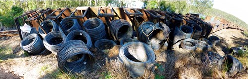
The train continued to travel with the derailed wagon for 1,397 m, passing over two bridges and reached a speed of 44 km/h before wagon RCOF20375S tipped on its side (Figure 1). The train then parted between the fourth and fifth last wagons. As the wagons parted, the train brake pipe separated, allowing air to vent to atmosphere and the train brakes to apply, bringing the train to a stop in about 320 m.
The train crew notified the network controller and arrangements were made to begin investigative and restoration work. The main line was subsequently reopened at 1816 on 16 May. The Nambucca Heads crossing loop line remained closed until further repairs could be conducted.
Nambucca Heads is located on the Main North Coast rail corridor between Sydney and Brisbane, about 565 track kilometres from Sydney Central Station. Nambucca Heads is a crossing location with a 1,951 m crossing loop.
The track at the location of the derailment was standard gauge, 53 kg/m rail mounted with resilient fastenings on timber sleepers spaced at about 667 mm centres.
The Australian Rail Track Corporation (ARTC) manages the railway corridor where the derailment occurred. Authorised movement of rail traffic is controlled from the ARTC’s Network Control Centre located at Broadmeadow, New South Wales.
Approaching from the southern end, the track through the derailment site consisted of a series of reverse curves between 480 m and 360 m radii on reasonably level track. While the posted maximum track speed was 75 km/h, most rail traffic traversing the loop would travel at considerably lower speed due to 25 km/h speed restrictions over the turnouts.
Train information
Train 3WB3 was a steel products freight service operated by Pacific National between Whyalla and Brisbane via Melbourne, Wollongong, and Morandoo (Newcastle). At the time of the derailment, the train consisted of two locomotives (NR94 leading and AN9 trailing) hauling 44 freight wagons. It was 817 m in length and had a trailing mass of 3,363 t.
Two qualified drivers operated the train. Both had been assessed as fit for duty in accordance with the requirements of the National Standard for Health Assessment of Rail Safety Workers.
Analysis of locomotive data logger indicated that there were no anomalies in the train speed, train handling or operational performance leading up to the derailment.
Rolling stock
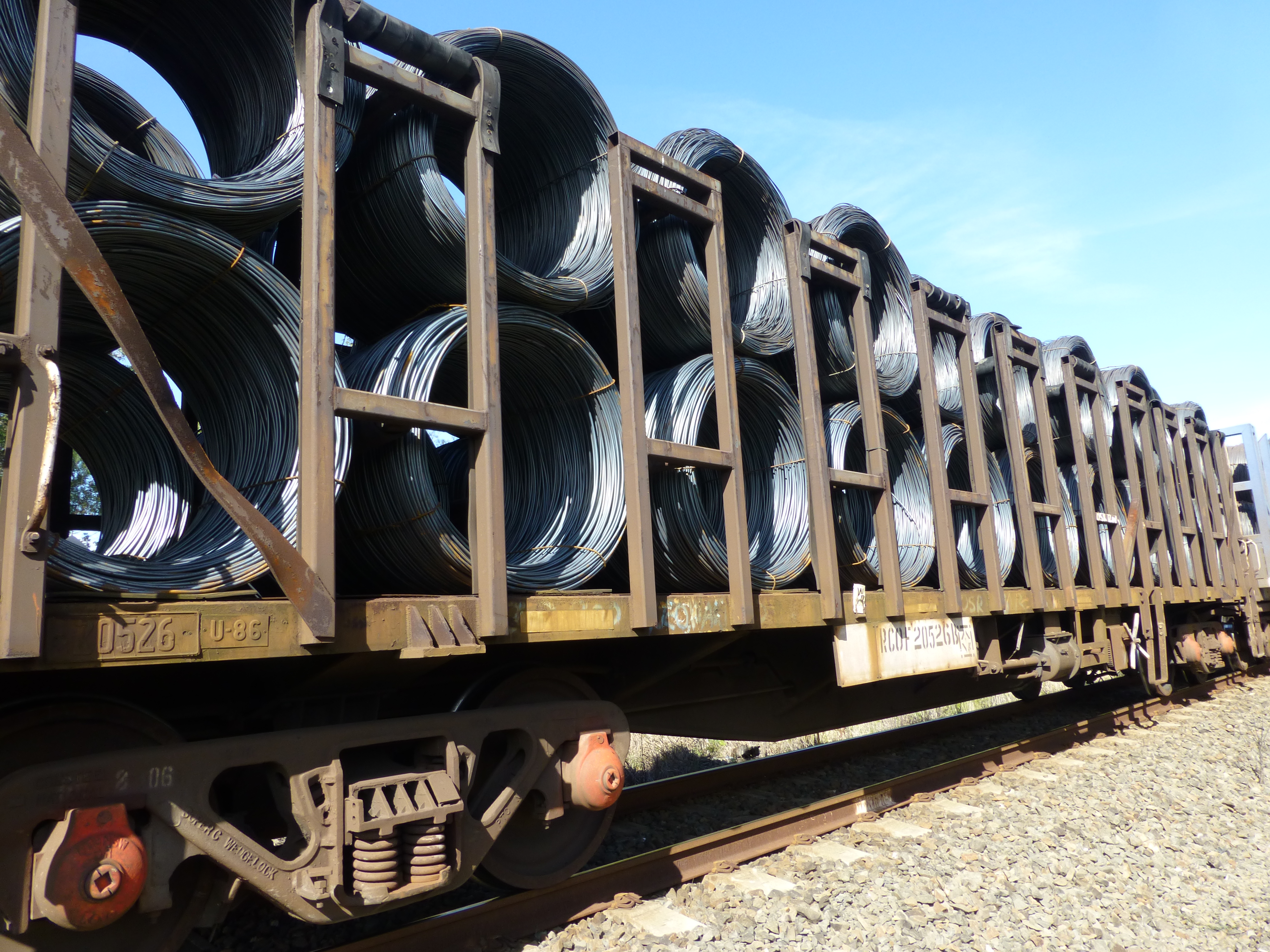
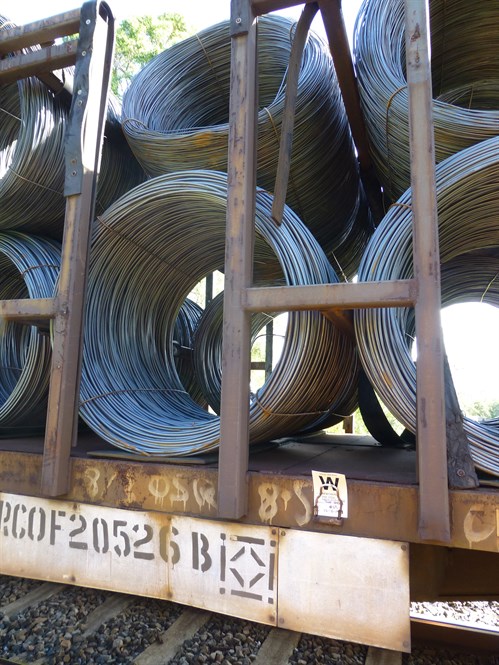
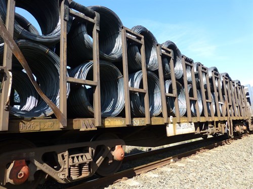
RCOF wagons are 15.1 m long and approved to carry up to 80 gross tonnes at speeds up to 80 km/h (depending on track speed limits). On the day of the derailment, wagon RCOF20375S (the wagon which derailed) was carrying 40 coils of steel rod, each weighing 1.5 t on average. The coils were arranged two-wide by two-high, in each of the wagon’s 10 bays (Figure 2). The coils were contained within the wagon, but they were not otherwise restrained. Wagon RCOF20375S was one of six wagons added to the train at Morandoo for travel to Brisbane.
On-site inspection and preliminary examination of the derailed wagons found no indication of any serious anomalies in rolling stock condition. However, evidence of load shifting was observed in wagons not affected by the derailment, but carrying the same rod-in-coil product.
A number of wagons were quarantined, including RCOF20375S. The bogies of wagon RCOF20375S were transferred to Newcastle where they were examined in more detail by Pacific National.
The examination noted that:
1.Wheelsets on wagon RCOF20375S were inspected and measurements recorded. All wheelsets were in good condition and wheels were within Pacific National requirements. There was nothing evident from inspection of the wheelsets that could have contributed to the wagon derailing.
2.Wagon RCOF20375S bogie and wagon condition was inspected, with no obvious wear or pre incident damage observed that could have contributed to the derailment.
3.A bolster drop test was conducted and the bogies of wagon RCOF20375S. The test confirmed that the overall friction damping was satisfactory.
Based on the available evidence, it was concluded that the mechanical condition of wagon RCOF20375S did not contribute to the derailment.
The Pacific National freight loading manual (FLM) is a document that provides information to employees and third parties on loading requirements for goods transported on Pacific National trains, to ensure the safe carriage of freight. The manual includes guidance on factors that may affect the stability of the wagon, such as composition, mass and distribution of the load, and the method of securing the load.
Section 01-10_07 documents the general requirements for mass and distribution of load. The FLM requires the load to be evenly distributed and the centre of gravity (including the weight of the bogies) shall not exceed 2,130 mm. Calculations indicate that a wagon fully loaded with road-in-coil product would likely result in a centre of gravity at or near the limit documented in the FLM.
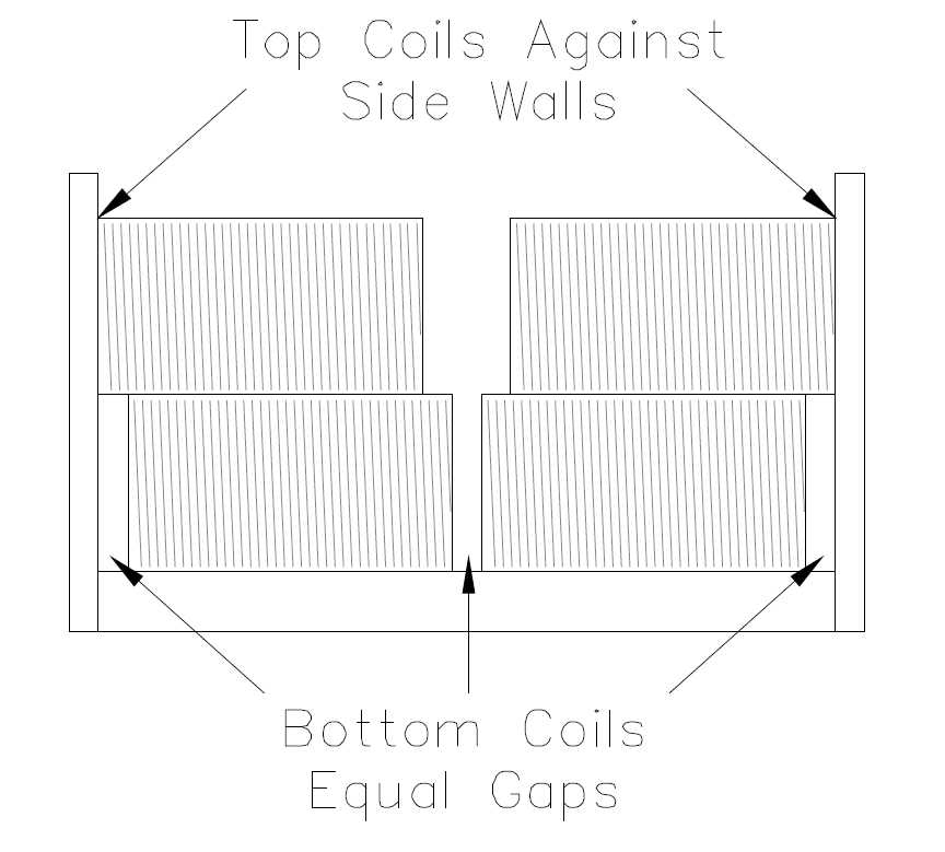
The FLM also provides loading guidelines for specific products and wagons. Section 5-13_07 of the manual (dated 3 July 2013) documented the specific requirements for transporting rod-in-coil product on RCOF and RCWF wagons, and stated:
Where possible, the top and bottom layer MUST cover the full width of the wagon’s frame to ensure the load cannot collapse.
Where the load does not cover the full width, the bundles are to be loaded as follows:
The bottom two bundles must be placed so that all gaps are consistent.
The top two bundles are to be placed against the side walls of the cage.
If the bottom bundles are too wide to allow all three gaps, place bundles against side walls of frames/stanchions.
Coil bundles placed on the on bottom tier MUST be of sufficient strength to ensure coil collapse will not occur in transit.
Figure 3 illustrates the requirements specified above and has been reproduced from Pacific National’s freight loading manual.
Figure 3: Loading requirements for rod-in-coil product on RCOF wagons
Source: Pacific National freight loading manual (Section 5-13_07, dated 3 July 2013).
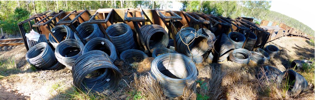
On site observations indicated that rod-in-coil product on both RCOF and RQRY wagons exhibited inconsistent gaps on the lower level, with the upper level having collapsed towards the centre of the wagon (Figure 4).
Figure 4: Loaded wagon RCOF20526B with shifted coils
Source: ATSB.
Examination of the track post-derailment
An onsite inspection was conducted on 15 May 2014 by the ATSB investigation team, ARTC, and an officer from the Office of the National Rail Safety Regulator (ONRSR).
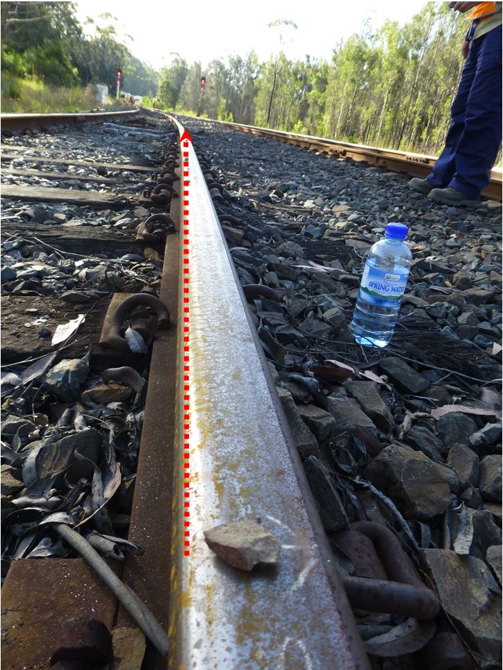
Evidence of flange climb was found on the high rail in a curve exit (Figure 5) at the 565.577 km point. The flange mark ran across the rail head and dropped off the field side of the high rail about 7 m further along the track. The rail did not show any signs of unusual wear.
Figure 5: Point of climb and derailment
Source: ATSB
The site was surveyed to record the track geometry on the approach and departure to the point of derailment. The measurements were recorded at 2 m intervals from 40 m on approach and 14 m on departure. The measurements were compared against the design parameters documented in the ARTC Engineering (Track & Civil) Code of Practice, Section 5, Track Geometry (CoP).
It was evident from the measured track geometry that the derailment had occurred in the curve transition[2] where the curve superelevation[3] runs-out to zero for the section of track leading to the turnout.
Track geometry parameters for curve design are largely dependent on train speed. In this case, the posted track speed was 75 km/h, though trains would rarely exceed 25 km/h due to the turnout (located about 200 m from the point of derailment). Analysis of the track measurements found that, at the point of derailment, a number of design parameters were approaching their recommended limits, especially at track speeds lower than 75 km/h. Despite this, there was no evidence of irregular track wear that can occur where trains regularly traverse track at speeds significantly lower than design.
Maintenance and inspection
The section of track at Nambucca Heads was maintained in accordance with ARTC’s CoP. The manual outlined two complementary inspection and assessment types:
• scheduled inspections, and
• unscheduled inspections.
At the time of derailment, the ARTC mandated that scheduled inspections for this section of track be performed by track patrols (at intervals not exceeding 7 days, or 28 days on crossing loops), ‘front-of-train inspections’ (at intervals not exceeding 6 months), and the track geometry car (at intervals not exceeding 4 months, or 24 months on crossing loops). Defects identified during inspections were to be recorded, assessed, and actioned in accordance with criteria documented in the CoP.
Previous track inspections did not record any defects in the vicinity of the derailment point. The previous track geometry car inspection, conducted on 14 January 2014, had not recorded any defects that required immediate rectification.
Examination of the survey data showed some variation in superelevation, track gauge and lateral alignment. While the variations in track geometry indicated a possibility of track movement in this area, when assessed against the CoP the magnitude of the measured geometry variations had not reached levels that would have required maintenance intervention.
Post-incident repairs
The ARTC performed rectification work on the track. The work involved the replacement of sleepers beyond the point of derailment, including part of the curve on the loop line. As part of the rectification work, the track was realigned and tamped which resulted in a reduction of superelevation and removal of the minor alignment variations through the curve near the point of derailment.
Mechanism of derailment
A flange climb derailment (as was evident in this case) occurs when a wheel has climbed up and over the top of the railhead. Flange climb is likely to occur in situations where the wheel experiences high lateral forces combined with a reduction in vertical force. The ratio of lateral to vertical force is often referred to as the L/V ratio. As this ratio increases, the likelihood of flange climb (derailment) also increases.
Flange climb derailments often occur on curves or track exhibiting alignment irregularities. A moving mass will try to continue moving in a straight line unless an external force is applied. On curved track, the external force occurs at the wheel flange/rail interface, in order to steer the wheel (and bogie) through the curve. The magnitude of lateral force is influenced by factors such as curve radius, vehicle speed, wheel/rail profiles and suspension characteristics.
As a vehicle traverses a curve, the vehicle is also subjected to overturning forces acting towards the outside of the curve. To limit the overturning forces on a vehicle, superelevation is applied whereby the outer rail is raised to a higher level than the inner rail. The magnitude of the overturning force is dependent on the radius of the curve, the amount of superelevation, and the speed of the vehicle.
In this case, train 3WB3 was negotiating a relatively tight curve at a relatively low speed. The superelevation of the left-hand curve at Nambucca Heads was high with respect to the actual speed of train 3WB3 of about 21 km/h. This would likely result in overturning forces acting towards the inside of the curve. That is, a transfer of vertical force from the wagon’s right side-bearer to the left side-bearer, resulting in a corresponding unloading of the right-hand wheels. For wagons exhibiting a high centre of gravity, such as RCOF class wagons loaded with rod-in-coil product, the wheel unloading effect would be further enhanced.
At the point of derailment, wagon RCOF20375S was negotiating a curve transition. Transitions apply a twist to the track as the superelevation is ramped in or out at the entry and exit of the curve. Any variation in track superelevation under the bogies of a wagon is another factor that can contribute to wheel unloading.
It was also evident that the rod-in-coil product loaded on train 3WB3 (and most likely on wagon RCOF20375S) had collapsed (in most cases) to the left in the direction of travel. It could not be ascertained whether the load in wagon RCOF20375S had shifted prior to arriving at Nambucca Heads, or if it had dynamically shifted when passing through the curve. Regardless of when the load moved however, the effect of a load shift to the left would also transfer vertical forces from the wagon’s right side-bearer to the left side-bearer, compounding the unloading of the right-hand wheels. A dynamic shift would also result in a lateral shock load, which could have added undesirable wagon dynamics and additional wheel unloading effects.
Dynamic modelling of wagon RCOF20375S
Following the derailment at Nambucca Heads, PN engaged consultants to undertake dynamic modelling of a RCOF wagon loaded with rod-in-coil product. However, the consultant noted that due to the limited data provided, a number of assumptions were required for both the vehicle and track models.
The analysis results over the measured track geometry showed that L/V ratios for the lead axles in each bogie were tending towards the criterion limit considered acceptable for stable vehicle behaviour. As expected, the L/V ratios were higher for laterally unbalanced loads than for balanced loads. The modelling also indicated that cyclic track irregularities exhibited wavelengths similar to the roll resonance of the vehicle when travelling at a speed of 23 km/h. However, the modelling did not specifically predict values high enough to suggest derailment.
The consultant suggested a need for further refinement to the model to better understand the propensity for derailment under various loading conditions.
ATSB assessment of derailment mechanism
While the dynamic modelling predicted an increase in unstable vehicle behaviour for wagon RCOF20375S when traversing the track geometry measured at Nambucca Heads, it did not specifically predict derailment. Of note however, was the analyst’s statement that with further refinement of the model, the propensity for derailment under unbalanced load conditions is likely to increase.
As discussed previously, while the assessment of track geometry against the CoP found the variations were not of a magnitude that would have required maintenance intervention, it was evident from the modelling that variations in track geometry had probably influenced the behaviour of wagon RCOF20375S.
The ATSB concluded that a combination of superelevation, twist and (more importantly) uneven lateral loading had combined to unload the right-hand wheels of wagon RCOF20375S, which, when steering through a left-hand curve, resulted in flange climb and derailment. Regardless of whether the rod-in-coil load shifted before or during the train’s passage through Nambucca Heads, its ability to shift in relation to the wagon was an undesirable condition that likely adversely affected the wagon’s dynamic behaviour.
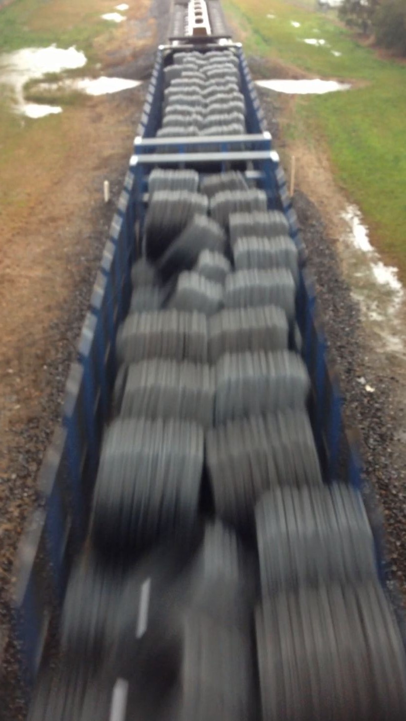
Evidence indicated an issue with rod-in-coil load shifting while the train was en route. Closed circuit television camera (CCTV) footage from Telarah, Maitland, Wallarobba, and Dungog stations was analysed. The footage, through Maitland particularly, shows evidence of load-shift on the wagon RCOF20375S. It was also evident that this was not an isolated instance, as video evidence of other trains travelling to Brisbane showed similar movement and collapsing of rod-in-coil product into the central void (in most cases to the left in the direction of travel). Given the tendency of rod-in-coil product to move (and possibly bounce), it is very likely that the load within wagon RCOF20375S had shifted during the journey from Morandoo, or possibly as train 2WB3 travelled through Nambucca Heads.
Figure 6: Rod-in-coil product on another train
Source: ARTC
Pacific National freight loading manual
An introduction to Pacific National’s freight loading manual stated ‘it is essential that the load is restrained to prevent any movement in any direction relative to the wagon’. While the manual also provided specific instructions on the positioning of rod-in-coil product when loaded on RCOF and RQRY wagons, there were no particular instructions or requirements to otherwise restrain the load and prevent it from shifting.
Following the incident, Pacific National reviewed the manual and published an update (FLM 05-13_08) dated 15 August 2014. The update added some detail as to how rod-in-coil must be loaded, but the requirements largely remained the same as the superseded version.
On 13-14 January 2015 an Office of National Rail Safety Regulator (ONRSR) audit noted that rod-in-coil product had been shifting en route – in a manner very similar to that shown in Figure 6. Accordingly, while it is almost certain that trains had been arriving in Brisbane with shifted rod-in-coil loads, there was no indication that the condition of arriving loads had been regularly reported back to Pacific National for consideration and corrective action.
During a subsequent inspection, the ONRSR observed that the wagons were loaded predominately from the left side with a fork lift. The loading did not generally conform to the freight loading manual, which required equal lateral spacing of coils on the bottom layer. This was most likely due to the loading method and lack of specific awareness of Pacific National requirements. Post-loading inspections did not detect the loading irregularity and were mainly focussing on out-of-gauge (uncontained) product or rolling stock running gear defects.
Uneven distribution of load on rail wagons can result in undesirable dynamic behaviour when traversing normal (within tolerance) track geometry. Consequently, it is essential that freight is restrained from shifting, to ensure that the load is not redistributed during its journey. In this case, it is likely that the shifted load significantly affected the lateral load distribution within the wagon, with this being enough to critically affect the vehicle handling dynamics around the curve where the derailment subsequently occurred.
Findings
From the evidence available, the following findings are made with respect to the derailment of train 3WB3 at Nambucca Heads, New South Wales, on 14 May 2014. These findings should not be read as apportioning blame or liability to any particular organisation or individual.
Safety issues, or system problems, are highlighted in bold to emphasise their importance. A safety issue is an event or condition that increases safety risk and (a) can reasonably be regarded as having the potential to adversely affect the safety of future operations, and (b) is a characteristic of an organisation or a system, rather than a characteristic of a specific individual, or characteristic of an operating environment at a specific point in time.
Contributing factors
The derailment of wagon RCOF20375S likely occurred due to imbalance effects stemming from uncontrolled shifting of the rod-in-coil load.
The relatively high track superelevation and twist at the point of derailment, in conjunction with some minor variations in track geometry leading up to the point of derailment, exacerbated the uneven loading and the dynamic behaviour of wagon RCOF20375S.
The Pacific National freight loading manual, and application of it, was ineffective at preventing load shift of rod-in-coil product. [Safety issue]
Safety issues and actions
The safety issues identified during this investigation are listed in the Findings and Safety issues and actions sections of this report. The Australian Transport Safety Bureau (ATSB) expects that all safety issues identified by the investigation should be addressed by the relevant organisation(s). In addressing those issues, the ATSB prefers to encourage relevant organisation(s) to proactively initiate safety action, rather than to issue formal safety recommendations or safety advisory notices.
All of the directly involved parties were provided with a draft report and invited to provide submissions. As part of that process, each organisation was asked to communicate what safety actions, if any, they had carried out or were planning to carry out in relation to each safety issue relevant to their organisation.
Where relevant, safety issues and actions will be updated on the ATSB website as information comes to hand. The initial public version of these safety issues and actions are in PDF on the ATSB website.
Loading rules and procedures
The Pacific National freight loading manual, and application of it, was ineffective at preventing load shift with rod-in-coil product.
The sources of information during the investigation included the:
Australian Rail Track Corporation Engineering (Track and Civil) Code of Practice, Section 5 – Track Geometry
Pacific National Freight Loading Manual
Submissions
Under Part 4, Division 2 (Investigation Reports), Section 26 of the Transport Safety Investigation Act 2003 (the Act), the Australian Transport Safety Bureau (ATSB) may provide a draft report, on a confidential basis, to any person whom the ATSB considers appropriate. Section 26 (1) (a) of the Act allows a person receiving a draft report to make submissions to the ATSB about the draft report.
A draft of this report was provided to Pacific National, the Office of National Rail Safety Regulation, and the Australian Rail Track Corporation.
Submissions were received from Pacific National, the Office of National Rail Safety Regulation, and the Australian Rail Track Corporation. The submissions were reviewed and where considered appropriate, the text of the report was amended accordingly.
Purpose of safety investigations
The objective of a safety investigation is to enhance transport safety. This is done through:
identifying safety issues and facilitating safety action to address those issues
providing information about occurrences and their associated safety factors to facilitate learning within the transport industry.
It is not a function of the ATSB to apportion blame or provide a means for determining liability. At the same time, an investigation report must include factual material of sufficient weight to support the analysis and findings. At all times the ATSB endeavours to balance the use of material that could imply adverse comment with the need to properly explain what happened, and why, in a fair and unbiased manner. The ATSB does not investigate for the purpose of taking administrative, regulatory or criminal action.
Terminology
An explanation of terminology used in ATSB investigation reports is available here. This includes terms such as occurrence, contributing factor, other factor that increased risk, and safety issue.
Publishing information
Released in accordance with section 25 of the Transport Safety Investigation Act 2003
Ownership of intellectual property rights in this publication
Unless otherwise noted, copyright (and any other intellectual property rights, if any) in this report publication is owned by the Commonwealth of Australia.
Creative Commons licence
With the exception of the Coat of Arms, ATSB logo, and photos and graphics in which a third party holds copyright, this publication is licensed under a Creative Commons Attribution 3.0 Australia licence.
Creative Commons Attribution 3.0 Australia Licence is a standard form licence agreement that allows you to copy, distribute, transmit and adapt this publication provided that you attribute the work.
The ATSB’s preference is that you attribute this publication (and any material sourced from it) using the following wording: Source: Australian Transport Safety Bureau
Copyright in material obtained from other agencies, private individuals or organisations, belongs to those agencies, individuals or organisations. Where you wish to use their material, you will need to contact them directly.
Preliminary report
Report release date: 12/09/2014
This preliminary report details factual information established in the investigation’s early evidence collection phase and has been prepared to provide timely information to the industry and public. Preliminary reports contain no analysis or findings, which will be detailed in the investigation’s final report. The information contained in this preliminary report is released in accordance with section 25 of the Transport Safety Investigation Act 2003.
The occurrence
At 1355[1] on 14 May 2014, freight train 3WB3 entered the Nambucca Heads crossing loop. The route was set for a through movement via the loop because of trackside work being performed adjacent to the main line.
At 1404:20, the trailing wheel set of the leading bogie on wagon RCOF20375S derailed to the right-hand-side in the direction of travel while the train was travelling through the crossing loop at a speed of 21 km/h. The derailed wagon was located fourth from last in the 44 wagon consist.
The train continued to travel with a derailed wagon for about 1,397 m. It passed over two bridges and reached a speed of 44 km/h before wagon RCOF20375S tipped on its side (Figure 1). The train then parted between the fourth and fifth last wagons. As the wagons parted, the train brake pipe separated, allowing air to vent to atmosphere and the train brakes to apply, bringing the train to a stop in about 320 m.
The train crew notified the network controller and arrangements were made to begin investigative and restoration work. The main line was subsequently reopened at 1816 on 16 May. The crossing loop line remained closed until further repairs could be conducted.
Figure 1: Derailed wagon RCOF20375S
Source: ATSB
Context
The location
Nambucca Heads is located on the main north rail corridor between Sydney and Brisbane, about 565 track kilometres from Sydney Central Station. Nambucca Heads is a crossing location with a 1,615 m crossing loop.
Track information
The ARTC manages the railway corridor where the derailment occurred. Authorised movement of rail traffic is controlled from the ARTC’s Network Control Centre located at Broadmeadow, New South Wales.
The standard gauge[2] track at the derailment location consisted of 53 kg/m rail fastened by resilient clips to timber sleepers, spaced at about 667 mm centres. The sleepers were supported on a bed of ballast to a nominal design depth of 250 mm.
Approaching from the southern end, the track through the derailment site consisted of a series of curves between 480 m and 360 m radii on reasonably level track. The posted maximum track speed was 75 km/h although this speed would rarely be reached, due to the restriction of speed through the points.
On-site examination and preliminary analysis of track condition found no indication of any serious anomalies in the track geometry leading up to the point of derailment in the crossing loop.
Train information
Train 3WB3 was a steel products freight service operated by Pacific National between Wollongong and Brisbane. At the time of the derailment, the train consisted of two locomotives (NR94 leading and AN9 trailing) hauling 44 freight wagons. It was 817 m in length and had a trailing mass of 3,363 t.
The train was operated by two qualified drivers. They had both been assessed as fit for duty in accordance with the requirements of the National Standard for Health Assessment of Rail Safety Workers.
RCOF wagons are 15.1 m long and capable of carrying up to 80 gross tonnes at speeds of up to 80 km/h (depending on track speed limits). On the day of the derailment, wagon RCOF20375S (the wagon which derailed) was carrying 40 coils of rod, each weighing on average 1.5 t. The coils were arranged, two wide by two high, in each of the 10 bays (Figure 2). The coils were contained within the wagon, but they were not individually restrained.
On-site inspection and preliminary examination of the derailed wagons found no indication of any serious anomalies in rolling stock condition. Similarly, preliminary analysis of train data indicated that there were no anomalies in the train speed, train handling or operational performance leading up to the derailment.
However, evidence of load shifting had been observed in wagons not affected by the derailment, but carrying the same rod-in-coil product.
The ATSB’s investigation is continuing and will focus on:
the integrity of the rolling stock involved
the possibility of load shifting en route
the policies and procedures relating the securing of loads
the integrity of the track structure
Purpose of safety investigations
The objective of a safety investigation is to enhance transport safety. This is done through:
identifying safety issues and facilitating safety action to address those issues
providing information about occurrences and their associated safety factors to facilitate learning within the transport industry.
It is not a function of the ATSB to apportion blame or provide a means for determining liability. At the same time, an investigation report must include factual material of sufficient weight to support the analysis and findings. At all times the ATSB endeavours to balance the use of material that could imply adverse comment with the need to properly explain what happened, and why, in a fair and unbiased manner. The ATSB does not investigate for the purpose of taking administrative, regulatory or criminal action.
Terminology
An explanation of terminology used in ATSB investigation reports is available here. This includes terms such as occurrence, contributing factor, other factor that increased risk, and safety issue.
Publishing information
Released in accordance with section 25 of the Transport Safety Investigation Act 2003
Ownership of intellectual property rights in this publication
Unless otherwise noted, copyright (and any other intellectual property rights, if any) in this report publication is owned by the Commonwealth of Australia.
Creative Commons licence
With the exception of the Coat of Arms, ATSB logo, and photos and graphics in which a third party holds copyright, this publication is licensed under a Creative Commons Attribution 3.0 Australia licence.
Creative Commons Attribution 3.0 Australia Licence is a standard form licence agreement that allows you to copy, distribute, transmit and adapt this publication provided that you attribute the work.
The ATSB’s preference is that you attribute this publication (and any material sourced from it) using the following wording: Source: Australian Transport Safety Bureau
Copyright in material obtained from other agencies, private individuals or organisations, belongs to those agencies, individuals or organisations. Where you wish to use their material, you will need to contact them directly.
[1] The 24 hour clock is used in this report. Local time was Australian Eastern Standard Time (EST).