On the morning of 29 January 2016, a Piper Aircraft Corp PA-28 aircraft, registered VH-PXD, was on a private flight from Moorabbin Airport, Victoria to King Island, Tasmania. After passing over Point Lonsdale, the aircraft entered an area of low visibility. The pilot conducted a 180° turn and initially tracked back towards Point Lonsdale, before heading south over the ocean. After about 2 minutes, the aircraft was again turned right before entering a rapid descent. The aircraft impacted the water at 1227 Eastern Daylight-saving time, 6.6 km south-west of Point Lonsdale. All four occupants of the aircraft were fatally injured.
What the ATSB found
The ATSB found that continuation of the flight beyond Point Lonsdale, and towards an area of low visibility conditions, was likely influenced by the inherent challenges of assessing those conditions.
The ATSB also found that due to the presence of low cloud and rain, the pilot probably experienced a loss of visual cues and became spatially disorientated, leading to a loss of control and impact with the water. The risk of a loss of control in the conditions was increased by the pilot’s lack of instrument flying proficiency.
Safety message
Pre-flight planning needs to include consideration of not only the conditions on departure, but at all stages of the flight. This informs the decision of whether to depart and allows for prior consideration of alternative actions in the case of deteriorating weather, such as returning or diverting.
It is always possible that the actual weather conditions will be different to those forecast. Pilots conducting a flight under the visual flight rules make every effort to avoid areas of low visibility and plan for unforeseen eventualities. However, this is dependent on the pilot perceiving the risks of the situation, which is not inherently easy. Education and training in the practical application of meteorological principles has been shown to enhance pilots’ ability to recognise and respond to deteriorating weather conditions.
The ATSB cautions that, on entering an area of reduced visual cues, the risk of experiencing spatial disorientation and a loss of control is high, measuring from between 60 to 178 seconds from the time of entering the area of low visibility. This risk is highest for those without proficiency or recent experience in instrument flying. Requesting assistance from air traffic control can increase the chances of re-establishing visual cues.
The occurrence
On the morning of 29 January 2016, a Piper Aircraft Corp. PA-28 aircraft, registered VH-PXD (PXD), was on a private flight under the visual flight rules (VFR)[1] from Moorabbin Airport, Victoria to King Island, Tasmania with four occupants on board. The ATSB was unable, given the physical evidence and available flight documentation, to establish which occupant was the pilot in command of the flight.
Several members of the Royal Victorian Aero Club (RVAC) were planning to fly to King Island throughout the weekend, although there was no coordination between the members.
Two of the occupants of PXD arrived at Moorabbin Airport by about 0800 Eastern Daylight‑saving Time[2] that day and ascertained that the weather in the vicinity of the airport was not yet suitable for departure. However, other pilots reported advising the occupants of PXD that the weather at King Island was good. It was also reported that one of the occupants formed the understanding that the weather was slowly moving east and that it was clearing to the west. At around 1000, the early arrivals contacted the other occupants of PXD. It was reported that the decision to go was made during that exchange. By 1100, all four occupants were at the airport and preparing for the flight.
At some stage during the morning, one of the occupants logged into their National Aeronautical Information Processing System account[3] and accessed a number of weather and aerodrome forecasts, weather observations and notices to airmen (NOTAM)[4] for the day. This same occupant also called the local Bureau of Meteorology phone number. Two of the occupants also made phone calls to the recorded Aerodrome Weather Information Services[5] for King Island (the evening before) and Moorabbin (that morning). Those products and services were broadly consistent with the intended route.
Recorded radio calls indicated that, as PXD was being prepared to depart, a number of other aircraft requested clearance for their arrivals/departures at Moorabbin under special VFR (refer to the section titled Additional information – Visual flight rules and visual meteorological conditions). This was due to a reported cloud base of 800 ft. The requests for special VFR were made by a pilot departing at 1138 and a pilot arriving into Moorabbin at 1213.
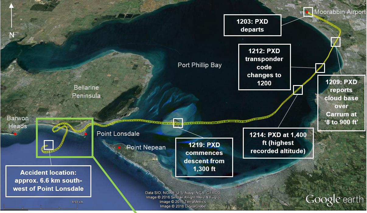
At 1144:32, a transmission was made by the pilot of PXD on the Moorabbin Ground frequency that the aircraft was positioned in the engine run-up bay and that they were ready for departure for King Island. At 1157:55, the pilot of PXD advised the Moorabbin Tower controller that they were at the holding point for runway 13L and ready for take-off. This call did not include a request for special VFR and ATC did not prompt the request. Three minutes later they received clearance for take-off before departing Moorabbin at 1203. The aircraft’s track to Point Lonsdale and a number of pilot actions and other observations are at Figure 1.
Around the same time, one of the RVAC aircraft flying to King Island was nearing Point Lonsdale. The pilot of that aircraft later reported having seen what appeared to be a storm cell over Point Lonsdale and the heads. The likelihood of reduced visibility in the area was reported to have prompted the pilot to return to Moorabbin Airport. The pilot of the RVAC aircraft landed back in Moorabbin at 1220 with a special VFR clearance. This was after PXD’s departure.
A transmission was made by the pilot of PXD on the Moorabbin Tower frequency at 1209. In this transmission, the pilot reported that the cloud base over Carrum was about 800–900 ft. No further radio contact with PXD was recorded. At 1212 the aircraft’s transponder code was switched to ‘1200’ per normal airspace procedures.[6]
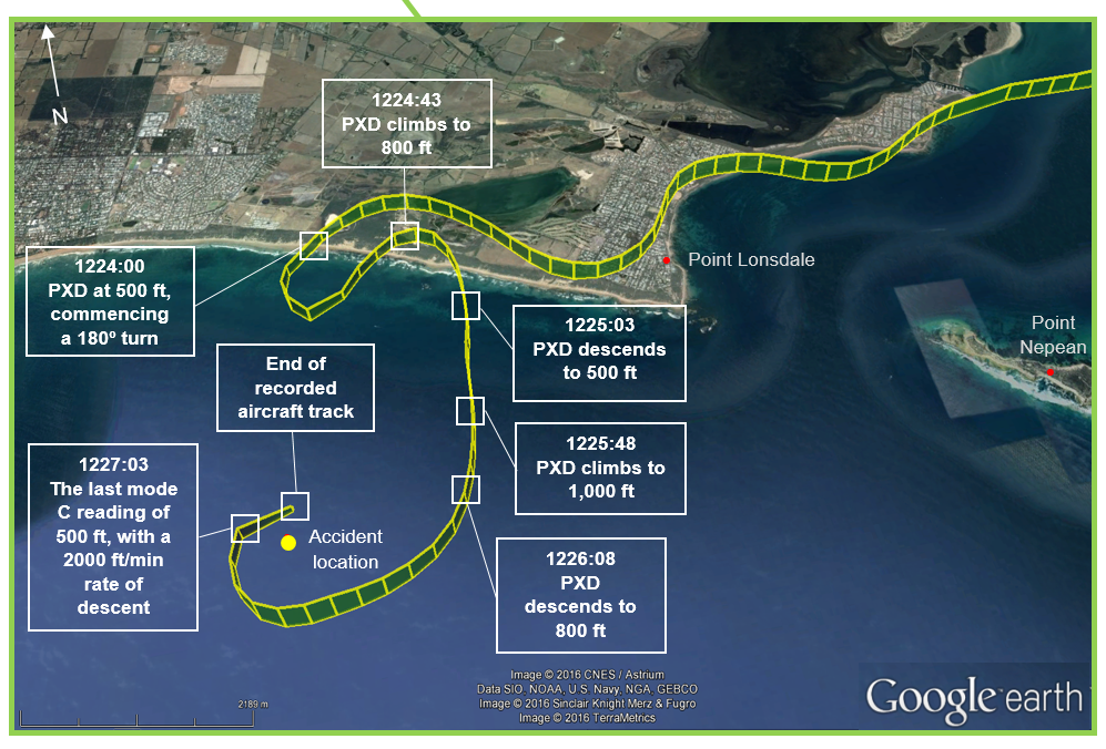
At about 1222, after passing over Point Lonsdale, the pilot conducted a series of left and right turns, followed by a 180° turn to initially track back towards Point Lonsdale. This was followed by a gentle right turn heading south over the ocean for about 2 minutes, before again turning right and entering a rapid descent. At about 1227, PXD impacted the water 6.6 km south-west of Point Lonsdale. All of the aircraft occupants were fatally injured.
Witnesses who were fishing in the vicinity of Point Lonsdale at the time reported hearing an aircraft pass nearby at what they interpreted to be a ‘very low altitude’. Due to the low cloud and visibility in the area they could not initially see the aircraft. The witnesses recalled that, a few minutes later, they saw the aircraft just before it impacted the water. It appeared to be in a nose‑down, right wing-low attitude and the engine sounded as though it was producing power.
Another two aircraft that were also from the RVAC departed Moorabbin for King Island at 1230 and 1250 respectively. Whilst communicating with each other on the RVAC frequency, they discussed the area of low visibility around Point Lonsdale. Both pilots reported descending in the vicinity of Point Lonsdale in an effort to maintain better visibility, particularly over Barwon Heads. One pilot took several photographs whilst flying over the area that show the weather conditions. Showers were reported passing through this area, reducing the cloud base. The two aircraft continued on to King Island.
Figure 1: PXD’s track from Moorabbin Airport until the collision with water near Point Lonsdale with the area between Point Lonsdale and the impact with the water at inset. Noteworthy pilot actions and other observations are annotated.
Of the four occupants on board PXD, three were pilots. Of these, two held the necessary qualifications and a current medical to be able to conduct the flight. None of the pilots had ever held an instrument rating. However, there was insufficient evidence to definitively identify the pilot in command for this flight.
Fatigue
An assessment was undertaken of whether any of the aircraft occupants may have been experiencing a level of fatigue known to have an effect on performance. This included consideration of their possible time awake at the time of the occurrence, sleep history and potential workload associated with the task and environmental factors. However, the limited data available on the occupants’ activities in the preceding days meant there was insufficient evidence to determine whether fatigue was contributory to this occurrence.
Aircraft information
General
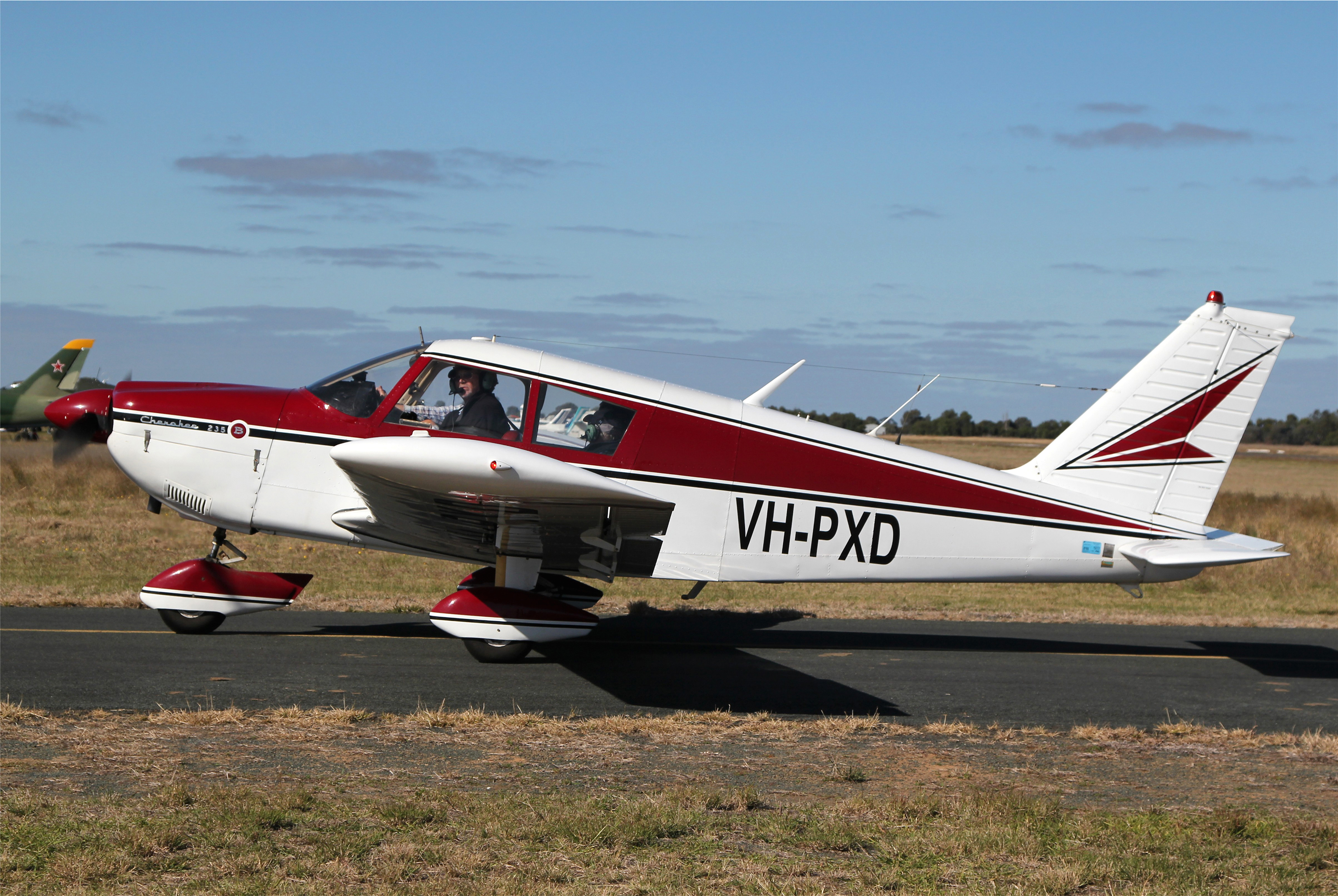
VH-PXD (PXD) was a Piper Aircraft Corp. PA-28 four seat, low wing, all metal, unpressurised, fixed undercarriage aircraft with a single reciprocating engine (Figure 2). It had current certificates of airworthiness and registration and a current maintenance release, with no noted defects.
The last periodic maintenance inspection on PXD was conducted in Bacchus Marsh on the day before the occurrence. During that inspection, the right-upper wing skin was replaced, the artificial horizon was repaired and all of the aircraft’s control cables were replaced. The maintenance was completed by an appropriately-qualified Licensed Aircraft Maintenance Engineer in an approved maintenance facility.
The 25-minute return flight to Moorabbin after the maintenance at Bacchus Marsh was completed with no reported issues.
Figure 2: VH-PXD, taken in April 2011 in Echuca, New South Wales
The ATSB was unable to determine the actual weights and seating positions of the occupants and amount of baggage on board at the time of the occurrence. Therefore, the actual weight of the aircraft and its centre of gravity was unable to be calculated.
It was reported that the aircraft was refuelled to full tanks prior to departing Moorabbin Airport that day. The weight of the aircraft on departure from Moorabbin Airport was estimated based on:
the recorded aircraft weight
the weight of the fuel
data from the Civil Aviation Safety Authority (CASA) medical examinations for three of the aircraft occupants[7]
a statistical average for the fourth occupant.
That estimate would have meant PXD was about 35 kg under the maximum permissible take-off weight for the flight. However, that weight did not account for the unknown amount of baggage on board. It was therefore concluded likely that the aircraft was close to its maximum take-off weight when it departed from Moorabbin Airport.
Meteorological information
Forecast weather
On the day of the occurrence, there was a complex weather pattern over south-eastern Australia. That weather pattern included a number of low pressure systems, along with upper atmosphere and surface troughs. This was forecast to result in significant areas of low cloud, showers and areas of rain.
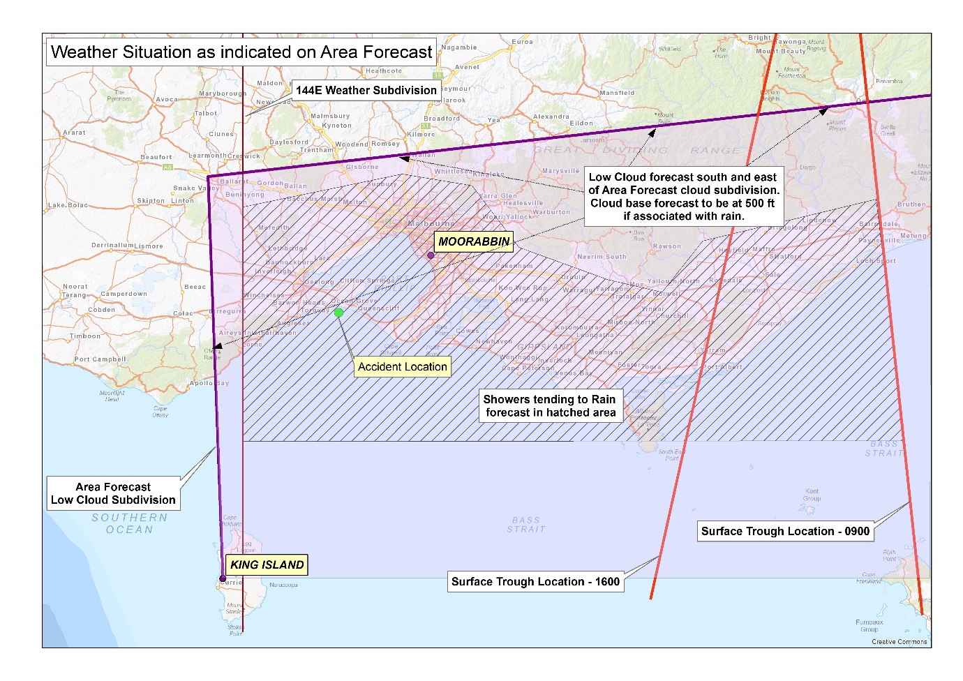
An area forecast (ARFOR)[8] covering the proposed route indicated a surface trough to the east of Melbourne that was forecast to slowly move to the west during the day. There were isolated thunderstorms forecast over the sea, coast and adjacent ranges to the east of Melbourne. Showers of rain, with associated broken[9] low cloud with a minimum base of 500 ft were forecast in an area starting west of Melbourne and extending to the east. Additionally, there was forecast low cloud south-east of a line extending from King Island, north to Ballarat and then east to Bombala. A pictorial representation of these areas is shown at Figure 3.
Figure 3: Pictorial representation of the Area 30/32 forecast valid from 0900 on 29 January 2016
Source: ATSB
The aerodrome forecast (TAF)[10] for Moorabbin Airport that was issued at 1003 indicated that the wind would be from the south-east at 8 kt and that the visibility would generally be greater than 10 km. Light rain was forecast with a scattered cloud base at 1,200 ft above the aerodrome and a broken layer at 3,500 ft. The forecast noted that there would also be periods of up to 60 minutes duration, starting from 1100, where the visibility would decrease to 4,000 m in rain and the cloud base would lower to 1,000 ft and the amount of cloud increase to broken.
A TAF for Avalon Airport indicated that the wind would be variable in direction at 5 kt and that the visibility would generally be greater than 10 km. Light showers of rain were forecast and the cloud was forecast to be scattered with a base 1,000 ft above the aerodrome and a broken layer at 3,500 ft. The forecast indicated that, from 0800, there would be periods of 30 minutes duration where the visibility would decrease to 5,000 m in showers of rain, and the cloud base would be scattered at 1,500 ft.
Actual weather conditions
Weather reports (captured by automatic sensors) for Moorabbin between 1100 and 1200 indicated a scattered layer of cloud with a base between 800 and 1,200 ft above the aerodrome elevation and a visibility of 10 km or more. A special report (SPECI)[11] issued at 1209 indicated that the cloud base was broken at 1,200 ft. None of the weather reports suggested that decreased visibility might have affected PXD’s departure.
A weather report issued at 1130 for Avalon indicated the visibility had reduced to 9,000 m in drizzle with cloud overcast at 2,700 ft. A SPECI at 1133 reported a further decrease in visibility to 6,000 m with cloud unchanged. The 1200 SPECI for Avalon indicated scattered cloud but with a lower base of 1,100 ft, and that the visibility had increased to in excess of 10 km.
Weather radar images from the Melbourne (Laverton) radar recorded the following:
At 1218, significant rainfall returns, from light to moderately heavy rain to the east of Melbourne, extending from the ranges to Bass Strait. There were also rainfall returns to the south-west of the radar location over land, the coastline and extending out to sea in the area of Barwon Heads. These indicated light rainfall, with the heaviest returns over the sea to the east of Anglesea.
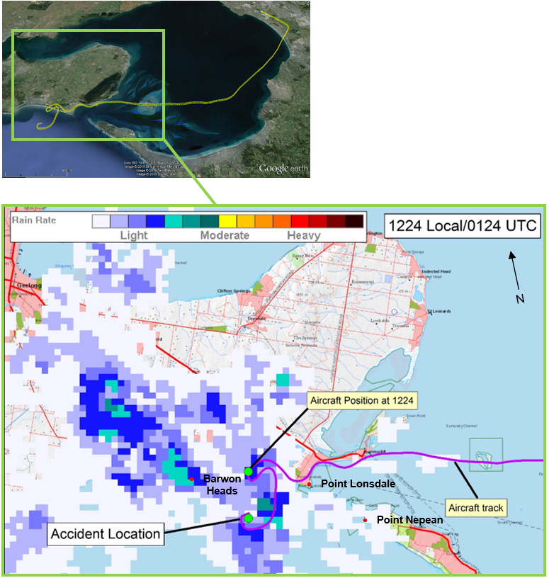
At 1224, that the rainfall returns to the south-west had increased in area and intensity. The returns were generally orientated along a line in a north‑westerly to south‑easterly direction. That line covered an area estimated from 5 km inland to a point estimated to be 20 km out to sea. A portion of this image is shown in Figure 4, with the aircraft’s track superimposed.
At 1307, that the area of rain enlarged, extending from Torquay to Anglesea and out to sea.
The weather radar information from 1224, when overlayed with the aircraft track, indicated that the aircraft likely entered an area of low visibility associated with light‑to‑moderate rain at about 1223.
Moorabbin Automatic Terminal Information Service
Relevant aspects of the Moorabbin Automatic Terminal Information Service (ATIS) reports of the actual conditions and requirements at around the time of the flight by PXD are listed in Table 1.[12] When operating at a controlled aerodrome where an ATIS is in operation, pilots are required to listen to the facility prior to taxi and advise air traffic control of receipt of that information. This advice is part of the pilot’s taxi call.
Table 1: Actual weather conditions and requirements as reported in successive ATIS reports at around the time of the flight by PXD
Condition/requirement
ATIS and time issued
‘Papa’ of 1137
‘Quebec’ of 1152
‘Romeo’ of 1215
Approach type
Expect instrument approach
Expect instrument approach
Expect instrument approach
Visibility
Reduced to 6 km
Reduced to 6 km
Greater than 10 km
Weather
Showers in the area
Showers in the area
Nil reported
Cloud
Broken at 600 ft
Scattered at 800 ft and broken at 1,500 ft
Scattered at 800 ft and broken at 1,500 ft
The pilot of PXD made their taxi call at 1144:32. Although ATIS is a passive facility, there was no indication in the recorded radio calls that the pilot of PXD accessed ATIS information ‘Papa’.
Figure 4: Weather radar recording (orientated with reference to a Google earth map at inset) and associated ‘Rain rate’ at 1224, showing the aircraft’s track
Source: At inset, Google earth, modified by the ATSB and larger image Geoscience Australia (base map) and the Bureau of Meteorology (weather radar), both modified by the ATSB
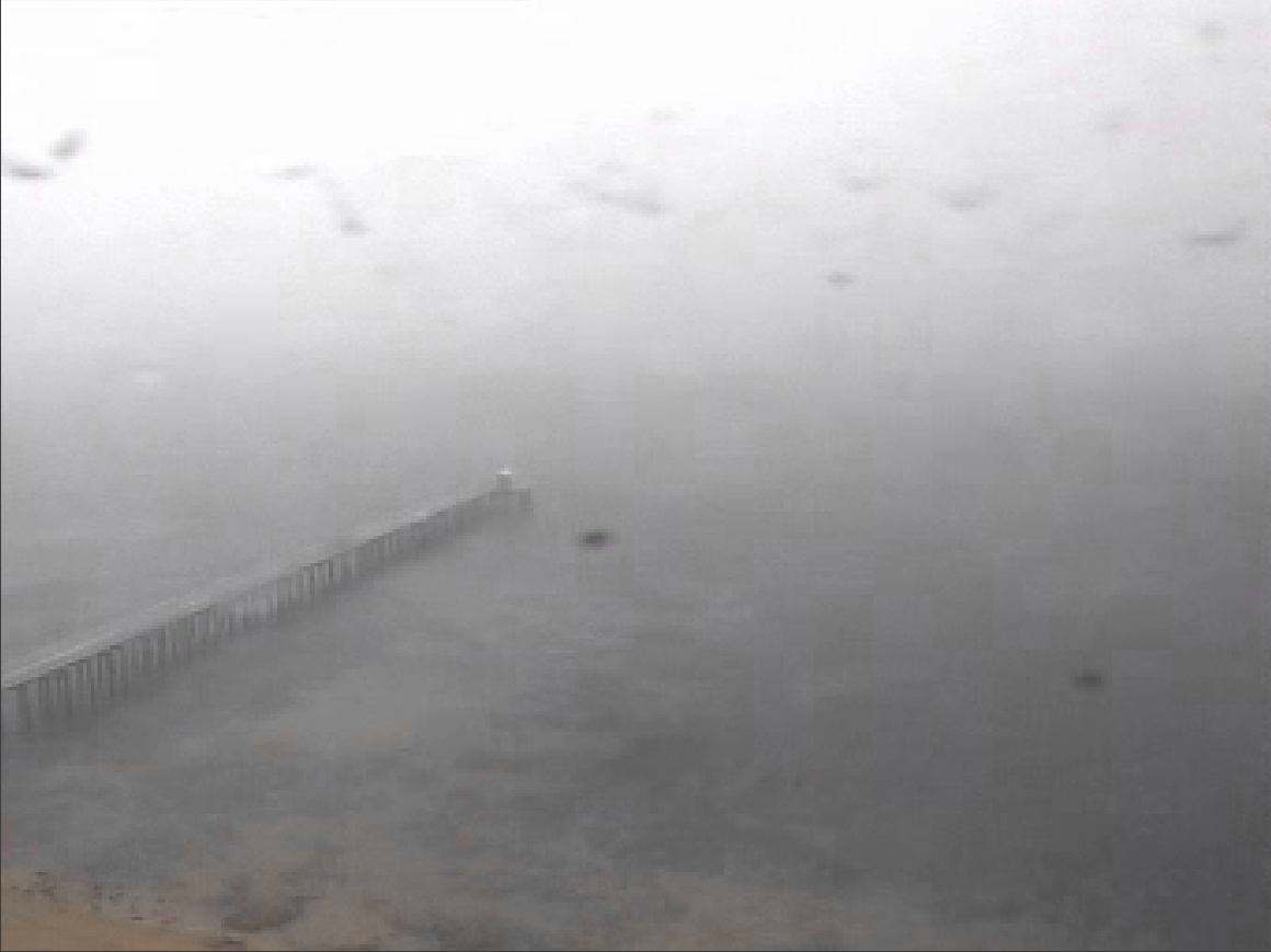
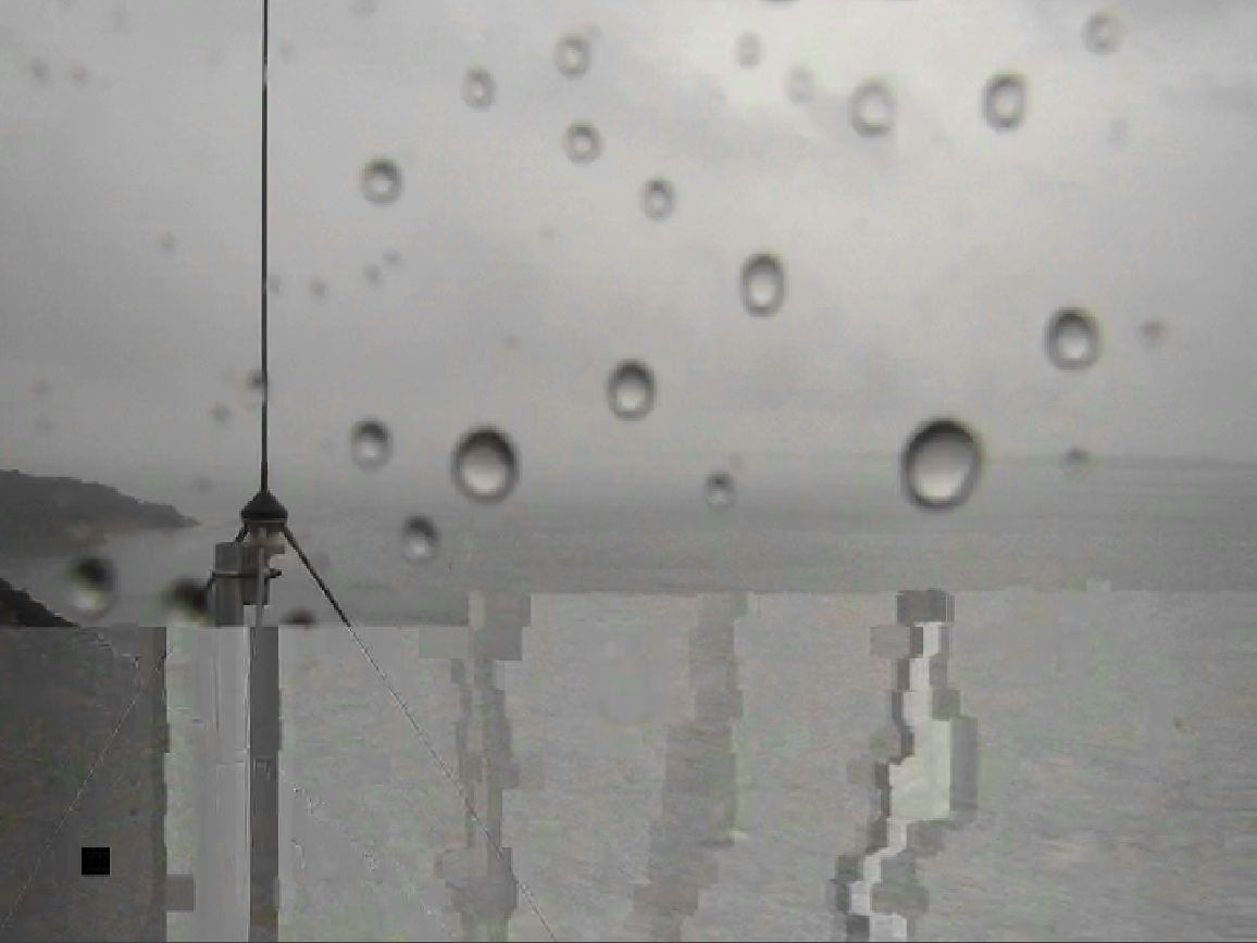
Closed-circuit television images from Port of Melbourne cameras facing east across the water from Point Lonsdale, and north from Point Nepean both showed drizzle, light rain and reduced visibility including little natural horizon as PXD tracked south along the eastern shore of Port Phillip Bay (Figure 5).
Witnesses that saw the aircraft recalled that the visibility at that time was very low, such that it prevented them seeing the land. The witnesses estimated that the land was between 1 and 4 km away and indicated that it was raining at the time.
Figure 5: Still images taken at 1215 from two different closed-circuit television cameras owned by the Port of Melbourne. One camera (left image) was positioned on the Point Lonsdale lighthouse facing east. The other camera (right image) was positioned at Point Nepean, facing north. The image quality is affected by contaminants on the camera lens, but the extent of the low visibility conditions in the area is evident
Source: Port of Melbourne, modified by the ATSB
Recorded data
Recorded flight data was obtained from an ‘electronic flight bag’ iPad™ application that the occupants were using on the flight. This data was used to assist in the wreckage recovery and in the analysis of the aircraft track.
Flight track information was also obtained from air traffic control (ATC) radar information. This included recorded radar returns from the aircraft from its departure from Moorabbin Airport to the time of the occurrence.
Witnesses that saw the occurrence also provided the ATSB with their ‘fish finder’ Global Positioning System device. Data was downloaded from this device and assisted with locating the wreckage.
Wreckage and impact information
The aircraft impacted the water after a rapid descent, with parts of the wreckage descending to the sea floor. Evidence from the wreckage was consistent with the aircraft impacting the water in a nose-down attitude, with the engine delivering power.
Recovery of the wreckage
A search for the wreckage was commenced by the Victoria Water Police and Air Wing within an hour of the accident. Small items of wreckage had surfaced, or remained on the surface and were recovered by the water police and nearby witnesses. These included items such as a number of the occupants’ personal effects and the three pilots’ CASA flight crew licences and aviation medical certificates.
After several day’s search using surface sonar and underwater robotic equipment, on 2 February 2016 Victoria Police located a large portion of the aircraft wreckage on the ocean floor at a depth of 34 m. The wreckage was about 1 km from shore, off the Point Lonsdale lighthouse.
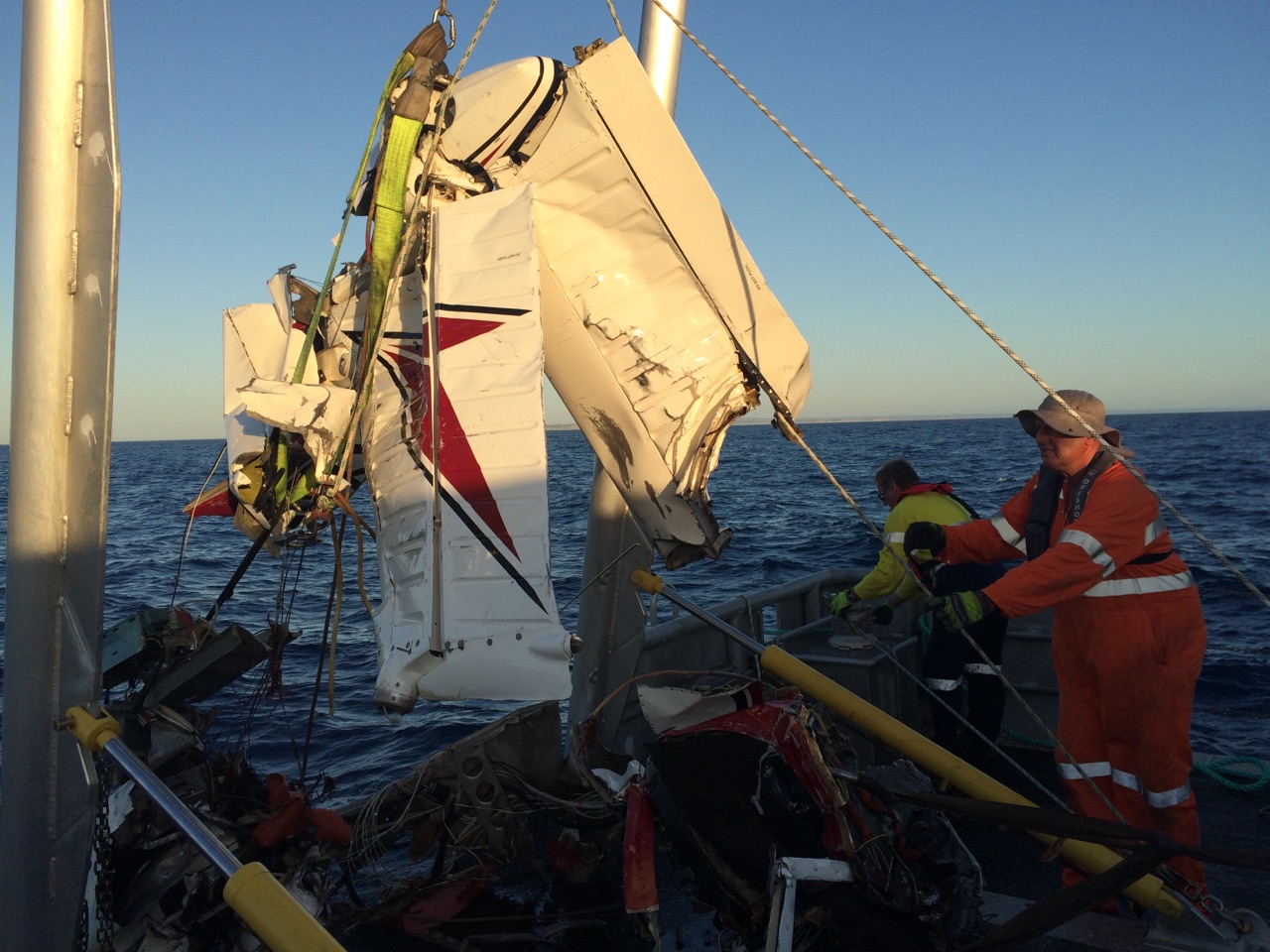
On the evening of 6 February 2016, the wreckage was recovered to the surface by police divers, supported by a barge and lifting equipment (Figure 6). On 7 February, the ATSB assisted with the removal and transportation of the wreckage to a secure site for inspection.
Figure 6: Recovery by Victoria Police of the aircraft’s fin and left horizontal stabiliser
Source: Victoria Police
Wreckage inspection
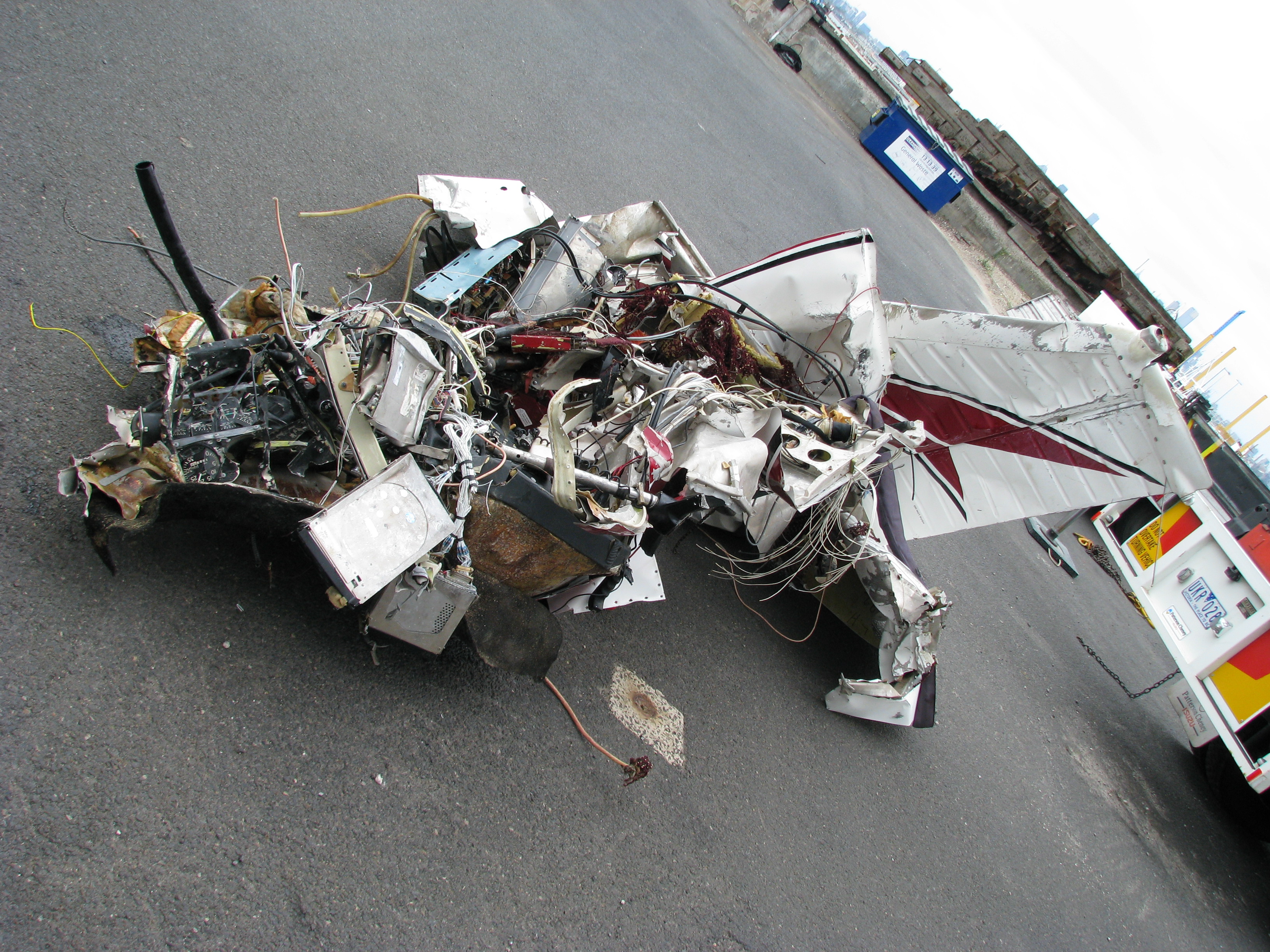
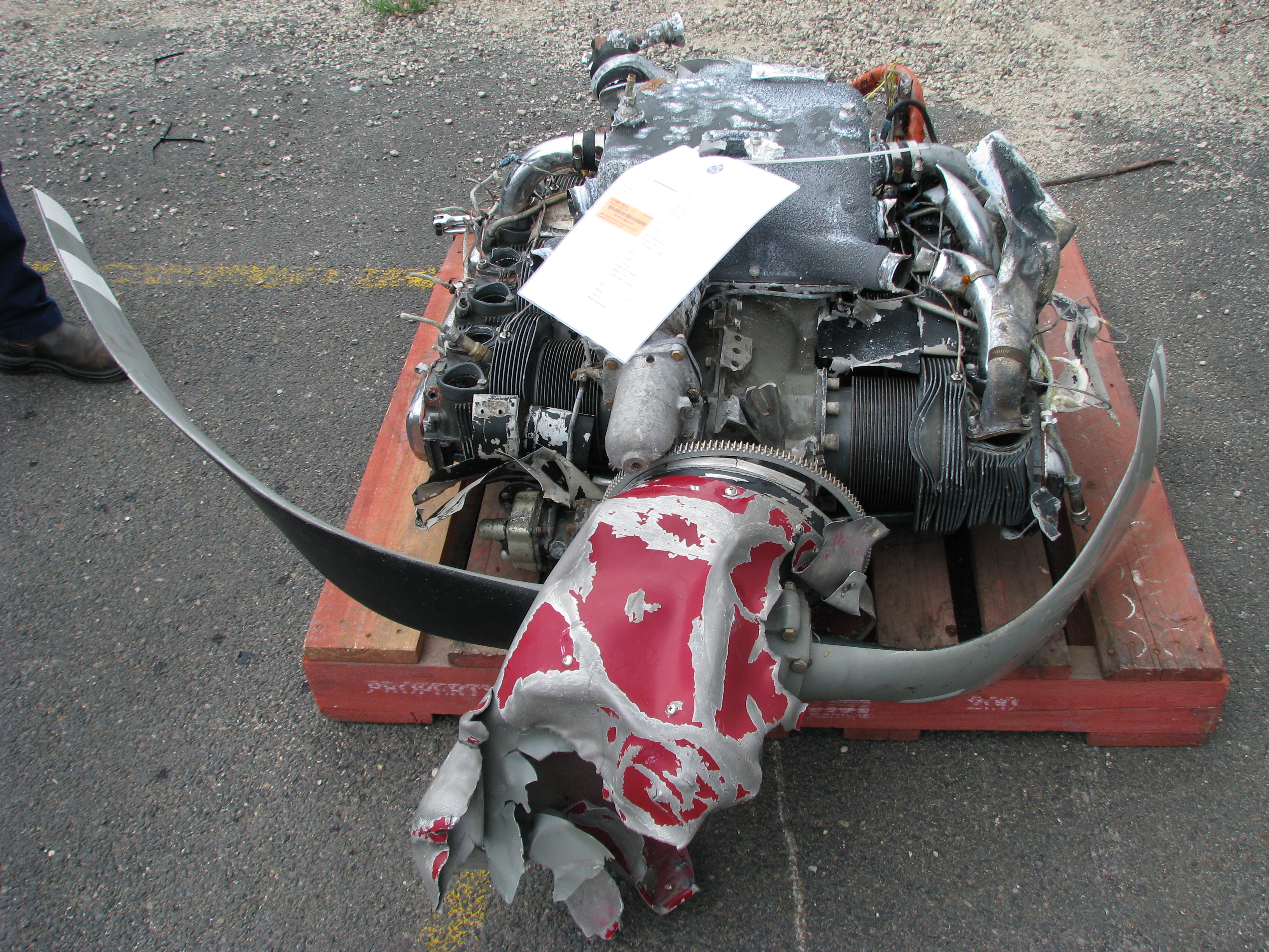
The majority of the aircraft’s fuselage, fin, horizontal stabiliser, engine and propeller, flight control cables, main landing gear assembly, instrument panel and some items from the cabin interior were recovered. Figures 7 and 8 show some of the airframe and other items and components that were recovered.
All identified fracture surfaces throughout the recovered wreckage were consistent with overload failure as a result of the impact with water. There was no evidence of pre-existing damage to the airframe, or failure of the primary control systems that may have contributed to the accident. However, the aircraft wreckage exhibited severe disruption.
Some components, such as the engine carburettor, right horizontal stabiliser assembly and left and right-wing structures were not recovered.
Figure 7: Some of the recovered aircraft wreckage. Note the extent of the disruption of the airframe
Source: ATSB
A detailed inspection of the engine and propeller was conducted in a CASA-approved maintenance facility. Nothing was identified during that inspection that may have contributed to the accident, or would have prevented the engine and propeller from normal operation.
Figure 8: Recovered aircraft engine, propeller and propeller spinner, looking at the lower surface of the engine
Source: ATSB
Medical and pathological information
Post-mortem and toxicological examination of all of the aircraft occupants found no underlying medical disorder likely to lead to incapacitation. All occupants on board PXD sustained multiple fatal injuries consistent with the aircraft impacting water.
Survival aspects
Due to the extent of the impact forces and aircraft break-up, the occurrence was not survivable. While the occupants of PXD were seen by witnesses to acquire life jackets prior to their departure from Moorabbin Airport, these were not found in the recovered wreckage.
Additional information
Visual Flight Rules and Visual Meteorological Conditions
The CASA Visual Flight Rules Guide outlined that flight under the visual flight rules (VFR) can only be conducted in Visual Meteorological Conditions (VMC).[13] This was provided that, when operating at or below 2,000 ft above the ground or water, the pilot is able to navigate by visual reference to the ground or water.
Moorabbin Airport was surrounded by Class D (controlled) airspace out to 3 NM (6 km) and below 2,500 ft above mean sea level. The visual meteorological conditions for class D airspace included:
a flight visibility of 5,000 m
a minimum horizontal distance from cloud of 600 m and height vertically above cloud of 1,000 ft or vertically below cloud of 500 ft.
When requested by a pilot, ATC could permit operations by day in Class D airspace under special VFR when the weather conditions did not meet the above VMC criteria. Operations under special VFR required pilots to:
remain clear of cloud
in the case of aeroplanes, ensure an in-flight visibility of 1,600 m
operate within the requirements of Civil Aviation Regulation 157 Low flying.
After departing class D airspace, the aircraft entered (uncontrolled) Class G airspace. The following conditions were stipulated for flight under the VFR in this airspace when below 10,000 ft:
a flight visibility of 5,000 m
a minimum vertical distance of 1,000 ft and horizontal distance of 1,500 m from cloud.
In addition, in the case of aeroplane operations in Class G at or below 3,000 ft above mean sea level or 1,000 ft above ground level (whichever is higher), the following minimum conditions were stipulated:
a flight visibility of 5,000 m
that the aeroplane shall be maintained clear of cloud and in sight of the ground or water
that a radio must be carried and used by the pilot on the correct frequency.
In this case, the area and aerodrome forecasts for Avalon and the surrounding area indicated that visibility was reduced to 5,000 m and a scattered cloud base of 1,500 ft around Avalon. In addition, there was an overall reduced visibility in the region.
Visual flight into Instrument Meteorological Conditions
The safety risks of VFR pilots flying from VMC conditions into instrument meteorological conditions (IMC)[14] are well documented. This has been the focus of numerous ATSB reports and publications, as VFR pilots flying into IMC represents a significant cause of aircraft accidents and fatalities. In 2013 the ATSB Avoidable Accidents series was re-published. Of these publications, the booklet titled Accidents involving pilots in Instrument Meteorological Conditions outlined that:
In the 5 years 2006–2010, there were 72 occurrences of visual flight rules (VFR) pilots flying in instrument meteorological conditions (IMC) reported to the ATSB…About one in ten VFR into IMC events result in a fatal outcome.
Additionally, a study conducted by the United States National Transportation Safety Board (2005) found that ‘about two-thirds of all general aviation accidents that occur in instrument meteorological conditions (IMC) are fatal’.
Wiggins and O’Hare (1995) explained that when pilots are not trained or qualified to fly in IMC and find themselves in these conditions, ‘the result will almost inevitably involve loss of control of the aircraft resulting in a fatal crash’.
Loss of visual cues and spatial disorientation in low visibility conditions
Gibb and others (2010) explain that seeing the horizon is ‘crucial for orientation of the pilot’s sense of pitch and bank of the aircraft.’ In conditions of low visibility, the horizon may not be visible to the pilot, during which time they can become rapidly disorientated. Newman (2007) found that ‘the major environmental factors [that contribute to spatial disorientation] are related to time of day and the ambient weather conditions. Poor visual cues are a function of most disorientation illusions, so flight at night or in conditions of bad weather can set a pilot up for a disorientation experience’.
In a discussion of spatial disorientation, Benson (1999) defined the experience as follows:
Spatial disorientation is…[where] the pilot fails to sense correctly the position, motion or attitude of the aircraft or of him/herself [resulting in] errors in perception by the pilot of their position, motion or attitude with respect to their aircraft...
Newman (2007) summarised the primary reason for spatial disorientation as follows:
The visual system is by far the most important of the three systems, providing some 80 per cent of the raw orientation information. In conditions where visual cues are poor or absent, such as in poor weather or at night, up to 80 per cent of the normal orientation information is missing. The remaining 20 per cent is split equally between the vestibular system and the proprioceptive system, both of which are prone to illusions and misinterpretation. In poor or absent visual cue situations, humans are forced to rely on the remaining 20 per cent of orientation information, which is less accurate…In the aviation setting, such a situation can then result in any number of well-described SD [spatial disorientation] illusions being experienced by the pilot…The majority of disorientation events are associated with poor visual cues (as in IMC or night flight).
Extensive research on spatial disorientation indicates that loss of control will likely occur between 60 seconds (Benson, 1983 in Gibb and others, 2010) and 178 seconds (Newman, 2007) after the loss of visual reference. This is the case even when the aircraft is in straight and level flight at the time vision is lost, and is shorter still if the aircraft is in a turn. Gibb and others (2010) state that ‘spatial disorientation accidents have fatality rates of 90–91 percent, which indicates how compelling the misperceptions can be’.
Pilot instrument flying proficiency
When there are no external visual cues, the ability to fly on instruments is essential. Research from the United States has shown that pilots without instrument ratings are five times more likely to have accidents in degraded visual conditions than pilots with instrument ratings (Groff and Price, 2006). The National Transportation Safety Board also noted that ‘Tests and experience have shown that non-instrument-trained pilots or non-proficient pilots are rarely successful in overcoming spatial disorientation’ (NTSB, 1988).
Gibb and others (2010) add that ‘a visual-only general aviation pilot encountering weather or night conditions is severely at risk because of [their] total inexperience, education, and training in using instruments.’ Simulator experiments at the University of Illinois determined that on average, a pilot with no instrument training can expect to retain control of their aircraft for 178 seconds after entering bad weather and losing visual contact (ATSB, 2011).
Although instrument flying proficiency is a very important defence against spatial disorientation, many studies have shown overall flying experience has little, if any, influence on spatial disorientation accident rates (Gawron, 2004). Newman (2007) noted that spatial disorientation can affect ‘any pilot, any time, any where, in any aircraft, on any flight, depending on the prevailing circumstances’.
Related occurrences
The previously-discussed ATSB research reports and educational material were based on occurrences up until 2013 (see the section titled Visual flight into Instrument Meteorological Conditions). In the period 2014 through to October 2016 there were 28 reported occurrences (not including this accident). Six of these included a decision by the pilot to divert or return to the departure airport, and another eight pilots sought assistance from ATC.
In addition, a number of recent ATSB investigations examined VFR into IMC occurrences. Of these, three are summarised below and are available at www.atsb.gov.au.
On 15 August 2011, the pilot of a Piper PA-28-180 Cherokee aircraft, registered VH-POJ, was conducting a private flight transporting two passengers from Essendon to Nhill, Victoria under the VFR. The flight was arranged to return the passengers to their home location after medical treatment in Melbourne.
Global Positioning System data recovered from the aircraft indicated that when about 52 km from Nhill, the aircraft conducted a series of manoeuvres followed by a descending right turn. The aircraft subsequently impacted the ground at 1820 Eastern Standard Time[15], fatally injuring the pilot and one of the passengers. The second passenger later died in hospital as a result of complications from injuries sustained in the accident.
The ATSB found that the pilot landed at Bendigo and accessed a weather forecast before continuing towards Nhill. After recommencing the flight, the pilot probably encountered reduced visibility conditions approaching Nhill due to low cloud, rain and diminishing daylight, leading to disorientation, loss of control and impact with terrain.
On 21 February 2014, the pilot of a Piper PA-28R aircraft, registered VH-TBB, departed Scone, New South Wales on a private flight to Warwick, Queensland. The flight was planned under the VFR.
The flight proceeded normally until the pilot encountered an increasing amount of cloud and light rain showers while en route between Inverell and Warwick. The pilot initially attempted to pass beneath the cloud, but had difficulty maintaining VMC. Although the pilot reported the cloud appeared to be relatively light with ill-defined edges, they found that forward visibility was restricted. The pilot advised ATC of occasionally encountering IMC, and with the aircraft intermittently identified on radar, ATC was able to assist the pilot with relevant advice.
The pilot had undertaken some instrument flight training about 2 years prior to the incident, which they reported had provided some confidence with respect to aircraft control in marginal conditions.
On 9 July 2014, at about 1340 Eastern Standard Time, a Cessna 206, registered VH-NCR, departed Dubbo, New South Wales on a private flight to the Gold Coast and Archerfield, Queensland, under the VFR, with three passengers on board.
When about 15 NM (28 km) south of Inverell, the pilot observed the weather deteriorating with low cloud about the ranges, and elected to climb and operate VFR on top of the cloud. As the aircraft climbed above 5,000 ft, the pilot observed a widespread frontal mass of cloud with tops around 12,000 ft. As a result, they contacted Brisbane Centre ATC and requested navigation assistance and ATC provided updated weather information.
The pilot initially considered a diversion to Moree, however, they were able to descend through a break in the cloud and elected to divert to Inverell. A turn was commenced, but passing about 3,800 ft during the turn, the aircraft entered cloud. The pilot immediately applied full power and commenced climbing until the aircraft cleared cloud at about 5,000 ft. The pilot diverted to Gunnedah.
One of the safety messages included in the report was to encourage pilots to make conservative decisions when considering how forecast weather may affect their flight. If poor weather is encountered en route, timely and conservative decision making may be critical to a safe outcome.
While en route from Moorabbin, Victoria to King Island, Tasmania, Piper Aircraft Corp. PA‑28 aircraft, registered VH-PXD (PXD), entered an area of low visibility around Point Lonsdale. The aircraft’s track became increasingly erratic until its impact with the water. There were no significant defects or anomalies found with the recovered components of the aircraft that might have contributed to the accident.
Of the three aircraft occupants that held a pilot licence, the ATSB was not able to establish the pilot in command for the flight. None of these occupants held an instrument rating and the flight was being carried out under the Visual Flight Rules (VFR).
The following analysis examines the decision to depart on the flight and the various human performance factors that likely influenced a VFR pilot, who did not hold an instrument rating, to continue the VFR flight with reduced visual cues. The effect on human performance of spatial disorientation is also examined.
Decision to depart Moorabbin Airport
Prior to departing Moorabbin, the occupants on board PXD had retrieved a number of aerodrome and area forecasts, weather observations and notices to airmen for the day. During their pre-flight preparations, the two early arrival occupants formed a view that the weather conditions at Moorabbin Airport would improve and suggested the last two occupants make their way to the airport.
The weather observations either side of PXD’s departure suggested scattered to broken cloud with a base of between 1,000 and 1,200 ft and a visibility of 10 km or more. The lower of those cloud bases, and content of the earlier Automatic Terminal Information Service ‘Papa’, would explain the use by a number of pilots of previous arrivals/departures to/from Moorabbin of special VFR.
The lack of evidence of the pilot of PXD accessing information ‘Papa’, or later information, could suggest that the pilot did not have that information on taxi. There was also no evidence of the pilot being on Moorabbin Tower frequency until about 1144, after the time the last of the preceding aircraft movements sought clearance under the special VFR. In this case, the pilot of PXD would not have developed an understanding of the implications of the content of information ‘Papa’ or the subsequent information, or of the earlier pilots’ clearance requests for departure from/entry to the Moorabbin control zone under special VFR. In the absence of that understanding, the successful arrival/departure of those aircraft could have contributed the decision by the pilot of PXD to depart Moorabbin.
ATSB analysis of the area forecasts relevant to the flight identified a complex weather system with showers tending to rain, low cloud with a minimum base of 500 ft and isolated thunderstorms over the sea, coast and adjacent areas. These conditions could be expected on the planned route to King Island. Although several sources of weather forecast information were accessed, the ATSB could not determine the extent to which the occupants of PXD considered these forecasts and the associated risk to their flight once they departed Moorabbin. In addition, the recorded weather conditions around the time of PXD’s departure from Moorabbin indicated minimal cloud cover en route to the Point Lonsdale area.
In the event, other pilots also departed Moorabbin for King Island. Of these, a preceding pilot returned to Moorabbin in response to the reduced visibility in the area of Point Lonsdale. The pilot of the returning aircraft indicated that the reduced visibility was due to what appeared to be storms. Two following pilots continued to King Island, although also reported reduced visibility conditions in the Point Lonsdale area.
The importance of careful study of all relevant weather and other operational information affecting a flight was highlighted in the ATSB Avoidable Accident Series booklet Accidents involving pilots in Instrument Meteorological Conditions. The benefits of thorough pre‑flight planning in minimising in-flight decision errors were highlighted as follows:
Prior to a flight, a pilot must study all available information appropriate to the intended operation, including the current weather forecasts. This is a requirement in the Civil Aviation Regulations (CAR 174) and [is] repeated in the Aeronautical Information Publication…Pre-flight planning minimises in‑flight decision errors because it removes the unforeseen element from situations that arise during the flight. Failure to carry out this prior planning can result in decisions being made under a situation of considerable stress and increases the likelihood of poor or incorrect decision making.
The following section examines the decision by the pilot of PXD to apparently continue the flight to King Island in the deteriorating weather conditions.
Flying into areas of low visibility
The United States National Transportation Safety Board (2005) found that ‘reduced-visibility weather represents a particularly high risk to [general aviation] operations’ and that ‘weather may…test the limits of pilot knowledge, training, and skill to the point that underlying issues are identified.’
After ascertaining that it was suitable to depart Moorabbin, the occupants of PXD encountered conditions over eastern Port Phillip Bay that allowed for flight to a recorded altitude of 1,400 ft. This may have strengthened a perception that continuing on their planned track past Point Lonsdale towards King Island was possible.
In contrast, closed-circuit television footage, witness statements and photographs taken by other pilots indicated localised precipitation and low cloud and low visibility conditions in the Point Lonsdale area. These conditions were consistent with the area forecast and would have affected PXD. Although audible, PXD was not visible to witnesses in the reported low cloud and visibility until it descended through, or appeared from behind the cloud and impacted the water.
Wiegmann and Goh (2000) explained that:
One reason why pilots may decide to continue a VFR flight into adverse weather is that they make errors when assessing the situation. That is, pilots are seen to engage in VFR flight into IMC [instrument meteorological conditions] because they do not accurately assess the hazard (i.e., the deteriorating weather conditions)…
The previously mentioned United States National Transportation Safety Board report (2005) added that in these cases, pilots who might appear to intentionally engage in risky behaviour may actually be making choices that they mistakenly believe to be safe:
Even if pilots are able to correctly assess current weather conditions, they may still underestimate the risk associated with continued flight under those conditions, or they may overestimate their ability to handle that risk.
This would explain the pilot’s assessment of the risk associated with the low visibility conditions in the Point Lonsdale area and subsequent decision to continue towards these conditions, rather than to divert. Wiggins and O’Hare (1995) further explained how errors in assessment can take place, acknowledging that weather-related decision making can be highly complex and therefore more prone to errors:
Because of the variable nature of operations in the aviation environment, weather-related decision making is often considered a skill that cannot be prescribed during training. Rather it is expected to develop gradually through practical experience. However, in developing this type of experience, relatively inexperienced pilots may be exposed to hazardous situations with which they are ill‑equipped to cope.
ATSB Aviation Research and Analysis Report B2007/0063 stated that pilots should not attempt to fly into instrument meteorological conditions under the VFR. Pilots should develop a plan prior to take-off on what to do if the weather en route is different from that expected, or deteriorates. This plan should consider a requirement to divert or turn back prior to entering instrument meteorological conditions. However, this depends on a pilot correctly assessing the weather conditions. The United States National Transportation Safety Board (2005) noted that targeted weather-related training programs have had some success in teaching pilots to recognise and respond to deteriorating weather conditions.
Additionally, Wiggins and O’Hare (2003) evaluated the effectiveness of a cue-based training system called Weatherwise, which was designed to equip VFR pilots with the skills to recognise and respond to the cues associated with deteriorating weather conditions during flight. VFR pilots were more likely to use the cues following the training, with subsequent improvements in their weather-related decision-making. The Weatherwise program was made available to pilots by the Civil Aviation Safety Authority (CASA). Additionally, CASA produced a Weather to Fly education program which focuses on topics such as the importance of pre-flight preparation, making decisions early and talking to ATC.
It was not known how the occupants understood the weather conditions ahead of them prior to entering an area of low visibility conditions. The occupants of PXD may have misperceived the severity of the conditions, resulting in them tracking into the area. In this case, the inherent challenges of assessing low visibility conditions in-flight likely influenced the pilot’s continuing towards an area of reduced visual cues, particularly when the pilots had limited instrument flying proficiency. This reinforces the benefits of comprehensive pre-flight planning to minimise the risk of in‑flight decision errors.
Spatial disorientation resulting from a loss of visual cues
PXD entered an area that was reported by witnesses to include low visibility at about 1223, just after passing Point Lonsdale. The pilot had already executed a number of left and right turns approaching this area, conceivably as they sought to avoid cloud or move towards areas of improved visibility. The decision to then undertake a 180° turn was likely an effort to track back over Point Lonsdale and avoid or exit the low visibility conditions.
On entry into the low visibility conditions, the pilot of PXD would have lost visual cues, in particular the horizon. It is well established that a loss of visual cues significantly increases the risk of spatial disorientation.
Along with the loss of visual cues, there was the potential that the 180° turn contributed to the development, or exacerbated the effects of spatial disorientation. Subsequently the aircraft tracked south over the water, initially in a right turn, with a series of climbs and descents varying in height between 500 ft and 1,200 ft. The final right turn was accompanied by a high rate of descent from 1,200 ft, followed by impact with the water.
The time from PXD entering the area of low visibility to impacting the water was about 180 seconds. This is broadly consistent with the time indicated by research between experiencing spatial disorientation and a subsequent loss of control. Reinforcing the high likelihood that, in the conditions, the pilot of PXD experienced spatial disorientation the:
pilot did not hold an instrument rating
aircraft’s track and height was erratic once it entered the area of low visibility
aircraft was seen to exit or appear from behind cloud in conditions of low visibility, reducing the available visual cues and likelihood of a reliable horizon.
The conditions that confronted the pilot of PXD are not alone in contributing to the development of spatial disorientation. All pilots are at risk given certain conditions. The ATSB publication Avoidable Accidents No. 4 – Accidents involving Visual Flight Rules pilots in Instrument Meteorological Conditions outlined that ‘disorientation can affect any pilot, no matter what their level of experience.’
As indicated previously (see the section titled Related occurrences), a pilot’s chances of avoiding and/or exiting disorienting conditions increase if they request the assistance of air traffic control. However, in reality the difficulties of identifying the risk faced in conditions of decreased visual cues, combined with what will likely be increased workload and stress, can often preclude a pilot considering this as an option. It is well-established that the likelihood of a loss of control when experiencing spatial disorientation remains very high.
The ATSB found that due to the presence of low cloud, rain and reduced visibility, the pilot of PXD likely experienced a loss of visual cues and became spatially disorientated, leading to a loss of control and impact with the water.
Findings
From the evidence available, the following findings are made with respect to the collision with water involving a Piper Aircraft Corp PA-28-235, registered VH‑PXD, 33 km south-south-east of Avalon Airport, Victoria on 29 January 2016. These findings should not be read as apportioning blame or liability to any particular organisation or individual.
Contributing factors
Continuation of the flight towards an area of low cloud and rain was likely influenced by the inherent challenges of assessing low visibility conditions, particularly without instrument flying proficiency.
Upon entering an area of low cloud, rain and reduced visibility, the pilot likely experienced a loss of visual cues and became spatially disorientated, leading to a loss of control and impact with the water.
Other findings
During their pre-flight preparations, the occupants' understanding of improving weather conditions at Moorabbin Airport, potentially reinforced by with the successful departure/arrival of other aircraft at the airport, contributed to their decision to depart.
Sources and submissions
Sources of information
The sources of information during the investigation included:
Benson, AJ 1999, ‘Spatial disorientation – general aspects’, in J Ernsting, AN Nicholson & DJ Rainford (Eds.), Operational Aviation Medicine (3rd ed.), Oxford, England, Butterworth Heinemann, pp. 419-436.
Gawron, V 2004, ‘Psychological factors’, in FH Previc & WR Ercoline (Eds.) Spatial disorientation in aviation, Lexington MA, American Institute of Aeronautics and Astronautics, Inc, pp. 145-195.
Gibb, R, Gray, R and Scharff, L 2010, Aviation Visual Perception: Research, Misperceptions and Mishaps, Ashgate Publishing Limited, Surrey, United Kingdom.
NTSB 2005, Risk Factors Association with Weather-Related General Aviation Accidents, National Transportation Safety Board Safety Study NTSB/SS-05/01, Washington DC, United States.
Wiegmann, D and Goh, J 2000, Visual Flight Rules (VFR) Flight into Adverse Weather: An Empirical Investigation of Factors Affecting Pilot Decision Making, Federal Aviation Administration research DTFA 00-G-010, Illinois, United States.
Wiggins, M and O’Hare, D 2003, Weatherwise: Evaluation of a cue-based training approach for the recognition of deteriorating weather conditions during flight, The Journal ofHuman Factors and Ergonomics Society, pp.337-345.
Wiggins, M and O’Hare, D 1995, Expertise in Aeronautical Weather-Related Decision Making: A Cross-Sectional Analysis of General Aviation Pilots, Journal of Experimental Psychology: Applied Vol. 1 No. 4, pp. 305-320.
Submissions
Under Part 4, Division 2 (Investigation Reports), Section 26 of the Transport Safety Investigation Act 2003 (the Act), the ATSB may provide a draft report, on a confidential basis, to any person whom the ATSB considers appropriate. Section 26 (1) (a) of the Act allows a person receiving a draft report to make submissions to the ATSB about the draft report.
A draft of this report was provided to the Civil Aviation Safety Authority.
Submissions were received from the Civil Aviation Safety Authority. The submissions were received and where considered appropriate, the text of report was amended accordingly.
Purpose of safety investigations
The objective of a safety investigation is to enhance transport safety. This is done through:
identifying safety issues and facilitating safety action to address those issues
providing information about occurrences and their associated safety factors to facilitate learning within the transport industry.
It is not a function of the ATSB to apportion blame or provide a means for determining liability. At the same time, an investigation report must include factual material of sufficient weight to support the analysis and findings. At all times the ATSB endeavours to balance the use of material that could imply adverse comment with the need to properly explain what happened, and why, in a fair and unbiased manner. The ATSB does not investigate for the purpose of taking administrative, regulatory or criminal action.
Terminology
An explanation of terminology used in ATSB investigation reports is available here. This includes terms such as occurrence, contributing factor, other factor that increased risk, and safety issue.
Publishing information
Released in accordance with section 25 of the Transport Safety Investigation Act 2003
Ownership of intellectual property rights in this publication
Unless otherwise noted, copyright (and any other intellectual property rights, if any) in this report publication is owned by the Commonwealth of Australia.
Creative Commons licence
With the exception of the Coat of Arms, ATSB logo, and photos and graphics in which a third party holds copyright, this publication is licensed under a Creative Commons Attribution 3.0 Australia licence.
Creative Commons Attribution 3.0 Australia Licence is a standard form licence agreement that allows you to copy, distribute, transmit and adapt this publication provided that you attribute the work.
The ATSB’s preference is that you attribute this publication (and any material sourced from it) using the following wording: Source: Australian Transport Safety Bureau
Copyright in material obtained from other agencies, private individuals or organisations, belongs to those agencies, individuals or organisations. Where you wish to use their material, you will need to contact them directly.
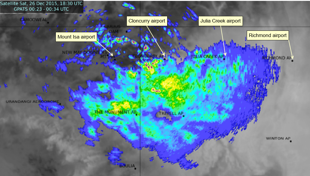
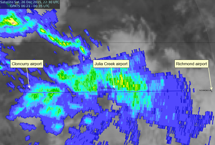
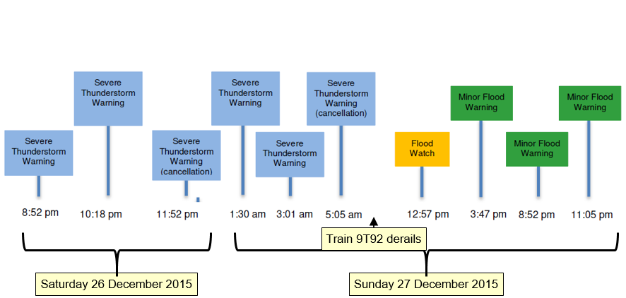
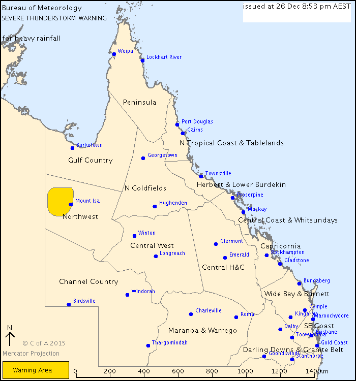
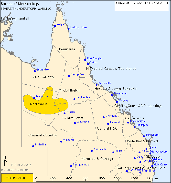
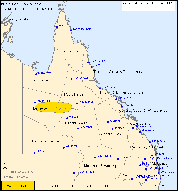
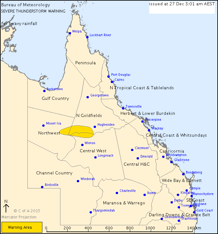
On 26 and 27 December 2015, the rail traffic crew of trains 9E56 and 9T92 encountered wet weather as they travelled toward Julia Creek. The Bureau of Meteorology had issued a series of localised severe thunderstorm warnings for the North West forecast district, which was normal during the wet season. The Network Control Officer (NCO) at the Queensland train control centre in Townsville was monitoring information on the BoM website and had received some information from the rail traffic crews who were travelling along the section. The NCO acted on the information available by arranging track inspections of the relevant sections of track west of Julia Creek.
As these inspections were occurring, train 9T92 continued travel toward Julia Creek from the east. Shortly after passing through a section of track where floodwaters had previously overtopped the track and receded, the crew of train 9T92 encountered another area where floodwater had overtopped the track. At this location, however, the floodwater had scoured the ballast and compromised the integrity of the track.
The driver became aware of the washout only moments before the locomotive impacted and derailed, causing the locomotive to tip on its side. After sighting the washout, the train crew could do nothing to prevent, or lessen the impact of the incident.
What the ATSB found
Scouring of the ballast and formation adjacent to the 617.190 km point by floodwater meant that the track could not support the weight of train 9T92 as it passed over the affected area. The resulting deformation in alignment of the track initiated the derailment. Reporting procedures implemented by Queensland Rail and Aurizon provided insufficient guidance to the NCO or rail traffic crew to identify and respond to potential hazards from a wet weather event.
What's been done as a result
Queensland Rail has issued Safety Alerts to improve the effectiveness of the current network rules in relation to managing hazards associated with weather events. A review of weather monitoring services and the upskilling knowledge of relevant personnel on interpreting meteorological information has also commenced. Queensland Rail has commenced a review into the feasibility of adopting the Australian Standard AS7637 Railway Infrastructure – Hydrology and Hydraulics.
Aurizon has introduced respiratory protection masks for train crew on trains transporting acid. Additionally Aurizon continues to reassess the emergency evacuation procedures, locomotive windscreens and secondary communication opportunities/options.
Safety message
Rail infrastructure managers must implement adequate operational procedures and training programs to ensure the timely identification and management of a hazard to the integrity of their rail infrastructure, such as a weather event. Rolling stock operators must ensure that their training programs include relevant operational procedures enabling consistent assessment, reporting and response by train crew to conditions that may adversely affect the integrity of rail infrastructure or trains.
The occurrence
Events prior to the derailment
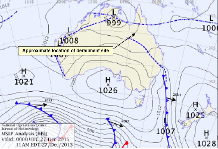
In late December 2015, a tropical low embedded on an active monsoon trough extended across the tropical north of Australia. This weather system brought heavy rainfall to northern Australia and caused moderate rainfall in the northwest, northern, and southern areas of Queensland.
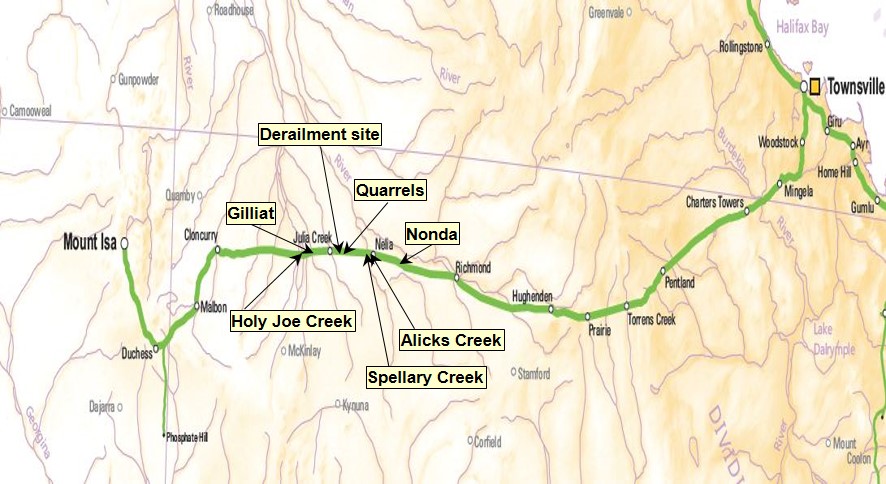
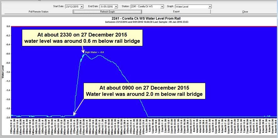
At about 0245[1] on 27 December 2015, the Queensland Rail (QR) Network Control Officer (NCO) for the Townsville far-west train control board received an intermittent alarm from the Rail Management System. The alarm indicated a high water level at Holy Joe Creek, located at the 681 km point, west of Julia Creek (Figure 1) on the Great Northern Railway (Mount Isa line).
About the same time, the crew of Aurizon train 9E56, travelling toward Julia Creek from the east, contacted the NCO to report encountering heavy rainfall around Nonda, located at the 561.340 km point, east of Julia Creek. The NCO recorded details of the alarm and the report from 9E56 on the train control graph.[2]
Figure 1: Locations, Mount Isa railway, Queensland
Also at about 0245, the Aurizon crew involved in the derailment commenced their shift at Hughenden. The crew was to operate Aurizon train 9T92 (loaded with sulphuric acid) from Hughenden through Julia Creek to Cloncurry. Following the arrival of 9T92 from Townsville, the crew took control and after receiving authority from the NCO, departed for Cloncurry at about 0330 that morning. Train 9T92 was following about 5 hours behind the preceding train 9E56.
At about 0400, a shift change of the NCO for the Townsville far-west train control board occurred. The incoming and outgoing NCO’s performed a handover to provide a brief on the status of relevant train running information for that control area.
At about 0520, the crew of 9E56 reported more heavy rain on their arrival at Gilliat, located at the 664.260 km point, west of Julia Creek. Train 9E56 remained stopped at Gilliat to enable a QR track inspector to access the track at Cloncurry and travel to Gilliat. The track inspector’s task was to examine the track for flood damage through to Gilliat, and to investigate the high water alarm at Holy Joe Creek before train 9E56 traversed the area.
The track inspector left Cloncurry at about 0645, travelling towards Julia Creek from the west.
At the same, train 9T92 continued towards Julia Creek from the east. The latest report of heavy rainfall in the area east of Julia Creek was about 4 hours earlier, by the crew of 9E56 (now situated at Gilliat).
At about 0839, the crew of 9T92 reported to the NCO that they were approaching Nelia, located about 49 km east of Julia Creek. They reported there was ‘plenty of water everywhere’, and that they experienced periods of rainfall during their journey between Hughenden and Nelia – a distance of 212 km. The NCO advised that the previous train 9E56 had reported similar conditions.
A little later, as train 9T92 passed over Alick Creek (located about 42 km east of Julia Creek) the crew noted that there was a substantial water flow along that waterway. The train crew and QR knew this area to be a flooding ‘hot spot’.
At about 0900, as train 9T92 approached Spellary Creek (about 32 km east of Julia Creek), the crew observed floodwaters pooling adjacent to the track formation ahead. The driver slowed the train, stopping about 815 m before Spellary Creek. The train crew noted light debris over the track, indicating that floodwater had overtopped the track formation at some time, before receding.
Meanwhile, the track inspector travelling towards Julia Creek from the west had made several reports to the NCO enroute to Gilliat, noting the presence of floodwaters at the locations that had triggered the alarm. The alarm at Holy Joe Creek was false. The false alarm resulted from low battery voltage due to cloud cover causing insufficient solar charging. At about 0905, the track inspector completed the inspection to Gilliat and advised the NCO that the inspected track was fit for service and that train 9E56 could depart.
After crossing train 9E56 at Gilliat, the inspector requested an authority to continue the inspection toward Julia Creek. The NCO gave authority to continue to Julia Creek and advised the track inspector that a cross was to occur with 9T92, at Julia Creek.
The derailment
While train 9T92 was stationary at Spellary Creek, the train crew took the opportunity to change drivers. Following the crew’s assessment of the conditions ahead, the driver proceeded at a low speed through the affected area. The train crew had no immediate concern in proceeding as they could see the track and ballast. The water adjacent the track was not flowing and appeared to be receding.
After traversing the affected area, train 9T92 continued travelling west. At about 0920, the train crew contacted the NCO to report ‘water just lapping the ballast’ at Spellary Creek between the 605 and 607 km points. They also reported their observation related to light debris over the track, and that the floodwaters appeared to be receding.
In response to the floodwater report from the crew of 9T92, the NCO commenced arrangements for a second track inspection, this time starting from Richmond (behind 9T92) and travelling west toward Julia Creek. The QR Transit Manager at Townsville had also commenced arrangements to notify rail operators of the potential for service disruptions, due to closing the track west of Richmond for the inspection.
At about 0926, the crew of 9T92 again contacted the NCO and reported they were approaching Quarrels. The NCO acknowledged the communication and gave authority through Quarrels. After passing through Quarrels, the driver reduced speed to around 15 km/h to traverse a short section of track with a 15 km/h speed restriction (615 to 615.3 km).
The track between Quarrels and Julia Creek was not an identified flooding hot spot. Consequently, after clearing the 15 km/h speed restriction, the driver started to increase the speed of 9T92 toward the posted maximum track speed of 60 km/h west of the Quarrels loop.
At about 0933, with 9T92 travelling at about 51 km/h, one of the train crew saw an area of disturbed ballast between the rails that indicated a washout[3] about 45 m ahead and called out a warning to the rest of the crew. The driver recalled immediately moving the throttle to idle and the brake handle toward the emergency position. Shortly after, the locomotive entered the washout. The crew felt the locomotive bounce and saw water splash on the windscreen before it derailed and began to tip over. As the locomotive tipped, the diesel engine shut down automatically.
The pitching of the locomotive while traversing the washout and tipping ejected the train crew from their seats. All crewmembers sustained minor injuries (cuts and abrasions) from contact with structures within the locomotive cab.
Events post-derailment
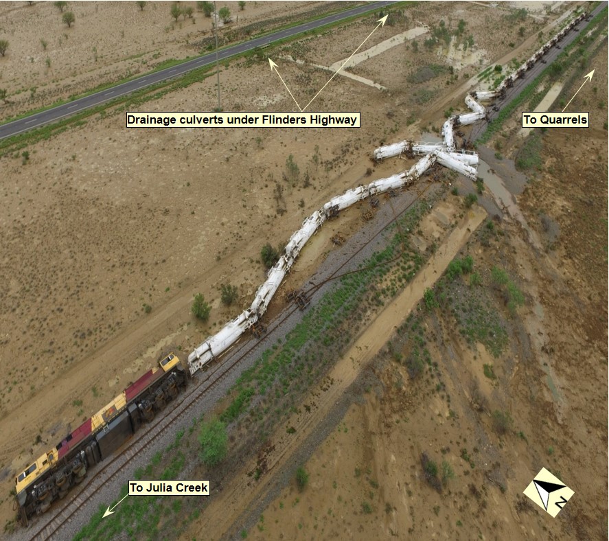
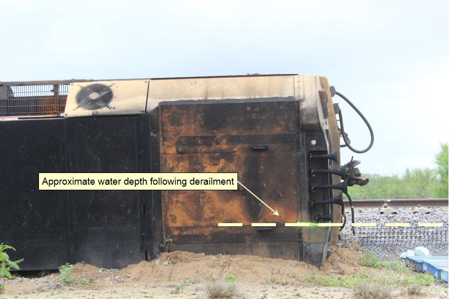
Train 9T92 had travelled about 2.6 km west of Quarrels before encountering the washout. The locomotive came to rest on its side to the north of the track, about 68 m past the washout (Figure 2). The locomotive was lying in about 600 mm of pooled floodwater. All of the 26 trailing tanker wagons had also derailed to the north of the track and were also lying in the pooled floodwaters.
Figure 2: Derailed train 9T92
The derailed locomotive 2814 and 26 trailing tanker wagons of 9T92 laying to the north of the railway about 20 km east of Julia Creek. The floodwaters present at the time of derailment had receded, however pooled water is still visible in the drainage channels from culverts under the Flinders Highway leading toward the washout of the track formation. Source: Queensland Police Service
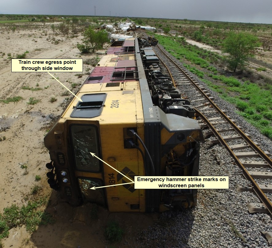
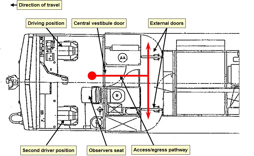
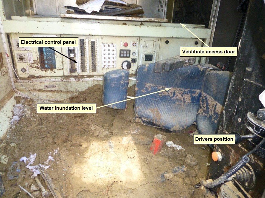
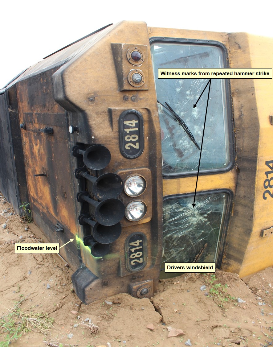
Immediately after the derailment, floodwater entered the cabin, before settling to a depth of about 600 mm. To escape the cab, the train crew attempted to break the front windscreens using the emergency hammer. After repeated strikes, they were unable to open an escape route through the windscreens, so the crew decided to climb up and out of the locomotive’s side window (Figure 3).
The first crewmember, on exiting the locomotive, saw an acid plume rising from the derailed tankers about half way along the train. The plume extended to the north for about 200 m and over the Flinders Highway.
The train crew did not have any breathing apparatus on board and, given the presence of the plume, decided to evacuate the area urgently in case the wind changed direction. The crewmembers assisted each other to climb from the locomotive cab before walking west along the track formation towards Julia Creek.
Figure 3: Derailed locomotive 2814
Derailed locomotive 2814 situated on the northern side of the track. The damage to the inside surface of both windscreens was from numerous strikes using the supplied emergency hammer. The train crew were unable to break out the windscreens. The train crew escaped from the locomotive through climbing up and out the sliding side window. Source: Queensland Police Service.
During the derailment, the radio handsets had fallen into the water and the train crew had no other serviceable communications equipment available to them. The train crew waited on the Flinders Highway until a motorist travelling along the highway arrived at their location. A crewmember borrowed a mobile telephone from the motorist and contacted the Aurizon Team Leader at Cloncurry to advise that train 9T92 had derailed.
The Team Leader then telephoned the emergency services. At about 0950, the Team Leader also contacted the Aurizon Service Delivery Supervisor to relay information of the derailment. About 20 minutes later, emergency services arrived to attend to the train crew and take control of the derailment site. The vapour plume that occurred immediately following the derailment had dispersed. The Police closed the Flinders Highway to road traffic and erected signage to the East and West of the derailment site to control unauthorised access.
Around the same time, the NCO had expected train 9T92 to arrive at Julia Creek. Unaware of the derailment, the NCO had commenced a series of radio and telephone calls in an attempt to raise the crew of train 9T92 and establish its location. At about 1022, the NCO received advice from the Aurizon Team Leader that train 9T92 had derailed about 20 km east of the Julia Creek Township.
The QR Rail Transit Manager reported the derailment internally and contacted representatives of the Incitec Pivot[4] emergency response team at Phosphate Hill. Due to flooding of the Flinders Highway, the emergency response team was unable to respond immediately to the incident.
At about 1815, the emergency response team arrived at Julia Creek. They then commenced preparations to assess the damage to the tanker wagons and the extent of product leakage, and to arrange for its containment.
The presence of floodwaters across the Flinders Highway and saturated soil conditions at the derailment site restricted access by QR, Incitec Pivot and other response teams. Assessment and recovery operations continued for several weeks following the derailment.
Environmental Management
Queensland Rail, Aurizon and Incitec Pivot developed an environmental management plan to minimise potential environmental harm following the derailment. The plan included:
Containment and Contingency to prevent further adverse impact
Construction of the rail deviation for the resumption of rail services
Removal of product
Removal of wagons
Monitoring and remediation strategies and actions to restore the receiving environment and prevent further release.
The development and implementation of the plan was in compliance with a clean-up notice issued by the Department of Environment & Heritage Protection pursuant to section 363H of the Queensland Environmental Protection Act 1994.
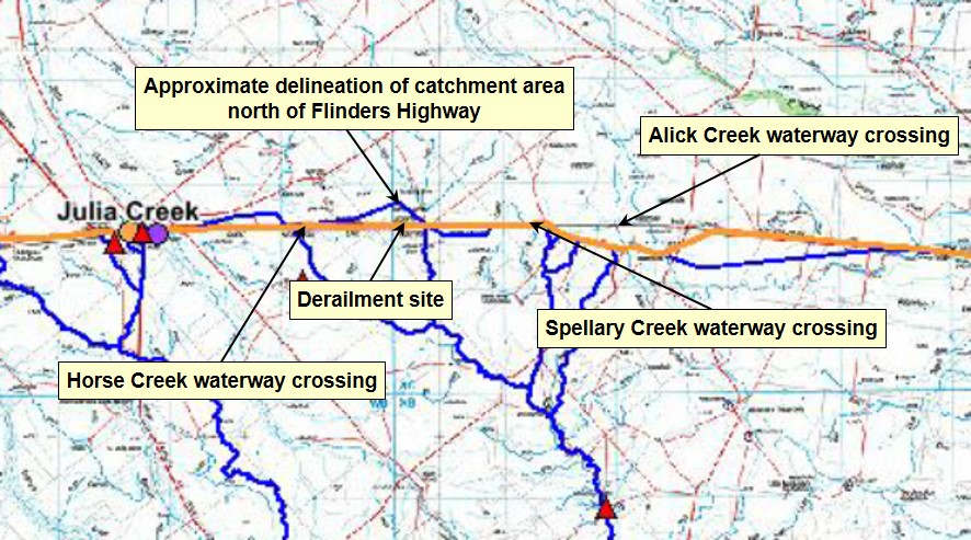
The derailment occurred about 20 km east of Julia Creek, at the 617.190 km mark on the Great Northern Railway between Townsville and Mount Isa. The derailment site was located approximately 350 km east of Mount Isa and 617 km west of Townsville by rail.
Train and train crew information
Train 9T92 was a freight service operated by Australia Eastern Railroad (Aurizon) between Townsville and Phosphate Hill. It consisted of one locomotive (2814) hauling 26-freight tanker wagons. Incitec Pivot Limited owned the GATX freight tanker wagons and the consignment. The train was 354.3 m in total length and had a trailing mass of 2028 t.
The consignment of train 9T92 contained dangerous goods (819,000 litres of sulphuric acid). As a consequence of the derailment, about 60,800 litres of acid leaked from the tanker wagons.
The train was crewed by two drivers. A third driver was also travelling in the locomotive cab to obtain route knowledge along various track sections. All drivers commenced work at Hughenden at about 0245 on 27 December 2015. They were to take control of train 9T92 at Hughenden and drive through to Cloncurry, where they would finish their shift.
The crew operating train 9T92 at the time of the derailment held the required competencies for the tasks being performed and had been assessed as fit for duty in accordance with the requirements of the National Standard for Health Assessment for Rail Safety Workers. Following a review of the drivers’ rosters in combination with interview evidence, the ATSB determined that fatigue impairment was unlikely to have affected their performance.
The driver at the controls of train 9T92, on realising the presence of a washout ahead, acted immediately in removing traction power to the train. There was no anomaly identified in the train speed, handling, rolling stock condition, or operational performance leading up to the derailment.
Aurizon tried to initiate screening tests on the train crew for the presence of a drug or alcohol following the derailment. However, due to flooding and the incident response, this could not be performed. There was no indication that any of the train crew had consumed, or had their performance influenced by, the deleterious effect of a drug or alcohol.
Rolling stock – locomotives
Aurizon was an accredited Rolling Stock Operator in Queensland[5]. It operated the 2800 class, diesel electric locomotive (2814) hauling train 9T92. Aurizon was providing a ‘hook and pull’ service to Incitec Pivot Limited for train 9T92 at the time of the derailment.
The locomotive was fitted with Ultra High Frequency train control radio and a Global Positioning System (GPS). Driver aids such as the Station Protection Device, Vigilance Control system, Automatic Train Protection (ATP) and Direct Traffic Control system were also available. The GPS system enabled the monitoring of the locomotive location and speed by the NCO at the QR train control centre in Townsville.
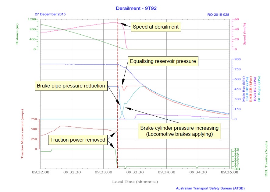
The locomotive 2814 was fitted with a Wabtec TDR-9000 data recorder (data logger). The data logger recorded various parameters including time, GPS position, speed, distance travelled, throttle position, vigilance, motor current and air reservoir/brake cylinder pressures. The data logger did not record a parameter to monitor the brake handle position.
The download of the data logger (Figure 4) indicates the driver changed the throttle setting from T8 toward T1 about three seconds before the train’s brake pipe displayed a rapid fall in the air pressure. The rate of change in brake pipe pressure suggests either an emergency brake application by the driver or an uncommanded break in continuity along the train’s brake pipe.
Figure 4: Locomotive 2814 data log plot
Plot of locomotive 2814 data log parameters. Plot illustrates driver actions in removing traction power immediately before train 9T92 enters the washed out track section. A rapid reduction in air pressure in the brake pipe occurs as train 9T92 traverses the washout and derails. Source: ATSB
Analysis of the data logger and ATP recordings by Aurizon engineering and maintenance staff showed that the reduction in brake pipe pressure did not correspond with a reduction in the equalising reservoir pressure. The movement of the brake handle by a driver toward the service or emergency position would typically cause both these pressures to reduce in unison.
The recorded events illustrate that a brake application, via the movement of the drivers brake handle to the emergency position (as recounted by the driver), did not cause the rapid reduction in brake pipe pressure. The reduction in brake pipe pressure was more likely due to a loss in brake pipe continuity during the derailment. The locomotive’s automatic brake control valve sensed the reduction in brake pipe pressure and began to apply the brakes on the locomotive.
While there is variance between the driver’s recollection and the data log analysis, the exact cause for brake pipe pressure reduction (brake handle or brake pipe continuity) had no material effect on the outcome of 9T92 entering the washout and derailing.
Rolling stock – tanker wagons
Incitec Pivot Limited was an accredited Rolling Stock Operator in Queensland[6]. Incitec Pivot operated the American made GATX tanker wagons. The GATX wagons were hauled under a hook and pull agreement with Aurizon.
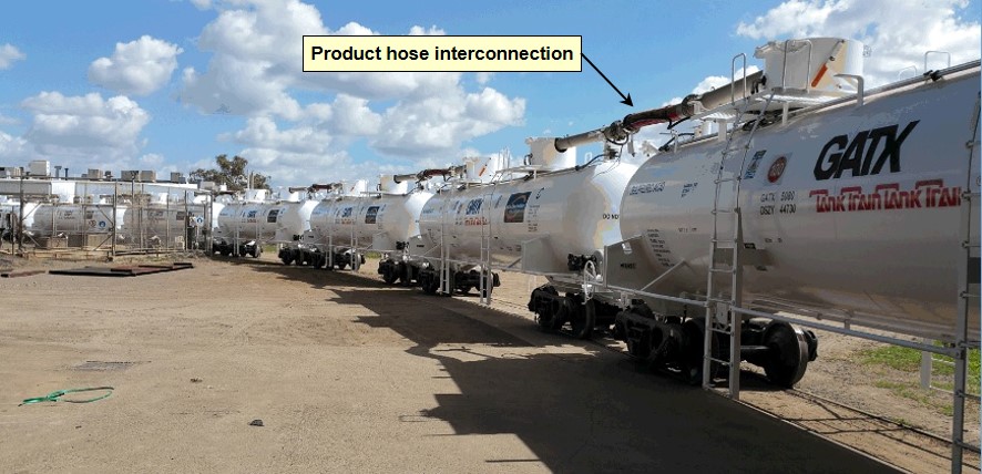
The Incitec Pivot tanker fleet comprised 145 wagons, classified as OZSY class wagons. The fleet operated as 11 x 13-wagon strings plus two spare wagons. A product hose interconnected each tanker wagon within a string (Figure 5). This configuration enabled the stabling of the strings at Phosphate Hill and decanting of product as required.
Train 9T92 included wagon strings numbered four and seven. The strings were loaded with 399.9 m3 and 400.2 m3 respectively (819,000 litres in total) of Sulphuric Acid (>98%) at the Sunmetals Corporation facility at Townsville on 25 December 2015.
Figure 5: GATX tank wagons
Image of a GATX tanker wagons coupled in a string and the product hoses interconnecting each vessel. Source: Incitec Pivot
The design capacity of each tanker wagon was 33,128 litres of product. The construction of the tanker shell was steel with a thickness of 12mm. The ellipsoidal tank heads were steel with a nominal thickness of 16mm. A phenolic resin coating protected the internal side of the tank shell and heads from a reaction with the product.
The tank wagons were generally grouped in a 3-unit configuration with a double-shelf coupler at each extremity and rigid draw-bar permanently interconnecting each unit. The provision of a Type ‘E’ double-shelf coupler was a safety measure commonly used in tanker wagons to prevent a vertical misalignment causing the accidental uncoupling of the knuckle. In the event of a derailment, an uncoupled knuckle may puncture the shell or head of an adjacent tank.
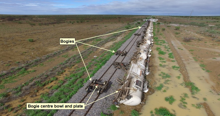
The design to prevent accidental separation of the coupling between tanker wagons can however lead to the sequential rollover of wagons in a ‘domino-effect’ during a derailment. As a wagon tilts, the torsional force transferred through each coupler (and rigid draw bar) progressively twists successive tanker units from their centre bowl mount in the bogie. Typically, this type of derailment would result in a number of the associated bogies remaining in situ on the track, while their corresponding bodies roll to the side (Figure 6).
Figure 6: Domino effect derailment of GATX tanker wagon string
View of rear of 9T92 of the tanker wagons that derailed due to the ‘domino-effect’. A number of the associated bogies remained in situ on the track adjacent to the corresponding position of the tanker unit bogie mounting point. Source: Queensland Police
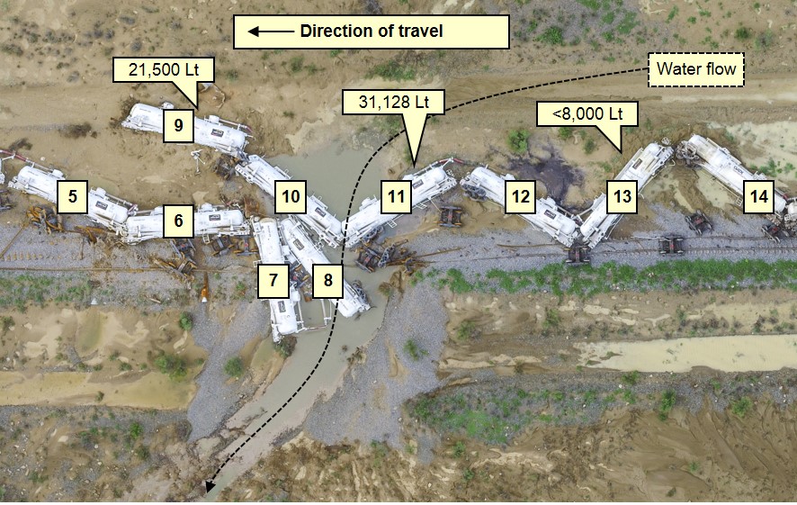
Derailment damage to tanker wagons in positions nine, eleven, and thirteen of the train caused sulphuric acid to escape (21,500 litres, 31,218 litres, and slightly less than 8,000 litres, respectively). The acid, 98 per cent pure, mixed with the surrounding floodwater and began to etch the damaged external surface of the tanker vessels within the acid pool hot zone[7] (Figure 7).
Figure 7: Acid hot zone
This image identifies the wagons that leaked product before restoration. Wagon 9 leaked 21,500 litres, wagon 11 leaked 31,218 litres (all contents), and wagon 13 leaked less than 8,000 litres. Source: Queensland Police Service. Annotated by ATSB
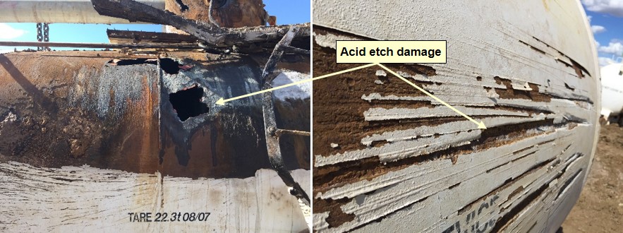
The etching resulted in further leakage of product, exacerbating the acid etching of the already damaged surfaces (Figure 8).
Figure 8: Acid etch damage to GATX tanker vessel
Images of acid etching to external surface of tanker vessel of GATX tanker wagon OZSY 44688. This tanker wagon was in position 11 of the train. Following the derailment, this tanker wagon was within the acid hot zone and lost all contents. Source: Incitec Pivot. Annotation by ATSB
Design standard
The GATX tanker wagons complied with QR requirements specified in the then QR Standard SAF/STD/0056/RSK-NET “Rail Tank Cars”. The standard reflected the requirements of the Railways of Australia Manual of Engineering Standards and Practices, and the Australia Code for the Transport of Dangerous Good by Road and Rail. The GATX tanker wagons were pressure vessels designed to the Australian Standard AS 1210[8] and maintained in accordance with AS 3788[9].
Maintenance records
The Incitec Pivot maintenance program included three levels of inspection:
Level one – a basic walk-around inspection that occurred at Mount Isa, Phosphate Hill and Townsville
Level two – An annual visual inspection undertaken at the maintenance facility in Townsville
Level three – a seven yearly reline inspection undertaken at the maintenance facility in Townsville.
Incitec Pivot provided the ATSB with records detailing the annual visual inspections undertaken in mid-2015 and late 2015. The inspections incorporated wheel-set replacement, minor maintenance works and pressure tests to the tanker wagons in string four and seven respectively. Incitec Pivot also provided records of an overhaul in mid-2014 that included the relining of the vessels for the tanker wagons in string four.
On the 25 December 2015, a walk-around inspection and brake function test was completed at Townsville and the wagons in strings four and seven were certified fit for travel.
The examination of the maintenance records identified no anomaly in the condition of the rolling stock that may have contributed to the derailment of train 9T92.
Track information
Queensland Rail (QR) managed the railway where the derailment occurred, with the movement of rail traffic controlled from the QR Control Centre located at Townsville in Queensland.
The narrow gauge (1,067 mm) track at the derailment location consisted of 41 kg/m rail fastened to steel sleepers by resilient clips. The track formation was composed of black vertosol[10] soil overlaid with ballast to a nominal design depth of 200 mm forming the track bed.
Approaching the derailment site from Quarrels, the track was tangent and the terrain relatively flat and open. The track gradient was a falling grade of 1 in 1649, before transitioning to level through the area adjacent to the derailment location.
Track drainage at derailment site
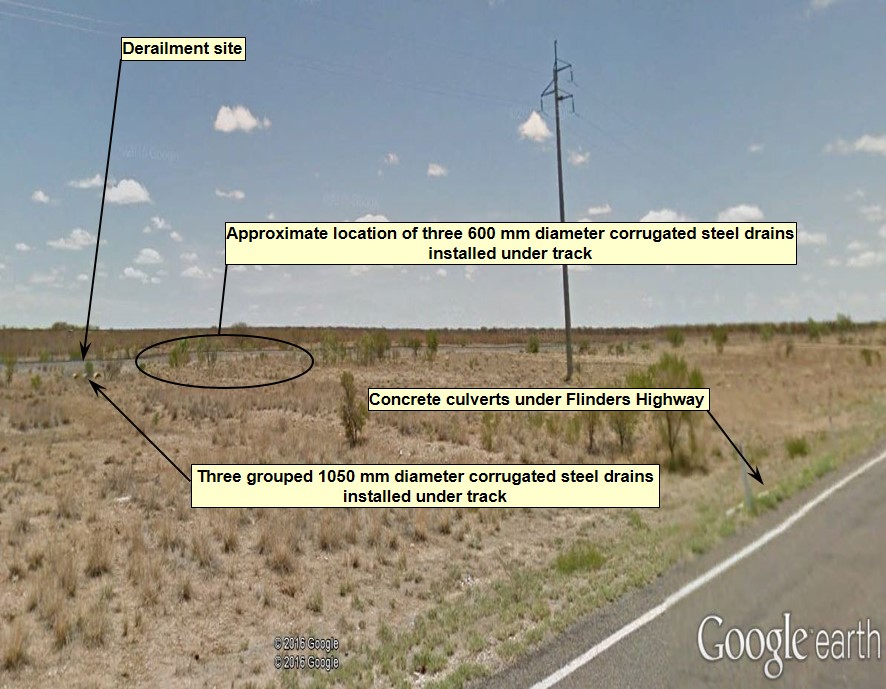
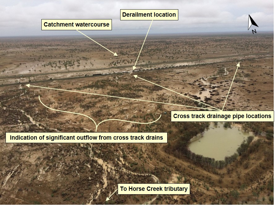
At the derailment site (617.190 km), there was a grouping of three 1050 mm diameter corrugated steel pipes installed under the track formation (Figure 9). Immediately west of the site three additional 600 mm diameter corrugated steel pipes were installed at about 10 m intervals (617.200, 617.210, 617.220 km).
Figure 9: Under-track drainage at the derailment site
Location of the derailment as it appeared before the event - viewed in a south-westerly direction from the Flinders Highway. Rainwater runoff flows from the catchment to the north, passes through a series of concrete culverts under the highway and toward the railway formation. A series of circular corrugated steel pipes installed under the track formation allows water to then flow into the watercourses located to the south of the railway. Source: Google Earth, annotated by ATSB
Queensland Rail (QR) advised that the group of three 1050 mm corrugated steel pipes were installed during the re-construction of the Mount Isa line completed in the early 1960s. In the 1980s a flood occurred that resulted in scouring of the formation adjacent the three existing pipes. This event resulted in the addition of the three 600 mm corrugated steel pipes to the west.
Track standards
The QR Civil Engineering Track Standard (CETS)[11] and Civil Engineering Structures Standard (CESS)[12] specified the safety standards and good practice guidelines for the construction and maintenance of track and structures owned by QR.
The standards noted that areas of the existing infrastructure may not meet the standards specified. Where a variance existed, the QR Rail Infrastructure Manager was to exercise sound professional judgement in the management of risk, rather than adhering to the literal application of specific detail contained in the standards. The QR Rail Infrastructure Manager was also required to ensure that the design of railway infrastructure broadly met the risk management intent of the standards.
With respect to track drainage systems, the structures standard provided guidance for monitoring and maintenance actions but was limited for design and construction. For example, the standard did not specify the QR design criteria for the standard of service (annual exceedance probability) used in designing track drainage systems. Typically, rail infrastructure managers specified the design of major and minor track drainage systems to accommodate an annual exceedance probability (AEP) of 1% or 2% respectively.
For minor track drainage systems, such as the corrugated pipe type drains installed along the Mount Isa line, QR had developed standard installation drawings. QR advised that the level of adherence to the standard installation drawings was at the discretion of the designer. Inclusion or modification of details contained in the drawings, for features such as head walls, aprons or flood rock protection, were dependent on an engineering assessment of the nature of the waterway. In effect, engineering design for the undertrack drainage was on a case-by-case basis. The final design relied on engineering judgement based on the known historical conditions for the location.
With respect to the track drainage systems near the derailment location, QR advised that based on local knowledge the designers decided not to install headwalls, aprons or flood rock, as the addition of the three waterway openings would adequately improve the site to handle localised flows. The selection of design features for the additional culverts was to match the existing waterway openings along the railway.
Queensland Rail (QR) could not provide records of the hydrologic modelling and hydraulic assessment for the location where train 9T92 derailed. Similarly, there were no records for the design criteria or the designed AEP flood immunity for the installed drainage infrastructure.
Track drainage inspections
The QR track and structures standards provided for multiple types of inspection:
Scheduled Patrol
Scheduled General Inspection
Unscheduled Patrol
Unscheduled General Inspection
Unscheduled Detailed Inspection.
Assessment of infrastructure condition and actions necessary could then be determined using:
Predetermined condition standards
Predetermined assessment rules
Engineering analysis.
Where the standards specified a condition standard or assessment rule, its application was mandatory to determine the required response.
With respect to drainage systems, the structures standard required scheduled inspection of culverts and other structures to assess their condition and monitor or action repairs.
A scheduled detailed inspection conducted on the 30 August 2015 of the corrugated pipes at the derailment location recorded a drain at the 617.220 km mark (600 mm diameter corrugated pipe) as ‘buried’. QR completed remediation work to clear the drain on the 15 September 2015.
The standards also required that condition standards or assessment rules determined for hazard locations must take into consideration the defined event that may require initiation of an unscheduled inspection. For example, a flood hazard location would require consideration of water levels, scour depths and water velocities to determine the condition standard or assessment rule applicable.
The track standard specified that unscheduled inspections must be undertaken at affected locations or operational restriction applied in response to environmental events such as:
Heavy rainfall / inundation / floods / washaways / ingress of underground water
Earth movements / subsidence / slops / earthquake
Loss of track support, such as collapsing soils, culvert or structure failure, erosion
Temperature extremes
In the hours prior to the derailment of 9T92, QR initiated unscheduled inspections of affected locations west of Julia Creek in response to information provided by the crew of 9E56 and the high water alarm at an automated monitoring station. For the area east of Julia Creek, the information received by the NCO from the train crew of 9T92 (reported overtopping at Spellary Creek) resulted in the NCO placing an operational restriction by closing the track behind 9T92 to enable a second track inspection to commence from Richmond.
Hazard locations register
The standards required the Rail Infrastructure Manager to prepare and maintain a Hazard Location Register. The register was to detail the hazards and the required action (such as unscheduled inspections) where defined events might rapidly reduce the capability of the track to safely perform the required function.
The hazard location register for the corridor between Hughenden and Cloncurry identified 40 individual locations. The identified hazards present at a location were either:
The potential for track buckle
Ineffective sleeper type
The potential for fouling of ballast following periods of heavy rainfall
Track alignment
Formation failure due to animals (foxes) digging.
The hazards identified near the derailment location were foxholes at the 617.420 and 618.270 km points.
In this case, QR initiated unscheduled inspections in response to potential flooding hazards both east and west of Julia Creek. However, the hazard location register showed no location identified between Hughenden and Cloncurry where a floodwater runoff event may result in a hazard to infrastructure.
Flinders Highway
The Flinders Highway extends around 754 km between Townsville and Cloncurry. The route of the highway and the Mount Isa railway follow a similar corridor for much of their length. At the location of the derailment, there was a separation of around 90 m between the road and rail alignment.
The Department of Transport and Main Roads (TMR) was responsible for the management of the road infrastructure. The Flinders Highway was susceptible to frequent closures caused by inundation following rainfall events, particularly during the annual wet season from November to March.
To improve the resilience of Flinders Highway, TMR commissioned a number of flood studies. The objectives were generally to identify flood delay priorities from closures, setting of performance targets for flood immunity across the road corridor and the prioritising of associated infrastructure projects.
There was limited hydrological data available for the various catchments along the corridor as many of the waterway crossings on the Flinders Highway were unmetered. TMR flood studies used historical data and local knowledge to develop hydrologic models on which to base flood assessment and the prediction of flow thresholds for road closure at key waterway crossings.
TMR flood studies identified a number of segments of the Flinders Highway between Townsville and Cloncurry that were prone to flooding. The Richmond and Julia Creek segment was not the most flood prone section but, on occasion had the potential to be significantly affected by road closures due to inundation (Figure 10).
Figure 10: Flinders Highway road closures per year between Richmond and Julia Creek
Illustration of the number of days each year that rainfall runoff inundated the Flinders Highway at locations between Richmond and Julia Creek, resulting the closure of the highway to road traffic. The 2009 year shows a significantly larger number of days closed, which aligns with severe flood events in the region (due to active monsoon trout that developed into tropical cyclones Charlotte and Ellie). Source: Queensland Department of Transport and Main Roads data, plotted by ATSB
The Richmond to Julia Creek segment contained the Alick, Spellary, Horse and Julia Creek waterways. The TMR flood study found that this segment of the highway had an overall 0.5-year ARI (86.47% AEP) flood immunity, with the Alick Creek crossing overtopping on frequent occasions.
The Mount Isa rail line ran roughly parallel to the Flinders Highway between Richmond and Julia Creek. The elevation of the rail track formation varied between 1.0 and 1.5 m higher than the adjacent highway. A review of QR records indicated the rainfall events during 2009 and 2012 that had closed the Flinders Highway also resulted in the closure of the railway on several occasions. These closures followed reports of rising water levels under rail bridges or overtopping of the track formation at the Alick or Spellary Creeks. These closures did not correspond to any report of damage to rail infrastructure.
Water catchment adjacent derailment site
TMR flood studies identified five major river basins and 32 individual catchments adjacent to the Flinders Highway between Stuart and Cloncurry. The catchment adjacent the derailment site included land areas located to the north and south of the Flinders Highway (Figure 11). The waterway at the derailment site flowed from the north to south into tributaries feeding Horse Creek. The Horse Creek subsequently flowed from south to north, crossing the Flinders Highway before joining to Julia Creek north of the Julia Creek Township.
Figure 11: Catchment Delineation Julia Creek area
Extract from Flinders Highway Flood Study Catchment Delineation – Richmond to Cloncurry. Image illustrates catchment area to the north and south of the Flinders Highway at the derailment site. Source: Queensland Department of Transport and Main Roads
The catchment land area to the north was a relatively flat plain with sparse vegetation. As much of central Queensland was in drought following below average rainfall since 2013, the catchment area was largely devoid of vegetative cover. This likely affected the amount of rainwater infiltration into the soil, subsequently increasing the overland flow of runoff from the catchment north of the highway and railway following a rain event (Figure 12).
The runoff followed south, crossing the Flinders Highway at two locations into excavated channels that directed the flow toward the location of drainage pipes under the track formation. At the location of the derailment, the two drainage channels converged the outflow from culverts under the Flinders Highway toward the under track drainage pipes.
The location of the under track drainage pipes was at the point of lowest elevation of the surrounding ground surface in the immediate area. As the construction of the track formation generally followed the elevation of the ground surface through that area, it was likely that the location of the derailment also corresponded to the lowest longitudinal vertical alignment of the track formation.
Figure 12: Northward view of catchment area and watercourses
Northward view of the catchment area and associated water courses that cross the Flinders Highway and the Mount Isa railway. The view shows the path of floodwater outflow from the cross track drains adjacent the derailment site. Source: Queensland Police
The train crew of 9E56 and 9T92 had both reported periods of heavy rainfall and areas of ponded water at locations next to the track formation enroute to Julia Creek. The crew of 9T92 reported that water had overtopped the track at Spellary Creek before receding to the level of the shoulder at the top of the ballast formation.
Approaching the derailment site, the train crew of 9T92 recalled observing water ponded on either side of the track formation. The water did not appear to be flowing and the depth was equal on either side of the formation, about 500mm below the top of the rails.
The train crew noticed that there was no ballast covering the top of some sleepers ahead, which was abnormal for this track section. The surrounding ballast, being wet, appeared black in colour but a section about 6.0 m wide of formation ahead, that also appeared black, had a different texture. This was the washed out track section.
When the locomotive derailed into floodwaters on the northern side of the track, the train crew recalled the cab filling with water to a depth of about 600mm. Watermarks on the locomotive supported the estimation of depth (Figure 13)
After evacuating the locomotive cab, the train crew had to walk about 800 m toward Julia Creek to avoid ponded water between the track and the highway. A crewmember recounted sighting evidence of inundation along the highway that extended for a distance of around 300 m immediately to the north of the derailment site. There was no estimation of the depth of water that had overtopped the highway at that location.
Figure 13: Approximate water depth following derailment
Watermark on the locomotive indicating the depth of the floodwater. Source: Queensland Rail
Based on the observed depth of water following the derailment, and evidence of sediment and scouring south of the track from water outflow (from under track drains and the washout), it was likely the level of floodwater that damaged the track formation was higher than was present at the time of the derailment. It is likely that water had banked up against the track formation, and the water level receded once the formation had washed away.
Environmental conditions
During 26 and 27 December 2015, the BoM was monitoring an active period of tropical weather that was affecting the Gulf of Carpentaria and surrounding inland, including north –western Queensland (Figure 14). The BoM analysis of the synoptic weather conditions, which gave rise to the rainfall near the derailment, found that:
A tropical low-pressure system located over the top end of the Northern Territory was moving slowly east during the period. This low extended a monsoon trough east through the far southern Gulf of Carpentaria, across southern Cape York Peninsula, and into the northern Coral Sea. Elsewhere, a cold front moving through south-eastern Australia extended an inland trough through western Queensland, which was located over inland north-western Queensland through the period. The atmosphere over north-western Queensland was moist and unstable and conducive to heavy rainfall, as is common in northern Queensland in late December.
The monsoon trough and the inland trough together provided triggers for widespread shower and thunderstorm activity during the period, particularly overnight on Saturday 26th December and in the early morning of Sunday 27th December.
Figure 14: Mean sea level weather chart at 1100 on Sunday 27 December 2015
Image shows the approximate location of the derailment site relative to the path of the tropical low-pressure system tacking eastward across the Gulf of Carpentaria and the trough from the cold front extending into inland north-western Queensland. Source: Bureau of Meteorology
The BoM had issued a series of localised severe thunderstorm warnings that included the potential for heavy rainfall and flash flooding for the North West district, which included the area around Julia Creek. It was common for the BoM to issue localised thunderstorm warnings during the northern wet season.
The rainfall measurement network is very sparse in the region near the derailment. The closest BoM weather station was at Julia Creek (Julia Creek Airport), about 23 km west of the derailment site. To 0900 on 27 December 2015, Julia Creek Airport recorded a daily rainfall 60.2 mm. The next nearest rain gauges with available data were at Corella Creek (about 24 km to the east) and Punchbowl (about 27 km to the north-northeast). These stations recorded rainfall over the same period, of 104 and 48 mm respectively.
The BoM rain gauge at Proa, located about 33.5 km to the southeast of the derailment site, recorded rainfall of 140 mm. This gauging was the record for the highest December daily rainfall at that station.
Post-incident analysis by the BoM concluded that the rainfall recorded from the weather event in the North West forecast area was typical of an Annual Exceedance Probability (AEP) of 9.5%. An AEP of 9.5% equates to an Average Recurrence Interval (ARI) of 10 years.
Queensland Rail risk management
The QR Enterprise Risk Management System (RMS) mapped relevant procedural and engineering controls against identified hazards. In February 2015, QR initiated a complete redesign and rebuild of the RMS. A tiered roll out the revised RMS through the business then commenced and was ongoing at the time of the derailment of 9T92.
Queensland Rail (QR) was aware that during the rollout of the RMS, the level of detail and maturity of the risk registers would vary due to factors, including by not limited to the:
Assigning of risk resources as a priority to higher risk areas of operation (passenger)
Access to subject matter expertise and a distributed delivery network
Working in a top down methodology addressing policy and administrative controls initially.
In managing risk associated with a derailment, QR developed a risk profile that addressed the management of rail infrastructure to prevent a ‘major avoidable event’[13]. The risk profile included a series of subset registers grouped under the headings:
Signalling and Operational Systems Discipline
Track and Structures Discipline
South East Queensland Track and Civil risk register
Supply Chain North Risk Register
Risk Management Risk Register.
On 16 December 2015, QR management at Townsville approved the subset of risk assessments linked to the Supply Chain North Risk Register, which included the rail infrastructure on the Mount Isa railway.
The assessments identified the risk from derailment caused by a number of factors that included damage to a bridge, culvert, track formation, or ballast from flooding. The associated treatments linked to various procedural controls contained in the QR track and structures standards (CESS and CETS). These controls primarily related to the inspection of track, competencies of network staff and network assurance audits.
The assessment recorded the risk as ‘high’ for ‘track failure or irregularity’, due to the onset of the wet season and the increased potential for flooding. However, the risk reduced to ‘medium’ for the dry season, since the assessed likelihood that a track failure would occur had diminished.
Assessments for the Track and Structures Discipline identified a related risk where track and structures standards/specifications did not adequately address the required reliability and safety of structural components. The identified causes associated with this risk were:
Track & Structures standards and specifications are incomplete or inadequate
Track & Structures specifications may be missing or not yet identified as necessary
Track & Structures standards and specifications are not maintained.
The risk treatments similarly linked to procedural controls within the standards. The modules contained within the structure standards (CESS) specified the construction, inspection, and maintenance requirements for structures that included corrugated steel pipe under track drainage systems. QR assessed these controls would also reduce the risk of derailment to a rating of ‘medium’.
For an assessed risk score of high or medium, QR’s processes require the ongoing monitoring of controls through network assurance audits.
The controls applicable to construction included the QR practice for undertaking engineering design work. With respect to under track drainage, this work was not only reliant on the application of the relevant standards but also on the application of engineering judgement based on the historical conditions at a particular location.
The standards did not adequately define the requirements for undertaking hydrologic modelling and hydraulic assessment. Similarly, the standards did not include the requirement to document the specifications or design criteria of the drainage infrastructure specifying the designed flood immunity for areas of the Mount Isa line, such as a culvert location, where 9T92 derailed.
Although the QR Enterprise Risk Management System included the identification of hazards and the management of risk to prevent a major avoidable event, (derailment) caused by a number of factors that included damage to a bridge, culvert, track formation, or ballast from flooding, QR advised that there was no legal requirement to know the flood immunity at a particular location.
Queensland Rail (QR) had implemented a variety of management systems and operational procedures/protocols to assist staff to detect and respond to a weather event that may affect the network. At the Townsville control centre, staff had available historical flooding information, trackside weather monitoring station information and BoM data for the district encompassing the Mount Isa railway.
Identified flood hazard areas
Operations staff at the control centre in Townsville referred to the Flood Hot Spot Information record to identify the location of areas prone to flooding. Staff also accessed trackside weather monitoring stations installed along the rail corridor to detect a defined weather event (Figure 15).
Between Richmond and Julia Creek, the hot spot information identified one flooding hot spot located between the 590 and 601 km points that encompassed the Corella and Alick Creeks. There was no record of a flooding event at the derailment site since the early 1980s, after which QR installed the three additional 600 mm drains. QR did not consider this location to be a flooding hot spot.
Figure 15: Great Northern Line flood spot information
Map showing locations of weather monitoring stations and identified flood hotspot areas. Weather stations indicated by green markers. Areas identified as prone to flooding identified by blue markers. Source: Queensland Rail
Queensland Rail (QR) advised that the document was general in nature and developed as a guidance tool for operational staff at the Townsville control centre. Updating the document to add a location in the record as a hot spot was dependent on local knowledge of the terrain and historical information of previous flooding occurrences. The Flood Hotspot Information was last updated in 2011 and was independent of the Hazard Location Register maintained by the QR Rail Infrastructure Manager.
The hazard register maintained by the Rail Infrastructure Manger did not reflect the 16 hazard locations identified by operational staff as prone to flooding between Hughenden and Cloncurry.
Weather monitoring systems
Trackside weather monitoring stations
The nearest QR trackside weather monitoring stations to the derailment site (617.190 km) were located Corella Creek (593.00 km) and Eastern Creek (658.620 km). The weather stations incorporated the following alarms to detect rainfall and flooding:
Heavy Rainfall, calibrated to detect a rainfall rate that exceeded 100mm/h for more than 5 minutes
One-hour total rainfall, calibrated to detect a rainfall over the last hour that exceeds 50 mm
Flood alarm, configured to detect pre-set measurements of water levels relative to the rail and current rate of rise or fall of the water level with the alarm.
The Townsville Train Control Centre was responsible for actioning any alarms received from the trackside weather monitoring stations. The measurement of water levels relative to the rail was available for display on monitors located at the Regional Transit Managers workstation (Figure 16).
Figure 16: Corella Creek graph of measured water level under rail
Graph of data from the Corella Creek weather station illustrating of rise in water level under the rail bridge at that location. After the passage to train 9T92, the water level rose about 1.4 metres over the next 14 hours to a level around 0.6 m below the rail level. Source: Queensland Rail
Information of rainfall recorded at a trackside weather monitoring station was also available for display to the Regional Transit Manager. The display was configurable to indicate rainfall information as an hourly rainfall rate or as hourly, daily, monthly totals.
For the 12-hour period to 0900 on the morning of the 27 December 2015, the weather station at Corella Creek recorded a rainfall of around 104 mm. The BoM estimated the intensity of the rainfall recorded at Corella Creek to an ARI of between 5–10 years.
Prior to the passage of 9T92, the intensity of the rainfall and water level measured was below the calibrated threshold to trigger an alarm at the Corella Creek weather station. There were no data available from the Eastern Creek weather station, as it was not functioning at the time of the derailment due to faulty sensors.
The Regional Transit Manager was unlikely to have identified a potential hazard to train 9T92 based on information from the Corella Creek trackside weather station.
Bureau of Meteorology data
In addition to the trackside monitoring systems, the Townsville control centre operational staff had access at each workstation to BoM weather information that included rainfall observations and radar images.
Plan Position Index radar reflectivity imagery
An overview screen, visible from various areas of the control centre (including the far west control board) displayed selected radar loops (Figure 17). The images displayed on this monitor were configurable from the Regional Transit Managers workstation.
Figure 17: Monitor at Townsville Control Centre displaying BoM radar images
Image of displayed BoM radar loops available to the QR staff at the Townsville Train Control centre. The screens displayed provide an overview of the area containing the Great Northern Rai line. The image does not represent the radar loop at the time of the derailment of train 9T92. Source: ATSB
The radar images do not display cloud formations but depicted echoes received from rainfall droplets produced by the clouds. These images provided an effective tool to determine the location of rainfall relative to points along the railway.
The radar image also displayed an indication of the intensity of the rainfall through the colour of the formation. The colour displayed corresponded to an approximated rainfall intensity in mm/hr at that location. Colours ranged from Off-white to Dark Brown indicating rainfall intensities of under 0.5 to over 360 mm/hr respectively.
Shortly after the passage of 9E56 through Quarrels (about 0400) and the shift change by NCOs, the incoming NCO recalled observing the BoM Mount Isa radar loop that indicated heavy cloud cover (rainfall) to the north-west of Julia Creek. The NCO recalled the display showed nothing of significance near the railway east of Julia Creek, where the derailment occurred. Nothing seen on the radar images raised any immediate alarm with the NCO about the presence of a potential hazard from the weather conditions.
At the commencement of their shift, the train crew of 9T92 had also monitored the BoM website, via their personal electronic devices, to identify likely weather conditions for the track ahead. A crewmember recalled that the BoM images showed some indication of rainfall, which they considered was normal for the time of year.
The rainfall distribution appeared light to medium colour shadings, with only a couple of areas showing heavy falls. The crewmember also checked the weather stations to the west noting rainfall recordings of around 30 mm up to 40 mm at Richmond. Nothing seen on the BoM website raised any immediate concern with the train crew about the presence a potential hazard from the weather conditions.
Post derailment data analysis
The BoM undertook post derailment analysis of the prevailing weather conditions for the north-western area of Queensland on the morning of Sunday 27 December 2015. The analysis used information from Mean Sea Level Pressure charts, Radio sonde devices and combined infrared imagery from the Himawari-8 geostationary satellite and radar reflectivity imagery.
The information indicated a considerable amount of moisture and instability in the tropical atmosphere and the presence of heavy cloud cover and an intense cluster of thunderstorms in a rough line south of Cloncurry in the west to south of Julia Creek in the east (Figure 18). For several hours from about 0130 on Sunday 27 December thunderstorms and rainfall in the general area of the derailment appeared to be at a peak
Figure 18: Combined satellite and radar reflectivity imagery over north-western Queensland at 0430
Image depicts cloud cover at 1830UTC Saturday 26 December 2015. This equates to 0430 AEST on Sunday 27 December 2015, about 5 hours before the derailment of 9T92. Colour on image blue through green/yellow to red indicate increasing rain rate from light toward Heavy. Source: Australian Bureau of Meteorology
By about 0730 on Sunday morning, the intense storms appeared to have weakened considerably, though areas of rain and showers persisted about the Julia Creek area for the remainder of the morning – most notably to the east of Julia Creek between 0800 and 0930 prior to the passage of 9T92 through Quarrels (Figure 19).
In assessing the likely rainfall, BoM advised that optimal radar coverage areas typically extend approximately 200 km away from the radar location. The derailment of 9T92 occurred around 250 km east of the Mount Isa radar installation.
Based on the distance between the radar installation and the location of the derailment, the BoM cautioned that:
At this distance, radar detection loses accuracy and generally underestimates actual rainfall intensities at the ground due to a combination of radar beam broadening with distance and subsequent partial beam filling by discrete storm cells earth curvature causing the radar beam to sample only the storm tops.
The fact that significant radar returns were measured at this distance could indicate the presence a very intense rainfall, but this is by no means certain.
Figure 19: Combined satellite and radar reflectivity imagery over north-western Queensland at 0830
Image depicts cloud cover at 2230UTC Saturday 26 December 2015. This equates to 0830 AEST on Sunday 27 December 2015, about one hour before the derailment of 9T92. Colour on image blue through green to yellow indicate increasing rain rate from light toward moderate. Source: Australian Bureau of Meteorology
Radar imagery – optimal coverage limitations
The operational staff at the Townsville control centre referenced the BoM weather radar installations at Mount Isa, Townsville and Bowen to identify weather conditions along the Mount Isa railway. At the 256 km radius webpage view, the Mount Isa radar provided coverage that extended to around Richmond. The Townsville and Bowen radars provided 256 km radius coverage that extended a short distance west of Charters Towers. Radar coverage of the entire Mount Isa line was only available through composite view of radar images. However, the BoM advised that optimal coverage only extends to approximately 200km away from the radar and can be further restricted due to hills or mountains. The area of optimal radar range for each radar that provided coverage for the Mount Isa line was considerably less that the views typically accessed by operational staff at the Townsville control centre (Figure 20).
Staff at the Townsville control centre and train crews operating on the Mount Isa railway accessed the BoM weather information to identify weather conditions that may affect the network. Considering the limitations of the BoM weather radar images and the absence of formal training, their assessment of likely conditions relied on a combination of the individual’s interpretation of information and possibly their local knowledge.
An over reliance on the individual interpretation of radar images to obtain predictive information could result in the underestimation/inconsistency in assessment of likely hazard posed by weather present along the railway.
Figure 20: BoM radar optimal coverage areas - Queensland
Image shows the optimal coverage areas surrounding BoM weather radar installations in Queensland. Queensland Rail references images from the Mount Isa and Bowen weather radars to identify weather conditions that may affect the Mount Isa railway. Source: Bureau of Meteorology
BoM weather warnings
The QR Regional Transit and Freight Operations managers at the Townsville operations centre received weather warnings published by the BoM.
For a weather event, such as a Monsoonal Low affecting coastal and inland areas, the BoM issues a suite of warnings for one or all of the following:
Severe Weather Warnings for the following potentially hazardous or dangerous weather that is not directly related to severe thunderstorms, tropical cyclones or bushfires:
• Sustained winds of gale force (63 km/h) or more
• Wind gusts of 90 km/h or more
• Very heavy rain that may lead to flash flooding (taken to be an hourly rainfall which equals or exceeds that which recurs on average once every 10 years)
• Abnormally high tides (or storm tides) expected to exceed highest astronomical tide
• Unusually large surf waves expected to cause dangerous conditions on the coast.
To warrant a Severe Weather Warning, the dominant mechanism causing the above phenomena should be a synoptic-scale weather system, not localised severe thunderstorms.
Severe Thunderstorm Warnings for the following potentially hazardous or dangerous weather:
Flood Watch Products to provide early advice of potential riverine flooding to communities at risk.
Flood Warning Products to provide advice that riverine flooding is occurring or expected to occur in a geographical area based on defined criteria. Flood warning products may include either qualitative or quantitative predictions for defined forecast locations or a more generalised statement about current and expected flooding at forecast and information locations.
These warnings are to alert communities in the forecast area of a potential threat from a weather event.
The Regional Transit Manager and Manager Freight Operations at the Townsville control centre receive weather warnings issued by the BoM. In the days preceding the derailment of 9T92 (26 and 27 December 2015), the BoM assessment of the weather conditions identified the presence of localised severe thunderstorms. This resulted in the broadcast of a series of Severe Thunderstorm Warnings at various times (Figure 21, with details of each warning included under Appendix A).
Figure 21: Timeline of weather warnings issued on 26 and 27 December 2015 for the Julia Creek area
Image depicts the time line for the issuance and cancellation of severe thunderstorm warning, which included the warning of potential flash flooding. An advice for the cancellation of severe weather warnings occurred about 4 hours before train 9T92 encountered the washout and derailed. Source: Bureau of Meteorology, annotations by ATSB
Around the time of the cancellation of the Severe Thunderstorm Warnings (0505) train 9T92 was approaching the passing loop at Marathon, about 170 km from the derailment site. There was no Severe Weather Alert, Severe Thunderstorm or Flood Warning current for the Julia Creek area at the time 9T92 derailed.
In addition to BoM weather warnings, customised weather alert services were also available to provide a range of predictive warnings/alerts of weather events. QR was using the alert services to provide predictive information on thunderstorm activity that may occur in the South East QR network area. This information assisted QR to plan contingency arrangements for delivery of passenger services in the event of power outages.
There was no arrangement with an alert service to provide information that could assist operational staff at Townsville to assess the potential risk from rainfall, flooding or flash flooding at locations along the Mount Isa line.
Disaster Management
In the event a situation is declared a disaster, the Department of Transport and Main Roads undertakes the lead in implementing the Queensland Disaster Management Arrangements applicable to transport systems. The type and severity of the situation determines the level of response that QR was to provide in support.
The QR disaster management plan[14] outlined the roles and responsibilities within QR and its relationship with other stakeholders in responding to any declared disaster. The response to an emerging event comprised a three-tiered structure involving emergency management, coordination and response by appointed teams.
To assist in providing a timely and effective response, region specific plans for preparedness, response and initial recovery actions were included for disaster events involving:
Severe Weather (incl. heavy torrential rain/strong winds)
Flooding (incl. flash flooding/rising water)
Cyclones (incl. tropical lows)
Fire
Earthquake
Tsunami.
On advice from the BoM, Emergency Warning Network or other relevant weather warning systems of an approaching severe storm, heavy torrential rain and/or high winds, the plan required the network control centre to implement processes to prepare, respond and if necessary recover from that event. Preparations for severe weather and flooding involved the:
Monitoring of emergency warnings, threat alerts, media and operational warning systems and advice from BoM.
Monitoring creek and river levels and weather conditions in the region
Identifying potential impacted locations
Advising Rail Traffic Crews and work crews on the network of the approaching threat
Reviewing train manifest and Train Diagrams concerning dangerous goods, hazardous goods, explosives and passenger train services considering the level of risk imposed by the severity of the event.
Reviewing flood prediction maps to determine potential impact
Developing plans to manage risks to train services on or approaching the section/corridor.
Prior to the derailment of 9T92, there were warnings for severe thunderstorms and the potential for flash flooding. However, there was no synoptic scale weather system to trigger a Severe Weather Warning, or the declaration of a disaster, to activate the Queensland Disaster Management Arrangements for the Cloncurry, McKinlay or Mount Isa districts[15].
QR Operational rules, procedures and safety manuals
Queensland Rail (QR) developed a suite of operational standards, rules and procedures that specified the requirements for the safe operation of rai traffic on the rail network. The General Operational Safety Manual, MD-10-107 and Queensland Network Rules and Procedures, (QNRP) MD-12-189 provided information and guidance on conditions affecting the network. Section 2009 of QNRP prescribed the rules for reporting and responding to unsafe conditions affecting or potentially affecting the network. A key element of the rules was the prompt reporting of conditions that can or do affect the safety of operations to the NCO.
If necessary, the Competent Worker[16] identifying such a condition must prevent rail traffic from approaching the affected portions of the line and apply protection for rail traffic.
On receipt of a report or when becoming aware of conditions that may affect the safety of operations, the NCO was required (as necessary) to respond by managing the conditions as a Condition Affecting the Network[17] by:
Notifying the nominated Operators’ Representatives
Arranging to warn rail traffic crews approaching the affected portions of the line
Arrange to prevent rail traffic from approaching the affected portions of the line and apply blocking facilities as necessary
Ask Maintenance Representatives to investigate
The general operational safety manual contained advice and guidance to train crew and NCOs for the operation of rail traffic under adverse conditions caused by:
Heavy rain
High wind
Reduced visibility from fog or smoke.
The train crew were required to operate rail traffic to suit the current conditions and advise the NCO when encountering such conditions. The NCO in turn was to consult with train crew, track supervisors, and any other resources available to determine factors that may affect the running of rail traffic. Where information was available to Network Control indicating an issue, the NCO could stop traffic or impose special conditions that include:
Continual monitoring
Restricting speed
Increased exchange of information to ensure safety
Updates on changes in weather conditions.
The QR general operational safety manual also contained an instruction to train crew for the working of rail traffic through flooded areas[18]. Flooded areas related to situations where running or still waters were overtopping the rails. The instructions specified the restrictions where it was necessary to operate rolling stock through the floodwater. This could only occur however following an inspection of the track and approval by operations management. No guidance was provided to train crew for situations where floodwater had overtopped the track and then receded.
On the 27 December 2015, the floodwaters were not overtopping the track at Spellary Creek when encountered by 9T92. However, the train crew identified that water has previously overtopped the track and therefore bought their train to a stop. After assessing and discussing the current conditions, the train crew proceeded through the area at low speed, before reporting to the NCO.
Supplementary to the QR rules and procedures, the Townsville Regional Safety Committee published a set of wet weather protocols for use by NCOs in the Townsville Control Centre. These protocols provided additional guidance to the NCO for the stopping of trains when conditions were uncertain, or until track inspection verifies the infrastructure is safe for traffic.
The protocol identified that the NCO may stop trains if ‘water is in the ballast’. The protocol did not clearly specify a level of water relative to the ballast that would trigger a decision to stop trains. The NCO responded to the train crew report that water had previously overtopped the track by closing the track west of Richmond and arranging a track inspection of the area.
The train crews reported observations of periods of heavy rainfall enroute and floodwaters at Spellary Creek. The NCO and train crews responded generally in accordance with the guidance available in the QR rules and procedures for conditions affecting the network.
The application of the rules, procedures or protocols did not assist the NCO or train crew to identify the magnitude of the potential hazard that existed ahead of train 9T92 from this weather event or describe the response when encountering water that had previously overtopped the track and receded or was pooled against the formation (ballast).
Aurizon operational procedures
The Aurizon operating plan[19] defined the services provided by Aurizon for the operation of sulphuric acid trains between Townsville and Phosphate Hill. The operations plan contained information related to the resourcing, rolling stock information and other service information. The operations plan augmented local procedures, and the infrastructure managers (QR) rules and procedures and general operational safety manual.
Aurizon Risk identification
The Aurizon procedures for the management of hazard and risk[20] listed natural influences arising from cyclones, flooding, or heat as hazards that may (due to the changing conditions) result in an incident.
The risk treatments identified by Aurizon were principally dependent on the effectiveness of the infrastructure manager’s (QR) procedures for:
Track inspections
Monitoring of river/flood heights
Track design to limit impacts of natural influences
Track upgrade program
Train control protocols.
The risk arising from derailment on the main line caused by washaway/flooding identified like treatments that were also dependent on the infrastructure manager’s procedures. Aurizon incorporated the following additional procedures to mitigate risk:
Driver training and competency
Reporting of hazards
Route knowledge
Dangerous Goods regulations.
Supplementary to the above, Aurizon proposed that the introduction of its representative into the infrastructure manager’s network audits would aid in gaining a thorough understanding of track condition and the management of associated issues.
Aurizon assessed the treatments would mitigate the risk associated with natural influences and derailment caused by washaway to a residual risk level of moderate.
Driver training
To raise awareness of the various mechanisms leading to a derailment, the Aurizon Derailment Prevention Community of Competence (CoC) provided an information package[21] to rail safety workers. The package included sections on derailment incidents attributed to Flooding and Washouts and Water Damage and Obstructions.
For flooding and washouts, the package identified that:
Heavy rainfall occurrences can cause unexpected events like flooding and washouts, which can be further compromised by reduction in driver visibility.
An extreme rainfall event or floodwater trackside should be immediately reported to control as it may affect the track integrity affecting the safety of the train and its crew. The consequences of a derailment in these conditions can be significant.
The installation of trackside weather monitoring stations with automatic alarms is one way that the track maintainer is trying to control the risk of these events.
Any running water on or approaching ballast should be reported to control or road infrastructure to inspect.
Should a driver encounter conditions outlined above the recommended “do’s and don’ts” for driver reaction included:
Know the road
Be more vigilant after rain
Stop if it is unsafe and walk
Wait for a track supervisor
If a driver can’t stop, hit the generator field switch to remove power
Don’t drive though water.
The key learning was that if a train crew had issues with limited visibility or concerns with the condition of the track (including water and high or extreme winds) they should notify the network controller with their concerns.
The section pertaining to water damage and obstructions contained similar information to the above reinforcing the key learning of not to drive locomotives over track where water was overtopping the sleepers.
The CoC also produced a series of training videos providing advice to train crew for the prevention of derailment. In 2013, an Aurizon iron ore train was involved in a derailment caused by a washout to a wide section of track from floodwater runoff near Salmon Gums, 140 km north of Esperance in Western Australia. The floodwater runoff resulted from a localised thunderstorm event that caused heavy rainfall.
On this occasion, the locomotives remained on track but around 30 of the 160 loaded iron ore wagons derailed. The Aurizon training video attributed the locomotive remaining on track and wagons not piling up, by the crew (on this occasion) being able to control the locomotives speed and braking through the degraded section.
Aurizon alert notices
In addition to the information packages, Aurizon circulated advice or alert notices to train crew. The advice and alert notices were colour coded to indicate importance.
Red icon for Alert = Stop, Assess the alert and take any required action before proceeding (Face to face communication of the alert was critical)
Amber icon for an Advice = Pause, Prepare to stop if necessary, assess the advice and take any required actions
Green icon for an Advice = Proceed but pay attention.
The advice and alert notices were posted on notice boards for three months after which they were removed but remained within the Aurizon intranet.
On 2 September 2015, Aurizon issued an advice notice related to ‘Summer Season Preparedness’. The purpose of this advice was to increase Aurizon employees’ awareness of potential threat from natural disasters and to prepare accordingly. The advice provided information on actions for review of functional plans and related risk assessments to ensure they are appropriate for the potential regional hazards. The advice also contained safety information for actions in the event of cyclone, storm or flooding. These actions related to general preparedness of buildings and emergency supplies for a severe weather event. No information was included specifically relating rail operations.
On 10 December 2010, Aurizon issued a Critical Safety Alert concerning the ‘Working of Rail Traffic in Flooded Areas’. The alert was for the attention of staff operating the Aurizon Central Queensland Coal Network but had relevance to all Aurizon rail traffic crews.
The distribution of the alert was in response to the larger that average rainfalls at that time (2010) and the high potential that the integrity of that network may be affected. The alert noted that different interpretations existed about when the integrity of the network was affected by adverse conditions.
Instructions in the alert specified that:
Rail Traffic Crews must immediately report any water that is on the formation and near the ballast to the Network Controller
If Rail Traffic Crews cannot see the track formation and/or supporting ballast, the trains must stop
If there are signs of any washouts or scouring on the side of the ballast formation the rail traffic must not proceed until the track can be inspected by infrastructure staff.
Although the safety alert was retained and was available within the Aurizon intranet for viewing by train crew, there was no record that the advice was distributed to staff on the Mount Isa line or that the train crew of 9T92 had received ‘face to face communication’ of the Critical Safety Alert.
Although the Critical Safety Alert had relevance to the train crew of 9T92 as Aurizon employees, they were operating on the Mount Isa line, which was part of the QR network. On the QR network, the General Operational Safety Manual MD-10-107 governed the actions of rail crews. The section of the QR manual relating to ‘working of rail traffic through flooded areas’, contained different criteria for operating trains under those situations when compared to the Aurizon documentation.
Rail Regulation Unit activity
The Department of Transport and Main Roads (Rail regulation unit) was the rail safety regulator administering the provisions of the Queensland Transport (Rail Safety) Act 2010. The rail regulation unit interacted with the rail industry to enhance safety through:
Conducting regular safety audits of operators
Investigating rail safety incidents
Overseeing compliance with rail safety legislation
Working with rail operators on potential opportunities to improve safety management
Collecting and analysing rail safety incident statistics.
Safety audits
In the 5 years preceding the derailment of train 9T92, the rail regulation unit undertook 10 compliance activities (audits or inspections) of the safety management systems implemented by QR or Aurizon to manage risk associated with wet weather events.
These activities targeted:
Post flood rail infrastructure recovery
Emergency preparedness including the management of train operations during adverse weather events
The identification and management of flood prone rail infrastructure
The implementation of occurrence investigation recommendations following a coal train derailment caused by a track washout
The rail regulation unit found, for the scope of the compliance activity undertaken, the organisations safety management system satisfied the legislative requirements, evidence of the application of relevant procedures, and that organisations had undertaken corrective action to address occurrence investigation recommendations.
Investigation of rail safety incidents
Between 2008 and 2013, 41 main line derailments occurred on the Mount Isa line. Due to the significant number of derailments, the rail regulation unit undertook the study titled Mount Isa Derailment Analysis 2008 -2013 to examine the causes. The purpose of the study was to improve rail safety by reducing the frequency of derailments and subsequently increase availability and capacity of the corridor. In October 2015, the rail regulation unit published the report[22].
The report focused on the operating practices of the:
Rail infrastructure manager in terms of incident prevention, maintenance, repair and upgrade
Rolling stock operators who use the Mount Isa line with respect to the age and suitability of rolling stock, inspection, maintenance practices and incident investigation.
The examination of the 41 derailments relevant to the scope of the report[23] found 35 of these occurred on the main line, five when travelling through passing loops and one when traversing a yard.
The rail regulation unit assessed each derailment to identify the principal causal factor identifying rolling stock and track related defects as the majority contributors (Figure 22). Flooding was the causal factor identified against one main line derailment.
This derailment occurred in November 2008 at Homestead near Charters Towers. Unexpected flooding resulted in loss of track integrity because of significant scouring to the track formation. In this derailment, locomotive 2813 derailed and tipped onto its side. There was no injury to the train crew.
Figure 22: Mount Isa line derailment principal causal factors
Graph illustrating relative incidence for each identified causal factor to a main line derailment. Source: The State of Queensland (Department of Transport and Main Roads)
The rail regulation unit cited legacy issues associated with rail infrastructure and rolling stock together with loading irregularities and identified a series of recommendations to the rolling stock and rail infrastructure managers for consideration.
With only one derailment linked to flooding, none of the recommendations directly related to the identification and management of the hazard to rail operations from weather events.
Following the release of the report, TMR established the Mount Isa Line Safety Working Group (SWG) in March 2016. A key objective of the SWG was to provide a platform to rail transport operators for jointly addressing specific recommendations. The SWG incorporated representatives from TMR and the rail transport operators that conducted rail safety work on the Mount Isa railway.
Rail safety incident statistics
The Queensland Transport (Rail Safety) Act 2010requires rail transport operators conducting rail operations in Queensland to report notifiable occurrences[24] to the rail regulation unit.
A sample of the notifiable occurrence data reported to the rail regulation unit for the 10-year period (2006 to 2015) records 85[25] derailment incidents on the Mount Isa line. The occurrences included two running line derailments and one yard derailment attributable to a washout of the track formation (Figure 23).
The report for a yard derailment related to the derailment of a train carrying railway ballast on the 8 January 2009. The ballast train was engaged in track repair work following a flooding event and was operating on a closed section of track. Due to the closure of the track to revenue operations, the rail regulation unit categorised the track as a yard as per the guideline for occurrence classification[26].
Figure 23: Derailments resulting from a track washout, Mount Isa line, 2006-2015
Table illustrating the distribution of occurrence reports by track section where a derailment occurred following a washout of the track formation. The table includes the derailment of 9T92 that occurred in December 2015 Source: Department of Transport and Main Roads (Rail Regulation Unit)
The occurrence data also contained 15 notifications recording track flooding or washout as the top event[27] (Figure 24). The identification of these track irregularities generally followed reports to QR from train crew or track patrol inspections.
Figure 24: Notifications of flooding or track washout, Mount Isa line, 2006-2015
Table illustrating the distribution of occurrence reports by track section where track flooding or washout occurred Source: Department of Transport and Main Roads (Rail Regulation Unit)
Of the 15 notifications, three occurred between Richmond and Julia Creek. All three occurrences related to a report of water overtopping the track at a location either east of Maxwelton, at Alick Creek, or at Spellary Creek.
While flooding of the track had occurred between Richmond and Julia Creek, there was no reported washout of the track between Quarrels and Julia Creek prior to the derailment of train 9T92 on 27 December 2015.
The number of derailments on the Mount Isa line actually caused by track washout was relatively low in comparison to other causes of derailment.
The following safety analysis examines the adequacy/effectiveness of triggers to identify conditions affecting the network and procedures to manage risk due to a weather event. The analysis also examines arrangements for train crew evacuation and the provision of personal protective equipment for use in the event of an emergency.
Train crew emergency evacuation
The Rail Industry Safety and Standards Board (RISSB) of Australia produces and maintains a suite of Australian Standards relevant to railway operations and safety. RISSB develop these standards using input from rail experts from across the rail industry to represent good practice for the industry in Australia. The RISSB standard AS7522.1-2012 Australian Standard - Railway Rolling Stock Access and Egress - Part 1: Locomotive Rolling Stock addresses the requirements for access and egress. Section 6.2 New and Modified Rolling Stock[28] states:
Enclosed cabs of new and modified rolling stock shall be fitted with sufficient emergency exits to provide escape paths to the vehicle exterior when the vehicle is upright and when overturned on the side.
A suitable solution is for emergency exit windows on each side and another emergency exit either in the front or rear of the compartment.
The construction of the 2800 class locomotive (2814) occurred prior to the publication of the RISSB Standard AS 7522. However, Aurizon had included the provision of an alternate escape path and had provided an emergency smash glass hammer to facilitate the breaking out of locomotive cab side windows.
The locomotive was a 2800 class locomotive, which had an enclosed cab. Access and egress to the cab was via two external doors into a central vestibule, then a central door into the rear of the cab (Figure 25). This access was also the primary emergency escape path. The supplemental escape path through side windows was available after sliding open the window, or using an emergency smash glass hammer to break out the side window.
Figure 25: 2800 class locomotive cab access/egress schematic
Diagram of 2800 class locomotive emergency egress path (in red) through centre vestibule and rear side doors. Source: Queensland Rail Annotated by ATSB.
Following the derailment on 27 December 2015, locomotive 2814 came to rest on the driver’s side, right side in direction of travel, in about 600 mm of muddy water. All crewmembers were thrown into the muddy water that had entered the cab (Figure 26). A crewmember located the emergency smash glass hammer and began to strike the front windshield of the locomotive.
Crewmembers struck the right side windshield (closest to the ground) about 24 times and the left side windshield (upper) about 35 times. The train crews’ attempts to smash the windscreen using the hammer were futile (Figure 27). The train crew tried using other items in the cab to smash through the windshields without success.
The windshields were laminated glass, used to prevent external objects from piercing the windshield and injuring the crew. The emergency smash glass hammer was completely ineffective on the laminated glass of the windshields. Furthermore, the wire tether connecting the hammer to the mount was not long enough to allow an effective swing. As the locomotive had rolled onto its side, the crew did not use the emergency hammer on the side windows; its effectiveness on the side windows of the locomotive was unknown.
Figure 26: Locomotive 2814 cab
Image showing drivers side seating position and vestibule access door at the rear of the cab post derailment. Floodwaters and sediment entered the locomotive cab to a depth of 600 mm inundating communications and electrical systems. Debris in vestibule door was placed in vestibule during recovery operations. Source: ATSB
Aurizon advised that the emergency escape paths/arrangements to evacuate from a locomotive were part of the training delivered during trainee development. The effectiveness of this training for an escape from a situation where a locomotive had tipped was not evident.
Although the emergency escape paths from a 2800 class locomotive provided options, these options became less accessible with the locomotive on its side.
In the derailment of train 9T92, both identified escape paths necessitated the crew climbing on internal structures to facilitate egress. One of the crewmembers had sustained injuries, and required substantial assistance by other crew to facilitate their escape in climbing up through the cab and out of the side window (now on top).
For comparison, the newer Aurizon 4100 class locomotives, also constructed prior to the publishing of the RISSB Standard AS 7522, were fitted with removable windshields. During an emergency, train crew could readily remove the windshields and evacuate the cab at ground level, even with the locomotive tipped on its side. The provision of an additional emergency exit through the front of the locomotive was consistent with the RISSB Standard by having a supplemental escape path at the front of the compartment in addition to the routine entry and egress paths through the vestibule at the rear.
Figure 27: Damage to windscreens of locomotive 2814
Image of leading locomotive 2814 in its final resting place and indicative water level. The image displays repeated attempt by train crew to smash out the windscreens with the emergency hammer. Source: Queensland Rail
When locomotive 2814 derailed, the ingress of water or loss of power affected all communication equipment (train radio, mobile phones, etc.) rendering it unserviceable. This meant that the train crew were initially unable to alert anyone about the incident.
The train crew knew the train was carrying dangerous goods. Their immediate concern was to evacuate the inundated locomotive cab, find a safe place, and communicate the details of the incident.
During evacuation, the train crew noticed vapour emanating from the wreckage (derailed tanker wagons). The train crew were not equipped with personal protective equipment (PPE) specific to the sulphuric acid product transported.
Train crews were however required to carry PPE breathing apparatus when attending the train in areas where loading or unloading operations occurred. The respective product handling companies provided the PPE apparatus for train crew to use within their facilities. There were no similar PPE requirements stipulated by Aurizon when transporting the product between facilities.
Following the incident, Aurizon introduced breathing apparatus on trains transporting acid. The arrangements to manage the control, training, issue, compliance, or maintenance of the equipment were to be finalised. Aurizon also commenced a review of emergency evacuation procedures, locomotive windscreens and secondary communication opportunities/options.
QR assessment of risk
Track drainage design
An upgrade of the Mount Isa rail corridor between Townsville and Mount Isa occurred circa 1960, using the standards and practices at that time. A hydrological study was conducted to assist in the design of bridges and culverts for the line at that time. The study was completed under time pressure and as a result, the assessment of the track provided ‘quick fix’ solutions to upgrade the railway line. Information kept by QR did not detail the hydrologic modelling or hydraulic assessment defining the designed flood immunity for the constructed track infrastructure.
Current QR standards (revised on 16 December 2015) did not specify the standard of service required of track infrastructure in relation to flooding. The standards required the QR Rail Infrastructure Manager to exercise ‘sound professional judgement’ in the management of risk. No records were available detailing the hydrologic modelling, hydraulic assessment or design criteria for the alterations to the drainage infrastructure at the location where train 9T92 derailed.
The RISSB published Australian Standard AS7637:2014 Hydrology and Hydraulics. The standard describes the hydrologic and hydraulic requirements (functions, performance, design constraints and risk attributes) for the design and assessment of railway infrastructure in relation to all forms of drainage and flood-prone areas.
The Standard provides a framework that promotes consistency and efficiency in design, construction, commissioning, maintenance, monitoring and decommissioning of track drainage and waterway crossings.
The Australian standard AS7637-2014 Hydrology and Hydraulicsstates:
Managing risks from flooding may include improving the flood immunity of railway infrastructure and surrounding areas, as well as reducing the impacts of flooding by minimising the railway's vulnerability and exposure to flooding.
Flood risk management should be addressed in a Flood Management Plan and include the following:
(a) Flood hazard identification
(b) Flood risk assessment
(c) Emergency response plan
(d) Flood management and mitigation
(e) Flood warning system
(f) Vulnerability assessment
(g) Identification of roles and responsibilities.
QR had undertaken work that incorporated several elements identified in the AS 7637 in undertaking improvement to the flood immunity of the rail infrastructure at the identified flood hotspot areas. However, flood hazard identification and flood risk assessment was not available for the majority of the Mount Isa railway to establish the flood immunity of the rail infrastructure, such as the culvert location where train 9T92 derailed.
Risk registers
The QR infrastructure hazard location register did not include all the locations identified by the QR Townsville Control centre as hotspots prone to flooding. Each business division controlled the records independently of the other.
On 31 January 2013, passenger train T842 collided with the station platform at Cleveland. The ATSB investigation into the occurrence identified a number of safety issues. One relevant safety issue was:
Despite numerous occurrences of slip-slide events in the years leading up to the accident at Cleveland, Queensland Rail’s risk management processes did not precipitate a broad, cross-divisional, consideration of solutions to the issue including an investigation of the factors relating to poor wheel/rail adhesion. [Safety issue]
This safety issue, although not directly related to this incident, highlighted deficiencies in organisational processes to identify hazards and disseminate them through the individual business divisions.
Queensland RaillAurizon procedures
Queensland Rail (QR) had developed and implemented operational rules and procedures for the management of flooding on their rail network. In this case, Aurizon was operating on the QR network. However, Aurizon is also an infrastructure manager and had similar operational rules and procedures for the management of flooding on their rail network.
These documents included:
Queensland Rail – Queensland Network Rules and Procedures (MD-12-189, Ver. 2.1) 14 April 2014
Queensland Rail – General Operational Safety Manual (MD-10-107, Ver. 2.4) 10 March 2014
Aurizon – Critical safety alert – Working rail traffic in flooded areas (CSA QR National 04-2014) 10 December 2010
Aurizon – Community of Competence - Derailment education pack 21 September 2010
Aurizon – Hazard and Risk Inventory - Driving Trains on Mainline [all crew configurations] (RIS.012, Ver. 3) (February 2011).
Each document outlined various requirements on staff when responding to an identified flood-affected area of the respective rail network. Table 1 highlights variances between the requirements in documents maintained by the rail infrastructure managers to define the particular conditions for reporting or level of water required to stop trains on their respective networks. Additional variances are evident when the train crew of one organisation is operating rolling stock on the other organisation’s rail network.
Table 1: Comparison of procedural actions
Rule / procedure
Reporting
Stop trains
QR MD-12-189 (QR 2009 Reporting And Responding To A Condition Affecting The Network)
Conditions that can or do affect the network must be reported promptly…If there is any doubt about the safety of rail traffic…tell the NCO
If necessary prevent rail traffic from approaching and apply protection…The NCO must, as necessary, warn train crew and prevent rail traffic from approaching…
QR MD-12-189 (QR 3027 Operating Rail Traffic In Flood Affected Areas)
Nil specified (consequent to QR 2009)
If made aware of flood affected track NCO must stop trains
QR MD-10-107 (Module GS-1, Sect 1.3 Adverse Conditions Affecting Operations On The Network)
Where it is required to operate trains in adverse conditions, such as heavy rain...Train crew to advise the NCO
The NCO should consult to determine other factors that may impact on the running of rail traffic.Where information is available, the network control officer will advise if it is unsafe for rail traffic to travel
QR MD-10-107 (Module GS-1, Sect 1.9 Working Traffic Through Flooded Areas)
Nil specified (consequent to Module GS-1, Sect 1.3)
Until track has been checked and provided floodwaters were > 250mm (maximum depth for type of rolling stock) above top of rail.
QR Wet Weather Protocols
NCO to provide information to train crew:Weather report advice, when neededConditions that could stop traffic* Water levels rising.* Water entering the ballast* Severe localised storm
Conditions are uncertain.Weather monitors indicate a problemWater is in ballast.Report from the last train over the section that indicates a problemCyclone or other severe weather event
Aurizon Critical Safety Alert
Floodwaters on the track formation or near the ballast
If train crew cannot see formation and/or ballastSigns of washout or scouring
Aurizon community of Competence
Running water on or approaching ballast.
If train crew had concernsTrain crew not to drive through water
Aurizon Driving Trains on Mainline
Train control protocols.
Train control protocols.
Neither the QR nor Aurizon documents provided unambiguous triggers/descriptors to quantify conditions that constituted a ‘flood affected track’ or to enable consistent identification and assessment or communication of a potential hazard from floodwaters that may affect the integrity of the track or safety of the train.
On 27 December 2015, the train crew were operating train 9T92 on the Mount Isa line, managed by QR. After stopping and assessing the floodwaters at Spellary Creek, the Aurizon train crew of train 9T92 proceeded, prior to notifying the conditions to the QR NCO.
The QR documents, MD-12-189 and MD-10-107 detailed the applicable network rules and operational procedures applied by train crew operating on the railway. The documents identified procedures[29] for the NCO if made aware of flood affected track and train crew (when necessary) to operate rolling stock through areas of ‘flood affected track’. The procedures specified the train speeds, after receipt of approval to proceed, for driving through the water. The allowable speed was dependent on the depth overtopping the track for type of rolling stock operated. The procedures contained no reference to what conditions defined a flood-affected area other that reference to where floodwaters had overtopped the track.
In this case, the train crew likely assessed the conditions as not meeting the trigger to stop the train at that point from proceeding or immediately report to the NCO. It is likely that if a clear trigger existed regarding floodwaters that have overtopped the track before receding, the train crew would have immediately reported or not have proceeded.
Neither document contained a clear definition of the flood conditions that constituted a hazard to the integrity of the track if water had not yet overtopped the track. Without an unambiguous definition of the conditions that are likely to affect the integrity of the track, including freeboard[30], reporting is reliant on individual assessment of the train crew or NCO.
The Aurizon documents also included trigger events for reporting floodwater. The triggers varied from those that the QR NCO was looking for to determine what action to take. Aurizon train crew training included both the Aurizon and relevant QR rules and procedures for crew operating on the Mount Isa line. Additionally, Aurizon train crews received training on the ‘do’s and don’ts’ when driving trains during a wet weather event. Aurizon also referred train crew to supplementary information contained in advice or alert notices issued from time to time.
The triggers included within the train crew training covering identifying hazards from wet weather were inconsistent between the Aurizon documents and the QR documents. Although Aurizon’s alert to their staff included information for network controllers, this was not applicable to the network controllers managing the QR network.
Furthermore, the document was marked to ‘remove from circulation: 10-12-11’. Aurizon advised that although it was marked for removal from circulation, it was still current and available from the Aurizon intranet for reference by the train crew. A critical safety alert stored within the intranet since 2011 has the potential to lose significance to train crew when removed from circulation, particularly given that subsequent documents did not reflect the critical content of the alert. Similarly, there is the potential that withdrawn critical alerts may not be included in training documentation. This increases the risk that personnel undertaking subsequent training may be unaware of the critical alert and its contents.
In summary, the QR NCO and Aurizon rail traffic crew relied on different triggers to determine action in response to conditions potentially affecting the network from a weather event. Train crew were likely assessing hazards based on a go-no go schema of water covering the track. Conversely, NCO was looking for information to predict conditions likely to affect the network.
The train crews operating on the network perform a key role in the timely identification of a condition affecting or likely to affect the network. This is particularly relevant for weather related events in remote areas where there is a sparse distribution of weather monitoring stations.
Rail infrastructure managers of a network and rolling stock operators conducting operations on a network need to ensure that train crew are provided with unambiguous guidance to identify a potential hazard to the rail infrastructure on the network.
Predictive information
The NCOs used various means to detect or monitor risks to the network. During a wet weather event, NCOs typically referred to information from the BoM website. The use of the BoM information, including the rain radar, assisted the NCOs to identify potential locations for flooding along the rail corridor. However, the information attainable from the publically available BoM rain radar images has limitations and may be misleading, especially when used in isolation.
The ATSB investigated several previous occurrences on other rail networks where ineffective weather prediction increased risk for rail operations. The investigations explored the use of specialist weather advice and warnings for predicting weather events.
Queensland Rail (QR) already source specialist advice on electrical storms that may affect the electrical rail network in southeast Queensland. However, provision of this type of advice at the Townsville Train Control Centre was not evident. Specialist weather advice and warnings may assist operational staff at Townsville to respond to potential hazards from weather events in the northern areas of Queensland.
From the evidence available, the following findings are made with respect to the derailment of train 9T92 that occurred about 20 km east of the Julia Creek, Queensland on 27 December 2015. These findings should not be read as apportioning blame or liability to any particular organisation or individual.
Safety issues, or system problems, are highlighted in bold to emphasise their importance. A safety issue is an event or condition that increases safety risk and (a) can reasonably be regarded as having the potential to adversely affect the safety of future operations, and (b) is a characteristic of an organisation or a system, rather than a characteristic of a specific individual, or characteristic of an operating environment at a specific point in time.
Contributing factors
Scouring of the ballast and formation adjacent to the 617.190 km point by floodwater meant that the track could not support the weight of train 9T92 as it passed over the affected area. The resulting deformation in alignment of the track initiated the derailment.
The Queensland Rail General Operational Safety Manual (MD-10-107) contained insufficient guidance for rail traffic crews to ensure the timely identification and management of a potential hazard (resulting from a weather event) that might affect the safe progress of the train.[Safety issue]
Other factors that increased risk
The information kept by Queensland Rail about hydrological and hydraulic assessments undertaken on Great Northern Railway was inadequate to define the designed flood immunity of rail infrastructure.
The Queensland Rail procedures provided insufficient guidance on the limitations of the weather information available on the Bureau of Meteorology website applicable to areas of the Great Northern Railway.
The Queensland Rail network rules, procedures and safety manual provided insufficient guidance to identify the magnitude of the potential hazard from a weather event, or define the response when encountering water that had previously overtopped the track and receded or was pooled against the track formation or ballast.[Safety issue]
The Aurizon emergency egress arrangements for rail crew from the 2800 class locomotive were not effective in all foreseeable circumstances.
Appropriate Personal Protective Equipment was not available to the Aurizon train crew for an emergency involving the escape of vapour from a dangerous goods consignment (in this case, sulphuric acid).
Wet Weather Protocols and Flood Hot Spot documents used by the Townsville Control Centre operational staff were not included within the Queensland Rail safety management system.
Other findings
There were no anomalies identified with the train speed, handling, rolling stock condition, or operational performance preceding the derailment.
Queensland Rail’s management of operations in response to the wet weather event was generally in accordance with the organisation’s existing policies and procedures.
There were no anomalies identified with the construction of the Incitec Pivot GATX tanker wagons that contributed to the loss of product from the derailment of train 9T92.
Safety issues and actions
The safety issues identified during this investigation are listed in the Findings and Safety issues and actions sections of this report. The Australian Transport Safety Bureau (ATSB) expects that all safety issues identified by the investigation should be addressed by the relevant organisation(s). In addressing those issues, the ATSB prefers to encourage relevant organisation(s) to proactively initiate safety action, rather than to issue formal safety recommendations or safety advisory notices.
Depending on the level of risk of the safety issue, the extent of corrective action taken by the relevant organisation, or the desirability of directing a broad safety message to the [aviation, marine, rail - as applicable] industry, the ATSB may issue safety recommendations or safety advisory notices as part of the final report.
All of the directly involved parties were provided with a draft report and invited to provide submissions. As part of that process, each organisation was asked to communicate what safety actions, if any, they had carried out or were planning to carry out in relation to each safety issue relevant to their organisation.
The initial public version of these safety issues and actions are repeated separately on the ATSB website to facilitate monitoring by interested parties. Where relevant the safety issues and actions will be updated on the ATSB website as information comes to hand.
Hazard identification and assessment by rail traffic crew
The Queensland Rail General Operational Safety Manual (MD-10-107) contained insufficient guidance for rail traffic crews to ensure the timely identification and management of a potential hazard (resulting from a weather event) that might affect the safe progress of the train.
Queensland Transport Occurrence classification guideline one (OC-G1), Document No OC-G1 Version 1, 13 June 2008
RISSB National Guideline Glossary of Rail Terminology, 3 December 2010
Submissions
Under Part 4, Division 2 (Investigation Reports), Section 26 of the Transport Safety Investigation Act 2003 (the Act), the Australian Transport Safety Bureau (ATSB) may provide a draft report, on a confidential basis, to any person whom the ATSB considers appropriate. Section 26 (1) (a) of the Act allows a person receiving a draft report to make submissions to the ATSB about the draft report.
A draft of this report was provided to:
Australia Eastern Railroad (Aurizon)
Bureau of Meteorology
Incitec Pivot
Queensland Police Service
Queensland Rail
Queensland Transport and Main Roads (Rail Regulation)
Queensland Transport and Main Roads (Program Delivery and Operations)
Witnesses and individuals
Submissions were received from Australia Eastern Railroad (Aurizon), Queensland Rail, Queensland Transport and Main Roads (Rail Regulation), Queensland Transport and Main Roads (Program Delivery and Operations) and witnesses and individuals. The submissions were reviewed and where considered appropriate, the text of the report was amended accordingly.
Appendices
Appendix A – BoM Weather and Flood warnings issued during 26 and 27 December 2015
The following information details the weather warnings issued by the Bureau of Meteorology for the area around Julia Creek between 2053 on Saturday 26 and 0301 on Sunday 27 December 2015. The BoM provided the information to the ATSB within the report titled Derailment of train 9T92 near Julia Creek, Qld on 27 December 2015.
Severe Thunderstorm Warnings
IDQ20041
Bureau of Meteorology
Queensland Regional Office
TOP PRIORITY FOR IMMEDIATE BROADCAST
SEVERE THUNDERSTORM WARNING
for HEAVY RAINFALL
For people in parts of the Northwest Forecast District.
Issued at 8:53 pm Saturday, 26 December 2015.
Severe thunderstorms are likely to produce heavy rainfall that may lead to flash flooding in the warning area over the next several hours. Locations which may be affected include New May Downs and Mount Isa.
Queensland Fire and Emergency Services advises that people should:
Never drive, walk or ride through flood waters. If it's flooded, forget it.
Seek shelter, preferably indoors and never under trees.
Avoid using the telephone during a thunderstorm.
Beware of fallen trees and powerlines.
For emergency assistance contact the SES on 132 500
The next warning is due to be issued by 11:55 pm.
Warnings are also available through TV and Radio broadcasts, the Bureau's website at www.bom.gov.au or call 1300 659 219. The Bureau and Queensland Fire and Emergency Services would appreciate warnings being broadcast regularly.
IDQ20041
Bureau of Meteorology
Queensland Regional Office
TOP PRIORITY FOR IMMEDIATE BROADCAST SEVERE THUNDERSTORM WARNING
for HEAVY RAINFALL
For people in parts of the Gulf Country, Northern Goldfields and Upper Flinders, Northwest and Central West Forecast Districts.
Issued at 10:18 pm Saturday, 26 December 2015.
Severe thunderstorms are likely to produce heavy rainfall that may lead to flash flooding in the warning area over the next several hours. Locations which may be affected include Cloncurry, Dajarra Hotel, Duchess Hotel, Selwyn and Mckinlay Roadhouse.
Queensland Fire and Emergency Services advises that people should:
Never drive, walk or ride through flood waters. If it's flooded, forget it.
Seek shelter, preferably indoors and never under trees.
Avoid using the telephone during a thunderstorm.
Beware of fallen trees and powerlines.
For emergency assistance contact the SES on 132 500
The next warning is due to be issued by 1:20 am Sunday.
Warnings are also available through TV and Radio broadcasts, the Bureau's website at www.bom.gov.au or call 1300 659 219. The Bureau and Queensland Fire and Emergency Services would appreciate warnings being broadcast regularly.
IDQ20041
Bureau of Meteorology
Queensland Regional Office
TOP PRIORITY FOR IMMEDIATE BROADCAST
CANCELLATION SEVERE THUNDERSTORM WARNING
Issued at 11:52 pm Saturday, 26 December 2015.
Severe thunderstorms are no longer occurring in QUEENSLAND.
The immediate threat of severe thunderstorms has passed, but the situation will continue to be monitored and further warnings will be issued if necessary.
Queensland Fire and Emergency Services advises that people should:
Beware of fallen trees and powerlines.
Never drive, walk or ride through flood waters. If it's flooded, forget it.
For emergency assistance contact the SES on 132 500.
Warnings are also available through TV and Radio broadcasts, the Bureau's website at www.bom.gov.au or call 1300 659 219. The Bureau and Queensland Fire and Emergency Services would appreciate warnings being broadcast regularly.
IDQ20041
Bureau of Meteorology
Queensland Regional Office
TOP PRIORITY FOR IMMEDIATE BROADCAST SEVERE THUNDERSTORM WARNING
for HEAVY RAINFALL
For people in parts of the Northern Goldfields and Upper Flinders, Northwest and Central West Forecast Districts.
Issued at 1:30 am Sunday, 27 December 2015.
Severe thunderstorms are likely to produce heavy rainfall that may lead to flash flooding in the warning area over the next several hours. Locations which may be affected include Duchess Hotel, Selwyn and Mckinlay Roadhouse.
Queensland Fire and Emergency Services advises that people should:
Never drive, walk or ride through flood waters. If it's flooded, forget it.
Seek shelter, preferably indoors and never under trees.
Avoid using the telephone during a thunderstorm.
Beware of fallen trees and powerlines.
For emergency assistance contact the SES on 132 500. The next warning is due to be issued by 4:30 am.
Warnings are also available through TV and Radio broadcasts, the Bureau's website at www.bom.gov.au or call 1300 659 219. The Bureau and Queensland Fire and Emergency Services would appreciate warnings being broadcast regularly.
IDQ20041
Bureau of Meteorology
Queensland Regional Office
TOP PRIORITY FOR IMMEDIATE BROADCAST SEVERE THUNDERSTORM WARNING
for HEAVY RAINFALL
For people in parts of the Northern Goldfields and Upper Flinders, Northwest and Central West Forecast Districts.
Issued at 3:01 am Sunday, 27 December 2015.
Severe thunderstorms are likely to produce heavy rainfall that may lead to flash flooding in the warning area over the next several hours. Locations which may be affected include Mckinlay Roadhouse.
Queensland Fire and Emergency Services advises that people should:
Never drive, walk or ride through flood waters. If it's flooded, forget it.
Seek shelter, preferably indoors and never under trees.
Avoid using the telephone during a thunderstorm.
Beware of fallen trees and powerlines.
For emergency assistance contact the SES on 132 500. The next warning is due to be issued by 6:05 am.
Warnings are also available through TV and Radio broadcasts, the Bureau's website at www.bom.gov.au or call 1300 659 219. The Bureau and Queensland Fire and Emergency Services would appreciate warnings being broadcast regularly.
IDQ20041
Bureau of Meteorology
Queensland Regional Office
TOP PRIORITY FOR IMMEDIATE BROADCAST CANCELLATION SEVERE THUNDERSTORM WARNING
Issued at 5:05 am Sunday, 27 December 2015.
Severe thunderstorms are no longer occurring in QUEENSLAND.
The immediate threat of severe thunderstorms has passed, but the situation will continue to be monitored and further warnings will be issued if necessary.
Queensland Fire and Emergency Services advises that people should:
Beware of fallen trees and powerlines.
Never drive, walk or ride through flood waters. If it's flooded, forget it.
For emergency assistance contact the SES on 132 500.
Warnings are also available through TV and Radio broadcasts, the Bureau's website at www.bom.gov.au or call 1300 659 219. The Bureau and Queensland Fire and Emergency Services would appreciate warnings being broadcast regularly.
Flood Watch
IDQ20890
Australian Government Bureau of Meteorology
Queensland
INITIAL FLOOD WATCH FOR THE GULF RIVERS CATCHMENTS
Issued at 12:57 pm EST on Sunday 27 December 2015 Issue Number: 1
Heavy rainfall associated with a low pressure system will affect the Gulf Rivers catchments over the next few days. The heaviest rainfall is expected to occur from Monday through to Wednesday.
Widespread daily rainfall totals of 50-100 mm are expected, with isolated falls of up to 150 mm possible with thunderstorms.
River level rises above the minor flood level are possible. Heavy rainfall may also lead to localised flash flooding.
Catchments at risk within the Flood Watch area include the Nicholson, Leichhardt, Flinders, Norman and Gilbert Rivers.
This Flood Watch means that people living or working along rivers and creeks should monitor the latest weather forecasts and warnings and be ready to move to higher ground should flooding develop.
For flood emergency assistance contact the SES on 132 500
For life threatening emergencies, call Triple Zero (000) immediately Current emergency information is available at Disasters and alerts | Queensland Government (www.qld.gov.au)
The next Flood Watch is due to be issued by midday (12:00 pm) AEST on Monday 28th December 2015.
This advice is also available by dialling 1300 659 219 at a low call cost of 27.5 cents, more from mobile, public and satellite phones. Warning, rainfall and river information are available at www.bom.gov.au/qld/flood
Flood Warnings
IDQ20875
Australian Government Bureau of Meteorology
Queensland
INITIAL MINOR FLOOD WARNING FOR THE FLINDERS RIVER
Issued at 3:47 pm EST on Sunday 27 December 2015 by the Bureau of Meteorology, Brisbane.
Issue Number: 1
Minor flood levels are occurring in the Cloncurry River at Cloncurry.
Rainfall totals of 60-80 mm have been recorded in the Cloncurry River in the 24 hours to 9:00 am Sunday.
Further heavy rainfall is forecast over the next 3 days. Widespread daily rainfall totals of 50- 100 mm are expected with isolated heavier falls of up to 150 mm possible with thunderstorms.
FLINDERS RIVER:
Minor flood levels are being recorded on the Cloncurry River at Cloncurry. River level rises are also being recorded in the upper Flinders catchment at Richmond but are currently below the minor flood level.
Predicted River Heights/Flows: CLONCURRY RIVER at:
CLONCURRY: Minor flood levels will continue into Sunday evening. River levels may fall below the minor flood level overnight Sunday into Monday, however, with further heavy rainfall forecast, renewed river level rises and minor flood levels are expected again during Monday.
Remember: If it's flooded, forget it.
For flood emergency assistance contact the SES on 132 500
The next warning is due to be issued by 9:00 pm AEST on Sunday 27th December 2015. Latest River Heights:
Flinders R at Richmond *3.26m rising 02:40 PM SUN 27/12/15
Cloncurry R at Cloncurry *3.33m rising 02:00 PM SUN 27/12/15
Julia Ck at Julia Ck *2.39m rising 12:47 PM SUN 27/12/15
Dugald R at Rail Crossing *2m rising 01:30 PM SUN 27/12/15
Williams R at Landsborough Hwy *2.24m falling 02:00 PM SUN 27/12/15
Flinders R at Etta Plains *0.06m steady 12:00 PM SUN 27/12/15
Cloncurry R at Canobie Auto *1.94m falling 12:00 PM SUN 27/12/15
Flinders R at Walkers Bend *0.74m steady 12:00 PM SUN 27/12/15
* auto station
Warnings and River Height Bulletins are available at www.bom.gov.au/qld/flood Flood Warnings are also available on telephone 1300 659 219 at a low call cost of 27.5 cents, more from mobile, public and satellite phones.
IDQ20875
Australian Government Bureau of Meteorology
Queensland
MINOR FLOOD WARNING FOR THE FLINDERS RIVER
Issued at 8:52 pm EST on Sunday 27 December 2015 by the Bureau of Meteorology, Brisbane.
Issue Number: 2
Minor flood levels are being recorded in the Cloncurry River at Cloncurry.
Rainfall totals of 60-80 mm have been recorded in the Cloncurry River catchment in the 24 hours to 9:00 am Sunday.
Further heavy rainfall is forecast over the next 3 days. Widespread daily rainfall totals of 50- 100 mm are expected with isolated heavier falls of up to 150 mm possible with thunderstorms.
FLINDERS RIVER:
Minor flood levels are starting to fall on the Cloncurry River at Cloncurry. River level rises are continuing in the upper Flinders catchment at Glendower Crossing and Richmond but are currently below the minor flood level.
Predicted River Heights/Flows: CLONCURRY RIVER at:
CLONCURRY: River levels will fall below the minor flood level overnight Sunday into Monday, however, with further heavy rainfall forecast, renewed river level rises and minor flood levels are expected again during Monday.
Remember: If it's flooded, forget it.
For flood emergency assistance contact the SES on 132 500
For life threatening emergencies, call Triple Zero (000) immediately
The next warning is due to be issued by 8:00 am AEST on Monday 28th December 2015.
Latest River Heights:
Flinders R at Richmond *3.75m rising 07:00 PM SUN 27/12/15
Cloncurry R at Cloncurry *3.27m falling 07:00 PM SUN 27/12/15
Julia Ck at Julia Ck *3.74m rising 07:30 PM SUN 27/12/15
Dugald R at Rail Crossing *1.62m falling 07:00 PM SUN 27/12/15
Williams R at Landsborough Hwy *2.05m falling 07:10 PM SUN 27/12/15
Flinders R at Etta Plains *0.19m rising 04:00 PM SUN 27/12/15
Cloncurry R at Canobie Auto *1.93m rising 04:00 PM SUN 27/12/15
Flinders R at Walkers Bend *0.75m steady 04:00 PM SUN 27/12/15
* auto station
Warnings and River Height Bulletins are available at www.bom.gov.au/qld/flood Flood Warnings are also available on telephone 1300 659 219 at a low call cost of 27.5 cents, more from mobile, public and satellite phones.
IDQ20875
Australian Government Bureau of Meteorology
Queensland
MINOR FLOOD WARNING FOR THE FLINDERS RIVER
Issued at 11:05 pm EST on Sunday 27 December 2015 by the Bureau of Meteorology, Brisbane.
Issue Number: 3
Minor flood levels are being recorded in the Cloncurry River at Cloncurry.
Rainfall totals of 60-80 mm have been recorded in the Cloncurry River catchment in the 24 hours to 9:00 am Sunday.
Further heavy rainfall is forecast over the next 3 days. Widespread daily rainfall totals of 50- 100 mm are expected with isolated heavier falls of up to 150 mm possible with thunderstorms.
FLINDERS RIVER:
Major flood levels are rising on Julia Creek at Julia Creek. Minor flood levels are starting to fall on the Cloncurry River at Cloncurry. River level rises are continuing in the upper Flinders catchment at Glendower Crossing and Richmond but are currently below the minor flood level.
Predicted River Heights/Flows: CLONCURRY RIVER at:
CLONCURRY: River levels will fall below the minor flood level overnight Sunday into Monday, however, with further heavy rainfall forecast, renewed river level rises and minor flood levels are expected again during Monday.
Remember: If it's flooded, forget it.
For flood emergency assistance contact the SES on 132 500
The next warning is due to be issued by 8:00 am AEST on Monday 28th December 2015.
Latest River Heights:
Flinders R at Richmond *4.01m rising 10:00 PM SUN 27/12/15
Cloncurry R at Cloncurry *3.26m rising 10:00 PM SUN 27/12/15
Julia Ck at Julia Ck *4.51m rising 10:25 PM SUN 27/12/15
Dugald R at Rail Crossing *1.37m falling 09:00 PM SUN 27/12/15
Williams R at Landsborough Hwy *1.4m falling 10:28 PM SUN 27/12/15
Flinders R at Etta Plains *0.19m steady 08:00 PM SUN 27/12/15
Cloncurry R at Canobie Auto *2.24m rising 08:00 PM SUN 27/12/15
Flinders R at Walkers Bend *0.74m steady 08:00 PM SUN 27/12/15
* auto station
Warnings and River Height Bulletins are available at www.bom.gov.au/qld/flood Flood Warnings are also available on telephone 1300 659 219 at a low call cost of 27.5 cents, more from mobile, public and satellite phones.
Purpose of safety investigations
The objective of a safety investigation is to enhance transport safety. This is done through:
identifying safety issues and facilitating safety action to address those issues
providing information about occurrences and their associated safety factors to facilitate learning within the transport industry.
It is not a function of the ATSB to apportion blame or provide a means for determining liability. At the same time, an investigation report must include factual material of sufficient weight to support the analysis and findings. At all times the ATSB endeavours to balance the use of material that could imply adverse comment with the need to properly explain what happened, and why, in a fair and unbiased manner. The ATSB does not investigate for the purpose of taking administrative, regulatory or criminal action.
Terminology
An explanation of terminology used in ATSB investigation reports is available here. This includes terms such as occurrence, contributing factor, other factor that increased risk, and safety issue.
Publishing information
Released in accordance with section 25 of the Transport Safety Investigation Act 2003
Ownership of intellectual property rights in this publication
Unless otherwise noted, copyright (and any other intellectual property rights, if any) in this report publication is owned by the Commonwealth of Australia.
Creative Commons licence
With the exception of the Coat of Arms, ATSB logo, and photos and graphics in which a third party holds copyright, this publication is licensed under a Creative Commons Attribution 3.0 Australia licence.
Creative Commons Attribution 3.0 Australia Licence is a standard form licence agreement that allows you to copy, distribute, transmit and adapt this publication provided that you attribute the work.
The ATSB’s preference is that you attribute this publication (and any material sourced from it) using the following wording: Source: Australian Transport Safety Bureau
Copyright in material obtained from other agencies, private individuals or organisations, belongs to those agencies, individuals or organisations. Where you wish to use their material, you will need to contact them directly.
Preliminary report
Report release date: 21/04/2016
The occurrence
The information contained in this Preliminary report is released in accordance with section 25 of the Transport Safety Investigation Act 2003 and is derived from the ongoing investigation of the occurrence. Readers are cautioned that new evidence will become available as the investigation progresses that will enhance the ATSB's understanding of the accident as outlined in this Preliminary report. As such, no analysis is included in this report.
Events prior to the derailment
In late December 2015, a tropical low embedded on an active monsoon trough extending across the tropical north of Australia. This weather system brought heavy rainfall to northern Australia and caused moderate rainfall in the northwest, northern, and southern areas of Queensland.
At about 0245[1] on 27 December 2015, the Queensland Rail (QR) Network Control Officer (NCO) for the Townsville far-west train control board received an intermittent alarm from the Rail Management System. The alarm indicated a high water level at the Holy Joe Creek located at the 681 km point, west of Julia Creek (Figure 1).
About the same time, the crew of Aurizon train 9E56, travelling toward Julia Creek from the east, contacted the NCO to report encountering heavy rainfall around Nonda, located at the 561.340 km point, east of Julia Creek. The NCO recorded details of the alarm and the report from 9E56 on the train control graph.[2]
Figure 1: Locations, Mount Isa railway, Queensland
Also at about 0245, the Aurizon crew involved in the derailment commenced their shift at Hughenden. The crew was to operate Aurizon train 9T92 (loaded with sulphuric acid) from Hughenden through Julia Creek to Cloncurry. Following the arrival of 9T92 from Townsville, the crew took control and after receiving authority from the NCO, departed for Cloncurry at about 0330 that morning. Train 9T92 was following about 4.5 hours behind the preceding train 9E56.
At about 0400, a shift change of the NCO for the Townsville far-west train control board occurred. The incoming and outgoing NCO’s performed a handover to provide a brief on the status of relevant train running information for that control area.
At about 0520, the crew of 9E56 reported more heavy rain on their arrival at Gilliat, located at the 664.260 km point, west of Julia Creek. Train 9E56 remained stopped at Gilliat to enable a QR track inspector to access the track at Cloncurry and travel to Gilliat. The track inspector’s task was to examine the track for flood damage through to Gilliat, and to investigate the high water alarm at Holy Joe Creek before train 9E56 traversed the area.
The track inspector left Cloncurry at about 0645. The inspector made several reports to the NCO enroute to Gilliat, noting the presence of floodwaters at the locations that had triggered alarms. At about 0905, the track inspector completed the inspection to Gilliat; advising the NCO that the inspected track was fit for service — and the departure of train 9E56.
After crossing train 9E56 at Gilliat, the inspector obtained an authority to continue the inspection toward Julia Creek. The NCO gave authority to continue to Julia Creek and advised the track inspector that a cross was to occur with 9T92 at Julia Creek.
The derailment
While the track inspection was occurring to the west of Julia Creek, train 9T92 continued to approach Julia Creek from the east. At this time, there had only been a report of heavy rainfall in the area east of Julia Creek.
At about 0839, the crew of 9T92 reported to the NCO that they were approaching Nelia, located about 49 km east of Julia Creek. They reported there was plenty of water everywhere, and that they experienced periods of rainfall during the 212 km between Hughenden and Nelia. The NCO advised that the previous train 9E56 had reported similar conditions. As train 9T92 passed over Alicks Creek, located about 42 km east of Julia Creek the crew noted that there was a substantial water flow along that waterway. This area was known to Queensland Rail and the train crew as a flood ‘hot spot’.
At about 0900 as train 9T92 approached Spellary Creek (about 32 km east of Julia Creek), the crew observed floodwaters pooling adjacent to the track formation ahead. The driver slowed the train; stopping about 815 m before Spellary Creek. The train crew noted light debris over the track, indicating that floodwater had overtopped the track formation at some time, before receding.
While stationary, the train crew changed drivers. Following the crew’s assessment of the conditions ahead, the driver proceeded at a low speed through the affected area. The train crew had no immediate concern in proceeding as they could see the track and ballast, and the water adjacent the track was not flowing and appeared to be receding.
After traversing the affected area, 9T92 continued toward Quarrels. The train crew contacted the NCO at about 0920 to report ‘water lapping ballast’ at Spellary Creek between the 605 and 607 km points. They also reported their observation of light debris over the track, and that the floodwaters appeared to be receding.
In response to the floodwater report from the crew of 9T92, the NCO commenced arrangements for a track inspection from Richmond (behind 9T92) toward Julia Creek. The Queensland Rail Transit Manager at Townsville had also commenced arrangements to notify rail operators of the potential for service disruptions due to closing the track west of Richmond for the inspection.
At about 0926, the crew of 9T92 again contacted the NCO to report they were approaching Quarrels. The NCO acknowledged the communication and gave authority through Quarrels. After passing through Quarrels, the driver reduced speed to around 20 km/h to traverse a short section of track with a 25 km/h speed restriction. After clearing the speed restriction, the driver started to increase the speed of 9T92 toward the posted maximum track speed of 60 km/h west of the Quarrels loop. The track between Quarrels and Julia Creek was not an identified flooding hot spot.
At about 0933, with 9T92 travelling at about 51 km/h, one of the train crew saw a washout[3] about 45 m ahead and called out a warning to the rest of the crew. The driver immediately moved the throttle to idle and moved the brake handle to the emergency position. Shortly after, the locomotive entered the washout. The crew felt the locomotive bounce and saw water splash on the windscreen before it derailed and began to tip over. As the locomotive tipped, the diesel engine shut down.
The pitching of the locomotive while traversing the washout and tipping, ejected the train crew from their seats. All crewmembers sustained minor injuries (cuts and abrasions) from contact with structures within the locomotive cab.
Events post-derailment
Train 9T92 had travelled about 2.6 km from Quarrels before encountering the washout. The locomotive came to rest on its side to the north of the track, about 68 m past the washout (Figure 2). The locomotive was laying in about 600 mm of pooled floodwater. All of the 26 trailing tanker wagons had also derailed to the north of the track and were laying in the pooled floodwaters.
Figure 2: Derailed train 9T92
The derailed locomotive 2814 and 26 trailing tanker wagons of 9T92 laying to the north of the railway about 20 km east of Julia Creek. The floodwaters present at the time of derailment had receded, however pooled water is visible in the drainage channels from culverts under the Flinders Highway leading toward the washout of the track formation. Source: Queensland Police Service
Immediately after the derailment, floodwater entered the cabin, before receding to a depth of about 600 mm. To escape the cab, the train crew attempted to break the front windscreens using the emergency hammer (Figure 3). After repeated strikes, they were unable to open an escape route through the windscreens, so the crew decided to climb up and out of the locomotive’s side window.
The first crewmember, on exiting the locomotive, saw an acid plume rising from the derailed tankers about half way along the train. The plume extended to the north for about 200 m over the Flinders Highway.
The train crew did not have any breathing apparatus on board and given the presence of the plume, decided to evacuate the area urgently before the wind changed direction. The crewmembers assisted each other to climb from the locomotive cab before walking along the track formation towards Julia Creek.
Figure 3: Derailed locomotive 2814
Derailed locomotive 2814 situated on the northern side of the track. The damage to the inside surface of both windscreens was from numerous strikes using the supplied emergency hammer. The train crew were unable to break out the windscreens. The train crew escaped from the locomotive through climbing up and out the sliding side window. Source: Queensland Police Service
The floodwaters and saturated ground provided limited opportunities for the train crew to access the Flinders Highway. About 800 m from the locomotive there was a small rise that allowed the crew to cross to the highway.
During the derailment, the radio handsets had fallen into the water and the train crew had no other serviceable communications equipment available to them. The train crew waited on the Flinders Highway until a motorist travelling along the highway arrived at their location. A crewmember borrowed a mobile telephone from the motorist and contacted the Aurizon Team Leader at Cloncurry to advise that train 9T92 had derailed. The Team Leader also telephoned the emergency services.
At about 0950, the Team Leader contacted the Aurizon Service Delivery Supervisor to relay information of the derailment.
Around the same time, the NCO had expected train 9T92 to have arrived at Julia Creek. Unaware of the derailment, the NCO had commenced a series of radio and telephone calls in an attempt to raise the crew of train 9T92 and establish its location. At about 1022, the NCO received advice from the Aurizon Team Leader that train 9T92 had derailed about 20 km east of the Julia Creek township.
About 20 minutes later, emergency services arrived to attend to the train crew and take control of the derailment site.
The QR rail transit manager reported the derailment internally and contacted representatives of the Incitec Pivot[4] emergency response team at Phosphate Hill. Due to the closure of the Flinders Highway due to flooding, the emergency response team was unable to respond immediately to the incident.
At about 1815, the emergency response team arrived at Julia Creek and commenced preparations to assess the damage to the tanker wagons, the extent of product leakage and arrangements for its containment. The presence of floodwaters across the Flinders Highway and saturated soil conditions at the derailment site restricted ready access by Queensland Rail, Incitec Pivot and other response teams. Assessment and recovery operations continued for several weeks following the derailment.
The derailment occurred about 20 km east of Julia Creek at the 617.190 km mark on the main line between Townsville and Mount Isa. The derailment site was located approximately 350 km east of Mount Isa and 617 km west of Townsville by rail.
Train and train crew information
Train 9T92 was a freight service operated by Australia Eastern Railroad (Aurizon) between Townsville and Phosphate Hill. It consisted of one locomotive (2814) hauling 26 freight tanker wagons. Incitec Pivot Limited owned the GATX freight tanker wagons and the consignment. The train was 354.3 m in total length and had a trailing mass of 2028 t.
The consignment of train 9T92 contained dangerous goods (819,000 litres of sulphuric acid), of which there was a loss of containment of about 60,800 litres due to the derailment.
The train was crewed by a driver and assistant driver. Another driver was also travelling in the locomotive cab to obtain route knowledge along various track sections. All drivers commenced work at Hughenden at about 0245 on the 27 December 2015. They were to take control of train 9T92 at Hughenden and drive through to Cloncurry, where they would finish their shift.
The crew operating train 9T92 at the time of the derailment held the required competencies for the tasks being performed and had been assessed as fit for duty in accordance with the requirements of the National Standard for Health Assessment for Rail Safety Workers.
Aurizon tried to initiate screening tests on the train crew for the presence of a drug or alcohol testing following the derailment. However, due to flooding and the incident response, this could not be performed. Aurizon arranged to perform the tests at hospital but this was not completed.
The driver of train 9T92 on realising the presence of a washout ahead acted immediately in braking the train. There was no anomaly identified in the train speed, handling, rolling stock condition, or operational performance leading up to the derailment.
Track information
Queensland Rail (QR) manages the railway where the derailment occurred, with the movement of rail traffic controlled from the QR Control Centre located at Townsville in Queensland.
The narrow gauge (1,067 mm) track at the derailment location consisted of 41 kg/m rail fastened to steel sleepers by resilient clips. The track formation was comprised of black vertosol[5] soil overlaid with ballast to a nominal design depth of 200 mm forming the track bed.
Approaching the derailment site from Quarrels, the track was tangent and the terrain relatively flat and open. The track gradient was a falling grade of 1 in 1649, before transitioning to level through the area adjacent the derailment location.
Track drainage
At the derailment site (617.190 km), there was a grouping of three 1050 mm diameter corrugated steel pipes installed under the track formation (Figure 4). Immediately west of the site three additional 600 mm diameter corrugated steel pipes were installed at about 10 m intervals (617.200, 617.210, 617.220 km).
Figure 4: Under-track drainage at the derailment site
Location of the derailment as it appeared before the event - viewed in a south-westerly direction from the Flinders Highway. Rainwater runoff flows from the catchment to the north, passes through a series of concrete culverts under the highway and toward the railway formation. A series of circular corrugated steel pipes installed under the track formation allows water to then flow into the watercourses located to the south of the railway. Source: Google Earth, annotated by ATSB
Wet weather operational procedures
Queensland Rail had implemented a variety of systems and operational procedures/protocols to detect and respond to a weather event that may affect track infrastructure and/or train operations.
These measures were aimed at providing the NCO with information on conditions affecting the network and guidance for its management. For an identified flood affected area, the procedures empowered the NCO to stop rail traffic and arrange an inspection of the track infrastructure in the flood affected area.
On the day of the derailment, the NCO implemented these procedures in response to the high water level alarm at the Holy Joe Creek (west of Julia Creek). That is, train 9E56 was held at Gilliat and a track inspection was initiated between Cloncurry and Julia Creek.
Similarly, the operational procedures required the train crew to operate in response to the current conditions and promptly report to the NCO any observed condition with the potential to affect the network. The NCO could then consult with the train crew, Track Maintenance Supervisors (track inspectors), and use any other resources available to establish a broad understanding of the issues which may affect the running of rail traffic.
The crew of train 9T92 reported weather-related conditions enroute, including their assessment of the floodwater at Spellary Creek (east of Julia Creek). The NCO implemented procedures in response to this information. That is, further rail movements were prevented from entering the affected track section and a track inspection was initiated between Richmond and Julia Creek.
Ongoing investigations
The investigation is continuing and will include an examination of the following:
The magnitude of the rainfall event that likely occurred immediately prior to the passage of 9T92.
The organisational systems and procedures to identify, monitor and respond to a weather event.
The organisational systems and procedures to manage the interface between adjacent flood water drainage systems.
The adequacy of track drainage arrangements to satisfy relevant standards and current rainfall average recurrence interval.
The training programs for train crew to identify and respond to consequential hazards from a significant weather event.
The arrangements for train crew egress from the locomotive cab and communication in an emergency.
The adequacy of rolling stock (tanker) crashworthiness and maintenance arrangements.
Human performance and behavioural factors that may have contributed to the incident.
From the evidence available, the following preliminary findings are made with respect to the derailment of train 9T92 that occurred about 20 km east of the Julia Creek, Queensland on 27 December 2015. These findings should not be read as apportioning blame or liability to any particular organisation or individual. These findings are subject to revision as new information comes to hand during the continuing investigation.
Safety issues, or system problems, are highlighted in bold to emphasise their importance. A safety issue is an event or condition that increases safety risk and (a) can reasonably be regarded as having the potential to adversely affect the safety of future operations, and (b) is a characteristic of an organisation or a system, rather than a characteristic of a specific individual, or characteristic of an operating environment at a specific point in time.
Contributing factors
Scouring of the ballast and formation adjacent to the 617.190 km point by floodwater meant that the track could not support the weight of train 9T92 as it passed over the affected area. The resulting deformation in alignment of the track initiated the derailment.
Other findings
There were no anomalies identified with the train speed, handling, rolling stock condition, or operational performance preceding the derailment.
Queensland Rail’s management of operations in response to the wet weather event was generally in accordance with the organisation’s existing policies and procedures.
Safety actions
Additional safety action
Whether or not the ATSB identifies safety issues in the course of an investigation, relevant organisations may proactively initiate safety action in order to reduce their safety risk. The ATSB has been advised of the following proactive safety action in response to this occurrence.
Aurizon
Aurizon have advised that respiratory protection masks have been introduced on trains transporting acid. Additionally, Aurizon have commenced a review of emergency evacuation procedures, locomotive windscreens, and secondary communication opportunities/options.
Sources and submissions
Sources of information
The sources of information during the investigation included the:
Australia Eastern Railroad (Aurizon)
Bureau of Meteorology
Incitec Pivot
Queensland Police Service
Queensland Rail
Queensland Department of Transport and Main Roads (Rail Regulation)
Train crew of 9T92
References
Bureau of Meteorology Monthly Weather Review - Australia December 2015 Product code IDCKGC17R1. Prepared on 9 February 2016, ISSN 1836-3067
RISSB National Guideline Glossary of Rail Terminology, 3 December 2010
Submissions
Under Part 4, Division 2 (Investigation Reports), Section 26 of the Transport Safety Investigation Act 2003 (the Act), the Australian Transport Safety Bureau (ATSB) may provide a draft report, on a confidential basis, to any person whom the ATSB considers appropriate. Section 26 (1) (a) of the Act allows a person receiving a draft report to make submissions to the ATSB about the draft report.
A draft of this report was provided to:
Australia Eastern Railroad (Aurizon)
Bureau of Meteorology
Incitec Pivot
Queensland Police Service
Queensland Rail
Queensland Transport and Main Roads (Rail Regulation)
Witnesses and individuals
Submissions were received from Australia Eastern Railroad, Incitec Pivot, Queensland Rail, Queensland Transport and Main Roads (Rail Regulation), and the crew of train 9T92. The submissions were reviewed and where considered appropriate, the text of the report was amended accordingly.
Purpose of safety investigations
The objective of a safety investigation is to enhance transport safety. This is done through:
identifying safety issues and facilitating safety action to address those issues
providing information about occurrences and their associated safety factors to facilitate learning within the transport industry.
It is not a function of the ATSB to apportion blame or provide a means for determining liability. At the same time, an investigation report must include factual material of sufficient weight to support the analysis and findings. At all times the ATSB endeavours to balance the use of material that could imply adverse comment with the need to properly explain what happened, and why, in a fair and unbiased manner. The ATSB does not investigate for the purpose of taking administrative, regulatory or criminal action.
Terminology
An explanation of terminology used in ATSB investigation reports is available here. This includes terms such as occurrence, contributing factor, other factor that increased risk, and safety issue.
Publishing information
Released in accordance with section 25 of the Transport Safety Investigation Act 2003
Ownership of intellectual property rights in this publication
Unless otherwise noted, copyright (and any other intellectual property rights, if any) in this report publication is owned by the Commonwealth of Australia.
Creative Commons licence
With the exception of the Coat of Arms, ATSB logo, and photos and graphics in which a third party holds copyright, this publication is licensed under a Creative Commons Attribution 3.0 Australia licence.
Creative Commons Attribution 3.0 Australia Licence is a standard form licence agreement that allows you to copy, distribute, transmit and adapt this publication provided that you attribute the work.
The ATSB’s preference is that you attribute this publication (and any material sourced from it) using the following wording: Source: Australian Transport Safety Bureau
Copyright in material obtained from other agencies, private individuals or organisations, belongs to those agencies, individuals or organisations. Where you wish to use their material, you will need to contact them directly.
On the morning of 26 January 2016, the air traffic controllers at Melbourne Airport, Victoria conducted a runway change from runway 16 for arrivals and runway 27 for departures to runway 16 for arrivals and departures. The Melbourne Tower Coordinator and the Melbourne Approach East Controller were required to coordinate the runway change with the Essendon Aerodrome Controller. However, both Melbourne controllers forgot to conduct the coordination.
At Essendon Airport, the pilot of a Robinson R44 helicopter, registered VH-WYR (WYR), had been cleared to operate overhead the airport, not above 1,500 ft, as there were overcast conditions above that level.
At 0705 Eastern Daylight-saving Time, a Boeing 737 was cleared for take-off on Melbourne runway 16. About 1 minute later, another Boeing 737 was cleared for take-off on the same runway. The Essendon Aerodrome Controller observed the first Boeing 737 departing runway 16 on their Tower Situation Awareness Display. As the controller was unaware of the change of runway at Melbourne, they believed the Boeing 737 was an uncoordinated missed approach.
Shortly after, the second Boeing 737 departure appeared on the display. The Essendon Aerodrome Controller queried the active runway with the Melbourne Planner Controller, and found out that the active runway had been changed at Melbourne Airport without the required coordination with Essendon. At 0708, the Essendon Aerodrome Controller instructed the pilot of WYR to operate over or to the east of the Essendon runway 26 threshold, ensuring a 3 NM (5.6 km) separation with the runway 16 departures from Melbourne Airport.
A review of the surveillance data confirmed losses of separation between WYR and the two Boeing 737 aircraft. At their closest, the first was 2.4 NM (4.4 km) west of and 800 ft above WYR, the second 2.5 NM (4.6 km) west of and 800 ft above. Either a 3 NM (5.6 km) surveillance separation standard or a 1,000 ft vertical separation standard was required.
What the ATSB found
The ATSB found that, while there were requirements for coordination between Melbourne and Essendon Airports, there were no documented procedures, checklists, tools or memory prompts to assist controllers to coordinate runway and airspace changes. In this case, the Melbourne Tower Coordinator and Melbourne Approach East Controller each forgot to conduct the required coordination with the Essendon Aerodrome Controller. Neither controller could explain this lapse.
What's been done as a result
As a result of this occurrence, Airservices Australia conducted a number of safety actions, including examining the national procedures for coordinating runway and associated airspace changes at locations with units in close proximity. At Melbourne, temporary local instructions introduced a runway change coordination checklist and a runway configuration coordination prompt. At Essendon, any update to the Melbourne automatic terminal information service is automatically displayed in the message queue, increasing controllers’ situation awareness and providing early opportunities to detect breakdowns in coordination between Melbourne and Essendon controllers.
Safety message
This occurrence highlights the benefits of effective memory prompts and checklists as an aid to memory and in ensuring that critical items are not overlooked or forgotten.
The occurrence
Early on the morning of 26 January 2016, the active runways at Melbourne Airport, Victoria were runway 16[1] for arrivals and runway 27 for departures (Figure 1). The Melbourne Tower Coordinator (coordinator)[2] reviewed the forecast weather and noted that a runway change to runway 16 for arrivals and departures would be required due to increasing downwind on runway 27. At the time, there was broken cloud[3] at 1,400 ft above ground level at Melbourne Airport.
Figure 1: The runway configuration in use at Melbourne Airport prior to the runway change, showing runway 16 for arrivals and 27 for departures, and the location of Essendon Airport
Source: Google earth, modified by the ATSB
At 0645 Eastern Daylight-saving Time,[4] the Melbourne coordinator notified the Melbourne Planner (planner)[5] that the runway change was required, due to a 10 kt downwind component on runway 27. The coordinator reported then coordinating the change with the Melbourne Surface Movement Controller, the Melbourne Aerodrome Controller (tower controller) and the Melbourne Clearance Delivery Controller. After the coordination, the coordinator proceeded to prepare a new Automatic Terminal Information Service (ATIS),[6] which reflected the changed conditions.
The coordinator did not inform the Essendon Aerodrome Controller (tower controller) of the runway change (see the section titled Coordination requirements). Coordination is required with the Essendon tower controller because of Essendon Airport’s proximity (4.3 km) to Melbourne Airport. The runway in use at Melbourne Airport affects the airspace available for use at Essendon Airport.
At 0653, the Melbourne tower controller, who was under training, contacted the Melbourne Approach East Controller (approach controller)[7] to suspend auto release procedures[8] at Melbourne in preparation for the runway change. During this coordination, the tower controller’s training instructor and the approach controller made some brief non-operational comments.
At 0654, the Melbourne tower controller broadcast the new ATIS, which included the changed runway configuration. Three minutes later, at 0657, recorded information indicates an ATIS message was acknowledged on the approach controller’s workstation. However, it was not possible to confirm if this message was the new ATIS. At 0658, the approach controller contacted the Melbourne tower controller to ask when the new ATIS was going to be available. The tower controller responded that it was available. During this discussion, there was a non‑operational comment from the controller’s instructor. The approach controller then confirmed they had the ATIS and resumed auto release.
As all Melbourne Terminal Airspace was combined under the jurisdiction of the Melbourne Approach East position, the approach controller only needed to inform the Melbourne tower controller and the Essendon tower controller of the runway change. However, the approach controller did not inform the Essendon tower controller of that change.
At Essendon Airport, at 0656, the pilot of a Robinson R44 helicopter, registered VH‑WYR (WYR), requested taxi and airways clearance for operations at Essendon Airport. The Essendon tower controller[9] cleared the pilot to operate overhead the airport (Figure 2), not above 1,500 ft above mean sea level (about 1,200 ft above ground level). The pilot had elected to operate overhead the airport due to the overcast cloud[10] at 1,300 ft above ground level. In addition, the Essendon tower controller stated that, believing that runway 16 was only in use for arrivals at Melbourne Airport, they arranged with the pilot of WYR to land on the threshold of Essendon runway 26 (Figure 2). This arrangement was in order to ensure separation if there was a missed approach from Melbourne runway 16.
Figure 2: Indicative flight paths for runway 16 operations at Melbourne Airport and the area overhead Essendon airport and the threshold of runway 26, where WYR was operating
Source: Google earth, modified by the ATSB
At 0700, the approach controller handed responsibility for the position to another controller and opened the Melbourne Departures North position. There was some non-operational discussion during the handover. The handover included a briefing on Essendon airspace, as required by the handover checklist, but did not mention coordination with the Essendon tower controller regarding the runway change.
At 0705, the Melbourne tower controller cleared the first aircraft for take-off on runway 16, a Boeing 737 (737), registered VH‑YFN. About 1 minute later, the Melbourne tower controller cleared another 737, registered VH‑VZV, for take-off on the same runway. At Essendon Airport, at 0706, a King Air aircraft requested taxi and airways clearance. During this request, the Essendon tower controller observed the first 737 departing runway 16 on their Tower Situational Awareness Display.[11] The controller looked out the tower window and observed WYR operating overhead the airport, but could not see the 737, as it had already entered cloud. As the Essendon tower controller was unaware of the change of runway at Melbourne, they believed that the 737 was an uncoordinated missed approach.
The Essendon tower controller then contacted the planner to coordinate the King Air departure. During this coordination, the second 737 departure appeared on the Essendon Tower Situation Awareness Display. The Essendon tower controller queried the planner if the active runway had changed to 16 only. The planner confirmed the change in runway configuration, to which the Essendon tower controller stated they had not been informed.
At 0708, the Essendon tower controller instructed the pilot of WYR to operate over or to the east of the Essendon runway 26 threshold, ensuring a 3 NM (5.6 km) separation with the runway 16 departures from Melbourne Airport.
A review of the surveillance data confirmed two losses of separation between WYR and the 737 aircraft (Figures 3 and 4). The required separation was 3 NM (5.6 km) or 1,000 ft, but separation reduced to 2.4 NM (4.4 km) and 800 ft between WYR and the first 737, and 2.5 NM (4.6 km) and 800 ft with the second.
Figure 3: Air traffic control surveillance image at 0706:56, showing VH-YFN 2.4 NM (4.4 km) from and 800 ft above VH-WYR at Essendon Airport[12]
Source: Airservices Australia, modified by the ATSB
Figure 4: Air traffic control surveillance image at 0708:07, showing VH-VZV 2.5 NM (4.6 km) from and 800 ft above VH-WYR at Essendon Airport[13]
Source: Airservices Australia, modified by the ATSB
Coordination requirements
Due to the proximity of Melbourne and Essendon Airports, requirements are in place to ensure Melbourne air traffic controllers inform the Essendon tower controller prior to a change of runways in use. These requirements state that the approach controller and the coordinator are to inform the Essendon tower controller of any runway change. This is to ensure the required separation standard is maintained between aircraft in the area. The approach controller was also required to coordinate the airspace change with the Melbourne Departures North and Departures South controllers, the Melbourne tower controller, Melbourne Centre and the Avalon Aerodrome Controller.[14]
There was no requirement for the Essendon tower controller to advise the Melbourne tower controller about WYR, as the helicopter was operating within the Essendon Airport boundary and the Essendon tower controller is required to separate Essendon traffic with departures from Melbourne’s runway 16.
When aircraft are departing Melbourne Airport from runway 16, the Essendon tower controller may be able to visually separate[15] aircraft operating at Essendon Airport from the aircraft departing Melbourne Airport. However, the cloud cover at the time meant the Essendon tower controller was not able to provide visual separation between WYR and aircraft departing from runway 16 at Melbourne. As a result, either a 3 NM (5.6 km) surveillance separation standard or a 1,000 ft vertical standard was required.
Controller information
All of the controllers involved in the occurrence were appropriately qualified for their roles and met the stipulated currency requirements.[16]
The approach controller and coordinator stated that they forgot to advise the Essendon tower controller of the runway change at Melbourne and did not realise their mistake until they themselves were informed. The Essendon tower controller could not recall a similar breakdown of coordination.
The coordinator stated that there was no documented procedure for when they needed to inform the Essendon tower controller of a runway change at Melbourne Airport. However, the coordinator was not in the habit of conducting the coordination at that point. The coordinator stated that in the previous paper-based system, there was a tick box on the paper form to remind controllers to notify the Essendon tower controller. However, this check box was not carried through onto the new electronic system.
The approach controller identified there was no checklist or visual aid to assist controllers to remember the requirement for coordination with the Essendon tower controller. They reported that they would typically notify the Essendon tower controller after receiving the ATIS, however there were no procedures requiring coordination at this point.
The Melbourne controllers noted that, at the time of the occurrence, there were other controllers beginning their shifts and there was a slightly elevated level of non-operational discussion. As the traffic volume was low, they did not consider the discussion to be a distraction.
The approach controller and the coordinator stated that their workload on the morning was light. However, the coordinator noted that the workload for a short-notice runway change, such as preceded the occurrence, was slightly higher.
Consideration of controller rostering and fatigue
The ATSB reviewed the actual hours worked by the coordinator and the approach controller for indications of fatigue on the day of the occurrence. The coordinator was on their fourth shift after a period of 4 weeks recreational leave. The coordinator did not believe they were affected by fatigue at the time of the occurrence, and there was no evidence to suggest they were fatigued.
In the days leading up to the occurrence, the approach controller had completed three overtime night shifts, had 25.5 hours off work, completed one morning shift and then started work at 0600 on the morning of the occurrence. The hours the approach controller actually worked did not meet the Airservices Australia (Airservices) fatigue risk management system tactical rostering principles.[17] However, the rostering principles provided guidance for changes to published rosters. These included a risk assessment and the implementation of any required mitigation strategies. The Airservices risk assessment for the occurrence shift assessed the predicted fatigue level as ‘low’.
An ATSB assessment of the fatigue risk for the coordinator and the approach controller on the day of the occurrence also rated the controllers’ fatigue level as ‘low’. In addition, the approach controller self-assessed that they were not experiencing the effects of fatigue at the time.
Non-operational discussion
The Melbourne Tower Shift Manager and Melbourne Terminal Control Unit Shift Manager reported being aware of, and observing, a usual level of general conversation. Conversation levels were reported consistent with the low volume of early morning traffic at the time. However, the levels were increasing with the arrival of additional rostered controllers. Both managers reported that, while the resulting conversation levels were elevated, they:
were typical following a shift change
in the period leading up to the handover of the approach/departure sectors, they did not need to intervene.
Airservices review
Airservices investigated the occurrence and found that while there were requirements for coordinating a runway or airspace change, there were no documented procedures detailing how it was to be achieved or when coordination was to take place. In addition, there were no system tools (for example memory prompts or checklists) to support a controller carrying out a runway change.
Other breakdown of coordination occurrences
On 18 November 2013, the ATSB received a confidential report (REPCON) (reference number AR201300090) relating to a breakdown in communication between the Melbourne and Essendon controllers. The reporter stated that the breakdown in communication might have resulted in a loss of separation assurance or potentially a loss of separation between aircraft operating at Melbourne and Essendon Airports. The breakdown in communication occurred within Melbourne Tower, and resulted in the the Melbourne Approach East Controller being unaware of the need to identify aircraft approaching Essendon Airport to the Melbourne Aerodrome Controller. Airservices confirmed that there was no loss of separation assurance or separation due to this breakdown in communication.
As a result of this confidential report, Airservices tasked the Check and Standardisation Supervisors of the involved air traffic control group with reviewing the coordination requirements. The aim of the review was to identify potential opportunities to minimise the likelihood of a similar breakdown of communication reoccurring. In the interim, Airservices also created a temporary console display at Melbourne to highlight the separation responsibility for Essendon traffic arriving from Melbourne Terminal Control Unit airspace.
The circumstances of this REPCON, and the related safety action, did not have any direct bearing on the breakdown of coordination on 26 January 2016.
A review of the ATSB occurrence database for the 5 years prior to the occurrence on 26 January 2016 found no similar occurrences.
The losses of separation between two Boeing 737 aircraft departing Melbourne Airport and a Robinson R44 operating overhead Essendon Airport, Victoria occurred due to a breakdown in coordination between the Melbourne and Essendon air traffic controllers. The Melbourne Tower Coordinator (coordinator) and the Melbourne Approach East Controller (approach controller) were required to coordinate the change with the Essendon Aerodrome Controller (tower controller). However, both Melbourne controllers forgot to conduct the coordination, resulting in the Essendon tower controller:
being unaware of the increased risk of a loss of separation between aircraft departing Melbourne Airport and aircraft operating overhead Essendon Airport
clearing the Robinson R44 helicopter to operate overhead Essendon Airport, which lead to a loss of separation with the two Boeing 737s departing from runway 16 at Melbourne Airport.
This analysis will examine the factors that increased the risk of these memory lapses occurring, the breakdown in coordination and the subsequent losses of separation.
Runway coordination procedures
The coordinator and the approach controller were required to coordinate the runway change at Melbourne with a number of other controllers. However, there was no documented procedure detailing how to coordinate the runway change and no specific point in the process at which to notify the Essendon tower controller.
In addition to the lack of documented procedures on how to coordinate the runway change, the coordinator and the approach controller did not have any checklist, system tools or memory prompts to remind them to coordinate the change. In the old, paper-based tower environment, there was a memory prompt on the controller’s paper form to remind the coordinator to coordinate the runway change. However, this was not carried through to the new electronic system.
Memory prompts and checklists provide an aid to memory and ensure critical items are not overlooked or forgotten. It is likely that a documented procedure detailing how to coordinate the runway change, along with system tools or memory prompts, would have reminded the Melbourne controllers to coordinate the runway change with the Essendon tower controller.
Other human factors
The ATSB considered a number of other human factors that could have contributed to the coordinator and the approach controller forgetting to coordinate the runway change with the Essendon tower controller. These factors are considered in the following discussion, however there was insufficient evidence to indicate these contributed to the occurrence.
Workload
The coordinator and the approach controller, along with the Melbourne Tower and the Terminal Control Unit Shift Managers, indicated that there was only light traffic on the morning of the occurrence. However, the coordinator had to coordinate the runway change with a number of other controllers. The workload associated with completing this task was elevated due to it being a short-notice runway change. In addition, at the time of the runway and airspace change, the approach controller was preparing to handover the position to another controller. Despite the potentially increased workload, both the coordinator and the approach controller assessed their workload as light.
Distraction
During the period when the runway and airspace change was being carried out, there were multiple instances of non-operational discussions. However, at the time, the traffic level was low and apart from the runway change, the workload was relatively light. The Tower and Terminal Control Unit Shift Managers believed that, while there was some conversation and non‑operational discussion, it was not sufficient to require intervention.
At the time of the airspace change, all Melbourne terminal airspace was combined into the Melbourne Approach East position and Avalon Tower had not opened. This meant that the approach controller only needed to coordinate the airspace change with the Melbourne tower controller and the Essendon tower controller. During discussions with the Melbourne tower controller, a number of non‑operational comments were made by the controller’s training instructor. These comments had the potential to distract the approach controller from their usual processes and contribute to their forgetting to coordinate with the Essendon tower controller. However, it was not possible to determine if this was the case.
Fatigue
It is unlikely that fatigue was a factor for the coordinator, as they had just returned from a period of leave. In comparison, the approach controller had a heavier workload in the preceding days, with a mix of day and night shifts. However, given the coordinator made the same omission as the approach controller, it is not possible to determine whether fatigue was a contributory factor in the approach controller’s memory lapse.
Findings
From the evidence available, the following findings are made with respect to the losses of separation involving Boeing 737 aircraft, registered VH‑YFN and VH‑VZV, and Robinson R44 helicopter, registered VH‑WYR, near Essendon Airport, Victoria, on 26 January 2016. These findings should not be read as apportioning blame or liability to any particular organisation or individual.
Contributing factors
Airservices Australia did not provide procedures with associated local instructions to Melbourne air traffic controllers regarding how to coordinate runway changes at Melbourne Airport. Furthermore, an absence of system tools increased the risk of the controllers forgetting to coordinate those changes with the Essendon Aerodrome Controller. [Safety issue]
The Melbourne Tower Coordinator and the Melbourne Approach East Controller did not inform the Essendon Aerodrome Controller of the runway change to runway 16 for arrivals and departures at Melbourne Airport. This meant that the Essendon Aerodrome Controller was unaware of the increased risk of a loss of separation between aircraft departing Melbourne Airport and aircraft operating overhead Essendon Airport.
The Essendon Aerodrome Controller, being unaware of the runway change at Melbourne Airport, cleared the pilot of a Robinson R44 helicopter to operate overhead Essendon Airport, leading to a loss of separation between the helicopter and two Boeing 737 aircraft departing from runway 16 at Melbourne Airport.
Safety issues and actions
The safety issues identified during this investigation are listed in the Findings and Safety issues and actions sections of this report. The ATSB expects that all safety issues identified by the investigation should be addressed by the relevant organisation(s). In addressing those issues, the ATSB prefers to encourage relevant organisation(s) to proactively initiate safety action, rather than to issue formal safety recommendations or safety advisory notices.
All of the directly involved parties were provided with a draft report and invited to provide submissions. As part of that process, each organisation was asked to communicate what safety actions, if any, they had carried out or were planning to carry out in relation to each safety issue relevant to their organisation.
Descriptions of each safety issue, and any associated safety recommendations, are detailed below. Click the link to read the full safety issue description, including the issue status and any safety action/s taken. Safety issues and actions are updated on this website when safety issue owners provide further information concerning the implementation of safety action.
Absence of air traffic control procedures and tools for runway changes at Melbourne Airport
Airservices Australia did not provide procedures with associated local instructions to Melbourne air traffic controllers regarding how to coordinate runway changes at Melbourne Airport. Furthermore, an absence of system tools increased the risk of the controllers forgetting to coordinate those changes with the Essendon Aerodrome Controller.
The sources of information during the investigation included the:
air traffic controllers involved in the occurrence
Airservices Australia.
Submissions
Under Part 4, Division 2 (Investigation Reports), Section 26 of the Transport Safety Investigation Act 2003 (the Act), the ATSB may provide a draft report, on a confidential basis, to any person whom the ATSB considers appropriate. Section 26 (1) (a) of the Act allows a person receiving a draft report to make submissions to the ATSB about the draft report.
A draft of this report was provided to the involved air traffic controllers, Airservices Australia and the Civil Aviation Safety Authority.
Submissions were received from Airservices Australia and the Civil Aviation Safety Authority. The submissions were reviewed and where considered appropriate, the text of the draft report was amended accordingly.
Purpose of safety investigations
The objective of a safety investigation is to enhance transport safety. This is done through:
identifying safety issues and facilitating safety action to address those issues
providing information about occurrences and their associated safety factors to facilitate learning within the transport industry.
It is not a function of the ATSB to apportion blame or provide a means for determining liability. At the same time, an investigation report must include factual material of sufficient weight to support the analysis and findings. At all times the ATSB endeavours to balance the use of material that could imply adverse comment with the need to properly explain what happened, and why, in a fair and unbiased manner. The ATSB does not investigate for the purpose of taking administrative, regulatory or criminal action.
Terminology
An explanation of terminology used in ATSB investigation reports is available here. This includes terms such as occurrence, contributing factor, other factor that increased risk, and safety issue.
Publishing information
Released in accordance with section 25 of the Transport Safety Investigation Act 2003
Ownership of intellectual property rights in this publication
Unless otherwise noted, copyright (and any other intellectual property rights, if any) in this report publication is owned by the Commonwealth of Australia.
Creative Commons licence
With the exception of the Coat of Arms, ATSB logo, and photos and graphics in which a third party holds copyright, this publication is licensed under a Creative Commons Attribution 3.0 Australia licence.
Creative Commons Attribution 3.0 Australia Licence is a standard form licence agreement that allows you to copy, distribute, transmit and adapt this publication provided that you attribute the work.
The ATSB’s preference is that you attribute this publication (and any material sourced from it) using the following wording: Source: Australian Transport Safety Bureau
Copyright in material obtained from other agencies, private individuals or organisations, belongs to those agencies, individuals or organisations. Where you wish to use their material, you will need to contact them directly.
On 14 January 2016, whilst taking-off from Ballina/Byron Gateway Airport, Airbus A320, registered VH-VQS (VQS) and operated by Jetstar Airways, came in close proximity to Beech Aircraft Corporation BE-76 Duchess, registered VH‑EWL (EWL). The Duchess was conducting navigation training in the vicinity of the runway and was noticed by the flight crew of VQS during the take‑off roll and below the maximum speed from which they could stop. The take-off was continued and while manoeuvring to maintain separation from EWL, the crew of VQS received master warning/caution alerts regarding the aircraft’s configuration. The crew also commenced flap retraction at low altitude and turned contrary to operator-prescribed departure procedures before departing for Melbourne. There were no injuries or damage to equipment recorded during the occurrence.
Your browser does not support the video tag.
What the ATSB found
The ATSB found that despite an increase in passenger numbers and a mixture of traffic, Ballina/Byron Gateway Airport operated without the support of air traffic information and/or services. While recognising that a direct comparison between airports is difficult, Ballina also experienced a higher number of incidents relating to communication and separation issues compared to airports with similar traffic levels. The ATSB also found that a number of non‑standard operating practices and procedures led to a breakdown of crew resource management and the ability to adequately manage the dynamic situation by the crew of VQS. Finally, the ATSB found that the level of communication between the crews of VQS and EWL was inadequate to develop a shared mental model of what each crew was intending to do to ensure separation.
What's been done as a result
Following a recommendation by the Civil Aviation Safety Authority (CASA), the operator of Ballina/Byron Gateway Airport implemented a certified air/ground radio service (CA/GRS) to provide weather services and traffic information at the airport. This service commenced in March 2017 and operates daily between 0800 and 1800 local time. The CASA Office of Airspace Regulation is planning a post‑CA/GRS implementation review in mid-2017 to assess its effectiveness.
Additionally, Jetstar Airways have proposed to increase their annual audit schedule of common traffic advisory frequency operations, reviewed their jump seat policy when operating in such aerodromes to assist in distraction management, and altered their training matrix to further include exercises pertaining to levels of assertion and upwards managing by first officers.
Safety message
Operations at non‑controlled airports remain a safety watch priority for the ATSB. This occurrence highlights that traffic separation in that environment relies on a clear and shared plan between involved aircraft.
Adherence to standard operating practices and procedures promotes a shared understanding of crew’s actions by making them ordered and predictable to the other pilots. As well as reducing the likelihood of task omission or duplication during times of high workload, standardised practices and procedures decrease the mental demand on flight crew when carrying out a set of complex steps, allowing for better processing of unexpected events.
The occurrence
On 14 January 2016, Airbus A320, registered VH-VQS (VQS) and operating as Jetstar 465 taxied for departure runway 06[1] at Ballina/Byron Gateway Airport, New South Wales. The flight was a scheduled passenger service originally scheduled to depart for Melbourne, Victoria at 1330 Eastern Daylight-saving Time[2] but had been delayed until 1404 by previous schedule disruptions. The flight crew consisted of a captain, who was pilot flying (PF) and a first officer (FO) who was pilot monitoring (PM).[3] Both had been called out as part of a reserve duty and had operated the previous flight from Melbourne.
As VQS taxied, a Beech Duchess BE-76, registered VH-EWL (EWL), was conducting navigation aid training in the Ballina area. EWL had commenced a practice RNAV Z instrument approach (appendix A) for runway 06, with the intention of conducting a missed approach manoeuvre from a point approximately 660 ft above the landing threshold. EWL had an instructor and a student on board, with the student pilot hand flying the practice approach and responsible for communicating on the radio. As part of the exercise, the student was using a hood that inhibited vision outside the cockpit, simulating a reduced visibility approach, while the instructor maintained a visual lookout. The approach was also conducted with a simulated single engine failure.
At 1406, while VQS was taxied towards the holding point prior to entering runway 06, the instructor of EWL reported being on a 5 nautical mile (9 km) final passing 2,000 ft and estimating the missed approach point at 1412.[4] The captain of VQS confirmed with the pilots of EWL that they intended to conduct a missed approach rather than land and, at 1407, the FO broadcast that they were entering the runway and backtracking. The FO reported that, as the aircraft backtracked, EWL was sighted on a long final approach and that the captain and FO were confident of maintaining adequate separation during the take-off. The instructor in EWL reported expecting the crew of VQS to delay commencement of the take‑off until EWL was in the missed approach. However, the captain of VQS advised that the intent was to depart prior to EWL reaching the missed approach point. That intention was not conveyed to the pilots of EWL.
As VQS taxied and EWL was conducting the practice approach, a third aircraft, a Boeing B737‑800, registered VH-VUE (VUE) and operating as Virgin 1141, approached the Ballina area from the south with the initial intention of carrying out an RNAV X instrument approach and landing on runway 06 (appendix B). All three aircraft communicated on the Common Traffic Advisory Frequency (CTAF)[5] in order to coordinate separation assurance between the aircraft. During this process, the crew of VUE elected to discontinue tracking for the RNAV X approach, and instead join the traffic pattern from overhead the runway at 3,000 ft before conducting a visual circuit to runway 06. As part of the communication, the instructor in EWL also agreed to conduct a left turn on reaching the missed approach point to assist with separation. Additionally, the crew of VQS agreed to remain below 2,000 ft on departure until clear of VUE.
Once VQS had entered the runway, there were no further exchanges on the CTAF between the crew and EWL. However, there were exchanges between the crews of VQS and VUE to confirm that VUE would be maintaining 3,000 ft and that VQS would not climb above 2,000 ft on departure until both aircraft had adequate separation. These radio exchanges contributed to the decision by the crew of VQS to hold in the line-up position for 41 seconds while EWL continued the approach. Both the captain and FO of VQS were heard transmitting on the CTAF. Although the PF making radio calls was contrary to that role (see the section titled Standard operating procedures), the FO indicated that the captain’s reason for making the transmissions as PF may have been to expedite understanding of the intentions of the crew of VUE.
At 1410, the captain of VQS commenced the take-off roll and shortly after the FO transmitted an ‘all stations’ radio call to announce the take-off. Although the crew had previously calculated and briefed the use of a reduced thrust take-off power setting as per standard operating procedure, the captain actually selected take-off/go-around (TOGA) power. By using TOGA,the engines were commanded to provide the maximum available thrust for the environmental conditions (see the section titled Take-off performance). The FO stated that the commencement of the take‑off at that time and the selection of TOGA thrust were unexpected. However, as TOGA thrust was in excess of that required for take-off, the FO did not challenge this selection. Additionally, the FO assessed that the initiation of the high‑energy take‑off limited the opportunity for further discussion on the position of EWL.
As EWL was on short final and approaching the missed approach point over the landing threshold of runway 06, the instructor noticed VQS commence the take-off roll and then heard the associated radio call from the FO of VQS on the CTAF. The instructor told the student to look up from under the hood because it was felt that VQS should not be commencing take‑off. There were no radio exchanges between the two aircraft at that time and the instructor recalled that EWL was just short of the runway as VQS rotated. The instructor stated that they were satisfied with continuing as planned and that they did not lose sight of, nor overtake VQS.
The captain of VQS stated that as the aircraft accelerated towards 100 kt, they noticed a proximate traffic symbol on the navigation display (see the section titled Traffic alert and collision avoidance system). This symbol indicated an aircraft approximately 400 ft above and directly behind VQS, which the captain believed to be EWL. The captain pointed this out to the FO and sought confirmation of the position of the traffic while continuing with the take‑off. The FO reported that in response, after rotation, the FO assessed the traffic alert and collision avoidance system (TCAS)[6] display and advised the captain that the aircraft was about ‘1 mile’ (nautical mile, 1.9 km) behind and 400 ft above their aircraft. The captain advised not being happy to fly through EWL’s level.
VQS rotated at approximately 134 kt, which coincided with the calculated maximum speed at which the crew could initiate a rejected take-off and stop the aircraft within the runway confines (see the section titled Take-off performance). Neither the captain nor the FO reported discussing rejection of the take‑off following identification of the TCAS traffic and the captain recalled that, given the length of the runway, they did not want to abort. Calculations by Jetstar Airways identified that had the take-off been rejected just prior to V1[7], the aircraft could have been stopped 239 m from the runway end.
The captain of VQS rotated the aircraft to an initial take-off pitch angle of approximately 10° and after lift‑off, the FO commenced retracting the landing gear. At approximately 150 ft above the runway, the pitch angle was reduced to 5° and the rate of climb reduced to approximately 600 ft per minute. The captain reported taking this action in order to avoid flying through EWL’s level until adequately laterally separated.
As a result of the lower pitch angle and TOGA thrust setting, the airspeed rapidly increased towards 200 kt, which was the maximum flap limit speed for the take‑off configuration selected (CONFIG 2). The FO recalled calling ‘speed’ in order to alert the captain of the impending flap overspeed and that the captain reacted by retarding the thrust levers to idle power. The captain then called for the FO to retract the flap to the CONFIG 1 position, which had a higher maximum limiting speed. The FO carried out this action.
The aircraft master warning activated due to the thrust lever being retarded below take-off thrust while the landing gear was not down and locked and the aircraft was at a low altitude. The master caution also activated as a result of the autothrottle system disengaging when the thrust was manually reduced (see the section titled Aircraft alerting systems).
The crew of VQS stated that on assessing that the aircraft was clear of EWL and accelerating away (Figure 1), they manually re-established a normal climb out pitch attitude and thrust setting. At approximately 1,700 ft VQS conducted a right turn to intercept the outbound track, which was contrary to the left turn stipulated in the Jetstar Airways departure procedures. The remaining flight to Melbourne was normal.
Figure 1: A screenshot of the radar display depicting the positions of VQS (JST 465) and EWL in the vicinity of Ballina. VUE (VOZ 1141) is also seen approaching from the south-west
Source: Airservices Australia, modified by the ATSB
Ballina/Byron Gateway Airport (Ballina airport) was a certified aerodrome with a single, sealed 1,900 m long and 30 m wide runway. The runway was orientated in a 062°/242° magnetic (north‑east/south‑west) direction with an elevation of 7 ft above sea level. The airport did not have taxiways parallel to the runway for use when positioning aircraft for departure or after arrival. Therefore, aircraft were often required to backtrack on the runway prior to take‑off and after landing. The airport had GPS‑based instrument approaches and a non-directional beacon ground-based navigation aid. Runway 06 was designated as a right-hand traffic pattern and circling to the north of runway 06/24 was not permitted for aircraft conducting instrument approaches. These requirements were due to the higher terrain to the north of the runway (Figure 2).
Figure 2: Navigational chart depicting the Ballina airport runway and position of the regular public transport (RPT) apron areas. Note there are no taxiways running parallel to the runway
Source: Airservices Australia
Traffic services
At the time of the occurrence, Ballina airport did not have a control tower and was not supported by air traffic control and/or traffic advisory facilities. It was equipped with a fire command centre and provided fire and rescue services when high-capacity aircraft were operating at the airport.
Civil radar around Ballina was capable of tracking aircraft that were equipped with a transponder above about 5,000 ft. Military radar and automatic dependant surveillance broadcast systems were not used by civil air traffic services in the Ballina area.
Airspace and traffic separation
Airspace above Ballina was classified as class G (non-controlled) below 8,500 ft. Above this altitude, the airspace changed to class C (controlled), where air traffic information and separation control were provided. Restricted airspace is located approximately 5 NM (9 km) south of the airport, which is activated by a notice to airmen when military high-speed jet aircraft were using that airspace and/or live-firing exercises where underway.
As well as prescribed traffic patterns for aircraft to follow in the immediate vicinity of the runway, the primary method of traffic separation at Ballina airport was visual. This relied on flight crew being able to use ‘see and avoid procedures’, which were stipulated in various regulations and guidance material for non-controlled aerodromes. See and avoid also relies on voice communication using the Common Traffic Advisory Frequency (CTAF). Due to their close proximity, the Ballina airport CTAF was shared with Casino and Lismore airports. As such, a pilot using this frequency would be affected by all radio transmissions from traffic at any one of these airports (Figure 3).
Figure 3: An extract of the Visual Terminal Chart of the Ballina area. The Casino and Lismore airports are depicted and share the CTAF of 124.2 MHz with Ballina airport. Also depicted in magenta are the restricted areas to the south Ballina, and the lower limit of the class C controlled airspace overhead those airports of 8,500 ft (in blue)
Source: Airservices Australia
Passenger numbers and traffic movements
An aeronautical study of activity at Ballina airport by the Civil Aviation Safety Authority’s (CASA) Office of Airspace Regulation[8] was released in July 2015. Using statistical data from the Bureau of Infrastructure, Transport and Regional Economics for the period 2009‑2014, the study identified an average increase in passenger numbers at Ballina airport between 2009 and 2014 of six per cent per annum. Over the same period, the number of regular public transport movements increased by an average of four per cent per annum.
More recent data from Airservices Australia (annualised to September 2016) identified that, while the number of air transport movements had remained constant, there has been a five per cent increase in passenger numbers to 486,600. That is consistent with the increased use of larger aircraft, such as the Airbus A320, Boeing 737‑800 and large turboprop aircraft.
The CASA study also identified that the total number of aircraft movements increased initially by five per cent per annum until 2013 and then by 12 per cent per annum. One-third of the projected 12 per cent increase was attributable to greater regular passenger transport services. The remaining increase was attributable to a mixture of VFR[9] traffic, including training flights (including aircraft conducting circuit training), helicopter operations, private and charter operations and intermittent parachute operations.
The CASA study also found that, when compared with other airports with similar traffic levels, Ballina recorded the highest number of reported safety incidents between 2009 and 2014 relating to separation and communication issues, and almost double the number of reported incidents as the next highest airport (Table 1). The study also noted that a direct comparison between airports was difficult as ‘…every aerodrome is different and supports different levels and mixes of air traffic.’
More recent data detailing the aviation activity at Ayers Rock, Port Hedland and Ballina for the year ending September 2016 is shown in Table 2. Of note, both the total movements and air transport movements at Ballina had reduced from the year ending December 2014, while the passenger numbers increased.
Table 1: Number of reported separation and communication incidents for similar airports
Source: Airservices Australia and ATSB data provided to the Office of Airspace Regulation
Table 2: Aviation activity at Ayers Rock, Port Hedland and Ballina airports for the year ending September 2016
Total movements
Air transport movements
Passenger numbers
Ayers Rock
18,200
5,500
365,100
Port Hedland
12,282
10,485
424,741
Ballina
12,200
6,300
486,600
Source: Airservices Australia
Certified air/ground radio service
A certified air/ground radio service (CA/GRS) is an aerodrome radio information service that provides pilots with weather and traffic information. CASA Advisory Circular AC 139-27 Guidelines for certified air/ground radio services stated that:
The primary purpose of a CA/GRS is to enhance the safety of air transport operations by the provision of relevant traffic information. A CA/GRS is beneficial in that the pilot receives traffic information in specific terms for their flight(s), which enhances their ability to see and avoid potentially conflicting traffic.
The CA/GRS also provides an automated aerodrome information service that broadcasts the:
preferred runway
wind direction and speed
runway surface conditions
atmospheric pressure at sea level (QNH)
temperature
cloud base and visibility
weather information
aerodrome operational information.
A CA/GRS does not provide definite traffic separation, as would occur at a controlled aerodrome. Instead, it provides relevant information to assist pilots organise their own separation.
The CA/GRS includes a certified air/ground radio operator who meets the training and qualifications requirements to hold the regulatory approval to carry out this role. The system also contains a minimum list of service facilities and documentation required by CASA. These facilities and documentation requirements included:
a workstation with full view of the circuit area and manoeuvring area
a very high frequency transmitter/receiver operating on the CTAF or broadcast area frequency
an automatic aerodrome information service on a separate very high frequency transmitter
meteorological instrumentation that complies with Bureau of Meteorology standards for aviation use
current aeronautical documents, including notices to airmen, appropriate to instrument flight rules and visual flight rules operations within the vicinity of the aerodrome or broadcast area
a telephone
local CA/GRS operating procedures
an aerodrome emergency plan.
At the time of the occurrence, Ballina airport did not have CA/GRS. Recent reviews of the airspace around Ballina by the CASA Office of Airspace Regulation identified a complex mix of air traffic and strong growth in overall passenger and operating traffic numbers. The reviews also examined the frequency and type of safety occurrences comparable to other non-controlled aerodromes.
The CASA report titled Supplementary Airspace Review of Ballina Byron Gateway of July 2015 recommended that the operator of Ballina airport implement a CA/GRS before the end of June 2016 to reduce the airspace risk. It also noted that CASA should continue to monitor movement numbers at Ballina with a view to designating Ballina as a controlled aerodrome as soon as the risk to traffic warranted.
In September 2016, the ATSB was informed by the operator of Ballina airport that approval had been granted for the implementation of a CA/GRS at Ballina by Airservices Australia and CASA. Certified air/ground radio operations commenced in March 2017 from the airport’s fire command centre’s facilities.
Aircraft systems
Traffic alert and collision avoidance system
The Airbus A320 is equipped with a traffic alert and collision avoidance system (TCAS) designed to detect transponder-equipped traffic within a 30-40 NM (56‑74 km) radius and up to 9,900 ft above and below the aircraft (referred to as intruders). Depending on the phase of flight, and the level of sophistication of the intruding aircraft, the TCAS categorises the intruder(s) depending on the potential for conflict and/or collision. The category of the intruder determined which symbol would be used to represent the traffic on the flight crew’s navigation displays (ND). In certain emergency situations the TCAS would offer instructions to the pilot through aural alerts and visual alerts on the navigation and primary flight displays to avoid a collision.
The intruder categories were represented as follows (Figure 4):
Proximate ‐ no collision threat existed but the intruder was in the vicinity of the aircraft (closer than 6 NM (11 km) laterally and ±1200 ft vertically). The pilot would see a white filled diamond symbol on their ND depicting the position of the intruder.
Traffic advisory (TA) ‐ a potential collision threat existed, however the closest point of separation was about 40 seconds away on the current projected flight paths. The pilot would see an amber filled circle on their ND, as well as receiving an aural alert.
Resolution advisory (RA) ‐ a real collision threat existed and the closest point of separation was approximately 25 seconds away or less. The pilot would see a red filled square on their ND and receive vertical speed orders on their primary flight display and a series of aural alerts.
Other intruders ‐ no collision threat existed and any non-proximate traffic with 30 NM (56 km) and a defined vertical range was depicted. The pilot would see a white outline diamond on their ND depicting the position of the intruder.
Relative altitude - in all categories the pilot would receive indications on their ND of the relative altitude of the intruder in hundreds of ft.
Vertical speed arrow - in all categories, if the intruder was climbing or descending at greater than 500 ft per minute, the pilot would see an up or down arrow on their ND.
No bearing intruder - If the bearing of a suspected TA or RA intruder was not available, it was displayed in amber or red in digital form at the bottom of the ND
Figure 4: Typical Airbus A320 navigation display depicting the various representations of TCAS intruders. The number of each representation accords with the numbered list above
Source: Airbus
TCAS inhibit
Depending on the aircraft’s altitude, some of the TCAS advisories and alerts were inhibited. In particular:
All intruders flying below 380 ft above ground level (AGL) when the own aircraft altitude is below 1,700 ft AGL.
All RA alerts when the own aircraft was below 1,100 ft AGL and climbing, and below 900 ft AGL on descent. In this case, the RA was converted into a TA.
All TA aural messages when the own aircraft is below 600 ft AGL in climb, and below 400 ft AGL on descent.
During take-off, all RA alerts are converted into TA alerts and all TA aural alerts are inhibited.
Aircraft alerting systems
The Airbus A320 is equipped with various sensors throughout the aircraft to monitor key parameters. These sensors feed their respective data into two System Data Acquisition Concentrators, which in turn process the data and feed it to two flight warning computers (FWCs). The FWCs check for discrepancies in the data and then display the data on the electronic centralised aircraft monitor system (ECAM). In the event of a fault, the FWCs generate the appropriate warning messages and sounds. More vital systems are routed directly through the FWCs such that failures in those systems can still be detected even with the loss of both System Data Acquisition Concentrators. The whole system can continue to operate even with a failure of one of the concentrators and one FWC.
Failures are classed by importance, ranging from level 1 failures to level 3 failures. In the event of simultaneous failures the most critical failure is displayed first. The warning/caution hierarchy is as follows:
Level 3 failures: Warnings reflecting situations that require immediate crew action and that place the flight in danger. These are enunciated with a red master warning light, a warning (red) ECAM message and a continuous repetitive chime or a specific sound or a synthetic voice. The chime can be silenced by pressing the master warning push button.
Level 2 failures: Cautions showing failures that require crew attention, but not immediate action and with no direct consequence to flight safety. Level 2 failures are shown to the crew through an amber master caution light, a caution (amber) ECAM message and a single chime.
Level 1 failures: Cautions, failures and faults that lead to a loss of system redundancy and require monitoring but present no hazard. Level 1 failures are enunciated by a caution (amber) ECAM message but produce no aural warning.
Gear not down and locked master warning
In the event that the system detects the thrust levers being retarded outside a defined take-off thrust parameter and the landing gear is not down while at a low altitude, the system classifies the condition as a level 3 failure. In this case the red master warning activates to alert the crew of the condition.
Autothrottle disengage master caution
If the thrust levers are retarded after the application of take-off/go-around thrust, the autothrottle system disengages and the system generates a level 2 failure message. This activates the amber master caution alerts to notify the crew of the condition.
Take-off performance
Take-off performance is typically calculated for each flight to allow for variations such as runway length, aircraft weight and environmental conditions. To assist with these calculations, Jetstar Airways (Jetstar) provided crews with a computer tablet loaded with a program known as ‘Flysmart’, into which a series of parameters could be entered before each flight. This program then generated an optimum take-off solution including the:
optimum flap setting
maximum speed in which the take-off can be rejected and remain within the runway confines (V1)
optimum speed in which to commence the take-off rotation (VR)
optimum speed to maintain in the event the take‑off is continued after the loss of thrust on one engine (V2).
To allow for minor fluctuations in temperature and/or barometric pressure between calculation of take-off performance and actual take-off time, pilots would typically increase the outside air temperature value by 1 °C and decrease the barometric pressure value by 1 hPa. This was a conservative measure designed to alleviate the need to recalculate performance data once taxiing had commenced.
Manufacturers and operators of transport category aircraft emphasise the importance of the decision to stop or continue the take-off in the event of a problem before reaching V1. The Airbus recommendations and Jetstar training matrixes in such cases included a list of reasons to reject the take-off before V1. This list was divided into reasons to reject below 100 kt for Airbus aircraft (80 kt for Boeing aircraft) and when above 100 kt but before V1. The rationale behind the two lists of reasons was that at higher speed it was only desirable to reject for critical conditions that affect the immediate safety of flight and that the take‑off could be continued for less serious faults.
The Jetstar Flight Crew Training Manual contained the following guidance to assist crews in the decision to reject the take‑off:
…To assist in the decision-making process, the take-off is divided into low and high-speed regimes, with 100 kt being chosen as the dividing line. The speed of 100 kt is not critical but was chosen in order to help the Captain make the decision and to avoid unnecessary stops from high speed:
Below 100 kt, the Captain will seriously consider discontinuing the take-off if any ECAM warning/caution is activated.
Above 100 kt, and approaching V1, the Captain should be “go‑minded” and only reject the take-off in the event of a major failure, sudden loss of thrust, and any indication that the aircraft will not fly safely, any red ECAM warning, or any ECAM caution listed below:
- F/CTL SIDESTICK FAULT
- ENG FAIL
- ENG REVERSER FAULT
- ENG REVERSE UNLOCKED
- ENG 1(2) THR LEVER FAULT
…
To ensure these reasons for continuing or rejecting a take-off were highlighted in the crew’s mind, and that all crew members shared the same mental model, it was compulsory to brief these reasons and required actions before every take-off.
The decision to stop or continue the take-off in the event of an impending traffic conflict before V1 was not covered in these reasons, either below or above 100 kt.
FLEX temp/take-off/go-around
The calculated performance data also included a temperature known as a ‘FLEX’ temperature, which could be programmed into the aircraft to provide a reduced take‑off power setting. With the exception of specific environmental conditions and certain runway conditions listed in the Jetstar manuals, reduced power take-off settings were encouraged whenever available to decrease engine wear and fuel burn while still meeting the required take-off parameters.
Once the FLEX temperature was calculated and entered into the aircraft’s systems, the desired thrust setting was achieved by the pilot pushing the thrust levers into the FLEX detent of the thrust lever quadrant at the commencement of the take-off roll. This signalled the autothrottle system to set the desired power. Alternatively, the pilot could push the thrust levers beyond the FLEX detent into the take-off/go-around detent. This would cancel the reduced thrust and provide maximum available engine thrust for the environmental conditions.
Standard operating procedures
Standard operating procedures encompass such things as the standardised and coordinated order in which a series of steps are undertaken (scan action flows) and checklists to ensure that the required steps are completed correctly. These scan action flows and checklists are described in the Jetstar Flight Crew Training Manual, Flight Crew Operations Manual amplified and supplementary procedures and the Quick Reference handbook.
In order to achieve a balanced workload and encourage a shared crew mental model, the standard operating procedures were typically divided into areas of responsibility. This ensured that each crew member was aware of their actions dependent on the phase of flight, and increased their ability to predict other crew members’ actions. This awareness and predictability increased the likelihood that a deviation from standard operating procedures would be detected.
In two pilot operations, the areas of responsibility were typically divided into the pilot flying role (PF) and pilot monitoring roles (PM). The PF was primarily responsible for guidance of the aircraft in the air and, on some aircraft, while taxiing. The PM was responsible for monitoring the aircraft’s progress and carrying out supplementary support tasks, such as the activation of switches at the PF’s request and communicating on the radio. Crew resource management principles dictate that during all phases of flight, each crew member has a clear understanding of the role for which they are responsible.
In the event that these areas of responsibility need to change, it is essential that this be communicated clearly. In the event of a complete change from PF to PM, standard phrases such as ‘handing over’ and ‘taking over’, or ‘you have control’ and ‘I have control’ are commonly used. In the event that the roles are partially amended, the area amended is clearly communicated such as ‘your radios’ or ‘I have the radios’.
A clear understanding of each crew member’s area of responsibility reduces duplication, omissions, and/or the risk of a loss of shared mental model.
Crew resource management
Crew resource management is a skill developed by flight crew through training that focuses on using all available resources to assist decision making while avoiding or managing error (Harris, 2011). It is underpinned by good communication and appropriate use of available resources, including those outside of the flight deck, such as air traffic control.
Cockpit gradient
The term ’cockpit gradient’ describes the relative level of authority that exists between various crew members, and the way this authority influences communication and decision making. It is widely accepted that the pilot in command has ultimate responsibility in terms of decision making. However, depending on the cockpit gradient, other crew members are encouraged or discouraged from influencing these decisions through their own inputs.
A ‘level’ cockpit gradient is where all crew members have equal weighting in their input and influence towards a decision. However, care must be taken to ensure the gradient is not too ‘flat’ and it is clear as to who is ‘in charge’.
A ‘steep’ cockpit gradient is when the pilot in command has an overwhelming influence in decision making, with little input sought from the other crew members. A steep gradient can ‘inhibit communication, coordination and the cross‑checking of errors’ (Harris, 2011).
Levels of assertion
In order to standardise and provide a graduated method in which a junior crew member, such as a first officer, communicates pertinent information to a more senior crew member, a number of acronyms have been developed. These are designed to enable junior crew to pass information in a way that emphasises its importance and the associated level of concern. In particular, they also include any observed deviations from standard operating procedures. For example, Jetstar has adopted the acronym ‘R.A.I.S.E’, which emphasises the importance of:
R - Relay information: "There's a strong tailwind here on base."
A - Ask a question: "Do you think you should start the final turn early?"
I - The 'I' statement: "I am concerned that we'll cross over to the other runway path."
S - Solution statement: "Increase your bank angle."
E - Emergency statement: "Captain, you must act now!"
If the situation is still unresolved, then the pilot-not-flying must take control of the aircraft using the phrase "I have control".
Depending upon the urgency of the situation, it may be necessary to skip some stages, or enter the process at a later stage.
On departure from Ballina/Byron Gateway Airport (Ballina airport), New South Wales an Airbus A320 commenced take-off while a Duchess BE-76 was conducting instrument approach training in close proximity and nearing the missed approach point for the same runway. The A320 crew noticed the Duchess before reaching the V1 decision speed, however the take-off was continued. During manoeuvres shortly after take-off to remain below the altitude of the Duchess, the crew of the A320 received master warning/caution alerts and commenced flap retraction at a low altitude. The A320 was then turned in a direction contrary to the prescribed noise abatement departure procedure.
The following analysis will examine the operating environment at the non-controlled Ballina airport, and the human performance factors involved in the occurrence.
Air traffic facilities
At the time of the occurrence, Ballina airport was a non-towered (non‑controlled) airport with no traffic control or advisory services.
Passenger numbers at Ballina airport had increased steadily over a number of years to in excess of 486,000 per annum by September 2016. That increase in passenger numbers occurred in the context of the airport also having a mix of non-passenger transport services (see the section titled Passenger numbers and traffic movements).
Direct comparisons of occurrence data between airports can be problematic due to differences in the levels and types of traffic that operate in the associated airspace, and the variance in incident reporting by operators. However, compared with other non‑controlled aerodromes, in the period 2009–2014 no other Common Traffic Advisory Frequency (CTAF) airspace had a higher total number of separation and communication incidents than Ballina airport. Ballina had approximately double the number of those incidents compared to the next highest similar airport. In addition, the two CTAFs with a high ratio of non‑passenger transport movements (Ballina and Gladstone) recorded the highest number of separation/communication incidents.
The data also supports that the availability of a certified air/ground radio service or an aerodrome flight information service, neither of which were available at Ballina, reduces the separation/communication risk. Non‑controlled airports equipped with a certified air/ground service, such as Ayers Rock, Northern Territory recorded little if any separation/communication incidents. Like Ballina, Ayers Rock also facilitated passenger transport movements and a large number of visual flight rules traffic. Similarly, airports equipped with an aerodrome flight information service, such as Port Headland, Western Australia recorded approximately 65 per cent fewer incidents compared with Ballina. Of note, in the period examined, Ballina recorded 26 per cent fewer aircraft movements, but approximately 32 per cent greater overall passenger numbers.
The ATSB also examined the broader suitability of the airspace surrounding Ballina airport. This included consideration of comments made in the Civil Aviation Safety Authority (CASA) Supplementary Airspace Review for Ballina conducted in July 2015, and additional information sought from CASA and Airservices Australia (Airservices) during the investigation. Airservices and CASA commented that since 2009 no aircraft separation incidents were recorded above 5,000 ft above mean sea level within 20 NM (37 km) of Ballina airport in Class G airspace. They also stated that existing radar or radar-like surveillance around Ballina is currently limited to 5,000 ft and this was unlikely to improve in the near future.
In response to a recommendation of the 2015 CASA review, Airservices examined the introduction of Class E airspace below Class C airspace in the vicinity of Ballina. Airservices determined that there would be no significant safety benefit to support the establishment of Class E airspace below Class C airspace. Airservices also identified that introducing Class E airspace would provide pilots with less time to comply with CTAF requirements when entering or leaving Class E airspace. CASA also consulted with passenger transport operators that regularly used Ballina Airport and determined that they also did not support the lowering of Class E. CASA did not recommend any changes to the existing airspace architecture at that time.
CASA is planning a post implementation review in mid-2017, which will, in part, assess any airspace risks since the introduction of the Certified Air/Ground Service. CASA will also continue to monitor aviation activity and incident reports around Ballina to determine if any changes in the volume or complexity of aviation activity generate the need for further airspace review.
Development of the occurrence
Take-off preparation
When the flight crew of A320, VH‑VQS (VQS) entered and backtracked for departure on runway 06 the estimate provided by the pilots of Duchess, VH‑EWL (EWL) indicated that there was about 5 minutes gap between the aircraft. Additionally, as the crew of VQS entered the runway EWL was sighted on a long final approach and the crew assessed that sufficient separation would be maintained between the two aircraft during the take-off. Once VQS was lined up however, its crew could no longer visually assess EWL’s position, as it was behind them.
The captain of VQS was operating as pilot flying for the departure from Ballina. As such, the first officer (FO) was providing the pilot monitoring support duties of, including managing radio communications. However, while entering and backtracking the runway for take‑off, the captain repeatedly communicated with the crew of a second, more distant aircraft, a Boeing 737 registered VH-VUE (VUE) on the CTAF.
The captain’s assumption of control of the radios was not conducted as part of a normal handover/takeover procedure, nor communicated to the FO beforehand. Although there are indications that the captain’s actions were an attempt to expedite a separation plan with the crew of VUE, the additional task increased their workload close to the time of departure. Furthermore, taking control of the radios without informing the FO was contrary to established crew resource management principles and removed the FO from the ‘loop’ regarding the division of responsibility for cockpit tasks.
The captain reported a level of frustration in relation to coordinating separation with the crew of VUE, which was also consistent with the CTAF audio recordings. It is likely that the captain’s increased workload and frustration was a distraction that led to their attention becoming focused on organising a separation plan from VUE, at the expense of maintaining an awareness of the position of the more proximal EWL. Focused attention occurs when an individual becomes fixated on one source of information or task, to the exclusion of other available information (Harris, 2011).
Initial take-off roll
The time required to confirm that adequate separation existed from VUE delayed the take‑off by VQS and reduced the separation from EWL. As the crew of VQS were unable to see EWL once lined up, assessing whether the delay created a traffic conflict essentially relied on radio communication.
The instructor in EWL believed that VQS would hold in the lined-up position until EWL completed the missed approach. However, the captain of VQS intended to depart prior to EWL reaching the missed approach point but did not convey that intent to the pilots of EWL. Had the pilots of EWL been advised of the intended take‑off, it is likely that on seeing VQS delayed in the lined‑up position, they would have perceived VQS as a traffic conflict threat. This would have provided an opportunity for the pilots of EWL to communicate with the crew of VQS and establish a different separation plan.
The FO reported not expecting the captain to commence take-off and, as such, did not transmit the take-off ‘rolling’ call to alert other traffic of the impeding take-off until after the VQS was already moving. This was contrary to normal practice, where the radio call was carried out prior to advancing the thrust levers. Based on the estimate provided by the crew of EWL, at the commencement of the take‑off roll there was about 2 minutes before EWL arrived overhead the runway threshold. However, given position estimates are only required to be updated when considered to be more than 2 minutes in error, the time and therefore separation between the two aircraft may have been significantly less.
The instructor in EWL reported only realising that the crew of VQS intended to take‑off on noticing the aircraft moving. The instructor reacted by getting the student pilot to look up and confirm the instructor’s interpretation of the situation. Shortly after, the instructor heard the take-off call by the crew of VQS. Although the instructor reported being satisfied with continuing the approach, had the take-off call taken place prior to VQS moving, the instructor in EWL would have had time to alert the crew of VQS early in the take‑off. This would have reduced the risk of a traffic conflict.
The captain commenced the take-off without first confirming that the FO was ready and before the FO completed the take-off radio call. Additionally, the use of Take-Off/Go-Around thrust was also decided and actioned by the captain without communicating with the FO. This was contrary to the pre-flight briefing where a FLEX temperature take‑off was discussed, calculated and entered into the aircraft systems.
The actions to commence the take-off that was contrary to plan was possibly motivated by the desire to expedite the take-off due to concern with the proximity of EWL. However, doing so reduced the shared understanding of what the captain was intending to do, and made managing these unexpected actions more difficult. They were also indicative of an elevated cockpit gradient. It is likely that these non-standard practices and procedures resulted in the FO experiencing a series of unexpected actions over a short period of time. This resulted in surprise, distraction and increased workload for the FO.
Research shows that surprise is a response to an unexpected action that results from a mismatch between one’s mental expectations and what is actually happening (Rivera and others 2014). If a pilot is not expecting something to go wrong, the level of surprise can result in taking no action, or the wrong action (Martin and others 2012). As the FO was surprised by the decision to commence the take‑off, it is likely their ability to recognise and respond to the traffic conflict was affected. As a result, there was no opportunity for the FO to question the decision to continue the take‑off. Instead, the FO focussed on supporting the captain. While there is insufficient evidence to determine whether this contributed to the development of this occurrence, avoiding distraction and a breakdown in shared crew mental modelling reduces the risk of a breakdown in standard operating procedure.
Take‑off and initial climb
The captain of VQS became aware of EWL’s proximity after observing it on the traffic alert and collision avoidance system (TCAS) at approximately 100 kt during the take‑off roll. While that was below the V1 decision speed and sufficient runway was available, there was no indication that actions associated with a rejected take-off were initiated by the captain. Furthermore, when the captain advised the FO of the traffic and requested proximity information, the FO did not encourage the captain to stop the take‑off.
Jetstar Airways guidance material advised that above 100 kt and nearing V1 the captain should give preference to continuing the take‑off, unless there was a major technical malfunction. In that context, the unexpected proximal traffic would probably not have been previously considered, nor pre‑briefed, by the crew as a reason to abort the take‑off. Additionally, the increased acceleration associated with the use of Take‑Off/Go‑Around thrust, and the exchange between the flight crew assessing the displayed position of EWL, would have provided limited time to assess and initiate a rejected take‑off.
Use of the RAISE model (see the section titled Levels of assertion) provides a method to recognise and identify a threat, assess the level of threat and then decide which step to use to achieve the appropriate level of assertion. Although there was no indication that the FO supported a rejected take‑off, it is likely that the FO’s ability to express an appropriate level of assertion to encourage the captain to stop was impeded by the available time.
The captain advised that, given the available runway length, they were concerned about aborting the take‑off and felt that the best course of action was to become airborne and remain below EWL’s altitude and until sufficient lateral separation was established. That option provided a means of separation between the two aircraft. However, as EWL was by now close to the missed approach point at low altitude, it required VQS to level off shortly after take‑off. That, in turn led to non‑standard handling of the aircraft and the activation of a number of master warning/caution alerts.
Findings
From the evidence available, the following findings are made with respect to the traffic management occurrence involving Airbus A320, registered VH-VQS and operated by Jetstar Airways, and a Beech Aircraft Corporation Duchess BE-76, registered VH-EWL that occurred at Ballina/Byron Gateway Airport, New South Wales on 14 January 2016. These findings should not be read as apportioning blame or liability to any particular organisation or individual.
Safety issues, or system problems, are highlighted in bold to emphasise their importance. A safety issue is an event or condition that increases safety risk and (a) can reasonably be regarded as having the potential to adversely affect the safety of future operations, and (b) is a characteristic of an organisation or a system, rather than a characteristic of a specific individual, or characteristic of an operating environment at a specific point in time.
Contributing factors
Despite a steady overall increase in passenger numbers and a mixture of types of operations, Ballina/Byron Gateway Airport did not have traffic advisory and/or air traffic control facilities capable of providing timely information to the crews of VH-EWL and VH-VQS of the impending traffic conflict. It is likely the absence of these facilities, which have been shown to provide good mitigation at other airports with similar traffic levels, increased the risk of a mid-air conflict in the Ballina area. [Safety Issue]
In addition to conducting the pilot flying role, the captain of VH-VQS assumed control of the radio to ensure separation with the incoming aircraft VH-VUE. This increased the captain's workload, resulting in reduced positional awareness of the more proximal VH-EWL and a subsequent traffic conflict with that aircraft.
Other factors that increased risk
The non-adherence to standard operating procedures by the captain of VH-VQS, although possibly influenced by a desire to expedite the take-off, was consistent with a steep cockpit authority gradient. This resulted in a lack of crew shared understanding and distraction, removing the opportunity for the first officer to identify the impending traffic conflict.
Despite a positive separation plan between VH-VUE and the two other aircraft, no such plan was established between the pilots of VH-EWL and the crew of VH-VQS. This led to the pilots of VH-EWL expecting VH-VQS to remain in the line-up position until after VH-EWL had completed the missed approach and therefore not perceived as a conflict threat.
The radio call to inform Ballina/Byron Gateway traffic that VH-VQS was rolling was transmitted after the take-off roll had commenced. This limited the opportunity for the instructor in VH-EWL to process the situation and ensure adequate separation.
The decision by the crew of VH-VQS to remain below VH‑EWL’s operating altitude after take‑off, although intended to assure adequate separation until sufficient lateral separation was established, resulted in non‑standard handling of the aircraft and the activation of a number of master warning/caution alerts.
Safety issues and actions
The safety issue identified during this investigation is listed in the Findings and Safety issues and actions sections of this report. The Australian Transport Safety Bureau (ATSB) expects that all safety issues identified by the investigation should be addressed by the relevant organisation(s). In addressing those issues, the ATSB prefers to encourage relevant organisation(s) to proactively initiate safety action, rather than to issue formal safety recommendations or safety advisory notices.
All of the directly involved parties were provided with a draft report and invited to provide submissions. As part of that process, each organisation was asked to communicate what safety actions, if any, they had carried out or were planning to carry out in relation to each safety issue relevant to their organisation.
Descriptions of each safety issue, and any associated safety recommendations, are detailed below. Click the link to read the full safety issue description, including the issue status and any safety action/s taken. Safety issues and actions are updated on this website when safety issue owners provide further information concerning the implementation of safety action.
Air traffic facilities at Ballina/Byron Gateway Airport
Despite a steady overall increase in passenger numbers and a mixture of types of operations, Ballina/Byron Gateway Airport did not have traffic advisory and/or air traffic control facilities capable of providing timely information to the crews of VH-EWL and VH-VQS of the impending traffic conflict. It is likely the absence of these facilities, which have been shown to provide good mitigation at other airports with similar traffic levels, increased the risk of a mid-air conflict in the Ballina area.
Sources and submissions
Sources of information
The sources of information during the investigation included:
the flight crews of VH-VQS and VH-EWL
flight data from VH-VQS
Jetstar Airways
Airservices Australia radar data
the Civil Aviation Safety Authority
the Ballina/Byron Gateway Airport operator.
References
Harris D 2011, Human Performance on the Flight Deck, Ashgate Surrey, England.
Martin WL, Murray, PS, Bates, PR 2012, The Effect of Startle on Pilots During Critical Events: A Case Study Analysis, Proceedings of the 30th EAAP Conference: Aviation Psychology & Applied Human Factors, Sardinia, Italy, pp. 388–394.
Rivera, JR, Talone, AB, Boesser, CT, Jentsch, F and Yeh, M 2014, Startle and Surprise on the Flight Deck: Similarities, Differences and Prevalence, Proceedings of the Human Factors and Ergonomics Society 58th Annual Meeting, Chicago, IL United States, pp. 1047–1051.
Under Part 4, Division 2 (Investigation Reports), Section 26 of the Transport Safety Investigation Act 2003 (the Act), the ATSB may provide a draft report, on a confidential basis, to any person whom the ATSB considers appropriate. Section 26 (1) (a) of the Act allows a person receiving a draft report to make submissions to the ATSB about the draft report.
A draft of this report was provided to the flight crew of VH-VQS, Jetstar Airways, the pilot instructor of VH-EWL, the Ballina/Byron Gateway airport operator, the Civil Aviation Safety Authority, Airservices Australia and the accredited representative of the French Bureau d'Enquêtes et d'Analyses (BEA).
Submissions were received from the first officer of VH‑VQS, Jetstar Airways, the Ballina/Byron Gateway airport operator, the Civil Aviation Safety Authority and Airservices Australia. The submissions were reviewed and where considered appropriate, the text of the report was amended accordingly.
Appendices
Appendix A- RNAV-Z (GNSS) approach runway 06
Appendix B –RNAV- X (RNP) approach runway 06
Purpose of safety investigations
The objective of a safety investigation is to enhance transport safety. This is done through:
identifying safety issues and facilitating safety action to address those issues
providing information about occurrences and their associated safety factors to facilitate learning within the transport industry.
It is not a function of the ATSB to apportion blame or provide a means for determining liability. At the same time, an investigation report must include factual material of sufficient weight to support the analysis and findings. At all times the ATSB endeavours to balance the use of material that could imply adverse comment with the need to properly explain what happened, and why, in a fair and unbiased manner. The ATSB does not investigate for the purpose of taking administrative, regulatory or criminal action.
Terminology
An explanation of terminology used in ATSB investigation reports is available here. This includes terms such as occurrence, contributing factor, other factor that increased risk, and safety issue.
Publishing information
Released in accordance with section 25 of the Transport Safety Investigation Act 2003
Ownership of intellectual property rights in this publication
Unless otherwise noted, copyright (and any other intellectual property rights, if any) in this report publication is owned by the Commonwealth of Australia.
Creative Commons licence
With the exception of the Coat of Arms, ATSB logo, and photos and graphics in which a third party holds copyright, this publication is licensed under a Creative Commons Attribution 3.0 Australia licence.
Creative Commons Attribution 3.0 Australia Licence is a standard form licence agreement that allows you to copy, distribute, transmit and adapt this publication provided that you attribute the work.
The ATSB’s preference is that you attribute this publication (and any material sourced from it) using the following wording: Source: Australian Transport Safety Bureau
Copyright in material obtained from other agencies, private individuals or organisations, belongs to those agencies, individuals or organisations. Where you wish to use their material, you will need to contact them directly.
On the morning of 28 December 2015, a DH82A Tiger Moth, registered VH-UZB, departed Pimpama Airfield, Queensland for an adventure flight. The pilot had assessed the weather as suitable, with a headwind of 10‑15 kt straight down the intended take-off airstrip.
Shortly after take-off, the pilot manoeuvred at low level, to remain over the clearest terrain for the climb out. At an altitude of between 200 and 300 ft, the engine power unexpectedly reduced. In response, the pilot made a left turn during which the aircraft entered an incipient spin. The pilot reported attempting to recover from the spin, however, the aircraft collided with terrain. The passenger was fatally injured, and the pilot sustained serious injuries. The aircraft was substantially damaged.
What the ATSB found
The ATSB examined the aircraft’s engine, its components and fuel system, but was unable to determine the reason for the partial power loss. The investigation also found that when the aircraft entered the spin, there was insufficient height to recover before ground contact.
Safety message
The partial power loss of an aircraft’s engine presents a more complex scenario than a complete power loss, where a forced landing is inevitable. The scenario is further complicated when the partial loss occurs shortly after take-off. Further, in a partial power loss situation, the power may continue to deteriorate and/or stay at the same reduced level and/or return to normal.
Prior to take-off, pilots should consider options and actions in the event of a partial power loss. Factors to consider should include their piloting skills, experience, conditions on the day and the aircraft type-specific characteristics to decide a height below which a forced landing straight ahead is required, should a partial or complete power loss occur. Self-briefing on this subject before take‑off reduces the decision-making load if a power loss does occur.
When an emergency landing is required, flying the aircraft in a controlled manner, wings level and at the recommended glide speed has a better survivability outcome than when control of the aircraft is lost.
DH82A Tiger Moth, registered VH-UZB
Source: Supplied
The occurrence
On the morning of 28 December 2015, a de Havilland DH82A Tiger Moth, registered VH-UZB, was prepared to conduct a 20-minute local adventure flight[1] operated by Gold Coast Aerobatic Adventures. The aircraft was to depart from and return to Pimpama Airfield near the Gold Coast, Queensland, with the pilot and one passenger.
The pilot arrived at the airfield at about 0800 Eastern Standard Time[2] and drove onto the airfield to check the windsock. He assessed the wind as being straight down the cross strip from the southeast. Based on the wind direction, he elected to conduct the take-off towards the southeast on the cross strip (Figure 1). He also assessed that, due to the forecast conditions, there would be some mechanical turbulence[3] during the flight. The pilot reported that the weather was forecast to deteriorate later in the day but he considered the conditions for the period of the adventure flight were suitable. While the cross strip was shorter than the main landing strip, it was adequate for the Tiger Moth and the pilot had reportedly used the cross strip many times for both take-off and landing.
At about 0815, the passenger and a relative arrived at the airstrip. They observed the pilot in the process of getting the aircraft out of the hangar. They went over and spoke with him while he inspected and prepared the aircraft for the flight. The pilot and passenger discussed the wind, with the pilot commenting that it would assist with take-off and landing. The pilot continued to prepare the aircraft and added about 20 L of fuel to the fuel tank, providing a total of about 60 L, sufficient for the planned flight.
The pilot assisted the passenger into the front seat of the aircraft and secured his 4-point harness. He then explained the operation of the intercom and stressed to the passenger the importance of not operating the controls.[4] The pilot then completed the pre-engine start actions.
The pilot hand swung the propeller to start the engine with wheel chocks in place (the Tiger Moth is not equipped with a starter motor). After starting the engine, the pilot climbed into the rear seat[5] of the aircraft and completed the checklist items and engine run-ups. The run-ups and magneto checks were conducted and the engine was running normally. At about 0900, after setting the engine throttle to idle, the pilot exited the aircraft, turned on the on-board video recorder and removed the wheel chocks.
After getting back in the aircraft and fastening his harness, the pilot taxied the aircraft to the take‑off strip. The aircraft was stopped about halfway between the end of the take‑off airstrip and the intersection of the two strips (Figure 1). The pilot reported that he elected to take-off from this location because the grass at the departure end of the runway was significantly longer than the part that he would use. The aircraft was equipped with a skid instead of a tailwheel, so the pilot exited and manually positioned the aircraft in the take-off direction.
At about 0906, the pilot commenced the take-off, with the aircraft becoming airborne 17 seconds later. About 2 seconds after it was airborne, at a height of approximately 20-40 ft above ground, the pilot commenced a left turn. After a substantial turn to the left, the pilot made a right turn back to the approximate take-off heading (Figure 1). The pilot stated that these turns allowed additional time to climb out over clear terrain before overflying trees.
Figure 1: Flight path of the aircraft
Source: Google Earth, modified by the ATSB. The yellow dotted line indicates the aircraft’s taxi, the blue line the ground roll and the pink the flight path, based on analysis of the on-board video recording (the recording stopped before the accident).
The yellow dotted line indicates the aircraft’s taxi, the blue line the ground roll and the pink the flight path, based on analysis of the on-board video recording (the recording stopped before the accident).
About 27 seconds after lift-off, when the aircraft was travelling approximately parallel to the take‑off strip, the pilot observed a change in engine noise and a reduction in engine RPM.[6] He reported that he retarded and then fully advanced the throttle but the engine only returned to a similar lower power condition.
The pilot assessed that, as the aircraft still had partial power, he would make a left turn and return to the airfield to land. Following review of the draft report, the pilot reported that following his decision to return to the airfield, the aircraft’s performance deteriorated further so he attempted to perform a forced landing in a cleared area. Soon after he started the turn, the aircraft aerodynamically stalled[7] and began to enter a left spin. The pilot recalled applying full right rudder in an attempt to stop the spin, however, the aircraft collided with the ground.
At 0916, about 9 minutes after the accident and after regaining consciousness, the pilot, who was trapped in the aircraft, called emergency services to request assistance. Emergency services arrived at the airfield at 0935 but there was a delay in locating the accident site. A rescue helicopter subsequently located the aircraft 45 minutes after the pilot’s phone call. The passenger received fatal injuries and the pilot sustained serious injuries. The aircraft was substantially damaged.
The pilot held a commercial pilot (aeroplane) licence and was endorsed to operate the Tiger Moth aircraft. The pilot’s logbook showed a total flying experience of 1,111.4 hours to the last recorded flight on 21 December 2015, of which 23.8 were on tail-wheel aircraft, including 7.6 hours on the Tiger Moth. All the pilot’s Tiger Moth experience was in UZB. The pilot had last completed a single‑engine aeroplane flight review on 22 December 2014, which was valid until 31 December 2016. The pilot held a tail-wheel design feature endorsement and an aerobatic flight activity endorsement.
Medical information
The pilot held a valid Class 1 Aviation Medical Certificate without restrictions. His last medical examination was conducted on 30 January 2015 and was valid until 30 January 2016. The pilot stated that he was well rested and in good health on the morning of the occurrence.
Tiger Moth training
The pilot held a current single-engine aircraft rating and a tail-wheel undercarriage endorsement, so no additional training was required by the Civil Aviation Safety Authority (CASA) to operate the Tiger Moth.
The operator’s operations manual indicated that initial training to conduct adventure flights consisted of 5 hours on type, conducted over four flights. The training could however, be tailored depending on previous experience. Flight reviews, medical and licence currency requirements were to be maintained in accordance with those applicable to charter operations. In addition, pilots were also required to have flown the aircraft type within 60 days prior to conducting an adventure flight.
The operator’s insurance certificate (valid between 14 January 2015 and 14 February 2016) attached to the operations manual, indicated that, for adventure flights, pilots were to be approved by the company director subject to having a commercial pilot licence and 25 hours tail-wheel experience (as applicable for tail-wheel aircraft).
The pilot commenced employment with the operator about 4 weeks prior to the accident. Before conducting adventure flights, the pilot received 3.7 hours of training, from the aircraft owner and operator, in the accident aircraft, at Pimpama. The training included:
general handling
slipping and skidding turns
aerial work
stalls and spins
emergency procedures, including:
full and partial engine failures
glide approaches
engine failures on take-off.
Organisational and management information
The operator company, PDRL, was established in 2008 and specialised in warbird adventure flights. They operated under a number of trading names, including Gold Coast Aerobatic Adventures. Their primary base of operation was in the Hunter Valley, New South Wales with the operation at Pimpama established in 2015. The accident pilot was the sole pilot operating at Pimpama and had been operating from that location since November 2015. The aircraft operated by PDRL were operated in the Limited Category[8] under the administration of the Australian Warbird Association Limited (AWAL).
The PDRL operations manual detailed how its warbird operations in limited category aircraft were to be conducted to ensure compliance with the regulations and AWAL policies. This included operations involving VH-UZB and noted the accident pilot as one of the operator’s pilots. The manual specifically stated that the over-arching philosophy was that aircraft should be operated as if they were in the charter category, though recognising the specific requirement for limited category aircraft.
After the accident, AWAL conducted an audit of the operator in March 2016, at its New South Wales facilities. The audit included a review of the operator’s facilities and operations as well as an aircraft inspection. The audit identified a number of required administrative corrective actions, but overall the results of the audit were deemed ‘acceptable’.
CASA requirements
Civil Aviation Regulation (CAR) 1988 subregulation 166A(2)(f) requires that a pilot conducting a take‑off from an uncontrolled aerodrome maintain the same track as the take-off until the aircraft is 500 ft above the terrain, unless as per subregulation 166A(4) it is necessary to avoid terrain.
Aircraft information
General
The DH82A Tiger Moth is a two-seat, single-engine biplane with a tailskid and fixed undercarriage. The accident aircraft VH-UZB (Figure 1), serial number 291, was manufactured in the United Kingdom in 1941 and had accumulated 7,986.4 hours total time in service at the time of the accident. The aircraft was powered by a Gipsy Major series 1 four-cylinder piston-engine, engine serial number 150.
Figure 2: DH82A Tiger Moth, registered VH-UZB
Source: Supplied
The Special Certificate of Airworthiness issued to VH-UZB in the Limited Category on 20 May 2015 required that the aircraft be operated in accordance with the Royal Australian Air Force (RAAF) Publication No. 416, Pilot’s Notes for Tiger Moth Aircraft. A copy of the publication was found in the aircraft at the accident site. These notes did not provide details of any crosswind take-off limitations. The aircraft was fitted with several placards that listed the relevant operating limitations. A summary of those limits are listed at Table 1.
Table 1: Relevant operating limits and speeds for VH-UZB
Condition
Limit (RPM)
Speed (kt)
Normal full throttle
2,100
Take-off
2,100
Climbing
2,100
56
Cruise 1,900-2,050 RPM
2,100
74
Stall
39
A review of industry‑accepted pilot handling notes for the aircraft found a maximum crosswind component listed as 10 mph (8 kt) in Tiger Moth Type Conversion Syllabus.[9]
Tiger Moth aerodynamic characteristics
First flown in 1931, the Tiger Moth has high overall drag[10] in comparison to more modern aircraft. The aircraft operates at relatively slow speeds and its light weight results in low inertia. Therefore, in order to maintain airspeed after a reduction in engine power, the attitude of the aircraft needs to be adjusted more quickly and by a greater amount than more modern aircraft.
The Civil Aviation Authority (CAA) of NZ accident report 03/2955 (ZK-DHA) noted that a rate one[11] level turn commenced at about 56 kt will reduce the airspeed to 52 kt. Steeper turns require full power to initiate and maintain the turn at a safe margin above the stall speed (which increases with the angle of bank in a level turn). An engine failure will require an immediate lowering of the nose to avoid stalling and loss of control.
Another CAA of NZ accident report ‑ 06/4477 (ZK-BAR) stated that, from a test flight and research into Tiger Moth spin characteristics, it was determined that in a spin the aircraft airspeed is usually low and the descent rate was high. In a spin, the Tiger Moth typically rotated once every 2‑3 seconds and descended at 4,000 feet per minute - one full turn equated to a height loss of about 200 ft. That investigation report also noted that recovery from a spin, if done quickly, correctly and precisely, would require about half a turn to stop. The aircraft would recover in a dive with airspeed increasing rapidly, resulting in further height loss. Therefore, any spin entered during climb-out after take-off or from circuit height (1,000 ft AGL) makes a recovery highly unlikely before collision with terrain. An analysis of accident records showed that a considerable number of stall/spin accidents commenced from relatively low altitude.
A RAAF test pilot in a discussion[12] of the Tiger Moth’s spin characteristics noted that during incipient spin recovery, the rapid yaw and roll ceased within half a turn of application of the recovery technique. The test pilot found that the height loss from the commencement of recovery from the incipient stage to wings level, climbing flight at 58 kt was about 250 ft. Flight testing also identified that rotation associated with a fully developed spin ceased within one turn, once recovery was initiated and that 300 ft was lost during recovery to the same parameters. These height losses were based on the time from initiation of recovery and did not take into account the height lost during the time taken to recognise and react to the situation.
Maintenance history
In 2009, at 7,884 hours total time in service, the accident aircraft was refurbished and an overhauled engine was installed. The last recorded maintenance was an oil change and tappet inspection. Prior to that a periodic inspection and maintenance release issue was performed on 13 April 2015 at 7,936.8 hours total time in service.
Fuel
The aircraft was operated using Mogas.[13] It was reported that unleaded 91 and 95 was used and mixed with a cylinder head lubricant. The RAAF Publication No. 416 pilot notes contained within UZB’s flight folder recommended a 73 octane fuel. Within industry it was accepted that the Gipsy Major engine runs better on lower octane fuel more suited to automotive specifications rather than the higher octane aviation fuel. Therefore, utilising automotive fuel was not unusual. The ATSB did not find any documentation that the use of a fuel additive, while common industry practice, was approved. However, there was no evidence that the use of Mogas or the fuel additive was linked to the partial power loss.
The total fuel on board prior to the flight was reported to be about 60 L, sufficient for the planned flight. This equated to about three-quarters of the fuel tank’s capacity. The pilot indicated that he generally departed with the fuel tank about three-quarters full and returned with the tank about half full.
Meteorological conditions
The ATSB gathered weather information from a number of sources to get an accurate representation of the weather at the time of the occurrence.
Bureau of Meteorology
The Bureau of Meteorology provided the ATSB with a report on the weather conditions in the vicinity of the occurrence location. For the period between 0900 and 0930 on 28 December 2015, the following was noted:
From exposed maritime locations (The Seaway and Banana Bank), winds were from the south-southeast and about 20 kt, gusting to 25-27 kt.
From locations on the Moreton Bay coast (Redland and Brisbane Airport), the winds were from the south-east at 10-12 kt gusting to 17 kt.
From the inland location of Beaudesert, the winds were from the south-southwest at 12 kt gusting to 15 kt.
At 0900, the recorded temperature at Beaudesert was 23.7oC
Private weather representations
A private weather station about 4 km north of Pimpama Airstrip provided an unverified representation of the likely wind conditions on the morning of the accident. Between 0840 and 1000, it recorded winds between 8‑13 kt, gusting up to 15 kt, and coming generally from the south‑southeast.
The website Windyty.com[14] provided an unverified representation of the wind conditions experienced in the vicinity of the accident site. At 0900, the wind was recorded as 19 kt from a south-south-easterly direction.
Observed weather
The pilot reported that there was about 10-15 kt of wind and it would gust every now and then, but overall was relatively constant. The wind direction was from the south-east, ‘down the cross strip’. The wind speed was consistent with a brief view of the windsock, recorded by the video camera during the take-off roll.
The Westpac Lifesaver helicopter was first to arrive on scene at about 1002. The pilot of the helicopter reported that it was very windy and gusty, with gusts to 30-35 kt from about a southerly direction. The helicopter pilot also stated that, when on the ground at the accident site, it did not feel as windy compared with the conditions above tree level and that it was ‘certainly’ less than 30 kt.
Summary of weather conditions
The proximity of the personal weather station and its consistency with the pilot’s weather observations suggest it provided a more accurate representation of the weather than the Bureau of Meteorology observations. Based on these sources, the wind at ground level at the time of the flight was probably 8-19 kt coming from the south-east and gusty. It is likely that the wind above tree level was stronger.
Recorded information
The aircraft was fitted with a Garmin portable video recorder mounted underneath the upper right wing and facing rearwards. The video recorder separated from the aircraft during the accident sequence and was subsequently located near the accident site.
The recorded files were downloaded. The memory card contained a flight on 16 December 2015, a damaged file and a file that contained a recording for approximately 1 hour after the accident. The accident flight file did not record correctly to the memory card, probably due to a power disruption during the impact, and had to be repaired. The accident flight video file was 6 minutes and 43 seconds long and ended a few seconds prior to the impact. It is likely the recording of the last few seconds of the flight was stored in random access memory prior to being recorded onto the memory card and was lost with the power disruption during the impact.
A summary of the events in the accident flight recording is detailed in Table 2.
Table 2: Summary of the accident flight recordings
Time (EST)
Event
0900
Recording starts – Engine running, pilot returns chocks to hangar and then takes his seat in aircraft
0901:40
Taxi commences
0903:15
Aircraft lines up for take-off – about 100 m in from the runway threshold (Figure 1)
0905:55
Take-off roll commences – windsock visible during ground roll, indicates a southerly wind of 10-15 kt
0906:11
Lift-off
0906:13
Left turn commences
0906:23
Right turn commences
0906:36
Aircraft heading towards the south-east
Pilot observed looking outside the cockpit.
0906:38
Engine RPM starts to reduce
After the reduction in engine RPM, the video shows the pilot looking inside the cockpit in the direction of the instrument panel. The pilot’s and passenger’s hand and any movements of the controls could not be observed in the video.
0906:43
End of flight recording – height between 200-300 ft
A frequency analysis of the recorded engine and propeller noise indicated that the engine was operating at around normal take-off RPM of 2,010 RPM until 0906:38 when RPM reduced to 1,740 over the last 4 seconds of the recording. The RPM did not appear to have stabilised at the time the video recording stopped. The reason for the reduction in engine RPM could not be determined from the video and frequency analysis.
Site and wreckage information
The accident site was located about 850 m east of where the aircraft began the take-off and about 7 m west of a group of tall trees (Figure 3). The initial ground impact mark was about 2 m east of the aircraft nose and co-located with propeller slash marks. The aircraft was orientated to the east, and was upright.
Impact marks were identified on the underside of the upper left wing (Figure 4) and significant tree debris were located in the vicinity of the left wing. There was evidence of freshly broken branches in the trees to the east of the accident site. There was minimal damage to the right wing.
The examination of the aircraft identified:
all parts of the aircraft were present at the accident site
there were no observable pre-accident defects to the airframe
propeller slash marks and the damage to the propellers indicative of the engine driving the propeller at the time of impact (Figure 5)
the aircraft impacted the ground in a steep nose-down attitude with little forward velocity
the damage to aircraft, the trees and location of the aircraft wreckage was consistent with a collision with terrain while spinning to the left.
Figure 3: Accident site
Source: ATSB
Figure 4: Tree impact marks on underside of upper left wing
Source: ATSB
Figure 5: VH-UZB damaged propeller
Source: ATSB
Fuel system
The fuel tank was located between the upper wings and had a capacity of 86 L. Fuel was gravity-fed from the tank to the engine. The fuel exiting the tank passed through a matrix of 21 - 1/8 inch (3 mm) diameter holes to trap larger contaminates. Any finer contaminates were captured by the fuel filter. The filters were examined and found to be relatively clear from debris.
The fuel tank ruptured during the accident and there was evidence of post-accident fuel leakage. A fuel sample was recovered from the fuel tank and found to be visually contaminant free. A water contamination test was conducted on-site and returned a negative result.
A vent with a ball mechanism was installed on the upper surface of the fuel tank to allow air to enter the tank as fuel was used. The vent and ball mechanism was examined on-site and found to be clear of debris and serviceable.
A cork float connected to a visual fuel quantity gauge was located within the fuel tank. The float was inspected and found to be intact and in good condition.
A fuel shut-off valve was located immediately below the fuel tank. The valve was mechanically connected to a lever located in the pilot compartment. The video of the flight showed the flight shut-off valve was open throughout the flight up to and including in the last frame of the recording. Previous testing identified that if the engine was operating at 2,050 RPM and the valve was turned off, the engine would stop in about 16 seconds.
Engine and engine systems examination
Engine
The engine was disassembled and examined at an engineering facility under the supervision of the ATSB. The examination found that there was no evidence of a catastrophic engine failure. In addition, the examination identified:
impact damage to the rocker covers and exhaust system
the number 1 cylinder exhaust valve was bent and stuck, most likely due to impact damage
the engine rotated freely by hand with all cylinders (apart from number 1) having correct compression
the number 4 piston had a full thickness crack through the piston pin boss (Figure 6). The crack may have been pre-existing or a result of the impact. As the crack had not propagated to the point of failure, it did not lead to the power loss.
the spark plugs appeared normal
the engine carburettor in line filter was clean
the valve guide clearances were within the documented tolerance. The cylinder number 4 exhaust valve was stiff in comparison to the other valves, although still free to move.
There were no mechanical defects identified that would have led to a sudden reduction in engine power.
Figure 6: Number 4 piston with full thickness crack in piston pin boss
Source: ATSB
Component examination
The magnetos were bench-tested, under the supervision of the ATSB. Both magnetos were found to be serviceable for normal engine operation.
The carburettor was disassembled and inspected. The float chamber was refilled with fuel and the fuel level was measured and found to be within limits. The freedom of movement of the mechanism was also checked and found to be serviceable. Some cracks in the varnish of the cork float were identified (Figure 7). Such cracking can allow the ingress of fuel into the float and affect both the dimensions and buoyancy of the float within the carburettor. Fuel-affected cork floats have been found to be a contributing factor in a number of other engine malfunctions involving Gipsy Major engines.
Consequently, the ATSB conducted testing of the float to determine if the cracks allowed fuel to penetrate the float. The cork float dimensions and weight were measured and recorded. The float was then immersed in unleaded petrol for a total of 26 hours. There were minor changes in the float dimensions and a minor increase in weight, however, these changes were not considered significant enough to have resulted in the observed power loss.
Following review of the draft report, de Havilland Support Ltd (the aircraft type certificate holder, provided advice that it could take many months for the cork to become impregnated with fuel to a point where engine performance was affected. As a result of this new information, the ATSB conducted additional testing on the float, in consultation with de Havilland Support (Figure 8).
The ATSB found that over a period of 101 days the float increased in weight by about 0.89 grams (from 39.41 to 40.30 grams), a 2.4 per cent increase in weight. When the cork float was re‑weighed approximately 16 months after the beginning of the test it weighed about 40.55 grams (a 2.91 per cent increase in weight). This final weight could not be verified, as a portion of the fuel had evaporated, and the cork had not been submerged for a period of time.
As part of the initial draft report review process, de Havilland Support advised that from practical experience cork floats with aluminium alloy rivets, such as the one in VH-UZB, will generally weigh between 36 and 40 grams. The final weight of the tested float was 0.55 grams more than the upper weight range.
The aircraft type certificate holder and the ATSB assessed that the increase in weight, while low, had the potential to affect the buoyancy of the float. However, the degree of any resultant effect on carburettor operation could not be determined.
Figure 7: Carburettor float chamber and cracked cork float
Source: ATSB
Figure 8: Carburettor cork float testing
Source: ATSB
Survival aspects
Examination of the aircraft, first responder observations and witness statements confirmed the correct function of the safety harnesses. Video footage of the flight showed that the pilot, seated in the rear, was wearing a helmet made of hard material and a 4-point harness. The passenger, seated in the front, was wearing a soft leather helmet and a 4-point harness.
The impact forces sustained to the forward section of the aircraft and passenger compartment were not considered survivable.
The aircraft was not fitted with an emergency locator transmitter (ELT) nor was a portable ELT carried. Carriage of an ELT was not required under Civil Aviation Regulation 1998 Section 252A, subsection 2.[15]
Managing partial power loss in single engine aircraft
The ATSB report Managing partial power loss after take-off in single-engine aircraft identified 242 reported occurrences (between 1 January 2000 and 31 December 2010) involving single-engine aircraft sustaining a partial engine power loss after take-off. In two-thirds of these, the pilot turned back toward the aerodrome. Four fatal accidents and one serious injury accident involved loss of control after a turn back due to the aircraft entering an aerodynamic stall and spin, followed by a collision with the ground. The report highlighted that a turn back requires accurate flying during a period of high stress to prevent a stall and possibly a spin. If a stall or spin does occur, there is little likelihood of recovery before collision with the terrain.
The research suggested that the following initial actions should be performed when responding to a partial loss in power:
lower the nose to maintain the aircraft’s glide speed
time permitting, conduct basic initial engine trouble checks as per a total engine failure in accordance with the aircraft manufacturer’s advice
Fly the aircraft to make a landing. If a turn is conducted, be mindful that an increase in elevator input to maintain a desired descent path will reduce the margin to the stall. Also, keep the aircraft in balance to minimise the rate of descent in the turn. Having a planned minimum turning height is recommended; CASA suggests a minimum height of 200 ft above ground level. Below your planned minimum turning height, if continued climb to a safer altitude is possible, it should be done with level wings. With insufficient remaining power to climb, landing ahead is the only option.
re-assess landing options throughout any manoeuvres
land the aircraft.
Unintentional spins
The CAA of New Zealand’s publication Spin Avoidance and Recovery[16] states: ‘The majority of unintentional spins occur at altitudes too low for recovery.’ The publication discusses how aircraft enter unintentional spins and methods to recover from a spin.
When in a low-speed climbing turn, the aircraft is already vulnerable by being at low speed with a nose-up attitude and therefore close to the stall. Low-energy, low-powered aeroplanes, such as the Tiger Moth, in this situation will suffer some performance loss during a turn. To compensate, the nose of the aircraft should be lowered, otherwise the speed will further diminish.
Increased rudder application in the direction of the turn without increasing bank will result in a skidding turn. This coupled with a reducing or low airspeed can provide the conditions to start a spin.
With a high nose-up attitude, high power setting and low speed, the immediate priority following an engine failure after take-off is to lower the nose and preserve existing airspeed. In most cases, there is little option but to land ahead. Attempting to turn back to the runway or to a limited landing area will increase the risk of a loss of control.
In the event of a spin, pilots must immediately recognise the spin, its direction, know what to do in the correct order and correctly execute the procedure the first time. In most cases, there is only about 3 seconds to do all this. The minimum altitude loss for a text-book recovery will be about 1,000 to 1,500 ft. At low heights above ground level, there will be little opportunity to recover.
Shortly after take-off, and at a height of about 150 ft above the ground, the Tiger Moth’s engine began to run rough and lose power. The pilot banked the aircraft to the right towards a clear area to avoid the residential area directly ahead. During the landing roll, the aircraft came into contact with a number of trees and was substantially damaged. The pilot and two passengers were uninjured.
Examination of the carburettor found that the carburettor’s cork float had two large blisters in the fuel proof varnish. Further examination indicated that the larger of these blisters was binding against the float chamber housing walls. This could have resulted in either an excessively rich or lean mixture, leading the engine to run rough and stop.
During the investigation, several experienced Tiger Moth operators were contacted to ascertain their experience with this type of problem. These operators advised that they were aware of several incidents where the varnish surrounding the cork float had cracked and the cork float had then absorbed fuel. However, none had any previous experience of the varnish blistering in this manner.
Immediately after take-off, the Tiger Moth was observed to have a partial, intermittent power loss. When at the upwind end of the runway, a climbing left turn was made. The aircraft then stalled and descended. The aircraft collided with terrain and both occupants were fatally injured. The aircraft was destroyed by the impact forces and a post-impact fire.
Examination found the varnish coating on the carburettor float was darker than normal and had blistered away from the float, allowing the blister to contact the float bowl and interfere with the free movement of the float. Tests on exemplar floats found that the coating blistered when exposed to elevated temperatures, which may have been similar to temperatures inside the carburettor during the post-impact fire.
The investigation determined that the partial engine power loss was probably the result of a partial blockage of the aircraft’s fuel cock.
ATSB occurrence 200806008 (VH-FBO)
The pilot reported that the airstrip was experiencing ‘powerful’ standing waves[17] with ground winds appearing to be strong. While on approach, the aircraft appeared ‘out of wind’ and turbulence and control difficulties were experienced. As a result, the pilot aborted the landing and commenced a go-around, with less than full power being applied. During this time, the pilot was reportedly focusing on the ground winds and it was possible that the control column was moved rearward. With likely windshear also being experienced, the aircraft’s airspeed diminished and the aircraft entered a spin. The aircraft collided with terrain and the pilot received serious injuries.
Civil Aviation Authority (CAA) of NZ 06/4477 (ZK-BAR)
While in level flight, between 500 and 800 ft above ground level, the Tiger Moth entered a left climbing turn and then stalled and spun towards the ground. No unusual engine noise was reported and if such had occurred, a pilot’s first visible and expected reaction would be to lower the nose to maintain airspeed and establish a glide. The aircraft impacted the ground and caught fire.
The examination of the wreckage indicated that the impact was in a steep nose-down attitude with the right main-planes striking the ground first following by the left main-planes. The aircraft then rebounded backwards pivoting around the right main-plane tips.
Examination of the CAA of NZ database showed that there had been three fatal Tiger Moth accidents in the previous 12 years resulting from a low altitude stall/spin. These were:
Registration
Injuries
Pilot experience on type
Details
ZK-BGP
2 fatal
33 hours
Stalled from less than 500 ft, spun, then caught fire.
Shortly after take-off, the aircraft had a partial engine power loss. In response, the pilot elected to return to the landing area. During the subsequent left turn, the aircraft stalled and entered a spin, at a height from which recovery was not possible before the collision with terrain.
The ATSB established that the pilot was appropriately qualified to be conducting the flight. The pilot had limited experience on the aircraft type, however, it was not possible to determine whether that contributed to the development of the accident as the management of this emergency would have challenged most pilots. While there was 8-19 kt of wind and gusty conditions, it did not exceed any aircraft- or industry-accepted limitations.
This analysis will examine the power loss and the potential reasons for the subsequent loss of control.
Engine power loss
The video audio analysis corroborated the pilot’s account that at a height of about 200 ft above ground level (AGL), the engine RPM began to reduce. The pilot reported that in an attempt to recover engine power, he retarded the throttle to idle and then advanced the lever back to full power. There was no apparent change to the reduced power level after the throttle was advanced.
The reported continued low power level after the pilot advanced the throttle indicated that the throttle had not ‘rolled back’ and had not been inadvertently interfered with by the passenger. The aircraft was refuelled prior to the flight and there was no evidence of fuel contamination. The engine, its components and fuel system were examined.
Observed cracking of the carburettor cork float varnish raised the possibility of the float being impregnated with fuel to the extent that the performance of the carburettor may have been affected. Testing of the carburettor mechanism and additional submersion testing of the float conducted during the investigation indicated that this was possible, however the likelihood was difficult to assess.
There was an anomaly with the number four exhaust valve clearance, however it was within the manufacturer’s specifications and there was insufficient evidence to determine if it contributed to the partial power loss. There were no other defects identified that would explain the partial power loss.
Loss of control
A partial engine power loss presents a more complex scenario to a pilot than a complete engine power loss. Following a complete engine failure, a forced landing is the only option whereas in a partial power loss, pilots are faced with making the difficult decision of whether to continue flight or to conduct an immediate forced landing. ATSB research found that the two-thirds of pilots who experience a partial power loss after take-off elect to return to the landing area. The pilot of VH‑UZB (UZB) similarly elected to return to the airfield.
In the event of a complete power loss, CASA suggests keeping wings level below 200 ft AGL and landing ahead. At the time of the partial power loss, UZB was just above this height and the pilot assessed that he had the option to return to the airfield. This accident highlights the decision‑making challenges during critical stages of flight, especially when faced with an unusual problem and the importance of pre‑briefing the intended actions if faced with a power loss during take‑off.
A number of scenarios could have led to the loss of control in the turn, these include:
The higher winds above tree height may have resulted in an illusion of slipping when the pilot turned the aircraft downwind. This may have resulted in the pilot increasing the rudder input, leading to an out-of-balance turn and entry to the spin.
The wind was reported to be gusting (gusts during the turn could have increased the angle of attack sufficiently to result in a stall/spin).
There may have been a sufficient loss of airspeed due to the power loss and turn to reduce the airspeed below the stall speed. The design of the Tiger Moth as a biplane with struts and wires creates higher drag than a monoplane.
The speed reduced below the stall speed as the nose may not have been lowered sufficiently after the partial loss of power.
Previous tests, research and accident data indicates that recovery from a spin is difficult to achieve below 1,000 ft. The aircraft was about 200-300 ft above ground level when the spin occurred and therefore recovery was not considered possible.
Immediately after take-off, the pilot conducted two low-level turns, despite the requirement to maintain the take‑off track until 500 ft above terrain. These turns were reportedly to provide additional time to climb out over clear terrain prior to overflying trees. However, banking during the climb resulted in a reduced climb rate. It was not possible to determine whether the increased altitude that could have been obtained by climbing straight ahead would have assisted in managing the power loss. However, even without the manoeuvring, the aircraft could not have gained sufficient height in 23 seconds (flight time prior to the power reduction) to recover from the spin.
While the pilot’s initial actions in deciding to return to the airfield were understandable, they introduced an additional risk of a loss of control. The best survivability outcome if an emergency landing is required for any reason is by flying:
the aircraft in a controlled manner
with wings level
at the recommended glide speed
using available headwinds, to reduce the touchdown speed.
Findings
From the evidence available, the following findings are made with respect to the loss of control and collision with terrain involving a DH82A Tiger Moth aircraft, VH-UZB, near Pimpama, Queensland, on 28 December 2015. These findings should not be read as apportioning blame or liability to any particular organisation or individual.
Contributing factors
Shortly after take-off, for reasons that could not be determined, the aircraft experienced a partial engine power loss at low altitude.
In response to the partial power loss, the pilot elected to return to the airfield. During the subsequent manoeuvring, the aircraft stalled and entered a spin that was unrecoverable in the available height.
Sources and submissions
Sources of information
The sources of information during the investigation included the:
Air Accidents Investigation Branch (AAIB) UK
Australian Warbirds Association
Bureau of Meteorology
Civil Aviation Authority of New Zealand
Civil Aviation Safety Authority (CASA)
Flight crew
Operator
Witnesses
Submissions
Under Part 4, Division 2 (Investigation Reports), Section 26 of the Transport Safety Investigation Act 2003 (the Act), the ATSB may provide a draft report, on a confidential basis, to any person whom the ATSB considers appropriate. Section 26 (1) (a) of the Act allows a person receiving a draft report to make submissions to the ATSB about the draft report.
A draft of this report was provided to the AAIB, Australian Warbirds Association, CASA, de Havilland Support, the owner/operator of Gold Coast Aerobatic Adventures, the pilot, the airstrip maintenance provider and the next of kin of the passenger.
Submissions were received from the AAIB, Australian Warbirds Association, CASA, de Havilland Support, the owner/operator of Gold Coast Aerobatic Adventures, the pilot and the airstrip maintenance provider. The submissions were reviewed and where considered appropriate, the text of the report was amended accordingly.
Purpose of safety investigations
The objective of a safety investigation is to enhance transport safety. This is done through:
identifying safety issues and facilitating safety action to address those issues
providing information about occurrences and their associated safety factors to facilitate learning within the transport industry.
It is not a function of the ATSB to apportion blame or provide a means for determining liability. At the same time, an investigation report must include factual material of sufficient weight to support the analysis and findings. At all times the ATSB endeavours to balance the use of material that could imply adverse comment with the need to properly explain what happened, and why, in a fair and unbiased manner. The ATSB does not investigate for the purpose of taking administrative, regulatory or criminal action.
Terminology
An explanation of terminology used in ATSB investigation reports is available here. This includes terms such as occurrence, contributing factor, other factor that increased risk, and safety issue.
Publishing information
Released in accordance with section 25 of the Transport Safety Investigation Act 2003
Ownership of intellectual property rights in this publication
Unless otherwise noted, copyright (and any other intellectual property rights, if any) in this report publication is owned by the Commonwealth of Australia.
Creative Commons licence
With the exception of the Coat of Arms, ATSB logo, and photos and graphics in which a third party holds copyright, this publication is licensed under a Creative Commons Attribution 3.0 Australia licence.
Creative Commons Attribution 3.0 Australia Licence is a standard form licence agreement that allows you to copy, distribute, transmit and adapt this publication provided that you attribute the work.
The ATSB’s preference is that you attribute this publication (and any material sourced from it) using the following wording: Source: Australian Transport Safety Bureau
Copyright in material obtained from other agencies, private individuals or organisations, belongs to those agencies, individuals or organisations. Where you wish to use their material, you will need to contact them directly.
On 29 December 2015, Pacific National grain train 9156 was travelling on the V/Line regional network from Carwarp in north-western Victoria to Geelong. The train consisted of two locomotives and 40 wagons.
At about 1713, the train was passing over the William Street level crossing in Ouyen travelling at about 40 km/h and was braking to stop at Ouyen Railway Station. As it crossed William Street, 12 loaded grain wagons located mid-consist derailed. The train came to a stand straddling the crossing. There were no injuries to train crew or members of the public.
There was extensive damage to the derailed wagons, trackside infrastructure and about 200 m of track. Community power, water and gas services were also disrupted. The level crossing was closed for three days and the rail line closed for five days.
What the ATSB found
The ATSB found that the derailment was probably the result of a track lateral misalignment that developed during the passage of train 9156. Over time the track had bunched at the William Street level crossing increasing the potential for a lateral misalignment in the hot conditions of that day.
Several safety factors were identified in this investigation that were similar to factors found in the investigation of a derailment at Nunga (8 km south of Ouyen) that had occurred seven weeks earlier. The asset management systems used to identify problematic levels of rail creep (the longitudinal movement of rail over time) did not incorporate algorithms to flag rail creep that had accumulated over an extended period. In addition, the management systems did not adjust creep measurements for fixed points. The network relied on this asset management system to identify problematic creep and there was no other supplementary system of identifying rail creep in jointed track.
V/Line had also identified deficiencies in the training and development of track maintenance personnel across its network and had commenced restructuring its training to address these deficiencies.
What's been done as a result
Given that this event occurred shortly after a similar derailment at Nunga (RO-2015-022), several safety actions are common to both occurrences. Following both events, V/Line made changes to its asset management system to better address cumulative creep and to correct for fixed points.
V/Line has also updated its network standard for the inspection and assessment of lateral stability, developed training materials for rail adjustment and the management of stress in rail, and undertaken additional training of track maintenance personnel.
Safety message
Asset management systems, track standards and training should provide a complementary suite of systems for the effective management of rail creep of jointed track and track stability in extreme weather conditions.
The occurrence
At 1615 on 29 December 2015, Pacific National grain train 9156 departed the grain facility at Carwarp (Figure 1), bound for Geelong. The train consisted of locomotives G542 and XR554 and 40 grain wagons having a total trailing mass of 3,037 t. Each wagon was loaded to a mass of about 76 t. The train was being operated by a crew of two persons who were qualified and medically fit to perform their respective duties.
Figure 1: The location of the derailment at Ouyen between Carwarp and Geelong
Source: Google Earth annotated by Chief Investigator, Transport Safety (Vic)
The journey between Carwarp and Ouyen was uneventful. The train was to stop at Ouyen Railway Station a short distance beyond the William Street level crossing for a change of crew. As the train approached Ouyen, the train crew observed that signal aspects and points were set to permit them to proceed on the mainline towards the station.
On the approach to and when passing over the William Street level crossing, the crew did not notice any track irregularity. The driver was controlling the train’s approach to Ouyen station with dynamic braking and after passing across William Street supplemented this with an air brake application. It was shortly after the air brake application, with the train travelling at about 40 km/h, that the crew experienced what they believed to be a runout (when the status of the couplings change in an uncontrolled manner from being in compression to being in tension) together with a rapid loss of brake pipe air pressure.
As a result of the loss of brake pipe air, the train quickly came to a stop. It was identified that twelve wagons (the 25th to 36th) had derailed at the William Street level crossing (Figure 2).
Figure 2: View of derailed train at the William Street level crossing.
Source: Chief Investigator, Transport Safety (Vic)
There were no injuries as a result of the derailment and a car that was stopped on the east side of crossing and a motorbike stopped on the west side were not impacted. There was severe infrastructure damage ahead of, and at, the level crossing (Figure 3).
Figure 3: Track damage on the approach side of the William Street level crossing
Source: Chief Investigator, Transport Safety (Vic)
Post-incident
As a result of the derailment, a range of community services including gas, water, and power were interrupted for several hours. The road crossing was closed for three days and the line closed for five days.
The train crew were tested for the presence of drugs and alcohol and recorded nil results. The locomotive event recorders were analysed and no evidence was identified to suggest that train handling contributed to this occurrence.
The first seven bogies to derail were inspected and no evidence was identified to suggest that they may have contributed to the derailment.
Previous event
This derailment in Ouyen followed a derailment seven weeks prior at Nunga, about 8 km south of Ouyen. That derailment was also investigated by ATSB and reported under RO-2015-022.
Context
Location
Ouyen is a rural town in north-western Victoria with a population of about 1,100. The derailment occured immediately to the north of the William Street level crossing located 509.492 km[1] from Melbourne.
Weather
The forecast maximum temperature for the area was 35 °C. The recorded temperature in the region on the day of the derailment was also about 35 °C with 12.4 hours of sun.[2]
Track infrastructure
The regional rail network, that includes the section of track from Carwarp to Ouyen, is managed by V/Line.
Approaching Ouyen from the 511 km post the track was undulating. There was a sag before the 510 km post, then an uphill grade (Figure 9). The track then crested before a slight undulation through to the William Street crossing where it decended on another slight grade towards to the yard and station. The track approaching and through the crossing had a right-hand curve of about 2000 m radius (Figure 4).
Figure 4: Approach to the William Street level crossing from Carwarp. The photograph was taken after track restoration that did not include the turnout on the Melbourne side of the crossing.
Source: Chief Investigator, Transport Safety (Vic)
Infrastructure layout
About 31 m on the Carwarp side of William Street there was a colour light Home signal to protect the crossing and control the movement of south-bound trains into Ouyen (Figure 5).
About 26 m beyond the crossing there was a set of facing points that provided access to and from the Ouyen yard. Their normal position was to be set and locked for the mainline.
Figure 5: Track layout and key features (not to scale)
Source: Chief Investigator, Transport Safety (Vic)
Track construction
The line between Carwarp and Ouyen was classified as Class 3 (minor passenger and major freight line) although it was not servicing passenger traffic. The line speed for freight traffic was 80 km/h.
Nominal track construction was timber sleepers and sleeper plates (baseplates) supporting mechanically jointed 47 kg/m rail in 82 m lengths affixed with non resilent fasteners. Intermittent boxed anchoring of rail was used to reduce rail movement (Figure 6). Ballast for new and upgrade works was required to be 300 mm deep under the sleeper and level with the sleeper top, and extend at least 400 mm beyond the sleeper ends.
The track condition was fair with a good ballast profile (Figure 6). The condition of sleepers varied, with intermittent higher quality sleepers used to supplement sleepers that were nearing end-of-life.
Figure 6: Undisturbed track on the Carwap side of the derailment site, showing intermittent higher quality sleepers and typical ballast condition. Rail was affixed with dog-spikes with intermittent use of box anchoring to reduce rail creep.
Source: Chief Investigator, Transport Safety (Vic)
Recent track works
In order to address multiple Temporary Speed Restrictions (TSRs) between Carwarp and Ouyen, substational track works were conducted in the section in May and June 2015. The scope of works included the renewal of 28,000 sleepers, ballast top up, and resurfacing. Rail adjustment[3] was not included in the scope.
William Street level crossing
The William Street level crossing was located at 509.492 km. It was sealed with bitumen and consisted of a dual-gauge concrete sleepered track panel with 47 kg/m rail fixed using resilient fasteners.[4]
When reinstated following the derailment the configuration was similar except timber sleepers were used (Figure 7).
Figure 7: The William Street level crossing after reinstatement, similar in construction to the pre-derailment installation except timber sleepers used instead of concrete.
Source: Chief Investigator, Transport Safety (Vic)
Rail joint measurements
Rail joints behind the derailed train (on the Carwarp side) were inspected following the derailment. Through 30 December all joints remained closed in the continuing hot weather. The joints were reassessed in the early morning on 31 December and all joints had opened by varying amounts. Measurements were taken between 0630 and 0700 with a stable mean rail temperature of 21.6 °C (Figure 8).
Figure 8: Measurement of the gap at the second joint to the north of the derailed train on the left (Up) rail.
Source: Chief Investigator, Transport Safety (Vic)
Measurements (Figure 10) were taken at joints on the undisturbed track over a distance of about 900 m including through the location of the 510 km creep monument (Figure 9).
Figure 9: The 510 km post and creep monuments on uphill grade approaching Ouyen.
Source: Chief Investigator, Transport Safety (Vic)
Figure 10: Joint gap measurements taken on the morning of 31 December 2015 at a mean rail temperature of 21.6 °C
Source: Chief Investigator, Transport Safety (Vic)
Rail gaps were found to progressively increase the further the distance from the rear of the train. Gaps as high as 20 mm were measured even though the nominal maximum gap in rail joints is 11 mm. This was probably the result of variations and wear in bolts and holes and it is probable that all joints in this track could extend to a gap of at least 15 mm.
Considering the data for the three rail joints to the north of the derailment site, the mean rail temperatures at which these joints would close was estimated to be about 26 °C for the Down leg and 32 °C for the Up leg.
Installation of jointed track and lateral stability
Jointed track
Jointed track made of 82 m welded lengths of rail has expansion gaps (nominally 11 mm) that provide a range of 12 degrees in rail temperature in which the rail is stress free.
V/Line construction standard NIST-2650 Use and Laying of Rail specified procedures to ensure that rails were installed to achieve design optimum levels of stress in weather extremes. For jointed 82 m lengths of rail, correctly installed rails are effectively stress free within the working limits of the expansion gap at rail temperatures of between about 26 and 38 °C. At temperatures below this range, the gap should be fully open and contracted rails would be in tension, and at temperatures above 38 °C joints would be expected to be fully closed and rails in compression.
The temperature range at which jointed rail is stress free can be affected by rail creep, the longitudinal movement of rail over time. Creep can result in rail bunching in some areas and being stretched in others. Bunching results in excess rail through a location, and the lowering of the stress free temperature range.
Rail behaviour in hot conditions
Rail temperatures in excess of 50 °C in the region are not uncommon. Rail temperatures can typically be 50 per cent more than ambient[5] or higher, depending on several environmental factors including solar radiation. As a result, in hot weather, rail temperatures normally exceed the nominal upper limit of the stress free temperature range (38 °C), resulting in rails being in a longitudinally compressed condition. Track stability then relies on rail fastenings and track supporting formations, including ballast, to resist the forces that induce rails to buckle (move laterally) when in compression.
Where there has been creep resulting in the bunching of rail, the rail will enter a state of longitudinal compression at a lower temperature to that intended. As a result, in hot weather these compressive forces will be greater and lateral buckling forces on fixings and track support higher. The potential for the lateral misalignment of rail is therefore increased.
Inspection and other measures for managing lateral stability
Regimes
The condition of track to withstand hot weather is managed by V/Line in a number of ways, including:
general inspections
the management of rail creep
heat related speed restrictions (WOLO[6]) and heat patrols.
General inspections
For Class 3 track, V/Line procedures specified weekly track patrols that were expected to identify the following defects and conditions that may relate to lateral stability:
lateral misalignments
poor track geometry
sharp or flat areas in curves
track movement.
The most recent track patrol through this location prior to the derailment was conducted by road-rail vehicle on the day of the derailment (29 December 2015); no defects were identified.
For Class 3 track, V/Line procedures also specified annual walking inspections. The most recent walking inspection was conducted on 1 July 2015 and did not identify any conditions at the derailment location requiring remedial action.
Management of rail creep
Rail creep changes the stress condition of the rails and therefore its management over time is a critical part of ensuring track stability. Creep that results in the bunching of rail at a particular location will result in higher compressive forces within the rail, increasing the potential for a rail to buckle. This is most likely to occur on the approaches to fixed points such as turnouts and level crossings.
V/Line managed creep using permanent trackside points called creep monuments that are typically 1 km apart. V/Line procedures required each creep measurement at each monument to be compared with the previous measurement and also to be assessed for long term accumulation (cumulative creep) since the creep point was last reset (Figure 11).
Figure 11: V/Line limits for rail creep
Change in creep since previous measurement
Cumulative gain or loss of rail between adjacent monitoring points
Priority 1 (C1 Defect)
50 mm or more
100 mm or more
Priority 2 (C2 Defect)
30 mm or more
50 mm or more
Source: V/Line network standard NIPR- 2708
Track maintenance personnel measured rail creep in the autumn and spring of each year. These measurements were recorded in a centralised asset management system and creep exceedance reports generated. These exceedance reports were then assigned to track supervisors for remediation.
The asset management system used by V/Line changed on 1 July 2015. Both the previous and new system had been tailored by V/Line to meet its business requirements. Both systems included algorithms for evaluating the ‘creep since previous measurement’ criterion but neither evaluated cumulative creep.
Additional heat-related controls
Additional controls to manage the risk of rail misalignment in hot weather included reduced train speeds (WOLO) and heat patrols. For this section of line, WOLO precautions were implemented when temperatures were forecast to exceed 36 °C. This temperature was consistent with or lower than other Australian regional networks and was established in the context of the condition of the network and other network measures for controlling track lateral stability.
The forecast (and actual) maximum temperature on 29 Decmber 2015 was 35 °C and as a result these heat-related controls were not applied.
Network standards for lateral stability in hot weather
At the time of this occurrence V/Line had two standards for maintaining lateral stability.
NIPR-2708 Inspection and Assessment of Lateral Stability (2013) specified track conditions to observe during inspections, instruction on creep measurement and joint gap assessment, and guidance on temperatures at which gaps should be closed and open. The standard did not include significant guidance material on understanding creep, nor tools for assessing joint gaps over a range of rail temperatures.
NIPR-2751 Management of Infrastructure During Hot Weather (2009) was a brief instruction on speed restrictions and heat patrols in hot weather and seasonal restrictions on track maintenance activities.
Following a number of heat related derailments, V/Line commenced a review and redevelopment of its standards for the assessment of track lateral stability. The reviews were not complete at the time of this (Ouyen) derailment.
Training for track maintenance personnel
Track inspection and maintenance training consisted of nine stages commencing at Way Maintainer and culminating at Supervisor (Figure 12). The stages used training components aligned with industry competencies as described in the Transport Logisitics Training Package TLI10.
Figure 12: Progression steps for track maintenance personnel
Source: V/Line
Certified training
Qualification as a Track Inspector required technical training to Certificate II level. Progression to Ganger was dependent on the application of these Certificate II competencies on-the-job, and then the successful completion of the Certificate III training in Transport and Distribution (Rail Infrastructure).
For experienced Gangers selected to progress to Supervisor, further formal training consisted of a range of management and workplace courses, including the Certificate IV in Training and Assessment. Refresher training or assessment in the core competencies associated with maintaining rail infrastructure in Certificate II and III was not a specified requirement.
Training 1999 to 2013
The Victorian regional network was privatised in 1999 after which it was managed by several private entities before returning to public management under V/Line in 2007. During this period of private management, Technical Inspector and Ganger training was conducted by private training providers under their Registered Training Organisation (RTO) accreditation. This continued during V/Line’s management of the network until 2013. On-the-job training and mentoring was by local arrangement.
Internal audits (by V/Line) of maintenance personnel competencies identified gaps in knowledge, and as result V/Line brought the technical training of Technical Inspectors and Gangers ‘in-house’ in 2014. V/Line advised the ATSB that, since 2014, the new regime of internal training involved considerably more mentoring and rigorous assessment. Refresher technical training for those with existing qualifications was also being considered.
Track supervisor for Ouyen
The Track Supervisor for Ouyen had 28 years track maintenance experience and had completed all requisite training required for a Track Supervisor including Certificate III in Transport and Distribution (Rail Infrastructure) in 2004 and a Certificate IV in Training and Assessment in 2012.
In 2008 and 2009 there was a major upgrade of the Mildura rail corridor, that included the track through Ouyen. The project included:
Sleeper and fastener replacement and upgrade works
Formation restoration and ballast shoulder rehabilitation
Track surfacing works
Rail joint rehabilitation
Level crossing upgrade works
Rail stress and lateral stability management works.
Rail stress and lateral stability management works
This component of the project scope included the final de-stressing of track and rail joint gap correction on completion of all works. The work components pertinent to the final rail adjustment included:
preparation of a Rail Stress and Lateral Stability Management Plan
measuring rail joint gaps and carrying out corrective works
carrying out work to ensure that the neutral temperature and the rail joint gaps were within tolerance.
Project documentation specified that at the end of project works, a rail neutral temperature of between 35 and 48 °C was acceptable, and where the calculated rail neutral temperature was between 32 and 35 °C, V/Line approval was required. For jointed track, the rail neutral temperature was defined as the temperature at which the joint gap became closed.
Rail adjustment at Ouyen
Records indicate that there were no rail adjustment works between the William Street level crossing and the 510 km post as part of this upgrade project. There were minor repair works to two mechanical joints (one on each rail) about 40 m to the north of the level crossing. There were no other works on joints between the level crossing and the 510 km post.
Neutral (stress free) temperature
The project undertook joint gap measurements and neutral temperature calculations to identify rail adjustment requirements to meet the allowable stress free temperature at project end. For the works module north of the William Street level crossing, the project’s calculation (Figure 13, scenario A) identified a neutral temperature of 35 °C for the Up rail (meeting the permitted figure), and 34 °C for the Down rail (that would be permitted if approved by V/Line).
The project based its calculations for this module on an average rail length of 73 m. This average was obtained by dividing the total module length (802 m) by the number joints (11).
Further analysis of the project data using the joint gap measurements for a four joint subset of the module joint data (positions 3 to 6 from the crossing)[7] shows that bunching was probably more severe near the crossing. The calculated localised rail neutral temperatures (across these four joints) are at or about the 32 °C project threshold[8] (Figure 13, scenario B).
Figure 13: Estimated neutral temperatures calculated by the project (scenario A) and for a four joint subset of this data (scenario B) nearer to the crossing.
Scenario
Input values
Neutral temperature (gap closed)
Number of joints
Rail length
Up Rail
°C
Down Rail
°C
A
Project data (baseline)
11
73 m
35
34
B
Using 4 joints nearer to the crossing, 82 m rail
4
82 m
32
33
Source: Based on joint gap measurements taken as part of the Mildura Rail Freight Corridor Upgtade Project
Similar occurrences
Derailment of train 9130 at Emu on 12 February 2014 (RO-2014-003)
On 12 February 2014 at around 1400, ten wagons of a loaded grain train travelling south from Birchip to North Geelong derailed at Emu in North Central Victoria. Emu is located about 230 km south of Ouyen.
The ATSB investigation concluded that the derailment was the result of the lateral misalignment of the track that developed during the passage of the train in the hot conditions of that day. It was found that V/Line’s processes for responding to identified rail creep defects did not ensure remedial action before the onset of warmer seasonal conditions.
Derailment of train 9150 at Nunga on 9 November 2015 (RO-2015-022)
On 9 November 2015 at around 1530, the trailing wagon of a loaded grain train travelling south from Carwarp derailed immediately ahead of the Janiels Road level crossing in Nunga (8 km south of Ouyen). The ATSB concluded that rail creep over a prolonged period had resulted in the bunching of rail on the north side of the crossing. This rendered the rails vulnerable to lateral instability in the hot weather and a lateral misalignment developed during the passage of the train. Safety issues identified included:
Asset management systems that were used to identify problematic levels of rail creep did not evaluate nor assess cumulative creep. [Safety Issue]
There was no supplementary system of inspection that was effective in identifying rail creep in jointed track. The network placed a high reliance on the asset management system to initiate closer inspection of track potentially affected by creep. [Safety Issue]
The procedures for measuring, assessing and remediating rail creep in spring did not ensure creep defects were addressed in a timely manner and prior to the onset of hot weather. A creep defect identified by the spring measurements was not corrected before the derailment. [Safety Issue]
Asset management systems used to identify problematic levels of rail creep did not correct for fixed points between creep monuments. [Safety Issue]
Creep is the longitudinal movement of rails and track caused by the action of traffic over time. It is most likely to occur on grades, at locations where trains brake, and in the direction of predominant traffic tonnage. Rail is also prone to bunching on the approach to level crossings. This was the scenario at the William Street level crossing with loaded traffic predominant in the Up direction (travelling south) and rail bunching on the north side of the crossing.
A creep monument was located 508 m to the north of the level crossing at the 510 km post. The measured values of rail creep at this location are shown at Figure 14. A corrected value for the level crossing fixed point (giving creep standardised to creep/1000 m) is also included.[9]
Figure 14: Measurements at the creep monument located at the 510 km post
Calculations based on this 510 km post creep data and post-incident measurement of joint gaps between the 510 km post and the derailed train, suggest that there was uneven distribution of rail creep between these points. More severe localised bunching in the 250 m before the crossing is probable. Estimations suggest that the joint gaps close to the crossing were probably fully closed at a rail temperature of about 20 °C or lower.[11] This reduced the rail stress free temperature resulting in higher compressive forces in the rails in hot conditions.
In the ambient and solar conditions of the afternoon of the 29 December 2015, the rail temperature was probably in the mid-50s °C and the rails in a state of longitudinal compression. It is probable that the track-train dynamics generated by the passage and braking of train 9159, in combination with this compression, resulted in lateral forces that could not be contained by the rail and track support, and at least one of the rails moved laterally.
The hypothesis of misalignment under the train is supported by the train crew in that they did not observe any misalignment in the track as they approached and traversed the level crossing. The derailment occurred soon after the application of the air brakes, which would indicate that the braking probably triggered the track misalignment event.
Asset management systems
Cumulative creep
V/Line network standards identified that creep could occur over a short period or may accumulate over time. Since the resetting of the creep in 2009, there had been regular southward creep in both rails at the 510 km measurement point (Figure 15).
Figure 15: Trend in creep measurements at the 510 km monument
Source: Graphical representation of V/Line supplied data
By 2014, cumulative creep had exceeded defect criteria. However, the asset management system did not flag this exceedance. Neither the previous nor the new systems included algorithms to identify and assess creep that had accumulated since the last creep reset. The asset management systems only compared creep measurements with the previous two readings. As a result, the slow but regular rail creep southward towards the William Street level crossing was not identified for remedial action.
Correction for fixed points
The asset management system did not correct the creep measurements to take account of the William Street level crossing acting as a fixed point. Given that the monument was about 500 m from the crossing, a correction would have effectively doubled the creep measurements. This would have resulted in the system identifying several creep defects for closer inspection in the years prior to the derailment.
Creep near fixed points
The movement of rail between the 510 km creep monument and the William Street level crossing was uneven and the creep measurements at the 510 km mark did not fully reflect the localised bunching of rail at the crossing.
Other track inspections
The scope of annual walking inspections included checking that joints were not frozen or had incorrect gaps. However, the consistent assessment of gaps requires inspection within a specific (and known) rail temperature range and it was unlikely that the annual walking inspection would provide a reliable assessment of rail stress condition.
There was no other inspection regime that might have consistently identified changes in rail stress condition at high-risk locations. As a result, the network placed a high reliance on the asset management system to initiate closer inspection of track potentially affected by creep.
The creep between the 510 km creep monument and the level crossing was also uneven. There was no structured inspection regime that may have identified any localised issues at the crossing. This and two other recent heat related derailments[12] have all occurred close to a fixed point.
Maintenance personnel
Training
Internal audit by V/Line across its network had identified gaps in maintenance personnel knowledge and raised concerns about outcomes of external training conducted between 1999 and 2013.
Loss of experienced personnel together with inconsistency in the training outcomes probably resulted in these gaps. V/Line brought training ‘in-house’ in 2014 with the aim of improving training and rectifying latent gaps in personnel knowledge. These reforms had not been fully implemented at the time of this derailment.
Track standards
The network standards for the management of creep and track lateral stability of the Victorian regional network comprised the minimum amount of information required by maintenance personnel to undertake their role. The standards were limited in the information included to support an understanding of creep, and the standard for assessing rail joint gaps did not include information on the expected gaps over a range of rail temperatures.
V/Line had recognised the limitations of these network standards and had initiated a review.
Rail adjustment and resetting of creep in 2009
At the conclusion of the Mildura Rail Freight Corridor Upgrade Project in 2009, the rails to the north of the William Street crossing already had a degree of bunching. The mean temperature at which the joint gaps closed was at the lower end of the acceptable range and near the crossing bunching was more severe.
By resetting the creep to zero at this point in time without any rail adjustment, the record of residual southward creep towards the William Street level crossing was lost.
From the evidence available, the following findings are made with respect to the derailment of train 9156 at Ouyen on 29 December 2015.
Safety issues, or system problems, are highlighted in bold to emphasise their importance. A safety issue is an event or condition that increases safety risk and (a) can reasonably be regarded as having the potential to adversely affect the safety of future operations, and (b) is a characteristic of an organisation or a system, rather than a characteristic of a specific individual, or characteristic of an operating environment at a specific point in time.
Contributing factors
Rail creep over a prolonged period resulted in the bunching of rail on the north side of the William Street level crossing. This rendered the rails vulnerable to lateral instability in hot weather and a lateral misalignment developed during the passage of train 9156.
Safety issues previously identified[13] and contributory safety factors in this occurrence are:
Asset management systems that were used to identify problematic levels of rail creep did not evaluate nor assess cumulative creep. [Safety Issue]
Asset management systems used to identify problematic levels of rail creep did not correct for fixed points between creep monuments. [Safety Issue]
There was no supplementary system of inspection that was effective in identifying rail creep in jointed track. The network placed a high reliance on the asset management system to initiate closer inspection of track potentially affected by creep. [Safety Issue]
Other factors that increased risk
Across the network there were gaps in the knowledge of track maintenance personnel that were probably the result of deficiencies in training and development. In addition, network standards for the assessment of track lateral stability, including creep management, provided limited information and tools for maintenance personnel. [Safety Issue]
The movement of rail between the 510 km creep monument and the William Street level crossing was uneven and the bunching was more severe near the crossing. The creep measurements at the 510 km mark did not fully reflect this localised rail bunching.
Other findings
A reduced rail neutral temperature probably existed when the rail creep values were reset in 2009.
The safety issues identified during this investigation are listed in the Findings and Safety issues and actions sections of this report. The Australian Transport Safety Bureau (ATSB) expects that all safety issues identified by the investigation should be addressed by the relevant organisation(s). In addressing those issues, the ATSB prefers to encourage relevant organisation(s) to proactively initiate safety action, rather than to issue formal safety recommendations or safety advisory notices.
All of the directly involved parties were provided with a draft report and invited to provide submissions. As part of that process, each organisation was asked to communicate what safety actions, if any, they had carried out or were planning to carry out in relation to each safety issue relevant to their organisation.
The initial public version of these safety issues and actions are repeated separately on the ATSB website to facilitate monitoring by interested parties. Where relevant the safety issues and actions will be updated on the ATSB website as information comes to hand.
In this instance, several safety issues and safety actions are in common with ATSB investigation RO-2015-022 into the Nunga derailment that occurred shortly before the Ouyen derailment. The combination of both incidents triggered safety action by V/Line.
Safety issue description: Asset management systems that were used to identify problematic levels of rail creep did not evaluate nor assess cumulative creep.
Safety issue description: Asset management systems used to identify problematic levels of rail creep did not correct for fixed points between creep monuments.
Safety issue description: There was no supplementary system of inspection that was effective in identifying rail creep in jointed track. The network placed a high reliance on the asset management system to initiate closer inspection of track potentially affected by creep.
Track maintenance personnel training and development
Safety issue description: There was an identified gap in the knowledge of track maintenance personnel that was probably the result of deficiencies in training and development. In addition, network standards for the assessment of track lateral stability, including creep management, provided limited information and tools for maintenance personnel.
V/Line Standards, Procedures, and Work Instructions
Mildura Rail Corridor Freight Upgrade Project Scope of Works and Project Data
Submissions
Under Part 4, Division 2 (Investigation Reports), Section 26 of the Transport Safety Investigation Act 2003 (the Act), the Australian Transport Safety Bureau (ATSB) may provide a draft report, on a confidential basis, to any person whom the ATSB considers appropriate. Section 26 (1) (a) of the Act allows a person receiving a draft report to make submissions to the ATSB about the draft report.
A draft of this report was provided to V/Line, Pacific National, the Office of the National Rail Safety Regulator and Interface Rail Engineering (extract only provided regarding the Mildura Rail Corridor Freight Upgrade Project).
Submissions were received from V/Line, the Office of the National Rail Safety Regulator and Interface Rail Engineering. The submissions were reviewed and where considered appropriate, the text of the report was amended accordingly.
Purpose of safety investigations
The objective of a safety investigation is to enhance transport safety. This is done through:
identifying safety issues and facilitating safety action to address those issues
providing information about occurrences and their associated safety factors to facilitate learning within the transport industry.
It is not a function of the ATSB to apportion blame or provide a means for determining liability. At the same time, an investigation report must include factual material of sufficient weight to support the analysis and findings. At all times the ATSB endeavours to balance the use of material that could imply adverse comment with the need to properly explain what happened, and why, in a fair and unbiased manner. The ATSB does not investigate for the purpose of taking administrative, regulatory or criminal action.
Terminology
An explanation of terminology used in ATSB investigation reports is available here. This includes terms such as occurrence, contributing factor, other factor that increased risk, and safety issue.
Publishing information
Released in accordance with section 25 of the Transport Safety Investigation Act 2003
Ownership of intellectual property rights in this publication
Unless otherwise noted, copyright (and any other intellectual property rights, if any) in this report publication is owned by the Commonwealth of Australia.
Creative Commons licence
With the exception of the Coat of Arms, ATSB logo, and photos and graphics in which a third party holds copyright, this publication is licensed under a Creative Commons Attribution 3.0 Australia licence.
Creative Commons Attribution 3.0 Australia Licence is a standard form licence agreement that allows you to copy, distribute, transmit and adapt this publication provided that you attribute the work.
The ATSB’s preference is that you attribute this publication (and any material sourced from it) using the following wording: Source: Australian Transport Safety Bureau
Copyright in material obtained from other agencies, private individuals or organisations, belongs to those agencies, individuals or organisations. Where you wish to use their material, you will need to contact them directly.
On 24 December 2015, the pilot of a Glasair Sportsman GS-2, registered N666GM, was conducting a private flight from Southport, Queensland, to Moruya, New South Wales (NSW). The pilot was the only person on board.
The pilot landed at Mudgee, NSW, to add fuel, before continuing to Moruya. While en route between Mudgee and Moruya, the aircraft collided with a large bird, believed to be a wedge-tailed eagle. At the time of the birdstrike, the aircraft was cruising at about 5,500 ft above mean sea level,[1] over mountainous terrain, and below a solid layer of cloud. The autopilot was engaged, but not in a mode that would hold a set altitude. The airspeed was about 140 kt.
The bird broke through the windscreen on the left side of the aircraft and struck the pilot. The collision left the pilot with serious facial injuries and they were temporarily unable to see (due to the effects of the impact). The pilot had been wearing a headset and spectacles, which were both dislodged and damaged during the collision.
Following the birdstrike, the aircraft entered an uncommanded and rapid descent. The extreme wind-rush and noise, combined with the effects of their serious injuries, meant that the pilot was not immediately aware that the aircraft was descending.
Despite the extreme circumstances, the pilot recovered sufficiently to manually override the autopilot and control the aircraft sufficiently to prevent a collision with terrain. Although the pilot continued to have difficulty seeing, they were able to apply full power and establish the aircraft in a climb. Following recovery from the initial urgency of the situation, the pilot was able to settle the aircraft in level flight, clear of the surrounding terrain.
The pilot elected to leave the autopilot engaged to assist with aircraft control, because the circumstances made it extremely difficult to continuously monitor airspeed and the flight path of the aircraft. With the autopilot still engaged, the pilot made overriding manual corrections to the flight path as required.
The pilot was able to locate the microphone of the headset by following the headset cord (by hand). The headset itself was substantially damaged and the pilot could only locate the microphone and one broken ear-cup. The pilot transmitted a MAYDAY[2] call using the damaged headset, hopeful that the microphone was functional despite the apparent damage. Air traffic control (ATC) received the MAYDAY call at about 1300 Eastern Daylight-saving Time (EDT) (see later section titled Air traffic control aspects).
Under the circumstances, the pilot was unable to ascertain an accurate position, so just referenced Mudgee and Moruya in the MAYDAY call. Damage to the headset prevented the pilot receiving transmissions, so they were unable to hear any acknowledgement of the MAYDAY call, and consequently were unsure if the transmission was successful. In addition to the MAYDAY call, the pilot attempted to communicate with an associate via a text message, in the hope that their associate may be able to alert relevant authorities.
The pilot succeeded in navigating the aircraft away from the more mountainous terrain. The aircraft was still tracking towards Moruya, but because Moruya was over an hour away, and with high terrain en route, the pilot began considering diversion options. By referencing an iPad mounted in the cockpit, the pilot was able to identify a built-up area, and track towards that area in anticipation of being able to locate an aerodrome. The pilot sent another text message to their associate with updated information, and made another MAYDAY call. Although uncertain at the time, the pilot believed that the built up area was the city of Bathurst, and was broadly aware of the location of Bathurst Airport relative to the city.
The pilot had been flying with the autopilot engaged, holding a high nose attitude, at relatively low airspeed (with the engine at full power) to try to reduce the wind rush and noise. The pilot had also selected half flap, to provide some margin over the aerodynamic stall[3] speed. Although concerned about aircraft controllability and the effect of their injuries, the pilot disconnected the autopilot in order to navigate the aircraft towards the anticipated location of the airport. While handling the aircraft carefully, mindful that the birdstrike may have damaged the wings and/or tail section of the aircraft, the pilot was able to locate and overfly Bathurst Airport.
Although unable to see the windsock, the pilot decided that runway 35 was the preferred runway under the circumstances. The pilot made another emergency (MAYDAY) call and positioned the aircraft for a landing via a wide circuit. Despite continuing problems with the wind-rush and noise, and the effect their injuries, the pilot concentrated on maintaining a safe airspeed during the approach, and landed successfully.
After landing, the Airport Safety Officer met the aircraft and provided the pilot with parking instructions. The pilot shut the aircraft down and medical services were called. Aside from the damage to the windscreen (Figure 1) and some relatively minor marks around the propeller, there appeared to be no other damage to the aircraft. The remains of the bird were retrieved from the cockpit (Figure 2).
Figure 1: Damage to the aircraft windscreen
Source: Bathurst Airport Staff
Figure 2: Some of the bird remains retrieved from the cockpit
Source: Pilot
Pilot comments – use of the autopilot
At the time of the birdstrike, the autopilot was set to hold the heading selected by the pilot, and neutral/zero vertical speed (level flight). This was in anticipation of entering a climb and manoeuvring when a suitable gap appeared in the overlying cloud cover. In this mode, however, the autopilot allowed the aircraft to descend rapidly following the birdstrike. The pilot believed that had the autopilot been set to hold a specific altitude, the aircraft may have maintained that altitude rather than entering an uncommanded descent. Under the circumstances, given the extent to which the pilot was incapacitated (particularly immediately following the birdstrike), altitude hold mode may have been preferable.
Additionally, the pilot believed that continuing to use the autopilot following the birdstrike was a good strategy, given the effect of their injuries and their inability to see clearly. While use of the autopilot reduced the likelihood of a loss of control, the pilot was still able to manually override the autopilot to adjust the flight path of the aircraft as required.
Air traffic control aspects
The pilot’s initial MAYDAY call indicated that the aircraft had been involved in a birdstrike and that the pilot was unable to see. The call also included reference to aircraft control difficulties and mentioned Mudgee and Bathurst. ATC acknowledged the call and initiated a Distress Phase.[4] ATC requested the callsign and location of the aircraft, which were not included or not clear from the MAYDAY call, but there was no response from the pilot. ATC attempted to establish contact with the incident pilot through the pilot of another aircraft who also heard the MAYDAY call, but those attempts were also unsuccessful. ATC also asked the pilots of other aircraft in the area to maintain a listening watch on relevant frequencies.
The pilot of the incident aircraft transmitted another MAYDAY call about a minute after the initial call, indicating that the aircraft was over hills and the windscreen was broken. The pilot added that they had no headset, and repeated that they were unable to see. No further calls or details were received by ATC from the pilot.[5]
Among other activities in response to the situation, ATC contacted the Airport Safety Officer at Bathurst Airport to see if they were aware of any aircraft that was missing or experiencing difficulty. At that point, the Airport Safety Officer was unaware of the situation, and unable to provide any information.
At about 1330, the Airport Safety Officer at Bathurst airport contacted ATC to advise that an aircraft with a broken windscreen was in the process of landing. Several minutes later, they called ATC again, this time to inform them that the aircraft had landed at Bathurst. The Airport Safety Officer was able to provide more relevant information, following which ATC cancelled the DISTRESFA.
ATSB comment
In 2014, the ATSB published a research report (AR-2014-075) titled Australian aviation wildlife strike statistics.The report provides some insights into the nature and characteristics of birdstrikes, and comments that a birdstrike involving a general aviation aircraft is more likely to cause aircraft damage than a birdstrike involving an air transport category or military aircraft.
The August 2010 edition of the Flight Safety Foundation magazine, AeroSafety World, includes an article titled Bird Strike Mitigation Beyond the Airport. The article includes some comments relevant to this occurrence, including:
While general aviation airplanes typically do not have the same engine ingestion concern as transport category jets, their overall design and certification make them much less able to resist damage from bird strikes. Mid-size to large birds can penetrate the windshields and can cause pilot incapacitation or disorientation, resulting in loss of control. The drag caused by the loss of the windshield has also resulted in accidents because enough thrust is not always available to overcome the huge drag increase. Likewise, collision-caused deformation of wing or tail surfaces can increase stall speed considerably and affect handling qualities, especially at slower speeds.
If birds are encountered en route, on climb or descent, the flight crew should pull up — consistent with good piloting technique — to pass over the birds. If birds see the aircraft, they will treat it as an obstacle, but may misjudge the closing speed because the threat is usually beyond their experience.
Birds may turn or dive as avoidance maneuvers, but they rarely climb. So pulling up is the best and fastest avoidance maneuver.
Safety message
Birdstrikes continue to present a serious hazard to aviation, and can cause substantial damage. Such damage has the potential to significantly adversely affect the performance and handling qualities of an aircraft. In this case, despite the damage to the aircraft and their injuries, the pilot effectively managed an extremely challenging situation, resulting in a positive outcome.
This accident highlights to pilots the importance of regular position updates with respect to in-flight diversion options. An ongoing awareness of diversion options may assist pilots in dealing effectively with a stressful and challenging in-flight emergency, particularly where time is critical.
When declaring an emergency, pilots are encouraged to relay as much relevant information as reasonably possible. Although in this event, the damage to the aircraft and injuries to the pilot made all communications very difficult, positional information and information with respect to the intentions of the pilot may be critical to an effective response by emergency services.
Decisions regarding whether to conduct an investigation, and the scope of an investigation, are based on many factors, including the level of safety benefit likely to be obtained from an investigation. For this occurrence, a limited-scope, fact-gathering investigation was conducted in order to produce a short summary report, and allow for greater industry awareness of potential safety issues and possible safety actions.
Publishing information
Released in accordance with section 25 of the Transport Safety Investigation Act 2003
Ownership of intellectual property rights in this publication
Unless otherwise noted, copyright (and any other intellectual property rights, if any) in this report publication is owned by the Commonwealth of Australia.
Creative Commons licence
With the exception of the Coat of Arms, ATSB logo, and photos and graphics in which a third party holds copyright, this publication is licensed under a Creative Commons Attribution 3.0 Australia licence.
Creative Commons Attribution 3.0 Australia Licence is a standard form licence agreement that allows you to copy, distribute, transmit and adapt this publication provided that you attribute the work.
The ATSB’s preference is that you attribute this publication (and any material sourced from it) using the following wording: Source: Australian Transport Safety Bureau
Copyright in material obtained from other agencies, private individuals or organisations, belongs to those agencies, individuals or organisations. Where you wish to use their material, you will need to contact them directly.
On 30 October 2015, following the completion of planned track maintenance work undertaken by the Australian Rail Track Corporation, a safe working irregularity occurred on the rail corridor between Allandale and Farley in the Hunter Valley region of NSW.
While exiting the rail corridor, a road vehicle involved in the maintenance work became bogged in a drain. The vehicle was located outside the danger zone, and therefore there was no requirement to employ a work on track method to retrieve the vehicle. Nevertheless, the protection officer in charge of the worksite made a safety assessment to exclude rail traffic from the portion of track to ensure the presence of workers in the rail corridor did not alarm a driver of an approaching train.
The protection officer contacted the network controller and requested controlled signal blocking. During this conversation and a subsequent conversation, the parties did not confirm their common understanding about the location of the worksite. Consequently, when controlled signal blocking was put into effect, a train had already passed the signal and was travelling toward the worksite.
Workers on the site assumed the track was protected and were preparing to remove the vehicle when they noticed an approaching train.
There were no injuries to people or damage to property.
What the ATSB found
The Australian Transport Safety Bureau found that communication between the protection officer and network controller resulted in the misunderstanding of information that contributed to a safe working irregularity where controlled signal blocking was issued with a train (HV130) located between the protecting signal and the worksite.
The rule and procedure associated with the issuing of controlled signal blocking did not manage the sequential communication of sufficient information to identify the worksite location before controlled signal blocking was acted upon.
There is also no requirement in the rule or procedure applicable to controlled signal blocking to keep a permanent record detailing the specific information relating to its implementation, therefore increasing the likelihood of error during the read-back process.
What's been done as a result
The Australian Rail Track Corporation has undertaken a review of ANWT 308 controlled signal blocking and will be seeking to amend and retitle ANWT 308 controlled signal blocking to ANWT 308 absolute signal blocking. The revised rule will include the requirement for the network control officer and protection officer to keep a permanent record about the Absolute Signal Blocking details. Including when the protection officer requests absolute signal blocking, the network control officer is informed of the location of the worksite and that the protection officer must identify the signals to be set and kept at stop with blocking facilities applied.
Safety message
It is vital that individuals planning work in the rail corridor ensure the communication of sufficient information to validate the worksite location in relation to approaching train movements.
The occurrence
What happened
On 30 October 2015, the Australian Rail Track Corporation (ARTC) scheduled track maintenance work (placement of ballast) to occur between Braxton and Farley on the Up main north line, Hunter Valley in NSW. To facilitate the work, the network controller[1] at the ARTC network control centre north (NCCN) situated at Broadmeadow issued the protection officer[2] a work on track authority.[3] The authority excluded rail traffic from the defined track section between Allandale and Farley, permitting safe access for the work to proceed (Figure 1).
Figure 1: Location of the Allandale to Farley track section
Source: Base map Australasian Railways Association, annotated by the ATSB
At about 0856, the track work was completed and the protection officer contacted the network controller to fulfil the work on track authority and return the track for rail traffic.
While travelling on the access road within the rail corridor, a maintenance vehicle became bogged in a drain. The vehicle was situated approximately five metres from the nearest rail of the Up Relief line.
The protection officer contacted the network controller to report the situation and requested permission to work within the rail corridor to retrieve the vehicle. The network controller authorised the work to commence, but only outside of the danger zone.[4] After initial attempts to recover the vehicle failed, they decided that a front-end loader was required to free the vehicle.
Although the recovery of the vehicle would not infringe on the danger zone, the protection officer was concerned that approaching train drivers may become alarmed when sighting the front-end loader and workers close to the running line. With this in mind, the protection officer decided to utilise controlled signal blocking[5] (CSB) to exclude rail traffic from the Up Relief line adjacent to the proposed worksite.
At about 1022, the protection officer contacted the network controller to obtain a CSB and nominated signal AE88UR as the controlled signal.[6] The protection officer also mentioned that a train was currently passing their location. The network controller referred to the Phoenix train display monitor at their workstation to establish train activity in the area, and noted that train HV130 was approaching signal AE88UR.
At that point in time, the protection officer had not yet informed the network controller of their location, which was at the 198.260 km mark about 6.6 km ahead of signal AE88UR (Figure 2). Coincidently, a second train (MB916) was in the section near the proposed worksite and bogged vehicle (Figure 2).
In an attempt to identify the train adjacent the worksite, the network controller asked the protection officer if they had obtained the locomotive number of the train that had just passed them. Unable to provide this, the network controller advised the protection officer to call back in five minutes. The intent was to allow time for the train to move clear of the protection officer’s location.
Figure 2: Extract of Phoenix replay showing indications displayed to the network controller at 1022 on 30 October 2015
Figure depicts the location of trains MB916 and HV130 travelling on the UP Relief Line when the protection officer requested controlled signal blocking from the network controller. Train MR981 on the Down Main (upper line shown in the screenshot) had no relevance to this occurrence. Source: Australian Rail Track Corporation
At about 1026, the protection officer again contacted the network controller to request CSB on signal AE88UR. During the discussion, the network controller requested the kilometre location of the proposed worksite. Initially, the protection officer could not provide this information, but after consulting with other workers in the group, confirmed that the worksite was located at the 198.260 km mark.
The network controller also informed the protection officer that a train was in the section (ahead of signal AE88UR) and it had gone past signal UR200.6. The network controller asked if the train was well clear of the worksite, to which the protection officer responded ‘yes’. However, the protection officer was referring to a train (MB916) that had recently cleared the proposed worksite, while the network controller was referring to a train (HV130) that was still approaching the worksite location (Figure 3).
Figure 3: Extract of Phoenix replay showing indications displayed to the network controller at 10:28 am on the 30 October 2015
Figure depicting the location of train HV130 as it approached the worksite at the 198.260 kilometre mark. At this time, the network controller had issued the protection officer with Controlled Signal Blocking. Source: Australian Rail Track Corporation.
Prior to finalising the CSB, the network controller requested the protection officer to repeat back the details relating to the CSB. While repeating back information, the protection officer stated that UR200.6 (signal ID) had passed the worksite, instead of the train number. The network controller corrected the protection officer, advising it was ‘Hunter Valley 130’ that had passed signal UR200.6 and the train was now approaching signal UR198.8.
During the subsequent conversation, the network controller mentioned that when the protection officer initially requested the CSB, train HV130 was passing signal AE88UR. The conversation finished with the network controller confirming that signal AE88UR was in the stop position with blocking facilities applied to prevent the signal from clearing. The network controller informed the protection officer that they were ‘…right to proceed there on your CSB at AE88UR…’
At about 1031, approximately 1 minute and 15 seconds after issuing CSB, train HV130 passed unexpectedly through the worksite location. There was no injury to people or damage to property.
It was evident that a misunderstanding occurred between the protection officer and network controller, relating to the relative location of the worksite and the trains in the vicinity.
Based on the recorded communication exchange and the available visual cues from the train display monitor, the network controller likely formed an understanding that the protection officer was located at or near to signal AE88UR. This was the result of a number of factors:
The communication began by discussing the requirements for CSB at signal AE88UR.
The conversation coincided with both a train passing the worksite (MB916) and a train passing signal AE88UR (HV130).
When asked, the protection officer could not provide the locomotive number of the train that had passed the worksite therefore the train identity was not verified.
The protection officer, at that time, had not communicated the location of the worksite by providing the km mark or any other location reference.
During the second conversation (5 minutes after the initial request), the network controller had preconceived the protection officer’s location in the field, based on their previous information exchange. However, the protection officer and the network controller missed a number of cues in respect to the movement of train HV130 relative to various signal locations, which may have resolved the misunderstanding and identified that train HV130 was approaching the worksite. This was likely the result of confirmation bias[7], which is a phenomenon were humans seek to confirm assumptions rather than disconfirm them. As a result, it is likely that the protection officer and network controller perceived only the information that confirmed their individual assumption and not the contradicting information.
Phoenix train display system
The network control centre north at Broadmeadow used the Phoenix train display system to provide real time train monitoring through a graphical display. The system also allowed the network controller to interact directly with the rail network in controlling signals, points and other signalling equipment. The Phoenix system displays location names, signal numbers, point numbers, and train numbers. However, it does not display kilometre marks along the track segments of the network.
It was the normal practice for operational staff to communicate their location on the rail network to the network controller by providing a kilometre mark. The ARTC Glossary defined ‘location’ as: ‘A place in the ARTC network with a designated name, identification number or kilometreage’.
On the day of the occurrence, during the later stages of the communication exchange, the protection officer provided the network controller with a kilometre mark to indicate the location of the worksite. In the absence of kilometreage detail on the train display monitor, the potential for misunderstanding between the protection officer and network controller increased. While other ancillary systems/documents may have existed to help correspond kilometreage and display references, these were not readily available to the network controller at the time as they were being utilised by another user.
ARTC Network Rules and Procedures
The ARTC had a documented suite of rules and procedures relevant to protecting personnel undertaking work on the ARTC rail network. If work was to be performed in the danger zone, one of the following five methods for working safely on track were to be applied – Local Possession Authority, Track Occupancy Authority, Track Work Authority, Controlled Signal Blocking or Lookout Working.
On the day of the safe working irregularity, the protection officer identified that the work for recovery of the vehicle would not intrude on the danger zone. Therefore, there was no requirement to employ a work on track method to retrieve the vehicle. Nevertheless, the protection officer decided to exclude rail traffic from the portion of track to ensure the presence of workers in the rail corridor did not alarm a driver of an approaching train. The method of protection chosen for excluding rail traffic from the worksite was suitable in this instance.
ARTC rules and procedures for Controlled Signal Blocking
ARTC rule ANWT 308 – Controlled Signal Blocking and procedure ANPR 703 – Working Using Controlled Signal Blocking prescribed the requirements for applying CSB on the ARTC network. In principle, the rule and procedure provided instruction and guidance to operational staff on how to implement the CSB method of protection when working in the danger zone.
Rule ANWT 308 stated that a protection officer may request CSB and that they must seek confirmation that the relevant signals have been set at STOP, blocking facilities applied, and that no rail traffic is approaching the worksite. The rule provided no requirement to communicate the location of the worksite. Procedure ANPR 703 stated that a protection officer must communicate the location of the work, but provided no guidance on a method to clearly define and identify the location.
On this occasion, the protection officer communicated the location of the work as required by the procedure. However, a misunderstanding occurred between the protection officer and the network controller since the method used to identify location (km mark) when requesting CSB did not provide a common reference for both parties.
Rail industry safety and standards
The Rail Industry Safety and Standards Board (RISSB) was responsible for the development and management of rail industry standards, rules, codes of practice and guidelines, all of which had national application.
One of their objectives was to develop, manage and promote a suite of standards, rules, guidance materials and other documents, including the ACOP[8] and ANRP[9], to assist the rail industry to manage rail safety, improve efficiency and achieve safety outcomes through standardisation, interoperability and harmonisation. Many rail operators draw down on the RISSB documentation for developing their network specific rules and procedures. Controlled signal blocking is a common method of worksite protection used by the rail industry throughout Australia. The ATSB examined the RISSB ANRP to identify the potential for similar inconsistencies between the rule and procedure.
The RISSB rule and procedure equivalent to the ARTC rule and procedure were ANRP 3011 –Absolute Signal Blocking (ASB) and ANRP 3012 – Using Absolute Signal Blocking.
Although the objectives for both sets of rules and procedures were similar, a number of requirements in the RISSB documents did not have corresponding requirements in the ARTC documents. The tables below illustrate the variances (highlighted in bold) between the respective sets of rules (Table 1) and procedures (Table 2).
Table 1: Comparison of prescribed actions between the RISSB and ARTC rules
Rule
RISSB, ANRP 3011 – ASB
ARTC, ANWT 308 – CSB
Requesting ASB, the protection officer must:
tell the network controller the location of the worksite
request permission for ASB
identify the signals to be set and kept at STOP with blocking facilities applied
keep a permanent record about the ASB details.
Requesting CSB, the protection officer must:
no equivalent criteria
request permission for CSB
identify the signals to be set and kept at STOP with blocking facilities applied
no equivalent criteria.
Table 2: Comparison of prescribed actions between the RISSB and ARTC procedures
Procedure
RISSB, ANRP 3012 – Using ASB (implementation stage)
ARTC, ANPR 703 – Working Using CSB (implementation stage)
Protection Officer
Make sure that your safety assessment shows that a work on track authority is not necessary for the work.
Tell the network controller:
your name and contact details
the type of work
the identification of the signals to be used to protect the limits of the ASB
the intended start and finish times
the location of the work, including the track name and at least one of the following identifiers:
- section and kilometre location - station name - points identification - permanent structures such as a bridge, roadway or overpass used only in conjunction with one of the above identifiers.
Ask the network controller to exclude rail traffic from the portion of track by:
setting and keeping controlled absolute signals at stop with blocking facilities applied, or
authorising the placing of points to normal mode to set controlled absolute signals at stop.
10. Before work begins, confirm with the Network Control Officer that:
controlled absolute signals have been set at STOP and blocking facilities applied, and
the track is clear of rail traffic between the controlled absolute signals being used for protection and the proposed worksite, and
any rail traffic that has passed complete beyond the proposed worksite will not return.
the agreed safety measures are in place.
Protection Officer
Make sure that your safety assessment shows that a work on track authority is not necessary for the work.
Tell the Signaller:
your name
no equivalent criteria
no equivalent criteria
the intended start and finish times
the location of the work
- no equivalent sub-criteria.
Ask the Signaller to exclude rail traffic from the portion of track by:
setting and keeping controlled signals at stop with blocking facilities applied to the signal controls, or
authorising the removal of the ESML handle to set signals at stop.
10. Before work begins, confirm with the Signaller that:
signals have been set at stop and blocking facilities applied
there is no rail traffic in the area between the controlled signals being used for protection and the workers
no equivalent criteria
no equivalent criteria.
The rules prescribed the actions required for implementing an ASB/CSB. The procedures described the methodology and sequencing of these actions to ensure the effective implementation of the rules.
While the ARTC rule did not specifically state that the protection officer communicate the worksite location, the ARTC procedure did. However, a key difference between the ARTC and the RISSB procedure was the RISSB’s inclusion of options for additional identifiers[10] for describing a location. The provision of such identifiers may provide a location reference common to both parties and assist the network controllers with identifying a worksite location with respect to the protecting signals and any approaching rail traffic.
The combination of identifiers communicated by a protection officer should be consistent with the information readily available to the network controller.
The ARTC rule also varied from the RISSB rule in that the ARTC does not specifically require a permanent record with the implementation of CSB. In the rail industry, it is common to produce permanent records on appropriately formatted documents for the safe working arrangement. The document not only provides a permanent record, but also acts as a checklist to standardise the communication steps required in the process, ensuring that important details are not overlooked.
On the day of the occurrence, the network controller requested that the protection officer repeat back the details relating to the CSB. The absence of a permanent (written) record made it more difficult to verify CSB details through a read-back process, increasing the likelihood of errors as occurred in this case.
From the evidence available, the following findings are made with respect to the safe working irregularity that occurred between Allandale and Farley, NSW on 30 October 2015. These findings should not be read as apportioning blame or liability to any particular organisation or individual.
Safety issues, or system problems, are highlighted in bold to emphasise their importance. A safety issue is an event or condition that increases safety risk and (a) can reasonably be regarded as having the potential to adversely affect the safety of future operations, and (b) is a characteristic of an organisation or a system, rather than a characteristic of a specific individual, or characteristic of an operating environment at a specific point in time.
Contributing factors
A misunderstanding of information relayed during spoken communications occurred when identifying the location of the proposed worksite with respect to rail traffic.
Other factors that increased risk
The Australian Rail Track Corporation rule and procedure for Controlled Signal Blocking did not ensure the sequential communication of sufficient information to identify the worksite location before the CSB was acted upon. The Controlled Signal Blocking rule and procedure did not specify a location referencing method that was common and verifiable to both the protection officer and the network controller.
The Australian Rail Track Corporation rule and procedure for the implementation of Controlled Signal Blocking did not specify a requirement to keep a permanent record about the details. The absence of a permanent (written) record made it more difficult to verify details through a read-back process, increasing the likelihood of errors.
Safety actions
Whether or not the ATSB identifies safety issues in the course of an investigation, relevant organisations may proactively initiate safety action in order to reduce their safety risk. The ATSB has been advised of the following proactive safety action in response to this occurrence
Safety action taken by the Australian Rail Track Corporation
The Australian Rail Track Corporation has undertaken a review of ANWT 308 Controlled Signal Blocking and will be seeking to amend and retitle ANWT 308 Controlled Signal Blocking to ANWT 308 Absolute Signal Blocking. The revised rule will include the requirement for the network control officer and protection officer to keep a permanent record about the Absolute Signal Blocking details. Including when the protection officer requests Absolute Signal Blocking, the network control officer is informed of the location of the worksite and that the protection officer must identify the signals to be set and kept at stop with blocking facilities applied.
Sources and submissions
Sources of information
The sources of information during the investigation included the:
Australian Rail Track Corporation
Rail Industry Safety and Standards Board
References
Australian Rail Track Corporation Procedure – ANPR 721 Spoken and Written Communication (NSW) Issue/Revision 2.0, 11 October 2015
Australian Rail Track Corporation Procedure – ANPR 703 Working Using Controlled Signal Blocking (NSW) Issue/Revision 2.0, 11 October 2015
Australian Rail Track Corporation Rule – ANWT 308 Controlled Signal Blocking (NSW) Issue/Revision 2.0, 11 October 2015
Australian Rail Track Corporation Rule – ANWT 300 Planned Working in the Rail Corridor(NSW) Issue/Revision 3.0, 11 October 2015
Australian Rail Track Corporation Rule – ANGE 204 Network Communication (NSW) Issue/Revision 2.0, 11 October 2015
RISSB Australian Network Rules and Procedures 3011 – Absolute Signal Blocking, Version 1.5 | 19 June 2015
RISSB Australian Network Rules and Procedures 3012 – Using Absolute Signal Blocking, Version 1.5 | 19 June 2015
Submissions
Under Part 4, Division 2 (Investigation Reports), Section 26 of the Transport Safety Investigation Act 2003 (the Act), the Australian Transport Safety Bureau (ATSB) may provide a draft report, on a confidential basis, to any person whom the ATSB considers appropriate. Section 26 (1) (a) of the Act allows a person receiving a draft report to make submissions to the ATSB about the draft report.
A draft of this report was provided to:
Australian Rail Track Corporation
protection officer
network controller
Office of the National Rail Safety Regulator
Submissions were received from the Australian Rail Track Corporation, the Office of the National Rail Safety Regulator and the network controller. The submissions were reviewed and where considered appropriate, the text of the report was amended accordingly.
Purpose of safety investigations
The objective of a safety investigation is to enhance transport safety. This is done through:
identifying safety issues and facilitating safety action to address those issues
providing information about occurrences and their associated safety factors to facilitate learning within the transport industry.
It is not a function of the ATSB to apportion blame or provide a means for determining liability. At the same time, an investigation report must include factual material of sufficient weight to support the analysis and findings. At all times the ATSB endeavours to balance the use of material that could imply adverse comment with the need to properly explain what happened, and why, in a fair and unbiased manner. The ATSB does not investigate for the purpose of taking administrative, regulatory or criminal action.
Terminology
An explanation of terminology used in ATSB investigation reports is available here. This includes terms such as occurrence, contributing factor, other factor that increased risk, and safety issue.
Publishing information
Released in accordance with section 25 of the Transport Safety Investigation Act 2003
Ownership of intellectual property rights in this publication
Unless otherwise noted, copyright (and any other intellectual property rights, if any) in this report publication is owned by the Commonwealth of Australia.
Creative Commons licence
With the exception of the Coat of Arms, ATSB logo, and photos and graphics in which a third party holds copyright, this publication is licensed under a Creative Commons Attribution 3.0 Australia licence.
Creative Commons Attribution 3.0 Australia Licence is a standard form licence agreement that allows you to copy, distribute, transmit and adapt this publication provided that you attribute the work.
The ATSB’s preference is that you attribute this publication (and any material sourced from it) using the following wording: Source: Australian Transport Safety Bureau
Copyright in material obtained from other agencies, private individuals or organisations, belongs to those agencies, individuals or organisations. Where you wish to use their material, you will need to contact them directly.
On 18 October 2015, a commercial fishing vessel, FV Jubilee sank in coastal waters in the Canterbury Bight, New Zealand. All three crew members that were on board did not survive the sinking.
The New Zealand Transport Accident Investigation Commission (TAIC) opened an investigation into the accident (TAIC MO-2015-203). As part of their inquiries, TAIC subsequently recovered a portable electronic device that may have contained information to assist the investigation.
On 15 December 2015, TAIC requested support from the ATSB to examine the electronic device and download any information that might be stored on its internal memory. To facilitate this request, the ATSB initiated an external investigation under the provisions of the Transport Safety Investigation Act 2003.
The ATSB successfully recovered the contents of the portable electronic device and provided a copy to the NZ TAIC.
TAIC is responsible for, and will administer the release of the final investigation report into this accident. Any enquiries regarding the TAIC investigation should be directed to the:
Deputy Chief Investigator of Accidents Transport Accident Investigation Commission Level 16, AXA Center 80 The Terrace PO Box 10-323, Wellington New Zealand
On 15 December 2015, train ND575 – a south bound empty bulk iron ore service operated by Rio Tinto, derailed on the Hamersley Railway east mainline, about 50 km north of Tom Price, Western Australia. As a result of the derailment, there was significant damage to track and rolling stock. There were no injuries.
What the ATSB found
The ATSB concluded that the derailment most likely began with a small horizontal track misalignment on the east mainline, just south of the Mt Brockman Road railway crossing. It was likely that the misalignment grew under train ND575, and eventually became large enough to cause the train to derail. The pathing of a large number of north-bound loaded ore trains on the east mainline probably caused a redistribution of longitudinal rail stresses south of the Mt Brockman railway crossing. This redistribution of rail stresses, coupled with extremely hot weather, and a track irregularity near the point of derailment, meant the track had a reduced capacity to withstand lateral forces, thereby increasing the likelihood of a track buckle event.
What's been done as a result
Rio Tinto have implemented a range of initiatives to reduce the risk of a similar occurrence including changes to operational and maintenance procedures, enhanced strategies for responding to minor track irregularities, and a strategy for balancing tonnage over the line.
Safety message
Early detection, assessment, and effective management of track defects are critical in minimising the risk of derailment and maintaining safe rail operations.
Derailed portion of train ND575, view looking north from ore car 20322
Source: Rio Tinto
The occurrence
On 15 December 2015, train ND575 operated as a routine empty bulk ore service from 7 Mile Yard, Dampier to Tom Price, Western Australia (Figure 1). The train departed 7 Mile Yard at 1004 and travelled on a section of double line, through to Brolga 27 (21.400 km),[1] then on a section of single line through to Emu Yard (78.500 km). The onward passage from Emu Yard, on the east mainline (double line track) through to Possum Station (227.250 km) was uneventful.
During this time, a series of south bound empty ore trains (YC2155, PD1058, RC1889, BC824, TD1284, YC156 and RD1890), also travelling on the east mainline, passed over the Mt Brockman Road railway crossing (234.335 km) at speeds ranging from 79 km/h to 59 km/h.
Figure 1: Location map – Rio Tinto network
Source: Map data (c) OpenStreetMap (and) contributors, CC-BY-SA
The train departed Possum Station at 1614. At about 1619, after passing over the Mt Brockman Road railway crossing, the train driver reduced train power from notch 8 to notch 3 to maintain a track speed of not more than 80 km/h.
Shortly thereafter, the driver felt a small surge from the train, followed by an automatic emergency brake application. The driver looked back, towards the rear of the train, and saw a large dust cloud. He immediately ‘bailed off’[2] the independent train brakes to prevent the trailing ore wagons from bunching behind the locomotives during braking. The train slowed down, and came to a stop about 1 km past the Mt Brockman Road railway crossing.
Post occurrence
The driver spoke to train control and advised that the train had come to a stand south of the Mt Brockman Road railway crossing, and some ore cars had probably derailed. After speaking to train control, he detrained and walked the length of the train to inspect for damage.
On completing the inspection, he returned to the cab and communicated with train control, advising that 56-ore cars had derailed (Figure 2). The derailed wagons were located in positions 71 through to 126, and there was about 450 m of track damage.
Figure 2: Derailed portion of train, ore car 35907 and 30907 in foreground near 234.500 km
Source: Rio Tinto, annotation by ATSB
Rio Tinto dispatched operations staff, investigation and recovery crews to site. An authorised person, while on-site, tested the train driver for the presence of drugs and alcohol; the results were negative.
The railway network was re-opened to rail traffic, on a restricted basis, using the west mainline. The east mainline was made operational for rail traffic by 18 December 2015, three days after the derailment.
The Hamersley railway is a privately owned rail network in the Pilbara region of Western Australia, built for carrying iron ore. The line shown at Figure 1 connects the port of Dampier at King Bay to a cluster of mine sites located about 250 km to the south, including the Nammuldi mine. The derailment occurred about 38 m south of the Mt Brockman Road railway crossing (Figure 3) on the Hamersley railway east mainline, 50 km north of Tom Price.
Rio Tinto own and manage the Hamersley railway.
Figure 3: Derailment site, near Mt Brockman Road railway crossing showing point of derailment (PoD) and location of derailed wagons.
Source: Rio Tinto, annotation by ATSB
Train and train driver information
Train ND575 was a regular Rio Tinto empty ore service operating from the port of Dampier, travelling south on the east mainline, to the Nammuldi mine. The train comprised three GE Evolution locomotives (HL8180 leading, HL8157 and RL8117 trailing) followed by 112 permanently coupled ‘pooled fleet ore cars’ sets.[3] Each permanently coupled set of ore cars had an overall length of 18.667 m and tare weight of approximately 42 t. Train ND575 had an overall length of 2,160 m and was hauling a trailing mass of 4,704 t.
Train driver
The driver in control had extensive train driving experience. He had worked for Rio Tinto for about 16 years and had driven trains for about 27 years. He held the required qualifications to drive trains on the Hamersley network, and was route certified for the track where the derailment occurred.
An examination of the driver’s records confirmed that he had been assessed as meeting the medical standards prescribed by the National Standard for Health Assessment of Rail Safety Workers. A review of the driver’s roster by the ATSB determined that fatigue impairment was unlikely to have affected his performance. The driver said he felt well when signing on for duty, and at the time of the derailment.
Train handling
Locomotives HL8180, HL8157 and RL8117 were each equipped with data recorders (loco-logs). The loco-logs capture information such as date/time, speed, brake pipe pressure, throttle position, and distance travelled.
An extract of the data from the lead locomotive (HL8180) was used to derive the graph at Figure 4; from this data, it was found:
Train ND575 was travelling at 78 km/h (2 km/h below the permitted track speed) as it passed over the Mt Brockman Road railway crossing.
During the period 1619:35 through to 1619:42, the driver moved the throttle from position T8 to T3 thereby maintaining a train speed below the track speed limit of 80 km/h.
The speed of train ND575 dropped from 79 km/h (1 km/h below track speed) to 73 km/h as ore cars in the group 71 to 94 (ore cars numbered 25332 to 20353) passed over the point of derailment (PoD).
At 1620:04, the electronically controlled pneumatic (ECP) brake parameters changed, followed by an emergency brake application.
At 1620:06, the driver throttles off from T3 through to Idle, and bails off.
At 1620:08, there is evidence of an initial reduction in brake pipe pressure (BPP).
At 1620:11, there is a major BPP reduction.
Train slowed down, coming to a stand at 1620:23, about 1 km past the PoD.
Figure 4: Graph derived from loco-log data, lead locomotive THL8180
Source: Rio Tinto, graphed by ATSB
A review of loco-log data corroborated the driver’s recollection of the final moments of the event, and showed that train handling, and driver performance was unlikely to have been factors that contributed to the derailment.
Rolling stock – pooled fleet ore cars
Train ND575 was hauling 112 pooled fleet ore car pairs. Two of the ore cars, 30907 and 30910 (position 102 and 154 respectively), were instrumented ore cars (IOCs). Data from the IOC at position 102 (30907) was corrupt after 1620:10. This probably coincided with the time the ore car incurred catastrophic damage during the derailment sequence. The second instrumented ore car (30910) did not pass over the PoD, and continued to supply data throughout and after the derailment event.
An examination of the non-corrupted data from IOC 30907 indicated a significant change in coupler forces at about the time ore car set 25335/20335 (position 81/82 - Figure 5) traversed the PoD. Based on the IOC data, and subsequent examination of damage to ore cars and the track, it was resolved that this probably coincided with the derailment event, and that ore car set 25335/20335 derailed first. Although ore car set 25332/20332 (position 71/72) was also in a derailed state, it was probably dragged off the track by ore car set 25335/20335 through to 25321/20321 (position 73/74).
Figure 5: Looking north - derailed ore car 25332/20332 (foreground) and ore car 25355/20335 (background)
Source: Rio Tinto, annotation by ATSB
An onsite inspection of derailed ore cars found no evidence of component deterioration or damage that may have initiated the derailment. All ore cars were considered fit for purpose, and in compliance with Rio Tinto maintenance standards. A post-derailment review of Rio Tinto records established that all derailed ore cars were serviced in accordance with Rio Tinto’s engineering requirements, and that there were no outstanding maintenance issues.
An examination of data from trackside monitoring systems (RailBAM[4] and WID[5]) did not uncover any evidence of wagon overloading or wheel defects that may have contributed to the derailment.
Based on available evidence the ATSB considered unlikely that rolling-stock condition was a factor that contributed to the derailment.
Track information
The track from the port of Dampier to Tom Price comprised a combination of single line with crossing loops, and double line (east/west mainline) with crossovers. Rail traffic operated bi-directionally on the mainlines, a strategy used by Rio Tinto for balancing rail wear, and minimising stress build up in the rails.
The derailment occurred on the east mainline just south of Possum Station (227.25 km), about 50 km north of Tom Price. The track leading into the derailment site (travelling from north to south) was straight (tangent track) and on a slight upgrade followed by a slight downgrade towards the point of derailment (Figure 6). The track comprised standard gauge (1,435 mm), 68 kg/m continuously welded rail (CWR) mounted on concrete sleepers at 650 mm centres. The sleepers had resilient fasteners (Pandrol Clips) on a nominal 200 mm layer of ballast below the sleepers.
At the time of derailment, axle loads were limited to a maximum of 36 t. The speed limit for trains was 80 km/h. There were no further speed restrictions in place, approaching the derailment site.
Figure 6: Design track elevation – 230 km to 242 km, showing point of derailment and direction of train travel
Source: Rio Tinto, annotation by ATSB
Examination of the track
The post derailment examination of evidence established that there were no apparent signs of track spread at or before the PoD, so gauge widening was discounted. Similarly, there were no signs of any broken/fractured rail immediately at or before the PoD. The track near the PoD (Figure 7) showed evidence of a significant horizontal displacement of the track to the right, in the direction of train travel, and was indicative of a track misalignment/buckling event. The railhead[6] at 234.373 km (Figure 7 – right image) showed evidence of wheel flange climb[7] on the right side running rail (direction of travel) followed by witness marks (about 4 – 5 m in length) consistent with a wheel flange crossing the railhead.
Figure 7: Witness marks at PoD (234.373 km) shown by line of arrows on railhead
Source: Rio Tinto, annotation by ATSB
Damage to sleepers (Figure 7– right image and Figure 8) was only evident after the point where the wheel(s) dropped off the railhead. Beyond the drop-off point, the wheels and bogies of derailed ore cars advancing along the track progressively damaged the track structure, both within the four foot,[8] and to the right side of the track (direction of travel).
Figure 8: Ballast condition before PoD indicate profile and quality in accordance with Rio Tinto requirements
Source: Rio Tinto, annotation by ATSB
As initially intact but derailed ore cars continued to move along the track, and bounce over sleepers, bogie wheels caused heavy damage within the four foot. This resulted in ore cars tilting to the left, dropping off their bogies, and eventually ejecting to the left side of the track. This gave rise to the multi-wagon pile-up shown at Figure 2.
Rio Tinto measured the rail profile, post derailment. The ATSB assessed these measurements for compliance against Rio Tinto standards. Side wear was negligible, vertical wear was about 14 mm. Measurements confirmed that the rail profile was within specified limits, and unlikely to be a factor that contributed to the derailment.
The ATSB assessed the ballast and ballast profile for compliance against Rio Tinto standards using photographs and other information provided by Rio Tinto. The amount of ballast (Figure 8) within the cribs,[9] and the shoulder[10] width and height was all in accordance with requirements. There was no indication of ballast fouling at or near the derailment site.
While the track leading into the derailment was in good condition, there was evidence of rail creep[11] (Figure 9 – left image) between the PoD and the Mt Brockman Road railway crossing. The observed rail creep was in a northerly direction, that is, from the PoD towards the Mt Brockman Road railway crossing, which was acting as a fixed point. There was no observed rail creep at and to the north of the crossing (Figure 9 – right image).
Figure 9: Evidence of rail creep through resilient fastener at PoD
Source: Rio Tinto, annotation by ATSB
Track inspection and maintenance standards
Inspections of track visually, and by use of mechanised track geometry vehicles, are two of the main methods for identifying and assessing track defects. Rio Tinto’s Track and Civil Code of Practice, Volume 5 – Track Geometry (GN-R105) defined the criteria for assessing and recording the condition of track, and determining mandatory remedial maintenance actions. The standard identified two inspection routines: unscheduled and scheduled inspections.
Unscheduled
Unscheduled inspections were generally in response to defined events, such as extreme weather conditions known to increase the risk of geometry defects. Unscheduled inspections could also be triggered by third-party intervention, such as a train driver’s report of a rough riding track.
There were no train driver reports, regarding rough track/track quality near the PoD that resulted in an unscheduled inspection prior to the derailment.
Scheduled
Rio Tinto uses two main scheduled inspections methodologies for assessing track geometry and identifying defects. These comprise the visual inspections of track and the use of mechanised track geometry vehicles. GN-R105 mandated that inspections be carried out weekly (intervals not exceeding seven days) by track patrol (road/rail vehicle), two monthly by track geometry vehicle inspection, and six monthly by on-train inspections.
A review of maintenance records established that the track near the PoD (234.373 km) was:
Regularly inspected by track patrol (road/rail vehicle). The last inspection was on 12 December 2015, three days before the derailment. No defects were identified.
Regularly examined using a track geometry car US6. The last inspection was on 11 December 2015 (Figure 10 – red line), four days before the derailment. While the red line in Figure 10 shows that there was evidence of a growing horizontal track misalignment at the railway crossing, the magnitude of the misalignment was well below the Rio Tinto maintenance intervention limit (Figure 10 – ‘Critical Max’).
Figure 10: Graph showing growth of horizontal track misalignment at PoDfrom data obtained by track geometry car US6.
Source: Rio Tinto – annotations ATSB
Rio Tinto advised that they do not usually record the date of on-train inspections, and therefore, could not advise if the last on-train inspection was done within the six-month period leading up to the derailment. However, Rio Tinto had an established process for monitoring track condition through a range of parameters (longitudinal, vertical and lateral acceleration) that indicated the ride quality of the fleet of IOCs. This data was progressively being optimised, by Monash University (Victoria) for Rio Tinto, to assist with the determination and evaluation of track irregularities. The setting and monitoring of pre-determined IOC track irregularity limits was intended to allow Rio Tinto to instigate site inspections on an as required basis to enable a maintenance response strategy before exceedances are reached.
While examination of data recorded by the IOC fleet in the eight months prior to the derailment showed an increase in IOC suspension travel and bounce (potentially reflecting a degradation in track quality just south of the Mt Brockman Road railway crossing), the magnitude of the bounce was well below pre-determined intervention limits.
Environmental conditions
The closest Bureau of Meteorology weather station to the derailment site was located at Paraburdoo, about 100 km south of Possum Station. On the day of the derailment, the temperature recorded at Paraburdoo at 1500 was 42.3 °C. There was no rainfall recorded in the 24-hour period preceding the derailment. At the time of derailment (about 1620), the weather was fine and very hot, probably in excess of 43 °C. The minimum overnight temperature was 23.1 °C, a temperature differential of 20.7 °C. For the week preceding the derailment, the weather was dry and very hot; most days exceeded 40 °C.
Rio Tinto also measured actual rail temperature at specific sites along the track. The closest measuring station was at 224 km, about 10 km north of the derailment site. At the time of the derailment, rail temperature measured at the 224 km measuring station was 54.4 °C or 14.4 °C above Rio Tinto’s neutral rail temperature[12] of 40 °C.
Other track misalignment occurrences
The ATSB has investigated eight previous derailments that were attributed to track misalignment/buckle events, namely:
RO-2014-003 – Derailment of grain train 9130 at Emu, Victoria on 12 Feb 2014
RO-2013-006 – Derailment of train 3MC1 near Locksley, Victoria on 12 Feb 2013
RO-2013-002 – Derailment of freight train 3PS6 Yunta, South Australia on 17 Jan 2013
RO-2010-015 – Derailment of train 1MP5 at Goddards, Western Australia on 28 Dec 2010
RO-2009-004 – Derailment of freight train 6MB2 at Tottenham, Victoria on 30 Jan 2009
RO-2008-012 – Derailment of train 3DA2 near Katherine, Northern Territory on 4 Nov 2008
RO-2006-001 – Derailment of freight train 3AB6 Yerong Creek, New South Wales on 4 Jan 2006
RO-2005-002 - Derailment of train 6MP4 Koolyanobbing, Western Australia and train 6SP5 Booraan, Western Australia on 30 January 2005 (two different events on the same day).
Although each of these occurrences was unique in its own right, and involved various track owners and rail operators, there are some common factors. These factors should be considered in mitigating the risk of derailment from track misalignment/buckling events. They include:
The effects of track disturbing works need to be prudently managed, particularly during periods of hot weather.
Rail de-stressing operations, if incorrectly managed, can result in high longitudinal track forces, increasing the risk of track buckling events.
Ballast quality and profile is essential for providing resistance against lateral track movement.
Effective creep monitoring points should be considered (particularly high-risk areas such as curves, and near fixed points, such as railway crossings, turnouts and bridge structures), to assist maintenance staff in determining the potential risk of track misalignment events.
Organisations should consider appropriate ‘heat speed restriction’ strategies to lower the risk of derailment events arising from track buckling during periods of high ambient temperature.
Management and quality assurance processes need to be robust to ensure that track work is carried out in accordance with prescribed standards.
Trains travelling along a track, particularly in one direction, can result in a redistribution of longitudinal rail stresses along the track. A fixed point (level crossings, turnouts, bridge structures, etc.) can further compound the risk of longitudinal rail stress redistribution, resulting in increasing track-buckling risk.
Based on available evidence, the ATSB concluded that the derailment of train ND575 most likely originated at a horizontal track misalignment at 234.373 km on the east mainline, just south of the Mt Brockman Road railway crossing.
Track inspection and maintenance were found to be in accordance with Rio Tinto’s standards. Rolling stock and driver performance (train handling) were discounted as factors that contributed to the derailment.
The subsequent analysis focuses on track performance and operational demand, and track inspection philosophies as key areas of interest.
Track stability
Track integrity is of prime importance in the running of a safe railway, and is reliant on the inter-relationship of many track components, including the sub-base, ballast bed, sleepers, rail and fastening systems. Although continuously welded rail (CWR) provides significant advantages over traditional rail jointing methods (such as fish-plated track), track disturbing activities (for example, trains moving along a section of track, thermal expansion, resurfacing, undercutting and removal of rail defects) can have an effect on track stability, and result in track that is susceptible to buckling (horizontal misalignment).
Track buckling[13] typically occurs when longitudinal compressive forces, induced by thermal expansion, rail creep and dynamic vehicle loads produce a lateral or vertical load that exceeds the passive restraining forces provided by the track structure. The cause of buckling is normally associated with the following factors:[14]
Longitudinal rail forces, those along the length of the track, can be considerable and are particularly sensitive to rail temperature. The neutral temperature (Rio Tinto used a temperature of 40 °C) or stress free temperature for rail is a theoretical temperature at which the rail is neither in tension nor in compression. If the rail temperature is greater than the neutral temperature, the rail will be in compression, with an increased likelihood of track buckling. Conversely, if the rail temperature is less than the neutral temperature, the rail will be in tension, with an increased likelihood of the rail breaking.
Longitudinal rail forces are directly proportional to the difference between the rail neutral temperature and actual rail temperature.
The high temperature at the time of derailment meant that the rail was in compression with a greater likelihood of a track-buckling event.
Dynamic rail forces
The long-term effect of trains moving along a section of track can result in rail movement (creep) and an associated redistribution of longitudinal rail stresses. Typically, a train slowing into a fixed point (for example a railway crossing or bridge structure) encourages bunching of the rail in the direction of train movement, thereby increasing the compressive forces within the track.
The Mt Brockman Road railway crossing was a fixed point in the track structure. The point of derailment (PoD) of the south-bound train ND575 was about 38 m south of the crossing on the east mainline.
During the period 19 November through to 13 December 2015, 666 loaded ore trains travelled in a northerly direction on the east mainline, compared to just 16 empty trains travelling in a southerly direction. The predominant traffic tonnage was therefore travelling north towards the Mt Brockman Road railway crossing. These loaded ore trains were also approaching the railway crossing on a slight downhill gradient and in trying to maintain a track speed of 80 km/h were probably braking. Therefore, with trains braking and the predominant traffic tonnage into the crossing, this would cause rail bunching (high compressive forces) on the southern side of the crossing.
On 11 December 2015, four days before the derailment, data from the track geometry car US6 showed evidence of worsening[15] horizontal track misalignment just south of the Mt Brockman Road railway crossing.
Observations (post derailment) between the PoD and Mt Brockman Road railway crossing clearly showed evidence of rail creep (Figure 9) through the resilient fasteners, and towards the railway crossing. The magnitude of the creep would have resulted in a significant increase in longitudinal compressive rail forces, exposing the track to an increased risk of buckling.
Lateral track resistance
Buckling resistance in the horizontal plane is contingent on the frictional interrelationship between sleepers and the surrounding ballast.[16] A buckle will develop when the lateral force exerted on the track structure exceeds the track’s ability to resist those forces. If the frictional bond between the sleepers and ballast is reduced, the lateral force required to generate a misalignment is lowered. This may result in a track-buckling event, even in areas that were previously stable.
The track’s ability to resist lateral forces is influenced by:
sleeper type and weight
ballast quality
compaction of ballast between sleepers
ballast shoulder geometry.
Ballast quality (angularity/sharpness of the ballast stone) is of critical importance in maximising lateral track stability. Where the ballast within the crib, and/or shoulder, is deficient or in poor condition, the track will be more susceptible to misalignment due to a lack of lateral resistance.[17]
Post derailment, the ballast and ballast profile was examined and found to be in good condition and was unlikely to have been a primary factor contributing to the derailment. However, there was evidence of increasing ore car bounce through this area (recorded by the IOCs in the eight months prior to the derailment). The bouncing of the ore cars would almost certainly cause a degradation of the frictional bonding between the ballast and sleepers, resulting in a reduction in lateral track resistance.
In conclusion, the pathing of a large number of loaded ore trains (travelling to Dampier) on the east mainline probably caused a redistribution of longitudinal rail stresses in a northerly direction towards the Mt Brockman railway crossing. The redistribution of rail stresses, coupled with the hot weather, and a degradation in track quality meant the track had a reduced capacity to withstand lateral forces increasing the likelihood of a track-buckling event.
From the evidence available, the following findings are made with respect to the derailment of train ND575, on the east mainline, about 50 km north of Tom Price, Western Australia on 15 December 2015. These findings should not be read as apportioning blame or liability to any particular organisation or individual.
Contributing factors
The integrity of the east mainline was compromised by a small horizontal track misalignment near 234.373 km. The misalignment probably grew under train ND575, becoming large enough to cause the train derailment.
Other factors that increased risk
The pathing of a large number of north bound loaded ore trains, on the east mainline, probably caused a redistribution of longitudinal rail stresses south of the Mt Brockman railway crossing.. The redistribution of rail stresses, coupled with the extreme hot weather, and horizontal track misalignment (234.373 km) meant the track had a reduced capacity to withstand lateral forces, thereby increasing the likelihood of a track-buckling event near the point of derailment.
There was evidence of a growing track misalignment near the point of derailment, however, available management systems were ineffective in alerting maintenance staff to the heightened risk of a track-buckling event.
Other findings
The track was regularly inspected in accordance with Rio Tinto maintenance requirements.
Train handling and driver performance were very unlikely to have been factors that contributed to the derailment.
It is unlikely that the condition of rolling-stock was a factor that contributed to the derailment.
Safety issues and actions
Whether or not the ATSB identifies safety issues in the course of an investigation, relevant organisations may proactively initiate safety actions in order to reduce their safety risk. The ATSB has been advised of the following proactive safety actions in response to this occurrence.
Additional safety action taken by Rio Tinto
Rio Tinto has advised of the following proactive safety actions:
Update the track geometry condition management process to consider minor irregularities in multiple geometry parameters.
Utilise the instrumented ore car fleet for identification of sites at risk of rapid failure due to deterioration of minor irregularities in multiple ore car response parameters.
Develop and implement an improved rail stress management process.
Implement a tonnage balance strategy and deviation authority process.
Sources and submissions
Sources of information
The sources of information during the investigation – Rio Tinto
References
RISSB National Guideline – Glossary of Railway Terminology
Bureau of Meteorology – Weather Observations for Paraburdoo, Western Australia (15 December 2015)
Rio Tinto: Asset Management Design Criteria – Rail Railway Route Infrastructure Civil & Track (DC-R001, 30 August 2010)
Rio Tinto: Incident Findings and Recommendations Report – Empty Train Derailment at 234.373 km MLETP (16 February 2016)
Rio Tinto: Code of Practice – Track and Civil, Volume 5 Track Geometry (GN-R105, 24 December 2014).
Submissions
Under Part 4, Division 2 (Investigation Reports), Section 26 of the Transport Safety Investigation Act 2003 (the Act), the Australian Transport Safety Bureau (ATSB) may provide a draft report, on a confidential basis, to any person whom the ATSB considers appropriate. Section 26 (1) (a) of the Act allows a person receiving a draft report to make submissions to the ATSB about the draft report.
A draft of this report was provided to:
Driver of train ND575
Office of the National Rail Safety Regulator
Rio Tinto.
Submissions were received from Rio Tinto (incorporating the driver of train ND575) and the Office of the National Rail Safety Regulator. The submissions were reviewed and where considered appropriate, the text of the report was amended accordingly.
Purpose of safety investigations
The objective of a safety investigation is to enhance transport safety. This is done through:
identifying safety issues and facilitating safety action to address those issues
providing information about occurrences and their associated safety factors to facilitate learning within the transport industry.
It is not a function of the ATSB to apportion blame or provide a means for determining liability. At the same time, an investigation report must include factual material of sufficient weight to support the analysis and findings. At all times the ATSB endeavours to balance the use of material that could imply adverse comment with the need to properly explain what happened, and why, in a fair and unbiased manner. The ATSB does not investigate for the purpose of taking administrative, regulatory or criminal action.
Terminology
An explanation of terminology used in ATSB investigation reports is available here. This includes terms such as occurrence, contributing factor, other factor that increased risk, and safety issue.
Publishing information
Released in accordance with section 25 of the Transport Safety Investigation Act 2003
Ownership of intellectual property rights in this publication
Unless otherwise noted, copyright (and any other intellectual property rights, if any) in this report publication is owned by the Commonwealth of Australia.
Creative Commons licence
With the exception of the Coat of Arms, ATSB logo, and photos and graphics in which a third party holds copyright, this publication is licensed under a Creative Commons Attribution 3.0 Australia licence.
Creative Commons Attribution 3.0 Australia Licence is a standard form licence agreement that allows you to copy, distribute, transmit and adapt this publication provided that you attribute the work.
The ATSB’s preference is that you attribute this publication (and any material sourced from it) using the following wording: Source: Australian Transport Safety Bureau
Copyright in material obtained from other agencies, private individuals or organisations, belongs to those agencies, individuals or organisations. Where you wish to use their material, you will need to contact them directly.