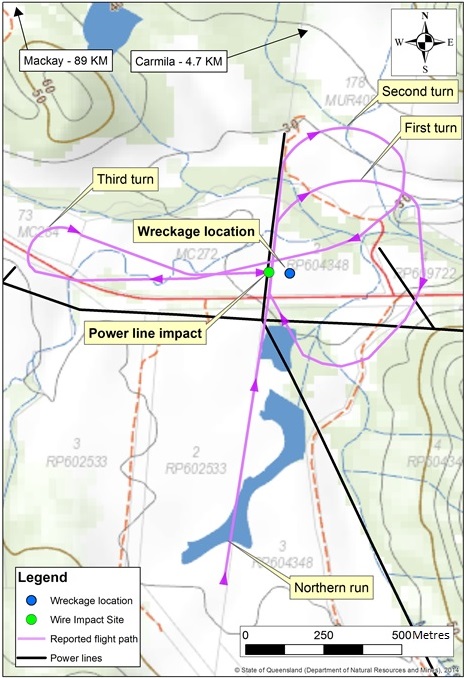
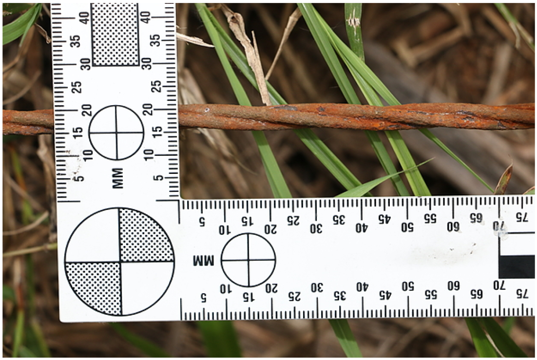
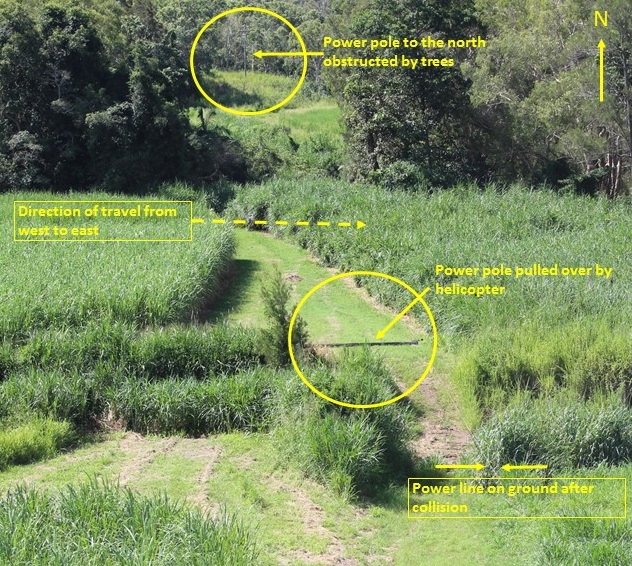
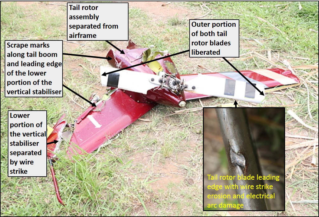
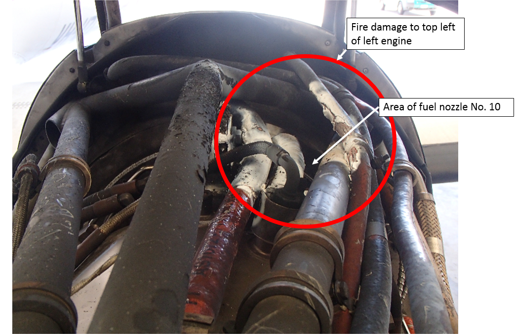
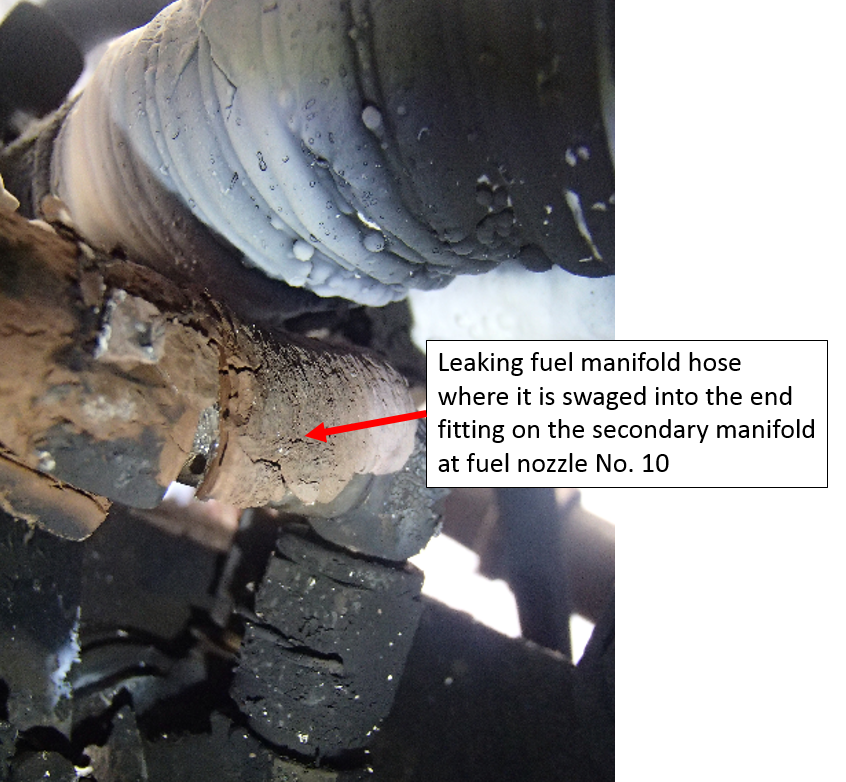
On 20 May 2017, an Airbus A380-842 aircraft, registered VH-OQG, was operating Qantas flight QF 94, from Los Angeles International Airport (LAX), United States, to Melbourne, Victoria. The aircraft departed from runway 24 left (24L) at LAX at about 0542 coordinated universal time (UTC),[1] at the maximum take-off weight of 569 tonnes.
The flight crew comprised the captain, the first officer and two second officers.
The aircraft was cleared by air traffic control (ATC) to climb to flight level (FL) 320.[2] After reaching that level, the captain and a second officer (SO2) left the flight deck for the crew rest area. The first officer then took over as pilot flying (PF) and the other second officer (SO1) was pilot monitoring (PM).[3]
About two hours after departing LAX, the flight crew requested and received ATC clearance to climb to FL 340. The flight crew commenced the climb and increased the thrust on all four engines to 93 per cent ‘N1’[4].
As the aircraft passed FL 325, the crew on the flight deck heard a loud bang and felt a sudden and unusual vibration of the aircraft, which reduced significantly after about 2 seconds. The first officer noticed No. 4 engine’s N1 was much lower than the other three engines – at about 49 per cent (although the flight data showed about 71 per cent N1). The captain, who was in the crew rest area, heard the bang and felt the vibration so he returned to the flight deck.
Flight data showed that as the aircraft passed FL 325, the No. 4 engine intermediate pressure turbine experienced an overspeed and its N2 increased from 92 per cent to the redline limit of 98.5 per cent over the next 2 seconds. An electronic centralised aircraft monitoring (ECAM) ‘ENG 4 N2 OVER LIMIT’[5] message and master warning appeared for 2 seconds.
The SO1 and first officer saw an ECAM message flash up but it disappeared before they could read it.
Shortly after, an advisory message (ADV) appeared on the engine warning display and 6 seconds later the message ‘ENG 4 NORM MODE FAULT’ appeared on the ECAM, along with the associated checklist, a single chime and illumination of the master caution. The ECAM message indicated that there was a problem with the full authority digital engine control (FADEC) of that engine. That fault was triggered by the automatic reversion of the FADEC of engine 4 to alternate mode, caused by the loss of air data or engine sensing parameters.
The flight crew actioned the ECAM first because it had a higher priority than the advisory message[6].
There were only two items on the ECAM checklist. The first required the flight crew to select the switch to set the FADEC to alternate mode for all engines. The second item was to set the autothrust as required (the autothrust was already at an appropriate setting). After completing those two actions, the ECAM message cleared and there were no other ECAMs at that stage.
The first officer received an interphone call from a cabin crewmember in the forward main galley reporting a bang and feeling vibrations. He then received a second interphone call from the cabin crewmember in the main economy galley, reporting that a passenger had seen flames and sparks coming from the right outboard engine.
As the flight crew finished actioning the engine 4 normal mode fault ECAM checklist, the captain arrived on the flight deck, about 60 to 90 seconds after he had heard the bang. The SO1 made the required callout to the first officer when the aircraft was 1,000 ft below FL 340, then swapped out of the captain’s seat. The first officer briefed the captain on the events, and the captain resumed the PF role from the left seat and the first officer became the PM.
The SO1 received multiple calls from cabin crewmembers advising that the aircraft was vibrating in an unusual way, and some had seen sparks and flames. The flight crew found this information very useful because at that stage they had no indication on the flight deck of engine fire.
The flight crew investigated the cause of the ADV message and found that the N1 vibration signal for engine No. 4 indicated 10 units, which was the maximum value.
At about 0724, the aircraft levelled off at FL 340 and the flight crew commenced the abnormal checklist for high engine vibration. According to the flight data, at 0726:17, the flight crew reduced the thrust on engine No. 4 to idle (then generating around 24 per cent N1).
At 0726:44, the engine fire warning ‘ENG 4 FIRE’ ECAM message displayed. The flight crew did not finish the high vibration checklist because the engine fire warning had the highest priority and the flight crew actioned the associated checklist. At 0727:02, the flight crew selected the No. 4 engine master switch off, then pushed the engine No. 4 fire button and discharged one fire retardant agent. The engine fire ECAM cleared.
With the No. 4 engine shut down, the flight crew discussed their options. The aircraft was short of the equal time point between Los Angeles and Honolulu and the weather at both airports was suitable for a diversion, so the crew decided to return to Los Angeles.
The SO1 spoke to the company (Qantas) maintenance watch about the aircraft’s status and to the integrated operations centre about the return to Los Angeles. He also sent a message via the aircraft communications addressing and reporting system (ACARS) advising the company of the engine fire and that they were returning to LAX. The first officer declared a PAN[7] and requested ATC clearance to descend initially to FL 300 and later to FL 290, advising they had shut down an engine and required a diversion to LAX. Air traffic control cleared the aircraft to return to LAX, which was about 2 hours away.
The captain made a public address to the cabin crew and passengers stating that they had an engine issue and had shut down one engine, and were returning to Los Angeles.
There was a light easterly wind at LAX, which would mean a tailwind on runway 25L of about 3 kt. Despite this, the flight crew assessed that it was preferable to land on runway 25L than runway 07 right (07R). This was because of sand dunes and a relatively dark area on the approach to 07R and, more significantly, because autoland[8] is not permitted on runway 07R. They therefore planned for an autoland on runway 25L at a landing weight of about 500 tonnes, and this was programmed into the flight management system. The FO and captain discussed the autobrake setting and elected to set autobrake 2.
When the flight crew received the next weather update, there was an indication of a 5 to 6 kt tailwind on runway 25L. They reworked the landing calculations and found that there was still sufficient margin available on runway 25L as their preferred runway for autoland. They decided, however, to jettison fuel down to a landing weight of 461 tonnes, which gave them a safety margin of 860 m runway length.
At 0944, the fuel jettison was completed over water prior to crossing the coast, about 140 NM from LAX.
The flight crew conducted a normal approach and autoland landing onto runway 25L at about 0956.
During the landing roll, as the aircraft decelerated to 80 kt, the captain deselected autobrake and used the full length of the runway to gradually stop the aircraft. After receiving ATC clearance, the captain taxied the aircraft to the parking bay escorted by airport firefighting services.
The maximum brake temperature recorded was 535 °C, within the normal range. As such, there was no requirement for an emergency disembarkation and the passengers and crew disembarked at the gate.
Communication between cabin crew and flight crew
If the cabin crew have concerns about something that potentially affects the safety of the flight, they should immediately contact the flight deck. According to the flight crew, the cabin crew had provided timely and vitally important information to them, particularly regarding flames and sparks that the flight crew had not known about.
However, due to the number of cabin crewmembers located in different places on the aircraft, several calls were made to the flight deck. The flight crew’s priority at the time was to respond to the fire warning, so they were unable to respond to all of the calls immediately. When the captain tried to contact the flight deck on the interphone after hearing the bang, it was engaged due to the cabin-flight deck communications.
Engine vibrations
The first officer indicated that unlike his experience of Boeing aircraft, where there was a hard limit for engine vibration, they did not get an ECAM generated for the high vibration. According to the captain, flight crew are trained to strictly adhere to ECAM protocols. The high engine vibration procedure was part of the abnormal procedures menu and not presented as an ECAM. Therefore, the FADEC ECAM had higher priority than the high vibration advisory, and the crew did not shut down the engine until the engine fire warning ECAM required this action.
The flight crew operating manual (FCOM) stated that the ECAM vibration advisory is mainly a guideline to monitor the engine parameters and does not call for an immediate engine shutdown. The FCOM also states that high N2 vibrations can occur with or without airframe vibrations and that flight crew should cross-reference other engine parameters in order to determine the required course of action.
Airbus provided the following rationale for the procedure to be followed by flight crew for engine vibrations:
The advisory message blinks when there is an abnormal vibration, that is, when N1 or N2 exceed 5 units.
When the advisory illuminates, flight crew can check the associated ECAM Not Sensed procedure ENG HI VIBRATIONS, which recommends monitoring engine parameters and reducing thrust if possible to maintain vibration level below the advisory threshold.
If vibration is still above the advisory threshold, the decision to shut down the engine is left to the crew – the checklist item states ‘ENG (AFFECTD) MASTER OFF…CONSIDER.’
Autoland and fuel jettison
The A380 is designed so that it can return immediately to the runway from where it departed, and the runway distance will be sufficient to land. The aircraft was certified to autoland at maximum take-off weight. It had taken off from LAX at the maximum take-off weight of 569 tonnes.
Jettisoning fuel enables the flight crew to reduce the aircraft weight to about 440 tonnes. The flight crew elected to jettison fuel to increase the safety margin with the tailwind on the preferred runway.
A prime consideration for an overweight landing is minimisation of the rate of descent on touchdown, where possible to less than 300 ft per minute. Autoland is recommended to reduce the rate of descent on touchdown, and it allows a more consistent approach profile. With one engine shut down, the attitudes, speeds and thrust settings differ from the normal landing phase. The autoland manages those settings and allows the flight crew to monitor the aircraft more effectively.
The overweight landing auto-generates a report that includes touchdown weight and descent rate. After landing in LAX, engineers performed the diagnostic checks and found the touchdown rate of descent was within the limits and the aircraft was wings level at touchdown.
The reduced weight also lessened the risk of hot brakes and wheel fires, and would improve performance in case a go-around was required.
Engineering inspection
Initial engineering inspection of the No. 4 engine following the incident found damage to the low‑pressure turbine blades. There was no visible indication of fire and the event was contained, such that there was no breach of the engine casing. There was minor damage to the right flap and flap fairing from debris exiting the rear of the engine.
Safety analysis
Engine manufacturer investigation
Rolls-Royce, the manufacturer of the aircraft’s Trent 900 engine, conducted an investigation into the engine failure that caused the shutdown.
A teardown of the engine found internally-corroded low-pressure turbine stage 2 (LPT2) blades. The corrosion led to fatigue cracking and subsequent release of blade shroud debris, resulting in significant downstream engine damage.
The corrosion resulted from chemical residue in the hollow blades from cleaning operations at the last service (July 2015). Consequently, Rolls-Royce conducted a thorough audit of cleaning operations and took additional safety action (see Safety action section).
Fire
The fire and overheat detection system was assessed in an attempt to determine the cause of the fire warning. No issues were identified and the fire/overheat detector assemblies were removed and returned to the vendor for further assessment.
The detector manufacturer identified wear in the unit that would have made it more sensitive to vibration and increase the chance of spurious warnings. Rolls-Royce assessed that it was very likely that the wear, coupled with the vibrations associated with this event, contributed to the spurious fire warning.
Findings
These findings should not be read as apportioning blame or liability to any particular organisation or individual.
Internal corrosion of low-pressure turbine stage 2 blades resulted in fatigue failure and separation of blade debris and downstream damage through the engine.
The blade corrosion resulted from chemical residue associated with the cleaning procedure used during the last engine service.
Safety action
Whether or not the ATSB identifies safety issues in the course of an investigation, relevant organisations may proactively initiate safety action in order to reduce their safety risk. The ATSB has been advised of the following safety action in response to this occurrence.
Rolls-Royce
Rolls-Royce, the engine manufacturer has advised the ATSB that it has taken the following safety actions as a result of this occurrence:
Twelve other engines with blades potentially affected by the cleaning process were identified for removal from service under Rolls-Royce Alert non-modification service bulletin (NMSB) RB.211-72-AJ933. At least five engines had been removed at the time of publication of this report.
Stage 5 low pressure turbine blades that had been exposed to the same processing corrosion issue were also identified. As a result, Rolls Royce drafted an additional, recommended NMSB to address engines with exposed Stage 5 blades installed.
Blade overhaul cleaning operation instructions were revised, with additional detail to incorporate best practice with respect to removal of process solutions and chemical residues. This included modifying the orientation and support of the blades during the cleaning process and pressurised water flushing of aerofoil cavities after cleaning to ensure removal of residual cleaning compounds. The rationalised best practice has been applied at all facilities that conduct cleaning of Trent 900 Stage 2 low pressure turbine blades.
Blade serial numbers are to be marked at the root so they are easily identified in future instead of at the tip where shroud losses more commonly occur.
The engine manufacturer distributed an internal safety alert report to highlight the potential issue that could affect other Rolls-Royce engine types.
European Aviation Safety Agency
The European Aviation Safety Agency released Airworthiness Directive (AD) 2018-0121, effective June 2018, relating to the potential for blade corrosion due to residual cleaning contaminants. The AD mandated replacement of the affected blades in accordance with the Rolls-Royce NMSB RB.211-72-AJ933.
Safety message
This incident highlights the importance of reviewing maintenance processes to ensure best practice is followed.
The incident is also an example of effective crew resource management techniques. The flight crew reported that their actions and response, from the initial engine issue when only two members of the flight crew were in the cockpit to the approach and landing with all four crewmembers on the flight deck, flowed very smoothly. They also felt that their collaborative decision-making was excellent and that the highly experienced second officers provided valuable support to the flying pilots.
Purpose of safety investigations
The objective of a safety investigation is to enhance transport safety. This is done through:
identifying safety issues and facilitating safety action to address those issues
providing information about occurrences and their associated safety factors to facilitate learning within the transport industry.
It is not a function of the ATSB to apportion blame or provide a means for determining liability. At the same time, an investigation report must include factual material of sufficient weight to support the analysis and findings. At all times the ATSB endeavours to balance the use of material that could imply adverse comment with the need to properly explain what happened, and why, in a fair and unbiased manner. The ATSB does not investigate for the purpose of taking administrative, regulatory or criminal action.
Terminology
An explanation of terminology used in ATSB investigation reports is available here. This includes terms such as occurrence, contributing factor, other factor that increased risk, and safety issue.
Publishing information
Released in accordance with section 25 of the Transport Safety Investigation Act 2003
Ownership of intellectual property rights in this publication
Unless otherwise noted, copyright (and any other intellectual property rights, if any) in this report publication is owned by the Commonwealth of Australia.
Creative Commons licence
With the exception of the Coat of Arms, ATSB logo, and photos and graphics in which a third party holds copyright, this publication is licensed under a Creative Commons Attribution 3.0 Australia licence.
Creative Commons Attribution 3.0 Australia Licence is a standard form licence agreement that allows you to copy, distribute, transmit and adapt this publication provided that you attribute the work.
The ATSB’s preference is that you attribute this publication (and any material sourced from it) using the following wording: Source: Australian Transport Safety Bureau
Copyright in material obtained from other agencies, private individuals or organisations, belongs to those agencies, individuals or organisations. Where you wish to use their material, you will need to contact them directly.
On 17 May 2017, the pilot of a Robinson Helicopter R44 II, registered VH-MNU, was conducting aerial work at Moreton Island, Queensland with one passenger on board.
The pilot completed one flight without incident and, after refuelling, departed for a second local flight at about 1005 Eastern Standard Time (EST). At the start of the flight, the wind was from the east-north-east at about 5–6 kt, but increased to about 10 kt.
At about 1130, the helicopter was approximately 50 ft above ground level and tracking in a north-westerly direction at an airspeed of about 10 kt (and groundspeed of about 20 kt), when the pilot commenced a right turn.
The pilot felt a loss of tail rotor effectiveness (LTE) as the helicopter continued to yaw to the right and reported that they were unable to arrest the yaw with left pedal input. The pilot applied forward cyclic to try to increase the helicopter’s forward speed, and some right cyclic to try to follow the turn. The pilot hoped the tail rotor effectiveness would return as the helicopter turned back into wind, but as it rotated through about 110 degrees, the rate of yaw started to increase. The pilot then raised the collective in an attempt to increase the helicopter’s height above trees, which further increased the yaw rate due to the increase in torque.
The helicopter completed about two full rotations and reached about 80 ft above the ground, when the low rotor RPM warning horn sounded. The pilot immediately lowered the collective and the helicopter descended. The pilot stated that they were going down, and the passenger braced for the impact.
As the helicopter neared treetop height, the pilot deployed the emergency floats. As the floats contacted the trees, the pilot raised the collective to cushion the impact. The pilot and passenger sustained minor injuries and the helicopter was substantially damaged (Figure 1).
Figure 1: Accident site showing damage to VH-MNU
Source: Pilot
Use of emergency floats
The pilot commented that the company pilots had previously discussed the use of the floats in case of having to conduct a forced landing over a treed area. The pilot assessed that the floats would increase the surface area, therefore slowing the helicopter’s descent.
Helmet
The pilot was wearing a helmet at the time of the accident. Although the helmet’s visor caused the pilot’s nose to bleed, the helmet sustained impact and scratch damage that probably prevented the pilot sustaining more serious injuries.
Performance
The helicopter departed for the flight about 36 kg below the maximum take-off weight and had been operating for about 30 minutes using about 30 L of fuel at the time of the accident, and was therefore more than 60 kg below the maximum take-off weight at the time of the accident.
Operator report
The helicopter operator conducted an investigation into the accident and provided the ATSB with a copy of their investigation report. The operator’s findings included the following.
The pilot wrote down their risk considerations prior to the flight and included LTE, but did not include the recovery technique. When the helicopter encountered the initial weathervane LTE, the correct recovery procedure of full left pedal, forward cyclic was not observed.
Although the pilot had the required training for low-level operations, they had not received specific training for the task.
The pilot’s scan during low-level operation may have been affected by focusing on the map, depicting drop locations.
Loss of tail rotor effectiveness
The United States Federal Aviation Administration (FAA) Helicopter flying handbook
The FAA Helicopter flying handbook chapter 11: Helicopter emergencies and hazards stated that loss of tail rotor effectiveness (LTE) is an uncommanded rapid yaw towards the advancing blade and is an aerodynamic condition caused by a control margin deficiency in the tail rotor. Tail rotor thrust is affected by numerous factors, including relative wind, forward airspeed, power setting and main rotor blade airflow interfering with airflow entering the tail rotor. Several wind directions relative to the nose of the helicopter are conducive to LTE, including the following:
120–240º, in which the helicopter attempts to weathervane its nose into the relative wind. The Handbook states ‘If the pilot allows a right yaw rate to develop and the tail of the helicopter moves into this region, the yaw rate can accelerate rapidly.
285–315°, which can lead to turbulent airflow from the main rotor disc interfering with the tail rotor.
210–330°, which can lead to the development of unsteady airflow through the tail rotor.
The FAA handbook warns that a combination of factors in a particular situation can lead to more anti-torque required from the tail rotor than it can generate. In addition, low speed flight activities are a high-risk activity for LTE. The FAA handbook advises pilots (among other things) to avoid tailwinds below an airspeed of 30 kt. In addition, it provides the following recovery technique for a sudden unanticipated yaw:
apply full left pedal while simultaneously moving cyclic control forward to increase speed
if altitude permits, reduce power
as recovery is effected, adjust controls for normal forward flight.
The Robinson Helicopter Company advised that to avoid unanticipated yaw, pilots should be aware of conditions that may require large or rapid pedal inputs. They recommend practising slow, steady-rate hovering pedal turns to maintain proficiency in controlling yaw.
Low rotor RPM recovery
The Robinson Helicopter Company R44 II Pilot’s operating handbook stated ‘To restore RPM, immediately roll throttle on, lower collective and, in forward flight, apply aft cyclic.’
Findings
These findings should not be read as apportioning blame or liability to any particular organisation or individual.
The combination of low airspeed and turning right with a tailwind contributed to a loss of tail rotor effectiveness. The pilot’s response was ineffective at recovering control of the helicopter, particularly given the operation at low height above the trees.
Safety action
Whether or not the ATSB identifies safety issues in the course of an investigation, relevant organisations may proactively initiate safety action in order to reduce their safety risk. The ATSB has been advised of the following proactive safety action in response to this occurrence.
Helicopter operator
As a result of this occurrence, the helicopter operator has advised the ATSB that they are taking the following safety actions:
Company pilots are to be briefed and trained on task specific operations.
A presentation on LTE has been given to all company helicopter pilots.
The operations manual has been amended to highlight and add more detail to specific task training and pilot limitations.
Training items have been updated to incorporate scenario/task training flights.
Company pilots were required to re-read the operations manual, with a focus on the planning section (Part D).
Company pilots will complete cockpit resource management (CRM) training.
Safety message
LTE
The FAA handbook states: ‘In order to avoid the onset of LTE in this downwind condition, it is imperative to maintain positive control of the yaw rate and devote full attention to flying the helicopter’.
Effectiveness of helmets in helicopter operations
The United States Army referenced two United States Army Aeromedical Research Laboratory studies of helmet effectiveness in USAARL report 93-2. The first study from the period 1957–1960 found that fatal head injuries were 2.4 times more common among unhelmeted occupants of potentially survivable helicopter accidents than among occupants wearing the army’s APH-5 helmet. The second study from the period 1972–1988 found that the risk of fatal head injury was 6.3 times greater in unhelmeted occupants of potentially survivable helicopter accidents than among occupants wearing the army’s SPH-4[1] helmet.
In a separate study (report 98-18) the Army Aeromedical Research Laboratory reviewed 459 accidents in the period 1990–1996 where helmet visor use was verified. They found that visor use was attributed to preventing facial injury in 102 accidents (22.2 per cent) and reducing injury in 13 accidents (2.8 per cent).
This accident highlights the effectiveness of wearing a helmet to prevent a more serious injury. ATSB report AO-2014-058 provides an account of a serious head injury to an R22 pilot who was not wearing a helmet. In a later ATSB report, AO-2015-134, the operator commented that the pilot of an R22 accident would have suffered more serious head injuries if they were not wearing a helmet.
The objective of a safety investigation is to enhance transport safety. This is done through:
identifying safety issues and facilitating safety action to address those issues
providing information about occurrences and their associated safety factors to facilitate learning within the transport industry.
It is not a function of the ATSB to apportion blame or provide a means for determining liability. At the same time, an investigation report must include factual material of sufficient weight to support the analysis and findings. At all times the ATSB endeavours to balance the use of material that could imply adverse comment with the need to properly explain what happened, and why, in a fair and unbiased manner. The ATSB does not investigate for the purpose of taking administrative, regulatory or criminal action.
Terminology
An explanation of terminology used in ATSB investigation reports is available here. This includes terms such as occurrence, contributing factor, other factor that increased risk, and safety issue.
Publishing information
Released in accordance with section 25 of the Transport Safety Investigation Act 2003
Ownership of intellectual property rights in this publication
Unless otherwise noted, copyright (and any other intellectual property rights, if any) in this report publication is owned by the Commonwealth of Australia.
Creative Commons licence
With the exception of the Coat of Arms, ATSB logo, and photos and graphics in which a third party holds copyright, this publication is licensed under a Creative Commons Attribution 3.0 Australia licence.
Creative Commons Attribution 3.0 Australia Licence is a standard form licence agreement that allows you to copy, distribute, transmit and adapt this publication provided that you attribute the work.
The ATSB’s preference is that you attribute this publication (and any material sourced from it) using the following wording: Source: Australian Transport Safety Bureau
Copyright in material obtained from other agencies, private individuals or organisations, belongs to those agencies, individuals or organisations. Where you wish to use their material, you will need to contact them directly.
On 13 May 2017, a Jetstar Airways Boeing 787-8 aircraft, registered VH-VKA, was being operated on a scheduled passenger service from Singapore Changi Airport, Singapore to Melbourne, Victoria. There were two flight crew, nine cabin crew and 231 passengers on board. The captain was designated as the pilot monitoring and the first officer (FO) was the pilot flying.[1]
At about 1325 Coordinated Universal Time (UTC),[2] the aircraft was pushed back from the departure gate at Singapore and the flight crew received taxi instructions for a departure from runway 20 Centre (20C). After a short taxi, the aircraft was lined up for departure at about 1332. The flight crew had set flaps 5 for departure with a calculated rotation speed (VR) [3] of 169 kt at the take-off weight of 191 t. Their planned acceleration altitude was 3,000 ft (the altitude at which the flaps would be retracted from flaps 5 to flaps 1).
The flight crew received air traffic control instructions for a standard instrument departure and the aircraft departed. At about 3,000 ft the FO called for flaps 1 and the captain set the flap lever to the flaps 1 setting. The flight crew then received an engine-indicating and crew-alerting system caution for FLAPS DRIVE, which indicated a fault with the wing flaps. The captain notified air traffic control of the fault, received a clearance to level the aircraft at 6,000 ft and completed the FLAPS DRIVE fault checklist actions. The aircraft entered a holding pattern at 6,000 ft and the captain elected to assume the role of pilot flying after the decision was made to return to Singapore.
While in the holding pattern, the flight crew completed their failure management briefing and briefed the cabin crew manager about the occurrence and their plan. The captain then made a public address to the passengers to inform them of the need to return to Singapore due to a technical issue with the flaps. The FO contacted the company to report their intentions, calculated the reference landing speed (VREF)[4] as 195 kt[5] at about 188 t[6] with flaps 1 selected and briefed the arrival procedure. The captain elected not to jettison excess fuel due to their proximity to other aircraft in the holding pattern, the landing distance required provided a sufficient safety margin, and the fact that the checklist did not require it.
The aircraft landed without incident and was taxied to the gate with emergency service vehicles in attendance. The captain noted on the engine-indicating and crew alerting system that there was a high brake temperature on one of the right landing gear brakes after landing and reported this to the engineering staff after shutdown. Before the flight crew exited the aircraft an engineering staff member entered the flight deck to report that they found damage to the left wing. This was followed by a report from a ground handling staff member that rubber debris was found on runway 20C (Figure 1). The captain annotated the FLAPS DRIVE fault and overweight landing with a ‘positive’[7] touchdown in the aircraft technical log.
Figure 1: Tyre debris on runway 20C
Source: ATSB (debris field locations courtesy Transport Safety Investigation Board, Singapore)
Aircraft flaps
The aircraft is fitted with inboard and outboard trailing edge flaps, and leading edge slats on each wing (Figure 2). The trailing edge flaps are used in conjunction with the leading edge slats to increase lift at lower speeds. The flap positions for the 787-8 are 0, 1, 5, 15, 20, 25 and 30 units. Take-off settings are 5, 15 and 20. Normal landing settings are 25 and 30.
Power to move the flaps is provided by hydraulic or electric motors on a power drive unit (PDU), which turns flap torque tubes, which in turn operate geared rotary actuators (Figure 3). The geared rotary actuators extend or retract the flaps with their drive arms. The aircraft’s flight control electronics cabinets monitor the position of each section of flap for misalignment using four flap skew sensors. The flight control electronics cabinets shut down the flap drive system and send an engine-indicating and crew-alerting system message (FLAPS DRIVE) if a flap asymmetry is detected.
The Boeing 787 flight crew operations manual indicated that the annunciation of FLAPS DRIVE is for a flap drive mechanism failure. Alternate flaps should not be used as asymmetry protection will not be provided. The ground proximity warning system should be set to flap override (to prevent nuisance warnings of incorrect flap configuration during the approach). The manual also stated that the flight management computer fuel predictions should not be used in this condition. If the fault occurred at flaps 5 or less, then the flap lever should be set to flaps 1 to ensure the slats are extended (Figure 2 and 3) and use the VREF for flaps 30 plus 40 kt for landing.
Flight data recorder
The flight data recorder provided the following key events (Table 1).
Table 1: Key events from the flight data recorder
Time
Event
13:35
Aircraft became airborne at about 180 kt
13:36
Flap lever set in flaps 1 detent – flaps not in commanded position – leading edge/trailing edge surfaces in motion (about 3,500 ft pressure altitude)
13:36
Flap asymmetry detected – flap drive system shutdown
13:36
Flaps drive fault message (flap lever remains in flaps 1 position until after landing)
13:38
Ground proximity warning system flap override set
14:16
Touchdown at about 190 kt
Aircraft damage
Inspection of the aircraft found the number 6 wheel tyre tread had delaminated (Figure 4). Damage to the airframe included the left inboard wing panel (above the number 6 wheel) was punctured (Figure 5 left), an area of the trailing edge of the left inboard flap was cracked, and the left inboard flap torque tube was broken (Figure 5 right). A broken torque tube will interrupt the flap drive system for flaps outboard of the break. Consequently, a change in the flap setting will trigger a misalignment between the flap skew sensors.
Figure 4: Number 6 wheel tyre (left picture looking forward and the right looking rearwards)
Aircraft tyres are designed for intermittent operation in which they are accelerated to high speeds in short periods of time. While the acceleration of the tyre is higher on landing, the take-off speed is usually higher compared to landing. The sudden periods of acceleration generate high temperatures and centrifugal forces, and, because the tyre is pneumatic, this leads to compression, tensile and shear forces. Deflection of the tyre tread from contact with the runway surface distorts the tyre from the normal shape and sets up a traction wave in the tread. This leads to higher tensile forces on the outer plies than on the inner plies, which generates shear forces between the layers of ply (Figure 6). Aircraft tyres have a groundspeed rating, which was 235 MPH (about 204 kt) for the occurrence aircraft tyre.
Figure 6: Generic tyre construction
Source: Michelin
Damaged tyre
The damaged tyre was Michelin part number M42202 for the Boeing 787, which was a replacement for the previous M42201. The damaged tyre and the number 5 wheel tyre (mate tyre) were returned to the tyre manufacturer for tyre analysis. The manufacturer’s report noted that 360° of tread was missing and the reinforcing plies were exposed and abraded in areas (Figure 7 left). There was shoulder step-wear and a crack along the serial side[8] shoulder (outboard of main landing gear truck) that had propagated through the tread reinforcing ply. There were no indications of rolling under low pressure.
Figure 7: Number 6 wheel tyre (left) and number 5 wheel tyre (right)
Source: Michelin, modified by the ATSB
The manufacturer’s report concluded that the shoulder step-wear allowed for a raised tread rib, which was subjected to a lateral force strong enough to tear the tread rubber with continued use. The cracking ‘propagated through the tread reinforcing ply and generated the thrown tread as the consequence’ (Figure 7 left). The number 5 wheel tyre was found with cracking on the opposite serial side shoulder (inboard of main landing gear truck), which had started to propagate through the tread reinforcing ply (Figure 7 right). They concluded that chevron cutting around the tread of both tyres indicated that they had been operated on an aggressive runway surface.
When asked to clarify the reference to an ‘aggressive runway surface’, the manufacturer indicated that chevron cutting is linked to grooved runways. The forces required to accelerate the tyre to ground speed during the touchdown phase generate a tearing action, which results in the chevron cutting damage.
Tyre maintenance
The number 6 wheel tyre was received by the operator as a new tyre with a Civil Aviation Safety Authority authorised release certificate, dated 30 November 2016. The wheel assembly was installed on VH-VKA on 9 December 2016 and had accumulated 302 cycles at the time of the failure. The maintenance program inspection interval for the tyres included a general visual inspection on each arrival. The replacement interval for the tyre was ‘on-condition’.[9] The number 5 wheel tyre had accumulated 307 cycles at the time of the incident. Both tyres were below the average life for the operator’s use of these part numbers. The operator reported that this was their first occurrence of a tyre delamination on its 787 fleet.
On arrival at Singapore Changi Airport from the previous flight, the aircraft was subjected to an arrival check and a pre-departure service check. The checks were certified as satisfactory and completed at 1145 UTC. Item 1.2 on the arrival check included:
Inspect (General Visual) the Nose and Main Wheel Tyres IAW DMC-B787-A-32-45-04-00B-311A-A
Note: Ensure tyres have a sufficient life remaining for the intended flight/s, including the return to an Australian Port.
Item 1.1 of the pre-departure service check included an inspection of the nose and main wheels and tyres. However, this check was not required to be performed if the same maintenance person performed the arrival check within the previous 120 minutes and was certifying for both checks. Both checks had the same certifying person’s signature and stamp. The operator reported that the certification for the pre-departure service check was likely an acknowledgement that the tyre check was not required, rather than that it was performed.
The checks took place between 0910 and 1145. Sunset in Singapore on 13 May 2017 was about 1106.
The aircraft maintenance manual task (DMC-B787-A-32-45-04-00B-311A-A) for the general visual inspection of the tyres included the following instructions:
1. C. (1) (a) Examine the tyres for air leaks, abrasions, unusual worn areas, cuts, and flat spots.
1. C. (1) (c) Remove tyres that have the conditions that follow:
- 1) Cuts or weather cracks in the grooves, the tread, shoulders or sidewalls that exceed the limits shown in Figure 2, Tyres General Visual Inspection.
- 2) Blisters, bulges, or other signs of ply separation in the tread, shoulder or the sidewall area.
Michelin’s care and service instructions
Michelin’s aircraft tyre care and service manual, chapter 5, section 8.17 described a ‘thrown tread’ as the ‘partial or complete loss of the tread rubber.’ Potential causes include cuts. The manual stated:
Early signs of separations of internal components may appear as bulges, uneven wear, or localised rubber splits. It is important to remove tyres from service when any evidence of separation is first seen. During high-speed rotation, even small areas of separation can grow into partial or full tread rubber loss.
Chapter 5, section 7.2 indicated ‘removal criteria for normal wear is based on remaining tread rubber as determined by groove depth or exposure of textile/steel ply material’.
Operator’s flight data review
A comprehensive review of flight data was conducted to determine if operational techniques, such as lateral acceleration on take-off and touchdown, may have exposed the tyre to increased side load. No occurrences were noted for any of the operator’s aircraft in the 787 fleet.
Safety analysis
The flap drive fault the flight crew received on departure from Singapore Changi Airport was the result of the delamination of the number 6 wheel tyre tread during take-off. The airport operator found two debris fields on runway 20C, which was used for the take-off and landing. The delamination on take-off likely occurred at the southern end of the runway, when the tyre was at high speed, which provided sufficient energy for the tread to penetrate the left under wing panel and break a flap torque tube. The runway 20C northern debris field was likely the result of further tyre delamination on landing as a result of the touchdown and wheel acceleration.
The tyre manufacturer concluded that the tyre had operated over its life on a grooved runway surface, which generated chevron cutting damage. Before departure the aircraft tyres were certificated as inspected in accordance with the aircraft manufacturer’s general visual inspection requirements. While no faults were recorded for the arrival and pre-departure service checks, it was possible that the tyre shoulder was already subject to undercutting of the tread before departure. The arrival inspection likely occurred during daylight hours, but the aircraft may have been parked with the tyre tread positioned such that the initiation site was not visible to the inspector. However, this was not confirmed by the ATSB. However, the certification for the pre-departure service check was likely an acknowledgement that the tyre check was not required, rather than that it was performed.
When the flight crew moved the flap selector from the flaps setting of 5 to 1, the left inboard and outboard flaps were unable to move, due to the broken torque tube. The right flaps started to move, which generated a flap misalignment signal. The flight control electronics cabinets shut down the flap drive system in response to the misalignment and generated the FLAPS DRIVE fault message. The flight crew then completed the FLAPS DRIVE checklist. While the crew did not know about the tyre damage, the aircraft protective systems and crew actions allowed for a safe return and landing, despite the aircraft being overweight and at a higher-than-normal landing speed.
Findings
These findings should not be read as apportioning blame or liability to any particular organisation or individual.
The number 6 wheel tyre experienced shoulder step-wear, which led to cracking and undercutting of the tyre tread and a subsequent delamination of the number 6 tyre, which occurred in less than the normal average life cycles.
Debris from the delaminated tyre penetrated the left under wing panel and damaged the flap torque tube, resulting in an asymmetric flap condition when the flaps were commanded to retract.
When retracting the wing flaps, the crew received a flap drive fault indication, which resulted in a return to the departure airport and a high-speed overweight landing.
Following the damage to the flap torque tube, the aircraft protective systems operated as designed and the flight crew completed the checklist as published.
Safety action
Whether or not the ATSB identifies safety issues in the course of an investigation, relevant organisations may proactively initiate safety action in order to reduce their safety risk. The ATSB has been advised of the following proactive safety action in response to this occurrence.
Aircraft operator
As a result of this occurrence, the aircraft operator has advised the ATSB that they have taken the following safety action:
Quality notice
The operator issued a quality notice to their maintenance line stations and external maintenance organisations on the subject 787 Main Landing Gear Tyre Inspections (Shoulder Wear). The notice explained the incident and highlighted the inspection and tyre replacement requirements for tyre shoulder damage.
Flight standing order
The operator issued a flight standing order to their 787 pilots on the subject of Tyre Wear to highlight the shoulder area of the tyre as requiring extra attention during pre-flight inspections.
Safety message
Following the flaps drive fault message, the flight crew completed the appropriate checklist and landed at the nearest suitable airport without further incident. While the condition of the tyre and the exact fault with the flaps were unknown to the flight crew at the time of their decision-making, this occurrence highlights the importance of following failure management procedures.
Purpose of safety investigations
The objective of a safety investigation is to enhance transport safety. This is done through:
identifying safety issues and facilitating safety action to address those issues
providing information about occurrences and their associated safety factors to facilitate learning within the transport industry.
It is not a function of the ATSB to apportion blame or provide a means for determining liability. At the same time, an investigation report must include factual material of sufficient weight to support the analysis and findings. At all times the ATSB endeavours to balance the use of material that could imply adverse comment with the need to properly explain what happened, and why, in a fair and unbiased manner. The ATSB does not investigate for the purpose of taking administrative, regulatory or criminal action.
Terminology
An explanation of terminology used in ATSB investigation reports is available here. This includes terms such as occurrence, contributing factor, other factor that increased risk, and safety issue.
Publishing information
Released in accordance with section 25 of the Transport Safety Investigation Act 2003
Ownership of intellectual property rights in this publication
Unless otherwise noted, copyright (and any other intellectual property rights, if any) in this report publication is owned by the Commonwealth of Australia.
Creative Commons licence
With the exception of the Coat of Arms, ATSB logo, and photos and graphics in which a third party holds copyright, this publication is licensed under a Creative Commons Attribution 3.0 Australia licence.
Creative Commons Attribution 3.0 Australia Licence is a standard form licence agreement that allows you to copy, distribute, transmit and adapt this publication provided that you attribute the work.
The ATSB’s preference is that you attribute this publication (and any material sourced from it) using the following wording: Source: Australian Transport Safety Bureau
Copyright in material obtained from other agencies, private individuals or organisations, belongs to those agencies, individuals or organisations. Where you wish to use their material, you will need to contact them directly.
On 12 May 2017, a Cessna 210M aircraft, registered VH-EGB, departed Broome, Western Australia (WA) on a freight charter flight with the intended destination of Fitzroy Crossing, WA.
About one hour into the flight, at about 1027 Western Standard Time (WST), the pilot noticed on the engine data monitor (EDM) that the fuel flow was fluctuating between 40 and 65 litres per hour. The pilot then confirmed that the analogue fuel flow gauge was also fluctuating and enriched the fuel mixture to see if that would stabilise the fuel flow, but the fluctuations continued.
The pilot then completed the fuel vaporisation checklist and switched the selected fuel tank from the right to the left. When the pilot selected the fuel pump on, in accordance with the checklist, the fuel flow initially indicated a rise, then stabilised to normal.
About 20 seconds later, the engine surged and then stopped, but the propeller was still turning. The engine RPM and fuel flow reduced to zero. At that time, the aircraft was 25 to 30 NM beyond Liveringa, so the pilot turned towards that airfield.
The pilot then conducted the engine restart procedure, leaving the left fuel tank selected. The mixture was already fully rich, with the throttle half open. The pilot selected the fuel booster pump on low for three seconds and then increased the throttle to full.
The engine restarted, but was coughing and surging and not producing enough power to maintain level flight at 9,500 ft above mean sea level. The pilot reduced the throttle to lessen the engine surges and set the attitude to maintain an airspeed of 80 kt, which was the best glide speed for that weight. In that configuration, the aircraft was descending at about 600 ft per minute.
The pilot broadcast a Mayday call and then reduced the power to just above idle, where it was running the smoothest. The fuel boost pump was also selected off, which reduced the surging. The aircraft was then descending at about 400 ft per minute. The pilot conducted a straight-in approach to join a five-mile final approach for runway 25 at Liveringa, maintaining additional height (to a normal approach) in case the engine stopped completely, requiring a glide approach and landing.
During the approach, the pilot observed that the cylinder head temperature (CHT) had dropped from above 337º (when they had conducted a trend measurement a few minutes before the engine issues started), to below 200º. The EDM display bar graph of each CHT would normally be at 5 or 6, but were at or below 2, with one cylinder on 0.
The aircraft landed without further incident. After landing, the pilot phoned a maintenance engineer, who advised the pilot to conduct a visual inspection. The pilot observed a fuel outlet valve that had sheared off, but as it was an overflow valve, would not have caused the power loss. The pilot then performed engine run-ups with all indications normal.
Pre-flight
Prior to the flight, the pilot conducted fuel drains, with no water or other contaminants found in the fuel.
Engineering report
The aircraft had just had a 200-hourly maintenance inspection. It was the first flight after the maintenance.
The post-incident inspection found that the fuel fluctuations probably resulted from a full or partial blockage of the fuel vent system.
Rough running and engine stoppage
The operator conducted an investigation into the incident and found the following.
Although the pilot selected the fuel pump to low, when the throttle is then moved forwards of 19 inches of manifold pressure, an actuator automatically switches the fuel pump to high flow.
The combination of the fuel mixture in the full rich position and the fuel pump at high flow probably introduced too much fuel into the engine, extinguishing the combustion process. As the aircraft was then at about 9,000 ft, the fuel to air ratio became high enough to result in the engine stopping.
The pilot’s comment that the engine subsequently ran better at lower power setting and the low CHT, suggests that the engine mixture was overly rich.
Cessna service information letter (SIL) SE 79-25, Fuel flow stabilization, provided information to aid in the recognition and prevention of excessive fuel vapour accumulation in the fuel system. It stated that ‘indications of fuel vapour accumulation are fuel flow gauge fluctuations greater than 5 lbs/hr. This condition with leaner mixtures or with larger fluctuations may result in power surges.’
Findings
These findings should not be read as apportioning blame or liability to any particular organisation or individual.
The fuel vent system was probably partially or fully blocked, resulting in fuel flow fluctuations.
The engine probably stopped due to over-rich fuel mixture.
Safety action
Whether or not the ATSB identifies safety issues in the course of an investigation, relevant organisations may proactively initiate safety action in order to reduce their safety risk. The ATSB has been advised of the following safety action in response to this occurrence.
Aircraft operator
As a result of this occurrence, the aircraft operator has advised the ATSB that they are taking the following safety actions:
Notice to aircrew
The company issued a notice to all flight crew and included Cessna service information letter (SIL) SE 79-25. The SIL included the fuel flow stabilisation procedure, what stated ‘Reset the mixture as required’. The notice advised flight crew regarding the ‘reset’, to first lean the mixture to peak exhaust gas temperature (EGT), then enrich to the company standard operating procedures setting of 75º rich of peak EGT, as ‘Placing the mixture to rich will most likely cause engine stoppage at altitude due to an incombustible mixture’.
Maintenance
Closer inspections of fuel tank vent systems are to be carried out during scheduled maintenance.
Daily inspection
Flight crew are to check the fuel vent as part of the daily inspection of aircraft.
Safety message
This incident highlights the importance of good decision making following an engine failure or malfunction. The pilot maintained as much altitude as was safely possible, to increase the glide distance. After turning towards the nearest airfield, the pilot also kept a lookout for suitable forced landing sites.
It further highlights the need for unambiguous actions in emergency procedure checks to prevent an event from escalating.
The objective of a safety investigation is to enhance transport safety. This is done through:
identifying safety issues and facilitating safety action to address those issues
providing information about occurrences and their associated safety factors to facilitate learning within the transport industry.
It is not a function of the ATSB to apportion blame or provide a means for determining liability. At the same time, an investigation report must include factual material of sufficient weight to support the analysis and findings. At all times the ATSB endeavours to balance the use of material that could imply adverse comment with the need to properly explain what happened, and why, in a fair and unbiased manner. The ATSB does not investigate for the purpose of taking administrative, regulatory or criminal action.
Terminology
An explanation of terminology used in ATSB investigation reports is available here. This includes terms such as occurrence, contributing factor, other factor that increased risk, and safety issue.
Publishing information
Released in accordance with section 25 of the Transport Safety Investigation Act 2003
Ownership of intellectual property rights in this publication
Unless otherwise noted, copyright (and any other intellectual property rights, if any) in this report publication is owned by the Commonwealth of Australia.
Creative Commons licence
With the exception of the Coat of Arms, ATSB logo, and photos and graphics in which a third party holds copyright, this publication is licensed under a Creative Commons Attribution 3.0 Australia licence.
Creative Commons Attribution 3.0 Australia Licence is a standard form licence agreement that allows you to copy, distribute, transmit and adapt this publication provided that you attribute the work.
The ATSB’s preference is that you attribute this publication (and any material sourced from it) using the following wording: Source: Australian Transport Safety Bureau
Copyright in material obtained from other agencies, private individuals or organisations, belongs to those agencies, individuals or organisations. Where you wish to use their material, you will need to contact them directly.
On 23 March 2017, a Gippsland Aeronautics GA-8 aircraft, registered VH-AJZ, was being used to conduct incendiary bombing aerial work operations[1] in the Prince Regent River area of northern Western Australia (WA). On board were a pilot, a navigator seated in the co-pilot seat and a bombardier in the rear of the aircraft cabin.
While conducting the incendiary bombing operations, the bombardier advised the pilot that he was suffering from motion sickness. The pilot elected to land at Gibb River aircraft landing area (ALA), WA, to take a lunch break and provide the bombardier with time to recover from the motion sickness.
At about 1255 Western Standard Time (WST), the aircraft landed on runway 07 at Gibb River. During the landing roll, the engine failed. The aircraft had sufficient momentum to enable the pilot to turn the aircraft around on the runway and begin to taxi to the parking area at the western end of runway 07. Shortly after turning around, the aircraft came to rest on the runway. The pilot attempted to restart the engine, but the engine did not start. The pilot waited about 10–20 seconds before again attempting to restart the engine.
While attempting the second restart of the engine, the pilot heard a loud noise similar to that of a backfire. The navigator then observed flames and smoke coming from around the front of the engine and immediately notified the pilot. After being notified of the fire, the pilot immediately shut down the engine and switched off the aircraft electrical system.
As the pilot switched off the aircraft electrical system, the navigator located the aircraft fire extinguisher and evacuated from the aircraft through the co-pilot door. After evacuating from the aircraft, the navigator observed fire on the aircraft nose wheel. The navigator had difficulty preparing the fire extinguisher for use and was unable to discharge the fire extinguisher onto the fire.
While the navigator was attempting to extinguish the fire, the pilot exited the aircraft through the pilot door and assisted the bombardier to exit the aircraft. After assisting the bombardier, the pilot moved to the front of the aircraft to assist the navigator with the firefighting. The pilot was able to activate the fire extinguisher and extinguished the fire on the nose wheel. The pilot observed fire continuing to burn within the engine compartment. Due to the heat of the fire, the pilot was unable to access the engine compartment to extinguish this fire. The pilot determined that no more could be done to contain the fire, and therefore, the pilot, navigator and bombardier moved clear of the aircraft to a safe location as the fire continued.
The crew members were not injured. As a result of the fire, the aircraft was destroyed (Figure 1).
Figure 1: VH-AJZ wreckage
Source: Operator
Pilot comments
The pilot of the aircraft provided the following comments:
The temperature at Gibb River at the time of the landing was about 33–34 °C.
There were no abnormal engine indications prior to the engine failing.
The engine failed in a manner similar to a normal engine shutdown. The pilot had not experienced an engine failure in that manner before.
The electric fuel pump remained on after landing and throughout the attempted starts. During the attempted starts, the pilot ‘cracked’ the throttle and advanced the mixture lever while cranking the engine. Between the first and second start attempts, the mixture control was selected to idle cut-off.
When assisting the bombardier to evacuate, one box of incendiary capsules was removed, however, three or four boxes remained in the aircraft.
Chief pilot comments
The operator’s chief pilot provided the following comments:
Due to the significant fire and heat damage, the cause of the fire could not be determined (Figure 2).
When taxiing in high ambient temperatures and at low power settings, fuel may vaporise within the mechanical engine fuel pump, and this can lead to the engine failing. When operated in these conditions, the aircraft should be taxied with the electric fuel pump on to prevent fuel vaporisation.
Figure 2: Fire damage to engine
Source: Operator
Engine fire during start emergency procedure
The GA-8 emergency procedures included the ‘engine fire during start emergency procedure.’ In case of an engine fire during start, the procedural steps to be followed are shown in Figure 3.
Figure 3: GA-8 fire during start on ground emergency procedure extract
Source: Mahindra Aerospace
After the fire was detected, the pilot shut down, rather than continued cranking the engine. After the engine was shut down, the fuel shutoff valve was not selected off.
Safety analysis
The extent of damage to the engine and aircraft prevented the reasons for the engine failure being determined.
The presence of fire on the nose wheel below the engine indicates that the fire was probably fed by a fluid. However, the extent of damage to the engine prevented the reason of the fire being determined.
After identifying the engine fire, the engine was shut down, and cranking was not continued in accordance with the emergency procedure. Cranking the engine may have extinguished the fire before it became unmanageable. After the engine was shut down, the fuel shutoff valve was not closed to provide a barrier between the fuel tanks and the engine. Not completing this step of the engine fire during start emergency procedure increased the likelihood of fire and allowed the fire to intensify.
Findings
These findings should not be read as apportioning blame or liability to any particular organisation or individual.
The cause of the engine failure and fire could not be determined.
After the fire was identified, two steps in the emergency procedure were omitted. This included not closing the fuel shutoff valve, which likely resulted in the fire not being extinguished and subsequently intensifying.
Safety Action
Whether or not the ATSB identifies safety issues in the course of an investigation, relevant organisations may proactively initiate safety action in order to reduce their safety risk. The ATSB has been advised of the following proactive safety action in response to this occurrence.
Aircraft operator
As a result of this occurrence, the aircraft operator has advised the ATSB that they are taking the following safety actions:
Retraining
The pilot has completed retraining with an emphasis on fire procedures.
Safety message
This investigation highlights the importance of knowing and understanding flight manual normal and emergency procedures. In this accident, steps in the engine fire during start procedures were omitted. When facing a situation as serious as a fire, the published emergency procedures provide the foundation for emergency response management.
The objective of a safety investigation is to enhance transport safety. This is done through:
identifying safety issues and facilitating safety action to address those issues
providing information about occurrences and their associated safety factors to facilitate learning within the transport industry.
It is not a function of the ATSB to apportion blame or provide a means for determining liability. At the same time, an investigation report must include factual material of sufficient weight to support the analysis and findings. At all times the ATSB endeavours to balance the use of material that could imply adverse comment with the need to properly explain what happened, and why, in a fair and unbiased manner. The ATSB does not investigate for the purpose of taking administrative, regulatory or criminal action.
Terminology
An explanation of terminology used in ATSB investigation reports is available here. This includes terms such as occurrence, contributing factor, other factor that increased risk, and safety issue.
Publishing information
Released in accordance with section 25 of the Transport Safety Investigation Act 2003
Ownership of intellectual property rights in this publication
Unless otherwise noted, copyright (and any other intellectual property rights, if any) in this report publication is owned by the Commonwealth of Australia.
Creative Commons licence
With the exception of the Coat of Arms, ATSB logo, and photos and graphics in which a third party holds copyright, this publication is licensed under a Creative Commons Attribution 3.0 Australia licence.
Creative Commons Attribution 3.0 Australia Licence is a standard form licence agreement that allows you to copy, distribute, transmit and adapt this publication provided that you attribute the work.
The ATSB’s preference is that you attribute this publication (and any material sourced from it) using the following wording: Source: Australian Transport Safety Bureau
Copyright in material obtained from other agencies, private individuals or organisations, belongs to those agencies, individuals or organisations. Where you wish to use their material, you will need to contact them directly.
On 23 April 2017, the pilot of a Robinson R44 Raven II helicopter, registered VH-SCM, conducted a short local charter flight from a helicopter landing site (HLS) on top of a boat at Talbot Bay, Western Australia (Figure 1). The pilot dropped off three passengers and then returned the helicopter alone to the boat. The pilot then remained seated in the helicopter, with the engine running, while two new passengers embarked. The helicopter’s doors had been removed previously.
At about 0940 Western Standard Time (WST), the helicopter lifted off from the boat rooftop HLS. The pilot conducted a descent from the HLS, which was about 20 ft above the water, to about 5 ft above the water and applied forward cyclic[1] so the helicopter would accelerate.
As the helicopter’s airspeed approached about 50 to 60 kt, the low rotor RPM warning horn sounded. The helicopter started to yaw[2] to the left and the pilot applied right pedal to correct the yaw. About 1 second later, the front of the helicopter skids collided with the water and the helicopter rolled over into the water.
The pilot and two passengers released their seatbelts and exited the helicopter underwater, but sustained minor injuries. After they exited the helicopter they inflated their lifejackets and swam about 50 m to shore.
Figure 1: Location of accident site
Source: Google earth – annotated by ATSB
Departure profile
The pilot commented that their intention, in accordance with the height-velocity curve (Figure 2) published in the aircraft’s pilot operating handbook, was to descend and remain in ground effect[3] until the helicopter had sufficient forward speed to achieve translational lift.[4]
The pilot reported rolling the cyclic and collective frictions off, ensuring the governor was on, rolling the throttle on until 102 per cent RPM was achieved, then lifting off into the hover, which was their normal lift-off procedure. The pilot then applied forward cyclic to accelerate the helicopter and descend from 20 ft to about 5–10 ft above the water level. The pilot was about to commence a climb (but had not yet raised collective[5] or applied aft cyclic) when the low rotor RPM warning horn sounded, indicating that the rotor RPM had reduced below 97 per cent. The helicopter struck the water about 300 m from the take-off site, at an airspeed the pilot estimated to be about 50 to 60 kt.
The pilot commented that although the helicopter was fitted with floats, they had no time to deploy them. The pilot and passengers were wearing life jackets, which they inflated after the helicopter collided with the water.
Figure 2: Robinson R44 II height-velocity curve
Source: Robinson R44 II Pilot’s operating handbook
Helicopter performance
The helicopter all up weight was 1,044 kg, which was 90 kg below the maximum take-off weight of 1,134 kg. At that weight, with the air temperature 33 °C, high relative humidity, nil wind and at sea level, the helicopter was within the performance limitations to hover both in and out of ground effect. The pilot had conducted the previous flight in the same way only minutes earlier with an additional passenger and the extra ten minutes of flight fuel on board, taking off in the same direction with nil wind, and had not had any issues with the helicopter’s performance.
The maximum manifold pressure (or engine power) available for the flight based on the conditions was 25.9 inches. The pilot reported setting about 23 to 24 inches.
Helicopter maintenance
The Civil Aviation Safety Authority reviewed the helicopter log books and did not identify any anomalies. The helicopter engine had five cylinders removed, repaired or replaced in the preceding 50.8 hours due to low compression and high oil consumption. The engine had a total time of 1,778.2 hours since new, with a time between overhaul of 2,000 hours for that model engine.
Safety analysis
The helicopter was below the published maximum take-off weight and within the published weight limits for hovering in and out of ground effect. In addition, the speed at which minimum power is required is about 55 kt for the R44 II, therefore the power required at the accident speed was less than the power required to hover. In the reported calm conditions, the helicopter should have had sufficient power available to maintain rotor RPM. The ATSB was unable to determine the cause of the RPM decay.
The take-off profile recommended by the manufacturer was for the helicopter to achieve a height of 25 ft at an airspeed of 50 kt. However, the helicopter was still at 5–10 ft at 50–60 kt, which provided the pilot with very little reaction time to the low rotor RPM warning.
The pilot reported that there was no outstanding maintenance on the maintenance release (which was not retrieved from the helicopter) and that the helicopter had been running normally on the previous flight only minutes before the accident flight. As the helicopter had not been recovered from the water at the time of the ATSB investigation, no inspection of the engine had occurred.
The helicopter had recently undergone significant engine maintenance, mostly working on the cylinders, and was using more oil than normal, but not an abnormal amount for a running-in period. The pilot had topped up the oil prior to the first flight of the day. The pilot did not observe any warnings after the low rotor RPM horn sounded, but there was very little time before the helicopter collided with the water. The pilot commented that even a small drop in engine performance, such as from a magneto failure, would have been difficult to recover from at 5–10 ft above the water.
The pilot commented that as there was no wind, the water surface was glassy and they may not have been able to assess the height of the helicopter above the surface accurately. Operating at an estimated 5 ft above the water did not allow time to react in case of an engine failure or temporary reduction in performance.
Findings
These findings should not be read as apportioning blame or liability to any particular organisation or individual.
The rotor RPM decayed below 97 per cent at 5–10 ft above the water and the pilot was unable to recover control of the helicopter, resulting in a collision with the water.
The helicopter was below maximum take-off weight and had sufficient power to hover in and out of ground effect with the engine operating normally.
Safety message
According to the FAA rotorcraft handbook, pilots should avoid the low altitude, high airspeed portion of the height-velocity diagram, because their ‘recognition of an engine failure will most likely coincide with, or shortly occur after, ground contact. Even if you detect an engine failure, there may not be sufficient time to rotate the helicopter from a nose low, high airspeed attitude to one suitable for slowing, then landing.’
Robinson Helicopter Company Safety Notice SN-19, Flying low over water is very hazardous, stated that ‘Many pilots do not realize their loss of depth perception when flying over water.’
Purpose of safety investigations
The objective of a safety investigation is to enhance transport safety. This is done through:
identifying safety issues and facilitating safety action to address those issues
providing information about occurrences and their associated safety factors to facilitate learning within the transport industry.
It is not a function of the ATSB to apportion blame or provide a means for determining liability. At the same time, an investigation report must include factual material of sufficient weight to support the analysis and findings. At all times the ATSB endeavours to balance the use of material that could imply adverse comment with the need to properly explain what happened, and why, in a fair and unbiased manner. The ATSB does not investigate for the purpose of taking administrative, regulatory or criminal action.
Terminology
An explanation of terminology used in ATSB investigation reports is available here. This includes terms such as occurrence, contributing factor, other factor that increased risk, and safety issue.
Publishing information
Released in accordance with section 25 of the Transport Safety Investigation Act 2003
Ownership of intellectual property rights in this publication
Unless otherwise noted, copyright (and any other intellectual property rights, if any) in this report publication is owned by the Commonwealth of Australia.
Creative Commons licence
With the exception of the Coat of Arms, ATSB logo, and photos and graphics in which a third party holds copyright, this publication is licensed under a Creative Commons Attribution 3.0 Australia licence.
Creative Commons Attribution 3.0 Australia Licence is a standard form licence agreement that allows you to copy, distribute, transmit and adapt this publication provided that you attribute the work.
The ATSB’s preference is that you attribute this publication (and any material sourced from it) using the following wording: Source: Australian Transport Safety Bureau
Copyright in material obtained from other agencies, private individuals or organisations, belongs to those agencies, individuals or organisations. Where you wish to use their material, you will need to contact them directly.
On 28 April 2017, at about 0936 Central Standard Time (CST), a Cessna 310R aircraft, registered VH‑COQ (COQ), was on approach to land at Tindal Airport, Northern Territory.
Tindal Airport has bi-directional hookcables, used to stop military jets in an emergency, positioned at both ends of the runway (Figure 1). The air traffic control tower had opened for a scheduled military jet departure and was therefore active when COQ made its approach to land. During the tower opening checklist procedure, the tower controller annotated the ‘cables’ check was completed. About 21 minutes after the tower opened, COQ requested a clearance to land from the base leg position for runway 14. The tower controller scanned the control console, noted that both hookcable pushbutton lights were green, and cleared COQ to land on runway 14.
Figure 1: Tindal airport runway hookcables
Source: Airservices Australia, annotated by ATSB
When COQ was on short final approach to land on runway 14, the pilot noticed the approach end hookcable was raised.[1] They[2] adjusted their aim point beyond the hookcable and landed without incident. The pilot of COQ reported the position of the hookcable to the tower controller, who then rectified the situation.
Hookcable status checks
During the air traffic control tower opening procedure, equipment failure resulted in the approach controller working downstairs and the adoption of procedural coordination between the positions of tower controller and approach controller. The tower controller noted that while traffic levels were low at the time of the incident, they were distracted by phone calls and attempts to restore the functioning of the failed equipment. Both the UP and DOWN hookcable positions have green indicator status lights (see Aircraft arrestor system).
Aircraft arrestor system
The Tindal Airport aircraft arrestor system (AAS) is used to stop military jets that have a malfunction, which may otherwise result in a runway excursion. The jet will lower a hook at the rear of the aircraft to catch the cable. The AAS includes two cables, one positioned at either end of the runway and displaced from the respective threshold as displayed in Figure 1.
The AAS may be controlled by air traffic control from the air traffic control tower using the cable control console pushbutton selection/indicator lights (Figure 2). There are four pushbutton selection/indicator lights for each hookcable. Two separate green UP and green DOWN pushbuttons are used to select, and then indicate, the desired position for each hookcable.
Figure 2: Tower control console hookcable pushbuttons
Source: Tindal Airport
Enroute Supplement Australia
The Enroute Supplement Australia entry for Tindal Airport includes the following information:
Physical characteristics: Recessed bi-directional hookcables installed. When arrestable aircraft are operating – departure end up, approach end down. In the event of power failure, cables will rise to a height of 10 cm until restored. Recommended that aircraft not approved to trample hookcables confine their operations to between cables outside air traffic control hours.
Enroute Supplement Australia introduction paragraph 22.2 (b) states:
Pilots should refer to the Pilot Operating Handbook or Flight Manual for specific restrictions for each aircraft. In the absence of any reference to trampling in either the handbook or manual, trampling is not authorised.
Previous incident
On 9 August 2016, an aircraft struck the runway 14 hookcable at Tindal Airport during take-off a few minutes after the air traffic control tower closed. Further information is available from ATSB report AO-2016-098.
Safety analysis
The distractions during the opening procedure resulted in the tower controller inadvertently leaving both hookcables in the UP position after they tested the operation of the system. When they received the request to land from COQ, the tower controller subsequently checked the status of the hookcable but they misidentified the two green UP status lights as DOWN indicators, which are also green.
Finding
When the air traffic tower was opened, the hookcables were inadvertently left in the UP position. When the tower controller subsequently checked the status of the hookcable before clearing COQ to land, they incorrectly identified the green UP light as the green DOWN light and cleared COQ to land.
The pilot detected the raised cable and adjusted their aim point to ensure they landed past the raised cable.
Safety action
Whether or not the ATSB identifies safety issues in the course of an investigation, relevant organisations may proactively initiate safety action in order to reduce their safety risk. The ATSB has been advised of the following proactive safety action in response to this occurrence.
Air traffic service provider
As a result of this occurrence, the air traffic service provider has advised the ATSB that they are taking the following safety action:
The possibility of changing the colour of the UP lights will be investigated through an engineering process to better differentiate between the UP and DOWN positions (this will be for all our sites that have arrestor systems). Furthermore, due to the relative low number of civilian aircraft operating at Tindal Airport, Tindal air traffic control will be advising the position of the cable with every landing and take-off clearance given to civilian aircraft. This will help force the controller to verify the position of the cable in addition to the conduct of the instrument scan.
Safety message
This incident highlights the risks of expectation bias. The tower controller observed two green lights on the control console, but did not recognise they were the UP indicators. However, the design of the indicators, where green lights can have two different meanings, removes the usefulness of the colour of the lights in determining whether the hookcable is up or down.
The pilot detected the problem in time to avoid trampling the hookcable during the landing. However, pilots should take note that the hookcables will automatically raise in the event of a power failure.
The objective of a safety investigation is to enhance transport safety. This is done through:
identifying safety issues and facilitating safety action to address those issues
providing information about occurrences and their associated safety factors to facilitate learning within the transport industry.
It is not a function of the ATSB to apportion blame or provide a means for determining liability. At the same time, an investigation report must include factual material of sufficient weight to support the analysis and findings. At all times the ATSB endeavours to balance the use of material that could imply adverse comment with the need to properly explain what happened, and why, in a fair and unbiased manner. The ATSB does not investigate for the purpose of taking administrative, regulatory or criminal action.
Terminology
An explanation of terminology used in ATSB investigation reports is available here. This includes terms such as occurrence, contributing factor, other factor that increased risk, and safety issue.
Publishing information
Released in accordance with section 25 of the Transport Safety Investigation Act 2003
Ownership of intellectual property rights in this publication
Unless otherwise noted, copyright (and any other intellectual property rights, if any) in this report publication is owned by the Commonwealth of Australia.
Creative Commons licence
With the exception of the Coat of Arms, ATSB logo, and photos and graphics in which a third party holds copyright, this publication is licensed under a Creative Commons Attribution 3.0 Australia licence.
Creative Commons Attribution 3.0 Australia Licence is a standard form licence agreement that allows you to copy, distribute, transmit and adapt this publication provided that you attribute the work.
The ATSB’s preference is that you attribute this publication (and any material sourced from it) using the following wording: Source: Australian Transport Safety Bureau
Copyright in material obtained from other agencies, private individuals or organisations, belongs to those agencies, individuals or organisations. Where you wish to use their material, you will need to contact them directly.
On 22 April 2017, Qube Logistics (Qube) grain train 8960, travelling from Bogan Gate to Inner Harbour, Port Kembla, New South Wales, ranaway as it descended the Illawarra Mountain between Dombarton and Unanderra. After passing Dombarton, the driver realised he had lost control of the train. At 1248, the driver contacted the ARTC network controller who, in conjunction with Sydney Trains’ train controller, cleared a pathway for 8960. The maximum allowable speed for the Dombarton to Unanderra section was 30 km/h; however, the train reached a maximum speed of 107 km/h. At 1255, the train stopped, assisted by a shallower gradient near Unanderra station. There were no injuries or damage because of the incident.
What the ATSB found
The ATSB’s investigation found that as train 8960 was operated down the Illawarra Mountain, the train management actions by the driver did not conform to train handling procedures. After passing Summit Tank, the driver made ten brake applications and in doing so did not allow the train’s pneumatic brake system to fully recharge. This resulted in a loss of necessary braking capability to be able to control the train’s speed on the steep continuous descent. The incident was further compounded when the driver’s actions caused the locomotive’s dynamic braking system to be rendered inoperative, further reducing control of the train.
The braking system was operating within specification and were loaded below the maximum allowable payload. However, the train was loaded by approximately 10% more than that recorded on the train’s consist record. It is probable that the additional mass placed an extra load on the braking system and affected the handling characteristics of the train.
After the incident, the train controller in Sydney directed the driver of train 8690 to move the train from the rail network to Inner Harbour Terminal without any formal inspection following the runaway event. The Pacific National yard train controller in Inner Harbour did not alert ground personnel of the emergency event or of a runaway train being directed into their terminal.
What's been done as a result
Immediately following the incident, Qube withdrew the QBX locomotives and CGSY wagons from this route pending testing and inspections. They have since been cleared to return to operate on this route. Qube also changed the requirements for competency assessment on the Moss Vale to Unanderra section, from a single initial assessment to every six months. If a train driver has not been rostered over the corridor within six months he or she must be reassessed on this route. Qube also implemented other more stringent requirements for the training of drivers and weekly auditing of train operations between Moss Vale and Inner Harbour.
A review between the various rail infrastructure managers was conducted regarding the plans and procedures enacted in emergency events, and the decision-making process to move trains from the rail network to Inner Harbour.
Safety message
In order to minimise the risk of runaway events, freight operators should ensure that train drivers receive regular training and competency assessment for steep continuous gradient routes. The standards that apply to these routes should ensure that the locomotive and wagon braking ratios are suitable for the terrain the train will encounter on its route. Contingency plans and procedures to accommodate runaway trains in this area should be continually reviewed and tested by rail infrastructure managers.
The occurrence
Events leading up to the occurrence
On 22 April 2017, a Qube Logistics (Qube)[1] train crew, comprising a driver and second person, signed on at Goulburn, New South Wales, depot at 0800[2]. The crew were rostered to operate a loaded grain train, 8960, to Inner Harbour at Port Kembla where it was to be unloaded at the Quattro facility. The train had been loaded with wheat the previous day at Bogan Gate and was operated to Goulburn where it arrived at 2130 and was stabled overnight. The next day, a qualified train examiner inspected the train and no defects were reported.
Before departure, the train crew performed an inspection of the train. The driver instructed the second person to apply the brakes while the driver walked to the rear of the train to ensure that the brakes applied and there was brake pipe continuity on the train. He then radioed to the second person to release the brakes. The driver walked back to visually ensure that the brakes released and that all brake pipe and main reservoir pipe hoses were connected, and isolating cocks were in the open position.
At 0910, train 8960 departed Goulburn with the second person operating the train under the supervision of the driver. As the train departed Goulburn yard, a roll by inspection was performed to ensure that there were no visible or audible defects. The train then travelled on the Up Main line to Moss Vale where it branched off towards Unanderra and Inner Harbour. The train passed through Moss Vale at 1045. The second person continued to drive the train, under the supervision of the driver, from Goulburn to Robertson. At Robertson, the driver took over the controls from the second person in order to operate the train down the Illawarra Mountain (Figure 1).
Figure 1: Gradient diagram Moss Vale to Robertson
Source: Qube Logistics, annotated by ATSB
Between Goulburn and Mt Murray, the driver made a number of running brake applications using the train’s air brake system to gauge the train’s braking capability. There were no issues found with the train’s braking capability. This is known as a running brake test and it is a standard driving practice that train crews conduct this test.
The train passed Mt Murray and then, at 1216 it was brought to a stand just past Summit Tank, as required by a Qube work instruction.[3] Here, the driver conducted a performance test of the brakes. The driver was satisfied with the braking performance and resumed the journey.
The track gradient between Summit Tank and Unanderra is one of the steepest in the New South Wales rail network and runs for approximately 18 km with a ruling gradient of 1 in 30. There is only one short intermediate shallow grade of 1 in 120 as the track passes through the Number 2 Tunnel (Figure 2). This means that once a train passes Summit Tank there are no rest points along the section where the train’s brake system can be fully recharged.
On departing Summit Tank, at 1216, event recorders indicated that the train increased speed to 28 km/h before the driver made a brake application, which reduced the train’s speed to 15 km/h. With dynamic brake engaged, the driver then made a further nine brake applications, and on each occasion, did not allow the air brake system to fully recharge prior to the next brake application.
Figure 2: Gradient diagram Mt Murray to Unanderra
Source: Qube Logistics, annotated by ATSB
The occurrence
The driver said the first indication that he had a problem was past signal WG 1058 (100.500 km), at Dombarton. The time was 1242. He said that the signal was at full clear with the train travelling at 20 km/h.
At 1242:07, the driver made a release of the train’s air brake for approximately 30 seconds. He then reapplied the air brakes with a 50 kPa reduction in the brake pipe pressure. The dynamic brake was delivering 229 kN of braking force. The independent brake handle was in the release position and there was 0 kPa in the locomotive brake cylinders.
At 1242:28, the train’s speed had increased to 30 km/h. At this point, the train brake air that had been venting to atmosphere was stopped by the movement of the automatic brake handle by the driver to the release position. The driver reduced the brake pipe pressure to 420 kPa. However, despite this, the train’s speed continued to increase. The driver continued to reduce the brake pipe pressure in order to slow the train. The driver again reduced the brake pipe pressure to 344 kPa and the train’s speed reached 46 km/h. The dynamic brake was still delivering 229 kN of force.
As the train approached a 20 km/h curve, at 1246:41, the driver applied the locomotive’s independent brake, which activated the dynamic brake power knockout switch. This eliminates the dynamic braking effort and is a feature that is designed to prevent skidded wheels from excessive braking effort. The train was travelling at 44 km/h at the time.
At 1246:52, the driver moved the automatic brake handle to the full emergency position. When the automatic brake handle is placed into the emergency position, the brake pipe pressure is reduced to zero. The brake pipe pressure took 25 seconds to reduce to 0 kPa, the locomotive independent brake cylinder pressure increased to 482 kPa. The maximum amount of available braking effort was applied however, the train’s speed increasing to 46 km/h.
The action of applying the automatic brake controller to the full emergency position by the driver did not increase the braking effort as the train brake was already fully applied. It also meant that the dynamic braking system was deactivated. At this stage there was nothing further the train crew could do to reduce the speed of the train.
At 1248:37, the driver alerted ARTC train control at Network Control Centre South (NCCS) via the train radio that the train was running away.
NCCS: ‘8960 received. Over.’
Driver: ‘Yeah mate, we are in emergency braking running away down the hill. Over.’
NCCS: ‘You are running away there? Over.’
Driver: ‘That is correct.’
The ARTC network controller[4] at NCCS remained in constant communication with the driver throughout the runaway. This communication was effective in gaining information about the train’s speed, location, and informing the driver about the route settings.
The ARTC network controller at 1249 notified Sydney Trains South Coast Control (STSCC) that Qube service 8960 was running away and that the train was in the ARTC controlled Dombarton to Unanderra section, but heading towards Sydney Trains’ network. The train controller from STSCC also communicated with the driver and NCCS throughout the runaway.
At 1250, STSCC confirmed to NCCS and the driver that 8960 had the ‘full road’—meaning that the route had been cleared for the train and that there was no rail traffic in its path. Around the same time, Sydney Trains Wollongong Complex contacted Pacific National’s Inner Harbour train control to confirm that the route was clear of rail traffic. Number 1 Departure Road was confirmed as the final destination, in the event that the train ran that far.
At 1252:11, the train reached a maximum speed of 107 km/h as it rounded a curve approaching Unanderra station. The track speed at this location was 100 km/h. The train passed through Unanderra railway station where it was captured on CCTV camera (Figure 3). At 1252:21, the train started to reduce speed once it had reached the rising gradient at Unanderra north junction. The ARTC network controller expressed his concern to STSCC train controller that the driver had been unable to get the train under control. Just as he was saying this, the driver announced that the speed had reduced to 95 km/h.
Figure 3: Runaway train passing Unanderra station
Source: Sydney Trains
Post occurrence
As the train was coming to a stand the ARTC network controller asked the driver about his condition, the driver responded that apart from a few nerves he was good. He said, “I am just coming to a stand there now, I don’t know what my engine brakes are like but there is a lot of smoke behind me on the train, over.” The train controller from STSCC, who was also connected into the conversation along with the area controller from the Sydney Trains Wollongong complex, informed the driver that Wollongong complex would take control of their route once the train had come to a stand.
At 1255:03, train 8960 came to a stand at 85.225 km, on the Up Inner Harbour South Fork line. The train had come to a stand on the Sydney Trains network. It was approximately 13 minutes from the time the runaway event commenced and during that time the train had travelled 14 km.
At 1259, under instructions from the area controller at Sydney Trains Wollongong Complex, the train driver moved 8960 from the main line into Inner Harbour. However, despite the runaway, no formal inspection was made on the train before it was moved.
At 1306, the area controller then requested that the train crew ensure that the end of train marker (EOTM) was still present. The driver then moved the train at reduced speed forward while the second person conducted a roll by inspection of the train. After inspecting the train and confirming that the EOTM was intact at its rear, the second person called the driver on the radio to confirm that everything was in order. The driver then stopped the train and walked back to meet the second person approximately halfway along the train. They discussed what problems they had identified and noted that one wagon had an extended brake piston travel and that several brake shoes were worn below limits. Under direction from the Pacific National Inner Harbour train controller, the driver moved 8960 into the Number 3 Arrival Road in Inner Harbour and waited for the train to be examined (Figure 4).
Figure 4: Inner Harbour track diagram
Source: Asset Standard Authority NSW, annotated by ATSB
At 1436, Sydney Trains inspected the track from the ARTC interface boundary at 91.080 km to Unanderra. No defects were found and the track was certified for use.
As well, ARTC organised a track inspection, from Mt Murray (118.800 km) to its boundary at 91.080 km. This was to observe if there was any:
damage to the track or track infrastructure
mechanical components that may have fallen from any train
contamination (such as curve wear grease) on the rail head
grease pots over greasing
grain spills on or around the track.
At 1615, ARTC reported internally that there was no evidence of damage to the track or infrastructure. The track was certified for use.
At 1632, the train crew were drug and alcohol tested. They returned negative test results.
Six days later, on 28 April 2017, the train departed the Number 3 Arrival Road and discharged its load of wheat at the Quattro facility in Inner Harbour, Port Kembla and the mass of each wagon was measured.
The runaway incident occurred between Dombarton and Unanderra on the Moss Vale – Unanderra line. Unanderra is in the Illawarra district, 88 rail km south of Sydney’s Central station (Figure 5).
Figure 5: Location of incident
This map shows the incident location and the path of 8960 (shown in red).
Source: Geoscience Australia, annotated by ATSB
Train information
The train, designated as 8960, was a loaded wheat service operating from Bogan Gate to Port Kembla. It consisted of two QBX-type locomotives (Figure 6), QBX003 and QBX002 and 40 loaded CGSY wagons.
Qube Logistics (Qube) owned the diesel-electric locomotives and the wagons were leased from CFCL Australia (CFCLA). The train was 664 m long and had a gross trailing load of approximately 3360 tonnes (as recorded on the train consist).
The wagons were a CGSY grain hopper-type wagon (Figure 7). The wagons were designed and built in China in 2015.
Figure 6: QBX locomotive
This figure shows the side elevation of a QBX locomotive.
Source: Qube Logistics
Figure 7: CGSY wagon
This figure shows CGSY wagon CGSY451F.
Source: ATSB
Braking system
The automatic brake, the independent brake and the dynamic brake are sub-systems of the train’s braking system.
Automatic brake
This brake is the normal service brake on the train and applies the brakes in balance when brake pipe pressure is reduced. When the train’s brake pipe is charged to 500 kPa, the train brakes are released. Maximum braking effort is achieved when the brake pipe pressure is reduced to 350 kPa. There is no increase in braking effort between 340 kPa and 0 kPa.
The brakes on the train do not apply simultaneously. The brake on the leading wagon will apply first and the other wagons sequentially. It may take 30 seconds for all the wagons brakes to fully apply. When the train’s air brakes are applied and released it may take 40 seconds for the air pressure to be fully restored to 500 kPa or to a level where the brakes can be effectively reapplied.
The train automatic brake controller has five positions:
Release – provides 500 kPa of air pressure in the brake pipe and releases the automatic brake and independent brake on the locomotive (if the independent brake controller is in release as well).
Minimum (or lap) – reduces the brake pipe pressure from 500 kPa to 430 kPa, this also initiates a minimum application of the train brakes and the locomotives brakes.
Service zone – allows the brake pipe pressure to be progressively reduced from 430 kPa to 350 kPa.
Full service – reduces the brake pipe pressure to 350 kPa and fully applies the locomotive brakes and train brakes.
Emergency – reduces the brake pipe pressure faster than other brake applications so that the train brakes and the locomotive independent brakes are quickly applied. This turns off the dynamic braking system.
Independent brake
This brake applies air brakes to the locomotive and works independently of the train brake system. The locomotive’s brakes are applied when the locomotive independent brake controller is operated separately from the train brake system. This turns off the dynamic braking system.
Dynamic brake
Dynamic braking is a function on locomotives designed to reduce wear and heat in the friction type braking equipment on the train. Being a supplementary system, it provides an additional means of train-speed control but is not a substitute for the train air brakes. Dynamic braking operates through the electrical traction motors that drive the locomotive wheels by reversing the function, from a motor using electrical current, to a generator producing electrical current. When using dynamic braking, the current generated by the traction motors dissipates out through an electrical resistor bank on the locomotive’s roof as heat. Increasing or decreasing the amount of electrical resistance varies the retardation or braking effect on the rotating locomotive wheels and thereby train.
Control of the braking system
The QBX-type locomotive is fitted with a Wabtec braking system. ‘The Wabtec system is an electro-pneumatic interface between the operation of the driver’s automatic and independent brake controller stands and the brake computer. This interface provides the various braking functions on the locomotive and the train as is required.’[5]
The position of the brake controller is to the driver’s left when seated (Figure 8). The movement of either brake controller transmits electronic signals to the brake computer, which in turn, responds to give the required brake application. The train control display shows pressure representations in numeric values on the driver’s screen.
The train control display shows the following air brake settings:
brake pipe pressure
equalising reservoir pressure
main reservoir pressure
brake cylinder pressure
brake pipe flow meter
end of train brake pipe setting (where fitted).
Figure 8: QBX locomotive driver’s control area
This figure shows the various controls and display areas for the driver’s position on a QBX-type locomotive.
Source: ATSB
Train crew
The train was crewed by a driver and a second person based at Qube’s Goulburn Depot. The driver was qualified for the rollingstock and the Goulburn to Port Kembla route. The driver had 17 years’ experience as a freight train driver and had previously worked in the rail industry as a shunter.
The second person was in training and qualified to drive a train under the supervision of the driver. Both the driver and second person held current competencies and medical certification.
Track information
The line on the Illawarra Mountain between Moss Vale and Unanderra is mostly a single track with crossing loops at Mt Murray. The section between Summit Tank and Unanderra, where the train ranaway, has a posted track speed of 30 km/h. At Dombarton, the line reverts to a double line. The track between Summit Tank and Unanderra has a ruling gradient of 1 in 30.
The posted track speed varies from 115 km/h from Goulburn to Moss Vale to 30 km/h from Summit Tank to Unanderra.
This standard gauge railway line was built in 1932. It provides a direct route linking Wollongong and Port Kembla to the Main South line. It carries mostly freight services (intermodal, coal and grain) and occasionally heritage passenger services.
No evidence exists to support that track conditions contributed to the incident.
Train control information
As 8960 progressed from Goulburn to its ultimate destination to the grain terminal at Port Kembla Inner Harbour, it came under three separate train control entities: ARTC, Sydney Trains and Pacific National.
Train movements on the Main South line from Goulburn to Moss Vale, and then between Moss Vale and Unanderra (at 91.080 km) are controlled from the ARTC Network Control Centre South at Junee under network rule ANSY 500 Rail Vehicle Detection System.
For trains travelling in the ‘Up’[6] direction, once a train passes the network interface boundary at 91.080 km the train enters the Sydney Trains network. Sydney Trains direct train movements in their network from the Rail Management Centre in Sydney. These movements are controlled in conjunction with Wollongong Signalling Complex.
The Quattro grain unloading facility is located in the Port Kembla Inner Harbour terminal. Once trains are routed into the terminal controlled by Pacific National Inner Harbour Train Control. Movements in and out of this terminal are controlled in conjunction with the Wollongong Signalling Complex.
Environmental conditions
Weather conditions at the time of the incident were dry and fine. The Bureau of Meteorology recorded a maximum temperature of 23.3°C, at Bellambi, approximately 15 km from Unanderra.
It was determined that environmental conditions did not contribute to the incident.
Related occurrences
On 7 February 2011, a loaded El Zorro Transport grain service travelling to Port Kembla ranaway down the Illawarra Mountain. The driver was unable to control the speed of the train towards the end of the descent. The 2988 tonne train was 691 metres in length.
After passing Summit Tank, the driver made a number of progressively larger brake applications on the descent into Unanderra. As the train approached the bottom of the Illawarra Mountain, braking effort was at its maximum. The train then proceeded uncontrolled through Unanderra Station and signal WG 1014 at Stop, before coming to a stand on the slight uphill gradient 527 metres beyond the signal.
When the crew realised they were in difficulty, the driver told the co-driver to contact the signaller to have signal WG 1014 cleared for them. The co-driver stated that he tried to do so on nine occasions using a mobile telephone but was unsuccessful. The signaller at Wollongong explained that he was busy on other calls at the time.
The Office of Transport Safety Investigations (OTSI) conducted an investigation[7] into this incident and found that the grain service became uncontrolled during its descent of the Illawarra Mountain because the train was not managed in accordance with current train management procedures.
The investigation also found that the company had no documented policies or procedures for the control of trains descending the Illawarra Mountain. Instead, drivers were instructed to use the rail infrastructure managers’ Train Operating Condition (TOC) manuals. It also found, despite being issued with TOC waivers that classified the wagons as single pipe wagons[8], the company operated the grain train services under differing dual pipe conditions from the time of introduction of the wagons into service. This anomaly was not identified by the rail infrastructure managers.
The investigation determined that the runaway event between Dombarton and Unanderra was the result of the train management actions made by the driver of train 8960. Despite concerns raised by train crew and another driver about the effectiveness of the train’s braking system, it was found to be within the specified standards.
It also analysed train management, braking performance, train loading, and risk management by the train operator and rail infrastructure managers.
Train management
Train management is a critical aspect of driving a train, especially loaded trains on a route that includes a long steep descent. Besides an understanding of the train performance itself, drivers need to have route knowledge over each rail section they travel over. Some aspects of route knowledge include gradients, train behaviour, location of signals, location of speed boards, brake release points and any changes to train operating conditions.
Drivers are trained and assessed in the operation of each locomotive type. This training consists of classroom instruction, in-field instruction and operation of the light engine working. The driver was assessed as competent in the operation of QBX locomotives on 3 September 2016.
The driver of 8960 had driven this route 31 times previously since the start of the year. The driver had also operated a further 20 different grain train configurations on this same route. The second person had also previously accompanied this driver and other drivers on this route. He said that he had done the trip between 15 to 20 times since 1 January 2017.
Neither crew member had previously experienced a runaway train incident. During interview, the driver said ‘you have to give that mountain a lot of respect’. Both crew members stated they understood the risks and were not complacent about the task of operating a loaded train down the Illawarra Mountain.
Qube restricted the speed of its freight services down the Illawarra Mountain to a maximum of 30 km/h. It stated in a work instruction[9] that ‘the 65 km/h and 45 km/h speed boards between Mount Murray and Dombarton must be disregarded. The Sydney Trains speed board approaching Unanderra must also be disregarded. Train speed must not exceed 30 km/h’. Specific instructions and driving techniques were also detailed in this work instruction. This instruction states that ‘if the brake pipe pressure reduction needs to exceed 100 kPa in order to control the speed then you must:
stop the train and apply the locomotives’ independent brakes
apply sufficient handbrakes if required, before recharging the train brake
fully recharge the train’s air brake system before releasing the independent brake.
In this case, the driver did not get the chance to follow this instruction as he only became aware there was a problem after the train had started running away. By this time, the train was travelling at 46 km/h and its speed was increasing. The window of opportunity to take action by completely stopping the train and applying the handbrakes on the wagons had passed.
The critical sequence of train management actions occurred after Summit Tank. The driver made ten air brake applications, which did not allow a full recharge of the train’s air brake system. This resulted in a loss of necessary braking capability to control the train’s speed on the steep descent.
When the driver applied the independent brake, at 12:46:41, it also deactivated the dynamic brake via a power knockout switch. When, ten seconds later, the driver applied the automatic brake controller to the full emergency this did not increase the braking effort as, by this time, the train air braking system was already fully applied. At this stage there was nothing further the train crew could do to reduce the speed of the train.
The driver understood that when he applied the independent brake the locomotive’s dynamic braking system would become inoperative. He stated that ‘it is the golden rule that you never put it into emergency on this mountain.’ When questioned at interview why he did so, he said that he panicked.
A few weeks after the incident, on 9 June 2017, an operational test was performed of the braking capabilities of a similar train between Moss Vale and Inner Harbour. This test was done with a similarly configured train—40 loaded CGSY wagons hauled by two QBX locomotives. However, this train was 3179 t, compared to 3680 t on the runaway train. There was no information provided in the test report regarding the condition of the brake slack adjustors and other braking components on the test train on 9 June 2017.
This test assessed the effectiveness of the current work instruction for the operation of freight services on this route. A representative of The Instruction Company, a training organisation responsible for the production of the Qube work instructions, was present and supervised the actions of the train crew. The train was operated according to the Qube work instruction. The train completed the journey without issue over the test route.
Brake performance
The locomotives, wagons and wagon brake system components were examined and tested a number of times both before and following the incident. While a number of minor faults were identified, overall, the train braking system complied with standards. Some of these checks and examinations are discussed below.
The train had undergone a number of inspections on its braking system before the incident.
A qualified train examiner inspected the train at Bogan Gate the day before the incident.
The train crew at Bogan Gate inspected the train after it was loaded and operated the train to Goobang Junction.
Another train crew operated this train between Goobang Junction and Goulburn without problem.
A qualified train examiner inspected the train at the Goulburn depot on the morning of departure without problem.
The driver tested the brake pipe continuity in the Goulburn depot.
The train crew conducted a roll by inspection as the train departed Goulburn.
The train crew conducted a running brake test between Goulburn and Mt Murray.
The train crew conducted a performance test of the train’s air brakes just past Summit Tank.
No issues or concerns were raised about the braking performance of 8960 on the day of the incident or the day before the incident when it was operated from Bogan Gate to Goulburn. The train examiners certificates, issued at Bogan Gate and Goulburn, indicated that the examined wagons were within specification.
Following the incident, the train was inspected a number of times. The summary of these tests are described below.
The second person conducted a visual inspection immediately after the incident. A wagon with an extended brake piston travel, and worn brake shoes were noted (these were within the allowable metrics). The end of train marker was also confirmed as being in place.
The Office of Transport Safety Investigations (OTSI) inspected the train approximately four hours after the incident. The brakes were still hot. No problems were identified with the exception of two wagons, which had worn brake blocks and excessive piston travel. There was no evidence of overheated brakes or wear.
On the day after the incident, 23 April 2017, an independent brake engineer tested the brake retention time, brake pipe leakage rate and brake pipe continuity. All were within specification.[10]
As well as testing the train’s brakes, the brake cylinder piston travel lengths were measured on all 40 CGSY wagons. It found that seven piston lengths exceeded the Asset Standard Authority (ASA) criteria relating to piston travel. Qube stated in their report that as the train had been manually regulated the piston travel was not considered a contributing issue.
On 1 May 2017, a single car air test (SCAT) was carried out on three randomly chosen wagons: CGSY 4502, CGSY 4507 and CGSY 4510. This test was conducted by an independent contractor. The tests found that the slack adjusters were ineffective. This can cause irregular braking forces if the piston lengths increase outside tolerances and they fail to take up or let out the slack. The issue with the slack adjusters was known to the operator and ‘due to their design have never been effective.’[11] The slack adjusters have since been re-engineered but at the time they were manually inspected and regulated prior to every train journey between Goulburn and Unanderra.
On 4 May 2017, the train was inspected by an independent railway bogie and braking engineer. The inspection found that apart from the known problem with the slack adjusters there were no other braking issues that may have affected the performance of the train. It found that the slack adjuster operation would not have contributed to the incident as adequate mitigation strategies had been put in place by CFCL Australia (CFCLA) and Qube.[12]
On 18 May 2017, an independent contractor measured the actual mass of a CGSY wagon. The total tare mass of a wagon (CGSY 4502V) was found to be 23.096 t. At this time, the Net Brake Ratio was calculated.[13] The ASA standard stated that for composite brake blocks a fully loaded wagon should have a net brake ratio of 13 per cent minimum. The net brake ratio calculated for this wagon complied with ASA standards.[14]
On 23 May 2017, a brake control valve from CGSY 4502 was tested by an independent contractor to determine its operational suitability. The test found that the valve was able to make repeatable minimum and normal brake applications and hold applied pressure for 15 minutes. It was considered satisfactory for normal use.[15]
On 9 June 2017, a simulated braking performance test was conducted at Goulburn Workshops. This test was conducted by an independent brake engineer, an independent driver trainer, and an independent wagon maintenance expert. Other staff from Qube and CFCLA assisted. The test involved two QBX locomotives (QBX 4 and QBX 5) with 42 loaded CGSY wagons. Pressure gauges were fitted to the brake cylinder and auxiliary reservoir on three test wagons. A test gauge was also fitted to the brake pipe of the 42nd wagon. The purpose of the test was to simulate the brake applications and release made before the runaway to assess the train braking performance. The result was that the train braking system performed satisfactorily. It also showed that the brake applications made by the driver on the day of the incident may have been ‘less than optimal to ensure full recharge of the brake system’.
The investigation noted that there were anecdotal reports from drivers that train 8960 did not handle consistently. The braking performance of the train was criticised by the train crew during the interview. The driver said ‘normally it is not a very good braking train. Most of the other trains you take down the hill when you use balanced braking they go down nice and sweet. This one, it doesn’t do anything the same on each particular day it is always different. It is a lot different actually.’
The second person was also critical of the braking performance of the train. He said ‘I have been down there (Illawarra Mountain), with that train, same wagons, a different driver, I’ve had to wind ten handbrakes on it, we’ve pulled it up, it hadn’t stopped, we wound five (handbrakes) on and it didn’t make much difference. So when we did pull up eventually the second time, I went and put another five on.’
Another driver from Qube came forward and was interviewed. This experienced driver said that this train did not brake consistently. ‘One time I can’t fault it; next time I’m flat out stopping it.’
Despite the criticism of the train braking performance by the train crew and another driver, the testing found that the train’s braking system was operating and adjusted to within the specified standards current at the time of the incident.
Since the runaway incident, the ASA has modified the braking ratios for bulk type commodity wagons across the rail network. This change was not made as a result of this incident but, rather, due to the introduction of new coal hopper wagons, and testing that identified brake performance deficiencies.
At the time of the incident, the net brake ratio was specified as a minimum of 13 per cent for high friction composite brakes on freight vehicles. From 1 January 2018 this specification was raised to 16 per cent for bulk commodities. The minimum level of 13per cent is still permitted, provided the brake performance can be confirmed by a stopping distance test.
The standard states: ‘From 1 January 2018 for all new bulk commodity type wagons, such as grain hopper, coal hopper, ore hopper, and wagons that are commonly marshalled in unit train consist at their fully loaded condition (for example, container wagons used to haul grain), the higher figure of 16% net brake ratio should be used as the minimum. Figures of less than 16%, down to 13% net brake ratio as a minimum, may be accepted; however, the wagons will require a dynamic brake test in the loaded condition in a comparable consist to confirm that the train consisting of these wagons is able to stop within the brake performance curves applicable for the operating corridor. Generally these will be the GW16, GW30, and GW40 brake performance curves; refer to T HR RS 00830 ST.’ [16]
The ATSB has been informed, that since the incident Qube has not experienced any significant braking incidents with grain trains operating from Moss Vale to Port Kembla. This provides some evidence that the changes made since April 2017 have, to a large extent been positive. The changes have included both procedural changes to the operation of the train, as well as a design change refinement to the braking system on the CGSY wagons. It has been noted by the ATSB that whilst the component level checks have been made and procedure specific train loading and setup as per the April 2017 incident has not been recreated exactly, commercial logistics have precluded this to date.
Train loading
There were discrepancies between the recorded train load and the actual mass of the train. The train consist recorded gross tonnage for the 40 wagons as 3360 t (84 t per wagon). It appeared that the mass for each wagon was originally recorded as 92 t with a gross tonnage of 3680 t however this had been hand written over. The changes to the consist should have been signed or initialled by the train crew, but this was not done.
The mass recorded on the train consist was 10 per cent lighter than the actual mass of the load. While the total mass was within the allowable limits of the track infrastructure, the heavier load impacted on the braking performance of the train. The train crew, that took over at Goulburn, said that they noticed the consist had been altered, they also noticed the extra load as the train was coming out of Goulburn. This indicated that the train crew was aware of the extra load and its potential to affect train performance.
The tare (unloaded) mass of each wagon was designated as 22.2 t with a loading capacity of 68.8 t. The actual tare mass of a wagon (CGSY 4502V) was measured after the incident. It was 23.1 t, 900 kg over the tare mass of 22.2 t stencilled on the side of the wagon and that designated by the manufacturer. Typically, the greater the payload (up to the allowable limit) loaded into the wagon the better the economic return on the trip.
When the train was discharged at the Quattro facility at Inner Harbour, the wheat load was weighed at the facilities as 2784 t in total. The heaviest wagon contained 73.91 t and the lightest 45.49 t. The average was 69.6 t per wagon (see Figure 9). This meant that the wagon mass was 3708 t, an average of 92.7 t per wagon. When the extra wagon mass and the extra grain mass was added together there was an extra 349 t or 10 per cent more than what the consist recorded.
As specified in the Qube work instruction, a calculation that should be performed by train crew before departing is the Tonnes per Operative Brake (TOB).[17] This will determine the braking effort required to control the train on the downward sections of the route. It is calculated by adding the mass of the locomotives to the total mass of the wagons, then dividing this by the number of wagons. In the case of 8960, it was the addition of locomotive 1 (134 t) with locomotive 2 (134 t) and the mass of consist (3360 t). This gives 8960 a TOB of 90.7. The work instruction states: ‘grain trains with a TOB that exceeds 80 generally require higher brake cylinder pressures to bring the train to a stop or to control the train speed. Train drivers need to be mindful of this requirement when operating down steep grades’.[18]
The train crew were aware of the extra load of the train, the driver said ‘we ran the train at 80 km/h that day, you can tell as soon as you get out of Goulburn, an extra 300 t is a heavy weight. It felt heavy pulling along the flat.’ The extra mass placed an additional load on the braking system and affected the handling characteristics of the train.
Figure 9: Wagon mass
This figure shows the recorded and actual loading of the 40 wagons in the train consist. Source: Qube Logistics and Quattro grain facility. Calculations by ATSB
Risk management
The track section where the runaway occurred had a ruling gradient of 1 in 30. Unlike the Blue Mountains, west of Sydney, there are no relief sections of shallow gradients to allow for the recharging of the air brake system.
Until the mid-1990s, a dead-end siding was available near Dombarton to divert an uncontrolled train in the event of a runaway. This siding was a part of the former Dombarton crossing loop. Though not originally placed as a risk mitigation measure, it could act as such if required. The siding was subsequently removed on the basis that the brakes on modern rollingstock were more effective.
Other issues
The train was moved on soon after coming to a stand despite not being formally inspected for any faults by a suitably qualified person. This was after a request from Sydney Trains Wollongong Signalling Complex to move the train from the Sydney Trains network to Arrival Road 3 in Inner Harbour. The request was made to keep the passenger line open.
The driver said that he should probably have refused to move the train but ‘wanted to do the right thing’. It was probable the driver was still affected by the incident. While the train was operated safely at a low speed into Inner Harbour, after such a runaway event it would have been prudent to ensure the train was safe to be moved and have an alternative crew to operate the train.
In addition, the Pacific National Train Controller at Inner Harbour did not inform any ground personnel, in particular the Pacific National Illawarra shift leader, of the emergency event of a runaway train being directed into the terminal. The original joint decision by Sydney Trains and Pacific National was to route the train into the Number 1 Departure Road. This road is adjacent to fuel storage and office buildings and other options were not discussed or considered. The option of routing the train into Number 1 Departure Road was not used as the train came to a stand outside the terminal.
Remedial actions
Qube have undertaken a number of changes since the incident. These include the following changes:
The QBX locomotives and CGSY wagons were initially suspended from service on the Goulburn to Inner Harbour route. After testing the QBX locomotives and the CGSY wagons were returned to service on the Goulburn to Inner Harbour route.
QUBE train drivers are now competency assessed on the Moss Vale to Unanderra section of track every 6 months. If a train driver has not been rostered over the corridor within 6 months he or she must be reassessed on the corridor.
All driver trainers are now competency assessed by an external Registered Training Organisation (RTO) on the Moss Vale to Unanderra section of track.
Trainee train drivers are now briefed to the same level as a train driver before being rostered on the Moss Vale to Unanderra section of track.
A training audit for assessing train handling strategies on the corridor has been conducted. This has resulted in the instruction being amended.
The recommencement of diesel and air brake refresher training for train crew was undertaken.
An RTO was engaged to develop an improved training package. The first train crew to be trained were the train crew on the Goulburn to Unanderra line.
An RTO was engaged to review QUBE Work Instruction WI-540 Train Management Moss Vale to Inner Harbour.
A QUBE investigation officer, since the incident, has conducted weekly audits of trains operating between Moss Vale and Inner Harbour.
Regular scheduled datalogger downloads have commenced for trains between Moss Vale and Unanderra.
As a result of this incident, Pacific National have undertaken a number of changes since the planned movement of 8960 into its facilities. These include the following changes:
Review with Sydney Trains the plans and procedures enacted in emergency events, and the decision making process to move Qube Trains from Sydney Trains network to Inner Harbour.
Review training for Train Controllers to ensure the protocols for an emergency event are followed, and risks are managed, for example: depot evacuation, and escalation process is followed.
From the evidence available, the following findings are made with respect to the runaway incident involving train 8960, between Dombarton and Unanderra, New South Wales on 22 April 2017. These findings should not be read as apportioning blame or liability to any particular organisation or individual.
Safety issues, or system problems, are highlighted in bold to emphasise their importance. A safety issue is an event or condition that increases safety risk and (a) can reasonably be regarded as having the potential to adversely affect the safety of future operations, and (b) is a characteristic of an organisation or a system, rather than a characteristic of a specific individual, or characteristic of an operating environment at a specific point in time.
Contributing factors
The train was loaded by approximately 10 per centmore than that recorded on the train’s consist, it is probable that the additional mass placed an extra load on the braking system and affected the handling characteristics of the train.
Train 8960 was not operated down Illawarra Mountain in accordance with the operator’s work instructions. After passing Summit Tank the driver made ten brake applications and the brake system was never permitted to fully recharge again before the brakes were reapplied. This resulted in a loss of control of a train on a steep descent. The incident was further compounded when the driver’s actions caused the locomotive’s dynamic braking effort to be deactivated, further reducing control of the train.
Other factors that increased risk
The Sydney Trains’ train controller directed the driver of train 8690 to move the train from the Sydney Trains network to Inner Harbour without any formal inspection of the train following the runaway event.
The Pacific National Train Controller did not inform Inner Harbour ground personnel of the emergency event of a runaway train being directed into the terminal.
Other findings
The train crew of 8960 was experienced and fully qualified. The crew had travelled this route down the Illawarra Mountain on numerous occasions.
The train braking system was operating within the required specifications.
The train was loaded by approximately 10 per cent more than that recorded on the consist, it is probable that the additional mass placed an extra load on the braking system and affected the handling characteristics of the train.
Sources and submissions
Sources of information
The sources of information during the investigation included:
Australian Rail Track Corporation
CFCL Australia
Pacific National
Office of National Rail Safety Regulation
Qube Logistics
Sydney Trains
Transport for NSW
References
AR Ball Rolling Stock Maintenance Pty Ltd. CGSY Braking System Incident Moss Vale to Unanderra line. 22 April 2017.
Asset Standards Authority NSW. T HR RS 00400 ST RSU 400 Series – Minimum Operating Standards for Rolling Stock – Freight Vehicle Specific Interface Requirements. Version 2.0. Issued 24 August 2017.
Australian Wheat Board (AWB) Wagon loading instructions. Issued by El Zorro No. 002 31 October 2010.
CFCL Australia. CGSY Wagon data sheet. Issue No. 1.
Lacterus Verus Pty Ltd. Report into the braking system performance of QBX 003 locomotive on 22 April 2017. 23 May 2017.
Office of National Rail Safety Regulator. Guideline for the top event classification of notifiable occurrences – OC-G1. 2008.
OTSI Investigation Report 04505 (2011) Uncontrolled movement of El Zorro grain service 3996 Unanderra 7 February 2011.
Pacific National Incident Report – Dombarton to Unanderra, to Inner Harbour. 31 August 2017.
QUBE Logistics. Initial Investigation Report FM-512. Version 1. 1 June 2017.
Qube Logistics. Work InstructionWI-540Moss Vale to Inner Harbour Train Management. Version 3.0. 14 September 2016.
SNC-Lavalin Rail & Transit Pty Ltd. Principal author Bruce Sismey. 10 May 2017 amended on 1 Nov 2017.
Sydney Trains. Incident Information System Management - Incident Report 43. 24 April 2017.
The Instruction Company. QLRS Train Braking Procedures Moss Vale to Inner Harbour – Participants Workbook. Version 1.0. 10 June 2017.
The Instruction Company. Report on 9 June 2017 test run Goulburn to Inner Harbour. 15 June 2017.
Wayne Clift Consulting Pty Ltd. Test report for train braking simulation on 9 June 2017. 26 May 2017.
Wayne Clift Consulting Pty Ltd. Test report for auxiliary reservoir fill times on CGSY 4502. 26 May 2017.
Wayne Clift Consulting Pty Ltd. Test report for control valve from CGSY 4502. Issued 25 May 2017.
Submissions
Under Part 4, Division 2 (Investigation Reports), Section 26 of the Transport Safety Investigation Act 2003 (the Act), the Australian Transport Safety Bureau (ATSB) may provide a draft report, on a confidential basis, to any person whom the ATSB considers appropriate. Section 26 (1) (a) of the Act allows a person receiving a draft report to make submissions to the ATSB about the draft report.
A draft of this report was provided to the Australian Rail Track Corporation, CFCL Australia, Pacific National, the Office of National Rail Safety Regulation, Qube Logistics, Sydney Trains, and Transport for NSW.
Submissions were received from the Office of National Rail Safety Regulator and CFCL Australia.
The submissions were reviewed and where considered appropriate, the text of the report was amended accordingly.
Purpose of safety investigations & publishing information
Purpose of safety investigations
The objective of a safety investigation is to enhance transport safety. This is done through:
identifying safety issues and facilitating safety action to address those issues
providing information about occurrences and their associated safety factors to facilitate learning within the transport industry.
It is not a function of the ATSB to apportion blame or provide a means for determining liability. At the same time, an investigation report must include factual material of sufficient weight to support the analysis and findings. At all times the ATSB endeavours to balance the use of material that could imply adverse comment with the need to properly explain what happened, and why, in a fair and unbiased manner. The ATSB does not investigate for the purpose of taking administrative, regulatory or criminal action.
Terminology
An explanation of terminology used in ATSB investigation reports is available here. This includes terms such as occurrence, contributing factor, other factor that increased risk, and safety issue.
Publishing information
Released in accordance with section 25 of the Transport Safety Investigation Act 2003
Ownership of intellectual property rights in this publication
Unless otherwise noted, copyright (and any other intellectual property rights, if any) in this report publication is owned by the Commonwealth of Australia.
Creative Commons licence
With the exception of the Coat of Arms, ATSB logo, and photos and graphics in which a third party holds copyright, this publication is licensed under a Creative Commons Attribution 3.0 Australia licence.
Creative Commons Attribution 3.0 Australia Licence is a standard form licence agreement that allows you to copy, distribute, transmit and adapt this publication provided that you attribute the work.
The ATSB’s preference is that you attribute this publication (and any material sourced from it) using the following wording: Source: Australian Transport Safety Bureau
Copyright in material obtained from other agencies, private individuals or organisations, belongs to those agencies, individuals or organisations. Where you wish to use their material, you will need to contact them directly.
At about 1109 Eastern Standard Time[1] on 20 April 2017, a Piper PA-28-161 aircraft, registered VH-SWV (SWV) taxied at Camden Airport, New South Wales for a private VFR[2] flight to the Blue Mountains. The pilot and a passenger were on board.
The pilot had conducted a pre-flight inspection of the aircraft and found everything to be serviceable. He had also flown the aircraft 2 days earlier and had not observed any problems with it.
Air traffic control (ATC) cleared SWV to taxi and informed the pilot that the wind was variable at about 5 kt and the QNH[3] was 1030 hPa. The pilot taxied SWV from the grass area where it was normally parked (Figure 1) to the engine run-up bay near the runway 06 threshold. The taxi time was about 1 minute and the taxi was conducted with the engine consuming fuel from the left-wing tank.
Figure 1: Aerial view of Camden Airport
Source: Google earth, annotated by the ATSB
At the run-up bay, the pilot conducted the engine run-up checks and found everything normal. He turned on the auxiliary fuel pump during the engine checks and, when ready to taxi, selected the right-wing fuel tank. The aircraft was then taxied to runway 06 holding point and the engine carburettor heat remained in the cold position. The pilot had previously been advised by ATC that there was another PA-28 aircraft in the circuit conducting a touch‑and‑go landing.[4]
At about 1114, when the pilot informed ATC that he was ready to take-off, he was issued a take-off clearance.
The pilot then lined up SWV on the runway 06 threshold and commenced the take-off. He noted that the engine indications were normal and the take-off was progressing normally. As the aircraft accelerated along the runway, it became airborne at the point the pilot expected (Figure 1).
When SWV was between 100‑200 ft above ground level (AGL), and not far past the runway 24 threshold, its engine ‘misfired’ and ‘coughed’ before an audible reduction in engine noise. The pilot recalled that the engine noise changed to a ‘humming’ but that the propeller continued rotating. He reported that he was using a passive noise reduction headset and was able to clearly hear the different aircraft and engine noises. The pilot saw that the vertical speed indicator (VSI) that had initially been indicating a positive climb of 400‑500 ft/min had decreased to 100‑200 ft/min.
The pilot assessed that the engine had experienced a partial power loss and adjusted the engine throttle in an attempt to restore full power. At the time, he believed there was enough engine power to remain in the circuit. At about 1115, he reported the engine problem to ATC and indicated that he would try to keep SWV in the circuit to land on runway 06.
The pilot noted the VSI was still positive and he started a slow turn to the left. Almost immediately, however, the engine began making a ‘coughing’ noise and stopped responding to throttle changes. A few seconds later, at about 160 ft AGL, the stall warning momentarily sounded. In response, the pilot lowered the aircraft’s nose to maintain airspeed and committed to a forced landing. At about 1116, another pilot broadcast ‘keep the nose down’ (about 25 seconds after SWV’s pilot had reported engine problems to ATC). A few months before the accident (late 2016), the pilot had conducted circuits and practiced forced landings during an aircraft flight review.
The pilot identified a small clearing between trees to the right and turned the aircraft toward that area. The aircraft continued to descend and about 8 seconds later, its right wing contacted the top of a tree. The aircraft then collided with the ground, spun around, and came to rest. The aircraft was substantially damaged (Figure 2) and fuel began leaking from its ruptured right fuel tank. The damaged right wing blocked the exit door; however, the front windscreen fractured on impact and provided an egress path for the occupants.
Figure 2: Accident site of Piper PA-28-161, VH-SWV
Source: NSW Police
At about 1119, a police helicopter that had been airborne in the area landed to assist. The helicopter crew helped the pilot and passenger to evacuate the aircraft and provided them with first aid. Both of them sustained serious injuries and were subsequently transported to hospital.
Post-accident inspection
The aircraft operator advised that an aircraft maintenance engineer conducted a post-accident inspection of the aircraft. The engineer found the fuel selector set to the right fuel tank and the electric boost pump switch in the ON position. About 25 L of fuel was drained from the damaged right fuel tank from which fuel had leaked after the accident. The pilot reported that a total of 120 L of fuel was on board the aircraft prior to the engine start – measured as 70 L in the right-wing tank and 50 L in the left tank.
Fuel was also found in the gascolator (main fuel strainer and drain for water and small particles) and the engine carburettor bowl. No water was evident in the fuel sample taken. The engine was removed from the aircraft and a complete test of its operation was carried out. That test did not identify any problem with the engine.
Aircraft maintenance
On 3 December 2016, a 100-hour/12-month periodic maintenance inspection of the aircraft was completed and a maintenance release was issued. An overhauled engine was installed at the time of that inspection. The engine carburettor was overhauled and two new magnetos were also installed at that time.
Since the December 2016 periodic inspection, the aircraft had flown a total of 6.7 hours before the accident. The maintenance release identified the next maintenance was due at 10 hours (change of engine oil and filter). In the time since the periodic inspection, the aircraft had not been flown for extended periods. These included a 29-day period over December/January and, more recently, a 91-day period until 2 days before the accident. Another pilot had flown SWV on the day before the accident and no defects were recorded on the aircraft’s maintenance release.
Carburettor icing
Induction icing, often referred to as carburettor icing, is the accumulation of ice within the induction system of an engine fitted with a carburettor. This ice forms as the decreasing air pressure and introduction of fuel reduces the temperature within the induction system. The temperature may reduce sufficiently for moisture within the air to freeze and accumulate. This build-up of ice restricts airflow to the engine, leading to a reduction in engine performance.
The aircraft engine manufacturer, Lycoming, issued a service instruction, No. 1148C Use of Carburetor Heat Control[5], that applied to all its engines fitted with a float type carburettors, including SWV. The service instruction indicated that for take-off at full throttle, the carburettor heat should be selected to the full cold position. The service instruction also noted that the possibility of throttle icing at wide throttle openings, such as during take‑off, was very remote (may be dependent on the individual engine installation).
By its nature, any evidence of carburettor icing will rapidly dissipate at an accident site. However, the Civil Aviation Safety Authority’s Carburettor icing probability chart[6] (Figure 3) provided a guide to the likelihood of carburettor ice forming based on environmental conditions.
Figure 3: Carburettor icing probability chart (prevailing conditions shown in orange)
Source: CASA, annotated by ATSB
Safety analysis
Examination of the aircraft by the operator did not identify anything that may have contributed to the engine power loss. The potential for induction icing to have led to the power reduction was considered.
The relevant temperatures recorded by the Camden Airport automatic weather station at the time of the accident are shown below (Table 1).
Table 1: Weather conditions at Camden Airport
Time
Temperature (°C)
Dew point Temperature (°C)
1109
23.0
13.5
1110
22.8
13.5
1111
23.0
13.5
1112
22.6
12.8
1113
22.4
13.2
1114
22.2
12.7
1115
22.0
13.1
The carburettor icing probability chart indicated that the probability of icing in the weather conditions at the time of accident was in the shaded royal blue area (orange dot in Figure 3). Therefore, moderate icing could be expected at cruise power setting and serious icing at descent power. The chart does not show icing probability at the higher take-off power setting at the time of the accident. However, based on the advice in the Lycoming service letter, the short period of operation at low power following the engine run-up and the icing probability chart, significant carburettor icing was considered unlikely.
Irrespective of the cause of the power loss, this occurrence highlights the short period of time available to the pilot to respond and manage the situation. The ATSB has produced a booklet, Avoidable Accidents No. 3 - Managing partial power loss after take-off in single-engine aircraft,[7] aimed at increasing awareness among flying instructors and pilots of the issues relating to partial power loss after take-off in single-engine aircraft. The key messages from the booklet emphasise the following strategies to minimise the risk of harm following a partial or complete power loss:
pre-flight decision making and planning for emergencies and abnormal situations for the particular aerodrome
conducting a thorough pre-flight and engine ground run to reduce the risk of a partial power loss occurring
taking positive action and maintaining aircraft control either when turning back to the aerodrome or conducting a forced landing until on the ground, while being aware of flare energy and aircraft stall speeds.
On this occasion, the pilot maintained control of the aircraft throughout the emergency and acted decisively when it became apparent that there was insufficient engine power to return to the runway.
Findings
These findings should not be read as apportioning blame or liability to any particular organisation or individual.
Following an engine power loss shortly after becoming airborne, the pilot conducted a forced landing having assessed that there was insufficient engine power to return to the runway.
Post-accident tests of the engine and fuel did not identify a cause for the loss of engine power. Carburettor icing at take-off power in the environmental conditions at the time was unlikely to have resulted in the loss of power.
Safety message
The accident highlights the value of practicing emergency procedures as time, and the options available in an emergency, can be minimal. In this case, the pilot had practiced forced landings in his last flight review. That may have assisted his decisive action and maintenance of aircraft control when faced with the engine power loss at low altitude.
Purpose of safety investigations
The objective of a safety investigation is to enhance transport safety. This is done through:
identifying safety issues and facilitating safety action to address those issues
providing information about occurrences and their associated safety factors to facilitate learning within the transport industry.
It is not a function of the ATSB to apportion blame or provide a means for determining liability. At the same time, an investigation report must include factual material of sufficient weight to support the analysis and findings. At all times the ATSB endeavours to balance the use of material that could imply adverse comment with the need to properly explain what happened, and why, in a fair and unbiased manner. The ATSB does not investigate for the purpose of taking administrative, regulatory or criminal action.
Terminology
An explanation of terminology used in ATSB investigation reports is available here. This includes terms such as occurrence, contributing factor, other factor that increased risk, and safety issue.
Publishing information
Released in accordance with section 25 of the Transport Safety Investigation Act 2003
Ownership of intellectual property rights in this publication
Unless otherwise noted, copyright (and any other intellectual property rights, if any) in this report publication is owned by the Commonwealth of Australia.
Creative Commons licence
With the exception of the Coat of Arms, ATSB logo, and photos and graphics in which a third party holds copyright, this publication is licensed under a Creative Commons Attribution 3.0 Australia licence.
Creative Commons Attribution 3.0 Australia Licence is a standard form licence agreement that allows you to copy, distribute, transmit and adapt this publication provided that you attribute the work.
The ATSB’s preference is that you attribute this publication (and any material sourced from it) using the following wording: Source: Australian Transport Safety Bureau
Copyright in material obtained from other agencies, private individuals or organisations, belongs to those agencies, individuals or organisations. Where you wish to use their material, you will need to contact them directly.
On 7 April 2017, a Qantas Airways Boeing 747-438, registered VH-OJU, was operated as scheduled passenger flight QF29 from Melbourne, Victoria, to Hong Kong International Airport, in the Hong Kong Special Administrative Region of the People's Republic of China. On board were 17 crew and 347 passengers.
While descending toward Hong Kong International Airport, air traffic control instructed the flight crew to hold at waypoint BETTY.
When entering the holding pattern, the aircraft’s aerodynamic stall warning stick shaker activated a number of times and the aircraft experienced multiple oscillations of pitch angle and vertical acceleration. During the upset, passengers and cabin crewmembers struck the cabin ceiling and furnishings.
A lavatory smoke alarm later activated, however, the cabin crew determined the smoke alarm to be false and silenced the alarm. The aircraft landed at Hong Kong International Airport without further incident. Four cabin crewmembers and two passengers suffered minor injuries during the incident and the aircraft cabin sustained minor damage.
What the ATSB found
The ATSB found that while planning for the descent, the flight crew overwrote the flight management computer provided hold speed. After receiving a higher than expected hold level, the flight crew did not identify the need to re-evaluate the hold speed. This was likely because they were not aware of a need to do so, nor were they aware that there was a higher hold speed requirement above FL 200. Prior to entering the hold, the speed reduced below both the selected and minimum manoeuvring speeds. The crew did not identify the low speed as their focus was on other operational matters.
The ATSB also found that due to a desire to remain within the holding pattern and a concern regarding the pitch up moment of a large engine power increase, the pilot flying attempted to arrest the rate of descent prior to completing the approach to stall actions. In addition, the pilot monitoring did not identify and call out the incomplete actions. This resulted in further stall warning stick shaker activations and pilot induced oscillations that resulted in minor injuries to cabin crewmembers and passengers.
Additionally, the operator provided limited guidance for hold speed calculation and stall recovery techniques at high altitudes or with engine power above idle. This in turn limited the ability of crew to retain the necessary manual handling skills for the recovery.
What’s been done
In response to the occurrence, the operator updated flight crew training lesson plans and commenced retraining of flight crew in more complex stall recovery events. The operator also amended the Boeing 747-400, 787 and 737 flight crew training manuals and updated flight crew ground school lesson plans to ensure standardisation of training.
Safety message
Balancing competing attention or decision demands can interrupt trained flight crew responses leading to procedures not being completed in full, particularly so if flight crews are not receiving comprehensive and regular training in the application of these skills.
Comprehensive theory and practical training can ensure that flight crews have a complete understanding of aircraft systems and maintain effective manual handling skills. This training should provide flight crew with the knowledge to correctly configure the aircraft’s automatic flight systems and manual handling skills to respond adequately to in-flight upsets.
The occurrence
On 7 April 2017, a Qantas Airways Boeing 747-438, registered VH-OJU, operated as scheduled passenger flight QF29 from Melbourne, Victoria, to Hong Kong International Airport, in the Hong Kong Special Administrative Region of the People's Republic of China. On board were 17 crew and 347 passengers. The captain operated as pilot flying and the first officer as pilot monitoring.[1]
At about 1745 Hong Kong Time (HKT),[2] in daylight, the aircraft descended toward waypoint[3] BETTY (Figure 1) with the autopilot engaged in lateral navigation (LNAV) and vertical navigation (VNAV) modes,[4] and the autothrottle engaged. As the aircraft descended from flight level (FL) 300,[5] the customer service manager (CSM) (following direction from the flight crew) advised the passengers to prepare for landing and fasten seatbelts, however, at this time, the fasten seatbelt sign was not illuminated.
Figure 1: BETTY 2A standard arrival route chart extract
The figure shows the position of the BETTY hold along with the inbound track of VH-OJU. Source: Hong Kong CAD, annotated by ATSB
The flight crew anticipated that air traffic control (ATC) would direct them to hold at waypoint BETTY, at about FL 150 to FL 160, and they used the aircraft flight management computer (FMC) to plan for the hold. The FMC provided a calculated target hold speed (Figure 2) of 223 kt at FL156, which was the FMC-calculated crossing level at waypoint BETTY. The crew verified this calculated speed by comparing it to the flaps-up manoeuvring speed (see Hold speed below) using a heuristic of adding 80 kt to the flaps-30 landing reference speed of 143 kt, resulting in 223 kt.[6] The captain asked the first officer to input 225 kt above FL 150 as the target hold speed.
Figure 2: Example of the FMC route hold page with the target speed and the best speed highlighted
The FMC route hold page, showing the best speed indication (representative and not indicating incident data). Source: Operator, annotated by ATSB
Prior to crossing BETTY, ATC descended the aircraft from FL 300 in steps. This positioned the aircraft above the planned descent profile. As the aircraft approached BETTY at FL 230, ATC instructed the flight crew to descend to FL 220 and hold at BETTY. The flight crew then entered 22,000 ft in the autopilot altitude selection window, which directed the FMC VNAV function to level at FL 220. However, the flight crew did not adjust the target hold speed in alignment with the higher-than-expected hold level. The flight crew later reported that they were not aware of a higher speed requirement for holding above FL 200.
At this time, service in the aircraft’s forward cabin had been completed. The CSM, along with other cabin crewmembers from the forward sections, moved towards the rear of the aircraft to assist with preparing the rear cabin for landing. This led to more cabin crewmembers than normal being in the rear cabin.
While descending towards BETTY, the aircraft’s speed reduced below both the target speed of 225 kt and the minimum manoeuvring speed, which was indicated on the pilot’s flight display (PFD) as the top of an amber band (see Figure 5 in Operational information below).
At this time, the captain was reviewing the Hong Kong approach documentation and the first officer was looking out to the right of the aircraft in an attempt to identify aircraft traffic in the vicinity of the holding pattern. As a result, the captain and first officer did not identify the reducing speed. The second officer later reported observing the speed reducing close to, but not below, the selected speed of 225 kt.
At 1747:42, the flight data showed that the aircraft crossed BETTY at a speed of 222 kt, while descending through FL 227, with engine power at idle. The aircraft then began a right turn to enter the holding pattern. While still turning, the aircraft descended through FL 222 and the pitch angle[7] began to increase as the autopilot prepared to level the aircraft at FL 220. Three seconds later, at 1747:59, the aircraft’s bank angle increased to a maximum of 32 degrees, its speed reduced to 220 kt and the aircraft began experiencing pre-aerodynamic stall buffeting.[8] The flight crew reported the stick shaker also activated, although the recorded flight data does not show a stick shaker activation at this time. The captain also later commented that he did not recall seeing the stall warning indication approaching the indicated speed on the PFD (see Stall warning activation speed below).
After the onset of the buffeting, flight data shows the autopilot was disconnected, most likely by the captain. The captain then pushed forward on the control column to reduce the aircraft’s pitch angle and reduced the aircraft’s bank angle. Due to a desire to remain within the protected airspace of the holding pattern, the captain did not roll to wings level as recommended by the operator’s approach to stall recovery procedure (see Figure 7 in Stall warning recovery procedure below). The captain also did not disconnect the autothrottle as required by the procedure, however, he manually advanced the thrust levers. Due to concerns regarding an excessive increase in pitch resulting from a large power increase,[9] he increased the engine power from about 37 per cent to about 73 per cent N1.[10]
The first officer observed the captain’s actions and was satisfied that the appropriate actions had been undertaken. He did not identify, and therefore did not call out, that the stall recovery procedure had not been completed. As a result of the captain’s actions, the aircraft accelerated slightly, the buffeting stopped and the aircraft continued descending.
Six seconds later, at 1748:05, the aircraft descended through FL 220, the speed increased to the selected 223 kt and the thrust reduced. At the same time, the captain pulled back on the control column to increase the pitch angle to prevent further descent. Four seconds later, the stick shaker activated. In response, the captain again pushed forward on the control column to reduce the aircraft’s pitch angle and increased thrust slightly. The stick shaker deactivated and the aircraft continued descending. As the aircraft descended through FL 218, the captain pulled back on the control column to increase the pitch angle and the stick shaker again activated. In response, the captain again pushed forward on the control column to reduce pitch angle and the stick shaker deactivated. At about this time, the seatbelt sign was selected on.
Over the next nine seconds, the captain disengaged the autothrottle, increased power to greater than 90 per cent N1 and increased the selected speed to 252 kt. The oscillations reduced and the aircraft continued accelerating.
At 1748:31, the aircraft levelled off at FL 214 and the speed was increasing through 238 kt toward the selected speed. At about this time, the first officer alerted the captain that the aircraft had descended below the cleared level. In response, the captain asked the first officer to request a lower level from ATC, who immediately cleared the flight crew to descend to FL 210. The autopilot was then re-engaged in VNAV and LNAV modes with 21,000 ft in the altitude window of the mode control panel. However, as the altitude selector was not activated, 22,000 ft remained as the commanded altitude and the aircraft commenced climbing to FL 220.
As the aircraft climbed, ATC contacted the flight crew to confirm that they were descending to FL 210. The flight crew confirmed that they were descending and activated the 21,000 ft altitude selection. The aircraft then descended to FL 210 and re-joined the BETTY holding pattern. During the event, there was no loss of separation with any aircraft.
During the pilot-induced oscillations, the CSM, who was standing in the left aisle in the vicinity of rows 63 and 64 (Figure 3), struck the cabin ceiling before falling on a seat armrest, sustaining injuries. Five other cabin crewmembers also struck the ceiling, with three sustaining injuries. A passenger located in an L5 lavatory struck the cabin ceiling landing on the lavatory seat, resulting in minor injuries and damage to the lavatory fittings. A passenger in seat 63C who did not have her seatbelt fastened, was also injured.
Figure 3: VH-OJU main deck layout
The figure shows the aircraft main deck layout. The locations of the injured cabin crewmembers, injured passengers and L5 and R5 lavatories are identified. Source: Operator
After the aircraft stabilised, the CSM was alerted to the injured passenger in the L5 lavatory. The CSM provided assistance to this passenger and then conducted the call back procedure.[11] During the call back procedure, cabin crew advised the CSM of further injured passengers and cabin crewmembers.
As the aircraft tracked on the outbound leg of the holding pattern, the lavatory smoke alarm activated and the flight crew received a lavatory smoke alarm warning. The captain asked the first officer to request a priority landing from ATC. ATC immediately cleared the flight directly to Hong Kong International Airport.
The cabin crewmembers established that the smoke alarm originated at the R5 lavatories and that there was no evidence of smoke, fire or fumes. The CSM reported to the flight deck that they believed the smoke alarm to be a false alarm caused by the lavatory damage.
While approaching Hong Kong International Airport, the smoke alarm activated a further six times. The cabin crewmembers determined that these alarms were also false. The aircraft landed without further incident.
Four cabin crewmembers and two passengers received minor injuries during the incident and the aircraft cabin sustained minor damage.
The captain held an Air Transport Pilot Licence (Aeroplane), a multi-engine command instrument rating and a Class 1 Aviation Medical Certificate. The captain had over 24,000 hours of flying experience, of which over 10,000 hours were on the Boeing 747.
First officer
The first officer held an Air Transport Pilot Licence (Aeroplane), a multi-engine command instrument rating and a Class 1 Aviation Medical Certificate. The first officer had over 16,000 hours of flying experience, of which over 5,000 hours were on the Boeing 747.
The investigation assessed whether the captain or first officer were experiencing a level of fatigue known to have an effect on performance. The ATSB found no indicators that increased the risk of either crew experiencing this level of fatigue.
Second officer
The second officer held an Air Transport Pilot Licence (Aeroplane), a multi-engine command instrument rating and a Class 1 Aviation Medical Certificate. The second officer had over 8,000 hours of flying experience, of which over 5,000 hours were on the Boeing 747.
Meteorological information
As the aircraft entered the holding pattern, the aircraft recorded wind direction was 268°M and speed was 41 kt. The flight crew reported visual meteorological conditions with slight haze prevailed at the time of the occurrence.
The flight crew also reported experiencing smooth conditions prior to, and throughout, the event. There was little to no recorded turbulence. The ATSB therefore concluded that turbulence did not contribute to the pre-aerodynamic stall buffeting or stick shaker activations.
Aircraft information
Autopilot holding with LNAV/VNAV active
When holding with LNAV active, the FMC tracks the holding pattern targeting a 25-degree bank angle up to a limit of 30 degrees of bank angle. The FMC computes holding patterns with constant radius turns based on the current wind and commanded speed.
The aircraft tracked 317°M as it crossed BETTY (Figure 4) and began a right turn, through a total of 207°, to track 164°M for the outbound leg of the pattern.
As the aircraft turned, the wind direction moved to a relative position behind the aircraft, increasing the aircraft’s ground speed. The increased ground speed required a greater bank angle to achieve the targeted turn radius and outbound track spacing. The first officer also later commented that when the holding entry required a turn in excess of 180°, the autopilot would initially command a bank greater than 30 degrees.
The aircraft manufacturer commented that the autopilot has the capability to increase bank angle beyond the FMC commanded angle. The manufacturer further commented that it was not unusual that the increasing ground speed led the autopilot to increase bank angle with an overshoot up to 32 degrees to achieve the FMC target turn radius and outbound track spacing.
Figure 4: BETTY holding pattern
The figure shows the BETTY holding pattern along with the recorded wind conditions, the approximate track of VH-OJU as it entered the holding pattern and the locations of the buffet/stick shaker occurrence and first smoke alarm. Source: Hong Kong Civil Aviation Department, annotated by ATSB
Operational information
Hold speed
The FMC calculated target hold speed and target level are based on the aircraft’s gross weight and programmed VNAV descent profile (see Figure 2). Below FL 150, this speed is based upon the flaps 30 landing reference speed with the addition of a speed increment. The speed increment varies with aircraft weight and is designed to provide a manoeuvre margin[12] equivalent to a level turn at 40 degrees angle of bank or 1.3 G of vertical acceleration.
Above FL 200, the FMC calculated hold speed corresponds to the minimum drag speed.[13]
Between FL 150 and FL 200 the FMC target hold speed is calculated using a linear interpolation between the speeds calculated for FL 150 and FL 200.
The FMC also calculates best speed, which is displayed on the hold page (see Figure 2). The operator’s flight crew operations manual (FCOM) contained the following guidance on the best speed function on the hold page of the FMC:
Displays best holding speed for airplane gross weight, altitude, and flap setting.
The displayed best speed may be different to the target hold speed in the hold planning stage as the hold may be planned using an altitude different to the current altitude. If no target speed is selected, the FMC will select the best speed.
The aircraft manufacturer provided the following advice regarding the hold speed for this event:
At 22,000 feet, the optimum holding pattern airspeed would have been approximately 240 knots based upon the event gross weight.
For holding when hold speeds are not available from the FMC, the operator’s flight crew training manual (FCTM) provided the following guidance:
Recommended holding speeds can be approximated by using the following guidance until more accurate speeds are obtained from the quick reference handbook:
- Flaps up manoeuvre speed approximates the minimum fuel burn speed and may be used at low altitudes[14] (approximated by adding 80 kt to the calculated flaps 30 landing reference speed)
- If the FMC calculated hold speed is not available, when holding above FL 200 recommended holding speeds can be approximated by adding 100 kt to the calculated flaps 30 landing reference speed.
Following the above guidance would have provided an approximate hold speed of 243 kt.
The programmed VNAV descent profile crossed BETTY at FL 156. The FMC calculated a target hold speed of 223 kt at FL 156 for holding at BETTY. When ATC instructed the flight crew to hold at FL 220, the captain instructed the first officer to input a target speed of 225 kt at or above FL 150 into the FMC.
While hold speed data was available from the FMC, the flight crew were not aware that a different speed was required above FL 200 and used speed data for FL 156 for holding at FL 220.
Flight crew high altitude hold speed knowledge and training
The flight crew reported that in practice they used the flaps up manoeuvring speed and then added an arbitrary buffer when selecting a hold speed. This is contrary to the FCTM guidance, and there was no other operator or manufacturer guidance recommending this procedure or the size of the buffer to be used. The investigation found that the flight crew were not aware of the function, or use of, the best speed in the hold page of the FMC.
The operator provided training for flight crew on holding patterns and speeds during ground school training prior to the commencement of operations on the aircraft type and during recurrent operational training.
The operator reported that there were no documented training exercises where a holding pattern was conducted at high altitude (above FL 200). Holding patterns were generally conducted at lower levels prior to commencing a landing approach.
Minimum manoeuvre speed
The aircraft’s FMC calculated minimum manoeuvre speed provides 0.3 G of margin above the onset of pre-aerodynamic stall buffet. This is equivalent to a level turn at 40 degrees angle of bank or 1.3 G of vertical acceleration.
The minimum manoeuvre speed is indicated by the top of an amber band on the speed tape of the PFD (Figure 6: Figure 5). When operating at a speed within the amber band, reduced manoeuver capability exists.
Figure 5: Representation of the primary flight display as the aircraft crossed BETTY
This figure shows a representative presentation of the primary flight display as the aircraft crossed BETTY, derived from recorded flight data. The minimum manoeuver speed amber band and selected speed bug are annotated. Source: ATSB
Stall warning activation speed
The speed at which the aircraft’s stall warning system would activate was indicated on the PFD as a red dashed line (see Figure 5 above).
This indication was dynamic and moved in accordance with various factors such as aircraft configuration, gross weight and aircraft manoeuvring. This provided the flight crew with a real-time indication of the stall warning activation speed.
Recorded flight data
Flight data was available from the flight data recorder and the quick access recorder.
Figure 6: Graphical representation of quick access recorder data
The figure shows a graphical representation of recorded flight data from stick shaker incident significant points of the occurrence are annotated. Source: ATSB
The aircraft manufacturer reviewed the flight data and determined that during the stick shaker occurrence, the aircraft did not enter a stall. The manufacturer provided the following analysis:
For the 747-400, at the event flight condition, the estimated maximum vane angle of attack before stall is achieved would be approximately five degrees.[15] During this occurrence, the highest recorded vane angle of attack was approximately -0.5 degrees, resulting in significant margin to the estimated maximum vane angle of attack when stick shaker activated.
The recorded data did not show a stick shaker activation at the time the autopilot disconnected,[16] as described by the flight crew. At this time, the recorded vane angle of attack reached a value about 0.3 degrees below the estimated angle for stick shaker activation. However, as the stick shaker activation parameters are recorded at a rate of one sample per second, it is possible that the stick shaker activated momentarily and was not captured by the flight recorders.
The recorded vertical acceleration at the time of the initial buffet and possible stick shaker activation was 1.29 G. The maximum vertical acceleration value recorded during the occurrence was 1.45 G, the minimum recorded value was 0.09 G.
Stall recovery procedures and training
Stall warning recovery procedure
The aircraft was fitted with a stick shaker device to provide warning to the flight crew that the aircraft was approaching an aerodynamic stall. When activated, the stick shaker vibrated both control columns, providing an aural and tactile warning indication.
The operator procedures included the ‘approach to stall or stall warning’ procedure. In case of a stall warning, the procedural steps to be followed are shown in Figure 7:
Figure 7: Approach to stall or stall recovery procedure
Source: Operator
The recorded data showed that during the recovery after the initial buffet and possible stick shaker activation, the captain did not disconnect the autothrottle. While he reduced the bank angle, he did not level the wings or advance the thrust levers as needed to effect recovery. Nor were these actions completed during the second and third recovery attempts.
The autothrottle was not disconnected and the thrust levers were not advanced as needed to effect recovery until the fourth oscillation. After this increase in thrust, speed increased sufficiently for the captain to arrest the descent and stabilise the aircraft without further stick shaker activations.
During the oscillations, the first officer did not identify or call out the incomplete actions, as required by the procedure.
Approach to stall and stall recovery training
The operator provided approach to stall and stall recovery training to flight crew during type conversion training and their recurrent operational training in accordance with manufacturer recommendations and as approved by the Civil Aviation Safety Authority. Each flight crew member had undergone this training on multiple occasions, exposing them to various stall recovery scenarios.
The stall recovery scenario conducted in the most recent exercise was simulated with the aircraft:
configured with landing gear down and flaps 20
positioned on the downwind leg of a circuit (about 1,500 ft above ground level)
weight of 266,000 kg.
During the exercise, a first officer, as pilot flying, closes the thrust levers while in level flight just before turning onto the base leg of the circuit. The crew should recover at first stall indication, using the correct recovery procedure. The exercise was then repeated with the captain as pilot flying.
The captain last underwent this training on 4 April 2017, three days prior to the incident flight. The first officer had last undergone stall recovery training in October 2014 and the second officer in February 2017.
The scenarios all commenced with the crew reducing the engine power to idle prior to the stick shaker activating, and all recoveries were initiated with engine power at idle.
In their internal investigation report, the operator provided the following analysis of the stall recovery training:
The investigation could not find any trained scenarios that approximated the conditions experienced by QF29; that is; stick shaker activation while manoeuvring at altitude. By limiting stick shaker recovery to non-realistic scenarios, with considerable lead in time giving Flight Crew ample opportunity to prepare for the forthcoming manoeuvring, there is limited exposure to the complexity of the required recovery actions at altitude in real life scenarios…
…Further enhancing stick shaker recovery by including realistic scenarios, during training may provide increased exposure for Flight Crew of the relationship between control column movement and true airspeed, preventing further Flight Crew over-controlling events brought about by startle effect.
Smoke alarm activations
The ATSB could not determine the reason why the smoke alarms in the R5 lavatory activated after the upset. However, the lavatories at R5 and L5 shared a ventilation system and it may have been that dust, from the lavatory fittings detaching in the L5 lavatory, activated the R5 smoke alarm.
During the smoke alarm activations, cabin crewmembers responded appropriately and acted in accordance with procedures. Additional crewmembers in the rear aircraft cabin also supported the response to the smoke alarm.
This research report reviewed 245 stall warnings and stall warning system events reported to the ATSB over a 5-year period (2008–2012). The ATSB identified 33 serious and higher risk incidents in which a stall warning occurred, and in several cases the stall warning speed was higher than normal (due to a higher vertical acceleration (G) factor in a turn, or an incorrect reference speed switch setting). The report contained the following safety message:
Stall warnings occur in normal operations, and are normally low risk events. In Australia, even the most serious events have not resulted in a loss of control, and have been effectively managed by flight crew to prevent a stall from occurring. To avoid higher risk stall warning events, pilots are reminded that they need to be vigilant with their awareness of angle of attack and airspeed.
Identification of necessity to recalculate hold speed
Prior to arriving at BETTY, the VNAV profile in the flight management computer (FMC) calculated holding at between FL 150 and FL 160. When selecting a target speed, the flight crew verified the FMC provided speed by comparing the speed to the flaps up manoeuvre speed calculation. However, the flight crew training manual advised that the flaps up manoeuvring speed guaranteed at least full manoeuvre capability, to stall warning activation at low altitudes. The flight crew were not aware of the requirement to use a different speed calculation verification for altitudes above FL 200.
Had the crew recalculated the hold speed for FL 220 using the flight management computer, it would have provided a target hold speed of 240 kt. In this case, the flight crew likely did not have an adequate understanding of how the FMC calculated the target hold speed. They also did not understand the use of the best speed provided on the hold page in the FMC. Using best speed would have provided the crew with a hold speed for the actual aircraft weight, altitude and configuration at that time. Orasanu (2010) outlines that decision errors in aviation are often a result of a lack of knowledge:
[They] typically are not slips or lapses in carrying out an intention, but errors of intention itself (Norman, 1981). The decision maker acts according to his/her understanding of the situation, and the source of error is in the decision maker’s knowledge base or in the process of reaching a decision.
The selection of an incorrect hold speed resulted in the aircraft entering the hold with a selected speed 15 kt below the required speed. Using the best speed in the FMC hold page or recalculating the hold speed using the FMC for the higher level would have resulted in the use of a speed which provided sufficient margin to prevent a stick shaker activation.
Absence of hold speed re-evaluation procedure
Neither the operator or aircraft manufacturer provided procedures or guidance which stated that a hold speed was required to be re-evaluated for a change in hold level when a speed was selected in the FMC during the planning stage of a descent. Therefore, the flight crew did not have the requisite knowledge to identify the need to re-evaluate the selected speed.
Reason (2008) explains that decision errors, such as not re-evaluating the hold speed, can be as a result of a ‘failure to detect a signal or problem’, and are more likely under conditions including ‘when the person did not expect to find a problem in that location…’. Detecting a problem, or an absence of an action can be particularly difficult when there are no cues to identify an issue. In this case, there was no procedural prompt for the flight crew to re-evaluate the speed for the higher level and select the correct speed. Therefore, the need to re-evaluate the hold speed relied on the crew’s knowledge of the higher speed requirement above FL 200.
This resulted in the remaining protections against a low-speed condition being the minimum manoeuvring and stall warning activation speed indications on the pilot’s flight display. At the time the speed reduced below both the selected speed and the minimum manoeuvring speed, the flight crew’s attention was focussed on other operational matters resulting in the crew not identifying the reduced speed.
In summary, a requirement to re-evaluate the speed for the higher than planned hold level would likely have provided the crew with a prompt to reselect the speed, which in turn would provide an adequate margin above the minimum manoeuvring speed.
Crew recognition of low speed prior to entering the hold
As the aircraft entered the holding pattern, the delay in the autothrottle system detecting and effecting changes in aircraft speed allowed the speed to reduce to 220 kt—below both the selected speed of 225 kt and the minimum manoeuvring speed of 223 kt.
These speeds, along with the stall warning activation speed were displayed on the PFD, but the flight crew did not detect that the speed had reduced as their attention was on other operational tasks. Reason (2008) outlines why focusing one’s attention on one task can be to the detriment of noticing other important tasks:
…attention is a limited resource. Direct it at one thing and it is withdrawn from another. When attention is ‘captured’ by something unrelated to the task at hand, actions often proceed unintentionally along some well-trodden pathway: strong habit intrusions.
Not noticing a visual indication well within one’s visual scan can be a common outcome to a crew’s attention being focused elsewhere, as explained by Wickens and McCarley (2008):
Change blindness…occurs when an observer fails to detect an event (e.g. discreet change) in the environment around him…[and is a] failure to notice that something is different from what it was…How do lapses occur? Very often, [change blindness] is a failure of attention. Data indicate that changes are likely to go unnoticed if they are not attended when they occur…[i.e.] if the observer is looking away…
It can be difficult to detect discreet changes, even with visual indicators of limits (i.e. speed bug on the PFD) in view of the crew, when attention is on other operational matters. In turn, this reduced the likelihood that they could detect an undesirable aircraft condition.
Pre-aerodynamic stall buffet and probable stick shaker activation
As the aircraft turned to enter the holding pattern, the bank angle increased and the aircraft began to transition from descent to level flight. The effects of these manoeuvres combined to increase the vertical acceleration and wing angle of attack. The increasing angle of attack initiated pre-aerodynamic stall buffeting.
At this time, although it was not recorded on the flight data, all flight crewmembers reported a stick shaker activation. The recorded angle of attack also indicated that a stick shaker likely occurred. The manufacturer advised that an activation of less than one second in duration may occur without being captured in the flight recorder data.
Pilot induced oscillations and cabin injuries
At the time of the initial buffeting and probable stick shaker activation, the captain commenced the approach to stall and stall recovery actions required within the operating procedures. However, after this, a number of the other actions required by procedures were not completed, including the following:
due to a desire to remain within the protected airspace of the holding pattern, the wings were not levelled
the autothrottle was not disconnected
due to the captain’s concern regarding the pitch up moment resulting from a large engine power increase, engine power was not manually increased sufficiently to effect recovery
the first officer assessed that the actions had been completed correctly and did not identify or therefore call out the missed actions.
After the captain did not complete the approach to stall recovery procedure, the aircraft entered a series of pilot induced oscillations during which the crew’s premature attempts to arrest the rate of descent without increasing power as needed and before the speed had increased sufficiently, resulted in a further two stick shaker activations. After a fourth oscillation (during which the flight crew did not recall a stick shaker activation and an activation was not recorded), the engine power was increased sufficiently to accelerate the aircraft to enable the flight crew to complete the recovery.
The ATSB considered whether the captain’s performance was affected by a startle response, which is defined by Landman and others (2017) as a ‘physiological reaction to a highly salient stimulus’ (e.g., sudden, intense, or threatening; Rivera, Talone, Boesser, Jentsch, & Yeh, 2014). Rivera and others (2014) add that it disrupts ‘cognitive processing and can negatively influence an individual’s decision making and problem-solving abilities’. They outline that the reaction can result in the following:
Studies have determined that motor response performance following a startling stimulus is disrupted for approximately 0.1 s to 3 s for simple tasks (May & Rice, 1971; Sternbach, 1960; Thackray, 1965)…In more complex motor tasks…startle may impact performance for up to 10 s following a loud intensity signal (Thackray & Touchstone, 1970).’
Rivera and others (2014) also stated that ‘one must also consider the time to cognitively recover after a startling stimulus’. Within this same reference citing Bürki-Cohen (2010), they outline the difference between startle and surprise.
…there are distinctive conceptual, behavioural, and physiological differences between the startle reflex and the surprise emotion.
In contrast to startle, which always occurs as a response to the presence of a sudden, high-intensity stimulus, surprise can be elicited by an unexpected stimulus or by the unexpected absence of a stimulus. Surprise can be described as a combination of physiological, cognitive, and behavioural responses, including increased heart rate, increased blood pressure, an inability to comprehend/analyze, not remembering appropriate operating standards, “freezing”…
In this case, it was not determined as to whether the tactile stimulus of the stick shaker and the aural alert was sufficient to elicit a startle response. However, the reaction of the captain in undertaking the initial approach to stall recovery did not largely appear to be adversely affected, as most actions were completed and the omitted or incomplete actions resulted from deliberate decisions. When then considering the continuation of the recovery steps, he was also able to outline the reasons for his actions, which do not necessarily demonstrate a negative influence on his decision making or problem-solving abilities.
With respect to the first officer, he perceived that the absence of his call-outs required of the pilot monitoring position (including not calling out any omissions during the recovery continuation and completion) were a result of experiencing the startle effect. Given that the approach-to-stall recovery actions overall were completed in about 10 seconds, this is possible. However, there was insufficient evidence to determine whether his was a response to a sudden, high-intensity stimulus. His reaction may appear more consistent with surprise, whereby there was a cognitive mismatch between new information and expectations, especially as he had no expectation of stick shaker activation.
The recorded flight data shows that during the oscillations, the aircraft underwent significant variations in vertical acceleration. The pilot-induced oscillation occurred at a time when the fasten seat belt sign was not illuminated and cabin crewmembers were standing in the rear cabin, completing the cabin preparation for landing. The variations in vertical acceleration resulted in several cabin crewmembers and passengers impacting the cabin ceiling and furnishings, sustaining minor injuries. The impact of occupants to the cabin ceiling and furnishings resulted in damage to these furnishings, in particular an L5 lavatory. This damage resulted in the L5 and R5 lavatory smoke alarm activations.
Limited guidance in high altitude manual handling and stall recovery training
All flight crew undertook simulator training exercises as part of a cyclic training schedule. The most recent exercise undertaken by the crew included an approach to stall recovery scenario exercise, which was simulated at low altitude and with the aircraft configured with flaps and landing gear extended. In this instance, the simulated aircraft response would be markedly different to that of an aircraft operating at higher altitudes (such as FL 200 and above) and with the landing gear and flaps retracted.
In this case, the flight crew had undergone this cyclic training exercise, including the captain who completed the training three days prior to the occurrence. In addition, after the event, they could recall the correct recovery actions indicating that the training was effective in providing the crew with the required knowledge to effect the recovery.
However, this training exercise did not familiarise the crew with the manual handling of the aircraft at higher altitudes. Hasleback (2014) states:
From [a pilot’s initial training onwards], pilots are faced with automation induced skill degradation (Balfe, Wilson, Sharples, & Clarke, 2012), caused by the automation taking over the responsibility for tasks previously performed by the human operators (Parasuraman & Riley, 1997).
There are ways to overcome this. In a study examining the relationship between pilot manual handling performance and recency, Ebbatson (2009) outlined that ‘significant relationships are identified between pilots’ recent flying experience and their manual control strategy’. Hasleback and others (2014) summarised this study to show that ‘recent flight practice including manual flying occurring a few weeks prior to the experiment had more influence on the measured performance than flight hours accumulated over a pilot’s entire career’.
Orlady and Orlady (1999) explain the importance of including manual handling exercises in training:
Using today’s automation more efficiently does not mean that today’s pilots do not need all of the old skills and knowledge… They need all of the old skills plus the new skills required by the automation…Manual skills must be a part of any recurrent or transition training and checking program in addition to the emphasis given to the proper use of the automatics.
In this case, the opportunity for flight crew to practice their high-altitude manual handling skills was limited, which in turn limited the ability of flight crews to retain the necessary manual handling skills for stall recovery at higher altitudes. As a result, the flight crew did not adequately respond to the initial buffet and probable stick shaker activation, leading to the in-flight upset.
Use of seatbelts
Prior to the occurrence, the cabin crewmembers prepared the cabin for arrival at Hong Kong. This included an announcement to fasten seatbelts, however, at this time, the fasten seatbelt sign was not illuminated.
At the time of the in-flight upset, a passenger was located in the L5 lavatory and cabin crewmembers were in the rear cabin preparing for arrival. During the upset, the aircraft cabin was subject to large variations in vertical acceleration. Due to the unexpected nature of the event, neither the cabin crewmembers or the passenger in the L5 lavatory, who did not have a seatbelt available, were seated and secured at the time of the event. As a result, four cabin crewmembers and the passenger in the L5 lavatory sustained minor injuries.
A passenger seated in seat 63C did not have their seatbelt fastened. During the upset, this passenger impacted cabin furnishings and sustained minor injuries. Other seated passengers did have seatbelts fastened and as a result were not injured.
In-flight upsets, while rare, can have the potential to cause injuries. Evidence from this incident along with other incidents demonstrates that while seated, keeping a seatbelt fastened and secure significantly reduces the likelihood of being injured during an upset.
Findings
From the evidence available, the following findings are made with respect to the stick shaker activation event involving Boeing 747, VH-OJU, that occurred 110 km SE of Hong Kong International Airport (BETTY IFR), on 7 April 2017. These findings should not be read as apportioning blame or liability to any particular organisation or individual.
Safety issues, or system problems, are highlighted in bold to emphasise their importance. A safety issue is an event or condition that increases safety risk and (a) can reasonably be regarded as having the potential to adversely affect the safety of future operations, and (b) is a characteristic of an organisation or a system, rather than a characteristic of a specific individual, or characteristic of an operating environment at a specific point in time.
Contributing factors
After overwriting the hold speed in the flight monitoring computer, the flight crew did not identify the need to re-evaluate the hold speed for the higher than expected hold level.
Prior to entering the hold, the aircraft’s speed reduced below both the selected and minimum manoeuvring speeds. The crew did not identify that the aircraft was operating below these speeds.
The reduced speed coincided with the turn to enter the holding pattern and the level capture. These factors resulted in pre-aerodynamic stall buffeting and probable stick shaker activation.
The pilot flying attempted to arrest the rate of descent prior to completing the approach to stall actions. The pilot monitoring did not identify and call out the incomplete approach to stall recovery actions. These combined actions led to pilot induced oscillations and further stick shaker activations.
The operator provided flight crew with limited training and guidance in stall prevention and recovery techniques at high altitudes or with engine power above idle. (Safety issue)
The passenger in seat 63C was not wearing a seatbelt at the time of the stick shaker activations.
Other safety factor
The operator provided flight crew with limited training and guidance relating to the need for crew to re-evaluatetheir holding speed for a change in altitude (specifically above flight level 200). (Safety issue)
Safety issues and actions
The safety issue identified during this investigation is listed in the Findings and Safety issues and actions sections of this report. The ATSB expects that all safety issues identified by the investigation should be addressed by the relevant organisation(s). In addressing those issues, the ATSB prefers to encourage relevant organisation(s) to proactively initiate safety action, rather than to issue formal safety recommendations or safety advisory notices.
All of the directly involved parties were provided with a draft report and invited to provide submissions. As part of that process, each organisation was asked to communicate what safety actions, if any, they had carried out or were planning to carry out in relation to each safety issue relevant to their organisation.
Descriptions of each safety issue, and any associated safety recommendations, are detailed below. Click the link to read the full safety issue description, including the issue status and any safety action/s taken. Safety issues and actions are updated on this website when safety issue owners provide further information concerning the implementation of safety action.
Safety issue description: The operator provided flight crew with limited training and guidance in stall prevention and recovery techniques at high altitudes or with engine power above idle.
Re-evaluating hold speeds for a change in altitude
Safety issue description: The operator provided flight crew with limited training and guidance relating to the need for crew to re-evaluate their holding speed for a change in altitude (specifically above flight level 200).
Proactive safety action
The operator reviewed the training and guidance provided to other Boeing aircraft types in its fleet, the 787 and 737, and made the following changes:
Training and guidance
The operator amended recurrent lesson plans for the 787 and 737 fleets to incorporate more complex stall warning recovery events. The operator also updated lesson plans and distributed educational material to all flight crews.
The operator amended the 787 and 737 flight crew training manuals relating to hold speed selection to provide enhanced holding pattern information to flight crew. They also updated ground school lesson plans and information to ensure standardised flight crew training and ensure holding pattern training was adequately addressed during flight crew training.
General details
Pilot details – Captain
Licence details:
Air Transport Pilot (Aeroplane) Licence
Aeronautical experience:
Approximately 24,556 hours
Last flight review:
3 April 2017
Pilot details – First officer
Licence details:
Air Transport Pilot (Aeroplane) Licence
Aeronautical experience:
Approximately 16,400 hours
Last flight review:
12 November 2016
Pilot details – Second officer
Licence details:
Air Transport Pilot (Aeroplane) Licence
Aeronautical experience:
Approximately 8,555 hours
Last flight review:
6 February 2017
Aircraft details
Manufacturer and model:
The Boeing Company 747-438
Year of manufacture:
1999
Registration:
VH-OJU
Operator:
Qantas Airways
Serial number:
25566
Type of operation:
Air transport high capacity - passenger
Persons on board:
Crew – 17
Passengers – 347
Injuries:
Crew – 4 (Minor)
Passengers – 2 (Minor)
Damage:
Minor
Sources and submissions
Sources of information
The sources of information during the investigation included the:
Operator
Boeing (manufacturer)
Aircraft crew
Hong Kong Civil Aviation Department
References
Australian Transport Safety Bureau (ATSB). (2013). Stall warnings in high-capacity aircraft: The Australian context 2008 to 2012. Canberra ATSB.
Ebbatson, M., Harris, D., Huddlestone, J. and Sears, R., 2010, The relationship between manual handling performance and recent flying experience in air transport pilots, Ergonomics, pp.268-277
Hasleback, A., Kirchner, P., Schubert, E. and Bengler, K., 2014, A flight simulator study to evaluate manual flying skills of airline pilots, Proceedings of the Human Factors and Ergonomics Society 58th Annual Meeting, pp.11-15
Landman, A., Groen, E., van Paassen, MM., Bronkhorst, AW. and Mulder, M., 2017, The Influence of Surprise on Upset Recovery Performance in Airline Pilots, The International Journal of Aerospace Psychology, 27:1-2, 2-14
Orlady, HW., and Orlady, LM., 1999, Human Factors in Multi-Crew Flight Operations, Ashgate Publishing Limited, Aldershot, England
Reason, J., 2008, The Human Contribution: Unsafe acts, accidents and heroic recoveries, Ashgate Publishing Limited, Surrey, England
Rivera, J., Talone, AB., Boesser, CT., Jentsch, F. and Yeh, M, 2014, Startle and Surprise on the Flight Deck: Similarities, Differences, and Prevalence, Proceedings of the Human Factors and Ergonomics Society 58th Annual Meeting, pp.1047-1051
Wickens, CD. and McCarley, JS., 2008, Applied Attention Theory, CRC Press, Florida, USA
Submissions
Under Part 4, Division 2 (Investigation Reports), Section 26 of the Transport Safety Investigation Act 2003 (the Act), the Australian Transport Safety Bureau (ATSB) may provide a draft report, on a confidential basis, to any person whom the ATSB considers appropriate. Section 26 (1) (a) of the Act allows a person receiving a draft report to make submissions to the ATSB about the draft report.
A draft of this report was provided to the flight crew, customer service manager, Qantas, the Civil Aviation Safety Authority, and Boeing.
Any submissions from those parties were reviewed and where considered appropriate, the text of the draft report was amended accordingly.
Purpose of safety investigations & publishing information
Purpose of safety investigations
The objective of a safety investigation is to enhance transport safety. This is done through:
identifying safety issues and facilitating safety action to address those issues
providing information about occurrences and their associated safety factors to facilitate learning within the transport industry.
It is not a function of the ATSB to apportion blame or provide a means for determining liability. At the same time, an investigation report must include factual material of sufficient weight to support the analysis and findings. At all times the ATSB endeavours to balance the use of material that could imply adverse comment with the need to properly explain what happened, and why, in a fair and unbiased manner. The ATSB does not investigate for the purpose of taking administrative, regulatory or criminal action.
Terminology
An explanation of terminology used in ATSB investigation reports is available here. This includes terms such as occurrence, contributing factor, other factor that increased risk, and safety issue.
Publishing information
Released in accordance with section 25 of the Transport Safety Investigation Act 2003
Ownership of intellectual property rights in this publication
Unless otherwise noted, copyright (and any other intellectual property rights, if any) in this report publication is owned by the Commonwealth of Australia.
Creative Commons licence
With the exception of the Coat of Arms, ATSB logo, and photos and graphics in which a third party holds copyright, this publication is licensed under a Creative Commons Attribution 3.0 Australia licence.
Creative Commons Attribution 3.0 Australia Licence is a standard form licence agreement that allows you to copy, distribute, transmit and adapt this publication provided that you attribute the work.
The ATSB’s preference is that you attribute this publication (and any material sourced from it) using the following wording: Source: Australian Transport Safety Bureau
Copyright in material obtained from other agencies, private individuals or organisations, belongs to those agencies, individuals or organisations. Where you wish to use their material, you will need to contact them directly.
Occurrence summary
Investigation number
AO-2017-044
Occurrence date
07/04/2017
Location
110 km south-east of Hong Kong International Airport