On the afternoon of 20 June 2017, the 22 m fishing vessel[1]Venessa S was being prepared for sea at the Fisherman’s Co-op wharf, Port Stephens, New South Wales. The crew comprised the skipper and five deck crew, two of whom were new to the vessel.
Venessa S had an inboard marine diesel engine and was equipped with the required navigation equipment including radar, chart plotter,[2] echo sounder and global positioning system receiver unit. The intention was to proceed to Cabbage Tree Island (Figure 1), about 1 NM off the coast, to catch bait for the upcoming fishing trip.
Figure 1: Section of navigational chart Aus 209 showing waters off Port Stephens
Source: Australian Hydrographic Office, modified by the ATSB
At about 1530,[3] the skipper had completed his pre-departure checks. These included checks on the engine, steering gear, fuel levels and navigation equipment. The skipper then moved the vessel to the refuelling wharf and took on approximately 3,100 L of diesel.
At about 1615, the skipper had finished refuelling and completed the vessel’s safety induction for the two new crew members. Shortly after, Venessa S departed for Cabbage Tree Island, with a draught of about 2.3 m, forward and aft. The sky was partly cloudy with a southerly wind at 10 to 15 knots and a 2 to 2.5 m swell from the south to south-east.
Shortly after sunset, at about 1700, Venessa S arrived off Cabbage Tree Island. At 1703, the skipper decided that the swell made it impractical to catch bait there and to proceed to the Fingal Bay area, about 4 NM to the south of Cabbage Tree Island (Figure 1). At about 1730, Venessa S arrived at the baiting area near Fingal Bay and found insufficient bait. The skipper decided to go back to Cabbage Tree Island to anchor and wait for the swell to subside before trying to catch bait.
At about 1800, Venessa S approached the planned anchor position (Figure 2) on the north-west side of Cabbage Tree Island. The anchor was prepared and hydraulic power made available for the anchoring operation. As the skipper reduced power on the engine to slow down, it started to splutter and cough with no warnings or alarms. He immediately attempted to increase power to prevent it shutting down, but was unsuccessful. The engine stopped as Venessa S continued to approach the island at about 4.5 knots. The skipper attempted to restart the engine and succeeded after several attempts. The propulsion was immediately placed to full astern, but it was too late to avoid striking the bank. The skipper called out a warning to the crew and told them to brace for the impact.
Almost immediately after the skipper’s warning, Venessa S struck the bank and then, as the astern propulsion took effect, slowly backed off towards deeper water. One of the crewmembers informed the skipper that the vessel was rapidly taking on water through a breach in the hull. The skipper instructed the crew to gather their life jackets and essential belongings and muster on deck in preparation to abandon the swiftly sinking vessel.
The skipper informed the vessel’s owner of the situation using his mobile phone, and at 1807, broadcast a distress message over the radio. Meanwhile, the crew donned their life jackets and placed the vessel’s tender[4] into the water. In darkness, the skipper and crew then abandoned Venessa S for the tender, started the outboard motor and moved to a safe distance. Venessa S sank shortly after. The crew retrieved the vessel’s life raft, which had inflated automatically as the vessel sank.
The skipper made phone contact with the local water police and remained in contact with them until they arrived on the scene at about 1920. The skipper and five crew were taken onboard the water police craft and the tender was taken in tow before proceeding back to the harbour. There were no reported injuries and the life raft was retrieved by the water police the next day.
In the days following the accident, the wreck of Venessa S began to break up and a notice for removal was issued by Roads and Maritime Services, New South Wales on 26 June 2017. The removal operation was completed on 14 July 2017 with the wreck removed from the seabed piece by piece and disposed of ashore.
Figure 2: Detailed section of navigational chart Aus 209 showing Cabbage Tree Island
Source: Australian Hydrographic Office, modified by the ATSB
Grounding of Venessa S
On the return from Fingal Bay, the skipper intended to anchor at Cabbage Tree Island to shelter from the swell before resuming baiting operations. The intended anchor position was close inshore off the north-west side of the island with a reef to the north. It offered shelter from the swell, was a good location to catch bait and the skipper had anchored there often in the past. The approach to the anchor position put Venessa S on a heading directly towards the island. Consequently, when the engine stopped, the vessel’s forward momentum, combined with the sea and swell, carried the vessel onto the bank.
Venessa S was required by the regulations[5] to carry two anchors with the necessary cable and equipment. At the time of the engine stoppage, as Venessa S was approaching the anchor position, one of the anchors was prepared and ready to be dropped. However, it was not reported to have been used.
The steering gear on Venessa S comprised a single, hydraulically operated rudder. When the engine stopped, there was no attempt made to turn the vessel away and Venessa S struck the bank head on. The skipper reported that he believed it was safer not to turn away as turning would have put the vessel into the reef instead of striking the bank.
Engine stoppage
Venessa S was equipped with a Yanmar 6AYM turbocharged, six cylinder marine diesel engine generating 485 kW of power. Both the skipper and owner indicated that the engine was robust, reliable and efficient. It had operated satisfactorily since it replaced the vessel’s original engine about 8 years prior to this occurrence. Regular maintenance and checks were carried out by the vessel’s owner assisted by the skipper. The vessel had five fuel tanks with about 5,000 to 6,000 L of fuel on board, which was sufficient for the intended trip. There was no evidence of any fuel quality issues and no reports of fuel issues from other vessels that used the refuelling wharf. There was also no evidence that the engine’s emergency fuel shut-offs had been inadvertently activated. The skipper stated that he had never experienced a similar engine stoppage on Venessa S before.
Crew safety induction
Australian Maritime Safety Authority regulations[6] require that each crew member be given a safety induction as soon as practicable after joining a vessel. The purpose of this induction is to adequately familiarise them with safety matters concerning their presence and duties on board the vessel.
The induction for the new crew who joined Venessa S was conducted before the vessel departed port. It included instruction in emergency procedures such as their emergency station, emergency duties and the use and location of the vessel’s life-saving appliances. The skipper stated that having the crew properly inducted and prepared helped ensure a safe abandoning of the vessel in darkness.
Safety analysis
The engine stoppage and associated loss of propulsion occurred as the skipper began to slow down to anchor. The engine was successfully restarted after several attempts and placed at full astern, but there was insufficient time to stop before impacting the bank. The time lost due to the engine stoppage was vital to the successful outcome of the manoeuvre. This indicated that the loss of propulsion occurred at a critical point in the approach to the anchor position.
At the time of the engine stoppage, the anchor was prepared and ready for use. While it was not certain that the immediate use of the anchor would have prevented the grounding, it may have helped reduce the severity of the impact and the subsequent consequences. The skipper also elected not to attempt to turn the vessel away from the island in order to prevent a possible stranding on the reef.
While the cause of the engine stoppage could not be determined, the engine was successfully restarted soon after. This indicated that, whatever the cause, it was likely temporary rather than a catastrophic failure.
Once the decision had been made to abandon the vessel, the crew remained calm and professional. Life jackets were donned and the vessel abandoned for the tender, which had an outboard motor. Communications were established and maintained with rescue services until the crew were rescued. The vessel’s life raft inflated automatically as the vessel sank and this was retrieved and secured to the tender by the crew. This ensured that they had additional survival resources at hand in the event of an extended wait for rescue.
Findings
These findings should not be read as apportioning blame or liability to any particular organisation or individual.
A loss of propulsion occurred at a critical point in the approach to the anchor position, leading to the grounding and subsequent foundering of Venessa S.
While unlikely to have prevented the grounding, the anchor was ready and available for use at the time of the engine stoppage.
The cause of the engine stoppage, while undetermined, was likely temporary and not a catastrophic failure.
The safety induction provided to the new crew members before departing almost certainly contributed to a safe and successful abandoning of the vessel in darkness.
Safety message
The effect of a loss of propulsion should be among the factors taken into account when planning approaches or manoeuvring close to navigational hazards. Mariners need to consider the possibility of machinery failure as an ever-present hazard and have appropriate contingency plans in place. The use of the anchor, especially if it is prepared and ready, should be among the options considered to slow or stop a vessel running into danger.
The safe abandoning of the vessel highlights the importance of a thorough safety induction for new crew. In emergency situations, valuable time may be lost trying to find or operate life-saving appliances under trying circumstances. A well familiarised crew, proficient in the use of the ship’s life-saving appliances, increases the likelihood of a successful abandoning after an accident.
Purpose of safety investigations
The objective of a safety investigation is to enhance transport safety. This is done through:
identifying safety issues and facilitating safety action to address those issues
providing information about occurrences and their associated safety factors to facilitate learning within the transport industry.
It is not a function of the ATSB to apportion blame or provide a means for determining liability. At the same time, an investigation report must include factual material of sufficient weight to support the analysis and findings. At all times the ATSB endeavours to balance the use of material that could imply adverse comment with the need to properly explain what happened, and why, in a fair and unbiased manner. The ATSB does not investigate for the purpose of taking administrative, regulatory or criminal action.
Terminology
An explanation of terminology used in ATSB investigation reports is available here. This includes terms such as occurrence, contributing factor, other factor that increased risk, and safety issue.
Publishing information
Released in accordance with section 25 of the Transport Safety Investigation Act 2003
Ownership of intellectual property rights in this publication
Unless otherwise noted, copyright (and any other intellectual property rights, if any) in this report publication is owned by the Commonwealth of Australia.
Creative Commons licence
With the exception of the Coat of Arms, ATSB logo, and photos and graphics in which a third party holds copyright, this publication is licensed under a Creative Commons Attribution 3.0 Australia licence.
Creative Commons Attribution 3.0 Australia Licence is a standard form licence agreement that allows you to copy, distribute, transmit and adapt this publication provided that you attribute the work.
The ATSB’s preference is that you attribute this publication (and any material sourced from it) using the following wording: Source: Australian Transport Safety Bureau
Copyright in material obtained from other agencies, private individuals or organisations, belongs to those agencies, individuals or organisations. Where you wish to use their material, you will need to contact them directly.
On 7 April 2017, a Jabiru J430 aircraft, registered VH-OFR (OFR), departed Bundaberg Airport, Queensland to operate a private flight to Williamtown Airport, New South Wales, with a pilot and passenger on board.
At 0816 Eastern Standard Time (EST), as the aircraft climbed through about 4,500 ft above mean sea level, the pilot noticed engine RPM reducing. The pilot reduced power and attempted to determine a reason for the power loss. At the same time, the pilot disconnected the autopilot and levelled the aircraft. The pilot was unable to determine a reason for the power loss and elected to advance the throttle to use remaining power to maintain height.
About a minute after advancing the throttle, the engine failed. The pilot used the aircraft electronic flight instrument system to locate the nearest airfields suitable for a forced landing. The electronic flight instrument system showed Childers aeroplane landing area (ALA) 9.8 NM to the south of his position and Bundaberg Airport 12.1 NM north (Figure 1). Due to a headwind towards Childers, the pilot determined that the aircraft could not glide to Childers and elected to turn back towards Bundaberg.
Figure 1: Overview of the flight showing an approximate flown track, the planned flight track, point of engine failure, Goodwood road and forced landing location.
Source: Google earth, annotated by ATSB
After turning towards Bundaberg, the pilot advised air traffic control (ATC) of the engine failure and that he was looking for a suitable area for a forced landing. ATC contacted an aircraft which had departed Bundaberg after OFR and requested the crew help locate OFR and provide assistance.
After establishing contact with the flight crew of the other aircraft, the pilot of OFR tracked east towards Goodwood Road, identifying it as a potential forced landing location. Unfortunately, traffic on the road prevented a safe landing. The pilot then identified a field to the east of Goodwood Road as suitable for a forced landing, and conducted a left circuit into the field. During the late stages of the approach, the pilot made a steep left turn to line up with furrows in the field. During this turn, the left wingtip clipped sugar cane in an adjacent field. The pilot continued the turn, and as the aircraft touched down in the field, the left wingtip and left main landing gear touched the ground simultaneously. The pilot levelled the aircraft for the landing. During the landing roll, the left main landing gear partially collapsed (Figure 2).
After coming to a stop, the pilot contacted the flight crew of the other aircraft to advise that the aircraft had landed safely and then shut down the aircraft.
The pilot and passenger were not injured, the aircraft sustained minor damage.
Figure 2: OFR after landing showing the sugar cane, Goodwood road, the landing roll marks and furrows.
Source: Queensland Police, annotated by ATSB
Engine history
VH-OFR was an owner built and maintained aircraft operated in the Experimental category.
The original engine, a Jabiru 3300A, was manufactured in February 2010. After 403.7 hours of operation, the pilot overhauled the engine with the assistance of a friend familiar with the engine type. During the overhaul, the engine was heavily modified using parts sourced mostly from another engine manufacturer. The pistons were balanced using a belt sander and die grinder (Figure 3).
Figure 3: Belt sanding and die grinding of a piston (left) and fragments of the number five piston (right).
Source: Jabiru
During the overhaul, the cylinders were also bored out to provide greater piston clearance. After conducting the overhaul, the pilot was satisfied with the performance of the engine.
At the time of the incident the engine had accumulated 816.2 hours.
Engineering examination
The original engine manufacturer, Jabiru Aircraft, conducted an examination of the engine and provided the following observations:
Balancing of the pistons using a die grinder or belt sander is not a recommended procedure.
Cylinder five had severe damage to the combustion chamber face and a bent exhaust valve (Figure 4). The piston was completely fragmented.
All cylinders showed scoring. Cylinder two also had corrosion pitting on the cylinder wall (Figure 5).
Figure 4: Cylinder five combustion chamber face showing damage and the bent exhaust valve.
Source: Jabiru
Figure 5: Corrosion pitting and scoring within cylinder two.
Source: Jabiru
Jabiru noted that they did not have complete knowledge of the design changes incorporated into the engine and did not have a detailed service history of the engine. The examination was unable to determine a conclusive cause of the engine failure.
Pilot/maintainer comments
The pilot, who was also the maintainer of the aircraft, provided the following comments:
When electing to overhaul the engine, the pilot contacted numerous sources and enlisted the assistance of a friend with extensive experience with Jabiru engines. The modifications to the engine were made to improve both performance and reliability.
In the month prior to the incident, the pilot had noted an increase in oil consumption, however, he was not concerned as this was below the limit of 100 ml/hr specified for Jabiru engines.
There were no abnormal engine indications prior to the loss of power.
After determining that he could not glide to Childers, the pilot elected to turn back towards Bundaberg due to the better availability of emergency services and facilities.
During the turn to line up for landing, the pilot had to lower the aircraft nose significantly to maintain speed to avoid an aerodynamic stall. As a result, the aircraft descended the last 300 ft of the approach very rapidly.
The field selected for landing was a recently harvested peanut plantation. The loose surface of the field helped the pilot maintain control when the left wingtip struck the ground. This also assisted in bringing the aircraft to a stop in about 150 m.
The pilot had about 120 hours of gliding experience and was confident with unpowered flight. The gliding experience assisted him in completing a successful forced landing.
Safety analysis
The engine in the aircraft was heavily modified, and the impact of these modifications on the reliability of the engine was unknown. As the aircraft climbed, the engine experienced a failure in cylinder five which destroyed the piston and led to a complete power loss.
The damage caused to the engine after the failure within cylinder five prevented the cause of the failure from being determined.
Findings
These findings should not be read as apportioning blame or liability to any particular organisation or individual.
The engine experienced a failure within cylinder five, leading to a complete engine power loss. The cause of the failure could not be determined.
Safety message
Sport aviation, such as Experimental category operations can be an economical way to participate in aviation.
This benefit comes with an increased risk to occupants of experimental and amateur built aircraft. The ATSB report: Amateur built aircraft, Analysis of accidents involving VH-registered non-factory-built aeroplanes 1988–2010 found that amateur built aircraft had an accident rate three times higher than comparable factory built aircraft conducting similar operations. Over half of the accidents were precipitated by mechanical events, which were mainly complete or partial engine failures. The report contained the following safety message:
Builders of amateur-built aircraft should select, install and maintain aircraft engines carefully as engine issues are the most likely reason why an accident will occur.
The Civil Aviation Safety Authority website: Sport aviation safety explained, provides guidance to assist participants in sport aviation in becoming informed participants and further information for understanding the risks associated with these operations.
The heightened risks of operating in a sport aviation category such as the Experimental category can be reduced through training. Furthermore, exposure to different sectors of aviation allows participants to increase their skills. The pilot involved in this incident had experience in unpowered aircraft, he was comfortable with unpowered flight and was able to use this experience to ensure a safe forced landing.
Purpose of safety investigations
The objective of a safety investigation is to enhance transport safety. This is done through:
identifying safety issues and facilitating safety action to address those issues
providing information about occurrences and their associated safety factors to facilitate learning within the transport industry.
It is not a function of the ATSB to apportion blame or provide a means for determining liability. At the same time, an investigation report must include factual material of sufficient weight to support the analysis and findings. At all times the ATSB endeavours to balance the use of material that could imply adverse comment with the need to properly explain what happened, and why, in a fair and unbiased manner. The ATSB does not investigate for the purpose of taking administrative, regulatory or criminal action.
Terminology
An explanation of terminology used in ATSB investigation reports is available here. This includes terms such as occurrence, contributing factor, other factor that increased risk, and safety issue.
Publishing information
Released in accordance with section 25 of the Transport Safety Investigation Act 2003
Ownership of intellectual property rights in this publication
Unless otherwise noted, copyright (and any other intellectual property rights, if any) in this report publication is owned by the Commonwealth of Australia.
Creative Commons licence
With the exception of the Coat of Arms, ATSB logo, and photos and graphics in which a third party holds copyright, this publication is licensed under a Creative Commons Attribution 3.0 Australia licence.
Creative Commons Attribution 3.0 Australia Licence is a standard form licence agreement that allows you to copy, distribute, transmit and adapt this publication provided that you attribute the work.
The ATSB’s preference is that you attribute this publication (and any material sourced from it) using the following wording: Source: Australian Transport Safety Bureau
Copyright in material obtained from other agencies, private individuals or organisations, belongs to those agencies, individuals or organisations. Where you wish to use their material, you will need to contact them directly.
On 16 June 2017, a Pacific Aerospace Limited FU24 Stallion, registered VH-EUO, was conducting aerial agricultural operations from an airstrip 40 km north‑east of Bathurst, New South Wales. The purpose of the operations was to apply fertiliser and seed to private grazing land.
At about 1405 Eastern Standard Time,[1] the aircraft took off from the airstrip for the second flight of the second job of the day. When the aircraft did not return as expected, the loader raised the alarm and a search for the aircraft commenced at approximately 1600. Early the next morning, the wreckage of the aircraft was found in dense scrubland to the east of the application area. The pilot received fatal injuries as a result of the collision with terrain.
What the ATSB found
The ATSB found that shortly after the end of the third application run, the aircraft was flown into an area of rising terrain that was outside the normal operating area for that job site. While subsequently repositioning the aircraft for the fourth application run, it was likely that the aircraft aerodynamically stalled leading to a collision with terrain. Based on the available evidence, it was not possible to determine the reason for the loss of control.
Additionally, there was no evidence of any in-flight failure of the airframe structure or flight control systems. The engine appeared to have been producing significant power at impact.
Safety message
Operators and pilots are reminded of the dangers of aerial application near rising terrain and the importance of pre-flight planning of application runs to account for nearby terrain. Although it could not be established that not dumping the hopper contributed to this accident, in an emergency, reducing the aircraft’s weight by dumping the hopper load will optimise an aircraft’s flight performance.
The Aerial Application Association of Australia (AAAA) have published strategies in their pilot’s manual. With regard to the dumping of the load, the manual states ‘The only safe rule is ‘if in doubt, dump’.’
On 16 June 2017, a Pacific Aerospace Ltd FU24 Stallion, registered VH-EUO (EUO), was conducting aerial agricultural operations from a private airstrip at Redhill, 36 km north‑north‑east of Bathurst, New South Wales (NSW). The operations planned for that day involved the aerial application of fertiliser on three properties in the Upper Turon area of NSW (Figure 1).
Figure 1: Accident location
Source: Google, annotated by the ATSB
At about 0700 Eastern Standard Time[2] on the morning of the accident, the pilot and loader drove to Bathurst Airport to fill the fuel tanker and then continued to the worksite at the Redhill airstrip in the Upper Turon area, arriving at about 0830. Work on the first property started at about 0900, with the first flight of the day commencing at 0920. Work on the first property continued until 1350 with two refuelling stops at 1048 and 1250. Approximately 40 tonnes of fertiliser was applied on the first job.
In preparation for the second job, fertiliser and seed were loaded into the aircraft and maps of the second job area were passed to the pilot. At 1357, the aircraft took off for the first flight of the second job. The aircraft returned to reload, and at 1405 the aircraft took off for the second flight. A short time later, at 14:06:59, recorded flight data from the aircraft ceased.
When the aircraft did not return as expected, the loader radioed the pilot. When the loader could not raise the pilot on the radio, he became concerned and drove his vehicle down the airstrip to see if the aircraft had experienced a problem on the initial climb. Finding no sign of the aircraft, he returned to the load site, while continuing to call the pilot on the radio. He then drove to the application area to search for the aircraft before returning to the load site. With no sign of the aircraft, the loader called emergency services to raise the alarm. By about 1500, police had arrived on site and a ground search commenced. A police helicopter also joined the search, which was eventually called off due to low light.
The next morning, at about 0630, the search recommenced and included NSW Police State Emergency Service personnel, and local volunteers. At about 0757, the wreckage of the aircraft was found in dense bush on the side of a hill to the east of the application area. The pilot was found deceased in the aircraft. The aircraft was found approximately 17 hours after the last recorded flight data and there were no witnesses to the accident.
Figure 2: Area of operations
Figure 2 shows the area of operations including Red Hill airstrip and the location of the wreckage. The red shaded areas shows the approximate area of application for the first and second job sites. Source: Google, annotated by ATSB.
The pilot held a Commercial Pilot Licence (Aeroplane) issued on 11 August 2008 and an Aerial Application Rating (Aeroplane) Grade 2. A review of the pilot’s logbooks showed that his flying experience was predominately in survey operations. He had completed his low level and aerial mustering endorsements on 2 June 2009 and subsequently obtained his Grade 2 agricultural (aerial application) operational rating on 13 May 2011.
The pilot’s logbook showed a total of 4,688 hours flying experience. Of this, 786 hours were on the FU-24 Fletcher aircraft and 1,001 hours were on the Pacific Aerospace Corporation (PAC) 750XL. The former of these two aircraft is a piston-powered version of the Stallion airframe, while the PAC 750XL is also a similar airframe to the Stallion, but fitted with a Pratt & Whitney Canada PT6 turboprop engine. On 19 May 2017, he obtained a FU-24 Stallion (turbine-powered) aircraft endorsement. A review of the pilot’s logbook and operator flight records indicated he had accrued about 43 hours in the FU-24 Stallion, all of which were within the 30 days before the accident.
Pilot training
Regulation 61.1130 of the Civil Aviation Safety Regulations 1998 requires that, after the initial issue of an aerial application endorsement,[3] a pilot is required to remain under direct[4] and indirect[5] supervision of an appropriately qualified pilot for at least 110 hours of aerial application operations. The initial 10 hours of this period shall be under direct supervision, while the following 100 hours is under direct or indirect supervision. The pilot’s logbook stated that 10 hours of direct supervision had been completed as at 8 April 2017 and 90 hours of indirect supervision had been completed as at 18 May 2017. The pilot had accumulated an additional 43 hours of agricultural flying since being signed-off. The operator advised that these hours would have satisfied the requirements of indirect supervision required by regulation 61.1130.
The pilot obtained the aircraft endorsement for the Honeywell (formally Garrett) TPE331-powered FU-24 Stallion on 19 May 2017. The Chief Pilot reported that he flew with the pilot a couple of times during this process and assessed the pilot as being competent on the type. Exposure to the aircraft’s stall characteristics and recovery methods was not part of this process, nor was it required to be.
Medical information
The pilot held a Class 1 Aviation Medical Certificate that was valid until 29 July 2017, with no restrictions. The pilot was reported to be a non-smoker who exercised regularly and rarely drank alcohol. Additionally, he reportedly displayed normal behaviour on the morning of the flight and was well-rested. He was not reported to be taking any prescription medications and had no reported medical condition that could have affected his ability to operate an aircraft that day.
A post-mortem examination identified no significant background natural disease, which could have contributed to the accident. Toxicological analysis concluded that the toxicology was also non‑contributory to either the accident or cause of death.
Aircraft information
Overview
VH-EUO (EUO) (Figure 3) was a Fletcher FU-24 Stallion agricultural aircraft manufactured in 1980 in New Zealand by Pacific Aerospace, formerly Air Parts (NZ). The aircraft was a conventional low-wing monoplane with tricycle undercarriage, aluminium construction and pronounced dihedral[6] on the outer wing panels. Side-by-side seating was forward of the wings and a hopper was located inside the fuselage, in line with the wings. EUO was first registered in Australia in 1980 and was operated in the ‘agricultural’ operational category, later defined as ‘aerial work’. The certificate of registration was transferred to the current owner on 18 April 2017.
Figure 3: Image showing VH-EUO
Figure 2 shows VH-EUO, a turbine-powered FU-24 Stallion. In the background is a piston-powered FU-24 Fletcher.
Source: Operator.
While undergoing repairs following an accident in 1993,[7] the aircraft was modified under supplemental type certificate (STC) 209. The modification involved replacing the Lycoming IO-720 piston engine with a Honeywell TPE331 turbine engine, including associated structural and avionics modifications. The Hartzell constant speed propeller was also replaced with a McCauley C661 series propeller in accordance with supplemental type certificate (STC) 209-1. EUO was returned to service in 1996.
Following an incident in 2001, an overhauled TPE331 engine was installed and EUO was returned to service in February 2002. A review of the aircraft maintenance logbooks identified no other major repairs. Only records from 1 March 2000, however, were made available to the ATSB.
EUO was maintained by a CASA-authorised maintenance facility and in accordance with an approved system of maintenance. A periodic inspection was completed on 4 May 2017, at 11,004.8 hours total time in service (TTIS). The current maintenance release (MR) was issued at that time, authorising EUO for aerial work operations in day VFR[8] conditions. This maintenance release was valid for 1 year or 100 hours, whichever came first. Before the first flight on 16 June 2017, the aircraft had 11,059.8 hours TTIS, meaning the maintenance release was valid at the time of the accident.
Stall warning system
The aircraft was equipped with a stall warning system, which was designed to illuminate a light in the cockpit. It also had an audible warning, which produced a steady signal approximately 5‑10 kt before the stall in all configurations.
Aircraft weight and balance
The maximum take-off weight (MTOW) for the aircraft in the normal category was 2,204 kg. Operations in the agricultural category allowed for an increase in the MTOW to 2,463 kg. Weight calculations, based on performance data provided by the operator, indicated the aircraft was below the agricultural MTOW at take-off for the accident flight. Further, the aircraft was within the weight and balance envelope at the time of the accident.
Meteorological information
Area weather forecasts (ARFOR)[9] that encompassed the area of operations, together with the aerodrome forecasts (TAF) and meteorological aerodrome report (METAR)[10] for both Bathurst and Mudgee Airports, were obtained from the Bureau of Meteorology. The forecasts predicted no significant weather in the area of operations for the duration of the accident flight. The METAR for Bathurst Airport (about 34 km south‑south‑west of the accident site) indicated that at 1400, the surface wind was 320° (true) at 1-3 kt, with a QNH[11] of 1023.5 and the conditions were CAVOK.[12] Similar conditions were observed at Mudgee Airport (about 68 km north‑north‑west of the accident site) with the METAR reporting that at 1400 that the surface wind was 020° (true) at 4-6 kt with a QNH of 1022.9. Conditions at Mudgee were also CAVOK.
Observations of the conditions on the day were consistent with these reports, with the aircraft loader reporting that conditions at the time of the accident were overcast with high clouds, well above the highest ridge. He also recalled that wind on the day was light and variable.
Wreckage and accident site information
Accident site
The accident site was located about 40 km north‑north‑east of Bathurst, in the Upper Turon area of New South Wales (Figure 1). A ridgeline running approximately north-south was located on the eastern edge of the property where EUO was conducting flight operations on the day of the accident (Figure 4). Knights Gully lies to the east of this ridgeline, flowing northward to join the Turon River. The terrain on the west side of Knights Gully rises from about 746 m at the eastern edge of the operating area to about 1,007 m over about 1.15 km. The wreckage of EUO was located about 220 m in from the eastern edge of the operation area and part way up an approximately 28˚ slope rising to the north. Elevation of the site was about 790 m and the aircraft was oriented with the nose toward 286˚ (approximately west‑north‑west). The surrounding terrain rose in both the south to north and west to east directions.
Figure 4: Topographical map showing the area of operations
Figure 4 shows the area of operation in relation to a ridgeline to the east of the application area.
Source: Map data: Google, annotated by ATSB
The accident site was located in a wooded area, with tree heights of about 10 m (Figure 5). Site examination indicated that the final aircraft trajectory was approximately 35˚ downwards in a steep nose-down attitude. Several large trees about 3 m from the initial ground impact halted forward momentum of the aircraft.
Figure 5: The accident site
Source: ATSB
Wreckage examination
The aircraft was examined for pre-impact defects, with none identified that were likely to have influenced the accident sequence. All of the aircraft and its components were accounted for at the accident site. There was no indication of any fire. The forward fuselage, including engine and cabin, was compressed and twisted. The condition of the wreckage, with minimal structural damage to the fuselage, in addition to the short length of the wreckage trail, was indicative of a relatively low energy impact. These observations are consistent with an aircraft that had stalled at a low level and collided with terrain at low horizontal speed.
All primary and secondary flight control surfaces were identified in the wreckage trail. Additionally, all control cables were attached to either the appropriate control surface or control mechanism. Cables that were fractured were identified as having failed due to overstress, consistent with impact forces.
All primary flight instruments were identified in the main portion of the wreckage. A number of electronic devices, including a TracMap GPS (see the next section titled Recorded flight data) were retrieved from the accident site for further examination.
On-site examination of both the engine and propeller did not identify any mechanical defects that may have contributed to the accident. Damage to the propeller blades and a number of severed branches indicated that at the time of the accident, the engine was producing significant power.
Fuel
The aircraft was refuelled throughout the day via a fuel tanker located at the airstrip. This tanker had uplifted Jet A-1 from Bathurst Airport on the morning of 16 June 2017. The aircraft was fully fuelled the day before, as well as twice on the day of the accident. The last refuel was at 1250, approximately 77 minutes before the accident. The endurance of the aircraft was about 120 minutes. A fuel sample was not available at the accident site due to the significant disruption of the aircraft fuel tanks, however, first responders and ATSB investigators identified a strong smell of fuel at the accident site. A sample of fuel was taken from the tanker and found to be clear with no water contamination. In addition, there were no reports of fuel quality concerns from Bathurst Airport fuel users.
Hopper load
An on-site visual inspection of the aircraft’s hopper identified that the hopper was approximately half-full. The operator also inspected the wreckage and advised that the amount remaining corresponded to approximately half of what the aircraft was loaded with for the accident flight, which was consistent with the operator’s reporting that each application run used approximately half the loaded amount (see Figure 7 for details of application runs).
Additionally, the on-site inspection found that the hopper outlet control quadrant was at the lower ‘closed’ end of travel and the dump control mechanism was observed to be fully forward (closed) position. The position of these levers and the half-load in the hopper are indicative of the hopper’s contents not being dumped or applied in the lead-up to the collision with terrain.
Additional information
Recorded flight data
The aircraft was fitted with a TracMap Flight GPS device. The in-aircraft device, which forms part of the TracMap job management system, logged GPS flight data as well as fertiliser application coverage data. The damaged device was recovered from the wreckage and sent to the manufacturer for download. Flight data for work undertaken on June 16, provided by the TracMap manufacturer, is shown in Figure 6 and Figure 7. When questioned about the time at which the unit stopped recording data, the manufacturer advised that the unit had a buffering time of 60 seconds. This meant that once data was recorded to volatile memory,[13] it took 60 seconds for that data to be transferred to non-volatile memory.[14]
Figure 6 shows TracMap data for the flights involved in the first job on 16 June. Work on this job started at about 0900 and continued until about 1350. During this time, two hot refuels[15] were conducted, one at 1048 and one at 1250. Approximately 40 tonnes of fertiliser was applied during this job.
Figure 6: TracMap data of the flights involved in the first job on 16 June
Figure 6 shows the aircraft’s flight tack (shown in green) as well as the areas where fertiliser was applied (shown in orange).The red shaded area shows the approximate area of application for this job. Also shown by the annotation is the location of the Red Hill airstrip.
Source: Google, annotated by ATSB.
TracMap data for the penultimate flight and the accident are shown in Figure 7. Data for the penultimate flight (shown in white) shows the aircraft taking off to the north and turning east to the job site. The aircraft then circles, perhaps to confirm the location of the application area, and then proceeds to the east across the northern border of the application area. The coverage data, shown in orange, shows that fertiliser was applied for 49 seconds on the first run to the east. At the end of the first run, the aircraft turned to the north to avoid the ridgeline, circled back, and applied fertiliser for 30 seconds on the second run before landing to reload with fertiliser and seed.
Figure 7: TracMap data of the penultimate flight (shown in white) and the accident flight (shown in red)
Figure 7 shows TracMap flight data for the accident flight in red and the previous flight in white. Areas on the previous flight where fertiliser was applied are shown in orange. The red shaded area shows the approximate area of application for this job. Also shown by the annotations are the Red Hill airstrip and the location of the wreckage.
Source: Google Earth, annotated by ATSB.
Data for the accident flight, identified in red in Figure 7, showed the aircraft taking off to the north at 1405. This time the aircraft turned earlier to the southeast before turning back to the northeast on a track similar to that of the previous flight. At 14:06:59, just before the aircraft reached the application area (the shaded red area in Figure 7), recorded flight data ceased. About 17 hours later, the wreckage of the aircraft was found about 3 km to the east of the last recorded position.
Analysis of the TrackMap data of the procedure turn conducted on the penultimate flight (Figure 7), as well as a number of standard procedure turns conducted on the previous job (Figure 6), indicated that it took the pilot between 30 and 35 seconds to reposition the aircraft safely onto a reciprocal track using a procedure turn. Additionally, analysis of a number of previous flights by the pilot that day indicated that application runs were conducted at an average speed of 100 kt.
Operational information
A planning meeting for the work to be undertaken on 16 June was conducted on the afternoon prior between the pilot, the loader and the property owner. Risks associated with the job were discussed and the ridge to the east of the application area was identified as a potential hazard. The Bingletree job site (shaded red in Figure 7) was significantly longer in the east-west direction, than the north-south direction. As such, the operator noted that the normal procedure for this site would be to conduct runs in an east-west direction to minimise the number of turns that would be required. The chief pilot also indicated that when undertaking work on the Bingletree site, both prior to and after the accident, the runs were conducted in an east-west-east orientation.
The operator and the chief pilot both indicated that the normal procedure would have been to cut the run short of the end of the property and turn away from the ridgeline, in either a north or south direction, and then conduct a procedure turn to reposition the aircraft for the return run. The job would then be finished with a couple of north-south runs to fill in any gaps at the end of the job site.
Figure 7 shows that this is exactly what the pilot had done on the first flight of the Bingletree job. The first application run was conducted in an easterly direction. At the end of the first run the pilot turned north, away from the ridgeline, before conducting a procedure turn to reposition the aircraft for the return run in a westerly direction. If this procedure were continued for the rest of the job, there would have been no operational reason for the aircraft to enter the area of rising terrain to the east of the application area where the accident occurred.
While top dressing a property in the Upper Turon area of New South Wales, an Airparts NZ FU-24 ‘Stallion’, registered VH-EUO, entered an area of rising terrain shortly after the end of an application run. While repositioning the aircraft for the next application run, control of the aircraft was lost, resulting in a collision with terrain.
Site and wreckage examination did not identify any defects or anomalies that might have contributed to the loss of control. Additionally, a review of the pilot’s medical records, post-mortem and toxicology results indicated that it was unlikely that the pilot became incapacitated during the flight. Therefore, this analysis will focus on the examination of the operational factors that led to the loss of control.
Development of the accident
Timing of the accident
The recorded flight data ceased at 1406:59, 2,870 m from the eastern end of the application area. Analysis of previous flights by the pilot that day indicated that application runs were conducted at an average speed of 100 kt (51.4 m/s) and that procedure turns took about 30 to 35 seconds. Assuming the aircraft travelled at 100 knots and in a straight line, it would have taken about 56 seconds for the aircraft to travel from the point of last recorded flight data to the other side of the application area.
Given the buffering time of the TrackMap, it is very likely that the aircraft collided with terrain within 60 seconds of the last recorded flight data. This leaves only about 4 seconds for the aircraft to travel an additional 220 m to the accident site, turn onto a nearly reciprocal track and impact terrain. Given the required 30–35 second timeframe previously established, it is very unlikely that the pilot had sufficient time to conduct a procedure turn before colliding with terrain. It is therefore unlikely that this manoeuvre was achieved in a controlled manner in the timeframe available.
Loss of control
On-site examination indicated that the wreckage was consistent with the aircraft aerodynamically stalling at a low altitude resulting in a low speed, low-energy collision with terrain.
The investigation explored several possible factors that may have contributed to the loss of control, including birdstrike, pilot distraction, mishandling of a procedure turn, among others. In this instance, the evidence available was insufficient to make a determination.
The loss of control occurred shortly after the end of the third application run, while repositioning the aircraft for the fourth run. While the pilot was very experienced in aircraft similar to the Stallion, he had only accrued about 43 hours in EUO. It was likely the pilot would have had stall training in other aircraft types, however, the chief pilot reported that stalling the aircraft was not included as part of the endorsement on the Stallion aircraft (nor was it required to be). It is therefore likely that the pilot had never experienced a stall in the Stallion aircraft-type. Although the Stallion was fitted with an audible stall warning system, additional training may have given the pilot familiarity with the stall characteristics of the aircraft. In this case, however, it is unknown if the absence of type‑specific stall training influenced the development of the accident.
Findings
From the evidence available, the following findings are made with respect to the collision with terrain involving a FU24 Stallion, VH-EUO, 40 km north‑east of Bathurst, New South Wales on 16 June 2017. These findings should not be read as apportioning blame or liability to any particular organisation or individual.
Contributing factors
The pilot flew the aircraft into an area of rising terrain that was outside the normal operating area for this job site.
For reasons that could not be determined, the aircraft aerodynamically stalled and collided with terrain during re-positioning at the end of the application run.
Other findings
There was no evidence of any defect with the aircraft that would have contributed to the loss of control.
General details
Pilot details
Licence details:
Commercial Pilot Licence (Aeroplane), issued August 2008
Class 1 Aviation Medical Certificate, valid until 29 July 2017
Aeronautical experience:
4,688 hours
Last flight review:
7 November 2016
Sources and submissions
Sources of information
The sources of information during the investigation included the:
Civil Aviation Safety Authority (CASA)
operator
Bureau of Meteorology (BoM).
References
Aerial Application Association of Australia (AAAA), Aerial Application Pilots Manual 3rd Edition, 2011.
Submissions
Under Part 4, Division 2 (Investigation Reports), Section 26 of the Transport Safety Investigation Act 2003 (the Act), the Australian Transport Safety Bureau (ATSB) may provide a draft report, on a confidential basis, to any person whom the ATSB considers appropriate. Section 26 (1) (a) of the Act allows a person receiving a draft report to make submissions to the ATSB about the draft report.
A draft of this report was provided to CASA, the New Zealand Transport Accident Investigation Commission (TAIC), TrakMap, Pacific Aerospace, the operator and the chief pilot.
Submissions were received from the operator. The submissions were reviewed and where considered appropriate, the text of the report was amended accordingly.
Purpose of safety investigations & publishing information
Purpose of safety investigations
The objective of a safety investigation is to enhance transport safety. This is done through:
identifying safety issues and facilitating safety action to address those issues
providing information about occurrences and their associated safety factors to facilitate learning within the transport industry.
It is not a function of the ATSB to apportion blame or provide a means for determining liability. At the same time, an investigation report must include factual material of sufficient weight to support the analysis and findings. At all times the ATSB endeavours to balance the use of material that could imply adverse comment with the need to properly explain what happened, and why, in a fair and unbiased manner. The ATSB does not investigate for the purpose of taking administrative, regulatory or criminal action.
Terminology
An explanation of terminology used in ATSB investigation reports is available here. This includes terms such as occurrence, contributing factor, other factor that increased risk, and safety issue.
Publishing information
Released in accordance with section 25 of the Transport Safety Investigation Act 2003
Ownership of intellectual property rights in this publication
Unless otherwise noted, copyright (and any other intellectual property rights, if any) in this report publication is owned by the Commonwealth of Australia.
Creative Commons licence
With the exception of the Coat of Arms, ATSB logo, and photos and graphics in which a third party holds copyright, this publication is licensed under a Creative Commons Attribution 3.0 Australia licence.
Creative Commons Attribution 3.0 Australia Licence is a standard form licence agreement that allows you to copy, distribute, transmit and adapt this publication provided that you attribute the work.
The ATSB’s preference is that you attribute this publication (and any material sourced from it) using the following wording: Source: Australian Transport Safety Bureau
Copyright in material obtained from other agencies, private individuals or organisations, belongs to those agencies, individuals or organisations. Where you wish to use their material, you will need to contact them directly.

On 11 June 2017, at about 1130 Eastern Standard Time (EST), the pilot of a Bell 206B helicopter, registered VH-ONE, conducted a forced landing about 39 km north-north-east of Sydney Airport, New South Wales. In addition to the pilot, there were four passengers on board.
At about 1107, the helicopter departed Sydney Airport for a planned 45-minute scenic (charter) flight to the north of Sydney. The cloud base was about 1,200 ft over water, but lower over land. Therefore, the pilot elected to conduct the entire flight over water. About 20 minutes after departing, as the helicopter tracked north, the weather deteriorated and the pilot elected to turn south, back towards Sydney (Figure 1).
Figure 1: VH-ONE flight path in red (left) and landing site (right)
Source: Operator, modified by the ATSB
While tracking south at about 1,000 ft, the pilot noticed engine torque fluctuations and a yawing[1] motion, which he described as ‘quite alarming’. The pilot identified a sports field out to his right, started a descending right turn towards the field and broadcast a MAYDAY[2] call on the area frequency. Immediately after the radio broadcast, the pilot noticed a significant change in the engine noise, which he described as ‘screaming…metallic high pitch noises’.[3] Not knowing what was wrong with the engine, the pilot lowered the collective[4] to maintain main rotor speed and then commenced an autorotation.[5]
After entering the autorotation, the pilot looked down at the instruments and noted that the power turbine revolutions per minute needle was split[6] from the main rotor revolutions per minute needle. However, he could not recall the exact power turbine speed indication. The unusual engine noise continued and the pilot elected to shutdown the engine. At about the same time, the pilot identified another landing site that he was more confident of reaching and turned left towards that site (Figure 1). The pilot completed the autorotation to a zero speed touchdown, which resulted in a hard landing and minor helicopter damage, but no injuries.
After landing, the pilot checked the warning lights and confirmed there was no fire, pulled the circuit breaker for the warning horns that were operating and made a broadcast that they had landed safely. The pilot then checked on the welfare of the passengers and prevented one passenger from attempting to exit the helicopter with the rotors still turning.[7] The pilot then made another broadcast with the street address of the landing site. Once the rotors stopped turning, the pilot exited the helicopter and assisted the passengers. By this time, emergency services were on the scene as the landing site was close to a fire station.
Maintenance inspection
Following retrieval of the helicopter, it was inspected by the operator’s maintenance organisation. They found that the power turbine governor drive shaft had sheared and that the drive shaft did not have freedom of rotation (Figure 2). The governor had a maintenance program life of 2,000 hours (time between overhaul) and at the time of the failure it had completed 794.7 hours. The next inspection due was in 96.5 hours at the next 300 hour engine inspection. The 300 hour inspection was as follows:
Check the fuel control and power turbine governor linkage for freedom of operation, full travel, and proper rigging. Check the security of linkage for loose or worn linkage and linkage bolts.
Figure 2: Sheared power turbine governor drive shaft
Source: CASA (left) and operator (right), modified by the ATSB
Power turbine governor
The power turbine drives the rotors, so the speed of the power turbine is proportional to rotor speed under normal powered flight conditions. The power turbine also drives the power turbine governor, which incorporates flyweights located on a spool bearing. A change in the drive speed will change the position of the flyweights, which will move the spool bearing in an axial direction. Axial movement of the spool bearing within the governor varies the sensing mechanism of the fuel control unit to adjust fuel flow to the engine, thereby restoring power turbine and rotor speed to the required datum in order to maintain a constant rotor speed.
To minimise transient droops[8] in rotor speed, the collective is mechanically connected to the governor, so that any change in the collective setting by the pilot will reposition the governor shaft. This will, in turn, also adjust the fuel flow to the engine as the pilot moves the collective in order to maintain a constant power turbine (and rotor) speed as power demands change.[9]
Power turbine governor history
In 2008, Bell (aircraft manufacturer) issued alert service bulletin 206-08-117 on the subject: Engine, fuel and control – power turbine governor increased reliability. The purpose of the bulletin was to achieve complete distribution of Rolls-Royce (engine manufacturer) commercial engine bulletin (CEB) 1402. CEB 1402 was a covering document for Honeywell (part manufacturer) service bulletin GT-73-344, which introduced a new bearing assembly (spool bearing) to ‘increase the reliability of the power turbine governor’. The requirement was to remove bearing assembly part number 2544198 and install part number 2526146. On completion of CEB 1402 (GT-73-344) the power turbine governor was to be re-identified from Honeywell part number 2549170-1 to Honeywell part number 2549170‑2.
The incident governor was received by a third-party repair station[10] on 23 November 2015 as power turbine governor part number 2549170-1. The unit was reconditioned and CEB 1402 was complied with. The unit was returned to service as modified part number 2549170-2. It was issued with an authorised release certificate on 14 March 2016, with the work certified by the repair station. The release certificate indicated that the work done on the governor complied with CEB 1402.
Power turbine governor teardown report
Following the removal and external inspection of the incident power turbine governor, the unit was sent to an authorised Rolls-Royce maintenance, repair and overhaul centre. A teardown (disassembly) of the unit was conducted on 21 July 2017. Disassembly of the governor revealed a sheared spool bearing guide post, failed spool bearing and consequential damage to other parts inside the governor (Figure 3).
Figure 3: Spool bearing (left) and power turbine governor (right)
Source: Overhaul organisation (courtesy Rolls-Royce), modified by ATSB
On inspection, the spool bearing and drive shaft bearing were found to be parts manufacturer approval (PMA) parts, rather than Honeywell original equipment manufacturer (OEM) parts.[11] The manufacture of PMA parts is based on the manufacturer demonstrating to the authority (United States Federal Aviation Administration) that it has developed specifications that will produce a part equal to the original. However, when the overhaul centre compared the PMA spool and drive bearings installed in the governor with OEM equivalent parts, they found discrepancies between the products (Figure 4). Figure 4 depicts the spool bearings top left, right and bottom left, and the drive shaft bearings bottom right.
A search of the ATSB occurrence database and the Civil Aviation Safety Authority defect reporting database was conducted for previous power turbine governor faults with the Bell 206 helicopter.
The ATSB database search of ‘powerplant/propulsion’ occurrences with the Bell 206 between the period 2003 and 2017 found nine occurrences of interest. Seven involved an undetermined cause for engine malfunction, one (ATSB investigation AO-2007-013) included the power turbine governor as a possible factor, and one (occurrence reference number 201308817, not investigated by the ATSB) indicated that the power turbine governor shaft splines were found to be worn off:
In AO-2007-013, the helicopter sustained an engine power loss. The first indication the pilot reported noticing was a slight yaw kick in the helicopter. The power loss resulted in a ditching in the ocean and corrosive damage to the engine and its components. The reason for the power loss was not determined due to the subsequent damage.
In 201308817, the pilot reported that shortly after take-off the engine started to overspeed and underspeed with torque and rotor speed fluctuations. The pilot immediately landed without further incident.
The Civil Aviation Safety Authority database search found five reports, of which four were related to the power turbine governor drive shaft shearing. In the fifth, the fault with the power turbine governor was not recorded.
Main rotor blade sailing
During start-up and shutdown there is less centrifugal force on the main rotor disc than when it is at operating speed. At these slower rotational speeds, the rotors are more susceptible to the influence of the wind conditions, which can cause large blade flapping movements if the local wind velocity changes during rotation. This condition is known as blade sailing. In this situation the height of the rotor disc will vary to a greater extent than at operational speed, which increases the risk of a blade striking a person or object underneath the rotor disc.
Safety analysis
The pilot elected to conduct a precautionary landing following his observation of uncommanded torque fluctuations. Soon after the torque fluctuations started, the pilot noted unusual engine noises, which concerned him to the point of electing to shut down the engine in-flight and conduct a forced landing. The pilot had already lowered the collective lever to maintain rotor speed before electing to shutdown the engine, which likely contributed to him completing a successful autorotation and landing with no reported injuries and only minor damage to the helicopter.
After landing, the pilot intervened to prevent a passenger exiting the helicopter with the rotors still turning. The pilot’s actions prevented a potential serious or fatal injury to the passenger from them being struck by the rotors at a time of increased blade sailing risk.
The post-incident inspection of the helicopter revealed the power turbine governor drive shaft had sheared. Further examination revealed that the governor spool bearing had failed and sheared the spool bearing guide post. This resulted in consequential damage to other parts within the governor and the failure of the drive shaft.
The spool bearing was found to be a PMA part, which was installed in place of an OEM part by a third-party repair station when the governor was last overhauled in 2015. While a comparison between the PMA spool bearing and OEM spool bearing revealed discrepancies, it was not determined if these discrepancies contributed to the failure of the spool bearing.
Findings
These findings should not be read as apportioning blame or liability to any particular organisation or individual.
The power turbine governor spool bearing was found to have failed and sheared the spool bearing guide post. This likely resulted in the failure of the governor drive shaft and engine malfunction.
In response to the engine malfunction, the pilot shutdown the engine and performed a successful forced landing.
The pilot’s intervention to prevent a passenger exiting the helicopter while the rotors were still turning avoided a potential serious or fatal injury at a time of increased risk of blade sailing.
The power turbine governor failure occurred within the prescribed time between overhaul periods. On inspection, the failed spool bearing was found to be a parts manufacturer approval part and not an original equipment manufacturer part, however, it was not determined if differences between the parts contributed to the failure of the spool bearing.
Safety message
The pilot commented that maintaining rotor speed was his number one priority. If he had attempted to troubleshoot the problem without entering an autorotation, he could have potentially lost rotor speed and compromised his ability to safely conduct the forced landing.
The United States Federal Aviation Administration Helicopter Flying Handbook stated that having a low rotor speed during an autorotation may result in a less than successful manoeuvre. Specifically, if the speed decayed to the point of a fully developed rotor stall,[12] the result would usually be fatal, especially if it occurred at altitude. This incident highlighted how the precautionary actions taken by the pilot minimised the risk of an unfavourable outcome.
Purpose of safety investigations
The objective of a safety investigation is to enhance transport safety. This is done through:
identifying safety issues and facilitating safety action to address those issues
providing information about occurrences and their associated safety factors to facilitate learning within the transport industry.
It is not a function of the ATSB to apportion blame or provide a means for determining liability. At the same time, an investigation report must include factual material of sufficient weight to support the analysis and findings. At all times the ATSB endeavours to balance the use of material that could imply adverse comment with the need to properly explain what happened, and why, in a fair and unbiased manner. The ATSB does not investigate for the purpose of taking administrative, regulatory or criminal action.
Terminology
An explanation of terminology used in ATSB investigation reports is available here. This includes terms such as occurrence, contributing factor, other factor that increased risk, and safety issue.
Publishing information
Released in accordance with section 25 of the Transport Safety Investigation Act 2003
Ownership of intellectual property rights in this publication
Unless otherwise noted, copyright (and any other intellectual property rights, if any) in this report publication is owned by the Commonwealth of Australia.
Creative Commons licence
With the exception of the Coat of Arms, ATSB logo, and photos and graphics in which a third party holds copyright, this publication is licensed under a Creative Commons Attribution 3.0 Australia licence.
Creative Commons Attribution 3.0 Australia Licence is a standard form licence agreement that allows you to copy, distribute, transmit and adapt this publication provided that you attribute the work.
The ATSB’s preference is that you attribute this publication (and any material sourced from it) using the following wording: Source: Australian Transport Safety Bureau
Copyright in material obtained from other agencies, private individuals or organisations, belongs to those agencies, individuals or organisations. Where you wish to use their material, you will need to contact them directly.
On 16 June 2017, a Cessna Aircraft Company C172M, registered VH-FYN, was being operated on a private flight from Southport Mason Field, Queensland to Ballina Airport, New South Wales. The purpose of the flight was to ferry the aircraft to Ballina for scheduled maintenance. En route, near the town of Bangalow NSW, the aircraft entered an area of reduced visibility, including low cloud, fog and drizzle. The aircraft diverted off the initial track and was last seen disappearing into cloud heading inland. A short time later the aircraft collided with terrain and the pilot was fatally injured.
What the ATSB found
The ATSB found that the decision to depart Southport for Ballina on the morning of 16 June placed the pilot at risk of encountering conditions of reduced visibility. En route to Ballina, the aircraft entered an area of reduced visibility and the pilot likely became spatially disorientated resulting in a loss of control and collision with terrain. It was also found that after re-scheduling his maintenance booking twice, and with the aircraft’s maintenance release due to expire, the pilot was likely under some degree of self-imposed pressure to continue with the flight despite encountering inclement weather conditions. It could not be determined if the pilot consulted the most current weather forecasts on the morning of the accident.
Safety message
Weather-related accidents remain one of the most significant causes of fatal accidents in general aviation and continues to be a focus of the ATSB’s SafetyWatch initiative. SafetyWatch highlights the broad safety concerns that come out of our investigation findings and from the occurrence data reported to us by industry. One of the safety concerns relates to inflight decision making, particularly involving pilots flying with reduced visual reference. SafetyWatch provides information about each safety concern, and strategies to help manage risk areas, along with links to safety resources. In relation to visual flight rules (VFR) pilots flying into areas of reduced visibility, some key messages are:
Pilots should avoid deteriorating weather by conducting thorough pre-flight planning. They should ensure they have alternate plans in case of an unexpected deterioration in the weather and make timely decisions to turn back, divert or hold in an area of good weather.
VFR pilots should use a ‘personal minimums’ checklist to help control and manage flight risks through identifying risk factors that include marginal weather conditions and only fly in environments that do not exceed their capabilities.
Pressing on into instrument meteorological conditions without a current instrument rating carries a significant risk of severe spatial disorientation due to powerful and misleading orientation sensations with reduced visual cues. Disorientation can affect any pilot, no matter what their level of experience.
If VFR pilots find themselves in marginal weather and becoming disoriented or lost, they should seek whatever help is available. Air Traffic Services (ATS) may be able to provide assistance, especially if the aircraft is in ATS surveillance coverage. There have been a number of reported occurrences where this simple action has averted potential disaster.
The occurrence
On the morning of 16 June 2017, a Cessna Aircraft Company C172M, registered VH-FYN (FYN), was being operated on a private flight under the visual flight rules (VFR)[1] from Southport Mason Field, Queensland to Ballina Airport, New South Wales. The purpose of the flight was to ferry the aircraft to Ballina for routine maintenance. The pilot, who was the owner of the aircraft, was the sole occupant.
The maintenance release for the aircraft was due to expire on Saturday 17 June 2017. Approximately four to six weeks prior to this, the pilot rang his maintenance provider in Ballina to book FYN in for its annual inspection. The initial booking was scheduled for Tuesday 13 June. On Monday 12 June, the pilot rang the maintenance provider to request the booking be moved to Wednesday 14 June due to inclement weather forecast at Ballina on the Tuesday. On Wednesday 14 June, the booking was moved again, this time to Friday 16 June, again due to inclement weather forecast at Ballina. Later on Wednesday 14 June, the pilot rang again to confirm the appointment for Friday.
On the morning of Friday 16 June, the pilot rose at his usual time of 0500 Eastern Standard Time[2] and at about 0645 departed for the airfield. At 0737 the pilot entered the clubhouse at Southport Flying Club and spoke with the aerodrome manager and another club member. The pilot was reportedly in good spirits but reported that he had had trouble submitting his on-line flight plan. At 0800 the pilot radioed air traffic control (ATC) to submit a flight plan to Ballina. The plan was accepted and at 0811 the aircraft departed Southport Mason Field. Recorded ATC data[3] showed the aircraft climbed to an altitude of 1,500 ft above mean sea level (AMSL)[4] and turned south-east, see Figure 1. The aircraft then tracked to Stotts Island at between 1,500 and 1,800 ft. At 0828, while overhead Stotts Island, the pilot radioed ATC to report his position. This was the last radio call recorded from the pilot of FYN. At this point FYN departed controlled airspace and turned further south to track towards Ballina.
Figure 1: Radar track of VH-FYN on 16 June 2017
Radar track sourced from Airservices Australia overlaid on a Google Earth image showing the track of VH-FYN on 16 June 2017. The radar data show the aircraft take-off from Southport Masson Field and head south-east along the western VFR route to Stotts Island before tuning south towards Ballina. Also shown is the accident location approximately 13 km north-north-west of Ballina.
Source: Google Earth, modified by the ATSB
The flight from Stotts Island onwards took place between about 1,500 and 2,000 ft, tracking alongside the Pacific Highway. At 0842, when the aircraft was about 6 km north of Bangalow, a steady descent was commenced (see Figure 2).
Figure 2: Radar track of VH-FYN near Bangalow, NSW
Radar track sourced from Airservices Australia overlayed on a Google Earth image showing the track of VH-FYN on 16 June 2017. The radar data show the aircraft descended from 1,500 to 800 ft just north of Bangalow before radar identification was lost. Also shown further to the west are the last radar data obtained from VH-FYN as well as the position of the last known eyewitness of the aircraft and the location of the accident site. Source: Google Earth, modified by the ATSB
By the time the aircraft was about 1 km north of Bangalow, at 0844, it had descended to 800 ft, at which point radar identification was lost. A short time later, at approximately 0845, and about 3 km further south, a witness driving south on the Pacific Highway reported seeing an aircraft overhead in front of her vehicle. The witness noted that the aircraft was flying lower than she would normally have expected. The witness then saw the aircraft turning gradually to the right (west) and disappear into cloud. The witness reported low patchy clouds, fog and drizzle in the area at the time.
At 0847, about 6 km south-west of the end of the initial radar track, surveillance data was regained momentarily capturing three points, five seconds apart (the standard radar sample rate). These data points showed the aircraft heading in a west-south-westerly direction at an altitude of 700 ft. The elevation of terrain in this area ranged between about 88 and 233 ft.
At approximately 0850, several witnesses in the vicinity of Brooklet, NSW heard the engine noise of a low flying aircraft, followed by a loud bang. The aircraft wreckage was located on a farming property near Brooklet at an elevation of about 400 ft, 13 km north-north-west of Ballina airport. Several witnesses in the vicinity of the accident site reported low cloud and fog in the area at the time of the accident.
The pilot held a Private Pilot Licence (Aeroplane) issued under the Civil Aviation Safety Authority (CASA) Civil Aviation Regulations (CAR 5) on 29 June 1992. He then transferred his licence to Civil Aviation Safety Regulations (CASR) Part 61 on 19 February 2016. The pilot was rated for single‑engine aeroplanes and had no additional endorsements. He most recently completed a flight review in accordance with CASR Part 61 in VH-FYN (FYN) on 3 February 2016 that was valid for 24 months. The pilot’s logbook showed a total flying experience of 580 hours to the last entry dated 9 June 2017. His total experience on type was 350 hours, representing almost all of his flying experience since August 2009. In the 90 days prior to the accident, the pilot had flown 5.0 hours, all in FYN. The pilot did not hold an instrument rating and had recorded only 4.1 hours of instrument flight time, most of which was gained during training for his licence. The most recent instrument flying was recorded in August 1997.
Medical information
The pilot held a Class 2 Medical Certificate. His last medical examination was conducted on 1 December 2015 and was valid until 13 December 2017. The pilot’s Medical Certificate required him to have reading correction available while flying. The ATSB was unable to determine whether spectacles were worn or carried by the pilot at the time of the accident. The pilot was reported to have displayed normal behaviour on the morning of the flight and was said to be well rested. He was not taking any prescription medications and had no reported medical condition that might have affected his ability to operate an aircraft that day.
A post-mortem examination identified no significant background natural disease which could have contributed to the accident. Toxicological analysis concluded that the toxicology was also non‑contributory to either the accident or cause of death.
Aircraft information
Overview
FYN (Figure 3) was a Cessna Aircraft Company 172M four-seat, single-engine, high (strut braced) wing, all metal, unpressurised, fixed (tricycle) undercarriage aircraft. The aircraft was manufactured in the United States in 1976 and first registered in Australia on 21 October 1976. The pilot had been the registered owner of the aircraft since 4 August 2009. It had current certificates of airworthiness and registration.
Figure 3: VH-FYN, taken in September 2009 at Dunwich, Queensland
FYN was maintained by a CASA-approved maintenance facility. The aircraft was VFR night certified in the private operational category and maintained under CASA CAO 100.5 – CASA schedule 5. The aircraft had a maintenance release that was valid until 17 June 2017 or 4164.3 flight hours, whichever was reached first. At the time of the accident there were nil recorded defects noted on the maintenance release nor were there any defects known by the maintenance provider. The maintenance release, which was recovered from the accident site, indicated that the aircraft had accumulated 4090.2 flight hours up to the previous flight.
Engines and propellers
The aircraft was originally fitted with a Textron Lycoming O-320-E2D with a McCauley 1C160DTM propeller. In April 2011, the aircraft was upgraded with a Textron Lycoming O-360-A4M 180 horsepower four-cylinder reciprocating engine. At the same time, a Sensenich two blade fixed pitch propeller model number 76EM8S14-0-60 was installed.
Wreckage and accident site information
Accident site
The accident site was located on the outskirts of the town of Brooklet, approximately 13 km north‑north‑west of Ballina, New South Wales (NSW). The initial impact occurred at the top of a ridge, at about 400 ft (122 m) elevation, on the border of two agricultural properties. The wreckage trail then continued for over 40 m down the side of the ridge through dense bush and rainforest. The trajectory of the wreckage trail was on a heading of about 145°.
Wreckage examination
On-site examination of the wreckage found that the aircraft collided with terrain with the right wing down at an angle of about 30° (Figure 4). The outboard section of the left wing, with the left aileron and aileron bell crank was situated in a tree about six to eight meters above the ground at the beginning of the wreckage trail. The right navigation light assembly was captured on a wire that was strung along the bottom of a net at ground level. Associated with the navigation light was a ground scar consistent with the wing tip colliding with the ground. The outer points of the wings were consistent with the Cessna 172M wingspan. Measurements of tree scars at the site indicated that the wreckage trail was at about a 50° downwards trajectory, indicating that the aircraft was in a significant nose-down attitude at the time of impact.
Figure 4: Initial collision with terrain at Brooklet, New South Wales
Image shows the initial impact points of VH-FYN. The left wing impacted trees while the right wing impacted the ground, indicating an angle of bank at the time of impact of about 30° to the right.
Source: ATSB
Airframe
The bulk of the fuselage was situated approximately 25 m from the initial point of impact. The engine and propeller were a further 16 m down the slope. No evidence of either a pre or post‑impact fire was found.
Engine and propeller
The engine and propeller assembly were found 41 m from the initial impact point. On-site examination of both the engine and propeller did not identify any mechanical defects that may have contributed to the accident. It was determined that at the time of the accident, the engine was producing significant power, which was translated through the propeller.
Flight controls
All primary and secondary flight control surfaces were identified in the wreckage trail. Additionally, all control cables were attached to either the appropriate control surface, or control mechanism. Cables that were fractured were identified as failing due to overstress, consistent with impact forces.
Weight and balance
The on-site examination found a small amount of cargo, which was stowed in the rear part of the fuselage and secured with a cargo net. The amount of cargo was not significant enough to have adversely affected the centre of gravity of the aircraft.
Fuel
Ten days prior to the accident, on 6 June 2017, fuel records show that that the pilot fuelled his aircraft with 64.84 litres of Avgas at Southport Flying Club. It is unknown if this amount filled the aircraft to its capacity of 42 US gallons (approximately 160 litres). There were two flights between 6 and 16 June 2017 (the date of the accident), totalling 1.2 flight hours. Dependant on throttle settings and altitude, the fuel burn rate of a standard Cessna 172M is about 8 US gallons per hour, or about 30 litres per hour. However, it would be slightly higher with the O-360 engine installed.
Although a fuel sample was not available at the accident site due to the significant disruption of the aircraft, investigators identified a strong smell of fuel at the accident site. Additionally, several witnesses reported hearing the sound of the engine up until the point of impact, indicating there was fuel on board the aircraft at the time of the accident.
Flight instruments
All instruments were identified in the main portion of the wreckage. A number of flight instruments, including the artificial horizon, altimeter, airspeed indicator, vertical speed indicator, directional gyroscope and the turn co-ordinator were retrieved from the accident site for further examination at the ATSB’s technical facilities in Canberra. The subsequent examinations did not find evidence to support a failure of any of these instruments prior to impact.
The vacuum supply line to the artificial horizon and directional gyroscope was found to have cracks in the outer sheath of the hose. The hose was retrieved from the site for further examination. Testing of the hose indicated that the cracking was superficial and did not affect the capacity of the hose to maintain the vacuum required to operate the instruments.
Meteorological information
Bureau of Meteorology forecasts
The flight from Southport to Ballina overlapped two forecast areas. [5] The flight originated in Area 40, which covers the area from just north of Rockhampton to just south of the Gold Coast. The destination, Ballina, is in Area 20, which covers the area from just south of the Gold Coast down to Lake Macquarie. Details of these forecast areas can be found on the Airservices Australia’s Planning Chart Australia (PCA).
Sections of the area forecast (ARFOR) for Area 40, which was valid from 0300 to 1800 on 16 June 2017, that potentially affected the flight included:
Areas of broken low cloud east of Thangool - Tenterfield until 1100 (see Figure 5).
Broken stratus clouds between 500 and 2,500 ft near precipitation
Scattered cumulus and stratus clouds between 2,500 and 8,000 ft east of Injune – Dalby - Stanthorpe
Significant weather in Area 40 was forecast as being fog, mist, showers of rain and smoke. Visibility was forecast to be 500 m in fog, 2,000 m in mist and thick smoke, 3,000 m in showers of rain and 8 km in smoke haze. The freezing level was above 10,000 ft and icing was forecast to be moderate in cloud above the freezing level. Turbulence was forecast to be moderate in cumulus clouds.
The amended ARFOR for Area 20 was valid from 0730 to 1500 on 16 June 2017. It forecast:
Scattered fog and mist on land south east of Tenterfield – Murrurundi - Doora until 0900, with isolated fog and mist on the remainder of land in area 20 until 1100.
Broken low cloud on the ranges and slopes east of Tenterfield – Murrurundi - Orange until 1200, contracting to the ranges northeast of Tabulam – Coffs Harbour.
Broken low cloud in precipitation as well as isolated showers on land east of Tabulam - Williamtown and scattered showers at sea.
Broken stratus clouds between 1,000 ft and 2,500 ft at sea and on the coast in precipitation.
Broken stratus clouds between 2,000 ft to 5,000 ft on the ranges and slopes east of Tenterfield –Murrurundi - Orange until 1200, then contracting to the ranges northeast of Tabulam - Coffs Harbour.
Broken cumulus and stratus clouds between 2,000 ft and 10,000 ft at sea and on the coast, with cloud tops above 10,000 ft at sea after 1200.
Significant weather in area 20 was forecast as being fog, mist and showers of rain. Visibility was forecast to be 300 m in fog, 2,000 m in mist and 4,000 m in showers of rain. The freezing level was above 10,000 ft, tending to 9,000 ft south of Murrurundi after 0900 with no significant icing conditions forecast. Turbulence was forecast to be moderate in cumulus clouds.
Figure 5: Figure showing the accident flight in relation to waypoint references given in the Area 20 and 40 forecasts. Boundaries given by the Area forecast are shown in red; the location of the flight path is shown in white.
Google Earth image showing waypoint locations given on the Area 20 and Area 40 forecasts in relation to the accident flight Source: Google Earth, modified by the ATSB
In addition to the area forecasts, the Bureau of Meteorology also provided a terminal forecast (TAF)[6] for Ballina. The Ballina TAF, issued at 0300 on 16 June 2017 was valid between 0600 and 1600. The TAF forecast 8 kt winds from 200°, visibility greater than 10 km and showers of rain. Cloud was forecast to be scattered with a base of 2,000 ft above the aerodrome and broken with a base 3,500 ft above the aerodrome. It was forecast that there would be intermittent periods (less than 30 minutes) between 0600 and 1600 where visibility would drop to 4,000 m there would be showers of rain, and broken cloud with a base of 1,000 ft above the aerodrome. The conditions forecast on the Lismore TAF were broadly consistent with the conditions at Ballina. The exception being the addition of a forecast 30 per cent probability of deteriorations of one hour or more with visibility to 4,000 m, mist, and scattered cloud with a base at 500 ft above the aerodrome, between 0800 and 1000 on 16 June.
Bureau of Meteorology observations
The Ballina Automatic Weather Station (AWS) recorded that at 0900 on the day of the accident, the wind at Ballina Airport was from the south-west at an average speed of 13 km/h, the temperature was 17.6 °C, the relative humidity was 95 per cent, the mean sea level pressure was 1024.5 hPa and cloud covered 8 oktas[7] of sky.
Witness observations of weather
The weather conditions at Southport on the morning of 16 June 2017 were reported by several witnesses to be clear and fine, with no rain or significant wind or cloud cover. In contrast, the maintenance provider described the conditions at Ballina on the morning of 16 June as ‘amongst some of the worst weather I had seen. There was very heavy rain, low cloud and very poor visibility’.
The last known eyewitness of FYN flying just south of Bangalow described the conditions as being ‘low patchy clouds, fog and drizzly rain’, and visibility that was ‘fairly low’. Witnesses in Brooklet at the time of the accident described the conditions in the vicinity of the accident site as ‘overcast with fairly low cloud’, with a ‘ceiling of about 200 ft.’ Other witnesses described ‘very low fog and cloud, there may have been some drizzle but it wasn’t raining.’
Pilot access to weather information
The pilot was reported to be diligent with checking weather conditions on a regular basis. He had an Airservices Australia National Aeronautical Information Processing System (NAIPS) account, which he accessed through the OzRunways electronic flight bag application. The NAIPS account provides meteorological information, Notice to Airmen (NOTAM), as well as briefing information. The pilot accessed his NAIPS account (though OzRunways) a number of times in the week leading up to the day of the accident. The last successful NAIPS logon was at 1703 on Thursday, 15 June 2017 (the evening before the accident flight), during which a location briefing was requested. The location briefing consisted of an Area 20 forecast valid from 1400 on 15 June to 0300 on 16 June 2017. A number of unsuccessful login attempts were made later that evening, between 2030 and 2037.
On the morning of the accident, the pilot reported that the weather was fine. Although there are no NAIPS logins reordered on that morning, it is possible that weather information was obtained from other sources. Upon reaching the Southport Flying Club, the pilot reported to other members that he had trouble submitting his flight plan, as he could not log in. At 0800, the pilot submitted his flight plan to ATC by radio.
Additional information
Visual Flight Rules
The CASA Visual Flight Rules Guide outlined that flight under the visual flight rules (VFR) can only be conducted in Visual Meteorological Conditions (VMC).[8] Additionally, when operating at or below 2,000 ft above the ground or water, the pilot must be able to navigate by visual reference to the ground or water.
The majority of the flight, and the location of the accident, were in (uncontrolled) Class G airspace. The following conditions were stipulated for flight under the VFR in Class G airspace when below 10,000 ft and above 3,000 ft AMSL or 1,000 ft above ground level (whichever is higher):
a flight visibility of 5,000 m
a minimum vertical distance of 1,000 ft and horizontal distance of 1,500 m from cloud.
In the case of aeroplane operations in Class G at or below 3,000 ft AMSL or 1,000 ft above ground level (whichever is higher), the following minimum conditions were stipulated:
a flight visibility of 5,000 m
that the aeroplane shall be maintained clear of cloud and in sight of the ground or water
Risks of flying in areas of reduced visual cues
The safety risks of VFR pilots flying from VMC conditions into instrument meteorological conditions (IMC) are well documented. This has been the focus of numerous ATSB reports and publications, as VFR pilots flying into IMC represents a significant cause of aircraft accidents and fatalities. In 2013 the ATSB Avoidable Accidents series was re-published. Of these publications, the booklet titled Accidents involving pilots in Instrument Meteorological Conditions outlined that:
In the 5 years 2006–2010, there were 72 occurrences of visual flight rules (VFR) pilots flying in instrument meteorological conditions (IMC) reported to the ATSB…About one in ten VFR into IMC events result in a fatal outcome.
Additionally, a study conducted by the United States National Transportation Safety Board (NTSB, 2005) found that ‘reduced-visibility weather represents a particularly high risk to [general aviation] operations’ and that ‘weather may…test the limits of pilot knowledge, training, and skill to the point that underlying issues are identified.’
The NTSB study also outlined that historically, about two-thirds of all general aviation (GA) accidents that occur in IMC are fatal; a rate much higher than the overall fatality rate for GA accidents. A study by Newman (2007) conducted for the ATSB titled An overview of spatial disorientation as a factor in aviation accidents and incidents outlined that there was a four times greater chance of fatality in a VFR flight into IMC accident than any other sort of accident (quoting Batt & O’Hare, 2005 and NTSB, 1989).
Spatial disorientation
Spatial disorientation is a type of loss of situation awareness, and is different to geographical disorientation, or incorrectly perceiving the aircraft’s distance or bearing from a fixed location. Spatial disorientation occurs when pilots do not correctly sense their aircraft’s attitude, airspeed or altitude in relation to the earth’s surface. In terms of an aircraft’s attitude, spatial disorientation is often described simply as the inability to determine ‘which way is up’, although the effects can often be more subtle than implied by that description.
Spatial disorientation occurs when the brain receives conflicting or ambiguous information from the sensory systems. It is likely to happen in conditions in which visual cues are poor or absent, such as in adverse weather or at night.[9] Spatial disorientation presents a danger to pilots, as the resulting confusion can often lead to incorrect control inputs and resultant loss of aircraft control.
Research on spatial disorientation indicates that, for pilots who are not instrument rated, loss of control will likely occur between about 60 seconds (Benson, 1988 in Gibb, Gray and Scharff, 2010) and 178 seconds on average (Bryan, Stonecipher, & Aron, 1954) after the loss of visual reference. These studies led to the FAA’s and CASA’s ‘178 seconds to live’ educational campaigns. Gibb, Gray and Scharff (2010) also state that ‘spatial disorientation accidents have fatality rates of 90–91 percent, which indicates how compelling the misperceptions can be.’
Related occurrences
There have been a number of accidents relating to VFR pilots flying into reduced visibility conditions. Many of these occurrences have been summarised in the research reports previously mentioned (B2005/0127 and AR-2011-050) as well as in ATSB accident reports (for example, ‑AO2015-131 and AO-2016-006). Of particular interest are those occurrences where pilots have avoided an accident outcome by seeking assistance from other aircraft or from ATC. Of note is a similar occurrence that happened on the same day and in the same location as the accident involving FYN, but with a very different outcome. See below for details.
ATSB occurrence 201702740
On 16 June 2017, the pilot of a light aircraft was flying under VFR from Taree, NSW, to Southport, Queensland. While near Ballina, NSW the weather suddenly deteriorated and the pilot attempted to turn back to land at Coffs Harbor, NSW. However, the weather continued to close in, at which point the pilot reported to ATC that he was now flying in instrument meteorological conditions (IMC). ATC observed a sporadic radar return in the position described by the pilot and advised that the pilot gain altitude, which assisted with radar identification. ATC then guided the aircraft to Evans Head, NSW where the weather had cleared sufficiently for the aircraft to land safely.
While en route from Southport, Queensland to Ballina, New South Wales, Cessna Aircraft Corporation 172M, registered VH-FYN (FYN), entered an area of low visibility near the town of Bangalow, New South Wales. The aircraft began a descent just north of Bangalow before deviating off course and heading inland. The aircraft was last witnessed at low altitude about 2 km south of Bangalow disappearing into cloud in an area of low cloud, fog and drizzle. A short time later the aircraft collided with terrain on an agricultural property about 13 km north-north-west of Ballina.
There were no defects or anomalies found with the recovered components of the aircraft that might have contributed to the accident. Additionally, a review of the pilot’s medical records, post‑mortem and toxicology results indicated that it was unlikely that the pilot became incapacitated during the flight. Therefore, this analysis will focus on the examination of the factors that led to a visual flight rules (VFR) pilot losing control of his aircraft in an area of reduced visibility.
Decision to depart Southport
The reason for the flight on 16 June 2017 was to deliver the aircraft to a maintenance facility, as the aircraft’s maintenance release was due to expire the following day. The pilot initially had the aircraft maintenance booked for Tuesday 13 June 2017. The pilot then rescheduled the booking twice that week based on the forecast weather conditions. The final booking was scheduled for Friday 16 June 2017. During the course of that week, the pilot had downloaded weather forecasts through his National Aeronautical Information Processing System (NAIPS) account a number of times. Additionally, the pilot had been in contact with the maintenance provider in Ballina to check the weather conditions and reschedule the bookings. The last call the pilot made to the maintenance provider was on Wednesday 14 June 2017. During that call, the maintenance provider told the pilot he could get a special flight permit to allow him to fly the aircraft to Ballina after the expiration of the maintenance release. Instead, the pilot confirmed the booking for Friday.
On the morning of the accident, the weather in Southport appeared fine. The pilot did not call ahead to the maintenance provider to check the weather conditions in Ballina. Due to difficulties logging into his account, the pilot did not access his NAIPS account to download a weather briefing. It is possible that the pilot accessed a weather forecast for Ballina through other means, however it could not be determined if that was done.
Neither the Area 20 forecast nor the Ballina Aerodrome Forecast (TAF) precluded a visual flight rules (VFR) flight from Southport to Ballina on the day of the accident. Both forecasts, however, indicated the possibility of encountering areas of fog, cloud and rain, in which visibility would reduce below that required for VFR flight. Additionally, the Ballina TAF intermittent (INTER) conditions indicated that for multiple periods of up to 30 minutes duration, the visibility at the aerodrome would be below that required for landing under the VFR. Although the planned flight from Southport to Ballina would have been possible under the VFR, the forecast conditions would have necessitated planning for an alternate landing point and/or being prepared to hold at Ballina during the INTER periods. Additional fuel would have been required to account for these diversions and holding time. It is unknown if these factors were taken into account by the pilot in his pre-flight planning but they were not mentioned in the verbal flight plan he lodged with Airservices Australia 11 minutes before taking off.
Development of the accident
Flying into area of reduced visibility
The majority of the flight south from Stotts Island was conducted between about 1,500 and 2,000 ft. Approximately 6 km north of Bangalow the aircraft began a steady decent. At 800 ft radar identification was lost. Given the witness descriptions of the weather conditions in this area, it is possible that the pilot initiated this descent to stay below cloud to maintain his visual reference to the ground, in accordance with the VFR requirements.
The last known eyewitness observed FYN at a low altitude about 2 km south of Bangalow at about 0845. The witness saw the aircraft enter into cloud in an area of low cloud, fog and drizzle as the aircraft turned inland, to the west. Additionally, the last radar data showed the aircraft tracking in a west-south-westerly direction about 5 km to the west of the planned track.
From the information available, it could not be determined why the pilot altered his heading and continued 5 km off the planned track to Ballina. It is possible that the pilot inadvertently followed the road to Lismore or attempted to turn back towards the north, but became disorientated. It is also possible that the pilot was intentionally attempting to divert to Lismore (about 30 km to the west of Ballina). The last three radar data points show the aircraft heading at about 240°. This heading, if continued, would track the aircraft to Lismore airport. Additionally, the location of the turn to the west is roughly consistent with the location of the road turn-off to Lismore (Bangalow road). If the pilot did intend on diverting to Lismore, he could have used Bangalow road to navigate there as the last three radar data show the aircraft in close proximity to Bangalow road. However, the radar data at this location only covers 10 seconds of flight and it difficult to infer the intentions of the pilot with such little data. In addition, diversion aerodromes were not mentioned in the pilot’s verbal flight plan submission and the Lismore TAF indicated that conditions at Lismore were probably no better than Ballina. It is not known, however, if the pilot had access to either the Ballina or Lismore TAFs.
En route decision making
The maintenance release for the aircraft was due to expire the day after the accident and the maintenance booking was rescheduled twice that week due to inclement weather conditions at Ballina. The maintenance provider had told the pilot he could apply for a special flight permit after the expiration of the maintenance release. Despite this, it is likely the pilot was under a degree of self-imposed pressure to continue to Ballina to conduct the maintenance inspection before it expired. Although it could not be determined what decisions the pilot made en route, an earlier decision to divert or return to Southport may have avoided flight into areas of reduced visibility.
Spatial disorientation resulting from a loss of visual cues
There was approximately five minutes between the last known sighting of FYN and the time of impact. The aircraft was last seen disappearing into cloud in an area of reduced visibility. The area in the vicinity of the accident site was also reported by a number of witnesses to have low cloud, fog, drizzle and reduced visibility. It is therefore likely that for most, if not all of the last five minutes of flight, FYN was flying in conditions of reduced visibility. The pilot of FYN did not hold an instrument rating and had logged only 4.6 hours of instrument flying, the most recent being in 1996.
Examination of the accident site found that at the time of impact, the aircraft was in a 30° right wing down and significant nose down attitude. This attitude is not consistent with normal operations of a C172, and is indicative of a loss of control. It is therefore likely that within five minutes of flying into conditions of reduced visibly, without adequate visual reference to the horizon, the pilot of FYN became spatially disorientated leading to a loss of control and collision with terrain.
Findings
From the evidence available, the following findings are made with respect to the collision with terrain involving Cessna 172, VH-FYN 13 km north-north-west of Ballina, NSW, on 16 June 2017. These findings should not be read as apportioning blame or liability to any particular organisation or individual.
Contributing factors
The pilot departed Southport, Queensland for Ballina, New South Wales under the Visual Flight Rules with a forecast likelihood of low cloud, fog and showers of rain that reduced conditions below that required for visual flight.
It is likely the pilot encountered conditions of reduced visual cues and became spatially disorientated which led to a loss of control and collision with terrain.
Sources and submissions
Sources of information
The sources of information during the investigation included the:
Groff L.S. & Price J.M. General aviation accidents in degraded visibility: a case control study of 72 accidents. Aviat Space Environ Med 2006; 77:1062–1067.
Gibb, R., Gray, R. & Sharff, L. Aviation Visual Perception: Research, Misperception and Mishaps. Ashgate, 2010.
Bryan, L.A., Stonecipher, J. W. & Aron, K. 180-degree turn experiment. University of Illinois Bulletin Volume 52, Number 11. September 1954.
Submissions
Under Part 4, Division 2 (Investigation Reports), Section 26 of the Transport Safety Investigation Act 2003 (the Act), the Australian Transport Safety Bureau (ATSB) may provide a draft report, on a confidential basis, to any person whom the ATSB considers appropriate. Section 26 (1) (a) of the Act allows a person receiving a draft report to make submissions to the ATSB about the draft report.
A draft of this report was provided to CASA and the family of the pilot.
Submissions were received from both parties. The submissions were reviewed and where considered appropriate, the text of the report was amended accordingly.
Purpose of safety investigations & publishing information
Purpose of safety investigations
The objective of a safety investigation is to enhance transport safety. This is done through:
identifying safety issues and facilitating safety action to address those issues
providing information about occurrences and their associated safety factors to facilitate learning within the transport industry.
It is not a function of the ATSB to apportion blame or provide a means for determining liability. At the same time, an investigation report must include factual material of sufficient weight to support the analysis and findings. At all times the ATSB endeavours to balance the use of material that could imply adverse comment with the need to properly explain what happened, and why, in a fair and unbiased manner. The ATSB does not investigate for the purpose of taking administrative, regulatory or criminal action.
Terminology
An explanation of terminology used in ATSB investigation reports is available here. This includes terms such as occurrence, contributing factor, other factor that increased risk, and safety issue.
Publishing information
Released in accordance with section 25 of the Transport Safety Investigation Act 2003
Ownership of intellectual property rights in this publication
Unless otherwise noted, copyright (and any other intellectual property rights, if any) in this report publication is owned by the Commonwealth of Australia.
Creative Commons licence
With the exception of the Coat of Arms, ATSB logo, and photos and graphics in which a third party holds copyright, this publication is licensed under a Creative Commons Attribution 3.0 Australia licence.
Creative Commons Attribution 3.0 Australia Licence is a standard form licence agreement that allows you to copy, distribute, transmit and adapt this publication provided that you attribute the work.
The ATSB’s preference is that you attribute this publication (and any material sourced from it) using the following wording: Source: Australian Transport Safety Bureau
Copyright in material obtained from other agencies, private individuals or organisations, belongs to those agencies, individuals or organisations. Where you wish to use their material, you will need to contact them directly.
On 11 June 2017, an Airbus A330-200 aircraft, registered B-6099 and operated by China Eastern Airlines, departed Sydney Kingsford Smith Airport (Sydney Airport) Australia on a scheduled passenger service to Shanghai, People’s Republic of China (China). During take-off, one of the three structural acoustic panels of the aircraft’s left engine inlet cowling, and the inboard outer skin failed. After reducing their fuel load and responding to the incident, the aircraft returned to Sydney about 42 minutes after departing. Debris from the left engine inlet cowling was strewn along the runway and the aircraft’s flight path.
What the ATSB found
There was limited physical evidence available, as the panel and other cowling debris was ingested into the engine. Therefore, despite extensive testing conducted by the engine and cowling manufacturers, the reason for the failure could not be conclusively determined. However, it was considered that the most likely reason for the failure was a localised disbond between the acoustic panel facing sheet and the honeycomb core.
This was the fourth inlet cowling failure event internationally, where an acoustic panel manufactured by Bombardier Aerospace on behalf of Rolls-Royce, fitted to an Airbus A330 aircraft with Trent 700 engines, had failed and was ingested into the engine.
What's been done as a result
As a result of this incident, Rolls-Royce amended service bulletin RB 211-71-AG419 R2 (now R3), which related to the inspection of the inlet acoustic panels. This service bulletin included increasing the initial and follow-on inspections by reducing the interval from 24 to 12 months (thereby increasing the frequency of inspections), the introduction of revised damage limits, and referencing a newly introduced training video that demonstrated how to conduct a ‘tap test’ to identify acoustic panel damage, including delamination. In addition, the European Aviation Safety Agency (EASA) issued Airworthiness Directive (AD) 2019-0042.
The operator, China Eastern Airlines, has proactively inspected their entire fleet of Rolls-Royce Trent 700 powered Airbus A330 aircraft and also reduced their inspection intervals from 24 to 12 months, thereby increasing the frequency of inspections.
Safety message
This event demonstrated the effectiveness of the certification design requirements and flight crew training to ensure continued flight despite effectively losing the power of one of two engines during a critical phase of flight.
The occurrence
On 11 June 2017, an Airbus A330-200 aircraft, registered B-6099 and operated by China Eastern Airlines, was on a scheduled passenger service from Sydney Kingsford Smith Airport (Sydney Airport), Australia to Shanghai, People’s Republic of China (China).
At 2042 Eastern Standard Time,[1] with the aircraft at maximum take-off weight, the take-off from runway 34 Left (L) was commenced, with all engine parameters recorded as being normal. About eight minutes after take-off, the pilot reported to Air Traffic Control that they had an issue with the No. 1 engine (left engine) and as a result, had throttled back to idle. The pilot made a request to return to Sydney Airport.
Data recovered from the aircraft Flight Data Recorder showed that about the time of rotation, the left engine pressure ratio[2] began to decrease. At the same time, the N1[3] vibrations momentarily increased as did the N1 speed, resulting in an overspeed condition for 1 second. During this period, the left engine continued to produce thrust.
The flight crew maintained control of the aircraft and continued the climb. They reduced the left engine thrust setting to idle and declared a PAN PAN.[4] The flight crew maintained an altitude of about 5,000-6,000 ft where the aircraft was manoeuvred in the Sydney region (Figure 1), while reducing their fuel load and addressing technical issues resulting from the incident.
Figure 1: Aircraft route, departure and landing at Sydney Airport
Source; Google earth, modified by the ATSB
About 42 minutes after departing, the aircraft landed at Sydney Airport in an overweight configuration with emergency services on standby. Debris from the left engine inlet cowling was strewn on runway 34L and along the aircraft’s flight path.
The aircraft was taxied to the terminal where passengers disembarked and maintenance engineers inspected the aircraft. Damage to the left engine inlet cowling was identified, including the No. 1 and No. 3 acoustic panels, and the inboard side outer inlet cowling skin (Figure 2). In addition, substantial damage was identified to the left engine fan blades and the cold stream duct.[5] Minor airframe damage to the left wing trailing edge flaps, landing gear door, and left side of the horizontal stabiliser was also identified.
Figure 2: Left engine inlet cowling acoustic panels and inboard side outer inlet panel destroyed
Source: ATSB
Inlet cowling debris was recovered from runway 34L by the Sydney Airport Corporation. Debris was also recovered along the flight path, including fragments at a school and on public roads by the New South Wales Police Force.
The aircraft is powered by two Rolls-Royce Trent 772B-60 engines (Trent 700). Each engine is a three-spool high bypass turbo fan, rated at 72,000 pounds of thrust.
Left engine damage examination
The left engine was removed and sent to Hong Kong Aero Engine Services, a joint owned Rolls-Royce maintenance and repair facility. The engine was inspected for foreign object debris damage and N1 overspeed under the supervision of the Air Accident Investigation Authority (Hong Kong) on behalf of the ATSB.
All fan blades were damaged and determined to be unrepairable. White paint and acoustic panel weave pattern witness marks were identified on the fan blades. The paint and weave pattern was consistent with the outer skin painted surface of the inlet cowling[6] and the acoustic panel carbon fibre weave (brochier) impacting the blades during the failure sequence. Composite engine core panels within the cold stream duct aft of the fan blades also had significant foreign object debris damage, where sections of the acoustic lining were loose, missing or damaged.
Several of the fan blades had smeared traces of foreign material. Energy dispersive X-ray analysis was conducted and the material was found to be consistent with debris liberated from the collapsed inlet cowling during the event.
In addition, an ultraviolet light inspection was conducted on the engine inlet cowling, fan blades and spinner. Fluorescence was identified on one fan blade, towards the blade root. Rolls‑Royce concluded that this was consistent with organic material, likely from a small bird. Nil engine damage was identified from that material.
No other significant engine damage was found.
Engine inlet cowling information
Inlet cowling description
The engine inlet cowling is manufactured by Bombardier Aerospace on behalf of Rolls-Royce. The engine inlet cowling (Figure 3) is designed to supply smooth flow of air to the engine and across the nacelle outer surfaces. The inlet cowling includes:
three all-composite material structural intake barrel panels (acoustic panels) designed to resist the dynamic pressures during flight and engine thrust
two outer skin panels, a rear bulkhead and an intake cowl leading edge (lipskin) assembly, which contains the forward bulkhead.
Figure 3: Left engine inlet cowling components, highlighting the inboard side outer skin in yellow and No. 1 acoustic panel that failed in red
Source: Rolls-Royce, modified by the ATSB
Acoustic panels
The upper inlet cowling acoustic panels, No. 1 and No. 3 fitted to B-6099 were manufactured from 3/4 inch honeycomb cell with a 1.5 lbs/ft3 density core. The panel consisted of a backing tray, manufactured from three layers of carbon fibre weave (Figure 4). This was then adhered to the 3/4 inch honeycomb with film adhesive. A facing sheet, consisting of a carbon fibre brochier and stainless steel mesh, was then adhered to the other side of the honeycomb with reticulated adhesive.
During flight and engine operations, the fan applies a pressure load on the inlet cowling acoustic panels. The facing sheet, honeycomb core and backing tray in each panel is designed in combination to absorb this load and maintain its rigidity. However, either of the following may lead to unequal load distribution that could adversely affect and compromise structural rigidity:
if the facing sheet or backing tray is damaged
a disbond between the honeycomb core and facing sheet or backing tray
a blockage of the facing sheet weave that resulted in pressure variation across the facing sheet (leading to pressure across the honeycomb cell being unable to equalise).
Figure 4: Diagram showing the construction of the 3/4 inch 1.5 lbs/ft3 density honeycomb core acoustic panel
Source: Bombardier Aerospace, modified by the ATSB
B-6099 inlet cowling history
The damaged inlet cowling (serial number 1530) fitted to the left engine of B‑6099 was manufactured during January 2008. At the time of the incident, it had operated for a total of 41,023 hours and 8,051 cycles. The inlet cowling had been inspected for delamination ‘on‑wing’ four times since the introduction of Rolls-Royce service bulletin (SB) RB 211‑71‑AG419. The most recent inspection was performed in March 2017, in a United States Federal Aviation Administration (FAA) approved facility in China. During that inspection, nil delamination was identified on the incident panels.
During the inspection following the incident, it was identified that the adjacent acoustic panel (No. 2), that did not fail, had three local acoustic lining repairs. This indicated that the method used to inspect the panels ‘on-wing’ resulted in past repairs. Therefore, it is reasonable to conclude that the inspection method to identify delamination was likely an effective technique.
Left engine inlet cowling damage examination
The damaged inlet cowling (serial number 1530) was removed from the aircraft and sent to the Bombardier Aerospace manufacturing facility in Northern Ireland, United Kingdom for a detailed investigation.
Accredited representatives from the United Kingdom’s Air Accidents Investigation Branch (AAIB) and their advisers Rolls‑Royce, Bombardier, and the European Aviation Safety Agency (EASA) and the French Bureau of Enquiry and Analysis for Civil Aviation Safety (BEA) and their adviser Airbus assisted the ATSB with the investigation.
The investigation found that the No. 1 acoustic panel (inboard upper) had collapsed (Figures 2 and 4) where a large portion of the centre section was missing. The inboard outer skin panel was almost completely missing, with only small sections remaining attached around the rear bulkhead and the leading edge lipskin assembly. The No. 2 acoustic panel (lower panel) remained intact.
The No. 3 acoustic panel (outboard upper) displayed superficial damage in the form of tears, gouges and impact marks to the stainless steel mesh and carbon fibre brochier facing sheet. The damage observed on this panel was consistent with secondary impacts following the break-up and release of material from the No. 1 acoustic panel and inboard outer skin separation.
Fragments recovered from the runway and along the aircraft’s flight path were also examined. An attempt to re-assemble and reconstruct the panel was made but was unsuccessful and inconclusive.
Key observations from the examination and testing of the limited sample from the inlet cowling included:
The inlet cowling structure (Figure 5) was compared to the design drawings, and was determined to be comparable.
A detailed visual inspection did not identify any specific region of damage that may have been significant or inconsistent with the design.
Examination with an ultraviolet light did not identify any significant organic matter that may have contributed to the incident.
Ultrasonic and ‘tap test’ inspections of the remaining intact acoustic panels (No. 2 and No. 3) and cowling structure did not identify any evidence of delamination.
In addition to the above observations, borescope inspections of the inlet cowling assembly forward structure found the thermal anti-ice (TAI) spray ring and piccolo tube intact. However, several TAI ‘H’ and ‘I’ links that secure the TAI spray ring to the forward bulkhead were found fractured and damaged at several locations. The forward bulkhead was also cracked around the radius for about one‑third of the circumference. The investigation determined that the H and I link fractures, bulkhead cracking and other minor cracking was pre-existing and not a result of the acoustic panel failure. The existing European Aviation Safety Agency airworthiness directive 2016-0086R1 indicated this type of damage would typically result from acoustic excitation and vibrations. No evidence was found to suggest that these defects contributed to the failure of the No. 1 acoustic panel in this event.
Impact damage (a depression) in the lower radius of the engine cowling was also found, but this was inconsistent with the acoustic panel failure. The circumstances of this damage could not be determined, nor if this contributed to the failure of the inlet cowling acoustic panel.
Figure 5: Location of the ‘H & I links’ that retain the thermal anti-Ice spray ring within the inlet cowling
Image source: Rolls-Royce, modified by the ATSB
Acoustic panel testing
No. 1 acoustic panel testing
The majority of the failed No. 1 inlet cowling acoustic panel was ingested into the engine and was not recovered. Examination was therefore limited to the remaining material available (Figure 6), including the adjacent panels that did not fail.
The fracture surfaces of the remaining structure showed a range of failure mechanisms including tearing, shearing and peeling of the honeycomb core from the inner facing sheet and carbon fibre backing tray. As the section of the No. 1 inlet cowling acoustic panel that likely initiated the failure sequence was not recovered, the findings were inconclusive.
Examination of build records determined that the No. 1 and No. 3 acoustic panels were manufactured and fitted to the engine cowling about the same time. Therefore, it was likely that both would be a similar product in terms of materials and workmanship standards. Further, both panels would have likely been exposed to the same operating loads and environmental conditions during the inlet cowlings service life. On that basis, the intact No. 3 acoustic panel was utilised for destructive testing as a representative of the failed No. 1 acoustic panel.
Figure 6: Damaged acoustic panel showing construction and honeycomb to brochier bond elements
Source: ATSB
No. 3 Acoustic panel testing
Acoustic panel No. 3 was removed from the support structure for examination and testing, with the following observations made:
Detailed visual inspection- nil visual defects other than FOD damage.
Ultrasonic examination-nil delamination or water identified.
Tap test-nil delamination identified.
A C-scan ultra-sonic inspection was performed and compared to the initial build C-scans conducted at the time of manufacture in 2008. It was determined to have nil degradation.
The acoustic panel was sectioned into sample specimens and a series of tests were conducted, which included climbing drum peel [7] and flatwise tensile [8] tests. These tests showed the bond was within the design specifications. Nil adverse findings in materials, process or workmanship were identified.
Rolls-Royce findings
Following the visual examination of the left engine inlet cowling and the visual and destructive testing of the No. 1 and No. 3 acoustic panels, Rolls-Royce concluded in respect to the No. 1 acoustic panel failure that:
… disbond between facing sheet and honeycomb was the most likely cause but this is impossible to confirm with most of the panel destroyed. Possibility of a disbond between backing tray and honeycomb could not be ruled out and has been considered, but we think this is less likely for a number of reasons:
- No reported experience of disbonds at the back tray interface through in-service inspections. A significant amount of experience of facing sheet disbonds had been identified.
- Facing sheet is much more vulnerable to in-service damage than backing tray.
- Recovered sections of panel from the collapse events have shown a good bond between backing tray and honeycomb.
- Use of a film adhesive at the backing tray interface achieves virtually 100% contact between the adhesive and the ends of the honeycomb cells.
- The facing sheet interface bond, between the reticulated honeycomb and the carbon fibre weave on the brochier, will only occur between the ‘high spots’ or contact areas which results in more variation.
Cowling acoustic panel conformance during manufacturing
As part of Bombardier Aerospace (the manufacturer) quality assurance and quality control processes, each component is inspected and certified at the time of manufacture to ensure that the design drawing specifications are met. Manufactured parts that did not conform to the specifications were subjected to a ‘concession’ process. The purpose of the concession process was to determine if the non-conforming part was acceptable for use, or what work was required to either make it conform or to bring it to a state where the non-conformance was acceptable. That work could be in the form of rework, rectification or repair/salvage.
In the case of the No. 1 acoustic panel, during the manufacturing process two concessions were raised where non-conformances were identified. Under the manufacturer’s approved process, that component was evaluated and certified as ‘fit for service’ with concessions applied.
The ATSB considered conducting an in-depth review of the Bombardier Aerospace concession process in light of this incident, but concluded that it was unlikely to identify systemic issues. This was in consideration that the manufacturer had in place a system designed to identify non-conforming components (in this case proved effective) and the system was approved by the regulator (the European Aviation Safety Agency). This was also supported by the premise that the component was in-service over a prolonged period and operating under a variety of conditions where defects were not identified during scheduled maintenance inspections. Furthermore, Rolls-Royce and Bombardier Aerospace conducted a detailed study of the manufacturing and build process of the inlet cowling after this incident. The study determined that the panels were manufactured within the accepted levels of the design specifications and within the manufacturer’s quality assurance and quality control requirements.
Similar occurrences
This was the first acoustic panel failure event experienced by China Eastern Airlines. However, it was the fourth event worldwide on a Rolls-Royce Trent 700 powered Airbus A330 aircraft. In all these events, the acoustic panels that failed were of the same design and modification status; that is, they contained the pre-modification 3/4 inch, 1.5 lbs/ft3 density honeycomb core panel:
October 2006: The first unit to fail was at 20,300 flight hours and 5,186 flight cycles. That acoustic panel was the No. 1 panel fitted to the right engine. At the time of the event, the aircraft was in a take-off/go-around configuration.
August 2009: The second unit to fail was at 32,950 flight hours and 16,849 flight cycles. That acoustic panel was the No. 3 panel fitted to the left engine. At the time of the event, the aircraft was in a ‘low speed/abort take-off configuration’.
May 2017: The third unit to fail was at 38,553 flight hours and 12,410 flight cycles. That acoustic panel was the No. 3 panel fitted to the left engine. At the time of the event, the aircraft was in a low speed/abort take-off configuration. At the time of writing, the investigation into this event was ongoing. However, similar to the China Eastern incident, the evidence required to determine the failure of the panel was ingested into the engine and likely destroyed.
June 2017: The fourth unit to fail was the China Eastern Airlines 41,023 flight hours and 8,051 flight cycles. The No. 1 panel fitted to the left engine had been on-wing since new. At the time of the incident, the aircraft was in a ‘take-off/climb configuration’.
Following the 2006 and 2009 intake cowling failure events, Rolls-Royce and Bombardier Aerospace conducted a detailed investigation and root cause analysis.
That analysis established the pressure and disbond area required to initiate the collapse of an acoustic panel of pre-modified status 3/4 inch, 1.5 lbs/ft3 honeycomb core. It was determined that 6 PSI was the maximum uniform pressure exhibited during certification aerodynamic load cases of the inlet cowling. Furthermore, it was established the during the maximum certification aerodynamic load, an area of 22 x 22 inch of disbond in the centre of the No. 1 panel acoustic panel, would be required to initiate the collapse.
Based on the available evidence, those investigations concluded that the failures were most likely the result of local disbonding of the acoustic skin between the facing sheet brochier and honeycomb.
Factors identified that could affect panel structural integrity
Previous investigations during the 2006 and 2009 events identified potential factors that could adversely affect the structural integrity of the acoustic panels. In particular, one consideration was the honeycomb to facing sheet bond made during the manufacturing process of the acoustic panel assembly. During the China Eastern Airlines investigation, this was again examined. Rolls‑Royce and Bombardier Aerospace determined the most likely contributors were:
Bond line variation associated with the panel lay-up process: The panel lay-up process is a method of draping layers of composite matting over a mould and curing to produce facing and backing skins. These are then bonded to the honeycomb core to produce the sandwich panel. The facing sheet can only be adhered to the honeycomb at the ‘high spots’ or contact areas of the carbon fibre open weave (brochier) material. The brochier used in this process has the potential to introduce variation in the facing sheet to honeycomb bond line.
Bond line variation associated with the stabilisation process: The stabilisation process was identified as another stage of the manufacturing process that could introduce bond line variation at the honeycomb to facing sheet interface. During bonding of the facing sheet to the honeycomb there is a stabilisation process, which includes an additional heat cycle that allows excess adhesive to run down the cell walls, away from the ultimate bonded junction. This is to control cosmetically unacceptable bleed-through on the stainless steel mesh surface (referred to as ‘leopard spotting’).
Unaccounted in-service deterioration: The possibility that a disbond between the honeycomb and facing sheet initiated from in-service damage could not be ruled out. The most likely causes of this type of damage were considered to be engine fan blade handling, maintenance inspections, birdstrikes or other foreign object debris damage.
Inspection of the pre-modified acoustic panels
After the second inlet cowling acoustic panel failure in 2009, the manufacturer introduced service management action that included a tap test inspection[9] to determine the condition of the acoustic panels, and provided associated repair limits and acceptable damage limit criteria for varying sizes of disbond. That service action was contained in:
Rolls-Royce SB RB 211-71-AG419:Airintake cowling-inspection of intake acoustic panels, issued in March 2011 (revision 1).
Bombardier SB RB211-NAC-71-018:Nacelle-powerplant-air intake-Inspection of intake cowl –inspection of acoustic panels, issued March 2011 (revision 1, 10 May 2011; revision 2, June 2014).
Airbus SB A330-71-3024: Powerplant-air intake cowl-inspection on T700 of the air intake cowling, issued in May 2011.
EASA issued Airworthiness Directive (AD) 2011‑ 0173[10] in September 2011 and the FAA issued AD 2012-22‑18 in December 2012. These directives mandated operators to conduct inspections in accordance with the manufacturer’s service bulletin to establish continued airworthiness of the aircraft.
Acoustic panel product improvement
Based on the outcome from the 2006 and 2009 investigations, Rolls-Royce decided to ‘redesign the acoustic panels to improve their robustness’. Consequently, in July 2014 they introduced modification SB RB 211-71-H205 (Introduction of an air intake nose cowlingassembly with revised acoustic panels featuring increased density and reduced cell size honeycomb cores). In response, Airbus also issued SB A330-71-3030 (Air intake cowling-improve acoustic panel on RR-Trent 700 engines), July 2014.
That modification effectively halved the honeycomb cell size, and doubled its density and brochier adhesive contact area by introducing 3/8 inch, 3.0 lbs/ft3 density core for all three inlet cowling acoustic panels. The changes effectively resulted in higher honeycomb core strength due to the density increase and higher bond. The modification also introduced additional strengthening plies around the P2T2[11] probe in the upper portion of the inlet cowling. In addition, the adhesive stabilisation process was deleted. While that process was originally introduced to reduce ‘leopard spotting’, Rolls‑Royce stated that, ‘although this was a fully qualified process, it was not considered best practice so it was agreed to remove this step for post-modified panels’. Although this could result in more ‘leopard spotting’, this was considered a secondary concern to eliminating any factors that could potentially introduce variation in bond strength.
The SB RB 211-71-H205 modification was introduced into the production line in 2014. By August 2019, it was estimated that there was about 900 pre-modified engine inlet cowlings with the 3/4 inch, 1.5 lbs/ft3 honeycomb core acoustic panels still in-service ‘on-wing’. This included approximately 177 pre-modified units retrofitted to the latest production line/standard since this event. Rolls-Royce reviewed the failure rate of these panels and considered the consequences. Based on the known number of unit’s ‘on-wing’ and the world fleet flight hours of 43 million (2017), they concluded that four units failing (including this incident) with the current consequences was an acceptable failure rate.
Since the introduction of SB RB 211-711-H205, there have been no recorded failures of the post‑modified 3/8 inch, 3.0 lbs/ft3 honeycomb core acoustic panels.
China Eastern Airlines reported in July 2017 they had 62 pre-modified inlet cowlings in-service and 59 post‑modified inlet cowlings fitted to their fleet of Airbus A330 aircraft powered by Trent 700 engines.
In-flight communications
Following comments from stakeholders, the ATSB reviewed the flight crew and cabin crew communications, utilising the cockpit voice recorder.
The review found that the flight crew were communicating in Mandarin in the flight deck and using English throughout the emergency to communicate with air traffic control and the cabin crew. The flight crew worked with air traffic control, where the salient issues were relayed and navigation instructions were given, acknowledged, and actioned.
During the occurrence, the flight and cabin crew communicated with the passengers stating the situation and intended actions. About 8 minutes prior to landing, the flight crew made a general passenger announcement in English. Shortly after, the cabin crew gave a pre-landing briefing to the passengers in several languages, including English.
All announcements captured on the cockpit voice recorder were considered clear, concise and appropriate for the situation.
During the take-off from runway 34 Left at Sydney Airport, New South Wales, the left engine pressure ratio decreased and momentarily over-sped. The aircraft was subsequently returned to Sydney Airport for an uneventful landing. Debris was found on the runway and along the aircraft’s flight path. A post-flight inspection found that one of three acoustic panels and the inboard outer skin on the left engine failed. The panel and other cowling debris was ingested into the engine, resulting in damage to the engine fan blades and cold stream duct.
Reasons for the acoustic panel failure
The acoustic panels on the Trent 700 engines were manufactured by Bombardier Aerospace on behalf of Rolls-Royce. The panels fitted to B-6099 were constructed from a 3/4 inch honeycomb cell, 1.5 lbs/ft3 density honeycomb core.
Extensive testing was conducted. Rolls-Royce and Bombardier Aerospace considered that the failure was most likely due to a localised disbond between the facing sheet and honeycomb core. However, as the majority of the panel was ingested into the engine, there was limited evidence available and this could not be conclusively determined. In addition, it could not be established if environmental or ground support activities contributed to the event. Likewise, the reason for the three earlier similar incidences of 3/4 inch acoustic panels failing on Trent 700 engines on other aircraft could not be established with certainty. For all four events, the panels failed at largely different flight hours and cycles, therefore, nil conclusions could be drawn with regard to operational characteristics.
In comparison, tests conducted on the adjacent acoustic panel manufactured and fitted about the same time as the failed panel, did not identify any deficiencies in design, build or significant in‑service deterioration. Therefore, it was reasonable to conclude that the manufacturing or design process likely did not contribute to the failure.
In response to the earlier incidents, Rolls-Royce initiated a number of actions including the introduction of a tap test inspection to identify potential delamination of the brochier from the honeycomb. The ATSB had considered if these inspections were ineffective, incorrectly performed or did not address the root cause of the acoustic panel failure. The tap test had been conducted on the failed panel about 3 months prior and nil delamination was detected. However, as damage was identified and repaired on the adjacent intact panel, the inspection technique was considered likely effective.
Rolls-Royce also introduced a product improvement, which strengthened the panels from being constructed from a 3/4 inch to a 3/8 inch honeycomb cell (3.0 lbs/ft3 density honeycomb core), effectively doubling the bond joint between the honeycomb and brochier. To date, there have been nil reports of 3/8 inch panels failing.
Based on the available evidence, Rolls-Royce postulated that the most likely cause of the acoustic panel failure was a localised disbond between the honeycomb core and facing sheet. It was likely that the disbond grew to a critical size, greater than 22x22 inch area resulting in the panel collapsing at high engine power during take-off.
However, the reason for the local disbonding could not be established. Nevertheless, contributing factors such as maintenance activities, ground handling and foreign object debris damage could not be discounted as possible initiation source of the likely disbond.
Findings
From the evidence available, the following findings are made with respect to the failure of the left engine inlet cowling fitted to China Eastern Airlines Airbus A330-200 aircraft, registered B-6099 that occurred on 11 June 2017 during take-off from Sydney Airport, New South Wales. These findings should not be read as apportioning blame or liability to any particular organisation or individual.
Contributing factors
During take-off, one of the three acoustic panels and the inboard outer skin of the left engine inlet cowling separated and were ingested into the engine. The engine sustained damage and the aircraft returned to the departure airport.
Other Key findings
The ATSB and the engine manufacturer, Rolls-Royce, were unable to determine conclusively the reason for the acoustic panel failure.
Safety actions
Whether or not the ATSB identifies safety issues in the course of an investigation, relevant organisations may proactively initiate safety action in order to reduce their safety risk. The ATSB has been advised of the following proactive safety action in response to this occurrence.
China Eastern Airlines
Following this incident, the operator immediately instigated visual and tap test inspections on both the pre-modified and post-modified cowlings to confirm serviceability in accordance with the Rolls-Royce Service Bulletins. In addition, they increased the frequency of the tap test inspection from every 24 months to 12 months for all pre-modified inlet cowlings.
Rolls-Royce
Rolls-Royce has introduced a tap test inspection video to provide operators and maintainers with additional guidance on how to conduct this inspection. In December 2018, Rolls-Royce also issued an amendment to Rolls-Royce SB RB 211-71-AG419 R2 (now R3). That amendment included the introduction of revised damage limits and the inspection interval reduced from 24 months to 12 months.
European Aviation Safety Agency (EASA)
Amendments to Rolls-Royce SB RB 211-71-AG419 (R3) and Airbus Service Bulletin A330‑713024 R4 have been incorporated into the European Aviation Safety Agency airworthiness directive AD 2019-042 (superseded AD 2011-0173R1).
Sources and submissions
Sources of information
The sources of information during the investigation included the:
Air Accident Investigation Authority (Hong Kong)
Air Accidents Investigation Branch (United Kingdom)
Airbus Industries
Bombardier Aerospace
Bureau of Enquiry and Analysis for Civil Aviation Safety (France)
Cathay Pacific Airways Ltd.
China Eastern Airlines
European Aviation Safety Agency
Rolls-Royce plc.
Submissions
Under Part 4, Division 2 (Investigation Reports), Section 26 of the Transport Safety Investigation Act 2003 (the Act), the Australian Transport Safety Bureau (ATSB) may provide a draft report, on a confidential basis, to any person whom the ATSB considers appropriate. Section 26 (1) (a) of the Act allows a person receiving a draft report to make submissions to the ATSB about the draft report.
A draft of this report was provided to Civil Aviation Safety Authority, Rolls-Royce plc, the Air Accidents Investigation Branch United Kingdom, the French Bureau of Enquiry and Analysis for Civil Aviation Safety, Bombardier Aerospace Inc., Airbus, European Aviation Safety Agency, China Eastern Airlines, the Hong Kong Air Accident Investigation Authority, and Cathay Pacific Airways Ltd.
Submissions were received from Rolls-Royce Plc and the Air Accidents Investigation Branch (United Kingdom). The submissions were reviewed and, where considered appropriate, the text of the report was amended accordingly.
Purpose of safety investigations & publishing information
Purpose of safety investigations
The objective of a safety investigation is to enhance transport safety. This is done through:
identifying safety issues and facilitating safety action to address those issues
providing information about occurrences and their associated safety factors to facilitate learning within the transport industry.
It is not a function of the ATSB to apportion blame or provide a means for determining liability. At the same time, an investigation report must include factual material of sufficient weight to support the analysis and findings. At all times the ATSB endeavours to balance the use of material that could imply adverse comment with the need to properly explain what happened, and why, in a fair and unbiased manner. The ATSB does not investigate for the purpose of taking administrative, regulatory or criminal action.
Terminology
An explanation of terminology used in ATSB investigation reports is available here. This includes terms such as occurrence, contributing factor, other factor that increased risk, and safety issue.
Publishing information
Released in accordance with section 25 of the Transport Safety Investigation Act 2003
Ownership of intellectual property rights in this publication
Unless otherwise noted, copyright (and any other intellectual property rights, if any) in this report publication is owned by the Commonwealth of Australia.
Creative Commons licence
With the exception of the Coat of Arms, ATSB logo, and photos and graphics in which a third party holds copyright, this publication is licensed under a Creative Commons Attribution 3.0 Australia licence.
Creative Commons Attribution 3.0 Australia Licence is a standard form licence agreement that allows you to copy, distribute, transmit and adapt this publication provided that you attribute the work.
The ATSB’s preference is that you attribute this publication (and any material sourced from it) using the following wording: Source: Australian Transport Safety Bureau
Copyright in material obtained from other agencies, private individuals or organisations, belongs to those agencies, individuals or organisations. Where you wish to use their material, you will need to contact them directly.
At about 0747 Eastern Standard Time[1] on 2 June 2017, a Robinson R44 II helicopter, registered VH-FOA (FOA) commenced taxiing at Canberra Airport, Australian Capital Territory. The helicopter was preparing for a training flight in the circuit area. A student pilot and instructor were on board the helicopter. The crew of FOA planned to conduct circuit operations on the eastern grass parallel to runway 12/30 (Figure 1).
Canberra Airport was a controlled airport and classified as Class C airspace.[2] Air traffic control (ATC) was providing an aerodrome control service from the Canberra tower. There were two controllers in the tower: a surface movement controller (SMC) and an aerodrome controller (ADC).
Source: Airservices Australia, annotated by the ATSB
The SMC issued a taxi clearance for FOA to taxi from the general aviation apron to taxiway C (Figure 2). The SMC also advised FOA’s crew to expect to depart from taxiway C in the runway 30 direction.
At about 0749, the SMC cleared a recently landed Boeing 737 (B737) on taxiway B to cross runway 30 southwards.
At about 0750, the ADC cleared a Boeing 737-838, registered VH-XZP (XZP), to land on runway 35 (Figure 2). The aircraft was a scheduled passenger flight from Melbourne, Victoria. At this time, FOA’s crew were on the surface movement control frequency, hence unaware of XZP’s landing clearance.
Figure 2: Canberra Airport and projected routes of the aircraft involved in the incident
Source: Google earth, annotated by the ATSB
Shortly after, FOA was lined up on taxiway C in the runway 30 direction and the student pilot informed the ADC that it was ready for departure. The taxiing B737 was still on taxiway B and on the surface movement control frequency, and XZP was about to land.
The ADC sighted FOA before issuing a take-off clearance to depart parallel to runway 12 and to maintain the runway heading. The student pilot read back this instruction to depart parallel to runway 12 and then realigned FOA in that take-off 12 direction (Figure 2). The student and instructor checked the airport windsocks – there was no downwind component in the take-off direction. Soon after, FOA began departing along taxiway C in the runway 12 direction.
After issuing FOA with a take-off clearance, the ADC initiated coordination with the approach controller (located at the ATC Melbourne centre) about a potential change of the duty runway from runway 35 to 17. This coordination became his priority as he needed to issue clearances to arriving aircraft that would use the changed runway. While conducting the coordination, the ADC was also assessing the weather conditions to the north of the airport, and scanning runway 35 prior to XZP crossing the threshold. His focus remained on those tasks – he did not observe FOA departing.
Both the instructor and student pilot of the departing FOA sighted the taxiing B737 to the left of the helicopter on taxiway B. The instructor was surprised ATC had not provided any information about the taxiing B737. The helicopter was about 200 ft above ground level (AGL), and in order to avoid overflying the taxiing aircraft that had started to cross taxiway C, FOA was manoeuvred slightly to the right of taxiway C’s centreline. After passing taxiway B and the B737, FOA returned to the centreline of taxiway C and continued on the cleared departure path.
Initially, the airport terminal buildings obscured the view that FOA’s crew had of the approach to runway 35 (see Figure 2). Once runway 35 came into view, and before crossing the runway, the crew looked to ensure there was no conflicting traffic. They then saw XZP touch down on the runway ahead of the helicopter.
At about 0751, the instructor informed the ADC of the proximity event FOA had had with XZP. The ADC then realised that FOA was departing in a different direction to what he had intended. He instructed FOA to maintain runway heading and issued it a wake turbulence caution. Then, at about 0753, he instructed FOA to track for the eastern grass before acknowledging that an incorrect take-off clearance instruction had been issued.
The helicopter and XZP continued their operations without further incident.
Flight progress strips
At the Canberra tower, controllers use flight progress strips to assist maintain situational awareness of ATC operations and traffic. The controllers use standard annotations on flight progress strips in accordance with ATC procedures. One of these annotations is recording the departure runway/location.
In the case of FOA, the departure location was recorded as two vertical lines followed by 30, indicating a departure parallel to runway 30 (Figure 3). As runway 30 was not the duty runway (which was runway 35) at the time, its designator was circled in red (see Figure 3).
Figure 3: Flight progress strip for FOA
Source: Airservices Australia, annotated by the ATSB
When a controller’s instructions to an aircraft are acknowledged, the controller can use the progress strip to check the information is correct. The controller then may (but is not required to) annotate that on the progress strip next to the information. However, when the ADC issued FOA a take-off clearance, he did not refer to the progress strip or annotate it.
Safety analysis
The ADC issued a take-off clearance to FOA that was contrary to his intended separation plan. The intended plan was for FOA to take-off in the runway 30 direction while the instruction given was to take-off in the runway 12 direction (the opposite direction). This error was not detected by the ADC or anyone else, until after FOA’s vigilant crew saw XZP touching down ahead of the helicopter and the instructor reported the event to ATC. In part, the error was a result of the ADC becoming preoccupied with coordination tasks with the approach controller immediately after he issued FOA the take-off clearance.
However, some existing risk controls could have allowed early detection of the error. The ADC’s intended plan was indicated on the flight progress strip but he did not refer to the progress strip. The student pilot read back the take-off clearance issued but the ADC did not notice that the clearance issued was not what he had intended. As he was not annotating the strip as a matter of course either, he did not have another cue or memory prompt to avoid the error or detect the error once it had been made. While the ADC should have been visually observing FOA departing, he did not because he became focused on the coordination tasks.
Airservices Australia advised that they had ‘classified the occurrence as an information error, not a loss of separation after determining that the error had occurred in the execution of an appropriate plan. It was also determined that the disposition of traffic, assured separation, including wake turbulence.’
This occurrence involved one aircraft being inadvertently cleared to depart along a flight path that crossed an active runway (and the associated go-around flight path) in use by a landing aircraft. Consequently, the ATSB assessed that the departing FOA encountered a loss of runway separation assurance with the arriving XZP. It was also determined that there was a conflict between FOA and the taxiing B737. While the timing of events and the location of the aircraft involved meant no significant manoeuvring was required by FOA’s crew, the consequences could have been severe had the sequence of events been slightly different.
Findings
These findings should not be read as apportioning blame or liability to any particular organisation or individual.
The aerodrome controller (ADC) made an error when issuing the take-off clearance to VH‑FOA. He instructed the helicopter to depart parallel to runway 12, in the opposite direction to his intended instruction of departing parallel to runway 30.
The ADC became preoccupied with runway coordination tasks immediately after issuing the incorrect take-off clearance and, hence, did not detect the error.
The ADC had not taken up the option of annotating the flight progress strips to check and confirm instructions given, which may have helped avoid the error or its earlier detection.
Safety message
This occurrence highlights the importance of air traffic controllers using system support tools effectively to manage the operational environment. The use of flight progress strips is intended to enhance the situational awareness of controllers. When fully utilised, these tools are an effective monitoring support tool. Flight progress strips also provide information to assist with the correct execution of the controller’s plan and the early detection of any errors that may occur.
In a complex and dynamic air traffic control environment, it is important that all people working in that environment remain vigilant, maintain open communications, and use the available systems and tools to minimise the risk of errors.
Purpose of safety investigations
The objective of a safety investigation is to enhance transport safety. This is done through:
identifying safety issues and facilitating safety action to address those issues
providing information about occurrences and their associated safety factors to facilitate learning within the transport industry.
It is not a function of the ATSB to apportion blame or provide a means for determining liability. At the same time, an investigation report must include factual material of sufficient weight to support the analysis and findings. At all times the ATSB endeavours to balance the use of material that could imply adverse comment with the need to properly explain what happened, and why, in a fair and unbiased manner. The ATSB does not investigate for the purpose of taking administrative, regulatory or criminal action.
Terminology
An explanation of terminology used in ATSB investigation reports is available here. This includes terms such as occurrence, contributing factor, other factor that increased risk, and safety issue.
Publishing information
Released in accordance with section 25 of the Transport Safety Investigation Act 2003
Ownership of intellectual property rights in this publication
Unless otherwise noted, copyright (and any other intellectual property rights, if any) in this report publication is owned by the Commonwealth of Australia.
Creative Commons licence
With the exception of the Coat of Arms, ATSB logo, and photos and graphics in which a third party holds copyright, this publication is licensed under a Creative Commons Attribution 3.0 Australia licence.
Creative Commons Attribution 3.0 Australia Licence is a standard form licence agreement that allows you to copy, distribute, transmit and adapt this publication provided that you attribute the work.
The ATSB’s preference is that you attribute this publication (and any material sourced from it) using the following wording: Source: Australian Transport Safety Bureau
Copyright in material obtained from other agencies, private individuals or organisations, belongs to those agencies, individuals or organisations. Where you wish to use their material, you will need to contact them directly.
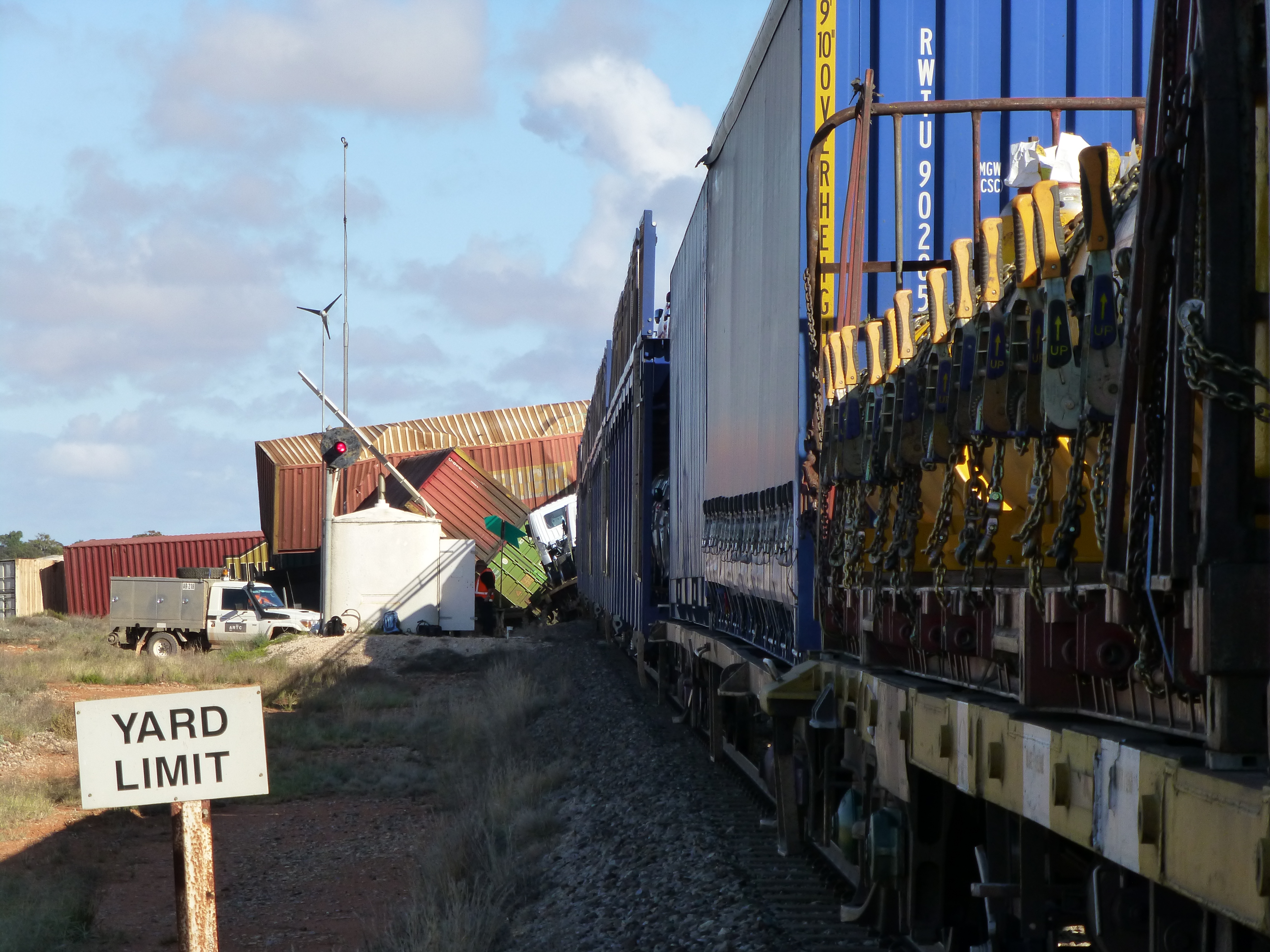
On 30 May 2017, a twin‑engine Cessna 441 Conquest II (Cessna 441), registered VH-XMJ and operated by AE Charter (trading as Rossair) departed Adelaide Airport, South Australia for a return flight via Renmark Airport, South Australia.
On board the aircraft were:
an inductee pilot undergoing a proficiency check, flying from the front left control seat
the chief pilot conducting the proficiency check, and under assessment for the company training and checking role for Cessna 441 aircraft, seated in the front right control seat
a Civil Aviation Safety Authority (CASA) flying operations inspector, observing and assessing the flight from the first passenger seat directly behind the inductee pilot.
Each pilot was qualified to operate the aircraft.
The flight departed Adelaide at about 1524 local time and flew to the Renmark area for exercises related to the check flight, followed by a landing at Renmark Airport. After a short period of time running on the ground, the aircraft departed from runway 25 at about 1614.
A distress beacon broadcast was subsequently received by the Joint Rescue Coordination Centre and passed on to air traffic services at 1625. Following an air and ground search the aircraft was located by a ground party at 1856 about 4 km west of Renmark Airport. All on board were fatally injured and the aircraft was destroyed.
What the ATSB found
The ATSB determined that, following a simulated failure of one of the aircraft’s engines at about 400 ft above the ground during the take‑off from Renmark, the aircraft did not achieve the expected single engine climb performance or target airspeed. As there were no technical defects identified, it is likely that the reduced aircraft performance was due to the method of simulating the engine failure, pilot control inputs or a combination of both.
It was also identified that normal power on both engines was not restored when the expected single engine performance and target airspeed were not attained. That was probably because the degraded aircraft performance, or the associated risk, were not recognised by the pilots occupying the control seats. Consequently, about 40 seconds after initiation of the simulated engine failure, the aircraft experienced an asymmetric loss of control.
The single engine failure after take‑off exercise was conducted at a significantly lower height above the ground than the 5,000 ft recommended in the Cessna 441 pilot’s operating handbook. This meant that there was insufficient height to recover from the loss of control before the aircraft impacted the ground.
While not necessarily contributory to the accident, the ATSB also identified that:
The operator’s training and checking manual procedure for simulating an engine failure in a turboprop aircraft was inappropriate and increased the risk of asymmetric control loss.
The CASA flying operations inspector was not in a control seat and was unable to share the headset system used by the inductee and chief pilot. Therefore, despite having significant experience in Cessna 441 operations, he had reduced ability to actively monitor the flight and communicate any identified problem.
The inductee and chief pilot, while compliant with recency requirements, had limited recent experience in the Cessna 441 and that probably led to a degradation in the skills required to safely perform and monitor the simulated engine failure exercise.
The chief pilot and other key operational managers within Rossair were experiencing high levels of workload and pressure during the months leading up to the accident.
The Civil Aviation Safety Authority’s method of oversighting Rossair in the several years prior to the accident increased the risk that organisational issues would not be identified and addressed.
Finally, a lack of recorded data from this aircraft reduced the available evidence about pilot handling aspects and cockpit communications. This limited the extent to which potential factors contributing to the accident could be analysed.
What's been done as a result
Following the accident, CASA issued a temporary management instruction to provide higher risk protection around operations involving CASA flying operations inspectors. However, at the time of writing these instructions had not been permanently incorporated into regulation.
Safety message
Conducting a simulated engine failure after an actual take-off is a high-risk exercise with little margin for error. For that reason, Cessna recommended practicing this sequence in the 441 aircraft at a height of 5,000 ft above ground level to allow the opportunity for recovery in the event that control is lost.
A review of past accidents indicates that, while accidents associated with engine malfunctions are rare, training to manage one engine inoperative flight (OEI) after take‑off is important. The ATSB recommends that such training should follow the manufacturer’s guidance and, if possible, be conducted in an aircraft simulator. If the sequence is conducted in the aircraft close to the ground, then effective risk controls need to be in place to prevent a loss of control as recovery at low height will probably not be possible. Such defences include:
defined OEI performance criteria that, if not met, require immediate restoration of normal power
use of the appropriate handling techniques to correctly simulate the engine failure and ensure that aircraft drag is minimised/OEI performance is maximised
ensuring that the involved pilots have the appropriate recency and skill to conduct the exercise and that any detrimental external factors, such as high workload or pressure, are minimised.
The occurrence
What happened
On 30 May 2017, a Cessna 441 Conquest II (Cessna 441), registered VH-XMJ (XMJ) and operated by AE Charter, trading as Rossair, departed Adelaide Airport, South Australia for a return flight via Renmark Airport, South Australia.
On board the aircraft were:
an inductee pilot undergoing a proficiency check, flying from the front left control seat
the chief pilot conducting the proficiency check, and under assessment for the company training and checking role for Cessna 441 aircraft, seated in the front right control seat
a Civil Aviation Safety Authority flying operations inspector (FOI), observing and assessing the flight from the first passenger seat directly behind the left hand pilot seat.
Each pilot was qualified to operate the aircraft.
There were two purposes for the flight. The primary purpose was for the FOI to observe the chief pilot conducting an operational proficiency check (OPC), for the purposes of issuing him with a check pilot approval on the company’s Cessna 441 aircraft. The second purpose was for the inductee pilot, who had worked for Rossair previously, to complete an OPC as part of his return to line operations for the company.
The three pilots reportedly started their pre‑flight briefing at around 1300 Central Standard Time.[1] There were two parts of the briefing – the FOI’s briefing to the chief pilot, and the chief pilot’s briefing to the inductee pilot. As the FOI was not occupying a control seat, he was monitoring and assessing the performance of the chief pilot in the conduct of the OPC.
There were two distinct exercises listed for the flight (see the section titled Check flight sequences). Flight exercise 1 detailed that the inductee pilot was to conduct an instrument departure from Adelaide Airport, holding pattern and single engine RNAV[2] approach, go around and landing at Renmark Airport. Flight exercise 2 included a normal take‑off from Renmark Airport, simulated engine failure after take-off, and a two engine instrument approach on return to Adelaide.
The aircraft departed from Adelaide at 1524, climbed to an altitude about 17,000 ft above mean sea level, and was cleared by air traffic control (ATC) to track to waypoint RENWB, which was the commencement of the Renmark runway 07[3] RNAV-Z GNSS approach. The pilot of XMJ was then cleared to descend, and notified ATC that they intended to carry out airwork in the Renmark area. The pilot further advised that they would call ATC again on the completion of the airwork, or at the latest by 1615. No further transmissions from XMJ were recorded on the area frequency and the aircraft left surveillance coverage as it descended towards waypoint RENWB.
The common traffic advisory frequency used for air-to-air communications in the vicinity of Renmark Airport recorded several further transmissions from XMJ as the crew conducted practice holding patterns, and a practice runway 07 RNAV GNSS approach. Voice analysis confirmed that the inductee pilot made the radio transmissions, as expected for the check flight. At the completion of the approach, the aircraft circled for the opposite runway and landed on runway 25, before backtracking and lining up for departure. That sequence varied from the planned exercise in that no single-engine go-around was conducted prior to landing at Renmark.
At 1614, the common traffic advisory frequency recorded a transmission from the pilot of XMJ stating that they would shortly depart Renmark using runway 25 to conduct further airwork in the circuit area of the runway. A witness at the airport reported that, prior to the take‑off roll, the aircraft was briefly held stationary in the lined‑up position with the engines operating at significant power. The take-off roll was described as normal however, and the witness looked away before the aircraft became airborne.
The aircraft maintained the runway heading until reaching a height of between 300‑400 ft above the ground (see the section titled Recorded flight data). At that point the aircraft began veering to the right of the extended runway centreline (Figures 1 and 15). The aircraft continued to climb to about 600 ft above the ground (700 ft altitude), and held this height for about 30 seconds, followed by a descent to about 500 ft (Figures 2 and 13). The information ceased 5 seconds later, which was about 60 seconds after take-off.
Figure 1: Position information of VH-XMJ as the aircraft circled and landed on runway 25 (depicted in red), before backtracking and departing (depicted in green).
Source: Google and OzRunways, annotated by the ATSB
Figure 2: Altitude information of VH-XMJ (each vertical line represents 5 seconds)
Source: Google and OzRunways, annotated by the ATSB
A distress beacon broadcast was received by the Joint Rescue Coordination Centre and passed on to ATC at 1625. Following an air and ground search the aircraft was located by a ground party at 1856 about 4 km west of Renmark Airport. All on board were fatally injured and the aircraft was destroyed.
There were three pilots on board VH-XMJ (XMJ). A summary of the role of each pilot, and their relevant training, qualifications and experience is provided below. The intention of the flight was to allow a Civil Aviation Safety Authority (CASA) flying operations inspector (FOI) to observe the Rossair chief pilot conduct an operator proficiency check (OPC), for the purposes of issuing him with a Conquest II (Cessna 441) check pilot approval (see the section titled Check pilot training). The pilot undertaking the OPC was being inducted into the company. The inductee pilot was seated in the left-hand control seat, the chief pilot in the right-hand control seat, and the CASA FOI in the first row passenger seat behind the left-hand seat pilot.
Inductee pilot
Flight role
The inductee pilot was the planned pilot flying. He was an experienced Cessna 441 pilot who had previously flown for Rossair from May 2010 to August 2014. Undertaking the OPC was part of his induction back into the company.
Qualifications and experience
The inductee pilot held an Air Transport Pilot (Aeroplane) Licence (ATPL), issued in December 1991, and Commercial Pilot (Aeroplane) Licence (CPL) issued in January 1979. He also held an ATPL from the Netherlands. He held a current class 1 aviation medical certificate (valid to 24 June 2017), which required reading correction to be available when flying, but placed no other restrictions on operation.
The pilot’s logbook showed a total flying experience of 14,751.1 hours, with 3,293.7 hours on single engine aircraft and 11,427.4 hours on a range of type-rated and class-rated multi-engine aircraft (see the section titled Pilot licencing). This included 987.7 hours on Cessna 441 aircraft. With the exception of the accident flight and an associated practice flight the week before, all of the inductee pilot’s Cessna 441 experience was gained prior to August 2014.
A review of the pilot’s licence and associated documentation identified that he held the relevant endorsements and ratings to fly the Cessna 441. In addition, he held a current grade 1 instructor rating for multi‑engine class rating training.
In the previous 90 days, the inductee pilot had logged 22.2 hours flying as pilot in command, all on multi-engine class rated aircraft, including 3.5 hours in XMJ the week prior to the accident.
Proficiency checks and flight reviews
The inductee pilot last completed an instrument rating proficiency check (IPC) during his multi‑engine class aircraft flight review in a Beechcraft Baron 95-B55 on 13 February 2017. This check required the pilot to demonstrate conducting a one-engine inoperative instrument departure, which was marked on his proficiency check form as completed satisfactorily. His IPC was valid at the time of the accident.
Chief pilot
Flight role
The pilot in the right-hand seat was appointed as the Rossair chief pilot in January 2016. On this flight, the chief pilot was being observed by the CASA FOI in order to assess his competence to perform operational proficiency checks on Rossair Cessna 441 pilots.
In accordance with the Rossair operations manual, as this was a checking flight, the chief pilot, in the check captain role, was the pilot in command (PIC) for the flight.
Based on the planned exercises for the flight the chief pilot’s role was to observe and monitor the inductee pilot’s proficiency. In addition, he was responsible for setting the power controls to simulate asymmetric flights when required and recover the aircraft if it deviated from safe flight.
Qualifications and experience
The chief pilot held an ATPL (Aeroplane), issued in June 2001, a CPL (Aeroplane) issued in August 1998, as well as an ATPL (Helicopter) issued in November 2013, and a CPL (Helicopter) issued in April 2007. He also held an ATPL (Aeroplane) from the United States of America. The pilot held a current class 1 aviation medical certificate, valid until 3 August 2017, which required reading correction to be available while flying, but placed no other restrictions on operation.
The chief pilot’s logbook history was sought by the ATSB, but the complete record could not be located. A review of available records for the pilot indicated the pilot had around 5,000 hours experience operating aeroplanes, including over 3,200 hours of turbine‑powered aeroplane experience. This included over 1,000 hours on a Cessna 441 aircraft, accumulated during the period between September 2001 and September 2004 and since March 2016. The pilot also had around 1,300 hours experience operating helicopters.
The pilot’s licence showed that the chief pilot held the ratings and endorsements required for the flight, as well as for operation of the company Embraer EMB 120 (EMB 120) aircraft. Additionally, he had previously held a grade 2 instructor rating for aeroplanes with night visual flight rules, design features (for example, retractable undercarriage and manual propeller pitch control), and single engine aircraft class rating endorsements.
In the previous 90 days, flight and duty records for the chief pilot recorded 128.1 hours of flight time, including 99.6 hours as a captain on the EMB 120 aircraft, and 16.6 hours in the Cessna 441, including a previous flight with the inductee pilot on 22 May 2017. The pilot’s flight and duty records had not been updated since 12 May 2017, so some of these times are based on planned flight times rather than actual flight times.
Proficiency checks and flight reviews
The chief pilot was inducted into Rossair Cessna 441 operations in April and May 2016 by the Cessna 441 fleet manager. The chief pilot successfully completed his line check and OPC on the Cessna 441 on 30 May 2016. As part of that flying, the chief pilot also completed training to become a check pilot on the aircraft. Following the flight on 30 May 2016, a recommendation was submitted to CASA that he be assessed as a Cessna 441 check pilot.
The chief pilot’s last IPC was completed as part of a type rating flight review in the EMB 120 simulator on 22 October 2016. Under CASA exemption 97/16 current at the time of the accident, this flight review conducted on a type‑rated aircraft, also satisfied the requirements of a flight review on the multi-engine class rated Cessna 441 aircraft.
The chief pilot had not completed an OPC or line check on the Cessna 441 aircraft since 30 May 2016. However, he had completed an OPC in the EMB 120 simulator on 1 February 2017, which was conducted under CASA observation. That 2017 check, although not conducted in the Cessna 441, met the required regulatory and operator proficiency checking requirements (see the section titled Operational proficiency check).
CASA flying operations inspector
Flight role
The CASA FOI was sitting in a non-control seat behind the inductee pilot, and therefore had no flying role on this flight. The role of the CASA FOI on the flight was to observe and assess the chief pilot’s skills in conducting an OPC on the inductee pilot.
Qualifications and experience
The CASA FOI held an ATPL (Aeroplane) issued in December 1990 and a CPL (Aeroplane) issued in February 1987. He also held a grade 1 instructor rating, with endorsements, among others, in instructor training, multi-engine class rating, and multi-engine aeroplane class rating instructor training. He held a class 1 aviation medical certificate, valid until 15 December 2017, which required reading correction to be available while flying, but placed no other restrictions on operation.
The CASA FOI had been in the role since 2008, and at the time of employment with CASA had 12,725 hours, including over 5,100 hours as a Cessna 441 pilot. The FOI role did not involve significant flying, but in the last 90 days he had completed 2.5 hours aircraft flight time, as well as simulator time.
Among a variety of flying and management roles prior to joining CASA, the FOI previously held chief pilot and head of training and checking roles at Rossair, with approval to conduct initial training on the Cessna 441.
Proficiency checks and flight reviews
The FOI completed a flight review and IPC in the Saab 340 simulator on 18 April 2017, and in the Bombardier Dash 8 simulator on 9 May 2017. He completed a flight proficiency check for his grade 1 instructor rating in a Beechcraft Baron 95-B55 on 24 May 2017. Additionally, the FOI had logged a 2.7 hour flight in the Cessna 441, with the FOI as PIC flying with the previous Rossair check pilot, in August 2016.
Aircraft information
General information
The Cessna 441 Conquest II is a pressurised, low‑wing, twin-engine turbopropeller (turboprop) aircraft with seating for up to 2 pilots and 9 passengers. Both pilot seats are equipped with flight controls however single‑pilot line operations are flown from the left seat. The right pilot seat would normally only be occupied by a second pilot for training and checking flights.
The accident aircraft, serial number 441‑0113, was manufactured in the United States by the Cessna Aircraft Company in 1980, and registered in Australia as XMJ in February 1989. The Cessna 441 is certified as a normal category[4] aircraft under the United States Federal Aviation Regulations Part 23, and issued with type certificate data sheet number A28CE by the United States Federal Aviation Administration in 1977. At the time of the accident, Textron Aviation Inc. was the Type Certificate holder[5] for the aircraft and as of March 2020, there were 39 Cessna 441 aircraft registered in Australia.
Notable modifications to the aircraft were the incorporation of supplemental type certificates to replace the three blade propellers with four blade propellers, replace the -8 engines with more powerful -10 engines and the installation of vortex generators[6] to increase the aircraft’s maximum take-off weight. Other than an associated increase in the aircraft’s maximum take-off weight, these modifications did not require any changes to the procedures and airspeed limitations in the aircraft’s pilot’s operating handbook (POH).
Aircraft records
XMJ had a current Certificate of Registration, Certificate of Airworthiness and maintenance release, all of which were recovered from the accident site. The maintenance release was due to expire on 10 March 2018 or upon 13,859.0 hours total time-in-service, whichever came first. The maintenance release indicated that XMJ was equipped to be operated under the instrument flight rules and in the charter operational category. The maintenance release indicated that there was no maintenance due on the aircraft or open defects at the time of the accident. Prior to the departure from Adelaide, the aircraft had accumulated a total time in service of 13,845.3 flight hours.
Part 1 of the aircraft’s Logbook Statement specified that the aircraft was to be maintained in accordance with the AE Charter Services system of maintenance and all applicable airworthiness directives. The following summarises the maintenance activities conducted on XMJ leading up to the accident.
On 31 August 2016 a number of parts, including both the left and right engines were removed for use on other company aircraft. These engines were reinstalled on 24 November 2016 and had operated for 385.2 hours on XMJ since this time.
On 30 April 2017, the installed fuel control unit (FCU) from the aircraft’s left engine was replaced by an FCU borrowed from a third party maintenance organisation.
On 4 May 2017, the aircraft was erroneously released to service prior to in-flight FCU set-ups having occurred, with an endorsement in the deferred defect list that the left engine had to be operated in manual mode until the FCU set-up had been completed but could continue in service until no later than 14 May 2017 without the set-up being completed.
The Rossair chief pilot raised a concern on 8 May 2017 about the aircraft being released into service without the in-flight set-ups being completed, as the aircraft was more difficult than normal to operate with one engine in manual mode. Further maintenance work was performed on the aircraft, and, on 10 May, the aircraft was released into service, with both engines operating in normal (automatic) mode.
The aircraft subsequently flew 28 flights, totalling 32.6 hours with no reported issues.
On 26 May 2017, the original FCU that was removed on the 30 April 2017 was reinstalled onto the left engine of XMJ following removal, cleaning and reinstallation of the FCU’s manual mode control valve.
A certification regarding a wing de-icing system unserviceability was made on 26 May 2017. It stated ‘No action was carried out at this time. Aircraft unavailable due to flying requirements. Customer notified.’ There was no entry in the defect field of the current maintenance release Part 3.
Between 26 May and 30 May, the aircraft flew 6.9 hours without reported issue, including 4.5 hours across five sectors on the morning of the accident.
Aircraft systems information
Flight control overview
The Cessna 441 is fitted with conventional flight controls connected to the aircraft’s primary flight control surfaces. The primary flight controls consist of the rudder, elevators, and ailerons, which control the aircraft about the yaw, pitch and roll axes respectively.
The pilot controls an aircraft by manipulating the control wheel and rudder pedals, which deflect the ailerons, elevators and rudder. Deflection of an aircraft’s primary flight control surfaces changes the aerodynamic shape and therefore the amount of lift generated by the associated part of each wing, vertical stabiliser or horizontal stabiliser. These local variations in lift result in changes to the aircraft attitude and consequently flight path.
Any deflection of the primary flight control surfaces into the adjacent airflow produces aerodynamic forces on the surface and corresponding loads on the control wheel or rudder pedals. The magnitude of the aerodynamic force is principally related to the amount of flight control surface deflection, airspeed and trim tab deflection.
On the Cessna 441, adjustable trim tabs are attached to the trailing edge of the primary flight controls. These tabs are used to ‘trim’ or counteract the aerodynamic forces felt by the pilot on the control wheel or rudder pedals. During flight, deflection of an aircraft’s trim tab produces an aerodynamic force on the aft part of the associated primary surface. The tabs have the capacity, when adjusted in the opposite direction to the deflection of the primary control surface, to modify the aerodynamic force on the surface and correspondingly, reduce the load felt by the pilot on the control wheel or rudder pedals. The effectiveness of a trim tab is principally related to the amount of deflection and the aircraft’s airspeed.
Flap system description
The aircraft has four flaps, one inboard, and one outboard per wing. The flaps are normally in the fully retracted position. They are extended to slow the aircraft and allow it to land at a lower airspeed. They can also be used to improve take-off performance in the ‘T.O.’ position. The flaps are operated using a sliding selector. Flap travel is registered on an indicator adjacent to the selector. There are four detents in the selector assembly as follows:
UP – fully retracted, 0⁰ of travel
T.O. – 10° of flap down travel
APPR – 20⁰ of flap down travel
LAND – full extension, 30⁰ of flap down travel.
Engine and propeller controls
Each engine is controlled by two levers located in the engine controls section of the centre pedestal (Figure 3).
The power levers provide control input to the engine for the power necessary throughout the entire operational envelope. The power lever has the following positions:
MAX
AIR START
FLIGHT IDLE
GROUND IDLE
REVERSE
The power levers can be moved freely forward of FLIGHT IDLE. A hard stop is provided at the FLIGHT IDLE position to prevent inadvertent selection of reverse thrust in flight (Figure 4). Finger latches located on each power lever must be pulled up to allow movement of the power levers rearward of the FLIGHT IDLE position.
The condition levers are used to set the engine revolutions per minute required for flight as well as acting as the control for propeller feathering and emergency fuel shut-off. The condition lever quadrant has the following positions:
TAKEOFF, CLIMB and LANDING
CRUISE
START AND TAXI
EMER SHUT-OFF
The condition levers can be moved freely forward of CRUISE. A hard stop is provided at the CRUISE position to prevent inadvertent selection of START AND TAXI speed in flight (Figure 5). Each condition lever must be pulled up to allow movement rear of the CRUISE stop. Another stop is provided at the START AND TAXI position. Rearward movement past this position allows the respective engine to be shut down and its propeller feathered.
Figure 3: Engine control levers
Source: ATSB
Figure 4: Power lever
Source: Textron Aviation Inc.
Figure 5: Condition lever
Source: Textron Aviation Inc.
Negative torque system
The aircraft’s engines are equipped with a negative torque sensing (NTS) system that activates under conditions of low propeller pitch (see the section titled Multi‑engine aeroplane propellers) when air loads drive the propeller instead of the engine. This can occur during normal operation at high airspeed and low power settings but will also happen following an engine failure. When NTS activates, the propeller blades are automatically driven towards the feathered[7] position to reduce both the air load and the significant associated drag. NTS will only activate while negative torque is detected so, unlike an auto‑feather system fitted to other aircraft, the blades will only automatically move to a high pitch position rather than fully feathered. Consequently, in the event of an engine failure the pilot is required to move the condition lever to the emergency shut off position to feather the propeller.
With regard to functioning of the NTS, the POH noted that:
NTS operation, as evidenced by a cycling sound of the engine(s) can occur at high airspeed with the power levers at FLIGHT IDLE; this is particularly true when operating in manual mode. NTS operation occurs when the propeller is driving the engine, rather than the engine driving the propeller. During normal mode operation, NTS can indicate the fuel flow is insufficient for existing conditions.
There is a POH requirement to confirm operation of the NTS prior to flight. Normal operation of the NTS on the ground is accompanied by illumination of an amber light on the cockpit annunciator panel for the respective engine being checked. The light was for check purposes only and would not illuminate during in‑flight activation of the NTS. Activation of the NTS on an operative engine in flight can be overcome by advancing the power levers slightly.
Manual mode operation
Manual mode refers to the engine power output being directly controlled by the power lever position rather than by a signal sent to the engine by the electronic engine control unit (EEC). The power system is designed so that fuel scheduling is lower in manual mode than it is in normal (automatic) mode.
Higher power lever positions are therefore required to maintain engine power when in manual mode compared to normal mode. This means that if a fault is detected in the EEC and the engine operation automatically reverts to manual mode the engine will have a reduction in power for that particular power lever setting. If that occurs the power can be restored by advancing the power lever as required.
Weight and balance
The ATSB determined the likely fuel on board at the time of the accident and the weight and location of people, baggage and ballast. From this information, it was calculated that the aircraft was within the weight and balance limitations specified in the aircraft’s POH and relevant supplements. The aircraft’s weight at the time of the accident was estimated to be about 3,950 kg. The aircraft’s maximum take-off weight was 4,690 kg.[8]
Meteorological information
The forecast weather conditions at Renmark Airport on the afternoon of the accident were benign with a southerly wind at 14 kt, visibility in excess of 10 km and scattered[9] cloud at 4,000 ft above the airport.
Weather observations recorded at one‑minute intervals by an automatic weather station at the airport were obtained from the Bureau of Meteorology (BoM). Consistent with the forecast, in the 20 minutes preceding the accident the wind strength varied between 8‑13 knots, and the direction varied between 188‑205° magnetic. The cloud cover was consistently seven oktas at about 6,500 ft above the airport and the ambient temperature was 13°C.
The ATSB also sought the assistance of the BoM to assess the likely wind strength and direction at the operating altitude of the aircraft immediately prior to the loss of control. This was done to enable an assessment of the airspeed during the final flight segment using recorded groundspeed data (see the section titled Recorded flight data).
Airport information
Renmark Airport is at an elevation of 115 ft above mean sea level and has one sealed runway, 07/25, and one gravel runway, 18/36.3 As there is no air traffic control tower at the airport, traffic at the airport broadcast on a common traffic advisory frequency to advise intentions and arrange separation with other traffic.
The terrain west of the airport, along the extended runway centreline in XMJ’s departure direction, slopes upwards, with an elevation gain of about 60 ft between the runway and the accident site location.
Circuit operations
In order to assure a safe and orderly traffic flow into and out of an airport, a standard circuit traffic pattern is used. The circuit consists of four legs: crosswind, downwind, base and final as shown in Figure 6, with standardised methods for joining the pattern to avoid traffic conflicts.
Figure 6: Standard circuit pattern
Source: Airservices Australia
Asymmetric flight
Multi-engine aeroplanes
In a discussion of small[10] multi-engine aeroplane operations, the United States Federal Aviation Administration (FAA) Airplane Flying Handbook FAA‑H‑8083‑3B, stated:[11]
The basic difference between operating a multiengine airplane and a single-engine airplane is the potential problem involving an engine failure. The penalties for loss of an engine are twofold: performance and control. The most obvious problem is the loss of 50 percent of power, which reduces climb performance 80 to 90 percent, sometimes even more. The other is the control problem caused by the remaining thrust, which is now asymmetrical. Attention to both these factors is crucial to safe OEI [one engine inoperative] flight. The performance and systems redundancy of a multiengine airplane is a safety advantage only to a trained and proficient pilot.
The importance of maintaining one engine inoperative performance and control was further emphasised in the handbook as follows:
In OEI flight at low altitudes and airspeeds such as the initial climb after takeoff, pilots must operate the airplane so as to guard against the three major accident factors: (1) loss of directional control, (2) loss of performance, and (3) loss of flying speed. All have equal potential to be lethal. Loss of flying speed is not a factor, however, when the airplane is operated with due regard for directional control and performance.
Multi-engine aeroplane propellers
In the event of an engine power loss, the inoperative engine may windmill - continue to rotate due to the airflow acting on the propeller. The FAA handbook described the hazard of a windmilling propeller as follows:
The propeller windmilling at high speed in the low range of blade angles can produce an increase in parasite drag, which may be as great as the parasite drag of the basic airplane.
In order to minimise this significant source of drag on single engine controllability and climb performance, the propellers of multi-engine aeroplanes are capable of aligning the blades with the airflow (Figure 7).
Figure 7: Multiengine aeroplane propeller
Source: United States Federal Aviation Administration
This ‘feathered’ configuration stops the rotation of the engine and propeller and significantly reduces the parasite drag compared to that associated with a windmilling propeller (Figure 8).
Figure 8: Propeller drag
Source: United States Federal Aviation Administration
Asymmetric control
The majority of small, multi-engine aeroplanes like the Cessna 441 have two wing‑mounted engines that produce symmetrical propeller thrust during normal operation. One engine inoperative (OEI) flight in these aeroplanes results in asymmetric thrust and drag due to the offset position of the engines from the aeroplane’s centreline. The result is a tendency for the nose of the aeroplane to turn in the direction of the inoperative engine. The extent of the yaw may vary depending on which engine becomes inoperative, with the inoperative engine that produces the greatest degree of asymmetry being termed the ‘critical’ engine.[12]
The asymmetric yawing tendency may be countered through the application of rudder and aileron control inputs. As the effectiveness of an aircraft’s control surfaces generally decreases with decreasing airspeed, sufficient airspeed must be maintained while operating OEI to ensure that the rudder and aileron retain sufficient control authority to maintain directional control of the aeroplane.
The minimum control airspeed with the critical engine inoperative (VMCA) is established by test pilots during aircraft certification under a specific set of conditions, and is marked on the air speed indicators of most multi-engine aeroplanes with a red radial line. VMCA is influenced by a large number of factors, including an aircraft’s configuration/loading, operating altitude and pilot control inputs and is therefore likely to vary from the stated value.
The VMCA published in the Cessna 441 pilots operating handbook (POH) was 91 kt indicated airspeed. The POH further stated that:
The airplane must reach the air minimum control speed (VMCA) before full control deflections are able to counteract the roll and yaw tendencies associated with one engine inoperative and full power operation on the other engine. VMCA with wing flaps in take-off position is indicated by a red radial on the airspeed indicator. VMCA with wing flaps in the UP position and the airplane in an en-route climb configuration will be buffet limited and occur at a higher speed.
In addition to the published VMCA the POH also listed an ‘intentional one engine inoperative’ indicated airspeed of 98 kt with advice that:
Although the airplane is controllable at the air minimum control speed, the airplane performance is less than optimum. A more suitable speed with wing flaps positioned in take-off is 98 KIAS [kt indicated airspeed]. This speed is identical to the normal rotation speed, thus the pilot can direct more of this attention to determining and securing the inoperative engine than to achieving a speed not normally associated with take-off. This speed also provides additional safety for controllability and allows easier maintenance of altitude during the period of gear retraction and securing the inoperative engine.
As detailed in the FAA handbook, maintaining directional control following an engine failure during take‑off and initial climb is especially critical:
The first consideration following engine failure during takeoff is to maintain control of the airplane. Maintaining directional control with prompt and often aggressive rudder application and STOPPING THE YAW is critical to the safety of flight. Ensure that airspeed stays above VMC [VMCA]. If the yaw cannot be controlled with full rudder applied, reducing thrust on the operative engine is the only alternative. Attempting to correct the roll with aileron without first applying rudder increases drag and adverse yaw and further degrades directional control.
Asymmetric performance
Optimum single-engine climb performance is obtained by flying the aircraft at the published OEI best rate of climb speed (VYSE), 120 KIAS for the Cessna 441, with maximum available power and minimised drag. Minimum drag is achieved by:
retracting the flaps and landing gear
feathering the propeller of the inoperative engine
minimising sideslip by presenting the smallest aircraft profile to the relative wind.
During symmetrical flight in a single-engine airplane, or a multiengine airplane with both engines operating, zero sideslip occurs when the balance ball[13] is centred. However, in the case of asymmetric thrust, zero sideslip requires a combination of bank angle and non‑centred ball position. That is, a combination of rudder and aileron inputs (Figure 9).
As it related to the Cessna 441, the POH provided the following information on the required combination of rudder and aileron inputs to minimise sideslip:
Best single-engine climb is attained with the wings banked approximately 3° to 4° and with a ⅔ to ¾ ball slip into the operative engine when the airplane is at low airspeed and heavy weight. As airspeed increases and/or airplane weight is significantly reduced, the ⅔ to ¾ ball slip becomes less important.
Figure 9: Zero sideslip
Source: United States Federal Aviation Administration
While it is possible to counteract asymmetric thrust using only rudder or only aileron, this results in significant performance and controllability penalties. Specifically, countering asymmetry with level wings and the ball centred (large rudder input towards the operative engine) results in moderate sideslip towards the inoperative engine that reduces climb performance (Figure 10). It also significantly increase VMCA as there is no horizontal component of lift to assist the rudder to counter the asymmetric thrust. In discussing this increase in minimum control speed as it related to the Cessna 441, the Civil Aviation Advisory Publication (CAAP) 5.23‑1(2) Multi-engine aeroplane operations and training stated:
…Flight tests in an instrumented Cessna Conquest showed that with a published VMCA [VMCA] of 91 kts, if the aircraft was flown in asymmetric flight with full power applied and the wings held level with the rudder balancing the aircraft, minimum control speed increased to 115 kts, an increase of 24 kts.
Figure 10: Rudder‑only input
Source: United States Federal Aviation Administration
Opposing asymmetric thrust using only aileron input results in a large sideslip towards the operative engine that also significantly reduces climb performance (Figure 11).
Figure 11: Aileron‑only input
Source: United States Federal Aviation Administration
OEI rate of climb performance for given operating conditions can be determined using data published in the POH/flight manual. Achieving the published performance relies on use of the zero sideslip technique and configuring the aircraft for minimum drag.
Considering the configuration and approximate weight of the aircraft at the time of the accident (see the section titled Weight and balance), the calculated OEI climb rate over a range of indicated airspeeds is shown in Table 1.
Table 1: One engine inoperative climb performance for Cessna 441 at 3,950 kg
Indicated airspeed (kt)
Excess Thrust Horse Power (HP)
Calculated climb rate (ft/min)
90
115.7
438
100
185.1
701
110
205.4
778
120
213.4
809
130
211.7
802
Source: ATSB analysis from aircraft certification data
The OEI performance data indicated that XMJ was capable of achieving a positive rate of climb following departure from Renmark if sideslip and other sources of drag were minimised.
Engine failure simulation
Zero thrust
Demonstration of OEI flight often involves simulating a failed engine by moving the power lever to a low power level rather than actually shutting down the engine and feathering the propeller. This method of simulation allows rapid normal power restoration. However, as detailed in the section titled Multi-engine aeroplane propellers, at low power settings the propeller will rotate due to the airflow rather than the engine, creating much higher drag than a feathered propeller. For that reason, a zero thrust power level is commonly set to overcome the drag associated with windmilling and more accurately simulate the low drag associated with a feathered propeller.
Zero thrust varies depending on the engine type, airspeed, altitude and temperature. In a piston engine aircraft zero thrust is normally achieved by setting a manifold pressure that results in a specific propeller rpm. In a turbine propeller engine zero thrust is expressed as an engine torque, and in some cases rpm, for a particular airspeed (normally VYSE).
Aircraft manufacturer’s procedures
The Cessna 441 POH detailed two procedures for simulating an engine failure, however neither procedure involved the use of a zero thrust power setting.
The first POH procedure was designed to practice management of an engine failure during the cruise phase of flight. The procedure involved retarding the power lever to the AIRSTART position and then shutting the engine down. In discussing the AIRSTART power lever position, the POH stated:
The AIRSTART position does provide some forward thrust. This position is recommended as it allows the best exhaust gas temperature stabilization before shutdown and it is the lowest position which will prevent the fuel computer from tripping to manual mode during an airstart.
If the power lever is retarded below the AIRSTART position and the fuel computer trips to manual mode, normal mode may be regained by advancing the power lever slightly and cycling the fuel computer switch to OFF then back to ON.
The second procedure was designed to train pilots to handle an engine failure in the take-off configuration. This involved using a fuel interruption process to actually shut the engine down. This was achieved by momentary selection of the engine stop button which activated a solenoid within the fuel control unit and cut off the fuel supply to the engine. In order to also simulate representative control forces during the exercise, the set up for the sequence involved:
extending the landing gear
extending the wing flaps to the take‑off position
trimming the aircraft for a speed greater than the intentional one engine inoperative speed of 98 kt.
This procedure directly referenced related guidance in the POH, applicable to the demonstration of VMCA, which stated:
One engine inoperative procedures should be practiced in anticipation of an emergency. This practice should be conducted at a safe altitude (5000 ft AGL), with full power on both engines, and should be started at a safe speed of at least 98 KIAS. As recovery ability is gained with practice, the starting speed may be lowered in small increments until the feel of the airplane in emergency conductions is well known. It should be noted that as the speed is reduced, directional control becomes more difficult. Emphasis should be placed on stopping the initial large yaw angles by the IMMEDIATE application of rudder supplements by banking slightly away from the yaw. Practice should be continued until: (1) an instinctive corrective reaction is developed and the corrective procedure is automatic, and (2) airspeed, altitude and heading can be maintained easily while the airplane is being prepared for a climb.
The POH did not contain any procedure relating to simulation of an engine failure during the actual take‑off phase.
Additionally, for Cessna 441 aircraft with the serial number 0173 onwards (not applicable to VH‑XMJ) the POH, in reference to the ‘engine shutdown to simulate engine failure in takeoff configuration’ procedure (second procedure), explicitly stated
“This procedure must not be practiced at an altitude below 5,000 ft AGL”
Some of Rossair’s other Cessna 441 aircraft operated under this later POH, but the operators manual did not note a difference between the two handbooks.
With respect to the change in the POH procedures applicable to serial number 0173 and onwards, the aircraft manufacturer advised that:
there was no material difference between the aircraft from serial numbers 0173 and onwards and the earlier serial numbers (0172 and prior) that necessitated a different method of simulating an engine failure in the take-off configuration
the statements in the earlier POH procedure that referenced the demonstration of VMCA have the same intent as the warning note in the POH for aircraft with serial numbers 0173 and onwards, which states this procedure must not be practiced at an altitude below 5,000 feet above ground level.
Operator’s procedures
Rossair’s operations manual contained information relating to simulated engine failures in both Part A (general operations) and Part C (training and checking). Part A of the manual stated:
Simulated asymmetric flight is not to be carried out unless specifically authorised, and then only when accompanied by an authorised person. Asymmetric flight shall not be carried out when passengers are being carried and shall only be conducted on a designated training flight.
Any engine failure simulation shall be conducted by closing the power lever to a position equivalent to zero thrust (Turbine) in accordance with Part C, or moving the mixture lever to the idle cut off position (Piston).
For the purpose of training, simulated engine failures and the feathering of aircraft propellers shall only be conducted in VMC conditions. In addition, the aircraft shall be operating above 3000 ft AGL, unless the simulation or feather practice is specifically required during the approach and landing phase.
Following any practice engine shut-down in flight, the engine controls must be set for an immediate restart.
At no time are stalling or Vmca demonstrations to be made with the aircraft propeller feathered.
Part C contained detailed information on the procedure for simulating engine failures in the Cessna 441 (Figure 12). However, the procedure varied from that outlined in Part A with regard to initial power settings and the height at which the simulation could be initiated.
Part A detailed that engine failure simulation for training purposes was to occur above 3,000 ft above ground level unless specifically required during the approach and landing phase. Part C permitted the simulation of engine failure ‘After attaining the higher of 400’ or acceleration altitude’. The reference to ‘acceleration altitude’ was not applicable to the Cessna 441.
Figure 12: Rossair training and checking manual
Source: AE Charter/Rossair
The Part C procedure involved retarding power to flight idle (power level to minimum) and then advancing the power to zero thrust (to represent a feathered propeller) on completion of the engine failure drills. This is the normal technique used for simulating the failure of a piston engine aircraft, where the pilot must manually feather the propeller.
It is not necessary to select less than a zero thrust setting to simulate failure of a turboprop engine equipped with auto feather or negative torque sensing systems (such as the Cessna 441). More importantly, setting the power lever below the zero thrust setting will increase propeller drag. As detailed previously, selection of less than the AIRSTART power lever position in the Cessna 441 can also affect automatic operation of the fuel computer.
An earlier version of the company operations manual detailed simulation of a failed engine on a turboprop engine by only moving the power lever to zero thrust. The ATSB could not determine how the procedure involving moving the power to below zero thrust was introduced into the 2016 version of the manual (in use at the time of the accident). However it may have occurred during the merger of Rossair with another company (see section titled Overview of the operator). Additionally, this section of the operations manual was approved by the Civil Aviation Safety Authority without detection of the error (see section titled Regulatory services processes).
Finally, the propeller manufacturer advised that for the four‑bladed propellers fitted to XMJ, the required zero thrust setting was about 234 ft.lbs of engine torque, 116 ft.lbs less than stated in Part C of the operations manual.
Regulatory guidance
CAAP 5.23‑1(2) Multi-engine aeroplane operations and training, provided comprehensive guidance on the operation of multiengine aeroplanes. With regard to the simulation of engine failures, it stated:
Before simulating engine failures in multi-engine aircraft, instructors must be aware of the implications and be sure of their actions. Consult the aircraft flight manual or POH for the manufacturer’s recommended method of simulating an engine failure.
The CAAP also provided guidance on setting power to simulate a failed engine. Specifically, it was recommended to initially close the throttle of a piston engine to replicate a windmilling propeller and then set zero thrust once the trainee had simulated propeller feathering. In the case of a turboprop engine, replication of an engine failure only required selection of zero thrust. Guidance was also provided on a method to establish zero thrust if it was not specified.
The CAAP also detailed a number of risks associated with multi-engine training, including:
inappropriate management of complex aircraft systems
conducting flight operations at low level (engine failures after take-off)
conducting operations at or near VMCA or VSO [stall speed with undercarriage and flap selected] with an engine inoperative
asymmetric operations.
With regard to flight operations at low level, the CAAP further stated:
Any flight operation at low altitude has potential dangers. Trainers have debated over the decades on the value of practicing engine failures after an actual take-off, near the ground. The general consensus is that despite the risks, pilots must be trained to manage these situations in multi-engine aircraft.
…Instructors should consider not simulating engine failures below 400 ft above ground level (AGL) to provide a reasonable safety margin.
Accident flight procedure
There was insufficient information and recording devices to determine the specific procedure used to simulate the engine failure after take‑off from Renmark Airport. However, the electronic briefing developed by the chief pilot in preparation for the occurrence check flight provided specific guidance on how engine failures were to be simulated as follows:
All failures will be preceded by the phrase “simulated”
• Once the memory items have been carried out, zero thrust will be set
• The instructor will handle the ‘failed’ engine
• Pilot is to use other power lever as required
• When landing, pilot may retard both levers as required
Any failure not preceded with the phrase “simulated” is real and shall be treated as such.
In preparation for the occurrence check flight, a practice flight covering similar sequences was conducted in XMJ the week before with the chief pilot and inductee pilot. That flight also had an observer on board with extensive Cessna 441 check pilot experience. The practice flight was not conducted as a training flight, but rather a private flight with two licenced and experienced pilots on board, preparing for their respective roles during the CASA check flight.
The observer advised that during the practice flight, the engine failure was simulated by the chief pilot reducing the power lever but not all the way to the flight idle stop. He further recalled that once the inductee pilot completed the initial response actions, the chief pilot partially advanced the power lever. The observer stated that, based on his experience, zero thrust in the occurrence aircraft was about 150 ft.lbs of torque and lower than other company Cessna 441 aircraft. He also recalled that the chief pilot set a power lever position at or slightly above that torque value during the simulation.
Stall speed
The calculated stall speed depends on the weight of the aircraft, as well as the gear and flap configurations, and the angle of bank. For XMJ, at the ATSB calculated take-off weight from Renmark Airport (3,950 kg), with:
gear and flap retracted
power at the flight idle,
the calculated stall speed with wings level was 85 KIAS. At 20° angle of bank, the stall speed increased to approximately 88 KIAS.
Flight recorders
XMJ was not equipped with a flight data recorder or cockpit voice recorder. Requirements relating to the fitment of flight recorders is detailed in Civil Aviation Order (CAO) 20.18 as follows:
An aircraft of maximum take-off weight:
a) In excess of 5,700 kg and which is:
i. turbine powered; or
ii. of a type first certificated in its country of manufacture on or after 1 July 1965;
shall not be flown (except in agricultural operations) unless it is equipped with an approved flight data recorder and an approved cockpit voice recorder system;
b) Less than or equal to 5,700 kg and which is:
i. pressurised; and
ii. turbine powered by more than one engine; and
iii . of a type certificated in its country of manufacture for operation with more than eleven places; and
iv. issued with its initial Australian Certificate of airworthiness after 1 January 1988;
shall not be flown unless it is equipped with an approved cockpit voice recorder system.
The Cessna 441 has a maximum take‑off weight of 4,468 kg so CAO 20.18(a) was not applicable. Additionally, although meeting a number of the criteria detailed in CAO 20.18(b), the Cessna 441 is certified for a maximum of eleven seats (two crew and nine passengers). The aircraft was therefore not required to be fitted with either a flight data recorder or a cockpit voice recorder.
Recorded flight data
As part of the investigation, data broadcast by the automatic dependent surveillance broadcast (ADS-B) equipment fitted to the aircraft was obtained from various web-based providers. Depending on the provider, this data recorded the following parameters at intervals of either 6 or 15 seconds:
latitude and longitude
time of the logged position
pressure altitude
groundspeed
track.
A review of the data identified that the aircraft descended outside ADS-B coverage as it approached the circuit area at Renmark Airport. Consequently, no ADS-B flight data was available for the departure of XMJ from Renmark.
However, GPS data transmitted from an on board mobile device with the OzRunways application installed was able to be sourced. This data was available at 5 second intervals with the GPS altitude truncated to the nearest 100 ft and accurate to about -30/+130 ft of the recorded value. The OzRunways data parameters were compared with ADS‑B information from earlier stages of the flight and was found to be consistent. That provided assurance that the OzRunways data was valid and could be relied upon for analysis of the final flight segment. Although the recorded parameters were considered representative of the actual flight profile, it was not possible to determine how they varied between sample points.
Using the GPS groundspeed, and wind information obtained from the BoM, the aircraft’s true airspeed (TAS) was calculated. The TAS values were then converted to a calculated indicated airspeed (IAS) using altitude and temperature data. Given the relatively low operating altitude, the IAS varied only slightly from the calculated TAS. The airspeed and height above the ground variation over the final 1 minute of the flight, referenced to the elapsed time from take‑off, is shown in Figure 13.
Figure 13: Indicated airspeed and altitude variation over the final minute of flight
Source: ATSB
The data showed a steady increase in airspeed up to about 132 kt, followed by loss of airspeed, brief stabilisation around 110‑115 kt, then a further decrease to about 107 kt before the data ended. The maximum recorded airspeed was about 10 kt higher than published OEI best rate of climb speed VYSE (120 kt, see the section titled Asymmetric performance) and occurred at a height of about 300 ft above ground level.
That height was derived from the recorded GPS altitude of 400 ft less 100 ft for the approximate runway elevation (see the section titled Airport information). Noting that the GPS altitude was truncated to the nearest 100 ft and had an accuracy of about ‑30/+130 ft, a height of 300 ft above the ground was indicative of an actual height range between 270‑420 ft above the ground.
Analysis of the indicated airspeed and height profiles indicated that, on attaining the minimum operator‑specified conditions for initiation of a simulated engine failure, the variation in airspeed and altitude was consistent with a reduction in performance associated with OEI flight.
The airspeed subsequently decreased below the target airspeed of VYSE and remained below that airspeed for the final 35 seconds of the data. The final airspeed value of 107 kt was above both the calculated stall speed (see the section titled Stall speed) and the published minimum control airspeed VMCA. However, it was below the VMCA range established during flight testing in the Cessna 441 (see the section titled Asymmetric performance).
Figure 14 illustrates the difference in the calculated IAS and height (above ground level) profiles between the departure from Renmark Airport and the earlier departure from Adelaide Airport.
Figure 14: Departure profile comparison
Source: ATSB
In addition to the airspeed variation, the aircraft’s rate of climb was derived from the GPS altitude data and is shown, together with the aircraft’s track deviation from the runway heading in Figure 15. The data indicated that the aircraft initially climbed at greater than the expected OEI rate of climb before levelling and maintaining approximately level flight for 30 seconds until the data ended. A review of the airspeed over the same time period identified that it reduced during the peak increase in the rate of climb, suggesting that the aircraft was pitched up to reduce airspeed.
Analysis of the track variation identified that the aircraft deviated to the right of the runway centreline during the final minute of the flight. That movement was consistent with both the prevailing left crosswind component during the departure and a reduction in power on the right engine.
Figure 15: Rate of climb and track variation over the final minute of flight
Source: ATSB
Operational information
Pilot licencing
Each of the three pilots on board held a Civil Aviation Safety Regulations 1998 (CASR) Part 61 licence. CASR Subpart 61E requires that pilots meet a series of ongoing requirements in order to exercise the privileges of their licence. Relevant requirements are discussed below.
Pilot recency requirements for carriage of passengers
CASR Part 61.395 outlines the recent experience requirements that pilots must have in order to carry passengers. By day, this includes at least three take-offs and three landings within 90 days in the aircraft. A pass in a flight check meets this requirement.
The Rossair operations manual (Part A) reflected the Part 61 requirements for landings and included the company recency requirements for conducting instrument approaches.
Both of the pilots in the control seats met the recency requirements for the flight they were conducting.
Class and type rated aircraft
Under the regulations prior to CASR Part 61, particular aircraft required a pilot to be trained, endorsed and checked on that aircraft type in order to operate that specific type. Under Part 61, there are still some aircraft which come under this requirement (‘type rated aircraft’), such as the Embraer EMB 120, but other aircraft are included in a class rating (‘class rated aircraft’). This means that a check on any aircraft in the class rating covers all other aircraft in that class rating. Pilots must complete a flight review for the class rating every two years to continue operating aircraft in that class.
The Cessna 441 is in the multi-engine class rating. However, the complexity of the aircraft is recognised by CASA, who requires that pilots that wish to operate the Cessna 441 first complete flight training and a flight review in this aircraft type, before it becomes covered by the class rating in subsequent years. Other complex twin aircraft covered by this legislation include the Beechcraft King Air C90, King Air B200 and the de Havilland DHC-6 Twin Otter.
As discussed previously (see the section titled Pilot licencing), the CASA FOI renewed his class rating in a Rossair Cessna 441 with the Cessna 441 fleet manager in late 2016. The inductee pilot completed his multi-engine class rating renewal along with his instrument proficiency check in a Beechcraft Baron 95-B55 in February 2017.
The chief pilot had not been checked on a class rated aircraft, since his check pilot training was completed in the Cessna 441 (see the section titled Pilot licencing). In October 2016 he completed his instrument proficiency check (IPC) and type rating renewal in the EMB 120 simulator, which, at that time, under CASA exemption 97/16 satisfied the requirements for the multi-engine class rating renewal. Despite the EMB 120 being a two crew aircraft, and the Cessna 441 being a single pilot operation, the chief pilot was not required to demonstrate on‑going competency in the Cessna 441, as long as he continued to be checked in the EMB 120.
General competency
CASR Part 61.385 ‘Limitations on exercise of privileges of pilots licences – general competency requirement’ states:
1) The holder of a pilot licence is authorised to exercise the privileges of the licence in an aircraft only if the holder is competent in operating the aircraft to the standards mentioned in the Part 61 Manual of standards for the class or type to which the aircraft belongs, including in all of the following areas:
• Operating the aircraft’s navigation and operating systems;
• Conducting all normal, abnormal and emergency flight procedures for the aircraft;
• Applying operating limitations;
• Weight and balance requirements;
• Applying aircraft performance data, including take-off and landing performance data, for the aircraft.
(1A) Subregulation (1B) applies if the holder of a pilot licence also hold an operational rating or endorsement
(1B) The holder is authorised to exercise the privileges of his or her pilot licence in an activity in an aircraft under the rating or endorsement only if the holder is competent in operating the aircraft in the activity to the standards mentioned in the Part 61 Manual of standards (if any) for:
a) The class or type to which the aircraft belongs; and
b) The activity.
In assessing personal competency under this regulation, CASA recommended that ‘pilots should seek advice and consider refresher training or practice before commencing an operation they haven’t carried out for a while’. Although the pilot is already licenced and current on the class of aircraft, training for general competency can only be given by a pilot who holds an instructor rating and appropriate training endorsements.
The check flight briefing (see the section titled Check flight sequences) prepared for the flight had a series of questions at the end of the briefing for the inductee pilot to answer, consistent with the areas of competency identified above. Additionally, the practice flight conducted by the two pilots the week prior was an opportunity to practice the handling skills in this aircraft rather than other aircraft flown by each of the pilots.
Operational proficiency check
A proficiency check is ‘an assessment of your skills and knowledge in a particular operational area. Pilots are required to undertake proficiency checks to ensure they continue to be competent conducting particular kinds of operations’ (CASA Proficiency checks information sheet, 2018). CASA recognises that skill decay occurs over time, and that these checks are an on-going measure to ensure that the licence competencies specified in the CASR Part 61 Manual of Standards continue to be met (see the section titled Skill decay).
Operational proficiency checks are carried out by an operator and may also include the elements required for an instrument proficiency check (IPC), provided the check pilot is authorised to conduct both types of check. The chief pilot in this case was being checked only for approval to conduct OPCs. Operational proficiency checks can only be conducted on pilots employed by that company.
Operating under Civil Aviation Regulations 1988 (CAR) Regulation 217 (see the section titled Organisational structure) Rossair pilots had to pass two proficiency checks per year (listed in the operations manual as alternating between an IPC and OPC), with at least four months between checks, in order to exercise the associated privilege. As the inductee pilot was re-joining the operator, this was his first OPC in the Cessna 441 in over three years. The chief pilot had completed an:
OPC in the Cessna 441 in April 2016 in the left seat, and in May 2016 from the right seat, as part of his Cessna 441 check pilot training
IPC in the EMB 120 in October 2016, and an OPC in the EMB 120 simulator in February 2017.
This met the regulatory and operator requirements for proficiency checking, but did not permit assessment of the chief pilot’s on-going competency in the particular area of single pilot operations.
Practice engine failure after take‑off check requirements
The chief pilot was the pilot primarily being checked during the flight and he had to conduct the inductee pilot’s operational proficiency check in line with the company procedure to be approved as a check pilot.
When a proficiency check is conducted under a CAR 217 approval, the exercises conducted are set by the CAR 217 holder rather than CASA. The Rossair operations manual Part C stated that proficiency checks were to be conducted in accordance with their own check assessment form and the CASA instrument proficiency check form. The company guidance was for check pilots to reference the section of the CASR Part 61 manual of standards for the instrument rating flight test.
When an operator proficiency check is conducted without an instrument proficiency check, there is no CASA requirement for the candidate to demonstrate management of a simulated engine failure after take-off. The Rossair check assessment form however, had a required flight component to ’deal with a simulated engine emergency after take-off requiring an immediate re-landing’.
There are a number of CASA checks which require demonstration of an engine failure after take‑off in a multi-engine aircraft, both for initial issue of a licence or endorsement and during specific types of proficiency checks. The wording of the specified activity varies slightly between checks, for example ’conduct instrument departure (one engine inoperative)’ for the multi-engine class rating; or ’manage an engine failure after take-off (simulated)’ in the multi-engine class rating.
While the wording varied, the competencies are all similar in intent: requiring the pilot to manage the simulated failure while maintaining the aircraft within specified tolerances; and configuring and flying the aircraft to achieve the best performance.
While the manual of standards does not specify a height at which these activities should be conducted, CAAP guidance stated that they should not be conducted below 400 ft above ground level. The requirement of managing an engine failure during an instrument departure or after take‑off, could be interpreted as meaning that these activities should to be conducted at low altitude. However, there was no direct comment in any CASA guidance that this is required.
The flight
Background
The chief pilot’s approval instrument had a conditional requirement that an additional pilot had to be either employed or contracted to Rossair as a fleet manager on the Cessna 441 (see the section titled Organisational structure). Due to an unexpected temporary loss of his medical approval, the fleet manager became unable to conduct flying duties for Rossair, and was therefore unable to fulfil the full fleet manager role, which included check flight responsibilities.
To resolve this issue, the chief pilot wrote to CASA to request a variation to his chief pilot instrument of approval, to remove the requirement for a Cessna 441 fleet manager. It was intended that the fleet manager would continue in an administrative fleet manager role, and a contract Cessna 441 pilot would be used for on-going check and training responsibilities, with the chief pilot maintaining oversight responsibilities only. The proposed contract pilot was known to CASA, and had been given permission to carry out two OPC checks for Rossair in April 2017 while there was no company check pilot.
In response to this request, CASA proposed that the chief pilot should be checked in the aircraft conducting an OPC on a company pilot. This check would give the chief pilot approval to conduct OPCs and line checks. The approval would then allow him to undertake the Rossair induction process with the contract Cessna 441 pilot, before the contract pilot began all checks on company pilots.
Check flight sequences
The chief pilot developed an electronic briefing, in preparation for the occurrence check flight, which included specific detail of the ground and flight components to be conducted. The briefing detailed the following two flight exercises:
Flight exercise #1
• Normal departure via SID [standard instrument departure from Adelaide Airport]
• Fly to
• Holding pattern, engine failure
- Conduct memory items then checklist - Radio calls, passenger brief
• RNAV approach
- Single engine
• Visual then go around on final
- Single engine
• Single engine circuit and landing
Flight exercise #2
• Normal take-off [from Renmark Airport]
- Engine failure above 400’ › Conduct memory items and checklists › On base,[14] engine will be restored
While the pre-check briefing was not witnessed by anyone other than the participants, surveillance data and radio transmissions indicated the accident flight was conducted as per the briefed flight exercises, except that no single‑engine go around was performed on arrival at Renmark. An observer on board the aircraft during the preparatory practice flight the week before reported that the briefed sequences, including a practice engine failure after take‑off from Renmark Airport, were undertaken.
With regard to that sequence, the second flight exercise detailed that following a normal take‑off and simulated engine failure above 400 ft above ground level, ‘memory items and checklists’ were to be conducted. These memory items, also known as ‘phase one’ checks, were detailed in the company operations manual for the Cessna 441 as follows:
1. Engine power
ADJUST as required
2. Inoperative engine
DETERMINE
a. Condition lever
EMERGENCY SHUT OFF
b. Firewall shut of
PUSH to close
3. Landing gear
UP
4. Flaps
UP above 115 knots
The memory checks duplicated the initial response actions detailed in the POH checklist for an engine failure above the minimum control airspeed, VMCA (see the section titled Asymmetric flight) (Figure 16).
Figure 16: POH engine failure checklist
Source: Cessna 441 Pilot’s operating handbook
In the event of an actual engine failure, the briefing detailed that the ‘[inductee] Pilot is to continue operating the aircraft unless the instructor [check pilot] elects to take over with the phrase “Taking Over”.’ and that the check would then be terminated and the aircraft landed at an appropriate airport.
The briefing also outlined the following process for transitioning control of the aircraft between the chief pilot and inductee pilot:
• Control over aircraft is to be conducted with the “handing over, taking over” phrase.
• If at any time, the instructor announces “taking over”, the pilot shall:
- Remove hands and feet from all controls’
- Respond “handing over”.
• To pass control of aircraft to pilot, instructor shall announce “handing over”. The pilot shall:
- Place hands and feet on the controls,
- Respond “taking over”,
- Be responsible for operation of the aircraft.
The briefing also specified the required test flight tolerances from the Civil Aviation Safety Regulations 1998 Part 61 Manual of Standards, including for asymmetric flight (Figure 17). In detailing the objectives of the proficiency check, with regard to flight tolerances the briefing also stated:
“a sustained deviation outside of the applicable flight tolerance is not permitted”.
Figure 17: Required flight accuracy tolerances
Source: Rossair
Carriage of passengers during practice emergency procedures
Regulation 249 of the Civil Aviation Regulations 1988 prohibited the carriage of passengers on board an aircraft during the practice of emergency procedures, such as simulated engine failures. CASA issued exemption EX74/15 which, under certain circumstances, permitted a passenger to be carried if the pilot in command - being either a check pilot, approved testing officer of flight examiner - carried out a proficiency check or flight test on another pilot. This exemption permitted the chief pilot to be carried as an observer on three check flights during his Cessna 441 check pilot training (see the section titled Check pilot training).
The exemption at the time did not explicitly refer to carriage of CASA FOIs, outside permitting them to be carried during their training in connection to become a flight examiner or inspector. Following this accident, CASA issued exemption EX58/19 – Carriage of passengers on proficiency check and flight test flight instrument 2019 - which clarified the previous exemption, clearly stating that a CASA officer could be carried as a passenger for duties directly relating to the conduct of the flight test or proficiency check. The explanatory statement for this exemption stated ’the pilot in command must ensure that the passenger does not interfere with the conduct of the proficiency check of flight test. The passenger must not occupy a control seat’.
Flying operations inspector seated in non-control seat
During the accident flight, two checks were being conducted simultaneously – the OPC on the inductee pilot, and the check pilot approval on the chief pilot. Therefore, the CASA FOI was not occupying a control seat for the flight.
The CASA flying qualification and training handbook (2016) stated the conditions with which a CASA FOI may sit in an observation seat:
A CASA inspector may conduct an assessment from an observation seat where that seat is in the immediate vicinity of the operating crew (e.g. a jump seat). The observation seat must have a reasonably unrestricted view of the flight crew and instrumentation.
Where an assessment from an observation seat occurs, suitable communication facilities must exist to permit the inspector to both monitor and communicate with the flight crew.
Where an inspector has a general exposure level of capability and is conducting an assessment from an observation seat, the inspector must have sufficient general exposure to ascertain that the operational activity is being planned and conducted safely and within the performance capabilities of the aircraft; and the competency of the person(s) being observed.
When making an assessment from an observation seat, the inspector must ensure (prior to flight) that the person acting as pilot in command is qualified and meets recency requirements (i.e. is qualified and proficient to conduct the activity required)
When conducting an inflight assessment a CASA inspector must wear a seatbelt where required by the regulations to do so.
A CASA inspector conducting an assessment from an observation seat shall conduct a pre-flight brief.
There is no jump seat[15] in a Cessna 441 aircraft, so the CASA FOI sat in the first row passenger seat, on the left side of the aircraft, behind the inductee pilot (Figure 18). From the seated position, he should have had some visibility of the chief pilot, and the controls and instruments, but was not likely to be able to read the instruments precisely.
Figure 18: Exemplar Cessna 441 in a similar configuration to the accident aircraft
Source: Rossair, annotated by ATSB
The aircraft intercommunication system did not allow the FOI to share communications or monitor exchanges between the pilots via headset. A briefing sheet found in the FOI’s documents indicated that if he had a safety concern he would tap the chief pilot on the shoulder, with the chief pilot responding when ready. While the noise within the aircraft is relatively high, it was reportedly not prohibitive to communication. However, as both of the other pilots were using headsets, this may have affected their ability to hear any verbal intervention by the FOI. Additionally, the volume of any spoken communication between the inductee and chief pilot would not have taken account of the ambient cabin noise and that may have increased the difficulty for the FOI to monitor communication between them.
Reports from other Cessna 441 pilots indicated that it was not unusual to have an FOI or other check pilot sitting in the front row passenger seat. This was the same seating positions as the practice flight conducted by the inductee pilot and chief pilot, along with the former Cessna 441 company check pilot, the week prior.
The FOI likely knew that the two pilots had conducted a practice flight the week before the test flight, and therefore considered that they were prepared for the planned flight. The practice flight and the planned flight were relatively similar, with the main difference between the flights being the presence of the FOI rather than the former Rossair Cessna 441 check pilot.
Of the three occupants, the CASA FOI had the most experience on the Cessna 441 overall, both in flying and in a check pilot role. He was the pilot on board with the most recent operational proficiency check in the aircraft type, albeit not with the most recent operational experience. In the investigation into the in-flight uncontained engine failure of QF32 in 2010 (ATSB report AO-2010-089), it was stated ’the additional flight crew that were present on the flight deck during the accident flight were resources available to provide support to the primary flight crew of the captain and the first officer...’. While the set-up of this flight was different from that on QF32, the FOI was an available resource knowledgeable about the aircraft type, had a problem arisen with the aircraft.
Following this accident, CASA issued an exemption instrument EX83/18 – Occupation of flight control seat (certain flight instruction and examination activities) Exemption 2018 - which permitted the FOI to conduct the flight examination activity while not occupying a control seat, as each of the pilots in the control seats were licenced to fly the Cessna 441. Some points in this exemption were:
In relation to a flight in an aircraft that is not a single-place aircraft, an authorisation holder conducting a relevant flight examiner activity, when occupying a seat that is not a flight control seat:
Must be located at a place on the aircraft that enables the authorisation holder to observe all the matters to be demonstrated by each flight crew member occupying a flight control seat; and
Must not manipulate any aircraft control or system accessible from a flight control seat
An authorisation holder conducting a relevant simulator instructor activity or a relevant flight examiner activity, when not occupying a flight control seat must ensure that at all times during the activity they can:
Monitor flight crew member use of radio communications systems; and
Maintain 2-way communications with the flight crew members.
Cessna 441 simulator
At the time of writing, there was no Cessna 441 simulator in Australia, or any foreign Cessna 441 simulator approved by CASA for use by Australian pilots.
In assessing the availability of simulators in Australia, the only CASA-approved simulator which fell into the same multi-engine class rating as the Cessna 441 was the King Air B200 simulator. However, as the B200 is another aircraft like the Cessna 441 which requires an initial type rating (under Part 61 Schedule 13) before it becomes covered by the multi-engine aircraft class rating, it cannot be used directly without training. Additionally, there are significant differences with the B200 aircraft such as auto-feathering (compared to the Cessna 441 negative torque sensing system) and rudder boost. Those differences may affect the training effectiveness between the aircraft types and introduce an adverse response to an emergency situation.
In February 2020, CASA identified the absence of an available simulator as a factor which increased risk in this accident.
Check pilot training
Role of a check pilot
A check pilot is defined by Civil Aviation Orders 82.0 as ‘a person approved by CASA to conduct flight training and proficiency checks’. A check pilot approval is the company equivalent of a flight examiner operating under the CASR Part 61 regulations. Part C of the Rossair operations manual required company check pilots to meet the same standards as flight examiners.
Under CASR Part 61 flight examiners must hold a flight instructor rating, whereas under CAR 217 (see the section titled Organisational structure) – ‘a pilot may conduct tests or checks for the purposes of an approved training and checking organisation without being the holder of a flight instructor rating’. This means that a company check pilot is not required to demonstrate the same skills in instructing as a flight examiner, but they are expected to have similar competencies.
The reason for this difference is that ‘the primary role of the CAR 217 organisation is the maintenance of competency for flight crew members’ (CASA CAAP 217, 2015), rather than the initial issue of a rating or endorsement for flight crew. In this case, all pilots on board held, or had held, some level of instructor rating.
The chief pilot’s check pilot training
The Rossair manual stated the phases required in the training of a check pilot:
1. Flight training in the handling of engine failures and other emergencies while operating from the right hand seat. The training/check pilot undergoing training shall reach a standard whereby he/she can safely handle engine and propeller malfunctions while in the right hand seat
2. A minimum of 6 line flights (sectors) under the supervision of the check pilot. 2 sectors shall be operated with the training/check pilot under training in the left hand seat and 4 sectors with him/her in the right hand seat. The training/check pilot under training shall reach a standard whereby he/she can adequately demonstrate normal line flying techniques from either seat/
3. Receipt of a thorough briefing from the nominated check pilot or the chief pilot on all aspects of training and checking on the particular aircraft type
4. Ground and flight training in the methods of simulating engine failures including the assessment of a student’s performance following a simulate engine failure and control of student errors.
The training / check pilot under training shall be able to satisfactorily demonstrate from the right hand seat, the following:
- Rejected take-off
- Engine failure after take-off
- Single engine circuit and landing
- Singe engine circling approach
- Singe engine missed approach
5. Pass a type specific proficiency check from the right hand seat.
The chief pilot underwent training as a check pilot on the Cessna 441 during April and May 2016. Training records confirmed that he completed all training in accordance with the operations manual procedure. Comment made on the training records indicated the chief pilot achieved a ‘high standard with simulated engine failures’.
At the time, the intention of this training was not for the chief pilot to become a main Cessna 441 check pilot, but rather to be a secondary check pilot available to check the primary Cessna 441 check pilot. This is a recommended practice, included in the CASA Air Operator’s Certificate handbook (Volume 2 – Flying operations) as it is the minimum number which allows each pilot to maintain competency checks.
CASA recognised the training the pilot undertook as sufficient for undertaking an assessment to conduct OPCs. As confirmed by CASA to the chief pilot via email prior to the flight, approval to conduct IPCs would require a separate approval under CASR Part 61.040, which would need to be applied for and assessed separately.
The chief pilot submitted his self-recommendation for CASA assessment as a Cessna 441 check pilot, on 30 May 2016. This recommendation was not formally assessed at the time of submission (see the section titled Regulatory services processes).
CASA observations of the chief pilot’s flying
In June 2016, the same CASA FOI was on board the aircraft with the chief pilot and the Cessna 441 fleet manager, for the fleet manager’s OPC. This was listed in the CASA regulatory services records for Rossair. The proficiency check paperwork for the fleet manager was completed by the chief pilot, listing himself as check captain. The CASA FOI also made observational comments and signed the document. Flight and duty records indicate that the chief pilot and the fleet manager were in the two control seats for the flight. However, there is no indication that the FOI reviewed or assessed the chief pilots check pilot skills at this time.
The chief pilot was also recommended by the EMB 120 fleet manager as competent in the check pilot role in January 2017. Unlike the Cessna 441 recommendation in May 2016, this recommendation accompanied an official request for regulatory approval from CASA.
While not being an official assessment by CASA, a CASA FOI observed the chief pilot completing an OPC in the EMB 120 simulator in February 2017. The chief pilot passed the OPC, however the CASA FOI raised a concern with another CASA staff member and the chief pilot about his performance, which was considered below his previous observed performance, and not of a suitable standard to monitor and assess a trainee candidate. The FOI expressed the opinion that the known high workload of the chief pilot was affecting his personal flying skills and potentially his ability in the assessor role.
The accident assessment flight was reported by CASA to also be a follow up observation of the chief pilot’s performance.
Time period between training and assessment
In Australia there is no limit on the elapsed time between a pilot being trained in an activity, and testing for licencing in that activity. For the chief pilot, there was a year between his assessment by the fleet manager as ready for assessment, and when the assessment with CASA occurred. He had not completed any more Cessna 441 check pilot specific training in this time. The chief pilot completed two flights as a check pilot in the year since being judged ready for assessment (Cessna 441 fleet manager’s OPC and a line check) and the practice test flight the week prior. All other flying he conducted in the Cessna 441 was in the role of line pilot, and conducted as single pilot operations.
By contrast, in the United Kingdom, pilots being assessed for class, type, instrument rating, or proficiency checks in single pilot aircraft must complete their skills test ’within a period of 6 months preceding the application for the issue of the class or type rating training course and with a period of 6 months preceding the application for the issue of the class or type rating’ (CAA, 2014).
As part of the temporary management instruction issued after the accident (see the section titled Safety issues and actions) CASA implemented a 28 day maximum between the recommendation for checking post training and checking.
Skill decay
The CASA CAAP 5.23-1(2) (see the section titled Regulatory information) stated:
Any pilot qualified to operate a multi-engine aircraft may shutdown an engine in flight. However, CASA strongly recommends that this only be done with a qualified flight instructor present, as there is a likelihood for errors and engine mismanagement. Flight instructors regularly practice this procedure and are less likely to cause problems
Furthermore, the CAAP added that:
Recency may not be an issue for a pilot who is operating a multi-engine aeroplane on a regular basis and receives ongoing training, but could be a significant problem for a pilot who flies infrequently, or has not practiced asymmetric operations in recent time.
Other than during the practice flight the week prior, the inductee pilot had not managed an engine failure in the Cessna 441 in over two and a half years, and the chief pilot had not had the opportunity to set an engine failure in almost a year. It is unclear from the chief pilot’s training records if he had ever been required to demonstrate a recovery from a mishandled engine failure after take‑off in a Cessna 441.
The Cessna 441 check pilot observer who was present on the practice flight the week before described that flight as ‘messy’, with the inductee pilot appearing to be ‘rusty’. Specifically he recalled that the inductee:
had to make reference to the checklist as he was unfamiliar with the memory items and was therefore ‘well behind’ the aircraft
adopted a steep pitch attitude that resulted in a lower than normal climb airspeed.
The observer further advised that there were also omissions by the chief pilot during the flight including that the:
pre-flight briefing did not cover the procedure for transferring control of the aircraft between the two pilots
incorrect use of the engine anti‑ice system was not identified.
He also stated that the practice engine failure simulation after take‑off from Renmark was ‘quite safe’ and that he debriefed both pilots on his observations.
Previous ATSB reports, such as the 2011 VFR flight into dark night involving an Aérospatiale, AS355F2 (Twin Squirrel) helicopter VH-NTV (ATSB report AO-2011-102), have identified the risk that limited recent experience can have on a pilot’s performance. Limitations in experience can relate to both total hours, and exposure to a particular exercise.
Arthur et al (1998) defined skill decay as ’the loss or decay of trained or acquired skills (or knowledge) after periods of non-use. Skill decay is particularly salient and problematic in situations where individuals receive training on knowledge and skills that they may not be required to use or exercise for extended periods of time’. Their research identified that there is a negative relation between skill retention and the length of non-use, starting from the day of training, and with participants showing a 92 per cent reduction in performance when there are more than 365 days between training and performing the skill again.
Research studies have identified a variety of factors which can affect skill retention. There is a general consensus that skill-retention is generally better for perceptual-motor skills than for procedural tasks, or tasks that require a sequence of steps to be completed.
Wreckage and impact information
Accident site
Examination of tree damage, ground scars and damage to the aircraft identified that the aircraft collided with terrain in an inverted near‑vertical attitude. Following the initial impact the aircraft travelled a further 20 meters in a west-north-westerly direction (Figure 19). All of the major aircraft components were accounted for at the accident site, indicating that an in‑flight structural failure of the aircraft or its components did not occur.
First responders reported a strong smell of fuel and evidence of extensive fuel soaked soil was found on-site consistent with a significant amount of fuel on board the aircraft.
Aircraft wreckage
The aircraft was destroyed as a result of the ground collision. There was no subsequent fire, however, damage to the aircraft precluded a complete examination of a number of the aircraft systems. On-site examination of the wreckage and later examination of recovered components did not identify any pre-impact faults that could have contributed to the accident.
Figure 19: Accident site and wreckage of VH-XMJ
Source: News Corp Australia, annotated by the ATSB.
Flap and undercarriage
The landing gear and flaps were found to have been in the retracted position at impact. Due to the disruption to the cockpit the ATSB was unable to determine the position of the flap and landing gear selector levers and position indicators.
Flight controls
A complete examination of the flight control systems was not possible due to the extent of the damage to the aircraft. However, the majority of the components were able to be examined in detail and no pre-impact defects were noted that could have contributed to the accident.
Rudder trim
The rudder trim actuator screw jack was found in a slightly over extended position which equated to a full nose‑left trim position. The actuator displayed evidence of having been alternately driven toward the retracted and extended positions by impact forces. The ATSB could not determine the extent to which impact forces affected the screw jack’s pre-impact position.
The rudder trim indicator was found in the full nose left position. Although it is possible that impact forces may have affected the position of the indicator, it was considered that crushing, evident in the cockpit area probably captured the indicator in its pre-impact position.
On balance, the evidence supported the rudder trim being in the full nose‑left position at impact. That position was consistent with pilot response to a simulated failure of the right engine.
Engines
Both engines were recovered from the accident site and sent to the engine manufacturer for examination. Following disassembly and examination under the supervision of the United States National Transportation Safety Board (NTSB) it was determined that both engines were operating prior to impact with terrain. The power output of each engine could not be established however, no defects were found that would have prevented normal operation.
Engine components
The aircraft’s fuel control units, electronic engine control units and propeller governors were inspected and, where possible, tested by the units’ manufacturer or approved facility under the supervision of the ATSB, NTSB or the United States Federal Aviation Administration. Those examinations did not identify any pre-impact faults that would have prevented normal engine operation.
Propellers
Both propellers were disassembled and examined by the ATSB. Assistance in interpreting the damage was provided by a Hartzell Propeller accident investigator. Damage to the propeller assembly was found to be consistent with both engines operating at comparable low power settings prior to impact with terrain. No defects were found that would have precluded normal operation.
Aircraft instruments
Instruments recovered from the accident site were examined in an attempt to determine their position at impact from contact marks between moveable and fixed parts of the instruments. Most of the instruments did not retain reliable information, however, the following instruments had contact marks indicating:
engine revolutions per minute indicator at 94 per cent
engine torque indicator at 50 ft.lbs
exhaust gas temperature (EGT) indicator at 450° Celsius.
Due to the disruption of the aircraft instrument panel it was not possible to determine which engine/s these gauges had been monitoring. However, with respect to the last two gauges, it is not possible for an engine to be operating simultaneously at such a high EGT and close to minimum torque. As such, either those two instruments were from different, unidentifiable engines or the contact marks were unreliable. In either case, they did not assist in the assessment of likely engine power levels.
Medical and pathological information
Due to the estimated airspeed and angle of impact with the ground following the loss of control, the accident was not considered survivable.
Autopsies were conducted on all three pilots on the flight. There were no medical conditions of note identified in either the chief pilot or the CASA FOI.
The autopsy conducted on the inductee pilot identified evidence of coronary artery disease, however did not note any change associated with a heart attack.
The inductee pilot’s autopsy report also referenced an audiologist’s report from January 2017 in which it was noted that he had hearing loss, with a referral to a hearing specialist recommended. This was also noted during his aviation medical examination in December 2016, and while follow‑up specialist examination was required, the inductee pilot was assessed as fit to exercise the privilege of his licence.
It was not possible to discount the possibility of a temporary medical event affecting the pilots’ response to handling the simulated engine failure.
Organisational information
Overview of the operator
Rossair, based in Adelaide, had operated continually since 1963, making it Australia’s second oldest air operator. Over many years it primarily conducted ad hoc passenger charter operations using Cessna 441 aircraft.
In 2011, Adelaide Equity Partners purchased Rossair, which at that time operated five Cessna 441 aircraft. The owners and managers in Rossair were interested in expanding to operate larger aircraft, and in 2013 the owners purchased Air South, another Adelaide-based operator. Air South operated two Beechcraft 1900 (19 seat, two pilot turboprop, greater than 5,700 kg maximum take‑off weight) aircraft and a Beechcraft King Air B200 (9 seat, single pilot turboprop) aircraft. Air South had a contract to conduct flights for a resources company using the Beechcraft 1900 aircraft, and Rossair had also acquired a similar contract using Cessna 441 aircraft.
Soon after the two operations were merged under the Air South air operator’s certificate (AOC). This involved integrating Rossair’s Cessna 441 operations into the Air South operations manual. During 2014, the combined operator obtained approval to operate the Embraer EMB 120 (30 seat, two-pilot turboprop) aircraft to fulfil a new contract. The EMB 120 required a cabin crew member and flight crew training and checking to be conducted in a simulator.
The AOC was reissued to AE Charter Services, operating both as Rossair Charter and Air South Charter, in July 2015 until the end of August 2018. It authorised passenger and cargo charter operations in Australia using Cessna 441, EMB 120, Beechcraft 1900, Beechcraft King Air B200 and Cessna 402/421 aircraft.
During 2015, there was a significant downturn in the resources industry. Ultimately the Beechcraft 1900s were leased to a Perth-based operator, and the number of serviceable aircraft reduced to two Cessna 441 and one EMB 120, with three other Cessna 441 and another EMB 120 still owned by the operator but requiring significant maintenance to be able to return to operations.
In late 2016, the operator was awarded multiple new contracts. According to the chief executive officer (CEO), at that time it did not have sufficient serviceable aircraft and pilots to conduct all the work, and it therefore had to cross-hire aircraft from other operators.
The owners of the operator also acquired a Perth-based operator, which was conducting operations under its own AOC using AE Charter’s two Beechcraft 1900 aircraft, and conducting operations on behalf of AE Charter. In February 2017, the operator applied for an AOC variation to integrate the Perth-based operation into the AE Charter AOC, but as of the end of May 2017 this variation had not been approved.
As of May 2017, the operator’s business focused primarily on fly-in-fly-out operations for the resource industry. The operator had a head office and terminal at Adelaide Airport, and also operated regularly from the nearby Parafield Airport. It owned two EMB 120 aircraft, two Beechcraft 1900 aircraft, and four Cessna 441 aircraft. However, it was still only operating two of the Cessna 441 aircraft (including VH‑XMJ) and one EMB 120, with two other Cessna 441 and one other EMB 120 aircraft still requiring maintenance and the two Beechcraft 1900s being used by the Peth-based operator.
At the time of the accident, the Cessna 441 aircraft were registered with Rossair Charter as the registered operator. The operations manuals were all under the ‘Rossair’ name, and company marketing and media reflected the use of this branding as the common use name for the operator.
The organisation also held a Certificate of Approval, in the name of Rossair Engineering, permitting limited maintenance on their aircraft. Rossair Engineering had been formed from another company which held a Certificate of Approval; the operations were based at Adelaide Airport and Parafield airports. The majority of Rossair’s aircraft maintenance for the Cessna 441 was outsourced to a third-party organisation.
Organisational structure
The Civil Aviation Act 1988 legislates the requirements around the issue of an AOC. Section 28(1) specified that CASA must be satisfied that an organisation can meet a number of requirements, including that:
The organisation has a sufficient number of suitably qualified and competent employees to conduct or carry out the AOC operations safely; and
Key personnel in the organisation have appropriate experience in air operations to conduct or carry out the AOC operations safely.
Further, section 28BF stated:
The holder of an AOC must at all times maintain an appropriate organisation, with a sufficient number of appropriately qualified personnel and a sound and effective management structure, having regard to the nature of the operations covered by the AOC.
Section 28(3) identified the key personnel for an aviation organisation as the:
• chief executive officer (CEO)
• head of flying operations (or chief pilot)
• head of aircraft airworthiness and maintenance control (HAAMC)
• head of training and checking
• any other position prescribed.
Each of these key post-holders was required to be assessed by CASA as suitable to hold the position. Civil Aviation Order (CAO) 82.1 Conditions on Air Operator’s Certificates authorising charter operations and aerial work operations also outlined additional requirements for the operator’s organisation and facilities, and CAO 82.0 Air Operators’ Certificates – applications for certificates and general requirements outlined additional requirements, particularly in regard to the role of the chief pilot.
In addition to the AOC, Rossair held an approval under Civil Aviation Regulations 1988 (CAR) regulation 217(3) to operate a training and checking organisation, in accordance with the procedures outlined in the operator’s training and checking manual. The operator was required to have a CAR 217 approval as it operated aircraft with a maximum take-off weight greater than 5,700 kg. The CAR 217 approval required the employment of check pilots, which also had to be approved by CASA.
As of May 2017, the operator had a CEO, chief pilot (who also acted as the head of training and checking), HAAMC, cabin crew manager, chief financial officer and operations manager. The chief pilot, HAAMC and cabin crew manager were responsible for the conduct of the operator’s activities, whereas the chief financial officer and operations manager were responsible for the commercial aspects of the operator. A contractor conducted the role of safety manger and quality manager on a part-time basis. All the managers reported to the CEO, who in turn reported directly to the board.
The operator had fleet managers for each aircraft type, who reported to the chief pilot (see the section titled Key personnel).
Flight and duty records for May 2017 indicated that the operator had three full-time Cessna 441 pilots, one casual Cessna 441 pilot, two full-time EMB 120 pilots and two other full-time pilots (including the chief pilot) who were primarily operating the EMB 120 but were also qualified to operate Cessna 441. In 2017, the Cessna 441 pilots were working close to maximum duty hours (see section titled Manager workloads) whereas the operator’s single EMB 120 aircraft was only conducting about 4–5 flights per week.
The operator’s personnel advised that there had been significant difficulties in obtaining additional pilots, both in terms of getting approval from the owners and also in terms of the availability of suitable pilots in the industry. As of the time of the accident, the operator had recruited two Beechcraft 1900 pilots (to be based in Adelaide) and was in the process of acquiring additional EMB 120 pilots, in addition to the inductee Cessna 441 pilot on board the accident flight.
Key personnel
Chief executive officer
The CEO at the time of the accident was approved by CASA in February 2017. The Rossair operations manual specified the role as having ’overall responsibility for the management of AE Charter and the formulating of company policy’. The CEO had previously lived in Perth, and up until the time of the accident worked two weeks a month in the Adelaide office and two weeks remotely from Perth.
The CEO reported that, since starting in the role, he had implemented a number of changes to increase organisational efficiency. He advised that he had received approval from the board for additional staffing of both pilots and office-based staff to facilitate the growth. He also advised that the operator’s aim was to move resources from the smaller Cessna 441 operations into the larger Beechcraft 1900 and EMB 120 operations. This plan had not been actioned at the time of the accident.
Some former Rossair personnel advised that the directors often directly interacted with personnel other than the CEO over the years, which had been problematic for some former managers. However, the CEO appointed in February 2017 advised that he had made it clear that the directors were to communicate with him on all operational matters, and other personnel advised that they had minimal interaction with the directors during 2017.
Chief pilot
CAO 82.0 listed the responsibilities of a chief pilot as follows:
The Chief Pilot for an operator is to have control of all flight crew training and operational matters affecting the safety of the flying operations of the operator.
The responsibilities of a Chief Pilot must, unless CASA otherwise specifies in writing, include the following responsibilities:
a) ensuring that the operator’s air operations are conducted in compliance with the Act, the Civil Aviation Regulations 1988, the Civil Aviation Regulations 1998 and the Civil Aviation Orders;
b) arranging flight crew rosters;
c) maintaining a record of licences, ratings, and route qualifications held by each flight crew member, including:
(i) validity; and
(ii) recency; and
(iii) type endorsements and any applicable licence restrictions;
d) maintaining a system to record flight crew duty and flight times to ensure compliance with duty and flight time limitations in accordance with Part 48 of the Orders;
e) ensuring compliance with loading procedures specified for each aircraft type used by the operator and proper compilation of loading documents, including passenger and cargo manifests;
f) monitoring operational standards, maintaining training records and supervising the training and checking of flight crew of the operator;
g) conducting proficiency tests in the execution of emergency procedures and issuing certificates of proficiency as required by section 20.11;
h) training flight crew in the acceptance and handling of dangerous goods as required by the Civil Aviation Regulations 1988 or the Orders;
i) maintaining a complete and up-to-date reference library of operational documents as required by CASA for the class of operations conducted;
j) allocating appropriate aircraft.
The Rossair operations manual described the role of the head of flying operations, or chief pilot, as ‘a full time management position with a component of line flying duties in order to maintain competency and currency on the most complex company aircraft type.’
The chief pilot started at Rossair in late 2015 and CASA issued his chief pilot approval instrument in January 2016. This was his first chief pilot role. Although meeting all the experience requirements to be chief pilot under CAO 82.0 Appendix 1, CASA placed a condition on his approval instrument that a fleet manager was to be appointed for each type of aircraft the company operated. CASA identified that this was due to the chief pilot not having a Beechcraft 1900 type rating, limited EMB 120 experience, and no substantial recent experience on the Cessna 441.
The operator’s previous permanent chief pilot (and previous chief pilot of Air South) resigned from the operator in mid-2015. At that time, the EMB 120 fleet manager, who was a contract check pilot, acted as chief pilot until a new permanent chief pilot could be appointed.
Head of training and checking
The role of the head of training and checking was defined in the operations manual as follows:
The Head of Training and Checking is the nominated head of the training and checking organisation in accordance with CAR 217 and CAO 82.1 and is a member of the Safety/Management committee.
The head of training and checking is required to monitor general flying standards, supervise route familiarisations, ensure compliance with operating procedures and techniques and ensure that all records for each training or check are completed promptly and accurately and placed in the pilot’s file. Appropriate advice must be given to the chief pilot as required.
In organisations operating under CAO 82.1, and with a CAR 217 approval, the chief pilot is also the head of training and checking. In addition to the experience requirements to become a chief pilot, the CASA AOC handbook volume 2 (2016) stated that, if the chief pilot is to hold both roles, the chief pilot should also have, or demonstrate the equivalent of:
1000 hours flight time in operations substantially similar to those proposed
500 hours in command of aircraft of a type substantially similar to the major type of aircraft proposed to be operated
12 months experience as a check pilot in operations substantially similar to those proposed.
However, the CASA guidance contained within the AOC handbook also stated:
If the operator is of a size that would cause high workload for one person, CASA should encourage or require to operator to appoint a separate person to the head of training and checking position.
The chief pilot did not have any prior experience as a check pilot, or formally hold any check pilot approvals, and therefore did not meet the recommended requirements to hold the head of training and checking role. As these were recommended requirements only, this did not prevent him from holding the role, as long as CASA made an assessment and assessed him as suitable given any other control measures imposed.
CAO 82.0 stated that:
A Chief Pilot, in exercising any responsibility, may delegate duties to other members of the operator’s staff, but may not delegate training and checking duties without the written approval of CASA.
There was evidence in internal Rossair paperwork naming the EMB 120 fleet manager as the head of training and checking, and a CASA document in November 2015 indicated that ‘new chief pilot candidate to be interviewed shortly, but with current temporary chief pilot being retained as the head of training and checking’ (see the section titled Key personnel). However, no instrument approving a specific or separate head of training and checking to Rossair could be located by CASA following the accident. Therefore, according to CASA’s post-accident assessment, the chief pilot was filling the role of both the chief pilot and the head of training and checking.
Fleet managers
The requirement for fleet managers was a method used by CASA, and the operator, to manage the chief pilot’s limited check pilot and aircraft type experience, while he gained that experience with the operator. The use of nominated fleet managers or similar appointments on a chief pilot’s approval instrument was not uncommon.
The responsibilities listed for the fleet managers in the operations manual were:
Ensuring that air operations undertaken are conducted safely and in compliance with the Company operations manual and regulatory legislation applicable to the aircraft fleet
Provision of advice to the chief pilot on specific fleet operations and AOC matters
Briefing the CEO on all incidents, accidents and surveillance reports, along with proposed corrective actions, as applicable to the fleet
Conduct research, as directed by the chief pilot on existing and future flight crew procedures, aircraft equipment and systems development to enhance operational safety and efficiency.
The Cessna 441 fleet manager listed on the chief pilot’s instrument from January 2016 until the time of the accident was a permanent employee of the operator. He was previously the chief pilot and head of training and checking for Rossair prior to the merger with Air South, and had considerable check pilot experience on the Cessna 441 aircraft.
The fleet manager conducted all the operator proficiency checks (OPCs) and instrument proficiency checks (IPCs) for the operator’s Cessna 441 pilots, as well as conducting line flying for the operator, until mid-April 2017 (he was also acting operations manager between March and April 2017). At that time he developed a medical condition, which meant he temporarily lost his medical certificate and was unable to exercise the privileges of his licence for 12 months. He continued to work for the operator in an administrative role to support the chief pilot.
The EMB 120 fleet manager named on the chief pilot’s instrument was a contractor who did not conduct line flying for the operator. He had assisted the operator getting the EMB 120 onto its AOC, and conducted all of the training and checking for the operator’s EMB 120 flights. He had also acted in the position of chief pilot (and head of training and checking) for several months up until January 2016, during which time he conducted line flights for the operator.
The Beechcraft 1900 check pilot listed on the chief pilot’s instrument was a contractor check pilot. However, because the operator had ceased operating its Beechcraft 1900 aircraft, he had not conducted any work for the operator after the chief pilot commenced in January 2016. A new Beechcraft 1900 fleet manager was to be assessed and appointed to support the integration of the Perth-based operator into Rossair during 2017.
Each of the fleet managers was an approved check pilot, capable of conducting OPCs and IPCs on the pilots in their fleet. CASA recommended in its AOC Handbook Volume 2 that ‘the minimum number of check pilots acceptable to CASA would generally be two, as this will allow each check pilot to maintain competency.’ There were no other instructor, check, or supervisory pilots on any of the fleets, other than the fleet managers. Check pilot redundancy was not needed on the EMB 120 fleet, where the fleet manager was a contractor pilot, but was needed for the Cessna 441 fleet. It was for this reason the chief pilot initially underwent training to be a Cessna 441 check pilot in April and May 2016 (see section titled Check pilot training), so that he could conduct OPCs on the Cessna 441 fleet manager.
Head of aircraft airworthiness and maintenance control
The HAAMC was defined in the operations manual as the person ‘with the responsibility for all airworthiness matters relating to aircraft operated by the company’.
More specifically, the HAAMC’s responsibilities listed in the operations manual were:
Supervision of the maintenance co-ordinator who carries out our compliance with airworthiness directives
Investigation and reporting of defects
Monitoring the continued effectiveness of the aircraft’s maintenance program
Monitoring and assessment of aircraft trends
Engaging and monitoring the performance of the nominated maintenance provider
Maintenance and security of aircraft and aircraft component records
Liaising with CASA and complying with CASA directions.
The HAAMC was appointed in October 2015, but had worked for Rossair previously in a variety of roles, including HAAMC and CEO. The HAAMC was also filling the roles of maintenance controller and technical records controller, as well working as a licenced aircraft maintenance engineer (LAME) operating under the Rossair Engineering Certificate of Approval. The HAAMC was nominated as deputy CEO to perform that role on an ad hoc basis if the CEO was away.
The HAAMC worked with one other LAME employed by Rossair Engineering, as well as in close liaison with the third party maintenance providers used for on-going maintenance on the EMB 120 and Cessna 441 aircraft.
Cabin crew manager
The cabin crew manager was responsible for training and standardisation of the cabin crew for the EMB 120 fleet. The current cabin crew manager was appointed in December 2015, and at the time of the accident the operator had two other cabin crew members in addition to the cabin crew manager.
The responsibility for the training of all flight and cabin crew in CAO 20.11 Emergency and life saving equipment and passenger control in emergencies training lies with the chief pilot. However, this training can be delegated, with the approval of CASA. This occurred in April 2016, with the cabin crew manager receiving approval after an initial assessment and operational line check.
The cabin crew manager reported that during her time with the operator her role had expanded from a cabin crew management role to also include operational and business development roles.
Organisational change
In the four years since the 2013 merger, there was almost a complete staff turnover, including:
three CEOs (last appointed February 2017)
three chief pilots (last appointed January 2016)
two cabin crew managers (last appointed April 2016)
new HAAMC (last appointed October 2015)
multiple people in the chief financial officer and operations manager roles (with the last appointed in 2017)
numerous pilot and cabin crew changes.
The biggest change to operations during this time was the introduction of the EMB 120 fleet, and fleet rationalisation, by ceasing operations on smaller piston aircraft and focusing on the three aircraft types owned.
Table 2 outlines some of the important events that occurred following the employment of the chief pilot.
Table 2: Overview of changes in the operator's organisation and activities following recruitment of the chief pilot
Date
Event
August 2015
Chief pilot application submitted to CASA.
October 2015
Chief pilot cleared through company induction and checked to line on EMB 120.
November 2015
First chief pilot interview conducted with CASA (unsuccessful).
January 2016
Second chief pilot interview conducted (successful), check flight conducted and chief pilot instrument of approval issued by CASA.
February 2016
Beechcraft 1900 fleet manager left and was not replaced.
April 2016
Chief pilot commenced Cessna 441 line training.
May 2016
Chief pilot completed Cessna 441 check pilot training and submitted recommendation to CASA for assessment as check pilot (to check the fleet manager).
June 2016
Operations manual part A (general operations manual) updated.
Cessna 441 fleet manager renews OPC, signed off by chief pilot, and with the same CASA FOI as in the accident flight on board
July 2016
Operations manual part E (cabin crew) updated.
September 2016
Cessna 441 wirestrike occurrence (see section titled Surveillance events for Rossair).
October 2016
Operations manual part C (training and checking) updated.
November 2016
CASA Level 1 systems audit scheduled. Opening meeting occurred, but audit not conducted (see section titled Surveillance events for Rossair).
January 2017
Chief pilot received recommendation for EMB 120 check pilot approval from EMB 120 fleet manager.
Check pilot training records submitted to CASA, as application for the chief pilot to conduct proficiency checks on the EMB 120.
February 2017
Chief pilot observed by CASA in the Embraer EMB 120 simulator undergoing OPC (as a captain). Concerns raised about his performance being below that required for a check pilot, potentially due to workload (see section titled CASA awareness of Rossair workload).
New CEO begins in role.
Application submitted to CASA for AOC variation to include Perth-based Beechcraft 1900 operator’s operations.
March 2017
Chief financial officer leaves and is replaced on temporary basis.
Flight operations manager leaves and is replaced.
Application for deputy maintenance controller submitted to CASA.
April 2017
Board approved recruitment for additional Beechcraft 1900 and EMB 120 pilots.
Cessna 441 fleet manager loses medical certificate, affecting operator’s ability to conduct checks on operator’s Cessna 441 pilots.
Contractor Cessna 441 check pilot given approval to conduct proficiency checks for two Cessna 441 pilots.
Inductee Cessna 441 pilot employed on part-time basis and begins preparation to be checked to line.
HAAMC takes 3 weeks unscheduled leave due to work-related stress issues. Returns mid-May.
May 2017
Check flight arranged for chief pilot to check inductee pilot.
CASA internal email suggests conducting ‘some sort of audit in the next week or two’ due to concerns about maintenance and the HAAMC and chief pilot’s workload.
Operations manual part B (Beechcraft 1900) submitted by chief pilot to CASA for AOC variation.
Manager workloads
Workload is defined by Orlady and Orlady (1999) as ‘reflecting the interaction between a specific individual and the demands imposed by a particular task.’
Chief pilot workload
The ATSB interviewed the chief pilot’s fiancée, several other current and former management personnel within the operator and CASA personnel who had interacted with the chief pilot in the weeks and months leading up the accident. Many of these people reported that the chief pilot was very busy and was working long hours to conduct all the tasks associated with his responsibilities.
According to CAO 48.1 Flight time limitations – pilots:
An operator shall not roster a pilot to fly when completion of the flight will result in the pilot exceeding 90 hours of duty of any nature associated with his or her employment in each fortnight standing alone. For the purpose of this paragraph, duties associated with a pilot’s employment include reserve time at the airport, tours of duty, dead head transportation, administrative duties and all forms of ground training.
The CAO applied to chief pilots as well as other pilots conducting flight duties.
The chief pilot’s flight and duty records indicated, in the six months leading up to the accident on 30 May 2017, he was working an average of 71 hours of duty per 14-day period. However, email records indicated that the chief pilot regularly conducted work-related tasks outside of the times which he officially logged duty time. That was consistent with the observations of his fiancée and indicated that his average duty time was higher than reported.
As defined in the operations manual, the role of chief pilot was primarily a management role, with a small component of flying on the predominant operated aircraft. In the previous year, he recorded an average of 59 hours flight time per 28-day period, although that had reduced to 30 hours in the most recent 28-day period. The maximum permissible flight time was not more than 100 hours per 28 days in two-pilot operations, or 90 hours per 28 days for single-pilot operations. In comparison to the chief pilot, the full-time Cessna 441 pilots were logging around 80–90 hours flight time per 28 day period, and 88-90 hours of duty time per 14 days. There was an increase in flight and duty times for Cessna 441 pilots since February 2017.
These flight and duty hours meant that, for most of 2017, the chief pilot was flying more than the ‘component of flying duties’ expected of a full time management position associated with the chief pilot role. In addition to this, the chief pilot was carrying out many training and checking responsibilities, other than the checks themselves.
As detailed in Table 2, the chief pilot was responsible for managing many of the recent changes that had occurred in the organisation, such as the updates to the operations manuals in 2016–2017, reviewing investigations of incidents, managing the current pilots, and recruiting new pilots. The chief pilot also had preparation work for further assessment in the check pilot roles on both the Embraer EMB 120 and the Cessna 441.
In terms of other ongoing work, email evidence showed that the chief pilot was preparing to fly an increased number of flight hours in June 2017 to cover a pilot who was taking annual leave. In addition, there was a continuing evolution of the operations manuals underway, a review of the safety management system manual, work towards applying for CASR Part 141/142 training approval with CASA for the organisation, and further work for the AOC variation associated with integrating the Perth-based operator into the organisation.
Reports from a number of the chief pilot’s colleagues indicated they had full confidence in him and thought that he was doing a good job. However, some people expressed concern that he was taking on too many responsibilities and spreading himself too thin. Several also described him as being a confident and/or positive individual who just got on with his job, to the point of taking on more work that he should have.
The CEO advised the ATSB that he wanted the chief pilot to do less flying and focus more on his management tasks. He had arranged to provide the chief pilot with some administrative support to help him manage his tasks.
Some people who interacted with the chief pilot in the weeks prior to the accident reported that they did not think he appeared any different than normal. However, a similar number indicated that he appeared to be stressed or tired (see also CASA comments in CASA awareness of Rossair workload). Some noted that he had not had an extended period of leave between joining Rossair in late 2015 and the accident on 30 May 2017, and that he was greatly looking forward to some leave planned in September 2017. Some also reported that the chief pilot had indicated at various times during 2017 that he was looking for another job elsewhere.
The chief pilot’s fiancée reported that the chief pilot was tired, and had a lot of work commitments, but had good sleep the night before, and appeared in good spirits before leaving for work.
Other managers’ workload
The HAAMC reported that the increase in flying hours, as well as having aircraft operate out of both Parafield and Adelaide airports, increased the workload associated with his roles. He also had limited support in the multiple roles being covered, although had recently recruited a second LAME. The HAAMC stated that he and other managers (including the chief pilot) were dealing with a high level of pressure associated with ensuring that they could conduct all of the required operations associated with the new contracts and related tasks.
In April 2017, the HAAMC required an unscheduled period of three weeks leave associated with work-related stress. An alternate HAAMC had to be brought in from the Perth operation to cover this period, as there was no one else in Rossair with approval to cover this role.
Other managers interviewed by the ATSB also reported high levels of pressure and workload within the operator during 2017, coming from a variety of sources, including the training of new staff due to the staff turnover, the nature of communications between staff, and differing goals from a commercial standpoint to what had been previously experienced. Despite that, it was also reported that the management and staff were working supportively together.
Regulatory oversight
Overview
The stated mission of the Civil Aviation Safety Authority (CASA) is ‘To promote a positive and collaborative safety culture through a fair, effective and efficient aviation safety regulatory system, supporting our aviation community.’
CASA was responsible, under Section 9 of the Civil Aviation Act 1988, for the safety regulation of civil aviation in Australia, including by:
(c) developing and promulgating appropriate, clear and concise aviation safety standards;
(d) developing effective enforcement strategies to secure compliance with aviation safety standards…
(e) issuing certificates, licences, registrations and permits;
(f) conducting comprehensive aviation industry surveillance, including assessment of safety‑related decisions taken by industry management at all levels for their impact on aviation safety…
CASA had documented a regulatory philosophy that included maintaining a risk-based approach to decision making, and being consultative and collaborative with industry, while balancing consistency with flexibility in its work.
CASA had two primary means of oversighting a specific operator’s aviation activities:
regulatory services, by assessing applications for the issue or variations to its AOC and associated approvals (including approvals of key personnel)
conducting surveillance of its activities.
CASA used a scale of prioritisation based on risk to determine where to focus resources. This prioritisation was based on a number of factors, such as the sector of operation, organisational changes and challenges.
In order to maintain oversight across Australian operators, CASA had a number of certificate management teams (CMTs), made up of CASA officers, including flying operations inspectors (FOIs) and airworthiness inspectors (AWIs), in different regions of Australia. Each of these teams oversighted a number of AOC holders. The majority of the oversight of Rossair was conducted by an Adelaide-based team.
Regulatory services processes
Regulatory services include changes to the AOC, key personnel approvals, maintenance personnel approvals, and check pilot approvals and renewals. Depending on the assessed risk, some of these regulatory services required a CASA FOI to conduct in-flight or simulator checks with the Rossair pilots, such as for operational proficiency checks (OPCs) for key personnel.
CASA’s procedures and guidance for assessing an application for the issue of, or variation to, an AOC and other approval processes were contained in the Air Operator’s Certificate ProcessManual and the Air Operator’s Certificate Handbook.
Regulatory services provided by CASA for Rossair (AE Charter) in 2015–2017 (and their start dates) included:
approval of a system of maintenance for the EMB 120 (January 2015)
CAR 217 approval for the EMB 120 type rating training (April 2015)
renewal of the operator’s AOC (June 2015)
approval of temporary chief pilot (August 2015)
initial issue of a maintenance controller approval (September 2015)
chief pilot assessment (October 2015)
check pilot assessments and renewals (Beechcraft 1900 fleet manager - October 2015, Cessna 441 fleet manager - March 2016)
CAO 20.11 assessment for approved person (April 2016)
OPC on the Cessna 441 fleet manager (June 2016)
Observation of OPC for EMB 120 fleet manager (June 2016)
flight check system approval for the EMB 120 (July 2016)
operations manual part E revision (August 2016)
authorisation for a person to carry out maintenance (various times for different types of maintenance)
renewal of maintenance controller approval (December 2016)
variation from the system of maintenance on VH-XMJ (January 2017)
check pilot approval for the chief pilot on the EMB 120 (January 2017)
AOC variation to add Beechcraft 1900C aircraft (March 2017)
initial issue of a maintenance controller approval (March 2017)
CAR 217 temporary approval for check pilot, to allow a contractor check pilot to conduct checks on two of the operator’s Cessna 441 pilots (April 2017).
Recent approvals of key personnel
Key personnel in an organisation must be approved by CASA in accordance with the process outlined in the Air Operator’s Certificate Handbook volume 2.
The chief pilot was issued with his instrument of approval following two interviews and a check flight in the EMB 120 in January 2016. This application was all processed, documented and assessed in accordance with the handbook procedure. Following his first interview in November 2015, CASA indicated that he needed more time to prepare for the interview. No problems were noted in his second interview in January 2016.
CASA’s assessment process of the chief pilot identified the need for the fleet managers to continue in an on-going role to support the chief pilot, while he gained additional experience in the chief pilot role. Notes made during the assessment identified the chief pilot as having a good attitude, and having sound systems and managerial skills. Regarding the chief pilot’s assessment flight, it was noted that he was ‘confident and accurate at ease with EMB 120 and unflustered by last minute changes.’ The assessment also noted that the chief pilot ‘would benefit from more exposure to line operations before any involvement in training beyond CAO 20.11’. The recommendation made for the chief pilot approval stated that ‘ongoing surveillance is essential’.
The approval for the CEO position, in February 2017, did not follow the documented formal key personnel assessment process. The procedure outlined in the handbook stated that CASA would conduct both a desktop assessment of a CEO application form and, once the assessment considered the application successful, an interview. There was no regulatory services task raised by CASA for this key personnel assessment, neither was there evidence recorded of a CEO application form being received or a desktop assessment being conducted. An email to the CEO confirming his successful application following an interview was sent on 22 February 2017, with a list of the issues discussed during the interview. This email was the only documented evidence of the assessment being conducted.
Approval process for chief pilot as check pilot
As with the key personnel assessments, the Air Operator’s Certificate Handbook volume 2 required CASA approval of check pilots to:
Conduct conversion training (CASR Parts 141/142) and proficiency checks
Conduct recurrent and remedial training including abnormal and emergency operations
Conduct competency checks and instrument proficiency checks
Conduct emergency procedures proficiency checks.
The documented procedure for applying for a check pilot approval was to submit the required CASA form, which was then to be subject to a desktop assessment, including a review of the candidate’s training records, and then completion of a flight test assessment.
Following submission of the form, the handbook stated CASA would assess the application, verifying that it contained:
Details of the nominee
The training and checking approval requested
The nomination is recommended by the head of training and checking
The nominee has successfully completed a syllabus of training conducted in accordance with procedures outline in the operators training and checking manual
Log book copies of the training flight
The nominee’s training and assessment records
The nominee’s resume or CV.
The self‑recommendation made by the chief pilot on his training records was for CASA to assess him in checking other check pilots, that is, just the Cessna 441 fleet manager, rather than checking all line pilots. Following that recommendation, a CASA FOI (who was on the accident flight) observed the Cessna 441 check pilot’s OPC, which was conducted by the chief pilot in the right‑hand seat.
The Cessna 441 fleet manager believed that this check gave the chief pilot approval to conduct the fleet manager’s OPCs from then on, in line with the recommendation made on the chief pilot’s training form. Although the chief pilot submitted his training records to CASA following successful completion of his check pilot training in May 2016, no formal application form for check pilot approval was submitted to CASA at that time, and no regulatory services task was raised by CASA. The June 2016 flight was processed as a regulatory services task as a check pilot OPC, with no CASA documentation to support the chief pilot’s approval as a check pilot in this capacity. Following the accident, CASA verified the chief pilot did not hold any formal check pilot approvals.
In January 2017, a regulatory services task was raised for the chief pilot to be assessed as an EMB 120 check pilot. As noted in the section titled CASA awareness of Rossair workload, another CASA FOI observed the chief pilot undergoing an OPC (as captain/in the left seat), and made comments about his performance and CASA needing to observe his personal proficiency again before considering any check pilot privileges. Some of the operator’s personnel and staff within CASA interviewed by the ATSB recalled that CASA had observed the chief pilot again in the EMB 120 simulator, and they were under the impression that the chief pilot’s check pilot approval for the EMB 120 had progressed. However, CASA advised that no further observations of the chief pilot’s flying performance had been undertaken prior to the day of the accident and as of May 2017 the assessment for the EMB 120 check pilot approval had not been completed.
On 2 May 2017, the chief pilot sent an email to CASA noting that the Cessna 441 fleet manager’s loss of a medical certificate presented an ongoing challenge. He noted that the contractor Cessna 441 check pilot, who had recently conducted two checks on two of operator’s Cessna 441 pilots with CASA approval, would be conducting checks on behalf of the operator in the future. However, the chief pilot requested that he would like to conduct an OPC and line check on the contractor check pilot to induct him into the operator. Alternatively, he requested approval to conduct OPCs on another experienced Cessna 441 pilot. The chief pilot noted that he had been undergoing training as a backup to the fleet manager, and had conducted the fleet manager’s OPC in June 2016 under CASA observation. He also noted that he had since gained further experience on the Cessna 441 and had observed the fleet manager conduct other checks on the operator’s pilots.
On 4 May 2017, CASA responded to the chief pilot, and advised that it could arrange for an FOI to observe him conducting another OPC which, if successful, meant that it could issue him with an approval to conduct OPCs and line checks. CASA subsequently varied the EMB 120 check pilot task to become a Cessna 441 check pilot task. No formal application form was received (as requested by CASA), and therefore the normal pre-flight assessment verification process, as per the CASA AOC handbook, was not recorded as having been conducted.
In subsequent correspondence, the inductee pilot was nominated by the chief pilot as the person he would conduct the OPC on. The flight was to be observed by the CASA FOI who was a Cessna 441 specialist and had previously observed the chief pilot during the June 2016 flight. CASA personnel advised the ATSB that, following the chief pilot’s request on 2 May 2017, they had discussed the request among themselves (including the CMT manager) in the Adelaide office. They believe they had considered all the risk factors involved with the proposed flight, and had sufficient mitigators in place. However, there was no written record of these considerations.
Approval of changes to the operations manual
Under CAR 215(1):
an operator shall provide an operations manual for the use and guidance of the operations personnel of the operator
Furthermore, CAR 215(5) required the manuals to be updated where necessary, and CAR 215(6) required these manuals to be provided to CASA. The record of interview during the chief pilot assessment in January 2016 indicated he was aware of the regulatory process for updating parts of the operations manual, including requiring a draft to be submitted to CASA before an amendment was incorporated.
The list of regulatory services tasks conducted by CASA in the preceding years did not reflect the 2016 updates to part A (general operations) and part C (training and checking) of Rossair’s operations manual. The only regulatory services tasks raised for a manual revision for the year was to part E (cabin crew).
There were a number of draft versions of each of the revised manuals located on the chief pilot’s computer, including iterations labelled ‘draft for CASA’. Although a record of the chief pilot submitting these to CASA could not be found, CASA confirmed that the version of part C current on 26 June 2016 was the version that it held.
Some operations manual parts are ‘accepted’ by CASA, while some are ‘approved’ by CASA. The operations manual part C, the training and checking manual, which contained the incorrect procedure for simulating an engine failure in a turboprop aircraft (see the section titled Engine failure simulation), was an example of a part that must be approved by CASA.
Surveillance processes
CASA Surveillance Manual
CASA developed a surveillance program to determine whether aircraft operators and other organisations were meeting the regulatory requirements. CASA’s surveillance policies, processes and procedures from July 2012 were outlined in the CASA Surveillance Manual (CSM). With the introduction of the CSM, CASA also started using Sky Sentinel, an information technology tool designed to help manage surveillance activities.
The CSM stated:
Surveillance is the mechanism by which CASA monitors the ongoing safety health and maturity of authorisation holders. Surveillance comprises audits and operational checks involving the examination and testing of systems, sampling of products, and gathering evidence, data, information and intelligence. Surveillance assesses an authorisation holder’s ability to manage its safety risks and willingness to comply with applicable legislative obligations…
CASA conducts surveillance on all authorisation holders with its principal obligation being to detect and mitigate threats to aviation safety as they manifest themselves in an authorisation holder…
CASA’s surveillance program uses a systems and risk-based approach. Surveillance events are recorded and tracked in a supporting IT system [Sky Sentinel] and the results analysed, which allows CASA to evaluate the authorisation holder’s safety performance. The Surveillance Program is dynamic, regularly reviewed and updated, taking the following issues into consideration:
• significant changes that could affect an authorisation holder, including changes to management or organisational structure, policy, technology; special projects; changes to authorisation holder’s service providers; global and/or local threats and regulatory requirements
• application of the authorisation holder’s Safety Management System (SMS) where applicable
• results of previously conducted surveillance and/or investigations
• surveillance resource requirements
• the authorisation holder’s willingness and ability to identify and control its aviation safety-related risks.
Types of surveillance
The CSM outlined the following types of surveillance events:
systems audits (or audits based on a defined scope to take into account the specific activities conducted by the authorisation holder ensuring their compliance with regulations and the use of effective control of risks)
health checks (which were similar to systems audits but reduced in scope and duration)
post-authorisation reviews (conducted within 6–15 months after initial authorisation)
operational checks (such as site inspections, ramp checks, en route checks, manual reviews, key personnel interview, desktop investigation of an occurrence and on-site investigation of an occurrence).
System audits, health checks and post-authorisation reviews were described as level 1 surveillance events, which meant they were structured, forward-planned and larger in nature. Systems audits would generally done by multi-disciplinary teams, whereas health checks could be done by teams or a single inspector as required. Operational checks, known as level 2 events, were significantly shorter in duration, and were described as generally being compliance assessments used to verify the process in practice.
A key personnel interview was described in the CSM as ‘an interview (phone or face to face) with a person with a key role in an authorisation holder’s operation during which matters of significance are discussed which can be constituted as surveillance’.
Frequency of surveillance activities
The recommended frequency of surveillance activities in the CSM for a passenger charter operator using air transport aircraft above 5,700 kg (such as the Beechcraft 1900 or EMB 120) and for an operator with a CAR 217 organisation was as shown in Table 3.
Table 3: Flight operations surveillance frequency guide
In discussing the scheduling of surveillance activities, the CSM stated:
CASA’s surveillance program scheduling is driven by the risk to safety posed by authorisation holders and is based on an assessment of a number of factors. These factors include the assessment of an authorisation holder’s safety performance, taking into account assessment factors indicated by the Authorisation Holder Performance Indicator (AHPI) assessment results and time since the last assessment, outstanding NCNs and findings history, time since the last surveillance event and safety‑related risks specific to each authorisation holder. Based on this consolidated information, CASA has the ability to prioritise surveillance activities commensurate with resources available.
CASA personnel interviewed during a number of ATSB investigations have advised that the recommended frequency of surveillance tasks was not achievable with their current resources. The Adelaide CMT members reported that workload for the team was high, due to the 52 AOC holders they were required to oversight, as well as the level of industry support required for regulatory changes at the time, particularly in relation to the CASR Part 61 and Parts 141/142.
In addition, CASA personnel advised the ATSB that its policy in recent years was to ensure that it was regularly interacting with operators and their key personnel, through regulatory services tasks and other means. These interactions could assist in forming an understanding of the operator, and help in assessment of when surveillance events where required.
Authorisation holder performance indicator (AHPI)
The authorisation holder performance indicator (AHPI) assessment is a tool used by CASA CMTs to assess ’the apparent risk to safety presented by an authorisation holder’. An AHPI assessment was required to be conducted at least every 6 months, and the results discussed either monthly, or 6 monthly, depending on the category of the operator.
Using the AHPI, the AOC holder was assessed on 19 parameters, using a word picture-based one to five scoring system, where one was a good score, and five was a bad score. A weighting based on risk was given to each of these parameters to give an overall score. The score itself did not have a particular meaning in terms of further action required, but it assisted the CMT to assess whether any risk-based surveillance of an organisation was required, and scope the areas for that assessment.
Conduct of surveillance events
The CSM outlined requirements for planning, scoping, conducting and reporting (and recording) of surveillance events. In terms of surveillance event reporting, the CSM outlined a number of different forms that could be used to document the nature and results of a surveillance event. The manual stated:
The Surveillance Report provides an official record of the surveillance event as well as information for CASA’s own ongoing analysis and risk management. The role of the report is to give CASA enough information to be satisfied that either an authorisation holder can continue to operate in a safe and effective manner, or is not operating safely and appropriate action should be taken. The report also provides context to the authorisation holder about any findings.
Authorisation Holder Performance Indicator scores for Rossair
A summary of the overall scores and comments made during AHPI assessments for Rossair in recent years are shown in Table 4.
Table 4: AHPI assessments on Rossair during July 2015 to May 2017
Date of AHPI assessment
Overall score
Selected comments
13 July 2015
94
[Discussion about regulatory services tasks being undertaken.]
19 August 2015
115
Significant changes to AOC holder. [Additional comments in Sky Sentinel at this time noted that ‘new CEO appointed after previous CEO… was terminated. Chief pilot resigned then withdrew resignation… will leave organisation on 24 August 2015…’.
9 November 2015
97
Organisation has new CEO with limited experience, and a temporary but very experienced chief pilot. Limited coverage of check pilots on B1900 fleet, which is being addressed. New Chief Pilot candidate to be interviewed shortly, but with current temporary [chief pilot] being retained as [head of training and checking]. Continued close oversight required.
8 February 2016
113
Concerns include new and inexperienced chief pilot, a new cabin services manager (awaiting training). B1900 fleet manager has resigned. New HAAMC. New CEO.
18 July 2016
85
New Chief Pilot becoming effective in role and implementing positive improvements in safety culture, IT and training. New [Flight Attendant] Manager also providing continual improvement. Good communication links with [Adelaide] CASA office with regular informal meetings and updates. Possible expansion and additional recruitment needs ongoing monitoring due to limited (but good) training resources.
9 September 2016
95
Recent wire strike may indicate issues with flight planning and preparation for [Cessna] 441 ad hoc operations.
3 February 2017
122
Limited personnel available with rapid turnover of crew, new CEO has been appointed and is awaiting interview. Chief pilot and [Flight Attendant] Manager have very high workloads.
4 May 2017
130
Change of CEO. Corporate owners have purchased another AOC… and the degree of separation is sometimes vague due to cross hiring of aircraft. Both [chief pilot] and HAAMC are reporting increased stress levels and commercial pressures.
Source: CASA, modified by ATSB
In the assessments in 2015 and early 2016, there had been some variation in the scores, reflecting the changes in the organisation. The same FOI conducted all five assessment since February 2016, and was conducting them at a higher frequency than was required. The trend of the last four AHPI scores was negative. These assessments had the organisation moving from its best score to its worst. It is not possible to compare the longer term trends, as CASA changed the AHPI scoring method in early 2015.
Some factors that were trending negatively in the 2017 assessments included:
Stability of the company, which had reached the highest risk score possible in May 2017, indicating that the authorisation holder was experiencing five or more of the following issues: changes to operation; expansion or contraction beyond capability and capacity; political issues; merger/take-over activity; management and staff turnover; financial concerns; and industrial relations tensions.
Between September 2016 and May 2017, the score for senior management attitude indicated a move from senior managers having cultivated a strong safety culture with a proactive attitude towards regulatory compliance and safety to senior managers having an accepting attitude towards these issues.
Management control, with a score which indicated that many and/or major aspects of the organisation’s operations were outsourced or leased and/or some suppliers/third party providers were considered as a medium to high risk.
There were also some positive changes noted in the scores, including:
Safety assurance had improved to a score indicating that proactive and reactive processes exist and are tied to safety outcomes or regulatory compliance (but only partially implemented)
Human resources was rated at a level indicating that ‘human resources and data meet minimum standards; personnel are generally available, although availability may be limited at peak times; human resource data systems are adequately maintained and available for all parts of the organisation and are used effectively.’ This score had deteriorated in early 2017, but improved to the previous level.
The training and competency rating had deteriorated in February 2017, but by May 2017 had returned to a score indicating that competency (including technical and non‑technical skills) of all personnel is actively managed through established training programs and assurance. This was the highest score possible.
At the time of the accident, Rossair had the eighth highest AHPI assessment score for the 52 AOC holders the CMT had responsibility to oversight. CASA advised that this was due, in part, the nature of the operator’s operations and the size of the aircraft involved.
Surveillance events for Rossair
The last audit conducted on the operator was in March 2012. This audit was conducted on Air South as a separate operator, before the merger with Rossair took place. The audit issued three non-compliance notices and 11 observations.
There had been no follow up systems audit on the merged AE Charter operation, or on the EMB 120 operation since its introduction.
A level 1 systems audit was scheduled for November 2016. There were 25 elements that could be assessed in a systems audit, and the scope selected was based on the information gathered by CASA during AHPI assessments and from other sources (including previous surveillance). The scope of the planned audit on Rossair included:
Aircraft – airworthiness control
Aircraft – line servicing
Cargo and passengers – fuel load control
Cargo and passengers – non dangerous goods / baggage system
Cargo and passengers – passenger control
Operations – authorised activities
Operations – operational support systems
Safety management – safety risk management
Training – flight testing
Training – qualifications and authorisations (instructor, examiner and support staff)
Training – training infrastructure
Training – training management.
This audit was postponed on the day it was scheduled to begin, following the opening meeting of the audit, reportedly due to both CASA FOI and operator availability.
In March 2017, the scope was updated to include ‘Operational personnel – crew scheduling.’ The audit had not occurred by the time of the accident.
CASA had conducted a number of unscheduled level 2 desktop investigations based on occurrence or event reports. There had been seven of these started since the beginning of 2016, two events of which were also subject to ATSB investigations: AO-2016-110 Wirestrike involving Cessna 441, VH-NAX and AO-2016-143 Flight control system event involving EMB 120, VH‑YEI. Five of the seven investigations had been completed by the time of the accident, with no findings or action required. Level 2 desktop investigations were usually started following a notification from either the ATSB or Airservices Australia about an occurrence or event. Following the accident, CASA noted that the frequency of the occurrence reports received, although generally minor, was of heightened interest for CASA.
Other surveillance events planned or conducted on the operator following the 2012 systems audit until 2017 are summarised in Table 5. Neither of the planned operational checks, the route check and the en-route check had occurred within the 17 months since the chief pilot had been approved into the role in January 2016. The assessment of the cabin crew manager as a CAO 20.11 emergency procedures trainer, which was primarily a regulatory services task, was the only formal surveillance event that had occurred since the chief pilot had started at Rossair.
Table 5: Surveillance events on Rossair (and previous AOCs) 2012–2017
Surveillance event
Date
Discussion
Level 2 unscheduled investigation
12 February 2014
Two incidents involved Cessna 441 aircraft at Marla aerodrome. Report completed and 4 non-compliance notices and two observations were issued. (Completed under Rossair AOC prior to merger with Air South AOC)
Level 2 operational check – CAR 217
14 March 2014
Check pilot approval for multi-engine command instrument rating delegations. No findings issued.
Level 2 unscheduled investigation
23 March 2014
Beechcraft 1900 flight director anomaly. Investigated as ATSB investigation AO-2014-066. CASA lists no further action required.
Level 2 operational en-route check
7 April 2014
Three Cessna 441 flights were observed (two proficiency checks and a night currency flight, involving the then chief pilot and other check pilot in Rossair). Two non-compliance notices and four observations were issued.
Level 2 operational en-route check
2 March 2015
Post AOC issue – monitoring of operation. Approved but not carried out.
Level 2 operational ramp check
24 August 2015
Ramp check completed on Cessna 441 pilot. Weight and balance chart showed 11 passengers, and the manifest showed 9 passengers. The checklist was not completed and signed off as a satisfactory or unsatisfactory assessment, although items were marked as assessed.
Level 2 operational check – 20.11
11 April 2016
CAO 20.11 approval granted for cabin crew manager (associated with a regulatory services event). CASA advised that no report was issued for this surveillance event. One observation was issued.
Level 1 systems audit
21 November 2016
Rescheduled
CASA awareness of Rossair workload
CASA was, at least informally, aware of workload issues with the chief pilot and other key personnel. Indicators of this awareness include:
Comments made in the authorisation holder performance indicator assessments conducted stated:
‘Chief pilot and flight attendant manager have very high workloads’ (February 2017)
‘Both chief pilot and HAAMC are reporting increased stress levels and commercial pressures’ (May 2017)
The internal email regarding the chief pilot’s performance in the EMB 120 simulator in February 2017 possibly being affected by workload, as it was below what had been seen previously.
An internal email in mid-May 2016, again identified concerns regarding workload of the HAAMC and chief pilot, regarding ‘Looks like we may need to do some sort of audit in the next week or two.’
After the accident, a CASA internal report stated ‘Interviews with CASA officers identified an awareness of under-resourcing and organisational stress within the operator, but no evidence of regulatory non-compliance.’
Additional information
The CASA FOIs maintained good links with the chief pilot, through regular informal meetings. While these meetings assisted the FOI in completing the AHPI assessment, in informing the FOI about changes in Rossair, and building a collaborative working environment between the regulator and the operator, there were no records kept of the conversations which could be used in later risk assessments and surveillance.
Rossair personnel reported that the lack of formal oversight placed them in a position where they did not always have the required support for safety related initiatives and, as a result, addressing commercial matters became a higher priority.
The risks of informal surveillance have been shown in previous accident investigations.
The reopened ATSB investigation into the 2009 Pelair Westwind ditching near Norfolk Island (AO-2009-072) identified a safety issue that:
Although the Civil Aviation Safety Authority (CASA) collected or had access to many types of information about a charter and/or aerial work operator, the information was not integrated to form a useful operations or safety profile of that operator. In addition, CASAs process for obtaining information in the nature and extent of an operator’s operations were limited and informal. These limitations reduced its ability to effectively prioritise surveillance activities.
CASA’s response to the safety issue referred to the introduction in 2012 of the CASA surveillance framework, including the surveillance manual and sky sentinel for logging information, and the use of AHPI assessments; and toward the National Surveillance Selection Process (NSSP) which was implemented in 2018.
In the 2017 investigation into the Collision with terrain following an engine power loss involving Cessna 172M, VH-WTQ, 12km north-west of Agnes Water, QLD on 10 January 2017 (ATSB report AO-2017-005), it was noted that there were limitations in the documentation associated with surveillance events, including ‘no scoping form, worksheets, or other documents that identified the specific aspects of each element that was being assessed in relation to flight operations elements.’ There were also further limitations with documented records about discussions held with the operator.
The New Zealand Transport Accident Investigation Commission (TAIC) investigation into a fatal AS350BA helicopter collision with terrain at Fox Glacier on 21 November 2015 (TAIC report AO-2015-007) found that ‘the operator had been allowed to continue providing helicopter air operations with little or no intervention from the CAA, in spite of the CAA having identified significant non-compliances with the operator’s training system and managerial oversight.’ More specifically:
The CAA auditors and inspectors had raised concerns at various audits since 2012 about the operator’s management oversight and training program. However, the CAA had not responded decisively to the information provided by its surveillance unit.
...
Without any formal findings having been raised during any audits at which this situation was observed, the CAA had not been able to address the continued non-compliance. Internal CAA processes had not ensured that higher-level CAA managers were made fully aware of the true situation. Without the correct information, the managers could not take the most appropriate action necessary to get the operator to comply with the requirements of its air operator certificate.
Furthermore, the report explained:
The CAA cannot reasonably be expected to ensure total compliance by all participants in the sector. However, its surveillance activity should ensure that where deficiencies are found they are formally recorded so that regulatory decisions can be informed. Appropriate action can then be taken to either cause change or remove the threat from the system before an accident occurs.
Unlike the TAIC investigation, there was no evidence collected in this investigation suggesting that CASA were aware of any regulatory non-compliances that had not been acted upon, however there is evidence, from both interviews and documents, that they did have concerns about the organisation only just meeting minimal regulatory compliance. The scope of the planned 2016 audit, which was expanded again following the February 2017 AHPI assessment, indicated some of the areas which CASA considered as necessary to audit.
Related occurrences
Training accidents 2008-2017
A review of the ATSB occurrence database revealed that in the 10 years between 2008 and 2017, there were 24 accidents for twin-engine, VH-registered, aircraft under 5,700 kg[17] conducting training or checking. Of these, in addition to this accident, two involved an asymmetric simulated engine failure on take‑off or climb. This accident was the only fatal training accident. The two other asymmetric training accidents were:
On 23 December 2010, a flight instructor and student pilot departed Camden Airport, New South Wales on an instrument training flight in a Piper PA-30 (Twin Comanche) aircraft. Shortly after take-off, the instructor simulated an engine failure by moving the mixture control on the right engine rearwards at 400 ft above the ground. In response, the student reduced the engine control/s on the left engine. Shortly after, the airspeed decayed and the aircraft stalled. The aircraft rolled abruptly, with the right wing dropping to a 120° angle and the aircraft entered a spin. The instructor regained control of the aircraft at about 10 ft above ground level, with the aircraft in a relatively level attitude. As the nose of the aircraft was raised the airframe began to shudder, indicating that a stall was imminent. Consequently, the instructor elected to reduce the throttles to idle and land the aircraft. The aircraft subsequently impacted the ground resulting in minor injuries to the instructor. The student was not injured. (ATSB investigation AO-2010-111).
On 10 July 2009, a flight instructor and student were conducting asymmetric circuit refresher training in a Beechcraft Aircraft 76 at Bunbury Airport, Queensland. During a go-around from a practice asymmetric landing, the flying pilot flared too high and bounced on one wheel. While the instructor said ‘I have control’, the student pilot applied power on the good engine, and (under 50 ft above the ground) the aircraft yawed right then impacted the ground in a flat attitude. The aircraft was seriously damaged but there were no reported injuries (ATSB occurrence number 200904058).
Engine failure and malfunction occurrences 2008-2017
For the same 10 year period and types of aircraft, there were 405 actual engine failures or malfunctions reported to the ATSB. Of these, 43 per cent were in the take-off/climb phases of flight. Only 9 resulted in accidents (2%), but 78 per cent of accidents were in the take-off/climb phases of flight. Five accidents followed a single engine failure on take-off or climb that resulted in asymmetric thrust:
On 6 February 2009, a Piper PA-31 aircraft was on a business flight departing from Darwin, Northern Territory. During the initial climb, the right engine gradually lost power. The aircraft failed to climb and the pilot shut the engine down and feathered the propeller. The aircraft did not maintain altitude and subsequently the pilot landed the aircraft on water. The pilot and five passengers walked to shore in knee deep water (ATSB occurrence number 200900366).
On 23 March 2010, a Piper PA-30 was conducting a ferry flight to the United States. During the initial climb from San Francisco Airport, the left engine failed at 60 ft above the ground. The aircraft veered left and lost height until it struck the ground. The aircraft was seriously damaged but the pilot was not injured (ATSB occurrence number 201001978).
On 15 June 2010, a Piper PA-31P aircraft, with a pilot and a flight nurse on board departed Bankstown Airport, New South Wales for a repositioning flight to Archerfield Airport, Queensland in preparation for a medical patient transfer flight. While the aircraft was climbing to 9,000 ft the right engine sustained a power problem and the pilot subsequently shut down that engine. Following the engine shut down, the aircraft’s airspeed and rate of descent were not optimised for one engine inoperative flight. As a result, the aircraft descended to a low altitude over a suburban area and the pilot was then unable to maintain level flight, which led to a collision with terrain. Both occupants were fatally injured and the aircraft was destroyed (ATSB investigation AO-2010-043).
On 14 November 2010, a Piper PA-31 aircraft was being operated on a passenger charter flight from Marree, South Australia. During the climb, at 2,500 ft, the pilot detected an unusual noise in the right engine followed by a gradual decrease in engine performance. The pilot returned to Marree Airport, however during the turn back the aircraft was unable to maintain altitude and elected to conduct a forced landing about 22 km south-east of the airport. The pilot did not feather the right engine as he assessed that the right engine was still producing some power. The aircraft was substantially damaged, however, the passengers and crew were able to exit the aircraft safely (ATSB investigation AO-2010-094).
On 8 March 2015, the pilot of an Aero Commander 500 aircraft taxied for a charter flight from Badu Island to Horn Island, Queensland, with five passengers. The pilot commenced rotation and the nose and main landing gear lifted off the runway. Just as the main landing gear lifted off, the pilot detected a significant loss of power from the left engine. The aircraft yawed to the left, which the pilot counteracted with right rudder. He heard the left engine noise decrease noticeably and the aircraft dropped back onto the runway. The pilot immediately rejected the take-off; reduced the power to idle, and used rudder and brakes to maintain the runway centreline. Due to the wet runway surface, the aircraft did not decelerate as quickly as expected and the pilot anticipated that the aircraft would overshoot the runway. To avoid a steep slope and trees beyond the end of the runway, he steered the aircraft to the right towards more open and level ground. The aircraft collided with a fence and a bush resulting in substantial damage. The pilot and passengers were not injured (ATSB investigation AO-2015-028).
Other related asymmetric training accidents
Two other notable training accidents, and one training serious incident, outside of the small twin‑engine aircraft (below 5,700 kg) data set and/or before than 2008 are described below. The two accidents (AO-2010-019 and 200300224) resulted in fatal and serious injuries and involved a simulated engine failure just after take-off, at less than 50 above the ground. The serious incident (200404589) involved a recovered loss of control after simulated engine failures at 2,200 ft above the ground.
Loss of control involving Embraer S.A. EMB-120ER Brasilia, VH-ANB, Darwin Airport, Northern Territory, 22 March 2010 AO-2010-019
On 22 March 2010, an AirNorth Embraer S.A. EMB-120ER Brasilia aircraft (EMB 120), registration VH-ANB, collided with terrain moments after take-off from runway 29 at Darwin Airport, Northern Territory, fatally injuring both pilots. The flight was for the purpose of revalidating the command instrument rating of the pilot under check and was under the command of a training and checking captain, who occupied the co‑pilot’s seat.
The take‑off included a simulated engine failure and a review of data from the aircraft’s flight recorders identified that the pilot in command (PIC) retarded the left power lever to flight idle to simulate an engine failure. That introduced a simultaneous failure of the left engine and propeller auto‑feathering system.
The increased drag from the ‘windmilling’ propeller increased the control forces required to maintain the aircraft’s flightpath. The pilot under check allowed the speed to decrease and the aircraft to bank toward the inoperative engine. Additionally, he increased power on the right engine, and engaged the yaw damper in an attempt to stabilise the aircraft’s flight. Those actions increased his workload and made control of the aircraft more difficult.
The PIC did not restore power to the left engine to discontinue the manoeuvre. The few seconds available before the aircraft became uncontrollable were insufficient to allow ‘trouble shooting’ and deliberation before resolving the situation.
Following this accident, the operator transitioned the majority of its EMB 120 proficiency checking, including asymmetric flight sequences, to simulator‑based training.
Loss of control involving SA227-AC Metro III, VH-TAG near Lake George, New South Wales on 21 March 2004 200404589
On 21 November 2004, the crew of a Fairchild Industries SA227-AC Metro III aircraft, registered VH-TAG, was conducting an endorsement training flight near Lake George, 33 km north-east of Canberra Airport. The flight included a planned in-flight engine shutdown and restart, conducted at an altitude below 4,500 ft (about 2,200 ft above ground level (AGL)).
During the engine restart preparation, the instructor departed from the published procedure by moving the power lever for the left engine into the beta range and directing the pilot to select the unfeather test switch. These actions were appropriate to prepare an engine for start on the ground with a feathered propeller, but not during an airstart. As a result, the propeller on the left engine became fixed in the start-locks position. The crew lost control of the aircraft and it descended 1,000 ft, to about 450 ft AGL, before they regained control.
The crew could not diagnose the source of the loss of control and proceeded to start the left engine while the propeller was fixed on the start-locks. As a result, the crew lost control of the aircraft for a second time and it descended 1,300 ft, to about 300 ft AGL, before they regained control.
The SA226 / SA227 aircraft contain no lockout system to prevent pilots from intentionally moving the power lever into the beta range during flight. It was the first time the instructor had given a Metro endorsement and he was subject to time pressure to complete the endorsement. Additionally, his ongoing difficulties in adapting to his employment tasks were not successfully dealt with by the operator. He had a limited understanding of the aircraft's engine and propeller systems, and had not practiced an airstart for 8 years as the Civil Aviation Safety Authority (CASA) check and training approval did not include an assessment of all flight critical exercises.
Collision with terrain involving Beechcraft Aircraft Corp 76, VH-JWX, Camden, New South Wales on 7 February 2003 200300224
A multi-engine command instrument rating flight test was being conducted in a Raytheon (Beechcraft Aircraft Corporation) BE76 Duchess aircraft at night. The Approved Testing Officer (ATO) simulated an engine failure shortly after take‑off (at 30 ft) from a touch and go approach during the test. The candidate could not achieve adequate climb performance from the aircraft, and called for the ATO to reset full power. Shortly after, the aircraft's right wing impacted a tree, and the aircraft descended, colliding with steel and concrete structures on the ground. The cockpit remained intact during the accident sequence, but was consumed in an intense post-impact fire.
The two occupants escaped from the aircraft, however the ATO did not survive his injuries. The investigation determined that a simulated engine failure was conducted from a height where it was not possible to ensure a safe flight path, unless visual reference with obstacles could be maintained. There was insufficient illumination to maintain that visual reference.
Regulatory documents provided guidance recommending against low level asymmetric operations at night. The flight test was a CASA flight test, being conducted by a CASA-approved testing officer. The flight was conducted as a private flight, without the oversight normally afforded by operating under the control of an air operators' certificate.
Shortly after departure from Renmark Airport, control of VH‑XMJ was lost at low altitude and the aircraft collided with terrain fatally injuring the three occupants. The accident occurred at the point in the flight at which a simulated engine failure after take-off exercise was to be conducted as part of a planned check flight.
The extent of impact damage meant that it was not possible to verify the operation of every aircraft system. However, detailed examination of those systems that had the potential to effect performance and/or controllability did not identify any pre‑existing technical defects. Additionally, while the extent of propeller damage indicated that both engines were operating at comparable low power at impact, reducing power on both engines would be an expected pilot recovery action following a loss of control. As such, the propeller damage signature was not necessarily indicative of engine issues.
On balance, the ATSB assessed that the accident occurred after the simulation of an engine failure rather than following an aircraft malfunction. As such, the following analysis will consider the operational factors associated with the development of the accident. It will also discuss the organisational factors and related risk controls that were identified, including their potential to influence future operations. The investigative challenges created by having limited recorded flight data available will also be discussed.
Development of the accident
A comparison of flight data for the respective departures from Adelaide and Renmark airports identified that both profiles were similar until the aircraft reached about 400 ft above the ground. At that point the aircraft was above the briefed minimum height and airspeed for initiation of a practice engine failure in the Cessna 441. From that point on the two profiles diverged significantly due to commencement of the planned one engine inoperative (OEI) flight sequence. Analysis of the track variation indicated that the exercise involved reducing power on the right engine.
The flight data showed that, while the initial yaw associated with the simulated engine failure was controlled, neither the target airspeed or a positive OEI rate of climb were achieved over the last 30 seconds of the flight. Despite that, the exercise was not discontinued resulting in a subsequent loss of control.
The company operations manual contained a requirement to restore normal power if difficulty was experienced in maintaining aircraft control and there was a briefed check flight requirement that sustained deviation below the target airspeed was not permitted. Arguably these requirements related more to controllability of the aircraft than performance limits. In that regard they may not have provided a prompt to the crew to consider terminating the exercise. While the reason for persisting with the practice emergency despite not achieving the expected performance could not be determined, the increased risk of a control loss was presumably not recognised by the pilots occupying the control seats. Furthermore, if a risk of control loss was identified by the flying operations inspector, as he was not able to communicate using a headset, he may have been hindered in communicating this to the other pilots. This aspect is discussed further below.
Degraded aircraft performance
There was no evidence of any mechanical defect likely to have influenced the accident and the two‑pilot operation provided redundancy in the event of incapacitation. The ATSB also considered it unlikely that practice of an OEI sequence would have required any variation to the power level of the ‘good’ engine. As such, the recorded degraded aircraft performance was probably the result of the power setting of the ‘failed’ engine, aircraft handling or a combination of both.
Engine failure simulation
The in‑flight power lever positions could not be identified as they were not recorded and the as‑found positions were not considered reliable. However, the operator’s procedure for simulating an engine failure initially required reduction of power on the ‘failed’ engine to flight idle. Once the initial response actions were complete, the power lever was then to be reset to zero thrust. That method of simulating an engine failure was different to the procedures outlined in Civil Aviation Advisory Publication 5.23‑1(2) Multi-engine aeroplane operations and training and the pilot’s operating handbook (POH).
Despite the operator’s procedure being approved by the Civil Aviation Safety Authority (CASA), reducing the power to flight idle on a turboprop aircraft is not representative of the drag associated with a real engine failure as it does not take account of the beneficial effect of auto‑feather/negative torque sensing systems. Consequently, had flight idle been selected it would have created significantly more drag on the ‘failed’ engine, making it more difficult to control the aircraft and achieve the expected OEI performance. While the operator’s procedure only required use of this power setting during the initial ‘phase one’ checks (which would be expected to be completed in less than 30 seconds), it has been a contributing factor to previous asymmetric loss of control accidents (for example AO-2010-019 in the section titled Related occurrences).
The ATSB sought information from CASA regarding the circumstances under which the incorrect procedure was approved for use by the operator. Despite this request, no information was provided by CASA. Consequently, the ATSB was unable to determine whether the approval of incorrect information was an isolated human error or symptomatic of a systemic deficiency with the approval process.
In addition, the operator’s documented zero thrust value was different to the value calculated and provided to the ATSB by the propeller manufacturer in support of this investigation. Despite this, had the pilot used the value in the operations manual, it was unlikely to have contributed to the accident, because it would have provided positive thrust on the failed engine and reduced asymmetric yaw.
However, based on the documented flight briefing and reported power lever manipulation during the previous week’s practice flight, the ATSB considered that simulation of the engine failure during the accident flight probably involved:
initial reduction of the power lever to a position short of the flight idle stop
if the ‘phase one’ actions were completed, advancement of the power lever to a position less than the zero thrust setting determined by the propeller manufacturer.
Setting less than zero thrust would have increased the drag, yaw tendency and therefore increased the actual asymmetric minimum control airspeed, VMCA.
Additionally, the likely power setting was less than the AIRSTART lever position detailed in the POH and had the potential to allow the aircraft’s right fuel computer to trip from the normal automated mode to the manual mode. If that occurred it could have affected that engine’s power level and/or been a distraction to the crew. As switching of the fuel computer from normal to manual was not recorded, it was not possible to determine if this occurred.
Aircraft handling
As detailed in the United States Federal Aviation Administration (FAA) Airplane Flying Handbook, achieving asymmetric performance relies on minimising sideslip through the appropriate use of rudder and aileron. The failure of the aircraft to achieve the published OEI rate of climb, despite retraction of the landing gear and flaps, indicated that the required combination of these flight controls, as detailed in the POH, may not have been applied.
The FAA handbook outlined that using either the rudder or aileron in isolation to counter asymmetric thrust will result in OEI performance penalties. Given the rudder trim was found to be at an extreme limit it was considered unlikely that the flying pilot had used only aileron to oppose the asymmetric thrust. Conversely, that trim setting was consistent with the use of significant and sustained rudder input. Therefore the recorded lack of OEI performance may have been influenced by a disproportionate use of rudder. In that circumstance, not only would there be a performance penalty but, as identified during Cessna 441 flight testing, the actual VMCA could have been as high as 115 kt.
Summary
Although a lack of recorded information prevented identification of the precise reason/s that the aircraft failed to achieve the expected OEI performance, the ATSB concluded that the method of simulating the power loss and pilot control inputs, together or in isolation, probably increased the actual VMCA significantly above the published value of 91 kt. The aircraft then experienced an asymmetric loss of control when the airspeed reduced below that minimum control speed. The near‑vertical impact signature was consistent with that loss of control mechanism.
The ATSB also considered the potential that the loss of control was the result of an aerodynamic stall. However, given that the final recorded indicated airspeed was about 20 kt higher than the aircraft’s stall speed that was considered unlikely.
Simulating engine failures after take-off
A 2002 Flight Safety Australia article published by the Civil Aviation Safety Authority, which discussed engine failures after take-off, stated that:
Few pilots will ever face a higher-risk situation than a loss of engine power immediately after take-off in a twin-engine aircraft.
This type of emergency occurs at low altitude, low airspeed, and close to maximum available power on the operating engine. To make matters worse, other workload elements competing for the attention of the pilot include asymmetric control issues; after-take-off actions and checks, and in most cases, the requirement to observe standard instrument departure procedures.
For those reasons, it has long been accepted as essential that pilots be exposed to simulated engine failures after take-off.
However, the practice of a simulated engine failure after an actual take-off is also a high-risk flight activity. Every element needs to be conducted precisely and the only defences are preventative as there is limited opportunity to recover from a loss of control. The same Flight Safety Australia article noted that if a simulated engine failure is ‘not done properly, engine failure after take-off training can be more dangerous than the real thing.’
A review of the ATSB occurrence database identified that there were three accidents during asymmetric training/checking flights in the last 10 years, with this accident being the only one with a fatal outcome.
Over the same time period there were nine accidents associated with actual engine failures/malfunctions in ‘small’ aeroplanes like the Cessna 441, four of which followed a single engine failure on take-off/climb that resulted in asymmetric thrust but no injuries. One of the accidents was fatal and followed an engine failure at an altitude of about 7,500 ft. The nine accidents represented two per cent of the total number of engine failure/malfunction occurrences. However, 78 per cent of the accidents occurred during the take‑off/climb phase of flight despite only 43 per cent of the total engine failures occurring during that flight phase.
The data indicates that while accidents associated with engine malfunctions are rare, training to manage OEI flight after take‑off is important.
At present there is insufficient information available to accurately assess the accident rate associated with simulated engine failures, compared to the accident rate of actual engine failures occurring after take-off. Specifically, there is no data collected about the number of times asymmetric exercises are conducted in aircraft in Australia, in either flight training or company‑based training and checking, which means the exposure is unknown.
Without knowing the exposure rate and how the training exercises are being conducted, including whether they accurately represent the conditions of a real engine failure, the ATSB could not determine whether the benefits of conducting simulated engine failures at low level outweighed the risks. Further research in this area is required to answer that question.
Simulated engine failure after take‑off guidance
The Cessna 441 POH did not contain a procedure to simulate an engine failure during the actual take off phase. Instead, the manufacturer’s procedure for practising this emergency involved shutting the engine down while in the take-off configuration (extended landing gear and take off flap) at a safe airspeed and safe height, which Cessna considered to be 5,000 ft above the ground as directly referenced in related guidance, and as subsequently explicitly defined in the POH for Cessna 441 aircraft with later serial numbers.
In discussing the simulation of engine failures, Civil Aviation Advisory Publication (CAAP) 5.23 1(2) Multi‑engine aeroplane operations and training, recommended that those conducting the sequences ‘Consult the aircraft flight manual or POH for the manufacturer’s recommended method of simulating an engine failure’. The CAAP also contained detailed guidance on how to simulate an engine failure in the event the flight manual/POH did not.
This included detail on the height for initiating the exercise with advice that consideration should be given to not simulating engine failures below 400 ft above the ground in order to provide what CASA considered to be a reasonable safety margin. The CAAP also advised use of zero thrust to simulate a turbopropeller engine failure and provided a method to establish a torque value for zero thrust in the event that none was provided by the manufacturer. Recognising that the correct zero thrust setting will appropriately balance thrust and drag to simulate an engine failure in turboprop aircraft, it is important that zero thrust be derived and set accurately to ensure that it does not introduce additional drag. Cessna did not publish a zero thrust setting for the 441 aircraft and it did not form part of the procedure for simulating an engine failure.
Despite guidance in the CAAP to follow flight manual/POH recommended methods, on this occasion the exercise was conducted in accordance with the more general CAAP procedure at minimum practice height of 400 ft above the ground. The same procedure was also reflected in Part C of the company operations manual and, as such, had been approved by CASA. Practically, conducting the exercise in that manner resulted in it being conducted at a much lower safety height and via a different engine failure simulation method than detailed in the POH. That in turn reduced the overall safety margin for the activity.
Simulating an engine failure at low level affords very limited available height for recovery in the event of a real emergency or a loss of control. While there was no flight test data available regarding the height required for a Cessna 441 to recover from an asymmetric loss of control, the 5,000 ft safety height indicated that considerable height may be lost during recovery and that should it occur at 400 ft, the situation will be probably be unrecoverable. It is expected that an asymmetric loss of control at 400 ft would similarly be unrecoverable for many other small twin‑engine aircraft.
In that context, if a simulated engine failure is required to be demonstrated after an actual take‑off, it should be conducted in an aircraft simulator. If that is not possible then the sequence needs to be carefully risk managed to ensure that effective preventative risk controls are in place. In the case of this accident the safety defences included:
a check flight requirement that the airspeed was not permitted to reduce below the target airspeed for any sustained period of time
an operations manual requirement that normal power was to be restored if difficulty was experienced in controlling the aircraft.
Despite these requirements, the exercise was not discontinued when the airspeed and expected climb performance were not attained. However as discussed above, these requirements relate to controllability more than performance so may not have provided a prompt to the crew to consider terminating the exercise.
Continuation of the exercise
The aircraft did not achieve close to the expected OEI climb performance over the last 30 seconds of the flight. That should have been a clear indicator that the exercise wasn’t progressing as planned.
With the overall level of flight experience of the pilots on board, it was considered very unlikely that the pilots would have knowingly persisted with the exercise to a point where the aircraft was in danger. As such, the pilots probably didn’t recognise the degraded aircraft performance or the risk of continuing the exercise in the degraded state. The ATSB considered the following potential reasons why the exercise continued:
Limited appreciation of the extent to which VMCA could increase if the simulated engine failure was not set-up or handled appropriately, and the risk that presented.
The chief and inductee pilot’s limited training and recent experience on the Cessna 441. This could have increased the time taken and attention required to conduct the phase one checks following the simulated engine failure. That, in turn, may have affected the timely recognition of the need to discontinue the exercise.
The check training completed by the chief pilot did not include recognition and recovery from abnormal situations that can develop from a mishandled simulated engine failure in a multi engine aircraft.
Delayed intervention by the chief pilot in order to allow the inductee pilot more time to achieve the required flight parameters and pass the check flight. Successful completion of the two checks would have assisted the operator’s understaffing and provided an additional check pilot resource.
Due to limited evidence, it was ultimately not possible to determine to what extent any of these factors contributed to continuation of the exercise.
Skill decay
The two pilots in control seats had demonstrated handling of an engine failure in a Cessna 441 and other aircraft types numerous times previously. For the occurrence flight they both had specific roles to complete - either to handle, or to set and monitor the engine failure. Skill decay is known to occur when there is an extended time between training of a skill and needing to use that skill. This is reflected by the proficiency testing requirements for organisations holding a training and checking approval under Regulation 217 of the Civil Aviation Regulations 1988, which was to ensure safety critical perishable skills are checked at least every six months.
Although licenced, recent and current to operate aircraft included in the multi engine class rating, other than the practice flight the week before the accident, the inductee pilot had not flown the Cessna 441 since August 2014. Most of his recent experience was in lower‑performance piston engine aircraft in the same class rating. While these aircraft may have the same methods of handling a simulated engine failure, they also had lower target speeds, and different expected performance, following an engine failure. This could have influenced the way the pilot configured the aircraft, or his flight control inputs. Had the inductee pilot obtained further experience before undertaking the assessment, he may have been in a better position to manage the engine failure and developing emergency situation.
The chief pilot completed his training for the Cessna 441 check pilot role a year prior to this flight. The practice flight the week prior likely helped the chief pilot recover from that skill decay to some extent. Additionally, as the chief pilot was also preparing to conduct the same exercises on the EMB 120 aircraft, there was probably some level of transfer of training, although potentially negative, between the practice of initiating the engine failure, and the expected performance of the aircraft following that simulation.
Due to the chief pilot primarily flying on the EMB 120, as well as the permitted CASA exemptions, he had not had to demonstrate his own proficiency in flying the Cessna 441 aircraft, including the handling of a simulated engine failure, in the previous 12 months. This is outside the intent of the proficiency check guidelines, and may have allowed his skills to decay further than if there was a greater frequency of practice.
Therefore, while it was not possible to establish any influence in this occurrence, it was probable that the inductee’s limited recent experience in the Cessna 441, and the time between the chief pilot’s training and assessment, led to a degradation in the relevant skills required to safely perform and monitor this exercise. The observations of the experienced check pilot who was present during the practice flight the week before the accident flight supports that conclusion.
Communication within the aircraft
The CASA flying operations inspector (FOI) was the most experienced Cessna 441 pilot on board the flight, in terms of overall experience and instructing/checking on the type. In a crew resource management context he was therefore a valuable available resource during the flight. Despite this, the aircraft was not fitted with a communication system that permitted the FOI to have a headset with speaker or microphone to communicate directly with the inductee and chief pilot. That reduced his ability to engage with the pilots and actively monitor the exercise, including communication between the inductee and chief pilots.
If a situation developed where the two pilots were struggling to control the aircraft, or there was an issue causing a distraction, the planned process for identifying an unsafe situation was to tap the chief pilot on the shoulder and wait for a response. That means of communication involved probable delay and a requirement to talk over the ambient cockpit noise. As such, it was significantly less effective than speaking to the pilots directly via headset.
While there was insufficient information to determine the extent to which this situation influenced the development of the accident, better communication and visibility of the control inputs and instruments of both pilots would have assisted the FOI to identify the degraded performance and intervene.
Organisational workload and pressure
Rossair had undergone many changes since the merger in 2013 of the former Rossair operation, conducting primarily Cessna 441 charter operations, and the Air South operator, conducting primarily Beechcraft 1900 charter operations. There had been the introduction of the larger EMB 120 aircraft, a significant turnover of key personnel and pilots, and a period of growth as well as shrinkage in operations. Since late 2016, there had been a significant increase in the operator’s work and, according to many within the operator, it was struggling to conduct the required work with the number of aircraft and pilots available. The operator was in a process of expanding its operations to include more aircraft and pilots, as well as integrating another operator’s operations into the same AOC.
A chief pilot is a safety-critical and important role within an organisation. The chief pilot of Rossair was managing many responsibilities, as is normally associated with a chief pilot role in a charter operator of this size. However, based on the available evidence, the amount of work being completed by the chief pilot, in addition to flying duties, while preparing for check pilot roles on two aircraft types, was very high, and it had probably been high for a sustained period of time. He was likely exceeding the required duty limits to complete both the flying and management duties, in a time of growth, understaffing, little (if any) redundancy of personnel in key positions and to some extent uncertainty.
In addition to workload, the chief pilot also probably felt a significant degree of pressure to ensure that his tasks would be completed successfully, as not doing so could have affected the viability of some or all of the operator’s activities.
Sustained periods of high workload and pressure can lead to chronic fatigue and/or chronic stress, as well as potentially periods of acute fatigue or stress. All of these effects can influence performance and increase the likelihood of error, which is of concern for someone conducting a safety-critical role, including normal flying duties and also check pilot duties. The extent to which an individual’s performance would be affected by high workload and pressure is highly variable, depending on a range of personal and situational factors, including an individual’s coping mechanisms and available support processes. However, high levels of workload, pressure and or stress have previously been associated with accidents and serious incidents involving key personnel, such as chief pilots[18] and check pilots.[19]
The chief pilot’s workload and pressure would have been exacerbated in the weeks leading up to the accident with the unexpected absence of the head of aircraft airworthiness and maintenance control (HAAMC) due to work-related stress and, more importantly, the unavailability of the Cessna 441 fleet manager to conduct any proficiency checks or flying duties for an extended period. Despite his existing high workload, he took on the additional responsibility and workload of becoming a Cessna 441 check pilot.
In terms of the actual events on the day, there is undoubtedly a level of elevated workload, pressure and stress associated with any in-flight emergency in an aircraft, regardless of whether it is real or simulated. In addition, there is also workload, pressure and/or stress associated with undertaking a proficiency check, or being assessed for a particular role. A 2011 New Zealand Transport Accident Investigation Commission (TAIC) report[20] discussed the potential for ’evaluative stress’, or stress coming from a check flight, which creates a change in flight deck dynamics when pilots are having their performance assessed. Additionally, an ATSB report (AO2014189) identified the risk of a pilot sleeping poorly prior to a check flight.
However, there is insufficient evidence to conclude that the chief pilot’s performance during the accident flight was affected by the sustained workload and pressure in the preceding months, or the specific workload and pressure associated with conducting the check. He was reported to have been well rested the night before, and there were no reports to suggest that his behaviour or demeanour on the day of the accident was unusual or problematic.
In addition to the chief pilot, there was also evidence that other key management personnel within the operator had been experiencing sustained periods of workload and pressure in the months leading up to the accident. Although some level of workload and pressure is unavoidable in any organisation, the available evidence indicates that the levels of workload and pressure during 2017 were clearly problematic for the chief pilot and some other key personnel.
Regulatory oversight of Rossair
The purpose of regulatory oversight is to ensure operators are meeting regulatory compliance and to monitor the ongoing safety health and maturity of the operators. This oversight is comprised of both regulatory services activities and surveillance activities.
In the case of Rossair, the Civil Aviation Safety Authority (CASA) had conducted a significant number of regulatory approval activities on the operator in recent years. In addition, the Adelaide Certificate Management Team (CMT) had regular and frequent contact with Rossair management personnel, particularly its chief pilots but also to some extent the HAAMCs and chief executive officers. This included during the months leading up to the accident.
The informal approach to conducting surveillance is undoubtedly a useful engagement tool, and overall the significant level of interaction CASA personnel had with some of the operator’s key personnel enabled CASA to have a reasonable understanding of the operator’s activities and the effectiveness and suitability of its structure and processes. Based on this approach, it had not identified any regulatory breaches on the operator’s operations. However, there were two limitations or problematic aspects of its oversight approach.
Firstly, much of the informal interaction that occurred between CASA and the operator’s key personnel was not documented. Some observations were recorded, as required, in authorisation holder performance indicator (AHPI) assessments. However, this was general in nature. In addition, some of the regulatory services activities were also not fully or effectively documented, such as the operations manual approvals or flight observations. This limited amount of documentation restricted the sharing of information among CASA personnel, and increased the potential for subjectivity when making assessments. It also limited the ability for CASA to objectively and systematically understand trends or make assessments over time.
Secondly, there had been very little formal surveillance conducted on the operator in recent years. The last systemic audit conducted on the operator was in March 2012, conducted on Air South’s Beechcraft 1900 prior to the merger with Rossair’s Cessna 441 operation. CASA had conducted surveillance events in the first half of 2014 on the Cessna 441 operation, which had led to a number of findings regarding flight operations matters. However, since then, there had been little if any formal surveillance conducted on the operator’s activities.
The CASA Surveillance Manual (CSM) recommended that, for an operator such as Rossair, there should have been one systems audit every year. The ATSB accepts that this recommended frequency may not be achievable for many operators, and that the use of regulatory services tasks and informal communications can provide very useful insights to determine when more formal surveillance activities should occur.
Nonetheless, the context of Rossair suggested that more formal surveillance activities should have been conducted. Since early 2014, the operator had introduced passenger-carrying operations in EMB 120 aircraft, and there had been significant turnover of pilots and key personnel, including during 2016 and early 2017.
CASA had planned and initiated a systems audit in November 2016, and the scope of the planned audit appeared to be relevant and appropriate for an operator of Rossair’s size and complexity. However, the audit was discontinued shortly after it commenced, with limited information recorded, and the audit had not yet recommenced by the time of the accident on 30 May 2017. In the meantime, CASA personnel had documented concerns about high workload, stress and commercial pressures on key personnel. CASA was also aware of the operator’s plans to expand its operations.
In summary, the level of interaction CASA had with the operator was significant and commendable. However, its ability to fully understand the effectiveness or suitability of the operator’s processes based on this interaction was limited. Given the significant changes in the operator, and known problems with the workload and stress of key personnel, a more systematic review and assessment of its operations would have provided more assurance that its informal assessment of the operator and its key personnel was warranted.
With regards to the specific approval to conduct the check pilot observation on 30 May 2017, CASA personnel reported they had considered the risk factors and mitigators associated with the activity. They believed that, as:
they knew the flying background of both the chief pilot and the inductee pilot
had observed them fly previously, and
knew that both pilots had completed flights recently with known instructors with no reported problems,
that both pilots had the skills for successful conduct of the flight.
Recorded data
Given the weight and seating configuration of the aircraft, neither a cockpit voice recorder or a flight data recorder were required to be fitted to the aircraft. Additionally, at low level, Renmark Airport is outside of surveillance coverage. Consequently, the data recovered for this flight was confined to information broadcast by a portable device carried by the FOI.
The limited recorded flight information available to the investigation prevented a full analysis of the handling aspects and cockpit communications, This in turn restricted the extent to which the factors contributing to the accident could be analysed and the potential for identification of safety issues and areas for safety improvement.
In 2008 The ATSB made a recommendation (R2006004) to CASA regarding the fitment of lightweight recorders. Specifically:
The Australian Transport Safety Bureau recommends that the Civil Aviation Safety Authority (CASA) review the requirements for the carriage of on-board recording devices in Australian registered aircraft as a consequence of technical developments.
CASA conducted a cost-benefit analysis with respect to mandating the carriage of on board recorders in smaller aircraft, but determined that priority be given to fitment of accident prevention technologies, such as airborne collision avoidance systems, terrain avoidance and warning systems and automatic dependent surveillance broadcast equipment. Based on that justification, the recommendation was accepted and closed.
Despite this, the ATSB continues to investigate accidents where the absence of on board recordings has limited the understanding of the occurrence. Notably, investigation AO-2017-118 (Collision with water involving a de Havilland Canada DHC-2 Beaver aircraft, VH-NOO, at Jerusalem Bay, Hawkesbury River, New South Wales on 31 December 2017) was similarly restricted by data availability. That investigation will re-examine the fitment of lightweight recording systems for passenger operations in aircraft with a maximum take-off weight of less than 5,700 kg in more detail.
From the evidence available, the following findings are made with respect to the collision with terrain involving Cessna 441, registered VH-XMJ, that occurred 4 km west of Renmark Airport, South Australia on 30 May 2017. These findings should not be read as apportioning blame or liability to any particular organisation or individual.
Contributing factors
Following a planned simulated engine failure after take-off, the aircraft did not achieve the expected single engine climb performance, or target airspeed, over the final 30 seconds of the flight.
The exercise was not discontinued when the aircraft’s single engine performance and airspeed were not attained. That was probably because the degraded aircraft performance, or the associated risk, were not recognised by the pilots occupying the control seats.
It is likely that the method of simulating the engine failure and pilot control inputs, together or in isolation, led to reduced single engine aircraft performance and asymmetric loss of control.
Not following the recommended procedure for simulating an engine failure in the Cessna 441 pilot’s operating handbook meant that there was insufficient height to recover following the loss of control.
Other factors that increased risk
The Rossair training and checking manual procedure for a simulated engine failure in a turboprop aircraft was inappropriate and, if followed, increased the risk of asymmetric control loss.
The flying operations inspector was not in a control seat and did not share a communication systems with the crew. Consequently, he had reduced ability to actively monitor the flight and communicate any identified performance degradation.
The inductee pilot had limited recent experience in the Cessna 441, and the chief pilot had an extended time period between being trained and being tested as a check pilot on this aircraft. While both pilots performed the same exercise during a practice flight the week before, it is probable that these two factors led to a degradation in the skills required to safely perform and monitor the simulated engine failure exercise.
The chief pilot and other key operational managers within Rossair were experiencing high levels of workload and pressure during the months leading up to the accident.
In the 5 years leading up to the accident, the Civil Aviation Safety Authority had conducted numerous regulatory service tasks for the air transport operator and had regular communication with the operator’s chief pilots and other personnel. However, it had not conducted a systemic or detailed audit during that period, and its focus on a largely informal and often undocumented approach to oversight increased the risk that organisational or systemic issues associated with the operator would not be effectively identified and addressed.
Other findings
A lack of recorded data from this aircraft reduced the available evidence about handling aspects and cockpit communications. This limited the extent to which potential factors contributing to the accident could be analysed.
Safety issues and actions
Whether or not the ATSB identifies safety issues in the course of an investigation, relevant organisations may proactively initiate safety action in order to reduce their safety risk. The ATSB has been advised of the following proactive safety action taken by the Civil Aviation Safety Authority in response to this occurrence.
Following the accident, CASA issued temporary management instruction (TMI) 2017-004 to provide interim instructions to CASA officers tasked to conduct in-aircraft activity as a CASA employee. These instructions were issued with the caveat that CASA did not know the contributing factors to this accident. The instruction’s intent was to generally provide higher risk protection around operations involving CASA flying operations inspectors (FOIs).
The operating requirements differed, based on whether the CASA FOI was occupying a control or non‑control seat in the aircraft. For key personnel and check pilot assessments when the FOI was in a position other than a control seat, the TMI required:
Emergencies were not to be simulated below 1000 ft above ground level and initiated at VYSE + 10 kt.
The assessment could only be conducted if the non-control seat was in the immediate vicinity of the operating crew, suitable communication existed and a pre-flight briefing was conducted.
The CASA FOI had to have evidence of each person at the controls meeting the requirements of Civil Aviation Safety Regulation 1998 Regulation 61.385 – General pilot competency requirements in relation to the manoeuvres intended to be conducted and recover from the above manoeuvres in the event of mishandling. For example, a person who does not regularly (and recently) operate the aircraft may be unable to demonstrate the general competency requirements to the satisfaction of a CASA officer.
The FOI had to have evidence that the person under check had been trained and considered competent / recommended by someone other than themselves. The time between the competency recommendation and the assessment flight could be no more than 28 days.
The temporary management instruction published on the CASA website expired in June 2018. This was reissued as an amended internal document in June 2018 and November 2019, with an expiry of May 2020. One additional relevant inclusion in the amended versions was a requirement for CASA officers to ensure the requirements of the new CASA exemption 58/18 - Carriage of passengers on proficiency check and flight test flight instrument (updated to 58/19 in May 2019).
As of April 2020, the TMI conditions had not been incorporated into regulation.
Sources and submissions
Sources of information
The sources of information during the investigation included the:
former aircraft operator and staff
aircraft, engine and propeller manufacturers
OzRunways flight data
Bureau of Meteorology
Civil Aviation Safety Authority
South Australia Police and Coroner’s Court.
References
Arthur Jr, W; Bennett, Jr, W; Stanush, PL and McNelly, TL 1988, Factors that influence skill decay and retention: A quantitative review and analysis. Human Performance 11(1) 57-101.
Civil Aviation Authority 2014, Standards Document 14, version 7 – Guidance for Examiners and Information for Pilots of Single Pilot Aeroplanes. Civil Aviation Authority, United Kingdom.
Civil Aviation Safety Authority 2002, Even worse than the real thing. Flight Safety Australia, March-April 2002.
Civil Aviation Safety Authority 2015, Civil Aviation Advisory Publication 217-1(0): CAR 217 Flight Crew – Training and checking organisations. Civil Aviation Safety Authority.
Civil Aviation Safety Authority 2016, Air Operators Certificate Handbook Volume 2 – Flying Operations. November 2016. Civil Aviation Safety Authority.
Civil Aviation Safety Authority 2016, Air Operators Certificate Process Manual – November 2016. Civil Aviation Safety Authority.
Civil Aviation Safety Authority 2016, Flying Qualification and Training Handbook – October 2016. Civil Aviation Safety Authority.
Civil Aviation Safety Authority 2017, CASA Surveillance Manual, Version 2.4 – April 2017. Civil Aviation Safety Authority.
Federal Aviation Administration 2016, Airplane Flying Handbook FAA-H-8038-3B. US Department of Transportation, Federal Aviation Administration, Flight Standards Service.
Orlady HM and Orlady LM 1999, Human Factors in Multi-Crew Flight Operations. Ashgate, Aldershot, England.
Submissions
Under Part 4, Division 2 (Investigation Reports), Section 26 of the Transport Safety Investigation Act 2003 (the Act), the ATSB may provide a draft report, on a confidential basis, to any person whom the ATSB considers appropriate. Section 26 (1) (a) of the Act allows a person receiving a draft report to make submissions to the ATSB about the draft report.
A draft of this report was provided to the former aircraft operator and staff that provided cited information to the ATSB, the aircraft, engine and propeller manufacturers, the United States National Transportation Safety Board and the Civil Aviation Safety Authority.
Submissions were received from the former aircraft operator, Textron Aviation Inc, Hartzell Propeller, Honeywell, the Civil Aviation Safety Authority, and some of the previous employees of the operator. The submissions were reviewed and where considered appropriate, the text of the report was amended accordingly.
Pilot details
Chief pilot details
Licence details:
Air Transport Pilot (Aeroplane) Licence, issued April 2001
Endorsements:
TWU, MPPC, GTE, PXS, RU
Ratings:
EMB 120, MEA, SEA, SEH
Medical certificate:
Class 1, valid to 3 August 2017
Aeronautical experience:
Approximately 5,000 hours (Aeroplane)
Last flight review:
22 October 2016
Inductee pilot details
Licence details:
Air Transport Pilot (Aeroplane) Licence, issued December 1991
Endorsements:
TWU, MPPC, MEAC, GTE, PXS, RU
Ratings:
FK 50, FK 70/100, FK 28, SA 226/227, SF 340, MEA, SEA
Medical certificate:
Class 1, valid to 24 June 2017
Aeronautical experience:
Approximately 14,750 hours
Last flight review:
13 February 2017
Purpose of safety investigations & publishing information
Purpose of safety investigations
The objective of a safety investigation is to enhance transport safety. This is done through:
identifying safety issues and facilitating safety action to address those issues
providing information about occurrences and their associated safety factors to facilitate learning within the transport industry.
It is not a function of the ATSB to apportion blame or provide a means for determining liability. At the same time, an investigation report must include factual material of sufficient weight to support the analysis and findings. At all times the ATSB endeavours to balance the use of material that could imply adverse comment with the need to properly explain what happened, and why, in a fair and unbiased manner. The ATSB does not investigate for the purpose of taking administrative, regulatory or criminal action.
Terminology
An explanation of terminology used in ATSB investigation reports is available here. This includes terms such as occurrence, contributing factor, other factor that increased risk, and safety issue.
Publishing information
Released in accordance with section 25 of the Transport Safety Investigation Act 2003
Ownership of intellectual property rights in this publication
Unless otherwise noted, copyright (and any other intellectual property rights, if any) in this report publication is owned by the Commonwealth of Australia.
Creative Commons licence
With the exception of the Coat of Arms, ATSB logo, and photos and graphics in which a third party holds copyright, this publication is licensed under a Creative Commons Attribution 3.0 Australia licence.
Creative Commons Attribution 3.0 Australia Licence is a standard form licence agreement that allows you to copy, distribute, transmit and adapt this publication provided that you attribute the work.
The ATSB’s preference is that you attribute this publication (and any material sourced from it) using the following wording: Source: Australian Transport Safety Bureau
Copyright in material obtained from other agencies, private individuals or organisations, belongs to those agencies, individuals or organisations. Where you wish to use their material, you will need to contact them directly.
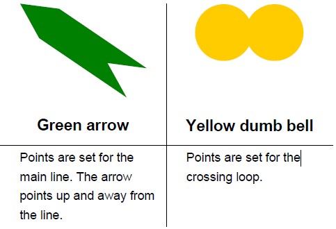
Preliminary report
Report release date: 30/06/2017
This preliminary report details factual information established in the investigation’s early evidence collection phase and has been prepared to provide timely information to the industry and public. Preliminary reports contain no analysis or findings, which will be detailed in the investigation’s final report. The information contained in this preliminary report is released in accordance with section 25 of the Transport Safety Investigation Act 2003.
At about 1503 CST[1] on 30 May 2017, Cessna 441 Conquest aircraft, registered VH-XMJ (XMJ), and operated by Rossair Charter, departed Adelaide International Airport, for Renmark Airport, South Australia.
On-board were:
an inductee pilot undergoing a proficiency check, flying from the front left control seat
the chief pilot conducting the proficiency check, and under assessment for the company training and checking role for Cessna 441 aircraft, seated in the front right control seat
a flying operations inspector from the Civil Aviation Safety Authority, observing and assessing the flight from the first passenger seat directly behind the two control seats.
Each occupant was qualified to operate the Cessna 441.
On departure, XMJ climbed to about 17,000 ft above mean sea level and was cleared by air traffic control (ATC) to a tracking waypoint RENWB, which was the commencement of the Renmark runway 07[2] RNAV-Z GNSS[3] approach. The pilot of XMJ was then cleared to descend and notified ATC that they intended to carry out airwork in the Renmark area. The pilot further advised that they would call ATC again on the completion of the airwork, or at the latest by 1615. No further transmissions from XMJ were recorded on the area frequency and the aircraft left radar coverage as it descended towards waypoint RENWB.
The common traffic advisory frequency used for air-to-air communications in the vicinity of Renmark Airport recorded several further transmissions from XMJ as the crew conducted practice holding patterns, and a practice runway 07 RNAV GNSS approach. At the completion of the approach, the aircraft circled for the opposite runway and landed on runway 25, before backtracking the runway and lining up ready for departure. Although outside radar coverage, position and altitude information continued to be transmitted via OzRunways[4], operating on an iPad in the aircraft. The weather information recorded at Renmark around this time was clear skies, south-to-south westerly winds of about 9 kt, and a temperature of 13°C.
At 1614, the common traffic advisory frequency recorded a transmission from the pilot of XMJ stating that they would shortly depart Renmark using runway 25 to conduct further airwork in the circuit area of the runway. A witness at the airport reported that, prior to the take‑off roll, the aircraft was briefly held stationary in the lined‑up position with the engines operating at significant power. The take-off roll was described as normal however, the witness looked away before the aircraft became airborne.
Figure 1: Position information of VH-XMJ as the aircraft circled and landed on runway 25 (depicted in red), before backtracking and departing (depicted in green).
Source: OzRunways
Position and altitude information obtained from OzRunways showed the aircraft maintained runway heading until reaching about 400 ft, before veering to the right of the extended runway centreline. The aircraft continued to climb to about 700 ft prior to levelling off for about 30 seconds, and then descending to about 600 ft. The information ceased 5 seconds later, about 60 seconds after take-off. The last recorded information had the aircraft at an altitude of 600 ft, and 22 degrees to the right of the runway extended centreline. The aircraft wreckage was located 228 m to the north-west of the last recorded position, about 3 km from the take-off point.
Figure 2: Altitude information of VH-XMJ – (each vertical line represents 5 seconds)
Source: OzRunways
On-site examination of the wreckage and surrounding ground markings indicated that the aircraft impacted terrain in a very steep (almost vertical) nose‑down attitude and came to rest facing back towards the departure runway. The horizontal and vertical tail surfaces and empennage separated from the main cabin directly behind the rear pressure bulkhead, and the cockpit and instrument panel were extensively damaged. The remaining aircraft cabin had separated from the wing. The left-hand propeller blades separated at the propeller hub. The right-hand propeller blade tips separated, however the blades remained attached to the hub. A strong smell and presence of jet fuel was evident at the accident site, however there was no evidence of fire. The aircraft was not equipped with a flight data recorder or cockpit voice recorder, nor was it required to be.
Both engine, gearbox and propeller assemblies, along with several other components and documentation, were removed from the accident site for further examination by the ATSB.
The investigation is continuing and will include examination of:
recovered components and available electronic data
aircraft, operator, and maintenance documentation and procedures
flight crew information
flight manoeuvres being carried out during the check flight and flight characteristics of the aircraft
aircraft weight and balance
risk assessments carried out when planning the flight
previous research, and similar occurrences.
__________
The information contained in this web update is released in accordance with section 25 of the Transport Safety Investigation Act 2003 and is derived from the initial investigation of the occurrence. Readers are cautioned that new evidence will become available as the investigation progresses that will enhance the ATSB's understanding of the accident as outlined in this web update. As such, no analysis or findings are included in this update.
Purpose of safety investigations
The objective of a safety investigation is to enhance transport safety. This is done through:
identifying safety issues and facilitating safety action to address those issues
providing information about occurrences and their associated safety factors to facilitate learning within the transport industry.
It is not a function of the ATSB to apportion blame or provide a means for determining liability. At the same time, an investigation report must include factual material of sufficient weight to support the analysis and findings. At all times the ATSB endeavours to balance the use of material that could imply adverse comment with the need to properly explain what happened, and why, in a fair and unbiased manner. The ATSB does not investigate for the purpose of taking administrative, regulatory or criminal action.
Terminology
An explanation of terminology used in ATSB investigation reports is available here. This includes terms such as occurrence, contributing factor, other factor that increased risk, and safety issue.
Publishing information
Released in accordance with section 25 of the Transport Safety Investigation Act 2003
Ownership of intellectual property rights in this publication
Unless otherwise noted, copyright (and any other intellectual property rights, if any) in this report publication is owned by the Commonwealth of Australia.
Creative Commons licence
With the exception of the Coat of Arms, ATSB logo, and photos and graphics in which a third party holds copyright, this publication is licensed under a Creative Commons Attribution 3.0 Australia licence.
Creative Commons Attribution 3.0 Australia Licence is a standard form licence agreement that allows you to copy, distribute, transmit and adapt this publication provided that you attribute the work.
The ATSB’s preference is that you attribute this publication (and any material sourced from it) using the following wording: Source: Australian Transport Safety Bureau
Copyright in material obtained from other agencies, private individuals or organisations, belongs to those agencies, individuals or organisations. Where you wish to use their material, you will need to contact them directly.
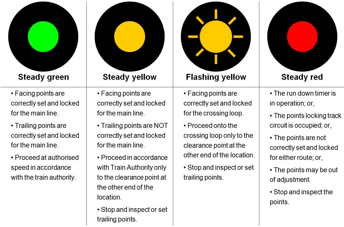
On 29 May 2017 at about 2225, a passenger train struck a protection officer at Petrie Station, Queensland, while walking on the track after placing permanent way protection equipment for a track closure on the Kippa-Ring line. As a result of the collision, the protection officer sustained fatal injuries.
What the ATSB found
The ATSB found that the protection officer did not apply personal continual vigilance (PCV) techniques while walking within 3 m of a track (the Danger Zone). PCV required the track worker to have clear and adequate sighting of tracks approaching their location, and frequently look (approximately every 5 seconds) in both directions for approaching rail traffic.
Although the reasons why the protection officer did not apply continual vigilance techniques could not be determined, it was possible that he had no expectation of rail traffic, and a number of factors that increased risk were identified. The ATSB found that the protection officers were not advised of the protection task and its earlier start time requirement, and felt pressure to continue with the task. Relating to the task, a Train Notice Diagram was provided to the protection officers which was incorrectly marked with the open and closed roads, which was likely linked to the Train Notice Diagram layout being conducive to misinterpretation.
It was also found that the protection officers working on the closure were unfamiliar with the new rail environment at Petrie, which had an uncommon grade separation of lines and there was no process for familiarisation. There was also no requirement to obtain train running information, meaning the protection officers were unaware of the location and direction of trains approaching their location. The process for selecting protection measures also did not drive selection to reasonable and practicable higher levels of protection.
What's been done as a result
Immediately following the accident, Queensland Rail (QR) proactively suspended all work within the danger zone of its running lines, later reinstating work in the Danger Zone with the prohibition of PCV.
Since the accident, QR reported that it has undertaken independent reviews on its safe work on track systems including PCV, use of mobile devices in the rail corridor, and its worksite protection compliance inspection systems. QR have since re-introduced PCV with some additional controls identified and validated from their independent reviewer.
QR have also re-enforced the message of ‘the right to stop work and getting safety right before commencing’ as part of its ongoing network pre-start brief project. They have also organised the development of a consistent process for marking up Train Notice Diagrams, including the provision of retraining protection officers in relation to PCV, mobile phones, pre-start briefs, and safeworking documentation.
Safety message
‘Safe work on track’ continues to be one of ATSB’s SafetyWatch priorities. To minimise risk, rail organisations should ensure processes relating to track work include provisions for protection officers to have sufficient resources, including time for task, information about the work environment, including train movements, and adequate protection available for the work.
The occurrence
On 29 May 2017 at about 2225 Eastern Standard Time,[1] passenger train T570 struck and fatally injured a protection officer (PO1) adjacent to Petrie Station, Queensland. PO1 was walking back to his work team vehicle after placing permanent way protection equipment for a track closure on the Kippa-Ring rail line in preparation for maintenance activities.
Possession planning for closure
Around 26 April 2017, a possession planning coordinator[2] commenced planning for a scheduled closure of the Kippa-Ring rail corridor on 29 May 2017 from Petrie Station to the end of the line at Kippa-Ring Station (Figure 1). The closure was required to facilitate planned maintenance works on both overhead wiring and track infrastructure.
Figure 1: South-Eastern Queensland rail lines north of Brisbane
Image shows the rail lines from Brisbane through Petrie, the Caboolture line continuing after Dakabin towards Narangba, and the newer Moreton Bay line also known as the Kippa-Ring rail line from Petrie to Kippa-Ring (depicted in red). Source: Australian Government National Map, annotated by ATSB
Also on 26 April 2017, the team seeking access for the Kippa-Ring line closure submitted a protection officer resource request to the night shift protection officer supervisor.[3] The supervisor later recorded the protection task and resource allocation for the Kippa-Ring line closure in his handwritten diary.
On 18 May 2017, the possession planning coordinator emailed the night shift protection officer supervisor (supervisor) requesting the name of the protection officer who would be in charge of the Kippa-Ring rail line closure. This information was required to finalise the Train Notice[4] associated with the closure. As the supervisor was preparing to commence leave (between 19 May 2017 and 28 May 2017), he forwarded the possession planning coordinator’s emailed request to the acting night shift protection officer supervisor (acting supervisor 1).[5] The acting supervisor 1 replied to the possession planning coordinator providing the name of the protection officer (PO3) who would be in charge of the Kippa-Ring rail line closure. The acting supervisor 1 also recorded the names of the four assigned protection officers (PO1, PO2, PO3 and PO4) into the handwritten diary.
Planning the week prior to closure
On 22 May 2017, one week prior to the day of the closure, the possession planning was complete and a Train Notice associated with the Kippa-Ring rail line closure was published.[6] The Train Notice detailed the purpose of the closure, the proposed work, the type of protection required and the extent of the closure including the signal numbers protecting the closure and the name and contact details of the protection officer in charge (PO3).
The team of four protection officers were required to establish the Kippa-Ring rail line closure using a Track Occupancy Authority (TOA).[7] Three of the four protection officers (PO1, PO2, and PO3) were assigned to Petrie Station, while PO4 was to be assigned to Kippa-Ring Station at the other end of the closure. The protection measures at Petrie involved the placement of permanent way stop signs[8] and three railway track signals[9] at signals PE67 and PE73 (Figure 2), closing the routes from Petrie towards the Kippa-Ring line.
Figure 2: Signal layout information for Petrie Station, with location of permanent way protection equipment placed by protection officers
Image shows location of signals, station platform numbering, and location where protection officers placed permanent way protection equipment and parked their vehicle. Lines closed as part of the Kippa-Ring line closure shown in red. Source: Queensland Rail, annotated by ATSB
The Train Notice for the Kippa-Ring line closure nominated a track closure commencement time of 2200. On 26 May 2017, one of the access seekers assigned to work within the Kippa-Ring rail line closure emailed the two acting supervisors requesting his work group briefing be held at Albion Depot at 2045 on 29 May 2017.
On 28 May 2017, acting supervisor 1 communicated via email an acceptance of the briefing location request, and agreed to the start time. The acting supervisor 2 and the normal supervisor were included in this communication. An earlier shift start time than the normal 2100 shift start would be required for this. However, the protection officers were not advised of their work task or briefing details, nor were they advised that an earlier shift start was required to accommodate the planned work.
On the night prior to the accident, the normal supervisor returned from leave. At this time, neither of the acting supervisors nor the normal supervisor detected that the protection officers had not been advised of the protection task and earlier shift start time requirement for the Kippa-Ring rail line closure.
Work on night of closure
The base depot and shift start location for the protection officers and supervisor on the night of the accident was the Mayne Depot. At about 2040 on the night of the accident (29 May), the supervisor, telephoned PO3 to enquire why he had not arrived at Mayne Depot for the early shift start time. PO3, who was travelling to work in the presence of PO1 and PO2, indicated that he and the others were unaware of the early shift start requirement and their involvement with the Kippa-Ring line closure.
In an attempt to avoid delaying the required closure, the supervisor marked up the Train Notice Diagram,[10] a task normally undertaken by a protection officer in charge. The diagram showed the worksite safety information, such as safe places, intended permanent way protection equipment location, open and closed track information, and other relevant information. However, the supervisor’s ‘mark ups’ on the Train Notice Diagram contained errors which did not accurately display which tracks were open or closed at Petrie Station.
Upon arrival at Mayne Depot, the supervisor presented PO3 with the Train Notice and the marked up Train Notice Diagram. Two of the protection officers (PO2 and PO3) recalled, that following their arrival at the Mayne Depot they advised the supervisor of their concerns regarding their lack of familiarity with the Petrie area, and the short time frame. The supervisor recalled reassuring the protection officers that it was a simple and straightforward task.
The briefing with the maintenance crew was at Albion Depot, so a short time later, PO1, PO2, and PO3 departed their base depot for Albion Depot (Figure 1). The fourth protection officer (PO4) departed the Mayne Depot for the end of the Kippa-Ring rail line. At about 2120, PO1, PO2 and PO3 arrived at Albion Depot. Members of the maintenance crew observed that PO3 looked ‘flustered’, and recalled that he apologised for being late. PO2 and PO3 later recalled feeling rushed to implement the closure.
At about 2120, PO3 participated in a briefing of the maintenance crew at the Albion Depot. After the briefing had concluded, PO1, PO2, and PO3 travelled to Petrie Station (Figure 1). Prior to commencing protection work, PO2 and PO3 reported undertaking a pre-start brief for the implementation of protection. Video footage showed PO1, PO2, and PO3 were in discussions together at the bonnet of their vehicle for approximately 90 seconds. However, the recorded pre-start briefing form contained errors and inconsistent sign-off entries.
A short time after the pre-start brief was reported as completed, PO3 contacted the network control officer (NCO)[11] to confirm[12] their location at Petrie. This was done by PO3 confirming the displayed aspect of a signal on the Down[13] Kippa-Ring line. As none of the protection officers at Petrie had worked at that location since major changes to the rail infrastructure had been completed,[14] there was some initial confusion in locating the correct signal to confirm their location.
At about 2215, after confirming their location at Petrie, PO3 commenced establishing the TOA for the Kippa-Ring rail line closure. Once blocking facilities had been applied for the closure, PO1 and PO2 entered the rail corridor. PO1 and PO2 placed permanent way stop signs and railway track signals adjacent to signal PE67 to block the Down Kippa-Ring line, and signal PE73 to block the Up Kippa-Ring line, respectively (Figure 2). As a culvert and small drain blocked a direct route from the protection officers’ vehicle to signal PE67, PO1 chose to walk 20 m along the middle of the Up Caboolture line (which was open for rail traffic) until there was clear access to walk across to signal PE67 (Figure 3). Video footage showed PO1 was likely not surveying for rail traffic behind him during this walk.
Figure 3: Petrie stormwater culvert/drain layout
The images shows the stormwater drain/culvert (blue dashed line) and the direction of the protection officer’s travel to and on return from PE67 near platform 3 (yellow dashed line). Source: Google Earth, Annotated by the ATSB.
At about 2222, after PO1 and PO2 had placed the permanent way stop signs and railway track signals, PO1 walked to the northern end of Platform 3 where he met with a station officer. They were engaged in conversation for a short time before the protection officer turned and walked in the direction of the protection officers’ vehicle.
PO1 again walked in the middle of the Up Caboolture line, the reverse path he had previously used to avoid the culvert and drain (yellow line in Figure 3). Video footage showed that PO1 was looking in his direction of travel, and was not looking behind him. At about this time, a passenger train, designation T570, approached Petrie Station on the Up Caboolture main line from the north. The distance separating train T570 and the protection officer when PO1 reached the Up Caboolture line was about 400 m.
The train’s headlights and ditch lights were on and functioning correctly as the train travelled a 50 km/h sweeping right hand curve (Figure 4). However, the lights only illuminated a short length of track ahead due to the curvature of the track. With his back to the train, PO1 was not aware of the approaching train and the driver of the train was unaware PO1 was positioned in the middle of the rail lines.
Figure 4: Layout of the Petrie Station
This image shows the location of platform 3, in relation to the stormwater culvert/drain (depicted in blue). As well as Caboolture lines (Up depicted in solid orange, and Down in dashed orange line) and the Kippa-Ring lines (Up depicted in solid yellow, and Down in dashed yellow line). The direction of travel of train T570 on the Up Caboolture line and the collision location is also shown. Source: Google Earth, annotated by ATSB
At about 2225, video footage showed PO1 had stopped walking in the middle of the rail lines at the same time as his mobile phone clipped to the front of his shirt illuminated. He remained in a stationary position, for about 6 seconds, with the phone illuminated and his back to the approaching train. As the train exited the sweeping curve, the headlights shone directly on PO1. Upon sighting PO1, the train driver applied the emergency brake and sounded the train horn. The protection officer attempted to vacate the track, however, there was insufficient time and the train collided with the PO1 (Figure 4). As a result of the collision, PO1 sustained fatal injuries.
A protection officer was defined within the Queensland Rail Network Rules and Procedures (QNRP) as a competent worker responsible for managing the rail safety component of worksite protection.
Protection officer PO1
PO1 was the protection officer struck by train T570.
Queensland Rail (QR) had employed PO1 for 36 years, with the last 17 years in a protection officer role. PO1 held current competencies for his role as a protection officer, with his last reaccreditation assessment satisfactorily completed on 12 May 2016. A periodic health assessment of PO1 was undertaken on 10 February 2017, with PO1 being recorded as fit for duty.
A toxicology examination for alcohol and prescribed drugs recorded a negative test result.
PO1 had taken leave in the days prior to the accident, with the accident occurring early in his first night back at work. It was unlikely that PO1 was experiencing a level of fatigue known to have a demonstrated effect on performance.
Protection officer PO2
PO2 was the protection officer placing permanent way protection equipment adjacent to signal PE73 at Petrie.
QR had employed PO2 for 22 years, with the last 10 years being in a protection officer role. PO2 held current competencies for his role as a protection officer, with his last reaccreditation assessment satisfactorily completed on 24 April 2015.
The ATSB reviewed the drug and alcohol test results, and rosters (with respect to fatigue). In conjunction with the PO2 comments and his leave in the days prior to the accident, these human performance factors were not considered a factor in this accident.
Protection officer PO3
PO3 was the protection officer in charge of implementing the protection and managing the rail safety component and implementation documentation associated with the closure.
PO3 was employed at QR for 21 years, with the last 11 years being in a protection officer role. PO3 held current competencies for his role as a protection officer, with his last reaccreditation assessment satisfactorily completed on 9 April 2015.
The ATSB reviewed the drug and alcohol test results, and rosters (with respect to fatigue). In conjunction with the PO3 comments and his leave in the days prior to the accident, these human performance factors were not considered a factor in this accident.
Protection officer PO4
PO4 was the protection officer tasked with clipping points at the Kippa-Ring Station end of the closure. Whilst PO4 was part of the protection officer team, he was not directly involved in the accident at Petrie.
Location
Petrie Station is located 28.5 km north of the Roma Street Station, Brisbane on the North Coast Line in Queensland. It services the suburb of Petrie in the Moreton Bay region, and is the junction for the main lines between Brisbane, Caboolture, and the recently commissioned Kippa-Ring rail line (Figure 5).
The Kippa-Ring rail line, also known as the Moreton Bay rail line and Redcliffe Peninsula line, was a 12.6 km dual-track passenger rail line between Petrie and Kippa-Ring. The Kippa-Ring rail line construction was completed in October 2016, with significant changes to rail infrastructure in the Petrie Station area.
Figure 5: Portion of Queensland Rail South-Eastern Queensland network
Image shows rail lines from Brisbane through Petrie, the Caboolture line continuing after Petrie towards Caboolture, and the Redcliffe Peninsula line also known as the Kippa-Ring line continuing from Petrie to Kippa-Ring. Source: Queensland Rail, annotated by ATSB
The new Kippa-Ring rail line connected to the existing QR network at Petrie Station. In respect to Petrie (Figure 6), this connection led to the construction of:
additional platforms (island platform 4 and 5)
track duplication south of Petrie to Lawnton
connection to new Kippa-Ring line
grade separation[15] of the Up Caboolture and Down Kippa-Ring lines at Petrie.
Figure 6: Rail infrastructure changes in vicinity of Petrie Station
Image shows new and changed rail infrastructure configurations in red within the Petrie Station precinct. Source: Queensland Rail, annotated by ATSB.
Petrie Station consisted of five passenger platforms, with Platform 1 serviced by a down direction rail line and Platforms 2 to 5 serviced with bi-directional[16] lines. The line allocations for each of the platforms were as follows (Figure 7):
Platform 1 – Down Caboolture Line
Platform 2 – Middle Road (predominantly down line, but could be bi-directional)
Platform 3 – Down Kippa-Ring Line (predominantly down line, but could be bi-directional)
Platform 4 – Up Caboolture Line (predominantly up line, but could be bi-directional)
Platform 5 – Up Kippa-Ring Line (predominantly up line, but could be bi-directional).
Figure 7: Petrie Station layout
Image shows platform and line allocation. Up and Down Caboolture lines depicted in orange, and Up and Down Kippa-Ring lines depicted in yellow. Source: Google Earth, annotated by ATSB
Platforms 1, 2, and 3, were separated by about 40 m from Platforms 4 and 5 due to a stormwater culvert/drain (Figure 7). Platforms 4 and 5 were configured in an island platform arrangement in a separate structure, and were connected to the other Petrie platforms by an overhead pedestrian walkway (Figure 7).
The Up Caboolture line and the Down Kippa-Ring line were grade separated about 400 m north-west of the Petrie Station (Figure 7). The grade separation created a relatively uncommon configuration in the QR Network, whereby two adjacent platforms (4 and 5) both serviced tracks that carried mainly Up direction traffic.
Organisation
QR provided suburban commuter rail services on the City network, covering Brisbane, Ipswich, Sunshine Coast and Gold Coast in South-Eastern Queensland. Queensland Rail was both a rail infrastructure manager and rolling stock operator.
Management of change
To manage rail safety legislative obligations, rail operators were required to establish and implement a safety management system (SMS).[17] One element of an SMS was a subsystem that provides for the management of changes. This subsystem is aimed to ensure that changes that may affect the safety of rail operations were identified and managed, so far as is reasonably practicable.
Kippa-Ring rail line changes
The Queensland Department of Transport and Main Roads was the agency responsible for the Kippa-Ring rail line project, who had engaged a third party design and construction contractor. On completion of the project, QR accepted management and control responsibility for the new infrastructure.
QR determined this was a complex change within the guidelines of its management of change processes. From this, a Rail Safety Management Plan was developed for the new Kippa-Ring rail line. This plan focussed on the changes resulting from QR’s acceptance of the new infrastructure, and the planned commencement of operations on the new infrastructure. The plan did not identify protection officers and other track workers as stakeholders, nor include the need for familiarisation for protection officers and track workers as a risk.
Protection officer familiarisation
The protection officers involved in this accident had not worked at Petrie since the completion of the rail infrastructure changes associated with the new Kippa-Ring line.
At the time of the accident, QR relied on protection officers becoming familiar with a new location by reviewing Train Notice Diagrams or route maps. These Train Notice Diagrams and route maps provided information about the configuration of rail infrastructure as well as some operational information (Figure 8). The diagrams and maps were limited in the topological information they contained, such as physical barriers that might create additional safety hazards to the work at the intended location.
Image shows samples of the information available from a Queensland Rail train notice diagram and route map for Petrie. Noting that there is limited information about physical site topology. Source: Queensland Rail, annotated by ATSB
The protection officers advised that when they had advanced warning of a protection task at a new or unfamiliar location, whilst not a QR requirement, they would consider a visit to the worksite in the days preceding the intended work. This opportunity was not available in this case.
Safeworking systems
Safeworking systems are an integrated system of procedures and technology aimed at ensuring the safe operation of trains including the protection of people and property on or about a railway.[18]
In June 2012, QR implemented the Queensland Network Rules and Procedures (QNRP) Standard as the safeworking system for their network. The QNRP Standard was aligned, with some exceptions, to the suite of Australian Network Rules and Procedures (ANRP). The ANRP was maintained and updated as required by the Rail Industry Safety Standards Board (RISSB) in collaboration with industry representatives. Since QR implemented the QNRP Standard in 2012, sections of the RISSB ANRP relevant to this investigation have been amended (2013 and 2014).
The QNRP Standard, among other safety measures, put in place specific safety measures for the risk of collision between rail traffic and workers. The QNRP specified the minimum requirements for trackside protection for anyone who entered the rail corridor, and for those who performed activities in the Danger Zone.[19]
The safety controls or protection levels relevant to track workers accessing rail corridors ranged from the higher safety level work on track authorities to means of protection followed by the lower level safety measures (Figure 9).
Figure 9: Image depicting protection levels of safety controls for accessing rail corridors
The image shows the lower protection level safety measures, through the means of protection to the higher protection level work on track authorities. Source: ATSB
The relevant protection officer undertook a safety assessment when choosing the appropriate track access method or the level of protection. The QNRP referred to two safety assessment documents for recording the safety assessment: Corridor Access Safety Assessment (SW61), and Trackside Safety Protection Planner (SW01).[20] These documents provided guidance on the selection of protection level, and recorded details of the intended track access safety assessment (Figure 10).
Figure 10: Image depicting protection level selection guidance within track access safety assessment QNRP forms SW01 and SW61
This image shows the portions of the track access safety assessment documents (SW01 and SW61) which were designed to assist the decision making process for protection level selection. Source: Queensland Rail, annotated by the ATSB
As included in the design of the safety assessment forms SW61 and SW01, there were two main safety hazards that protection officers needed to consider when determining what level of protection to select. These were:
the safety hazards to rail traffic from the intended work
safety hazards to track workers and protection officers from rail traffic while within the proposed worksite.
The decisions related to the rail traffic risk assessment required the protection officer to consider what work was to be undertaken and whether that work would make the track unsafe for rail traffic by breaking or obstructing the track (Figure 11). This was followed by a consideration of the rail infrastructure/operational configuration and site topology effects on the protection officer, and ultimately track workers ability, to sight an approaching train and move to a safe place before the train arrived (Figure 11).
Figure 11: Flowchart showing protection level selection decision-making process (starting in the top left), informed by Queensland Rail SW61 and SW01 forms.
This image shows a protection level selection flowchart created by the ATSB to explain the protection level selection decision making process and decision assistance guidance contained in Queensland Rail Corridor Access Safety Assessment (SW61) and Trackside Safety Protection Planner (SW01) forms. Source: ATSB
There were some common baseline safety requirements between work on track authorities, means of protection, and safety measures for workers accessing the Danger Zone. These were:
Track workers must wear high-visibility clothing.
Electronic communications devices were not to be used in the Danger Zone.
Track workers must not step on points, interlocking equipment, or rails.
Track workers must not wear or use anything that prevents them from seeing or hearing rail traffic.
The differences between the work on track authorities, means of protection, and safety measures that are relevant to this investigation are explained below in the context of the Kippa-Ring line closure at Petrie.
Track Occupancy Authority (Authority)
Track Occupancy Authority (TOA) is an authority for competent workers and their worksite equipment to occupy a defined portion of track for an agreed period. A TOA essentially is issued to the access seeker and provides sole occupancy except where joint occupancy is negotiated. A TOA is intended for work that breaks or obstructs the track, or where a safety assessment has determined a lower protection level is not appropriate. The implementation of a TOA in an application similar to the Kippa-Ring line closure at Petrie required the following safety controls:
The protection officer must contact the Network Control Officer (NCO) and request the TOA. The protection officer must clearly describe the location, work site limits, work to be undertaken, and proposed start finish times.
The NCO must test and confirm the location of the worksite with the protection officer and ensure that the track within the proposed worksite limits is unoccupied.
The NCO must apply blocking facilities[21] and secure points to prevent unauthorised rail traffic into the portion of track within the TOA limits.
The protection officer must confirm that the NCO has applied blocking facilities, and ask for the train running information for rail traffic planned to pass through the work location.
NCO must authorise TOA.
The protection officer must place in-field protection consisting of railway track signals[22] and stop signs at the limits of the TOA or 500 m on either side of the worksite.
Depending on operational and network configurations, the protection officer may clamp points in a position to direct rail traffic away from the TOA limits.
Absolute Signal Blocking (Means of protection)
Absolute Signal Blocking (ASB) is a means of protection used by competent workers to carry out work on track. ASB is only available in remote controlled signalling territory and uses controlled absolute signals set at STOP with blocking facilities applied. ASB is not permitted to be used for work that breaks or obstructs the track, and does not provide exclusive occupancy to the access seeker. The implementation of an ASB in an application similar to the Kippa-Ring line closure at Petrie required the following safety controls:
The protection officer must contact the NCO and request the ASB. The protection officer must clearly describe the location, the absolute signals to be used to protect the work site limits, work to be undertaken, and proposed start finish times.
The NCO must test and confirm the location of the worksite and the controlled absolute signals with the protection officer, and ensure that the track within the proposed worksite limits is un-occupied.
The NCO must set the controlled absolute signals to stop and apply blocking facilities and secure points to prevent unauthorised rail traffic into the portion of track within the ASB limits.
The protection officer must confirm that the NCO has set the controlled absolute signals for the work site to stop and applied blocking facilities.
Look Out Working (Safety measure)
Look Out Working (LOW) is a safety measure used by competent workers to carry out work on track without a formally issued work on track authority, or means of protection. While the QNRP permits the use of LOW at night for protection officers placing permanent way protection equipment, a local understanding/practice within the protection officer business unit precluded the use of LOW at night. LOW was restricted to applications where workers, tools and equipment could be cleared from the track to a safe place 10 seconds before the arrival of rail traffic. LOW required competent workers to be assigned as lookouts,[23] where their sole role was to keep watch for approaching rail traffic and warn workers to move to the designated safe place. The implementation of LOW in an application similar to the Kippa-Ring line closure at Petrie required the following safety controls:
The protection officer must contact the NCO and notify them of their intent to use LOW. The protection officer must clearly communicate their name, contact details, location of work site, type of work to be done, and proposed start and finish times.
The protection officer must determine how many lookouts are required and their placement to ensure the minimum sighting distance is achieved to provide adequate warning to the people within the work site.
The protection officer must determine communication arrangements for lookouts to warn workers (this excludes radios or telephones).
Lookouts must keep watch for rail traffic approaching the worksite and warn workers immediately if rail traffic approaches the worksite.
Lookouts must remain in their designated position and not do any other work while performing lookout duties.
On 7 March 2014, QR published a Critical Safety Alert advising that the use of LOW at night was prohibited except for the placing or removal of permanent way protection equipment. However, a local rule or understanding corroborated by several QR representatives, confirmed that it was accepted policy that LOW was not to be used at night even for placement or removal of permanent way protection equipment.
Personal Continual Vigilance (Safety measure)
Personal Continual Vigilance (PCV) is a safety measure used by competent workers to walk from place to place in the Danger Zone and do no work other than place/remove permanent way protection equipment. The ANRP equivalent process had been amended in June 2014. This amendment brought in an option for rail operators like QR to consider adopting a requirement that, before walking in the Danger Zone, workers must contact network control and get information about rail traffic for that location. Although QR had considered this optional requirement from the ANRP amendment, it had elected not to adopt it. As such, the QNRP version of PCV at the time of the accident did not require any communications or operational train running advice from the network controller before accessing the Danger Zone using PCV. In addition to this, the QNRP specified that competent workers must not rely on train running information. This requirement was consistent with the understanding of protection officers, who advised that NCOs do not like to provide train running information. Therefore, the implementation of PCV in an application similar to the Kippa-Ring line closure at Petrie required the following safety controls:
The track worker must make sure that they can see that tracks are clear of approaching rail traffic.
The track worker must look frequently (approximately every 5 seconds) in both directions for approaching rail traffic.
The track workers must not rely on another person to give warnings of approaching rail traffic.
Protection officers reported that the common operational practice was to select PCV as the preferred choice for initial access to the Danger Zone when placing permanent way protection equipment, or when crossing from place to place.
Safeworking comparison
The comparison of each of the safety controls for the work on track authority, means of protection, and safety measures relevant to the investigation is summarised and displayed in Table 1:
Table 1: Comparison of summarised safeworking tasks between protection levels relevant to this investigation
Safety control
TOA
ASB
LOW
PCV
Requires notification to NCO of intent to access Danger Zone
Requires NCO authority / permission to proceed
Requires NCO confirmation of location
Requires NCO to block signals / points
Requires protection officer to confirm application of NCO blocks
Requires protection officer to request train running information
Requires protection officer to place in-field protection/point clamps
Requires adequate sighting distance of approaching rail traffic
Requires lookout to solely look out for trains and warn workers
Requires track worker to look frequently in both directions
Possession task
On the night of the accident, maintenance access seekers planned to close and take possession of the Kippa-Ring rail line using a TOA to facilitate maintenance inspections of the overhead traction wiring equipment and the distribution of track ballast to rail turnouts. The closure was scheduled to commence at 2200 on 28 May 2017 until 0320 on 29 May 2017, and was to be repeated on the following night.
Possession planning
The QR track possession planning processes encompass the planning for business and customer continuity, accomplishment of works, safety within the worksite, and safety of normal operations. Possession planning in QR began with a possession bid raised by an access seeker. Possession bids were lodged within a database, which tracks the planning activities in relation to a possession.
As per planning protocols, a possession planning coordinator was assigned planning responsibility for the Kippa-Ring line closure prior to the scheduled closure. The possession planning coordinator initially undertakes a review of the possession bid to determine the complexity of the planning work required. This review considers the proposed possession dates/times, proposed worksite limits, adjacent signals, rail infrastructure geography, overhead isolation points, and what are the most appropriate bus transfer points for passengers. This review leads to the determination of the most appropriate level of protection for the worksite and the development of a traffic plan for the rail service changes to facilitate the possession.
The possession planning coordinator determined that a TOA would be the most appropriate protection level, with signal PE67 and PE73 at Petrie Station and the end of the Kippa-Ring rail line being the worksite protection limits for the possession. The traffic plan which was developed required the termination of all Kippa-Ring line rail services at Petrie Station. Alternate bus services were provided for QR customers between 2200 and 0320 on the night of the accident (29 May 2017) and the following night (30 May 2017). The traffic plan was completed on 27 April 2017, and the possession bid was approved on 3 May 2017.
The possession planning coordinator then commenced drafting a Train Notice for the altered safeworking arrangements. The possession planning coordinator, upon completing their draft of the Train Notice, organised for an independent review of the Train Notice, as per planning protocols. The review was completed on 22 May 2017, with the Train Notice published later that same day.
The publishing of the Train Notice concluded the possession planning coordinator’s involvement unless a further change to the Train Notice or the possession plan was required. At this stage, the planning and risk management associated with the placement of the protection within the Danger Zone for the track possession became the responsibility of the protection officer. The ATSB found that the possession planning for the proposed Kippa-Ring line closure was adequate.
Possession implementation
The published Train Notice for the Kippa-Ring rail line closure prescribed the protection level of TOA with the following limits:
The Up Kippa-Ring line from the end of the Kippa-Ring line to signal PE73 at Petrie.
The Down Kippa-Ring line from signal PE67 Petrie to the end of the Kippa-Ring line.
To facilitate the implementation of the TOA for the Kippa-Ring rail line closure, protection officers PO1, PO2, and PO3 were required to access the Danger Zone at Petrie to place stop signs and railway track signals at signals PE73 and PE67 at Petrie (Figure 12).
The protection officers at Petrie were to be protected on the Up and Down Kippa-Ring lines by the signal blocking applied by the NCO as part of the TOA requirements. Personal Continual Vigilance (PCV) was the protection level selected for all other rail lines at Petrie, including the Up Caboolture line where the collision occurred.
The fourth protection officer, PO4 was assigned to the end of the Kippa-Ring rail line and was to access the Danger Zone at Kippa-Ring to secure and lock points at the entrance to a stabling yard to prevent rollingstock accessing the Kippa-Ring rail line.
Figure 12: Petrie Station, showing placement of permanent way protection equipment for Kippa-Ring line closure.
Image indicates the location, and permanent way protection equipment type and placement for the Kippa-Ring line closure on the night of the accident. Source: Google Earth, annotated by ATSB
To access the rail corridor and Danger Zone to place the permanent way protection equipment for assigned protection tasks, protection officers also need to consider their own protection in line with the Queensland Rail Network Rules and Procedures. Queensland Rail have documented their processes for implementing track protection within a safe work method statement (SWMS). The SWMS assigns responsibility to the protection officer for implementing the pre-planning, and site arrival tasks for implementation of protection.
Pre-planning
The pre-planning work sequence required the protection officer in charge to use route maps, train notice diagrams, and train notices to plan and undertake the safety assessment. The safety assessment was recorded on QR forms SW01 and SW61. The SW01 form required a worksite sketch, which provided details of the closed tracks, worksite limits, safe areas, and other safety information. QR representatives reported that these sketches were generally undertaken using a Train Notice Diagram as a base, with the protection officer marking up the required safety information to assist in communicating this information at the pre-start brief.
In regards to the Kippa-Ring closure, a Train Notice Diagram for the Petrie Station area was used to sketch or mark-up the closure information. The base (unmarked) Train Notice Diagram displayed the rail infrastructure layout of the Petrie Station, and about 3 km of the Up and Down Northern Lines towards Caboolture. The layout of the Train Notice Diagram was arranged with the Petrie Station layout at the top of the page, with the Caboolture line extension displayed at the bottom of the page (Figure 13).
Figure 13: Train Notice Diagram 126, for Petrie Station
Image showing Train Notice Diagram TN 126. Train Notice Diagram TN 126 describes the rail infrastructure layout and some operational information for Petrie Station. Noting the connection points on the map between the two portions of the Caboolture line. This Train Notice Diagram was used as the base or starting point for recording the worksite sketch information required by the safety assessment and Queensland Rail SW01 Form. Source: Queensland Rail, annotated by ATSB
The mark-up of the safety information on the Train Notice Diagram involved highlighting the closed tracks, and recording where the permanent way protection equipment was to be placed (Figure 14). QR representatives advised that this mark-up would normally be undertaken by the protection officer in charge. However, in this case the supervisor marked up the Train Notice Diagram. The supervisor’s mark-up contained errors that did not accurately depict the open and closed tracks (Figure 14).
Although not a formal process, an independent check of this mark-up would normally be undertaken by either the supervisor or one of the other senior leaders before the protection officers departed for the worksite. On the night of the accident, no independent check of the Train Notice Diagram mark-up was conducted.
Image showing the Petrie Train Notice Diagram marked up with closure safety information. Noting that highlighted portions of track are intended to depict closed tracks and other markings relate to the location of permanent way protection equipment placement. Image also shows marking error where the Caboolture line was marked as closed. Source: Queensland Rail, annotated by ATSB
The pre-planning work sequence included checks of required equipment and worksite transport, plus the drafting of the pre-start safety briefing in preparation for delivery at the worksite.
Site arrival
Upon arrival at the planned worksite, the protection officer in charge was required to work through the SWMS onsite task sequence to ensure the following tasks were undertaken:
Confirm correct network location with the NCO, plus complete and read back applicable safeworking forms (SW08 for TOA).
Communicate pre-start brief to worksite participants.
Place track protection for possession.
Complete checklist for protection of track closures, so that all permanent way protection equipment used was recorded and accounted for.
Contact the NCO and advise what permanent way protection equipment had been placed, and the time that it was undertaken.
Mobile communication devices
A key component of a protection officer’s role is to communicate safeworking information to NCO’s, other protection officers and personnel within their assigned worksite. To facilitate communication, QR issued protection officers with mobile phones.
To manage the risk of distraction in the Danger Zone, the QR safety rules and procedures stated that personnel were not to use mobile communication devices within the Danger Zone.
In addition to this, and specific to protection officers, observational and verbal reaccreditation assessments were undertaken periodically. These reaccreditation assessments included verbal questioning of protection officers on QR’s policies with respect to mobile communication equipment use in the Danger Zone.
An Apple branded mobile phone had been issued to PO1 by QR. Phone records were obtained from the QR mobile phone service provider. The records indicated that no incoming or outgoing phone calls or text messages had been transmitted at the time of the collision. Additionally, email accounts linked to the mobile phone had not been accessed since 13 March 2017. A post-accident examination of the mobile phone settings revealed that a number of mobile phone applications had been permitted to trigger notifications.[24]
Previous occurrences
A review of previous ATSB investigation reports found several investigations relating to track work, which are listed below by common safety factors. The ATSB also periodically conducts research on safe work on track, specifically focusing on track workers involved in conflicts or potential conflict with trains.
Worksite briefing – train running information
RO-2011-006: Collision between freight train 7SP3 and a track mounted excavator near Jaurdi, Western Australia, on 28 March 2011.
On 28 March 2011, at about 1308, a freight train 7SP3 collided with a track mounted excavator between Jaurdi and Darrine, Western Australia. The train driver sustained a minor injury. There was significant damage to the lead locomotive and the excavator, and minor damage to the track as a result of the accident.
The ATSB found that two track mounted excavators had been placed back on the track without permission of the Authorised Employee responsible for the coordination of track side safeworking activities between Jaurdi and Darrine. Another finding was that although separate pre-work briefings were conducted, there was no discussion about train running information and site protection between the Supervisor (Excavators) and the Supervisor (Track Machines).
RO-2015-019: Track worker struck by a passenger train, near Laverton Station, Victoria, on 2 October 2015.
On 2 October 2015, at about 0916, a train departing Laverton Station approached a worksite where a supervisor was marking a track to identify dog spikes to be removed, with a lookout for his protection. The lookout observed the train, warned workers of its approach and signalled to the driver that the track was clear. However, as the train took the crossover, the supervisor was foul of the track, and was struck by the train that was travelling at about 59 km/h. The supervisor suffered serious injuries.
The ATSB found that the pre-work briefing was not conducted. This meant that not everyone in the work group had a clear understanding of train movements that morning. The supervisor may also have thought that the train would proceed on its track and not take the crossover track to his location. It was also concluded that on the train’s approach, the train was given the all clear to proceed prior to the supervisor moving to a position of safety, clear of all tracks.
Protection selection
RO-2015-002: Collision between track worker and passenger train at Guildford, Western Australia on 10 February 2015.
On 10 February 2015, a Public Transport Authority (PTA) maintenance crew commenced work at Meadow Street, Guildford, Western Australia. The crew’s assigned tasks included maintaining the pedestrian gates adjacent to the level crossing. At about 1035, one of the track workers was struck by a Perth-bound suburban passenger train. The track worker sustained fatal injuries.
The ATSB investigation found that the PTA maintenance workers had not implemented any form of track worker protection at the work site. This was partially due to the PTA not having documented instructions specifying the level of protection required, preferring that track workers make their own assessment based on their knowledge of the Network Rules. The ATSB found that, under these arrangements, track workers could make an incorrect assessment, placing themselves at a greater risk of being struck by a train.
On 29 May 2017 at about 2225, a passenger train T570 struck a protection officer at Petrie Station while he was returning to the work team vehicle after placing permanent way protection equipment for a track closure on the Kippa-Ring rail line. As a result of the collision, PO1 sustained fatal injuries.
The ATSB found no technical faults with the train or the driver’s actions on approach to Petrie Station. Speed and braking were consistent with sound driving practice. Consequently, the analysis will focus on the following topics:
the events leading up to the Kippa-Ring line closure
Queensland Rail (QR) safeworking procedures.
Personal Continual Vigilance
Personal Continual Vigilance (PCV) was a safety measure available for accessing the Danger Zone to place/remove permanent way protection equipment. PCV required the track worker to see that tracks are clear, frequently look (approximately every 5 seconds) in both directions for approaching rail traffic and not rely on another person to give warning. Consequently, PCV is largely reliant on the track worker having some awareness of their surrounds and an understanding of where the most likely hazards may appear.
A method used in some rail networks, which is consistent with the optional Australian Network Rules and Procedures (ANRP) 2001 requirements, is for track workers to seek some operational awareness of their location by requesting and receiving train running information from the network control officer (NCO). Train running information is defined within the Queensland Rail Network Rules and Procedures (QNRP) as information about rail traffic movement and frequency provided for a particular location. However, the QNRP prohibits the use of train running information being used by protection officers and track workers to provide information about the running of rail traffic.
Further to this, the QNRP is unclear regarding the format of train running information. For example, it is not clear whether it is information about predicted rail traffic timetabled arrival times/frequency through a location, or simply the provision of the current location of the rail traffic approaching the protection officer/track worker’s location. While some logic can be seen in the prohibition of the former, it is possible that train running information describing the current location of the approaching rail traffic could provide protection officers/track workers a benefit from the knowledge of what direction the next rail traffic could approach their location.
On the night of the accident, the protection officers did not seek train running information from the NCO. The protection officers were reliant on their own personal vigilance when within the Danger Zone of the live tracks, in this instance the Up Caboolture line at Petrie.
It is known that providing location information increases the likelihood of detecting targets during visual search tasks.[25] As applicable to rail, having additional information of the environment, in this case the location of any approaching trains, should increase the opportunity for protection officers to detect them while in the Danger Zone.
From this, the ATSB found that there is no requirement in the QNRP for protection officers (when using PCV) to notify the NCO of an intention to access the railway Danger Zone or obtain approaching train running information. Consequently, the protection officers had no knowledge of the direction and location of approaching train movements when accessing the Danger Zone. While the application of PCV may provide a risk control for identifying an approaching train, it only does so if applied effectively. Knowledge of approaching trains in the vicinity through provision of train running information may encourage the more diligent application of PCV.
Personal Continual Vigilance implementation
Protection Officer (PO1) actions
After the placement of permanent way protection equipment and while returning to the work vehicle, PO1 walked along the middle of the track on the Up Caboolture line (Road 4) in a south-westerly direction. This track was live and not part of the Kippa-Ring line closure. The two adjacent tracks, which comprise the Up and Down Kippa-Ring lines (Road 3 and 5) were protected by the closure. The direction PO1 was walking meant that his back was facing the train involved in the collision, which was approaching from the north. Video footage from Petrie Station showed PO1 walking along the track, and was not turning his head every 5 seconds to check for approaching traffic.
It was evident that protection officer PO1 did not apply continuous vigilance techniques when accessing the Danger Zone in accordance with PCV rules. Consequently, he did not see the approaching train in time to avoid being struck by the train.
The ATSB explored the underlying reasons why PCV had not been implemented. While there was some factors that potentially explain PO1’s actions, its effect on the accident could not be determined. The subsequent analysis discusses this evidence and provides possible reasons why PCV was not implemented.
Worksite and Task familiarity
After arrival at Petrie, PO2 and PO3 reported undertaking a pre-start brief. The opportunity for pre-start discussions for all three protection officers together at the bonnet of their vehicle was limited to about 90 seconds. In addition to this, the recorded pre-start brief forms contained errors and inconsistent sign-off entries; it is possible that the recording of the pre-start brief had been rushed.
Further to this, PO1 was not involved, nor required to be, at the briefing of the maintenance workers at Albion Depot, and was not present when PO2 and PO3 discussed details of the closure with the supervisor upon arriving at Mayne Depot. Therefore, PO1’s opportunity for familiarisation of task and safety requirements was possibly limited to the content of the pre-start brief conducted at Petrie.
In October 2016, Petrie Station was opened with its new layout. The new layout included a grade separation of the Up Caboolture Main and the Down Kippa-Ring lines which is an uncommon infrastructure configuration within the QR network. This grade separation creates the situation where the Up Caboolture Main and the Up Kippa-Ring lines are adjacent to each other as they feed into the island configuration platform (Figure 7 above).
The Kippa-Ring line construction was managed and conducted by an independent third party. There were limited opportunities for QR protection officers to become familiar with the new rail infrastructure configuration and layout during construction.
Following the completion of construction, QR took on the management and operation of the new Kippa-Ring line. The implementation of the QR management of change processes for the new Kippa-Ring rail line did not specifically include familiarisation as a risk to protection officers and other track workers. Nor did it specifically identify them as stakeholders to the changes. Therefore, it is likely that the protection officers’ opportunity for familiarisation of the new infrastructure was limited to general staff communications, media coverage, and when tasked with work in the new areas.
The protection officers who worked on the Kippa-Ring Line closure had not been to Petrie since the new layout was completed. Whilst it cannot be confirmed, it is possible that PO1 may have been confused about which tracks were open and closed at Petrie. Particularly as he was unfamiliar with the new layout and which direction the approaching trains were likely to appear from.
The ATSB found that the protection officers were not familiar with the new rail infrastructure and uncommon site layout at Petrie Station. This was influenced, in part, by the late communication of the task assignment.
QR relied on protection officers obtaining familiarity with a new or unfamiliar location by reviewing Train Notice Diagrams or route maps. While these Train Notice Diagrams and route maps provide some information, there were limitations in the topographical information available. The limitations included information about site entry and exit points, rail infrastructure configuration with respect to local physical environment, such as any physical obstructions or barriers to access/escape or sighting of approaching trains.
Protection officers advised that when they had advanced warning of a protection task at a new or unfamiliar location, whilst not a QR requirement, they would consider a visit to the worksite in the days preceding the intended work. While this may assist with familiarisation, there was no formal requirement within the QR safety management system for ensuring the provision of adequate time for the protection officers to familiarise themselves with new or changed work sites.
Train Notice Diagram
The layout and clarity of information is a factor of how people process the information. A principle for information processing is proximity, where display elements that are located close together will tend to be grouped together.[26] Another principle is one of legibility of information,[27] with one example being size. The size of a character for instance, must be large enough so the human eye can resolve the details.
The Train Notice Diagram for Petrie Station (TN 126) was characterised with the extension of the Up and Down Caboolture main lines printed below the Up and Down Kippa-Ring lines (Figure 15).
Figure 15: Train Notice Diagram TN 126, for Petrie Station
Image showing Train Notice Diagram TN 126, which describes the rail infrastructure layout and some operational information for Petrie Station. This diagram has been annotated to show the connection points between the two portions of the Caboolture line, and the conspicuity of the connection point character. Source: Queensland Rail, annotated by ATSB
This layout is potentially conducive to misinterpretation as the Up and Down Caboolture rail lines can be associated as being linked to the Up and Down Kippa-Ring lines due to their close proximity. This is further influenced by the small size and conspicuity of the ‘connection point A’ character used to link or connect the two Caboolture line sections. The potential for error can increase, particularly under conditions of low lighting, or as relevant to this accident, under time pressure.
On the night of the accident, the normal night shift supervisor departed from the normal process, and marked up the Train Notice Diagram himself for the protection officers tasked with the Kippa-Ring line closure. The supervisor incorrectly interpreted the lower line section on Train Notice Diagram (TN 126) as the Kippa-Ring line, and incorrectly marked the open Up and Down Caboolture lines as closed (Figure 16).
The red highlighter marking on the Train Notice Diagram (Figure 16) indicating the Up and Down Kippa-Ring lines and Up and Down Caboolture lines could have been interpreted that these lines were closed. The majority of interviewed protection officers and protection officer supervision staff had difficulties detecting the error, and after the error had been pointed out believed the error had the potential to be confusing.
Figure 16: Train Notice Diagram TN 126, of Petrie Station, as marked up for the Kippa-Ring line closure.
Image showing Train Notice Diagram TN 126 as marked up in error for the Kippa-Ring line closure. Noting that the highlighted portions of the track are intended to show closed track sections within the planned closure, and red arrow indicates connection points of track sections. Source: Queensland Rail, annotated by ATSB
Likely, due to time pressures, the supervisor departed from the normal process and did not seek an independent check of the marked-up Train Notice Diagram from one of the other senior leaders.
It can be observed that there was a potential for confusion in interpreting the Train Notice Diagram with the mark-up errors. However, it cannot be determined what effect the Train Notice Diagram mark-up errors had, if any, on PO1’s understanding of which tracks were open and closed.
Time and work pressure
The protection officers involved in this accident were inadvertently not notified of this task until the night of the accident. This notification was prompted following the supervisor’s phone call enquiry as to the protection officer’s whereabouts when they did not arrive early for their work shift to accommodate the earlier task start time. This then influenced a perception of limited time available to become familiar with the task requirements and perform relevant duties.
Work pressure is defined as degree to which employees feel under pressure to complete work, amount of time to plan and carry out work, and balance of workload.[28] One source of work pressure can be supervisors[29] whereby a supervisor’s influence shapes employee’s habits.
Employees who perceive that they are under pressure to increase production may deviate from safety rules that impede their progress, or perform tasks with less care, increasing the likelihood of errors. There is evidence for a link between work demands and accident involvement, where the higher the perception of work demands, the more accidents that occur.[30] Time pressure has also been found to degrade performance, such as task or load shedding, and a trading of accuracy for speed.[31]
As part of the investigation, the following perceptions were noted as indicators of work pressure. The protection officer in charge (PO3) said he did not feel confident in completing the closure because he was not route competent with the area. He mentioned this concern to the supervisor who said he should be fine to complete the closure because it was a simple closure. He also felt pressured to complete the closure.
PO3 recalled they were ‘rushing’ and felt they had limited opportunity to organise the task properly. He was also observed to appear ‘flustered’ when he arrived at Albion Depot.
PO2 also recalled that he was rushing to complete the pre-start briefing book so the workers from Albion could continue with their tasks. In summary, as the protection officers were inadvertently not advised of their task until the night of the accident, they had insufficient time to prepare for the task and experienced pressure to complete the task within the scheduled time. Given they were also unfamiliar with the area and were working with a marked-up train diagram that contained errors, this time pressure to start and complete their tasks had the potential to lead to the protection officers making mistakes.
Complacency
Complacency is ‘the failure to recognise the gravity of a situation or to follow procedures or standards of good practice’.[32] The rail environment can be repetitive and workers can often operate within the same territory over many years.[33] This means that they are likely to repeatedly encounter the same conditions, which can increase the likelihood of complacency. It is possible that PO1 realised he was walking on an open line but chose not to practice PCV due to complacency. However, there was limited evidence to support complacency in this case.
Distraction from mobile communication devices
Immediately prior to the collision with passenger train T570, PO1 was walking within the Danger Zone of the Up Caboolture line with his back towards the approaching train. Co-workers recalled, and video footage confirmed, that the mobile phone was normally clipped to the front of PO1’s shirt. About 6 seconds prior to the collision, video footage shows PO1’s phone illuminating. At the same time, PO1 stops walking and tilted his head towards his mobile phone.
There was no evidence to support that the mobile phone illuminated at the time of the accident due to the receipt or transmission of any phone calls, text messages or emails. A post-accident examination of the mobile phone settings revealed that a number of mobile phone applications had been permitted to trigger notifications. However, it could not be determined which or even whether a notification led to the phone’s illumination. Overall, the reason why the phone illuminated is unknown.
QR policies prohibit the use of mobile communication devices while in the Danger Zone, requiring personnel to move to a safe place if required to use a mobile communication device in a rail corridor. Protection officer reaccreditation assessments successfully completed by PO1 included verification of an understanding of QR’s polices with respect to mobile communication devices in the Danger Zone.
The effects of mobile phone distraction on performance is well documented in literature in different contexts. Research in pedestrian usage of mobile phones has found that people using their phone (phone call, texting, or listening to music) are less likely to look around their surroundings, recall features of their surroundings, are more likely to engage in unsafe behaviours, and have an increased risk of being struck by a vehicle.[34],[35]
It is important to note the dangers of using mobile phones while undertaking another task. In this case, it was evident that immediately prior to the collision, the protection officer’s attention was diverted to his mobile phone. However, the protection officer was already in a position of danger with a collision imminent at the time when the protection officer’s attention was diverted to his mobile phone.
Safeworking systems - Protection selection
Petrie Station provided reasonable opportunity to sight rail traffic approaching from the Caboolture direction. PO3 had recorded conflicting sighting information in the safety assessment documentation. However, his selection of PCV to protect the protection officers for the open Up Caboolture line (Road 4) at Petrie was compatible with the guidance contained within the QNRP and safety assessment guidance documents SW01 and SW61.
While this decision was compatible, the QNRP provided alternate levels of protection that provided higher levels of protection than PCV. For example, Absolute Signal Blocking (ASB), or Look Out Working (LOW). Noting that the additional protection officer actions required for LOW or ASB compared to PCV are not substantial, and provide a higher level of protection.
The QNRP provided some encouragement to drive selection of higher levels of protection, although it was not consistent for all protection levels or methods. For example, the LOW rule and procedure QR3013 states ‘If the Absolute Signal Blocking or Electronic Authority System Blocking methods are practical, these are the preferred methods over the Lookout Working method’. Whereas there is no such preference suggestion included for PCV.
In consideration of this, the ATSB examined the protection selection decision-making guidance contained within the Queensland Rail Corridor Access Safety Assessment (SW61), and Trackside Safety Protection Planner (SW01). This examination focussed on the effectiveness of the safety assessment documentation in meeting QR’s intent to drive selection of a protection type that provides the highest level of protection.
LOW was prohibited at night, and accepted practice extended this to include the placing or removal of permanent way protection equipment. In respect to hazards associated with protection officers entering rail corridors to place or remove permanent way protection, the local preclusion of LOW as a protection option had an effect on the safety assessment and ultimately protection selection decisions. In explanation, when a safe place is accessible and adequate sighting distance to approaching rail traffic can be maintained, the guidance contained within SW01 and SW61 with the preclusion of LOW leads the user to selecting PCV. Noting that ASB and work on track authorities are not considered for selection unless sighting distance cannot be maintained (Figure 17).
Figure 17: Flowchart showing effect of local preclusion of LOW on protection selection decision-making process, informed by Queensland Rail SW61 and SW01 forms.
This image shows protection level selection flowchart created by the ATSB to explain the effect of the local preclusion of LOW on the protection level selection decision-making process and decision assistance guidance contained in Queensland Rail Corridor Access Safety Assessment (SW61) and Trackside Safety Protection Planner (SW01) forms. Note that the labels, A, B, C within this image depict the procedural flow, which starts at A and proceeds through B to C. Source: Queensland Rail, Annotated by the ATSB.
Protection officers reported that the common operational practice was to select PCV as the preferred choice for initial access to the Danger Zone when placing permanent way protection equipment, or when crossing from place to place.
It is noted that the safety assessment decision-making systems did not require the user to justify or record reasons for rejecting higher levels of protection that might be available (i.e. ASB, or Work on Track Authorities) before selecting the lowest in PCV. There is a risk that this may allow the selection of PCV to be seen as an easier option requiring less additional paperwork.
In summary, the ATSB found that the systems and practices for the selection of protection measures for the placement of permanent way protection equipment did not drive selection to, or seek a justification for the rejection of available, reasonable and practicable higher-level protection measures.
The ATSB has previously undertaken analysis of notifiable occurrence data in regards to safe work on track. This analysis was published in 2017 (RI-2014-011) and found that among the most common events that expose track workers to the highest risk of a collision with rail traffic was the type of protection being insufficient or incorrect. __________
From the evidence available, the following findings are made with respect to the collision between a passenger train and track worker at Petrie Station, Brisbane, Queensland on 29 May 2017. These findings should not be read as apportioning blame or liability to any particular organisation or individual.
Safety issues, or system problems, are highlighted in bold to emphasise their importance. A safety issue is an event or condition that increases safety risk and (a) can reasonably be regarded as having the potential to adversely affect the safety of future operations, and (b) is a characteristic of an organisation or a system, rather than a characteristic of a specific individual, or characteristic of an operating environment at a specific point in time.
Contributing factors
The protection officer PO1 did not apply continuous vigilance techniques when accessing the Danger Zone in accordance with personal continual vigilance (PCV) rules. Consequently, he did not see the approaching train in time to avoid being struck.
Other factors that increased risk
There was no requirement in the Queensland Rail Network Rules and Procedures for protection officers (when using PCV) to notify the network control officer of an intention to access the railway Danger Zone or obtain approaching train running information. Consequently, the protection officers had no knowledge of the direction and location of approaching train movements when accessing the Danger Zone.
The protection officers were not familiar with the new rail infrastructure and uncommon site layout at Petrie Station.
Queensland Rail had no process for ensuring the provision of adequate time for the protection officers to familiarise themselves with new or changed work sites.
The Train Notice Diagram representation of connecting lines for Petrie Station was conducive to misinterpretation.
The night shift protection officer supervisor inadvertently marked some open lines as closed on the Train Notice Diagram for Petrie Station used by the protection officers. Independent verification was not undertaken, so the error was not identified.
The protection officers were inadvertently not advised of the early work shift start requirement. This resulted in the protection officers having insufficient time to prepare for the task and they experienced pressure to complete the task within the scheduled time.
Immediately prior to the collision, the protection officer’s attention was diverted to his mobile phone.
The systems and practices for the selection of protection measures for the placement of permanent way protection equipment did not drive selection to, or seek a justification for the rejection of available, reasonable and practicable higher-level protection measures.
Safety issues and actions
Additional safety action
Whether or not the ATSB identifies safety issues in the course of an investigation, relevant organisations may proactively initiate safety action in order to reduce their safety risk. The ATSB has been advised of the following proactive safety action in response to this occurrence.
As a result of this occurrence, Queensland Rail (QR) has advised the ATSB they have or are taking the following safety actions:
Immediately following the accident, QR issued a critical safety alert prohibiting all non-safety critical work in the Danger Zone or running lines managed by its Rail Management Centre.
QR later issued another critical safety alert reinstating work in the Danger Zone with the exception of personal continual vigilance (PCV) on running lines managed by its Rail Management Centre.
Prior to reinstating the wider use of PCV, a review of PCV was conducted and risk assessed. A number of amendments to the practices and processes in force on the 29 May 2017 have been made. These amendments have been subject to external independent validation and include:
not using PCV unless specific training has been attained
reinforcing the requirement to consider a higher level of protection before using PCV
performing a safety assessment and documenting it on a corridor safety planner and assessment form (SW01) before using PCV for any reason
only using PCV in groups of two or more, where one of the group is to act as a spotter
clarifying that PCV can only be used for walking directly across the track from safe place to safe place, or for placement of permanent way protection equipment.
QR implemented the recommendations and improvements from its ongoing Network Pre-Start Brief Project, including training of employees and enhancing the delivery of the brief.
QR provided retraining to PO2 and PO3 with respect to the use of PCV, completion of pre-start briefs, safeworking paperwork and use of mobile phones.
QR engaged an independent rail safety management expert to lead a task force charged with conducting a comprehensive review of hazards, environmental factors, current safety controls and opportunities for safety improvement relating to the safeworking aspect of work on track within the QR network. This review included an examination of:
the protection planning process
human factors review of task distribution for protection officers
task design with respect to safety prioritisation and communication
team structure in relation to risk and safety culture, including an examination of management supervision and risk complacency.
Completed an internal review of the Worksite Protection Compliance Inspections Review process and the protection officer 12 month monitoring process. This review raised three secondary recommendations, which are currently ongoing.
Engaged a consultancy firm to undertake a review of the safety considerations for workers using mobile devices (phones, radios, tablets, mp3 players, etc.) in the rail corridor, in particular risks associated with:
a worker being struck by a train
distraction while performing safety critical tasks.
This review examined the adequacy of current safety controls, opportunities to further reduce risk including benchmarking against other railways and comparable industries.
Published and issued critical safety alerts relating to the risk of mobile phones in the Danger Zone across the QR network.
QR reinforced its message about the right to stop work and getting safety right before commencing as part of the Network pre-start brief.
QR developed a procedure to ensure a uniform and consistent process for marking up Train Notice diagrams, MD-18 352 Detailed Work Plan for Worksite Protection; full implementation of this process is currently ongoing.
Sources and submissions
Sources of information
The sources of information during the investigation included:
Queensland Rail
Queensland Police Service
Rail Safety Workers involved in accident
Recorded Data
Rail Industry Safety and Standards Board (RISSB).
References
Rail Industry and Safety Standards Board, 2010, National Guideline Glossary of Railway Terminology
Clarke, S 1999, Perceptions of organizational safety: implications of the development of safety culture, Journal of Organizational Behaviour, 20, 185-198.
Clarke, S 2006, Safety climate in an automobile manufacturing plant: The effects of work environment, job communication and safety attitudes on accidents and unsafe behaviour, Personnel Review, 35, 413-430.
Dekker, S 2000. The Field Guide to Human Error. Bedford: Cranfield University Press.
Glendon, AI and Stanton, NA 2000, Perspectives on safety culture, Safety Science, 34, 193-214.
Human Engineering 2005 A review of safety culture and safety climate literature for the development of the safety culture inspection toolkit, Research report 367, Bristol: Human Engineering.
Kath, LM, Marks KM, and Ranney, J 2010, Safety climate dimensions, leader–member exchange, and organizational support as predictors of upward safety communication in a sample of rail industry workers, Safety Science, 48, 643-650.
Nasar, J, Hecht, P, and Wener, R, 2008, Mobile telephones, distracted attention, and pedestrian safety. Accident analysis & prevention, 40(1), 69-75.
Posner, MI, and Snyder, CRR, and Davidson, BJ 1980, Attention and the detection of signals, Journal of Experimental Psychology: General, 9, 160-174.
Proctor, RW and Proctor, JD, 2012 Sensation and perception. In Salvendy, G (ed), Handbook of Human Factors and Ergonomics (3rd ed), New Jersey: John Wylie & Sons.
Queensland Rail, Version 1.2 2013, Queensland Network Rules and Procedures, QR2001 – Walking in the Danger Zone.
Rail Industry and Safety Standards Board, Version 1.2 2014, Australian National Rules and Procedures, ANRP2001 – Walking in the Danger Zone.
Salvendy, G 2012, Handbook of Human Factors and Ergonomics (4th edition), New Jersey: John Wiley & Sons.
Schwebel, DC, Stavrinos, D, Byington, KW, Davis, T, O’Neal, EE, and De Jong, D 2012, Distraction and pedestrian safety: how talking on the phone, texting, and listening to music impact crossing the street. Accident Analysis & Prevention, 45, 266-271.
Staal, MA 2004, Stress, cognition, and human performance: a literature review and conceptual framework. Moffett Field: NASA.
Sussman, D and Coplen, M 2001, Fatigue and alertness in the United States railroad industry part I: The nature of the problem. Transportation Research Part F: Traffic Psychology and Behaviour, 3, 211-220.
Young, MS and Stanton, NA 2002, Malleable attentional resources theory: a new explanation for the effects of mental underload on performance. Human Factors, 44, 365-375.
Submissions
Under Part 4, Division 2 (Investigation Reports), Section 26 of the Transport Safety Investigation Act 2003 (the Act), the Australian Transport Safety Bureau (ATSB) may provide a draft report, on a confidential basis, to any person whom the ATSB considers appropriate. Section 26 (1) (a) of the Act allows a person receiving a draft report to make submissions to the ATSB about the draft report.
A draft of this report was provided to Queensland Rail, the Office of the National Rail Safety Regulator, and individuals directly involved in the occurrence.
Submissions were received from Queensland Rail and the Office of the National Rail Safety Regulator. The submissions were reviewed and where considered appropriate, the text of the report was amended accordingly.
Purpose of safety investigations & publishing information
Purpose of safety investigations
The objective of a safety investigation is to enhance transport safety. This is done through:
identifying safety issues and facilitating safety action to address those issues
providing information about occurrences and their associated safety factors to facilitate learning within the transport industry.
It is not a function of the ATSB to apportion blame or provide a means for determining liability. At the same time, an investigation report must include factual material of sufficient weight to support the analysis and findings. At all times the ATSB endeavours to balance the use of material that could imply adverse comment with the need to properly explain what happened, and why, in a fair and unbiased manner. The ATSB does not investigate for the purpose of taking administrative, regulatory or criminal action.
Terminology
An explanation of terminology used in ATSB investigation reports is available here. This includes terms such as occurrence, contributing factor, other factor that increased risk, and safety issue.
Publishing information
Released in accordance with section 25 of the Transport Safety Investigation Act 2003
Ownership of intellectual property rights in this publication
Unless otherwise noted, copyright (and any other intellectual property rights, if any) in this report publication is owned by the Commonwealth of Australia.
Creative Commons licence
With the exception of the Coat of Arms, ATSB logo, and photos and graphics in which a third party holds copyright, this publication is licensed under a Creative Commons Attribution 3.0 Australia licence.
Creative Commons Attribution 3.0 Australia Licence is a standard form licence agreement that allows you to copy, distribute, transmit and adapt this publication provided that you attribute the work.
The ATSB’s preference is that you attribute this publication (and any material sourced from it) using the following wording: Source: Australian Transport Safety Bureau
Copyright in material obtained from other agencies, private individuals or organisations, belongs to those agencies, individuals or organisations. Where you wish to use their material, you will need to contact them directly.

Preliminary report
Report release date: 22/08/2017
What happened
On Monday 29 May 2017 at about 2225, a suburban passenger train struck a protection officer at Petrie station while he was implementing protection for a track closure on the recently opened Moreton Bay rail corridor. The protection officer received life threatening injuries as a result of the accident and subsequently died later that evening.
Petrie railway station is located 28.5 km north of Brisbane Central on the North Coast Line in Queensland, Australia. It services the suburb of Petrie in the Moreton Bay Region, and is the junction for the main lines between Brisbane, Caboolture, and Moreton Bay rail corridor to Kippa-Ring.
Around 26 April 2017, planning commenced for a scheduled closure of the Moreton Bay rail corridor on 29 May from Petrie Railway Station to the end of the line at Kippa-Ring railway station (Figure 1). The closure was required to facilitate planned maintenance works on overhead traction wiring equipment and the realignment of rail turnouts.
Figure 1: Moreton Bay Region, showing rail lines from Brisbane through Lawnton, the Caboolture line continuing after Dakabin towards Narangba, and the new Moreton Bay rail corridor from Petrie to Kippa-Ring (depicted in red).
Source: Queensland Rail, annotated by ATSB
On Monday 22 May 2017, one week prior to the day of the closure, the planning was complete and a Train Notice[1] associated with the Moreton Bay corridor closure was published. The Train Notice detailed the purpose of the closure, the proposed work, the type of protection required and the extent of the closure including the signal numbers protecting the closure and the name and contact details of the protection officer in charge.
The implementation of the track closure involved the participation of four protection officers, whose job it was to manage the rail safety component of the Morton Bay corridor closure.
On the night of the closure, Monday 29 May three of the four protection officers were assigned to Petrie station, while the other was assigned to Kippa-Ring at the other end of the closure.
The protection officer supervisor on the night of the accident informed one of the protection officers that he was to be the protection officer in charge. The protection officer in charge was presented with the Train Notice associated with the work, and a diagram of Petrie rail precinct which had the protection arrangements ‘marked-up’.
The three protection officers, including the protection officer in charge, travelled to Petrie station (Figure 2). The fourth protection officer travelled to Kippa-Ring. Prior to commencing protection work at Petrie, a pre-start brief for the implementation of protection was signed by the three protection officers. A short time after, the protection officer in charge contacted the network control officer[2] to confirm their location at Petrie. This was done by clearing and restoring the aspect of a signal on the Down Kippa-Ring line.
Figure 2: Layout of the Petrie Railway Station showing platform numbers (depicted in green), location of the Culvert/Drain (depicted in blue), Up[3] Caboolture line feeding platform 4 (depicted in orange) and Up Kippa-Ring line feeding platform 5 (depicted in yellow).[4]
Source: Google Earth, annotated by ATSB
On hearing that blocking facilities had been applied, two protection officers proceeded into the rail corridor to erect permanent way stop signs.[5] One of the protection officers proceeded to erect a stop sign adjacent to signal PE73 (Figure 3), which was located near to the protection officers’ vehicle and at the northern end of No.5 platform (Figure 3). This was to block the Up Kippa-Ring line for down rail movements.
Another protection officer proceeded to erect a stop sign on the Down Kippa-Ring line adjacent to signal PE67 (Figure 3). This was to block the Down Kippa-Ring line. As a culvert and small drain (Figure 2) blocked a direct route from the protection officers’ vehicle to signal PE67, the protection officer chose to walk 20 metres in a northerly direction along the middle of the Up Caboolture line (which was open for rail traffic) until there was clear access to walk across to signal PE67.
Figure 3: Signal layout information for Petrie Railway Station
Source: Queensland Rail, annotated by ATSB
At about 2222, the protection officer who had erected the stop sign adjacent to PE67 signal proceeded to the northern end of No.3 platform where he met with a station officer. They were engaged in conversation for a short time before the protection officer turned and walked in the direction of the protection officers’ vehicle.
The protection officer proceeded to walk in the middle of the Up Caboolture line in a southerly direction (Figure 4). The protection officer was walking the same section of track that he had previously used to avoid the culvert and drain. At about this time, suburban train, designation T570, approached Petrie station on the Up Caboolture main line from the north. The ATSB determined that the distance separating the train and the protection officer when the protection officer reached the Up Caboolture line was approximately 400 metres.
The train’s headlights and ditch lights were on and functioning correctly, as the train traversed a 50 km/h sweeping right hand curve (Figure 2). The lights only illuminated a short length of track ahead due to the curvature of the track. With his back to the train, the protection officer was not aware of the approaching train and the driver of the train was unaware the protection officer was positioned in the middle of the rail lines.
At about 2225, video footage showed the protection officer stopped in the middle of the rail lines. He remained in a stationary position, for approximately four seconds, with his back to the approaching train. As the train then exited the sweeping curve, the headlights shone directly on the protection officer. Upon sighting the protection officer, the train driver applied an emergency brake and sounded the train horn. The protection officer attempted to vacate the track, however, there was insufficient time and the train collided with the protection officer (Figure 4).
Figure 4: Layout of Petrie accident site, showing details of open (depicted in green) and closed (depicted in red) tracks, protection officer direction of travel (depicted in blue), train details (depicted in orange), and point of collision.
Source: Google Earth, annotated by ATSB
The protection officer sustained serious injuries and was taken by ambulance to hospital. Later that night, he died as a result of these injuries.
The investigation is continuing and will include examination of the following:
procedures for the planning and implementing of work within the rail corridor
procedures for protecting workers undertaking work in the rail corridor
procedures for communication with, and management of, protection officer resources
human performance and behavioural factors that may have contributed to the accident
safety management system, as applicable to the accident
worker training, competence and route knowledge, as applicable to the accident.
___________
The information contained in this web update is released in accordance with section 25 of the Transport Safety Investigation Act 2003 and is derived from the initial investigation of the occurrence. Readers are cautioned that new evidence will become available as the investigation progresses that will enhance the ATSB's understanding of the accident as outlined in this web update. As such, no analysis or findings are included in this update.
Purpose of safety investigations
The objective of a safety investigation is to enhance transport safety. This is done through:
identifying safety issues and facilitating safety action to address those issues
providing information about occurrences and their associated safety factors to facilitate learning within the transport industry.
It is not a function of the ATSB to apportion blame or provide a means for determining liability. At the same time, an investigation report must include factual material of sufficient weight to support the analysis and findings. At all times the ATSB endeavours to balance the use of material that could imply adverse comment with the need to properly explain what happened, and why, in a fair and unbiased manner. The ATSB does not investigate for the purpose of taking administrative, regulatory or criminal action.
Terminology
An explanation of terminology used in ATSB investigation reports is available here. This includes terms such as occurrence, contributing factor, other factor that increased risk, and safety issue.
Publishing information
Released in accordance with section 25 of the Transport Safety Investigation Act 2003
Ownership of intellectual property rights in this publication
Unless otherwise noted, copyright (and any other intellectual property rights, if any) in this report publication is owned by the Commonwealth of Australia.
Creative Commons licence
With the exception of the Coat of Arms, ATSB logo, and photos and graphics in which a third party holds copyright, this publication is licensed under a Creative Commons Attribution 3.0 Australia licence.
Creative Commons Attribution 3.0 Australia Licence is a standard form licence agreement that allows you to copy, distribute, transmit and adapt this publication provided that you attribute the work.
The ATSB’s preference is that you attribute this publication (and any material sourced from it) using the following wording: Source: Australian Transport Safety Bureau
Copyright in material obtained from other agencies, private individuals or organisations, belongs to those agencies, individuals or organisations. Where you wish to use their material, you will need to contact them directly.
On 16 May 2017, an amateur-built Monnett Sonerai aircraft, recreational registration 19-3971, collided with terrain near Limpinwood, NSW. The pilot was fatally injured. Examination of the aircraft and accident site identified that the right wing had come to rest some distance away from the main accident site.
Recreational Aviation Australia (RAAus) commenced an investigation of this accident and requested technical assistance from the Australian Transport Safety Bureau (ATSB) in the examination of the right wing components. Specifically, the ATSB was requested to identify if there were any metallurgical factors that may have contributed to the accident. RAAus also requested that the ATSB attempt to extract any flight data off a GPS unit recovered from the accident site. To protect the information supplied by RAAus to the ATSB, as well as the ATSB's investigative work to assist RAAus, the ATSB initiated an investigation under the Transport Safety Investigation Act 2003.
The ATSB identified that both the main and rear wing spars of the right wing fractured due to overstress. There was no evidence of fatigue or other pre-existing defects. The recovered GPS unit was examined, but no relevant data could be recovered.
The ATSB has completed its investigative work and any enquiries relating to the accident investigation should be directed to RAAus at: www.raa.asn.au/
____________ The information contained in this update is released in accordance with section 25 of the Transport Safety Investigation Act 2003.