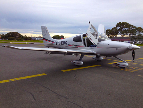
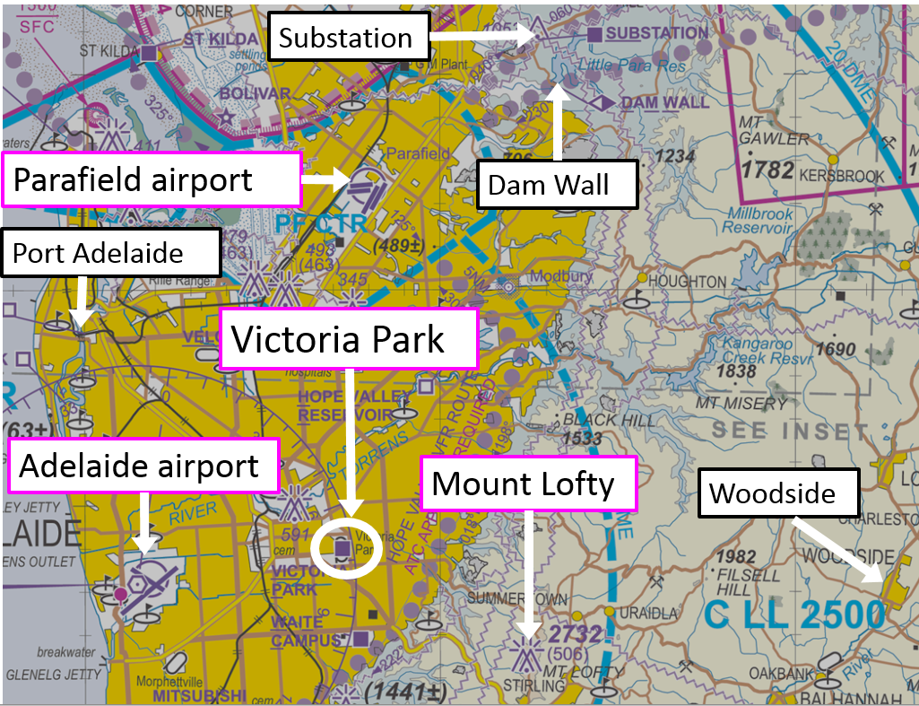
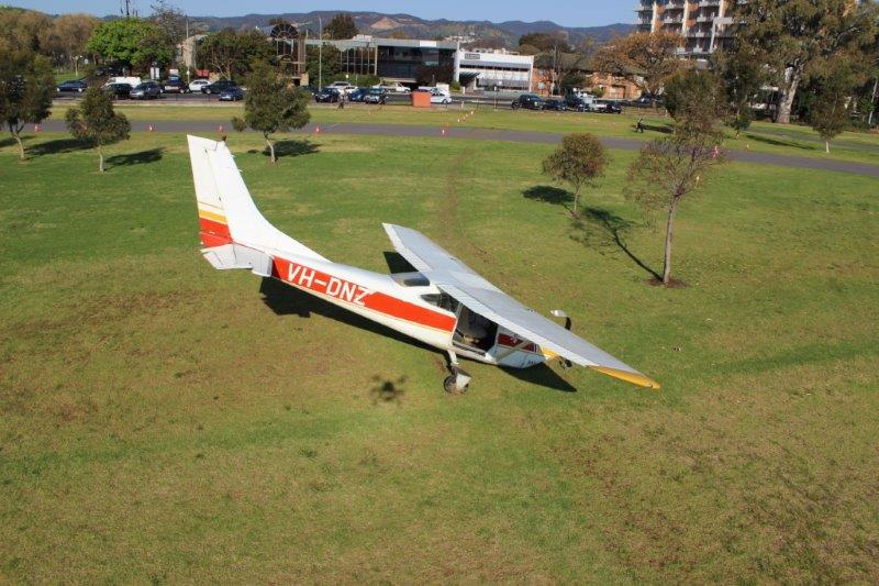
On 5 October 2016, a Qantas-operated Boeing 747-438 aircraft, registered VH-OJT (Figure 1) was undergoing routine maintenance at a contracted repair and overhaul facility in the Hong Kong Special Administrative Region (SAR) in the People’s Republic of China. Inspection of the No. 2[1] engine pylon identified cracking of four outboard strut ribs from within the torque box of the pylon (Figure 2).
Following technical advice from Boeing, the No. 2 engine was removed from its wing installation to allow access to the pylon and removal of the cracked strut ribs. The aircraft was repaired and, after completing the maintenance visit, it was returned to regular passenger service. The cracked ribs were sent to Boeing’s facilities in the United States for specialist metallurgical examination.
Figure 1: Qantas Boeing 747-438 aircraft, registered VH-OJT
Source: Christopher Chai
Pylon inspection requirements
The engines on a Boeing 747 aircraft are mounted to pylons located on the underside of each wing. The pylons transmit thrust from the engine to the airframe and are designed to withstand flight loads from normal operation along with transient dynamic loading in the event of an engine failure. Hydraulic, fuel, electrical and air conditioning lines all pass through the pylon structure.
Boeing’s ongoing maintenance requirements included an inspection of the engine pylon every 48 months. A general visual inspection within the torque box for corrosion damage was required along with a more detailed inspection for cracking of the ribs. The procedures noted that during the inspection, particular attention should be applied to the cutaway where stringers passed through each rib.
Qantas reported to the ATSB that several years prior to this occurrence, it had independently increased the frequency of the zonal inspections from 48 to 24 months due to repeated instances of corrosion and cracking damage within the pylon region. That new inspection interval was formalised by Qantas within its maintenance documentation for its 747 fleet.[2]
Figure 2: Boeing 747 engine pylon showing the location of the cracking (highlighted)
Source: Boeing, annotated by the ATSB
Manufacturer’s examination
Following removal from the aircraft, four cracked outboard strut ribs were sent to Boeing for metallurgical examination and fracture analysis. The examination confirmed that five cracks had developed in the strut ribs, all emanating from the rib cutaway region, ranging in length from 3—19 mm (Figure 3 to Figure 5). Boeing’s report[3] contained the following detail:
Optical examination of the fracture surfaces was conducted and no anomalies were found that might otherwise have contributed to the development of the cracking.
Scanning electron microscopy (SEM) of the fracture surfaces did not find any aberrations or defects on the surfaces of the strut ribs that might have otherwise contributed to the development of the cracking.
SEM analysis of the fracture surfaces confirmed that each strut rib had striations and crack-progression marks consistent with fatigue cracking. No evidence was found of ductile tearing or plastic deformation at the crack origins, which might otherwise suggest that the fatigue cracking had initiated due to excessive vibration or torque loads from a transient engine event.
Metallographic examination of the aluminium alloy microstructure from each rib did not reveal any abnormalities that could have led to the fracture of the strut ribs.
Chemical analysis of each strut rib found the composition met the materials specifications, as listed within the engineering drawings.
Hardness and conductivity measurements from each strut rib confirmed that they were within the correct range, as listed within the engineering drawings.
The ribs were painted and primed in accordance with manufacturing specifications.
Boeing also conducted a structural loads analysis on the pylon, which confirmed that despite the presence of the cracking, the No. 2 engine pylon retained sufficient residual strength for all certified loading conditions.
Figure 3: A strut rib in-situ within the No. 2 pylon with two cracks identified
Source: Boeing, annotated by the ATSB
Figure 4: The strut rib from Figure 3 after removal from the pylon
Source: Boeing, annotated by the ATSB
Figure 5: Close-up of the cracking in the cutaway region shown at Figure 4
Source: Boeing, annotated by the ATSB
Aircraft history
On 24 June 2016, a few months before the detection of the pylon cracks, VH-OJT sustained a failure of the low-pressure turbine from the No. 2 engine during the take-off roll. This resulted in a high-speed seizure of the engine resulting in significant vibration and torque loads on the pylon. Following removal of that engine, the pylon was inspected and no damage to the critical structural members was evident.
Maintenance records noted that when the cracks were discovered in the Hong Kong SAR, the aircraft had accumulated 79,928 hours and 8,313 landings. There were no other identified defects reported from previous inspections on the No. 2 strut support assembly for VH-OJT.
Safety analysis
Cracking of the engine pylon strut ribs
During routine maintenance on 5 October 2016, four strut ribs from the No. 2 engine pylon were found to have developed fatigue cracks. The parts met the manufacturer’s engineering drawing and material specifications. With no obvious defects detected, it is likely that the fatigue cracking developed from exposure to vibratory loading that occurred within the pylon during normal engine operation. A factor that may have contributed to the crack growth was the number of hours and flight cycles that the airframe had accumulated within its service life. The manufacturer’s analysis indicated that despite the crack damage to the ribs, the pylon retained sufficient residual strength for all load cases, which indicates that the aircraft remained safe to operate.
Approximately 6 months prior to the detection of the strut rib cracking, the No. 2 engine sustained a seizure that resulted in the transmission of significant vibratory and torque loads into the pylon structure. Metallurgical analysis of the fracture at the crack origins did not show any evidence of plastic deformation or tearing of the alloy that might otherwise suggest that the seizure was a contributing factor to the cracking.
Pylon inspection
When compared with the 48-month inspection interval recommended by the manufacturer, the 24‑month inspection interval set by Qantas provided greater opportunity for the timely detection of cracking and other defects within the pylon. The reduced inspection interval proved effective in this case, detecting cracks before they reached a level considered by the manufacturer to be a safety risk.
Findings
These findings should not be read as apportioning blame or liability to any particular organisation or individual.
The fatigue cracking in four outboard strut ribs in the No. 2 engine pylon is likely to have developed from exposure to vibratory loading within the pylon during normal engine operation over the aircraft’s service life.
The extent of fatigue cracking in the ribs did not affect the structural integrity of the pylon for all certified load cases, which meant that the aircraft’s safe operation was not affected.
Safety message
The Qantas Boeing 747 maintenance program for the engine pylon area is completed at a higher frequency and in more detail than is required by Boeing. This enhanced inspection regime was effective in detecting cracking of the strut rib assembly, before the cracks reached a level considered to be a safety risk.
This occurrence highlights the importance for vigilance during ongoing routine maintenance activities. It also highlights that, when relevant, operators should consider reviewing prescribed maintenance schedules in order to address issues that may develop as their aircraft age and accumulate time in service.
Purpose of safety investigations
The objective of a safety investigation is to enhance transport safety. This is done through:
identifying safety issues and facilitating safety action to address those issues
providing information about occurrences and their associated safety factors to facilitate learning within the transport industry.
It is not a function of the ATSB to apportion blame or provide a means for determining liability. At the same time, an investigation report must include factual material of sufficient weight to support the analysis and findings. At all times the ATSB endeavours to balance the use of material that could imply adverse comment with the need to properly explain what happened, and why, in a fair and unbiased manner. The ATSB does not investigate for the purpose of taking administrative, regulatory or criminal action.
Terminology
An explanation of terminology used in ATSB investigation reports is available here. This includes terms such as occurrence, contributing factor, other factor that increased risk, and safety issue.
Publishing information
Released in accordance with section 25 of the Transport Safety Investigation Act 2003
Ownership of intellectual property rights in this publication
Unless otherwise noted, copyright (and any other intellectual property rights, if any) in this report publication is owned by the Commonwealth of Australia.
Creative Commons licence
With the exception of the Coat of Arms, ATSB logo, and photos and graphics in which a third party holds copyright, this publication is licensed under a Creative Commons Attribution 3.0 Australia licence.
Creative Commons Attribution 3.0 Australia Licence is a standard form licence agreement that allows you to copy, distribute, transmit and adapt this publication provided that you attribute the work.
The ATSB’s preference is that you attribute this publication (and any material sourced from it) using the following wording: Source: Australian Transport Safety Bureau
Copyright in material obtained from other agencies, private individuals or organisations, belongs to those agencies, individuals or organisations. Where you wish to use their material, you will need to contact them directly.
On the morning of 16 November 2016, a single-engine Cessna 208B aircraft, registered VH-LNH, operated by Aviair Pty Ltd, departed Solomon Airport, Western Australia on a charter flight to Karratha. On board the aircraft were two flight crew and 11 passengers. Approximately 8 km from the airport, while climbing through an altitude of approximately 4,600 ft, the aircraft sustained an engine failure. The flight crew heard a loud bang and observed smoke billowing from the exhaust.
The flight crew elected to conduct an emergency landing on a nearby dirt road associated with the Solomon mine precinct. The landing was accomplished without injury to the occupants and the aircraft sustained only minor damage.
What the ATSB found
The ATSB found that a compressor turbine blade from the Pratt & Whitney Canada (PWC) PT6A‑114A engine developed fatigue cracking and fractured after approximately 1.8 hours of operation, leading to an in-flight engine failure and forced landing of the aircraft. A repaired compressor turbine vane ring that was fitted to the engine was identified by PWC to contain variations in aerofoil geometry. These variations likely led to an increase in vibratory stresses and the associated development of fatigue cracking and fracture of the compressor turbine blade.
From this and other recent occurrences, the investigation identified that PT6A-114A engines fitted with compressor turbine vane rings that had been repaired in accordance with the United States Federal Aviation Administration (FAA) approved repair scheme STI 72-50-254 had an increased likelihood of CMSX-6 single-crystal compressor turbine blade fracture and subsequent failure of the engine.
The ATSB also found that the flight crew’s handling of the engine failure and subsequent emergency landing reduced the risk of damage to the aircraft and/or injury to the passengers or crew.
What's been done as a result
On 16 March 2017, the holder of the major repair specification for the compressor turbine vane ring, Southwest Turbine Inc. (STI), ceased conducting repairs on CT vane rings for fitment into PWC PT6A-114A engines.
On 29 March 2017, the engine manufacturer, PWC, released Service Instruction Letter (SIL) PT6A-252 to all operators of PT6A-114 and -114A engines. The SIL advised of the heightened risk of CMSX-6 single-crystal compressor turbine blade fatigue fracture when combined with a compressor turbine vane ring that had been repaired using processes that were not approved by PWC.
Proactive safety action from the aircraft operator, Aviair Pty Ltd, included adopting the recommendations contained in PWC SIL PT6A-252. Their Cessna 208B fleet was reviewed, and any PT6A-114A engines containing compressor turbine vane rings that had been repaired using ‘non-PWC approved processes’, were replaced with CT vane rings produced by PWC.
On 19 August 2019, Transport Canada released airworthiness directive (AD) CF-2019-30 linking the low-time fatigue-fracture of CMSX-6 single-crystal compressor turbine blades and the use of CT vane rings that had been repaired in accordance with repair specification STI 72‑50‑254. The AD required operators to check for, and remove, STI‑repaired CT vane rings from PT6A‑114 and PT6A-34 series engines within a defined period of 9 calendar months, or 250 hours of operation.
The Civil Aviation Safety Authority automatically adopted AD CF-2019-30. This required Australian operators to remove STI-repaired compressor turbine vanes rings fitted to PT6A-114A and PT6A‑34 series engines.
On 17 August 2020, the FAA released a Notice of Proposed Rulemaking advising that they were considering mandating AD CF-2019-030. Public submissions to that process closed on 1 October 2020.
The vibratory effect of repaired CT vane rings on CMSX-6 single-crystal CT blades within PWC PT6A-114A engines was identified as a safety issue by the ATSB. However, due to the significant safety action taken by the directly involved parties since the occurrence, including action from the engine and component manufacturers, as well as the aviation regulatory authorities, the ATSB considers that the risk of CMSX-6 single-crystal CT blade fractures in Australian‑operated PWC PT6A-114A engines has been adequately addressed.
Safety message
This occurrence shows how subtle changes can have a detrimental effect on modern complex turbine engines. In this instance, geometry variations in a repaired compressor turbine vane ring likely led to rapid fatigue cracking and fracture of a compressor turbine blade, and subsequent engine failure.
The incident also reinforces the importance of communication and effective decision-making during an emergency. The crew’s handling of the forced landing minimised the potential for injury or aircraft damage.
VH-LNH Cessna 208B aircraft
Source: Jim Woodrow
Sources and submissions
Sources of information
The sources of information during the investigation included:
Aviair Pty Ltd
The pilots from the occurrence aircraft
Pratt & Whitney Canada
Cessna - Textron Aviation
United States Federal Aviation Administration
Transport Canada
Southwest Turbine Inc.
Submissions
Under Part 4, Division 2 (Investigation Reports), Section 26 of the Transport Safety Investigation Act 2003 (the Act), the ATSB may provide a draft report, on a confidential basis, to any person whom the ATSB considers appropriate. Section 26 (1) (a) of the Act allows a person receiving a draft report to make submissions to the ATSB about the draft report.
A draft of this report was provided to the operating flight crew of VH-LNH, Aviair Pty Ltd, Transport Canada, Transport Safety Board of Canada, Pratt & Whitney Canada, United States Federal Aviation Administration, Southwest Turbine Inc., United States National Transportation Safety Board, and the Civil Aviation Safety Authority.
Submissions were received from:
Aviair Pty Ltd
the Civil Aviation Safety Authority
Pratt and Whitney Canada
Southwest Turbine Inc.
the United States National Transportation Safety Board
the United States Federal Aviation Administration.
The submissions were reviewed and were considered appropriate, the text of the report was amended accordingly.
The occurrence
What happened
On 16 November 2016, at about 0630 Western Standard Time,[1] a single-engine Cessna 208B aircraft, registered VH-LNH, departed Karratha Airport, Western Australia (WA) on a flight to Solomon Airport, WA. On board the aircraft were the pilot-in-command, a safety pilot, and 11 passengers. The flight was operated by Aviair as a charter[2] service, transferring workers to and from the Solomon Hub, an iron-ore mining and processing facility in the Hamersley Ranges of northern WA.
At about 0710, after a 40-minute flight, the aircraft arrived at Solomon Airport. Following disembarkation at the terminal, the flight crew prepared the aircraft for the return flight with 11 passengers. The start-up and pre-flight checks for the return flight to Karratha were conducted without any reported issues. At 0740, the aircraft was taxied to runway 27[3] and about 3 minutes later, the flight departed for Karratha, initially conducting a left climbing turn overhead the Solomon Airport and then climbing on a north-westerly heading over the Hamersley Range (Figure 1).
A few minutes after taking off, while climbing through an altitude of approximately 4,600 ft above mean sea level (AMSL), the pilot-in-command reported hearing a ‘loud bang’ and ‘grinding noise’ from the engine followed by a decrease in aircraft performance. Blue and white smoke ‘billowed’ from the exhaust. Instruments within the cockpit showed rapidly reducing turbine speed and torque, indicating the aircraft’s engine had failed. At this point, the aircraft was about 8 km from the departure airport.
The pilot-in-command recalled lowering the aircraft’s nose to attain the recommended glide speed and reducing the engine power lever to idle as part of the initial checks. On commencing a right turn back toward the airport, the flight crew assessed that an emergency landing to the airport would not be possible. The aircraft would be gliding into a southerly headwind and given their altitude, it was uncertain whether they could safely avoid the high terrain between their current position and Solomon Airport.
Scanning the immediate area, the flight crew identified an unsealed dirt road as a potential emergency landing area. The road was oriented north-south and was near to an accommodation village associated with the mine construction. The pilot-in-command delegated the emergency calls to the safety pilot and concentrated on setting up for the forced landing. The safety pilot conducted the necessary actions to secure the engine further and communicate their situation. The fuel lever was set to cut-off and the propeller lever to feather.[4] Suspecting that the aircraft was too low to communicate effectively with air traffic services, the safety pilot broadcast an emergency MAYDAY[5] advising of their situation on the VHF common traffic advisory frequency for Solomon Airport. A departing Qantas aircraft detected the broadcast, along with Solomon Airport personnel who were monitoring the frequency. The safety pilot also activated the Spidertracks[6] emergency notification system.
In preparation for the forced landing, the safety pilot provided an emergency passenger briefing.
The pilot-in-command manoeuvred the aircraft for an approach to the mine road from the south. Full flap was selected about 1,000 ft above the terrain. The flight crew observed three vehicles travelling along the mine road close to their intended landing area. Approximately 100 ft above the road surface, the pilot flashed the aircraft’s landing lights to warn the driver of an approaching mine vehicle that the aircraft was preparing for an emergency landing. On touchdown, heavy braking was applied, slowing the aircraft until it came to a controlled stop about 150 m short of a bend in the road.
All passengers remained seated until instructed to exit the aircraft. The safety pilot moved the passengers away from the aircraft, while the pilot-in-command inspected for fire and other damage. Emergency responders from the airport arrived on scene shortly after. With the exception of some flat spots on the main gear tyres due to the emergency braking, the aircraft was undamaged. There were no injuries.
Figure 1: Sequence showing the aircraft departure from Solomon Airport, the pilot‑reported location of the engine failure, and other events during the forced landing
Spidertracks aircraft location markers (identified green in the above image) are transmitted every 2 minutes under normal operation. When the SOS function is activated transmission signals are broadcast at 10-15 second intervals.
Image source: Google, Maxar Technologies, annotated by the ATSB
From the evidence available, the following findings are made with respect to the engine failure and subsequent forced landing involving a Cessna Aircraft Company 208B, registered VH-LNH, that occurred 8 km northwest of Solomon Airport, Western Australia on 16 November 2016. These findings should not be read as apportioning blame or liability to any particular organisation or individual.
Safety issues, or system problems, are highlighted in bold to emphasise their importance. A safety issue is an event or condition that increases safety risk and (a) can reasonably be regarded as having the potential to adversely affect the safety of future operations, and (b) is a characteristic of an organisation or a system, rather than a characteristic of a specific individual, or characteristic of an operating environment at a specific point in time.
Contributing factors
A compressor turbine blade from the engine developed fatigue cracking and fractured after approximately 1.8 hours of operation, leading to an in-flight engine failure and resultant forced landing of the aircraft.
The compressor turbine vane ring that was repaired in accordance with STI 72-50-254 and fitted to the engine contained variations in aerofoil geometry that likely led to an increase in vibratory stresses and the associated development of fatigue cracking and fracture of the compressor turbine blade.
Pratt & Whitney Canada (PWC) PT6A-114A engines fitted with compressor turbine vane rings that have been repaired in accordance with the United States Federal Aviation Administration-approved scheme STI 72-50-254 have a significantly increased likelihood of CMSX-6 compressor turbine blade fracture and subsequent failure of the engine compared to those engines fitted with PWC‑manufactured compressor turbine vane rings. [Safety Issue]
Other findings
The ATSB found that the flight crew’s response to the engine failure and subsequent emergency landing on the mine road was handled in a competent and proficient manner that reduced the risk of damage to the aircraft and/or injury to passengers or crew.
Safety analysis
While on a charter flight within Western Australia from Solomon Airport to Karratha, a Cessna 208B aircraft, registered VH-LNH, sustained the failure of its single-turbine engine. The aircraft had departed just a few minutes prior and was climbing steadily when the engine failed. The pilots assessed that the safest option was to conduct a forced landing onto a nearby dirt road that was part of the Solomon mine precinct.
This analysis discusses the contributing factors that led to the engine failure, as well as the decision-making aspects of the flight crew during the conduct of the emergency landing.
Compressor turbine blade fracture
The failure of the Pratt & Whitney Canada (PWC) PT6A-114A engine was the result of fatigue cracking and fracture of a single compressor turbine (CT) blade. Release of the aerofoil section led to multiple consequent power turbine blade failures from impact debris.
The engine had undergone maintenance activity in the days prior to the occurrence, having had the CT vane ring and CT blades replaced. The blades were replaced to comply with airworthiness directive CF-2013-21R1. Following reinstallation of the engine, the aircraft was flown for approximately 1.8 hours prior to the failure. Information obtained from the engine teardown did not identify any maintenance-related factors that might have contributed to the engine failure.
The blade was manufactured from CMSX-6, a single-crystal nickel-base alloy. A coating to improve resistance to oxidation was applied to the blade surfaces comprising a thin layer of a platinum-modified aluminide material. Though the CMSX-6 alloy type and the aluminide coating system can, in combination, develop brittle sub‑surface microstructural phases and associated micro-cracks, no such features were identified that might have contributed to the fatigue cracking. There were no other material defects or damage identified that had the potential to initiate the fatigue cracking.
In the short time since installation, the fatigue crack had initiated at the leading edge of the CT blade, along the suction side of the aerofoil. It subsequently transitioned and propagated through the blade-chord toward the trailing edge, through approximately 50 per cent of the blade cross‑section, prior to overstress fracture. The high-cycle fatigue cracking seen in this occurrence was produced via bending and the associated high-frequency vibrations during engine operation.
Compressor turbine vibratory stresses
The compressor turbine vane ring from the occurrence engine had been repaired by Southwest Turbine Inc. The repair had been completed and the part released as airworthy in accordance with major repair specification STI 72-50-254. Initial approval to repair the PWC CT vane rings using STI 72-50-254 was granted to Southwest Turbine by the United States Federal Aviation Administration (FAA) in 2006.
At that time, the CT blades from PT6A-114 and -114A engines were manufactured from Inconel 100 (IN100) alloy. High cycle fatigue was not a large contributor to fractures experienced by the IN100 CT blades. Component life for the IN100 blades was generally limited by thermal effects, where exposure to higher operating temperatures led to oxidation, creep and overstress of the blade materials.
In 2008, PWC introduced single-crystal blades manufactured from CMSX-6 alloy. These blades were resistant to the temperature-related failure modes of the IN100 blades but were more susceptible to high-cycle fatigue cracking. In their early analysis of the single-crystal blade design, PWC identified a resonant modal frequency that could lead to increased flexure and cyclic vibration of the single-crystal blades. PWC’s subsequent engineering analysis of the vibration characteristics of the single-crystal blades, when fitted to the PT6A-114A engine, led to several design changes intended to increase the ‘vibratory stress margin’.
Changes to the single-crystal design included adjustment of the platform dimensions and the incorporation of under-platform blade dampeners. The under-platform dampeners, introduced by PWC through service bulletin 1769, were shown to have the greatest effect toward limiting the in‑service flexure of the CT blades and reducing the likelihood of a blade fatigue fracture from occurring. When the dampeners were incorporated with other hardware changes identified as a result of the PWC vibration testing, such as optimisation of the CT vane ring angular alignment, vibratory stresses within the CMSX-6 CT blades from blade flexure were minimised.
CT vane aerofoil geometry and their relative positions were also identified to have a significant effect on CT blade vibratory stresses. PWC identified through vibration testing that CT blade flexure could increase significantly when an engine was operated with a CT vane ring that contained aerofoil geometry variations outside of their design tolerance. The vibration testing was conducted using an STI‑repaired CT vane ring that had been removed from a PT6A-114A engine that had also sustained a CT blade failure. Although the CT vane ring had sustained damage from the blade release, PWC indicated that such local damage would not be detrimental toward the overall aerodynamic performance of the part.
The increase in CT blade dynamics was attributed by PWC to subtle, but important, overall dimensional variations in areas that that had been designed by PWC to control the incoming airflow onto the compressor turbine blade aerofoils. This included vane stagger angle, which can affect gas pressures from the inlet to the outlet of the vane, accelerating the mass flow, and leading to low‑amplitude, high-frequency excitations of the aerofoil surfaces.
The STI-repaired CT vane ring from the occurrence engine was not subjected to this vibration testing. However, it contained similar geometry variations to the tested component. Both PT6A‑114A engines had sustained a CT blade failure in a short period of operation. The identified out of tolerance geometry variations were also similar to other PT6A‑114A engines that had sustained CT blade fatigue-fracture in relatively rapid time when operated with STI-repaired CT vane rings. In the absence of any identified material defect associated with the failed occurrence CT blade itself, it can be concluded that variations in aerofoil geometry likely led to an increase in vibratory stresses, excitation and the associated development of fatigue cracking and fracture of the CT blade from the occurrence engine.
Failure rates
Major repair specification STI 72-50-254 by Southwest Turbine Inc. (STI) was a method approved by the FAA to restore the functionality of PWC CT vanes for fitment into numerous PWC PT6 engine models, one of which included the PT6A-114A. In part, the repair involved machining away a large portion of the vane structure and welding an equivalent casting in place. The replacement casting ensured structural fitment to the engine and also contained the vanes that determined the aerodynamic performance of the part.
Both STI and the FAA reported that, since the introduction of the repair, there were 73 STI‑repaired CT vanes released into service for installation into the PT6A-114A engine. Of that population, six PT6A-114A engines (of the 12 total reported failures) sustained a compressor turbine blade failure that led to an in-flight shutdown of the engine. This represented approximately 8 per cent of the repaired population. All CT blade failures occurred in relatively short time periods after fitment of the CT vanes, leading to an overall failure rate of approximately 24 failures per million flight hours. In contrast, the remaining six PT6A-114A engines that had sustained CT blade fatigue-failure were fitted with PWC‑manufactured CT vanes and none of them had been repaired/overhauled by PWC. This represented 0.31 per cent of the PT6A-114A fleet and a significantly lower failure rate of approximately 0.89 failures per million flight hours.
Comparing the failure rate from both populations showed that PT6A-114A engines fitted with the FAA-approved and repaired CT vane rings from STI had a significantly increased likelihood of CMSX‑6 compressor turbine blade fracture, compared to those engines fitted with PWC‑manufactured compressor turbine vane rings.
Flight crew response
The ATSB found that the flight crew response to the engine failure and subsequent emergency landing was handled in a competent and proficient manner that reduced the risk of damage to the aircraft and/or injury to passengers or crew.
Due to the aircraft’s position when the engine failed, and the southerly headwind component, it is unlikely the aircraft could have reached the airport. In consideration of the rugged terrain surrounding the Solomon Airport, the decision to land on the access road considerably reduced the risk of damage and injury. The delegation of the passenger briefing and emergency radio calls from the pilot-in-command to the safety pilot was an effective practical application of crew resource management.
Context
Recorded information
Engine data
The aircraft was equipped with an engine condition trend monitoring system. A range of parameters were automatically recorded by the system, including:
pressure altitude
airspeed
engine torque
turbine temperature
gas generator speed
fuel flow
propeller shaft speed.
The system was designed to assess engine performance by allowing an analyst to monitor recorded data over longer periods to identify emerging trends. It also recorded any turbine temperature or torque exceedances that can contribute to longer-term degradation in engine performance. The system recorded flight data at approximately 0.5-second time intervals.
The data from the flight from Karratha to Solomon Airport, conducted earlier on the day of the occurrence showed no major deviations or ‘events’, generated from an inter-turbine temperature exceedance, gas generator overspeed or fuel flow anomaly. Data from the monitoring system also indicated normal operation of the engine up to the point of failure.
The recorded data from the occurrence flight is plotted in Figure 2. Following departure, the aircraft was climbing at an indicated airspeed of 106 kt when at 4,615 ft AMSL and time 0747:47, the engine failed. This was represented in the data by a rapid decline in the measured parameters for torque, propeller shaft speed, fuel flow and gas generator speed. The pilot’s report of sudden loud noises from the engine were consistent with the abrupt variation in the recorded parameters.
Eight seconds after the initial reduction in engine parameters, torque and fuel flow had reduced to zero, correlating with the pilot’s recollection of the events immediately following the failure. At 0750:17, the aircraft had descended to 4,200 ft AMSL and the recorded propeller speed had reduced to zero. After the failure, the inter-turbine temperature rapidly increased from 715 C, peaking at 887 C, before steadily declining as the failed engine cooled. Twenty-nine seconds after the engine failed, the gas generator speed had reduced from 99.5 per cent to zero. Changes to the indicated airspeed and altitude identified that touchdown on the mine road occurred at 0751:09 at an airspeed of approximately 80 kt.
Figure 2: Presentation of the recorded data from the occurrence flight noting that the engine failure occurred at 0747:57 and the touchdown occurred at 07:51:09
Inter-turbine temperature, gas generator speed, indicated airspeed, pressure altitude, propeller shaft speed, torque and fuel flow are plotted. The data is presented 4 minutes after take-off until the emergency landing.
Image source: ATSB
Spidertracks
The aircraft was equipped with a Spidertracks tracking and communication system. The system was satellite-based and sent a position update for the aircraft every 2 minutes. This allowed Aviair to monitor the progress of the aircraft in near real‑time. An ‘SOS’ button on the keypad of the system could be activated by the flight crew. In the event the ‘SOS’ function was activated, the fidelity of the flight track was improved by transmitting a data point at 10‑15 second intervals.
Data from the Spidertracks system showed that the aircraft was tracking to the northwest when the engine failure occurred. Two ‘SOS’ pings were transmitted by the system late in the sequence, shortly before touchdown on the mine road, however, these transmissions did not continue at the expected 10‑15 second intervals for the remainder of the flight and landing. Spidertracks advised the ATSB that the unit on board the aircraft sustained a power shutdown shortly after the SOS signals were emitted. No further information was available to explain the signal loss during the emergency broadcast.
Emergency locator beacon
The flight crew did not activate the emergency locator transmitter (ELT) during the emergency. The ELT was a radio beacon that, once activated, could assist search and rescue operations locate the aircraft and its occupants.
The Australian search and rescue authorities provide the following advice[7] for pilots in relation to the use of an ELT during an emergency:
When in the air, a beacon can be activated if you feel you are in grave and imminent danger. Facing a forced landing would be a reason to feel in grave and imminent danger. In a forced landing situation, when you are unsure of your position, when you are lost or have deviated from the planned or notified flight route, you should activate your distress beacon.
During this emergency, the flight crew of VH-LNH were in two-way radio communication with Solomon Airport authorities along with other commercial aircraft. The Spidertracks SOS alert had also been activated. These measures provided the flight crew with a level of assurance that an appropriate response was being provided. Had the emergency occurred later in the flight, in a remote area without access to a suitable landing area, in-flight activation of the ELT would likely have assisted any search and rescue operation identify the aircraft position and its occupants.
Flight data recorders
The aircraft was not fitted with a flight data recorder or cockpit voice recorder. VH-LNH had a maximum take-off weight under 5,700 kg, utilised a non-pressurized hull, and had a single turbine engine. Fitment of flight recorders was not required for such an aircraft.[8]
Meteorological information
Weather observations were recorded every minute by the Solomon Airport automatic weather station (AWS). Between 0720 and 0751, the surface winds were from the southwest, averaging 11 kt, and gusting to 14 kt. No cloud or significant weather was observed within the vicinity of the airport.
The pilot-in-command reported that weather conditions were consistent with the AWS data, and that the flight was conducted in visual meteorological conditions.
Personnel information
Both the pilot-in-command and the safety pilot were appropriately qualified to conduct the flight. The pilot-in-command had a total aeronautical experience of 541 hours, with 222 hours flying Cessna 208B aircraft. The safety pilot had a total aeronautical experience of 1,972 hours, with 312 hours flying Cessna 208B aircraft. The pilot-in-command reported that due to recent company changes, this was his first flight to Solomon Airport. Aviair normally conducted single-pilot charter operations, however, for this flight a safety pilot experienced with the Solomon route and its surrounds was on board to help familiarise the pilot-in-command with the route.
Aircraft information
The Cessna 208B (Caravan), registration VH-LNH, airframe serial number 208B0590, was a high‑wing, all‑metal, non-pressurised aircraft with a fixed tricycle landing gear. It was manufactured in the United States in 1996 and was configured to carry a maximum of 13 people (two pilots and 11 passengers). The aircraft was first placed on the Australian civil register in December 2006. A nose-mounted 675 shaft horsepower Pratt & Whitney Canada (PWC) PT6A‑114A free-turbine, turboprop engine[9] was fitted with a McCauley three-blade constant‑speed, full-feathering propeller.
Engine failure procedure
The initial memory actions for the Cessna 208B engine failure procedure are to establish 95 knots indicated airspeed (KIAS), power lever to IDLE, propeller to FEATHER and fuel condition lever to CUTOFF (Figure 3). The pilot-in-command’s recollection of the initial actions in response to the engine failure were consistent with the flight manual procedures.
Figure 3: Cessna 208B initial items for the engine failure procedure
Image source: Cessna - Textron Aviation
Aircraft glide performance
The aircraft was at an altitude of approximately 4,600 ft AMSL and Solomon Airport was about 8 km (4.3 NM) to the south‑east when the engine failed. The airport is at an elevation of 2,000 ft AMSL, indicating the aircraft was approximately 2,600 ft above the airport elevation when the engine failed. Taking into account an approximate 600 ft height loss due to the initial right turn towards the airport, the flight crew probably had an allowance of about 2,000 ft above the airport elevation when assessing the available landing options.
VH-LNH was configured with a cargo pod, which resulted in a glide range of 4 NM at 2,000 ft above the airport elevation. The best glide speed at the maximum weight is 95 KIAS, and 80 KIAS for a power-off landing speed with full flap. The airspeeds recorded by the engine-recording module were consistent with these figures.
A graph of the Cessna 208B glide performance from the pilot operating manual is depicted at Figure 4. Calculations indicated that, based on the published data, it might have been possible for the aircraft to reach the airport in a glide on a direct track in nil wind conditions. However, given the south‑westerly wind would have resulted in a headwind component, it was unlikely the aircraft would have reached the airport. The crew also considered that an attempt to reach the airport presented an unnecessary risk of a forced landing on unprepared ground in rugged terrain, and instead, they opted to conduct the forced landing on the mine road.
Figure 4: Cessna 208B maximum glide range with the glide distance highlighted
Image source: Cessna - Textron Aviation, annotated by ATSB
Engine information
A typical PWC PT6A engine cross-section is shown in Figure 5. The design incorporates two independent turbines: the compressor turbine that is coupled to the compressor, and the power turbine that is coupled to the propeller reduction gearbox. Inlet air enters the engine via a plenum chamber and is compressed by the axial/centrifugal compressor. Fuel is injected into the compressed air stream and ignited within the combustion chamber.
The pressurised outflow of expanding hot gases from the combustion chamber is deflected onto the blades of the compressor turbine by the preceding compressor turbine vane ring. The power turbine is rotated by the remaining energy in the gas flow exiting the compressor turbine which, in turn, drives the propeller shaft via a two-stage planetary reduction gearbox. Inter-turbine temperature is monitored by an integral probe installed between the compressor turbine and power turbine.
Figure 5: Basic layout of a PT6A engine
Image source: PWC, modified and annotated by ATSB
Engine disassembly
Following the forced landing, the aircraft was relocated from the mine road to Solomon Airport. An initial on-wing inspection through the exhaust duct of the engine revealed considerable damage to the power turbine (Figure 6). Several power turbine blades were missing, having fractured at places varying from the blade root to the tip. Aviair personnel subsequently removed the engine and transported it to an approved facility for controlled disassembly and examination.
Investigators from the ATSB supervised the examination. Representatives from PWC, the Civil Aviation Safety Authority (CASA), Aviair and other interested parties attended the examination. The examination found the most significant damage had occurred to the power turbine and compressor turbine sections of the engine.
Figure 6: Composite image displaying the observed damage to the power turbine (left) and compressor turbine (right) displaying the missing aerofoil section.
Image source: ATSB
Compressor
Inspection of the compressor section identified that it was relatively undamaged, and the rotor assembly was free to rotate. Slight tip rub to the compressor blades had occurred. There was no evidence of foreign object damage.
Power turbine
The power turbine had sustained the most severe damage, with several blades having fractured due to overstress at varying heights between the blade root and the tip due to contact with upstream[10] debris (Figure 6). The upstream face of the power turbine inlet guide vane had sustained significant hard-body impact damage, most likely from metallic debris released from the compressor turbine. The power turbine was seized and not able to rotate freely. The propeller shaft was also unable to be rotated.
Compressor turbine
Examination of the compressor turbine (CT) identified that a single CT blade had fractured close to the blade root (Figure 7 and 8). Multiple blades had sustained bending from impact damage with the liberated aerofoil section. One of the adjacent blades displayed a clear imprint from contact with the liberated aerofoil section (Figure 9). The fracture surface of the failed blade was largely flat and located at the root, close to the platform. Characteristic ‘beach mark’ features were present that extended to approximately 50 per cent of the overall fracture surface, indicating that a fatigue crack had progressed through that portion of the blade. The remainder of the fracture was jagged and angular and representative of a sudden overstress fracture.
Manufacturing identifiers on the fractured blade base confirmed it to be a PWC component:
3079351-01 (part number)
HWB5PL (serial number)
702055 (vendor supplier)
Aside from the missing aerofoil section from one of the CT blades, the engine disassembly did not reveal any other anomalies with respect to the CT disc and its installation.
Figure 7: The fractured CT blade
Fractured blade manufacturing identifiers; part number 3079351-01, serial number HWB5PL, vendor supplier 702055.
Image source: ATSB
Figure 8: Close view of the the CT blade fracture surface
Image source: ATSB
Figure 9: Composite view of a CT blade adjacent to the one that had fractured showing the collision imprint from the liberated aerofoil section
An exemplar blade (right image) from the disc has been used to illustrate the collision of the liberated aerofoil section from the fractured blade.
Image source: ATSB
Compressor turbine vane ring
The CT vane ring fitted to the engine was also examined (Figure 10). The vanes had sustained abrasion and minor impact damage. The shroud segments had sustained two major gouges from the engine failure. The following manufacturing part numbers were identified:
P/N 3029051 (part number)
S/N 931E (serial number)
WO 0452R16 CL 6.25
STI 72-50-254 (authorised repair number)
STI 02-0356
Figure 10: Compressor turbine vane ring assembly, view of the downstream face with gouge damage (labelled)
CT vane ring manufacturing identifiers: (part number) 3029051, (serial number) 931E, (work order) WO 0452R16, (flow class) CL 6.25, (major repair specification) STI 72-50-254, (repair authority) STI 02-0356.
Image source: ATSB
Oil system
The magnetic chip detectors for the reduction and accessory gearboxes, as well as the oil filter, were removed from the engine and inspected. A large amount of metallic debris had accumulated on the magnetic poles of each detector. Metallic debris was also present in the oil and oil filter.
Significant engine maintenance
The engine, serial number PCE-17404, had accumulated 9,210.1 hours and 12,375 cycles since new, and 1,001.3 hours and 1,057 cycles since the last overhaul. This was within PWC’s normal recommendation of 3,600 hours between overhauls.
Airworthiness Directive (AD) CF-2013-21R1 Compressor Turbine Blade Failures was complied with on 15 November 2016. The AD required the existing compressor turbine (CT) blades[11] manufactured from IN100 material to be replaced with PWC blades manufactured from CMSX-6, a single-crystal nickel-based superalloy.[12]
Records confirmed that the replacement CT blade set had a Transport Canada authorised release certificate from PWC. The part number of those blades was 3079351-01, indicating they were a single-crystal blade-type intended for use in this application and were the blades specified in AD CF-2013-21R1.
Due to the identification of converging cracks on the inner portion of the CT vane ring during maintenance inspection, the CT vane ring assembly was replaced. A release certificate authorised by the United States Federal Aviation Administration (FAA) accompanied the replacement CT vane ring. The certificate showed that the replacement vane ring, part number 3029051, serial number 931E, was repaired by Southwest Turbine Inc. in accordance with major repair specification STI 72-50-254.
The CT disc assembly and CT vane ring were provided by a Brisbane-based facility authorised to repair and overhaul PT6 engines. The parts were transferred to Karratha, where they were installed into the engine by an approved maintenance organisation. Following reassembly of the engine, records indicated that all required parameters of torque, inter-turbine temperature, fuel flow, gas generator and propeller speeds were met during power assurance testing.
During ground operation following the reassembly, a ‘whistling’ noise was identified when the gas generator speed was less than 60 per cent. A borescope inspection of the engine CT section along with a check of the bleed valve was performed, with no faults found. The engine operated for an additional 1.8 hours and two engine start-stop cycles before the CT blade fracture occurred. The recent maintenance activity is summarised in Table 1.
Table 1: Recent significant maintenance items for engine serial number PCE-17404
Date and location
Engine hours / cycles since overhaul
Maintenance / inspections completed
1 November 2016 Karratha
Time: 1,001.3 hrs Cycles: 1,057
Compliance with Airworthiness Directive CF-2013-21 R1 required CT disc removed and blades removed CT vane ring found to contain cracks
10 November 2016 Brisbane
Time: 1,001.3 hrs Cycles: 1,057
CT disc inspected and 58 x new PWC single-crystal CT blades (PN 3079351-01) installed. CT disc is assembled and balanced Repaired CT vane ring (PN 3029051, SN 931E) prepared for installation
15 November 2016 Karratha
Time: 1,001.3 hrs Cycles: 1,057
Airworthiness Directive CF-2013-21 R1 completed Installation of CT disc and single-crystal CT blades Repaired CT vane ring (PN 3029051, SN 931E) installed
15 November 2016 Karratha
Time: 1,001.3 hrs Cycles: 1,057
Engine ground performance run and acceleration checks carried out. Minor fault finding for noise below 60 % Ng with no issues found Aircraft returned to service
16 November 2016
Time: 1,003.1 hrs Cycles: 1,059
Engine failure on departure from Solomon Airport ~1.8 hours after CT blade replacement
Component examination
Following this occurrence, the CT disc, blades and vane ring from the engine were sent to the Pratt & Whitney Canada (PWC) facilities in Montreal for detailed examination. An Accredited Representative[13] from the Transportation Safety Board of Canada assisted the ATSB by providing oversight of the examination.
Compressor turbine blade from the occurrence engine
The PWC metallurgical investigation confirmed that the engine failure was initiated by the fracture of a single compressor turbine (CT) blade. Fracture and release of the CT blade aerofoil section into the gas path led to many of the surrounding CT blades sustaining tip-bending and abrasion from rubbing against the CT shroud segments. Major downstream damage to the power turbine resulted from the blade release. Other CT blades exhibited secondary damage in the form of random nicks, cracks, bending and indentations from repeated impact against the liberated debris.
The fractured blade exhibited a very flat and smooth fracture surface at the leading edge, with features characteristic of fatigue crack propagation. The fracture plane was located at the platform-to-blade radial transition. Crack arrest features, or ‘beach marks’, were also clearly defined on the fracture surface, confirming the progressive growth of the fatigue crack through the blade section (Figure 11).
Figure 11: High-magnification optical image of the fractured blade showing that cracking initiated at the leading edge on the suction face, progressing through approximately 50 per cent of the cross-section prior to overstress fracture and release of the aerofoil
Image source: ATSB
Scanning electron microscopy
PWC’s examination of the fracture surface using a scanning electron microscope (SEM) further confirmed that the fatigue crack initiated from the blade-coating’s inter-diffusion layer at the leading-edge surface (Figure 12). River lines on the fracture surface indicated that the fatigue crack had initiated from several sites along the leading edge of the blade. No evidence of anomalies such as coating defects or impact damage were noted at the fatigue crack initiation site. The crack initiation site was not associated with the blade casting parting line.
The SEM examination did not identify any defective features within the nickel-base alloy or coating material that might otherwise have led to the cracking.
Figure 12: High-magnification SEM image of the crack origin at the leading edge showing the direction of propagation ‘river lines’ and other features associated with the blade coating
Image source: Pratt & Whitney Canada, annotated by ATSB
PWC reported that a semi-quantitative analysis of the fractured blade base material was performed using energy-dispersive spectroscopy, which confirmed that the blade material met the chemical requirements for CMSX-6, the alloy-type specified for use as the base blade material. The material analysis and part number identification 3079351-01 were coincident with the blade being manufactured from a CMSX-6 alloy, with a platinum-aluminide outer coating, as specified.
Metallurgical examination
PWC’s destructive cross-sectioning of the CT blade through the fatigue initiation zone did not reveal any metallurgical anomalies in this region. The microstructure of the fractured blade exhibited uniform cuboidal gamma / gamma-prime[14] with no evidence of heat alteration. The microstructural examination identified some patches of secondary reaction zone[15] underneath the blade coating. They were not, however, associated with the fatigue crack initiation site and PWC did not consider them to be contributory to the fatigue crack development. A cross-section through the aerofoil of an adjacent blade from the CT disc did not identify evidence of heat alteration to the blade microstructure. There was no report of micro-cracking of the blade coating in the region of the fatigue origin.
PWC concluded that there were no material anomalies identified on the remnant CT blade that might otherwise have initiated the fatigue cracking. The ATSB subsequently reviewed the physical evidence in detail, examining the remnants of the fractured blade using an optical microscope and SEM (Figure 13). Although some patches of altered microstructure were identified underneath the blade coating, the patches were unlikely to have affected the crack initiation. After examining the CT blades and disc from the occurrence engine, and reviewing the PWC metallurgical report, the ATSB agreed with PWC’s findings in respect of the fractured CT blade.
Figure 13: Composite optical and SEM micrograph of the remnant fractured CT blade
The main SEM image is a cross-section through the crack origin. The primary microstructural features are described. Some alteration of the microstructure was observed with the formation of secondary reaction zone (SRZ) between the gamma / gamma -prime (ɣ / ɣ’) base microstructure and the blade coating.
Image source: ATSB
Compressor turbine vane ring from the occurrence engine
The CT vane ring fitted to the occurrence engine had the identifier STI 72-50-254. The identifying markings showed that the CT vane had been repaired by Southwest Turbine Inc. (STI), a supplier of components to the aviation gas turbine industry. The repair was performed under an approval granted by the FAA.
The CT vane ring from the occurrence engine was examined in the PWC Airfoil Laboratory and compared against the specifications for a PWC-manufactured vane ring[16] for the PT6A-114A engine. STI did not participate in the inspection of the compressor turbine vane ring. PWC reported that notable differences existed between the STI-repaired vane ring and the specifications for the part. Several features on the STI-repaired vane ring were similar to a PWC part, but did not meet the specification for a PWC-manufactured CT vane ring, including:
variations in the cooling air outlet slot dimensions and overall surface area
significant differences in the vane sealing plate size and shape of the weldment
variations in the leading and trailing edge aerofoil position with respect to the inner and outer shroud (Figure 14 to 16)
deviation of the chord length of the CT vanes at two aerofoil planes
a large variation in flow area between the individual vanes
variations to the vane stagger angle, chord length and trailing edge thickness that did not meet the tolerances specified in the PWC design.
Appendix A contains comparison plots from PWC of the measured values for vane chord length, trailing edge thickness and vane stagger angles of the STI-repaired CT vane ring against the PWC design. Also contained within appendix A are plots of the vane stagger angle of other STI‑repaired compressor turbine vane rings from PT6A-114A engines that had sustained CT blade fracture.
Figure 14: Trailing edge positioning variations against the inner shroud from the STI‑repaired CT vane ring, highlighting a non-conformance
Image source: Pratt & Whitney Canada
Figure 15: Trailing edge positioning variations against the outer shroud from the STI‑repaired CT vane ring, highlighting a non-conformance
Image source: Pratt & Whitney Canada
Figure 16: Example of trailing edge positioning against the outer shroud from a PWC‑manufactured CT vane ring
Notable differences in vane positioning exist when compared with the STI-repaired item from the occurrence engine.
Image source: Pratt & Whitney Canada
PWC CT blade vibration measurement
PWC reported to the ATSB that during development of both the IN100 and CMSX-6 compressor turbine blades, the blade vibration characteristics were studied at various engine shaft speeds. A Mode-1 vibration, otherwise known as a fundamental frequency vibration, was identified as affecting the CMSX-6 blades. This increased the amplitude of aerofoil cyclic flexure, in turn, increasing stresses at the blade root.
PWC further reported that a resonant sub-harmonic of the Mode-1 vibration could excite the CT blades. Identified as the ‘Mode-1 7E’ (seventh excitation), PWC advised that it is driven by aerodynamic buffeting from the upstream combustor, which results in a pattern of non-uniform airflow around the CT disc. Different CT vane geometries and relative positioning can lead to buffeting of the CT blades from the upstream airflow and were reported to be a major contributor to the Mode‑1 7E excitation.
PWC advised the ATSB that, following the development and release from production of the single‑crystal CMSX-6 CT blades, a method was developed to evaluate the vibration experienced by the CT blades in PT6A-114A test engines. The method was a ‘non-contact strain measurement system’ (NSMS) and was intended to help manage high-cycle fatigue by identifying the vibratory conditions that might influence the fatigue life of the CT blades.
In basic terms, the NSMS testing utilised a laser-sensor arrangement to measure in-situ tip timing of each passing blade. The return signal from the time lag of each blade tip was analysed to assess the significance of aerofoil deflections, or the vibratory response of the blade, during engine operation.
PWC reported to the ATSB that their NSMS test program evaluated the effects of fuel nozzle variation, CT vane ring ‘clocking’ (or angular positioning), axial clearance, and new versus used engine hardware. In total, their NSMS testing involved 24 engine builds using different hardware and varying configurations. The testing indicated that the dynamic response (vibration) of the CT blades could be reduced by controlling variables such as:
the inter-platform gap between respective blades
CT blade trailing edge thickness
the relative position of the vane (clocking)
under-platform blade dampening.
PWC reported that the changes introduced for preferential CT vane clocking (angular positioning) and CT blade dampening (under-platform seals) was not intended to eliminate the Mode-1 7E excitation, but to reduce the magnitude of blade tip flexure at the operating speed. Incorporation of the seals was determined by PWC to achieve the greatest reduction in CT blade stresses by dampening blade tip flexure during operation.
The PWC NSMS test program also evaluated the vibratory response when an STI-repaired CT vane ring was used in place of their own product. The STI-repaired CT vane ring used in the testing program had been removed from a PT6A-114A engine that had sustained a CT blade fracture during post-overhaul testing.[17] The CT vane ring had sustained impact and penetration damage to some of the vane aerofoil surfaces as a result of the blade failure.
PWC provided the ATSB with plots of the CT blade vibratory behaviour, comparing the two CT vane rings (STI-repaired and a PWC item). The PWC results indicated that blade deflections associated with the Mode-1 7E excitation could be increased by as much as 200 per cent when an STI-repaired CT vane ring was used in a PT6A-114A engine. PWC indicated to the ATSB that such deflections were due to airflow distortions leading to stresses that exceeded the design requirements for CMSX-6 CT blades.
It was noted by the ATSB that the deflection behaviour of the CT blades during the NSMS testing may not be totally representative because of the aerofoil damage previously sustained to the STI‑repaired item used during the NSMS test program.
When questioned by the ATSB about the damaged CT vane ring used during the NSMS test program, PWC indicated that the damage was unlikely to have contributed to an increase in CT blade flexure. The increases in CT blade flexure measured during testing was likely a function of the overall aerodynamic performance of the CT vane ring, rather than a product of local aerofoil damage.
In September 2019, PWC indicated to the ATSB that, although NSMS technology was a complementary tool, it was being implemented where practical and warranted during all future product testing and development activities. In addition, the NSMS test data analysis had been used to support the development of service bulletins released by PWC in reference to the use of single-crystal CMSX-6 compressor turbine blades within the PT6A-114A engine.
CT vane ring from occurrence engine
PWC’s geometric measurements taken of the STI-repaired CT vane ring removed from the occurrence engine revealed out-of-tolerance conditions across the aerofoils. Although the STI‑repaired CT vane from this occurrence was not subject to NSMS testing, PWC indicated that the aerofoil and geometry variations likely led to higher stresses being applied to the single-crystal CMSX-6 CT blades during operation of the PT6A-114A engine from VH-LNH. PWC further indicated that the observed geometry variations in the CT vane from the occurrence engine were similar to those on the repaired CT vane that was used during the NSMS testing. They concluded that those variations likely led to increased vibratory stresses, excitation of the CT blade and rapid failure due to high-cycle fatigue.
Compressor turbine vane ring repair
During the course of the investigation, the ATSB was provided with the major process specification, STI 72-50-254 for the repaired vane ring. The revision history of the document indicated that in December 2006, Southwest Turbine were authorised by the FAA to conduct the repair following the method set out in the specification. The STI specification contained the approved method for repair and alteration of a range of PWC part number CT vane rings. The PWC part number of the CT vane ring intended for the PWC PT6A-114A engine was listed within the document as an eligible candidate for the repair scheme. The specification described the methods and processes that:
…could restore the vane to at least equivalent to its original condition with respect to aerodynamic function, structural strength, resistance to vibration and deterioration, and other qualities that could affect airworthiness.
In broad terms, the repair workflow involved replacing a major portion of the existing PWC vane ring through machining and welding processes. Following the machining processes, only a small portion of the original structure remained (Figure 17). A brazing process was then used to weld the remnant PWC part to the Southwest Turbine replacement casting, which contained the vanes and supporting structure. The CT vane was then finish machined and coated for oxidation resistance. The flow area was adjusted, and the flow class recorded. The item then underwent non‑destructive penetrant inspection for cracks in the structure, dimensional inspection and part marking (inscribing manufacturing identifiers), followed by a final inspection before being issued an authorised release certificate.
Figure 17: Illustration of a PT6A CT vane ring with the blue highlighted section displaying the approximate portion that is replaced as part of the STI 72-50-254 repair
The remnant section of the original PWC part is identified as the grey ring located along the mounting flange. The ring of original material was kept while the remainder of the part discarded to be replaced as part of the STI 72-50-254 repair process.
Image source: Southwest Turbine Inc.
Regulatory review of major repair specification STI 72-50-254
Prompted by this occurrence and other PT6A-114A engine failures, in January 2017, representatives from Pratt & Whitney Canada (PWC) met with Transport Canada and the US Federal Aviation Administration (FAA) to review CMSX-6 single-crystal CT blade failures. The NSMS vibration data and analysis of the suspected contributory effects of non-PWC repaired CT vane rings on CT blade fatigue fractures was presented to the regulatory authorities at that meeting.
On 12 July 2017, representatives from the FAA visited Southwest Turbine Inc. (STI) to review the major repair specification, STI 72-50-254. During the visit, it was determined by the FAA that, from 2012 through to 2017, 73 CT vane rings intended for the PT6A-114A had been repaired in accordance with the STI 72-50-254 specification.
The FAA advised that the complete substantiation document, containing the technical analysis and engineering data utilised to develop the repair of the PT6A-114A compressor turbine vane ring, was not available at the time of their visit.
Subsequently, the FAA requested STI provide the data necessary to complete the repair. STI agreed to reproduce the substantiation document, in particular to address key design features that included:
vane angle
vane chord length
trailing edge thickness
vane throat area
trailing edge position.
Data from Southwest Turbine Inc.
In August 2019 and September 2020, the ATSB received extensive communication from STI that provided the following details:
STI advised that in March 2017 (prior to the FAA visit), they had voluntarily ceased conducting repairs in accordance with major repair specification STI 72-50-254 to the PWC CT vane rings (PN 3029051) for fitment to the PT6A-1114A. The halt in vane ring repair was reportedly due to the relatively small market, coupled with a perceived increased risk associated with installation of the mandated CMSX-6 single crystal blades.
STI advised that following the FAA visit they commenced a project lasting in excess of 12 months to generate the technical data necessary to substantiate their repair.
New and overhauled PWC CT vane rings were purchased by STI and optically scanned to produce digital models of the scanned part.
The scanning process was then repeated for several STI-repaired CT vane rings to produce digital models of each vane ring type.
In September 2017, a copy of the Southwest Turbine Inc. revised substantiation report, ‘Conformity Analysis Report’ CAR 72-50-254 containing the geometric data comparison for the repaired compressor turbine vane rings was provided to the FAA. STI again presented the data to FAA personnel in December 2019.
STI indicated in their communication to the ATSB that the revised substantiation report demonstrated that:
‘…..The data unequivocally demonstrated to the FAA… that dimensional and geometric features of the STI overhauled CT Vane Rings do not differ from the dimensional and geometric features of the PWC CT Vane Rings.’
STI also reported that major repair specification, STI 72-50-254, is intended for the repair of multiple CT vane ring part numbers that are eligible for installation into engines in addition to the PT6A-114A engine type. Southwest Turbine Inc. reported that, in totality, they have repaired and returned into service over 1,155 CT vane rings in accordance with STI 72-50-254, with 73 of those eligible for installation into the PT6A-114A engine. Southwest Turbine has not performed the repair since March of 2017.
History of compressor turbine blade and related design changes
Inconel 100 compressor turbine blades
The PT6A-114A engine was originally developed to operate with compressor turbine blades manufactured from Inconel 100 (IN100) alloy. PWC reported to the ATSB their awareness of 80 events of IN100 CT blade failure between the years 1990 and 2010, including 27 resulting from creep and 26 from overstress. In those years, PWC published service bulletins and maintenance manual advice to provide information on over-temperature operating conditions that could lead to creep of the CT blades. High-cycle fatigue was not a large contributor to the fractures experienced by the IN100 CT blades, however, they were prone to creep fracture when the engine was operated outside the recommended power settings.
CMSX-6 single crystal compressor turbine blade development
In recognition of the temperature sensitivity of the IN100 CT blades, PWC developed a replacement blade (part number 307291-01) that was introduced into service in July 2008 via service bulletin (SB) 1669.[18] The new blades were manufactured from CMSX-6, which is a low‑density superalloy using a vacuum investment casting process creating a single-crystal microstructure. The blade design also offered a platinum-modified aluminide coating system that was deposited to the external surfaces for barrier oxidation and thermal protection of the underlying CMSX-6 substrate. The main advantage of using a single-crystal alloy over a conventionally cast and directionally solidified alloy, such as the previous generation of CT blades manufactured from IN100, is the microstructural refinement that provides greatly enhanced high‑temperature creep-rupture properties.
Since the release of SB1669, PWC have progressively modified the CT blade design ‘to increase the vibratory stress margin’. The design changes and reasoning were published in several service bulletins as follows:
In August 2013, SB 1727[19] was released to advise of a new CT blade part number, 3072791‑02, that had reduced blade platform dimensions to avoid blade-to-blade contact during engine operation.
In September 2014, SB 1749[20] was released to advise of further dimensional changes to the CT blade design. The blade platform width had again been reduced to create greater clearances between blades, limiting the potential for blade-to-blade contact during service. Part number 3079351-01 CT blades were introduced via that service bulletin.
In July 2015, SB1768[21] was released to improve the vibratory stress margin of the CT blades. Design changes were made to allow for an optimised angular alignment and clocking of the PWC CT vane ring within the engine.
In December 2015, SB 1769[22] was released to incorporate the fitment of a seals (dampeners) underneath the CT blade platforms to dampen the effects of high-frequency blade tip vibrations. PWC reported that NSMS testing of the blades fitted with blade dampeners achieved the most significant reduction in blade flexure during operation. On 18 November 2016, PWC distributed Revision 1 to SB 1749, which recommended incorporation of under platform blade dampeners (SB 1769). PWC identified that this configuration provided the most significant reduction in blade flexure during engine operation.
Related compressor turbine blade failure occurrences
PWC reported to the ATSB that since the introduction of the single-crystal CMSX-6 blades,[23] there have been 12 PT6A-114A engine failures due to CT blade fracture. Unlike the creep‑related failures involving the IN100 blades, each occurrence event of the single-crystal blades has been attributed to the initiation of high-cycle fatigue cracking. The cracking leads to overstress fracture of the blade aerofoil, and downstream damage to the power turbine and potentially to other sections of the engine. PT6A-114A engines that have sustained fracture of the single-crystal CT blades are listed in Table 2.
One of the CMSX-6 compressor turbine blade failure occurrences was during engine testing in which a blade fractured after just 0.25 hours of engine operation while the engine was fitted with a non-PWC CT vane ring. The remaining occurrences have predominantly resulted in forced landings with minor airframe damage and/or injuries to the occupants. There have also been two accidents leading to significant damage and serious and/or fatal outcomes for those on board. Both accidents were investigated by agencies within the state of occurrence as summarised below.
On 25 November 2013, a Cessna 208B Caravan, registration P2-SAH, was on a charter flight from Kamusi to Purarui River. There was one pilot and nine passengers on board. Shortly after being established in the cruise, the engine failed. The pilot elected to conduct an emergency landing at a remote airstrip adjacent Kibeni village. On touchdown, the aircraft bounced and overran the landing area, struck a palm tree, and impacted a river just beyond the village boundary. Three passengers sustained fatal injuries.
The PNG AIC investigation report contained a summary of technical findings from PWC concluding that the engine power loss was caused by the fracture of one CT blade in fatigue, which resulted in secondary damage to the remainder of the CT blades and downstream components. The fatigue originated from multiple origins on the pressure side of the blade’s trailing edge. The report indicated that the underlying factors for the fatigue initiation could not be determined with certainty.
PWC reported to the ATSB that the engine from the Tropicair aircraft had been fitted with a CT vane ring manufactured by PWC.
Aereo Servicios Empresarialis S.A – Mexican Directorate General of Civil Aviation (DGCA) Report ACCDTAFA011/2016MMDO
On 1 April 2016, a Cessna 208B Caravan, registration XA-ULU, was substantially damaged during an off-airport forced landing near Tayoltita, Mexico. The aircraft had departed from Tayoltita and was enroute to Durango. On board were nine passengers and one pilot. The engine failed while transiting over mountainous terrain, requiring the conduct of an emergency landing. The aircraft was landed along a rocky riverbed, however it struck a tree and large boulders leading to substantial damage and break-up of the fuselage. Two passengers and the pilot sustained fatal injuries.
PWC conducted the subsequent engine teardown and examination, the results of which were summarised in the Mexican DGCA report. The examination determined that a single compressor turbine blade had fatigue-fractured around the leading edge of the blade root. No metallurgical abnormalities were observed. In their analysis of the accident, the DGCA stated that the engine had been fitted with a CT vane ring, which had a repair not approved by PWC.
Of all the PT6A-114A engines that have sustained CMSX-6 compressor turbine blade fractures, PWC reported to the ATSB that none of those engines had under platform blade seals (dampeners) incorporated, in accordance with PWC SB 1769.
PT6A-114A engine in-flight shutdown rates
Certification
The Canadian Aviation Regulations[24] (CARs) that describe the design, testing and construction of turbine engines are based on Part 33 of the United States Federal Aviation Regulations.[25]
Engine manufacturers, such as PWC, must demonstrate they meet all aspects of the prescribed airworthiness standards (CARs). A Type Certificate covering all variants of the PT6A engine-type is issued by the national aviation administrator[26] when the airworthiness standards are demonstrated, allowing for other countries to grant type acceptance.
Safety analysis
Part 533 - subsection 75 of the CARs prescribes that a safety analysis must be performed to demonstrate the likely consequences of all failures that can reasonably be expected to occur. The analysis of hazardous, major and minor engine effects is required. An engine failure resulting in an in-flight shutdown (IFSD) within the standard was defined as:
(1) An engine failure in which the only consequence is partial or complete loss of thrust or power (and associated engine services) from the engine will be regarded as a minor engine effect.
Although the CARs list an engine failure as a Minor Effect, PWC advised the ATSB that in consideration of the possible occurrences of loss of useable thrust coupled with an unavailability of an adequate landing site, their procedures classify an IFSD as a SignificantEffect. Such classification has the potential to result in a substantial reduction in the safety margin, or the potential to have a more significant impact on flight. PWC further advised that for IFSD events associated with the design of a specific engine component, a probability of occurrence exceeding 1 failure per 1,000,000 flight hours would generally drive additional mitigation.
Failure rates
PWC reported to the ATSB that they use an industry standard method for calculating the mean time between IFSDs for their engines. A basic IFSD is a shutdown attributed to a malfunction directly related to the engine or an engine component. These occurrences are used in the failure rate calculations. They also include unsubstantiated events where investigations are still in progress to identify the primary part that has led to the failure. A non-basic IFSD is a failure caused by a component failure not directly related to the engine. These events are not included in the failure rate calculations and include occurrences such as fuel exhaustion, or bird ingestion.
The PT6A-114 engine was certified for use in the Cessna 208 Caravan when the aircraft entered service in June 1984. By May 2020, PWC reported that there had been 2,628 engines produced, including the -114(A) variant, which had accumulated 20,159,000 hours total flying hours.
Since the introduction of the single-crystal CMSX-6 blades, PN’s 3072791-01, 3072791-02 and 3079351-01, PWC reported that 1,958 engines had been fitted with the newer single‑crystal blade type. The accumulated -114A fleet time operating the single-crystal blades was approximately 6,742,000 hours.
As previously described in Table 2, six engines fitted with genuine, non-modified (or repaired) PWC CT vane rings had sustained single-crystal CT blade failure. For those engines, the calculated failure rate was approximately 0.89 failures per 1,000,000 flight hours. ATSB calculations indicated that the number of failures of -114A engines fitted with single-crystal blades and PWC CT vane rings represented 0.31 per cent of the overall ‘PWC-fleet’ population.
The ATSB notes that, at the time of writing, there have been no instances of CMSX-6 compressor turbine blade fractures on PT6A-114A engines that have platform blade dampeners incorporated. This is consistent with PWC’s assessment that blade dampeners have the greatest effect toward limiting in-service flexure of the CT blades at the engine operating speed and their use more generally across numerous turbine engine types to reduce CT blade tip flexure and vibration.
It is also noted that the failure rate without blade damper fitment is below the threshold that generally drives mitigation by PWC and that their incorporation, although recommended, has not been mandated by regulation. This indicates that the CT blade dampers provide a reliability improvement rather than resolution of a safety issue associated with PT6A‑114A engines.
Of the 73 CT vane rings that had been produced under the FAA-approved major repair specification STI 72-50-254, and fitted to PT6A-114A engines, there have been six occurrences of single-crystal CT blade failure. The time to failure of the single-crystal CT blade from when the STI 72-50-254 CT vane rings were installed into the respective PT6A-114A engines ranged from 0.25 to 617 flight hours. Assuming the 73 vane rings produced by Southwest Turbine were installed and operated, the calculated failure rate was approximately 24 failures per 1,000,000 flight hours. The number of failures of PT6A-114A engines fitted with single-crystal blades, and which had STI 72-50-254 repaired CT vane rings fitted, represented approximately 8 per cent of the overall PT6A-114A ‘STI-fleet’ population.
PT6A-114A turbine blade and vane ring regulatory action
Replacement of IN100 blades with single-crystal CMSX-6 blades
On 1 August 2013, Transport Canada announced the formal requirement to replace IN100 blades fitted to PT6A-114 and -114A engines with the newer, single-crystal CMSX-6 variant through the release of airworthiness directive (AD) CF-2013-21. The AD stated that:
There have been a number of reported incidents where Compressor Turbine (CT) blades failures have caused power loss on PT6-114 & PT6A-114A engines, resulting in in-flight shutdown (IFSD). Investigation by engine manufacturer Pratt & Whitney Canada (P&WC) has determined that when operated at high power and high temperature settings, the subject CT blades are prone to crack/fracture as a result of creep and/or sulfidation.
The AD provided a criteria and several options to maintain the ongoing airworthiness of the -114 / -114A fleet. These included:
a reduced time between borescope inspection of the existing IN100 CT blades
submitting a sample pair of IN100 CT blades for metallurgical evaluation
replacing all existing IN100 blades with the newer single-crystal CT blades manufactured from CMSX-6 within a 36-month time period.
Removal of repaired STI 72-50-254 CT vane rings
On 19 August 2019, Transport Canada released AD CF-2019-30 linking the low-time fatigue‑fracture of CMSX-6 single crystal CT blades and the use of compressor turbine vane rings that had been repaired in accordance with major repair specification STI 72-50-254. The AD required:
1. Within 9 months or 250 hours airtime, whichever occurs first, from the effective date of this AD, determine if a CT vane, repaired in accordance with repair specification number STI 72-50-254, is installed on the affected engine and replace it with a serviceable non-STI repaired CT vane.
2. Within 9 months or 250 hours airtime, whichever occurs first, from the effective date of this AD, replace and discard any CMSX-6 CT blade that has been operating in service on an engine with an above-mentioned STI repaired CT vane installation.
3. As of the effective date of this AD, it is prohibited for anyone to allow the installation of an above-mentioned STI repaired CT vane on affected engines.
On 17 December 2019, Revision 1 to AD CF-2019-030 was released by Transport Canada. The revision contained some minor amendments to specifically restrict the installation of STI 72‑50‑254 repaired CT vane rings.
Appendix A: Compressor turbine vane ring measurements
Figure A1: The measured vane chord length and trailing edge thickness measurements of the STI-repaired CT vane ring from the occurrence engine (Aviair Cessna 208, VH-LNH) compared to the Pratt & Whitney Canada design tolerance.
Image source: Pratt & Whitney Canada
Figure A2: The respective vane stagger angles of the STI-repaired compressor turbine vane ring from the occurrence engine (Aviair Cessna 208, VH-LNH) compared to the Pratt & Whitney Canada design tolerance.
Image source: Pratt & Whitney Canada
Figure A3: The vane stagger angles of three STI-repaired compressor turbine vane rings fitted to three PT6A-114A engines that had sustained compressor turbine blade fracture, compared a CT vane ring with a Pratt & Whitney Canada CT vane ring that had also sustained a CT blade failure.
Image source: Pratt & Whitney Canada
Safety issues and actions
Central to the ATSB’s investigation of transport safety matters is the early identification of safety issues. The ATSB expects relevant organisations will address all safety issues an investigation identifies.
Depending on the level of risk of a safety issue, the extent of corrective action taken by the relevant organisation(s), or the desirability of directing a broad safety message to the aviation industry, the ATSB may issue a formal safety recommendation or safety advisory notice as part of the final report.
All of the directly involved parties were provided with a draft report and invited to provide submissions. As part of that process, each organisation was asked to communicate what safety actions, if any, they had carried out or were planning to carry out in relation to each safety issue relevant to their organisation.
Descriptions of each safety issue, and any associated safety recommendations, are detailed below. Click the link to read the full safety issue description, including the issue status and any safety action/s taken. Safety issues and actions are updated on this website when safety issue owners provide further information concerning the implementation of safety action.
Safety issue description: Pratt & Whitney Canada (PWC) PT6A-114A engines fitted with compressor turbine vane rings that have been repaired in accordance with the United States Federal Aviation Administration‑approved scheme STI 72-50-254 have a significantly increased likelihood of CMSX-6 compressor turbine blade fracture and subsequent failure of the engine compared to those engines fitted with PWC‑manufactured compressor turbine vane rings.
Purpose of safety investigations & publishing information
Purpose of safety investigations
The objective of a safety investigation is to enhance transport safety. This is done through:
identifying safety issues and facilitating safety action to address those issues
providing information about occurrences and their associated safety factors to facilitate learning within the transport industry.
It is not a function of the ATSB to apportion blame or provide a means for determining liability. At the same time, an investigation report must include factual material of sufficient weight to support the analysis and findings. At all times the ATSB endeavours to balance the use of material that could imply adverse comment with the need to properly explain what happened, and why, in a fair and unbiased manner. The ATSB does not investigate for the purpose of taking administrative, regulatory or criminal action.
Terminology
An explanation of terminology used in ATSB investigation reports is available here. This includes terms such as occurrence, contributing factor, other factor that increased risk, and safety issue.
Publishing information
Released in accordance with section 25 of the Transport Safety Investigation Act 2003
Ownership of intellectual property rights in this publication
Unless otherwise noted, copyright (and any other intellectual property rights, if any) in this report publication is owned by the Commonwealth of Australia.
Creative Commons licence
With the exception of the Coat of Arms, ATSB logo, and photos and graphics in which a third party holds copyright, this publication is licensed under a Creative Commons Attribution 3.0 Australia licence.
Creative Commons Attribution 3.0 Australia Licence is a standard form licence agreement that allows you to copy, distribute, transmit and adapt this publication provided that you attribute the work.
The ATSB’s preference is that you attribute this publication (and any material sourced from it) using the following wording: Source: Australian Transport Safety Bureau
Copyright in material obtained from other agencies, private individuals or organisations, belongs to those agencies, individuals or organisations. Where you wish to use their material, you will need to contact them directly.
At about 0936 Central Daylight-saving Time (CDT) on 10 November 2016, a QantasLink Bombardier DHC‑8‑315 aircraft, registered VH-SBB (SBB), was on approach to Adelaide Airport South Australia. Two flight crew, two cabin crew and 43 passengers were on board the regular public transport flight.
At this time, the flight crew contacted air traffic control and informed the approach controller that they were at 9,000 ft. Soon after, the first officer, who was the pilot flying,[1] noticed that the captain’s electronic attitude director indicator (EADI) screen had gone blank. The flight crew conducted the display failure checklist. As the captain turned the EADI screen off, they noticed the screen return to normal for about five seconds and then the entire screen pulsed on and off, before returning to a blank state.
The flight crew were then cleared to descend by air traffic control and at about 6,000 ft they noticed a faint electrical smell. They were not able to identify the source of the smell, but suspected that it originated from the failed EADI screen.
The cabin crew had prepared the cabin for landing and all passengers and the two cabin crew were seated. The flight crew contacted the cabin crew through the aircraft’s intercom and informed them that there was a smell in the cockpit. The cabin crew reported that they had not identified any unusual smells where they were seated at the rear of the aircraft.
The flight crew were cleared by air traffic control to conduct a visual approach for a landing on runway 12.
The flight crew determined that the smell was getting worse and conducted their phase one-memory checklist items for a fuselage fire or smoke. Both flight crew fitted their oxygen masks and smoke goggles and turned off the air-conditioning recirculation fans for the flight deck and the cabin.
One of the cabin crew went to the forward area of the cabin and could smell an electrical smell that did not go past row one and reported this to the flight crew. At this stage, the flight crew informed them that they were using their supplemental oxygen.
At about 0943, the flight crew made a PAN PAN[2] call to air traffic control and advised that they had an instrument failure and electrical smell. As the aircraft was already, established on approach for runway 12 they were cleared to land by air traffic control. As the electrical smell was increasing in intensity, the flight crew advised the tower controller that they would require emergency services on standby.
The aircraft landed, taxied onto taxiway E and stopped just past the holding point clear of runway 12 (Figure 1). The first officer made an alert announcement through the aircraft’s public announcement (PA) system that informed the passengers to remain seated and await further instructions. The PA also signalled to the cabin crew that there was an abnormal situation that may require an emergency or precautionary evacuation. The flight crew contacted one of the cabin crew using the intercom and the cabin crew informed them that the smell in the cabin was getting stronger and that there were no other issues in the cabin. The flight crew contacted the ground controller at about 0950 to inform them that they would be conducting an evacuation at their position on the taxiway. They then conducted the precautionary disembarkation checklist. When the engine propellers had stopped, the captain made the precautionary disembarkation PA. The cabin crew at the front of the aircraft opened the main entry door and directed the passengers towards the airport safety officers that were located on the grassed area near the taxiway. The first officer disembarked the aircraft after the twelfth passenger and also directed the passengers to the grass area where the airport safety officers were located.
Figure 1: SBB parked on taxiway E after the crew and passengers had disembarked
Source: Airport operator
When all passengers had disembarked, the captain and cabin crew disembarked the aircraft with their emergency equipment. The captain briefed the airport fire fighters about the nature of the fumes. The fire fighters informed the captain that no toxic fumes or hot spots were detected although they were able to smell the strong electrical smell.
There were no injuries as a result of the occurrence and the aircraft was not damaged.
Captain’s comment
The captain reported practicing emergency procedures about four months prior to the occurrence when conducting simulator training. They commented how valuable that training was to be prepared for this type of occurrence. The captain indicated that the operator provided different tools for different situations. In this emergency, the captain reported using the GRADE model (gather information, review information, analyse alternatives, decide and evaluate the outcome of the action) and that it was helpful to evaluate the situation and decisions to ensure that there was a safe outcome.
The captain indicated that there were no issues with the communication between the flight crew and the cabin crew and that everyone worked together well.
Cabin crew comment
A member of the cabin crew reported that before the disembarkation, the passengers remained seated and calm. Most passengers followed the instructions to leave everything with only 2 or 3 people taking small bags from the aircraft. They advised that everything went smoothly, in accordance with their training and that they worked well as a team.
Aircraft operator comment
The aircraft operator reported that the electronic attitude director indicator (EADI) had failed. The fumes were caused by damage to a circuit card assembly due to a blown resistor on the video driver. There was no damage to any other aircraft parts or components.
Findings
These findings should not be read as apportioning blame or liability to any particular organisation or individual.
The captain’s electronic attitude director indicator (EADI) failed, resulting in fumes in the aircraft.
As a result of the fumes in the aircraft, the crew reduced the potential risk to the aircraft occupants by conducting a precautionary disembarkation onto a taxiway.
Safety message
Many factors come into play when pilots make decisions in the aviation environment. There are many different models and tools that pilots can use for effective decision making, such as GRADE, as was used by the captain in this event. The models involve a systematic approach to decision making, to consistently determine the best course of action in response to a given situation.
An understanding of the decision-making process provides a pilot with a foundation for developing aeronautical decision-making skills. Some situations require a pilot to respond immediately using established procedures, with little time for detailed analysis. These decisions are based upon training, experience, and recognition. Other situations require a more reflective response, where greater analysis is necessary.
Additional information is provided in the following publication:
The objective of a safety investigation is to enhance transport safety. This is done through:
identifying safety issues and facilitating safety action to address those issues
providing information about occurrences and their associated safety factors to facilitate learning within the transport industry.
It is not a function of the ATSB to apportion blame or provide a means for determining liability. At the same time, an investigation report must include factual material of sufficient weight to support the analysis and findings. At all times the ATSB endeavours to balance the use of material that could imply adverse comment with the need to properly explain what happened, and why, in a fair and unbiased manner. The ATSB does not investigate for the purpose of taking administrative, regulatory or criminal action.
Terminology
An explanation of terminology used in ATSB investigation reports is available here. This includes terms such as occurrence, contributing factor, other factor that increased risk, and safety issue.
Publishing information
Released in accordance with section 25 of the Transport Safety Investigation Act 2003
Ownership of intellectual property rights in this publication
Unless otherwise noted, copyright (and any other intellectual property rights, if any) in this report publication is owned by the Commonwealth of Australia.
Creative Commons licence
With the exception of the Coat of Arms, ATSB logo, and photos and graphics in which a third party holds copyright, this publication is licensed under a Creative Commons Attribution 3.0 Australia licence.
Creative Commons Attribution 3.0 Australia Licence is a standard form licence agreement that allows you to copy, distribute, transmit and adapt this publication provided that you attribute the work.
The ATSB’s preference is that you attribute this publication (and any material sourced from it) using the following wording: Source: Australian Transport Safety Bureau
Copyright in material obtained from other agencies, private individuals or organisations, belongs to those agencies, individuals or organisations. Where you wish to use their material, you will need to contact them directly.

On 12 November 2016, a Robinson R44 helicopter, registered VH-YMJ, departed from a landing site on the Riversleigh Station property for the return leg of a private sight-seeing flight to Adels Grove aircraft landing area (ALA), Queensland. On board the helicopter were the pilot and three passengers.
The pilot used the helicopter to ferry two groups of people from Adels Grove ALA, to a dirt road landing site near a river in the morning for swimming, and then ferried the first group back to Adels Grove after lunch. At about 1420 Eastern Standard Time (EST), the pilot attempted the last planned departure of the day from the landing site for the return flight. The take-off direction followed the road, which was a south-south-east direction. The pilot reported that there were no power performance issues in the hover, but then during the initial climb, at about 100–130 ft above ground level (AGL) and between 15–20 kt airspeed, the helicopter started to experience a loss of performance. The helicopter started to descend and the pilot advised there was insufficient engine power to prevent the descent.
As the helicopter approached the ground, the pilot raised the collective lever[1] to cushion the landing. The right skid of the helicopter landed first, on the side of the road and the left skid landed off the side of the road below the right skid, which resulted in the helicopter rolling onto the left side before coming to rest (Figure 1). One passenger received minor injuries and the helicopter was substantially damaged.
Figure 1: VH-YMJ accident site
Source: Operator
Terrain and weather conditions
Riversleigh Station is located in the north-west quarter of Queensland, about 200 km south-west of the southern corner of the Gulf of Carpentaria. The countryside along the river in the vicinity of the accident site was described by the pilot as hilly with plateaus and escarpments and tall gumtrees.
The pilot reported that the weather conditions started fine in the morning, but changed late in the morning with a hot wind, which was gusting in strength and varying in direction. Wind strength varied from 0–20 kt, and wind direction varied between south and south-east. The temperature was about 38 °C, the elevation of the landing site was about 430 ft above mean sea level (AMSL), and the QNH[2] was about 1010 hPa. There were also rain showers in the vicinity.
Aircraft performance
The maximum take-off weight (MTOW) published for the Robinson R44 in the rotorcraft flight manual is 1,088 kg. The weights of the occupants and estimated fuel on board at the time of the accident indicate the all-up weight (AUW) of the helicopter was about 1,041 kg. With an estimated elevation of 430 ft, QNH of 1010 hPa and maximum height on take-off of 130 ft, the pressure altitude was about 650 ft when the pilot noticed there was insufficient power to continue the climb. The pilot reported that they started the take-off with about 10 kt of head wind and the helicopter had just passed through translational lift[3] and was at about 15–20 kt before the descent started.
If the wind speed dropped during the initial climb, then the helicopter could have been below translational lift at 100-130 AGL when the descent started. In this case the helicopter would have been in the hover out of ground effect[4] (HOGE) flight regime (Figure 2). At the reported temperature and AUW, this would place the helicopter at the limit of the hover altitude for the power available (point B, Figure 2).
In comparison, the hover in ground effect (HIGE) performance chart indicated the helicopter could maintain a hover at about 4,500 ft pressure altitude at the AUW and 38 °C.
Air density
The power produced by the engine and the lift produced by the helicopter rotors are influenced by air density. Low atmospheric pressure[5] and hot and humid conditions decrease air density. A decrease in air density decreases power available from the engine, but increases the power required for rotor thrust, because a larger angle of attack[6] is required from the rotor blades to produce the same lift.
Tail rotor and demand for power
The helicopter tail rotor is an anti-torque device, which is controlled by the tail rotor pedals to increase or decrease the angle of attack of the tail rotor blades. The engine provides the power for the tail rotor drive. Therefore, an increase in demand for anti-torque ‘bleeds off’ engine power. When the relative wind is directly in front of the nose of the helicopter, the helicopter airframe behaves like a weathervane, holding the nose of the helicopter into the wind and reducing the requirement for anti-torque. However, if the wind strikes the helicopter from the right side, this will increase the demand for left tail rotor pedal to maintain heading, which will bleed off engine power.
Figure 2: R44 HOGE performance
Source: Manufacturer, annotated by ATSB
Previous incidents
Previous ATSB reports of Robinson R44 helicopters descending with insufficient power in low airspeed and low air density (high density altitude) conditions include the following:
Collision with terrain involving a Robinson R44, VH-HLB (AO-2014-154)
Collision with terrain involving a Robinson R44, VH-UGC (AO-2013-203)
Collision with terrain 10 km west of Gunpowder Mine, Qld, 21 February 2006, VH-HBS (200600979)
Safety analysis
The AUW of the aircraft was below the published MTOW and within the published limits for HIGE operations. At the time of take-off, there were no unusual noises or vibrations, the engine was delivering power to the rotors and the rotor speed did not decrease below limits. The pilot estimated they had a 10 kt headwind component, but that the wind was gusting in strength and variable in direction. Therefore, it is likely that the forced landing was the result of insufficient power for the prevailing environmental conditions at the helicopter’s AUW.
Two possible scenarios for insufficient power are a shift in wind direction to the right side of the helicopter or a decrease in head wind strength. In the first scenario, a shift in wind direction to the right would demand more left tail rotor pedal to maintain take-off heading and decrease the power available from the engine for main rotor thrust. In the second scenario, a decrease in wind strength just after translational lift would place the helicopter inside the HOGE flight regime and at the limit for the take-off AUW and temperature.
Findings
These findings should not be read as apportioning blame or liability to any particular organisation or individual.
The forced landing was the result of power required to continue flight in excess of power available for the take-off AUW, temperature and wind conditions.
The helicopter was within the published maximum take-off weight limit.
Safety message
This incident highlights the effect of high AUW, high air temperature and gusting wind conditions on the R44 helicopter’s performance. In particular, the combination of high AUW and high air temperature increase the power required and decrease the power available, which can lead to a significant difference between the HIGE and HOGE performance. In addition, the pilot reported that it is important to keep a close eye on changing wind conditions as they had never previously experienced a similar loss of performance.
The objective of a safety investigation is to enhance transport safety. This is done through:
identifying safety issues and facilitating safety action to address those issues
providing information about occurrences and their associated safety factors to facilitate learning within the transport industry.
It is not a function of the ATSB to apportion blame or provide a means for determining liability. At the same time, an investigation report must include factual material of sufficient weight to support the analysis and findings. At all times the ATSB endeavours to balance the use of material that could imply adverse comment with the need to properly explain what happened, and why, in a fair and unbiased manner. The ATSB does not investigate for the purpose of taking administrative, regulatory or criminal action.
Terminology
An explanation of terminology used in ATSB investigation reports is available here. This includes terms such as occurrence, contributing factor, other factor that increased risk, and safety issue.
Publishing information
Released in accordance with section 25 of the Transport Safety Investigation Act 2003
Ownership of intellectual property rights in this publication
Unless otherwise noted, copyright (and any other intellectual property rights, if any) in this report publication is owned by the Commonwealth of Australia.
Creative Commons licence
With the exception of the Coat of Arms, ATSB logo, and photos and graphics in which a third party holds copyright, this publication is licensed under a Creative Commons Attribution 3.0 Australia licence.
Creative Commons Attribution 3.0 Australia Licence is a standard form licence agreement that allows you to copy, distribute, transmit and adapt this publication provided that you attribute the work.
The ATSB’s preference is that you attribute this publication (and any material sourced from it) using the following wording: Source: Australian Transport Safety Bureau
Copyright in material obtained from other agencies, private individuals or organisations, belongs to those agencies, individuals or organisations. Where you wish to use their material, you will need to contact them directly.
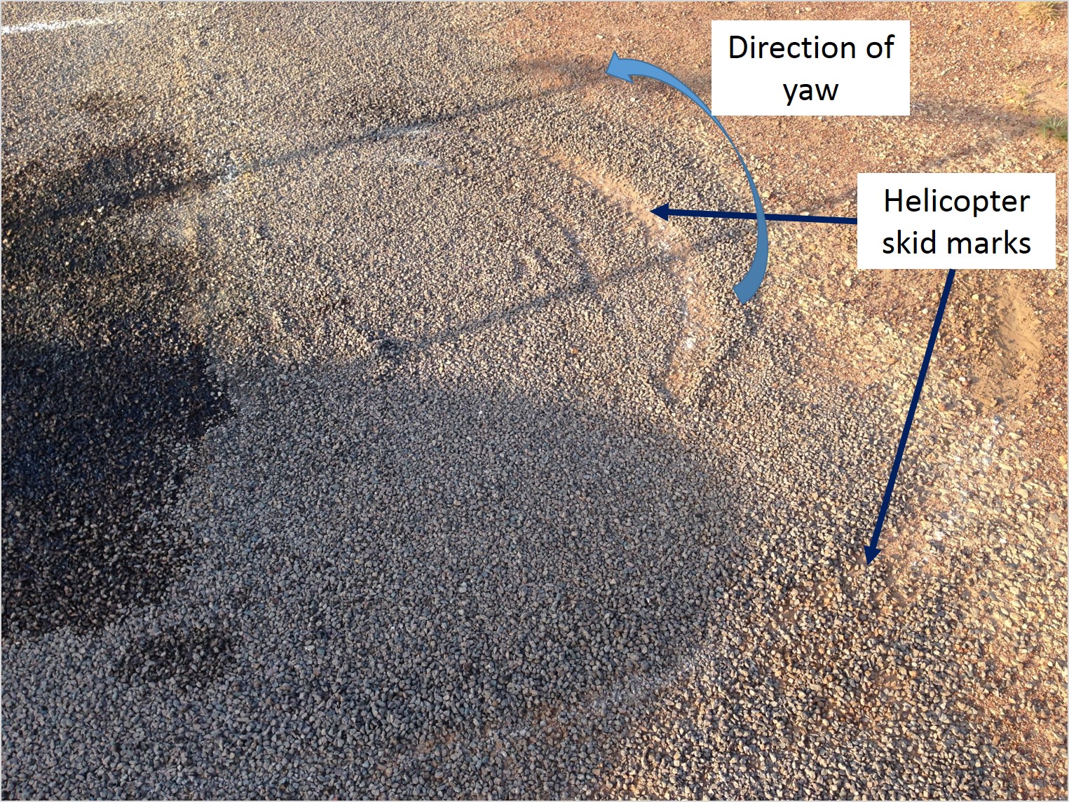
On 11 November 2016, at about 1546 Central Standard Time (CST), a Cessna 208B (C208B) aircraft,[1] registered VH-TYV (TYV) entered runway 29, at the intersection of taxiway E2 (Figure 1) at Darwin Airport, Northern Territory for an aircraft type re-familiarisation training flight. On board were an instructor and trainee pilot.
Figure 1: Darwin Airport overview showing approximate flight path of TYV
Source: Google Earth, annotated by ATSB
At the beginning of the take-off run, the trainee pilot set take-off power prior to releasing the brakes. After releasing the brakes, the aircraft accelerated to the take-off speed. The trainee pilot rotated[2] the aircraft to 12 degrees nose up, to achieve a best angle of climb speed of 80 kt. The trainee pilot maintained 12 degrees nose up and 80 kt until the aircraft climbed to an altitude of about 500 ft above ground level (AGL).
At about 500 ft, the trainee pilot reduced the flap setting from the take-off setting of 20 degrees to 10 degrees. At this time, the instructor noted the climb speed reducing while the trainee continued to maintain the nose attitude for best angle of climb. At the same time, the instructor heard the engine lose power and a thin film of fuel partially obscured the windscreen. The instructor noted reducing engine torque, fuel flow, inter-turbine temperature and airspeed.
As the airspeed reduced to 60 kt, the instructor took control of TYV. They immediately felt a strong nose down force through the control column and the aircraft pitched significantly nose down. They recovered the aircraft to the glide attitude and could not see a suitable landing area ahead of the aircraft. They identified an area to the left of the aircraft as the most suitable for a forced landing and began a left turn towards that clear area at the target glide speed of 85 kt.
During the left turn, the instructor made a PAN[3] broadcast on the Darwin Tower air traffic control (ATC) frequency advising that the engine had failed and that they intended to turn back to Darwin Airport. As the turn continued, they un-stowed the emergency power lever, in accordance with the engine failure procedures and attempted to recover engine power. The engine did not respond, so they feathered[4] the propeller.
The instructor observed a drainage ditch within the clear area to the left of the aircraft, and initially selected the drainage ditch as the most suitable location for the forced landing. As the aircraft turned, they assessed that sufficient height remained to continue the turn back towards Darwin Airport. At the completion of the turn, they selected 30 degrees of flaps to provide a short climb, which allowed the aircraft to clear two hangars and an area of trees.
After clearing the hangars and trees, the instructor observed taxiway A in line with the aircraft and elected to land on taxiway A. The aircraft landed on taxiway A without further incident.
After landing, the instructor and trainee pilot exited the aircraft. They observed fuel on the canopy and underside of the aircraft along with a significant leak from the engine cowling which had created a large pool of fuel below the aircraft.
The instructor and trainee were not injured, and the aircraft was not damaged in the incident.
Instructor comments
The instructor in TYV provided the following comments:
A pre-flight inspection of the aircraft found no defects and no evidence of fluid leaks in the engine compartment.
The instructor developed the C208B operating procedures for the operator. The instructor regularly practiced and trained pilots on the conduct of these procedures.
The instructor had recently conducted significant multi-engine aircraft training, including engine failures where procedures direct a PAN broadcast. They probably reverted to this behaviour when contacting ATC to advise of the emergency rather than declaring MAYDAY.[5] The ATC response indicated that the emergency situation was understood and further declaration of a MAYDAY was not required.
The operator take-off safety briefing directs a pilot to only attempt a turn-back at altitudes in excess of 700 ft AGL.
The aircraft departed with a 10-15 kt headwind, only two occupants on board and 900 kg of fuel. The light weight of the aircraft and the assisting headwind, which became a tailwind during the turn-back, led the instructor to continue the turn-back despite commencing the procedure at about 500 ft AGL.
Departure from the E2 taxiway intersection on runway 29 provides in excess of 1,600 m of runway for take-off. This is ample for a C208B and more than is available at any other runway the C208B is operated to by the company. Departing from the end of runway 29 requires a significantly further taxi distance.
The initial strong pitch down force, as the instructor took control after the engine failure, was probably due to the loss of thrust along with the drag produced as the propeller pitch initially reduced before the propeller was feathered.
The turn back procedure is not suitable for all aircraft types, piston engine aircraft do not have the same ability to turn back after an engine failure.
Engineering examination
A post-incident examination of the engine found the number eight fuel nozzle locking plate missing (Figure 2). This allowed the fuel transfer tube to migrate out of the number eight fuel nozzle adaptor. There was no damage to the locking plate mounts.
The fuel nozzles had been replaced 86 flight hours prior to the incident, while the aircraft underwent maintenance in the United States, prior to importation into Australia. All other required hardware was found to be correctly installed, including the number eight fuel transfer tube locking plate fasteners.
Figure 2: TYV fuel transfer tubes
Source: Operator, annotated by ATSB
Safety analysis
The lack of damage to the locking plate mounts, along with the locking plate being entirely missing, and the fasteners being found installed indicates the locking plate probably did not fail. The locking plate was probably not reinstalled when the fuel transfer tubes and nozzles were installed after replacement. The missing locking plate allowed the fuel transfer tube to slowly migrate out of the nozzle adaptor over the subsequent 86 flight hours.
On the incident flight, the fuel transfer tube migrated far enough that fuel under pressure was able to escape from the nozzle adaptor (Figure 3).
Figure 3: Fuel under pressure escaping from migrated fuel transfer tube
Source: Operator, annotated by ATSB
Findings
These findings should not be read as apportioning blame or liability to any particular organisation or individual.
The number eight fuel transfer tube locking plate was likely not installed when the fuel transfer tubes and nozzles were installed after replacement.
The missing locking plate allowed the fuel transfer tube to migrate out of the fuel nozzle adaptor and fuel to escape. This starved the engine of fuel and led to the engine power loss in flight.
Safety message
This incident serves to underline the importance of ensuring all maintenance is completed entirely and correctly. The locking plate was not installed during scheduled maintenance, however, the fuel leak did not develop for a further 86 flight hours. This demonstrates how the effects of incomplete maintenance can take a long period of time to manifest. The ATSB research report: An overview of human factors in aviation maintenance provides information on human factors errors made in the maintenance environment.
This incident also provides an excellent example of the value of regular training and the effective implementation of procedures following engine failure after take-off in a single engine aircraft.
Successful completion of a turn back manoeuvre to land on the departure runway, or other suitable airport area, requires well-developed procedures and good pilot proficiency to ensure procedures are effectively applied. Careful consideration of the characteristics and performance of each aircraft type is required when developing turn back procedures. The impact of wind and weather conditions must also accounted for when electing to conduct the turn back procedure. As demonstrated in this incident, during the turn back the pilot should constantly assess the ability of the aircraft to complete the procedure and be prepared at any time to cease the turn and land ahead.
The objective of a safety investigation is to enhance transport safety. This is done through:
identifying safety issues and facilitating safety action to address those issues
providing information about occurrences and their associated safety factors to facilitate learning within the transport industry.
It is not a function of the ATSB to apportion blame or provide a means for determining liability. At the same time, an investigation report must include factual material of sufficient weight to support the analysis and findings. At all times the ATSB endeavours to balance the use of material that could imply adverse comment with the need to properly explain what happened, and why, in a fair and unbiased manner. The ATSB does not investigate for the purpose of taking administrative, regulatory or criminal action.
Terminology
An explanation of terminology used in ATSB investigation reports is available here. This includes terms such as occurrence, contributing factor, other factor that increased risk, and safety issue.
Publishing information
Released in accordance with section 25 of the Transport Safety Investigation Act 2003
Ownership of intellectual property rights in this publication
Unless otherwise noted, copyright (and any other intellectual property rights, if any) in this report publication is owned by the Commonwealth of Australia.
Creative Commons licence
With the exception of the Coat of Arms, ATSB logo, and photos and graphics in which a third party holds copyright, this publication is licensed under a Creative Commons Attribution 3.0 Australia licence.
Creative Commons Attribution 3.0 Australia Licence is a standard form licence agreement that allows you to copy, distribute, transmit and adapt this publication provided that you attribute the work.
The ATSB’s preference is that you attribute this publication (and any material sourced from it) using the following wording: Source: Australian Transport Safety Bureau
Copyright in material obtained from other agencies, private individuals or organisations, belongs to those agencies, individuals or organisations. Where you wish to use their material, you will need to contact them directly.
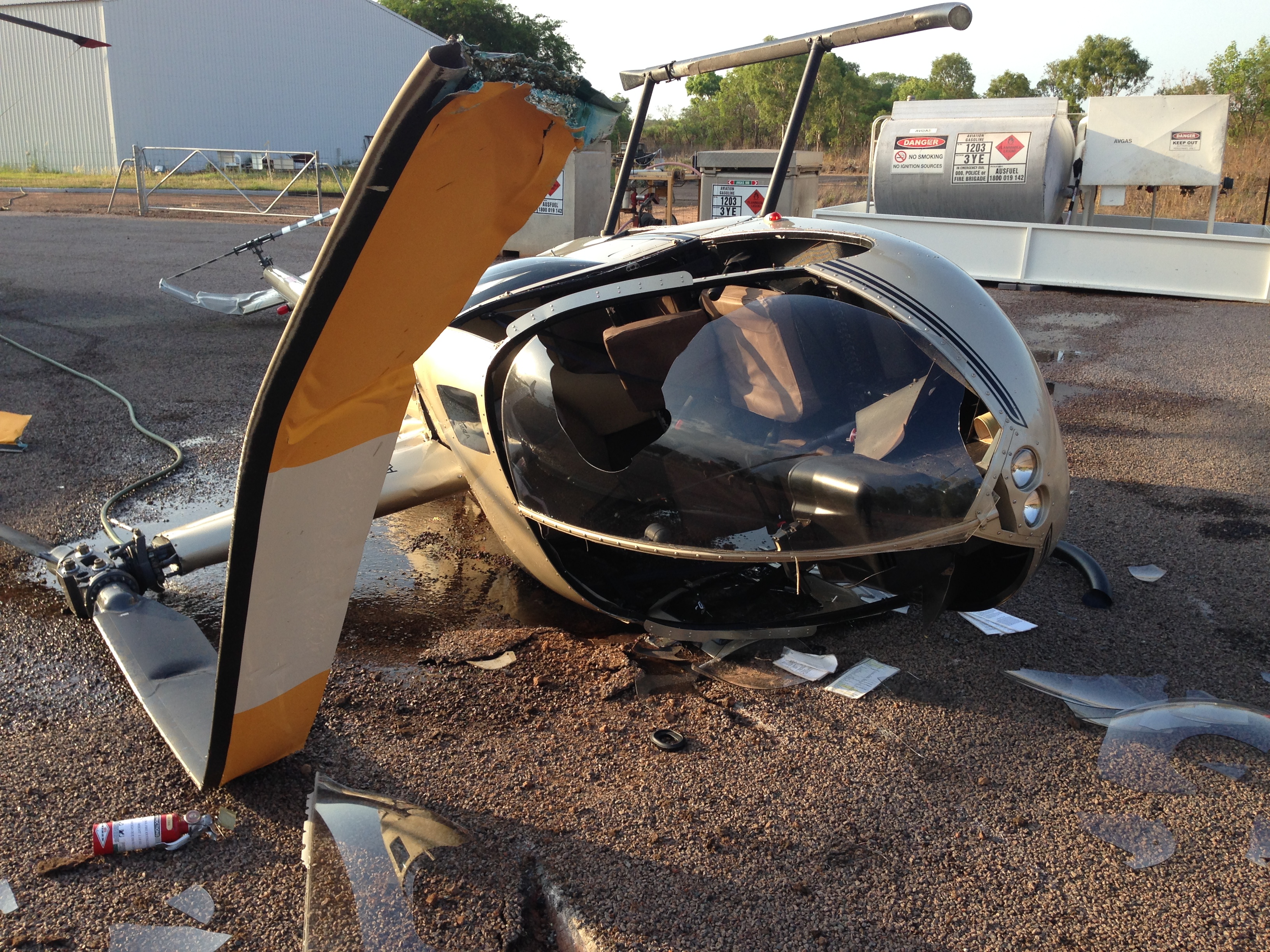
At about 1113, Central Daylight-saving Time (CDT) on the 6 November 2016, a Cessna 172S aircraft, registered VH-USL (USL), departed Parafield Airport, South Australia for a local flight in the western training area. The pilot was the only person on board the private flight.
The pilot reported that the aircraft has a ‘glass cockpit’[1] and they had only flown it once before with an instructor. The purpose of this flight was to become more familiar with the ‘glass cockpit’ and specifically the autopilot. Prior to taxi with the engine running, the pilot reviewed the operation of the autopilot. In addition, as preparation the pilot had read the auto pilot manual and watched some videos on the operation of the autopilot.
During the initial climb, the pilot engaged the autopilot. As the aircraft started to climb at a faster rate than expected, the pilot disconnected the autopilot and continued on to St Kilda (Figure 1).
Figure 1: Approximate flight path of USL from Parafield to just past the Lower Light ALA
Source: Google earth, modified by the ATSB
When the aircraft reached 1,000 ft, the pilot again engaged the autopilot and the autopilot again started to change the attitude of the aircraft, not as expected, and the pilot disconnected the autopilot. After passing St. Kilda, the pilot initiated a climb to 2,500 ft and navigated along the VFR route towards Dublin (Figure 2). In the cruise, the pilot continued to attempt to get the autopilot to engage but it did not respond as they expected. The pilot reported that they made regular checks and would look from inside the cockpit to outside to check the aircraft was maintaining a direction to Dublin and that no other aircraft were in the vicinity.
Source: Airservices Australia: Visual Terminal Chart, modified by the ATSB
During this time, a Cessna 206 (C206) aircraft departed Lower Light aircraft landing area (ALA) for parachute operations. They were on climb to flight level (FL) 120 where four parachutists planned to exit the aircraft overhead the Lower Light ALA. The aircraft planned to then continue to climb to FL 140 where two other parachutists in tandem were to exit the aircraft.
The pilot contacted the Adelaide Approach controller and received a clearance to climb initially to FL 120. Approaching FL 120, the pilot received a clearance to drop the first parachutists and then climb to FL 140. The controller also advised them that there was an unverified aircraft (USL) about 3 NM to the south of Lower Light ALA at 2,500 ft. At about 1123, the pilot broadcast on the area frequency advising traffic in the Lower Light area that in about three minutes they would be at FL 120 and would conduct a parachute drop. The pilot of USL reported that they heard this broadcast but no subsequent broadcasts from the aircraft.
The parachute operator’s safety officer was listening on the radio frequencies (parachute operation frequency, area frequency and Adelaide Approach frequency) and was standing in front of the operator’s hangar. The safety officer reported that they heard the broadcast made that the four parachutists had exited the aircraft (this was not recorded on the area or Adelaide approach frequencies). At about the same time, the safety officer saw a Cessna 172 (C172) aircraft (USL) fly directly over the hangar from the south, heading towards where the safety officer expected to see the four parachutes open. The safety officer contacted the C206 pilot on the radio to let the pilot know that there was an aircraft flying directly towards the parachutists. The safety officer observed the parachutes open near the C172 and observed the C172 aircraft turn to the right slightly and then make a left turn away from Lower Light ALA.
At about the same time, the pilot looked out and observed parachutes just below and to the left of the aircraft at a distance of about 200 m. After checking that it was all clear, the pilot turned the aircraft to the left to manoeuvre away from Lower Light ALA.
At about 1126, the C206 pilot broadcast that the traffic adjacent to Lower Light ALA to depart the area immediately, as there were parachutists in the air. However, the pilot heard no response from the pilot of USL. The C206 pilot contacted Adelaide Approach and advised that an aircraft had interfered with the parachutists. The controller replied that the traffic was outside controlled airspace, and they did not have any details on the aircraft. As the C172 was heading away from the area, the controller approved the C206 to drop the remaining parachutes and then descend from FL140.
The pilot of USL disconnected the autopilot, navigated to Dublin, returned to Parafield via the inbound VFR route, and landed without further incident. The six parachutists landed without further incident.
Pilot comment
The pilot reported that they were distracted while trying to operate the autopilot and were not aware that they had flown close to the Lower Light ALA. They heard the broadcast from the C206 pilot, but they did not realise that they were that close to the ALA and did not take any action. When the parachutes were sighted, the pilot checked the area before turning, to ensure they were not about to turn into another parachute which was taking action to avoid his aircraft.
After the incident, the pilot reported they informed the flying school where the pilot hired the aircraft about the incident and that they believed the autopilot had a problem.
The pilot reported that the weather was clear, and the wind was about 8 knots from the west.
Aircraft owner
The maintenance release for USL contained an endorsement that the autopilot roll servo was unserviceable in August 2016 and another roll servo was installed. On 26 October 2016, the autopilot roll servo was replaced with an exchange servo. There were no other endorsements on the maintenance release about the autopilot.
The aircraft owner reported that apart from the replacement of the autopilot servo there had been no defects recorded about the serviceability of the autopilot. Subsequent to the incident, the operator conducted a full test in flight of the autopilot on USL and no fault was found with the autopilot or with any of its functions.
Parachute operator
The parachute operator reported that in the past they have contacted flying schools in the area notifying them of the frequencies that their pilot will use to notify that there are parachute operations. The parachute operator indicated that there have been other ‘close calls’ reported but this was the closest that an aircraft has come to a collision with a parachutist.
A search of the ATSB database confirmed three other notifications from 2006 to 2016 where an aircraft was near parachutists at the Lower Light ALA.
Findings
These findings should not be read as apportioning blame or liability to any particular organisation or individual.
The pilot of the Cessna 172 was distracted by the operation of the aircraft autopilot and as a result, had reduced awareness of the aircraft’s position and flew in close proximity to four parachutists.
Safety message
This incident highlights the importance to maintain situational awareness through active navigation and active listening to radio communications. Ensuring you are listening to the correct frequencies and communicating on the correct frequencies helps to maintain your situational awareness but also that of other pilots flying in your area.
The Civil Aviation Safety Authority (CASA) has developed the Look out! Situational awareness DVD and video for pilots to learn more about the safety-critical skills that makes up situational awareness. There is a strong emphasis on the need to prepare and plan for every flight. The DVD gives a definition of situational awareness as “what’s happened, what’s happening and what might happen”.
The CASA Safety Video - Situational awareness is available from the CASA website and the CASA Look out! Situational awareness DVD is available from the CASA online store.
The objective of a safety investigation is to enhance transport safety. This is done through:
identifying safety issues and facilitating safety action to address those issues
providing information about occurrences and their associated safety factors to facilitate learning within the transport industry.
It is not a function of the ATSB to apportion blame or provide a means for determining liability. At the same time, an investigation report must include factual material of sufficient weight to support the analysis and findings. At all times the ATSB endeavours to balance the use of material that could imply adverse comment with the need to properly explain what happened, and why, in a fair and unbiased manner. The ATSB does not investigate for the purpose of taking administrative, regulatory or criminal action.
Terminology
An explanation of terminology used in ATSB investigation reports is available here. This includes terms such as occurrence, contributing factor, other factor that increased risk, and safety issue.
Publishing information
Released in accordance with section 25 of the Transport Safety Investigation Act 2003
Ownership of intellectual property rights in this publication
Unless otherwise noted, copyright (and any other intellectual property rights, if any) in this report publication is owned by the Commonwealth of Australia.
Creative Commons licence
With the exception of the Coat of Arms, ATSB logo, and photos and graphics in which a third party holds copyright, this publication is licensed under a Creative Commons Attribution 3.0 Australia licence.
Creative Commons Attribution 3.0 Australia Licence is a standard form licence agreement that allows you to copy, distribute, transmit and adapt this publication provided that you attribute the work.
The ATSB’s preference is that you attribute this publication (and any material sourced from it) using the following wording: Source: Australian Transport Safety Bureau
Copyright in material obtained from other agencies, private individuals or organisations, belongs to those agencies, individuals or organisations. Where you wish to use their material, you will need to contact them directly.
A limited-scope, fact-gathering investigation into this occurrence was conducted in order to produce this short summary report and allow for greater industry awareness of potential safety issues and possible safety actions.
What happened
On 30 October morning, the 119 m general cargo ship Searoad Mersey (Cover) arrived off Grassy Harbour, King Island (Figure 1) from Melbourne, Victoria. The ship was operating a 7-day schedule between Melbourne, King Island and Devonport, Tasmania. At about 0700,[1] the ship’s master received a weather report for the harbour. The wind was from the north-west at 25 to 28 knots[2] as per the forecast.
Figure 1: Navigational chart Aus 178 showing Grassy Harbour
Source: Australian Hydrographic Office (annotated by ATSB)
At 0730, the ship approached Grassy Harbour’s outer breakwater at 12 knots. Shortly after, the master manoeuvred the ship into the outer harbour and started a starboard turn to bring the ship onto the inner lead beacons for the inner harbour. Once inside the inner harbour, the ship’s master swung the ship to port to berth the ship starboard side alongside the wharf.
By 0800, Searoad Mersey’s mooring lines were all fast. Shortly after, the ship’s stern ramp was lowered and cargo unloading started. Cargo operations continued throughout the day with several delays. As a consequence, the ship’s scheduled departure time of 1500 was delayed by an hour. The wind was from the west-northwest throughout the day at 27 to 33 knots.
At 1604, the ship’s main engines and bow thruster were on standby and ready for use. The master held a departure brief with the ship’s bridge team detailing the departure plan. The ship’s master and crew were very experienced and familiar with arrivals into and departures from Grassy Harbour. The standard brief detailed using the port engine ahead and full starboard rudder.
Figure 2: Searoad Mersey’s grounding in the Inner Harbour
South Australian Hydrographic Office (annotated by ATSB)
The wind was still from the west-northwest at 27 to 33 knots and the tide was ebbing with low water expected at 1853. The ship’s departure draughts were 5.1 m forward and 5.3 m aft. The master expected an under keel clearance of between 1 and 1.5 m for the departure.
At about 1605, the mooring lines were singled up forward and aft and by 1607, all mooring lines had been let go and recovered. The wind acting on Searoad Mersey’s starboard quarter[3] started to move the ship away the berth.
The ship’s heading[4] while alongside the berth was 155° and the next course was 232°, a 77° alteration to starboard. The master increased the port engine to 60 per cent ahead. The ship moved about 30 m ahead, parallel to the wharf, and the rudder was put hard over to starboard.
At 1608, the ship had moved ahead about 90 m and had started swinging to starboard. Shortly after, the ship grounded on the sandy bottom to the east of the inner breakwater (Figure 2).
The master stopped the port engine and put the bow thruster full to port. He then increased the starboard engine to 70 per cent ahead and the rudder hard to port. However, the ship’s starboard shoulder[5] remained grounded. Shortly after, the master unsuccessfully attempted to move the ship astern using both engines.
Searoad Mersey’s crew sounded the ship’s tanks to check for water ingress and started ballasting the ship’s port tanks to list the ship. However, the port list had no effect and the ship remained grounded forward with the stern swinging freely in deep water. The second mate then started pumping ballast from the fore peak tank to the aft peak tank, to reduce the draught forward.
At 1648, the master reported the grounding to the ship’s managers and the joint rescue coordination centre (JRCC) in Canberra. Shortly after, as the tide was still ebbing, he ordered the starboard anchor lowered to the sea bed.
At 1658, the main engines were stopped. Then, at 1700, the master felt Searoad Mersey roll slightly and immediately started the main engines. At 1705 with the main engines running astern, the ship started to move astern. The crew sounded the tanks again for any water ingress. The anchor was recovered and the rudder and engine tested. The master then manoeuvred the ship out of the inner harbour and continued the voyage to Devonport.
On 31 October, the ship’s flag State authority, the Australian Maritime Safety Authority (AMSA), attended the ship in Devonport. The ballast tanks were inspected and no damage was found.
On 3 November, Searoad Mersey underwent an underwater hull inspection in Melbourne. Minor paint damage near the starboard shoulder was found but there was no structural damage.
ATSB comment
Since the last hydrographic survey in 2015, it is probable that silting had occurred near the inner breakwater. It is likely that the reduction in water depth to the charted depths were the result of the predominant westerly winds blowing sand from the nearby beach into the channel together with the movement of sand within the harbour.
Safety message
Masters, harbour masters and others responsible for ships calling safely at ports need to assure themselves of the reliability of charted depths, particularly in some small, remote ports. A possible reduction in charted depths due to local conditions, reference to the charted zone of confidence diagrams and the date of the last hydrographic survey are among the factors that should be taken into account.
The objective of a safety investigation is to enhance transport safety. This is done through:
identifying safety issues and facilitating safety action to address those issues
providing information about occurrences and their associated safety factors to facilitate learning within the transport industry.
It is not a function of the ATSB to apportion blame or provide a means for determining liability. At the same time, an investigation report must include factual material of sufficient weight to support the analysis and findings. At all times the ATSB endeavours to balance the use of material that could imply adverse comment with the need to properly explain what happened, and why, in a fair and unbiased manner. The ATSB does not investigate for the purpose of taking administrative, regulatory or criminal action.
Terminology
An explanation of terminology used in ATSB investigation reports is available here. This includes terms such as occurrence, contributing factor, other factor that increased risk, and safety issue.
Publishing information
Released in accordance with section 25 of the Transport Safety Investigation Act 2003
Ownership of intellectual property rights in this publication
Unless otherwise noted, copyright (and any other intellectual property rights, if any) in this report publication is owned by the Commonwealth of Australia.
Creative Commons licence
With the exception of the Coat of Arms, ATSB logo, and photos and graphics in which a third party holds copyright, this publication is licensed under a Creative Commons Attribution 3.0 Australia licence.
Creative Commons Attribution 3.0 Australia Licence is a standard form licence agreement that allows you to copy, distribute, transmit and adapt this publication provided that you attribute the work.
The ATSB’s preference is that you attribute this publication (and any material sourced from it) using the following wording: Source: Australian Transport Safety Bureau
Copyright in material obtained from other agencies, private individuals or organisations, belongs to those agencies, individuals or organisations. Where you wish to use their material, you will need to contact them directly.
On 5 November 2016, the pilot of an Air Tractor AT-502 aircraft, registered VH-LIK, was conducting aerial spraying operations from an airstrip at Cryon, New South Wales. After completing six spray loads, the pilot loaded liquid chemical into the aircraft’s hopper and refuelled the aircraft. At 0953 Eastern Daylight-saving Time,[1] the pilot commenced a take-off to the north.
About 44 seconds after commencing the take-off, the aircraft collided with trees and the ground before coming to rest inverted. The pilot was fatally injured, and the aircraft was destroyed by impact forces and a fuel-fed fire.
What the ATSB found
The flaps were retracted at some point during the take-off, which significantly degraded the take‑off and climb performance. This effect was compounded by the estimated weight of the aircraft, the local temperature and wind conditions at the time of the flight. The combined effect probably resulted in the aircraft having insufficient take-off performance. The reason the flaps were retracted was not able to be determined.
The aircraft reached a height above the ground where the reduced benefit of ground effect further degraded the aircraft’s performance. The low height and airspeed precluded the pilot from turning the aircraft towards a clear area and the aircraft descended into trees.
Recorded data from the aircraft indicated that the pilot attempted to dump the hopper contents after becoming airborne, which would have achieved significant gains in climb performance, however a complete dump was not achieved. The reason for this could not be determined.
What has been done as a result
The aircraft manufacturer is updating the maintenance section of the aircraft owner’s manual to specify that the gatebox and emergency dump controls are to be inspected periodically for condition, function and adjustment.
Safety message
Acknowledging that the pilot was unable to dump the load on this occasion, the performance benefits in quickly and significantly reducing the aircraft weight means that the requirement to dump the hopper load, when the aircraft performance is not as expected, should be at the forefront of the minds of agricultural pilots. As with all emergency procedures, it is essential that pilots have a well-rehearsed plan, appropriate training and recent practice in conducting an emergency hopper load dump in the aircraft they are operating.
Proper functioning of the emergency jettison system is vital as pilots rely on it in case performance is inadequate, particularly when taking off with a heavy load. Therefore, registered operators should ensure adequate ongoing maintenance and regular checks to maintain serviceability of the system.
Pilots are reminded to monitor weather conditions like temperature and wind and anticipate the potential adverse effects of local conditions on aircraft performance. Where performance data is available for an aircraft, pilots should make active use of it to have the best opportunity to assess the expected performance of the aircraft for the given weight and environmental conditions before take‑off.
The ATSB did not identify any organisational or systemic issues that might adversely affect the future safety of aircraft operations. However, relevant organisations may proactively initiate safety action in order to reduce their safety risk. The ATSB has been advised of the following safety action in response to this occurrence.
Air Tractor
As a result of this occurrence, Air Tractor advised the ATSB that the following inspection will be added to the maintenance section of the owner’s manual, to be completed every 100 hours:
Check gatebox controls and emergency dump controls for proper function and adjustment. Check all components and hardware for condition, wear, and/or cracking.
This requirement will apply to all three types of emergency dump system that can be fitted to Air Tractor aircraft.
The occurrence
On 5 November 2016, at about 0641 Eastern Daylight-saving Time,[2] the pilot of an Air Tractor AT‑502 aircraft, registered VH-LIK (LIK), commenced a flight from Wee Waa Airport, New South Wales, to position the aircraft at an agricultural airstrip near Cryon, about 20 minutes flying time away. The aircraft was carrying full fuel (794 L) but the hopper, which had the capacity to carry about 1,892 L of liquid, was empty.
The aircraft landed at Cryon at about 0700 in preparation for aerial spraying of a crop about 5 km north of the airstrip. A loader[3] filled the aircraft’s hopper with between 1,650 L and 1,670 L of liquid chemical, which was a solution of fungicide and insecticide in water.
At about 0721, the pilot commenced the first of seven planned loads of aerial spraying. After the aircraft landed from spraying the fifth load, the loader loaded the aircraft’s hopper for the sixth load. The loader reported that a similar quantity of chemical was loaded on each of those flights.
Following completion of the seventh flight, the intention was to reposition to a property about 50 km away and continue spraying activities. In order to avoid delaying commencement of the next job, the loader mixed the seventh batch of liquid chemical and arranged for the pilot to load the hopper and refuel the aircraft himself. At about 0907, the loader observed the aircraft take off on the sixth load and then left the airstrip to drive to the next property.
Data recorded by the aircraft’s GPS showed that the aircraft landed after completing the sixth load at 0930. About 24 minutes later, the aircraft commenced a take-off run to the north, consistent with previous departures. The last recorded aircraft position was 44 seconds later, 2 km north of the runway threshold.
The aircraft clipped the top of a fence 1,300 m beyond the start of the runway, struck multiple trees about 700 m beyond the fence and subsequently collided with terrain. The aircraft flipped over and came to rest inverted.
The pilot sustained fatal injuries and the aircraft was destroyed by the impact with terrain and a subsequent fuel-fed fire.
Pilot experience
The pilot held a commercial aeroplane pilot licence, was appropriately endorsed for the aircraft, and held aerial application and low-level ratings applicable to operation of the accident flight. At the start of the accident day, the pilot had logged a total of 9,896.8 flying hours. Over 8,000 hours of that time were low-level flying, including survey, firebombing and about 2,500 hours of aerial agricultural operations. The pilot had accrued over 4,600 hours in turbine-engine aircraft and had about 450 hours on AT-502 aircraft.
The pilot had successfully completed a flight review and agricultural flight proficiency check on 7 June 2016.
Medical and pathological information
The pilot held a current Class 1 medical certificate without restriction that was valid to 22 December 2016. The pilot had also passed medical testing for entry into the Australian Defence Force as a military pilot within the previous two months.
The post-mortem examination did not identify any conditions that could have contributed to the accident. Toxicology results were negative for alcohol and commonly-tested drugs.
Aircraft
LIK was an Air Tractor Incorporated AT-502 single-seat agricultural aircraft manufactured in 1990 in the United States (US), (serial number 502-0115). It was powered by a Pratt & Whitney PT6A-15AG turboprop engine that drove a Hartzell HC-B3TN-3D three-bladed constant speed, reversible pitch propeller.
The aircraft was fitted with a fuel tank in each wing and had a total capacity of 817 L, of which 794 L was useable. The aircraft was also fitted with dispersal equipment for spraying and spreading, and a system that allowed the hopper contents to be dumped if required.
Maintenance
The aircraft was maintained under a Civil Aviation Safety Authority (CASA)-approved system of maintenance (SOM) by a CASA-approved maintenance organisation. The last scheduled 75‑hourly was on 16 August 2016 at which time the aircraft had 13,000.4 hours total time in service (TTIS) and 150- and 300-hourly inspections were carried out on 15 October 2016 at 13,150.6 TTIS. The aircraft had flown about 40 hours since the last inspection.
Previous recent maintenance
30 November 2015: the maintenance records stated that a ‘flap system fault caused a take-off accident.’ The flap system was found to be intermittent and a new flap motor was installed and the ‘up’ relay was replaced.
8 April 2016: the flap actuator pivot bearing and right flap middle attachment bracket were identified as unserviceable and replaced.
16 August 2016: the flap motor was replaced in accordance with the operator’s requirement to replace it every 450 hours. The motor had accumulated about 150 hours of operation at the time of the accident.
15 October 2016: the hopper dump door boot was found unserviceable and was replaced.
The SOM specified that the daily pre-flight walk-around inspection was to be conducted in accordance with the AT-502 flight manual. The manual identified various checks relating to the dispersal equipment, however there was no reference to checking the integrity or operation of the hopper dump system.
The SOM specified that the airframe, electrical and instrument categories were to be maintained in accordance with the latest revision of the AT-502 owner’s manual, inspection section. Additionally, agricultural role equipment was to be maintained to the applicable manufacturer’s schedule when installed on aircraft. As with the daily inspection, the Air Tractor inspection information specified a number of checks relating to the dispersal equipment, but no specific reference to maintenance and operation of the hopper dump mechanism.
Registration holders of class B aeroplanes may optionally use the CASA Maintenance Schedule to maintain their aircraft. In contrast to LIK’s SOM, the CASA Maintenance Schedule Daily Inspection included the following items specific to agricultural aeroplanes:
1. Check that the agricultural equipment (e.g. hopper, hopper lid and fasteners, spray tanks, spray pump and lines, booms and boom supports, dump doors, fan and fan brake) is secure.
2. Check that the dump and fan brake mechanisms are free from obstructions and operate correctly.
The CASA Maintenance Schedule for Periodic Inspection – The Airframe specified additional items for agricultural aeroplanes:
1. Inspect the hopper, hopper lid and fasteners, baffles and internal braces.
2. Inspect the spreader, spreader gate and controls.
3. Inspect the spray pump fan, fan mount, fan brake, spray pump lines booms and boom supports.
4. Inspect the emergency dump doors and dump controls.
Agricultural operations
The AT-502 is a specialised aircraft designed for agricultural operations. Liquid or granular chemical for aerial spraying or spreading can be carried in the aircraft’s hopper. With a load in the hopper, a pilot can use the performance benefits of flying the aircraft close to the ground (in ground effect)[4] while it accelerates to a safe airspeed prior to climbing. If the pilot assesses the aircraft’s performance is inadequate, particularly during the take-off, a jettison system enables them to dump the load, which quickly reduces the aircraft’s weight and increases performance.
Regulations
The US Federal Aviation Administration (FAA)-approved Airplane Flight Manual (AFM) for the AT‑502 specified an original maximum agricultural gross take-off weight of 3,296 kg. However, the AFM for LIK had revised weight and balance data, specifying a maximum agricultural gross take‑off weight of 8,000 lb (3,629 kg). Additionally, the AT-502, like most agricultural aircraft, had provision in its Type Certificate Data Sheet (TCDS)[5] for operators to approve a higher maximum (gross take-off) weight. The TCDS applicable to LIK stated that the aircraft type and model had demonstrated satisfactory operation, at a maximum (gross take-off) weight of 9,200 lb (4,173 kg) under the following conditions:
1,300 ft altitude
32 °C outside air temperature
a stall speed of 77 kt calibrated airspeed (CAS) and maximum speed 122 kt (CAS).
Australian Civil Aviation Regulations 1988 (CAR) 138 requires that the pilot must comply with the aircraft’s flight manual. CAR 235(4) prohibits taking off in an aircraft if its gross weight exceeds its maximum take-off weight. However, to facilitate overweight operations in Australia, CASA has issued exemptions against the requirements of CAR 138 and 235. The exemption current at the time of the accident was EX217/15, which allowed operations up to weights where jettisoning the hopper load would reduce the gross weight to below the maximum take-off weight. However, the gross weight at take-off was not permitted to exceed the highest of the weights shown on:
the aircraft TCDS
a placard (with a weight certified by CASA)
the approved flight manual.
Under the exemption, LIK was permitted to operate at the maximum demonstrated weight of 9,200 lb (4,173 kg) specified in the TCDS.
The aircraft operator reported that although the aircraft had capacity to carry 800 L of fuel and 1,800 L of liquid in the hopper, they carried a maximum of 600 L and 1,600 L respectively, in accordance with regulatory requirements. However, they also advised that LIK had successfully operated at its maximum capacity of about 400 kg higher than the demonstrated maximum take‑off weight, with the same engine and propeller combination, for many years under an earlier exemption that did not specify a gross weight limit.
Effect of increased weight
An increase in aircraft weight reduces aircraft performance. In the take-off phase, increased weight for the same power setting:
increases induced drag and rolling resistance
slows acceleration
lengthens the ground run.
An increase in weight also increases the stalling speed and means that the aircraft has to reach a higher groundspeed (for the same configuration and wind conditions) before it can safely fly. That in turn also increases the length of the required ground run.
Induced drag is proportional to the weight of the aircraft squared, so an increase in weight of 10 per cent increases induced drag (in all flight conditions) by about 20 per cent and the power required to overcome that drag increases similarly.
Flaps
To increase lift and aid in overcoming the increased induced drag, the aircraft was fitted with large Fowler-type flaps, interconnected to the ailerons. Fowler flaps extend rearwards before extending downwards, increasing the wing surface area and then the camber. The initial rearwards extension means in the partially extended or take-off position, the flaps increase lift without significantly increasing the drag. That flap design particularly assists agricultural aircraft operating at high weights, close to the ground and for short take-off performance. The flaps are operated electrically and may be stopped at any position from 0° to the maximum of 26° of travel. The flaps had external markings visible from the cockpit at 10° and 20° of travel.
For take-off with a load or for short-field take-offs, 10 to 20° flap was used. Up to 10° of flap was also used during turns. The AFM stated that for take-off with a full hopper load, ‘lower flaps to 10° position…after breaking ground do not retract the flaps until at least 91 kt indicated airspeed is reached.’ This was consistent with the manual’s stated best rate of climb speed[6] for a heavy load, which was between 86 kt and 91 kt indicated airspeed.
When fully extended (to 26°), the flaps significantly increased drag. Following reports of pilots attempting to use full flap on take-off, the aircraft manufacturer added the following warning to the AFM:
Full flaps should not be used during the takeoff sequence. The use of full flaps creates large amounts of drag and will lengthen the ground roll and impair climb performance.
Flap switch position
The AT-502 aircraft are fitted at manufacture with a flap switch near the throttle quadrant. The pilot presses the electric switch and holds it until the desired amount of extension or retraction is achieved. The pilot can verify the amount of flap extended based on two markings on the flap.
In Australia, it is common to fit an additional flap switch in accordance with an engineering order. The setup comprises either a rocker switch or, in the case of LIK, two buttons on the control stick (Figure 1). This allows the flaps to be operated with the pilot’s right hand, leaving the left hand free to operate the throttle and/or dump lever.
Figure 1: Flap stick switch
Source: Aircraft operator
The aircraft manufacturer advised that, although the additional flap switch position was convenient, very few US operators placed one on the control stick due to safety concerns associated with this setup. Specifically, it was reported that during high stress, high workload events, pilots had squeezed the control grip tightly and unintentionally actuated the switch and raised or lowered the flap.
The ATSB received notification in September 2017 of inadvertent flap retraction during take-off, using the flap stick switch, which resulted in the aircraft descending and colliding with terrain (see also ATSB investigation 199800640 in Similar occurrences).
Operations
The day’s planned operation
The task for the pilot was to spray a combination of insecticide and fungicide over an area of 390 hectares, at a volume rate of 30 L per hectare. Seven loads were programmed, with each load area 55.7 hectares and each load volume 1,671 L.
The loader reported loading 1,650–1,670 L of water-based chemical into the hopper for each spray run. In preparation for the seventh spray load, the loader had mixed 400 L of chemical, which the pilot was to load into the hopper along with water to make up the total volume. The exact volume loaded was not witnessed but there was no reason for it to have varied from the quantity loaded on the previous runs.
Fuel
The pilot refuelled the aircraft and refilled the hopper after the loader had left and therefore the amount of fuel and chemical on board at the time of the accident was estimated, based on the available evidence.
The aircraft fuel tanks were full (794 L usable fuel) at the start of the first flight that day. Based on a planned fuel consumption of 225 L per hour, the usable fuel remaining after the sixth spray load would have been 160 L. This was a conservatively high consumption figure used for fuel planning so the fuel remaining may have been greater.
The aircraft operator had a supply fuel tank with a capacity of 14,000 L situated at the airstrip. On 26 October 2016, 12,940 L of Jet A1 fuel was delivered to fill the supply tank. Two days prior to the accident, the job record obtained for a company aircraft showed that 594 L of fuel was taken from the tank to refuel that aircraft. There was no other known refuelling from the supply tank prior to the day of the accident.
After the accident, the supply tank contained about 13,000 L. This indicates that the pilot likely added approximately 400 L of fuel to LIK. In consideration of the conservatively low estimated fuel remaining value (160 L), and the reported normal procedure of filling to a visible indicator, it was therefore estimated that the pilot filled aircraft to between 560‑600 L at the start of the seventh take-off.
Weight and balance
Using the estimated fuel and chemical load at the start of the seventh take-off run, the aircraft take-off weight was probably between 4,214‑4,246 kg (Table 1). This weight was about 41‑73 kg above the TCDS weight of 4,173 kg. At the estimated weight, the aircraft’s centre of gravity would have been within the fore and aft limits.
The stalling speed at the TCDS demonstrated weight was 77 kt CAS (equivalent to 75 kt indicated airspeed).[7]
Table 1: Estimated take-off weight range
Source
Weight (kg)
Basic empty weight
2,007
Pilot
95
Hopper load
1,670
Fuel (using specific gravity of 0.79 for jet A1 fuel at 29 °C)
442‑474
Estimatedlikely take-off weight
4,214‑4,246
Meteorological conditions
As part of the investigation, the ATSB obtained weather data for 5 November 2016 recorded at 10-minute intervals at:
Cryon Station, which was about 7 km south-west of the accident airstrip
Burren Junction (40 km east)
Rowena (40 km north-northeast).
Recorded 1-minute interval data was also obtained for Walgett Airport (50 km west of the accident airstrip).
The weather recorded between 0720 and 1000 at those locations showed the temperature increased from 19 °C to 29 °C and the wind changed from north-westerly, through westerly to south-westerly. As the wind changed direction, it became gustier and the wind speed increased.
The average wind speed and direction for each 10-minute period was recorded at Cryon Station, about 7 km south-west of the accident airstrip. Figure 2 shows the recorded 10-minute data divided into the crosswind and tailwind components for the runway heading 017° True. During the 24 minutes the pilot was on the ground between the sixth and seventh loads, the average wind speed increased to about 11 kt and changed direction so that there was a tailwind of about 6 kt and a crosswind of about 8 kt for the final take‑off. Shortly after take-off, the aircraft turned to track in a more north‑easterly direction (Figure 6), which would have increased the tailwind component by about 1.5 kt.
Figure 2: Recorded wind data at Cryon showing headwind and crosswind components for a runway heading 017° T
Source: Delta Ag – analysed by ATSB
South-westerly winds at Walgett were at 14 kt, gusting to 20 kt between 0930 and 1000. Figure 3 shows the crosswind and tailwind components for the runway heading 017° True if the wind at the accident site was similar to that recorded at Walgett Airport.
Figure 3: Recorded wind data at Walgett Airport showing tailwind and crosswind components for runway heading 017° T
Source: Bureau of Meteorology – analysed by ATSB
A pilot who was operating about 11 km east-south-east of the accident site reported that the wind changed suddenly at the time of the accident, and that he had just ceased spraying operations for the day because of the strong wind. He estimated the wind was gusting about 30 to 35 km per hour (16–19 kt) and potentially over 40 km per hour (22 kt).
Based on the pilot’s assessment and the recorded 1-minute wind data at Walgett, the aircraft may have encountered wind gusts stronger than the 10-minute average recorded at Cryon during take‑off for the seventh run.
Density altitude
Density altitude is pressure altitude corrected for non-standard temperature. As density altitude increases, aircraft and engine performance decrease. The pressure altitude decreased by 30 ft during the morning’s flights from 575 to 545 ft, and the density altitude increased due to an increase in temperature.
The temperature at the time of the accident was 29 °C and the density altitude for the airstrip (elevation 485 ft above mean sea level) was 2,405 ft above mean sea level. The 10 °C increase in temperature and slight decrease in pressure altitude since the first spray run of the day increased the density altitude by 1,170 ft (from 1,235 ft). AT-502B performance data indicated (no performance data was available for the AT‑502) that this would have increased the length of the take-off ground run by about 15% and the distance to clear a 50 ft obstacle by about 17%. As the performance of the AT-502 and 502B is comparable, the required ground run and obstacle clearance distance for LIK would have been similarly affected.
Recorded information
The aircraft was equipped with a satellite navigation system that provided tracking guidance to the pilot to facilitate accurate spray coverage of the crop. The system recorded in-flight data to a compact flash (CF) memory card that included the time and the aircraft’s position, speed, track and altitude.
Data from the seven flights (loads) that day were recovered from the device and the accident flight was compared with the first minute of the six previous flights (Figure 4). On each flight, the system started recording when the aircraft reached 50 kt on the take-off run and stopped when the aircraft decelerated below 50 kt during the landing roll.
The aircraft’s recorded groundspeed on the accident take-off was comparable to the six previous flights, except that the acceleration was slower — between about 70 and 80 kt. The ATSB combined the recorded 10-minute wind data at Cryon with the system data to derive the approximate airspeed for all of the day’s flights. The accident flight showed significantly reduced airspeed and slower acceleration between about 60 and 80 kt airspeed. The previous six flights had similar profiles to each other. Fuel consumption reduced the aircraft’s weight over the six flights, which would have offset the decreasing headwind component to some extent during the morning’s operation.
Based on the recorded groundspeed and 10-minute average wind data at Cryon, the aircraft’s maximum airspeed on the accident flight was about 87 kt (and 80 kt based on the Walgett 1‑minute data) immediately before impact.
Figure 4: Comparison of LIK’s seven flights from the day of the accident – groundspeed (left) and airspeed (right) calculated from recorded groundspeed and adjusted for recorded wind
Source: ATSB analysis of VH-LIK navigation system data
Altitude data from the day’s flights revealed that the aircraft did not climb more than 20 ft above the ground on the final take-off. The data does not depict the exact flight profile and height due to data accuracy limitations (the ‘ground level’ for the accident take-off varies between about 5 and 10 ft), but provides a reliable comparison of the flights (Figure 5).
Figure 5: Navigation system recorded data comparing the aircraft’s recorded height above ground on the day’s flights
Source: ATSB analysis of VH-LIK navigation system data
The data contained a discrete recorded spray on/off parameter. The spray ON is actuated through a pressure switch on the spray boom, as well as a micro-switch at the bottom of the dump handle (for spreading granular chemical or jettisoning the hopper load). The normal data recording rate was about one record per second. However, if the system was actively spraying or spreading, the data recorded at a higher rate of 4 to 5 times per second.
During the first six flights, the spray ON parameter remained on during the spray runs, and then OFF as the aircraft turned for the next run or was taking off and landing. Consistent with the spray ON activating, the data logging rate was higher than once per second.
At 0954:19 on the final take-off, 26 seconds into the recording the system briefly recorded at a higher rate without the spray discrete parameter activating (Figure 5). This occurred just before the aircraft reached a one-metre high fence, about 1.3 km beyond the start of the runway.
Nine seconds later, at 0954:28, the system again recorded at a higher rate, and the spray discrete parameter activated ON once only and then immediately returned to OFF. The discrete parameter activated once more (for one data record) at 0954:37, and the recording ended 0.25 seconds later.
The aircraft’s recorded flight path on the accident flight showed the aircraft’s take-off and a turn gradually to the right, consistent with previous flights and in the direction of the target area to be sprayed on that load (Figure 6).
Figure 6: Recorded aircraft track for accident flight
Source: ATSB
Site and wreckage information
Witness information
A pilot who was conducting aerial spraying about 11 km east-southeast of Cryon saw black smoke and flew towards it. He found LIK inverted and on fire, and radioed for assistance.
The pilot landed his aircraft at the Cryon airstrip and met a farm worker with a vehicle and they travelled together to the accident site. He reported that he could not see any evidence that the pilot had dumped the load.
Wreckage information
The accident site was about 2 km north of the southern end of the runway and the general spread of wreckage indicated the aircraft had been tracking to the north-northeast. Examination of the accident site determined that the aircraft’s left wing struck a tree about 9 ft above the ground, then a second tree about 6 ft above the ground (Figure 7). The right wingtip struck the ground and the aircraft then collided with a third tree dislodging the propeller and engine. The main landing gear struck the ground and separated from the airframe, and the fuselage then collided with the ground nose first, flipped over and came to rest inverted. The debris trail extended about 80 m from the first tree impact to the fuselage. A fuel-fed, post-impact fire destroyed most of the aircraft.
About 1.3 km from the start of the runway, a 1.2 m high wire fence ran across the flight path. The top two fence wires were broken in line with the aircraft’s flight path, suggesting contact with part of the aircraft. The fence was noted to have been undamaged about a week prior to the accident.
The impact forces and post‑impact fire destroyed many of the aircraft components, however all major components of the aircraft were identified.
Figure 7: Accident site showing tree impacts
Source: ATSB
Engine and propeller
Examination of the engine outer combustion case identified evidence of twisting associated with engine torque. Additionally, the compressor blades at the engine inlet were bent opposite to the direction of rotation and the power turbine blades were fractured around the entire circumference of the disc. All of those indications were consistent with the engine rotating at the time of the accident.
The propeller separated from the engine upon striking a tree, with only one of the blades remaining within the hub. One of the two detached propeller blades was located at a right angle to the aircraft’s flight path, approximately 90 m from the tree strike. The significant distance of travel by the ejected blade required significant energy, which was only likely to occur under conditions of high engine power/torque.
That blade had fractured at the blade tip and displayed rearward bending that was indicative of a ground or tree strike while rotating. There was a hand file mark along the edge of the blade but no indication of pre-existing cracking or other defects.
All of the propeller blades exhibited a general level of bending, twist and leading edge impact damage that was consistent with the propeller being driven with significant torque at the time of impact.
Flight controls
Examination of the aircraft’s flight controls verified that they were continuous prior to the collision. The flaps were found in the retracted position. The flap controls were heavily damaged by impact forces and fire, but the remaining identifiable parts appeared to be in place. The flap micro‑switches and relays had melted, so their positions could not be verified.
Flap actuator
The flap actuator was in the fully retracted position (Figure 8) and the flap actuator motor had broken free from the gearbox.
Figure 8: Flap actuator
Source: ATSB
When fully retracted, the manufacturer specified that there should be a gap of 1/16” to 1/8” (1.6‑3.2 mm) between the striker and the end of the up travel. If the flap micro-switch is not set correctly, and the gap is insufficient, the flap motor may stop the ‘up’ travel. If this occurs, it can jam the actuator and prevent the flaps from extending. An appropriate gap was identified on the occurrence actuator. The aircraft’s maintenance records indicate that the aircraft had flown 150 hours without any related issues since the flap micro-switch was set.
Air Tractor Service Letter 260 reported a case of the rubber coupling between the flap actuator motor and gearbox tearing. This occurred during take-off with the flaps extended and allowed the actuator to back-drive, which resulted in an uncommanded flap retraction. The service letter recommended that the coupling be replaced upon condition and inspected every 400 hours to prevent a similar event occurring. Due to the extent of damage, the condition of the rubber coupling prior to the impact could not be assessed.
Hopper
The emergency hopper dump mechanism appeared to be continuous except for a rod end fracture, consistent with impact damage. The dump lever (handle) was found in the closed position, but was not locked and was free to move. Its pre-impact position could not be determined. The over-centre latch of the hopper gate box was in the unlocked and fully-open position; however, it was not clear whether it had moved to that position during the impact sequence.
A modification, involving a sleeve bolted to the hopper gate box push rod, was identified during the wreckage examination (Figure 9). No documentation for the modification was available and therefore an assessment of its suitability could not be made. However, the operator advised that the modification had been made to extend the rod, and that the aircraft had flown over 10,000 hours since, without any issue relating to the dump mechanism. The push rod was bent at the sleeve modification but it had not fractured. It was likely that the damage was a result of the accident impact. The hopper gate mechanism had been used in this configuration during spreading operations and cleaning.
Examination also identified that a bolt was missing from one of two gate box push rod attachments (Figures 10 and 11). The bolt was not recovered and therefore the failure mode could not be assessed. The aircraft manufacturer advised that those bolts and clamps were known to separate from the torque tube during the majority of impact sequences. In any event, testing showed that failure or absence of one of the bolts would not prevent the transfer of sufficient force to open the hopper door, providing the associated clamp was tightened securely.
At the time of writing, the aircraft manufacturer reported that there were no known failures of the hopper dump mechanism.
Figure 9: Gate box push rod showing modification
Source: ATSB
Figure 10: Gate box wreckage showing hole in gate box torque tube where bolt was missing
Source: ATSB
Figure 11: Image of gate box torque tube bolt in place
Source: ATSB
Survivability
The webbing of the seat harness was entirely destroyed in the post-impact fire. Despite this level of damage, various buckle and harness adjust mechanisms were identified. The lap-belt harness buckle was found in the secured, or closed position. The pilot’s helmet was located in the wreckage and seriously damaged by fire. The loader reported that the pilot was wearing the helmet throughout the morning’s flights, and it was therefore very likely he was wearing it at the time of the accident. The cockpit survivable space was relatively intact but severely burnt.
Previous occurrences
Occurrence involving VH-LIK
On 16 November 2015, the pilot of VH-LIK was conducting the ninth load of a spray job. There was 1,500 L of chemical in the hopper, and 400 L of fuel on board (about half fuel capacity). The pilot reported that the start of the take-off roll was normal – the first performance check point was reached with the tail wheel off the ground at approximately 400 m, the second check point at 600 m was achieved. At the 800 m mark, the pilot selected additional flap to try to get the aircraft to climb out of ground effect (break ground) and applied back pressure on the control stick. The aircraft failed to break ground so the pilot selected the dump lever and jettisoned the chemical load. The pilot descended onto the remaining airstrip and attempted to land, but the aircraft collided with a fence.
The operator reported that aircraft likely encountered windshear during the take-off run and once airborne. An engineering inspection found a faulty relay on the flap system such that the flaps could be raised but not lowered. In response to that accident, the operator implemented a periodic inspection for the flap relay to be replaced every 1,000 hours. Prior to that, the flap motors were routinely replaced at 450 hours but the relays were not routinely replaced, nor were they required to be.
On 1 March 1998, the pilot of VH-ODL was conducting a fire-fighting demonstration at an air show. The pilot started the drop run and at a height of about 40 ft, the load release commenced at, or close to, the maximum rate. During the load release, the nose of the aircraft pitched up and the aircraft entered a climb. On completion of the load release, the aircraft nose continued to pitch up and the climb angle increased. The aircraft climbed straight ahead for a short distance before commencing to yaw and roll to the left. The bank angle increased to a maximum of about 90 degrees, while the nose attitude dropped to almost horizontal. At about 450 ft and a very low airspeed, the aircraft rolled inverted and entered the incipient stages of an inverted spin. Recovery to controlled flight was not achieved and the aircraft impacted the ground inverted. The pilot sustained fatal injuries and impact forces and the ensuing fire destroyed the aircraft.
Among other findings, the investigation found that the flaps were fully extended (to 30 degrees), which could be selected by the pilot using either a switch mounted just below the throttle quadrant, or by a toggle switch mounted on the control stick. Experienced AT-802A pilots reported that it was possible to inadvertently extend the flaps by unintentionally activating the control stick switch. Extending the wing flaps resulted in a nose-up pitching moment.
200600851 Aircraft loss of control – 20 km SSW of Cootamundra, NSW, 16 February 2006, VH‑FVF PZL M-18A, Dromader
The pilot was fatally injured when the aircraft stalled and impacted terrain during fire-bombing operations. The pilot was an experienced agricultural pilot with previous fire-bombing experience, but had limited familiarity with the handling characteristics of the modified and heavily-loaded aircraft. The pilot had not jettisoned the load of retardant when the aircraft stalled. The ensuing loss of control occurred at a height that did not permit recovery before the aircraft collided with the ground.
Review of occurrence data
For the period September 2000 to September 2018, the ATSB identified 26 take-off accidents involving aircraft in agricultural operations, where inadequate aircraft performance was a factor. These included stalling shortly after take-off, tailwind conditions, and several occurrences where the pilot dumped or attempted to dump part or all of the hopper load. Three of the accidents resulted in serious injuries and another three in minor injuries.
Of the accident aircraft, at least 18 had take-off performance data available. Five involved AT-502 aircraft, which did not have published take-off performance data. Given that the majority of the accidents occurred in aircraft with performance data available, this suggests that a lack of performance data is not associated with an increased likelihood of take-off accidents. However, a lack of reference to performance data may have contributed to these accidents.
Having failed to gain any significant altitude, the aircraft clipped the top of a fence about 1,300 m beyond the start of the runway. The aircraft subsequently descended and collided with trees and the ground a further 700 m along the flightpath. Despite the impact and fire damage to the aircraft, there was no evidence of failure of the engine, or structural failure of the aircraft that may have contributed to the accident. The pilot was suitably qualified and experienced in low-level and agricultural operations and the investigation did not identify any preconditions with the pilot that may have contributed to the accident.
The investigation identified some operational factors that would have contributed to decreased aircraft performance during the accident flight. These included high outside air temperature and aircraft weight, tailwind conditions, combined with the flaps being retracted at some point prior to the impact. Apparently unable to maintain height, the aircraft descended into the trees. Although it is evident that the pilot attempted to dump the hopper load, which would have significantly improved the aircraft’s performance, no significant dump of the contents occurred. These factors are explored in detail below.
Aircraft performance
Aircraft weight
After refuelling, the estimated weight of the aircraft at the start of the accident flight take-off run was likely at, or about 70 kg above, the aircraft’s maximum demonstrated weight and within the aircraft’s centre of gravity fore and aft limits. The additional weight of the aircraft, due to refuelling after the previous load, would have comparatively lengthened the ground run, slowed acceleration, increased the stalling speed and reduced the rate and angle of climb. However, the aircraft had reportedly been operated at that airstrip previously at the same weight and in similar conditions and therefore the weight alone was not considered to have affected the performance sufficiently to have resulted in the accident.
Environmental conditions
Similar to the effect of aircraft weight, the 10 °C increase in temperature across the day’s operations would have resulted in a significant reduction the aircraft’s performance, including a 15 per cent increase in the length of the ground roll, for an equivalent weight, over that time.
The take-off distance and climb gradient would have been further increased by the effect of the probable tailwind. The aircraft was on the ground for 24 minutes before the start of the accident take-off. The pilot may not have been aware of the wind change as he was refuelling and refilling the aircraft and there was no fabric on the windsock frame. A gusty tailwind can cause sudden reductions in airspeed and increase the pilot’s workload to control the aircraft. There would have been an increase of 16 per cent in the take-off distance for a tailwind of 6 kt based on the wind conditions measured at Cryon, and a greater effect if the wind conditions were similar to those recorded at Walgett Airport and reported by a nearby witness.
Effect of retracted flap
The combined effect of the likely weight and local environmental conditions was considered in terms of overall effect on aircraft performance. There was no performance data available for the 502 aircraft. However, based on performance data for the 502B aircraft with the same engine model, there was sufficient runway distance available for the aircraft to take off with the estimated weight, temperature and density altitude, with the flaps extended 20 degrees. When the effect of the recorded average tailwind component was considered, there was still likely sufficient runway distance available for the take-off. Although if the aircraft encountered the witnessed stronger wind gusts during the take-off, this may have resulted in the ground roll extending to the fence.
The distance required to climb to a height of 50 ft above ground level was sufficient even at the highest likely aircraft weight, in nil wind, with the flaps extended to 20 degrees. However, with a tailwind of 6 kt (or more), the aircraft may not have achieved 50 ft by 2,000 m beyond the start of the runway – the distance at which the aircraft struck a tree. The recorded data identified that the aircraft was not climbing at that time, and that it struck the tree about 9 ft above the ground while descending.
In summary, the aircraft had reportedly taken off successfully at that airstrip on previous occasions, with similar weight and environmental conditions, with the flaps extended in the take‑off position of between 10 and 20 degrees. However, with the flaps retracted, as found at the accident site, the aircraft would likely have had insufficient take-off performance in the distance available.
While the evidence from the engine and propeller damage at the accident site indicated the engine was making significant power at the time of impact, a partial power loss that may have reduced the aircraft performance could not be ruled out.
Reduction of ground effect
According to the recorded data, the aircraft descended in the last 3–4 seconds while continuing to accelerate. This likely occurred as a result of diminishing ground effect.
After lift-off and before the aircraft reaches the best rate of climb speed, induced drag is nearly all of the total drag. Remaining in ground effect significantly reduces the induced drag. The normal take‑off technique for heavily loaded agricultural aircraft is to hold the aircraft in ground effect as it accelerates until the airspeed approaches the best rate of climb speed, which is the speed where the aircraft has the most excess power.
The best rate of climb speed for the likely weight of the aircraft was 91 kt indicated airspeed. The highest recorded groundspeed of about 93 kt was the last recorded interval on the accident flight. Assuming a 6 kt tailwind, the aircraft’s highest airspeed was about 87 kt immediately prior to impact, so it never reached the best rate of climb speed, and therefore the best available performance was not achieved.
As the aircraft approached trees, it effectively climbed gradually as the ground sloped away. This height above the ground resulted in the aircraft losing some of the benefit of ground effect – less than half the reduction in induced drag of that achieved near the ground. As the induced drag increased, the aircraft performance would have reduced, further reducing the excess power available to climb.
In discussing ground effect on take-off, the United States Federal Aviation Administration Airplane Fling Handbook (section 5-9 page 107) stated:
Due to the reduced drag in ground effect, the airplane may seem to be able to take off below the recommended airspeed. However, as the airplane climbs out of ground effect below the recommended climb speed, initial climb performance will be much less than at [best rate of climb speed] Vy or even [best angle of climb speed] Vx. Under conditions of high-density altitude, high temperature, and/or maximum gross weight, the airplane may be able to lift off but will be unable to climb out of ground effect. Consequently, the airplane may not be able to clear obstructions. Lift off before attaining recommended flight airspeed incurs more drag, which requires more power to overcome. Since the initial take-off and climb is based on maximum power, reducing drag is the only option. To reduce drag, pitch must be reduced which means losing altitude. Pilots must remember that many airplanes cannot safely take off at maximum gross weight at certain altitudes and temperatures, due to lack of performance.
With insufficient performance available to climb or maintain altitude, despite accelerating, the aircraft descended. The small margin above the stalling speed and low height above ground would have precluded any turn away from the trees ahead in the flight path, as an increase in bank angle would have increased the load factor and further reduced the margin.
Retracted flaps
With the flaps retracted, the stalling speed would have increased by about 10 kt. Retracting the flaps would also have increased the angle of attack to achieve the same lift coefficient. If the pilot was not aware the flaps were retracted, the higher nose attitude may have led the pilot to perceive the aircraft was climbing and would out-climb the trees. Several scenarios for when and how the flaps were retracted were considered.
The pilot may have omitted to extend the flaps prior to take-off due to oversight. Normal pre‑take‑off checks included that the pilot looks out to a mark on the left flap and checks the 10 degrees of extension prior to commencing take-off. However, some highly experienced pilots reported that they extend the flaps based on feel and, rather than looking outside to check, extend (or retract) small amounts of flap and assess how the aircraft responds.
Based on interviews with a number of pilots of Air Tractor aircraft, the ATSB assessed that the experienced pilot would have been well aware of the importance of flap for take-off with a heavily‑loaded aircraft. Therefore, he was unlikely to have commenced the take-off run if he knew that the flaps were retracted or would have quickly assessed that the weight was excessive for the conditions (and no flap) and dumped the hopper load.
The flaps may have been extended at the start of the take-off run but then retracted at some point during the flight. It was considered unlikely that the pilot would have deliberately retracted the flaps during the take-off, given his experience and knowledge of performance degradation that would have ensued. Previous occurrences have shown that it was possible to inadvertently retract the flaps using the flap stick switch however, there was insufficient evidence to determine if that occurred.
It was possible that the flaps may have suffered a technical failure. Failure of a flap relay or the flap motor, or jamming of the flap actuator would result in the flaps being stuck in whatever position they were in at the time of failure. The likelihood of this was reduced by the fact that the flap relay had been replaced after failing 12 months earlier and the flap motor had been replaced on schedule, 150 flying hours prior to the accident flight.
There was one known means for the flaps to retract uncommanded. That is, if the rubber coupling in the flap actuator perished (as per Air Tractor Service Letter 260), which should be inspected for during scheduled maintenance. The condition of the coupling prior to the accident was unable to be assessed, however, based on previous occurrences, the likelihood of this occurring was considered low.
Ultimately, there was no conclusive evidence to determine how and when the flaps were retracted. In any event, if the pilot was aware that the flaps were retracted, based on his experience he is very likely to have recognised the adverse effect on the take-off and climb performance, and dumped the chemical load.
Emergency hopper dump
If the aircraft is not achieving the required performance for take-off, particularly to clear obstacles in the flight path, the pilot can dump all or a portion of the hopper load and/or abort the take-off. When the pilot pushes the dump handle forward and the hopper door opens fully, the entire liquid load should jettison in about 8 seconds. Dumping the hopper load will significantly, and almost immediately, reduce the aircraft’s weight and increase performance. In the context that agricultural aircraft are often operated near their maximum capability, pilots should be prepared to dump the load if the expected performance is not realised during take‑off.
About 26 seconds after the start of the recorded data (50 kt groundspeed) there was an increased logging rate, but no activation of the spray ON discrete parameter. For this to occur, it was possible that the pilot moved the spray lever down, but not enough to activate the spray pressure switch or that the pilot moved the dump lever forwards slightly very briefly and then returned it to closed. Normal procedure was to take-off with the spray pump off, so activation of the spray lever would not result in any liquid dispersal. The ATSB analysed data from a test flight where the spray lever was activated with the pump off, and no Spray ON or increased logging rate occurred in the data. This indicated that the accident data was not consistent with the pilot inadvertently pushing the spray lever instead of the dump lever.
About 9 seconds before the recording ceased, the spray ON discrete parameter activated and the logging rate increased. The operator conducted a flight test by setting the unit to liquid (spraying) and then pushing the dump lever forwards to jettison the contents of the hopper during the take-off run and again in level flight. The data from the test flight exhibited the same characteristics of the accident flight. The Satloc manufacturer advised that the accident and test dump data is consistent with the pilot pushing the dump lever forward far enough to activate the micro-switch. The data was therefore consistent with one positive dump handle micro-switch activation during the accident flight.
This indicated that the pilot pushed the dump handle forward far enough to activate the micro‑switch, in an attempt to jettison at least a portion of the hopper load. However, the recorded data did not show any significant aircraft performance improvement at the time the micro-switch activated (or at any time during the flight), and the airspeed and groundspeed continued to increase at a comparable rate to the previous six flights. In addition, there was no evidence of chemical residue other than at the main wreckage site. Based on those factors, it was determined that, at most, only a small amount of liquid was jettisoned.
The ATSB considered the following potential factors contributing to why that may have occurred.
Timing of the micro-switch activation
The micro-switch activation consistent with the pilot initiating a jettison of the hopper contents occurred 35 seconds after the data started recording and about 5 seconds after the aircraft clipped the fence. The delay in the pilot’s initiation of the dump may have been due to the pilot experiencing high workload controlling the aircraft in gusty conditions.
The pilot may also have expected that the aircraft would fly when it accelerated to 80 kt. About 40 seconds into the recorded data, the derived airspeed (based on a tailwind of 6 kt) reached 85 kt, and although the speed continued to increase, the aircraft then started to descend. A number of AT-502 pilots reported that once the airspeed reached 80 kt (with the take-off flaps extended) the aircraft would normally climb away and this may have also been the pilot’s expectation, particularly if he was unaware that the flaps were retracted.
Hopper door malfunction
The aircraft manufacturer advised that there was no known malfunction of the dump lever that would have prevented a successful dump and that the mechanical jettison system had never been known to fail. Despite this, the data indicated that the pilot pushed the lever far enough forward to activate the micro-switch, which would ordinarily effect a hopper dump. Therefore, while a detailed examination of the dump system functionality was not possible due to accident damage, a technical failure or malfunction could not be ruled out. The effect, if any, that the apparently unapproved modification of the dump mechanism had on the ability to jettison the chemical could not be determined.
Hopper dump mechanism checks
Civil Aviation Advisory Publication (CAAP) 42B-1(1.1), January 2016, stated that the manufacturer’s maintenance schedule is generally more appropriate than the alternative Civil Aviation Safety Authority (CASA) maintenance schedule. However, in this instance, the aircraft’s system of maintenance (in referencing the aircraft flight manual and owner’s manual) was less specific than the CASA alternative in relation to required daily or scheduled inspection of the dump mechanism and controls.
The reason for the unsuccessful hopper dump was unknown, as was the extent of any pre-flight or periodic inspections leading up to the accident. Therefore, the potential influence of dedicated checks of the dump system in this occurrence could not be established. Nevertheless, daily and scheduled inspections do provide an established and effective means of providing improved assurance around component and system integrity. Additionally, the majority of aeroplanes used in agricultural operations rely on operation of the dump mechanism to reduce weight if there is insufficient available performance.
Take‑off performance
Successive approvals to operate the AT‑502 aircraft at weights higher than that originally certified indicate that the aircraft is often operated at the upper end of its load capacity. That situation increases the risk that the aircraft may not have adequate take‑off performance for certain weight/operating conditions. This has been partially recognised by publication of a revised stall speed associated with the Type Certificate Data Sheet that demonstrated safe operation of the aircraft at weights 877 kg (27 percent) higher than the originally‑approved limit. However, and although not required, that approval was not accompanied by access to performance data to assess the runway length required to take off for given aircraft weights/environmental conditions.
A review of performance‑related accidents involving agricultural aircraft identified that performance data was available for the overwhelming majority of the involved aircraft. While that indicated that the absence of performance data for the AT‑502 was not itself a safety issue, it did indicate that this important source of planning information may not be widely used during agricultural operations.
The majority of agricultural aircraft have the advantage of a dump mechanism to rapidly reduce weight if the pilot assesses that there is insufficient available performance during the take‑off. While this does provide some mitigation, pilots may still be exposed to degraded performance situations, with the associated risk that control of the aircraft may be lost before the load can be jettisoned. Past performance‑related accidents have demonstrated this does occur. All of the aircraft involved in the 26 accidents reviewed by the ATSB had the capacity to jettison the load however, in all cases this either did not commence or the dump was unable to prevent the accident.
As environmental conditions change throughout the day, take-off performance can change significantly. In addition, variations in runway surfaces used in agricultural operations can also significantly affect the required runway distance required. For those reasons, pilots need to monitor changes in operating conditions and use all means to assess the effect on the aircraft’s performance. These include the use of experience, local knowledge and published take‑off data (including documented take‑off configuration).
The Australian Aerial Application Association’s Aerial Application Pilots Manual advises pilots that:
if you are operating off an unfamiliar strip, always take a light load first time and then build up gradually to a load that is heavier but still safe.
Further, the manual reminds pilots that environmental conditions will change throughout the day and the pilot must constantly monitor these.
Additional details
Pilot details
Licence details:
Commercial pilot (aeroplane) licence issued 24 February 2015 (first issued 4 September 1990)
Relevant ratings and endorsements:
Aircraft ratings and endorsements:
Class ratings: single and multi-engine aeroplane Design feature endorsements: gas turbine engine, tailwheel undercarriage
Operational ratings and endorsements:
Aerial application rating aeroplane (day and night)
Low level rating
Medical certificate:
Class 1 valid to 22 December 2016; Restrictions: none
Aeronautical experience:
9896.8 hours at the start of the accident day
Last flight review:
7 June 2016
Aircraft details
Manufacturer and model:
Air Tractor Incorporated AT-502
Year of manufacture:
1990
Registration:
VH-LIK
Serial number:
502-0115
Total Time In Service
13150.6 (at last inspection 15 October 2016)
Type of operation:
Aerial work – Aerial agriculture
Persons on board:
Crew – 1
Passengers – 0
Injuries:
Crew – 1 Fatal
Passengers – N/A
Damage:
Destroyed
Findings
From the evidence available, the following findings are made with respect to the collision with terrain involving an Air Tractor AT-502 aircraft, registered VH-LIK, which occurred at an agricultural airstrip 50 km east of Walgett Airport, New South Wales, on 5 November 2016. These findings should not be read as apportioning blame or liability to any particular organisation or individual.
Contributing factors
The flaps were either never extended, or were retracted at some point during the take-off sequence. This probably resulted in insufficient take-off performance when combined with the high aircraft weight and environmental conditions. The ATSB could not determine at what point during the take-off the flaps were retracted.
The pilot attempted to jettison the hopper contents but no significant dump of the chemical occurred and therefore the associated performance gains were not realised. It could not be determined why the load did not dump.
The aircraft reached a height above the ground where the reduced benefit of ground effect further reduced the aircraft's performance, at a height and airspeed which precluded the pilot from turning the aircraft towards a clear area. This probably resulted in the aircraft descending into trees.
Other factors that increased risk
There was no evidence of appropriate approvals for the modification to the hopper gate box push rod.
There was no performance data available for the AT-502 aircraft to calculate the required departure runway length.
The aircraft was operated under a Civil Aviation Safety Authority‑approved system of maintenance that did not explicitly require a daily or periodic inspection of the hopper dump system.
Sources and submissions
Sources of information
The sources of information during the investigation included:
recorded meteorological information
the Civil Aviation Safety Authority
Satloc US
Air Tractor US
the aircraft operator and operator records
a number of Air Tractor pilots
the aircraft maintainer and maintenance records
the pilot’s medical records and logbook.
Submissions
Under Part 4, Division 2 (Investigation Reports), Section 26 of the Transport Safety Investigation Act 2003 (the Act), the Australian Transport Safety Bureau (ATSB) may provide a draft report, on a confidential basis, to any person whom the ATSB considers appropriate. Section 26 (1) (a) of the Act allows a person receiving a draft report to make submissions to the ATSB about the draft report.
A draft of this report was provided to the aircraft operator, aircraft maintainer, Civil Aviation Safety Authority, Air Tractor via the United States National Transportation Safety Board, Bureau of Meteorology, and a number of Air Tractor pilots.
Submissions were received from the aircraft operator, the Civil Aviation Safety Authority and the aircraft manufacturer. The submissions were reviewed and where considered appropriate, the text of the report was amended accordingly.
Purpose of safety investigations & publishing information
Purpose of safety investigations
The objective of a safety investigation is to enhance transport safety. This is done through:
identifying safety issues and facilitating safety action to address those issues
providing information about occurrences and their associated safety factors to facilitate learning within the transport industry.
It is not a function of the ATSB to apportion blame or provide a means for determining liability. At the same time, an investigation report must include factual material of sufficient weight to support the analysis and findings. At all times the ATSB endeavours to balance the use of material that could imply adverse comment with the need to properly explain what happened, and why, in a fair and unbiased manner. The ATSB does not investigate for the purpose of taking administrative, regulatory or criminal action.
Terminology
An explanation of terminology used in ATSB investigation reports is available here. This includes terms such as occurrence, contributing factor, other factor that increased risk, and safety issue.
Publishing information
Released in accordance with section 25 of the Transport Safety Investigation Act 2003
Ownership of intellectual property rights in this publication
Unless otherwise noted, copyright (and any other intellectual property rights, if any) in this report publication is owned by the Commonwealth of Australia.
Creative Commons licence
With the exception of the Coat of Arms, ATSB logo, and photos and graphics in which a third party holds copyright, this publication is licensed under a Creative Commons Attribution 3.0 Australia licence.
Creative Commons Attribution 3.0 Australia Licence is a standard form licence agreement that allows you to copy, distribute, transmit and adapt this publication provided that you attribute the work.
The ATSB’s preference is that you attribute this publication (and any material sourced from it) using the following wording: Source: Australian Transport Safety Bureau
Copyright in material obtained from other agencies, private individuals or organisations, belongs to those agencies, individuals or organisations. Where you wish to use their material, you will need to contact them directly.
On 29 October 2016, an Airbus A320 registered VH-VQC, approached Gold Coast Airport, Queensland, prior to operating Jetstar flight JQ407 from Gold Coast to Sydney, New South Wales.
In preparation for the aircraft’s arrival, the ground crew leading hand checked whether the pit load sheet[1] from the previous destination had arrived. This would allow the crew to be better prepared to unload the aircraft. As it had not, the leading hand went to assist loader operator 1 in preparing the bay for the aircraft’s arrival.
At about 1050 Eastern Standard Time (EST), 20 minutes before the aircraft’s arrival, the leading hand received a call detailing the requirements for the aircraft. These requirements included two lifts for passengers who could not board the aircraft using the portable stairs, a non-standard toilet clean and an aircraft water top up. The ground crew were also advised that the aircraft would arrive 3 minutes later than scheduled.
About 7 minutes prior to the aircraft’s arrival, the leading hand again checked whether the pit load sheet had arrived, it had not.
Once the aircraft arrived, the leading hand estimated the unloading would require three dollies[2] and retrieved the dollies to unload the aircraft. Loader operator 1 unloaded containers from positions 41, 42, and 32 (Figure 1). Both loader operator 1 and the leading hand assumed only three containers needed to be unloaded.
Figure 1: Aircraft hold positions (with position 31 highlighted)
Source: Operator (modified by the ATSB)
After unloading, the loading procedures require a check of the aircraft hold to confirm if there are any containers remaining in the hold. The loader operator 1 reported checking the hold, however as they were walking towards the hold door, watching their footing, they did not detect a container in position 31. The leading hand witnessed loader operator 1 checking the aircraft hold and assumed all containers had been unloaded.
Loader operator 1 then turned the loader around, and unloaded the container in the front of the aircraft (which was staying on the aircraft) and reloaded it at position 11. During that time, they inadvertently put the yellow copy of the underfloor load advice (ULA) [3] sheet in their pocket, rather than on the clipboard as is required. As loader operator 1 repositioned the loader at the rear of the aircraft, they received the request for a passenger lift, and they left the loader, to organise the lift. After organising the lift, loader operator 1 went to complete the clean of the two rear toilets, which took between 5–10 minutes. At the same time, loader operator 2 assisted with the aircraft water top up.
After cleaning the aircraft’s toilets, loader operator 1 observed loader operator 2 on the loader continuing the loading process. Loader operator 2 presumed that loader operator 1 had started the loading process and had already loaded a container in position 31. They loaded containers in position 42 and 32, using the information on the container destination cards, as they did not have the yellow ULA copy, and ensured all the locks were engaged. Loader operator 1 then completed the yellow ULA copy using the bingo cards,[4] but they were not aware of the container at position 31.
The leading hand observed loader operator 2 entering the rear hold and assumed that they were checking the locks, which they were doing. As the leading hand had previously worked with the loader operator, they trusted them to have completed the lock check.[5] Loader operator 1 signed the yellow copy of the ULA and handed it to the leading hand for crosschecking. The leading hand checked the yellow copy against their white copy. As both copies matched, they assumed the aircraft was loaded correctly.
The leading hand then proceeded to the flight deck to hand the paperwork to the captain and confirmed that all locks had been engaged.
While pushing the aircraft back, the leading hand received a call advising that the aircraft had been correctly loaded for the previous flight in Cairns and that 20 bags had been reported missing. The duty manager also contacted the leading hand to confirm if all containers had been unloaded, which the leading hand confirmed.
After the aircraft departed the bay, the leading hand and loader operator 1 considered the possibility that a container may have been left on the aircraft. They recalled that all areas had been checked. The leading hand contacted loader operator 2 assisting on the loader who confirmed that there was a container in position 31, however they assumed it had been loaded prior to them taking over the loading of that hold. The duty manager contacted company personnel in Cairns, who provided a pit load sheet for the previous flight. The pit load sheet confirmed there was a container in position 31 with 40 bags that should have been unloaded at Gold Coast Airport.
At about 1230 EST during the cruise, the flight crew received an aircraft communications addressing and reporting system (ACARS) message advising that there was an extra container in position 31. The container weighed about 360kg and had not been included in the aircraft take-off performance calculations.
Prior to being advised of the extra container, the flight crew determined the aircraft take-off weight to be 62,844 kg and the take-off trim[6] position to be 0.4 degrees nose down. After being advised of the extra container, the flight crew recalculated the aircraft weight and trim to be 63,204 kg and 0.5 degrees nose down. The recalculated weight and trim showed that the aircraft was within all weight and balance limitations.
The flight proceeded to Sydney without further incident.
Loading procedures
Jetstar’s ground operations procedures include the following steps:
All compartments must be checked and confirmed as empty, including the bulk hold, on all arrivals after unloading.
If a position in the cargo hold is labelled as ‘Nil fit’ (empty), then the loader operator is required to inspect the position. The leading hand is then required to visually inspect the nil fit positon and initial the loader copy to show it has been inspected.
As containers are progressively loaded, the loader operator must notate on the ULA container serial number, destination, contents, and tick loaded and locks up.
Leading hand comments
The leading hand provided the following comments:
It is unusual for a loader operator to complete a different task.
The leading hand and two loader operators had worked together previously. This led to a lot of trust within the group.
At the time, there were also two off-schedule aircraft being handled. This resulted in no extra staff being available to assist with the servicing of the aircraft.
The other tasks to be completed (lift, water top up, and toilet clean) during the unloading had taken a lot of time and created pressure, which may have led to short cuts being taken.
They had not come across through-freight before, normally they just take all containers off the aircraft. This particular through-freight needed to have the destination card completed and this created a distraction.
When they realised that loader operator 2 had not been using the yellow ULA to load the aircraft, they considered unloading the aircraft and restarting the loading process. As they were already running late, they decided against this.
They were experiencing personal issues on the day, but does not believe they were contributory to the incident.
Loader operator 1 comments
Loader operator 1 provided the following comments:
Normally when they operate as loader operator, they have always fully loaded or fully unloaded the aircraft.
During unloading, if you are standing at the controls of the loader you cannot see position 31, only part of 32, and positions 41, and 42. It is only when you walk into the compartment door, or stand on the very edge of the loader at the door are you able to see position 31.
They were feeling fatigued on the day due to a lack of, and poor quality sleep the previous night. They were also feeling a little dehydrated at the time.
Captain’s comments
The captain provided the following comments:
The pilot flying commented that during the take-off, they did not notice any unusual aircraft behaviour and did not detect the incorrect trim setting.
They had used a higher take-off weight than required, to allow for last minute adjustments in the passenger loads. This meant that the extra weight did not have much effect on the flight.
Ground handling operator internal report
The ground handling operator internal report found the following:
Initially, loader operator 1 was not aware that loader operator 2 had commenced the loading as they were still cleaning. Therefore, they did not offer the yellow copy of the ULA.
There was a revision to the Standard Underfloor Load Advice Procedures for both leading hand and loader operators to commence from 13 October 2016. One of the changes was that loader operators are to complete the yellow ULA copy progressively as containers are loaded. This was not adhered to during the loading process.
Previous occurrences
A search of the ATSB database of previous loading related occurrences involving incorrect load or weight on the aircraft were detected, particularly when crew were under time pressures and procedures were not followed to resolve discrepancies:
8 May 2014: During unloading, unmanifested baggage in the front hold of the aircraft was detected from the previous flight. The dispatcher did not check the front hold due to time pressures from the short turnaround times.
Loading related event, Bali, Indonesia, 26 May 2014 (ATSB investigation AO-2014-110)[7]. A Boeing 737 aircraft was being loaded at Bali Airport for a flight to Melbourne, Victoria. Due to the time restrictions, the ground staff were unable to load all of the bags for the flight before aircraft had to be prepared for departure. The load controller assessed that a total of 93 bags had been loaded and the flight documents produced were using that figure. About 30 minutes after the aircraft departed Bali, the ground handler advised network operations and load control that the final baggage numbers were incorrect. The total number of bags loaded onto the aircraft was 189 instead of 93, which an estimated additional weight of about 1,600 kg. Prior to loading, the ground crew were under time pressure due to the flight already being delayed, breakdown of baggage belt, and scheduled closure of the runway and impending airport curfew.
Loading event, Sydney Airport, NSW, 8 September 2016 (ATSB investigation AO-2016-119)[8]. An Airbus A320 was being loaded at Sydney for a flight to Brisbane, Queensland. The leading hand received the deadload weight statement (DWS) and checked the containers. The third container number (1483) did not match the number listed on the DWS (4183), nor the container card (4183). The leading hand assumed that the freight handler had inadvertently transposed the numbers incorrectly and amended the card and DWS with 1483 and continued loading. When the aircraft was unloaded in Brisbane, it was found that the incorrect container (1483) was delivered and was nearly 650kg heavier than container 4183. The loading procedure if the DWS is incorrect, is that the container must not be loaded onto the aircraft. The leading hand noted that the short turnaround time and the flight was the last one of the day led to procedures being bypassed.
Loading event, Brisbane Airport, Qld, 19 October 2015. During boarding, the flight crew were notified of a discrepancy between passenger numbers, but later advised the issued had been resolved. After the passenger count during the flight, it was found that the aircraft departed with 16 more passengers than advised. The investigation is continuing.
Safety analysis
The first step in the ground handling operator’s aircraft loading procedures involve obtaining a pit load sheet, if available. If the load sheet is not available, then the ground crew can contact the ground operations controller. The ground crew attempted to contact the ground operations controllers, but they were unavailable at the time of this occurrence. These are the only two sources that can provide accurate load information. The investigation was unable to determine why the pit load sheet was not provided.
After unloading, all compartments are to be checked and confirmed as empty. Loader operator 1 did check the hold, but did not see the container in position 31. The leading hand witnessed loader operator 1 checking the hold, but did not check the hold themselves.
Loader operator 1 had commenced the loading and was called away with the yellow ULA copy in their pocket, as opposed to on the clipboard in the loader per normal. Because loader operator 2 continued the loading process, they assumed that any containers on the aircraft had been pre-loaded. This assumption was reinforced as the yellow copy was with loader operator 1. Therefore, load operator 2 completed the loading without the yellow copy and did not complete the sheet as containers were loaded. There was also no communication between the two loader operators on how much of the task had been completed.
When a position is identified as empty on the ULA, the loader operator and leading hand are to check the position is empty and initial it on the yellow copy. The loader operator 1 had commenced the loading process but did not complete the process, nor did they check all the containers once they had been loaded. The leading hand also did not check position 31 though it was marked as empty.
On that day, the ground crew were required to complete additional tasks, including putting in a lift, toilet clean, and water top up. Ordinarily, the leading hand would have asked another team to complete the toilet clean in order to keep the loader operator on that task. It is unusual to have a leading hand complete a different task. The leading hand did call for assistance, but as there were two off-scheduled aircraft also being turned around at the time, no assistance was available Furthermore, the leading hand reported feeling rushed because of the extra tasks to be completed during the 30-minute turnaround, and this contributed to the checks not being completed.
Findings
These findings should not be read as apportioning blame or liability to any particular organisation or individual.
The lack of loading documentation received at the Gold Coast resulted in the ground crew not knowing the number of containers to be off-loaded from the aircraft. Loader operator 1 did not detect the container in position 31 as they checked to ensure the hold was empty.
The loader operator and leading hand did not adequately check the containers during the loading process, leading to the container in position 31 not being noticed.
The individual conducting the loader operator role changed during the loading of the aircraft, which likely led to a misunderstanding of how much of the loading had been completed.
The ground crew had additional tasks to complete during the unloading and a smaller ground team than normal, which led to the hold not being checked adequately.
Safety action
Whether or not the ATSB identifies safety issues in the course of an investigation, relevant organisations may proactively initiate safety action in order to reduce their safety risk. The ATSB has been advised of the following proactive safety action in response to this occurrence.
Ground handling operator
As a result of this occurrence, the ground handling operator has advised the ATSB that they have taken the following safety actions:
Ground handling operator’s safety communications
The loader operator procedures have changed to include the following requirements:
Physically touch each bulkhead wall after unloading is completed, to ensure no containers are left inside the aircraft.
If there is no leading hand present, then no movement by the loader machine including unloading/loading will be undertaken.
If there is no yellow ULA, then no loading is to be completed.
Yellow ULA must be completed as each container is loaded
Yellow ULA must be handed to the leading hand for cross checking before the white ULA is taken to the crew.
Standardised communication between loader operators and leading hand to confirm that all containers have been unloaded.
The leading hand is to conduct a mandatory visual check to ensure unloading has been completed before any loading commences for the new outbound flight.
Safety message
This incident highlights the effect time pressures and workload can have during loading operations. The ATSB report: Aircraft loading occurrences - July 2003 to June 2010 found that one reason unlisted cargo was loaded into an aircraft was time pressure where late arriving inbound traffic left little time for loading. This pressure is increased when airlines are under internal and external pressures to meet timeframes.
Overall, this investigation emphasises the importance of adhering to procedures during the completion of tasks and communication between fellow colleagues, particularly if there is a role changeover.
The objective of a safety investigation is to enhance transport safety. This is done through:
identifying safety issues and facilitating safety action to address those issues
providing information about occurrences and their associated safety factors to facilitate learning within the transport industry.
It is not a function of the ATSB to apportion blame or provide a means for determining liability. At the same time, an investigation report must include factual material of sufficient weight to support the analysis and findings. At all times the ATSB endeavours to balance the use of material that could imply adverse comment with the need to properly explain what happened, and why, in a fair and unbiased manner. The ATSB does not investigate for the purpose of taking administrative, regulatory or criminal action.
Terminology
An explanation of terminology used in ATSB investigation reports is available here. This includes terms such as occurrence, contributing factor, other factor that increased risk, and safety issue.
Publishing information
Released in accordance with section 25 of the Transport Safety Investigation Act 2003
Ownership of intellectual property rights in this publication
Unless otherwise noted, copyright (and any other intellectual property rights, if any) in this report publication is owned by the Commonwealth of Australia.
Creative Commons licence
With the exception of the Coat of Arms, ATSB logo, and photos and graphics in which a third party holds copyright, this publication is licensed under a Creative Commons Attribution 3.0 Australia licence.
Creative Commons Attribution 3.0 Australia Licence is a standard form licence agreement that allows you to copy, distribute, transmit and adapt this publication provided that you attribute the work.
The ATSB’s preference is that you attribute this publication (and any material sourced from it) using the following wording: Source: Australian Transport Safety Bureau
Copyright in material obtained from other agencies, private individuals or organisations, belongs to those agencies, individuals or organisations. Where you wish to use their material, you will need to contact them directly.
Since September 2016, the ATSB has received several reports of contaminants being identified in Jet A1 drum stock fuel around Australia. The contaminant was a white, stringy, rubbery substance, varying in size and shape from 10-20 mm to as small as 1-2 mm. An operator first identified the contamination in Queensland through visual inspection of fuel drums. Subsequent fuel pump filter inspections revealed that the filters had trapped further contaminants prior to it entering the aircraft’s fuel system. No contaminants were found in any aircraft exposed to the fuel.
Contaminated drums were filled by different refuelling companies but were manufactured by the same company, VIP Packaging. Batch numbers and manufacturing dates on the drums across the incidents did not show any correlation.
What the ATSB found
The ATSB determined that the contaminant was a sealant used by the drum manufacturer on the lid and base of the drums. The sealant’s mechanical properties were found to degrade when exposed to solvents such as Jet A1 fuel. This, in combination with vibration and drum deformation during transport, likely caused pieces of the sealant to enter the fuel within the drum.
Filtration during the refuelling process appeared to be effective in preventing contaminants from reaching the aircraft and there was no evidence that the sealant dissolved in the fuel.
Safety message
Fuel sourced from drum stock is particularly susceptible to contamination. However, there are a number of ways to minimise the likelihood of using contaminated fuel. These include:
applying appropriate drum handling and storage methods
visually inspecting drums for contaminants prior to refuelling activities
regularly inspecting fuel pump filters
conducting fuel drains from the aircraft after each refuel for visual inspection.
The following publications provide useful information to pilots, operators, and refuellers regarding the use of drum stock:
Civil Aviation Order 20.9 titled Air service operations – precautions in refuelling, engine and ground radar operations; available from the Federal Register of Legislation.
Safety on the ground provides advice on refuelling from a drum, and on the correct way to store a fuel drum; available from the Civil Aviation Safety Authority’s website.
CASA Safety Video – Drum Refuelling provides an overview of safe refuelling practices using drum stock; available from the Civil Aviation Safety Authority’s YouTube channel.
Safety analysis
There have been several occurrences of white contaminants found in refuelling systems’ fuel pump filters and fuel drums, all involving drums from the same manufacturer. Photos and descriptions of the contaminants indicated that they were all a similar material and also similar to instances of drum contamination identified in 2015. At that time, the contaminant was tested and found to be sealant from the base and/or lid of the drums.
Experiments carried out by the ATSB demonstrated that the presence of Jet A1 fuel adversely affects the sealant used in the drums. The sealant manufacturer confirmed that the sealant is not designed for exposure to solvents such as Jet A1, and must remain in the drum seam to be effective. After being immersed in Jet A1, vibrations caused the sealant to break down into very fine particles. This result is consistent with the contaminants reported in the fuel transfer pumps’ coarse (‘rock catcher’) and micronic pre-filters. Large pieces were caught by the ‘rock catchers’, while very small pieces passed through and coalesced on the pre-filter. There was no evidence to suggest that the sealant was dissolving in Jet A1, so the properties of the fuel should not be affected by the sealant.
VIP Packaging believed transport on rough roads could lead to deformation of the drums. In particular, a gap can open up between the barrel and base/lid of a drum. Coupled with vibrations associated with transport, this deformation may have allowed pieces of sealant to escape the seam and enter the fuel.
There have been no reported instances of this contaminant affecting the performance of an aircraft, or entering an aircraft’s fuel system. In every instance of contaminated fuel, adequate fuel filtration caught the contaminant. It is possible that the sealant may break down into small enough pieces to pass through the micronic pre-filter and reach the aircraft’s fuel tank, and from there pass through the aircraft’s fuel filtration system and enter the engine. However, if that was to occur, the particles would be in minor quantities and too small to affect engine operation. As long as fuel is filtered as required under the regulations, and in accordance with best practice, harmful contaminants should not be able to reach the aircraft.
Sources and submissions
Sources of information
The sources of information during the investigation included:
a number of helicopter operators and refuelling companies
the fuel drum manufacturer
the Civil Aviation Safety Authority.
Submissions
Under Part 4, Division 2 (Investigation Reports), Section 26 of the Transport Safety Investigation Act 2003 (the Act), the ATSB may provide a draft report, on a confidential basis, to any person whom the ATSB considers appropriate. Section 26 (1) (a) of the Act allows a person receiving a draft report to make submissions to the ATSB about the draft report.
A draft of this report was provided to the fuel drum manufacturer, the sealant manufacturer, the involved operators, refuelling companies and the Civil Aviation Safety Authority.
A submission was received from the sealant manufacturer, which was reviewed and, where considered appropriate, the report was amended accordingly.
The occurrence
What happened
In September 2016, the ATSB received a report from a helicopter operator regarding contaminated drum stock fuel in Cloncurry, Queensland. One of the operator’s pilots observed white particles floating in Jet A1 fuel while inspecting one of several recently arrived drums. The same contaminant was subsequently found in all seven of the drums that were opened and inspected. Similar contaminants were found in the fuel filtration system of the drum transfer pump.
All of the drums appeared to be new, and came from the same manufacturer, VIP Packaging. One of the contaminated drums was manufactured less than a month prior to the incident. The refueller was informed of the contamination and recalled all 50 of the drums that had been recently supplied to the operator.
In October 2016, the same operator reported that it had found four more drums containing the same type of contaminant near McKinlay, Queensland. The contaminants were observed during visual inspection of the drums and ranged in size from 1-2 mm to 10-20 mm in length (Figure 1). These drums were also manufactured by VIP Packaging. Date stamps on the fuel drums showed that they were all manufactured at different times. The operator noted that the drums had been previously used, cleaned, and refilled by the refuelling company with no evidence of contaminants.
Figure 1: Contaminant removed from the drum
Source: Operator
In April 2017, the same operator reported drum stock contamination at two remote airfields in Western Australia. The majority of drums inspected were reported to contain the same sort of contaminant. The contaminant was described as small pieces of white debris and tended to settle at the base of the drum. The contaminant was most easily detected when the fuel was stirred well and then allowed to settle, causing the contaminant to collect at the centre of the drum’s base.
The drums in Western Australia were filled by a different refuelling company but supplied by the same drum manufacturer. The drums had various manufacturing dates, including some produced less than a month prior to the observed contamination. On 10 June 2019, the same operator reported 20 more VIP drums with various levels of contamination. The filters within the drum transfer pump also contained white contaminants.
At the time of publication, every reported instance of this type of contamination involved Jet A1 fuel. Additionally, there have been no reports of the contaminant entering an aircraft’s fuel system.
Context
Drum fuel filtration
Fuel drums are often used as a means of transporting and storing fuel in remote areas and for smaller operations, where using fuel trucks or bulk storage is not practical.
The requirements for refuelling aircraft using ground stock is outlined in Civil Aviation Order 20.9. With regard to drum stock fuel, the following applies:
All fuel shall be strained or filtered for the removal of free or suspended water and other contaminating matter before entering the aircraft tanks.
There are no other regulations pertaining to the state of the drum, however the following broader guidance is available on safe drum refuelling practices:
Safety on the ground provides advice on refuelling from a drum, and on the correct way to store a fuel drum; available from the Civil Aviation Safety Authority’s website.
The CASA Safety Video – Drum Refuelling provides an overview of safe refuelling practices using drum stock; available from the Civil Aviation Safety Authority’s YouTube channel.
Refuelling systems that use fuel drums typically have multiple types of filtration. Refuelling systems used in these occurrences had the following:
A coarse ‘rock catcher’ filter made from rigid wire mesh located immediately downstream of the fuel drum. This removed larger contaminants and protected the refuelling pump.
A micronic pre-filter – a cylindrical filter made from pleated fabric – prevented fine contaminants and water from being uplifted to the aircraft.
Contaminant description
The white, stringy material was observed in the Jet A1 fuel drums in each instance of contamination. Figure 2 shows the largest of these contaminants.
Figure 2: A large contaminant observed at the base of a drum of Jet A1 fuel
Source: Operator, modified by ATSB
On several occasions, contaminants were also found within the fuel filtration system of the pump used for fuelling aircraft. Several pieces of the white contaminant can be seen in the coarse filter shown in Figure 3.
Figure 3: White contaminants in the ‘rock catcher’ – part of the fuel pump system
Source: Operator, modified by the ATSB
Contaminants were also found beyond the ‘rock catcher’, such as in the micronic pre-filter seen in Figure 4. This filter was from a fuel pump involved in the April 2017 occurrence and was provided to the ATSB for examination. Figure 5 shows contaminants removed from the same filter. These rubbery contaminants appeared too large to pass through the upstream coarse filter, as well as the mesh surrounding the filter shown in Figure 4. Assuming the filters were all functioning properly, the large contaminants found in the pre-filter were likely the result of many small pieces (less than 1 mm) coalescing into a larger piece. Other small contaminants (such as dirt and metal) were found within these larger pieces (Figure 5). The smaller pieces were not identified in the fuel drum, most likely because they were too small to be visually observed.
Figure 4: Micronic pre-filter containing contaminants from April 2017
Source: ATSB
Figure 5: Contaminants removed from a pre-filter involved in the April 2017 occurrence
Source: ATSB
Drum manufacturing
VIP Packaging is the only Australian manufacturer of fuel drums. All of the drums in the occurrence were the same type – a stainless steel drum with rolled seams on the lid and base. The drum parts were manufactured in Victoria, but the drums were assembled at different facilities in Queensland and Western Australia. A bead of sealant was added onto the lids and bases of each drum before being transported for assembly.
The assembly process involved rolling the lid/base and the barrel of the drum together to create a sealed vessel with a cylindrical lip on the top and bottom to add rigidity (Figure 6).
Figure 6: Cross section of a drum's triple seam
Source: Henkel
Previous instances of fuel contamination
In 2015, a refueller in Western Australia reported an instance of fuel contamination to the Civil Aviation Safety Authority. The contamination was discovered by an operator in the Kimberley region. The drums were also supplied by the same manufacturer. Contaminants were found in drums as well as filters in the refuelling system. The refueller arranged to have the material tested and found that the contaminant was consistent with the sealant used on the lids and bases of the fuel drums manufactured by VIP Packaging. The refueller published a customer alert identifying the contaminant as drum sealant, and urged customers to inspect their drums, filters, and strainers for any evidence of the contaminant. Figure 7 shows a comparison of the contaminant found in the ‘rock catcher’ filters in 2015 and the most recent occurrence in 2017.
Figure 7: A comparison of the white contaminant found in 2015 and in April 2017
Source: Refueller, Operator
The refueller reportedly brought the issue to the attention of the drum manufacturer, who sent them a batch of new drums manufactured in a different factory. However, the refueller found the new drums had the same contamination present.
Drum manufacturer’s response
As a result of the 2015 occurrence, the drum manufacturer reportedly increased their inspections of the fabricated drums and acquired a probe to check inside the empty barrels before sale. This check was meant to ensure that no sealant was visible within the drum, since it should all be trapped in the seam between the barrel and lid/base. The bead of sealant was also moved closer to the edge of the lid/base to reduce the likelihood of any sealant entering the drum. It was also reported that instead of shipping the lids, bases and barrel of the drum to be assembled at other facilities, the manufacturer started shipping some drums fully fabricated from their manufacturing facility in Victoria.
The manufacturer reported being unsure how the contaminant, whether it was drum sealant or otherwise, was entering the drum. They suggested that contamination by drum sealant could be caused or exacerbated by drum handling and noted that transport to remote airports could cause drum damage from high temperatures as well as rough and corrugated roads. One of the refuelling companies involved also believed that the contaminants might be associated with the forces resulting from transport. One drum that had been returned to VIP with reported contaminants showed signs of physical deformation consistent with mishandling. A cross section of the drum revealed that the gap had opened up between the base and sidewall.
Sealant interaction with fuel
The ATSB sought to determine whether the sealant interacted physically and/or chemically with Jet A1, and whether a combination of handling and temperature could degrade the sealant.
A drum base was provided by the manufacturer in order to test the behaviour of the sealant in Jet A1. The base had a bead of sealant applied around its circumference, which was removed for testing. The removed sealant exhibited the behaviour of a piece of thin, elastic tape (Figure 8).
Figure 8: A section of sealant removed from a drum base.
Source: ATSB
Pieces of sealant were taken from the base, immersed in Jet A1, and exposed to:
room temperature without agitation
periodic heating to 50C without agitation
periodic heating to 50C and agitation by a magnetic stirrer bar
an ultrasonic bath for one hour.
A sample of the sealant was also immersed in water, as an experimental control.
It was found that after 24 hours of immersion in Jet A1, the appearance and properties of the sealant changed noticeably. Specifically, the:
width of the sealant increased by approximately 50 per cent
extension to failure dropped from ~250 per cent of original length down to less than 20 percent
sealant became friable when held.
Temperature had no noticeable effect on the sealant, but agitation by the stirrer and the ultrasonic bath both caused the sealant to degrade. The stirrer caused the sealant to break into pieces of varying sizes, while the ultrasonic bath liberated very fine particles from the single piece of sealant (Figure 9). When the sealant was removed from the Jet A1 and dried, the appearance and properties appeared to return to normal. There was insufficient evidence to suggest the sealant dissolved in Jet A1. When immersed in water, the sealant did not appear to change properties or appearance at all.
Figure 9: A piece of sealant after immersion in Jet A1 fuel and ultrasonic agitation
Source: ATSB
Once properly dried, the sealant’s properties returned to normal. Therefore, it was concluded that the interaction between sealant and Jet A1 was primarily physical rather than chemical. The substantial change in the width of the sealant suggested that Jet A1 was being temporarily absorbed into the material, causing the change in properties.
In response to these findings, the sealant manufacturer stated the following:
Drum and can sealants are designed to be tightly bound within a metal seam of the drum. This keeps them largely protected from drum contents… Can sealants are not designed for direct exposure to solvents and must be incorporated into a correctly formed drum seam.
The manufacturer also stated that the drum sealant it supplied had been used in Australia for approximately 45 years without issue.
Findings
From the evidence available, the following findings are made with respect to the fuel contamination issues observed at Cloncurry Airport, Queensland and in Western Australia in 2016. These findings should not be read as apportioning blame or liability to any particular organisation or individual.
Contributing factors
Interaction with Jet A1 and rough handling likely caused pieces of drum sealant to detach and enter the fuel stock, increasing the risk of contaminants entering an aircraft's fuel system.
Other findings
Adequate fuel filtration in accordance with regulations and best practice should prevent contaminants from entering aircraft.
There have been no reported occurrences of this contaminant entering an aircraft’s fuel system or affecting the performance of an aircraft.
Purpose of safety investigations & publishing information
Purpose of safety investigations
The objective of a safety investigation is to enhance transport safety. This is done through:
identifying safety issues and facilitating safety action to address those issues
providing information about occurrences and their associated safety factors to facilitate learning within the transport industry.
It is not a function of the ATSB to apportion blame or provide a means for determining liability. At the same time, an investigation report must include factual material of sufficient weight to support the analysis and findings. At all times the ATSB endeavours to balance the use of material that could imply adverse comment with the need to properly explain what happened, and why, in a fair and unbiased manner. The ATSB does not investigate for the purpose of taking administrative, regulatory or criminal action.
Terminology
An explanation of terminology used in ATSB investigation reports is available here. This includes terms such as occurrence, contributing factor, other factor that increased risk, and safety issue.
Publishing information
Released in accordance with section 25 of the Transport Safety Investigation Act 2003
Ownership of intellectual property rights in this publication
Unless otherwise noted, copyright (and any other intellectual property rights, if any) in this report publication is owned by the Commonwealth of Australia.
Creative Commons licence
With the exception of the Coat of Arms, ATSB logo, and photos and graphics in which a third party holds copyright, this publication is licensed under a Creative Commons Attribution 3.0 Australia licence.
Creative Commons Attribution 3.0 Australia Licence is a standard form licence agreement that allows you to copy, distribute, transmit and adapt this publication provided that you attribute the work.
The ATSB’s preference is that you attribute this publication (and any material sourced from it) using the following wording: Source: Australian Transport Safety Bureau
Copyright in material obtained from other agencies, private individuals or organisations, belongs to those agencies, individuals or organisations. Where you wish to use their material, you will need to contact them directly.