On 11 March 2022, at about 1050 local time, the pilot of a Bell Helicopter Company B206L-1, registered VH‑BHF and operated by Heli Surveys Pty Ltd, departed Jindabyne aerodrome, New South Wales, to conduct a weed survey task on behalf of the New South Wales National Parks and Wildlife Service (NPWS). On board were the pilot and 4 NPWS officers. At about 1112, at a low level and low speed over the Snowy River, control of the helicopter was lost. While attempting an emergency landing in the river, the helicopter collided with a large boulder. Three of the occupants received serious injuries and 2 received minor injuries. The helicopter was destroyed.
What the ATSB found
The ATSB found that, to conduct the weed survey above the riverbank, the helicopter was flown at low-level, at a slow speed, and yawed to the right by about 45°. It was also noted that the helicopter was operating at a high gross weight and higher density altitude. In combination, these conditions were conducive to the onset of a loss of tail rotor effectiveness. As such, it was likely that a loss of tail rotor effectiveness occurred at an insufficient height to recover and avoid a collision with terrain. Following the collision into the river, the carriage of dedicated emergency locator transmitting devices allowed for a timely response for retrieving the occupants.
Further, one of those on board was not required for the survey task, which unnecessarily exposed them to the risks associated with low-level flight. While the client’s operating procedures referred to ‘essential personnel’, they did not provide a definition or specify the roles and responsibilities of these personnel.
The ATSB also identified that the operator’s risk assessment for low-level operations did not contain the hazard and control measures to avoid the likelihood of loss of tail rotor effectiveness. Further, there was no requirement for its pilots to conduct pre-flight risk reviews to ensure that operations could be conducted without unacceptable safety risk.
What has been done as a result
Heli Surveys conducted a review of its risk management processes and made changes to its operational conduct. Its changes focused on identifying flight‑related hazards that included loss of tail rotor effectiveness and compiling mitigation controls in a dedicated risk assessment. Other changes included the introduction of a ‘Hazardous Flight Conditions’ course for pilots and a requirement for flight crews to ensure that only essential crew were to be on board its helicopters.
The NPWS revised its aviation safety policy and developed an aviation safety management system to enhance safety and manage risk across its aviation activities and operations. To define essential personnel, the NPWS committed to developing detailed task profiles to ensure that the roles and responsibilities of all personnel were clearly defined and committed to the development of task‑specific risk profiles to manage risks associated with its aerial work activities.
Safety message
Survey flights, particularly when performed in alpine environments, are generally conducted at low level and slow speeds. This creates a high-risk operating environment that requires effective risk management. Risk management should include an overarching pre‑operational risk assessment to identify the hazards and risks common to that type of operation. This assessment can then be used to inform the management of risk for specific taskings including a pilot’s pre-flight risk review, to ensure the operation can be conducted safely.
This accident further highlighted the benefits of carrying multiple position transmitting devices. This not only eliminates potential doubt associated with transmissions generated from inadvertent beacon activation but can accelerate an emergency response.
The occurrence
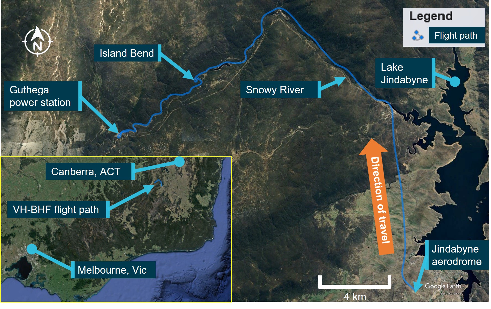
On 11 March 2022, at about 1050 local time, the pilot of a Bell Helicopter Company B206L-1 helicopter, registered VH‑BHF and operated by Heli Surveys Pty Ltd, departed Jindabyne aerodrome, New South Wales, to conduct a low-level English Broom weed[1] survey task on behalf of the New South Wales National Parks and Wildlife Service (NPWS) (Figure 1). On board were the pilot and 4 NPWS officers.[2]
Following departure, the flight tracked north along the western side of Lake Jindabyne and at about 1055, the pilot turned north-west and tracked upstream along the Snowy River before turning south-west towards Island Bend. At about 1102, the helicopter passed overhead Island Bend where a clump of the weed was located. This local infestation provided an opportunity for the NPWS officers to familiarise themselves with spotting the target weed in the local environment, to assist with identification during the survey.
From Island Bend, the flight continued south-west, following the course of the river. At 1110:35, the helicopter approached Guthega (Munyang) hydro‑electric power station where the pilot commenced a left turn, to pass to the east of the power station.
Figure 1: VH-BHF flight path from Jindabyne aerodrome to Guthega power station with inset showing location relative to capital cities
Source: Google Earth and TracPlus data, annotated by the ATSB
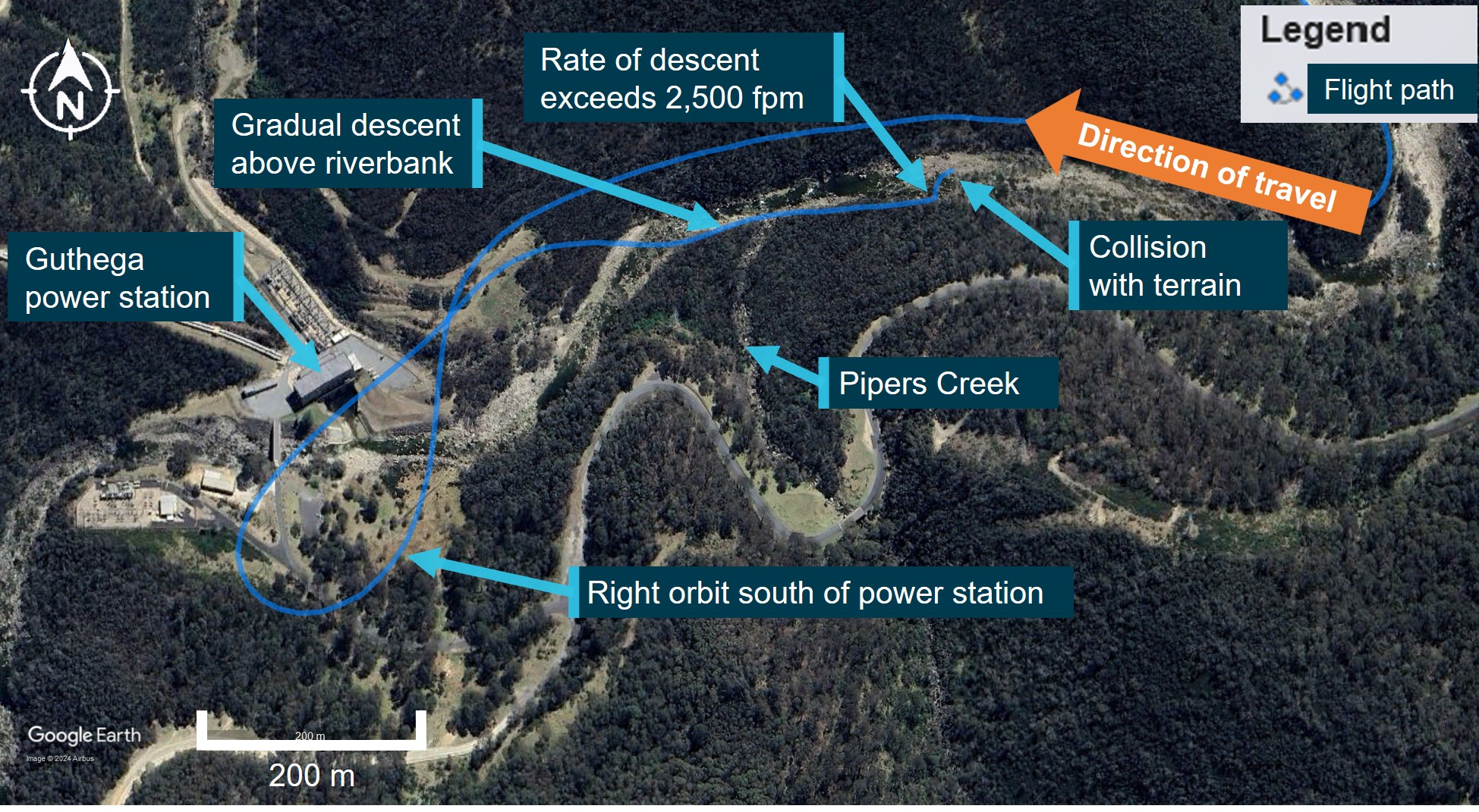
At 1110:47, and now south of the power station, the pilot commenced a right, high orbit to remain clear of power lines in the area and return towards the river course.
By 1111:17, the helicopter was heading downstream above the southern riverbank and established in a descent towards the river in preparation for commencing the weed survey (Figure 2).
Corroborating reports from the occupants of the helicopter, which included the pilot, indicated that due to the seating position of the NPWS officers (3 seated on the left side of the helicopter), the later part of the descent was conducted with the nose of the helicopter yawed to the right about 45°. The right yaw was in response to the officers’ request to provide the best view of the riverbanks for them to identify and map the locations of the English Broom weed. The officers reported that they asked the pilot to fly lower and sideways to enhance their view. The pilot reported to the ATSB that, prior to setting up the right yaw position, the helicopter’s speed was about 30 kt and they noted they had sufficient power with no abnormal engine indications.
As the helicopter descended past Pipers Creek, the pilot reported that their vision of trees and other obstacles was obscured by the helicopter’s instrument console. To improve their vision for the final descent to the river, the pilot indicated that they ‘touched’ the left anti-torque pedal[3] to straighten the helicopter ‘a bit’, upon which the helicopter started an uncommanded yaw[4] to the right.
In interview with the ATSB, the pilot stated that they believed they had full and free movement of the anti-torque pedals until the uncommanded yaw to the right started. After the yaw started, they felt that the helicopter did not respond to their pedal inputs, but they could not recall exactly what inputs they made. The pilot did not recollect any shock loading of the tail rotor, such as from a bird or tree strike. The officers reported that, when the uncommanded right yaw started, they thought it was a pilot‑initiated turn and that they were clear of trees and there were no physical knocks or signs of a failure before the yaw commenced.
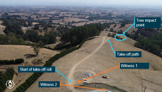
After the first turn, when the helicopter was facing downstream, the pilot attempted to gain forward speed, but the helicopter continued to yaw right, and the yaw rate started to accelerate. At 1111:58, when about 200 m past Pipers Creek, the pilot reported realising their only landing option was in the river and, to do so, they rolled the throttle to idle, which stopped the yawing motion. The helicopter entered an autorotation[5] with the pilot aiming for a spot in the river. The pilot attempted to cushion the landing but did not see a large boulder in the water at their aim point.
At 1112:04, the helicopter collided with terrain. Three occupants received serious injuries, and 2 sustained minor injuries. The helicopter was destroyed.
Figure 2: Approach to Guthega power station, orbit to the south, descent and collision with terrain
Source: Google Earth and TracPlus data, annotated by the ATSB
At the time of the accident, the operator had another helicopter in the local area conducting sling‑work operations. At around 1130, the pilot of that helicopter, who was also the head of flying operations, received a report[6] of an alert notification from the emergency locator transmitter on VH‑BHF, and a subsequent report of a personal locator beacon activation. Aided by their onboard resources, the pilot identified the last recorded position of VH-BHF that was transmitted by its satellite‑based tracking system (TracPlus) and immediately ceased the sling-work operation and departed for that recorded position. While enroute, the pilot notified emergency services and directed their ground‑based resources in the local area to the expected helicopter location.
The pilot located VH-BHF at about 1138 and confirmed the accurate position with emergency services. While surveying the scene from overhead, they were joined by another of the operator’s helicopters, and that pilot was able to unload an air crew person at the accident site. The air crew person was equipped with a first aid kit and provided a communications link between the ground and the overhead helicopters. At about 1210, the operator’s ground-based staff arrived to provide assistance and reported that emergency services had started to arrive. Following initial treatment, 3 of the injured persons were airlifted to hospital while the remaining 2 were able to walk from the site to awaiting ambulances.
Context
Personnel information
Pilot
Qualifications and experience
The pilot held a valid class 1 aviation medical certificate and a Commercial Pilot’s Licence (Helicopter) with single‑engine helicopter and low‑level rating, and a gas turbine endorsement. The operator’s pilot record sheet, dated 2 November 2021, indicated the pilot had accrued 900 hours turbine experience from a total of 2,065 flying hours experience. The pilot had also logged 530 hours aerial work and low flying, and 20 hours mountain flying. In the 28 days prior to the accident, the pilot had accrued 47.1 hours flight time, and 98.7 hours in the previous 90 days. In total, the pilot had 145 hours experience on the Bell 206L-1 helicopter, which included 9.3 hours in the previous 90 days.
Operator training
The pilot joined the operator, Heli Surveys, in early November 2021. On 21, 22 and 23 October 2021 they completed 6 pre-employment check flights on the AS350 helicopter with a contracted training and checking organisation. The syllabus for the checks included low flying within the normal procedures and tail rotor malfunction, autorotation, fire, jammed controls and system failures within the emergency procedures.
The pilot reported that a loss of tail rotor effectiveness (LTE) (refer to section titled Loss of tail rotor effectiveness) would have been covered in their training history at some stage but could not recall any specific occasion, and that they had never experienced it before in flight. The operator’s head of flying operations (HOFO) reported that they conducted a flight with the pilot before they were released to line and was impressed with their attention and focus on control of the helicopter during take-off and landing. The HOFO did not specifically discuss LTE during their flight with the pilot but did discuss mountain and survey operations. They further reported that they considered LTE a component of the low-level flying conducted in the pilot’s pre‑employment check flights.
National Parks and Wildlife Service officers
The National Parks and Wildlife Service (NPWS) team on board consisted of:
A task coordinator who had the lead role in terms of liaising with the pilot and the other officers and was logging the location of the English Broom weed on a hand-held electronic device.
Two officers designated as primary observers (spotters). Their role was to look for the weed, and when a plant was identified, advise the coordinator. One of these observers was logging the position of the weed on a hand-held electronic device.
Another NPWS officer had joined the group given their employment as the area ranger. The survey task had provided the opportunity for the officer to familiarise themselves with the area from the air and observe the conduct of the weed survey task. While the officer did not have a specific function to perform for the survey, they assisted the team in locating the English Broom weed.
Helicopter information
General
VH-BHF was a Bell Helicopter Company B206L-1 powered by a Rolls-Royce model 250‑C30P gas turbine engine driving a 2‑blade main and tail rotor system. It was manufactured in the United States in 1979 and assigned serial number 45164. The helicopter was issued with an Australian Certificate of Airworthiness on 7 April 1987 and first registered in Australia on the same date. Including the pilot, the helicopter provided seating for 7 occupants. At the time of the accident, the helicopter had accumulated about 11,849 hours, total time in service.
Recent maintenance history
At the last 100-hour periodic inspection on 27 November 2021, a maintenance release was issued, permitting night visual flight rules[7] operations. The maintenance release showed that an engine hot start defect had been recorded in December 2021. Rectifications for that included the replacement of the engine turbine assembly, and post‑repair power assurance checks that were certified as completed on 14 February 2022, deeming the engine serviceable. The maintenance release also showed that:
other than items that would be addressed during a daily inspection, no maintenance was due
there were no defects that required rectification before the next flight
the helicopter had been flown for about 22 hours from when the maintenance release was issued prior to the accident.
Modifications
The helicopter was fitted with Van Horn Aviation 2062200-101/-301 tail rotor blades with a United States Federal Aviation Administration (FAA) approved rotorcraft flight manual supplement (206L1‑FMS‑901). The supplement stated that the tail rotor blade design increased the stall margin, thereby improving high altitude performance:
Satisfactory stability and control has been demonstrated in relative winds of 30 MPH (26 knots) sideward and rearward at all loading conditions…
The helicopter was also fitted with main rotor yoke part number 206-011-149-101 allowing flight operations up to a gross weight limit of 1,882 kg (4,150 lb), up from 1,837 kg (4,050 lb) as stated on the type certificate data sheet.
Weight and balance
The ATSB completed weight and balance calculations for the helicopter, considering the pilot and 4 NPWS officers on board. Including fuel, baggage and cargo, the helicopter all‑up weight at take‑off was determined to be about 1,842 kg, 40 kg below its gross weight limit of 1,882 kg, and within its centre of gravity limits. Accounting for fuel burn-off, the helicopter’s all-up weight at the time of the accident was about 1,799 kg, 83 kg below its gross weight limit.
Meteorological information
The Bureau of Meteorology grid point wind and temperature forecast (relevant to the accident) for 1100 on 11 March 2022 was 5 kt of wind from the west (280°) and a temperature of 8°C at 5,000 ft. The graphical area forecast, valid from 1000, was for visibility greater than 10 km with scattered[8] stratus cloud between 2,000 ft and 3,500 ft until 1100.
The nearest aerodrome with an automatic weather information service was Cooma, New South Wales, located 50 km east of the accident site at an elevation of 3,106 ft. The recorded conditions at Cooma at 1100 were a wind of 9 kt from 030°, visibility greater than 10 km, no cloud detected, a temperature of 13°C and QNH[9] at 1021.
The pilot reported fine weather conditions with light winds from the south-west of no more than 5 kt when in the vicinity of the power station, dropping to nearly nil wind conditions once below treetop height on descent towards the river. The NPWS officers reported that the weather was calm. One of the first responders provided a similar report of light and variable winds, as they noted that the wind conditions allowed each rescue helicopter to assume a different heading while hovering as the injured persons were winched on board.
A similar report regarding local weather conditions was received from the operator who maintained an airborne presence during the initial discovery of the wreckage and throughout the rescue operation. They described the conditions on the day as very good with visibility greater than 10 km and wind speed predominantly below 5 kt. They added that there was a very light wind flowing in the downstream direction of the river at the accident site.
Recorded data
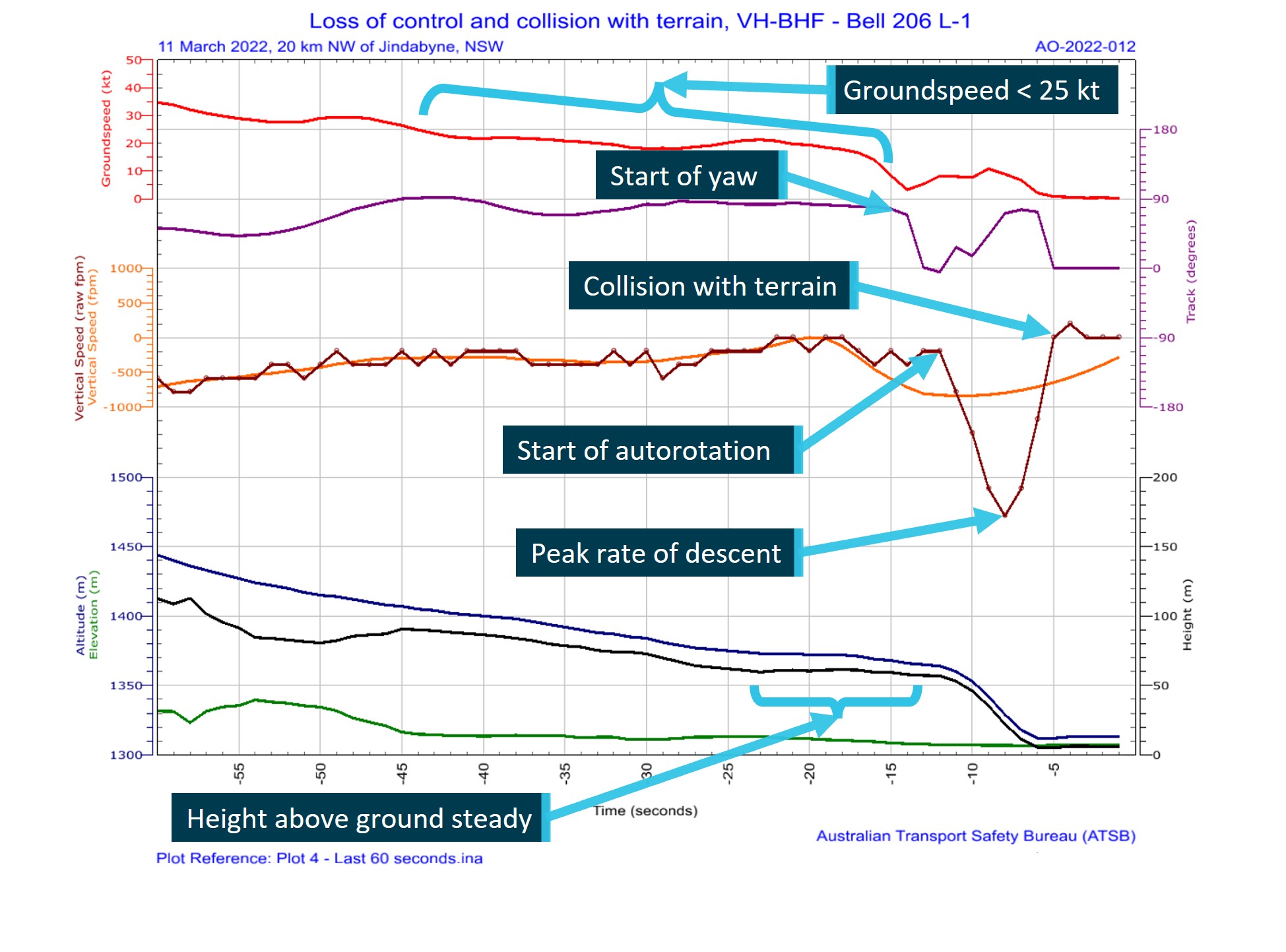
A TracPlus™ RockAIR tracking device was recovered from the helicopter following the accident. The device recorded global positioning system tracking information at a frequency of 1 Hz on a removable micro-SD card. ATSB analysis of the recorded data for the last 60 seconds of the flight is shown in Figure 3 for illustrative purposes.
For a period of about 32 seconds before the helicopter started to yaw, the recorded data indicated that its groundspeed was below 25 kt and further decreased below 20 kt about 5 seconds before the yaw began. About 3 seconds after the yaw commenced, and from a height of about 200 ft above ground level, the helicopter’s rate of descent (vertical speed) increased and reached a peak of about 2,500 ft/min, consistent with the pilot rolling off the throttle and entering an autorotational descent. The data indicated that the yaw lasted for about 5 seconds and was arrested within about 3 seconds of the start of the descent. When the yaw stopped, the helicopter’s height was about 65–100 ft above ground level.
Figure 3: Ground positioning system flight tracking data over the last 60 seconds of recording
Graphical representation of flight data showing helicopter forward and vertical speeds, altitude, height above terrain and helicopter track with descriptive comments added. Source: TracPlus data, accessed and annotated by the ATSB
Wreckage and impact information
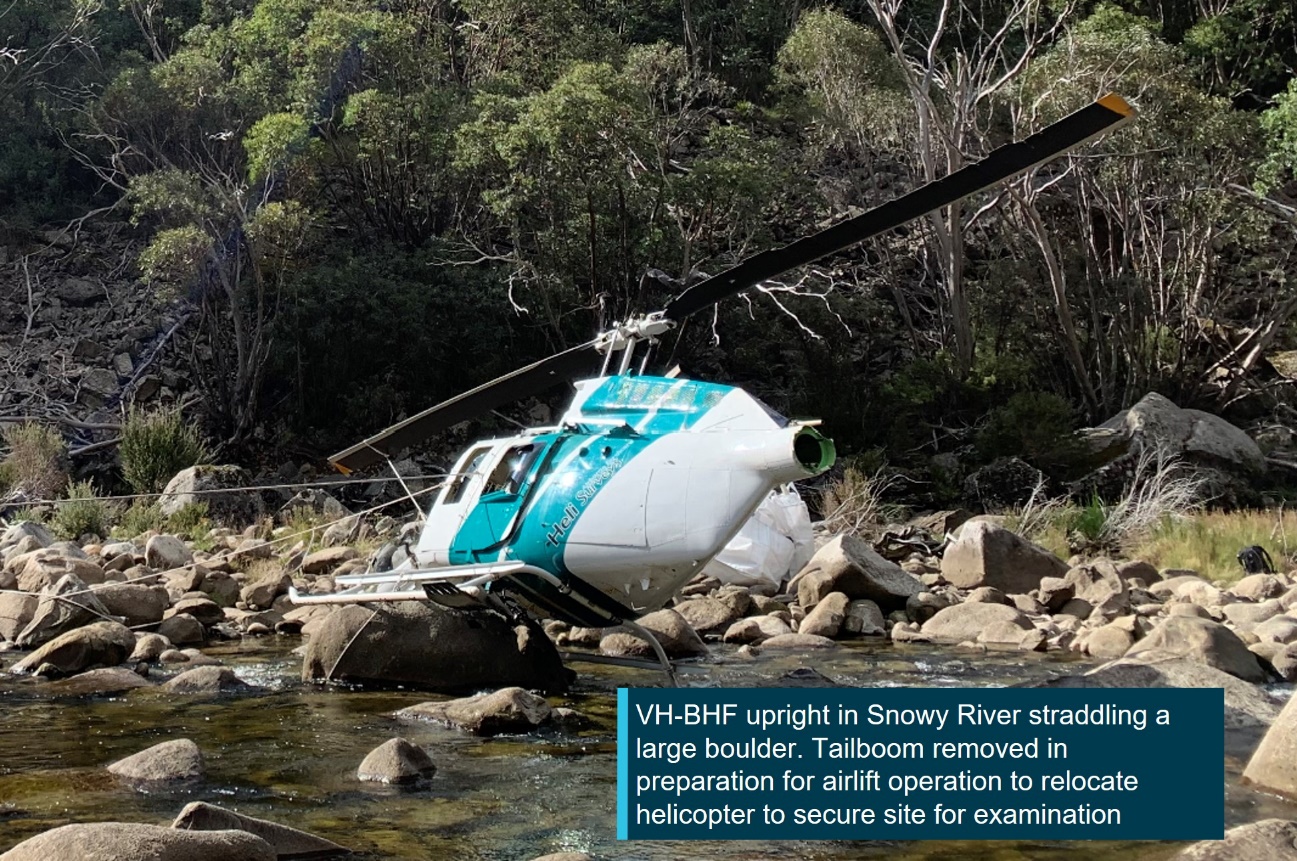
The accident site was located less than 600 m downstream from the Guthega power station (Figure 2) and 20 km north-west of Jindabyne, New South Wales. The helicopter landed on top of a large boulder in the shallows of the Snowy River and came to rest on a heading of 310°, with the fuselage canted significantly to the right (Figure 4).
The helicopter struck the boulder at a point forward of the external cargo hook fuselage mount and slightly aft of the forward skid gear cross tube. The impact with the boulder structurally damaged the helicopter, breaking the forward cockpit section from the cabin area, and resulted in the tailboom partially fracturing near its fuselage attachment point.
The tailboom fracturing and subsequent deflection likely resulted in a tail rotor ground strike and loss of a portion of a tail rotor blade, which was not recovered from the site. Apart from the missing section of tail rotor blade, the rest of the helicopter was present at the accident site. No evidence of a bird or in-flight tail rotor strike was identified and there was no post‑impact fire.
The location of the helicopter in the riverbed and the surrounding environment precluded a complete examination of the wreckage at the accident site. The operator reported receiving advice that anticipated water inflows at Guthega Dam would result in increased water levels downstream of the dam from water exiting the uncontrolled spillway. In response, the wreckage was removed from the accident site at the earliest opportunity, airlifted from the riverbed and relocated to a secure site in Cooma for detailed examination.
Figure 4: VH-BHF following collision with terrain against large boulder in the Snowy River, New South Wales
Source: ATSB
The ATSB’s site examination did not reveal any pre-existing defects that may have affected the operation of the helicopter or its systems. The detailed examination of the flight control systems in Cooma did not identify any pre-existing defects that may have affected the control of the helicopter.
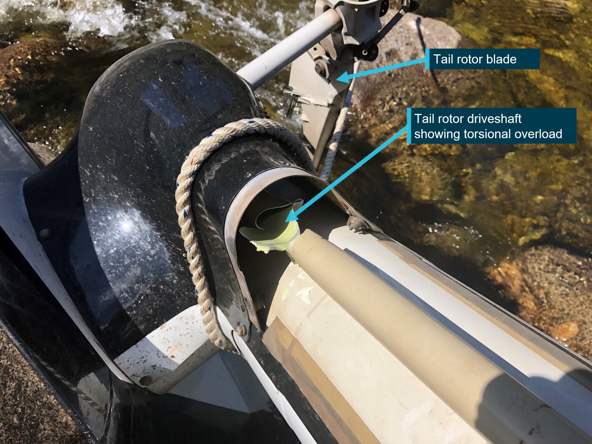
Where evidence of structural fractures and breaks were identified, the failures were found to be fresh and were attributed to being either collision‑related, or as the result of torsional overload forces. Of note was the torsional overload of the tail rotor driveshaft at the tail rotor gear box location. This indicated that the driveshaft was driving the tail rotor when the tail rotor experienced a sudden stoppage (Figure 5).
The engine presented as intact, securely mounted, and with controls functional but with restricted movement due to fuselage damage. The compressor and turbine were found to spin freely. No defects were identified with the supply, delivery and quality of the fuel that was available to the engine.
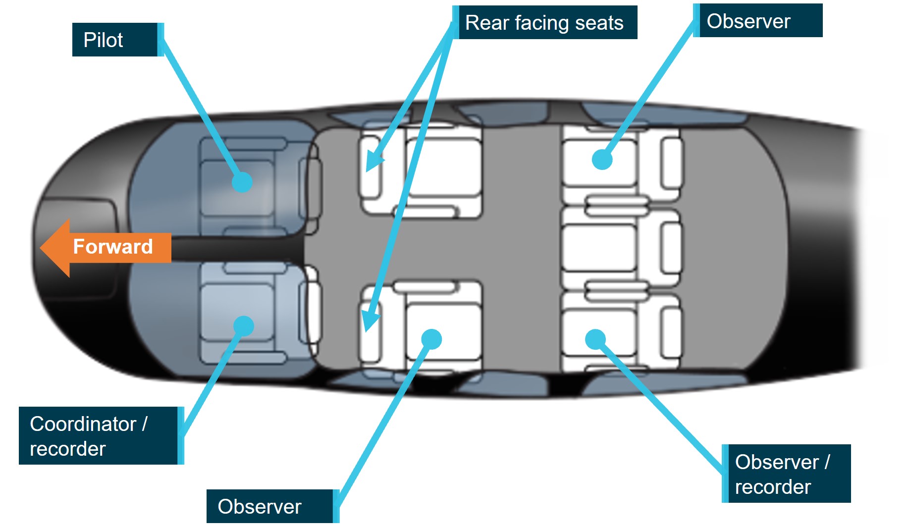
The seating configuration of the helicopter consisted of 2 cockpit seats and, in the cabin section, a centre row of 2 aft-facing seats and a rear row of 3 forward‑facing seats. For the accident flight, the pilot was in the front right seat with an NPWS officer (coordinator/recorder) in the front left seat, another officer (area ranger – observer) in the centre row left seat (facing rearwards), and the 2 remaining officers in the left (observer/recorder) and right (observer) seats of the rear row (Figure 6). Each seat was equipped with a 4-point restraint harness.
Figure 6: VH-BHF cockpit and cabin seating layout and NPWS officers’ functional positions
Bell 206 LongRanger III seating layout adopted for illustrative purposes only. Source: FlyFlapper.com annotated by the ATSB
Injuries
The pilot, task coordinator, and observer in the rear‑facing cabin seat sustained serious injuries. The 2 observers in the rear row received minor injuries.
Evacuation
While airborne above the accident site, the HOFO reported they contacted the power station and advised them of the accident downstream of their location and for consideration of the possible impact on power generation commitments. They were advised that power generation would be postponed, however, water levels downstream of Guthega Dam were dependent on natural inflows and outflows from the dam.
At interview, 2 of the NPWS officers advised that they were aware that the water level would likely rise in response to power generation activity. As a precaution, after assisting the injured with evacuating from the helicopter, they were immediately moved to higher ground.
Survival equipment
The NPWS aviation standard operating procedure for low-level flying specified that, when engaged in such activities, helicopters were to carry an emergency locator transmitter (ELT) and be fitted with a tracking system that could be tracked by the agency. As such, the helicopter was equipped with an ELT, and a survival pack that included a personal locator beacon (PLB), a first aid kit and a satellite phone. A TracPlus RockAIR device was also mounted on the instrument console, which provided real-time location tracking of the helicopter through GPS technology. The tracking device was designed to transmit an alert if a sudden impact of 16g or more for a period greater than 10 milliseconds was detected.
ELT and PLB emergency radio beacons are used to provide a location fix on a person, aircraft or other vehicle (ATSB, 2013). ELTs are usually fixed in an aircraft and are designed to activate automatically during an impact, typically by a g-force[10] activated switch but can also be wired to be manually activated by a cockpit-located switch usually mounted within reach of the pilot or a front‑seat passenger. PLBs are designed for personal use and may be carried on the person or carried as part of a survival kit. They are manually activated and may be used as an alternative to a fixed ELT, provided certain requirements are met.
In the event of an accident followed by beacon activation, the aircraft wreckage and its occupants can be located quickly by search and rescue authorities. Finding the aircraft wreckage quickly not only increases the chance of survival of the occupants but also reduces the risk to pilots of search and rescue aircraft who commonly need to operate in marginal weather conditions and over mountainous terrain (ATSB, 2013).
The collision resulted in both the ELT and tracking device activating. The collision alerts were received by the operator (HOFO) and were followed by a third report of a PLB that was manually activated by one of the NPWS officers. This allowed the HOFO to promptly identify the last known position of VH-BHF and commence an emergency response. The operator reported that the multiple transmissions from independent sources provided the surety that a distress situation existed.
Operational information
Helicopter performance
The out-of-ground effect performance chart in the B206L-1 rotorcraft flight manual indicated the helicopter had the performance required to hover out-of-ground effect at the elevation and temperature conditions for the accident. The accident site was located at an altitude of 4,308 ft. Accounting for temperature and QNH, the density altitude for the flight just prior to the accident was calculated to be about 4,500 ft.
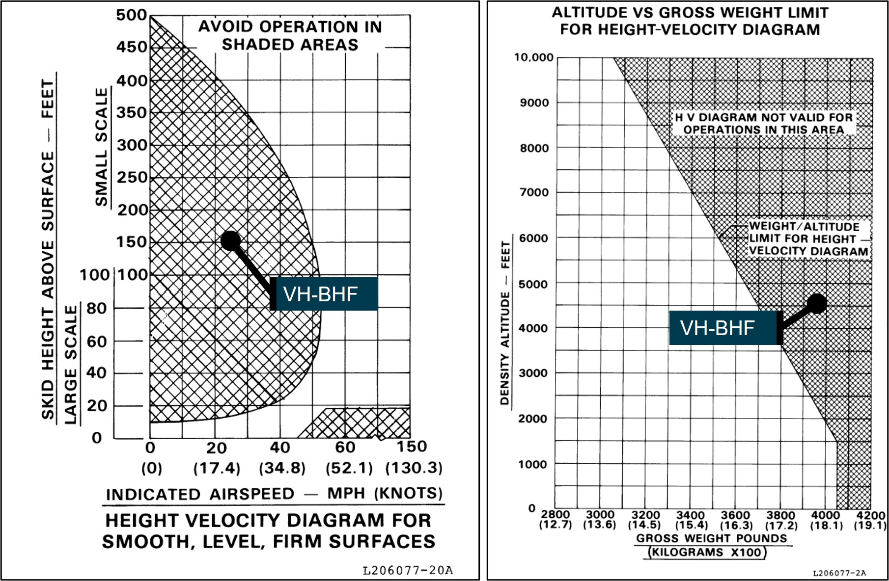
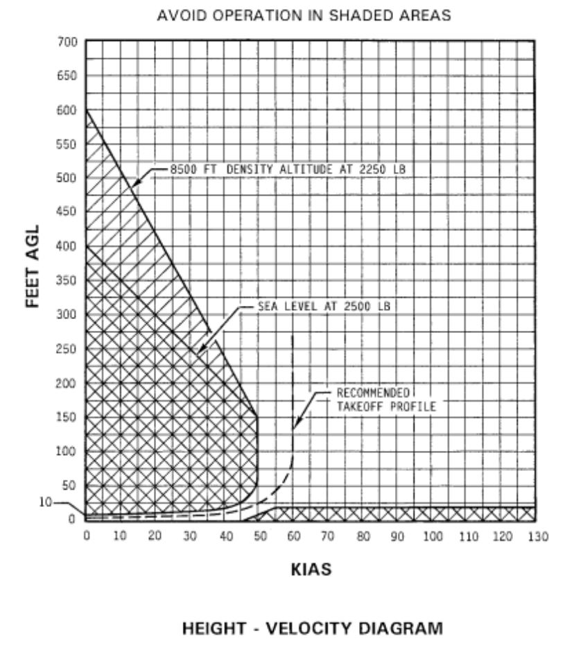
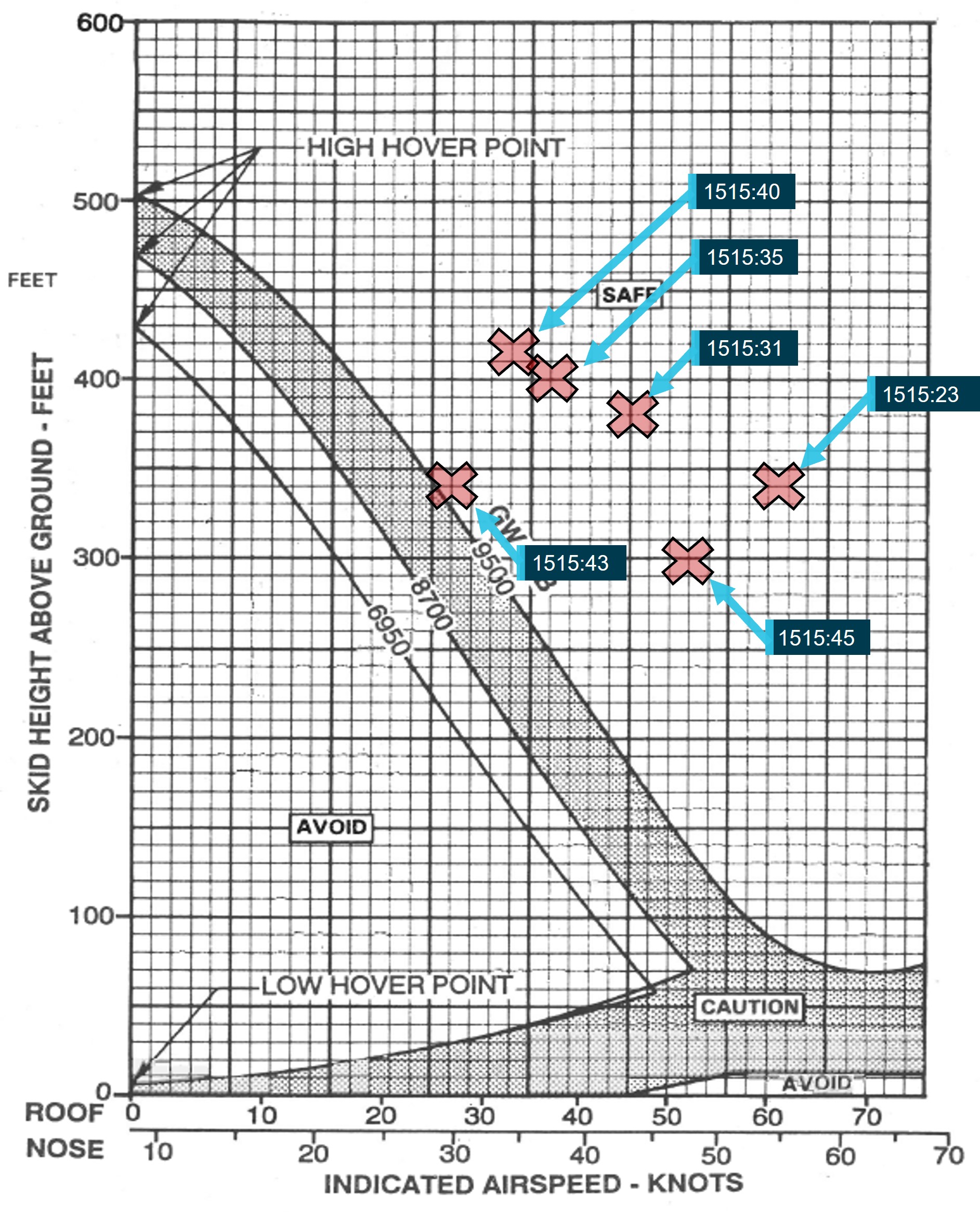
The recorded data for the flight indicated that the groundspeed had dropped below 20 kt before the loss of control, and accounting for density altitude influence, this equated to a calibrated[11] airspeed of about 1–2 kt below the groundspeed in nil wind. The height and airspeed of the helicopter at this time placed it inside the avoid area of the height-velocity diagram[12] (Figure 7 – left). The helicopter’s weight and density altitude also placed the operation outside of the weight-altitude limit for the height-velocity diagram (Figure 7 – right).
Consequently, the helicopter was operating in a region of the flight envelope where there was no assurance that a safe autorotation could be made without damage and injuries to occupants. At interview, the operator advised that flight operations in the avoid area was common practice, and necessary to effectively and accurately conduct a weed survey task.
Figure 7: B206L-1 flight manual performance charts showing operational caution zones and VH-BHF relative position in preparation for survey task
Source: Bell Helicopter Company, annotated by the ATSB
Aerial work operations
Heli Surveys
Heli Surveys Pty Ltd was approved by the Civil Aviation Safety Authority (CASA) to conduct various flight operations including Civil Aviation Safety Regulation (CASR) Part 138 aerial work operations. Its aerial work operations were varied and included roles associated with feral animal control and survey flights of pest animals, weeds and power lines.
Part 138 aerial work operations
CASR Part 138 and the Part 138 (Aerial Work Operations) Manual of Standards (MOS) addressed the certification, operational and safety risk management requirements for operators engaged in aerial work operations (CASA, 2021e). At the time of the accident, aerial work encompassed the core activities of external load operations, dispensing operations or task specialist operations.[13] Advisory circular AC 138-01 v1.0 Part 138 core concepts defined task specialist operations as:
carrying out a specialised activity using an aircraft in flight and includes training for such an activity. An example of a task specialist operation is a low level weed survey or pipeline inspection.
Additional guidance for aerial work operations applicable at the time of the accident was provided in advisory circular AC 138-05 v1.1 Aerial work risk management (July 2021b) and the Part 138 Acceptable means of compliance and guidance material – Aerial work operations v2.2 (December 2021f).
Conducting the survey flight
At interview, the HOFO described the accident task as an ad hoc type survey in which the helicopter would be flown up-valley and then down-valley to view both sides of the river and that the airspeed, direction and height was not prescribed. The HOFO expressed the view that the optimum profile for survey flights was a height of 300 ft and airspeed of 55 kt. However, if adopting that profile, it would make it impractical to identify English Broom weed in surveys of the Snowy River.
The HOFO reported that, from experience, they did not consider that it was unusual when the client presented with 4 NPWS officers for the conduct of the survey flight. In terms of managing client requests, all pilots are provided with a ‘stop work authority’ and can therefore decline a client request if they perceive a safety of flight issue.
The NPWS officers indicated that, on the morning of the accident flight, they discussed their English Broom weed survey plan while waiting for the pilot and helicopter to return from a prior task. After the pilot arrived, they completed the operator’s online induction and a safety brief with the pilot and then briefed the pilot on their plan for the weed survey.
None of the officers had previously met the pilot who they understood was new to the company and had not previously done the English Broom weed survey task with them. They reported that the pilot was operating in a cautious manner and appeared to be safety‑conscious, advising them all to speak-up if they identified any hazards during the flight. On departure, the pilot made a radio call to their NPWS contact for flight‑following purposes, and they conducted a hazard identification for wires during the flight upstream to the Guthega Power Station.
Persons permitted on board during aerial work operations
For aerial work operations conducted under Part 138, CASA advisory circular 138-01 specified that persons who were permitted on board must be categorised as either:
crew members (including flight crew, air crew and task specialists)
passengers that meet the requirement to be aerial work passengers.
The advisory circular further defined an air crew member, task specialist and aerial work passenger as:
Air crew member
An air crew member…includes crew members who carry out a function during the flight relating to the safety of the aircraft.
Task specialist
A task specialist … includes crew members who carry out a function for the flight relating to the aerial work operation (as distinct from a safety related role).
Examples of a task specialist would include a camera operator that operates an external camera pod, or an aerial shooter used in an animal culling operation.
A task specialist will require training to be inducted into the operation and to ensure they are competent in carrying out their assigned function as a member of the operator's crew.
Aerial work passenger
…are persons who are closely associated with the purpose of the aerial work operation. Their presence in the aircraft must not be for mere convenience or enjoyment.
Examples of such persons would include: Personnel involved in carrying out or supporting a mustering activity carried on a positioning flight before or after the mustering operation, such as ground based personnel to assist with refuelling or for opening and closing of gates etc. and yarding of stock for the mustering operation…
In most circumstances aerial work passengers do not require training before their carriage on an aerial work operation or a positioning flight, but they will in all cases (except for some notable situations, such as a person being rescued) require a safety briefing prior to the flight...
On the accident day, as the helicopter was being used to conduct a low-level weed survey activity, it met the definition of a task specialist operation. In terms of the roles as defined above, the pilot was the only flight crew member and there were no air crew members. The 3 NPWS officers with the roles of task coordinator and primary observers would be classed as task specialists. While the area ranger assisted with the task, they reported that they were on the flight as an opportunity for familiarisation of the survey area.
Operational hazards
CASA flight crew licencing uses a competency-based training and assessment system for pilots. Various competencies are required to be demonstrated by pilots during both initial and recurrent licence testing. The competencies vary by aircraft type and licence type.
For pilots to achieve their helicopter rating, they are required to demonstrate that they have the skills and underpinning knowledge to manage abnormal and emergency situations in helicopters (CASA, 2021c). The range of situations include, but are not limited to:
key hazards – underpinning knowledge of their causal factors, contributing operational situations, avoidance and recognition of symptoms and recovery techniques that include:
the impact of high gross weight and high-density altitude on key hazards
techniques for how to avoid a potentially hazardous situation whilst in flight.
These competencies were consistent with the list of hazards detailed in the jointly developed CASA and Civil Aviation Authority of New Zealand helicopter flight instructor manual, issue 3 (CASA, 2012). The instructor manual differentiated hazards from emergencies, which are the technical failures particular to the helicopter model and addressed in the flight manual emergency procedures section.
To be licensed for low-level helicopter operations, pilots must demonstrate skills to safely conduct low‑level operations include managing variable terrain and weather, surface conditions, loose objects and personnel. The required underpinning knowledge related to critical operational conditions that included retreating blade stall,[17] vortex ring state, over pitching and loss of anti‑torque or tail rotor effectiveness (CASA, 2021c).
The ATSB reviewed the emergencies and hazards chapter of the FAA Helicopter Flying Handbook (2019) and found key operational hazards presented were the same as those that CASA required pilots to demonstrate. The FAA handbook provided a thorough description of each of the key hazards, which included techniques for avoidance and recovery. The FAA handbook also reported the following about LTE events:
Certain flight activities lend themselves to being more at high risk to LTE than others. For example, power line and pipeline patrol sectors, low-speed aerial filming/photography as well as in the Police and Helicopter Emergency Medical Services (EMS) environments can find themselves in low and slow situations over geographical areas where the exact wind speed and direction are hard to determine.
Loss of tail rotor effectiveness
Introduction
Loss of tail rotor effectiveness (LTE) or unanticipated yaw is a phenomenon that can occur in single main rotor, tail rotor-equipped helicopters. It is a condition that occurs when the air flow through a tail rotor is changed in some way, by altering the angle or speed at which the air passes through the rotating blades of the tail rotor disc (FAA, 2019). If uncorrected, LTE can result in loss of control of the helicopter and serious to fatal occupant injuries. In 1995, the FAA published advisory circular 90-95 Unanticipated right yaw in helicopters, which described a loss of tail rotor effectiveness as:
…a critical, low-speed aerodynamic flight characteristic which can result in an uncommanded rapid yaw rate which does not subside of its own accord and, if not corrected, can result in the loss of aircraft control.
Any manoeuvre which requires the pilot to operate in a high-power, low-airspeed environment with a left crosswind or tailwind creates an environment where unanticipated right yaw may occur.
LTE is not related to a maintenance malfunction and may occur in varying degrees in all single main rotor helicopters at airspeeds less than 30 knots.
Single-rotor helicopters manufactured in the US, such as the Bell 206, have main rotors that rotate anticlockwise when viewed from above. When powered, their rotation produces a torque reaction or tendency of the helicopter to turn in the opposite direction, which is a right yawing motion from the pilot’s view. The tail rotor thrust provides the anti‑torque control. An effective tail rotor relies on a stable and relatively undisturbed airflow in order to provide a steady and constant anti-torque reaction (FAA, 2019).
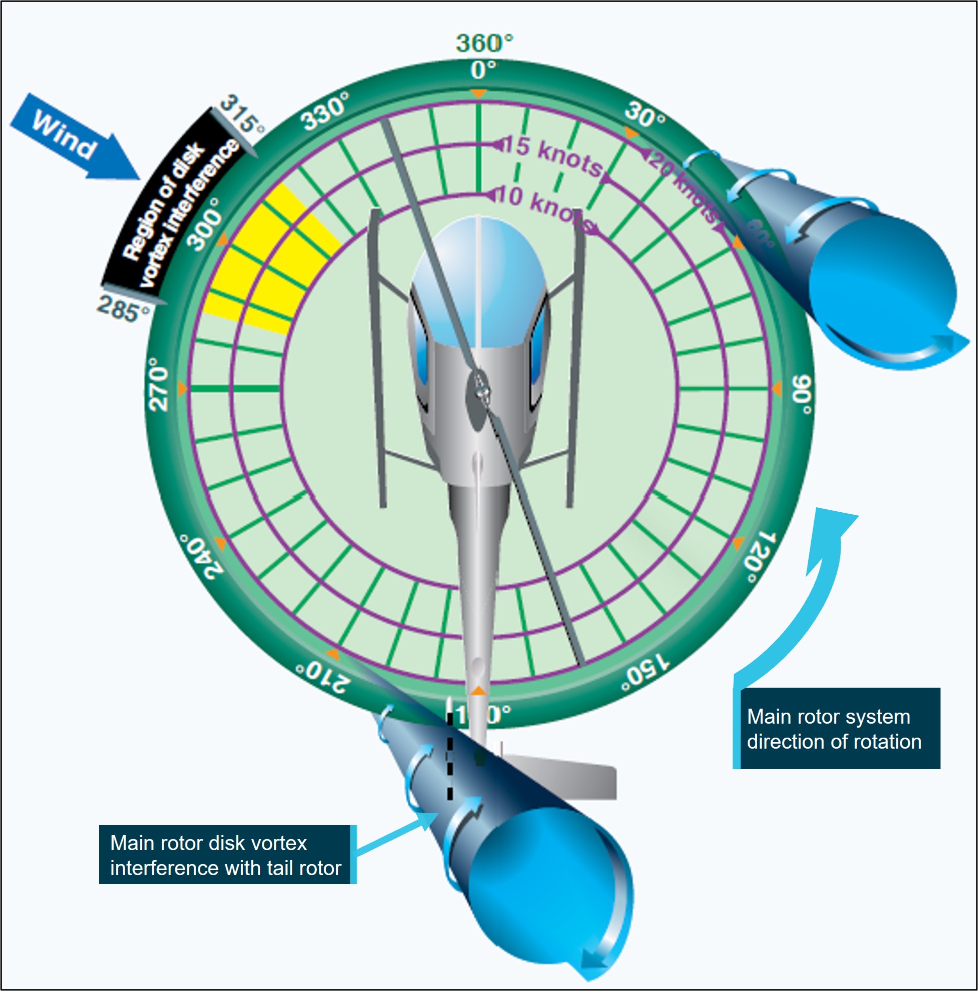
The FAA AC described 3 wind conditions conducive to the onset of LTE. One of these conditions refers to the relative wind[18] azimuth of 285° to 315°, which can produce ‘main rotor disc vortex interference’ with the tail rotor (Figure 8) and is described as:
As the main rotor vortex passes the tail rotor, the tail rotor angle of attack is reduced. The reduction in the angle of attack causes a reduction in thrust and a right yaw acceleration begins. The thrust reduction will occur suddenly and, if uncorrected, will develop into an uncontrollable rapid rotation about the [main rotor] mast.
The relative wind from the critical quadrant may present when the nose of the helicopter is pointing forward (Figure 8), or the condition is generated when the helicopter is flown with the nose sufficiently yawed to the right.
Figure 8: Main rotor disc vortex interference with tail rotor
Source: FAA Helicopter Flying Handbook (FAA, 2019), annotated by the ATSB
Factors affecting loss of tail rotor effectiveness
Other than main rotor blade action affecting the quality of the airflow about the tail rotor disc and impacting its ability to provide useful thrust, additional factors are also considered when discussing LTE. According to the FAA Helicopter Flying Handbook (2019):
The design of main and tail rotor blades and the tailboom assembly can affect the characteristics and susceptibility of LTE but will not nullify the phenomenon entirely.
FAA AC 90-95 also identifies other factors that influence the severity of the onset of LTE including:
Gross Weight and Density Altitude. An increase in either of these factors will decrease the power margin between the maximum power available and the power required to hover. The pilot should conduct low-level, low-airspeed manoeuvres with minimum weight.
Recovery technique
The Bell 206L-1 rotorcraft flight manual revision 14 did not have an emergency procedure for LTE but did have a procedure for a complete loss of thrust under the heading tail rotor control failure, which was a mechanical failure. Following the procedure for a complete loss of thrust, pilots were to reduce the throttle to idle and immediately enter an autorotation while maintaining a minimum airspeed of 52 kt during the descent.
The FAA AC 90-95 recommended recovery technique from LTE was:
a. If a sudden unanticipated right yaw occurs, the pilot should perform the following:
(1) Apply full left pedal. Simultaneously, move cyclic[19] forward to increase speed. If altitude permits, reduce power.
(2) As recovery is effected, adjust controls for normal forward flight.
b. Collective[20] pitch reduction will aid in arresting the yaw rate but may cause an increase in the rate of descent. Any large, rapid increase in collective to prevent ground or obstacle contact may further increase the yaw rate and decrease rotor rpm.
c. The amount of collective reduction should be based on the height above obstructions or surface, gross weight of the aircraft, and the existing atmospheric conditions.
d. If the rotation cannot be stopped and ground contact is imminent, an autorotation may be the best course of action. The pilot should maintain full left pedal until rotation stops, then adjust to maintain heading.
Heli Surveys operations manual
The Heli Surveys Operations Manual volume 10 – Specialist operations, prescribed the operator’s general low flying requirements. Paragraph 0.7.3, under Conduct of flight during low flying stated the following:
Pilots shall be aware of recovery techniques and avoid flight configurations which could include:
• Vortex ring/ settling with power.
• Tail rotor vortex ring or loss of tail rotor effectiveness.
• Downwind operations outside the aircraft performance envelope.
• Loss of close visual cues to indicate actual aircraft relative movement and out of wind operations (particularly over water), leading to possible unanticipated control difficulties.
The operations manual did not include any avoidance or recovery procedures for LTE nor any reference material to address this condition.
Safety risk management
Aerial work risk management
Pre-operational risk assessment
CASR Part 138 required an operator conducting aerial work to undertake risk assessments of its operations. The Part 138 MOS and corresponding advisory circular (AC 138-05 v1.1) detailed a layered approach to risk assessments. One of the key requirements was that an operator should undertake an overarching assessment (pre‑operational risk assessment) to consider and evaluate the risks associated with its proposed operations, in this case, low-level helicopter survey. This assessment recognised the underlying principles of CASR Part 138, where the risks and hazards associated with a type of aerial work operation are common to that type of operation. The MOS indicated that the matters to be considered for such an assessment included:
• the operation and its particular characteristics
• the location of the operation and its particular characteristics
• the aircraft to be used in the operation, its particular characteristics, and its performance
• the qualifications and experience of the crew members to be used in the operation
• the hazards, external to the aircraft, that may be met in the course of the operation.
The operator is required to gather data for inclusion in the pre-operational risk assessment using a range of sources. Acknowledging that certain risk factors may be common to all operators, may be particular to the aircraft type operated or may be unique to the operator; potential sources include, but are not limited to (CASA, 2021b):
CASA ‘sector risk profiles’ for the varying types of operations
ATSB incident and accident reports
industry association safety reports
manufacturers' safety bulletins and advisory notices
input from experienced pilots and other operators.
Once the pre-operational risk assessment has been populated, it should be updated over time to include lessons learnt from previous operations. It should also form part of the operator’s operations manual.
Flight risk management plan
The results of the pre-operational risk assessment were to be considered when preparing the flight risk management plan, which was specific to an individual flight or task within the type of operation. The plan should outline the specific mitigators or risk controls that were to be used during the flights.
Pre-flight risk review
The next step was for the pilot, on behalf of the operator, to conduct a pre-flight risk review, with reference to the pre‑operational risk assessment, flight risk management plan, and the most recent data for the operation. The review was to be completed prior to the commencement of the operation and was to consider the conditions and circumstances that existed at the site or area at the time of the proposed activities. This ensured that the operation could be conducted without unacceptable safety risk.
Operator risk management
As per CASR Part 138, Heli Surveys was required to undertake risk assessment and mitigation processes and include those processes in its suite of operational documents. The Heli Surveys Operations Manual described that the operator would address its risk management obligations via the use of Safe Work Method Statements (SWMS).
The Heli Surveys Safety Management Systems Manual further detailed how risk was identified, controlled and documented. Their safety risk management process started with hazard identification, which included internal sources and external sources. A hazard was defined in their SWMS as ‘what could result in harm’ and was used to describe both the hazard and associated risk.
Internal sources for hazard identification included, but were not limited to:
safety assessments of systems and operations
voluntary and mandatory safety reports
inspections and audits.
Its list of external sources included, but was not limited to:
accident and incident reports
safety information bulletins, safety alerts and other safety publications from CASA, Airservices Australia, the ATSB and other authorities worldwide.
The operator had prepared SWMSs to comply with the CASR Part 138 requirements which was equivalent to a pre-operational risk assessment. As the accident flight was a low‑level survey operation in the Snowy Mountains, the 2 SWMS relevant to the flight were Low level surveys and aerial photography (henceforth referred to as Low-level surveys) and Alpine operations.
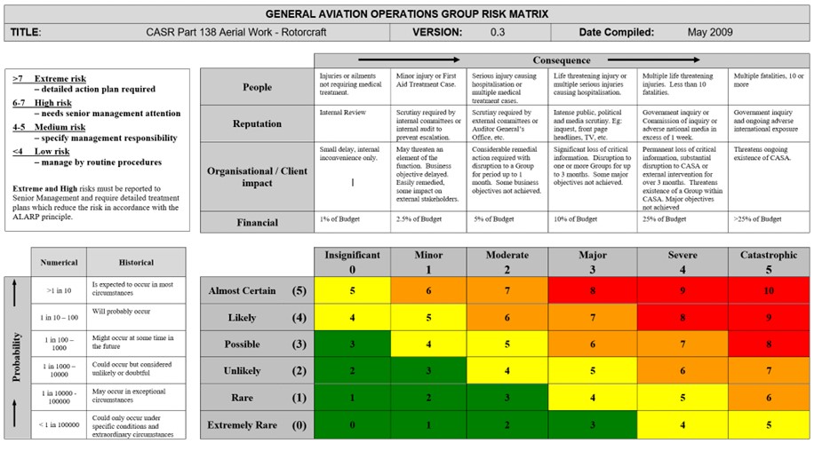
The SWMS documents provided the means to record the specific tasking event, the equipment and approvals that were relevant, and any specific checks or personal protective equipment required to perform the task. A risk matrix was also included. The risk matrix described the likelihood and consequence of each identified hazard and provided the means to assess the initial and residual risk level following the implementation of suitable risk controls.
The ATSB reviewed the SWMSs that were developed by the operator. A summary of the internal and external hazards that were identified by the operator are below (Table 1).
Table 1: Summary of hazards related to Safe Work Method Statements for low-level survey tasking and alpine operations
Low-level survey hazards
Alpine operations hazards
intercom failure
adverse weather events
high communication workload/distraction
inadvertent flight into instrument meteorological conditions
loose articles exiting aircraft
collision with powerlines/aerials
collision with objects while airborne
heavy landing – exceeding power requirements
inadvertent flight into instrument meteorological conditions
exposure – inappropriate dress for conditions
restraint harness issues
aircraft door issue
turbulence/windshear
The heavy landing hazard associated with the alpine operations SWMS was assessed by the ATSB to be related to the CASA flight crew licensing competency requirement to manage the hazard associated with overpitching. The SWMS provided some control measures, such as a power check, landing into wind and monitoring environmental conditions between a landing and take-off.
With the exception of the relationship between overpitching and the operator’s heavy landing hazard in its alpine operations SWMS, the ATSB did not find references to hazards associated with abnormal situations and emergencies specific to the operator’s unique activities in its SWMS. Of note, there was no reference to LTE and vortex ring state, and the impact of flight regimes and operations at high gross weights and density altitudes that may affect such hazards.
The operator reported that pilots were required to have read and understood the suite of SWMS documents, which were provided during their induction process and at scheduled intervals thereafter. However, there was no requirement for pilots to conduct a pre-flight risk review for low-level survey operations and reference the relevant SWMS when conducting pre-flight tasks in preparation for the activity. As such, the pilot had not conducted a review prior to the accident flight.
Client risk management
The NPWS (the client) had contracted Heli Surveys to conduct the weed survey operation. Its Aviation Safety Policy and related documents were provided to the ATSB. The policy identified a range of aviation operations that utilised rotary wing aircraft.
The policy adopted a risk management approach to aviation operations and safety. Key elements of the policy were the development and observance of aviation‑related standard operating procedures and the use of a job safety analysis (JSA).[21] The JSA assessed the risks associated with each task, which was equivalent to a flight risk management plan.
Regarding vegetation‑related activities that necessitated low-level flight operations, the NPWS provided several task-related JSA documents that identified specific hazards. The documents also detailed the control measures to be implemented to manage the associated risks. The JSA documents that were provided related to low-level flying in general, low-level flying when undertaking Scotch (English) Broom survey and aerial application (spraying) activities.
When engaging in those activities, a key control measure specified in the JSA advised that only ‘essential personnel’ were to be on board the operating helicopter. The NPWS reported that the suite of documents supporting aviation operations did not provide a definition of essential personnel nor was there a procedure on record that detailed the roles and responsibilities of NPWS personnel reflected in the JSA control measure.
Related occurrences
Loss of tail rotor effectiveness
Between 2013 and 2022, the ATSB received 16 notifications where the reporter advised of an LTE or unanticipated yaw event. Of the 16 notifications, 12 were investigated by the ATSB. Most of these resulted in nil to minor injuries to those involved and one serious injury and one fatality. Some of these investigations are described below.
On 19 January 2013, a Bell 206B3 helicopter was being operated on an aerial filming task over hilly terrain on the north-eastern outskirts of Perth, Western Australia. After hovering and manoeuvring at about 500 ft above ground level to allow the camera operator to record footage of a truck accident, the pilot conducted a right orbit to complete filming and depart the area. The pilot had initiated the turn when the nose of the helicopter moved left, then suddenly and rapidly to the right as the helicopter yawed and developed a rotation of about 5 revolutions.
The ATSB found that, when the pilot turned to the right to commence the orbit, the helicopter was exposed to a crosswind from the left while at an airspeed around the 30 kt threshold value for susceptibility to LTE, precipitating an unanticipated right yaw and temporary loss of control. The pilot regained sufficient control for a forced landing.
On 20 July 2015, the pilot of a Bell 206L3 (LongRanger) helicopter, registered VH-BLV, conducted a charter flight from Essendon Airport to Falls Creek, Victoria, with 5 passengers on board. The helicopter took off from Essendon close to its maximum take‑off weight.
When at 700 ft above ground level and tracking from the north-west, the pilot conducted a shallow approach towards the helipad at Falls Creek. As the helicopter descended to about 50 ft above ground level, the pilot found that significantly more power was required to conduct the approach than anticipated. The pilot assessed that there was insufficient power available to continue to land and elected to abort the approach. The pilot pushed forward on the cyclic to increase the helicopter’s airspeed and conducted a left turn.
As the helicopter turned left, it started to yaw rapidly towards the right. The pilot applied full left anti-torque pedal to counteract the yaw, but the helicopter continued to yaw. The helicopter turned through one and a half revolutions, as the pilot lowered the collective. Lowering the collective reduced the power demand of the power rotor system, thereby increasing the ability of the anti‑torque pedals to stop the right yaw. The combination of lowering collective and applying forward cyclic to gain forward airspeed, allowed the pilot to regain control of the helicopter. The pilot then conducted a left turn towards the helipad and made an approach to the helipad from an easterly direction. The helicopter landed following the second approach without further incident.
The ATSB’s report highlighted the importance for pilots to understand and avoid conditions that are conducive to unanticipated yaw or LTE and noted that pilots can reduce their exposure to LTE by maintaining awareness of the wind and its effect on the helicopter. Further, if a pilot encounters unanticipated yaw, quick application of the correct response is essential to recover control of the helicopter.
On 28 January 2019, the crew of a Sikorsky S-64E Skycrane helicopter was conducting firebombing activities when it collided with water at Woods Creek Dam, Victoria. The collision occurred following an approach to the dam to fill an external tank with water. The helicopter was crewed by 2 pilots, and a maintenance crew chief was also on board. Following the collision, all the occupants were able to exit the helicopter and swim to shore. One crewmember was seriously injured and 2 were uninjured. The helicopter was substantially damaged.
The ATSB found that the helicopter was placed in a steep flare, which contributed to the helicopter entering vortex ring state when on approach to the dam.
It was also noted that the operator’s operations manual stated that only flight crew and crew essential to the operation could be carried aboard the aircraft during firefighting operations. The operation could be conducted without the crew chief, and not all company crew chiefs were on board their aircraft during firefighting operations. While the crew chief had significant system and task knowledge, they were not required to be on board the helicopter.
On this occasion, their presence on board subjected them to the significant hazards associated with underwater egress. More generally, the carriage of additional personnel during specialised operations like firefighting exposes them to unnecessary risk.
On 21 May 2019, while engaged in a planned cull of feral animals in Kakadu National Park, Northern Territory, a crew of 3 were using a Bell 206B3 JetRanger helicopter for aerial platform shooting. While the helicopter was operating at about 50 ft above the ground, the engine decelerated to idle, resulting in an immediate loss of power, and subsequent collision with terrain. The 3 occupants (pilot, shooter and spotter) were seriously injured.
The investigation identified that it was normal practice across industry that an aerial culling task was performed with just 2 persons on board the helicopter, the pilot and a shooter. Experienced aerial shooters interviewed after the accident expressed a preference for carrying just the pilot and shooter on board to reduce risk to crew, carry more fuel to improve endurance and to complete more work. In 2016, the aerial culling task was redesigned for 3 crew, including a spotter. There was no formal risk analysis of the inclusion of the spotter position, or consideration of the potential benefits of improved data collection when weighed against operational difficulties in recording data, reduced efficiencies in operation, and increased exposure of employees to risk.
The investigation identified that, given the increased complexity and risk in low-level operations, the number of crew should be kept to a minimum. That is, only personnel essential for conducting the task should be carried.
Safety analysis
Introduction
On the morning of 11 March 2022, a Bell B206L-1 helicopter, registered VH-BHF, departed Jindabyne aerodrome, New South Wales, to conduct a weed survey task on behalf of the National Parks and Wildlife Service (NPWS). On board were the pilot and 4 NPWS officers. While descending towards the riverbed in the vicinity of the Guthega power station, the helicopter started an uncommanded yaw to the right. The pilot was able to stop the yaw but was unable to arrest the descent before the helicopter collided with terrain. The helicopter was destroyed. Three occupants received serious injuries, and the remaining 2 occupants received minor injuries.
The following analysis will discuss the uncommanded yaw, and the carriage of persons on the flight. It will also consider the risk management practices of both the operator and its client and discuss the emergency response following notification of the accident.
Helicopter position
The weed survey task was a low-level, low-speed flight activity. On the accident flight, in addition to the pilot seated in the front right seat, there was an NPWS officer in the front left seat and 3 NPWS officers in the cabin area with 2 seated on the left of the helicopter. With 3 of the NPWS officers seated on the left, the pilot was asked if the helicopter could be flown sideways to provide the best view of the target vegetation for those officers. In response, the pilot yawed the helicopter about 45° to the right of their track. Forward flight with the helicopter yawed 45° to the right, in calm wind conditions, produced a relative wind opposite to the motion of the helicopter, from an angle of about 315°.
Weight and balance data indicated that with the 5 occupants on board, the helicopter was operating within 100 kg of its maximum all-up weight. It was also operating at a density altitude of about 4,500 ft. As weight and density altitude increase, the margin between the power available and power required for the flight is reduced. Further, the flight data identified that the groundspeed of the helicopter was below 25 kt and further reduced to less than 20 kt for several seconds prior to the uncommanded right yaw. As there was little wind, the airspeed was close to the recorded groundspeed.
As described by the United States Federal Aviation Administration in its Helicopter Flying Handbook and advisory circular 90-95, there are certain conditions that can change the air flow through a tail rotor, subsequently resulting in a loss of tail rotor effectiveness (LTE). In this case, the combination of a low speed and right yaw placed the helicopter inside the region of main rotor disc vortex interference with the tail rotor, a condition conducive to the onset of LTE. The severity of the onset of LTE was further influenced by the high gross weight and density altitude.
Contributing factor
The sideways movement of the helicopter during the weed survey operation, combined with the high-density altitude, high gross weight, and low airspeed, were conditions conducive to the onset of a loss of tail rotor effectiveness.
Loss of tail rotor effectiveness
The pilot’s description of flying the helicopter with a significant amount of right yaw at about 30 kt was consistent with the recorded data at the start of their run from the Guthega power station. However, the speed slowly decayed below 20 kt just prior to an uncommanded right yaw when the pilot applied some left anti-torque pedal to straighten the helicopter and improve their vision on their approach to the river below. After the helicopter started yawing to the right, the pilot identified a forced landing site in the river and rolled the throttle back to idle, which stopped the yawing motion. The cessation of the yawing motion when the engine power was reduced indicated the yaw was being driven by the reaction to the engine torque applied to the main gearbox and there was insufficient anti-torque to prevent it.
The ATSB determined that there was no evidence of a pre-existing mechanical issue, and the helicopter had the performance capability to operate at the altitude of the survey area. However, the helicopter was positioned in the region of main rotor disc vortex interference with the tail rotor just prior to the loss of control. As such, the ATSB concluded that the uncommanded right yaw was likely an LTE event.
At the time of the event, the helicopter was operating at about 150 ft above ground level in the avoid area of the height-velocity diagram, in addition to which, it was also outside the weight-density altitude limits for the height‑velocity diagram. Therefore, there was no assurance a safe forced landing with minimal damage and injuries could be achieved from the height that the autorotation was commenced.
Contributing factor
It was likely that a loss of tail rotor effectiveness occurred at a height that was insufficient for the pilot to recover before the helicopter impacted the ground.
Operator’s risk management
As a Part 138 operator, Heli Surveys was required to adopt a layered approach to risk management. This approach included conducting a pre-operational risk assessment, which considered all the generic risks and hazards common to the type of operation, in this case, low‑level survey. Heli Surveys achieved this requirement through the Safe Work Method Statements (SWMS).
To inform the pre-operational risk assessment, a range of internal and external data sources could be used that considered the risks common to all low-level survey operators, particular to the aircraft type operated, or unique to the operator. For example, for low-level helicopter operations this may include hazards such as a high-density altitude, retreating blade stall, LTE, vortex ring state and over pitching. Therefore, it was foreseeable that hazards influenced by the particular operating environment would be included in the operator’s SWMS for both Low-level surveys and Alpine operations.
The ATSB reviewed the SWMS accounting for the circumstances of the accident. The SWMS incorporated heavy landings, adverse weather events, collisions with obstacles and hazards associated with the carriage of passengers and task specialists. In consideration of the operation and activities, which included the carriage of passengers and task specialists, the hazards identified by the operator appeared to be relevant. However, their SWMS did not address LTE, although this was identified in its operations manual as a condition specific to low flying and is a known hazard as discussed by the Civil Aviation Safety Authority and the United States Federal Aviation Administration.
The English Broom weed survey operation was conducted at low level and low speed, which were conditions conducive to the onset of LTE. Therefore, and in establishing the context for the operation, LTE was relevant. However, while the risk of LTE was not considered in the SWMS, the accident pilot was familiar with LTE and indicated that it had been covered in their training at some point. As a result, the ATSB was unable to determine if having LTE identified in the SWMS would have influenced the accident outcome. That said, the absence of this consideration did not allow for formal mitigation strategies to be implemented, nor provide assurance that the risk level associated with LTE was as low as reasonably practical. Consequently, there was a reliance on the underpinning knowledge and operational experience of the individual pilot to manage the risk of LTE.
In addition, as a requirement for Part 138 operators, the pre-operational risk assessment, or in this case the SWMS, was to inform the pre-flight risk review. This review was to be performed by a pilot, on behalf of the operator, before a flight commenced. The operator reported that such a review was not conducted for its low-level survey operations nor was one performed by the accident pilot. The merits of this process would have provided the operator an opportunity to validate the SWMS against the proposed operation and allow pilots to determine that the operation could be conducted without unacceptable safety risk.
Documenting and detailing known hazards and the associated risk controls in a dedicated SWMS, reviewed pre-flight, would complement a pilot’s underpinning knowledge. In turn, this would raise immediate awareness of the possibility of encountering hazards such as LTE when conducting a low-level survey task. Further, the pre-flight risk review would provide the means for all the participants involved to consider these critical operational conditions and associated controls. This would complement the safety briefing provided by the pilot in conjunction with the NPWS officers as they prepared for the accident flight.
Other factor that increased risk
The Heli Surveys safe work method statements for low-level survey and alpine operations did not identify the operational factors that could affect the control of the helicopter. There was also no requirement for its pilots to conduct a pre‑flight risk review for low-level survey operations. Combined, this limited the operator’s ability to manage the possibility of loss of tail rotor effectiveness and ensure that the risks associated with low-level survey operations were as low as reasonably practicable. (Safety issue)
Helicopter occupants
There were 5 occupants on the helicopter, including the pilot. It was very likely that the weed survey could have been completed with just the NPWS coordinator in the front left seat and 2 officers in the left and right rear forward‑facing seats. As such, they would meet the criteria of a task specialist as described under Part 138. If not required as a task specialist, and excluding the pilot, all others on board would be regarded as aerial work passengers and would not be permitted. As such, it was likely that the additional NPWS officer on board (the area ranger) was not fulfilling the role of a task specialist. The additional person’s presence appeared to be motivated by opportunity, and while it was acknowledged that they could contribute as a survey team member, their involvement was not essential to a successful task outcome.
Given the nature of the task and the operating conditions under which it was being conducted, the inclusion of personnel who were not essential to fulfilling the task outcomes exposed them to the risks of low-level helicopter flight and, in the event of an accident or incident, potential injury. On this occasion, the occupant who did not have a specific role to perform, for either the spotting or logging activity, was seriously injured in the accident when operating at low level with limited landing options available due to the surrounding terrain.
Contributing factor
The carriage of an additional person on board the helicopter who was not essential to the tasking, exposed them to risks associated with low flying operations over inhospitable terrain.
Client’s risk management
The client (NPWS) arranged for the survey flight to be undertaken, and its officers presented at Jindabyne to board the helicopter on the appointed day. Risk assessments covering low-level flying operations and weed survey tasks in the form of a job safety analysis were on record, and a key risk control measure advised that only essential personnel were to be on board. However, no definition of essential personnel was available to potentially limit the number of persons that would be exposed to the identified risks. Defining essential personnel would also support informed distinctions between those who would appropriately fulfil roles as task specialists and those who were aerial work passengers.
Further, the procedure and roles of the persons conducting the survey were not documented. This likely allowed a degree of discretion to be applied by the participants, which resulted in others participating alongside task specialist(s) whose presence may, on occasion, be unnecessary. For example, for this accident one of the NPWS officers who did not have a specific role received serious injuries.
The client was also engaged in other activities such as aerial spraying and culling, both of which likely involved helicopter operations at low level. Having a definition of essential personnel and documenting their respective roles and responsibilities as task specialists would provide the necessary information for determining who should be involved. This would potentially confine the numbers to the minimum required to conduct the task thereby minimising risk exposure.
Contributing factor
The New South Wales National Parks and Wildlife Service operating procedures referred to, but did not define ‘essential personnel’, or specify their roles and responsibilities as task specialists when performing aerial work activities. (Safety issue)
Accident notification
The helicopter was equipped with a fixed emergency locator transmitter and an electronic flight tracking device (TracPlus), which provided active monitoring of the helicopter’s position. Additionally, a personal locator beacon and a satellite phone were carried on board as part of the operator’s survival kit.
Within a very short time of the accident occurring there were reports of the helicopter's fixed emergency locator transmitter activating, the TracPlus unit transmitting the helicopter’s last recorded position and manual activation of a personal locator beacon. The multiple reports removed any doubt of a spurious transmission from any of the units and, as a result, the operator and emergency services were able to respond with minimal delay.
The timely alerts also provided the means for the power station to be alerted to the presence of injured persons on the riverbank who required urgent medical assistance. Their recovery would likely have been impacted by an increase in water level and provided the opportunity for decisions to be made regarding water discharge into the river via the power station.
The extraction of the damaged helicopter from the Snowy River was also influenced following advice of water storage buildup and possible uncontrolled discharge from the Guthega Dam spillway. The early notification likely provided sufficient time to plan for and safely airlift the helicopter wreckage from the river for detailed examination and removed a potential environmental issue.
Other finding
The activation of the on-board emergency locator transmitter and a flight monitoring device, and manual activation of a personal locator beacon, resulted in an immediate emergency response.
Findings
ATSB investigation report findings focus on safety factors (that is, events and conditions that increase risk). Safety factors include ‘contributing factors’ and ‘other factors that increased risk’ (that is, factors that did not meet the definition of a contributing factor for this occurrence but were still considered important to include in the report for the purpose of increasing awareness and enhancing safety). In addition, ‘other findings’ may be included to provide important information about topics other than safety factors.
Safety issues are highlighted in bold to emphasise their importance. A safety issue is a safety factor that (a) can reasonably be regarded as having the potential to adversely affect the safety of future operations, and (b) is a characteristic of an organisation or a system, rather than a characteristic of a specific individual, or characteristic of an operating environment at a specific point in time.
These findings should not be read as apportioning blame or liability to any particular organisation or individual.
From the evidence available, the following findings are made with respect to the collision with terrain involving Bell 206L-1, VH-BHF, 20 km north-west of Jindabyne, New South Wales, on 11 March 2022.
Contributing factors
The sideways movement of the helicopter during the weed survey operation, combined with the high-density altitude, high gross weight, and low airspeed, were conditions conducive to the onset of a loss of tail rotor effectiveness.
It was likely that a loss of tail rotor effectiveness occurred at a height that was insufficient for the pilot to recover before the helicopter impacted the ground.
The carriage of an additional person on board the helicopter who was not essential to the tasking, exposed them to risks associated with low flying operations.
The New South Wales National Parks and Wildlife Service operating procedures referred to, but did not define ‘essential personnel’, or specify their roles and responsibilities as task specialists when performing aerial work activities. (Safety issue)
Other factors that increased risk
The Heli Surveys safe work method statements for low-level survey and alpine operations did not identify the operational factors that could affect the control of the helicopter. There was also no requirement for its pilots to conduct a pre‑flight risk review for low-level survey operations. Combined, this limited the operator’s ability to manage the possibility of loss of tail rotor effectiveness and ensure that the risks associated with low-level survey operations were as low as reasonably practicable. (Safety issue)
Other findings
The activation of the on-board emergency locator transmitter and a flight monitoring device, and manual activation of a personal locator beacon, resulted in an immediate emergency response.
Safety issues and actions
Central to the ATSB’s investigation of transport safety matters is the early identification of safety issues. The ATSB expects relevant organisations will address all safety issues an investigation identifies.
Depending on the level of risk of a safety issue, the extent of corrective action taken by the relevant organisation(s), or the desirability of directing a broad safety message to the aviation industry, the ATSB may issue a formal safety recommendation or safety advisory notice as part of the final report.
All of the directly involved parties are invited to provide submissions to this draft report. As part of that process, each organisation is asked to communicate what safety actions, if any, they have carried out or are planning to carry out in relation to each safety issue relevant to their organisation.
Descriptions of each safety issue, and any associated safety recommendations, are detailed below. Click the link to read the full safety issue description, including the issue status and any safety action/s taken. Safety issues and actions are updated on this website when safety issue owners provide further information concerning the implementation of safety action.
Safety issue description: The Heli Surveys Safe Work Method Statements for low-level survey and alpine operations did not identify the operational factors that could affect the control of the helicopter. There was also no requirement for its pilots to conduct a pre-flight risk review for low-level survey operations. Combined, this limited the operator’s ability to manage the possibility of loss of tail rotor effectiveness and ensure that the risks associated with low‑level survey operations were as low as reasonably practicable.
Safety issue description: The New South Wales National Parks and Wildlife Service operating procedures referred to, but did not define, ‘essential personnel’, or specify their roles and responsibilities as task specialists when performing aerial work activities.
Safety action not associated with an identified safety issue
Whether or not the ATSB identifies safety issues in the course of an investigation, relevant organisations may proactively initiate safety action in order to reduce their safety risk. The ATSB has been advised of the following proactive safety action in response to this occurrence.
Additional safety action taken by Heli Surveys
In addition to the safety action detailed above, Heli Surveys has revised its risk register detailing both flight-based and ground‑based threats in its operations and associated risk controls. It has also introduced a ‘Hazardous Flight Conditions’ ground-based course that was proactively developed in response to this accident. The intent of the course was to refamiliarize pilots with such conditions (for example, loss of tail rotor effectiveness) to ensure currency and assist with informed decision‑making and is to be completed every 12 months. The flying aspects discussed in the course will be covered in operator proficiency checks.
Additionally, Heli Surveys has defined ‘essential crew’ in its operations manual. It has also added a requirement that, prior to flight, the pilot in command is to confirm that when undertaking Part 138 operations, all persons on board are deemed essential and each person has a relevant and specific task.
Glossary
AC
Advisory circular
CASA
Civil Aviation Safety Authority
CASR
Civil Aviation Safety Regulations
ELT
Emergency locator transmitter
FAA
Federal Aviation Administration (United States)
HOFO
Head of flying operations
JSA
Job safety analysis
LTE
Loss of tail rotor effectiveness
NPWS
National Parks and Wildlife Service
MOS
Manual of Standards
PLB
Personal locator beacon
SWMS
Safe Work Method Statement
Sources and submissions
Sources of information
The sources of information during the investigation included:
the pilot
New South Wales National Parks and Wildlife Service officers
Heli Surveys Pty Ltd
New South Wales National Parks and Wildlife Service
Bureau of Meteorology
Civil Aviation Safety Authority
New South Wales Police Force
recorded data – TracPlus unit.
References
ATSB. (2013). A review of the effectiveness of emergency locator transmitters in aviation accidents (AR-2012-128). Australian Transport Safety Bureau, Canberra, ACT, Australia.
CASA. (2021c). Part 61 Manual of Standards Instrument 2014. Civil Aviation Safety Authority, Canberra, ACT, Australia.
CASA. (2021d). Part 91 (General Operating and Flight Rules) Manual of Standards 2020. Civil Aviation Safety Authority, Canberra, ACT, Australia.
CASA. (2021e). Part 138 (Aerial Work Operations) Manual of Standards 2020. Civil Aviation Safety Authority, Canberra, ACT, Australia.
CASA. (2021f). Acceptable means of compliance and guidance material, (Aerial work operations - Part 138 of CASR). Civil Aviation Safety Authority, Canberra, ACT, Australia.
CASA. (2023). Multi-part Advisory Circular: AC 91-30, AC 121-12, AC 133-03 and AC 135-14 V1.0, Emergency locator transmitters. Civil Aviation Safety Authority, Canberra, ACT, Australia.
FAA. (1995). Advisory Circular: Unanticipated right yaw in helicopters (AC 90-95). U.S. Department of Transportation, Federal Aviation Administration, Washington, D.C., USA.
FAA. (2019). Helicopter Flying Handbook (FAA-H-8083-21B). U.S. Department of Transportation, Federal Aviation Administration, Oklahoma City, OK, USA.
NTSB. (2017). Safety Alert SA-062: Loss of tail rotor effectiveness in helicopters. National Transportation Safety Board, Washington, D.C. USA.
Weeds Australia. (2019). Broom, English Broom, Scotch Broom, Common Broom, Scottish Broom, Spanish Broom,www.weeds.org.au accessed July 2024.
Submissions
Under section 26 of the Transport Safety Investigation Act 2003, the ATSB may provide a draft report, on a confidential basis, to any person whom the ATSB considers appropriate. That section allows a person receiving a draft report to make submissions to the ATSB about the draft report.
A draft of this report was provided to the following directly involved parties:
pilot of the accident flight
Heli Surveys Pty Ltd
National Parks and Wildlife Service officers
National Parks and Wildlife Service
Civil Aviation Safety Authority
Transportation Safety Board of Canada.
Submissions to the report were received from the following parties:
Civil Aviation Safety Authority
Heli Surveys Pty Ltd
National Parks and Wildlife Service
National Parks and Wildlife Service officers.
The submissions were reviewed and where appropriate, the text of the report was amended accordingly.
Purpose of safety investigations
The objective of a safety investigation is to enhance transport safety. This is done through:
identifying safety issues and facilitating safety action to address those issues
providing information about occurrences and their associated safety factors to facilitate learning within the transport industry.
It is not a function of the ATSB to apportion blame or provide a means for determining liability. At the same time, an investigation report must include factual material of sufficient weight to support the analysis and findings. At all times the ATSB endeavours to balance the use of material that could imply adverse comment with the need to properly explain what happened, and why, in a fair and unbiased manner. The ATSB does not investigate for the purpose of taking administrative, regulatory or criminal action.
About ATSB reports
ATSB investigation reports are organised with regard to international standards or instruments, as applicable, and with ATSB procedures and guidelines.
Reports must include factual material of sufficient weight to support the analysis and findings. At all times the ATSB endeavours to balance the use of material that could imply adverse comment with the need to properly explain what happened, and why, in a fair and unbiased manner.
An explanation of terminology used in ATSB investigation reports is available here. This includes terms such as occurrence, contributing factor, other factor that increased risk, and safety issue.
Publishing information
Released in accordance with section 25 of the Transport Safety Investigation Act 2003
Ownership of intellectual property rights in this publication
Unless otherwise noted, copyright (and any other intellectual property rights, if any) in this report publication is owned by the Commonwealth of Australia.
Creative Commons licence
With the exception of the Commonwealth Coat of Arms, ATSB logo, and photos and graphics in which a third party holds copyright, this report is licensed under a Creative Commons Attribution 4.0 International licence.
The CC BY 4.0 licence enables you to distribute, remix, adapt, and build upon our material in any medium or format, so long as attribution is given to the Australian Transport Safety Bureau.
Copyright in material obtained from other agencies, private individuals or organisations, belongs to those agencies, individuals or organisations. Where you wish to use their material, you will need to contact them directly.
[1]English Broom: also known as Broom, Scotch Broom, Common Broom or Spanish Broom and is a highly invasive, environmental weed of national significance that favours cooler, higher rainfall regions.
[2]Officers: denotes NPWS personnel and their job titles and includes officers, rangers and other staff members.
[3]Anti-torque control pedals: a primary helicopter flight control that changes the pitch of tail rotor blades to control thrust around the yaw axis. Acts to counterbalance the main rotor torque reaction and provides heading control in the hover and balanced flight when the helicopter is in forward motion.
[4]Yaw: the motion of an aircraft about its vertical or normal axis.
[5]Autorotation: a condition of descending flight where, following engine failure or deliberate disengagement, the rotor blades are driven solely by aerodynamic forces resulting from rate of descent airflow through the rotor. The rate of descent is determined mainly by airspeed.
[6]The operator reported that, as the registered owner of the beacons, the Australian Maritime Safety Authority contacted the nominated person and the head of flying operations was subsequently advised of the beacon activations.
[7]Visual flight rules: a set of regulations that permit a pilot to operate an aircraft only in weather conditions generally clear enough to allow the pilot to see where the aircraft is going.
[8]Cloud cover: in aviation, cloud cover is reported using words that denote the extent of the cover – ‘scattered’ indicates that cloud is covering between a quarter and a half of the sky.
[9]QNH: the altimeter barometric pressure subscale setting used to indicate the height above mean seal level.
[10]The force needed to accelerate a mass. G-force is normally expressed in multiples of gravitational acceleration (normal gravity = 1g).
[11]For flight operations at low airspeeds, there is a negligible difference between calibrated and indicated airspeed.
[12]The height-velocity diagram shows the combinations of indicated airspeed and height above the ground which will allow an average pilot to successfully complete a landing after an engine failure. By carefully studying the height-velocity diagram a pilot can avoid the combinations of altitude and airspeed that may not allow sufficient time or altitude to enter a stabilised autorotative descent (FAA, 2019).
[13]As of July 2025, the carriage of fireground personnel was also classified as an aerial work operation core activity.
[14]Vortex ring state describes an aerodynamic condition where a helicopter may be in a vertical descent with 20% up to maximum power applied, and little or no climb performance (FAA, 2019).
[15] Overpitching occurs when collective pitch is increased to a point where the main rotor blade angle of attack creates so much drag that all available engine power cannot maintain or restore normal operational revolutions per minute (ICAO, 2024).
[16]When a helicopter is hovering, some of the air passing through the main rotor disc is recirculated back into the disc from the top. This phenomenon is common to all airfoils and is known as tip vortices. As long as the tip vortices are small, their only effect is a small loss in rotor efficiency. However, operating in close proximity to obstructions can lead to an increase in recirculation and loss of performance (FAA, 2019).
[17]In forward flight, the relative airflow through the main rotor disc is different on the advancing and retreating side of the rotor blades. The relative airflow over the advancing side is higher due to the forward speed of the helicopter, while the relative airflow on the retreating side is lower. To generate the same amount of lift across the rotor disc, the advancing blade flaps up while the retreating blade flaps down. This causes the angle of attack to increase on the retreating blade, which increases lift. At some point, as forward speed increases, the low blade speed on the retreating blade, and its high angle of attack will result in a stall and loss of lift (FAA, 2019).
[18]Relative wind: the airflow relative to an aerofoil created by movement of an aerofoil through the air.
[19]Cyclic: a primary helicopter flight control that is similar to an aircraft control column. Cyclic input tilts the main rotor disc, varying the attitude of the helicopter and hence the lateral direction.
[20]Collective: a primary helicopter flight control that simultaneously affects the pitch of all blades of a lifting rotor. Collective input is the main control for vertical velocity.
[21]Job safety analysis: a form of risk assessment that details, step-by-step, how a task is to be performed safely.
The ATSB conducts 'no-blame' investigations for the purpose of improving transport safety. ATSB investigations are independent of other investigations, including those conducted by the Civil Aviation Safety Authority and the Northern Territory Police Force.
What happened
On 28 February 2022, at about 0900 local time, a pilot and an egg collector were preparing to commence crocodile egg collection activities near King River, Northern Territory, using a Robinson R44 Raven II helicopter, registered VH-IDW and operated by Helibrook. The activity was conducted under a Civil Aviation Safety Authority (CASA) instrument authorising the pilot to carry a sling person (egg collector) on a 100 ft line attached to the helicopter.
At 1024, the crews of 2 other R44 helicopters collecting crocodile eggs nearby became concerned that they had not heard any communications from the crew of VH-IDW, which they reported was unusual. One of those helicopters returned to the area where VH-IDW was last seen and, at 1036, the search pilot found the fatally injured egg collector on the ground, wearing their harness and attached to the sling line, which was disconnected from the helicopter. The helicopter had collided with terrain 44 m beyond the sling person, and the pilot lay beside the helicopter having sustained serious injuries.
The ATSB referred matters concerning possible offences under the Transport Safety Investigation Act 2003 relating to the status of evidence available to the ATSB for the purposes of its 'no-blame' safety investigation to the Australian Federal Police for investigation. The referral did not concern the circumstances of the accident itself. The Australian Federal Police referred the matters to the Northern Territory Police as part of its broader investigations.
What the ATSB found
The ATSB found that the helicopter was likely not refuelled at the en route fuel depot, which was about three quarters of the way between the departure location on the outskirts of Darwin and a clearing near King River where the helicopter and crew were to commence crocodile egg collecting. The pilot did not identify the reducing fuel state before the helicopter’s engine stopped in flight due to fuel exhaustion. During the subsequent autorotation, the pilot released the egg collector above a likely‑survivable height, fatally injuring them. The pilot then completed the autorotation to the ground, but there was insufficient main rotor energy to cushion the landing. This resulted in serious injuries to the pilot and substantial damage to the helicopter.
The ATSB found that Helibrook’s CASA-approved safety management system was not being used to systematically identify and manage operational hazards. As a result, the risks inherent in conducting human sling operations, such as carriage of the egg collector above a survivable fall height, were not adequately addressed.
The ATSB also found that CASA did not have an effective process for assuring an authorisation would be unlikely to adversely affect safety. As a result, CASA delegates did not use the available structured risk management process to:
identify and assess risks
ensure suitable mitigations were included as conditions of the instrument
assess the effects of changes on the overall risk.
This resulted in removal of instrument conditions limiting the height, speed and exposure for the sling person, which permitted carriage of the egg collector at a non‑survivable fall height.
In addition to the above contributing factors to the accident, the ATSB identified the following factors that increased risk but there was insufficient evidence to show they contributed to the accident or severity of the consequences, or to another contributing safety factor. The ATSB identified that CASA's lack of effective process resulted in the continued operation of piston engine helicopters for human sling operations without adequate mitigations. This included the issue of a 3-year instrument to Helibrook shortly prior to the commencement of improved regulations that would require a turbine engine helicopter for human slinging operations. Although conducting the operation with a piston helicopter increased the overall risk of the activity compared with use of a turbine helicopter, previous accident data showed fuel exhaustion was as likely to occur in a piston as it was in a turbine engine helicopter.
Although not likely to result in sudden power loss, engine defects present at the time of the accident likely affected the engine’s maximum power output and fuel consumption. Additionally, Helibrook had likely overrun the helicopter's maintenance, inspection and overhaul periods, which increased the likelihood of the helicopter experiencing a technical failure or malfunction.
The ATSB also found that the pilot’s exposure to cocaine within the previous few days increased the likelihood of fatigue, depression and inattention, however there was insufficient evidence to determine whether these effects occurred.
Finally, the ATSB found that the helicopter's emergency locator transmitter had been removed from its mount prior to the accident. Therefore, it could not activate automatically, which likely delayed the emergency response.
What has been done as a result
CASA implemented significant changes to its internal processes to ensure that the assessment and management of safety risks of new aviation activities (and associated approvals) were standardised in accordance with the CASA Risk Management Manual and that decision-making was appropriately documented. Additionally, CASA developed an ‘exemption protocol suite’ of documents, which detailed the principles, protocols and work instructions for CASA’s regulatory exemption process. CASA also completed and provided exemplar bowtie and aviation safety risk assessments using the structured process.
Following this accident, Helibrook advised that it had ceased operation and the helicopter fleet was being sold. In addition, the chief executive officer/chief pilot was no longer involved with the operation. CASA confirmed that as Helibrook no longer had the required key personnel, it was considered to be suspended from operation. Under those circumstances, the operator’s safety management system was no longer in use.
Safety message
The contributing factors to this fatal accident highlight the significant influence that the actions and decisions of pilots, operators and the regulator can all have on aviation safety.
Fundamentally, this occurrence illustrates the importance of effective fuel management. It is vital to use all available means, including accurate fuel records and quantity cross‑checks, to ensure that pilots accurately know their aircraft’s fuel state. This is especially critical when operating a helicopter where a fuel‑related power loss offers few safe options, such as inside the height-velocity avoid area with a vulnerable human external load. Pilots also should understand the functionality and limitations of any installed low fuel warning systems.
At the operator and regulatory level, effective safety management processes that identify and safely manage hazards are vital to preventing future accidents.
The ATSB referred matters concerning possible offences under the Transport Safety Investigation Act 2003 relating to the status of evidence available to the ATSB for the purposes of its 'no-blame' safety investigation to the Australian Federal Police for investigation. The referral did not concern the circumstances of the accident itself. The Australian Federal Police referred the matters to the Northern Territory Police as part of its broader investigations.
The occurrence
On 28 February 2022, the crews of 3 Robinson R44 helicopters were preparing to conduct crocodile egg collection in Arnhem Land, Northern Territory. Each helicopter was operated by a different aircraft operator, contracted to Wild Harvest Northern Territory, and crewed by a pilot and an egg collector.
One of the helicopters was an R44 Raven II, registered VH-IDW, operated by Helibrook. The method of egg collection included slinging the collector underneath the helicopter, in a harness attached to a 100 ft ‘long line’ (see the section titled R44human external cargo operations).[1]
The pilot of VH-IDW reported that they arrived at Helibrook’s hangar at Noonamah, on the outskirts of Darwin, Northern Territory at about 0530 local time, conducted the daily inspection of the helicopter and found no defects.
The other 2 R44 helicopters involved in the egg collection on the accident day arrived at Noonamah at about 0645. Their crews reported briefing together with the VH-IDW crew. The briefing involved discussing the day’s plan, including who was collecting from which nests, and where they would meet to refuel. The plan was to refuel at Mount Borradaile en route to King River, then collect eggs from about 15 nests located between King River and Maningrida, which was 90 km beyond King River (Figure 1). The crews then planned to refuel at Maningrida, before continuing south-east to collect additional eggs.
At about 0703, the 3 helicopters departed Noonamah for Mount Borradaile, 205 km east-north-east, where fuel drums had been pre-positioned. At 0743, having travelled 111 km from Noonamah, a photo was taken in the cockpit of VH-IDW. The image showed the accident pilot as the passenger, seated in the left front seat, and the egg collector piloting the helicopter from the right seat. Based on the time taken to reach that point, the helicopter probably arrived at Mount Borradaile at about 0816.
Figure 1: Map showing key locations and times
Source: Google Earth with OzRunways data, annotated by the ATSB
The 3 R44 helicopters landed at Mount Borradaile for the planned refuelling, where the crews intended to ‘hot refuel’[2] each helicopter from fuel drums. A witness reported that the 3 R44 helicopters departed Mount Borradaile at about 0830 to track towards King River. One helicopter continued past King River to the north-east and commenced collecting eggs. OzRunways[3] data for the other 2 helicopters, including VH-IDW, recorded their arrival near King River at 0850.
At a clearing near King River, 60 km beyond Mount Borradaile, the second helicopter’s crew retrieved a harness from VH-IDW. Two witnesses reported that the accident pilot was in the left passenger seat and the egg collector was in the pilot seat and flew VH-IDW to King River, where the dual controls were removed. However, the accident pilot and one other egg collector reported that the dual controls had been removed at Mount Borradaile and the pilot had swapped to the pilot seat and flown VH-IDW from Mount Borradaile to King River. While VH-IDW was still on the ground, the second helicopter departed to commence collecting eggs about 12 km to the north-east. Data recorded from an egg collection application showed that the crew of the 2 helicopters, other than VH‑IDW, conducted operations from 9 nests (Figure 2) between 0911 and 1014.
Figure 2: Accident area including King River, accident site and nests
Source: Google earth overlaid with nest collection data, annotated by the ATSB
At 1024, the pilot of one of those helicopters became concerned that they had not heard any radio communications from the crew of VH-IDW since they commenced egg collection operations and were unable to contact them. As a result, the pilot elected to return to the area where they expected VH-IDW to be operating. The pilot travelled in the reverse direction past the 3 planned nests assigned to the crew of VH‑IDW (Figure 12).
At 1036, they located the accident site closest to the first planned nest and landed nearby. They found the sling person (egg collector) fatally injured. VH-IDW was located 44 m beyond the sling person, substantially damaged having collided with trees and terrain (Figure 3). The accident pilot had sustained serious injuries and was found lying beside the helicopter. After providing reassurance to the pilot of VH-IDW, the other pilot returned to their helicopter and briefly became airborne to get mobile reception and call for assistance. The first call to emergency services was received at 1046.
Figure 3: VH-IDW accident site
Source: CareFlight
The second helicopter and remaining crew arrived at the site about 1 hour later. They found spare egg collection equipment from VH-IDW in the clearing where VH-IDW was last seen before the accident. The accident site was between the clearing and the closest of 3 nests that were to be collected by VH-IDW’s crew. No eggs had been collected.
Based on photos and reports from those who attended the site on the accident day, the egg collector’s bucket and pole were the first items in the accident trail (Figure 4). The pole was vertical with one end embedded in the ground. About 4 m beyond the pole, the long line attachment rings were found, also embedded in wet ground, with the long line loosely coiled over about 8 m. The egg collector was found wearing a harness, which was intact, firmly secured and attached to the long line, and their helmet was on the ground nearby. The long line was not connected to the helicopter.
Figure 4: Accident trail
Source: Apple Maps annotated by the ATSB
Following notification of the accident, a CareFlight rescue helicopter departed Darwin at 1122, arrived at the accident site at 1232, and departed with the injured pilot at 1310. As they departed the site, another Helibrook R44 helicopter arrived with Helibrook’s chief pilot, a Wild Harvest Northern Territory representative and an off-duty Northern Territory Police Force officer.
A CareFlight nurse remained at the site until the rescue helicopter returned at 1532 to retrieve the deceased egg collector, departing about 20 minutes later. The crews of the other 3 helicopters reported departing about 20 minutes after the rescue helicopter.
Context
Personnel information
Pilot information
Qualifications and experience
The pilot held a commercial pilot licence (helicopter) with low-level and sling ratings. At the time of the accident, the pilot had recorded about 2,500 hours total aeronautical experience. The pilot’s most recent flight review was on 21 May 2021. The pilot had recorded 340.1 hours of sling experience, the most recent of which was gained in May 2021. The pilot had been contracting to Helibrook for 8–9 years, including for crocodile egg collection. In addition, the pilot operated their own R44 helicopters and contracted to other operators. According to the pilot’s logbook, they had first conducted slinging of human external cargo (HEC) for crocodile egg collection on 13 December 2017. Their last recorded HEC sling time was in March 2020, but the pilot reported having also conducted human slinging for egg collection in the wet season from December to May of 2020–2021 and 2021–2022.
Documents provided by the operator indicated that the pilot had completed a proficiency check flight with the Helibrook chief pilot on 3 August 2021 in the pilot’s R44 II helicopter, which was not fitted with dual hooks. The pilot had recorded a flight time of 0.8 hours in their logbook with no reference to conducting sling operations, whereas the Helibrook Rotary Pilot Competency Check form stated the flight time as 1.1 hours. According to the form, the pilot had demonstrated competency in pre-flight tasks, normal and emergency procedures and the following specialised tasks:
search and rescue
charter
sling operations
croc egg harvesting
aerial advertising – banner towing
supply dropping
surveillance
hover exit entry.
The pilot was also a licenced aircraft maintenance engineer and the head of aircraft airworthiness and maintenance control (HAAMC) for Helibrook.
Medical and toxicology
The pilot held a class 1 aviation medical certificate with no restrictions, valid to 27 May 2022.
A blood sample was taken from the pilot at 1638 on the accident day, 11 minutes after the pilot’s arrival at Royal Darwin Hospital. Toxicology results from the sample identified several substances administered by CareFlight and Royal Darwin Hospital medical staff. Additionally, the results detected 2 metabolites of cocaine – ecgonine methyl ester and benzoylecgonine – at low levels (less than 0.01 mg/L). These results were identified using mass spectrometry and considered to be reliable indications of previous cocaine exposure. These metabolites can be detected in the blood up to 3–4 days after exposure (see the section titled Cocaine metabolites).
Cocaine itself is generally detectable in blood tests for up to 1–2 days after exposure and was not detected in the pilot’s blood.
The pilot had no reported medical conditions and in the self-disclosure section of their aviation medical application, they had advised not using any drugs or recreational substances within the last 5 years. The pilot also advised the ATSB that they did not use cocaine.
Anticonvulsant medication levetiracetam was also identified in the pilot’s toxicology results. There was no evidence of this having been administered by CareFlight or Royal Darwin Hospital medical personnel, although it was consistent with emergency treatment for the pilot's injuries. There was also no evidence obtained to indicate that the pilot had recently visited a doctor, had a condition requiring the medication, or obtained a prescription for it. A pharmacological expert advised the ATSB that even if it had been present before the accident, it was one of the least likely anticonvulsant drugs to interfere with cognitive process as there was evidence of its widespread positive effects on cognition. It was also less likely to produce ataxia[4] and dizziness than other antiepileptic drugs.
Recent history
The pilot reported having limited recollection of events leading up to, and including, the accident sequence. Despite that, the ATSB was able to identify the following activity in the days leading up to the accident.
On 24 February 2022, the pilot was operating a Robinson R22 helicopter (not associated with Helibrook) to locate crocodile nests, when an engine valve failed, requiring the pilot to conduct a forced landing. The pilot reported feeling ‘pretty rattled’ by it.
The next day, after repairs were conducted on the R22, its engine again lost power during take-off. Additionally, the day’s egg collection activities were suspended due to rain and the pilot’s partner reported that they spent a quiet evening at home together.
On 26 February, the pilot was involved in crocodile egg collection activities, which were again suspended due to rain. The pilot consumed alcohol that evening and reportedly attended a party, returning home between 0100 and 0200 the following morning. The pilot left again before their partner awoke between 1000 and 1100 on 27 February. Rideshare records from the pilot’s phone indicated that a car was used between 0243 and 0306, and again at 1040, with no end time recorded.
Information obtained from the pilot’s phone showed that later that day, the pilot started operating VH-IDW at 1545 and conducted crocodile egg collection about 60 km south‑west of Darwin, until 1810. This was consistent with information subsequently provided by the helicopter operator. The pilot’s partner reported that the pilot went to bed at about 2130 that evening and left for work at about 0445 on the accident morning.
The ATSB considered whether the pilot’s activity in the preceding days may have led to them being fatigued at the time of the accident. Specific factors that potentially increased fatigue risk included:
the pilot likely experienced a high level of stress following 2 engine power losses, leading to an unscheduled overnight stay at accommodation away from the pilot’s home
the pilot’s usual sleep pattern was significantly disrupted on one night, getting to sleep around 6 hours after the usual reported sleep time
over the previous 4 nights, the pilot slept in 3 different locations, which had the potential to affect sleep quality
the pilot only had 6–7 hours sleep opportunity on each of the 2 nights before the accident, meaning that the pilot was probably carrying some level of sleep debt at the time of the accident
on the day of the accident the pilot awoke during the window of circadian low, which also has the potential to affect the pilot’s sleep debt
consumption of alcohol or exposure to recreational drugs is known to reduce sleep quality
hot, humid weather conditions, such as those in the Northern Territory in February, are associated with reduced sleep quality and quantity.
While a number of these factors could combine to increase likelihood, there was insufficient evidence to establish if the pilot was likely experiencing a level of fatigue known to affect performance at the time of the accident. In a statement provided to the ATSB in response to the draft report, the pilot reported that they were not tired or affected by alcohol or drugs on commencing the operation of the helicopter.
Egg collector information
At the time of the accident, the egg collector had passed their private pilot licence (helicopter) flight test but not yet been issued that licence.
Wild Harvest Northern Territory (WHNT) held a suite of documents for crocodile egg collection, which included safe work method statements[5] and procedures. WHNT engaged multiple helicopter operators each season to undertake crocodile egg collection. At the start of each egg collection season, those intending to conduct egg collection, including pilots and collectors, attended a WHNT ground-based training and administration day. Both the accident pilot and the egg collector attended this training on 1 December 2021, and had signed safe work method statement sign-on sheets for:
ground operations for croc egg collecting, including:
equipment checks
personal protective equipment
safety around helicopters
firearm safety
selecting and collecting nests
human sling operations (see the section titled Operator risk assessment)
safe handling of fuel.
Aircraft information
General history
VH-IDW was a 4-seat Robinson Helicopter Company (Robinson) R44 Raven II (R44 II) helicopter, certified in accordance with United States (US) Federal Aviation Regulations (FAR) Part 27 and manufactured in the US in 2008. The helicopter was first registered in Australia in July 2008 and had a standard certificate of airworthiness and was to be operated in the normal category.[6] The helicopter was powered by a 6-cylinder Textron Lycoming IO-540-AE1A5 engine derated to 205 brake horsepower (BHP) with a maximum 5-minute take-off power of 245 BHP.
In December 2009, at 62.2 total hours in service, the helicopter was involved in a dynamic rollover that resulted in sudden stoppage/damage to the main/tail rotor and the engine. The aircraft was returned to Robinson for overhaul, including the engine. The hour meter was reset to zero, and the helicopter was returned to service in May 2012.
Helibrook commenced operating VH-IDW on 15 October 2020 and, as the registered operator, was responsible for the continuing airworthiness of the helicopter. VH-IDW was to be maintained in accordance with the airframe and engine manufacturers’ maintenance schedule, which required a periodic inspection every 100 hours or 12 months, whichever occurred sooner. The engine and airframe were subject to overhaul at 2,200 hours or 12 years, whichever occurred first. Additionally, any instructions for continued airworthiness on approved modifications, such as cargo hooks, were to be complied with. The helicopter was fitted with an hour meter activated by a combination of oil pressure and an electrical switch on the collective.[7] The hour meter was an acceptable means of recording time in service, however it could be disconnected, which would prevent flight hours being recorded.
On 22 October 2020, shortly after the helicopter was purchased by Helibrook, a 100‑hourly inspection was carried out on VH-IDW, at which time the helicopter’s total time in service, recorded in the maintenance records was 1,577.9 hours and the hour meter read 1515.75. The maintainer reported that in November 2021, the hour meter was rolled forward 62.2 hours to match the helicopter’s total time in service for ease of record-keeping. At the accident site, the helicopter hour meter read 2,070.05 hours, which equated to 2,007.85 hours since overhaul.
Maintenance release
A maintenance release is required to be carried on an aircraft as an ongoing record of the aircraft’s time-in-service and airworthiness status. Subject to conditions, a maintenance release is valid for a set period, nominally 100 hours in service or 12 months from issue.
A daily inspection was required to be carried out and the maintenance release signed to show the inspection had been completed, prior to the first flight of the day. The inspection and certification could be made by any pilot licenced to fly the aircraft, or an appropriately licenced aircraft maintenance engineer. After the last flight of the day and before the aircraft was next flown, the total daily flight time was required to be entered and the progressive total time in service recorded.
VH-IDW’s maintenance release, current at the time of the accident, was provided to the ATSB on 3 March 2022. It had been issued on 7 February 2022, with 2,036.3 hours total time in service recorded. The accident pilot’s signature was on the maintenance release for 8, 9 and 10 February, with 7.6, 4.3 and 1.5 hours recorded respectively.
The accident pilot’s signature was on the maintenance release for the accident day. The pilot initially reported having conducted the daily inspection of VH-IDW on the morning of the accident, found no defects and signed the maintenance release. However, the pilot subsequently reported being unsure when they had signed the maintenance release for the accident day’s flight.
No defects had been recorded on part 2 of the maintenance release. Additionally, there were no entries on part 2 of the maintenance releases from when the fuel calibration was certified on 1 May 2020 to the accident day to indicate any issue with the fuel calibration, calibration card or fuel quantity indication.
Recent maintenance
On 15 January 2022, due to a pilot reporting that the engine was ‘low on power’, the maintainer adjusted the magneto engine timing and renewed the spark plugs.
On 7 February 2022, the maintenance organisation completed a periodic inspection of VH-IDW. During that inspection, the No. 6 cylinder was replaced due to failed compression, however, there was no documentation supporting that a post-replacement compression check had been conducted. Other maintenance items completed at that time included replacement of the engine-driven fuel pump and the tail rotor assembly.
On 11 February 2022, with 2,050.09 hours recorded in the engine logbook, a Helibrook pilot had reported an ‘intermittent miss in flight’ to the maintainer. The maintainer identified that the left magneto had a failed drive bearing and replaced it with an overhauled magneto. The right magneto timing was also adjusted. The worksheet stated ‘compression test ok’ but no figures were recorded. The maintainer reported checking compression during troubleshooting for the intermittent miss but did not record the figures as they were satisfactory. The maintainer then recorded conducting a post-maintenance flight of 0.8 hours with no issues identified.
Recorded hours and other observations
The pilot’s logbook did not contain any entries relating to the operation of VH-IDW, and the pilot’s last logbook entry was in their own helicopter on 12 February 2022. Additionally, and despite the pilot reporting conducting egg collecting using VH‑IDW in previous seasons, the earlier VH-IDW maintenance releases covering the previous egg collection season did not contain any entries by the accident pilot. However, this did not preclude the pilot having flown VH-IDW after another person conducted the daily inspection and signed the maintenance release.
The pilot reported that VH-IDW had flown significantly more hours than were recorded and that the hour meter was never operating when they flew it, although they could not recall whether the hour meter was operating on the accident morning. The pilot estimated that they had flown VH‑IDW for about 70 hours in the 2021–22 crocodile egg collection season and had also flown it during 2020–21. The ATSB obtained invoices that indicated the pilot had conducted over 36 full days of egg collection in 2020–21 and 2021–22 seasons, all of which were reported to have been in VH‑IDW. Due to the apparent discrepancy in operating hours, the ATSB compared the hours recorded on VH-IDW’s maintenance releases from November 2020 to the accident day with:
the pilot’s time (in units of days/half days) invoiced for crocodile egg collection
spreadsheets recording hours for helicopters (by operator and helicopter type) and day/half‑day rates for personnel involved in crocodile egg collection
the pilot’s phone records of start and stop times for VH-IDW
recorded egg collection data (see the section titled Crocodile nest data)
fuel uplift records
evidence of VH-IDW being operated for a purpose other than egg collecting.
There were 21 days identified when VH-IDW was operating and there was no entry on the maintenance release, some of which were recorded as 10 to 11 hours of helicopter operation. For all other entries for crocodile egg collection, only a portion of the spreadsheet time was recorded – including as little as 10% of the hours recorded on the spreadsheet on single days. On those days, collected nests were recorded on the crocodile egg collection application and for many of them, the pilot had retained a record of VH-IDW start and stop times consistent with the spreadsheet’s recorded hours. The review of the spreadsheets and comparison with VH-IDW’s maintenance release hours included consideration of whether multiple Helibrook R44s were operating on a given day.
The accident pilot reported that the helicopter had not ‘missed a beat this season’, then subsequently described VH-IDW’s performance as good and that it flew well, but that it was nearing the end of its overhaul life and had problems in the weeks prior to the accident. These included a damaged inlet valve, a loose induction tube and fuel injector. The latter 2 items were recorded as rectified on the maintenance release on 14 December 2021. There was no documented recent inlet valve replacement identified but the No. 2 cylinder exhaust valve was replaced on 22 April 2021. When questioned whether there was any indication that the helicopter was overrunning the 100-hour inspection intervals, the maintainer reported that it was difficult to determine whether a helicopter had done 100 or more hours when it arrived for maintenance.
A maintainer who previously maintained Helibrook helicopters from June 2016 to January 2020, reported that they had previously found a Helibrook R44’s hour meter disconnected. In addition, the operator had leased a helicopter from the maintainer and a comparison of recorded GPS flight data with documented flight times showed that the hour meter had been disconnected and about 4 hours of the 14 hours flown during the cross-hire period were not recorded on the maintenance release.
A Civil Aviation Safety Authority (CASA) airworthiness inspector produced a report as part of CASA’s review of this accident. The report identified that VH-IDW’s engine-driven fuel pump had been replaced at reducing hours since new: 733.4 in 2017, 651.9 in January 2020, then, after purchase by Helibrook, at 387.8 hours in April 2021 and 263.2 hours in February 2022. The report stated this was indicative of flight hours not being accurately recorded.
Fuel capacity, calibration and indications
The R44 II POH stated that for tanks fitted with bladders (including VH‑IDW), the main fuel tank capacity was 115 L, of which 112 L was usable, and the auxiliary tank capacity was 65 L, of which 64 L was usable. Of the combined 180 L capacity, the total usable fuel was 176 L. The POH defined usable fuel as the fuel available for flight planning.
Unusable fuel is the amount of fuel in the tank/s below which continued running of the engine while performing the most adverse manoeuvre cannot be assured. Below this level, there is the potential to un-port[8] the fuel tank outlet due to fuel movement. In straight and level flight, some of the unusable fuel is likely to reach the engine. In the R44 II, the main tank to engine fuel union is located on the inboard side of the tank, forward and near its base.
Calibration of the main and auxiliary tank fuel gauges was required every 48 months. The last calibration was conducted by a CASA‑authorised maintainer in May 2020. The calibration is shown in Figure 5. The associated placards for the main and auxiliary tank gauge calibration were affixed in the cockpit, but the auxiliary tank placard was damaged and illegible (Figure 6).
Figure 5: Fuel tank gauge calibration as recorded in May 2020
Source: Supplied
Figure 6: VH-IDW cockpit photo showing fuel gauges and placards
Source: ATSB
The main tank placard stated that the low fuel warning light would illuminate when 20 L total fuel (usable and unusable) remained (Figure 6). According to the maintenance manual, the low fuel warning switch was not subject to calibration. The organisation that conducted the fuel calibration reported that, to establish the 20 L figure, they drained the tank, checked the low fuel light was illuminated, then added fuel until the low fuel light went out. The pilot reported that the light would illuminate with 18 L total fuel remaining. Both those figures differed from the POH, which stated that the low fuel warning light would illuminate with approximately 3 US gallons (11 L) of usable fuel remaining (14 L total fuel in the main tank) (Figure 7).
Figure 7: Low fuel warning
Source: Robinson R44 II Pilot’s Operating Handbook
The Robinson R44 II POH included Safety Notice SN-15 – Fuel exhaustion can be fatal, which advised pilots never to rely solely on the fuel gauge or low fuel warning light but to always record the hour meter reading each time the fuel tanks were filled. This enabled pilots to monitor fuel consumption and endurance. In addition, the POH required the pilot to visually check fuel quantity at each tank during the pre-flight. VH‑IDW was also fitted with a fuel flow transducer and an associated Fuel Scan (totaliser) instrument in the cockpit. The instrument could display fuel flow and other parameters including fuel used and fuel or time remaining. However, the display of accurate fuel quantity relied on the correct amount of fuel to be entered following engine start and the in-flight photograph taken en route from Noonamah for Mount Borradaile identified that the Fuel Scan instrument display was not visible.
Manifold pressure limits
Maximum continuous power manifold pressure limits were prescribed in the POH (Figure 8).
Figure 8: R44 II Maximum continuous power, manifold pressure limits
The red square depicts the limit for the conditions at the time the in-flight photo was taken.
Source: Robinson Helicopter Company, annotated by the ATSB
Flying with a higher manifold pressure than the prescribed limit may exceed the approved torque for the rotor drive system. Robinson advised that if excessive power was held continuously, the helicopter would exceed the normal flight envelope, likely causing stress to drive system components that were not designed for such loads.
Robinson safety notice SN-37 – Exceeding approved limitations can be fatal, stated:
Every second the limitations are exceeded, more stress cycles occur and additional fatigue damage can accumulate within the metal. Eventually, a fatigue crack will begin and grow until a sudden failure occurs…Do not operate the engine above its placarded manifold pressure limits…
Robinson also advised that higher‑than‑normal manifold pressure for a given airspeed could also indicate an engine issue. If one or more cylinders were not operating correctly, higher manifold pressure would be required to produce the same power. In this case, the higher manifold pressure may not exceed the approved torque for the rotor drive system.
Hydraulic flight control assistance
The main rotor flight controls are hydraulically boosted to eliminate cyclic[9] and collective feedback forces. The hydraulic system operates at a pressure between 450–500 psi and consists of a pump, 3 servos, a reservoir, and interconnecting lines. The pump is mounted on, and driven by, the main rotor gearbox. A servo is connected to each of the 3 push-pull tubes that activate the main rotor swashplate. The reservoir is mounted on the steel tube frame behind the main rotor gearbox and includes a filter, pressure relief valve, and pilot-controlled pump bypass valve. A sight gauge for pre-flight fluid level checks is incorporated in the reservoir, which has a vented filler cap.
The pump bypass valve is solenoid-actuated and controlled by the hydraulic switch on the cyclic. When selected to HYD (on), the solenoid is deactivated. This fail-safe ensures hydraulic assist is retained in the event of a loss of electric system power. The switch should be on from start-up to shutdown, except during the hydraulic system check or simulated hydraulic failure training. When selected to off, power is applied to the solenoid and high-pressure hydraulic fluid is returned to the reservoir, removing hydraulic assist from the controls.
Robinson reported being unaware of any instances of the solenoid actuating in flight and causing a loss of hydraulic assist in the controls. The ATSB occurrence database contained 3 hydraulic related occurrences in R44 helicopters since 1997, none of which resulted in a loss of control or an accident. The first was the result of the pilot inadvertently switching off the hydraulic master switch in flight, the second was a failure of the hydraulic pump, and the third was a hydraulic leak.
Inadvertent engine stoppage
Robinson advised that there had been several accidents in which a pilot had inadvertently induced an engine stoppage by rolling off the throttle too fast. This had occurred in flight training when simulating an engine failure and in response to abnormal situations such as rapid engine RPM changes or discrepancy between engine and rotor RPM.
Skids
The helicopter had previously been fitted with floats, which had been removed, but the skid extenders necessary for float fitment remained fitted to the helicopter.
Emergency locator transmitter
The helicopter had a factory mount for an emergency locator transmitter (ELT) and associated wiring in the main rotor gearbox bay however no ELT was fitted to VH‑IDW, nor was one required to be. When fitted, the ELT is connected to an external antenna. The ELT had an arm/on/off switch, and a remote switch was located next to the cyclic, with a default position of ‘armed’.
Pannier
A pannier for the carriage of egg collection equipment was fitted on the left side of VH-IDW. This had been approved by a CASA-authorised aeronautical engineer under an engineering order, although the associated rotorcraft flight manual supplement (RFMS) was not inserted in the POH.
Dual hook system
VH-IDW was originally fitted with dual hooks for HEC under an engineering order. The engineering order required that the hook system be maintained in accordance with the instructions for continued airworthiness and operated in accordance with the associated flight manual supplement. The engineering order was replaced by a CASA-approved supplemental type certificate (STC)[10] in 2021. The system and hook part numbers and the maintenance requirements were unchanged, and the only change was a reduction in the maximum allowable hook weight from 150 to 129 kg (and the associated placard). This was to provide a greater safety margin for HEC operations for the same hook and its strength rating.
The STC approved nominated R44 and R44 II helicopters to be:
modified with a dual Onboard Systems International cargo hook kit for HEC operations in accordance with Master Document List R5106-07-R5 (28 July 2021)
maintained in accordance with Instructions for Continued Airworthiness (ICA) R5106-09-R11 (21 July 2021)
operated in accordance with RFMS R5106-25-R13 (11 June 2021), which was required to be inserted in the POH. The associated RFMS was not contained within VH-IDW’s POH.
The dual hooks could attach to rings on a 100 ft long line, enabling the carriage of a person below the helicopter. The 2 hooks could be released by the pilot by pressing 2 independent buttons of the primary quick release system (PQRS) or pulling 2 manual handles of the back-up quick release system (BQRS). In addition to 2 independent actions, the PQRS buttons were recessed into a housing to further reduce the likelihood of inadvertent pilot activation. The dual hook and release systems were designed to provide redundancy in case of failure.
Following electrical or manual activation, the hook arm would remain open, until it was manually relatched by pushing the hook up by hand to the closed/locked position (Figure 9). (Note: the red component in Figure 9 is the manual release lever).
Figure 9: Onboard Systems hook open and closed/locked (same part number as those installed on VH-IDW)
Source: Onboard Systems
Serviceability
The Onboard Systems HEC dual hook system was installed on VH-IDW on 23 October 2020. The ICA required the external load operation hours to be recorded when the primary hook, or both hooks, were used for external load operations in flight.[11] There was no evidence that external load operation hours were recorded on either hook. There was also no record in the aircraft maintenance documentation of the required 100-hourly/annual checks having been conducted. Finally, one of the hooks had been removed from another helicopter prior to being installed on VH‑IDW and had exceeded its 3 years in‑service limit.
The RFMS included the requirement for the pilot to conduct a functional check of the quick release systems prior to commencing the day’s HEC operations. The pilot reported that their normal procedure was to test that the primary and back-up quick releases were functional before the sling person hooked up but could not recall whether they had done so on the accident day.
Meteorological information
The helicopter departed Noonamah on the accident morning at about 0703. The weather conditions at the time included a light northerly wind and scattered low cloud. At 0743, the helicopter was en route, 60 NM beyond Noonamah and 50 NM from Mount Borradaile. The nearest Bureau of Meteorology weather station was at Point Stuart (Figure 1), where, at 0800, the wind was a north-north-westerly at 10–14 kt, the temperature was 27.5 °C and the QNH[12] 1008 hPa.
The Bureau of Meteorology weather station nearest the accident site was South Goulburn Island Airport (Warruwi), 29 km north-north-west. At 0930, the recorded meteorological conditions were westerly wind at 6 kt, temperature 29 ⁰C, dewpoint 24 ⁰C, QNH 1010 hPa and no cloud. Similar conditions were recorded at Oenpelli, 63 km south-west, and Maningrida, 90 km east-south-east of the accident site.
Recognising that the winds at these recording stations were light and the actual accident time unknown, the accident trail was consistent with it being approximately into wind. At the sea level elevation of the accident site, with QNH 1010 hPa and temperature 29 ⁰C, the calculated pressure altitude was 90 ft and density altitude[13] was 1,770 ft.
Recorded data
Mobile devices
There was a mobile telephone and an iPad on board the helicopter at the time of the accident with the potential to contain data relevant to the accident sequence. The ATSB was able to recover information from the pilot’s phone pertaining to their activities in the days prior to the accident, records of hours the pilot operated VH-IDW and previous maintenance release practices. However, no data directly relevant to the accident flight was able to be recovered.
The egg collector’s phone had been operating in the vicinity of the accident site, but was missing and could not be obtained by the ATSB for analysis and the iPad was severely damaged in the accident impact, rendering any stored data unrecoverable.
Phone records show the last mobile data session before the accident, commenced on the pilot’s phone at 0847:37 and the egg collector’s phone at 0858:16. The egg collector was sent a text message at 0923:44 but the message was not received. This indicated that the phone was either out of mobile range, which occurred below about 300 ft in the vicinity of the accident site, or was off/not powered.
In-flight photo
A georeferenced in-flight photo was taken at 0743 on the accident morning, 111 km beyond Noonamah and 94 km prior to the Mount Borradaile refuelling stop, on a direct track between the 2 locations (Figure 10). The photo showed:
the fuel gauges reading just below three quarters full
the Fuel Scan instrument was not operating
the manifold pressure about 24 inches of mercury (inHg)
an indicated airspeed 90 kt
the engine and rotor RPM about 103%
a chronometer indicating 00:45.
The photo also showed the accident pilot seated in the left seat as a passenger and the egg collector piloting the helicopter from the right seat.
Figure 10: Cut-out of in-flight photo taken at 0743 showing cockpit indications
Source: Northern Territory Police, annotated by the ATSB
As detailed in VH-IDW’s POH, for the pressure altitude at sea level and temperature 30 °C, the maximum continuous power was 23.1 inHg manifold pressure (red box in Figure 8). Based on the aircraft’s height, temperature and QNH at Point Stuart and interpolating the POH table, the maximum continuous power was about 23 inHg. Robinson advised that exceeding the manifold pressure limits with an engine functioning normally would be expected to result in a higher airspeed or rate of climb than depicted in the photo.
Assuming VH-IDW departed Noonamah at 0703, which was the time one of the other R44s departed, it averaged 90 kt ground speed to the in-flight photo location.
Crocodile nest data
A custom-built iPad application named ‘Crocpad’ was used to record the collection of eggs and nest locations. In the week prior to the accident, pilots (including the accident pilot) had conducted flights to locate the nests and entered each nest’s location into Crocpad.
The Crocpad data included fields for the device name, status, created date and modified date. The device name was that used by the person who located the nest (for example, ‘my iPad’). The created date contained the date and time the nest was located, at which time the nest’s status was set to LOCATED. When a nest was subsequently either COLLECTED or DELETED, the modified date was amended with the date and time this occurred. This did not need to be the same person or Crocpad that located the nest. The device name was not updated when a nest was collected or deleted, and remained as the device name that had been used to locate the nest. The Crocpad data would update to the server when in mobile range, which the accident site was not. The iPad that was running Crocpad in VH-IDW had not updated the server with any information before it was severely damaged in the accident impact. The 9 nests amended on 28 February are shown in Table 1 and Figure 11.
Table 1: Crocpad data for 28 February 2022
Nest number
Local time
Status
1
0911
COLLECTED
2
0912
DELETED
3
0915
COLLECTED
4
0935
COLLECTED
5
0955
COLLECTED
6
0955
COLLECTED
7
1009
COLLECTED
8
1011
COLLECTED
9
1014
COLLECTED
Figure 11: Crocpad data showing nests recorded as collected or deleted on 28 February 2022
Source: Crocpad data overlaid on Google Earth, annotated by ATSB
On the accident morning, after departing the King River set-down area, the pilots and egg collectors of the 2 helicopters other than VH-IDW, reported meeting at a patch of 3 nests (No.1 to No. 3), then one helicopter went to a single nest (No. 4), before re-joining the crew of the other helicopter at another patch of nests (No. 5 to No. 9).
The accident pilot reported that one of the nests in the vicinity of the accident site could be collected on foot (without slinging). It was not known whether the crew of VH-IDW visited that nest before slinging towards the target nest where the accident occurred. However, the first person to attend the accident site reported no eggs had been collected and there was no indication any of the nests in the area had been visited.
Figure 12: Inset from Figure 11 showing nests in the vicinity of the accident site with the status of ‘located’ on the Crocpad data
Source: Crocpad data overlaid on Google Earth, annotated by ATSB
OzRunways data
OzRunways flight path data was obtained for 2 of the R44 helicopters, including VH-IDW. The data contained tracks commencing about halfway between Mount Borradaile and the King River, and ceasing near the clearing where VH-IDW and its crew were last seen prior to the accident (Figure 13). The data for VH-IDW was recorded on the egg collector’s iPhone from 0841:28 to 0850:13 local time and uploaded to the OzRunways server. The data covered about 15 NM, equating to a ground speed of about 100 kt. The other track was from 0840:22 to 0850:15, indicating the 2 helicopters were operating in company.
Figure 13: Recorded OzRunways tracks of VH-IDW and another R44 helicopter
Source: OzRunways data overlaid on Google Earth, annotated by ATSB
No OzRunways data was retrieved from the accident pilot’s phone and no data had uploaded to the server from the pilot’s phone or iPad. The pilot reported that they generally used landmarks to navigate for the ferry flight, and would only use OzRunways, in combination with Crocpad, for the egg collection.
Communications
The egg collector carried a UHF radio to enable communication with the pilot. It was reported that as the egg collector usually held a bucket in one hand and a pole in the other, it was difficult for them to press the transmit button to talk to the pilot, so they would usually use hand signals to communicate. The accident pilot subsequently reported that egg collectors could easily hold the crate and pole in one hand, making the radio accessible. Additionally, the accident pilot reported that as the helicopter radio was selected to VHF at the time of the accident, they could not have quickly communicated with the egg collector as it would have required switching the radio selector to UHF.
The pilot who was first on the accident site estimated that the accident occurred at about 0922 while they were on the ground and out of radio range. This estimation was based on the pilot not hearing an unintelligible radio transmission, later attributed to IDW, that was reported to have been heard by the crew of the other R44 which was airborne at the time.
Accident site assessment
The ATSB attended the accident site on 2 March 2022. The site was in a paperbark swamp approximately 440 m east of the clearing where spare equipment was found and where VH-IDW was last seen. From the egg collector to the helicopter, the accident trail lay in an approximately north‑westerly direction towards, and about 150 m before, a nest that was assigned to the crew of VH-IDW.
Assuming a direct transit from the clearing towards the first nest, the trees between where the helicopter probably took off, and where the egg collector was released, were 12–15 m tall. The trees in the vicinity of the target crocodile nest were at least 18 m tall. The bucket and pole were reported to have been found on the ground between trees about 4 m prior to the long line attachment rings. The egg collector was located about 8 m beyond the attachment rings and between 2 trees (Figure 14). On the first tree in the direction of flight, a section of bark had peeled away, about 4–5 m above the ground. While this may have been evidence of possible recent impact, no associated bark was found on the equipment or egg collector.
Figure 14: Accident trail
Source: Northern Territory Police annotated by ATSB
The helicopter impacted the ground upright 44 m beyond the sling person, with the fuselage oriented on a heading of about 060° (Figure 15). The main rotor blades had struck one tall slender tree 3 times, indicating a vertical descent through the tree. The tree was about 9 m tall, with 2 distinctive upper branches that forked from the main trunk about 5 m above the ground. One rotor blade severed one upper branch 8 m above the ground, where the branch diameter was 35–40 mm). A blade then severed the trunk at the fork, 5 m above the ground, where the branch diameter was 50–55 mm. The final cut of the main trunk occurred 1.1 m above the ground, which was below the normal main rotor blade height above the ground in a level attitude.
The severed main tree stump (diameter 150 mm) was 2.4 m in front of the helicopter’s nose, leaning about 55° in the direction of main rotor rotation. The helicopter was facing over 90° right of the apparent direction of travel, consistent with rotation of the fuselage due to the main rotor blade’s impact with the tree trunk or pilot pedal input. During the accident sequence, one main rotor blade fractured about 1 m inboard from the blade tip, with the fragment located 45–50 m north‑west of the wreckage. It was noted that the main rotor pitch control link associated with this blade had fractured in overstress, with no damage to the other pitch link.
Figure 15: Site overview, with the orange arrow showing approximate direction of the accident trail
Source: Northern Territory Police, annotated by the ATSB
In addition to multiple rotor strikes to a single tree, indications of a mostly vertical descent, slightly right and nose-down attitude and a heavy impact included:
the landing gear had splayed almost to horizontal, and fractured
the forward cross tube was pushed up into the cabin, significantly reducing the available space in the rear cabin, resulting in empty egg crates in the middle of the back seats being distorted and wedged up against the internal cabin roof
both skids had fractured forward of the front struts
deformation to the nose was more pronounced to the right of the landing lights
the pilot’s seat was collapsed towards the front right corner.
The base of the pilot’s seat had crushed, as designed, to absorb impact forces. The pilot’s restraint had reportedly been cut by those first on site and used in providing first aid to stabilise their injuries.
All the helicopter components were located in the vicinity of the accident site, indicating that there was no in-flight breakup. The forward doors were not installed, and the rear doors had been ejected on impact but were reportedly moved and placed under the pilot for support.
The helicopter was in a black dirt swamp and surrounded by water, up to about 0.5 m deep. The swamp had a gentle flow away from the helicopter, in a northerly direction, toward a nearby creek that was part of the King River system. When the ATSB attended the site 2 days after the accident, both fuel tank caps were correctly fitted, there was no fuel smell, no fuel in the auxiliary tank and a very small quantity of fuel at the bottom of the main tank.
The impact forced the right side of the transmission deck up to contact the underside of the auxiliary tank, such that the fuel drain could not be accessed. There was no evidence of fuel leaks on the transmission deck, from either tank or associated fuel lines. The right-side low orientation of the helicopter would have directed any fuel in the main tank to the engine fuel hose union near the base of the inboard side of the tank. Any fluid that leaked from the helicopter would have flowed downstream and away from the site.
The first person to arrive at the site could not recall checking the fuel tanks, but 2 others who arrived in the second Helibrook helicopter reported having observed the first person to arrive look in one tank and advise that there was fuel visible. In addition, the Helibrook chief pilot who was on board the second Helibrook helicopter reported looking in one tank and seeing a shimmer of fluid however, they did not dip the tanks to check the quantity. The first person to arrive at the accident site reported that there had been a fuel smell, but subsequently reported that the fuel smell may have been from a damaged jerry can that had been behind the pilot’s seat at the time of the accident.
A CareFlight first responder who arrived at 1232 reported that there was no smell or indication of fuel, only hydraulic fluid, which created a sheen on the water. A photo taken at 1555 on the accident day showed a slick on the water near the accident site. It was unknown whether that was from hydraulic fluid, fuel or another source. The ATSB obtained images of the site taken in June 2022, 4 months after the accident, in which there was no evidence of vegetation dieback that can indicate fuel contamination. However, 206.2 mm of rainfall had been recorded at the nearest Bureau of Meteorology weather station (Warruwi Airport) since the accident, reducing the likelihood that vegetation dieback would be evident.
The first person to arrive at the accident site also reported that there was no power to the aircraft when they arrived, but they switched off the electrical system master and alternator switches as a precaution, and rotated the main rotor blades to provide shade for the pilot. They further reported the fuel mixture control was in the full rich position and the magnetos were selected to ‘Both’, consistent with positions identified by the ATSB on site. The engine RPM governor switch, located at the forward end of the collective, was found in the OFF position. The hour meter read 2070.05. The stowage space under both forward seats was inspected, with nothing being located under the left seat and several small items, including a damaged headset, under the pilot’s seat. The POH and maintenance release were not in the helicopter.
No oil was found in the hydraulic system, however, hydraulic fluid was observed on the main transmission deck. The hydraulic switch was selected ON at the cyclic. Flight control continuity from the tail rotor to the main rotor head, above the transmission deck, was established. The fuses for the belt tensioning actuator, in-use and spare, were noted to be the correct amperage and undamaged. All 4 drive belts were present. The distorted pannier prevented easy access to the left side of the engine and the underside of the helicopter was not accessible due to the collapsed landing gear and distortion to the engine cowls. On-site images indicated that the engine was probably above the water level, however, water may have entered the cowls on impact.
The tail cone remained connected to the fuselage. There was no damage to the upper vertical fin and horizontal stabiliser. The tail cone and the lower vertical fin displayed compression damage consistent with terrain impact.
The tail rotor assembly was secure and rotated freely. Oil was evident in the tail rotor gearbox sight glass and the chip detector was clear of metal contamination. The tail rotor blades were in new condition and undamaged, with some light wood debris at the tip on the leading edge of one tail rotor blade. There was some corresponding minor scuffing to a partially submerged, sodden tree branch immediately under the tail rotor, consistent with contact following a vertical descent.
The ELT’s mount was located in the main rotor gearbox bay however, the ELT was not installed. The ELT harness, which included a quick disconnect socket, and antenna cable, were secured with cable-ties. The ELT end of the antenna cable was secured to the helicopter frame with tape. The remote switch, located next to the cyclic, was in the default ‘armed’ position.
Following on-site examination, VH-IDW was slung from the site by another helicopter. People on the ground when VH-IDW was lifted from the accident site did not report observing any fuel leaking from the helicopter. During the retrieval, VH-IDW was lifted multiple times, and also put down heavily en route to Jabiru, Northern Territory due to a technical issue with the slinging helicopter. At Jabiru, VH-IDW was loaded upright onto a truck and transported 252 km by road to a secure facility in Darwin for detailed examination. The switch positions identified on site were not altered during the retrieval and arrived in the same positions.
Helicopter examination
Hook system
The hook electric and manual release systems could not be functionally tested due to impact damage. However, both manual release T handles were found in the down position (not activated) and visual inspection did not identify any faults with the dual hook system. The hooks were found in the ‘up and locked’ position when the wreckage was lifted during retrieval from the accident site. Following activation, the hook arm would normally remain open, until manually relatched by pushing the hook up to the closed/locked position. In this instance, having had to open to release the egg collector, they were likely closed by the subsequent helicopter ground impact.
Drivetrain
Continuity of the drivetrain was established from the main rotor gearbox to the tail rotor gearbox, including all flex couplings. There was some distortion to the main rotor gearbox input driveshaft yoke and flex coupling, along with minor scraping on the transmission deck under the intermediate flex plate which was consistent with an unpowered rotor system (see the section titled Autorotation) during a heavy impact.
The main rotor gearbox could be rotated without restriction and the oil level was in the middle of the sight glass. Several main rotor gearbox mounts were fractured and the chip detector was damaged from perforating the transmission deck but was clear of debris. There was no indication of overheating of the main gearbox or clutch assemblies.
The clutch assembly was disassembled with no obvious damage to the sprags or race surface, consistent with the helicopter being in autorotation during multiple tree strikes before impacting the ground.
The belt tensioning actuator assembly had fractured in overstress at the connection to the upper bearing assembly and at the actuating rod. The actuator rod extension was consistent with properly engaged belts, which included assessment of expected stretch typical of their time in service. The drive belts were intact and appeared in reasonable condition although they were displaced from their respective sheave grooves, which was typical of heavy impact and actuating rod failure.
Main rotor
The main rotor head droop stops were undamaged with no evidence of excessive teeter or mast bumping. Both blades exhibited rearward distortion about mid-span, with some mild upward coning, indicative of low energy during the descent and tree strikes (Figure 16). The fractured pitch link failed in overstress at the upper rod end thread. The corresponding rod end was secured to the pitch horn, with a slight inboard deflection consistent with the rotor strike and blade fracture. The associated fractured blade had more pronounced coning near the hub, and impact marks and deformation on the lower surface, consistent with the blade being able to rotate about the pitch axis (up) following the pitch link failure. The blade tip was likely liberated at the stump strike.
Figure 16: VH-IDW’s main rotor blades showing rearward bending and fracture
Both main rotor blades were cut at the accident site to facilitate transport to Darwin
Source: ATSB
Control continuity
Flight control continuity was established throughout. Many control tubes had fractured due to overstress associated with impact, but the corresponding rod ends were secured to bell cranks. The left seat quick-disconnect (dual) controls were not installed and the cyclic boot was in place. The collective friction device had fractured due to impact forces. There was some movement in the collective, but it was restricted due to damaged control tubes. The overtravel spring was bent in a manner consistent with impact damage.
Engine RPM governor
A power source was applied to the governor motor. The motor operated in both directions with no evidence of interference. The governor wiring loom connector was secure and there was no evidence of loose or deformed pins. The governor switch was functional, with the governor itself sent to Robinson for testing under supervision of the US National Transportation Safety Board and found serviceable.
Hydraulics
The aft servo return line tee union was found to have fractured in overstress. The filter was clear with no sediment and the pump was secure. The solenoid that actuated the pressure shut-off valve was also tested and found functional.
Emergency locator transmitter
As detailed above, on-site examination identified that no ELT was fitted to the helicopter. The ATSB was subsequently provided with an ELT by the helicopter operator, who reported that they had removed it from the site after the accident. They advised that it was typically carried under one of the seats, otherwise it would get wet and erroneously activate. The produced ELT was registered to a former Helibrook chief pilot and not associated with any aircraft registration. It appeared intact, in reasonable condition, was switched off and its battery was due to expire in August 2022.
The Australian Maritime Safety Authority confirmed that previous unintended ELT activations had occurred due to water ingress and identified one record of activation of the ELT associated with VH-IDW, which occurred on 28 December 2021. A company representative for VH-IDW had advised the authority that the ELT had self-activated, likely due to water making contact with the ELT while collecting crocodile eggs. That ELT was not the one provided to the ATSB.
Warning and caution lights
All warning and caution lights were inspected, and electrical continuity confirmed. The filaments of the low rotor, low fuel, alternator and governor warning lamps were subsequently inspected under a microscope with none found stretched or broken as sometimes occurs if illuminated at impact. However, due to variables that affect the rate of acceleration applied to the filament, the absence of filament stretch does not enable a conclusion regarding whether or not the light was illuminated.
Electrical system
The helicopter battery was found out of the battery box but still connected to the helicopter by the battery leads. The alternator control unit was secure and connected.
Hour meter
One of the 2 electrical connections at the back of the hour (Hobbs) meter was found finger tight. Despite that, the connector would not move freely and had a lock washer under the nut to prevent it from coming loose during operation. However, only a small amount of hand pressure was needed to move the connection, consistent with it having been tightened by hand rather than with a spanner or socket.
Indications of engine rotation at impact
There were no indications of engine rotation at impact, evidenced by:
no rotational damage to the engine cooling fan or housing
no slippage to the cooling fan retention nut alignment mark
no evidence of rotational scoring to the alternator housing or cooling fan and backing plate.
Significantly, impact damage and bending to the upper sheave forward end, lower surface was consistent with impact with the starter ring gear, and showed defined teeth impact marks, with no smearing (Figure 17).
This strongly supported the ring gear being stationary (engine stopped) when the helicopter collided with terrain.
Figure 17: Upper sheave damage from impact with non-rotating starter ring gear
Source: ATSB
Powerplant
External engine examination
External examination found no evidence of a catastrophic engine failure. The throttle butterfly was fully open at the fuel control unit, however as the impact forces would have tended to pull it open, the throttle position prior to impact could not be determined.
Oil
The engine oil cap and dipstick were secure, and the sump plug was relatively clean. The ATSB drained 8.6 L of oil from the engine with no significant debris found in the oil. The recommended maximum engine oil quantity was 9 quarts (8.5 L). Although the oil level slightly exceeded the maximum recommended capacity, it would not have affected the engine’s performance. The oil filter was opened and inspected with nil contamination identified on the filter element.
Air
Induction air enters through an opening on the right side of the fuselage and passes through the air filter within the air box. Air then passes along a flexible sceet duct, through the fuel control unit and into the engine. The air intake was damaged consistent with accident impact, but there was no evidence of blockage or ingestion of foreign material. The air box casing was distorted, also consistent with accident damage, though the filter was clean and there was no sign of blockage. The induction sceet hose had been crushed consistent with impact forces. The induction hose was also checked for delamination, due to a previously-identified issue with some induction hoses, and none was evident.
Engine examination
The engine was shipped to a CASA-authorised maintenance facility for examination under ATSB’s supervision. Differential compression checks were carried out on the assembled engine. Cylinders No. 3 and No. 6 were below the limit of 60/80, which the engine manufacturer advised was the point that removal and overhaul should be considered (Table 2). However, cylinder compression is normally checked on a warm engine, as a cold engine may not provide reliable results.
Table 2: Compression checks of assembled engine – red denotes below limit
Cylinder No.:
1
2
3
4
5
6
Compression
78/80
70/80
45/80
60/80
78/80
0/80
The cylinders were then removed from the engine and subjected to a second, differential compression check on a test bench. During testing, the valves were tapped to ensure any debris was not preventing a good seal. All cylinders then reached or exceeded 70/80 except cylinder No. 6, which only attained 5/80. The leak from cylinder No. 6 was visually identified as coming from both valve seats.
The valves from cylinder No. 6 were removed and the seating surface contact was examined. The seating faces were uneven (nonconcentric), particularly on the intake, and the exhaust seat had a low spot consistent with the valve not sealing properly (Figure 18). The poorly seated valves would have accounted for the low compression although the valves appeared in good condition with no evidence of carbon build-up. The No. 6 cylinder had been overhauled in 2016 and a vacuum pressure test was reportedly conducted at the time to check for leaking, however the results weren’t recorded. After overhaul, the cylinder was stored until installation in VH-IDW in 2022.
Figure 18: No. 6 cylinder intake and exhaust seats showing nonconcentric valve seating and low spot
Source: ATSB
The engine examination also found corrosion in all intake tubes, consistent with post-accident moisture from the impact in the swamp.
Prior to removing the cylinders, the valve trains were removed, and the hydraulic plungers were returned to a dry/deflated condition. After reassembly, the rocker arm to valve clearances were checked and only 5 of the 12 clearances were found to be within the engine manufacturer’s service limits. Table 3 shows the resulting clearances, with those out of service limits highlighted in red. Valve clearances were set on installation of the cylinder and can vary with wear. Insufficient clearance may prevent the valve from closing properly and excessive clearance can reduce valve lift and duration.
Table 3: Rocker arm to valve clearance – red denotes outside limits (0.28–0.80”)
Cylinder No.
Intake valve
Exhaust valve
1
0.110
0.047
2
0.022
0.024
3
0.032
0.036
4
0.016
0.095
5
0.000
0.052
6
0.000
0.047
The low compression in cylinder No. 6 would reduce the maximum power output and at any achievable power output, the fuel consumption would be higher than an engine with compressions within service limits. No defects were identified that should have resulted in sudden power loss or engine stoppage.
The ATSB also obtained an expert opinion from the engine manufacturer, regarding the engine and specifically the low compression result. They advised that low compression in the cold test scenario was not necessarily representative of results obtained from a warm engine. They also stated that the low compression would not result in a significant power reduction or sudden engine stoppage.
Loose B nut
At the engine examination, it was identified that the ‘B’ nut[14] on the fuel control unit (FCU) was loose – about 1.5 turns from tight. This was not indicative of its security at the time of the accident as it was loosened by an ATSB investigator during engine removal prior to shipping for examination.
Ignition system
The engine data plate recorded the engine-to-magneto timing as 20° before top dead centre. The left magneto[15] timing to the engine was found at about 35° and the right magneto timing at 23°. The incorrect timing of the left magneto was assessed as having resulted from impact forces, which resulted in mount fracture and anticlockwise rotation of the magneto that advanced the timing. The external oil filter impacted the right magneto.
Testing of spark plugs and visual inspection of the ignition leads found no defects of the ignition system.
The magnetos were functionally tested and internally inspected at a CASA-authorised electrical and instrument maintenance facility, under the supervision of the ATSB. The magnetos were run on a test bench and both functioned throughout the normal operating range, with nil faults. The magnetos were then partially disassembled for internal examination and testing including points gap and continuity, internal timing, coil and capacitor serviceability. Both magnetos were found to be in normal operating condition.
Fuel system examination
Fuel tanks
The fuel system includes one main and one auxiliary tank, a gascolator, and a shut-off valve, with the associated pilot control knob located between the front seats. The fuel shut-off selector knob was found separated from the control tube and free to rotate however, the valve position was consistent with the fuel selected to the on position. The auxiliary tank was correctly interconnected with the main tank and, due to it being mounted higher than the main tank, would empty first while fuel remained in the main tank. The inter-tank flexible hose assembly was found clear of obstructions.
The fuel tank bladders remained intact despite splitting along riveted joins and punctures to the outer aluminium tanks. The aluminium tanks showed impact damage and subtle deformation (Figure 19 and Figure 20). Robinson assessed that the deformation of the fuel tanks was consistent with ‘lower fuel quantity’ but could not determine whether the deformation was due to impact damage, bulging of internal contents, or a combination of both. Robinson provided an image of an auxiliary tank that was known to have been nearly full at impact for comparison, which presented severe bulging over the entire tank (Figure 20). When compared with the exemplar image, the damage to VH-IDW’s fuel tanks was assessed as representative of the high vertical impact resulting in severe distortion to the airframe around the tanks, with little or no fuel within. This was also consistent with an ATSB investigation into a previous Robinson R22 accident, in which the tank was half-full on impact and displayed distinctive bulging from the internal contents that was not evident in the deformation of VH-IDW’s tanks.
Figure 19: VH-IDW’s auxiliary and main tanks showing subtle deformation and compression damage
Source: ATSB
Figure 20: An exemplar auxiliary tank known to be nearly full at impact and VH-IDW’s
Source: RHC, annotated by the ATSB
All remnant fuel was drained from the main tank on arrival at Darwin. It comprised about 250 ml of blue fuel (Figure 25), contained minimal debris/sediment and was tested clear of water. No fuel was found in the auxiliary tank. Noting as detailed previously (see the section titled Fuel capacity, calibration and indications) that the helicopter’s fuel system had 4 L of unusable fuel, the relatively small recovered quantity indicated that fuel had either been removed from the tanks after the accident or, considered more likely, had leaked out following the accident and/or during the transport from the accident site to Darwin.
Pressurised fuel system
The pressurised fuel system includes an engine-driven fuel pump, an electric (auxiliary) fuel pump and a fuel return line, which allows pump supply in excess of engine demand to return to the fuel tanks. If pressure from the electric pump is low in flight, a pressure switch illuminates the auxiliary fuel pump caution light. Return fuel passed through the fuel pressure relief valve (FPRV) and then flowed to a tee junction connected to the auxiliary tank. The return fuel jet and tee assembly were found to be installed correctly.
The FPRV was tested on a rig, to simulate both fuel return and static leak from the tank back into the engine fuel system. The FPRV fully opened at about the expected parameter however, a small bypass at lower pressures was noted. Robinson reported that the flow curve was similar to other FPRVs they have seen with significant time in service, and advised that:
We have done extensive testing, with [US Federal Aviation Administration] FAA involvement, on valves with variations in their flow curves, and found that they have very little to no effect on engine operation, both with and without the electric (auxiliary) pump operating and not operating. We found that the only FPRV valve condition that had any effect on the engine operation was a valve that was simulated as being stuck in an excessively open position, and in that case the stuck valve resulted in illumination of the auxiliary fuel pump caution light in idle and run-up (as well as at flight power levels).
The electric fuel pump was connected to a power source and operated. The pump was then disassembled, and the pump vane could be rotated manually. The electric motor was worn, with brushes almost down to the leads and the commutator grooved (Figure 21).
Figure 21: Electric fuel pump showing worn brush and commutator
Source: ATSB
There was no sign of particulate contamination or water in the fuel system.
The mechanical (engine-driven) fuel pump serial number matched that recorded as being installed on 7 February 2022. The pump was not blocked, and no defects were found. In addition, function of the driving plunger was observed with engine rotation.
Fuel control unit examination
The FCU was examined by a specialist at a CASA-authorised maintenance facility, overseen by the ATSB. There was no fuel found in the FCU, and the finger filter was clear. The throttle arm was distorted and there was damage to the FCU body, near the mixture control lever, consistent with impact forces. The nozzles were all visually clear and were bench tested. The fuel flow was within the service limits for overhauled nozzles (31.4–32.6 lb/h) except No. 6, which was slightly low (31.0 lb/h). The fuel system specialist advised the slightly reduced flow would not stop the engine from operating.
On the test bench, the FCU tested slightly high (running slightly rich) at the lower power setting, and within limits at all other settings including maximum power. The specialist advised that it was not uncommon for the low-test point to become overly rich. During the testing, flushed fuel was passed through a filter membrane with no contaminants collected. The FCU diaphragm was in good condition and there was no evidence of water contamination in the FCU. Throughout the examination and disassembly no seals or O-rings were found to be failed or damaged. The throttle mechanism was functional.
Fuel system disruption
The fuel lines, flow divider and gascolator were all clean, and empty of fuel. The gascolator drain valve was found depressed against the firewall when examined at the Darwin hangar but reset when manipulated. Upward forces during impact distorted the aircraft structure around the drain assembly resulting in the drain extender tube, used to compress the drain valve, bending and splitting (Figure 22).
Following removal from the accident site, yellow sand was observed in the end of the tube, which was consistent with the site where the helicopter was set down during the wreckage retrieval. The sand likely entered the tube as the skids were removed prior to extrication of the wreckage from the swamp, leaving the tube as the lowest point below the fuselage. The gascolator bowl was dry and the filter screen was clear. Examination of the cowls did not identify any discolouration or staining that would be associated with leaking fuel, either prior to, or after the accident.
Figure 22: Gascolator, drain valve and tube, and R44 II Illustrated Parts Catalog extract
Source: Robinson Helicopter Company and ATSB
The fuel flow transducer, positioned between the fuel control unit and flow divider, had a fractured outlet fitting. The fracture surface was consistent with impact damage, with no evidence of pre‑existing fatigue. On behalf of the ATSB, Robinson conducted a test by removing the fuel line (and transducer) from the FCU outlet with the fuel valve open, mixture full rich and throttle full open. Robinson found that due to gravity, the fuel flowed out at a significant rate and would eventually empty the tanks. Loose black organic soil consistent with the accident site filled the transducer end of the fractured fitting (Figure 23), which likely would have been dislodged at the fuel flow rate demonstrated by Robinson.
The flow divider was opened and noted to be dry and clean, and there were no contaminants or restrictions that would have prevented fuel flowing through each of the nozzles and into the cylinders.
Figure 23: Fractured fitting between transducer and flow divider
Source: ATSB
Fuel system indications
The fuel gauges and low fuel switch were independent systems, in that the low fuel switch would illuminate the low fuel warning lamp, independently of the fuel sender position. The float-operated low fuel switch assembly, located in the main tank, was electrically tested, while manipulating the float up and down, and found to be functional. Additionally, the low fuel switch and lamp were signed off as having been tested by the maintainer on 7 February 2022, as part of the periodic inspection.
The ATSB removed the fuel quantity senders from both tanks and tested the sender calibration in Darwin in June 2022. Further testing of the main tank senders and gauge was conducted by Northern Territory Police on behalf of ATSB in August 2023.
Both senders moved smoothly throughout the operating range. The R44 Maintenance Manual fuel quantity sender check specified positioning the float arm at 4 noted heights and measuring the resistance at each point to verify it was within the specified tolerance. The main tank sender could not be positioned to the up stop height and at the down stop was slightly below the down stop height for the testing, and measured slightly above the resistance range at the intermediate heights. When the fuel gauge was connected to the sender and a power source, the fuel quantity indicator needle moved smoothly from empty to full. The 4 sender test heights corresponded to the gauge indications at Empty, 1/4,1/2 and Full. As a result of the sender float arm position, the gauge very slightly overread (within a needle-width) at the lower 3 indications.
The results were sent to Robinson for expert assessment. Robinson advised that the testing indicated the main tank gauge would have been reading slightly higher than what was actually in the main tank, but ‘nowhere near’ the calibration sticker figures, which indicated the main tank gauge was underreading.
Examination of the auxiliary tank sender base plate identified a slight bend to the sender pole and that the strainer and siphon assemblies were distorted. It could not be determined if the distortion was associated with the fuselage impact forces, or pre-existing. Regardless, the strainer distortion would not have affected fuel flow to the tank interconnect hose. In addition, the siphon, part of the fuel tank drain system would have no effect on fuel supply to the engine. The ATSB determined that the auxiliary tank sender was within the required resistance range at the up and down stops.
Partial power loss
Robinson advised that main rotor blade strike, or strikes, to a tree could stall an engine at low power or idle, prior to impact with the terrain. The ATSB assessed all available evidence against the engine manufacturer’s troubleshooting tables for Low power and uneven running and Failure of engine to develop full power. In addition, the 29 items on Robinson’s troubleshooting checklist for low power were reviewed. All applicable items were tested where possible, within the constraints of damage. Nothing was identified that would likely result in a sudden onset of low power.
Fuel considerations
Fuel uplift
Procedure for filling tanks
The placard adjacent to the auxiliary fuel tank stated that the procedure to fill the tanks to full fuel entailed filling the main tank, then the auxiliary tank, then topping up the main tank. This procedure was required due to the self-levelling of the interconnected tanks.
The Helibrook operations manual included a procedure for hot refuelling (with the engine running). The manual stated that Robinson helicopters were not to be refuelled with the engine running,
unless a person remained at the controls and an authorised person who has undertaken training recorded on the Aircraft Refuelling Training Record Form 16 is available to carry out the refuel.
The Helibrook safety manager advised that they did not have a completed form for the pilot or the egg collector of VH-IDW, and there was no other evidence to indicate whether they had undertaken the training. The egg collector in the second helicopter to land at Mount Borradaile previously flew and collected eggs for Helibrook and was the only person present who had completed the required training to hot refuel a Helibrook R44 helicopter.
Noonamah
Based on interviews with the helicopter operator, pilot and fuel supplier, and the 2 most recently delivered fuel batch receipts, the Noonamah fuel storage tank contained blue 100 low lead (LL) Avgas. A total fuel quantity of 440 L was recorded as being taken from the Noonamah tank on 28 February, but there were no records of the quantity uplifted to individual helicopters. As well as VH-IDW, at least one of the other 2 R44 helicopters was reportedly refuelled when they arrived at Noonamah at about 0645 and several jerry cans were also filled from the Noonamah storage tank. The Helibrook R44 helicopter that flew to the site after the accident may also have used fuel included in that total.
The quantity and source of fuel remaining in VH-IDW prior to refuelling on the accident morning could not be determined. The accident pilot reported that they would have filled the helicopter to full at Noonamah, in accordance with normal procedures. They also stated that their usual practice was to set the chronometer to zero after fuelling the helicopter. Other pilots reported that normal practice was to ensure sufficient fuel to get to Mount Borradaile, but not necessarily to fill both tanks.
In a submission provided to the ATSB following review of the draft report, one of the egg collectors operating on the accident day reported that VH-IDW was filled with 100 LL fuel at a Helibrook base near Sweets Lagoon, 33 NM from Noonamah at the end of the previous day’s activities. They further reported that they were present at the hangar on the accident morning and had not observed VH-IDW being fuelled. Based on that account, if the helicopter was not refuelled at the hangar on the accident morning it would have departed Noonamah with 23-25 L less than the full fuel tank capacity.
Mount Borradaile
As detailed previously, based on the georeferenced in-flight photograph, VH-IDW probably arrived at Mount Borradaile at about 0816. This time was consistent with the departure and arrival time recorded on a GPS device on the third R44 helicopter to arrive at Mount Borradaile that morning.
There were no records of the fuel uplifted at Mount Borradaile. Those present at Mount Borradaile reported that the R44 helicopters were hot refuelled. The accident pilot reported that their normal action was to always fill the helicopter to full at Mount Borradaile.
An Airbus/Eurocopter AS350 helicopter, with a pilot and crewman onboard, had landed at Mount Borradaile before the three R44 helicopters arrived. The helicopter was associated with the crocodile egg collection and its pilot was waiting for the pilot of the third R44 helicopter, who was the operator of the AS350, to assist with a maintenance issue with the AS350.
In preparation for the R44 refuelling, the AS350 crewman rolled 2 200 L drums out, checked they were marked WHNT, and verified they were labelled 100/130 green Avgas. They further recalled that the first drum had been partly used, and its lid was on tightly and difficult to open.
The helicopter crews reported that VH-IDW arrived first of the 3 R44s at Mount Borradaile. There were consistent recollections that the egg collector was in the pilot seat of VH‑IDW, and the accident pilot was in the passenger seat of VH-IDW, when it arrived. Pilot 2 (P2) and egg collector 2 (E2) were in the second helicopter and pilot 3 (P3) and egg collector 3 (E3) in the third.
When P3 arrived, they reportedly went immediately to the AS350 and did not witness the refuelling. The accident pilot could not confidently recall the refuelling events at Mount Borradaile, other than that they got into the third R44 and moved it up to the fuel drum. P2 reported that there was no drum pump carried in VH-IDW that day, and the pump used for refuelling was from the second helicopter. P2 and E2 reported that the pump from their helicopter was used by the accident pilot to put fuel into the main tank of VH-IDW, before the second helicopter moved to the drum. A submission to the ATSB following review of the draft report included a statement made in April 2023 by E2. In their statement, E2 reported that they had not seen VH-IDW being refuelled at Mount Borradaile.
In a statement to the ATSB in March 2022, E3 reported that when they arrived in the third helicopter at Mount Borradaile, they went to hold the hose for the accident pilot, who was getting ready to fuel VH‑IDW. They recalled that the third helicopter was refuelled next, and the second helicopter was still refuelling when the other 2 helicopters departed Mount Borradaile. However, in a subsequent statement in September 2022, E3 stated that they observed the egg collector partially fuelling VH-IDW before they took over and personally filled VH-IDW to full after first helping to refuel the third helicopter.
The AS350 crew reported that the 3 R44 helicopters left Mount Borradaile at 0830, which was consistent with the OzRunways recorded data for 2 of the 3 helicopters.
Based on the planned fuel figures, each R44 would have consumed about 80–90 L of fuel to reach Mount Borradaile. They therefore needed at least 80–90 L to fully fill at Mount Borradaile (noting that would have resulted in a minimum of 50% of the fuel in the tanks being 100/130 Avgas). The pump transferred about 1 L per revolution from the drum to the tank. After refuelling, the standard operating procedure required pilots to conduct fuel drains from 3 points on each helicopter to check for water and other contaminants. It was possible to fill each helicopter within a few minutes, particularly as several people capable of pumping fuel and conducting fuel drains were at Mount Borradaile.
The WHNT fuel drums at Mount Borradaile contained green-coloured 100/130 ‘leaded’ fuel.[16] The same person who rolled out the 2 fuel drums for the R44 pilots to refuel on the accident day, subsequently identified those drums and provided samples to the ATSB for testing. The person identified that as the drums had been reused, they had old 100 LL labels on the side, and the current 100/130 fuel labels on the top (Figure 24). WHNT was also clearly painted on the drums. The person checked the labels and seals, and recalled that the fuel in the drums was green.
Figure 24: WHNT fuel drum at Mount Borradaile showing distinct paint and labels. Inset: Fuel sample
Source: Supplied, annotated by the ATSB
The first drum rolled out was emptied on the accident morning then placed upside down by the AS350 crewman. As a result, when that crew person subsequently obtained fuel samples on behalf of the ATSB, the drum was distinctive as it had mud on the lid from having stood inverted. It was identified as the drum most likely to have been used first on the accident morning and VH‑IDW was reportedly the first helicopter to land at Mount Borradaile that morning. Samples from all 4 WHNT 100/130 drums at Mount Borradaile were taken to Darwin by WHNT and the ATSB arranged for the fuel to be tested.
The ATSB was subsequently advised that there were many empty fuel drums at Mount Borradaile, including some containing 100 LL located near the 100/130 drums. This raised the possibility that the drums used on the day of the accident may have been misidentified when samples were subsequently collected on behalf of the ATSB. However, a photo of one of those drums showed it was not painted with WHNT but was labelled with a different crocodile farm name and had a fuel expiry date of 13 October 2021. Additionally, the owner of the fuel supply reported that due to the remoteness and the criticality of having fuel available, they would not expect pilots to use fuel purchased for other operators and had not been advised of any fuel being wrongly taken.
Fuel testing and analysis
Testing of the fuel drained from VH-IDW found it was consistent with 100 LL fuel, partially evaporated due to handling post-accident (see Appendix A – Fuel analysis). Gas chromatography with mass spectrometry testing of the VH-IDW sample found that it comprised less than approximately 1% 100/130 Avgas (1% was the testing limit of distinguishing between 100 LL and 100/130). There was also no evidence of contamination with Jet A-1, diesel, premium 98 petrol (car fuel) or Opal (low-aromatic car fuel used in the Northern Territory).
Samples from the 4 drums at Mount Borradaile containing green 100/130 fuel supplied by WHNT were obtained. The fuel from the 2 drums identified as having been used on the accident morning, were tested and found to meet the specifications of 100/130 fuel in accordance with the supplied batch test results. Figure 25 shows the colour of the Mount Borradaile sample compared with the remaining fuel recovered from VH‑IDW.
Figure 25: Comparison of Mount Borradaile sample and VH-IDW fuel
Source: ATSB
Fuel jerry cans
Images provided to the ATSB from first responders at the accident site showed 2 jerry cans in VH‑IDW, one behind each of the front seats. The jerry cans were subsequently removed from the helicopter and were not at the site when the ATSB arrived, nor subsequently provided to verify their contents. Those first on site and the accident pilot reported that both were full at the time of the accident and had probably been filled at Noonamah that morning. The jerry can behind the pilot seat was reportedly damaged on impact and may have leaked fuel, although no one reported detecting fuel leaking at the time.
The ATSB considered the potential effect of interference with the site in relation to the laboratory fuel testing results. The only plausible scenario that permitted both the described full refuelling at Mount Borradaile with 100/130 fuel and the residual 100 LL identified in testing was if 40 L of 100 LL fuel was poured from the jerry cans into VH-IDW after the accident and then most of it subsequently leaked away before the ATSB assessed the tank fuel quantity on arrival at the accident site. To dilute the 100/130 fuel component to less than the tested 1%, there would have to have been less than approximately 800 ml of fuel remaining in tank at the time prior to the addition of 100 LL from the jerry cans, comprised of approximately 50% 100/130 and 50% 100 LL fuel.
No one at the site, including the first to arrive, who was there until 1555, reported seeing anyone pour fuel into, or drain fuel from, VH-IDW. It was also reported that fuel from the 2 jerry cans was emptied into other helicopters that attended the site prior to their return to Darwin. Further, the empty jerry cans were then reportedly used to transfer fuel from a fuel drum to a helicopter at Mount Borradaile on the return to Darwin.
Fuel flow
The Helibrook operations manual required pilots to use a fuel flow rate of 60 L/h for flight planning purposes for R44 II helicopters for ‘normal, specialised and holding’, and a fixed reserve of 20 minutes (20 L). In a submission to the ATSB draft report, the pilot stated that VH‑IDW’s normal fuel burn was 60 L/h. The operator reported that VH-IDW normally consumed about 65–70 L/h.
Robinson does not publish fuel flow rates for their helicopters. They provide a planning fuel flow of 60 L/h and guidance including to record the hour meter reading each time fuel tanks are filled, check the fuel level in the tanks visually, continually check hour meter and fuel gauges, and to refuel before the main tank fuel gauge reads less than 1/4 full.
With 176 L of usable fuel (full fuel) with no reserves, VH-IDW would have the following endurance:
2 hours 56 minutes at 60 L/h
2 hours 42 minutes at 65 L/h
2 hours 31 minutes at 70 L/h.
Required engine power, and therefore fuel flow, is highest during take-off, landing and while hovering. As such, when conducting low‑speed flight while carrying an external load, the engine would be operating at high power and fuel flow rate.
Low compression in one cylinder results in less power produced compared to the other cylinders. Therefore, a higher power setting and increased overall fuel usage would be required to achieve the same airspeed as a fully serviceable engine. The actual increase in fuel consumption on the accident day due to low compression in the number 6 cylinder could not be quantified as the specific compression was unknown.
Regarding in-flight fuel re-planning and quantity measurement, the Helibrook operations manual stated:
Single-pilot low-level aerial work activities undertaken by this company are such that the priority of maintaining control of the aircraft and awareness of their surroundings prevents more than a visual scan of the fuel quantity gauges. For these operations where the recording of fuel figures may be detrimental to safe flight, fuel state will be managed using visual gauge checks, watches and reference to elapsed flight time.
The pilot reported never using the fitted fuel flow meter and the display was not visible in the in‑flight photo.
Operational information
Loading and performance
The RFMS required that the weight and centre of gravity be checked to verify the helicopter remained within the approved limits throughout each flight. Although not required to be documented, there was no evidence that a weight and balance assessment had been conducted on the accident day.
Based on photos, interviews, and evidence from the accident site, when the helicopter departed Noonamah on the accident morning with the pilot and egg collector on board, its contents included:
slinging equipment
6 to 10 egg collecting buckets and poles
2 x 20 L jerry cans filled with 100 LL Avgas fuel
8 x 1 quart (0.95 L) engine oil cartons
fishing rod/s, firearms, drink bottles, ammunition and personal effects.
The ATSB did not have access to many of these items and it is unknown if other items may have been on board but removed from the site. Therefore, the helicopter’s exact total weight at the time of the accident could not be calculated. However, based on the available information, the helicopter was likely operating below the maximum allowable weight of 1,134 kg at the time of the accident.
In addition to the gross weight limit, it was also a requirement of the RFMS for HEC operations that the aircraft was operated at a weight at which the helicopter could hover out of ground (OGE) effect[17] at least 3,000 ft above the ground. Due to the above uncertainty associated with the helicopter’s actual weight (including its fuel quantity), and the identified low engine cylinder compression, it was not possible to determine whether OGE performance existed at the time of the accident. However, in the ambient conditions at the time of the accident, the helicopter would not have met the 3,000 ft out of ground effect hover capability requirement at its maximum gross weight (1,134 kg).
The RFMS also stated that the maximum weight permitted on the dual hooks was 129 kg including the sling person, line, harness, equipment, bucket and crocodile eggs. At the time of the accident, the egg collector with equipment weighed 118 kg and the line weighed 26 kg. The total weight on the hooks was therefore 144 kg plus the bucket, pole and small items that were not weighed. Although this exceeded the permitted weight, there was no evidence the hooks or associated equipment had failed.
Autorotation
In the event of an engine power loss, drive is no longer supplied to the rotor system and the pilot must lower the collective and sometimes conduct an initial flare to maintain sufficient rotor RPM while establishing autorotation. In an autorotation, the rotor blades are driven solely by the upward flow of air through the main rotor. The total energy available for an autorotation in the event of a power loss comes from the kinetic energy of the rotor blades and airspeed, and potential energy, which is directly proportional to the height.
Several factors affect the rate of descent in autorotation: bank angle, density altitude, gross weight, rotor RPM, trim condition, and airspeed. Two aspects pilots commonly use for managing distance travelled and rate of descent, are airspeed and rotor RPM.
In an autorotation in an R44 II, the rate of descent is high at zero airspeed, lowest at 55 kt, and increases again at higher airspeeds. The only energy available to arrest the descent rate for landing is the forward speed of the helicopter and the rotational kinetic energy stored in the rotor blades. Maintaining adequate rotor RPM is essential to ensure sufficient energy to flare the helicopter for landing. The flare is a critical manoeuvre that ensures safe completion of a power-off landing. The flare simultaneously decreases forward speed and rate of descent while increasing rotor RPM. Flaring too far away from the ground will leave the helicopter without sufficient energy to cushion the landing.
The R44 II POH stipulated that in the event of complete power loss, the pilot was to immediately lower the collective to enter autorotation. The specific procedure for power failure between 8 and 500 ft above ground level was:
Lower collective immediately to maintain rotor RPM.
Adjust collective to keep RPM between 97 and 108% or apply full down collective if light weight prevents attaining above 97%.
Maintain airspeed until ground is approached, then begin cyclic flare to reduce rate of descent and forward speed.
At about 8 feet AGL, apply forward cyclic to level ship and raise collective just before touchdown to cushion landing. Touch down in level attitude and nose straight ahead.
The minimum rate of descent during an autorotation was about 1,350 ft per minute at an airspeed of 55 kt and rotor RPM 97% when below 500 ft.
Height-velocity diagram
A height-velocity (H/V) diagram is required for single-engine helicopters certified under FAR Part 27. The diagram:
defines an envelope of airspeed and height above the ground from which a safe power-off or one engine inoperative (OEI) landing cannot be made (FAA, 2014).
The Robinson R44 II Pilot’s Operating Handbook (POH)[18] included the H/V diagram for R44 II helicopters, including VH-IDW (Figure 26).
Figure 26: Robinson R44 II height-velocity diagram
Source: Robinson Helicopter Company R44 II POH
When operating at low speed in the shaded (or ‘avoid’) area on the left side of the diagram, in the event of a power loss, a pilot may have insufficient height to accelerate to the speed required to autorotate successfully (autorotation speed).[19] Above a certain height above the ground, at least 400 ft for the R44 II depending on the density altitude, it is possible for a pilot to achieve autorotation speed even from a high hover (FAA, 2019). In the shaded area on the lower right side of the diagram, the combination of faster airspeed and proximity to the ground provides limited reaction time for the pilot in the event of in-flight emergencies. The FAA Helicopter Flying Handbook (FAA, 2019), stated:
the shaded areas should be avoided, as the pilot may be unable to complete an autorotation landing without damage.
The unshaded region of the diagram shows the combinations of airspeed and height above the ground that allows a pilot to successfully complete a landing in a full autorotation without requiring exceptional skill. At low heights (below about 10 ft) with low airspeed, such as a hover taxi, the helicopter is in a safe part of the H/V diagram. There, a pilot can use the kinetic energy from the rotor disc to cushion the landing with collective, converting rotational inertia to lift. An increase in height without a corresponding increase in airspeed puts the helicopter above a survivable un‑cushioned impact height, until a height is reached from which rotor inertia and gravitational potential energy can be converted to sufficient lift to reduce the vertical velocity at impact to a survivable value (FAA, 2019).
Rotorcraft flight manual supplement
Limitations and procedures for HEC operations
A requirement of certification of the dual hooks for HEC was to have the appropriate limitations and procedures for conducting human external cargo operations incorporated in the rotorcraft flight manual supplement (RFMS). The first draft of the RFMS associated with the STC for the hooks system was developed in 2013, and revision 13 of the R44 RFMS for HEC Dual Hook was approved by CASA, along with the STC, in July 2021.
The CASA-approved rotorcraft flight manual supplement
The CASA-approved RFMS and associated STC were specifically for the activity of collecting crocodile eggs, and some operational procedures were included in the RFMS. The RFMS Introduction stated that it was only valid if the operator also had ‘CASA approved operational procedures for use of the HEC Dual Hook system’.
The RFMS Section 1 General, contained a warning of elevated risk to aircrew ‘and particularly the Human External Cargo (HEC)’ involved in helicopter crocodile egg collection operations. The elevated risks included:
a. Any failure in the attachment of the line to the helicopter, lines and harness, including accidental release actuation, inevitably results in injury or death of the HEC.
b. In any malfunction of the helicopter resulting in an emergency landing, the HEC does not have the protection of the airframe structure and restraint harness.
c. The helicopter is operating most of the time in the corner of the speed/height diagram for which a safe landing may not be possible.
d. Operating the aircraft to safely position the HEC in relation to the ground and obstacles is a high skill, high workload operation.
It then detailed additional risks including the:
‘use of a low powered single piston engine helicopter’
lack of a ‘spotter’ in the aircraft due to R44 weight restrictions
isolated nature of crocodile egg collection
potential for crocodile attack.
Section 2 Limitations included:
a maximum airspeed of 60 kt during HEC operations
maximum 15 kt wind
no operations within 5 NM of lightning
a weight limit such that the helicopter has out-of-ground-effect hover capability at least 3,000 ft above ground level
maximum 129 kg down weight: combined weight carried on the hooks including the HEC person, line, harness, equipment, crocodile eggs and their container
HEC line length between 48 and 105 ft (15–32 m).
The RFMS Section 3 Emergency procedures stated:
Survivability of HEC personnel during an in-flight emergency is best accomplished by having suspended personnel remain attached to the aircraft as it makes an emergency landing. Apart from exceptional circumstances, release of the HEC line is not an operational consideration while human external cargo (HEC) is attached beneath the aircraft. In case of an aircraft emergency, the pilot will normally conduct a landing with HEC attached to the short-haul line. The only exception is the HEC or line snagging on terrain, or the probability that this may happen. The choice by the HEC person to cut away from the line is a personal decision depending on the circumstances and best chance for survival.
WARNING
Short-haul operations are inherently dangerous and could be fatal. This must be discussed in detail during training, re-currency and mission pre-flight briefings.
NOTE
It is imperative that potential emergency scenarios, actions and reactions likely required of all involved personnel are discussed as thoroughly as possible prior to flight.
PQRS [PRIMARY QUICK RELEASE SYSTEM] OPERATION
Emergency use of the PQRS is restricted to circumstances where the pilot judges that the consequences for the HEC person are outweighed by the reduction in risk for the aircraft and aircrew.
…
ENGINE POWER LOSS
In addition to the procedures defined in the [Rotorcraft Flight Manual] RFM
1. Roll away, upwind if possible, away from the HEC person.
2. Attempt to touch down level and clear of the HEC person. If insufficient clearance from HEC person, touch down banked so the rotor will be away from the HEC person.
NOTE
HEC person is to rapidly unhook or cut the lines and lay prone on ground to minimize injury risk from the helicopter.
GRADUAL ENGINE POWER LOSS
1. If obstacles permit, place the HEC person on the ground if possible.
2. Attempt to touch down level and clear of the HEC person. If insufficient clearance from HEC person, touch down banked so the rotor will be away from the HEC person.
NOTE
HEC person is to rapidly unhook or cut the lines and lay prone on ground to minimize injury risk from the helicopter.
In establishing the emergency procedures, the design engineer advised that considerations of the line disconnecting (uncommanded) resulting in release of the HEC, were addressed by the hooks’ compliance with FAR certification standards for hooks for HEC. They reported that it was recognised that engine failure was the biggest risk. In managing this risk, the expectation was that an engine would rarely stop suddenly – usually running rough and degrading over a period of 30–60 seconds before stopping. It was considered that expected behaviour should give a pilot time to manoeuvre the helicopter away from the HEC, preferably downwind.
Furthermore, the design engineer advised that the emergency procedures were based on minimising risk to the HEC because the sling person was unprotected, whereas the pilot had a seat, restraint, and airframe as protection. Jettisoning the HEC from higher than 10 to 15 ft above ground would likely result in fatality, therefore keeping the HEC on the line while the helicopter autorotated, was assessed as offering a better overall outcome. The design engineer reported that at the time of the STC approval, the FAA advised that they could see ‘almost no circumstances in which the pilot would release the HEC’, but that more recently FAA’s emphasis had changed to requiring a very high degree of engine and systems reliability.
Comparison emergency procedures
US Department of the Interior
The US Department of the Interior (DOI) defined the transport of one or more people suspended beneath a helicopter as ‘short-haul’. The DOI Helicopter Short-Haul Handbook outlined minimum policies, procedures, qualifications, training requirements and equipment for helicopter short-haul programs, and was accepted as ‘best-practice’ guidance material.
Preplanning for emergency procedures is a critical component of risk management. Accordingly, each short-haul program must evaluate and discuss potential scenarios and actions that may best mitigate any associated hazards. Training for effective crew resource management should be a part of this process.
It is imperative that everyone involved in short-haul understand how instantaneously an in-flight emergency may occur. Survival of short-haul personnel during an in-flight emergency is best accomplished by having suspended personnel remain attached to the rope while the pilot attempts emergency landing. Examples of formalized emergency planning procedures are outlined below.
WARNING: Short-haul operations are inherently dangerous and could be fatal. This must be discussed in detail during training and recurrency. Release of the short-haul line is a possible consideration while human external cargo (HEC) is attached beneath the aircraft. In case of an aircraft emergency, the pilot may attempt to land with HEC attached to the short-haul line. The decision of any short-hauler to cut away from the line is a personal choice depending on the circumstances and best chance for survival.
The only difference between this text and the CASA-approved RFMS Emergency procedures, was that the DOI Handbook stated that ‘Release of the short-haul line is a possible consideration’, whereas the RFMS stated ‘Apart from in exceptional circumstances, release of the HEC line is not an operational consideration’, while HEC is attached beneath the aircraft. Both documents stated that the HEC survival was best assured by the sling person remaining attached to the line in the event of an emergency landing.
Other dual hooks for HEC RFMS
There were no STCs for dual hooks for HEC for R44 helicopters in Canada or the US. The ATSB reviewed the RFMS and STCs for dual hooks for HEC (using single turbine engine helicopters) that were approved in Canada and the US. Those STCs were used for multiple activities, unlike the R44 dual hooks with HEC for crocodile egg collection, which were only approved for that activity.
In Canada, single turbine engine HEC was only approved for rescue and similar activities considered to be in the public interest, that is, where there is a value of life consideration. The RFMS approved by Transport Canada incorporated only emergency procedures as they related to failure of the hook system. For example, a Transport Canada-approved RFMS for Bell 206L‑series helicopters HEC dual hook system Emergency/malfunction procedures section consisted of:
the need to release both hooks to jettison HEC
actions in the event of (hydraulic) failure of the PQRS to open the HEC hook
uncommanded release of either hook system.
An FAA-approved RFMS for Bell 206L/407 had emergency procedures for the event of electrical failure of the hooks, plus the following statement:
Engine Failure
The presence of an external load may further complicate a failed engine condition. In an emergency, land the rotorcraft as soon as practical.
An FAA-approved RFMS for MD Helicopters MD 369 Emergency procedures stated:
If any aircraft emergency occurs during flight with HEC, the operations should be terminated by landing HEC in the nearest safe area. If during an emergency the aircraft must be landed immediately due to engine failure, or catastrophic control failure, HEC may need to be jettisoned.
1. Land HEC safely to the ground as soon as possible.
2. Release empty long line as required…
3. Refer to basic flight manual Emergency and Malfunction Procedures.
In summary, a Transport Canada-approved test pilot advised that an RFMS associated with an STC for dual hooks for HEC would document how to release a load, and procedures in the event of failure of the hooks or quick release system (QRS), but would not address particular operational scenarios. The expectation was that these would generally be contained in an operator’s standard operating procedures approved by the Operational Authority.
Operator information
Helibrook
Helibrook held an air operator’s certificate issued 2 April 2020, with an expiry date of 31 July 2022. Under the certificate, Helibrook was permitted to conduct charter and aerial work operations, including sling load operations. At the time of the accident, Helibrook had one Bell 206L and 3 Robinson R44 II helicopters.
The 3 key positions at Helibrook were the head of aircraft airworthiness and maintenance control (HAAMC), who was the accident pilot of VH-IDW, the chief executive officer (CEO), who was also the chief pilot, and the safety manager.
Head of aircraft airworthiness and maintenance control
The accident pilot was a licenced aircraft maintenance engineer and had held the role of Helibrook’s HAAMC since 12 July 2019. The Helibrook operations manual defined the HAAMC role as follows.
The safety of aircraft airworthiness and maintenance of aircraft is delegated to the HAAMC. The responsibilities and duties of the HAAMC include, but are not limited to ensuring that appropriate arrangements are made for:
1. Maintenance scheduling
2. Monitoring and recording of aircraft hours, cycles and other information relevant to Maintenance scheduling
3. Monitoring and scheduling of maintenance due and deferred maintenance actions (including deferred defects)
4. The review of Airworthiness Directives for applicability and compliance
5. Defect rectification and unscheduled maintenance
6. Investigation and reporting of defects.
The HAAMC is accepted by CASA under a letter of acceptance and is responsible for ensuring that the aircraft operated are airworthy and maintained in accordance with CASA regulations and directions and liaise directly with the maintenance provider – ultimate responsibility remains with the registered operator.
Chief pilot
The chief pilot was responsible to CASA for all operational matters affecting the safety of flying operations. The chief pilot’s responsibilities listed in Helibrook’s operations manual included:
safe and efficient operation of the aircraft
monitoring operational standards
maintaining training records and supervising the training and checking of pilots and crew including of equipment used
ensuring pilot flight and duty times were accurately recorded
ensuring the aircraft were appropriately maintained.
Prior to holding the chief pilot role, the Helibrook CEO had been subject to CASA enforcement action. As a result, CASA imposed a variation on the pilot’s helicopter licence. The variation required the CEO to attend aviation theory remedial training and testing, and complete four 6‑monthly flight reviews with a CASA-approved examiner. These were aimed at ensuring ongoing proficiency in making appropriate safety judgements.
The CEO reported completing the first of those flight reviews and aviation theory training on 6 July 2019. On the same day, the CEO submitted an application to CASA for approval to become Helibrook’s chief pilot. The applicant’s previous breaches meant they did not meet one of the criteria for the chief pilot appointment, which required the person to have ‘maintained a satisfactory record in the conduct or management of flying operations’. CASA offered the applicant the opportunity to demonstrate an acceptable means of compliance with that requirement and submit a safety case stating how they would manage the risks.
Having provided a response to CASA, the chief pilot applicant was required to conduct 2 flights with a CASA flight operations inspector and complete associated ground activities. The CEO conducted the first CASA assessment flight on 6 August 2019 and was assessed satisfactory. The activities assessed were a charter flight and simulated crocodile egg collection. The examiner identified some gaps in knowledge of recent legislation, which the applicant was reported to be working to address. The examiner’s notes described an experienced pilot with a good safety focus.
The CEO’s second chief pilot assessment flight and ground activity was conducted on 25 November 2019. The examiner commented that the CEO demonstrated the ability to supervise and mentor other pilots and was assessed as suitable for consideration for appointment as chief pilot of Helibrook.
CASA subsequently approved the CEO as Helibrook’s chief pilot on 20 January 2020. Additionally, the CEO was provided with an exemption removing the requirement for the previously imposed 6-monthly flight review checks. As part of the process for the CEO to conduct the chief pilot role, Helibrook introduced a safety management system (SMS) and appointed a safety manager.
Safety manager
The safety manager was recruited by the Helibrook CEO in August 2019. The safety manager was also assigned the roles of operations manager and drug and alcohol management plan (DAMP) officer for Helibrook. Apart from a short period in 2020, when the safety manager worked for Helibrook in the Northern Territory, including as a helicopter charter pilot, the safety manager lived interstate and conducted the safety manager, operations manager, and DAMP officer roles remotely.
Documented key responsibilities of the safety manager included:
maintaining the safety management system and ensuring it was relevant to the operations
conducting hazard and risk identification
conducting incident and accident investigations.
Safety management system
Overview
Attributes of a safe organisation include a healthy safety culture with appropriate risk management processes, which achieves safety objectives through internal responsibility rather than relying on regulatory compliance (CASA, 2019). The International Civil Aviation Organization (ICAO, 2018) defined an SMS as:
A systematic approach to managing safety, including the necessary organizational structures, accountability, responsibilities, policies and procedures.
It is designed to continuously improve safety performance through the identification of hazards, collection and analysis of safety data and safety information, and continuous assessment of safety risks. An SMS seeks to proactively mitigate safety risks before they result in aviation accidents and incidents.
The Helibrook SMS manual version 1.0 was issued on 1 August 2019 and accepted by CASA on 22 November 2019. Although not generally required by CASA regulations at the time, it was introduced to demonstrate a commitment to safety and thereby aid in obtaining CASA’s approval of the chief pilot. The SMS manual outlined the company’s safety policy, objectives, and responsibilities for supporting the SMS and reporting of incidents, risks and hazards. It stated:
HELIBROOK will identify hazards and safety risks to minimise risk to innocent people, clients, contractors, employees, other airspace users and aircraft. It will also maintain the health of all stakeholders, and continually improve safety; these goals will be accomplished through a Safety Management System (SMS).
Helibrook’s SMS manual stated that it was to be updated annually, by the CEO in collaboration with the safety manager, and that safety meetings were to occur monthly and involve the safety manager, CEO/chief pilot and HAAMC.
Safety risk management
Safety risk management includes hazard identification, and safety risk assessment, mitigation and risk acceptance (ICAO, 2018). The safety risk management process is continuous and risk mitigation strategies must be monitored to determine whether they are effective. Helibrook’s SMS manual stated the aim of risk management was ‘to treat or control risks to as low as reasonably practicable’. Their stated risk management tools included a documented risk assessment, evaluation and treatment process, a master risk register, and a regular hazard and risk review process.
Hazard identification
According to ICAO (2018), a hazard can be considered as a dormant potential for harm, which is present in one form or another within the system or its environment. Therefore, hazard identification is the first step in the safety risk management process. The intention is to proactively identify hazards before they lead to accidents, incidents, or other safety‑related occurrences. Hazard identification may also consider hazards that are generated outside of the organisation and outside their direct control, such as weather (ICAO, 2018).
The Helibrook SMS manual listed several means of identifying hazards including reporting systems, audits, staff input, and experience.
Helibrook hazards
The Helibrook hazard register, titled Hazards and Risks, listed items under 7 headings: organisation, operational, helicopter, pilot and flight crew, operating environment, weather and egg collecting. The following 2 lists are relevant to this investigation:
Helicopter:
(a) Preflight checklist
(b) Safety equipment – EPIRB, helmets, life jackets, satellite phone and flares
(c) Equipment lists, equipment and checks
(d) Fuel
(e) Inspection – MRs
(f) Maintenance and status
(g) Inspection and status
(h) Time to rebuild/overhaul
(i) Communications – headsets/radio
(j) Weight/centre of gravity
(k) Fuel margins and range limits
(l) Sling Equipment / Harness equipment PPE
Egg collecting:
(a) Crocodile activity
(b) Terrain
(c) Weather
(d) Pilot and crew performance
On 30 September 2019, in response to a request from CASA, the safety manager identified 13 hazards ‘that have the potential to cause harm to pilots and passengers’ and proposed actions to mitigate associated risks. None were associated with crocodile egg collection operations.
Risk assessment
A risk assessment is a process where hazards and the chances of an adverse event happening due to the hazard were identified, analysed, and evaluated (CASA, 2021). This evaluation was expressed in terms of likelihood and consequence and should highlight the risks to be considered before and while carrying out an operation.
Organisations should have multiple layers of controls or defences in place to manage their identified hazards (CASA, 2014). Risk assessments should be carried out across all levels of an organisation and at different stages in the operation. These could consist of a formal, documented process or a continuous ongoing mental assessment carried out by a pilot, or a combination of both. An example of a formal risk assessment would be an operational risk assessment conducted by the operator to consider and evaluate the risks associated with the type of work being undertaken.
The Helibrook operations manual stated that the ability to identify hazards and assess risks was an important component of their continuous safety improvement process. It stated that if a risk assessment was required, the chief pilot would conduct and document the process, which included assessing the risk, developing risk control strategies and implementing them, then assessing those controls. The Helibrook operations manual standard operating procedure for crocodile egg harvesting included that in the event of an aircraft failure:
the sling person must have a clear understanding of the risk and implications of such an emergency
the risk of injury will be reduced providing all height and speed limitations are adhered to
prior to slinging, the pilot must advise the sling person of the high risk nature of the operation and what steps shall be taken to reduce the risk.
Risk register
Safety risk management activities should be documented, including any assumptions underlying the probability and severity assessment, decisions made, and risk controls implemented (ICAO, 2018). A tool such as a risk register could be used to ensure identified hazards were tracked and mitigated as part of a formal risk management process of prioritisation, documentation, and assessment. The register could include the hazard, potential consequences, assessment of the associated risks, and any controls put in place to manage the risk (ICAO, 2018).
Safety reporting system
The effectiveness of a safety reporting system partly relies on the promotion of a positive reporting culture and proactive identification of safety deficiencies. One way of achieving this is by clearly stating that reported information will be used solely to support the enhancement of safety (International Civil Aviation Organization, 2018). This also included a culture where people can report without fear of punishment (Reason, 1998). The Helibrook SMS described a formal reporting system as a key element of the SMS.
Safety culture
CASA SMS booklet 2 – Safety policy and objectives stated that good safety management ‘is not about having an SMS manual on the shelf…it needs context to be effective’. Further, that the ‘ultimate responsibility for safety rests on the shoulders of senior managers’, who should demonstrate a commitment to safety. This included maintaining a positive safety culture.
Safety culture has been defined as 'the set of enduring values, behaviors and attitudes regarding safety, shared by every member at every level of an organization' (SM ICG, 2019). More simply, it is ‘what goes on when no-one is watching’ (EASA, n.d.). Additionally, the effectiveness of a safety management system has been shown to be dependent on the safety culture (SM ICG, 2019).
The Hudson Ladder defined 5 steps, or maturity levels, in the evolution of safety culture (Figure 27). The first step – pathological (‘who cares as long as we’re not caught’) – was not really a culture of safety (Hudson, n.d.). The second step, a reactive safety culture, was one in which safety was a burden imposed by the regulator. In a reactive culture, action was only taken in response to an incident, and often involved blame or punishment. In a poor safety culture, ‘not everyone takes safety seriously, are not watchful, are complacent and compromise too readily’ (ARPANSA, n.d.). In contrast, a positive safety culture ensures operations are conducted as safely as practicable, which reduces the risk of accidents occurring.
CASA described safety culture elements, in which an example ‘enabler’ of a positive safety culture was that an ‘effective method of hazard identification has been established’. The converse example ‘disabler’ of a positive safety culture was ‘no effort is spent on hazard identification’ (CASA, 2021).
Figure 27: Hudson Ladder
Source: Hudson n.d.
Helibrook’s safety management
Helibrook’s SMS manual had not been amended since initial issue and no meetings had been conducted since the introduction of the SMS. The safety manager described their role as ‘lacking’ and reported that most of their time was devoted to managing day-to-day operations (in their other role as Helibrook’s operations manager).
The safety manager also described the Helibrook hazard register as ‘a bit lacking’, with many of the listed items not actually hazards. Additionally, there was no assessment of risks, controls or mitigation strategies. Helibrook did not have or maintain a formal risk register, or any alternate means to track and identify hazards and associated controls for their operation. The safety manager also reported that no risk assessment had been conducted of any of Helibrook’s approved activities, including crocodile egg collection (an activity which the safety manager had not actually observed). The CASA instrument that approved human external cargo operations stipulated that human slinging could only be conducted if it was assessed as reducing the risk of heat exhaustion and/or crocodile attack. Despite that, there was no documented means of assessing the relative risks.
Safety equipment, maintenance and time to rebuild/overhaul were listed on the hazard register relating to ‘Helicopter’, however no risks had been identified with VH-IDW. The safety manager also reported being unaware that VH-IDW’s ELT was not installed.
The safety manager described Helibrook’s reporting culture as ‘not great’, with only one incident in Helibrook’s safety reporting system – a hard landing involving VH-XHB, which occurred on 30 August 2020, while the safety manager was at the site. In relation to that occurrence, the safety manager submitted an incident report to ATSB on 1 September 2020.
The report stated the pilot was the only person on board at the time of the accident. However, the ATSB obtained footage taken by one of 3 passengers on board at the time. The safety manager was nearby at the time of the accident and, despite the detail on the incident report, reported being unaware how many people were on board. The safety manager was also the Helibrook DAMP officer and had not requested drug and alcohol testing of the pilot following that incident, as they did not think the incident was sufficiently serious to warrant it. In response to that incident, the safety manager reported proposing a windsock be put in the area to assist pilots identifying the wind direction, as misidentification of the wind direction was assessed as a factor contributing to the incident.
The safety manager did not conduct an internal investigation into the accident involving VH‑IDW and several months after the accident reported that they did not know what happened, had not seen the aircraft or been able to obtain any information about it. As the DAMP officer, the safety manager had also not requested testing of the accident pilot.
Helibrook operations manual
CASA first assessed and accepted the Helibrook operations manual in December 2016. The Helibrook operations manual version 7.3 was accepted by CASA on 28 February 2020. The manual included a standard operating procedure (SOP) for crocodile egg harvesting. That SOP was approved by CASA on 11 June 2020. CASA’s approval of the slinging operation was based on reducing the overall risk of crocodile attack and heat exhaustion. The SOP stated that the primary reason for slinging personnel was to:
reduce the risk of heat exhaustion of personnel in extremely difficult terrain and high humidity temperatures.
It further stated:
Should heat exhaustion or fatigue be a factor in collecting the nest then the nest shall be collected by other means other than using a Sling person.
The intent of the latter statement appeared to be to avoid operating in and around a helicopter if personnel were affected by fatigue.
One requirement of the procedure was for the chief pilot to have briefed the pilot before the pilot was permitted to conduct HEC sling loads. The briefing was to include a minimum 30-minute oral brief, a minimum 30-minute equipment demonstration/inspection and a minimum of 1 hour flying time. This was to be documented on a pilot competency check form. There was no record this had been conducted for the accident pilot.
Additionally, Helibrook did not have documented training for the pilot to conduct HEC slinging operations, or evidence that the pilot had trained in Helibrook’s emergency procedures for HEC slinging. The pilot reported having demonstrated some criteria and conducted ergonomic testing of the switches with CASA, but could not recall specific training by the operator. At the start of each season, the pilot completed annual administration and recurrency with WHNT but no helicopter-based training specifically for the activity.
The pilot reported that they did not generally practise emergency procedures for slinging. In their most recent operator proficiency check, the pilot recalled conducting autorotations and other emergencies. They did not practise releasing the sling load, as the pilot reported doing it ‘every day’ and it was ‘just two pushes of the buttons’. The chief pilot reported that it was ‘too dangerous to put yourself in an autorotation in that scenario to practise’, but they did general emergencies/autorotations as part of the training.
The SOP included ‘Safety aspects to consider before approaching a nest’. It required pilots and sling persons to assess slinging access to the nest including consideration of timber, trees and obstacles. It stated: ‘Should there be obstacles that will affect the safe operation then the sling option will be abandoned’.
Pilots were also required to be ‘fully conversant’ with the CASA instrument (approving use of HEC for crocodile egg collection) including the conditions and limitations. The requirement for the pilot to brief the crew/sling person on the emergency procedures was included.
Emergency procedures for crocodile egg harvesting
Helibrook’s standard operating procedure
The SOP included the following section titled Emergency procedures:
The pilot shall brief the crew on the emergency procedures in the event of an aircraft failure. The pilot, crew and Sling Person shall together discuss that in the event of an engine failure, aircraft strike or any other type of incident the pilot may need to release the Sling Person. The Sling Person shall have a clear understanding of the risk involved and the implications of such an emergency. Providing all height and speed limitations are being adhered to the risk of injury in the event of an emergency will be reduced.
Both the pilot and Sling Person shall carry personnel emergency locator transmitters during all operations. The aircraft shall have a satellite phone on board at all times and all personnel are to be briefed on its use.
Prior to any Sling Person being slung, the pilot in command must advise the Sling Person of the high risk nature involved in sling operations with an aircraft in the high hover state and the potential for injury or death should there be an equipment failure.
In addition to the Company standard passenger brief the Chief Pilot or approved pilot in command shall brief the Sling Person on the possibility of an emergency happening and what steps shall be taken to reduce the risk to persons involved.
The following emergency procedures were then specified:
Partial engine failure malfunction
The pilot in command shall attempt to place the Sling Person on the nearest safe area and release the strops from the aircraft
The aircraft shall proceed to land at the nearest suitable area
Complete engine failure
The pilot in command shall release the Sling Person as close to the ground as practicable and attempt the cushioning of the aircraft onto the ground, forward of the Sling Person and clear
Note:
At any time that a Sling Person is on the strop (long-line) he / she shall not be any more than five (5) m above the immediate ground and or vegetation
Should an engine failure occur the aircraft will already be in the high hovering state which is outside a safe auto-rotational envelope therefore the pilot will only be able to cushion the aircraft the best he / she can
The Sling Person shall do his / her best to move away from the aircraft or where the aircraft is coming to rest
Training in emergency procedures
Planning for emergency procedures is a critical component of risk management in HEC operations (DOI, 2010). A study into the human factors aspects of human external loads recommended that all HEC crewmembers be initially and continually trained and practised in emergency procedures (Shehab, Schlegel & Palmerton, 1998). For any in-flight emergency, training is essential to ensure a pilot responds quickly and appropriately. The FAA General Aviation Joint Steering Committee’s Safety Enhancement Topic – Emergency Procedures Training (FAA, 2013), stated:
Every pilot needs to prepare for the unexpected. Engine failures and inflight emergencies have a nasty habit of cropping up at the most inopportune times. However, with the right training and preparation, you can be ready for any hazardous situation that comes your way.
In the event of an engine power loss while operating in the H/V avoid area, a safe outcome is not always possible, and a pilot has very limited time to respond to achieve the most effective autorotation possible. In the event of a power loss with an external load, the decision to release a load is dependent on the load characteristics. For non-HEC, the load would be jettisoned to reduce aircraft weight, prevent the load from interfering with controllability and increase survivability of the helicopter’s landing.
For HEC, the pilot must decide whether to put the sling person on the ground or to release them. If the sling person is placed on the ground at a speed that minimises their risk of injury, the helicopter will descend rapidly from the height of the length of the sling line, increasing the pilot’s injury risk. The pilot’s injury risk is reduced as the impact velocity decreases. The minimum rate of descent of an R44 II helicopter in an autorotation is achieved at 55 kt airspeed. A sling person would be unlikely to survive an autorotation to the ground with that combination of vertical and horizontal velocity.
Although the Helibrook SOP permitted a sling person to be carried up to 5 m above vegetation (including trees), releasing the sling person more than 5 m above the ground is likely to result in fatal injuries. Additionally, release of the sling person with any horizontal velocity may make it difficult for them to remain erect, increasing the risk of landing other than feet first and increased injury severity.
Release of the sling person
The CASA-approved RFMS stated that survivability of HEC personnel during an in-flight emergency was best accomplished by having the sling person remain attached to the helicopter, unless they were snagged on terrain or likely to become so. However, the Helibrook emergency procedure in the event of engine failure stated that the pilot ‘shall release the sling person as close to the ground as practicable’.
CASA’s instrument approving HEC for crocodile egg collection required pilots to comply with both the RFMS and the company operations manual, and the onus was on the helicopter operator to ensure there was no discrepancy between the 2 documents. When asked about the discrepancy between the RFMS emergency procedure to keep the HEC attached to the line and Helibrook’s emergency procedure to release the HEC, the accident pilot reported that the RFMS stated it was the pilot’s discretion whether to jettison the HEC in the event of an engine failure.
The pilot commented that they ‘did not agree with’ the RFMS procedure to leave the sling person connected in the event of emergency, as that was ‘not a good method at all’. The pilot further commented that with a complete engine failure when operating above trees, if they left the HEC attached to the helicopter, the helicopter would either descend 100 ft vertically on top of the sling person, or the sling person would be dragged through the trees.
The chief pilot advised that in the event of an issue with the helicopter with HEC the pilot would flare the helicopter to try to ‘get the sling person off safely’, and in doing so, sacrifice themselves (and the helicopter) because they would lose rotor RPM. They further stated that in the event of engine failure while slinging, they would likely have their head out the door (watching the sling person) and would look in at the cockpit instruments and identify what had happened. The pilot reported that if they had forward speed, they would flare to release the sling person as safely as possible, then nose forward to try to regain airspeed before flaring the helicopter onto the ground.
Operating height
The Helibrook emergency procedure stated that the HEC ‘shall not be more than 5 m above the ground and or vegetation’. The accident pilot reported that when slinging with HEC, they tried to minimise the height and distance, and the sling person would usually be just above the treetops. The chief pilot also reported that they would go over trees and another pilot who had previously conducted crocodile egg collection reported that the SOP requirement to be not more than 5 m above the ground or vegetation was interpreted to include not more than 5 m above 30.5 m (100 ft) trees. One of the other operators conducting crocodile egg collection reported that they had normalised operating above treetop height, and had removed the height reference from their operations manual. The amendment to that operations manual had been accepted by CASA.
Operating above trees increased both the height of the fall if the sling person was released and the likelihood of having to release the sling person to prevent entanglement with vegetation rather than place them on the ground.
R44 human external cargo operations
Requirements for human external cargo operations
A CASA-authorised aeronautical (design) engineer first issued an engineering order approval for installation of a hook system on an R44 helicopter in December 2007, to enable slinging of an egg collector onto a crocodile nest to facilitate egg collection. However, the approval for fitment of the hook system did not in itself provide approval to conduct external load operations. To make it clear that operational approval was also required, the RFMS associated with the engineering order for the hooks system stipulated that use of the hooks was limited to the commercial collection of crocodile eggs in accordance with CASA-approved operational procedures.
CASA authorisation
Civil Aviation Regulations 151 and 250, which were in force throughout the 2007–2021 period of instrument approvals, did not permit a person to be picked up or carried outside a helicopter without CASA’s authorisation and permission. For crocodile egg collection, CASA issued instruments to helicopter operators that authorised the pilot in command to pick up a person under Civil Aviation Regulation 151(3) and permitted the pilot to carry that person in a harness system attached to the R44 helicopter under Civil Aviation Regulation 250(2). Civil Aviation Safety Regulations Part 11 applied to this authorisation. Specifically, CASR 11.055 (1)(d)[20] stated that CASA may grant the authorisation only if ‘granting the authorisation would not be likely to have an adverse effect on the safety of air navigation’ (CASR, 2010).
Key safety considerations
For the helicopter and pilot (and any other occupants), the key risk that results from carrying (slinging) a person under the helicopter is an event in which the HEC becomes entangled or a similar scenario that may cause a loss of control to the helicopter. Additionally, slinging involves operation in the H/V avoid area, and carries similar hazards to the helicopter and occupants as any other operation in that flight regime.
As the sling person is outside the protection of the helicopter, consideration is required of the likelihood of any scenario where they may collide with an obstacle or the ground, such as a fall resulting from deliberate or inadvertent release of the hooks.
Certification of dual hooks for HEC
Certification requirements
In 2013, CASA identified that the hooks that were being used for crocodile egg collection operations were not certified for HEC. The premise for the certification of any jettisonable external load was that it could be released, without exceptional pilot skill, to prevent hazard to the aircraft, such as causing a loss of control. For HEC, in addition to the need to be able to rapidly release the load to avoid a hazard to the aircraft, it was also necessary to minimise the probability of inadvertent release.
The design engineer then commenced a process to enable the hooks to be approved for HEC by meeting the certification requirements of US FAR 27.865. Compliance was demonstrated except for the requirement that the hooks would not open uncommanded and release the HEC or fail to release, due to electromagnetic interference (EMI). Given limited time until the crocodile egg collection season started that year (December 2013), CASA approved the design engineer to continue to authorise installation of the dual hooks under the engineering order with an interim approval exempting compliance with the FAR EMI requirement until March 2014. The operation continued to be conducted in accordance with a separate CASA operational approval (instrument).
Equivalent level of safety
About 12 months later (after the March 2014 deadline had passed), the design engineer advised CASA that the EMI testing had not been carried out and sought an equivalent safety determination[21] for the requirement. The basis for the proposed equivalent level of safety was that the operational limitations for HEC specific to the egg collection role ‘reduce the risk to equivalent or less than that of a system showing compliance’. That is, there would not be an unacceptable level of risk to the sling person if the hooks released due to EMI while the sling person was on the line, or to the pilot and helicopter if the hooks failed to release due to EMI.
A suite of supporting documents was supplied to CASA, including one that documented operational conditions to reduce exposure to EMI. Another key document proposed limitations to the height the HEC could be carried, to reduce the consequences in the event of release of the sling person due to EMI.
HEC height limitations
In approving crocodile egg collection operations with HEC, CASA had imposed speed and height limitations – that the HEC was to be carried at walking pace and not more than 5 m above the ground or obstacles. The HEC height limitations document relating to EMI risk proposed that those conditions already in place would provide an equivalent level of safety to compliance with the requirement that EMI must not result in release of the hooks. The report concluded that the proposed limitations provided ‘a strictly controlled level of risk for the HEC person in crocodile egg collection operations’. The proposed limitations included ‘a speed not exceeding walking pace’ and that:
a height limitation of 5 metres be imposed. In the alternative if this is unacceptable to CASA a height limitation of 5 meters above water or swampy terrain and a height of 3.3 meters above hard ground be imposed.
The report referenced scientific studies into injuries and mortality due to falls from heights. These studies identified a significant increase in the likelihood of mortality associated with:
falls from heights above 5 m
increased age
landing other than feet first
head injury.
Based on these factors, the report noted 4 conditions associated with crocodile egg collection that mitigated against the risk of injury in falls from heights. These were that:
only fit, young persons were employed
any release would have the person in the best orientation, normally erect, and a maximum of three body lengths above the ground, minimising the time for the orientation to be upset
In October 2015, a new hook wiring design was bench tested and the 28 Volt electrical system was found compliant with the EMI requirement. At that time, CASA requested the design engineer lodge an application for the hooks to be fitted under an STC.
In the same month, the design engineer provided CASA with a compliance report detailing assessment of the R44 dual hook for HEC installation with FAR 27.865 – External loads. Demonstration of the reliability of the system included completion of a Failure Modes and Effects Analysis,[23] showing that all potential failure modes of the QRS that may result in catastrophic failures, serious injuries or fatalities were extremely improbable (in the order of 10-9 or less), and any less significant failures were improbable (in the order of between 10-7 and 10-9). The FAA Advisory Circular (AC) 27-1B regarding Reliability of the external load system, including QRS, stated:
(ii) Any failure mode of the external load system (including QRS, hook and attachments to the rotorcraft) leading to a loss of the HEC should be considered a Catastrophic event….
In meeting all requirements of FAR 27.865, failure of the hooks resulting in the release of the HEC or failing to release were assessed as extremely improbable. These therefore met the defined acceptable (tolerable) level of safety. Having conducted the analysis for failure modes of the hooks, the design engineer described helicopter engine or control loss as ‘the most significant risk for this operation and can only partly be ameliorated’. Further, that the ‘only amelioration which can be applied is’:
5.2.1. Maintaining a high level of airworthiness of the helicopter. CASA have specified a power check prior to each operation, but it is possible stricter control of maintenance processes mat [sic] assist.
5.2.2. Training of persons involved, although options for personnel control of events are extremely limited in this failure mode.
Instrument conditions
Purpose of the conditions
In granting an authorisation to conduct HEC, CASA could specify conditions that were required to be complied with when operating under the authorisation. These were stipulated in an authorisation instrument. CASA delegates stated that the instrument conditions were designed to mitigate the risks of the activity.
Previous CASA instrument conditions
The first CASA authorisation instrument for R44 HEC for crocodile egg collection, was reported to have been issued in 2007 associated with the first fitment of a hook system to an R44 helicopter for HEC. CASA was unable to find any record of instruments issued prior to 2010 or any documented safety case or risk assessment associated with the first instruments that were issued for the activity.
The ATSB obtained instruments issued to several operators from 2010 to 2021 and interviewed several CASA delegates who had approved instruments for the activity, or were involved in the approval process from 2013 onwards.
The 2010 instrument was issued for both R44 and Bell 206 helicopters. All subsequent instruments were for R44 (and R44 II) helicopters only. The 2010 instrument listed 20 conditions, most of which appeared in all subsequent instruments. Included in the conditions were limitations to the height, speed and distance the sling person could be carried. Appendix C – HEC height, speed and distance/time conditions 2010–2021 includes a table of the HEC limitation conditions in the instruments issued from 2010 to 2021.
For the instruments issued from 2010 to 2013 (inclusive), these conditions were:
The person is not lifted to a height of greater than 5 metres above the ground or obstacles.
The aircraft is not flown at a ground speed greater than walking pace when the person is carried under the helicopter.
The maximum distance the person is carried under the helicopter is 500 metres for each pick up.
Request for changes to conditions
In 2013, one operator requested an amendment to the conditions, including replacing HEC height, speed and distance limits with pilot-assessed safe height, speed, and distance. In response, CASA asked the operator to conduct a risk assessment.
Operator risk assessment
That operator provided CASA with an assessment of risks identified for human sling operations for crocodile egg collection. The assessment was derived from a WHNT safe work method statement provided to all operators involved in the crocodile egg collection. The assessment detailed 7 steps in the job sequence. For each of those, it identified ‘What can go wrong’, assessed the initial risk, proposed control measures and assessed the resulting risk.
The job sequence ‘Lift collector and transit to crocodile nest’ obtained an initial risk rating of ‘catastrophic’. The likelihood was assessed as ‘very possible – will probably occur in most circumstances’; the consequences were assessed as ‘extreme – fatality or multiple fatalities’.
The list of hazards for that risk included equipment failure, falling from height and external load limitations (along with crocodile attack, adverse weather, fatigue/heat exposure/exhaustion, flora and fauna). The risk was reduced to ‘high’: unlikely – could happen sometime, with extreme consequences of one or multiple fatalities, with the following proposed mitigations:
• First Aid/trained personnel
• Medivac
• Pilot is spotter for people on ground, must ensure direct line of sight to human sling person at all times
• Collection crews in 1-2 man teams – lookout
• Pre-start inspections include belly hook & longline test
• Collecting crew to inspect harnesses, helmets, radios
• Training/Experience
• Rehydration available
• Lift register
Engine mechanical failure and fuel exhaustion/starvation were not included in the hazards for the slinging component therefore no relevant mitigations were included. Engine mechanical failure was however identified as a hazard in the non-slinging job sequences ‘Start aircraft and take-off’, Fly/Ferry to collection areas’ and ‘Return to base/ferry to next job’. Mitigations for engine mechanical failure included the daily inspection, emergency training and rescue plans, adherence to helicopter limitations, and pilot training/experience.
The CASA delegate who assessed the provided risk assessment described it as basic and the requested condition changes were not granted. However, there was no documentation provided that correlated the risk assessment with CASA’s retention of the conditions in the instrument.
2014 and 2015
The 2014 and 2015 instruments were valid from December to the following May, consistent with the crocodile egg collection season. In 2014, the 2013 condition that limited the HEC height to 5 m above the ground or obstacles was amended to:
The person is not to be lifted to a height of greater than 5 metres above the ground or water. To remove doubt this instrument does not permit lifting of a person to a height greater than 5 metres above an obstacle. The height restriction is in reference to the ground or water in all instances.
No documented reason for amendment to the operating height conditions was provided. The delegate who made that amendment reported that the purpose was to make it clearer and avoid ambiguity. The delegate also amended the speed condition to be less prescriptive and provide ‘flexibility to operate more safely’. The HEC speed limitation was changed from ‘walking pace’ to:
The aircraft is to be flown at speed that is considered by the pilot in command to be a safe speed, taking into consideration the prevailing wind direction, wind speed, and aircraft performance when the person is carried under the helicopter. Minimisation of injury to the person in the event of hook release (whether planned or inadvertent release) must be considered in the context of the total forward speed of the person over the ground.
A new condition was also added in the 2014 instrument, which stated that the sling person must be provided with a copy of the instrument and ‘made aware, in writing, that the hook system is not certified for human use’. That condition was retained in all subsequent instruments.
2016
In 2016, the CASA delegate was invited to a demonstration of human slinging for simulated crocodile egg collection. Following the demonstration, the height condition was amended to provide the operators ‘some relief to be able to go over obstacles that might be in their flight path to go from one point to another’ as follows:
The person is only to be lifted to a height above the ground or water that enables the person and aircraft to safely traverse over natural obstacles. In all other instances, the person is not to be lifted more than 5 metres above the ground or water. Minimisation of injury to the person in the event of hook release (whether planned or inadvertent release) must be considered in the context of the height the aircraft is operated above the ground or water at any particular time.
When asked how lifting the HEC above the nominal survivable height of 5 m affected the activity risk, the delegate commented that it was not un-survivable because ‘the operator had an obligation to conduct the operation in a safe manner’. Additionally, in 2016, the 500 m distance limit the HEC could be carried was amended to:
The person is only to be carried for the minimum distance and time required in order to safely conduct the activity, taking the possible effects of suspension trauma on the person into consideration. To avoid any ambiguity, the intent of this condition is that the person is not to be carried for the purpose of positioning flights over landing sites where it would be possible to conduct the safe donning or removal of the person from the strop used to carry the person.
In 2016, Helibrook received their first instrument for R44 HEC for crocodile egg collection. The chief pilot had previously been involved in conducting the same operation for different AOC holders.
2017 and 2018
The ATSB obtained instruments issued to 3 operators in 2017, including Helibrook. As Helibrook was oversighted by a different CASA regional office to the other operators, multiple delegates were involved in the instrument approvals.
Late in 2016, the EMI test report demonstrating compliance of the hook system was completed. As a result, the HEC height limit was removed from the RFMS for the hooks, which was only required to consider failure of the hook system, not failure of the helicopter and associated operational safety limitations. A 60 kt speed restriction was included in the RFMS, based on reported feedback from an egg collector stating that was a suitable operating speed. It was noted at the time the amendments were made to the RFMS, that operational limitations specified in CASA’s operational instrument would be ‘overarching and could contain more conservative limitations’. However, when CASA asked for advice regarding limitations, the design engineer advised that additional limitations were unnecessary as the system was now HEC compliant.
The 2017 delegates and their CASA subject matter experts – airworthiness/engineering and the previous delegate – agreed that as the height limitation had been removed from the RFMS, it could also be removed from the CASA instrument, because inadvertent release was now extremely unlikely as the hook system was compliant. It was also assessed that there was no longer any purpose in stipulating a speed limit because ‘at 500 ft above ground level…forward speed will have no bearing on the HEC’s chances of survivability’. Therefore, the height limitation condition and the clause in the speed condition regarding minimisation of injury to the HEC were removed from the 2017 instrument conditions. However, the pilot-assessed safe speed and minimum distance conditions were retained.
The delegates reported that they relied on information provided by the subject matter experts and assessed that there were reasonable mitigations in place with the conditions. One delegate reported that they had accessed relevant files and had conversations with other delegates. They therefore assessed that the activity presented an acceptable risk, particularly as the instrument was a renewal for an activity that had been conducted without accident or serious incident for at least 5 years.
Although the height and speed limit conditions were removed once the hooks were HEC compliant, the instrument condition advising that the hooks were not certified for human use was retained. The delegate reported that their understanding was that the hooks were satisfactory and fit for purpose but not certified or approved by CASA.
The instrument delegate responsible for the instrument issued to Helibrook assessed that the activity was high risk, but accepted by CASA. Further, they considered that the removal of the height limitation was ‘a small change’ and nothing significant that would affect the operation.
From 2018, the instruments were issued for a 12-month period from December.
2019 and 2020
The CASA flight operations inspector responsible for oversighting Helibrook was assigned as the delegate for Helibrook’s instrument renewal in 2019 and 2020. The delegate assessed that the Helibrook operations manual had reasonable procedures for the activity, the sling equipment was approved, and the chief pilot and/or pilots involved had sling approval and relevant experience.
The delegate assessed that as it was a renewal, the procedures were in place and if they continued doing what they were doing previously, there was probably no reason not to allow them to continue what was an established activity. They also assessed that minimisation of exposure was included in the operator’s procedures. The delegate did not identify any discrepancies between the operations manual, RFMS and the instrument conditions.
In both of those instruments, CASA’s STC approval process of the hooks was underway. In anticipation of that approval, the conditions included that the aircraft must have been modified in accordance with the nominated engineering order for the dual hooks, but would need to be shown to be compliant with and certified to the STC within 14 days of the STC’s approval.
Delegate guidance material
In an email to the ATSB, CASA reported that there was no ‘granular documented process’ for approving instruments like the R44 Dual Hooks for HEC for Crocodile Egg Collection authorisation. The CASA Air Operator’s Certificate (AOC) Process Manual included a section on CASA approvals and exemptions, with a process map and the administrative steps required. Additionally, CASA’s Air Operator’s Certificate Handbook provided detailed information for assessing and issuing an AOC, including:
process overview
assessment criteria, methodology and link to checklists for AOC approvals
operational personnel
inspection of specialised equipment fitted to aircraft
assessing an operations manual
volume 2 provided guidance for assessing an application to include an aerial work purpose on an AOC, which included appropriate operations manual content, inspection of specialised equipment and review of the chief pilot's experience and qualifications
volume 4 included assessing safety management systems with a sub-section on safety risk management, which included guidance to assure an acceptable level of safety existed.
The CASA delegates approached by the ATSB reported that the AOC‑related documents provided broad or generic guidance, and while similar principles could be used for assessing a request for an authorisation and permission instrument, they did not contain specific relevant guidance.
Safety assessment
To determine how CASA delegates assessed that safety was preserved when issuing authorisations, the ATSB requested detail of any risk assessments associated with the instruments. In response, CASA advised that they could not locate any risk assessments and that they had not conducted any specific testing or assessment of the risk profile for the activity of R44 HEC for crocodile egg collection. Specifically, CASA also advised that they had no evidence of any risk assessments associated with the instruments issued to Helibrook between 2016 and 2021.
CASA required a request for an authorisation to be made in writing and when assessing a request, delegates relied on the advice of other CASA personnel with subject matter expertise and experience. This advice was generally communicated by emails, some of which were filed in the records management system, or by telephone. The assessment was then made based on judgement of the activity’s reasonableness, but there was no documented acceptable risk level.
Although they reported not having seen a CASA risk assessment for the activity, the involved delegates assumed that a safety case would have been provided with the first operator’s request for approval for the activity (sometime prior to 2013) and that had been assessed and accepted by CASA. The activity was understood to be high risk, but delegates believed that CASA accepted that risk level. In particular, as the 2013 instruments were signed by a senior CASA manager, this was interpreted as an endorsement that it was appropriate to continue issuing the approvals.
Additionally, the annual approvals for operators were considered to be reissues of instruments for a previously accepted activity, albeit to varying helicopter operators. All the operators conducting crocodile egg collection each season received essentially the same instrument, although some conditions varied from one year to another. Prior to issuing Helibrook’s first instrument in 2016, a CASA inspector verified that the operator had:
a procedure for conducting the activity
appropriately experienced personnel
relevant documentation and sling equipment.
For an annual issue of an instrument to an operator who had previously held the authorisation, the delegate’s primary check was whether there had been changes to procedures or personnel since the previous issue. The delegates reported that if there had been no changes to procedures, and no enforcement action taken against an operator, they had no reason not to reissue the instrument. Additionally, as mentioned above, they assessed that the activity was being done safely as there had been no reported accidents or serious incidents.
The delegates all reported that the instrument conditions were intended to mitigate the risks associated with the activity, and that they assessed there were sufficient conditions and procedures in place to mitigate the risk to a reasonable level. Additionally, they considered that there was an onus on the operators to act safely and to advise CASA, via their operating procedures, how they were going to reduce the associated risks.
Human external cargo rotorcraft load combination decision
In August 2013, a CASA project was initiated to consider existing HEC regulations and propose amendments to Civil Aviation Order (CAO) 29.6, which only applied to non-human sling operations. The project identified that permissions being issued by CASA regional offices were not issued on the basis of a risk assessment or reflective of international standards. Specifically, in the US, United Kingdom and Canada, HEC was not permitted with piston engine rotorcraft and, CASA had assessed that the use of piston engine helicopters increased the risks to HEC compared with turbine engine rotorcraft. Additionally, in 2013, helicopter operators involved in the powerline industry had approached CASA for HEC approval using turbine engine rotorcraft, consistent with international requirements.
As a result of the project, in October 2013, the then CASA Director of Aviation Safety (DAS) signed an internal minute that recommended CASA restrict HEC operations to the following requirements:
single engine turbine powered rotorcraft with a usage monitoring system
out of ground effect hover performance with a performance buffer
restrictions on who could be carried
an attachment means certified for the carriage of humans.
The minute also recommended that the proposed standard be communicated to CASA field officers for consideration in all authorisation/permission approvals, while the proposed amendment to CAO 29.6 to reflect the policy was being drafted.
As a component of the project, a CASA risk workshop on crocodile egg collection using HEC was held on 20 November 2013. While no minutes were recorded from the meeting, a draft risk management plan (RMP) provided to the ATSB formed the basis of the discussions.
Risk management plan
The stated purpose of the RMP was:
to examine the risk indicators in HEC operations in a piston engine rotorcraft in an Australian operational context of crocodile egg harvesting.
The RMP was drafted by a senior standards officer with significant helicopter and HEC expertise using a CASA general aviation operations template. The scope included that the assessment:
…considers isolated factors specific to piston engine rotorcraft, single engine turbine rotorcraft and multi-engine turbine rotorcraft. Risks relevant to the task of HEC beneath any rotorcraft are examined for context and amplification. A limitation to scope is that the cumulative effect of the individual risks should they be realised in combination is not considered. It would be prudent to conduct analysis of this eventuality should the risk assessment be furthered.
The assumptions listed in the RMP were:
• Permitted operators must have a proven safety and compliance record underpinned by a robust Safety Management System that could be leveraged for continued operation with strict regulatory oversight.
• CASA will exercise additional oversight of approved operators should an approval be granted that is strictly limited in scope and will result in removal of the operators [sic] approval should any non‑compliance be identified.
• The risk exposed by utilizing an external load assembly not approved for HEC provides a residual risk rating that is acceptable for a finite period of six months.
The overall operational risk of the activity was assessed with an initial risk rating of high (7), which ‘needs senior management attention’, and the residual risk (with controls in place) of medium (5), requiring ‘management responsibility’.
CASA’s General aviation operations group risk matrix utilised to assess the operational risk is depicted in Appendix B – CASA operational group risk matrix (2013). Extreme and high risks were required to be reported to senior management and have detailed treatment plans, ‘which reduce the risk in accordance with the ALARP [as low as reasonably practicable] principle’. CASA AC 138-05 – Aerial work risk management defined ALARP as ‘the point where the costs of introducing further safety measures to lower a risk outweigh the safety benefit. However, a risk should be tolerated only if there is a clear benefit such as a compelling operational need’ (CASA, 2022).
The broad risk categories considered in assessing the risk associated with HEC operation were:
engine failure/malfunction inside the H/V envelope with HEC attached
insufficient excess power available for role and environment
equipment/hardware failure of rotorcraft system or subsystem
human error while undertaking HEC operation.
Potential risk controls were:
preference of multi engine turbine rotorcraft with [one engine inoperative] OEI accountability
preference to single engine turbine rotorcraft
usage monitoring systems of pertinent parameters
equipment standards to HEC design criteria
limitation of exposure measured in time, distance, speed and height [above ground level] AGL
CASA increased surveillance of operations whilst under limited conditions
CASA mandated minimum experience level and qualification to conduct HEC
increased engine and critical component inspection criteria
mandated excess power margin requirements for [hover out of ground effect] HOGE conditions
limitations in environmental conditions including wind azimuth, velocity, humidity.
The RMP identified 26 individual hazards, all of which were assessed as initially not ALARP. Some of the documented hazards were linked to the R44 POH and Robinson Safety Notices. Proposed operational mitigations included additional regulatory oversight to ensure procedures were followed and maintenance/overhaul requirements were adhered to.
For the hazard of single engine piston rotorcraft engine failure while operating in the H/V envelope, the likelihood was assessed as rare – 1 in 10,000 to 1 in 100,000, with severe consequences – multiple life-threatening injuries/less than 10 fatalities, and an overall medium risk. Suggested mitigations to reduce the residual risk, still rated as medium, included:
minimise exposure time for HEC and enforce conservative limits of distance, height and time
require engine usage monitoring system
use fuel injected models only
require single engine turbine to reduce failure rate, or multi-engine rotorcraft with one engine inoperative accountability; or in consultation with the manufacturer increase inspection requirements including engine compression checks, and reduce overhaul period.
There was no assessment of the hazard of fuel exhaustion, but fuel starvation or contamination was assessed. For these, the initial risk was assessed as unlikely, and the consequences were severe with an overall high risk rating. With mitigations including fuel checks, minimum fuel requirements, fuel usage policy and turbine engine, the residual risk was medium, requiring CASA management responsibility.
The author of the RMP subsequently advised the ATSB that the omission of fuel exhaustion as a hazard was unintended, and that the proposed mitigations were also applicable to fuel exhaustion.
CASA’s Flight Standards Branch advised the ATSB that the RMP was never finalised, and the risk controls proposed to mitigate the risks of continuing R44 HEC for a further 6-month period were not implemented. The draft RMP was however used by CASA Flight Standards Branch to propose HEC standards, first for an amendment to Civil Aviation Order 29.6, which was subsequently discontinued (in 2016), and then for the development of CASR Part 138.
CASA also advised that the RMP was used to consider the potential viability of allowing single engine piston helicopter HEC operations based on an equivalent level of safety. This would have required demonstration that the piston engine helicopter had a similar in-flight failure rate as a turbine engine helicopter with a usage monitoring system. Members of CASA’s Flight Standards Branch presented this option to operators in 2014, however, no operator attempted to demonstrate this equivalence.
Intent to amend approval conditions from 2014
On 6 December 2013, CASA’s operations division sent a letter to an operator that had previously been authorised to conduct R44 HEC operations. The letter included the proposed future position requiring single engine turbine power rotorcraft with a usage monitoring system and other requirements as per the revised policy position approved by the then DAS. The letter stated that CASA had:
reviewed a number of risks and hazards in human external cargo operations, particularly when conducted by single-engine piston rotorcraft that resulted in unacceptable risks particularly to the person being slung.
The letter then detailed the relative risks of single engine piston rotorcraft compared with single engine turbine rotorcraft. This included detail that in the US from 2004–2008, the accident rate of single engine piston rotorcraft on average exceeded 1 per 10,000 flight hours and was more than 3 times that of single engine turbine rotorcraft. Engine failure inside the H/V envelope was identified as one of the main risks related to single engine rotorcraft. It also listed other known failure modes of R44 rotorcraft that had been identified in the RMP.
In summary, the letter advised the operator that CASA intended to renew the authorisation with some changes to the conditions for one more season before turbine engine rotorcraft would be required. At the time, the cargo hooks were not certified for HEC and a proposed condition was that the authorisation did not override engineering or airworthiness limitations.
Response to the proposed changes
The design engineer responsible for the hooks system responded to CASA’s letter on behalf of operators that conducted crocodile egg collection. The response disputed the safety data referenced in CASA’s letter, requested coordination between CASA’s certification/airworthiness and operations personnel and continued R44 operation for one more season to allow operators time to address the proposed requirements.
In response, a CASA regional manager made a documented recommendation to a senior manager within CASA that R44 HEC operations continue. The recommendation outlined CASA’s authorisations of R44 HEC operations for crocodile egg collection, the 2013 DAS decision to establish formal policy (including the use of turbine powered rotorcraft for human sling load operations) and that since that decision, CASA had undertaken work regarding the appropriateness of piston engine rotorcraft to carry human external cargo.
The recommendation also advised that that operator had requested reissue of the authorisation to continue to operate until CAO 29.6 changes were finalised. In support of the request for continued R44 HEC operations, the design engineer provided their comparative analysis of Bell 206 (turbine helicopter) and R44 engine failure data. Additionally, the regional manager proposed that extra conditions be included in the instrument to ‘mitigate those risks further’. Key additional conditions from the precedent instrument (which was valid from 2 December 2011 to 31 December 2013) were:
the hooks are to be certified for use in human sling load operation
engineering orders must confirm that all things attached to the hook systems are fit for purpose
the aircraft is to be operated in accordance with the approved FMS
daily inspection includes sling system/equipment
the pilot is required to verify the engine is capable of normal rated power with no defects evident and to certify this on the maintenance release
only persons employed or contracted for egg collection can be carried.
The reasons given for the recommendation were that:
the overall risk to safety of the egg collector could be reduced by the use of the R44 aircraft type
other operational activities permitted by CASA possessed ‘equal hazards and risks, such as mustering operations, night agricultural operations, and parachuting activities’.
The senior manager agreed with the recommendation and signed instruments authorising continued R44 HEC operations for crocodile egg collection to the end of April 2014 for 2 operators.
The CASA delegate who approved the following year’s instrument assumed that one reason the 2013 instruments were signed by a senior manager was to demonstrate that CASA senior management was aware of the operational approvals process and was satisfied it was appropriate to issue the instruments.
Proposal to discontinue CAO amendments
In 2016, the then DAS agreed with a proposal from CASA Flight Standards Division to close the existing project to amend CAO 29.6, as it had been ‘superseded by Part 138’. The finalisation of Part 138 was reported to be ‘imminent’, with a proposed effective date of September 2018. The proposal included that crocodile egg collection would ‘continue as per current exemptions until such time as Part 138 is made and the regulation commences’.
Transitional regulations
At the time of the accident, Helibrook and other operators were conducting crocodile egg collection under their AOC as an aerial work operation. From 2 December 2021, crocodile egg collection required a CASR Part 138 Certificate (instead of an AOC) to authorise the operation. The crocodile egg collection operation (carriage of a person outside a rotorcraft) was categorised as an aerial work class D external load operation under CASR Part 138.[24] Chapter 15 of the Part 138 manual of standards (MOS) – Rules for external load operations, applied to the activity.
Section 15.06(3)(e) applied to rotorcraft that cannot hover out of ground effect with one engine inoperative, requiring section 9.05(b), (c), (d) and (e) of the MOS to be complied with. This required the rotorcraft to have:
a turbine engine
a usage monitoring system
control to be maintained in all phases of flight in the event of a hydraulics failure or alternatively dual hydraulics
redundant means of controlling fuel flow to the engine.
CAR 151 and 250 were repealed on 2 December 2021. An authority under CAR 151(3) and a permission under CAR 250(2) applied to CASR Part 138. The Part 138 requirements were more onerous than the existing instrument issued to Helibrook for crocodile egg collection, which permitted use of a piston-engine helicopter without a usage monitoring system. In order to permit continued egg collection using the R44 an exemption was granted under Division 11.F.1, including CASR 11.170(3), which stated:
In making its decision, CASA must regard the preservation of a level of aviation safety that is at least acceptable as paramount.
Despite the intended safety improvement associated with the introduction of Part 138 requirements, Helibrook’s instrument was issued on 9 September 2021, with a 3‑year validity period. Under the transitional legislation, it would cease at the earliest of the:
expiry of the instrument (31 December 2024)
second anniversary of the instrument commencement (7 September 2023)
day the operator’s AOC expired (31 July 2022, extended to July 2023 after the accident).
Considering these criteria, Helibrook would be required to comply with CASR Part 138 and Part 138 MOS when its AOC expired.
Briefing note July 2021
In July 2021, an internal briefing note to a senior CASA manager stated that:
When Part 138 of CASR commences on 2 December 2021, operators conducting crocodile egg collection operations will need to replace their Robinson R44 helicopters with a helicopter that has improved reliability.
The briefing note outlined the risk assessment and subsequent work, which had concluded that HEC operations were very high risk for the sling person. It stated that the risk could be substantially mitigated through the use of a turbine engine helicopter with a usage monitoring system. Additionally, the hook system needed to provide redundancy in the case of failure of the hooks/system.
The Background section of the briefing note included that CASA’s previous permission instruments had not been issued on the basis of a risk assessment, and that the risk had been assessed in 2013 as unacceptable without mitigation. Further, that CASA’s authorisation of R44 HEC operations was not reflective of international standards and significantly differed from the FAA, Transport Canada and EASA. At that time these organisations generally required multi turbine engine helicopters with one engine inoperative accountability for commercial operations, with the use of high-reliability single turbine engine helicopters permitted for limited specified operations.
The Way Forward section of the document noted that some helicopter operators were already conducting powerline maintenance work using a single engine turbine helicopter for HEC, based on the CASR Part 138 standards.
Helibrook’s 2021 instrument
The 2020 instruments were valid until 31 December 2021. On 2 September 2021, the Helibrook safety manager emailed CASA’s Regulatory Services requesting a renewal of the instrument with the 2020 instrument attached to the email. After payment, the task was assigned to the delegate on 9 September 2021, who recalled that it was relatively urgent. The delegate reported being unaware of the history of the authorisation, but was aware of the general risk of the operation and that it had been assessed by multiple sections within CASA.
The delegate reviewed the file relating to the most recent instruments and emailed the previous approver asking whether there were any concerns regarding reissue of the instrument to Helibrook. The previous approver advised that:
the STC for the hooks had been issued on 30 July 2021
there had been no changes to Helibrook’s equipment or procedures that they were aware of
CASR Part 138 was not yet in force
considering the above, they saw no reason why a new instrument should not be issued.
They also commented that they did not believe there was a compelling statistical argument to justify the higher cost of a turbine engine helicopter that would be required under Part 138.
The delegate then signed the instrument on 9 September 2021 with an expiry date of 31 December 2024. There was no change to the conditions from the previous year’s instrument. The references to the now redundant EO were not removed. Condition 23 stated that when the STC is approved, ‘all aircraft previously certified to the [engineering order] EO will be shown to be compliant with and certified to the STC within 14 days of the STC being approved, after which time aircraft certified only to the EO may no longer undertake this work’. Helibrook did not update the hook installation on VH-IDW to the STC. The delegate reported that they were unsure about whether the hooks had been certified. The delegate also reported being unaware of the implications of the impending Part 138 requirements when they issued the instrument for a 3-year period.
At the time of the accident, VH-IDW was operating under CASA Instrument CASA.CARRY.0163 Revision 1, issued to Helibrook and dated 7 September 2021 (2 days prior to it being assigned to the delegate).
There were 34 listed conditions that Helibrook and the pilot in command were required to comply with (Appendix D – Instrument conditions). There was no limitation specified for the HEC carriage height. Key conditions discussed previously included:
The pilot in command and sling person were required to have completed a course of training for the activity promulgated in the helicopter operator’s operations manual. The operator’s training course was to include not less than 1 hour of flight time and 1 hour of ground instructional time.
A thorough pre-flight briefing was to include actions to be taken by crew members during possible emergencies – the briefing was to be conducted in accordance with the briefing procedures in the operations manual.
The helicopter was required to be compliant with the STC SVR 541 and to be operated in accordance with the FMS, which details normal and emergency procedures associated with the activity.
The pilot and operator were required to comply with the relevant procedures in the company operations manual.
The pilot was required to have continuous and clear radio communications with the sling person throughout.
The pilot was required to fly the helicopter at a ‘safe speed’ and to carry the sling person ‘for the minimum distance and time required in order to safely conduct the activity’.
The sling person was required to wear an Australian Standard helmet (‘appropriate to the risks encountered during the activity’).
Prior to commencement of the activity each day, the pilot was required to verify that the engine was producing normal rated power output, and that no defects were evident which could lead to power reduction during those operations.
The sling person must be made aware, in writing, that the hook system is not certified for human use.
Engine failure probability analysis
US data
Data based on the Lycoming Service Reporting Database, National Transportation Safety Board Aviation Accident Database, FAA Service Difficulty Reports, and FAA Accident and Incident Database System from 31 December 2016 to 31 December 2021, found power loss rate (incidents per 100,000 flight hours) were 0.54 for the R44 and 0.11 for the R44 II. These helicopter types therefore met the EASA requirements[25] for ‘Helicopter operations without an assured safe forced landing capability’ engine in-service sudden power loss rate requirement of not more than 1 per 100,000 (1 x 10⁻⁵) engine hours in a 5-year moving window. For that data, where the cause of the engine failure was unknown, or where maintenance was identified as the reason for the failure, they were counted as 0.5 and 0 events respectively.
Australian data
A review of R44 and R44 II engine failure occurrences reported to the ATSB,[26] compared with flight hours for the period 2011 and 2020 showed the average engine failure rate was 4.4 per 100,000 flight hours. Unlike the power loss rate data above, these did not consider whether the failure resulted from maintenance or an unknown reason, which may account for the higher engine failure rate in Australia. Fuel exhaustion and fuel starvation were not coded as engine failures.
In addition to engine failures, the ATSB identified R44/R44 II accidents and serious incidents that occurred during the same period, which would likely result in injury to the sling person if they occurred during slinging operations. These were primarily losses of control and occurred at a rate of 2.8 per 100,000 flight hours. The combined rate of engine failure and other occurrence types likely to result in injury to the sling person was 7.2 per 100,000 flight hours.
At risk time
To quantify the risk of the activity, it was necessary to approximate the amount of time HEC was being conducted each year in Australia under a CASA authorisation. In the 2020–21 and 2021–22 seasons, 3 helicopter operators had CASA authorisation for R44 HEC operations to conduct crocodile egg collection. Of those, 2 contracted to WHNT and one operator supplied a different crocodile farm. WHNT provided total invoiced hours for 3 R44 helicopter operators for those seasons, one of which did not have a CASA instrument for HEC, but the ATSB obtained evidence from February 2021 showing dual hooks installed on their helicopter. In the 2020–21 season, 566.1 hours were invoiced and 507.3 in the following season, in which activities were suspended following the accident. This included the accident pilot, operating VH-IDW as one of the 2 HEC helicopters for WHNT, who had invoiced 21.5 full days of conducting crocodile egg collection for the 2021–22 season to 22 February 2022 (approximately 200 hours).
WHNT initially estimated that they were generally slinging about half the total engine-running time, and later revised this to about 20% of the total time for the 3 helicopters operating for WHNT. The other (non-WHNT) operator estimated they did about 15 hours of HEC each season.
Based on the information and approximations provided, the ATSB assessed the effect of slinging a person under an R44 helicopter for 200 hours per year. On average, an engine failure or in-flight emergency likely to result in an accident, would occur once every 69 years while slinging a person.
Exceeded maintenance intervals
Exceeding maintenance, inspection and overhaul limits, increases the probability of an in-flight engine failure. The Robinson R44 Maintenance Manual stated that it ‘is the operator’s responsibility to maintain a record of time in service for the airframe, engine and life-limited components…[an] hour meter is an acceptable means of recording time in service’. The manual included the warning that:
Components with mandatory overhaul times or life limits whose time in service is not reliably documented cannot be considered airworthy and must be removed from service.
Lycoming Service Instruction 1009BE – Time between overhaul (TBO) schedules included the warning that ‘Operation of an engine in a non-airworthy condition could result in loss of life, serious injury, and damage to property’. Additionally, the Lycoming operator’s manual included:
Neglecting to follow the operating instructions and to carry out periodic maintenance procedures can result in poor engine performance and power loss. Also, if power and speed limitations specified in this manual are exceeded, for any reason, damage to the engine and personal injury can happen.
Previous occurrences
HEC accident
On 11 May 2022, a Bell Helicopter Textron Canada 407 helicopter was conducting HEC training in Livermore, California, US. The helicopter was about 175 ft above ground level with a sling person on a 60-ft long line when the engine lost power. The pilot manoeuvred the helicopter and partially raised the collective when the sling person was about 15 ft above the ground (AGL) and cushioned them onto the ground. The sling person was uninjured.
The pilot then manoeuvred the helicopter away from the sling person and when about 10 ft AGL, raised collective and released the sling line. The helicopter landed hard resulting in substantial damage to the helicopter and serious injury to the pilot, who had to be extricated from the wreckage. At the time of publication of this report, the US NTSB investigation was ongoing however, the occurrence showed that in a helicopter with more main rotor inertia than an R44, it is possible to cushion the HEC onto the ground, but the ensuing autorotative landing can result in serious injuries to the pilot.
Fuel exhaustion happens when there is no usable fuel remaining to supply the engine/s.
Fuel starvation happens when the fuel supply to the engine/s is interrupted although there is adequate fuel on board.
The report stated that the ATSB received an average of 21 reports of fuel exhaustion or starvation occurrences each year. Fuel exhaustion occurrences were normally either the result of an error in pre-flight fuelling, or a number of seemingly minor aspects of fuel planning and management during the flight. Consideration of different fuel consumption rates depending on the activity being conducted and flight conditions is a key component of fuel planning.
The chance of fuel exhaustion is reduced if a pilot accurately determines the amount of fuel on board prior to starting, by cross-checking from multiple sources. These include fuel quantity gauges, dipsticks, totalisers/flow meters and calculations from previous refuels and fuel usage regularly checked for accuracy.
ATSB fuel exhaustion occurrences 2011–2020
The ATSB occurrence database held 54 fuel exhaustion occurrences for the 10-year period 2011‑2020. Considering the involved engine types, 49 were piston, 4 were turbine and 1 engine type was unknown. However, of the total aircraft, only 5 were helicopters, 3 of which had turbine engines and 2 were piston engine helicopters. Neither of the piston helicopters were an R44, but one of the occurrences involved a piston engine R22 Beta helicopter conducting mustering operations. Given the small data set, there was no significant difference in engine type for helicopter fuel exhaustion occurrences.
For 14 of the 54 occurrences, the total flight time of at least one pilot was recorded. Table 4 details the number of occurrences, the number of those where the total flight time of one pilot was known, and the median total flight time. The median total flight time of a pilot involved in a fuel exhaustion occurrence was 1,227 hours with a range of 20 to 14,500 hours. This suggests that experience is not a mitigation against fuel exhaustion occurrences.
Table 4: Fuel exhaustion occurrences 2011–2020, engine type (1 unknown), median and range of pilot total flight time (TT)
On 4 October 2010, a Robinson R22 Beta helicopter collided with the ground while conducting cattle mustering operations. The pilot was fatally injured, and the helicopter sustained substantial damage. The investigation found that the collision with terrain was probably a result of engine stoppage due to fuel exhaustion, while operating at low altitude. The investigation also found that:
The nature of mustering operations had the potential to divert the pilot's attention away from other safety-critical tasks, such as monitoring the helicopter's fuel state.
Long line fuel exhaustion accident
In 2012, the US National Transportation Safety Board investigated an MD Helicopters 500D helicopter accident, in which the engine lost power while a utility worker was suspended on a long line attached to the helicopter. The investigation analysis included the following:
The helicopter was in a hover about 120–150 feet above the ground while a utility worker performing a long-line operation worked on a transmission tower. After the loss of power, the helicopter spun and descended during which the worker was pulled off the tower by the attached long line. The pilot performed an autorotation that resulted in a hard landing. The pilot sustained serious injuries and the worker sustained fatal injuries.
Post accident examination of the helicopter revealed no usable fuel on board, and fuel quantities between the fuel tank and engine were consistent with fuel exhaustion. The examination revealed that the electrical wire to the start pump was not secured, which allowed for the possibility of it interfering with the fuel quantity transmitter float mechanism, thus providing erroneous cockpit fuel quantity indications to the pilot. The examination also revealed that the low fuel quantity annunciator was inoperative due to separation of the fuel quantity transmitter’s low-level fuel whisker.
The National Transportation Safety Board determined the accident to be a result of improper maintenance resulting in erroneous fuel gauge indications, combined with the pilot’s inadequate fuel management. The investigation also found there were no written company procedures or fuelling records to track fuel loading and time-based fuel consumption.
Survivability
Post-mortem report
The post-mortem examination of the egg collector found multiple blunt force injuries resulting from a fall from a height. The examination identified that there were numerous head, neck, and torso (or trunk) injuries. There was also external evidence of blunt force trauma to the upper and lower limbs, but there were no underlying skeletal injuries. No obvious evidence of fuel was found on the egg collector’s clothing to indicate a fuel leak prior to the accident, but the clothing was not specifically tested for the presence of fuel. Additionally, no bark residue, indicative of tree contact, was identified.
Height of fall
Three studies conducted on patients presenting to an emergency or trauma centre following a fall from height analysed injuries sustained and the height of the fall (Icer and others, 2013, Liu and others, 2008, Nau and others, 2021). The studies found that the overall injury severity was higher with increasing fall height. With increased height of the fall, there was a significantly higher severity of thoracic and pelvic injuries, whereas the severity of head injuries and spinal fractures did not increase with fall height. Life-threatening injuries were more likely the higher the fall height, and falls greater than 18 m were usually fatal (Nau and others, 2021).
In one study, the mean fatal fall height was 6.61 m, noting that the study excluded people who had died before arriving at the hospital. About 30% of people who fell from 10 m or higher died, which was twice the percentage of those who fell from 6–9.9 m and nearly 3 times that of those who fell from 3.1–6 m. Of those fatally injured, 91% sustained head injuries. The study found haemopneumothorax[27] and subarachnoid haemorrhage[28] were the most important factors affecting mortality (Icer and others, 2013). Another study also found severe head injury was a significant prognostic factor for mortality in people who fell from heights of at least 6 m (Liu and others, 2009).
These research findings were consistent with a retrospective study of autopsy reports (Abder-Rhman, Jaber, & Al-Sabaileh, 2018), which found that internal injuries were directly proportional to the height of the fall. Head injury was the most common fatal injury in all heights, chest injuries and skull base fractures were more prevalent in falls from above 3 m, and abdominal injuries were mainly prominent in heights above 9 m.
The Civil Aeromedical Research Institute of the US FAA report Human survivability of extreme impacts in free-fall, analysed factors affecting survivability in individuals who survived falls from heights of up to 84 m (275 ft) (Snyder, 1963). Among other factors, the study found that orientation of the body was important. The initial impacts were feet-first in 10 of the 12 cases of survived falls from over 33 m (100 ft). The impact force was found to be greatly attenuated by bending and flexion of the leg muscles.
Freefall orientation
The sling person’s harness is designed to keep them in an upright position. Keeping the sling person attached during an emergency landing would allow them to remain upright and impact the ground feet first, decreasing the mortality risk. When the sling person is released, they have no means of orientating themselves and are more likely to tumble, increasing the likelihood of landing other than feet first, thereby potentially increasing risk of fatal injury.
Injury assessment
A forensic pathologist assessed the egg collector’s injuries and found that there was evidence of significant head injury due to ground impact. In assessing the height from which the sling person was likely released, the pathologist referenced research showing that higher mortality is found in falls from greater heights and that the threshold for suffering major trauma from a fall from a height is at least 6.1 m (20 ft). Further, that pelvic fractures occur significantly more often if the fall height is at least 6 m, and chest trauma is more common the higher the height of the fall.
Based on the research and the egg collector’s extensive pelvic, spinal, and chest fractures, the forensic pathologist assessed that they likely fell from a height above 5 m.
Egg collector helmet
The egg collector’s helmet was found nearby, and the helmet’s clasp receptacle had fractured.
The instrument issued to Helibrook for picking up and carrying a sling person under an R44 helicopter for crocodile egg collection stipulated that the sling person was to wear a helmet that ‘meets the Australian standard appropriate to the risks encountered during the activity’. The sling person’s helmet had a sticker showing compliance with American National Standard for Industrial Head Protection ANSI/ISEA Z89.12009 Type I Class C. This standard was amended (in 2014) to Z89.1-2014.
The standard stated that Type I helmets were ‘intended to reduce the force of impact resulting from a blow only to the top of the head’. (The Class C (‘conductive’) helmets also provided no electrical protection). In contrast, Type II helmets met additional requirements for lateral impact protection (front, back and sides) and chin strap retention. In this accident, a Type II helmet would not have reduced the severity of the egg collector’s injuries to a survivable level.
Pilot restraint and helmet
The pilot sustained swelling and bleeding on the brain indicative of rapid deceleration and acceleration. Although the pilot was not wearing a helmet, it would likely not have reduced the severity of head injury in this accident as no head impact occurred. The pilot reported always wearing the 4-point restraint and could not recall how they exited the helicopter.
Pilot seat
R44 helicopter seats are designed to crush and absorb impact forces. Under the seat is a stowage area marked with a weight limit and a limitation for storage of soft articles only. The pilot reported that they normally had the following under their seat: lunch, water bottle, satellite phone, first aid kit and a raincoat. A broken headset and other small items were found under the pilot seat and photos from the site showed other items that were removed before ATSB arrived that may also have been stored under the seat.
Impact forces crushed the seat into the storage area, with the seat box and support structure collapsing. Additionally, the fuselage belly pushed upwards after the undercarriage skids exceeded their capability. The floor also pushed up to the level of the collapsed seat pan.
This indicated that the energy absorption capability of the airframe with respect to the seat installation had been exceeded. The seat probably collapsed onto the contents of the stowage compartment and may have contributed to the pilot’s injuries.
Cocaine metabolites
In Australia, cocaine is classed as a ‘Schedule 8 – controlled drug’. Cocaine is a central nervous system stimulant and an illicit drug, unless there is evidence it is used for medical purposes. In a dilute solution, it is used as a topical anaesthetic for limited purposes and is listed as an unrestricted Schedule 8 substance in Northern Territory hospitals. A deputy director at Royal Darwin Hospital advised that cocaine was not stocked in the Emergency Department and was not administered to the pilot at Royal Darwin Hospital. CareFlight NT’s Medical Director advised that their aircraft did not carry topical cocaine.
In the context of aviation safety, detrimental effects of cocaine can occur in the hours immediately after use, and depending on the regularity and dose used, there may also be longer-term effects. Immediate effects of a moderate dose of cocaine on skills performance can include risk-taking, inattentiveness and poor impulse control. During the ‘crash phase’, which lasts 9 hours to 4 days following cocaine use, the user can feel depressed, agitated, irritable, and there can be significant fatigue and lack of energy (Isenschmid, 2002). As the effects of cocaine wear off, the user can suffer fatigue, depression, sleepiness, and inattention (Couper and Logan, 2014).
Cocaine is metabolised in the body to benzoylecgonine and ecgonine methyl ester. Blood concentration of cocaine decreases rapidly and is typically detectable in blood 1–2 days after use. Cocaine metabolites benzoylecgonine and ecgonine methyl ester may be detectable for at least 3–4 days after cocaine use. The presence of benzoylecgonine and other cocaine metabolites in blood in the absence of cocaine usually indicates the cocaine exposure did not occur immediately prior to the blood sampling (Isenschmid, 2002). A toxicological pharmacologist advised the ATSB that it was extremely difficult to correlate blood cocaine concentration with the timing and quantity of exposure to the drug. They also assessed that the pilot’s toxicological results were indicative of exposure to cocaine possibly up to about 4 days prior, but not in the previous 24 hours.
CASR 91.520 detailed that a crew member is unfit for duty if their ability to perform the duty is likely to be impaired because they have used a psychoactive substance such as cocaine. Pilots are required to declare recreational drug use to a designated aviation medical examiner.
Safety analysis
Introduction
From about 0850 on 28 February 2022, the crew of Robinson R44 II helicopter, VH-IDW, were preparing to conduct crocodile egg collection, near King River, Northern Territory. The helicopter was operating under a Civil Aviation Safety Authority (CASA) instrument that authorised the pilot to operate with a person in a harness system (‘sling person’) outside and attached to the helicopter, for the purpose of collecting crocodile eggs. The authorisation was subject to conditions that were intended to mitigate the risks of the operation.
After hearing no communications from the pilot of VH-IDW for more than one hour, another pilot conducting egg collection nearby commenced a search. They found the accident site about 150 m from the first nest they expected VH-IDW’s crew to collect eggs from. The egg collector lay fatally injured on the ground, wearing their harness and attached to one end of the sling. The attachment rings at the other end of the sling were not connected to the helicopter, which had collided with the ground upright, 44 m from the egg collector, and was substantially damaged. The pilot sustained serious injuries.
There were no witnesses to the accident and the accident pilot had no recollection of the accident and limited recollection of the hours leading up to it. No recorded data to accurately determine the accident sequence, including the time of the accident, was recoverable.
There was no fuel present in the helicopter’s auxiliary tank and a very small quantity in the main tank. Assessment of the helicopter indicated that the engine was stopped before the helicopter impacted the ground. Additionally, there was no evidence of failure of the harness, sling, attachments or the hooks system. There was also no evidence of failure or defects to the airframe or the helicopter’s systems likely to have contributed to the accident.
This analysis will discuss:
fuel uplift
the pilot’s awareness of the helicopter’s fuel state
potential reasons for the in-flight engine stoppage
the circumstances relating to the release of the sling person and the helicopter’s collision with terrain.
The influence of the helicopter operator’s safety management system and the Civil Aviation Safety Authority’s (CASA’s) process for issuing authorisation instruments will also be analysed. Finally, the potential contribution of the helicopter’s state of airworthiness, presence of cocaine metabolites in the pilot’s toxicology results and lack of emergency location transmitter fitted to the helicopter will also be considered.
Fuel uplift
After reportedly being filled with fuel, the helicopter departed from the operator’s hangar at Noonamah on the outskirts of Darwin at about 0703 in company with 2 other R44 helicopters. Fuel receipts showed that the Noonamah fuel tank contained only blue‑coloured 100 low lead (LL) Avgas fuel and there was no record of the quantity of fuel uplifted to VH-IDW at Noonamah on the accident morning. An in-flight photo taken en route to Mount Borradaile showed the chronometer reading 45 minutes, which the pilot reported usually setting to zero after refuelling.
A subsequent report that VH-IDW was filled the evening prior to the accident and not on the accident morning, suggested that VH-IDW departed with less than full fuel (151–153 L usable). However, the in-flight photo showed the gauges reading slightly below 3/4, consistent with the helicopter having departed Noonamah at or near full, based on the reported fuel flow rate of about 65 L/h.
Based on flight data, witness accounts and evidence from the in-flight photo, the 3 helicopters probably arrived at the en-route fuel depot at Mount Borradaile at around 0816. The accident pilot reported that they always left Mount Borradaile with full fuel tanks and their intention had been to refuel there. However, they were unable to confidently recall the specific fuelling activities at Mount Borradaile or events thereafter.
There were consistent recollections from others present at Mount Borradaile that VH-IDW was the first helicopter to arrive and that it did not have a fuel drum pump on board to transfer fuel from the drum stock. However, there were also differing recollections of the order in which the R44s were refuelled, with each helicopter being repositioned in turn close to the drums and the entire activity being undertaken without shutting any of the aircraft down. Two people reported seeing the accident pilot pumping fuel, including into VH-IDW. However, in a submission following review of the draft report, one of those reported not having seen anyone fuel VH-IDW. One other person reported assisting the pilot to pump fuel. However, that person’s recollection subsequently changed to having observed the egg collector partially fuelling VH-IDW before taking over to finish the fuelling themselves.
In the approximately 14 minutes the helicopters were at Mount Borradaile, there was probably sufficient time to refuel 3 helicopters given the number of people available to assist. Two witnesses reported that the egg collector was flying VH-IDW, from the right seat, when it departed Mount Borradaile, and that the accident pilot removed the dual controls after arriving at King River. However, the accident pilot and another egg collector reported that the accident pilot had flown VH-IDW from Mount Borradaile, having removed the dual controls there.
The ATSB’s assessment, based on the consistent accounts of the first 2 witnesses and recorded GPS data transmitted to a server from the egg collector’s phone indicating they were using an electronic flight bag application to navigate between Mount Borradaile and King River, was that it was more likely that the egg collector flew VH-IDW from Mount Borradaile to King River.
The person who prepared the 2 fuel drums for the R44 crews on the accident morning at Mount Borradaile had a detailed recollection of which drums were used and subsequently obtained fuel samples from those drums for ATSB testing. The samples were confirmed as green‑coloured 100/130 fuel in accordance with the relevant specifications and the delivered batch test data.
The first person to arrive at the accident site, reported that there was a fuel smell but later assessed that may have been from a leaking jerry can stored behind the pilot’s seat. The first emergency responder on site reported the absence of a fuel smell, but noted leaking hydraulic fluid that created a sheen on the water. The Helibrook chief pilot also reported that there was no fuel smell when they arrived. As the helicopter wreckage was in a swamp, with water slowly running downstream, it was possible for fuel to also drain away, although no one observed that occurring. There were also varying reports that people who attended the site after the accident looked in one or both fuel tanks and detected fuel, but no one attempted to measure the quantity.
When ATSB investigators arrived at the accident site 2 days after the accident, there was no fuel present in the auxiliary tank and only a small quantity of fuel in the main fuel tank. Although it was not possible to accurately measure the quantity in the main fuel tank on‑site, it was assessed by the ATSB investigators to be significantly less than the documented unusable quantity of 4 L. Recognising that the worst‑case helicopter orientation is used to arrive at that unusable fuel quantity, it is possible to consume some of the published 4 L in‑flight. However, it was considered unlikely that the small remaining quantity observed by the ATSB on‑site would have sustained the engine. As such, following the ground collision some fuel was either removed from the helicopter or was able to drain away.
Examination of the helicopter identified that it was possible for fuel to drain under gravity from the tanks through the fuel system and out via either a fractured fitting between the fuel flow transducer and flow divider, or through the drain at the gascolator. However, the loose organic black soil from the accident site that filled the fractured transducer fitting would likely have been flushed out if fuel had drained through that route. There was also no fuel staining on the cowls, but this may have been due to water ingress into the cowls at the accident site. Images taken of the site 4 months after the accident showed no evidence of vegetation dieback that would be indicative of significant fuel leakage, however over 200 mm of rain had fallen in the intervening period.
The helicopter manufacturer assessed that the deformation of the fuel tanks was consistent with a lower fuel quantity, but was unable to distinguish between some or no usable fuel remaining, or between impact damage and possible bulging due to internal contents. However, the degree of tank deformation indicated that the helicopter was not filled with any significant amount of fuel at Mount Borradaile unless the accident occurred at about the time the helicopter was located. This was considered unlikely because the accident occurred between the clearing and the first target nest in the direction of travel that morning. Other than the egg collector’s phone briefly contacting a cell tower at 0858, there was no evidence the crew planned to go anywhere other than the 3 nests they had been allocated to collect, and no eggs had been collected. There was no communication between the cell tower and the pilot’s phone at that time.
Scientific testing of the fuel drained from VH-IDW after the accident found that it was 100 LL Avgas and likely contained no more than 1% 100/130 fuel, consistent with residue from previous fuelling. This physical evidence opposed any significant quantity of 100/130 fuel being added to the tank at Mount Borradaile. Although it was later reported that it was possible for other drums at Mount Borradaile containing 100 LL to have been used, the distinct drum markings and reported general usage of the fuel location made that unlikely.
The potential effect of interference with the site was considered in relation to the removal of the jerry cans and the fuel testing results. The only plausible scenario that permitted both refuelling at Mount Borradaile to occur and the sole presence of 100 LL when chemically tested was if 40 L of 100 LL fuel was poured from the jerry cans into VH-IDW after the accident and then subsequently largely leaked away.
While it was possible that the addition of 40 L of 100 LL from the jerry cans could produce the attained test results, there was no evidence that occurred. Conversely, those on‑site reported that one of the jerry cans was damaged on impact and fuel from the jerry cans out of VH-IDW was used to fuel one of the other helicopters before departing the accident site. This was consistent with reports of empty jerry cans being used at Mount Borradaile to transfer fuel from a drum to a helicopter on the return trip. Additionally, the lack of fuel smell, cowl staining and soil lodged in the fractured transducer fitting also indicated that 40 L of fuel was not poured through the system.
Considering the relatively greater strength of the technical evidence, the ATSB concluded that the helicopter was probably not refuelled at Mount Borradaile prior to the commencement of the egg collecting activity.
Detection of low fuel state
The sources of information for the pilot regarding the helicopter’s fuel state were the chronometer, fuel totaliser, fuel log, fuel gauges and low fuel warning system.
The pilot’s normal practice, consistent with the in-flight photo was to reset the chronometer to zero following refuelling. The chronometer did not store data and therefore its reading at the time of accident could not be determined. The pilot reported that they did not use the totaliser, which was not visible in the in-flight photo. Further, there were no records of fuel uplifted to VH-IDW for the accident day.
When tested, the main tank indication overread within a needle-width at empty, a quarter and half full. The auxiliary tank gauge indicated very close to the actual fuel level. The placard below the main fuel tank gauge, from the last fuel calibration, indicated the main tank gauge would significantly underread. Therefore, had the pilot been relying on the calibration placard’s quantity to interpret the gauges, there would have been less fuel in the main tank than expected, other than when full or empty. However, based on the in-flight photo showing the fuel gauges, and testing of the gauge senders and gauges, the gauges would likely have been reasonably accurate.
The calibration placard also stated the low fuel warning light would illuminate with 20 L fuel total remaining and the pilot recalled that it would illuminate with 18 L remaining. However, according to VH-IDW’s Pilot’s Operating Handbook, the low fuel warning light would illuminate with 11 L of usable fuel remaining, which would be 14 L total. It is therefore likely that, if the light illuminated in flight, the pilot would think there was more fuel remaining than the POH indicated. The accident pilot also reported that their normal practice was to depart Mount Borradaile with full fuel. This expectation may have influenced the degree to which the pilot focused on the fuel quantity.
The low fuel warning system was found to be functional. However, it is possible that, if the low fuel light and/or fuel gauges were indicating low fuel, the accident pilot may have dismissed these cues as they would not have been consistent with their expectation. Additionally, had the low fuel light illuminated, the pilot may have thought there was more fuel remaining than actual.
A previous ATSB investigation into a Robinson R22 accident that occurred during mustering operations, found that the nature of the operation potentially diverted the pilot’s attention away from monitoring the helicopter’s fuel state. This resulted in probable fuel exhaustion and stoppage of the engine in flight. This potential also existed in conducting slinging operations, as the pilot would have had their head out the door, looking down at the sling person, and not at the instrument panel or gauges. This limitation of monitoring gauges was included in the Helibrook operations manual and suggested pilots conducting low-level aerial work operations also monitor elapsed flight time. However, had the chronometer been reset to zero at Mount Borradaile but the helicopter not refuelled, this would have provided an erroneous indication of time since refuelling.
Had the pilot detected a low fuel situation, there were 2 jerry cans of 100 LL fuel in VH-IDW that could be used for refuelling and multiple landing sites were available. Ultimately, while indications of the in-flight fuel state should have been available to the pilot, the pilot may have not observed them, dismissed them as erroneous or misinterpreted them. In any case, it is likely that the pilot did not recognise the helicopter’s fuel state.
In assessing whether the pilot’s experience as a helicopter pilot and in slinging operations would mitigate the risk of fuel exhaustion, the ATSB reviewed fuel exhaustion occurrences in the 10-year period 2011–2020. The median total experience of pilots involved in fuel exhaustion occurrences reported to the ATSB in that period was 1,227 hours. This illustrates that experience alone does not mitigate fuel exhaustion.
In-flight event assessment
The ATSB analysed what in-flight event occurred that led to the egg collector dropping their equipment, the pilot releasing them, and the subsequent helicopter collision with terrain. The orientation of the accident trail was consistent with the route between the clearing and the nest most likely to be collected first. There was no evidence of snagging of the sling line or egg collector that led the pilot to release them. There was also no evidence of in-flight breakup or damage to the helicopter airframe due to failure, bird strike, or consistent with a manoeuvring error or mishandling.
Significantly, there was physical evidence that the engine was stationary when the helicopter impacted the ground, and no evidence that supported engine rotation was identified. Based on advice from the helicopter manufacturer, the ATSB assessed whether the engine had stopped in flight or because of the main rotor blade striking the tree while the engine was producing low power. The damage to the main rotor blade, including one broken pitch link, was consistent with a tree strike in a low rotor energy state. The diameter of the branches struck on the first 2 strikes was assessed as too small to stop the engine. The last tree strike was more substantial but occurred below the main rotor blade height, indicating the helicopter impacted the ground prior to that strike. On balance it was therefore considered likely that the engine stopped in flight.
Reason for engine stoppage
Pilot action
The ATSB assessed the possibility of inadvertent pilot-induced engine stoppage in the context of the pilot’s logged total helicopter flight experience of about 2,500 hours and more than 300 hours of sling time. Robinson advised that there had been several accidents in which a pilot had inadvertently induced an engine stoppage by rolling off the throttle too fast. This had occurred in flight training when simulating an engine failure and as an incorrect response to abnormal situations such as a sudden change in engine RPM or discrepancy between engine and rotor RPM.
It was considered very unlikely that the pilot would have simulated an engine failure at any stage during the accident flight. Although it could not be determined whether there was another situation that led to the pilot quickly rolling off the throttle, this would be a highly unlikely response of an experienced pilot, while conducting human external cargo (HEC) operations.
Aircraft, engine and fuel system examinations
The ATSB conducted extensive airframe and component examinations. Independent experts were engaged to conduct engine and fuel system examinations, overseen by the ATSB and other involved parties. The results were also analysed by manufacturers of the helicopter and engine, and other specialists. There was no evidence of a defect that could have led to sudden stoppage of the engine, of any critical component of the engine, fuel, or other helicopter system. Examination of the engine and fuel system found:
no evidence of any issue with air intake to the engine or the exhaust system
low static compression in one cylinder, but the actual compression was probably higher when the engine was running and warm, which was unlikely to have resulted in sudden in-flight complete or substantial power loss
several valve clearances were out of service limits
no evidence of any issue with the spark plugs, ignition leads or magnetos
no fuel remaining in the system other than the main fuel tank, no evidence of fuel contamination with debris, water, or wrong fuel, no defects in the fuel system and no condition likely to prevent usable fuel reaching the engine.
The out‑of‑limit valve clearances and low cylinder compression probably reduced the power that the engine was able to produce. However, the accident was not consistent with insufficient power available to lift the sling person, as the maximum power required would have occurred during the lift and before forward speed (consistent with the accident trail) was achieved. The ATSB assessed VH-IDW for all the possible reasons for an engine problem listed by the engine and helicopter manufacturer. The aircraft, engine and fuel system examinations did not identify any failure or condition, other than an absence of fuel throughout the system, that would likely result in sudden complete or substantial engine power loss.
Fuel exhaustion
The helicopter had not been shut down between when it was started before 0700 and last seen at a clearing near King River at about 0855. No recorded data was available to indicate the helicopter’s movements after 0900, including at the time of accident. However, the egg collector’s phone was momentarily in range of the nearest phone tower at 0858 and the accident pilot’s phone was not. As mobile phone reception was only in range when about 300 ft above the accident site, this may indicate that the egg collector was briefly airborne in the helicopter at that time.
As described above, the accident occurred between the clearing and VH-IDW’s first target nest, and no eggs had been collected. Additionally, no communication had been made with VH-IDW since about 0900, and it was considered unusual for the crew not to communicate for over an hour.
The operator reported VH-IDW’s normal fuel flow was 65–70 L/h, equating to a fuel endurance between 2 hours 31 minutes and 2 hours 42 minutes. Had the helicopter not been refuelled since 0658 at Noonamah, the helicopter would have exhausted usable fuel between 0929 and 0940. Furthermore, if the helicopter had been refuelled the previous evening and then travelled for about 23 minutes to Noonamah, and was not fuelled prior to the start of the accident day, fuel exhaustion was possible from 0904. Low cylinder compression evident in the No. 6 cylinder at engine examination, and high power settings, as evident in the in-flight photo, increase fuel consumption. Fuel exhaustion was therefore possible earlier than 0929. This was consistent with the search pilot’s estimation that the accident occurred at about 0922, when they were on the ground and out of communication range, and other crew heard a static radio transmission that may have been from VH-IDW.
The helicopter’s hour meter read 2070.05 at the accident site and the maintenance release recorded 2067.6 at the end of the previous day. This indicated the helicopter had a flight time of 2.45 hours (not including time on the ground), which would also support fuel exhaustion. However, this was considered unreliable evidence as the pilot reported that the hour meter was never running when they operated VH-IDW, in which case the maintenance release did not reflect actual hours flown.
In summary, considering the:
likely lack of fuel on site, including in the helicopter tanks
elapsed time since last probable refuelling
timeframe in which the accident likely occurred
the absence of any fault with the helicopter likely to result in sudden or substantial power loss
fuel exhaustion was assessed as the probable reason for engine stoppage.
Release of sling person and helicopter terrain impact
There was no evidence of a failure of the hooks system or sling equipment. The pilot reported that they always checked both quick release systems were functional before slinging. Had the experienced egg collector not attached themselves correctly, it was unlikely the pilot would have been able to lift them into the air attached to the helicopter and traverse above trees before they were released. By design and certification, inadvertent release of the hooks by the pilot was extremely improbable. Furthermore, inadvertent release of the egg collector would not have resulted in the subsequent helicopter ground collision without an additional failure/malfunction or mishandling. Therefore, the pilot almost certainly released the sling person, consistent with their stated procedure in the event of an engine failure or malfunction in the vicinity of trees.
Due to a lack of recorded data or recollection from the pilot, an assessment could not be made of the height and speed of the helicopter when the engine stopped or the egg collector was released. The trees between where the helicopter probably took off and the vicinity of the accident site were between 12–15 m tall, with taller trees up to 18 m tall closer to the crocodile nest site. The pilot’s reported procedure was to remain within about 5 m above the vegetation and therefore, if following their stated practice, the egg collector was likely about 20 m above the ground when the power loss occurred. Considering the length of the sling line, that would have positioned the helicopter about 50 m (164 ft) above the ground.
To estimate the height from which the egg collector was released, their injuries were assessed by a forensic pathologist using survivability research into falls from heights. Based on the injuries sustained, the pathologist assessed that the egg collector likely fell from at least 5 m above the ground. Additional research reviewed by the ATSB that considered how specific injuries varied with height indicated a likelihood that the egg collector was released from above 9 m, from which most falls are fatal.
Based on the pilot’s reported normal practice to minimise height and speed while slinging, the helicopter was likely operating within the ‘avoid’ area of the helicopter’s height-velocity graph. In that area, the combination of height and airspeed was such that a pilot may have been unable to complete an autorotation landing without damage. This was consistent with the low rotor energy and crushing of the fuselage evident in the damage sustained by VH-IDW.
The helicopter’s vertical descent through at least the last 8 m (24 ft), which was the height of the tree that the main rotor blade struck 3 times, was consistent with an attempt to avoid the obstacles ahead (due to densely growing tall trees) relative to the direction of travel.
Helibrook safety management
Helibrook had introduced a CASA-accepted safety management system (SMS) in conjunction with CASA’s approval of the Helibrook chief pilot. This included purchase of a third‑party produced SMS manual and assigning the operations manager to also perform the safety manager role. The SMS manual stated that through the SMS, Helibrook would identify hazards and risks, with the goals of minimising risk, maintaining the health of stakeholders, and continually improving safety.
An assessment of the operator’s SMS following the accident quickly identified that in the 2 years since its approval, Helibrook had not implemented the system described in the SMS manual. Time or resources had not been allocated to safety management tasks, and the safety manager’s priority had been to fulfill their other role as operations manager. There was no evidence of a maturing safety culture, in which effective hazard identification enabled actions to proactively manage risks and prevent accidents. No formal, documented risk assessment had been conducted for any of Helibrook’s approved activities, including human external cargo (HEC) operations. As an operator conducting a specialised high-risk activity, application of the SMS would have assisted the identification of hazards and risk controls to reduce the risk of harm to operating crew.
CASA’s approval to conduct HEC operations required the pilot and egg collector to assess that the risk of heat illness and crocodile attack outweighed the risks of slinging. A structured risk process would have provided a means for this assessment to be made as well as identifying occasions when slinging was unacceptably risky. The same process should also have identified mitigations to reduce the:
likelihood of an emergency event occurring, such as:
good maintenance practices and adherence to operating limitations to ensure ongoing helicopter airworthiness
ensuring that required pilot briefing and training in HEC operations were conducted, including fuel management
consequences of an in-flight emergency, such as height and speed limits for carrying the sling person, and fitting the helicopter with an emergency locator transmitter.
In not using their SMS, Helibrook did not identify the risks associated with conducting human external cargo operations, particularly the carriage of the egg collectors at non‑survivable fall heights, and ensure they were adequately managed.
The Civil Aviation Safety Authority’s approval process
Approval process
Picking up and carrying a person outside a helicopter was not permitted without specific authorisation. CASA could only grant such an authorisation, if doing so would be unlikely to have an adverse effect on safety. To ensure safety was preserved, CASA could impose conditions set out in an authorisation instrument.
Guidance was available for the administrative side of processing a request for an authorisation. However, there were no guidance or tools for conducting the safety assessment to determine whether an authorisation and its conditions assured the preservation of safety. Flight operations considerations for approving an aerial work activity were detailed in the Air Operator’s Certificate (AOC) Handbook, but this did not include the management of risk. The AOC handbook also contained safety management and risk assessment guidance for assessing an AOC holder's SMS, but the CASA delegates contacted by the ATSB as part of this investigation did not consider this relevant to the instrument approval process.
The first approval instrument to conduct HEC operations for the purpose of crocodile egg collection was reported to have been issued in 2007, and subsequently reissued generally on an annual basis. CASA was unable to locate records of instruments issued before 2010, any assessment as to whether the authorisation was likely to adversely affect safety, or how the imposed conditions mitigated the risks. The first instrument obtained by the ATSB was for 2010 and listed 20 conditions. These included a requirement that hooks were fitted to the helicopter under an appropriate design approval and limitations to the height, speed and distance the sling person could be carried.
The CASA delegates who issued authorisation instruments for R44 HEC for crocodile egg collection from 2013–2021 incorrectly assumed a risk assessment had been performed when the first instrument was issued. The delegates also assumed previous approvals meant that the risks of HEC operations had been assessed as acceptable by CASA, and that the conditions included in the instrument mitigated the risks. However, none of the delegates had sighted a risk assessment for the activity, nor did they conduct one, including when changing or removing instrument conditions. Additionally, although the instrument only permitted operators to conduct HEC if there was an overall safety advantage in reducing the risk of crocodile attack and heat illness, CASA did not ensure that the operators had a process for assessing the relative risks.
In the absence of a formal risk assessment process, delegates based their approval of the activity and the imposed conditions on the advice of CASA flight operations and airworthiness inspectors, and a reasonableness test. Additionally, delegates considered the instruments were reissues of an existing approval even when removing or amending conditions. Therefore, if there were no changes to procedures and no accidents, they assessed that there was no reason not to issue an authorisation, as the level of safety was considered not to have changed.
A draft HEC in piston engine rotorcraft risk management plan (RMP) using a CASA general aviation template was prepared by CASA Flight Standards Branch personnel and presented to CASA executive in 2013. The RMP and associated template was a formal risk assessment tool. The RMP assessed that HEC operations in single engine piston (R44) and turbine helicopters was an unacceptable risk without mitigations to improve helicopter reliability, and speed, height and duration limitations for carrying the HEC.
The RMP formed the basis of CASA’s proposed standard to cease issuing approvals for HEC with the R44 and to require a single engine turbine helicopter with a usage monitoring system. This was due to the associated higher risk of in-flight power loss and additional failure modes of an R44. The turbine engine requirement aligned with US and European regulations and was to be included as an amendment to Civil Aviation Order 29.6. That amendment was abandoned in 2016, due to planned implementation in 2018 of the same ruleset incorporated in Civil Aviation Safety Regulations Part 138. However, regulatory change took longer than anticipated, and Part 138 was implemented in December 2021. None of the delegates involved in approving instruments after 2013 reported having seen the RMP.
As the instrument conditions were described as risk mitigations, a formal risk assessment would have enabled delegates to quantify the change in overall risk associated with changes to, or removal of, conditions. Without a formal risk management process, CASA delegates were unable to show in a structured way that an authorisation did not adversely affect safety or that the conditions included in an authorisation were sufficient to achieve the required level of safety.
Influence on human external cargo risks
Once the hooks met the required certification standard, failure of the hooks was extremely improbable. As a result, CASA approved amendments to the rotorcraft flight manual supplement associated with the dual hooks. These included the removal of limits for the height and distance a sling person could be carried and an increase of the maximum slinging speed to 60 kt. However, this did not consider circumstances that could result in release of the sling person, other than failure of the hooks.
CASA delegates then removed the HEC limitations from CASA’s instrument conditions. It is unclear why these conditions were removed. However, as a formal risk assessment was not performed it was not identified that there were other failure conditions likely to result in release of the sling person and that the removal of height and speed limits for carrying the sling person significantly increased the overall risk.
Falls from greater than 5 m above the ground are more likely to result in a fatality. CASA’s removal of those limitations meant that an operator could both operate within an authorisation instrument’s conditions and permit an avoidable fatal outcome for a sling person in the event of an emergency release, such as occurred during this accident.
Continued unmitigated operational risk
As CASA delegates had not formally assessed the operational risk of using an R44 helicopter they continued to approve R44 HEC for crocodile egg collection without assurance that aviation safety was preserved. Although CASA’s RMP assessed that a single turbine engine helicopter with a usage monitoring system had a higher reliability and less likelihood of engine failure than an R44 helicopter, it did not consider or compare the hazard of fuel exhaustion.
Having formally assessed the risks for the RMP in 2013, the following year, CASA Flight Standards Branch personnel engaged with operators who conducted HEC for crocodile egg collection and advised of CASA’s intent to require a turbine helicopter with a usage monitoring system for improved helicopter reliability. CASA personnel then drafted the relevant legislation and engaged with the industry before it was finalised. Although operators had been notified and engaged during the rulemaking process, shortly prior to commencement of the regulations in 2021, a CASA delegate issued Helibrook with a 3-year instrument approving continued use of an R44 helicopter for human slinging operations. This resulted in continuation of what CASA had assessed as an unacceptable ongoing risk.
There was insufficient data available of helicopter fuel exhaustion accidents to indicate an increased risk in piston engine helicopters compared with turbine engine helicopters. There was also insufficient evidence from which to assess the difference in outcome between an autorotation in a single engine turbine helicopter and in an R44. Single engine turbine helicopters, with a higher inertia rotor than the R44, may provide more opportunity to place the sling person on the ground, as occurred in a Bell 407 accident in the US in 2022, and reduce the consequences for the pilot in an autorotative landing. However, operating in any helicopter's height-velocity avoid area does not ensure a safe landing can be made.
Without adequate height and speed limitations to protect the sling person, there is no evidence that the use of a single turbine engine helicopter would have altered the outcome in this accident.
Engine defects
The low compression in one cylinder and valve clearances out of service limits increased the likelihood that the engine's maximum power output was reduced. Although the engine was derated, to counter the reduction in performance at higher density altitudes, the defects increased the risk of having insufficient performance for the helicopter to hover out of ground effect, essential to conduct slinging operations.
The higher-than normal fuel flow for slinging operations was unlikely to have affected the pilot’s assessment of fuel endurance. This was because the pilot had conducted slinging in VH-IDW the day prior to the accident and the fuel flow would unlikely have changed since then. The in-flight photo taken on the accident morning showed the helicopter operating above the manifold pressure limit at the time, which may have been symptomatic of reduced engine performance.
The approval to conduct HEC operations required that the engine was capable of making maximum rated power and able to hover out of ground effect 3,000 ft above the ground. Poor engine condition increased the likelihood of insufficient power available to conduct safe slinging operations and of an in-flight failure. However, there was no evidence of any failure or condition that would have suddenly stopped or significantly reduced engine power.
Helicopter hours overrun
Accurate recording of time in service is required to ensure helicopter components are inspected, overhauled or replaced within life limits. Exceeding the life limits increases the probability of component failure and renders the helicopter unairworthy.
VH-IDW was to be maintained in accordance with the airframe and engine manufacturers’ maintenance schedule, which required a periodic inspection every 100 hours or 12 months, whichever occurred sooner, and was subject to overhaul at 2,200 hours or 12 years, whichever occurred first. Based on a review of VH-IDW’s maintenance releases, at the periodic inspections, the helicopter’s hour meter matched the time in service recorded on the maintenance release.
Based on the hour meter reading at the accident site, VH-IDW had about 192 hours until overhaul. The ATSB found the hour meter connected, but one of the 2 connections was only finger tight, consistent with having been connected by hand. Additionally, the hour meter had almost certainly been disconnected for periods, resulting in under-recording of the hours in operation. Based on a comparison of the hours recorded on VH-IDW’s maintenance releases with hours recorded in spreadsheets and on the pilot’s phone, it was likely the helicopter had been overrunning the 100-hour maintenance intervals and had exceeded its overhaul life. This was also supported by a CASA airworthiness inspector’s review of maintenance records, which identified the engine-driven fuel pump being replaced at decreasing recorded hourly intervals, as VH-IDW approached its end of overhaul life and while being operated by Helibrook.
In-use hours for the hooks were independent from total helicopter hours but were also not being recorded. Additionally, one hook was overdue for overhaul based on calendar time and the hooks had not been maintained as required, but there was no evidence these had failed.
Although overrunning maintenance, inspection and overhaul periods increased the likelihood of component failure, there was no evidence of an engine, airframe or hook component failure that resulted in the engine stoppage, helicopter accident or increased severity of injuries or damage. Despite that, while operating in the height-velocity avoid area, a successful autorotation was not guaranteed. Therefore, high reliability of the helicopter and systems was necessary to mitigate the risks to the pilot and the sling person. In stopping the hour meter and exceeding maintenance, inspection and overhaul limits, the operator increased the likelihood of a catastrophic component failure of the helicopter. This posed an unnecessary increase in risk for the pilot and particularly sling crew conducting HEC operations.
Cocaine metabolites
Cocaine is an illicit drug and can have deleterious effects on pilot performance. Possible effects include risk-taking, inattentiveness and poor impulse control. Although the pilot reported that they did not use cocaine, very low levels of cocaine metabolites were found in the pilot’s toxicology results.
On the basis that the metabolites indicate exposure to cocaine, the detected levels indicated the pilot had not been exposed to cocaine within the previous 24 hours and may not have been affected by cocaine on the accident day. There was insufficient evidence to enable an assessment of whether the drug contributed to the development of the accident. However, the indication of exposure to cocaine is highlighted, as the effects of cocaine and post-cocaine exposure clearly increase risk to aviation activities. The post-cocaine exposure effects can include fatigue, depression and inattention.
Emergency locator transmitter
The helicopter's emergency locator transmitter was not mounted and did not activate in the accident impact. Although the actual time of the accident could not be established, there is a high likelihood that it was a significant time before the helicopter was located. Therefore, had the emergency locator transmitter been fitted and activated on impact, emergency medical care may have arrived sooner.
Immediate notification to rescue medical services can have a significant effect on the outcome for occupants of a serious aircraft accident. Although prompt medical attention would not have altered the outcome for the egg collector, the pilot’s condition likely worsened over time since the accident. The actions of the individual to search for VH‑IDW and alert emergency services contributed to the pilot’s survival, but more timely initiation of medical assistance would have reduced the risks of exacerbating the pilot’s injuries and deterioration of their condition.
Findings
ATSB investigation report findings focus on safety factors (that is, events and conditions that increase risk). Safety factors include ‘contributing factors’ and ‘other factors that increased risk’. In addition ‘other findings’ may be included to provide important information about topics other than safety factors.
Safety issues are highlighted in bold to emphasise their importance. A safety issue is a safety factor that (a) can reasonably be regarded as having the potential to adversely affect the safety of future operations, and (b) is a characteristic of an organisation or a system, rather than a characteristic of a specific individual, or characteristic of an operating environment at a specific point in time.
These findings should not be read as apportioning blame or liability to any particular organisation or individual.
At the time this report was published there were ongoing police investigations concerning the status of evidence at the accident site. Acknowledging this, the following findings are made with respect to the collision with terrain involving Robinson R44 II, VH-IDW, at King River, Northern Territory, on 28 February 2022 on the evidence obtained by the ATSB.
Contributing factors
Following likely not refuelling at Mount Borradaile, the pilot did not identify the reducing fuel state before the helicopter engine stopped, probably due to fuel exhaustion.
During the autorotation, the pilot released the egg collector above a likely survivable height, resulting in their fatal injuries.
The pilot continued the autorotation to the ground but there was insufficient main rotor energy to cushion the landing, resulting in serious injuries to the pilot and substantial damage to the helicopter.
Helibrook’s approved safety management system was not being used to systematically identify and manage operational hazards. As a result, risks associated with conducting human external cargo operations such as carriage of the egg collector above a survivable fall height were not adequately addressed. (Safety issue)
The Civil Aviation Safety Authority (CASA) did not have an effective process for assuring an authorisation would be unlikely to have an adverse effect on safety. As a result, CASA delegates did not use the available structured risk management process to identify and assess the risks, ensure appropriate and adequate mitigations were included as conditions of the approval, or assess the effects of changes on the overall risk. (Safety issue)
CASA's lack of effective process for assuring an authorisation would be unlikely to have an adverse effect on safety resulted in the removal of height, speed, and exposure limits, which permitted carriage of the egg collector above a survivable fall height.
The following factors were considered important to include in the report for the purpose of increasing awareness and enhancing safety, but there was insufficient evidence to show they contributed to the accident or severity of the consequences, or to another contributing safety factor.
Other factors that increased risk
CASA's lack of effective process for assuring an authorisation would not have an adverse effect on safety resulted in the continued operation of piston engine helicopters for human sling operations without adequate mitigations and the issue of a 3-year instrument to Helibrook shortly prior to the commencement of improved regulations, which would require a turbine engine helicopter for human slinging operations.
Several engine defects were present at the time of the accident. Although there was no defect likely to result in sudden power loss, these factors likely affected the engine maximum power output and fuel consumption.
Helibrook had likely overrun the helicopter's maintenance, inspection and overhaul periods, which increased the likelihood of the helicopter experiencing a technical failure or malfunction.
The presence of cocaine metabolites in the pilot’s blood sample indicated the pilot had been exposed to cocaine within the previous few days, increasing the likelihood of fatigue, depression and inattention.
The helicopter's emergency locator transmitter had been removed from its mount prior to the accident. Therefore, it could not activate automatically, which likely delayed the emergency response.
Safety issues and actions
Central to the ATSB’s investigation of transport safety matters is the early identification of safety issues. The ATSB expects relevant organisations will address all safety issues an investigation identifies.
Depending on the level of risk of a safety issue, the extent of corrective action taken by the relevant organisation(s), or the desirability of directing a broad safety message to the aviation industry, the ATSB may issue a formal safety recommendation or safety advisory notice as part of the final report.
All of the directly involved parties were provided with a draft report and invited to provide submissions. As part of that process, each organisation was asked to communicate what safety actions, if any, they had carried out or were planning to carry out in relation to each safety issue relevant to their organisation.
Descriptions of each safety issue, and any associated safety recommendations, are detailed below. Click the link to read the full safety issue description, including the issue status and any safety action/s taken. Safety issues and actions are updated on this website when safety issue owners provide further information concerning the implementation of safety action.
Safety issue description: The Civil Aviation Safety Authority (CASA) did not have an effective process for assuring an authorisation would be unlikely to have an adverse effect on safety. As a result, CASA delegates did not use the available structured risk management process to identify and assess the risks, ensure appropriate and adequate mitigations were included as conditions of the approval, or assess the effects of changes on the overall risk.
Safety issue description: Helibrook’s approved safety management system was not being used to systematically identify and manage operational hazards. As a result, risks associated with conducting human external cargo operations such as carriage of the egg collector above a survivable fall height were not adequately addressed.
Glossary
AC
Advisory circular
AEB
Airworthiness and Engineering Branch
AMSA
Australian Maritime Safety Authority
AOC
Air Operator’s Certificate
AWB
Airworthiness bulletin
BHP
Brake horsepower
BQRS
Back-up quick release system
CAO
Civil Aviation Order
CAR
Civil Aviation Regulations
CASA
Civil Aviation Safety Authority
CASR
Civil Aviation Safety Regulations
CST
Central Standard Time
DAMP
Drug and alcohol management plan
DAS
Director of Aviation Safety
DOI
(US) Department of the Interior
EASA
European Union Aviation Safety Agency
ELT
Emergency locator transmitter
EMI
Electromagnetic interference
EO
Engineering order
EPIRB
Emergency position indicating radio beacon
FAA
(US) Federal Aviation Administration
FAR
(US) Federal Aviation Regulations
FCU
Fuel control unit
FMEA
Failure modes and effects analysis
FPRV
Fuel pressure relief valve
HAAMC
Head of aircraft airworthiness and maintenance control
HEC
Human external cargo
HF
High frequency
H/V
Height-velocity
IAS
Indicated airspeed
ICAO
International Civil Aviation Organization
KIAS
Knots indicated airspeed
LL
Low lead
MOS
Manual of standards
MR
Maintenance release
NT
Northern Territory
NTSB
(US) National Transportation Safety Board
POH
Pilot’s operating handbook
PQRS
Primary quick release system
RFMS
Rotorcraft flight manual supplement
RHC
Robinson Helicopter Company
RMP
Risk management plan
RPM
Revolutions per minute
SMS
Safety management system
SN
Safety Notice
SOP
Standard operating procedure
SPO
Specialised operation
STC
Supplemental type certificate
SWMS
Safe work method statement
TBO
Time between overhaul
UHF
Ultra high frequency
US
United States
USG
US gallons
VHF
Very high frequency
WHNT
Wild Harvest Northern Territory
Sources and submissions
Sources of information
The sources of information during the investigation included the:
pilot of the accident flight
other pilots who conducted flights for the operator
other crews conducting egg collecting
helicopter maintainer
helicopter operator and chief pilot
Northern Territory Police Fire and Emergency Service
Abder-Rhman, H., Jaber, M.S., & Al-Sabaileh, S.S. (2018). Injuries sustained in falling fatalities in relation to different distances of falls. Journal of Forensic and Legal Medicine 54:69-73.
Couper, F.J. and Logan, B.K. (2014 revision). Drugs and Human Performance Facts Sheets. Technical Report DOT HS 809 725, National Highway Traffic Safety Administration (NHTSA), Washington DC.
Department of Defence, Defence Science and Technology Group (2022). Fuel analysis for ATSB Investigation AO-2022-009 involving Robinson R44, VH-IDW. DSTG-CR-2022-0060.
Department of the Interior (2010). Helicopter short-haul handbook. US DOI 351 DM 1
European Union Aviation Safety Agency (n.d) Safety culture, EU-South East Asia Aviation Partnership Project (EU-SEA APP), EASA.
Federal Aviation Administration (2014). Advisory Circular 27-1B, accessed 4 June 2023.
Federal Aviation Administration (2013). Emergency procedures training,www.FAAsafety.gov, accessed 21 December 2022.
Federal Aviation Administration (2019). Helicopter Flying Handbook. FAA-H-8083-21B
Icer, M., Guloglu, C., Orak, M., Ustundag, M. (2013). Factors affecting mortality caused by falls from height. Ulus Travma Acil Cerr Derg, November 2103, 19(6):529-535 doi:10.5505/tjtes.2013.77535
Isenschmid, D.S. (2002), Cocaine – Effects on human performance and behavior. Forensic Science Review, 14:61; 2002.
Liu, C.-C., Wang, C.-Y., Shih, H.-C., Wen, Y.-S., Wu, J.-K., Huang, C.-I., . . . Huang, M.-S. (2009). Prognostic factors for mortality following falls from height. Injury – International Journal of the Care of the Injured, 40, 595-597.
Nau, C., Leiblein, M., Verboket, R.D., Hörauf, J.A., Sturm, R., & Marzi, I. (2021). Falls from Great Heights: Risk to Sustain Severe Thoracic and Pelvic Injuries Increases with Height of the Fall. Journal of Clinical Medicine, 10(2307):1-9. doi:https://doi.org/10.3390/jcm10112307
Papdimitriou-Olivgeris, M., Panteli, E., Koutsileou, K., Boulovana, M., Zotou, A., Marangos, M., Fligou, F. (2021). Predictors of mortality of trauma patients admitted to the ICU: a retrospective observational study. Brazilian Journal of Anesthesiology. 71:23-30.
Reason, J., 1998. Achieving a safe culture: theory and practice. Work & Stress, 12(3), pp. 293-306.
Shehab, R.L., Schlegel, R.E., and Palmerton, D.A., (1998). A human factors perspective on human external loads, The university of Oklahoma and FAA Civil Aeromedical Institute. Federal Aviation Administration. DOT/FAA/AM-98/13
Snyder, R.G. (1963). Human survivability of extreme impacts in free-fall. Civil Aeromedical Research Institute, Aeromedical Research Division. Oklahoma City: Federal Aviation Administration.
Submissions
Under section 26 of the Transport Safety Investigation Act 2003, the ATSB may provide a draft report, on a confidential basis, to any person whom the ATSB considers appropriate. That section allows a person receiving a draft report to make submissions to the ATSB about the draft report.
A draft of this report was provided to the following directly involved parties:
pilot of VH-IDW
helicopter operator
helicopter maintainer
helicopter manufacturer
helicopter engine manufacturer
Civil Aviation Safety Authority
United States National Transportation Safety Board
Wild Harvest Northern Territory
emergency responders
other people involved in the egg collection operation
various subject matter experts.
Submissions were received from:
pilot of VH-IDW
helicopter operator
helicopter maintainer
helicopter manufacturer
Civil Aviation Safety Authority
Wild Harvest Northern Territory
emergency responders
other people involved in the egg collection operation
various subject matter experts.
The submissions were reviewed and, where considered appropriate, the text of the report was amended accordingly.
Appendices
Appendix A – Fuel analysis
Initial fuel analysis
The ATSB drained the remaining fuel from VH-IDW after it was relocated to a hangar in Darwin. The observed blue colour of the fuel was consistent with 100 low-lead (LL) fuel. The fuel was stored in an unsealed container overnight resulting in some evaporation. The remaining 235 mL of fuel was sent to Intertek for testing to determine the fuel type. The initial tests requested were for fuel density and aromatics as these are key distinguishing properties between fuel types.
The density of the VH-IDW sample was 729.1 kg/m3 and contained 11.8 % v/v aromatics, see column 4 in Table 5.
The ATSB then obtained the invoices, fuel release notes and certificates of quality for the 100/130 Avgas fuel drums delivered to Mount Borradaile and the 2 most recent (prior to the accident day) batches of 100 LL Avgas delivered to the storage tank at Helibrook’s Noonamah base. In a submission provided following review of the ATSB draft report, Helibrook advised that VH‑IDW had been filled the night before the accident from its base at Sweets Lagoon, which also had 100 LL fuel. Fuel receipts showed 100 LL Avgas with batch density 718.3 kg/m3.
The fuel batch delivered in the drums to Mount Borradaile was green, had a density of 693.7 kg/m3 and 0.7% v/v aromatics, see column 3 in Table 5. The 100 LL fuel delivered to the Noonamah tank was blue, had a density of 715.4 and aromatics of about 15%, based on certificates of quality of recent fuel batches delivered to Darwin Port, see column 2 in Table 5.
The ATSB arranged for samples to be taken from 4 WHNT drums at Mount Borradaile, including the 2 identified as the drums used to refuel the R44 helicopters on the accident day. The first drum rolled out on the day was reportedly not full and its density was slightly higher than the batch testing as shown in column 5 of Table 5. The second drum closely matched the delivered batch results.
The initial comparison between the VH-IDW sample and 100 LL fuel indicated that the sample was consistent with partially evaporated 100 LL fuel. However, it was postulated that the reduction in aromatics could also result from a mixing of 100 LL and 100/130 fuel.
To determine whether the VH-IDW sample contained a proportion of 100/130 fuel, or any other fuel type, the ATSB liaised with 2 fuel experts – one from Viva energy, involved in the supply of the 100 LL Avgas, and the other in distribution of the 100/130 Avgas. The Viva expert suggested the ATSB request a distillation of the VH-IDW sample. The distillation process separates the sample into its component hydrocarbons. The sample would be heated then put into a distillation column where different products boil off at different temperatures. However, insufficient fuel remained from the VH-IDW sample to conduct that test. As an alternative, the Viva expert recommended conducting a simulated distillation, which only uses a very small quantity of fuel.
Intertek conducted the simulated distillation, which involved using a method for crude oil, with the results shown in column 4 of Table 5. The final boiling point obtained for the VH-IDW sample was significantly higher than the values stated in the certificates of quality for the batches of 100 LL and 100/130 fuels, and that obtained by using the normal fuel distillation method on the Mount Borradaile sample, all shown in row 9 of Table 5.
Table 5: Initial fuel test results
Tested property
100 LL delivered batch
100/130 delivered batch
VH-IDW sample
Mount Borradaile sample 4
Density @15 °C kg/m3
715.4
693.7
729.1
704.5
Aromatics %v/v
Est. 15%
0.7
11.8
N/A
Colour
blue
green
blue
green
Distillation Initial boiling point °C
38
36
58*
43
Distillation 10% °C
72
54
99*
85
Distillation 50% °C
102
102
112*
105
Distillation 90% °C
112
112
124*
113
Distillation final boiling point °C
139
131
188
130
Tetraethyl lead g-Pb/L
0.39
0.732
Inconsistent**
N/A
* Distillation for VH-IDW was done with incorrect method (used for crude oils not Avgas)
** Different TEL g-Pb/L values were obtained with 3 separate tests
The ATSB again consulted the Viva expert to understand the implications of the high final boiling point. They advised that, among other fuels, Jet A1 (kerosene) and unleaded car petrol have higher final boiling points than Avgas. This prompted further testing to determine whether the VH‑IDW sample was contaminated with another fuel type.
The Viva expert then liaised with Intertek on the ATSB’s behalf to conduct a gas chromatography test to analyse the hydrocarbons and compare the VH-IDW sample with Jet A1, unleaded petrol and 100 LL Avgas. They advised that the chromatogram of VH-IDW showed no traces of Jet A1, or unleaded petrol, but was consistent with partial evaporation of 100 LL Avgas. While this ruled out contamination with an unsuitable fuel type, it did not enable a determination of whether the VH‑IDW sample contained a significant proportion of 100/130 fuel.
As the lead content of 100/130 fuel is nearly twice that of the 100 LL, the Viva expert recommended that ATSB request Intertek conduct testing of the tetraethyl lead (TEL) content of the VH-IDW sample. The first test of the VH-IDW sample resulted in a value (1.370 g-Pb/L) which exceeded the test method upper limit of detection of > 1.3 g-Pb/L. Consequently, the ATSB requested Intertek retest the sample. Intertek conducted 2 subsequent tests of the VH-IDW sample and obtained values of 0.969 and 0.558 g-Pb/L.
Intertek was unsure why the results were inconsistent, and their final report stated they were unable to report a value due to the lack of a consistent result. Additionally, Intertek advised the ATSB that following the third TEL test, the colour of the VH-IDW fuel sample unexpectedly turned from blue to yellow-green. The ATSB then engaged the Defence Science and Technology Group (DSTG) for independent expert advice and provided all remaining fuel samples to DSTG.
The Viva expert’s assessment of the test results was that the VH-IDW sample was consistent with 100 LL Avgas that had undergone significant evaporation of the lighter boiling components. They assessed that there was no kerosene or road grade petrol in the sample. Based on the colour, prior to the sample turning yellow-green, they assessed that there was no more than 5% v/v of 100/130 fuel in the VH-IDW sample.
Defence Science and Technology Group analysis
Gas chromatography with mass spectrometry
DSTG conducted gas chromatography with mass spectrometry (GC-MS) analysis of the VH-IDW fuel and samples of blue 100 LL and green 100/130 Avgas fuel. The 3 resulting GC-MS traces were overlaid on each other for comparison. This showed that the VH‑IDW sample was missing, or had a very low concentration of, low boiling point compounds, consistent with evaporation. The DSTG report referenced a study performed by Canada’s Environmental agency, which found that a 33% evaporation of Avgas 100 LL resulted in a density change from 714.3 to 725.8 kg/m3 (CETC, 2022). Additionally, evaporation skews results such as distillation profile, TEL and total aromatics content. The evaporation skewed the trace for VH‑IDW towards the heavier side, exaggerating those peaks, including the peak for TEL. Tetraethyl lead was readily identified by DSTG using GC-MS, which showed a high concentration that could be attributed to evaporation and/or residual elements in the fuel tank.
The VH-IDW trace was more consistent with 100 LL than 100/130 fuel, although some extremely low concentrations overlapped with 100/130. This suggested that remnant fuel from previous days may have been detected in the GC-MS analysis. A comparison of the VH-IDW sample with the Mount Borradaile drum sample showed distinct differences in the GC-MC traces, and the VH-IDW sample had a significant number of peaks found only in 100 LL Avgas.
Ultraviolet-visible spectroscopy
The VH-IDW sample was blue when drained from the fuel bladder by the ATSB and when it arrived at Intertek. Following testing for TEL at Intertek, it turned a yellow-green colour. On arrival at DSTG, they described the VH-IDW sample as visually a deeper yellow-green than the 100/130 Avgas sample from Mount Borradaile and lacked the blue that was observed by ATSB investigators. DSTG therefore conducted ultraviolet-visible (UV-Vis) spectroscopy to compare VH‑IDW sample with 100 LL and 100/130 Avgas and, if possible, determine the source of the colour change.
Dyes were isolated using solid phase extraction and evaporated then dissolved in heptane prior to analysis. The UV-Vis spectra of the VH-IDW sample found blue dyes common to the Avgas 100 LL and 100/130 (batch and Mount Borradaile) samples. However, the VH-IDW sample did not contain a yellow dye found in the 100/130 samples. The absence of the yellow dye indicated 100/130 Avgas was not present in the VH-IDW sample at any significant concentration. DSTG subsequently assessed that there was likely less than 1% of 100/130 fuel in the VH-IDW sample.
The compounds contributing to the yellow-green colour were not in 100 LL or 100/130 Avgas and were not attributed to an approved yellow Avgas fuel dye. Further analysis to determine the likely source of the colour was ongoing at the time of the publication of this report.
Findings
The DSTG report found that the VH-IDW sample was consistent with Avgas 100 LL that had partially evaporated. The GC-MS trace of the VH-IDW sample significantly overlapped with the 100 LL sample. The UV-Vis spectra absorptions of the VH-IDW sample closely matched the dye for 100 LL Avgas. The 100/130 levels in the VH-IDW sample were assessed as trace volumes, subsequently approximated at less than 1% of otherwise 100 LL fuel. This was evidence that there was no refuelling of VH-IDW with 100/130 prior to the accident.
There was no evidence of Opal, premium 98 petrol, diesel or Jet A-1 fuel in the VH-IDW sample. The distillation method used by Intertek, although undertaken due to the small available volume of fuel, was for crude oil and not valid for other fuels. Consequently, the resultant high final boiling point was consistent with an incorrect test method rather than an accurate representation of the distillation profile.
At the time of writing, the nature of the colour contamination that occurred at Intertek was still under investigation.
Appendix B – CASA operational group risk matrix (2013)
Appendix C – HEC height, speed and distance/time conditions 2010–2021
Year
Height
Speed
Distance/time
2010-2013
The person is not lifted to a height of greater than 5 metres above the ground or obstacles
The aircraft is not flown at a ground speed greater than walking pace when the person is carried under the helicopter
The maximum distance the person is carried under the helicopter is 500 metres for each pick up
2014-2015
The person is not lifted to a height of greater than 5 metres above the ground or water. To remove doubt, this instrument does not permit lifting of a person to a height greater than 5 metres above an obstacle. The height restriction is in reference to the ground or water in all instances
The aircraft is to be flown at speed that is consider by the pilot in command to be a safe speed, taking into consideration the prevailing wind direction, wind speed, and aircraft performance when the person is carried under the helicopter. Minimisation of injury to the person in the event of hook release (whether planned or inadvertent release) must be considered in the context of the total forward speed of the person over the ground
The maximum distance the person is carried under the helicopter is 500 metres for each pick up
2016
The person is only to be lifted to a height above the ground or water that enables the person and aircraft to safely traverse over natural obstacles. In all other instances, the person is not to be lifted more than 5 metres above the ground or water. Minimisation of injury to the person in the event of hook release (whether planned or inadvertent release) must be considered in the context of the height the aircraft is operated above the ground or water at any particular time
The aircraft is to be flown at speed that is consider by the pilot in command to be a safe speed, taking into consideration the prevailing wind direction, wind speed, and aircraft performance when the person is carried under the helicopter. Minimisation of injury to the person in the event of hook release (whether planned or inadvertent release) must be considered in the context of the total forward speed of the person over the ground
The person is only to be carried for the minimum distance and time required in order to safely conduct the activity, taking the possible effects of suspension trauma on the person into consideration. To avoid any ambiguity, the intent of this condition is that the person is not to be carried for the purpose of positioning flights over landing sites where it would be possible to conduct the safe donning or removal of the person from the strop used to carry the person
2017-2021
N/A
The aircraft is to be flown at a speed that is considered by the pilot in command to be a safe speed, taking into consideration the prevailing wind direction, wind speed, and aircraft performance when the person is carried under the helicopter
The person is only to be carried for the minimum distance and time required in order to safely conduct the activity, taking the possible effects of suspension trauma on the person into consideration. To avoid any ambiguity, the intent of this condition is that the person is not to be carried for the purpose of positioning flights over landing sites where it would be possible to conduct the safe donning or removal of the person from the strop used to carry the person
This instrument is subject to the condition that the pilot in command and the operator must each ensure that:
1. The flying operations for the purpose of the activity are only done so utilising the Robinson Helicopter Company R44 helicopter type and only where the person and pilot in command both determine there is an overall safety advantage to the operation by reducing the risk of crocodile attack and heat exhaustion to the person; and
2. Persons other than crew members essential to the activity are not carried; and
3. Life jackets are worn by all crew members for all flights where the takeoff, positioning flights or approach path is so disposed that, in the event of a mishap occurring during operations, it is reasonably possible that the aircraft would be forced to land onto water; and
4. The pilot in command and the person have successfully completed a course of training for the activity promulgated in the operator’s operations manual which includes not less than 1 hour of actual flight time and 1 hour of ground instructional time; and
5. All crew, including the person being slung, have been inducted into the operator’s organisation, and have been included in the operator’s Drug and Alcohol Management Plan requirements; and
6. No pilot shall undertake the activity unless he or she has a minimum of 100 hours experience in helicopter external sling load operations; and
7. Only one person is carried below the aircraft at any one time; and
8. The chief pilot has personally authorised the flight program for the day associated with operations under this instrument; and
9. A thorough preflight briefing specifically related to each flight is conducted by the pilot in command to all personnel associated with the particular flight and is to include actions to be taken by crew members during possible emergencies encountered during the activity. The briefing is to be in accordance with, but not limited to, the activity briefing procedures promulgated in the operator’s operations manual; and
10. The pilot in command has continuous and clear radio communications with the person throughout the activity; and
11. The aircraft is to be flown at a speed that is considered by the pilot in command to be a safe speed, taking into consideration the prevailing wind direction, wind speed, and aircraft performance when the person is carried under the helicopter; and
12. Wind conditions, including wind gusts, for the area of proposed operation, must not exceed 15 knots; and
13. Operations not to be conducted within 5 kilometres of thunderstorm activity or observed lightning strikes. Should thunderstorm activity or lightning strikes be observed, activities under this instrument are to be terminated as soon as safely possible; and
14. The person is only to be carried for the minimum distance and time required in order to safely conduct the activity, taking the possible effects of suspension trauma on the person into consideration. To avoid any ambiguity, the intent of this condition is that the person is not to be carried for the purpose of positioning flights over landing sites where it would be possible to conduct the safe donning or removal of the person from the strop used to carry the person; and
15. The person wears a helmet that meets the Australian standard appropriate to the risks encountered during the activity; and
16. The person must wear an Australian Standard harness (designed for lifting a person) connecting them to the strop at all times during flight to and from the crocodile egg collection site. The person may be released from the strop during the actual process of crocodile egg collection; and
17. The person carries a readily accessible harness knife capable of cutting the lifting strop or harness in an emergency; and
18. All legislative requirements pertaining to the conduct of sling load operations are complied with; and
19. All normal and emergency equipment utilised for the conduct of the activity are serviceable; and
20. The helicopter carries a portable satellite phone with all crew members trained in its use; and
21. The person carries, and is trained to activate, a portable emergency location transmitter; and
22. Prior to the approval of CASA STC SVR 541, the aircraft must have been modified in accordance with, and remain compliant with, Engineering Order (EO) TDE5106-04-R2, dated 12/12/17 or later approved revision.
23. When CASA STC SVR 541 is approved, all aircraft previously certified to the EO will be shown to be compliant with and certified to the STC within fourteen (14) days of the STC being approved, after which time aircraft certified only to the EO may no longer undertake this work. Further aircraft to be used after the STC approval date will only be certified in accordance with the STC; and
24. Aircraft approved under EO TDE5106-04-R2 or later approved revision are to have the HEC Lines and harnesses installed and maintained in accordance with the EO approved data; and
25. Aircraft approved under STC SVR 541 are to have the HEC Lines and harnesses installed and maintained in accordance with the STC approved data; and
26. Other hook down equipment, such as collection basket/cages, helmets and other things will be determined by the Operator as being fit for purpose and meeting any required workplace or industrial standard; and
27. Aircraft operated under the EO TDE5106-04-R2 or later approved revision, are to be operated in accordance with an approved aircraft flight manual supplement R5106-101-R2 or later approved revision which details normal and emergency procedures associated with the activity; and
28. Aircraft operated under STC SVR 541 are to be operated in accordance with an approved aircraft flight manual supplement R5106-25-R9 or later approved revision which details normal and emergency procedures associated with the activity; and
29. The daily inspection schedule for each aircraft utilised for the activity incorporates detailed requirements for the inspection of any component, part or system utilised as part of human sling load operations; and
30. Prior to the commencement of the activity each day, the pilot in command has verified the aircraft engine is producing normal rated power output, and that no defects are evident which could lead to power reduction during those operations; and
31. Only persons employed or contracted for the purposes of the activity are carried. To avoid any ambiguity, this instrument does not permit persons who have provided consideration of any nature to any party to conduct egg collection activities or to be slung from the aircraft involved in such activities; and
32. The person must be provided with a copy of this instrument and must be made aware, in writing, that the hook system is not certified for human use; and
33. The operator and the pilot in command must comply with all applicable instructions relating to the activity contained within the operator’s operations manual. The operator must not, without the prior written consent of CASA, revise any part of its operations manual relating to the authorisation and permission given under this instrument.
Any breach of the conditions of this instrument will result in the instrument being immediately cancelled by CASA.
Purpose of safety investigations
The objective of a safety investigation is to enhance transport safety. This is done through:
identifying safety issues and facilitating safety action to address those issues
providing information about occurrences and their associated safety factors to facilitate learning within the transport industry.
It is not a function of the ATSB to apportion blame or provide a means for determining liability. At the same time, an investigation report must include factual material of sufficient weight to support the analysis and findings. At all times the ATSB endeavours to balance the use of material that could imply adverse comment with the need to properly explain what happened, and why, in a fair and unbiased manner. The ATSB does not investigate for the purpose of taking administrative, regulatory or criminal action.
Terminology
An explanation of terminology used in ATSB investigation reports is available here. This includes terms such as occurrence, contributing factor, other factor that increased risk, and safety issue.
Publishing information
Released in accordance with section 25 of the Transport Safety Investigation Act 2003
Ownership of intellectual property rights in this publication
Unless otherwise noted, copyright (and any other intellectual property rights, if any) in this report publication is owned by the Commonwealth of Australia.
Creative Commons licence
With the exception of the Coat of Arms, ATSB logo, and photos and graphics in which a third party holds copyright, this publication is licensed under a Creative Commons Attribution 3.0 Australia licence.
Creative Commons Attribution 3.0 Australia Licence is a standard form licence agreement that allows you to copy, distribute, transmit and adapt this publication provided that you attribute the work.
The ATSB’s preference is that you attribute this publication (and any material sourced from it) using the following wording: Source: Australian Transport Safety Bureau
Copyright in material obtained from other agencies, private individuals or organisations, belongs to those agencies, individuals or organisations. Where you wish to use their material, you will need to contact them directly.
[1] Long lines are lightweight, high‑strength, low‑stretch ropes used for carrying loads underneath a helicopter.
[2] Refuelling conducted while the engine(s) are operating and the rotors are turning.
[3] OzRunways is an electronic flight bag application that provides navigation, weather, area briefings and other flight information. It provides the option for live flight tracking by transmitting the device’s position and altitude.
[4] Loss of coordination of the muscles, especially of the extremities (Macquarie Dictionary).
[5] Safe work method statement (SWMS): a document that sets out high risk activities, the hazards associated with the activities and measures required to be in place to control the risks to an acceptable level.
[6] Normal category rotorcraft have a maximum take-off weight (MTOW) up to 3,175 kg and up to 9 passenger seats.
[7] Collective: a primary helicopter flight control that simultaneously affects the pitch of all blades of a lifting rotor. Collective input is the main control for vertical velocity.
[8] Manoeuvring with low fuel levels can result in fuel flowing away from the fuel tank outlet, or port, to the engine. This disrupts the engine fuel supply, resulting in power fluctuations and/or engine stoppage.
[9] Cyclic: a primary helicopter flight control that is similar to an aircraft control column. Cyclic input tilts the main rotor disc, varying the attitude of the helicopter and hence the lateral direction.
[10] A supplemental type certificate (STC) is a type certificate (TC) issued when an applicant has received regulatory approval to modify an aeronautical product from its original design. The STC, which incorporates by reference the related TC, approves not only the modification but also how that modification affects the original design.
[11] The primary hook could be used for non-human cargo lifting operations and, as such, could accrue more operational hours than the secondary hook (required for HEC operations).
[12] QNH: the altimeter barometric pressure subscale setting used to indicate the height above mean sea level.
[13] The altitude in the International Standard Atmosphere at which a given air density is found.
[14] B nut - threaded sleeve nut that provides clamping force to ensure an effective/good seal to fuel, air and oil lines.
[15] Due to engine installation orientation, the engine right magneto is located on the left side of the helicopter. Further, the engine right magneto contains a second set of points that provided a signal to the governor and engine tachometer.
[16] The lead content of 100/130 is about 0.732 g Pb/L and the lead content of 100 LL fuel is approximately 0.38 g Pb/L.
[17] Out of ground effect: helicopters require less power to hover when in ‘ground effect’ than when out of ‘ground effect’ due to the cushioning effect created by the main rotor downwash striking the ground. The height of ‘ground effect’ is usually defined as more than one main rotor diameter above the surface.
[18] The Pilot’s Operating Handbook (POH) incorporates the US Federal Aviation Administration-approved Rotorcraft Flight Manual.
[19] Autorotation is a condition of descending flight where, following engine failure or deliberate disengagement, the rotor blades are driven solely by aerodynamic forces resulting from rate of descent airflow through the rotor. The rate of descent is determined mainly by airspeed.
[20] This was CASR 11.055 (1)(d) in 2010 and CASR 11.055 (1A)(e) in 2013, but the wording is the same in both.
[21] Equivalent level of safety means an alternative action taken provides a level of safety equal to that provided by the requirements for which equivalency is being sought.
[22] The parachute landing fall is used to spread the forces of impact across various parts of the body to reduce the risk of injury. The landing position is with the knees slightly bent and feet together. The feet and toes contact the ground first, followed by a sideways roll onto the legs and torso then the back.
[23] A Failure Modes and Effects Analysis is a systematic method of identifying the failure modes and the failure outcome. The assessment may be quantitative or qualitative.
[24] Part 138 MOS definition: Class D external load means a load that is a person, carried external to the rotorcraft, by a rotorcraft in an external load operation.
[26] Transport Safety Investigation Regulation 2.4 (2)(e) and (2)(f)(i) specified that these occurrences were required to be reported if they occurred when the aircraft was boarded for flight and it involved the use of any procedure for overcoming an emergency or resulted in difficulty controlling the aircraft.
[27] Haemopneumothorax is the condition of having air and blood in the chest cavity.
[28] Subarachnoid haemorrhage is bleeding in the space that surrounds the brain.
Updates
Updated 31/10/2023: The ATSB is in receipt of directly involved parties’ submissions with their comments on the draft report, including information on any safety actions they have taken. As such the investigation is now in the ‘final report: approval’ phase, where the submissions are being assessed and the report is being prepared for final review and approval for public release by the ATSB Commission. Once approved by the Commission, the final report will be prepared for publication and dissemination. Public release is currently anticipated by the end of November.
Updated 04/10/2023:The ATSB has agreed to a brief further extension of the period afforded to directly involved parties to review and provide comment on the ATSB’s draft final report.
The ATSB will provide an update on timing for the public release of the report by the middle of October once all submissions from directly involved parties have been reviewed. The ATSB does not anticipate providing any further extensions to the involved parties review process.
The ATSB provides draft reports to directly involved parties to allow them to check the report’s factual accuracy and to ensure natural justice.
Updated 05/09/2023:Following receipt of the draft report as part of the ‘final report: external review’ phase, some extensions to the 14 day review period have been provided.
Given the complexity of this systemic-level investigation, the ATSB has agreed to extension requests commensurate with the interests of the involved parties.
An update on timing for the publication of the report will be provided at the end of September when the ATSB will have had an opportunity to review submissions.
Updated 28/08/2023: The ATSB’s investigation into the collision with terrain involving Robinson R44, VH-IDW, King River, Northern Territory, on 28 February 2022, is now in the ‘final report: external review’ phase.
After the draft final report was reviewed by ATSB management, the ATSB Commission approved providing the draft report to directly involved parties (DIPs) to allow them to check the report’s factual accuracy and to ensure natural justice.
DIPs are individuals or organisations who possess direct knowledge of the circumstances surrounding the accident.
The draft report was provided to DIPs under Section 26(1)(a) of the Transport Safety Investigation Act 2003. Under Section 26, the report may only be copied and disclosed for the purpose of taking safety action or providing comment to the ATSB. Anyone who receives a copy for these purposes is also bound by the confidentiality requirements.
Disclosure of the draft report in any other circumstance may constitute a criminal offence.
ATSB draft reports may contain information that is subject to change as a result of internal and external review and consideration of further evidence. In its draft form, copying or disclosing the report may unjustly affect reputations. This in turn could potentially impede and discourage the crucial, future free flow of safety information to the ATSB.
Directly involved parties have been provided 14 days to provide any comments on the draft report and to present evidence in support of their comments.
Any submissions from directly involved parties will then be reviewed and, where considered appropriate, the text of the report will be amended accordingly.
The report will then be reviewed by ATSB management before approval by the ATSB Commission for public release.
Once approved, the final report will be prepared for publication and dissemination and released to DIPs prior to its public release.
This preliminary report details factual information established in the investigation’s early evidence collection phase and has been prepared to provide timely information to the industry and public. Preliminary reports contain no analysis or findings, which will be detailed in the investigation’s final report. The information contained in this preliminary report is released in accordance with section 25 of the Transport Safety Investigation Act 2003.
The occurrence
On 28 February 2022, the crew of three Robinson R44 helicopters were preparing to conduct crocodile egg collection in Arnhem Land, Northern Territory. The egg collection was conducted under contract to Wildlife Harvesting (Northern Territory).
Each helicopter had two crewmembers – one nominated pilot in command and one egg collector. Two of the helicopters were operating under a Civil Aviation Safety Authority Instrument. The instrument authorised the pilot in command to operate with a person outside the aircraft in a harness system attached to the helicopter for the purpose of collecting crocodile eggs. The authorisation was subject to a number of conditions, which included fitment of equipment under an Engineering Order or a Supplemental Type Certificate and an associated flight manual supplement.
The two helicopters used for sling operations were fitted with dual external cargo hooks, which attached to rings on a 100 ft long line. This enabled the egg collector (‘sling person’) to be slung 100 ft below the helicopter to access the nests. The line could be released by the pilot via a quick release system for the cargo hooks. The cargo hooks were fitted with primary and back-up dual quick release systems, to reduce the likelihood of inadvertent pilot activation and provide redundancy in case of failure. One of those two helicopters was an R44 Raven II, registered VH-IDW, operated by Helibrook Pty Ltd. The third helicopter was primarily to be used for transporting eggs, although both its pilot and collector also collected eggs on foot and wore a harness so they could be slung under either of the other two helicopters as needed.
At about 0703 Central Standard Time,[1] the three helicopters departed from Noonamah, for a 90-minute flight to a site where fuel drums had been pre-positioned en route to the collect sites. Fuel was available at Noonamah and the drum site, however, there were no accurate records of fuel uplift for VH-IDW.
The helicopters departed from the drum site at about 0830 and tracked to the King River staging area, where the crews prepared to commence egg collection operations (Figure 1). Recorded OzRunways[2] data for two of the helicopters recorded their arrival at the staging area at 0850. The pilot and sling person of VH‑IDW planned to start the egg collection from a nest located close to the staging area. At about 0900, the other two helicopters departed the staging area for their crew to commence collecting eggs about 12 km to the north-east. Data recorded for the egg collection showed that the crew of those two helicopters collected eggs from nine nests between 0911 and 1014.
By 1014, the four crewmembers operating to the north-east became concerned that they had not heard any radio communications from the crew of VH-IDW since departing the staging area. As a result, one of the pilots elected to return to the area they expected VH-IDW to be operating in. At 1036, the pilot located the wreckage of VH-IDW and landed near the accident site (Figure 1). They found the helicopter substantially damaged having collided with trees and terrain. The sling person was deceased, and the pilot had sustained serious injuries. After providing reassurance to the pilot of VH-IDW, the other pilot returned to their helicopter and took off briefly to get mobile reception and call for assistance. A Careflight helicopter arrived on site at about 1230 and airlifted the pilot to Maningrida, where they were transferred to an aeroplane and flown to Darwin.
The location of the accident was in the vicinity of the first target nest for egg collection by the crew of VH-IDW. No eggs had been collected, indicating that the accident probably occurred about 90 minutes before it was found. A handheld emergency position indicating radio beacon and the helicopter’s emergency locator transmitter, which was not mounted in the installed airframe rack or armed in case of emergency, were subsequently found in helicopter. Neither was activated to alert rescue personnel at the time of the accident.
Figure 1: Accident area including King River, staging area, accident site and the approximate tracks of the other two helicopters
Source: Google earth overlaid with positions obtained from OzRunways and collection data
Context
Site and wreckage
The accident site was located in a paperbark swamp approximately 300 m from the staging area. Preliminary analysis of the site indicated that the accident sequence had occurred in a north‑westerly direction. The sling person was found approximately 40 m prior to the main wreckage. The long line attachment rings were not connected to the helicopter cargo hooks. Although the pilot reported that they had been wearing the 4‑point seat restraint, the pilot had egressed the helicopter and lay beside it.
The helicopter’s main rotor blade had struck and cut through the trunk of at least one tree at multiple points before the helicopter collided with terrain upright, facing north-east (Figure 2). The helicopter’s skids had splayed and fractured, and the base of the pilot’s seat had crushed as designed to absorb impact forces.
Figure 2: VH-IDW accident site
Source: Careflight
Initial assessment indicated that the engine was stopped when the helicopter collided with the ground. There was no visible damage to the tail rotor blades and continuity of the drive system and flight controls was established.
The two fuel bladder tanks were intact despite breaches of the surrounding metal tanks and there was no fire. However, the fuel system was compromised in the accident, and it was possible fuel escaped into the creek that flowed beneath the wreckage. After initial assessment, the helicopter wreckage was retrieved from the site. ATSB investigators subsequently drained about 250 ml of blue fuel from the main tank’s bladder.
Engine examination
The engine and associated components were taken to CASA-authorised maintenance facilities for examination under supervision of the ATSB. The examinations did not identify defects of the engine likely to result in engine stoppage.
Pilot qualifications and experience
The pilot held a Class 1 Medical Certificate, a Commercial Pilot Licence (helicopter) and a low-level helicopter rating. At the time of the accident, the pilot had a total aeronautical experience of about 2,500 hours.
Weather
The weather recorded at 0900 at the two nearest Bureau of Meteorology weather stations was:
Warruwi (Goulburn Island) 30 km north of the accident site: west-north-westerly wind at 13 km/hr, QNH 1009.6 hPa, temperature 28.8 °C.
Maningrida 90 km east of the accident site: westerly wind at 6 km/hr, QNH 1009.1, temperature 27.5 °C.
At sea level QNH 1009 hPa and 28 °C, the density altitude is 1,680 ft.
Further investigation
The investigation is continuing and will include review and examination of:
electronic components retrieved from the accident site
fuel system components
refuelling practices
fuel quality
maintenance records
operational documentation
regulations
survivability aspects.
Should a critical safety issue be identified during the course of the investigation, the ATSB will immediately notify relevant parties so appropriate and timely safety action can be taken.
A final report will be released at the conclusion of the investigation.
Acknowledgements
The ATSB would like to acknowledge the assistance of Careflight, the Northern Territory Police and Nautilus Aviation.
Purpose of safety investigations
The objective of a safety investigation is to enhance transport safety. This is done through:
identifying safety issues and facilitating safety action to address those issues
providing information about occurrences and their associated safety factors to facilitate learning within the transport industry.
It is not a function of the ATSB to apportion blame or provide a means for determining liability. At the same time, an investigation report must include factual material of sufficient weight to support the analysis and findings. At all times the ATSB endeavours to balance the use of material that could imply adverse comment with the need to properly explain what happened, and why, in a fair and unbiased manner. The ATSB does not investigate for the purpose of taking administrative, regulatory or criminal action.
Terminology
An explanation of terminology used in ATSB investigation reports is available here. This includes terms such as occurrence, contributing factor, other factor that increased risk, and safety issue.
Publishing information
Released in accordance with section 25 of the Transport Safety Investigation Act 2003
Ownership of intellectual property rights in this publication
Unless otherwise noted, copyright (and any other intellectual property rights, if any) in this report publication is owned by the Commonwealth of Australia.
Creative Commons licence
With the exception of the Coat of Arms, ATSB logo, and photos and graphics in which a third party holds copyright, this publication is licensed under a Creative Commons Attribution 3.0 Australia licence.
Creative Commons Attribution 3.0 Australia Licence is a standard form licence agreement that allows you to copy, distribute, transmit and adapt this publication provided that you attribute the work.
The ATSB’s preference is that you attribute this publication (and any material sourced from it) using the following wording: Source: Australian Transport Safety Bureau
Copyright in material obtained from other agencies, private individuals or organisations, belongs to those agencies, individuals or organisations. Where you wish to use their material, you will need to contact them directly.
On 27 February 2022, south-east Queensland and the Port of Brisbane were in the grip of a significant weather and flooding event that exceeded the initial forecasts. The Brisbane River was in flood and a persistent ebb flow, with the downriver current increasing as rain continued to fall and large volumes of water continued to enter the river. The oil products tanker, CSC Friendship, was berthed at the Ampol products wharf in the river and had completed loading of about 32,000 tonnes of petroleum products bound for other Australian ports.
At about 2250 local time, the downriver current was flowing at 4.5 knots when CSC Friendship’s mooring arrangement capability was exceeded. Mooring lines parted, winch brakes slipped, and the ship surged down the wharf. Despite the efforts of the ship’s crew, including release of the outboard anchor and the swift attendance of 2 tugs, the ship broke away from the wharf. The current swept the ship across the channel and it grounded 400 m downstream, on the opposite side of the river.
At about 0105 on 28 February, following a request by the Brisbane vessel traffic service, a port pilot boarded the ship to assist recovery. The ship remained fast aground until it refloated at 0500. During the subsequent recovery, with 3 tugs assisting, an attempt was made to retrieve the anchor. Heaving in the anchor led to the ship veering across the channel and grounding on the other side of the channel, downstream of the wharf and close to Clara Rock, a charted hazard. The anchor was then slipped, and the ship manoeuvred clear of Clara Rock. Subsequently, the pilot safely conducted the ship downriver into Moreton Bay, where it anchored.
What the ATSB found
The ATSB found that the deteriorating conditions exceeded those initially forecast but that the associated increased safety risk to shipping and the port was foreseeable. The Bureau of Meteorology had issued numerous warnings of the impending event spanning the greater Brisbane River catchment area from 21 February, which provided sufficient information to identify and assess the increased likelihood of a breakaway. The current in the river exceeded operational limits for both the berth and the ship’s mooring arrangements for more than 14 hours prior to the breakaway.
The investigation identified that Maritime Safety Queensland (MSQ) did not have structured or formalised risk or emergency management processes or procedures. Consequently, MSQ was unable to adequately assess and respond to the risk posed by the river conditions and current to ensure the safety of berthed ships, port infrastructure or the environment.
The ATSB also identified that Poseidon Sea Pilots (PSP), the port’s pilotage provider, did not have procedures to manage predictable risks associated with increased river flow or pilotage operations outside normal conditions. This, in part, resulted in PSP not considering risks due to the increased river flow properly and not taking an active role until after the breakaway.
It was also found that Ampol, the wharf operator, had not considered the risk to the ship or the wharf due to increased river flow.
What has been done as a result
Maritime Safety Queensland made significant changes to operations and systems in response to this incident and flood event. The changes included:
policy and procedural updates including:
emergency and contingency planning and response, including developing a port flood evacuation guideline and extreme weather aids
revisions to contingency plans and the port procedures manual
adoption of the Australian Warning System for marine weather events
capital improvements, including:
installation of 3 additional current meters in the river
provision of public access to real-time port weather information, including current meters
involvement with multiple investigations and analyses of the incident, river conditions, port operations (mooring studies, ship manoeuvring) and contingency planning
engaging with multiple port stakeholders, facility owners and other parties to better improve collaborative planning for and response to extreme weather events including river flood
establishing a distinct management role to lead a dedicated Maritime Emergency Management team to support the Incident Controller in managing an incident.
Further, MSQ required pilots to complete simulator training for manoeuvring ships in high water current conditions.
Poseidon Sea Pilots (PSP) has taken various safety actions, which included collaborating with MSQ to develop emergency evacuation procedures to respond to increased river flow and document them in its pilotage operations safety management system (POSMS). In addition, PSP provided input for changes to MSQ’s standard port procedures.
Other action by PSP included developing emergency evacuation procedures with MSQ using its bridge/ship simulator and documenting several such procedures for berths, including the Ampol products wharf, in its POSMS. All its pilots are now required to undertake at least one emergency evacuation procedure in the simulator as part of continuous professional development.
The POSMS was amended to include an ‘extreme weather event’ section to provide general information and guidance and all pilots were provided MSQ’s Brisbane port evacuation guidelines. An emergency response procedure introduced to the POSMS describes aspects of emergency management and states that MSQ’s regional harbour master will manage port emergencies with PSP’s support.
Ampol advised the ATSB that it had conducted an incident investigation and an analysis of mooring arrangements and limitations for ships berthed at the products wharf in increased current speed. Based upon this study, Ampol developed a Product Wharf Safe Operating Envelope document which specified wharf operational limits and response actions for varying wind and river speeds.
The ATSB assessed the safety action taken by all parties in response to the identified safety issues. This assessment indicated that the action taken by MSQ, while significant, did not fully address the issue with respect to its risk management processes or procedures to manage any type of emergency. Therefore, the ATSB has issued a recommendation to MSQ to take further safety action.
Safety message
As this breakaway illustrates, port infrastructure and associated shipping can be exposed to dynamic hazards, which include the inherent uncertainty of weather forecasts. The safe management of such situations requires clearly defined emergency and risk management arrangements which include an accurate assessment of all the available information by the involved parties with a willingness to err on the side of safety where doubt exists.
The emergency response process can be significantly aided by a structured process to present the relevant information in a usable format to those tasked with assessing and responding. Then, as the risk increases, coordinated and timely decisions can be made using established processes, including trigger points, priority lists, and escalation and contingency plans and procedures for an effective response to the emergency.
Summary video
The occurrence
Weather event
Significant rain in south-east Queensland during February 2022 resulted in the Bureau of Meteorology (BoM) issuing an initial flood watch on 22 February for possible minor to major flooding in catchments (areas where water collects), including the upper and lower Brisbane River. The following day an initial minor flood warning was issued for rivers upstream of Somerset and Wivenhoe dams (in the upper Brisbane River catchment). The warning indicated that the weather system was likely to produce areas of heavy to intense rainfall and thunderstorms over south-east Queensland. The BoM also advised that, as catchments were already wet, this additional significant rainfall was likely to quickly result in surface run‑off.
As the weather system approached south-east Queensland and the Port of Brisbane, awareness of the situation increased, and local and district emergency management agencies were put on alert. The regional harbour master (RHM)[1] for the Port of Brisbane, having assessed the situation at that time, concluded that the weather event would likely affect an area north of Brisbane and the port.
On 24 February, debris was observed in the Brisbane River. The pilot manager of Brisbane’s port pilotage service provider, Poseidon Sea Pilots (PSP), was concerned that the river flow could affect shipping movements in the river and reported raising this with the RHM but believed that movements were still feasible at that time.
Early on 25 February, BoM started issuing moderate, and then major, flood warnings for the upper Brisbane River (above Wivenhoe Dam). At 1635 local time, BoM issued the initial (minor) flood warning for the lower Brisbane River[2] advising of possible flooding over the following days (weekend). Agencies across south-east Queensland increased their levels of readiness during the course of the day and multiple warnings and notices were promulgated to prepare for the unfolding situation. From about 1700, the river current (recorded in the port at the 2F beacon)[3] became a continuous downriver flow regardless of whether the predicted tide was flooding or ebbing at the river mouth.[4]
CSC Friendship
When the continuous downriver flow commenced, the 185 m oil tanker CSC Friendship (cover) was berthed head-down[5] alongside the Ampol[6] Lytton Products wharf in the river (Figure 1) to load diesel and gasoline cargoes. Loading had started at 2000 on 25 February and was expected to be completed early on 27 February, with the ship due to sail at about 0500 that day on the flooding tide.
At about 2230 on 25 February, Brisbane vessel traffic service (VTS) notified relevant port stakeholders via email and radio (VHF channel 12) that BoM had issued a ‘severe thunderstorm’ warning with very dangerous thunderstorms and intense rainfall expected in the area, including the port.
Figure 1: CSC Friendship’s location at the Ampol products wharf
Vertical chart gridlines are at one minute of latitude. Source: Australian Hydrographic Office, annotated by the ATSB
At about 0615 on 26 February, a minor flood level was reached in the river at Brisbane City. At about 0800, the RHM consulted the manager vessel traffic services (MVTS) and the Maritime Safety Queensland (MSQ) duty area manager to further assess the situation. Shortly thereafter, at 0830, the RHM issued the first MSQ situation report in relation to the weather event.
At that time, the port was open and there were ship movements in and out of Fisherman Islands berths. MSQ advised all concerned port stakeholders of disruptions to port operations and the shipping schedule, especially above Pelican Banks (river berths). All berthed ships were advised to check their mooring lines and put out additional lines. Additionally, 3 harbour tugs were placed on standby and available for immediate deployment.
Meanwhile, CSC Friendship’s cargo loading progressed and the ‘Ampol marine movements specialist’[7] (Ampol marine specialist) arranged for the ship’s departure, including booking a pilot and tugs for its scheduled sailing time.
At 1157 on 26 February, MSQ advised the Ampol marine specialist that the port was likely to close due to the deteriorating conditions. As the port’s closure would prevent CSC Friendship departing and disrupt Ampol’s fuel supply services to other Australian ports, the Ampol marine specialist decided to change the loading plan of the ship so it could depart earlier. The departure time tidal windows would need to be after high water to minimise the ebb flow with the ship berthed head‑down. The first tidal window was around the high tide at about 1800 that day and a request was made to depart at that time.
As ship movements were being affected by the fast-flowing ebb current in the river, the RHM consulted the pilot manager who visually checked the current and advised that it was about 4 knots.Subsequently, the pilot manager, together with another experienced pilot, considered the risks of moving CSC Friendship. Their considerations were largely based on MSQ’s standard procedures, which prohibited ship departures from the Ampol products wharf during an ebb flow. They concluded that, in the prevailing ebb flow and considering the proximity of Clara Rock to the wharf (about 300 m downstream, see Figure 1), moving the ship presented a greater risk than leaving it there. Additionally, both assessed that the debris in the river did not allow safe ship movements. The 1800 departure was therefore cancelled and, over the following hours, other departure time requests were also declined by VTS.
At 1508 on 26 February, BoM issued a moderate flood warning for Brisbane, expected on the morning high tide on 27 February. At about 1750, the river level in Brisbane City was above the minor flood level, and remained above this level until 2 March (Figure 5).
Heavy rainfall continued over the region and BoM issued numerous weather and flood warnings as conditions in the river continued to deteriorate. Port operations were increasingly disrupted, including due to the limited availability of pilots, tug crews and line handlers as the floods affected land transport. All ships were advised to lower an anchor (outboard) to the seabed in addition to taking extra mooring precautions.
At about 1600 that day, the container ship S Santiago broke away from its berth at Fisherman Islands when its mooring lines parted as another container ship was being berthed ahead and upstream of it. S Santiago was resecured alongside its berth at 1630 with tug assistance. At the time, the ship’s master stated that a 20–25 knot wind had pushed the stern away from the wharf resulting in several mooring lines parting.
At 2020, CSC Friendship completed loading (25,000 t of diesel oil and 7,000 t of gasoline) and the ship’s crew went about preparations for departure.
Late on 26 February, after an oil tanker berthed at Fisherman Islands, all shipping movements in the port were suspended at the direction of the RHM.
At 0400 on 27 February the planned release of water from Wivenhoe Dam commenced, with that flow expected to take more than 24 hours to reach the port. Then, at about 0515, the Brisbane River passed the moderate flood level in the city. It remained above this level until after 1300 on 1 March.
At 0600, the Ampol marine specialist boarded CSC Friendship and confirmed that the ship was ready for departure. VTS advised the marine specialist that the port was closed and departure would be rescheduled to a later date. At 0700, all ships in the port were directed to have their main engines on standby (for immediate use).
BoM continued to issue flood and gale force wind warnings for south-east Queensland throughout 27 February. Other authorities, including MSQ, also issued alerts and warnings for their areas of responsibility. At 1813, BoM issued a major flood warning for the Brisbane River.
Breakaway and grounding
At about 2250 on 27 February, the crew of CSC Friendship felt a sudden surge through the ship. A short time later, the centre aft stern line, secured on bitts,[8] parted. This increased the load on the 13 remaining mooring lines. In response, the crew quickly mustered, powered up the ship’s mooring winches, and prepared to bring the ship’s main engine online.
The ship’s mooring winch brakes slipped[9] under the increased load and the ship picked up momentum and surged downstream along the berth. One forward spring line, 2 aft spring lines and an aft breast line parted a short time later. The ship continued to move downstream, causing the gangway to strike the ‘marine loading arm’ (oil transfer arm or boom) before falling away from the ship’s side onto the wharf.
The ship came to rest about 90 m further down the berth with the aft one third of it resting on the wharf pads and secured only by the 9 remaining mooring lines.
At 2254, the master contacted VTS and requested permission to let go the port anchor. Following receipt of permission, the anchor was released with 4 shackles[10] of chain on deck. At 2258, the master again called VTS and urgently requested tug assistance and by 2311 had engaged astern propulsion.
Meanwhile, at about 2300, Brisbane VTS requested the attendance of 2 tugs, which arrived about 12 minutes later and immediately made fast lines: centre lead forward and aft on the port quarter. However, due to the strong river current, the tugs had minimal effect moving the ship and the master called VTS and requested an additional tug to assist. The master was informed that the extra tug would take 30 minutes to get underway. Concurrently, VTS asked for a pilot to urgently attend the ship at the wharf to return it back alongside (as the port was closed, no pilots had been assigned for any movements).
About 0028 on 28 February, with the 2 tugs unable to hold the ship alongside, the remaining mooring lines paid out and CSC Friendship broke free of the berth. The ship was swept downstream by the fast-flowing river, across the channel and grounded east of Clara Rock beacon at Lytton Rocks Reach (Figure 2). A short time later, the additional tug, arrived.
Figure 2: CSC Friendship aground at Lytton Rocks Reach with tug in attendance
Source: Svitzer
Subsequent groundings
About 0105, the pilot arrived by launch and boarded the grounded ship via the ship’s pilot ladder. The pilot quickly established the ship was aground with its port quarter on the bank, bow slightly in the channel and head down river. The pilot estimated the river current was 5 to 6 knots from astern and that it was effectively pushing the ship onto the bank. Further, the port anchor had 6 shackles of chain paid out. The chain had fouled over the ship’s bulbous bow and was leading astern on the starboard side, and back towards the wharf.
The pilot conducted a briefing with the masters of the ship and the assisting tugs. Then, at about 0150, the pilot attempted to free the ship using a combination of 2 tugs pulling the ship’s stern to starboard, heaving on the anchor, and running the main engine astern. By 0210 it became evident that the ship had not moved and remained aground at Lytton Rocks Reach (Figure 3, top right). In response, the pilot stopped the engine and stood down the tugs with one directed to remain on station. The other tugs returned to the tug base to manage crew fatigue prior to returning at high tide.
Figure 3: CSC Friendship’s position (red) at key times
Source: Australian Hydrographic Office, annotated by the ATSB
At 0500, while it was still dark, the pilot estimated the ebb current flow had decreased to roughly 3 or 4 knots and requested the tugs to make fast to the ship to attempt another move. The port anchor remained a concern for the pilot and, after discussion with the master (who was consulting the ship’s managers ashore), the pilot agreed to the request to retrieve the anchor without compromising the re-floating attempt. Ten minutes later, the pilot instructed both tugs aft to lift off using full power and move out to starboard to bring the ship’s stern towards the channel.
The stern of the ship immediately started to move into the channel and the pilot instructed the master to heave in the anchor. The attempt to weigh anchor caused the bow of the ship to swing sharply to starboard and the stern to swing back to port. This resulted in the ship grounding again along its port quarter.
The pilot asked the master to walk back the anchor,[11] resulting in the ship’s stern quickly moving clear of the bank and across the channel current such that the current was pushing on the port quarter. The pilot then asked the master to heave in the anchor, which resulted in the ship’s bow again swinging to starboard towards Clara Rock. The pilot ordered the ship’s main engine full astern to gather sternway against the current and thus clear Clara Rock and assist heaving in the anchor.
The bow’s movement continued, and the pilot then ordered the ship’s crew to stop weighing anchor and ordered the tug forward to pull at full power to stop the bow swinging to starboard. The bow was successfully checked. However, because the current was now fully impacting the ship’s port quarter, the stern sheered rapidly to starboard, towards the wharf, and the starboard quarter grounded (Figure 3, bottom left).
Removal to anchorage
The pilot decided to cease any further attempts to retrieve the anchor and instructed the crew to release the bitter end and let the anchor go.[12] The pilot then ordered hard starboard, and full ahead while the 2 aft tugs pulled full to port. The ship came free of the bank on the starboard side of the channel and quickly moved towards Lytton Rocks Reach, clearing Clara Rock (Figure 3, bottom right). As the ship gathered headway, the pilot used the rudder to control the ship’s movement and a short time later instructed the forward tug to lay flat[13] and both aft tugs to stream dead astern.
Once clear of Pelican Banks Reach and into the Fisherman Islands swing basin, the pilot released 2 tugs, retaining one tug on the centre lead aft until clear of the entrance beacons. CSC Friendship was subsequently anchored at the ship-to-ship transfer anchorage at about 0645.
No injuries or pollution resulted from the grounding.
Ship inspections
On 28 February, the Australian Maritime Safety Authority (AMSA) detained CSC Friendship as unseaworthy pending various investigations, inspections and until necessary repairs had been completed.
Internal and external hull inspections, including an underwater survey, were carried out while the ship was at anchor. The inspections confirmed shell plate damage, including buckling and medium to heavy abrasion of the hull. However, no hull penetration or cracking of plate or welds was found. The propeller had impact damage on 3 of its 4 blades and the rudder was dented and abraded to its lower parts. Although the steering gear was in working order, a rudder angle of only 25° to port could be achieved (designed maximum angle was 35°).
CSC Friendship’s classification society, China Classification Society (CCS), imposed a condition of class on the ship permitting a single voyage to discharge cargo and transit directly to dry dock for repair.
Once AMSA was satisfied with the actions taken and precautions in place, it conditionally released the ship on 4 March. On 9 March, CSC Friendship departed Brisbane bound for Port Botany, New South Wales to discharge cargo and then onto China for repairs in dry dock.
Context
CSC Friendship
CSC Friendship was a Hong Kong-registered, medium range (MR)[14] oil tanker (products) built at the Jinling Shipyard in Nanjing, China, in 2008. The ship was 185 m long with a beam of 32.2 m and had a deadweight capacity of 45,800 t. At the time of the incident, it was loaded with more than 32,000 t of flammable oil products and had a draught of 10.0 m forward and 10.1 m aft. The ship was owned by Fu Ning Marine, managed by Nanjing Tanker Corporation and classed with the China Classification Society (CCS).
CSC Friendship had a crew of 25 Chinese nationals, including the master, all suitably qualified for their positions held on board. The master had joined the ship for the first time as master in April 2021. The working language on board was Mandarin, with English being the language for bridge communications whenever the ship was in port.
Mooring arrangement
At the time of the breakaway, CSC Friendship was secured with 14 polypropylene mooring ropes – 3 head and stern lines, 2 breast lines forward and aft and 2 spring lines forward and aft, or 3-2-2 forward and aft (Figure 4). Each mooring rope had a minimum breaking load of about 51 t and the ship’s maintenance records indicated they were in good condition. Of the 14 ropes, 12 were run onto drum winches and held by a manual brake set to slip at about 31 t. The ship was therefore optimally secured at the wharf for a tanker of its size, utilising adequate ship and shore mooring equipment to meet industry standards.
Figure 4: CSC Friendship’s mooring arrangements
Source: Australian Hydrographic Office, Google Earth, MSQ, CSC Friendship, annotated by the ATSB
The pilot
The pilot who attended CSC Friendship after its breakaway was a very experienced ship-handler. The pilot had first obtained a master class 1 qualification in 1997, sailed as master in offshore and survey ships before starting as a pilot in the port of Melbourne in 2002. After more than 19 years in Melbourne, the pilot relocated to Brisbane about 6 months before the incident. They then trained and qualified as a licensed (unrestricted) Brisbane pilot and were involved in preparations for PSP’s provision of pilotage services for Brisbane from 2022.
Port of Brisbane
The Port of Brisbane is located at the mouth of the Brisbane River and is Queensland's largest general cargo port with 30 berths. Port throughput in 2021/22 exceeded 32 million tonnes. Imports included:
crude and refined oil products
fertilisers
chemicals
motor vehicles
cement clinker and gypsum
paper and building products
machinery.
Exports included:
coal
refined petroleum products
grain and woodchips
mineral sand
scrap metal
tallow
live cattle
beef and dairy products
timber.
The Brisbane port limits encompass a significant area of Moreton Bay and extend to the northern end of the bay with about 45 miles[15] from the pilot boarding ground to river entrance beacons. The Brisbane regional harbour master’s (RHM) area of responsibility extends beyond the port limits to include areas of other commercial and recreational activities, including Moreton Bay, the Brisbane River upstream of the port and the coastal sea area to about 45 miles further north of the port limits.
The port was privatised in 2010 and, under a 99-year lease from the Queensland Government, is managed and developed by the Port of Brisbane (PBPL).[16] Collectively, the RHM and the PBPL have responsibility for managing the safe and efficient operation of the port.
While very dependent upon the circumstances at the time, such as number and type of ships in the river and the location of their berths, advice from MSQ and the pilotage provider was that the river, upstream of Pelican Banks, could be safely evacuated of shipping in 6 to 12 hours.
Ampol Lytton Products Wharf
The Ampol refinery is one of 2 oil refineries in Australia. The refinery commenced operations in 1965 and, at the time of the incident, processed in excess of 13,000 tonnes of crude oil each day into refined products such as automotive fuel, diesel and jet fuel. These refined products were vital for fuel supplies to multiple markets in Queensland and across Australia and interruptions to the supply chain could adversely affect communities countrywide. The refinery site included Brisbane River access via the Ampol Lytton Products Wharf (Ampol products wharf).
The Ampol products wharf is located in the narrowest part of the Brisbane River, 6.6 miles upstream of the river entrance beacons, adjacent to the Lytton Refinery. It was wholly owned and operated by Ampol Lytton Refineries (Qld). Maritime Safety Queensland (MSQ), through the RHM, had jurisdiction over all shipping within the Port of Brisbane pilotage area, including arrivals and departures at the Ampol products wharf.
The Ampol Lytton Refinery safety management system included several emergency response procedures related to operations at the Ampol products wharf. The plans and procedures outlined facility preparation and response to emergencies, internal and external, which could affect the facility and its operations. This included the outline of the emergency management organisation, incident scenarios and emergency response. The procedures considered risks at the Ampol products wharf, including fire and oil spill, but did not detail ship related plans or actions. In the case of natural external risk events the incident management team was to assess the risk to shipping and wharves as required. River current or wharf or mooring loads were not considered.
Ampol had completed several studies, reports and assessments of the wharf and berth when assessing its condition, operating parameters and for redesign or upgrade. The studies assessed mooring loads based upon river water speed to a maximum of 2.5 knots as prescribed by the RHM.[17] These studies resulted in guidance and plans for berth capacity, operational limits including surge and passing ships and optimal mooring arrangements.
In addition to the berth mooring arrangements, the industry standard OCIMF[18] mooring equipment guidelines required that shipboard mooring capabilities withstand 3 knots of current from ahead or astern in combination with winds up to 60 knots from any direction.
Part of the Ampol marine specialist’s role was to ensure continued and smooth shipping of product from the refinery and that ships using the berth met or exceeded terminal requirements. Requisites included that the Intertanko[19] chartering questionnaire[20] was completed. This questionnaire required details of mooring arrangements and capabilities, including mooring rope specifications, winch specifications (including brake capacity) and fixed mooring arrangement capacities. CSC Friendship’s master provided Ampol a mooring plan to meet the mooring arrangement requirements for its Brisbane port call.
Brisbane River
The Brisbane River basin drains a catchment of about 13,560 km2 (to the mouth of the river). The river system includes 2 water storage and flood mitigation dams—Somerset Dam on an upstream tributary, which drains to Wivenhoe Dam on the Brisbane River proper. About half of the catchment is above Wivenhoe Dam which is situated about 150 km from the mouth of the river. Seqwater[21] estimates indicated that water released from Wivenhoe Dam would take about 30 hours to reach the port of Brisbane.
The Brisbane River has an extensive documented history of floods, with records dating back to the early exploration of the river by John Oxley in 1824.[22] Flood records for Brisbane City extend back to the 1840s and highlight the range and frequency of flood events that have occurred since official records began.
Seqwater identified Moggill, 72 km from the river mouth (about 14 hours water travel time to the port), as a key location for the assessment of downstream flooding, through Brisbane City and the port. About 93% of the Brisbane River catchment is above Moggill.
The Bureau of Meteorology (BoM) publicly available advice was that, for the lower Brisbane River catchment, downstream of Wivenhoe Dam:[23]
Major flooding requires a large-scale rainfall situation over the Brisbane River catchment…(and)…average catchment rainfalls in excess of 200-300 mm in 48 hours, may result in…the possibility of moderate to major flooding…throughout the Brisbane River catchment.
Flooding in the Brisbane City area can also be caused by local creeks…(and) during intense rainfalls, the suburban creeks rise very quickly and can cause significant flooding of streets and houses.
Average (metropolitan creek) catchment rainfalls in excess of 100 mm in 6-12 hours may result in…major flooding…
2022 flood event
The 2022 rainfall and flooding were the result of a series of slow-moving low-pressure systems that fed a large volume of warm moist air from the Coral and Tasman Seas into eastern Australia. At the time, after 2 years of regularly wet conditions, the rain fell on catchments that were already wet, water storages and river levels were high, and catchments quickly became saturated.[24]
From 21 February BoM forecast heavy rainfall for south-east Queensland, with intense rainfall recorded in areas to the north of Brisbane from 22 February. From the morning of 23 February, flood warnings were issued for rivers in the Brisbane River catchment, upstream of the storage dams. Over the following days, flood warnings were issued for multiple south-east Queensland waterways and at 1635 on 25 February the initial minor flood warning was issued for the lower Brisbane River, at Brisbane City. At this time, there were also major flood warnings for other rivers and creeks higher in the catchment.
Records showed that in the 72 hours to 0900 on 25 February, the average rainfall across the lower Brisbane River catchment was about 110 mm (Table 1). The initial BoM minor flood warning for the lower Brisbane River noted that:
In the past 24 hours widespread rainfall has occurred across the lower Brisbane River and tributaries, with totals of 70-230 mm observed. Additional areas of heavy rainfall are forecast for the remainder of Friday (25 February) and into Saturday (26 February), which may lead to further rapid river level rises across the lower Brisbane River catchment.
Minor flooding is likely along the Brisbane River downstream of Wivenhoe Dam.
Table 1 shows average rainfall figures for the lower Brisbane River catchment and related Brisbane River heights (at the city) for the period around the breakaway. The data shows that about 110 mm in 72 hours was sufficient to lead to minor flood conditions. This was followed by significantly more rain in subsequent 24-hour periods (215 mm, 150 mm and 120 mm). This increased volume and rate of accumulated water flowed into the river and through the port.
Table 1: Rainfall and river height for Brisbane River lower catchment
Date
Time
Average catchment rainfall in previous 24 hrs (mm)
River height
(m)
Notes
25 Feb
0900
110[1]
26
0617
1.7
Minor flood level
0900
215
27
0400
Water release from Wivenhoe dam commenced
0514
2.6
Moderate flood level
0900
150
2250
CSC Friendship’s breakaway
28
0608
3.5
Major flood level
0900
120
1000
Approximate time water released from Wivenhoe dam would reach the port
01 Mar
0900
3
Average rainfall depth over the Brisbane River lower catchment in 72 hours to 0900 on 25 February
The river level (height) did not reduce to consistently less than the minor flood height until 5 March (Figure 5).
Figure 5: Brisbane River height recorded at Brisbane City, February–March 2022
The height of the tide is referred to the port, and navigational chart, datum: lowest astronomical tide (LAT). When a low water falls below the datum, it is marked with a minus sign (-). Source: Bureau of Meteorology and Maritime Safety Queensland, annotated by the ATSB
According to BoM,[25] Queensland’s weather is complex and highly dynamic, with weather forecasting carrying inherent uncertainty, particularly at a local scale. The weather event associated with this occurrence was rare and evolved rapidly. Post-event analysisshowed that BoM modelling did not initially identify how slowly the weather systems were moving. As a consequence, forecasts, especially further than 24 hours ahead, decreased in accuracy and some places had rainfall in excess of that forecast.
BoM advice changed as the event progressed, however, forecasts and warnings indicated widespread rainfall and flooding was expected across south-east Queensland from 25 February.
Further, BoM reported that more than 50 sites in south-east Queensland and north-east New South Wales recorded more than 1,000 mm of rain in the week ending 1 March 2022. BoM also noted that ‘In recent decades, there has been a trend towards a greater proportion of high‑intensity, short‑duration rainfall events, especially across northern Australia.’
Queensland’s disaster management
Local government is primarily responsible for managing disasters within the local government area with progressive escalation of support and assistance to state/territory government level and beyond as required (Figure 6). The 2022 flood event presented as an event requiring response from both local and state authorities.
At the state level, the framework, arrangements and practices for disaster management in Queensland are established within the Queensland State Disaster Management Plan. The plan includes guidance for disaster management stakeholders through the provision of commentary and directions to supporting documents such as plans, strategies or guidelines. MSQ was represented at the state and district levels and on invitation to the local disaster management group. The Queensland government disaster management arrangements, including risk assessments, training and awareness, guidelines and warnings, are publicly available.[26]
If, during a disaster event, the responding state or territory authority is unable to ‘reasonably cope with the needs of the situation’, there is the opportunity for assistance to be provided by the Commonwealth under the provisions of the Australian Government Disaster Response Plan (COMDISPLAN 2020).[27]
Figure 6: Government disaster management structure
Source: Queensland Government: Queensland State Disaster Management Plan
Maritime Safety Queensland
Marine legislation in Queensland is administered and implemented by Maritime Safety Queensland (MSQ), a state government agency within the Department of Transport and Main Roads. As such, MSQ is responsible for safety oversight of pilotage, pollution protection services, vessel traffic services (VTS) and the administration of all aspects of ship registration and marine safety in the state of Queensland, including the management of an emergency in the port of Brisbane. The agency’s core focus is the preservation of life and property in the state’s waters and in the prevention of, and response to, ship-sourced pollution and other maritime emergencies and disasters. This includes the development of hazard‑specific plans.
Queensland’s 5 maritime regions are each controlled by an RHM.[28] The Brisbane RHM was responsible for the region extending from the New South Wales border (about 60 miles south of the Brisbane River entrance) to Double Island Point (45 miles north of Brisbane port limits). The region included a significant proportion of Moreton Bay and its connected river systems. The RHM was responsible for:
improving maritime safety for shipping and small craft through regulation and education
minimising ship sourced waste and providing response to marine pollution
providing essential maritime services such as pilotage, vessel traffic services and aids to navigation and
encouraging and supporting innovation in the maritime industry.
Procedures
MSQ provided and maintained procedures applicable to shipping and port operations throughout Queensland with specific procedures for each pilotage or port area.
Port Procedures and Information for Shipping Manual
Each Queensland port had a publicly available Port Procedures and Information for Shipping Manual (PPM) document, which defined the standard procedures to be followed in the port’s pilotage area. The PPM contained information and guidelines to assist the masters, owners, and agents of ships arriving in the port and traversing the area, including details of the services and the regulations and procedures to be observed.
The Port of Brisbane PPM identified the Ampol products wharf (berth) as an area of concern for ship operations such as berth surge and interaction, ship speed limits and specific berthing and unberthing requirements. In particular, the PPM stated that ‘berthing and unberthing of ships at Ampol Products wharf in a “head down” direction is not permitted during the ebb tidal stream.’
Extreme Weather Event Contingency Plan Brisbane—2021/2022
The Queensland Government had published an Extreme Weather Event Contingency Plan (EWE) for each maritime region. Each plan detailed the response required from ship masters and owners to different warning and/or alert levels in that region.
The Brisbane EWE was intended to address the range of adverse weather events that may affect the region, such as summer storms, river flooding or the effects of a cyclone. It was the responsibility of ship owners and masters to take the necessary action within the context of the official weather warnings to protect their passengers, crew and ships, and comply with any directions from the RHM. This included the requirement for all ships to have a safety plan.
The EWE noted that, at times, it may be necessary for the RHM to give directions in relation to the operation and movement of ships when entering, leaving or operating in the pilotage area. This included the evacuation of commercial ships to sea and closure of the pilotage area to all marine activities and operations.
The plan outlined an incremental response encompassing prevention, preparedness, response and recovery phases. The plan aimed to allow appropriate actions in response to the imminent threat to be planned and implemented. Under the EWE, the primary objective was to have the port area secure and safety plans enacted at least 6 hours before the weather event occurred.
Vessel traffic service extreme weather event procedure
An internal vessel traffic services extreme weather event procedure provided information to vessel traffic service operators about extreme weather events in the Brisbane region and the responses required. The procedure provided the trigger points for escalation of response based on the information (warning or other event advice) received.
The procedure stated that, in general, extreme weather in Queensland is cyclone‑related and provided response guidelines for wind, storm, surf and cyclone hazards. The procedure then went on to outline response actions to extreme weather specifically related to the Brisbane River. The river-related events included notification of dam releases and the receipt of BoM flood warnings.
General flood warning response actions included monitoring flood effects on tidal flows, debris in the river and weather warnings. Port users were to be kept informed of the situation through appropriate means of communication.[29] Individual, high‑risk commercial ships and facilities could also receive specific advice and instructions through direct messaging from the RHM. Other, relevant, flood-related precautions contained in the procedure are shown in Table 2.
all ships to tend mooring lines and double up mooring lines if necessary
consider extra towage for shipping movements
monitor water flow at the Ampol products berth (via the 2F beacon current meter) as increased flow may require ships to berth head-up (bow facing upstream, into river flow) only.
Moderate flood warning
In addition to minor flood warning actions:
terminal operators to determine safety of operations and discontinue if necessary
monitor pilot transfer operations (for possible suspension of operations)
ensure tugs on stand-by
RHM to consider suspending any ship arrivals until conditions improve.
Major flood warning
In addition to moderate flood warning actions:
ships moored upstream of the Gateway Bridge (about 3.8 miles from Ampol products wharf) to be evacuated
RHM to stop all arrivals and consider evacuating the port
RHM to close all/part of pilotage area
Closure of pilotage area and suspension of all ship movements.
Note: The table does not show all actions contained in the procedure.
The procedure advised that the pilotage area would not be re-opened until the RHM was satisfied that all danger had passed, and the pilotage area was safe for ships to re-enter or exit. VTS would then coordinate the safe movement of ships following re-opening.
Severe weather website
Advice for severe weather was also publicly available via the MSQ website.[30] Among other information, this site provided links to the state and regional extreme weather event contingency plans.
Risk and emergency management arrangements
The Brisbane PPM made multiple references to risk assessments to be carried out by port users as well as the RHM, especially in situations outside normal operations, such as for high risk or first‑time ship visits or movements. However, MSQ had no structured, formalised or documented risk and emergency management processes or procedures to ensure that these risk analyses and emergency management steps were taken. The procedures in place for the Brisbane port and VTS then presented as the only tools available for MSQ staff to mitigate the risks associated with port operations.
During this investigation, MSQ stated that risk assessments were conducted (dynamically) during incidents by management and response teams, and were also considered as part of the procedure development process. Any risk assessments conducted during this event were not documented.
To fulfil the role of advising on the prevention of, preparedness for, and response to maritime emergencies and disasters, MSQ was an active member of the disaster management arrangements from local to national levels. MSQ was represented at the state and district levels and on invitation to the local disaster management group.
As the 2022 weather event intensified, MSQ received warnings from BoM, PBPL and other weather stations and public media and through the state disaster management arrangements. VTS and the RHM monitored the situation and river conditions. By the morning of 25 February, the RHM had established contact with other emergency response agencies, including within MSQ’s parent state government department and the state and local government disaster coordination agencies.
Elsewhere, local and state disaster management plans were activated and, by 26 February, the Brisbane Local and District Disaster Management Groups were escalated to ‘stand up’ status.[31] Subsequently, MSQ officers, including the RHM, attended daily meetings of the Local Disaster Management Group.
Starting from 0830 on 26 February, the RHM began issuing situation reports to MSQ management advising of the status of the rain event and its effects on the port and operations. At about this time, an MSQ management team, comprising the Duty Area Manager, the RHM and the MVTS, was convened to discuss the situation. Throughout this period, VTS maintained contact with port stakeholders through radio, telephone, email and messaging services.
Later that day, after the request from the Ampol marine specialist for CSC Friendship to depart the wharf on the evening tide, the RHM consulted the PSP pilot manager about that possibility. As noted earlier (see the section titled Occurrence), the pilot manager advised that a safe, normal departure was not possible in the prevailing conditions.
Vessel traffic service
The Brisbane vessel traffic service (VTS) is the principal resource available to the RHM to manage the safe and efficient movement of ship traffic in the Brisbane VTS area. The VTS operates 24 hours per day, 7 days per week within the declared Brisbane VTS area, which includes the compulsory pilotage area and area within port limits. Standard operating procedures have been established for the VTS.
In addition to normal port operational tasks, during the weather event and river flood, VTS was also tasked with being the initial point of contact for reports regarding debris or other incidents occurring in the river, including calls from members of the public. As a consequence of this flood event, MSQ recovered more than 6,700 tonnes of debris from the Brisbane River.
Weather monitoring
The principal source of weather forecasts, warnings and information for MSQ (via a subscription service) was the BoM. Brisbane VTS received forecasts and warnings from BoM for weather, storm, rain, wind and flood conditions. The information received was passed on to port users by VTS via VHF channel 67 and other means such as email and phone messaging, as required.
MSQ also gathered weather data from a network of 6 tide gauges and 12 weather stations located in the port and surrounding areas. Of these sources, a meter which measured current flow and direction was situated at the 2F beacon in Pelican Banks Reach, about 8 cables[32] (nearly 1.5 km) downstream of the Ampol products wharf and just upstream of where the river opens out into the Fisherman Islands swing basin.[33] The current speed from this meter was prominently displayed on an electronic display board in the VTS centre.
Brisbane VTS also routinely received weather reports from several sources including Seqwater and PBPL NCOS (Nonlinear Channel Optimisation Simulator system).[34] The NCOS system provided wind forecasts and automated warnings to VTS for the port and surrounding Moreton Bay areas.
Advice from Seqwater regarding water releases (forecast and actual) from Wivenhoe Dam was also received by VTS.
Wind
Throughout the weather event, in addition to storms and flooding, south-east Queensland also experienced significant winds. MSQ received multiple wind and gale alerts and warnings from BoM, the NCOS alert system and from MSQ weather stations. Severe weather alerts issued by BoM from 23 to 28 February included warnings of ‘damaging wind gusts in excess of 90 km/hr (48 knots)’ being possible over south-east Queensland.
The MSQ 2F beacon weather station recorded wind speed and direction in addition to current information. Data from this station showed that for several hours before the breakaway, the mean wind speed was less than 22 knots with gusts less than 28 knots (Figure 7). During this period the direction of the wind aligned with the direction of the wharf. During the following hours and the refloat and recovery task, the wind abated to 10 knots or less.
Figure 7: Wind speed and direction recorded at Lytton
Data recorded at the 2F beacon weather station, about 8 cables downstream from the Ampol products berth.
The Ampol products berth alignment is along the directions 17°-197° indicated by the dashed green horizontal line in the figure.
Source: Maritime Safety Queensland, annotated by the ATSB
Bureau of Meteorology
The Bureau of Meteorology (BoM) is Australia's national weather, climate and water agency, and provides weather forecasts, warnings and observations for coastal waters areas and high seas around Australia.
Among other services, BoM conducts research, consultancy and training in partnership with government and private agencies, industries and organisations. BoM provides tailored products and services to enhance operational decision-making and strategic planning for clients. During the course of the investigation, BoM advised the ATSB that the Brisbane River had exceeded minor flood level 6 times since the 1974 floods.[35]
BoM is the lead national agency with responsibility for flood forecasting and warning and is tasked to issue ‘warnings of…weather conditions likely to give rise to floods...’.[36] BoM issued over 500 warnings across the duration of this weather event (to 7 March), including 27 severe weather warnings from 22 February until the breakaway. It was the principal source of weather information for MSQ.
After this incident, BoM stated that,[37] in hindsight, the official rainfall and flood forecasts for this event performed well given the inherent uncertainties.
Pilotage
All ships over 50 m in length calling at Brisbane are required to take a pilot. From 1 January 2022, Poseidon Sea Pilots (PSP) provided the port’s pilotage services under contract to MSQ.
Safety management system
Before PSP was awarded the contract, it submitted a comprehensive documented safety management system for the port’s pilotage operations. Titled ‘Pilotage Operations Safety Management System (POSMS)’, it was based upon and intended to complement the port procedures manual (PPM) and in the event of inconsistency, the PPM was to take precedence. The POSMS was reviewed and endorsed by MSQ and was subject to an annual audit schedule. The PPM contained requirements and guidance for pilotage in Brisbane, including navigation and operational restrictions such as specific limitations for the Ampol products wharf.
The POSMS provided treatment of risk management principles and processes as well as guidance on pilotage emergencies and the management of such. This included PSP-specific emergency management guidance in addition to information derived from the PPM. The procedures included details of PSP’s emergency management structure, roles and responsibilities and lines of communications.
An emergency was defined as ‘a situation that has developed during an act of pilotage’ that could lead to damage, harm or injury. As such, preparations for and response to a developing emergency caused by wider port or external influences, such as a river flood creating dangerous conditions for ships berthed in river/port, did not trigger the PSP emergency management procedures. Port emergencies were to be managed by the RHM with PSP support if required.
The PSP emergency and risk management arrangements were directed at addressing issues with the operational piloting aspect of the service. The arrangements did not include a formal process or structure to address and document the management of wider port and regional safety to which the pilotage service provider is an important and major contributor. The provider had no direct role in disaster and emergency management, including the Extreme Weather Event Contingency Plan, described earlier (see the section titled Maritime Safety Queensland, Procedures), other than supporting decisions taken by MSQ and following the RHM’s directions to manage port/shipping emergencies.
The POSMS allowed for deviations from procedures as long as the safety of the operation was not compromised. The action was to be discussed with PSP management and the RHM and supported by a risk assessment. Operational guidance was provided for conditions including guidelines for wind including force calculations for wind speed versus exposed area. However, hazardous conditions associated with river flood or high current speed were not addressed.
Operations
In the months prior to commencement of pilotage services, all PSP pilots completed multiple observation trips into and out of the Port of Brisbane, conducted ship simulator training and were assessed by an MSQ check pilot prior to being licensed by MSQ. Simulation training included emergency training, but this did not include manoeuvring or piloting in river flood conditions such as experienced during this incident. PSP procedures, similarly, did not include guidance for pilotage in such conditions. Further, PSP procedures did not include plans or arrangements for evacuation of the port.
In general, PSP management liaised directly with the RHM or delegate to co-ordinate and plan pilotage within the port. The PSP offices were adjacent to the Brisbane River and personal observation of the river and conditions, in addition to information available from VTS, formed part of pilot knowledge and assessment of operations.
During this event, PSP management assessments of river conditions were that pilotage and ship manoeuvring would be affected from 24 February and operations in the river were unlikely from the afternoon of 25 February due to excessive ebb flow.[38] It reported raising these matters with the RHM but no records exist to verify specific matters although it is evident that there were several communications between PSP and MSQ (RHM or VTS).
On 26 February, PSP was contacted by VTS to follow up the request for CSC Friendship departing the Ampol products wharf to sea. The PSP pilot manager, in consultation with another experienced pilot, conducted a risk assessment of the manoeuvre. The assessment was informal and not recorded. They concluded that, given the proximity of Clara Rock (about 300 m downstream of the ship) and the river conditions (high ebb flow and significant debris), the risk was unacceptably high, even with additional tugs.
As the weather event intensified, PSP operations were affected, including the provision of pilots to ships from the pilot station at the north of the port limits (Mooloolaba for Point Cartwright) due to flooded roadways. This resulted in 2 pilots locating to Mooloolaba and another on standby from Brisbane.
In submission to the draft of this report, PSP stated that the risk assessment following the request to consider departing CSC Friendship from the wharf was largely based on the standard PPM requirement prohibiting movements at that berth during an ebb flow. It further stated that moving the ship in those conditions could only have been undertaken under formal direction by the RHM to conduct the pilotage outside PPM-imposed limits.
Towage
Harbour towage requirements were specified in the Port Procedures and Information for Shipping Manual (PPM). The tug base was located in Boat Passage adjacent to Pelican Banks and about 5 cables downstream of the Ampol products wharf.
Five tugs were normally available for booking and allocation. During the weather event, from 26 February, 2 tugs were kept on active standby with a third on short notice. The flooding and resulting road closures restricted the movement of tug crews and resulted in the 3 tug crews being restricted to the tug base and on board the tugs. This, coupled with the dangers posed by the debris in the river, limited the number and availability of tugs to assist operations within the port.
The effectiveness of the tugs at the time of the breakaway and subsequent groundings of CSC Friendship was observed to be significantly reduced when operating in the excessive current.
Safety analysis
Introduction
From 22 February 2022, south-eastern Queensland experienced a multi-day rainfall and flooding event during which multiple sites recorded in excess of one meter of rainfall. In the 5 days prior to the breakaway of CSC Friendship, more than 500 mm (average) rain fell over the entire Brisbane River catchment (Figure 8). This led to significant inflow into the Brisbane River, resulting in major flooding and increased water speed (peaking at about 5 knots) through the Port of Brisbane.
While additional water release from Wivenhoe Dam had commenced at 0400 on 27 February, travel time for this water meant that it would not impact the port for at least 24 hours (that is, several hours after the breakaway).
Figure 8: Average rainfall depths for the Brisbane River sub-catchments from 22 February to 10 March 2022
The figure shows average rainfall depths for the sub-catchments which constitute the Brisbane River basin. Bracketed figures are average rainfall depths for the 5-day period, 22 to 27 February, and cover the lower Brisbane River catchment (below Wivenhoe Dam). Source: Seqwater with annotations by the ATSB.
The breakaway
Recorded current data showed that the mooring arrangements and equipment (both ship and berth) withstood current speeds in excess of design requirements on multiple occasions prior to the breakaway (Figure 9).
Figure 9: Brisbane River current speed and flow direction
Date label shows the start of that day (0000 hrs) local time Rainfall arrows show average rainfall across the lower Brisbane River catchment to 0900. Source: Maritime Safety Queensland annotated by the ATSB
The mooring equipment and its arrangement to secure ships at the Ampol Lytton Products Wharf were designed to withstand current speed of at least 2.5 knots. Additionally, CSC Friendship’s mooring equipment was required to withstand 3 knots of current from ahead or astern. At the time that the ship surged ahead, the current was recorded at more than 4.5 knots from astern and had been more than 3 knots for the preceding 14 hours.
The forces imparted by the increasing water speed exceeded the capabilities of the ship’s mooring arrangement and equipment leading to its mooring winch brakes slipping, lines parting and the ship breaking away. During attempts to return the ship to the wharf using tugs and operating astern propulsion on its main engine, the ship’s stern swung to port. This exposed the ship’s quarter to the current, increasing the hull surface exposed to it and the ship broke away from the wharf. The current then pushed the ship across the channel (to its northern side) where it grounded, 400 m downstream of the wharf.
After initial attempts to refloat the ship, it remained aground while inspections and refloating and removal plans were made. The ship’s port anchor had been deployed with 6 shackles of chain out (about 170 m), and it was decided to retrieve the anchor and move the ship downriver and out of the port. At 0500 on 28 February, with the assistance of tugs, as the ship was refloated and the anchor heaved in, the ship veered across the channel toward Clara Rock. The ship was kept clear of Clara Rock but its stern touched bottom.
At this stage further attempts to retrieve the anchor were abandoned and the anchor cable was let go at the bitter end. The ship was then manoeuvred clear of Clara Rock and back into the channel using tugs and the main engine.
After the master’s repeated requests, the pilot agreed to attempt to retrieve the anchor. However, as the anchor was heaved in, control of the ship was lost, it veered across the channel and grounded in close proximity to Clara Rock. Pilot testimony after the incident was that, once clear of Clara Rock, control of the ship and manoeuvring in the channel were better than anticipated in the strong following current. With hindsight, this suggests that slipping the anchor and subsequent removal of the ship directly to sea from the initial grounding location probably would have involved lower risk than attempting to retrieve the anchor.
Incident preparedness
It is acknowledged that this weather event was very unusual and extremely rare (estimated recurrence interval between 300 and 800 years);[39] notwithstanding, appropriate planning and preparation for emergencies, including rare events, is important. This importance was reiterated in a Queensland Government report about this event, which stated:
This (weather event) demonstrates the importance of response agencies and the community adopting a high risk threshold and taking a conservative approach to planning and preparation (that is, plan for the worst-case scenario and hope for the best-case scenario) to ensure preparatory actions are taken for extreme weather events.[40]
The ATSB found that the following data and information were available, prior to the breakaway, to assist Maritime Safety Queensland (MSQ) with weather‑related decision making:
BoM weather monitoring, forecasting and warnings regarding the weather system approaching south-east Queensland, including:
an initial flood watch issued on 22 February for possible minor to major flooding in catchments, including the upper and lower Brisbane River
a minor flood warning issued on 23 February for rivers upstream of Somerset and Wivenhoe dams
further progressive flood warnings from 25 February for both the upper and lower Brisbane River
advice, including multiple severe weather warnings, that the weather system was likely to produce areas of heavy to intense rainfall and thunderstorms over south-east Queensland and, as catchments were already wet, there would probably be significant runoff.
rain and river observations and reports, including local and state authorities and public news broadcasts from 24 February, noted that river current was increasing, with debris in the river.
river current recorded at the 2F beacon and displayed in the VTS centre:
shows it was effectively in persistent ebb from about 1700 on 25 February (Figure 9)
exceeded 2.5 knots from 0730 on 27 February
exceeded 3 knots from 0900 on 27 February.
operational guidelines and limits for ships and infrastructure within the port, including that:
MSQ RHM guiding river current speed for assessment and design of safe berthing infrastructure and mooring arrangements was 2.5 knots
oil tanker mooring design requirements were to meet established guidelines and withstand water speed of 3 knots (in combination with wind speeds to 60 knots)
the port procedures manual stated that there were to be no shipping movements from the Ampol products wharf in an ebb flow.
In summary, the weather information identified that a large-scale weather event was affecting south‑east Queensland, resulting in a significant volume of water in the Brisbane River catchment. The weather event was a rare occurrence and evolved rapidly resulting in BoM forecasts and advice changing many times in response to the dynamic and challenging conditions. However, by 25 February (about 2 days before the breakaway), it was clear that conditions would continue to deteriorate over the following days. Significantly, all this anticipated water would flow to the sea through the port, increasing the risk that the current flow would exceed infrastructure and mooring limits.
In this context, it was reasonably foreseeable that the risks to ships and infrastructure could escalate to dangerous levels and that the time window to safely remove ships to sea would likely close. However, although port management took steps to further secure berthed ships, the increasing risk to the port of the rain continuing to fall in the catchment was not effectively managed.
In addition, MSQ (and VTS) did not have a structured, formalised or documented emergency management process, and documentation did not include procedures for the management of emergencies or assessing and managing risks. A review of the procedures identified that the assessments of hazards to the port had not considered sources of increased river flow or the risks associated with currents beyond those normally encountered. Consequently, there were:
no arrangements in place to translate the information being received into succinct, relevant information or messaging in a form that the decision-making team could use for timely and prudent decisions
no response escalation trigger points linked to current speed or other measures such as river heights, water flow rates or catchment inflows – the 2F beacon current meter provided real‑time information but no forecasting, in part due to its location
no plans, guides or procedures for ship manoeuvring in conditions exceeding those normally experienced, especially in sustained or high ebb flow
no readily usable procedures or plans for port evacuation
no lists of priority berths or ship types to evacuate.
As a result, the information received had to be managed and assessed by the RHM’s team with no documented procedures, operational limits or response and escalation triggers to manage the risks of a breakaway.
Consequently, when the time came to make critical decisions quickly in response to the rapidly deteriorating conditions, it was decided that the risk of moving ships (evacuating the port) outweighed the risk posed by them remaining at their berths in the flooding river. There was no procedure or process to record risk assessments and any that were conducted were not documented. The risk posed by CSC Friendship remaining at its berth was subsequently realised when it broke away and grounded multiple times. The significant risk that the laden tanker then posed had to be managed through its complicated removal from the river in adverse conditions, which itself involved elevated risk.
Poseidon Sea Pilots
Pilots are a valuable resource for consultation and advice to port authorities for ship operations under any conditions within the port. As such, the pilotage service provider is one of the principalrisk mitigators for a port and for ship operations. They should therefore be actively involved in preparations for, assessment of, and response to, any situation affecting shipping in the port.
Poseidon Sea Pilots (PSP) commenced operations as the pilotage provider for the port of Brisbane in the months before the incident. In the time leading up to becoming the pilotage provider, PSP engaged with MSQ, the RHM and the port community in ensuring efficient and safe movement of ships, with MSQ consulted in the revision and development of PSP’s POSMS.
Despite only being the provider for a relatively short time, PSP pilots had piloting experience in ports other than Brisbane and underwent several months of prior training and preparation. As an active and knowledgeable contributor to management of port operations, the pilotage provider should have plans and processes in place to prepare for and assist port authorities in the event of an emergency.
The Brisbane River has a long history of flooding and there had also been several significant recent flood events (since 2011). However, while PSP had practised normal operations and ship emergencies such as loss of propulsion or steering, pilots’ experience and training did not include preparing for a persistent high current event as experienced during this incident.
The PSP pilot manager was aware of the unfolding weather event and on 24 February had become concerned with conducting shipping movements in the river due to the speed of the current and the amounts of debris floating down the river. However, at that time the pilot manager considered that shipping movements upstream of Pelican Banks were still possible by exercising caution. Shipping movements downstream of Pelican Banks, to and from berths on Fisherman Islands, remained unaffected.
As the rain intensified and conditions deteriorated, on 25 February, the pilot manager assessed that shipping movements above Pelican Banks were no longer feasible. On 26 February, when specifically contacted by VTS about moving CSC Friendship, the risk assessment, largely based on the standard requirement prohibiting movements at that berth during an ebb flow, concluded that it was safer for the ship to remain alongside.
However, as the rain continued to fall, and the already accumulating surface water flowed to the river and the port, conditions were predictably going to worsen, especially with the days of very heavy rainfall from 25 February onwards. This continued deterioration of conditions and increase in risk should have been evident to PSP management and highlighted to the RHM.
Preparations for, and response to, the situation were not supported and guided as PSP did not have in place a structured process, documentation or procedures for:
assessing and conducting operations outside normal operating conditions, or conditions limited by the port procedures manual
operational planning for ship handling, manoeuvring or prioritising in circumstances such as port evacuation, conducting shipping movements in persistent and/or high ebb flow or removal of ships to sea for safety purposes
formalised arrangements, procedures or agreements with the port authority (MSQ) to collaboratively assess and respond to adverse conditions affecting port operations and ship movements
observing and assessing wider port and district conditions which may affect port operations including prediction of deteriorating conditions.
As a consequence, there was no pre-planning or preparation for the unfolding events and risks threatening the safety of berthed ships. It was only after the emergency communication from VTS following the breakaway that PSP had an active role, which essentially was a recovery operation that could have been avoided or mitigated through planning and preparation with MSQ.
According to PSP, it met its obligations by complying with its POSMS that covered normal pilotage operations, and the overarching PPM and RHM directions in an MSQ-managed emergency. This was the basis of PSP’s risk assessment to move CSC Friendship in conditions well outside the PPM‑imposed limits when, it stated, formal direction by the RHM was required to consider the risks of the movement outside the normal limits (see the previous section titled Pilotage, Operations).
However, if PSP expected or required the RHM’s formal direction, it should have explicitly raised that at the time. Further, a proactive approach by PSP to discuss all considerations and risks in relation to the worsening situation in the port would have been far more effective in preparing for and managing the situation. This is particularly important as an emergency involving a ship in the port will almost certainly involve PSP and its pilots and it was, therefore, essential that its POSMS addressed these matters.
Ampol’s operations
Ampol employed a marine specialist to ensure the safe and efficient turnaround of ships at the products wharf to maintain the supply of petroleum products to customers from one of just 2 oil refineries in Australia. When made aware of the possibility of port closure, the marine specialist attempted to expedite CSC Friendship’s departure to maintain the movement of products in the supply chain. The trigger for the decision was the avoidance of commercial disruption rather than safety concerns. Ampol’s request to allow the ship to depart was made with the reasonable expectation that MSQ and PSP would have risk assessed its request in the context of possible port closure and available safe options.
Ampol’s procedures, risk assessments and guidance for operations at the products wharf did not include risks to associated infrastructure and ships berthed there due to river conditions, including current. While aware of the weather event and deteriorating conditions, the marine specialist did not have access to river current data. Consequently, neither Ampol nor the ship’s master were alerted when the river current exceeded the design capabilities of both ship and shore mooring equipment and arrangements.
Findings
ATSB investigation report findings focus on safety factors (that is, events and conditions that increase risk). Safety factors include ‘contributing factors’ and ‘other factors that increased risk’ (that is, factors that did not meet the definition of a contributing factor for this occurrence but were still considered important to include in the report for the purpose of increasing awareness and enhancing safety). In addition ‘other findings’ may be included to provide important information about topics other than safety factors.
Safety issues are highlighted in bold to emphasise their importance. A safety issue is a safety factor that (a) can reasonably be regarded as having the potential to adversely affect the safety of future operations, and (b) is a characteristic of an organisation or a system, rather than a characteristic of a specific individual, or characteristic of an operating environment at a specific point in time.
These findings should not be read as apportioning blame or liability to any particular organisation or individual.
From the evidence available, the following findings are made with respect to the breakaway and grounding of CSC Friendship, Port of Brisbane, Queensland on 27 February 2022.
Contributing factors
From 21 February 2022, the Bureau of Meteorology issued forecasts and warnings for heavy, sustained rainfall over south-east Queensland, including the Brisbane River catchment. This rainfall led to several days of continuous, high, ebb current speeds through the Port of Brisbane, which exceeded the design parameters of wharf and mooring arrangements at the Ampol products berth.
CSC Friendship remained at the Ampol products berth in deteriorating conditions which exceeded ship design mooring limits.
Increasing river flow generated forces that exceeded the capabilities of CSC Friendship’s mooring arrangement. The ship surged downstream, parted mooring lines and broke away. Despite the best efforts of ship’s crew and assisting tugs and others, the ship came off the wharf, was swept across the channel and grounded on the northern side of the river, about 400 m downstream of its original berthed location.
During refloating and removal of the ship from the river, manoeuvring of the ship when attempting to recover its anchor led to it grounding on the southern side of the river, in close proximity to Clara Rock.
Maritime Safety Queensland (MSQ) did not have structured or formalised risk or emergency management processes or procedures. Consequently, MSQ was unable to adequately assess and respond to the risks posed by the river conditions and current exceeding operating limits and ensure the safety of berthed ships, port infrastructure or the environment, and avoid CSC Friendship’s breakaway. (Safety Issue)
Poseidon Sea Pilots’ (PSP) safety management system for pilotage operations did not have procedures or processes to manage predictable risks associated with increased river flow or pilotage operations outside normal conditions. This, in part, resulted in PSP not considering risks due to the increased river flow properly and not taking an active role until after the breakaway. (Safety Issue)
Ampol’s assessment of risk to the ship and facility did not consider water speed in excess of the design and safety limits for the ship and berth mooring arrangements. (Safety Issue)
Safety issues and actions
Central to the ATSB’s investigation of transport safety matters is the early identification of safety issues. The ATSB expects relevant organisations will address all safety issues an investigation identifies.
Depending on the level of risk of a safety issue, the extent of corrective action taken by the relevant organisation(s), or the desirability of directing a broad safety message to the marine industry, the ATSB may issue a formal safety recommendation or safety advisory notice as part of the final report.
All of the directly involved parties were provided with a draft report and invited to provide submissions. As part of that process, each organisation was asked to communicate what safety actions, if any, they had carried out or were planning to carry out in relation to each safety issue relevant to their organisation.
Descriptions of each safety issue, and any associated safety recommendations, are detailed below. Click the link to read the full safety issue description, including the issue status and any safety action/s taken. Safety issues and actions are updated on this website when safety issue owners provide further information concerning the implementation of safety action.
Safety issue description: Maritime Safety Queensland (MSQ) did not have structured or formalised risk or emergency management processes or procedures. Consequently, MSQ was unable to adequately assess and respond to the risks posed by the river conditions and current exceeding operating limits and ensure the safety of berthed ships, port infrastructure or the environment, and avoid CSCFriendship’s breakaway.
Safety recommendation to Maritime Safety Queensland
The ATSB makes a formal safety recommendation, either during or at the end of an investigation, based on the level of risk associated with a safety issue and the extent of corrective action already undertaken. Rather than being prescriptive about the form of corrective action to be taken, the recommendation focuses on the safety issue of concern. It is a matter for the responsible organisation to assess the costs and benefits of any particular method of addressing a safety issue.
The Australian Transport Safety Bureau recommends that Maritime Safety Queensland takes further safety action to address the safety issue through adequately structured and formalised risk management processes and procedures to manage emergencies.
Poseidon Sea Pilots preparations for emergency port pilotage
Safety issue description: Poseidon Sea Pilots’ (PSP) safety management system for pilotage operations did not have procedures or processes to manage predictable risks associated with increased river flow or pilotage operations outside normal conditions. This, in part, resulted in PSP not considering risks due to the increased river flow properly and not taking an active role until after the breakaway.
Ampol preparations for increasing river current speed
Safety issue description: Ampol’s assessment of risk to the ship and facility did not consider water speed in excess of the design and safety limits for the ship and berth mooring arrangements.
Glossary
BoM
Bureau of Meteorology
MSQ
Maritime Safety Queensland
Head down
Berthing ‘head-down’ denotes the direction the ship is facing is down river, towards the river mouth.
NCOS
Nonlinear Channel Optimisation Simulator system. Was developed to provide a near real-time seven-day detailed forecast of environmental conditions and a ship’s under keel clearance (UKC). (Port of Brisbane Pty Ltd website)
PBPL
Port of Brisbane
POSMS
Pilotage operations safety management system
PPM
Port Procedures and Information for Shipping Manual
PSP
Poseidon Sea Pilots
RHM
Regional harbour master
VTS
Vessel traffic service
Sources and submissions
Sources of information
The sources of information during the investigation included:
Inspector-General of Emergency Management 2022, South East Queensland Rainfall and Flooding February to March 2022 Review, Queensland Government. <https://www.igem.qld.gov.au/node/183>
Maritime Safety Queensland 2021, Port Procedures and Information for Shipping – Port of Brisbane, Queensland Government.
Under section 26 of the Transport Safety Investigation Act 2003, the ATSB may provide a draft report, on a confidential basis, to any person whom the ATSB considers appropriate. That section allows a person receiving a draft report to make submissions to the ATSB about the draft report.
A draft of this report was provided to the following directly involved parties:
the master and operators of CSC Friendship
Maritime Safety Queensland
Ampol
Poseidon Sea Pilots
Australian Maritime Safety Authority
Hong Kong Marine Department
Bureau of Meteorology
Svitzer Australia
Submissions were received from:
Maritime Safety Queensland
Ampol
Poseidon Sea Pilots
Australian Maritime Safety Authority
Hong Kong Marine Department
Bureau of Meteorology
Svitzer Australia
The submissions were reviewed and, where considered appropriate, the text of the report was amended accordingly.
Purpose of safety investigations
The objective of a safety investigation is to enhance transport safety. This is done through:
identifying safety issues and facilitating safety action to address those issues
providing information about occurrences and their associated safety factors to facilitate learning within the transport industry.
It is not a function of the ATSB to apportion blame or provide a means for determining liability. At the same time, an investigation report must include factual material of sufficient weight to support the analysis and findings. At all times the ATSB endeavours to balance the use of material that could imply adverse comment with the need to properly explain what happened, and why, in a fair and unbiased manner. The ATSB does not investigate for the purpose of taking administrative, regulatory or criminal action.
Terminology
An explanation of terminology used in ATSB investigation reports is available here. This includes terms such as occurrence, contributing factor, other factor that increased risk, and safety issue.
Publishing information
Released in accordance with section 25 of the Transport Safety Investigation Act 2003
Ownership of intellectual property rights in this publication
Unless otherwise noted, copyright (and any other intellectual property rights, if any) in this report publication is owned by the Commonwealth of Australia.
Creative Commons licence
With the exception of the Coat of Arms, ATSB logo, and photos and graphics in which a third party holds copyright, this publication is licensed under a Creative Commons Attribution 3.0 Australia licence.
Creative Commons Attribution 3.0 Australia Licence is a standard form licence agreement that allows you to copy, distribute, transmit and adapt this publication provided that you attribute the work.
The ATSB’s preference is that you attribute this publication (and any material sourced from it) using the following wording: Source: Australian Transport Safety Bureau
Copyright in material obtained from other agencies, private individuals or organisations, belongs to those agencies, individuals or organisations. Where you wish to use their material, you will need to contact them directly.
[1]The RHM role and responsibilities at the time of the incident were fulfilled by the assistant regional harbour master.
[2]The lower Brisbane River area, as described by the Bureau of Meteorology, encompasses the area downstream of Wivenhoe Dam, including Brisbane City and the Port of Brisbane (bom.gov.au).
[3]Unless otherwise stated, all references to river current are from the 2F beacon current meter.
[4]This abnormal, continuous ebb flow down the river continued for about 8 days until 5 March 2022.
[5]Berthing ‘head-down’ denotes the direction the ship is facing (that is down river towards the river mouth and bay).
[6]Ampol is an Australian oil company operating since the 1930s. In the 1990s Ampol became part of Caltex. In 2020 the company returned to being Ampol Limited and at the time of writing was Australia's largest fuel supplier.
[7]The ‘Ampol marine movements specialist’ was an Ampol employee with knowledge and experience to co‑ordinate ship‑shore operations at the Ampol refinery and products wharf.
[8]Bitts: paired vertical metal posts mounted either aboard a ship or on a wharf, pier or quay. The posts are used to secure mooring lines, ropes, hawsers, or cables.
[9]Mooring winch drum brakes are designed to slip and allow mooring lines to pay out prior to reaching the minimum breaking load (MBL) of the mooring line.
[11]Walk back the anchor: to lower the anchor under power.
[12]To ‘let the anchor go at the bitter end’ refers to releasing the shackle securing the chain to the anchor locker and allowing the chain to run out and over the side.
[13]‘Lay flat’ is a command requesting a tug lay flat alongside the ship, beam-on, allowing the ship to drive against the tug, thereby increasing the ship’s steerage without resulting in excessive ship’s speed.
[14]An MR (medium range) class tanker has a deadweight carrying capacity of 25–45,000 tonnes. The global crude oil and refined product tanker fleet uses a classification system to standardise contract terms, establish shipping costs, and determine the ability of tankers to travel into ports or through certain straits and channels. This system, known as the average freight rate assessment (AFRA) system, was established by Royal Dutch Shell 6 decades ago. It is overseen by the London Tanker Brokers' Panel (LTBP), an independent group of shipping brokers.
[17]Ampol advised that the allowable (peak) water speed in the Brisbane River, for the design of safe berthing infrastructure and mooring plans, of 2.5 knots, was provided by the harbour master.
[18]OCIMF: The Oil Companies International Marine Forum (OCIMF) is a voluntary association of oil companies with an interest in the shipment and terminalling of crude oil, oil products, petrochemicals and gas (https://www.ocimf.org/). OCIMF is widely recognised as representing the oil industry and providing expertise in best practices for the design, construction and safe operation of tankers, barges and offshore vessels and their interfaces with terminals.
[19]Intertanko is the International Association of Independent Tanker Owners. It is a trade association representing independent tanker owners, established in 1970. (https://www.intertanko.com)
[20]The Intertanko chartering questionnaire 88 is the industry standard for the information on ships relevant for commercial screening (vetting) purposes.
[21]Seqwater (the Queensland Bulk Water Supply Authority) is a statutory authority whose responsibilities include the management of bulk water storage and supply, and flood mitigation for south-east Queensland.
[25]See Inspector-General of Emergency Management 2022, South East Queensland Rainfall and Flooding February to March 2022 Review, Queensland Government. <https://www.igem.qld.gov.au/node/183>
[28]Regional harbour masters are all officers of Maritime Safety Queensland and report to the General Manager under the Transport Operations (Marine Safety) Act 1994 (TOMSA).
[29]Appropriate means of communications listed included: VHF radio, notices to mariners, email (address groups), short message services, media releases, telephone to individual parties.
[31]Under the Queensland State Disaster Management Plan there are 4 levels of emergency management activation: alert, lean forward, stand up and stand down. Stand up is an operational state where resources are mobilised, activities commence, and disaster coordination centres are activated.
[32]One cable equals one tenth of a nautical mile or 185.2 m.
[33]The Brisbane River channel upstream of Pelican Banks was 120 m wide dredged to 9.1 m deep. Downstream of this, the river was better than 400 m wide and dredged to 14.0 m deep, through the swing basin and past Fisherman Islands.
[34]In 2017, the Port of Brisbane (PBPL) partnered with DHI and Force Technology to develop NCOS Online. This system provided a near real-time 7-day detailed forecast of environmental conditions and a ship’s under keel clearance (UKC) (Port of Brisbane website).
[37]See Inspector-General of Emergency Management 2022, South East Queensland Rainfall and Flooding February to March 2022 Review, Queensland Government. https://www.igem.qld.gov.au/node/183.
[38]On 26 February, 3 ships were berthed in the river upstream of Fisherman Islands.
[39]Bureau of Meteorology, CSIRO 2023, Perspectives on the Feb-Mar 2022 east coast extreme rainfall event, Bureau Research Report – 075.
[40]Inspector-General of Emergency Management 2022, South East Queensland Rainfall and Flooding February to March 2022 Review, Queensland Government https://www.igem.qld.gov.au/node/183.
Preliminary report
Report release date: 25/05/2022
This preliminary report details factual information established in the investigation’s early evidence collection phase and has been prepared to provide timely information to the industry and public. Preliminary reports contain no analysis or findings, which will be detailed in the investigation’s final report. The information contained in this preliminary report is released in accordance with section 25 of the Transport Safety Investigation Act 2003.
The occurrence
Earlier events
On the evening of 27 February 2022, the Hong Kong flagged product tanker CSC Friendship (Figure 1) was secure head-down[1] alongside the Ampol Products Wharf in Brisbane (Figure 2). It had completed loading of 25,000 tonnes of diesel oil and 7,000 tonnes of gasoline, which was bound for Adelaide.
At that time, a low-pressure system and associated rain and wind was impacting the greater Brisbane area, resulting in a significant amount of flooding and water ingress into the Brisbane River. The Bureau of Meteorology (BoM) had issued several severe weather and flood warnings from 24 February.
Figure 1: CSC Friendship arriving in Port Botany, New South Wales after the occurrence
Source: ATSB.
Breakaway and grounding
About 2250[2] on 27 February, during consistent flooding and increased ebb flow on the Brisbane River, the crew of CSC Friendship felt a sudden surge through the ship. A short time later, the centre aft stern line, secured on bitts,[3] parted suddenly. This increased the load on the 13 remaining mooring lines. The crew quickly mustered, powered up the ship’s mooring winches, and prepared to bring the ship’s main engine online. The engine had previously been placed on stand-by due to the prevailing conditions, at the request of Brisbane Vessel Traffic Services (VTS).
The ship’s mooring winch drums slipped on the brake[4] under the increased load, the ship picked up momentum and surged downstream along the berth. One forward spring line, 2 aft spring lines and an aft breast line parted a short time later. The ship continued to break away downstream, causing the gangway to strike berth loading booms before falling away from the ship’s side onto the wharf.
Figure 2: CSC Friendship’s position at berth in relation to Lytton Rocks Reach
Source: Australian Hydrographic Office, annotated by the ATSB using electronically recorded data
The ship finally came to rest about 90 m further down the berth with the aft one third of the vessel resting on the wharf pads and secured only by the 9 remaining mooring lines.
At 2254, the master contacted VTS, requested and received permission to drop the port anchor, and subsequently released the anchor to 4 shackles on deck. At 2258, the master called VTS and urgently requested tug assistance and by 2311 had engaged astern propulsion in an attempt to arrest the ship’s movement.
Meanwhile, at about 2300, Brisbane VTS requested the attendance of 2 tugs, SL Murrumbidgee and Clontarf, which arrived about 12 minutes later and immediately made fast lines: Clontarf centre lead forward and SL Murrumbidgee aft on the port quarter. The tugs had minimal effect moving the ship and the master called VTS and requested an additional tug to assist, which they were informed would take 30 minutes to get underway. Concurrently, VTS arranged for a pilot to urgently attend the vessel at the wharf to assist bringing it back alongside.
About 0028 on 28 February, with the 2 tugs unable to hold the ship alongside and the river current not abating, CSC Friendship broke free of the berth. The ship was swept downstream, across the channel and grounded east of and abeam Clara Rock beacon at Lytton Rocks Reach (Figure 3). A short time later, the additional tug, SvitzerNewstead, arrived.
Figure 3: CSC Friendship aground at Lytton Rocks Reach with tug in attendance
Source: Svitzer
Recovery activities and further groundings
About 0105, the pilot arrived by launch and boarded the grounded vessel via the ship’s pilot ladder. The pilot quickly established the vessel was aground with the port quarter on the bank, bow slightly in the channel and head down river. The pilot estimated the river current was running at 5 or 6 knots from the ship’s starboard quarter, effectively pushing the ship continuously onto the bank. Further, the port anchor had 6 shackles payed out. The chain had fouled over the ship’s bulb, around the stem, then into the water on the starboard side and back towards the wharf.
The pilot conducted a briefing with the ship and tug masters. Then, at about 0150, the pilot attempted to free the vessel using a combination of 2 tugs pulling the ship’s stern to starboard, heaving in on the anchor, and engaging astern propulsion from the ship’s engine. By 0210 it became obvious the vessel had not moved and remained grounded at Lytton Rocks Reach (Figure 4, top right). The pilot stopped engines and stood down the tugs, requesting one remain on station while the others managed their crew’s fatigue ready for another attempt at high tide.
Figure 4: Overview of CSC Friendship’s positions during the occurrence
Source: Australian Hydrographic Office, annotated by the ATSB using electronically recorded data
At 0500, the pilot estimated the ebb current flow to have dropped to about 3 or 4 knots and requested the tugs to make fast to the ship to attempt another move. The port anchor remained a concern for the pilot. After discussion with the master, the pilot agreed to attempt to retrieve the anchor if possible, without compromising the re-floating attempt. Ten minutes later, the pilot instructed both tugs aft to lift off using full power and move out to starboard to bring the ship’s stern towards the channel.
The stern of the ship immediately started to move into the channel and the pilot instructed the master to commence heaving in the anchor. The attempt to weigh anchor caused the bow of the ship to swing sharply to starboard and the stern to swing back to port, which resulted in the ship running aground again by the port quarter.
The pilot instructed the master to cease weighing anchor and commence paying it out. The ship quickly started to clear its stern away from bank and across the channel current. As a result, the current was pushing on the port quarter and the pilot instructed the master to heave in on the anchor. Again, this caused the ship’s bow to shear to starboard towards Clara Rock. The pilot instructed the ship’s engine be put full astern to try and back up into the current and clear Clara Rock and assist in the retrieval of the anchor.
The bow’s movement continued, and the pilot then ordered the ship’s crew to stop weighing anchor and ordered the tug forward to pull with full power to arrest the bow swinging to starboard. The bow was successfully checked. However, because the current was now full on the ship’s port quarter, the stern sheered rapidly starboard towards the Ampol berth and ran aground on the starboard quarter (Figure 4, bottom left).
Recovery
The pilot decided to cease any further attempts to retrieve the anchor and instructed the crew to release the bitter end and let the anchor go.[5] They then ordered hard starboard, and full ahead while the 2 aft tugs pulled full to port. The ship came free of the bank on the starboard side of the channel and quickly moved off towards Lytton Rocks Reach, clearing Clara Rock (Figure 4, bottom right). Once underway the pilot was able to gain control of the ship with rudder alone and a short time later instructed the forward tug to lay flat[6] and both aft tugs to stream dead astern. The anchor cleared away from the bitter end and exited the hawse pipe soon thereafter, with a bang.
The ship transited downstream without further incident. Once it was clear of Pelican Banks Reach and into the Fisherman Island swing basin, the pilot released 2 tugs, retaining only the centre lead aft tug until clearing the entrance beacon. CSC Friendship anchored at the Ship-to-Ship transfer anchorage (STS1) at about 0645.
Crew inspections, internal tank soundings and an underwater hull survey conducted on 3 March confirmed some shell plate damage, including buckling and medium to heavy abrasion of the hull. No hull penetration or cracking of plate or welds was found. Although the steering gear was in working order, a rudder angle of only 25° to port could be achieved instead of the full 35°. No injuries or pollution resulted from the grounding.
On receipt of a conditional safety construction certificate from China Classification Society (CCS), CSC Friendship was permitted to sail to Botany Bay, to discharge cargo, then directly to China for dry dock and repair.
Context
CSC Friendship
CSC Friendship was a Hong Kong-registered, medium range (MR) oil products tanker[7] built at the Jinling Shipyard in Nanjing, China, in 2008. The ship’s length overall (LOA) was 185 m, the beam 32 m, the summer draught 10.2 m, and the gross tonnage 29,593.
At the time of the grounding, the ship was owned by Fu Ning Marine Pte Ltd, managed by Nanjing Tanker Corporation and classed with China Classification Society (CCS). CSC Friendship had a Chinese crew of 25 personnel, including the master, and the working language on board was Chinese.
CSC Friendship was chartered by Ampol Limited to backload 25,000 tonnes of diesel oil and 7,000 tonnes of gasoline at the Ampol Products Wharf, Brisbane and deliver the product to Adelaide, South Australia. The ship was fully loaded by 2020 on 26 February.
Location
The Ampol Products Wharf was wholly owned by Ampol Limited and is located on the Brisbane River adjacent to the Lytton Refinery within the Port of Brisbane.
Maritime Safety Queensland (MSQ) through the Regional Harbour Master, had jurisdiction over all shipping within the Port of Brisbane pilotage area, including arrivals and departures at the Ampol products wharf.
Further investigation
To date, the ATSB has attended CSC Friendship in Port Botany to collect relevant physical, documentary and electronic recorded evidence and interview the master and relevant crew. Additionally, the ATSB attended the Port of Brisbane to collect relevant physical evidence and interview directly involved individuals.
The investigation is continuing and will include the following subject areas:
weather and flood conditions prior to and during the breakaway and grounding
dissemination and interpretation of weather information
mooring arrangements
effectiveness of the ship’s emergency response, including readiness and drills
shipboard communication systems (internal and external)
verification, interpretation, and analysis of recorded data
effectiveness of the port procedures, operational guidance and inter-agency communications during a flood event
analysis of relevant human factors.
Should a critical safety issue be identified during the course of the investigation, the ATSB will immediately notify relevant parties so appropriate and timely safety action can be taken.
A final report will be released at the conclusion of the investigation.
Purpose of safety investigations
The objective of a safety investigation is to enhance transport safety. This is done through:
identifying safety issues and facilitating safety action to address those issues
providing information about occurrences and their associated safety factors to facilitate learning within the transport industry.
It is not a function of the ATSB to apportion blame or provide a means for determining liability. At the same time, an investigation report must include factual material of sufficient weight to support the analysis and findings. At all times the ATSB endeavours to balance the use of material that could imply adverse comment with the need to properly explain what happened, and why, in a fair and unbiased manner. The ATSB does not investigate for the purpose of taking administrative, regulatory or criminal action.
Terminology
An explanation of terminology used in ATSB investigation reports is available here. This includes terms such as occurrence, contributing factor, other factor that increased risk, and safety issue.
Publishing information
Released in accordance with section 25 of the Transport Safety Investigation Act 2003
Ownership of intellectual property rights in this publication
Unless otherwise noted, copyright (and any other intellectual property rights, if any) in this report publication is owned by the Commonwealth of Australia.
Creative Commons licence
With the exception of the Coat of Arms, ATSB logo, and photos and graphics in which a third party holds copyright, this publication is licensed under a Creative Commons Attribution 3.0 Australia licence.
Creative Commons Attribution 3.0 Australia Licence is a standard form licence agreement that allows you to copy, distribute, transmit and adapt this publication provided that you attribute the work.
The ATSB’s preference is that you attribute this publication (and any material sourced from it) using the following wording: Source: Australian Transport Safety Bureau
Copyright in material obtained from other agencies, private individuals or organisations, belongs to those agencies, individuals or organisations. Where you wish to use their material, you will need to contact them directly.
On the morning of 18 February 2022, the pilot of a Raytheon B200, registered VH-MVP and operated by Eastern Air Link, conducted an air transport flight from Port Macquarie, New South Wales to Lord Howe Island. At about 0800 local time, the pilot commenced a distance measuring equipment (DME) arrival procedure into Lord Howe Island. While the flight was conducted under instrument flight rules (IFR), the pilot established visual meteorological conditions early in the approach enabling a transition to a visual approach.
The pilot then descended the aircraft visually below cloud while over the water to an altitude below 1,000 ft, while also positioning the aircraft for a straight-in approach to runway 10. During the approach, the aircraft entered an area of reduced visibility in rain and the aircraft touched down to the left of the runway.
What the ATSB found
At the time of the aircraft's final approach and landing, the aerodrome was experiencing a heavy rain shower with limited visibility, conditions that were marginal for visual flight. While the pilot commenced a visual approach to the runway with the required visual cues, it was highly unlikely that the required visual contact with the runway was retained throughout the approach.
Contrary to the missed approach requirements, the pilot did not commence a go around with the loss of visual cues, but instead continued towards the runway. This resulted in an increasing displacement from the runway centreline. Late in the approach with the aircraft close to the runway but with a significant displacement from the runway centreline, visual contact with the runway was reacquired.
Considerable manoeuvring with significant heading changes were required to realign the aircraft with the runway, resulting in an unstable approach. Despite not being within the operator's stabilised approach criteria the pilot elected to continue and land after assessing that a missed approach from short final held excess risk due to the high terrain in the vicinity of the runway. The realignment was unsuccessful, resulting in the aircraft touching down off and to the left of the runway, on the runway strip.
The investigation also identified several flights conducted by the operator that followed a similar approach profile to runway 10 as that used by the occurrence flight, which were also conducted in marginal weather conditions for visual approach operations. This practice significantly reduced obstacle clearance assurance for both an approach and a potential missed approach, thereby increasing risk. Consequently, the ATSB brought this safety issue to the operator's attention.
Further, the practice of joining for a short straight-in approach from well within the 3 NM requirement while also below a normal circuit height presented an increased collision risk to any aircraft operating within the aerodrome’s circuit using normal non-controlled aerodrome circuit procedures, or any aircraft conducting an instrument approach.
What has been done as a result
The operator, Eastern Air Link, amended its operations manual to ensure compliance with straight-in approach operational procedures as required under relevant regulations and the aeronautical information publication. The ATSB acknowledges this proactive action taken by Eastern Air Link but does not consider that it addresses the practice of conducting a visual approach in marginal weather conditions.
Consequently, the ATSB issued a recommendation to Eastern Air Link that further action be taken to address this safety issue.
Safety message
Adherence to operational procedures ensures consistency of pilot action and aircraft operation during the approach and landing phases of flight. This, along with careful monitoring of aircraft and approach parameters, ensures approaches are conducted safely.
Most importantly, an operator should encourage the use of the most appropriate and safe approach available. When conditions are marginal, the use of an instrument approach that provides obstacle clearance assurance minimises the risks of any unforeseen deterioration in conditions. These approach types provide a protected flight path for any missed approach and have been shown to be significantly safer than a visual approach when weather conditions are marginal.
The occurrence
At 0639 local time on 18 February 2022, a Raytheon B200 aircraft, registered as VH‑MVP and operated by Eastern Air Link,[1] departed Port Macquarie, New South Wales (NSW), on an air transport flight[2] to Lord Howe Island, NSW, under the instrument flight rules.[3] The aircraft was crewed by a single pilot and was carrying 6 passengers.
At 0707, the aircraft reached its cruise altitude of flight level (FL) 230.[4] Prior to descending the aircraft, the pilot recorded the weather conditions at Lord Howe Island[5] aerodrome as being: wind 020° at 6 kt, temperature 23 °C, broken[6] cloud at 1,100 ft and overcast cloud at 1,900 ft. At 0747, the pilot commenced the descent.
The pilot intended to conduct a distance measuring equipment (DME)[7] arrival procedure (see section titled Aids to navigation) with the aim of establishing visual flight conditions[8] as early as possible. Based on the reported weather conditions, the pilot expected to ‘become visual’ early in the arrival procedure. At that point, the pilot planned to conduct a visual approach, which entailed maintaining visual flight below any cloud while continuing towards the airport.
Before entering the island’s lagoon (Figure 1), the intention was to establish visual contact with the runway (see the section titled Aerodrome information). The aircraft would then be tracked towards a point between North Head and Rabbit Island, which would enable the pilot to intercept the runway’s extended centreline and position the aircraft on its final approach track. Once established on the final approach, the aircraft’s vertical profile could be checked using a known altitude target of 300 ft when abeam Rabbit Island.
Figure 1: VH-MVP approach into Lord Howe Island
Source: Google Earth, annotated by the ATSB
Early in the DME arrival procedure, the pilot established visual flight conditions, and at about 10 NM from the DME (10 DME), the aircraft descended below the 1,700 ft[9] segment lowest safe altitude for the arrival procedure. The pilot continued descending the aircraft towards the aerodrome, passing 1,000 ft at about 7 DME, and 600 ft at 5 DME. Near 5 DME, the aircraft commenced a slow left turn to track towards a point between North Head and Rabbit Island. At 3.3 DME, the aircraft descended to about 400 ft and then entered the aerodrome’s circling area.[10]
Following the incident, the pilot reported that on entering the circling area, North Head, Rabbit Island and the aerodrome were visible. Recorded tracking data showed that the aircraft turned onto final approach about 1.5 NM from the runway threshold, however, it was not established on the runway centreline. The aircraft began to track towards the airport, but with a displacement of about 125 m to the right of the extended runway centreline. As it descended toward the runway, the aircraft continued to track to the right of and parallel to the extended runway centreline. On passing Rabbit Island, the pilot reported that the aircraft’s altitude was the targeted 300 ft. From that point onwards, the aircraft began to diverge further from the runway centreline, and as it reached about 400 m from the runway threshold, it was about 140 m to the right of the centreline.
The pilot stated that visual contact with the runway was maintained throughout the final approach but, due to crosswind from the left and as the aircraft tracked into the lee of the mountain to the north of the runway, some realignment with the runway was necessary. Recorded data showed that at about 350 m from the runway threshold, there was a track change of about 15° to the left, toward the threshold. As the aircraft passed over the threshold, a right turn was initiated, and the pilot flared the aircraft for touchdown on the runway.
According to the pilot, during the final approach the aircraft started deviating from the centreline almost immediately after crossing the runway threshold. This coincided with the aircraft entering an unexpected rain shower, which led to a reduction in visibility and loss of visual contact with the runway. A go-around was commenced, but at the same time, the wheels touched down on the grass strip to the left of the runway. The pilot was aware that the aircraft had touched down to the side of the runway, but at the time thought that only the left main tyre was displaced at or around the edge of the runway. The pilot elected to therefore continue the landing, manoeuvring the aircraft onto the runway, and the landing rollout was completed on the runway. The aircraft landed at 0806.
Subsequently, the aircraft taxied clear of the runway at about 0807 and parked at the terminal. A postflight inspection of the aircraft did not identify any damage, and the pilot conducted the return service to Port Macquarie in VH-MVP later that morning.
Context
Pilot information
The pilot held an Air Transport Pilot (Aeroplane) Licence with a Class 1 medical certificate, was appropriately qualified for the flight, and had accumulated about 20,100 hours of flight experience, of which 2,500 hours were on the B200 type aircraft. In the previous 28 days, the pilot had flown 40 hours on this type. The pilot had significant experience of operations into Lord Howe Island.
The ATSB found no indicators that increased the risk of the pilot experiencing a level of fatigue known to affect performance.
Flight plan
The pilot submitted a flight plan prior to departure from Port Macquarie. That flight plan stated that:
the flight was a scheduled air service flight operating under instrument flight rules.
the aircraft’s performance category was CAT B.[11]
the aircraft was fitted with GNSS,[12] and both the aircraft and pilot were approved for performance-based navigation (PBN) operations,[13] such that:
for route navigation, the aircraft met the required navigation performance (RNP)2[14] requirements
for approaches, the aircraft was capable of the RNP APCH[15] standard.
the aircraft was fitted with an ADS-B transceiver.[16]
Port Macquarie, New South Wales was nominated as an alternate airport.[17]
Aerodrome information
General
Lord Howe Island is in the Tasman Sea about 600 km to the east of Port Macquarie. Lord Howe Island airport is non-controlled aerodrome situated in the centre of the island at one of its narrowest points (Figure 2). Significant terrain lies to the south of the airport, the most prominent being Mount Lidgbird (2,549 ft) at about 3.2 km and Mount Gower (2,871 ft) at about 5.1 km from the airport (Figure 1). The terminal was located at the south-eastern section of the airport. A Bureau of Meteorology automatic weather station (AWS) was also located at the eastern end of the airport.
The runway is located on level terrain between two hills, Transit Hill (433 ft) to the north, and Intermediate Hill (809 ft) to the south-east (Figure 2). The runway is at a height of 17 ft and aligned 100 °M and 280 °M (10/28). The sealed runway is 30 m wide, and the associated runway strip 90 m wide.[18] The published aerodrome information required operations to be confined to the runway’s sealed surface.
The approach to runway 10 was over the island’s lagoon. Significant terrain for the approach (Figure 1) was:
North Head Hill, (441 ft) situated 3.4 km from the runway threshold and about 300 m to the north of the extended runway centreline
Rabbit Island[19] (98 ft) located 1.1 km from the threshold and 250 m to the south of the extended runway centreline.
Significant terrain also affected a go-around from an approach to runway 10. Transit Hill and Intermediate Hill were the primary obstacles, but the departure track was also affected by:
Mutton Bird Point at 1.5 km from the end of the runway on the runway centreline
Mutton Bird Island (265 ft) at 2.7 km from the end of the runway and 950 m to the north of the centreline.
When the wind was more than 12 kt and from the northern sector—between 320 and 060 degrees—runway 10 and its approaches could be affected by moderate to severe mechanical turbulence.[20]
Aerodrome damage
After receiving notification about the off-runway landing by VH-MVP, the aerodrome operator inspected the runway. The inspection identified ground marks from an aircraft’s tyres along the left section of the runway strip, and a broken runway edge light on the left side of the runway about 1,000 ft (300 m) from the threshold of runway 10 (Figure 3). The ground markings indicated that the aircraft had touched down on the runway strip, with the closest main landing gear to the sealed runway surface about 2 m from the edge, and that the aircraft had quickly regained the runway shortly after touchdown.
Figure 3: Runway 10 damage
Source: The Lord Howe Island Board, annotated by the ATSB.
Aids to navigation
The island had a non-directional beacon (NDB)[21] and DME, which were co-located to the north of Transit Hill. Runway 10 was served by a straight-in RNP approach procedure (RNP RWY 10),[22] which had minimum descent altitude (MDA) of 800 ft and 4.5 km visibility for an aircraft fitted with a vertical profile capability (which VH-MVP was). An NDB approach procedure was also available, but this positioned the aircraft to the east of the runway and required a visual circling manoeuvre to enable the aircraft to land on runway 10.
The airport also had DME or GNSS arrival procedures that were based on sectors around the island. These arrival procedures were not associated with any runway, but instead provided a means for the aircraft to descend towards the airport and become established within the airport’s circuit area at a safe altitude. The route flown by VH-MVP placed the aircraft in the Sector A arrival procedure (Figure 4), which covered inbound tracks from 026‑088°. The descent profile for VH‑MVP has been superimposed over the arrival procedure’s profile. The circling minima for that arrival procedure, based on a CAT B aircraft, was an MDA of 1480 ft[23] with 2.4 km visibility. The arrival procedure chart also stated that circling to the south of the runway was prohibited.
Figure 4: DME arrival procedure with VH-MVP descent profile superimposed
Source: Airservices Australia, modified by ATSB.
The DME arrival procedure provided obstacle clearance for an IFR flight by positioning the aircraft within the aerodrome’s circling area at the circling MDA. From that point, the pilot was required to conduct a visual circling procedure, which required the pilot to establish visual contact with the landing runway and then manoeuvre to join that runway’s circuit pattern.
Once established within the circuit pattern at the MDA, further obstacle clearance for the descent to the runway was assured by remaining within the pattern, keeping the runway threshold in sight, and conducting a normal descent profile to the landing. For runway 10, the use of the normal circuit pattern, that is manoeuvring to the north of the runway using left turns for the circuit pattern, was critical for obstacle clearance, as manoeuvring to the south of the runway was prohibited—most likely due to the location and height of Intermediate Hill and the high terrain further south.
Aircraft information
General
The Raytheon Aircraft Company B200 aircraft, more commonly known as the Super King Air, is an all‑metal, low‑wing, twin‑engine turboprop aeroplane equipped with a retractable tricycle undercarriage. VH‑MVP could carry 2 flight crew and 9 passengers.
Maintenance inspection of the aircraft
On completion of the return flight to Port Macquarie, the operator’s maintenance provider conducted a manufacturer’s ‘operating from very soft or unusual terrain’ inspection. That inspection also included checks related to the suspected contact with a runway light. No damage was found, and the aircraft was returned to service.
Regulations and Aeronautical Information Publication
The Civil Aviation Safety Regulations (CASR) Part 91 and the Aeronautical Information Publication (AIP) contained several rules and procedures applicable to the descent and approach conducted by VH-MVP into Lord Howe Island. These concerned minimum en-route altitude, the conduct of operations at a non-controlled aerodrome, the visual approach for an IFR flight, visual circling, and the requirements for a missed approach.[24].
Descent and operations into a non-controlled aerodrome
Minimum safe altitudes
As an IFR flight, there were various minimum safe altitudes that the pilot of VH-MVP was required to meet during the flight. Under the CASR, the lowest safe altitudes for the enroute and descent segments were based on route or route segment minimum safe altitudes. Once established on the DME arrival procedure, the required minimum safe altitudes to be met were the various segment minimum safe altitudes and finally the minimum descent altitude (MDA) for that procedure (see the section titled Aids to navigation). After the pilot established visual flight conditions and transitioned to a visual approach, the descent was then limited to 500 ft above the water, until the landing phase of flight.
Operations into a non-controlled aerodrome
The CASRs also contained regulations governing the operation of aircraft in the vicinity of a non‑controlled aerodrome. These regulations required that, once an aircraft had joined the aerodrome’s circuit pattern, all turns were to be to the left, unless otherwise stated in the aerodrome’s published information. Runway 10 required a left circuit. The AIP included further procedures and guidance that recommended aircraft arriving at a non-controlled aerodrome conduct at least 3 legs of the local circuit pattern before landing. The regulations also required that, for the conduct of a straight-in approach, any manoeuvring prior to becoming established on the straight-in approach be carried out at least 3 NM from the threshold of the intended landing runway.
The Civil Aviation Safety Authority advisory circular (AC) 91-10v1.1—operations in the vicinity of non-controlled aerodromes provided advice and guidance on the conduct of operations around non-controlled aerodromes. This AC contained discussion on the various hazards that exist within this environment, which included those specific to the traffic circuit:
Most collisions occur on downwind or on final approach. There are many distractions during this time, including configuring the aircraft, completing checklists, setting equipment and communicating. Early completion of checklists and configuration changes will help to minimise distractions at this critical time.
The AC also contained the following regarding the conduct of straight-in approaches:
Pilots who choose to adopt a straight-in approach should only do so when it does not disrupt or conflict with the flow of circuit traffic. Regulation 91.395 requires a pilot conducting a straight-in approach to give way to any other aircraft flying in the circuit pattern. Nonetheless, pilots conforming to the circuit pattern, particularly on the base leg, should continue to check for traffic entering along the final approach path.
When conducting a straight-in approach, the aircraft must be established on final approach at not less than 3 NM from the landing runway threshold (regulation 91.395).
Visual approach and circling rules applicable to VH-MVP
The pilot of VH-MVP could transition from the DME arrival to a visual approach, but only under specific conditions:
the aircraft was required to be at an altitude of not less than the appropriate segment minimum safe altitude step for the DME arrival and less than 30 NM from the airport, and
the pilot had established and was able to continue flight to the aerodrome with visual reference with the ground or water, and
have visibility along the flight path of not less than 5,000 m or have the aerodrome in sight.
When the above conditions were fulfilled, a descent below the approach procedure’s segment minimum safe altitude could be commenced, but to no less than 500 ft above the water until the final descent to the runway.
If conditions for a visual approach did not exist, the pilot was required to maintain the aircraft at or above the MDA of 1,480 ft until the aircraft was established within the circling area, which commenced at 2.66 NM (4.9 km) from the runway’s threshold. Once within the circling area, the pilot was required to observe the following visual circling requirements while positioning the aircraft for final approach:
the aircraft remained within the circling area and clear of cloud
the pilot maintained:
sight of the ground or water
visual contact with the landing runway environment
flight visibility of not less than 2.4 km.
The pilot was also required to maintain a minimum of 300 ft clearance above all obstacles until the aircraft was established on the extended centreline of, and on a normal descent profile to, the runway. As the aircraft was entering the circling area in a no-circling segment by day, an additional requirement was that the pilot maintain visual flight conditions while operating within that segment.
Missed approach
For the visual approach conducted by VH-MVP into Lord Howe, the AIP indicated that a missed approach be conducted if visual reference was lost.[25] Visual reference was stated to mean the runway threshold, or approach lights, or other markings identifiable with the landing runway, being clearly visible to the pilot.
Operational information
Operations manual
The operator had an Operations Manual[26] that contained information required by flight operations personnel to perform their duties. These manuals also contained several policies and procedures relevant to the conduct of the approach into Lord Howe Island.
Descent procedures
Under the Operations Manual requirements, a pilot conducting an instrument flight rules (IFR) flight was authorised to conduct a visual descent and landing when the in-flight conditions met or exceeded visual meteorological conditions (VMC) criteria applicable for that airspace. For the approach into Lord Howe Island, when below 3,000 ft, the relevant criteria for VMC was visibility of 5,000 m while remaining clear of cloud and in sight of ground or water.
If the descent was to be conducted in instrument meteorological conditions, the operator’s policy stated that the pilot should consider conducting an instrument approach with a straight in landing rather than a circle-to-land manoeuvre. However, if operations below the normal circuit altitude were necessary due to weather, the manual required that the operation be conducted in accordance with the AIP visual circling procedures.
Approach and landing procedures
When an instrument approach was expected, the pilot was required to conduct that approach using instrument procedures. Once visual reference was established and could be maintained to the circling area of the destination airport, the pilot could transition from instrument procedures to visual procedures.
A visual approach was only authorised when VMC criteria were established, or the landing area was in sight, and at an altitude of not less than that prescribed for VFR flight which can then be maintained to the landing site. The manual also required compliance with the provisions of the AIP when conducting manoeuvres in the vicinity of aerodromes.
Stabilised approach criteria
In both VMC and IMC, all flights were required to be stable on the correct flight path by 300 ft above the aerodrome elevation, with only small changes in heading and pitch required to maintain that path. Additional stabilised approach criteria applied to instrument approaches, including that, during a circling approach, wings were to be level on final by 300 ft above aerodrome elevation. A special briefing was required when the pilot anticipated the need for unique approach procedures or abnormal conditions requiring a deviation from the elements of a stabilised approach.
Missed approach
When doubt existed as to the safe continuation of an approach and landing, or the approach was not stable below 300 ft above the aerodrome elevation, the pilot was required to conduct a missed approach. The missed approach policy also required pilots to comply with the AIP rules for when a missed approach was to be conducted following an instrument approach.
Aerodromes and routes
Policy, guidance and procedures for routes and airports used by the operator was contained in the operator’s Aerodromes and Routes Manual. This manual contained several general observations and requirements relevant to the conduct of operations at Lord Howe Island.
The manual noted that approach zones to either runway, as well as operations over the runway, could be subject to standing waves, severe turbulence, and wind shear. These standing waves were most likely to be encountered in the lee of the mountains. For approaches to runway 10, the manual noted that, in conditions where the wind was from the north, airspeed fluctuations and turbulence could be expected when on final.
The manual contained guidance recommending the latest METAR(s)[27] be obtained during flight, and early radio communication with Lord Howe Island to establish actual weather conditions. For instrument approaches into Lord Howe Island, the manual stated:
1. If it is necessary to conduct an instrument approach the DME/GPS Arrival offers the most convenient approach and uses the least fuel. 2. RNAV and NDB/DME approaches are also available with slightly lower minimum descent altitudes.
The manual also contained guidance on the conduct of an approach and landing to runway 10, which included:
1. When conducting a visual approach over the lagoon ensure that the weather conditions will permit a go-around to be conducted whilst remaining visually clear of terrain. 2. The aircraft must be established on final with wings level by 300’ AGL to comply with Eastern Air Link’s stable approach requirements… 5. A strong northerly will produce moderate turbulence when inside the lagoon on final for this runway and may produce down-draughts. 6. In northerly winds, the air curves around Transit Hill and can produce downwind on both runway thresholds. As a result undershoot shear may be experienced on late final approach to both runways. A strong up-draught is then set up around the middle of the runway, where the tailwind component becomes a headwind… If touch down is not achieved close to the threshold a roller coaster effect is then encountered, the aircraft then tends to climb or float. Depending on wind strength, a go-around may encounter moderate to severe turbulence until crossing Blinky Beach and into free air again.
Meteorological information
Automatic weather station and weather reporting
As well as the automatic weather station (AWS) located at the airport, the Bureau of Meteorology (BoM) also had a weather observer at Lord Howe Island. That observer was generally only available from 1000‑1600 local time. For further information on the AWS and weather data, see Appendix A – Bureau of Meteorology data. The airport also had an aerodrome weather information system (AWIS) service, which broadcast actual weather conditions as recorded by the AWS at 1-minute intervals. The AWIS was available to pilots through multiple sources, including through a standalone VHF transmitter.
Terminal forecasts
The pilot’s briefing package for the flight included an aerodrome forecast (TAF)[28] for Lord Howe Island issued at 0506. It covered a 24‑hour period from 18 Feb at 0500 through to 19 Feb at 0500. The expected conditions for the aerodrome were wind 050° at 12 kt, visibility of 10 km or greater but with showers of light rain, scattered cloud at 1,000 ft[29] and broken cloud at 2,500 ft. However, from 0500 to 1200, and for periods of more than 30 minutes but less than 1 hour (TEMPO), the weather could be expected to deteriorate in showers of moderate rain, with a visibility of 2,000 m and broken cloud at 1,000 ft.
Prior to the aircraft’s departure, two amendments to the TAF were issued. The first, issued at 0546, forecast similar weather conditions, but for the 0500 to 1200 TEMPO period the cloud associated with the moderate rain showers and reduced visibility had lowered to broken cloud at 800 ft. The second, issued at 0613, was substantially unchanged for the period covering the aircraft’s arrival. The pilot had not received the amended TAFs prior to the aircraft’s arrival at Lord Howe Island.
A further amended TAF was issued at 0801, just before the aircraft landed at Lord Howe Island. That TAF was also substantially unchanged for the period covering the aircraft’s landing.
Aerodrome weather reports
The BoM provided regular meteorological aerodrome reports (METARs) that were normally issued on the hour and half hour. When the data for the report was exclusively sourced from an AWS, the report would include AUTO within the text. When certain components of the report dropped below specific minima relevant to operations at the aerodrome, the Bureau would issue a special report (SPECI). If that report coincided with the normal METAR schedule, that scheduled report would be issued as a SPECI. A SPECI would also be issued where there was an improvement in the observed conditions that had persisted for 10 minutes.
In the period 0730 to 0830, the Bureau issued 6 SPECI reports. Those reports, listed at Appendix A – Bureau of Meteorology data, were issued as SPECIs for the following reasons:
The 0730 was a standard report issued as a SPECI due to the recorded cloud extent being broken with the base being below the alternate minima[30] of about 2,100 ft.
The 0800 was a standard report issued as a SPECI due to cloud below the alternate minima. Of note, this report included moderate showers of rain.
A SPECI distributed at 0802, about 4 minutes prior to the occurrence, was an extra report issued due to the visibility dropping below the alternate minima of 6 km, but also with cloud below the minima. The visibility had reduced to 5,000 m in light showers of rain.
A SPECI distributed at 0825, was a clearing report, issued due to visibility increasing above the alternate minima.
Two further SPECI’s were issued at 0828 and 0830. Both reported substantial reductions in visibility (5,000 m and 3,500 m, respectively) in showers of rain that were reported to be light and then heavy.
Bureau of Meteorology analysis of the weather for the arrival
The BoM provided an analysis of the weather conditions observed at Lord Howe Island during the period 0600 through to 0900 on 18 February. That analysis noted that the lowest cloud layer was mostly broken, with a base that varied between 800 ft and 1,800 ft. Rainfall was recorded in two distinct periods, including between 0802 and 0853. That rainfall was accompanied by visibility reductions and low cloud.
Recorded information
Airservices Australia used Automatic Dependent Surveillance Broadcast (ADS-B) data as a component of the airspace surveillance system. ADS-B is a satellite-based technology that requires aircraft to be fitted with an ADS-B capable transponder. Aircraft data is transmitted by the transponder via data link to a satellite and ground stations. That data included aircraft identification and four-dimensional position information derived from on-board navigation systems. The data was automatically provided in data packets at a rate of transmission greater one per second. ADS-B data records provided by Airservices were used to derive VH‑MVP’s tracking into Lord Howe Island.
The ADS-B data from VH-MVP provided the following information about its approach and landing:
The aircraft turned onto a straight-in final when it was about 1.5 NM from the runway threshold.
When on final approach, the aircraft was initially displaced by about 125 m to the right of the runway centreline.
During the initial part of the final approach, the aircraft’s track converged slightly with the centreline until, just before passing abeam Rabbit Island, it was displaced about 110 m to the right.
From that point, at about 1,400 m from the runway, the aircraft’s track began to diverge from the centreline.
At about 400 m from the runway threshold, and with a divergence of about 150 m to the right of the centreline, that divergence ceased, and shortly after the aircraft turned towards the runway, resulting in a track change of about 15° to the left.
The data included the aircraft’s landing phase, and turnoff at the taxiway into the terminal. The data was correctly aligned with the taxiway, indicating accurate navigational tolerance during the late phases of flight and the landing.
Airservices flight and communications data showed that, at the time of the approach and landing of VH-MVP, there was no record of any other aircraft operating in the Lord Howe Island airport circuit area. A second aircraft landed on runway 10 about 2 minutes after VH-MVP.
Witness observations
Ground witnesses
A number of witnesses near the airport observed the aircraft’s landing. These witnesses advised that, at the time of the aircraft’s arrival, there was a very heavy rain shower at the airport, with very limited visibility and very low cloud overhead (probably at about 100 ft). When the aircraft appeared out of the rain, it was very low. It banked sharply left to reach the runway and then right, which was almost immediately followed by a pronounced flare and touchdown. The touchdown occurred off the runway, on the grass.
Aircraft passenger
A passenger on board VH-MVP stated that the aircraft was in the clear approaching the lagoon, and that over the lagoon the cloud increased significantly. The pilot had turned the windscreen wipers on early during the approach as the aircraft had passed showers up towards North Head. During the approach, the witness could see the runway out the right side, but then the aircraft entered zero visibility with rain. The aircraft's wipers were on for the whole of the approach and landing.
Organisational and management information
Operations into Lord Howe Island
The operator provided advice relating to operations into Lord Howe Island, and the threats that were unique to this airport. This advice included the use of the DME arrival procedures, techniques for the approach to runway 10, and risks associated with that approach as well as for any subsequent go-around.
DME arrival priority
For an instrument approach into the island, the operator preferred the use of the DME arrival procedure as, while it did not align the aircraft with the runway, it was considered to provide the best opportunity to get into the airport. When the arrival weather was poor, most often those poor conditions were to one side of the island, while the other side was likely to be better. The DME arrival enabled the aircraft to descend early while on track and below any weather. If the aircraft could not descend below the minima, the arrival procedure brought the aircraft across the top of the island and most likely into better conditions, from which visual conditions and descent could be achieved.
Final approach to runway 10
For final approach off the DME arrival, the goal was to align with the centreline at North Head, which was 1.8 NM from touchdown. The aircraft would not join the circuit, but instead the goal was to position for a turn to join for a straight-in final approach. Pilots were instructed to establish the aircraft visually within the lagoon before positioning for final approach—this enabled clearance from obstacles, while the observation of wind lanes on the lagoon’s water aided in identifying likely turbulence. North Head and Rabbit Island enabled the pilot to establish alignment with the runway centreline.
The predominant risk for the approach into runway 10 at Lord Howe Island was from the turbulence often created by the hills in the immediate runway environment, and mountains further to the south. North Head also presented a risk, from both an obstacle and turbulence perspective, but also as a locale for bird populations.
Missed approach from runway 10
For the missed approach or go-around from runway 10, the hills around the airport were an immediate obstacle threat, particularly in poor weather. Strong turbulence early in the missed approach was most likely, which, when combined with the complexities of reconfiguring the King Air during this manoeuvre, while also operating single pilot and most likely head down, significantly increased risk. For this reason, pilots were required to ensure that the hills within the immediate north and south of the runway were visual before committing to final approach.
Operator’s assessment of VH-MVP’s approach
The operator stated that the final approach tracking of VH-MVP during this occurrence complied with the Operations Manual stabilised approach criteria.
ATSB review of operations
The aircraft that landed 2 minutes after VH-MVP was also an air transport service operated by the same operator. That aircraft used the same DME approach procedure profile, transiting into a visual approach, with the aircraft joining for a straight-in final approach from a point between North Head and Rabbit Island. That flight landed without apparent incident.
The similarity of these two approaches prompted the ATSB to review ADS-B data for other flights conducted by the operator into Lord Howe Island when conditions were most likely to be marginal for flight under VMC. The flights reviewed were air transport operations, and the conditions were based on Bureau of Meteorology METAR and SPECI reports covering the arrival times for that flight. The data is presented at Appendix D – Operations into Lord Howe Island runway 10.
Thirteen flights operated by the same operator into Lord Howe Island were reviewed. Seven conducted a DME arrival, where the aircraft descended below the MDA before the final approach fix and entered the aerodrome circling area below the circling MDA. The ADS-B data for these flights indicated the conduct of a visual approach for runway 10.
In each instance, the aircraft entered the circling area in the non‑circling segment and conducted a straight-in final approach from a right turn onto final while well inside 3 NM from the runway threshold. All but one were below the circling minima when they entered the circling area. For each of those 7 flights, the visibility recorded by the AWIS identified that the visibility at the automatic weather station was either at or below the 5 km required for VMC operations.
There were also examples of pilots using the RNP RWY 10 approach, but these were limited to aircraft arriving from Queensland and when weather conditions were significantly below that required to achieve VMC.
CASA surveillance
Due to the safety implications identified following the ATSB review of the operator’s approach tendencies, specifically the unstable nature of the occurrence approach, in June 2022 the ATSB advised the operator of an intent to disclose[31] these matters to the Civil Aviation Safety Authority (CASA). Following a meeting with CASA on the subject matter, CASA conducted an unscheduled surveillance event on Eastern Air Link’s operations during July and August 2022. The report from that surveillance event found that the off-runway landing of VH-MVP was likely the result of inconsistent operational practices relating to stabilised approach standard operating procedures.
In the period January 2018 to December 2022 CASA conducted 6 surveillance events on the operator. Of these events, 5 were scheduled events, 1 in 2019 and 4 in 2021, while the remaining event was the July/August 2022 unscheduled event. The observation from the unscheduled event was the only finding or observation raised from the 6 surveillance events.
On 22 March 2021, the pilot of a Piper PA-31P-350 Mojave commenced a GPS instrument approach into runway 11C at Bankstown Airport, NSW. The flight was conducted under the instrument flight rules. While the initial part of the approach proceeded normally, the aircraft started to deviate from the required track, with that deviation increasing to 0.5 NM (0.9 km) to the south of the required track. The Bankstown tower controller observed this and advised the pilot. The deviation continued until, after the aircraft had passed the final approach fix, the tower controller instructed the pilot to discontinue the approach. The pilot did not conduct a missed approach, but instead initially acknowledged the instruction and then requested clearance to continue the approach visually. While this was approved by the controller, it resulted in the aircraft operating significantly below the minimum allowable altitude.
The pilot then conducted extensive manoeuvring, including 2 orbits, at low altitude that were not in accordance with the approach requirements. Further, having descended visually below the minimum descent altitude, and commenced manoeuvring to position the aircraft for a landing at Bankstown Airport, the pilot did not conduct a missed approach when the aircraft exited the circling area and the required visual reference with the runway was lost. The aircraft completed the circling approach and landed safely on runway 11C.
Safety analysis
Introduction
On the morning of 18 February 2022, the pilot of a Raytheon B200, VH-MVP commenced a distance measuring equipment (DME) arrival procedure into Lord Howe Island. While the flight was conducted under instrument flight rules (IFR), the pilot established visual meteorological conditions (VMC) early in the approach enabling a transition to a visual approach. The pilot descended VH-MVP below the DME arrival procedure’s descent profile (a ‘low early’ profile), while positioning the aircraft for a straight-in approach to runway 10 from a point between North Head and Rabbit Island. Following the approach, the aircraft touched down to the left of the runway. This analysis will examine the meteorological and operational factors that led to the off-runway landing and the conduct of other similar approaches by the operator’s aircraft at this airport.
Marginal weather conditions
The aerodrome weather forecast (TAF) covering the arrival, which had been reviewed by the pilot, identified conditions were generally above that necessary for a visual approach, but also included periods when visibility would significantly deteriorate below those requirements. These weather conditions were substantially unchanged in subsequent amended forecasts. While the automated weather information system (AWIS) data recorded by the pilot prior to descent indicated suitable conditions for a visual approach, the AWIS only provided current conditions at the automatic weather station (AWS). It did not indicate likely changes in weather, nor conditions in the approach to runway 10.
Bureau of Meteorology weather observations covering the aircraft’s arrival identified weather conditions that were consistent with the forecasts and were marginal for the conduct of a ‘low early’ visual approach. Those reports, and witness observations, identified that at the time of the approach and landing, the aerodrome was experiencing a heavy rain shower with limited visibility. Further, information from a passenger on board the aircraft indicated that the aircraft had entered rain showers well before arriving over the runway threshold. The runway weather conditions recorded by the pilot from the AWIS preceded the deterioration in weather at the aerodrome prior to the aircraft’s landing.
The ‘low early’ plan
As the flight was an IFR operation, the pilot was required to meet specific safety heights and procedural rules for the descent and approach into Lord Howe Island. These safety heights and procedural rules could be relaxed through establishing criteria suitable to transition to a visual approach. In accordance with the operator’s preference, the pilot conducted a DME arrival procedure while also seeking to transition to a visual approach and descend below the arrival procedure’s circling approach minimum descent altitude (MDA) of 1,480 ft as early in the approach as possible (the low early profile).
Having transitioned to a visual approach, the pilot descended the aircraft below the MDA while well outside of the aerodrome’s circling area, entering the circling area from a direction that placed it within the no-circling zone. As a result, while manoeuvring the aircraft to intercept final approach, it was critical for terrain separation that the pilot maintain VMC (visibility of at least 5,000 m and not the circling visibility requirement of 2,400 m) and keep the runway threshold in sight.
Further, the pilot did not join the circuit for landing but instead turned onto a straight-in final at a point between North Head and Rabbit Island, which was less than the 3 NM required under the regulations. However, as there were no records of other aircraft operating within the aerodrome’s circuit pattern at the time, it is unlikely that this elevated risk during this phase of flight.
The final approach
The pilot stated that, on entering the aerodrome’s circling area, the required flight visibility was maintained and visual contact with the runway established and retained until the aircraft reached the runway threshold, whereupon the aircraft unexpectedly entered a shower.
However, recorded ADS-B data showed that it is very unlikely that the required visual reference was maintained during this period. The recorded early turn onto final, where the aircraft turned to fly parallel the extended centreline but with a significant displacement to the south of the centreline, and the continued displaced and parallel tracking of the extended centreline, indicate that it was extremely unlikely that the pilot had the runway threshold visual. This is further supported by the late manoeuvring to return the aircraft to the runway centreline, indicating that visual contact with the runway was reacquired just before this manoeuvring. Witness accounts are also consistent with the late visual acquisition of the runway.
The operator’s guidance for Lord Howe Island also stipulated that, when conducting a visual approach to runway 10, weather conditions should be sufficient to ensure that visual contact with the terrain around the runway can be maintained. This was intended to ensure the safety of a go-around‑, if needed. The late turn towards the runway indicated that it was extremely unlikely that the pilot had visual conditions capable of meeting this safety requirement. Further, the pilot was required to observe the AIP missed approach criteria, which included commencing a go-around‑ where visual contact with the runway was lost.
An unstable approach
The operator's stable approach criteria required 'only small changes in heading' to maintain the correct flight path. The correct flight path for the final approach to the runway included being on the extended runway centreline, or if displaced, needing only small changes in heading to return to that centreline. While the operator’s view that the realignment undertaken by VH-MVP was within those criteria, a change in heading to enable a 15° track adjustment to reacquire the centreline when only about 400 m from the threshold does not constitute a small change in heading.
The aircraft was not within the operator’s stabilised approach criteria, and under those policies, was required to conduct a go-around. However, having continued an approach without the requisite visual contact, both a continuation of the unstable approach, and a go-around without the required visual terrain separation, carried significant risk.
The late manoeuvring to reacquire the runway centreline resulted in the aircraft deviating left of the runway’s sealed runway surface and touching down to the left of the runway. Although the aircraft quickly recovered to the runway, it damaged a runway light.
Inappropriate use of the visual approach in marginal weather
For the approach into runway 10, the occurrence flight used a DME arrival and visual approach transition to descend below weather and position for a straight-in approach, but in visibility conditions that were marginal for this type of operation. The flight also approached the runway’s circuit area from a no-circling zone, and then joined the non-controlled aerodrome’s circuit through a turn onto a straight in approach from the opposite side to the normal circuit pattern while well within the required 3 NM limit for that manoeuvring. The investigation identified a number of similar approach profiles, also in marginal weather conditions for visual approach operations, that were conducted by the operator’s aircraft to runway 10.
As demonstrated by the occurrence flight, this approach method in marginal weather conditions removes obstacle clearance assurance for both an approach and any potential missed approach, thereby increasing risk. Further, as identified by advisory circular (AC) 91-10v1.1, the operator’s regular practice of joining for a short straight-in approach from well within the 3 NM requirement while also below a normal circuit height, presented an increased collision risk to aircraft operating within the aerodrome’s circuit using normal non‑controlled aerodrome circuit procedures, or any aircraft conducting an instrument approach.
Findings
ATSB investigation report findings focus on safety factors (that is, events and conditions that increase risk). Safety factors include ‘contributing factors’ and ‘other factors that increased risk’ (that is, factors that did not meet the definition of a contributing factor for this occurrence but were still considered important to include in the report for the purpose of increasing awareness and enhancing safety). In addition, ‘other findings’ may be included to provide important information about topics other than safety factors.
Safety issues are highlighted in bold to emphasise their importance. A safety issue is a safety factor that (a) can reasonably be regarded as having the potential to adversely affect the safety of future operations, and (b) is a characteristic of an organisation or a system, rather than a characteristic of a specific individual, or characteristic of an operating environment at a specific point in time.
These findings should not be read as apportioning blame or liability to any particular organisation or individual.
From the evidence available, the following findings are made with respect to the touchdown off the runway surface by VH-MVP at Lord Howe Island Airport on 18 February 2022.
Contributing factors
At the time of the aircraft's final approach and landing, the aerodrome was experiencing a heavy rain shower with associated limited visibility, conditions that were marginal for visual flight.
The pilot commenced a visual approach to the runway with the required visual cues, but during final approach over the lagoon visual contact with the runway was lost as the aircraft entered a heavy shower. Contrary to the missed approach requirements, the pilot did not commence a go around but instead continued towards the runway, resulting in an increasing displacement from the runway centreline until late in the approach when visual contact with the runway was reacquired.
Contrary to the operator's stabilised approach criteria, the pilot elected to continue and land from an unstable approach, where the aircraft required significant late heading changes to align with the runway. The realignment was unsuccessful, resulting in the aircraft touching down off and to the left of the runway, on the runway strip.
The pilot did not conduct a missed approach, as, based on their significant experience with operations at Lord Howe, the pilot assessed that a missed approach from short final held excess risk due to the high terrain in the vicinity of the runway.
The pilot elected to conduct a distance measuring equipment arrival with the intent to convert to a visual approach as early as possible and continue the approach below any weather to the aerodrome's circling area and then continue for a landing in marginal weather conditions.
Other factors that increased risk
The occurrence flight used a distance measuring equipment arrival procedure to establish a visual approach in unsuitable visibility conditions. The investigation identified a number of similar approaches conducted by the operator in marginal visibility conditions. Using this approach method, rather than a straight in instrument approach, significantly reduced obstacle clearance assurance for both an approach and any potential missed approaches, and increased the risk to both the operator’s and other aircraft through the use of a non-standard circuit procedure. (Safety issue)
Safety issues and actions
Central to the ATSB’s investigation of transport safety matters is the early identification of safety issues. The ATSB expects relevant organisations will address all safety issues an investigation identifies.
Depending on the level of risk of a safety issue, the extent of corrective action taken by the relevant organisation(s), or the desirability of directing a broad safety message to the aviation industry, the ATSB may issue a formal safety recommendation or safety advisory notice as part of the final report.
All of the directly involved parties were provided with a draft report and invited to provide submissions. As part of that process, each organisation was asked to communicate what safety actions, if any, they had carried out or were planning to carry out in relation to each safety issue relevant to their organisation.
Descriptions of each safety issue, and any associated safety recommendations, are detailed below. Click the link to read the full safety issue description, including the issue status and any safety action/s taken. Safety issues and actions are updated on this website when safety issue owners provide further information concerning the implementation of safety action.
Inappropriate use of the visual approach in marginal weather
Safety issue description: The occurrence flight used a distance measuring equipment (DME) arrival to establish a visual approach in unsuitable visibility conditions. The investigation identified a number of similar approaches conducted by the operator in marginal visibility conditions. Using this approach method, rather than a straight in instrument approach, significantly reduced obstacle clearance assurance for both an approach and any potential missed approaches, and also increased the risk to both the operator’s and other aircraft through the use of a non-standard circuit procedure.
Safety recommendation description: The ATSB recommends that Eastern Air Link address the safety issue, through provision of guidance and training to flight crew concerning the safest option in the selection of an approach method when weather conditions are marginal for the conduct of a visual approach.
Safety action not associated with an identified safety issue
Whether or not the ATSB identifies safety issues in the course of an investigation, relevant organisations may proactively initiate safety action in order to reduce their safety risk. The ATSB has been advised of the following proactive safety action in response to this occurrence.
Additional safety action by the Civil Aviation Safety Authority
The Civil Aviation Safety Authority identified a lack of clarity/imprecision within the Aeronautical Information Publication regarding the application of AIP ENR 1 GENERAL RULES AND PROCEDURES, section 1.5 HOLDING, APPROACH AND DEPARTURE PROCEDURES, subsection 1. HOLDING AND INSTRUMENT APPROACH TO LAND (IAL) PROCEDURES, sub subsection 1.9 Missed Approach – Standard Procedures, and its link to sub subsection 1.14 Visual approach requirements for IFR flights.
Specifically, while paragraph 1.14.6 outlines that the visual approach is subject to the requirements of sub subsections 1.6, 1.9 and 1.13, 1.9 does not itself reflect that a missed approach must be executed from a visual approach if the required visibility is lost. To clarify this requirement, CASA will propose to other AIP stakeholders to amend AIP ENR 1.5 to include new content containing this requirement.
Glossary
AC Advisory circular
ADS-B Automatic dependent surveillance broadcast
AIP Aviation information publication
ATC Air traffic control
AWIS Aerodrome weather information service
AWS Automated weather station
CASA Civil Aviation Safety Authority
CASR Civil Aviation Safety Regulations
CAT B Aircraft performance category B
DME Distance measuring equipment
FL Flight level
FO First officer
GNSS Global navigation satellite system
IFR Instrument flight rules
IMC Instrument meteorological conditions
MDA Minimum descent altitude
METAR Aviation routine weather report
NDB Non-directional beacon
PBN Performance based navigation
RNP(x) Required navigation performance with the designator (x) identifying the accuracy in nautical miles
RNP APCH RNP approach
SPECI Aviation special weather report
TAF Aerodrome forecast
VFR Visual flight rules
VMC Visual meteorological conditions
Sources and submissions
Sources of information
The sources of information during the investigation included:
the pilot of VH-MVP
Eastern Air Link
Civil Aviation Safety Authority
Airservices Australia
Bureau of Meteorology
Lord Howe Island Board
witnesses to the incident.
Submissions
Under section 26 of the Transport Safety Investigation Act 2003, the ATSB may provide a draft report, on a confidential basis, to any person whom the ATSB considers appropriate. That section allows a person receiving a draft report to make submissions to the ATSB about the draft report.
A draft of this report was provided to the following directly involved parties:
the pilot of VH-MVP
Eastern Air Link
Civil Aviation Safety Authority
Submissions were received from:
Eastern Air Link
Civil Aviation Safety Authority
witnesses.
The submissions were reviewed and, where considered appropriate, the text of the report was amended accordingly.
Appendices
Appendix A – Bureau of Meteorology data
Automated weather stations
The Bureau of Meteorology’s automated weather stations (AWS), such as the one located at Lord Howe Island airport (YLHI), provided automated weather observations at one-minute intervals on sensor derived data that included surface wind, air pressure, rainfall, cloud information, and visibility. This data was transmitted to the Bureau for use in forecasting, and was also used for other information services, including the provision of aerodrome weather information services (AWIS) and aerodrome weather reports, also known as meteorological aerodrome reports (METAR).
The wind records were generally an average of the previous 10 minutes, but with exceptions that covered significant variations. The cloud and visibility data were based on one-minute data output from ceilometer and visibility meters.[33]
Ceilometer
The ceilometer used a single vertical-pointing laser beam to obtain spot heights of the cloud base directly above. The cloud base was identified as being the height of the peak reflected light intensity. Only heights up to 12,500 ft were reported. Cloud type was not reported. Processing data over time produced an estimate of cloud amount. There were several limitations to ceilometer data, including misreporting of stationary cloud amounts due to minimal cloud movement, and a time lag in reporting rapidly changing cloud conditions, as well as other limitations related to the accuracy of the ceilometer output associated with the instrument and the sampling method used. Figure 5 displays the recorded ceilometer data for the YLHI AWS covering the period 17 February at 1200 UTC to 2359 UTC (17 February at 2300 to 18 February 1100 local time).
Figure 5: YLHI ceilometer data
Source: Bureau of Meteorology
Visibility meter
The visibility meter used the visible light forward scatter principle of operation. Light from a high intensity light source was beamed into a scattering volume (approximately 1 litre) which was viewed by a receiver. Visibility was deduced from the amount of light received. Water, dust or smoke particles, which cause a reduction in visibility, will increase the scattering. Data is collected over a 10-minute period and processed using a formula which gives a higher weighting to any reports of lower visibility. Visibility meter output represents the visibility at a single point and may not be representative of the visibility away from that point.
When an air mass with reduced visibility moved across the airfield, such as a fog bank or a shower, the sensor will not detect that reduced visibility unless it also moved across the sensor. There may be other limitations as to the accuracy of the visibility output associated with the instrument and the sampling method used. Figure 6 displays the recorded ceilometer data for the YLHI AWS covering the period 17 February at 1200 UTC to 2359 UTC (17 February at 2300 to 18 February 1100 local time).
Figure 6: YLHI visibility meter data
Source: Bureau of Meteorology
Terminal forecasts issued for Lord Howe Island
The following terminal forecast (TAF) for Lord Howe Island (YLHI) were issued by the Bureau of Meteorology on the 18 February:
TAF AMD YLHI 172101Z 1721/1818 01014KT 9999 -SHRA SCT015 BKN025 TEMPO 1721/1801 2000 SHRA BKN008 TEMPO 1801/1804 3000 SHRA BKN010 INTER 1804/1808 4000 SHRA BKN010 RMK T 23 24 24 24 Q 1012 1013 1012 1011
Weather observations issued for Lord Howe Island
The weather observation reports were sourced from the island’s AWS. Data sourced solely from automated observations included AUTO in the report’s text. Actual weather observations (METAR) were reported at the hour and half hour. A METAR would be designated as a SPECI, or issued in addition to the regular reports, under the following conditions:
SPECI is used to identify reports of observations when conditions are below specified levels of visibility and cloud base; when certain weather phenomena are present; and when the temperature, pressure or wind change by defined amounts. SPECI is also used to identify reports of observations recorded 10 minutes following an improvement in visibility, weather or cloud to METAR conditions.
Regarding the criteria that would trigger a SPECI for YLHI, these were:
visibility less than the highest alternate minimum (which was 6,000 m) or 5,000 m, whichever was greater
when there is broken or overcast cloud below the aerodrome’s highest alternate minimum cloud base (which was 2,160 ft AGL) or 1,500 ft, whichever is greater
moderate or heavy precipitation.
The Bureau issued the following automated METAR/SPECI reports on the 18 February for Lord Howe Island (YLHI) between 0730 and 0830:[34]
SPECI YLHI 172030Z AUTO 03006KT 350V050 9999 // BKN012 BKN016 OVC021 23/21 Q1012 RMK RF00.0/021.2
SPECI YLHI 172100Z AUTO 03013KT 9999 SHRA SCT010 OVC016 22/21 Q1012 RMK RF00.0/021.2
SPECI YLHI 172102Z AUTO 02013KT 5000 -SHRA BKN010 OVC018 22/20 Q1012 RMK RF01.0/022.2
SPECI YLHI 172125Z AUTO 04012KT 8000 -SHRA BKN010 OVC018 22/21 Q1012 RESHRA RMK RF00.0/023.4
SPECI YLHI 172128Z AUTO 04013KT 5000 -SHRA BKN010 OVC018 OVC033 22/21 Q1012 RESHRA RMK RF01.0/024.4
SPECI YLHI 172130Z AUTO 04013KT 3500 +SHRA BKN010 OVC018 OVC033 22/21 Q1012 RMK RF01.8/025.2
Analysis of weather data
The Bureau of Meteorology provided an analysis of observed weather conditions at Lord Howe Island. For the period 1900-2200 UTC on the 17 February 2022 (18 February from 0600 to 0900 local), the following conditions were observed.
Wind speed and direction
Observed winds at YLHI were moderate north to north-easterly.
Cloud
The Lord Howe Island ceilometer recorded a layer of mostly broken, occasionally scattered, low cloud with base varying between approximately 800 ft to 18,00 ft AGL. Cloud base was lowest during periods of rainfall. A secondary layer of cloud with base at approximately 5,000 ft to 6,000 ft AGL was observed at times. These observations were consistent with the 23Z aerological diagram, which indicated two shallow saturated air layers at approximately 1,000 ft and 5,500 ft AGL.
Rainfall
Rainfall was recorded in the METAR/SPECIs up until 1924 UTC (0624 local time) and then again between 2102 and 2153 UTC (0802 to 0853 local time), and the ceilometer and visibility meters indicated accompanying visibility reductions and low cloud. Satellite imagery indicated that this rainfall was associated with a convective cloud moving over the aerodrome. This was consistent with the 23Z areological diagram which indicated an unstable convective environment.
Low Cloud within 5 NM of the aerodrome
Satellite imagery indicates that some areas within a 5 NM radius of the airport were, at times, clear of any cloud. Where cloud was present on the satellite imagery, it is reasonably likely that these were areas of broken low cloud. The uncertainty is due to the lack of direct observations and the difficulty in determining whether low cloud is less or more likely to form over the ocean than at Lord Howe Island. On the one hand, a moist marine environment was favourable for the development of low cloud, but conversely, the absence of orographic uplift (uplift of air caused by movement over elevated topography) was less favourable for the development of low cloud.
The likely presence of showers in the marine environment increased the likelihood of low cloud.
Appendix B – Regulation and the Aeronautical Information Publication
The Civil Aviation Safety Regulations (CASR) Part 91[35] and the Aeronautical Information Publication (AIP)[36] contained certain rules and procedures relevant to the conduct of the descent and approach of VH-MVP—which was an Instrument Flight Rules (IFR) flight operating in class G[37] airspace to a non-controlled aerodrome. These rules and procedure covered minimum heights, operations into a non-controlled aerodrome, the visual approach, and visual circling.
Minimum heights
For the en-route and descent phase of the flight, CASR r.91.305 required a minimum height to be maintained. This height was determined by methods including either a published lowest safe altitude for the aircraft’s route or route segment, or a minimum sector altitude published in an aeronautical information publication. This minimum height requirement did not apply when the aircraft was:
being flown in visual meteorological conditions (VMC) by day
landing
being flown in accordance with a visual approach procedure, or
being flown in accordance with an instrument approach procedure.
These minimum height requirements were repeated in various parts of the AIP, but more specifically, the exceptions to the minimum height requirement included the conduct of a published DME or GNSS arrival procedure.[38]
Once established in VMC and conducting the visual approach, CASR regulations 91.265 and 91.267 determined the minimum height for the descent and continued tracking into Lord Howe Island. As the route was exclusively over water and not over a populous area or a public gathering, the minimum height was 500 ft above the water or land within 300 m immediately below the aircraft, or any obstacles thereon, except when the aircraft was landing.
Operations into a non-controlled aerodrome
The Civil Aviation Safety Regulations (CASR) contained regulations that mitigated the risk of collision for aircraft operating in the vicinity of a non-controlled aerodrome.[39] A non-controlled aerodrome was one that was in uncontrolled airspace, while the vicinity of that aerodrome included being within 10 NM of the aerodrome reference point. Two regulations specifically applied to the conduct of the approach into Lord Howe Island airport, a non-controlled aerodrome, by VH‑MVP.
For aircraft operating within the circuit pattern for landing at YLHI, all turns were required to be to the left.[40]
A straight-in approach to YLHI runway 10 was prohibited, except when all manoeuvring to establish the aircraft on final approach was carried out at least 3 NM from the threshold of the runway intended to be used for the landing.[41]
The AIP also contained procedures and guidance on circuit entry,[42] which recommended aircraft joining the circuit do so no later than mid-downwind while also giving way to other circuit traffic. The AIP also repeated the rule concerning straight-in approaches at non-controlled aerodromes.[43]
Visual approach procedure
The AIP contained the visual approach procedure applicable to an IFR flight.[44] For the approach of VH-MVP into Lord Howe Island, these procedures stated that the pilot could discontinue the DME arrival procedure if, by day and within 30 NM of the aerodrome, with the aircraft at or above the relevant DME step altitude, the aircraft is established: [45]
clear of cloud
in sight of ground or water
with flight visibility of not less than 5,000 m, or the aerodrome in sight
and can subsequently maintain these 3 criteria while at an altitude of not less than 500 ft[46] above the water.
A visual approach procedure should be visually terminated by joining the circuit as per AIP ENR 1.1 paragraphs 9.12, 9.13 or 9.14. By contrast, visual circling and missed approach procedures are terminating phases of an instrument approach.
In the specific case of Lord Howe Island, a visual approach procedure can be flown in lieu of continuing the DME arrival or instrument approach if the above conditions exist. By undertaking a visual approach the DME arrival or instrument approach is discontinued and the flight continued to the aerodrome visually, joining the circuit as per AIP ENR 1.1 paragraphs 9.12, 9.13 or 9.14.
Alternatively, if the DME arrival or instrument approach is continued, the flight should continue tracking as per the published procedure, where dependant on the conditions encountered, either visual circling or a missed approach conducted. A missed approach should also be conducted if the required visibility is lost while conducting a visual approach.
Advice from CASA on the relationship between the visual approach and missed approach requirements under the AIP, stated that there was a lack of clarity between these two procedural requirements. While ENR 1.5 paragraph 1.14.6 outlined the visual approach and is subject to the requirements of paras 1.6, 1.9 and 1.13, paragraph 1.9 does not itself reflect that a missed approach must be executed from a visual approach if the required visibility is lost.
Circling approaches and visual circling
An instrument approach can be aligned with a particular runway, in which case it is described as a straight-in approach, or non-aligned. For the non-aligned case, the instrument approach positions the aircraft within the aerodrome environment, from which the pilot is then required to visually manoeuvre the aircraft (visual circling) into position for a landing onto the runway. This extension of the instrument approach procedure is known as the circling approach.
The circling approach procedure was based on the concept of the pilot maintaining visual contact with the runway while the aircraft was circled at the circling minimum descent altitude (MDA) to position it within the aerodrome’s traffic pattern. When the aircraft was established in the normal traffic pattern, descent would be commenced at a point that would enable a normal rate of descent to the runway, thereby further ensuring obstacle clearance below the MDA.
Circling approach MDA
Obstacle clearance during visual circling was assured through a survey of airspace above a specific area around the aerodrome—known as the circling area. This circling area was designed to circumscribe normal manoeuvring for landing under specific environmental conditions. The dimensions of the circling area were determined by the aircraft’s performance category. VH-MVP was a CAT B aircraft. The circling area for a CAT B aircraft was established by drawing an arc of 4,926 m (2.66 NM) centred on the threshold of each usable runway and joining these arcs by tangents.
Under instrument flight conditions, a CAT B aircraft required a minimum of 300 ft separation from all obstacles within this circling area. An obstacle survey around Lord Howe Island aerodrome identified that an aircraft within this CAT B circling area was required to be at a minimum altitude (MDA) of 1,580 ft, or 1480 ft with an accurate barometric pressure reading, to ensure the required obstacle clearance was maintained. This was also the circling MDA for the DME/GNSS arrival procedure conducted into Lord Howe Island.
Descent from the circling MDA
For a circling approach into Lord Howe Island from the GNSS/DME arrival procedure, descent below the circling MDA required the pilot to meet a number of criteria:
the aircraft was to be maintained within the circling area; and
the pilot maintained a visibility, along the intended flight path, of not less than 2,400 m; and
the pilot maintained visual contact with the landing runway environment (i.e. the runway threshold or approach lighting or other markings identifiable with the runway).
There were also criteria that related to the establishment of a continuous descent to the runway using normal manoeuvring and rates of descent, and obstacle clearance requirements until aligned with the runway.
Descent when not in the traffic pattern
The basic concept of establishing the aircraft within the traffic pattern before commencing the descent had an exception. In daylight and in conditions where obstacles could be seen, the pilot was permitted to descend from the circling MDA from any position within the circling area while maintaining obstacle clearance of not less than that required for the aircraft’s performance category. Once the pilot had initiated descent below circling MDA, the obstacle protection offered by visual circling at the MDA ended and the pilot was responsible for visually ensuring the required clearance from obstacles.
Appendix C – Lord Howe Island instrument approaches
Figure 7: Lord Howe Island NDB approach procedure
Source: Airservices Australia
Figure 8: Lord Howe Island RNP RWY 10 approach procedure
Source: Airservices Australia
Appendix D – Operations into Lord Howe Island runway 10
Table 1 contains data relevant to various approaches by the operator into Lord Howe Island runway 10 during marginal weather conditions. For each flight, the table identifies the type of approach conducted by a particular flight, the manoeuvring to align that aircraft with final approach to land, and the latest reported meteorological conditions prior to the aircraft landing.
Table 1: Approaches into Lord Howe Island conducted by operator on days with marginal weather conditions (identified in red)
Landed YHLI (UTC)
Approach Type
Circling
METARs (UTC)
Date
Time
Visual circling
< MDA @ 5 NM
< circling MDA @ circle area
Within no circling zone
Right base < 3 NM
17 Feb
2106
DME Arr
Yes
Yes
Yes
Yes
Yes
YLHI 172102Z AUTO 02013KT 5000 -SHRA BKN010 OVC018 22/20 Q1012
17 Feb
2108
DME Arr
Yes
Yes
Yes
Yes
Yes
YLHI 172102Z AUTO 02013KT 5000 -SHRA BKN010 OVC018 22/20 Q1012
The objective of a safety investigation is to enhance transport safety. This is done through:
identifying safety issues and facilitating safety action to address those issues
providing information about occurrences and their associated safety factors to facilitate learning within the transport industry.
It is not a function of the ATSB to apportion blame or provide a means for determining liability. At the same time, an investigation report must include factual material of sufficient weight to support the analysis and findings. At all times the ATSB endeavours to balance the use of material that could imply adverse comment with the need to properly explain what happened, and why, in a fair and unbiased manner. The ATSB does not investigate for the purpose of taking administrative, regulatory or criminal action.
Terminology
An explanation of terminology used in ATSB investigation reports is available here. This includes terms such as occurrence, contributing factor, other factor that increased risk, and safety issue.
Publishing information
Released in accordance with section 25 of the Transport Safety Investigation Act 2003
Ownership of intellectual property rights in this publication
Unless otherwise noted, copyright (and any other intellectual property rights, if any) in this report publication is owned by the Commonwealth of Australia.
Creative Commons licence
With the exception of the Coat of Arms, ATSB logo, and photos and graphics in which a third party holds copyright, this publication is licensed under a Creative Commons Attribution 3.0 Australia licence.
Creative Commons Attribution 3.0 Australia Licence is a standard form licence agreement that allows you to copy, distribute, transmit and adapt this publication provided that you attribute the work.
The ATSB’s preference is that you attribute this publication (and any material sourced from it) using the following wording: Source: Australian Transport Safety Bureau
Copyright in material obtained from other agencies, private individuals or organisations, belongs to those agencies, individuals or organisations. Where you wish to use their material, you will need to contact them directly.
[1] Eastern Air Link was a subsidiary of the Eastern Air Services Group. VH-VMP was owned by Eastern Air Services but operated by Eastern Air Link.
[2] A passenger transport operation or cargo transport operation that is conducted for hire or reward, as defined under the Civil Aviation Safety Regulations Dictionary Part 2.
[3] Instrument flight rules (IFR): a set of regulations that permit the pilot to operate an aircraft in instrument meteorological conditions (IMC), which have much lower weather minimums than visual flight rules (VFR) under which pilot’s must operate to the visual meteorological conditions (VMC). Procedures and training are significantly more complex for IFR as a pilot must demonstrate competency in IMC conditions while controlling the aircraft solely by reference to instruments. IFR-capable aircraft have greater equipment and maintenance requirements.
[4] Flight level: at altitudes above 10,000 ft in Australia, an aircraft’s height above mean sea level is referred to as a flight level (FL). FL 230 equates to 23,000 ft.
[5] The weather information was sourced from the Aviation Weather Information Service (AWIS). For further information, see the section titled Automatic weather station and weather reporting.
[6] Cloud cover: in aviation, cloud cover is reported using words that denote the extent of the cover – ‘scattered’ indicates that cloud is covering between a quarter and a half of the sky and ‘broken’ indicates that more than half to almost all the sky is covered.
[7] A radio navigation aid that provides the distance (in nautical miles) from the aircraft to the aid.
[8] See the section titled Visual approach and circling rules applicable toVH-MVP.
[9] All heights are referenced to sea level, unless otherwise stated.
[10] See the section titled Visual approach and circling rules applicable to VH-MVP.
[11] For the purposes of determining safety-based criteria such as landing minima for an instrument approach procedure, aircraft are separated into performance categories. These categories are based on aircraft configuration and weight criteria, and the aircraft’s indicated airspeed under these conditions at the threshold when landing. CAT B covers airspeeds from 91-120 kt.
[12] Global navigation satellite system. The term GNSS is given to a worldwide position, velocity, and time determination system, that includes one or more satellite constellations, receivers, and system integrity monitoring, augmented as necessary to support the required navigation performance for the actual phase of operation. There are currently four implementations of GNSS, the US GPS, the European GALILEO, the Russian GLONASS and the Chinese BDS.
[13] Area navigation based on performance requirements for aircraft operating along an ATS route, on an instrument approach procedure, or in a designated airspace. Performance requirements are expressed in navigation specifications using terms of accuracy, integrity, continuity, availability and functionality needed for the proposed operation in the context of a particular airspace concept. The availability and use of GNSS is a key component of the PBN specification.
[14] Required navigation performance (RNP). A navigation specification based on area navigation that includes the requirement for on-board performance monitoring and alerting. The suffix to RNP identifies the type and precision (in NM) of the navigation for a particular phase of flight.
[15] RNP APCH, previously designated as the RNAV GNSS approach, is a GNSS based non-precision approach procedure. It requires more precise navigation accuracy as the aircraft progresses along the approach, with 1 NM accuracy for the initial and intermediate segments, and 0.3 NM for the final approach segment.
[17] An aerodrome to which an aircraft may proceed—when it becomes either impossible or inadvisable to proceed to or to land at the aerodrome of intended landing—where the necessary services and facilities are available, where aircraft performance requirements can be met and which is operational at the expected time of use.
[18] The runway strip is a defined area around a runway that is provided to, amongst other things, reduce the risk of damage to an aircraft that may run off the runway. The strip is graded and generally free from obstacles. The runway is located centrally within the strip.
[19] A previous name for the island, now known as Blackburn Island.
[20] Interaction between flowing air and terrain, in particular irregular terrain and man-made obstacles, causing turbulence known as mechanical turbulence.
[21] A radio beacon operating in the medium or low frequency bandwidths. NDBs transmit a signal of equal strength in all directions. The signal contains a coded element which is used for station identification. NDBs are often associated with Non-Precision Approach procedures.
[22] See Appendix C – Lord Howe Island instrument approaches.
[23] The minima titles are shaded, identifying that the published minima could be reduced by 100 ft when using an actual QNH, such as that provided by the Lord Howe Island AWIS.
[24] For further detail see Appendix B – Regulation and the Aeronautical Information Publication.
[25] Advice from CASA stated that the AIP requirements regarding the missed approach procedures did not properly reflect that a missed approach must be executed from a visual approach if the required visibility is lost (see Appendix B – Regulation and the Aeronautical Information Publication).
[26] The term ‘Operations Manual’ was used by the operator to describe 6 volumes required under aviation legislation. The volumes relevant to the conduct of the approach and landing of VH-MVP were: Volume 1 Administration, Volume 2 Aircraft Operations, and Volume 3 Aerodrome and Routes.
[27] See the section titled Aerodrome weather reports.
[28] Aerodrome Forecast (TAF): a statement of meteorological conditions expected for a specific period of time in the airspace within a radius of 5 NM (9 km) of the aerodrome reference point.
[29] The stated cloud height was for the base of that cloud mass. For TAF, cloud heights are referenced to the aerodrome elevation. For other forecasts, heights are expressed with reference to mean sea level.
[30] Alternate minima: specified weather conditions or facilities for a particular aerodrome such that, if the weather conditions or facilities are less than the alternate minima, the pilot in command must provide for a suitable alternate aerodrome.
[31] Under the provisions of the Transport Safety Investigation Act 2003 section 61.
[33] The ceiling and visibility data was not subject to the Bureau’s quality control procedures, this should be considered when interpreting the data.
[34] The reason for the SPECI designation is in brackets after the report.
[35] CASR Part 91 General operating and flight rules.
[36] The AIP edition applicable for the approach was dated 2 December 2021.
[37] Class G airspace was uncontrolled airspace. Both IFR and VFR aircraft were permitted to operate within this airspace, and an ATC clearance not required for these operations. See AIP ENR 1 GENERAL RULES AND PROCEDURES, section 1.4 ATS AIRSPACE CLASSIFICATION, subsection 4. CLASSES OF AIRSPACE-SERVICES AND REQUIREMENTS.
[38] AIP ENR 1 GENERAL RULES AND PROCEDURES, section 1.5 HOLDING, APPROACH AND DEPARTURE PROCEDURES, subsection 1. HOLDING AND INSTRUMENT APPROACH TO LAND (IAL) PROCEDURES, sub-subsection 1.4 Minimum Route Altitudes.
[39] CASR Part 91 General operating and flight rules, Subpart 91.D—Operational procedures, Division 91.D.4—Flight rules, Subdivision 91.D.4.6—Avoiding collisions at or in the vicinity of aerodromes.
[42] AIP ENR 1 GENERAL RULES AND PROCEDURES, section 1.1 GENERAL RULES, subsection 9. OPERATIONS IN CLASS G AIRSPACE, sub-subsection 9.12 Circuit Entry.
[43] AIP ENR 1 GENERAL RULES AND PROCEDURES, section 1.1 GENERAL RULES, subsection 9. OPERATIONS IN CLASS G AIRSPACE, sub-subsection 9.13 Straight-in Approach, paragraph 9.13.4.
[44] AIP ENR 1 GENERAL RULES AND PROCEDURES, section 1.5 HOLDING, APPROACH AND DEPARTURE PROCEDURES, subsection 1. HOLDING AND INSTRUMENT APPROACH TO LAND (IAL) PROCEDURES, sub subsection 1.14 Visual approach requirements for IFR flights.
[45] AIP ENR 1 GENERAL RULES AND PROCEDURES, section 1.5 HOLDING, APPROACH AND DEPARTURE PROCEDURES, subsection 1. HOLDING AND INSTRUMENT APPROACH TO LAND (IAL) PROCEDURES, sub subsection 1.14 Visual approach requirements for IFR flights
[46] Determined by the minimum heights prescribed under CASR 91.265 or 91.267.
Occurrence summary
Investigation number
AO-2022-007
Occurrence date
18/02/2022
Location
Lord Howe Island Airport
State
New South Wales
Report release date
24/05/2023
Report status
Final
Investigation level
Defined
Investigation type
Occurrence Investigation
Investigation status
Completed
Mode of transport
Aviation
Aviation occurrence category
Runway - Other
Occurrence class
Serious Incident
Highest injury level
None
Aircraft details
Manufacturer
Raytheon Aircraft Company
Model
B200
Registration
VH-MVP
Serial number
BB-1812
Aircraft operator
Eastern Air Link
Sector
Turboprop
Operation type
Part 135 Air transport operations - smaller aeroplanes
On the evening of 22 February 2022, a severe weather system developed over south‑east Queensland and started to affect the Queensland Rail North Coast rail line south of Gympie.
At 2332 on that day, freight train Y279, operated by Aurizon, departed Acacia Ridge in Brisbane for a journey via the North Coast rail line to Stuart Yard, near Townsville. As train Y279 travelled north, the weather system intensified throughout the evening and into the early hours the following day.
On 23 February 2022, at 0232, a signalling system outage between Cooran and Traveston resulted in signal CR25 at Cooran to display a red (stop) indication. Network control informed the driver of Y279 about the outage and told them to stop at Cooran for further instruction. Around the same time, the Queensland Rail environmental monitoring station at Traveston generated a critical flood alarm due to the water level overtopping the rails at the cross‑track drain. Network control personnel were aware of the weather conditions and related signalling system outages and had received reports from rail traffic crew of heavy rainfall and flood water around the track at several locations including Pomona. However, the report of floodwater at Pomona by the driver of Y279 did not occur until after train had passed through the area and arrived at Cooran. Network control personnel were not alerted to the automated critical flood alarm at Traveston, the next location.
At 0309, network control personnel instructed the driver of Y279 to proceed according to the green indication now displayed on CR25. The driver, aware of the local conditions and the flood‑prone area ahead, continued toward Traveston at reduced speed. At about 0318, while travelling at 33 km/h, the driver noticed an abnormality with the track ahead and placed the automatic brake control handle to the emergency position.
Shortly after, train Y279 derailed, and the lead and trailing locomotives rolled and came to rest on their sides. Three wagons also derailed, with some of the containerised load becoming dislodged from the twist lock mounts. The driver sustained minor injuries during the derailment and rollover.
What the ATSB found
The ATSB found that, when the network control workstation for the Glass House Mountains to Gympie North area was transferred from the Brisbane Operations Centre to the Rail Management Centre, weather-related warning and alarm messages would no longer be directly displayed at the workstation. Instead, the system would broadcast email and text messages to key personnel to promptly alert them of related alarm states on the network. However, this system had not been correctly configured, and entries for key personnel details had been left empty.
In addition, a procedure required Queensland Rail personnel located at the Fault Coordination Centre to follow up and contact network control if an alarm was not acknowledged in a timely manner. The procedure was ineffective as roles were not clearly defined and personnel at the Fault Coordination Centre were often dealing with many alarms. In this case, the fault shift coordinator on duty became aware of a critical flood alarm at Traveston about 40 minutes after it had activated but believed it should have been addressed by network operations, and it was not within their role to follow‑up on alarms that were the responsibility of network control.
Neither network operations personnel nor rail traffic crew recognised the potential for the weather conditions to affect the safety of the network and rail traffic. In the absence of follow‑up or the broadcast of weather-related alarm messages, network control personnel were not alerted to the floodwaters that had overtopped the track at Traveston. Also, as the track fault had recovered and signal CR25 cleared, network operations personnel were of the understanding that the integrity of the track was safe. Consequently, they authorised the driver of train Y279 to continue toward Traveston according to the indications displayed on the signals.
The ATSB noted that the Queensland Rail training program did not ensure network operations personnel proactively monitored an adverse weather event or responded to a condition that could present a hazard to train movements.
The driver knew there was a flood‑prone area ahead. Although they continued at a speed lower than the authorised track speed, they did not see the track washout at a distance sufficient to stop the train. Train Y279 entered the washout and derailed, the locomotives overturned into flood water adjacent to the track. The driver operating train Y279 as a driver‑alone service received minor injuries but was able to respond to the emergency and exit from the overturned locomotive. However, the driver was exposed to several evacuation hazards identified as having the potential to cause harm. The ATSB identified that the emergency exit pathway on the Aurizon 2800 class locomotive did not ensure a prompt escape by rail traffic crew in the event the locomotive overturned.
It was also determined that the closed‑circuit television footage and rainfall sensor at the Traveston environmental monitoring station were unserviceable at the time of the accident. Queensland Rail did not have an effective means to ensure that network operations personnel were aware of such an unserviceability.
What has been done as a result
Queensland Rail advised that, following the accident, it had implemented comprehensive systemic improvements addressing all the identified deficiencies, including enhanced alarm notification systems, upgraded training programs, improved equipment serviceability protocols, and strengthened operational procedures to manage adverse weather events. Additionally, Queensland Rail advised it had commenced a comprehensive wet weather management second-line assurance activity aligned with the ATSB safety issues. The assurance activity was scheduled for completion by 31 March 2026.
Aurizon also advised it has developed an access and egress compliance strategy to align its locomotive fleet to the Rail Industry Safety and Standards Board Australian Standard AS7522–Access and Egress. Additionally, Aurizon advised it was a development group member for the review of the content of AS7522:2021.
Safety message
This accident highlights the importance of having serviceable environmental monitoring station equipment and for network operations personnel to be promptly and reliably alerted to any hazardous condition detected by the station. Furthermore, training for network control personnel and rail traffic crews must ensure they can effectively identify and consistently assess conditions affecting the network during adverse weather events, especially those impacting the integrity of the rail infrastructure or rollingstock.
It also highlights the importance of equipping locomotive rollingstock with systems to mitigate evacuation hazards that rail traffic crew may encounter following the derailment and rollover of a locomotive. In particular, when operating driver‑only and in remote locations where assistance may not be readily available.
Summary video
The occurrence
Overview
On 23 February 2022, freight train Y279 was being operated by a single driver on a scheduled service from Acacia Ridge to Stuart Yard in Townsville, Queensland. At about 0318 local time, train Y279 entered a section of track that had been overtopped by floodwater. Both locomotives derailed and rolled onto their sides, several wagons also derailed but remained upright. The driver sustained minor injuries.
Precursor events
On 22 February 2022, a severe weather system developed over south‑east Queensland leading to heavy rainfall and significant floodwater run‑off, especially in the region south of Gympie. The southern part of the Queensland Rail (QR) North Coast Line (Figure 1) was situated in the rain‑affected area.
At 2332 on the above day freight train Y279, operated by Aurizon, left Acacia Ridge in the Brisbane area to head north along the North Coast Line towards Stuart Yard, in Townsville. Train Y279 was scheduled to follow an earlier train movement, light engine EM99.
On 23 February 2022, at 0005, as train EM99 travelled between Palmwoods and Woombye, the QR network control officer (NCO) managing the UTC[1] 7 control board at the Rail Management Centre in Brisbane started to receive multiple alarms of track circuit and signal telemetry outages at Woondum, Traveston, and Palmwoods. The outages triggered a signal at Woombye to revert to red (stop) as train EM99 neared.
At 0007, the NCO made an emergency radio call to the driver of EM99 to check if they were affected by the signal that had reverted to red in front of them. The driver advised they did not see the signal change. Additionally, the driver informed the NCO that earlier, while passing through Eudlo, they had observed a significant amount of water running off the Bruce Highway overpass bridge. The driver also noted substantial water was pooled adjacent to the track between Eudlo and Woombye. The NCO acknowledged the report and advised that they would relay the information within the network control centre.
The NCO found the signal at Woombye would not operate for the driver to continue their journey under signal indication. The NCO reported this issue to the train control leader (TCL) and the network shift asset manager, which led to a decision by network control personnel to issue a SW50 form[2] to the driver, permitting their continuation past the red signal. Throughout the rest of the trip to Gympie, the driver of EM99 did not make any further reports related to adverse weather conditions to the NCO.
Around the time of the signalling system outage at Woombye, train Y279 was passing through the Brisbane area and had not yet reached the southern boundary of the area managed by the UTC 7 control board, which started at Glass House Mountains. The driver of Y279 recalled their trip from Acacia Ridge through the Brisbane area to their arrival at Glass House Mountains was uneventful, with light rain at various points along the way.
Figure 1: Station locations North Coast Line between Roma Street and Gympie North
Note: The image shows stations and their distance (in track km) from Roma Street Station in Brisbane. Source: Queensland Rail, annotated by the ATSB
Train Y279 movement through the UTC 7 control area
Glass House Mountains to Pomona
At 0124, train Y279 left Glass House Mountains toward Pomona. The driver recalled the rainfall intensity increased as they continued their trip northward. Around the same time, rainfall sensors at the QR environmental monitoring station (EMS), located at Pomona, triggered a warning alarm due to heavy rainfall. The NCO was unaware of the alarm as the UTC 7 workstation did not display alarms or other related weather information from the EMS.
At about 0200, as Y279 approached Eudlo, flood sensors at the Traveston EMS, located further ahead at the 149.280 km point between Cooran and Traveston, triggered a warning alarm as water flowing through a culvert that crossed under the track had risen to around 945 mm below rail height.
At 0208, the signalling system displayed a text message on the UTC 7 workstation, to alert the NCO of a track circuit failure at Cooran. This was followed by receipt of another text message that the signalled block section between Pomona and Cooran had also failed. These failures recovered then reoccurred intermittently for the next 15 minutes with corresponding text messages displayed to the NCO.
At about 0220, the NCO telephoned the fault shift coordinator (FSC), at the Rail Management Centre to report the recurring signalling‑related events at Cooran. The NCO and FSC discussed the intermittent nature of the signalling events and their potential to delay train Y279. The FSC informed the NCO that maintenance staff were off duty, and a call‑out would be necessary for any attendance before their scheduled shift due to commence at 0600. The NCO opted to monitor the situation for a further 10 to 15 minutes to determine if the signalling would stabilise, negating a call‑out of maintenance staff to investigate.
At 0232, the NCO received a text message of another track circuit failure, this time at Traveston. This was followed by a message that the signalled block section between Cooran and Traveston had failed. Signal CR25 at Cooran, which was displaying a green (proceed) indication reverted to display a red (stop) indication. Around this time, train Y279 was travelling between North Arm and Eumundi and the driver was unaffected by the change to the signal indication ahead.
At 0236, the Traveston EMS flood sensor triggered a warning alarm, as the water level had risen further to 12 mm below the rail height. About 2 minutes later, the sensor triggered a critical alarm as the water level was recorded to have overtopped the rail by 90 mm. The driver of Y279 recalled the rain was getting heavier, with ‘very heavy’ rain falling at times as they travelled towards Cooroy.
At 0242, as Y279 approached Cooroy, the NCO radioed the driver to inform them a track circuit failure had affected the signalling system between Cooran and Traveston and that an SW50 form may be required for the driver to continue past CR25 at Cooran. The NCO also asked the driver to radio them when they had stopped on the approach to signal CR25.
The driver acknowledged and continued their journey through Cooroy toward Pomona. Around the same time, the Traveston EMS sensor recorded the water level had risen to 193 mm above the rail height, before starting to recede.
At about 0250, the far north controller[3] telephoned the NCO to check on the progress of train Y279. During the conversation, they discussed the rainfall, with the far north controller noting they were aware that 300 mm had fallen at Cooroy. They then asked the NCO about the amount of rainfall at Traveston. The NCO acknowledged an awareness of heavy rain, but they did not know the amount that had fallen at Traveston. The NCO mentioned several track faults at Traveston and indicated that Y279 would need an SW50 to proceed. The far north controller then mentioned they hoped Traveston was not under water, as they could not recall if the location was a low‑lying area. The NCO stated they would inquire with the driver and provide an update on the situation to the far north controller.
Pomona to Cooran
At about 0253, as train Y279 neared Pomona, the driver noted persistent heavy rain and observed water pooled beside the track, nearly reaching the top of the ballast in some areas. The driver recalled they slowed the train and proceeded, noting that the water was lapping the underside of a rail bridge spanning a small creek at the yard entrance.
The driver proceeded from Pomona toward Cooran. As they neared the Jampot Creek rail bridge, they noted the floodwaters were again pooled against the ballast with water lapping the underside of the rail bridge. After crossing Jampot Creek, the driver continued toward Cooran where they stopped Y279 at signal CR25, as previously requested by the NCO.
At about 0308, the NCO radioed the driver of Y279 to tell them that the track fault at Traveston had recovered, but not to accept the proceed (green) signal indication displayed on CR25. The driver acknowledged the instruction and told the NCO that there was a lot of water around Pomona with the water level in the creek at the southern end of the yard lapping the underside of the bridge and water pooled next to the track was nearly at the top of the ballast.
The NCO acknowledged the driver’s report and asked them to standby. The NCO later recalled that, at that time, the driver’s report did not raise any concerns with them as the driver did not report that water had overtopped the rail.
The NCO had prepared an SW50 form and obtained approval from the TCL, ready for issue to the driver after their arrival at CR25. As the track fault had recovered and signal CR25 cleared, the NCO and DOC were of the understanding that the integrity of the track was safe. The NCO asked the TCL whether train Y279 should proceed under the SW50 or signal indication. Believing the latter to be the safer option, network control personnel decided not to issue the SW50 form to the driver.
At 0309, the NCO radioed the driver instructing that, once ready, they should proceed according to the signal indications and be vigilant of the signals between Cooran, Traveston and Woondum. The driver acknowledged the instruction and informed the NCO they anticipated there would be floodwaters ahead in the Traveston area. The NCO asked the driver to provide updates throughout the journey.
Cooran to Traveston
At about 0310, train Y279 passed signal CR25 and proceeded toward Traveston. The driver initially accelerated to a train speed of 27 km/h. The driver then reduced the train speed to 15 km/h upon entering a section of track known for flooding. The driver recalled seeing floodwaters but considered there was not enough to be of concern.
At about 0315, having passed the area prone to flooding, the driver started to accelerate the train. They recalled it was raining, and visibility was poor, so they opened the side window to get a better view. Soon after, while travelling at 33 km/h the driver noticed an abnormality with the track ahead, which was at around the 149.020 km point (Figure 2).
The derailment of train Y279
At 0318, the driver placed the throttle to idle and the automatic brake control handle to the emergency position. As the locomotive commenced braking, they recalled feeling an initial dip followed by a pitching motion, and ultimately a roll[4] as the locomotive derailed and overturned. The derailment occurred at the 149.067 km mark. The lead locomotive (2811) had travelled approximately 56 m from the point where the driver made the emergency brake application to its final stop. The trailing locomotive (2338) and several wagons also derailed (Figure 2).
During the derailment and overturning, the driver was ejected from their seat, fell across the cab to the assistant driver’s side and landed on their back in approximately 300 mm of water that had entered the cab. The driver sustained a head knock, neck, back and rib soreness and had lost their glasses.
At about 0319, the driver radioed the NCO to report the train had derailed, with the lead locomotive laying on its side in floodwaters. The driver stated they were ‘alright’ but ‘a bit shaken up’ and that there would be a ‘fair sort of a mess at the site’. The NCO acknowledged the driver and asked for the kilometrage location of the derailment to arrange emergency assistance.
In the darkness, the driver could not see anything to identify the kilometre location of the train apart from a 60 km/h speed board located ahead on the trackside near the derailment site. Through discussion between the driver and other network control personnel it was determined the derailment occurred ‘on the straight just before Traveston Station’. The condition of the overhead traction supply was unknown, and network control personnel instructed the driver to stay in the locomotive cab until receipt of further advice.
Figure 2: Derailed rail vehicles from train Y279
The image (taken later on the day of the derailment) shows derailed rail vehicles from train Y279, washout and other damage to the track formation. Source: ATSB
Post‑derailment
The network control personnel activated the emergency response procedures, contacted the emergency services and relevant QR staff. The NCO kept regular radio communication with the driver to monitor their wellbeing and to provide them updates on the status of emergency services, and the isolation of the overhead traction system. Mobile telephone services were unavailable at the site of the derailment and effective communication with the driver was reliant solely on the train radio system.
At about 0407, the driver informed the NCO they had sighted flashing lights of emergency service vehicles. The emergency services were unable to access the derailment site due to the extensive flooding.
At about 0505, the driver informed the NCO the main train radio had failed, and they were now using a handheld radio. They also mentioned that floodwaters in the locomotive cab were rising slowly. At about 0552, network control staff contacted the driver to confirm the overhead supply was isolated allowing them to exit the cab if required.
Earlier, the driver had located a handheld torch and retrieved their glasses, mobile phone and other personal belongings that had scattered through the cab during the rollover. They recalled they had climbed onto the train inspector’s seat[5] to escape standing in the floodwaters. The driver also recalled unlatching the external door of the cab, which swung open allowing them to place their bag outside on the side of the locomotive engine hood.
At 0618, emergency services arrived at the locomotive. The driver recalled climbing out of the cab and sitting on the engine hood. Emergency personnel climbed onto the locomotive and after assessing the driver’s condition helped them climb down the locomotive’s bogie.
Ongoing access difficulties due to the floodwaters delayed the driver’s access to ambulance services and medical assessment until about 0755.
Context
Train crew information
Roles and experience
Train Y279 was crewed as a driver-alone operation (DAO).[6] The driver had a total of 10 years’ experience in driving locomotives on the Mount Isa and north coast lines. The driver held the required rail safety worker competencies to operate train Y279 on the North Coast Line and had several years’ experience driving the track section between Acacia Ridge and Gympie North.
The driver stated they had not previously experienced any similar adverse weather condition when driving a locomotive on either the Mount Isa or North Coast Line.
The driver had a current heath assessment and met the fitness for duty criteria according to the national standard of health assessment for rail safety workers. After the accident, the driver underwent drug and alcohol testing and returned a zero result to both.
Recent history
On 22 February 2022, the driver arrived at the Acacia Ridge rail yard to begin their first shift after a 10‑day recreational leave period. In accordance with the Aurizon sign‑in procedure, the driver conducted a self‑test for alcohol and, upon receiving a zero reading, signed on for duty at 2305.
Train information
General
Aurizon intermodal freight train Y279 consisted of locomotives 2811 in the lead and 2338 trailing, hauling 27 wagons loaded with containerised freight, including dangerous goods. These containers were towards the train’s rear. Train Y279 measured 563.4 m in length[7] with a gross weight of 1,695.7 t.
2800 class locomotive
The lead locomotive was an Aurizon 2800 class CM30‑8 diesel electric locomotive (built by A. Goninan & Co), measuring 20.4 m long, 2.87 m wide and 3.68 m high. The hood‑type locomotive design featured full‑width cabs at both ends. Access to the locomotive was provided via fixed steps on either side of the frame, and exterior walkways ran along both sides of the locomotive.
Access and egress for the No 1 operator's cab was through a rear‑facing door, which opened into a vestibule. Two external doors provided access and egress to the walkways on both sides next to the engine hood.
The No 2 end operator's cab was accessed through a rear-facing external door that led directly to the walkway on the ‘B’ side of the engine hood only. The locomotive was designed to be operable in either direction from both operator's cabs (Figure 3). At the time of the derailment, the driver was operating the locomotive from the No 2 end. Figure 3 shows the access and egress pathways for the cabs at either end of the locomotive and the layout of the driving positions (driver, assistant driver and train inspector seats).
Figure 3: Top view of the Goninan CM30‑8 diesel electric locomotive
Source: A. Goninan & Co Ltd 1998, annotated by the ATSB
The locomotive windscreens were made of laminated glass and not fitted with release handles to remove the windscreen in the event of an emergency. Aurizon designated the side windows of the cab as the alternate pathway for emergency egress from the enclosed space.
The locomotive incorporated internal and external lighting systems powered by the main battery included access lights and cab lighting to create a safe working environment for operating staff. The cab lighting comprised of several individually switched circuits for overhead lights, timetable lights, gauge lights and panel lights. Three overhead fluorescent lights were fitted in each cab. The lights were operated either from a cab light switch on the driver’s overhead console or a switch on the assistant driver’s console (Figure 4). An eyeball type light and rocker switch were located over the train inspector’s seat.
Figure 4: Driving cab control layout
Illustrations from 2800 class manual showing layout of equipment controls at the driver and assistant driver positions. Source: A. Goninan & Co Ltd 1998, annotated by the ATSB
Meteorological and environmental information
Forecasts and warnings
In the late evening of 22 February 2022 and the early hours of 23 February 2022, the Bureau of Meteorology (BoM) released several severe weather warnings. The warnings indicated the presence of dangerous storms and severe thunderstorms in the region south of Gympie. The warnings highlighted the potential for intense rainfall to result in flash flooding and identified the increasing levels of rivers and creeks, including Six Mile Creek. The BoM weather warnings, along with other information such as radar images, were available to network operations personnel as part of their workstation standard operating environment.
The radar images for the early hours of 23 February 2022, covering the time trains EM99 and Y279 were under the control of the UTC 7 board, showed areas of persistent rainfall in the area south of Gympie (Figure 5).
Figure 5: Excerpts from Brisbane radar rain rate loop on 23 February 2022
Source: Bureau of Meteorology, annotated by the ATSB
Recorded rainfall and water level data
Traveston
The Traveston weather station (040206), operated by the BoM, was located approximately 570 m north‑west of the derailment site. The weather station recorded rainfall data only. During the 24‑hour period between 0900 on 22 February 2022 to 0900 on 23 February 2022 it recorded a total rainfall of 248.4 mm (Figure 6).
Figure 6: Traveston weather station daily rainfall data
Observations of daily rainfall are normally made at 0900 local clock time and recorded the total for the previous 24 hours. Source: Bureau of Meteorology, annotated by the ATSB
Cooran
The BoM Cooran weather station (040782) was located approximately 2,200 m south‑east of the derailment site. The weather station recorded both rainfall and river height data.
For the 24-hour period between 0900 on 22 February 2022 and 0900 on 23 February 2022, a total rainfall of 326 mm was recorded to have fallen. The river height recording for Six Mile Creek recorded rapidly rising water levels with major flooding recorded on the morning of the 23 February 2022 (Figure 7). The river height data reflected the current level, not the accumulated totals over the previous 24 hours as was the rainfall record.
Figure 7: Cooran weather station river height data
Bureau of Meteorology product code IDQ65390. Source: Bureau of Meteorology
Climate statement
The BoM special climate statement[8] noted that, in late February 2022, a high‑pressure system near New Zealand and a series of low‑pressure systems combined to feed a large volume of tropical air over the coastal regions of eastern Australia. The combination of weather systems led to intense rainfall in areas of south‑eastern Queensland and north‑east New South Wales. The area from north of Brisbane towards Gympie was the first affected, with rainfall starting in the late evening of 22 February 2022 and the early hours of 23 February 2022, as indicated in the daily rainfall totals recorded to 0900 on that day (Figure 8).
Figure 8: Bureau of Meteorology daily rainfall totals map, 23 February 2022
Bureau of Meteorology product code IDCKARADT0. Source: Bureau of Meteorology, annotated by the ATSB
Queensland Rail – rail line information
North Coast Line
The Queensland Rail (QR) North Coast rail system extended between Brisbane in the south and Cairns in the north. The system comprised 2 parts: the north, from Rockhampton to Cairns, and the south, from Roma Street Station to Rockhampton. Traveston Station was in the south. The North Coast rail system carried various containerised and bulk freight products. Long distance and high‑speed passenger train services also operated on the system to service the central and North Queensland areas.
The narrow gauge (1,067 mm) track consisted of a mix of nominal 47/50/53/60 kg/m rail fastened to concrete sleepers by resilient clips laid on a formation of crushed rock ballast. The track length between Roma Street Station and Rockhampton was electrified with a 25 kV 50 Hz alternating current (AC) traction system.
Cooran to Traveston section
The configuration of the track from Cooran toward Traveston included a series of left and right curves of varying radius and was generally of falling grades. Approaching the derailment site in the direction of travel of train Y279, the configuration included a left curve of 239 m radius before transitioning to tangent track. The maximum track speed for freight services was 70 km/h.
Derailment location
The track adjacent to the derailment site had a 900 mm diameter concrete pipe installed beneath the track formation at the 149.020 km mark. To the west of the derailment site, 2 x 2,700 mm concrete box culverts were installed beneath the track formation at the 149.280 km mark. The undertrack drains were installed on 4 January 1998 and 6 December 1951. The flow of rainwater run‑off through these drainage systems was generally from the south toward the Six Mile Creek in the north (Figure 9).
Figure 9: Cross‑track drainage systems installed near the derailment site
Source: Google Earth, annotated by the ATSB
The Traveston area was known to be prone to catchment flooding. Historical flood mapping was developed by the Queensland Government to provide a visual representation tool that identified catchments at risk of flooding. The flood hazard overlay map of the catchment around the derailment site identified a flood event risk equivalent to a 1% annual exceedance probability (AEP)[9] (Figure 10).
Figure 10: Excerpt from Queensland Government flood check map
Illustration of rainwater catchment and basing level flood modelling for 1% AEP event in the vicinity of the derailment site. Source: Queensland Department of Resources, annotated by the ATSB
The QR route map reflected the historical flood mapping and identified the track kilometrages of a flood hazard area at Traveston. These route maps provided geographical operational information useful to QR personnel, including network control and infrastructure teams, and the operational staff from other rolling stock operators that use the network. Primarily, the route maps were used as a training tool to impart competency‑based route knowledge to train drivers, highlighting important information as the key learning point such as the flood‑prone area (Figure 11). Figure 11 also shows the position of signal CR25 and the environmental monitoring system (EMS) at Traveston.
The driver of train Y279 was aware of the flood‑prone area.
Figure 11: Route map excerpt showing features between Cooran to Traveston
Image shows sections of driver competency-based route knowledge material highlighting key learning points. Image not drawn to scale; some discrepancy between km identifiers may present. Source: Queensland Rail, modified by the ATSB
Civil engineering track and structures standards
The QR Civil Engineering Track Standard (CETS)[10] and Civil Engineering Structures Standard (CESS)[11] specified the minimum engineering safety standards and good practice guidelines for the maintenance of track structures, which included under‑track drainage systems.
The standards specified that they should not be applied retrospectively and acknowledged that there might be areas of existing infrastructure built before the standards were published. In such cases, the standard was to serve as a guideline for managing that track infrastructure. It was the responsibility of the rail infrastructure manager to identify deviations from the standard and manage them accordingly.
The content of the QR standards was aligned to the Rail Industry Safety and Standards Board (RISSB) Code of Practice Volume 4: Track, Civil and Electrical Infrastructure and associated RISSB standards. Where the requirements of a QR standard were less than the minimum requirements of an RISSB standard, further information explaining the variation was provided. The QR CETS identified that requirements related to flooding and Australian standard AS 7637 Hydrology and Hydraulics were addressed within the CESS.[12]
With respect to under-track drainage systems, the CESS provided guidance for monitoring and maintenance actions but was limited for design and construction. For example, the standard did not specify the QR design criteria for the AEP used in designing track drainage systems. Typically, rail infrastructure managers specified the design of major and minor track drainage systems to accommodate an AEP of 1% or 2%.
QR undertook localised assessments conforming to a series of checklists associated with the civil engineering in‑house design process, design verification, and a drainage and hydrology assessment, which assessed the culvert’s immunity to an exceedance probability. The hydraulic assessments typically estimated the flood levels and calculated the drainage system’s peak discharge capacity for AEP events between 10% and 1%. QR provided records of hydraulic assessments conducted in 2019 and 2021 for selected culverts near Cooran, however, it was unable to provide historical drainage and hydrology assessments for the culverts located at the 149.020 km or 149.280 km marks.
Track inspection procedures
The QR CETS specified the safety standards and good practice guidelines for the construction and maintenance of track owned by QR. The standard provided for the following types of track inspections:
scheduled patrol
scheduled general inspection
scheduled detailed inspection
unscheduled patrol
unscheduled general inspection
unscheduled detailed inspection.
Scheduled patrols were required to be conducted at a maximum interval of every 96 hours. Such patrols involved examining the track and related infrastructure and were usually conducted by a single infrastructure worker driving an on‑track (hi‑rail) vehicle[13] along the track, at a speed not exceeding 40 km/h. Scheduled general inspections and detailed inspections occurred at a maximum interval of 4 months and 4 years respectively.
The CETS also stated that unscheduled patrols, unscheduled inspections or operational restrictions were to be applied in response to various events. These included ‘heavy rainfall, inundation, floods, washaways and ingress of ground water’.
The records from the QR Enterprise Asset Management System indicated that a scheduled inspection of the waterways and undertrack drainage systems near the derailment site was carried out on 2 February 2022. No remedial actions were specified following the inspection.
There were no unscheduled track patrols or operational restrictions applied in response to the weather event affecting the North Coast Line on the evening of 22 February 2022, nor to the related reports from drivers of heavy rainfall and floodwaters adjacent to the track, particularly the area south of Traveston.
Hazard locations register
The CETS also required the rail infrastructure manager to create and maintain a hazard location register. The register was to itemise the hazards and outline the required actions (such as unscheduled patrols or inspections) at locations where defined events could rapidly reduce the ability of the track to function safely.
The track and civil hazard location register for the North Coast Line, between Caboolture and Theebine[14] included around 244 entries. These were broadly categorised into track, safe working, structures and severe weather. For severe weather, the primary event was heavy rainfall, which could lead to hazards from flooding, washouts, subsidence or embankment slip. Specifically, there were 13 entries that identified risk associated with heavy rainfall (Table 1).
Table 1: Severe weather-related hazard register entries between Cooran and Traveston
Defined event
Risk
Kilometrage
Asset type
Date entered, closed or updated
Heavy rain
Flooding
145.200 to 146.080
Track
[1]
Heavy rain
Embankment slip
146.200
Embankment
[1]
Heavy rain
Flooding
147.000 to 149.400
Unnamed bridge
[1]
Heavy rain
Flooding
147.000 to 149.400
Unnamed bridge
[1]
Heavy rain
Washout
149.200 to 149.350
Embankment/track
Entered 14/03/2022
No entry was made in the Queensland Rail risk register
The prescribed action for each entry was:
Monitor weather conditions in the region, Corridor and asset inspection to be carried out before next service. Develop and implement a priority-based plan to commence train operations if required.
The manager track and civil and the rail infrastructure manager were assigned as the risk owner and responsible authority for the required action as described in the CESS and MD‑15‑483 Disaster Management – SEQ region plan (refer to section titled Disaster management plan for south‑east Queensland region).
Queensland Rail network control information
Overview
The QR network was segmented into 3 network control regions, each managed from either the Townsville Operations Centre, Brisbane Operations Centre RC1 or the Rail Management Centre (RMC). The RMC was located at Bowen Hills in Brisbane. The RMC contained 10 universal traffic control (UTC) workstations that each managed defined track sections within the region.
The UTC 7 workstation managed train movements on the North Coast Line, including between Glass House Mountains and Gympie North, utilising the remote‑controlled signalling system and information obtained from remote monitoring system (RMS) equipment that monitored the signalling and civil infrastructure.
Prior to 2010, the UTC 7 workstation was part of the RC1 control centre. In January 2010, the workstation function was moved from the RC1 to the Mayne Control Centre (the previous Brisbane area Control Centre). Along with this change, it was decided that warning and critical alarm messages from the environmental monitoring station (EMS) equipment installed at selected locations along the track controlled by the UTC 7 workstation would no longer be displayed on the workstation, as was previously the case at RC1. In November 2015, the Mayne control centre and associated workstations were relocated to the RMC.
QR was unable to locate documents detailing the change management processes, risk assessments, or assurance activities carried out in 2010 for the workstation transfer from RC1 to the Mayne Control Centre. Further, there was no record of the decision to stop displaying warning and critical alarm messages from the EMS equipment on the workstation. QR advised that the decision to exclude these display messages was probably due to network operations controllers’ workload and the EMS equipment’s tendency to produce numerous false alarms at that time.
Documentation was available for the change management and risk assessments related to the shift from the Mayne Control Centre to the RMC in November 2015. However, the documentation mainly addressed staff considerations, and maintaining services and contingency plans for the transition. The functionality of individual workstations, including alarms from the RMS and EMS was not addressed.
Rail Management Centre personnel information
Network operations personnel responsible for the daily operation and safety of train movements in the region managed by the RMC included a network control officer (NCO), train control leader (TCL) and the day of operations coordinator (DOC). A network shift asset manager (NSAM) and fault shift coordinator (FSC) supported the operations personnel through the management of the remote‑control signalling, communications, and other systems and infrastructure assets in the region.
The signalling and communication telemetry systems' status within the 3 network control regions were managed by an associated Fault Coordination Centre (FCC). After operational hours, the systems across all regions were overseen by the FSC at the RMC.
Network control officer
The NCO commenced their shift at the RMC at 2200 on 22 February 2022, attended a pre‑brief and then a handover from the previous controller at about 2300. The NCO had about 1.5 years of experience as a train controller and 4 months qualified on the UTC 7 workstation. The NCO had primary responsibility for the management of train operations within their assigned control area. The NCO noted that, although qualified in the UTC 7 workstation, they stated that they were not aware of any identified hazardous areas or the existence of EMS equipment within the UTC 7 controlled area.
Train control leader
The TCL commenced their shift at the RMC at 2100 on 22 February 2022 and attended a handover with the previous TCL. With approximately 3.5 years of experience as an acting TCL, they provided overarching supervision to the NCOs operating the workstations, including the UTC 7 workstation. The TCL stated they were unaware of the existence of EMS within the UTC 7 control area.
Day of operations coordinator
The DOC commenced their shift at the RMC at 2100 on 22 February 2022, taking over from the previous DOC following a handover. With approximately 30 years of experience as a train controller at RC1 and RMC they were recently assessed as competent for the DOC role and were acting in the position unsupervised for the second time this shift. The DOC was responsible for overseeing all the daily rail operations within the region. They were familiar with the UTC 7 control area and were aware of the RMS and EMS equipment in the UTC 7 control area from their time as a train controller at RC1.
Network shift asset manager
The NSAM commenced their shift at the RMC at 2000 on 22 February 2022 and attended a handover with the previous NSAM. The NSAM had approximately 11 years of experience in the role. They stated the primary responsibility of their role was managing network incidents related to signalling, track and overhead power infrastructure. The NSAM was aware of the RMS and EMS equipment, however, stated that the EMS was not an application that they routinely accessed, other than to check rail temperatures.
Fault shift coordinator
The FSC commenced their shift at 1945 on 22 February 2022 and attended a briefing before taking over the workstation. The FSC had around 19 years of experience in the role. They stated the primary responsibility of their role was the regular monitoring of all telecommunication systems to ensure that any continuous or intermittent faults indicated at their workstation were recorded and acted upon as necessary. The FSC was aware of the RMS and EMS.
Weather monitoring systems
General information
QR implemented a variety of management systems and operational procedures/protocols to assist staff to detect and respond to weather events that may affect the network. Available sources of weather information included:
My GEO (‘My Emergency Management’ and ‘My Emergency Weather’ applications)
BoM data
weather briefings and 3‑day forecast summary
QR EMS
condition reports from rail traffic crew operating trains or maintenance personnel undertaking track patrols through an affected area.
My GEO weather applications
The My GEO emergency management and weather applications portal was established to assist network control centres with incident and emergency response on the network. The portal was to enhance efficiency by enabling access to multiple sources of data in one location for use in managing incidents and emergencies, including major weather events.
Network control centre personnel accessing My GEO via the intranet had access to various applications including ’My Emergency Management’ and ‘My Emergency Weather’. The applications provided a range of information through multiple layers that could be turned on or off as required. Each application displayed QR infrastructure overlaid with information including BoM warning services such as:
rain radar
radar thunderstorm tracking
radar thunderstorm track direction
severe weather and thunderstorm warnings
flood watch and warning.
Although network control centre personnel had access to the My GEO applications, they reported that they did not use them to ascertain the status of the weather event impacting the signalling system on the North Coast Line during the evening of 22 February 2022 and early hours of 23 February 2022. Personnel noted they found the applications slow and difficult to use and interpret.
Interpreting Bureau of Meteorology data
QR instruction MD-11-171, Interpreting weather information, aimed to enhance the ability of personnel at the network control centres to interpret live weather data. This was to manage the rail network safety during significant severe weather events. The instruction was in line with the QR emergency management standard and complemented various region‑specific plans and procedures for handling weather‑related incidents and emergencies. It included login details for a registered BoM website, which provided tailored real‑time data services, forecasts, MetEye[15] and latest observations, on rainfall and river conditions.
The instruction offered comprehensive guidance to navigate the relevant web pages to display necessary data. The instruction did not include guidance on how to interpret the data to identify potential hazards specific to the rail network arising from heavy rainfall or other adverse weather events.
Weather briefings and 3‑day forecast summary
The weather forecast summary for Monday 21 February 2022 through to Wednesday 23 February 22 inclusive was circulated to various recipients including network operations personnel at the RMC. The summary provided forecasted information on rainfall, thunderstorm activity, flooding, cyclones, heatwaves, fires, and earthquakes.
The rainfall forecast for Wednesday 23 February 2022 indicated an inland trough would persist over the interior, with a slight to medium chance of showers and thunderstorms, increasing to a medium to high chance in the far north and east, and a high to very high chance about the south‑east. The thunderstorm forecast was sourced from the BoM website and was only applicable from midnight on Sunday 20 February 2022 to midnight on Monday 21 February 2022.
The forecast noted that thunderstorms were possible across the interior, southern and northern areas of Queensland on the Monday with a very slight chance of severe thunderstorm activity through the southern interior (Figure 12).
Figure 12: Excerpt from weather forecast summary
Excerpts from weather forecast summary. Left image shows 1 to 10 mm rainfall forecast in the Traveston area. Right image indicates thunderstorms were possible. Source: Queensland Rail, annotated by the ATSB
The information on flooding did not relate to the area around Traveston. The summary included a caution, noting that conditions could change without warning and recipients were advised to continue monitoring the My GEO application and the BoM website.
Bureau of Meteorology weather warnings
The BoM weather warnings were publicly available from the BoM website. In addition, the warnings were forwarded to the Queensland State Disaster Coordination Centre watch desk (SDCC). The SDCC maintained a significant role in both the preparation and response to a disaster and emergency events in Queensland through coordination with emergency services and other government organisations including QR.
From the weather event commencing on 22 February 2022, the SDCC disseminated several emergency alert messages and weather warnings issued by local government areas and the BoM. The SDCC sent several BoM weather warnings (Table 2) to the QR emergency preparedness email inbox. However, the inbox was monitored by QR personnel during business hours only. The warning messages were not forwarded internally to the RMC network operations personnel. The BoM information was still available to network operations personnel via the My GEO or BoM website.
Table 2: Excerpts from weather warnings forwarded to Queensland Rail by the State Disaster Coordination Centre
Event
Issue date and time
Weather warning
Severe Thunderstorm warning – SEQ [south-east Queensland]
9:12 pm Tuesday, 22 February 2022
At 9:05 pm, severe thunderstorms were detected on the weather radar near Maroochydore and Pomona. They are forecast to affect Gympie, the area south of Gympie and the area southeast of Gympie by 9:35 pm and the area southwest of Gympie, Conondale and Borumba Dam by 10:05 pm. Heavy rainfall that may lead to flash flooding is likely.
Severe Thunderstorm warning - SEQ
10:10 pm Tuesday, 22 February 2022
At 10:10 pm, severe thunderstorms were detected on the weather radar near the area west of Noosa Heads, the area east of Gympie, the area southwest of Noosa Heads and Beerwah. They are forecast to affect Gympie, the area northeast of Gympie and Pomona by 10:40 pm and Jimna, Kandanga and Goomboorian by 11:10 pm. Intense rainfall that may lead to dangerous and life-threatening flash flooding is likely. 104mm has been recorded in the last hour at Mount Wolvi Alert
Severe Thunderstorm warning - SEQ
10:32 pm Tuesday, 22 February 2022
At 10:30 pm, very dangerous thunderstorms were detected on the weather radar near the area east of Gympie, Pomona and the area southwest of Noosa Heads. Very dangerous thunderstorms are forecast to affect Gympie, the area south of Gympie and Amamoor by 11:00 pm and the area southwest of Gympie, Conondale and Borumba Dam by 11:30 pm. Intense rainfall that may lead to dangerous and life-threatening flash flooding is likely. 104mm has been recorded in the last hour at Mount Wolvi Alert
Severe weather warning – intense rainfall
10:54 pm Tuesday, 22 February 2022
HEAVY, locally INTENSE RAINFALL, which may lead to flash flooding is occurring north of Maroochydore and is forecast to extend to areas east of about Double Island Point, Toowoomba, Boonah and the Gold Coast early Wednesday morning. Six-hourly rainfall totals between 100 to 200 mm are likely, with 250 to 350 mm possible. Currently, the most intense rainfall is occurring the area east of Gympie, near Kin and Kin, and parts of the Sunshine Coast. A Flood Watch is current for parts of Southeast Queensland. Locations which may be affected include Toowoomba, Brisbane, Maroochydore, Gympie, Caboolture and Ipswich. 257 mm in the 3 hours to 10:30 pm at Mount Wolvi (near Kin Kin, east of Gympie).
Moderate Flood Warning for the Mary River and Flood Warning for the Six Mile Creek
2:32 am Wednesday 23 February 2022
The Mary River at Gympie is likely to exceed the minor and go on to exceed moderate flood level (6.00 m) early Wednesday morning. Further river level rises are possible with further heavy rainfall. Six Mile Creek: Strong creek level rises are occurring along parts of Six Mile Creek early Wednesday morning.
Severe weather warning – intense rainfall
4:53 am Wednesday, 23 February 2022
HEAVY RAINFALL which may lead to flash flooding is expected during today and into Thursday between Double Island Point, Toowoomba and Northeast NSW. A Flood Watch and various Flood Warnings are current for parts of Southeast Queensland.
Locations which may be affected include Gold Coast, Toowoomba, Brisbane, Maroochydore, Gympie, Caboolture, Coolangatta and Ipswich. In the 6 hours to 4 am: 270 mm at Cooran, 255 mm at Cedar Pocket Dam, 219 mm at Black Mountain, 209 mm at Dagun Pocket.
Network control centre staff observations
The standard operating environment at the various network control centre workstations provided access to BoM information. After encountering issues with the signalling system, the NCO said they checked the BoM website and noted rain passing through, shown in blue shading on the radar image, which they considered typical for the area. Both the TCL and DOC stated they had also reviewed the BoM website, and based on the information available at that time, expected approximately 60 mm of rainfall.
The DOC recalled a weather alert from the BoM, issued in the early hours of Wednesday, 23 February 2022, warning of intense rainfall developing along the south‑east coast and other regions, but they were not sure from the alert when the rainfall was predicted to occur. The NSAM was also aware of heavy rain around Nambour, had checked with station staff, and viewed closed‑circuit television (CCTV) footage, but assessed the rainfall to be within normal expectations for that area.
Throughout the evening of 22 February 2022 and into the early hours of the next day, the network control centre staff monitored the BoM radar images at different times. They shared their observations of rainfall during discussions about the signalling system failures. The staff noted that, without radar images showing colours indicative of heavy rainfall (red or darker), the weather event was not typically recognised as a risk to rail traffic.
Apart from the DOC, no other network operations personnel recalled observing BoM weather warnings.
Queensland Rail asset protection systems
QR operated a trackside RMS and EMS with installations situated at selected sites across the rail network. The RMS equipment gathered data from a range of devices, that included weighbridges, hot bearing detectors, dragging equipment detectors, acoustic bearing monitors, level crossings and wheel impact and load detectors. The devices and data were not designated as vital equipment[16] but were important to the safe movement of rail traffic and equipment faults were generally repaired as a priority.
The EMS equipment gathered data from sensors measuring rainfall, floodwater level and temperature. The devices and data were similarly not designated as vital equipment. The information, although not directly associated with the operation of rail traffic, was important to identify conditions affecting the network that could affect the safety of rail traffic. The EMS equipment faults were, however, generally repaired as a lower priority.
All data from the RMS and EMS was collated and transmitted through the RMSv2 telemetry and Integrated Asset Management Protection System (IAMPS)[17] to the graphic interface applications installed as part of the standard operating environment of selected workstations located at the network control centres.
At the RMC, the following arrangements applied to the network operations personnel in relation to their user profile for accessing the EMS application at their workstation:
The NCO did not have access.
The TCL did not have access.
The DOC did not have access.
The NSAM had access but was unable to acknowledge alarm messages.
The FSC had access and was able to acknowledge alarm messages.
There were 4 EMS on the North Coast rail system (south) located at:
Caboolture (King John Creek)
Glass House Mountains (Coonoowrin Creek)
Pomona
Traveston.
The Traveston weather station was located adjacent to a cross‑track drainage culvert at the 149.280 km point (Figure 13).
Figure 13: Location of Traveston wayside environmental monitoring station and cross‑track drains
The image taken later on the day of the derailment shows the relative locations of the derailed train Y279, cross‑track drains and the Traveston weather station. Source: ATSB
The Traveston station recorded rainfall, water level (flood) and temperature data. At the time of the accident, no rainfall data was recorded from the station due to a faulty sensor. As there was no formal procedure in place at the RMC for network control personnel to be notified of such an unserviceability (refer to section titled ATSB investigation (RO‑2018‑007)), QR were unable to determine if personnel were made aware the function was faulty, and that no rainfall data was available from that site.
Following a user logging into the application, the weather information was accessible via selection of the appropriate tabs. The application functionality also included text displays of warning and alarm messages in response to the detection of a range of defined parameters (Table 3).
Table 3: Weather station (EMS) warning and alarm parameters for rainfall and flooding
Parameter
Priority
Description
Alarm text [1]
Water height has been detected 1 m below rail height
Warning
Flood sensor has detected water 1m below the rail height
Water level is 1m below rail height at <KM Point/Track Name or location name>.
Water height has been detected 40 cm below rail height
Warning
Flood sensor has detected water 40cm below the rail height
Water level is 40cm below rail height at <KM Point/Track Name or location name>.
Water height has been detected 10 cm below rail height
Warning
Flood sensor has detected water 10cm below the rail height
Water level is 10cm below rail height at <KM Point/Track Name or location name>
Water height has been detected at rail height
Critical
Flood sensor has detected water at rail height
Water level is at rail height at <KM Point/Track Name or location name>.
Water height has been detected 20 cm above rail height
Critical
Flood sensor has detected water 20cm above the rail height
Water level is 20cm above rail height at <KM Point/Track Name or location name>
Water height has been detected 50 cm above rail height
Critical
Flood sensor has detected water 50cm above the rail height
Water level is 50cm above rail height at <KM Point/Track Name or location name>
The 1-hour total rainfall figure has exceeded 50 mm
Warning
Heavy rainfall detected
Heavy rainfall (more than 50mm in 1 hour) at <station>.
Rainfall in excess of 100 mm/h has been detected for 10 minutes
Warning
Heavy rainfall detected
Heavy rainfall (more than 100mm/hr in 10 minutes) at <KM Point/Track Name or location name>.
Warning and critical alarm messages trigger for both the exceedance and recovery of a listed parameter. Recovery messages not included in the table above.
In addition to displaying the alarm text messages, the RMSv2/IAMPS functionality disseminated warning and critical alarm messages via email and text messaging to the address and mobile telephones of the alert recipients listed in the RMSv2/IAMPS database.
For each of the North Coast rail system (south) weather monitoring stations, there were no alert recipients defined within the database to receive the automated warning and critical alarm emails and text messages. On the evening of 22 February 2022 and morning of 23 February 2022, for each warning and critical alarm event generated by the EMS at Traveston and Pomona, the system recorded ‘No valid user to redirect alarm to’.
Functionality testing
The functionality of the RMSv2 was tested by QR when installed at the NSAM workstation during the change from the Mayne Control Centre to the RMC. This testing did not identify the omissions in the database that defined the key operational and infrastructure personnel to receive the warning and critical alarm messages alerting of the adverse conditions affecting the network.
Closed-circuit television footage
The Traveston EMS was also equipped with CCTV for assessing the local conditions at the cross‑track drainage point. However, at the time of the derailment of train Y279, the CCTV camera was not fitted with a memory card and was not operational. QR was unable to determine when or why the memory card was removed or whether network control personnel at the RMC were made aware the equipment was faulty and not available for use. As mentioned above, there was no formal procedure for network control personnel to be notified of an equipment unserviceability.
The camera was repaired following the derailment. A review of footage from the operational CCTV found the images obtained during the hours of darkness were blacked out and would provide no discernible detail to a user.
Disaster management plan for south‑east Queensland region
The disaster management plan for the south-east Queensland region[18] outlined the roles and responsibilities within QR in response to a declared disaster and the relationships with key stakeholders such as the SDCC. The plan was primarily targeted toward large scale weather events and contained a series of specific plans to address the events most likely to be experienced across the network, such as severe weather (including heavy torrential rain/strong winds) and flooding (including flash flooding/rising water).
The plans described that, following receipt of advice from the BoM, MyGeo, Emergency Warning Network, Department of Transport and Main Roads,[19] the SDCC or other relevant weather warning systems of an approaching severe storm, heavy torrential rain or high winds, the network control centre was to undertake various preparation/mitigation actions including:
consider establishing a watch desk to monitor the approaching weather system
monitor emergency warnings, threat alerts, media and operational warning systems and advice, for example, the BoM
monitor creek and river levels and weather conditions in the region
review flood prediction maps to determine potential impact
refer to the Train Operations Severe Weather Strategy
identify potential impacted locations (that is, corridor, stations, depots and locations of vulnerable infrastructure)
advise rail traffic crews and work crews on the network of the approaching threat
review train manifest and train diagrams for dangerous goods, hazardous goods, explosives and passenger train services considering the level of risk imposed by the severity of the event
consider reducing speed limits and/or cancelling traffic where appropriate
check and monitor functionality and operation of train control systems
develop plans to manage the risks to train services on or approaching the section/corridor
discuss potential impacts on train services with stakeholders.
Personnel at the network operations centre were aware of the existence of various warnings and other weather‑related information available on the BoM website. In the absence of a disaster declaration or the provision of information disseminated by the SDDC, network control personnel continued to treat the weather conditions as typical for that area and continued to monitor. A risk event[20] was not identified and the preparation/mitigation actions to respond to the event (such as the initiation of an unscheduled track patrol prior the next train service to inspect the track condition) were not triggered at the network control centre to address the weather‑related hazards between Cooran and Traveston.
Managing wet weather events
Monitoring system alarm response
Procedure
Alarms from the RMS/EMS equipment were relayed via the RMSv2/IAMPS to the FCC in each region. Procedure MD‑11‑1955 (version 2.0), RMS Alarm Response for Fault Coordination Centres, provided guidance to FSCs on the interpretation and response to the various alarms.
The procedure indicated that ‘site offline’ alarms, common to all sites, should be acknowledged by the FSC with follow‑up arrangements made during normal working hours. For other alarms the procedure stated:
Only, users who are able to take action and responsibility for the alarms should acknowledge them. The FCC should acknowledge alarms that are obviously system errors or online reports etc. Where Network Control is required to acknowledge the alarms, this is noted in the following text. When in doubt, the FCC should acknowledge the alarm and report the alarm to Network Control if required.
The procedure then outlined the alarms related to level crossings, radio sites, and weather stations, and the required action by the FCC in response. For the weather stations, the alarms included temperature, rainfall and flood. The temperature and rainfall alarms specified the FSC action as:
This alarm is the responsibility of the Network Control Centre, If the alarm is not acknowledged in a timely manner, contact the Network Control Supervisor and advise that an alarm has occurred. Advise that Civil personnel should be contacted to determine the appropriate response to the alarm.
The FSC action in response to a flood alarm was similar but excluded the requirement to inform civil personnel of the flood event.
With respect to the requirement for the FSC to contact the network control supervisor should an alarm not be acknowledged in a timely manner, QR advised the terminology used in the document was outdated and the appropriate contact was the day of operations controller (DOC).
Training
To support MD-11-1955, overview training on the RMSv2 system was delivered to relevant personnel including the FSC. The training included a responsibilities section detailing ‘who does what’. The section listed the following responsibilities:
Network control officers (NCO) – action UTC critical alarms
Train control supervisors (NSAM, DOC) – action RMS/EMS critical alarms.
Fault Coordination Centre (FSC, signal engineering system support) – action all other alarms and assign faults and maintenance tasks.
The training focused primarily on the RMSv2 hardware, configuration, troubleshooting and available alarms. Alarm information was exclusively focused on alarms from the RMS equipment associated with monitoring the status level crossings. There was no information related to other available RMS alarms or weather-related alarms from the EMS equipment nor was there any reference to the automated email and text messaging feature.
Fault shift coordinator’s understanding of alarm response actions
The FSC on duty at the RMC during the evening of 22 February 2022 and early hours of 23 February 2022, described their role was to monitor and acknowledge alarms resulting from failures in the RMS telecommunication systems, power supplies or sensors. They clarified that acknowledging operational type alarms, which were triggered when conditions exceeded predefined parameters, was not part of their duties and were the responsibility of other system users.
The FSC noted that their workstation screen's alarm field could only display about 30 lines of text, regardless of the number of active alarms. Although the shift on the night of the derailment of Y279 was not particularly busy, they still had to prioritise alarms and fault reports for action as they came in.
They recalled becoming aware of the critical flood alarm at Traveston about 40 minutes after it had been activated. The FSC mentioned that if an alarm in the south‑east Queensland region had not been acknowledged and addressed by the network operations personnel within the preceding 40 minutes, it likely indicated a false indication or that the condition had resolved. Subsequently, they did not follow up the alarm status with network operations personnel.
The critical flood alarm for the Traveston EMS remained active until the relieving FSC acknowledged it following the commencement of their shift at the FCC at about 0800 on the morning of 23 February 2022.
Rail Management Centre storm/severe weather response
The RMC Storm/Severe Weather Response guidance (MD‑17‑446, version 3.0) was developed for network operations personnel to determine and communicate the response to severe weather events affecting the region. The guidance supported other instructions including part 6 of the QR Network Rules and Procedures (QNRP) (MD‑12‑189) discussed below.
The guidance was directed toward identifying an impending storm/severe weather event that may result in trains (particularly passenger) becoming stranded mid‑section (between platforms). The guidance identified:
The Bureau of Meteorology (BOM) will issue a warning via email
The intensity and direction of the storm / severe weather can then be followed on− ‘Severe Weather Tracker’ on the BOM website for rainfall intensity
Depending on the intensity of the approaching storm / severe weather event, the RMC may activate the Incident Watch desk
Distribution of storm warning / information may be provided to internal staff including Rail Traffic Crew (RTC) and Station Staff in the path of/or within the expected affected area(s). CCTV is activated to monitor the station
Stations predicted to be affected by the event
Station staff and RTC will monitor the network and report to the RMC (as required) of storms/severe weather approaching their immediate area, its intensity and its present location and anticipated projected path
RMC may decide to stop trains at station platforms pre-emptively to safeguard trains being stranded mid-section between station platforms….
Conditions affecting the network
Network Rules and Procedures
The Network Rules and Procedures (QNRP) outlined the safety requirements for all persons who were required to access and perform activities in the network rail corridor managed by QR. The standard was divided into 8 parts addressing the rules and procedures to safely access the track. Part 6 addressed rules and procedures associated with conditions affecting the network.
The standard defined a condition affecting the network as a situation or condition that affects, or has the potential to affect, the safety of the network. All conditions that affect the network were required to be immediately reported to the appropriate NCO for response.
Where a condition affecting the network was due to flooding or rain, the standard specified:
Rail traffic crew must advise the Network Control Officer of any potential Condition Affecting the Network due to rain or flooding; particularly where the water level is above sleeper level. Rail traffic crew or workers may become aware of flood affected area by:
unusually heavy rain
water pooling against the formation or on land adjacent to the railway
a washout or scouring of ballast or the formation
poor visibility caused by heavy rain
high or rising levels in creek waterways
any other condition that affects or potentially affects the network
If made aware of flood affected track, rail traffic crew must stop the rail traffic and advise Network Control Officer.
Additionally, the standard specified:
Network Control Officer may become aware of flood affected area by:
reports from the field
failure of track circuits
remote monitoring station [EMS] data
meteorological forecast, observations, warning and alerts.
Network Control Officer must:
stop the rail traffic
arrange inspection by Maintenance Representative
advise the Electric Control Operator the location of any water above sleeper level in electrified areas.
Where a condition affecting the network was due to extreme weather, the standard specified:
The Network Control Officer must be notified of extreme weather conditions that require speed restrictions to be imposed by:
nominated managers
Maintenance Representatives
access user representatives
advice from the Bureau of Meteorology
automated devices.
Where notification has been received from other than the Maintenance Representative that necessitates a speed restriction, the Network Control Officer must advise the Maintenance Representative of the notification received.
If the Network Control Officer is not able to contact the Maintenance Representative, rail traffic must be advised to travel at controlled speed until advice is received from the Maintenance Representative.
Issuing advice to Rail Traffic Crew
The Network Control Officer must communicate speed restriction information to affected rail traffic crews and supply the following information
the speed restrictions,
the sections the restriction apply to,
the hours during which the restrictions apply.
Rail traffic crews will record the instructions on a Written Authority for Rail Traffic form
General operational safety manual
The General Operational Safety Manual (MD‑10‑107, version 5.2) outlined the instructions and procedures for rail traffic movements and other matters. With regard to adverse conditions affecting the network, it stated:
Where it is required to operate rail traffic in adverse conditions such as:
heavy rain,
high wind, or
reduced visibility…
and these conditions affect or have the potential to affect the safe operation of rail traffic and people on the network, the rail traffic crew will operate their rail traffic to suit the current conditions and advise Network Control of the conditions
Network Control should consult with rail traffic crew, Track Maintenance Supervisors and any other resources available and determine other factors which may impact on the running of rail traffic.
Where information is available to Network Control that relates to the condition of the network, the Network Control Officer will advise if it is unsafe for rail traffic to travel.
The Network Control Officer will impose such special conditions as may apply when rail traffic travel under adverse conditions and these include but are not limited to:
continual monitoring
restricted speed
increased exchange of information to ensure safety
updates on changes in weather conditions
Rail Management Centre Control Safety Manual
The RMC Control Safety Manual (MD‑14‑697, version 8), outlined operational and business processes used at the RMC to comply with the QR safety and environmental management system. With respect to extreme weather events, storms and flooding the instruction required:
When an adverse weather report is received from Rail Traffic Crews or Infrastructure Personnel and the integrity of the network is uncertain:
RMC Control Officer [Network Control Officer]
After conferring with the NSAM suspend rail traffic on affected section/s
Resume rail traffic operations on advice of NSAM
Advise Rail Traffic Crews of any temporary speed restrictions or to report on local conditions
Monitor adverse weather; and
Resume normal operations when integrity of network is confirmed.
Network control competency assessment
QR introduced a variety of training programs to manage competencies to ensure network control personnel had the necessary knowledge to safely manage operations on the network. The competencies associated with rail operations and risk management focused on the personnels’ comprehension and implementation of the requirements contained in the applicable standards, procedures, guidance and instructions such as MD‑17‑446, MD‑10‑107 and MD‑12‑189.
An NCO’s understanding was assessed based on initial and ongoing refresher training in specific competencies, including the UTC workstation control areas, network control manuals, safe working systems, and conditions affecting the network.
The assessment titled ‘RMC UTC 7’, evaluated the comprehension of the overall operational requirements for the control area. It included a question on an online wayside detection training package and MD‑14‑36 General Appendix – part 4, focusing on the placement of wayside detection systems [RMS] within the control area and the correct responses to any alarm state. The assessment did not include evaluation of a broader awareness of, and the available information from the weather stations (EMS), which were also situated within the UTC 7 control area.
The assessment titled ‘Conditions affecting the network e‑learning digital storyboard’, evaluated the NCO’s comprehension of standards MD‑10‑107 and MD‑12‑189. Several questions related to the NCO’s action in response to a notification of flooding, rain or extreme weather. The assessment omitted an evaluation of the NCO's understanding that they were to proactively monitor and assess conditions that may affect the network, like flooding, and the protocols within the RMC for responding to adverse weather reports received from rail traffic crews, infrastructure personnel or other sources.
The records of competency showed that the NCO successfully completed a range of competencies including the ‘RMC UTC 7 Board Pack NCO’ and ‘RMC Conditions Affecting Network QNRP NCO’.
Operations personnel comments on the weather event
Network operations personnel (NCO, TCL, DOC, NSAM and FSC) stated they were aware of the weather event and the repeated telemetry and signalling system outages affecting the passage of trains EM99 and Y279. Network operations personnel each recalled looking at the BoM website at various times during the evening of 22 February 2022 and the early morning of the following day. The NCO, TCL, DOC and NSAM also recalled that none of the environmental conditions observed, or the telemetry and signalling system outages at that time, appeared out of the ordinary for the observed weather conditions in that area. Consequently, the conditions did not raise any significant concern for continued train operations. The NCO, TCL and DOC stated that, although they were monitoring the BoM website and were aware of the information that was available, they had not received training on the interpretation of that information.
The NCO stated the reports from the driver of Y279 of floodwaters adjacent to the track did not raise a concern as they understood there had not been an event where the water had overtopped the track. Additionally, the NCO indicated that reports from train crews are usually subjective as descriptions of local conditions may vary considerably, as one driver may identify conditions were bad, but others identify them as typical. The NCO said, in the absence of an alarm or report of a defined event, they would usually wait for multiple reports from train crews before acting.
Network operational status
The procedures for the management of wet weather operations varied between the RMC, RC1 and Townsville control centres. The regional control centres, RC1 and Townsville, developed a suite of region‑specific hazard registers and control centre procedures, instructions and guidelines for the identification and management of adverse weather conditions.
The instruction MD-20-53, Regional Network Operational Status, provided users of the regional network greater visibility of unplanned closures or changes to network conditions that were foreseeable, or that may have occurred without warning on the day of operation, such as excessive rainfall/flooding from extreme weather events. The instruction used a traffic light system to identify the network status and operation mode:
Green – Conditions and forecasts are favourable and changes to network conditions are not expected (business as usual).
Amber – A heightened level of risk to the network has been identified. Additional steps will be taken to ensure the safety of the network.
Red – Network closed.
Where an identified event or changed condition resulted in an approval to change the network status, additional risk mitigation actions were to be initiated that involved the asset management team, network control and rail traffic crew. Some of the controls that could be implemented are listed below (Table 4).
Table 4: Mitigation controls
Responsible area
Action
Asset management team
Increased road runs [unscheduled inspections] as conditions change
Network control
Increased monitoring of all appropriate systems – including BOM, Queensland Rail GIS System (my.emergencyweather), weather stations/cameras, DTMR [Queensland Department of Transport and Main Road] road conditions
Heightened communication with all rail traffic - this may be: − Request RTC [Rail traffic crew] report any changing conditions - this may be at regular intervals, as they are seen or section cleared, e.g. heavy rain in the area, water nearing the toe [base] of the ballast
Restrict speed of train - as determined by the Asset manager or controlled / restricted speed (as per CAN [Condition affecting the network] document)
Implement no running at night-time until the track has been inspected
Frequent meetings with Asset management teams to obtain local / on the ground knowledge / experience on condition changes
Rail traffic crew
Increased communication with network control – must provided accurate and detailed information as requested from network control (regardless of time interval); i.e. changes to rain intensity, water anywhere near the toe of the ballast (e.g. 5 m from toe of ballast), water flowing through culverts
Aurizon procedures and guidance to drivers for managing adverse weather conditions
Critical safety alert
On 5 January 2016, following the December 2015 derailment of an Aurizon train near Julia Creek, Queensland, Aurizon issued a safety alert titled Stop! Don’t drive through water. The alert stipulated important information and actions to be taken when driving in wet weather or areas of localised flooding. The information and actions specified for train crew included:
Rail traffic crew must immediately stop and report to the Network control officer:
Water on the formation and near the ballast
Any potential track or formation deficiencies
If the track formation and/or supporting ballast cannot be seen
Any signs of washouts or scouring on the side of the ballast or formation
Water in close proximity or around overhead line equipment
Rail traffic crew were to take appropriate steps to protect the safety of their rail traffic and the track by driving to the conditions. If it is not safe to continue, rail traffic crew are to stop and contact the Network control officer and National operations service centre.
The safety alert included the following diagram to clarify the difference between ballast and formation.
Figure 14: Excerpt from Aurizon safety alert showing the difference between ballast and formation
Source: Aurizon
Operation of rail traffic in adverse weather conditions
On 21 November 2017, Aurizon published an enterprise‑wide safety, health and environment guideline.[21] The purpose was to provide guidance to rail traffic crew when operating rail traffic in severe weather conditions. The guidance noted that train crew may encounter severe weather events such as flooding where sound judgement is required by the crew to keep themselves (and the rail traffic they are operating) safe.
Rail traffic crews were to comply with the reporting protocols detailed in the guide and the reporting/response requirements for a condition affecting the network as mandated by the respective rail infrastructure manager. The guideline also included information to train crew on the observations, actions to take, and train‑handling techniques to be used when faced with a severe weather event.
When operating on a main line in wet weather (fog, heavy rain, unexpected storms and situations where visibility is reduced) train crew were to:
…take appropriate steps to protect their safety, the safety of the rail traffic and the track infrastructure by driving to the conditions. RTC[22] should assess the situation and regulate the speed of the rail traffic in accordance with the conditions, and advise the NCO and LRC[23] of their intended action, i.e. they are proceeding at reduced speed because of low visibility.
If operation of rail traffic in heavy rain is required, the Rail Infrastructure Manager (RIM) will normally monitor any flood indicator alarms and/or water levels and to take whatever action is necessary to ensure safe rail traffic operations (e.g. speed restrictions, track closures etc.). RTC operating rail traffic on the affected line(s) are to adhere to any instructions received and take whatever other action is necessary to ensure their own safety and the safety of the rail traffic they are operating.
Occasionally, RTC will encounter storms, flash flooding or similar events where advice is not received from the RIM. In these situations, RTC are to observe any water adjacent to the rail infrastructure. Where the water level is such that the sleepers and the supporting ballast is not visible, or there is signs of washouts or scouring on the side of the ballast and/or in the formation (Refer Figure 1,2,&3)[24] the RTC is required to stop the rail traffic and advise the NCO and LRC.
The guidance further stated that, if unsafe conditions were present and the driver decided to stop, they were then not to proceed until the track was inspected by infrastructure maintenance staff and determined suitable for the safe operation of rail traffic, subject to any operational limitations deemed necessary by the infrastructure staff.
Incident safety share
On 7 March 2018, Aurizon issued an ‘incident safety share’ document concerning an incident where a train collided with floodwaters that had overtopped the track at Banyan Creek, Queensland.[25] The document stated that the driver was operating the train under an SW50 form, which required them to travel at a controlled speed due to adverse weather conditions affecting the network. The driver was to inform the NCO if floodwaters were observed rising to track level.
While reporting the rising floodwater to the NCO, the driver noticed the track ahead at Banyan Creek bridge was submerged. The driver made an emergency brake application, however, the train entered the floodwater, resulting in the locomotive and 3 wagons becoming submerged in about 1 m of water. The safety share emphasised the information and actions to be taken when operating in wet weather or in areas of localised flooding, as published in the critical safety alert from January 2016.
Emergency response guide – Emergency and abnormal situation response for rail traffic crew
On 9 March 2021, Aurizon published an emergency response guide[26] as a basic reference for new train crew in response to abnormal and emergency situations. The guide described an abnormal situation as any deviation from standard operations within the operational area that required monitoring and appropriate action to prevent a more serious incident.
The list included various abnormal conditions and included severe wet weather events. The guide mandated immediate reporting of each incident to the appointed contact person, depending on the operational area. For instance, a weather event on the North Coast Line would be reported to a QR NCO.
The guidance also provided details on the use of emergency brake application in response to an emergency and urged drivers to consider the procedures for operating rail traffic during adverse weather conditions. Drivers were cautioned against using emergency brakes as it could potentially cause already unstable tracks to shift under the rail traffic, thereby increasing the risk of derailment. Additionally, the guidance specified:
Where Rail Traffic Crew determine an Emergency Brake application is necessary, then the safest option should always be applied.
The requirements to apply an Emergency Brake application, do not diminish Rail Traffic Crews discretion in the method of braking to be applied when operating Rail Traffic in adverse weather conditions.
The guidance included a safety advice notice initially published on 3 April 2018, titled Staying safe on track in adverse weather conditions. This notice cited the guide for the operation of rail traffic in adverse weather conditions, outlining the actions and rail traffic‑management techniques that train crew should employ during severe weather events. It used the incident of the train collision with floodwaters at Banyan Creek as contextual information. Similar to the critical safety alerts and safety share notices, it also contained vital information or actions required based on the safe working method (Direct Traffic Control or Remote‑Controlled Signalling) relevant to the operational area. In Remote‑Controlled Signalling territories (as used between Glass House Mountains and Gympie North), all operating train crews were to follow this guidance:
if you are operating a rail traffic vehicle and believe at any time that conditions are becoming unsafe - Stop Take Time and Switch On.
Ask the Network Controller if they can confirm that the track in the section you are travelling into is open and clear of obstructions.
Again, ask the Network Controller if all infrastructure alarms are functioning and reporting that the track is clear. If the Network Controller is not able to confirm that the track is clear and safe to travel on, stop your vehicle and report the situation to your live run co-ordinator or appropriate leader.
RTC to read the Guide and familiarise themselves with the observations required, actions to take and rail traffic management techniques to use should they encounter severe weather events during operations.
If it’s flooded forget it.
All injuries can be prevented
Emergency situations were defined as any event that had the potential to cause injury or serious damage including a:
derailment
signal passed at danger
fire on a train
medical emergency
collision.
Emergency situations on a rail network were to be reported immediately to the NCO. The guide detailed further contacts dependent on the type of situation and location.
Response to emergency situations required rail traffic crew to follow this guidance:
Reporting an any situation you need to ensure that you clearly communicate the following:
Train Number ID
Location or Kilometre point
Situation, initially short and clear
Any assistance required
Extra information - could be station name, nearest road or landmark for access and any information to warn or assist next train or emergency services if required.
In any emergency the RTC’s primary responsibility is to protect their own safety and that of any other person followed by safety of the rail traffic they are responsible for
The guide noted that in emergency situations such as a fire on the locomotive or locomotive rollover, access and egress may not be possible by the normal pathways and that:
Alternative exits vary between Locomotive classes and some may be fitted with glass hammers for side windows or release handles for front windscreen removal. In some classes the windscreen is not an alternate exit due to it being laminated with no release handles.
The following diagram (Figure 15) was included to illustrate where the windscreen was not designed as an alternative exit.
Figure 15: Excerpt from Aurizon guideline showing windscreen damage from repeated strikes from the window hammer
Source: Aurizon
Driver training
Rail traffic crews had the potential to be exposed to various hazards during the normal operation of locomotives. Additionally, crews had the potential to be exposed to hazards arising from abnormal or emergency situations. To manage risk, Aurizon provided training to rail traffic crews in the operation of rolling stock (including various locomotive types), safe working systems, route knowledge, response to emergency and abnormal situations as well as other instructions and procedures.
The driver noted that every emergency was different and that travelling as driver-alone in remote areas increased the reliance on communications systems for reassurance of timely response, and that ongoing safety arrangements were actioned in the event of an emergency. The driver, however, could not recall if any specific training was provided in managing emergency situations following a loss of communications. The driver recalled that they had an awareness of the glass hammer but had not received any specific instructions on its use or how to remove the window glass or how to egress the locomotive cab in an emergency.
Accident site information
Following the derailment, the lead and trailing locomotives (2811 and 2388 respectively) rolled and came to rest on their sides to the south of the track formation. Three BEZY wagons (47727, 47707 and 47736) also derailed with some of the containerised load becoming dislodged from the twist lock mounts (Figure 16).Figure 2 also highlights the extensive scouring of the track formation and ballast from the floodwaters overtopping the rail head.
Figure 16: Train Y279 derailment site
Derailment site viewed in an easterly direction. Source: ATSB
Survival aspects
Driver’s egress
The driver, after being ejected from their seat, was standing in darkness on the wall/window on the opposite side of the cab, with floodwaters inundating the cab. The diesel engine had shut down and electrical power was supplied from the locomotive main battery bank only.
The train borne radio equipment remained operational, and the driver maintained emergency communications with network control personnel. When the battery failed, the main train radio was no longer usable. The driver then maintained emergency communication with network control via the handheld 2-way radio, which they had earlier retrieved from within the disarranged cab.
The escape paths available to the driver on the no 2 end of the locomotive were via the rear‑facing external door that provided the only ready access point between the driver cab and external ‘B’ walkway or via the driver side sliding window. Both exits were situated on the upper side of the overturned locomotive cab (Figure 17).
After self-assessing the extent of their injuries, the driver was able to climb on the train inspector’s seat to reach the external door, which they were able to easily open, as the door was hinged to open outward from the cab and toward the engine hood. The door did not need to be latched or propped in the open position. Additionally, the driver side window was in the open position as the driver had opened it just before the derailment. The open window, although at height, provided an alternative escape path from the overturned locomotive cab. The 2800 class locomotive was not fitted with any purpose‑built footholds or climbing arrangements to assist rail traffic crew egress via the alternative pathway or to assist with descending the outside of the locomotive.
Figure 17: Derailed lead locomotive 2811 no 2 end cab
Source: ATSB
The cab was equipped with 2 window‑breaking hammers to facilitate emergency egress should the side windows not slide open, or the opening space was insufficient to provide ready egress. Hammers were fitted to the overhead console above the driver and assistant driver positions. Each hammer was attached by a short tether to the mount (Figure 18).
Figure 18: Window‑breaking hammer installation in locomotive 2811 no 2 end cab
Images obtained following the recovery of locomotive 2811. Detached hammer on driver side occurred post‑recovery. Source: Aurizon, annotated by the ATSB
Locomotive emergency egress standards
Overview
Rolling stock operators, as the risk owner, were to provide for the effective management of safety risks associated with their railway operations through the implementation of a safety management system. The system encompassed the identification of hazards and the assessment of risk, and the implementation of risk control measures to address those risks. Control measures included the application of standards, codes of practice, guidelines and rules that were either developed individually to address the organisations’ unique operations or operational requirements, adopted from RISSB products, or a combination of both.
RISSB was the accredited standards development organisation for the rail industry in Australia. RISSB collaborated with its rail industry members to promote best practices by the provision of a catalogue of publications including standards, codes of practice, guidelines and rules.
To develop publications, RISSB relied on input from the rail industry to ensure the products best reflected the needs of stakeholders. RISSB sought nominations from rail industry subject matter experts to form development groups, tasked to deliver the products. Standards were developed following an 8‑step process, and in compliance with the requirements of Standards Australia SG‑003: Standards and Other Publications.
RISSB also published a hazard register that was available to member organisations for reference when undertaking their organisation’s risk assessment process. RISSB noted that it did not own the hazards/risks and therefore could not mandate associated controls or actions, as the responsibility was with the relevant organisation using the product.
The RISSB hazard register broadly grouped content under rolling stock, infrastructure and operational related hazards. Further subgrouping defined the source, precursors and related factors. An identified source associated with rolling stock was ‘evacuation hazards’. Several precursors were listed against this source including derailment, track failure, track obstructions or environmental impact. There were 44 related factors (hazardous events/publishable consequences) associated with evacuation hazards including:
evacuation capacity of exit(s) being inadequate
no instructions being provided, so persons do not know how to evacuate
exits being out of reach (for example, overturned vehicle) preventing safe exit
no exit being available
being unable to operate exits.
Each of these factors was linked to an evacuation not being successfully initiated or unable to successfully evacuate. Although not listed as an evacuation hazard, RISSB also identified falling from height as a hazard.
Australian industry standards
Railway rolling stock access and egress
The purpose of the rolling stock Access and egress (AS 7522:2021) standard was to describe the:
…requirements for access and egress of workers and passengers on locomotives, freight, passenger, and infrastructure maintenance (track machines) rolling stock.
The main purpose of the requirements is to provide safe, efficient, equitable and dignified access and egress, and to minimize risks to passengers and workers associated with access and egress, emergency evacuations, and requirements for people with disabilities.
The scope was expanded from the previous version (AS 7522:2012), to make the standard applicable to existing rolling stock as well as modified and new locomotives, freight, passenger, and infrastructure maintenance rolling stock. Compliance with the standard referenced the 4 types of provisions (requirements, recommendations, permissions and constraints) typically contained within the Australian Standards developed by RISSB.
The adoption of all requirements (identified by the term ‘shall’) was mandatory for claiming full compliance with the standard. Recommendations (identified by the term ‘should’) was a preferred option but did not exclude other possibilities. The standard also stated:
For compliance purposes, where a recommended control is not applied as written in the standard it could be incumbent on the adopter of the standard to demonstrate their actual method of controlling the risk as part of their WHS or Rail Safety National Law obligations. Similarly, it could also be incumbent on an adopter of the standard to demonstrate their method of controlling the risk to contracting entities, or interfacing organisations where the risk may be shared.
RISSB Standards address known hazards within the railway industry. Hazards, and clauses within this Standard that address those hazards, are listed in Appendix B.
The hazardous events/publishable consequences controlled by the standard (listed in Appendix B of the standard) were related to train fire and slips, trips or falls. None of the listed hazardous events related to the evacuation hazards from locomotives or passenger rolling stock.
The section titled Emergency evacuation contained requirements and recommendations relevant to locomotive, freight, passenger and infrastructure maintenance rolling stock. For locomotives, several requirements were stated including:
Enclosed cabs of rolling stock shall be fitted with sufficient emergency exits to provide escape paths to the vehicle exterior when the vehicle is upright and when overturned on the side.
In the previous version (2012), when discussing egress from new and modified rolling stock, the standard stated that:
A suitable solution is for emergency exit windows on each side and another emergency exit either in the front or rear of the compartment.
This reference was removed from the 2021 version of the standard.
For passenger rolling stock, the section titled Emergency exits recommended emergency exit windows should have a built-in lever, handle or other similar device allowing the window to be removed without the need for tools. Commentary identified a breakout type exit using a hammer was satisfactory due to the hammer being an integral part of the window. The section also included a requirement that:
Emergency exit performance shall be verified in a type test.
There was no requirement in the standard to verify the performance of the emergency exit from a locomotive cab.
RISSB identified evacuation hazards applicable to train crew egressing from an overturned locomotive in an emergency. Aurizon could not provide a risk assessment or other documentation that evaluated the effectiveness of the emergency exit arrangements provided in the 2800 class locomotive in foreseeable circumstances such as a rollover.
Lighting and visibility
The purpose of the Lighting and Visibility (AS 7531:2015) standard was to describe the requirements for lighting and rolling stock visibility. The scope was applicable to new and existing locomotive, freight, passenger and infrastructure maintenance rolling stock. The adoption of requirements and recommendations was the same as other RISSB rolling stock standards if claiming compliance.
The standard defined the requirements for normal and emergency interior lighting. For emergency interior lighting, the standard stated:
Spaces (cabins, rooms, vestibules, aisles etc.) on locomotives, passenger rolling stock, and infrastructure maintenance rolling stock where people may be enclosed in during operation, shall have emergency lighting.
Emergency lighting was defined as:
Lighting, powered from a separate source (e.g. battery) to the vehicle's main power source, providing illumination for evacuation purposes.
Several additional emergency lighting requirements were specified, however, they were only applicable to new and modified locomotives, and not existing locomotives.
The hazardous events/publishable consequences (listed in Appendix A of the standard) controlled by the standard were related to poor visibility of train and work health and safety hazards due to inadequate illumination. One of the listed hazardous events related to an evacuation hazard arising from an inability to locate exits and being unable to reach an exit safely or unable to successfully evacuate.
After the accident, on 21 December 2023, RISSB published AS 7531:2023, Rolling stock lighting and visibility, superseding AS 7531:2015. The objective was similar to the previous version. Notably, the scope was amended to be applicable to new and modified self‑propelled locomotive, freight, passenger, road rail vehicles and infrastructure maintenance rolling stock. Reference to ‘existing’ rolling stock was deleted. Like the previous version of the standard, hazardous events controlled by the standard were listed (Appendix A of the standard). However, none of the listed events related to hazardous events associated with an emergency evacuation.
Aurizon rolling stock standards
General
Aurizon developed a catalogue of rolling stock standards to address the organisation’s unique operations and risk management programs. The standards detailed the requirements to attain the desired performance and to manage hazards that might arise during operation of the rolling stock. The standards referenced related documents including the Australian industry standards published by RISSB.
The requirements to manage hazards that rail traffic crew may be exposed to when egressing a locomotive in an emergency were contained in several Aurizon standards including:
07-STD-003-RSK Emergency equipment carried in rolling stock
07-STD-004-RSK Rolling stock interior environment
07-STD-007-RSK Rolling stock cab layout
07-STD-009-RSK Rolling stock structural requirements
07-STD-013-RSK Rolling stock fire performance.
Emergency equipment carried in rolling stock 07‑STD‑003‑RSK
Aurizon standard 07-STD-003-RSK, published with an effective date of 3 October 2017, defined the key requirements for the emergency equipment that must be carried to manage risk in the event of an accident, obstruction or mechanical failure involving rolling stock. The equipment was to facilitate the provision of protection for the train when stopped on the track, first aid, fire suppression and evacuation.
The standard included a list of required safety equipment and included flags, audible track warning devices, signal lamp, hand torch, wheel chocks and clips, and specifications of the equipment. For example, the hand torch was specified as an electric waterproof torch capable to maintaining one candela of white light continuously for 5 hours.
For an evacuation, the requirements specified:
On existing rolling stock, a window breaking hammer shall be accessible for every worker occupied glassed area that does not have emergency access to the outside of the vehicle as per AS 7522, Railway Rolling Stock, Access and Egress.
At the time of publication of the Aurizon standard, AS 7522:2012 Railway Rolling Stock Access and Egress – Part 1 Locomotive Rolling Stock, was current. This standard was superseded, and the 2021 version was current at the time of the derailment of train Y279.The construction of the 2800 class locomotives occurred prior to the publication of both 07‑STD‑003‑RSK and AS 7522:2021.
The lead locomotive of train Y279 (2811) was fitted with window‑breaking hammers for the train crew to access the outside of the vehicle in an emergency.
Rolling stock interior environment 07‑STD‑004‑RSK
Aurizon standard 07-STD-004-RSK defined the interior environment requirements for locomotives related to noise, vibration, air quality and non‑ionising radiation, and magnetic fields. Under the heading ‘air quality’, the standard identified:
Interior lighting systems shall comply with applicable parts and sections of AS 7531 Railway Rolling Stock - Lighting and Rolling Stock Visibility.
Standard 07-STD-004-RSK was published with an effective date of 3 October 2017. At the time of publication, AS 7531:2015 Lighting and Visibility, was current.
The construction of the 2800 class locomotives occurred prior to the publication of 07‑STD‑004‑RSK and AS 7531:2015. Spaces within Aurizon locomotive 2811 were not fitted with emergency lighting or a back‑up power supply in the event of a main battery failure.
Rolling stock cab layout 07‑STD‑007‑RSK
Aurizon standard 07-STD-007-RSK defined the cab layout requirements to ensure that crew were able to safely control a train and the minimisation of risk of injury during a collision or derailment. To minimise risk of injury, surfaces or objects likely to be impacted by cab occupants were to be:
free of sharp corners, edges or projections
non rigid and capable of absorbing energy due to bodily impact
made from materials that avoid production of sharp edges, projections or other features that could cause injury.
Additionally, cab furniture, equipment and fixtures were to be secured and loose items such as equipment boxes and driving crews’ luggage, stowed when not in use to prevent them becoming a hazard under collision or derailment conditions.
The standard did not consider the minimisation of risk of injury subsequent to a collision or derailment that might arise from train crews’ exposure to evacuation hazards.
Rolling stock structural requirements 07‑STD‑009‑RSK
Key requirements of standard 07‑STD‑009‑RSK were for the structure and attachments of rolling stock to withstand normal train forces and the minimisation of risk of injury during a collision and derailment. In a derailment, the locomotive was, as far as practicable, to remain coupled, upright and resist jack‑knifing. In the event of a rollover onto its side, the cab structure design was to maximise protection to the train crew by:
…..supporting the weight of the locomotive (including the bogies) in the situation when the locomotive is resting on its side without exceeding the critical design stress in the main supporting members, assuming the locomotive is supported on the edge of the underframe and at the cantrail of the cab.
Rolling stock fire performance 07‑STD‑013‑RSK
Aurizon standard 07-STD-013-RSK, published with an effective date of 3 October 2016, described that fire safety performance of rolling stock was not solely determined by the fire resistance of materials used but included vehicle design, occupant response, ease of evacuation, and detection and suppression. The standard applied to existing rolling stock that was proposed to be operated under changed conditions, that was to be modified, and any new rolling stock introduced into operation. A key goal of the standard was to assist staff and emergency service operations in response to a fire.
The vehicle design methods considered fire prevention, suppression/retardation and the protection of people. For the protection of people, the standard detailed 25 requirements including:
Exit design to have adequate capacity to evacuate all persons onboard within a suitable time….
Adequate normal and emergency lighting levels be provided - refer AS 7531.1 Railway Rolling Stock - Lighting and Rolling Stock Visibility – Locomotive Rolling Stock and AS 2293.3, Emergency Escape Lighting and Exit Signs for Buildings - Emergency Escape Luminaries and Exit Signs
Emergency lighting to be provided along exit paths and at all emergency exits.
Back-up power supplies to have adequate capacity to provide required power output for suitable period of time.
Assist staff and emergency service operations
Provide emergency exits accessible from outside the vehicle for use by emergency service personnel to gain entry to the vehicle
Communication systems to have back-up power supply.
Existing locomotives that complied with recognised national and international rolling stock fire standards (such as AS 5062, Fire Protection for Mobile and Transportable Equipment) were deemed to comply with the standard, subject to certain qualifications contained in the appendix. The qualification related to the provision of emergency lighting stated:
Emergency lighting to comply with the requirements of 07‑STD‑004‑RSK, Rolling Stock Interior Environment, instead of the prescribed requirements
There were no qualifications related to emergency exits or backup power supplies for emergency lighting or communication systems.
Standard 07-STD-013-RSK included a reference to the superseded Australian standard AS 7531.1. The content of AS 7531.1 had been consolidated into standard AS 7531:2015 Lighting and Visibility, which was the current standard at that time.
Similar occurrences
The ATSB has investigated several occurrences, and despite the uniqueness of each case, involving various rail infrastructure managers and rolling stock operators, common safety issues were identified. These pertained to the management of adverse weather conditions and the associated hazards to rail traffic crews, from the derailment and rollover of locomotives.
ATSB investigation (RO‑2015‑028)
On 27 December 2015, Aurizon train 9T92 derailed on the Mount Isa rail line near Julia Creek, Queensland, after entering a section of track where floodwaters had overtopped the track and scoured the ballast and formation.[27] The Mount Isa railway was managed by QR. The investigation identified several findings including:
The QR General Operational Safety Manual (MD‑10‑107) contained insufficient guidance to rail traffic crews to ensure the timely identification and management of a potential hazard from a weather event that might affect the safe progress of the train.
The QR network rules, procedures and safety manual provided insufficient guidance to network operations personnel to identify the magnitude of the potential hazard from a weather event or define a response to the adverse conditions.
QR advised of several proactive safety actions including the issue of safety alerts to rail traffic crews, (including third party operators, such as Aurizon) if water was observed at or above the bottom of the ballast and the correct reporting of information relating to weather to network control. The second alert provided additional guidance for network control on decision‑making relating to extreme weather. Additionally, QR was looking at methods of upskilling knowledge for relevant personnel relating to the use and interpretation of meteorological information.
Further, QR also indicated that several actions were undertaken to verify the effectiveness of its systems and processes, and where practicable, to reduce the likelihood of recurrence. These actions included:
A review of the management of extreme weather events to assess the effectiveness of Queensland Rail’s preparation for and response to extreme weather events including flooding and extreme heat. The review examined control of train movements, communication between Queensland Rail and third-party operators, training of key personnel in preparation for extreme weather events and the actions of key personnel during six selected events between 2015 and 2016 across regional and metropolitan areas. For the majority of events reviewed, there was clear and concise communication between all interfaces which contributed to early identification of events and potential issues, as well as ensuring that remedial actions were taken in a timely manner
The investigation also identified that the Aurizon emergency egress arrangements for rail crew from the 2800 class locomotive were not effective in all foreseeable circumstances. In response, Aurizon advised that it continued to reassess the emergency evacuation procedures, locomotive windscreens and secondary communication options/opportunities.
ATSB investigation (RO‑2018‑007)
On 7 March 2018, Aurizon freight train 6792 entered floodwaters that had overtopped the Little Banyan Creek rail bridge.[28] A condition affecting the network (CAN) was declared due to wet weather requiring the train crew to operate at a controlled speed for a significant part of the journey. The train rounded a curve prior to the Little Banyan Creek rail bridge at a speed significantly more than the controlled speed, and the train entered the floodwater. The crew were not injured, but there was some damage to the rolling stock caused by immersion in water. The investigation identified several findings including:
The network control officer and regional transit manager on duty in the period leading up to the occurrence were not aware that the Little Banyan Creek water level sensor was out of service. Consequently, they expected to be alerted to any problem by a flood alarm, and did not actively search for additional information about the water level at the bridge prior to train 6792 arriving.
QR did not have an effective means of ensuring that, during situations such as a CAN, network control personnel were aware of the relevant weather monitoring systems that were unserviceable. QR advised of proactive safety actions including:
The provision of overview screens to provide an overview of weather information negating the need to search through multiple screens and menus on smaller screens at individual workstations to check different systems and alarms.
Implementation of a formal procedure in their regional control centres (RC1 and Townsville) to manage EMS alarms by the Fault Coordination Centre, with the control centre to be notified. Repair of EMS faults classified at attendance (high priority) with response occurring as soon as practically possible or the control centre notified if the fault cannot be repaired.
The NCO must proactively monitor resources, for example, BoM sites, cameras, RMS, EMS, rail traffic crews or any other means available for the safe management of the network.
QR did not have procedures that required network control personnel to actively search for information about track conditions ahead of a train during situations such as a CAN, when conditions had the realistic potential to have deteriorated since the last patrol or train had run over the relevant sections. QR advised of proactive safety actions including:
Conducting a risk assessment of safe working rules and procedures to ensure they adequately manage the risk of a CAN.
Review of the MD-18-20 Condition affecting the Network Management Procedure, ensuring that the documentation was clear in relation to the expectations on NCOs to proactively monitor the network.
To address the concerns with NCOs actively searching for information about track conditions ahead of a train, a training package was developed and delivered to regional transit managers and NCOs for CAN events and the use of weather monitoring systems for proactive train monitoring. Additionally, as a part of their training packages, including their maintenance of competency training, NCOs are now required to complete a scenario that requires them to manage a CAN event.
Introduced MD-20-53 Instruction – Regional Network Operational Status, which further supports the management of a CAN.
Safety analysis
Introduction
On 23 February 2022, at about 0318 local time, freight train Y279, operated by a single driver, entered a section of track that had been overtopped by floodwater. Both locomotives derailed and rolled onto their sides into floodwater, several wagons also derailed but remained upright. The driver sustained minor injuries.
This analysis will discuss the weather event and factors that limited the effectiveness of arrangements at the Rail Management Centre to alert network control personnel to a condition affecting the safety of the network prior to authorising a train to proceed. It will then discuss other factors identified during the investigation that increased safety risk to the rail traffic crew following the derailment and rollover of a locomotive.
Adverse conditions affecting the network
In the late evening of 22 February 2022, and into the early hours of the next day, a significant weather event affected the southern part of the Queensland Rail (QR) North Coast Line in south‑east Queensland. The accompanying heavy to intense rainfall caused rainwater run‑off and the rapid rise in water levels, including at Six Mile Creek. Flooding also occurred in the low‑lying areas of the track between Cooran and Traveston. The volume of floodwater at Traveston, as recorded by the environmental monitoring station (EMS), exceeded the designed discharge capacity of the cross‑track drainage systems at the 149.020 and 149.280 km marks and pooled against the track formation. The water level rose rapidly, overtopped the rails, eroding the track formation and ballast. This undermined the rails and sleepers to the extent the structural integrity of the track was compromised.
Contributing factor
A localised heavy rainfall event near Traveston resulted in floodwater run-off that exceeded the capacity of the cross-track drainage system.
Contributing factor
Floodwaters that overtopped the track scoured areas of the ballast and formation. The scouring compromised the capacity of the track to support the weight of a train passing over the affected area.
As the driver approached the affected area of track, heavy rainfall hitting the locomotive windscreen and other ambient conditions likely impeded their clear vision of the track area ahead. Despite travelling at a speed (33 km/h) lower than the maximum permitted track speed limit (60 km/h) for the area, the driver did not see the affected track at a distance that was sufficient for them to stop the train before it entered the washout. The track was unable to support the weight of the rolling stock as it passed over the affected area and the resultant deformation of the track initiated the derailment of train Y279.
Contributing factor
Ambient environmental conditions during the approach to Traveston impeded the driver's visibility of the track ahead. The driver sighted the scoured track area at a distance that was insufficient to stop the train before it entered the affected area and subsequently derailed.
Proceed authorisation
Network control personnel at the Rail Management Centre (RMC) were aware of the adverse weather conditions and associated signalling system outages that had affected the control area including track circuit failures at Traveston that resulted in signal CR25 at Cooran displaying a stop (red) indication. The driver of train Y279 was also aware of the adverse weather and had reported observations of the conditions to network control.
Both QR and Aurizon had implemented rules, procedures and guidelines to manage the risk to rail operations that may arise from an adverse weather event. The QR network rules and procedures (MD‑12‑189) specifically addressed the operation of rail traffic in flood areas. The rule specified conditions that would alert either rail traffic crew or the network control officer (NCO) to the existence of a flooded area. When either party became aware of a flood‑affected area, the rule required rail traffic to be stopped.
The network control personnel on duty did not associate any of the weather conditions or temporary signalling fault with the potential for flooding of the track. In the absence of information (including alarms) from the environmental monitoring station, they were unaware of the high rainfall or that floodwaters had overtopped the track in the section ahead of signal CR25.
On the belief that the clearance of signal CR25 to a proceed (green) indication confirmed the integrity of the track formation, and that it was generally safer for the train to proceed under signal indication than a written proceed authority (SW50), they instructed the driver of Y279 to accept the signal indication and proceed toward Traveston. The instruction to the driver to proceed in accordance with the signal indications meant the driver was authorised to travel up to the maximum speed permitted for that track section.
The signalling system provided a range of functions that included detection of rail vehicles, setting and proving of routes and the display of signal indications to rail traffic crew. Assurance of the integrity of the ballast or track formation supporting the rails was not a function of the signalling system.
The Aurizon procedures, critical safety alerts and safety shares each provided rail traffic crew with guidance on weather events that were hazardous to rail traffic. Generally, rail traffic crew were to take appropriate steps to protect the safety of the train and themselves, and if they believed conditions were unsafe to continue, they were to stop and report to the NCO.
If the water level meant the sleepers and the supporting ballast were not visible, or there were signs of washout or scouring of the ballast or formation, the decision to stop was easily justified by the rail traffic crew. Other conditions described in the guidance were less quantified such as ‘water on the formation and near the ballast’, ‘water in close proximity or around overhead line equipment’ or ‘potential track for formation deficiencies’. In those cases, the driver may be less likely to stop the train and report. Other than encountering overtopped or scoured track formation, rail traffic crews were to apply their judgement and drive to the conditions when proceeding, such as driving at a reduced speed to keep themselves and the rail traffic safe.
Rail traffic crews were also advised that, in addition to their actions, the rail infrastructure manager (in this instance QR) would monitor flood indicator alarms and take appropriate action should a condition affecting the network occur. The rail traffic crew were then to follow any instruction provided by the NCO.
It was possible that the driver of train Y279 was concerned of the risk of flooding but had an expectation that the rail infrastructure manager was also monitoring conditions and would provide instruction if required. Similarly, it was possible that the NCO was waiting for further advice from the driver on the conditions at Traveston. Despite this, having received the instruction to accept the indication displayed on signal CR25, the driver of train Y279 decided to proceed at reduced speed.
Contributing factor
While operations staff knew adverse weather in the area had affected the signalling system, they were not aware that floodwaters from heavy rainfall had overtopped the track. On the belief the clearance of signal CR25 confirmed the integrity of the track formation, they instructed the driver of Y279 to accept the signal indication and proceed toward Traveston.
Change management plans – network control
When the universal traffic control (UTC) 7 control area (encompassing Traveston) was moved from the Brisbane Operations Centre RC1 to the Mayne Control Centre in 2010, a decision was made to remove the display of warning and critical alarm text messages generated by the EMS from the NCO’s workstation. This change meant the NCO would no longer directly receive any weather-related warning or critical alarm messages for their control area. Instead, the fault shift coordinator was responsible for monitoring and responding to these messages in accordance with QR procedure MD‑11‑1955. This arrangement differed from what was in place at the Brisbane Operations Centre - RC1, and this remained unchanged when the Mayne Control Centre later transitioned to the RMC in 2015.
QR could not find a documented change management plan, risk assessment, or assurance activity for the transition of the UTC 7 board between control centres that explained the reason for this variance or assessed the potential risk to rail operations from removing the direct display of warning and alarm messages to the NCO. Additionally, there was no available information assessing whether the administrative procedure MD‑11‑1955 would provide a timely alert to network operations personnel, particularly the NCO, of a warning or critical alarm. Although functionality was available to automatically broadcast an email and text message to defined users of the warning or critical alarm, the user information fields within the remote monitoring system V2 (RMSv2) and integrated asset management protection system (IAMPS) databases were not populated to enable this functionality for any EMS in the UTC 7 control area. QR could not find any record of why the database was not updated to include network operations staff as alert recipients during the change or why the omission was not subsequently identified.
It was unclear whether the absence of the user information for network control personnel within the database was intentional or an error. However, the omission of user information for relevant network control personnel prevented an automated broadcast of warning and critical alarm messages to alert multiple users of the existence of a hazardous condition affecting the network. Rather, the arrangements implemented at the RMC relied solely on administrative procedures providing a timely alert to the NCO.
Contributing factor
The Queensland Rail change management processes implemented in 2010 and in 2015 to transfer the universal traffic control board for area 7 (Glass House Mountains to Gympie North) between control centres did not ensure that the system to alert operations staff at the Rail Management Centre of an adverse weather-related event would effectively manage the related risk to rail operations.
Environmental monitoring station alarm notification system ineffective
Weather-related warnings and critical alarm messages from the RMSv2/IAMPS were accessible at the network shift asset manager (NSAM) and fault shift coordinator (FSC) workstations within the RMC and Fault Coordination Centre (FCC) respectively. Despite being the only role with access to the application in the network control area, the NSAM's user profile did not allow them to acknowledge weather-related alarms. In addition, there was no procedural requirement for the NSAM to actively monitor the application for adverse weather conditions or alarm messages during their normal duties or when storm activity was forecast. This was consistent with the NSAM’s comments, where they stated that they did not routinely access the system. Therefore, unless the NSAM opened the application and selected a specific feature or were alerted by another means, they were unlikely to be aware of any weather-related alarms.
The FSC was tasked with monitoring and actioning alarms displayed at their workstation. All faults, warning or critical alarm messages, including weather related alarms were displayed as lines of text. According to alarm response procedure MD‑11‑1955, applicable to the control centre, the FSC was to acknowledge and action specific alarms (for example, level crossing, sensor, power supply, or telemetry failure). For other alarms, the procedure stipulated that only the responsible user(s) capable of actioning the alarm should acknowledge them. Weather-related alarms such as temperature, rainfall, and flooding were designated as the responsibility of the network control centre, with the NSAM being the only position at the RMC with access to the system.
If uncertain about the responsible party or if an alarm was not acknowledged promptly, the FSC was to acknowledge the alarm and contact the network control supervisor [day of operations coordinator] to report the event. The procedure identified network control as the responsible party to act on the alarm implying the FSC should intervene if the alarm was not acknowledged in a timely manner. The term ‘timely manner’ was not defined, but it was likely intended that alarms be acknowledged promptly.
RMSv2 training indicated that FSC responsibilities included signal engineering system support, actioning all other alarms displayed at their workstation, and assigning fault repair and maintenance tasks accordingly. If this responsibility was meant to encompass actioning weather‑related alarms, it appeared in conflict with the alarm response procedure, which indicated this was the role of the network control centre (NSAM). Therefore, the response procedure and associated RMSv2 system training contained conflicting and ambiguous information regarding which role was responsible to actively monitor and respond promptly to weather-related alarms.
Furthermore, the response procedure and RMSv2 system training did not include any reference to the automated email and text messaging feature designed to automatically broadcast weather‑related warnings and critical alarm messages to defined users. It was unclear whether the FSC, NSAM, train control leader, or day of operations coordinator roles would have been included in the database for the prompt receipt of the automated messages.
In summary, while network control centre operations personnel were primarily responsible for actioning EMS alarms, only the NSAM position had access to the system that displayed the alarm. However, there was no requirement for the NSAM to routinely access or monitor the system for flood alarms, but they did not have the permissions to acknowledge them. The FSC position did have the permissions but would likely only acknowledge the alarm if not done so promptly. In this case, the FSC had observed the alarm for Traveston (about 10 minutes prior to the derailment) but believed it was not their responsibility to action in the first instance and would likely to have already been addressed by operations personnel. Given this, and in the absence of an automated email and text message, the NCO responsible for the safe passage of Y279 was not aware of the significance of the weather event and authorised the train to proceed toward Traveston.
Contributing factor
The Queensland Rail alarm response procedure and automated messaging system used at the Rail Management Centre were ineffective in providing network operations staff timely notification of alarms from the environmental monitoring stations in the Glass House Mountains to Gympie North control area. (Safety issue)
Alarm follow-up
The QR alarm response procedure indicated that warning and critical alarms for temperature, rainfall, or flood exceedances from an EMS were the responsibility of the network control centre. This was likely as network control personnel, such as the NCO or train control leader, were best positioned to act promptly to manage the risk to rail traffic. The FSC was only to intervene if an alarm was not acknowledged in a timely manner or if the FSC doubted that the alarm was being addressed.
These preconditions were likely to result in delays in the FSC's response or lead to alarms being overlooked among other messages at their workstation. The FSC was the only user with permission to acknowledge an alarm from an EMS sensor. The FSC would therefore need to be involved at some point, if only to clear an EMS-related alarm text message from their workstation text field. In this instance, the alarm was not acknowledged by the FSC and remained active until cleared by the relieving FSC.
The FSC had to perform various tasks at the FCC, meaning they might not always be at their workstation to monitor weather-related warnings and alarms. The FSC became aware of a critical flood alarm at Traveston about 40 minutes after it activated, which coincided with the derailment of train Y279. The FSC likely did not know the location of train Y279 and considered an alarm active for that length of time as either already actioned by network control personnel. Statements from the FSC about when they noticed the alarm implied that, even if they had contacted network control personnel, the timing would not have been sufficient to alert the NCO to stop the train and prevent the derailment.
If the FSC had been aware of the critical flood alarm earlier that morning, the discrepancy between the intended response in the procedure and their understanding of their responsibilities meant they were unlikely to have informed network control personnel of the warning or critical alarm messages.
Other factor that increased risk
At about the time of the derailment, the fault shift coordinator had become aware of a critical flood alarm at Traveston that had activated about 40 minutes prior but believed it was not within their role to follow up on alarms that were the responsibility of network control.
Environmental monitoring station sensors
Traveston was one of several flood-prone locations on the North Coast Line identified by QR. This location had an EMS that could provide real-time recordings of rainfall, floodwater levels, and temperature. It also had closed-circuit television (CCTV) to give remote visual access for assessing local conditions at the cross-track drainage point.
Accessing CCTV footage was part of the RMC's guideline for responding to storm or severe weather events. However, the Traveston EMS rainfall sensor and CCTV camera were unserviceable at the time of the derailment.
Despite this, the absence of the rainfall sensor and CCTV was not an impediment to network control personnel identifying potential weather-related hazards to rail traffic. There was enough information from the flood sensor and other sources to alert network control personnel to conditions affecting the network and the potential hazards they posed to rail traffic safety.
Other factor that increased risk
The Traveston environmental monitoring station rainfall sensor and closed-circuit television camera were unserviceable at the time of the derailment.
The asset protection systems, including the EMS, provided network control personnel with ready access to real-time weather information when needed. It was crucial to maintain these systems in a serviceable condition and ensure their availability to network control personnel. If equipment failed or there was a delay in repairing the system, it was equally important to keep network control informed of the equipment's operational status.
The ATSB investigation RO-2018-007 found there was no process to ensure network control personnel knew which environmental monitoring or CCTV systems were unserviceable. QR implemented various proactive safety actions in response to these findings, however, they were applied only to the regional control centres (RC1 and Townsville). No similar arrangements were evident within the RMC. Therefore, the network control personnel at the RMC were not aware that the Traveston rainfall sensor and CCTV were not serviceable at the time of the derailment.
Other factor that increased risk
Queensland Rail did not have an effective means to ensure that operations staff at the Rail Management Centre were aware that environmental monitoring station sensors were unserviceable. (Safety issue)
Competency training to identify condition affecting network ineffective
The QR worker competency program trained network operational personnel in the relevant network control procedures, network rules, and general operating instructions through a series of initial and ongoing courses. Regular assessments verified the personnel’s understanding and application of these procedures, rules and instructions.
Effectively identifying and responding to conditions affecting the network was an essential part of the required competencies. For conditions caused by flooding or rain, the competencies included how personnel would become aware of adverse condition and the actions they should take in response. Alerts for network operations personnel could come from train crew, the Bureau of Meteorology (BoM), equipment failure or remote monitoring system (RMS) data.
The RMS related training and assessment provided an overview of available information and assessed their understanding of the required responses. However, no training included an overview of the EMS equipment, the possible alarm states, and their impact on safety. Several network operations personnel were not aware of the EMS equipment installed in the UTC 7 control area or the related weather information available through the RMSv2/IAMPS application on selected workstations.
Network operations personnel were also instructed that they may be alerted to conditions affecting the network through interrogating information published by the BoM. While aware of the instruction on the use of the BoM website, several personnel stated they had not received any training on how to interpret the information to recognise conditions that may be hazardous to rail traffic. On the evening of 22 February 2022 and into the early hours of the following day, several network operations personnel viewed information displayed on the BoM website. None of them considered the weather information particularly unusual for that location or time of year, or that the conditions posed and immediate risk to the operation of rail traffic.
Despite adverse weather conditions, BoM information (including severe weather warnings), reports from rail traffic crew of heavy rainfall and flooding, repeated signalling equipment and power supply failures, and known flood‑prone areas, a condition affecting the network was not recognised. Believing the signalling system would assure track integrity network control personnel authorised the driver of train Y279 to proceed past signal CR25 based on the displayed (green) indication.
Therefore, the training in the network control procedures, rules, and general operating instructions did not help the network operations personnel identify and evaluate the magnitude of the weather event or the conditions affecting the network that could pose a risk to rail traffic.
Without clear exceedance criteria for weather events (including high wind, temperature, rainfall intensity and flooding) and clear go/no go instructions, there was likely variability in how conditions were handled between QR network control centres and personnel. The ATSB investigation RO‑2015-028 similarly found the network rules, procedures and safety manual provided inconsistent guidance for identifying the magnitude of the potential hazards from weather events.
Other factor that increased risk
The Queensland Rail training program did not ensure personnel at the Rail Management Centre proactively monitored an adverse weather event or responded to reports and other information of a condition that could present a hazard to train movements. Subsequently, the network operations personnel relied on the clearance of a signal to determine the integrity of the track through a known flood‑prone area. (Safety issue).
Emergency egress
After derailing, the locomotive came to rest on its left side in the direction of travel, and in rising flood waters. The driver was ejected from their seat, fell to the assistant driver side, sustained minor injuries and lost their glasses. The disarrangement of equipment within the cab and the sudden darkness hindered the driver’s ability to assess their situation, locate their glasses, safety equipment (torch, handheld radio), or if necessary, exit the cab promptly. Crewing the train as driver-alone operation meant the driver had no other crew to assist in alerting network control of the emergency, assessing/treating injury, or egress from the overturned locomotive cab.
The driver managed to alert the NCO of the emergency using the train borne radio system, which remained operational but powered solely by the locomotive's main battery post-rollover. The radio functioned until the battery failed. Backup communication was available via a handheld 2-way radio, which the driver was able to locate and found serviceable following the derailment and rollover, allowing them to maintain welfare checks with train control. There was no mobile telephone coverage at the derailment location.
The locomotive cab was not fitted with an emergency lighting system. The overhead lighting, which had switched off during the derailment, could be operated by switches on the assistant driver’s side or the driver’s overhead console, neither of which were likely easily identifiable due to the lack of illumination. As the locomotive rested on its left side, only the switch on the assistant driver’s console was readily accessible to the driver. Powered solely by the main battery, it was unknown if the cab lights were serviceable or if the driver attempted to use them. However, after the driver located their hand-held torch, they were able to find their glasses, handheld 2-way radio, and further assessed their situation.
After the overhead traction system had been isolated, the driver, who was ambulatory, climbed onto the inspectors’ seat to access and open the rear-facing door leading to the walkway on the ‘B’ end side of the engine hood, enabling evacuation from the cab. The driver of train Y279 faced several conditions that matched the evacuation hazards identified in the Rail Industry Safety and Standards Board (RISSB) hazard register, increasing the risk of injury before emergency services arrived.
Other factor that increased risk
After derailing, the locomotive came to rest on its side in floodwaters. The driver was in darkness and unable to readily locate safety equipment.
Collision survivability – locomotive
Emergency equipment
The Aurizon rollingstock standards cross referenced relevant standards published by RISSB. Aurizon standards were developed in-house to address hazards specifically applicable to the Aurizon operations and rollingstock fleet (including locomotives). The RISSB standards were developed to broadly address rollingstock related hazards across multiple rail transport operators. As the standards were developed by Aurizon and RISSB independently, variance between the version dates of the standards was likely.
Additionally, for older locomotive classes such as the 2800, which was constructed prior to the published date of a referenced RISSB standard, variance between the existing locomotive construction or equipment fit out and the requirements of the standard may also arise. Variances were typically addressed through the scope of RISSB standards being applicable only to new or modified locomotives.
Both the Aurizon standard for rolling stock fire performance and interior environment referred to requirements contained in the RISSB lighting and rolling stock visibility standard. To protect people, the Aurizon fire performance standard specified rolling stock was to have adequate capacity to evacuate within a suitable time, adequate normal and emergency lighting (with reference to AS 7531) and back-up power supplies with adequate capacity. The back-up power supplies applied to both lighting and communications systems. As there was no distinction between the communication systems fitted to locomotive or passenger rolling stock, this indicated that the train borne radio communication system should have a back-up power supply in the event of a main battery failure.
The scope of standard AS 7531 applied to existing locomotives and included requirements for spaces (cabins, rooms, vestibules, aisles) to be fitted with emergency lighting. This was specifically to address the RISSB identified hazard of the inability to locate exits (unable to reach exit safety - unable to successfully evacuate). The Aurizon 2800 class locomotive, including 2811, was not fitted with an emergency lighting system or back-up power supplies. Rail traffic crew (including driver-alone operations) responding to an emergency during the hours of darkness were then reliant on locating, in the disarranged cab of an overturned locomotive, a hand-held torch carried as part rollingstock emergency equipment.
Similarly, in the event of damage to the train borne radio or failure of the main battery, rail traffic crew were also reliant on locating a serviceable 2-way radio or mobile telephone, if issued to the locomotive and mobile service was available, to notify network control of an emergency and for welfare communications.
Egress pathways
Locomotive 2811 was being operated from the No 2 end when it overturned. The laminated windscreens in the 2800 class locomotive did not have release handles, so the driver could only access and exit through the rear-facing door leading to the walkway on the ‘B’ side of the engine hood (primary pathway) or the driver’s side window (alternative pathway). Both these pathways were on the high side of the overturned 2.87m wide locomotive cab.
The driver, who was ambulatory, climbed on the inspector’s seat to reach the rear-facing door. In this instance, the derailment and rollover did not distort the door and frame, and since the door was hinged at the engine hood side, it opened easily without the need for further restraint.
If the rear-facing door could not be opened, the driver could use the alternative pathway through the driver’s side window. The driver had already slid open the window before the derailment and rollover, so the use of the glass hammer would not have been necessary.
The rigidity of the side window glass and frame to withstand the forces applied by a rail traffic crew member using this pathway was unknown. Additionally, should the driver (and other crew) be required use the glass hammer to break and remove the window glass above their head, their pathway would likely be difficult due to the hammer being fixed by a short tether, the necessity to climb, the layout of the console, and other fixtures within the cab. As the 2800 class locomotive cab did not have any footholds or climbing arrangements to aid rail traffic crew egress via the alternative pathway, this potentially increased their exposure to known evacuation hazards. This was particularly relevant to driver-alone operations where no other train crew were available to provide immediate assistance to egress the locomotive cab in an emergency.
Once the crew had exited to the high side of the locomotive, they had to descend to the surrounding ground level. Like the above, there were no external footholds or climbing arrangements to assist in descending from the locomotive. Unless emergency services were present with a ladder, the crew would likely need to climb down onto the locomotive bogie if attached. In this case, the driver was assisted to climb down onto the bogie. Alternatively, they would have to jump approximately 3 m to the ground level, exposing them to the additional hazard of falling from height. This hazard, although listed in the RISSB hazard register, was not associated with an evacuation hazard from a locomotive.
If the locomotive had rolled onto the right side in the direction of travel, the driver could have used the rear-facing door on the low side of the locomotive or the assistant driver’s side window, on the high side. Egress via the rear-facing door, if not obstructed by floodwater, debris or wreckage required the door, which is typically of heavy construction, to be latched/propped open during egress. The driver would have also faced hazards from the pathway being underneath damaged or potentially unstable rolling stock.
Similar evacuation hazards occurred if locomotive 2811 was operated from the No 1 end when it overturned. The primary access and egress pathway to the cab was via 2 external doors into a central vestibule, then a central door into the rear of the cab. The alternative pathway was via the side windows. The effectiveness of these egress pathways depended on which side the locomotive came to rest. On the left side in the direction of travel, the hinge of the door between the cab and central vestibule was on the upper side, meaning the door would likely need to be latched/propped open. After entering the vestibule, the crew then had to access the void between the external doors and latch/prop open the upper external door before climbing onto the upper side of the locomotive engine hood. The lower external door, once unlatched, would likely remain open, but egress via the lower external door to the underside of rolling stock exposed the crew to additional hazards.
If resting on the right side in the direction of travel, the central vestibule door would likely remain open. On entering the vestibule, the crew would likely encounter the scenario described above. The crew, using the alternative pathway via a side window, would likely encounter a similar scenario to that described for the No 2 end.
The driver of train Y279 noted that every emergency was different and was aware of the glass hammers in the locomotive cabs but had not received any specific instruction on its use, how to remove the glass from above their head or how to egress safely from the cab in an emergency. The Aurizon emergency response guide identified that, following locomotive rollover, access and egress may not be possible by the normal pathways and that alternative egress arrangements varied between locomotive classes, with some fitted with glass hammers for side windows or release handles for front windscreen removal.
The Aurizon standard 07‑STD‑003‑RSK required a window breaking hammer be accessible for every worker occupied glassed area that did not have emergency access to the outside of the vehicle. For a driver to exit from an overturned locomotive that did not have emergency access, such as the 2800 class, they either slid open a side window or used the hammer that was fixed by a short tether to smash and remove glass, at height and overhead.
The effectiveness of these emergency exit arrangements had not been assessed and verified to determine if the foreseeable scenarios such as those involving injury, varying physical attributes, mobility and availability of immediate assistance, as in driver-alone operations, were adequate.
Similarly, the ATSB investigation RO-2015-028, found the Aurizon emergency egress arrangements for rail crew from the 2800 class locomotive were not effective in all foreseeable circumstances. Aurizon was to continue reassessing the emergency evacuation procedures, windscreens, and secondary communication opportunities/options appliable to the locomotive fleet.
A collision or derailment can result in structural damage to the cab and/or result in the locomotive rolling onto its side. This can impede the egress routes normally used to access the cab. Situations where rolling stock has overturned present an increased exposure of rail traffic crew to hazards particularly at night in remote areas, and in this case, also with rising flood waters. Exposure is increased when operating the locomotive in the driver-alone configuration, where no immediate support is readily available to assist a potentially injured driver to egress from an overturned locomotive.
Other factor that increased risk
The emergency exit pathway through a side window, and the emergency equipment available in the enclosed cab of an Aurizon 2800 class locomotive were inadequate to ensure a prompt escape by crew and potentially limited access by emergency services in the event of a locomotive overturning. This increased the risk of injury to the crew from known evacuation hazards. (Safety issue)
Findings
ATSB investigation report findings focus on safety factors (that is, events and conditions that increase risk). Safety factors include ‘contributing factors’ and ‘other factors that increased risk’ (that is, factors that did not meet the definition of a contributing factor for this occurrence but were still considered important to include in the report for the purpose of increasing awareness and enhancing safety). In addition ‘other findings’ may be included to provide important information about topics other than safety factors.
Safety issues are highlighted in bold to emphasise their importance. A safety issue is a safety factor that (a) can reasonably be regarded as having the potential to adversely affect the safety of future operations, and (b) is a characteristic of an organisation or a system, rather than a characteristic of a specific individual, or characteristic of an operating environment at a specific point in time.
These findings should not be read as apportioning blame or liability to any particular organisation or individual.
From the evidence available, the following findings are made with respect to the Derailment involving freight train Y279 near Traveston, Queensland, on 23 February 2022.
Contributing factors
A localised heavy rainfall event near Traveston resulted in floodwater run-off that exceeded the capacity of the cross-track drainage system.
Floodwaters that overtopped the track scoured areas of the ballast and formation. The scouring compromised the capacity of the track to support the weight of a train passing over the affected area.
Ambient environmental conditions during the approach to Traveston impeded the driver's visibility of the track ahead. The driver sighted the scoured track area at a distance that was insufficient to stop the train before it entered the affected area and subsequently derailed.
While operations staff knew adverse weather in the area had affected the signalling system, they were not aware that floodwaters from heavy rainfall had overtopped the track. On the belief the clearance of signal CR25 confirmed the integrity of the track formation, they instructed the driver of Y279 to accept the signal indication and proceed toward Traveston.
The Queensland Rail change management processes implemented in 2010 and in 2015 to transfer the universal traffic control board for area 7 (Glass House Mountains to Gympie North) between control centres did not ensure that the system to alert operations staff at the Rail Management Centre of an adverse weather-related event would effectively manage the related risk to rail operations.
The Queensland Rail alarm response procedure and automated messaging system used at the Rail Management Centre were ineffective in providing network operations staff timely notification of alarms from the environmental monitoring stations in the Glass House Mountains to Gympie North control area. (Safety issue)
Other factors that increased risk
At about the time of the derailment, the fault shift coordinator had become aware of a critical flood alarm at Traveston that had activated about 40 minutes prior but believed it was not within their role to follow up on alarms that were the responsibility of network control.
The Traveston environmental monitoring station rainfall sensor and closed-circuit television camera were unserviceable at the time of the derailment.
Queensland Rail did not have an effective means to ensure that operations staff at the Rail Management Centre were aware that environmental monitoring station sensors were unserviceable. (Safety issue)
The Queensland Rail training program did not ensure personnel at the Rail Management Centre proactively monitored an adverse weather event or responded to reports and other information of a condition that could present a hazard to train movements. Subsequently, the network operations personnel relied on the clearance of a signal to determine the integrity of the track through a known flood‑prone area. (Safety issue)
After derailing, the locomotive came to rest on its side in floodwaters. The driver was in darkness and unable to readily locate safety equipment.
The emergency exit pathway through a side window, and the emergency equipment available in the enclosed cab of an Aurizon 2800 class locomotive were inadequate to ensure a prompt escape by crew and potentially limited access by emergency services in the event of a locomotive overturning. This increased the risk of injury to the crew from known evacuation hazards. (Safety issue)
Safety issues and actions
Central to the ATSB’s investigation of transport safety matters is the early identification of safety issues. The ATSB expects relevant organisations will address all safety issues an investigation identifies.
Depending on the level of risk of a safety issue, the extent of corrective action taken by the relevant organisation(s), or the desirability of directing a broad safety message to the rail industry, the ATSB may issue a formal safety recommendation or safety advisory notice as part of the final report.
All of the directly involved parties were provided with a draft report and invited to provide submissions. As part of that process, each organisation was asked to communicate what safety actions, if any, they had carried out or were planning to carry out in relation to each safety issue relevant to their organisation.
Descriptions of each safety issue, and any associated safety recommendations, are detailed below. Click the link to read the full safety issue description, including the issue status and any safety action/s taken. Safety issues and actions are updated on this website when safety issue owners provide further information concerning the implementation of safety action.
Environmental monitoring station alarm notification system ineffective
Safety issue description: The Queensland Rail alarm response procedure and automated messaging system used at the Rail Management Centre were ineffective in providing network operations staff timely notification of alarms from the environmental monitoring stations in the Glass House Mountains to Gympie North control area.
Competency training to identify condition affecting the network ineffective
Safety issue description: The Queensland Rail training program did not ensure personnel at the Rail Management Centre proactively monitored an adverse weather event or responded to reports and other information of a condition that could present a hazard to train movements. Subsequently, the network operations personnel relied on the clearance of a signal to determine the integrity of the track through a known flood‑prone area.
Environmental monitoring station equipment serviceability
Safety issue description: Queensland Rail did not have an effective means to ensure that operations staff at the Rail Management Centre were aware that environmental management station sensors were unserviceable.
Safety issue description: The emergency exit pathway through a side window, and the emergency equipment available in the enclosed cab of an Aurizon 2800 class locomotive were inadequate to ensure a prompt escape by crew and potentially limited access by emergency services in the event of a locomotive overturning. This increased the risk of injury to the crew from known evacuation hazards.
Glossary
AEP
Annual exceedance probability
BoM
Bureau of Meteorology
CCTV
Closed-circuit television
CESS
Civil Engineering Structures Standard
CETS
Civil Engineering Track Standard
DAO
Driver-alone operation
DOC
Day of operations coordinator
EMS
Environmental monitoring station
FCC
Fault coordination centre
FSC
Fault shift coordinator
IAMPS
Integrated asset management protection system
NCO
Network control officer
NSAM
Network shift asset manager
QNRP
Queensland Network Rules and Procedures
QR
Queensland Rail
RMS
Remote monitoring system
RISSB
Rail Industry Safety and Standards Board
RMC
Rail Management Centre
RMSv2
Remote monitoring system telemetry
RTC
Rail traffic crew
SDCC
State Disaster Coordination Centre
SW50
Safeworking form
TCL
Train control leader
UTC
Universal traffic control
Sources and submissions
Sources of information
The sources of information during the investigation included:
rail traffic crew of train Y279
network operations personnel
Queensland Rail
Aurizon
recorded data from train Y279
recorded data and voice communications from Queensland Rail - Rail Management Centre
Rail Industry Safety and Standards Board, (2012). Australian Standard AS 7522:2012 – Railway Rolling Stock Access and Egress – Part 1 Locomotive Rolling Stock.
Rail Industry Safety and Standards Board. (2023). Australian Standard AS 7531:2023 – Lighting and Visibility,
Submissions
Under section 26 of the Transport Safety Investigation Act 2003, the ATSB may provide a draft report, on a confidential basis, to any person whom the ATSB considers appropriate. That section allows a person receiving a draft report to make submissions to the ATSB about the draft report.
A draft of this report was provided to the following directly involved parties:
rail traffic crew of train Y279
network operations personnel
Queensland Rail
Aurizon
Office of the National Rail Safety Regulator.
Submissions were received from:
Queensland Rail
Aurizon
Office of the National Rail Safety Regulator.
The submissions were reviewed and, where considered appropriate, the text of the report was amended accordingly.
Purpose of safety investigations
The objective of a safety investigation is to enhance transport safety. This is done through:
identifying safety issues and facilitating safety action to address those issues
providing information about occurrences and their associated safety factors to facilitate learning within the transport industry.
It is not a function of the ATSB to apportion blame or provide a means for determining liability. At the same time, an investigation report must include factual material of sufficient weight to support the analysis and findings. At all times the ATSB endeavours to balance the use of material that could imply adverse comment with the need to properly explain what happened, and why, in a fair and unbiased manner. The ATSB does not investigate for the purpose of taking administrative, regulatory or criminal action.
Terminology
An explanation of terminology used in ATSB investigation reports is available here. This includes terms such as occurrence, contributing factor, other factor that increased risk, and safety issue.
Publishing information
Released in accordance with section 25 of the Transport Safety Investigation Act 2003
Ownership of intellectual property rights in this publication
Unless otherwise noted, copyright (and any other intellectual property rights, if any) in this report publication is owned by the Commonwealth of Australia.
Creative Commons licence
With the exception of the Commonwealth Coat of Arms, ATSB logo, and photos and graphics in which a third party holds copyright, this report is licensed under a Creative Commons Attribution 4.0 International licence.
The CC BY 4.0 licence enables you to distribute, remix, adapt, and build upon our material in any medium or format, so long as attribution is given to the Australian Transport Safety Bureau.
Copyright in material obtained from other agencies, private individuals or organisations, belongs to those agencies, individuals or organisations. Where you wish to use their material, you will need to contact them directly.
[1]Universal traffic control (UTC): a system unique to Queensland Rail that assists network control officers to safely route and monitor the movement of trains. Refer to section titled Queensland Rail network control information.
[2]Written authority for rail traffic used to issue an alternative proceed authority.
[3]Far North Controller was located at the Queensland Rail RC1 Operations Centre in Brisbane and controlled train movements on the North Coast Line from Gympie North to Parana, south of Rockhampton.
[4]Locomotive rolled to the left side of the track in the direction of travel.
[5]Small fold down seat located on the rear wall of the locomotive cab.
[6]Operation in which one sole rail safety worker has the responsibility for the control, operations and procedures for rail traffic.
[7]The effective train crossing loop length was recorded as 577.6 m, which included train slack and handling safety factors (comparison length).
[8]Special Climate Statement 76 – Extreme rainfall and flooding in south-eastern Queensland and eastern New South Wales, issued 23 May 2022.
[9]Annual exceedance probability (AEP) of 1% equates to a 1 in 100 likelihood of occurring in any given year.
[10]Queensland Rail Civil Engineering Structures Standard MD-10-586, version 7.0, dated 17 December 2021
[11]Queensland Rail Civil Engineering Track Standard MD-10-575, version 5, dated 20 November 2020
[12]In the rail co-regulatory model, RISSB provided good practice Standards, guidance and advice to help industry prove its so far as is reasonably practicable obligation in managing risk.
[13]Light vehicle capable of operating on rail tracks and the road network.
[14]Located at the 207.490 km mark, to the north of Gympie.
[15]MetEye was a BoM weather service that provided the latest weather and forecasts out to 7 days ahead, and for any location.
[16]Signalling equipment and circuits are considered vital where failure to function correctly could cause an unsafe outcome either directly or together with another signalling equipment or circuit failure. Vital signalling equipment is equipment whose safe operation is fundamental to the safe operation of the signalling system. Equipment for use in this mode should have been designed to ensure that it will not fail in an unsafe manner. This may well involve designing it in such a way that should it fail, it will fail in a predetermined state that does not lead to an unsafe situation.
[17]A system that concentrates information from various wayside systems into a single data feed that can be consumed by other applications.
[18]Disaster Management Plan SEQ Region, MD-15-483, version 4.0, updated 23 March 2021.
[19]The Department of Transport and Main Roads had the lead functional role in Queensland’s disaster management arrangements for transport systems.
[20]CESS defined a risk event to include heavy rainfall that may result in washouts, scour of foundations, ingress of underground water, and subsidence or slips.
[21]Aurizon Safety, Health & Environment (SNE) Enterprise-wide guide, Operation of rail traffic in adverse weather conditions, 07-GUI-002-SWK, version 1.0, 21 November 2017.
[22]Rail traffic crew defined as competent workers responsible for the operation of rail traffic.
[24]Reference to figures in Aurizon document illustrating examples of critical water levels, both still and flowing that covered the formation and ballast.
[25]Aurizon Incident Safety Share, Water across the track at Banyan Creek, Wednesday 7 March 2018.
[26]Aurizon Emergency response guide – Emergency and abnormal situation response for RTC, version 1.0 published on 9 March 2021 and updated to version 1.1 on 29 April 2022. Update included additional advice related to emergency or penalty brake applications.
[27]Derailment of freight train 9T92 near Julia Creek, Queensland 27 December 2015 (RO-2015-028).
[28]Collision with floodwater involving freight train 6729, Little Banyan Creek, Queensland, 7 March 2018 (RO-2018-007)
Interim report
Report release date: 22/11/2022
This interim report details factual information established in the investigation’s early evidence collection phase, and has been prepared to provide timely information to the industry and public. The report contains no analysis or findings, which will be detailed in the investigation’s final report. The information contained in this interim report is released in accordance with section 25 of the Transport Safety Investigation Act 2003.
The occurrence
Overview
At 2332 local time on 22 February 2022, freight train Y279, operated by Aurizon, departed Acacia Ridge, Queensland, for a journey to Stuart Yard, Queensland (Figure 1).
Figure 1: Station locations Acacia Ridge to Gympie North
The image shows stations and their distance (in track km) from Roma Street Station in Brisbane. Source: Queensland Rail, modified by the ATSB
At about 0200 on 23 February 2022, the Queensland Rail (QR) Traveston wayside remote monitoring system, located at the 149.280 km point between Cooran and Traveston, detected rising flood waters and, later, the overtopping of the rails by the floodwaters at that location. The weather station transmitted data via the QR integrated asset management protection system to the rail management centre, located at Bowen Hills. The system did not, however, broadcast any of the automatically generated warnings or critical alarm messages to the network control officer (NCO) or other relevant staff managing the rail operations through the Traveston area. The NCO, and subsequently the driver of train Y279, were not alerted that the floodwaters had overtopped the rails at the 149.280 km point.
At about 0318 on 23 February 2022, train Y279 derailed at the 149.076 km point after traversing a section of track affected by the floodwater run-off. Both locomotives and 4 rail vehicles of train Y279 derailed. The driver sustained minor injuries during the derailment.
Acacia Ridge to Pomona
At 2332 on 22 February 2022, train Y279 departed Acacia Ridge to travel north towards Stuart Yard (in Townsville). The driver recalled their journey from Acacia Ridge through the Brisbane area to their arrival at Glass House Mountains was routine, with light rain falling at several locations during that part of the journey.
At 0124 on 23 February 2022, Y279 departed Glass House Mountains (71.840 km point). The driver recalled that, after departing Glass House Mountains, there was an increase in the intensity of the rain as they travelled further north.
At about 0200, Y279 approached Eudlo (92.680 km point). At this time, the Traveston wayside remote monitoring system (Traveston RMS), located adjacent to a cross track concrete box type drainage culvert at the 149.280 km point (Figure 2), recorded the water level in the culvert had risen to 945 mm below rail height.
Figure 2: Location of Traveston wayside remote monitoring station and cross track drains
The image taken later the day of the derailment shows the relative locations of the derailed train Y279, cross track drains and the Traveston RMS. Source: ATSB
At about 0230, Y279 departed North Arm (117.170 km point). At this time, the Traveston RMS recorded the water level had risen to 321 mm below rail height. About 0236, the Traveston RMS recorded the water level had risen further to 12 mm below rail height. At about 0238, the water level was recorded to have overtopped the rail by 90 mm.
The Traveston RMS transmitted the recorded floodwater levels to the QR integrated asset management protection system (IAMPS) located at the rail management centre (RMC) at Bowen Hills. The IAMPS generated several warnings and critical alarm messages in response to the rising floodwater level and the overtopping of the rails at the Traveston RMS location. The IAMPS set-up did not enable the alarm messages generated from the Traveston or Pomona wayside remote monitoring stations to display at the Mayne network control centre’s universal traffic control (UTC) 7 workstation or broadcast to other key staff for response.
The NCO managing train movements through the Traveston area via the UTC 7 workstation was not aware that floodwaters had overtopped the rails at Traveston. The driver of Y270 recalled that, as they continued toward Cooroy (130.990 km point), they encountered ‘very heavy’ rain through that area.
At about 0242, as the driver approached Cooroy, the NCO radioed the driver to notify of a track fault that had affected the signalling system from Cooran toward Traveston and to prepare to stop Y279 at Cooran, signal CR25, to receive an SW50 form[1] to authorise them to continue toward Traveston. The driver acknowledged receipt of the message and continued their journey through Cooroy toward Pomona.
At about 0244, the Traveston RMS recorded floodwaters peaked at 193 mm above rail height before then starting to recede.
Pomona to Cooran
As Y279 approached Pomona (139.980 km point), the driver recalled that the rain was still heavy, and that there was floodwater pooled adjacent the track, with the level nearly to the top of the ballast in places.[2] The driver reduced train speed and continued toward the Pomona yard, where they recalled observing the floodwaters were lapping the underside of a rail bridge over a small creek at the entry to the yard.
The driver continued through Pomona toward Cooran (145.520 km point). They recalled that, as the train approached the Jampot Creek rail bridge, the floodwaters were pooled against the track formation and water was lapping the underside of the rail bridge. After crossing Jampot Creek, the driver continued toward Cooran where they stopped Y279 at signal CR25, as previously requested by the NCO.
At about 0308, the driver radioed the NCO in preparation to receive the SW50 form. The driver reported their observations of floodwaters through Pomona to the NCO, who advised they would follow up on the driver’s report.
During the conversation between the driver and the NCO, the signalling system recovered and signal CR25 displayed a proceed indication. The NCO advised the driver that they could now proceed under signal indication toward Woondum, the next station after Traveston. The NCO asked the driver to observe the signal indications as they went. The driver acknowledged and advised the NCO that they expected to encounter a lot of floodwater through the area ahead as well. The NCO requested the driver kept them updated on the situation along the way.
Cooran to Traveston
At about 0310, Y279 passed signal CR25 and continued toward Traveston. The driver initially increased the train speed to 27 km/h. Shortly after, the driver, expecting to encounter floodwaters, reduced the train speed to 15 km/h to travel through an area of track that was known to be prone to flooding (Figure 3). The driver recalled that, although floodwaters were present, they considered there was not enough water to be of concern.
Figure 3: Route map extract showing features between Cooran to Traveston
Image shows sections of driver competency-based route knowledge material highlighting key learning points. Image not drawn to scale; some discrepancy between km identifiers may present. Source: Queensland Rail, modified by the ATSB
At about 0315, after passing through the flood-prone area, the driver began to increase the train speed. The driver recalled that it was still raining, and they were having difficulty seeing out so they opened the driver’s side window to look out. Shortly after the driver sighted an anomaly in the track ahead. The train was travelling at a speed of 33 km/h.
At 0318 the driver moved the throttle to idle and the automatic brake control handle to the emergency position. The driver recounted they initially felt the locomotive dip, before commencing a pitching motion and rolling onto its side. Locomotive 2811 travelled about 56 m between the time the driver made an emergency brake application and coming to a stop resting on its side in the floodwater (Figure 4).
At about 0319, the driver radioed the NCO to report the train had derailed and the lead locomotive 2811 had come to rest on its side in the floodwaters. The driver reported they were ‘alright’ but ‘a bit shaken up’ and that there would be a ‘fair sort of a mess’ at the site.
The driver could not see anything to identify the kilometre location of the train apart from a 60 km speed board located on the trackside ahead. Network control centre staff established, in discussion with the driver, the derailment location was ‘on the straight’ just prior to Traveston Station. The status of the overhead traction supply was unknown and network control staff instructed the driver to remain in the locomotive cab until receipt of further advice.
Figure 4: Derailed rail vehicles from train Y279
The image (taken later on the day of the derailment) shows derailed rail vehicles from train Y279, washout and other damage to the track formation. Source: ATSB
Events post derailment of Y279
The network control centre staff initiated emergency response procedures, contacting the emergency services and QR staff. The NCO made regular radio contact with the driver, checking their welfare and updating them on the status of emergency services and the isolation of the overhead traction system.
At about 0407, the driver reported to the NCO that they had sighted flashing lights from emergency services vehicles. At about 0505, the driver reported the train radio had failed and they were now using a handheld radio. The driver also reported that floodwaters in the locomotive cab were rising slowly. At about 0552, network control radioed the driver to advise the overhead supply was isolated and they could exit the cab.
At 0618, emergency services reached the locomotive and assisted the driver to climb out of the cab onto the side of the locomotive. Floodwaters hindered arrangements for the driver to access ambulance services for a medical assessment until about 0755.
Context
Train information
Aurizon train Y279 comprised locomotives 2811 leading and 2338 trailing, hauling 27 wagons carrying containerised freight, which included dangerous goods. The containers carrying dangerous goods were positioned toward the rear of the train. Train Y279 was 562.9 m in length with a gross mass of 1,695.7 tonnes. The train was crewed in a driver only configuration.
Track information
North Coast Line system
The Queensland Rail (QR) North Coast rail system extended between Brisbane in the south and Cairns in the north. The system comprised 2 parts: the north, running from Rockhampton to Cairns; and the south, running from Roma Street Station to Rockhampton. Traveston Station was located in the south. The North Coast rail system (south) carried various containerised and bulk freight products. Long distance and high-speed passenger train services also operated on the system to service the central and North Queensland areas.
QR managed the railway where the derailment occurred, with the movement of rail traffic controlled from its QR Mayne network control centre, UTC 7 workstation, located at Bowen Hills in Queensland. The system was operated utilising remote controlled signalling, automatic train control and automatic train protection systems. The track length between Roma Street Station and Rockhampton was electrified with an 25kV 50 Hz alternating current (AC) traction system.
The narrow gauge (1,067 mm) track at the derailment location consisted of 47 kg/m rail fastened to concrete sleepers by resilient clips laid on a formation of crushed rock ballast. The configuration of the track from Cooran toward Traveston included a series of left and right curves of varying radius and was generally of falling grades. Approaching the derailment site in the direction of travel of train Y279, the configuration included a left curve of 239 m radius before transitioning to tangent track.
Track drainage at derailment site
Adjacent the derailment site, there was one 900 mm diameter concrete pipe installed under the track formation at the 149.020 km point. Immediately north of the site there were 2, 2700 mm concrete box culverts installed under the track formation at the 149.280 km point. Rainwater run-off flowed through the under-track drainage from the west to east into Six Mile Creek (Figure 2).
Queensland Rail weather monitoring systems
QR implemented a variety of management systems and operational procedures/protocols to assist staff to detect and respond to weather events that may affect the network. Available sources of weather information included:
Bureau of Meteorology data
weather briefings/3 day forecast summary
MyGEO Emergency management and weather applications[3]
QR integrated asset management protection system (IAMPS).
The IAMPS provided an interface displaying real time data derived from a variety of sources to relevant personnel at either the regional or Mayne network control centres. Wayside remote monitoring stations (RMSs) situated at selected sites throughout the rail system relayed information from a variety of installed devices, which included weighbridges, rainfall, flood and temperature monitors, hot bearing detectors, bearing acoustic monitors, wheel impact and load detectors.
The RMS sites on the North Coast rail system (south) included:
Elimbah
Glass House Mountains (Coonowrin Creek)
Caboolture (King Johns Creek)
Pomona
Traveston.
The Pomona and Traveston RMSs recorded rainfall,[4] flood and temperature data. The IAMPS application displayed related information and generated various warning and alarm messages in response to the detection of a range of defined parameters (Table 1).
Table 1: Weather station warning and alarm parameters for rainfall and flooding
Parameter
Priority
Description
Alarm text
Water height has been detected 1 m below rail height
Warning
Flood sensor has detected water 1m below the rail height
Water level is 1m below rail height at <KM Point/Track Name or location name>.
Water height has been detected 40 cm below rail height
Warning
Flood sensor has detected water 40cm below the rail height
Water level is 40cm below rail height at <KM Point/Track Name or location name>.
Water height has been detected 10 cm below rail height
Warning
Flood sensor has detected water 10cm below the rail height
Water level is 10cm below rail height at <KM Point/Track Name or location name>
Water height has been detected at rail height
Critical
Flood sensor has detected water at rail height
Water level is at rail height at <KM Point/Track Name or location name>.
Water height has been detected 20 cm above rail height
Critical
Flood sensor has detected water 20cm above the rail height
Water level is 20cm above rail height at <KM Point/Track Name or location name>
Water height has been detected 50 cm above rail height
Critical
Flood sensor has detected water 50cm above the rail height
Water level is 50cm above rail height at <KM Point/Track Name or location name>
The 1-hour total rainfall figure has exceeded 50 mm
Warning
Heavy rainfall detected
Heavy rainfall (more than 50mm in 1 hour) at <station>.
Rainfall in excess of 100 mm/h has been detected for 10 minutes
Warning
Heavy rainfall detected
Heavy rainfall (more than 100mm/hr in 10 minutes) at <KM Point/Track Name or location name>.
Warning and alarm messages trigger for both the exceedance and recovery of a listed parameter. Recovery messages not included in the table above.
The data and alarms were available at workstations at the fault centre coordinator (FCC) and network shift asset manager (NSAM), located respectively at the Mayne fault coordination centre and the Mayne network control centre at Bowen Hills. The staff attending the respective workstations had to open the application to view readings and the warning and critical alarm messages.
Automated messaging via text and e-mail alerts to specified recipients was also available if a warning or critical alarm occurred. In response to the warnings and alarms generated from the Traveston and Pomona RMS data, the automated messages were not broadcast, as no recipients were defined within the IAMPS database.
The IAMPS also displayed messages of new alarms generated in a text format on the display of the train control workstations located in the regional network control centres. No messaging of alarms generated by the IAMPS was displayed to the UTC train control workstations located at the Mayne network control centre.
Safety action
Following the derailment of train Y279, Queensland Rail undertook actions to:
Review the regional operations status document, MD-20-53 to consider the effectiveness/appropriateness of the risk management for network conditions
Review/implement local business procedures for compliance with the minimum requirements of MD-20-53 and ensure that relevant staff receive related training and/or instructions
Review the asset protection systems delivery specification, MD-21-306 to include the principles for alarm management and to clarity response actions to ensure consistency across QR operations as the rail infrastructure manager
Review the amendments to MD-21-306 and (if required) develop an action plan to review and update associated documents:
MD-11-1955, RMS alarm response for fault coordination centres procedure
UTC SR200, wayside alarms to train control
RMS V2 VIEWX and VVIEWX user guide
Ensure consistency between the above amendments and documents:
MD-14-37, network control manual
MD-14-36, general appendix
Review whether training and/or instruction to affected rail safety workers is required following an amendment to the above documents
Conduct a risk-based review to determine the feasibility of implementing environmental management system (EMS) alarms at the South-East Queensland (SEQ) rail management centre universal traffic control boards to provide relevant alarm notification to the network control officer (NCO). Pending the outcome of the review, develop an implementation plan for the training of affected NCOs and other stakeholders
Review current EMS alarm notifications provided at regional control centres to ensure effectiveness/appropriateness of the alarms displayed at the NCO workstations
Review SEQ control centre EMS CCTV availability and consider access arrangements for network control centre personnel to monitor as required including the:
appropriate roles to have access
appropriate response actions to be taken upon identification of possible conditions
training and/or instruction requirements for the affected rail safety workers
Review available EMS CCTV availability at regional control centres to ensure NCOs have sufficient access and instruction to monitor the CCTV information
Develop maintenance bulletin/alert in relation to the requirements for raising corrective maintenance work orders when conducting preventative maintenance on the weather monitoring system (WMS)/EMS equipment, as per the asset protection preventative maintenance check sheet MD-16-442
Review sampled work orders that fall outside of the scheduled response timeframes to determine causality. Pending causality, review findings and present to the relevant general managers of the business line for corrective action development.
Further investigation
To date, the ATSB has obtained relevant material and conducted interviews with a number of Aurizon and Queensland Rail staff.
The investigation is continuing and will include review and examination of:
the integrated asset management protection system (IAMPS) and arrangements for the distribution of weather-related warning and alarm messages generated by the system
procedures for response to weather related warning and alarm messages
procedures for the identification and management of a potential hazard from a weather event
training provided to network control operations staff in the management of weather events
maintenance inspections of the serviceability of cross track drainage systems at Traveston
training provided to drivers in the identification and management of weather events
procedures and training provided to drivers in the emergency egress arrangements from a locomotive cab.
Should a critical safety issue be identified during the course of the investigation, the ATSB will immediately notify relevant parties so appropriate and timely safety action can be taken.
A final report will be released at the conclusion of the investigation.
Purpose of safety investigations
The objective of a safety investigation is to enhance transport safety. This is done through:
identifying safety issues and facilitating safety action to address those issues
providing information about occurrences and their associated safety factors to facilitate learning within the transport industry.
It is not a function of the ATSB to apportion blame or provide a means for determining liability. At the same time, an investigation report must include factual material of sufficient weight to support the analysis and findings. At all times the ATSB endeavours to balance the use of material that could imply adverse comment with the need to properly explain what happened, and why, in a fair and unbiased manner. The ATSB does not investigate for the purpose of taking administrative, regulatory or criminal action.
Terminology
An explanation of terminology used in ATSB investigation reports is available here. This includes terms such as occurrence, contributing factor, other factor that increased risk, and safety issue.
Publishing information
Released in accordance with section 25 of the Transport Safety Investigation Act 2003
Ownership of intellectual property rights in this publication
Unless otherwise noted, copyright (and any other intellectual property rights, if any) in this report publication is owned by the Commonwealth of Australia.
Creative Commons licence
With the exception of the Coat of Arms, ATSB logo, and photos and graphics in which a third party holds copyright, this publication is licensed under a Creative Commons Attribution 3.0 Australia licence.
Creative Commons Attribution 3.0 Australia Licence is a standard form licence agreement that allows you to copy, distribute, transmit and adapt this publication provided that you attribute the work.
The ATSB’s preference is that you attribute this publication (and any material sourced from it) using the following wording: Source: Australian Transport Safety Bureau
Copyright in material obtained from other agencies, private individuals or organisations, belongs to those agencies, individuals or organisations. Where you wish to use their material, you will need to contact them directly.
[1] MyGEO application developed by QR provided network control centres and other operational areas with a portal for single-point access to weather information, fire conditions, traffic and other relevant information for the management of major weather events or emergencies.
[2] At the time of the occurrence, no rainfall rate data was available from the Traveston RFS.
[3] SW50 form was a written authority for rail traffic to proceed.
[4] At 0150, the Pomona RMS recorded a rainfall rate of 127 mm/h. At 0220, the Pomona RMS recorded the floodwater level at 380 mm below rail height.
On the morning of 23 February 2022, a Piper Aircraft Corporation PA-25-235/A9, registered VH‑SEH, was conducting agricultural spreading operations from a private landing area located near Seaview, Victoria. At 0711, the pilot commenced take-off for the first load of the day. The aircraft accelerated along the prepared strip and briefly became airborne. The outboard section of the aircraft’s left wing impacted trees and detached from the aircraft. The aircraft rolled to the left, pitched down, and collided with terrain. The pilot, who was the sole occupant, was fatally injured and the aircraft was destroyed.
What the ATSB found
The ATSB found that the take-off was attempted at an aircraft weight that likely did not permit sufficient performance to clear the trees at the end of the strip. Although the pilot had conducted take-offs using the Seaview runway strip in previous years, the increased height of trees at the northern end of the strip were found to have reduced safety margins to some extent.
It was also identified that engine power during take-off may have been slightly lower than normal. This may have been due to the water content of the air, carburettor ice, or the carburettor heat selector may have been inadvertently left on during the take-off. However, a conclusion regarding the existence of these scenarios could not be drawn with any certainty.
The ATSB also found that the pilot likely initiated a jettison of the hopper contents shortly after becoming airborne, but any effect this had on the aircraft’s performance was probably negligible.
Safety message
Aircraft operators and pilots are reminded of the hazards associated with operations from small landing areas that are not prepared as permanent runways. In any case, pilots should ensure aircraft loads are within specified limits, appropriate for the environmental conditions, and will result in the required performance to maintain safety margins.
The investigation
Decisions regarding the scope of an investigation are based on many factors, including the level of safety benefit likely to be obtained from an investigation and the associated resources required. For this occurrence, a limited-scope investigation was conducted in order to produce a short investigation report, and allow for greater industry awareness of findings that affect safety and potential learning opportunities.
The occurrence
On 23 February 2022 at about 0650 local time, the pilot of a Piper Aircraft Corporation PA-25-235/A9, registered VH-SEH, departed Leongatha Aerodrome, Victoria, for a positioning flight to a private landing area[1] situated 25 km to the north in the locality of Seaview. The aircraft was reportedly carrying full fuel (170 L) prior to take-off.
The aircraft landed at about 0700 in preparation for the aerial spreading of superphosphate pellets. The pilot had been tasked to spread 41,000 kg of superphosphate fertiliser at 6 nearby properties. It was anticipated this would take about 80 loads and 8 hours to complete.
The loader driver[2] for the day’s activities arrived at the Seaview landing area at about 0705. On arrival, the loader driver found VH‑SEH parked with the engine stopped and the pilot out of the aircraft. The pilot had filled the loader’s bucket with superphosphate prior to the arrival of the loader driver.
The loader driver and the pilot had a short conversation and the pilot returned to the aircraft. The loader driver transferred the superphosphate to the aircraft’s hopper with the pilot on board the aircraft. The loader driver could not see how much superphosphate had been loaded into the bucket, and the weighing system in the loader only indicated weight at the time of filling the bucket.
The loader driver then parked the loader at the southern end of the landing area and prepared for the next load. A short time later, the pilot started the aircraft’s engine and remained at the southernmost point of the landing area for about 5 minutes.
Based on local weather observations and a witness’s video recording of the take-off, the weather at the time of the accident was fine with the wind likely calm. The loader driver described the weather conditions at the time as good.
According to witness reports, the pilot was wearing a 4-point harness and a helmet. Data from an onboard GPS device showed that the pilot commenced the take-off on the prepared runway strip at about 0711 (Figure 1).
The runway strip went downhill, and then uphill, where it branched into 2 sections. According to the 2 witnesses and the recorded video, the aircraft accelerated along the strip and traversed the right section where the strip divided.
The aircraft briefly became airborne at a point at the end of the strip where the terrain dropped away. The outboard section of the aircraft’s left wing then impacted trees and separated the left outboard section of wing. The aircraft rolled to the left, pitched down, and collided with terrain about 30 m beyond the trees (Figure 2). The pilot was fatally injured and the aircraft was destroyed.
Figure 1: Runway strip overview
Source: ATSB
Figure 2: End of runway strip and impact points
Source: ATSB
Context
Pilot information
The pilot held a valid class 1 aviation medical certificate and a commercial pilot licence (aeroplane), having completed a flight review and an aerial application proficiency check on 11 November 2021. At the time of the accident, the pilot had about 12,350 hours total aeronautical experience. The pilot was the owner and chief pilot of the aerial work operator, which conducted mostly aerial application activities.
The pilot was reported to be fit and healthy and there was no indication they were experiencing a level of fatigue known to affect performance. The post-mortem and toxicology examinations did not identify any indicators of incapacitation or substances that could have affected the pilot’s capacity to perform the flight.
Aircraft information
General information
The aircraft was a 2-seat Piper Pawnee PA-25-235/A9 with a 6-cylinder, normally aspirated Textron Lycoming O-540-H2A5 engine driving a 2-blade McCauley Propellers 1A200/FA8452 fixed-pitch propeller (Figure 3). This propeller was designed for increased efficiency during cruise compared with other propeller options, but also resulted in decreased climb performance and increased the take-off distance required. The propeller was first installed on the aircraft in March 2019.
Figure 3: A similar Piper PA-25-235/A9 configured for agricultural spreading
Source: ATSB
The aircraft was originally manufactured as a single-seat PA-25-235 in 1974. In 1988, the aircraft was involved in an accident while conducting herbicide spraying near Deddick Park, Victoria. The outboard section of the right wing collided with a tree. The aircraft climbed steeply then descended in a nose-down attitude and impacted terrain.[3]
In 1989, the aircraft was rebuilt and converted to an ‘A9’ variant. This conversion included the installation of a second seat (in a side-by-side configuration), replacement of the fabric-covered wings with metal wings, the installation of a larger chemical hopper, and the fitment of a larger Lycoming O-540-H2A5 engine. Flying controls were on the left side.
The engine was last overhauled in March 2021, and the last periodic inspection was carried out in July 2021 with no defects recorded. At the time of the accident, the aircraft had accumulated 9,543.5 hours total time in service, and the engine had accumulated 159 hours since overhaul.
Aircraft hopper
The hopper was located between the instrument panel and the engine firewall. It was constructed from fiberglass and had a 544 kg maximum permissible load. Its volume (200 gallons, or 757 L) was sufficient to hold up to about 800 kg of superphosphate pellets. There was a clear section in the cockpit, with graduations in gallons, to enable the pilot to see how much volume of product was in the hopper.
The quantity of superphosphate on board the aircraft during the take-off could not be determined. Those familiar with the recent operating practices of the pilot of the accident flight reported that, if weather and strip surface conditions were favourable, it was normal for the pilot to take a full load of superphosphate on the first flight from a landing area. Otherwise, the pilot would normally opt to take a reduced load on a first flight. A typical reduced load for this pilot was reported as being about 400 kg.
The aircraft was fitted with an emergency hopper dump mechanism. The mechanism allowed a pilot to dump all or part of the hopper contents if the aircraft did not achieve the required performance. To do so, the pilot would push a button on the spread/dump lever (to enable the lever to move past a gate) and move the lever past the spread selection to the full forward position. This would fully open the hopper door located on the underside of the aircraft fuselage. A full load of superphosphate was expected to completely jettison in about 4 seconds. Dumping the hopper load would significantly, and almost immediately, reduce the aircraft’s weight and increase performance.
The total elapsed time from the aircraft becoming airborne to impacting the trees was 2 seconds.
Performance
The approved flight manual for VH‑SEH contained take-off performance charts that could be applied to calculate a performance-limited maximum take-off weight using aircraft and environmental parameters for a given flight. These charts included a wet or dry surface and long or short grass. Such charts had reduced applicability for landing areas with significant changes in slope, and rough surface conditions were not captured by the charts. The aircraft operator’s operations manual (OM) contained the responsibilities for company pilots. The OM stated:
In determining that an operation can be conducted safely, the pilot will consider:
a) carriage of heavier than manufacturers’ recommended weights
b) strip length and conditions, particularly in relationship to the performance parameters of the particular aircraft used by the Company
c) strip altitude and density altitude
d) wind speed and direction, especially any downwind component
e) obstacles
The OM also stated:
Pilots are responsible for the safety of the aircraft. Many accidents have loading as a causal factor. That is, the aircraft may have flown off the same landing area with the same load but slightly different environmental conditions. The decision to dump a load may be relatively cheap when compared to repairing an aircraft. The ability to dump the load is the last line of defence in the accident chain but it remains a very good defence and should be used as required. Pilots should make a conscious decision on each take off about how much load they will take and at what stage they will either abort take-off or dump the load in the event that the aircraft fails to become airborne at the expected time. To make this decision, pilots should have firmly in their mind where the aircraft should get airborne.
The ATSB undertook performance calculations using known and estimated aircraft and environmental information, including fuel and hopper loads. It was estimated that the aircraft was probably near the performance-limited maximum take-off weight for a level (no slope) strip the same length as the actual strip, without any load in the hopper. Using an estimated weight range for the hopper load of 400–544 kg, the aircraft would have been over the performance-limited maximum take-off weight for an equivalent-length level strip. This range of hopper loads would have resulted in a take-off weight of about 1,400–1,544 kg. The aircraft’s maximum take-off weight was 1,315 kg.
Carburettor heat
Carburettor icing occurs when water vapour freezes within an engine’s carburettor due to a decrease in temperature and pressure within the carburettor. The likelihood of carburettor icing increases with humidity and at partial power settings (for example, when idling). If ice accumulates within a carburettor, the flow of air to the engine (and, ultimately, available power) reduces.
A carburettor heat control was available in VH‑SEH. When selected, warm air was directed from a heat exchanger on the exhaust system to the carburettor inlet, melting any ice in the carburettor. The operator’s other pilots reported that it was standard practice to apply carburettor heat during ground operations, selecting it off just prior to commencing the take-off. The purpose of this practice was to prevent carburettor ice build-up during engine idling.
It was reported that the application of carburettor heat in VH‑SEH would result in a propeller speed reduction of about 100 RPM and, if inadvertently left on during take-off, would significantly increase the take-off distance required. Due to the level of damage, the ATSB could not determine the position of the carburettor heat control at the time of the accident or whether carburettor icing occurred during the take-off.
Water vapour and engine performance
High concentrations of water vapour within the air (a high relative humidity) can impact engine performance. The water vapour alters the fuel to air ratio, causing enrichment, as well as reducing the burning and cooling efficacy of the engine. This reduces the power output of engine and may increase the take-off distance required. The ATSB could not determine the relative humidity at the landing area at the time of the accident (see also Weather information).
Runway strip
The runway strip at Seaview was prepared annually for aerial agricultural operations by the operator of VH‑SEH. The prepared strip had been mowed into a ‘Y’ configuration by the pilot of the accident flight in the days before the accident. It consisted of mowed grass and the surface was hard and rough from previous cattle movements. The strip was at an elevation of about 1,100 ft above mean sea level (AMSL) and each branch provided about 360 m take-off and landing distance on the ground.
Take-offs were always conducted in the same direction due to the more downwards slope. In this direction, the strip followed the natural terrain, with a downwards then upwards slope before dropping steeply towards the stand of trees. The left branch was oriented to the left of the trees and the right branch was oriented directly towards the trees (Figure 4).
Figure 4: Runway strip ‘Y’ intersection showing the left and right branches with the trees at the runway’s end
Source: ATSB
The pilot had not operated from this strip for at least 2 years prior to the accident. It was reported that the trees at the end of the strip had grown about 3–10 ft during that time. The pilot was reportedly aware of the hazard presented by the trees, having commented on their growth over the years. In the days prior to the accident, the pilot had communicated their intent to use the right side of the prepared strip for the day’s operations. Another of the operator’s pilots reported preferring the left branch of the strip in order to avoid the trees. The reasons for the accident pilot’s preferred use of the right branch could not be determined.
Site and wreckage
The wreckage was located about 30 m north of the stand of trees at the northernmost end of the strip. The trees were about 90 ft in height above ground level (AGL). Damage to the trees indicated the left wing impacted the trees at a height of about 74 ft AGL. Examination of the accident site indicated the aircraft impacted the ground inverted with an angle of entry of about 50° with the left wing low, and came to rest about 8 m from the initial impact point. The cabin sustained significant damage (Figure 5). Significant curved compression damage was evident on the leading edge of the left wing consistent with tree impact damage (Figure 6).
Figure 5: Aircraft wreckage
Source: ATSB
Figure 6: Outboard section of left wing with tree impact damage
Source: ATSB
The hopper door was open, and superphosphate had spilled from the hopper with most in the vicinity of the fuselage. Superphosphate was also found in smaller quantities near the initial impact point with the trees and scattered from halfway between the aircraft’s point of take-off to the wreckage site. The scattered pellets were consistent with a pilot-initiated release (and not post-impact scatter); however, it could not be determined if the mechanism had been activated in the spread or emergency dump position. The position of the spread/dump lever at the time of impact could not be determined.
Examination of the propeller, along with ground marks, indicated the propeller was rotating under power at the time of impact.
External examination of the engine did not identify any obvious defects. The engine tachometer displayed a needle ‘slap mark’[4] indicating about 2,240 RPM.[5] The throttle position at the time of impact could not be determined due to disruption of the controls.
There were no evident pre-impact defects with the aircraft structure and flight control continuity was confirmed as far as possible. The flap handle was in the top notch, indicating full flap. The operator’s other pilots reported that it was normal practice to apply full flap at the lift-off point, followed by a gradual reduction of flap setting as the aircraft climbed away.
ATSB analysis (based on estimates of the aircraft’s speed, impact angle and damage to the aircraft) indicated the impact forces for this type of accident would normally be expected to result in fatal injuries irrespective of any safety equipment worn.
Weather information
Recorded meteorological data for the landing area was not available. The weather conditions captured on the video recording made by a nearby witness included no cloud, visibility greater than 10 km and wind calm.
At the time of take-off, there was no fog at the landing area, there was a layer of fog in a nearby valley below the landing area. Given the proximity of the fog (saturated airmass), it indicates that conditions conducive with reduced engine performance and/or carburettor icing may have been present at the landing area. Recorded information
Accident video
The video recording captured by the witness was 30 seconds in length and commenced 6 seconds prior to the initiation of the take-off roll, ceasing 1 second after the aircraft impacted trees. No anomalies were evident in engine sound recorded on the video, such as rough running or power reduction during the take-off roll.
Audio spectrogram analysis of the video recording indicated that the aircraft’s propeller speed was likely about 2,357–2,587 RPM during the take-off roll, and this was maintained until the collision with the trees. The operator’s other pilots indicated that a typical propeller speed for VH‑SEH during take-off was about 2,500 RPM.
Global positioning system
A Tracmap Aviation TMA384 GPS device was recovered from the accident site and the stored data was downloaded. The data captured the aircraft’s arrival at the Seaview landing area, and the moments prior to take-off, but the device did not capture the subsequent take-off or the accident sequence. This was probably due to power supply disconnection during impact, preventing data being written to the memory card.
Safety analysis
The accident flight was the first load of the day and the aircraft had almost full fuel on board. Although the amount of superphosphate loaded onto the aircraft could not be determined, it was likely that the aircraft’s weight exceeded the performance-limited maximum take-off weight for the strip as well as the aircraft’s documented maximum take-off weight. This likely degraded the aircraft’s take-off performance significantly and contributed to the aircraft being unable to clear the stand of trees downslope of the lift-off point.
Additionally, the tachometer slap mark and the audio spectrogram analysis of the video recording indicated the power generated by the engine during the take-off may have been slightly lower than normal. No obvious defects were identified with the engine and the propeller was rotating under power at the time of impact. The relative humidity at the time of take-off could not be established. However, it is possible the aircraft’s engine performance was negatively impacted by the volume of water present within the air, affected by carburettor ice, or the carburettor heat selector may have been inadvertently left on during the take-off. Although these scenarios could explain a reduced propeller speed, there was insufficient evidence available to determine whether these events took place.
Although the pilot had conducted take-offs using the Seaview runway strip in previous years, the increased height of trees at the northern end of the strip had reduced safety margins to some extent. The aircraft struck the trees about 16 ft from the top, which meant that even without their estimated 3–10 ft extra height, there would not have been sufficient clearance for a safe take-off.
The investigation was unable to determine why the pilot elected to prepare, and use, a strip orientated directly towards the trees when an alternate take-off option was available.
A limited number of superphosphate pellets were found scattered between the aircraft’s point of take-off and the location where the aircraft impacted the ground. This indicated the pilot likely attempted to jettison the hopper contents around the time of becoming airborne. However, the effect this jettison would have had on the aircraft’s performance was probably insufficient for it to clear the trees, given that it would have had to gain about 16 ft in 2 seconds with some of the load still on board.
Findings
ATSB investigation report findings focus on safety factors (that is, events and conditions that increase risk). Safety factors include ‘contributing factors’ and ‘other factors that increased risk’ (that is, factors that did not meet the definition of a contributing factor for this occurrence but were still considered important to include in the report for the purpose of increasing awareness and enhancing safety). In addition ‘other findings’ may be included to provide important information about topics other than safety factors.
These findings should not be read as apportioning blame or liability to any particular organisation or individual.
From the evidence available, the following findings are made with respect to the collision with terrain involving Piper PA-25, VH-SEH, near Seaview, Victoria, on 23 February 2022.
Contributing factors
The take-off was attempted at an aircraft weight that did not permit sufficient performance to clear a stand of trees downslope of the lift-off point. As a result, the aircraft impacted the trees and collided with terrain.
Other factor that increased risk
Although successful take-offs had been made using the prepared strip in previous years, the increased height of trees at the end of the strip reduced the safety margins over time.
Other findings
The pilot likely attempted to jettison the hopper contents shortly after becoming airborne. However, the jettison would have only been partially completed by the time the aircraft collided with the trees, and there had probably been insufficient time for the aircraft to gain enough height to clear them in the intervening period.
Sources and submissions
Sources of information
The sources of information during the investigation included the:
Bureau of Meteorology
operator, 2 of the operator’s other pilots and loader driver
Civil Aviation Safety Authority
Victoria Police
maintenance organisation
witness and witness video.
Submissions
Under section 26 of the Transport Safety Investigation Act 2003, the ATSB may provide a draft report, on a confidential basis, to any person whom the ATSB considers appropriate. That section allows a person receiving a draft report to make submissions to the ATSB about the draft report.
A draft of this report was provided to the following directly involved parties:
the Civil Aviation Safety Authority
the operator.
A submission was received from a party familiar with the operator’s activities. The submission was reviewed and, where considered appropriate, the text of the report was amended accordingly.
Purpose of safety investigations
The objective of a safety investigation is to enhance transport safety. This is done through:
identifying safety issues and facilitating safety action to address those issues
providing information about occurrences and their associated safety factors to facilitate learning within the transport industry.
It is not a function of the ATSB to apportion blame or provide a means for determining liability. At the same time, an investigation report must include factual material of sufficient weight to support the analysis and findings. At all times the ATSB endeavours to balance the use of material that could imply adverse comment with the need to properly explain what happened, and why, in a fair and unbiased manner. The ATSB does not investigate for the purpose of taking administrative, regulatory or criminal action.
Terminology
An explanation of terminology used in ATSB investigation reports is available here. This includes terms such as occurrence, contributing factor, other factor that increased risk, and safety issue.
Publishing information
Released in accordance with section 25 of the Transport Safety Investigation Act 2003
Ownership of intellectual property rights in this publication
Unless otherwise noted, copyright (and any other intellectual property rights, if any) in this report publication is owned by the Commonwealth of Australia.
Creative Commons licence
With the exception of the Coat of Arms, ATSB logo, and photos and graphics in which a third party holds copyright, this publication is licensed under a Creative Commons Attribution 3.0 Australia licence.
Creative Commons Attribution 3.0 Australia Licence is a standard form licence agreement that allows you to copy, distribute, transmit and adapt this publication provided that you attribute the work.
The ATSB’s preference is that you attribute this publication (and any material sourced from it) using the following wording: Source: Australian Transport Safety Bureau
Copyright in material obtained from other agencies, private individuals or organisations, belongs to those agencies, individuals or organisations. Where you wish to use their material, you will need to contact them directly.
[1] Landing area: a place, whether or not an aerodrome, where an aeroplane is able to take off and land.
[2] Loader driver: an operator of loading equipment to support aerial application operations.
[3] ATSB investigation 198801404, Piper PA25-235 (Pawnee), VH-SEH, "Deddick River" (24 km NE of Gelantipy) Victoria, 9 November 1988.
[4] Needle slap mark: an imprint made on the gauge face by the instrument’s needle at time of impact.
[5] The propeller speed prior to the aircraft impacting the terrain would have been higher than indicated by the slap mark due to the slowing of the engine during the impact sequence, as well as the angle of impact tending to push the needle left just before making the mark.
Preliminary report
Report release date: 28/06/2022
This preliminary report details factual information established in the investigation’s early evidence collection phase and has been prepared to provide timely information to the industry and public. Preliminary reports contain no analysis or findings, which will be detailed in the investigation’s final report. The information contained in this preliminary report is released in accordance with section 25 of the Transport Safety Investigation Act 2003.
The occurrence
On 23 February 2022, at about 0650 Eastern Daylight-saving Time,[1] the pilot of a Piper Aircraft Corporation PA-25-235/A9, registered VH-SEH, departed Leongatha Aerodrome, Victoria, for a positioning flight about 25 km north to a private landing area[2] at Seaview.
The aircraft landed at about 0700 in preparation for aerial spreading of superphosphate pellets. The loader driver[3] arrived shortly after, finding that the loader’s bucket had been pre-filled by the pilot. The loader driver transferred the superphosphate to the aircraft’s hopper with the pilot on board. The loader driver could not later recall how much superphosphate had been loaded.
The loader driver then parked the loader at the southern end of the landing area and prepared for the next load. A short time later, the pilot started the aircraft’s engine and remained at the southernmost point of the landing area for about 5 minutes.
Based on local weather observations and a video recording made by a nearby witness, the weather at the time of the accident was fine with the wind likely calm.
Data from an onboard GPS showed that the pilot commenced the take-off on the prepared runway strip at about 0711 (Figure 1). According to witnesses and the recorded video, the aircraft accelerated along the prepared strip and traversed the right section where the strip split into 2 directions. The aircraft briefly became airborne at a point at the end of the strip, where the terrain dropped away, before the outboard section of the aircraft’s left wing impacted trees. The aircraft rolled to the left, pitched down, and collided with terrain about 30 m north of the trees (Figure 2). The pilot was fatally injured and the aircraft was destroyed.
Figure 1: Landing area overview
Source: ATSB
Figure 2: Landing area overview showing approximate lift-off point, impact with trees and ground impact point
Source: ATSB
Context
Pilot information
The pilot held a valid class 1 aviation medical certificate and a commercial pilot licence (aeroplane), having completed a flight review on 30 October 2020 and a proficiency check on 11 November 2021. At the time of the accident, the pilot had about 12,350 hours total aeronautical experience.
The pilot was the operator’s owner and chief pilot.
Aircraft information
The aircraft was a Piper Pawnee PA-25-235/A9 with a 6-cylinder, normally-aspirated Textron Lycoming O-540-H2A5 engine driving a 2-blade McCauley Propellers 1A200/FA8452 fixed-pitch propeller (Figure 3).
Figure 3: Another Piper PA-25-235/A9 configured for agricultural spreading
Source: ATSB
The aircraft’s hopper could hold up to about 700 kg of superphosphate pellets, but its maximum permissible hopper load was 544 kg (considered a full load by the operator’s other pilots). There was a clear section in the cockpit to enable the pilot to see how much volume of product was in the hopper.
The exact volume or weight of superphosphate loaded into the aircraft’s hopper could not be determined. The operator’s other pilots reported that it was normal to take a full load of superphosphate on the first flight from a landing area unless weather and strip surface conditions were unfavourable. In these scenarios, the pilot could opt to take a half load as a first flight.
Landing area
The landing area was normally used for cattle grazing and was prepared as a landing area for aerial application operations once a year. The pilot had not operated from the landing area since 2019.
The prepared strip had been mowed into a ‘Y’ configuration by the pilot in the days before the accident. It consisted of mowed grass and the surface was rough from previous cattle movement in wet soil. The strip was about 360 m in length and followed the natural terrain, with a downwards then upwards slope before the terrain dropped steeply towards a stand of trees about 60 m from the northernmost end of the strip. The left of the ‘Y’ was oriented to the left of the trees and the right of the ‘Y’ was oriented directly towards the trees (Figure 4).
Figure 4: Runway strip Y intersection showing the left and right take-off options with the trees at the runway’s end
Source: ATSB
Site and wreckage
The ATSB conducted an on-site examination of the aircraft wreckage (Figure 5). The aircraft impacted the ground inverted with an angle of entry of about 50°. There were no evident pre-impact defects with the flight controls or aircraft structure, and external examination of the engine did not identify any obvious defects. The propeller damage was indicative of the engine driving the propeller with significant power at impact. Preliminary audio analysis of the witness video indicated that the engine was at or close to its maximum rotational speed throughout the take-off.
Figure 5: Wreckage of VH-SEH
Source: ATSB
Further investigation
The investigation is continuing and will include:
pilot records
aircraft records
aircraft weight and balance
aircraft take-off performance
further analysis of the witness video recording and downloaded GPS data.
Should a critical safety issue be identified during the course of the investigation, the ATSB will immediately notify relevant parties so appropriate and timely safety action can be taken.
A final report will be released at the conclusion of the investigation.
Purpose of safety investigations
The objective of a safety investigation is to enhance transport safety. This is done through:
identifying safety issues and facilitating safety action to address those issues
providing information about occurrences and their associated safety factors to facilitate learning within the transport industry.
It is not a function of the ATSB to apportion blame or provide a means for determining liability. At the same time, an investigation report must include factual material of sufficient weight to support the analysis and findings. At all times the ATSB endeavours to balance the use of material that could imply adverse comment with the need to properly explain what happened, and why, in a fair and unbiased manner. The ATSB does not investigate for the purpose of taking administrative, regulatory or criminal action.
Terminology
An explanation of terminology used in ATSB investigation reports is available here. This includes terms such as occurrence, contributing factor, other factor that increased risk, and safety issue.
Publishing information
Released in accordance with section 25 of the Transport Safety Investigation Act 2003
Ownership of intellectual property rights in this publication
Unless otherwise noted, copyright (and any other intellectual property rights, if any) in this report publication is owned by the Commonwealth of Australia.
Creative Commons licence
With the exception of the Coat of Arms, ATSB logo, and photos and graphics in which a third party holds copyright, this publication is licensed under a Creative Commons Attribution 3.0 Australia licence.
Creative Commons Attribution 3.0 Australia Licence is a standard form licence agreement that allows you to copy, distribute, transmit and adapt this publication provided that you attribute the work.
The ATSB’s preference is that you attribute this publication (and any material sourced from it) using the following wording: Source: Australian Transport Safety Bureau
Copyright in material obtained from other agencies, private individuals or organisations, belongs to those agencies, individuals or organisations. Where you wish to use their material, you will need to contact them directly.
On 14 February 2022, the pilot of a Garlick UH-1H helicopter was supporting the Tasmania Fire Service (TFS) by providing aerial firebombing support to the Lebrina bushfire, in northern Tasmania. The pilot was requested by TFS to provide firebombing assistance to combat a spot fire that had flared up on the western flank of the fireground and at 1509 local time the pilot departed the TFS staging area. After transiting to a nearby dam and loading water into the underslung bucket, the pilot tracked toward the spot fire.
Witnesses observed the unexpected early release of water from the underslung bucket prior to reaching the target, before the helicopter tracked away from the location of the spot fire toward an open paddock. As the helicopter approached the paddock, the helicopter was observed to rotate rapidly before pitching steeply nose-down and descending. The helicopter collided heavily with terrain in a tail low, upright orientation before coming to rest on its left side. A post‑impact fire started in the engine bay, destroying the helicopter. The pilot received fatal injuries.
What the ATSB found
During the conduct of a firebombing operation, the helicopter’s engine-to-transmission main KAflex drive shaft partially failed and entered fail-safe mode. That resulted in the pilot jettisoning the water load from the underslung bucket and diverting toward clear ground. The failure was likely due to the fracture of a flex frame attaching bolt, or a flex frame element during the accident flight.
As the helicopter was slowing during a descent over clear ground, the KAflex subsequently completely failed, resulting in instantaneous loss of drive to the rotor system.
Following loss of drive to the main rotor system, the pilot was unable to complete a survivable autorotative descent and landing, probably due to a critical reduction in main rotor speed.
What has been done as a result
Following the accident, the Civil Aviation Safety Authority released 2 updates to a previously released Airworthiness Bulletin on the subject of pre-flight inspection requirements for the KAflex drive shaft. The Airworthiness Bulletin recommended that maintainers and operators check the condition of all drive shaft hardware in addition to the pre-existing inspection requirements listed in the flight manual. The bulletin also provided further advice to operators and maintainers on potential operational aspects once a KAflex has entered fail-safe mode.
The ATSB released a safety advisory notice (SAN) in June 2022 to all operators of UH-1H helicopters advising of the circumstances surrounding the accident and that it involved failure of the KAflex driveshaft. The SAN advised operators of UH-1H helicopters to note the details of this accident and to look for the presence of red metallic residue or debris at the bolted connections, frame cracking, missing or damaged attaching hardware during all inspections of the KAflex driveshaft. Any identified defects should be notified to the Civil Aviation Safety Authority.
Additionally, the SAN also advised that operators should be aware of the KAflex manufacturer’s (Kamatics) concern regarding shafts for the UH-1H helicopter that may be fitted with legacy attachment hardware. Kamatics should be contacted if a shaft, serial number 0635 and below, is identified.
Richmond Valley Aviation, the maintainer and operator of the accident helicopter, advised that following the accident they removed all KAflex main transmission drive shafts from the helicopters that they maintained and replaced them with an alternate type of shaft that can be greased.
Kamatics advised that for KAflex shafts returned to their factory a teardown inspection will be completed to identify any evidence of fretting, cracked washers or any other undesirable defect in hardware items normally replaced during overhaul.
The Tasmania Fire Service advised that, since the accident they have completed the following agency safety actions in relation to their aviation operations:
Transitioned to the Tasmanian Government Radio Network to enable direct communications with other emergency service organisations, fire land managers and aircraft operators working at multi-agency incidents.
Conducted an inter-agency exercise to test the response to a rescue incident in remote and isolated areas. The exercise tested the TFS timelines, incident management command and control, communication links, processes and roles of each agency. A key outcome was that the notification procedures have been improved between TFS, Tasmania Police and the Ambulance Tasmania Air Rescue Aviation Unit.
Safety message
Pilots of UH-1H helicopters should note that if vibrations or noise from the transmission area rapidly increases or becomes severe during flight, it may signify that the KAflex drive shaft has entered fail‑safe mode and could imminently fail.
Significantly, the commencement of a distinct ‘howling’ or ‘shrieking’ noise is a key indication of a developing KAflex failure.
The ATSB strongly recommends that pilots land as soon as possible on detection of such symptoms. Of the UH-1H accidents that have occurred, complete failure of the drive shaft has typically occurred in just a few minutes leading to an emergency landing and significant damage to the helicopter. In addition, pilots should be aware that complete failure of the KAflex can unexpectedly lead to right yaw, which is contrary to indications of a loss of drive to the main rotor system detailed in the flight manual.
The ATSB also reminds UH-1H helicopter pilots, operators, and maintainers that fatigue cracking can occur on critical flight components. Particular vigilance should be applied during the daily or pre-flight inspections of the main transmission driveshaft because it represents an important opportunity to detect for defects such as cracks, and to identify evidence of loose or missing attachment hardware.
The occurrence
On 10 February 2022, a bushfire developed after a registered burn escaped containment lines near Pipers Brooke Road, north of Launceston, Tasmania (Figure 1). A multi-agency[1] response commenced work to contain the ‘Lebrina’ fire using fire tankers, bulldozers and helicopters performing aerial firebombing. The pilot of a Garlick Helicopters[2] UH-1H, registered VH-UHX, was tasked by the Tasmania Fire Service (TFS) to combat the fire, which by 13 February had burnt 1,662 hectares of bushland and forestry plantations.
Over the period 10–13 February 2022, the pilot flew multiple firebombing sorties over the fireground from a temporary staging area established by TFS on a private field adjacent to Pipers Brook Road. At the conclusion of each day’s activity the helicopter was flown to the south of Launceston and hangared at the pilot’s residence.
Figure 1: Accident location and the Lebrina fireground, Tasmania
Source: Google Earth, annotated by the ATSB
On 14 February 2022, at about 0833 local time, the pilot departed their residence in VH-UHX and tracked toward the staging area. They then completed firebombing operations in the north‑eastern sector of the fireground. The tasking involved flying circuits between the fire boundary and a nearby dam, where an underslung water bucket was replenished with water. After completing several sorties, the pilot returned to the staging area and landed, shutting down the helicopter at 0929. The pilot remained at the staging area with other helicopter pilots, ground support and firefighting personnel.
At about 1455, 2 fire commanders, a TFS observer, and a pilot departed the staging area in an AS350 helicopter, registered VH-RLR (designated Firebird 460), to provide air attack supervision and to conduct an aerial survey of the fireground. Shortly after 1500, the personnel onboard Firebird 460 observed a rising plume of smoke in a region of unburnt vegetation on the western flank of the fireground. In response, they requested a firebombing helicopter attend the spot fire.
The pilot received the TFS request and, at about 1509, departed the staging area in VH-UHX. Witnesses at the staging area observed VH-UHX proceed to a small dam and hover, while the pilot filled the underslung bucket with water. The helicopter then departed and climbed toward the designated target (Figure 2).
The pilot and TFS personnel within Firebird 460 observed VH-UHX approach the spot fire and the release of the water load from the underslung bucket. The pilot of Firebird 460 recounted that the drop was unusual because they estimated the water had missed the target by ‘hundreds of meters.’ VH-UHX then commenced a gradual climbing turn to the left and tracked to the north‑west. To avoid any potential conflict with the now‑approaching helicopter, the pilot of Firebird 460 initiated a climbing 360° right turn, with those onboard losing sight of VH-UHX during the manoeuvre.
After completing the turn and regaining sight of VH-UHX, the Firebird 460 pilot recalled that the helicopter was now beyond the bushland and above an open paddock. They then witnessed the underslung longline and bucket fall to the ground and the helicopter descend rapidly. The pilot commented that VH-UHX appeared to be ‘diving toward the paddock’, in what they assessed was preparation for an emergency landing. Noting that the airspeed and descent rate for VH-UHX had increased, the pilot in Firebird 460 did not identify any slowing or flaring as the helicopter approached the ground and commented that their attention was also diverted to finding a suitable nearby landing site to provide assistance.
A passenger onboard Firebird 460 recalled irregular side-to-side movement of the tail section and a brief puff of white smoke emanate from the rear area of VH-UHX as it descended, prior to it colliding with terrain. They further commented that there did not appear to be any dust or debris from rotor wash that would normally be expected as VH-UHX approached the ground. Further, the Firebird 460 pilot did not hear any radio calls from the pilot of VH-UHX following the approach to the spot fire.
About 30 seconds after the collision, the pilot of Firebird 460 landed adjacent to the wreckage and alighted along with the TFS personnel. They reported that VH-UHX was on its left side and substantially damaged. Small fires had ignited in the surrounding grass and within the engine bay. The responders from Firebird 460 were unable to suppress the fire using handheld fire extinguishers. A nearby witness attended the site and connected a strap between their vehicle and the right skid of VH-UHX, however the helicopter was unable to be moved. The fire spread quickly and within a few minutes the wreckage was engulfed.
Two other pilots who were positioned with their helicopters at the TFS staging area responded to the emergency and proceeded to the accident site. They deposited multiple loads of water, however the fire was unable to be extinguished. The pilot of VH-UHX sustained fatal injuries and the helicopter was destroyed.
Figure 2: Key areas of the Lebrina fireground relative to the accident site
Source: Google Earth, annotated by the ATSB
Context
Additional witness information
A pilot-witness positioned at the Tasmania Fire Service (TFS) staging area had been monitoring VH-UHX, described seeing the pilot depart in VH-UHX, fill the underslung bucket at a nearby dam and then track toward the spot fire. They further identified that the water drop was conducted too high and too early, significantly missing the target. The helicopter was then observed to slow and commence a descending profile before completely rotating twice to the right about its vertical axis (yawing). The helicopter then pitched up and then down, before rapidly descending with a nose‑low pitch attitude.
Personnel onboard the air attack supervising helicopter (Firebird 460) captured several images and a short video of VH-UHX approaching the designated spot fire. One of the images showed the early release of water from the underslung bucket (Figure 3). The video file recorded by another passenger commenced in the moments after the water had been released and showed VH-UHX in a left turn (Figure 4). The video did not capture the yawing movement reported by the pilot-witness at the TFS staging area.
Another witness who was in their house near to the accident site recalled seeing VH-UHX in a descending approach. In their statement the witness reported hearing a screeching/roaring noise, with the helicopter observed to be descending in a left banking turn before moving out of sight.
Figure 3: VH-UHX releasing the underslung bucket contents at a considerable height and distance away from the spot fire (smoke plume)
The image was captured by a witness onboard Firebird 460. Metadata identified that the image had been captured at timestamp 1514:42
Source: Rod Sweetnam
Figure 4: VH-UHX in a left turn moments after the water release
This image is cropped from a video file captured by TFS personnel within Firebird 460 and shows the empty underslung bucket trailing VH-UHX
Source: Tasmania Fire Service, modified by ATSB
Aircraft information
General
The UH-1H ‘Huey’ helicopter was developed by Bell Helicopters in the 1960s as a military utility helicopter for the United States (US) Army. Records showed that the accident helicopter was manufactured in November 1965 (airframe serial number 64-13865). After ceasing US Army operations, surplus UH-1H helicopters were made available for civilian operations. Several organisations were authorised by the US Federal Aviation Administration (FAA) to convert ex‑military helicopters for civilian use. This included Garlick Helicopters Inc, who was the type certificate holder for this helicopter.
Operational arrangements
In September 2014 the helicopter was listed on the Australian civil aircraft register as VH‑UHX. In October 2014, the Civil Aviation Safety Authority (CASA) issued a special certificate of airworthiness permitting the helicopter to be operated in the restricted category to complete agricultural, forest, wildlife conservation, firefighting, and slinging of external loads. An additional special certificate of airworthiness was issued by CASA in May 2015 for the purpose of conducting adventure flights.[3]
The helicopter was purchased by its last owner in July 2020 to complete firefighting and slinging contracts. A pre-purchase inspection report completed on VH-UHX prior to the sale identified no airworthiness issues. The owner entered a contractual arrangement with Richmond Valley Aviation to operate and maintain the helicopter. Richmond Valley Aviation was in turn contracted to the National Aviation Firefighting Centre to provide on-call aerial firefighting capability using VH‑UHX.
The pilot, who was based in Tasmania, was contracted by Richmond Valley Aviation. The helicopter was re‑positioned to Tasmania in early 2021 where it was operated solely by the accident pilot.
Fuel
A 4,400 litre fuel storage tank was located at the pilot’s property where VH-UHX was hangared. This tank was used to replenish two 1,325 litre fuel storage tanks and four 205 litre drums on a refuelling truck. It was reported that VH-UHX had used drum fuel from the refuelling truck for the entirety of the Lebrina fire campaign tasking.
On the morning of 14 February, VH-UHX was fuelled from the refuelling truck that had been positioned at the TFS staging area. Fuel records indicated that 124 litres were added to the main tank of the helicopter, bringing the total fuel onboard to approximately 700 litres at the time of the final departure.
A sample of this fuel was obtained from the truck. Testing showed the sample was clear and slightly straw-coloured with no visible contaminants or indication of water. A visual inspection of all the fuel storage tanks similarly revealed no visible contaminants.
Water bucket
For firebombing applications, the helicopter used either 1,200 or 1,400 litre flexible buckets. The bucket was attached to the helicopter cargo hook via a 150 ft steel cable (longline). A push button switch mounted on the collective control was electrically connected to an air‑operated valve within the bucket that allowed the pilot to regulate the water release, including complete dumping of the water.
Cargo hook
VH-UHX was fitted with an equipment cargo hook that allowed external cargo to be released via an electrical switch on the pilot’s cyclic control grip. A switch on the forward section of the overhead console enabled the system to be armed and/or isolated. In addition, a foot-activated manual release lever was located between the tail rotor pedals. This release lever was used to jettison cargo in the event of an emergency or failure of the electrical release system. The ATSB was informed that the pilot sometimes isolated electrical control for the cargo hook. With the cyclic switch inoperative, the foot-activated manual lever was the only available option to release the external cargo.
Wreckage and impact information
Accident site
The helicopter wreckage was located in a grassy paddock near Pipers Brook Road, about 2.6 km north of the TFS staging area. The helicopter had been destroyed from ground impact forces and the subsequent fuel-fed fire (Figure 5). A survey of the accident site showed the wreckage to be orientated in a westerly direction (Figure 6).
Ground marks at the site showed that the tubular steel tail skid on the underside of the tail boom first contacted the ground, followed by the landing skids, main rotor blades and the cabin. After the initial ground strike, almost the entire tail section, including the tail rotor gearbox, separated from the fuselage, coming to rest a short distance beyond the main wreckage. Other items that separated from the helicopter included both main rotor blades, the battery and the landing skids. Three distinct ground scars identified where the main rotor blades struck the ground.
Figure 5: View of the fuselage and separated tail section at the accident site
The Lebrina fireground was located beyond the foreground tree line at the perimeter of the paddock. The upper wire cutter guide, longline and water bucket were located further back toward the tree line.
Source: ATSB
Figure 6: Overhead view of the accident site
Source: ATSB
The furthest items from the accident site were the tip from the upper wire cutter guide (located 220 m from the wreckage) and the underslung water bucket that remained attached to its longline (located 300 m from the wreckage) (Figure 7). Deformation to the fractured wire cutter guide was consistent with it being struck and projected by a main rotor blade.
Figure 7: Accident site showing the flight track of VH-UHX (red/green shaded area) and items that had liberated from the helicopter
Source: Google Earth, modified by ATSB
Engine examination
The helicopter was fitted with a Lycoming T53-L-703 turboshaft engine. The T53-L-703 consists of a single-spool five-stage axial compressor with the sixth-stage being a centrifugal flow compressor. The high-pressure turbine (gas producer) drives the compressor and accessory gearbox, while the low-pressure turbine (power turbine) drives the output gearbox to the main transmission drive shaft.
Examination of the wreckage identified that the main support mounts and forward trunnion mounts to the engine were still connected, however the supporting tubular frame had torn from the engine bay floor area during the impact. The engine was significantly damaged by the post-impact fire, resulting in destruction to the electrical looms, braided oil lines and the accessory gearbox. The engine fuel filter was removed from the engine and was found to be clear with no visual contaminants.
The power turbine was unable to be rotated. However, metallic material had solidified at numerous locations on the second-stage power turbine aerofoil surfaces indicating that metallic debris had passed through the combustion chamber while the engine was operating. Although absolute engine power levels were not able to be assessed the extent of internal compressor damage in combination with the ingested debris provided evidence that the engine was rotating at high speed during the impact sequence (Figure 8).
Internal inspection[4] of the compressor section identified that the compressor blades had been dislodged and bent against their normal direction of rotation. Debris was found throughout the compressor, including a piece of the main transmission drive shaft (KAflex coupling), multiple blade segments, inlet guide vanes and pieces of airframe structure (Figure 9).
Figure 8: Solidified metallic deposits were identified on the surfaces of the second stage power turbine
Source: ATSB
Figure 9: Severe disruption occurred to all internal stages of the compressor (left) and the debris that was recovered from within the compressor (right)
The rectangular item in the right image is a piece from the main transmission drive shaft (KAflex) Source: ATSB
Flight controls
The UH-1H flight control system is hydraulically assisted and actuated by conventional helicopter controls for both the pilot and co-pilot. Due to the extensive fuel-fed post-impact fire, most of the aluminium flight control components were destroyed leaving behind the steel componentry and connecting hardware. Of the recovered connecting hardware there was no evidence of missing fasteners or disconnections.
Tail rotor control system
VH-UHX was fitted with composite tail rotor blades connected to a common yoke by a grip and pitch change bearings. The hub and blade assembly are mounted on the tail rotor shaft with a delta-hinge trunnion and a static stop to minimize rotor flapping. Heading control is accomplished by movement of the anti-torque pedals which are connected to the pitch control system through the tail rotor (90°) gearbox. A multi-segmented drive shaft provides power from the main transmission to a 42° gearbox then to the 90° tail rotor gearbox.
The tail rotor anti-torque pedals were partially identified; however, the majority of the system had been consumed by fire. Continuity to the extent possible was established through to the tail boom section. The tail rotor drive shaft displayed rotational scoring damage at various locations along its length. The composite tail rotor blades also displayed evidence of impact damage from a ground strike. The tail rotor gearbox had fractured through its mount at the end of the tail boom. There was no evidence of pre-existing damage to the separated tail rotor gearbox with no evidence of binding or internal seizure. Overstress features present on the gearbox mount fracture surfaces were consistent with ground impact.
Hydraulic system
The hydraulic system is used to minimise the force required by the pilot to move the cyclic, collective and pedal controls. Due to the extensive damage sustained to the helicopter from the post-impact fire, a detailed assessment of the hydraulic system components was not possible.
Fuel
Only partial remnants of a flexible fuel cell were identified within the wreckage. No fuel was recoverable from the aircraft for testing.
Transmission
The UH-1H main rotor transmission is mounted forward of the engine and connected to the power turbine shaft at the front end of the engine by the main transmission drive shaft (KAflex). A freewheeling unit (sprag clutch) within the transmission reduces drag on the main rotors following an engine power loss, enabling an autorotative landing.
The wreckage examination identified that the transmission had partially separated from its airframe mounts and was located on its left side. The mast had fractured during the impact sequence, liberating the rotor head and both main rotors. The freewheeling unit within the transmission housing was seized due to the extensive heat damage from the post-impact fire and unable to be moved. The post-impact fire consumed a large section of the transmission housing exposing the main bull gear. There was no observable pre-impact damage to the gear teeth.
Main transmission drive shaft
The main transmission drive shaft (KAflex) was identified at the accident site to have fractured into multiple pieces (Figure 10). One of those pieces was found within the compressor section of the engine. Due to the extent of impact and fire damage, several attachment bolts and portions of flexible frame elements from the coupling were unrecoverable. The KAflex components were retained for subsequent examination at the ATSB’s technical facilities in Canberra.
Figure 10: Burnt wreckage noting the forward section of the fragmented KAflex main transmission drive shaft
Source: ATSB
Recorded information
Flight data recorders
The helicopter was not fitted with a flight data recorder or cockpit voice recorder, nor was it required to be.[5]
GPS and other data
The helicopter was equipped with a Tracplus tracking system that recorded GPS positional information at 2-minute intervals. Due to the relatively low sampling rate, the Tracplus data provided general aircraft track information rather than high fidelity information about the accident flight. The Tracplus data identified that for the accident flight, the system had commenced recording at 1508:49, which corresponded with the pilot preparing to depart from the TFS staging area.
A Garmin 296 GPS system was recovered from the accident site. The GPS was retained by the ATSB for data recovery at the ATSB’s technical facilities in Canberra. The device recorded time, position, ground speed and barometric altitude at varying time intervals, ranging between 1‑15 seconds.
Those onboard the Firebird 460, also recorded imagery and video files throughout the flight. Data from those files provided timestamp and georeferenced information. The ATSB completed an analysis of the available recorded data during the accident flight (Figures 11 - 13).
Take-off, water pick-up and climb out
At about 1509, VH-UHX departed the staging area and proceeded to a dam approximately 1 km to the west. At 1512:50, the helicopter was slowed to a hover, indicating the underslung bucket was being filled with water. After about 30 seconds overhead the dam, the helicopter departed and climbed to an altitude of 1,100 ft above mean sea level (AMSL) while transiting to the spot fire.
Water drop
At 1514:11, a left descending turn was conducted toward the spot fire at an average descent rate of about 250 ft per minute. During this time, the helicopter was slowed from a ground speed of about 60 kt to 30 kt. An image taken at 1514:42 by a TFS member onboard Firebird 460 showed water being released from the underslung bucket. GPS data indicated that VH-UHX climbed about 30 feet around that time, consistent with the reducing weight of the underslung load.
Cruise descent, deceleration, and final climb
From 1514:52 to 1515:22 VH-UHX descended at an average rate of 400 feet per minute to an altitude of about 780 ft AMSL, while slowing from about 68 to 55 knots ground speed. The ground speed and the rate of descent of about 400 feet per minute indicated that this was a powered descent, based on the autorotational glide characteristics from the UH-1H helicopter flight manual. Based on the data, about 20 seconds into the descent, VH-UHX was established over open terrain.
Following this, UHX commenced a shallow climb up to an altitude of about 840 feet, with the track changing by about 20° to the right, and the ground speed reducing to about 36 knots. The data did not contain sufficient information to determine the rate of yaw or the pitching movements observed by the pilot-witness at the TFS staging area.
It was not possible to determine the precise location of the helicopter when the bucket was released. However, based on the recorded flight path and the location of the bucket, approximately 300 m to the east of the main wreckage, the ATSB estimated the earliest possible release point of the bucket was at 1515:31, when the helicopter was in a slight climb and the track had altered slightly to the right.
Recorded rapid descent
The final 2 data points (Figure 13) indicated that VH-UHX descended at a mean rate between 1,500 and 1,700 feet per minute, consistent with autorotation. Calculations indicated that the descent commenced at approximately 430 ft above the terrain. During this time, the horizontal ground speed component of the helicopter initially reduced to about 30 kt before increasing to about 50 kt. The final data point from the onboard GPS was recorded at 1515:45. The final data point from the Tracplus was transmitted at 1515:58 and was likely a post-collision system shutdown.
Figure 11: Garmin 296 track data showing the flight path of UHX during the accident flight
Source: Google Earth, annotated by ATSB
Figure 12: Presentation of recorded data plotting altitude and groundspeed against local time
Key moments in the accident flight sequence of events are annotated
Source: ATSB
Figure 13: Presentation of the final GPS data points from the accident flight plotting altitude and ground speed against local time
Source: ATSB
Aircraft performance
Weight and balance
The ATSB evaluated whether VH-UHX was operated within the allowable weight and balance limits during the accident flight. Weights considered for this assessment included the onboard equipment, approximately 700 litres of fuel, pilot weight, and the weight of water contained within the bucket. A load cell and onboard digital gauge allowed the amount of water in the bucket to be monitored and provided a means for the pilot to assure that the helicopter remained within weight limits.
Although it was not possible to determine the precise amount of water transferred into the bucket from the dam, the ATSB concluded that VH-UHX was likely operating below the maximum take-off weight and within the centre of gravity limits throughout the accident flight.
Emergency procedures
Total power loss vs drive shaft failure
Emergency procedures were described in Chapter 9 of the UH-1H Operator’s Manual. For an engine malfunction or complete power loss, the manual stated that:
a. The indications of an engine malfunction, either a partial or a complete power loss are left yaw, drop in engine rpm, drop in rotor rpm, low rpm audio alarm, illumination of the rpm warning light, change in engine noise.
Additionally, the manual detailed the following indications associated with a drive shaft failure:
A failure of the main driveshaft will be indicated by a left yaw (this is caused by the drop in torque applied to the main rotor), increase in engine rpm, decrease in rotor rpm, low rpm audio alarm (unmodified system), and illumination of the rpm warning light. This condition will result in complete loss of power to the rotor and a possible engine overspeed. If a failure occurs:
1. Autorotate.
2. EMER SHUTDOWN.
Comparing the 2 malfunctions, in the event of a drive shaft failure the helicopter will exhibit some of the symptoms listed above for an engine power loss. Specifically, reduction in rotor RPM, activation of the low RPM audio alarm and illumination of the warning light would be expected. However, there will be no drop in engine RPM. Rather the engine RPM will likely initially increase (with associated noise), due to the sudden unloading from the rotor system.
Contrary to the advice in the Operator’s Manual, in both this occurrence and a past occurrence involving failure of the drive shaft (see the section titled Other occurrences), the helicopter unexpectedly experienced right yaw.
The helicopter manufacturer advised the ATSB that if the transmission RPM decreased, both the main rotor and tail rotor RPM would also decrease. A decrease in tail rotor RPM would result in less tail rotor thrust and therefore a nose-right yaw could occur. They further advised that a reduction in main rotor RPM would result in a corresponding reduction in hydraulic system pressure, which may then result in increasing stiffness through the flight controls (including the hydraulically boosted pedals). An overcontrol application of right pedal could occur due to these changes in control feel.
Forced landing
A successful forced landing in a single-engine helicopter can only be achieved if the helicopter has sufficient energy in the rotor to achieve the required landing deceleration and touch down configuration. For single-engine helicopters, the height-velocity (H/V) diagram is established by the manufacturer at the time of certification. The diagram:
defines an envelope of airspeed and height above the ground from which a safe power-off or one engine inoperative (OEI) landing cannot be made (FAA,2014).
The UH-1H flight manual included the H/V diagram for UH-1H helicopters, including VH-UHX (Figure 14). When operating at low speed in the shaded (or ‘avoid’) area on the left side of the diagram, in the event of a power loss, a pilot may have insufficient height to accelerate to the speed required to autorotate successfully. Above a certain height above the ground, at least 500 ft for the UH-1H depending on the density altitude, it is possible for a pilot to achieve autorotation speed even from a high hover. In the shaded area on the lower right side of the diagram, the combination of faster airspeed and proximity to the ground provides limited reaction time for the pilot in the event of an engine power loss. The FAA Helicopter Flying Handbook (FAA, 2019), stated:
…the shaded areas should be avoided, as the pilot may be unable to complete an autorotation landing without damage.
The unshaded region of the diagram shows the combinations of airspeed and height above the ground that allows a pilot to successfully complete a landing in a full autorotation without requiring exceptional skill. At low heights (below about 10 ft) with low airspeed, such as a hover taxi, the helicopter is in a safe part of the H/V diagram. There, a pilot can use the kinetic energy from the rotor disc to cushion the landing with collective, converting rotational inertia to lift. An increase in height without a corresponding increase in airspeed puts the helicopter above a survivable un‑cushioned impact height, until a height is reached from which rotor inertia and gravitational potential energy can be converted to sufficient lift to reduce the vertical velocity at impact to a survivable value (FAA, 2019).
The US Federal Aviation Administration (2019) also stated that:
As the airspeed increases without an increase in height, there comes a point at which the pilot’s reaction time would be insufficient to react with a flare in time to prevent a high speed, and thus probably fatal, ground impact.
The ATSB evaluated the likelihood that VH-UHX should have been able to complete a safe landing after an engine failure. Figure 14 and Figure 15 show the recorded heights and speeds of the last 6 data points from the flight path data. This shows that for this phase of the flight, the helicopter was outside the avoid area of the height-velocity curve, indicating that an autorotative glide should have been possible with the nominal helicopter rotor rpm.
Figure 14: Data points from the onboard GPS noting time, airspeed (calculated) and height are overlaid on the UH-1H height-velocity helicopter performance diagram
Source: Garlick Helicopters, annotated by the ATSB
Figure 15: The final data points from Figure 14 are overlaid against the final track of the helicopter
The approximate position of the yawing (rotations), the longline and fire bucket, and the accident site are also shown.
Source: Google Earth, annotated by the ATSB
Autorotative glide
The ATSB evaluated the descent of VH-UHX between the final recorded data points and the accident site for the purpose of establishing if it had entered a stable autorotative glide during the last part of the flight.
The calculated glide ratio from the last 2 flight data points was approximately 1 to 3.6, with a rate of descent of between 1,500 and 1,700 feet per minute and a ground speed of about 50 knots. Published UH-1H autorotational glide characteristics indicated that for an airspeed comparable to 50 knots and main rotor rpm of 314 rpm, a glide ratio of 1 to 3.8 is predicted at a descent rate of 1,600 feet per minute. The actual main rotor rpm was not recorded in the flight data and could not be determined. Further, there were insufficient flight data points to establish if the flight had entered a steady descent at this stage. Therefore, although the actual and published glide characteristics appeared to be comparable for this phase of flight, it was not possible to determine if VH-UHX was in a stable autorotation at the nominal rpm at this point in the flight.
A 1 to 1 glide ratio was estimated between the final recorded flight data point and the initial ground impact location. This ratio was at least 3 times steeper than that indicated by the flight data and published glide characteristics predicted for a stable autorotation noted above. This is consistent with the actual aircraft track, ground speed and vertical trajectory being considerably different to the last 2 flight data points. The most likely explanation for this is that the vertical speed was increasing between the final data point and the collision with terrain.
Personnel information
General
The pilot was an Australian citizen who had flown in several countries and had experience on numerous helicopter types. The pilot held a current commercial pilot licence (helicopter) that was issued on 22 December 2000, and a current Class 1 aviation medical certificate. In addition, the pilot held a low-level operational rating issued on 5 January 2001, with endorsements for helicopter sling-load operations issued on 21 June 2004. All the flight ratings held by the pilot were current and valid at the time of the accident and the pilot had worked with the TFS for several years.
Flying experience
Their logbook showed an accumulation of more than 9,900 hours total aeronautical experience, mostly in helicopters. In the previous 30 and 90 days, the pilot had flown 75 and 146 hours respectively and almost all those hours were accumulated in the accident aircraft.
The pilot attained a type rating for the UH-1H, in addition to the Bell 204 and Bell 205, on 9 July 2014. At the time of the accident the pilot’s total flying experience on the Bell 204, Bell 205 and the UH-1H was approximately 814 hours.
The pilot had about 2,090 hours total experience in aerial firefighting. In the last 90 days, most of the flying performed by the pilot (132 of the 146 hours) related to firefighting activities in the accident aircraft, with 108 hours of firefighting sling load operations recorded.
Proficiency
The pilot’s most recent aircraft flight review was completed in a Bell 505 helicopter on 5 August 2021. The ATSB consulted the flight examiner from an earlier review[6] where the pilot completed their proficiency check in VH-UHX. For the longline operational component of the check, during which the pilot’s control of the aircraft was assessed, the examiner reported requiring the pilot to select a water source, collect the water in the fire bucket and choose a target.
When asked about the pilot’s management of abnormal and emergency situations, the examiner advised that autorotations were conducted at elevations of 500 ft and 1,000 ft. Simulated hydraulic or engine failures were conducted, as well as a jammed flight control (usually the left pedal).
In the event of an emergency, the examiner advised the ATSB that pilots were trained to ‘clean‑up’ the aircraft by jettisoning the longline and bucket. Though it was normal industry practise to release the bucket and longline during an in-flight emergency, the examiner advised that it was up to the pilot’s discretion when to complete that action.
At the conclusion of the proficiency check, the examiner recorded that the accident pilot was of a ‘high standard’ and had no concerns with the accident pilot managing an in-flight emergency.
Fatigue assessment
The ATSB assessed whether the pilot may have been fatigued at the time of the accident. The pilot’s start times, rest time available, accommodation, environmental factors and workload associated with the task were all reviewed.
From the evidence available, while there were some long days of firebombing leading up to the accident, based on the pilot’s sleep obtained and the hours worked on the day and during the 72 hours prior (Table 1), it is unlikely the pilot was experiencing a level of fatigue that would have affected their ability to safely operate the helicopter.
Table 1: 72-hour pilot history
Duty
11 February 2022
12 February 2022
13 February 2022
14 February 2022
Flight time
10
10
6.5
1.0
Duty time
11.5
10
11
6.5
Survival aspects
Medical and pathological information
Post-mortem and toxicology reports were reviewed by the ATSB, with no natural disease or apparent toxicology identified. The post-mortem report concluded that the cause of death was a combination of head and thermal injuries.
Pilot seating
A flight manual supplement allowing the pilot in command to conduct operations from the left seat during external load operations was located in the recovered flight manual. The pilot was known to operate the helicopter from the left seat during firebombing operations. The pilot was located by first responders within their seat harness on the left side of the helicopter and had been wearing a flight helmet and flight suit. The left seat was fitted with a four-point harness, however, first responders were unable to advise whether the shoulder harness had been in use. Due to the significant vertical and horizontal loads, the resulting compression of the fuselage, and the post‑impact fire, the accident was not survivable.
Meteorological information
Meteorological reports and a private weather station within 5 km of the accident site indicated clear sky and light to moderate wind conditions. The air temperature at the accident site was estimated to range between 25°C and 29°C.
A pilot who was situated at the TFS staging area at the time of the accident described the weather as light winds from the east-north-east or the north-east and to be suitable for the helicopter firebombing operations.
Helicopter maintenance information
General
The logbook statement for VH-UHX specified that it was to be maintained in accordance with the Garlick Helicopters Inc. Instructions for Continued Airworthiness (ICA) report GH-H13WE-CA1H. The Garlick ICA report stated that the UH-1H helicopter-type was to be maintained in accordance with the US Army technical publications.
The US Army UH-1H maintenance schedule included a phased program that had a 900-flight hour cycle with intermediate 150-hour phases. There were also 25-hour and daily inspections.
The special certificate of airworthiness for VH-UHX stated:
The helicopter must at all times be operated in accordance with the UH-1H TM-55-1520-2010-10 and any approved Flight Manual Supplements associated with FAA or CASA approved modifications to the aircraft.
Recent scheduled maintenance
The helicopter’s maintenance records identified that the helicopter had accrued 6,786 hours total time in service while operated in the US. The records further indicated that by 30 January 2022, the helicopter had accrued a total time in service of 7,746.0 hours.
A scheduled 150-hour airframe and engine inspection was conducted by Richmond Valley Aviation between 26–30 January 2022. An additional inspection of the engine’s axial compressor and stators was performed requiring the removal of the top half of the compressor case. The compressor was washed and a linear actuator for the compressor guide vanes was replaced. In addition, the helicopter’s KAflex main drive shaft was removed and inspected. No defects were detected.
On 13 February 2022, the day prior to the accident, a scheduled 25-hour inspection that included a main rotor blade examination and airframe lubrication was completed by a licensed maintenance engineer at the pilot’s residence. The engineer recalled that no defects were identified during the inspection.
A partly burnt maintenance release was recovered from the wreckage. The document was issued on 30 January 2022 with an expiry of 30 January 2023, or 150 hours of operation from the time of issue, whichever occurred first. A signed entry on the document indicated that the daily inspection had been completed on 14 February 2022. There were no endorsements (defects) annotated on the maintenance release.
Flight time from 30 January 2022 was unable to be established due to fire damage. However, examination of the pilot’s flight records established that the helicopter had operated for 38 hours since the 150-hour phased inspection.
Unscheduled maintenance
In December 2021, while the pilot was completing firefighting operations at Sisters Beach, Tasmania, a defect associated with the 90° tail rotor gearbox was detected by the pilot. An attaching stud had reportedly loosened and contacted the upper part of the tail rotor drive shaft clamp. The helicopter was grounded until the gearbox and several components from the tail rotor drive system were replaced.
Richmond Valley Aviation reported that the KAflex drive shaft was scheduled for replacement due to the release of Federal Aviation Administration airworthiness directive (FAA AD) 2021-26-16, which became effective on 25 February 2022. The operator’s maintenance personnel advised that they had discussed the replacement of the KAflex with another type of greaseable drive shaft with the pilot and scheduled the replacement for the end of February 2022.
KAflex – main transmission drive shaft
General description
The KAflex main drive shaft for the UH-1H was manufactured by Kamatics Corporation (Kamatics). It was initially manufactured for the US Army in 1975 and was utilised as a direct replacement for the original Bell Helicopters driveshaft in their UH-1H fleet. The KAflex drive shaft is a flexible mechanical assembly that transmits torque from the engine output shaft to the input quill of the main rotor transmission. The drive shaft uses plates (flex frames) to accommodate relative movement between the engine and transmission. In normal operation, each flex frame transmits load from one bolt pair to the next bolt pair (Figure 16).
The drive shaft is designed with a fail-safe feature. Should an in-service fracture occur within the flex frame pack, or in the attaching hardware, the interconnect and end fitting are forced together. The resultant friction maintains drive between the engine and transmission. The off-centre and out-of-balance operation of the interconnect shaft causes vibrations, which signals that a partial failure has occurred and fail-safe mode is in operation (Figure 17). A pilot may be alerted to a shaft operating in fail-safe mode by increased noise and vibration.
Kamatics advised the ATSB that during qualification testing to demonstrate the fail-safe feature, a drive shaft demonstrated 21.5 minutes of continued powered operation when a flex-frame had been intentionally failed. The testing involved a short-term high-power operation (such as a climb or to manoeuvre to avoid an obstacle) followed by reduced power operation (such as flight in search of a landing site).
The testing did not consider a bolt failure and Kamatics advised a rapid decline of the shaft would result if a bolt failure were to occur.
KAflex maintenance
Kamatics reported that the US Army developed their own technical manuals and instructions for continued airworthiness for maintaining the KAflex drive shaft. It was to be inspected daily (pre‑flight) and during the phased-maintenance intervals. No life-limits were applied by the US Army to the drive shaft.
The US Army phased maintenance required the KAflex to be visually inspected after every 150 hours of operation. Specifically, the instructions listed the following statement and required maintainers to:
CAUTION: Do not attempt to loosen or tighten any hardware. Any reason for necessary part removal is cause for shaft replacement.
a. Visually inspect shaft for cracks.
b. Visually inspect shaft for nicks, dents, scratches and corrosion.
(1) superficial scratches
(2) damage to protective coating.
The 150-hour inspection did not explicitly state to check for red metallic residue or debris at the bolted connections. Kamatics advised that a check for fretting material could be an early indicator of a washer failure or joint movement from loose bolts.
The daily inspections were to be completed by the pilot and were listed in the operating procedures and manoeuvres section of the UH-1H flight manual.[7] The VH-UHX flight manual recovered from the accident site was severely damaged. It had been partially burned, and was fuel and water soaked, and was therefore incomplete. An exemplar flight manual was sourced that advised:
Main driveshaft – Check condition and security.
Figure 16: KAflex main transmission drive shaft
The main components of the drive shaft and their quantity are labelled
Source: CASA, annotated by the ATSB
Figure 17: KAflex – normal operation and fail-safe mode
Source: Kamatics Corporation, annotated by the ATSB
KAflex drive shaft part history
Component records for the drive shaft, serial number 0110, were provided by the manufacturer and showed that the KAflex (fitted to VH-UHX) had been released into service in 1978 as part number SKCP2180-1 to be operated and maintained by the US Army. The records further showed that in 1979, it had been returned to Kamatics for disassembly and the connecting hardware was changed over, being released as updated part number SKCP2281-103.
Throughout its history installed within the UH-1H helicopter, there was no specified life-limit or a time-between-overhaul for the KAflex. The shafts were operated and maintained on-condition and this maintenance practice continued when UH-1H helicopters were transferred to the civil register.
The maintenance organisation reported that the drive shaft hours had not been tracked because of the on-condition requirements associated with its service life. The KAflex was removed during the last scheduled phased inspection, approximately 39 hours prior to the accident. During that period of maintenance, the shaft was visually inspected prior to reinstallation into VH-UHX with no identified defects.
United States Federal Aviation Administration airworthiness directive
In 2018, Kamatics reported to the FAA their concern over several KAflex drive shaft failures that had occurred within UH-1H civil-operated helicopters. They identified that several variants of the KAflex were in extended use and had an unknown period of service. Prompted by those safety concerns, on 21 January 2022 the Federal Aviation Administration (FAA) issued airworthiness directive (AD) 2021-26-16, which became effective on 25 February 2022. The FAA AD advised that, if not addressed, an unsafe condition could result in the loss of engine power to the transmission and a subsequent loss of control of the helicopter.
The FAA AD required for operators to check the part number[8] and the total hours time-in-service of fitted drive shafts. A life-limit of 5,000 hours was also introduced by the FAA AD. If the drive shaft hours were unable to be verified through the maintenance records, the FAA AD required helicopter airframe total hours to be used as a measure of the overall drive shaft service life.
The FAA AD instructed that KAflex drive shafts with less than 5,000 hours service were able to be overhauled in accordance with FAA approved procedures. Additionally, shafts were to be removed from service if during visual inspection the following damage was identified:
broken, loose or missing hardware
bolt movement
fretting corrosion and fretting product
mechanical damage, nicks, indents or corrosion.
Examination of the KAflex from VH-UHX
A detailed metallurgical examination of the failed KAflex was completed at the ATSB’s technical facilities in Canberra. The drive shaft had fragmented into multiple pieces (Figure 18). The end fittings had remained attached to the engine and transmission, respectively, with the separated interconnect tube and fractured pieces of flex frame recovered from the burnt wreckage. As previously indicated, one of the flex frame segments was found in the compressor section of the engine. Several flex frame segments were unable to be located at the accident site.
The intense heat damage sustained from the post-accident fire consumed evidence of markings usually present on KAflex drive shafts, including a factory-applied serial number (ink-stamped onto each end fitting), and the factory-applied torque stripe (for each assembled nut and bolt). A permanent mechanical stamping onto the interconnect ‘SER NO 0110’ identified the drive shaft serial number, confirming its 1978 year of manufacture.
Visual examination of the interconnect identified a portion at the end of the tube that had fractured with associated bell-mouth deformation. The fracture occurred where the transmission end fitting had resided during operation. A lip of material at the end of the interconnect tube had been rolled outward and the fracture surfaces smoothed, likely from sustained metal-to-metal frictional contact. The portion of the end fitting that resided within interconnect exhibited associated severe frictional damage to the shouldered portion of the coupling region (Figure 19). The ATSB noted the distinct similarity between this and other KAflex shafts that had entered fail-safe mode.
Kamatics technical data showed that the attachment hardware comprising the bolts, countersunk washers and the spacers were of the correct type for KAflex part number KCP2281-103. From that data it was established that of the recovered fragments there was 1 missing bolt from the engine portion of the drive shaft, and 3 missing bolts (and their nuts and washers) from the transmission portion of the drive shaft. Breakaway torque values were measured during disassembly of the KAflex for all remaining fasteners. None were shown to meet the assembly specifications, though it was identified that shaft had fragmented and had been exposed to a significant fire.
An additional missing washer from the transmission portion of the drive shaft was identified on an intact attachment bolt associated with a fractured flex frame (Figure 20). A red-coloured substance consistent with fretting product remained on the surfaces of the attachment bolt (associated with the missing washer) and the surrounding flex frame surfaces. Furthermore, 6 other countersunk washers had either radially cracked, or contained circumferential cracks (Figure 21). A metallurgical cross-section through one of the washers showed that angular cracks had initiated at the washer metallic coating, which had then penetrated into the steel substrate.
Detailed examination of the flex frame fracture surfaces was completed using an optical microscope and scanning electron microscope. Evident thermal damage to the surfaces of the damaged flex frames significantly damaged and/or obscured any possible fractographic evidence of the mechanism of failure. Similar thermal damage had occurred to washer / spacer attachment hardware. Many of the finer surface features on the flex frame fractures were completely or partially obscured from that thermal damage.
The results of ATSB’s technical examination were presented to Kamatics, the US National Transportation Safety Board, CASA and the operator’s maintenance personnel. Kamatics advised that the frictional damage sustained to the end fitting and corresponding fracture of the interconnect indicated that the shaft had entered fail-safe mode during operation.
Figure 18: KAflex prior to disassembly at the ATSB’s technical facilities
Not all flex frame fragments or their attachment hardware were recovered at the accident site. One flex frame fragment was found in the compressor section of the engine.
Source: ATSB
Figure 19: Photographic montage of the KAflex showing damage sustained upon entering fail-safe mode
The identification of severe frictional damage and fracture that had occurred to both the interconnect and the end fitting (transmission) indicated the shaft had entered fail-safe mode
Source: ATSB
Figure 20: Photographic montage identifying a missing washer and evidence of fretting product on the associated flex frame and its attachment hardware
Source: ATSB
Figure 21: Photographic montage of cracks (arrowed) in countersunk washers from the KAlex attachment hardware
The intact washer (left image) displaying a series of cracks (arrowed) was recovered from the flex frame shown at Figure 20
Source: ATSB
Other occurrences
The ATSB identified one occurrence in Australia and 6 in the US with similarities to this accident. Further details of the publicly available accident reports of these occurrences are contained at Appendix A of this report. In all cases, the fail-safe feature of the drive shaft performed as designed after fracture of a flex frame or attachment bolt, allowing continuous operation under load and time for the pilot to commence an emergency landing. Excluding VH‑UHX, the other accidents were non-fatal, however significant damage was sustained during some of the forced landings. To summarise:
Pilots became aware of a drive system problem due to increased noise i.e. a ‘howling’ or ‘shrieking’ sound and vibrations from the transmission area.
Once the main drive shaft has failed, stiffness through the flight controls may occur.
Once in fail-safe mode KAflex drive shafts transmitted operational power for just a few minutes, which was significantly less than the 21.5 minutes established during the Kamatics qualification testing (with the caveat that the testing did not consider a bolt failure and the associated rapid decline in the shaft).
Failures of the KAflex drive shafts were initiated by the fatigue cracking and eventual fracture of a flex frame, with a single reported instance of an attachment bolt fatigue fracture.
In each case, unique and deteriorating contact damage occurred to the interconnect and end fitting surfaces once the drive shaft entered fail-safe mode (Figure 22).
There was one other reported instance of a rapid nose-right yaw (rotation of the helicopter about its vertical axis), and associated loss of directional control prior to impact with the terrain, following the subsequent total failure of the drive shaft. That accident is documented in ATSB investigation AO-2019-070 and is also further discussed in Appendix A of this report.
The contributing factors that have been established from the investigation of other KAflex failures included:
unauthorised / inappropriate overhaul methods
operation with sustained misalignment of the helicopter drive system
drive shaft components being out-of-tolerance
high-frequency utilisation and heavy lifting operations
excessive wear due to loose attachment hardware (i.e. bolts).
Figure 22: A KAflex that entered fail-safe mode due to fatigue cracking of a flex frame element
Physical characteristics of fail-safe mode after complete failure of the drive shaft include severe frictional damage and bell-mouth (opening) deformation to the end fitting, along with associated frictional damage, deformation and eventual fracture of the interconnect.
Source: Kamatics Corporation
Safety analysis
Introduction
On 14 February 2022, the pilot of a Garlick UH-1H helicopter was supporting the Tasmania Fire Service (TFS) by providing aerial firebombing support to the Lebrina bushfire, northern Tasmania. At 1509 the pilot departed the local TFS staging area to extinguish a small spot fire in a region of unburnt vegetation on the western flank of the fireground. The helicopter was observed to unexpectedly miss the designated target with the underslung water load. It was then tracked toward an open paddock, losing directional control as it was slowed on approach to the paddock, before pitching steeply nose-down and colliding with terrain.
The following analysis details the factors that prevented the skilled and experienced pilot from conducting a survivable descent and landing.
Technical failure
The ATSB considered possible reasons for the apparent premature release of water from the underslung bucket during the accident flight, which was captured in imagery by personnel onboard a nearby helicopter. Two eyewitnesses, who knew the accident pilot and also conducted aerial firefighting operations, observed the release of the water from an elevated height. Based on their knowledge of the operation and the accident pilot, who was well-regarded for precision water bombing operations, they considered that the off-target release of the water was unlikely to have been accidental.
Technical examination of the KAflex drive shaft identified definitive evidence of the disruption and disconnection of the KAflex coupling that transmitted engine drive torque to the transmission. Further, this disruption was characteristic with a torsional-induced breakout of the transmission‑side interconnect tube and the end fitting. Metallurgical evidence of high contact forces and severe surface friction damage was identified on both transmission coupling and the interconnect bore. This failure mode typically results from fatigue cracking and fracture of an interconnected flex frame or attachment bolt.
Of significance in this occurrence was the presence of fretting product (oxide dust/deposits) over a frame joint at the transmission coupling, together with extensive wear to the plain shank of the associated frame bolt. The attaching bolt was found to be intact but missing one of the washers. It is uncertain when the washer separated, however the presence of the fretting product indicated the flex frame joint at that location had been unstable for a significant period of operation.
The effects of post‑impact fire on the surfaces of the recovered flex frames significantly damaged and/or obscured any possible fractographic evidence of the mechanism of failure. Despite this, the extent of physical evidence around the general failure of the coupling was sufficient to conclude that the shaft had partially failed and entered fail-safe mode.
Considering pilot accounts from previously investigated occurrences, although drive is initially maintained when a KAflex enters fail-safe mode, this malfunction results in significant noise and increased vibration. It was therefore considered likely that the early water release while on approach to the spot fire and the diversion toward clear ground were deliberate actions taken by the pilot in response to activation of the fail-safe mode.
Emergency management
Analysis of the recorded flight data confirmed that, following the water release, an initial powered descent was conducted by the accident pilot toward the open field. However, the analysis also indicated that, as the helicopter was slowed and gently climbed over the open area, complete failure of the KAflex occurred. This resulted in an instantaneous and complete loss of drive to the rotor system. At that time, the helicopter was outside of the avoid area of the height-velocity envelope, indicating that a successful forced landing should have been possible. As the outcome was significantly more severe, the ATSB considered the factors that hampered management of the emergency.
Based on the observations of a pilot positioned at the staging area, the loss of drive to the rotor system was accompanied by an abrupt and significant right yaw. That direction of movement was consistent with the described helicopter behaviour following a previous KAflex drive shaft failure, but contrary to the expected left yaw detailed in the Flight Manual. This indicated that the reduction in rotor RPM following the sudden loss of drive may have disproportionately reduced tail rotor thrust.
In addition, Bell Helicopter reported that as the main transmission slowed, reduced pressure from the hydraulic system would lead to a stiffening of the flight controls, increasing the potential for the pilot to over control the anti-torque pedals to the tail rotor. Alternatively, given their proximity, it is possible that debris from the failing KAflex may have impacted the flight controls and/or the tail rotor drive shaft, and affected their operation. The degree of fire damage prevented an assessment of whether that occurred.
Irrespective of the reason for the right yaw, it may have led to an inappropriate pilot response (at least initially), as uncommanded right yaw is generally associated with a loss of tail rotor thrust, due to either a related mechanical failure or an aerodynamic loss of tail rotor effectiveness.
In addition to any potential uncertainty created by the yaw direction, as the engine was still operating when the KAflex drive shaft decoupled, the pilot was likely presented with unusual indications of simultaneous declining rotor RPM and increasing engine RPM due to the sudden unloading of the transmission and rotor system. Additionally, it was reported that the pilot operated the helicopter with the electrical hook release system deactivated. Therefore, release of the bucket and longline could only be achieved via the foot‑activated pedal, which would probably have delayed the response to the unexpected yaw.
In combination, these factors would have presented the pilot with a significant challenge to both troubleshoot and respond to the emergency.
Analysis of the flight data showed that, during the reported rotations immediately following the failure of the KAflex, VH-UHX continued a shallow climb for an 8 second period. Consequently, as there was no drive being provided to the rotor system during this time, significant drag on the main rotor would have reduced the rotor RPM. The helicopter was then observed to abruptly pitch down (which may have further degraded the rotor RPM) and descend steeply. This was followed by recovery of directional control by the pilot.
Mistiming of collective input by the pilot during the termination and landing was considered unlikely given their flying experience and previous demonstration of competency in conducting autorotative approaches. Further, ground scars showed that the helicopter was oriented in a pitch up attitude and tracking straight, indicating the helicopter was flared by the pilot prior to impact.
The ATSB concluded that, possibly exacerbated by insufficient height, the pilot was unable to recover the low RPM state during the unpowered descent. This limited their ability to decelerate and arrest the descent of the helicopter during the emergency landing, leading to high impact forces, and the subsequent post-impact fire.
Findings
ATSB investigation report findings focus on safety factors (that is, events and conditions that increase risk). Safety factors include ‘contributing factors’ and ‘other factors that increased risk’ (that is, factors that did not meet the definition of a contributing factor for this occurrence but were still considered important to include in the report for the purpose of increasing awareness and enhancing safety). In addition ‘other findings’ may be included to provide important information about topics other than safety factors.
These findings should not be read as apportioning blame or liability to any particular organisation or individual.
From the evidence available, the following findings are made with respect to the collision with terrain involving Garlick Helicopters UH-1H, registered VH-UHX, that occurred 36 km north of Launceston, Tasmania on 14 February 2022.
Contributing factors
During the conduct of firebombing operations, the helicopter’s engine-to-transmission main KAflex drive shaft partially failed due to fracture of a flex frame attaching bolt, or a flex frame element and entered fail-safe mode. It is probable this resulted in the pilot jettisoning the water load from the underslung bucket and diverting toward clear ground.
As the helicopter was slowed during a descent over clear ground, the main drive shaft decoupled, probably at about the time the longline and underslung bucket were released. The failure resulted in an instantaneous loss of drive to the rotor system.
Following loss of drive to the main rotor system, the pilot was unable to complete a survivable autorotative descent and landing, probably due to a critical reduction in main rotor speed.
Safety issues and actions
Whether or not the ATSB identifies safety issues in the course of an investigation, relevant organisations may proactively initiate safety action in order to reduce their safety risk. All of the directly involved parties are invited to provide submissions to this draft report. As part of that process, each organisation is asked to communicate what safety actions, if any, they have carried out to reduce the risk associated with this type of occurrences in the future.
Whether or not the ATSB identifies safety issues in the course of an investigation, relevant organisations may proactively initiate safety action in order to reduce their safety risk. The ATSB has been advised of the following proactive safety action in response to this occurrence.
Proactive safety action taken by Civil Aviation Safety Authority
Action number:
AO-2022-006-PSA-01
Action organisation:
Civil Aviation Safety Authority
Action status:
Closed
CASA released Issue 3 to Airworthiness Bulletin (AWB) 63-004 Kamatics Corporation KAflex Drive Shafts – UH-1H and Bell 407, on 28 June 2022. The purpose of the AWB was to alert operators and maintainers:
That the approved Bell 407 Flight Manual did not adequately detail the pre-flight check inspection requirements with regard to checking the KAflex drive shaft for serviceability.
To alert operators of 2 ATSB investigations involving UH-1H helicopters where the KAflex drive shafts had failed (ATSB investigation number AO-2019-070 and AO-2022-006).
That the United States Federal Aviation Administration airworthiness directive AD 2021‑26-16 was applicable and imposed a 5,000 hour life-limit on the drive shaft.
Following review of the draft investigation report, on 5 March 2024, CASA released Issue 4 to AWB 63-004. Reflecting the advisory material contained in ATSB’s investigation report, Issue 4 of the AWB contained further advice to operators and maintainers on potential operational aspects once a KAflex has entered fail-safe mode.
Safety advisory notice to operators and maintainers of Garlick UH-1H helicopters
SAN number:
AO-2022-006-SAN-01
SAN release date:
15 June 2022
On 15 June 2022 the ATSB advised operators of UH-1H helicopters to note the details of this accident and to look for the presence of corrosion, fretting, frame cracking, missing or damaged attaching hardware during all inspections of the KAflex drive shaft. Any identified defects were to be notified to the Civil Aviation Safety Authority.
Additionally, operators should be aware of Kamatics’ concern of shaft serial numbers 0635 and below for the UH-1H helicopter that may be fitted with legacy attachment hardware. Kamatics should be contacted if a shaft in the affected serial number range is identified.
Proactive safety action taken by Tasmania Fire Service
Action number:
AO-2022-006-PSA-02
Action organisation:
Tasmania Fire Service
Action status:
Closed
The Tasmania Fire Service (TFS) advised that, since the accident, they have completed the following agency actions in relation to their aviation and emergency response operations:
TFS has transitioned to the Tasmanian Government Radio Network to enable direct communications with other emergency service organisations, fire land managers and aircraft operators working at multi-agency incidents.
In November 2022, TFS conducted an inter-agency training exercise to test the response to a rescue incident in remote and isolated areas. The exercise tested the TFS timelines, incident management command and control, communication links, processes and roles of each agency. A key outcome was that the notification procedures have been improved between TFS, Tasmania Police and the Ambulance Tasmania Air Rescue Aviation Unit.
Proactive safety action taken by Kamatics
Action number:
AO-2022-006-PSA-03
Action organisation:
Kamatics
Action status:
Closed
Kamatics advised that for KAflex shafts returned to their factory they will complete a teardown inspection to identify evidence of fretting, cracked washers or any other undesirable defect in hardware items normally replaced during overhaul.
Proactive safety action taken by Richmond Valley Aviation
Action number:
AO-2022-006-PSA-04
Action organisation:
Richmond Valley Aviation
Action status:
Closed
Richmond Valley Aviation, the maintainer and operator of VH-UHX, advised that subsequent to the accident they removed all KAflex drive shafts from service in aircraft that they maintained. Additionally, to mitigate the potential risk of future main transmission drive shaft failures they have elected to use an alternate type of drive shaft that has a 600 hour / 12-month inspection and re‑grease interval.
In their response they identified that the couplings of the alternate drive shafts have external temperature indicators that can provide a warning to pilots / maintainers of potential problems before they escalate.
Glossary
AD
airworthiness directive
AWB
airworthiness bulletin
CASA
Civil Aviation Safety Authority
CASR
Civil Aviation Safety Regulations
CVR
cockpit voice recorder
FAA
Federal Aviation Administration
FDR
flight data recorder
IAS
indicated airspeed
ICA
instructions for continued airworthiness
NSTB
National Transportation Safety Board
RPM
revolutions per minute
TFS
Tasmania Fire Service
Sources and submissions
Sources of information
The sources of information during the investigation included:
Richmond Valley Aviation
the helicopter owner and manufacturer
Kamatics Corporation
Bureau of Meteorology
United States Federal Aviation Administration and National Transportation Safety Board
Tasmania Fire Service
Civil Aviation Safety Authority
witnesses
the aircraft maintainer
the pilot’s flight examiner
onboard recorded GPS data.
Submissions
Under section 26 of the Transport Safety Investigation Act 2003, the ATSB may provide a draft report, on a confidential basis, to any person whom the ATSB considers appropriate. That section allows a person receiving a draft report to make submissions to the ATSB about the draft report.
A draft of this report was provided to the following directly involved parties:
Richmond Valley Aviation
the helicopter owner and manufacturer
Kamatics Corporation
United States Federal Aviation Administration and National Transportation Safety Board
Tasmania Fire Service
Civil Aviation Safety Authority
the aircraft maintainer
the pilot’s flight examiner
witnesses
Submissions were received from:
Richmond Valley Aviation
the helicopter manufacturer
Kamatics Corporation
National Transportation Safety Board
Tasmania Fire Service
Civil Aviation Safety Authority
the pilot’s flight examiner
a witness.
The submissions were reviewed and, where considered appropriate, the text of the report was amended accordingly.
Appendices
Appendix A: Related accidents and other investigations
During the course of this investigation, the ATSB became aware of similar accidents involving failure of KAflex main drive shafts. The United States (US) National Transportation Safety Board (NTSB) investigated and reported on 2 UH-1H accidents and the ATSB has previously investigated one other accident. Kamatics Corporation investigated 4 other failures and they can be contacted for details.
On June 3, 1997, a Garlick UH-1H helicopter, collided with the terrain during a forced landing near Addy, Washington. The commercial pilot, who was the sole occupant, was not injured, but the aircraft sustained substantial damage. According to the pilot, they were about 30 minutes into the first logging cycle of the day and heading back to pick up another log load when the accident sequence began. The pilot heard a high-speed shredding sound with accompanying high‑frequency vibration.
The pilot immediately lowered the collective and released the underslung 150 foot longline. While transiting away from tall forest trees the sound and vibration rapidly worsened. The pilot heard a second loud noise and identified that the main rotor RPM began to decay, prompting an emergency landing.
The NTSB found that a number of the flex frames on the drive shaft had failed. The KAflex was sent to the NTSB materials laboratory, and their metallurgical examination identified evidence of pre-existing fatigue cracking on the fracture surfaces of a flex frame.
NTSB accident number WPR15LA178
The pilot of a UH-1H helicopter reported that on 31 May 2015, while manoeuvring the helicopter at low altitude during logging operations, a vibration and howling sound was detected coming from the transmission area. In response, the pilot immediately initiated a precautionary landing, however, the flight controls stiffened as the helicopter settled to the ground and the main rotor RPM reduced. The helicopter landed heavily.
The NTSB materials laboratory found multiple fractures had occurred to the KAflex drive shaft assembly. The KAflex failure was initiated by the fatigue cracking and fracture of an attachment bolt that secured the coupling assembly to the transmission shaft flange (Figure A1). No evidence of any material anomalies were found in the fractured bolt.
Figure A1: The KAflex entered fail‑safe mode following fatigue fracture of an attachment bolt, prior to total failure of the drive shaft
The interconnect and end fitting displayed characteristic contact features from entering fail-safe mode
On 7 December 2019, the pilot of a UH-1H helicopter was completing fire control aerial work. While hovering and preparing to uplift river water into the underslung bucket, the pilot heard a momentary ‘burring’ noise with a ‘buzzing’ vibration through the airframe. The pilot aborted the uplift and started to transition away from the hover when the noise and vibrations resumed. The pilot noted the intensity increased when the collective lever was raised.
The pilot radioed the firefighting personnel of the intention to land, released the bucket and longline, and tracked towards a clear area. The continuing noise indicated to the pilot that the condition of the helicopter was deteriorating. In response, the pilot elected to divert to a small clearing. On approach to the hover, at a height of about 10 ft, the helicopter commenced an uncontrolled rotational yaw to the right, which the pilot was unable to stop. The helicopter rotated about 180° from the approach heading before landing hard.
The ATSB’s metallurgical examination found that the KAflex drive shaft had failed due to the development of a fatigue crack in a flex frame that led to its fracture prior to the hard landing (Figure A2).
Figure A2: Fatigue cracking of a flex frame element led to the shaft entering fail-safe mode prior to total failure during operation
The interconnect and end fitting displayed characteristic contact features from entering fail-safe mode
Source: ATSB
Purpose of safety investigations
The objective of a safety investigation is to enhance transport safety. This is done through:
identifying safety issues and facilitating safety action to address those issues
providing information about occurrences and their associated safety factors to facilitate learning within the transport industry.
It is not a function of the ATSB to apportion blame or provide a means for determining liability. At the same time, an investigation report must include factual material of sufficient weight to support the analysis and findings. At all times the ATSB endeavours to balance the use of material that could imply adverse comment with the need to properly explain what happened, and why, in a fair and unbiased manner. The ATSB does not investigate for the purpose of taking administrative, regulatory or criminal action.
Terminology
An explanation of terminology used in ATSB investigation reports is available here. This includes terms such as occurrence, contributing factor, other factor that increased risk, and safety issue.
Publishing information
Released in accordance with section 25 of the Transport Safety Investigation Act 2003
Ownership of intellectual property rights in this publication
Unless otherwise noted, copyright (and any other intellectual property rights, if any) in this report publication is owned by the Commonwealth of Australia.
Creative Commons licence
With the exception of the Coat of Arms, ATSB logo, and photos and graphics in which a third party holds copyright, this publication is licensed under a Creative Commons Attribution 3.0 Australia licence.
Creative Commons Attribution 3.0 Australia Licence is a standard form licence agreement that allows you to copy, distribute, transmit and adapt this publication provided that you attribute the work.
The ATSB’s preference is that you attribute this publication (and any material sourced from it) using the following wording: Source: Australian Transport Safety Bureau
Copyright in material obtained from other agencies, private individuals or organisations, belongs to those agencies, individuals or organisations. Where you wish to use their material, you will need to contact them directly.
[1] Tasmania Fire Service, Sustainable Timber Tasmania, Parks and Wildlife Service, State Emergency Service and Reliance Forest Fibre responded to the fire.
[3] This type of flight uses a range of ex-military, historic and replica aircraft to offer adventure-style flights to the general public for a fee.
[4] The compressor section of the engine was examined using a flexible video borescope.
[5] Requirements relating to the fitment of flight recorders are detailed in Part 91 Manual of Standards (MOS), Division 26.9 Flight recording equipment.
[6] The proficiency check was completed on 11 December 2020.
[7] Department of the Army, Operator’s Manual, Army Model UH-1 H/V Helicopter, UH-1H TM-55-1520-210-10 section 8-19 Area 6 para 2.b
[8] Kamatics Corporation KAflex part number: SKCP2180-1, SKCP2281-1, SKCP2281-1R or SKCP2281-103
Preliminary report
Report release date: 29/04/2022
This preliminary report details factual information established in the investigation’s early evidence collection phase and has been prepared to provide timely information to the industry and public. Preliminary reports contain no analysis or findings, which will be detailed in the investigation’s final report. The information contained in this preliminary report is released in accordance with section 25 of the Transport Safety Investigation Act 2003.
The occurrence
The pilot of a Garlick Helicopters UH-1H, registered VH-UHX, was tasked by the Tasmania Fire Service (TFS) to provide fire-fighting support to combat the ‘Labrina’ bushfire, centred approximately 34 km north of Launceston, Tasmania. Over the period 10‑13 February 2022, the pilot flew multiple aerial fire‑bombing operations over the fire-ground from a temporary staging area established along Pipers Brook Road. At the conclusion of each of these days the helicopter was flown to the south of Launceston and hangered at the pilot’s residence.
On 14 February 2022, at about 0833 Eastern Daylight‑saving Time,[1] the pilot departed toward the ‘Labrina’ fire-ground. Onboard GPS data showed that the helicopter tracked toward the staging area before diverting to the north-east sector of the fire-ground to conduct firebombing operations. Those operations were conducted using a water bucket attached underneath the cabin via a 140 ft long-line (the underslung bucket). After completing those sorties, the pilot returned to the staging area and landed, shutting down the helicopter at 0929.
At 1510, the pilot departed the staging area after receiving further tasking from TFS that a localised hot-spot had developed. The hot-spot had been identified by TFS fire commanders that were providing air attack supervision overhead the fire ground in an Airbus Helicopters AS350 helicopter, registered VH-RLR (designated Firebird 460). Onboard GPS data indicated that about 2 minutes after departure, VH-UHX entered a hover over a small dam where the pilot filled the underslung bucket.
Those onboard Firebird 460 observed VH-UHX approach the identified fire hot-spot and witnessed the release of the water load from the underslung bucket. The pilot of Firebird 460 recounted that the drop was unusual because the water missed the target (Figure 1). VH-UHX was then observed by those onboard Firebird 460 to commence a gradual left turn and track away from the staging area. Suspecting the pilot of VH-UHX was encountering an in-flight difficulty and wanting to avoid any potential conflict with the approaching helicopter, the pilot of Fireboard 460 initiated a climbing 360° turn away from VH-UHX.
A witness positioned at the staging area, who had also been monitoring VH-UHX, observed the pilot depart in the helicopter, fill the underslung bucket in a nearby dam and then track toward the hot-spot. On release of the water, the witness also identified that the load had missed the target. They then observed the helicopter commence a descending profile, enter a hover and then rapidly yaw twice, before descending from view below the tree line.
After completing the 360° turn the Firebird 460 pilot trailed VH-UHX and observed the helicopter descend toward an open paddock where it impacted the terrain. Throughout this monitoring phase, the Firebird 460 pilot did not detect any radio calls issued from VH-UHX. The Firebird 460 pilot landed adjacent to the wreckage and alighted along with the passengers to provide assistance. They reported that the helicopter was on its left side and was substantially damaged. A fuel-fed fire spread rapidly and despite attempts to extinguish the fire it was unable to be contained. Two other pilots who were positioned with their helicopters at the TFS staging area also responded to the emergency and proceeded to the accident site to supply aerial suppressant to the fire. The pilot of VH-UHX sustained fatal injuries and the helicopter was destroyed.
Figure 1: VH-UHX photographed by a witness onboard Firebird 460 completing the aerial water drop away from the identified hot-spot
Source: Rod Sweetnam, amended by ATSB
Wreckage and impact information
The helicopter wreckage was located in an open paddock near Pipers Brook Road, about 2.6 km north of the TFS staging area. It had been destroyed from exposure to ground impact forces and the subsequent fuel-fed fire. A survey of the accident site showed that the helicopter had impacted the ground along a westerly flight track. Ground scars at the site showed that the tail section made first contact with the ground, followed by the skids, main rotor blades and the cabin (Figure 2).
Almost the entire tail section, including the tail rotor gearbox, separated from the fuselage, and had come to rest a short distance from the main wreckage. Other items that separated from the helicopter included both main rotor blades, the battery and the landing skids. The furthest item from the accident site was the underslung bucket that remained attached to its long line. The bucket and line had been released from the helicopter prior to the ground impact and were positioned approximately 300 m from the wreckage.
Figure 2: Accident site
Source: ATSB
Aircraft information
The accident helicopter was manufactured as a UH-1H by Bell Helicopters in November 1965 for the United States (US) military and was converted by Garlic Helicopters for civilian application in November 2007 (Figure 3). The helicopter had a two-blade main rotor and two-blade tail rotor and was powered by a Honeywell Aerospace (formally Lycoming Engines) T53-L-703 turboshaft engine.
The helicopter was listed on the Australian Civil Aircraft Register as VH-UHX in September 2014. In October 2014, the Civil Aviation Safety Authority issued a Special Certificate of Airworthiness permitting the helicopter to be operated in the ‘restricted’ category for agricultural, forest, and wildlife conservation, firefighting, and slinging of external loads. An additional Special Certificate of Airworthiness was issued in May 2015 in the ‘limited’ category for the purpose of conducting adventure flights.
Maintenance records identified that the helicopter had accrued 6,785.6 hours total time in service while operating in the US. They further indicated that by 30 January 2022, the helicopter had accrued a total time in service of 7,746.0 hours.
Figure 3: VH-UHX at the Tasmania Fire Service staging area
Source: Jamie Davis
Recent maintenance
In December 2021, while completing fire-fighting operations at Sisters Beach, Tasmania, a defect associated with the 90° tail rotor gearbox required replacement of the gearbox and several components from the tail rotor drive system. Commencing 26 January and concluding 30 January 2022, a scheduled 150-hour airframe and engine inspection was conducted. An additional inspection of the engine’s axial compressor and its stator was performed that involved removal of the top half of the compressor case. On 13 February 2022, the day prior to the accident, a scheduled 25-hour main rotor blade inspection and airframe lubrication was completed at the pilot’s residence with no reported defects.
Further investigation
The investigation is continuing and will include consideration of the:
helicopter flight profile during the occurrence flight
engine, transmission, tail rotor gearbox and component examinations
witness reports, imagery and video footage
helicopter maintenance and its operational history
helicopter performance and emergency procedures
pilot’s qualifications, medical history, and experience
related occurrences in Australia and overseas.
An accredited representative from the US National Transportation Safety Board (NTSB) has been appointed to assist with the investigation.
Should a critical safety issue be identified during the course of the investigation, the ATSB will immediately notify relevant parties so appropriate and timely safety action can be taken.
A final report will be released at the conclusion of the investigation.
Acknowledgements
The ATSB acknowledges the support of the Tasmania Police Force, Tasmania Fire Service, and all parties that assisted the investigation team through the evidence collection phase of the investigation.
Purpose of safety investigations
The objective of a safety investigation is to enhance transport safety. This is done through:
identifying safety issues and facilitating safety action to address those issues
providing information about occurrences and their associated safety factors to facilitate learning within the transport industry.
It is not a function of the ATSB to apportion blame or provide a means for determining liability. At the same time, an investigation report must include factual material of sufficient weight to support the analysis and findings. At all times the ATSB endeavours to balance the use of material that could imply adverse comment with the need to properly explain what happened, and why, in a fair and unbiased manner. The ATSB does not investigate for the purpose of taking administrative, regulatory or criminal action.
Terminology
An explanation of terminology used in ATSB investigation reports is available here. This includes terms such as occurrence, contributing factor, other factor that increased risk, and safety issue.
Publishing information
Released in accordance with section 25 of the Transport Safety Investigation Act 2003
Ownership of intellectual property rights in this publication
Unless otherwise noted, copyright (and any other intellectual property rights, if any) in this report publication is owned by the Commonwealth of Australia.
Creative Commons licence
With the exception of the Coat of Arms, ATSB logo, and photos and graphics in which a third party holds copyright, this publication is licensed under a Creative Commons Attribution 3.0 Australia licence.
Creative Commons Attribution 3.0 Australia Licence is a standard form licence agreement that allows you to copy, distribute, transmit and adapt this publication provided that you attribute the work.
The ATSB’s preference is that you attribute this publication (and any material sourced from it) using the following wording: Source: Australian Transport Safety Bureau
Copyright in material obtained from other agencies, private individuals or organisations, belongs to those agencies, individuals or organisations. Where you wish to use their material, you will need to contact them directly.
Section 21 (2) of the Transport Safety Investigation Act 2003 (TSI Act) empowers the ATSB to discontinue an investigation into a transport safety matter at any time. Section 21 (3) of the TSI Act requires the ATSB to publish a statement setting out the reasons for discontinuing an investigation. The statement is published as a report in accordance with section 25 of the TSI Act, capturing information from the investigation up to the time of discontinuance.
Overview of the investigation
The occurrence
On 24 December 2021, the ATSB commenced a transport safety investigation into a fatal accident involving an amateur-built Jodel D11 aircraft, registered VH-WBL, at Ball Bay about 34 km north‑north-west of Mackay Airport, Queensland, on the same day.
At about 0740 Eastern Standard Time,[1] the pilot reported starting the aircraft at the Ball Bay airstrip and conducting engine run-ups before the passenger boarded for a private pleasure flight. After the passenger boarded, the pilot taxied the aircraft to the northern end of the runway and conducted a second engine run-up and magneto check, with no anomalies detected. The aircraft was then lined up for a take-off towards the south-east. The ground run and take‑off were uneventful until the aircraft reached a height of about 60 ft, when the engine started to intermittently cut-out. The pilot ‘pumped’ the throttle lever. However, the engine failed and power could not be restored. As there was insufficient runway remaining to land ahead, the pilot turned the aircraft left towards the beach for a forced landing.
Impact marks in the sand indicated that, during the landing, the left main wheel struck the ground first followed by the aircraft nose. One propeller blade (wooden) broke off, and the aircraft rotated and rolled onto its right side before coming to rest partially inverted about 22 m from the initial impact mark. The passenger was fatally injured, and the aircraft was destroyed. The pilot was taken to Mackay Hospital and self-discharged on the same day.
The wreckage was removed from the accident site by the Queensland Police Service Mackay Forensic Crash Unit and transported to a secure facility for examination.
Pilot and aircraft history
The ATSB visited Mackay from 12 to 16 January 2022 and the investigation found that:
The pilot did not hold a Civil Aviation Safety Authority aeroplane pilot licence, aircraft maintenance engineer licence or authorisation to perform or certify for maintenance on the accident aircraft.
The aircraft was issued with a standard certificate of airworthiness in 1978.
The pilot purchased the aircraft from the owner-builder in 2011.
The aircraft logbook statement specified that it was to be maintained in accordance with the Civil Aviation Authority[2] Schedule 5. All components were lifed ‘on condition’, except those within the scope of relevant airworthiness directive requirements and the engine. The time‑in‑service between maintenance release issue was at 100‑hours or 12‑month intervals, whichever was earlier. The operational category was ‘private’.
The most recent maintenance release was issued in 2015 by the pilot, who was not authorised to do so. The expiration date was recorded as ‘27/1/16’, the system of maintenance was recorded as in accordance with ‘Schedule 5’ and the operating category as ‘experimental private’. It contained the pilot’s daily inspection certifications for 2015 and further entries in 2021, after the maintenance release had expired (none recorded for the period 2016–2020).
The aircraft logbook entries for periodic inspections in accordance with Schedule 5 ended with the last entry in March 2011. There was no entry for the maintenance release issued in 2015.
The engine logbook entries ended in January 2014, with the last entry certified by the pilot.
The last entry in the pilot’s logbook for VH-WBL was in 2015.
Wreckage examination
The ATSB conducted a preliminary examination of the wreckage, but did not identify anything obvious that would lead to the engine completely failing. Relevant observations are noted below:
The tachometer indicated a time of about 6 minutes between engine start and the accident.
The remaining propeller blade did not exhibit any damage, which was consistent with a loss of power.
The core of the engine was intact with the crankcase free from impact damage and the cylinders securely attached. The engine rotated freely and the valve train was observed to respond to crankshaft rotation.
A differential pressure (leak) check was performed on the engine cylinders with the engine at ambient temperature. One cylinder recorded a low result for a compression check of 16/80. The others recorded 55/80, 74/80 and 76/80.
There was sufficient engine oil and the oil filter was relatively clean with no significant debris.
An internal examination of the exhaust system showed that the muffler inner matrix had collapsed with loss of matrix material to both mufflers. However, the condition of the matrix should not have prevented the operation of the engine.
The gascolator was dislodged in the accident and no fuel was found in the carburettor float bowl.
The main fuel tank dip stick was bent during the accident and indicated there was sufficient fuel for flight at impact. This was the tank selected for the flight and was gravity-fed to the engine. The tank had split open, resulting in the loss of all the contents, and therefore no examination of this fuel was possible. The right-wing fuel tank contained blue aviation gasoline (100LL) and the left-wing fuel tank contained green fuel, which was likely a blend of aviation gasoline with yellow unleaded motor gasoline. Both wing tanks passed a water test.
Although not used on the accident flight, the electric fuel pump for the wing tanks contained fuel that failed a water test. The pump filter was found to be clean and unobstructed.
A functional check of the engine ignition switch did not reveal any defect with the magneto switching.
The flight controls were connected and free to move in the correct sense. However, the aileron control cables were significantly corroded at their outboard thimble and sleeve.
The passenger’s seat belt had completely failed at 2 locations. Both the pilot and passenger’s seat belts were manufactured in May 1973 and were required to be removed from service prior to 1 January 1990 in accordance with Civil Aviation Safety Authority airworthiness directive AD/RES/24: Aeronautique Seat Belts and Harnesses. At the time the airworthiness directive was issued in 1990, the aircraft was being maintained by an approved maintenance organisation.
Safety message
This accident highlights the importance of following standards for the maintenance and operation of aircraft. The Civil Aviation Safety Authority airworthiness directive AD/RES/24 regarding seat belt replacement was cancelled in 2009 with the explanation that ‘As all affected aircraft would have been modified long ago, this AD is no longer required’. However, compliance with this airworthiness directive was missed on this aircraft for about 30 years, despite both seat belts displaying the affected manufacturer’s label and their inspection was a requirement under Schedule 5.
Reasons for the discontinuation
The Civil Aviation Safety Authority have put in place regulations designed to ensure aircraft are airworthy and pilots are properly trained and qualified. When owners operate outside of the rules, they remove the built-in safety defences and undetected problems are more likely to emerge. Given that the aircraft and engine had not been maintained in accordance with the regulations for about 10 years, a more detailed investigation to find the source of the engine failure would have unlikely led to the identification of broader systemic safety issues. On that basis, the ATSB determined that there was limited safety benefit in continuing to direct resources at this investigation when compared with other priorities and elected to discontinue this investigation.
On 28 January 2022, shortly before noon, the bulk carrier Goliath collided with the moored tugs York Cove and Campbell Cove in Devonport, Tasmania. The tugs, which were unmanned at the time, sustained significant damage and subsequently sank. Authorities ashore initiated pollution control and oil spill recovery measures and the ensuing loss of fuel and other oils from the tugs were largely contained. Goliath sustained minor damage to its bow while the tugs were both subsequently declared a constructive total loss.
What the ATSB found
The ATSB found that, in the process of a transfer of manoeuvring controls from Goliath’s bridge to the bridge wing, the correct steering mode was not selected. Consequently, control of the ship’s rudders remained at the wheel, inside the ship’s wheelhouse, while the master attempted to manoeuvre the ship in the swing basin using the bridge wing VecTwin joystick panel. The master’s manoeuvring orders, issued in the belief that the ship was in joystick steering mode, had the effect of increasing the ship’s speed as it closed on the tugs before colliding with them.
The investigation found that neither the master nor the second mate had undertaken the required bridge resource management (BRM) training and that BRM on board was ineffective. The design of the ship’s joystick system was also identified as having increased the risk as it was misleading and did not provide a positive visual confirmation that the correct steering mode had been selected.
Finally, the ATSB observed that, while the TasPorts risk assessment for Devonport had considered the potential for collisions between ships manoeuvring in the swing basin and smaller vessels in the vicinity, the risk of injury to personnel on board those smaller vessels was not specifically considered. On this occasion, it was largely fortuitous that there were no personnel on board the tugs at the time of the collision.
What has been done as a result
CSL Australia arranged for all deck officers serving on board Goliath, to attend bridge resource management (BRM) training ashore. Additionally, the ship’s health safety environment and quality (HSEQ) manager and HSEQ superintendent also undertook the training, and a new dynamic navigation audit was instituted to allow for regular audits focused on implementation of BRM on board. The safety management system requirement for BRM training was also incorporated into crew training schedules across the CSL Australia fleet.
Goliath’s VecTwin joystick panels were modified to incorporate a positive visual indication that joystick steering mode was selected, and the transfer of control checklist modified accordingly. The company’s standing orders, bridge checklists and the ship’s procedures on navigation, watchkeeping and passage planning were amended to specify the conditions under which the relief of watchkeeping officers could take place during pilotages or during extended manoeuvres.
TasPorts’ investigation into the accident resulted in several recommendations for proposed safety action, including recommendations to prohibit Goliath using the swing basin to berth port side alongside if vessels are berthed at berth number Three West, to introduce changes to the Devonport pilot exemption conditions, training, assessment, and renewal processes and to clarify the applicability of tidal restrictions relevant to Goliath’s port calls.
Safety message
The various concepts, techniques, and attitudes that together comprise bridge resource management remain among the most effective measures available to identify and eliminate, or rectify, human error. Training in the various elements that comprise effective BRM provides a foundation upon which competency may be built through experience and practice. In addition, the design of bridge systems can also play a part in mitigating the risks of human error by incorporating intuitive and conspicuous indications of correct operation and conversely, of errors or incorrect settings.
Summary video
The occurrence
Overview
On 28 January 2022, the 143 m Australian-registered, bulk cement carrier Goliath (Figure 1) collided with the moored tugs York Cove and Campbell Cove in Devonport, Tasmania. The tugs, which were not manned at the time, sustained significant damage and sank shortly after. Authorities ashore initiated pollution control and oil spill recovery measures with the ensuing loss of fuel and other oils from the tugs largely contained. Goliath sustained minor damage to its bow while the tugs were both subsequently declared a constructive total loss.[1]
Pre-arrival activity
On the morning of 28 January 2022, Goliath was on passage from Melbourne, Victoria to Devonport, Tasmania. The ship had departed Melbourne the previous evening and was bound for the bulk cement facility at Devonport’s berth number One West, where it usually berthed port side alongside.
Figure 1: Goliath, alongside at berth number One West, Devonport
Source: TasPorts
Shortly after 1000 Eastern Daylight-saving Time,[2] the officer of the watch (third mate) began to complete the ship’s bridge arrival checklist in preparation for arrival at Devonport. This included checks of the bridge equipment and other machinery. By about 1020, most of the checks in the bridge arrival checklist had been completed, including checks of the ship’s steering gear,[3] whistle, and very high frequency (VHF) radios. By 1050, the deck crew reported that the ship’s anchors had been unsecured and made ready for use. Shortly after, the third mate began reducing the ship’s sea speed using the main engine slow down program. At about the same time, the master came to the bridge and, shortly after, took over the conduct of the ship. At about 1055, the master moved the main engine telegraph from ‘navigation ahead’ to manoeuvring ‘full ahead’.
At about 1106, as the ship approached Devonport port limits (Figure 2), the third mate tested the ship’s bow thruster and had the main engine put on stand-by for manoeuvring. Shortly after, the watchkeeping integrated rating (IR)[4] came to the bridge for helmsman duties. At about 1108, the master called Devonport vessel traffic service (VTS) on the port’s VHF radio working channel (VHF channel 14). The master reported the ship’s maximum draught of 6.6 m and pilotage exemption details to the VTS and requested permission to enter port limits and proceed inwards. The VTS granted permission and advised that there was no other traffic expected in the port.
The weather at the time was overcast with slight seas and a light north-easterly breeze. The tide was ebbing with low water at Devonport predicted at 1422 with a height of tide of 0.50 m.[5]
Figure 2: Section of chart Aus 164 showing Goliath’s track
Source: Australian Hydrographic Office, annotated by the ATSB using electronically recorded data
At about 1110, the ship’s steering mode was switched from autopilot to manual steering using the steering mode selector switch located on the starboard side of the steering console (see the section titled Steering system), and the IR began steering. The master continued reducing the ship’s speed, moving the telegraph to ‘half ahead’ and by 1128, to ‘slow ahead’. Shortly before 1130, the chief mate came to the bridge and, after a brief hand over, relieved the third mate who proceeded to the aft mooring stations.
Navigation within port limits
At 1130, Goliath passed the breakwater inbound. At the time, the ship’s bridge team comprised the master, chief mate, helmsman, and the deck cadet.
At about 1140, the second mate came to the bridge with the intention of relieving the chief mate. The second mate and chief mate, situated to starboard of the steering console, began discussing the state of various ship’s machinery, personnel, and bridge equipment. The helmsman was steering, and the master was stationed to port of the steering console where the main engine telegraph, bow thruster controls and VecTwin steering control joystick were located (see the section titled Goliath’s manoeuvring system and Figure 3). By this time, the master had placed the telegraph on ‘dead slow ahead’ and shortly after, to ‘stop’.
Figure 3: Goliath's bridge layout showing the location of various controls and equipment
Source: CSL Australia, modified and annotated by the ATSB
At about 1142, crew on board the mooring lines boat Rubicon called Devonport VTS on VHF channel 14 advising that it was underway in preparation to assist with Goliath’s berthing. The call was acknowledged by VTS. Following this, at about 1143, Rubicon called Goliath on VHF channel 14, requesting a radio check. On board Goliath, the master asked the second mate to deal with the radio call as he was busy conducting the ship in the approach to the swing basin.
After a brief discussion with the master and chief mate about which radio to use, the second mate moved to the left of the master to use one of the 2 VHF radios located on the bridge-front console (Figure 4). One of those radios was generally used to maintain a listening watch on VHF channel 16[6] and the other to monitor working frequencies such as the port’s working channel (in this case, channel 14). A portable VHF radio was normally reserved for berthing communications (channel 6).[7] The second mate acknowledged Rubicon’s call on channel 14 and advised that the ship was standing by on channel 6.
Figure 4: Goliath's bridge showing location of various controls and equipment
Source: CSL Australia, modified and annotated by the ATSB
By this time, the engine had been placed on ‘dead slow astern’ and the master used the main engine and bow thruster to commence slowly turning the ship to starboard in preparation to swing it to a northerly heading for approaching the berth. Shortly after, the engine telegraph was placed on ‘slow astern’ and, a few seconds later, the helmsman advised the master that the ship was no longer steering (that is, it was no longer responding to the rudder due to the ship’s decreasing speed). The master advised the helmsman that he was finished with the wheel and the helmsman promptly left the bridge for the aft mooring stations.
At about 1144, Rubicon’s crew again called the ship, requesting a radio check, this time on VHF channel 6. Recorded audio from Goliath’s voyage data recorder (VDR)[8] indicates that the call from Rubicon was almost certainly received on one of the 2 VHF radios on Goliath’s bridge-front console, indicating that one of the radios was set on channel 6. Following a brief period of confusion over which radio to use to respond, the second mate responded tothecall using one of the bridge-front console radios. The second mate then remained beside those radios, to the left of the master, while the chief mate went to locate the portable VHF mooring radio. At about this time, a further brief VHF radio transmission between VTS and another vessel also resulted in the officers on the bridge voicing some confusion.
The collision
At about 1145, as the ship continued turning slowly to starboard, the master stopped the engine in readiness to transfer controls to the port bridge wing conning station.
As was normal practice on board, the master then called out to the chief mate that he was ready to ‘change over’ (that is, for controls of the ship’s steering and propulsion to be transferred to the port bridge wing conning station for the master to move outside, complete the swing and berth the ship). The second mate (who was closer to the port bridge wing door) verbally acknowledged the master’s order and recalled going out on to the bridge wing and taking control of the main engine, bow thruster and VecTwin steering system (joystick) on their respective panels on the port bridge wing console.
Once the second mate confirmed that the wing console was ready, the master walked out and took the con at the port bridge wing conning station (Figure 5). The chief mate, who had walked to the bridge wing door and observed the second mate taking control of the propulsion and steering at the wing console, then left the bridge and went down to the mess room.
Figure 5: Goliath's port bridge wing conning station (looking forward)
Source: ATSB
By this time, Goliath was turning slowly to starboard in the swing basin and its speed was about 1.2 knots. The third mate reported clearances to the shore from the ship’s port quarter while the bosun stationed on the foc’sle reported clearances ahead of the ship. At 1145:52, the master announced to the second mate that he was placing the bridge wing engine telegraph on ‘slow ahead’ (Figure 6). As was standard practice on board, the second mate went back inside the bridge and confirmed that the wheelhouse telegraph was appropriately replicating the master’s engine telegraph orders. The master set the VecTwin joystick to the ‘astern to port’ setting[9] and continued to use the bow thruster to swing to starboard. The second mate positioned himself just outside the wheelhouse door to monitor the ship’s swing and assist the master as required.
Figure 6: Section of chart Aus 164 showing Goliath's track and sequence of collision
Source: Australian Hydrographic Office, annotated by the ATSB using electronically recorded data
As the manoeuvre progressed, the master felt that the ship was not swinging as expected and was closing with 2 tugs, which were moored at berth number Three West ahead. In an effort to arrest the ship’s headway, the master set the VecTwin joystick to the ‘astern’ setting[10] and, at 1147:22, placed the main engine at ‘half ahead’. A few seconds later, at 1147:29, the master used ‘full ahead’, but the ship’s headway continued to increase, with the speed now about 2.9 knots. Meanwhile, the bosun had begun reporting rapidly decreasing clearances to the tugs ahead. The bridge engine telegraph data logger shows that at 1147:41, the telegraph was placed at ‘half ahead’ before quickly being returned to ‘full ahead’. At 1148:04, the master placed the telegraph at ‘navigation ahead’ (that is, the maximum ahead engine telegraph setting). The ship’s speed had increased to 4 knots.
With the ship’s speed still increasing, the master checked the rudder angle indicator located in front of the port wing console and then observed that both rudders were still amidships and not at the angles corresponding to the VecTwin joystick setting as expected. The master called out to the second mate that the steering was not in VecTwin steering mode and immediately brought the engine telegraph to ‘slow ahead’ and then to ‘stop’.
At about the same time (1148:22), Goliath collided with the two tugs ahead. (Figure 7). The ship’s speed was 4.7 knots as it struck the port midships area of the tug York Cove, which was moored outboard, and alongside, of the tug Campbell Cove.[11] Both the tugs were severely damaged and began taking on water almost immediately. The tug Wilga and the fishing vessel Del Richey II, berthed to the north and south of the two damaged tugs respectively, were not impacted.
Figure 7: Goliath, immediately before the collision with the tugs
Source: TasPorts
On board Goliath, the second mate had run into the wheelhouse, checked the steering mode selector switch on the steering console and realised that it was still in manual steering mode. The second mate immediately switched it over to VecTwin (joystick) steering mode while the master placed the engine at ‘half astern’ followed by ‘full astern’ and, by 1148:31, at ‘emergency astern’.
At about 1149, crew on board the lines boat Rubicon called Devonport VTS on VHF channel 14 and reported that Goliath had collided with York Cove. Meanwhile, the fishing vessel Del Richey II, which was manned, began preparing to get underway and render assistance.
Shortly after, at about 1150, the second mate called Devonport VTS on VHF channel 14 and reported the collision. By this time, Goliath had started moving astern and the master decided to focus on getting clear of the tugs and berthing the ship. The chief mate, who had been resting in the mess room had felt the impact of the collision and come up to the bridge.
Subsequently, as the master manoeuvred the ship towards its berth, crew on deck began sounding the forepeak tank to check for possible hull damage. Meanwhile, the chief mate and second mate monitored the tank levels on the bridge’s ballast control screen.
Emergency response
At about 1154, two other vessels in the port (Searoad Mersey II and Torquay Ferry) called VTS on VHF channel 14 and advised that they were standing by to render assistance if required. Meanwhile, VTS notified key Tasmanian Ports Corporation (TasPorts)[12] personnel of the incident including the harbour master and deputy harbour master.[13]
On receiving advice of the collision, the TasPorts state operations centre[14] activated the port’s crisis management and incident management teams while port personnel began to organise oil spill response equipment and oil containment booms.
On board Goliath, its berthing now proceeded normally with the master using the engine, bow thruster and VecTwin steering joystick to bring the ship alongside. By 1159, the first mooring line had been passed ashore. At 1204, the master called VTS on the telephone about the collision and was informed that no one had been on board the damaged tugs. The master subsequently reported the collision to the ship’s manager (CSL Australia) and to the Australian Maritime Safety Authority (AMSA). There were no reported injuries on board Goliath and, by 1218, the ship was all fast, port side alongside, at berth number One West.
By about 1220, both damaged tugs had developed a list to starboard as they took on more water and oil began to escape (Figure 8). By this time, the fishing vessel Del Richey II had cast off from its berth and taken up station nearby to assist. The tug Wilga remained alongside the berth.
Figure 8: York Cove and Campbell Cove about 20 minutes after the collision
Source: TasPorts
At about 1300, the TasPorts crisis management team met and appointed an incident controller to lead the incident management team and manage the incident response. Shortly after, AMSA placed a detention order on Goliath.[15] Meanwhile, Devonport’s mooring lines boats Rubicon and Dasher were engaged in setting up available oil containment booms around the damaged tugs. By about 1331, the booms were secured in place around the two foundering tugs and the undamaged tug Wilga.
TasPorts also notified the Environment Protection Authority (EPA) Tasmania[16] and Marine and Safety Tasmania (MAST)[17] of the incident and engaged a salvage company to undertake oil recovery operations from the sunken tugs. At 1436, MAST issued a navigation warning advising mariners of the incident and to avoid navigating in the area. By 1500, an EPA incident management team had been put in place by the State Marine Pollution Controller with the initial goal of protecting sensitive areas and collecting spilled oil as quickly as possible.[18]
By about 1700, both tugs had sunk in about 7 m of water off their berth (Figure 9). It was estimated that there had been 54,000 litres of diesel and other oil on board Campbell Cove and 15,000 litres on board York Cove,of which an unknown quantity had escaped the booms into the wider Mersey River estuary. By 1800, specialised oil containment booms and an EPA oil skimmer had been deployed.
On 29 January, while skimming and other spill response operations continued, aerial surveillance operations confirmed the escape of oils from the containment area.
Figure 9: The submerged York Cove and Campbell Cove
Source: ATSB
On 30 January, the EPA declared a ‘level 2 marine pollution incident’[19] in accordance with the Tasmanian Marine Oil and Chemical Spill Contingency Plan (TasPlan) and its agreement with TasPorts and MAST. The EPA assumed responsibility for oversight of the response and for the control and management of environmental aspects related to the incident. TasPorts was tasked with control of containment and oil recovery operations within the containment area. In addition, personnel from the Department of Natural Resources and Environment Tasmania, supported by EPA staff, monitored shorelines over the following days for signs of pollution and affected wildlife.
On 31 January, the tug Wilga was extracted from within the containment area, a larger skimmer from the AMSA’s National Plan stockpile was deployed and MAST declared a prohibited area due to the ongoing oil spill response activity. The next day, the EPA detained[20]Goliath and EPA inspections of the shoreline and surrounding areas identified small quantities of oil and several bird mortalities.
On 3 February, following temporary repairs, AMSA issued consent for Goliath to undertake a single voyage to Melbourne for further repairs. On 4 February, the EPA released Goliath from its detention, and the ship sailed.
By 11 February, salvage teams had recovered more than 18,000 litres of diesel, lubricating oil, and hydraulic oil from the sunken tugs. An estimated 10,000 litres of fuel and oil remained unaccounted for and probably had not escaped from the tugs’ hulls.
On 15 February, the EPA State Marine Pollution Controller formally advised TasPorts that the level 2 marine pollution incident response had been completed, and responsibility for ongoing aspects of the response were transferred to TasPorts.
Damage and recovery
The collision resulted in the destruction of the wharf’s fendering system, which was subsequently repaired. Further assessment of the damage to the concrete wharf face was required to be undertaken.
Damage sustained by Goliath was limited to deformation of its bulbous bow shell plating and internal structural members and, a non‑penetrating crack in the starboard bow’s shell plating. Following the repairs in Melbourne and after meeting other regulatory requirements, AMSA released Goliath from detention on 10 February and the ship returned to service.
Both York Cove and Campbell Cove were declared constructive total losses. On 11 March 2022, United Salvage were awarded the tender for removal of the wrecks of the sunken tugs. In July 2022, the heavy-lift ship AAL Melbourne was engaged to lift and remove the tugs’ wrecks. The ship arrived in Devonport on 7 August and recovered York Cove’s wreck (Figure 10). Campbell Cove’s wreck was also recovered by 12 August. During the recovery operation, an unknown quantity of oil escaped the containment area although EPA surveys of the shoreline and water did not detect any affected wildlife. AAL Melbourne departed Devonport on 16 August for Brisbane, Queensland where the tugs were to be scrapped (recycled).
Figure 10: York Cove being recovered
Source: TasPorts (Courtesy of Rob Burnett Images)
Context
Goliath
Ship details and history
Goliath is an Australian‑registered, self-unloading, bulk cement carrier built in 1993 by Hanjin Heavy Industries in Ulsan, Republic of Korea. At the time of the collision, the ship was classed with Lloyd’s Register and owned by CSL Australia. It was managed and operated by CSL Australia and engaged almost exclusively in the carriage of cement from Devonport, Tasmania to Melbourne, Victoria.
The ship was originally owned by Cement Australia until it was purchased by CSL Australia in 2007. Following the change of ownership, the ship was managed by Inco Ships until 2015 when management was taken over by CSL Australia.
Goliath was equipped with the necessary navigational, and other equipment, machinery and systems required by SOLAS[21] for a ship of its size. This included radar, automatic identification system (AIS), gyrocompass and electronic chart display and information system (ECDIS), which was the ship’s primary, and back-up means of navigation. Goliath was also equipped with a Japan Radio Company JCY 1850 voyage data recorder (VDR) from which data and information useful to the investigation was recovered, including audio recordings from the bridge.
Goliath’s main propulsion was provided by a Sulzer 5RTA 52 engine developing 6,080 kW driving a single, fixed pitch, right-handed propeller. The ship was also equipped with an Ulstein 883 kW bow thruster.
Ship’s crew
Goliath had a predominantly Australian crew of 17, including the master, 3 deck watchkeeping officers, chief engineer and 3 engineers, 2 cadets, 6 integrated ratings (IRs), including a trainee, and a cook. The ship was operated on a 6-week crew roster with many of the crew regularly assigned to the ship over several years.
The master had about 46 years of seagoing experience, with over 20 years in the rank of master with CSL Australia and, previously, another company. The master held a United Kingdom master’s certificate of competency, the equivalent Australian certificate of recognition and pilotage exemption certificates for Melbourne and Devonport. The master began working on board Goliath in 2002 as a third mate and was promoted to master after CSL Australia became its owners in 2008 and had continued in that rank since. The master had re-joined the ship about a week before the accident.
The chief mate had about 28 years of seagoing experience and had been a chief mate for about 8 months. The chief mate held an Australian chief mate’s certificate of competency and had worked on board Goliath since 2008. The chief mate had re-joined the ship 2 days before the accident.
The second mate had about 15 years of seagoing experience and had been second mate for about 8 months. The second mate held an Australian second mate’s certificate of competency and had also worked on board Goliath since 2008. The second mate had re-joined the ship about 3 weeks before the accident.
Hours of work and rest
Goliath’s deck officers maintained a traditional 4-on 8-off watchkeeping schedule at sea. Hence, the three watchkeeping officers kept a 4-hour navigation watch followed by 8 hours of rest opportunity or time to carry out non-watchkeeping duties. The master did not stand a navigational watch at sea.
The ship had departed Melbourne for Devonport at 1612 on 27 January (the day before the accident) and the night was spent underway at sea in good weather. This provided all the deck officers an opportunity for a full 8 hours of uninterrupted rest or sleep.
The master reported going to bed by about 2200 on 27 February and sleeping well until waking at 0600 on the morning of the accident. The master recalled being well rested and alert in the time leading up to the accident.
The chief mate had joined the ship during the port call at Melbourne after spending 2 nights in a hotel due to a delay with the ship’s berthing. The chief mate recalled sleeping reasonably well the night before the accident although still adjusting to the sleep environment on board and being at sea. The chief mate kept the usual navigational watch between 0400 and 0800, followed by breakfast and some paperwork, until about 1130, before relieving the third mate on the bridge. The chief mate reported being reasonably well rested and alert in the time leading up to the accident (although it was nearing the usual time for the rest period).
The second mate kept the 0001-0400 watch and then went to bed by about 0500 before waking at about 1100. The second mate then had lunch before going up to the bridge to relieve the chief mate. The second mate reported being well rested and alert in the time leading up to the accident.
Analysis of the master, chief mate and second mate’s recorded hours of work and rest found that they were compliant with the minimum hours of rest as required by the relevant international conventions[22] and the Australian Maritime Safety Authority’s (AMSA) Marine Order.[23]
Goliath’s manoeuvring system
Steering system
Goliath was fitted with a Hamworthy Industramar VecTwin steering system comprising 2 highlift, Schilling rudders installed symmetrically behind the propeller. Each rudder was independently driven by a Frydenbø-Mjølner HS 120 rotary vane steering gear unit, each fitted with 2 steering motors.
The steering gear could be remotely operated from the bridge in 4 main control modes:
autopilot steering
manual steering (wheel control)
non-follow-up (NFU) steering
VecTwin steering (joystick control).
Additionally, and similar to other ships, the steering could be operated locally from the steering gear room in case of an emergency involving the failure of the remote operating systems.
When steering in autopilot or manual steering modes, the 2 rudders operate in unison based on rudder angle commands respectively from the autopilot or the manual steering wheel. In non‑follow-up (NFU) mode, the rudders could be operated either independently with separate levers (tillers) or by a single lever.[24] In VecTwin steering mode, a joystick was used to control the rudders.
The steering could be operated in any mode when conning from inside the wheelhouse. When conning the ship exclusively from the bridge wing conning stations, joystick steering was the only available means of rudder control.
The mode of steering operation was selected by means of a manually operated selector switch on the bridge steering console (Figure 11). The selected steering mode was indicated by the illumination of the respective symbol on the steering selector switch panel, and on the autopilot panel on top of the steering console.
Rudder angle indicators were fitted in the wheelhouse, on each bridge wing (port and starboard), and in the steering gear room.
In VecTwin (joystick) steering mode, a joystick was used to select various pre-set combinations of rudder angles which, with ahead inputs on the ship’s main engine, allowed for the generation of thrust in different directions and for enhanced manoeuvrability, particularly at slow speeds. The system coordinated the 2 rudders independently with rudder angle settings ranging from 105° outboard to 25° inboard depending on the joystick setting selected (Figure 12). On board Goliath, VecTwin steering mode was generally only used at speeds under 2 knots, which generally limited its use to low-speed manoeuvring in port.
When using the VecTwin steering mode, ahead inputs on the main engine could be used to generate astern thrust, transverse thrust or even to ‘hover’, all with the propeller kept rotating in the ahead direction. For example, with the ‘astern’ joystick setting selected, each rudder was set to 105° outboard, with ahead inputs on the main engine generating astern thrust to slow/stop the ship or move the ship in the astern direction. This meant that the ship could be slowed, stopped, or moved astern without the need to stop the engine and engage astern propulsion, as usually required for conventional ship manoeuvring.
Note that the direction of ship motion shown for various VecTwin joystick rudder angle settings is the direction of the resultant ship motion when ahead main engine movements are used in combination with the respective joystick setting.
Source: ATSB
Joystick design
There were 3 VecTwin joystick control panels, one in the wheelhouse and one on each bridge wing conning station.[25] Control could be taken at any one of the joystick panels by pushing the ‘joystick call up’ push button and the joystick selected for command was indicated by the illumination of a ‘joystick on’ indicator light on the respective panel.
During the ATSB’s on site investigation, investigators’ testing of the system determined that the illumination of the ‘joystick on’ light was independent of, and unrelated to, the steering mode selected. The illumination of the ‘joystick on’ light only indicated which joystick panel was selected and that control was possible from that panel.
This meant that the ‘joystick on’ light remained illuminated at whichever joystick panel had been selected (or last selected) even when the chosen steering mode was a mode other than ‘joystick control’ (such as ‘autopilot’ or ‘manual’ steering modes).
This was contrary to the understanding of the master and other deck officers who believed that the illumination of the ‘joystick on’ light was also indicative of the steering being in the correct VecTwin joystick steering mode. That is, the officers believed that the illumination of the ‘joystick on’ light was only possible if the steering mode selector switch had been turned to the right setting to select joystick steering mode.
Interview accounts also indicate that, in practice, there was no consistency among the involved officers regarding the use of the ‘joystick on’ light as an indicator of a successful transfer of control. At interview, the master stated that they often checked for the illumination of the ‘joystick on’ light to assure themselves that transfer had been successfully executed and that steering was in joystick mode. However, the chief mate and second mate both reported that they largely ignored the light and did not assign any significance to it either as an indicator of transfer or otherwise. It was also reported that the bridge joystick panel ‘joystick on’ light was usually left obscured by covering it with an opaque plastic bottle cap.
Following the accident, CSL Australia arranged for modification of the joystick control panels to provide affirmative visual confirmation that the correct steering mode had been selected and that the panel was selected for command (Figure 13). The modification was completed in April 2022.
Figure 13: Joystick panel at the time of the accident (left) and after modifications (right)
Source: CSL Australia, modified and annotated by the ATSB
Previous VecTwin steering incidents
As part of this investigation, the ATSB sought records of past incidents involving Goliath and its VecTwin joystick steering system. TasPorts records showed 2 relevant incidents involving Goliath (described below). At the time of those incidents, Goliath was owned by CSL Australia and managed by Inco Ships. As such, there was no record of those incidents or of the implementation of the resulting proposed corrective action within the CSL Australia incident management database. Neither of the 2 earlier incidents involved officers on board at the time of this accident
Devonport, 2007
On 10 December 2007, while manoeuvring Goliath in the Devonport swing basin, the master selected the ‘astern’ joystick setting on the port bridge wing joystick panel and ordered ahead inputs on the main engine telegraph to slow the ship for the final approach to the berth. However, the master observed that instead of slowing down, the speed was increasing. The master checked the rudder angle indicators and realised the rudders were amidships. Despite the master then ordering ‘full astern’, the bow made contact with the shore, resulting in some minor paint damage to the bulbous bow. There was no damage to shore infrastructure or pollution.
Following the incident, the steering mode selector switch was reset to manual steering before joystick mode was selected again. The joystick steering system then operated as normal and the ship berthed without further incident. The shipboard investigation found that joystick steering mode had been correctly selected, and control correctly transferred to the port bridge wing conning station. Subsequently, it was found that there were several loose connections and wiring with poor terminations in the steering mode selector switch mechanism, which resulted in the steering mode remaining in manual steering.
The incident resulted in a proposal to amend the ship’s procedures to include a requirement for a functional test of the steering following a change in the selected steering mode.
Devonport, 2009
On 15 May 2009, while manoeuvring Goliath in the swing basin, the master selected the ‘astern to starboard’ joystick setting on the port bridge wing joystick panel and ordered ‘slow ahead’ on the main engine telegraph. However, the master found that the ship was not swinging as expected, so ordered ‘half ahead’. At about that time, the master realised that the rudders were still amidships and that joystick control had not been accepted on the port bridge wing joystick panel. The master immediately pushed the ‘joystick call up’ push button, selected the ‘astern’ joystick setting and ordered ‘full ahead’ to slow down the ship. The master subsequently ordered ‘full astern’ and used the bow thruster to avoid colliding with the wharf ahead. Goliath narrowly avoided colliding with Campbell Cove, which was moored at berth 3W, but it did collide with an aluminium walkway for the small craft mooring pontoon north of the berth. There was only minor paint damage to the ship’s bow but substantial damage to the walkway and mooring pontoon. The moorings of 2 pilot launches at the pontoon also parted.
The shipboard investigation found that the master did not take control of the VecTwin joystick on the wing joystick panel and there was no verbal confirmation between the master and chief mate to confirm the transfer of control had been successfully completed. The investigation also identified that although there was a general practice for the transfer of controls, this was not documented and was not followed on the day. Importantly, the investigation identified that the design of the joystick panel did not incorporate an unambiguous indicator that control had been successfully transferred.
The incident resulted in a proposal to identify and document the indications of a successful transfer of controls and to identify locations where the transfer could occur safely in advance of committing to a critical manoeuvre. The corrective action also recommended that the improved process be captured in the ship’s passage plan and the ship’s officers be familiarised with the procedure and provided refresher training on aspects of good ‘bridge resource management’.
Safety management system
The International Safety Management (ISM) Code[26] has as its objective the prevention of human injury or loss of life and the avoidance of damage to the environment and to property. Among other things, it requires companies to provide for safe practices in ship operations, to assess all identified risks to ships, personnel and the environment and, to establish appropriate safeguards against these risks. The Code aims to achieve this by requiring companies to develop, implement and maintain a safety management system (SMS), with instructions and procedures to ensure the safe operation of ships, to prepare for and respond to emergencies and to conduct regular audits and reviews of the system.
Goliath’s SMS consisted of general procedures and instructions broadly grouped under sections such as fleet operations, company operations and safety and environmental procedures. The section on fleet operations covered navigation including procedures for passage planning, watchkeeping, and bridge resource management while the safety and environmental procedures covered risk assessment and risk management. These generic procedures applied to ships across the fleet and were augmented by the company’s standing orders. Additionally, each ship was required to develop master’s standing orders and ship-specific checklists taking into account the particular ship’s operations, circumstances, and equipment.
Passage planning
CSL Australia’s procedures for passage planning were largely aligned with the requirements of the relevant international conventions and best practice. Goliath’s passages were planned from berth‑to‑berth and generally required little change between voyages. The passage plan included guidance notes relevant to specific waypoints. For example, for the waypoint in the swing basin, the plan advised the master to monitor transit points during the swing and to take care not to develop unwanted headway towards the berth. The plan did not include any guidance on safe locations for the transfer of controls.
An ‘exempt master pilotage briefing’ card, completed as part of the ship’s pre‑arrival and pre‑departure checks, was used to capture information such as the weather, state of the tide, traffic, draught, and other variables relevant to port entry or departure.
The exempt master briefing card for Devonport documented information such as tidal restrictions applicable to berthing, relevant port rules including courses and speeds within port limits and the dimensions of the swing basin. The briefing card included a short checklist with reminders to monitor the ship’s course and speed, helm orders and that the ship was proceeding according to the agreed passage plan. The card also included a check titled ‘Bridge Control transfer procedure confirmed’ but did not include guidance or information on safe locations where the transfer of controls could or should take place before the ship was committed to a manoeuvre. The briefing card for Goliath’s arrival in Devonport on the day of the accident was initialled by the master and all 3 deck officers and the bridge control transfer procedure check was marked completed.
Watchkeeping
Goliath’s SMS procedures relating to navigational watchkeeping were largely aligned with the requirements of the STCW Code[27] and other internationally recognised publications reflecting best practice on the subject, such as the Bridge Procedures Guide.[28]
The ship’s schedule of working arrangements described a traditional watchkeeping roster with one officer of the watch (OOW) on duty at any given time. In addition, the ship’s procedures called for a deck officer to assist with mooring and unmooring during port calls. While the role of the additional deck officer was usually allocated based on whether the mooring/unmooring operation occurred in the first or second half of the 4-hour watch, the roles of the additional officer and OOW were often allocated by agreement among the officers, or by their own initiative.
More importantly, the company’s standing orders also specified that the OOW was not to be changed over during a navigational manoeuvre. However, the definition of what constituted a ‘navigational manoeuvre’ was not specified.
Critical operations checklist
Goliath’s SMS defined critical tasks and operations as those with an initial risk rating of significant, high, or very high and that were performed more than 3 times a year. Every critical operation or task was to be supported by a checklist and other tools such as work permits, if required.
The risk assessment for the transfer of bridge controls between the wheelhouse and wing assessed the risk of an incorrect transfer of joystick steering to be ‘very low’. The risk of a similar incorrect transfer for the main engine was also assessed as ‘very low’ while the risk of an incorrect transfer of the bow thruster controls was assessed as ‘medium’. Nevertheless, a critical operations checklist was developed to provide a documented procedure for the transfer of bridge controls from the wheelhouse to the bridge wing conning station and vice versa.
Goliath’s documented procedure for the transfer of bridge controls to the wing described a sequential series of 5 steps and checks to ensure a safe and successful transfer of steering control, summarised as follows:
Bridge wing and wheelhouse joysticks to be set to the ‘ahead’ position.
Change the steering mode selector switch from ‘manual steering’ to ‘joystick steering’.
Confirm that the indicator light on the steering console indicates ‘Joystick control’.
To take joystick control at the bridge or bridge wing joystick panels, press the green button.
Test VecTwin joystick function to confirm rudder movement.
A laminated copy of the transfer procedure was kept in a folder on the bridge along with other critical operations checklists (Appendix A).
On the day of the accident, 4 out of the 5 steps and checks in the transfer of control were either not carried out or were overlooked. The joysticks were not set to the ahead position and the steering mode selector switch was not switched over to joystick steering. The 2 checks that may have been able to identify that the steering was not in the correct mode: the check of steering console ‘joystick control’ light and the test of the joystick to move the rudders, were not carried out by either the master or the second mate.
Bridge resource management
Bridge resource management (BRM) can be defined as the effective management and utilisation of all resources, human and technical, available to the bridge team to ensure the safe completion of the vessel’s voyage.[29] BRM provides a method of organising the best use of these resources to reduce the level of operational risk. Its key safety aspect is to put in place defences against ‘single-person errors’, with the aim of avoiding serious incidents.
Published AMSA guidance stated that BRM techniques were integral to responsible navigation practices and that well executed BRM techniques enhanced safety and reduced the risk of single person errors.[30] An AMSA marine notice[31] on the subject also noted that effective BRM should include the following considerations, among others:
Navigational and operational tasks and responsibilities should be clearly defined and delegated.
Navigational, operational, and general safety priorities should be set and consistently reviewed in the context of the prevailing circumstances and conditions.
Masters and officers in charge of a navigational watch, who regularly undertake the same voyage/route, should be mindful of the risks associated with human performance limitations (such as the effects of fatigue and workload on vigilance and monitoring tasks) and familiarity, to retain resilience.
Goliath’s SMS highlighted the need for effective BRM. The SMS stated that the primary goal of BRM was the elimination of single-person errors and the procedures expanded on several elements of good BRM.
Bridge resource management is a broad topic covering many inter-related subjects. Key principles of effective BRM include situational awareness and shared mental models, closed loop communications, briefing and debriefing, challenge and response, delegation, and short-term strategies. The implementation of these principles on any ship’s bridge is the responsibility of all bridge team members.
Situation awareness and distraction
The concept of situation awareness is closely associated with the concept of a shared mental model. Situation awareness can be defined as ‘using cognitive processes to develop and maintain a mental model upon which decisions are made’ or more simply as knowing what is going on around you. In relation to a ship’s passage, situation awareness is dependent on working memory and is, therefore, affected by distraction, interruption, and stimulus overload.
Distractions during the completion of a task increase the likelihood of error. Distractions can be related to the task or from some external, unrelated source or event. An individual, or team, can also become completely occupied (fixated) with one event or task and therefore distracted from the overall objective. Minimising possible distractions is important for effective BRM.
Goliath’s SMS emphasised the need for officers to avoid distractions particularly during navigation in port or in restricted waters. In particular, the SMS advised that bridge team members should avoid getting engrossed in unimportant VHF radio communications.
At interview, Goliath’s master, chief mate and second mate, all reported being distracted by the VHF radio calls from the mooring lines boat. The evidence indicates that the relatively unimportant activity associated with responding to the radio calls and locating the mooring radio clearly occupied the officers’ attention and distracted them during the ship’s approach to the swing basin.
The process of transferring manoeuvring controls to the bridge wing was a highly regimented, often repeated activity for the second mate. The routine practice was to stand by the steering console and await the master’s order to transfer controls. Whenever the order was given, the second mate’s usual practice was to immediately reach out and use the steering mode selector switch to select joystick mode before proceeding to the wing to complete the transfer process.
The handover and distraction from the radio calls before the incident resulted in the second mate moving away from the usual station near the steering mode selector switch, disrupting the routine process for transferring controls. The second mate also recalled the master’s order on the day was unexpected (usually the second mate was ready and waiting for the order).
Roles and responsibilities
A key element of effective BRM requires that all bridge team members involved are aware of their roles and responsibilities. Duties should be clearly and unambiguously assigned to specific individuals, who should confirm that they understand their responsibilities and tasks should be performed according to a clear order of priority. A mutual understanding of individual roles and responsibilities in executing the agreed plan makes it more likely that single-person errors are detected early.
On the morning of the accident, the chief mate took over as OOW from the third mate at about 1130. About 10 minutes later, the second mate came up to the bridge intending to relieve the chief mate. This occurred at what was a high workload phase of the passage. The ship was passing the narrowest section of the passage into port (known as ‘the cut’) and approaching an area where large ships, such as the Searoad Mersey II, were moored. This section of the passage also included the approach to the swing basin where several critical steps had to be taken, such as the initiation of the swing and the transfer of controls to the wing. During this time, radio calls from the mooring lines boat distracted Goliath’s officers. When the master ordered the transfer of controls, it was directed at the chief mate, but it was the second mate who acknowledged the order and moved to carry it out.
The second mate could not recall whether the watch was formally handed over, but in responding to the master’s order to transfer control, assumed that it had and that the chief mate was no longer required on the bridge. The chief mate also shared the same understanding of the handover.
The master and second mate also had a different understanding about who was responsible for testing the operation of the bridge wing joystick following the transfer of controls. The master believed that the checklist required the OOW transferring the controls to test the function of the joystick. However, the second mate was of the understanding that function tests of the propulsion and steering were to be left to the master. The master stated that the joystick was usually tested and its operation confirmed using the rudder angle indicators but, on the day of the collision, it was not.
Error management
The detection and management of errors is key to avoiding serious incidents. Error management seeks to detect errors and control their effects to minimise negative outcomes. It generally comprises measures designed to limit the occurrence of errors and their adverse consequences.
Goliath’s master and second mate both knew that the manoeuvre in the Devonport swing basin allowed little room for error due to factors such as the dimensions of the basin and environmental conditions. While the tide and weather at the time of the accident were relatively benign, once committed to the manoeuvre, it required the master’s sustained attention, and unrestricted use of all the ship’s manoeuvring aids and equipment.
The procedure for the transfer of controls provided a sequential series of steps and checks which, if carried out, offered the safest method for the transfer. For example, the procedure required that the autopilot panel be checked to ensure the ‘joystick control’ sign was illuminated, and that the joystick function was tested (by checking that the rudder angle indicators moved to match the joystick setting selected). These checks provided opportunities to identify errors and, if any were identified, for these to be quickly rectified as part of the transfer process.
Past incidents on board Goliath (see the section titled Previous VecTwin steering incidents) had demonstrated the value of having pre-planned locations where the steps and checks associated with the transfer of controls could be safely carried out and identified issues rectified before committing the ship to a manoeuvre. At the time of the incident, no such planned locations were identified or documented in the ship’s passage plans.
Complacency
Goliath’s master had worked on board the ship since 2002 and had been its regular master since 2008. In that time, the master estimated having successfully conducted over 1,000 port arrivals and departures using the VecTwin joystick system, in various states of weather, tide and light. A significant proportion of these manoeuvres were at Devonport. Similarly, the chief mate and second mate had also worked on board the ship for over a decade. In the second mate’s case, the entirety of their career as a deck officer had been spent on board Goliath, largely operating between the ports of Melbourne and Devonport.
… it may be wise to avoid exaggerated emphasis on time only. Parallel with length of time or quantity of experience, we should also emphasise the content or quality of experience.
We seldom refer to the actual content of experience. It is possible that a person, even with long experience, hasn’t met many situations from which he/she could benefit professionally, nor faced many critical or hazardous situations. Most work on board a ship involves routine and repetitiveness in such a way that another year in the same position does not necessarily add much to anybody’s competence.
Some repetitive experience can also be detrimental as it induces a sense of routine, safety, and normality in an otherwise risky environment. Over time, an officer’s respect for what he or she is doing might decrease while the skills and quantity of experience increase.
This sense of extended experience in the task or role can build up and, over time, result in a false sense of security or an illusionary feeling sometimes called complacency.
According to Schager (2008), complacency may be defined as:
being a state of mind. It is an unconcerned attitude, e.g. in connection with the presence of danger and risk, where individuals behave and think in a routine-like mode, anticipating an uneventful and ordinary development of the present situation.
Schager also stated that:
Complacency is a passive state, not an active one, and no one chooses to be complacent. It creeps into one’s mind imperceptibly. Individuals are therefore unaware of being complacent and would, if asked, reassuringly deny it. Instead, individuals would probably justify their state of mind as rational, realistic, reasonable and in line with situational requirements, as well as a sign of experience.
Complacency can lead to such things as disbelief when something unexpected happens. It can lead to a false sense of security as well as a false sense that the situation is under control when it isn’t. It can furthermore lead to deficient risk assessment or to repress risks and not paying proper attention to what one is engaged in.
Table 1 below sets out the times and sequence of manoeuvring orders and other associated events in the lead up to the collision (based on engine telegraph and VDR data).
Table 1: Sequence of manoeuvring orders and events
Time
Speed (knots)
Event
1144:30
1.92
Last radio broadcast from Rubicon to Goliath on VHF channel 6.
1145:08
1.27
Master orders transfer of manoeuvring controls to port bridge wing.
1145:29
1.21
Second mate confirms transfer completed and master moves to bridge wing.
1145:52
1.19
Joystick set to ‘astern to port’ and engine telegraph set to ‘slow ahead’.
1147:22
2.78
Telegraph set to ‘half ahead’ and joystick set to ‘astern’ at about same time.
1147:29
2.91
Telegraph set to ‘full ahead’.
1148:04
3.96
Telegraph set to ‘navigation ahead’.
1148:21
4.68
Master realises that ship was not in joystick steering mode.
Telegraph setting reduced to ‘slow ahead’.
1148:22
4.72
Goliath collides with York Cove and Campbell Cove.
Following the initial order of slow ahead and joystick setting of ‘astern to port’, the master found that the ship was not swinging as expected. In response to the ship’s increasing speed, the master set the joystick to ‘astern’ and increased engine rpm to ‘half ahead’, then ‘full ahead’ and ‘navigation ahead’, which further increased the speed.
In that time, it would have become increasingly obvious that there was something abnormal and a collision was becoming unavoidable. However, the master did not check the rudder angle indicators until 2.5 minutes after the first order of ‘slow ahead’ likely indicating that they were not unduly concerned with the progress of the manoeuvre.
The risk of complacency in Goliath’s bridge team due to the frequent, repetitive nature of the team members was highlighted by a placard on the bridge that paraphrased Schager’s findings on the detrimental nature of repetitive tasks.
Emergency response
Goliath’s SMS included emergency contingency plans for collision. While the drills schedule did not specifically include a requirement to conduct drills for responding to a collision, there was evidence of several past oil spill drills which incorporated a collision in the drill scenario.
As the collision became imminent, no attempt was made to warn the tugs ahead or personnel in the vicinity (either by sounding the ship’s whistle or using the VHF radio). Following the collision, the master manoeuvred the ship away from the tugs, notified VTS and berthed the ship.
Post-collision activity on board was timely and appropriate and included the sounding of tanks, damage assessments and reporting. The general emergency alarm was not sounded however all the ship’s personnel were awake and alerted to the collision by other means.
Bridge resource management training
The importance of BRM and usefulness of BRM training is recognised internationally. The STCW Code (1995, as amended) required companies to develop and issue watchkeeping guidance to masters and officers based on bridge resource management principles.[33]
In 2010, the Manila amendments to the STCW Convention and Code introduced mandatory requirements for masters and deck officers to demonstrate knowledge of bridge resource management as part of their respective competency requirements.[34] While the Code allowed for competence to be demonstrated in various ways including through training or experience, companies were responsible for providing training in areas where seafarers did not have appropriate training or required refresher training.
Goliath’s SMS reflected this need for BRM training and required that all deck officers undertake formal BRM training (including simulator training) organised by the company or at a recognised shore establishment. The SMS also required that BRM refresher training be carried out at intervals not exceeding 3 years.
At the time of the collision, the master and second mate had not completed any formal BRM training. The chief mate had last undertaken BRM training about 13 years prior, in 2009.
Audits
On 18 November 2021,an annual internal audit was conducted on board Goliath to verify the ship’s compliance with the requirements of the ISM Code and Maritime Labour Convention,[35] among others. While there were no non-conformities identified, the audit resulted in one observation recommending that the ship’s master and chief mate attend BRM training as required in the ship’s SMS.[36] The observation also recommended that the company review the relevant sections of the SMS and include the requirement for regular BRM refresher training in the company’s training matrix.
TasPorts
Port of Devonport
The port of Devonport, located on Tasmania’s north coast, is a key entry point into Tasmania for passengers and cargo. The port accommodates berths for ro-ro vessels, tankers, ferries, and bulk carriers and serves as the Tasmanian port of call for the TT Line ferries between Melbourne, Victoria and Devonport, Tasmania. Each year between 3 and 4 million tonnes of cargo transit through the port. This includes the export of wheat, grain and cement and the import of fertilisers, fuel, and consumables.
The port of Devonport was managed and operated by the Tasmanian Ports Corporation (TasPorts); a Tasmanian State-owned company responsible for 11 Tasmanian ports including Devonport, and the Devonport airport. Among other things, TasPorts was responsible for the provision and maintenance of port infrastructure and navigational aids and the delivery of pilotage, towage, and vessel traffic services (see the section titled TasPorts).
Berth activity
Berth number Three West (berth 3W) was a general use berth used by Devonport’s tugs, other small commercial craft, and fishing vessels. These small vessels were often manned when alongside the berth.
On the day of the accident, there had been up to 4 persons scheduled to carry out maintenance and other routines on board the 2 tugs berthed together (Campbell Cove and York Cove). Shortly before the collision, coincidentally, all of them left the tugs for lunch or work elsewhere. Incidentally, at the time there were 3 persons on board Del Richey II, berthed immediately south of the tugs. Wilga, berthed just north of the 2 tugs, however, was not manned at the time.
Swing basin
A swing basin or turning basin is a designated body of water generally located in a port or shipping channel to allow ships to turn or reverse their direction of travel. Swing basins are a common feature of ports across Australia and the world. Devonport’s swing basin was used by all large ships that called at the port. The ships that used it most often were those that called regularly at Devonport including Goliath, the TT Line ferries and Searoad ships. As these ships called at the port regularly, they were generally also exempt from taking a pilot or tugs. Almost all ships turning in the swing basin, including Goliath, turned to the west (towards berth 3W).
TasPorts’ vessels
TasPorts owned, managed, and operated several vessels for the provision of harbour towage, pilotage, and mooring operations. At the time of the collision, Devonport was serviced by the tugs Wilga, Campbell Cove and York Cove, the mooring lines boats Dasher and Rubicon and the pilot launch Tamar.
York Cove (Figure 14) was an Australian-registered tug built in 1990 by Ryochu Kairiku Unyu, Japan. The tug operated under other names in Japan and the Republic of Korea until it arrived in Australia in 1998 and was re-named York Cove.
Figure 14: York Cove
Source: TasPorts
Campbell Cove (Figure 15) was an Australian-registered tug built in 1976 by Carrington Slipways in Newcastle, New South Wales. The tug initially operated at the port of Newcastle until about 1998 when it relocated to Devonport.
At the time of the collision, both tugs were classed with Lloyd’s Register.
Figure 15: Campbell Cove
Source: TasPorts
Port procedures manual
Tasmanian Ports Corporation (TasPorts) was engaged by Marine and Safety Tasmania (MAST) and the Environment Protection Authority Tasmania (EPA) to undertake specified marine safety functions. This was achieved through a deed of agreement between the 3 organisations and supported by delegations and authorisations under the relevant legislation to TasPorts and its employees. Under the deed, TasPorts was engaged to perform and deliver the following functions, among others:
provision of port communication services
maintenance of navigation aids
provision of pilotage services
preparation of a pilotage code
training of pilots
administration of pilotage exemption certificate requirements
regulation enforcement in pilotage areas
provision of emergency response services including oil spill response functions.
In carrying out the above functions, TasPorts developed relevant manuals and plans, including a ports procedures manual, marine pilotage code, crisis management manual, incident management plan and oil spill contingency plan.
The TasPorts port procedures manual provided information on pilotage, operating parameters in applicable ports, incident reporting, vessel traffic services (VTS) and emergency response. The manual and its procedures applied to the 5 Tasmanian primary ports (including Devonport) and 6 secondary ports.[37]
Vessel traffic service
TasPorts operated an authorised vessel traffic service (VTS), providing advisory information to vessels. The VTS also served as the primary communications centre for contact with vessels and was tasked with monitoring pilot exempt master requirements. TasPorts procedures required any vessel intending to enter, depart or move within the port to report to VTS. While there was no documented requirement in the port’s procedures for a radio check between the lines boat and ships, such checks are generally consistent with good practice.
On the day of the accident, Goliath reported to VTS as required before entering port limits. Shortly after, the mooring lines boat Rubicon reported to VTS when departing the wharf in preparation for Goliath’s berthing. Following this, Rubicon conducted a radio check with Goliath, first on VHF channel 14 and then on channel 6. Goliath’s deck officers reported that these radio calls were highly unusual. The master, chief mate and second mate also stated that they were unexpected and contributed to them being distracted during the approach to the swing basin.
Radio communications during previous port calls
The ATSB analysed recorded VTS radio traffic from 3 of Goliath’s previous arrivals at Devonport in January 2022 to determine whether a radio check between the ship and assigned mooring lines boat was standard practice.
During a port call on 22 January, there was no radio check conducted between Goliath and the assigned mooring lines boat Dasher. Similarly, on 18 January, there was no evidence of a radio check being conducted between the shipand Dasher.
During a port call on 9 January, there was a radio check conducted between Goliath and Dasher although, on this occasion, the radio check was initiated by Goliath’s master.[38] This radio check was probably prompted by a planned lifeboat drill on board the ship, which would require the assistance of the mooring lines boat.
In summary, there is some evidence to support Goliath’s officers’ accounts that the radio check from the mooring lines boat Rubicon was unusual and out of the ordinary. However, in submission, TasPorts stated that such radios checks were not an unusual occurrence.
Incident reporting
TasPorts procedures required that all maritime incidents in pilotage areas be reported to MAST and VTS. If required, incidents would be investigated, and recommendations made to reduce the likelihood of a similar occurrence. Incident reports were also entered into the TasPorts incident management system and reviewed during 3-yearly risk assessments where they were used to inform improvements to the port procedures and pilotage manual. TasPorts was also required to retain accident and incident reports and records of other risk events for review by MAST during the annual port audit process.
During this investigation, TasPorts located, retrieved, and provided the ATSB with information on two previous incidents involving Goliath in Devonport (see the section titled Previous VecTwin steering incidents).
Risk assessment
As part of this investigation, the ATSB sought to assess whether the 2007 and 2009 Goliath incidents had any influence on the subsequent risk management in Devonport. In both the earlier incidents, Goliath narrowly avoided colliding with berth 3W and, in the 2009 incident, with Campbell Cove, which was moored alongside at berth 3W.
The ATSB sought the most recent TasPorts risk assessment as well as the last five 3-yearly risk assessments. The ATSB was provided with a pilotage and port risk assessment from 2019 and a safety review of Devonport pilotage services from 2008. There were no port or pilotage risk assessments completed between 2008 and 2019 and, there was no record available of risk assessments conducted prior to 2008.
2008 safety review
The 2008 safety review of pilotage services at Devonport and the associated workshop considered hazards associated with the provision of pilotage services to various berths and at various points of the pilotage. The review noted that berth number One West (Goliath’s berth) was the most exposed to the effects of tide and that there was potential for an incident if the ship’s exempt master were unfamiliar with the manoeuvring system. Control measures included the port’s pilotage exemption requirements and pilotage training.
The review identified that the physical constraints of the port made a number of berthing manoeuvres difficult. It recommended that smaller commercial vessels be relocated from berth number 3W to ease access to berth number Four West (used by larger bulk carriers) thereby improving safety and operability for the port. The review also suggested implementing a ‘large vessel approaching’ alert to warn small vessels operating near the mouth of the Mersey River of bow waves from passing large vessels.
2019 pilotage and port risk assessment
The 2019 risk assessment was aimed at reviewing the core hazard in several Tasmanian ports with the aim of ensuring that all reasonable precautions were in place. The core hazard for Devonport was assessed to be a grounding in the channel or swing basin. The assessment considered the potential threats that could lead to such a scenario as well as the control measures in place noting that these were different for piloted vessels and pilot exempt vessels.
The assessment concluded with a recommendation that all piloted vessels over 95 m in length use a tug for arrival and departure. There were no recommendations made regarding pilot exempt vessels and no consideration of any other scenarios.
VTS risk assessment
In addition to the 2008 and 2019 risk assessments, TasPorts also provided the ATSB with a risk assessment conducted in 2020 as part of TasPorts’ VTS accreditation process. As such, the assessment was focused on risks and risk controls related to aids to navigation rather than more general risks. The assessment included a consideration of past incidents and near misses however there was no evidence that Goliath’s 2007 and 2009 incidents were among those considered.
The assessment identified a scenario involving an ‘allision’[39] between a vessel manoeuvring in the swing basin and a wharf. The potential consequences identified included damage to the ship, infrastructure and environment, closure of the port and, notably, also collision with other vessels. Loss of life of personnel on board the vessels, however, was not among the consequences considered. Existing risk control measures included port and vessel procedures, VTS monitoring, navaids, pilot training and experience, and vessel audits. Nevertheless, the residual risk associated with this scenario was assessed as being ‘High’.[40]
The risk assessment also proposed further control measures which, if implemented, had the potential to further reduce the risk. These proposed further measures included the development of new procedures between VTS, pilots and pilot exempt masters, upgrades of VTS technology, continuous BRM training and VTS training. While TasPorts was subsequently authorised as a VTS provider, it is not known if any of the other additional proposed control measures were implemented or if the identified risk was re-assessed and found to have reduced.
Pilotage in Devonport
The TasPorts port procedures manual laid out the operating parameters for ships calling at Devonport including pilotage and towage requirements, tidal restrictions, and exemptions.
Pilotage exemption
Generally, TasPorts rules required all vessels over 35 m in length to engage a pilot unless the vessel’s master held a valid pilotage exemption certificate (PEC). The TasPorts marine pilotage code set out the required standards for obtaining and renewing pilot licences and pilotage exemption certificates while MAST was the responsible authority for the issue of the licences and exemptions. TasPorts’ marine pilotage code acknowledged the importance of BRM and human factors in pilotage operations. The code required pilots to undertake BRM training prior to the issue of a pilot’s licence, but this requirement did not extend to the issue of pilot exemption certificates.
Goliath’s master held a valid pilotage exemption certificate for Devonport that was first obtained in 2008 and been regularly renewed. The initial application for the pilotage exemption required the master to complete 15 trips[41] with a pilot on board and to pass a local knowledge test for the port in addition to other requirements such as medical fitness and holding an approved seagoing qualification. PECs were valid for a period of 12 months and could be renewed for a further 12 months by completing at least one voyage in the pilotage area. Additionally, vessels over 75 m in length were required to undertake an audit of the ship’s port and pilotage related bridge documentation.
In June 2021, the harbour master instituted an additional requirement for masters seeking to renew a PEC. Exempt masters at several ports in Tasmania, including Devonport, were now required to undertake a check pilotage in addition to the bridge documentation audit. On 21 July 2021, Goliath’s master undertook a check pilotage for Devonport with a licenced check pilot. The check pilotage occurred during arrival at the port and included a bridge documentation audit.
The check pilot’s report noted that the ship’s passage plan and waypoints were consistent with the TasPorts approved plan, that closed loop communications and challenge and response mechanisms were used to effect on the bridge and that communications with VTS were as required. Overall, the report concluded that the master’s conduct of the pilotage was good and conducted in compliance with all relevant port regulations. Goliath’s master’s PEC was subsequently renewed for a further year based on having satisfactorily completed the check pilotage and bridge documentation audit.
Towage and tidal restrictions
TasPorts procedures required ships of Goliath’s size to engage at least 2 tugs for all arrivals and departures at Devonport although this requirement could be reduced if the ship had a bow thruster and/or a stern thruster. The procedures included a specific exemption for Goliath which could arrive or depart without towage (as it was equipped with a bow thruster and VecTwin steering) provided the ship’s under keel clearance was adequate. Nevertheless, Goliath’s master advised that the tug exemption did not prevent them from engaging tug assistance when conditions warranted it and that they had done so several times in the past without issue.
The procedures also stated that, when Goliath was under pilotage, the ‘middle 2 hours of the ebb tide’[42] were to be avoided and that the ship was not to berth ‘in the 'middle of the ebb tide’.[43] TasPorts advised that the tidal restriction on berthing was originally introduced in 2011. The restriction was only strictly applicable when the ship had a pilot on board and not when being piloted by an exempt master for whom it was only recommended guidance. Similarly, while Goliath’s passage plan and exempt master pilotage briefing card also documented the tidal restriction, the master indicated that it was only recommended guidance.
TasPorts advised that the origin and underpinning reasoning for these tidal restrictions could not be conclusively established, although it was probably associated with managing any difficulties encountered in berthing Goliath at berth number One West during an ebb tide.
Similar occurrences
Over the years, flag administrations and safety investigation agencies in Australia and overseas have investigated several incidents involving ships colliding with infrastructure and/or other vessels while manoeuvring in port. Common themes identified in these investigations include the effectiveness of BRM and the management of risk in ports.
Wahei Maru
On 7 November 2018, the Japanese-registered bulk carrier Wahei Maru collided with the wharf in the port of Kobe, Japan. The ship was equipped with a VecTwin steering system similar to Goliath’s. The incident resulted in damage to the ship’s bow and to the wharf.
The Japan Transport Safety Board’s (JTSB) investigation found that, on the approach to the wharf, the ship’s master had not changed the steering selector switch over to the VecTwin steering mode. As the ship closed on the wharf, the master used the joystick to select the ‘astern’ setting on the VecTwin rudders and gave increasing engine movements ahead in effort to slow the ship.
The master did not notice that the rudder indicators showed that both rudders were still in the ‘hover’ (neutral) position. The ship subsequently collided with the wharf at a speed of about 4.3 knots. The JTSB report noted that corrective action taken by the ship’s owner included the creation of a procedure for the changeover which was posted on the steering console and the installation of an audible alert which sounded briefly when the steering selector switch was set to VecTwin steering.
Grand Rodosi
On 8 October 2010, the Liberian-registered bulk carrier Grand Rodosi, collided with the Australian fishing vessel Apollo S in Port Lincoln, South Australia. As a result of the collision, Apollo S, which was not manned at the time, was crushed against the wharf and sank shortly afterwards. Grand Rodosi sustained several relatively small holes in its bow shell plating.
The ATSB transport safety investigation report MO-2010-008 found that the collision occurred during the final turn to approach the berth because the ship’s main engine continued to run ahead despite astern engine telegraph orders by the pilot on the bridge. The main engine, which was being operated from the engine control room, was not allowed sufficient time for starting air to stop the ahead running engine. Consequently, when fuel was introduced into the engine, it continued to run ahead, despite the astern telegraph orders. The investigation also found that the incorrect operation of the engine was not identified by anyone on the ship’s bridge or in the engine room control room until after the collision and that BRM principles could have been better applied during the passage to the berth. Finally, the investigation found that while the port operator had identified several hazards and risk relevant to pilotage in Port Lincoln, the risk of a ship colliding with a wharf or another ship on an adjacent berth, while the berthing manoeuvre was being attempted, had not been identified.
Amarantos
On 10 April 2000, the Maltese-registered bulk carrier Amarantos collided with the wharf in Wallaroo, South Australia. The collision resulted in substantial damage to the wharf, piles, and the grain loader and its supporting superstructure on the wharf. The ship sustained minor non‑structural damage.
found that the ship’s speed of approach was misjudged by the ship’s pilot on the final approach to the berth. The investigation found that the tugs assisting the ship lacked the power and manoeuvrability to arrest the ship’s momentum and that the angle of approach to the wharf left little room for error. The investigation also found that there was a lack of proper BRM on board and that there was no formal risk assessment completed for the berthing and unberthing of ships of Amarantos’ size in the port of Wallaroo.
Safety analysis
Introduction
On 28 January 2022, shortly before noon, the bulk carrier Goliath collided with the moored tugs York Cove and Campbell Cove in Devonport, Tasmania. The tugs, which were not manned at the time, sustained substantial damage, and subsequently sank. Authorities ashore initiated pollution control and oil spill recovery measures and the ensuing loss of fuel and other oils from the tugs were largely contained. Goliath sustained minor damage to its bow while the tugs were both subsequently declared a constructive total loss.
There were no technical failures or other mechanical issues which could have affected the operation of Goliath’s propulsion and steering systems. It was also considered unlikely that the ship’s officers were experiencing a level of fatigue known to affect performance. Therefore, the following analysis examines the events, actions and conditions leading up to the collision, including the management of bridge resources on board Goliath and the factors that influenced the behaviour of the personnel involved. The analysis also considers the management of risks associated with ships manoeuvring in swing basins in the context of operations at Devonport.
Goliath
The collision
Goliath’s approach to its berth in Devonport involved turning the ship to starboard in the swing basin before it was brought alongside and moored. The practice on board was for the master to manoeuvre the ship through the swing and the subsequent berthing from the conning station on the port bridge wing. This required the transfer of propulsion and steering controls to the port bridge wing. As joystick control was the only available means of rudder control on the bridge wing, joystick steering mode needed to be selected before transferring steering control to the bridge wing.
However, on the day on the accident, when controls were transferred to the bridge wing, the steering mode selector switch was not switched over from manual steering to joystick steering. Consequently, the ship’s steering remained in manual steering mode, controlled by the wheel on the steering console inside the wheelhouse. The master though believed that the transfer of manoeuvring controls to the bridge wing had been successful, and therefore began to manoeuvre the ship using the bridge wing controls.
However, the master’s manoeuvring input did not have the desired effect because control of the rudders remained inside the wheelhouse. When the master realised that the turn was not progressing as expected and that the ship was moving ahead towards the berth, the master selected the ‘astern’ joystick setting and increased the engine setting to ‘half ahead’ in an attempt to slow the ship. This decision was consistent with the master’s belief that the ship was in joystick steering mode, although a glance at the rudder angle indicators would have made it apparent that the rudders were still amidships.
As Goliath advanced on the berth and the moored tugs at an increasing speed, the master continued to issue increasing engine telegraph orders ahead. The engine’s rpm was increased from ‘half ahead’ to ‘full ahead’ and finally to ‘navigation ahead’ to slow the ship. However, the ship’s speed kept increasing. Seconds before the collision, the master checked the rudder angle indicators and realised that they were still amidships. By this time, the collision was unavoidable.
Critical operations checklist
Goliath’s safety management system (SMS) required that a checklist be developed for operations which were conducted frequently, and which were considered to present a significant risk. The transfer of manoeuvring controls from the wheelhouse to the wing was one such operation for which a checklist had been developed.
The procedure for the transfer of steering controls involved a sequence of 5 actions and checks which, if carried out, would have ensured that control had been safely and effectively transferred to the wing. However, a critical step in the sequence—the switching of the steering selector switch to joystick steering mode—was not carried out. Two further checks, which could have alerted the officers to this oversight—a check of the autopilot panel and a function test of the VecTwin joystick, were also not carried out.
Bridge resource management training
The importance of effective bridge resource management (BRM) to the safe navigation of ships is a universally accepted tenet. Regulations not only require that guidance on watchkeeping and navigation be based on BRM principles but that knowledge of, and training in, BRM be part of competence requirements for masters and deck officers. The aim of these formal requirements is to ensure effective BRM by providing navigators, in addition to necessary behaviours, techniques and tools, a proper appreciation of the vital importance of BRM in preventing accidents. Goliath’s SMS recognised this importance and placed expectations on the ship’s officers to conduct the ship in accordance with best practice BRM principles. In support of this, the SMS also included requirements for deck officers to be provided with BRM training.
However, at the time of the accident, Goliath’s master and second mate had never undertaken BRM training. Although the chief mate had completed this training, it had been about 13 years prior. BRM training would have provided the officers with the techniques and tools to support effective BRM. That in turn would probably have resulted in the single person‑errors that contributed to this accident being detected and the collision prevented.
Events and conditions on Goliath’s bridge
In the 20 minutes leading up to the collision, there were 2 changes of the officer of the watch (OOW). During the handover from the chief mate to the second mate, radio calls from the mooring lines boat distracted both officers and the master from what was otherwise a well-practiced manoeuvre that had been safely executed many times before. Less than a minute had passed after the last radio call before the master ordered the transfer of controls to the bridge wing.
The second mate was taken by surprise when the order was given, probably due to a loss of situation awareness with regard to the ship’s progress on the approach to the swing basin. The second mate immediately moved to respond to the master’s order but in doing so, overlooked the selection of the correct steering mode. This error probably occurred because, when they heard the order, they were not standing where they otherwise would have been (next to the steering console) had they not been distracted by their need to deal with the radio traffic.
The need to change the OOW during a pilotage is a foreseeable risk. The change involves potential disruption to the bridge team and distraction of personnel. There is also the risk of loss of information during the handover, a loss of the shared mental model and loss of situation awareness. The company’s standing order that changes to the OOW were not to occur during a manoeuvre primarily sought to mitigate that risk. However, the definition of what constituted a manoeuvre was open to interpretation, and consequently this order was not effectively implemented on board.
Following the (incomplete) transfer of manoeuvring controls, the master began manoeuvring the ship in the belief that all controls had been transferred successfully. The master and second mate had conflicting understandings of who was responsible for the function test of the joystick that was required by the transfer of bridge controls checklist. Consequently, checks in the wheelhouse and on the bridge wing that could have identified the error were not carried out by either officer.
Good practice dictated that the master visually check any rudder angle order issued against the rudder angle indicator. However, this did not occur until collision was imminent, despite the mounting evidence that their manoeuvring inputs were not having the desired effect. A check of the rudder indicators at any time after the transfer of controls would have immediately alerted the officers to the situation. This would have allowed time to either select the correct steering mode, operate the main engine astern conventionally or take other action to minimise damage and to alert other port users to the situation.
It is also possible that the master’s long association with the ship, calls at the same ports, experience in the role, and repetitive use of the VecTwin joystick system without incident, influenced their perception of the risk involved with the manoeuvre. The master’s use of increasing engine orders ahead to slow the ship, the failure to check the rudder angle indicators, to use conventional astern propulsion or to sound the ship’s whistle indicate that they probably believed that the situation was under control almost until the collision. This points to a confidence in the conduct of the manoeuvre and a false sense of security in the unerring operation of the VecTwin system that was at odds with the actual risks involved.
Past incidents
Goliath had previously been involved in 2 incidents involving the VecTwin joystick steering system and its use. On both occasions, there were several circumstances that were similar to this accident. Both earlier incidents occurred during arrival at Devonport, while the ship was manoeuvring in the swing basin, and involved an ineffective transfer of steering control to the bridge wing joystick. Both incidents resulted in the ship making contact with the shore or the wharf in the vicinity of berth number Three West, with the ship narrowly avoided colliding with Campbell Cove in one instance.
While acknowledging that Goliath’s current managers were not the ship’s managers at the time, these earlier incidents, and the potential lessons learned, offered valuable opportunities to prevent future incidents due to similar contributing factors. They also offered opportunities to identify other factors and improvements that could contribute to the safety of future operations and a reduction of risk.
Safety action that resulted from these earlier incidents included the drafting of a procedure for the transfer of controls and for function testing of the bridge wing joystick. However, other proposed safety action such as amending passage plans to identify and document safe locations for the transfer of controls or for providing refresher bridge resource management training were not implemented. The incidents also offered an opportunity to assess the design of the joystick and its indicator lights from a human centric point of view.
Joystick design
Goliath’s master and other deck officers had an incorrect understanding of the significance of the joystick panel indicator lights. The master believed that the illumination of the green ‘joystick on’ light signified that the joystick could be used to operate the ship’s rudders. They also understood that this must have meant that the ship was in joystick steering mode, that is, the illumination of the ‘joystick on’ light was confirmation that joystick steering mode had been selected on the steering console.
However, the design of the system was such that the illumination of the ‘joystick on’ light bore no relation to the steering mode selected and therefore provided no positive indication that the correct steering mode had been selected.
TasPorts
An analysis of risk assessments from TasPorts show that elements of the risks associated with vessels in the swing basin were identified, albeit in the context of risks to the provision of port services. However, specific risks to personnel on board vessels alongside at berth 3W did not appear to have been considered. The potential for incidents involving vessels manoeuvring in the swing basin and the risks they posed to vessels alongside at berth number 3W was not unforeseeable. Records show at least 2 previous incidents involving Goliath, where the ship narrowly avoided colliding with berth 3W (including one instance with Campbell Cove alongside).
In Devonport, pilot- and tug-exempt ships such as Goliath, the TT Line ferries and Searoad ships regularly utilise the swing basin to manoeuvre in the port. The risk control measures in place at Devonport to manage the risks associated with ships manoeuvring in the port generally relied on pilotage services, the port’s pilotage exemption requirements (in the case of pilot exempt masters), VTS monitoring, effective BRM and port procedures. However, the fact that the collision between Goliath and the tugs did not result in injury to personnel who may have been on board the tugs or adjacent vessels is largely attributable to good fortune rather than effective risk management.
The existence and use of swing basins as well as the associated risks to vessels in the vicinity and to personnel on board are not unique to Devonport. However, the defined scope of this investigation precluded a more comprehensive analysis of incidents, risks, and risk controls associated with vessels manoeuvring in swing basins in Devonport and more widely in ports across Australia.
Nevertheless, consideration of port risks relating to personnel and small vessels in the vicinity of swing basins and other areas where larger vessels manoeuvre would likely improve the safety of operations.
Findings
ATSB investigation report findings focus on safety factors (that is, events and conditions that increase risk). Safety factors include ‘contributing factors’ and ‘other factors that increased risk’ (that is, factors that did not meet the definition of a contributing factor for this occurrence but were still considered important to include in the report for the purpose of increasing awareness and enhancing safety). In addition ‘other findings’ may be included to provide important information about topics other than safety factors.
Safety issues are highlighted in bold to emphasise their importance. A safety issue is a safety factor that (a) can reasonably be regarded as having the potential to adversely affect the safety of future operations, and (b) is a characteristic of an organisation or a system, rather than a characteristic of a specific individual, or characteristic of an operating environment at a specific point in time.
These findings should not be read as apportioning blame or liability to any particular organisation or individual.
From the evidence available, the following findings are made with respect to the collision involving the bulk carrier Goliath and tugs York Cove and Campbell Cove, in Devonport, Tasmania on 28 January 2022.
Contributing factors
During the transfer of steering and propulsion controls from Goliath’s wheelhouse to the port bridge wing conning station, the steering mode selector switch was not changed from manual steering to joystick steering mode. Consequently, control of the rudders remained at the wheel inside the wheelhouse.
On transferring to the bridge wing, Goliath's master manoeuvred the ship in the belief that the ship’s steering was in joystick steering mode (which allowed for the use of ahead inputs on the main engine to generate astern thrust). Consequently, as the ship closed on the tugs and wharf, the master’s efforts to slow the ship and avoid collision by using ahead inputs on the main engine had the opposite effect of increasing the ship’s speed, resulting in the collision with the tugs.
Actions and checks for the effective transfer of steering controls from one conning station to another, documented in the safety management system’s critical operations checklist for transfer of bridge controls, were not fully complied with. Had the actions and checks described in the checklist been carried out, it is likely that the failure to select the correct steering mode would not have occurred or been identified in time to be rectified.
Bridge resource management was ineffective because:
The chief mate and second mate were engaged in watch hand over activity in the lead up to a critical phase of the passage
all the officers on the bridge were distracted by the unexpected and relatively unimportant radio traffic with the mooring line boat
at the time the master issued the order to transfer controls to the bridge wing, there was no consistent understanding of whether the watch hand over had been completed and which of the mates was assisting the master
neither the master nor the second mate identified that the correct steering mode had not been selected, that steering control remained at the wheel or that the master’s joystick rudder angle and main engine telegraph orders were not having the desired effect until it was too late to avoid the collision
the master’s perception of the risk involved with the manoeuvre and the transfer of controls had probably diminished over time due to complacency resulting from extended service on board.
Neither the master nor the second mate had undertaken required bridge resource management training. This probably contributed to the ineffective implementation of bridge resource management on board, which resulted in the single person errors that contributed to this accident not being detected. (Safety issue)
Other factors that increased risk
Corrective action, proposed as a result of a previous incident involving factors related to the use of the joystick steering system in 2009 (and while under the ship’s previous management), were not reflected in Goliath's safety management system and had not been fully implemented on board. This lost opportunity to learn and implement corrective action increased the risk of future similar incidents.
The illumination of the joystick steering panel’s ‘joystick on’ light indicated which panel was selected (or last selected) for use and bore no relation to the steering mode selected. This increased risk as it was misleading and contrary to the understanding of the ship’s officers who believed that the illumination of the light was only possible when the joystick steering mode was selected. (Safety issue)
TasPorts’ risk assessments for Devonport included consideration of a potential collision between ships manoeuvring in the swing basin and vessels moored in the vicinity, however, the risks to personnel on board those moored vessels and possible risk control measures were not considered.
Safety issues and actions
Central to the ATSB’s investigation of transport safety matters is the early identification of safety issues. The ATSB expects relevant organisations will address all safety issues an investigation identifies.
Depending on the level of risk of a safety issue, the extent of corrective action taken by the relevant organisation(s), or the desirability of directing a broad safety message to the marine industry, the ATSB may issue a formal safety recommendation or safety advisory notice as part of the final report.
All of the directly involved parties are invited to provide submissions to this draft report. As part of that process, each organisation is asked to communicate what safety actions, if any, they have carried out or are planning to carry out in relation to each safety issue relevant to their organisation.
Descriptions of each safety issue, and any associated safety recommendations, are detailed below. Click the link to read the full safety issue description, including the issue status and any safety action/s taken. Safety issues and actions are updated on this website when safety issue owners provide further information concerning the implementation of safety action.
Safety issue description:Neither the master nor the second mate had undertaken required bridge resource management training. This probably contributed to the ineffective implementation of bridge resource management on board, which resulted in the single person errors that contributed to this accident not being detected.
Safety issue description: The illumination of the joystick steering panel’s ‘joystick on’ light indicated which panel was selected (or last selected) for use and bore no relation to the steering mode selected. This increased risk as it was misleading and contrary to the understanding of the ship’s officers who believed that the illumination of the light was only possible when the joystick steering mode was selected.
Safety action not associated with an identified safety issue
Whether or not the ATSB identifies safety issues in the course of an investigation, relevant organisations may proactively initiate safety action in order to reduce their safety risk. The ATSB has been advised of the following proactive safety action in response to this occurrence.
Additional safety action by CSL Australia
On 3 June 2022, CSL Australia advised the ATSB of amendments made to Goliath’s safety management system procedures for navigation, passage planning, watchkeeping, master/pilot exchange and the bridge arrival and departure checklists. The amendments included a requirement for watch handovers during pilotage to be planned and agreed upon by the master in advance and for safe areas to be identified for such handovers to take place.
Additional safety action by TasPorts
On 12 December 2022, TasPorts advised the ATSB that the port’s investigation into the accident resulted in several recommendations for proposed safety action. These included recommendations to:
amend the port procedures manual to require that Goliath engage a tug and to prohibit the use of the ship’s VecTwin steering system when berthing in Devonport
amend the port procedures manual and other port rules to prohibit Goliath from swinging on arrival if vessels are alongside at berth number Three West
review the risk assessment for the port of Devonport with a view to identifying additional mitigation measures
review Pilotage code to include emergency training for pilotage exemptions
review and update the port procedures manual to clarify the requirements for Goliath’s entry, pilotage, manoeuvring and berthing in the port including clarifying the applicability of any tidal restrictions.
Glossary
AIS Automatic Identification System
AMSA Australian Maritime Safety Authority
BRM Bridge resource management
CSL Canada Steamship Lines
ECDIS Electronic chart display and information system
EPA Environment Protection Authority
HSEQ Health safety environment and quality
IR Integrated Rating. Integrated ratings are qualified to perform the duties of both an able seaman and an engine rating.
ISM International Management Code for the Safe Operation of Ships and for Pollution Prevention, 1995, as amended
MAST Marine and Safety Tasmania
NFU Non-follow-up steering
PEC Pilotage exemption certificate
RPM Revolutions per minute
SMS Safety management system
SOLAS The International Convention for the Safety of Life at Sea, 1974, as amended
STCW Standards of Training, Certification and Watchkeeping for Seafarers, 1995, as amended
TasPlan Tasmanian Marine Oil and Chemical Spill Contingency Plan
TasPorts Tasmanian Ports Corporation
VDR Voyage data recorder
VHF Very high frequency (radio)
VTS Vessel Traffic Service
Sources and submissions
Sources of information
The sources of information during the investigation included the:
Australian Maritime Safety Authority
Bureau of Meteorology
CSL Australia
directly involved officers and crew of Goliath
Environment Protection Authority Tasmania
investigation reports from the Japan Transport Safety Board
Marine and Safety Tasmania
recorded information from Goliath’s voyage data recorder (VDR)
records, documents, manuals, and logbooks from Goliath
Tasmanian Ports Corporation
the master of the fishing vessel Del Richey II.
References
Australian Maritime Safety Authority, 2020, Pilot advisory note, Bridge resource management and the reduction of single person errors—advisory note, Canberra, Australia.
Australian Transport Safety Bureau, Report No. 157, Contact between the Maltese flag bulk cargo vessel Amarantos, Wallaroo, SA, 10 April 2000, ATSB, 2000.
Australian Transport Safety Bureau, Report No. MO-2010-008, Collision between the Liberian registered bulk carrier Grand Rodosi and the Australian registered fishing vessel Apollo S in Port Lincoln, SA, 8 October 2010, ATSB, 2012.
Cannon-Bowers, JA, Salas, E, Converse, S A (1993). Shared mental models in expert team decision making. In Mathieu, J, Heffner, T, Goodwin, G, Salas, E, Cannon-Bowers, J. The influence of Shared Mental Models on Team Process and Performance. Journal of Applied Psychology 2000, Vol 85, No. 2, pp. 273-283. American Psychological Association Inc, 2000.
Focus on Bridge Resource Management. Washington State Department of Ecology, 2007.
International Chamber of Shipping 2016, Bridge Procedures Guide, Marisec Publications, London.
International Maritime Organisation (IMO), Standards of Training, Certification and Watchkeeping for Seafarers (STCW) Code, 1995, as amended, IMO, London.
International Maritime Organization (IMO) 1995, International Management Code for the Safe Operation of Ships and for Pollution Prevention (ISM Code) as amended, IMO, London.
International Maritime Organization (IMO) 2014, The International Convention for the Safety of Life at Sea (SOLAS) 1974 as amended, IMO, London.
International Transport Workers’ Federation, STCW A guide for seafarers, ITF, London.
Schager, B. Human Error in the Maritime Industry – How to understand, detect and cope. Marine Profile, Sweden, 2008.
Submissions
Under section 26 of the Transport Safety Investigation Act 2003, the ATSB may provide a draft report, on a confidential basis, to any person whom the ATSB considers appropriate. That section allows a person receiving a draft report to make submissions to the ATSB about the draft report.
A draft of this report was provided to the following directly involved parties:
directly involved officers and crew of Goliath
CSL Australia
Australian Maritime Safety Authority
Environment Protection Authority Tasmania
Tasmanian Ports Corporation
Marine and Safety Tasmania.
Submissions were received from:
Goliath’s master and second mate
CSL Australia
Australian Maritime Safety Authority
Environment Protection Authority Tasmania
Tasmanian Ports Corporation
Marine and Safety Tasmania.
The submissions were reviewed and, where considered appropriate, the text of the report was amended accordingly.
The objective of a safety investigation is to enhance transport safety. This is done through:
identifying safety issues and facilitating safety action to address those issues
providing information about occurrences and their associated safety factors to facilitate learning within the transport industry.
It is not a function of the ATSB to apportion blame or provide a means for determining liability. At the same time, an investigation report must include factual material of sufficient weight to support the analysis and findings. At all times the ATSB endeavours to balance the use of material that could imply adverse comment with the need to properly explain what happened, and why, in a fair and unbiased manner. The ATSB does not investigate for the purpose of taking administrative, regulatory or criminal action.
Terminology
An explanation of terminology used in ATSB investigation reports is available here. This includes terms such as occurrence, contributing factor, other factor that increased risk, and safety issue.
Publishing information
Released in accordance with section 25 of the Transport Safety Investigation Act 2003
Ownership of intellectual property rights in this publication
Unless otherwise noted, copyright (and any other intellectual property rights, if any) in this report publication is owned by the Commonwealth of Australia.
Creative Commons licence
With the exception of the Coat of Arms, ATSB logo, and photos and graphics in which a third party holds copyright, this publication is licensed under a Creative Commons Attribution 3.0 Australia licence.
Creative Commons Attribution 3.0 Australia Licence is a standard form licence agreement that allows you to copy, distribute, transmit and adapt this publication provided that you attribute the work.
The ATSB’s preference is that you attribute this publication (and any material sourced from it) using the following wording: Source: Australian Transport Safety Bureau
Copyright in material obtained from other agencies, private individuals or organisations, belongs to those agencies, individuals or organisations. Where you wish to use their material, you will need to contact them directly.
[1] A constructive total loss, in the case of damage to a ship, occurs when the cost of repairing the damage under its insurance terms would exceed the value of the ship when repaired.
[2] Eastern Daylight-saving Time (EDT): Coordinated Universal Time (UTC) + 11 hours.
[3] The testing of the steering gear was done with the steering in manual mode and with all four steering motors running. The test involved the officer of the watch (third mate) on the bridge applying up to 20° of helm to either side, on both rudders, and the deck cadet physically verifying the rudder movements in the steering gear room.
[4] Integrated ratings are qualified to perform the duties of both an able seaman and an engine rating.
[5] Predicted high water was at 0741 with a height of tide of 3.42 m above chart datum.
[6] VHF channel 16 (156.800 MHz) is the international distress, safety and calling frequency. All VHF-equipped vessels are required to maintain a continuous listening watch on this frequency at sea.
[7] VHF channel 6 was the Devonport VHF working channel used for pilotage, towage, and berthing communications.
[8] A voyage data recorder is designed to collect and store data from various shipboard systems in compliance with SOLAS requirements.
[9] In VecTwin steering (joystick) mode, the ‘astern to port’ joystick setting sets the port rudder to a rudder angle of 105° to port and the starboard rudder to a rudder angle of 75° to starboard. In this setting, ahead movements of the ship’s main engine could be used to generate astern thrust and swing its stern to port.
[10] In VecTwin steering (joystick) mode, the ‘astern’ joystick setting sets the port rudder to a rudder angle of 105° to port and the starboard rudder to a rudder angle of 105° to starboard. In this setting, ahead movements of the ship’s main engine could be used to generate astern thrust
[11]Campbell Cove was moored with its head to the north while York Cove was moored outboard of Campbell Cove with its head to the south.
[12] The Tasmanian Ports Corporation (TasPorts) is Tasmania’s State-owned company responsible for the operation and management of eleven Tasmanian ports (including Devonport).
[13] The harbour master and deputy harbour master are responsible for overseeing navigational safety and ensuring compliance with regulatory and statutory requirements for the 11 Tasmanian ports operated by TasPorts.
[14] The TasPorts state operations centre (TSOC) was the main control hub for all port security functions including monitoring of CCTV, alarms, and other functions.
[15] A detention is an intervention action taken by the port State to ensure that the ship will not sail until it can proceed to sea without presenting a danger to the ship or persons on board, or without presenting an unreasonable threat of harm to the marine environment, regardless of whether such action affects the scheduled departure of the ship.
[16] The Environment Protection Authority (EPA) is Tasmania's independent statutory environmental regulator.
[17] Marine and Safety Tasmania (MAST) is a statutory authority established to ensure the safe operation of vessels, provide, and manage marine facilities, and manage environmental issues relating to vessels in Tasmania.
[18] The person with the overall responsibility for ensuring that a response to a tier 2/3 incident is managed and coordinated appropriately and with the authority to direct response and clean-up arrangements at a management level.
[19] According to the Tasmanian Marine Oil and Chemical Spill Contingency Plan (TasPlan) and the National Plan for Maritime Environmental Emergencies (National Plan), level 2 Incidents are more complex in size, duration, resource management and risk and may require deployment of jurisdiction resources beyond the initial response.
[20] Pursuant to section 51(1) of Tasmania’s Marine-related Incidents (MARPOL Implementation) Act 2020.
[21] International Maritime Organization, 2014, The International Convention for the Safety of Life at Sea (SOLAS) 1974 as amended, IMO, London.
[22] International Maritime Organisation, The International Convention on Standards of Training, Certification and Watchkeeping for Seafarers 1978, as amended, IMO, London.
[23] Marine Orders, also described as regulatory instruments or legislative regulations, are legal instruments made by AMSA pursuant to powers under Commonwealth legislation.
[24] In non-follow-up (NFU) mode, the movement of rudder to port or starboard is controlled using a lever. The lever is released when the rudder reaches the required angle.
[25] At the time of the collision, the starboard bridge wing joystick control station was not in commission.
[26] International Maritime Organization, 2018, International Management Code for the Safe Operation of ships and for Pollution Prevention (ISM Code) as amended, IMO, London.
[27] International Maritime Organisation, Standards of Training, Certification and Watchkeeping for Seafarers (STCW) Code, 1995, as amended, IMO, London.
[28] International Chamber of Shipping 2016, Bridge Procedures Guide, Marisec Publications, London.
[29] Focus on Bridge Resource Management. Washington State Department of Ecology, 2007.
[30] Australian Maritime Safety Authority, 2020, Pilot advisory note, Bridge resource management and the reduction of single person errors—advisory note, Canberra, Australia.
[32] Schager, B. Human Error in the Maritime Industry – How to understand, detect and cope. Marine Profile, Sweden, 2008.
[33] STCW Code (1995, as amended), Section B, Chapter VIII/2, Part 3-1 – Guidance on keeping a navigational watch, Bridge resource management.
[34] The STCW Convention prescribes minimum standards relating to training, certification and watchkeeping for seafarers which countries are obliged to meet or exceed. The STCW Code supports, explains, and expands on the basic requirements contained in the Convention’s regulations. Part A of the Code is mandatory while Part B of the Code contains recommended guidance intended to help implement the Convention.
[35] The Maritime Labour Convention was established in 2006 under the International Labour Organization to consolidate all up-to-date standards of existing international maritime labour conventions and recommendations and introduced modern standards for the working and living conditions of seafarers. The convention came into force in 2013.
[36] With respect to the ISM Code, a ‘non-conformity’ means an observed situation where objective evidence indicates the non-fulfillment of a specified requirement and an ‘observation’ means a statement of fact made during a safety management audit and substantiated by objective evidence.
[37] The applicable ports were defined in the Marine and Safety (Pilotage and Navigation) Regulations 2017 (TAS).
[38] The master at the time was a different officer and not the person who was master on the day of the accident.
[39] An ‘allision’ is a term used to describe a collision between a vessel and a fixed object or structure or with another stationary vessel.
[40] High risk was defined as a level of risk for which substantial and urgent efforts must be made to reduce it to ‘ALARP’ [As low as reasonably practicable] levels within a defined time period. Significant funding was likely to be required and services may need to be suspended or restricted until risk control options had been actioned.
[41] A ‘trip’ meant a single voyage into or out of a port or marine pilotage area.
[42] For example, on the day of the accident, when high water was at 0741 and low water was at 1422, TasPorts identified the middle 2 hours of the ebb tide as being between 1001 and 1201.
[43] The procedures defined the middle of the ebb tide to be the period beginning 1.5 hours after high water and ending 2.5 hours before low water. For example, on the day of the accident, Goliath arrived on an ebb tide with the ‘middle of the tide’ lasting from 0911 to 1152.
Preliminary report
Report release date: 05/05/2022
This preliminary report details factual information established in the investigation’s early evidence collection phase, and has been prepared to provide timely information to the industry and public. Preliminary reports contain no analysis or findings, which will be detailed in the investigation’s final report. The information contained in this preliminary report is released in accordance with section 25 of the Transport Safety Investigation Act 2003.
The occurrence
On the morning of 28 January 2022, the 143 m Australian-registered, bulk cement carrier Goliath (Figure 1) was on passage from Melbourne, Victoria to Devonport, Tasmania. The ship had departed Melbourne the previous evening and was bound for the bulk cement facility at Devonport’s berth number One West, where it usually berthed port side alongside.
Figure 1: Goliath
Source: CSL Australia
Shortly after 1000 Eastern Daylight-saving Time,[1] the officer of the watch (third mate) began to complete the ship’s bridge arrival checklist in preparation for arrival at Devonport. This included checks of the bridge equipment and other machinery. By about 1020, most of the checks in the bridge arrival checklist had been completed, including checks of the ship’s steering gear,[2] whistle and very high frequency (VHF) radios. At about 1045, the master came to the bridge and, shortly after, took over the conduct of the ship. By 1050, the deck crew reported that the ship’s anchors had been unsecured and made ready for use.
At about 1106, as the ship approached Devonport port limits (Figure 2), the third mate tested the ship’s bow thruster and had the main engine put on stand-by for manoeuvring. Shortly after, the master called Devonport vessel traffic service (VTS) on the port’s VHF radio working channel (VHF channel 14). The master reported the ship’s draught and pilotage exemption details to the VTS and requested permission to enter port limits. The VTS granted permission and advised that there was no expected traffic in the port. The weather at the time was overcast with slight seas and a light north-easterly breeze. The tide was ebbing with low water at Devonport predicted at 1422.
Figure 2: Section of chart Aus 164 showing Goliath’s track
Source: Australian Hydrographic Office, annotated by the ATSB using electronically recorded data
At about 1110, the watchkeeping integrated rating (IR)[3] came to the bridge for helmsman duties. Shortly after, the ship’s steering mode was switched from autopilot to manual steering using the steering mode selector switch located on the starboard side of the steering console (see the section titled Steering system), and the IR began steering.
Shortly before 1130, the chief mate came to the bridge and relieved the third mate who proceeded to the aft mooring stations. At 1130, Goliath passed the breakwater inbound. At the time, the ship’s bridge team comprised the master, chief mate, helmsman, and the deck cadet.
At about 1140, the second mate came to the bridge with the intention of relieving the chief mate. The second mate and chief mate, situated to starboard of the steering console, began to discuss the state of the various ship’s machinery, personnel, and bridge equipment. The helmsman was steering and the master was stationed to port of the steering console where the main engine telegraph, bow thruster controls and VecTwin steering control joystick were located (Figure 3).
Figure 3: Goliath's bridge layout showing the location of controls for various equipment
Source: CSL Australia, modified and annotated by the ATSB
At about 1142, crew on board the mooring lines boat Rubicon broadcast a call to Devonport VTS on VHF channel 14 advising that the boat was underway in preparation to assist with Goliath’s berthing. The call was acknowledged by VTS. Following this, Rubicon broadcast a call on VHF channel 14, directed at Goliath, requesting a radio check. On board Goliath, the master asked the second mate to deal with the radio call as he was busy conducting the ship on the approach to the swing basin.
The second mate crossed over to the master’s left to use one of the two VHF radios located on the bridge-front console. One of the two VHF radios on the bridge-front console was used to maintain a listening watch on VHF channel 16[4] and the other to monitor the port’s working channel (in this case, channel 14). A portable VHF radio was normally reserved for berthing communications (channel 6).[5] The second mate acknowledged Rubicon’s call on channel 14 and advised that the ship was standing by on channel 6.
At about the same time, the helmsman advised the master that the ship was no longer steering (with the ship’s decreasing speed). The master advised the helmsman that he was finished with the wheel and the helmsman promptly left the bridge for the aft mooring stations.
At about 1144, Rubicon’s crew again broadcast a call directed at Goliath, this time requesting a radio check on VHF channel 6. On board Goliath, the call from Rubicon was heard by the bridge team, most likely over the portable VHF mooring radio as it was the only radio tuned to channel 6. However, being unable to immediately locate the portable VHF radio, the second mate responded to Rubicon’s call using one of the VHF radios on the bridge-front console. The second mate then remained near the VHF radios, to the left of the master, while the chief mate went to locate the portable VHF mooring radio.
At about 1145, the master used the main engine and bow thruster to commence slowly turning the ship to starboard in preparation to swing it onto a northerly heading for approaching the berth.
As was normal practice, the master then called out that he was ready to move out to the port bridge wing conning station to complete the swing and berth the ship. The second mate (who was closer to the port bridge wing door) recalled going out on to the bridge wing and taking control of the main engine, bow thruster and VecTwin steering system (joystick) on their respective panels on the port bridge wing console. Once the second mate confirmed that the wing console was ready, the master walked out and took the con at the port bridge wing conning station (Figure 4). The chief mate, who had walked to the bridge wing door and observed the second mate taking control of the propulsion and steering at the wing console, then left the bridge and went down to the mess room.
Figure 4: Goliath's port bridge wing conning station (looking forward)
Source: ATSB
By this time, Goliath was turning slowly to starboard in the swing basin and its speed was about 1.3 knots. The third mate reported clearances from the ship’s port quarter while the bosun stationed on the foc’sle reported clearances ahead of the ship. At 1145:52, the master announced to the second mate that he was placing the bridge wing engine telegraph on ‘slow ahead’ (Figure 5). As was standard practice on board, the second mate went back inside the bridge and confirmed that the wheelhouse telegraph was appropriately replicating the master’s engine telegraph orders. The master set the VecTwin joystick to the ‘astern to port’ setting[6] and continued to use the bow thruster to swing to starboard. The second mate positioned himself just outside the wheelhouse door to monitor the ship’s swing and assist the master as required.
Figure 5: Section of chart Aus 164 showing Goliath's track and sequence of collision
Source: Australian Hydrographic Office, annotated by the ATSB using electronically recorded data
As the manoeuvre progressed, the master felt that the ship was not swinging as expected and closing with two tugs moored at berth number Three West ahead. In an effort to arrest the ship’s movement ahead, the master set the VecTwin joystick to the ‘astern’ setting[7] and, at 1147:22, put the main engine ‘half ahead’. A few seconds later, at 1147:29, the master used ‘full ahead’, but the ship’s movement ahead continued to increase, with the speed now about 2.9 knots. Meanwhile, the bosun had begun reporting rapidly decreasing clearances to the tugs ahead. The bridge engine telegraph data logger shows that at 1147:41, the telegraph was placed at ‘half ahead’ before quickly being returned to ‘full ahead’.[8] At 1148:04, the master placed the telegraph at ‘navigation ahead’ (that is, maximum available rpm) as the ship’s speed increased to 4 knots.
As the ship’s speed continued increasing, the master checked the rudder angle indicator located in front of the port wing console and found that both rudders were still amidships and not at the angles corresponding to the VecTwin joystick setting as expected. The master called out to the second mate that the steering was not in VecTwin steering mode and immediately placed the engine telegraph to ‘stop’.
At about the same time, at 1148:22, Goliath collided with the two tugs while moving at a speed of 4.7 knots (Figure 6). The ship struck the tug York Cove’s amidships area on its starboard side. York Cove was moored outboard of and alongside the tug Campbell Cove. Both the tugs were severely damaged and began to take on water almost immediately. The tug Wilga and the fishing vessel Del Richey II, berthed to the north and south of the two impacted tugs respectively, were not impacted.
Figure 6: Goliath, immediately before the collision with the tugs
Source: TasPorts
On board Goliath, the second mate had run back into the wheelhouse, checked the steering mode selector switch on the steering console and found that it was still in manual steering mode. The second mate immediately switched it over to VecTwin (joystick) steering mode while the master placed the engine at ‘half astern’ followed by ‘full astern’ and, by 1148:31, at ‘emergency astern’.
At about 1149, crew on board the lines boat Rubicon called Devonport VTS on VHF channel 14 and advised that Goliath had collided with York Cove.
Shortly after, at 1153, the second mate called VTS on VHF channel 14 and reported the collision. By this time, Goliath had started moving astern and the master decided to concentrate on getting clear of the tugs and berthing the ship. The chief mate, who had been resting in the mess room, felt the impact of the collision, and came up to the bridge. As the master manoeuvred the ship towards the berth, the crew began sounding the forepeak tank while the chief mate and second mate monitored tank levels on the bridge’s ballast control screen.
At about 1154, two other vessels in the port (Searoad Mersey II and Torquay Ferry) called VTS on VHF channel 14 and advised that they were standing by to render assistance if required. Meanwhile, the Tasmanian Ports Corporation (TasPorts)[9] activated the port’s crisis management and incident management teams while port personnel began to deploy oil spill response equipment and oil containment booms around the two foundering tugs.
On board Goliath, the berthing of the ship proceeded normally with the master using the engine, bow thruster and VecTwin steering joystick to bring the ship alongside. By 1159, the first line was ashore. At 1204, the master called VTS on the telephone to report the collision and was informed by the VTS operator that there was no one present on board the tugs at the time of the collision. The master subsequently also reported the collision to ship’s manager (Canada Steamship Lines Australia) as well as to the Australian Maritime Safety Authority (AMSA). There were no reported injuries on board Goliath and, by 1218, the ship was all fast, port side alongside, at berth number One West.
TasPorts notified the Environment Protection Authority (EPA) Tasmania[10] of the incident and an EPA incident management team assumed responsibility for the management of environmental aspects related to the incident.
By about 1700, both tugs had sunk in about 7 m of water alongside berth number Three West (Figure 7).
Figure 7: York Cove and Campbell Cove submerged alongside berth number Three West
Source: ATSB
On 29 January, the EPA declared the incident a ‘level 2 marine pollution incident’[11]. The EPA and TasPorts continued to deploy pollution response equipment to contain and begin to recover the approximately 54,000 litres of diesel fuel and other oil on board Campbell Cove and approximately 15,000 litres on board York Cove. Additionally, personnel from the Department of Natural Resources and Environment Tasmania, supported by EPA staff, monitored shorelines over the following days for signs of pollution and affected wildlife. By 8 February, the EPA assumed a stand-by and monitoring posture with containment measures retained around the sunken tugs while professional salvors worked to recover fuel and oil from the tugs.
As a result of the collision, and subsequent sinking of the tugs, both York Cove and Campbell Cove were subsequently declared a constructive total loss (CTL). [12] Damage sustained by Goliath included deformation of the bulbous bow shell plating and internal structural members and, a non‑penetrating crack in the bow’s starboard shell plate. The ship was detained by AMSA in Devonport while inspections, temporary repairs and other regulatory actions were carried out. On 4 February Goliath was allowed to sail to Melbourne for further repairs. On 10 February, after additional repairs and meeting other regulatory requirements, the AMSA detention was lifted and Goliath returned to service.
Context
Goliath
Goliath is an Australian‑registered, self-unloading, bulk cement carrier built in 1993 by Hanjin Heavy Industries in Ulsan, Republic of Korea. At the time of the collision, the ship was classed with Lloyd’s Register and owned by Canada Steamship Lines Australia (CSL Australia). It was managed and operated by CSL Australia and engaged almost exclusively in the carriage of cement from Devonport, Tasmania to Melbourne, Victoria.
Goliath was crewed by a crew of 17, including a master, three deck watchkeeping officers, chief engineer and three engineers, two cadets, six IRs (including a trainee) and a cook.
The ship’s main propulsion was provided by a Sulzer 5RTA 52 engine developing 6,080 kW driving a single, fixed pitch, right-handed propeller. The ship was also equipped with an Ulstein 883 kW bow thruster.
The ship’s primary and back-up means of navigation was electronic chart display and information system.
Steering system
Goliath was fitted with a Hamworthy Industramar VecTwin steering system comprising two highlift, Schilling rudders installed symmetrically behind the propeller. Each rudder was independently driven by a Frydenbø-Mjølner HS 120 rotary vane steering gear unit, each fitted with two steering motors.
The steering gear could be operated in four main modes of steering control:
autopilot steering
manual steering (wheel control)
non-follow-up (NFU) steering
VecTwin steering (joystick control).
Additionally, in an emergency, the steering could be operated locally from the steering gear room.
When steering in autopilot or manual steering modes, the two rudders operate in unison based on rudder angle commands respectively from the autopilot or the manual steering wheel. In non‑follow-up (NFU) mode, the rudders could be operated either independently with separate levers (tillers) or by a single lever. [13] In VecTwin steering mode, a joystick was used to control the rudders.
The mode of operation was selected by means of a manually operated selector switch on the bridge steering console (Figure 8). Rudder angle indicators were installed in the wheelhouse, one each on the port and starboard bridge wings, and in the steering gear room.
In VecTwin steering mode, a joystick was used to arrange the twin rudders in various pre-set combinations of rudder angles which, in combination with ahead inputs on the ship’s main engine, allowed for the generation of thrust in different directions and for enhanced manoeuvrability, particularly at slow speeds. The system coordinated the two rudders independently with rudder angle settings ranging from 105° outboard to 25° inboard depending on the joystick setting selected.
When using the VecTwin steering mode, ahead inputs on the ship’s main engine could be used to generate astern thrust, transverse thrust or even to ‘hover’, all with the propeller kept rotating in the ahead direction. For example, with the ‘astern’ joystick setting selected, each rudder was set to 105° outboard, with ahead inputs on the main engine generating astern thrust to slow/stop the ship or move the ship in the astern direction (Figure 9). This meant that the ship could be slowed, stopped or moved astern without the need to stop the engine and engage astern propulsion, as is usually required during conventional ship manoeuvring.
There were three VecTwin joystick control panels, one in the wheelhouse and one each at the port and starboard bridge wing conning stations.[14] Control could be taken at any one of the joystick panels by pushing the ‘joystick call up’ push button and the joystick selected for command was indicated by the illumination of a ‘joystick on’ indicator lamp. The illumination of the ‘joystick on’ lamp was independent of the steering mode in use and only indicated which joystick panel was selected at any given time. This meant that the ‘joystick on’ lamp remained illuminated at whichever joystick panel had been selected even when the chosen steering mode was a mode other than ‘joystick control’ (such as ‘autopilot’ or ‘manual’ steering modes).
Specialist ATSB investigators attended Goliath in Devonport to collect relevant physical, documentary, and electronic recorded evidence, including from TasPorts, and interviewed the master and relevant crew.
The investigation is continuing and will include a review and assessment of the:
ship’s safety management system and navigation procedures
effectiveness of bridge resource management on board
TasPorts’ pilotage exemption processes and port procedures
shore pollution response following the collision
past incidents involving Goliath.
Should a critical safety issue be identified during the course of the investigation, the ATSB will immediately notify relevant parties so appropriate and timely safety action can be taken.
A final report will be released at the conclusion of the investigation.
Purpose of safety investigations
The objective of a safety investigation is to enhance transport safety. This is done through:
identifying safety issues and facilitating safety action to address those issues
providing information about occurrences and their associated safety factors to facilitate learning within the transport industry.
It is not a function of the ATSB to apportion blame or provide a means for determining liability. At the same time, an investigation report must include factual material of sufficient weight to support the analysis and findings. At all times the ATSB endeavours to balance the use of material that could imply adverse comment with the need to properly explain what happened, and why, in a fair and unbiased manner. The ATSB does not investigate for the purpose of taking administrative, regulatory or criminal action.
Terminology
An explanation of terminology used in ATSB investigation reports is available here. This includes terms such as occurrence, contributing factor, other factor that increased risk, and safety issue.
Publishing information
Released in accordance with section 25 of the Transport Safety Investigation Act 2003
Ownership of intellectual property rights in this publication
Unless otherwise noted, copyright (and any other intellectual property rights, if any) in this report publication is owned by the Commonwealth of Australia.
Creative Commons licence
With the exception of the Coat of Arms, ATSB logo, and photos and graphics in which a third party holds copyright, this publication is licensed under a Creative Commons Attribution 3.0 Australia licence.
Creative Commons Attribution 3.0 Australia Licence is a standard form licence agreement that allows you to copy, distribute, transmit and adapt this publication provided that you attribute the work.
The ATSB’s preference is that you attribute this publication (and any material sourced from it) using the following wording: Source: Australian Transport Safety Bureau
Copyright in material obtained from other agencies, private individuals or organisations, belongs to those agencies, individuals or organisations. Where you wish to use their material, you will need to contact them directly.
On the evening of 25 January 2022, a gas control equipment malfunction occurred on the liquified hydrogen tanker, Suiso Frontier, while the ship was berthed in the Port of Hastings, Victoria. The fault resulted in a gas flame briefly propagating onto its deck, however, it did not result in a fire or explosion.
What the ATSB found
It was found that the ship’s gas combustion unit’s (GCU) air fan discharge damper actuators were fitted with the incorrect type of electrical solenoid valves, which subjected the valves to damage during service. During operation on 25 January, one of the solenoid valves failed, resulting in the fan damper closing. With no air, the GCU overheated and the hydrogen flame inside it became unstable and propagated outside the unit’s vent on the ship’s deck.
The ATSB also found that the GCU control system was not equipped to detect a damper closing during operation, and that automated safety controls intended to detect a malfunction to prevent such an incident were not effective.
What has been done as a result
The manufacturer of the GCU has advised the ATSB that limit switches have been fitted on each air fan discharge damper to monitor damper position. In addition, the system’s control logic has been programmed to stop the unit if a fault is detected.
Safety message
This incident highlights the importance of ensuring automated shipboard operating systems are equipped with safety controls to prevent hazardous consequences in the event of a malfunction. Since operators may be inherently removed from the control loop of automated systems, there is a heightened risk that they will not be able to identify abnormalities promptly and respond to them. Therefore, system safeguards should be appropriate for promptly alerting operators to any issues, or automatically stopping the operation to prevent damage or injury.
The incident also shows the importance of stringent manufacturer quality controls to ensure correct system components are specified and fitted to equipment.
The investigation
Decisions regarding the scope of an investigation are based on many factors, including the level of safety benefit likely to be obtained from an investigation and the associated resources required. For this occurrence, a limited-scope investigation was conducted in order to produce a short investigation report, and allow for greater industry awareness of findings that affect safety and potential learning opportunities.
The occurrence
At 1330 Eastern Standard Time[1] on 20 January 2022, the liquified hydrogen (LH2) tanker, Suiso Frontier, berthed at Bluescope berth number 2 in the Port of Hastings, Victoria. The ship was on its maiden voyage, having departed Kobe, Japan on 25 December with 55 t of LH2, loaded for the purpose of testing its cargo and monitoring systems. The shipwas to load additional LH2 from the gas liquefaction facility at Hastings for Kobe, as part of a pilot program associated with the carriage of LH2 by sea.
After 3 days of preparation, the transfer of LH2 to Suiso Frontier began at 0715 on 24 January. The transfer was completed by 1500 that day, with the ship scheduled to depart on 27 January.
While berthed on the evening of 25 January, the chief mate and cargo engineer made plans to start the ship’s gas combustion unit or GCU (see the section titled Gas combustion unit and Figure 1) to burn excess boil-off gas (BOG) from the LH2 cargo tank.[2] They notified the wharf operator and followed standard procedures for preparing the GCU, including conducting required safety checks. The ship was equipped with 2 radial fans to supply combustion, cooling and dilution air to the GCU, and fan number 1 was pre‑selected for use.
Figure 1: The gas combustion unit
Source: Suiso Frontier
At 1947, the chief mate and cargo engineer initiated the starting sequence of the GCU from the unit’s compartment in the ship’s forecastle space. The unit’s control system then performed a series of automated function tests to ensure the correct parameters were present for stable hydrogen combustion. By 2007, the GCU was in operation.
Over the next 8 minutes, the cargo engineer gradually increased the hydrogen flow until the maximum combustion rate of 40 kg of hydrogen per hour was reached. All GCU parameters and temperatures were observed to be within their normal range. Meanwhile, the third mate had started their watch and was assigned to monitor the GCU from the cargo control room (CCR).
At about 2147, an able seaman (AB) was conducting routine safety rounds on deck when they saw a 1 m high yellow flame propagate for about 5 seconds from the GCU vent stack on the port side of the ship’s foredeck (Figure 2). The AB immediately notified the third mate in the CCR via handheld radio. Seconds later, the GCU flue gas temperature reached 450°C, triggering the high flue gas temperature and common alarms in the CCR. The third mate quickly shut down the GCU and closed its main hydrogen supply valve. After confirming with the AB that there was no flame from the vent stack, the third mate telephoned the chief mate, master and cargo engineer.
Figure 2: Location of the GCU vent stack
Source: Online photo from hydrogen-central.com and inset photo from Suiso Frontier
When the chief mate arrived in the CCR, the GCU was going through its programmed shutdown sequence. When the GCU stopped at 2149, the chief mate ventured out on deck to investigate. Moments later, the master arrived in the CCR and was informed that the GCU had been stopped and inspections were underway. The master then proceeded to the bridge, raised the fire alarm and used the ships public address system to make an announcement to muster the crew. Crew members promptly responded, mustering at their emergency stations and began preparing fire hoses as per standard procedures.
Meanwhile, the chief mate was joined by the cargo engineer on deck where they inspected the GCU and adjacent compartments. They closed additional gas valves to isolate the GCU and checked temperatures with an infrared thermometer. While temperatures around the GCU vent stack appeared to be abnormally high at 160‑180°C, there were no significant hot spots or signs of fire.
At 2249, after confirming that the temperature of the GCU was steadily decreasing, the master determined that there was no risk of fire and stood down the crew. As a precaution, regular inspections of the GCU were carried out throughout the rest of the evening.
Post-incident inspections
Following the incident, the ship’s engineers inspected the GCU under guidance from its manufacturer. They did not identify any significant damage to the GCU.
A review of the GCU data log from the time of the incident revealed that the GCU combustion chamber and flue gas temperatures had started rising at 2144, about 3 minutes before the AB sighted the flame.
Further inspections identified that the solenoid valve for one of the GCU’s air fan discharge damper actuators had burnt-out and was no longer operational. It was concluded that the solenoid valve had failed at about 2144 and caused the damper to close, cutting off the GCU’s air supply for combustion, cooling and dilution.
Context
Suiso Frontier
Suiso Frontier is a 116 m liquefied hydrogen (LH2) tanker registered in Japan. The ship was built in 2021 by Kawasaki Heavy Industries, Japan and classed with Nippon Kaiji Kyokai. It was built as a prototype ship for assessing the technical aspects of transporting large volumes of LH2 by sea. A 1,250 m3 vacuum-insulated double-shell cargo tank permits the carriage of LH2 at 1/800 of its gas-state volume at a temperature of -253°C.
The ship was owned and operated by the multi-company consortium Hydrogen Energy Supply‑chain Technology Research Association (HySTRA) and managed by the Shell International Trading and Shipping Company (STASCO).
Crew
Susio Frontier had a crew of 24, comprising Indian, Croatian, British and Filipino nationals. The master and crew were appropriately qualified and had experience on various ship types, including gas tankers.
The master had 20 years of seagoing experience, most of which was on board gas tankers, including liquid petroleum gas (LPG), liquid natural gas (LNG) and ammonia tankers. They were first assigned to Suiso Frontier during its building in November 2020, before joining the ship as master in December 2021.
The chief mate had 16 years of seagoing experience and had worked on oil, product, chemical and LNG tankers. They joined Susio Frontier as chief mate in August 2021.
The cargo engineer had 16 years of seagoing experience and had worked on bulk carriers, container ships and LPG, LNG and chemical tankers. They first became involved with Suiso Frontier during its building in November 2020, before joining the ship as cargo engineer and second engineer in December 2021.
The third mate had 16 years of seagoing experience and had worked on container ships and LNG, chemical and oil tankers. They first became involved with Suiso Frontier during its construction in December 2020, before joining the ship as third mate and extra chief officer in November 2021.
The able seaman (AB) had 27 years of seagoing experience and had worked on LNG tankers before joining Suiso Frontier in December 2021.
Hydrogen safety precautions
Hydrogen gas has a wide flammability range of between 4‑75% concentration in air. It is easily ignited by various ignition sources, including flames, sparks, static electricity and hot surfaces. While pure hydrogen burns with a barely visible flame, it reacts with impurities such as dust or sodium resulting in a yellow flame. Due to the volatility of hydrogen, robust fire prevention controls were established on Suiso Frontier, including the elimination of any potential ignition sources on its outer decks. The ship was also fitted with gas detectors throughout, and the crew carried portable gas detectors and wore anti-electrostatic boiler suits and boots on deck.
Gas combustion unit
Suiso Frontier’s gas combustion unit (GCU)was built by the German company Saacke, which manufactures numerous industrial and marine combustion systems, including GCUs for LNG tankers.
It was routine on board the ship to start the GCU whenever it was necessary to reduce the LH2 cargo tank pressure through combustion of boil-off gas (BOG). After the GCU start sequence was initiated, the operation was managed automatically by the unit’s programmable logic controller.
As the ship had departed Kobe partially loaded, the GCU had been operated regularly during the voyage to Australia, logging about 800 hours of service.
Fan air supply
Saacke GCU models for LNG tankers were commonly fitted with 4 independent air fans, each providing a separate air supply for combustion, cooling and dilution. Although Suiso Frontier’s GCU was a similar design to those, it was required to be smaller in size due to limited space on board the ship. Hence, Saacke designed the unit to operate with 2 radial air fans.
During operation, only one fan was required to be operating. The fan provided a large volume of air via a distribution drum to 3 automatically‑operated control vanes which split the air supply into different parts of the GCU for the combustion, cooling and dilution functions (Figure 3).
Figure 3: GCU and fan air supply
Source: Saacke, annotated by the ATSB
A discharge air damper was installed between each fan outlet and the air distribution drum. The dampers were designed to be either fully open when the corresponding fan was running or fully closed when it was stopped. Each damper was controlled by an actuator equipped with a pneumatic solenoid valve. When energised by the GCU control system, the solenoid valve directed compressed air into the actuator to open the damper. When the solenoid was not energised, the valve closed and the spring-loaded damper actuator returned the damper to its closed position.
An investigation by Saacke identified that the specifications it had issued for the vent damper actuator solenoid valves were incorrect. As a result, the 24 V direct current (DC) solenoid valves which had been installed on the actuators (Figure 4) were incompatible with the 230 V alternating current (AC) supply from the GCU control system.
Figure 4: The vent damper actuator solenoid valve
Source: Suiso Frontier
Unlike DC solenoids, AC solenoids feature a conductive shading ring which minimises vibrations and helps keep the solenoid’s armature open as the supply current continuously changes polarity (alternates). The structural components used in a 230 V AC solenoid, such as the insulated wire used for the coil, were constructed differently and rated for higher loads than those used in a 24 V DC solenoid.
Safeguards and alarms
The risk assessment carried out by Saacke for GCU operation was based on existing documents for its LNG tanker GCU models. The resulting Failure Mode and Effect Analysis (FMEA) documented the potential consequences of various component failures, and the safeguards to mitigate them. The safeguards relied on 2 ultraviolet flame scanners and various temperature and pressure transmitters to detect deviations from normal operating parameters. These were designed to trigger system alarms and shut down the GCU as required.
The FMEA included a failure study involving the discharge damper being in the wrong position or closed, causing the hydrogen flame inside the GCU to become unstable. The flame scanners were intended to detect this and trigger an automatic shut-down of the GCU.
The GCU was also fitted with transmitters to monitor the flue gas and combustion chamber temperatures. If the flue gas temperature reached 450°C, a high temperature alarm would activate, and if it reached 513°C, the GCU was programmed to automatically shut down.
A display on the GCU control panel in the CCR indicated whether the damper actuator solenoid valve for the selected supply air fan was receiving a command signal. However, the system could not detect whether the dampers were open or closed.
A low-pressure transmitter had been installed between each radial fan and the corresponding damper (Figure 5). The transmitter was intended to detect any drop in air pressure from the fan during operation. There were no other air pressure transmitters between the damper and the GCU.
Figure 5: Location of the low air pressure transmitter
Source: Saacke, annotated by the ATSB
Safety analysis
Failure of damper actuator solenoid
The solenoid valves installed on the gas combustion unit’s air fan discharge damper actuators were of the incorrect specification.
Due to the mismatched specifications between the 24 V DC solenoid valves and the control system’s 230 V AC power supply, the solenoid valves had been subjected to damaging vibrations and high temperatures during operation. After a relatively short 400-hour service life, one of the solenoids eventually failed at the time of the incident, most probably due to overheating and material fatigue, leading to a short circuit or functional fault.[3]
Closing of vent damper
Following the failure of the damper actuator solenoid valve during GCU operation, the damper closed, significantly restricting air supply to the GCU for combustion, cooling and dilution.
Due to the wide flammability range of hydrogen gas, enough air remained within the GCU to support combustion of the gas for several minutes after the damper closed. However, as the airflow for cooling and dilution was significantly restricted by the closed damper, temperatures in the GCU began to rise. Following the restriction of air to the GCU, the hydrogen flame gravitated towards the ambient air outside of the vent. As the flame rose up from the vent, it probably reacted with sodium chloride (salt from the environment at sea) ingrained on the innerflue surfaces resulting in the yellow flame that the AB reported.
Gas combustion unit design
The GCU’s safety systems did not detect and respond to the malfunction in time to prevent the hydrogen flame propagating from the vent stack.
The manufacturer’s failure mode and effect analysis (FMEA) predicted that, in the event of the damper closing during operation, the GCU’s 2 flame scanners would detect the resulting instability of the hydrogen flame and shut down the GCU. However, when the damper closed, the scanners did not detect any abnormality despite the hydrogen flame transitioning out of the vent stack.
The GCU was not equipped to detect the failure of the vent damper solenoid valve or the subsequent closing of the damper. A low air pressure transmitter was fitted to the GCU but was located between the fan and the damper. As a result, it did not activate when the damper closed since the air pressure on the fan side of the damper did not drop.
Findings
ATSB investigation report findings focus on safety factors (that is, events and conditions that increase risk). Safety factors include ‘contributing factors’ and ‘other factors that increased risk’ (that is, factors that did not meet the definition of a contributing factor for this occurrence but were still considered important to include in the report for the purpose of increasing awareness and enhancing safety). In addition, ‘other findings’ may be included to provide important information about topics other than safety factors.
These findings should not be read as apportioning blame or liability to any particular organisation or individual.
From the evidence available, the following findings are made with respect to the gas control equipment malfunction on board the liquid hydrogen tanker Suiso Frontier at the Port of Hastings, Victoria on 25 January 2022.
Contributing factors
An incorrect type of solenoid valve had been installed on the pneumatic damper actuators for the gas combustion unit's (GCU) 2 air fans. The 24 V direct current solenoid valves installed were incompatible with the system's 230 V alternating current power supply.
During operation of the GCU, the fan discharge damper providing combustion, dilution and cooling air closed when the damper's actuator solenoid valve failed. Consequently, the temperature in the GCU increased, making the hydrogen flame unstable, which then propagated from the unit's vent stack on the ship’s deck.
The GCU was not equipped to detect an air damper closing during operation, and its flame scanners were ineffective in detecting the abnormal condition as per the manufacturer’s risk assessment. As a result, the GCU alarm and shut-down mechanisms did not activate in time to prevent the flame propagating from the vent on deck.
Safety actions
Whether or not the ATSB identifies safety issues in the course of an investigation, relevant organisations may proactively initiate safety action in order to reduce their safety risk. All of the directly involved parties are invited to provide submissions to this draft report. As part of that process, each organisation is asked to communicate what safety actions, if any, they have carried out to reduce the risk associated with this type of occurrences in the future. The ATSB has so far been advised of the following proactive safety action in response to this occurrence.
Safety action by Saacke
On 12 October 2022, Saacke advised the ATSB that it has installed limit switches to the gas combustion unit’s air fan discharge dampers as agreed with the Suiso Frontier’s manager, Shell International Trading and Shipping Company. The limit switches are designed to monitor the position of the dampers and the system’s control logic has been programmed to automatically stop the GCU if an ‘open’ signal from the dampers is not detected. The modifications were confirmed to be functioning as designed and approved by the ship’s classification society.
Sources and submissions
Sources of information
The sources of information during the investigation included:
Shell International Shipping and Trading Company
Saacke
Kawasaki Heavy Industries
Australian Maritime Safety Authority
Festo
the directly involved officers and crew of Suiso Frontier
recorded data from Suiso Frontier’s gas combustion unit
records, manuals, documents and logbooks from Suiso Frontier
References
Grech M R, Horberry T J, Koester T 2008, Human Factors in the Maritime Domain, CRC Press Taylor & Francis Group USA
Submissions
Under section 26 of the Transport Safety Investigation Act 2003, the ATSB may provide a draft report, on a confidential basis, to any person whom the ATSB considers appropriate. That section allows a person receiving a draft report to make submissions to the ATSB about the draft report.
A draft of this report was provided to the following directly involved parties:
Shell International Shipping and Trading Company
Saacke
Kawasaki Heavy Industries
Australian Maritime Safety Authority
directly involved officers and crew of Suiso Frontier
Japan Transport Safety Board
Submissions were received from:
Kawasaki Heavy Industries
The submissions were reviewed and, where considered appropriate, the text of the report was amended accordingly.
Purpose of safety investigations
The objective of a safety investigation is to enhance transport safety. This is done through:
identifying safety issues and facilitating safety action to address those issues
providing information about occurrences and their associated safety factors to facilitate learning within the transport industry.
It is not a function of the ATSB to apportion blame or provide a means for determining liability. At the same time, an investigation report must include factual material of sufficient weight to support the analysis and findings. At all times the ATSB endeavours to balance the use of material that could imply adverse comment with the need to properly explain what happened, and why, in a fair and unbiased manner. The ATSB does not investigate for the purpose of taking administrative, regulatory or criminal action.
Terminology
An explanation of terminology used in ATSB investigation reports is available here. This includes terms such as occurrence, contributing factor, other factor that increased risk, and safety issue.
Publishing information
Released in accordance with section 25 of the Transport Safety Investigation Act 2003
Ownership of intellectual property rights in this publication
Unless otherwise noted, copyright (and any other intellectual property rights, if any) in this report publication is owned by the Commonwealth of Australia.
Creative Commons licence
With the exception of the Coat of Arms, ATSB logo, and photos and graphics in which a third party holds copyright, this publication is licensed under a Creative Commons Attribution 3.0 Australia licence.
Creative Commons Attribution 3.0 Australia Licence is a standard form licence agreement that allows you to copy, distribute, transmit and adapt this publication provided that you attribute the work.
The ATSB’s preference is that you attribute this publication (and any material sourced from it) using the following wording: Source: Australian Transport Safety Bureau
Copyright in material obtained from other agencies, private individuals or organisations, belongs to those agencies, individuals or organisations. Where you wish to use their material, you will need to contact them directly.
[1] Eastern Standard Time (EST): Coordinated Universal Time (UTC) + 10 hours
[2] While gas that has been cooled to a liquid state can be stored within cargo tanks specially designed to maintain the low temperatures required for liquefaction (hydrogen gas condenses to a liquid at -253°C), it is never possible to perfectly insulate the tank from external heat sources. As a result, there is always an unavoidable amount of evaporation of the liquid back to gas form, known as boil-off gas (BOG). This builds pressure inside the cargo tank and is often managed on ships by combustion of the BOG with gas control equipment.
[3] The manufacturer of the solenoid advised that the impedance of its coil would theoretically increase with temperature (from 807 ohms to about 1441 ohms at 230°C, at 30°C ambient temperature), limiting the amount of thermal runaway to burn the coil out. The coil winding had an insulation resistance with a maximum temperature rating of 155°C and a relative thermal index of up to 180°C. Therefore, a reasonably high temperature could be sustained, and a service life of a few hundred hours might be expected before distortion of the coil housing due to the excessive temperatures.