Occurrence Briefs are concise reports that detail the facts surrounding a transport safety occurrence, as received in the initial notification and any follow-up enquiries. They provide an opportunity to share safety messages in the absence of an investigation. Because occurrence briefs are not investigations under the Transport Safety Investigation Act 2003, the information in them is de-identified.
What happened
On 12 April 2026, a student pilot, the sole occupant of a Cessna 172R, was conducting solo circuits at Archerfield Airport, Queensland. Prior to this, dual training (with an instructor) was conducted for about half an hour. The flight was the third time the student had flown solo, and an instructor was responsible for supervising their flight. There was a quartering headwind at about 8 kt.
The solo circuits were initially conducted on runway 28L prior to the pilot requesting a ‘full-stop landing’1 to complete the flight. At this point the air traffic controller (tower) changed the runway assignment to runway 28R.
The pilot then conducted three unsuccessful landing attempts to runway 28R. Each of these attempts resulting in the aircraft either ‘bouncing’2 or ‘porpoising’3 followed by the student conducting a go-around. The student pilot reported that during one of the attempted landings a significant ‘bounce’ occurred.
The controller reported to the operator that the second landing attempt involved the aircraft porpoising, resulting in a tail strike and what appeared to be a possible propeller strike.
The supervising instructor reported observing that the third landing was a hard landing. noting the nose wheel came into contact with the runway first. The earlier landing attempts were not fully visible by the instructor due to them not having a clear line of sight.
After the third attempt to land, the supervising instructor contacted the air traffic control tower and communicated directly with the student, via the tower frequency, to provide the student verbal assistance, helping to facilitate a safe landing on the fourth attempt.
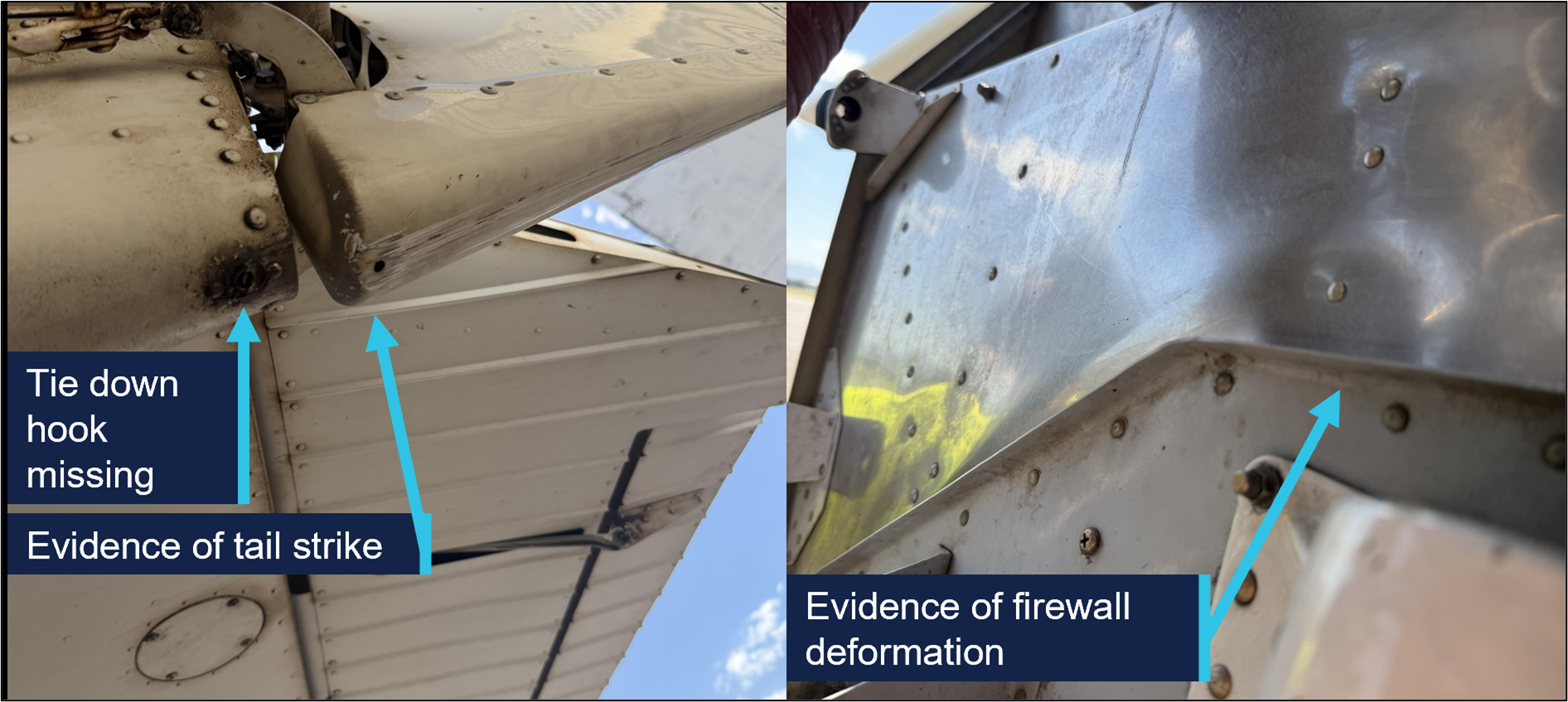
A post-flight inspection of the aircraft by the operator revealed the tail tie-down hook was missing, with evidence of a tail strike and firewall deformation (Figure 1).
Figure 1: Damage to aircraft
Source: Operator, annotated by the ATSB
Safety message
While conducting training flights, students can experience a high workload, particularly during solo flights and landing. Maintaining a calm mindset is important in order to adjust the aircraft’s profile and airspeed accordingly and determine if a go‑around is necessary.
All pilots, regardless of their experience levels, should be prepared to undertake a go‑around rather than continuing if they are not confident that a successful landing can be achieved. This occurrence also serves as a reminder that after any hard landing or other related incident where the integrity of the airframe or structure may be compromised, an engineering inspection can detect damage that may not be immediately apparent.
About this report
Decisions regarding whether to conduct an investigation, and the scope of an investigation, are based on many factors, including the level of safety benefit likely to be obtained from an investigation. For this occurrence, no investigation has been conducted and the ATSB did not verify the accuracy of the information. A brief description has been written using information supplied in the notification and any follow-up information in order to produce a short summary report, and allow for greater industry awareness of potential safety issues and possible safety actions.
^A ‘full-stop landing’ in pilot training means the pilot does not intend to take off again immediately.
^A bounced landing is a condition where the aircraft lands on the runway, but instead of rolling on the surface after touchdown, it rebounds/bounces off the ground.
^‘Porpoising’ refers to the manoeuvre that can occur after a bounced landing that is improperly recovered, in which the aeroplane comes in nose first setting off a series of cyclic vertical motions.
Occurrence summary
Mode of transport
Aviation
Occurrence ID
AB-2026-024
Occurrence date
12/04/2026
Location
Archerfield Airport
State
Queensland
Occurrence class
Accident
Aviation occurrence category
Control issues, Hard landing, Missed approach
Highest injury level
None
Brief release date
22/05/2026
Aircraft details
Manufacturer
Cessna Aircraft Company
Model
172R
Sector
Piston
Operation type
Part 141 Recreational, private and commercial pilot flight training
Activity
General aviation / Recreational-Instructional flying-Instructional flying - solo
Occurrence Briefs are concise reports that detail the facts surrounding a transport safety occurrence, as received in the initial notification and any follow-up enquiries. They provide an opportunity to share safety messages in the absence of an investigation. Because occurrence briefs are not investigations under the Transport Safety Investigation Act 2003, the information in them is de-identified.
What happened
On 16 April 2026, a pilot and passenger on board a Van’s RV-7 departed Archerfield Airport on a private flight to Fig Tree Aircraft Landing Area (ALA), Queensland. The Fig Tree ALA had a 400 m unsealed grass runway at an elevation of 1,600 ft AMSL. The pilot noted that they were conscious of the increased risk of operating into an airstrip with a short runway and had conducted short field landing practice at Archerfield the day prior.
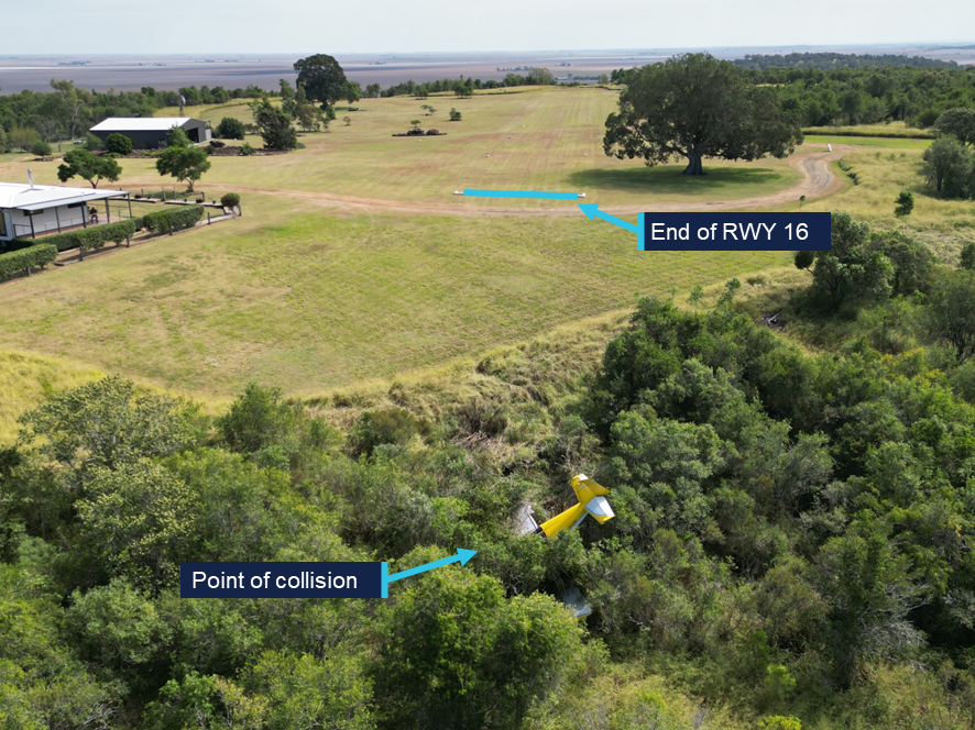
After arriving overhead Fig Tree airfield, a standard field inspection and a go-around was conducted to gain familiarity with the runway characteristics, as was required by the field operator. At 1110 local time, the aircraft commenced an approach and landing on runway 16. As the aircraft touched down midfield on the runway, the pilot determined that with the remaining landing distance available and the aircraft’s high speed, a go-around was required. During the go-around at approximately 20 ft AGL, the aircraft encountered sink and failed to climb as expected. The pilot made the decision to reduce the power to idle and attempted to conduct an off-field landing. The aircraft subsequently collided with thick shrubbery off the end of runway 16, resulting in substantial structural damage. (Figure 1). Both occupants were uninjured and extricated themselves from the aircraft.
After the occurrence, the pilot recalled that the accident approach was faster than anticipated. The operator determined there were no technical faults with the engine that affected the reduced climbing performance.
Figure 1: Fig Tree ALA
Source: Operator, annotated by the ATSB
Safety message
The margin for error while operating at airfields with short runways is limited and requires pilots to conduct the appropriate short field take-off and landing technique. In the case when an approach becomes unsuitable for a safe landing to occur, it is vital that pilots conduct a go-around as soon as practical.
The occurrence also highlights the importance for all pilots to have a personal minimums checklist that aligns with their individual flying experience. If at any time the conditions exceed these minimums or doubt is experienced, pilots should not continue to land and consider using alternative runways, alternative airfields or returning to the departure location if the available fuel permits.
About this report
Decisions regarding whether to conduct an investigation, and the scope of an investigation, are based on many factors, including the level of safety benefit likely to be obtained from an investigation. For this occurrence, no investigation has been conducted and the ATSB did not verify the accuracy of the information. A brief description has been written using information supplied in the notification and any follow-up information in order to produce a short summary report, and allow for greater industry awareness of potential safety issues and possible safety actions.
Occurrence summary
Mode of transport
Aviation
Occurrence ID
AB-2026-026
Occurrence date
16/04/2026
Location
Fig Tree Aircraft Landing Area
State
Queensland
Occurrence class
Accident
Aviation occurrence category
Collision with terrain, Control issues, Missed approach
Highest injury level
None
Brief release date
21/05/2026
Aircraft details
Manufacturer
Van's Aircraft
Model
RV-7
Sector
Piston
Operation type
Part 91 General operating and flight rules
Activity
General aviation / Recreational – Sport and pleasure flying – Pleasure and personal transport
Departure point
Archerfield Airport, Queensland
Destination
Irongate/Fig Tree Aircraft Landing Area, Queensland
The ATSB is investigating a near collision involving a Tecnam P2002 Sierra, registration 24-7996, and a Diamond Aircraft Industries DA40 NG, registration VH-YPH, at Port Macquarie Airport, New South Wales, on 29 April 2026.
During final approach, the crew of the Diamond DA 40 observed the Tecnam P-2002 enter active runway 21 and line up for take-off. The DA40 conducted a missed approach and subsequently overflew the P-2002 in close proximity.
To date, the ATSB investigation has included interviewing witnesses and involved parties, retrieving and reviewing recorded data, and the collection of other relevant information. The ATSB has commenced the examination and analysis of the initial evidence collected.
A final report will be released at the conclusion of the investigation. Should a critical safety issue be identified during the course of the investigation, the ATSB will immediately notify relevant parties, so that appropriate safety action can be taken.
Last updated:
Occurrence summary
Investigation number
AO-2026-077
Occurrence date
29/04/2026
Occurrence time and timezone
15:55 Australian Eastern Standard Time
Location
Port Macquarie Airport
State
New South Wales
Report status
Pending
Anticipated completion
Q3 2026
Investigation level
Short
Investigation type
Occurrence Investigation
Investigation phase
Examination and analysis
Investigation status
Active
Mode of transport
Aviation
Aviation occurrence category
Missed approach, Near collision, Runway incursion
Occurrence class
Serious Incident
Highest injury level
None
Aircraft details
Manufacturer
Tecnam - C. Aeronautiche SRL
Model
P2002 Sierra
Registration
24-7996
Serial number
23
Sector
Piston
Operation type
Part 103 Sport and recreational aircraft
Activity
General aviation / Recreational-Instructional flying-Instructional flying - dual
Departure point
Port Macquarie Airport, New South Wales
Destination
Port Macquarie Airport, New South Wales
Injuries
None
Damage
Nil
Aircraft details
Manufacturer
Diamond Aircraft Industries
Model
DA40 NG
Registration
VH-YPH
Serial number
40.N289
Aircraft operator
Australian International Aviation College Pty Ltd
Sector
Piston
Operation type
Part 141 Recreational, private and commercial pilot flight training
Activity
General aviation / Recreational-Instructional flying-Instructional flying - dual
The ATSB is investigating a collision with tree involving a GippsAero GA8 Airvan, VH-WSU, at Lindeman Island, Queensland, on 8 March 2026.
During landing on soft and wet ground, the wheels slid and the pilot applied full power to conduct a go-around. The aircraft became airborne after the end of the runway and the landing gear contacted a tree, resulting in substantial damage. The aircraft was flown with reduced performance to Shute Harbour due to the runway condition at Lindeman Island being deemed unsuitable.
The ATSB has commenced the examination and analysis of the initial evidence collected. Further investigation will involve interviewing witnesses and involved parties, examination of maintenance records, retrieving and reviewing recorded data, and the collection of other relevant information.
A final report will be released at the conclusion of the investigation. Should a critical safety issue be identified during the course of the investigation, the ATSB will immediately notify relevant parties, so that appropriate safety action can be taken.
Occurrence summary
Investigation number
AO-2026-065
Occurrence date
08/03/2026
Occurrence time and timezone
14:35 Eastern Australia Standard Time
Location
Lindeman Island
State
Queensland
Report status
Pending
Anticipated completion
Q3 2026
Investigation level
Short
Investigation type
Occurrence Investigation
Investigation phase
Examination and analysis
Investigation status
Active
Mode of transport
Aviation
Aviation occurrence category
Collision with terrain, Control issues, Diversion/return, Missed approach, Stall warning
Occurrence class
Accident
Highest injury level
None
Aircraft details
Manufacturer
Gippsland Aeronautics Pty Ltd
Model
GA8
Registration
VH-WSU
Serial number
GA8-17-244
Aircraft operator
Wave Air
Sector
Piston
Operation type
Part 135 Air transport operations - smaller aeroplanes
Activity
Commercial air transport-Non-scheduled-Joyflights / sightseeing charters
The ATSB is investigating a descent below minimum safe altitude involving Boeing 767, VH‑XQU, 16 km north of Sydney Airport, New South Wales, on 10 September 2025.
During approach, the aircraft descended below the minimum safe altitude. The approach controller received a minimum safe altitude warning (MSAW) and issued a safety alert. The crew subsequently conducted a missed approach.
In the course of the investigation, the ATSB identified potential limitations in risk controls / organisational factors relevant to the occurrence that potentially contributed to the occurrence. Examination of these factors represent a significant increase in the scope of this investigation, and it has been upgraded from Short to Defined as a result (the ATSB's different levels of investigation are detailed here).
The draft report internal review process has been completed. The draft report has been distributed to directly involved parties (DIPs) to check factual accuracy and ensure natural justice. Any submissions from those parties will be reviewed and, where considered appropriate, the draft report will be amended accordingly.
Following the external review process, any submissions and amendments to the draft report are internally reviewed. Once approved, the final report is prepared for publication and dissemination and released to DIPs prior to its public release.
The final report will be released at the conclusion of the investigation. Should a critical safety issue be identified during the course of the investigation, the ATSB will immediately notify relevant parties, so that appropriate safety action can be taken.
On 22 August 2025, a GippsAero GA8, operated by Air Kimberley and registered VH‑LHC, entered the circuit in preparation for landing at Djarindjin/Lombadina Airport, Western Australia. At about this time, the pilot identified an uncommanded 3-inch drop in engine manifold pressure. After briefly liaising with the chief pilot via phone, the pilot conducted an orbit between the base and final legs of the circuit to prepare for the landing.
Crossing the threshold, the pilot identified that they were between 20 and 25 kt above the target approach speed. Approximately two-thirds of the way down the runway, the pilot assessed there was insufficient runway remaining to land, commenced a go-around and attempted to climb away. However, the airspeed reduced and the pilot assessed that they did not have sufficient power to climb and elected to level the aircraft and conduct a turnback to land on the reciprocal runway. The pilot used the mixture control to reduce the engine’s power and landed without further incident.
What the ATSB found
During the approach, the securing mechanism for the aircraft’s throttle linkage failed, resulting in a loss of throttle control and a constant partial power setting. The approach then continued at a higher-than-normal speed that did not permit the aircraft to land safely.
During the subsequent go-around, the pilot assessed there was insufficient power to climb. This was due to the throttle failing to open to at least 75% in accordance with the manufacturer’s requirement, likely due to the spring that opened the throttle in the event of a disconnection not being fitted.
Additionally, the ATSB found that there were multiple inconsistencies between the throttle linkage hardware fitted to VH-LHC and that laid out in the aircraft documentation. Although the ATSB could not determine whether the inconsistencies contributed to this incident, they increased the risk of throttle disconnection due to unintended interactions between components in the linkage.
What has been done as a result
In response to the ATSB advice noting the inconsistencies between the linkage assembly and the manufacturer’s prescribed configuration, the maintenance organisation, BOAB Engineering (BOAB), conducted a review of the 3 GA8 aircraft that it was responsible for.
BOAB identified various inconsistencies related to incorrect throttle body lever arms, missing torsion springs and incorrectly located or missing spacers. At the time of writing, BOAB advised that the correct parts had been ordered and that the linkage assemblies would be re-assembled in accordance with the manufacturer’s requirements.
Safety message
Partial power loss can be more complex to manage than a complete power loss. The response to a complete power loss is definitive and standardised but the response to a partial power loss may be dependent on the amount of power lost and reliability of the remaining power. CASA's guidance is to treat a partial power loss as though it is a complete power loss and to ensure that the aircraft is landed as soon as possible. Where engine power is available pilots can consider using it to extend available flight time to identify a better landing site with the awareness that the power may reduce or fail at any time.
This occurrence also demonstrates the importance of being aware of and adhering to the manufacturer’s assembly requirements. Reconnecting a component’s attachment hardware on a like-for-like basis may not ensure compliance with the manufacturer’s requirements and can increase the risk of an adverse outcome.
The investigation
The ATSB scopes its investigations based on many factors, including the level of safety benefit likely to be obtained from an investigation and the associated resources required. For this occurrence, the ATSB conducted a limited-scope investigation in order to produce a short investigation report, and allow for greater industry awareness of findings that affect safety and potential learning opportunities.
The occurrence
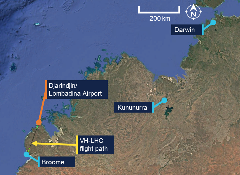
On the morning of 22 August 2025, a GippsAero GA8, operated by Air Kimberley and registered VH‑LHC, departed Broome, Western Australia, for a charter flight to Djarindjin/Lombadina Airport (Figure 1) with the pilot, one passenger and freight on board.
Figure 1: VH-LHC flight location
Source: Google Earth and FlightRadar24, annotated by the ATSB
Approximately 55 minutes after departing Broome, the pilot joined the downwind leg of the circuit for runway 28 at Djarindjin/Lombadina Airport. Shortly after joining the circuit, at about 1251 local time, the pilot identified an uncommanded 10 kt reduction in airspeed and a drop from approximately 20 inches of mercury (inHg) of engine manifold pressure to 17 inHg. In response, the pilot moved the aircraft throttle lever across its full range of movement but did not hear or feel a response from the engine and reported no change to the manifold pressure.
At this time, the pilot contacted the operator’s chief pilot via mobile phone for guidance. The pilot reported that in the brief conversation they outlined the issue that they were encountering. While the pilot could not remember the details of the chief pilot’s response the general guidance provided was to land as safely as possible and to call back when they were on the ground.
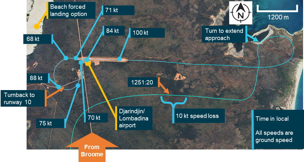
Following this conversation, the pilot elected to conduct an orbit to extend the approach (Figure 2) and allow themselves more time to assess the problem and conduct pre‑landing checks and procedures. They intended to conduct the approach normally but with an extended final approach. The pilot also considered the early use of a second stage of flap to slow the aircraft. However, they decided against it due to the unknown reliability of the engine’s performance and extended the second stage of flap as part of the normal pre-landing process on final approach.
Figure 2: Downwind, final approach, go‑around and return
Note: Due to the light and variable winds at the time of the occurrence, the aircraft ground speeds were within 5 kt of the airspeeds that would have been presented to the pilot. Source: Google Earth, FlightRadar24 and Bureau of Meteorology, annotated by the ATSB
The pilot recalled, and recorded data confirmed, that the aircraft was at about 100 kt, 20–25 kt faster than planned, when crossing the threshold. Approximately two-thirds of the way down the runway, the pilot identified that the aircraft was ‘floating,’1 had insufficient runway remaining to land the aircraft, and elected to conduct a go-around. The pilot initiated a climb, retracted one stage of flap and felt the airspeed start to reduce from 84 kt at the time the go‑around was initiated, to 68 kt as they turned off the runway heading. The pilot reported reaching approximately 300 ft above ground level, assessed that there was insufficient performance to safely continue the climb and levelled the aircraft.
The pilot’s planned forced landing option when taking off from runway 28 at Djarindjin/Lombadina was a beach on the western side of scrubland beyond the end of the runway (Figure 2). However, the pilot assessed that this was not suitable and subsequently turned to the left for a return to runway 28.
During the turn, the aircraft maintained altitude and accelerated from 68 to 88 kt. The pilot reported that, after the turn, they were unsure if the engine would continue producing power long enough to complete a circuit. They subsequently decided to land on runway 10, the reciprocal runway. Having determined that they were able to reduce the engine’s power using the mixture control, the pilot brought the mixture to near the cut‑off position and conducted a turnback to runway 10, slowing the aircraft through 75 kt to 70 kt before landing.
After landing, the pilot increased engine power by returning the mixture to rich and taxied off the runway. Subsequently, after consultation with the company’s maintenance provider, it was determined that the throttle linkage had disconnected at the engine.
Context
Pilot information
The pilot held a Commercial Pilot Licence (Aeroplane) with a command instrument rating and a valid class 1 aviation medical certificate. The pilot reported that at the time of the occurrence they had 869 hours of total aeronautical experience with 385 of these being on the GA8 and 48 in the last 90 days.
Operational information
Emergency procedures
The GA8 pilot’s operating handbook contained relevant procedures for the operation of the aircraft in the event of an emergency. The manual did not contain a specific procedure for the management of partial power, however there were procedures for both a precautionary landing with engine power and an emergency landing without engine power.
The procedure for a precautionary landing with power included an indicated airspeed of 75 kt on approach with stage 1 flap extended. The procedure for landing without engine power included an indicated airspeed on final approach of between 64 and 71 kt depending on aircraft weight. In normal operation the approach speed was 71 kt.
The procedure for landing without engine power required the pilot to switch off the ignition, fuel shutoff valve, and the master electrical buses, to move the throttle to the closed position, the mixture to the idle cut off position and the propellor to coarse.
The procedure for a precautionary landing with power required the mixture to be moved to the idle cut‑off position and the ignition, fuel shut‑off valve and bus 1 and 2 master switches to be moved to the off position after touchdown.
Management of partial power loss
Management of a partial power loss is more complex than a complete power loss. The response to a complete power loss should be definitive and standardised while the number of factors that could lead to a partial power loss and the unreliability of any remaining power meant that a situationally specific response is required.
While the manufacturer did not provide guidance on the management of partial power loss in the GA8, both the Civil Aviation Safety Authority (CASA) and the ATSB have published general guidance on the subject – CASA in its flight instructor manual and the ATSB in Managing partial power loss after takeoff in single-engine aircraft (AR-2010-055 - Number 3). The guidance contains 3 key points:
a partial power loss event should be treated like a complete power loss and a landing should be conducted as soon as possible
any available power may be used to extend the flight time to locate a better landing area
this should be done with the consideration that the power may degrade further or be lost at any time.
Throttle operation
The GA8 flight manual advised that a normally aspirated engine had a manifold pressure range between 10 and 30 inHg. However, the range available for use was dependent on the altitude at which the aircraft was operating.
The pilot stated that when approaching Djarindjin/Lombadina on descent they typically set 20 inHg, reducing this to 18 inHg passing the threshold during the downwind leg of the circuit and then to 15 inHg when making the turn onto the base leg.
Meteorological information
An aerodrome meteorological report for Djarindjin/Lombadina was issued at 1300 local time, approximately 5 minutes after VH-LHC crossed the threshold on its first approach. The wind recorded was from 050° at 4 kt with 9,000 meters visibility, temperature 30°C and no recorded rainfall.
One-minute wind observations between 1250 and 1300 showed variable wind direction at 2–5 kt.
Aircraft information
General information
The GA8 is a single‑engine aircraft manufactured by GippsAero2 of Victoria, Australia. It is fitted with a Textron Lycoming IO-540-K1A5 piston engine and can seat up to 8 people, including the pilot. VH-LHC (serial number GA8-04-057) was manufactured and registered in 2004. At the time of the occurrence, it had accumulated 11,768 hours total time in service. For this flight, the aircraft was configured for a single passenger next to the pilot and with the rear passenger seats removed and appropriate securing equipment in place for carriage of freight.
Throttle cable attachment assembly
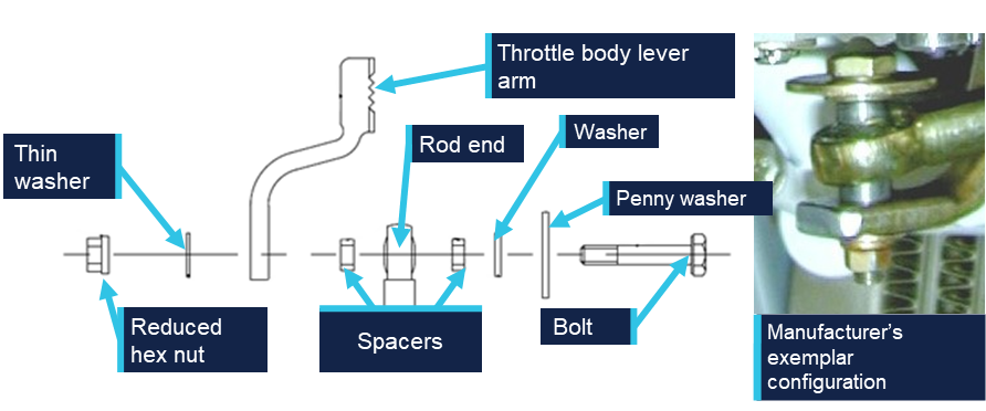
The throttle cable assembly translated movement of the throttle lever in the cockpit to the throttle body on the engine. The throttle body attachment consisted of a rod end and throttle body lever arm bolted together with a series of washers and spacers used to ensure appropriate geometry was maintained. The geometry of the washers and spacers allowed both the rod end and throttle body lever arm to move freely and limited interaction with the other components. If the geometry was not correctly maintained, the rod end could forcefully contact the penny washer and, as the rod end moved through its arc of motion, induce a rotation in the penny washer and subsequently, in the bolt. This interaction could result in a loosening or disconnection of the linkage.
Figure 3 shows the exploded diagram of the linkage from the aircraft manufacturer’s illustrated parts catalogue (IPC) and an exemplar assembly provided by the manufacturer.
Figure 3: Throttle cable attachment assembly
Source: Manufacturer, modified and annotated by the ATSB
The threaded end of the bolt specified in the IPC (AN3-11) is drilled allowing a split pin to be used as a secondary securing mechanism. However, the specified nut (MS21042-3) is a reduced hex nut that uses interference with an out of round section to lock the nut onto the bolt and consequently does not require a split pin. This combination, while permitted and approved, was not commonly used as a reduced hex nut is typically used in combination with a non-drilled bolt. When consulted, the manufacturer could not advise why this hardware combination had been prescribed for the aircraft. However, they advised that some elements of the design for this aircraft had been reproduced from the design of another aircraft, including the specified bolt.
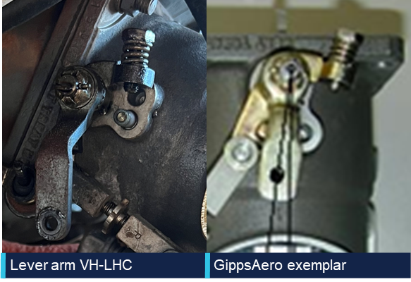
The throttle body lever arm on the GA8 was developed by GippsAero by modifying the design of the standard arm supplied by the engine manufacturer. The modification made the arm approximately 12 mm shorter than when used for other applications with the same engine. This modification altered the arc through which the arm moved to ensure that the geometry between the throttle cable and the throttle body was correct. The manufacturer’s review of the images of VH-LHC’s throttle arm identified that a standard lever arm was fitted rather than the GippsAero lever arm.
Figure 4 shows the throttle lever arm as fitted to VH-LHC in comparison to an exemplar of the shortened lever arm as prescribed for the aircraft by GippsAero in the IPC. Note the throttle positions shown in the images are not the same and the image has been rotated to show the difference in length between the lever arms.
Figure 4: Throttle lever arm comparison
Source: Operator and aircraft manufacturer, modified and annotated by the ATSB
Spring‑loaded mechanism
The certification standard for the GA8 required that if the engine control separated, it must be designed so that the aircraft is capable of ‘continued safe flight and landing’. This requirement was implemented by the United States Federal Aviation Administration (FAA) in response to a 1981 National Transportation Safety Board (NTSB) study of single‑engine aircraft accidents involving separation of throttle linkages and subsequent loss of propulsive power. The NTSB recommendation (A-81-6) to the FAA was to:
Establish a requirement that, when throttle linkage separation occurs in a small single engine aircraft the fuel control will go to a setting which will allow the pilot to maintain level flight in the cruise configuration; (Class 11, Priority Action)
In response, the FAA introduced a requirement under regulation 23.1147(g) that:
For reciprocating single-engine airplanes, each power or thrust control must be designed so that if the control separates at the engine fuel metering device, the airplane is capable of continued safe flight and landing
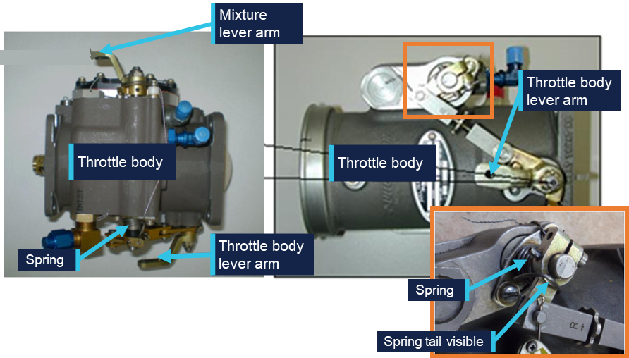
For the GA8 to comply with this requirement, the throttle body linkage was fitted with a torsion spring with sufficient tension to drive the throttle to at least 75% of the full throttle setting. The torsion spring is mounted directly to the throttle body as shown in Figure 5 and can subsequently drive the throttle to the required position in the event of a disconnection anywhere along the throttle linkage.
Figure 5: Spring location
Source: Manufacturer, modified and annotated by the ATSB
In 2011, GippsAero published service bulletin SB-GA8-2011-64 in response to reports of throttles failing to open sufficiently. The service bulletin required that spring tension be tested and if it was not able to open the throttle sufficiently, a stiffer spring was required to be installed. This service bulletin was completed on VH-LHC on 28 February 2011 at 5,150.5 hours.
Post‑occurrence examination
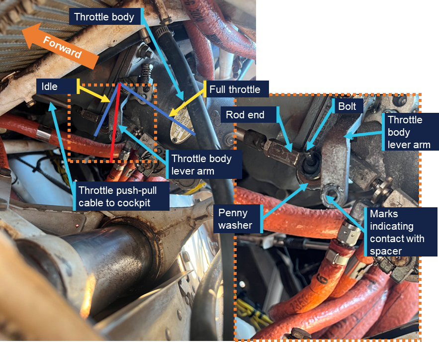
The ATSB was provided with an image taken by the pilot immediately after the occurrence (Figure 6). It shows the throttle body lever arm at approximately 25% travel with the through bolt from the rod end disconnected from the lever arm. Only the bolt and penny washer from the cable attachment assembly were visible in the image. The remaining components including the nut, washer and spacers were unable to be identified.
Figure 6: Post‑occurrence image of throttle body and throttle cable attachment assembly
Source: Operator, annotated by the ATSB
Following reconnection of the linkage using new hardware, the ATSB requested the nut and bolt from the maintainers, however they were unable to provide either. They reported that the nut was not recovered during the repair and the bolt could not be located. The maintainers reported that damage to the bolt threads was identified when it was removed.
A subsequent review of the IPC identified that the correct securing mechanism was a reduced hex nut and not the castellated nut and split pin that had been fitted during the repair (see the section titled Engine change for further information).
Following the occurrence, the ATSB and the manufacturer reviewed the available imagery. The manufacturer stated that the imagery appeared to show an incorrect configuration of the throttle cable attachment assembly, with markings on the end of the throttle body lever arm indicating that at least one of the spacers had been incorrectly located. The ATSB also identified, and the manufacturer confirmed, that the spring on the throttle mechanism was missing (Figure 7).
Figure 7: Post‑occurrence imagery identifying location of throttle mechanism spring
Source: Operator and manufacturer, annotated by the ATSB
Maintenance information
Engine change
In June 2025, VH-LHC’s engine was removed due to detonation damage. The engine including the frame and ancillary components, such as hoses and baffles, were removed and a serviceable engine and propeller from another GA8 were installed. The aircraft was released back into service on 3 June 2025. The maintainer who conducted the engine change was contracting to the maintenance organisation and had not previously (and did not subsequently) work on this aircraft.
They reported that when they disconnected the linkage there were thick section washers fitted to either side of the rod end, a penny washer under the bolt and the linkage was secured with a castellated nut and split pin. They reported reusing the hardware from the removed engine with a new split pin and that their post‑installation checks identified no issues with the movement of the throttle.
The maintainer stated that, based on their experience and the presence of the hole in the bolt, the use of a castellated nut and split pin was logical, and they did not refer to the aircraft documentation to confirm the hardware configuration.
Related occurrences
A review of the ATSB’s occurrence database did not identify any similar occurrences, however the manufacturer identified a continuing airworthiness notice (CAN) issued in 2007 by the New Zealand Civil Aviation Authority (CAA) related to a similar issue and a review of the CASA defect reporting database identified a similar issue from an aircraft in Botswana in 2017.
New Zealand Civil Aviation Authority Continuing Airworthiness Notice 76‑001
On 5 July 2007, the NZ CAA released a CAN on all GA8 aircraft for an inspection of the throttle cable and the throttle lever installation. A CAA investigation had been prompted by reports of a sluggish feel in the throttle operation of a GA8. The investigation identified that the linkage bolt was rotating, resulting in a loosening of the nut securing the mechanism. Contact between the penny washer and the rod end resulted in movement of the rod end causing the penny washer, and subsequently the bolt, to rotate.
As published, the CAN contained a recommendation for an updated configuration of the linkage assembly intended to increase the approach angle between the penny washer and the rod end. In February 2026, the CAA advised that the manufacturer’s configuration addressed the issue and subsequently the CAN had been removed from the NZ CAA website. In response to the draft ATSB report, the CAA advised that the CAN was pending revision and reissue, following the release of the ATSB report.
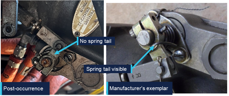
Figure 8 compares the reconnected linkage configuration on VH-LHC (left) with the manufacturer’s exemplar configuration (right). The spacers shown in the manufacturer’s configuration provide increased clearance between the penny washer, rod end and the throttle body lever arm compared to the washers used in the reconnected configuration.
Figure 8: Throttle linkage assembly comparison
Source: Operator and manufacturer, annotated by the ATSB
The pre-occurrence configuration of the linkage fitted to VH-LHC was unable to be determined. However, the reconnected configuration showed a limited clearance between the rod end and the penny washer due to the missing spacers. This lack of clearance meant that the rod end was likely to contact the penny washer when the throttle was moved through the full range of motion.
As identified by the CAA’s investigation, this creates a risk of interaction between these parts and potential for loosening and disconnection of the linkage. In comparison, the spacers used in the manufacturer’s configuration separate the rod end from the penny washer to prevent interaction.
CASA defect report
A review of the CASA defect reporting database identified a report from 8 May 2017 related to aircraft A2-FTW,3as follows:
Loosened nut and insecure throttle control cable rod-end and bolt discovered, caused by engine vibration.
New nut installed and tightly secured to the throttle control linkage on fuel injector.
Safety analysis
Approach
The pilot reported that the flight to Djarindjin/Lombadina was uneventful until the aircraft entered the circuit. During the downwind leg of the circuit, the pilot observed an uncommanded drop in manifold pressure from 20 to 17 inHg and was no longer able to control engine power using the throttle lever. Once the pilot made the base turn, the 17 inHg manifold pressure was above the 15 inHg setting they would have typically been using. Imagery of the throttle linkage captured by the pilot following the occurrence showed the linkage disconnected and the securing nut missing with the throttle arm near to, but not at, the idle position. The consequence of the linkage disconnection was that movement of the throttle lever in the cockpit could not be translated to the throttle lever arm on the engine resulting in a loss of throttle control.
As the approach progressed, the pilot reported, and recorded data showed, that the aircraft was 20–25 kt above the recommended approach speed of 75 kt as it crossed the threshold. At that speed, the pilot assessed that there was insufficient runway available to slow the aircraft and make a safe landing.
Go-around
After the pilot identified that there was insufficient runway remaining to land safely, they commenced a go-around and the aircraft’s speed immediately started to reduce. The pilot reported that the aircraft was correctly configured for climb with one stage of flap, propeller pitch at full fine and that other than the limited power there were no issues that should have adversely affected climb performance. Unable to use the throttle to increase the power from the engine, the aircraft continued to slow, and so the pilot levelled the aircraft. The pilot then commenced a left turn and the engine was producing sufficient power for the aircraft to accelerate through the turn while maintaining altitude.
Aircraft certification standards required that, in the event of a throttle linkage disconnect, the engine side of the throttle linkage move to a position that would enable ‘continued safe flight and landing’. The manufacturer therefore required that a torsion spring be installed on the throttle linkage that would open the throttle to at least 75% of the open position in the event of a disconnection.
The image captured by the pilot immediately following the occurrence showed the throttle in a low power position, well below the 75% open position that was required by the manufacturer. Due to the number of factors that can impact the relationship between throttle position and observed manifold pressure, it was not possible to determine what the manifold pressure should have been if the throttle was open to 75%. However, as available power increases as the throttle opens, the position of the throttle arm below the 75% open position meant that there was less power available than that required by the manufacturer to sustain ‘continued safe flight and landing’.
It was further identified and confirmed by the manufacturer that the torsion spring was not visible in the imagery captured immediately after the occurrence. The ATSB considered 2 possible scenarios for the missing torsion spring. The first was that the spring had been present and had failed since the last maintenance activity or during the occurrence and the second was that the spring was not fitted at the time of the engine change.
As the spring was fitted around the shaft, in the event of a failure, the spring would have been retained on the shaft and been visible. Additionally, it is very unlikely that the spring would have failed at the time of the linkage disconnection as in the event of a disconnection the tension on the spring would have been released to drive the throttle arm to at least the 75% open position.
While it could not be conclusively determined if the required torsion spring was fitted at the time of the occurrence, it was considered very likely that it was not fitted due to:
the visible lack of the spring
the fact that the spring would have been retained should it have failed
the limited time between maintenance and the occurrence for the spring to become detached and be lost
the fact that the throttle did not open, which is the purpose of the spring being fitted.
Installation inconsistencies
There were several inconsistencies between the throttle linkage installation on VH-LHC and the arrangement outlined in the aircraft documentation, as follows:
the manufacturer identified that the throttle arm fitted was not correct for the aircraft
the maintainer reported using a castellated nut with split pin, rather than the specified reduced hex nut
the throttle opening spring was very likely not fitted
the spacers were likely not fitted correctly prior to the occurrence.
As shown by the New Zealand Civil Aviation Authority Continuing Airworthiness Notice, changes to the throttle linkage geometry can lead to undesirable interactions between components within the linkage, most notably the rod end and the penny washer. This can subsequently loosen the linkage and could result in complete disconnection.
The ATSB could not determine whether the inconsistencies between the recommended, and actual throttle linkage configurations contributed to the disconnection. This was primarily due to limited evidence about the sequence of the disconnection but was also influenced by the limited and incomplete information about the pre-occurrence linkage configuration. The likely configuration of the throttle linkage was determined based on manufacturer review of the available imagery, the recollection of the maintainer who completed the engine installation approximately 4 months before the occurrence and imagery of the reassembled linkage following the occurrence.
The individual impact of each of these inconsistences could not be determined. However, the combination of the inconsistencies, and their potential impact on the geometry of the linkage and subsequent interaction between the components, increased the risk of a disconnection.
Findings
ATSB investigation report findings focus on safety factors (that is, events and conditions that increase risk). Safety factors include ‘contributing factors’ and ‘other factors that increased risk’ (that is, factors that did not meet the definition of a contributing factor for this occurrence but were still considered important to include in the report for the purpose of increasing awareness and enhancing safety). In addition ‘other findings’ may be included to provide important information about topics other than safety factors.
These findings should not be read as apportioning blame or liability to any particular organisation or individual.
From the evidence available, the following findings are made with respect to the engine malfunction involving GippsAero GA8, VH-LHC, at Djarindjin/Lombadina Airport, Western Australia, on 22 August 2025.
Contributing factors
During the approach, the securing mechanism for the aircraft’s throttle linkage failed resulting in a loss of throttle control and a constant partial power setting. The approach then continued at a higher-than-normal speed that did not permit the aircraft to land safely.
During the subsequent go-around, the pilot assessed there was insufficient power to climb. This was due to the throttle failing to open to at least 75% in accordance with the manufacturer’s requirement, likely due to the spring that opened the throttle in the event of a disconnection not being fitted.
Other factors that increased risk
There were multiple inconsistencies between the throttle linkage hardware fitted to VH-LHC and that laid out in the aircraft documentation. This increased the risk of throttle disconnection due to unintended interactions between components in the linkage.
Safety actions
Whether or not the ATSB identifies safety issues in the course of an investigation, relevant organisations may proactively initiate safety action in order to reduce their safety risk. The ATSB has been advised of the following proactive safety action in response to this occurrence.
Safety action taken by BOAB Engineering
In response to the ATSB advice noting the inconsistencies between the linkage assembly and the manufacturer’s prescribed configuration, the maintenance organisation (BOAB) conducted a review of the 3 GA8 aircraft that it was responsible for.
BOAB identified various inconsistencies related to incorrect throttle body lever arms, missing torsion springs and incorrectly located or missing spacers. It advised that the correct parts had been ordered and that the linkage assemblies would be re-assembled in accordance with the manufacturer’s requirements.
Sources and submissions
Sources of information
The sources of information during the investigation included:
the pilot of the occurrence flight
the operator of VH-LHC
the maintenance organisation for VH-LHC
the maintainer who completed the engine change on VH-LHC
GippsAero
New Zealand Civil Aviation Authority
Civil Aviation Safety Authority
Bureau of Meteorology
Flight Radar 24
Federal Aviation Administration
National Transportation Safety Board.
Submissions
Under section 26 of the Transport Safety Investigation Act 2003, the ATSB may provide a draft report, on a confidential basis, to any person whom the ATSB considers appropriate. That section allows a person receiving a draft report to make submissions to the ATSB about the draft report.
A draft of this report was provided to the following directly involved parties:
the pilot of the occurrence flight
the operator of VH-LHC
the maintenance organisation for VH-LHC
the maintainer who completed the engine change on VH-LHC
GippsAero
Transport Accident Investigation Commission (New Zealand)
New Zealand Civil Aviation Authority
Civil Aviation Safety Authority.
Submissions were received from:
New Zealand Civil Aviation Authority
the maintainer who completed the engine change on VH-LHC.
The submissions were reviewed and, where considered appropriate, the text of the report was amended accordingly.
Purpose of safety investigations
The objective of a safety investigation is to enhance transport safety. This is done through:
identifying safety issues and facilitating safety action to address those issues
providing information about occurrences and their associated safety factors to facilitate learning within the transport industry.
It is not a function of the ATSB to apportion blame or provide a means for determining liability. At the same time, an investigation report must include factual material of sufficient weight to support the analysis and findings. At all times the ATSB endeavours to balance the use of material that could imply adverse comment with the need to properly explain what happened, and why, in a fair and unbiased manner. The ATSB does not investigate for the purpose of taking administrative, regulatory or criminal action.
About ATSB reports
ATSB investigation reports are organised with regard to international standards or instruments, as applicable, and with ATSB procedures and guidelines.
Reports must include factual material of sufficient weight to support the analysis and findings. At all times the ATSB endeavours to balance the use of material that could imply adverse comment with the need to properly explain what happened, and why, in a fair and unbiased manner.
An explanation of terminology used in ATSB investigation reports is available here. This includes terms such as occurrence, contributing factor, other factor that increased risk, and safety issue.
Publishing information
Released in accordance with section 25 of the Transport Safety Investigation Act 2003
Ownership of intellectual property rights in this publication
Unless otherwise noted, copyright (and any other intellectual property rights, if any) in this report publication is owned by the Commonwealth of Australia.
Creative Commons licence
With the exception of the Commonwealth Coat of Arms, ATSB logo, and photos and graphics in which a third party holds copyright, this report is licensed under a Creative Commons Attribution 4.0 International licence.
The CC BY 4.0 licence enables you to distribute, remix, adapt, and build upon our material in any medium or format, so long as attribution is given to the Australian Transport Safety Bureau.
Copyright in material obtained from other agencies, private individuals or organisations, belongs to those agencies, individuals or organisations. Where you wish to use their material, you will need to contact them directly.
Footnotes
1
Float: a term used to describe when the aircraft continues flying when the pilot intends to touch down but is unable due to the wing generating excess lift.
2
The manufacturer was previously known as Gippsland Aeronautics.
3
A2 is the national aircraft registration identifier of Botswana.
Occurrence summary
Investigation number
AO-2025-052
Occurrence date
22/08/2025
Occurrence time and timezone
1300 Western Standard Time
Location
Djarindjin/Lombadina Airport
State
Western Australia
Report release date
08/05/2026
Report status
Final
Investigation level
Short
Investigation type
Occurrence Investigation
Investigation phase
Final report: Dissemination
Investigation status
Completed
Mode of transport
Aviation
Aviation occurrence category
Engine failure or malfunction, Missed approach
Occurrence class
Incident
Highest injury level
None
Aircraft details
Manufacturer
GippsAero
Model
GA-8
Registration
VH-LHC
Serial number
GA8-04-057
Aircraft operator
Air Kimberley
Sector
Piston
Operation type
Part 135 Air transport operations - smaller aeroplanes
Activity
Commercial air transport - Non-scheduled - Passenger transport charters
Occurrence Briefs are concise reports that detail the facts surrounding a transport safety occurrence, as received in the initial notification and any follow-up enquiries. They provide an opportunity to share safety messages in the absence of an investigation. Because occurrence briefs are not investigations under the Transport Safety Investigation Act 2003, the information in them is de-identified.
What happened
On the evening of 6 July 2025, a Saab 340 was being used to conduct a scheduled air transport flight to Sydney Airport, New South Wales. On board were 2 flight crew, 1 cabin crew and 27 passengers. The captain reported that the weather around Sydney at the time included developed thunderstorms and that holding and diversions had been in effect. They further reported that arrivals had recently been resumed as storms had passed and that, on final approach, weather radar indicated that the nearest storm cell was no closer than 19 km to the north.
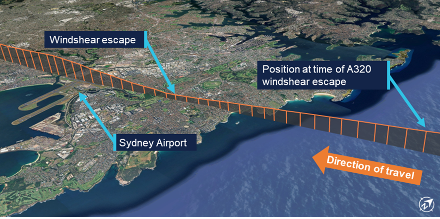
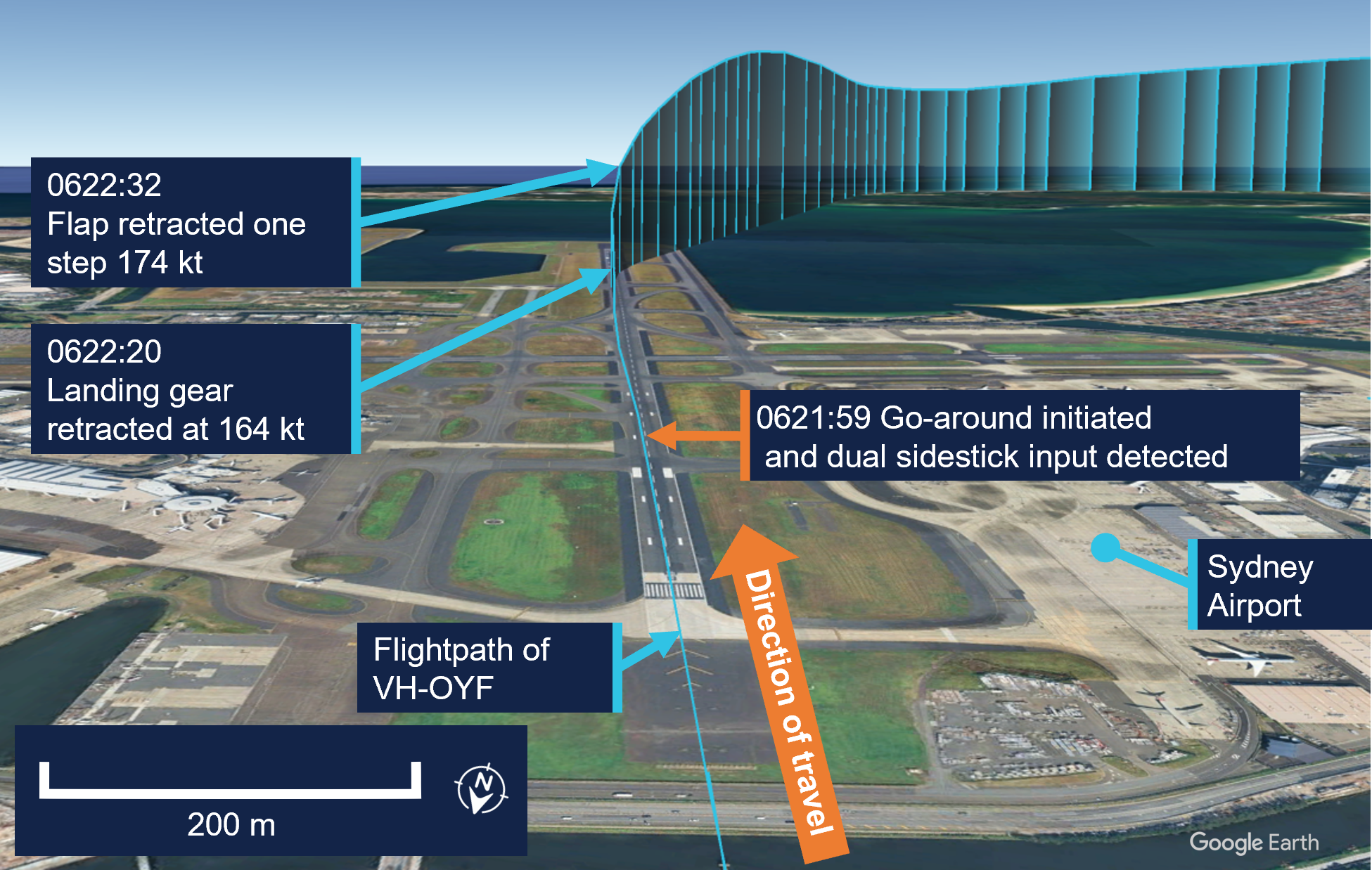
When the aircraft was about 19 km west of Sydney, the automatic terminal information system (ATIS)[1] was revised to advise that the wind had increased from 20 kt from the west to include gusts of up to 40 kt. Consequently, air traffic control (ATC) changed the active runway to runway 25.[2] The aircraft was the second to be sequenced for an approach to the revised runway, following an Airbus A320. Passing about 14 km from the airport on final approach, the Saab crew heard a broadcast from the A320 crew that they were conducting a windshear escape[3] (Figure 1).
At the time, the A320 was approximately 9 km ahead. Hearing that the preceding aircraft had encountered windshear, the Saab crew discussed their windshear escape procedure and decided to continue the approach, waiting to hear more details about the nature of the windshear.
Figure 1: Aircraft flight path
Source: Flightradar24 overlaid on Google Earth, annotated by the ATSB
Approximately 2 minutes later, ATC advised the Saab crew that the A320 had encountered severe undershoot windshear.[4] The crew assessed that they were passing the position the A320 had first detected the windshear at this time. Shortly afterwards, when at approximately 700–800 ft, the captain reported that they observed a decrease in airspeed and an abnormal power indication consistent with windshear. The captain called for a windshear escape which the crew initiated. Throughout the subsequent climbing manoeuvre, they conducted a series of power, airspeed and configuration changes until confident they were no longer affected by windshear.
Two subsequent aircraft landed on runway 25 without any further reported windshear encounters, after which arriving aircraft were again sequenced for runways 34L/34R. Following the windshear escape, the aircraft was re-sequenced for runway 34L and landed without further incident.
Safety message
Low-level windshear is a serious threat to the safety of departing and landing aircraft. If windshear is encountered, rapid and large control inputs may be required and in severe cases, the effect of windshear may exceed the performance capabilities of the aircraft. Flight crew should use all available indicators to avoid areas of known windshear on the intended flight path. These include the presence of thunderstorm cells, and reports from pilots of other aircraft and air traffic control.
About this report
Decisions regarding whether to conduct an investigation, and the scope of an investigation, are based on many factors, including the level of safety benefit likely to be obtained from an investigation. For this occurrence, no investigation has been conducted and the ATSB did not verify the accuracy of the information. A brief description has been written using information supplied in the notification and any follow-up information in order to produce a short summary report, and allow for greater industry awareness of potential safety issues and possible safety actions.
[1]Automatic terminal information service: the provision of current, routine information to arriving and departing aircraft by means of continuous and repetitive broadcasts. ATIS information is updated either routinely or when there is a significant change to weather and/or operations.
[2]Runway number: the number represents the magnetic heading of the runway. The runway identification may include L or R as required for left or right when there are parallel runways.
[3]Windshear: a change in wind speed and/or direction over a short distance. A windshear escape is a pilot recovery technique used when an inadvertent windshear encounter is experienced.
[4]Undershoot windshear: a rapid decrease in the headwind component of the wind.
Occurrence summary
Mode of transport
Aviation
Occurrence ID
AB-2025-029
Occurrence date
06/07/2025
Location
5 km east of Sydney Airport
State
New South Wales
Occurrence class
Incident
Aviation occurrence category
Missed approach, Turbulence/windshear/microburst
Highest injury level
None
Brief release date
25/08/2025
Aircraft details
Manufacturer
Saab Aircraft Co.
Model
340B
Sector
Turboprop
Operation type
Part 121 Air transport operations - larger aeroplanes
On the afternoon of 9 August 2025, an Aero Commander 500-U, registered VH-LRI, and operated by 360° Aviation Group, was being repositioned from Bacchus Marsh Airport to Moorabbin Airport, Victoria, with a single pilot on board. At the same time, a Cessna 172, registered VH-EUE and operated by CAE Melbourne Flight Training, was being used to conduct circuit training at Moorabbin Airport with a flight instructor and a student pilot on board.
During the approach to Moorabbin, the Aero Commander crossed through the centreline of the intended runway 17R and instead aligned with the parallel runway 17L, behind the Cessna 172. Separation between the aircraft reduced as they proceeded on final before air traffic control (ATC) observed the aircraft in close proximity. ATC then instructed the Aero Commander to climb and the Cessna 172 to continue landing and the aircraft were deconflicted. The Aero Commander subsequently conducted a visual circuit and landed without further incident, and the Cessna 172 continued circuit training.
What the ATSB found
The ATSB found that the pilot of the Aero Commander configured their GPS navigation unit to provide guidance to the runway. However, due to the waypoint and track selected, the guidance provided was significantly offset from the runway’s centreline. As a result, the pilot inadvertently intercepted the final approach path of the parallel runway behind the Cessna 172.
It was also found that after identifying that the aircraft were in close proximity, air traffic control quickly issued instructions to both pilots, deconflicting the aircraft and directing them away from other traffic.
What has been done as a result
360° Aviation Group disseminated information to flight crew about the potential for misleading indications when using the aerodrome reference point for navigation at Moorabbin Airport. In addition, CAE Melbourne Flight Training advised that it was incorporating ADS-B in/out capability into the Cessna 172s in its fleet that were not currently equipped.
Safety message
Pilots are reminded of the importance of comprehensive preparation when planning a flight to an unfamiliar aerodrome. This is particularly the case when flying into a Metropolitan Class D airport due to their typical high traffic volumes, complex runway layouts, and use of local landmarks and procedures. When arriving during tower hours, advising air traffic control that you are unfamiliar with the airport alerts them to the fact that you may require additional guidance. They can also then direct extra attention to monitor your progress if their workload allows. It is also important to ask for clarification if an instruction from air traffic control is not understood, or if there is confusion or uncertainty about how the flight is progressing.
Airservices Australia publishes a number of resources for pilots operating into Class D airports. General information regarding operating in Class D airspace can be found in Operating in Class D airspace safety net and pilot safety information specific to each airport is available on the Airservices Industry Hub. The Civil Aviation Safety Authority (CASA) also publishes the Stay OnTrack series of booklets designed to help pilots flying under visual flight rules (VFR) in busy metropolitan areas.
The investigation
The ATSB scopes its investigations based on many factors, including the level of safety benefit likely to be obtained from an investigation and the associated resources required. For this occurrence, the ATSB conducted a limited-scope investigation in order to produce a short investigation report, and allow for greater industry awareness of findings that affect safety and potential learning opportunities.
The occurrence
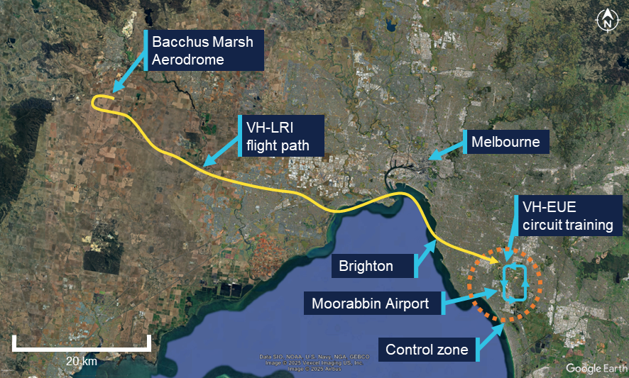
On the afternoon of 9 August 2025 an Aero Commander 500-U, registered VH-LRI and operated by 360° Aviation Group, was being repositioned from Bacchus Marsh Airport to Moorabbin Airport, Victoria, with a single pilot on board. At the same time, a Cessna 172, registered VH-EUE and operated by CAE Melbourne Flight Training, was being used to conduct circuit training[1] at Moorabbin Airport with a flight instructor and a student pilot on board (Figure 1). Both aircraft were operating under the visual flight rules (VFR).[2]
Figure 1: Aircraft flight paths
Source: Flight data overlaid on Google Earth, annotated by the ATSB
Weather conditions at the airport included clear skies, greater than 10 km visibility and a light southerly wind. At 1321, the pilot of VH-LRI contacted Moorabbin Airport air traffic control (ATC) as the aircraft approached Brighton to request a clearance to enter the control zone. The western circuit controller cleared the aircraft to enter the control zone and continue toward the airport, instructing the pilot to join an oblique base for runway 17R.[3] The controller also advised the pilot that they were ‘number 1’, indicating that there was no traffic ahead that was approaching the same runway.
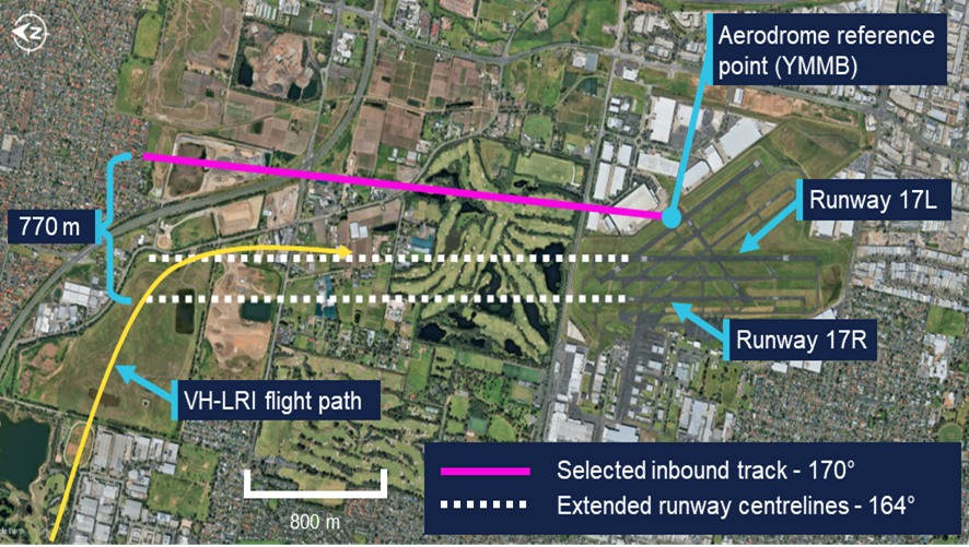
The pilot of VH-LRI recalled that at this time they configured their GPS navigation unit to assist them in orienting with the runway. To achieve this, they set the destination waypoint as ‘YMMB’, the airport code for Moorabbin Airport (see the section titledAerodrome reference point), and an inbound track of 170° corresponding to the approximate heading of runway 17R. This inbound track was 770 m offset to the east from the runway 17R extended centreline (Figure 2). They also carried an electronic flight bag (EFB) displaying navigation charts and showing the orientation of the runways.
Figure 2: Aircraft flight path relative to inbound track and runway centrelines
Source: Google Earth, annotated by the ATSB
At 1325, the western controller observed VH-LRI on the base leg of runway 17R and cleared the aircraft to land. By this time VH-EUE was on final approach to runway 17L. The pilot of VH-LRI recalled using a combination of visual references, and GPS navigation indications, to inform when they were approaching the centreline of runway 17R and should commence a turn to intercept the final approach course. They also recalled that, while expecting to be aligning with the western runway closest to the coast, they observed that their GPS unit was aligning them to the left of where they expected.
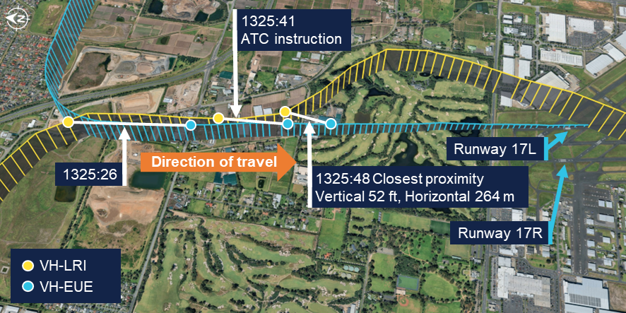
Approximately 12 seconds later, VH-LRI crossed the final approach course of runway 17R and turned to join final approach for runway 17L (Figure 3), aligning with the runway at 1325:26. The pilot of VH-LRI recalled that, at around that time they observed VH-EUE in front of them. Recognising that they had been advised not to expect preceding traffic they realised that they were not aligned with the correct runway.
Figure 3: VH-LRI and VH-EUE flight paths on final approach
The ATSB has connected the data points from each flight at the same time to show the relative positions of the aircraft at the corresponding time. Source: Flight data overlaid on Google Earth, annotated by the ATSB
The western circuit controller reported that when looking toward the final approach area of the runways they observed that VH-LRI and VH-EUE were closer to each other than expected. They alerted the eastern circuit controller to the situation and, at 1325:41, asked the pilot of VH-LRI over the radio to confirm they were on final for runway 17R. Observing the aircraft commence a left turn, they immediately asked the pilot why they were doing so, to which the pilot responded that they were orbiting. The controller then advised the pilot that they could not orbit and instructed them to join upwind for runway 17R and climb to 1,500 ft. They further advised the pilot that there was traffic low, on short final for the other runway and to make sure they joined upwind for runway 17R. The pilot read back this instruction, discontinued the orbit and commenced a climb back toward the airport.
At the same time as the western circuit controller contacted the pilot of VH-LRI, the eastern circuit controller contacted the occupants of VH-EUE to advise that there was an aircraft in their vicinity approaching the incorrect runway. In response, the instructor of VH-EUE advised that they would go around. The controller instructed them not to go around, and instead to continue their approach, clearing them for a touch-and-go landing. The instructor read back the instruction and continued toward the runway.
During the radio exchanges, at 1325:48, the proximity between the aircraft reduced to 52 ft vertically and 264 m horizontally. While the instructor on board VH-EUE did not see VH-LRI until it had passed on their left and had commenced climbing, the pilot of VH-LRI advised that they maintained visual contact with the Cessna throughout the final approach.
Following the deconfliction, VH-LRI climbed to 1,500 ft, conducted a visual circuit for runway 17R and landed without further incident. The instructor and student on board VH‑EUE completed a touch-and-go landing and continued circuit training. The instructor reported they were not aware of the proximity of VH-LRI until reviewing flight data after the flight. They also reported that the student pilot was solely focused on operating the aircraft at the time and was not aware that any incident had occurred.
Context
Pilots
The pilot of VH-LRI held a commercial pilot licence (aeroplane) issued in 2022 and a class 1 aviation medical certificate. They had accumulated 2,058 flight hours, of which 32 hours were operating the Aero Commander 500. In the previous 90 days, the pilot had accumulated 110 flight hours. They completed an instrument proficiency check in October 2024.
The pilot advised that they had flown into Moorabbin as pilot in command once previously, approximately 9 months before. They reported that they had talked to their chief pilot and another pilot at the operator familiar with Moorabbin Airport for advice prior to the flight. They further reported that they reviewed the En Route Supplement Australia (ERSA) and satellite imagery to familiarise themselves with the runway layout and procedures at Moorabbin and considered themselves sufficiently prepared.
The flight instructor on board VH-EUE held a commercial pilot licence (aeroplane) and a class 1 aviation medical certificate. They had accumulated 1,818 flight hours, of which 1,124 hours were operating the Cessna 172. In the previous 90 days, the pilot had accumulated 82 hours. The student pilot had accumulated 18 hours, all in the Cessna 172 and all within the last 90 days.
Aircraft
Aero Commander VH-LRI
VH-LRI was an Aero Commander 500-U aircraft fitted with 2 Lycoming IO-540-E1A5 engines, each driving a Hartzell constant speed propellor. The aircraft was manufactured in 1967 and first registered in Australia in 1991. It was subsequently registered with the operator in August 2025.
At the time of the occurrence, the aircraft had accumulated 5,543 hours total time in service. The last periodic inspection was conducted in May 2025, and the maintenance release showed no outstanding items. The aircraft was equipped with both ADS-B out and in capability, including a traffic awareness and alerting system. The pilot recalled hearing the aural traffic alert activate prior to Brighton due to traffic in the area. However, they did not recall hearing any alert on approach to the airport.
Cessna 172S VH-EUE
VH-EUE was a Cessna 172S fitted with a Lycoming IO-360-L2A engine powering a McCauley propellor. The aircraft was manufactured and registered with the operator in 2006. The ATSB did not request any information on the aircraft’s maintenance history. The operator advised that the aircraft was not equipped with ADS-B out or in capability, however recorded flight data was downloaded from the aircraft’s avionics.
Moorabbin Airport
Runway layout
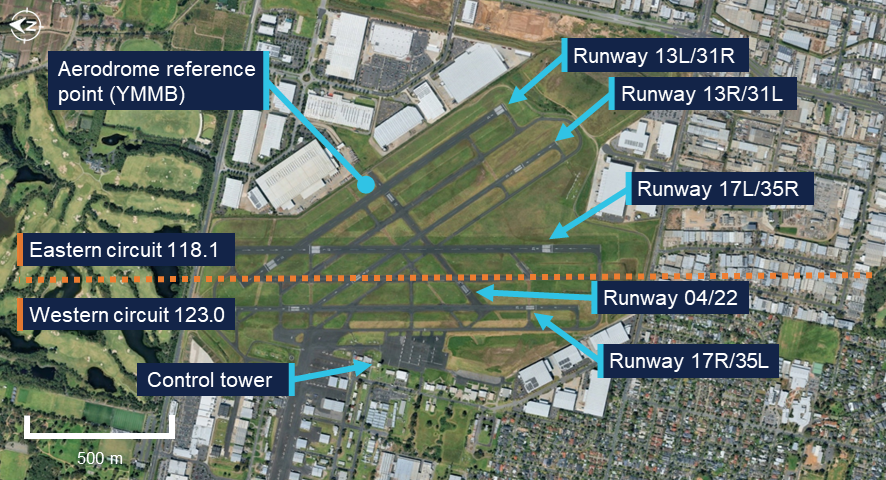
Moorabbin Airport has numerous runways (Figure 4), with the preferred runways being the north-south parallel runways of 17/35. Two additional parallel runways 13/31 were also available, while the shortest of the runways, runway 04/22, was not available unless operationally required. At the time of the occurrence, runways 17L and 17R were nominated as the duty runways.
Figure 4: Moorabbin Airport runway layout
Source: Google Earth, annotated by the ATSB
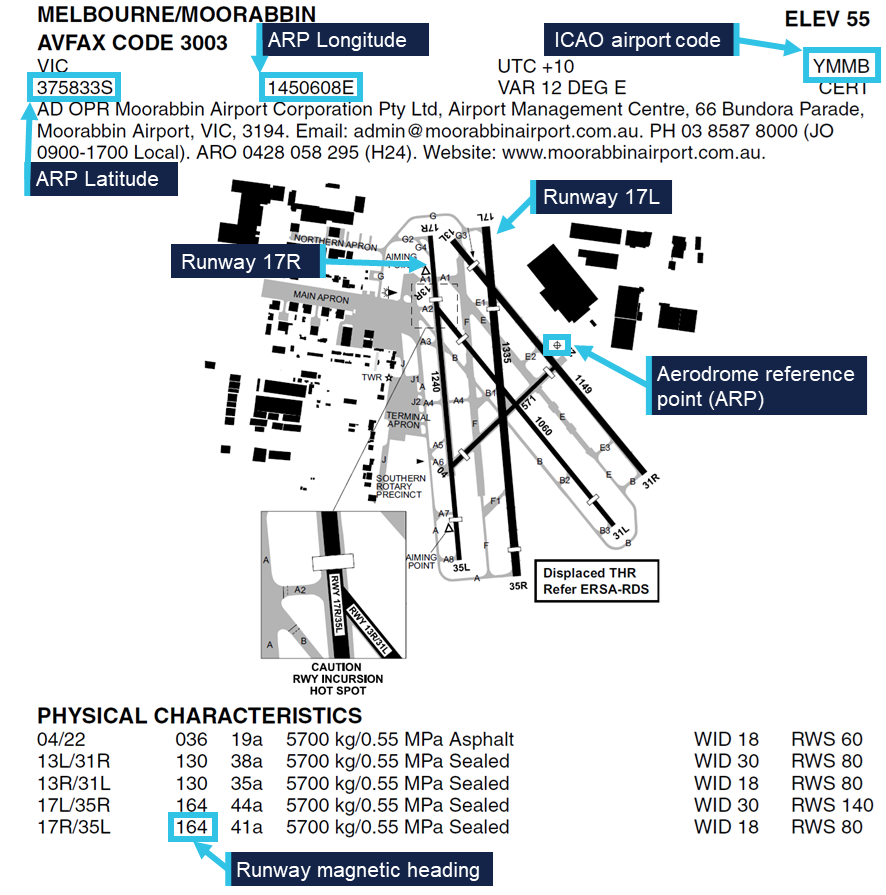
The En Route Supplement Australia (ERSA) (Figure 5) contained information on the physical characteristics of each runway, including that the magnetic heading was 164° for runways 17L and 17R. The runway designations represented the magnetic heading of the runway to the nearest 10°. However, the magnetic variation at Moorabbin Airport had increased approximately 1° over the previous 40 years and therefore the magnetic heading of the runways had drifted slightly since they were originally named.
Figure 5: En Route Supplement Australia (ERSA) extract
Source: Airservices Australia, annotated by the ATSB
Aerodrome reference point
The airport’s aerodrome reference point (ARP) was the designated geographical location of the airport, and the location associated with the International Civil Aviation Organisation (ICAO) airport code YMMB in aircraft navigation databases. The ARP for Moorabbin Airport was located on the eastern side of the airport, near the runway 22 threshold and 440 m away from the runway 17R centreline. This location was published in the ERSA as a latitude and longitude and shown graphically on the aerodrome plan.
Air traffic control
During tower hours, Moorabbin Airport operated as a Class D aerodrome. Pilots were required to establish and maintain 2-way communications with the tower and receive a clearance prior to entering the control zone. When operating in the airspace, aircraft operating under the visual flight rules (VFR) were given traffic information with respect to all other flights, but did not receive a separation service. Pilots were responsible for sighting and maintaining separation from other aircraft. If a pilot was unable to see, or lost sight of, other aircraft notified as traffic they were required to immediately advise ATC.
When operating parallel runways, Moorabbin Airport operated simultaneous independent circuits with each circuit utilising a different radio frequency. The eastern circuit, on runway 17L, was predominantly for circuit training and used the radio frequency 118.1 for communications between flight crew operating in the circuit and ATC. The western circuit, on runway 17R, was typically used for aircraft arriving from and departing to the west and used the radio frequency 123.0. Pilots operating in one circuit were not expected to monitor the radio frequency of the other circuit and the Aeronautical Information Package (AIP) stated that:
Operations will be regulated independently in each circuit, with an ATC clearance required to enter the opposite circuit or airspace.
At the time of the occurrence, 3 controllers were on duty in the control tower. One controller was controlling the eastern circuit while another was controlling the western circuit. A third controller was responsible for ground movements on a separate frequency. The controllers communicated with pilots in their circuit on a headset. They also had an awareness of activity in the other circuit via speakers in the tower broadcasting each frequency. In addition, the controllers were positioned physically close to each other and could communicate directly when required.
The tower was equipped with a tower situational awareness display (TSAD) which provided radar information that could be used to assist when providing control services. The western circuit controller advised that information provided by this system was limited and therefore it was not typically utilised for monitoring aircraft within the circuit area. Instead, each aircraft was monitored visually, using binoculars to assist. They further advised that at the time of the occurrence the airport was busy with multiple aircraft arriving and departing, in addition to aircraft transiting outside of the control zone to the west. There were also multiple aircraft established in the eastern circuit in addition to VH-EUE. As such, the controllers’ workload required them to direct attention to each aircraft in turn.
Related occurrences
The ATSB database contained 73 instances of aircraft approaching or landing on the incorrect runway at Moorabbin between 2015 and July 2025. During the course of this investigation the ATSB was advised of a similar occurrence that occurred on 13 August 2025 involving the same aircraft, but with a different pilot and without confliction with other traffic. The pilot of this flight advised that they had similarly configured their GPS navigation unit to provide guidance to the aerodrome reference point without realising its distance from the runway. In addition, it was reported to the ATSB that due to the high number of training flights at Moorabbin Airport, aircraft inadvertently entering into the other circuit occurred relatively regularly and was something controllers were alert for.
Safety analysis
Planning the flight to Moorabbin Airport, the pilot of VH-LRI identified that having flown there only once previously, the flight required additional planning and preparation. This included:
consulting pilots familiar with Moorabbin Airport
reviewing the information in the En Route Supplement Australia (ERSA)
studying satellite imagery of the airport.
Additionally, in flight they utilised their electronic flight bag (EFB) to display the runway configuration and setup their GPS navigation to provide guidance. All of these measures were intended to improve the pilot’s situation awareness when approaching an unfamiliar aerodrome.
However, when reviewing the ERSA, the pilot did not identify that the aerodrome reference point (ARP) was located distant from the runway 17R centreline. Additionally, they did not identify that the magnetic heading of the runway differed slightly from that implied by its designation. Consequently, the inbound track configured for guidance was offset and deviated away from the runway centreline. At the point that the aircraft crossed the runway 17R centreline, the navigation unit would have indicated that the aircraft was still significantly to the right of the configured inbound track. Therefore, it is likely that the navigation indications contributed to the pilot flying through the runway centreline of 17R and joining final for 17L behind VH-EUE. VH-LRI was not advised of VH-EUE as traffic by air traffic control (ATC) as the other aircraft was operating in the eastern circuit, which required an additional clearance to enter. In addition, VH-EUE was not equipped with ADS-B out and therefore would not have been detected by a traffic awareness system.
VH-LRI was being periodically visually monitored by the western circuit controller as it approached the airport. During this time, both the eastern and western controllers’ attention was also directed to other traffic. Therefore, both controllers were likely looking away from the final approach path when VH-LRI crossed the runway 17R centreline and entered the eastern circuit. The deviation was not detected until visual contact was re‑established by the western circuit controller, by which time the aircraft was already on final approach for runway 17L.
While the distance between the aircraft reduced as they converged on the same final flightpath, as the pilot of VH-LRI reported that visual contact was maintained, there was likely no significant risk of a collision. However, upon intervention by ATC, the initial instinct of the pilot of VH-LRI was to orbit to the left, while the instructor on board VH‑EUE intended to climb. Initiation of a climb by VH-EUE would have increased the risk of collision between the aircraft, while an orbit would have placed VH-LRI in conflict with other aircraft in the eastern circuit. Therefore, the timely issuing of instructions contrary to the pilots’ intentions deconflicted the aircraft and directed them away from other traffic.
Findings
ATSB investigation report findings focus on safety factors (that is, events and conditions that increase risk). Safety factors include ‘contributing factors’ and ‘other factors that increased risk’ (that is, factors that did not meet the definition of a contributing factor for this occurrence but were still considered important to include in the report for the purpose of increasing awareness and enhancing safety). In addition ‘other findings’ may be included to provide important information about topics other than safety factors.
These findings should not be read as apportioning blame or liability to any particular organisation or individual.
From the evidence available, the following findings are made with respect to the approach to incorrect runway involving Aero Commander 500-U, VH-LRI, at Moorabbin Airport, Victoria, on 9 August 2025.
Contributing factors
Due to unfamiliarity with the airport, the pilot of the Aero Commander configured their GPS navigation unit to provide guidance to the runway. However, due to the waypoint and track selected, the guidance was significantly offset from the runway’s centreline, resulting in the pilot inadvertently intercepting the final approach path of the parallel runway in proximity to a Cessna 172.
Other findings
Identifying that the aircraft were in close proximity, air traffic control quickly issued instructions to both pilots, deconflicting the aircraft and directing them away from other traffic.
Safety actions
Whether or not the ATSB identifies safety issues in the course of an investigation, relevant organisations may proactively initiate safety action in order to reduce their safety risk. All of the directly involved parties are invited to provide submissions to this draft report. As part of that process, each organisation is asked to communicate what safety actions, if any, they have carried out to reduce the risk associated with this type of occurrences in the future.
Safety action by 360° Aviation Group
360° Aviation Group disseminated information to flight crew about the potential for misleading indications when using the aerodrome reference point for navigation at Moorabbin Airport.
Safety action by CAE Melbourne Flight Training
CAE Melbourne Flight Training advised that it was incorporating ADS-B in/out capability into the Cessna 172s in its fleet that were not currently equipped.
Sources and submissions
Sources of information
The sources of information during the investigation included:
the pilot and operator of the Aero Commander
the flight instructor and operator of the Cessna
the air traffic controllers
recorded data from aircraft avionics
Airservices Australia
Bureau of Meteorology.
Submissions
Under section 26 of the Transport Safety Investigation Act 2003, the ATSB may provide a draft report, on a confidential basis, to any person whom the ATSB considers appropriate. That section allows a person receiving a draft report to make submissions to the ATSB about the draft report.
A draft of this report was provided to the following directly involved parties:
the pilot and operator of the Aero Commander
the flight instructor and operator of the Cessna
the air traffic controllers
Airservices Australia
Civil Aviation Safety Authority.
Submissions were received from:
the operator of the Aero Commander
the operator of the Cessna
Airservices Australia
Civil Aviation Safety Authority.
The submissions were reviewed and, where considered appropriate, the text of the report was amended accordingly.
Purpose of safety investigations
The objective of a safety investigation is to enhance transport safety. This is done through:
identifying safety issues and facilitating safety action to address those issues
providing information about occurrences and their associated safety factors to facilitate learning within the transport industry.
It is not a function of the ATSB to apportion blame or provide a means for determining liability. At the same time, an investigation report must include factual material of sufficient weight to support the analysis and findings. At all times the ATSB endeavours to balance the use of material that could imply adverse comment with the need to properly explain what happened, and why, in a fair and unbiased manner. The ATSB does not investigate for the purpose of taking administrative, regulatory or criminal action.
About ATSB reports
ATSB investigation reports are organised with regard to international standards or instruments, as applicable, and with ATSB procedures and guidelines.
Reports must include factual material of sufficient weight to support the analysis and findings. At all times the ATSB endeavours to balance the use of material that could imply adverse comment with the need to properly explain what happened, and why, in a fair and unbiased manner.
An explanation of terminology used in ATSB investigation reports is available here. This includes terms such as occurrence, contributing factor, other factor that increased risk, and safety issue.
Publishing information
Released in accordance with section 25 of the Transport Safety Investigation Act 2003
Ownership of intellectual property rights in this publication
Unless otherwise noted, copyright (and any other intellectual property rights, if any) in this report publication is owned by the Commonwealth of Australia.
Creative Commons licence
With the exception of the Commonwealth Coat of Arms, ATSB logo, and photos and graphics in which a third party holds copyright, this report is licensed under a Creative Commons Attribution 4.0 International licence.
The CC BY 4.0 licence enables you to distribute, remix, adapt, and build upon our material in any medium or format, so long as attribution is given to the Australian Transport Safety Bureau.
Copyright in material obtained from other agencies, private individuals or organisations, belongs to those agencies, individuals or organisations. Where you wish to use their material, you will need to contact them directly.
[1]Circuit training: a phase of pilot training focused on take-offs and landings. It involves making approaches to the runway, touching down and then applying power to take off again.
[2]Visual flight rules (VFR): a set of regulations that permit a pilot to operate an aircraft only in weather conditions generally clear enough to allow the pilot to see where the aircraft is going.
[3]Runway number: the number represents the magnetic heading of the runway. The runway identification may include L, or R as required for left or right when there are parallel runways.
On 25 June 2025, the flight crew of a Jetstar Airways Airbus A321-251, VH-OYF, were conducting a scheduled passenger transport flight, JQ38, from Denpasar International Airport, Bali, Indonesia, to Sydney, New South Wales. The first officer was the pilot flying and the captain was the pilot monitoring.
During the landing at Sydney Airport, the aircraft floated for a prolonged period along the runway, was subject to a right crosswind and drifted left of the runway centreline. The captain responded by commanding a go-round which the first officer executed.
The crew proceeded to continue with the published missed approach procedure and subsequently landed without further incident.
What the ATSB found
The ATSB found that after the first officer initiated the flare manoeuvre, their control inputs resulted in a lateral deviation from the runway centreline when the aircraft floated for a prolonged period in crosswind conditions.
After the captain commanded a go-around, they inadvertently manipulated their sidestick control, which resulted in a brief period where simultaneous control inputs occurred. The crew were alerted by a ‘dual input’ generated voice message and the captain took control. There was a moment of preoccupation which resulted in the first stage of flap being retracted out of sequence, however, there were no associated flight envelope exceedances or negative effects on aircraft performance.
Safety message
Sound go-around decision-making is an effective defence against the hazards associated with low-level manoeuvring during the landing phase of flight, such as lateral runway excursions. If adequate safety margins cannot be maintained during an approach and landing, the correct and expected response is to go around.
Being go-around minded improves crew readiness and supports timely, coordinated actions during a period of high workload. This should involve crew members reviewing potential go‑around scenarios, procedures and responses prior to conducting an approach.
When flight crews are faced with the unexpected need to execute a go-around even at the final stages of landing, effective crew resource management, with clear communication between flight crew, is essential. This promotes effective teamwork when responding to disruptions and increased workload under stress, ensuring that the aircraft remains on a safe flight path and is correctly configured for the relevant phase of flight.
The investigation
The ATSB scopes its investigations based on many factors, including the level of safety benefit likely to be obtained from an investigation and the associated resources required. For this occurrence, the ATSB conducted a limited-scope investigation in order to produce a short investigation report, and allow for greater industry awareness of findings that affect safety and potential learning opportunities.
The occurrence
On the evening of 25 June 2025, a Jetstar Airways Pty Limited Airbus A321-251 registered VH‑OYF was operating on a schedule passenger transport Jetstar flight, JQ38, from Denpasar International Airport, Bali, Indonesia, to Sydney, New South Wales. The flight was scheduled to arrive at Sydney Airport the following morning at 0630 AEST.[1] The operating crew included the captain, first officer, 6 cabin crew and 234 passengers. For the flight to Sydney, the first officer was the pilot flying (PF) and the captain was the pilot monitoring (PM).[2]
After departing Denpasar, the aircraft climbed to flight level (FL) 330[3] and later descended to FL310 after reaching Australian airspace due to turbulence en route. Due to the turbulence en route, the captain elected not to take any controlled rest on the nearly 6‑hour flight, while the first officer stated they would not usually take controlled rest in flight.
Prior to descent, the flight crew briefed for the arrival at Sydney, recalling that the turbulent conditions and the crosswind for the approach and landing were the main considerations.
At 0554, the flight crew commenced their descent to the west-south-west of Sydney Airport and was cleared for the approach for runway 16R[4] which was conducted in day visual meteorological conditions[5] using the autopilot. The flight crew recalled there was a 30 kt crosswind down to about 500 ft above mean sea level (AMSL) and the approach up to that point was ‘pretty normal.’ Air traffic control (ATC) advised the crew to expect an 8 kt right crosswind for landing and the first officer chose to land in the flap 3 configuration,[6] which was consistent with guidance for landing in ‘rough’ conditions. (The first officer was procedurally restricted to a maximum crosswind landing component of 20 kt).
The aircraft reached 500 ft at 0621:14 and the captain called ‘stable’ (see Stabilised approach criteria). The first officer disengaged the autopilot 5 seconds later as the aircraft approached 400 ft and recalled encountering turbulence which placed the aircraft ‘a little higher’ on the approach. At 0621:45 at 90 ft, the first officer pitched forward, which they observed resulted in a 900 ft per minute rate of descent.
At 0621:51, the first officer initiated the flare at 50 ft and reduced the thrust levers to idle at around the final approach speed (VAPP)[7] of 150 kt, which included a wind correction of 5 kt. At this point the first officer recalled they ‘over flared’. The captain also observed that the first officer applied the flare technique that was consistent with the technique for landing in the flap full configuration. The aircraft subsequently floated for a prolonged period along the runway after the first officer’s flare manoeuvre.
During the prolonged float, the aircraft was subjected to the crosswind conditions for a greater length of time. After observing the centreline deviation, the captain commanded a go-around approximately 600 m past the runway threshold, just prior to touchdown. The captain recalled they were ‘startled by the need to go around’ as the approach seemed ‘benign’ aside from the crosswind. They also reported a sudden stress response at this time as they had to rapidly transition from landing to commencing the go-around.
In response to the captain’s command, the first officer set take-off/go-around thrust at 0621:59 (Figure 1), which initiated the published missed approach procedure for the 16R GBAS landing system (GLS)[8] approach in the aircraft flight management system. The first officer also referenced their primary flight display (PFD) to command a target pitch attitude of 15° nose up.
At this point, the captain recalled they instinctively applied control inputs via their sidestick while the aircraft was just above the runway, and the crew were alerted to this by the aircraft’s ‘dual input’ voice message (see Sidestick priority logic).
The captain then engaged their sidestick pushbutton, and the first officer recalled hearing the ‘priority left’ voice message and the captain announce, ‘I have control.’ The captain subsequently took control of the thrust levers and the first officer relinquished control and became PM after the aircraft achieved a positive rate of climb. It was the role of the PM to retract the flap ‘one step’ at this point (see Go-around procedure).
Figure 1: Overview of go-around
Source: Google Earth, annotated by the ATSB
The captain announced the active flight modes on their PFD, which prompted the first officer to call ‘positive climb.’ The captain subsequently instructed the first officer to retract the landing gear, which was accomplished 42 ft above the runway at 0622:20.
At this time, the captain looked up to the flight control unit located on the cockpit glareshield to engage the autopilot. After this was actioned, they looked back to their PFD and was ‘startled’ when they noticed that the aircraft suddenly banked right and responded by disengaging the autopilot at 0622:22. They subsequently realised that the aircraft flight director was providing commands for the published missed approach procedure and subsequently re-engaged the autopilot at 0622:29.
The captain then requested flap 1, but the first officer noticed they were still configured with Flap 3 and retracted the flap by one step and announced, ‘flap 2.’ This occurred at 0622:32 when the airspeed reached 174 kt, which was below the maximum flap 3 speed of 195 kt.
They continued to follow the missed approach procedure, and the first officer advised ATC they were going around. The crew were given instructions to track for a right downwind for runway 16R at 4,000 ft. The captain recalled conducting a welfare check on the first officer, briefed the cabin manager via the interphone and made an announcement to the passengers through the public address system.
The captain elected to remain as PF for the remainder of the flight, with the first officer acting as PM. The crew then conducted a second GLS approach for runway 16R, landing at 0638 without further incident.
Context
Flight crew information
The captain held an Air Transport Pilot Licence (Aeroplane), class 1 aviation medical certificate, and had accrued 5,921 hours total flying time, 1,480 of which were in the Airbus A320 and A321 aircraft types.
The first officer held a Commercial Pilot Licence (Aeroplane), class 1 aviation medical certificate, and had 2,212 hours total flying time, 551 of which were on the Airbus A320 and A321 aircraft types.
Fatigue
The captain reported that they felt 'moderately tired' during the go-around, likely due to the back-of-the clock[9] flight, which departed Denpasar at 0057 local time in Sydney. They also stated there was limited opportunity for controlled rest during the flight and their nap prior to the flight was disrupted due to noise at the hotel. The first officer reported feeling 'ok, somewhat fresh.’
The flight crew also reported they had an adequate rest opportunity the evening prior to the flight and obtained around 6 hours sleep in the previous 24 hours and around 13–14 hours in the previous 48 hours. Their sleep during the rest opportunity was reported to be good quality and the conditions at the hotel where they spent the night were suitable and therefore conducive to obtaining restful sleep. Biomathematical modelling[10] of the flight crew’s roster for the 2 weeks leading up to the flight indicated a low likelihood of fatigue.
The ATSB considered that fatigue was unlikely to have affected the flight crew’s performance at the time of the occurrence.
Aircraft information
General
The Airbus A321-251NX is a modern, fly-by-wire aircraft, powered by 2 CFM International LEAP-1A32 turbofan engines and had seating for 232 passengers in a single-class layout.
All the flight controls are electronically actuated with the pilots using sidesticks to fly the aircraft in pitch and roll during manual flight. The 2 sidestick controllers are not coupled mechanically, and they send separate sets of signals to the flight control computers.
Sidestick priority logic
Jetstar Airways A320-A321 Flight crew operating manual (FCOM) contains the following description of the aircraft sidestick priority logic:
At all times, only one flight crewmember should fly the aircraft. However, if both flight crewmembers use their sidesticks simultaneously, their orders are algebraically added.
The flight control laws limit the combined order to the equivalent of the full deflection of one sidestick.
In this case the two green SIDE STICK PRIORITY lights on the glareshield come on and "DUAL INPUT" voice message is activated.
A flight crewmember can deactivate the other sidestick and take full control, by pressing and keeping pressed the sidestick pb (Figure 2).
A “PRIORITY LEFT” or “PRIORITY RIGHT” audio voice message is given each time priority is taken.
Figure 2: Airbus A320/A321 captain's side sidestick and sidestick pushbutton
Source: Operator, annotated by the ATSB
Post-flight maintenance
The operator reported that there were no corrective maintenance actions that were required to be carried out in relation to the occurrence. The aircraft subsequently operated a scheduled passenger service the following day.
Meteorological information
The pre‑flight briefing package provided to the flight crew from the operator’s flight dispatcher included the aerodrome forecast[11] for Sydney Airport. The forecasted weather conditions for the scheduled time of arrival 0630 local time on 26 June indicated:
wind direction of 240° at 15 kt with gusts up to 25 kt
One-minute weather data for Sydney Airport from the Bureau of Meteorology indicated a wind direction of 255° at 17 kt with gusts up 20 kt at the time of the occurrence.
Airport information
Runway 16R at Sydney Airport is oriented on a magnetic heading of 155° and has a declared length of 3,962 metres with a width of 45 metres. A precision approach path indicator system is installed and set to 3° with a threshold crossing height of 64 ft.
For daytime operations, the runway centreline, aiming point and touchdown zone markings provide visual references to assist pilots with approach and landing (Figure 3).
Figure 3: Sydney Airport runway 16R markings
Source: Google Earth, annotated by the ATSB
Recorded information
The aircraft’s quick access recorder data which captured the incident approach indicated that, as the aircraft descended below 1,000 ft, it maintained an appropriate speed and flightpath with no sustained exceedances of the stable approach criteria throughout the approach.
At 0621:59, the recorded data captured the captain’s control inputs commencing concurrently with the initiation of the go-around, while the first officer was actively manipulating their sidestick control. Simultaneous control inputs lasted for a duration of 6 seconds (Figure 4), while the aircraft’s pitch attitude remained below the aircraft’s pitch limit of 11.5° until the aircraft had climbed through about 50 ft.
The recorded data further indicated that the wind direction and speed varied following the flare manoeuvre, however the crosswind component remained well below the first officer’s operational limitation. The wind direction and speed was 315° at 13 kt with a crosswind component of 5 kt when the go-around was initiated.
Figure 4: Graphical representation of the recorded quick access data
Source: Quick access recorder from VH-OYF, annotated by the ATSB
Following the initiation of the go-around, the landing gear was retracted at 06:22:20 and 12 seconds later, the flap was retracted to the flap 2 configuration[14] at 174 kt.
Operational information
Stabilised approach criteria
Jetstar Airways A320-A321 Flight crew operating manual (FCOM) defined a stabilised approach criteria as being established on the correct lateral and vertical flight path by 1,000 ft height above airport (HAA), configured for landing, and within the stated tolerances with the required checklists completed by 500 ft HAA. The FCOM also stated that if these criteria could not be met, or if the approach became unstable below 1,000 ft HAA, a missed approach was required.
The crew reported the approach was stabilised against these criteria, which was consistent with the available recorded data.
Touchdown zone
The FCOM provided the following operational information regarding the touchdown zone:
The touchdown zone commences at 300 m (1000 ft) beyond the threshold and will not normally extend further than 600 m (2000 ft) beyond the threshold.
It is a requirement that the touchdown is planned to occur within the touchdown zone. Should it become apparent that the aircraft will touch down further than 600 m (2,000 ft) beyond the threshold, and the PIC believes that the landing is safe to continue, the PF must apply maximum reverse thrust and sufficient braking to ensure the aircraft stops within the landing distance available. If the PIC decides that a go-around is required, they will without delay, call “Go-Around”. In all cases this must be completed before the PF initiates reverse thrust.
The captain stated that runway 16R in Sydney was long enough to stop the aircraft on the runway if they had continued with the landing during the occurrence. This would have involved requesting maximum reverse and manual braking as necessary after the aircraft touched down.
The FCOM did not specifically reference runway centreline tracking during a visual approach, however the captain stated that it was their personal expectation that a deviation from the runway centreline would lead them to calling for a go-around.
Transfer of control
The operator described procedures for transfer of control within the FCOM as follows:
The pilot relinquishing control of the aircraft shall say “You have control”. The pilot assuming control shall ensure that they have clear and unobstructed access to the flight controls and, when ready, say “I have control”. Only then is the pilot relinquishing control permitted to remove their hands and feet from the flight controls.
In critical phases of flight the PIC must be alert and positioned such that they can assume immediate control of the aircraft.
Following the occurrence, the captain stated the preferable method to conduct a go‑around at low level would have been to announce ‘I have control’ and initiate the go‑around themselves. They stated that their primary consideration when conducting a go‑around at low level was to avoid the risk of tail strike.
Go-around procedure
The FCOM defined the go-around procedure for the A320/A321, which specified the task sequence, memory-based crew actions and applicable guidance relating to techniques and navigation (Figure 5).
Following the occurrence, the captain stated that although they could have taken over and landed, they believed that going around was considered the safest option. The first officer also stated, at about that time, that they were in the mindset of preparing to initiate a go-around themselves.
Related occurrences
The following ATSB investigation highlights the importance of pilots maintaining their readiness for a go-around on every approach as it is typically a period of high workload requiring effective crew coordination.
On the morning of 18 May 2018, an Airbus A320 aircraft, registered VH-VQK, was being operated on a regular public transport flight by Jetstar Airways. The flight departed from Sydney for Ballina/Byron Gateway Airport, New South Wales.
The flight crew conducted a go-around on the first approach at Ballina because the aircraft’s flight path did not meet the operator’s stabilised approach criteria. On the second approach, at about 700 ft radio altitude, a master warning was triggered because the landing gear had not been selected DOWN. The flight crew conducted a second go‑around and landed without further incident on the third approach.
The flight crew did not follow the operator’s standard procedures during the first go‑around and subsequent visual circuit at 1,500 ft. In particular, the flaps remained at flaps 3 rather than flaps 1 during the visual circuit. This created a series of distractions leading to a non‑standard aircraft configuration for a visual circuit. Limited use of available aircraft automation added to the flight crew’s workload.
Safety analysis
During the approach to Sydney airport, with the first officer acting as the pilot flying (PF), the flight crew reported experiencing a crosswind of up to 30 kt until descending through about 500 ft above mean sea level. The crew were advised by air traffic control to expect a right crosswind component of 8 kt for landing, which was within the first officer’s operational crosswind limit of 20 kt. The captain confirmed the approach was ‘stable’ at 500 ft and the first officer continued the approach as PF.
At 50 ft, the first officer initiated the flare manoeuvre prior to landing. They recalled they ‘over flared,’ and the aircraft subsequently floated for an extended period along the runway. During this time, the first officer’s control inputs did not counteract the effect of the crosswind, and the aircraft drifted left of the centreline. After observing the lateral deviation from the centreline, the captain commanded the first officer to conduct a go‑around.
This occurred just prior to the aircraft touching down when the flight crew would normally be focused on landing. The flight crew did not expect a go-around at the time and had to rapidly shift their focus to conducting the missed approach procedure. The captain recalled being ‘startled’ by the unexpected need to discontinue the landing, however they were more likely experiencing ‘surprise.’ Surprise is a cognitive-emotional response to something unexpected, which results from a mismatch between one’s mental expectations and perceptions (Rivera, Talone, Boesser, Jentsch, & Yeh, 2014). But their decision was consistent with the expectation that an approach be discontinued if the aircraft departed from the correct lateral flight path.
The unexpected change from landing to conducting a go-around close to the ground also resulted in the captain experiencing a sudden stress response at this time. When experiencing acute stress, people can respond quickly to a situation, but without conscious decision‑making (Wickens, Helton, Hollands, & Banbury, 2022). After the go‑around was commanded, there was a rapid increase in pitch attitude, engine thrust and airspeed, and in response the captain instinctively and inadvertently manipulated their sidestick while the first officer was flying, resulting in a dual-input alert.
The captain reported they only realised they had manipulated their sidestick when they heard the dual input alert. Their primary consideration during the go-around was to avoid an excessive rotation rate to avoid a tail strike, which did not occur. Additionally, operator procedures directed captains to be alert and be positioned to ‘assume immediate control of the aircraft’ during critical phases of flight.
Following the dual input alert, the captain took full control by engaging their sidestick push‑button and announced ‘I have control’, and the first officer assumed the role of pilot monitoring. A consequence of the control handover during the initial stages of the go‑around was the momentary interruption of sequential crew actions during the go‑around procedures. Interruptions typically disrupt the chain of procedure execution so abruptly that pilots turn immediately to the source of the interruption without noting the point where the procedure was suspended (Loukopoulos, Dismukes, & Barshi, 2009).
Additionally, there was a further disruption (rapid task switching) associated with the first officer and captain exchanging pilot flying and pilot monitoring roles. As a result, some of the procedural items were completed out of sequence (flap 3 retraction occurred after gear retraction).
Pilots are highly vulnerable to errors of omission when they must attend to multiple tasks. If one task becomes demanding, their attention is absorbed by these tasks demands and they can forget to switch their attention to other tasks (Loukopoulos, Dismukes, & Barshi, 2009). Although the flap retraction occurred out of sequence during the go-around, there were no associated flight envelope exceedances or negative effects on aircraft performance.
Findings
ATSB investigation report findings focus on safety factors (that is, events and conditions that increase risk). Safety factors include ‘contributing factors’ and ‘other factors that increased risk’ (that is, factors that did not meet the definition of a contributing factor for this occurrence but were still considered important to include in the report for the purpose of increasing awareness and enhancing safety). In addition ‘other findings’ may be included to provide important information about topics other than safety factors.
These findings should not be read as apportioning blame or liability to any particular organisation or individual.
From the evidence available, the following findings are made with respect to the control issues during landing and go-around involving Airbus A321, VH-OYF, at Sydney Airport, New South Wales, on 26 June 2025.
Contributing factors
During the landing after crossing the threshold, the first officer’s control inputs resulted in a lateral deviation from the runway centreline during a prolonged float.
After calling for a go-around, the captain inadvertently manipulated their sidestick while the first officer was the pilot flying, which resulted in a simultaneous control input and the go-around procedure being completed out of sequence.
Sources and submissions
Sources of information
The sources of information during the investigation included:
Jetstar Airways Pty Limited
Bureau of Meteorology
the flight crew
recorded data from the quick access recorder from VH-OYF.
References
Loukopoulos, L., Dismukes, R., & Barshi, I. (2009). The perils of multitasking. AeroSafety World, 4(8), 18-23.
Rivera, J., Talone, A., Boesser, C., Jentsch, F., & Yeh, M. (2014). Startle and surprise on the flight deck: Similarities, differences, and prevalence. In Proceedings of the human factors and ergonomics society annual meeting (Vol. 58, No. 1, pp. 1047-1051). Sage CA: Los Angeles, CA: SAGE Publications.
Wickens, C. D., Helton, W. S., Hollands, J. G., & Banbury, S. (2022). Engineering psychology and human performance, 5th edn. Routledge, doi: 10.4324/9781003177616.
Submissions
Under section 26 of the Transport Safety Investigation Act 2003, the ATSB may provide a draft report, on a confidential basis, to any person whom the ATSB considers appropriate. That section allows a person receiving a draft report to make submissions to the ATSB about the draft report.
A draft of this report was provided to the following directly involved parties:
Civil Aviation Safety Authority
the flight crew
Jetstar Airways Pty Limited
Bureau of Meteorology.
Submissions were received from:
the flight crew
Jetstar Airways Pty Limited.
The submissions were reviewed and, where considered appropriate, the text of the report was amended accordingly.
Purpose of safety investigations
The objective of a safety investigation is to enhance transport safety. This is done through:
identifying safety issues and facilitating safety action to address those issues
providing information about occurrences and their associated safety factors to facilitate learning within the transport industry.
It is not a function of the ATSB to apportion blame or provide a means for determining liability. At the same time, an investigation report must include factual material of sufficient weight to support the analysis and findings. At all times the ATSB endeavours to balance the use of material that could imply adverse comment with the need to properly explain what happened, and why, in a fair and unbiased manner. The ATSB does not investigate for the purpose of taking administrative, regulatory or criminal action.
About ATSB reports
ATSB investigation reports are organised with regard to international standards or instruments, as applicable, and with ATSB procedures and guidelines.
Reports must include factual material of sufficient weight to support the analysis and findings. At all times the ATSB endeavours to balance the use of material that could imply adverse comment with the need to properly explain what happened, and why, in a fair and unbiased manner.
An explanation of terminology used in ATSB investigation reports is available here. This includes terms such as occurrence, contributing factor, other factor that increased risk, and safety issue.
Publishing information
Released in accordance with section 25 of the Transport Safety Investigation Act 2003
Ownership of intellectual property rights in this publication
Unless otherwise noted, copyright (and any other intellectual property rights, if any) in this report publication is owned by the Commonwealth of Australia.
Creative Commons licence
With the exception of the Commonwealth Coat of Arms, ATSB logo, and photos and graphics in which a third party holds copyright, this report is licensed under a Creative Commons Attribution 4.0 International licence.
The CC BY 4.0 licence enables you to distribute, remix, adapt, and build upon our material in any medium or format, so long as attribution is given to the Australian Transport Safety Bureau.
Copyright in material obtained from other agencies, private individuals or organisations, belongs to those agencies, individuals or organisations. Where you wish to use their material, you will need to contact them directly.
[1]Local time in Sydney was Australian Eastern Standard Time (AEST), which is Coordinated Universal Time (UTC) +10 hours. Times in this report are AEST unless otherwise noted.
[2]Pilot flying (PF) and pilot monitoring (PM): procedurally assigned roles with specifically assigned duties at specific stages of a flight. The PF does most of the flying, except in defined circumstances, such as planning for descent, approach and landing. The PM carries out support duties and monitors the PF’s actions and the aircraft’s flight path.
[3]Flight level: at altitudes above 10,000 ft in Australia, an aircraft’s height above mean sea level is referred to as a flight level (FL). FL 330 equates to 33,000 ft.
[4]Runway numbering: the number represents the magnetic heading closest to the runway (runway 16 at Sydney Airport is oriented 155° magnetic) and R indicates the right most of 2 parallel runways.
[5]Visual meteorological conditions (VMC): an aviation flight category in which visual flight rules (VFR) flight is permitted – that is, conditions in which pilots have sufficient visibility to fly the aircraft while maintaining visual separation from terrain and other aircraft.
[6]Flap 3 on the A321-251 is 21° of flap and 22° of slat extension.
[7]Final approach speed (VAPP): the VAPP is the target airspeed for the aircraft when crossing the runway threshold with the aircraft configured for landing. VAPP is equal to the lowest selectable speed with the addition of wind correction. The wind correction is limited to a minimum of 5 kt and a maximum of 15 kt.
[8]GBAS landing system (GLS): a GLS consists of a GBAS ground station located on or in the vicinity of one or more aerodromes and an aircraft subsystem. The GBAS provides data and corrections for the GNSS ranging signals over a digital VHF data broadcast to the aircraft subsystem. The aircraft subsystem translates the position signal into flight guidance similar to that provided for an ILS.
[9]Back of the clock: Work schedules that involve extended periods of night-work between midnight and dawn.
[10]A biomathematical model of fatigue predicts the effect of different patterns of work on measures such as subjective fatigue, sleep, or the effectiveness of performing work, using mathematical algorithms. Each model uses different types of inputs and assumptions and produces different types of outputs, each having limitations. The ATSB used the biomathematical modelling software SAFTE-FAST and FAID Quantum for the analysis.
[11]Aerodrome forecast (TAF): a TAF is a coded statement of meteorological conditions expected at an aerodrome and within a radius of 5 nautical miles of the aerodrome reference point.
[12]Ceiling and visibility okay (CAVOK): visibility, cloud and present weather are better than prescribed conditions. For an aerodrome weather report, those conditions are visibility 10 km or more, no significant cloud below 5,000 ft, no cumulonimbus cloud and no other significant weather.
[13]Moderate turbulence: changes to accelerometer readings of between 0.5 g and 1.0 g at the aircraft’s centre of gravity. Moderate change to aircraft attitude and/or altitude may occur but aircraft remains under positive control. Usually small changes in airspeed. Difficulty in walking. Lose objects move about.
[14]Flap 2 on the A321-251 is 14° of flap and 22° of slat extension.
Occurrence summary
Investigation number
AO-2025-036
Occurrence date
26/06/2025
Location
Sydney Airport
State
New South Wales
Report release date
27/01/2026
Report status
Final
Investigation level
Short
Investigation type
Occurrence Investigation
Investigation status
Completed
Mode of transport
Aviation
Aviation occurrence category
Control issues, Missed approach, Warning devices
Occurrence class
Incident
Highest injury level
None
Aircraft details
Manufacturer
Airbus
Model
A321-251NX
Registration
VH-OYF
Serial number
11529
Aircraft operator
Jetstar Airways Pty Limited
Sector
Jet
Operation type
Part 121 Air transport operations - larger aeroplanes
On the afternoon of 13 June 2025, a Pilatus PC‑12, registered VH‑NWI and operated by Armada Aviation, was being used to conduct a charter air transport flight from Essendon Airport, Victoria, to Launceston Airport, Tasmania. On board were a pilot and 4 passengers.
During the approach to Launceston, the aircraft deviated left from the final approach course and intercepted the extended centreline of the adjacent taxiway. The aircraft then continued towards the taxiway where a Cessna 152 (C152) was holding for departure. Approaching the taxiway, the pilot conducted a low-level right then left turn to realign with the runway, before commencing a missed approach. During the manoeuvre the aircraft passed in close proximity to the C152. Following the missed approach, the aircraft conducted a visual circuit and landed without further incident.
What the ATSB found
The ATSB found that the final approach was conducted in clear conditions almost directly into the sun, exposing the pilot to glare. Subsequently, the pilot misidentified the taxiway as the runway and aligned the aircraft with the taxiway's extended centreline. The pilot then corrected the aircraft's flight path at a low level rather than conducting an immediate missed approach. During the manoeuvre the aircraft passed in close proximity to an aircraft on the taxiway.
It was also found that after identifying that the approaching aircraft was aligned with the taxiway, the instructor on board the aircraft on the taxiway made a radio broadcast, likely alerting both the pilot and air traffic control to the situation.
What has been done as a result
Armada Aviation circulated a notice to its aircrew advising them of hazards associated with a visual approach, such as sun glare. Additionally, it made the following changes to its operating procedures:
Updated the final decision to proceed to landing to include a requirement that the runway was confirmed and clear by 400 ft above ground level, or the approach minima.
Added a top of descent safety briefing to ensure pilots brief other risks associated with the visual approach segment following an instrument approach, including lighting configuration and sun position.
Updated the checklist of the final phase of flight to include checking that the runway was confirmed and clear.
Safety message
Sun glare can reduce a pilot’s visual effectiveness even when meteorological visibility is good. When flying visually in such conditions, pilots should crosscheck against available flight and navigation instruments in conjunction with external indicators, such as airport lighting, to verify that the aircraft is on the intended flight path.
If a discrepancy is identified below an appropriate stabilised approach height, an immediate missed approach should be conducted. Low-level manoeuvring outside of the published approach and associated obstacle clearance increases the risk of collision with terrain or objects on the ground.
The investigation
The ATSB scopes its investigations based on many factors, including the level of safety benefit likely to be obtained from an investigation and the associated resources required. For this occurrence, the ATSB conducted a limited-scope investigation in order to produce a short investigation report, and allow for greater industry awareness of findings that affect safety and potential learning opportunities.
The occurrence
On 13 June 2025, a Pilatus PC-12, registered VH‑NWI and operated by Armada Aviation, was being used to conduct a charter air transport flight from Essendon Airport, Victoria, to Launceston Airport, Tasmania (Figure 1). On board were a pilot and 4 passengers.
Figure 1: Occurrence flight
Source: Google Earth annotated by the ATSB
At 1511 local time, the aircraft commenced the instrument approach procedure for runway 32L[1] at Launceston. The weather at the time was predominately clear skies with few[2] clouds at 3,000 ft, variable wind up to 5 kt and visibility greater than 10 km.
At approximately the same time, the occupants (instructor and student) of a Cessna 152 (C152) on the ground at Launceston contacted air traffic control (ATC) to request taxi clearance for departure on a training flight. Due to the closure of a section of the taxiway (see Figure 4 and the section titled Construction works), the C152 was required to backtrack the runway and vacate onto taxiway A at the runway 32L threshold. The aircraft then turned 180° on the taxiway and stopped with the nose of the aircraft at holding point A. At 1515, the C152 reported to ATC that they had completed the taxi and were clear of the runway.
By this time VH‑NWI was established on the final segment of the approach, approximately 7 NM (13 km) from the runway. Shortly thereafter, ATC cleared the aircraft to land, later reporting that at this time they observed the aircraft established on the final approach. The pilot reported that throughout the final approach, they were looking into the sun and consequently they ‘couldn’t really see much at all’.
ATC reported again sighting the aircraft when it was approximately 4 NM (7 km) from the runway. At this point the aircraft was approximately 1,340 ft above ground level (AGL) and still aligned with the final approach course (Figure 2).
Figure 2: Final approach flight path
Recorded altitude resolution ± 12.5 ft, over underlying terrain elevation, rounded to nearest 5 ft. Source: ADS-B flight data overlaid on Google Earth, annotated by the ATSB
The pilot advised that, during the approach, they used the autopilot to manage the aircraft’s flight path until approximately 1,000 ft AGL. At this point they disconnected the autopilot and transitioned to looking outside. The pilot recalled that they were still looking into the sun and only seeing one feature on the ground that stood out. Identifying it as the runway, they began visually flying the aircraft towards it. Recorded flight data showed that at approximately 750 ft AGL, the aircraft began to deviate left until it intercepted the extended centreline of taxiway A. From this position the aircraft continued to descend towards the taxiway. At 1519, when the aircraft was approximately 120 ft AGL, weather cameras at the airport recorded images showing both the aircraft on final and the C152 at the holding point (Figure 3).
Figure 3: Weather camera images at 1519
Combination of 2 images: Left image camera bearing 135° (SE) at 1519:04, right image camera bearing 225° (SW) at 1519:02. Source: Bureau of Meteorology, annotated by the ATSB
The instructor on board the C152 recalled that upon looking for the approaching aircraft, they saw that it was lined up with the taxiway. At 1519:12, they made a radio broadcast on the Launceston Tower frequency advising ‘He’s landing on the taxiway’. Following the call, VH-NWI passed above and behind them. It then reappeared on their left side, after conducting a right, then left, turn to align with the runway.
A review of flight data showed that VH-NWI continued to descend as it tracked the taxiway extended centreline until 1519:16, at which point it commenced a right turn (Figure 4). During the turn, the aircraft passed over the taxiway at a height of approximately 45 ft AGL, 15 m behind holding point A, at which the C152 was positioned. Subsequently, the aircraft descended further as it flew over the grassed area between the taxiway and the runway before turning left to align with the runway centreline. During the realignment manoeuvre, the aircraft descended to approximately 15 ft AGL.
Figure 4: Low-level manoeuvre and missed approach
Recorded altitude resolution ± 12.5 ft, over underlying terrain elevation, rounded to nearest 5 ft. Source: ADS-B flight data overlaid on Google Earth, annotated by the ATSB
The pilot recalled that when not far from the runway environment they became aware that they were approaching the taxiway and in response turned the aircraft towards the runway. They further reported that they were not aware of the C152 at the holding point. While they recalled hearing a radio broadcast as they were moving towards the runway, they did not know who had made it.
ATC reported that upon hearing the broadcast from the C152 they observed VH-NWI on short final lined up with taxiway A, after which it immediately made a right turn to align with the runway. At 1519:22 they instructed the pilot to go around.[3] The pilot later reported that they heard the instruction from ATC, by which time they had decided to initiate a missed approach. Flight data recorded that the aircraft commencing a climb away from the runway at 1519:31. Following the missed approach, the pilot conducted a visual circuit and the aircraft landed without further incident. Subsequently, the C152 departed.
Context
Pilot
The pilot held an air transport pilot licence (aeroplane) issued in 2013 and a class 1 aviation medical certificate. They had accumulated 4,251 flight hours, of which 659 hours were operating the Pilatus PC‑12. In the previous 90 days, the pilot had accumulated 26 hours, all in the PC‑12. They completed an instrument proficiency check in January 2025.
The pilot reported that they had flown into Launceston Airport a number of times previously, both during the day and at night. They did not recall any prior occasion where sun glare had been an issue during final approach.
Aircraft
VH-NWI was a Pilatus PC‑12, powered by a Pratt & Whitney PT6A‑67B turbine engine driving a 4‑bladed, variable pitch Hartzell propeller. The aircraft was manufactured in 1995 and first registered in Australia in 2002. It was subsequently registered with the operator in 2014.
At the time of the incident, the aircraft had accumulated 8,674 hours total time in service. The aircraft was being maintained in accordance with the operator’s system of maintenance and the PC‑12 maintenance manual. The last periodic inspection was conducted in April 2025, and the maintenance release showed no outstanding items.
Launceston Airport
Runway environment
Launceston Airport had a single grooved asphalt runway 14R/32L (Figure 5). The runway was 45 m wide and approximately 2 km long with a runway heading of 313°. The airport had previously operated a parallel grass runway 14L/32R which had been decommissioned however, the remaining runway had not been renamed to remove the left / right designation. The En Route Supplement Australia (ERSA) provided information on Launceston Airport and identified the single operational runway and the decommissioned runway.
Access to the ends of the runway was via taxiway A located on the western side. The taxiway was 23 m wide and ran the length of the runway. The taxiway surface was a lighter colour compared to that of the asphalt runway.
Figure 5: Launceston Airport runway environment and lighting
Source: Google Earth, annotated by the ATSB
Aerodrome and approach lighting
Launceston Airport was equipped with runway edge lighting, approach lighting, taxiway lighting and precision approach path indicator (PAPI)[4] systems. Approach lighting was installed leading to runway 32L with a PAPI on both sides of the runway. Runway 14R had no approach lighting, and a single PAPI on the left of the runway. When activated, the intensity level of each lighting component could be set between 1–6, with 1 being the lowest intensity, and 6 being the highest. During tower hours, this setting was controlled by ATC via a panel in the control tower. Outside tower hours the settings were preset.
On the day of the occurrence, all aerodrome lighting was initially inactive. At 1331 local time, the PAPIs for both runway 14R and 32L were activated at an intensity setting of 5. At 1506, 13 minutes prior to the occurrence, the runway edge lighting, taxiway lighting and the approach lighting for runway 32L were activated with an intensity setting of 4. At the same time, the intensity of the PAPIs was reduced to 4. Airservices advised that this intensity setting was selected due to decreasing ambient light associated with winter conditions at that time of day.
The pilot could not recall whether the airport lighting was on during the first approach. During the second approach and landing, they recalled that the lighting was on and thought that it looked dim and was difficult to see.
Construction works
At the time of the incident construction works were being conducted in the area adjacent to the southern apron. These works required the closure of taxiway A between taxiway B and taxiway E (Figure 6). Barriers, unserviceability markers and lighting was deployed at the ends of the closed section of taxiway to prevent access. The presence of works and the taxiway closure were advised both via NOTAM[5] and the airport’s automatic terminal information service (ATIS).[6] The pilot reported being aware that the taxiway was closed.
Figure 6: Airport construction works
Source: Google Earth, inset supplied, annotated by the ATSB
Sun effect during the approach
Sun position
At 1517, the time that the aircraft began to deviate from the final approach course, the sun was positioned 10° to the left of the runway heading and 12° above the horizon.
Glare
Glare occurs when unwanted light enters the eye. Direct glare comes directly from a light source whereas veiling glare occurs when light is reflected from crazing[7] or dirt on the windscreen. The ATSB research report Limitations of the See-and-Avoid principle examined the effect of glare on pilots stating:
It has been claimed that glare which is half as intense as the general illumination can produce a 42 per cent reduction in visual effectiveness when it is 40 degrees from the line of sight.
When the glare source is 5 degrees from the line of sight, visual effectiveness is reduced by 84 per cent (Hawkins 1987). In general, older pilots will be more sensitive to glare.
Direct glare from the sun and veiling glare reflected from windscreens can effectively mask some areas of the view.
The pilot reported that the aircraft was equipped with a tinted sun visor. They had placed this between their eyes and the sun during the approach however this did not sufficiently reduce the direct glare. Consequently, they reported that for most of the final approach, when not required for power adjustments, they held their right hand in front of their face to block the sun.
They further reported that the windscreen was not crazed or dirty and that the aircraft had been recently washed. They were wearing reading correction glasses which did not provide glare protection and were not wearing any headwear that could be used to shield the sun.
Stabilised approach criteria
The operator’s procedures defined criteria for stabilised approaches. If an approach was not stable below 300 ft above aerodrome elevation, an immediate missed approach was required to be conducted. These criteria included that:
From 500 ft AGL on the descent, the aircraft shall be:
- on the correct flight path with only small changes in heading and pitch required to maintain the correct flight path
- the indicated airspeed is not more than Vref [landing reference speed] (-0/+ 10 kts)
- the aircraft is in an acceptable landing configuration
- sink rate is no greater than 600 fpm [feet per minute]; if an approach requires a sink rate greater than 1000 fpm, a special briefing should be conducted
- power setting is appropriate for the aircraft configuration and is not below the minimum power for approach as defined by the aircraft operating manual
- all briefings and checklists have been completed.
Safety analysis
The pilot conducted the final approach segment in clear conditions with the sun low in the sky and 10° to the left of runway heading. This exposed them to direct sun glare during the approach. To reduce the effect of the glare they used the aircraft’s visor and their right hand to block the sun. However, some glare remained, and their raised hand likely impacted their view of the runway and associated lighting. Consequently, the pilot misidentified the taxiway as the runway and aligned the aircraft with the taxiway centreline.
During the subsequent segment of the approach, the aircraft’s navigation instruments were likely indicating that the aircraft was to the left of the intended flight path. However, the pilot was looking outside during this time and therefore did not detect the deviation. Furthermore, they did not observe the C152 positioned on the taxiway, likely due to the continued reduced visibility throughout the approach.
The instructor on board the C152 broadcast over the radio after identifying that the approaching aircraft was aligned with the taxiway. Shortly after this broadcast, the aircraft commenced a turn towards the runway. While continuation to landing on the taxiway would likely have resulted in the aircraft passing over the C152, it would probably have resulted in a collision with obstacles associated with the airport’s construction works. As the aircraft commenced its turn toward the runway after the broadcast was made, it is likely that the broadcast contributed to the pilot’s recognition of the situation. However, they advised that they remained unaware that there was an aircraft on the taxiway.
During the manoeuvre, the aircraft passed behind and in close proximity to the C152. Conducting such a manoeuvre carried a risk of collision with both the C152 and other objects on the ground. Moreover, this manoeuvre was not in accordance with the operator’s stabilised approach criteria where only small heading changes were permitted below 500 ft above ground level (AGL). Upon recognising that the aircraft was not on the intended flight path, an immediate missed approach was required to be conducted. The broadcast from the C152 instructor also alerted air traffic control (ATC) to the situation, prompting them to instruct the pilot to discontinue the landing.
Consideration was given to whether the designation of the landing runway at Launceston Airport as the left runway may have led the pilot to misidentify the taxiway as the left of 2 parallel runways. However, this was not reported by the pilot. Furthermore, they had prior experience operating at the airport and were therefore familiar with the runway layout.
Findings
ATSB investigation report findings focus on safety factors (that is, events and conditions that increase risk). Safety factors include ‘contributing factors’ and ‘other factors that increased risk’ (that is, factors that did not meet the definition of a contributing factor for this occurrence but were still considered important to include in the report for the purpose of increasing awareness and enhancing safety). In addition ‘other findings’ may be included to provide important information about topics other than safety factors.
These findings should not be read as apportioning blame or liability to any particular organisation or individual.
From the evidence available, the following findings are made with respect to the passing in close proximity to an aircraft on a taxiway during approach involving a Pilatus PC‑12, VH‑NWI, Launceston Airport, Tasmania, on 13 June 2025.
Contributing factors
The final approach was conducted in clear conditions almost directly into the sun, exposing the pilot to glare. Subsequently, the pilot misidentified the taxiway as the runway and aligned the aircraft with the taxiway's extended centreline.
The pilot corrected the aircraft's flight path at a low level rather than immediately conducting a missed approach. During the manoeuvre, the aircraft passed in close proximity to an aircraft on the taxiway.
Other findings
After identifying that the approaching aircraft was aligned with the taxiway, the instructor on board the aircraft on the taxiway made a radio broadcast, likely alerting both the pilot and air traffic control to the situation.
Safety actions
Whether or not the ATSB identifies safety issues in the course of an investigation, relevant organisations may proactively initiate safety action in order to reduce their safety risk. All of the directly involved parties are invited to provide submissions to this draft report. As part of that process, each organisation is asked to communicate what safety actions, if any, they have carried out to reduce the risk associated with this type of occurrences in the future.
Safety action by Armada Aviation
Armada Aviation circulated a notice to its aircrew advising them of hazards associated with a visual approach, such as sun glare. Additionally, it made the following changes to its operating procedures:
Updated the final decision to proceed to landing to include a requirement that the runway was confirmed and clear by 400 ft above ground level, or the approach minima.
Added a top of descent safety briefing to ensure pilots brief other risks associated with the visual approach segment following an instrument approach, including lighting configuration and sun position.
Updated the checklist of the final phase of flight to include checking that the runway was confirmed and clear.
Sources and submissions
Sources of information
The sources of information during the investigation included:
the pilot and operator
the pilot and operator of the aircraft on the taxiway
Bureau of Meteorology
Launceston Airport
Airservices Australia
recorded data from the electronic flight bag (EFB) on the aircraft.
References
Australian Transport Safety Bureau (ATSB) (2004). Limitations of the see-and-avoid principle, /sites/default/files/media/4050593/see_and_avoid_report_print.pdf, ATSB, accessed 13 June 2025
Hawkins, F.H. (1987). Human Factors in Flight, Gower, Aldershot.
Submissions
Under section 26 of the Transport Safety Investigation Act 2003, the ATSB may provide a draft report, on a confidential basis, to any person whom the ATSB considers appropriate. That section allows a person receiving a draft report to make submissions to the ATSB about the draft report.
A draft of this report was provided to the following directly involved parties:
the pilot and operator
the pilot and operator of the aircraft on the taxiway
Launceston Airport
Airservices Australia
Civil Aviation safety Authority.
Submissions were received from:
the operator.
The submission was reviewed and, where considered appropriate, the text of the report was amended accordingly.
Purpose of safety investigations
The objective of a safety investigation is to enhance transport safety. This is done through:
identifying safety issues and facilitating safety action to address those issues
providing information about occurrences and their associated safety factors to facilitate learning within the transport industry.
It is not a function of the ATSB to apportion blame or provide a means for determining liability. At the same time, an investigation report must include factual material of sufficient weight to support the analysis and findings. At all times the ATSB endeavours to balance the use of material that could imply adverse comment with the need to properly explain what happened, and why, in a fair and unbiased manner. The ATSB does not investigate for the purpose of taking administrative, regulatory or criminal action.
Terminology
An explanation of terminology used in ATSB investigation reports is available here. This includes terms such as occurrence, contributing factor, other factor that increased risk, and safety issue.
Publishing information
Released in accordance with section 25 of the Transport Safety Investigation Act 2003
Ownership of intellectual property rights in this publication
Unless otherwise noted, copyright (and any other intellectual property rights, if any) in this report publication is owned by the Commonwealth of Australia.
Creative Commons licence
With the exception of the Commonwealth Coat of Arms, ATSB logo, and photos and graphics in which a third party holds copyright, this report is licensed under a Creative Commons Attribution 4.0 International licence.
The CC BY 4.0 licence enables you to distribute, remix, adapt, and build upon our material in any medium or format, so long as attribution is given to the Australian Transport Safety Bureau.
Copyright in material obtained from other agencies, private individuals or organisations, belongs to those agencies, individuals or organisations. Where you wish to use their material, you will need to contact them directly.
[1]Runway number: the number represents the magnetic heading of the runway. The runway identification may include L, or R as required for left or right when there are parallel runways.
[2]Cloud cover: in aviation, cloud cover is reported using words that denote the extent of the cover – ‘few’ indicates that up to a quarter of the sky is covered.
[3]Missed approach / go-around: a standard aircraft manoeuvre that discontinues an approach to landing.
[4]Precision Approach Path Indicator (PAPI): a ground-based system that uses a system of coloured lights to visually identify the correct glide path to the runway when conducting an approach.
[5]Notice to Airmen (NOTAM): a notice containing information or instructions concerning the establishment, condition or change in any aeronautical facility, service, procedure or hazard, the timely knowledge of which is essential to persons concerned with flight operations.
[6]Automatic terminal information service (ATIS): the provision of current, routine information to arriving and departing aircraft by means of continuous and repetitive broadcasts. ATIS information is updated either routinely or when there is a significant change to weather and/or operations.
[7]Crazing: Small, thin cracks or lines that can develop on the surface of an aircraft window.