

Final report
Report release date: 08/05/2026
Investigation summary
What happened
On 22 August 2025, a GippsAero GA8, operated by Air Kimberley and registered VH‑LHC, entered the circuit in preparation for landing at Djarindjin/Lombadina Airport, Western Australia. At about this time, the pilot identified an uncommanded 3-inch drop in engine manifold pressure. After briefly liaising with the chief pilot via phone, the pilot conducted an orbit between the base and final legs of the circuit to prepare for the landing.
Crossing the threshold, the pilot identified that they were between 20 and 25 kt above the target approach speed. Approximately two-thirds of the way down the runway, the pilot assessed there was insufficient runway remaining to land, commenced a go-around and attempted to climb away. However, the airspeed reduced and the pilot assessed that they did not have sufficient power to climb and elected to level the aircraft and conduct a turnback to land on the reciprocal runway. The pilot used the mixture control to reduce the engine’s power and landed without further incident.
What the ATSB found
During the approach, the securing mechanism for the aircraft’s throttle linkage failed, resulting in a loss of throttle control and a constant partial power setting. The approach then continued at a higher-than-normal speed that did not permit the aircraft to land safely.
During the subsequent go-around, the pilot assessed there was insufficient power to climb. This was due to the throttle failing to open to at least 75% in accordance with the manufacturer’s requirement, likely due to the spring that opened the throttle in the event of a disconnection not being fitted.
Additionally, the ATSB found that there were multiple inconsistencies between the throttle linkage hardware fitted to VH-LHC and that laid out in the aircraft documentation. Although the ATSB could not determine whether the inconsistencies contributed to this incident, they increased the risk of throttle disconnection due to unintended interactions between components in the linkage.
What has been done as a result
In response to the ATSB advice noting the inconsistencies between the linkage assembly and the manufacturer’s prescribed configuration, the maintenance organisation, BOAB Engineering (BOAB), conducted a review of the 3 GA8 aircraft that it was responsible for.
BOAB identified various inconsistencies related to incorrect throttle body lever arms, missing torsion springs and incorrectly located or missing spacers. At the time of writing, BOAB advised that the correct parts had been ordered and that the linkage assemblies would be re-assembled in accordance with the manufacturer’s requirements.
Safety message
Partial power loss can be more complex to manage than a complete power loss. The response to a complete power loss is definitive and standardised but the response to a partial power loss may be dependent on the amount of power lost and reliability of the remaining power. CASA's guidance is to treat a partial power loss as though it is a complete power loss and to ensure that the aircraft is landed as soon as possible. Where engine power is available pilots can consider using it to extend available flight time to identify a better landing site with the awareness that the power may reduce or fail at any time.
This occurrence also demonstrates the importance of being aware of and adhering to the manufacturer’s assembly requirements. Reconnecting a component’s attachment hardware on a like-for-like basis may not ensure compliance with the manufacturer’s requirements and can increase the risk of an adverse outcome.
The investigation
| The ATSB scopes its investigations based on many factors, including the level of safety benefit likely to be obtained from an investigation and the associated resources required. For this occurrence, the ATSB conducted a limited-scope investigation in order to produce a short investigation report, and allow for greater industry awareness of findings that affect safety and potential learning opportunities. |
The occurrence
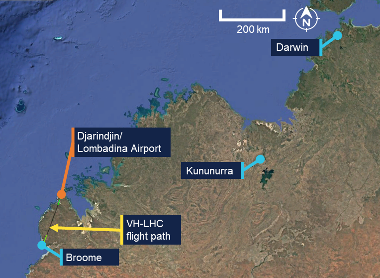
On the morning of 22 August 2025, a GippsAero GA8, operated by Air Kimberley and registered VH‑LHC, departed Broome, Western Australia, for a charter flight to Djarindjin/Lombadina Airport (Figure 1) with the pilot, one passenger and freight on board.
Figure 1: VH-LHC flight location
Source: Google Earth and FlightRadar24, annotated by the ATSB
Approximately 55 minutes after departing Broome, the pilot joined the downwind leg of the circuit for runway 28 at Djarindjin/Lombadina Airport. Shortly after joining the circuit, at about 1251 local time, the pilot identified an uncommanded 10 kt reduction in airspeed and a drop from approximately 20 inches of mercury (inHg) of engine manifold pressure to 17 inHg. In response, the pilot moved the aircraft throttle lever across its full range of movement but did not hear or feel a response from the engine and reported no change to the manifold pressure.
At this time, the pilot contacted the operator’s chief pilot via mobile phone for guidance. The pilot reported that in the brief conversation they outlined the issue that they were encountering. While the pilot could not remember the details of the chief pilot’s response the general guidance provided was to land as safely as possible and to call back when they were on the ground.
Following this conversation, the pilot elected to conduct an orbit to extend the approach (Figure 2) and allow themselves more time to assess the problem and conduct pre‑landing checks and procedures. They intended to conduct the approach normally but with an extended final approach. The pilot also considered the early use of a second stage of flap to slow the aircraft. However, they decided against it due to the unknown reliability of the engine’s performance and extended the second stage of flap as part of the normal pre-landing process on final approach.
Figure 2: Downwind, final approach, go‑around and return
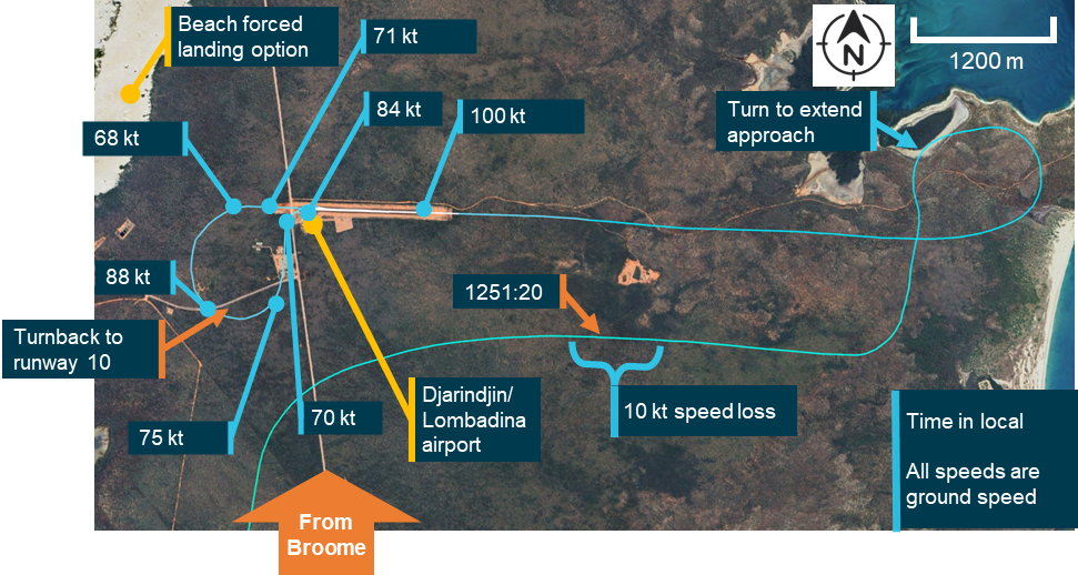
Note: Due to the light and variable winds at the time of the occurrence, the aircraft ground speeds were within 5 kt of the airspeeds that would have been presented to the pilot. Source: Google Earth, FlightRadar24 and Bureau of Meteorology, annotated by the ATSB
The pilot recalled, and recorded data confirmed, that the aircraft was at about 100 kt, 20–25 kt faster than planned, when crossing the threshold. Approximately two-thirds of the way down the runway, the pilot identified that the aircraft was ‘floating,’1 had insufficient runway remaining to land the aircraft, and elected to conduct a go-around. The pilot initiated a climb, retracted one stage of flap and felt the airspeed start to reduce from 84 kt at the time the go‑around was initiated, to 68 kt as they turned off the runway heading. The pilot reported reaching approximately 300 ft above ground level, assessed that there was insufficient performance to safely continue the climb and levelled the aircraft.
The pilot’s planned forced landing option when taking off from runway 28 at Djarindjin/Lombadina was a beach on the western side of scrubland beyond the end of the runway (Figure 2). However, the pilot assessed that this was not suitable and subsequently turned to the left for a return to runway 28.
During the turn, the aircraft maintained altitude and accelerated from 68 to 88 kt. The pilot reported that, after the turn, they were unsure if the engine would continue producing power long enough to complete a circuit. They subsequently decided to land on runway 10, the reciprocal runway. Having determined that they were able to reduce the engine’s power using the mixture control, the pilot brought the mixture to near the cut‑off position and conducted a turnback to runway 10, slowing the aircraft through 75 kt to 70 kt before landing.
After landing, the pilot increased engine power by returning the mixture to rich and taxied off the runway. Subsequently, after consultation with the company’s maintenance provider, it was determined that the throttle linkage had disconnected at the engine.
Context
Pilot information
The pilot held a Commercial Pilot Licence (Aeroplane) with a command instrument rating and a valid class 1 aviation medical certificate. The pilot reported that at the time of the occurrence they had 869 hours of total aeronautical experience with 385 of these being on the GA8 and 48 in the last 90 days.
Operational information
Emergency procedures
The GA8 pilot’s operating handbook contained relevant procedures for the operation of the aircraft in the event of an emergency. The manual did not contain a specific procedure for the management of partial power, however there were procedures for both a precautionary landing with engine power and an emergency landing without engine power.
The procedure for a precautionary landing with power included an indicated airspeed of 75 kt on approach with stage 1 flap extended. The procedure for landing without engine power included an indicated airspeed on final approach of between 64 and 71 kt depending on aircraft weight. In normal operation the approach speed was 71 kt.
The procedure for landing without engine power required the pilot to switch off the ignition, fuel shutoff valve, and the master electrical buses, to move the throttle to the closed position, the mixture to the idle cut off position and the propellor to coarse.
The procedure for a precautionary landing with power required the mixture to be moved to the idle cut‑off position and the ignition, fuel shut‑off valve and bus 1 and 2 master switches to be moved to the off position after touchdown.
Management of partial power loss
Management of a partial power loss is more complex than a complete power loss. The response to a complete power loss should be definitive and standardised while the number of factors that could lead to a partial power loss and the unreliability of any remaining power meant that a situationally specific response is required.
While the manufacturer did not provide guidance on the management of partial power loss in the GA8, both the Civil Aviation Safety Authority (CASA) and the ATSB have published general guidance on the subject – CASA in its flight instructor manual and the ATSB in Managing partial power loss after takeoff in single-engine aircraft (AR-2010-055 - Number 3). The guidance contains 3 key points:
- a partial power loss event should be treated like a complete power loss and a landing should be conducted as soon as possible
- any available power may be used to extend the flight time to locate a better landing area
- this should be done with the consideration that the power may degrade further or be lost at any time.
Throttle operation
The GA8 flight manual advised that a normally aspirated engine had a manifold pressure range between 10 and 30 inHg. However, the range available for use was dependent on the altitude at which the aircraft was operating.
The pilot stated that when approaching Djarindjin/Lombadina on descent they typically set 20 inHg, reducing this to 18 inHg passing the threshold during the downwind leg of the circuit and then to 15 inHg when making the turn onto the base leg.
Meteorological information
An aerodrome meteorological report for Djarindjin/Lombadina was issued at 1300 local time, approximately 5 minutes after VH-LHC crossed the threshold on its first approach. The wind recorded was from 050° at 4 kt with 9,000 meters visibility, temperature 30°C and no recorded rainfall.
One-minute wind observations between 1250 and 1300 showed variable wind direction at 2–5 kt.
Aircraft information
General information
The GA8 is a single‑engine aircraft manufactured by GippsAero2 of Victoria, Australia. It is fitted with a Textron Lycoming IO-540-K1A5 piston engine and can seat up to 8 people, including the pilot. VH-LHC (serial number GA8-04-057) was manufactured and registered in 2004. At the time of the occurrence, it had accumulated 11,768 hours total time in service. For this flight, the aircraft was configured for a single passenger next to the pilot and with the rear passenger seats removed and appropriate securing equipment in place for carriage of freight.
Throttle cable attachment assembly
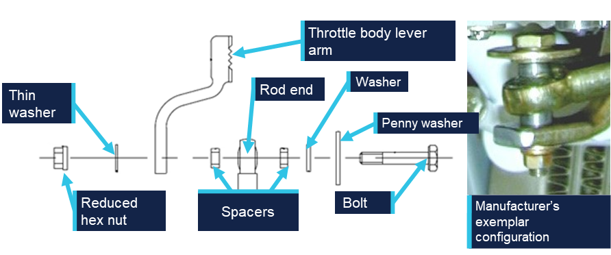
The throttle cable assembly translated movement of the throttle lever in the cockpit to the throttle body on the engine. The throttle body attachment consisted of a rod end and throttle body lever arm bolted together with a series of washers and spacers used to ensure appropriate geometry was maintained. The geometry of the washers and spacers allowed both the rod end and throttle body lever arm to move freely and limited interaction with the other components. If the geometry was not correctly maintained, the rod end could forcefully contact the penny washer and, as the rod end moved through its arc of motion, induce a rotation in the penny washer and subsequently, in the bolt. This interaction could result in a loosening or disconnection of the linkage.
Figure 3 shows the exploded diagram of the linkage from the aircraft manufacturer’s illustrated parts catalogue (IPC) and an exemplar assembly provided by the manufacturer.
Figure 3: Throttle cable attachment assembly
Source: Manufacturer, modified and annotated by the ATSB
The threaded end of the bolt specified in the IPC (AN3-11) is drilled allowing a split pin to be used as a secondary securing mechanism. However, the specified nut (MS21042-3) is a reduced hex nut that uses interference with an out of round section to lock the nut onto the bolt and consequently does not require a split pin. This combination, while permitted and approved, was not commonly used as a reduced hex nut is typically used in combination with a non-drilled bolt. When consulted, the manufacturer could not advise why this hardware combination had been prescribed for the aircraft. However, they advised that some elements of the design for this aircraft had been reproduced from the design of another aircraft, including the specified bolt.
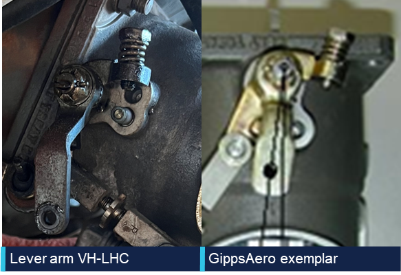
The throttle body lever arm on the GA8 was developed by GippsAero by modifying the design of the standard arm supplied by the engine manufacturer. The modification made the arm approximately 12 mm shorter than when used for other applications with the same engine. This modification altered the arc through which the arm moved to ensure that the geometry between the throttle cable and the throttle body was correct. The manufacturer’s review of the images of VH-LHC’s throttle arm identified that a standard lever arm was fitted rather than the GippsAero lever arm.
Figure 4 shows the throttle lever arm as fitted to VH-LHC in comparison to an exemplar of the shortened lever arm as prescribed for the aircraft by GippsAero in the IPC. Note the throttle positions shown in the images are not the same and the image has been rotated to show the difference in length between the lever arms.
Figure 4: Throttle lever arm comparison
Source: Operator and aircraft manufacturer, modified and annotated by the ATSB
Spring‑loaded mechanism
The certification standard for the GA8 required that if the engine control separated, it must be designed so that the aircraft is capable of ‘continued safe flight and landing’. This requirement was implemented by the United States Federal Aviation Administration (FAA) in response to a 1981 National Transportation Safety Board (NTSB) study of single‑engine aircraft accidents involving separation of throttle linkages and subsequent loss of propulsive power. The NTSB recommendation (A-81-6) to the FAA was to:
Establish a requirement that, when throttle linkage separation occurs in a small single engine aircraft the fuel control will go to a setting which will allow the pilot to maintain level flight in the cruise configuration; (Class 11, Priority Action)
In response, the FAA introduced a requirement under regulation 23.1147(g) that:
For reciprocating single-engine airplanes, each power or thrust control must be designed so that if the control separates at the engine fuel metering device, the airplane is capable of continued safe flight and landing
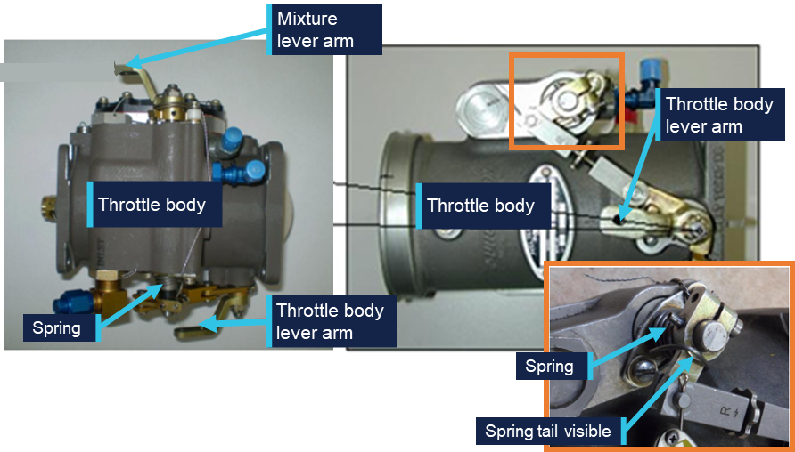
For the GA8 to comply with this requirement, the throttle body linkage was fitted with a torsion spring with sufficient tension to drive the throttle to at least 75% of the full throttle setting. The torsion spring is mounted directly to the throttle body as shown in Figure 5 and can subsequently drive the throttle to the required position in the event of a disconnection anywhere along the throttle linkage.
Figure 5: Spring location
Source: Manufacturer, modified and annotated by the ATSB
In 2011, GippsAero published service bulletin SB-GA8-2011-64 in response to reports of throttles failing to open sufficiently. The service bulletin required that spring tension be tested and if it was not able to open the throttle sufficiently, a stiffer spring was required to be installed. This service bulletin was completed on VH-LHC on 28 February 2011 at 5,150.5 hours.
Post‑occurrence examination
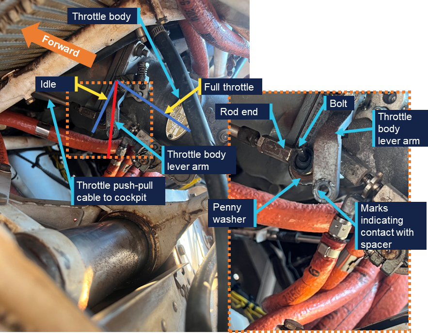
The ATSB was provided with an image taken by the pilot immediately after the occurrence (Figure 6). It shows the throttle body lever arm at approximately 25% travel with the through bolt from the rod end disconnected from the lever arm. Only the bolt and penny washer from the cable attachment assembly were visible in the image. The remaining components including the nut, washer and spacers were unable to be identified.
Figure 6: Post‑occurrence image of throttle body and throttle cable attachment assembly
Source: Operator, annotated by the ATSB
Following reconnection of the linkage using new hardware, the ATSB requested the nut and bolt from the maintainers, however they were unable to provide either. They reported that the nut was not recovered during the repair and the bolt could not be located. The maintainers reported that damage to the bolt threads was identified when it was removed.
A subsequent review of the IPC identified that the correct securing mechanism was a reduced hex nut and not the castellated nut and split pin that had been fitted during the repair (see the section titled Engine change for further information).
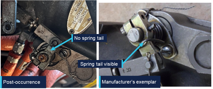
Following the occurrence, the ATSB and the manufacturer reviewed the available imagery. The manufacturer stated that the imagery appeared to show an incorrect configuration of the throttle cable attachment assembly, with markings on the end of the throttle body lever arm indicating that at least one of the spacers had been incorrectly located. The ATSB also identified, and the manufacturer confirmed, that the spring on the throttle mechanism was missing (Figure 7).
Figure 7: Post‑occurrence imagery identifying location of throttle mechanism spring
Source: Operator and manufacturer, annotated by the ATSB
Maintenance information
Engine change
In June 2025, VH-LHC’s engine was removed due to detonation damage. The engine including the frame and ancillary components, such as hoses and baffles, were removed and a serviceable engine and propeller from another GA8 were installed. The aircraft was released back into service on 3 June 2025. The maintainer who conducted the engine change was contracting to the maintenance organisation and had not previously (and did not subsequently) work on this aircraft.
They reported that when they disconnected the linkage there were thick section washers fitted to either side of the rod end, a penny washer under the bolt and the linkage was secured with a castellated nut and split pin. They reported reusing the hardware from the removed engine with a new split pin and that their post‑installation checks identified no issues with the movement of the throttle.
The maintainer stated that, based on their experience and the presence of the hole in the bolt, the use of a castellated nut and split pin was logical, and they did not refer to the aircraft documentation to confirm the hardware configuration.
Related occurrences
A review of the ATSB’s occurrence database did not identify any similar occurrences, however the manufacturer identified a continuing airworthiness notice (CAN) issued in 2007 by the New Zealand Civil Aviation Authority (CAA) related to a similar issue and a review of the CASA defect reporting database identified a similar issue from an aircraft in Botswana in 2017.
New Zealand Civil Aviation Authority Continuing Airworthiness Notice 76‑001
On 5 July 2007, the NZ CAA released a CAN on all GA8 aircraft for an inspection of the throttle cable and the throttle lever installation. A CAA investigation had been prompted by reports of a sluggish feel in the throttle operation of a GA8. The investigation identified that the linkage bolt was rotating, resulting in a loosening of the nut securing the mechanism. Contact between the penny washer and the rod end resulted in movement of the rod end causing the penny washer, and subsequently the bolt, to rotate.
As published, the CAN contained a recommendation for an updated configuration of the linkage assembly intended to increase the approach angle between the penny washer and the rod end. In February 2026, the CAA advised that the manufacturer’s configuration addressed the issue and subsequently the CAN had been removed from the NZ CAA website. In response to the draft ATSB report, the CAA advised that the CAN was pending revision and reissue, following the release of the ATSB report.
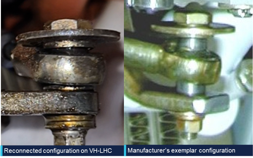
Figure 8 compares the reconnected linkage configuration on VH-LHC (left) with the manufacturer’s exemplar configuration (right). The spacers shown in the manufacturer’s configuration provide increased clearance between the penny washer, rod end and the throttle body lever arm compared to the washers used in the reconnected configuration.
Figure 8: Throttle linkage assembly comparison
Source: Operator and manufacturer, annotated by the ATSB
The pre-occurrence configuration of the linkage fitted to VH-LHC was unable to be determined. However, the reconnected configuration showed a limited clearance between the rod end and the penny washer due to the missing spacers. This lack of clearance meant that the rod end was likely to contact the penny washer when the throttle was moved through the full range of motion.
As identified by the CAA’s investigation, this creates a risk of interaction between these parts and potential for loosening and disconnection of the linkage. In comparison, the spacers used in the manufacturer’s configuration separate the rod end from the penny washer to prevent interaction.
CASA defect report
A review of the CASA defect reporting database identified a report from 8 May 2017 related to aircraft A2-FTW,3 as follows:
Loosened nut and insecure throttle control cable rod-end and bolt discovered, caused by engine vibration.
New nut installed and tightly secured to the throttle control linkage on fuel injector.
Safety analysis
Approach
The pilot reported that the flight to Djarindjin/Lombadina was uneventful until the aircraft entered the circuit. During the downwind leg of the circuit, the pilot observed an uncommanded drop in manifold pressure from 20 to 17 inHg and was no longer able to control engine power using the throttle lever. Once the pilot made the base turn, the 17 inHg manifold pressure was above the 15 inHg setting they would have typically been using. Imagery of the throttle linkage captured by the pilot following the occurrence showed the linkage disconnected and the securing nut missing with the throttle arm near to, but not at, the idle position. The consequence of the linkage disconnection was that movement of the throttle lever in the cockpit could not be translated to the throttle lever arm on the engine resulting in a loss of throttle control.
As the approach progressed, the pilot reported, and recorded data showed, that the aircraft was 20–25 kt above the recommended approach speed of 75 kt as it crossed the threshold. At that speed, the pilot assessed that there was insufficient runway available to slow the aircraft and make a safe landing.
Go-around
After the pilot identified that there was insufficient runway remaining to land safely, they commenced a go-around and the aircraft’s speed immediately started to reduce. The pilot reported that the aircraft was correctly configured for climb with one stage of flap, propeller pitch at full fine and that other than the limited power there were no issues that should have adversely affected climb performance. Unable to use the throttle to increase the power from the engine, the aircraft continued to slow, and so the pilot levelled the aircraft. The pilot then commenced a left turn and the engine was producing sufficient power for the aircraft to accelerate through the turn while maintaining altitude.
Aircraft certification standards required that, in the event of a throttle linkage disconnect, the engine side of the throttle linkage move to a position that would enable ‘continued safe flight and landing’. The manufacturer therefore required that a torsion spring be installed on the throttle linkage that would open the throttle to at least 75% of the open position in the event of a disconnection.
The image captured by the pilot immediately following the occurrence showed the throttle in a low power position, well below the 75% open position that was required by the manufacturer. Due to the number of factors that can impact the relationship between throttle position and observed manifold pressure, it was not possible to determine what the manifold pressure should have been if the throttle was open to 75%. However, as available power increases as the throttle opens, the position of the throttle arm below the 75% open position meant that there was less power available than that required by the manufacturer to sustain ‘continued safe flight and landing’.
It was further identified and confirmed by the manufacturer that the torsion spring was not visible in the imagery captured immediately after the occurrence. The ATSB considered 2 possible scenarios for the missing torsion spring. The first was that the spring had been present and had failed since the last maintenance activity or during the occurrence and the second was that the spring was not fitted at the time of the engine change.
As the spring was fitted around the shaft, in the event of a failure, the spring would have been retained on the shaft and been visible. Additionally, it is very unlikely that the spring would have failed at the time of the linkage disconnection as in the event of a disconnection the tension on the spring would have been released to drive the throttle arm to at least the 75% open position.
While it could not be conclusively determined if the required torsion spring was fitted at the time of the occurrence, it was considered very likely that it was not fitted due to:
- the visible lack of the spring
- the fact that the spring would have been retained should it have failed
- the limited time between maintenance and the occurrence for the spring to become detached and be lost
- the fact that the throttle did not open, which is the purpose of the spring being fitted.
Installation inconsistencies
There were several inconsistencies between the throttle linkage installation on VH-LHC and the arrangement outlined in the aircraft documentation, as follows:
- the manufacturer identified that the throttle arm fitted was not correct for the aircraft
- the maintainer reported using a castellated nut with split pin, rather than the specified reduced hex nut
- the throttle opening spring was very likely not fitted
- the spacers were likely not fitted correctly prior to the occurrence.
As shown by the New Zealand Civil Aviation Authority Continuing Airworthiness Notice, changes to the throttle linkage geometry can lead to undesirable interactions between components within the linkage, most notably the rod end and the penny washer. This can subsequently loosen the linkage and could result in complete disconnection.
The ATSB could not determine whether the inconsistencies between the recommended, and actual throttle linkage configurations contributed to the disconnection. This was primarily due to limited evidence about the sequence of the disconnection but was also influenced by the limited and incomplete information about the pre-occurrence linkage configuration. The likely configuration of the throttle linkage was determined based on manufacturer review of the available imagery, the recollection of the maintainer who completed the engine installation approximately 4 months before the occurrence and imagery of the reassembled linkage following the occurrence.
The individual impact of each of these inconsistences could not be determined. However, the combination of the inconsistencies, and their potential impact on the geometry of the linkage and subsequent interaction between the components, increased the risk of a disconnection.
Findings
ATSB investigation report findings focus on safety factors (that is, events and conditions that increase risk). Safety factors include ‘contributing factors’ and ‘other factors that increased risk’ (that is, factors that did not meet the definition of a contributing factor for this occurrence but were still considered important to include in the report for the purpose of increasing awareness and enhancing safety). In addition ‘other findings’ may be included to provide important information about topics other than safety factors. These findings should not be read as apportioning blame or liability to any particular organisation or individual. |
From the evidence available, the following findings are made with respect to the engine malfunction involving GippsAero GA8, VH-LHC, at Djarindjin/Lombadina Airport, Western Australia, on 22 August 2025.
Contributing factors
- During the approach, the securing mechanism for the aircraft’s throttle linkage failed resulting in a loss of throttle control and a constant partial power setting. The approach then continued at a higher-than-normal speed that did not permit the aircraft to land safely.
- During the subsequent go-around, the pilot assessed there was insufficient power to climb. This was due to the throttle failing to open to at least 75% in accordance with the manufacturer’s requirement, likely due to the spring that opened the throttle in the event of a disconnection not being fitted.
Other factors that increased risk
- There were multiple inconsistencies between the throttle linkage hardware fitted to VH-LHC and that laid out in the aircraft documentation. This increased the risk of throttle disconnection due to unintended interactions between components in the linkage.
Safety actions
| Whether or not the ATSB identifies safety issues in the course of an investigation, relevant organisations may proactively initiate safety action in order to reduce their safety risk. The ATSB has been advised of the following proactive safety action in response to this occurrence. |
Safety action taken by BOAB Engineering
In response to the ATSB advice noting the inconsistencies between the linkage assembly and the manufacturer’s prescribed configuration, the maintenance organisation (BOAB) conducted a review of the 3 GA8 aircraft that it was responsible for.
BOAB identified various inconsistencies related to incorrect throttle body lever arms, missing torsion springs and incorrectly located or missing spacers. It advised that the correct parts had been ordered and that the linkage assemblies would be re-assembled in accordance with the manufacturer’s requirements.
Sources and submissions
Sources of information
The sources of information during the investigation included:
- the pilot of the occurrence flight
- the operator of VH-LHC
- the maintenance organisation for VH-LHC
- the maintainer who completed the engine change on VH-LHC
- GippsAero
- New Zealand Civil Aviation Authority
- Civil Aviation Safety Authority
- Bureau of Meteorology
- Flight Radar 24
- Federal Aviation Administration
- National Transportation Safety Board.
Submissions
Under section 26 of the Transport Safety Investigation Act 2003, the ATSB may provide a draft report, on a confidential basis, to any person whom the ATSB considers appropriate. That section allows a person receiving a draft report to make submissions to the ATSB about the draft report.
A draft of this report was provided to the following directly involved parties:
- the pilot of the occurrence flight
- the operator of VH-LHC
- the maintenance organisation for VH-LHC
- the maintainer who completed the engine change on VH-LHC
- GippsAero
- Transport Accident Investigation Commission (New Zealand)
- New Zealand Civil Aviation Authority
- Civil Aviation Safety Authority.
Submissions were received from:
- New Zealand Civil Aviation Authority
- the maintainer who completed the engine change on VH-LHC.
The submissions were reviewed and, where considered appropriate, the text of the report was amended accordingly.
Purpose of safety investigationsThe objective of a safety investigation is to enhance transport safety. This is done through:
It is not a function of the ATSB to apportion blame or provide a means for determining liability. At the same time, an investigation report must include factual material of sufficient weight to support the analysis and findings. At all times the ATSB endeavours to balance the use of material that could imply adverse comment with the need to properly explain what happened, and why, in a fair and unbiased manner. The ATSB does not investigate for the purpose of taking administrative, regulatory or criminal action. About ATSB reportsATSB investigation reports are organised with regard to international standards or instruments, as applicable, and with ATSB procedures and guidelines. Reports must include factual material of sufficient weight to support the analysis and findings. At all times the ATSB endeavours to balance the use of material that could imply adverse comment with the need to properly explain what happened, and why, in a fair and unbiased manner. An explanation of terminology used in ATSB investigation reports is available here. This includes terms such as occurrence, contributing factor, other factor that increased risk, and safety issue. Publishing informationReleased in accordance with section 25 of the Transport Safety Investigation Act 2003 Published by: Australian Transport Safety Bureau © Commonwealth of Australia 2026 
Ownership of intellectual property rights in this publication Unless otherwise noted, copyright (and any other intellectual property rights, if any) in this report publication is owned by the Commonwealth of Australia. Creative Commons licence With the exception of the Commonwealth Coat of Arms, ATSB logo, and photos and graphics in which a third party holds copyright, this report is licensed under a Creative Commons Attribution 4.0 International licence. The CC BY 4.0 licence enables you to distribute, remix, adapt, and build upon our material in any medium or format, so long as attribution is given to the Australian Transport Safety Bureau. Copyright in material obtained from other agencies, private individuals or organisations, belongs to those agencies, individuals or organisations. Where you wish to use their material, you will need to contact them directly. |
Footnotes
| 1 | Float: a term used to describe when the aircraft continues flying when the pilot intends to touch down but is unable due to the wing generating excess lift. |
| 2 | The manufacturer was previously known as Gippsland Aeronautics. |
| 3 | A2 is the national aircraft registration identifier of Botswana. |
Occurrence summary
| Investigation number | AO-2025-052 |
|---|---|
| Occurrence date | 22/08/2025 |
| Occurrence time and timezone | 1300 Western Standard Time |
| Location | Djarindjin/Lombadina Airport |
| State | Western Australia |
| Report release date | 08/05/2026 |
| Report status | Final |
| Investigation level | Short |
| Investigation type | Occurrence Investigation |
| Investigation status | Completed |
| Mode of transport | Aviation |
| Aviation occurrence category | Engine failure or malfunction, Missed approach |
| Occurrence class | Incident |
| Highest injury level | None |
Aircraft details
| Manufacturer | GippsAero |
|---|---|
| Model | GA-8 |
| Registration | VH-LHC |
| Serial number | GA8-04-057 |
| Aircraft operator | Air Kimberley |
| Sector | Piston |
| Operation type | Part 135 Air transport operations - smaller aeroplanes |
| Activity | Commercial air transport - Non-scheduled - Passenger transport charters |
| Departure point | Broome Airport, Western Australia |
| Destination | Djarindjin/Lombadina Airport, Western Australia |
| Injuries | None |
| Damage | Nil |