Premature parachute deployment involving Cessna 208, VH-DVS, over Tully Airport, Queensland, on 20 September 2025
Final report
Report release date: 11/12/2025
Investigation summary
What happened
On 20 September 2025, the pilot of a Cessna 208 aircraft, registered VH-DVS, was conducting parachute operations for Far North Freefall Club at Tully Airport, Queensland. After successfully completing 2 parachute drops that morning, at 0950 local time the aircraft took off for the third load of the day with 17 parachutists on board. The plan was for the parachutists to conduct a 16-way formation filmed by a parachuting camera operator.
After the aircraft climbed to about 15,000 ft, the pilot signalled to the parachutists to exit. The camera operator stepped out onto a small step and held on to the fuselage outside and aft of the cabin door. As the first parachutist (P1) stepped out the door to assume the most forward (front float) position, their reserve parachute inadvertently deployed, dragging P1 backwards and dislodging the camera operator into freefall, causing them a minor injury. P1’s legs were injured as they struck and damaged the aircraft’s horizontal stabiliser. The parachute wrapped around the horizontal stabiliser and the elevator, suspending P1 beneath it.
Thirteen parachutists exited the aircraft and 2 remained in the doorway, watching as P1 used a knife to cut sufficient reserve parachute lines to enable the parachute to tear free. P1 then deployed their main parachute, which tangled with the remnants of the reserve parachute. P1 was able to untangle the lines and regain sufficient control of the main parachute to land without further incident.
Despite control difficulties due to substantial damage to the horizontal stabiliser and part of the reserve parachute wrapped around the tail, the pilot safely landed the aircraft at Tully Airport.
What the ATSB found
The ATSB found that as the first parachutist climbed out of the aircraft and into the front float position, their reserve handle snagged on the aircraft's flap, resulting in deployment of the reserve parachute. The parachute wrapped around the now-damaged tailplane, resulting in aircraft control difficulties.
The ATSB also found that, although it did not contribute to the accident, the pilot and aircraft operator did not ensure the aircraft was loaded within its weight and balance envelope.
Furthermore, the ATSB found that the parachutists opened the roller door and clipped it open before exiting the aircraft. As a result, the roller door remained open during the descent, increasing the ease with which the pilot could have exited the aircraft if needed. Although not mandatory at the time of the accident, the parachutist had a hook knife attached to their chest strap, enabling them to cut enough reserve parachute lines for the parachute to tear free of the tailplane. Finally, in difficult circumstances, the pilot managed to control the aircraft and return to land safely.
What has been done as a result
To ensure aircraft are loaded within their weight and balance envelope, and this is documented on a load sheet, Far North Freefall Club (FNFF) has:
- engaged with the current software distributor about including balance in the manifest system
- commenced investigation of alternative software
- implemented a proprietary interim system that calculates and graphically displays the centre of gravity position on the aircraft’s weight and balance envelope, indicating whether it is within or outside limits.
Additionally, FNFF distributed a circular to all company pilots reminding them of the requirement to use supplemental oxygen when the aircraft is at or above flight level 140, and of the risks of hypoxia. FNFF also mandated parachutists carry a hook knife.
Furthermore, FNFF updated the loadmaster checklist within its safety management system. The checklist is displayed around the drop zone to raise awareness of loadmaster roles and procedures in the event of an emergency. A circular has also been sent to all current company loadmasters to reinforce familiarity with in-aircraft emergency procedures.
In addition, the FNFF safety team is reviewing its standard operating procedures manual to ensure all procedures, including those relating to loadmaster training and emergency response, are clearly documented and up to date. FNFF is also preparing a training slideshow incorporating footage from the incident. This presentation will be shared across the wider skydiving community for educational purposes.
Finally, at the time of writing, the Australian Parachute Federation was in the process of developing a guide for loadmasters. The guide will detail the role and responsibilities, including during an emergency. It will take into consideration the range of complexity of various operations, and aircraft type and size. Training and assessment material will also be developed.
Safety message
This accident highlights the importance of parachutists being mindful of their handles particularly when exiting the aircraft. Additionally, this accident demonstrates that carrying a hook knife secured to the parachute container could be lifesaving in the event of a premature reserve parachute deployment. It is also a reminder for pilots conducting parachute operations of the importance of wearing an emergency parachute and knowing how to deploy it. Parachute aircraft operators should also ensure, where possible, that there is a suitable open door for the pilot to exit in the event of an irretrievable loss of aircraft control.
Furthermore, as fatal parachuting accidents have occurred due to aircraft being loaded outside the centre of gravity limits, this is a reminder for pilots and aircraft operators conducting parachute operations to ensure aircraft weight and balance calculations are conducted prior to each load.
Finally, altitude hypoxia is an insidious and potentially deadly hazard associated with operations at high altitude. Although there is limited research into hypoxia for parachuting operations, effects of mild hypoxia can impair performance and judgement, critical for safe operations. Pilots conducting parachute operations are required to use supplemental oxygen at or above 14,000 ft, and should also do so during holding or delays above 10,000 ft, or when experiencing mild hypoxia symptoms.
Summary video
The investigation
The occurrence
On 20 September 2025, the pilot of a Cessna 208 aircraft, registered VH-DVS, was conducting parachute operations at Tully Airport, Queensland. The aircraft and pilot had been hired by Far North Freefall (FNFF) skydive club based in Tully. In accordance with company policy, the pilot was wearing an emergency parachute.
After successfully completing 2 parachute drop loads earlier that morning, at 0950 local time, the aircraft took off for the third load of the day with 17 parachutists on board. The plan was for the parachutists to conduct a 16-way formation filmed by a parachuting camera operator. The parachute jump was part of the annual ‘Big Ways at the Beach’ multi-day event, hosted by FNFF, in which experienced parachutists completed large group formations in belly-to-earth[1] freefall.
At 0954 local time, the pilot requested and received a clearance from Brisbane Centre air traffic control (ATC), to conduct parachute operations within 5 NM (10 km) of Tully Airport, up to flight level (FL) 150.[2]
At 0959, the pilot advised ATC they were ‘3 minutes to drop’ and requested clearance to drop and then descend, which they received 14 seconds later. About 3 NM (5.6 km) prior to the drop point, the pilot illuminated a red light on the rear wall of the aircraft cabin to alert the parachutists.
At 1001, the pilot illuminated an orange light, indicating there was about 1 NM (1.9 km) to the drop. The camera operator and the first parachutist exiting (P1) then moved to the doorway and opened the roller door. The roller door was clipped open and remained open until after the aircraft landed. On reaching about FL 150, the pilot slowed the aircraft to 85 kt indicated airspeed and extended 10° of flap, before illuminating a green light at 1002. On seeing the green light, P1 tapped the camera operator on the shoulder. The camera operator then stepped outside the doorway, with their right foot on the camera step, their right hand on the handle above and aft of the door and their left hand on the bar at the top of the door frame.
Parachutist 1 then crouched down and stepped out at the front of the doorway facing forwards, into the ‘front float’ position, with their right foot in the front corner of the door frame and their left knee under the wing (Figure 1).
Figure 1: Parachutist 1 stepping out the door

Source: Jarrad Nolan, annotated by the ATSB
Parachutist 1 then stood up outside the door, reaching for a small post on top of the fuselage with their left hand and lifting their left knee under the wing and flap. During this manoeuvre, P1’s left handle (pud[3]) snagged on the wing flap and rotated (Figure 2).
Figure 2: Left pud (outlined in red) snagging on the flap and rotating
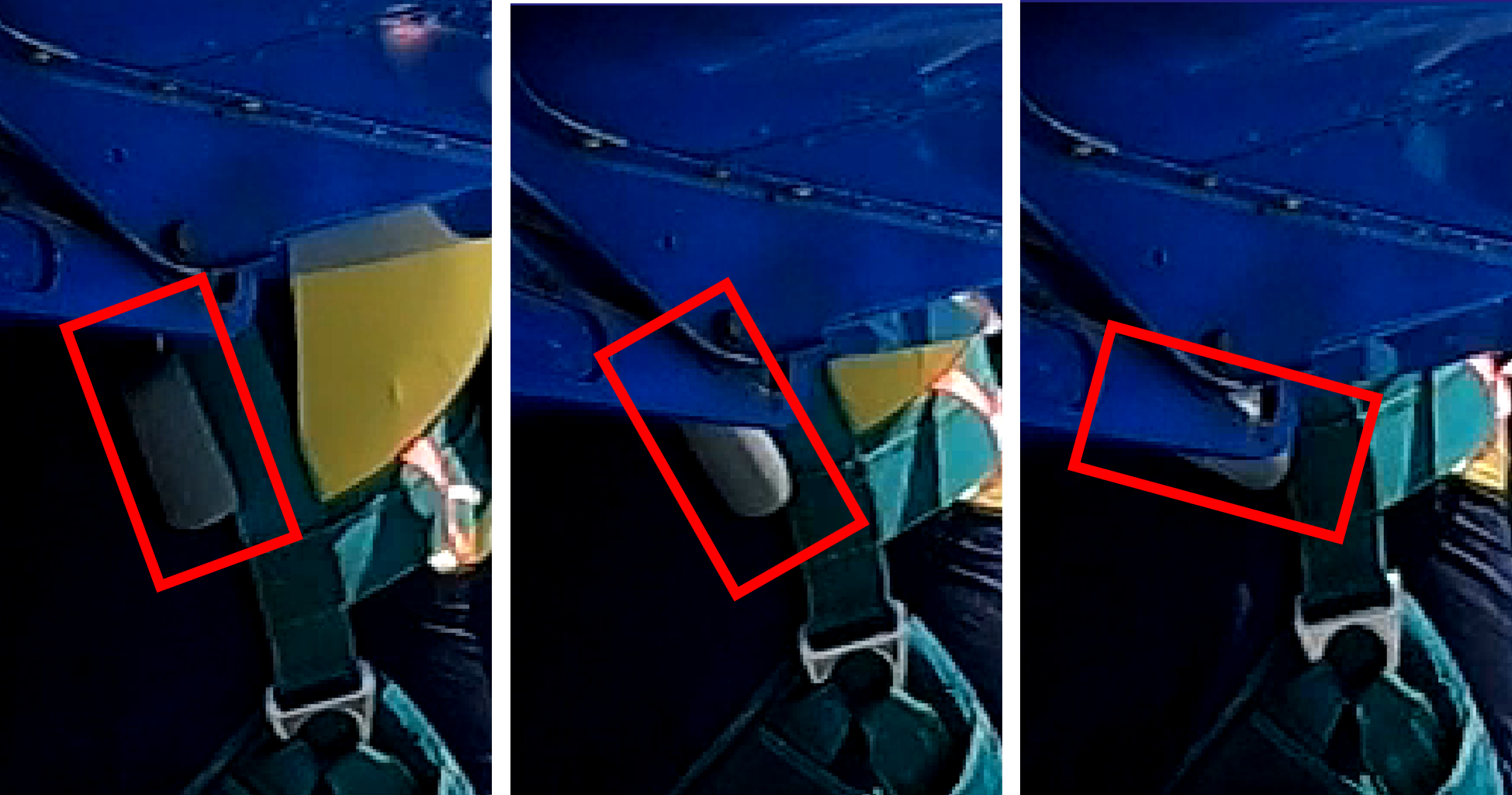
Source: Jarrad Nolan, annotated by the ATSB
That movement dislodged the pud from the parachute container, deploying its reserve pilot chute (Figure 3).
Figure 3: Pilot chute deployment
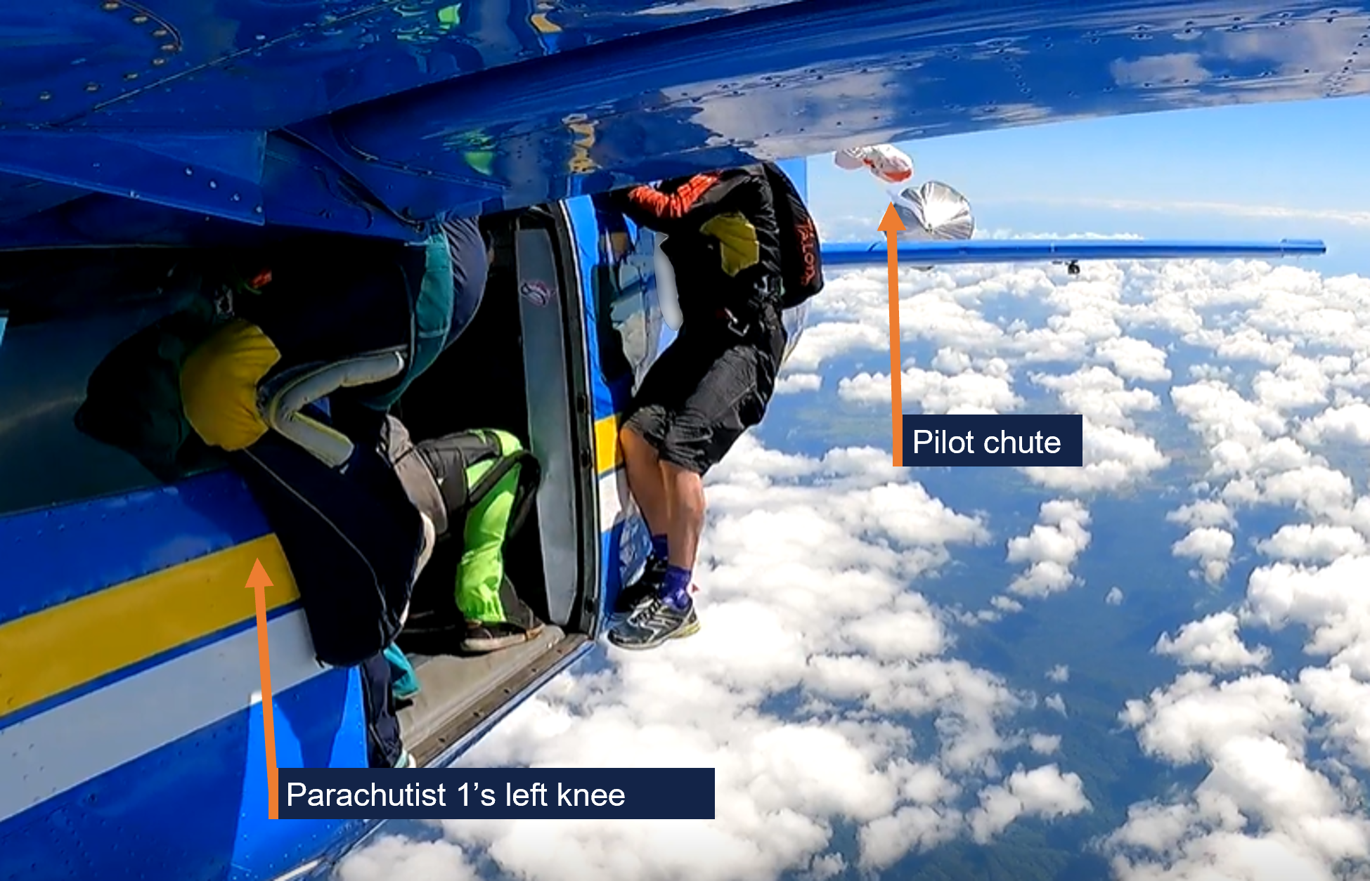
Source: Jarrad Nolan, annotated by the ATSB
The pilot chute then pulled the reserve parachute and lines out of the container. As the reserve parachute inflated and the lines became taut, P1 was pulled off the side of the aircraft towards the tail, dislodging the camera operator into freefall (Figure 4 and 5).
Figure 4: Reserve parachute inflating and dragging the parachutist rearwards
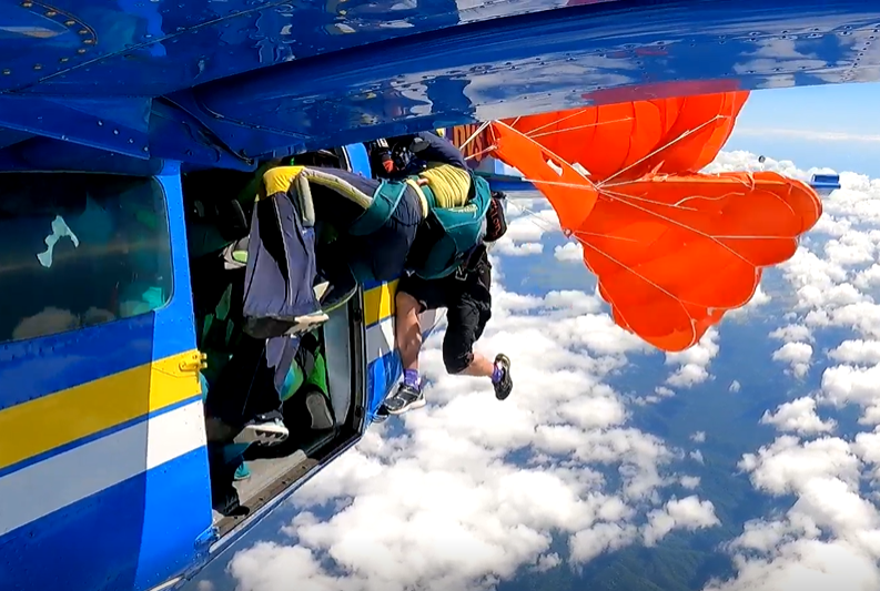
Source: Jarrad Nolan
The reserve parachute wrapped around the left horizontal stabiliser and elevator and deflated as P1’s lower legs struck the stabiliser (Figure 5). P1 was then suspended beneath the tailplane (Figure 6).
Figure 5: Parachutist 1 striking horizontal stabiliser as camera operator falls free

Source: Jarrad Nolan
Figure 6: Reserve parachute wrapped around horizontal stabiliser with Parachutist 1 suspended beneath it
Source: Jarrad Nolan
Initially unaware of what had occurred, the pilot recalled feeling the aircraft suddenly pitch up and observed the airspeed rapidly decreasing. Assessing that the aircraft had stalled, the pilot pushed forward on the control column and applied some power. At that time, a parachutist called out that there was a canopy[4] wrapped around the tail. The FNFF senior pilot (on board as a parachutist), who was seated beside the pilot but facing rearwards, felt the aircraft shudder, and relayed to the pilot that there was a skydiver hung up on the tailplane.
The pilot then reduced power and felt the controls vibrating. The pilot reported having to use significant forward pressure on the controls and right aileron input to maintain straight and level flight. To reduce some of the control pressure, the pilot applied full forward trim, which then jammed in that position for the remainder of the flight.
After an initial hesitation, the loadmaster directed the other parachutists to exit. Over the next 15 seconds, 13 parachutists left the aircraft. The last 2 parachutists (the FNFF senior pilot and the loadmaster) remained in the doorway watching as P1 began to cut themselves free using a hook knife, retrieved from a pouch secured by a lanyard to the left side of their chest strap.
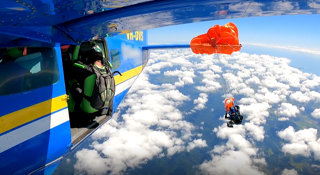
P1 reported that they found the lines harder to cut than expected but managed to cut 11 lines in 50 seconds. The reserve parachute then tore, releasing P1 from the aircraft with part of the reserve remaining on the aircraft’s tail. The last 2 parachutists then exited the aircraft.
Figure 7: Reserve canopy torn and parachutist detached from aircraft

Source: Jarrad Nolan
At 1003 while in freefall, P1 used their main pilot chute handle to release the pilot chute out into the airflow, deploying their main parachute. However, during the main parachute deployment, the remaining reserve parachute lines twisted around the main parachute lines. Additionally, during the opening sequence, the right brake toggle[5] of the main parachute released (Figure 8).
The main parachute fully inflated with line twists, and after initially turning right, commenced a rapid left turn. After several rotations, P1 grabbed and pulled on the right brake line above the line twists to arrest the turn. The parachute stopped turning, and P1 was able to unwind the line twists and release the left brake toggle. Passing about 8,000 ft, the main parachute lines fully unwound from the reserve parachute lines and functioned normally for the remainder of the descent.
Figure 8: Main parachute opening, left brake stowed and right brake toggle released, twisted main and reserve lines
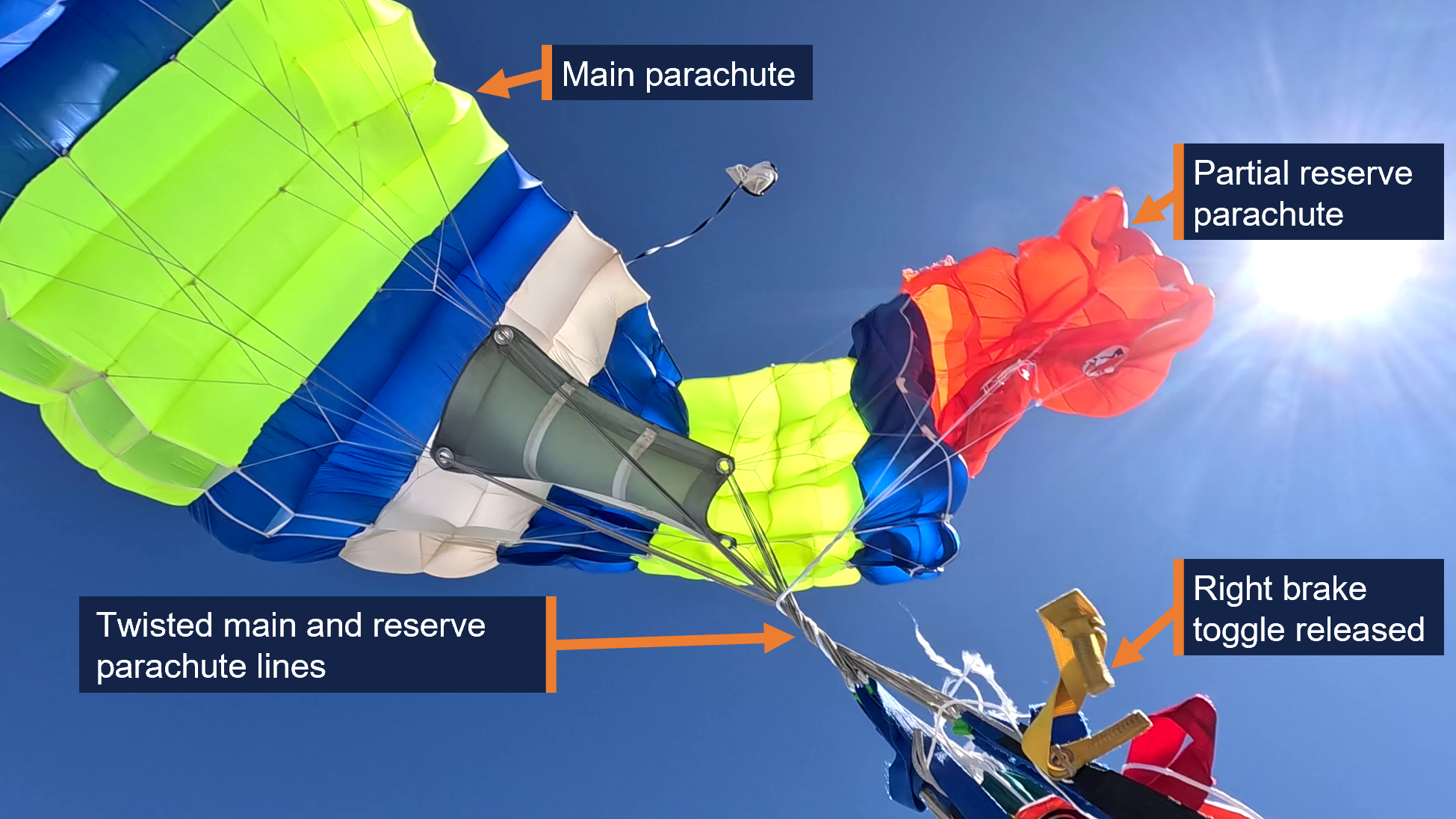
Source: Adrian Ferguson
The pilot assessed they had limited pitch[6] control and with forward pressure could achieve a gradual descent. The pilot retracted the flap, which then allowed slightly more rudder, aileron and elevator control. The pilot reported maintaining about 120 kt airspeed during the descent and assessed that with the limited elevator movement available, they would be able to conduct a gentle flare for landing. The pilot also looked over their shoulder and saw the parachute remnant wrapped over the tail and the damage to the leading edge of the horizontal stabiliser. The pilot radioed the FNFF ground control assistant and advised them of the situation.
At 1005, the pilot declared MAYDAY[7] to Brisbane Centre ATC, advising they had a canopy wrapped around the elevator ‘with minimal control input’. The pilot then advised ATC that their plan was to assess the aircraft’s controllability and try to land it, but if ‘the tail fell off’, they would attempt to advise ATC and ‘bail out’.
The controller clarified details with the pilot and directed another aircraft in the area to remain clear. The controller then declared a distress phase,[8] alerted emergency services, and transferred other aircraft to a different Brisbane Centre frequency.
Descending through about 2,500 ft, the pilot assessed that they would land the aircraft rather than exit and parachute to the ground. The pilot elected to conduct a straight-in approach with a slight tailwind to runway 36,[9] to minimise manoeuvring the aircraft clear of high terrain either side of Tully Airport. The pilot also assessed there was insufficient elevator control to be able to safely extend landing flap.
As the aircraft crossed the threshold, the pilot initially reduced power, but this led the aircraft nose to drop significantly. The pilot then reintroduced power and flew level with the runway before reducing the throttle to idle and using both hands to apply full backpressure on the controls. The aircraft landed at 1010, having sustained substantial damage to the horizontal stabiliser (Figure 9). P1 landed 9 seconds later with minor lacerations and bruising to their left lower leg and a deep gash to their right lower leg. After receiving phone confirmation that the aircraft had landed safely, at 1018 ATC cancelled the distress phase.
Figure 9: VH-DVS after landing, showing damage to the horizontal stabiliser
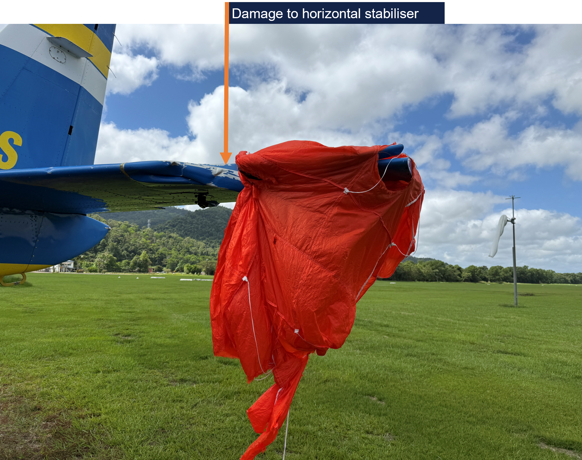
Source: Jarrad Nolan
Context
Personnel information
Pilot
The pilot held a commercial pilot licence (aeroplane), a class 2 aviation medical certificate and an instrument rating. They completed their most recent single engine aeroplane flight review and gas turbine engine design feature endorsement, as part of their jump pilot[10] authorisation in a Cessna 208 aircraft, on 21 June 2024.
The pilot had accrued 800 flight hours, 410 of which were operating Cessna 208 aircraft. They had been conducting parachute operations at Tully Airport for about 11 months and last conducted emergency procedures training for parachute operations in April 2025.
Parachutist 1
The accident jump was the parachutist’s (P1’s) 2,013th over a 21-year period. P1 held an Australian Parachute Federation (APF)[11] Certificate E, and achieved the Australian Star Crest in 2011, required for participation in skydive formations of more than 10 people.[12]
The parachutist’s equipment included:
- Sunpath Javelin Odyssey harness and container, SN 25429, manufactured December 2003.
- Airtec CYPRES 2 Expert automatic activation device, SN 96270 manufactured July 2014.
- Icarus Safire 2 139 main parachute, which was royal blue, fluoro yellow with a white centre cell.
- Bottom of container throwaway main deployment type.
- Performance Designs Optimum 143 reserve parachute, SN 25632, manufactured in October 2021. The reserve was repacked on 13 August 2025 by Freefall Support and valid for 12 months.
- A hook knife in a pouch attached to their chest strap and secured with a lanyard (Figure 10).
Figure 10: Parachutist’s hook knife and lanyard
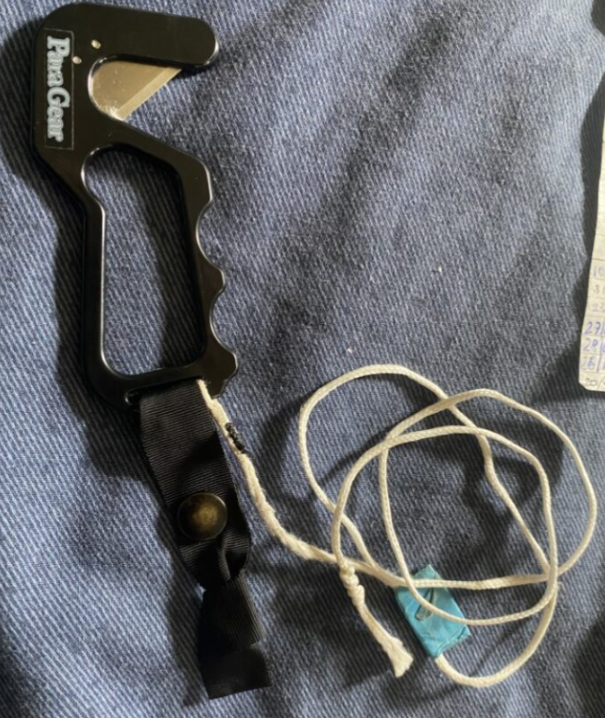
Source: Supplied
P1 used puds – soft handles held in place with Velcro – for their reserve deployment and main cutaway handles, in preference to ‘D’ handles, which they reported had previously been snag points (Figure 11). The reserve handle was a ‘Phat Daddy Tube Style’, described as ‘a soft handle with the bulk required to get a good grip in an emergency’. The APF assessed that the bulky handle design ‘may have increased the risk of snagging if not adequately protected’.
Figure 11: Pud ‘Phat Daddy’ soft reserve handle (left) and D handle (right)
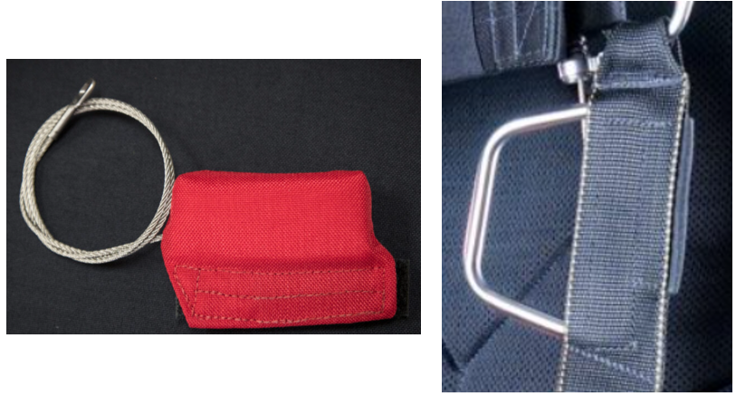
Source: www.sunpath.com
P1 commented that having a bright orange reserve parachute that was visually distinct from their main parachute meant that it was immediately obvious that it was their reserve that deployed prematurely. The APF reported that this type of deployment occurred far less frequently than premature deployment of a main parachute.
P1 conducted their normal gear check when the red light illuminated, which comprised checking:
- 3 handles (main pilot chute, cutaway of main chute and reserve handle)
- 3 straps (leg and chest straps properly routed and tucked away)
- 3 rings properly assembled on shoulders
- 3 things: altimeter on the back of left hand, altimeter inside of right wrist and helmet done up.
The accident jump was the parachutist’s first jump that day. P1 had an altimeter with a recording function, which showed that the reserve parachute tore free of the tailplane at 13,720 ft. After a freefall time of 26 seconds, the main parachute deployed at 10,780 ft.
The front float position is the most forward person in line and whose ‘exit’ is from outside the aircraft. P1 preferred the front float position. This was their third jump in that position out of the 6 jumps they had done at Tully that week. P1 also reported that out of the 20–22 jumps they did the previous year at the Big Ways at the Beach event, they had been in the front float position for about 8 of them.
All the event jumps were practised first on the ground as a ‘dirt dive’ using a mock-up aircraft at the airport. The mock-up had outer pegs and inner bars, but not a wing or flap to simulate their position (Figure 12).
Figure 12: Tully mock-up aircraft for practising ‘dirt dives’
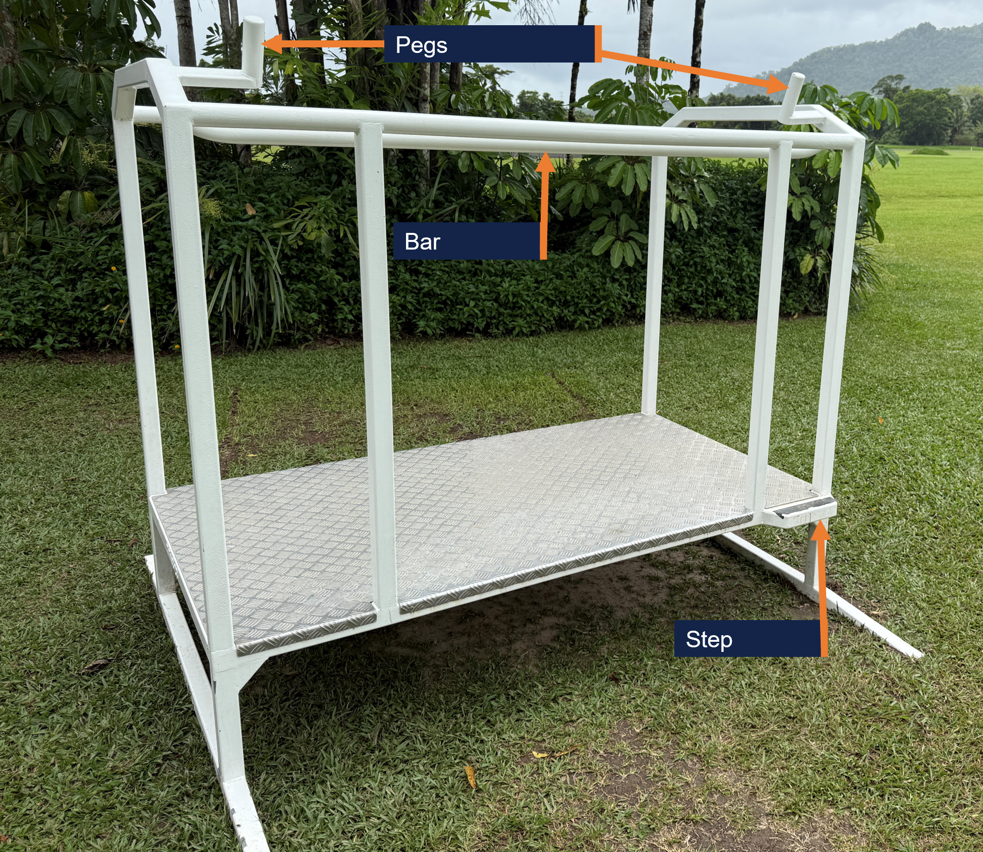
Source: Far North Freefall, annotated by the ATSB
Senior pilot
The FNFF senior pilot was approved by the APF. According to the APF Jump Pilot Manual (JPM), senior pilot responsibilities included:
- oversight of all aircraft related aspects of FNFF
- ensuring the safe and legal operation of aircraft.
Drop zone safety officer
The Far North Freefall (FNFF) chief instructor (parachuting) was the drop zone safety officer (DZSO) for the day’s operations at Tully. Due to wet weather earlier in the week, participants in the event had attended safety seminars. One seminar included reinforcing to parachutists to always be mindful of their handles. The DZSO reported that the front float position had specifically been mentioned in the seminar, because it required being as far forward as possible, with an associated risk of snagging equipment on the aircraft while reaching to stand up. It was regarded as a relatively difficult position to hold.
The DZSO was in the ground control assistant role (with a handheld radio) during the accident flight, when the pilot radioed and said there was a parachutist on the tail. The DZSO then started counting the parachutes they could see in the air. Another jump pilot on the ground came to help and asked the pilot whether they had declared MAYDAY, and the pilot replied that the jumper had got free of the aircraft’s tail. The camera operator was the first parachutist to land and pointed out to the DZSO that P1 was under their main parachute, with the reserve trailing.
After P1 landed, the DZSO handed the radio to the FNFF senior pilot, sent a car to pick up P1 and arranged for a doctor (who was also a parachutist), to provide first aid. P1 was then driven to hospital.
Loadmaster
The APF JPM detailed the loadmaster (LM) role as follows.
(a) Each parachute operation must have a nominated Loadmaster for each load.
(b) As per APF Operational Regulations (Part 6), the Loadmaster is responsible for:
(i) conducting a pre-jump briefing before any parachute descents are made, which covers all relevant aspects of the descent, and which includes all persons on-board the aircraft including pilot and parachutists;
(ii) ensuring the airspace and [drop zone] DZ below is clear of conflicting air traffic and any necessary drop clearances have been obtained; and
(iii) confirming the integrity of the exit point.
The LM on the accident flight reported being unaware they were the appointed LM for that load until after landing. There were 3 parachuting instructors on the load who were also approved and experienced LMs. About 5 minutes before departure, all parachutists on the load met at the mock-up, where they revised the exit and checked each other’s equipment (buddy checks). The load was displayed nearby on the manifest screen, showing who was the appointed LM for that load. The LM had not checked the screen. However, they reported that the LM role on the accident load was minimal, as it:
- only contained experienced parachutists
- was not the first load of the day (requiring confirmation of the spot position)
- only required one exit as all the parachutists were in the single formation.
Normally, communications between the pilot and parachutists were via the LM. On this load, the FNFF senior pilot (also the most experienced parachutist) was seated next to the pilot and therefore more readily able to communicate.
The LM’s role in an emergency was not included in the APF Operational Regulations or Training Operations Manual. However, the JPM Section 9.6 Emergency exit, stated:
In an airborne emergency such as a structural failure or fire, the pilot may decide that the chances of surviving a landing in the aircraft are non existent, and decide to order the evacuation of the aircraft. Each load must have a loadmaster who will start the aircraft evacuation once the pilot gives the command.
At lower levels, the parachutists will open their reserve parachutes as soon as they are clear of the aircraft. These parachutes are designed and packed to deploy quickly and only require a couple of hundred feet.
Note: Emergency procedures for structural failure are not discussed in manuals or safety publications because there are to [sic] many variables and little that can be effectively done. It is mentioned here because, with parachutes on-board, there is a chance that lives can be saved by exiting the aircraft. This applies equally to you as a pilot if you are wearing a parachute.
Additionally, the APF Safety management system continuous improvement package 4 2019, Aircraft emergency and evacuation procedures, was provided to APF member organisations to discuss in safety meetings. Regarding the LM role in an emergency, it included the section ‘Communication’:
The Pilot is in command. Wait for the Pilot’s instructions. You can make the situation worse for the Pilot, i.e. if you move closer to the door and cause a shift in the centre of gravity or asymmetric drag, by opening the door or everyone yelling and asking what to do.
Load Master to be ready to make the call if the Pilot does not respond (the Pilot may not be prepared for the emergency or may not provide instructions). The Load Master needs to be ready to give instructions. However, do not rush this decision (unless a catastrophic emergency) as the Pilot may be assessing the situation, e.g. if there is a small electrical fire the Pilot may try to put out this fire with the extinguisher before having a forced landing with a full plane load or instructing everyone to exit.
The APF and FNFF did not specify an emergency exit command.
The LM reported calling ‘get out, get out, get out’ but that ‘exit, exit, exit’ was the command they should have used. The FNFF senior pilot recalled shouting ‘go, go, go’. Another parachutist nearer the door also yelled and pointed parachutists to exit when they had briefly paused in the doorway. That parachutist reported that in hindsight it was the LM’s role, not theirs, to give the command, but the chief instructor advised that in this case, it facilitated a quick exit, which was correct action at the time.
The LM and FNFF senior pilot remained in the doorway until P1 was free of the tailplane, before exiting the aircraft. However, both later reported that, in hindsight, they should have gone back to the front of the aircraft and relayed the situation to the pilot, although they reported the pilot was probably aware that the parachutist was clear, as the aircraft ‘bucked’ when the parachutist tore free.
During their discussions with the parachutists after the incident, the FNFF chief instructor (parachuting) identified that there had not been a plan as to what the parachutists would do in the event of an emergency to ensure they assisted and remained clear of each other’s parachute after exiting. Further, that there was no documented training for the LM role and the requirements in the event of an emergency were not well understood.
Aircraft
VH-DVS was a Cessna Aircraft Company 208, manufactured in 1988, serial number 20800131, modified under a Texas Turbines Conversions supplemental type certificate with a Honeywell TPE331-12JR-704TT engine and a Hartzell Propellers 4-blade HC‑E4N-5KL propeller. At the time of the accident, the airframe total time in service was 10,270.60 hours. The aircraft’s tail assembly (empennage) consisted of a vertical stabiliser, rudder, horizontal stabiliser and elevator. VH-DVS was unpressurised and equipped with supplemental oxygen for the pilot’s use.
VH-DVS was modified for parachuting with bench seats and single point restraints. Handrails, posts, a step and a roller door were also fitted to facilitate parachutists to exit the aircraft, along with a ‘Baz clip’ to secure the door open (Figure 13).
Figure 13: Baz clip securing the roller door open
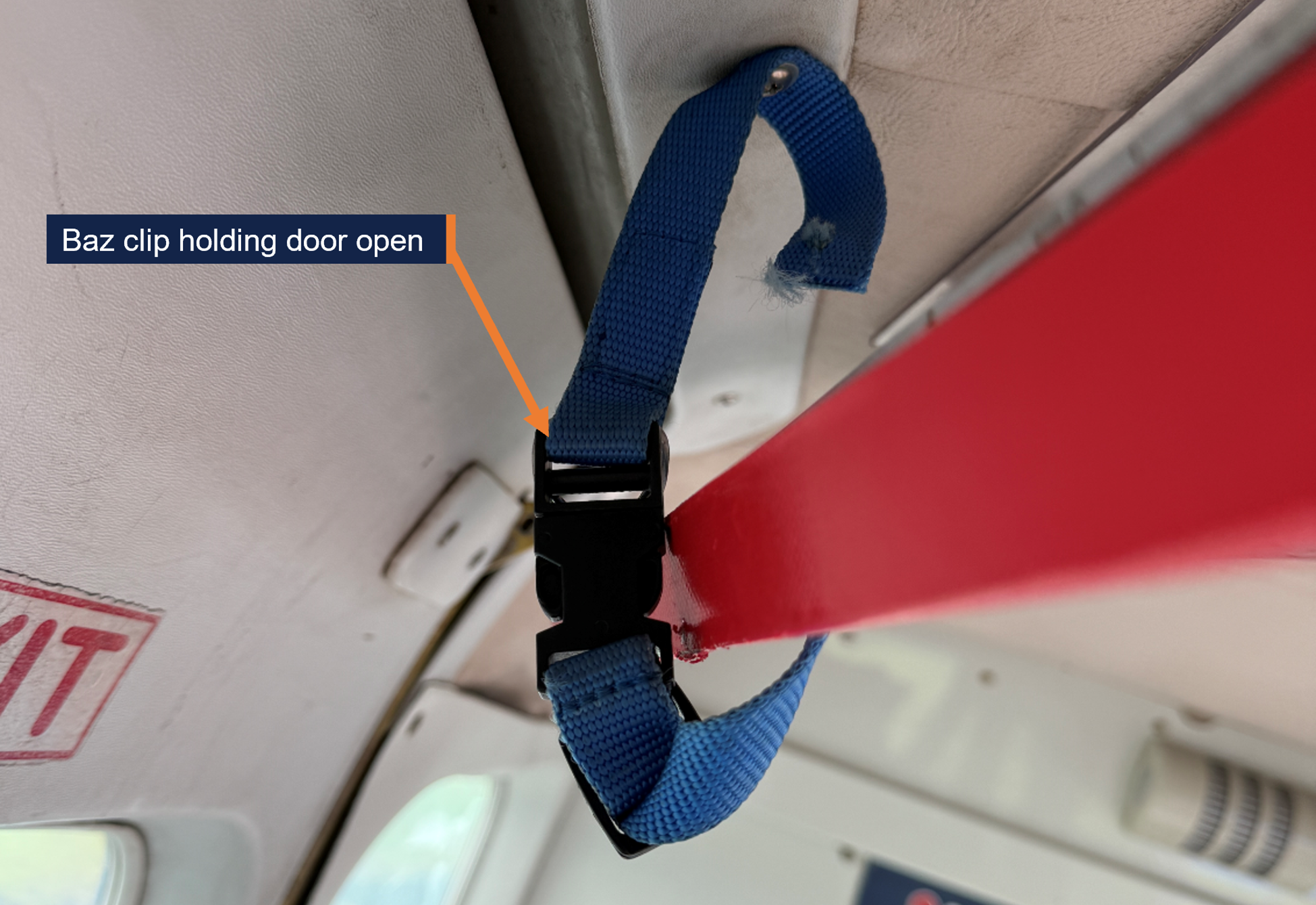
Source: Far North Freefall, annotated by the ATSB
Following an accident involving another Cessna 208 in 2001 (see the section titled Previous similar occurrences), in which the pilot’s emergency egress was delayed by the roller door (blind) closing, the designer of the blind amended the design to include:
- a device to lock the door in the open position
- a placard warning that the blind must be locked open during parachuting.
The aircraft was also fitted with a light system controlled by the pilot. In accordance with FNFF procedures, the pilot was to illuminate the:
- red light 3 NM from the drop position
- orange light 1 NM from the drop position, at which time door could be opened
- green light to indicate pilot approval to commence exit.
Following the accident, the following maintenance was conducted:
- inspection of the fuselage to horizontal stabiliser attach fittings; no defects found
- inspection of the elevator control cable assembly; no defects found
- left and right elevator control surfaces replaced
- horizontal stabiliser assembly replaced.
Weight and balance
The Civil Aviation Safety Authority (CASA) legislative instrument EX105/23 – Part 105 (Parachute Operators and Pilots) Instrument 2023, as amended and in force on 1 July 2025, exempted compliance with paragraph 91.095(2)(a) of the Civil Aviation Safety Regulations (CASR) regarding the maximum number of passengers that may be carried, the seating configuration and restraints stated in the airplane flight manual. For the exemption to apply, the instrument included in Section 9, among other requirements:
1) If the aeroplane has been modified in a manner that affects any of the following:
(a) the maximum number of passengers that may be carried on the aeroplane in accordance with the [airplane flight manual] AFM; or
(b) the passenger seating, or method of passenger restraint, in accordance with the AFM;
then the modification must have been approved:
(c) by an authorised person or an approved design organisation under regulation 21.437 of CASR; or
(d) otherwise in accordance with a Part 21 approval; or
(e) by an approval continued in force, according to its terms, under regulation 202.054 of CASR.
(2) The pilot in command must follow the procedures designed to ensure that the aeroplane:
(a) remains within its MTOW; and
(b) remains within its centre of gravity limits and requirements at all stages of the operation; and
(c) complies with all limits, restrictions and conditions imposed by the approval mentioned in subsection (1).
Additionally, Section 10 of the instrument required the pilot to comply with the conditions of the exemption and for the operator, in this case FNFF, to ensure the pilot did so.
Regulation 91.805 of CASR also required the pilot to ensure at all times that an aircraft was loaded and operating within its weight and balance limits.
The CASR Part 105 Manual of standards (MOS), Chapter 7 – Weight and balance required both the aircraft operator and the pilot to ensure a load sheet was completed before flight, unless the aircraft was carrying the same load for multiple parachute drops. The load sheet was required to be carried in the aircraft and a copy given to the chief parachuting instructor or drop zone safety officer (and retained for 3 months). Among other things, the load sheet was required to include:
(g) the weights and moment arms of:
(i) the occupants of the aircraft; and
(ii) any cargo carried on the aircraft; and
(iii) any removable equipment carried on the aircraft; and
(iv) fuel and consumables carried on the aircraft (for example, water or ethanol);
(h) the calculated load weight, and total moment, that demonstrates that the centre of gravity is within the approved limits;
(i) the maximum allowable weight for the flight, having regard to the prevailing environmental conditions;
(j) a statement by the person who is responsible for planning the loading of the aircraft, that the load and its distribution are in accordance with the aircraft loading system;
FNFF used BURBLE manifest software. Parachutists were required to use an app to check in each morning, and their weight was included in their personal details. BURBLE then verified that APF members had signed the required waiver, the reserve parachute was within the repack date, and the parachutist intended to do an appropriate jump for their certificate/licence.
A manifest person then re-checked the information in BURBLE. After check-in, parachutists could be manifested on a load, along with a coach and/or camera operator as needed. A DZSO, ground control assistance (GCA) and loadmaster would be assigned for each load.
As parachutists were allocated to a load, their weights were added to the aircraft weight. The manifest person would then update the quantity of fuel on board. The chief instructor (parachuting) advised that their normal process was to use a standard fuel weight based on sufficient fuel to conduct 3 parachute drop loads (and required reserves). If BURBLE flagged that the aircraft was overweight with that fuel quantity, the manifest person would then use a more precise fuel figure.
The aircraft had an iPad as an electronic flight bag (EFB), which included a load sheet based on the BURBLE manifest. The pilot reported that they would review the load sheet on the iPad and ensure the aircraft was below the maximum take-off weight.
Although BURBLE performed a weight calculation, it did not calculate the aircraft centre of gravity or balance, or have any means to allocate parachutists to a particular (loading) zone of the aircraft. Several other Australian drop zones used IBIS software, which could perform weight and balance calculations. Under a Memorandum of Understanding, FNFF was required to operate the aircraft in accordance with Section 5 – Aircraft operational procedures of the Skydive Australia operations manual. This section of the Skydive Australia operations manual provided procedures for calculating weight and balance with IBIS or OzRunways.[13] VH-DVS’s OzRunways EFB included the aircraft’s skydive configuration, allowing pilots to enter fuel and passenger weights in order to determine the aircraft’s take-off weight and centre of gravity position for each flight.
Emergency procedures
Knife
Part 105 – Parachuting from aircraft – MOS 5.40 Emergency equipment carried on jump aircraft, required a knife suitable for emergency situations be carried on board the aircraft and to be readily available to the pilot or parachute instructor. This was also required in the APF Operational regulations, section 5.2 – Aircraft:
5.2.5 Knife in Aircraft
A knife, capable of cutting parachute harness webbing, must be readily available and appropriately stored in the aircraft.
There was at least one knife on board VH-DVS as required by the APF JPM. However, in this occurrence, there was no practical means of getting the onboard knife to the parachutist hung up on the tail.
Skydive Australia’s emergency procedures checklist, a copy of which was in VH-DVS, included actions in the event of a parachutist being hung up by their restraint, or their parachute snagging on exiting the aircraft (Figure 14).
Figure 14: Skydiver hang up checklist
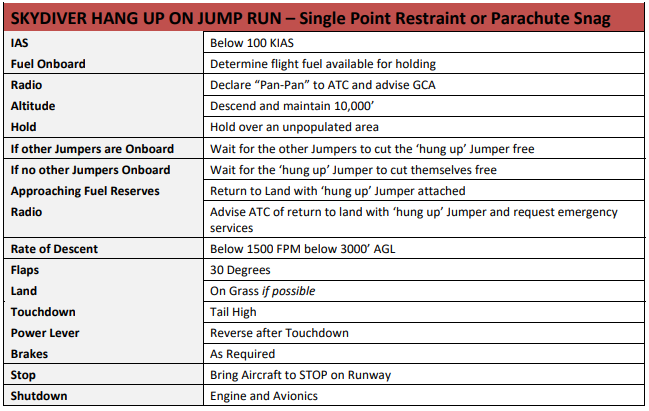
Source: Skydive Australia Operations Manual
Emergency parachute
The APF’s Operational regulations, section 5.2 – Aircraft, also required an emergency parachute be made available to pilots:
5.2.6 Pilot’s Emergency Parachute Availability
A parachute that complies with APF Equipment Standards and training in the proper use of that parachute must be made available to pilots of aircraft used in making descents.
The Skydive Australia operations manual required the pilot to wear an emergency parachute when conducting skydiving operations. There was no requirement for a pilot to have conducted a parachute jump; they were trained in its use verbally and by demonstration. Emergency parachutes had one parachute, which was large and designed to open very quickly. The pilot was wearing an emergency parachute, had been trained in its use, and reported that they would only exit if they had no control of the aeroplane.
The APF JPM section 9.7 Emergency pilot rig use stated:
In the event that you decide to use the pilot emergency parachute, you must be prepared to follow the procedures you’ve been briefed on by the DZSO for the particular rig in use. Pilot rigs normally contain a round canopy, which achieve minimal air speed (~5 to 8 knots) and glide ratios of up to 1:1. The general procedure for use is as follows:
(a) prior to leaving the aircraft, grasp the ripcord handle. It is easier to locate it prior to exit as it may move once in freefall, and the associated disorientation may make it more difficult to find.
(b) once clear of the aircraft, pull the ripcord to full arms length,
(c) once the parachute is open, reach up and grasp the two small steering toggles (handles), or the coloured lines, on the risers above your shoulders.
(d) to steer, pull down one side to turn in that direction.
(e) fly towards a cleared area and try to land into the wind to minimise landing speed.
(f) for landing, it is highly recommended that you perform a Parachute Landing Roll (PLR).
Premature parachute deployment
The APF JPM Part 9 Emergency procedures, included 9.3 In-aircraft parachute deployment:
There are a number of situations where a ripcord may be accidentally pulled or a pin dislodged resulting in a container opening in the aircraft, on climb‐out, or on the step. An extremely hazardous situation exists when the door has been opened and a pilot chute is suddenly deployed finding its way outside.
Further, it stated that parachutists ‘are taught to protect their handles and equipment while inside the aircraft and during climb-out’ (Figure 15).
Figure 15: Jump pilot manual extract
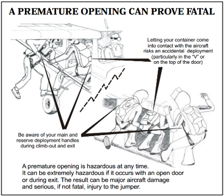
Source: Australian Parachute Federation
The emergency procedures continued:
An accidental opening in the aircraft with the door open is potentially disastrous. If a pilot chute escapes while the door is open, it can be out and into the slip stream before reaction is possible. The jumpers will do their best to ensure the person attached is able to be expedited out the door as quickly as possible. In the past, this has resulted in the parachutist attached to the parachute being pulled through the side of the aircraft!
Keep a close watch for any premature openings and if one occurs, immediately apply maximum rudder to swing the tail clear of the deploying parachute and the person attached.
The APF produced a safety poster, which was on the wall at FNFF. The poster stated that premature deployments can be prevented by:
- Proper equipment maintenance
- Using compatible equipment
- Buddy checks
- Minimising excessive movement in aircraft
- Checking handles, pins, etc before emplaning and before exit
- Taking care and being conscious of equipment during climb-out.
Tully Airport
Tully Airport was an aircraft landing area with one sealed runway 18/36, 936 m long. The airport elevation was 47 ft, with terrain about 2,200 ft above mean sea level to the east and west. The drop zone was adjacent to the northern end of the runway.
The drop position for the day was heading south (180°), running centrally overhead Tully Airport, with the pilot illuminating the green light at 0.8 NM (1.5 km) before (north of) the aerodrome reference point.
The weather at Tully Airport on the morning of the accident included 6–10 kt south‑easterly winds, cloud covering about half the sky, and an ambient temperature of 21°C. The nearest Bureau of Meterology weather station was at Innisfail, about 42 km north.
At 1000, the Innisfail METAR[14] stated that the wind was from 170° at 3 kt, visibility greater than 10 km, QNH 1,014 hPa,[15] temperature 25°C. At 1010 (the time the aircraft landed), the 1‑minute weather data at Innisfail included: temperature 27°C, wind (which had been variable for the past 5 minutes) from 245° at 1 kt and QNH 1,014.6 hPa.
Supplemental oxygen
CASR Part 105 MOS required unpressurised aircraft operating a parachute descent to have supplemental oxygen in accordance with the Part 91 MOS Division 26.11 – Oxygen equipment and oxygen supplies. The aircraft was required to be fitted with, or carry, supplemental oxygen, which was required to be used by:
- flight crew for any period exceeding 30 minutes when the cabin pressure altitude was continuously at least flight level (FL)[16] 125 but less than FL 140
- flight crew for any period when the cabin pressure altitude was at or above FL 140
- passengers for any period when the cabin pressure altitude was at or above FL 150.
CASA advised that this was incorporated in Part 91 between 2003 and 2011 to align with the United States Federal Aviation Regulations. The European Union Aviation Safety Agency required crew members to use supplemental oxygen when between 10,000 ft and 13,000 ft for more than 30 minutes, and at all times when above 13,000 ft.
Aircraft conducting parachute drops from FL 150 were usually between FL 140 and FL 150 for about 2 minutes. In the occurrence flight, due to the premature parachute deployment, the aircraft was between FL 140 and FL 150 for closer to 3 minutes. For jump pilots, that is a high workload period, involving slowing and configuring the aircraft for the drop, confirming the drop position, and communicating with parachutists, air traffic control, the ground control assistant and on the common traffic advisory frequency.
The APF operational regulations required adherence to the Part 91 MOS oxygen requirements. However, the pilot did not use oxygen on the accident flight.
Hypoxia
Hypoxia is the absence of an adequate supply of oxygen to the tissues. Hypobaric hypoxia is the most common form in aviation and is associated with breathing air at low barometric pressure. A deficiency in alveolar oxygen exchange due to low oxygen tension (partial pressure) of inspired air leads to inadequate oxygen supply to the blood and reduced oxygen available to the tissues. In an aviation context, acute hypobaric hypoxia is the ‘most serious single physiological hazard during flight at altitude’ (Gradwell and Rainford, 2006).
The risk of hypoxia increases with altitude and time at altitude. Additionally, multiple ascents to altitude may have a compounding effect on hypoxia. There is considerable variation between individuals in the effects of hypoxia. Hypoxia can occur in susceptible individuals below 10,000 ft. Between 10,000 ft and 15,000 ft, brain function is mildly impaired and hypoxic symptoms are common. Above 15,000 ft, brain function exponentially deteriorates (Shaw, Cabre and Gant, 2021).
Physical activity, cold, illness and certain drugs increase the onset speed and severity of hypoxia. Additionally, jump pilots require a class 2 aviation medical certificate, which is less stringent than class 1 medical certification, and may allow underlying cardio‑respiratory conditions that increase hypoxia risks to go undetected.
Those experiencing hypoxia may have no signs or symptoms and may be unaware of any cognitive impairment. In unpressurised aircraft, hypoxia can be prevented by breathing supplemental oxygen.
Limited research has been conducted into the effects of ascents to FL 140 and FL 150 for jump pilots or parachutists. An article in the United States Parachute Association’s publication Parachutist, described a small study of parachutists using pulse oximeters. They found that in ascents to 14,500–15,000 ft above mean sea level, blood oxygen saturation levels, normally 95–100%, dropped into the 80s (%) during ascent, and, into the 70s on one flight in which air traffic control holding resulted in an additional 10 minutes at altitude (Galdamez, 2024). Although individual responses vary to reduced oxygen saturation levels, a finger‑mounted pulse oximeter can alert pilots and parachutists to reduced blood oxygen saturation levels, prompting the use of supplemental oxygen.
Previous similar occurrences
Premature parachute deployment
The ATSB investigated a parachuting accident involving Cessna 208 VH-MMV at Nagambie, Victoria, on 29 April 2001 (AAIR200101903). The aircraft climbed to FL 140 with 11 parachutists and the pilot on board. As the first 4 parachutists exited the aircraft, the middle parachutist’s reserve pin dislodged on the top of the door frame and the pilot chute deployed. The pilot chute pulled the reserve parachute over the horizontal stabiliser. The reserve parachute risers and lines tangled around the left elevator and horizontal stabiliser, with the parachutist hanging below them. Eleven seconds later, the empennage separated from the aircraft and the left elevator and parachutist separated from the empennage. The parachutist fell to the ground and was fatally injured.
The remaining parachutists exited the aircraft before it descended through 9,000 ft. The pilot transmitted a MAYDAY call, shut down the engine and left their seat. However, the rear roller door (blind) had closed. After several attempts, the pilot raised the blind sufficiently to exit the aircraft at about 1,000 ft above ground level and deploy their parachute before landing safely. The aircraft impacted the ground and was destroyed by impact forces and post-impact fire.
Parachutists striking aircraft
The Nagambie report referenced 3 previous premature parachute deployments and 2 occurrences in which a parachutist struck the aircraft. Table 1 details occurrences since 2001 in which a parachutist struck and damaged the aircraft.
Table 1: ATSB occurrences since 2001 in which a parachutist struck the aircraft
| Date Time | Aircraft type | Occurrence | Summary |
| 12/3/2003 1500 | Cessna 208 | OA2003-00849 | On exit, the parachutist struck the tailplane of the aircraft and was rendered unconscious. The altitude release mechanism on the reserve parachute opened allowing the parachutist to land. The parachutist later died in hospital from their injuries. The aircraft sustained minor damage to the tailplane and trim tab. |
| 18/7/2004 1200 | GippsAero GA-8 | OA2004-02741 | While carrying out parachute operations, a jumper was observed to strike the tailplane on exiting the aircraft. The aircraft suffered minor damage to the leading edge of the left tailplane however landed safely a short time later. |
| 2/2/2005 1615 | Piper PA-31 | OA2005-00602 | As the parachutist exited the aircraft, their leg struck the tailplane resulting in a fractured ankle. The aircraft incurred a minor dent in the left leading edge of the tailplane. |
| 29/7/2007 1231 | Piper PA-31 | OA2007-04921 | The pilot reported that the last exiting parachutist had struck the aircraft, impacting the horizontal stabilizer and denting the fuselage. The aircraft and the parachutist landed safely with local emergency services in attendance. The parachutist was not injured. |
| 18/12/2010 1700 | Pacific Aerospace 750XL | OA2010-08869 | After exiting the aircraft, the parachutist collided with the left flap and sustained a minor injury. |
| 24/2/2013 1630 | GippsAero GA-8 | OA2013-01896 | During parachute drop, a parachutist struck the tail of the aircraft. The parachutist sustained minor injuries, and the aircraft sustained minor damage. |
| 25/3/2015 1600 | Cessna 208 | OA2015-02582 | While exiting the aircraft, the parachutist struck the horizontal stabiliser resulting in minor damage and a minor injury to the parachutist. |
| 1/4/2017 1300 | Embraer EMB-110P1 | OA2017-01515 | During parachute operations, a parachutist prematurely exited the aircraft and struck the elevator. |
| 27/8/2020 1330 | Cessna 208 | OA2020-04239 | During parachuting operations, the aircraft commenced descent with a parachutist still on board. Passing FL 100 on descent, the parachutist exited the aircraft and struck the left horizontal stabiliser resulting in minor damage to the aircraft and minor injuries to the parachutist. The pilot diverted the aircraft to Bankstown. |
| 20/9/2024 1225 | Cessna 182L | OA2024-04119 | During parachute dropping operations, the pilot detected airframe vibrations with associated uncommanded pitch oscillations and encountered control issues. The engineering inspection revealed multiple elevator parts to be missing. The ATSB could not determine whether a parachutist had struck the tail. |
Weight and balance
There were 2 accidents in Sweden investigated by the Statens Haverikommission (SHK) involving aircraft conducting parachuting operations, in which the aircraft’s weight and balance was not calculated.
On 14 July 2019, 8 parachutists and the pilot were fatally injured in an accident in Sweden involving a GippsAero GA8 aircraft. The SHK investigation found that the parachutists moved to the back of the aircraft in preparation for the jump, which altered the weight distribution, resulting in the aircraft stalling, before breaking up in flight. The aircraft was found to have been overloaded. The SHK also found that as the load sheet did not contain the weights of the parachutists or the total mass of the load, the pilot was unable to complete weight and balance calculations.
On 8 July 2021, the pilot and 8 parachutists were fatally injured when a de Havilland DHC-2 aircraft collided with terrain shortly after take-off. The SHK found that:
Control of the aircraft was likely lost in connection with the wing flaps being retracted in a situation where the stick forces were high due to an abnormal elevator trim position, while the aircraft was unstable due to being tail-heavy and abnormally trimmed. Due to the low altitude, it was not possible to regain control of the aircraft.
The investigation also found that the pilot had no ability to perform a weight and balance calculation with the available information.
Safety analysis
As the parachutist climbed out of the aircraft and into the front float position, their reserve handle snagged on the aircraft's flap, resulting in deployment of the reserve pilot chute and parachute. The parachutist was highly experienced, had performed their gear checks before exiting the aircraft, and attended safety seminars in the days prior to the accident, which included being mindful of their handles.
The parachutist was also experienced in the front float position and had practised getting into that position several times in the mock-up on the ground before the jump. However, the mock-up did not have a flap to simulate its position, reducing the likelihood that the snagging potential would be recognised.
As the parachutist was pulled rearwards, they struck the camera operator, who was dislodged from the aircraft sustaining a minor shoulder injury. The parachutist’s lower legs struck and damaged the leading edge of the horizontal stabiliser, which, combined with the parachute wrapped around the horizontal stabiliser and elevator, resulted in the pilot experiencing difficulties controlling the aircraft. Although not required to be carried, the parachutist had a hook knife, which enabled them to cut themselves free of the aircraft. Without access to the knife, separation from the aircraft may not have been possible. Additionally, although the pilot was wearing an emergency parachute and the roller door was clipped open to aid exiting if control was lost, the pilot was able to maintain sufficient control to land the aircraft without further incident.
The parachuting club at Tully was using manifest software that calculated the aircraft’s weight including the parachutists. However, it did not perform balance calculations to ensure the aircraft was loaded within its centre of gravity envelope. Additionally, the pilot was not using the available electronic flight bag tool to calculate weight and balance for each flight, and the senior pilot was not ensuring this was done. There was no evidence that the aircraft was out of balance or that this contributed to the occurrence. However, fatal accidents have occurred involving aircraft conducting parachute operations, in which the aircraft were operated outside the aircraft’s balance limits.
Hypoxia poses a risk to both pilots and parachutists when operating above about 10,000 ft, noting that its specific effects are highly variable between individuals. There is limited research into the effects of short, repeated exposure to altitude associated with parachuting operations, or of the magnitude of additional risk in operating for 2–3 minutes between 14,000 and 15,000 ft. However, given individual responses to altitude exposure, use of supplemental oxygen at and above 14,000 ft as required by legislation, reduces hypoxia risks and any compounding effects of multiple ascents associated with parachute operations.
Findings
ATSB investigation report findings focus on safety factors (that is, events and conditions that increase risk). Safety factors include ‘contributing factors’ and ‘other factors that increased risk’ (that is, factors that did not meet the definition of a contributing factor for this occurrence but were still considered important to include in the report for the purpose of increasing awareness and enhancing safety). In addition, ‘other findings’ may be included to provide important information about topics other than safety factors. These findings should not be read as apportioning blame or liability to any particular organisation or individual. |
From the evidence available, the following findings are made with respect to the premature parachute deployment involving Cessna 208, VH-DVS, over Tully Airport, Queensland, on 20 September 2025.
Contributing factors
- As the parachutist climbed out of the aircraft and into the front float position, their reserve handle snagged on the aircraft's wing flap, resulting in deployment of the reserve parachute and entanglement with the empennage. The parachute wrapping around the horizontal stabiliser, combined with damage from impact with the parachutist's legs, resulted in aircraft control difficulties.
Other factors that increased risk
- The pilot and aircraft operator did not ensure the aircraft was loaded within the weight and balance envelope.
- The pilot did not use oxygen when the aircraft was at or above flight level 140 as required by regulations to reduce the risks of hypoxia.
Other findings
- The parachutists opened the roller door and clipped it open before exiting the aircraft. As a result, the roller door remained open during the descent, increasing the ease with which the pilot could have exited the aircraft if needed.
- Although not mandatory at the time of the accident, the parachutist had a hook knife attached to their chest strap, enabling them to cut enough reserve parachute lines for the parachute to detach from the tailplane.
- In difficult circumstances, the pilot managed to control the aircraft and return to land safely.
Safety actions
Safety action taken by Far North Freefall
To ensure aircraft are loaded within their weight and balance envelope and this is documented on a load sheet, Far North Freefall Club (FNFF) has:
- engaged with the current software distributor about including balance in the manifest system
- commenced investigation of alternative software
- implemented a proprietary interim system that calculates and graphically displays the centre of gravity position on the aircraft’s weight and balance envelope indicating whether it is within or outside the limits.
Additionally, FNFF distributed a circular to pilots reminding them of the requirement to use supplemental oxygen when the aircraft is at or above flight level 140, and of the risks of hypoxia. FNFF also mandated parachutists to carry a hook knife.
Furthermore, FNFF updated the loadmaster checklist within its safety management system. Copies of the checklist are displayed around the drop zone to raise awareness of loadmaster roles and procedures in the event of an emergency. A circular has also been sent to all current FNFF loadmasters to reinforce familiarity with in-aircraft emergency procedures.
In addition, the FNFF safety team is reviewing its standard operating procedures manual to ensure all procedures – including those relating to loadmaster training and emergency response – are clearly documented and up to date.
FNFF is also preparing a training slideshow incorporating footage from the incident. This presentation will be shared across the wider skydiving community for educational purposes.
Safety action taken by the Australian Parachute Federation
At the time of writing, the Australian Parachute Federation was in the process of developing a guide for loadmasters. The guide will detail the role and responsibilities, including during an emergency. It will take into consideration the range of complexity of various operations, and aircraft type and size. Training and assessment material will also be developed.
Sources and submissions
Sources of information
The sources of information during the investigation included:
- the pilot and parachutists
- the aircraft operator
- Australian Parachute Federation
- Civil Aviation Safety Authority
- Airservices Australia
- witnesses
- video footage of the accident flight and other photographs and videos taken on the day of the accident
- recorded data.
References
Galdamez L (2024, December) Studying hypoxia in skydivers, Parachutist, Volume 65, Number 12, Issue 782, 58–59
Gradwell DP, Rainford DJ (2006), Ernsting’s aviation medicine, Edward Arnold (Publishers) Ltd London, Chapter 3.
Shaw DM, Cabre G and Gant N (2021) Hypoxic Hypoxia and Brain Function in Military Aviation: Basic Physiology and Applied Perspectives. Front. Physiol. 12:665821. doi: 10.3389/fphys.2021.665821
Submissions
Under section 26 of the Transport Safety Investigation Act 2003, the ATSB may provide a draft report, on a confidential basis, to any person whom the ATSB considers appropriate. That section allows a person receiving a draft report to make submissions to the ATSB about the draft report.
A draft of this report was provided to the following directly involved parties:
- the aircraft operator
- the aircraft owner
- the pilot and parachutists
- Australian Parachute Federation
- Civil Aviation Safety Authority.
Submissions were received from:
- the aircraft owner
- the aircraft operator
- a parachutist
- Civil Aviation Safety Authority
- Australian Parachute Federation.
The submissions were reviewed and, where considered appropriate, the text of the report was amended accordingly.
Purpose of safety investigationsThe objective of a safety investigation is to enhance transport safety. This is done through:
It is not a function of the ATSB to apportion blame or provide a means for determining liability. At the same time, an investigation report must include factual material of sufficient weight to support the analysis and findings. At all times the ATSB endeavours to balance the use of material that could imply adverse comment with the need to properly explain what happened, and why, in a fair and unbiased manner. The ATSB does not investigate for the purpose of taking administrative, regulatory or criminal action. About ATSB reportsATSB investigation reports are organised with regard to international standards or instruments, as applicable, and with ATSB procedures and guidelines. Reports must include factual material of sufficient weight to support the analysis and findings. At all times the ATSB endeavours to balance the use of material that could imply adverse comment with the need to properly explain what happened, and why, in a fair and unbiased manner. An explanation of terminology used in ATSB investigation reports is available here. This includes terms such as occurrence, contributing factor, other factor that increased risk, and safety issue. Publishing informationReleased in accordance with section 25 of the Transport Safety Investigation Act 2003 Published by: Australian Transport Safety Bureau © Commonwealth of Australia 2025 
Ownership of intellectual property rights in this publication Unless otherwise noted, copyright (and any other intellectual property rights, if any) in this report publication is owned by the Commonwealth of Australia. Creative Commons licence With the exception of the Commonwealth Coat of Arms, ATSB logo, and photos and graphics in which a third party holds copyright, this report is licensed under a Creative Commons Attribution 4.0 International licence. The CC BY 4.0 licence enables you to distribute, remix, adapt, and build upon our material in any medium or format, so long as attribution is given to the Australian Transport Safety Bureau. Copyright in material obtained from other agencies, private individuals or organisations, belongs to those agencies, individuals or organisations. Where you wish to use their material, you will need to contact them directly. |
[1] Belly-to-earth position: horizontal, front of the body facing down, with a slightly arched back. It is the most stable position with the slowest terminal velocity.
[2] Flight level: at altitudes above 10,000 ft in Australia, an aircraft’s height above mean sea level is referred to as a flight level (FL). FL 150 equates to 15,000 ft pressure altitude.
[3] Pud: an aerodynamically low-profile, soft handle that is ergonomically designed to fit into a clenched fist. Used for various parachute operation handles. The left pud is typically used to deploy the reserve parachute.
[4] Parachute and canopy are used interchangeably.
[5] The toggles attach to the brake line. Pulling the toggles to apply the brakes ‘flares’ the parachute, to slow the descent rate for landing. Asymmetric brake application slows one side of the parachute, resulting in rotation.
[6] Pitching: the motion of an aircraft about its lateral (wingtip-to-wingtip) axis.
[7] MAYDAY: an internationally recognised radio call announcing a distress condition where an aircraft or its occupants are being threatened by serious and/or imminent danger and the flight crew require immediate assistance.
[8] Distress phase (DETRESFA): an emergency phase declared by the air traffic services when there is reasonable certainty that an aircraft and its occupants are threatened by grave and imminent danger or require immediate assistance.
[9] Runway number: the runway number represents the magnetic heading of the runway. Runway 36 heads about 360°.
[10] A jump pilot operates an aircraft to facilitate a parachute descent.
[11] The Australian Parachute Federation (APF) is the peak body for the administration and regulation of civilian parachuting operations in Australia.
[12] The Australian Star Crest recipient must dock fifth or later, on 3 separate, successful 8,9, or 10‑ways (formations). They must be ‘flatfly’ (belly to earth) jumps.
[13] OzRunways is an electronic flight bag application that provides navigation, weather, area briefings and other flight
information. It provides the option for live flight tracking by transmitting the device’s position and altitude.
[14] METAR: a routine report of meteorological conditions at an aerodrome. METAR are normally issued on the hour and half hour.
[15] QNH: the altimeter barometric pressure subscale setting used to indicate the height above mean seal level.
[16] Flight level: at altitudes above 10,000 ft in Australia, an aircraft’s height above mean sea level is referred to as a flight level (FL). FL 125 equates to 12,500 ft.
Occurrence summary
| Investigation number | AO-2025-057 |
|---|---|
| Occurrence date | 20/09/2025 |
| Location | Overhead Tully Airport |
| State | Queensland |
| Report release date | 11/12/2025 |
| Report status | Final |
| Investigation level | Short |
| Investigation type | Occurrence Investigation |
| Investigation status | Completed |
| Mode of transport | Aviation |
| Aviation occurrence category | Cabin Safety, Control issues, Emergency/precautionary descent |
| Occurrence class | Accident |
| Highest injury level | Minor |
Aircraft details
| Manufacturer | Cessna Aircraft Company |
|---|---|
| Model | 208 |
| Registration | VH-DVS |
| Serial number | 20800131 |
| Aircraft operator | Far North Freefall Club Inc |
| Sector | Turboprop |
| Operation type | Part 105 Parachuting |
| Departure point | Tully Airport, Queensland |
| Destination | Tully Airport, Queensland |
| Damage | Substantial |