Steering failure and contact with navigational beacon involving CMA CGM Puccini, Port of Melbourne, Victoria, on 25 May 2023

Interim report

Interim report released 4 October 2023

This interim report details factual information established in the investigation’s early evidence collection phase, and has been prepared to provide timely information to the industry and public. Interim reports contain no analysis or findings, which will be detailed in the investigation’s final report. The information contained in this interim report is released in accordance with section 25 of the Transport Safety Investigation Act 2003.

The occurrence

Arrival Melbourne

At 0900[1] on 23 May 2023, a pilot boarded the 277.3 m, fully cellular container ship CMA CGM Puccini (Figure 1) for pilotage into the Port of Melbourne. Pre-pilotage checks included a test of machinery and equipment, including the steering gear. The ship was safely berthed at Swanson Dock at 1330 and cargo operations commenced soon thereafter.

Figure 1: CMA CGM Puccini

Figure 1: CMA CGM Puccini

Source: Owen Foley

The following day, the ship was attended by an Australian Maritime Safety Authority (AMSA) surveyor to conduct, among others, a port State control (PSC) inspection. As part of the PSC inspection, emergency operation of the steering was conducted with the surveyor in attendance in the steering gear room. The ship’s chief engineer, chief mate, electro-technical officer and the third engineer were there to carry out or oversee the test.

The test included changeover of steering control from the navigation bridge (bridge) to the steering gear room followed by demonstration of local operation of the steering gear. The third engineer configured the steering machinery for local operation including starting one steering gear pump and opening the by-pass valve on the other pump (stopped). Control of the rudder was then demonstrated by manual operation of the running pump solenoid valve. Both pump systems were tested in local control, individually and in parallel. The steering tests were conducted to the satisfaction of the surveyor.

Steering failure

The ship’s remaining stay at the berth was routine with nothing significant or unusual reported. At 0300 on 25 May, the second mate on watch on the bridge called the engine control room (ECR) and gave one hour’s notice to ready the main engine for departure. The second mate then called the third mate and the deck cadet to assist with preparations for departure, including steering gear checks. The deck cadet was sent to the steering gear room to witness rudder movement and repeat its response to the third mate who operated the steering from the bridge steering console. At 0322, rudder operation to maximum angles (hard over on both sides) was checked using one, then the second pump, separately, and then both together. The steering gear was recorded to have been tested as required by regulations.

At 0346, the main engine was tested and the pilot boarded at 0350. The bow thruster was tested and, at 0354, the master-pilot exchange was conducted on the bridge. On the bridge for departure were the pilot, master, chief mate, deck cadet and an able seafarer at the helm. In the engine control room were the chief engineer, third engineer (the duty engineer) and the electro-technical officer.

Weather conditions for the departure were clear skies and good visibility with winds from the north-north-east at force 4.[2] The tide was flooding, with high water expected at 0545. Just after 0405, 2 tugs were made fast (one forward, one aft) and by 0418 all mooring lines had been let go. CMA CGM Puccini was then manoeuvred out of Swanson Dock, through a 60° starboard turn and into the Yarra River.[3] (Figure 2)

During the turn to leave Swanson Dock, the master and chief mate noticed that the rudder response appeared sluggish, as if only one steering pump was running (both pumps were operating). Neither raised their observations with each other, or the pilot, and there were no alarms to indicate a pump had stopped or other abnormal condition.

By 0436, the ship was moving along the channel in the river, both tugs had been dismissed and the main engine was increased to slow ahead. At 0442, the ship passed under the Westgate bridge, about 1 mile downriver of Swanson Dock. The ship’s speed was 6.6 knots[4] with a rate of turn of 4° per minute to port. At 0443, the main engine was increased to half ahead[5] and more rudder ordered (port 10)[6] to increase the rate of turn. To maintain the turn rate, the pilot then gave helm orders (rudder) of port 5 (0443:34), followed by port 10 (0443:54).

Soon thereafter (0444:03), the pilot noticed that the rudder angle indicator was showing that the rudder was midships and repeated the earlier port 10 order. The able seafarer steering the ship by hand (helmsman) responded that the helm (steering wheel) was at port 10. This exchange drew the attention of the master and chief mate, who both verified that the helmsman had correctly followed the order. The helmsman informed them that the rudder was not responding to the wheel. By that time, the chief mate had moved to the steering console to investigate and observed that the rudder moved to port 5 and then slowly to starboard 5. The ship, with its speed increasing and rate of turn diminishing, tracked toward the western edge of the channel and beacon 32. At the time, the ship’s speed was 7.7 knots, it was turning to port at 3° per minute and was 7 m to starboard of its planned track.[7]

Figure 2: CMA CGM Puccini’s track from Swanson Dock to Webb dock

Figure 2: CMA CGM Puccini’s track from Swanson Dock to Webb dock

Position markers indicate location of ship’s main mast, about 181 m from the bow (atop the wheelhouse).
Source: Australian Hydrographic Office, Google Earth with annotations by ATSB

Further helm orders and helm (wheel) movement indicated that the rudder was not responding. The master remained at the manoeuvring console and, after confirming with the pilot, reduced the main engine to slow ahead, and then (0444:50) to dead slow ahead. The master confirmed that the bow thruster was operational and suggested further slowing the ship (to less than 5 knots) to make the thruster effective.

At about this time, the master called the ECR and asked for the steering gear to be attended immediately. In response, the chief engineer called the electro-technical officer, who had returned to the accommodation, and directed them to go to the steering gear room. The electro-technical officer collected a radio and, soon thereafter, was informed by the master (via radio) that emergency steering was required.

Meanwhile, the chief mate and the helmsman went about fault finding and checked steering control modes, including non-follow-up (NFU)[8]. Their attempts were unsuccessful and the rudder remained unresponsive to their control inputs. At 0445, the pilot contacted Melbourne vessel traffic service (VTS) and reported that the ship had lost steering and requested immediate tug assistance. Both tugs that had been dismissed earlier were directed to return to the ship.[9]

The pilot then instructed the helmsman, using NFU, to put the rudder hard to port if and when possible. At 0445:26, the main engine was stopped. CMA CGM Puccini’s speed was 8 knots and it was turning to port at 1° per minute. The ship was now 26 m to starboard of track with its bow about 32 m from the 10 m depth contour (the edge of the navigable channel).

Shortly thereafter, the rudder was observed to move to 35° to port (wheel was hard to port). The main engine was restarted, and the bow thruster set full to port. At 0445:30, the ship’s rate of turn to port suddenly increased as its bow closed with the side of the channel. By 0445:44, the ship’s speed had reduced marginally (to 7.9 knots) and its swing to port had increased to 13° per minute, with the bow now less than 20 m from channel's edge. The pilot ordered the rudder midships and immediately after to starboard 20 to reduce the increasing swing to port with the aim of avoiding the ship’s stern closing and contacting the western bank or shoals (Figure 3).

At 0446:12, the ship was 58 m to starboard of the planned track with significant headway (7.7 knots) and turning rapidly to port (20° per minute) with the bow only about 12 m from the 10 m depth contour and shoal water. Hard starboard rudder and bow thruster full starboard were ordered and the rudder observed to move to about 20° to starboard. However, as CMA CGM Puccini was swinging to port, its stern was swinging in the opposite direction (to starboard) and contacted beacon 32. The impact resulted in damage to the beacon, which canted over about 20° from the vertical. The ship’s side was scratched due to scraping against the beacon.

Following the contact, the helmsman advised that the wheel was hard starboard (as ordered) but the rudder angle was only 5° to starboard. At 0447, the ship’s speed had decreased to 7.2 knots and its swing to port had reduced (now 13° per minute). The ship was 67 m to starboard of track as the curve of its stern passed across the 10 m depth contour.

Meanwhile, both tug masters had been in contact with the pilot and the closer of the 2, SL Daintree, was instructed to make fast on the port shoulder. Svitzer Marysville was instructed to make fast aft through the centre lead. The ship’s speed was reducing (6.9 knots at 0447:26) and its turn rate was unchanged with the bow thruster kept full starboard to arrest the swing.

The master confirmed that steering control had not been restored. The ship’s bow was now in the middle of the channel and the stern clear of the channel’s edge. The engine was ordered dead slow astern at 0448:56, followed soon after by slow astern. The master ordered the rudder to be put midships and a series of astern engine movements reduced the ship’s speed to 4.5 knots.

Figure 3: CMA CGM Puccini’s track showing contact with Beacon 32

Figure 3: CMA CGM Puccini’s track showing contact with Beacon 32

Source: Australian Hydrographic Office, Google Earth with annotations by ATSB

At about 0451, the bow thruster was stopped and tug orders given to arrest CMA CGM Puccini’s headway. The ship had started swinging to starboard and at 0451 cleared the eastern side of the channel with its bow about 15 m from the channel edge. Headway had reduced to 2 knots and the ship continued to move away from the eastern bank, now turning to starboard at 3° per minute.

At 0454, with the ship temporarily stabilised along the centre of the channel, the pilot discussed moving the ship to Webb Dock (about 5 cables downriver) with the ship’s bridge team and the tug masters. Once they had agreed on the proposed plan, the pilot advised VTS about the recovery plan.

Meanwhile, efforts to engage emergency steering locally from the steering gear room were ongoing with the electro-technical officer and the third engineer there. At 0456, they notified the bridge that the steering gear was being reconfigured for emergency steering.

By this time, the ship’s speed had decreased to about 1 knot and the 25-knot wind from the north‑north‑east was turning the ship to port. The pilot ordered dead slow ahead and, with the tugs assisting, began moving the ship towards Webb Dock. Shortly after, emergency steering was engaged and rudder orders given via the dedicated emergency telephone in the steering gear room.

At 0541, CMA CGM Puccini was made fast alongside Webb Dock East berth 4 without further incident. At completion of movements, the electro-technical officer and third engineer reconfigured the steering from emergency to normal.

Inspections

Later that day various parties attended CMA CGM Puccini to inspect the ship’s steering gear. This included personnel from AMSA, the ship’s manager’s (CMA CGM), classification society (Bureau Veritas (BV)) and 2 independent service engineering companies to fault-find and test the steering gear. The ship was detained (by AMSA) as reasonably assumed as ‘being unseaworthy due to failure of steering and possible damage to the hull.’

An underwater hull examination by divers the following day found no hull damage. Additionally, the ship’s engineers inspected and tested the steering gear and systems and changed the hydraulic oil filters. Nothing abnormal was found.

Despite multiple, extensive inspections and tests by the ship’s engineers and the service engineers, the erratic behaviour of the steering gear could not be replicated and no fault was identified.

Later on 26 May, AMSA received confirmation from BV that the steering gear had been tested, no defect found and nor had there been any hull damage. Subsequently, AMSA released the ship from detention.

At 2028 that day, the ship was issued its port clearance and preparations were made to depart Melbourne the next morning.

Departure Melbourne

At 0630 on 27 May, one hour’s notice was given to the engine room for departure and, at 0640, the steering gear was tested in bridge control without issue. At 0700, the pilot (the same pilot as during the incident) boarded. The master-pilot exchange was completed, and, among other things, a steering failure risk assessment prepared for this pilotage was discussed. Additional precautions prescribed by the Melbourne harbour master were in place and included in the risk assessment. These included having the electro-technical officer and an able seafarer standing by in the steering gear room for the pilotage.

CMA CGM Puccini‘s unberthing and departure into Port Phillip Bay were completed without incident. Once sufficient sea room was available, the ship was taken out of the channel into open water in the bay, its speed increased to 16 knots and the steering tested with various rudder movements. The steering gear operated normally.

At 1150, the ship re-entered the channel to depart Melbourne. The pilotage continued without incident, the pilot disembarked at 1357 and the ship set course for Port Botany, New South Wales.

Melbourne to Brisbane

On 28 May, in preparation for arrival to Port Botany, and to meet Port Authority of New South Wales’ arrival requirements, CMA CGM Puccini‘s crew tested the steering gear. The chief mate, duty mate, deck cadet, bosun and off duty able seafarers were in the steering gear room with the master and duty able seafarer on the bridge.

These tests included changing over to emergency steering (local control). The chief mate reconfigured the steering machinery as previously shown by the third engineer. When an attempt to steer the ship was made, the steering began to behave erratically and did not respond exactly to the helm orders. At this time, the newly‑joined second engineer arrived to observe the tests. The engineer noticed that the system’s hydraulics was incorrectly configured and asked the chief mate to close the by-pass valve of the (non-running) pump. Once the valve was closed, there were no further erratic rudder responses.

At 1912 that day, a pilot boarded. The pre-arrival declaration from the master to the Port Authority confirmed that the steering had been tested but made no mention of the Melbourne incident. The pilot had been made aware (informally) of the incident in Melbourne, though not of its nature, extent or resolution. Hence, during the master-pilot exchange, the pilot queried the master about the incident but received no additional information. The master, however, did inform the pilot that the steering gear room was attended by the electro-technical officer and an able seafarer for the duration of the pilotage. With 2 tugs in attendance (the usual for such pilotages), the pilot safely conducted the ship into Port Botany. After it was berthed, the pilot submitted a report about the steering matter to the harbour master.

Subsequently, on 30 May, the ship departed Port Botany for Brisbane. The steering had been tested at 0450, with nothing abnormal observed, and at 0545 the (same) pilot boarded. As a result of the pilot’s earlier incident report, an additional tug was assigned for departure. The electro-technical officer and an able seafarer stood by in the steering gear room during the pilotage, which was completed without incident, and at 0645, the pilot disembarked.

At 0630 on 1 June, the ship’s steering gear was tested before entering Brisbane and functioned normally. The electro-technical officer and an able seafarer again stood by in the steering gear room during the pilotage and the ship berthed without incident at 1318.

On 2 June, ATSB investigators attended the ship (see the section titled Further investigation) and as part of the investigation, inspected the steering gear and conducted tests and simulations. No defects with the steering gear systems were found.

CMA CGM Puccini departed Brisbane on 4 June without incident.

Context

CMA CGM Puccini

CMA CGM Puccini was built by Samsung Heavy Industries (Korea) in 2004. At the time of the incident, it was owned by CMA CGM, France, managed and operated by CMA CGM International Shipping, Singapore, and classed with Bureau Veritas (BV). The ship’s trading in recent years has regularly included Australian ports of call. 

The ship’s length overall is 277.30 m long and a beam of 40.0m. It has a gross tonnage[10] of 65,730 and deadweight[11] of 73,234 DWT at a draught of 14.526 m. It can carry 5,782 TEU including 3,168 on deck and 500 refrigerated containers. On arrival into Melbourne the ship was carrying 4,337 TEU (2,860 containers) and on departure 3,552 TEU (2,354 containers).

The ship was fitted with a Hyundai MAN B&W 10K98 MC-C main engine that delivered 57,075 kW through a fixed‑pitch, four-bladed, 8.70 m diameter, right-handed propeller. The ship’s manoeuvring speeds (in loaded condition) were 6.2 knots at dead slow ahead, 8.3 knots at slow ahead and 12 knots at half ahead.

CMA CGM Puccini was fitted with a semi-balanced, spade type rudder with an effective area of 52.18 m² and standard maximum working angles of 35° to port and starboard (see the section titled Steering gear for further details). The ship was also fitted with a 2,000 kW bow thruster. The speed at which the bow thruster became ineffective was 5 knots.

Crew

CMA CGM Puccini had a multinational crew of 23 Romanian, Sri Lankan and Malaysian nationals. All were appropriately qualified and endorsed for the positions held.

The deck department consisted of the master, 4 deck officers (chief mate, second mate and 2 third mates) and a deck cadet. The chief mate did not keep a navigation watch. The deck crew consisted of the bosun, 3 able seafarers and an ordinary seafarer.

The engineering department consisted of the chief engineer, 3 engineers (second, third and fourth engineers), an electro-technical officer, a reefer engineer (for refrigerated containers) and a refrigeration assistant plus a fitter and 2 oilers.

The master was sailing with a Romanian master’s (>3,000 GT) qualification issued in 2023. They had joined the ship for this posting in February 2023

The chief mate was sailing with a Romanian chief mate’s (>3,000 GT) qualification issued in 2018. Prior to joining CMA CGM Puccini as chief mate in 2021, and since 2016, they had sailed as second mate in the CMA CGM fleet of container ships. This was their fourth contract as chief mate on CMA CGM Puccini and they had joined in February 2023.

The chief engineer was an experienced seafarer with many years in the position. At the time of the incident, they were sailing with a Romanian chief engineer (>3,000 kW) qualification issued in 2017. Recent experience, since 2017, had all been on CMA CGM container ships. This was their first time on CMA CGM Puccini after their previous 4-month posting as chief engineer of the sistership CMA CGM Chopin and they had engineer joined CMA CGM Puccini in April 2023.

The second engineer was sailing with a Romanian chief engineer (>3,000 kW) qualification issued in 2016. They had sailed on 4 ships since 2021, all as second engineer, after spending time ashore in a CMA CGM shore management role. Recent experience was all on CMA CGM container ships. The second engineer joined in Melbourne, 2 days before the incident.

The third engineer was sailing with Sri Lankan engineering qualifications issued in 2017. Since 2017, the third engineer had sailed on 7 ships, all as third engineer. They joined the CMA CGM container ship fleet in 2018. This was the third engineer’s first posting to CMA CGM Puccini with a previous posting (9 months) as third engineer in its sistership CMA CGM Bellini. The third engineer joined CMA CGM Puccini in March 2023.

The electro-technical officer had Romanian qualifications as an electrical officer obtained in 2016. This was their tenth ship (all container ships) since 2016. The electro-technical officer joined CMA CGM Puccini in February 2023 and had had a previous 5 month posting to the ship in 2022.

Steering gear

The normal method of steering a ship is from the bridge (that is, remotely). The generally accepted use of the term ‘emergency steering’ refers to the method of steering when remote steering from the bridge fails. In most ships, and in CMA CGM Puccini, emergency steering is local steering, from the steering gear room.

Description

CMA CGM Puccini was fitted with a Samsung-Hatlapa, Teleram type R4ST 700, 2-ram (300 mm diameter), 4-cylinder Rapson-slide electro-hydraulic steering gear with 2 identical power units. Rudder angle limits were set at 35° by electrical limit switches and 37° by mechanical stops.

The steering gear comprised 2 identical constant speed electric motors driving variable delivery piston pumps in a closed-loop hydraulic system (system relief valve setting was 250 kg/cm²). Each pump supplied bi-directional, infinitely‑variable hydraulic oil flow to/from 2 cylinders connected to a ram. This ram was then attached through a Rapson-slide mechanism to the tiller arm, rudder stock and rudder. Pump flow rate and direction were controlled via a spring-loaded, self-centring pump control cylinder mounted as part of the pump housing, connected to the pump swashplate mechanism.

Each electric motor also drove a smaller, hydraulic auxiliary servo pump which provided 25 kg/cm² pressure control oil to the machinery. An electric solenoid operated hydraulic proportional control valve altered control oil flow to/from either side of the pump control cylinder to adjust the swashplate angle and oil flow rate and direction at the pump, as required. The rudder position was thereby changed by altering the rate and direction of oil flow to or from the cylinders connected to the tiller (Figure 4).

Figure 4: Steering gear hydraulic diagram

Figure 4: Steering gear hydraulic diagram

Source: CMA CGM, annotated by ATSB

Other ancillary components, such as oil expansion and storage tanks, oil filtration and cooling systems and electrical control, switching and monitoring completed the steering machinery.

Hydraulic pump unit 1 (starboard) was connected to cylinders C3 and C4 and pump unit 2 (port) to cylinders C1 and C2. Manually operated valves were fitted in the hydraulics systems to allow flexible operation of the system:

  • isolation valves (designated U1 and U2) separated the 2 hydraulic circuits
  • pump by-pass valves (B1 and B2) provided connection between individual pump suction and discharge lines to allow oil flow between cylinders, across a (non-running) pump.

Brass plaques with operating instructions, a block diagram of the system and the valve position status matrix were permanently mounted adjacent to the steering machinery. Copies of CMA CGM Puccini’s steering gear failure procedure were mounted and available at the steering gear.

Normal operation

During normal operation either one, or both, pumps were running, supplying all 4 cylinders. Isolation valves (U1 and U2) were open, pump by-pass valves (B1 and B2) were closed
(Figure 5).

Figure 5: Single pump, 4-cylinder, normal operation of steering, to port and starboard

Figure 5: Single pump, 4-cylinder, normal operation of steering, to port and starboard

Single pump (#1) operation shown; diagram is similar for pump 2. Isolation valves (U1, U2) open, pump by-pass valves (B1, B2) closed. Signal is received into the proportional valve altering the flow rate and direction of oil at the pump. System response will be improved (faster) with second pump operating in parallel.
Source: CMA CGM, annotated by ATSB
Operation with one hydraulic circuit isolated

It was possible to separate the 2 hydraulic circuits and operate on one circuit (and pump) alone. In this case, the isolation valves were to be closed and the by-pass valve on the non‑running pump was to be opened (Figure 6). This mode of operation was referred to in the shipboard procedures in relation to operation of the steering gear with an oil leak in one of the circuits.

Figure 6: Port rudder using pump 1 with hydraulic system 2 (pump 2, cylinders C1 and C2) isolated

Figure 6: Port rudder using pump 1 with hydraulic system 2 (pump 2, cylinders C1 and C2) isolated

Hydraulic system 2 out of service, isolation valves (U1, U2) closed, pump 2 isolated, pump 2 by-pass valve (B2) open to allow oil flow between cylinders C1 and C2 and prevent hydraulic locking.
Source: CMA CGM, annotated by ATSB
Remote operation

The manufacturer (Samsung-Hatlapa) provided machinery and equipment to scope and, as a minimum, supplied an electro-hydraulic steering gear which could be operated locally, from the steering gear room. Capability was provided for interfacing with a variety of possible remote operating systems available from the manufacturer or other third-party equipment provider.

CMA CGM Puccini was fitted with a Sperry Marine, Navipilot 4000 heading control system for remote steering control from the steering console on the bridge. In remote operation, rudder position (steering) signals were sent from the console to the pump proportional control valve. The signal operated the valve and adjusted the rudder position. Rudder position was monitored by sensors connected to the tiller boss (attached to the rudder stock).

Three modes of remote operation were available:

  • Auto: The user input the desired heading, rate of turn or turn radius into the Navipilot control and display unit at the steering console. The software then adjusted the rudder angle to achieve the set value. Signals were sent to the solenoids of the proportional control valve to move the rudder in the desired direction. Feedback of rudder position from one of the independent rudder angle sensors was compared to the desired value. The control system compared the desired and actual values and adjusted the rudder angle until the difference between them (the error) reduced to zero.
  • Follow-up (FU): Follow-up steering mode is closed-loop, hand steering from the bridge steering console. The desired rudder angle is set by the operator adjusting the position of the ship’s wheel. This set value is compared to the actual rudder position taken from the rudder angle sensor and the error used to generate a control signal to the appropriate solenoid of the proportional valve. The signal remains and the rudder moved until the error is reduced to zero and the rudder position is the same as that set at the steering wheel.
  • Non-follow-up (NFU): This is open-loop, manual steering from the steering console. The operator uses a lever to manually send signals to the proportional valve to turn the rudder in the direction desired. When the lever is returned to the neutral position the signal stops, as does the rudder movement. The control loop is closed by the operator visually comparing the rudder position displayed on the rudder angle indicator with that desired and using the lever to move the rudder accordingly. On board CMA CGM Puccini, NFU control was available from the steering console, the manoeuvring panel, and both bridge wings.
Local control

Local control of the steering was from the steering gear room. To change from remote to local control, the rudder position feedback signal to the steering console had to be isolated. This was achieved by selecting NFU on the steering console on the bridge.

Once the feedback signal was isolated, the steering could be controlled by manually operating the proportional control valve on the running hydraulic pump. Rudder position was displayed on a graduated scale by a pointer connected to the rudder. The operator manipulated the appropriate solenoid valve of the proportional valve until the desired rudder angle was achieved.

It was normal to use one pump for local control, but the system did not require the second pump to be stopped to operate. In that case, the second variable delivery pump remained in the neutral position, with no throughput, and did not affect operation of the system.

Shipboard procedures

As part of safety management, the CMA CGM Group fleet operated an integrated management system (IMS) for operations across its fleet and related shore operations. The IMS included more than 500 procedures (cards) for common fleetwide tasks kept in various ‘manuals’. Ship‑specific cards were managed on board an individual ship with approval from shore management. The system on board CMA CGM Puccini included about 70, ship-specific cards of which the ones key to steering are summarised below.

  • This bridge ‘departure checklist’ (Bridge manual card Bridge-051) was to be completed before departure and its completion recorded in the bridge logbook. The checklist included verifying the steering gear, including means of communication to the steering gear room, were operational. This required testing each pump and system operated individually and then together. The test required all pumps and rudder angle indicators to be checked while moving the rudder to hard over on both sides, as required by regulations.
  • The navigation ‘preparation for arrival checklist’ (Bridge manual card Bridge-070A) required both steering systems operating with manual (follow-up) steering engaged. Its completion was to be recorded in the bridge logbook with any items in the checklist not completed to be listed.
  • The ‘steering gear failure checklist’ (Emergency manual card Emcy-030) detailed the checks to be followed in the event of steering failure. Immediate, actions included engaging manual steering and starting the second steering motor. Where necessary, further actions included mustering the crew and transferring to local steering control.
  • The ship-specific ‘steering gear and auto pilot control’ (Bridge-550 card) procedure related to using the bridge steering column controls fitted in CMA CGM Puccini and made passing references to operating the steering machinery. The procedure referred to FU as hand steering, and, when referring to NFU, stated ‘This position must be selected for steering from Steering gear room (Em’cy steering)’
  • The ship-specific ‘steering gear failure’ procedure outlined, with illustrations, the actions to take in 2 different scenarios:
1. Control from the steering gear room
This section detailed the changeover from remote steering to local control. NFU was to be selected on the steering console and the preferred steering motor selected. An explanation, with photographs, illustrated how to access and manipulate the solenoids for the steering pump proportional control valve to operate the steering. Requirements to verify communications using the sound-powered telephone and checking that the local gyrocompass repeater was reading the same as that on the bridge were also included.
2. Steering gear failure with oil leakage
This section outlined the actions in the event of an oil leakage and the steering gear was to be operated using only one steering system and 2 cylinders. Users were advised to follow the maker’s instructions posted in the steering gear room. The procedure then stepped through the reconfiguration (manipulating the by-pass and isolating valves as described in the Steering gear section above) of the machinery to steer the ship. Rudder movement was via manual manipulation of the proportional control valve solenoids as in local control.
Copies of the ‘steering gear failure’ card were posted adjacent to the bridge steering console and in the steering gear room.
  • Three-monthly steering drills were required by SOLAS[12] Chapter V, Regulation 26 Steering gear: Testing and drills. This regulation required drills to include testing steering control from the steering gear compartment and verifying the communications procedure with the bridge. The ‘Emcy-006 drill report form’ was to be completed with details of the drill conducted (the most recent such drill before this incident was recorded in May 2023).

Further investigation

Initial reports advised that, despite multiple inspections, the erratic behaviour of the ship's steering on 25 May remained unexplained over the following days and the ship departed Melbourne with no problem identified. On this basis, the ATSB commenced an investigation and, to date, has:

  • attended the ship in Brisbane (June), and again upon its return to Melbourne (July)
  • gathered evidence from the ship including conducting interviews, obtaining documents and recorded data, including from the ships’ voyage data recorder, and extensive testing of steering gear systems
  • interviewed and obtained evidence from the incident pilot and pilotage organisation
  • obtained evidence from other organisations and agencies including AMSA, Ports Victoria and the Port Authority of New South Wales.

The investigation is continuing and will include:

  • verification of data and evidence to confirm incident conditions, events and sequence
  • analysis of the ship’s steering arrangement, machinery and operation
  • analysis of crew actions
  • an assessment of shipboard and CMA CGM fleetwide procedures and steering gear guidance, operation, information sharing and testing/drills.

Should a critical safety issue be identified during the course of the investigation, the ATSB will immediately notify relevant parties so appropriate and timely safety action can be taken.

A final report will be released at the conclusion of the investigation.

Purpose of safety investigations

The objective of a safety investigation is to enhance transport safety. This is done through:

  • identifying safety issues and facilitating safety action to address those issues
  • providing information about occurrences and their associated safety factors to facilitate learning within the transport industry.

It is not a function of the ATSB to apportion blame or provide a means for determining liability. At the same time, an investigation report must include factual material of sufficient weight to support the analysis and findings. At all times the ATSB endeavours to balance the use of material that could imply adverse comment with the need to properly explain what happened, and why, in a fair and unbiased manner. The ATSB does not investigate for the purpose of taking administrative, regulatory or criminal action.

Terminology

An explanation of terminology used in ATSB investigation reports is available here. This includes terms such as occurrence, contributing factor, other factor that increased risk, and safety issue.

Publishing information 

Released in accordance with section 25 of the Transport Safety Investigation Act 2003

Published by: Australian Transport Safety Bureau

© Commonwealth of Australia 2023

image_5.png

Ownership of intellectual property rights in this publication

Unless otherwise noted, copyright (and any other intellectual property rights, if any) in this report publication is owned by the Commonwealth of Australia.

Creative Commons licence

With the exception of the Coat of Arms, ATSB logo, and photos and graphics in which a third party holds copyright, this publication is licensed under a Creative Commons Attribution 3.0 Australia licence.

Creative Commons Attribution 3.0 Australia Licence is a standard form licence agreement that allows you to copy, distribute, transmit and adapt this publication provided that you attribute the work.

The ATSB’s preference is that you attribute this publication (and any material sourced from it) using the following wording: Source: Australian Transport Safety Bureau

Copyright in material obtained from other agencies, private individuals or organisations, belongs to those agencies, individuals or organisations. Where you wish to use their material, you will need to contact them directly.

[1]     All times referred to in this report are local time, Coordinated Universal Time (UTC) + 10 hours.

[2]     The Beaufort scale of wind force, developed in 1805 by Admiral Sir Francis Beaufort, enables sailors to estimate wind speeds through visual observations of sea states. Force 4 indicates moderate winds, 11 to 16 knots.

[3]     Speed limit in the Yarra River Channel upstream of the West Gate Bridge was 6 knots.

[4]     One knot, or one nautical mile per hour, equals 1.852 kilometres per hour.

[5]     Speed limit in the Yarra River Channel downstream of the West Gate Bridge was 8 knots.

[6]     Rudder angle orders are direction and rudder angle in degrees. Port 10 equals an order for the rudder to be moved to 10° to port.

[7]     Under the West Gate Bridge, the Yarra River Channel is 153 m wide (CMA CGM Puccini had a beam of 40.00 m).

[8]     In non-follow-up (NFU) steering mode, movement of the rudder to port or starboard is controlled using a lever. The lever is released when the rudder reaches the required angle.

[9]     Both tugs were nearby (less than a cable (0.10 NM) away), Svitzer Daintree following just astern of the ship and Svitzer Marysville was off to port in the tug den, having arrived shortly before.

[10]    Gross tonnage (GT) is a measurement of the enclosed internal volume of a ship and its superstructure with certain spaces exempted.

[11]    Deadweight tonnage (DWT) is a measure of how much weight a ship can carry including cargo, fuel, ballast, fresh water, crew, passengers, and provisions.

[12]    SOLAS is the International Convention for the Safety of Life at Sea, 1974, as amended.

Final report

Executive summary

What happened

In the early hours of 25 May 2023, the container ship CMA CGM Puccini was departing the port of Melbourne under the conduct of a harbour pilot. As the ship continued downriver, main engine power was increased and the rudder used to remain in the centre of the channel.

Just after 0444, the bridge team noticed that the rudder was not responding to the helm ordered, with the ship turning wide in the channel as attempts were made to verify and restore steering. A few minutes later, the ship closed on the western edge of the channel and contacted navigation beacon 32. The ship was then slowed and returned towards the middle of the channel. By 0454, it was stabilised in the channel with tug assistance and then conducted to nearby Webb Dock. The ship suffered minor hull paint damage and beacon 32 was significantly damaged.

What the ATSB found

The investigation found that one of the steering hydraulic pump bypass valves had been left open following earlier testing. In this condition, the steering operated sufficiently well with minimal load on the rudder to pass pre-departure visual inspection. However, when the hydrodynamic loads on the rudder increased, with increasing ship’s speed and rudder movements, the open bypass valve allowed leakage of hydraulic oil and system pressure around the pump leading to erratic response of the rudder.

The investigation also found that several officers on board were not as proficient with steering gear operation and change of control modes as was required by regulations. Further, steering terminology used on board and within the CMA CGM fleet was not clearly and explicitly defined – official fleet terminology was ‘steering gear failure’ and did not recognise common industry terms such as ‘emergency’ and ‘local steering’.

Consequently, unnecessary procedures, which included reconfiguration of steering hydraulics, were followed when using and demonstrating steering from the steering compartment. Following one such demonstration, one of the bypass valves was not closed.

Further, the possible confusion between common-use and official CMA CGM terminology existed fleetwide and was not clarified in the procedures or other guidance. This increased the risk of a similar unnecessary, and incorrect, configuration of the steering machinery occurring elsewhere in the fleet.

What has been done as a result

In addition to other investigations, CMA CGM commissioned the steering gear manufacturer to conduct independent tests of the steering gear and its operation. In late 2023, CMA CGM notified all ships in its fleet of the incident in the regular fleet circular. Several months later, all ships and the company’s designated persons ashore were reminded of this incident and to follow the steering gear failure procedure.

In order to fully address the safety issue, CMA CGM has advised the ATSB that its fleetwide ‘steering gear failure’ procedure has been amended and titled as the ‘emergency steering procedure’. The amended draft procedure defines emergency steering and clearly outlines the change of steering control from the navigation bridge to the steering gear room. The draft procedure is to be assessed by the company’s technical committee before it is finalised for an expected fleetwide implementation in March 2025. The ATSB will monitor the safety issue and reassess its status once it is implemented. 

Ports Victoria has updated the harbour master’s directions for Melbourne to strengthen towage requirements in the Yarra River and include advice for the crews of ships that experience a main engine or steering failure while transiting port waters.

Safety message

All seafarers are reminded that ‘any loss of steering may imperil the safety of the ship and life at sea’. Steering is a vital ship system and any source of possible confused or incorrect operation, especially in an emergency, is a risk which should be minimised. Unclear or ambiguous operating instructions and terminology should be corrected as soon as they are identified.

Seafarers and shore management are reminded of the importance of ensuring shipboard personnel understand and are competent in how the ship’s steering machinery and control systems operate. Ship’s officers in particular should be aware of the correct procedures:

  • for changeover of steering control from the navigation bridge to the steering gear compartment
  • to follow in the event of steering gear failure, especially failure of remote steering from the navigation bridge and during ship manoeuvring, such as when entering or departing ports.

The occurrence

Arrival Melbourne

At 0900 local time on 23 May 2023, a pilot boarded the 277.3 m, fully cellular container ship CMA CGM Puccini (Figure 1) for pilotage into the port of Melbourne.[1] Pre-pilotage checks involved a test of machinery and equipment, including the steering gear. The ship was safely berthed at Swanson Dock at 1330 and cargo operations commenced soon thereafter.

Figure 1: CMA CGM Puccini

Figure 1: CMA CGM Puccini

Source: Owen Foley

The following day, the ship was attended by an Australian Maritime Safety Authority (AMSA) surveyor to conduct, among other things, a port State control (PSC) inspection. As part of the PSC inspection, emergency operation of the steering was conducted with the surveyor in attendance in the steering gear room. The ship’s chief engineer, chief mate, electro‑technical officer and the third engineer were there to carry out or oversee the test. 

The test included changeover of steering control from the navigation bridge (bridge) to the steering gear room followed by demonstration of local operation of the steering gear. The third engineer configured the steering machinery for local operation, including starting one steering gear pump and opening the bypass valve on the other pump (stopped). Control of the rudder was then demonstrated by manual operation of the running pump solenoid valve. Both pump systems were tested in local control. The steering tests were completed to the satisfaction of the surveyor. 

Steering failure

The ship’s remaining stay at the berth was routine with nothing significant or unusual reported. At 0300 on 25 May 2023, the second mate on watch on the bridge called the engine control room (ECR) and gave one hour’s notice to ready the main engine for departure. The second mate then called the third mate and the deck cadet to assist with preparations for departure, including steering gear checks. The deck cadet was sent to the steering gear room to witness rudder movement and repeat its response to the third mate who operated the steering from the bridge steering console. At 0322, rudder operation to maximum angles (hard over on both sides) was checked using one, then the second pump, separately, and then both together. The steering gear was recorded to have been tested as required by regulations.

At 0346, the main engine was tested and the pilot boarded at 0350. The bow thruster was tested and, at 0354, the master-pilot exchange was conducted on the bridge. On the bridge for departure were the pilot, master, chief mate, deck cadet and an able seafarer at the helm. In the engine control room were the chief engineer, third engineer (the duty engineer) and the electro-technical officer. 

Weather conditions for the departure were clear skies and good visibility with winds from the north‑north-east at force 4.[2] The tide was flooding, with high water expected at 0545. Just after 0405, 2 tugs were made fast (one forward, one aft) and by 0418 all mooring lines had been let go. CMA CGM Puccini was then manoeuvred out of Swanson Dock, through a 60° turn to starboard and into the Yarra River[3] (Figure 2).

During the turn to leave Swanson Dock, the master and chief mate noticed that the rudder response appeared sluggish, as if only one steering pump was running (both pumps were operating). Neither raised their observations with each other, or the pilot, and there were no alarms to indicate a pump had stopped or other abnormal condition.

By 0436, the ship was moving along the channel in the river, both tugs had been dismissed and the main engine was increased to slow ahead. At 0442, the ship passed under the Westgate bridge, about 1 mile[4] downriver of Swanson Dock. The ship’s speed was 6.6 knots[5] with a rate of turn of 4° per minute to port. At 0443, the main engine speed was increased to half ahead[6] and more rudder ordered (port 10)[7] to increase the rate of turn. To maintain the turn rate, the pilot then gave helm orders (rudder) of port 5 (0443:34), followed by port 10 (0443:54).

Soon thereafter (0444:03), the pilot noticed that the rudder angle indicator was showing that the rudder was midships and repeated the earlier port 10 order. The able seafarer steering the ship by hand (helmsman) advised that the helm (steering wheel) was at port 10. This exchange drew the attention of the master and chief mate, who both verified that the helmsman had correctly followed the order.

The helmsman informed them that the rudder was not responding to the wheel. By that time, the chief mate had moved to the steering console to investigate and observed that the rudder moved to port 5 and then slowly to starboard 5. The ship, with its speed increasing and rate of turn diminishing, tracked toward the western edge of the channel and beacon 32. At the time, the ship’s speed was 7.7 knots, it was turning to port at 3° per minute and was 7 m to starboard of its planned track.[8]

Figure 2: CMA CGM Puccini’s track from Swanson Dock to Webb dock

Figure 2: CMA CGM Puccini’s track from Swanson Dock to Webb dock

Position markers indicate location of ship’s main mast, about 181 m from the bow (atop the wheelhouse). Source: Australian Hydrographic Office, Google Earth, annotated by the ATSB

Further helm orders and helm movement indicated that the rudder was not responding. The master remained at the manoeuvring console and, after confirming with the pilot, reduced the main engine speed to slow ahead, and then (0444:50) to dead slow ahead. The master confirmed that the bow thruster was operational and suggested further slowing the ship (to less than 5 knots) to make the thruster effective. 

At about this time, the master called the ECR and asked for the steering gear to be attended immediately. In response, the chief engineer called the electro-technical officer, who had returned to the accommodation, and directed them to go to the steering gear room. The electro-technical officer collected a radio and soon thereafter was informed by the master (via radio) that emergency steering was required.

Meanwhile, the chief mate and the helmsman went about fault finding and checked steering control modes, including non-follow-up (NFU).[9] Their attempts were unsuccessful and the rudder remained unresponsive to control inputs. At 0445, the pilot contacted Melbourne vessel traffic service (VTS) and reported that the ship had lost steering and requested immediate tug assistance. Both tugs that had been dismissed earlier were directed to return to the ship.[10]

The pilot then instructed the helmsman, using NFU, to put the rudder hard to port if and when possible. At 0445:26, the main engine was stopped. CMA CGM Puccini’s speed was 8 knots and it was turning to port at 1° per minute. The ship was now 26 m to starboard of track with its bow about 32 m from the 10 m depth contour (the edge of the navigable channel). 

Shortly thereafter, the rudder was observed to move to 35° to port (wheel was hard to port). The main engine was restarted, and the bow thruster set full to port. At 0445:30, the ship’s rate of turn to port suddenly increased as its bow closed with the side of the channel. By 0445:44, the ship’s speed had reduced marginally (to 7.9 knots) and its swing to port had increased to 13° per minute, with the bow now less than 20 m from channel's edge. The pilot ordered the rudder midships and immediately after to starboard 20 to reduce the increasing swing to port with the aim of avoiding the ship’s stern closing and contacting the western bank or shoals (Figure 3). 

At 0446:12, the ship was 58 m to starboard of the planned track with significant headway (7.7 knots) and turning rapidly to port (20° per minute) with the bow only about 12 m from the 10 m depth contour and shoal water. Hard starboard rudder and bow thruster full starboard were ordered and the rudder observed to move to about 20° to starboard. However, as CMA CGM Puccini was swinging to port, its stern was swinging in the opposite direction (to starboard) and contacted beacon 32. The impact resulted in damage to the beacon, which canted over about 20° from the vertical (cover photo). The ship’s side paintwork was scratched due to scraping against the beacon. 

Following the contact, the helmsman advised that the wheel was hard starboard (as ordered) but the rudder angle was only 5° to starboard. At 0447, the ship’s speed had decreased to 7.2 knots and its swing to port had reduced (now 13° per minute). The ship was 67 m to starboard of track as the curve of its stern passed across the 10 m depth contour. 

Meanwhile, both tug masters had been in contact with the pilot and the closer of the 2, SL Daintree, was instructed to make fast on the port shoulder. Svitzer Marysville was instructed to make fast aft through the centre lead. The ship’s speed was reducing (6.9 knots at 0447:26) and its turn rate was unchanged with the bow thruster kept full starboard to arrest the swing.

The master confirmed that steering control had not been restored. The ship’s bow was now in the middle of the channel and the stern clear of the channel’s edge. The engine was ordered dead slow astern at 0448:56, followed soon after by slow astern. The master ordered the rudder to be put midships and a series of astern engine movements reduced the ship’s speed to 4.5 knots. 

Figure 3: CMA CGM Puccini’s track showing contact with Beacon 32

Figure 3: CMA CGM Puccini’s track showing contact with Beacon 32

Source: Australian Hydrographic Office, Google Earth, annotated by the ATSB

At about 0451, the bow thruster was stopped and tug orders given to arrest CMA CGM Puccini’s headway. The ship had started swinging to starboard and at 0451 cleared the eastern side of the channel with its bow about 15 m from the channel edge. Headway had reduced to 2 knots and the ship continued to move away from the eastern bank, now turning to starboard at 3° per minute. 

At 0454, with the ship temporarily stabilised along the centre of the channel, the pilot discussed moving the ship to Webb Dock (about 5 cables[11] downriver) with the ship’s bridge team and the tug masters. Once they had agreed on the proposed plan, the pilot advised VTS about the recovery plan. 

Meanwhile, efforts to engage emergency steering locally from the steering gear room were ongoing with the electro-technical officer and the third engineer there. At 0456, they notified the bridge that the steering gear was being reconfigured for emergency steering. 

By this time, the ship’s speed had decreased to about 1 knot and the 25-knot wind from the north‑north‑east was turning the ship to port. The pilot ordered dead slow ahead and, with the tugs assisting, began moving the ship towards Webb Dock. Shortly after, emergency steering was engaged and rudder orders given via the dedicated emergency telephone in the steering gear room.

At 0541, CMA CGM Puccini was made fast alongside Webb Dock East berth 4 without further incident. At the completion of movements, the electro-technical officer and third engineer reconfigured the steering from emergency to normal.

Inspections

Later that day various parties attended CMA CGM Puccini to inspect the ship’s steering gear. This included personnel from AMSA, the ship’s manager’s (CMA CGM), classification society (Bureau Veritas (BV)) and 2 independent service engineering companies to fault-find and test the steering gear. The ship was detained (by AMSA) as reasonably assumed as ‘being unseaworthy due to failure of steering and possible damage to the hull.’ 

An underwater hull examination by divers the following day, 26 May, found no hull damage. Additionally, the ship’s engineers inspected and tested the steering gear and systems and changed the hydraulic oil filters. Nothing abnormal was found.

Despite multiple, extensive inspections and tests by the ship’s engineers and the service engineers, the erratic behaviour of the steering gear could not be replicated and no fault was identified.

Later on 26 May, AMSA received confirmation from BV that the steering gear had been tested, no defect found and nor had there been any hull damage. Subsequently, AMSA released the ship from detention.

At 2028 that day, the ship was issued its port clearance and preparations were made to depart Melbourne the next morning.

Departure Melbourne

At 0630 on 27 May 2023, one hour’s notice was given to the engine room for departure and, at 0640, the steering gear was tested in bridge control without issue. At 0700, the pilot (the same pilot as during the incident) boarded. The master-pilot exchange was completed, and, among other things, a steering failure risk assessment prepared for this pilotage was discussed. Additional precautions prescribed by the Melbourne harbour master were in place and included in the risk assessment. These included having the electro-technical officer and an able seafarer standing by in the steering gear room for the pilotage.

CMA CGM Puccini’s unberthing and departure into Port Phillip Bay were completed without incident. Once sufficient sea room was available, the ship was taken out of the channel into open water in the bay, its speed increased to 16 knots and the steering tested with various rudder movements. The steering gear operated normally. 

At 1150, the ship re-entered the channel to depart Melbourne. The pilotage continued without incident, the pilot disembarked at 1357 and the ship set course for Port Botany, New South Wales.

Melbourne to Brisbane

On 28 May, in preparation for arrival to Port Botany, and to meet Port Authority of New South Wales’ arrival requirements, CMA CGM Puccini’s crew tested the steering gear. The chief mate, duty mate, deck cadet, bosun and off-duty able seafarers were in the steering gear room. The master and duty able seafarer were on the bridge for the test. 

These tests included changing over to emergency steering (local control). The chief mate reconfigured the steering machinery as previously shown by the third engineer. When an attempt to steer the ship was made, the steering began to behave erratically and did not respond exactly to the helm orders. At this time, the newly‑joined second engineer arrived to observe the tests. The engineer noticed that the system’s hydraulics were incorrectly configured and asked the chief mate to close the bypass valve of the (non-running) pump. Once the valve was closed, there were no further erratic rudder responses.

At 1912 that day, a pilot boarded. The pre-arrival declaration from the master to the Port Authority confirmed that the steering had been tested but made no mention of the Melbourne incident. The pilot had been made aware (informally) of the incident in Melbourne, though not of its nature, extent or resolution. Hence, during the master-pilot exchange, the pilot queried the master about the incident but received no additional information. The master, however, did inform the pilot that the steering gear room was being attended by the electro-technical officer and an able seafarer for the duration of the pilotage. With 2 tugs in attendance (the usual for such pilotages), the pilot conducted the ship into Port Botany. After it was berthed, the pilot submitted a report about the steering matter to the harbour master. 

Subsequently, on 30 May, the ship departed Port Botany for Brisbane. The steering had been tested at 0450, with nothing abnormal observed, and at 0545 the (same) pilot boarded. As a result of the pilot’s earlier incident report, an additional tug was assigned for departure. The electro‑technical officer and an able seafarer stood by in the steering gear room during the pilotage, which was completed without incident and, at 0645, the pilot disembarked. 

At 0630 on 1 June, the ship’s steering gear was tested before entering Brisbane and functioned normally. The electro-technical officer and an able seafarer again stood by in the steering gear room during the pilotage and the ship berthed without incident at 1318. 

On 2 June, ATSB investigators attended the ship and as part of this investigation, inspected the steering gear and conducted tests and simulations. No defects with the steering gear systems were found.

CMA CGM Puccini departed Brisbane on 4 June without incident.

Context

CMA CGM Puccini

CMA CGM Puccini was built by Samsung Heavy Industries (Korea) in 2004. At the time of the incident, it was owned by CMA CGM, France, managed and operated by CMA CGM International Shipping, Singapore, and classed with Bureau Veritas (BV). The ship’s trading in recent years has regularly included Australian ports of call. 

The ship had a length overall of 277.30 m and a beam of 40.0m. It had a gross tonnage[12] of 65,730 and deadweight[13] of 73,234 DWT at a draught of 14.526 m. It could carry 5,782 TEU including 3,168 on deck and 500 refrigerated containers. On arrival into Melbourne the ship was carrying 4,337 TEU (2,860 containers) and on departure 3,552 TEU (2,354 containers).

The ship was fitted with a Hyundai MAN B&W 10K98 MC-C main engine that delivered 57,075 kW through a fixed‑pitch, four-bladed, 8.70 m diameter, right-handed propeller. The ship’s manoeuvring speeds (in loaded condition) were 6.2 knots at dead slow ahead, 8.3 knots at slow ahead and 12 knots at half ahead.

CMA CGM Puccini was fitted with a semi-balanced, spade type rudder with an effective area of 52.18 m² and standard maximum working angles of 35° to port and starboard (see the section titled Steering gear for further details). The ship was also fitted with a 2,000 kW bow thruster. The bow thruster became ineffective once the ship’s speed increased to 5 knots.

Crew

CMA CGM Puccini had a multinational crew of 23 Romanian, Sri Lankan and Malaysian nationals. All were appropriately qualified and endorsed for the positions they held. 

The deck department consisted of the master, 4 deck officers (chief mate, second mate and 2 third mates) and a deck cadet. The chief mate did not keep a navigation watch. The deck crew consisted of the bosun, 3 able seafarers and an ordinary seafarer. 

The engineering department consisted of the chief engineer, 3 engineers (second, third and fourth engineers), an electro-technical officer, a reefer engineer (for refrigerated containers) and a refrigeration assistant, plus a fitter and 2 oilers.

The master was sailing with a Romanian master’s qualification issued in 2023. They had joined the ship for this posting in February 2023.

The chief mate was sailing with a Romanian chief mate’s qualification issued in 2018. Prior to joining CMA CGM Puccini as chief mate in 2021, and since 2016, they had sailed as second mate in the CMA CGM fleet of container ships. This was their fourth contract as chief mate on CMA CGM Puccini and they had joined in February 2023.

The chief engineer was an experienced seafarer with many years in the position. At the time of the incident, they were sailing with a Romanian chief engineer qualification issued in 2017. Recent experience, since 2017, had all been on CMA CGM container ships. This was the chief engineer’s first time on CMA CGM Puccini after their previous 4-month posting as chief engineer of the sistership CMA CGM Chopin and they had joined CMA CGM Puccini in April 2023.

The second engineer was sailing with a Romanian chief engineer qualification issued in 2016. They had sailed on 4 ships since 2021, all as second engineer, after spending time ashore in a CMA CGM shore management role. Recent experience was all on CMA CGM container ships. The second engineer joined in Melbourne, 2 days before the incident.

The third engineer was sailing with Sri Lankan engineering qualifications issued in 2017. Since 2017, the third engineer had sailed on 7 ships, all as third engineer. They joined the CMA CGM container ship fleet in 2018. This was the third engineer’s first posting to CMA CGM Puccini with a previous posting (9 months) as third engineer in its sistership CMA CGM Bellini. The third engineer joined CMA CGM Puccini in March 2023.

The electro-technical officer had Romanian qualifications as an electrical officer obtained in 2016. This was their tenth ship (all container ships) since 2016. The electro-technical officer joined CMA CGM Puccini in February 2023 and had had a previous 5‑month posting to the ship in 2022.

Pilot

The pilot assigned to CMA CGM Puccini first went to sea as a deck cadet in 2002 and went on to obtain an Australian master class 1 certificate in 2012. After working in several positions at sea and ashore, the pilot commenced training as a Melbourne marine pilot, with Auriga Pilots, in 2018. They obtained an unlimited pilot’s licence in 2022 and had piloted CMA CGM Puccini, and its sisterships, on multiple occasions, including with the master at the time of the incident. 

Steering gear

The normal method of steering a ship is from the bridge (that is, remotely). The generally accepted use of the term ‘emergency steering’ refers to the method of steering when remote steering from the bridge fails. On most ships, including CMA CGM Puccini, emergency steering is local steering from the steering gear room.

Description

CMA CGM Puccini was fitted with a Samsung-Hatlapa,[14] Teleram type R4ST 700, 2-ram (300 mm diameter), 4-cylinder Rapson-slide electro-hydraulic steering gear with 2 identical power units. Rudder angle limits were set at 35° by electrical limit switches and 37° by mechanical stops.

The steering gear comprised 2 identical constant‑speed electric motors driving variable delivery piston pumps in a closed-loop hydraulic system (system relief valve setting was 250 kg/cm²). Each pump supplied bi-directional, infinitely‑variable hydraulic oil flow to/from 2 cylinders connected to a ram. This ram was then attached through a Rapson‑slide mechanism to the tiller arm, rudder stock and rudder. Pump flow rate and direction were controlled via a spring-loaded, self-centring pump control cylinder mounted as part of the pump housing, connected to the pump swashplate mechanism.

Each electric motor also drove a smaller, hydraulic auxiliary servo pump which provided 25 kg/cm² control oil to the machinery. An electric solenoid‑operated hydraulic proportional control valve altered control oil flow to/from either side of the pump control cylinder to adjust the swashplate angle and oil flow rate and direction at the pump, as required. The rudder position was thereby changed by altering the rate and direction of oil flow to or from the cylinders connected to the tiller (Figure 4).

Each pump was separated from the hydraulic circuit via an electrically‑operated automatic pump isolation valve. Under normal conditions, when the pump motor started, its automatic pump isolation valve operated and connected the pump oil lines to the greater hydraulic circuit. Both pump proportional control valves received signals from the control system (signal from the bridge steering console), which allowed both pumps to be operated in parallel supplying pressurised oil to the system. With 2 pumps running the system would respond more quickly.

Figure 4: Steering gear hydraulic diagram

Figure 4: Steering gear hydraulic diagram

Source: CMA CGM, annotated by the ATSB

Other ancillary components, such as oil expansion and storage tanks, oil filtration and cooling systems and electrical control, switching and monitoring completed the steering machinery.

Hydraulic pump unit 1 (starboard) was connected to cylinders C3 and C4 and pump unit 2 (port) to cylinders C1 and C2. Manually operated valves were fitted in the hydraulics systems to allow flexible operation of the system:

  • pump bypass valves (B1 and B2) provided connection between individual pump suction and discharge lines to allow oil flow between cylinders, across a (non-running) pump. The valves were painted red and had their valve handles fitted.
  • isolation valves (designated U1 and U2) separated the 2 hydraulic circuits. The valves were painted red and the valve handles had been removed and were located adjacent to the steering gear in an area marked ‘Tools for emergency steering’. The valve handles were to be refitted and the valves operated as part of the ship ‘Steering gear failure with oil leakage’ procedure.

Brass plaques with operating instructions, a block diagram of the system and the valve position status matrix were permanently mounted adjacent to the steering machinery. A copy of CMA CGM Puccini’s steering gear failure procedure was mounted and available at the steering gear.

Normal operation

During normal operation either one or both pumps were running, supplying all 4 cylinders. Isolation valves (U1 and U2) were open, pump bypass valves (B1 and B2) were closed (Figure 5).

Figure 5: Single pump, 4-cylinder, normal operation of steering, to port and starboard

MO-2023-002_Figure5.jpg

Single pump (#1) operation shown; diagram is similar for pump 2. Isolation valves (U1, U2) open, pump bypass valves (B1, B2) closed. Signal is received into the proportional valve altering the flow rate and direction of oil at the pump. System response will be improved (faster) with second pump operating in parallel. Source: CMA CGM, annotated by the ATSB

If the second pump was started, the run signal to the electric motor also activated the automatic pump isolation valve. This connected the second pump’s oil lines to the active hydraulic circuit. The control signal (from the bridge) now adjusted both pumps in parallel and the second pump boosted oil flow to the pressure line, increasing the speed of operation of the system.

Operation with one hydraulic circuit isolated

It was possible to separate the 2 hydraulic circuits and operate on one circuit (and pump) alone. In this case, the isolation valves were to be closed and the bypass valve on the non‑running pump was to be opened (Figure 6). This mode of operation was referred to in the shipboard procedures in relation to steering gear failure with oil leakage in one of the circuits. 

Figure 6: Port rudder using pump 1 with hydraulic system 2 (pump 2, cylinders C1 and C2) isolated

Figure 6: Port rudder using pump 1 with hydraulic system 2 (pump 2, cylinders C1 and C2) isolated

Hydraulic system 2 out of service, isolation valves (U1, U2) closed, pump 2 isolated, pump 2 bypass valve (B2) open to allow oil flow between cylinders C1 and C2 and prevent hydraulic locking. Source: CMA CGM, annotated by the ATSB
Remote operation

The manufacturer (Samsung-Hatlapa) provided machinery and equipment to design scope and, as a minimum, supplied an electro-hydraulic steering gear which could be operated locally from the steering gear room. Capability was provided for interfacing with a variety of possible remote operating systems available from the manufacturer or other third party equipment providers.

CMA CGM Puccini was fitted with a Sperry Marine, Navipilot 4000 heading control system for remote steering control from the steering console on the bridge. In remote operation, rudder position (steering) signals were sent from the console to the running pump(s) proportional control valve(s). The signal operated the valve(s) and adjusted the rudder position. Rudder position was monitored by sensors connected to the tiller boss (attached to the rudder stock).

Three modes of remote operation were available:

  • Auto: The user input the desired heading, rate of turn or turn radius into the Navipilot control and display unit at the steering console. The software then adjusted the rudder angle to achieve the set value. Signals were sent to the solenoids of the proportional control valve to move the rudder in the desired direction. Feedback of rudder position from one of the independent rudder angle sensors was compared to the desired value. The control system compared the desired and actual values and adjusted the rudder angle until the difference between them (the error) reduced to zero.
  • Follow-up (FU): Follow-up steering mode is closed-loop, hand steering from the bridge steering console. The desired rudder angle is set by the operator (e.g. helmsman) adjusting the position of the ship’s wheel. This set value is compared to the actual rudder position taken from the rudder angle sensor and the error used to generate a control signal to the appropriate solenoid of the proportional valve. The rudder is moved until the error is reduced to zero and the rudder position the same as that set at the steering wheel.
  • Non-follow-up (NFU): This is open-loop, manual steering from the steering console. The operator uses a lever to manually send signals to the proportional valve to turn the rudder in the direction desired. When the lever is returned to the neutral position the signal stops, as does the rudder movement. The control loop is closed by the operator visually comparing the rudder position displayed on the rudder angle indicator with that desired and using the lever to move the rudder accordingly. On board CMA CGM Puccini, NFU control was available from the steering console, the manoeuvring panel, and both bridge wings.
Local control

As is common, local control of the steering was from the steering gear room. To change from remote to local control, the rudder position feedback signal to the steering console had to be isolated. This was achieved by selecting NFU on the steering console on the bridge. 

Once the feedback signal was isolated, the steering could be controlled by manually operating the proportional control valve on the running hydraulic pump. Rudder position was displayed on a graduated scale by a pointer connected to the rudder. The operator manipulated the appropriate solenoid valve of the proportional valve until the desired rudder angle was achieved. A tool to assist operation of the solenoid valves was mounted in the area marked ‘Tools for emergency steering’, adjacent to the steering machinery.

It was normal to use one pump for local control, but the system did not require the second pump to be stopped to operate. In that case, the second variable delivery pump remained in the neutral position, with no throughput, and did not affect operation of the system.

Manufacturer instructions

The steering gear manufacturer’s ‘Instruction manual for steering gear’ described technical, operation, maintenance and spare parts requirements for the machinery. 

The manual provided instructions for:

  1. Standard operation, which covered:
    1. operation from the bridge – instruction to change running pump every 24 hours
    2. operation from the steering gear compartment – instructions to establish contact with the bridge, disconnect the solenoid valves from the autopilot and operate solenoid valves manually as required.
  2. Emergency operation, which included instructions to:
    1. Reduce ship speed to less than 70%
    2. Choose one pump system for use
    3. Configure system valves as per the valve position plate
    4. Manually operate proportional solenoid valve as appropriate.

The emergency operation instructions also include actions to take for system alarms: pump alarm on the bridge, hydraulic locking and low oil level.

The valve position plate (Figure 7) provided a table displaying pump operation and valve positions (bypass and isolating valves) for 3 operating modes:

  1. Standard operation with 4 cylinders and one or both pumps
  2. Emergency operation with pump 1 only
  3. Emergency operation with pump 2 only.

A brass instruction plate and a separate brass valve position plate were attached to the steering machinery. The instruction plate was separated into 3 sections:

  1. at the top, a block diagram of the steering gear
  2. below this, operating instructions for standard and emergency operation as described above
  3. at the bottom, a copy of the table from the valve position plate.

Shipboard procedures

As part of mandatory safety management requirements,[15] the CMA CGM Group fleet operated an integrated management system (IMS) for operations across its fleet and related shore operations. The IMS included more than 500 procedures (cards) for common fleetwide tasks in various ‘manuals’. Ship‑specific cards were managed on board an individual ship with approval from shore management. The system on board CMA CGM Puccini included about 70 ship-specific cards of which the ones key to steering are summarised below. 

  • The bridge ‘departure checklist’ (Bridge manual card Bridge-051) was to be completed before departure and its completion recorded in the bridge logbook. The checklist included verifying the steering gear, including means of communication to the steering gear room, was operational. This required testing each pump and system operated individually and then together. The test required all pumps and rudder angle indicators to be checked while moving the rudder to hard over on both sides, as required by regulations.
  • The navigation ‘preparation for arrival checklist’ (Bridge manual card Bridge-070A) required both steering systems operating with manual (follow-up) steering engaged. Its completion was to be recorded in the bridge logbook, with any items in the checklist not completed to be listed.
  • The ‘steering gear failure checklist’ (Emergency manual card Emcy-030) detailed the checks to be followed in the event of steering failure. Immediate actions included engaging hand steering (manual) and starting the second steering motor. Where necessary, further actions included mustering the crew and transferring to local steering control.
  • The ship-specific ‘steering gear and auto pilot control’ (Bridge-550 card) procedure related to using the bridge steering column controls fitted in CMA CGM Puccini and made passing references to operating the steering machinery. The procedure referred to FU as hand steering, and, when referring to NFU, stated ‘This position must be selected for steering from Steering gear room (Em’cy steering)’[16]
  • The ship-specific ‘steering gear failure’ procedure (Engine-650) outlined, with illustrations, the actions to take in 2 different scenarios:
  1. Control from the steering gear room
    This section detailed the changeover from remote steering to local control. NFU was to be selected on the steering console and the preferred steering motor selected. An explanation, with photographs, illustrated how to access and manipulate the solenoids for the steering pump proportional control valve to operate the steering. Requirements to verify communications using the emergency, sound-powered telephone and checking that the local gyrocompass repeater was synchronised with the one on the bridge were also included.
  2. Steering gear failure with oil leakage
    This section outlined the actions in the event of an oil leakage and the steering gear was to be operated using only one steering system and 2 cylinders. Users were advised to follow the maker’s instructions posted in the steering gear room. The procedure then stepped through the reconfiguration (manipulating the bypass and isolating valves as described in the Steering gear section above) of the machinery to steer the ship. Rudder movement was via manual manipulation of the proportional control valve solenoids as in local control. This procedure followed the valve reconfiguration as described by the steering gear manufacturer’s emergency operation with one pump procedure shown on the valve position plate.

    Copies of the ‘steering gear failure’ card were posted adjacent to the bridge steering console and in the steering gear room.

    CMA CGM documents confirmed that the ship‑specific steering gear failure procedure (Engine‑650) was contained in the company IMS index and used by ships fleetwide. Examples provided (from ships other than CMA CGM Puccini) contained similar language and detail to that outlined above. According to CMA CGM, this procedure met SOLAS[17] requirements and was to be displayed on the navigation bridge and in the steering compartment, as required.
  • SOLAS required 3-monthly steering drills[18] and these were completed on board as required. The steering drills included testing steering control from the steering gear compartment, verifying the communications procedure with the bridge and verifying operation of alternative power supplies, as required by the regulation. The ‘Emcy-006 drill report form’ was to be completed with details of the drill conducted. The most recent such drill before this incident was recorded in March 2023, with the drill described as having been conducted as per the company Emcy-030 checklist and the SOLAS regulation. The steering gear failure (Engine‑650) procedure was explained by the chief mate and electro-technical officer. The third engineer was also present for this drill.

CMA CGM advised that ‘steering gear failure’ was the term officially used in the IMS and fleetwide. Other terms such as ‘emergency, local, hand or manual steering’ were not defined in company procedures.

On board steering procedural knowledge

Following the incident, the ATSB interviewed crewmembers to determine their understanding of the steering system. Interviews were conducted while the ship was alongside in Brisbane, 8 days after the incident in Melbourne.

The chief engineer described normal and emergency operation of the steering gear, including being able to describe the valves to be manipulated and the need to fit valve handles to the isolation valves. The chief engineer was present during the PSC inspection and recalled operating the steering gear locally, but did not note any operation of the manual valves. 

The chief mate learned how to configure the steering gear for emergency steering from the third engineer. That is, with the bridge steering console mode set to NFU, in the steering gear compartment the non-running pump bypass valve was to be opened, and rudder position adjusted by manually operating the solenoids of the proportional control valve on the running pump. The chief mate applied this knowledge when conducting steering tests prior to arrival into Port Botany.

The electro-technical officer described having a general understanding of the steering gear operation, with a focus on the electrical component. Their understanding of the configuration of the machinery for emergency control was similar to that of the third engineer. They described deferring to the third engineer for the hydraulic system changes when reconfiguring the steering to ‘emergency’ control during the incident.

The third engineer described their understanding of steering gear operation. When asked to describe how to achieve emergency steering, the third engineer indicated that they followed the valve position plate as fixed to the steering gear and shown in the steering gear instruction manual (Figure 7). The third engineer described how, as per this plate, ‘emergency’ operation required one pump to be isolated and its bypass valve to be opened. Following on from this, with the bridge steering console mode in NFU, the rudder could be moved by manually operating the solenoids of the proportional control valve on the running hydraulic pump.

This was the procedure followed by the third engineer when reconfiguring the steering gear for emergency steering during the incident. However, the third engineer could not then explain why the isolating valves, shown in the valve position table to be closed for this ‘emergency’ mode of operation, would not be operated. 

Figure 7: Steering gear manufacturer's valve position plate

Figure 7: Steering gear manufacturer's valve position plate

Source: CMA CGM, annotated by the ATSB

The chief mate, the electro-technical officer and the third engineer had all been present at the most recent steering gear drill.

While all persons interviewed showed some familiarity with how the steering gear operated, remotely and locally, none, including several senior officers, were able to accurately describe how the system operated. This was particularly so for steering from the steering gear room and relating to the need or otherwise for manual valve operation. This lack of knowledge was supported by the actions taken in relation to this incident and indicated that the depth of understanding was not as thorough as required. 

International requirements

Steering gear regulations

SOLAS Chapter V, Regulation 26 described requirements for steering gear testing and drills. This regulation required the following:

  • A pre-departure steering check and test by ship’s crew. This was to include machinery, system and control tests, a visual inspection of the steering gear, full movement tests and communications checks with the bridge.
  • Simple operating instructions showing changeover procedures for remote steering gear control systems and steering gear power units (steering motor and pump etc) to be permanently displayed on the navigation bridge and in the steering gear room.
  • All ships' officers concerned with the operation and/or maintenance of steering gear to be familiar with the operation of the steering systems fitted on the ship and with the procedures for changing from one system to another.
  • Steering drills to be conducted at least every 3 months, as described above.

SOLAS Chapter II-1, Regulation 29 sets steering gear requirements such as rudder angle limits and speed of operation.

Training standards

The STCW code[19] sets the standards of competence for seafarers internationally. In relation to steering gear:

  • Part A, Chapter II outlines standards regarding the master and deck department including:
    • Section A-II/1 requires officers in charge of a navigational watch to demonstrate competence in steering control systems, operational procedures and changeover between manual and automatic modes and to manoeuvre the ship within safe steering system limits.
    • Section A-II/2 requires masters and chief mates to have competence in responding to navigational emergencies with knowledge, understanding and proficiency in emergency steering through practical instruction, in-service experience and practical drills in emergency procedures.
  • Part A, Chapter III sets standards regarding the engine department, including having demonstrated competence in operating and maintaining steering gear systems.

Post-incident steering gear tests

ATSB 

Following initial investigation and analysis, ATSB investigators attended CMA CGM Puccini when it next called at Melbourne in July 2023 and tested the steering gear, including with one pump bypass valve open. With the bypass valve open, the rudder was moved through its full range of movement including from hard port to hard starboard and back. The steering was observed to operate as required and expected, and within the time required by the regulations.

Steering gear manufacturer 

CMA CGM assessment of the incident and possible causes agreed with analyses completed and conclusions reached by the ATSB, including results from the post-incident tests outlined above. CMA CGM also commissioned the steering gear manufacturer to conduct further independent tests. The manufacturer’s tests identified that, with one bypass valve open:

  • at low ship speeds (below about 8 knots), and low speed of water over the rudder, the hydrodynamic forces acting on the rudder (including the force as the rudder is moved and greater rudder surface area is exposed to the flow of water) did not affect steering gear operation
  • at higher ship speeds (above about 8 knots) and increased water flow over the rudder, the hydrodynamic forces overcame the hydraulic forces and the steering gear would not operate correctly.

On this basis, CMA CGM concluded that the bypass valve was probably left open following testing for the PSC inspection. 

Safety analysis

Introduction

In the early hours of 25 May 2023, the container ship CMA CGM Puccini was departing the port of Melbourne under the conduct of a harbour pilot. As the ship continued downriver, main engine power was increased and the rudder used to remain in the centre of the channel. Just after 0444, the bridge team noticed that the rudder was not responding exactly to the helm ordered. The ship turned wide in the channel as attempts were made to verify and restore steering. At about 0447, the ship closed on the western edge of the channel and contacted navigation beacon 32. The ship was then slowed and returned towards the middle of the channel. By 0454, it was stabilised in the channel with tug assistance and then conducted to nearby Webb Dock. The ship suffered minor hull paint damage and beacon 32 was significantly damaged.

The following analysis examines the events, actions and conditions leading up to and following the contact, particularly in regard to steering gear operating procedures and guidance. The analysis also considers the risks associated with ambiguities arising from steering terminology in common (industry) use and that used within the ship and the CMA CGM fleet.

Contributing factor

During departure manoeuvring in the Yarra River, CMA CGM Puccini's rudder responded erratically and control of the steering was lost. As a result, the ship turned wide in the channel and contacted a navigational beacon.

Loss of steering control

During manoeuvring on departure from Melbourne, as main engine speed was increased, and load on the rudder increased, control of the ship’s steering was lost. The only plausible explanation for the loss of steering control was that one of the steering pump bypass valves had been left open following recent testing (Figure 8).

Contributing factor

Following steering tests conducted for port State control inspections on the day before the incident, one of the hydraulic pump bypass valves was left open. This resulted in the steering system hydraulics being incorrectly configured for normal operation.

Figure 8: Steering gear hydraulics with both pumps running and one pump bypass valve open

Figure 8: Steering gear hydraulics with both pumps running and one pump bypass valve open

Source: CMA CGM, annotated by the ATSB

The steering pump bypass lines were about half the diameter of the system flow lines (Figure 9). The difference in pipe diameter allowed the majority of oil flow to pass to the hydraulic cylinders, with leakage through the open valve around the pump. With the ship alongside and with no water flow over the rudder, the load on the rudder was minimal and the hydraulics moved the rudder as expected and sufficiently well to pass the visual observations.

The open bypass valve would have slowed the speed of response but the system, with either, or both pumps running, was still capable of moving the rudder. This was probably the case during the PSC inspection, as well as during pre-departure steering checks. 

Figure 9: Steering pump #2 bypass valve and system isolation valve arrangement

Figure 9: Steering pump #2 bypass valve and system isolation valve arrangement

Source: CMA CGM, annotated by the ATSB

However, when the ship was underway and the main engine speed was increased, as the rudder was moved and a larger surface area was exposed to the water flow, the load on the rudder increased. At low speeds, the hydraulic system pressure and flow were sufficient to overcome the rudder loads. However, as the main engine was increased to half ahead, and the ship’s speed exceeded about 8 knots, the hydraulics were then adversely affected by the flow through the open bypass valve, leading to inconsistent, erratic response of the machinery. Control of the steering was subsequently lost, with the ship turning wide in the channel and making contact with the navigational beacon. 

Following the incident, operational tests conducted with one bypass valve open and one (either) pump running confirmed that, while alongside, the steering system would move the rudder through its full range of operation, sufficient to pass visual inspection. The loss of positive response by the hydraulic system as the ship’s speed increased was confirmed by the steering gear manufacturer’s tests. The manufacturer’s report stated that: 

…the sea water’s resistance does not affect steering gear under the low speed (below 8 knots) operation.

However, when increase speed above 8~10 knot then the hyd[raulic] pressure cannot keep pressure due to opened by-pass valve.

Therefore cannot operate steering gear properly.

Contributing factor

The open bypass flow did not allow development of the required hydraulic system pressure to overcome the increased load on the rudder as the ship’s speed increased, resulting in erratic rudder response.

Emergency steering

Seafarers are routinely warned that ‘any loss of steering may imperil the safety of the ship and life at sea’.[20] The critical importance of steering is highlighted in regulations[21] requiring: 

  • all ships' officers concerned with the operation and/or maintenance of steering gear to be familiar with the operation of the steering systems fitted on the ship and with the procedures for changing from one system to another. This includes the requirement for demonstrated competence by navigation officers in emergency steering, and change-over of steering control systems.
  • regular and routine testing by the ship's crew of the ship's steering gear before departure. These checks and tests are often extended by ship procedures and/or port requirements to include pre‑arrival testing.
  • emergency steering drills to be conducted at least once every 3 months and include direct control from the steering gear compartment and testing of alternative power supplies (emergency power).
  • regular, routine and adequate inspection rounds of the steering machinery spaces.

Regulatory requirements are reflected in initial and continued seafarer training. These are also reinforced in ship and company procedures, requiring knowledge, proficiency and competence in steering system operation and maintenance, and all-of-crew training and emergency drills. 

The term ‘emergency steering’ is widely used and accepted in the marine industry, and by regulators, as referring to steering from the steering gear room, or ‘local steering’. On board CMA CGM Puccini, in addition to its use in regulations, the term ‘emergency steering’ was found in procedures and in reference to emergency drills. However, following the incident, CMA CGM stated that ‘steering gear failure’ was the terminology used across its fleet’s documentation and other terms, such as ‘emergency steering’ were not used or defined. Consequently, no specific ‘emergency steering’ procedure, or definition, was used in ship‑specific and fleetwide procedures.

However, onboard CMA CGM Puccini, ‘emergency operation’ of the steering gear was used in the machinery manufacturer’s instruction manual. At interview, the third engineer, in explaining emergency steering, directed ATSB investigators to the valve position plate mounted on the steering gear and referenced in the steering gear instruction manual (Figure 7). The ‘emergency operation’ mode included in this instruction required reconfiguration of steering hydraulic system valves (pump bypass and system isolating valves) to separate the hydraulic systems and allow independent operation of each.

As a result of their understanding, the third engineer reconfigured the system valves when they manipulated the steering gear for ‘emergency steering’. 

However, this understanding that ‘emergency steering’ required reconfiguring of system valves, was inconsistent with the general understanding that ‘emergency steering’ required the transfer of steering control from the navigation bridge to the steering gear compartment (local) (see the section titled Steering gear, local control for further information). 

Regulations required that all relevant officers on board understood and were proficient in the requirements for and change-over to local operation of the steering gear. Such proficiency should have shown that to demonstrate steering from the steering compartment for the PSC inspection did not require the manipulation of steering hydraulics system valves. Similarly, subsequent reconfiguration of the hydraulics during the departure incident and before arrival to Port Botany was unnecessary.

The events, and the presence of senior officers at each, show that, collectively, the officers of CMA CGM Puccini did not have the required proficiency with steering gear operation and changer-over procedures. This had not been corrected by shipboard procedures or during routine shipboard operations including demonstration during steering gear emergency drills.

Contributing factor

The responsible officers on board CMA CGM Puccini had an incomplete understanding of how the steering gear operated. This resulted in the incorrect configuration of the steering system hydraulics and erratic response of the rudder on multiple occasions.

CMA CGM fleetwide steering gear guidance

The ship-specific steering gear failure procedure was used by all ships within the CMA CGM fleet. Further, commonly used steering terms, including ‘emergency steering’, were not defined within the company and the official term used was ‘steering gear failure’. The investigation found that, on board CMA CGM Puccini, there was a misunderstanding between the requirements for changeover of steering control from the navigation bridge (normal or remote steering) to the steering gear compartment (emergency or local steering) with the requirements for operation of the steering gear with oil leakage. 

This misunderstanding manifested itself in the unnecessary reconfiguring of the steering system hydraulics when requested to demonstrate or change to local (emergency) steering. Furthermore, the possibility of such a misunderstanding was not restricted to CMA CGM Puccini as fleetwide procedures for steering gear failure contained similar language and detail and the terms used (and not used) were not explained. The use of multiple terms when referring to differing steering modes and operations in various procedures was ambiguous and confusing.

Following the incident, CMA CGM shared details of the incident with all ships in its fleet and then, in 2024, an article was published in the CMA CGM Group monthly QSSE (Quality Safety Security and Environment Management) report. This article was directed to Designated Persons Ashore (DPA) and briefly outlined the incident and the likely misconfiguration of the pump bypass valve as a cause. The article stated:

Based on…IMS Specific Card Engine-650 (Steering Gear Failure Procedure), the operation procedure during steering gear failure has been clearly defined. Please follow instruction step by step during each testing operation and ensure to reinstate valve’s setting back to normal operational condition.

However, the procedures in place and actions taken following the incident did not directly address the requirements for changing steering control from the navigation bridge to the steering gear room. Further, the terminology in use was not made clear and explained and, therefore, possible misunderstanding or confusion with common terms in use on board CMA CGM ships and within the industry remained.

Contributing factor

The ship's managers' (CMA CGM) safety management system procedures and guidance for steering gear operation across its fleet were ambiguous and did not clarify the different terminology to those commonly used by the industry. This increased the risk of incorrect configuration of the steering gear, which occurred on board CMA CGM Puccini. (Safety issue)

Findings

ATSB investigation report findings focus on safety factors (that is, events and conditions that increase risk). Safety factors include ‘contributing factors’ and ‘other factors that increased risk’ (that is, factors that did not meet the definition of a contributing factor for this occurrence but were still considered important to include in the report for the purpose of increasing awareness and enhancing safety). In addition ‘other findings’ may be included to provide important information about topics other than safety factors. 

Safety issues are highlighted in bold to emphasise their importance. A safety issue is a safety factor that (a) can reasonably be regarded as having the potential to adversely affect the safety of future operations, and (b) is a characteristic of an organisation or a system, rather than a characteristic of a specific individual, or characteristic of an operating environment at a specific point in time.

These findings should not be read as apportioning blame or liability to any particular organisation or individual.

From the evidence available, the following findings are made with respect to steering failure and contact with navigational beacon involving CMA CGM Puccini, port of Melbourne, Victoria on 25 May 2023.

Contributing factors

Safety issues and actions

Central to the ATSB’s investigation of transport safety matters is the early identification of safety issues. The ATSB expects relevant organisations will address all safety issues an investigation identifies. 

Depending on the level of risk of a safety issue, the extent of corrective action taken by the relevant organisation(s), or the desirability of directing a broad safety message to the marine industry, the ATSB may issue a formal safety recommendation or safety advisory notice as part of the final report.

All of the directly involved parties were provided with a draft report and invited to provide submissions. As part of that process, each organisation was asked to communicate what safety actions, if any, they had carried out or were planning to carry out in relation to each safety issue relevant to their organisation. 

Descriptions of each safety issue, and any associated safety recommendations, are detailed below. Click the link to read the full safety issue description, including the issue status and any safety action/s taken. Safety issues and actions are updated on this website when safety issue owners provide further information concerning the implementation of safety action.

CMA CGM fleetwide steering system guidance

Safety issue number: MO-2023-002-SI-01

Safety issue description: The ship's managers' (CMA CGM) safety management system procedures and guidance for steering gear operation across its fleet were ambiguous and did not clarify the different terminology to those commonly used by the industry. This increased the risk of incorrect configuration of the steering gear, which occurred on board CMA CGM Puccini

Safety action not associated with an identified safety issue

Whether or not the ATSB identifies safety issues in the course of an investigation, relevant organisations may proactively initiate safety action in order to reduce their safety risk. The ATSB has been advised of the following proactive safety action in response to this occurrence.
Additional safety action by Ports Victoria (port of Melbourne)

Following this incident, towage requirements under Harbour Master’s Directions for the port of Melbourne were strengthened so that all SOLAS commercial vessels transiting the Yarra River do so with harbour tugs in attendance. 

In addition to updated towage requirements, specific directions were added for ships which experience a main engine or steering failure.

Glossary

AMSAAustralian Maritime Safety Authority
DPAThe International Safety Management (ISM) Code requires a ship’s managers to have a Designated Person Ashore (DPA) who should aim to ensure the ship’s safe operation and provide a link between all those on board and the highest level of management ashore.
DWTDeadweight tonnage is a measure of how much weight a ship can carry including cargo, fuel, ballast, fresh water, crew, passengers, and provisions. It is the difference between the displacement and the mass of empty vessel (lightweight) at any given draught. 
ECREngine control room
FUFollow-up is a steering mode in which rudder movement is controlled using the ship’s wheel in the navigation bridge. The desired rudder angle is set using the wheel and the control system adjusts the rudder position until the desired angle is achieved.
GTGross tonnage is a measurement of the enclosed internal volume of a ship and its superstructure with certain spaces exempted.
IMOInternational Maritime Organization. (www.imo.org)
IMSIntegrated management system
ISM CodeInternational Safety Management Code – an international standard for the safe management and operation of ships and for pollution prevention.
NFUNon-follow up is a steering mode in which movement of the rudder to port or starboard is controlled using a lever. The lever is released when the rudder reaches the required angle.
PSCPort State Control is the inspection of foreign ships in national ports to verify that the condition of the ship and its equipment comply with the requirements of international regulations and that the ship is manned and operated in compliance with these rules. (IMO)
SOLASThe International Convention for the Safety of Life at Sea, 1974, as amended.
STCW CodeSeafarer’s Training, Certification and Watchkeeping Code, International Maritime Organization, 1995
TEUTwenty-foot equivalent unit – a standard shipping container. The nominal size of a container ship in TEU refers to the number of standard containers it can carry.
VTSVessel traffic service. A VTS is any service implemented by a competent authority, designed to maximise the safe and efficient movement of water‑borne traffic within the jurisdiction.

Sources and submissions

Sources of information

The sources of information during the investigation included:

  • the master and crew of CMA CGM Puccini
  • CMA CGM
  • the marine pilot for departure Melbourne
  • Auriga Pilots Melbourne
  • Ports Victoria – port of Melbourne
  • Port Authority of New South Wales
  • Australian Maritime Safety Authority
  • Transport Malta
  • Normarine Services
  • MacGregor
  • Bureau Veritas

Submissions

Under section 26 of the Transport Safety Investigation Act 2003, the ATSB may provide a draft report, on a confidential basis, to any person whom the ATSB considers appropriate. That section allows a person receiving a draft report to make submissions to the ATSB about the draft report. 

A draft of this report was provided to the following directly involved parties:

  • the master, chief mate, chief engineer, electro-technical officer, third engineer of CMA CGM Puccini
  • CMA CGM
  • Australian Maritime Safety Authority
  • Transport Malta
  • the pilot at the time of the incident
  • Auriga Pilots Melbourne
  • Ports Victoria

Submissions were received from:

  • CMA CGM
  • Ports Victoria

The submissions were reviewed and, where considered appropriate, the text of the report was amended accordingly.

Purpose of safety investigations

The objective of a safety investigation is to enhance transport safety. This is done through: 

  • identifying safety issues and facilitating safety action to address those issues
  • providing information about occurrences and their associated safety factors to facilitate learning within the transport industry.

It is not a function of the ATSB to apportion blame or provide a means for determining liability. At the same time, an investigation report must include factual material of sufficient weight to support the analysis and findings. At all times the ATSB endeavours to balance the use of material that could imply adverse comment with the need to properly explain what happened, and why, in a fair and unbiased manner. The ATSB does not investigate for the purpose of taking administrative, regulatory or criminal action.

Terminology

An explanation of terminology used in ATSB investigation reports is available here. This includes terms such as occurrence, contributing factor, other factor that increased risk, and safety issue.

Publishing information

Released in accordance with section 25 of the Transport Safety Investigation Act 2003

Published by: Australian Transport Safety Bureau

© Commonwealth of Australia 2025

Ownership of intellectual property rights in this publication

Unless otherwise noted, copyright (and any other intellectual property rights, if any) in this report publication is owned by the Commonwealth of Australia.

Creative Commons licence

With the exception of the Commonwealth Coat of Arms, ATSB logo, and photos and graphics in which a third party holds copyright, this report is licensed under a Creative Commons Attribution 4.0 International licence.

The CC BY 4.0 licence enables you to distribute, remix, adapt, and build upon our material in any medium or format, so long as attribution is given to the Australian Transport Safety Bureau. 

Copyright in material obtained from other agencies, private individuals or organisations, belongs to those agencies, individuals or organisations. Where you wish to use their material, you will need to contact them directly.

[1]     In 2016, Port of Melbourne (the entity) was awarded a 50-year lease of the port of Melbourne by the Victorian Government and provides strategic management of the port’s commercial operations and assets.

[2]     The Beaufort scale of wind force, developed in 1805 by Admiral Sir Francis Beaufort, enables sailors to estimate wind speeds through visual observations of sea states. Force 4 indicates moderate winds, 11 to 16 knots.

[3]     Speed limit in the Yarra River Channel upstream of the West Gate Bridge was 6 knots.

[4]     A nautical mile of 1,852 metres.

[5]     One knot, or one nautical mile per hour, equals 1.852 kilometres per hour.

[6]     Speed limit in the Yarra River Channel downstream of the West Gate Bridge was 8 knots.

[7]     Rudder angle orders are direction and rudder angle in degrees. Port 10 equals an order for the rudder to be moved to 10° to port.

[8]     Under the West Gate Bridge, the Yarra River Channel is 153 m wide (CMA CGM Puccini had a beam of 40.00 m).

[9]     In non-follow-up (NFU) steering mode, movement of the rudder to port or starboard is controlled using a lever. The lever is released when the rudder reaches the required angle. 

[10]    Both tugs were nearby (less than a cable (0.10 NM) away), SL Daintree following just astern of the ship and Svitzer Marysville was off to port in the tug den, having arrived shortly before. 

[11]    One cable equals one tenth of a nautical mile or 185.2 m.

[12]    Gross tonnage (GT) is a measurement of the enclosed internal volume of a ship and its superstructure with certain spaces exempted.

[13]    Deadweight tonnage (DWT) is a measure of how much weight a ship can carry including cargo, fuel, ballast, fresh water, crew, passengers, and provisions.

[14]    In 2013 Hatlapa became a MacGregor brand and part of Cargotec Corporation. The MacGregor brothers developed the first steel hatch cover in 1929.

[15]    The ISM (International Safety Management) Code requires that companies establish safety objectives and develop, implement and maintain a safety management system.

[16]    The ship-specific procedure Bridge-550 was a normal operational procedure and not an emergency procedure. The NFU guidance referred to ‘emergency steering’ and directed the user to Emcy-030 procedure card. 

[17]    SOLAS is the International Convention for the Safety of Life at Sea, 1974, as amended.

[18]    SOLAS Chapter V, Regulation 26 Steering gear: Testing and drills

[19]    Seafarer’s Training, Certification and Watchkeeping Code, International Maritime Organization, 1995. 

[20]    For example: STCW Part A, Part 4-2 Principles to be observed in keeping an engineering watch

[21]    See the report section titled International requirements

Occurrence summary

Investigation number MO-2023-002
Occurrence date 25/05/2023
Location Beacon 32, Yarra River, Melbourne, Victoria
State Victoria
Report release date 12/02/2025
Report status Final
Investigation level Short
Investigation type Occurrence Investigation
Investigation status Completed
Mode of transport Marine
Occurrence class Serious Incident
Highest injury level None

Ship details

Name CMA CGM Puccini
IMO number 9280627
Flag Malta
Manager CMA CGM International (Singapore)
Departure point Port of Melbourne
Destination Port of Sydney

Investigation into incident involving container ship CMA CGM Puccini

The Australian Transport Safety Bureau has commenced an investigation into an incident involving the container ship CMA CGM Puccini when departing Port Melbourne on 25 May 2023.

The following is attributable to ATSB Chief Commissioner Angus Mitchell:

“On 25 May, CMA CGM Puccini departed its berth in Swanson Dock under the conduct of a harbour pilot. During the ship's transit of the Yarra River it is reported that the ship experienced a steering gear failure.

“While the pilot and crew were responding to the steering failure, the ship moved to the side of the channel and contacted a navigation beacon, damaging it.  A short time later, some steering control was restored, and the pilot called the two tugs that had attended for unberthing to assist the ship.

“The ship was then moved to a berth in Webb Dock, where the Australian Maritime Safety Authority detained it while technicians and others conducted checks and inspections of its steering gear and hull on 25 and 26 May.

“The steering gear was found operational, and no defects were identified. An underwater hull inspection did not identify any damage due to the incident or evidence of grounding. The ship was released from detention on the evening of 26 May and it subsequently departed Port Melbourne without incident.

“As part of its investigation, the ATSB will examine the circumstances leading to the steering gear failure and the response to it, determine any contributing factors to the failure and related safety issues.

“The ATSB deployed a team of investigators with experience in marine navigation, engineering and data recovery to interview the ship's master and crew, and the pilot and other relevant persons, to inspect the steering gear and systems, to download and analyse recorded data for the incident, and to examine relevant records and documents.

“Should a critical safety issue be identified at any time during the investigation, the ATSB will immediately notify the operators of the ship and the port, and other relevant parties so that appropriate and timely safety action can be taken. A final report will be published at the conclusion of the investigation.”

Forced landing accident following catastrophic engine failure

The Lycoming O-360 engine of a four-seat MS.893A Rallye light aircraft which failed during a ferry flight from Moruya to Archerfield, resulting in a forced landing and serious injuries to the pilot, had not been overhauled in more than two decades.

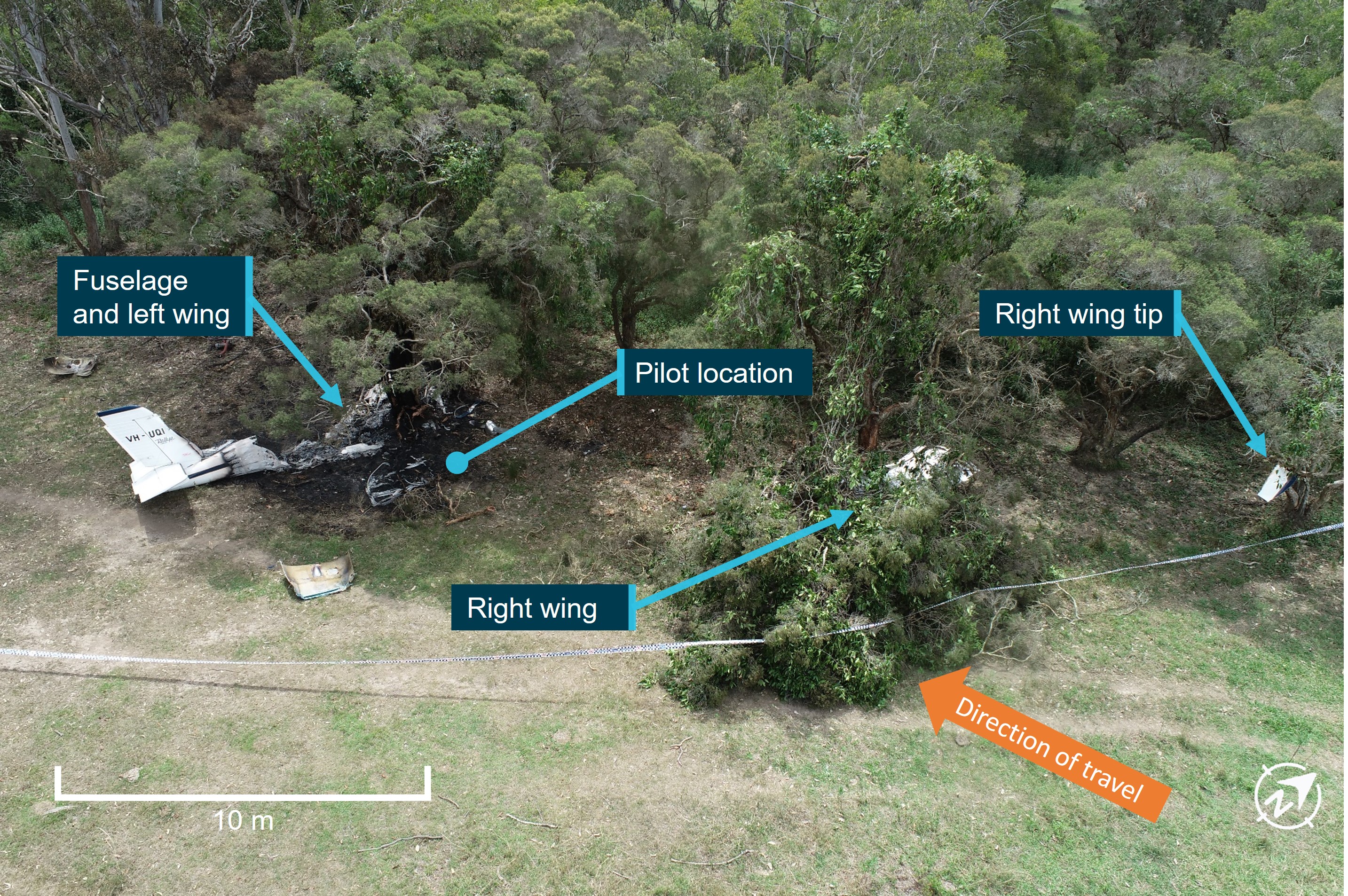
The ATSB’s investigation report from the 6 November 2020 accident details that the pilot experienced a catastrophic engine failure when they were about 37 km from their destination. With their forward visibility reduced due to engine oil over the windscreen and smoke created by escaping oil on the exhaust system, the pilot force landed in a paddock, with the aircraft striking trees.

Witnesses found the unconscious pilot had been thrown from the aircraft and moved them to safety before the aircraft was consumed by a post-impact fire.

“The ATSB’s investigation found the separation of the number 2 piston connecting rod initiated a catastrophic mechanical failure of the engine,” ATSB Director Transport Safety Dr Stuart Godley said.

The engine had not been overhauled since 1997, and had had limited usage for an extended period, possibly with no specific engine preservation done while in storage.

“Had the engine been overhauled at the manufacturer’s recommended calendar time, the connecting rod journal bearings would have been replaced with post-modification bearings,” Dr Godley said.

“This accident highlights the need for owners and maintainers to be cognisant of the manufacturer’s service information, to ensure the serviceability of engine and airframe systems are maintained to the highest standards.”

In addition, the pilot had been ferrying the aircraft on behalf of the owner and had limited aircraft type experience and knowledge of its performance capabilities.

“The pilot was unaware of the aircraft’s slow speed performance capability, a full understanding of which capability may have been beneficial when responding to the engine failure and forced landing,” Dr Godley said.

The investigation also found that the aircraft was not fitted with a fixed or portable emergency locator transmitter, and that the pilot did not leave a flight note with a responsible person.

“Fortunately the forced landing occurred in a populated area and there were witnesses to the accident who were able to render assistance and call emergency services,” Dr Godley said.

Read the final report: Engine failure and collision with terrain involving S.E.D.E. Morane-Saulnier MS.893A, VH-UQI, 22 km south-west of Archerfield Airport, Queensland, on 6 November 2020

Nut loosened over time before R44 drive belt tensioning motor failed during flight

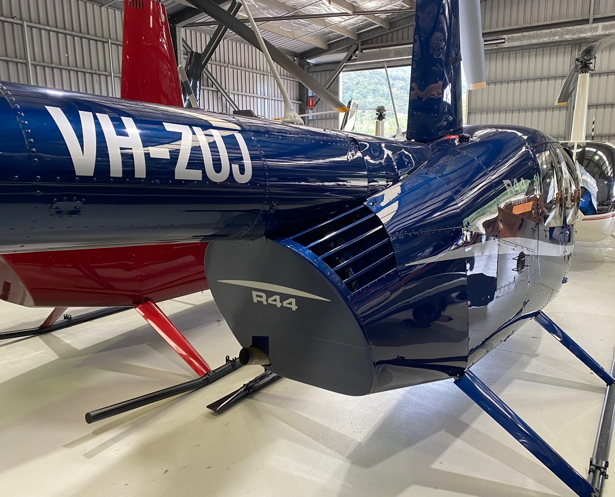
Personnel involved in maintenance and operations of R44 helicopters should be aware of the risks posed by the failure of the drive belt tensioning motor, as demonstrated by an incident at Hamilton Island in January.

On 8 January 2023, the pilot of an R44 was on approach to Hamilton Island Airport, Queensland, when they noticed a persistent clutch warning light.

The pilot carried out the clutch warning light emergency procedure, and landed at the airport.

Ground crew found the clutch actuator electric drive motor had separated from the gearmotor assembly, and fallen between the drive belts and the right-hand fan shroud.

“A subsequent Australian Transport Safety Bureau investigation found that during assembly of the gearmotor, the required thread adhesive was either not applied, or applied in a manner that did not prevent the loosening of the electric motor retaining nut,” ATSB Director Transport Safety Stuart Macleod said.

“Consequently, over time, normal aircraft vibrations loosened the retaining nut, resulting in the clutch actuator electric motor separating from the gearmotor assembly in flight.”

Robinson Helicopter Company advised the ATSB they are working with the component manufacturer to rectify identified quality issues with the gearmotor assembly.

Robinson said it is also considering updating the procedures for the inspection of the clutch actuator assembly.

“This incident is a reminder to R44 maintainers and operators to be aware of the risks posed by the failure of this component, specifically the risk of a loose component interfering with the v-belts and impacting rotor drive,” Mr Macleod said.

“The ATSB encourages pilots and maintenance engineers to physically check the security of the R44 clutch gearmotor assembly on a regular basis.”

Additionally, Mr Macleod emphasised that any discovered defects should be rectified, and reported to the Civil Aviation Safety Authority, and the manufacturer.

Read the final report: Drive belt tensioning motor failure involving Robinson R44 helicopter, VH-ZUJ, at Hamilton Island Airport, Queensland, on 8 January 2023

Aerodrome operators urged to review use of non-standard surfaces

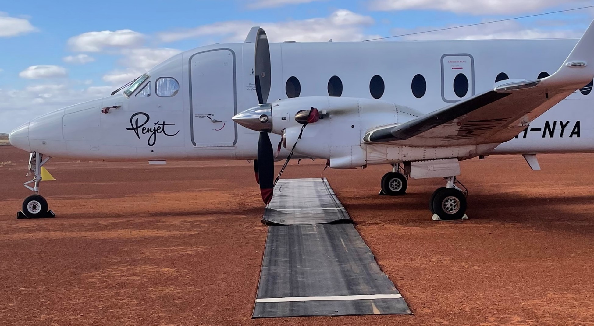
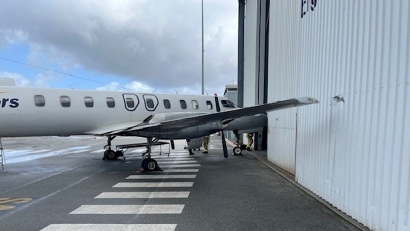
The propeller blade of a Beech 1900D regional airliner sheared off after it was struck by matting that had been installed to prevent stone damage to propeller blades at a gravel aerodrome.

The Australian Transport Safety Bureau investigation report from the incident notes that on 17 November 2022, the flight crew of the Beech 1900D, operated by Penjet, refuelled and then boarded passengers at Fortnum Aerodrome, in WA’s Murchison region, for a flight to Perth.

The runway, taxiways, and parking area at Fortnum are gravel. At the time of the incident, there were designated parking areas with pieces of conveyor belt matting fixed to the ground, intended to allow engines to be operated with minimal propeller damage from loose gravel.

“As the flight crew was conducting pre-take-off checks, the end of the conveyer belt matting under the left propeller was drawn into the propeller arc, resulting in a sheared propeller blade and vibration damage to the aircraft,” ATSB Director Transport Safety Stuart Macleod said.

The aerodrome manager, who witnessed the event, detailed that the propeller picked up a corner of the matting and one propeller blade was ejected about 50 to 100 m in the air.

In addition to the detached propeller blade, another propeller blade snapped approximately 250 mm from the blade tip, and the left engine propeller governor control arm fractured.

There was also buckling to the left engine firewall and cracking to the nacelle structure adjacent to the engine mount.

Since the incident, the aerodrome operator has removed the strips from the apron.

“The installation of the matting was a non-standard method to prevent propeller damage, and was not subject to any installation specifications or inspection requirements,” said Mr Macleod.

“As this occurrence demonstrates, the consequences of a propeller strike can be serious, and operators of aircraft and aerodromes are advised to review the use of any non-standard surfaces for aircraft movement areas.”

Read the final report: Propeller strike due to foreign object debris involving Beech 1900D, VH-NYA, at Fortnum Aerodrome, Western Australia, on 17 November 2022

Conflict of Interest

Under section 13AE of the Transport Safety Investigation Act 2003 and in line with section 29 of the Public Governance, Performance and Accountability Act 2013, Commissioners must declare to the Minister any interests which are material personal interests.

In accordance with section 13(7) of the Code of Conduct contained in the Public Service Act 1999, an APS employee must: 

a) take reasonable steps to avoid any conflict of interest (real or apparent) in connection with the employee's APS employment

b) disclose details of any material personal interest of the employee in connection with the employee's APS employment

Our Conflict of Interest Policy provides guidance for all employees, Commissioners and contractors to disclose and take reasonable steps to avoid and manage any conflicts of interest connected to their employment. 

Multiple safety actions taken in response to Weipa train collision

Key points

  • Bulk ore train was unable to slow down and collided with rear of stationary wagons;
  • Final report details ten findings, including three safety issues addressed by relevant parties;
  • Accident highlights importance of ensuring published rules and procedures are followed, with effective monitoring and auditing.

An Australian Transport Safety Bureau investigation into an empty ore train’s collision with stationary wagons has led to the operator and Australia’s rail standards board taking a number of safety actions. 

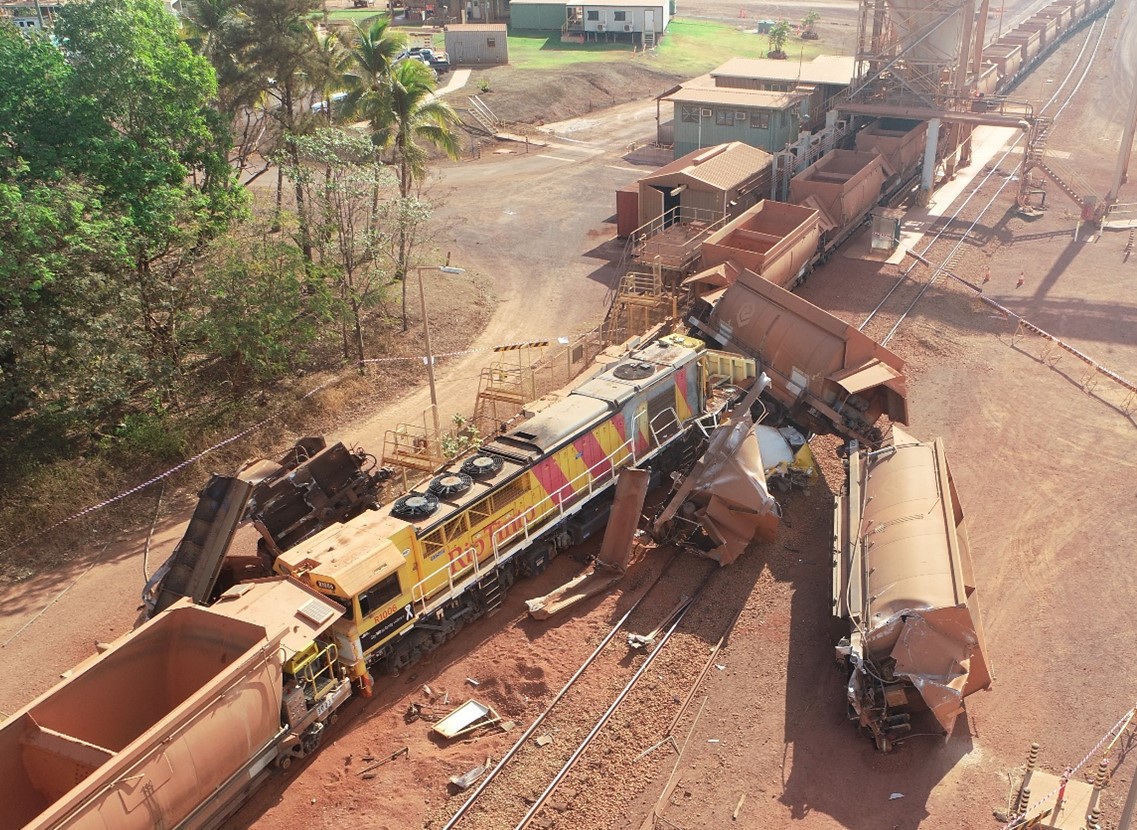
A driver was unable to slow a bulk ore train as it approached a bauxite loading station north of Weipa, resulting in a collision with a rake of stationary wagons on 22 September 2019. 

As detailed in the ATSB’s preliminary report, the locomotive and four wagons from the stationary rake derailed in the collision. The modular driver’s cabin separated from the main body of the locomotive and was substantially damaged, and the driver was initially trapped inside, but fortunately sustained only minor injuries. 

The ATSB’s final report, released at the conclusion of a systemic-level investigation into the accident, details 10 safety factors, which either contributed to the accident, or increased risk. 

These include three safety issues, which have now been addressed by the operator RTA Weipa Pty Ltd, the Rail Industry Safety and Standards Board (RISSB), and the locomotive’s design owner. 

“The ATSB’s investigation found the driver was not able to slow the train as there was no continuity of air through the train’s brake pipe,” Chief Commissioner Angus Mitchell said. 

“This was due to the brake pipe cock not being opened when the locomotive and rake were coupled together, prior to the accident journey.” 

Compounding this, the ATSB found a brake continuity test was not performed during the pre-departure check – a missed opportunity to detect the issue. 

“The coupling process being used was inconsistent with the published procedure, and routine audits conducted by the operator did not identify this inconsistency,” Mr Mitchell said. 

Additionally, the investigation found management of change processes were not applied when the end of train telemetry system became inoperable, and the Lorim Point dump station became automated. 

“This accident highlights the importance of ensuring that published rules and procedures are followed, through an effective monitoring and audit process, which is fundamental to rail safety,” Mr Mitchell said.  

“Likewise, changes to rail operations need to be adequately managed to identify new or altered risks.” 

As a result of the accident, RTA Weipa has installed a revised telemetry system to allow drivers to perform brake continuity tests without relying on a second person. In addition, the operator has introduced safety improvements to the manual brake continuity testing, and all relevant team members have been re-trained in the test requirements. 

The ATSB’s investigation also found the design of the modular driver’s cabin mount was not resilient to frontal impact forces, and the industry standard did not provide design and/or performance standards for modular cabin resilience and retention for locomotive crashworthiness. 

Since the accident, RISSB has included modular cabin retention within the update to Australian Standard 7520, which is underway. 

Separately, the locomotive’s design owner, Progress Rail, has re-engineered the modular cabin mounts to improve strength, to reduce the risk of cabin separation in the event of a collision. 

“One of the ATSB’s primary goals is to encourage safety action to prevent reoccurrences when safety factors are identified, and I welcome the actions taken in response to this accident,” Mr Mitchell said. 

Read the final report: Collision with rake of wagons and derailment of ore train R1006, Andoom (near Weipa), Queensland, 22 September 2019 | ATSB 

Image credit: RTA Weipa Pty Ltd

Signal passed at danger involving passenger train TE43, between Fortitude Valley and Bowen Hills, Queensland, on 24 May 2023

Final report

Investigation summary

What happened

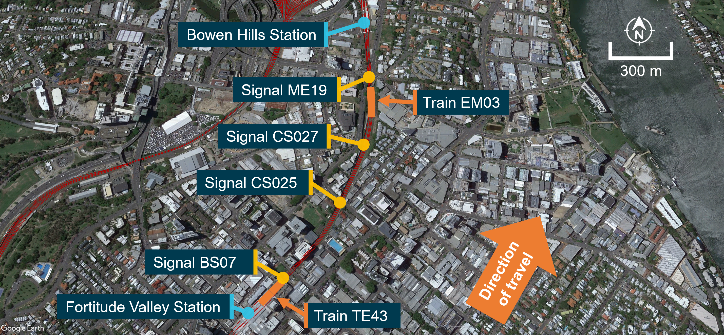
On 24 May 2023, a Queensland Rail suburban passenger train (TE43) was operating a scheduled service between Coopers Plains and Ferny Grove in Brisbane, Queensland. After stopping at Fortitude Valley Station platform 2, the driver continued their trip, passing a signal (BS07) that was displaying a yellow aspect (caution indication) at the northern end of the platform. The next signal ahead (CS025) displayed a red aspect (stop indication) due to another train (EM03) that was ahead of a further signal (CS027) and waiting to enter Bowen Hills Station. 

Between Fortitude Valley Station and signal CS025, the driver of train TE43 reported that they had a sudden sneezing fit. Approaching signal CS025 at red, the driver acknowledged the in-cab Automatic Warning System alarm and shortly after, realising the signal was at stop, applied emergency braking. Train TE43 passed signal CS025 by about 64 m, stopping prior to signal CS027 and about 296 m behind train EM03.

After train TE43 stopped, the driver contacted the Queensland network control centre to report a signal passed at danger (SPAD). The network control officer subsequently issued an authority for the driver to proceed to Bowen Hills Station, where they were relieved from duty. There were no injuries to passengers or crew, and no damage to either the train or infrastructure.

What the ATSB found

The driver likely experienced a degree of impairment arising from the sneezing reflex, which adversely affected their control of train speed and observance of the signal aspect displayed on signal CS025. Additionally, the multiple automatic warning system (AWS) alerts previously acknowledged by the driver during the trip, possibly in conjunction with the impairment arising from the sneezing fit, likely influenced the driver’s action to acknowledge the AWS alarm and not identify the red aspect in signal CS025 until it was too late to prevent passing it.

The ATSB previously identified the AWS provided the same audible alarm and visual indication to a driver on the approach to all restricted indications. The potential for habituation, and the absence of a higher priority alert when approaching a signal displaying a red aspect, reduced the usefulness of the AWS to prevent signals passed at danger (SPADs). 

Queensland Rail had a system designed to alert the network control officer of a SPAD event. However, there were inherent constraints in the system, particularly for automatic signals, where an alert would not be provided under certain circumstances. This reduced the opportunity for the network control officer (NCO) to identify and respond to a SPAD.

While the driver recognised the signal was at red and stopped their train in this instance, the critical risk control provided by the NCO intervention was ineffective. This was not considered in the risk assessments that addressed risks to train separation, including SPAD events. 

What has been done as a result

Queensland Rail continues to maintain the current risk control arrangements, in conjunction with the AWS functionality, to manage the risk of SPADs while the preferred engineering control of European Train Control System (ETCS) technology is being implemented. 

The Queensland Department of Transport and Main Roads has a long-term plan to deploy ETCS throughout the South East Queensland rail network. Deployment is occurring in prioritised sectors and full deployment will take several years. ETCS is currently installed on the Shorncliffe pilot line and is undergoing verification, validation and certification. Bowen Hills Station and surrounding areas were indicated to be included in sectors 2 and 3. Until this occurs, the established risk will remain. 

Additionally, Queensland Rail is undertaking a range of SPAD risk management activities, and has advised the ATSB that the current enterprise and operational area risk assessments support the organisation’s so far as is reasonably practicable (SFAIRP) position. However, Queensland Rail’s current risk registers were not updated following this occurrence and therefore did not assess inherent constraints identified by the ATSB that may lead to risk controls being less effective. Specifically, the ATSB considers the scenario where a SPAD alarm was not generated and the driver did not report the SPAD, had not been considered in the Queensland Rail risk assessments. 

The ATSB therefore issued a recommendation that Queensland Rail reviews the risk associated with a SPAD in circumstances where the inherent constraints of the universal traffic control system do not alert the network control officer and the driver does not self‑report, and any additional risk controls that may be appropriate for the current signalling system.

Safety message

This investigation highlighted inherent limitations in the effectiveness of the automatic warning system (AWS) to prevent a SPAD event. It also identified that a SPAD alarm may not be presented to NCOs in all circumstances, preventing their active intervention.

These types of limitations should ideally be eliminated and, where that is not possible, the hazards they create should be considered in risk assessments related to SPAD and collision prevention. 

The occurrence

On 24 May 2023, Queensland Rail suburban passenger train TE43 was operating a scheduled service between Coopers Plains and Ferny Grove in Brisbane, Queensland.

At about 0942 local time, as the train approached platform 2 at Fortitude Valley Station, the rail traffic driver (driver) received an alarm from the onboard automatic warning system (AWS) (see the section titled Automatic warning system information). This indicated that signal BS07, located at the northern end of platform 2, displayed a caution indication (steady yellow aspect).

The driver acknowledged the AWS alarm and continued into the platform where they stopped the train for passengers, as scheduled. At 0943:31, train TE43 departed platform 2 to continue along the down[1] suburban line towards Bowen Hills Station. Signal BS07 continued to display a steady yellow caution indication. The next 2 signals ahead, CS025 and CS027, displayed a restricted indication (red, ‘at danger’ aspect). 

Ahead of signal CS027, empty suburban passenger train EM03 was stopped at signal ME19, waiting to proceed into platform 2 at Bowen Hills Station. Signal ME19 had changed from a restricted indication to a proceed indication (green aspect), however train EM03 had not yet moved. Train EM03 was travelling in the same direction as train TE43 (Figure 1).

Figure 1: Midsection track layout of down suburban line between Fortitude Valley Station and Bowen Hills Station

Map of Brisbane city between Fortitude Valley Station and Bowen Hills Station. Signals on the down suburban line (BS07, CS025, CS027, ME19) are highlighted, as well as the locations of trains TE43 and EM03 before the SPAD.

The train images superimposed on the aerial view of the track are not their precise location. Source: Google Earth and Queensland Rail, annotated by the ATSB

After departing Fortitude Valley Station, train TE43 accelerated to 50 km/h, before the driver shut off traction power. The driver later reported that they had a sneezing fit, sometime after departing platform 2.

At 0943:51, as train TE43 traversed a curve in the track, signal CS025 came into the driver’s view. As the front of train TE43 passed over the AWS magnet, fixed between the rails about 80 m before signal CS025, the in‑cab AWS sounded a continuous audible alarm, indicating that the signal ahead displayed a restricted indication. The driver responded to the alarm by pressing the AWS acknowledgement button, however, they later advised they could not remember doing so.

The driver recalled that just before they passed signal CS025, they recognised the red restricted indication and immediately placed the brake controller into full-service, and then the emergency brake position. 

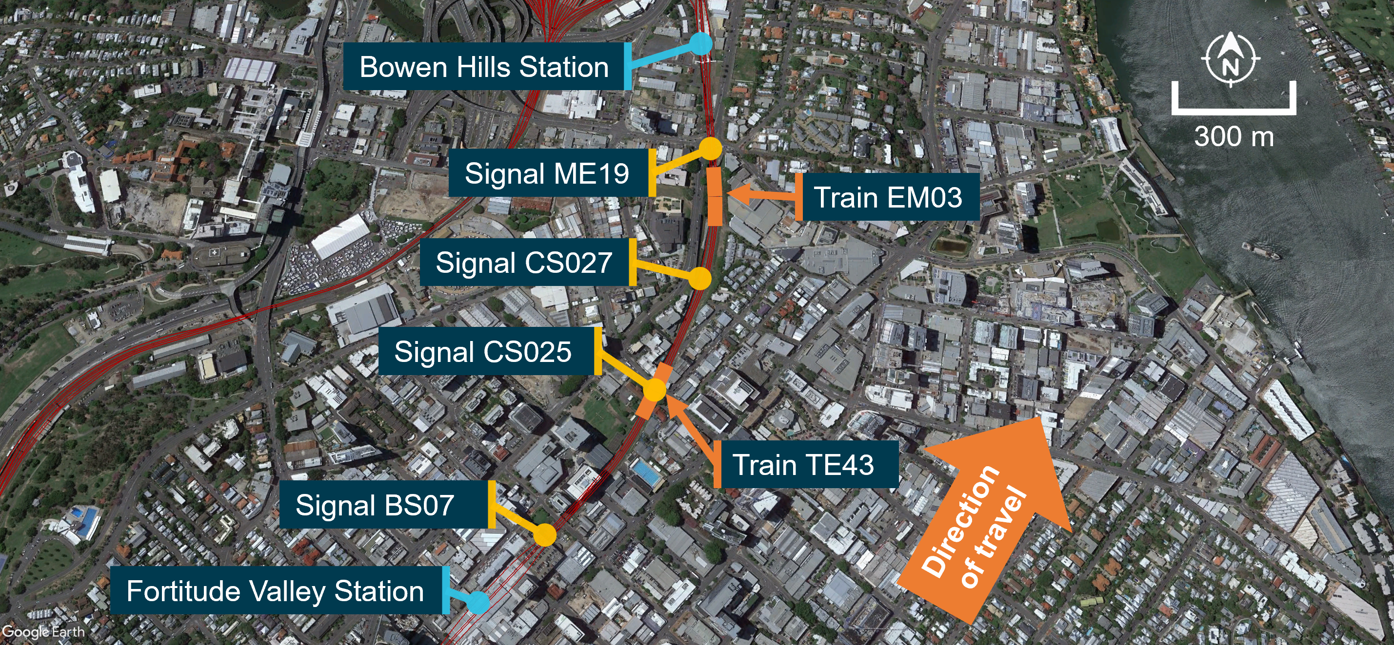
Train TE43 stopped about 64 m past signal CS025, and about 296 m behind train EM03 (Figure 2). The rear of train EM03 was about 92 m ahead of signal CS027, which was also displaying a restricted indication. The driver of TE43 recalled seeing the rear of train EM03 as it started to move.

Figure 2: Approximate stopping locations of train TE43 and train EM03 after train TE43 passed signal CS025 at stop

Map of Brisbane city between Fortitude Valley Station and Bowen Hills Station. Signals on the down suburban line (BS07, CS025, CS027, ME19) are highlighted, as well as the locations of trains TE43 and EM03 after the SPAD

The train images superimposed on the aerial view of the track are not their precise location. Source: Google Earth and Queensland Rail, annotated by the ATSB

The driver of TE43 made an emergency radio call to the network controller officer (NCO) to report a signal passed at danger (SPAD). The NCO established details surrounding the SPAD with the driver, then issued an authority for train TE43 to proceed to Bowen Hills Station platform 2, where the driver was relieved from duty.

The NCO did not receive a SPAD visual dialogue box or audible alert for signal CS025 at their workstation. 

There were no injuries to passengers or crew, and no damage to either the train or infrastructure. 

Context

Driver information

The driver had about 25 years of driving experience and was qualified on the route. They had completed the required maintenance of competency[2] assessments in June 2021 and subsequent on‑job observations on 12 April 2022 and 5 March 2023. An audit on safe driving was also completed on the Brisbane suburban network on 11 October 2021.

They underwent a medical assessment (rail category 1 – high‑level safety worker) in September 2022 and were considered fit for duty (unconditional). Following the incident, testing of the driver for both drugs and alcohol returned negative results. 

After 2 consecutive early morning shifts, the driver signed on for work at 0437, the morning of 24 May 2023. During the shift, they had completed 2 scheduled trips, with a meal break between 0738‍–‍0808. They had commenced the incident trip from Cooper Plains at 0910. They reported feeling fully alert at the time of the occurrence. However, about 12 hours later, they tested positive to Coronavirus disease (COVID-19).[3] 

Records provided by Queensland Rail (QR) showed that the driver had 2 previous signal passed at danger (SPAD) incidents (2001 and 2019), however these were not considered relevant to the occurrence.

Train information

General 

Train TE43 consisted of a 6‑car multiple unit (3‑car interurban multiple unit [IMU] 181 leading and a 3‑car suburban multiple unit [SMU] 295 trailing), with an overall length of about 145 m, and individual car length of 72.4 m. Lead unit IMU181 was fitted with an event recorder and forward‑facing CCTV recorder.

Lead unit IMU181 had been modified to decrease the volume of the automatic warning system (AWS) audible beeps at a green proceed indication, and increase the volume for the continuous buzzing alarm at a restricted indication (see the section titled Previous occurrences).

Recorded information
Park Road Station to Fortitude Valley Station

A review of data from the event recorder showed that, prior to departing Fortitude Valley Station, the driver operated the train consistent with safe driving procedures (see the section titled Safe driving procedures). The driver recalled that from Park Road Station,[4] there was peak congestion, which was normal for the inner‑city area at that time of day.

Recorded data showed that, from Park Road Station, the driver: 

  • acknowledged 20 AWS alerts for restricted indications
  • received 3 AWS alerts for proceed indications, of which they acknowledged one.
Fortitude Valley Station to signal CS025

The event recorder captured the following sequence after TE43 departed Fortitude Valley Station:

  • 0943:31 traction power was applied and the train departed platform 2
  • 0943:47 traction power was shut off at 50 km/h
  • 0943:59 the lead unit IMU181 passed over the on-track AWS magnet (see the section titled Automatic warning system information)
  • 0944:00 AWS buzzer activated and shortly after the driver pressed the acknowledgment button
  • 0944:03 at 50 km/h driver selected full-service brake position
  • 0944:07 at 37.5 km/h driver selected emergency brake position
  • 0944:15 train TE43 stopped

The driver safety control, also known as ‘deadman’s system’,[5] did not activate at any time during the incident.

Rollingstock brake performance 

The recorded braking distance was calculated to be within the expected performance for the rollingstock and the track gradient. No braking issues were recorded in the train fault log on the day of the occurrence. Additionally, the driver of train TE43 did not report anything unusual about the train's handling on the day. 

Safe driving procedures

QR procedure MD‑11‑72 Train service and delivery (TSD) Professional driving – safe driving outlined rules for train drivers ‘to mitigate the incidence of signals passed at danger (SPAD) and other adverse operational safety events’. 

The procedure contained general safe driving rules which included:

  • 75% speed rule: rail traffic must be travelling at or below 75% of the designated track and/or traction speed at the point of passing a double yellow or single yellow aspect signal.
  • 20/20 rule: on the approach to a red aspect signal, the speed of the rail traffic must not exceed 20 km/h at the point of passing over the automatic warning system (AWS) magnet.

The procedure also contained ‘safe driver application’ rules which included that when starting on a single yellow aspect, the driver must:

  • after coming to a stop at a platform, place direction controller to neutral
  • apply or maintain the 75% speed rule
  • maintain situational awareness and vigilance through scanning, crosschecking and application of, or continued use of RTCD [risk triggered commentary driving] (MD-13-165 TSD Professional driving - risk triggered commentary driving procedure)
  • When approaching a red aspect signal the procedures included that the driver must:
  • initiate a further positive action, i.e., make a brake application or reduce tractive power depending on track gradient
  • maintain situational awareness and vigilance through scanning, crosschecking and application of, or continued use of RTCD (MD-13-165 TSD Professional driving - risk triggered commentary driving procedure)
  • apply the 20/20 rule 

When approaching restricted indications, QR procedure MD‑13‑165 TSD Professional driving – risk triggered commentary driving required drivers to verbalise:

  • acknowledgement of the aspect of the restricted signal
  • the location and aspect of the next signal
  • their intended actions.

On receiving an AWS alert, risk triggered commentary driving (RTCD) was to be applied continuously from the acknowledgement of the audible alarm, until the required actions were complete. 

The driver recalled applying RTCD on the morning of the incident, but could not recall if it was applied at Fortitude Valley Station platform 2. The QR internal investigation report found that the driver did not apply RTCD on approach to signal CS025.

Network and signalling information

Train safeworking system and signalling

On the Brisbane suburban network, the train safeworking system utilised remote controlled signalling. The system included signalling infrastructure (signals, points, etc.), which network control officers (NCOs) could interact with using the universal traffic control (UTC) system. 

The UTC system displayed a range of indications on the NCO’s workstation. These included the location of all trains, points, signals and alarms, such as a SPAD alarm message (see the section titled Signal passed at danger warning system).

Signals on the network were either controlled (operated by the NCO) or automatic (set by the passage of rail traffic). The aspect of a controlled signal was displayed on the NCO’s workstation. In contrast, automatic signals were displayed as a yellow icon and their aspect was not shown (Figure 3).

Universal traffic control recorded information 

The recorded UTC replay identified the following: 

  • 0943:50 as train TE43 departed Fortitude Valley Station, the path for train EM03 was set to Bowen Hills Station  
  • 0943:52 signal ME19 displayed a green proceed indication for train EM03 to enter Bowen Hills Station, as train TE43 approached signal CS025
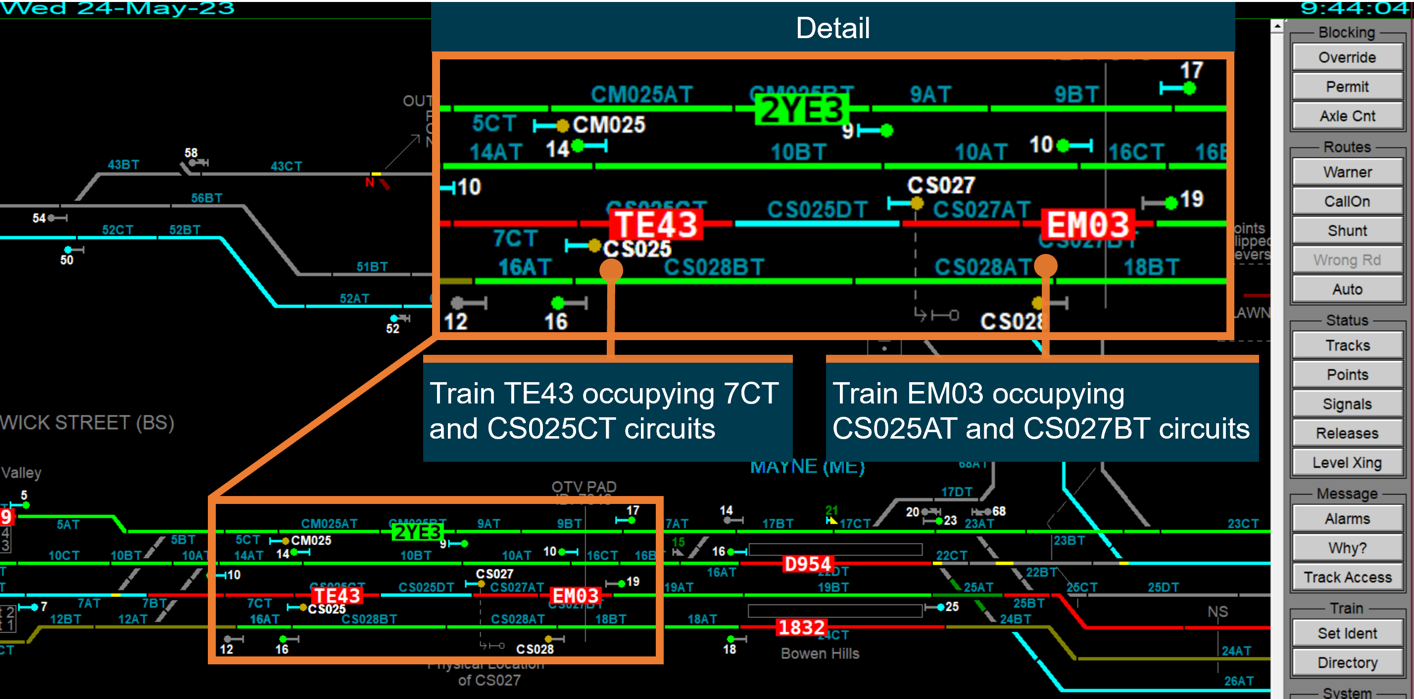
  • 0944:04 train TE43 passed signal CS025 and occupied track circuit CS025CT. Train EM03 was occupying track circuits CS027AT and CS027BT. Train EM03 was likely moving but had not passed signal ME19. 

Figure 3 shows the UTC replay of the track section between Fortitude Valley Station and Bowen Hills Station after the SPAD. Of note, no SPAD warning dialogue box was displayed (see the section titled Signal passed at danger warning system). 

Figure 3: UTC replay of TE43 passing CS025 at stop

A screenshot of the UTC workstation showing TE43 passing signal CS025. TE43 is occupying track circuits 7CT and CS025CT. Train EM03 is occupying track circuits CS025AT and CS027BT.

Source: Queensland Rail, annotated by the ATSB

Automatic warning system information

QR’s suburban network was fitted with an automatic warning system (AWS). This system consisted of an in‑field magnet on the track and a magnetic receiver linked to a warning system on the rollingstock.

QR Standard MD‑10‑119 Automatic warning system (AWS) operations manual noted that the AWS was designed to:

  • provide an in-cab visible and audible indication of the aspect displayed in the next signal
  • prompt and warn the rail traffic driver of a RESTRICTED signal aspect displayed in the next signal
  • stop the rail traffic if the rail traffic driver fails to acknowledge the AWS alarm of a RESTRICTED signal aspect.

This procedure also stated:

AWS is an advisory system and not a control system. The setting of rail traffic speed remains with the rail traffic driver. The AWS is designed to apply the brake when the rail traffic driver cannot or does not acknowledge a RESTRICTED signal aspect…

When the train’s magnetic receiver passed over the in-field magnet on approach to a signal, the AWS would provide a different alert to the driver for proceed or restricted indications:

  • proceed indication: the AWS indicator would display a black visual and sound a short series of beeps. Acknowledgment of the clear to proceed indication was not required by the driver.
  • restricted indication: the AWS indicator would display the same yellow and black ‘sunflower’ visual display for both caution and stop indications and sound a louder, continuous buzzing alarm. The driver was required to cancel the alarm by pressing and releasing the acknowledgment button. If the AWS alarm was not acknowledged after 3 seconds, a penalty brake application would occur.

On approach to signals BS07 and CS025, the AWS provided a ‘sunflower’ visual display and a continuous buzzing alarm, which were both cancelled by the driver using the acknowledgement button. During interview, the driver advised that they could not recall acknowledging the AWS for signal CS025, and they could not remember if they were first alerted to the red aspect by the AWS alarm, or visual observation of the signal.

Previous ATSB investigations have identified instances where train drivers have acknowledged the AWS alarm for a red aspect, and subsequently passed the signal at danger (see the section titled Previous occurrences ). 

Signal CS025

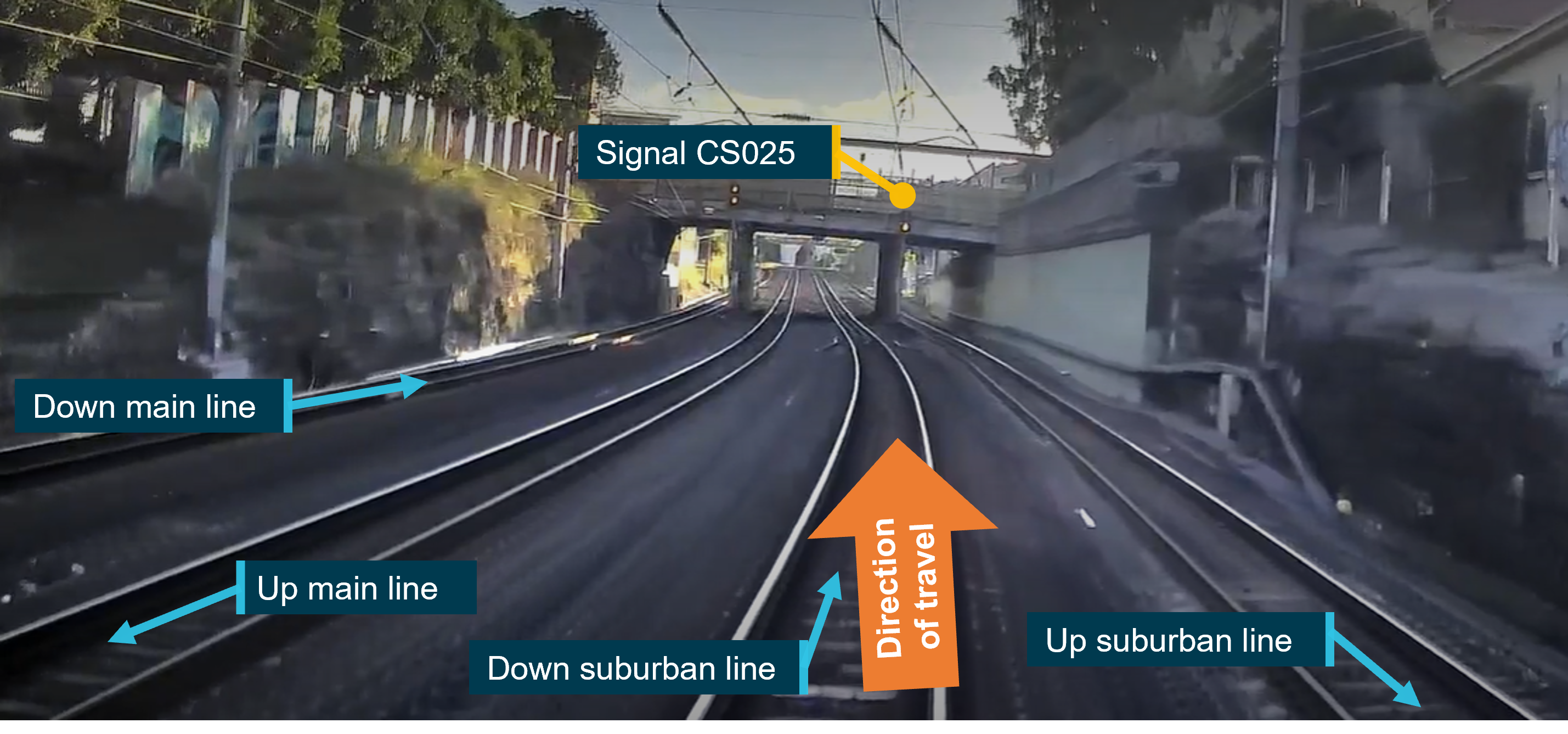
Signal CS025 was a 4‑aspect[6] automatic signal located at the 2.545 km mark on the down suburban line, mid‑section between Fortitude Valley Station and Bowen Hills Station (Figure 4). On approach to signal CS025, the mainline speed for this track section was 60 km/h.

Figure 4: Approach to signal CS025 along down suburban line towards Bowen Hills Station

Approach to signal CS025 along down suburban line towards Bowen Hills Station

Note that this image shows CS025 with a caution steady yellow aspect. Source: Queensland Rail, annotated by the ATSB

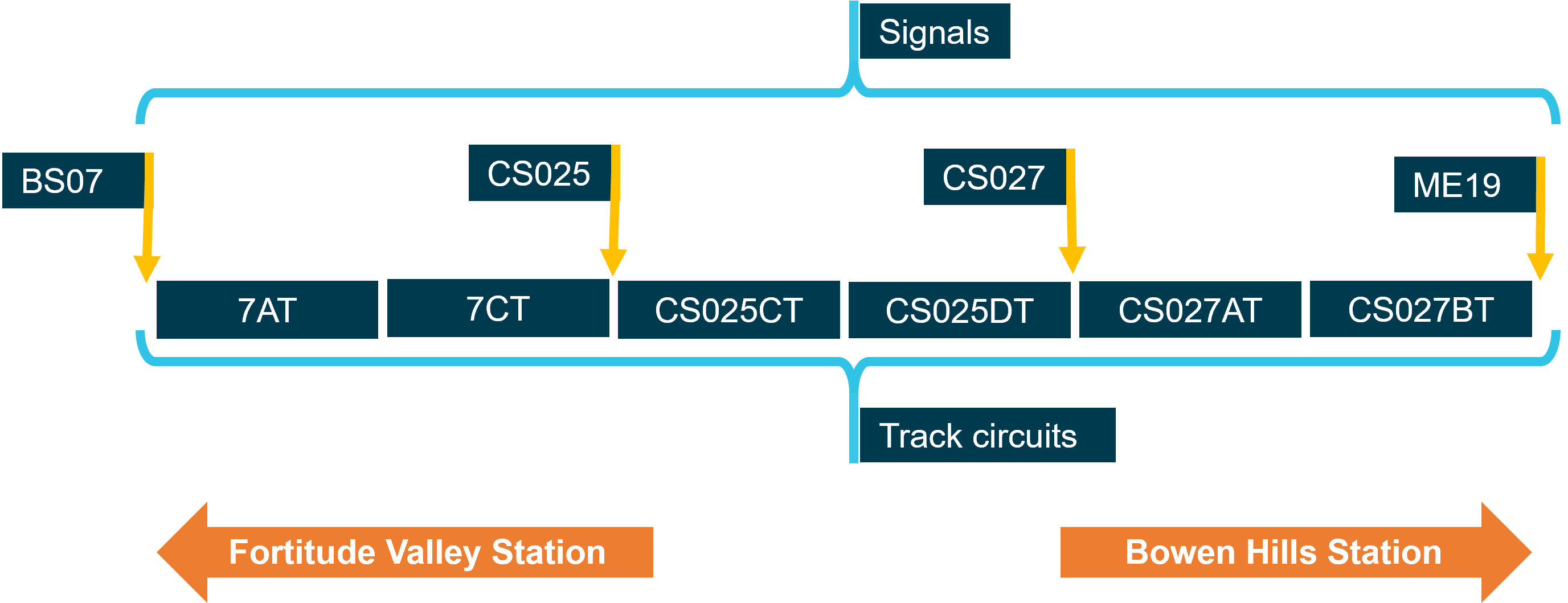
There were 2 track circuits between signal CS025 and the next signal CS027 (CS025CT and CS025DT) (Figure 5). Signal CS025 would display a stop indication when either track circuit CS025CT or CS025DT was detected as occupied. Additionally, if track circuit CS027AT was occupied, after CS025CT and CS025DT had cleared, CS025 would also display a stop indication. 

Figure 5: Track circuits between signal BS07 and ME19 on the down suburban line towards Bowen Hills Station

A simplified diagram showing the layout of signals and track circuits between Fortitude Valley Station and Bowen Hills Station on the down suburban line.

Source: ATSB, based on signalling arrangement maps and diagrams - not to scale

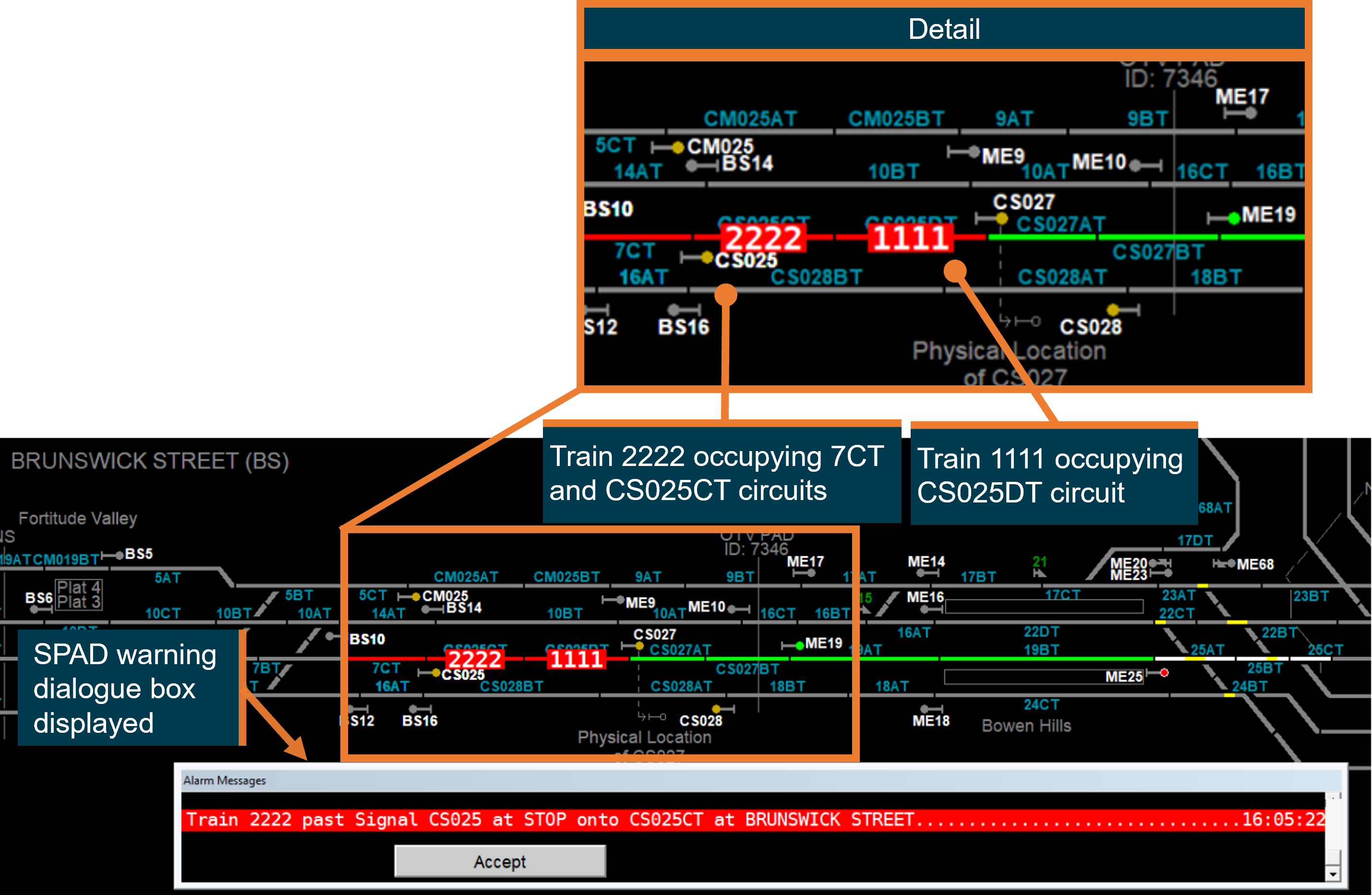
QR confirmed via simulation that the UTC system would generate a SPAD alarm, and display a SPAD message indication on the NCO’s workstation for signal CS025, if track circuit CS025DT was occupied by another train ahead when signal CS025 was passed at stop (Figure 6). In this simulation track circuit CS027AT, ahead of signal CS027, was unoccupied. 

Figure 6: UTC simulation of train passing CS025 at stop

A screenshot of the UTC workstation showing a simulation of train 2222 passing signal CS025. Train 2222 is occupying track circuits 7CT and CS025CT. Train 1111 is occupying track circuit CS025DT. A SPAD warning dialogue box is displayed.

Source: Queensland Rail, annotated by the ATSB

QR identified that there had been no SPADs recorded at signal CS025 since 2010, and the signal complied with the sighting distance requirements described in QR Standard MD‑10‑95 Signalling positioning principles.

Signal passed at danger (SPAD) warning system

The SPAD warning system consisted of an audible 3‑beep alert tone and a red text dialogue box that appeared on the NCO’s workstation (Figure 6).

The QR manual MD‑14‑37 Network control manual outlined different UTC alarm messages that would be provided to warn the NCO of threats to safeworking. The NCO was required to immediately respond to these messages, unless they assessed that doing so had the potential to increase the hazard.

UTC SPAD alarm messages were identified as of critical importance, with the highest response requirement by the NCO. The NCO was to:

Investigate cause. Make emergency call to stop offending train. If other trains are present, call all trains in the area(s) to stop. Assess if rail traffic driver is fit to continue, move train to position of safety.

QR procedure MD‑11‑42 Signal passed at danger – module EP1‑13 reflected the above required response by the NCO following receipt of a SPAD alarm.

In this instance, the NCO did not receive a SPAD alarm and was first alerted to the SPAD of train TE43 by the driver’s emergency radio call. 

Signal passed at danger alarm generation principles

The QR manual SR105 SPAD Alarm generation principles defined the criteria used by the UTC system to determine if a SPAD alarm message would be displayed to the NCO.

Section 6.1 of the manual stated:

The UTC Controller Workstation shall generate a ‘Train passed signal at stop’ alarm if all of the following rules are met:

Rule 1       The first track beyond a Limit of authority (LOA)[7] becomes occupied.

Rule 2       There is no train on a track adjacent to the newly occupied track with a proceed authority onto this newly occupied track.

Rule 3       There are one or more trains that can step onto the newly occupied track from an adjacent track which has an LOA facing towards the newly occupied track.

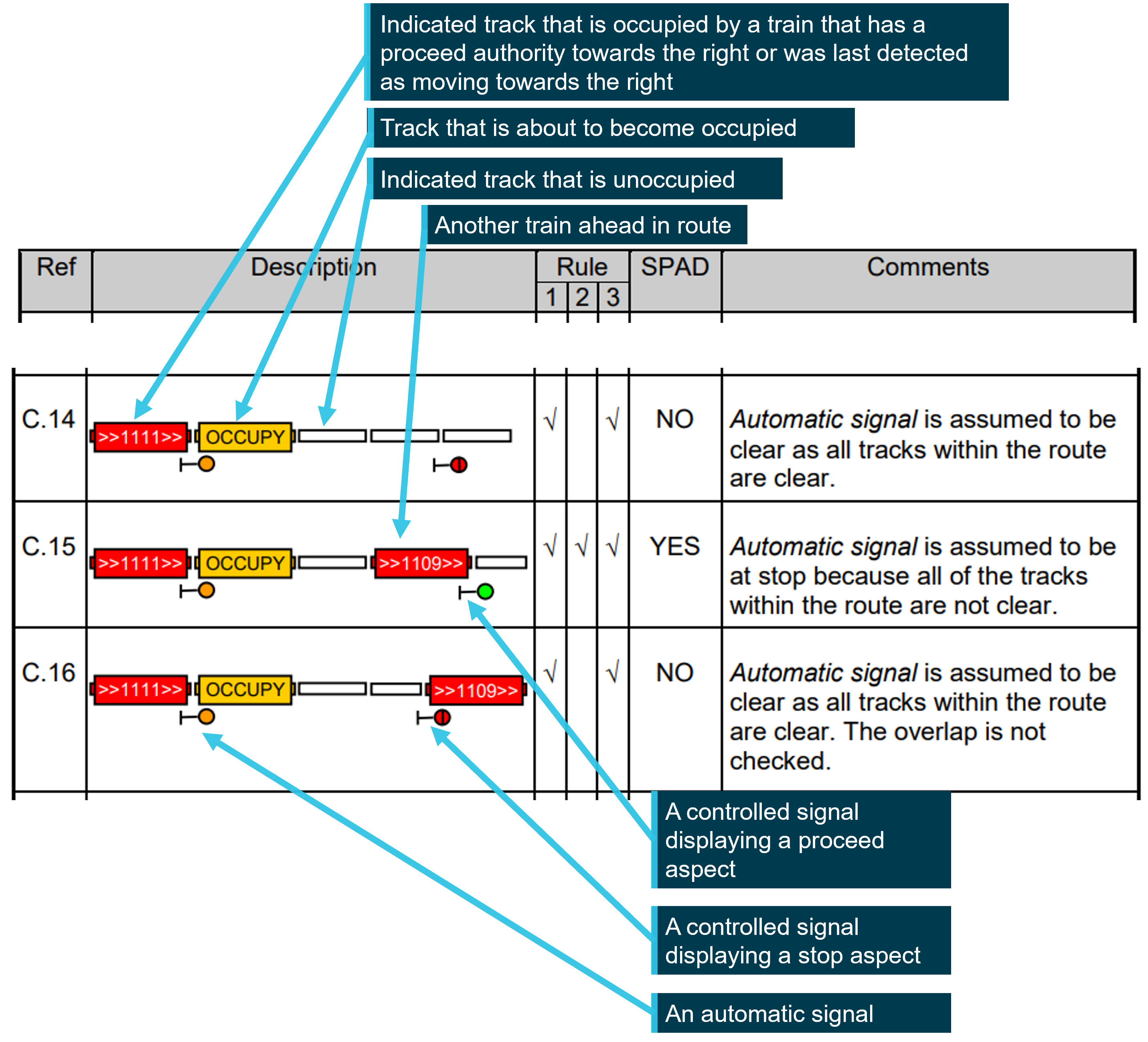
To illustrate the application of the rules, several scenarios were included in the appendices of the manual (Figure 7).

Figure 7: Extract from appendices of SR105 signal passed at danger alarm generation principles manual

Extract from appendices of SR105 signal passed at danger alarm generation principles manual

Source: Queensland Rail, annotated by the ATSB

The examples showed:

  • For C.14, all the track circuits between the automatic signal and the next signal were unoccupied. The automatic signal was assumed to be displaying a proceed indication. When train 1111 passed the automatic signal to occupy the track ahead, no SPAD alarm would be generated.
  • For C.15, a track circuit between the automatic signal and the next signal is occupied by train 1109. The automatic signal was assumed to be displaying a stop indication. When train 1111 passed the automatic signal to occupy the track ahead, a SPAD alarm would be generated.
  • For C.16, a track circuit ahead of the next signal is occupied by train 1109. The automatic signal was assumed to be displaying a proceed indication. When train 1111 passed the automatic signal to occupy the track ahead, no SPAD alarm would be generated.

Additionally, Section 6.8.1 of the manual noted that:

  • Automatic signals are not indicated, and therefore UTC is unaware of whether the signal has a proceed aspect or not. So that SPAD alarms can be generated for automatic signals, UTC will assume that an automatic signal has a proceed aspect when all of the tracks up to the next signal are all clear. The tracks in the overlap[8] (if any) will not be checked.

Section 7 also noted further limitations:

If the replacement track[9] of a signal is already occupied (e.g. by another train, gang or track fault), then a train passing the signal will not be able to be detected, and therefore a SPAD alarm will not be generated.

Due to the possibility of timing issues,[10] the overlap of an automatic signal (if any) will not be checked when determining whether an automatic signal is clear. Consequently, if the overlap of an automatic signal is occupied, then a SPAD alarm will not be generated if a train passes the automatic signal.

Overview of Queensland Rail SPAD risk management

QR maintained a suite of risk registers that identified hazards and related risk controls. The enterprise risk register identified several key risks and controls related to SPAD events including the following: 

  • …SEQ [South East Queensland] Operations failing to adequately prevent a rollingstock collision (train to train, train to vehicle, train to person), potentially resulting in one or more fatalities
  • …rail traffic separation or route integrity not being maintained on the mainline resulting in train to train, train to person, train to infrastructure, train to object collision or derailment 

These risks were last reviewed on 22 September 2021. Risk controls included:

  • ongoing SPAD prevention strategies/programs/campaigns
  • focus groups designed to prevent SPADs
  • maintenance of worker competencies
  • assurance activities
  • safeworking audits
  • the application of the UTC system.

The effectiveness of the respective controls was assessed as ‘substantially effective’ with the hierarchical level primarily identified as ‘administrative’. For each of the risk controls above, the risk score following implementation of the controls was assessed as ‘medium’. The justification for the risk score was respectively: 

  • Controls at this level are administrative. Where appropriate GM’s [General Managers] registers identify higher levels of controls where the control owner has accountability/responsibility of the control.
  • No higher-level engineering control is currently available to control this risk. Until ETCS [Level 2][11] 
    is fully implemented across the QR SEQ network this safety risk is being controlled by administrative/people control (active supervision) which is inherently partially effective in the absence of the higher engineering control (ETCS).

The TSD Operations SEQ Risk register – Risk 3 Train to train collision included the risk description: ‘risk of train‑to‑train collision resulting in injury or death as a result of a SPAD event’. 

Risk controls included:

  • rail traffic crew training
  • safe driving techniques
  • risk triggered commentary driving (RTCD)
  • application of the SPAD risk management standard (MD-10-89)
  • SPAD risk management procedure (MD-13-362)
  • SPAD risk management instruction (MD-13-446). 

Again, the effectiveness of the controls was assessed as ‘substantially effective’ and the hierarchical level as ‘administrative’. The residual risk score was assessed as ‘medium’. The justification for the risk score was:

Higher order controls are in place but owned by other business areas (e.g. Engineering: Level Crossing protection systems, signalling system & UTC). TSD Operations therefore has not identified any further higher order controls available for implementation by our functional area.

Additionally, a pilot bowtie analysis for QR operations was developed on 1 September 2021. This was intended as an information aid for QR’s safety management system, including the enterprise and operational area risk registers. The bowtie analysis identified risk controls and highlighted those assessed as critical risk controls[12] associated with the prevention of human factors‑related SPADs, including driver distraction. Risk controls listed in the bowtie included:

  • Safeworking training standards (MD‑10‑199) – critical risk control
  • TSD Professional driving followed by drivers (MD‑11‑72)
  • Train safety systems (AWS, ATP, DTC)[13] (MD‑10‑218) – critical risk control
  • Automated train protection remove and replace with train safety systems
  • QNRP network rules and procedures (MD‑12‑189)
  • Safety in yards (MD‑10‑175)
  • DTC Alarms in cabs
  • UTC SPAD alarm triggering emergency response procedure
  • NCO emergency response to SPAD alarm to stop train
  • Potential control: Train control radio for emergency comms with driver (workers on track do not have radio)
  • Observe signal approach warning (MD‑10‑109) – critical control
  • Risk triggered commentary driving (RTCD) (MD‑13‑165)
  • Potential control: Rail resource management human factors framework training and competency (RTC and NCO)
  • Potential control: ETCS controls train in event of incapacitation

UTC SPAD alarms and the NCO’s emergency response to a SPAD alarm were listed as risk controls in the bowtie analysis. QR did not consider them as critical risk controls, as they were partially effective administrative controls. In contrast, train safety systems (including AWS) were considered a critical risk control.

The QR standard MD‑10‑89 SPAD Risk Management ranked the severity of a SPAD incident to the application of risk controls, based on the Office of the National Rail Safety Regulator (ONRSR) Reporting requirements for notifiable occurrences guideline. Where the rollingstock stopped more than 50 m from the rear of the train ahead by the actions of the driver alone, the severity was ranked as ‘minor’ due to ‘significant escalation of SPAD required before incident could occur’. Additionally, where the rollingstock stopped more than 50 m from rear of the train ahead by the actions of the NCO, the severity was also ranked as ‘minor’ due to ‘significant escalation of SPAD required before incident could occur’. 

In contrast, where the rollingstock stopped less than or equal to 50 m from the rear of the train ahead by the actions of NCO, the severity was ranked as ‘significant’ due to ‘potential incident prevented by recovery action’. 

QR confirmed that training and toolbox talks for NCOs included information about SPAD alarm warning messages not being presented under certain circumstances.

QR advised that the effectiveness of the recovery action provided by the NCO (including the effectiveness of the SPAD alarm warning system), were not risk assessed by QR business or functional areas. 

The QR internal investigation report for this incident did not identify the absence of the SPAD alarm activation for signal CS025.

Previous occurrences

The ATSB has investigated several occurrences that identified the important role of active intervention by the NCO to prevent a further reduction in safety margins once a SPAD had occurred. These investigations all showed that it was possible for the driver to completely miss a signal.

RO-2017-010 Signal ME45 passed at danger, involving suburban passenger train 1A21, Bowen Hills, Queensland, on 26 August 2017[14]

Train 1A21 passed controlled signal ME45 at the northern end of Platform 2 Bowen Hills, and an alarm activated at the QR Rail Management Centre at Mayne. The network control officer overseeing that particular area, broadcast an emergency radio message calling for the driver of 1A21 to stop. Due possibly to distraction, the driver did not apply the applicable procedures relevant to the restricted indication displayed at signal ME25 prior to departing the platform, therefore missing vital information concerning the aspect status of signal ME45. The driver’s attention was likely focussed on peripheral trackside activity as the train approached signal ME45, distracting him from the primary task of observing signal indications.

RO-2018-002 Signal ME45 passed at danger involving suburban passenger train TP43 and near collision with another suburban passenger train, Bowen Hills, Queensland, on 10 January 2018[15]

Train TP43 passed controlled signal ME45 at the northern end of Platform 2 Bowen Hills, and an alarm activated at the QR Rail Management Centre at Mayne. After receiving a SPAD alarm, the network control officer broadcast an emergency stop command to the driver of TP43. The train was stopped 220 m past signal ME45, and 126 m prior to a conflict point. At the time that TP43 came to a stop, another suburban passenger train had just cleared the conflict point.

Approaching the first signal (ME45, displaying a red aspect) after departing from Bowen Hills, the driver probably read through to another signal for an adjacent line that was displaying a green aspect, which they incorrectly believed was signal ME45. Although the driver of train TP43 acknowledged the automatic warning system audible alarm, this was almost certainly an automatic response that did not result in an effective check of signal ME45’s aspect indication, resulting in the signal’s red aspect not being detected.

During the investigation, the ATSB identified a safety issue with the AWS (Safety Issue RO‑2018‑002‑SI‑03).[16] This was due to the potential for habituation, and the absence of a higher priority alert when approaching a signal displaying a red aspect, which reduced the effectiveness of the AWS to prevent SPADs.

QR advised the ATSB of safety action taken, including:

…conducting a whole fleet project to decrease in volume of the AWS audible indication at a proceed signal aspect (green) and increase the volume of the AWS audible indication at a restricted signal aspect, with input from the Principal Human Factors Advisor and Principal Electrical Engineer. The estimated project completion was 30 December 2023.

…projected introduction of the European Train Control System (ETCS) into the Citytrain network as a safety action to manage the risk of SPADs. In April 2019, the Queensland Government announced that the ETCS works package would be delivered by Hitachi Rail STS. As the future operator, Queensland Rail would be responsible for successfully integrating the cross-river rail project and ETCS Level 2 project into its rail network.

On 15 April 2021, the safety issue was closed as partially addressed:

The ATSB notes the safety action to change the auditory volume of the AWS for restricted signals verses green signals, but believes that this will not have a significant impact in reducing the risk of the safety issue as it does not help differentiate red signals from other restricted signals. The ATSB also appreciates that there would be substantial difficulty in redesigning the AWS to provide a clear distinction between the alerts that occur in response to signals with a red aspect compared to other restricted signals. However, the ATSB welcomes the safety action to introduce the European Train Control System (ETCS) and believes that this system will reduce the risk of SPADs where and when it is implemented.

Safety analysis

Introduction

After departing Fortitude Valley Station on the down suburban line, suburban passenger train TE43 passed signal CS025 that was displaying a red stop indication by about 64 m. There were no technical issues associated with the rollingstock, and the signalling system functioned as designed. 

The safety analysis will discuss:

  • the immediate reason for the signal passed at danger (SPAD)
  • the habituation of acknowledging the automatic warning system (AWS)
  • alarms for SPAD occurrences not being displayed to the network control officer (NCO) by the universal traffic control (UTC)
  • the effectiveness of current recovery risk controls for signal passed at danger (SPAD) events in risk assessments. 

Driver performance

On departure from Fortitude Valley Station platform 2, a steady yellow aspect was displayed on signal BS07. Application of the safe driving procedures meant the driver was required to travel at a speed not exceeding 45 km/h (75% speed rule) and maintain situational awareness and vigilance through cross checking and the use of risk triggered commentary driving.

Approaching the next signal (CS025) displaying a red, ‘at danger’ aspect, the driver was required to initiate further positive action to slow the train. If the signal remained at stop, the driver was to further reduce speed to not exceed 20 km/h as the train traversed the AWS magnet (20/20 rule). The driver would then receive, and acknowledge, the AWS alarm before stopping 20 m prior to the signal. 

In this instance, after passing BS07, the driver accelerated train TE43 to 50 km/h before removing traction power and coasting. There was no braking or reduction of train speed as TE45 rounded the curve on the approach to signal CS025. Additionally, there was no reduction in speed as TE43 approached and then traversed the AWS magnet. The first brake application and reduction in train speed occurred just prior to passing signal CS025.

A review of the onboard recorded data found that prior to Fortitude Valley Station, the driver generally reduced train speed in accordance with the safe driving procedures, as they approached and passed each restricted indication. Additionally, the driver also placed the direction controller in neutral at the platform in accordance with the safe driving procedure. The only recorded occasion during the trip where the driver had not applied the speed reduction occurred after the departure from platform 2 at Fortitude Valley Station. 

The driver reported that, after departure from platform 2, they experienced a sudden sneezing fit. Additionally, they were diagnosed with COVID‑19 about 12 hours after the occurrence. They also stated that although they did acknowledge the AWS alarm approaching CS025, they could not recall if it was a conscious or reflex response to the alarm.

Sneezing is a symptom that may be observed in individuals presenting with COVID‑19 or other acute respiratory infections (Australian Centre for Disease Control, 2024). Such a prolonged sneezing reflex, or fit of sneezing while operating a train, could affect the driver’s capacity to effectively control the train during a critical phase approaching a restricted indication, and impair their ability to detect and react to stimuli.

The ATSB concluded that, although the driver was aware the departure signal (BS07) displayed a restrictive indication showing the signal ahead (CS025) was at stop, they likely experienced a degree of impairment arising from the sneezing reflex, which adversely affected the driver’s control of train speed and observance of the signal aspect.

Contributing factor

The sneezing fit between signal BS07 and signal CS025 reported by the driver likely impeded their control of the train and observance of the red aspect displayed in CS025. Train TE43 subsequently passed signal CS025 at stop by about 64 m. 

Automatic warning system

During the trip between Park Road Station and Fortitude Valley Station, the driver promptly acknowledged multiple AWS alarms (continuous buzzers) from restricted indications, and on one occasion an AWS alert (short series of beeps) from a proceed indication, which the driver was not required to acknowledge. Approaching signal CS025, the driver again acknowledged the AWS alarm for the restricted indication promptly, although they could not remember doing so. 

ATSB investigation report RO‑2018‑002 discussed the effectiveness of AWS alarms, noting that although they reduced the likelihood of SPADs in some situations, the design was fundamentally limited and would not eliminate SPADs. The report also highlighted research indicating a significant number of drivers in many rail networks had reported ‘automatically’ acknowledging an AWS alarm at a restricted signal without recognising it had occurred, particularly in situations where drivers repeatedly encountered signals displaying restricted indications. The report also noted with drivers encountering an increased frequency of restricted indications, they could become conditioned to cancelling the AWS alarm as a habitual or reflex reaction. 

In this instance, the driver recalled that from Park Road Station, the suburban network was operating at near peak capacity. This meant that the driver received and acknowledged many AWS alarms to restricted indications along with proceed indications. This, possibly in conjunction with the impairment arising from the sneezing fit, likely influenced the driver’s action to acknowledge the AWS alarm and not identify the red aspect until it was too late to prevent passing it.

Contributing factor

There were frequent automatic warning system (AWS) alarms presented to the driver between Park Road Station and Fortitude Valley Station due to traffic congestion. This likely influenced the driver’s reaction in acknowledging the AWS alert on approach to signal CS025, which cancelled the train’s automatic brake application, while not recognising the red aspect.

ATSB investigation RO‑2018‑002 identified the AWS alarm was also not an effective risk control because it provided the same visual and aural alarm for all restricted indications and that substantially diminished the significance of approaching a stop indication (red aspect). Queensland Rail (QR) undertook several safety actions, including changing the auditory volume of the AWS for restricted indications versus proceed indications. Although this action provided a degree of improvement, it did not differentiate a red aspect from other restricted indications (double yellow, yellow, flashing yellow aspects).

The AWS was the primary engineering risk control used by QR in the suburban network to reduce the likelihood of, or to mitigate the consequences of a SPAD event. However, the AWS system was vulnerable to human error as drivers could acknowledge the alarm and cancel the automated application of a brake penalty, without necessarily considering the next signal ahead was at stop. 

This risk control was less effective than systems like Automatic Train Protection or European Train Control Systems (ETCS), that offered a higher level of automation, such as automatic initiation of a penalty brake application following a SPAD event. In 2021, QR advised that, in addition to improvements to the AWS, work was being undertaken with suppliers to determine an ETCS Level 2 implementation schedule for parts of the QR rail network in South-East Queensland. As of May 2023, the project had progressed to testing ETCS technology on the Shorncliffe Line with compatible rollingstock, but had not been commissioned into operational service.

Contributing factor

The automatic warning system (AWS) provided the same audible alarm and visual indication to a driver on the approach to all restricted indications. The potential for habituation, and the absence of a higher priority alert when approaching a signal displaying a red aspect, reduced the effectiveness of the AWS to prevent signals passed at danger (SPADs). This placed substantial reliance on procedural or administrative controls to prevent SPADs, which are fundamentally limited in their usefulness. (Safety issue)

Signal passed at danger warning

The UTC signal passed at danger (SPAD) warning functionality was designed to generate a SPAD alarm on the network control officer’s workstation if a train passed a signal aspect displaying a stop indication. However, inherent constraints within the UTC system meant that under certain situations, although an automatic signal displayed a stop indication, no alarm was generated if a SPAD occurred.[17]

In this instance, automatic signal CS025 was displaying a red stop indication when passed by train TE43, and no SPAD alarm was generated at the NCO’s workstation. The track circuit ahead of the next signal CS027 was occupied by train EM03, the reason signal CS025 was at stop. However, signal CS025 was assumed by the UTC to be displaying a proceed indication as the 2 track circuits in between were clear. 

The SPAD alarm generation principles were designed to not check the track ahead of the next signal, to avoid timing issues associated with the operation of the UTC system. This design, while solving a technical problem, prevented notification of certain SPAD events to the NCO. It also compromised the effectiveness of the recovery action provided by the active intervention of the NCO in making an emergency call to the driver to stop their train.

The signal after CS025 (CS027) ahead of train TE43 was also at stop, and the red aspect, coupled with the associated AWS warning, provided protection to the rear of train EM03. However, if the driver had not stopped after passing signal CS025, and continued passed CS027, with EM03 still occupying the track immediately ahead of the signal (CS027AT), again no SPAD alarm would have been produced on the NCO’s workstation. This was also due to a design limitation in function, as the replacement track circuit to signal CS027 (CS025AT) was already occupied by EM03, and the UTC was unable to detect a change in state of the track circuit from unoccupied to occupied.

Other factor that increased risk

The universal traffic control (UTC) system did not present a signal passed at danger (SPAD) alarm for signal CS025 to the network control officer, because the conditions required for the UTC to display the alarm were not met. Consequently, mitigation of the safety risk relied on the driver recognising the SPAD and stopping the train.

In this occurrence, the driver of train TE43 recognised that signal CS025 was at stop just before they passed it, stopped the train and made an emergency broadcast, initiating the NCO’s response. Fortunately the inherent constraint resulting in the absence of a SPAD alarm and associated risk mitigation from active intervention by the NCO had no effect on the consequence of this occurrence. However, if the driver had completely missed signal CS025, then automatically acknowledged the next AWS warning and continued past signal CS027 (i.e., multiple SPAD), a SPAD alarm would again not have been generated, if the replacement track was still occupied by train ahead EM03. 

Other finding

The driver of train TE43 recognised signal CS025 was at stop just before they passed it, applied emergency braking and made an emergency radio call to network control. The signal after CS025 (CS027) ahead of train TE43 was also at stop. This red aspect, coupled with the associated automatic warning system activation, provided protection to the rear of train EM03. However, if train TE43 had passed signal CS027 with train EM03 occupying the replacement track, a SPAD alarm would also not have been generated by the universal traffic control system. 

Risk management of signal passed at danger

QR knew of conditions that would prevent a signal passed at danger (SPAD) alarm being provided to the NCO following a SPAD event. These conditions were noted in SR105 – SPAD Alarm generation principles manual, which included specific limitations applicable to automatic signals.

In this instance, the NCO became aware of the SPAD at signal CS025 after the driver had stopped their train and only because the driver made an emergency call. QR Network control manual identified the signal passed at danger alarm as a critically important control to mitigate the risk from SPADs. Additionally, the QR standard MD‑10‑89 SPAD Risk Management noted the actions of the NCO as a factor that reduced the severity of SPAD incidents once they occurred. The absence of a SPAD alarm message to an NCO, would prevent them from taking any recovery action. 

Additionally, QR had developed a bow tie analysis to assess the risk of a SPAD due to driver distraction. All of the risk controls listed were contingent on the driver performing the correct action, which while they were distracted was unlikely to be effective. The bowtie analysis did identify ‘UTC SPAD alarm triggering emergency response procedure’ and ‘NCO emergency response to SPAD alarm to stop train’ as risk controls. However, it did not recognise that the NCO taking action was dependent up on a SPAD alarm being generated, and the UTC SPAD alarm was not specifically identified as critical risk control.

QR had also undertaken both enterprise and operational area risk assessments that addressed risks to train separation, including SPAD events. The risk assessments did not assess the effectiveness of the recovery action provided by the NCO or consider the SPAD alarm warning limitations inherent to the UTC system. Risk assessments conducted in operational areas referenced other QR functional areas, however these also did not assess the risk further.

The risk control of active intervention by the NCO in response to a SPAD was an administrative control and was not defined as a critical risk control. This was because it could not guarantee all trains in the area would stop. However, previous ATSB investigations noted NCOs had an important role in preventing further reduction in safety margins, once a SPAD had occurred. In other SPAD scenarios where a signal was completely missed by a driver and not self‑reported, the system was reliant upon the NCO receiving and responding to a SPAD alarm (which will not always occur) to prompt the driver to stop the train.

Other factor that increased risk

The signal passed at danger (SPAD) alarm for CS025 did not alert the network control officer when train TE43 passed the signal at stop. This was due to inherent constraints of the universal traffic control system, which was not considered in the way Queensland Rail managed the risk of SPADs. (Safety issue)

Findings

ATSB investigation report findings focus on safety factors (that is, events and conditions that increase risk). Safety factors include ‘contributing factors’ and ‘other factors that increased risk’ (that is, factors that did not meet the definition of a contributing factor for this occurrence but were still considered important to include in the report for the purpose of increasing awareness and enhancing safety). In addition ‘other findings’ may be included to provide important information about topics other than safety factors. 

Safety issues are highlighted in bold to emphasise their importance. A safety issue is a safety factor that (a) can reasonably be regarded as having the potential to adversely affect the safety of future operations, and (b) is a characteristic of an organisation or a system, rather than a characteristic of a specific individual, or characteristic of an operating environment at a specific point in time.

These findings should not be read as apportioning blame or liability to any particular organisation or individual.

From the evidence available, the following findings are made with respect to the signal passed at danger involving passenger train TE43 between Fortitude Valley and Bowen Hills, Queensland on 24 May 2023.

Contributing factors

  • The sneezing fit between signal BS07 and signal CS025 reported by the driver likely impeded their control of the train and observance of the red aspect displayed in CS025. Train TE43 subsequently passed signal CS025 at stop by about 64 m.
  • There were frequent automatic warning system (AWS) alarms presented to the driver between Park Road Station and Fortitude Valley Station due to traffic congestion. This likely influenced the driver’s reaction in acknowledging the AWS alert on approach to signal CS025, which cancelled the train’s automatic brake application, while not recognising the red aspect.
  • The automatic warning system (AWS) provided the same audible alarm and visual indication to a driver on the approach to all restricted indications. The potential for habituation, and the absence of a higher priority alert when approaching a signal displaying a red aspect, reduced the effectiveness of the AWS to prevent signals passed at danger (SPADs). This placed substantial reliance on procedural or administrative controls to prevent SPADs, which are fundamentally limited in their usefulness. (Safety issue)

Other factors that increased risk

  • The universal traffic control (UTC) system did not present a signal passed at danger (SPAD) alarm for signal CS025 to the network control officer, because the conditions required for the UTC to display the alarm were not met. Consequently, mitigation of the safety risk relied on the driver recognising the SPAD and stopping the train.
  • The signal passed at danger (SPAD) alarm for CS025 did not alert the network control officer when train TE43 passed the signal at stop. This was due to inherent constraints of the universal traffic control system, which was not considered in the way Queensland Rail managed the risk of SPADs. (Safety issue)

Other finding

  • The driver of train TE43 recognised signal CS025 was at stop just before they passed it, applied emergency braking and made an emergency radio call to network control. The signal after CS025 (CS027) ahead of train TE43 was also at stop. This red aspect, coupled with the associated automatic warning system activation, provided protection to the rear of train EM03. However, if train TE43 had passed signal CS027 with train EM03 occupying the replacement track, a SPAD alarm would also not have been generated by the universal traffic control system. 

Safety issues and actions

Central to the ATSB’s investigation of transport safety matters is the early identification of safety issues. The ATSB expects relevant organisations will address all safety issues an investigation identifies. 

Depending on the level of risk of a safety issue, the extent of corrective action taken by the relevant organisation(s), or the desirability of directing a broad safety message to the Rail industry, the ATSB may issue a formal safety recommendation or safety advisory notice as part of the final report.

All of the directly involved parties are invited to provide submissions to this draft report. As part of that process, each organisation is asked to communicate what safety actions, if any, they have carried out or are planning to carry out in relation to each safety issue relevant to their organisation. 

The initial public version of these safety issues and actions will be provided separately on the ATSB website on release of the final investigation report, to facilitate monitoring by interested parties. Where relevant, the safety issues and actions will be updated on the ATSB website after the release of the final report as further information about safety action comes to hand. 

Automatic warning system alert limitations

Safety issue number: RO-2023-004-SI-02

Safety issue description: The automatic warning system (AWS) provided the same audible alarm and visual indication to a driver on the approach to all restricted indications. The potential for habituation, and the absence of a higher priority alert when approaching a signal displaying a red aspect, reduced the effectiveness of the AWS to prevent signals passed at danger (SPADs). This placed substantial reliance on procedural or administrative controls to prevent SPADs, which are fundamentally limited in their usefulness.

Signals passed at danger risk management

Safety issue number: RO-2023-004-SI-01

Safety issue description: The signal passed at danger (SPAD) alarm for CS025 did not alert the network control officer when train TE43 passed the signal at stop. This was due to inherent constraints of the universal traffic control system, which was not considered in the way Queensland Rail managed the risk of SPADs.

Safety recommendation to Queensland Rail

The ATSB makes a formal safety recommendation, either during or at the end of an investigation, based on the level of risk associated with a safety issue and the extent of corrective action already undertaken. Rather than being prescriptive about the form of corrective action to be taken, the recommendation focuses on the safety issue of concern. It is a matter for the responsible organisation to assess the costs and benefits of any particular method of addressing a safety issue.

Safety recommendation number: RO-2023-004-SR-01

Safety recommendation description: The Australian Transport Safety Bureau recommends that Queensland Rail reviews the risk associated with a signal passed at danger (SPAD) in circumstances where the inherent constraints of the universal traffic control system do not alert the network control officer and the driver does not self‑report, and any additional risk controls that may be appropriate for the current signalling system.

Glossary

AWSAutomatic warning system
ETCSEuropean train control system
IMUInterurban multiple unit
LOALimit of authority
NCONetwork control officer
QRQueensland Rail
RTCDRisk triggered commentary driving
RTORail transport operator. Encompassed both rail infrastructure managers (track, signalling etc.) and rolling stock operators (locomotives, wagons etc.).
SEQSoutheast Queensland operations
SMUSuburban multiple unit
SPADSignal passed at danger (also known as a proceed authority exceedance)
TSDTrain service and delivery operations
UTCUniversal traffic control system

Sources and submissions

Sources of information

The sources of information during the investigation included:

  • the train driver of TE43
  • Queensland Rail

References

RISSB AS 7711:2018 Signalling Principles: Train control systems standard

RISSB Glossary of Terms

Australian Centre for Disease Control 2024, Coronavirus Disease 2019 (COVID-19): CDNA National Guidelines for Public Health Units. https://www.health.gov.au/sites/default/files/2024-06/coronavirus-covid-19-cdna-national-guidelines-for-public-health-units_0.pdf

Office of the National Rail Safety Regulator's Reporting Requirements for Notifiable Occurrences Guideline. Version 2. https://www.onrsr.com.au/operator-essentials/reporting-requirements/notifiable-occurrences

Submissions

Under section 26 of the Transport Safety Investigation Act 2003, the ATSB may provide a draft report, on a confidential basis, to any person whom the ATSB considers appropriate. That section allows a person receiving a draft report to make submissions to the ATSB about the draft report. 

A draft of this report was provided to the following directly involved parties:

  • the train driver of TE43
  • Queensland Rail
  • Office of the National Rail Safety Regulator
  • Queensland Government Department of Transport and Main Roads.

Submissions were received from:

  • Queensland Rail
  • Office of the National Rail Safety Regulator
  • Queensland Government Department of Transport and Main Roads.

The submissions were reviewed and, where considered appropriate, the text of the report was amended accordingly.

Purpose of safety investigations

The objective of a safety investigation is to enhance transport safety. This is done through: 

  • identifying safety issues and facilitating safety action to address those issues
  • providing information about occurrences and their associated safety factors to facilitate learning within the transport industry.

It is not a function of the ATSB to apportion blame or provide a means for determining liability. At the same time, an investigation report must include factual material of sufficient weight to support the analysis and findings. At all times the ATSB endeavours to balance the use of material that could imply adverse comment with the need to properly explain what happened, and why, in a fair and unbiased manner. The ATSB does not investigate for the purpose of taking administrative, regulatory or criminal action.

Terminology

An explanation of terminology used in ATSB investigation reports is available here. This includes terms such as occurrence, contributing factor, other factor that increased risk, and safety issue.

Publishing information

Released in accordance with section 25 of the Transport Safety Investigation Act 2003

Published by: Australian Transport Safety Bureau

© Commonwealth of Australia 2025

Title: Creative Commons BY - Description: Creative Commons BY
 

Ownership of intellectual property rights in this publication

Unless otherwise noted, copyright (and any other intellectual property rights, if any) in this report publication is owned by the Commonwealth of Australia.

Creative Commons licence

With the exception of the Commonwealth Coat of Arms, ATSB logo, and photos and graphics in which a third party holds copyright, this report is licensed under a Creative Commons Attribution 4.0 International licence.

The CC BY 4.0 licence enables you to distribute, remix, adapt, and build upon our material in any medium or format, so long as attribution is given to the Australian Transport Safety Bureau. 

Copyright in material obtained from other agencies, private individuals or organisations, belongs to those agencies, individuals or organisations. Where you wish to use their material, you will need to contact them directly.

[1]      Rolling stock movements on the down-rail line travel away from the Central Railway Station (Brisbane).

[2]      Maintenance of competency: QR program to ensure driver theory and practical competency. The program ran on a 3‑year cycle, with additional on the job observations at 12- and 24‑month intervals. In December 2023, the program was changed to verification of competency and added an additional 18‑month intervention within the 3‑year cycle. This intervention included a safeworking reaccreditation theory assessment, simulator scenario, unit preparation and shunt, and practical on track component, followed by an on‑job observation.

[3]      The COVID-19 pandemic was a public health emergency of international concern between 30 January 2020 and 5 May 2023.

[4]      Park Road Station was located 5 stations prior to Fortitude Valley Station on the down Ferny Grove line.

[5]      Driver safety control: a safety feature designed to apply the train’s brakes in the event of the driver incapacitation.

[6]      4-aspect signalling: A system of colour light signalling which provides red, yellow, double yellow and green aspects in a manner that normally provides the first caution at least 2 signals before a signal at red.

[7]      Limit of authority (LOA): The limit of authority may be defined by a sign, a signal capable of displaying a STOP indication, or a specific kilometrage point on a line. It defines the location to which rail traffic may travel under a Proceed Authority or the limits of a work on track authority.

[8]      Overlap: The overlap of a signal is an extension of a track circuit beyond a stop signal to provide a margin of safety beyond that signal. The overlap must be unoccupied and free of opposing signal locking before the signal is permitted to show a proceed aspect

[9]      Replacement track: track sections that are after the entry signal

[10]    In-built time delays within the UTC/interlocking software implemented to prevent the possibility of spurious SPAD alarms.

[11]    European Train Control System (ETCS) Level 2: an engineering level control for the mitigation of SPADs, comprised of a system includes a Driver Machine Interface which displays maximum permitted speed and the distance to the applicable limit of authority (LOA) to the Rail Traffic Driver. Where the system detects that the rail traffic is exceeding the required braking curve to an LOA, warnings and if necessary, a brake intervention is automatically initiated. The braking curve and any required brake intervention are configured to prevent the rail traffic reaching a point of conflict where a collision with other rail traffic might otherwise occur.

[12]    Critical risk controls in the Queensland Rail risk management framework were related to engineering controls. The remaining controls, although operationally critical were administrative controls. 

[13]    Refers to automatic warning system (AWS), automatic train protection (ATP) and direct train control (DTC) used across the whole Queensland Rail network.

[14]    RO-2017-010 Signal ME45 passed at danger, involving suburban passenger train 1A21, Bowen Hills, Queensland, on 26 August 2017 /publications/investigation_reports/2017/rair/ro-2017-010

[15]    RO-2018-002 Signal ME45 passed at danger involving suburban passenger train TP43 and near collision with another suburban passenger train, Bowen Hills, Queensland, on 10 January 2018 /publications/investigation_reports/2018/rair/ro-2018-002

[16]    RO-2018-002-SI-03 Design of the automatic warning system (AWS) /safety-issues/RO-2018-002-SI-03

[17]    This is contrary to previous ATSB investigations, which incorrectly reported that ‘non-controlled’ (automatic) signals located on the QR suburban rail network did not generate a SPAD alarm on the UTC system under any circumstances. See /publications/investigation_reports/2018/rair/ro-2018-002

Occurrence summary

Investigation number RO-2023-004
Occurrence date 24/05/2023
Location Between Fortitude Valley Station and Bowen Hills Station
State Queensland
Report release date 18/06/2025
Report status Final
Investigation level Defined
Investigation type Occurrence Investigation
Investigation status Completed
Mode of transport Rail
Rail occurrence category SPAD (signal passed at danger)
Occurrence class Serious Incident
Highest injury level None

Train details

Train operator Queensland Rail
Train number TE43
Rail vehicle sector Passenger - metropolitan
Train damage Nil

King Air lands off runway surface during visual approach

A King Air aircraft with a pilot and six passengers on board touched down on the grass strip to the left of the runway at Lord Howe Island after conducting an approach and landing during a heavy rain shower, an ATSB investigation report details.

The aircraft, being operated by Eastern Air Link, was conducting a scheduled passenger flight from Port Macquarie to Lord Howe Island on the morning of 18 February 2022. Approaching Lord Howe at about 0800, the pilot commenced a DME (distance measuring equipment) instrument arrival procedure conducted under instrument flight rules.

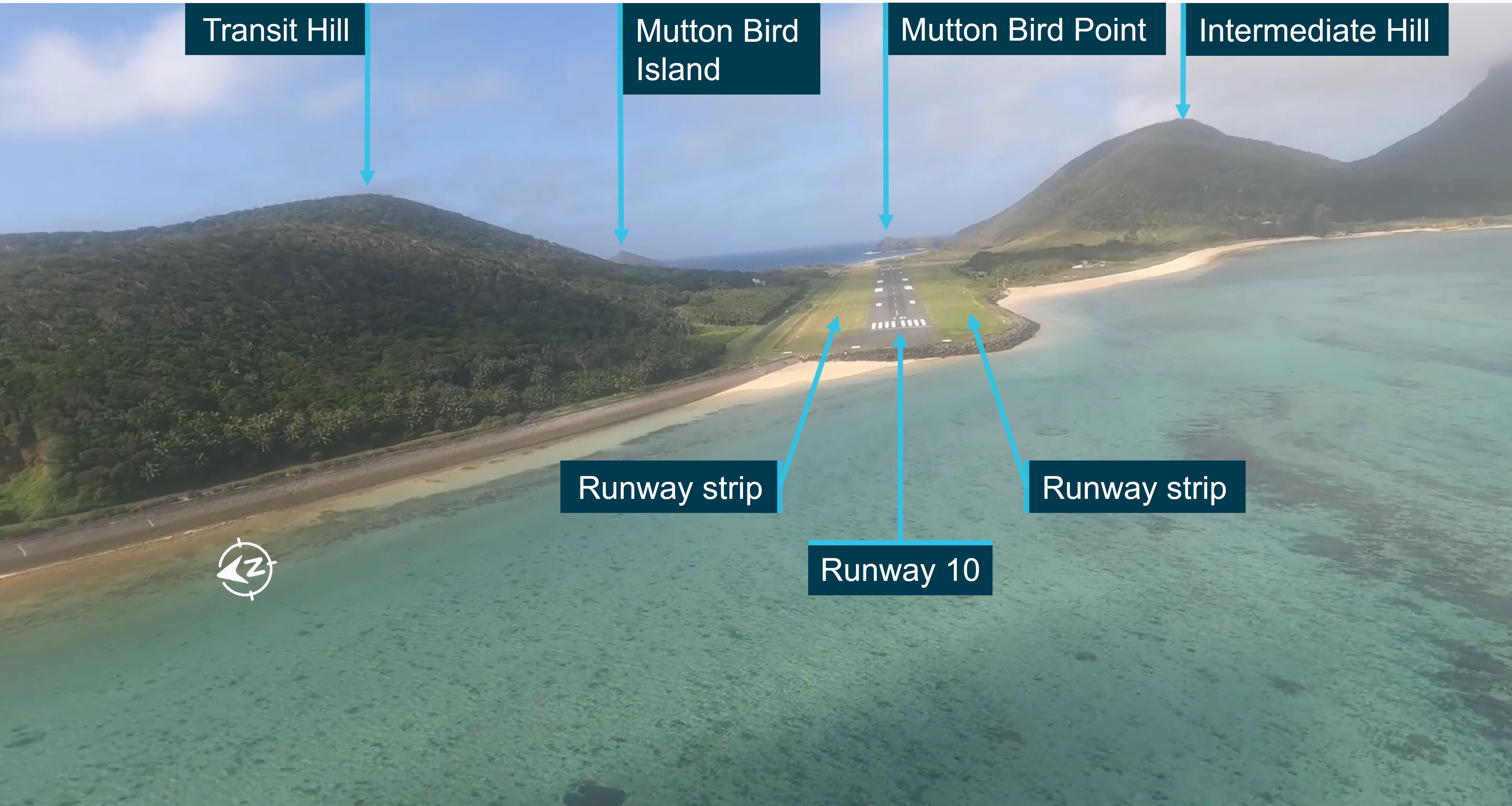
Early in the DME approach the pilot established visual meteorological conditions and transitioned to a visual approach. The pilot then descended the aircraft visually below cloud while over the water to an altitude below 1,000 ft, while also positioning for a straight-in approach to runway 10. During the approach, the aircraft entered an area of reduced visibility in rain and then touched down to the left of the runway.

“At the time of the aircraft's final approach and landing, the Lord Howe Island aerodrome was experiencing a heavy rain shower with limited visibility, conditions that were marginal for visual flight,” said ATSB Chief Commissioner Angus Mitchell.

“While the pilot commenced a visual approach to the runway with the required visual cues, it was highly unlikely that the required visual contact with the runway was retained throughout the approach.”

The ATSB investigation found that, with the loss of visual cues, the pilot did not commence a go around, which was contrary to the missed approach requirements, and instead continued towards the runway. This resulted in an increasing displacement from the runway centreline.

“Late in the approach with the aircraft close to the runway but with a significant displacement from the runway centreline, visual contact with the runway was reacquired,” Mr Mitchell said.

“Considerable manoeuvring with significant heading changes were required to realign the aircraft with the runway, resulting in an unstable approach, and, ultimately, the aircraft touching down off and to the left of the runway, on the runway strip.”

The pilot was aware that the aircraft had touched down to the side of the runway, but at the time thought that only the left main tyre was displaced at or around the edge of the runway. They elected to therefore continue the landing, manoeuvring the aircraft onto the runway and completing the landing roll without further incident.

A postflight inspection of the aircraft did not identify any damage, however an inspection of the runway by the aerodrome operator identified ground marks from an aircraft’s tyres along the left section of the runway strip, and a broken runway edge light on the left side of the runway, about 1,000 ft (300 m) from the runway threshold.

The ground markings indicated that the aircraft had touched down on the runway strip, with the closest main landing gear to the sealed runway surface about 2 m from the edge, and that the aircraft had quickly regained the runway shortly after touchdown.

In addition, the investigation also identified several flights conducted by the operator that followed a similar approach profile as that used by the occurrence flight, which were also conducted in marginal weather conditions for visual approach operations.

This practice significantly increased the risk of reduced obstacle clearance assurance for both an approach and a potential missed approach. 

“Adherence to operational procedures ensures consistency of pilot action and aircraft operation during the approach and landing phases of flight. This, along with careful monitoring of aircraft and approach parameters, ensures approaches are conducted safely,” Mr Mitchell said.

The ATSB has issued a safety recommendation to the operator that it provides guidance and training to flight crew concerning the safest option in the selection of an approach method when weather conditions are marginal for the conduct of a visual approach.

“Operators should encourage the use of the most appropriate and safe approach available,” Mr Mitchell said.

“When conditions are marginal, the use of an instrument approach that provides obstacle clearance assurance minimises the risks resultant from any unforeseen deterioration in conditions,” he continued.

“These approach types provide a protected flight path for any missed approach and have been shown to be significantly safer than a visual approach when weather conditions are marginal."

Read the final report: Touchdown off the runway surface involving Raytheon B200, VH-MVP, at Lord Howe Island Airport, NSW, on 18 February 2022

Lessons for operators and maintainers from in-flight fire accident investigation

Key points

  • A landing gear electrical system fault likely ignited fuel from the cabin heater supply line, resulting in a cockpit fire;
  • ATSB advises maintenance organisations and operators to review current practices for the prevention of damage to wiring and ensure that all available steps are being taken;
  • Where available, 4-point restraints provide increased protection and survivability.

An in-flight fire and subsequent collision with terrain of a Beechcraft Baron near Kununurra, WA demonstrates the danger damaged electrical wiring can pose to safe flight, an Australian Transport Safety Bureau final report explains.

The fire ignited in the Baron’s cockpit during its approach to land at Kununurra’s East Kimberley Regional Airport on the morning of 16 April 2022.

Despite expending the contents of a portable fire extinguisher, the fire quickly filled the cockpit with flames and thick smoke, preventing the pilot from effectively seeing external visual references or the aircraft’s instruments.

The loss of visual cues combined with the direct heat of the fire meant that the pilot was presented with significant difficulty retaining control of the aircraft.

The aircraft subsequently diverged from the runway centreline track and collided with the ground, coming to rest inverted about 600 metres beyond the Ord River and about 800 m from the Kununurra runway threshold.

After the impact, the seriously injured pilot managed to extract themselves and the sole passenger out of the wreckage before it was destroyed by fire. Unfortunately, the passenger succumbed to their injuries.

The ATSB’s transport safety investigation determined that a fault associated with the landing gear electrical system likely ignited fuel from the cabin heater supply line, resulting in the significant and sustained cockpit fire.

“The fuel line to the aircraft’s cabin heater passes through the area where the pilot reported the fire initiated, and multiple looms of electrical wiring pass through that area as well,” ATSB Chief Commissioner Angus Mitchell said.

“The fire coincided with multiple unusual indications and a burning smell as the pilot attempted to extend the landing gear.”

A breach of the cabin heater fuel line likely created a fuel source, and an electrical fault within the aircraft’s landing gear system provided an ignition source, for a rapidly spreading and sustained fire in the cockpit.

The investigation report cites four other occurrences in Australia and the United States involving in-flight fires in Baron aircraft, with damaged wiring identified as a likely factor in three of these instances.

Early on in the investigation, the ATSB issued a Safety Advisory Notice to operators of the Beechcraft Baron, urging them to inspect their aircraft’s heater fuel line to ensure electrical wiring is not rubbing or chafing against it.

“Damaged electrical wiring can pose a range of hazards to the safety of flight, including loss of electrical power, malfunctioning systems, and in-flight fire,” Mr Mitchell said.

“This hazard is further increased when wiring is proximal to lines carrying flammable liquid. Maintenance organisations and operators should review current practices for the prevention of damage to wiring and ensure that all available steps are being taken.”

The investigation final report also details findings around the survivability of light aircraft accidents.

It notes the pilot’s four-point harness provided a better restraint and attenuation of impact forces compared to the best available option of a three-point restraint in the rear of the aircraft.

“Four-point restraints, where available, provide increased survivability,” Mr Mitchell said.

“And where available and practical, rearward-facing passenger seats improve frontal impact protection and survivability in an accident.”

Read the final report: In-flight fire and collision with terrain involving Beechcraft B58 Baron, VH-NPT near East Kimberley Regional Airport, Kununurra, Western Australia, on 16 April 2022