At about 16:40, while in a climb Northeast of Lake Wabby, the rear cabin door separated and fell from the aircraft. The pilot immediately flew toward the nearest aeroplane landing area on Seventy-Five Mile beach, north of Eurong Township, and landed without incident. The pilot and passengers were not injured. The door was not recovered.
Door departure history
There have been several reported instances of a cargo door departure in flight with the GA8 aircraft. Initial investigations indicated that excessive wear of the forward cargo door slide could have been a contributing factor. Further investigations identified that over rotation of the door handle may also lead to the door opening in flight.
GippsAero advised that the typical failure mode involves the front door slider disconnecting from its track, the front of the door popping outward, and airflow peeling the door off the side of the aircraft.
Service Bulletin
CASA Airworthiness Directive AD/GA8/3 Amendment 2 mandated compliance with Gipps-Aero Service Bulletin SB-GA8-2005-23, issue 3. Service Bulletin SB-GA8-2005-23 issue 3 introduced the mandatory modification to the cargo door guide assembly, and requirement for periodic cabin door inspections, for all GA8 and GA8-TC 320 aircraft.
SB-GA8-2005-23 issues 4 to 6 specify the mandatory requirement for inspection of the door operating rod and mechanism, replacement of the door handle with an integrated stop added, and embodiment of a centre cargo door rail aft stop modification.
Safety action
Other company GA8 aircraft were inspected prior to return to service with no abnormal wear reported. The company is working with GippsAero and revisiting all relevant Service Bulletins and Airworthiness Directives to help determine the cause of the failure and prevent a reoccurrence.
Safety message
Operators of GippsAero GA8 and GA8-TC 320 aircraft are reminded of the requirement to regularly inspect the cargo door slides and rails for excessive wear in accordance with CASA AD/GA8/3 Amendment 2 and SB-GA8-2005-23 issue 3.
GippsAero further recommends that SB-GA8-2005-23 issue 6 inspections are carried out, and the door rail stop is installed, and the latch modifications embodied, to increase reliability and safety of the door latch mechanism and reduce the likelihood of a recurrence of a door departing in-flight.
About this report
Decisions regarding whether to conduct an investigation, and the scope of an investigation, are based on many factors, including the level of safety benefit likely to be obtained from an investigation. For this occurrence, no investigation has been conducted and the ATSB did not verify the accuracy of the information. A brief description has been written using information supplied in the notification and any follow-up information in order to produce a short summary report and allow for greater industry awareness of potential safety issues and possible safety actions.
Occurrence summary
Mode of transport
Aviation
Occurrence ID
AB-2023-004
Occurrence date
06/04/2023
Location
Fraser Island
State
Queensland
Occurrence class
Incident
Aviation occurrence category
Objects falling from aircraft
Brief release date
15/06/2023
Aircraft details
Manufacturer
GippsAero
Model
GA8
Sector
Piston
Operation type
Part 135 Air transport operations - smaller aeroplanes
A NSW Central Coast helicopter accident highlights to pilots the need to be cognisant of factors that can induce unanticipated yaw, according to an Australian Transport Safety Bureau investigation report.
On 19 November 2022, the pilot of a Robinson R44 was conducting a private flight with two passengers to a function centre at Forresters Beach from a nearby property.
During the approach to the planned landing site, a carpark beside the venue, the pilot reported experiencing an uncommanded yaw to the right, which was unable to be recovered.
“During the approach to the confined carpark landing site, the helicopter experienced an unanticipated yaw to the right,” ATSB Director Transport Safety Stuart Macleod said.
“The pilot’s response was ineffective at recovering control – however the unanticipated yaw may have occurred at a height from which control of the helicopter was not recoverable.”
The helicopter subsequently struck powerlines before impacting the ground. While the helicopter was substantially damaged, fortunately the occupants received only minor injuries.
Considering Gosford weather observations of a north-east wind at 10 kt, the approach track placed the wind from a direction and at a speed known to be conducive to the onset of unanticipated yaw, the investigation notes.
“It’s important for helicopter pilots to remain cognisant of the factors that can induce unanticipated yaw, especially the relative wind direction,” Mr Macleod said.
“These factors should be avoided, or their influence on the helicopter’s anti-torque system should be managed through positive control of the yaw rate. Depending on the yaw rate recovery may not be immediate, but maintaining the recovery control inputs is the most effective way to stop the yaw.”
In the early afternoon of 6 June 2023, a Piper PA-28-161, registered VH-ENL, taxied for runway 36 at Mildura, Victoria for a private flight to Broken Hill, New South Wales. At about the same time, a QantasLink Bombardier DHC-8-315 (Dash 8), registered VH-TQH, being operated on a scheduled passenger transport flight to Sydney, began to taxi at Mildura for runway 09.
Both aircraft gave taxi, and entering and backtracking calls on the local common traffic advisory frequency (CTAF). The pilot of the PA‑28 was aware of the Dash 8 backtracking on runway 09. The crew of the Dash 8 were not aware of the PA‑28 preparing for take‑off from the cross runway. The crew of the Dash 8 had commenced their take-off on runway 09 as the pilot of the PA‑28 gave a rolling call on runway 36 at the commencement of their take‑off. The Dash 8 crossed ahead of the PA‑28 at the runway intersection of 09/36 by about 600 m.
What the ATSB found
The ATSB’s investigation identified that the pilot of the PA‑28 incorrectly identified the runway direction at Mildura Airport during their taxiing, and entering and backtracking radio calls (saying ‘runway 35’ instead of ‘runway 36’). This, combined with the Dash 8 crew’s focus on obtaining their pre‑departure information from air traffic control, with the volume for the radio tuned to the CTAF frequency turned down, and only receiving certain elements of the PA‑28 pilot’s radio calls due to an over transmission from air traffic control, likely led to an incomplete comprehension of traffic at Mildura by the Dash 8 crew (who believed that the PA‑28 was not at Mildura). However, they did not seek further information of the source of the radio calls to positively identify the traffic location.
While the pilot of the PA‑28 was aware of the Dash 8, they assumed that the Dash 8 was still backtracking on runway 09, were unable to visually sight the location of the Dash 8 (due to airport buildings) and did not directly contact the Dash 8 to positively organise separation.
The ATSB also found that even though it wasn’t a requirement, the Dash 8 crew did not give a rolling call on runway 09, based on their mental model of the local traffic at Mildura.
Due to topography and buildings at Mildura Airport, aircraft are not directly visible to each other on the threshold of runways 09, 27 and 36. The lack of a requirement for mandatory rolling calls increased the risk of aircraft not being aware of each other immediately prior to take-off.
After the incident, the Dash 8 crew monitored the flightpath of VH-ENL to ensure their safety and provide assistance if required.
What has been done as a result
QantasLink has updated its operations manual to reflect the updated minimum company requirements of a rolling call to be made at all CTAF aerodromes. This is to improve procedural consistency across the pilot group, and to reduce the likelihood of traffic conflict. Additionally, QantasLink have also provided further guidance to their pilot group on specifics of potential radio wave degradation on the ground at Mildura between runway 36 and 09 thresholds, including the conduct of rolling calls and clarification of broken, suspicious or ambiguous radio calls from other aircraft prior to departure.
Review of potential radio interference at Mildura Airport is being further investigated in an ATSB investigation (AO-2023-050) into a similar event at Mildura Airport about 3 months later, involving a similar collision-risk pairing. ATSB is continuing to work with Qantas Safety, Mildura Airport, the Australian Communications and Media Authority, CASA and Airservices Australia to identify any potential radio communication interference and shielding.
Safety message
Communication and self-separation in non-controlled airspace is one of the ATSB’s SafetyWatch priorities. Wherever you fly, into either non-towered or controlled aerodromes, maintaining a vigilant lookout at all times is important. Situational awareness and alerted see-and-avoid is an effective defence against collisions, and good airmanship dictates that all pilots should be looking out and not be solely reliant on the radio for traffic separation. Being aware of other nearby aircraft and their operational intentions is important. Remember that there may be a variety of aircraft of different sizes, flight rules, and performance levels all operating at the same time, in the same airspace.
Pilots can guard against similar issues to those highlighted by this incident by:
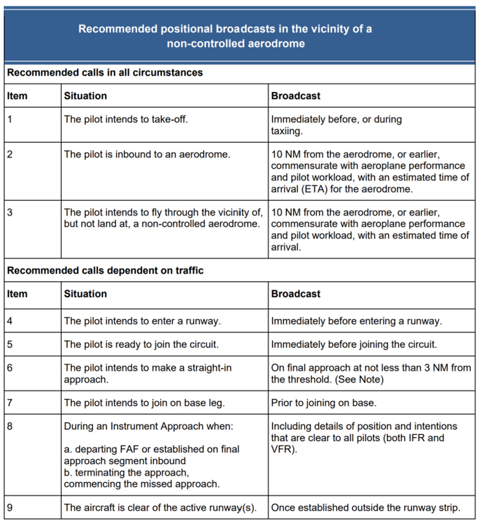
making the recommended broadcasts when in the vicinity of a non-controlled aerodrome
actively monitoring the CTAF while maintaining a visual lookout for other aircraft and constructively organising separation through direct contact with other aircraft
ensuring transponders, where fitted, are selected to transmit altitude information.
The ATSB SafetyWatch highlights the broad safety concerns that come out of our investigation findings and from the occurrence data reported to us by industry. This investigation report highlights the safety concerns around Reducing the collision risk around non-towered airports.
The occurrence
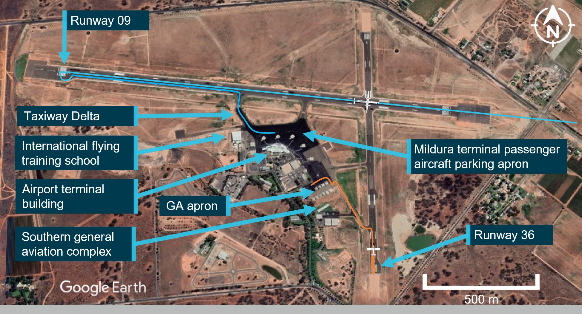
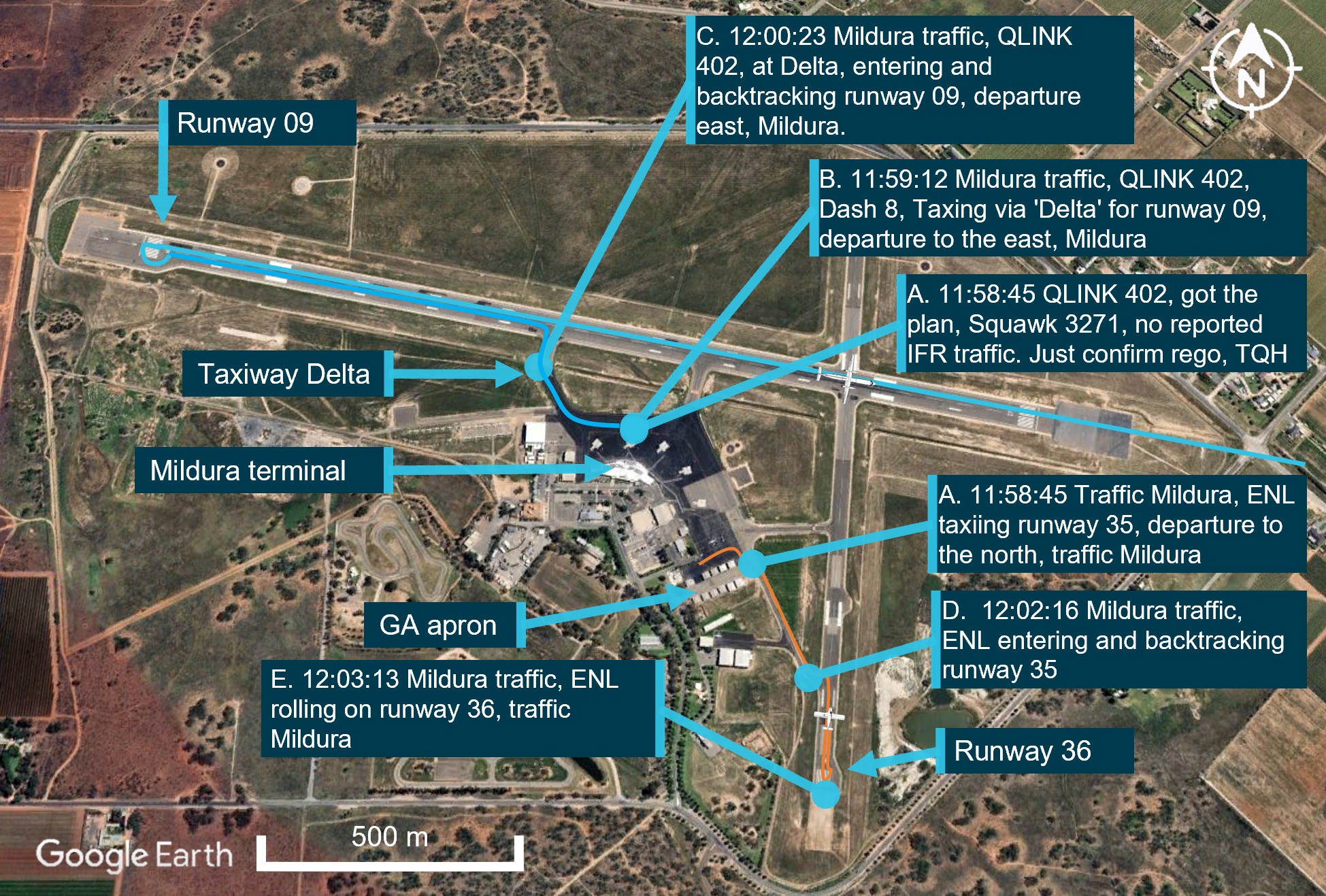
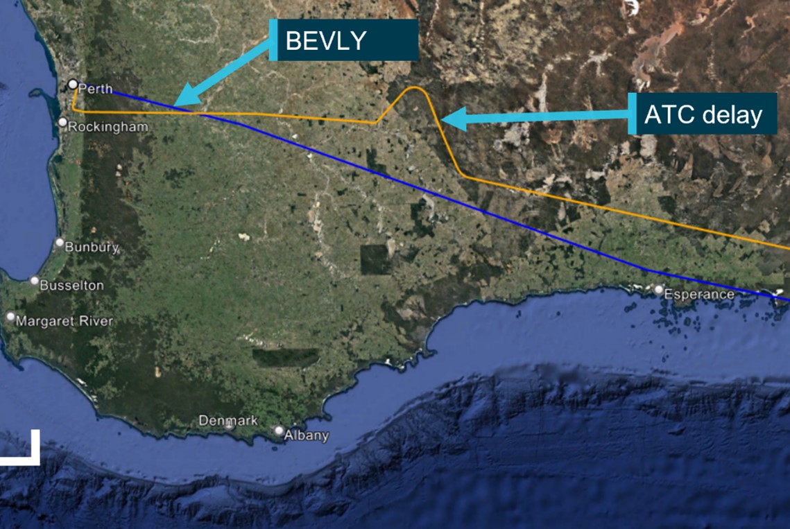
In the early afternoon of 6 June 2023, a Piper PA-28-161 (PA‑28), registered VH-ENL taxied for runway 36[1] at Mildura, New South Wales, for a private flight to Broken Hill (Figure 1 orange line). The pilot was the sole occupant. At about the same time, a QantasLink Bombardier DHC-8-315 (Dash 8), registered VH-TQH, with 3 crew and 33 passengers on board, being operated on a scheduled passenger transport flight to Sydney, began to taxi at Mildura for runway 09 (Figure 1 blue line).
Both aircraft gave taxi, runway entering and runway backtracking calls on the local common traffic advisory frequency (CTAF) (see Radio calls). The pilot of the PA‑28 was aware of the Dash 8 backtracking on runway 09, however the crew of the Dash 8 were not aware of the PA‑28 preparing for take-off on the cross runway.
The Dash 8 had started its take off roll on runway 09 as the PA‑28 gave a rolling call on runway 36 and commenced take-off. As the Dash 8 crossed the runway intersection of 09/36 at about 200 ft vertically, the PA‑28 was rolling towards the intersection and about 600 m from the Dash 8 (Figure 1 aircraft positions).
Figure 1: VH-TQH (Dash 8) and VH-ENL (PA‑28) ground tracks
Source: Google Earth, annotated by the ATSB
Context
Aircraft information
VH-TQH
The Bombardier Incorporated, DHC-8-315, is a high-wing, pressurised aircraft powered by 2 turboprop engines. VH-TQH was manufactured in Canada in 2003 and was first registered in Australia on 15 August 2003. It was registered with Qantas Airways Limited on 7 February 2011, and operated by Eastern Australia Airlines Pty Limited.
VH-ENL
VH-ENL was a privately owned Piper Aircraft Corporation, PA-28-161 Cherokee Warrior II, manufactured in the US in 1980. The Cherokee was a popular training and private owner aircraft, featuring a fixed-tricycle undercarriage configuration, 4 seats and a low wing design.
Pilot Information
Flight crew VH-TQH (Dash 8)
The captain held an Air Transport Pilot Licence (ATPL) (Aeroplane), a valid Class 1 aviation medical certificate, and reported a total flying time of 2,375 hours with about 2,130 of those being on the Dash 8. The captain reported being familiar with Mildura Airport and had operated there regularly in the past and recalled operating into Mildura at least 5 times in 2023, with the last flight being the week before the occurrence.
The first officer (FO) held an ATPL (Aeroplane), a valid Class 1 aviation medical certificate, and reported a total flying time of about 2,230 hours, having flown about 1,900 of those hours in the Dash 8. The FO was familiar with Mildura Airport having regularly operated there over 40 times and had also operated into Mildura the previous week.
Pilot VH-ENL (PA‑28)
The pilot held a Private Pilot Licence (Aeroplane) and reported a total flying time of about 1,250 hours, with about 260 hours on the PA‑28, and about 60 hours on VH-ENL. They held a valid Class 2 aviation medical certificate and had last conducted a single-engine flight review on 5 October 2022.
The pilot was familiar with Mildura Airport after conducting their initial training there in 1995 and reported operating into Mildura at least 3 times in 2023.
Meteorological conditions
Weather conditions at Mildura Airport around the time of the occurrence were identified as a moderate north-north easterly wind at 10 kt, with greater than 10 km visibility. The cloud reported was broken (between 5-7 oktas[2]) at 1,000 ft above ground level.
Mildura Airport
Mildura Airport was a certified aerodrome situated about 5 NM south-west from the city of Mildura. The airport had an elevation of 167 ft above mean sea level and had 2 sealed runways, orientated in an east-west, north-south direction. The main east-west runway was 1,830 m long and the secondary, north-south runway was 1,139 m long.
The airport was serviced by a number of major aviation carriers and a large international flying school. Mildura Airport accommodated aircraft as large as Boeing 737s but regularly operated with lower capacity passenger flights from numerous operators, while also accommodating general and recreational aviation flight training schools, charter operators and private flying. The airport terminal building was upgraded in 1994 with further expansion constructed in 2004 due to utilisation and growth. Due to airport expansion in recent years, numerous new buildings had been erected, including the site of an international flight training school and the southern general aviation hangar complex (Figure 1).
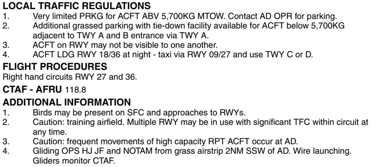
The Enroute Supplement Australia (ERSA) promulgated by Airservices Australia provides information to pilots on the operations specific to each aerodrome. The ERSA entry for Mildura Airport detailed that aircraft may not be visible to one another while on the runway. It also stated that the circuit can be busy due to it being a training airfield with multiple runways in use at any time, in conjunction with frequent high-capacity passenger carriage operations (Figure 2).
Figure 2: Mildura Airport ERSA details
Source: Airservices Australia
Airspace and traffic services
Mildura Airport was located within non-controlled Class G[3] airspace, and did not have an air traffic control tower. The non-controlled airspace surrounding Mildura Airport was available for use by aircraft operating under visual flight rules (VFR) and instrument flight rules (IFR). No separation service was provided to aircraft operating in this airspace, with pilots responsible for making themselves aware of nearby aircraft and maintaining mutual self-separation. The primary method of traffic separation at Mildura Airport was by visual reference and relied on pilots using ‘alerted see-and-avoid’[4] practices (see Alerted see‑and-avoid).
Common traffic advisory frequency
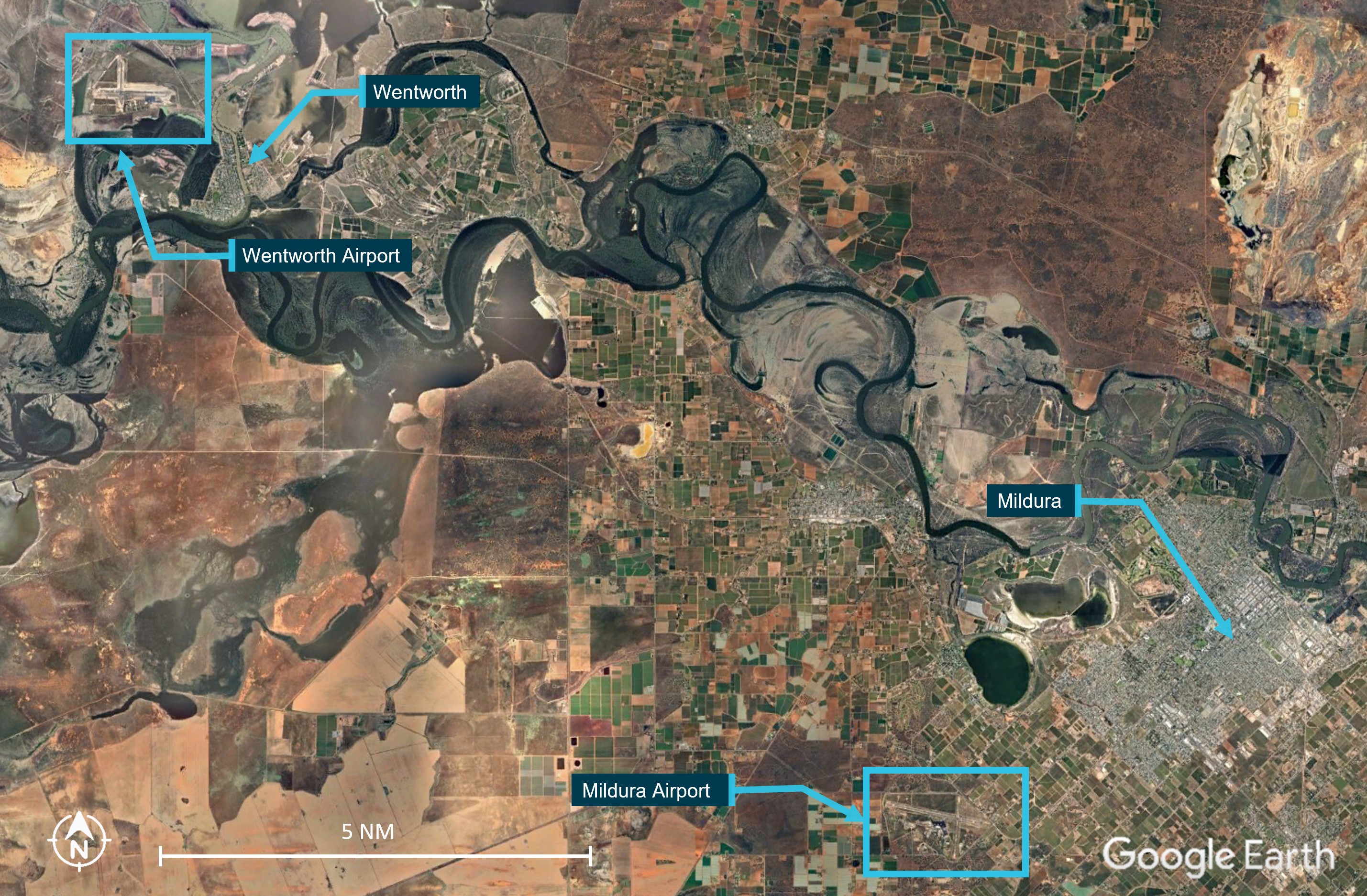
The Mildura Airport CTAF was a designated very high frequency (VHF) radio frequency on which pilots must monitor and make positional broadcasts when operating within a 10 NM radius of the airport. The Mildura Airport CTAF was shared with Wentworth Airport to assist traffic coordination and to enhance the situational awareness of pilots operating within the surrounding airspace. Wentworth Airport was 13 NM to the north‑west of Mildura Airport and was commonly used by general and recreational aviation operators (Figure 3).
Figure 3: Mildura / Wentworth proximity
Source: Google Earth, annotated by the ATSB
Delays due to aircraft serviceability
The captain of the Dash 8 was conducting the daily aircraft checks on arrival at Mildura early in the morning and identified the unserviceability of an altitude alerter instrument on VH‑TQH. After discussions and troubleshooting with Qantas technical support by phone, the aircraft was declared unserviceable for the proposed flight. This required dispatch of components by another company aircraft from Melbourne to Mildura, thereby delaying the intended flight by about 6 hours before the aircraft was repaired and declared serviceable to depart.
Recorded information
Radio calls
Recorded radio data collected from Mildura Airport CTAF and the Melbourne Centre (air traffic control) area frequency recordings (Appendix 1) indicated that the crew of the Dash 8 contacted Melbourne Centre to arrange a transponder code prior to taxing at Mildura. Due to the delayed departure of the Dash 8, the transponder code was not readily available and this resulted in a number of radio calls between the Dash 8 and Melbourne Centre, with an associated delay in receipt of the transponder code.
At the same time the Dash 8 was receiving the code on the Melbourne Centre frequency, the pilot of the PA‑28 broadcast their taxi call on the Mildura CTAF (Figure 4, note A). However, the pilot of the PA‑28 mis-identified runway 36 during this call, instead referring to the intended runway as ‘… runway 35’.
The crew of the Dash 8 confirmed the code to Melbourne Centre and about 14 seconds later made a taxi call for runway 09. About 10 seconds after that, the Dash 8 crew made an entering and backtracking call for runway 09 at Mildura.
A further 2 minutes later, the pilot of the PA‑28 made an entering and backtracking call, again with the mis-identified runway number ‘35’ and did not finalise the radio call with the required location identifier of ‘… traffic Mildura’.
The crew of the Dash 8, missed the first part of the transmission on the CTAF, however identified that the aircraft calling was referring to runway 35 and assumed the aircraft was in Wentworth, due to the runway direction, signal strength and clarity of the transmission.
No radio call was recorded for the Dash 8 as it began to roll on runway 09. About 20 seconds later, the pilot of the PA‑28 gave a rolling call, this time with the correct runway direction and location, ‘… runway 36, traffic Mildura”.
After the Dash 8 crew had departed, the FO recalled visually checking for VH-ENL to establish if they had rejected the take-off, over-run the runway or needed assistance. After observing VH-ENL on climb from runway 36 at Mildura, the FO attempted to contact the pilot of the PA‑28 in order to establish the reason for the breakdown of communication and to render any airborne assistance.
Flight tracking data
Recorded ADS-B exchange data from VH-TQH on the day of the occurrence showed the Dash 8 entering and backtracking on runway 09 at 0200:37. After reaching the threshold of runway 09, the crew of VH-TQH lined up, and began their take-off roll at 0202:32.
Recorded data (Garmin watch of the pilot) on the taxi track of VH-ENL showed the PA‑28 initial entry to runway 36 and backtrack occurred at 0202:18, and that initial power application occurred on the threshold of runway 36 at about 0203:22 (about 31 seconds after VH-TQH), accelerating VH-ENL along runway 36 until about abeam taxiway Bravo at 0203:38. At that time, the recorded data of VH-TQH shows the Dash 8 crossing the runway 09/36 intersection about 600 m ahead, and about 200 ft above the intersection of both runways (Figure 4).
Figure 4: Recorded data sequence
Source: Google Earth with recorded data overlay, annotated by the ATSB
The pilot of the PA‑28, after identifying that the Dash 8 had departed on the crossing runway, continued their take-off roll. Recorded data further showed the PA‑28 crossing the runway intersection about 18 seconds after the Dash 8, and at about 220 ft above the intersection.
Operations in the vicinity of non-controlled aerodromes
At and around non-controlled and non-towered aerodromes, pilots are responsible for making themselves aware of nearby aircraft and maintaining separation. Safe operations at non-towered aerodromes relies on all pilots maintaining awareness of their surroundings and of other aircraft, and on flying in compliance with procedures, while being observant, courteous and cooperative.
VHF radio is the primary communication tool to provide ‘alerted see-and-avoid’ commonly across aviation from sport and recreational flying to air transport. VHF radio allows for the communication of information (in this instance traffic information) to the pilot from other aircraft (Civil Aviation Safety Authority, 2013). Other tools to enhance ‘alerted see-and-avoid’ include ground radar, automatic dependent surveillance broadcast (ADS-B), and traffic collision avoidance system (TCAS).
To aid in increasing situational awareness at non-controlled aerodromes, recommended broadcasts are published by the Civil Aviation Safety Authority (CASA) for pilots to alert other traffic to their location and intentions before take-off, inbound to land at, or if intending to overfly a non-controlled aerodrome.
Table 1: Recommended radio calls
Source: CASA advisory circular 91-10 Operations in the vicinity of non-controlled aerodromes
In addition, individual aerodromes can require additional broadcasts due to unique circumstances by adding a requirement into the ERSA entry for their aerodrome. As seen in Figure 2 above, the ERSA entry for Mildura did not have any additional broadcast requirements.
CASA advisory circular 91-10, Operations in the vicinity of non-controlled aerodrome, provides further guidance on operations at non-controlled aerodromes, including that:
• In addition to making positional broadcasts, pilots should listen to other broadcasts to increase situational awareness
• Whenever pilots determine that there is a potential for traffic conflict, they should make radio broadcasts as necessary to avoid the risk of a collision or an Airprox event. Pilots should not be hesitant to call and clarify another aircraft’s position and intentions if there is any uncertainty.
Alerted see-and-avoid
Issues associated with unalerted see-and-avoid have been detailed in the ATSB research report Limitations of the See-and-Avoid Principles(Hobbs, 1991). The report highlights that unalerted see-and-avoid relies entirely on the pilot’s ability to sight other aircraft. An ‘unalerted’ search is one where reliance is entirely on the pilot searching for, and sighting, another aircraft without prior knowledge of its presence.
An ‘alerted’ search is one where the pilot is alerted to another aircraft’s presence, typically through radio communications or aircraft based alerting systems. Broadcasting on the CTAF to any other traffic in the vicinity of a non-controlled aerodrome is known as radio-alerted see-and-avoid and assists by supporting the pilot’s situational awareness and visual lookout for traffic with the expectation of visually acquiring the subject in a particular area. The ATSB research report found that an alerted search is likely to be 8 times more effective than an unalerted search, as knowing where to look greatly increases the chances of sighting traffic.
Positional broadcasts
Traditionally VHF radio broadcasts are made at non-controlled aerodromes in order to provide situational awareness, traffic separation and deconfliction to other traffic in the vicinity of the aerodrome.
However, positional broadcasts rely on the accuracy of the information being broadcast and the ability of other traffic receiving, comprehending and reacting to this information.
Civil Aviation Advisory Publication (CAAP) 166-2(1),Pilots’ responsibility for collision avoidance in the vicinity of non-controlled aerodromes using ‘see and-avoid’ stated:
11.5 Pilots should be mindful that transmission of information by radio does not guarantee receipt and complete understanding of that information. Many of the worst aviation accidents in history have their genesis in misunderstanding of radio calls, over-transmissions, or poor language/phraseology which undermined the value of the information being transmitted.
11.6 Without understanding and confirmation of the transmitted information, the potential for alerted see-and-avoid is reduced to the less safe situation of unalerted see-and-avoid.
Positional broadcasts are a one-way communication, they are intended to provide a short and concise broadcast to minimise radio channel congestion. However, they do not imply receipt of information by other parties unless direct radio contact is made between stations to acknowledge the traffic, confirm intentions and if required, discuss measures to provide deconfliction.
The successful broadcast of the information is also subject to limitations of the VHF radio system.
VHF radio line of sight limitations
The VHF radio requires line-of-sight between both stations in order to function effectively. If an aircraft does not have a clear visual path direct to another in the vicinity, then the radio wave signal strength and clarity can be affected by obstacles. In some cases, terrain, vegetation or buildings can create areas that may shield or substantially reduce radio wave propagation and adversely affect broadcast signal strength and clarity.
Mildura Airport had an aerodrome frequency response unit (AFRU) that assists in indicating the correct selection of the VHF frequency at non-towered aerodromes. The AFRU automatically responds to a radio transmission with either a pre-recorded voice message, if no transmission has been received in the last 5 minutes or an audible ‘beep-back’ tone, on the CTAF. This then alerts the pilot to the possibility of other traffic currently broadcasting or being in the vicinity of the CTAF.
After the event, the operator’s internal investigation report concluded that broken radio transmissions were present and due to radio wave degradation, which was determined by the operator’s investigation to be likely caused by terrain shielding, obstacles, buildings and the local environment between runways 09 and 36.The operator concluded that non-mandated radio calls, a cross strip layout with runway visibility restrictions and low level radio shielding may have contributed to the Dash 8 not hearing a radio call from the PA‑28.
Visual line of sight limitations
Threshold visibility
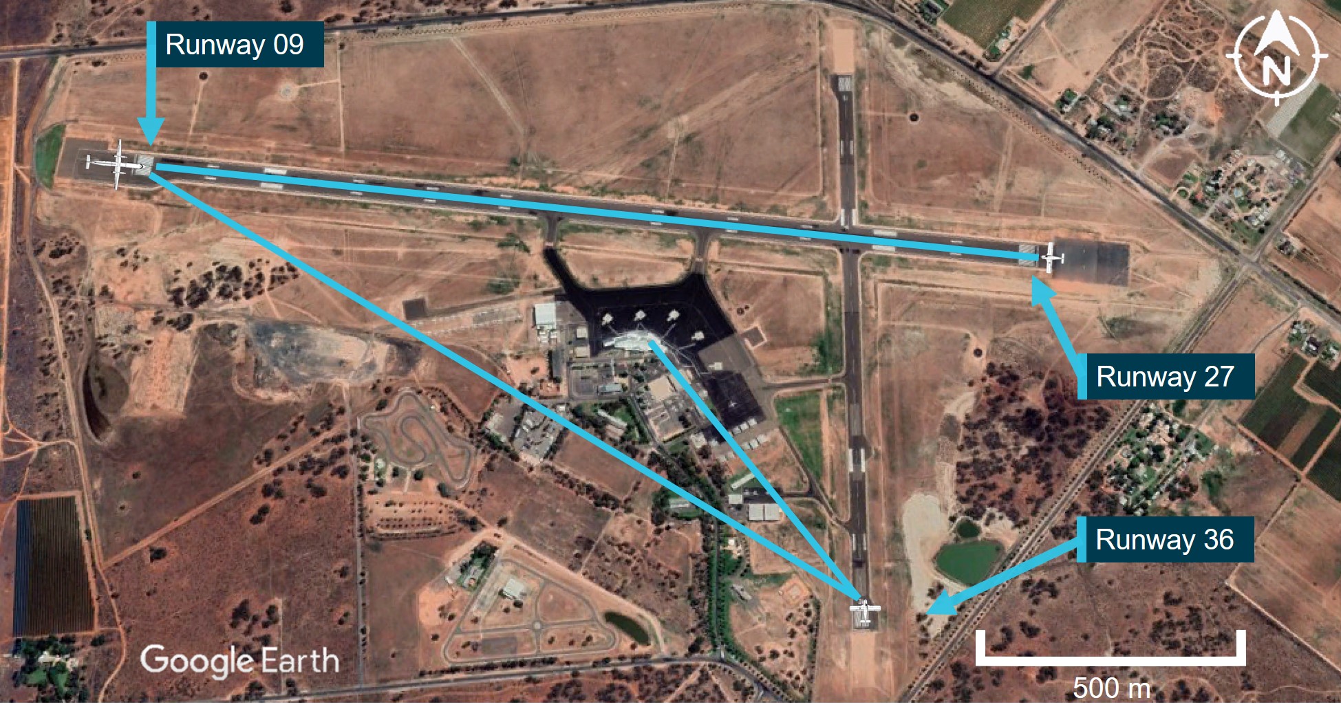
The Dash 8 captain recalled that from the threshold of runway 09, the threshold of runway 36 was visually obscured by the terminal buildings, and the pilot of the PA‑28 also recalled the buildings prevented pilots from seeing the threshold of runway 09 from the southern end of runway 36 (Figure 5).
Figure 5: Visual line of sight from runway 36/09/27
Source: Google Earth, annotated by the ATSB
Operator’s report
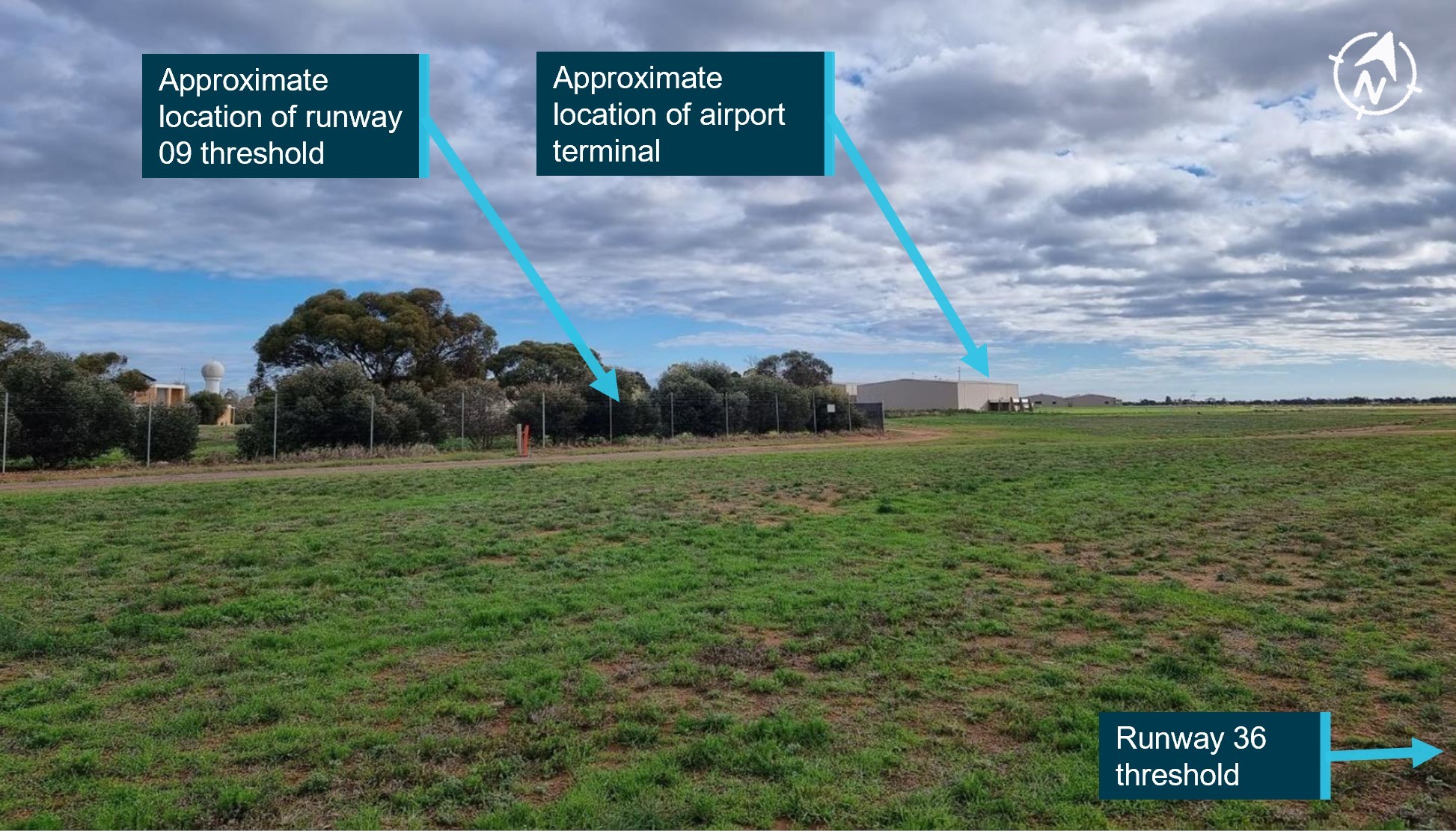
The operator’s internal investigation report identified an obstructed visual line of sight from the threshold of runway 36 to 09 (Figure 6). The report identified that neither aircraft could visually identify each other ‘due to local infrastructure and terrain that limits visibility between runway 09 and 36’.
Figure 6: View from threshold runway 36
Source: Operator report, annotated by the ATSB
ATSB site examination
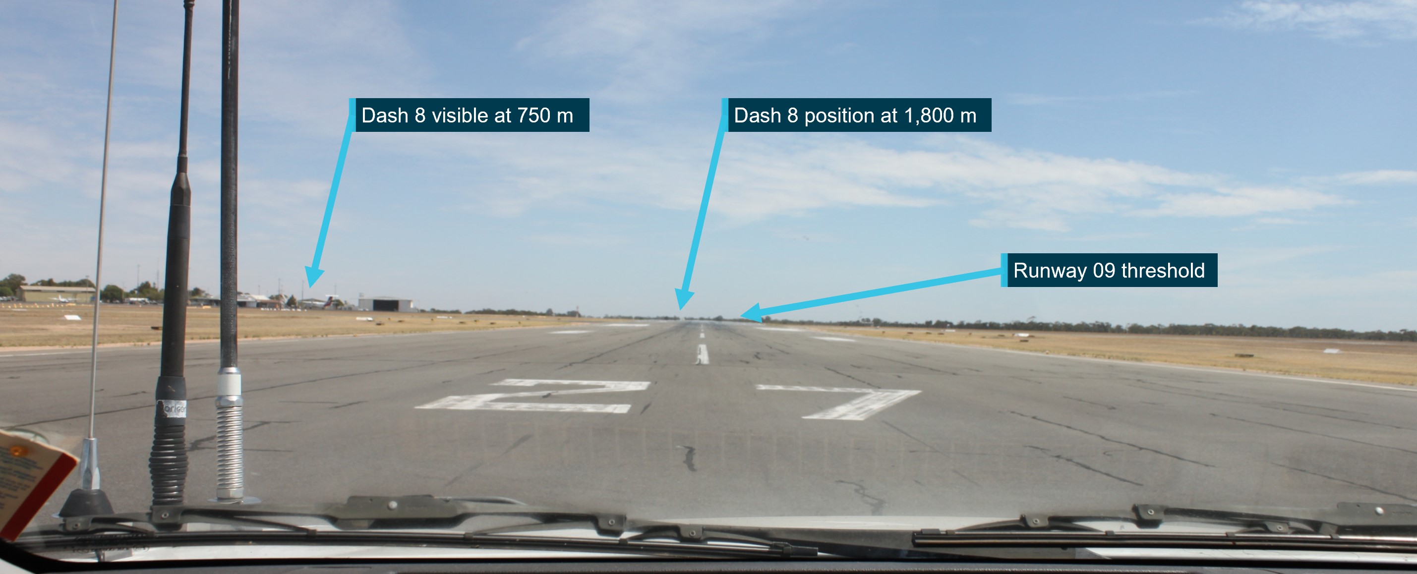
ATSB on-site examination of the airport confirmed the obstruction noted in the operator’s report from the threshold of runway 36 to the threshold of runway 09, and in addition, from the threshold of runway 09 to the threshold of 36. In addition, the ATSB site inspection identified a lack of aircraft visibility also occurs from the thresholds of runway 09 and 27 (either end of the same physical runway). However, this was due to raised terrain along the runway between the two ends (Figure 7).
Figure 7: View from threshold of runway 27
Source: ATSB
Traffic collision avoidance system
A traffic collision avoidance system (TCAS), as fitted to the Dash 8, interrogates the transponders of nearby aircraft and uses this information to calculate the relative range and altitude of this traffic. The system provides a visual representation of this information to the flight crew as well as issuing alerts should a traffic conflict be identified.
These alerts include:
Proximate traffic – an alert issued when an aircraft is within a range of less than 6 NM and 1,200 ft, or a range of 6 NM if the traffic is not transmitting altitude information
Traffic advisory (TA) – an alert issued when the detected traffic may result in a conflict
Resolution advisory (RA) – a manoeuvre, or a manoeuvre restriction, calculated by the TCAS to avoid a collision (the closest point of separation is approximately 25 seconds away or less).
Due to its method of operation, a TCAS cannot detect aircraft that are not equipped with a transponder (or switched off). Additionally, the system is unable to issue an alert for traffic that is not fitted with an altitude reporting transponder (mode C or S), or in circumstances where the mode C or S transponder on board the conflicting traffic is not transmitting altitude information.
The PA‑28 was equipped with a Mode C transponder and the pilot recalled normally setting the transponder to code 1200 and then selected mode C before entering the runway, meaning the altitude of the aircraft was being transmitted during the take-off.
The crew of the Dash 8 reported that the TCAS was used as an aid to identify potential conflicting traffic in the vicinity of an aerodrome prior to take-off, however on climb the RA alert is inhibited below 1,100 ft.
QantasLink advised that the use of TCAS was not a formalised procedure for monitoring other aircraft ground movements and that TCAS identification on the ground may be unreliable due to system limitations.
The first officer recalled conducting a check of the TCAS prior to rolling on runway 09 and the TCAS did not identify any traffic in the vicinity of Mildura Airport, however after crossing the upwind end of runway 09, the FO recalled the TCAS identifying an aircraft consistent with the PA‑28’s position and altitude after take-off on runway 36.
Crew/pilot mental models
The ATSB investigation considered a range of human factors that could have influenced the decisions and actions of the pilots involved.
Cognitive tunnelling is an inattentional blindness/deafness where an individual becomes overly ‑focused on some variable other than the present environment (Mack & Rock, 1998). This can reduce the likelihood of seeing/hearing something unexpected. Cognitive tunnelling may also impact an individual’s decision-making processes (Bell, Facci, & Nayeem, 2005).
The flight crew recalled that before taxiing, they focused their attention on receiving the transponder code for their departure. The Dash 8 operator’s internal investigation report identified that the VHF radio volume on Com 2 (tuned to the Mildura CTAF) was turned down to aid the receipt of the transponder code.
Recorded data from the area frequency (Melbourne Centre) and the CTAF (local traffic) indicated that, while receiving a radio broadcast from Melbourne Centre with the transponder code, the pilot of the PA‑28 also broadcast on the CTAF local frequency at the same time.
Alerted see-and-avoid relies on crew/pilot awareness of all traffic in the vicinity that may be considered a hazard to their operations. Enhanced situational awareness requires the crew/pilot mental model of the location and intentions of nearby traffic being updated in order to form an evolving understanding of the nearby traffic.
Without this information, the likelihood of effective situational awareness is degraded, and the mental model and shared understanding of hazards is compromised.
Safety analysis
Introduction
On 6 June 2023, a Piper PA-28-161, registered VH-ENL (PA‑28) began its take-off roll on runway 36 at Mildura, however, a QantasLink Bombardier DHC-8-315 registered VH-TQH (Dash 8), was just becoming airborne on runway 09 at Mildura. The Dash 8 crossed ahead of the PA‑28 at the runway intersection of 09/36 by about 600 m laterally, and 200 ft vertically.
This analysis will explore the operational considerations pertaining to radio calls at Mildura, the flight crew and pilot’s mental models and factors pertaining to the breakdown of communication.
Communication
Succinct and timely radio communication is important to ensuring high levels of situational awareness and aids in providing alerted see-and-avoid safety outcomes. As such, the accuracy of the information broadcast by pilots is also critical in ensuring minimum misunderstanding.
The use of a standard phraseology format is an important factor to increase the effectiveness of radio communication and to prevent misunderstanding. It also increases the attentional expectation of pilots to recognise key phraseology in the cockpit to determine the significance of the information to their operations.
However, these communications can be subject to human error, even when it involves experienced pilots. In this instance, the pilot of the PA‑28 unknowingly announced an incorrect runway direction designator (runway 35 instead of runway 36) on 2 separate occasions which introduced confusion and led the Dash 8 crew to incorrectly deduce that the transmission did not originate from Mildura.
During one of the busiest parts of passenger transport operations from a non‑controlled aerodrome, the crew of the Dash 8 had difficulty in receiving a transponder code for their departure from Mildura. Controllers had difficulty finding the code due to the 6-hour mechanical delay from the original flight plan and their response also coincided with the taxi call from the PA‑28 pilot.
This added complexity within a busy phase of pre-departure, and likely led to additional attentional focus on obtaining the departure code to the exclusion of effective situational awareness and the monitoring of other traffic on the CTAF. Such focus can reduce the chance of hearing and appreciating the relevance of other radio broadcasts.
In addition, the volume on the aircraft radio that was tuned to the Mildura CTAF was turned down (likely to facilitate the crew’s focus on receiving the pre-departure transponder code). This would have further reduced the likelihood of the crew noticing the PA‑28 broadcasts.
Although the operator suggested VHF radio shielding may have affected the receipt of the PA‑28 radio call by the Dash 8 crew, the ATSB had no direct evidence of such radio shielding. However, even if radio shielding was possible at Mildura Airport, the above explained over transmission, focus of attention and radio volume in this occurrence likely contributed to the Dash 8 crew not fully comprehending the PA‑28 broadcasts.
Local traffic mental model and runway threshold visibility
The circumstances and the restrictions imposed on the available electronic aids, particularly TCAS functionality, were impediments to effectively applying alerted see-and-avoid practices.
The crew of the Dash 8 were not aware of the presence of the PA‑28 as a threat to their operation. Although visibility was greater than 10 km with no cloud in the area, visual searches prior to take-off on runway 09 for other conflicting traffic were likely obscured by obstacles such as trees, hangars and buildings between the threshold of runway 09 and runway 36.
In many instances the conduct of a rolling call on the runway is given by pilots to increase the situational awareness of other traffic, however if there is no identified traffic that may cause a hazard at the airport, a pilot is not required to make a rolling call.
However, other traffic may be expecting such a call, in order to update their mental model of traffic in the vicinity of the aerodrome, especially where visual identification of traffic is limited.
The pilot of the PA‑28 received and understood the calls from the Dash 8, however believed that the aircraft was still backtracking on runway 09 as they had not heard, but were expecting, the Dash 8 to give a rolling call. Visual identification of the location of the Dash 8 backtracking on runway 09 was not possible from the threshold of runway 36 and therefore reduced the effectiveness of the alerted see-and-avoid principle.
This resulted in both crew of the Dash 8 and the pilot of the PA‑28 having incorrect mental models of the local traffic at Mildura during their take-off. While each of the pilots made assumptions as to local traffic location and intentions, neither tried to contact the other directly to positively ascertain traffic separation, resulting in a missed opportunity to utilise the mitigation of alerted see-and-avoid effectively.
Rolling calls at Mildura Airport
While take-off rolling calls are not required when there is no identified traffic, this is based on the situational awareness of flight crew and may not always be correct at airports where visual identification of other traffic is limited by buildings, terrain or vegetation. At Mildura Airport, it has been established that when two aircraft are at the thresholds of runway 09 and 36, they are not visible to each other due to buildings and trees. Similarly, two aircraft at either end of runway 09/27 intending to take-off will not be visible to each other due to central runway elevation.
While the lack of visibility may be recognised by some pilots and prompt them to make a take-off rolling call, a lack of awareness of another aircraft will not prompt the pilot to think about the possibility of another aircraft. As such, a reliance on an extra broadcast through recognition of the lack of visibility will often be ineffective, especially when there is no expectation of another aircraft.
Airports can mandate additional broadcasts where there is a need, such as a rolling call to improve flight crew situational awareness of conflicting traffic when there are visibility limitations. However, although Mildura Airport had recognised that aircraft may not be visible to each other on the runway and had this noted in the Enroute Supplement Australia (ERSA), they had not mandated additional radio calls.
Airmanship
After take-off the crew of VH-TQH made contact with the pilot of VH-ENL, partly to establish the communication breakdown, but also to check on the welfare of the other pilot after the incident and if required render any additional airborne support to the pilot after the occurrence.
Findings
ATSB investigation report findings focus on safety factors (that is, events and conditions that increase risk). Safety factors include ‘contributing factors’ and ‘other factors that increased risk’ (that is, factors that did not meet the definition of a contributing factor for this occurrence but were still considered important to include in the report for the purpose of increasing awareness and enhancing safety). In addition ‘other findings’ may be included to provide important information about topics other than safety factors.
Safety issues are highlighted in bold to emphasise their importance. A safety issue is a safety factor that (a) can reasonably be regarded as having the potential to adversely affect the safety of future operations, and (b) is a characteristic of an organisation or a system, rather than a characteristic of a specific individual, or characteristic of an operating environment at a specific point in time.
These findings should not be read as apportioning blame or liability to any particular organisation or individual.
From the evidence available, the following findings are made with respect to the near collision involving a Piper PA-28-161, VH-ENL, and Bombardier DHC‑8-315, VH-TQH, at Mildura Airport, Victoria, on 6 June 2023.
Contributing factors
Both aircraft crews had incorrect mental models of local traffic at Mildura and neither crew spoke directly to the other to ascertain position and intentions before take-off.
Both Dash 8 crew were focussed on receiving the final information from air traffic control when the CTAF broadcast from the other aircraft occurred, and the volume for the radio tuned to the CTAF frequency had been turned down. Their focus and reduced radio volume, and an over transmission, likely led to an incomplete comprehension of traffic at Mildura during the time compressed phase of pre-departure.
Due to topography and buildings at Mildura Airport, aircraft are not directly visible to each other on the threshold of runway 09, 27 and 36. The lack of a requirement for mandatory rolling calls increased the risk of aircraft not being aware of each other immediately prior to take-off.
The Dash 8 crew assumed there was no traffic at Mildura and elected to not make a rolling call on runway 09 before take-off. The PA 28 pilot was aware that the Dash 8 was backtracking, but was not aware it had begun its take-off roll.
The PA‑28 pilot broadcasted an incorrect runway direction for Mildura Airport in both the 'taxiing' and 'entering and backtracking' radio calls.
Other findings
The crew of the Dash 8 monitored the other aircraft after the occurrence to ensure their safety and render assistance if required.
Safety issues and actions
Central to the ATSB’s investigation of transport safety matters is the early identification of safety issues. The ATSB expects relevant organisations will address all safety issues an investigation identifies.
Depending on the level of risk of a safety issue, the extent of corrective action taken by the relevant organisation(s), or the desirability of directing a broad safety message to the aviation, industry, the ATSB may issue a formal safety recommendation or safety advisory notice as part of the final report.
All of the directly involved parties are invited to provide submissions to this draft report. As part of that process, each organisation is asked to communicate what safety actions, if any, they have carried out or are planning to carry out in relation to each safety issue relevant to their organisation.
Descriptions of each safety issue, and any associated safety recommendations, are detailed below. Click the link to read the full safety issue description, including the issue status and any safety action/s taken. Safety issues and actions are updated on this website when safety issue owners provide further information concerning the implementation of safety action.
Safety issue description: Due to topography and buildings at Mildura Airport, aircraft are not directly visible to each other on the threshold of runway 09, 27 and 36. The lack of a requirement for mandatory rolling calls increased the risk of aircraft not being aware of each other immediately prior to take-off.
Safety action not associated with an identified safety issue
Whether or not the ATSB identifies safety issues in the course of an investigation, relevant organisations may proactively initiate safety action in order to reduce their safety risk. All of the directly involved parties are invited to provide submissions to this draft report. As part of that process, each organisation is asked to communicate what safety actions, if any, they have carried out to reduce the risk associated with this type of occurrences in the future. The ATSB has so far been advised of the following proactive safety action in response to this occurrence.
Safety action by QantasLink addressing CTAF operations
The introduction of rolling calls at all CTAF aerodromes through introduction of changes to their current Operations Manual.
Pilot group provided further guidance on specifics of potential radio wave degradation on the ground between runway 36 and 09 thresholds at Mildura.
Safety action by ATSB
Review of potential radio interference at Mildura Airport is being further investigated in an ATSB investigation (AO-2023-050) into a similar event at Mildura Airport about 3 months later, involving a similar collision-risk pairing. ATSB is continuing to work with QantasLink Safety, Mildura Airport, the Australian Communications and Media Authority, CASA and Airservices Australia to identify any potential radio communication interference and shielding.
Glossary
ADS-B
Automatic Dependant Surveillance - Broadcast
AFRU
Aerodrome frequency response unit
ATPL
Air transport pilot licence
ATSB
Australian Transport Safety Bureau
CAAP
Civil aviation advisory publication
CASA
Civil Aviation Safety Authority
CTAF
Common traffic advisory frequency
ERSA
En route supplement Australia
ETA
Estimated time of arrival
FO
First officer
IFR
Instrument flight rules
Qantas
Queensland and Northern Territory Air Service
RA
Resolution advisory
TA
Traffic advisory
TCAS
Traffic collision advisory system
VFR
Visual flight rules
VHF
Very high frequency
Sources and submissions
Sources of information
The sources of information during the investigation included:
the pilot of VH-ENL
the crew of VH-TQH
QantasLink
the Civil Aviation Safety Authority
Airservices Australia
Mildura Airport
AVDATA
ADSB and Garmin watch data
References
Bell, M., Facci, E., & Nayeem, R. (2005). Cognitive Tunnelling, Aircraft-Pilot Coupling Design Issues and Scenario Interpretation Under Stress in Recent Airline Accidents. 2005 International Symposium on Aviation Psychology, (pp. 45-49).
Civil Aviation Safety Authority. (2013, December). Pilot's responsibility for collision avoidance in the vicinity of non-controlled aerodromes using 'see-and-avoid'. Canberra, ACT, Australia.
Civil Aviation Safety Authority. (2021, November). Operations in the vicinity of non-controlled aerodromes. Canberra, ACT, Australia.
Hobbs, A. (1991). Limitations of the see-and-avoid principle. Canberra: Australian Transport Safety Bureau.
Mack, A., & Rock, I. (1998). Inattentional blindness. Cambridge MA: MIT Press.
Submissions
Under section 26 of the Transport Safety Investigation Act 2003, the ATSB may provide a draft report, on a confidential basis, to any person whom the ATSB considers appropriate. That section allows a person receiving a draft report to make submissions to the ATSB about the draft report.
A draft of this report was provided to the following directly involved parties:
Civil Aviation Safety Authority
Airservices Australia
Mildura Airport
QantasLink
pilot of VH-ENL
crew of VH-TQH
Submissions were received from:
Civil Aviation Safety Authority
QantasLink
Mildura Airport
Airservices Australia
Pilot of VH-ENL.
The submissions were reviewed and, where considered appropriate, the text of the report was amended accordingly.
Appendices
Appendix – Recorded VHF radio transmissions
Combined VHF radio transmissions transcribed. Shaded transmissions indicate calls made on Melbourne Centre frequency, while unshaded transmissions were made on Mildura common traffic advisory frequency.
Table 2: Recorded VHF radio transmissions
Time
Radio call detail
11:57:57
Mel Centre, g'day QLINK 402, IFR Dash 8 taxis runway 09 for Sydney
11:58:10
QLINK 402, g'day centre, I'll need to find your plan here, is this the one from earlier this morning?
11:58:20
Affirm QLINK 402, if it does not come up, we can resend it again
11:58:24
Standby, I should be able to chase that up, just standby one
11:58:45
QLINK 402, got the plan, squawk 3271, no reported IFR traffic, I'll just confirm the aircraft rego while I have you as well, Tango, Quebec, Hotel.
11:58:45
Traffic Mildura, ENL taxiing runway 35, departure to the north, traffic Mildura
11:58:58
Thanks very much squawk 3271 and affirm that's correct, just broken plan 6, no swap, QLINK 402
11:59:07
Thanks
11:59:12
Mildura traffic, QLINK 402, Dash 8, Taxing via 'Delta' for runway 09, departure to the east, Mildura
12:00:23
Mildura traffic, QLINK 402, at Delta, entering and backtracking runway 09, departure east, Mildura
12:02:16
Mildura traffic, ENL entering and backtracking runway 35
12:03:13
Mildura traffic, ENL rolling on runway 36, traffic Mildura
12:03:35
Mildura traffic, QLINK 402airbourne runway 09’er, did not hear any of your calls
12:05:21
Aircraft on Mildura CTAF, are you there?
12:05:48
Aircraft just departed runway 36 Mildura on CTAF, you there?
12:05:57
ENL yes
12:05:59
G'day ENL, QLINK 402, just confirming you copied our taxi calls, we did not hear you on that one, we heard an aircraft at Wentworth
12:06:10
Ah, negative, I thought you were still taxiing 09, I did not hear you make a rolling call
Copy, we did not hear a taxi call, that's OK, but you did hear us entering and backtracking?
I did hear you entering and backtracking, did you hear my entering and backtracking?
12:06:32
Ah negative, we heard a rolling call, just as we were as well
12:06:36
My apologies
12:06:44
Copy, just confirm it was ENL
Confirm, affirm
Source: Transcribed from Airservices and AVDATA recorded data
Purpose of safety investigations
The objective of a safety investigation is to enhance transport safety. This is done through:
identifying safety issues and facilitating safety action to address those issues
providing information about occurrences and their associated safety factors to facilitate learning within the transport industry.
It is not a function of the ATSB to apportion blame or provide a means for determining liability. At the same time, an investigation report must include factual material of sufficient weight to support the analysis and findings. At all times the ATSB endeavours to balance the use of material that could imply adverse comment with the need to properly explain what happened, and why, in a fair and unbiased manner. The ATSB does not investigate for the purpose of taking administrative, regulatory or criminal action.
Terminology
An explanation of terminology used in ATSB investigation reports is available here. This includes terms such as occurrence, contributing factor, other factor that increased risk, and safety issue.
Publishing information
Released in accordance with section 25 of the Transport Safety Investigation Act 2003
Ownership of intellectual property rights in this publication
Unless otherwise noted, copyright (and any other intellectual property rights, if any) in this report publication is owned by the Commonwealth of Australia.
Creative Commons licence
With the exception of the Commonwealth Coat of Arms, ATSB logo, and photos and graphics in which a third party holds copyright, this report is licensed under a Creative Commons Attribution 4.0 International licence.
The CC BY 4.0 licence enables you to distribute, remix, adapt, and build upon our material in any medium or format, so long as attribution is given to the Australian Transport Safety Bureau.
Copyright in material obtained from other agencies, private individuals or organisations, belongs to those agencies, individuals or organisations. Where you wish to use their material, you will need to contact them directly.
[1]Runway number: the number represents the magnetic heading of the runway. In this case, ‘36’ represents a magnetic heading of 360 degrees.
[2]Total cloud amount measured visually by the fraction (in eighths or oktas) of the sky covered by clouds.
[3]This airspace is uncontrolled. Both IFR and VFR aircraft are permitted and neither require air traffic control clearance.
[4]Improved visual acquisition by pilots alerted to traffic presence (by radio, electronic conspicuity, or other means).
Occurrence summary
Investigation number
AO-2023-025
Occurrence date
06/06/2023
Location
Mildura Aerodrome
State
Victoria
Report release date
14/05/2024
Report status
Final
Investigation level
Defined
Investigation type
Occurrence Investigation
Investigation status
Completed
Mode of transport
Aviation
Aviation occurrence category
Runway incursion
Occurrence class
Serious Incident
Highest injury level
None
Aircraft details
Manufacturer
Piper Aircraft Corp
Model
PA-28-161
Registration
VH-ENL
Serial number
28-8116063
Aircraft operator
Galaxy Aviation Australia Pty Ltd
Sector
Piston
Operation type
Part 91 General operating and flight rules
Departure point
Mildura Airport, Victoria
Destination
Broken Hill Airport, New South Wales
Damage
Nil
Aircraft details
Manufacturer
Bombardier Inc
Model
DHC-8-315
Registration
VH-TQH
Serial number
597
Aircraft operator
Eastern Australia Airlines Pty Ltd
Sector
Turboprop
Operation type
Part 121 Air transport operations - larger aeroplanes
Higher than planned fuel burn and longer than anticipated arrival delays meant the crew of a Boeing 737 operating a passenger service from Brisbane to Perth were required to declare a fuel MAYDAY to avoid landing below fuel reserves.
On 18 July 2022, the Qantas Airways Boeing 737-838 was operating flight QF933 from Brisbane to Perth with 174 people on board, including two flight crew.
During the cruise, the flight crew descended from 34,000 ft to 28,000 ft due to turbulence and to take advantage of lesser headwinds, but identified they were using more fuel than planned.
“As the aircraft reached the decision point, the flight crew were aware the aircraft had used 600—700 kg more fuel than planned, but there was still sufficient fuel to continue to Perth,” ATSB Director Transport Safety Stuart Macleod said.
“However, advice then came from air traffic control (ATC) that delays at Perth were longer than the promulgated estimate of 10 minutes.”
Given this new information, the flight crew determined they would be unable to accept the ATC delay without landing in Perth below fuel reserves (sufficient fuel, as required by the Civil Aviation Safety Regulations, to allow up to 30 minutes flying at holding speed, at 1,500 ft above the aerodrome elevation).
ATC advised the flight crew that the order of aircraft in the arrival sequence could not be changed unless they declared a fuel MAYDAY.
“This left the flight crew with no other option than to declare a fuel MAYDAY to receive priority landing,” Mr Macleod said.
After declaring the fuel MAYDAY, the aircraft was given priority for the approach, and landed in Perth without incident, and with the required reserve fuel intact.
The ATSB investigation report from the incident notes that sophisticated flight planning and monitoring systems allow fuel usage and aircraft movement to be accurately determined, and that the ATSB independently verified that the aircraft had departed Brisbane with the required fuel on board.
“Decisions by flight crew and air traffic controllers can result in higher-than-planned fuel usage, reducing available airborne options,” Mr Macleod said.
“Where flight crew find that they may not have required fuel reserve, it is vital – as in this case – that flight crew alert air traffic control and, if necessary, declare a fuel MAYDAY, to ensure the aircraft receives priority during the approach, preventing an unsafe situation from developing.”
An interim report from an ongoing Australian Transport Safety Bureau investigation has detailed the sequence of events of a loaded iron ore carrier’s grounding in a channel while departing Port Hedland, Western Australia.
The interim report, which details factual information established in the investigation’s evidence collection phase but contains no analysis or findings, notes that in the early hours of 9 April 2022, Liberian-flagged bulk carrier Hagen Oldendorff departed its berth at Port Hedland, with a harbour pilot onboard.
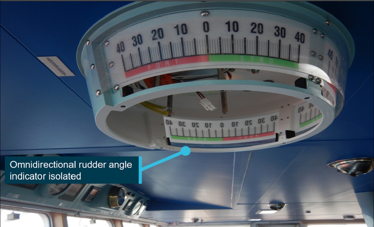
About 50 minutes after departure, the ship was travelling through the harbour channel at 6.8 knots, with one tug connected to its stern and two others closely following, when the pilot observed the lighting extinguish on the rudder angle indicators.
As the ship had begun to swing to starboard, the pilot ordered port rudder, and the tug connected to the ship’s stern to pull the stern to starboard, to counteract the swing.
Recorded data from the ship’s voyage data recorder (VDR) shows the ship subsequently began to swing to port at an increasing rate.
To counteract this port swing, the pilot directed the tug to pull the stern to port, but also ordered the ship’s rudder ‘hard to port’. The ship’s master followed this direction, but then queried it after about 30 seconds. Subsequently, the pilot asked for the rudder to be put hard to starboard instead.
The rudder angle indicator failure meant the pilot and ship’s crew were unable to ascertain the rudder’s position, or whether it was responding to commands.
While the ship’s rate of turn to port reduced after this change, it was not enough to prevent it grounding on the edge of the dredged channel.
“Upon coming into contact with the channel’s edge, the ship’s bow swung away from the side of the channel, back to starboard,” ATSB Chief Commissioner Angus Mitchell said.
“With tugs assisting, the ship was taken out to anchorage for inspection.”
A post-incident inspection found the tracking motor of the bridge’s omnidirectional rudder angle indicator had burnt out, causing a short circuit which tripped the circuit breaker, causing a power outage in all the rudder angle indicators available on the bridge.
An underwater hull inspection identified substantial damage, including holes in the ship’s port side and bottom shell plating, and the failure of the transverse bulkhead between the number 1 and 2 port double-bottom water ballast tanks, allowing flooding between them.
Temporary repairs were conducted, and on 18 May the ship departed on a direct voyage to its discharge port in China. After discharging, it proceeded to the shipyard in Zhoushan, China, for permanent repairs.
As the investigation continues, it will include a review of Port Hedland Pilots’ operating procedures, practices and training regime, as well as analysis of the conduct of the pilotage and the effectiveness of bridge resource management.
It will also include a review of Pilbara Ports Authority’s policies and procedures, and a review of towage practices and procedures in Port Hedland.
Hagen Oldendorff’s steering gear arrangement, controls and indicators will also be assessed, and the ship’s procedures and emergency readiness will also be reviewed.
“Should a critical safety issue be identified during the course of the investigation, the ATSB will immediately notify relevant parties so appropriate and timely safety action can be taken,” Mr Mitchell said.
The interim report notes Pilbara Ports Authority has, since the incident, issued a marine notice requiring that a suitably qualified and competent person stands by in the steering gear room during a ship’s transit of the Port Hedland channel.
“A final report, which will detail analysis and findings, will be released at the conclusion of the investigation,” Mr Mitchell said.
The ATSB is investigating a safe working breach at Ooldea, South Australia, on 1 June 2023, involving Aurizon train 4PM1 and Pacific National train 3SP7.
At about 0835 central standard time, train 4PM1 enroute from Perth to Melbourne called the western points at Ooldea to reverse, in order to enter the crossing loop, in accordance with their authority from Fisher to Ooldea. At about the same time, train 3SP7 made a controlled stop on approach to Ooldea, due to the eastern points enhancer colour light displaying yellow, despite expecting a green light and having authority through that location to Fisher. This meant that there was an overlapping authority for the 84 km section of track from Ooldea to Fisher.
To date, the ATSB investigation has included:
interviewing the network control officer
examining available recorded data
examination of safe working rules and procedures
examination of training documents and records
examination of incident notification data, held by the Office of the National Rail Safety Regulator, from 2012 involving issuing of overlapping train authorities in the Australian Rail Track Corporation train order working territory between Tarcoola (South Australia) and Kalgoorlie (Western Australia).
Australian Rail Track Corporation risk identification and register
risk controls associated with cross-checking and issuing of train authorities in Australian Rail Track Corporation train order working territories.
training curriculum and assessment for network control officers issuing train authorities.
The final report has been drafted and is undergoing internal review to ensure the report adequately and accurately reflects the evidence collected, analysis, and agreed findings.
The final report will be released at the conclusion of the investigation. Should a critical safety issue be identified during the course of the investigation, the ATSB will immediately notify relevant parties, so that appropriate safety action can be taken.
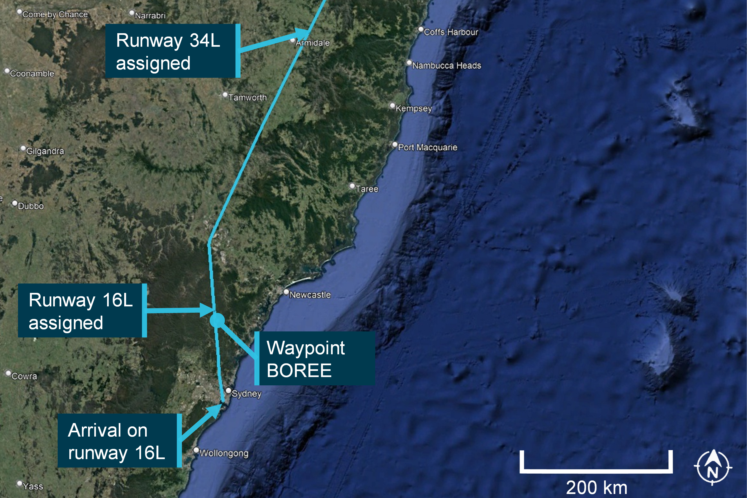
During scheduled passenger flight from Brisbane to Sydney, airliner was cleared for standard arrival for runway 34L at Sydney, which was operating runway 16L at the time.
Error was not detected initially by flight crew, despite ATIS indicating 34L was not operating. It was also not detected by crew or controller during read-back or hear-back.
Sydney Approach controller identified discrepancy and corrected clearance; aircraft landed 16L without incident.
Incident is a reminder that verbal slips can happen at any time, and that pilots and controllers should seek verification when there is confusion or misunderstanding.
A mistakenly-issued standard instrument approach arrival clearance for the incorrect runway at Sydney Airport highlights the importance of pilots and air traffic controllers being alert to verbal slips and seeking verification when there is confusion.
On 19 October 2022, after a Virgin Australia Boeing 737-800 reached top of descent on a scheduled passenger flight from Brisbane to Sydney, the flight crew contacted air traffic control, advising they were maintaining flight level 340.
The enroute controller provided the flight crew a clearance to conduct a standard instrument arrival for a landing on runway 34L in Sydney. The flight crew then read back this clearance to the controller, including runway 34L.
This was despite runway 16L being operational at Sydney at the time, and information available to the crew via the automatic terminal information service (ATIS) indicating runways 16L and 16R were in operation for arrivals and departures.
The ATSB’s investigation of the incident found the incorrect clearance was verbally communicated, and not identified, likely due to momentary interference of related, coinciding information about the assigned flight level (FL 340) and the runway (34L).
“This error was not identified by the enroute air traffic controller or the flight crew during the read-back or hear-back,” ATSB Director Transport Safety Stuart Macleod said.
“However, the information entered into the air traffic management system was correct, and when the crew transferred to Sydney Approach, the approach controller identified the error and rectified it well before an undesirable state for landing had the opportunity to develop.”
Once the approach controller had established the correct runway clearance, the crew performed an uneventful landing on runway 16L.
Mr Macleod said the incident is a reminder to pilots and air traffic controllers that verbal slips can happen at any time, and are less likely to be detected when there is a high degree of similarity between the presentation of simultaneous, related information, while performing a familiar and repetitive action.
“Slips in verbal communication can pose a threat to safe operations if the content of the message is inaccurate, and then not identified during the read-back or hear back process.
“In this case, the read-back and hear-back procedure was the opportunity for both parties to detect the error before it propagated further.”
Freight train derailed at a section of track which had been damaged by floodwaters
The risk of flooding in the area the derailment occurred was not adequately identified or addressed by the track manager;
Limitations in network procedures for monitoring and responding to extreme weather events meant that network users were not aware of the extent of the severe weather event, and had not been advised of an alert issued prior to the accident;
Several safety actions have been taken since the accident, but two recommendations have been made for further action in the final report.
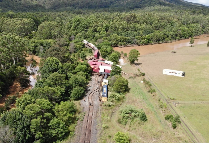
A systemic transport safety investigation has highlighted a range of issues related to risk management, and the identification and response to extreme weather by the operators involved in a significant freight train derailment on the New South Wales north coast.
In the early hours of 25 February 2021, a southbound Pacific National freight train derailed near Nana Glen, where floodwaters had built up and overtopped the track, washing away ballast.
Rolling stock, freight and a large section of railway were significantly damaged, one of the two crew on board the train sustained minor injuries, and the line was closed for nine days.
An investigation into the accident was conducted by the Office of the Transport Safety Investigations (OTSI), which undertakes rail investigations in NSW on behalf of the Australian Transport Safety Bureau.
It found that the track manager ARTC had not adequately identified or addressed the risk of flooding along the rail corridor or the culvert near the accident site, as well as numerous others along the Mid North Coast.
“ARTC could not reliably determine the risk of flooding along the section of rail corridor where the accident occurred, and it had not undertaken formal assessments to determine the need for, or the locations of, remote weather monitoring stations to detect extreme weather events,” OTSI Chief Investigator Dr Natalie Pelham said.
“Extreme weather events pose a significant risk to the rail network and are likely to increase in frequency and intensity in the future.
“These events can affect the integrity and exceed the design of rail infrastructure so infrastructure managers must ensure they have effective systems in place to identify, assess and manage the risks so that trains are prevented from entering sections where the design of the infrastructure will be exceeded.”
The investigation found network users were not aware of the extent of the severe weather event and had not been advised of an ‘amber alert’ issued prior to the derailment.
“Although ARTC had procedures in place to monitor and respond to extreme weather events, the process had significant limitations,” Dr Pelham said.
“The mechanism for alerting operational personnel, which was an email, did not ensure that alerts were always identified, or actioned, in a timely manner. Additionally, the actions specified were insufficient to respond to escalating rainfall and flooding events, both forecast and actual.”
The investigation also found that the weather alerts issued by the weather service provider did not reliably reflect the data and frequency of ARTC’s extreme weather monitoring procedure or the service agreement.
Separately, the report notes that two trains which had earlier passed through the derailment site – including an XPT passenger service which passed through 27 minutes before the derailment – had not reported a condition affecting the network. These drivers had not been provided with guidance for operating through severe weather conditions and floodwater. And, although visibility was severely affected, the drivers did not slow down.
“This reduced their opportunity to sight signals and potential obstructions, and to safely traverse level crossings,” Dr Pelham noted.
Since the accident, ARTC has taken several safety actions, including installing 20 more remote weather stations along the Telarah to Acacia Ridge corridor, developing and implementing a work instruction for the management of flooding and special locations, and issuing a safety bulletin increasing rainfall and flooding alerts by one category.
“We welcome these and other actions undertaken by the network operator, however our report also makes two recommendations for further safety action to be undertaken by both ARTC and Pacific National,” Dr Pelham said.
The recommendations stem from the same finding – that neither ARTC nor Pacific National provided guidance for train crew to respond to extreme wet weather events or floodwater in the rail corridor.
“There was no guidance for when trains should stop or report if there was water on the track formation, covering the ballast, sleepers or the rail,” Dr Pelham explained.
“Both rail infrastructure managers and rolling stock operators must ensure they provide guidance and operational procedures to enable consistent responses to conditions that may adversely affect the integrity of rail infrastructure and operational safety.”
In the early hours of 25 May 2023, the container ship CMA CGM Puccini was departing the port of Melbourne under the conduct of a harbour pilot. As the ship continued downriver, main engine power was increased and the rudder used to remain in the centre of the channel.
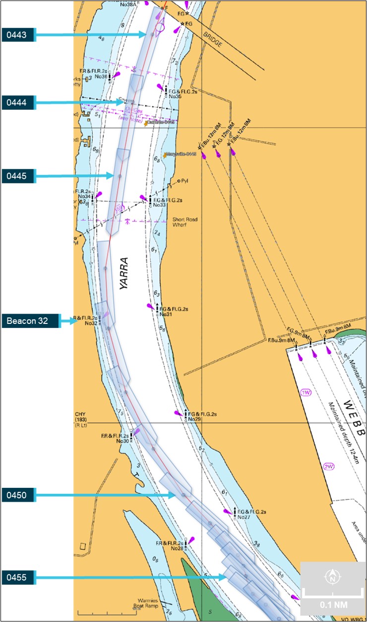
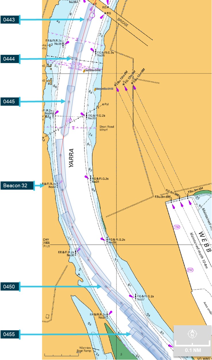
Just after 0444, the bridge team noticed that the rudder was not responding to the helm ordered, with the ship turning wide in the channel as attempts were made to verify and restore steering. A few minutes later, the ship closed on the western edge of the channel and contacted navigation beacon 32. The ship was then slowed and returned towards the middle of the channel. By 0454, it was stabilised in the channel with tug assistance and then conducted to nearby Webb Dock. The ship suffered minor hull paint damage and beacon 32 was significantly damaged.
What the ATSB found
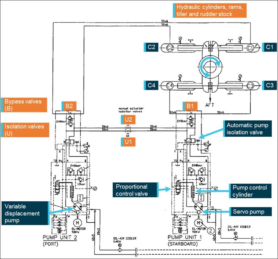
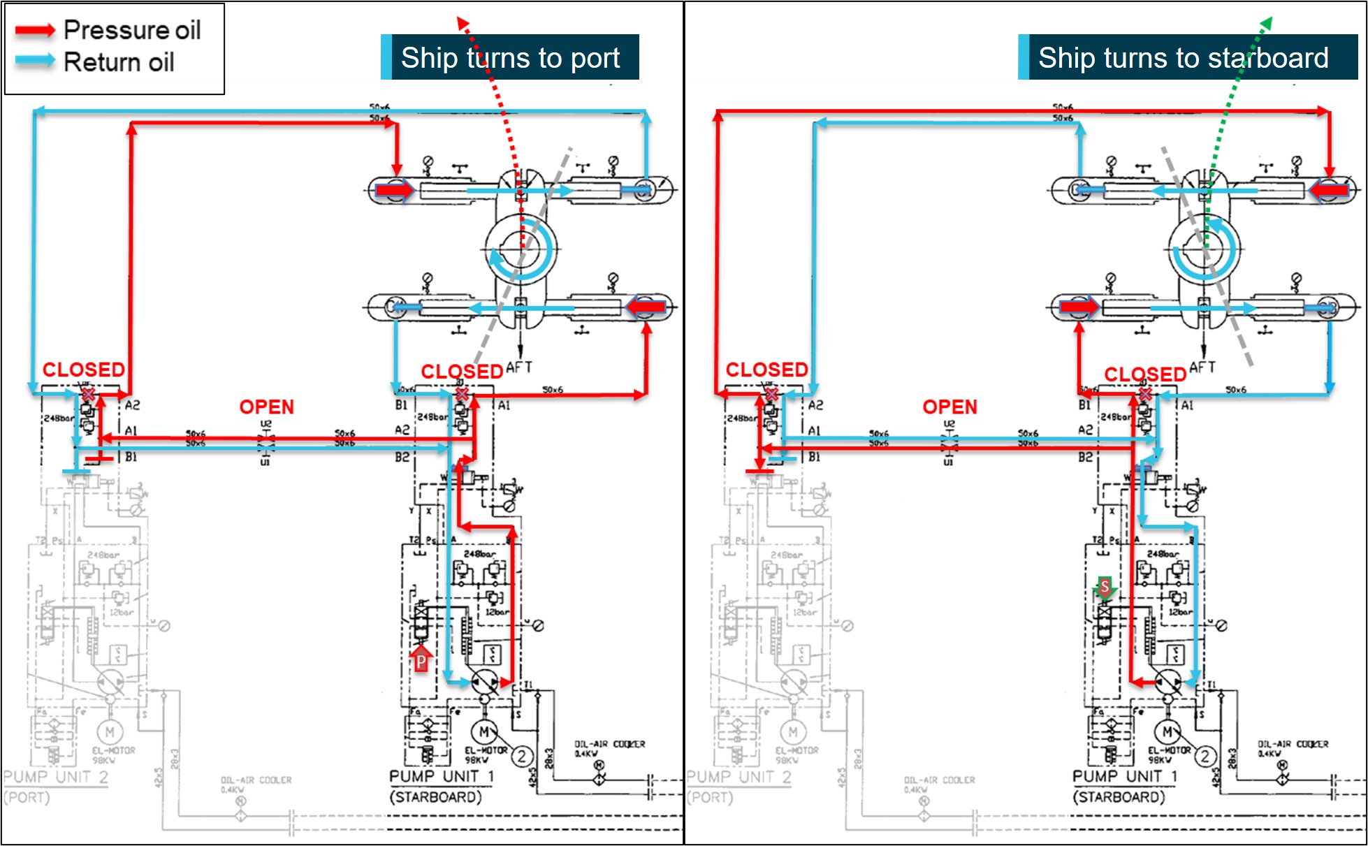
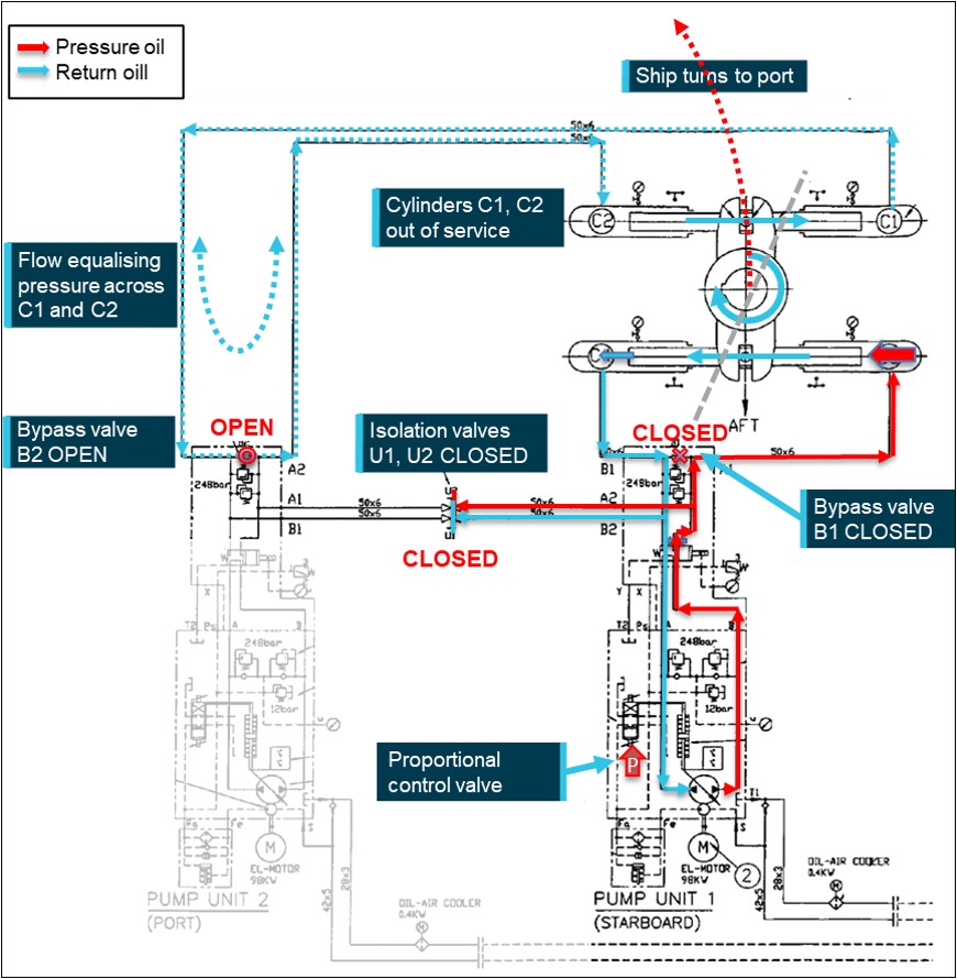
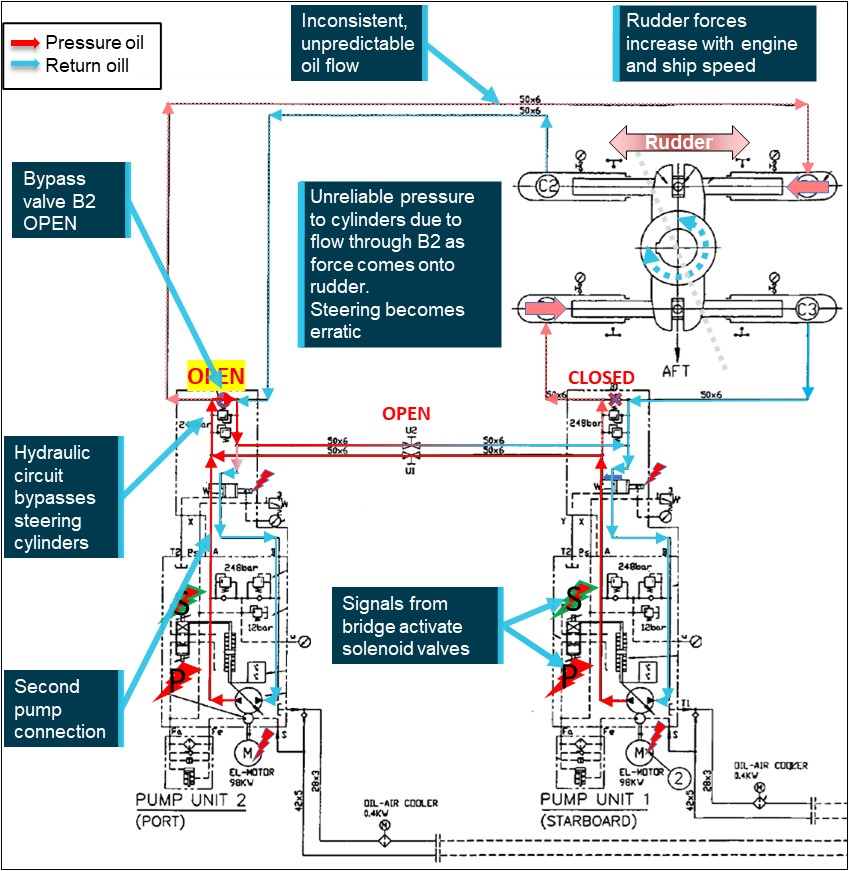
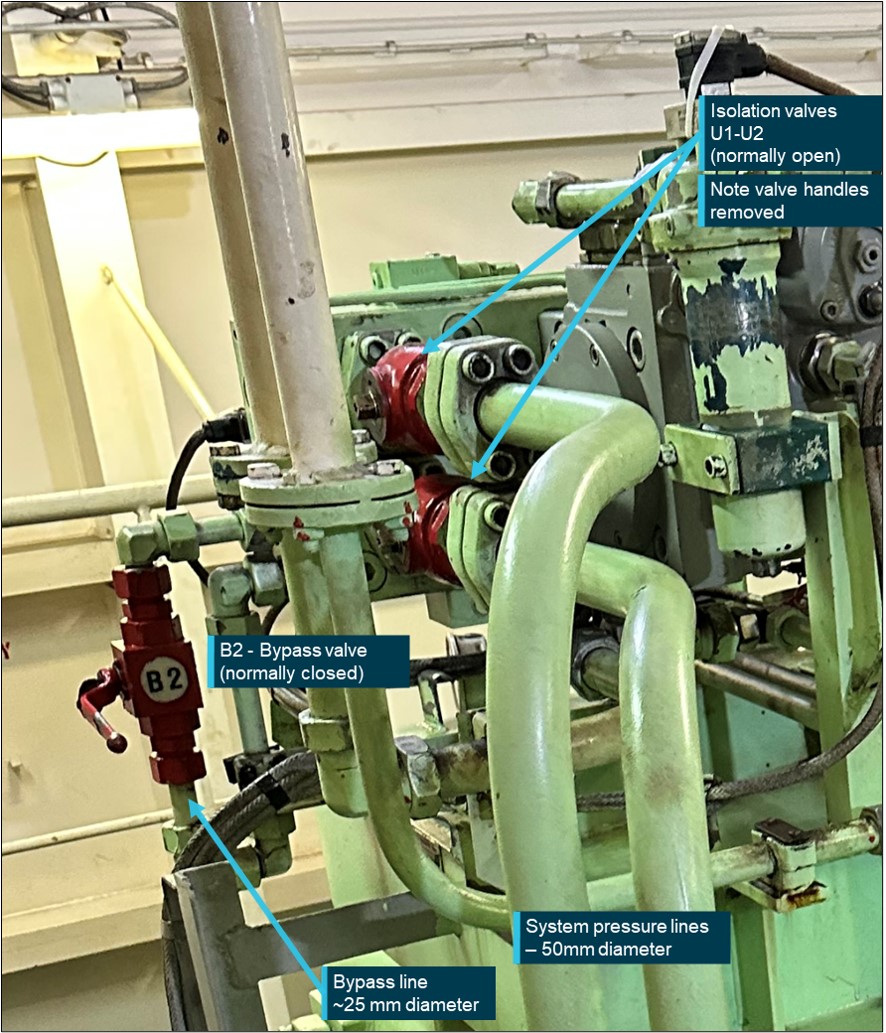
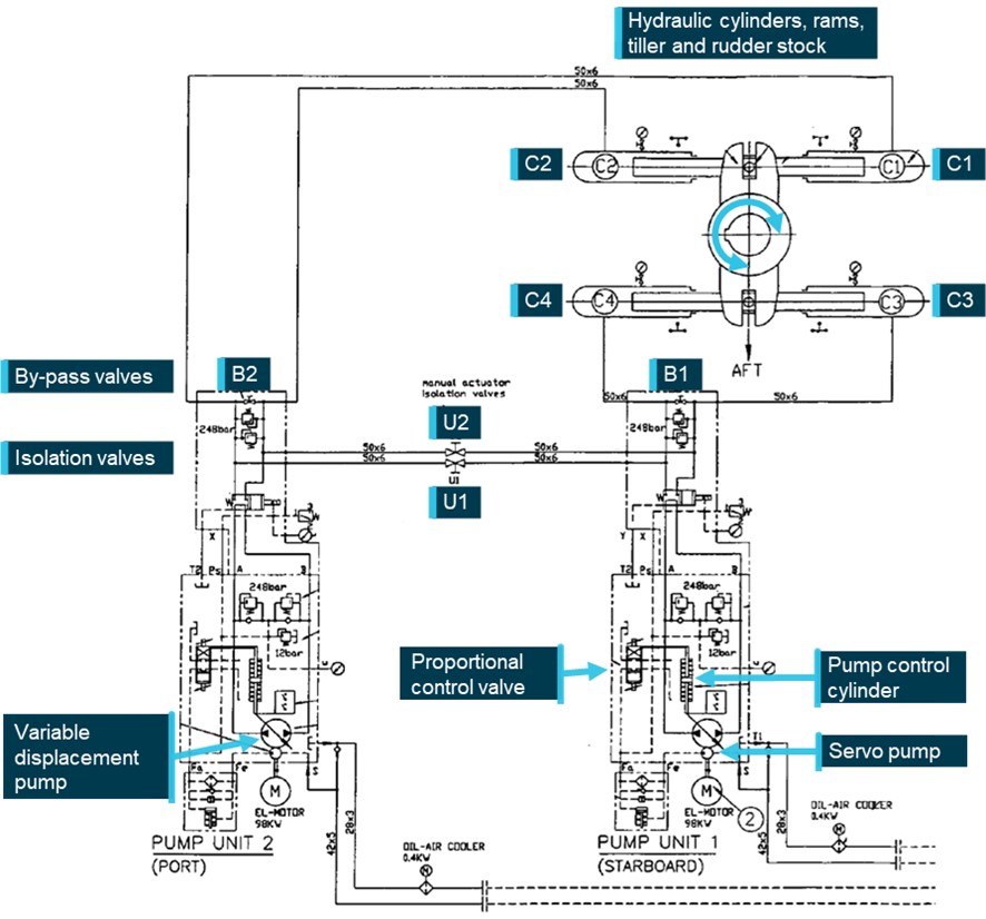
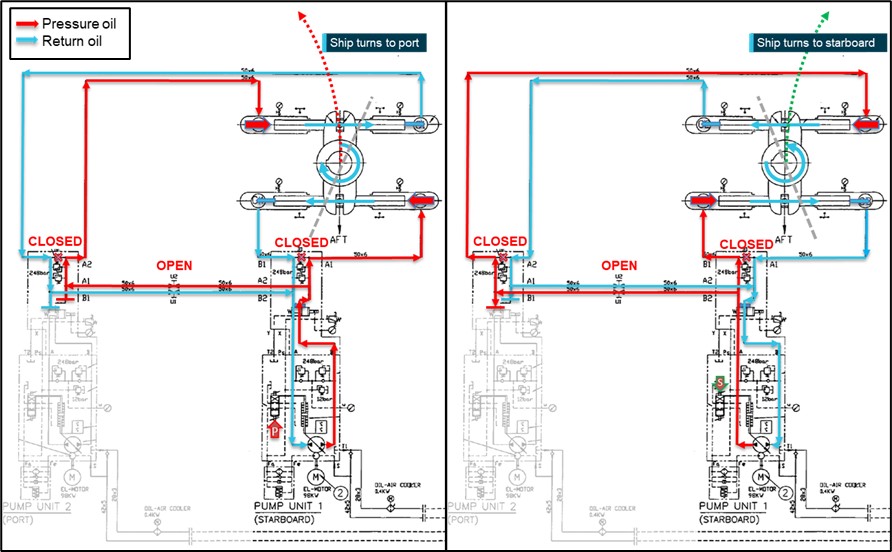
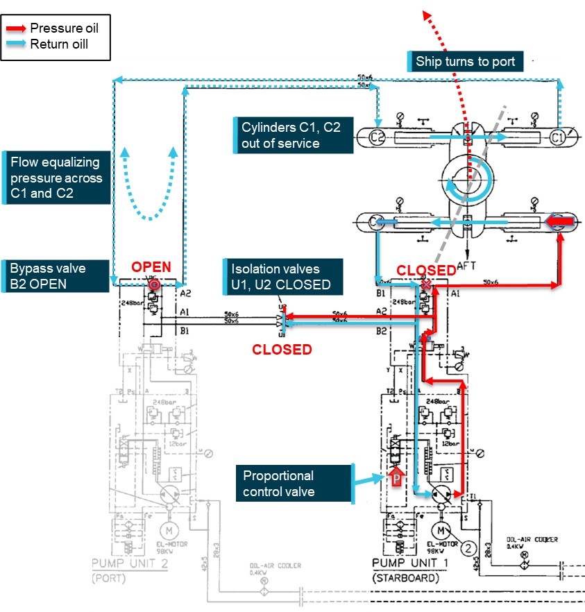
The investigation found that one of the steering hydraulic pump bypass valves had been left open following earlier testing. In this condition, the steering operated sufficiently well with minimal load on the rudder to pass pre-departure visual inspection. However, when the hydrodynamic loads on the rudder increased, with increasing ship’s speed and rudder movements, the open bypass valve allowed leakage of hydraulic oil and system pressure around the pump leading to erratic response of the rudder.
The investigation also found that several officers on board were not as proficient with steering gear operation and change of control modes as was required by regulations. Further, steering terminology used on board and within the CMA CGM fleet was not clearly and explicitly defined – official fleet terminology was ‘steering gear failure’ and did not recognise common industry terms such as ‘emergency’ and ‘local steering’.
Consequently, unnecessary procedures, which included reconfiguration of steering hydraulics, were followed when using and demonstrating steering from the steering compartment. Following one such demonstration, one of the bypass valves was not closed.
Further, the possible confusion between common-use and official CMA CGM terminology existed fleetwide and was not clarified in the procedures or other guidance. This increased the risk of a similar unnecessary, and incorrect, configuration of the steering machinery occurring elsewhere in the fleet.
What has been done as a result
In addition to other investigations, CMA CGM commissioned the steering gear manufacturer to conduct independent tests of the steering gear and its operation. In late 2023, CMA CGM notified all ships in its fleet of the incident in the regular fleet circular. Several months later, all ships and the company’s designated persons ashore were reminded of this incident and to follow the steering gear failure procedure.
In order to fully address the safety issue, CMA CGM has advised the ATSB that its fleetwide ‘steering gear failure’ procedure has been amended and titled as the ‘emergency steering procedure’. The amended draft procedure defines emergency steering and clearly outlines the change of steering control from the navigation bridge to the steering gear room. The draft procedure is to be assessed by the company’s technical committee before it is finalised for an expected fleetwide implementation in March 2025. The ATSB will monitor the safety issue and reassess its status once it is implemented.
Ports Victoria has updated the harbour master’s directions for Melbourne to strengthen towage requirements in the Yarra River and include advice for the crews of ships that experience a main engine or steering failure while transiting port waters.
Safety message
All seafarers are reminded that ‘any loss of steering may imperil the safety of the ship and life at sea’. Steering is a vital ship system and any source of possible confused or incorrect operation, especially in an emergency, is a risk which should be minimised. Unclear or ambiguous operating instructions and terminology should be corrected as soon as they are identified.
Seafarers and shore management are reminded of the importance of ensuring shipboard personnel understand and are competent in how the ship’s steering machinery and control systems operate. Ship’s officers in particular should be aware of the correct procedures:
for changeover of steering control from the navigation bridge to the steering gear compartment
to follow in the event of steering gear failure, especially failure of remote steering from the navigation bridge and during ship manoeuvring, such as when entering or departing ports.
The occurrence
Arrival Melbourne
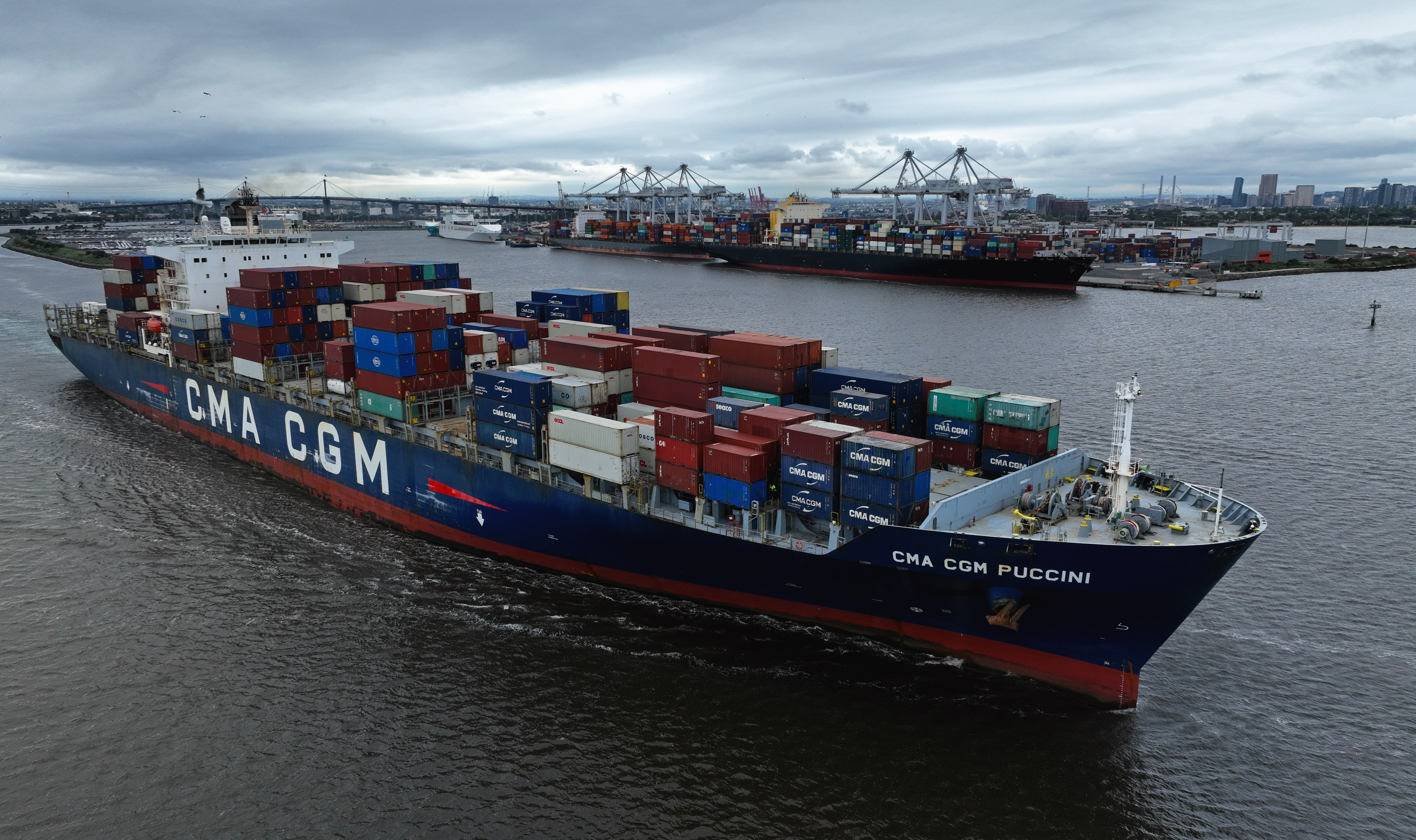
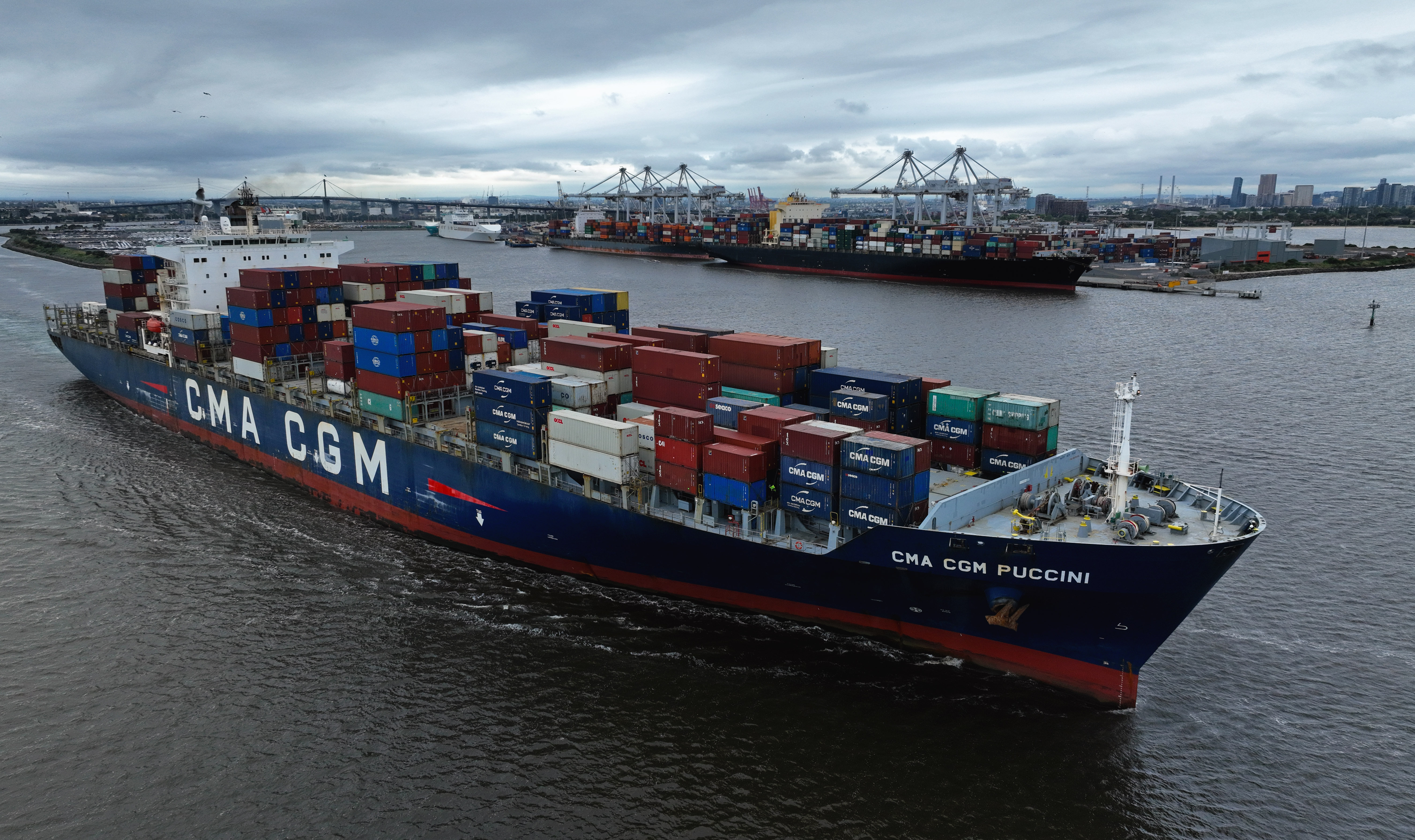
At 0900 local time on 23 May 2023, a pilot boarded the 277.3 m, fully cellular container ship CMA CGM Puccini (Figure 1) for pilotage into the port of Melbourne.[1] Pre-pilotage checks involved a test of machinery and equipment, including the steering gear. The ship was safely berthed at Swanson Dock at 1330 and cargo operations commenced soon thereafter.
Figure 1: CMA CGM Puccini
Source: Owen Foley
The following day, the ship was attended by an Australian Maritime Safety Authority (AMSA) surveyor to conduct, among other things, a port State control (PSC) inspection. As part of the PSC inspection, emergency operation of the steering was conducted with the surveyor in attendance in the steering gear room. The ship’s chief engineer, chief mate, electro‑technical officer and the third engineer were there to carry out or oversee the test.
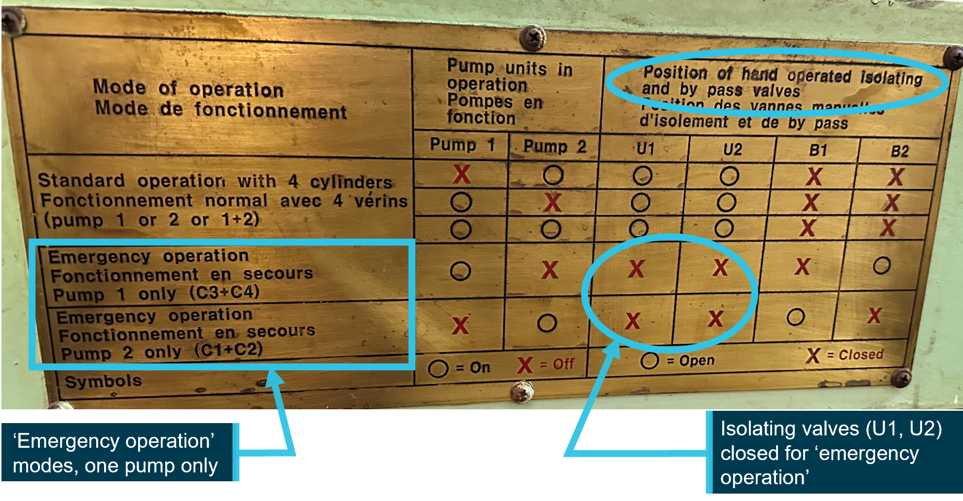
The test included changeover of steering control from the navigation bridge (bridge) to the steering gear room followed by demonstration of local operation of the steering gear. The third engineer configured the steering machinery for local operation, including starting one steering gear pump and opening the bypass valve on the other pump (stopped). Control of the rudder was then demonstrated by manual operation of the running pump solenoid valve. Both pump systems were tested in local control. The steering tests were completed to the satisfaction of the surveyor.
Steering failure
The ship’s remaining stay at the berth was routine with nothing significant or unusual reported. At 0300 on 25 May 2023, the second mate on watch on the bridge called the engine control room (ECR) and gave one hour’s notice to ready the main engine for departure. The second mate then called the third mate and the deck cadet to assist with preparations for departure, including steering gear checks. The deck cadet was sent to the steering gear room to witness rudder movement and repeat its response to the third mate who operated the steering from the bridge steering console. At 0322, rudder operation to maximum angles (hard over on both sides) was checked using one, then the second pump, separately, and then both together. The steering gear was recorded to have been tested as required by regulations.
At 0346, the main engine was tested and the pilot boarded at 0350. The bow thruster was tested and, at 0354, the master-pilot exchange was conducted on the bridge. On the bridge for departure were the pilot, master, chief mate, deck cadet and an able seafarer at the helm. In the engine control room were the chief engineer, third engineer (the duty engineer) and the electro-technical officer.
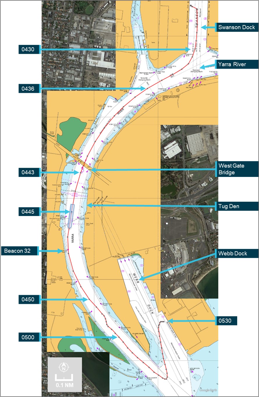
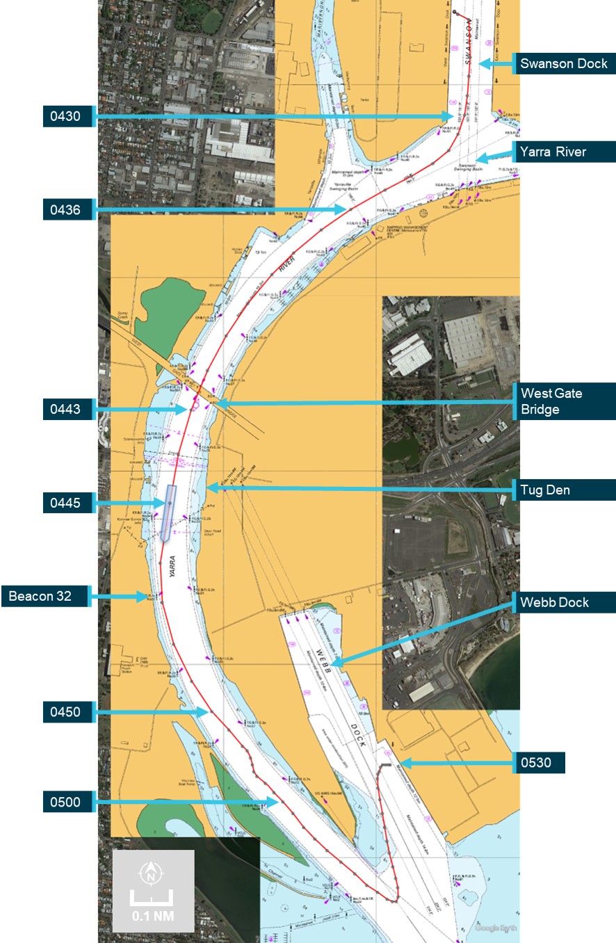
Weather conditions for the departure were clear skies and good visibility with winds from the north‑north-east at force 4.[2] The tide was flooding, with high water expected at 0545. Just after 0405, 2 tugs were made fast (one forward, one aft) and by 0418 all mooring lines had been let go. CMA CGM Puccini was then manoeuvred out of Swanson Dock, through a 60° turn to starboard and into the Yarra River[3] (Figure 2).
During the turn to leave Swanson Dock, the master and chief mate noticed that the rudder response appeared sluggish, as if only one steering pump was running (both pumps were operating). Neither raised their observations with each other, or the pilot, and there were no alarms to indicate a pump had stopped or other abnormal condition.
By 0436, the ship was moving along the channel in the river, both tugs had been dismissed and the main engine was increased to slow ahead. At 0442, the ship passed under the Westgate bridge, about 1 mile[4] downriver of Swanson Dock. The ship’s speed was 6.6 knots[5] with a rate of turn of 4° per minute to port. At 0443, the main engine speed was increased to half ahead[6] and more rudder ordered (port 10)[7] to increase the rate of turn. To maintain the turn rate, the pilot then gave helm orders (rudder) of port 5 (0443:34), followed by port 10 (0443:54).
Soon thereafter (0444:03), the pilot noticed that the rudder angle indicator was showing that the rudder was midships and repeated the earlier port 10 order. The able seafarer steering the ship by hand (helmsman) advised that the helm (steering wheel) was at port 10. This exchange drew the attention of the master and chief mate, who both verified that the helmsman had correctly followed the order.
The helmsman informed them that the rudder was not responding to the wheel. By that time, the chief mate had moved to the steering console to investigate and observed that the rudder moved to port 5 and then slowly to starboard 5. The ship, with its speed increasing and rate of turn diminishing, tracked toward the western edge of the channel and beacon 32. At the time, the ship’s speed was 7.7 knots, it was turning to port at 3° per minute and was 7 m to starboard of its planned track.[8]
Figure 2: CMA CGM Puccini’s track from Swanson Dock to Webb dock
Position markers indicate location of ship’s main mast, about 181 m from the bow (atop the wheelhouse). Source: Australian Hydrographic Office, Google Earth, annotated by the ATSB
Further helm orders and helm movement indicated that the rudder was not responding. The master remained at the manoeuvring console and, after confirming with the pilot, reduced the main engine speed to slow ahead, and then (0444:50) to dead slow ahead. The master confirmed that the bow thruster was operational and suggested further slowing the ship (to less than 5 knots) to make the thruster effective.
At about this time, the master called the ECR and asked for the steering gear to be attended immediately. In response, the chief engineer called the electro-technical officer, who had returned to the accommodation, and directed them to go to the steering gear room. The electro-technical officer collected a radio and soon thereafter was informed by the master (via radio) that emergency steering was required.
Meanwhile, the chief mate and the helmsman went about fault finding and checked steering control modes, including non-follow-up (NFU).[9] Their attempts were unsuccessful and the rudder remained unresponsive to control inputs. At 0445, the pilot contacted Melbourne vessel traffic service (VTS) and reported that the ship had lost steering and requested immediate tug assistance. Both tugs that had been dismissed earlier were directed to return to the ship.[10]
The pilot then instructed the helmsman, using NFU, to put the rudder hard to port if and when possible. At 0445:26, the main engine was stopped. CMA CGM Puccini’s speed was 8 knots and it was turning to port at 1° per minute. The ship was now 26 m to starboard of track with its bow about 32 m from the 10 m depth contour (the edge of the navigable channel).
Shortly thereafter, the rudder was observed to move to 35° to port (wheel was hard to port). The main engine was restarted, and the bow thruster set full to port. At 0445:30, the ship’s rate of turn to port suddenly increased as its bow closed with the side of the channel. By 0445:44, the ship’s speed had reduced marginally (to 7.9 knots) and its swing to port had increased to 13° per minute, with the bow now less than 20 m from channel's edge. The pilot ordered the rudder midships and immediately after to starboard 20 to reduce the increasing swing to port with the aim of avoiding the ship’s stern closing and contacting the western bank or shoals (Figure 3).
At 0446:12, the ship was 58 m to starboard of the planned track with significant headway (7.7 knots) and turning rapidly to port (20° per minute) with the bow only about 12 m from the 10 m depth contour and shoal water. Hard starboard rudder and bow thruster full starboard were ordered and the rudder observed to move to about 20° to starboard. However, as CMA CGM Puccini was swinging to port, its stern was swinging in the opposite direction (to starboard) and contacted beacon 32. The impact resulted in damage to the beacon, which canted over about 20° from the vertical (cover photo). The ship’s side paintwork was scratched due to scraping against the beacon.
Following the contact, the helmsman advised that the wheel was hard starboard (as ordered) but the rudder angle was only 5° to starboard. At 0447, the ship’s speed had decreased to 7.2 knots and its swing to port had reduced (now 13° per minute). The ship was 67 m to starboard of track as the curve of its stern passed across the 10 m depth contour.
Meanwhile, both tug masters had been in contact with the pilot and the closer of the 2, SL Daintree, was instructed to make fast on the port shoulder. Svitzer Marysville was instructed to make fast aft through the centre lead. The ship’s speed was reducing (6.9 knots at 0447:26) and its turn rate was unchanged with the bow thruster kept full starboard to arrest the swing.
The master confirmed that steering control had not been restored. The ship’s bow was now in the middle of the channel and the stern clear of the channel’s edge. The engine was ordered dead slow astern at 0448:56, followed soon after by slow astern. The master ordered the rudder to be put midships and a series of astern engine movements reduced the ship’s speed to 4.5 knots.
Source: Australian Hydrographic Office, Google Earth, annotated by the ATSB
At about 0451, the bow thruster was stopped and tug orders given to arrest CMA CGM Puccini’s headway. The ship had started swinging to starboard and at 0451 cleared the eastern side of the channel with its bow about 15 m from the channel edge. Headway had reduced to 2 knots and the ship continued to move away from the eastern bank, now turning to starboard at 3° per minute.
At 0454, with the ship temporarily stabilised along the centre of the channel, the pilot discussed moving the ship to Webb Dock (about 5 cables[11] downriver) with the ship’s bridge team and the tug masters. Once they had agreed on the proposed plan, the pilot advised VTS about the recovery plan.
Meanwhile, efforts to engage emergency steering locally from the steering gear room were ongoing with the electro-technical officer and the third engineer there. At 0456, they notified the bridge that the steering gear was being reconfigured for emergency steering.
By this time, the ship’s speed had decreased to about 1 knot and the 25-knot wind from the north‑north‑east was turning the ship to port. The pilot ordered dead slow ahead and, with the tugs assisting, began moving the ship towards Webb Dock. Shortly after, emergency steering was engaged and rudder orders given via the dedicated emergency telephone in the steering gear room.
At 0541, CMA CGM Puccini was made fast alongside Webb Dock East berth 4 without further incident. At the completion of movements, the electro-technical officer and third engineer reconfigured the steering from emergency to normal.
Inspections
Later that day various parties attended CMA CGM Puccini to inspect the ship’s steering gear. This included personnel from AMSA, the ship’s manager’s (CMA CGM), classification society (Bureau Veritas (BV)) and 2 independent service engineering companies to fault-find and test the steering gear. The ship was detained (by AMSA) as reasonably assumed as ‘being unseaworthy due to failure of steering and possible damage to the hull.’
An underwater hull examination by divers the following day, 26 May, found no hull damage. Additionally, the ship’s engineers inspected and tested the steering gear and systems and changed the hydraulic oil filters. Nothing abnormal was found.
Despite multiple, extensive inspections and tests by the ship’s engineers and the service engineers, the erratic behaviour of the steering gear could not be replicated and no fault was identified.
Later on 26 May, AMSA received confirmation from BV that the steering gear had been tested, no defect found and nor had there been any hull damage. Subsequently, AMSA released the ship from detention.
At 2028 that day, the ship was issued its port clearance and preparations were made to depart Melbourne the next morning.
Departure Melbourne
At 0630 on 27 May 2023, one hour’s notice was given to the engine room for departure and, at 0640, the steering gear was tested in bridge control without issue. At 0700, the pilot (the same pilot as during the incident) boarded. The master-pilot exchange was completed, and, among other things, a steering failure risk assessment prepared for this pilotage was discussed. Additional precautions prescribed by the Melbourne harbour master were in place and included in the risk assessment. These included having the electro-technical officer and an able seafarer standing by in the steering gear room for the pilotage.
CMA CGM Puccini’s unberthing and departure into Port Phillip Bay were completed without incident. Once sufficient sea room was available, the ship was taken out of the channel into open water in the bay, its speed increased to 16 knots and the steering tested with various rudder movements. The steering gear operated normally.
At 1150, the ship re-entered the channel to depart Melbourne. The pilotage continued without incident, the pilot disembarked at 1357 and the ship set course for Port Botany, New South Wales.
Melbourne to Brisbane
On 28 May, in preparation for arrival to Port Botany, and to meet Port Authority of New South Wales’ arrival requirements, CMA CGM Puccini’s crew tested the steering gear. The chief mate, duty mate, deck cadet, bosun and off-duty able seafarers were in the steering gear room. The master and duty able seafarer were on the bridge for the test.
These tests included changing over to emergency steering (local control). The chief mate reconfigured the steering machinery as previously shown by the third engineer. When an attempt to steer the ship was made, the steering began to behave erratically and did not respond exactly to the helm orders. At this time, the newly‑joined second engineer arrived to observe the tests. The engineer noticed that the system’s hydraulics were incorrectly configured and asked the chief mate to close the bypass valve of the (non-running) pump. Once the valve was closed, there were no further erratic rudder responses.
At 1912 that day, a pilot boarded. The pre-arrival declaration from the master to the Port Authority confirmed that the steering had been tested but made no mention of the Melbourne incident. The pilot had been made aware (informally) of the incident in Melbourne, though not of its nature, extent or resolution. Hence, during the master-pilot exchange, the pilot queried the master about the incident but received no additional information. The master, however, did inform the pilot that the steering gear room was being attended by the electro-technical officer and an able seafarer for the duration of the pilotage. With 2 tugs in attendance (the usual for such pilotages), the pilot conducted the ship into Port Botany. After it was berthed, the pilot submitted a report about the steering matter to the harbour master.
Subsequently, on 30 May, the ship departed Port Botany for Brisbane. The steering had been tested at 0450, with nothing abnormal observed, and at 0545 the (same) pilot boarded. As a result of the pilot’s earlier incident report, an additional tug was assigned for departure. The electro‑technical officer and an able seafarer stood by in the steering gear room during the pilotage, which was completed without incident and, at 0645, the pilot disembarked.
At 0630 on 1 June, the ship’s steering gear was tested before entering Brisbane and functioned normally. The electro-technical officer and an able seafarer again stood by in the steering gear room during the pilotage and the ship berthed without incident at 1318.
On 2 June, ATSB investigators attended the ship and as part of this investigation, inspected the steering gear and conducted tests and simulations. No defects with the steering gear systems were found.
CMA CGM Puccini departed Brisbane on 4 June without incident.
Context
CMA CGM Puccini
CMA CGM Puccini was built by Samsung Heavy Industries (Korea) in 2004. At the time of the incident, it was owned by CMA CGM, France, managed and operated by CMA CGM International Shipping, Singapore, and classed with Bureau Veritas (BV). The ship’s trading in recent years has regularly included Australian ports of call.
The ship had a length overall of 277.30 m and a beam of 40.0m. It had a gross tonnage[12] of 65,730 and deadweight[13] of 73,234 DWT at a draught of 14.526 m. It could carry 5,782 TEU including 3,168 on deck and 500 refrigerated containers. On arrival into Melbourne the ship was carrying 4,337 TEU (2,860 containers) and on departure 3,552 TEU (2,354 containers).
The ship was fitted with a Hyundai MAN B&W 10K98 MC-C main engine that delivered 57,075 kW through a fixed‑pitch, four-bladed, 8.70 m diameter, right-handed propeller. The ship’s manoeuvring speeds (in loaded condition) were 6.2 knots at dead slow ahead, 8.3 knots at slow ahead and 12 knots at half ahead.
CMA CGM Puccini was fitted with a semi-balanced, spade type rudder with an effective area of 52.18 m² and standard maximum working angles of 35° to port and starboard (see the section titled Steering gear for further details). The ship was also fitted with a 2,000 kW bow thruster. The bow thruster became ineffective once the ship’s speed increased to 5 knots.
Crew
CMA CGM Puccini had a multinational crew of 23 Romanian, Sri Lankan and Malaysian nationals. All were appropriately qualified and endorsed for the positions they held.
The deck department consisted of the master, 4 deck officers (chief mate, second mate and 2 third mates) and a deck cadet. The chief mate did not keep a navigation watch. The deck crew consisted of the bosun, 3 able seafarers and an ordinary seafarer.
The engineering department consisted of the chief engineer, 3 engineers (second, third and fourth engineers), an electro-technical officer, a reefer engineer (for refrigerated containers) and a refrigeration assistant, plus a fitter and 2 oilers.
The master was sailing with a Romanian master’s qualification issued in 2023. They had joined the ship for this posting in February 2023.
The chief mate was sailing with a Romanian chief mate’s qualification issued in 2018. Prior to joining CMA CGM Puccini as chief mate in 2021, and since 2016, they had sailed as second mate in the CMA CGM fleet of container ships. This was their fourth contract as chief mate on CMA CGM Puccini and they had joined in February 2023.
The chief engineer was an experienced seafarer with many years in the position. At the time of the incident, they were sailing with a Romanian chief engineer qualification issued in 2017. Recent experience, since 2017, had all been on CMA CGM container ships. This was the chief engineer’s first time on CMA CGM Puccini after their previous 4-month posting as chief engineer of the sistership CMA CGM Chopin and they had joined CMA CGM Puccini in April 2023.
The second engineer was sailing with a Romanian chief engineer qualification issued in 2016. They had sailed on 4 ships since 2021, all as second engineer, after spending time ashore in a CMA CGM shore management role. Recent experience was all on CMA CGM container ships. The second engineer joined in Melbourne, 2 days before the incident.
The third engineer was sailing with Sri Lankan engineering qualifications issued in 2017. Since 2017, the third engineer had sailed on 7 ships, all as third engineer. They joined the CMA CGM container ship fleet in 2018. This was the third engineer’s first posting to CMA CGM Puccini with a previous posting (9 months) as third engineer in its sistership CMA CGM Bellini. The third engineer joined CMA CGM Puccini in March 2023.
The electro-technical officer had Romanian qualifications as an electrical officer obtained in 2016. This was their tenth ship (all container ships) since 2016. The electro-technical officer joined CMA CGM Puccini in February 2023 and had had a previous 5‑month posting to the ship in 2022.
Pilot
The pilot assigned to CMA CGM Puccini first went to sea as a deck cadet in 2002 and went on to obtain an Australian master class 1 certificate in 2012. After working in several positions at sea and ashore, the pilot commenced training as a Melbourne marine pilot, with Auriga Pilots, in 2018. They obtained an unlimited pilot’s licence in 2022 and had piloted CMA CGM Puccini, and its sisterships, on multiple occasions, including with the master at the time of the incident.
Steering gear
The normal method of steering a ship is from the bridge (that is, remotely). The generally accepted use of the term ‘emergency steering’ refers to the method of steering when remote steering from the bridge fails. On most ships, including CMA CGM Puccini, emergency steering is local steering from the steering gear room.
Description
CMA CGM Puccini was fitted with a Samsung-Hatlapa,[14] Teleram type R4ST 700, 2-ram (300 mm diameter), 4-cylinder Rapson-slide electro-hydraulic steering gear with 2 identical power units. Rudder angle limits were set at 35° by electrical limit switches and 37° by mechanical stops.
The steering gear comprised 2 identical constant‑speed electric motors driving variable delivery piston pumps in a closed-loop hydraulic system (system relief valve setting was 250 kg/cm²). Each pump supplied bi-directional, infinitely‑variable hydraulic oil flow to/from 2 cylinders connected to a ram. This ram was then attached through a Rapson‑slide mechanism to the tiller arm, rudder stock and rudder. Pump flow rate and direction were controlled via a spring-loaded, self-centring pump control cylinder mounted as part of the pump housing, connected to the pump swashplate mechanism.
Each electric motor also drove a smaller, hydraulic auxiliary servo pump which provided 25 kg/cm² control oil to the machinery. An electric solenoid‑operated hydraulic proportional control valve altered control oil flow to/from either side of the pump control cylinder to adjust the swashplate angle and oil flow rate and direction at the pump, as required. The rudder position was thereby changed by altering the rate and direction of oil flow to or from the cylinders connected to the tiller (Figure 4).
Each pump was separated from the hydraulic circuit via an electrically‑operated automatic pump isolation valve. Under normal conditions, when the pump motor started, its automatic pump isolation valve operated and connected the pump oil lines to the greater hydraulic circuit. Both pump proportional control valves received signals from the control system (signal from the bridge steering console), which allowed both pumps to be operated in parallel supplying pressurised oil to the system. With 2 pumps running the system would respond more quickly.
Figure 4: Steering gear hydraulic diagram
Source: CMA CGM, annotated by the ATSB
Other ancillary components, such as oil expansion and storage tanks, oil filtration and cooling systems and electrical control, switching and monitoring completed the steering machinery.
Hydraulic pump unit 1 (starboard) was connected to cylinders C3 and C4 and pump unit 2 (port) to cylinders C1 and C2. Manually operated valves were fitted in the hydraulics systems to allow flexible operation of the system:
pump bypass valves (B1 and B2) provided connection between individual pump suction and discharge lines to allow oil flow between cylinders, across a (non-running) pump. The valves were painted red and had their valve handles fitted.
isolation valves (designated U1 and U2) separated the 2 hydraulic circuits. The valves were painted red and the valve handles had been removed and were located adjacent to the steering gear in an area marked ‘Tools for emergency steering’. The valve handles were to be refitted and the valves operated as part of the ship ‘Steering gear failure with oil leakage’ procedure.
Brass plaques with operating instructions, a block diagram of the system and the valve position status matrix were permanently mounted adjacent to the steering machinery. A copy of CMA CGM Puccini’s steering gear failure procedure was mounted and available at the steering gear.
Normal operation
During normal operation either one or both pumps were running, supplying all 4 cylinders. Isolation valves (U1 and U2) were open, pump bypass valves (B1 and B2) were closed (Figure 5).
Figure 5: Single pump, 4-cylinder, normal operation of steering, to port and starboard
Single pump (#1) operation shown; diagram is similar for pump 2. Isolation valves (U1, U2) open, pump bypass valves (B1, B2) closed. Signal is received into the proportional valve altering the flow rate and direction of oil at the pump. System response will be improved (faster) with second pump operating in parallel. Source: CMA CGM, annotated by the ATSB
If the second pump was started, the run signal to the electric motor also activated the automatic pump isolation valve. This connected the second pump’s oil lines to the active hydraulic circuit. The control signal (from the bridge) now adjusted both pumps in parallel and the second pump boosted oil flow to the pressure line, increasing the speed of operation of the system.
Operation with one hydraulic circuit isolated
It was possible to separate the 2 hydraulic circuits and operate on one circuit (and pump) alone. In this case, the isolation valves were to be closed and the bypass valve on the non‑running pump was to be opened (Figure 6). This mode of operation was referred to in the shipboard procedures in relation to steering gear failure with oil leakage in one of the circuits.
Figure 6: Port rudder using pump 1 with hydraulic system 2 (pump 2, cylinders C1 and C2) isolated
Hydraulic system 2 out of service, isolation valves (U1, U2) closed, pump 2 isolated, pump 2 bypass valve (B2) open to allow oil flow between cylinders C1 and C2 and prevent hydraulic locking. Source: CMA CGM, annotated by the ATSB
Remote operation
The manufacturer (Samsung-Hatlapa) provided machinery and equipment to design scope and, as a minimum, supplied an electro-hydraulic steering gear which could be operated locally from the steering gear room. Capability was provided for interfacing with a variety of possible remote operating systems available from the manufacturer or other third party equipment providers.
CMA CGM Puccini was fitted with a Sperry Marine, Navipilot 4000 heading control system for remote steering control from the steering console on the bridge. In remote operation, rudder position (steering) signals were sent from the console to the running pump(s) proportional control valve(s). The signal operated the valve(s) and adjusted the rudder position. Rudder position was monitored by sensors connected to the tiller boss (attached to the rudder stock).
Three modes of remote operation were available:
Auto: The user input the desired heading, rate of turn or turn radius into the Navipilot control and display unit at the steering console. The software then adjusted the rudder angle to achieve the set value. Signals were sent to the solenoids of the proportional control valve to move the rudder in the desired direction. Feedback of rudder position from one of the independent rudder angle sensors was compared to the desired value. The control system compared the desired and actual values and adjusted the rudder angle until the difference between them (the error) reduced to zero.
Follow-up (FU): Follow-up steering mode is closed-loop, hand steering from the bridge steering console. The desired rudder angle is set by the operator (e.g. helmsman) adjusting the position of the ship’s wheel. This set value is compared to the actual rudder position taken from the rudder angle sensor and the error used to generate a control signal to the appropriate solenoid of the proportional valve. The rudder is moved until the error is reduced to zero and the rudder position the same as that set at the steering wheel.
Non-follow-up (NFU): This is open-loop, manual steering from the steering console. The operator uses a lever to manually send signals to the proportional valve to turn the rudder in the direction desired. When the lever is returned to the neutral position the signal stops, as does the rudder movement. The control loop is closed by the operator visually comparing the rudder position displayed on the rudder angle indicator with that desired and using the lever to move the rudder accordingly. On board CMA CGM Puccini, NFU control was available from the steering console, the manoeuvring panel, and both bridge wings.
Local control
As is common, local control of the steering was from the steering gear room. To change from remote to local control, the rudder position feedback signal to the steering console had to be isolated. This was achieved by selecting NFU on the steering console on the bridge.
Once the feedback signal was isolated, the steering could be controlled by manually operating the proportional control valve on the running hydraulic pump. Rudder position was displayed on a graduated scale by a pointer connected to the rudder. The operator manipulated the appropriate solenoid valve of the proportional valve until the desired rudder angle was achieved. A tool to assist operation of the solenoid valves was mounted in the area marked ‘Tools for emergency steering’, adjacent to the steering machinery.
It was normal to use one pump for local control, but the system did not require the second pump to be stopped to operate. In that case, the second variable delivery pump remained in the neutral position, with no throughput, and did not affect operation of the system.
Manufacturer instructions
The steering gear manufacturer’s ‘Instruction manual for steering gear’ described technical, operation, maintenance and spare parts requirements for the machinery.
The manual provided instructions for:
Standard operation, which covered:
operation from the bridge – instruction to change running pump every 24 hours
operation from the steering gear compartment – instructions to establish contact with the bridge, disconnect the solenoid valves from the autopilot and operate solenoid valves manually as required.
Emergency operation, which included instructions to:
Reduce ship speed to less than 70%
Choose one pump system for use
Configure system valves as per the valve position plate
Manually operate proportional solenoid valve as appropriate.
The emergency operation instructions also include actions to take for system alarms: pump alarm on the bridge, hydraulic locking and low oil level.
The valve position plate (Figure 7) provided a table displaying pump operation and valve positions (bypass and isolating valves) for 3 operating modes:
Standard operation with 4 cylinders and one or both pumps
Emergency operation with pump 1 only
Emergency operation with pump 2 only.
A brass instruction plate and a separate brass valve position plate were attached to the steering machinery. The instruction plate was separated into 3 sections:
at the top, a block diagram of the steering gear
below this, operating instructions for standard and emergency operation as described above
at the bottom, a copy of the table from the valve position plate.
Shipboard procedures
As part of mandatory safety management requirements,[15] the CMA CGM Group fleet operated an integrated management system (IMS) for operations across its fleet and related shore operations. The IMS included more than 500 procedures (cards) for common fleetwide tasks in various ‘manuals’. Ship‑specific cards were managed on board an individual ship with approval from shore management. The system on board CMA CGM Puccini included about 70 ship-specific cards of which the ones key to steering are summarised below.
The bridge ‘departure checklist’ (Bridge manual card Bridge-051) was to be completed before departure and its completion recorded in the bridge logbook. The checklist included verifying the steering gear, including means of communication to the steering gear room, was operational. This required testing each pump and system operated individually and then together. The test required all pumps and rudder angle indicators to be checked while moving the rudder to hard over on both sides, as required by regulations.
The navigation ‘preparation for arrival checklist’ (Bridge manual card Bridge-070A) required both steering systems operating with manual (follow-up) steering engaged. Its completion was to be recorded in the bridge logbook, with any items in the checklist not completed to be listed.
The ‘steering gear failure checklist’ (Emergency manual card Emcy-030) detailed the checks to be followed in the event of steering failure. Immediate actions included engaging hand steering (manual) and starting the second steering motor. Where necessary, further actions included mustering the crew and transferring to local steering control.
The ship-specific ‘steering gear and auto pilot control’ (Bridge-550 card) procedure related to using the bridge steering column controls fitted in CMA CGM Puccini and made passing references to operating the steering machinery. The procedure referred to FU as hand steering, and, when referring to NFU, stated ‘This position must be selected for steering from Steering gear room (Em’cy steering)’[16]
The ship-specific ‘steering gear failure’ procedure (Engine-650) outlined, with illustrations, the actions to take in 2 different scenarios:
Control from the steering gear room This section detailed the changeover from remote steering to local control. NFU was to be selected on the steering console and the preferred steering motor selected. An explanation, with photographs, illustrated how to access and manipulate the solenoids for the steering pump proportional control valve to operate the steering. Requirements to verify communications using the emergency, sound-powered telephone and checking that the local gyrocompass repeater was synchronised with the one on the bridge were also included.
Steering gear failure with oil leakage This section outlined the actions in the event of an oil leakage and the steering gear was to be operated using only one steering system and 2 cylinders. Users were advised to follow the maker’s instructions posted in the steering gear room. The procedure then stepped through the reconfiguration (manipulating the bypass and isolating valves as described in the Steering gear section above) of the machinery to steer the ship. Rudder movement was via manual manipulation of the proportional control valve solenoids as in local control. This procedure followed the valve reconfiguration as described by the steering gear manufacturer’s emergency operation with one pump procedure shown on the valve position plate.
Copies of the ‘steering gear failure’ card were posted adjacent to the bridge steering console and in the steering gear room.
CMA CGM documents confirmed that the ship‑specific steering gear failure procedure (Engine‑650) was contained in the company IMS index and used by ships fleetwide. Examples provided (from ships other than CMA CGM Puccini) contained similar language and detail to that outlined above. According to CMA CGM, this procedure met SOLAS[17] requirements and was to be displayed on the navigation bridge and in the steering compartment, as required.
SOLAS required 3-monthly steering drills[18] and these were completed on board as required. The steering drills included testing steering control from the steering gear compartment, verifying the communications procedure with the bridge and verifying operation of alternative power supplies, as required by the regulation. The ‘Emcy-006 drill report form’ was to be completed with details of the drill conducted. The most recent such drill before this incident was recorded in March 2023, with the drill described as having been conducted as per the company Emcy-030 checklist and the SOLAS regulation. The steering gear failure (Engine‑650) procedure was explained by the chief mate and electro-technical officer. The third engineer was also present for this drill.
CMA CGM advised that ‘steering gear failure’ was the term officially used in the IMS and fleetwide. Other terms such as ‘emergency, local, hand or manual steering’ were not defined in company procedures.
On board steering procedural knowledge
Following the incident, the ATSB interviewed crewmembers to determine their understanding of the steering system. Interviews were conducted while the ship was alongside in Brisbane, 8 days after the incident in Melbourne.
The chief engineer described normal and emergency operation of the steering gear, including being able to describe the valves to be manipulated and the need to fit valve handles to the isolation valves. The chief engineer was present during the PSC inspection and recalled operating the steering gear locally, but did not note any operation of the manual valves.
The chief mate learned how to configure the steering gear for emergency steering from the third engineer. That is, with the bridge steering console mode set to NFU, in the steering gear compartment the non-running pump bypass valve was to be opened, and rudder position adjusted by manually operating the solenoids of the proportional control valve on the running pump. The chief mate applied this knowledge when conducting steering tests prior to arrival into Port Botany.
The electro-technical officer described having a general understanding of the steering gear operation, with a focus on the electrical component. Their understanding of the configuration of the machinery for emergency control was similar to that of the third engineer. They described deferring to the third engineer for the hydraulic system changes when reconfiguring the steering to ‘emergency’ control during the incident.
The third engineer described their understanding of steering gear operation. When asked to describe how to achieve emergency steering, the third engineer indicated that they followed the valve position plate as fixed to the steering gear and shown in the steering gear instruction manual (Figure 7). The third engineer described how, as per this plate, ‘emergency’ operation required one pump to be isolated and its bypass valve to be opened. Following on from this, with the bridge steering console mode in NFU, the rudder could be moved by manually operating the solenoids of the proportional control valve on the running hydraulic pump.
This was the procedure followed by the third engineer when reconfiguring the steering gear for emergency steering during the incident. However, the third engineer could not then explain why the isolating valves, shown in the valve position table to be closed for this ‘emergency’ mode of operation, would not be operated.
Figure 7: Steering gear manufacturer's valve position plate
Source: CMA CGM, annotated by the ATSB
The chief mate, the electro-technical officer and the third engineer had all been present at the most recent steering gear drill.
While all persons interviewed showed some familiarity with how the steering gear operated, remotely and locally, none, including several senior officers, were able to accurately describe how the system operated. This was particularly so for steering from the steering gear room and relating to the need or otherwise for manual valve operation. This lack of knowledge was supported by the actions taken in relation to this incident and indicated that the depth of understanding was not as thorough as required.
International requirements
Steering gear regulations
SOLAS Chapter V, Regulation 26 described requirements for steering gear testing and drills. This regulation required the following:
A pre-departure steering check and test by ship’s crew. This was to include machinery, system and control tests, a visual inspection of the steering gear, full movement tests and communications checks with the bridge.
Simple operating instructions showing changeover procedures for remote steering gear control systems and steering gear power units (steering motor and pump etc) to be permanently displayed on the navigation bridge and in the steering gear room.
All ships' officers concerned with the operation and/or maintenance of steering gear to be familiar with the operation of the steering systems fitted on the ship and with the procedures for changing from one system to another.
Steering drills to be conducted at least every 3 months, as described above.
SOLAS Chapter II-1, Regulation 29 sets steering gear requirements such as rudder angle limits and speed of operation.
Training standards
The STCW code[19] sets the standards of competence for seafarers internationally. In relation to steering gear:
Part A, Chapter II outlines standards regarding the master and deck department including:
Section A-II/1 requires officers in charge of a navigational watch to demonstrate competence in steering control systems, operational procedures and changeover between manual and automatic modes and to manoeuvre the ship within safe steering system limits.
Section A-II/2 requires masters and chief mates to have competence in responding to navigational emergencies with knowledge, understanding and proficiency in emergency steering through practical instruction, in-service experience and practical drills in emergency procedures.
Part A, Chapter III sets standards regarding the engine department, including having demonstrated competence in operating and maintaining steering gear systems.
Post-incident steering gear tests
ATSB
Following initial investigation and analysis, ATSB investigators attended CMA CGM Puccini when it next called at Melbourne in July 2023 and tested the steering gear, including with one pump bypass valve open. With the bypass valve open, the rudder was moved through its full range of movement including from hard port to hard starboard and back. The steering was observed to operate as required and expected, and within the time required by the regulations.
Steering gear manufacturer
CMA CGM assessment of the incident and possible causes agreed with analyses completed and conclusions reached by the ATSB, including results from the post-incident tests outlined above. CMA CGM also commissioned the steering gear manufacturer to conduct further independent tests. The manufacturer’s tests identified that, with one bypass valve open:
at low ship speeds (below about 8 knots), and low speed of water over the rudder, the hydrodynamic forces acting on the rudder (including the force as the rudder is moved and greater rudder surface area is exposed to the flow of water) did not affect steering gear operation
at higher ship speeds (above about 8 knots) and increased water flow over the rudder, the hydrodynamic forces overcame the hydraulic forces and the steering gear would not operate correctly.
On this basis, CMA CGM concluded that the bypass valve was probably left open following testing for the PSC inspection.
Safety analysis
Introduction
In the early hours of 25 May 2023, the container ship CMA CGM Puccini was departing the port of Melbourne under the conduct of a harbour pilot. As the ship continued downriver, main engine power was increased and the rudder used to remain in the centre of the channel. Just after 0444, the bridge team noticed that the rudder was not responding exactly to the helm ordered. The ship turned wide in the channel as attempts were made to verify and restore steering. At about 0447, the ship closed on the western edge of the channel and contacted navigation beacon 32. The ship was then slowed and returned towards the middle of the channel. By 0454, it was stabilised in the channel with tug assistance and then conducted to nearby Webb Dock. The ship suffered minor hull paint damage and beacon 32 was significantly damaged.
The following analysis examines the events, actions and conditions leading up to and following the contact, particularly in regard to steering gear operating procedures and guidance. The analysis also considers the risks associated with ambiguities arising from steering terminology in common (industry) use and that used within the ship and the CMA CGM fleet.
Contributing factor
During departure manoeuvring in the Yarra River, CMA CGM Puccini's rudder responded erratically and control of the steering was lost. As a result, the ship turned wide in the channel and contacted a navigational beacon.
Loss of steering control
During manoeuvring on departure from Melbourne, as main engine speed was increased, and load on the rudder increased, control of the ship’s steering was lost. The only plausible explanation for the loss of steering control was that one of the steering pump bypass valves had been left open following recent testing (Figure 8).
Contributing factor
Following steering tests conducted for port State control inspections on the day before the incident, one of the hydraulic pump bypass valves was left open. This resulted in the steering system hydraulics being incorrectly configured for normal operation.
Figure 8: Steering gear hydraulics with both pumps running and one pump bypass valve open
Source: CMA CGM, annotated by the ATSB
The steering pump bypass lines were about half the diameter of the system flow lines (Figure 9). The difference in pipe diameter allowed the majority of oil flow to pass to the hydraulic cylinders, with leakage through the open valve around the pump. With the ship alongside and with no water flow over the rudder, the load on the rudder was minimal and the hydraulics moved the rudder as expected and sufficiently well to pass the visual observations.
The open bypass valve would have slowed the speed of response but the system, with either, or both pumps running, was still capable of moving the rudder. This was probably the case during the PSC inspection, as well as during pre-departure steering checks.
Figure 9: Steering pump #2 bypass valve and system isolation valve arrangement
Source: CMA CGM, annotated by the ATSB
However, when the ship was underway and the main engine speed was increased, as the rudder was moved and a larger surface area was exposed to the water flow, the load on the rudder increased. At low speeds, the hydraulic system pressure and flow were sufficient to overcome the rudder loads. However, as the main engine was increased to half ahead, and the ship’s speed exceeded about 8 knots, the hydraulics were then adversely affected by the flow through the open bypass valve, leading to inconsistent, erratic response of the machinery. Control of the steering was subsequently lost, with the ship turning wide in the channel and making contact with the navigational beacon.
Following the incident, operational tests conducted with one bypass valve open and one (either) pump running confirmed that, while alongside, the steering system would move the rudder through its full range of operation, sufficient to pass visual inspection. The loss of positive response by the hydraulic system as the ship’s speed increased was confirmed by the steering gear manufacturer’s tests. The manufacturer’s report stated that:
…the sea water’s resistance does not affect steering gear under the low speed (below 8 knots) operation.
However, when increase speed above 8~10 knot then the hyd[raulic] pressure cannot keep pressure due to opened by-pass valve.
Therefore cannot operate steering gear properly.
Contributing factor
The open bypass flow did not allow development of the required hydraulic system pressure to overcome the increased load on the rudder as the ship’s speed increased, resulting in erratic rudder response.
Emergency steering
Seafarers are routinely warned that ‘any loss of steering may imperil the safety of the ship and life at sea’.[20] The critical importance of steering is highlighted in regulations[21] requiring:
all ships' officers concerned with the operation and/or maintenance of steering gear to be familiar with the operation of the steering systems fitted on the ship and with the procedures for changing from one system to another. This includes the requirement for demonstrated competence by navigation officers in emergency steering, and change-over of steering control systems.
regular and routine testing by the ship's crew of the ship's steering gear before departure. These checks and tests are often extended by ship procedures and/or port requirements to include pre‑arrival testing.
emergency steering drills to be conducted at least once every 3 months and include direct control from the steering gear compartment and testing of alternative power supplies (emergency power).
regular, routine and adequate inspection rounds of the steering machinery spaces.
Regulatory requirements are reflected in initial and continued seafarer training. These are also reinforced in ship and company procedures, requiring knowledge, proficiency and competence in steering system operation and maintenance, and all-of-crew training and emergency drills.
The term ‘emergency steering’ is widely used and accepted in the marine industry, and by regulators, as referring to steering from the steering gear room, or ‘local steering’. On board CMA CGM Puccini, in addition to its use in regulations, the term ‘emergency steering’ was found in procedures and in reference to emergency drills. However, following the incident, CMA CGM stated that ‘steering gear failure’ was the terminology used across its fleet’s documentation and other terms, such as ‘emergency steering’ were not used or defined. Consequently, no specific ‘emergency steering’ procedure, or definition, was used in ship‑specific and fleetwide procedures.
However, onboard CMA CGM Puccini, ‘emergency operation’ of the steering gear was used in the machinery manufacturer’s instruction manual. At interview, the third engineer, in explaining emergency steering, directed ATSB investigators to the valve position plate mounted on the steering gear and referenced in the steering gear instruction manual (Figure 7). The ‘emergency operation’ mode included in this instruction required reconfiguration of steering hydraulic system valves (pump bypass and system isolating valves) to separate the hydraulic systems and allow independent operation of each.
As a result of their understanding, the third engineer reconfigured the system valves when they manipulated the steering gear for ‘emergency steering’.
However, this understanding that ‘emergency steering’ required reconfiguring of system valves, was inconsistent with the general understanding that ‘emergency steering’ required the transfer of steering control from the navigation bridge to the steering gear compartment (local) (see the section titled Steering gear, local control for further information).
Regulations required that all relevant officers on board understood and were proficient in the requirements for and change-over to local operation of the steering gear. Such proficiency should have shown that to demonstrate steering from the steering compartment for the PSC inspection did not require the manipulation of steering hydraulics system valves. Similarly, subsequent reconfiguration of the hydraulics during the departure incident and before arrival to Port Botany was unnecessary.
The events, and the presence of senior officers at each, show that, collectively, the officers of CMA CGM Puccini did not have the required proficiency with steering gear operation and changer-over procedures. This had not been corrected by shipboard procedures or during routine shipboard operations including demonstration during steering gear emergency drills.
Contributing factor
The responsible officers on board CMA CGM Puccini had an incomplete understanding of how the steering gear operated. This resulted in the incorrect configuration of the steering system hydraulics and erratic response of the rudder on multiple occasions.
CMA CGM fleetwide steering gear guidance
The ship-specific steering gear failure procedure was used by all ships within the CMA CGM fleet. Further, commonly used steering terms, including ‘emergency steering’, were not defined within the company and the official term used was ‘steering gear failure’. The investigation found that, on board CMA CGM Puccini, there was a misunderstanding between the requirements for changeover of steering control from the navigation bridge (normal or remote steering) to the steering gear compartment (emergency or local steering) with the requirements for operation of the steering gear with oil leakage.
This misunderstanding manifested itself in the unnecessary reconfiguring of the steering system hydraulics when requested to demonstrate or change to local (emergency) steering. Furthermore, the possibility of such a misunderstanding was not restricted to CMA CGM Puccini as fleetwide procedures for steering gear failure contained similar language and detail and the terms used (and not used) were not explained. The use of multiple terms when referring to differing steering modes and operations in various procedures was ambiguous and confusing.
Following the incident, CMA CGM shared details of the incident with all ships in its fleet and then, in 2024, an article was published in the CMA CGM Group monthly QSSE (Quality Safety Security and Environment Management) report. This article was directed to Designated Persons Ashore (DPA) and briefly outlined the incident and the likely misconfiguration of the pump bypass valve as a cause. The article stated:
Based on…IMS Specific Card Engine-650 (Steering Gear Failure Procedure), the operation procedure during steering gear failure has been clearly defined. Please follow instruction step by step during each testing operation and ensure to reinstate valve’s setting back to normal operational condition.
However, the procedures in place and actions taken following the incident did not directly address the requirements for changing steering control from the navigation bridge to the steering gear room. Further, the terminology in use was not made clear and explained and, therefore, possible misunderstanding or confusion with common terms in use on board CMA CGM ships and within the industry remained.
Contributing factor
The ship's managers' (CMA CGM) safety management system procedures and guidance for steering gear operation across its fleet were ambiguous and did not clarify the different terminology to those commonly used by the industry. This increased the risk of incorrect configuration of the steering gear, which occurred on board CMA CGM Puccini. (Safety issue)
Findings
ATSB investigation report findings focus on safety factors (that is, events and conditions that increase risk). Safety factors include ‘contributing factors’ and ‘other factors that increased risk’ (that is, factors that did not meet the definition of a contributing factor for this occurrence but were still considered important to include in the report for the purpose of increasing awareness and enhancing safety). In addition ‘other findings’ may be included to provide important information about topics other than safety factors.
Safety issues are highlighted in bold to emphasise their importance. A safety issue is a safety factor that (a) can reasonably be regarded as having the potential to adversely affect the safety of future operations, and (b) is a characteristic of an organisation or a system, rather than a characteristic of a specific individual, or characteristic of an operating environment at a specific point in time.
These findings should not be read as apportioning blame or liability to any particular organisation or individual.
From the evidence available, the following findings are made with respect to steering failure and contact with navigational beacon involving CMA CGM Puccini, port of Melbourne, Victoria on 25 May 2023.
Contributing factors
During departure manoeuvring in the Yarra River, CMA CGM Puccini's rudder responded erratically and control of the steering was lost. As a result, the ship turned wide in the channel and contacted a navigational beacon.
Following steering tests conducted for port State control inspections on the day before the incident, one of the hydraulic pump bypass valves was left open. This resulted in the steering system hydraulics being incorrectly configured for normal operation.
The open bypass flow did not allow development of the required hydraulic system pressure to overcome the increased load on the rudder as the ship’s speed increased, resulting in erratic rudder response.
The responsible officers on board CMA CGM Puccini had an incomplete understanding of how the steering gear operated. This resulted in the incorrect configuration of the steering system hydraulics and erratic response of the rudder on multiple occasions.
The ship's managers' (CMA CGM) safety management system procedures and guidance for steering gear operation across its fleet were ambiguous and did not clarify the different terminology to those commonly used by the industry. This increased the risk of incorrect configuration of the steering gear, which occurred on board CMA CGM Puccini.(Safety issue)
Safety issues and actions
Central to the ATSB’s investigation of transport safety matters is the early identification of safety issues. The ATSB expects relevant organisations will address all safety issues an investigation identifies.
Depending on the level of risk of a safety issue, the extent of corrective action taken by the relevant organisation(s), or the desirability of directing a broad safety message to the marine industry, the ATSB may issue a formal safety recommendation or safety advisory notice as part of the final report.
All of the directly involved parties were provided with a draft report and invited to provide submissions. As part of that process, each organisation was asked to communicate what safety actions, if any, they had carried out or were planning to carry out in relation to each safety issue relevant to their organisation.
Descriptions of each safety issue, and any associated safety recommendations, are detailed below. Click the link to read the full safety issue description, including the issue status and any safety action/s taken. Safety issues and actions are updated on this website when safety issue owners provide further information concerning the implementation of safety action.
Safety issue description: The ship's managers' (CMA CGM) safety management system procedures and guidance for steering gear operation across its fleet were ambiguous and did not clarify the different terminology to those commonly used by the industry. This increased the risk of incorrect configuration of the steering gear, which occurred on board CMA CGM Puccini.
Safety action not associated with an identified safety issue
Whether or not the ATSB identifies safety issues in the course of an investigation, relevant organisations may proactively initiate safety action in order to reduce their safety risk. The ATSB has been advised of the following proactive safety action in response to this occurrence.
Additional safety action by Ports Victoria (port of Melbourne)
Following this incident, towage requirements under Harbour Master’s Directions for the port of Melbourne were strengthened so that all SOLAS commercial vessels transiting the Yarra River do so with harbour tugs in attendance.
In addition to updated towage requirements, specific directions were added for ships which experience a main engine or steering failure.
Glossary
AMSA
Australian Maritime Safety Authority
DPA
The International Safety Management (ISM) Code requires a ship’s managers to have a Designated Person Ashore (DPA) who should aim to ensure the ship’s safe operation and provide a link between all those on board and the highest level of management ashore.
DWT
Deadweight tonnage is a measure of how much weight a ship can carry including cargo, fuel, ballast, fresh water, crew, passengers, and provisions. It is the difference between the displacement and the mass of empty vessel (lightweight) at any given draught.
ECR
Engine control room
FU
Follow-up is a steering mode in which rudder movement is controlled using the ship’s wheel in the navigation bridge. The desired rudder angle is set using the wheel and the control system adjusts the rudder position until the desired angle is achieved.
GT
Gross tonnage is a measurement of the enclosed internal volume of a ship and its superstructure with certain spaces exempted.
IMO
International Maritime Organization. (www.imo.org)
IMS
Integrated management system
ISM Code
International Safety Management Code – an international standard for the safe management and operation of ships and for pollution prevention.
NFU
Non-follow up is a steering mode in which movement of the rudder to port or starboard is controlled using a lever. The lever is released when the rudder reaches the required angle.
PSC
Port State Control is the inspection of foreign ships in national ports to verify that the condition of the ship and its equipment comply with the requirements of international regulations and that the ship is manned and operated in compliance with these rules. (IMO)
SOLAS
The International Convention for the Safety of Life at Sea, 1974, as amended.
STCW Code
Seafarer’s Training, Certification and Watchkeeping Code, International Maritime Organization, 1995
TEU
Twenty-foot equivalent unit – a standard shipping container. The nominal size of a container ship in TEU refers to the number of standard containers it can carry.
VTS
Vessel traffic service. A VTS is any service implemented by a competent authority, designed to maximise the safe and efficient movement of water‑borne traffic within the jurisdiction.
Sources and submissions
Sources of information
The sources of information during the investigation included:
the master and crew of CMA CGM Puccini
CMA CGM
the marine pilot for departure Melbourne
Auriga Pilots Melbourne
Ports Victoria – port of Melbourne
Port Authority of New South Wales
Australian Maritime Safety Authority
Transport Malta
Normarine Services
MacGregor
Bureau Veritas
Submissions
Under section 26 of the Transport Safety Investigation Act 2003, the ATSB may provide a draft report, on a confidential basis, to any person whom the ATSB considers appropriate. That section allows a person receiving a draft report to make submissions to the ATSB about the draft report.
A draft of this report was provided to the following directly involved parties:
the master, chief mate, chief engineer, electro-technical officer, third engineer of CMA CGM Puccini
CMA CGM
Australian Maritime Safety Authority
Transport Malta
the pilot at the time of the incident
Auriga Pilots Melbourne
Ports Victoria
Submissions were received from:
CMA CGM
Ports Victoria
The submissions were reviewed and, where considered appropriate, the text of the report was amended accordingly.
Purpose of safety investigations
The objective of a safety investigation is to enhance transport safety. This is done through:
identifying safety issues and facilitating safety action to address those issues
providing information about occurrences and their associated safety factors to facilitate learning within the transport industry.
It is not a function of the ATSB to apportion blame or provide a means for determining liability. At the same time, an investigation report must include factual material of sufficient weight to support the analysis and findings. At all times the ATSB endeavours to balance the use of material that could imply adverse comment with the need to properly explain what happened, and why, in a fair and unbiased manner. The ATSB does not investigate for the purpose of taking administrative, regulatory or criminal action.
Terminology
An explanation of terminology used in ATSB investigation reports is available here. This includes terms such as occurrence, contributing factor, other factor that increased risk, and safety issue.
Publishing information
Released in accordance with section 25 of the Transport Safety Investigation Act 2003
Ownership of intellectual property rights in this publication
Unless otherwise noted, copyright (and any other intellectual property rights, if any) in this report publication is owned by the Commonwealth of Australia.
Creative Commons licence
With the exception of the Commonwealth Coat of Arms, ATSB logo, and photos and graphics in which a third party holds copyright, this report is licensed under a Creative Commons Attribution 4.0 International licence.
The CC BY 4.0 licence enables you to distribute, remix, adapt, and build upon our material in any medium or format, so long as attribution is given to the Australian Transport Safety Bureau.
Copyright in material obtained from other agencies, private individuals or organisations, belongs to those agencies, individuals or organisations. Where you wish to use their material, you will need to contact them directly.
[1]In 2016, Port of Melbourne (the entity) was awarded a 50-year lease of the port of Melbourne by the Victorian Government and provides strategic management of the port’s commercial operations and assets.
[2]The Beaufort scale of wind force, developed in 1805 by Admiral Sir Francis Beaufort, enables sailors to estimate wind speeds through visual observations of sea states. Force 4 indicates moderate winds, 11 to 16 knots.
[3]Speed limit in the Yarra River Channel upstream of the West Gate Bridge was 6 knots.
[5]One knot, or one nautical mile per hour, equals 1.852 kilometres per hour.
[6]Speed limit in the Yarra River Channel downstream of the West Gate Bridge was 8 knots.
[7]Rudder angle orders are direction and rudder angle in degrees. Port 10 equals an order for the rudder to be moved to 10° to port.
[8]Under the West Gate Bridge, the Yarra River Channel is 153 m wide (CMA CGM Puccini had a beam of 40.00 m).
[9]In non-follow-up (NFU) steering mode, movement of the rudder to port or starboard is controlled using a lever. The lever is released when the rudder reaches the required angle.
[10]Both tugs were nearby (less than a cable (0.10 NM) away), SL Daintree following just astern of the ship and Svitzer Marysville was off to port in the tug den, having arrived shortly before.
[11]One cable equals one tenth of a nautical mile or 185.2 m.
[12]Gross tonnage (GT) is a measurement of the enclosed internal volume of a ship and its superstructure with certain spaces exempted.
[13]Deadweight tonnage (DWT) is a measure of how much weight a ship can carry including cargo, fuel, ballast, fresh water, crew, passengers, and provisions.
[14]In 2013 Hatlapa became a MacGregor brand and part of Cargotec Corporation. The MacGregor brothers developed the first steel hatch cover in 1929.
[15]The ISM (International Safety Management) Code requires that companies establish safety objectives and develop, implement and maintain a safety management system.
[16]The ship-specific procedure Bridge-550 was a normal operational procedure and not an emergency procedure. The NFU guidance referred to ‘emergency steering’ and directed the user to Emcy-030 procedure card.
[17]SOLAS is the International Convention for the Safety of Life at Sea, 1974, as amended.
[18]SOLAS Chapter V, Regulation 26 Steering gear: Testing and drills
[19]Seafarer’s Training, Certification and Watchkeeping Code, International Maritime Organization, 1995.
[20]For example: STCW Part A, Part 4-2 Principles to be observed in keeping an engineering watch
[21]See the report section titled International requirements
Interim report
Report release date: 04/10/2023
This interim report details factual information established in the investigation’s early evidence collection phase, and has been prepared to provide timely information to the industry and public. Interim reports contain no analysis or findings, which will be detailed in the investigation’s final report. The information contained in this interim report is released in accordance with section 25 of the Transport Safety Investigation Act 2003.
The occurrence
Arrival Melbourne
At 0900[1] on 23 May 2023, a pilot boarded the 277.3 m, fully cellular container ship CMA CGM Puccini (Figure 1) for pilotage into the Port of Melbourne. Pre-pilotage checks included a test of machinery and equipment, including the steering gear. The ship was safely berthed at Swanson Dock at 1330 and cargo operations commenced soon thereafter.
Figure 1: CMA CGM Puccini
Source: Owen Foley
The following day, the ship was attended by an Australian Maritime Safety Authority (AMSA) surveyor to conduct, among others, a port State control (PSC) inspection. As part of the PSC inspection, emergency operation of the steering was conducted with the surveyor in attendance in the steering gear room. The ship’s chief engineer, chief mate, electro-technical officer and the third engineer were there to carry out or oversee the test.
The test included changeover of steering control from the navigation bridge (bridge) to the steering gear room followed by demonstration of local operation of the steering gear. The third engineer configured the steering machinery for local operation including starting one steering gear pump and opening the by-pass valve on the other pump (stopped). Control of the rudder was then demonstrated by manual operation of the running pump solenoid valve. Both pump systems were tested in local control, individually and in parallel. The steering tests were conducted to the satisfaction of the surveyor.
Steering failure
The ship’s remaining stay at the berth was routine with nothing significant or unusual reported. At 0300 on 25 May, the second mate on watch on the bridge called the engine control room (ECR) and gave one hour’s notice to ready the main engine for departure. The second mate then called the third mate and the deck cadet to assist with preparations for departure, including steering gear checks. The deck cadet was sent to the steering gear room to witness rudder movement and repeat its response to the third mate who operated the steering from the bridge steering console. At 0322, rudder operation to maximum angles (hard over on both sides) was checked using one, then the second pump, separately, and then both together. The steering gear was recorded to have been tested as required by regulations.
At 0346, the main engine was tested and the pilot boarded at 0350. The bow thruster was tested and, at 0354, the master-pilot exchange was conducted on the bridge. On the bridge for departure were the pilot, master, chief mate, deck cadet and an able seafarer at the helm. In the engine control room were the chief engineer, third engineer (the duty engineer) and the electro-technical officer.
Weather conditions for the departure were clear skies and good visibility with winds from the north-north-east at force 4.[2] The tide was flooding, with high water expected at 0545. Just after 0405, 2 tugs were made fast (one forward, one aft) and by 0418 all mooring lines had been let go. CMA CGM Puccini was then manoeuvred out of Swanson Dock, through a 60° starboard turn and into the Yarra River.[3] (Figure 2)
During the turn to leave Swanson Dock, the master and chief mate noticed that the rudder response appeared sluggish, as if only one steering pump was running (both pumps were operating). Neither raised their observations with each other, or the pilot, and there were no alarms to indicate a pump had stopped or other abnormal condition.
By 0436, the ship was moving along the channel in the river, both tugs had been dismissed and the main engine was increased to slow ahead. At 0442, the ship passed under the Westgate bridge, about 1 mile downriver of Swanson Dock. The ship’s speed was 6.6 knots[4] with a rate of turn of 4° per minute to port. At 0443, the main engine was increased to half ahead[5] and more rudder ordered (port 10)[6] to increase the rate of turn. To maintain the turn rate, the pilot then gave helm orders (rudder) of port 5 (0443:34), followed by port 10 (0443:54).
Soon thereafter (0444:03), the pilot noticed that the rudder angle indicator was showing that the rudder was midships and repeated the earlier port 10 order. The able seafarer steering the ship by hand (helmsman) responded that the helm (steering wheel) was at port 10. This exchange drew the attention of the master and chief mate, who both verified that the helmsman had correctly followed the order. The helmsman informed them that the rudder was not responding to the wheel. By that time, the chief mate had moved to the steering console to investigate and observed that the rudder moved to port 5 and then slowly to starboard 5. The ship, with its speed increasing and rate of turn diminishing, tracked toward the western edge of the channel and beacon 32. At the time, the ship’s speed was 7.7 knots, it was turning to port at 3° per minute and was 7 m to starboard of its planned track.[7]
Figure 2: CMA CGM Puccini’s track from Swanson Dock to Webb dock
Position markers indicate location of ship’s main mast, about 181 m from the bow (atop the wheelhouse). Source: Australian Hydrographic Office, Google Earth with annotations by ATSB
Further helm orders and helm (wheel) movement indicated that the rudder was not responding. The master remained at the manoeuvring console and, after confirming with the pilot, reduced the main engine to slow ahead, and then (0444:50) to dead slow ahead. The master confirmed that the bow thruster was operational and suggested further slowing the ship (to less than 5 knots) to make the thruster effective.
At about this time, the master called the ECR and asked for the steering gear to be attended immediately. In response, the chief engineer called the electro-technical officer, who had returned to the accommodation, and directed them to go to the steering gear room. The electro-technical officer collected a radio and, soon thereafter, was informed by the master (via radio) that emergency steering was required.
Meanwhile, the chief mate and the helmsman went about fault finding and checked steering control modes, including non-follow-up (NFU)[8]. Their attempts were unsuccessful and the rudder remained unresponsive to their control inputs. At 0445, the pilot contacted Melbourne vessel traffic service (VTS) and reported that the ship had lost steering and requested immediate tug assistance. Both tugs that had been dismissed earlier were directed to return to the ship.[9]
The pilot then instructed the helmsman, using NFU, to put the rudder hard to port if and when possible. At 0445:26, the main engine was stopped. CMA CGM Puccini’s speed was 8 knots and it was turning to port at 1° per minute. The ship was now 26 m to starboard of track with its bow about 32 m from the 10 m depth contour (the edge of the navigable channel).
Shortly thereafter, the rudder was observed to move to 35° to port (wheel was hard to port). The main engine was restarted, and the bow thruster set full to port. At 0445:30, the ship’s rate of turn to port suddenly increased as its bow closed with the side of the channel. By 0445:44, the ship’s speed had reduced marginally (to 7.9 knots) and its swing to port had increased to 13° per minute, with the bow now less than 20 m from channel's edge. The pilot ordered the rudder midships and immediately after to starboard 20 to reduce the increasing swing to port with the aim of avoiding the ship’s stern closing and contacting the western bank or shoals (Figure 3).
At 0446:12, the ship was 58 m to starboard of the planned track with significant headway (7.7 knots) and turning rapidly to port (20° per minute) with the bow only about 12 m from the 10 m depth contour and shoal water. Hard starboard rudder and bow thruster full starboard were ordered and the rudder observed to move to about 20° to starboard. However, as CMA CGM Puccini was swinging to port, its stern was swinging in the opposite direction (to starboard) and contacted beacon 32. The impact resulted in damage to the beacon, which canted over about 20° from the vertical. The ship’s side was scratched due to scraping against the beacon.
Following the contact, the helmsman advised that the wheel was hard starboard (as ordered) but the rudder angle was only 5° to starboard. At 0447, the ship’s speed had decreased to 7.2 knots and its swing to port had reduced (now 13° per minute). The ship was 67 m to starboard of track as the curve of its stern passed across the 10 m depth contour.
Meanwhile, both tug masters had been in contact with the pilot and the closer of the 2, SL Daintree, was instructed to make fast on the port shoulder. Svitzer Marysville was instructed to make fast aft through the centre lead. The ship’s speed was reducing (6.9 knots at 0447:26) and its turn rate was unchanged with the bow thruster kept full starboard to arrest the swing.
The master confirmed that steering control had not been restored. The ship’s bow was now in the middle of the channel and the stern clear of the channel’s edge. The engine was ordered dead slow astern at 0448:56, followed soon after by slow astern. The master ordered the rudder to be put midships and a series of astern engine movements reduced the ship’s speed to 4.5 knots.
Source: Australian Hydrographic Office, Google Earth with annotations by ATSB
At about 0451, the bow thruster was stopped and tug orders given to arrest CMA CGM Puccini’s headway. The ship had started swinging to starboard and at 0451 cleared the eastern side of the channel with its bow about 15 m from the channel edge. Headway had reduced to 2 knots and the ship continued to move away from the eastern bank, now turning to starboard at 3° per minute.
At 0454, with the ship temporarily stabilised along the centre of the channel, the pilot discussed moving the ship to Webb Dock (about 5 cables downriver) with the ship’s bridge team and the tug masters. Once they had agreed on the proposed plan, the pilot advised VTS about the recovery plan.
Meanwhile, efforts to engage emergency steering locally from the steering gear room were ongoing with the electro-technical officer and the third engineer there. At 0456, they notified the bridge that the steering gear was being reconfigured for emergency steering.
By this time, the ship’s speed had decreased to about 1 knot and the 25-knot wind from the north‑north‑east was turning the ship to port. The pilot ordered dead slow ahead and, with the tugs assisting, began moving the ship towards Webb Dock. Shortly after, emergency steering was engaged and rudder orders given via the dedicated emergency telephone in the steering gear room.
At 0541, CMA CGM Puccini was made fast alongside Webb Dock East berth 4 without further incident. At completion of movements, the electro-technical officer and third engineer reconfigured the steering from emergency to normal.
Inspections
Later that day various parties attended CMA CGM Puccini to inspect the ship’s steering gear. This included personnel from AMSA, the ship’s manager’s (CMA CGM), classification society (Bureau Veritas (BV)) and 2 independent service engineering companies to fault-find and test the steering gear. The ship was detained (by AMSA) as reasonably assumed as ‘being unseaworthy due to failure of steering and possible damage to the hull.’
An underwater hull examination by divers the following day found no hull damage. Additionally, the ship’s engineers inspected and tested the steering gear and systems and changed the hydraulic oil filters. Nothing abnormal was found.
Despite multiple, extensive inspections and tests by the ship’s engineers and the service engineers, the erratic behaviour of the steering gear could not be replicated and no fault was identified.
Later on 26 May, AMSA received confirmation from BV that the steering gear had been tested, no defect found and nor had there been any hull damage. Subsequently, AMSA released the ship from detention.
At 2028 that day, the ship was issued its port clearance and preparations were made to depart Melbourne the next morning.
Departure Melbourne
At 0630 on 27 May, one hour’s notice was given to the engine room for departure and, at 0640, the steering gear was tested in bridge control without issue. At 0700, the pilot (the same pilot as during the incident) boarded. The master-pilot exchange was completed, and, among other things, a steering failure risk assessment prepared for this pilotage was discussed. Additional precautions prescribed by the Melbourne harbour master were in place and included in the risk assessment. These included having the electro-technical officer and an able seafarer standing by in the steering gear room for the pilotage.
CMA CGM Puccini‘s unberthing and departure into Port Phillip Bay were completed without incident. Once sufficient sea room was available, the ship was taken out of the channel into open water in the bay, its speed increased to 16 knots and the steering tested with various rudder movements. The steering gear operated normally.
At 1150, the ship re-entered the channel to depart Melbourne. The pilotage continued without incident, the pilot disembarked at 1357 and the ship set course for Port Botany, New South Wales.
Melbourne to Brisbane
On 28 May, in preparation for arrival to Port Botany, and to meet Port Authority of New South Wales’ arrival requirements, CMA CGM Puccini‘s crew tested the steering gear. The chief mate, duty mate, deck cadet, bosun and off duty able seafarers were in the steering gear room with the master and duty able seafarer on the bridge.
These tests included changing over to emergency steering (local control). The chief mate reconfigured the steering machinery as previously shown by the third engineer. When an attempt to steer the ship was made, the steering began to behave erratically and did not respond exactly to the helm orders. At this time, the newly‑joined second engineer arrived to observe the tests. The engineer noticed that the system’s hydraulics was incorrectly configured and asked the chief mate to close the by-pass valve of the (non-running) pump. Once the valve was closed, there were no further erratic rudder responses.
At 1912 that day, a pilot boarded. The pre-arrival declaration from the master to the Port Authority confirmed that the steering had been tested but made no mention of the Melbourne incident. The pilot had been made aware (informally) of the incident in Melbourne, though not of its nature, extent or resolution. Hence, during the master-pilot exchange, the pilot queried the master about the incident but received no additional information. The master, however, did inform the pilot that the steering gear room was attended by the electro-technical officer and an able seafarer for the duration of the pilotage. With 2 tugs in attendance (the usual for such pilotages), the pilot safely conducted the ship into Port Botany. After it was berthed, the pilot submitted a report about the steering matter to the harbour master.
Subsequently, on 30 May, the ship departed Port Botany for Brisbane. The steering had been tested at 0450, with nothing abnormal observed, and at 0545 the (same) pilot boarded. As a result of the pilot’s earlier incident report, an additional tug was assigned for departure. The electro-technical officer and an able seafarer stood by in the steering gear room during the pilotage, which was completed without incident, and at 0645, the pilot disembarked.
At 0630 on 1 June, the ship’s steering gear was tested before entering Brisbane and functioned normally. The electro-technical officer and an able seafarer again stood by in the steering gear room during the pilotage and the ship berthed without incident at 1318.
On 2 June, ATSB investigators attended the ship (see the section titled Further investigation) and as part of the investigation, inspected the steering gear and conducted tests and simulations. No defects with the steering gear systems were found.
CMA CGM Puccini departed Brisbane on 4 June without incident.
Context
CMA CGM Puccini
CMA CGM Puccini was built by Samsung Heavy Industries (Korea) in 2004. At the time of the incident, it was owned by CMA CGM, France, managed and operated by CMA CGM International Shipping, Singapore, and classed with Bureau Veritas (BV). The ship’s trading in recent years has regularly included Australian ports of call.
The ship’s length overall is 277.30 m long and a beam of 40.0m. It has a gross tonnage[10] of 65,730 and deadweight[11] of 73,234 DWT at a draught of 14.526 m. It can carry 5,782 TEU including 3,168 on deck and 500 refrigerated containers. On arrival into Melbourne the ship was carrying 4,337 TEU (2,860 containers) and on departure 3,552 TEU (2,354 containers).
The ship was fitted with a Hyundai MAN B&W 10K98 MC-C main engine that delivered 57,075 kW through a fixed‑pitch, four-bladed, 8.70 m diameter, right-handed propeller. The ship’s manoeuvring speeds (in loaded condition) were 6.2 knots at dead slow ahead, 8.3 knots at slow ahead and 12 knots at half ahead.
CMA CGM Puccini was fitted with a semi-balanced, spade type rudder with an effective area of 52.18 m² and standard maximum working angles of 35° to port and starboard (see the section titled Steering gear for further details). The ship was also fitted with a 2,000 kW bow thruster. The speed at which the bow thruster became ineffective was 5 knots.
Crew
CMA CGM Puccini had a multinational crew of 23 Romanian, Sri Lankan and Malaysian nationals. All were appropriately qualified and endorsed for the positions held.
The deck department consisted of the master, 4 deck officers (chief mate, second mate and 2 third mates) and a deck cadet. The chief mate did not keep a navigation watch. The deck crew consisted of the bosun, 3 able seafarers and an ordinary seafarer.
The engineering department consisted of the chief engineer, 3 engineers (second, third and fourth engineers), an electro-technical officer, a reefer engineer (for refrigerated containers) and a refrigeration assistant plus a fitter and 2 oilers.
The master was sailing with a Romanian master’s (>3,000 GT) qualification issued in 2023. They had joined the ship for this posting in February 2023
The chief mate was sailing with a Romanian chief mate’s (>3,000 GT) qualification issued in 2018. Prior to joining CMA CGM Puccini as chief mate in 2021, and since 2016, they had sailed as second mate in the CMA CGM fleet of container ships. This was their fourth contract as chief mate on CMA CGM Puccini and they had joined in February 2023.
The chief engineer was an experienced seafarer with many years in the position. At the time of the incident, they were sailing with a Romanian chief engineer (>3,000 kW) qualification issued in 2017. Recent experience, since 2017, had all been on CMA CGM container ships. This was their first time on CMA CGM Puccini after their previous 4-month posting as chief engineer of the sistership CMA CGM Chopin and they had engineer joined CMA CGM Puccini in April 2023.
The second engineer was sailing with a Romanian chief engineer (>3,000 kW) qualification issued in 2016. They had sailed on 4 ships since 2021, all as second engineer, after spending time ashore in a CMA CGM shore management role. Recent experience was all on CMA CGM container ships. The second engineer joined in Melbourne, 2 days before the incident.
The third engineer was sailing with Sri Lankan engineering qualifications issued in 2017. Since 2017, the third engineer had sailed on 7 ships, all as third engineer. They joined the CMA CGM container ship fleet in 2018. This was the third engineer’s first posting to CMA CGM Puccini with a previous posting (9 months) as third engineer in its sistership CMA CGM Bellini. The third engineer joined CMA CGM Puccini in March 2023.
The electro-technical officer had Romanian qualifications as an electrical officer obtained in 2016. This was their tenth ship (all container ships) since 2016. The electro-technical officer joined CMA CGM Puccini in February 2023 and had had a previous 5 month posting to the ship in 2022.
Steering gear
The normal method of steering a ship is from the bridge (that is, remotely). The generally accepted use of the term ‘emergency steering’ refers to the method of steering when remote steering from the bridge fails. In most ships, and in CMA CGM Puccini, emergency steering is local steering, from the steering gear room.
Description
CMA CGM Puccini was fitted with a Samsung-Hatlapa, Teleram type R4ST 700, 2-ram (300 mm diameter), 4-cylinder Rapson-slide electro-hydraulic steering gear with 2 identical power units. Rudder angle limits were set at 35° by electrical limit switches and 37° by mechanical stops.
The steering gear comprised 2 identical constant speed electric motors driving variable delivery piston pumps in a closed-loop hydraulic system (system relief valve setting was 250 kg/cm²). Each pump supplied bi-directional, infinitely‑variable hydraulic oil flow to/from 2 cylinders connected to a ram. This ram was then attached through a Rapson-slide mechanism to the tiller arm, rudder stock and rudder. Pump flow rate and direction were controlled via a spring-loaded, self-centring pump control cylinder mounted as part of the pump housing, connected to the pump swashplate mechanism.
Each electric motor also drove a smaller, hydraulic auxiliary servo pump which provided 25 kg/cm² pressure control oil to the machinery. An electric solenoid operated hydraulic proportional control valve altered control oil flow to/from either side of the pump control cylinder to adjust the swashplate angle and oil flow rate and direction at the pump, as required. The rudder position was thereby changed by altering the rate and direction of oil flow to or from the cylinders connected to the tiller (Figure 4).
Figure 4: Steering gear hydraulic diagram
Source: CMA CGM, annotated by ATSB
Other ancillary components, such as oil expansion and storage tanks, oil filtration and cooling systems and electrical control, switching and monitoring completed the steering machinery.
Hydraulic pump unit 1 (starboard) was connected to cylinders C3 and C4 and pump unit 2 (port) to cylinders C1 and C2. Manually operated valves were fitted in the hydraulics systems to allow flexible operation of the system:
isolation valves (designated U1 and U2) separated the 2 hydraulic circuits
pump by-pass valves (B1 and B2) provided connection between individual pump suction and discharge lines to allow oil flow between cylinders, across a (non-running) pump.
Brass plaques with operating instructions, a block diagram of the system and the valve position status matrix were permanently mounted adjacent to the steering machinery. Copies of CMA CGM Puccini’s steering gear failure procedure were mounted and available at the steering gear.
Normal operation
During normal operation either one, or both, pumps were running, supplying all 4 cylinders. Isolation valves (U1 and U2) were open, pump by-pass valves (B1 and B2) were closed (Figure 5).
Figure 5: Single pump, 4-cylinder, normal operation of steering, to port and starboard
Single pump (#1) operation shown; diagram is similar for pump 2. Isolation valves (U1, U2) open, pump by-pass valves (B1, B2) closed. Signal is received into the proportional valve altering the flow rate and direction of oil at the pump. System response will be improved (faster) with second pump operating in parallel. Source: CMA CGM, annotated by ATSB
Operation with one hydraulic circuit isolated
It was possible to separate the 2 hydraulic circuits and operate on one circuit (and pump) alone. In this case, the isolation valves were to be closed and the by-pass valve on the non‑running pump was to be opened (Figure 6). This mode of operation was referred to in the shipboard procedures in relation to operation of the steering gear with an oil leak in one of the circuits.
Figure 6: Port rudder using pump 1 with hydraulic system 2 (pump 2, cylinders C1 and C2) isolated
Hydraulic system 2 out of service, isolation valves (U1, U2) closed, pump 2 isolated, pump 2 by-pass valve (B2) open to allow oil flow between cylinders C1 and C2 and prevent hydraulic locking. Source: CMA CGM, annotated by ATSB
Remote operation
The manufacturer (Samsung-Hatlapa) provided machinery and equipment to scope and, as a minimum, supplied an electro-hydraulic steering gear which could be operated locally, from the steering gear room. Capability was provided for interfacing with a variety of possible remote operating systems available from the manufacturer or other third-party equipment provider.
CMA CGM Puccini was fitted with a Sperry Marine, Navipilot 4000 heading control system for remote steering control from the steering console on the bridge. In remote operation, rudder position (steering) signals were sent from the console to the pump proportional control valve. The signal operated the valve and adjusted the rudder position. Rudder position was monitored by sensors connected to the tiller boss (attached to the rudder stock).
Three modes of remote operation were available:
Auto: The user input the desired heading, rate of turn or turn radius into the Navipilot control and display unit at the steering console. The software then adjusted the rudder angle to achieve the set value. Signals were sent to the solenoids of the proportional control valve to move the rudder in the desired direction. Feedback of rudder position from one of the independent rudder angle sensors was compared to the desired value. The control system compared the desired and actual values and adjusted the rudder angle until the difference between them (the error) reduced to zero.
Follow-up (FU): Follow-up steering mode is closed-loop, hand steering from the bridge steering console. The desired rudder angle is set by the operator adjusting the position of the ship’s wheel. This set value is compared to the actual rudder position taken from the rudder angle sensor and the error used to generate a control signal to the appropriate solenoid of the proportional valve. The signal remains and the rudder moved until the error is reduced to zero and the rudder position is the same as that set at the steering wheel.
Non-follow-up (NFU): This is open-loop, manual steering from the steering console. The operator uses a lever to manually send signals to the proportional valve to turn the rudder in the direction desired. When the lever is returned to the neutral position the signal stops, as does the rudder movement. The control loop is closed by the operator visually comparing the rudder position displayed on the rudder angle indicator with that desired and using the lever to move the rudder accordingly. On board CMA CGM Puccini, NFU control was available from the steering console, the manoeuvring panel, and both bridge wings.
Local control
Local control of the steering was from the steering gear room. To change from remote to local control, the rudder position feedback signal to the steering console had to be isolated. This was achieved by selecting NFU on the steering console on the bridge.
Once the feedback signal was isolated, the steering could be controlled by manually operating the proportional control valve on the running hydraulic pump. Rudder position was displayed on a graduated scale by a pointer connected to the rudder. The operator manipulated the appropriate solenoid valve of the proportional valve until the desired rudder angle was achieved.
It was normal to use one pump for local control, but the system did not require the second pump to be stopped to operate. In that case, the second variable delivery pump remained in the neutral position, with no throughput, and did not affect operation of the system.
Shipboard procedures
As part of safety management, the CMA CGM Group fleet operated an integrated management system (IMS) for operations across its fleet and related shore operations. The IMS included more than 500 procedures (cards) for common fleetwide tasks kept in various ‘manuals’. Ship‑specific cards were managed on board an individual ship with approval from shore management. The system on board CMA CGM Puccini included about 70, ship-specific cards of which the ones key to steering are summarised below.
This bridge ‘departure checklist’ (Bridge manual card Bridge-051) was to be completed before departure and its completion recorded in the bridge logbook. The checklist included verifying the steering gear, including means of communication to the steering gear room, were operational. This required testing each pump and system operated individually and then together. The test required all pumps and rudder angle indicators to be checked while moving the rudder to hard over on both sides, as required by regulations.
The navigation ‘preparation for arrival checklist’ (Bridge manual card Bridge-070A) required both steering systems operating with manual (follow-up) steering engaged. Its completion was to be recorded in the bridge logbook with any items in the checklist not completed to be listed.
The ‘steering gear failure checklist’ (Emergency manual card Emcy-030) detailed the checks to be followed in the event of steering failure. Immediate, actions included engaging manual steering and starting the second steering motor. Where necessary, further actions included mustering the crew and transferring to local steering control.
The ship-specific ‘steering gear and auto pilot control’ (Bridge-550 card) procedure related to using the bridge steering column controls fitted in CMA CGM Puccini and made passing references to operating the steering machinery. The procedure referred to FU as hand steering, and, when referring to NFU, stated ‘This position must be selected for steering from Steering gear room (Em’cy steering)’
The ship-specific ‘steering gear failure’ procedure outlined, with illustrations, the actions to take in 2 different scenarios:
1. Control from the steering gear room
This section detailed the changeover from remote steering to local control. NFU was to be selected on the steering console and the preferred steering motor selected. An explanation, with photographs, illustrated how to access and manipulate the solenoids for the steering pump proportional control valve to operate the steering. Requirements to verify communications using the sound-powered telephone and checking that the local gyrocompass repeater was reading the same as that on the bridge were also included.
2. Steering gear failure with oil leakage
This section outlined the actions in the event of an oil leakage and the steering gear was to be operated using only one steering system and 2 cylinders. Users were advised to follow the maker’s instructions posted in the steering gear room. The procedure then stepped through the reconfiguration (manipulating the by-pass and isolating valves as described in the Steering gear section above) of the machinery to steer the ship. Rudder movement was via manual manipulation of the proportional control valve solenoids as in local control.
Copies of the ‘steering gear failure’ card were posted adjacent to the bridge steering console and in the steering gear room.
Three-monthly steering drills were required by SOLAS[12] Chapter V, Regulation 26 Steering gear: Testing and drills. This regulation required drills to include testing steering control from the steering gear compartment and verifying the communications procedure with the bridge. The ‘Emcy-006 drill report form’ was to be completed with details of the drill conducted (the most recent such drill before this incident was recorded in May 2023).
Further investigation
Initial reports advised that, despite multiple inspections, the erratic behaviour of the ship's steering on 25 May remained unexplained over the following days and the ship departed Melbourne with no problem identified. On this basis, the ATSB commenced an investigation and, to date, has:
attended the ship in Brisbane (June), and again upon its return to Melbourne (July)
gathered evidence from the ship including conducting interviews, obtaining documents and recorded data, including from the ships’ voyage data recorder, and extensive testing of steering gear systems
interviewed and obtained evidence from the incident pilot and pilotage organisation
obtained evidence from other organisations and agencies including AMSA, Ports Victoria and the Port Authority of New South Wales.
The investigation is continuing and will include:
verification of data and evidence to confirm incident conditions, events and sequence
analysis of the ship’s steering arrangement, machinery and operation
analysis of crew actions
an assessment of shipboard and CMA CGM fleetwide procedures and steering gear guidance, operation, information sharing and testing/drills.
Should a critical safety issue be identified during the course of the investigation, the ATSB will immediately notify relevant parties so appropriate and timely safety action can be taken.
A final report will be released at the conclusion of the investigation.
Purpose of safety investigations
The objective of a safety investigation is to enhance transport safety. This is done through:
identifying safety issues and facilitating safety action to address those issues
providing information about occurrences and their associated safety factors to facilitate learning within the transport industry.
It is not a function of the ATSB to apportion blame or provide a means for determining liability. At the same time, an investigation report must include factual material of sufficient weight to support the analysis and findings. At all times the ATSB endeavours to balance the use of material that could imply adverse comment with the need to properly explain what happened, and why, in a fair and unbiased manner. The ATSB does not investigate for the purpose of taking administrative, regulatory or criminal action.
Terminology
An explanation of terminology used in ATSB investigation reports is available here. This includes terms such as occurrence, contributing factor, other factor that increased risk, and safety issue.
Publishing information
Released in accordance with section 25 of the Transport Safety Investigation Act 2003
Ownership of intellectual property rights in this publication
Unless otherwise noted, copyright (and any other intellectual property rights, if any) in this report publication is owned by the Commonwealth of Australia.
Creative Commons licence
With the exception of the Coat of Arms, ATSB logo, and photos and graphics in which a third party holds copyright, this publication is licensed under a Creative Commons Attribution 3.0 Australia licence.
Creative Commons Attribution 3.0 Australia Licence is a standard form licence agreement that allows you to copy, distribute, transmit and adapt this publication provided that you attribute the work.
The ATSB’s preference is that you attribute this publication (and any material sourced from it) using the following wording: Source: Australian Transport Safety Bureau
Copyright in material obtained from other agencies, private individuals or organisations, belongs to those agencies, individuals or organisations. Where you wish to use their material, you will need to contact them directly.
[1] All times referred to in this report are local time, Coordinated Universal Time (UTC) + 10 hours.
[2] The Beaufort scale of wind force, developed in 1805 by Admiral Sir Francis Beaufort, enables sailors to estimate wind speeds through visual observations of sea states. Force 4 indicates moderate winds, 11 to 16 knots.
[3] Speed limit in the Yarra River Channel upstream of the West Gate Bridge was 6 knots.
[4] One knot, or one nautical mile per hour, equals 1.852 kilometres per hour.
[5] Speed limit in the Yarra River Channel downstream of the West Gate Bridge was 8 knots.
[6] Rudder angle orders are direction and rudder angle in degrees. Port 10 equals an order for the rudder to be moved to 10° to port.
[7] Under the West Gate Bridge, the Yarra River Channel is 153 m wide (CMA CGM Puccini had a beam of 40.00 m).
[8] In non-follow-up (NFU) steering mode, movement of the rudder to port or starboard is controlled using a lever. The lever is released when the rudder reaches the required angle.
[9] Both tugs were nearby (less than a cable (0.10 NM) away), Svitzer Daintree following just astern of the ship and Svitzer Marysville was off to port in the tug den, having arrived shortly before.
[10] Gross tonnage (GT) is a measurement of the enclosed internal volume of a ship and its superstructure with certain spaces exempted.
[11] Deadweight tonnage (DWT) is a measure of how much weight a ship can carry including cargo, fuel, ballast, fresh water, crew, passengers, and provisions.
[12] SOLAS is the International Convention for the Safety of Life at Sea, 1974, as amended.