The Australian Transport Safety Bureau today acknowledges the 10th anniversary of the disappearance of Malaysia Airlines flight MH370, in which 239 passengers and crew, including seven people who called Australia home, were lost.
The ATSB led the initial underwater search for the missing Boeing 777 aircraft in the southern Indian Ocean between October 2014 and January 2017 in support of the Malaysian Government.
“The ATSB expresses our deepest sympathies to the families and friends of the passengers and crew who were on board MH370,” said ATSB Chief Commissioner Angus Mitchell.
“We acknowledge your profound and ongoing grief.”
Using high-resolution sonar the ATSB-led search covered an area in excess of 120,000 square kilometres, the largest ever underwater search or survey of its kind to that time.
Mr Mitchell reflected on the challenge that faced those tasked with the search, in tracing the whereabouts of the aircraft with very limited evidence available.
“This evidence consisted of aircraft performance information and satellite communication metadata initially, and then long-term drift studies to trace the origin of MH370 debris which washed up in East Africa during the search,” he said.
“Our search area was defined by the continual assessment of the available evidence.
“We truly regret that that evidence was not able to lead us to finding the aircraft’s final resting place, and to not be able to provide definitive answers to the families and the aviation industry as to the circumstances of the aircraft’s loss.”
Mr Mitchell also recognised the efforts of the hundreds of dedicated professionals from organisations in Australia and around the world who contributed to the search.
“We acknowledge the extraordinary diligence and professionalism of all those personnel across multiple agencies and organisations involved in the search.”
The disappearance of MH370, and the loss of Air France flight AF447 in the South Atlantic Ocean in 2009, have led to some important learnings related to locating missing aircraft on flights over deep ocean areas.
A number of airlines have implemented aircraft tracking solutions that are capable of almost real-time data to be monitored at ground stations. In addition, aircraft and equipment manufacturers have begun developing and implementing autonomous distress tracking (ADT) systems as a retrofit to existing aircraft in addition to installation in newly-built aircraft.
“The ATSB has not had a formal role in any further search efforts for the aircraft since the publication of its report on the search on 3 October 2017, but remains supportive of all practical efforts to find the aircraft,” Mr Mitchell concluded.
“On this 10th anniversary our thoughts and sympathies remain with the loved ones of those on board MH370.”
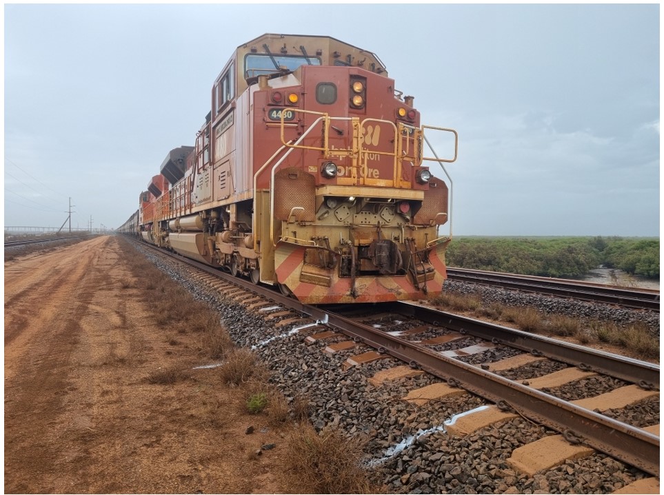
Early on the morning of 2 March 2024, BHP Western Australia Iron Ore trains M05519A and M05519B were stopped 232 m apart, queued to be unloaded at BHP’s Finucane Island Balloon Loop, near Port Hedland, Western Australia. At about 0425 local time, the driver of M05519A slowly moved their train 325 m forwards to the handover point, where the train would be prepared for unloading.
As train M05519A came to a stop, the driver of train M05519B began to move their train forwards, intending to stop 200 m behind train M05519A. Over the next 6 minutes, train M05519B accelerated to a maximum speed of 12 km/h, and the driver acknowledged 4 audible alerts of the locomotive’s vigilance system. However, there was no brake application or reduction in throttle during that time, resulting in the train colliding with the rear of train M05519A. The driver was uninjured and there was no damage to the rollingstock.
What the ATSB found
The ATSB found that the driver of train M05519B had been experiencing stress, sleeping with the light on, and waking often, resulting in poor quality sleep. As a result, on their fourth consecutive night shift, during darkness and while experiencing low workload, the driver set the train in motion while in a degraded level of alertness, possibly associated with a microsleep, and did not detect the impending collision.
The ATSB also found that without awareness or memory of having done so, the driver acknowledged 4 audible vigilance alerts, which, by design, prevented a penalty brake application. This resulted in a low-speed collision with stationary train M05519A.
What has been done as a result
Following the collision, BHP undertook a series of actions to manage fatigue and the limitations of the vigilance systems in the SD70Ace/LCi locomotives.
BHP reviewed the fatigue risk periods for their fly-in fly-out (FIFO) rail operations driver rosters, and increased the number of fatigue assessments during each rotation. Fatigue assessments are now conducted on each of the first 5 night shifts and on the first and fourth day shifts of each rotation. These assessments are conducted face-to-face with the on-shift supervisor or coordinator at each depot location.
BHP is also implementing an additional check-in per shift, to be conducted with the rail crew team member either face-to-face or electronically via phone or radio. To support this activity, BHP employed additional resources to support existing operations supervisors and superintendents to identify and monitor fatigue concerns within the rostering environment.
Additionally, research was conducted into the viability of an interactive fatigue assessment tool (FAT), delivered through a mobile application, to improve the quality of fatigue assessments. A trial of the FAT was scheduled to commence at the end of November 2024.
BHP also proposed several changes to the vigilance system installed on their SD70Ace/LCi locomotives, including changing from fixed-time intervals to random intervals for the countdown, and limiting consecutive alerter resets to require different inputs and eliminate ‘muscle memory’.
Safety message
Adequate sleep duration is important, but sleep quality is also important. Of the factors that affect sleep, light has the most profound effect on the sleep-wake cycle. Exposure to light promotes wakefulness and darkness is necessary for deep restorative sleep. Exposure to sun or blue light, before and during sleep, also results in fragmented sleep and reduces the amount of deep restorative sleep. Stress also negatively affects sleep quality and creates hyperarousal that can mask symptoms of tiredness and fatigue. An increasing deficit of restorative sleep increases the body’s sleep drive and can result in reduced levels of alertness during waking hours, as well as napping, dozing, and microsleeps outside of planned sleep times.
Effective fatigue management includes self-reporting of fatigue or factors likely to contribute to fatigue. Conditions such as stress and interrupted sleep that affect sleep quality should prompt workers to assess and report an elevated risk of fatigue even if sleep quantity may be adequate. Use of fatigue reporting mechanisms is essential for an organisation to be able to apply mitigation strategies to address the associated risks.
The investigation
Decisions regarding the scope of an investigation are based on many factors, including the level of safety benefit likely to be obtained from an investigation and the associated resources required. For this occurrence, a limited-scope investigation was conducted in order to produce a short investigation report, and allow for greater industry awareness of findings that affect safety and potential learning opportunities.
The occurrence
Late at night on 1 March 2024, at the Mooka staging facility (about 32 km south-south-east of Port Hedland, Western Australia) train M05519, operated by BHP Western Australia Iron Ore, was divided into 2 single-crew trains. The 2 trains, M05519A (train A) and M05519B (train B), were each about 1.4 km long, consisting of 2 Progress Rail EMD SD70Ace/LCi Locomotives, short-end leading, followed by 135 wagons loaded with iron ore. A flashing red LED light was secured on the last wagon of each train as an end-of-train marker.
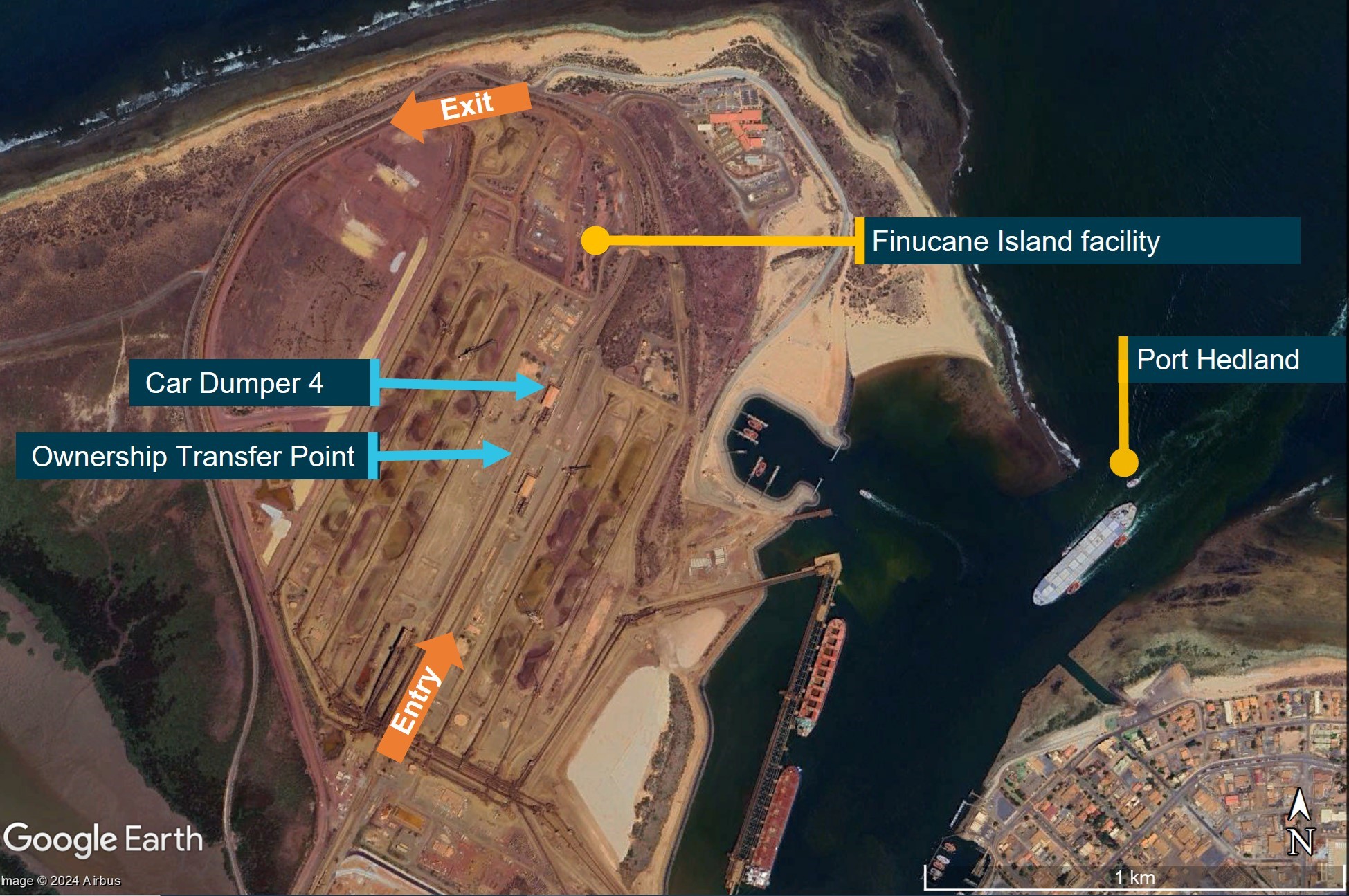
Train A, followed by train B, proceeded towards BHP’s Finucane Island facility at Port Hedland, which consisted of a standard-gauge dual track balloon loop servicing 2 car dumpers (CDs), where iron ore wagons were emptied. Emptying occurred under the authority of a dumper operator, in a semi-automated process where wagons were rotated to dump their contents, and control arms progressed each rake through the dumper facility. As the emptying process could take up to several hours, drivers would secure and hand over the train, then head to the control room for a short break before being assigned a further task.
At about 2320 local time, train A entered Finucane Island yard limits.[1] Within the yard limits, drivers had authority to move their train up to the owner transfer point (OTP) board for the relevant CD (Figure 1). There were no signals and limited controller oversight of the section between the yard limits board and the OTP board, and train drivers were responsible for visually maintaining separation with other rail traffic. Train A slowly progressed, before coming to a stand between 28 points and the OTP board for CD4, where it remained between 0156 and 0425 on 2 March 2024.
Figure 1: Finucane Island facility showing car dumper 4 and its owner transfer point
Source: Google Earth, annotated by the ATSB
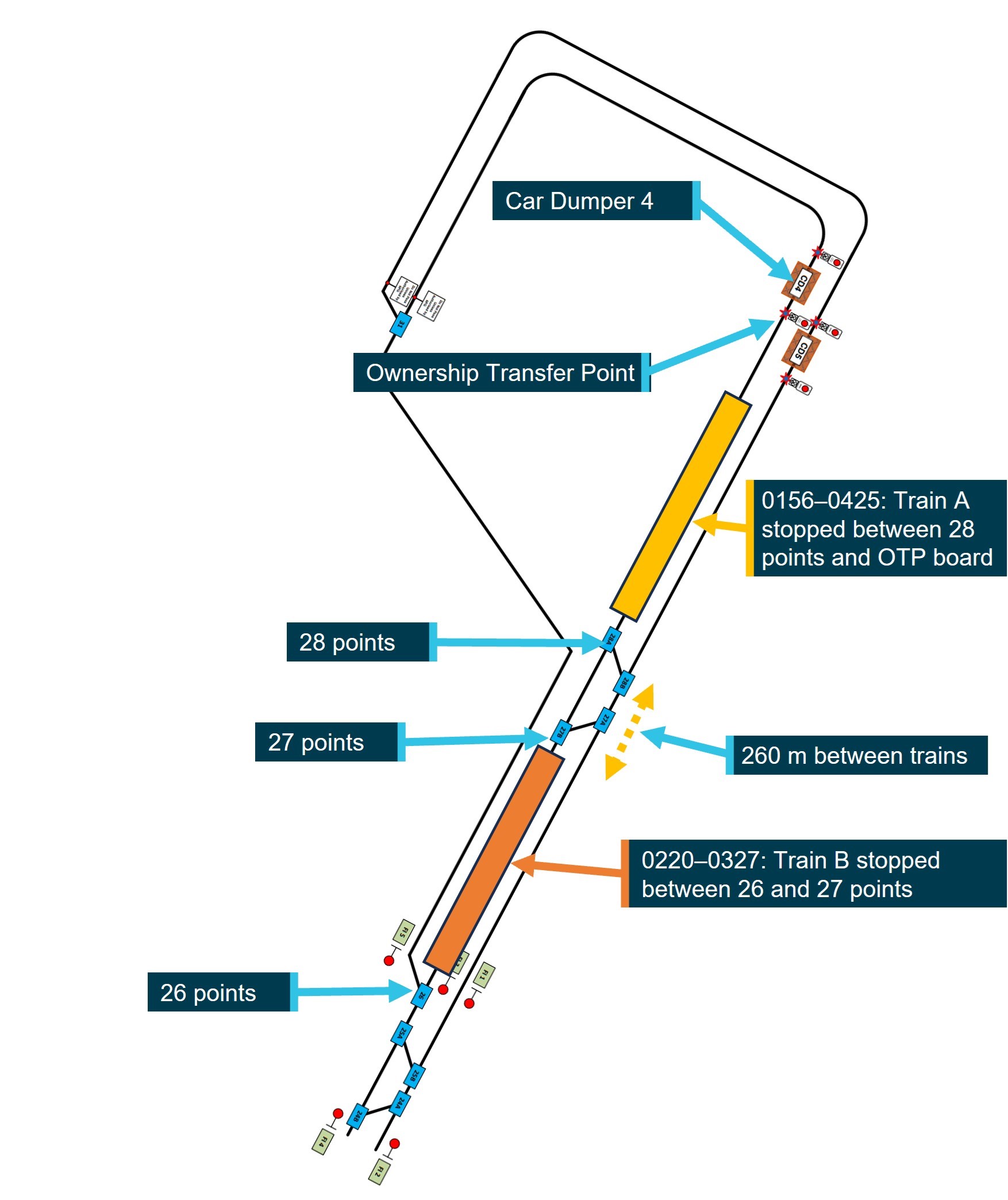
At about 0200, having been stopped by train control for one hour at an en route yard, train B was authorised to enter Finucane Island yard limits and, at 0220, came to a stand 260 m behind train A. The entirety of train B was stopped between 26 and 27 points, the section of track with the steepest uphill grade before the car dumpers. Train B remained stopped in that location from 0220 until 0327 (Figure 2).
Figure 2: Diagrammatic representation of train positions from 0220 to 0327
Not to scale
Source: BHP, annotated by the ATSB
Recorded locomotive data for train B showed that between 0327 and 0331, the driver moved the train forward 27 m before briefly coming to a stand. At 0334, the driver moved the throttle to 1 notch,[2] the train moved forward 1 m then stopped, and the driver applied the independent brake at 0340. Train B was then 232 m behind train A and remained there with the throttle in 1 notch and the brake on, which deactivated the vigilance system (see the section titled Locomotive vigilance system), until 0400 when the driver moved the throttle to idle.
The driver of train B reported that while waiting for the train in front to move, they monitored the radio, swept and cleaned out the cab and spent some time standing outside on the locomotive’s footplate. At that time, the half-moon was above the horizon, and it was a clear night.
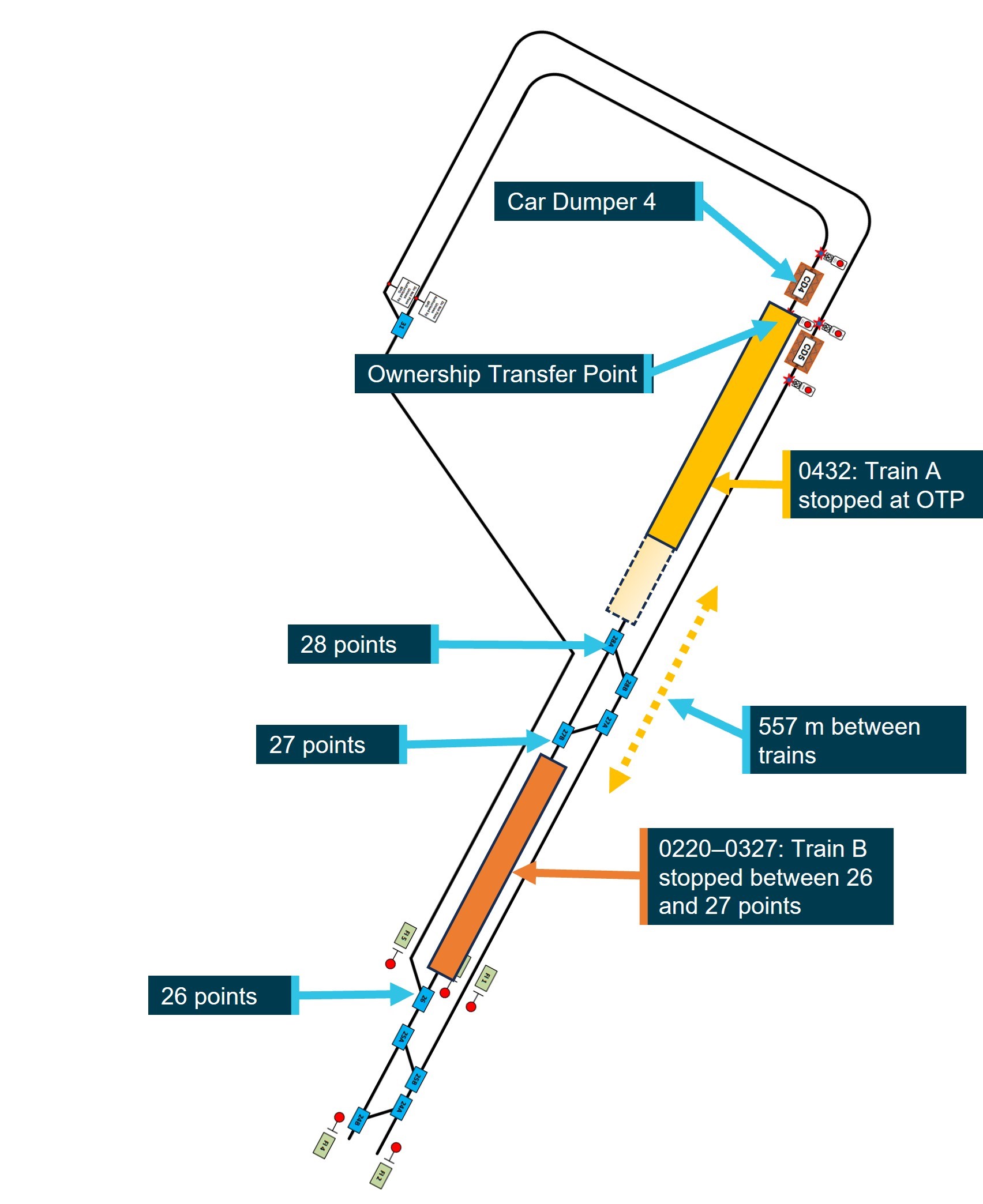
At 0425, after the preceding train departed CD4, the driver of train A placed the throttle into 2 notch, applying sufficient tractive effort to slowly move the train 325 m to the OTP board, before coming to a stand at 0432 (Figure 3). Train A’s driver then awaited authority from the dumper operator to start the process for the train to proceed into CD4 and commence unloading.
Figure 3: Diagrammatic representation of train positions at 0432
Not to scale
Source: BHP, annotated by the ATSB
After detecting that train A had moved ahead, the driver of train B applied power to move their train forward, intending to stop at least 200 m behind train A. At 0431:27, the driver placed the throttle to 1 notch, then 10 seconds later to 2 notch, and another 31 seconds later to 3 notch. At 0433:28, the driver responded to an audible alert from the vigilance system, the train started to move, and the driver placed the throttle into 4 notch.
Over the next 4 minutes, as the trained slowly accelerated to 12 km/h, the driver made 3 more responses to audible alerts from the vigilance system, the last of which occurred at 0437:28. At 0437:42, nearly one hour before first light,[3] train B impacted the rear of train A. The impact sequence lasted 38 seconds and, although the locomotive brakes were fully applied on train A from the point of contact, train A was pushed forwards about 40 m.
The driver of train B reported remembering moving the throttle to 1 notch, but had no awareness of hearing or responding to audible vigilance alerts in the lead up to the collision, and thought they must have had a microsleep. The driver reported being awoken by the impact, and immediately communicated with drivers on nearby trains and controllers to coordinate movements, maintain safe operations, and initiate post-incident protocols.
The driver also uncoupled the lead locomotive of train B from the rear of train A and checked for any damage. There was no damage to rollingstock (Figure 4) and the driver was uninjured.
Figure 4: Lead locomotive of train M05519B after the accident
Source: BHP
Context
Train driver information
Experience, qualifications, and training
The driver had over 30 years of experience driving trains and had worked in Western Australia for over a decade on a fly-in, fly-out (FIFO) basis, operating grain, container, and heavy bulk mineral trains. The driver joined BHP in 2022 and completed all relevant safeworking, locomotive, and in‑field training courses. The driver also held the required route knowledge and operational competencies for the tasks undertaken. The driver regularly operated trains around Finucane Island and last did so 3 days prior to the incident.
The driver successfully completed BHP’s fatigue management training course in 2022 as part of the induction process, but had not completed a refresher course that had been due since December 2023, due to an absence from work.
Medical information
The driver passed an annual category 1 rail medical assessment on 4 October 2023. The driver’s responses to the sleep-related questions in the medical assessment indicated no sleep issues, no tendency to doze, and the driver reported normally sleeping for 6 hours when on day or night shifts and at home.
On 29 November 2023, the driver presented to a medical centre at Port Hedland with a bite on their leg, which they had received while sleeping at night in the barracks.[4] The driver was given temporary pain relief and flew home to Sydney, New South Wales, where they subsequently underwent surgery for what was identified as a white‑tailed spider bite. The driver was subsequently cleared by their general practitioner to resume normal work duties from 16 January 2024 and, that day, flew from Sydney to Port Hedland.
Just over one week after returning to work, on the morning of 25 January 2024, the driver awoke at 0600 and noticed similar signs of a white-tailed spider bite, this time on their neck. On 29 January, the driver returned to Sydney, where they underwent surgery for the second white‑tailed spider bite, followed by a period of rehabilitation. The general practitioner then deemed the driver fit to return to duties, with no requirement for ongoing treatment or medication, and the driver returned to work on 27 February 2024.
Upon returning to Port Hedland, the driver began to experience panic attacks and stress, possibly associated with a response to the previous spider bites. The driver had been allocated the same room at barracks after returning to duty in January and February. BHP provided the ATSB with receipts confirming that the driver’s room and 3 adjacent rooms were fumigated on 1 February 2024. However, when the driver returned to their room 26 days later, they reported there were no obvious signs it had been fumigated as it did not appear to have been cleaned. As a result, the driver began frequently spraying their room and locomotive cab with insect spray. The driver reported that their sleep quality was affected as they woke often, including to spray the room, fearing they would be bitten again, and slept with the lights on to deter spiders.
Following the collision, BHP conducted standard post-incident drug and alcohol testing on the driver, with negative results for both drugs and alcohol, and no substance-related impairment was identified.
Rostering and recent history
Roster and fly-in fly-out arrangements
The driver’s FIFO roster involved 7 12-hour night shifts, followed by a minimum 24-hour changeover period, then 7 12-hour day shifts, followed by 7 days off duty. Drivers were expected to fly in on the day of their first shift (or the day prior, if their start time was at or after midnight), with an opportunity to rest for several hours at barracks prior to commencing their first shift later that night. At the end of each rotation, drivers would fly home on the first morning after their final day shift. The driver travelled from their home in Sydney to Port Hedland via Perth on scheduled airline flights.
Accommodation at Port Hedland
The accommodation barracks were located next to Port Hedland International Airport. The barracks were fully serviced with a dining area and recreational facilities, and all personnel were allocated a single occupancy room with an en suite and air-conditioning. The driver reported that, as a 24-hour facility, the barracks could be moderately noisy at times with the movement of cleaners and their equipment during the day, and the activities of other workers between shifts.
Adjusting to shift work and variable sleep patterns
The driver was experienced in shift work and reported that they adjusted well to variable sleep and roster patterns. The driver reported maintaining similar sleep habits at barracks in Port Hedland and at home. The driver also reported commonly having broken sleep, but no problems returning to sleep.
The driver reported that they would usually be in bed no later than 2 hours after the end of each shift, and aimed to wake at least 2–3 hours prior to commencing their next shift. The driver also reported that they could sleep for several hours on the flights to Port Hedland prior to commencing the first shift of a new rotation.
Fatigue mitigation strategies
BHP Western Australia Iron Ore had strategies aimed at mitigating fatigue risks associated with the FIFO roster. These included a fatigue assessment, which was required to be conducted at specific times in the roster and under certain other conditions. Individuals could also voluntarily complete the assessment at other times. If a driver reported being fatigued, they could be assigned rest or non-operational duties. Drivers could also request a fatigue break during a shift.
The ATSB assessed whether a safety issue relating to BHP’s rostering practices, which was identified during investigation RO‑2018‑018, was relevant to this occurrence. However, contrary to the circumstances associated with RO‑2018‑018, the driver had been off work for one month and during this first rotation back had 11–12 hours of sleep opportunity each day, during which they reported obtaining their normal sleep duration.
Recent history
The driver reported having had a good sleep at home in Sydney, before waking on the morning of 27 February 2024. The driver then obtained another 4–5 hours of sleep on the flights to Port Hedland with their first 12-hour night shift rostered to commence that night at 2200. The driver reported that, prior to arriving at Port Hedland, they had completed a fatigue assessment form, which based on their responses, indicated a low fatigue score.[5] The collision occurred on the fourth night of this rotation, after which the driver was relieved from duty and placed on leave. The driver reported that they generally felt most fatigued towards the end of the fourth shift of a rotation.
The driver reported that in the 72 hours prior to the collision, they followed their normal sleep pattern. They went to bed about 1130–1200, obtained about 6–7 hours of broken sleep, with a maximum continuous sleep period of about 4 hours. The driver rated the quality of their sleep in the days prior to the collision as being 1 out 10 (where 0 indicates the worst possible sleep and 10 indicates the best possible sleep), due to numerous sleep interruptions.
Despite that, the driver reported that before the incident shift, they felt well rested and did not consider completing a fatigue assessment. The driver assessed their perceived level of alertness at the time of the collision as ‘ok, somewhat fresh’, and reported feeling wide awake with no symptoms of tiredness.
Food and drink consumption
The driver maintained regular eating patterns, eating conventional breakfast foods in the morning and more traditional or substantial dinner-style meals in the evening. The driver was not taking medication, natural sleep aids or vitamin supplements, and they rarely consumed alcohol and did not drink caffeinated energy drinks.
After returning from the previous night shift mid-morning, on 1 March 2024, the driver consumed a light meal before going to bed, and, after waking, ate a full meal at around 1900. The driver made a coffee at the office when signing-on at 2100, which was the only caffeinated beverage they consumed prior to the collision.
Locomotive vigilance system
Locomotive vigilance systems monitor driver activity and responsiveness and apply the train’s brakes if the driver does not respond to vigilance alerts in a specified period. The vigilance alerts consist of an initial visual alert followed soon after by the addition of an audible alert. The system will initiate a penalty brake application, causing the train to stop, if no acknowledgement is made.
A limitation of such systems, as identified in an ATSB investigation into a collision between 2 freight trains in 2019 (RO-2019-022), was that drivers could acknowledge vigilance systems during periods of acute fatigue, and habituate to these systems, responding to alerts without conscious thought by pressing the reset button through a reflexive motor response. Vigilance systems could identify and intervene in cases of driver absence or total incapacitation but were less effective in detecting and responding when drivers were mildly incapacitated, inattentive, fatigued, or otherwise distracted.
The vigilance system installed on SD70Ace/LCi locomotives operated as a task/activity-based system with a fixed-time element. If the system detected inactivity in relation to control inputs or locomotive settings, the timer would commence a countdown with a visual alert displayed on the Functionally Integrated Railroad Electronics (FIRE)[6]system display screen and a warning light on the vigilance push‑button.
If the driver did not respond within a specified time, an audible tone would sound. The timer would automatically reset if the driver made control inputs such as throttle, brake, or directional controller settings, or operated items such as the locomotive horn or sanding[7] equipment. It would also reset if the driver pressed the vigilance acknowledgement push‑button or the reset button on the FIRE display screen.
The vigilance timer operated on a 90-second cycle with the following sequence:
0 seconds – system reset, commence silent countdown
70 seconds – flashing countdown and warning lights on the driver’s display, warning light illuminated on the FIRE alert reset button and vigilance pushbutton
75 seconds – commencement of audible tone increasing in volume and frequency to accompany visual alerts
85 seconds – rising audible tone reaches peak volume and continues to sound along with the visual alerts until the vigilance is reset or the timing cycle ends
90 seconds – full emergency brake application.
The alerts would not be generated while the train was idle or the independent brake[8] was applied, and only became active when at least one of the following conditions were met:
locomotive speed was greater than 0.8 km/h (task-linked to the throttle)
brake cylinder pressure was lower than 25 psi (task-linked to the independent brake).
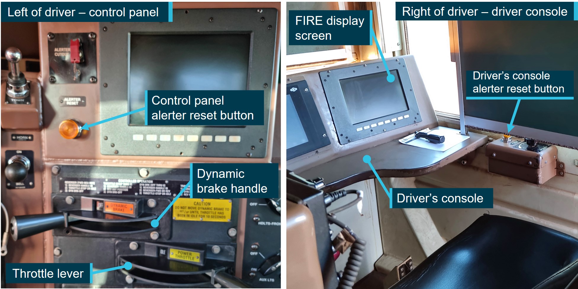
In addition to the electronic button on the FIRE display screen, there were 4 physical alerter reset buttons available to drivers in the SD70Ace/LCi locomotives, in the following positions:
driver’s console (right side of the cab, on the right of the desk)
driver’s control panel (left of the driver’s seat above the dynamic brake handle)
observer’s console (left side of the cab)
rear of locomotive cab.
The first 2 of these listed alerter reset buttons, together with the FIRE display screen, are shown in Figure 5.
Figure 5: Alerter reset button on control panel and driver’s console
Source: BHP, annotated by the ATSB
Recorded information
The FIRE system also recorded data on a logger when an event occurred, or at an interval when no other triggers had caused an event recording. The events that triggered a recording included changes in analogue parameter values, and changes of discrete inputs, such as the movement of throttle or brake controls, activation of the horn, changes to light settings, and the acknowledgement of the vigilance system. There was no way to determine which specific button the driver pressed in the locomotive to reset the vigilance system, as the buttons were all in parallel through a single digital input/output channel in the locomotive.
Data from one locomotive per train – locomotives 4328 (train A) and 4480 (train B) – showed that both trains were operated below the track speed limits with both trains functioning within normal parameters and responding appropriately to driver inputs. The system recorded speed in whole km/h, and the following tables outline key events recorded on train B across 3 time periods.
Table 1 shows the sequence of events on train B between 0327 and 0332, when the driver applied power for over 2 minutes before releasing the independent brake. The driver responded to either the flashing reset button or the visual alert on the FIRE screen to acknowledge the vigilance system as train B moved forwards 27 m.
Table 1: Sequence of events recorded on train B (0327 to 0332)
Time
Action by driver
Effect
Gap to train A (m)
0327:44
Throttle to 1 notch
Tractive effort increased
260
0328:01
Throttle to 2 notch
Tractive effort increased
260
0328:12
Throttle to 3 notch
Tractive effort increased
260
0329:54
Independent brake released
Train is able to move
260
0330:00
Vigilance system activated
(brake psi threshold met)
Safety system in operation
260
0330:18
Throttle, brake settings maintained
Train starts to move
259
0331:14
Vigilance system acknowledged
Timer at 74 seconds: Visual alert
244
0331:24
Throttle to 2 notch
(Speed remains at 1 km/h)
240
0331:33
Throttle to 1 notch
Tractive effort reduced
236
0331:39
Independent brake applied
Train begins to slow
235
0331:43
Throttle to idle
Train comes to a stand
233
Table 2 shows the driver released the independent brake at 0334. The driver then applied power, and responded to the audible alert tone when resetting the vigilance system on 4 occasions, during which time the train moved forward 1 m. At 0340, the driver reapplied the independent brake, deactivating the vigilance system but with power applied to the traction motors for the next 20 minutes. Due to the brakes, uphill grade, and tonnage, this setting was insufficient to move the train fast enough to reactivate the vigilance system. At 0400, the driver moved the throttle to idle.
Table 2: Sequence of events recorded on train B (0334 to 0400)
Time
Action by driver
Effect
Gap to train A (m)
0334:07
Independent brake released
Reduction in brake pressure
233
0334:08
Throttle to 1 notch
Tractive effort increased
233
0334:14
Vigilance system activated
(brake psi threshold met)
Safety system in operation
233
0334:15
Throttle to 2 notch
Tractive effort increased
233
0335:32
Vigilance system acknowledged
Timer at 78 seconds: visual alert and audible tone increasing in volume and frequency
233
0335:50
Throttle to 1 notch
Vigilance timer reset to zero
233
0337:08
Vigilance system acknowledged
Timer at 78 seconds: visual alert and audible tone increasing in volume and frequency
232
0338:29
Vigilance system acknowledged
Timer at 81 seconds: visual alert and audible tone increasing in volume and frequency
232
0339:48
Vigilance system acknowledged
Timer at 79 seconds: visual alert and audible tone increasing in volume and frequency
232
0340:27
Independent brake applied
Vigilance system deactivated
232
0400:18
Throttle to idle from 1 notch
Tractive effort stops
232
Between 0400 and 0431, train B remained at a stand with idle throttle and brakes applied, before the driver made a series of control inputs as outlined in Table 3Table 4. The throttle was moved to 4 notch, which applied half the available power to the traction motors and the driver responded to the audible alert tone when resetting the vigilance system on 4 occasions.
Table 3: Sequence of events recorded on train B (0431 to 0438)
Time
Action by driver
Effect on train
Gap to train A (m)
0431:27
Throttle to 1 notch
Tractive effort increased
557
0431:34
Independent brake released
Vigilance system activated
557
0431:37
Throttle to 2 notch
Tractive effort increased
557
0432:08
Throttle to 3 notch
Tractive effort increased
557
0433:28
Vigilance system acknowledged
Timer at 80 seconds: visual alert and audible tone increasing in volume and frequency
543
0433:31
Throttle to 4 notch
Train begins to accelerate
542
0434:49
Vigilance system acknowledged
Timer at 78 seconds: visual alert and audible tone increasing in volume and frequency
472
0436:08
Vigilance system acknowledged
Timer at 79 seconds: visual alert and audible tone increasing in volume and frequency
304
0437:28
Vigilance system acknowledged
Timer at 80 seconds: visual alert and audible tone increasing in volume and frequency
47
0437:42
Impact with Train 5519A at 12 km/h
Loss of data recording
0
Human factors considerations
Workload
The driver described their workload on the night prior to the incident night as being ‘flat out’ with numerous locomotive and rolling stock movements. On the incident night, the driver’s workload was low, the trainhaving been stationary first at Mooka, then stopped by train control for one hour, and again while waiting at Finucane Island. Low workload situations lack stimulation, leading to monotony and boredom, and this can reveal underlying sleepiness from inadequate sleep, and degrade performance (Williamson et al 2011). Limited stimulation of a task can also reduce attention (Young and Stanton 2002).
Sleep cycle
It is generally agreed that most adults need at least 7 hours of sleep each day to achieve maximum levels of alertness and performance (Hirshkowitz and others 2015). Getting enough sleep quantity is critical in mitigating fatigue. However, sleep quality is also important. Good quality, restorative sleep depends on obtaining sufficient deep and rapid eye movement (REM) sleep, which only occur after being asleep for some time (Carskadon and Dement 2017).
The sleep cycle comprises 4 stages – drowsiness, light sleep, deep sleep, and REM sleep. During sleep, adults normally cycle through these stages, with the duration of each stage and the proportions changing with age. Each stage is important, and waking frequently reduces the ability to obtain deep sleep and REM sleep, because after waking, the cycle begins again.
Sleep quality broadly refers to the capacity of sleep to restore waking function. Ohayon et al (2017) reviewed sleep-related research and identified characteristics consistent with poor sleep quality. These include 4 or more awakenings per night (for more than 5 minutes) or being awake for more than 40 minutes after falling asleep. While there is less research on the effect of sleep quality than of sleep duration on performance, it has been found that sleep fragmentation has been shown to degrade memory, reaction time, vigilance, and mood (Bonnet & Arand 2003).
Sleep-wake cycle
In addition to the sleep cycle, there is the daily sleep-wake cycle. The sleep-wake cycle, known as the circadian rhythm, is usually comprised of a single period of wake and a major sleep episode every 24 hours. This alternation of sleep and wake normally coincides with the daily light-dark cycle, such that sleep occurs at night and wake occurs during the day (Kosmadopolos 2023). The sleep-wake cycle is regulated by the circadian clock and sleep homeostasis – the longer a person is awake, the stronger the drive for sleep. A reduction in sleep quantity or quality, or extension of the time awake since sleep, produces a sleep debt and increases the drive to sleep (Williamson et al 2011).
Effects of light
Light affects both the sleep cycle and the sleep-wake cycle. The greatest influence on circadian rhythm is sunlight or blue light. Exposure to light promotes wakefulness and hinders sleep (Chellappa et al 2011). Light exposure before or during sleep times can reduce sleep quality, cause repeated awakenings and interrupt the sleep cycle.
Effects of stress
Psychological stress and worry are known to reduce the recuperative value of sleep and increase mental demands in waking hours (Kim & Dimsdale 2007). Being stressed or anxious affects multiple systems in the body and increases activation of the sympathetic nervous system and cortisol levels (Stanford et al 2015). This causes alertness, or hyperarousal, and can lead to sleep fragmentation and reduced deep sleep (Han, Kim & Shim 2012). The effects of stress and anxiety can result in a high state of alertness despite disrupted sleep, where a person feels ‘tired but wired’ (Ramlakhan 2010).
Stress responsible for prolonged sleep disruption in humans may be a cognitive and emotional phenomenon that is not necessarily always associated with an acute challenge. Humans may experience stress based on memories of past events as well as worries and expectations about the future. They can take a single acute stressor or life event that occurred in the past, or even one pending in the future, into a persistent and chronic stress state. Research has found that stress and worry experienced over successive days, particularly at bedtime, was shown to negatively affect sleep quality (Akerstedt et al 2012). In addition, poor sleep can result in people performing an action without any awareness or memory of having done so (Leschziner 2020).
Microsleeps
As sleep is a biological need, when it reaches a critical level, the brain will sleep regardless of any effort to remain awake. This may result in microsleeps, which are described as brief fragments of sleep shorter than 15 seconds (Malafeev et al 2021). They can occur due to sleep loss, where the propensity for sleep is increased (Durmer and Dingers 2005), or during periods of low workload. One consequence of a microsleep is when a person does not respond during cognitive performance demands (Kause et al 2017). Microsleeps can occur without conscious awareness and can occur in settings where automation is provided, such as through automatic train protection systems (Thomas et al 2023).
Safety analysis
Following multiple surgeries and medical leave because of 2 white-tailed spider bites, which occurred while the train driver was asleep in their accommodation at Port Hedland, the train driver returned to work at Port Hedland and commenced a week of night shifts. Experiences of acute stressors, such as spider bites, can result in persistent stress based on memories and associations of the past event and worries that a bite may occur in the future. Fearing another bite, the driver was frequently spraying insecticide in the locomotive and their bedroom, including waking from sleep to do so. In addition to impacting sleep, stress stimulates the sympathetic nervous system. This likely led to the driver feeling awake and alert, rather than experiencing symptoms of tiredness that would normally arise from a deficiency of deep restorative sleep.
In the 11–12 hours of sleep opportunity on each of the first 3 daytime off-duty periods, the driver reported having obtained the same total duration of sleep as normal. However, the disruption detail above inhibited their ability to obtain deep restorative sleep, reducing overall sleep quality. This was exacerbated by the driver sleeping with the light on (to deter spiders), which delays sleep onset and fragments sleep, reducing the amount of deep sleep. As the circadian rhythm is dependent on bright light for regulation, sleeping with the light on also likely affected the driver’s ability to adapt to sleeping during the day and being wakeful while on duty at night.
Unlike the previous (third) night shift, during which the driver experienced a high workload, on the incident night (fourth night shift), the driver spent long periods of time in a stationary locomotive, resulting in an extremely low workload situation. This, combined with the reduced overall sleep quality, and a dark environment, likely resulted in a condition where the driver started to perform actions, without any awareness or memory of having done so.
Between 0335 and 0340 on the incident morning, while applying some tractive effort with the brakes released, the driver acknowledged 4 audible alerts with no memory of having heard or acknowledged them. The driver then set the independent brake, deactivating the vigilance system, and both throttle and brakes were then engaged for about 20 minutes. This configuration was unlikely to have been conscious, given that the simultaneous application of power and brakes was not a normal operating mode and would almost certainly have resulted in the train moving either forwards or backwards but for the incline on which the train was stopped.
The unusual configuration was resolved at 0400 by the driver moving the throttle to idle, following which the train was stationary with no driver inputs for 31 minutes. That period was consistent with the driver’s recollection of standing outside on the footplate and cleaning the cab in preparation for the handover that would occur when the locomotive eventually reached the car dumper.
When the driver recognised that the train ahead had progressed, they set their train in motion. However, the driver had no recollection of subsequently hearing and acknowledging another 4 vigilance alerts. Vigilance systems are ineffective in detecting drivers who are mildly incapacitated, inattentive, fatigued, or otherwise distracted, and who can perform an automated task in acknowledging the alerts without conscious awareness.
Although the driver did not respond to visual alerts within the time required, and the vigilance system progressed to issuing audible alerts, the vigilance timer reset each time the driver acknowledged a vigilance alert, and consequently, the vigilance system did not activate the emergency brake. There was also no driver action to reduce the throttle or apply independent braking, or any other recorded control or system inputs by the driver. The pattern of slowed reaction times to the vigilance system alerts throughout the shift may indicate the driver was pre‑occupied or distracted. However, there was no evidence of any distraction.
As a result of poor-quality sleep, low workload, and dark conditions, after the driver set the train in motion it is probable that the driver was in a degraded level of alertness, possibly associated with a microsleep. During this period, the driver was unable to detect the risk posed by the stationary train ahead and identify the appropriate actions to be taken to stop the train.
As a result, about 5 minutes after the train started to move, and 14 seconds after the driver last acknowledged a vigilance alert, the locomotive impacted the rear of the stationary train ahead. The driver reported having no recollection of anything after setting the train in motion until the collision.
After the impact the driver was immediately able to perform normal and post-incident functions. This was consistent with being aroused from a degraded state rather than having suffered a medical incapacitation, and there was no evidence of any condition likely to result in incapacitation in the driver’s medical history or subsequent evaluation.
Findings
ATSB investigation report findings focus on safety factors (that is, events and conditions that increase risk). Safety factors include ‘contributing factors’ and ‘other factors that increased risk’ (that is, factors that did not meet the definition of a contributing factor for this occurrence but were still considered important to include in the report for the purpose of increasing awareness and enhancing safety). In addition, ‘other findings’ may be included to provide important information about topics other than safety factors. These findings should not be read as apportioning blame or liability to any particular organisation or individual.
From the evidence available, the following findings are made with respect to the low-speed collision between trains M05519A and M05519B at Finucane Island Balloon Loop, Port Hedland, Western Australia on 2 March 2024.
Contributing factors
The driver of train M05519B had been experiencing stress, sleeping with the light on, and waking often, resulting in poor quality sleep. As a result, on their fourth consecutive night shift, during darkness and while experiencing low workload, the driver set the train in motion while in a degraded level of alertness, possibly associated with a microsleep, and did not detect the impending collision.
Without awareness or memory of having done so, the driver acknowledged 4 audible vigilance alerts, which, by design, prevented a penalty brake activation. This resulted in a low-speed collision with stationary train M05519A.
Safety actions
Whether or not the ATSB identifies safety issues in the course of an investigation, relevant organisations may proactively initiate safety action in order to reduce their safety risk. The ATSB has been advised of the following proactive safety action in response to this occurrence.
Safety action by BHP
Following the collision, BHP undertook a series of actions to manage fatigue and the limitations of the vigilance systems in the SD70Ace/LCi locomotives.
BHP reviewed the fatigue risk periods for its FIFO rail operations driver rosters and increased the number of fatigue assessments during each rotation. Fatigue assessments are now conducted on each of the first 5 night shifts and on the first and fourth day shifts of each rotation. These assessments are conducted face-to-face with the on-shift supervisor or coordinator at each depot location.
BHP is also implementing an additional check-in per shift, to be conducted with the rail crew team member either face-to-face or electronically via phone or radio. To support this activity, BHP employed additional resources to support existing operations supervisors and superintendents to identify and monitor fatigue concerns within the rostering environment.
Additionally, research was conducted into the viability of an interactive fatigue assessment tool (FAT), delivered through a mobile application, to improve the quality of fatigue assessments. A trial of the FAT was scheduled to commence at the end of November 2024.
BHP also proposed several changes to the vigilance system installed on its SD70Ace/LCi locomotives, including changing from fixed-time intervals to random intervals for the countdown, and limiting consecutive alerter resets to require different inputs and eliminate ‘muscle memory’.
Sources and submissions
Sources of information
The sources of information during the investigation included:
the driver of train M05519B
BHP.
References
Åkerstedt T., Orsini N., Petersen H., Axelsson J., Lekander M., and Kecklund G. (2012). ‘Predicting sleep quality from stress and prior sleep–a study of day-to-day covariation across six weeks’, Sleep Medicine, 13(6):674–679. doi: 10.1016/j.sleep.2011.12.013.
Bonnet M.H. and Arand D.L. (2003). ‘Clinical effects of sleep fragmentation versus sleep deprivation’, Sleep Medicine Reviews, 7(4): 297-310, doi: 10.1053/smrv.2001.0245.
Carskadon M.A. and Dement W.C. (2017). ‘Normal human sleep: and overview’, in Kryger, M.H., Roth T. and W.C. (eds). Principles and practice of sleep medicine (6th edition), Elsevier.
Chellappa S.L., Gordijn M.C. and Cajochen C. (2011). ‘Can light make us bright? Effects of light on cognition and sleep’. Progress in Brain Research, 190:119 –133, doi: 10.1016/B978-0-444-53817-8.00007-4.
Durmer J.S. and Dinges D.F. (2005). ‘Neurocognitive consequences of sleep deprivation’. Seminars in Neurology, 25(1):117-129, doi: 10.1038/nrn.2017.55.
Han, K.S., Kim, L., Shim, I. (2012). ‘Stress and sleep disorder’, Experimental Neurobiology, 21(4):141-50. doi: 10.5607/en.2012.21.4.141. Accessed 5 September 2024: Stress and Sleep Disorder - PMC (nih.gov)
Hirshkowitz M., Whiton K., Albert S.M., Alessi C., Bruni O., DonCarlos L., Hazen N., Herman J., Katz E.S., Kheirandish-Gozal L., Neubauer D.N., O’Donnell, A.E., Ohayon, M., Peever, J., Rawding, R., Sachdeva, R.C., Setters B., Vitiello, M.V., Ware, J.C., and Adams-Hillard, P.J. (2015). ‘National Sleep Foundation’s sleep time duration recommendations: methodology and results summary’, Sleep Health, 1(1):40–43. doi: 10.1016/j.sleh.2014.12.010.
Krause A.J., Simon E.B., Mander, B.A., Greer S.M., Saletin J.M., Goldstein-Piekarski A.N. and Walker M.P. (2017). ‘The sleep-deprived human brain’, Nature Reviews Neuroscience, 18(7):404-418. doi:
Kim, E. J. and Dimsdale, J. E. (2007). ‘The effect of psychosocial stress on sleep: a review of polysomnographic evidence’, Behavioural Sleep Medicine, 5(4), 256-278.
Kosmadopolos A. (2023). ‘Sleep pressure and circadian rhythms’, in Rudin-Brown C. and Filtness, A.J., The handbook of fatigue management in transportation: waking up to the challenge, CRC Press, Boca Raton, Florida.
Leschziner, G. (2020). The nocturnal brain: nightmares, neuroscience, and the secret world of sleep. First St. Martin's Griffin edition. New York, NY, St. Martin's Griffin.
Malafeev A., Hertig-Godeschalk A., Schreier D.R., Skorucak J., Mathis J. and Achermann P. (2021). ‘Automatic detection of microsleep episodes with deep learning’, Frontiers in Neuroscience, 15:1-12. doi: 10.3389/fnins.2021.564098.
Ohayon M., Wickwire E.M., Hirshkowitz M., Albert S.M., Avidan A., Daly F.J., Dauvilliers Y., Ferri R., Fung C., Gozal D., Hazen N. (2017). ‘National Sleep Foundation's sleep quality recommendations: first report’, Sleep Health 3(1):6–19. doi:10.1016/j.sleh.2016.11.006.
Ramlakhan, N. (2010). Tired but wired: how to overcome sleep problems – the essential sleep toolkit. Souvenir Press; Main edition (3 May 2010). London, United Kingdom.
Sanford L.D., Suchecki D. and Meerlo P. (2015). ‘Stress, arousal, and sleep’. Sleep, Neuronal Plasticity and Brain Function, 25:379-410. doi:10.1007/7854_2014_314.
Thomas M.J.W., Sprajcer M. and Dawson D. (2023). ‘The effects of fatigue on performance in transportation operations’, in Rudin-Brown C. and Filtness, A.J., The handbook of fatigue management in transportation: waking up to the challenge, CRC Press, Boca Raton, FL.
Williamson A., Lombardi D.A., Folkard S., Stutts J., Courtney T.K. and Connor J.L. (2011). ‘The link between fatigue and safety’, Accident Analysis and Prevention, 43(2): 498–515. doi:10.1016/j.aap.2009.11.011.
Young M.S. and Stanton N.A. (2002). ‘Malleable attentional resources theory: a new explanation for the effects of mental underload on performance’, Human Factors, 44(3):365–375. doi:10.1518/0018720024497709.
Submissions
Under section 26 of the Transport Safety Investigation Act 2003, the ATSB may provide a draft report, on a confidential basis, to any person whom the ATSB considers appropriate. That section allows a person receiving a draft report to make submissions to the ATSB about the draft report.
A draft of this report was provided to the following directly involved parties:
the driver of train M05519B
BHP
the Office of the National Rail Safety Regulator.
Submissions were received from:
BHP
the Office of the National Rail Safety Regulator.
The submissions were reviewed and, where considered appropriate, the text of the report was amended accordingly.
Purpose of safety investigations
The objective of a safety investigation is to enhance transport safety. This is done through:
identifying safety issues and facilitating safety action to address those issues
providing information about occurrences and their associated safety factors to facilitate learning within the transport industry.
It is not a function of the ATSB to apportion blame or provide a means for determining liability. At the same time, an investigation report must include factual material of sufficient weight to support the analysis and findings. At all times the ATSB endeavours to balance the use of material that could imply adverse comment with the need to properly explain what happened, and why, in a fair and unbiased manner. The ATSB does not investigate for the purpose of taking administrative, regulatory or criminal action.
Terminology
An explanation of terminology used in ATSB investigation reports is available here. This includes terms such as occurrence, contributing factor, other factor that increased risk, and safety issue.
Publishing information
Released in accordance with section 25 of the Transport Safety Investigation Act 2003
Ownership of intellectual property rights in this publication
Unless otherwise noted, copyright (and any other intellectual property rights, if any) in this report publication is owned by the Commonwealth of Australia.
Creative Commons licence
With the exception of the Commonwealth Coat of Arms, ATSB logo, and photos and graphics in which a third party holds copyright, this report is licensed under a Creative Commons Attribution 4.0 International licence.
The CC BY 4.0 licence enables you to distribute, remix, adapt, and build upon our material in any medium or format, so long as attribution is given to the Australian Transport Safety Bureau.
Copyright in material obtained from other agencies, private individuals or organisations, belongs to those agencies, individuals or organisations. Where you wish to use their material, you will need to contact them directly.
[1]Yard Limits: a defined area of track where rail traffic movements are authorised and managed by a nominated network control officer or other suitably qualified employee, and whose boundaries are marked by trackside signage and, where relevant, labelling on signal panel displays. Train movements in these areas can be co-ordinated through fixed signal routes, hand signals, or verbal/written authorities.
[2] Notch: refers to engine power/RPM settings. Drivers apply or remove gradations of power by moving the throttle handle to the desired notch, which then provides a fixed percentage of the maximum power available to the traction motors.
[3]First light: when the centre of the sun is at an angle of 6° below the horizon before sunrise. At this time, the horizon is clearly defined but the brightest stars are still visible under clear atmospheric conditions. On 2 March 2024, first light at Port Hedland occurred at 0541 local time.
[4]Barracks: a place provided to railway personnel for rest between shifts. Usually consists of serviced accommodation located en route or in remote areas where staff are required to start and/or end their allocated shifts away from their home depot.
[5]Fatigue assessment tools rely upon an individual’s subjective reporting of factors that may contribute to the experience of fatigue. A low score indicates a low risk of fatigue, and the higher the score, the greater the severity or risk of fatigue.
[6]Functionally Integrated Railroad Electronics (FIRE): connected to the train’s onboard computer control system, this system monitors and measures train parameters and is linked to the vigilance device. Train information, control settings, and fault indications are presented to the driver on a digital display screen located in the driver’s console as well as recorded on an event/data logger.
[7]Sanding: a process where sand is applied to the railhead in order to improve overall traction and prevent wheel slip. This enables increased adhesion between the wheels and the rails to facilitate the smooth acceleration and braking of rollingstock, particularly when traversing slippery rails, tight curves, or steep grades. Excessive sand can have the opposite effect by reducing traction in certain circumstances.
[8]Independent brake: The independent brake solely controls air brakes within the locomotive(s) and works independently of a train’s other braking control systems. These brakes are controlled via the driver’s independent brake control handle and apply when the locomotive brake cylinder pressure is increased and release when the pressure is decreased.
On 23 February 2024, an Alliance Airlines Embraer E190-100 aircraft, registered VH-UYI, was operating a scheduled passenger flight, IE700, on behalf of Solomon Airlines, from Honiara, Solomon Islands to Brisbane, Queensland. On board were the captain as pilot monitoring (PM), first officer as pilot flying (PF), 2 cabin crew and 66 passengers.
Prior to conducting the Before-start checklist, the left seat pilot (captain) was required to set the aircraft’s speed mode selector, with flight management system (FMS) mode recommended. While the crew’s intention was to depart in FMS speed mode, undetected by either flight crew, this step was omitted, and the speed selection remained in manual mode.
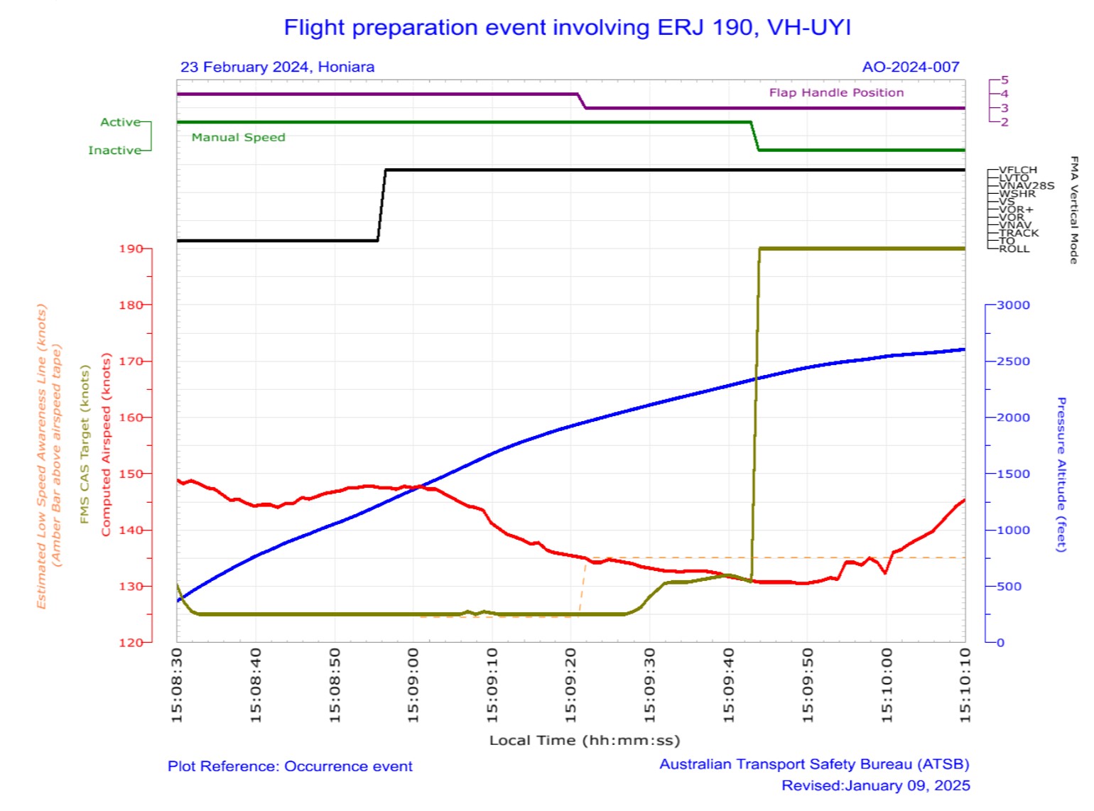
As the aircraft was climbing through 1,200 ft, vertical flight level change (VFLCH) mode engaged in the FMS. Once in VFLCH, the flight director (FD) commenced targeting the manual target speed which, at that time, was 125 kt.
Over the next 20 seconds, the aircraft’s speed gradually reduced and the pitch gradually increased to target the manual speed. Detecting that the aircraft was not accelerating, the PM assessed there was too much drag on the aircraft and retracted one stage of flap. The flap retraction resulted in a visual low airspeed cockpit alert.
Shortly afterwards, the crew detected the speed mode was incorrectly set, and changed the speed mode to FMS mode, at which time the aircraft commenced accelerating to the correct target airspeed.
What the ATSB found
The ATSB determined that the left seat pilot (captain) unintentionally left the speed selection in manual mode instead of flight management system mode with no manual speed set. The manual speed mode selection was not detected by either flight crew member, resulting in the aircraft decelerating after VFLCH mode engaged.
While the captain was monitoring traffic, weather and making a radio broadcast, the first officer was not effectively monitoring the airspeed and as a result, did not initially detect the aircraft decelerating. Having assessed that the low airspeed was due to excessive drag, the captain retracted one stage of flap while below the minimum flap target speed, resulting in the aircraft entering a low-speed state.
Alliance Airlines’ standard operating procedures manual (SOPM) included a step of initially selecting the speed knob to ‘manual’ in its pre-flight procedures, despite that mode very rarely being used for take-off. This increased the risk of flight crews departing with the manual speed mode unintentionally selected. The ATSB also identified that Alliance’s right seat pilot shutdown flow was undocumented and not in accordance with the manufacturer’s guidance.
Additionally, Embraer's airplane operations manual was inconsistent with its standard operating procedures manual in regard to setting the speed knob to manual in the Before start procedures.
Likely due to a training deficiency, Alliance Airlines flight crews' conduct of the Before startprocedures and Pre-take-off brief review were not being performed effectively to ensure the speed selector knob was correctly set and checked, which increased the risk of a low-speed event after take-off.
A review by the operator of flight data found that in 112 flights operated over a 30-month period, flight crew had also not selected, or detected, the speed selector knob in manual mode prior to commencing the take-off run. In 76 of these events, flight crew were changing the speed selector knob setting during the take‑off run, increasing the risk of distraction during a critical phase of flight.
What has been done as a result
Action was taken by Alliance Airlines to address the safety issues identified in this investigation, including:
E190 SOPM pre-flight procedures have been amended so the left seat pilot selects FMS mode to mitigate unintentionally departing in manual speed mode.
The practice of the right-seat pilot setting manual speed and 80 knots during the after‑shutdown flow will be discontinued. Recurrent training and check events will reinforce compliance with the correct procedure.
Training and procedural guidance to reinforce the correct setting and verification of the speed mode selector knob is being enhanced. Flight crews will receive targeted refresher training through a dedicated simulator training module, emphasising correct procedural discipline for conducting pre-take-off reviews.
Flight crews will receive targeted instruction emphasising that no adjustments to the speed selector knob are to be made during the take-off roll. This will be reinforced during initial, recurrent and line check assessments. Compliance with this policy will be monitored through the collection and analysis of flight data and will be assessed during recurrent simulator training and annual line proficiency checks.
Proactively, Alliance Airlines has also:
Issued an article to flight crew highlighting that at the completion of the before start duties, the left seat pilot should apply the technique of selecting ‘TOGA, TARA, SPEED’, followed by confirmation of the relevant modes and settings on the primary flight display, prior to calling for the completion of the Before start checklist.
Advised that a dedicated training module will be incorporated into recurrent simulator cyclic training exercises commencing 1 January 2025. This module will include a review of this occurrence, its root cause, and a reinforced focus on correct procedures and techniques to prevent reoccurrences.
Advised that during recurrent line check events, there will be an added emphasis on reviewing and ensuring adherence to the correct procedures and techniques.
Finally, Embraer advised that it proposes to align the contents of the AOM and SOPM in the first half of 2025, likely removing reference to selection of manual mode in the Before start procedure.
Safety message
This incident highlights how important continuous attention to the modes displayed on the primary flight display is to situation awareness. An ICAO safety advisory on Mode awareness and energy state management aspects of flight deck automation stated that loss of mode awareness and mode confusion have been identified as factors in several major accidents around the world. Further, that mode confusion can often result in flight crews' mismanagement of an aircraft's energy state, such as the low-speed state that occurred in this incident. The circular recommended that at any time an aircraft does not follow the desired vertical or lateral flight path, or airspeed, flight crew should adapt the level of automation to the task and/or circumstances, or revert to hand flying or manual thrust/throttle control, if required.
The circular also identified inadequate training and system knowledge as a key factor contributing to mode confusion. In this case, training in quick identification of mode indications, including speed display colours during pre-take-off checks, would reduce the likelihood of a similar incident occurring.
The investigation
Decisions regarding the scope of an investigation are based on many factors, including the level of safety benefit likely to be obtained from an investigation and the associated resources required. For this occurrence, a limited-scope investigation was conducted in order to produce a short investigation report, and allow for greater industry awareness of findings that affect safety and potential learning opportunities.
The occurrence
On 23 February 2024, an Alliance Airlines Embraer E190-100 aircraft, registered VH-UYI, was operating a scheduled passenger flight, IE700 on behalf of Solomon Airlines, from Honiara, Solomon Islands to Brisbane, Queensland. On board were the captain as pilot monitoring (PM), first officer as pilot flying (PF),[1] 2 cabin crew and 66 passengers. The flight was scheduled to depart at 1400 local time, but due to several delays (see the section titled Pre-departure delays), departed at 1507.
As the crew were preparing the aircraft, the captain identified that they were likely to encounter a thunderstorm on the track of the planned standard instrument departure (SID). The captain advised that, in order to avoid it, they suggested to the first officer that they conduct a visual departure. However, the first officer reported being ‘comfortable’ with the weather and advised their preference to fly the SID, which was then agreed. The SID required that the aircraft initially climb to 1,000 ft, then conduct a 180° left turn to intercept the outbound track.
The operator’s pre-flight procedures required the left seat pilot (LSP) (captain) to set the speed knob to manual mode (see the section titled The operator split the Before start procedures between Pre-flight and Before start procedures). This resulted in a target speed setting of 80 kt.
Prior to conducting the Before start checklist, the LSP was then required to action the Before start flow[2] which again included setting the speed mode, with the flight management system (FMS) mode recommended. While the crew's intention was to depart in FMS mode, undetected by either flight crew, this step was omitted, and the speed mode selection remained in manual.
The flight crew then configured the aircraft for a flap 4 take-off (see the section titled Flaps) due to the warm, humid conditions and the 2,200 m long runway. The PF armed take-off (TO) mode (see the section titled Vertical modes) in the FMS. In that mode, the flight director (FD) (see the section titled Flight guidance control system) displayed a pitch attitude for the crew to manually follow during rotation and the initial climb.[3]
The PF then commenced the take‑off, selecting TOGA[4] power. After the aircraft rotated, the aircraft’s controller logic (see the section title Controller logic) automatically changed the target speed from 80 kt to V1,[5] which was 125 kt. That change in target speed was displayed on the primary flight display (PFD) (in cyan) but was not detected by either flight crewmember.
The PF manually followed the FD guidance for pitch attitude and the aircraft maintained an airspeed of about V2[6] plus 10 kt (144 kt). In accordance with the operator’s standard operating procedures manual, the PF engaged the autopilot at about 1,000 ft, and subsequently, as the aircraft climbed through 1,200 ft, vertical flight level change (VFLCH) engaged (see the section titled Vertical modes). Once in VFLCH, the FD commenced targeting the target speed, which was 125 kt.
A few seconds later, the aircraft entered a 25° left turn to comply with the SID. At about that time, the PF reduced the power from TOGA power to climb power, and the PM diverted their attention to visually assessing weather on the departure route and monitoring the traffic collision avoidance system for other aircraft. Over the next 20 seconds, the aircraft’s speed gradually reduced while the PM made a departure broadcast on the common traffic advisory frequency (CTAF).[7]
The PM recalled that at that stage of the flight the aircraft felt ‘draggy’. In response, they looked at the PFD and saw the airspeed indicating around 134 kt and recognised that the aircraft was not accelerating. The PM instructed the PF to ‘roll out’ of the banked turn, to reduce drag. However, the PF did not follow that instruction, likely due to believing the call to roll out was regarding the weather ahead, which the PF was not concerned about.
The PM recalled further advising the PF ‘you’re not accelerating’, while also being unsure why the aircraft was not accelerating. Knowing that the landing gear was already retracted, the PM retracted flap from 4 to 3 (slats from 25° to 15°) to further reduce the drag. The PF recalled hearing the PM stating that they were selecting flap 3. After the slats were retracted, the speed further reduced to 131 kt and the PF detected the amber pitch limit indicators (see the section titled Pitch limit indicators) on the PFD and alerted the PM accordingly.
The PF then decided to change the speed mode from FMS to manual, to manually increase the airspeed. However, when they went to change the speed selector knob, they detected that it was already in manual mode and so changed the selection to FMS mode. This occurred 21 seconds after the flap handle was moved to the flap 3 detent. Once the speed mode was in FMS mode, the aircraft accelerated to the correct target speed of 190 kt.
Context
Flight crew information
The captain and first officer both held an air transport pilot licence (aeroplane) and a class 1 aviation medical certificate. The captain had accumulated 17,000 flight hours, and the first officer had about 13,000 flight hours of experience.
Both crewmembers reported feeling well rested prior to the flight, however, the captain reported feeling ‘mentally tired’ prior to take-off, following ground-handling and dispatch irregularities and delays.
Airspace information
Honiara Airport operated a flight information service[8], with the surrounding airspace being non‑controlled. That is, the airspace had no active supervision by air traffic control and pilots were responsible for their own separation from other traffic.
Aircraft information
The aircraft was an ERJ 190-100 IGW, manufactured in Brazil in 2006 and issued serial number 19000053. It was registered in Australia as VH-UYI on 24 January 2022. The aircraft was fitted with 2 General Electric Company CF34-10E5 turbofan engines. It had an integrated avionics system with either ‘load 25’ or ‘load 27’ software installed. VH-UYI had load 27 software.
Flight management system and manual speed modes
Flight guidance control system
According to the E190 maintenance manual, the flight guidance control system (FGCS) has 2 relevant functions:
flight director (FD) guidance: The FGCS calculates the FD guidance commands that show on the primary flight display (PFD). The FD is selected by pressing a button on the guidance panel (GP).
autopilot: this sends automatic pitch and roll guidance to the elevator and aileron servos. Its control authority is limited to keep the aircraft within a safe operating envelope. It is engaged by the AP button on the GP.
The aircraft also had an autothrottle, which the operating policy stated should be used during the entire flight, engaged just prior to take-off and disengaged after touchdown or at the pilot flying (PF) discretion.
The avionics pilot guide stated:
When engaged, the A/T system automatically positions the thrust levers to control the aircraft thrust throughout the flight regime. The A/T system keeps the aircraft within the thrust and speed envelopes and controls the engine thrust modes in synchronization with the active FGCS modes.
Flight management system
According to the avionics pilot guide, the flight management system (FMS) is:
an integrated system providing data for the cockpit displays and flight control system (FCS). The FMS serves as an aid to performance, flight planning, navigation, database, and redundancy management.
The FMS is used for complete flight planning activities… Once programmed, the FMS gives control outputs to the autopilot system to fly the aircraft along the planned route, both laterally and vertically.
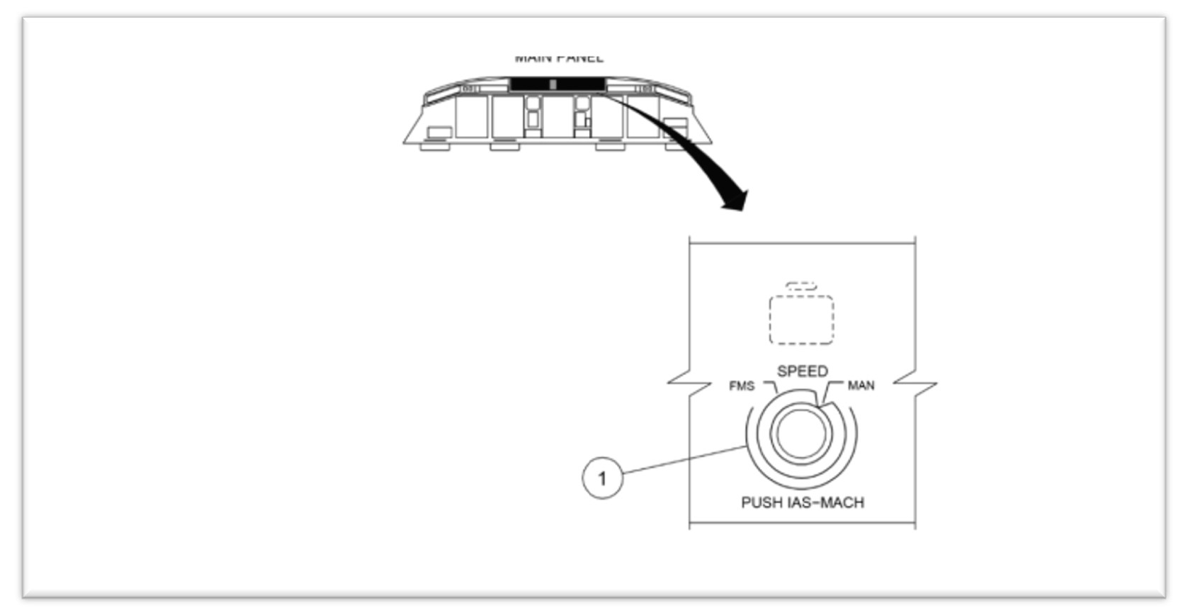
Speed modes
The flight crew had the option of selecting either of 2 speed management modes on the GP – FMS or manual mode (Figure 1).
Figure 1: E190 speed selector knob on guidance panel
Source: Alliance interim safety report
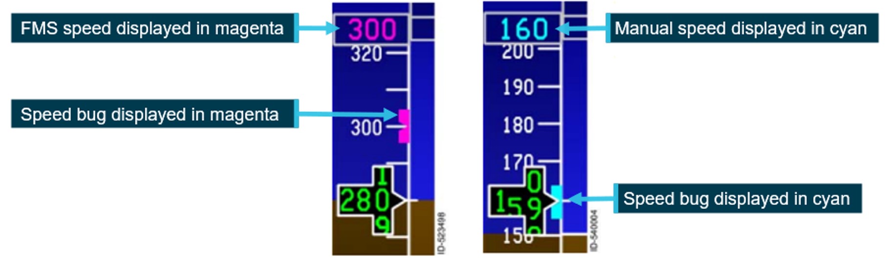
In FMS mode, the airspeed selection was managed by the FMS. The airspeed was displayed on the PFD in magenta (Figure 2).
In manual mode, flight crew retained responsibility for airspeed control, by selecting the airspeed using the SPEED selector knob, which then displayed the selected airspeed on the PFD (Figure 2). This target speed was used by both the autothrottle and the autopilot. A manual selected airspeed was displayed on the PFD in cyan.
Figure 2: FMS and manual speed displays
Example of speed tape showing the different speed modes. FMS mode on the left and manual mode on the right. Source: Honeywell, annotated by the ATSB
Prior to take-off, the pilot entered the required V speeds[9] from the multifunction control display unit (MCDU). These were then displayed on the lower portion of the speed tape.
The operator specified that if manual speed mode was selected for take-off:
when conducting a take-off in flap 1 to 3 configuration, the airspeed was to be set to final segment speed (VFS), which was the speed to be achieved during the final take-off segment, with landing gear up and flaps retracted
when conducting take-off in a flap 4 configuration, the airspeed should be set to 175 kt
when using noise abatement procedures, the airspeed should be set to V2 +10 kt.
The selection of speed mode was referenced in pre-flight, before-start and shutdown procedures (see the section titled Mode selection procedures).
Vertical modes
The autoflight control system (AFCS) has 11 modes to control the aircraft’s flight path. Two modes were relevant to this incident – take-off (TO) and vertical navigation flight level change (VFLCH).
In TO mode, the flight crew fly with reference to the flight director (FD). The flight crew set take‑of/go around (TOGA) power and then manually rotate the aircraft to the displayed pitch attitude on the FD to achieve the required airspeed.
When the mode was changed to a mode other than TO, the AFCS will start using the target airspeed as a reference. In VFLCH, the autothrottle holds the thrust lever at the set thrust value and the FD changes the pitch angle to maintain the airspeed at the target airspeed selected on the PFD. According to the operator’s standard operating procedures manual (SOPM), VFLCH is the preferred climb mode.
Flaps
The E190, has both flaps and slats. With the flap lever in position 4, the flaps extend to 20° and the slats to 25º. Moving the flap lever to position 3 moves the slats to 15º, with the flap position remaining unchanged.
With slats extended, the critical angle of attack (AOA)[10] is increased, enabling the aircraft to operate at a greater AOA. Conversely, once slats are retracted, the critical AOA decreases.
Flap retraction – F-Bug
The PFD shows the ideal flap selection speed using a symbol (green dot) on the speed tape. The flap retraction speed is shown using a magenta bug (F-bug). The flap manoeuvring speed is calculated based on the airplane weight and slat/flap setting and does not change with bank angle or turbulence.
The operator’s E190 aircraft operations manual (AOM) stated that:
During flap retraction, the next flap setting should be selected when the F-Bug is reached.
The F-Bug calculation is designed to meet minimum safe margins to VFE[11] and shaker speed. A minimum margin of 20% above the stall speed[12] is set for the next flap.
F-bug speeds calculated for the flight, provided by the manufacturer:
Flap lever
4
3
2
1
0
F-bug
154
164
174
184
-
Stall warning protection system
Overview
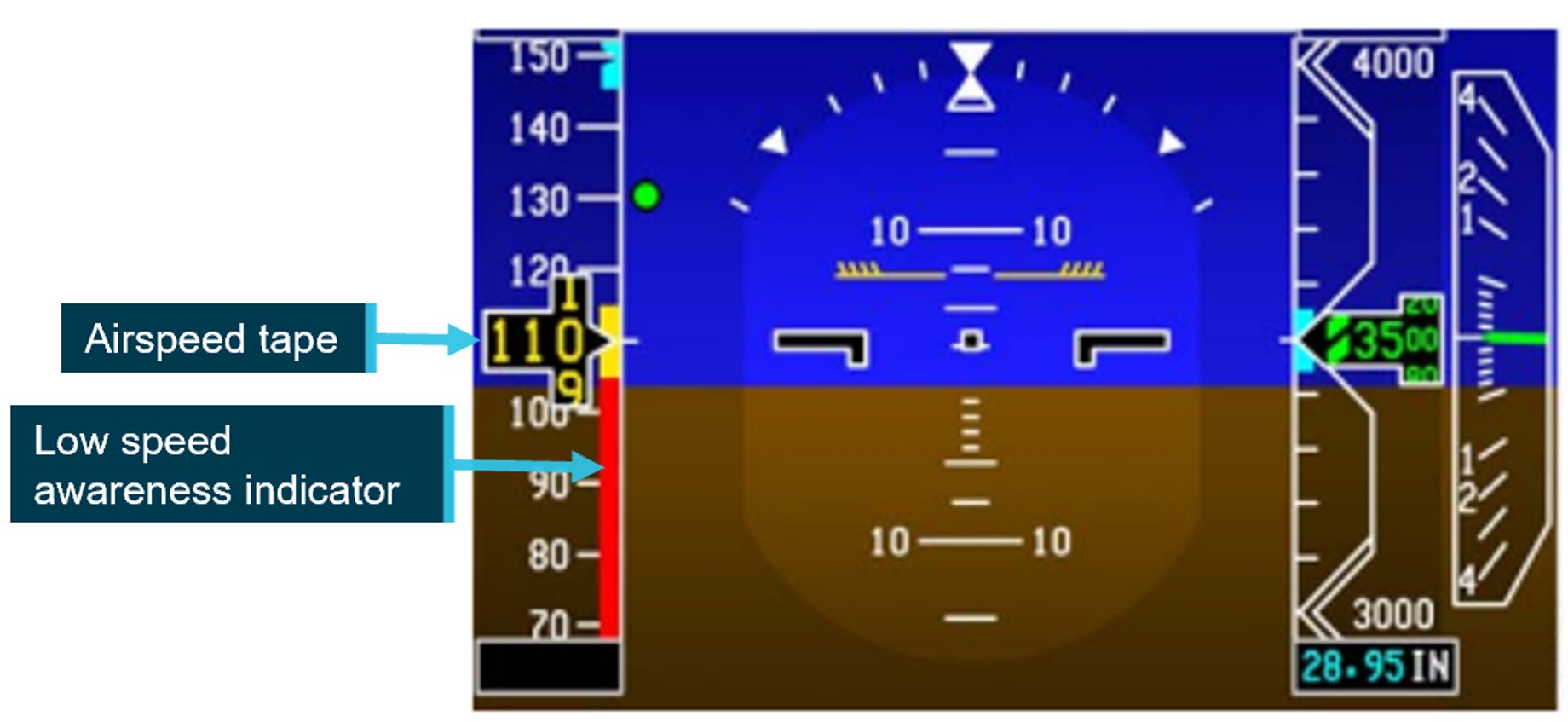
The E190 stall warning protection system (SWPS) is a 2-stage system that warns and protects the aircraft from aerodynamic stall conditions. The first stage warns the pilot of the impending stall by:
showing a low-speed awareness indication on the airspeed tape
showing a pitch limit indication on the attitude direction indicator on the primary flight display
activating the stick shaker motor on each control column results in each control column to shake (simulating the aircraft buffeting).
The second level is an AOA limiter protection system that limits the maximum AOA to a safe value below the predicted aerodynamic stall (preventing a stall).
Low-speed awareness system
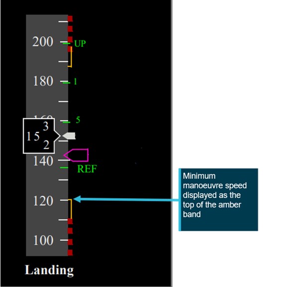
A low-speed awareness (LSA) indicator is displayed along the lower-right side of the airspeed tape (Figure 3Figure 3). LSA varies with the load factor[13] of the aircraft and the bar position is based on airspeed, aircraft configuration and AOA. The bar rises from the bottom of the tape to show both the calculated stall and stick shaker[14] speed (Vshaker) in 2 coloured ranges:
the amber range displays from Vshaker to 1.13 x stall speed
a stall occurs at the top of the red range, when the airspeed drops below Vshaker.
If the speed enters the red range, the stick shaker will activate, and an audible alarm will sound. The speed displayed on the PFD will also change colour to red reverse video.
Figure 3: Low speed awareness indicator
Source: Honeywell, annotated by the ATSB
Controller logic
While in TO mode with the speed control in manual, if the speed set is lower than V1, the controller logic automatically increases the speed to V1, after the ground‑to‑air transition.
Further, the aircraft manufacturer and avionics manufacturer advised that the controller logic ensures that the LSA indicator does not allow the selected speed to stay in the red range. If the manual speed selected on the guidance panel was in the amber band, the LSA automatically increased the speed to target the top of the amber band.
In this instance, the manual speed target initially increased to 125 kt after rotation and then, due to load effects during the climbing turn, the top of the amber band (and the target airspeed) further increased to 131 kt.
The aircraft manufacturer advised that the aircraft’s controller logic would always attempt to avoid unsafe conditions within a given envelope. The protective measures would not stop working unless the limit of conditions were met – in which case they would be announced to the crew by way of speed displayed in amber on the LSA indicator, the activation of pitch limit indicators (PLI) (see the section titled Pitch limit indicators) and eventually a stick shaker.
Autothrottle low speed protection
When the autothrottle was providing speed control, it would ensure both high and low speed envelope protection. The manual target speed was limited to the minimum maneuvering speed, flap/gear placard speed or the low speed awareness speed. The autothrottle lower speed limit was the greater of the manual speed target or 1.2 the stall speed. When flaps were extended, the autothrottle would maintain 1.2 x stall speed.
However, when the system was in VFLCH mode, airspeed was controlled by the elevator, with the autothrottle targeting a fixed thrust setting and therefore not providing low speed protection. The FD pitch controller providing speed control did not contain low speed protection and targeted the selected target speed on the guidance panel.
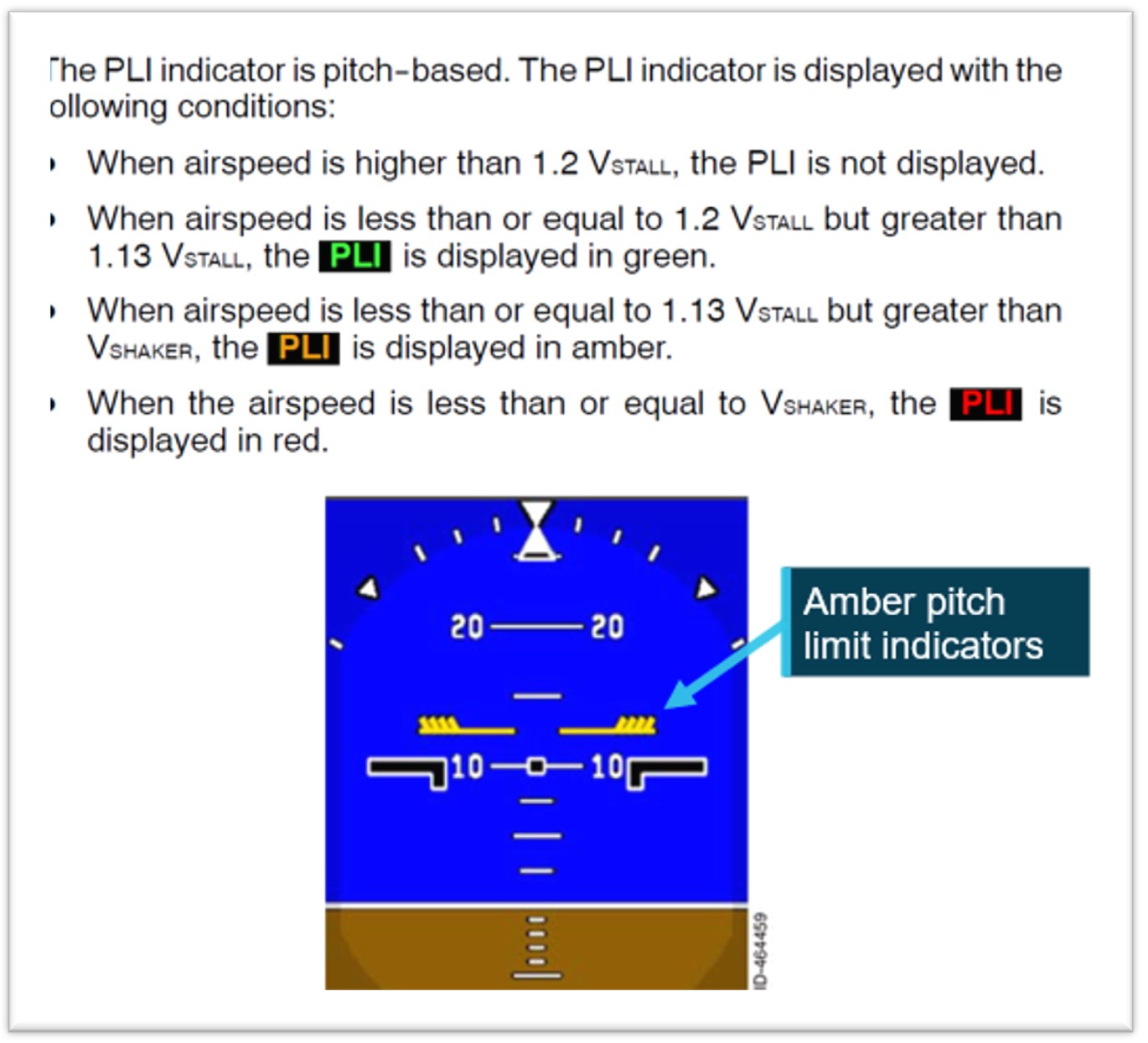
Pitch limit indicators
The aircraft’s SWPS computed a pitch limit indicator (PLI). This was a ‘pitch-based indication of the margin (in degrees) between the stick shaker speed and the current airspeed’ (Figure 4). The PLI margin was calculated continuously and displayed on the PFD when the airspeed was less than 1.2 the stall speed.
Figure 4: Pitch limit indicators
Source: Honeywell, annotated by the ATSB
Operational information
Mode selection procedures
The aircraft manufacturer provided operators with an airplane operations manual (AOM) and standard operating procedures manual (SOPM).
Regarding the 2 documents, the aircraft manufacturer stated:
The intention of the AOM is to gather all the information related to the operation of the aircraft, while the Embraer SOP is generated to provide operational guidance (it is ‘our way’ of operating the aircraft).
Both can be used by the operator, who must produce their own procedures (usually, dealing with mixed fleets) … Thus, operators can create their SOP using our SOP as a starting point and can add or change some points using information from the AOM, or even mix some internal operational information, but the final set must be approved.
This is a flexibility that operators can take advantage of. However, in all cases, following the instructions of the Embraer AOM/SOP entirely, as well as the operator’s SOP, should not lead to undesirable conditions.
As long as the Embraer AOM or SOP is followed in full, no undesirable results will occur.
Manufacturer’s airplane operations manual
The manufacturer’s AOM Before start procedures called for the speed selector knob to be set to manual:
SPEED Knob............................................. MAN
Subsequently, the Shortly before startup procedures (Figure 5), called for the speed selector knob to be set at pilot discretion, with FMS recommended for Load 27 aircraft (including VH-UYI).
Figure 5: Shortly before startup procedures
Source: Embraer E190 airplane operations manual – normal procedures
Manufacturer’s standard operating procedures manual (SOPM)
Unlike the AOM, the SOPM did not have a requirement to set the speed selector knob to manual in the Before start procedures. The first reference to speed selector knob was in the Shortly before start procedures (Figure 6), where the left seat pilot (LSP) was required to set it at pilot’s discretion (with FMS speed recommended).
Figure 6: Shortly before start procedures
Source: Embraer E190 standard operating procedures manual – normal procedures
The manufacturer advised that:
There is no need to set the speed to manual in the pre-flight, because once the necessary data is filled in the FMS (via MCDU), the correct speed target will be automatically set, provided that the selector is in FMS SPEEDS.
The step of bringing it [speed] to manual, mentioned in the AOM, is not included in our SOP, and is not taught in our [original equipment manufacturer] OEM training, as the SOP procedures are followed instead.
Operator’s standard operating procedures manual (SOPM)
The operator advised that:
As is industry practice, Alliance Airlines adapted the manufactures E190 manual suite, including the E190 AOM and SOPM to develop SOPs that are suitable for our operation. Like other airlines, Alliance Airlines continuously monitors manufacturers recommendations and conducts ongoing reviews of our SOPs to ensure they are fit for purpose, compliant with regulations and follow industry best practice.
The operator split the Before start procedures between Pre-flight and Before start procedures
Pre-flight procedures
Due to the alignment with the manufacturer’s AOM, the operator’s Pre-flight procedures required the LSP to set the speed selector knob to manual mode.
The operator understood this step was required to clear any previously set FMS speeds. However, the avionics manufacturer advised that:
From the FMS side (Load 27), there is not a mandatory requirement to set it [speed knob] to manual and it does not have logic to reset the previous autospeed target by setting the speed selector to manual. Rather, the previous flight information is cleared 2 minutes after landing.
Although not documented in their SOPM, the operator advised that it was customary for the right seat pilot (RSP) to switch the speed selector knob to manual during a Shutdown flow, which was intended as an additional protection to ensure that the speed selector knob was selected to manual.
Before start procedures
As part of the Before start flow, the operator’s procedures required the LSP to set the speed selector knob to either manual or FMS, and for aircraft running load 27, FMS mode was the recommended mode. This was not required to be stated out loud, nor challenged by the right seat pilot.
The Before start flow was termed ‘TOGA TARA SPEED’ as follows:
The LSP should perform the following actions
• Press the TO/GA [take-off/go-around] button to arm the Flight Director for take-off mode.
• Select TA/RA on the transponder.
• At the pilot’s discretion set the SPEED Knob to FMS or MANUAL. If MANUAL, set VFS on the speed window for Flap 1–3 take-off or 175kts for Flap 4 take-off.
• If required, select NAV for a LNAV [lateral navigation mode] departure.
The crew then performed the Before start procedures, which again called for the speed selector knob to be set, with FMS mode recommended.
The engines were then started, and the relevant checklists completed.
The operator’s procedures subsequently included:
As late as practical approaching the take-off point, the PF for the sector should complete a take-off brief review in accordance with Alliance Airlines [Operations Policy and Procedures Manual] OPPM. This should also include items such as flap setting, runway and intersection, RNP status, assigned altitude setting as applicable and changed weather conditions.
However, the OPPM referred to did not include any information regarding speed settings.
The manufacturer stated that:
while the Embraer [standard operating procedures] SOP did not explicitly mention speeds, it was expected that operators' SOPs cover speeds and cross-check the parameters, which are: V1, VR, V2, VFS values and bugs on the speed tape and V2 magenta or VFS blue on the speed target. In this way, the take-off briefing is a second opportunity to verify the correct value set.
Take-off procedures
The operator’s Take-off procedures stated:
FMA modes are not called until 400 ft to allow the PM to call any abnormal conditions as well as to reduce distraction during the take-off roll.
The manufacturer advised that as the take-off is a critical phase of flight:
Embraer’s SOPs recommend that selections and other heads-down tasks be avoided during this phase. The PF is flying the aircraft even while on the ground, and should be concentrating on maintaining directional control, cross-checking the instruments and alerting for any abnormal conditions. While the PM should be monitoring flight parameters (speed), engine parameters, the engine indicating and crew alerting system (EICAS) and monitoring the actions of the PF. Furthermore, the pilot in command is also monitoring for any abnormalities to make the Go/No-Go decision until V1 is reached.
Speed mode training
The operator advised that, although it was not documented in their training manual:
Thorough simulator type rating training is conducted to consolidate understanding…
the general practice of confirming a selection using the PFD/ND [navigation display], rather than the position of a physical switch/lever, is best practice and a key principle of operating advanced aircraft. This philosophy is integrated into the Alliance E190 Type Rating program, with a strong emphasis on correct technique starting during the ground school phase.
during line operations (and training), the before start procedures (scans), cover the requirement for confirmation that either cyan or magenta, are as anticipated, and that the calculated speeds are accurate.
The captain reported that manual speed would have been displayed in cyan, which should have stood out during the scans. They advised they had not used manual speed mode for take-off other than in the simulator during type rating training.
The FO also reported not having used manual mode previously and had not specifically been told to check for FMS/manual speed displaying in cyan or magenta in the speed window.
The manufacturer did not provide a specific training syllabus, rather expected the aircraft operator to develop the training manual. Therefore, type rating training for the aircraft was operator-specific.
Review of other E190 operator’s procedures
The ATSB conducted a review of another E190 operator’s procedures and found that they did not have a requirement for the speed mode to be set to manual during pre-flight, before start procedures or shut down procedures. That is, the speed mode remained in FMS speed throughout all phases of flight.
In addition, the operator had introduced into their SOPM, a verbal check of speed settings (FMS or Manual) as part of their FMS performance review prior to the flight.
Flight crew roles
The manufacturer established areas in the cockpit that were placed under the responsibility of a specific flight crewmember. Ground operations are divided between the left seat pilot (LSP) and the right seat pilot (RSP) while in-flight operations are divided between pilot flying (PF) and pilot monitoring (PM).
Regarding roles and responsibilities, the operator’s manual stated that:
The PF is responsible for controlling the vertical flight path and horizontal flight path and for energy management by either:
• supervising the auto pilot vertical and lateral modes through awareness of modes being armed or engaged, mode changes and of selected mode targets; or
• hand flying the aircraft, with or without flight director guidance.
The PNF [pilot not flying – same concept as PM] is responsible for:
• systems related monitoring
• monitoring tasks
• performing the actions requested by the PF.
The manufacturer manuals stated that when the aircraft does not perform as expected, the autopilot must be disconnected and manual flight promptly established. The manufacturer further advised it is ‘primary airmanship to monitor airspeed during every phase of flight, especially during take-off and initial climb’.
Pre-departure delays
Prior to departure, there were multiple irregularities involving ground handling, dispatch and loading sheets, passenger boarding and catering that required the captain’s attention. These included:
final loading sheet with a 2-tonne discrepancy from initial loading sheet
flight plan issued for Extended-range Twin-engine Operational Performance Standards (ETOPS) when not an ETOPS flight
final paperwork approximately 50 pages instead of 3–4 pages of relevant information
HF radio failure – requiring extra fuel to hold under 24,500 ft until ATC (Brisbane Centre) could be contacted
requirement to leave the bay due to incoming company aircraft.
Resolution of these issues resulted in the aircraft pushing back 30 minutes later than scheduled and the captain reportedly feeling mentally drained by the time they entered the cockpit. Additional delays due to other traffic, a closed taxiway and a displaced runway threshold resulted in the aircraft departing a further 30 minutes after pushback.
Recorded data
Quick access recorder data
Flight data from the aircraft’s quick access recorder (QAR) for the incident flight and the previous flight was analysed by the ATSB and the aircraft manufacturer.
The data showed that the speed selector knob had been selected to manual after touchdown on the previous flight.
QAR data confirmed that TOGA power was set and LNAV was armed, which were both items on the Before-start ‘TOGA TARA SPEED’ flow, indicating that part of the captain’s flow was conducted. TA/RA, another required item on the flow, was not a recorded parameter.
QAR data also confirmed that the captain was using the push to talk button as the aircraft’s speed decreased.
Stall speed, the low speed awareness (LSA) indicator and the pitch limit indicators (PLI’s) were not recorded by the QAR, however, the manufacturer provided the ATSB with calculations based off the QAR data.
They advised that prior to the flap lever retraction from 4 to 3, the top of the amber band on the LSA was 124.5 kt. When the slats retracted, 20 kts prior to the target speed (F-bug), the upper value of the amber LSA indicator[15] increased to 135.1 kt.
Figure 7: QAR data during initial climb
Source: ATSB
The data showed that once VFLCH was engaged, the airspeed (red line) reduced towards the FMS target speed (green line) at 125 kt. When the flap lever was retracted (purple line), the low speed awareness indicator increased to approximately 135.1 kt (dotted orange line), which was above the current airspeed of 134 kt. The PLIs would have been displayed on the PFD at this stage. The target speed then increased when the speed mode was selected to FMS.
Similar occurrences
As part of the operator’s internal safety investigation into this incident, a review of QAR data was conducted on flights operated in manual speed. From January 2022–July 2024, 254 flights were identified where manual speed setting was used. In 112 of those (including this incident), the flight crew had manual speed selected with no associated target speed set (80 kt).
In 76 of these 112 events, the QAR data showed that flight crew adjusted the speed mode selector to FMS during the take-off run and departed in FMS mode.
The operator advised that a review of the last 50 events where speed had not been set correctly, 38 individual captains were involved, operating from a range of different bases throughout the operator’s network.
Safety analysis
Introduction
During the pre-flight checks, undetected by either flight crew member, the captain unintentionally omitted to select the speed selector knob to flight management system (FMS), and the aircraft departed in manual mode without a target speed set. After take-off, with the airspeed at about 144 kt, vertical flight level change (VFLCH) mode engaged in the FMS, resulting in the flight director targeting the airspeed displayed on the primary flight display, of 125 kt. The aircraft then decelerated while in a banked turn with flap extended. The captain responded by retracting one stage of flap, resulting in a low-speed state. The flight crew then identified and corrected the speed mode selection. The stick shaker did not activate.
This analysis will discuss the flight crew’s actions in setting and monitoring modes and speeds, and flap retraction. The contribution of training and differences between the manufacturer’s and operator’s documentation will also be examined. Finally, other similar occurrences by Alliance Airlines flight crews and their responses will be examined.
Speed mode selection
Recorded flight data showed that the speed selector knob had been set to manual, as per the operator’s procedure for the copilot’s flow at shutdown, following the previous flight and the Pre‑flight procedures. It also showed the selector was not switched to FMS mode, as per the captain’s intention in the Before start procedures. Neither flight crewmember detected the speed selector knob in manual or that the speed colour on the primary flight display (PFD) was cyan (compared to the expected magenta) in the before start scans or during the take-off brief review.
After the aircraft rotated, the controller logic automatically increased the target speed to V1, which was 125 kt. However, at that time, as the aircraft was in take-off (TO) mode, the target speed was not affected, as the pilot flying was following flight director TO mode pitch guidance, and the system was targeting the desired V2 plus 10 kt (about 144 kt) for the take-off, and climb was maintained as expected.
Passing 1,200 ft, vertical flight level change (VFLCH) mode engaged. At this time, the flight director (FD) began to target the selected airspeed (125 kt) by increasing the pitch of the aircraft, and the airspeed gradually began to decrease.
Contributing factor
During the Before start procedure, the captain unintentionally left the speed selector knob in manual mode instead of flight management system mode, with no manual speed set. The manual speed mode selection was not detected by either flight crewmember, resulting in the aircraft decelerating after vertical flight level change mode was engaged.
Not monitoring speed
During the initial climb in non‑controlled airspace, the captain was making the required departure call, and monitoring traffic and weather.
As the aircraft entered a 25° bank turn to comply with the standard instrument departure (SID), the airspeed further decreased. The speed reduction and increased pitch was not detected by the PF, which may have been due to anticipating a slower climb in flap 4 configuration and a banked turn.
Contributing factor
While the captain was monitoring traffic, weather and making a radio broadcast, the first officer was not effectively monitoring the airspeed and, as a result, did not initially detect the aircraft decelerating.
Flap retraction
Although the aircraft was slower and pitched higher than usual at that time, it was operating at a safe speed. Manufacturer calculations showed that the top of the LSA amber band was at approximately 125 kt during this time and the airspeed was decelerating through 134 kt.
However, when the PM detected that the aircraft was not accelerating, they retracted flap from 4 to 3 (slat retraction) to reduce drag. The manufacturer’s calculations showed that this resulted in the upper value of the amber range on the LSA indicator increasing to about 135 kt. When slats were retracted, the airspeed was around 134 kt, therefore within the amber band, before further reducing to 131 kt. During that time, the pitch limit indicators (PLI’s) would have activated and been displayed on the primary flight display.
The manufacturer required that if the aircraft was not performing as expected, the flight crew were required to disconnect the autopilot and manually fly the aircraft.
Contributing factor
Having assessed that the low airspeed was due to excessive drag, the captain retracted one stage of flap while below the minimum flap target speed, resulting in the aircraft entering a low-speed state.
Manufacturer’s airplane operations manual
The manufacturer’s airplane operations manual (AOM) was inconsistent with their standard operating procedures manual (SOPM). Specifically, it required the speed selector knob to initially be set to ‘manual’ in the Before start procedures, which was not an SOPM requirement.
While the use of manual speed was valid, it was unnecessary for the AOM to require initial setting of manual speed in the Before start procedures, as the selection of speed mode was later made in the Shortly before start procedures. It also increased the risk of flight crews not switching the speed selector knob back to the commonly-used FMS speed prior to departure.
Contributing factor
Embraer's airplane operations manual was inconsistent with its standard operating procedures manual in relation to speed mode selection. This increased the risk of flight crews departing with the manual speed mode unintentionally selected. (Safety issue)
Operator’s procedures
While the manufacturer’s AOM was inconsistent with their SOPM, the operator advised that it had reviewed both documents when developing their own SOPM.
Despite manual speed mode rarely being used, the operator included a requirement for it to be initially set to manual, and then selected to FMS prior to take-off, in line with the AOM. The inclusion of this requirement in its SOPM may have also been influenced by an incorrect belief that it was required to clear previous speeds entered in the flight management system (FMS). In that context, while well intentioned, it increased the risk of the aircraft departing with the incorrect speed mode selected.
In addition, the operator also included an undocumented right seat pilot flow at shut down to switch the speed selector knob to manual. This step was not in accordance with the aircraft manufacturer’s AOM or SOPM and similarly increased the risk of the incorrect speed being selected for take-off.
Contributing factor
Consistent with Embraer’s airplane operations manual, the Alliance Airline's pre-flight procedure required flight crew to unnecessarily initially set the speed knob to ‘manual’. That increased the risk of the aircraft departing with the incorrect speed mode selected. (Safety issue)
Other factor that increased risk
Alliance Airlines’ right seat pilot shutdown flow was undocumented and not in accordance with the manufacturer’s guidance.
Training
While the operator stated that the training and line checks ensured that crews were checking that the speeds were displayed in cyan or magenta as expected, these requirements were not documented in the training manual. Additionally, the first officer (FO) reported never having been told to specifically look at the colour (magenta/cyan) of the speed display as part of their scans.
The captain did not ensure the target speed was depicted in the expected colour. They had only conducted a take‑off with the speed selector knob in manual mode once, as part of their initial training in the simulator.
Unlike standard operating procedures, type rating training was not stipulated by the manufacturer, instead was developed by each aircraft operator. The manufacturer was unaware of any other operator having had similar events. Given there were 112 occurrences where the operator’s flight crew had not correctly set the speed selector knob, nor detected the incorrect speed selector knob selection and the speed colour in cyan in the display prior to the take-off run, it is likely that the operator’s training and line checks were not adequate in ensuring flight crew were completing their scans as per the manufacturer’s and operator’s requirements.
Contributing factor
Likely due to a training deficiency, Alliance Airlines flight crews' conduct of the Before start procedures and Pre-take-off brief review were not being performed effectively to ensure the speed selector knob was correctly set and checked, which increased the risk of a low-speed event after take-off. (Safety issue)
Similar incidents
A review of past occurrences identified 112 incidents (including this incident) in the preceding 30 months where flight crews had unintentionally not set the speed selector knob to FMS. In 76 of these events it was identified that the flight crew had adjusted the speed selector knob during the take-off run, a critical stage of flight. The manufacturer’s SOPM recommended that mode selections and other heads-down tasks be avoided during critical phases of flight. To mitigate that risk, the manufacturer’s and operator’s SOPM required that correction to the speed mode selection should be made when passing 400 ft on climb.
Other factor that increased risk
Alliance Airlines flight crews were regularly changing the speed selector knob setting during the take‑off run. This was contrary to Embraer's guidance, and Alliance Airlines’ own standard operating procedures manual. This increased the risk of distraction during a critical phase of flight. (Safety issue)
Findings
ATSB investigation report findings focus on safety factors (that is, events and conditions that increase risk). Safety factors include ‘contributing factors’ and ‘other factors that increased risk’ (that is, factors that did not meet the definition of a contributing factor for this occurrence but were still considered important to include in the report for the purpose of increasing awareness and enhancing safety). In addition ‘other findings’ may be included to provide important information about topics other than safety factors.
Safety issues are highlighted in bold to emphasise their importance. A safety issue is a safety factor that (a) can reasonably be regarded as having the potential to adversely affect the safety of future operations, and (b) is a characteristic of an organisation or a system, rather than a characteristic of a specific individual, or characteristic of an operating environment at a specific point in time.
These findings should not be read as apportioning blame or liability to any particular organisation or individual.
From the evidence available, the following findings are made with respect to the incorrect configuration involving Embraer E190, VH-UYI at Honiara Airport, Solomon Islands on 23 February 2024:
Contributing factors
During the Before start procedure, the captain unintentionally left the speed selector knob in manual mode instead of flight management system mode, with no manual speed set. The manual speed mode selection was not detected by either flight crewmember, resulting in the aircraft decelerating after vertical flight level change mode was engaged.
While the captain was monitoring traffic, weather and making a radio broadcast, the first officer was not effectively monitoring the airspeed and, as a result, did not initially detect the aircraft decelerating.
Having assessed that the low airspeed was due to excessive drag, the captain retracted one stage of flap while below the minimum flap target speed, resulting in the aircraft entering a low‑speed state.
Embraer's airplane operations manual was inconsistent with its standard operating procedures manual in relation to speed mode selection. This increased the risk of flight crews departing with the manual speed mode unintentionally selected. (Safety issue)
Consistent with Embraer’sairplane operations manual, the Alliance Airline's pre-flight procedure required flight crew to unnecessarily initially set the speed knob to ‘manual’. This increased the risk of the aircraft departing with the incorrect speed mode selected. (Safety issue)
Likely due to a training deficiency, Alliance Airlines flight crews' conduct of the Before start procedures and Pre-take-off brief review were not being performed effectively to ensure the speed selector knob was correctly set and checked, which increased the risk of a low-speed event after take-off. (Safety issue)
Other factors that increased risk
Alliance Airlines’ right seat pilot shutdown flow was undocumented and not in accordance with the manufacturer’s guidance.
Alliance Airlines flight crews were regularly changing the speed selector knob setting during the take‑off run. This was contrary to Embraer's guidance, and Alliance Airline’s own standard operating procedures manual. This increased the risk of distraction during a critical phase of flight. (Safety issue)
Safety issues and actions
Central to the ATSB’s investigation of transport safety matters is the early identification of safety issues. The ATSB expects relevant organisations will address all safety issues an investigation identifies.
Depending on the level of risk of a safety issue, the extent of corrective action taken by the relevant organisation(s), or the desirability of directing a broad safety message to the aviation industry, the ATSB may issue a formal safety recommendation or safety advisory notice as part of the final report.
All of the directly involved parties were provided with a draft report and invited to provide submissions. As part of that process, each organisation was asked to communicate what safety actions, if any, they had carried out or were planning to carry out in relation to each safety issue relevant to their organisation.
Descriptions of each safety issue, and any associated safety recommendations, are detailed below. Click the link to read the full safety issue description, including the issue status and any safety action/s taken. Safety issues and actions are updated on this website when safety issue owners provide further information concerning the implementation of safety action.
Safety issue description: Embraer's airplane operations manual was inconsistent with its standard operating procedures manual in relation to speed mode selection. This increased the risk of flight crews departing with the manual speed mode unintentionally selected.
Safety issue description: Consistent with Embraer’s airplane operations manual, the Alliance Airline's pre-flight procedure required flight crew to unnecessarily initially set the speed knob to ‘manual’. This increased the risk of the aircraft departing with the incorrect speed mode selected.
Multiple occurrences of the speed selector knob not being set correctly and flight crews not detecting the incorrect setting
Safety issue description: Likely due to a training deficiency, Alliance Airlines flight crews' conduct of the Before start procedures and Pre-take-off brief review were not being performed effectively to ensure the speed selector knob was correctly set and checked, which increased the risk of a low-speed event after take-off.
Multiple occurrences of speed selector knob being reset during a critical phase of flight
Safety issue description: Alliance Airlines flight crews were regularly changing the speed selector knob setting during the take‑off run. This was contrary to Embraer's guidance, and Alliance Airline’s own standard operating procedures manual. This increased the risk of distraction during a critical phase of flight.
Safety action not associated with an identified safety issue
Additional safety action by Alliance Airlines
In addition to the safety action taken to address the identified safety issues, Alliance Airlines:
Issued an article to flight crew highlighting that at the completion of the before start duties, the left seat pilot should apply the technique of selecting ‘TOGA, TARA, SPEED’, followed by confirmation of the relevant modes and settings on the primary flight display, prior to calling for the completion of the Before start checklist.
Advised that a dedicated training module will be incorporated into recurrent simulator cyclic training exercises commencing 1 January 2025. This module will include a review of this occurrence, its root cause, and a reinforced focus on correct procedures and techniques to prevent reoccurrences.
Advised that during recurrent line check events, there will be an added emphasis on reviewing and ensuring adherence to the correct procedures and techniques.
The sources of information during the investigation included:
flight crew of the incident flight
Alliance Airlines
recorded data from the quick access recorder
Embraer
Honeywell
References
Alliance Airlines, ‘E190 standard operating procedures manual’, Issue 1.2, August 2023.
Embraer S.A., ‘170/175/190/195 Standard Operating Procedures Manual’, Revision 29, June 2024.
Embraer S.A., ‘Embraer E190 Airplane Operations Manual, Volume 1, AOM-1502-047, November 27 2020, Revision 5 – January 31, 2024
Honeywell, Primus Epic pilot’s guide – integrated avionics system for E190 Load 27, October 2023.
Regional Aviation Safety Group-Pan America ‘Mode Awareness and Energy State Management Aspects of Flight Deck Automation’, November 2022
Submissions
Under section 26 of the Transport Safety Investigation Act 2003, the ATSB may provide a draft report, on a confidential basis, to any person whom the ATSB considers appropriate. That section allows a person receiving a draft report to make submissions to the ATSB about the draft report.
A draft of this report was provided to the following directly involved parties:
flight crew of the incident flight
Alliance Airlines
Civil Aviation Safety Authority
Honeywell
Embraer
Brazilian Aeronautical Accidents Investigation and Prevention Center
United States National Transportation Safety Board
Submissions were received from:
the first officer of the incident flight
Alliance Airlines
Embraer
The submissions were reviewed and, where considered appropriate, the text of the report was amended accordingly.
Purpose of safety investigations
The objective of a safety investigation is to enhance transport safety. This is done through:
identifying safety issues and facilitating safety action to address those issues
providing information about occurrences and their associated safety factors to facilitate learning within the transport industry.
It is not a function of the ATSB to apportion blame or provide a means for determining liability. At the same time, an investigation report must include factual material of sufficient weight to support the analysis and findings. At all times the ATSB endeavours to balance the use of material that could imply adverse comment with the need to properly explain what happened, and why, in a fair and unbiased manner. The ATSB does not investigate for the purpose of taking administrative, regulatory or criminal action.
Terminology
An explanation of terminology used in ATSB investigation reports is available here. This includes terms such as occurrence, contributing factor, other factor that increased risk, and safety issue.
Publishing information
Released in accordance with section 25 of the Transport Safety Investigation Act 2003
Ownership of intellectual property rights in this publication
Unless otherwise noted, copyright (and any other intellectual property rights, if any) in this report publication is owned by the Commonwealth of Australia.
Creative Commons licence
With the exception of the Commonwealth Coat of Arms, ATSB logo, and photos and graphics in which a third party holds copyright, this report is licensed under a Creative Commons Attribution 4.0 International licence.
The CC BY 4.0 licence enables you to distribute, remix, adapt, and build upon our material in any medium or format, so long as attribution is given to the Australian Transport Safety Bureau.
Copyright in material obtained from other agencies, private individuals or organisations, belongs to those agencies, individuals or organisations. Where you wish to use their material, you will need to contact them directly.
[1]Pilot Flying (PF) and Pilot Monitoring (PM): procedurally assigned roles with specifically assigned duties at specific stages of a flight. The PF does most of the flying, except in defined circumstances, such as planning for descent, approach and landing. The PM carries out support duties and monitors the PF’s actions and the aircraft’s flight path.
[2]A flow is the basic methodology for running through system checks and setup of the aircraft in varying phases of flight. A flow is meant to be a muscle-memory way to set up the aircraft. Flows are memorised and seen as a quick way to run through all the important checks of an aircraft.
[3]Rotation: the positive, nose-up, movement of an aircraft about the lateral (pitch) axis immediately before becoming airborne.
[4]TOGA power: Take off/Go around power – During take-off, pressing the TO/GA switch or advancing the thrust levers to the TO/GA position will command the engines to increase their RPM to the calculated take-off power setting.
[5]V1: the critical engine failure speed or decision speed required for take‑off. Engine failure below V1 should result in a rejected take‑off; above this speed the take-off should be continued.
[6]V2: The minimum speed at which a transport category aircraft complies with those handling criteria associated with climb following an engine failure. V2 is the take-off safety speed and is normally obtained by factoring the stalling speed or minimum control (airborne) speed, whichever is the greater, to provide a safe margin.
[7]CTAF: VHF radio frequency allocated at an airport for pilots to self-announce their intentions and communicate with one another. It's a basic collision avoidance tool at uncontrolled (non-towered) airports.
[8]Flight information service: A service that provides pilots with advice and useful information such as: meteorological traffic information and aerodrome facilities or hazards.
[9]V speeds: take-off reference speeds or V speeds are provided by the manufacturer to assist pilots in determining when a rejected take off should be initiated, and when the aircraft can rotate, lift off and climb.
[10]Critical angle of attack: as the AOA increases, both lift and drag increase, however, above a wing’s critical AOA, the flow of air separates from the upper surface and backfills and eddies, which reduces lift and increases drag. This condition is a stall, which can lead to loss of control and an abrupt loss of altitude if the AOA is not reduced.
[11]VFE: maximum flap extended speed: the fastest speed at which an aircraft can fly safely with its flaps extended.
[12]Aerodynamic stall: occurs when airflow separates from the wing’s upper surface and becomes turbulent. A stall occurs at high angles of attack, typically 16° to 18°, and results in reduced lift.
[14]Stick shaker: a mechanical warning device that vibrates the aircraft’s control column when it approaches a stall.
[15]Amber band is not a recorded parameter on the QAR. Calculations of amber band values were made by the manufacturer based on the weight and configuration of the aircraft and was estimated to be 1.08 x red band. The calculated value does not consider the aircrafts pitch attitude, which may have induced an even higher LSA value.
Occurrence summary
Investigation number
AO-2024-007
Occurrence date
23/02/2024
Location
Near Honiara International Airport
State
International
Report release date
03/04/2025
Report status
Final
Investigation level
Defined
Investigation type
Occurrence Investigation
Investigation status
Completed
Mode of transport
Aviation
Aviation occurrence category
Incorrect configuration
Occurrence class
Incident
Highest injury level
None
Aircraft details
Manufacturer
Embraer-Empresa Brasileira De Aeronautica
Model
ERJ-190-100 IGW
Registration
VH-UYI
Serial number
19000053
Aircraft operator
Alliance Airlines Pty Limited
Sector
Jet
Operation type
Part 121 Air transport operations - larger aeroplanes
At about 0945 local time on 25 February 2024, Metro Trains Melbourne (MTM) train 7255 travelling between Bayswater and Upper Ferntree Gully passed through Ferntree Gully and entered the single line section between the stations. The train then stopped around mid‑section at a signal at stop. The train was a non-revenue service without passengers.
At 0958, passenger train 3148 travelling in the opposite direction departed Upper Ferntree Gully towards Ferntree Gully and entered the same single line section. The driver of train 3148 had been given permission by the station officer at Upper Ferntree Gully to pass the station departure signal which was at stop. After the train had travelled about 350 m, the driver sighted train 7255 ahead and brought their train to a stop. The two trains were facing each other and about 300 m apart.
What the ATSB found
It was found that the station officer at Upper Ferntree Gully gave permission for train 3148 to enter the single line section in the belief that the track was clear of other rail traffic. They were unaware that train 7255 had departed Bayswater earlier than its scheduled departure time and had entered the section. Although the signal panel at Upper Ferntree Gully indicated that the section was occupied, they believed that the panel indication was due to a recurring track fault. The panel was of an older type and did not include train identification information. The investigation also found:
Processes in place at Upper Ferntree Gully did not require validation by a second person of a station officer’s decision to issue permission to pass a signal at stop.
The station officer at Upper Ferntree Gully did not receive a bell signal from Ringwood signal box for the early departure of train 7255 from Bayswater. Over time, the application of several MTM administrative signalling procedures and practices had become inconsistently applied by signalling staff on the Belgrave line.
An internal MTM audit was ineffective in addressing deviation from MTM train control processes on the Belgrave line.
Departure signals at Bayswater and Ferntree Gully stations were set to fleeting which meant train 7255 could depart both stations without signaller intervention or awareness.
What has been done as a result
Metro Trains Melbourne has:
introduced a procedure that requires the signaller to obtain the permission of the train controller at Metrol (the central control centre for the Melbourne suburban rail network) when they are required to issue an Automatic and Track Control system caution order
introduced a new belling procedure, trained all affected signallers on the new procedure, and issued a communication to reinforce the usage of train describer bells
reviewed procedures to improve safeworking training and competency assurance activities
commissioned changes to the control circuitry to remove the capability of fleeting movements onto the single line section between Ferntree Gully and Upper Ferntree Gully.
Safety message
Rail infrastructure managers should ensure that procedures associated with managing trains are consistently applied and checks on safety critical decisions are incorporated into procedural systems to reduce the likelihood of single-person errors.
The occurrence
Background
The incident occurred in a single line section between Ferntree Gully (FTG) and Upper Ferntree Gully (UFG) Railway Stations. These stations are located on the Melbourne metropolitan rail network on the Belgrave line (Figure 1).
Figure 1: The Belgrave line from Ringwood
Source: Public Transport Victoria annotated by the Office of the Chief Investigator (OCI)
As part of the Victorian Government’s Level Crossing Removal Project (LXRP), level crossing removal works were being carried out at Bedford Road in Ringwood. The works affected train operations between Ringwood and Belgrave. Belgrave trains from Melbourne were being terminated at Ringwood and trains from Belgrave towards Melbourne were being terminated at Bayswater. Buses replaced trains between Ringwood and Bayswater.
Prior to the incident
At about 0935 local time on 25 February 2024, passenger train 3109 departed Bayswater railway station for Belgrave. At 0936, train 7255, a non-revenue service (not taking passengers), was provided a proceed aspect at signal BAY306 located about 500 m on the Ringwood side of Bayswater station to travel towards Belgrave.
At about 0939, train 7255 passed through Bayswater station with signals at proceed and without stopping, following train 3109. Train 7255 was not scheduled to depart Bayswater station until 0951 and therefore left about 12 minutes ahead of its timetabled departure from Bayswater. Train 3109 continued ahead of train 7255 and arrived at UFG station at 0944.
The incident
Train 7255 passed through Boronia station at about 0942 and then through FTG station and departure home signal[1] 2R at about 0945 (Figure 2). Signal 2R displayed a medium speed warning which indicated that the line ahead was clear, but that the next signal was at stop. Medium speed at this location was 40 km/h.
Figure 2: Signalling arrangement between Bayswater and UFG
Source: Metro Trains Melbourne annotated by the OCI
Train 7255 then entered the single line section between FTG and UFG. At about 0947 the train stopped on the single line at signal L1161 which displayed a stop indication (Figure 3). Under network rules and procedures, the signal could have been passed and the train continue under caution. However, the driver advised that they decided to wait because they were aware that train 3109 was ahead and had probably not yet exited UFG.
Figure 3: Signal L1161 on the approach from FTG, annotated to show at stop
Signal L1161 has been annotated to show the signal aspect when at stop. Source: Still frame taken from Metro Trains Melbourne training video, annotated by the OCI
At around the same time, the station officer[2] at UFG returned to the signal panel after preparing a meal in the nearby office kitchen and observed the red illumination at track circuit 2RBK (Figure 4).
Figure 4: Photograph of signal panel taken by station officer at 0947
Note 1: The distance between signals L1161 and 2L was approximately 830 track-m. Train 7255 was about 72 m long and therefore able to stand at signal L1161 without encroaching on the track circuit in advance of signal 2L. Hence, 2L was able to show a proceed aspect. Note 2: The signal panel was not capable of displaying an indication for signal 6 (L1161) when the trackside signal showed a stop aspect. Source: MTM, annotated by the OCI
Unaware that the red illumination was caused by the presence of train 7255 which was now stationary at signal L1161, the station officer, using switches on the panel, made an unsuccessful attempt to change the UFG departure signal (signal 18) to proceed in preparation for train 3148 (which was approaching from Upwey) to travel to FTG.
At 0950, train 3148 arrived into platform 1 at UFG. At 0951 train 3109 departed the station platform 2 towards Belgrave.[3] Train 3148 was then to depart UFG towards FTG but was held at platform 1 by departure signal 18 which continued to display a stop indication (Figure 5).
Figure 5: Home departure signal 18 at UFG platform 2 shown at stop
Source: Office of the Chief Investigator
The station officer recalled seeing a train at Bayswater station on the station CCTV. As train 7255 was not due to depart Bayswater until 0951, the station officer assumed that the train at the Bayswater station was train 7255. The train sighted was likely to have been train 3111, which had arrived at Bayswater station at 0951 and was due to depart the station at 1006.
Believing departure signal 18 would not clear because of a recurring track fault, the station officer contacted Metrol[4] and sought permission to issue a caution order[5] to the driver of train 3148. The Metrol train controller advised that the station officer had the authority to issue a caution order as they were the controlling signaller for both ends of the single line section. At 0953 a signal fault was logged by Metrol for the suspected fault advised by the station officer.
At 0954, the station officer issued a caution order to the driver of train 3148[6] to allow the train to pass signal 18. The caution order allowed the driver to proceed at no more than 25km/h past signal 18 at stop and towards FTG.
At 0958 the train departed and on reaching signal 18 tripped at the train stop[7] and came to a stop a short distance past the signal. The driver then reset the train’s systems to allow the train to proceed into the single line section towards FTG. This was the normal practice when a train stop was tripped after a train was allowed to proceed under a caution order.
As train 3148 proceeded towards FTG and the stationary train 7255, it did not exceed 20km/h. After the train had travelled about 350 m, the driver sighted train 7255 stationary at signal L1161 and brought train 3148 to a stop at about 1001. Trains 3148 and 7255 were facing each other and about 300 m apart. Drivers of both trains contacted the station officer at UFG to advise of the situation. It was a clear day and visibility was good.
No injuries or damage were reported. The incident resulted in significant delays to train operations on the Belgrave line.
Context
Melbourne metropolitan rail network
Overview
Metro Trains Melbourne (MTM) was the metropolitan train franchisee and accredited rail transport operator. MTM’s responsibilities included the operation and maintenance of the rail system assets, including the signalling system.
For about 4 weeks leading up to the incident, there were no direct train services between Melbourne and Belgrave due to the level crossing removal works at Bedford Road, Ringwood. On the day of the incident the level crossing removal works were continuing and trains from Melbourne, which would normally travel to Belgrave were terminated at Ringwood and then returned to Melbourne. Trains from Belgrave which would normally travel to Melbourne were terminated at Bayswater and then returned to Upper Ferntree Gully (UFG). Buses had replaced trains between Ringwood and Bayswater.
The Belgrave Line
The incident occurred on the Ringwood to Belgrave line on the MTM rail network, in the single line section between Ferntree Gully (FTG) and UFG stations (Figure 6). FTG is about 35.8 rail km from Flinders Street Station in central Melbourne.
Figure 6: MTM station map - Belgrave line, east of Melbourne
Source: Office of the Chief Investigator
Train control on the metropolitan network
Overview
Metrol was the central signalling and train control centre for the Melbourne suburban rail network. Train controllers and signallers based at Metrol were able to control the points and signals within central Melbourne and some outer suburban areas. Metrol also controlled passenger information and coordinated emergency response.
Outside the areas of Metrol’s control, train movements were managed by signallers or station officers located either in dedicated signal boxes or operating signal control panels at suburban railway stations. The Ringwood station signal box and UFG station signal box controlled local areas using signal control panels at each station.
There were also several sections of track on the metropolitan network known as ‘dark territory’. When a train was in dark territory, the signalling system did not pass train location information to a signal box. Trains within dark territory were controlled by the signals located within that section without intervention from Metrol controllers or locally based signallers.
Fleeting signals
Controlled signals that were capable of being set to operate automatically and show a proceed indication when a section ahead was clear of rail traffic were termed fleeting signals. The provision of a fleeting signal at the entrance to a single line section was in accordance with MTM’s engineering standard for signal box workstations (2018). The standard advised that fleeting was used to provide the ability for signaller workload to be minimised during periods where direct control of the Home Signal was not required.
Train control on the Belgrave line
Overview
The Belgrave line between Ringwood and Belgrave was comprised of 3 control sections:
local signalling between Ringwood and Bayswater by the Ringwood signal box
a section of dark territory (with automatic signalling)[8] between the Bayswater and FTG and including Boronia
local signalling between FTG and Belgrave by the UFG signal box.
Ringwood signal box
The Ringwood signal box controlled train operations on the Lilydale line, the Belgrave line as far as Bayswater and the section between Ringwood and Blackburn. Three separate signal panels controlled the three sections. Station staff operated customer information system equipment from a separate room at the station.
During the level crossing removal works, Ringwood signallers were signalling train movements at Bayswater and Ringwood, including turning around trains that terminated at Bayswater and Ringwood for their return trips to Belgrave and Melbourne respectively.
Two signallers were rostered for duty at Ringwood signal box on the morning of the incident. The Ringwood signallers operated the signalling panels in two-hour shifts, rotating between signalling and their other duties. The first signaller started work about 0600 and handed over to the second signaller about 0800.
On the morning of the incident, the train to become train 7255 was to have a change of direction (back towards UFG) at the crossover located about 500 m on the Ringwood side of Bayswater station (Figure 7). The train was provided with a proceed indication at signal BAY306, took the crossover and travelled towards platform 2 of the Bayswater station.
Figure 7: Track and signalling layout at Bayswater
Source: Metro Trains Melbourne, annotated by the OCI
The platform 2 departure signal BAY310 was set to ‘fleeting mode’. This feature allowed the signal to provide a proceed indication as soon as the track ahead was clear of rail traffic. This also meant that trains could be provided a proceed indication in advance of their timetabled departure times. On the day of the incident, signal BAY310 displayed a proceed aspect when train 7255 approached the signal. This allowed the driver to pass the signal without stopping at platform 2 at Bayswater station and in advance of its scheduled departure time and proceed towards FTG.
Upper Ferntree Gully signal box
Control panel
The signal control panel at the station showed the signal aspects and the position of the points (Figure 8). Installed in 1962, the incandescent indicators on the panel illuminated red when sections of track were occupied but did not display a corresponding train number to show which train occupied the section.
Switches, used to set points and signals were positioned close to the bottom of the panel. The panel was used to control points and signals between FTG station and the line’s terminus at Belgrave station and was one of only five such panels operating on the MTM network.
Figure 8: UFG station signal control panel
Source: Office of the Chief Investigator
Train entry into section between Ferntree Gully and Upper Ferntree Gully
Departure home signal 2R, located at platform 2 of FTG station for outbound trains, controlled entry onto the single line section between FTG and UFG. Controls for that signal were on the signal control panel (Figure 9).
Figure 9: No. 2 control switch on the UFG signal control panel
Source: Office of the Chief Investigator
Signal 2R could be set to fleeting for train movements towards Belgrave by setting the control switch on the signalling panel to the ‘R’ position. The switch was in this position and set for fleeting when train 7255 approached platform 2 at FTG. Once train 3109 had cleared the single line section and arrived at the platform at UFG station, signal 2R provided a proceed indication which allowed train 7255 to enter the section at about 0945.
Other positions for the control switch were ‘L’ and ‘N’ (Normal). With the switch in the ‘L’ position, the points at the Ferntree Gully end of the single line section were set to allow trains to travel towards Melbourne and signal 2L would show a proceed aspect if the track section ahead was clear of rail traffic. In the ‘N’ position, signals 2R and 2L would show a stop aspect and the points would remain in the last position used. With either the 2R or 2L position selected, signals 2R or 2L respectively would operate in fleeting mode, and continue to operate in fleeting mode until the switch position was changed by the signaller.
The settings of the signalling control panel at UFG were not recorded.
CCTV and passenger information systems
At UFG, a control desk was situated in the same room as the signal control panel. Monitors located on the control desk showed real time CCTV images of other stations on the Belgrave line (Figure 10).
Figure 10: UFG control desk equipment
Source: Office of the Chief Investigator
Station staff could manipulate the CCTV images depending on the station they wished to view. A television monitor for the Passenger Real-Time Information Dissemination Equipment (PRIDE), an electronic timetable and announcement system that provided information to passengers, were also located on the control desk and displayed the location of trains to station staff (Figure 10). However, the PRIDE system could not be relied upon for signalling purposes as it did not always accurately indicate where trains were situated.
The PRIDE system in the Bayswater to Belgrave area relied on the Train Location Provider (TLP) system to indicate the location of trains. TLP used the timetable to update Train Description Numbers (TDN) once trains reached their destinations. In cases where the TLP could not determine a TDN from the timetable, it allocated an undescribed TDN (‘U’ Number) to the train.
Because the TLP could not identify train 7255 when it left Bayswater to travel to UFG, the train was allocated a ‘U’ number (U076) within the PRIDE system. The train was shown located in the single line section between FTG and UFG (Figure 11). The PRIDE system also displayed scheduled departures for trains leaving Bayswater. At 0947 it indicated that train 7255 was scheduled to depart at 0951.
Figure 11: Screenshot of a recording of the PRIDE system at 0947, 25 February
Source: MTM, annotated by Office of the Chief Investigator
Communications
Telephone equipment on the UFG control panel was available to communicate with Metrol and Ringwood station staff. In the hours before the incident on 25 February, there were no telephone communications between the Ringwood signallers and the UFG station officer.
Drivers operating trains on the Belgrave line could communicate with UFG on the Digital Train Radio System and these conversations were recorded. On the day of the incident the driver of train 3148 contacted the station officer using his MTM‑issued mobile phone. These conversations were not recorded.
Staffing at Upper Ferntree Gully signal box
On the morning of 25 February and at the time of the incident, the station officer was working alone. Two other members of staff had been rostered to work at UFG that morning. One was scheduled to start at 0800 but was relocated to another station. The other was due to start at 1000 but arrived late as the train they were on was delayed by the incident. It was not uncommon for UFG to be staffed by one person.
In the 4 weeks up until the day of the incident, of the 205 rostered shifts for all staff, 39 (19%) were not attended by the rostered staff member owing to sick leave, position vacancies, staff redeployed to cover absentees at other stations, training, and meetings. Five of the 10 positions that performed signalling duties at UFG were vacant at the time of the incident.
Train location management and transfer
Belling equipment and signals
Train operations on the MTM network outside of the Metrol controlled area were managed locally by various signalling control methods. In most cases the transmission of train numbers[9] in the outer suburban network occurred electronically via the Train Number Transmitter (TNT) system. TNT required manual intervention by the signaller at each interlocked location to send train numbers onward to the next location.
On the Belgrave line, signallers at Ringwood would typically inform signallers at UFG of the movement of trains using a belling system (Figure 12).
Figure 12: UFG belling equipment
Source: Office of the Chief Investigator
MTM specified bell signal codes that were to be sent to the receiving signal box depending on the composition of the train (passenger train, ballast train, locomotive only). Specific codes were also required to repeat and cancel previous signals.
The Ringwood signaller would send a bell code to UFG when a train departed Bayswater and moved out of the Ringwood area of control. The receiving staff at UFG would send a reply bell code acknowledging the receipt of the original bell code. The system did not allow for train number information to be transmitted.
The times that bell signals were transmitted was not recorded either electronically or by hand in the Ringwood signal box train register book, and the use of the belling system that day could not be verified. The Ringwood signaller on the day of the incident reported that they sent a bell signal to UFG signal box when train 3109 departed Bayswater station. However, they did not send a bell signal when train 7255 departed as they had not seen it depart on either the CCTV or the signal panel. They recalled being occupied performing other duties.[10]
Annunciator bell
An annunciator bell was installed in the UFG signal box to provide an automatic audible notification that a train was approaching the station.
The annunciator bell was designed to ring once when a train departed Boronia station towards FTG and occupied a specific track circuit (track circuit in advance of signal L1053). However, the bell would only ring if the section of track between signal L1119 and signal 2R at Ferntree Gully was clear of rail traffic (Figure 13).[11] The station officer at UFG was not required to acknowledge receipt of the annunciator bell and its activation was not recorded.
Figure 13: Schematic of track and signals relevant to the incident location
Source: Metro Trains Melbourne, annotated by the OCI
Train register book
The signal boxes at UFG and Ringwood stations were both equipped with train register books. The train register books were used by the signallers to record activities relating to rail traffic and signals, including the movement of rail traffic. Section 26 of the Book of Rules and Operating Procedures (PTC 1994, incorporated into the MTM safety management system) required that information recorded in the train register include:
the running of trains – details relating to the late running or alterations to the running of trains
signaller ceasing duty – when finishing a shift, the signaller must sign off in the register under the last entry
trains at stations – if a train occupies the platform at a station for more than 1 minute
the time which electric bell signals were received (entered in the 'Train departure received' column)
if a train is detained at a signal, the actual time and reason for detention must be recorded
if a train is detained at a home signal, a notation must be made in the 'Remarks' column of the train register book stating the action taken by the signaller.
The Book of Rules also instructed signallers to advise the signaller on each side when leaving the signal box or signalling instruments and instructed supervising officers to check the train register book on each visit to a signal box.
Bell signals for trains departing Bayswater after about 0330 on the morning of the incident were not recorded in the UFG train register book (see Belling equipment and signals). Bell signals advising the departure of trains towards Upper Ferntree Gully from Bayswater were recorded correctly for all trains in the UFG register for only 15 of the 53 days of train operations prior to the day of the incident.
Review of the UFG train register book for the weeks preceding the incident showed that the train register book often contained entries that deviated from MTM procedures, including details of messages received not recorded, records of no-belling not recorded and details of signallers signing on and off not being recorded correctly.
Safeworking and caution orders
Train management
The safeworking system used at the incident location was known as Automatic and Track Control (ATC). Under ATC the authority to enter a section of track was given by signals located at the end of each section and arranged so that only one signal could be set to 'proceed' at a time. Once a train was in the section, a train travelling in the opposite direction could not be signalled to enter. Intermediate signals inside each section allowed multiple trains running in the same direction to enter the single line section.
Caution orders
Procedure
The safeworking of trains was governed by the Book of Rules. On the MTM network procedural safeworking was used when the signalling system failed. It permitted the ongoing operation of the network through the use of caution orders. A caution order was issued by a train controller[12] or signaller and it gave a train driver authority to pass a signal at stop in accordance with network rules.
The safeworking system in place at UFG specified that the signaller was to complete a caution order form and hand it to the driver. The signaller was expected to ensure the points ahead of the signal were correctly set and that there were no trains in the section prior to the issuing of the caution order. The signaller was also required to note in the train register book[13] when a caution order was issued and, when the train departed, advise the train controller[14] and signaller in the area ahead.
The issuing of a caution order in this incident
Train 3148 was held at the platform at UFG by home departure signal 18 which displayed a stop indication. Due to their belief that the departure signal 18 would not clear because of a recurring track fault, the station officer issued a caution order to the driver of train 3148 to allow the train to pass signal 18 (Figure 13).[15]
Operating procedures did not require the UFG signaller to seek authorisation when issuing an ATC caution order.
Figure 14: Caution order provided to the driver of train 3148
Source: MTM, redacted by the OCI
The station officer at Upper Ferntree Gully
The station officer on duty at UFG on the day of the incident was performing the functions of a signaller. They had been carrying out signalling duties for about 6 months since completing their training for the UFG signal box. Prior to undertaking the functions of a signaller, they were engaged in customer service roles. The station officer was medically fit for duty. The station officer undertook mandatory drug and alcohol testing after the incident, returning negative results.
The station officer had not been rostered to work from 17 to 21 February, although they had attended training on 19 February. From 22 February to the day of the incident, the station officer began early morning shifts, commencing at about 0315 each day. The station officer was rostered to start work at 0315 on the day of the incident, which was their fourth early morning shift start in a row.
Station officer responsibilities included the signalling of trains and other safeworking duties, providing information to passengers via the public address system and dealing with passenger ticketing and enquiries.
Signaller training
Signallers working the UFG signal box were required to be qualified in the ATC safeworking system and for signalling specific to the location. New signalling staff at UFG learnt how to use the signalling panel by shadowing a qualified member of staff and operating the panel under supervision.
The examination for the UFG panel listed 28 ‘topics of questions’ which required the station officer to demonstrate, amongst other criteria, that they could safely operate the signal panel and explain actions required when equipment failed. The checklist did not include a demonstration of how to use the train register book.
The station officer on duty at the time of the incident held the relevant competencies for UFG, having successfully passed both the ATC and the examination to operate the UFG panel.
Prior to the COVID-19 pandemic, safeworking refresher training specific to the UFG signal box was conducted with staff performing signaller duties, however this was postponed because of the pandemic and had not been reinstated.
Reported signalling faults
A record of reported signalling faults (excluding graffiti on signal signage) affecting the single line section between FTG and UFG in the 2 weeks before the incident is shown in Table 1. The fault that occurred on 21 February 2024 would likely have resulted in the UFG signalling panel indicating that the single-track section was occupied by a train when it was not. This signalling fault was rectified on the same day.
Table 1: Signalling faults affecting the incident location
Date
Location
Table header
11/2/2024
Ferntree Gully
Signal L1119 reported as failed to clear. The investigation did not identify a root cause.
14/02/2024
Upper Ferntree Gully
Loss of power to signalling assets resulting in a Technical Proceed Authority Exceeded [1] event on Signal L1161 (UFG 6).
21/02/2024
Upper Ferntree Gully
A6 track circuit identified to be intermittently failing due to blown spark gaps. The spark gap is an electrical safety device that is designed to connect an overhead structure to the rail in event of a lightning strike or defective insulator. Connection to rail can have an adverse effect to the track circuit operation.
Source: MTM
[1] A Proceed Authority Exceedance is when a train exceeds the Limit of Authority. In this instance a loss of power resulted in a signal reverting from a proceed aspect to a stop aspect. The signal aspect changed from proceed to stop as a train approached and without enough time for the train to be stopped before reaching the signal.
Risk management
Risk of train-to-train collision
MTM had identified two trains in the same section as being a risk source for a train‑to‑train collision, and ‘human error’ as a cause/precursor for that risk source. The level of risk had been estimated for the whole MTM network rather than specific sections of line.
At the time of the incident, MTM had noted the following controls relating to cause of human error:
fatigue management policy and standard, supported by local plans
speed restrictions
station staff (some acting in a signaller role) compliance to Book of Rules and Operating procedures
signaller / Metrol training
route risk analysis when change to rail operating environment
asset strategy (Signalling).
The MTM train to train collision between Metro Trains risk register included ‘RTPOTS (Real time position of train) for a train position visual aid (verification only)’ as a proposed control. This control was classified as closed, although was unavailable at Upper Ferntree Gully.
MTM had not undertaken a risk assessment for train collision specific to the section between UFG and FTG, and there was no requirement for a location specific risk assessment in the MTM SMS.
In May 2023 MTM undertook a train collision risk review[16] during which consultation occurred with relevant key stakeholders with the intent ‘to provide clarity and improve accountability and captured key risk scenarios and causes.’
The review identified ‘Incorrect authority’ as a train collision risk factor. Preventative controls documented by MTM for this risk factor included:
double validation of instruction given (caution order)
signalling control system (e.g. TCMS (Train Control Management System), Sigview, Railview’[17]
ensure section is unoccupied before providing authority to proceed
nominated safe speed to proceed.
Fatigue
A fatigue risk register for UFG (MTM 2022a) identified ‘insufficient staff’ as a cause for the risk of fatigue, however no controls had been documented in the register against this cause. ‘Insufficient break time (or allocated)’ had also been identified as a cause. The MTM Fatigue Risk Management Plan Station Operations (2023c) had been listed as a control against the cause of insufficient break time. However, the plan did not reference break times within shifts. There was no evidence that MTM had assessed the risk of station officer fatigue caused by working a shift without a break.
Level crossing removal project (LXRP)
On 5 December 2023 MTM undertook a risk assessment workshop to assess the running of a fleet of trains between Belgrave and Bayswater during the LXRP works. The scope of the workshop was defined as:
Risk assess SW3688 Captive Fleet Operations and the associated occupation (BED03 Commissioning Occo), including Captive Fleet Running, which includes deviations from ensuring overhead mainline traction section is supplied by two circuit breakers from independent substations as required by MTM A1531 Electrical Networks Systems Standard, Cl9.4..5.
The context of the workshop was described as ‘The proposed works are noted to pose risks to assets and network operations.’ The workshop involved representatives from operations, signalling and other engineering disciplines and from MTM’s human factors section.
The workshop recorded the following 7 risk events:
failure of a single circuit breaker, cutting power resulting loss of power to track
train services unable to be delivered
damaged or vandalised trains unable to be replaced (due to the occupation), resulting in reduced numbers of captive fleet trains
train drivers experiencing issues with the positioning of trains (i.e. station platforms) resulting in impeded train onboarding and/or passenger trips and falls
3 car captive fleet trains beating level crossing times, resulting in train to vehicle collision
failure of equipment causing delays to operations/handback or train breaching occupation area
train driver disruptions and potential industrial relations issues.
No changes were made to the configuration of the signalling in the applicable area as a result of the risk assessment.
MTM had previously identified ‘human error’ as a cause/precursor to two trains being in the same section (MTM 2023b) and had identified ‘Route risk analysis when change to rail operating environment’ as a risk control. While the workshop conducted on 5 December 2023 considered the 7 risk events noted above, it did not identify risk factors that may have affected the signallers’ ability to undertake the signalling of trains between Bayswater and Belgrave during the LXRP works.
MTM audit of signal boxes and signallers
MTM had an assurance program that audited both individual signallers and signal boxes. Those performing signalling duties were scheduled to be audited every 12 months. Signallers were often qualified to operate more than one signal box, and the location of signaller audits could be undertaken at any signal box at which they were qualified to work. Some signallers working at UFG were overdue their 12-monthly audit.
Signallers were also audited by MTM in their safety critical communication skills at least once per year. The station officer on duty at UFG had completed their training about 6 months prior to the incident and had not yet been audited.
Separate audits of the signal boxes (not specific to individual signallers) were also scheduled to be undertaken by MTM about every 12 months. Both individual and signal box audits could include inspection of the train register book within their scope.
Prior to the incident, 6 audits of the UFG signal box had been conducted by MTM since 17 May 2019, with the most recent on 9 July 2023. Two of these 6 audits, conducted in 2019 and 2020, recorded non-conformances associated with filling in the train register book. No non-conformances in relation to the train register book had been recorded by MTM since 2020.
MTM had also instituted a program of signal box audits specifically focused on occupations, such as when line engineering works were being undertaken at night. Fourteen audits of the UFG signal box were undertaken between 7 October 2020 and the time of the incident that were specific to occupations on the Belgrave line. The last occupation audit at the signal box had been undertaken on 12 August 2023. Four of these MTM audits recorded non-conformances in relation to the recording of occupation information into the train register book. The last non‑conformance prior to the incident had been made in January 2023.
In addition to audits, ad hoc checks were undertaken by Rail Incident Controllers who visited signal boxes.
Trains and drivers
The trains involved in the incident were train 7255, which was not in service and travelling from Bayswater to UFG where it was to be stabled, and train 3148, a scheduled passenger service between Belgrave and Bayswater. Trains 7255 and 3148 were introduced to the timetable on 5 February 2024, along with other timetable changes, as a result of the level crossing removal works.
Both trains were comprised of 3-car Alstom X’Trapolis sets. Train 7255 was empty of passengers. Train 3148 had about 15 passengers on board.
Both drivers had booked on for duty on the morning of the incident. Both drivers were qualified and experienced on the Belgrave line.
Related occurrences
On 31 May 2022, the UFG station signaller issued a caution order to a train driver giving permission to depart. The signaller had commenced to set the points but did not check that they were set prior to issuing the caution order. The duty station master realised that the points were not set properly and advised the driver not to depart. It was determined that the caution order was issued 6 seconds prior to the points being set.
The findings from the MTM investigation (MTM 2022b) included:
consistent track faults affecting the Belgrave Line
increase in errors and incidents over the preceding 8 weeks
increased vacancy rate across stations staff in the Burnley Group.
Actions identified by MTM to prevent recurrence included:
reinstate refresher training
round table workshop of key stakeholders to explore a Safety Improvement Plan for UFG panel
review of the resource plan for Burnley Group including Occupation planning.
Safety analysis
Introduction
This safeworking incident involved opposing trains concurrently being in the single line section between Ferntree Gully (FTG) and Upper Ferntree Gully (UFG). Train 7255 had entered the section departing FTG station under normal signal proceed indications and then stopped mid-section awaiting a signal to clear. Unaware that train 7255 was in the section, the station officer at the UFG signal box issued a caution order to train 3148 giving its driver permission to pass the station departure signal (which was at stop) and proceed towards FTG. After entering the single line section, the driver of 3148 observed train 7255 ahead and stopped their train about 300 m clear of 7255.
The analysis discusses:
Issuing of the caution order
Validation of the caution order
Train information at UFG
Fleeting signals
Belling systems
Network rules and procedures
Risk management of the level crossing removal project
Reduced speed as a risk mitigation
Recording of communications.
Issuing of the caution order
The station officer’s belief that the section between UFG and FTG was clear of other trains was probably initially established by their expectation that train 7255 was not due to be in the section. When train 3148 arrived from Belgrave at about 0950, train 7255 was scheduled to have not yet departed Bayswater. The station officer had also not heard any bell signals that may have alerted them to the earlier departure of 7255.
The station officer’s subsequent assessment of information was probably influenced by confirmation bias. This type of bias is when information is perceived in a way that confirms an existing assumption or information is discarded if it is contrary to that assumption.
The presence of a train was indicated on both the UFG signal control panel and the Passenger Real-time Information Dissemination Equipment (PRIDE) display although neither identified the number of the train. In contrast, the PRIDE system showed the scheduled departure of 7255 from Bayswater as 0951. Further, the station officer observed a train at the Bayswater platform on the CCTV and based on the schedule, assumed that the train still at the Bayswater station was train 7255.
In processing the available information including the display information, the station officer concluded that the train detections shown on the signal panel was the result of a system fault rather than indicating the presence of a train. The station officer was aware of a fault that occurred on 21 February where a track occupancy was indicated between FTG and UFG but no trains were present.
The station officer called Metrol to confirm that a caution order could be issued, and to report the perceived fault. Although the Metrol controller was probably intending to simply confirm to the station officer that they had the authority to issue a caution order, the conversation probably reinforced with the station officer that they were correct to be issuing the order.
The stationofficer was in the latter part of their shift, had been working alone (increasing workload) and their sleep patterns in the days prior to the incident were consistent with an elevated likelihood of fatigue. However, there was insufficient evidence to conclude that fatigue contributed to this event.
Contributing factor
The station officer at Upper Ferntree Gully issued a caution order for train 3148 to enter the single line section between Upper Ferntree Gully and Ferntree Gully while train 7255 was in that section. The station officer believed the section was clear of other trains and the failure of signals to clear for train 3148 was due to a system fault.
Validation of the caution order
The station officer at UFG was working alone on the morning of the incident. Other staff had been rostered to work at UFG but had become unavailable for that shift. It was not uncommon for UFG to be staffed by one person, placing additional load on the individual at times of higher operational activity.
MTM had previously identified that ‘double validation’ of instructions was a control to assist in the mitigation of risks associated with single person errors. Checking by a second person was reflected in the caution order form that called for signing by the signaller and the train controller. However, for the section under UFG signalling control (and some other similar sections on the network), it was normal for a station officer to perform all the signalling duties and there was not a separate train controller. That meant that caution orders at these locations on the network could be issued without second person validation, removing a risk control to reduce the likelihood of a single person error.
Contributing factor
At Upper Ferntree Gully (and some other parts of the MTM network), the issuing of a caution order did not require validation by a second person. (Safety issue)
Train information at Upper Ferntree Gully
UFG signal box was equipped with a range of equipment and systems for the management of trains within its control area. The primary train monitoring facility was an older style signal panel which showed detected trains between FTG and Belgrave. However, unlike much of the modernised parts of the MTM network, the panel did not provide train specific identification of detected trains shown on the panel.
In the absence of this direct train identification information, there was a reliance on other information sources and administrative procedure to maintain an awareness of the location of each train in the control area.
Other factor that increased risk
The signal control panel at the Upper Ferntree Gully signal box did not provide direct train-specific identification information for the monitoring of trains between Ferntree Gully and Belgrave. Compared to modern systems, this placed a higher reliance on procedural systems.
Fleeting signals
Some signals have a facility to be set to fleeting for operational reasons and to minimise signaller workload during periods where direct signaller control of the signal is not required. Fleeting allows signals to operate automatically and clear to proceed when the required sections ahead are clear of trains.
In this instance, the departure signals at both Bayswater (controlled by Ringwood) and FTG (controlled by UFG) were set to fleeting. Train 7255 was able to pass through Bayswater station towards FTG without stopping, ahead of schedule and without the awareness of the Ringwood signal box. Then, at FTG, train 7255 was able to proceed into the single line section towards UFG without the awareness of the station officer at UFG.
It was not uncommon for non-revenue service trains to depart towards Belgrave on receiving a proceed aspect rather than wait for their scheduled departure times.
Other factor that increased risk
The departure signals at Bayswater and Ferntree Gully stations were set to fleeting which meant the Upper Ferntree Gully-bound train 7255 could depart both stations without signaller intervention or awareness.
Belling systems
Bell signals from Ringwood
A belling system was used to communicate a train’s departure from Bayswater towards FTG. The belling process involved the sending of a bell signal to UFG by the Ringwood signaller and acknowledgement by a return bell from the UFG station officer.
The departure of train 7255 was not accompanied by a bell signal by Ringwood to UFG. This removed a potential indicator to the station officer that train 7255 had departed early.
The belling for other trains departing Bayswater towards FTG could not be confirmed due to the absence of recording. It is possible that the disrupted operations associated with the level crossing removal works impacted the normal belling routine of the Ringwood signal box. The track closure associated with the works resulted in shuttle operations between Bayswater and Belgrave and changes to a routine activity.
Other factor that increased risk
A bell signal was not sent by the Ringwood signal box to the Upper Ferntree Gully signal box to notify Upper Ferntree Gully of the departure of train 7255 from Bayswater towards Ferntree Gully.
Annunciator bell
An annunciator bell at UFG station was designed to automatically ring when a train departed Boronia station which was located in dark territory. The system used train detection on track circuits and was designed for the bell to be inhibited if the section between signal U2R (L1119) and signal 2R was not clear.
The signalling log showed that the section of track between signal U2R and signal 2R was probably occupied by train 3109 (travelling ahead of 7255) when train 7255 entered the circuit to trigger the annunciator. It is therefore probable that the annunciator did not ring, removing a potential audible indication of an approaching train.
Other factor that increased risk
The annunciator bell, installed at Upper Ferntree Gully to advise the station officer of a train’s departure from Boronia station towards Ferntree Gully did not ring for train 7255. This was a result of a design feature of the system and train 7255 following closely behind train 3109.
Network rules and procedures
Application of procedure
The train register book was an important tool used in signal boxes to record information about the movement of rail traffic, with each train movement logged by hand. At UFG signal box, the train register also recorded the times that bell signals were received from the Ringwood signal box.
During the station officer’s shift that morning, there were no times recorded for the receipt of bell signals for the departure of trains from Bayswater were not recorded for any train. Review of records for the previous weeks also suggest missing bell signal entries on several occasions and other deviations from MTM procedure.
Record keeping at Ringwood did not require Ringwood to record the time the bell signal was sent to UFG nor the acknowledgement from UFG. Due to the absence of records, the effectiveness of the belling exchange could not be determined.
It was also identified that signallers at Ringwood and Upper Ferntree Gully were unaware of the correct bell code patterns to use when bell codes were to be sent between the signal boxes.
Other factor that increased risk
Procedures associated with movement of trains between Bayswater and Upper Ferntree Gully were inconsistently applied and gaps in protocols and record-keeping probably impacted the effectiveness of the systems. (Safety issue)
Internal audit of signal box procedure application
Review of train register books and MTM internal audit records indicated that audits did not routinely detect and rectify deviations from MTM network rules. In particular, the time bell signals were received were often not recorded.
The MTM assurance program also included the annual auditing of persons undertaking signalling duties on the network. An analysis of audit records revealed that several staff members undertaking signalling duties at UFG were overdue for their annual signalling audit.
Other factor that increased risk
MTM assurance and audit processes for signal box management was ineffective in addressing deviation from MTM train control processes on the Belgrave line.
Risk management of the level crossing removal project
Train operations in the section were disrupted due to level crossing removal project (LXRP) works between Ringwood and Bayswater. This meant that for several weeks trains were only operating between Baywater and Belgrave, and trains returning from Belgrave would be terminated at Bayswater and their direction changed for the return journey.
MTM conducted a risk assessment for the LXRP works and train operations between Bayswater and Belgrave. However, this assessment did not consider factors associated with the disruption which may have affected the signalling of trains between Bayswater and UFG. As a result, additional risk controls were not considered.
Other factor that increased risk
A risk assessment conducted for the level crossing removal did not consider factors that may have affected the signalling of trains between Bayswater and Upper Ferntree Gully.
Reduced speed as a risk mitigation
Travel under a caution order required the train to be driven at a speed not exceeding 25 km/h and so that it could be stopped in half the distance that could be seen ahead. In this instance, the driver of train 3148 proceeded at a speed less than 20 km/h and consistent with this requirement.
The outcome was assisted by train 7255 remaining stopped at the mid-section automatic signal that was at stop. This signal could have been passed under certain conditions, which included not exceeding 25 km/h, although in this instance the driver decided to wait. Had 7255 proceeded, the procedural maximum closing speed of the 2 trains would have been 50km/h.
The caution and actions exercised by both train drivers mitigated the risk of a train‑to‑train collision despite two trains being in the same section.
Recording of communications
The investigation noted that several safety communications and operator activities undertaken by the signallers and station officers at Ringwood and UFG were not recorded. Signalling and control panel activities at UFG including the setting of points and signals, and the operation of the belling equipment and the annunciator bell were not recorded. The operation of the belling equipment at Ringwood station was also not recorded. The investigation also noted that communication between the driver of train 7255 and the station officer on the day of the incident was not recorded.
As a result of an incident at UFG in 2015 (ATSB 2015) MTM advised that they would ‘consider a system modification to capture all safeworking communications at UFG’. The recording of safety communications provides significant benefits when determining the circumstances surrounding an incident and may mitigate the likelihood of similar incidents.
Other finding
Several safety critical communications and signalling operations were not recorded at Ringwood or Upper Ferntree Gully signal boxes.
Findings
ATSB investigation report findings focus on safety factors (that is, events and conditions that increase risk). Safety factors include ‘contributing factors’ and ‘other factors that increased risk’ (that is, factors that did not meet the definition of a contributing factor for this occurrence but were still considered important to include in the report for the purpose of increasing awareness and enhancing safety). In addition ‘other findings’ may be included to provide important information about topics other than safety factors.
Safety issues are highlighted in bold to emphasise their importance. A safety issue is a safety factor that (a) can reasonably be regarded as having the potential to adversely affect the safety of future operations, and (b) is a characteristic of an organisation or a system, rather than a characteristic of a specific individual, or characteristic of an operating environment at a specific point in time.
These findings should not be read as apportioning blame or liability to any particular organisation or individual.
From the evidence available, the following findings are made with respect to the safeworking incident involving MTM trains 3148 and 7255 at Ferntree Gully, Victoria, on 25 February 2024.
Contributing factors
The station officer at Upper Ferntree Gully issued a caution order for train 3148 to enter the single line section between Upper Ferntree Gully and Ferntree Gully while train 7255 was in that section. The station officer believed the section was clear of other trains and the failure of signals to clear for train 3148 was due to a system fault.
At Upper Ferntree Gully (and some other parts of the MTM network), the issuing of a caution order did not require validation by a second person. (Safety issue)
Other factors that increased risk
The signal control panel at the Upper Ferntree Gully signal box did not provide direct train-specific identification information for the monitoring of trains between Ferntree Gully and Belgrave. Compared to modern systems, this placed a higher reliance on procedural systems.
The departure signals at Bayswater and Ferntree Gully stations were set to fleeting which meant the Upper Ferntree Gully-bound train 7255 could depart both stations without signaller intervention or awareness.
A bell signal was not sent by the Ringwood signal box to the Upper Ferntree Gully signal box to notify Upper Ferntree Gully of the departure of train 7255 from Bayswater towards Ferntree Gully.
The annunciator bell, installed at Upper Ferntree Gully to advise the station officer of a train’s departure from Boronia station towards Ferntree Gully did not ring for train 7255. This was a result of a design feature of the system and train 7255 following closely behind train 3109.
Procedures associated with managing trains between Bayswater and Upper Ferntree Gully were inconsistently applied and gaps in protocols and record‑keeping probably impacted the effectiveness of the systems. (Safety issue)
MTM assurance and audit processes for signal box management was ineffective in addressing deviation from MTM train control processes on the Belgrave line.
A risk assessment conducted for the level crossing removal did not consider factors that may have affected the signalling of trains between Bayswater and Upper Ferntree Gully.
Other findings
The driver of train 3148 drove at a speed less than 20 km/h after being issued the caution order and in accordance with MTM procedures. This mitigated the risk of a train‑to‑train collision despite two trains being in the same section.
Several safety critical communications and signalling operations were not recorded at Ringwood or Upper Ferntree Gully signal boxes.
Safety issues and actions
Central to the ATSB’s investigation of transport safety matters is the early identification of safety issues. The ATSB expects relevant organisations will address all safety issues an investigation identifies.
Depending on the level of risk of a safety issue, the extent of corrective action taken by the relevant organisation(s), or the desirability of directing a broad safety message to the Rail industry, the ATSB may issue a formal safety recommendation or safety advisory notice as part of the final report.
All of the directly involved parties are invited to provide submissions to this draft report. As part of that process, each organisation is asked to communicate what safety actions, if any, they have carried out or are planning to carry out in relation to each safety issue relevant to their organisation.
Descriptions of each safety issue, and any associated safety recommendations, are detailed below. Click the link to read the full safety issue description, including the issue status and any safety action/s taken. Safety issues and actions are updated on this website when safety issue owners provide further information concerning the implementation of safety action.
Safety issue description: At Upper Ferntree Gully (and some other parts of the MTM network), the issuing of a caution order did not require validation by a second person.
Safety issue description: Rules and procedures associated with managing trains between Bayswater and Upper Ferntree Gully were inconsistently applied and gaps in the recording protocols at Ringwood probably impacted the effectiveness of the administrative systems.
Safety action not associated with an identified safety issue
Whether or not the ATSB identifies safety issues in the course of an investigation, relevant organisations may proactively initiate safety action in order to reduce their safety risk. All of the directly involved parties are invited to provide submissions to this draft report. As part of that process, each organisation is asked to communicate what safety actions, if any, they have carried out to reduce the risk associated with this type of occurrences in the future.
Additional safety action by Metro Trains Melbourne
Metro Trains Melbourne has commissioned changes to the control circuitry to remove the capability of fleeting movements onto the single line section between Ferntree Gully and Upper Ferntree Gully.
Glossary
AS
Australian Standard
ATC
Automatic and Track Control
ATSB
Australian Transport Safety Bureau
Book of Rules
The Book of Rules and Operating Procedures 1994
CCTV
Closed-circuit television
DTRS
Digital Train Radio System
FTG
Ferntree Gully
LXRP
Level Crossing Removal Project
Metrol
Central control centre for the Melbourne suburban rail network
MTIA
Major Transport Infrastructure Authority
MTM
Metro Trains Melbourne
OCI
Office of the Chief Investigator Transport Victoria
PRIDE
Passenger Real-Time Information Dissemination Equipment
ONRSR
The Office of the National Rail Safety Regulator
RIM
Rail Infrastructure Manager
RTO
Rail Transport Operator
RTPOTS
Real time position of train
SMS
Safety Management System
SPAD
Signal Passed at Danger
TCMS
TD
Train Control Management System
Train Describer Number
TNT
Train Number Transmitter
UFG
Upper Ferntree Gully
VIDA
Victorian Infrastructure Delivery Authority
Sources and submissions
Sources of information
The sources of information during the investigation included the:
MTM staff
station CCTV from Bayswater and Upper Ferntree Gully
MTM train data logger recordings
MTM radio and telephone communications
MTM Customer Information System data.
References
ATSB (Australian Transport Safety Bureau) (2015) Rail Occurrence Investigation Report RO-2015-008 Signals Passed at Danger by passenger train TD3050, Victoria, on 12 April 2015, Australia.
Lim, J., & Dinges, D. F. (2010). A meta-analysis of the impact of short-term sleep deprivation on cognitive variables. Psychological bulletin, 136(3), 375–389.
MTM (Metro Trains Melbourne) (2018) Engineering Standard- Signalling, Signal Box Workstation Specification, L1-CHE-STD-072, Version 1.
MTM (Metro Trains Melbourne) (2019) Technical Note – Vital Blocking, L1-CHE-INS-062, Version 1, dated 26 July 2019.
MTM (Metro Trains Melbourne) (2021a) Train Collision Risk Review (Level 3 – Assurance), Document A1898, Version 3, dated 21 December 2021.
MTM (Metro Trains Melbourne) (2021b) Fatigue Risk Management Standard, Document A8174, Version 1.
MTM (Metro Trains Melbourne) (2022a) Risk Assessment Report - 05112022 Exposure to Fatigue - Stations, dated 08 April 2022.
MTM (Metro Trains Melbourne) (2022b) Detailed Incident Investigation Report, INX180022, Safeworking Breach at Upper Ferntree Gully, 31 May 2022.
MTM (Metro Trains Melbourne) (2023a) Burnley Group Operating Procedures, Document number A8253, Version 22.
MTM (Metro Trains Melbourne) (2023b) Risk Assessment Report, Top train collision risk review, Reference No. 217386, dated 17 May 2023.
MTM (Metro Trains Melbourne) (2023c) Station Operations – Fatigue Risk Management Plan, Document A6236, Version 3, dated 17 April 2023.
MTM (Metro Trains Melbourne) (2024) Signalling diagram 95/23, Heathmont to Belgrave, 3 January 2024.
Public Transport Corporation (PTC) Book of Rules and Operating Procedures (1994), Revision 7.
Submissions
Under section 26 of the Transport Safety Investigation Act 2003, the ATSB may provide a draft report, on a confidential basis, to any person whom the ATSB considers appropriate. That section allows a person receiving a draft report to make submissions to the ATSB about the draft report.
A confidential copy of the draft report was provided to involved parties and agencies. The submissions were reviewed and, where considered appropriate, the text of the report was amended accordingly.
Purpose of safety investigations
The objective of a safety investigation is to enhance transport safety. This is done through:
identifying safety issues and facilitating safety action to address those issues
providing information about occurrences and their associated safety factors to facilitate learning within the transport industry.
It is not a function of the ATSB to apportion blame or provide a means for determining liability. At the same time, an investigation report must include factual material of sufficient weight to support the analysis and findings. At all times the ATSB endeavours to balance the use of material that could imply adverse comment with the need to properly explain what happened, and why, in a fair and unbiased manner. The ATSB does not investigate for the purpose of taking administrative, regulatory or criminal action.
Rail safety investigations in Victoria
Most transport safety investigations into rail accidents and incidents in Victoria and New South Wales (NSW) are conducted in accordance with the Collaboration Agreement for Rail Safety Investigations and Other Matters between the Commonwealth Government of Australia, the State Government of Victoria and the State Government of New South Wales. Under the Collaboration Agreement, rail safety investigations are conducted and resourced in Victoria by the Chief Investigator, Transport Safety (OCI) and in New South Wales by the Office of Transport Safety Investigations (OTSI), on behalf of the ATSB, under the provisions of the Transport Safety Investigation Act 2003.
The Chief Investigator, Transport Safety(OCI) is a statutory position established in 2006 to conduct independent, no-blame investigation of transport safety matters in Victoria. OCI has a broad safety remit that includes the investigation of rail (including tram), marine and bus incidents.
Terminology
An explanation of terminology used in ATSB investigation reports is available here. This includes terms such as occurrence, contributing factor, other factor that increased risk, and safety issue.
Publishing information
Released in accordance with section 25 of the Transport Safety Investigation Act 2003
Ownership of intellectual property rights in this publication
Unless otherwise noted, copyright (and any other intellectual property rights, if any) in this report publication is owned by the Commonwealth of Australia.
Creative Commons licence
With the exception of the Commonwealth Coat of Arms, ATSB logo, and photos and graphics in which a third party holds copyright, this report is licensed under a Creative Commons Attribution 4.0 International licence.
The CC BY 4.0 licence enables you to distribute, remix, adapt, and build upon our material in any medium or format, so long as attribution is given to the Australian Transport Safety Bureau.
Copyright in material obtained from other agencies, private individuals or organisations, belongs to those agencies, individuals or organisations. Where you wish to use their material, you will need to contact them directly.
[1]A home signal controls arrival and departure movements at stations and protects points and other interlocking. If a home signal is not displaying a proceed aspect, it can only be passed after the signaller has issued a caution order to the driver of the train.
[2]At Upper Ferntree Gully station, the station officers undertook signalling duties.
[3]When train 3109 departed, signal L1611 was unable to display a proceed aspect to allow train 7255 to enter UFG station. This was because the station officer had set the points 17 (Figure 2) for train 3148 to depart UFG and enter the single line section between UFG and FTG.
[4]Metrol is the central control centre for the Melbourne suburban rail network (see section in Context).
[5] A caution order is an instrument used to give a train driver authority to pass a controlled (non-automatic) signal at stop.
[6]The caution order form records the time of issue as being 0954. However, by the time the station officer left the signal box and handed it to the driver it was 0957.
[7]A train stop mechanism is designed to stop a trip-gear equipped train should it pass a signal when it is in the stop position. The trip arm of the train stop mechanism will engage with the trip gear on the train and automatically apply the brakes.
[8]Signals automatically show a proceed aspect once the required section ahead is clear of rail traffic.
[9] A train or run number used to provide unique identification of a train.
[10]Trains departing Bayswater for Belgrave could be viewed on the CCTV at Ringwood and UFG, and their departure was indicated and recorded, on the Ringwood signal panel.
[11]If the track between L1119 and 2R was occupied, a following train could still proceed onto the track section past signal L1053, however the annunciator bell would not ring at UFG.
[12] A competent worker who authorises, and may issue, occupancy authorities, and who manages rail traffic paths to ensure safe and efficient transit of rail traffic in the network.
[13]A book used in signal boxes to record information about the condition of the line or the movement of rail traffic.
[14] The signaller was also the train controller for rail traffic at UFG (MTM 2023a).
[15]The caution order form records the time of issue as being 0954. However, by the time the station officer left the signal box and handed it to the driver it was 0957.
[16] Risk Assessment Report - Top train collision risk review May 2023’, dated 17 May 2023 (MTM 2023b).
[17] Systems available to MTM for monitoring and controlling train movements.
Preliminary report
Report release date: 17/05/2024
This preliminary report details factual information established in the investigation’s early evidence collection phase, and has been prepared to provide timely information to the industry and public. Preliminary reports contain no analysis or findings, which will be detailed in the investigation’s final report. The information contained in this preliminary report is released in accordance with section 25 of the Transport Safety Investigation Act 2003.
The occurrence
Background
As part of the Victorian Government’s Level Crossing Removal Project (LXRP) on the Melbourne metropolitan rail network, level crossing removal works were being carried out at Bedford Road in Ringwood. The removal works had implications for train operations between Ringwood and Belgrave (Figure 1). Down trains travelling from Melbourne were being terminated at Ringwood and up trains originating at Belgrave and travelling towards Melbourne were being terminated at Bayswater. Trains were being operated to an altered timetable and buses replaced trains between Bayswater and Ringwood.
Figure 1: Section of Belgrave line affected by level crossing removal works
Source: Public Transport Victoria annotated by the Office of the Chief Investigator
Prior to the incident
On the morning of 25 February 2024, after taking on passengers transported by bus from Ringwood, train TD3109 departed Bayswater at about 0935 (local time) for a scheduled service to Belgrave. Shortly after, train TD7255, a non-revenue service (not taking passengers), departed Bayswater, following TD3109. Train TD7255 was scheduled to leave Bayswater Station at 0950 but left early at about 0937. Being a non-revenue service, it was authorised to move via signals rather than at the scheduled time.
Train TD3109 continued its journey ahead of TD7255 and towards Belgrave as scheduled. Meanwhile, passenger train TD3148 departed Belgrave at about 0942 and was travelling in the opposite direction towards the temporary terminus at Bayswater station.
The incident
Trains TD7255 and TD3148 were travelling towards the single line section between Ferntree Gully and Upper Ferntree Gully (Figure 2).
Figure 2: Signalling arrangement between Ferntree Gully and Upper Ferntree Gully
Source: Metro Trains Melbourne annotated by the Office of the Chief Investigator
The driver of TD7255 reported that after passing through Boronia station, they proceeded at between 30 and 40 km/h through Ferntree Gully station on a departure home signal[1] (2R) that displayed a medium speed warning (Figure 3). A medium speed warning (red over yellow) indicated that the line ahead was clear, but the next signal was at stop. A train must not exceed 40 km/h after proceeding past a signal displaying a medium speed warning.
Figure 3: Home signal 2R located at the end of the platform at Ferntree Gully station
Signal 2R annotated to show a Medium Speed Warning indication
Source: Office of the Chief Investigator
Train TD7255 then entered the single bi-directional line between Ferntree Gully station and Upper Ferntree Gully station. The train arrived at signal L1161 at about 0947 and stopped at that signal as it displayed a stop indication (Figure 4). Train TD3109 that was travelling ahead of TD7255 was stopped on platform 2 at Upper Ferntree Gully awaiting the arrival of TD3148.
Figure 4: Signal L1161 on the approach from Ferntree Gully
Signal L1161 annotated to show the signal aspect when at stop
Source: Still frame from Metro Trains Melbourne training video annotated by the Office of the Chief Investigator
After departing Belgrave, train TD3148 had stopped at Tecoma and Upwey stations before arriving on platform 1 at Upper Ferntree Gully Railway Station at about 0951. TD3109 then departed the station towards Belgrave. TD3148 was to depart towards Ferntree Gully but was held at the platform by departure home signal 18 that displayed a stop indication (Figure 5).
Figure 5: Departure home signal 18 at Upper Ferntree Gully station at stop
Source: Office of the Chief Investigator
The signaller based at Upper Ferntree Gully reported checking the signalling panel and train schedule and making an unsuccessful attempt to reset the signals. In the belief that the departure signal for TD3148 would not clear due to a recurring fault, the signaller contacted Metrol[2] and sought permission to issue a caution order[3] to the driver of TD3148. This instrument would allow the driver to proceed at slow speed (no more than 25 km/h) towards Ferntree Gully. The Metrol train controller confirmed that a caution order could be issued.
The signaller issued a caution order for the train to proceed past signal 18 and the train departed at about 0958. The train tripped the automatic train stop[4] for signal 18 and came to a stop a short distance past the signal. After the driver reset the train’s systems, TD3148 proceeded into the single line section between Upper Ferntree Gully and Ferntree Gully stations.
The train proceeded towards Ferntree Gully and the stationary TD7255 at speeds not exceeding 20 km/h. As TD3148 approached the other train, the driver was alerted to its presence by the whistle of TD7255. The driver brought TD3148 to a stop with the trains on the same line facing each other and about 300 m apart. The train was recorded as stopped at about 1001.
Context
Melbourne metropolitan rail network
Metro Trains Melbourne (MTM)[5] was the network manager and the operator of all trains on the Melbourne metropolitan passenger rail network and the Belgrave line was a part of the network.
Figure 6: Melbourne metropolitan rail network showing eastern lines including the Belgrave line
Source: Public Transport Victoria annotated by Office of the Chief Investigator
Metrol was the central control centre for the Melbourne suburban rail network. While the centre’s train control function covered the whole suburban network, its control of points and signalling was limited to a centrally controlled area. Outside this area, signals were controlled by signallers located either in dedicated signal-boxes or operating signal control panels at suburban railway stations.
Signal control from Upper Ferntree Gully
Signal and points between Ferntree Gully and Belgrave were controlled from Upper Ferntree Gully Railway Station which was fitted with a signal control panel (Figure 7). Installed in 1962, the control panel had incandescent indications. Signals L1119 and 2R were operated by lever no.2 and when it was placed to the ‘R’ position, signals L1119 and 2R displayed proceed aspects.
Figure 7: Part of signalling panel at Upper Ferntree Gully station
Source: Office of the Chief Investigator
The signalling system used between Ferntree Gully and Belgrave was the Automatic and Track Control (ATC) system. In this system, authority for a train to enter a section of track was provided by signals located at each end of the section. In single-line operations, the signals at each end of a track section were configured such that once a train was in the section, an opposing train could not be signalled to enter the section.
The Upper Ferntree Gully signal box was also provided with a dedicated telephone line, signal post telephones and a Digital Train Radio System (DTRS) radio console, and a bell system.[6]
Further investigation
To date the following investigation activities have been completed:
examination of train operational information
interview of several parties
inspection of the Upper Ferntree Gully signal box
collection of other relevant documentation.
The investigation is continuing and will include review and examination of:
train operations
actions of signallers and train controllers
the operation of the signalling system
management of train operations during level crossing upgrade works
safe working systems and risk controls.
Should a critical safety issue be identified during the investigation, the ATSB will immediately notify relevant parties so appropriate and timely safety action can be taken.
A final report will be released at the conclusion of the investigation.
Purpose of safety investigations
The objective of a safety investigation is to enhance transport safety. This is done through:
identifying safety issues and facilitating safety action to address those issues
providing information about occurrences and their associated safety factors to facilitate learning within the transport industry.
It is not a function of the ATSB to apportion blame or provide a means for determining liability. At the same time, an investigation report must include factual material of sufficient weight to support the analysis and findings. At all times the ATSB endeavours to balance the use of material that could imply adverse comment with the need to properly explain what happened, and why, in a fair and unbiased manner. The ATSB does not investigate for the purpose of taking administrative, regulatory or criminal action.
Terminology
An explanation of terminology used in ATSB investigation reports is available here. This includes terms such as occurrence, contributing factor, other factor that increased risk, and safety issue.
Rail safety investigations in Victoria
Rail safety investigations in Victoria are conducted by the Office of the Chief Investigator (OCI) under a collaboration agreement with the Australian Transport Safety Bureau (ATSB). OCI is the office supporting the statutory position of the Chief Investigator, Transport Safety to conduct independent, no-blame investigation of transport safety matters in Victoria.
Publishing information
Released in accordance with section 25 of the Transport Safety Investigation Act 2003
Ownership of intellectual property rights in this publication
Unless otherwise noted, copyright (and any other intellectual property rights, if any) in this report publication is owned by the Commonwealth of Australia.
Creative Commons licence
With the exception of the Commonwealth Coat of Arms, ATSB logo, and photos and graphics in which a third party holds copyright, this report is licensed under a Creative Commons Attribution 4.0 International licence.
The CC BY 4.0 licence enables you to distribute, remix, adapt, and build upon our material in any medium or format, so long as attribution is given to the Australian Transport Safety Bureau.
Copyright in material obtained from other agencies, private individuals or organisations, belongs to those agencies, individuals or organisations. Where you wish to use their material, you will need to contact them directly.
[1]A Home Signal controls arrival and departure movements at stations, and protects points and other interlocking. A Home Signal can only be passed on the issue of a caution order by a signaller.
[2]Metrol is the central control centre for the Melbourne suburban rail network (see section in Context).
[3] An ATC caution order is an instrument used by a signaller to give a train driver authority to pass a signal at stop under the Automatic and Track Control signalling system.
[4]The purpose of the automatic train stop is to bring a train to a stand when the train passes a signal that is at stop. The trip mechanism has to be reset by the driver before the train can proceed.
[5]MTM is the franchise contract manager for the Melbourne metropolitan rail network. MTM is also responsible for asset maintenance on the network.
[6]A system for the practice of pressing a button at a signal box that rings a bell to inform that a train has departed a station and is heading towards another station.
An Australian Transport Safety Bureau final report encourages flight crews to utilise published holding patterns if needed, to provide time to complete tasks prior to critical phases of flight, after an Embraer E190 descended below minimum safe altitude on approach into Napier, New Zealand.
On 24 May 2023, the Pionair Australia-operated aircraft was being used for a non-scheduled (charter) passenger flight from Brisbane to Napier with a stop to clear customs in Auckland.
While on approach into Napier, the aircraft encountered unexpected icing conditions, requiring the flight crew to conduct the appropriate checklists in response.
Passing the intermediate approach fix a short time later, the flight crew noticed the aircraft was high on the approach profile.
To remedy this, the flight crew opted to conduct a descending orbit, and re-joined the profile at the appropriate altitude before an uneventful landing.
However, the orbit took the aircraft beyond the lateral tolerance of the intermediate approach segment, and when the aircraft exited this tolerance, it was flying below the 3,300 ft minimum safe altitude in the airspace surrounding the approach.
“The need to run through relevant checklists after unexpectedly entering icing conditions increased the flight crew’s workload during a critical phase of flight,” ATSB Director Transport Safety Stuart Macleod explained.
“Additionally, after delays in Auckland, the flight crew were concerned they would not land in time for ground handling to assist with disembarking the aircraft, and they reported feeling rushed during their preparations for the Auckland-Napier sector, and during the flight itself.”
Perceived time pressures and the belief the visual approach criteria could be complied with influenced a decision to conduct an orbit during the approach rather than conducting a missed approach, the investigation found.
Mr Macleod said the occurrence was a reminder of the effect perceived time pressures can have on flight safety.
“Crews should focus on arriving as safely as possible, and should take time to reassess the situation and develop a new plan if needed, when unexpected tasks arise,” he said.
“Flight crews can utilise published holding patterns on approaches to ensure all crew members have completed individual tasks, and are ready to provide their full attention during the critical stage of flight.
“Complying with a published holding pattern combined with flight path monitoring will ensure the aircraft has terrain clearance while the crew are completing other tasks.”
The Australian Transport Safety Bureau has completed its safety study into the risks associated with level crossing collisions, in particular involving heavy road vehicles.
“The study, released ahead of the national rail level crossing safety roundtable on Wednesday 6 March, set out to compare the severity of level crossing collisions involving heavy road vehicles, to those involving light road vehicles,” ATSB Chief Commissioner Angus Mitchell explained.
The research, detailed in the final report, used qualitative and quantitative methods to analyse data from both Australia and the United States, including a review of all reported level crossing collisions involving heavy vehicles in Australia from July 2014 to August 2022.
“The analysis confirmed collisions involving heavy road vehicles are more common, and more dangerous, than those involving light vehicles,” Mr Mitchell said.
On a ‘per vehicle’ and ‘per kilometre travelled’ basis, heavy vehicles are more frequently involved in level crossing collisions than cars and other light vehicles.
“Level crossing collisions involving heavy vehicles were more likely to lead to injuries to the occupants of rail vehicles, to damage to rail vehicles and track, and to the derailment of rail vehicles,” Mr Mitchell said.
The study identified several themes in the 49 level crossing collisions involving heavy vehicles in Australia from July 2014 to August 2022. These included:
In at least 12 collisions the heavy vehicle driver had regularly used the level crossing prior to the collision with the train.
In at least 14 collisions, the heavy vehicle driver’s view of the track or level crossing protection equipment was obstructed by vegetation, the design of the heavy vehicle cab, poor crossing lighting, or sun glare.
In at least 14 accidents, it was likely the heavy vehicle driver intentionally entered the level crossing in a manner contrary to road rules, however even in these instances the intention was to proceed through the crossing prior to the arrival of a train.
The study found that in a large majority of accidents at passively controlled crossings (that is, crossings without flashing lights or boom gates), the heavy vehicle driver did not detect the train, or detected the train too late to avoid a collision.
“Safety at passive crossings relies on motor vehicle drivers looking for and identifying trains, and the collisions analysed in our study primarily resulted from the presence of trains not being detected, being detected late, or being perceived incorrectly,” Mr Mitchell said.
“We know that humans are inherently susceptible to unintentional errors. And so long as passively controlled level crossing safety systems rely on road vehicle drivers always detecting the presence of trains, it is certain that this will fail from time to time and result in accidents in the future.”
Mr Mitchell said the use of additional engineering controls to alert road users to the need to stop would almost certainly provide an enhanced level of safety at level crossings.
“Safety improvements would be made by reducing the reliance on road vehicle drivers detecting the presence of trains.”
From this safety study, Standards Australia has also committed to reviewing the standard AS1742.7 to determine if additional design guidance for the installation of level crossing protection equipment can be provided to manage risks associated with curved road approaches to level crossings.
Mr Mitchell noted the ATSB is also currently investigating two heavy vehicle level crossing collisions, one near Katherine, in the Northern Territory, where two train drivers were injured, and the second near Cutana, South Australia, where two train drivers were fatally injured.
“I urge industry and government to review the findings of our safety study, and look forward to working with stakeholders at Wednesday’s roundtable in Brisbane,” Mr Mitchell concluded.
On the 23 December 2023, a Boeing 737 departed Gold Coast Airport, Queensland, for Sydney, New South Wales on a scheduled passenger flight.
During the approach to runway 16L[1] at Sydney, the aircraft was configured for landing with the flaps set at 30°. At around 800 ft and stable at 146 kt, the crew received an AIRSPEED LOW warning. The crew observed the top of the amber band on the airspeed indicator (ASI) increased from around 124 kt to 151 kt (see the section titled Minimum manoeuvre speed). In response to the varying airspeed indication, the crew conducted a missed approach and actioned the after‑take-off checklist.
At this time, as all the indications had returned to normal, the crew prepared the aircraft for a second approach. However, upon selection of flap 15, the crew observed the amber band’s lower and upper limits extend beyond the normal range on the ASI. The crew then observed the LEADING EDGE FLAP TRANSIT caution light illuminate and confirmed on the overhead panel that the number 1 leading edge flap was indicating that it had not extended. The crew conducted a visual check and determined that the leading edge flaps appeared to be extended.
The crew conducted a second missed approach and notified air traffic control (ATC) of a potential flap issue. ATC then vectored the aircraft to the east of the airport, where the crew kept the aircraft configured at flaps 15 and conducted the appropriate checklist.
As per standard procedure, the crew advised ATC that they would require the longer runway 16R for landing, which was approved. Around the same time, the crew observed the LOW FUEL warning light illuminate, indicating there was 1,800 kg of fuel remaining on the aircraft.
On the base leg of the circuit for runway 16R, the crew observed the fuel had reduced to 1,700 kg. Given that ATC were aware that the aircraft had a technical issue, and was vectoring the aircraft for 16R, the crew assumed the aircraft was already receiving a level of priority and determined that it was unnecessary to notify ATC of the low fuel state. At this point, the crew was satisfied that they would land with their final reserve fuel intact (see the section titled Final reserve fuel).
However, as the aircraft approached the localiser,[2] ATC issued the crew with new vectors away from the airport to allow other aircraft to land before them. This was to reduce the delay to the other aircraft as there was a mandatory requirement to conduct a runway inspection after an aircraft landed with a technical issue.
The crew accepted the vectors but advised ATC that the aircraft only had 1,500 kg of fuel remaining and needed to land soon. As a result, ATC vectored the aircraft back to the localiser and they were cleared to land ahead of the other aircraft. The crew conducted a flap 15 landing without further issue. However, the crew observed that the fuel gauge was indicating 1,000 kg on touchdown, which was below their calculated final reserve fuel (see the section titled Fuel gauges).
Figure 1: Flight path
Source: FlightRadar24, annotated by ATSB
The operator’s review of the flight data following the occurrence identified that the aircraft touched down with 1,019 kg of fuel, 35 kg below the retrospective calculation of 1,054 kg final reserve fuel.
The post-flight engineering inspection determined a faulty sensor on the number 1 slat to be the source of the AIRSPEED LOW warning.
The aircraft’s flight management computer calculates a minimum manoeuvre speed, which provides a margin above the pre-aerodynamic stall[3] buffet speed for the configuration of the aircraft. This speed is indicated by the top of the amber band on the speed tape on the primary flight display (Figure 2).
Figure 2: Sample of B737 primary flight display airspeed indicator
Source: Boeing 737NG flight crew training manual, annotated by ATSB
The fuel gauge on the primary display indicates fuel levels to the nearest 100 kg, meaning the gauge could be indicating up to 49 kg less than the fuel on board.
Fuel policy
The operator’s fuel policy specified the minimum fuel required for the flight, including the necessary final reserve fuel (See the section titled Final reserve fuel).
In the case of the occurrence flight, the operator advised that the flight was planned in accordance with the operator’s fuel policy, and the captain chose to load an additional 500 kg of fuel prior to departure. Discretionary loading of additional fuel by an aircraft captain is permitted under the operator’s fuel policy.
A turbine-engine aeroplane is required to carry 30 minutes of fuel to allow the aircraft to fly at holding speed, at 1,500 ft above the aerodrome elevation. This must be available at the completion of the flight.
Where the PIC has calculated that the aircraft will land with less than the final reserve fuel, the flight crew
must declare a situation of ‘emergency fuel’ by broadcasting ‘MAYDAY MAYDAY MAYDAY FUEL’.
As this is a distress message, the aircraft will be given priority to land.
The declaration of a FUEL MAYDAY is an internationally recognised procedure associated with the standards of the International Civil Aviation Organization and designed to assist in the management of aviation safety risks.
The MOS further stated that the pilot in command (PIC) should advise ATC of a minimum fuel state if they are committed to land at an airport and where any changes to the clearance will result in the aircraft landing with less that the final reserve fuel. Significantly however, flight crew should not expect any form of priority handling as a result of declaring minimum fuel.
Safety message
The intent of a FUEL MAYDAY declaration is to alert air traffic control and other airspace users to an aircraft with a low fuel situation, and ensures priority is given to that aircraft.
As in this case, when a situation unfolds where flight crews are required to deviate from the planned flight resulting in a concern that the aircraft may not have the required fuel reserves, flight crews are reminded of the importance of declaring a FUEL MAYDAY.
About this report
Decisions regarding whether to conduct an investigation, and the scope of an investigation, are based on many factors, including the level of safety benefit likely to be obtained from an investigation. For this occurrence, no investigation has been conducted and the ATSB did not verify the accuracy of the information. A brief description has been written using information supplied in the notification and any follow-up information in order to produce a short summary report, and allow for greater industry awareness of potential safety issues and possible safety action.
[1] Runway number: the number represents the magnetic heading of the runway. The runway identification may include L, R or C as required for left, right or centre.
[2] The component of an ILS which provides azimuth guidance to a runway. It may be used as part of an ILS or independently.
[3] Aerodynamic stall: occurs when airflow separates from the wing’s upper surface and becomes turbulent. A stall occurs at high angles of attack, typically 16˚ to 18˚, and results in reduced lift.
Occurrence summary
Mode of transport
Aviation
Occurrence ID
AB-2024-001
Occurrence date
23/12/2023
Location
Sydney Airport
State
New South Wales
Occurrence class
Incident
Aviation occurrence category
Low fuel
Highest injury level
None
Brief release date
06/03/2024
Aircraft details
Manufacturer
The Boeing Company
Model
737
Sector
Jet
Operation type
Part 121 Air transport operations - larger aeroplanes
On 12 February 2024, an Airbus A330-300, registered 4R-ALQ, departed from Melbourne, Australia to Colombo, Sri Lanka.
During climb, the crew detected smoke and fumes in the flight deck and cabin. The flight crew donned oxygen masks, carried out the smoke removal checklist, and declared a MAYDAY. The crew returned the aircraft to Melbourne and conducted an overweight landing. There were no injuries.
The engineering inspection revealed an air cycle machine (ACM) had failed, with metal debris identified in the ACM duct.
During its investigation, the Civil Aviation Authority (CAA) of Sri Lanka requested assistance and the appointment of an accredited representative from the ATSB. To facilitate this support and to provide the appropriate protections for the information, the ATSB appointed an accredited representative in accordance with paragraph 5.23 of the International Civil Aviation Organization Annex 13 and commenced an investigation under the Australian Transport Safety Investigation Act 2003.
On 18 September 2024, the CAA released the final investigation report into this accident. Accordingly, the ATSB has concluded its involvement in the investigation. The report is available from the Civil Aviation Authority of Sri Lanka here(Opens in a new tab/window).
Any enquiries relating to the investigation should be directed to the CAA of Sri Lanka.
A Boeing 737’s crossfeed valve was not closed after a pre-flight fuel transfer, later resulting in a fuel imbalance warning which led to the flight crew unnecessarily shutting down one of the aircraft’s engines, an ATSB investigation report details.
Just after reaching cruise altitude on a Perth to Adelaide flight on 25 October 2021, the captain and first officer of a Qantas 737 were alerted to a fuel imbalance, indicating there were unequal quantities of fuel in the left and right main fuel tanks, located in each wing of the aircraft.
Prior to the flight, the captain had identified extensive cold soaked fuel frost on the wings, due to cold fuel remaining in the main tanks from the aircraft’s previous flight.
“To remedy this, the cold fuel was transferred to the centre tank, and the main tanks were refuelled with additional, warmer fuel,” ATSB Director Transport Safety Dr Stuart Godley said.
“The procedures required the crossfeed valve to be closed when the operation was completed, however, the valve was not closed. This was likely associated with the crew following the maintenance engineer’s verbal instructions rather than referring to the relevant procedure. While this is permissible, referring to procedures is a more reliable method to ensure all steps are carried out.”
During pre-flight checks, and later during the climb and level-off, the pilots did not notice the crossfeed selector in the open position, or the associated dimmed blue indicator light on the fuel panel.
Once the centre fuel tank was exhausted and its pumps were switched off, the open crossfeed valve allowed fuel to be continually pumped from the left main tank to the right engine, as a result of uneven fuel pump pressures.
While the aircraft’s manuals stated this could occur, the flight crew did not recall this, and the Boeing 737 imbalance checklist, worked through by the flight crew, did not provide sufficient guidance for an open crossfeed valve to be identified as the potential reason for a fuel imbalance.
“This led the flight crew to decide there could be a fuel leak and then, partly as a result of confirmation bias, stress and perceived time pressure as the aircraft approached the Great Australian Bight where it would fly over water, they abbreviated the relevant checklists and mistakenly confirmed a fuel leak as the cause for the imbalance.”
The ATSB’s report notes the flight crew, when working through the fuel engine leakchecklist, inadvertently performed a step out of sequence, invalidating the process, and contributing to their conclusion that there was a fuel leak.
As a result of this incorrect confirmation, the flight crew unnecessarily shut down the aircraft’s left engine during flight.
After the flight crew diverted to Kalgoorlie and conducted a single-engine landing, a post-flight inspection revealed there was no fuel leak, and the fuel system was serviceable.
Dr Godley noted that, although the presence of information in the checklist about the effect of an open crossfeed valve probably would have led to a different outcome in this case, a fuel imbalance condition is itself usually a minor condition, and the ATSB considered the checklists adequate to address a more serious condition such as a fuel leak.
“This incident highlights the importance to all pilots of being precise when following checklists, especially when under stress,” Dr Godley said.
“Checklists are designed to minimise performance variability under workload and stress, increasing the likelihood that all required actions are successfully carried out.”
On 22 December 2023, a Bombardier DHC-8 was operating a scheduled passenger flight between Adelaide, South Australia and Port Lincoln, South Australia. During final approach to runway 19,[1] the pilot of a Van’s RV-6 made a broadcast on the Port Lincoln common traffic advisory frequency (CTAF),[2] advising that they were taxiing to runway 15 for a departure.
The crew of the DHC-8 acknowledged the RV-6’s broadcast, relayed their current position, and their intention to backtrack on runway 19 before taxiing to the passenger terminal via runway 15 and taxiway Bravo (Figure 1). The pilot of the RV-6 acknowledged and advised they would hold at the threshold of runway 15 until the DHC-8 was established on taxiway Bravo and clear of runway 15.
Figure 1: Track of DHC-8 and RV-6 at Port Lincoln Airport
The blue track depicts the holding position of the RV-6 and its subsequent take-off roll. The orange track shows the landing and taxi path of the DHC-8 the position held when the crew heard the RV-6 take-off broadcast and their subsequent taxi path to the apron.
Source: Google Earth annotated by ATSB.
After landing, the DHC-8 turned around using the turning node at the end of runway 19. They then backtracked on the runway and as they approached the intersection of runway 19 and 15, the crew heard the pilot of the RV‑6 make a rolling call. The crew of the DHC-8 immediately stopped and advised the RV-6 pilot of their position and requested the RV-6 pilot stop their take-off run. However, the RV-6 continued and became airborne prior to the runway intersection. After the RV‑6 had passed, the crew of the DHC-8 noted that the right side of their aircraft was infringing the gable markers for runway 15.
The pilot of the RV-6 stated that upon reflection, they should have waited for the DHC-8 to backtrack and use runway 15 to exit via taxiway Bravo as originally arranged. They advised that their judgement had been affected due to the build‑up of excessive heat inside the cockpit associated with the aircraft’s bubble canopy.
Safety message
Runway incursions and other runway separation issues continue to be a significant risk to safe aviation operations and are a key global safety priority. When operating at a non-towered airport, pilots have responsibility for maintaining separation with other aircraft. One of the key ways of doing this is the clear communication of intentions and ensuring that any changes to agreed plans are communicated in advance. This allows involved crews time to assess and, if necessary, revise their operation.
The ATSB SafetyWatch highlights the broad safety concerns that come out of our investigation findings and from the occurrence data reported to us by industry. One of the safety concerns is reducing the collision risk around non-towered airports.
About this report
Decisions regarding whether to conduct an investigation, and the scope of an investigation, are based on many factors, including the level of safety benefit likely to be obtained from an investigation. For this occurrence, no investigation has been conducted and the ATSB did not verify the accuracy of the information. A brief description has been written using information supplied in the notification and any follow-up information in order to produce a short summary report, and allow for greater industry awareness of potential safety issues and possible safety actions.
[1] Runway number: the number represents the magnetic heading for the runway.
[2] A common traffic advisory frequency (CTAF): a designated frequency on which pilots make positional broadcasts when operating in the vicinity of a non-controlled airport or within a broadcast area.
Occurrence summary
Mode of transport
Aviation
Occurrence ID
AB-2024-002
Occurrence date
22/12/2023
Location
Port Lincoln Airport
State
South Australia
Occurrence class
Incident
Aviation occurrence category
Runway incursion
Highest injury level
None
Brief release date
29/02/2024
Aircraft details
Manufacturer
Bombardier Inc
Model
DHC-8
Sector
Turboprop
Operation type
Part 121 Air transport operations - larger aeroplanes