A Beech Baron’s descent below minimum altitude on approach to Adelaide’s Parafield Airport highlights to pilots the importance of vigilance of their aircraft’s altitude and workload management, an ATSB investigation report details.
On 12 August 2022, the twin-engined Baron was being repositioned from Port Augusta to Parafield, with weather conditions necessitating an instrument approach (using the RNAV GNSS RWY 21R instrument approach procedure).
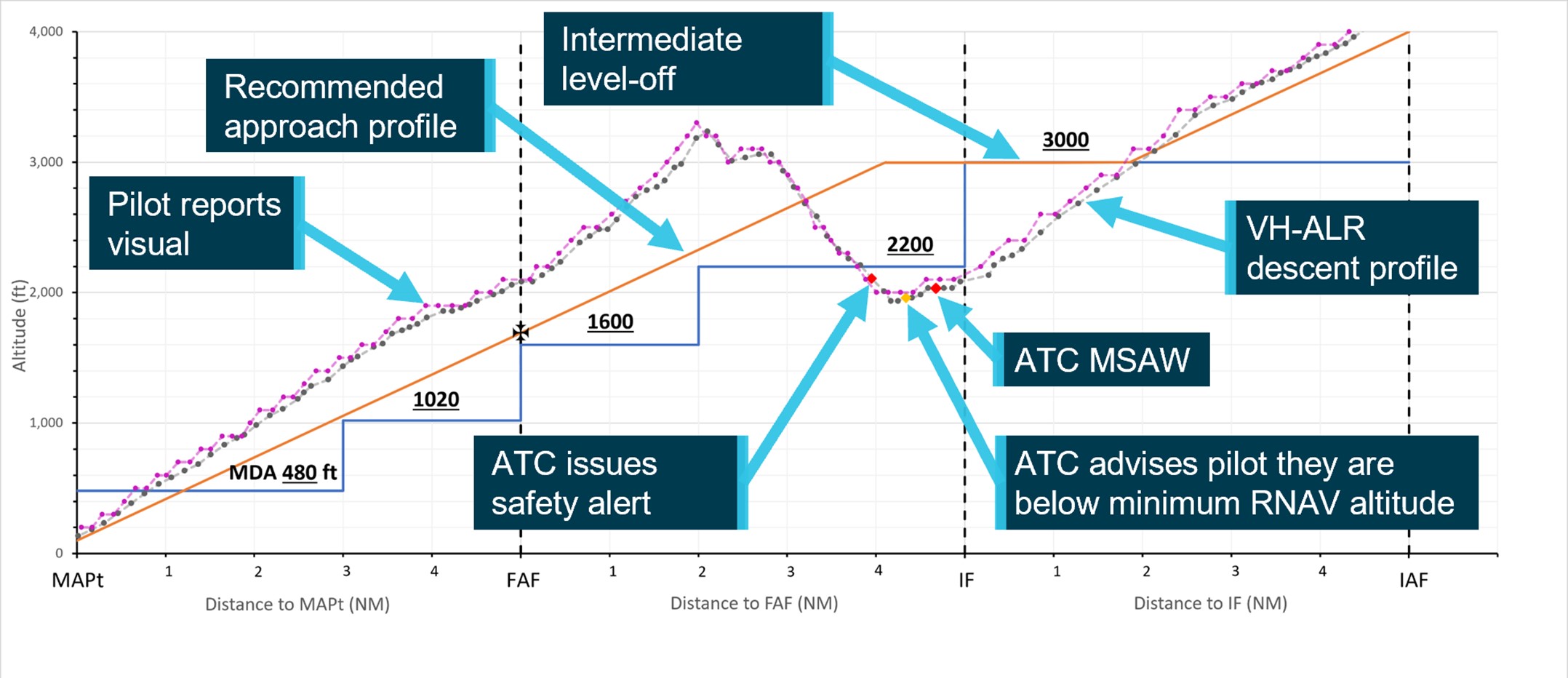
“While in cloud on the approach segment between the initial approach fix and intermediate fix, the aircraft descended below the 3000 ft segment minimum safe altitude,” ATSB Director Transport Safety Dr Stuart Godley explained.
“The aircraft continued to descend and entered the next segment at 2000 ft, below that segment’s minimum safe altitude of 2200 ft.”
The approach controller then received an automated warning, and contacted Parafield tower, who alerted the pilot. The pilot subsequently climbed the aircraft back above the minimum altitude.
“The pilot was experiencing an increased workload from conducting an instrument approach in cloud and turbulence and did not detect their flight below the segment minimum safe altitude.
“This incident is a good reminder to pilots of the importance of close monitoring of the aircraft’s vertical and lateral navigation, in particular during high workload phases of flight.”
The investigation report notes that once the pilot returned above minimum safe altitude, they continued the climb.The aircraft was about 7 NM from the runway and 850 ft above the recommended profile, when the pilot elected to continue the approach.
“Continuing the approach from that position, above the recommended profile, required a higher-than-normal descent rate, and had the potential to increase the pilot’s workload,” Dr Godley added.
The pilot established visual reference with the runway about 4 NM from the threshold, and landed without further incident.
The ATSB report notes the pilot was referring to a hand-held paper copy of the instrument approach procedure, but that the aircraft’s control yoke did not have a chart holder, nor did the pilot have a document holder or kneeboard available.
This increased the difficulty monitoring the check altitudes and segment minimum safe altitudes.
“Continuous monitoring of the aircraft’s altitude relevant to the various segment minimum safe altitudes, and having the instrument approach procedure available in a suitable location, are both key to minimising workload and conducting an instrument approach safely,” Dr Godley said.
“Pilots also need to remain vigilant about the relationship between the procedure commencement altitude and the constant descent final approach path, including that the correct waypoint has been identified for managing the descent profile and ensuring the distance-based check altitudes are correctly interpreted.”
At 1421 on 21 April 2024, a Sydney Trains service 805K travelling from Penrith to Sydney Central Station traversed BN 318 turnout near Blacktown Station at a speed of 101 km/h. The turnout speed was sign posted for 25 km/h. The driver was thrown from their driving position but resumed control shortly after a train activated automatic emergency brake application had applied. The driver brought the train to stop at Blacktown Station and had suffered minor injuries. There were no reports of injured passengers.
What the ATSB found
The driver did not operate the train in accordance with signal indications and traversed BN 318 turnout at 101 km/h, 76 km/h over the permitted speed limit.
The driver was not situationally aware as they approached the turnout. They also expected the signal aspects and direction of travel to be the same as they had experienced many times before. So, the driver did not react to the medium signal aspects and slow the train before reaching the turnout.
The investigation also found BN 318 turnout was identified as a high-risk turnout as part of an Automatic Train Protection (ATP) project led by Transport for NSW (TfNSW). The decision to install additional protection for overspeed at this location and others was later revised by TfNSW and overspeed protection was not installed when the ATP project was handed over to Sydney Trains.
As a result, Sydney Trains did not have effective controls for overspeed on parts of the rail network where high-risk turnouts were present. The overspeed of 805K was one of several overspeed events that had occurred on the Sydney Trains Network in previous years.
Shortly after this incident, the Office of the National Rail Safety Regulator (ONRSR) issued Sydney Trains with an improvement notice to address the network-wide risk of overspeed through turnouts on their rail network.
While the track infrastructure was inspected immediately after the overspeed event, the train was permitted to continue in service without being inspected. Sydney Trains identified it did not have a response procedure for overspeed incidents in place at the time.
What has been done as a result
Sydney Trains addressed the immediate risk of overspeed through high-risk turnouts by lowering speed limits at high-risk turnout locations on the rail network. Sydney Trains also developed a plan to implement ATP at these high-risk turnout locations with funding approved and provided by TfNSW.
Sydney Trains also developed and implemented a response procedure for overspeed incidents.
Safety message
Overspeed on the rail network carries a high risk of train rollover and the potential for multiple fatalities as demonstrated by previous incidents in Australia. Risk controls for areas of a rail network where credible safety risks have been identified should be reviewed periodically to determine whether the existing controls remain effective and to establish whether practical means exist to further reduce or eliminate risk.
Near-miss events that occur on Australia’s rail networks present an opportunity to reassess the effectiveness of existing controls in real world environments. Rail network managers should have processes in place to capture incident data and to initiate reviews of risk control effectiveness. Risk reviews should assess the risk of known and foreseeable incidents, and establish controls, based on the most critical, credible outcomes.
Post-incident processes should be in place to manage responses consistently and in a manner that reduces the likelihood of further incident escalation.
The occurrence
Events preceding the incident
On the afternoon of 21 April 2024, an 8-car double-deck suburban train was being operated between Penrith and Sydney Central Station, New South Wales. This train was a scheduled Western Line passenger service, run number 805K, and was crewed and operated by Sydney Trains. Run 805K’s crew comprised of one driver, who was seated at the front of the train, and one guard, who was located at the rear of the train.
The driver was scheduled to work an 8.5-hour shift and signed on at Blacktown just after 0900 local time. The driver began their shift by travelling to Lidcombe and operated several passenger services between Lidcombe and Olympic Park. The driver had their scheduled crib break[1] at Lidcombe at around 1215 and then took control of passenger service 805J at around 1300, which they drove from Lidcombe to Penrith.
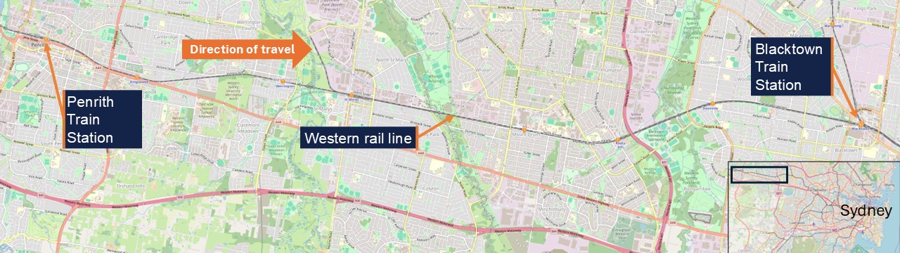
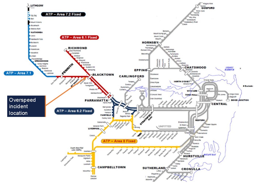
This service would form run 805K to Central after a short turnaround at Penrith, and both crew members would operate the train to Blacktown where they would be relieved by a new crew. The guard was scheduled to end their shift at Blacktown, while the driver was rostered to take charge of another revenue service at Blacktown, following a short break (Figure 1).
Figure 1: Geographic area of operation
Source: TfNSW ArcGIS, annotated by OTSI
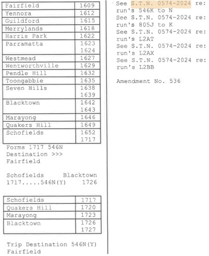
Run 805K’s stopping pattern was all stations from Penrith to Blacktown, and the train crew was provided with a crew diagram containing the stopping pattern for reference. These crew diagrams outlined each service a crew member would operate during their shift, as well as crib breaks, turnaround times, and relief information (Figure 2).
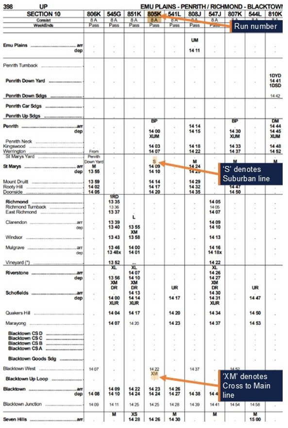
Additional information about run 805K was provided to the crew in Special Train Notice[2] (STN) 0574-2024, which detailed all passenger and empty train movements for that weekend, the running times, the running lines and turnouts train services would be operating on (Figure 3).
The STN number was listed on the crew diagram next to each run the crew would operate during their shift.
Figure 2: Extract of crew diagram
Source: Sydney Trains
Figure 3: Extract from STN 0574-2024
Source: Sydney Trains, annotated by OTSI
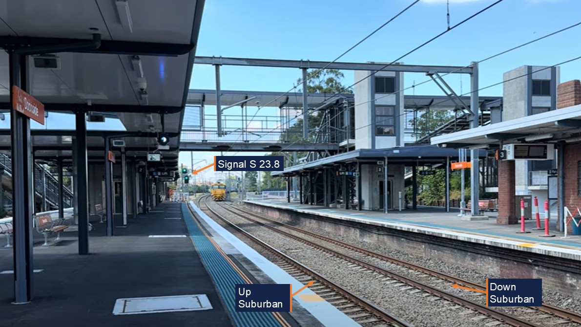
Run 805K was 1 of 8 trains scheduled to operate via the Up Suburban and BN 318 turnout on 21 April. The train departed Penrith on time at 1400 hours and proceeded without incident to Doonside, where the train stopped briefly before departing at 1419:52. On departure, the train passed automatic signal S 23.8 which was showing a Clear[3] indication, and the driver applied maximum power to accelerate the train (Figure 4).
Figure 4: Signal S 23.8
Image from Doonside platform upgrade VLOG. Source: Sydney Trains, annotated by OTSI
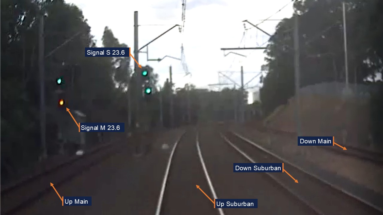
Around 44 seconds later, at 1420:36, the train had travelled 650 m and reached a speed of 81 km/h as it passed automatic signal S 23.6 (Figure 5). This signal also showed a Clear indication, and the driver maintained the same power setting as they proceeded into the next block[4].
Figure 5: Signal S 23.6
Image from Front of Train CCTV Car D6432 on incident run, approaching signal S 23.6. Source: Sydney Trains, annotated by OTSI
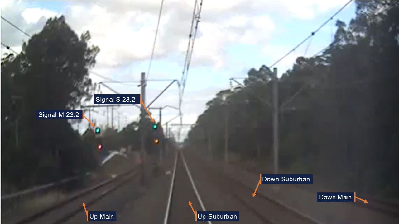
The train travelled another 624 m in the next 24 seconds, passing automatic signal S 23.2 at 1421:00 at a speed of 106 km/h (Figure 6). This signal was displaying a Preliminary Medium[5] indication, which warned the driver that the next signal would be displaying at least a Medium[6] indication. The driver maintained maximum power as they passed signal S 23.2 and only moved the power handle to OFF to coast the train when the speed reached 110 km/h around 11 seconds later.
Figure 6: Signal S 23.2
Image from Front of Train CCTV Car D6432 on incident run, approaching signal S 23.2. Source: Sydney Trains, annotated by OTSI
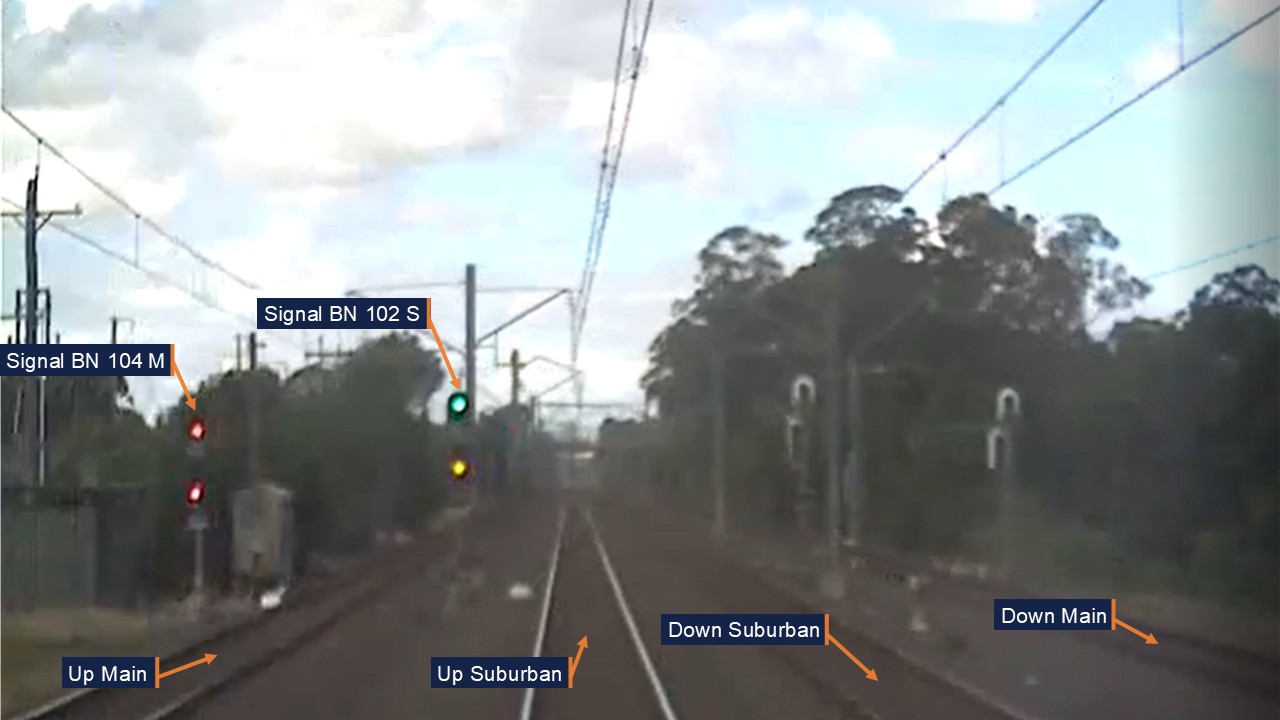
The train’s speed dropped back to 106 km/h by 1421:21 as the train reached Blacktown West, which was marked by a yard limit[7] sign and controlled Accept signal BN 102 S (Figure 7). This signal was displaying a Medium indication, which warned the driver that the next signal would be displaying a Caution[8], Caution Turnout[9] or Medium Turnout[10] indication. However, the driver continued to coast at 106 km/h with no braking action applied.
Figure 7: Signal BN 102 S
Image from Front of Train CCTV Car D6432 on incident run, approaching signal BN 102 S. Source: Sydney Trains, annotated by OTSI
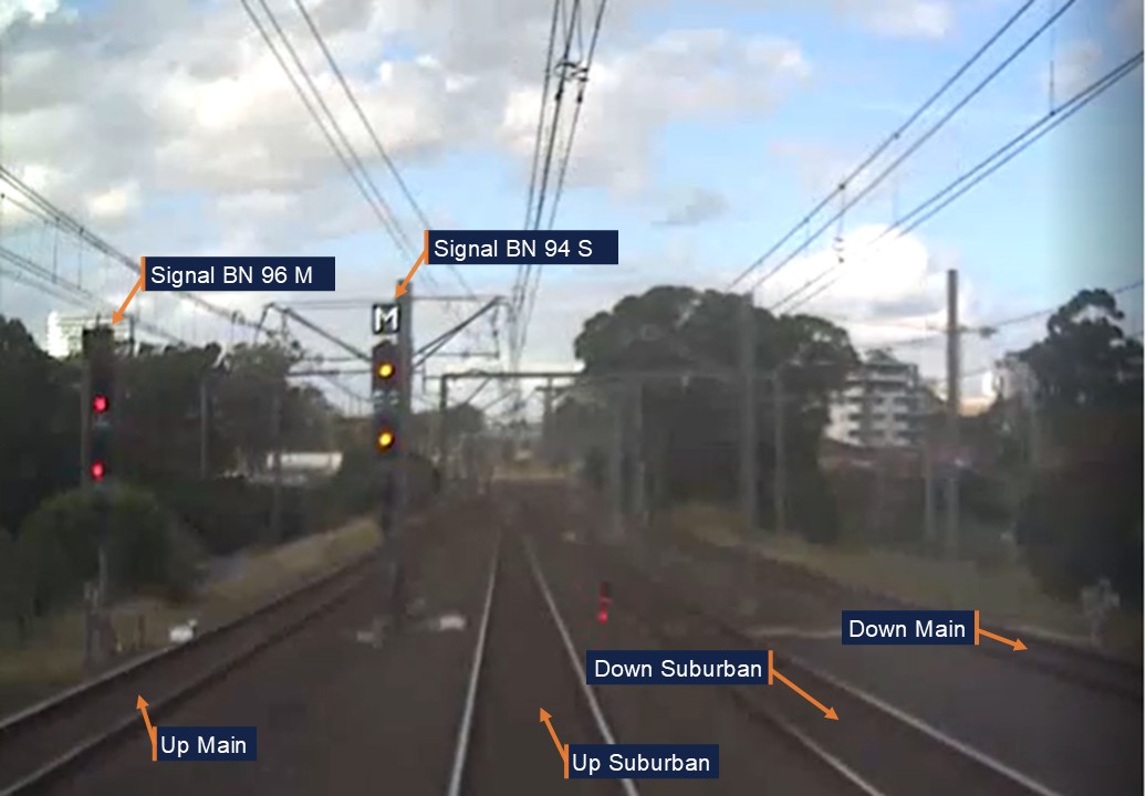
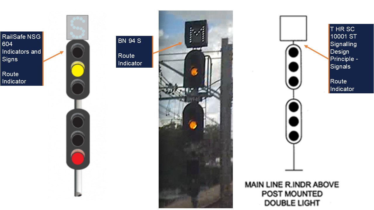
At 1421:42, around 21 seconds and 635 m after passing signal BN 102 S, the train reached controlled Home signal[11] BN 94 S at a speed of 106 km/h. This signal was displaying a Medium Turnout indication with a corresponding route indication of ‘M’. This warned the driver that the points beyond the signal were set for the route from the Up Suburban to the Up Main, which had a posted speed limit of 25 km/h (Figure 8).
Figure 8: Signal BN 94 S
Image from Front of Train CCTV Car D6432 on incident run, approaching signal BN 94 S. Source: Sydney Trains, annotated by OTSI
At this point, the train had travelled past 2 medium signals in 42.5 seconds at a consistent speed of 106 km/h, with idle throttle and no braking action applied. As the train passed signal BN 94 S, the driver acknowledged a visual alert from the onboard task‑linked vigilance device via a pushbutton, which reset the timing cycle. The driver then moved the power handle to the Brake position when run 805K was less than one train length from BN 318 turnout.
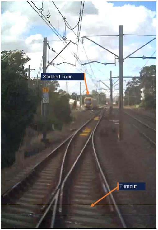
The train decelerated to 103 km/h before the lead car entered BN 318 turnout at 1421:49 and at a speed of 101 km/h. Although the train went through the leading points at more than 4 times the posted speed limit, the train remained upright and did not derail. A 4-car Millennium set was stabled at the country end of Blacktown Up Loop, which was adjacent to the Up Main, but it was not impacted as run 805K stayed on the tracks (Figure 9).
Figure 9: Dashcam of train mid turnout
Image from Front of Train CCTV Car D6432 on incident run, mid turnout with stabled train ahead. Source: Sydney Trains, annotated by OTSI
The driver was thrown from their seat by the force of the train’s movement through the turnout. This caused the driver to relinquish control of both the train controls and the Operator Enabled Pedal (OEP), a safety device which is activated when the driver becomes incapacitated. This action triggered an emergency brake application[12] which slowed the train down and the driver was able to return to their seat and reset the OEP, 6 seconds later.
As the train continued to slow, the driver contacted the guard to check if they were okay, and the guard and driver confirmed to each other that they were fine. The guard also enquired as to what had happened, and the driver said they had missed the signal and gone through the points too quickly. The driver released the brakes and slowly accelerated the train from 15 km/h back up to 50 km/h over the next minute.
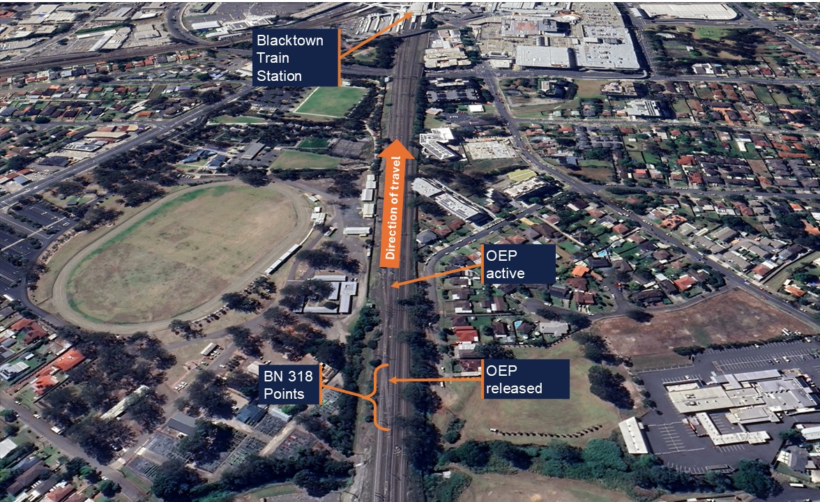
The train then continued uneventfully to Blacktown Station (Figure 10), where the driver brought the train to a controlled stop at the scheduled arrival time of 1423.
Figure 10: Approach to Blacktown Station
The Operator enabled pedal (OEP) was released by the driver passing through BN 318 points and turnout at approximately 101 km/h. Source: Google Earth, annotated by OTSI
Events after the incident
After the train arrived at Blacktown, the guard was unsure as to whether the incident needed to be reported and called the Train Crew Liaison Officer (TCLO) at 1429 to seek clarification. The TCLO confirmed that the guard was okay and said that they would progress the incident report to other parties, and then they called the driver at 1433.
The driver told the TCLO that they were not feeling well and that they had been thrown out of their seat during the incident. The TCLO advised the driver to go to the Blacktown sign-on area for post-incident testing and arranged a replacement driver for their roster. After speaking with the driver, the TCLO contacted the Network Incident Manager (NIM) at 1435 to report the incident.
The NIM then took the following actions:
At 1438, instructed the Blacktown Area Controller (AC) to book out BN 318 turnout pending inspection.
At 1443, asked Civil and Signals to check BN 318 turnout points for damage.
At 1445, requested a data logger download for run 805K from Defects[13].
At 1450, requested an Incident Response Commander (IRC) to attend Blacktown Station to interview the driver.
At 1457, arranged for drug and alcohol testing to be conducted on the driver.
At 1501, reported the incident to the on-call investigator.
At 1517, spoke with Defects to confirm the set number, which was A32, for run 805K and repeated their request for a data logger download.
At 1540, confirmed with Infrastructure Control (ICON)[14] that BN 318 turnout had been inspected and certified.
At 1541, told the Train Service Delivery Manager (TSDM) that BN 318 turnout was available for traffic.
At 1601, confirmed the speed of the train and incident categorisation with the IRC.
Set A32 was not removed from service during this time and continued to convey passengers for several hours after the incident. At 1800, there was a shift changeover and the NIM on duty at the time of the incident handed over to the NIM of the next shift.
Set A32 continued in service for another hour until Defects contacted the new NIM to check on the condition of the train. At 1902, the NIM instructed the TSDM and Defects to stop the train and remove it from service immediately pending an inspection. The train was then transferred to Auburn Maintenance Centre (AMC), where it was inspected the following day.
No damage or problems were reported with set A32 while it was in service, and no issues were found during the inspection at AMC. No infrastructure damage was found at Blacktown West following the overspeed, and no injuries were reported by the guard or passengers on board the train.
Context
Driver information
Training and competencies
The driver joined RailCorp[15] in 2005 and had extensive experience driving suburban trains in the Sydney metropolitan area. The driver had transferred to Blacktown Crew Depot around 7 years prior to the incident, but in that time, they could only recall driving a train through BN 318 turnout ‘‘maybe two or three times’’. However, the driver held the required route knowledge and operational competencies for the tasks undertaken and had passed their most recent competence assessment in August 2023.
Roster
The driver was working an altered diagram[16] on 21 April between 0922 and 1751 hours, with a total shift time of 8 hours and 29 minutes. This diagram required the driver to operate Olympic Park services in the morning, a Penrith service in the middle of the day, and Y-Link services[17] in the late afternoon. This was the driver’s third shift following 2 days off, and the FAID[18] score for their roster was calculated to be 35.
Awareness of train running
Most city-bound Western Line suburban services travelled on the Up Main between St Marys and Blacktown. However, a handful of services each day were timetabled to operate on the Up Suburban between St Marys and Blacktown West, then cross back to the Up Main via turnout BN 318. This occurred for operational reasons such as rail cleans, crew route knowledge, line closures for track inspections, or to pass freight trains.
This planned route information was not specified in crew diagrams, but was shown in STNs, Standard Working Timetable books, and the Digital Timetable Information Portal. These resources were made available for crews to review online via a mobile device but were principally designed to provide train operating information to rostering staff, signallers, customers and the rail operations centre. The STN’s provided details of any alterations from the standard working timetable due to planned track works or other special events and did not expressly advise of conditions with the potential to affect safety on the rail network.
The STN’s were large documents. For services on 21 April 2024 the relevant STN was 420 pages in length. Crews were prohibited from using mobile devices while operating a service, therefore there was an expectation that they were to review any relevant train running information provided ahead of operating services.
Crews were not required to confirm that they had read each STN for every service they operated. General network rule ‘NGE 212 Network Information publications’ required that ‘Qualified Workers must read and use the information in relevant publications to do their work’. The specific use of the word ‘relevant’ in the procedure appeared to leave the determination of what is relevant to the discretion of the driver.
The driver in this event did not read the STN, and the procedure implies that they are not required to if they did not consider them relevant. The driver also reported that crews don't have much time to read all the documents and that it took a long time to find and read these documents using the iPad prior to their shifts. It is therefore unclear whether drivers were required to read the STN, or had been provided with sufficient time, resources and training to review them prior to operating services.
However, safeworking rule ‘NSG 606 Responding to signals and signs’ states when operating a service drivers must be qualified in the route, use their route knowledge to navigate the section and above all they must obey lineside signals, and route/turnout indications to know the specific route their train will be taking. In addition to published alterations to the timetable, network conditions may require the train to be diverted to another line at any time to meet immediate operational requirements.
While crews operating Up services on the Western Line generally expect to run via the Up Main, they are qualified for both tracks as part of their route knowledge requirements. Driver route knowledge diagrams document the information crews are required to know and support familiarisation and retention (Figure 11).
Figure 11: Driver route knowledge diagrams – Doonside and Blacktown
The track between Doonside and Blacktown, indicates a slight right hand curve leaving Doonside then straight track to BN 318 turnout. Source: Sydney Trains, annotated by OTSI
The driver confirmed that they had not seen STN 0574-2024 on the day of the incident, and that they had not used their company-issued iPad during sign-on time to view it. The driver added that they had used the iPad to swap a shift that morning but did not use it for anything else.
Recollection
The driver stated during interview that their usual routine was to start packing their items prior to the station where they were being relieved. On the day of the incident, the driver said that they started packing at Doonside because they were leaving run 805K at the next station, which was Blacktown.
The driver stated that when the guard gave the ‘all right’ bell signal confirming it was safe to depart, they checked signal S 23.8 and saw it was showing ‘full green’. They also confirmed that they could see the next three signals from a distance, stating that signal S 23.6 also indicated ‘full green’, and that the two signals beyond that were at medium.
The driver recalled that they powered the train ‘up to around 100’ past the green signals, and then ‘shut off’ the power to coast towards the next signal which was at Medium. However, the driver continued coasting, expecting the next signal to be at Caution. Although the driver knew they were on the Up Suburban as they departed Doonside, they said they began to think of the signalling sequence on the Up Main instead.
The driver stated that when driving on the Up Main from Doonside, the usual sequence of signalling would be ‘three green signals, and then medium, caution, and stop’. They explained that as a train approached the Lancaster Street bridge on the Up Main, the Stop signal would clear first, which would then change the Caution to Clear. The driver added that, if the Stop signal did not clear, they would usually begin braking from the Lancaster Street bridge on the Up Main.
However, on the day of the incident, the driver said that as they approached the bridge, they read-through[19] to 2 signals at Stop on the Up Suburban. The driver said they did not see the Medium Turnout or Route indications on signal BN 94 S, even though they had expected to see this signal at Caution. The driver recalled that, because they had missed the signal, they began to apply the brakes, but there was insufficient time to reduce the train speed to 25 km/hr as required. The train then continued through the turnout at 101 km/hr, and the driver was thrown from the chair.
Train information
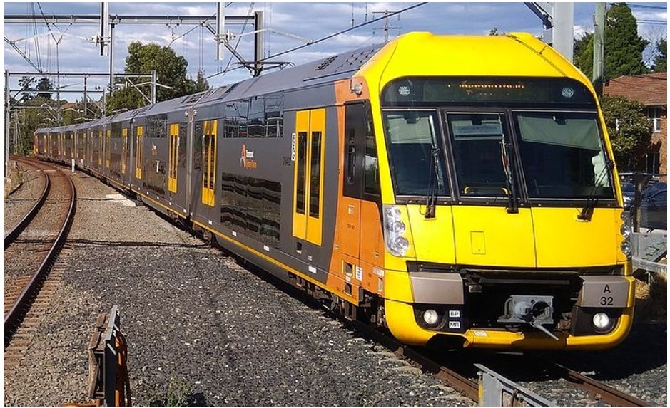
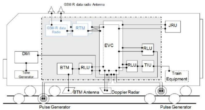
The train involved in the incident was an 8-car double-deck Waratah, set number A32 (Figure 12). These trains entered service between July 2011 and July 2014 and were maintained at Downer Group’s[20]Auburn Maintenance Facility. All Waratah sets were fitted with Automatic Train Protection (ATP)[21] technology, which provided a risk control against driver error or system failures through automatic brake interventions in some locations. Further details of the ATP system are described in Appendix A.
Figure 12: Waratah set – A32
Train set involved in the overspeed, A32. Source: Pinterest
Track information
The Western Line at Blacktown West consisted of 4 standard-gauge tracks, arranged in parallel with 2 Up lines and 2 Down lines. The Up Main and Up Suburban had a speed limit of 115 km/h from Doonside to Blacktown West, which decreased to 100 km/h at Blacktown West.
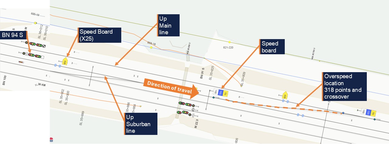
A ladder of bi-directional points connected the country-end of Blacktown Up Loop to the Down Suburban, and each turnout had a speed limit of 25 km/h. This included BN 318 turnout, which facilitated movements between the Up Main and Up Suburban (Figure 13).
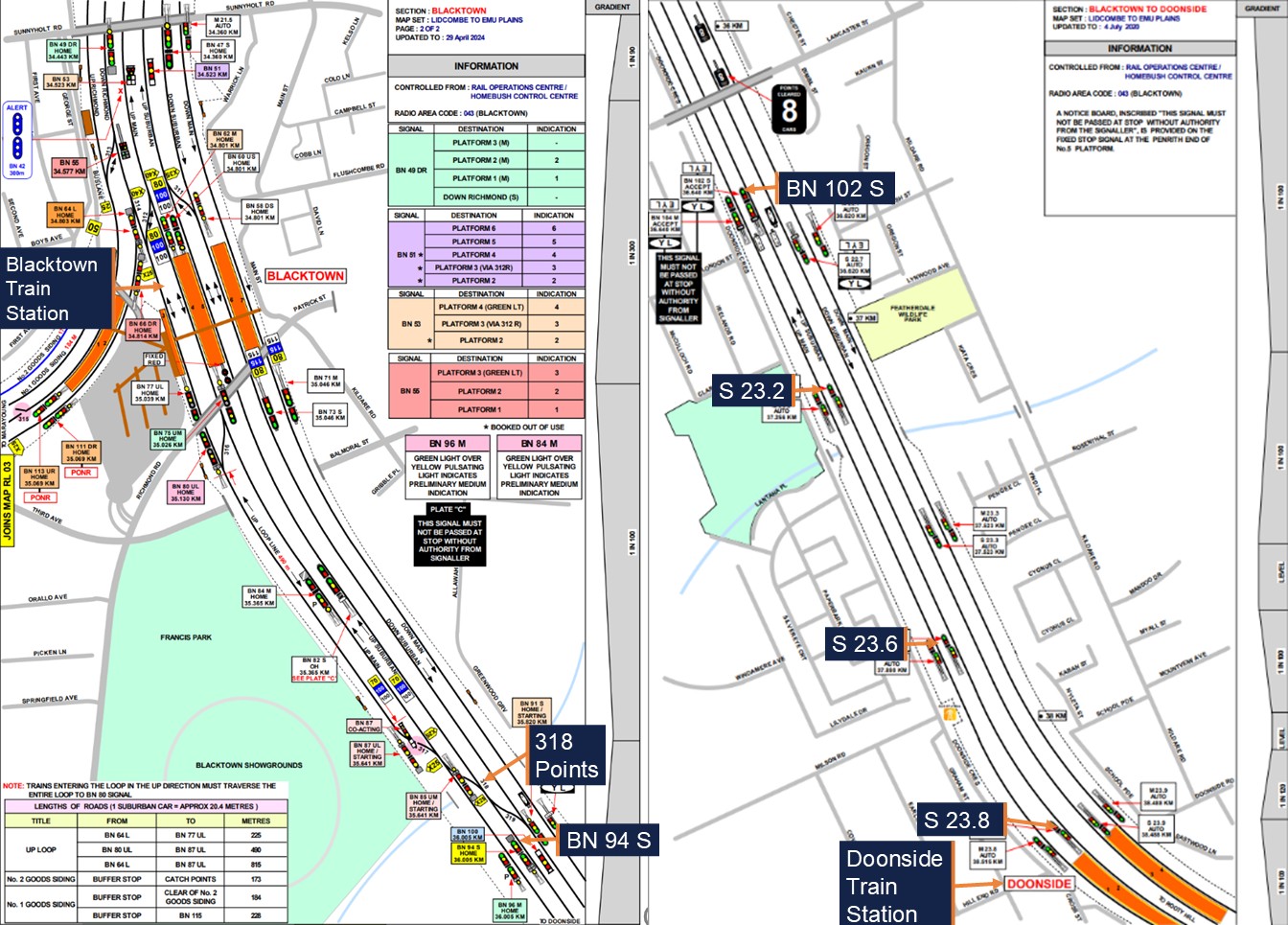
Figure 13: Track and signal layout at Blacktown West
Map (not to scale) – BN 94 S route indicator and signal, X25 speed board and BN 318 turnout. Source: WebGISME, annotated by OTSI
Signalling design
Signalling systems provide a critical risk control to protect infrastructure and other trains. The signalling system on the Sydney Trains network was designed to the Transport for NSW (TfNSW) signalling design principles standard[22]. Within the metropolitan area bounded by Emu Plains, Waterfall, Macarthur and Berowra, double-light colour light[23] signalling controlled train movements. Sydney Trains confirmed that the signals between Doonside and Blacktown West were compliant with signal design requirements.
Signal layout
In double-light colour light signal territory, the default indication for automatic signals is a proceed indication, e.g. Clear, Medium or Caution and the default indication for Home signals is ‘Stop’, or Red over Red. This is because automatic signals are controlled exclusively by track circuits and show the occupation of the track ahead, whereas Home signals are controlled by signallers and directly protect points, level crossings, and other risks.
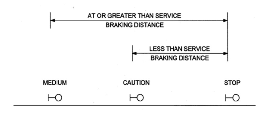
Home[24] signals can be preceded by an Outer Home[25] or an Accept[26] signal, depending on the location and the nature of the risk requiring protection. In a location where a Home signal at ‘Stop’ was immediately preceded by an Accept signal, the Accept signal would show a Caution indication by default. Additionally, the automatic signal prior to the Accept would show a Medium indication (Figure 14), until such time as the Home signal beyond was cleared. This was the arrangement of the signals on approach to Blacktown West.
Figure 14: Basic signal layout – plain track
Source: TfNSW standard T HR SC 10001 ST Signalling Design Principles - Signals
A total of 5 signals controlled train movements between Doonside and Blacktown West on both the Up Main and Up Suburban. Table 1 shows the signals that a train would pass in order on the Up Suburban after departing Doonside:
Table 1: Signals on the Up Suburban from Doonside to Blacktown West
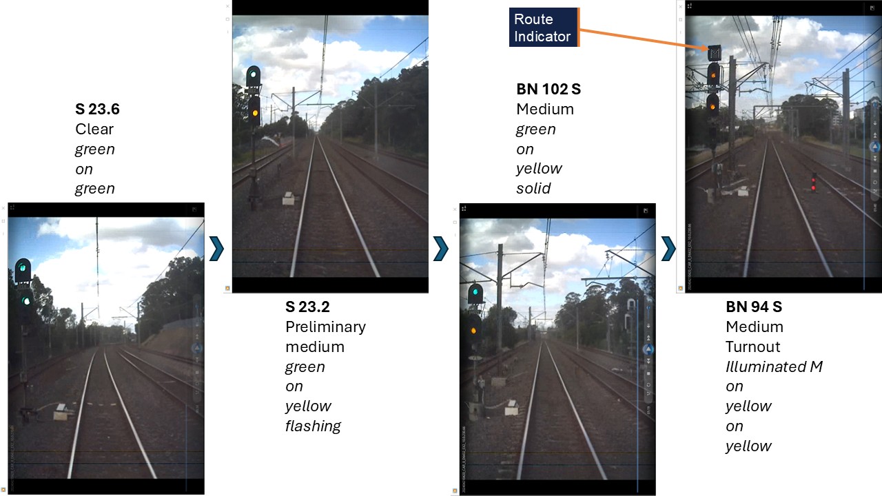
Set A32 was equipped with a front-of-train camera which recorded run 805K’s journey between Doonside and Blacktown West on 21 April. This camera showed the signalling sequence as the train approached BN 318 turnout, showing the progression from a Clear indication to Preliminary Medium, Medium, and then Medium Turnout.
There was a slight right-hand curve between signals S 23.8 and S 23.6, but the corridor was straight with unobstructed sightlines from signal S 23.6 to Blacktown West. In clear weather conditions, signal BN 94 S had a sighting distance of around 1.5 km (Figure 15).
Figure 15: Signal aspects from S 23.6 to Blacktown West and BN 318 turnout
Front of Train CCTV - Signal sequence approaching Blacktown from Doonside, starting with S 23.6. Source: Sydney Trains, annotated by OTSI
The automatic signals on the Up Main were placed parallel to those on the Up Suburban at the same kilometrages and were only differentiated by the ‘M’ for Main in the signal name (see Figure 5 and Figure 6). The controlled signals, Accept and Home, on the Up Main were BN 104 M and BN 96 M respectively (see Figure 7 and Figure 8).
Route indicators
Route indicators provide a supplement to proceed indications by displaying an indication to the driver of the route destination.
Section 1.4.2 of the TfNSW signalling design principles standard stated that:
If a double light colour light signal applies to more than one diverging route, then it shall be fitted with a main line route indicator to supplement the turnout indication.
Additionally, Network Rule NSG 604 Indicators and Signs also stated that:
In single and double light colour light signalled territory, route indicators on running signals indicate, in most cases, the turnout route.
If the signal displays a PROCEED indication, the route indicator shows, letters, usually related to the name of the line, as in S for Suburban, and M for Main.
The signal protecting BN 318 turnout was BN 94 S, and this signal was a double-light colour light signal which controlled more than one diverging route. Signal BN 94 S had a route indicator which only illuminated for routes which deviated from the Up Suburban.
If a route was set for the Up Main or Up Loop via BN 318 turnout, the route indicator would show an ‘M’ or an ‘L’ respectively. At the time of the incident, signal BN 94 S was displaying a Medium Turnout indication with a corresponding ‘M’ route indication. This was compliant with the TfNSW standard and the Network Rules (Figure 16).
Figure 16: Route indicators
Left: NSG 604 Route Indicator; Middle: BN 94 S; Right: T HR SC 10001 ST Route Indicator. Source: Transport for NSW and RailSafe, annotated by OTSI
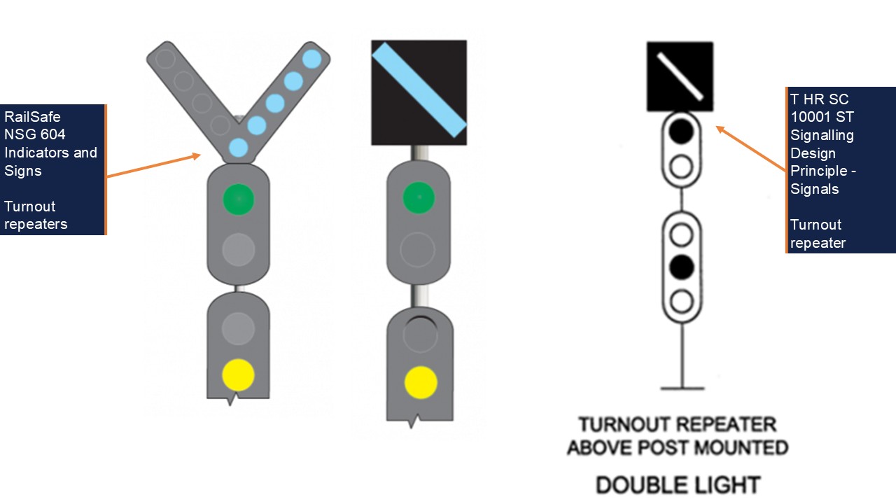
Turnout repeaters
Following the incident, Sydney Trains identified that there was no turnout repeater[28] for signal BN 94 S as an advanced warning mechanism for BN 318 turnout (Figure 17).
Figure 17: Turnout repeaters
Left: NSG 604 Examples of Turnout repeaters; Right: T HR SC 10001 ST Turnout repeater. Source: Transport for NSW and RailSafe, annotated by OTSI
Section 1.4.9 of the TfNSW engineering standard stated:
Where it is required to provide advance warning that the turnout route is set at a junction, a turnout repeater shall be fitted on the first warning signal in the rear of the turnout signal.
Additionally, Network Rule NSG 604 Indicators and Signs stated:
Turnout repeaters are placed at braking distance from points to give advance warning that a turnout route is set. They have one or more diagonal bars of white lights, in a separate unit fixed to the signal. The lights are angled up towards the turnout route.
Sydney Trains advised that a turnout repeater was not required for BN 318 turnout. However, if a turnout repeater had been installed for BN 94 S, this warning likely would have been placed on controlled signal BN 102 S. At line speed, this would have provided the driver of run 805K an extra 20 seconds of response time and 635 m of additional braking distance ahead of BN 318 turnout.
In its investigation, Sydney Trains confirmed that turnout repeater signals enhanced overall visibility and signal recognition for drivers and provided additional confirmation of primary signal indications. Sydney Trains also noted that turnout repeaters could improve a crew’s situational awareness, but that they did not eliminate the risk or prevent the consequences of an overspeed.
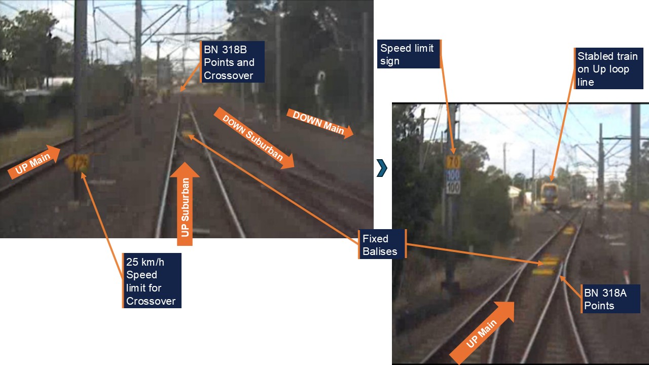
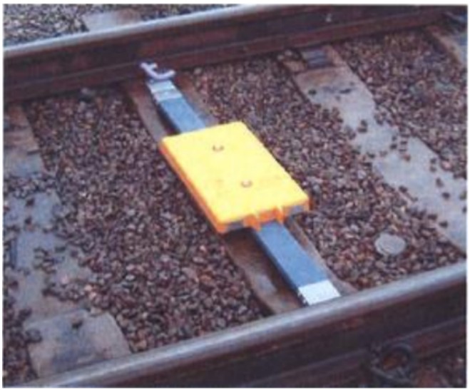
Fixed balises
Automatic Train Protection (ATP) was installed on the Sydney Trains network as a risk control to monitor a train’s operation in relation to speed limits and signal indications. To support the ATP system, electronic beacons in the form of balises were placed between the rails, which sent static or dynamic data to receivers on passing trains.
Fixed balises provided static, pre-programmed data, such as maximum line speed for the location or position data. While controlled balises are connected to a Line side Electronic Unit that reads current signalling conditions and provides dynamic, real-time data to the train via the balise.
Fixed balises were used in some parts of the Sydney Trains network, including at BN 318 turnout (Figure 18).
Figure 18: BN 318 points and crossover (turnout)
Front of Train CCTV. Top left: view after passing BN 94 S, crossover speed sign X25; Bottom right: passing over the crossover, main line speed sign 70/100/100. Fixed balises in four-foot. Source: Sydney Trains, annotated by OTSI
Each fixed balise provided a package of pre-programmed data, depending on its purpose and where it was placed on the network. For example, some fixed balises were used for maximum line speed monitoring. These fixed balises provided static, location‑specific speed sign information to passing trains to enable the train’s onboard equipment to apply an emergency brake intervention if the train exceeded the speed limit for the location. Others were used for repositioning and only communicated odometer information to a train for location readings.
Sydney Trains confirmed the fixed balises beyond the speed limit sign (bottom right picture in Figure 18) were installed for maximum line speed monitoring of the Up Main line and for repositioning of trains travelling in the Up direction. The fixed balises at either end of BN 318 turnout were for repositioning only in both directions (see also High-Risk Turnout Operational risk assessmentfor balise configuration for the turnouts).
Government plan to implement ATP
Waterfall inquiry recommendations
The implementation of ATP on the Sydney Trains network was directly linked to the findings from the Special Commission of Inquiry (SCOI) into the Waterfall rail disaster on 31 January 2003. The SCOI found that the existing vigilance devices installed on trains had shortcomings such as a lack of overspeed protection.
To address this issue, one of the recommendations from the SCOI stated that:
RailCorp should progressively implement, within a reasonable time, Level 2 Automatic Train Protection.
The New South Wales Rail Regulator (ITSRR[29]) at the time was tasked with overseeing the implementation of these recommendations, and discovered at the time that:
Level 2 ATP, using the European Rail Traffic Management System definition, has not been installed on a network comparable to RailCorp. No other comparable rail network has been successful in retrospectively introducing this level of automatic train protection on an existing rail network. The feasibility of retrofitting this type of ATP system to the existing NSW railway network therefore requires further review.
ITSRR also noted a 2004 RailCorp study into the risks associated with train overspeed and potential options to mitigate those risks. The study determined that a system based on the use of track transponders to provide warnings to drivers and apply the brakes in certain conditions would be feasible.
ITSRR continued to monitor the implementation of the SCOI recommendations quarterly until the end of 2012, which coincided with the creation of ONRSR[30]. ONRSR published annual updates on the SCOI recommendations until March 2020, when it stated that ‘the implementation of an ETCS Level 2 system remains in TfNSW’s future strategies for the electrified railway network’.
Intended ATP rollout
In response to the Special Commission of Inquiry (SCOI) into the Waterfall accident, and the 2004 RailCorp feasibility study, European Train Control System (Level 1) equipment otherwise known as ATP, was planned to be deployed across the Sydney Trains network. This system was designed to overlay the existing signalling system with its primary purpose being to minimise risks from over speeding.
In August 2010, the NSW Government approved a 3-stage rollout of ATP on the rail network, beginning with Stage 1 in 2011 and an expected finish date for Stage 3 in 2021. Stage 1 involved the installation of ATP equipment on portions of the electrified rail network and on the entire OSCAR and Tangara train fleets between 2011 and 2017.
Stages 2 and 3 involved the installation of ATP equipment on the remainder of the electrified rail network, as well as extending ATP technology to the Waratah and Millennium train fleets. Stage 2 was expected to run between 2013 and 2018, with Stage 3 running concurrently from 2015 to 2021.
In January 2011, RailCorp engaged a supplier to provide equipment and engineering services for the first approved package of works.
The program became known as the ATP Project and was vested to Transport for NSW (TfNSW) in 2013.
Safety roles and responsibilities
Rail Safety National Law (RSNL) describes that rail infrastructure managers, rolling stock operators and designers, manufacturers and suppliers of rail infrastructure or rolling stock assets each have a duty to ensure so far as is reasonably practicable (SFAIRP) the safety of railway operations[31].
This includes, but is not limited to, ensuring that assets are designed, constructed, commissioned, used and maintained in a way that ensures the safety of railway operations.
ONRSR Guideline ‘Meaning of duty to ensure safety so far as is reasonably practicable’ provides guidance, references and a broad framework for making SFAIRP determinations[32]. Risk management principles such as likelihood and severity are to be applied, with the guideline also providing guidance on reversing previously determined SFAIRP decisions. In such circumstances, ONRSR acknowledges there may be very specific, albeit limited, occasions when it may be shown that an existing control is no longer necessary to ensure safety SFAIRP.
It can also be interpreted from the ONRSR Guideline ‘Major Projects’[33] that everyone involved from the project conception through to operations and maintenance to decommissioning, has a shared safety responsibility, and that each party has a duty to work with others to ensure that everything reasonably practicable is done to ensure the safety of assets throughout their lifecycle.
The guideline also describes that safety roles and responsibilities be well defined for each involved party, and that there is merit in supporting a project delivery model that has the operator and maintainer as the accredited entity during the project delivery phases to support the management of safety risks in a manner consistent with how the assets will be used throughout their service life. In particular, the guideline specifically requires that the operator and maintainer will need to demonstrate how it will be assured that the delivered assets manage safety risk SFAIRP.
The TfNSW Safety Assurance Report (SAR) for Area 6.1 and 6.2, dated 9 Nov 2021, outlines the key roles and responsibilities for engineering safety assurance for the ATP project as being exclusively TfNSW employees or external contractors. Sydney Trains is not nominated to play a role, other than to conduct technical diligence reviews during the Design Safety Review and approval process.
Sydney Trains in its SAR for Area 6.1, dated 27 Oct 2021, outlines its own principal responsibilities as being the operation and maintenance of the ATP trackside assets and its fleet after handover, and operational readiness activities leading to passenger service operations.
Sydney Trains also outlines key roles and responsibilities which focus principally on operational readiness based on its defined role, but some roles did include responsibilities such as formally liaising with the TfNSW to obtain the required evidence for a safety assurance demonstration from TfNSW.
High-Risk Turnout Operational risk assessment
Where a low-speed turnout exists on a high-speed line, the risk of derailment and/or rollover in the event of an overspeed through the turnout exists, as observed at Wallan in February 2020 (reference Appendix C – Similar related Incidents).
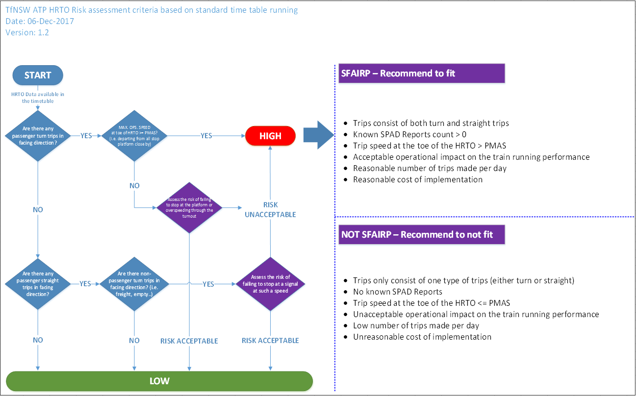
Following the introduction of the 2017 Standard Working Timetable (SWTT), TfNSW initiated a High-Risk Turnout Operational (HRTO) risk assessment to review commonly used turnouts in the timetable. This assessment was conducted between December 2017 and September 2019, and established which points and turnouts were high risk based on specific criteria (Figure 19).
Figure 19: High risk turnout risk assessment criteria
Source: Transport for NSW
Where a turnout was identified as high risk, TfNSW standard Signalling Design Principle – ETCS Level 1TS 05333.31:2.0, current at the time of the incident, required, on approach to the turnout, ‘target speed monitoring’ to minimise ‘the risk of derailment resulting from excessive speed’. This means that turnouts on divergent routes would require communication with the signalling system to determine the real time target speed based on the set route, via the installation of line side electronic units and controlled balises.
Several points and turnouts across the network in regular timetable use were identified as being high risk, including BN 317 turnout and BN 318 turnout at Blacktown West.
BN 317 turnout – Up Main to Up Loop
The HRTO risk assessment stated there were 7 passenger trips timetabled to use BN 317 turnout from the Up Main to the Up Loop, and this was used as the basis for the risk calculation. However, in the SWTT, 3 empty trips on weekdays, and none on weekends, were scheduled to use this turnout. No passenger trips were timetabled through BN 317 turnout across the week, and turning out from the Up Main to the Up Loop was an uncommon move for passenger trains in normal operations.
There were also no reported safety incidents at BN 317 turnout in the 5 years to September 2019, and the estimated cost to install ATP protection to the turnout was over $1 million.
Nevertheless, it was determined that the risk of overspeed and derailment was not tolerable at BN 317 turnout, and that ATP speed protection should be installed at BN 317 turnout in the Up direction.
BN 318 turnout – Up Suburban to Up Main
A similar decision was made for BN 318 turnout from the Up Suburban to the Up Main.
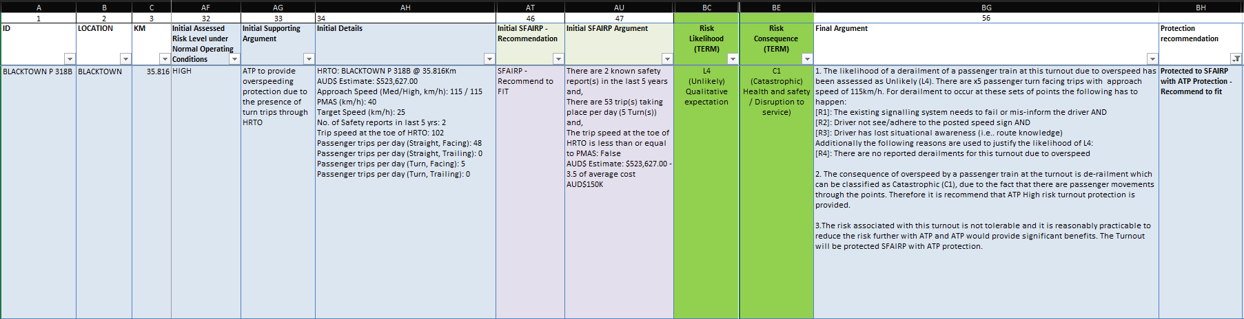
5 passenger trips were timetabled on weekdays and 3 on weekends to use BN 318 turnout in the Up direction, and there were also 2 reported safety incidents at BN 318 turnout in the 5 years to September 2019. The estimated cost to install ATP protection was just over $500,000.
It was determined that:
The risk associated with this turnout is not tolerable and it is reasonably practicable to reduce the risk further with ATP and ATP would provide significant benefits. The turnout will be protected SFAIRP[34] with ATP protection.
As a result, the risk assessment recommended that ATP turnout protection be provided at BN 318 turnout to prevent overspeed through the turnout and reduce the risk of a derailment (Figure 20).
The risk assessment calculated a low likelihood of a derailment through BN 318 turnout due to overspeed but added that a derailment could occur in specific circumstances such as a driver’s loss of situational awareness.
For 805K to derail through BN 318 turnout due to overspeed, the speed required of the train was calculated to be just over 115 km/hr. With the maximum permitted line speed of 115km/hr, it remained within the realm of possibility for 805K to have entered BN 318 turnout over this critical derailment speed.
Figure 20: TfNSW risk assessment of 318 points
Source: Transport for NSW
While fixed balises were installed on BN 317 and BN 318 turnouts, it was found during the investigation that the balises had different functions on each turnout and in the Up and Down directions.
On the Up Main at BN 317, fixed balises were installed for maximum line speed of the Up Main and for repositioning in the Up direction. In the Down direction, there were fixed balises installed for repositioning and for maximum speed monitoring through the turnout from the end of the Up Loop Line onto the Up Main only.
On the Up Suburban at BN 318, fixed balises were installed for maximum line speed monitoring of the Up Suburban and for repositioning in the Up direction. In the Down direction fixed balises were installed for repositioning only.
Sydney Trains confirmed the fixed balise for BN 318 turnout could not be used for turnout speed protection as there were 2 routes, a mainline speed 115 km/h on approach and 25 km/h for the turnout and a fixed balise can only provide static information. A controlled balise (one that is integrated with the signalling) would be required to provide the 2 different speed profiles for the routes set by the Signalling system, which would then be sent to the onboard ATP system.
Changes to ATP scope
TfNSW conducted a review of the ATP program in August 2019, and identified several issues impacting its rollout, including:
Capacity constraints caused by ATP slowing down trains..
Redundant equipment as ATP was slowly replaced by European Train Control System (ETCS) Level 2 digital in-cab train control
Budget and delivery constraints due to track access and resource allocation across concurrent projects.
A strategic review of the ATP scope recommended that the following changes be made to the ATP rollout:
Deploy ATP with fixed Balise only in Areas 6 and 8 (Figure 21)
Cancel ATP deployment in Areas 7.2 and 9, and focus on ETCS 2 introduction
Realign fleet deployment to provide priority in safety benefits.
The revised functional specification for areas 6 and 8 released in October 2019 removed, amongst other protections, the following functionalities from the ATP baseline specification:
High risk turnout protection
High risk converging movements protection
This represented a downgrade in the original scope and implementation of ATP, with the known risk of HRTO remaining post‑project implementation. The proposed changes were presented to ONRSR in November 2019, and feedback was provided resulting in a review by TfNSW. This resulted in additional fixed balises being installed in Area 7.2 Area 9 to protect essential functions.
Sydney Trains’ SAR documents that all residual safety risks transferred by TfNSW are managed and reduced SFAIRP, and notes that not all High-risk turnouts (HRTO) were to be protected in accordance with the revised design guidelines for ATP. Thus, accepting the residual risk to their operations of the untreated turnouts.
Subsequently, post this incident and a related occurrence, ONRSR issued an improvement notice to Sydney Trains to address the risk of overspeed through crossovers and turnouts. This notice identified that the current configuration of ATP provided overspeed protection for only some of the highest risk turnouts and crossovers. And acknowledged that the risk assessment to identify these turnouts was carried out by TfNSW.
As the accredited operator ONRSR placed the action on Sydney Trains to minimise the network risk of overspeed through turnouts SFAIRP.
Figure 21: Area 6, 7 and 8 geographic location and sub-area breakdown
Source: Transport for NSW
Management of overspeed risk
Sydney Trains maintained a risk register of network‑wide safety risks. Overspeed was not contained in the safety risk register as its own risk but had been considered as a contributor to the higher-level network hazard of ‘Loss of control passenger train’.
Sydney Trains had assessed this network hazard as ‘well controlled’ in its Bow Tie SFAIRP determination[35], Nov 2018.
Despite known incidents occurring on the network, including this incident, a review of the Bow Tie SFAIRP Determination in May 2024 post‑incident, maintained the assessment as ‘well controlled’.
Following the issue of an improvement notice from the ONRSR in late May 2024, Sydney Trains reviewed the network hazard of Loss of Control again and subsequently determined the control rating as ‘Requires Some Improvement’.
It was observed by OTSI that most risk controls identified in the Bow Tie SFAIRP determination under the direct control of Sydney Trains were administrative. Other existing preventative controls of driver vigilance systems, rolling stock design, speed monitoring and Level 1 ATP, identified as engineering controls, were delivered by TfNSW. Speed monitoring and Level 1 ATP were considered only partially effective, at the time, as these controls were not installed across the entire network.
ONRSR Case Study – ATP and Sydney Trains
In September 2025, ONRSR released a safety case study, Automatic Train Protection – ONRSR and Sydney Trains – Case Study advocating for funding approval on behalf of Sydney Trains to address the risk of high-risk turnouts as a priority.
ONRSR became increasingly concerned by a series of overspeed events through 25 km/h turnouts that occurred on the Sydney Trains network over a period of 20 months between October 2023 and March 2025.
Considering these overspeed events and citing 2 specific events at Blacktown Junction on 4 October 2023, and Blacktown West on 21 April 2024, ONRSR issued an Improvement Notice to Sydney Trains on 23 May 2024. While acknowledging a longer‑term strategy to manage overspeed risk was in place, ONRSR’s focus was necessarily on the ‘here and now’ of managing risks to safety SFAIRP.
In response to the Improvement Notice, Sydney Trains identified areas on the rail network with potential for overspeed events and prioritised these based on risk. It was found as part of the review that only a fraction of the turnouts on the Sydney Trains network were overspeed protected by ATP.
Sydney Trains introduced interim measures to control overspeed risk by slowing trains with speed restrictions in high-risk areas until an ATP or similar technological solution could be implemented. Sydney Trains additionally presented to TfNSW a business case to seek funding and support for the implementation of engineering controls to reduce the risk of overspeed through turnouts at high-risk locations on its network.
These actions and the continued advocacy by ONRSR at senior government levels resulted in a High-Risk Turnout (HRTO) Program being agreed to and funded by TfNSW, as a short-term solution, to ensure engineered controls for high-risk turnouts were in place. The longer-term solution of upgrading the Sydney Trains Network to European Train Control System Level 2 technology and introducing a Traffic Management System remained the future end state.
Overspeed response
Sydney Trains did not have a formalised procedure for responding to an overspeed event, but the Network Rules provided general guidelines for operational staff to follow.
Train Crews and Track Vehicle Crews
General Network Rule NGE 232, ‘Responsibilities of Train Crews and Track Vehicle Crews’, prescribed the responsibilities of Train Crews and Track Vehicle Crews on the network. It stipulated that the primary responsibility of Train Crews and Track Vehicle Crews was ‘to operate trains and track vehicles for the safe and efficient transit of rail traffic through the Network’.
NGE 232 stated that Train Crews and Track Vehicle Crews must:
• be responsible for the safe operation of rail traffic and the safety of other crew and passengers, and
• tell a Signaller[36] about breaches of Network Rules and Network Procedures, and
• promptly report delays to the Signaller.
The rule also stated that drivers ‘must tell a relieving crew about any conditions that could affect the operation of the rail traffic’.
Additionally, Sydney Trains’ Operator Specific Procedure OSP 12 Responding to an incident stated:
• Workers who become aware of or are involved in an incident must make every endeavour to ensure it is immediately reported to a Signaller.
Following the incident, when the driver returned to their seat and regained control of the train, they called the guard to check on their welfare and to explain they had misread the signals and went through the turnout too quickly. They had this conversation as the driver continued driving the train to Blacktown.
The driver did not report the incident to the Area Controller as required under NGE 232 but discussed the incident when they were contacted by the TCLO. The driver explained at interview that they did not provide the relieving driver at Blacktown with any details about the incident or condition of the train because at the time they were in a state of shock. The driver further explained they felt relieved when they were contacted by the TCLO because it meant that someone knew what happened and they could provide details about the incident.
The guard said at interview that as the train approached Blacktown, they noticed the train shake a little bit like a rough ride and thought it was a bit unusual. It was at this time the guard received the call from the driver.
The guard stated at the end of the communication with the driver, that they did not consider a major incident had occurred. They had not felt the train jolt so significantly from the rear of the train as the train had slowed by the time the rear carriage passed over the turnout. Further no Passenger Emergency Intercom[37] calls were made between the turnout and Blacktown Station where they were relieved, which led the guard to conclude passengers were okay.
On arrival at Blacktown the guard decided to call the TCLO to report and confirm what they now thought was an incident due to the train shaking and the driver stating they had misread a signal. The TCLO confirmed the details and contacted the driver for further information and subsequently made an incident report to the NIM.
Network Controllers
General Network Rule NGE 236, ‘Responsibilities of Network Controllers’, prescribed the primary responsibility of a Network Controller[38] was ‘to manage train paths for the safe and efficient transit of rail traffic through the Network’. The rule also stated that Network Controllers must plan, set priorities for, and manage liaison with relevant Operators and Maintenance Representatives and external services during incident management and manage available facilities to restore train services safely and promptly.
Additionally, Network Controllers must, as necessary, provide rail traffic details to affected Network Controllers and Signallers; promptly report breaches of Network Rules and Network Procedures to the controlling officer and affected Operator’s Representatives and compile and maintain, in permanent form, relevant records and reports about conditions and movements in the Network.
After arriving at Blacktown, the train crew discussed the incident with the TCLO who then reported the incident on their behalf to the NIM. Although the TCLO was not specifically covered by either NGE 232 or NGE 236, their responsibilities included assisting crews with Network and Operator-specific rules and procedures.
Upon receiving the incident report, the NIM undertook a series of actions to inspect the affected infrastructure, obtain train information, and begin an internal investigation. The NIM also had a verbal discussion with Defects and the Duty Control Manager (DCM) about whether the train needed to be withdrawn from service and inspected. There was no specific instruction on how to respond to an overspeed event, which meant that decisions on whether to inspect infrastructure and trains were at the discretion of the NIM on duty. After the discussion with Defects and the DCM, a collective decision was taken that the train could remain in service without inspection. However, after a shift changeover several hours later, the replacement NIM had a follow-up discussion with a different representative from Defects, and a decision was made to immediately remove the train from service.
Similar related incidents
ONRSR’s reporting requirements classify ‘trains significantly exceeding the permitted speed limit’ as an Incident Directly Threatening Safety. This falls under Category A – Report Immediately. Trains exceeding the speed limit but to a lesser extent, may be reported by the Operator as an Occurrence Type 7, Network Rule or Procedure Breach.
The incident at Blacktown West on 21 April 2024 was one of 16 reported overspeed incidents through turnouts on the Sydney Trains network between January 2019 and March 2025, and one overspeed incident involving a NSW TrainLink service that derailed and overturned, resulting in multiple fatalities. Each of these incidents is outlined in Appendix C.
Safety analysis
The contributing factors that led to the incident are discussed below.
Loss of situational awareness
Prior to departing Doonside, the driver of run 805K began to pack their belongings in anticipation of being relieved at Blacktown. They were also aware that the train was travelling on the Up Suburban as they passed the automatic signal off the departure end of Doonside Station. As the train accelerated, the driver recalled that they could see the next 3 signals from a distance and began to recall the usual signalling sequence they would encounter in this section.
However, this sequence was for trains on the Up Main, where they would continue in a straight line rather than turnout, and was the standard routing for suburban services in this section, rather than for the Up Suburban. As a result, it is likely that the driver of run 805K whilst preparing to depart the train at Blacktown, lost their situational awareness of which track the train was operating on, which influenced how they read and responded to each signal, and how they operated the train, as they approached Blacktown West.
Expectation bias
Expectation bias is a phenomenon in which people’s expectations about a situation or event can influence their interpretation of and/or reaction to that situation or event.
In the rail context, a high frequency of train movements on a specific track in a specific area allows train drivers to habituate to the signals, speed limits, and gradients unique to that location, and handle their train accordingly. As the frequency of train movements on an alternate track or route decreases, so does the ability for drivers to maintain the requisite route knowledge or memory recall.
Train drivers are expected to maintain their route knowledge and awareness of their area of operations, but the opportunity to do so may be limited by operational considerations. Accordingly, if a driver does not operate a train on a particular route or track on a regular basis, it is possible for drivers to assume that route is no longer used or expect that their train will not traverse that track in regular operations.
The altered train running information for 805K was contained within the daily STN which was issued to crew. However, the driver did not read the STN and Sydney Trains did not have processes in place to ensure the crew reviewed each STN. It was also unclear from the word ‘relevant’ in the procedures whether the driver was required to read the STN if they had assessed by other means that there were no ‘relevant’ changes to their services.
Had the driver reviewed the STN they may have recalled the information as they approached BN 318, but it is not possible to conclude that the STN would have provided an effective control based on the size of the document, and a reliance on memory recall due to potential distractions and passage of time. In this incident, the train driver had been based at Blacktown Depot for around 7 years but stated that they had only driven a train over BN 318 turnout 2 or 3 times in this period. This was a consequence of timetable design, with only 5 trains scheduled daily, to use BN 318 turnout in the Up direction in the Standard Working Timetable (SWTT).
The High-Risk Turnout Risk Assessment found that this equated to fewer than 1 in 10 suburban trips being operated via the Up Suburban and BN 318 turnout. Thus, opportunities for drivers to learn and remember the signalling sequence and maintain route knowledge were wholly dependent upon a driver’s shift time and allocated crew diagram, or changes to a train’s pathing for operational reasons.
With limited opportunities to traverse BN 318 turnout over the preceding 7 years, the driver became habituated to the signal sequencing and characteristics of the Up Main and handled their train accordingly. The driver explained the usual signal sequence they would observe approaching Blacktown West, and that they would drive the train in accordance with their expectations – that the preceding signals would be cleared once the Home signal was cleared, and they would continue on straight track.
Because the Home signal at Blacktown West would almost always switch from Stop to Clear as the train approached the Lancaster Street bridge, the train driver would maintain their speed and wait for the Home signal to show Green on Green instead of responding to the preceding two signals at Medium.
On the day of the incident, the key difference was that, instead of the Home signal clearing to Green over Green, the signal showed Yellow on Yellow with a corresponding route indication. The driver recalled that, as they approached the Lancaster Street bridge, they were driving the train in their routine manner and ‘read through’ past the nearest signal to the signals further down the line.
The driver continued to do this as they approached Signal BN 94 S, even though this signal was showing a different indication. As they had rarely traversed BN 318 turnout, and almost always went through Blacktown West at track speed, the driver did not believe this trip would be different to previous journeys in the Up direction. This was further exacerbated by the driver’s loss of situational awareness, which caused them to believe they were on the Up Main instead of the Up Suburban.
Therefore, the driver of run 805K did not drive their train in accordance with the prevailing signal indications and was not aware that the train would take a diverging route. This was due to an expectation that the signal sequencing and route setting would be the same as previous journeys, leading to an overspeed through BN 318 turnout at Blacktown West.
Contributing factor
The driver of train 805K did not operate the train in accordance with signal indications.
Contributing factor
The driver was not situationally aware as they approached BN 318 turnout. They expected the signal aspects and direction of travel to be the same as they had experienced many times before. So, the driver did not react to the actual signal aspects which resulted in the train travelling over speed through the turnout.
Ineffective controls for the risk of overspeed
Technology-based risk controls such as ATP and mechanical risk controls such as speed-based train stops, are key mitigations against train driver error and loss of situational awareness. However, Sydney Trains had no such mitigations available at BN 318 turnout to protect against the risk of an overspeed, or to intervene in the event a driver did not respond appropriately to the signals or speed signs.
Responsibility for the ATP rollout was assigned to TfNSW. During the HRTO risk assessment, TfNSW had identified in September 2019 that BN 318 turnout at Blacktown West had a high risk of overspeed and derailment and calculated that this risk was not tolerable. TfNSW also determined that ATP would provide SFAIRP protection – but that protection had not been installed at BN 318 turnout by April 2024, likely due to changes in the ATP project scope and implementation.
TfNSW’s decision to downgrade the ATP Project and install fixed balises only in areas of the network where high risk turnouts had been identified (including BN 318 turnout) decreased the opportunity of effectively controlling the high-speed turnout risk.
Fixed balises could only provide static data which made configuring speed protection on a line that offered more than one route unachievable. In the case of BN 318 turnout, an approaching train could be pathed straight on the Up Suburban or pathed through the turnout. With a fixed balise, only one speed limit could be provided, which was the 115 km/h limit on the Up Suburban line.
The history of incidents (reference Appendix C – Similar related Incidents) meant that overspeed through turnouts was a well-known hazard on the Sydney Trains network.
As the rolling stock operator and infrastructure maintainer, Sydney Trains was responsible for managing the risk SFAIRP to their operations posed by high-risk turnouts in the absence of engineered controls from TfNSW who controlled the capital budget and project management capability for major works such as the TfNSW ATP Project.
Sydney Trains, whilst identifying the risk of derailment due to overspeed in its Loss of Control passenger train SFAIRP determination, assessed the risk to its operations as controlled SFAIRP citing primarily administrative controls. The engineering controls noted for overspeed, such as speed monitoring and Level 1 ATP were documented as only partially effective, acknowledging the limitations of the TfNSW ATP rollout.
Sydney Trains identified the risk of rollover in its derailment SFAIRP determination, which was determined as well controlled. However, like the loss of control determination the identified controls on which the determination was made were predominately administrative. The only control that directly related to the risk of overspeed was driver compliance with speed boards which was documented as partially effective. Neither determination specifically identified high speed entry into low-speed turnouts as representing a unique risk of derailment and rollover with customised controls.
The administrative nature of the controls in the Sydney Trains SFAIRP determinations were likely reflective of Sydney Trains’ funding and capability/resources within the broader TfNSW portfolio, and the controls made available to them. These were specifically identified by Sydney Trains as constraints during works to address the ONRSR improvement notice.
As an alternative to ATP speed protection, turnout repeaters on the preceding signals may have provided an additional control to inform drivers of an upcoming route change. Sydney Trains confirmed that there was no turnout repeater for signal BN 94 S for BN 318 turnout, which could have provided the driver of run 805K an extra 20 seconds and 635 m to slow their train. However, this was reliant upon the driver seeing and responding to the turnout repeater, and much like other signal indications, could be easily overlooked by a driver who had lost their situational awareness.
When trains are routed to use turnouts, the risks associated with overspeed increase with line speed as trains will usually be travelling at line speed approaching a set of points and its controlling signal. Across the rail network, the primary control in place to ensure a train slowed down sufficiently to traverse points safely was the train driver. In the absence of ATP speed protection, there was no other means of controlling the speed of a train prior to it taking a diverging route.
With no mitigation against a driver losing their situational awareness and driving a train at or near line speed through a turnout, the risk of overspeed at high-risk turnouts such as BN 318 turnout – which TfNSW had originally deemed as ‘not tolerable’ – was significantly increased. In this incident, if ATP speed protection had been installed at BN 318 turnout, it is likely that the train would have been automatically slowed down by the onboard ATP system before the train reached the points, and the severity of the overspeed of 805K through BN 318 turnout would have been significantly reduced, if not eliminated entirely.
Other factor that increased risk
TfNSW downgraded the ATP project scope and did not install speed protection at high-speed turnout BN 318, despite the initial risk assessment assessing the risk as not tolerable.
Contributing factor
Sydney Trains did not have effective controls for overspeed where high risk turnouts were present. (Safety issue)
No response process for overspeed incidents
During the investigation, it was established that the crew of run 805K did not know or follow the correct process for reporting an overspeed event. According to the Network Rules, the crew should have reported the incident immediately to the Area Controller, but the train continued in service to Blacktown where the guard then informed the TCLO.
Although the TCLO was able to inform the NIM and commence post-incident activities, crews cannot rely on the TCLO to assist in incident reporting. This uncertainty around reporting processes increased the risk that a serious incident might not be reported by crews, delaying inspections of fleet and infrastructure and potentially delaying medical treatment in the event of injuries.
Sydney Trains also confirmed that there was no formalised process for Control Room staff to manage and respond to an overspeed event. When the NIM on shift became aware of the incident, they undertook a series of actions to obtain train information, inspect the affected infrastructure, and commence an internal investigation.
However, there was no written instruction specifying what actions needed to be taken following an overspeed event. As a result, the NIM spoke with the DCM and Defects to discuss what should be done with set A32. During this conversation, it was collectively agreed that set A32 could remain in service for the rest of its roster, even though the train had not been inspected for damage or defects.
Other factor that increased risk
The train continued in service after the overspeed event without being inspected.
However, the NIM on the following shift several hours later did not agree. Upon learning that set A32 was still in revenue service, the NIM requested that the set be taken out of service and inspected immediately. At that point, set A32 had continued for several hours in revenue service, albeit with no observed damage or defects.
As there was no procedure in place regarding overspeed incidents, it was left to NIMs and other Control Room staff to collectively determine an appropriate course of action after each overspeed incident. This increased the risk that fleet and infrastructure could remain in revenue service without any assessment of whether it was safe to do so.
Other factor that increased risk
Sydney Trains did not have a response process for overspeed incidents. (Safety issue)
Findings
ATSB investigation report findings focus on safety factors (that is, events and conditions that increase risk). Safety factors include ‘contributing factors’ and ‘other factors that increased risk’ (that is, factors that did not meet the definition of a contributing factor for this occurrence but were still considered important to include in the report for the purpose of increasing awareness and enhancing safety). In addition, ‘other findings’ may be included to provide important information about topics other than safety factors.
Safety issues are highlighted in bold to emphasise their importance. A safety issue is a safety factor that (a) can reasonably be regarded as having the potential to adversely affect the safety of future operations, and (b) is a characteristic of an organisation or a system, rather than a characteristic of a specific individual, or characteristic of an operating environment at a specific point in time.
These findings should not be read as apportioning blame or liability to any particular organisation or individual.
From the evidence available, the following findings are made with respect to the train overspeed by run 805K, through BN 318 turnout, Blacktown, New South Wales, on 21 April 2024.
Contributing factors
The driver of train 805K did not operate the train in accordance with signal indications.
The driver was not situationally aware as they approached BN 318 turnout. They expected the signal aspects and direction of travel to be the same as they had experienced many times before. So, the driver did not react to the actual signal aspects which resulted in the train travelling over speed through the turnout.
Sydney Trains did not have effective controls for overspeed where high risk turnouts were present (Safety issue).
Other factors that increased risk
TfNSW downgraded the ATP project scope and did not install speed protection at high-speed turnout BN 318, despite the initial risk assessment assessing the risk as not tolerable.
The train continued in service after the overspeed event without being inspected.
Sydney Trains did not have a response process for overspeed incidents. (Safety issue)
Safety issues and actions
Central to the ATSB’s investigation of transport safety matters is the early identification of safety issues. The ATSB expects relevant organisations will address all safety issues an investigation identifies.
Depending on the level of risk of a safety issue, the extent of corrective action taken by the relevant organisation(s), or the desirability of directing a broad safety message to the Rail industry, the ATSB may issue a formal safety recommendation or safety advisory notice as part of the final report.
All of the directly involved parties are invited to provide submissions to this draft report. As part of that process, each organisation is asked to communicate what safety actions, if any, they have carried out or are planning to carry out in relation to each safety issue relevant to their organisation.
Descriptions of each safety issue, and any associated safety recommendations, are detailed below. Click the link to read the full safety issue description, including the issue status and any safety action/s taken. Safety issues and actions are updated on this website when safety issue owners provide further information concerning the implementation of safety action.
Safety issue description: Sydney Trains did not have a response process for overspeed incidents.
Glossary
ATP
Automatic Train Protection (ATP) is a train safety system used across the Australian rail industry to monitor a train’s speed, distance and direction, providing warnings to the driver and automatically applying brakes when required to prevent overspeed, signal overruns. Or other unsafe conditions
ITSRR
The Independent Transport Safety and Reliability Regulator (ITSRR) was a statutory authority in New South Wales, responsible for overseeing the safety and reliability of transport services. Established in 2004, ITSRR’s primary roles included regulating rail safety, providing independent advice to the government on transport sustainability, and ensuring the safe operation of transport services.
OEP
The Operator Enable Pedal (OEP) is a foot operated vigilance device installed in cabs to ensure the driver remains alert and actively engaged in train operation. The driver must keep the pedal depressed when operating the train. Releasing it can trigger vigilance alerts or safety interventions depending on the train’s safety system design.
ONRSR
The Office of the National Rail Safety Regulator (ONRSR) is the regulatory body responsible for overseeing rail safety in Australia. Established in July 2012 and commencing operation in January 2013, to promote and improve national rail safety and ensure the safety of the community by enforcing the Rail Safety National Law (RSNL) across all Australian states and territories.
RailCorp
RailCorp, or Rail Corporation New South Wales, was an agency of the State of New South Wales. It was established on 1 January 2004, under the Transport Administration Act 1988. RailCorp was responsible for holding rail property assets, rolling stock, and rail infrastructure in the Sydney metropolitan area and some country locations.
In 2013, RailCorp’s operational and maintenance functions were transferred to Sydney Trains and NSW TrainLink, leaving RailCorp as the legal owner of a significant portfolio of railway property. On 1 July 2020, RailCorp was converted into a state-owned corporation and renamed the Transport Asset Holding Entity (TAHE).
RailSafe
RailSafe is a platform managed by Transport for NSW. It serves as a comprehensive resource for safeworking rules, procedures, and updates specifically for the Sydney Trains Network.
SFAIRP
So Far As Is Reasonably Practicable, is a requirement to eliminate or minimise safety-related risks, so far as is reasonably practicable, associated with the planning, design, build, installation, testing and commissioning, operation, maintenance and disposal of rail assets.
Sydney Trains
Sydney Trains is the operator of suburban and intercity rail services in and around Greater Sydney, New South Wales. Established on 1 July 2013, Sydney Trains took over the suburban services previously managed by RailCorp’s CityRail division.
The network covers a significant area, bounded by Berowra, Emu Plains, Macarthur, and Waterfall, and includes 168 stations across nine lines. Sydney Trains is responsible for the operation, maintenance, and management of rail services, tracks, trains, signals, overhead wiring, stations, and facilities within this area.
TCLO
The Train Crew Liaison Officer (TCLO) is a role in Sydney Trains involved in the Day of Operations Management team. The role provides oversight and support across the rail network to achieve operational objectives.
TfNSW
Transport for NSW (TfNSW) is a statutory authority established on 1 November 2011. It is responsible for managing and coordinating transport services and infrastructure across New South Wales. This includes roads, rail, buses, ferries, light rail, and point-to-point transport.
Sources and submissions
Sources of information
The sources of information during the investigation included:
the driver of 805K
the guard of 805K
Office of the National Rail Safety Regulator (ONRSR)
Sydney Trains CCTV cameras
Sydney Trains audio communication systems
Sydney Trains documented management systems
Transport for NSW.
References
Australian Transport Safety Bureau. Derailment of passenger train ST23, Wallan, Victoria on 20 February 2020 (Report No. RO-2020-002). /publications/investigation_reports/2020/rair/ro-2020-002
Under section 26 of the Transport Safety Investigation Act 2003, the ATSB may provide a draft report, on a confidential basis, to any person whom the ATSB considers appropriate. That section allows a person receiving a draft report to make submissions to the ATSB about the draft report.
A draft of this report was provided to the following directly involved parties:
Crew of 805K
Sydney Trains
Transport for NSW
ONRSR.
Submissions were received from:
Sydney Trains
Transport for NSW
ONRSR.
The submissions were reviewed and, where considered appropriate, the text of the report was amended accordingly.
Appendices
Appendix A – Automatic Train Protection (ATP)
ATP is a system designed to enhance train safety by monitoring and ensuring that a train’s speed is within the permitted limits set by the signalling system. ATP can be configured to prevent incidents such as signals passed and danger (SPAD) and over‑speeding, thereby significantly reducing the risk of collisions and derailments.
At the time of writing, there were 4 active levels of ATP, based on European Train Control Standards (ETCS)[39].
Level 0 – No ATP
Basic operation with traditional signals.
No onboard ATP functionality: driver relies entirely on visual signals.
Level NTC – Legacy National Train Control systems
ATP onboard equipment interfacing with legacy train control systems.
Used during transition or on mixed infrastructure
Level 1 – Limited Supervision
ATP overlays existing trackside signalling.
Uses balises (track-mounted transponders) to transmit speed and signal data to the train.
Can automatically apply brakes if the train exceeds speed limits or passes a signal at danger.
This is the level rolled out across the Sydney Trains rail network.
Level 2 – Full Supervision
Removes reliance on trackside signals.
Continuous communication between train and control centre via radio, provides real-time movement authority
Speed profiles, and braking curves to apply brakes if train exceeds speed limits
Train positioning via balises
Enhances safety and allows for higher network capacity.
Onboard equipment
TfNSW publication T HR SC 01650 SP - ETCS On-board Equipment defined the requirements for ETCS onboard equipment, its configuration and installation for TfNSW. Onboard equipment included the following (Figure 22):
Vital Processing Unit, known as the European Vital Computer (EVC)
Track to Train interface via air gap (Balise Antenna)
Radio Transmission Module (RTM)
GSM-R data radio
GSM-R data radio antenna
Balise Transmission Module (BTM)
BTM antenna
Relay Logic Unit (RLU)
Driver Man-Machine Interface (DMI) Tone Generator
Pulse Generator
Doppler Radar
Juridical Recording Unit (JRU)
Train interface Unit (TIU)
Figure 22: Waratah ATP architecture overview
Source: Downer
By November 2020 the installation of all physical ATP equipment was completed on all A-sets.
Track side infrastructure
The ATP track side infrastructure provided network control information to the ATP onboard equipment allowing the vehicle to be operated on the network with improved levels of safety and vehicle protection. During train operation, ATP would function in a number of states depending on the ATP level of track infrastructure. If ATP failed, manual isolation was possible with additional safety controls to allow the rolling stock to be removed from the network if required.
The trackside equipment included:
Transponders, known as balises (Figure 23) – these transponders are used to transmit information such as location, speed limits and signal aspects to trains. The exact functionality can vary depending on the railway system.
Lineside Electronic Units (LEU’s) – an electronic device that acts as the interface between the balise and the railway signalling system. It collects information from the interlocking system (which controls signals and points) and sends appropriate data to the balise. The LEU generates telegrams to be sent by balises, on the basis of information received from external trackside systems.
Figure 23: Transponder (balise)
Source: Transport for NSW
Appendix B – Rail Regulator yearly summary of progress – Rec 32
December 2005
Identified national standards required for fitment of ATP to rollingstock. Australasian Railway Association (ARA) invited to develop standard.
2006
RailCorp gained funding to pilot trial ATP technology on part of its network. The Regulator agreed in principle
2007
RailCorp tested three (3) types of ATP technology on sections of the Blue Mountains line. One manufacturer has fitted a trial train and performed tests.
2008
RailCorp developed a business case outlining an implementation strategy and funding requirements based on successful trial in early 2008. RailCorp’s Board had approved funding for the design and planning phase and was prepared to continue following Government approval for full funding of ATP. The Regulator set an interim target date for completion of the recommendation of 30 June 2009
2009
The Regulator had changed the interim target date to 31 July 2010 based on completion of NSW Treasury Gateway Review of the business case. RailCorp required to review the technical feasibility and cost benefit of introducing Level 1 ATP as well as Level 2 ATP. Level 1 ETCS involves the overlay of ATP on the coloured light signalling system to transmit authorities for trains to proceed on the network via the track mounted balises. Level 2 ETCS involves the connection of ATP to the signalling interlockings to transmit authorities for trains to proceed via GSMR radio.
2010
In August 2010, Cabinet gave in-principle funding approval for the rollout of the three stages of the ATP program and full funding approval for the implementation of Stage 1 of the program. Stage 1 involves the supply of ATP equipment for RailCorp’s OSCAR and Tangara train fleets and the installation of ATP equipment to 600 kilometres of the CityRail network. Stages 2 and 3 will involve the installation of ATP equipment across the rest of RailCorp’s electrified network and onboard the Waratah and Millennium train fleets. Expected completion dates for the three stages are: Stage 1 – 2011 to 2017 Stage 2 – 2013 to 2018 Stage 3 – 2015 to 2021 The first of RailCorp’s trains to be fitted with ATP equipment and introduced into service between Wyong and Berowra is expected to be in 2013.
2011
RailCorp awarded four separate supply contracts including ETCS supply and engineering services for trackside and onboard, and through life support for trackside and onboard. RailCorp engaged consultants to risk assess and evaluate implementation of additional ATP systems on RailCorp network.
2012
ATP system testing commenced using the ATP V set test train and the newly commissioned ATP trackside equipment between Gosford and Wyong. This allowed configuration of the ATP system to be fine-tuned prior to the second phase of testing using an OSCAR train and a more extensive area of the track in 2013. ATP installation on the first two OSCAR prototype trains is almost complete, with installation underway on the second train during the fourth quarter 2012. The two trains will be commissioned in the second quarter of 2013.
2013
Trackside construction from Berowra to Wyong was completed with the exception of the installation of compliant, Type Approved lineside electronic units (a key component of the trackside equipment which acts as the interface between the existing signalling system and the ATP system). The installation of ATP equipment on the first two OSCAR prototype trains was almost complete.
2014
Installation of compliant Type Approved lineside electronic units not complete. The issue preventing full Type Approval from being achieved for the lineside electronic units (version 5.1) is related to its use with signals that have flashing aspects. The delays in achieving full Type Approval for the installation of the lineside electronic units means that the first OSCAR train fitted with ATP equipment will not be commissioned into passenger service and operate between Berowra and Wyong until September 2015
2015
In December 2014, Transport for NSW’s (TfNSW) Transport Executive Committee approved an alternate strategy known as the ‘Advanced Train Control Migration System’ (AMS) to proceed under the existing funding arrangements of stage 1. TfNSW’s alternate strategy involves fitting all suburban trains with equipment that supports European Train Control System (ETCS) Level 2 systems, but reducing the infrastructure works required (e.g. signalling interlocking modifications – i.e. fewer balises). The result is an ATP system that provides limited supervision including speed control, together with the continued use of train stops and ETCS Level 1 full supervision at high risk locations.
To ensure that the alternate strategy satisfies the intent of the Special Commission of Inquiry’s recommendation for ATP as an ‘acceptable alternative response’, ITSR has requested TfNSW to provide formal advice and the safety argument to support this decision.
2016
ITSR accepted TfNSW’s proposal for the Advanced Train Control Migration System (AMS) to be considered as an ‘acceptable alternative response’ to the Special Commission of Inquiry’s recommendation for ATP.
ITSR’s acceptance of TfNSW’s proposed alternate response was based on the quantitative risk assessment report; the AMS strategy being completed by December 2019 and the inclusion of an ‘Early Deployment Scheme’ which will deliver in the Berowra to Newcastle area, controlled trialling of AMS protection for passenger trains in October 2018. This will be in preparation for the scheduled milestone of March 2019. The implementation of an ETCS Level 2 system remains in TfNSW’s future strategies for the electrified rail network
On 22 March 2016, the NSW Government approved TfNSW’s Business Case to proceed with its AMS scope of works comprising: • AMS fitment to 100% of the electrified network (excluding stabling yards). • AMS fitment to Sydney Trains’ electrified fleet: OSCAR, Tangara, Millennium, V sets (excluding some that will be replaced by New Intercity Fleet within the project’s timeframe), C sets, K sets, S sets and Waratahs. • Extend AMS to provide the cumulative equivalent level of safety as the original ATP strategy through the addition of controls to mitigate for those locations where the risk is high (turnouts, deficient overlaps, level crossings with interlocked signals and catchpoints protecting signals). • Provide ETCS Level 2 compliant onboard equipment which supports the interface between the Digital Train Radio System and a future ETCS Level 2 system.
2017
NSW Government approved full funding for TfNSW’s ATP projects final business case in April 2016. The scope of works for the ATP project includes ATP fitment to 100% of the electrified network (excluding stabling yards), and ATP fitment to Sydney Trains’ electrified fleet (OSCAR, Tangara, Millennium, V sets (excluding those that will be replaced by new rollingstock), C sets, K sets and Waratahs)
2018
Fitment of ATP equipment to the OSCAR train fleet is complete, subject to a configuration upgrade to be concluded in September 2019. Dynamic testing of the Tangara prototype (fitted with ATP) on the network was successfully completed in July 2016 and the approvals process commenced with installation part of the Tangara Technical Upgrade (TTU) project. The Waratah ATP system design works have been completed and prototype installation commenced in March 2018. The C set and K set fleets have completed system and installation design. The M Set design and prototype is complete and the V set fleet is currently in the design phase.
ATP trackside equipment network surveys have been completed and current progress includes · System integration testing · Detailed design · Installation and testing
2019
As of 31 March 2019, the following progress has been achieved: - ATP enabled H-set trains carrying passengers between Cockle Creek and Newcastle - ATP prototype installation completed on A/C/K/T/V sets - ATP installation completed on H sets - ATP infrastructure commissioned between Cockle Creek and Newcastle
2020
TfNSW’s introduction of ATP involves fitting electric passenger trains with equipment that supports European Train Control Systems (ETCS) Level 2 technology and uses ETCS Level 1 Limited Supervision to reduce the infrastructure works required (e.g. signalling interlocking modifications). The implementation provides an accelerated safety benefit by enabling all of the Sydney electrified network to be fitted with ATP equipment in a shorter timescale. The result is an ATP system that prevents trains exceeding their maximum allowable speed; prevents trains speeding at high-risk locations; and provides a modern train stop function at unprotected locations. The implementation of an ETCS Level 2 system remains in TfNSW’s future strategies for the electrified railway network.
As of 31 March 2020, the following progress has been achieved: - ATP enabled H-set trains carrying passengers between Newcastle and Berowra (excluding Warnervale to Point Clare) - ATP prototype installation completed on M sets - ATP installation for T sets resolved and contracted to the Tangara Technology Upgrade project - ATP installation completed on H sets - ATP infrastructure commissioned between Newcastle and Berowra (excluding Warnervale to Point Clare) - Delivery rescheduled to align with major fleet replacement and the digital systems program.
2021
The Rail Regulator ceased publication of implementation progress reports
Appendix C – Similar related incidents
2019
19 January 2019 – 8 car Tangara at Illawarra Junction
At around 2137 hours, Tangara set T57 was leading an 8‑car consist[40] on the Down Suburban at Redfern. This train was operating run 101S and was scheduled to cross from the Down Suburban to the Down Main at Illawarra Junction via 668 points.
These points had a speed limit of 25 km/h, but the train went through the points at 78 km/h. The maximum track speed on the Down Suburban approaching the points was 80 km/h. The ATP system was not installed at the time of the incident, so an automatic emergency brake intervention could not be initiated as a protective measure.
The train remained upright and did not derail, but several passengers in the lead carriage were thrown from their seats in the vestibule area onto the floor. The driver did not report the incident, but several passengers approached the driver at the next stop, Burwood, to discuss what had occurred. The driver stated that there was rough riding between Redfern and Macdonaldtown, which was the section in which 668 points were located.
The driver was then approached by the Station Duty Manager at Burwood, who reported the incident to the NIM. Following this report, Sydney Trains reviewed the train’s data logger and inspected the points for damage. One passenger reported minor injuries, but no damage was reported and the points were cleared for service.
2020
20 February 2020 – XPT at Wallan
A NSW TrainLink XPT service to Melbourne derailed at high speed at a low speed turnout near Wallan Victoria, with the leading locomotive overturning in the derailment, resulting in fatal injuries to the driver and a qualified worker in the cab.
The Australian Transport Safety Bureau released its investigation into the Wallan derailment on 9 August 2023, with some key findings relevant to the findings in this investigation.
The report found:
On the balance of evidence, it was concluded that the driver of ST23 probably expected to remain on the straight track through Wallan and was operating the train with that expectation. The driver of ST23 had operated the XPT service through the location 8 times in the 12 days prior, and on all occasions the loop track at Wallan was locked out of service consistent with the arrangements not to use the crossing loop at Wallan while signalling was non-operational.
Information on the routing of ST23 through Wallan Loop on the evening of 20 February was provided to the driver in a modified train authority document given to them at Kilmore East. However, the train working arrangements that were established by ARTC on 6 February did not include protocols that would confirm the driver’s understanding of the authority and excluded the requirement for the driver to read back the train authority to the network control officer.
Expectations based on experience influence the perception of information and it is probable that the driver did not recognise the text changes made to the train authority from those issued to them on their 8 previous trips.
2021
20 January 2021 – 8 car Tangara at Erskineville
At around 1249 hours, Tangara sets T108 and T110 were travelling on the Up Illawarra at Erskineville. This train was operating run 619G and was scheduled to cross from the Up Illawarra to the Up Illawarra Relief at Erskineville Junction via 679 points.
These points had a speed limit of 25 km/h, but the train reportedly went through the points at 35 km/h. The maximum track speed on the Up Illawarra approaching the points was 65 km/h. The ATP system did not make an emergency brake intervention, and the train remained upright and did not derail.
The driver did not report the incident, but a Standards Officer located in the guard’s cab notified the driver and reported the incident. No damage or injuries were reported.
2022
3 October 2022 – 8 car Waratah B-series at Homebush
At around 1435 hours, Waratah B-series set B13 was travelling on the Up Suburban at Homebush. This train was operating run 817L and was scheduled to cross from the Up Suburban to the Local Terminating Road at Homebush via 619, 618, and 617 points.
619 points was the first turnout on the approach and had a speed limit of 25 km/h, but the train went through the points at approximately 50 km/h. The maximum track speed on the Up Suburban approaching the points was 80 km/h. The ATP system made an emergency brake intervention, and train remained upright and did not derail.
The driver reported the incident and stated that they were not aware of pre-planned altered working and therefore did not notice the signal indication and did not expect to traverse 619 points. Following this report, Sydney Trains reviewed the train’s data logger and inspected the points for damage. No damage or injuries were reported, and the points were cleared for service.
2023
27 June 2023 – 8 car Waratah at Hornsby
At around 1215 hours, Waratah set A52 was arriving at Platform 1 at Hornsby. This train was operating run 121H and was required to cross from the Down Shore to the Up Shore via 515 points.
These points had a speed limit of 15 km/h, but the train went through the points at approximately 38 km/h. The ATP system did not make an emergency brake intervention, and the overspeed was not reported by the driver until the following day.
Following this report, Sydney Trains reviewed the train’s data logger and inspected the points for damage. The train remained upright and did not derail whilst traversing the points, and no damage or injuries were reported.
17 July 2023 – 8 car Waratah B-series at Emu Plains
At around midday, Waratah B-series set B26 was travelling on the Down Main at Emu Plains, where the train would terminate. This train was operating run 193H and was scheduled to cross from the Down Main to the Up Main at this location via 54 points.
These points had a speed limit of 25 km/h, but the train entered the points at 46 km/h and exited the points at 32 km/h. The maximum track speed on the Down Main approaching the points was 80 km/h. The ATP system did not make an emergency brake intervention.
The train remained upright and did not derail, and the driver attempted to report the incident immediately. The driver stated that they were not certain as to whom they needed to report the incident, so they contacted their Shift Manager who then relayed the information to the Train Crew Liaison Officer (TCLO). Following this report, Sydney Trains inspected the points for damage. No damage or injuries were reported, and the points were cleared for service.
4 October 2023 – 8 car Tangara at Blacktown Junction
At around 1217 hours, Tangara set T74 was leading an 8 car consist on the Up Main at Blacktown Junction. This train was operating run 108F and was scheduled to cross from the Up Main to the Up Suburban at this location via 308 points.
These points had a speed limit of 25 km/h, but the train entered the points at 86 km/h and exited them at 62 km/h. The maximum track speed on the Up Main through Blacktown Junction was 105 km/h. The ATP system did not make an emergency brake intervention, and the driver applied low to moderate braking to slow the train and come to a stand at Seven Hills Station. The train remained upright and did not derail.
The driver stated that they had not expected the signal to show a caution or that they would traverse the points, although they knew it was possible the route could be set. The driver also stated that the controlling signal was around a slight bend, and that they were looking at their dashboard and learning the cab layout as they approached the signal.
The dashboard of set T74 had been changed as part of the Tangara Technology Upgrade program, and this was the driver’s first time driving in a modified cab since graduating the driver training program several months earlier. The only training the driver received on the altered layout was watching an online video 3 months prior to the incident. As a result, the driver was unfamiliar with the dashboard and had to spend extra time reading their screen and gauges whilst the train was in service.
Although the driver lost situational awareness as they approached 308 points, they brought the train to a controlled stop at Seven Hills and reported the incident immediately to the Signaller. Following this report, Sydney Trains reviewed the train’s data logger and recommended that ATP overspeed protection be installed on 308 points to prevent future incidents at the same location. No damage or injuries were reported.
5 November 2023 – 8 car Waratah at Lindfield
At around 1233 hours, Waratah set A76 was travelling on the Down Shore approaching Lindfield. This train was operating run 726S and was scheduled to cross from the Down Shore to the Lindfield terminating road via 20 points.
These points had a speed limit of 25 km/h, but the train entered the points faster than the signposted limit. The maximum track speed in this section approaching the points was 50 km/h. The ATP system made an emergency brake intervention before the train went through the points, and the train came to a stand.
The train remained upright and did not derail, and the driver reported the incident immediately. No damage or injuries were reported.
2024
28 January 2024 – 8 car Waratah at Blacktown West
At around 2054 hours, Waratah set A73 was travelling on the Up Main at Blacktown West. This train was operating run 826T and was scheduled to cross from the Up Main to the Up Loop at this location via 317 points.
These points had a speed limit of 25 km/h, but the train entered the points at 45 km/h. The maximum track speed in this section approaching the points was 115 km/h. The ATP system made an emergency brake intervention as the train went through the points.
The train remained upright and did not derail, and the driver reported the incident immediately. No damage or injuries were reported.
9 February 2024 – 8 car Waratah at Hornsby
At around 1749 hours, Waratah set A7 was arriving at Platform 1 at Hornsby. This train was operating run 158K and was required to cross from the Down Shore to the Up Shore via 515 points.
These points had a speed limit of 15 km/h, but the train went through the points at 29 km/h. The ATP system did not make an emergency brake intervention, and the overspeed was not reported by the driver. However, the Hornsby Shift Manager observed the train overspeed through the points and immediately reported the incident. The train remained upright and did not derail.
Following this report, Sydney Trains reviewed the CCTV footage and the train’s data logger. No damage or injuries were reported.
16 February 2024 – 8 car Millennium at Parramatta
At around 1006 hours, Millennium set M33 was departing from Platform 4 at Parramatta. This train was operating run 826T and was required to cross from the Down Main West to the Up Main West via 722 points.
These points had a speed limit of 25 km/h, but the train reportedly reached a speed of around 30 km/h while travelling through the points. The ATP system made an emergency brake intervention before the train went through the points, and the train remained upright and did not derail.
The driver reported the incident and stated that they were feeling fatigued at the time of the overspeed. Following this report, Sydney Trains reviewed the train’s data logger and inspected the points for damage. No damage or injuries were reported, and the points were cleared for service.
18 March 2024 – 8 car Waratah at Lindfield
At around 1328 hours, Waratah set A18 was travelling on the Down Shore approaching Lindfield. This train was operating run 168H and was scheduled to cross from the Down Shore to the Lindfield terminating road via 20 points.
These points had a speed limit of 25 km/h, but the train entered the points at 38 km/h. The maximum track speed in this section approaching the points was 50 km/h. The ATP system made an emergency brake intervention before the train went through the points, and the train remained upright and did not derail.
The driver did not report the incident, but the TSDM advised Fleet Operations of the ATP activation. No damage or injuries were reported.
4 April 2024 – 8 car Waratah at Mulgrave
At around 0639 hours, Waratah set A77 was travelling in the Down direction on the Richmond Branch line departing Mulgrave. This train was operating run 142C and was scheduled to turnout from the Loop Line back to the Branch line via 53 points.
These points had a speed limit of 25 km/h, but the train entered the points at 35 km/h. The maximum track speed in the section past the points was 115 km/h. The ATP system made an emergency brake intervention as the train went through the points, but the overspeed and brake intervention were not reported at the time. The train remained upright and did not derail.
The driver did not report the incident until around 0710, as the train was due to depart Richmond in the Up direction with an AM peak service. Following this report, Sydney Trains reviewed the train’s data logger and inspected the points for damage. No damage or injuries were reported, and the points were cleared for service.
2 May 2024 – 8 car Waratah B-series at North Strathfield
At around 2157 hours, Waratah B-series set B36 was travelling on the Up North Main at North Strathfield Junction. This train was operating run 192U and was scheduled to cross from the Up North Main to the Up North Suburban at this location via 550 points.
These points had a speed limit of 25 km/h, but the train entered the points at 40 km/h. The maximum track speed on the Up North Main approaching the points was 70 km/h, and on the Up North Suburban after the points was 35 km/h. The ATP system made an emergency brake intervention before the train went through the points, and the train remained upright and did not derail.
The driver reported the incident after the train came to a stand, and the NIM and Defects were advised. No damage or injuries were reported.
9 May 2024 – 8 car Waratah at Lindfield
At around 1457 hours, Waratah set A23 was travelling on the Down Shore approaching Lindfield. This train was operating run 192L and was scheduled to cross from the Down Shore to the Lindfield terminating road via 20 points.
These points had a speed limit of 25 km/h, but the train entered the points at 42 km/h. The maximum track speed in this section approaching the points was 50 km/h. The ATP system made an emergency brake intervention before the train went through the points, and the train remained upright and did not derail.
The driver reported the incident after the train came to a stand. Following this report, Sydney Trains reviewed the train’s data logger and inspected the points for damage. No damage or injuries were reported, and the points were cleared for service.
18 August 2024 – 8 car Waratah at Blacktown West
At around 2142 hours, Waratah set A18 was travelling on the Up Suburban at Blacktown West. This train was operating run 811M and was scheduled to cross from the Up Suburban to the Up Main at this location via 318 points.
These points had a speed limit of 25 km/h, but the train entered the points at 65 km/h. The maximum track speed in this section approaching the points was 115 km/h. Although this incident occurred 4 months after the overspeed involving run 805K in the same location, there was still no protection in place to mitigate against future overspeed events. As a result, the ATP system did not make an emergency brake intervention.
The train remained upright and did not derail, and the driver reported that they slowed the train to a stand and contacted the signaller after clearing the points. Following this report, Sydney Trains reviewed the train’s data logger and inspected the points for damage. No damage or injuries were reported, and the points were cleared for service.
2025
23 March 2025 – 8 car Waratah at Flemington
At around 1916 hours, Waratah set A46 was travelling on the Down Suburban at Flemington Car Sidings Junction. This train was operating run 714S and was scheduled to go from the Down Suburban to the Down Main at this location via 631 and 633 points.
These points had a speed limit of 25 km/h, but the train entered the points at 59 km/h. The maximum track speed in this section approaching the points was 80 km/h. The ATP system made an emergency brake intervention before the train went through the points, and the train remained upright and did not derail.
The overspeed and brake intervention were not reported by the driver at the time. Another train was crossing parallel to 714S in the Up direction, and the driver of this service heard the emergency brakes apply on 714S as the two trains passed each other. This driver reported the incident three days later on 26 March.
Following this report, Sydney Trains reviewed the train’s data logger and inspected the points for damage. No damage or injuries were reported, and the points were cleared for service.
Rail safety investigations in New South Wales
Most transport safety investigations into rail accidents and incidents in New South Wales (NSW) and Victoria are conducted in accordance with the Collaboration Agreement for Rail Safety Investigations and Other Matters between the Commonwealth Government of Australia, the State Government of NSW and the State Government of Victoria. Under the Collaboration Agreement, rail safety investigations are conducted and resourced in NSW by the Office of Transport Safety Investigations (OTSI) and in Victoria by the Chief Investigator, Transport Safety (OCI), on behalf of the ATSB, under the provisions of the Transport Safety Investigation Act 2003.
The Office of Transport Safety Investigations (OTSI) is an independent statutory body which contributes to improvements in the safety of bus, ferry and rail passenger and rail freight services in NSW by investigating safety incidents and accidents, identifying system-wide safety issues and sharing lessons with transport operators, regulators and other key stakeholders. Visit www.otsi.nsw.gov.au for more information.
Purpose of safety investigations
The objective of a safety investigation is to enhance transport safety. This is done through:
identifying safety issues and facilitating safety action to address those issues
providing information about occurrences and their associated safety factors to facilitate learning within the transport industry.
Investigations under the TSI Act do not apportion blame or provide a means for determining liability. At the same time, an investigation report must include factual material of sufficient weight to support the analysis and findings.
Under the TSI Act investigations endeavour to balance the use of material that could imply adverse comment with the need to properly explain what happened, and why, in a fair and unbiased manner.
TSI Act investigations are not for the purpose of taking administrative, regulatory or criminal action.
About ATSB reports
ATSB investigation reports are organised with regard to international standards or instruments, as applicable, and with ATSB procedures and guidelines.
Reports must include factual material of sufficient weight to support the analysis and findings. At all times the ATSB endeavours to balance the use of material that could imply adverse comment with the need to properly explain what happened, and why, in a fair and unbiased manner.
An explanation of terminology used in ATSB investigation reports is available here. This includes terms such as occurrence, contributing factor, other factor that increased risk, and safety issue.
Publishing information
Released in accordance with section 25 of the Transport Safety Investigation Act 2003
Ownership of intellectual property rights in this publication
Unless otherwise noted, copyright (and any other intellectual property rights, if any) in this report publication is owned by the Commonwealth of Australia.
Creative Commons licence
With the exception of the Commonwealth Coat of Arms, ATSB logo, and photos and graphics in which a third party holds copyright, this report is licensed under a Creative Commons Attribution 4.0 International licence.
The CC BY 4.0 licence enables you to distribute, remix, adapt, and build upon our material in any medium or format, so long as attribution is given to the Australian Transport Safety Bureau.
Copyright in material obtained from other agencies, private individuals or organisations, belongs to those agencies, individuals or organisations. Where you wish to use their material, you will need to contact them directly.
[2]A published notice providing details of train operations or events that might affect train operations.
[3] Clear: a green over green indication indicating proceed, and next signal indication.
[4] Block: a portion of track with defined limits, usually denoted by fixed lineside signals, between which only one rail traffic movement is permitted at any one time.
[5]Preliminary medium: a green over pulsating yellow indication. Indicates proceed, and next signal indication is at least a medium.
[6]Medium: a green over yellow indication, indicating proceed, and that next signal is at least a caution or turnout.
[7]Yard Limits: a defined area of track where rail traffic movements are authorised and managed by a nominated network control officer or other suitably qualified employee, and whose boundaries are marked by trackside signage and, where relevant, labelling on signal panel displays. Train movements in these areas can be coordinated through fixed signal routes, hand signals, or verbal/written authorities.
[8] Caution: a green over red indication, indicating proceed and next signal may be a stop.
[9] Caution turnout: a yellow over red indication, indication proceed on turnout route, next signal may be a stop.
[10] Medium turnout: a yellow over yellow indication, indicating proceed on turnout route and next indication is at least a caution.
[11] A Home signal is a stop signal that controls the entrance to a block section, station limits, or controlled area such as a turnout or junction.
[12]An automatic emergency brake application in response to certain pre-determined conditions.
[13] Defects – a team within Sydney Trains responsible for identifying, logging and managing rolling stock faults.
[14] ICON – Integrated Control Operations Network, encompasses the management, maintenance and coordination of all assets and systems that support train operations.
[15] RailCorp (Rail Corporation New South Wales) was a government agency responsible for rail infrastructure and operations. It was established 1 January 2004 and dissolved 30 June 2020. Its parent agency was Transport for NSW.
[16] Altered diagram: temporary or updated version of the crew diagram reflecting changes to signalling track layout or operational conditions.
[17] Y-link services utilize the Y shaped junction between the T1 Western line and T2/T5 Inner West and Leppington line, and Cumberland line.
[18] FAID: the Fatigue Audit InterDyne score is a measure used to estimate the fatigue exposure of a worker based on their work schedule. Generally, a FAID score above 80 is considered to indicate a high level of fatigue. A typical 9am to 5pm work schedule produces a peak FAID score of around 40. Sydney Trains used OpCrew software to calculate FAID scores.
[19] A read-through refers to the driver looking past the closest signal(s) to the next one(s), overlooking the closest signal.
[20]Downer Group was Sydney Trains’ contract maintenance provider for Waratah sets.
[21] Automatic Train Protection: a system that supervises train speed and target speed, it can alert the driver of braking requirements and enforces braking when necessary. The system may be intermittent, semi-continuous or continuous according to its track-to-train transmission updating characteristics.
[22]T HR SC 10001 ST ‘Signalling Design Principle – Signals’.
[23] Where signals comprise of coloured lights mounted on a signal post, of which two colours indicate the aspect.
[24]Home signal: controlled signal that protects a risk e.g. a turnout, a station platform, an interlocking area.
[25]Outer home signal: a controlled signal that protects the home signal and gives the driver early notice of signal aspect ahead.
[26]Accept signal: controlled signal at the start of a network control boundary.
[28] Turnout repeater: turnout repeaters provide drivers of trains an early warning that a turnout route through the junction is set for the train and enables train speed to be more readily controlled to the turnout speed.
[29]ITSRR, the Independent Transport Safety and Reliability Regulator was established in 2004 as a statutory authority in New South Wales with the primary roles of regulating rail safety, providing independent advice to the government on transport sustainability and ensuring safe operation of transport services.
[30]ONRSR, the Office of the National Rail Safety Regulator, was established in July 2012 and commenced operations in January 2013 to create a unified, national approach to rail safety regulation in Australia. ONRSR enforces the Rail Safety National Law (RSNL) across all Australian states and territories.
[34] SFAIRP: or So Far As Is Reasonably Practical, is a concept under the Rail National Safety Law (s47), to describe that which is, or was at a particular time, reasonably able to be done to ensure safety, taking into account and weighing up all relevant matters including: a) the likelihood of the hazard or the risk concerned occurring; and b) the degree of harm that might result from the hazard or the risk; and c) what the person concerned knows, or ought reasonably to know, about the hazard or risk, and ways of eliminating or minimising the risk; d) the availability and suitability of ways to eliminate or minimise the risk; and e) after assessing the extent of the risk and the available ways of eliminating or minimising the risk, the cost associated with available ways of eliminating or minimising the risk, including whether the cost is grossly disproportionate to the risk.
[35] Bow-tie SFAIRP determinations were part of the risk management tools used by Sydney Trains to manage operational safety risks so far as is reasonably practicable (SFAIRP).
[36] Signaller: a competent worker who issues proceed authorities, and works points, signals and other signalling equipment usually located in a signal box, to manage routes for safe and efficient transit of rail traffic. On the Sydney Trains network, signallers are also known as Area Controllers.
[37] The Passenger Emergency Intercom (PEI) is a device installed in passenger carriages allowing passengers to communicate with the train crew in case of emergency or if urgent assistance is needed.
[38] Network Controller (NC): Qualified Workers who manage the safe and efficient operation of the Network: for train paths, on time running and possession management, the NC is the Train Service Delivery Manager (TSDM); for network incidents, special working, and the authorisation of work on track authorities the NC is the Network Incident Manager (NIM).
The pilots of two aircraft had incorrect mental models of local traffic when their aircraft took off from intersecting runways at the same time, an ATSB final report details.
During the 6 June 2023 incident at Mildura Airport, a Piper PA-28 Cherokee was conducting a solo private flight to Broken Hill, while a QantasLink Dash 8 with 3 crew and 33 passengers was departing on a scheduled service to Sydney.
The Cherokee had taxied to the threshold of runway 36, while the Dash 8 had taxied to the threshold of runway 09.
Both aircraft had made the required mandatory calls on the local common traffic advisory frequency (CTAF), used by pilots to coordinate and self-separate at non-controlled aerodromes, such as Mildura.
However, ATSB Director Transport Safety Dr Stuart Godley said, during their calls, the pilot of the Cherokee had incorrectly identified Mildura’s runway 36 as ‘runway 35’.
“This occurred while the Dash 8’s pilots were obtaining their pre-departure information from air traffic control, and had the volume turned down on the CTAF radio,” Dr Godley explained.
“In addition, the Dash 8 crew only received certain elements of the Cherokee’s calls due to an over transmission from air traffic control.”
The incorrect runway identification compounded with these factors to create an incomplete comprehension of local traffic in the Dash 8 crew’s mental models – specifically, both Dash 8 pilots did not believe that the Cherokee was at Mildura, given that the nearby Wentworth Airport also uses the same CTAF.
Additionally, when the Cherokee was ready for its take-off roll on runway 36, its pilot believed the Dash 8 would still be backtracking on runway 09 – but the Dash 8 was in fact also about to begin its own take-off roll.
“Subsequently, both aircraft began take-off rolls towards the intersection of their respective runways, and the Dash 8 passed about 600 m in front of the Cherokee,” Dr Godley outlined.
The report notes the pilot of the Cherokee gave a rolling call on the CTAF at the start of their roll, while the Dash 8 crew did not – but that rolling calls are not mandatory.
“However, due to terrain and buildings at Mildura Airport, aircraft are not directly visible to each other on the thresholds of runways 09, 27 and 36,” Dr Godley said.
“With the inability to see another aircraft when each aircraft is at the threshold at Mildura Airport, the lack of a requirement for mandatory rolling calls increased the risk of aircraft not being aware of each other immediately prior to take-off.”
Since the incident, Mildura Airport established a permanent requirement for Mildura Airport operations as of 4 April 2024 for mandatory rolling calls from all aircraft immediately prior to take-off due to the increased risk of aircraft not being aware of each other.
In addition, QantasLink has made rolling calls part of the minimum requirements for operations at CTAF aerodromes.
“Communication and self-separation in non-controlled airspace is one of the ATSB’s SafetyWatch priorities,” Dr Godley said.
“Pilots can guard against occurrences like this one by making the recommended broadcasts when in the vicinity of a non-controlled aerodrome, actively monitoring the CTAF while maintaining a visual lookout for other aircraft and constructively organising separation through direct contact with other aircraft, and ensuring transponders, where fitted, are selected to transmit altitude information.”
While the ATSB did not identify radio interference or shielding as contributing to this occurrence, another ongoing investigation into a similar event that occurred at Mildura later in 2023 (AO-2023-050), is considering these factors.
As part of that investigation, the ATSB is continuing to work with Qantas Safety, Mildura Airport, the Australian Communications and Media Authority, the Civil Aviation Safety Authority and Airservices Australia.
A propeller strap that became embedded in a Saab 340 regional airliner’s cabin on take‑off from Canberra in November 2022 had been left in place, unnoticed, during preflight preparations, an ATSB investigation report details.
The Link Airways-operated Saab 340 was taking off from Canberra for a passenger service to Sydney when the propeller strap – designed to stop the propeller windmilling – was thrown free of the blade and embedded in the cabin wall. In addition, cowling pins broke free of the strap, and one struck a passenger, resulting in a minor injury (bruising).
The aircraft then returned to Canberra, landing safely, with emergency services assessing the injured passenger.
The ATSB’s investigation found that several factors contributed to the propeller strap not being noticed or removed by the first officer, captain, or dispatcher, prior to departure.
Notably, an extension line to the strap, used to guide passengers onto the aircraft, was not fitted.
“The strap extension does not allow the door to be closed while in place – and as such would almost certainly have prevented the flight from proceeding with the propeller strap in place,” ATSB Chief Commissioner Angus Mitchell said.
Additionally, the strap did not have a high-visibility streamer fitted in accordance with the manufacturer’s design. The operator conducted a post-incident survey that found the condition of propeller straps varied significantly across its Saab 340 fleet.
Further, guidance provided by Link Airways for training of dispatchers from the ground handling contractor, Swissport, did not explain the appearance, function and importance of the propeller straps.
And while it did not contribute to this occurrence, the ATSB also found that Swissport did not ensure that the implemented dispatcher training and audits for operations involving the Link Saab 340 dispatches incorporated all of the elements required for pre-departure walk-arounds in its own ground handling manual.
“For those directly involved in aircraft operations, this occurrence should highlight the importance of vigilance,” Mr Mitchell said.
“When there are multiple risk controls in place and multiple responsible parties, it is easy to become complacent from an expectation that earlier checks have been done correctly and that future checks elsewhere in the system will likely catch anything missed.”
At an organisational level, Mr Mitchell noted the occurrence illustrates the importance of strong communication and harmonised procedures.
“The use of external ground handling services has become increasingly common in aviation, and the relationship between a carrier and a ground handler can add complexity to ground handling operations,” he said.
“It is critical that all involved parties have a complete understanding of their roles and responsibilities, and how they fit together to create a safe and functional operating environment.”
Since the occurrence, Link has rectified discrepancies in its propeller straps, and updated its flight crew and cabin crew operating manuals to include additional preflight checks for the presence of the propeller strap and extension.
Link also amended training guidance to Swissport, including more details on the use of propeller straps and extensions, as well as the dispatcher’s role in checking for the strap.
And Swissport has informed all ramp staff, including dispatchers and trainers, that walk‑arounds are required on Saab aircraft, and is examining the potential to include more guidance for its auditors to assess specific task elements. It also consulted with Link to better define dispatcher responsibilities and expectations.
Piston aircraft operators and maintainers are urged to proactively replace O-ring seals within fluid-carrying components of their aircraft before they naturally deteriorate from age, after a Mooney fatal in-flight fire near Luskintyre, NSW on 17 October 2022.
The ATSB has issued the safety advisory with the release of its investigation report from the accident where a pilot was fatally injured when the Mooney M20J they were flying caught fire in flight, and collided with terrain short of the runway at Luskintyre Airfield.
The Mooney had taken off from Maitland for a local flight, and flew to and around Cessnock, before heading north-east to Luskintyre.
“The Mooney had just completed a left orbit of the airfield when witnesses observed the aircraft descending to land, and reported seeing smoke and flames trailing the aircraft,” ATSB Chief Commissioner Angus Mitchell said.
The aircraft collided with terrain near the threshold of Luskintyre’s runway 30. While the pilot survived the collision, they later succumbed to injuries associated with an intense post-impact fire.
“The ATSB investigation determined fuel leaking from an age-affected O-ring seal of the engine-driven fuel pump ignited and caused an engine compartment fire,” Mr Mitchell said.
“A leak from the pump outlet fitting that supplied the engine fuel control unit was identified, and analysis indicated the O-ring sealing that fitting had deteriorated with age.”
Piston engines, and the components necessary for their operation, installed in aircraft operating in the private or airwork category are permitted to remain in service beyond their recommended calendar time overhaul interval, the investigation report notes.
Aircraft records indicated the pump had been in service for more than 29 years and had likely remained undisturbed for maintenance throughout that period.
“Inspect the uninspected,” Mr Mitchell said.
“If aircraft records identify elastomer – rubber-based – type components that have remained undisturbed for significant periods of time, take a proactive approach – replace components such as O-ring seals before they deteriorate to the point of failure.”
The ATSB’s final report also notes the finding that the aircraft had been recently refurbished.
“This refurbishment included repainting the aircraft, and replacing interior furnishings with alternate materials, but neither the refurbishment, nor the flammability assessment of the substituted materials, were recorded in the aircraft’s logbooks,” Mr Mitchell explained.
“While the effect this had on the in-flight fire or survivability in this case could not be determined, aircraft owners should be sure to document refurbishment action in the logbook, and include details of materials if substituted, as well as their suitability for use in aircraft interiors.”
To registered operators and maintenance organisations ofpiston engine aircraft
A proactive approach to replacing O-ring seals before they deteriorate to the point of failure, may avoid fluid leakage that on this occasion led to an in-flight, fuel-fed, engine fire.
What happened
On 17 October 2022, at about 1345, the pilot of a Mooney Aircraft Corporation M20J aircraft, registered VH‑UDQ, departed Maitland Airport, NSW for a local flight before heading to Luskintyre Airfield, NSW. After the aircraft completed an orbit of the airfield, witnesses reported seeing smoke trailing the aircraft as it descended. VH‑UDQ collided with terrain about 330 metres (0.2 NM) short of runway 30 and burst into flames. The aircraft was destroyed. The pilot survived the collision, but later succumbed to injuries associated with the post‑impact fire.
Why did it happen
Following the accident, pressure testing of the engine driven fuel pump revealed a fluid leak from the pump outlet fitting that supplied the engine fuel control unit. The ATSB’s analysis indicated that the condition of the O-ring sealing the fitting had deteriorated with age, with evidence of loss of pliability, permanent deformation and the presence of surface defects. Examination of aircraft records revealed that the pump had been in service for just over 29 years, and had likely remained undisturbed for maintenance related purposes throughout that period.
Age-affected O-ring seal of fluid carrying fitting with inset image displaying permanent deformation of the seal
Safety advisory notice
AO-2022-049-SAN-001: A proactive approach to replacing O-ring seals before they deteriorate to the point of failure, may avoid fluid leakage that on this occasion led to an in-flight, fuel-fed, engine compartment fire. The ATSB advises aircraft owners, registered operators and maintenance personnel to consider replacement of the O‑ring seals of fluid carrying components, when examination of aircraft records identify components that have remained undisturbed for significant periods of time.
Advisory material published by the Civil Australian Safety Authority differentiates between ‘on-condition’ and ‘fit‑until-failure’ maintenance principles (Airworthiness Bulletin AWB 02-1) however O‑ring seals may not be specifically identified as a sub-set of elastomer type products requiring periodic attention for potential loss of function (AWB 85-004).
Replacing O-ring seals before they deteriorate
Unlike engine hoses and rubber isolation mounts, some elastomers contained in engine compartments may not be readily inspected for signs of deterioration or degradation due to age, during routine engine maintenance. In practice, reliance on the absence of a leak when inspecting an engine may not be a reliable indicator of O-ring serviceability across all engine power settings.
On 27 April 2024, a Grob - Burkhart Flugzeugbau G109B glider, registered VH-GUM, collided with terrain at Mount Beauty, Victoria. The pilot and passenger were fatally injured.
In response to this accident, Gliding Australia commenced an investigation. As part of its investigations, Gliding Australia requested technical assistance from the ATSB to examine video footage of the accident.
To facilitate this support and to provide the appropriate protections for the information, the ATSB initiated an investigation under the Transport Safety Investigation Act 2003.
The ATSB has concluded work on the supplied video footage and provided the results to Gliding Australia on 20 May 2024.
Any enquiries relating to the accident investigations should be directed to Gliding Australia.
On 26 April 2024, the pilot (who was the sole occupant) of a DHC‑1 MK 22 Chipmunk, registered VH‑POR, taxied for take‑off from Jandakot Airport, Western Australia for a private flight. A witness took photographs of the aircraft taxiing past, which showed the engine cowl latches on the left side had not been secured.
After the aircraft took off, another witness near the runway recalled seeing something ‘flapping’ on the aircraft. This witness, and witnesses in a nearby building looking through a window, observed the aircraft turn to the left at low height near the end of the runway. The pilot declared a MAYDAY, and camera footage showed the aircraft’s angle of bank increasing and the aircraft descending before colliding with terrain.
An instructor, with a student pilot who had just landed, taxied to a position adjacent to the accident site to provide assistance. The pilot was initially treated onsite by Royal Flying Doctor Service personnel before being transported to hospital. Later, the pilot succumbed to injuries.
What the ATSB found
Prior to commencing taxi, the pilot did not detect that the engine cowl latches on the left side had been left unfastened. After take-off, the cowl was free to open and close in flight. Witness reports and camera footage show the engine cowl was opening and closing until the aircraft collided with terrain.
While likely distracted by the flapping engine cowl and experiencing a high cognitive workload, the pilot made a MAYDAY call while commencing a low‑level turn, likely in an attempt to return to land. During the turn, the aircraft’s angle of bank increased, and the aircraft aerodynamically stalled and collided with terrain.
When the aircraft collided with terrain, the upper structure between the front and rear cockpits, corresponding to the attach point for the front cockpit shoulder harness, was torn away from its mountings. Most noteworthy, all 12 rivets (6 per side) that attached the structure to the mountings had sheared. ATSB examination of the rivets using metallurgical equipment found that all of the rivets were of a non-conforming type, and half were estimated to be about one-third of the specification strength. This compromised the crashworthiness of the aircraft, however, the effect on survivability in this accident could not be determined.
What has been done as a result
To advise DHC‑1 Chipmunk maintainers and owners of the importance of ensuring modifications are carried out to the required specification, the ATSB issued a safety advisory notice (AO‑2024‑013‑SAN‑01) on 11 September 2024.
The Portuguese Office for the Prevention and Investigation of Accidents in Civil Aviation and Rail (GPIAAF) published information from the ATSB’s safety advisory notice (AO-2024-013-SAN-01) in its Civil Aviation Quarterly Bulletin Publication (issue QB 03/2024) in October 2024.
Safety message
This accident illustrates the importance of pre-flight preparation to reduce the likelihood of an abnormal occurrence. In addition, pilots are reminded of the hazards that can lead to loss of control events, such as high angles of bank, especially at low heights, which should be avoided to reduce the risk of a stall/spin accident.
The modification carried out on the accident aircraft significantly compromised its crashworthiness. Maintainers and owners are reminded that when making modifications to any aircraft, that they are carried out to the required specification, or during maintenance returned to that specification.
The investigation
Decisions regarding the scope of an investigation are based on many factors, including the level of safety benefit likely to be obtained from an investigation and the associated resources required. For this occurrence, a limited-scope investigation was conducted in order to produce a short investigation report, and allow for greater industry awareness of findings that affect safety and potential learning opportunities.
The occurrence
On the afternoon of 26 April 2024, the pilot (who was the sole occupant) of a DHC‑1 MK 22 ‘Chipmunk’, registered VH‑POR, commenced taxi for take-off at Jandakot Airport, Western Australia for a private flight. The weather was clear, with the wind about 10 kt from the north‑west.
A witness on the southern apron took photographs of the aircraft taxiing past, which show the engine cowl latches on the left side were oriented vertically[1] (Figure 1).
Figure 1: VH‑POR taxiing for take-off
The gap at the rear edge of the cowl is normally present when the cowl is closed fully. Image source: Witness, annotated by the ATSB
The pilot continued to taxi to the end of runway 24L and at 1313 was given clearance to take off. Camera footage recorded the aircraft commencing its take-off roll and becoming airborne about halfway along the runway’s length (Figure 2).
Figure 2: Approximate flight path
Image source: Google Earth, annotated by the ATSB
One witness, located at the run-up bay, recalled seeing something ‘flapping’ on the aircraft during the take-off. This witness, and witnesses in a nearby building looking through a window, observed the aircraft turn to the left at low height near the end of runway 24L. There were no reports of an abnormal engine sound. At 1314:24, the pilot made a radio call stating ‘papa oscar romeo papa oscar romeo MAYDAY MAYDAY MAYDAY’.[2]
The camera footage showed the aircraft’s angle of bank increasing and the aircraft descending before colliding with terrain.
A camera at a building about 180 m to the south‑east of the accident site recorded the engine cowling on the left side opening and closing in the seconds prior to the aircraft’s collision with terrain (Figure 3).
Figure 3: VH-POR showing engine cowl open
Image source: Supplied, annotated by the ATSB
An instructor with a student pilot who had just landed recalled seeing the aircraft’s engine cowl open and the collision with terrain. The instructor and student taxied to a position adjacent to the accident site to provide assistance. The pilot was initially treated onsite by Royal Flying Doctor Service personnel before being transported to hospital. The pilot succumbed to injuries 3 days later.
Context
Pilot information
The pilot was issued a private pilot licence (aeroplanes) by the United Kingdom Civil Aviation Authority in 1977. The pilot was issued with an Australian private pilot licence (aeroplanes) in 1978 and held a current Civil Aviation Safety Regulation Part 61 Private Pilot (Aeroplane) Licence. The pilot held a valid class 2 civil aviation medical certificate with no restrictions and was required to wear vision correction when flying.
The pilot had no reported significant medical conditions. Toxicology and post-mortem examination reports were not available at the time of publication.
At the time of the accident, the pilot had accumulated about 330 hours total aeronautical experience. In the 12 months prior to the accident, the pilot had flown about 5 hours, 3.5 hours of which was in VH‑POR. The pilot completed a flight review in December 2023, and their last flight prior to the accident was in January 2024. Both flights were in VH-POR.
Aircraft information
General information
The DHC-1 MK 22 Chipmunk is a 2 seat, low-wing aircraft constructed predominantly from light aluminium alloy with fabric covered wings and control surfaces. The aircraft was designed for ab initio military flight training. The Chipmunk was manufactured in Canada, the United Kingdom, and Portugal.
VH‑POR was manufactured in Portugal under licence by Oficinas Gerais de Material Aeronautico[3] (OGMA) in 1958 as a DHC-1 MK 20, and later modified to MK 22 specifications.[4] It was powered by a 4 cylinder de Havilland Gipsy Major 10 MK 2 engine driving a fixed-pitch wooden propeller. The aircraft operated in service with the Portuguese Air Force before being operated privately in the United States from 1979. It was first registered in Australia in 2010, and the accident pilot had been the registration holder since 2018.
A periodic inspection and minor maintenance tasks were carried out on 22 March 2024. At the time of the accident, the aircraft had accumulated 2,082 flying hours.
Engine cowl
Access to the engine is via a cowling door on either side. The cowl doors are hinged at the top and fastened by 2 latches at the bottom of each cowl. The latches are attached to the lower engine cowl and when in the vertical position pass through holes on the cowling doors (Figure 4, left). To fasten the cowl, the latches are pulled outboard, further compressing a pre‑compressed spring, and turned aft (1/4 turn) to the horizontal position. Releasing the latch then fastens the cowl. The latches are held in place by the spring and prevented from unfastening by a tab (Figure 4, right). There was no evidence of pre‑impact damage to the engine cowl latches fitted to VH‑POR (see Wreckage and impact information).
Figure 4: DHC-1 Chipmunk cowl latch detail (exemplar aircraft, left side shown)
Image source: Supplied, annotated by the ATSB
Fuel line priming and carburettor flooding
A number of actions are required to start the engine of a DHC-1 Chipmunk, including to ensure the lines from the fuel pumps to the carburettor have been filled with fuel (primed). This is accomplished by the use of a hand lever on the rear fuel pump which is accessed via an opening on the left engine cowl. After this is accomplished, the carburettor is flooded[5] using a pull-wire that is accessed via another opening on the left engine cowl. The left engine cowl can be opened to allow direct access instead of using the access openings to perform these actions.
Crashworthiness modification
Modification H.268
The upper structure between the front and rear cockpits of the DHC-1 Chipmunk, corresponding to the attach point for the front cockpit shoulder harness, had 2 mountings, called gussets (Figure 5 and Figure 6).
Image source: Alan K. Radecki, annotated by the ATSB
Figure 6: Modification H.268 gusset and rivet location (left side shown)
Image source: ATSB, de Havilland Support Ltd, annotated by the ATSB
In October 1966, modification H.268 was issued[6] to strengthen this structure. The modification was classified as ‘desirable’, and was applicable to DHC-1 Chipmunk marks 20 (which included Portuguese-manufactured aircraft), 21, 22, 22A and 23. The modification replaced the original aluminium alloy gussets with high-tensile steel. The modification required the forward row of rivets attaching the structure to the gussets to be part number SP85 mushroom head rivets, and the rear row to be part number AS2230 countersunk rivets. Later testing by the manufacturer subjected the front cockpit shoulder harness of a modified aircraft to a 22 G load, with no failures.
Information on the ATSB examination of relevant components of VH‑POR is presented in Wreckage and impact information.
Technical news sheet 154
On 29 March 1966, in the United Kingdom there was a fatal accident involving a DHC-1 MK 22 Chipmunk, registered G‑ARME. Following the investigation into the accident, Hawker Siddeley[7] issued technical news sheet TNS 154 in May 1967. Compliance with TNS 154 was classified as ‘mandatory’, to be carried out prior to 31 July 1967. The heading indicated that it was applicable to ‘CT(C1)’ series aircraft, meaning those in civilian (non-military) service. TNS 154 also stated that it was for English production Chipmunk aircraft. The ATSB was advised by de Havilland Support Ltd (DHSL) that since the 1990s, the Portuguese Air Force and military operators of DHC-1 Chipmunks in the United Kingdom have been briefed when new technical news sheets were issued.
The procedure to fulfil TNS 154 is summarised as follows. After gaining access to the gussets securing the upper structure between the front and rear cockpits to the fuselage, dimensional checks (diameter and edge distance) were to be made on the 3 bolt holes in each gusset. If either criterion was not met, the aircraft was required to have modification H.268 embodied. Additionally, each gusset was to be inspected for the presence of the correct number of securing rivets.
Applicability to Portuguese manufactured DHC-1 Chipmunks
All Chipmunk aircraft manufactured in Portugal had been originally built to MK 20 specifications. When issued in 1966, modification H.268 was applicable to Portuguese manufactured MK 20 Chipmunks and remained applicable when those aircraft were converted to MK 22 (civilian) specifications. When issued in 1967, TNS 154 was not applicable for MK 20 (military) aircraft but became applicable to any aircraft modified to MK 22 (civilian) specifications.
The available Portuguese records for VH‑POR did not include entries for modification H.268 or TNS 154. The records did however show that various modifications and civilian TNS inspection requirements had been carried out when VH-POR was operating in Portuguese Air Force service.
The aircraft manufacturer (OGMA) advised that it had no record of being advised about modification H.268 by Hawker Siddeley, and that it had received technical news sheet TNS 154 in 1997.
Additionally, the ATSB were advised[8] that the Portuguese Air Force held no records for aircraft serial number OGMA 44 (VH‑POR). However, of the 6 remaining DHC-1 Chipmunk aircraft still operating in Portuguese Air Force service in 2025, records indicate that:
no aircraft have records of modification H.268 being embodied
records showed inspections in accordance with TNS 154, and that modification H.268 was not needed.
Australian airworthiness requirements
In 1966, the Australian Department of Civil Aviation (DCA) issued airworthiness advisory circular AAC 1‑3 Chipmunk aircraft – crashworthiness. This document outlined 3 modifications that were considered by the DCA as ‘highly desirable’. The modifications were for the installation of inertia reel shoulder harnesses, energy absorbing seat inserts, and for the modification of the front cockpit shoulder harness mount point structure. For the latter, AAC 1‑3 stated that:
The structural shell which carries the front shoulder harness attachment is in itself quite rigid, but fails by tearing at its attachment to the aircraft upper longerons when subjected to a high load applied through the shoulder harness. A sheet aluminium alloy doubler running from the shoulder harness attach point down to the longeron bolts and using existing rivets and bolts will provide the reinforcement desired.
This modification could be seen in historical photographs of DHC-1 Chipmunk aircraft in Royal Aero Club service in Australia.
In response to TNS 154, an Australian airworthiness directive, AD/DHC-1/18, was issued in August 1967 and mandated that compliance to TNS 154 was required before 1 January 1968. In 2008, AD/DHC-1/18 was cancelled on the basis that ‘as all affected aircraft would have been inspected and modified by now, this AD is no longer required.’
VH-POR crashworthiness modification
No records from the aircraft’s time in the United States were available for examination. Maintenance records from the time the aircraft was registered in Australia were available to the investigation, along with incomplete records from the aircraft’s service in Portugal. There was no record available showing whether modification H.268 or the requirements of technical news sheet TNS 154 having been carried out on VH‑POR. Examination by the ATSB of the aircraft showed that modification H.268 had been embodied (the relevant mountings, or gussets, were steel as required by H.268) at an unknown time, and with non-conforming rivets (see Rivet examination).
Aerodrome information
Jandakot Airport is a certified, controlled airport. It had 3 asphalt runways:
06L/24R (in parallel with 06R/24L and 1,392-m long)
12/30 (1,508-m long).
The accident flight took off from runway 24L, which was only available from sunrise to sunset, and at all times the circuit direction was left (turns made in the circuit were to the left).
Wreckage and impact information
General information
The wreckage had been relocated to a secure hangar on Jandakot Airport prior to the arrival of ATSB investigators. Further, the accident site had been decontaminated after the wreckage was relocated due to a significant fuel spill. Therefore, a detailed survey of the impact location was not possible. However, in addition to the 2 cameras showing the flight and accident, the ATSB obtained photographs of the site provided by first responders.
The ATSB examined the wreckage in the hangar. All major aircraft components were accounted for, and the propeller showed evidence that the engine was running at impact. The engine control pushrods in the engine compartment had been fractured by impact forces. Flight control continuity was established. The wing flaps were assessed to have likely been in the retracted position at the time of impact, which is a permissible setting for take-off.
Damage to the engine cowl latches was indicative of the latches being correctly fastened on the right side but unfastened on the left at the time of impact. The engine cowls and latches were otherwise undamaged.
Cockpit structure
The ATSB found that on impact the upper structure between the front and rear cockpits, corresponding to the attach point for the front cockpit shoulder harness, was torn away from its mountings (Figure 7). All 12 rivets (6 per side) that attached the structure to the mountings had sheared.
Figure 7: Detached upper structure showing harness attach point and location of sheared rivets
Upper structure has been placed in position for the photograph and is representative of its position immediately post-accident. Image source: ATSB, de Havilland Support Ltd (detail), annotated by the ATSB
Rivet examination
The gussets fitted to VH‑POR were steel, rather than aluminium alloy, which indicated that modification H.268 had been embodied. This modification also required the use of part number SP85 and AS2230 rivets. Both types were required to be manufactured to British standard L.86, which was an aluminium alloy that included copper and magnesium.[10] The standard also specified that the rivets were to be anodised (a surface treatment) and coloured violet.
The sheared rivets and coatings from VH‑POR were examined and tested by the ATSB using metallurgical equipment. It was determined that:
The material composition of the rear row of rivets (countersunk) was consistent with pure or near-pure aluminium[11] and therefore a non-conforming specification. Testing indicated a significant reduction in strength, estimated to be about one-third of the strength of the specification rivets.
The material composition of the forward row of rivets (mushroom head) was consistent with an alloy consistent with L.86. The rivets were coated with a gold-coloured chromate conversion coating instead of violet anodising. ATSB testing indicated that the strength of the rivets met or exceeded literature values for L.86 alloy.
The presence of the non-conforming rivets significantly reduced the integrity of the structure retaining the front cockpit restraint, and thereby compromised the crashworthiness of the aircraft. This non-conforming modification may be present in other Chipmunk aircraft, in which case it would likely affect survivability in an accident.
To advise DHC‑1 Chipmunk maintainers and owners of the importance of carrying out this modification to the required specification, the ATSB issued a safety advisory notice (AO‑2024‑013‑SAN‑01) on 11 September 2024.
Survival aspects
The ATSB attempted to determine the impact velocity and deceleration imparted on the aircraft’s structure during the accident. As there was no recorded data[12], calculations of deceleration during the impact were made using estimates of the aircraft’s velocity and angle of impact. Additionally, assumptions were required in the analysis resulting in a wide range of possible outcomes across the established threshold for human tolerance. As a result, the ATSB was unable to definitively determine whether the impact accelerations were within or exceeded the levels considered tolerable for human survival.
Similarly, it was not possible to determine whether the longitudinal force was greater than the force that the restraints were known to withstand in testing (22 G) and therefore not possible to determine whether the correct rivets would also have failed had they been fitted.
Flight path analysis
The pilot’s handbook and pilot’s notes for the Chipmunk state that normal take-off speed is 45 kt, climb speed is 70 kt, and stall speed is 47 kt with the wing flaps up. The ATSB estimated from camera footage of the accident flight that the aircraft’s angle of bank increased to about 55° during its turn while maintaining about 130 ft, immediately prior to the descent (Figure 8). It was not possible to accurately estimate its airspeed at this time.
Figure 8: VH-POR angle of bank during left turn after take-off
Image source: Supplied, annotated by the ATSB
The aerodynamic stall[13] speed of aircraft in a steady turn increases appreciably with an angle of bank greater than 30°, and at angles greater than 45° there is a rapid increase in stall speed. At 55° angle of bank, stall speed is increased by about 32%. The Chipmunk’s stall speed in a 55° steady turn while maintaining level flight would have therefore been about 62 kt.
Guidance on manoeuvring at low level
The 2024 Civil Aviation Safety Authority information card Preventing a stall at low level (2405.4903) provided tips for pilots including:
Manoeuvring at low level increases the chances of a low-level stall.
…
Remember that turns and any application of ‘G’ will increase the stall speed – sometimes dramatically.
…
Try to avoid using more than 30 degrees of bank in the circuit. Use coordinated controls.
The 2010 ATSB educational publication Avoidable Accidents No. 3 - Managing partial power loss after take-off in single-engine aircraft (AR-2010-055) noted that:
A turnback requires accurate flying during a period of high stress to prevent a stall and possibly a spin occurring. If an aerodynamic stall and or spin occurs, given that these circumstances are likely to be at low level, there is little likelihood of a successful recovery. With careful management and by being aware of the hazards that can lead to loss of control events, the risk of being involved in a stall/spin accident can be reduced.
During a non-normal or emergency event in-flight, and particularly in a critical phase of flight such as initial climb and final approach, there can be a high cognitive workload placed on the pilot. In such a situation, a pilot’s hierarchical priorities are to ensure the aircraft remains in controlled flight, navigate (such as to a suitable landing area) and, if time permits, communicate the nature of the emergency to air traffic control enabling them to respond appropriately. These hierarchical priorities are colloquially known as ‘aviate, navigate, communicate’.
Related occurrences
The ATSB was advised by DHSL of an occurrence in the United Kingdom where the left engine cowl of a DHC-1 Chipmunk opened in flight. The pilot of that aircraft reported that by sideslipping[14] the aircraft, the cowling slammed shut until the aircraft was straightened for touchdown when it opened again. The aircraft landed safely, and there was no reported damage to the cowling.
Additionally, a DHC-1 Chipmunk subject matter expert advised the ATSB of 3 other occurrences in Australia involving a Chipmunk where the left cowl opened in flight. The ATSB was able to obtain formal investigation records about one of these accidents (described below). On the other 2 occasions there were no reported issues with performance or controllability, and both aircraft landed safely. There was minor damage to the left cowl on one aircraft.
Accident involving DHC-1 MK 10 Chipmunk, VH-RFW at Bull Creek, Western Australia on 19 September 1959
On 19 September 1959, the pilot of a DHC‑1 MK 10 Chipmunk, registered VH‑RFW, had difficulty recovering from a spin during aerobatic manoeuvres and entered a dive, during which the left engine cowl opened then slammed shut. The investigation report did not state whether the cowl stayed shut or opened again. When the pilot applied power to return to Perth Airport, the engine did not respond, and the throttle lever was reportedly loose. The pilot elected to land at an emergency airstrip at Bull Creek. During landing the pilot inadvertently approached downwind and the aircraft overshot the runway, collided with trees and caught fire. The pilot survived and was treated for burns in hospital. The investigation found that the left engine cowl had been unfastened, and had damaged the throttle linkage as it slammed closed in flight.
Safety analysis
Engine cowl latches
In preparing the aircraft for flight, it is possible that the fuel line priming and carburettor flooding functions were carried out by opening the left engine cowl, rather than via the openings on it, and that the cowl was then left unsecured. Alternatively, the cowl might have been opened for another reason or left unfastened from previous activities. In any case, the pilot did not detect that the engine cowl latches on the left side had been left unfastened prior to boarding the aircraft and commencing taxi. After take-off, the cowl was free to open and close in flight.
Left turn after take-off
This accident, and the 1959 accident involving VH‑RFW, demonstrate that the engine cowl being free to open and close in‑flight can be hazardous. However, while by no means a benign event, there were 2 anecdotally reported occasions involving DHC-1 Chipmunks where the left engine cowl was not secured. With these, there were no reported performance or controllability issues, and the aircraft were able to be recovered safely. Nevertheless, in this case the engine cowl began flapping after take-off, and the pilot would have been likely distracted and experiencing a high cognitive workload while managing the in-flight emergency.
From the available evidence, there were no indications of pre-impact defects, configuration issues (other than the cowl being unfastened), or controllability issues. There were no engine issues, and it is very likely the aircraft’s engine controls had not been damaged in a similar way to the accident involving VH‑RFW. The reason for the pilot commencing a left turn after take-off could not be determined, though it is possible that the pilot was attempting to recover by conducting a circuit and returning to Jandakot Airport.
During the turn the pilot made a MAYDAY call, and the aircraft’s angle of bank then increased until reaching about 55°. The rapid increase in stall speed associated with higher angles of bank resulted in the aircraft aerodynamically stalling at a height where recovery was not possible.
While the pilot was appropriately licenced and had completed a flight review using VH‑POR about 4 months prior to the accident, the extent to which the pilot’s limited recent experience influenced their actions could not be established.
Non-conforming rivets and survivability
On an unknown date, potentially many years previously, rivets that did not conform to the design specification had been fitted to the mountings between the front and rear cockpits. Importantly, the attach point for the front cockpit shoulder harness was attached to this structure. Testing indicated a significant reduction in strength in half of the rivets (the aft 3 rivets on both sides), estimated to be about one-third of the strength of the specification rivets.
During the accident, all of the rivets securing the structure failed. However, it was not possible to establish whether the correct rivets would also have failed, and the impact deceleration alone may have been above expected human tolerance. Therefore, it was not possible to establish whether the presence of non-conforming rivets affected survivability in this instance. Regardless, the presence of non-conforming rivets was a latent threat to the aircraft’s crashworthiness and reduced the likelihood of an accident being survivable.
As complete records for the aircraft were not available, it was not possible to determine where or when the rivets had been installed. The 6 DHC-1 Chipmunk aircraft still operating in Portuguese Air Force service had been inspected but not modified, and this likely occurred after the aircraft manufacturer (OGMA) received TNS 154 in 1997. It is therefore likely that VH‑POR had not been inspected under TNS 154 in Portugal prior to 1979 when the aircraft was privately registered in the United States, and modification H.268 was likely carried out some time later. While the existing rivets would have been replaced when the H.268 modification was made, some or all may have been replaced again later.
This non-conforming modification may be present in other Chipmunk aircraft, in which case it would likely affect survivability in an accident.
Australian airworthiness directive
The Australian airworthiness directive relating to TNS 154, AD/DHC-1/18, was issued when the aircraft operating in Australia had been manufactured in England, and therefore meeting the stipulated applicability for TNS 154. The airworthiness directive was cancelled in 2008 (before VH‑POR was first registered in Australia) on the expectation that all aircraft by that time had been inspected and modified. Read strictly, the cancellation did not account for the possibility that an aircraft could have been inspected, met the dimensional criterion, and therefore not modified in accordance with H.268.
Findings
ATSB investigation report findings focus on safety factors (that is, events and conditions that increase risk). Safety factors include ‘contributing factors’ and ‘other factors that increased risk’ (that is, factors that did not meet the definition of a contributing factor for this occurrence but were still considered important to include in the report for the purpose of increasing awareness and enhancing safety). In addition ‘other findings’ may be included to provide important information about topics other than safety factors.
These findings should not be read as apportioning blame or liability to any particular organisation or individual.
From the evidence available, the following findings are made with respect to the collision with terrain involving Oficinas Gerais de Material Aeronautico DHC-1 MK 22 Chipmunk, VH‑POR at Jandakot Airport, Western Australia on 26 April 2024.
Contributing factors
The pilot did not detect that the engine cowl latches on the left side had been left unfastened prior to commencing taxi. After take-off, the cowl was free to open and close in flight.
During a low level, high angle of bank turn, and while the pilot was likely distracted by the flapping engine cowl and experiencing a high cognitive workload, the aircraft aerodynamically stalled and collided with terrain.
Other factors that increased risk
Rivets that did not conform to the design specification had been fitted to mountings between the front and rear cockpits and significantly reduced the integrity of the structure retaining the front cockpit restraint. This compromised the crashworthiness of the aircraft; however, the effect on survivability in this accident could not be determined.
Safety actions
Whether or not the ATSB identifies safety issues in the course of an investigation, relevant organisations may proactively initiate safety action in order to reduce their safety risk. The ATSB has been advised of the following proactive safety action in response to this occurrence.
Safety advisory notice to DHC-1 Chipmunk maintainers and owners
SAN number:
AO-2024-013-SAN-01
SAN release date:
11 September 2024
The ATSB advises DHC-1 Chipmunk maintainers and owners to be aware that fitment of non‑conforming rivets where the upper structure between the front and rear cockpits attaches to the gussets on either side could significantly compromise the crashworthiness of the aircraft.
Those conducting work on aircraft must ensure modifications are carried out to the required specification, or during maintenance returned to that specification.
Proactive safety action taken by the GPIAAF
Action number:
AO-2024-013-PSA-01
Action organisation:
Gabinete de Prevenção e Investigação de Acidentes com Aeronaves e de Acidentes Ferroviários (GPIAAF)
Action status:
Closed
The Portuguese Office for the Prevention and Investigation of Accidents in Civil Aviation and Rail (GPIAAF) published information from the ATSB’s safety advisory notice (AO-2024-013-SAN-01) in its Civil Aviation Quarterly Bulletin Publication (issue QB 03/2024) in October 2024.
Sources and submissions
Sources of information
The sources of information during the investigation included:
Air Accidents Investigation Branch (United Kingdom)
Airservices Australia
Civil Aviation Safety Authority
de Havilland Support Ltd
Gabinete de Prevenção e Investigação de Acidentes com Aeronaves e de Acidentes Ferroviários (Portugal)
National Archives of Australia
OGMA Indústria Aeronáutica de Portugal
Portuguese Air Force
Royal Aero Club of Western Australia
Western Australia Police Force
accident witnesses
camera footage of the accident flight and other photographs taken on the day of the accident
subject matter experts.
Acknowledgement
The ATSB would like to acknowledge the significant assistance provided by multiple DHC-1 Chipmunk subject matter experts during the onsite investigation phase and evidence collection activities.
References
Hurt, Jr., H.H. (1965). Aerodynamics for naval aviators (NAVAIR 00-80T-80) University of Southern California, United States.
National Archives of Australia B638, 6/659/133 - Accident at Bulls [sic] Creek on 19/9/1959: DHC‑1 A/C: VH‑RFW [includes photographs and plans], 1959 - 1960.
Submissions
Under section 26 of the Transport Safety Investigation Act 2003, the ATSB may provide a draft report, on a confidential basis, to any person whom the ATSB considers appropriate. That section allows a person receiving a draft report to make submissions to the ATSB about the draft report.
A draft of this report was provided to the following directly involved parties:
Air Accidents Investigation Branch (United Kingdom)
Civil Aviation Safety Authority
De Havilland Aircraft of Canada Limited
de Havilland Support Ltd
Gabinete de Prevenção e Investigação de Acidentes com Aeronaves e de Acidentes Ferroviários (Portugal)
Royal Aero Club of Western Australia
Transport Safety Board of Canada.
The submissions were reviewed and, where considered appropriate, the text of the report was amended accordingly.
Purpose of safety investigations
The objective of a safety investigation is to enhance transport safety. This is done through:
identifying safety issues and facilitating safety action to address those issues
providing information about occurrences and their associated safety factors to facilitate learning within the transport industry.
It is not a function of the ATSB to apportion blame or provide a means for determining liability. At the same time, an investigation report must include factual material of sufficient weight to support the analysis and findings. At all times the ATSB endeavours to balance the use of material that could imply adverse comment with the need to properly explain what happened, and why, in a fair and unbiased manner. The ATSB does not investigate for the purpose of taking administrative, regulatory or criminal action.
Terminology
An explanation of terminology used in ATSB investigation reports is available here. This includes terms such as occurrence, contributing factor, other factor that increased risk, and safety issue.
Publishing information
Released in accordance with section 25 of the Transport Safety Investigation Act 2003
Ownership of intellectual property rights in this publication
Unless otherwise noted, copyright (and any other intellectual property rights, if any) in this report publication is owned by the Commonwealth of Australia.
Creative Commons licence
With the exception of the Commonwealth Coat of Arms, ATSB logo, and photos and graphics in which a third party holds copyright, this report is licensed under a Creative Commons Attribution 4.0 International licence.
The CC BY 4.0 licence enables you to distribute, remix, adapt, and build upon our material in any medium or format, so long as attribution is given to the Australian Transport Safety Bureau.
Copyright in material obtained from other agencies, private individuals or organisations, belongs to those agencies, individuals or organisations. Where you wish to use their material, you will need to contact them directly.
[2]MAYDAY: an internationally recognised radio call announcing a distress condition where an aircraft or its occupants are being threatened by serious and/or imminent danger and the flight crew require immediate assistance.
[3]Currently known as OGMA Indústria Aeronáutica de Portugal.
[4]The DHC-1 MK 20 was the export version of the original MK 10 manufactured for military service in the United Kingdom. For civilian use, aircraft were modified to MK 22 and other specifications.
[5]Flooding fills the carburettor float bowl by depressing its float and overriding the float’s normal function which is to shut off fuel flow to the carburettor bowl when it reaches a set level.
[7]Hawker Siddeley was the type certificate holder at the time.
[8]The Portuguese Office for the Prevention and Investigation of Accidents in Civil Aviation and Rail (GPIAAF) established contact with the Portuguese Air Force on the ATSB’s behalf and provided a response.
[9]Runway numbering: represents the magnetic heading closest to the runway orientation (for example, runway 24L is oriented 236º magnetic).
[10]International equivalences were Alloy Designation 2117, US specification AMS7222, and European specification ENAW-AlCu2.5Mg).
[11]The composition was not determined exactly; there was >99% aluminium with some alloying iron and silicon, consistent with 1000-series aluminium, although the specific alloy could not be determined.
[12]The aircraft was not fitted with flight or engine recording devices, and there was no requirement to do so.
[13]Aerodynamic stall occurs when airflow separates from the wing’s upper surface and becomes turbulent. A stall occurs at high angles of attack, typically 16˚ to 18˚, and results in reduced lift.
[14]Sideslipping is a manoeuvre in which controls are deliberately crossed, for example to sideslip to the left, the aircraft is banked to left while right rudder is applied.
Preliminary report
Report release date: 04/07/2024
This preliminary report details factual information established in the investigation’s early evidence collection phase, and has been prepared to provide timely information to the industry and public. Preliminary reports contain no analysis or findings, which will be detailed in the investigation’s final report. The information contained in this preliminary report is released in accordance with section 25 of the Transport Safety Investigation Act 2003.
The occurrence
On the afternoon of 26 April 2024, the pilot (who was the sole occupant) of a DHC‑1 MK 22 Chipmunk, registered VH‑POR, commenced taxi for take-off at Jandakot Airport, Western Australia for a private flight. The weather was clear, with the wind about 10 kt from the north‑west.
A witness on the southern apron took photographs of the aircraft taxiing past, which show the engine cowl latches on the left side were oriented vertically[1] (Figure 1).
Figure 1: VH‑POR taxiing for take-off
The gap at the rear edge of the cowl is normally present when the cowl is closed fully.
Image source: Witness, annotated by the ATSB.
The pilot continued to taxi to the end of runway 24L and at 1313 was given clearance to take off. Camera footage recorded the aircraft commencing its take-off roll and becoming airborne about halfway along the runway’s length (Figure 2).
Figure 2: Approximate flight path
Image source: Google Earth, annotated by the ATSB.
One witness, located at the run-up bay, recalled seeing something ‘flapping’ on the aircraft during the take-off. This witness, and witnesses in a nearby building looking through a window, observed the aircraft roll to the left at low height near the end of runway 24L. There were no reports of an abnormal engine sound. At 1314:24, the pilot made a radio call stating ‘papa oscar romeo papa oscar romeo MAYDAY MAYDAY MAYDAY’.[2]
The camera footage showed the aircraft’s angle of bank increasing and the aircraft descending before colliding with terrain. A camera at a building about 180 m to the south‑east of the accident site recorded the engine cowling on the left side opening and closing in the seconds prior to the aircraft’s collision with terrain (Figure 3).
Figure 3: VH-POR showing engine cowl open
Image source: Supplied, annotated by the ATSB.
An instructor with a student pilot who had just landed recalled seeing the aircraft’s engine cowl open and the collision with terrain. The instructor and student taxied to a position adjacent to the accident site to provide assistance. The pilot was initially treated on‑site by Royal Flying Doctor Service personnel before being transported to hospital. Later, the pilot succumbed to injuries.
Context
Pilot information
The pilot was issued a private pilot licence (aeroplanes) by the United Kingdom Civil Aviation Authority in 1977. The pilot was issued with an Australian private pilot licence (aeroplanes) in 1978 and held a current Civil Aviation Safety Regulation Part 61 Private Pilot (Aeroplane) Licence. The pilot held a valid class 2 civil aviation medical certificate with no restrictions and was required to wear vision correction when flying.
The pilot had no reported significant medical conditions. Toxicology and post-mortem examination reports were not available at the time of publication.
At the time of the accident, the pilot had accumulated about 330 hours total aeronautical experience.
Aircraft information
General information
The DHC-1 MK 22 Chipmunk is a 2 seat, low-wing aircraft constructed predominantly from light aluminium alloy with fabric covered wings and control surfaces. The aircraft was designed for ab initio military flight training.
VH-POR was manufactured in Portugal under licence by Oficinas Gerais de Material Aeronautico (OGMA) in 1958. It was powered by a 4 cylinder de Havilland Gipsy Major 10 MK 2 engine driving a fixed-pitch wooden propeller. It was first registered in Australia in 2010 and the accident pilot had been the registration holder since 2018.
A periodic inspection and minor maintenance tasks were carried out on 22 March 2024. At the time of the accident, the aircraft had accumulated 2,082 flying hours.
Engine cowl
Access to the engine is via a cowling door on either side. The cowl doors are hinged at the top and fastened by 2 latches at the bottom of each cowl. The latches are attached to the lower engine cowl and when in the vertical position pass through holes on the cowling doors (Figure 4, left). To fasten the cowl, the latches are pulled outboard, further compressing a pre‑compressed spring, and turned clockwise (1/4 turn) to the horizontal position. Releasing the latch fastens the cowl and the latches are held in place by the spring and prevented from turning counterclockwise by a tab (Figure 4, right).
The wreckage had been relocated to a secure hangar on Jandakot Airport prior to the arrival of ATSB investigators. Further, the accident site had been repatriated due to a significant fuel spill after the wreckage was relocated. Therefore, a detailed survey of the impact location was not possible. However, in addition to the 2 cameras showing the flight and accident, the ATSB obtained photographs of the site provided by first responders.
The ATSB examined the wreckage in the hangar. All major aircraft components were accounted for, and the propeller showed evidence that the engine was running at impact. Flight control continuity was established, and the wing flaps were assessed to have likely been in the retracted position at the time of impact.
Damage to the engine cowl latches was indicative of the latches being correctly fastened on the right side and unfastened on the left.
Further investigation
To date, the ATSB has:
examined the wreckage
recovered aircraft components associated with occupant restraints
interviewed relevant parties and eyewitnesses
collected aircraft, pilot, airport, and operator documentation
conducted preliminary analysis of video recordings and ATC transmissions.
The investigation is continuing and will include further:
examination of the aircraft components
review of aircraft and pilot documentation
analysis of the aircraft flight path, and impact forces.
A final report will be released at the conclusion of the investigation. Should a critical safety issue be identified during the course of the investigation, the ATSB will immediately notify relevant parties so appropriate and timely safety action can be taken.
Purpose of safety investigations
The objective of a safety investigation is to enhance transport safety. This is done through:
identifying safety issues and facilitating safety action to address those issues
providing information about occurrences and their associated safety factors to facilitate learning within the transport industry.
It is not a function of the ATSB to apportion blame or provide a means for determining liability. At the same time, an investigation report must include factual material of sufficient weight to support the analysis and findings. At all times the ATSB endeavours to balance the use of material that could imply adverse comment with the need to properly explain what happened, and why, in a fair and unbiased manner. The ATSB does not investigate for the purpose of taking administrative, regulatory or criminal action.
Terminology
An explanation of terminology used in ATSB investigation reports is available here. This includes terms such as occurrence, contributing factor, other factor that increased risk, and safety issue.
Publishing information
Released in accordance with section 25 of the Transport Safety Investigation Act 2003
Ownership of intellectual property rights in this publication
Unless otherwise noted, copyright (and any other intellectual property rights, if any) in this report publication is owned by the Commonwealth of Australia.
Creative Commons licence
With the exception of the Commonwealth Coat of Arms, ATSB logo, and photos and graphics in which a third party holds copyright, this report is licensed under a Creative Commons Attribution 4.0 International licence.
The CC BY 4.0 licence enables you to distribute, remix, adapt, and build upon our material in any medium or format, so long as attribution is given to the Australian Transport Safety Bureau.
Copyright in material obtained from other agencies, private individuals or organisations, belongs to those agencies, individuals or organisations. Where you wish to use their material, you will need to contact them directly.
[2]MAYDAY: an internationally recognised radio call announcing a distress condition where an aircraft or its occupants are being threatened by serious and/or imminent danger and the flight crew require immediate assistance.
Occurrence summary
Investigation number
AO-2024-013
Occurrence date
26/04/2024
Location
Jandakot Airport
State
Western Australia
Report release date
25/03/2025
Report status
Final
Investigation level
Short
Investigation type
Occurrence Investigation
Investigation status
Completed
Mode of transport
Aviation
Aviation occurrence category
Aircraft preparation, Collision with terrain, Loss of control
Occurrence class
Accident
Highest injury level
Fatal
Aircraft details
Manufacturer
De Havilland Canada/De Havilland Aircraft of Canada
The tail rotor of an Agusta A109 struck a handrail while landing on a bulk carrier as the pilot did not detect the obstacle and the ship’s crew were using an older version of the vessel’s helicopter operations checklist.
An ATSB investigation report details that the A109E helicopter was conducting marine pilot transfer operations to the bulk carrier Tai Keystone, which was about 240 km north-east of Mackay, Queensland, on 6 December 2023.
As the helicopter’s wheels touched down on the ship’s helicopter landing site, the tail rotor struck an upright handrail that was not identified by the pilot during approach.
The pilot reported hearing a shredding noise and an increase in the engine pitch before completing the emergency shutdown procedure.
The helicopter sustained substantial damage and was secured to the deck of the Tai Keystone,which then returned to Hay Point to allow the helicopter to be recovered.
The ATSB investigation found that the ship’s crew was using an older version of the vessel’s helicopter operations checklist, which did not require the removal of the handrail, and the handrail was not removed during preparation of the landing site.
In addition, the handrail was not painted in a colour that contrasted with the ship’s deck, which was not in accordance with international guidance. The helicopter was also not positioned correctly during the landing, resulting in its tail rotor being outside the obstacle free zone.
“It is the responsibility of the pilot in command to ensure that a landing area is safe, but likewise, vessel operators should ensure their procedures and landing areas on ships are aligned with the relevant guidance material,” ATSB Director Transport Safety Stuart Macleod said.
“To best aid pilots, objects that present a threat to a landing helicopter that are retractable, collapsible or removable should be painted in an appropriate colour to ensure they are visible if forgotten or missed.”
Since the accident, the ship’s operator has updated the relevant checklist, and the helicopter operator has amended its procedures to ensure helicopter pilots are provided with a visual representation of each individual vessel’s helicopter landing site prior to departure.
“Where possible, helicopter pilots should attempt to gather as much information as possible about the helicopter landing site, prior to departure, in these types of operations,” Mr Macleod said.
The Australian Transport Safety Bureau has published a final report from its investigation into a Saab 340’s descent below the glideslope during approach to land at Sydney Airport.
On the evening of 24 October 2022, the Link Airways operated aircraft was approaching Sydney, in cloud and darkness, on a scheduled passenger flight from Canberra.
Air traffic control cleared the aircraft for the instrument landing system (ILS) approach to runway 34 left, and the aircraft, with autopilot engaged, intercepted the ILS localiser at an altitude and distance from the runway that positioned it close to being on the glideslope for the approach.
“However, unknown to the crew, an instrumentation fault resulted in the pilots being presented with erroneous on-slope indications, without any failure indication,” ATSB Director Transport Safety Stuart Macleod said.
As the approach continued, the crew observed the aircraft did not begin to descend as expected, with the cockpit instruments indicating the aircraft remained on the glideslope.
“In response, the captain increased the descent rate before re-engaging the autopilot. The autopilot maintained the increased descent rate, and the approach continued until the aircraft descended significantly below glideslope and the ground proximity warning system generated a ‘glideslope’ alert,” Mr Macleod said.
At about the same time, the crew assessed the approach as unstable and commenced a missed approach.
The crew subsequently identified the erroneous glideslope indications, and completed a safe landing using a different approach type.
“This crew faced a complex scenario,” Mr Macleod said.
“The absence of any failure indications reduced the ability of the crew to identify the fault, which incorrectly showed the aircraft on the correct and expected approach path.
“This incident highlights the importance of using all available indications, and reacting early to a significant exceedance from expected performance or instrument indications.
“It also underscores the value of adherence to operational procedures to ensure safe aircraft operation,” Mr Macleod added.
The precise source of the error could not be determined during the investigation, which included a teardown of the captain’s display processor unit by the manufacturer.
While maintenance action could not be linked to the incident, the operator developed and implemented several maintenance-related safety actions following the occurrence.
“These included a standardised component reinstallation (re-rack) procedure based upon aircraft manufacturer guidance,” Mr Macleod noted.
“This procedure is aimed to reduce faults possibly created during defect troubleshooting.”
The operator also issued an internal notice to maintenance personnel that provided guidance on the required items to be included in maintenance explanatory text.