On 8 November 2024, a Boeing 737-838 aircraft, registered VH-VYH and operated by Qantas Airways, commenced take-off from runway 34R at Sydney Airport, New South Wales, en route to Brisbane, Queensland. As the aircraft reached V1 – the speed beyond which a take-off should be continued rather than aborted in the event of an emergency – the flight crew heard a loud bang and the right engine failed. Fragments of the engine landed on the grass adjacent to the runway, igniting a grass fire. The flight crew continued with the take-off, declared an emergency and began working through the relevant checklists for the engine failure, planning a return to Sydney Airport.
The crew performed a single-engine landing on runway 34L, 30 minutes after take-off. The Aviation Rescue Fire Fighting Service (ARFFS) inspected the failed right engine for any signs of fire, after which the aircraft was cleared to return to the gate. Passengers then disembarked via standard procedures.
What the ATSB found
Although the emergency occurred at the worst possible moment, the flight crew responded quickly and decisively in continuing the take-off. All parties involved in the emergency worked together effectively, allowing a safe and uneventful return to Sydney Airport.
An engine teardown by the manufacturer revealed that the right engine failed due to a fatigue crack in one of its high-pressure turbine (HPT) blades. The blade was liberated from the HPT disc during take-off, damaging other components in the flow path of the engine and ultimately resulting in a contained engine failure.
The engine had been scheduled for removal on 21 November 2024 due to it nearing the manufacturer’s recommended removal threshold (RRT). Previous engines of this type had experienced failures due to the same kind of fatigue cracking, and the engine manufacturer had previously lowered the RRT to reduce the likelihood of HPT blade liberations in service. Newer HPT blade configurations had also previously been introduced, with improved failure rates.
What has been done as a result
The manufacturer performed an analysis of the engine fleet and found that although there had been several previous blade liberation events due to this kind of fatigue cracking, this engine’s HPT blade configuration (2403M91P02) still met internal reliability targets and relevant regulatory guidelines and rules.
Safety message
This incident provides a positive example of effective training and procedures, highlighting their importance within the aviation safety framework. In this instance, faced with an emergency during a critical phase of flight, the flight crew responded decisively and appropriately in accordance with their training and procedures.
Summary video
The investigation
The ATSB scopes its investigations based on many factors, including the level of safety benefit likely to be obtained from an investigation and the associated resources required. For this occurrence, the ATSB conducted a limited-scope investigation in order to produce a short investigation report, and allow for greater industry awareness of findings that affect safety and potential learning opportunities.
The occurrence
On the afternoon of 8 November 2024, a Boeing 737-838 aircraft, registered VH-VYH and operated by Qantas Airways, was being prepared for a scheduled passenger air transport operation from Sydney, New South Wales, to Brisbane, Queensland. On board were 2 flight crew, 4 cabin crew and 175 passengers.
At 1234:35 local time, the flight crew began the take-off roll on runway 34R. At 1235:20, at the same time as the first officer (FO) called ‘V1’ to indicate that the aircraft had reached its decision speed (see Take-off reference speeds), a loud bang was heard in the flight deck, accompanied by a shudder through the airframe. The aircraft reached the rotation speed, VR, 3 seconds later, and the captain pulled back on the control column to pitch the aircraft up.
The flight crew immediately identified the engine failure based on caution lights and indications. After lift-off, the captain continued along the runway heading and requested that the FO declare a PAN PAN call[1] when possible. The FO broadcast the call to air traffic control (ATC) 28 seconds after lift-off.
The flight crew then briefly discussed the engine indications they observed, determined that the right engine had experienced severe damage, and began to action the Engine fire, severe damage or separation checklist and commenced planning a return to Sydney Airport. The flight crew then requested an inspection for runway 34R. The controller reported:
…much FOD [foreign object debris], there’s now fire so it looks like there has been an explosion and there are bits all over the runway, so I would suggest the engine is gone.
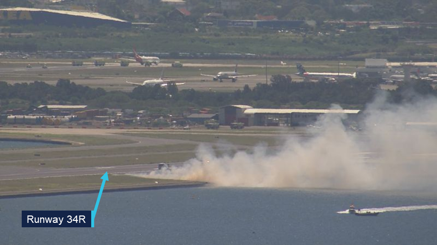
The flight crew requested a return to Sydney Airport and ATC directed the flight accordingly. The aircraft was slightly over its maximum landing weight due to unspent fuel, and the expected landing distance was higher for a single engine landing. The flight crew therefore planned to land on runway 34L, which was longer than runway 34R (3,962 m vs. 2,438 m). In addition, ATC closed runway 34R, due to fragments from the engine, which ignited a grass fire next to the runway (Figure 1).
Figure 1: Grass fire next to runway 34R
Source: Nine Network Australia, annotated by the ATSB
At 1251, while the aircraft was in a holding pattern at a waypoint south of Sydney Airport, the captain provided a briefing to members of the cabin crew, followed by an announcement to passengers in the cabin, informing them of the situation. Because the right engine could not be clearly seen from the flight deck, the flight crew also requested that the cabin service manager (CSM) have an off-duty pilot on board the flight photograph the right engine. Based on the photograph, the flight crew determined that the engine failure was likely contained,[2] and the FO could not see any damage to the aircraft’s right wing.
At 1301, once the relevant checklists were completed, the flight crew advised ATC that they were ready to commence the approach. ATC subsequently cleared the aircraft for landing on runway 34L, and the aircraft landed safely at 1305:50. The aircraft was cleared to roll through to the end of the runway where it could be inspected by the Aviation Rescue Fire Fighting Service (ARFFS) personnel. When ARFFS was confident that there was no risk of fire from the engine, the aircraft was clear to return to the gate, where passengers disembarked via standard procedures.
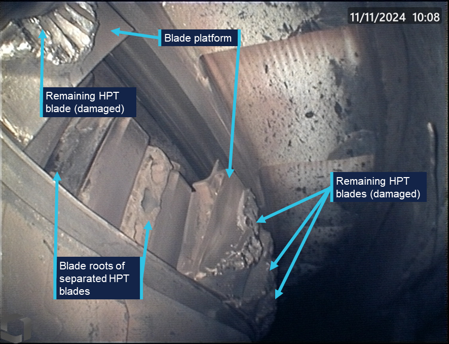
The failed right engine was inspected for damage by Qantas engineering personnel. Examination of the engine confirmed that the engine failure was contained. Borescope imagery found that 2 high-pressure turbine (HPT) blades had undergone a below‑platform separation from the HPT disc (Figure 2).
The engine was removed from the aircraft and sent to the engine manufacturer, CFM International, for further examination. The ATSB did not attend either of these examinations.
Figure 2: Below-platform separation of 2 HPT blades
Source: Qantas Airways, annotated by the ATSB
Context
Pilot information
The captain held an Air Transport Pilot (Aeroplane) Licence, a current class 1 aviation medical certificate, and had accrued 17,554 hours of aeronautical experience. Of this, about 4,578 hours were on the Boeing 737, including 251 hours in the previous 90 days.
The FO held an Air Transport Pilot (Aeroplane) Licence, a current class 1 aviation medical certificate, and had accrued 14,809 hours of aeronautical experience. Of this, about 3,832 hours were on the Boeing 737, including 216 hours in the previous 90 days.
The captain’s most recent simulator training was in June 2024. The captain was assessed as proficient at the manoeuvre ‘Engine out between V1 & V2’. This manoeuvre simulated an engine failure after the decision speed was reached, but before the aircraft attained the speed required to climb on one engine. The first officer was marked proficient at the same procedure during simulator training in October 2024.
Aircraft and engine information
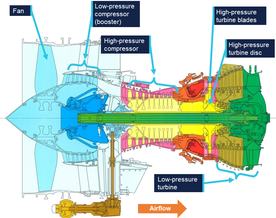
VH-VYH was a Boeing Company 737-838 aircraft, powered by 2 CFM56-7B24E high bypass turbofan engines. The engine is a dual-rotor, axial-flow turbofan. A cross-section of the engine is illustrated in Figure 3.
Figure 3: CFM56-7B engine cross-section
Source: CFM International, annotated by the ATSB
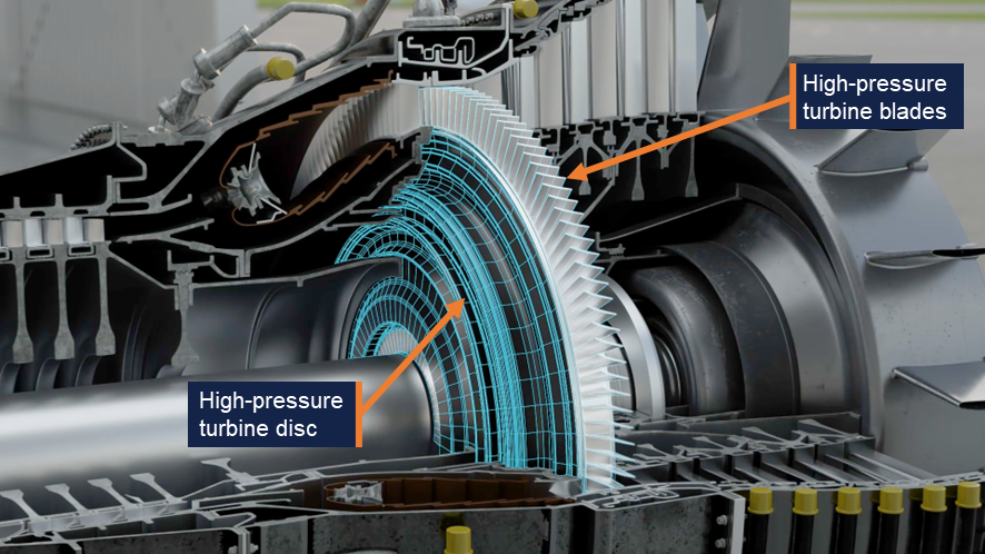
One rotor consisted of a 9-stage high-pressure compressor driven by a single‑stage high‑pressure turbine (HPT), highlighted in Figure 4. The other rotor consisted of a 3‑stage low‑pressure compressor and fan, driven by a 4‑stage low‑pressure turbine.
Figure 4: Cutaway model of a CFM56 engine
Source: ATSB
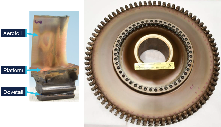
The HPT was made up of 76 turbine blades, each consisting of an aerofoil, platform and dovetail (photographs of an exemplar blade and disc are shown in Figure 5). The dovetail of each blade was secured within the HPT disc, making the platform a continuous surface around the HPT’s circumference, with the blades radiating outward. Various iterations of HPT blade were used throughout the global fleet of CFM56-7B engines due to updated blade designs. VH-VYH’s failed right engine was fitted with the 2403M91P02 configuration of HPT blades.
Figure 5: CFM56-7B HPT blade (left) and disc (right)
Source: CFM International, annotated by the ATSB
Aircraft maintenance
The most recent maintenance release for VH-VYH was issued on 7 November 2024. There were no issues listed, unresolved or otherwise, relating to operation of the right engine.
The area around the HPT was last inspected via borescope on 25 September 2024. This inspection included the combustion chamber, HPT blades and adjacent nozzle guide vanes. There were no significant findings, although it is important to note that these borescope inspections were not capable of examining below-platform areas of the blades, which could only be inspected when they were removed from the disc. This required removal of the engine’s core and disassembly of the HPT system. For this engine, HPT disassembly would only be expected to occur when HPT blades were due for replacement.
The right engine had completed 17,656 flight cycles, and the HPT blades were original to the engine. The engine was scheduled to be removed from the aircraft on 21 November 2024 due to a service bulletin (SB 72-1082) issued by the manufacturer in April 2023 which imposed a recommended removal threshold (RRT) of 17,900 cycles on this engine’s blade configuration (2403M91P02).
Engine examination
An engine teardown inspection was conducted by CFM International at its technical facility in Malaysia. This was a multi-day process, with the ATSB remotely evaluating the inspection progress and observations. The examination confirmed that 2 of the 76 HPT blades had been liberated due to below-platform fractures in the dovetails. All of the remaining HPT blades had fractured at the base of the aerofoil, above the blade platform. Damage was also observed on components elsewhere in the engine, almost all found to be consequent to the HPT blade failures. The exception was evidence of birdstrike observed on the fan and low‑pressure compressor. However, there was no evidence to indicate that the bird ingestion was relevant to the HPT blade separation.
CFM International conducted further metallurgic examination on the HPT blades and disc. Evidence of fatigue cracking was found in 28 blades, originating in the region described as the ‘min-neck’ of the blade dovetails. This was the area on the blade where the dovetail cross-section was at its thinnest point. The fatigue cracks originated on the ‘convex side’ of the blade, which is the face visible in Figure 5.
Blade number 50 was one of the 2 blades that experienced a below-platform failure. It exhibited the most extensive fatigue cracking. Conversely, the other blade with a below‑platform failure, blade 51, exhibited no evidence of fatigue, failing purely due to tensile overstress. The manufacturer noted that there had been previous occurrences involving a below‑platform fatigue failure where the adjacent blade failed in the dovetail due to tensile overstress resulting from contact with the liberated blade. The remaining 74 blades failed due to overstress fractures at the base of each aerofoil.
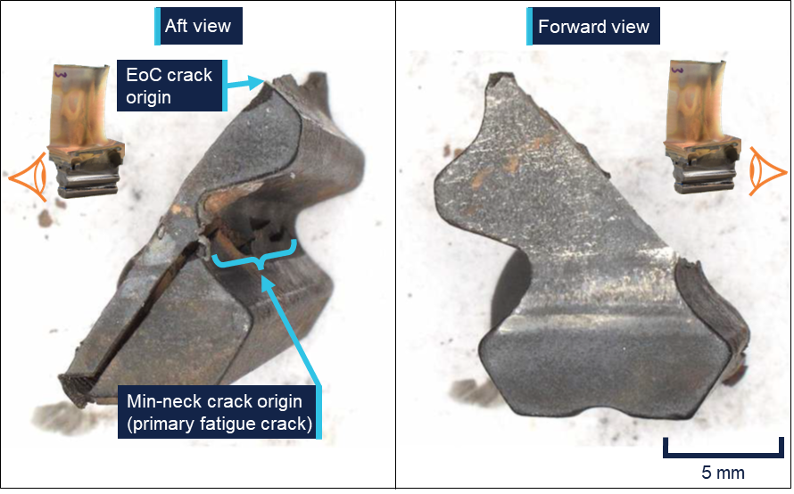
The fracture morphology of blade number 50 was examined to determine how the cracking progressed. The dovetail recovered from the HPT disc is shown in Figure 6.
Figure 6: Dovetail of blade 50 recovered from the HPT disc
The edge-of-contact (EoC) crack originated where the blade made contact with the HPT disc during normal operation. The min-neck crack originated where the dovetail’s cross‑section was at its thinnest. Source: CFM International, annotated by the ATSB
There were 2 fatigue cracks observed, propagating in a diagonally downward direction on parallel planes. These cracks initiated with small regions of low-cycle fatigue[3] (LCF) which transitioned to a larger high-cycle fatigue[4] (HCF) region. One crack originated at what the manufacturer described as the ‘edge-of-contact’ or ‘EoC’, where the blade contacted the HPT disc during normal operation. This crack propagated through approximately 70% of the dovetail cross-section. This resulted in an overstress failure of the remaining 30%, liberating the top section of the blade, including the platform and aerofoil, from the HPT disc. The edge‑of‑contact fracture as viewed from the concave side of the blade is shown in Figure 7.
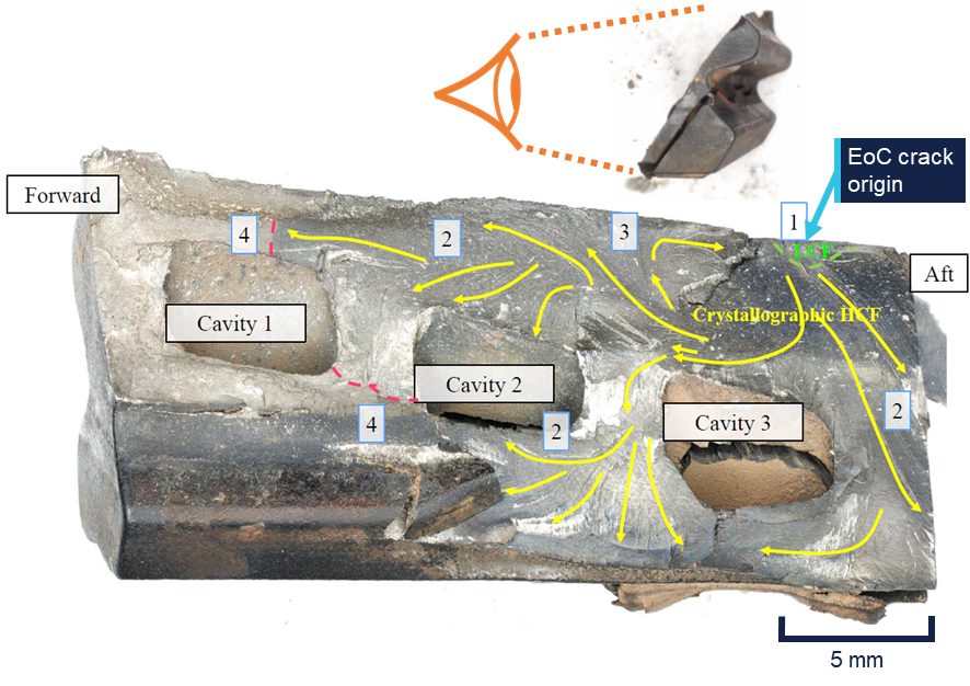
Figure 7: Concave view of the edge-of-contact fracture surface
From the crack origin, LCF cracking propagated to the green dashed line. The fracture morphology then transitioned to HCF, which propagated along crystal planes within the material until it reached the red dashed lines. The remaining material then failed in overstress, resulting in the top section of the blade becoming liberated form the HPT disc. Source: CFM International, modified by the ATSB
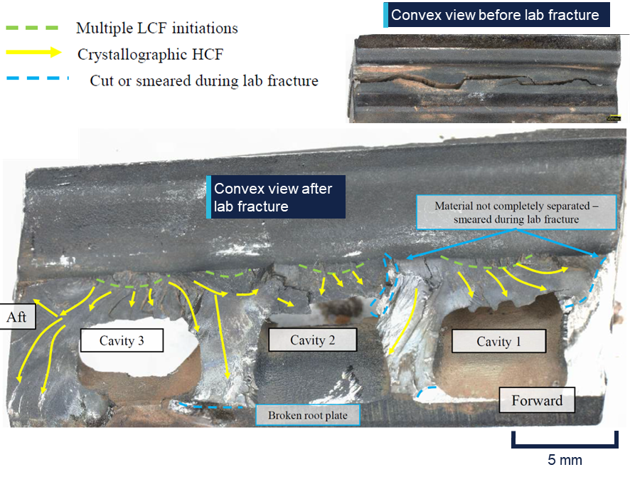
The other crack originated in the min-neck region of the dovetail. This crack propagated through approximately 80% of the dovetail’s cross-section. The remaining cross-section was still intact when the blade separated. As part of the manufacturer’s examination, the remaining material was fractured in the laboratory, and the crack opened for inspection (Figure 8).
Figure 8: Convex view of the min-neck fracture surface
Multiple crack origins were observed, from which LCF propagated in small thumbnails. These fatigue cracks transitioned to HCF travelling along crystal planes within the material, consuming approximately 80% of the dovetail’s cross-section. Source: CFM International, annotated by the ATSB
The manufacturer’s analysis found that the min-neck cracking observed in blade 50 was the primary fracture within the blade. As the cracking propagated downward through the blade, tensile forces from disc rotation could no longer be effectively transmitted to the bottom half of the dovetail. Consequently, excessive force was placed on the top half, resulting in the propagation of the edge-of-contact crack and eventual separation of the blade.
HPT service performance
The failure mechanism in this occurrence (a min-neck fatigue crack and subsequent below platform liberation of an HPT blade) had been observed in other engine failures within the CFM56-7B fleet. At the time of writing, there were 86 events reported to the manufacturer over the course of 115 million flight hours. The majority of these engine failures occurred in 2403M91P02 and 2403M91P03 blade configurations.
CFM International’s fleet analysis found that accounting for all failures including min-neck cracks, these blade configurations remained within internal fleet reliability targets and were well within regulatory limits and guidance, including the continued operational safety guidance described by the US Federal Aviation Administration, as well as an Acceptable Means of Compliance outlined by the European Aviation Safety Agency.
Because below-platform cracks could not be inspected without complete disassembly of the engine, the manufacturer’s primary method for reducing below-platform separations was by imposing recommended removal thresholds (RRTs) on blade configurations susceptible to min-neck cracking. The purpose of the service bulletin issued in April 2023 was to mitigate the risk of HPT blade failure by reducing the RRT from 20,000 cycles to 17,900 cycles for 2403M91P02 and 2403M91P03 blade configurations.
In March 2025, as a result of its ongoing reliability monitoring, the engine manufacturer published a revised RRT for 2403M91P03 blade configurations, reducing it to 17,200 cycles. The 2403M91P02 fleet reliability was found to be consistent with existing reliability targets and was not adjusted. The more recent 2403M91P06 blade design included an adjusted dovetail geometry in order to reduce instances of min-neck fatigue cracking.
Take-off reference speeds
Take-off reference speeds, commonly referred to as V speeds, are provided by aircraft manufacturers to assist pilots in determining when a rejected take-off should be initiated, and when the aircraft can rotate, lift-off and climb away safely given the existing flight conditions. They are defined as follows:
V1: Decision speed – the maximum speed at which a rejected take-off can be initiated. In the event of an engine failure below V1, there is enough remaining runway distance for the aircraft to stop safely, and the take-off should be aborted. Conversely, if an engine failure occurs after V1 is reached, the take-off should be continued. It can be said that V1 is the ‘commit to fly’ speed. It is calculated for every take-off as it is based on aircraft available thrust, aircraft weight, flap setting, runway length and slope, wind conditions, and airport density altitude.
VR: Rotation speed – the speed at which the aircraft rotation is initiated by the pilot. This speed ensures that, in the event of an engine failure, lift-off is achievable and the take‑off safety speed (V2) is reached at no higher than 35 ft above ground level.
V2: Take-off safety speed – the minimum speed at which the aircraft complies with the handling criteria associated with climb following an engine failure. V2 is normally obtained by factoring the stalling speed or minimum control (airborne) speed, whichever is the greater, to provide a safe margin.
Safety analysis
Engine failure
During the take-off roll, one of the right engine’s HPT blades was liberated from the HPT disc due to pre-existing fatigue cracks in the blade’s dovetail. This region was prone to fatigue cracking in the 2403M91P02 blade configuration. The HPT blades had been scheduled to be removed from the engine 13 days later, in accordance with a service bulletin that was intended to reduce instances of such blade liberations. Due to contact with the liberated blade, the adjacent blade 51 failed through the dovetail and was also liberated from the disc.
The 2 liberated blades were thrown into the engine shroud and likely made contact with adjacent HPT blades still fitted in the rotating disc. As a result of this contact, all of the remaining 74 blades experienced overstress failure through their aerofoils, liberating additional blade fragments from the HPT disc.
The liberated blades and other debris then travelled rearward through the low-pressure turbine and were ejected out the rear of the engine. With no torque being produced by the HPT, and debris obstructing and damaging the low-pressure turbine, the right engine failed. The flight crew observed a single loud bang and a shudder, indicating that the liberation of all HPT blades and subsequent engine failure occurred extremely rapidly.
Given the location of the blade failure, it is likely that there was no opportunity to detect the crack during the engine’s lifespan. The removal thresholds put in place by the engine manufacturer, CFM International, did not completely prevent blade liberation events. Nevertheless, the manufacturer’s fleetwide analysis found that the CFM56-7B fleet remained within its defined reliability targets as well as airworthiness guidelines set by relevant regulators.
Flight crew response
The decision speed, V1, is the critical point between a take-off that should be aborted and one that should be continued. This is the worst possible time for a multi-engine aircraft to experience an engine failure during take-off, because safety margins are at a minimum whether the take-off is aborted (minimum remaining runway distance available) or continued (minimum airspeed available). When the engine failure occurred, the aircraft had reached V1, meaning any attempt to abort the take-off would have occurred beyond the point when it was safe to do so.
Confronted with this situation, the flight crew responded quickly and decisively in continuing the take-off, declaring an emergency, identifying the problem and then working through the appropriate procedures. The flight crew, cabin crew, ATC and ARFFS all worked together effectively to enable the aircraft’s safe return to Sydney Airport.
Findings
ATSB investigation report findings focus on safety factors (that is, events and conditions that increase risk). Safety factors include ‘contributing factors’ and ‘other factors that increased risk’ (that is, factors that did not meet the definition of a contributing factor for this occurrence but were still considered important to include in the report for the purpose of increasing awareness and enhancing safety). In addition ‘other findings’ may be included to provide important information about topics other than safety factors.
These findings should not be read as apportioning blame or liability to any particular organisation or individual.
From the evidence available, the following findings are made with respect to the engine failure involving Boeing 737, VH-VYH, at Sydney Airport, New South Wales, on 8 November 2024.
Contributing factors
During take-off, a high-pressure turbine blade failed due to a fatigue crack that had developed prior to the flight, and the blade was liberated from the high-pressure turbine disc. Engine damage from the liberated blade resulted in a contained engine failure.
Other findings
The flight crew responded quickly and appropriately to an engine failure at V1, a critical time during take-off.
Safety actions
Whether or not the ATSB identifies safety issues in the course of an investigation, relevant organisations may proactively initiate safety action in order to reduce their safety risk. The ATSB has been advised of the following proactive safety action in response to this occurrence.
Safety action from CFM International
Based on the number of previous engine events involving min-neck fatigue cracking of high‑pressure turbine blades, and projected events in future, CFM International reviewed its recommended removal thresholds for HPT blades on CFM56-7B engines. The review found that 2403M91P02 blade configurations were not projected to exceed reliability targets and so thresholds were not adjusted.
Sources and submissions
Sources of information
The sources of information during the investigation included:
flight crew
cabin crew
Airservices Australia
Qantas Airways
CFM International
The Boeing Company
Civil Aviation Safety Authority
recorded data from the aircraft.
Submissions
Under section 26 of the Transport Safety Investigation Act 2003, the ATSB may provide a draft report, on a confidential basis, to any person whom the ATSB considers appropriate. That section allows a person receiving a draft report to make submissions to the ATSB about the draft report.
A draft of this report was provided to the following directly involved parties:
flight crew
Airservices Australia
Qantas Airways
CFM International
Civil Aviation Safety Authority.
Submissions were received from:
Qantas Airways
CFM International.
The submissions were reviewed and, where considered appropriate, the text of the report was amended accordingly.
Purpose of safety investigations
The objective of a safety investigation is to enhance transport safety. This is done through:
identifying safety issues and facilitating safety action to address those issues
providing information about occurrences and their associated safety factors to facilitate learning within the transport industry.
It is not a function of the ATSB to apportion blame or provide a means for determining liability. At the same time, an investigation report must include factual material of sufficient weight to support the analysis and findings. At all times the ATSB endeavours to balance the use of material that could imply adverse comment with the need to properly explain what happened, and why, in a fair and unbiased manner. The ATSB does not investigate for the purpose of taking administrative, regulatory or criminal action.
About ATSB reports
ATSB investigation reports are organised with regard to international standards or instruments, as applicable, and with ATSB procedures and guidelines.
Reports must include factual material of sufficient weight to support the analysis and findings. At all times the ATSB endeavours to balance the use of material that could imply adverse comment with the need to properly explain what happened, and why, in a fair and unbiased manner.
An explanation of terminology used in ATSB investigation reports is available here. This includes terms such as occurrence, contributing factor, other factor that increased risk, and safety issue.
Publishing information
Released in accordance with section 25 of the Transport Safety Investigation Act 2003
Ownership of intellectual property rights in this publication
Unless otherwise noted, copyright (and any other intellectual property rights, if any) in this report publication is owned by the Commonwealth of Australia.
Creative Commons licence
With the exception of the Commonwealth Coat of Arms, ATSB logo, and photos and graphics in which a third party holds copyright, this report is licensed under a Creative Commons Attribution 4.0 International licence.
The CC BY 4.0 licence enables you to distribute, remix, adapt, and build upon our material in any medium or format, so long as attribution is given to the Australian Transport Safety Bureau.
Copyright in material obtained from other agencies, private individuals or organisations, belongs to those agencies, individuals or organisations. Where you wish to use their material, you will need to contact them directly.
[1]PAN PAN: an internationally recognised radio call announcing an urgency condition which concerns the safety of an aircraft or its occupants but where the flight crew does not require immediate assistance.
[2]A contained engine failure is one in which components within the engine might separate but either remain in the engine’s cases or exit the engine with comparatively low energy through the tailpipe.
[3]Low-cycle fatigue cracking is associated with cyclic loading of a magnitude that produce elastic strain as well as plastic strain during each cycle. Fracture due to low-cycle fatigue is typically fewer than 10,000 cycles.
[4]High-cycle fatigue cracking is associated with cyclic loading of a magnitude that produces deformation that is primarily elastic. Fracture due to high-cycle fatigue is typically greater than 10,000 cycles.
Occurrence summary
Investigation number
AO-2024-057
Occurrence date
08/11/2024
Occurrence time and timezone
1235 EDT
Location
Sydney Airport
State
New South Wales
Report status
Final
Investigation level
Short
Investigation type
Occurrence Investigation
Investigation phase
Final report: Dissemination
Investigation status
Completed
Mode of transport
Aviation
Aviation occurrence category
Diversion/return, Engine failure or malfunction
Occurrence class
Serious Incident
Highest injury level
None
Aircraft details
Manufacturer
The Boeing Company
Model
737-838
Registration
VH-VYH
Serial number
34180
Aircraft operator
Qantas Airways Limited
Sector
Jet
Operation type
Part 121 Air transport operations - larger aeroplanes
The Australian Transport Safety Bureau has commenced a transport safety investigation into the engine failure incident involving a Qantas 737 aircraft during take-off from Sydney on Friday afternoon.
A team of transport safety investigators, with experience in aircraft maintenance, aircraft operations, material failure analysis and data recovery, has commenced the evidence collection phase of this investigation.
At the ATSB’s request the operator has quarantined the aircraft’s cockpit voice and flight data recorders. Once downloaded, information from those recorders will be analysed at the ATSB’s technical facilities in Canberra.
Other likely investigation activities will include interviewing the flight crew, reviewing operator procedures, analysing weather information, examining any relevant engine components, and potentially attending any tear-down inspection of the engine.
Our investigators will now work methodically to progressively establish the incident’s sequence of events and contextual information, with a view to determining contributing factors and any underlying safety issues, which will be detailed in the investigation’s final report.
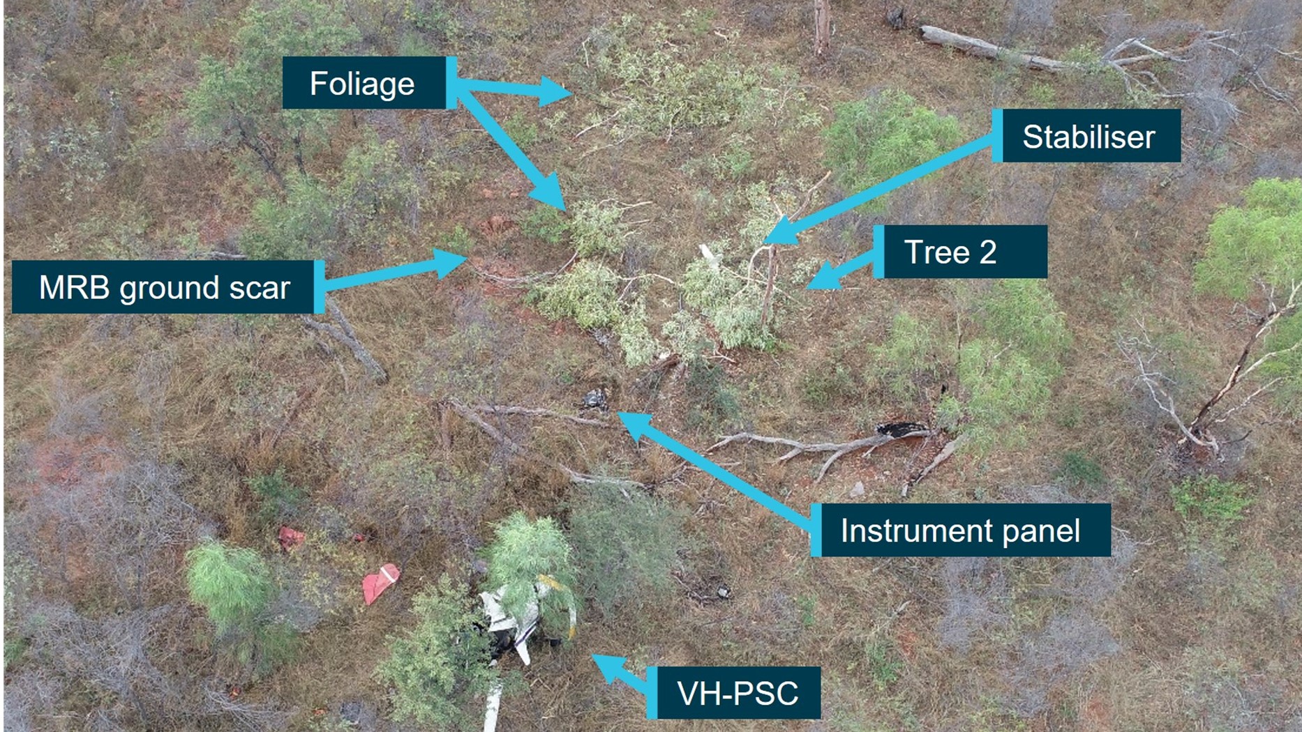
The ATSB has released the final report from its investigation into a fatal R22 helicopter mustering accident at Limbunya Station, near the NT-Western Australia border, on 27 June 2023.
The helicopter was one of two Robinson R22s mustering cattle when the pilot of the second helicopter reported not hearing from the other for some time.
The wreckage of the helicopter was located after a short search, and the pilot was fatally injured.
ATSB transport safety investigators deployed to the accident site, a flat and moderately wooded area, and determined that the helicopter impacted terrain in a nose-down, right side low attitude. However, there were no witnesses to the accident and no recorded data to accurately determine the accident sequence.
“The site and wreckage signatures were consistent with the helicopter being in a low rotor energy state with low-to-nil engine power,” Director Transport Safety Kerri Hughes said.
“Investigators were able to confirm continuity of the flight controls prior to the accident, while an examination of the helicopter’s engine found no damage or defects that may have affected its pre-accident operation.”
Ms Hughes noted that the investigation considered the possibility of the pilot experiencing some level of incapacitation, which could have explained the low rotor energy and/or helicopter trajectory into terrain. However, after a review of the pilot’s medical history and post-mortem examination results there was insufficient evidence to determine if the pilot experienced an incapacitation event.
“Therefore, in the absence of an identified problem with the helicopter and having considered other plausible explanations, the reason for the engine reduction and loss of control could not be determined.
“This accident is a reminder of the complexities of low-level flight where there is reduced time to respond to emergencies and a reduced likelihood of finding a suitable forced landing area,” Ms Hughes noted.
While not found to have contributed to the accident, the ATSB’s investigation also identified that the helicopter’s maintenance release contained no endorsements for daily inspection certification, hours flown, total time-in-service, or engine oil uplift.
“This was despite the helicopter being operated every day since the maintenance release was issued 13 days earlier,” Ms Hughes said.
“Aircraft owners and pilots should ensure maintenance releases are updated at the end of each day’s flying, to ensure pilots can be aware of the operational status of the aircraft, and avoid unintentional flight beyond maintenance.”
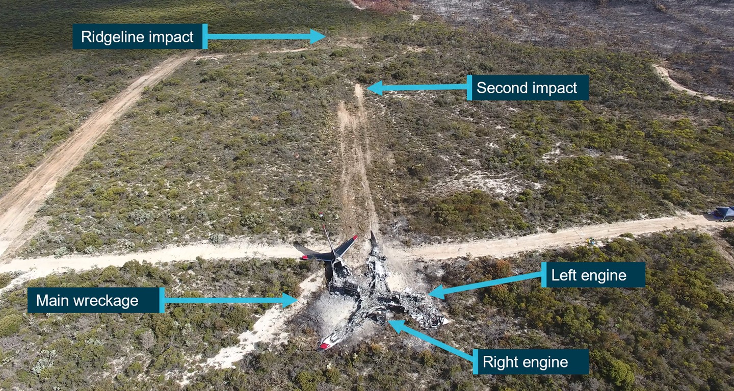
Minimum safe drop heights are in development for large firefighting aircraft in Australia, to address safety issues identified by an ATSB investigation into a 737 air tanker accident in south-west WA.
‘Bomber 139’, a Boeing 737 aircraft converted as a large air tanker, impacted a ridgeline after completing a drop while extending a fire retardant containment line during a bushfire-fighting task in the Fitzgerald River National Park on 6 February 2023.
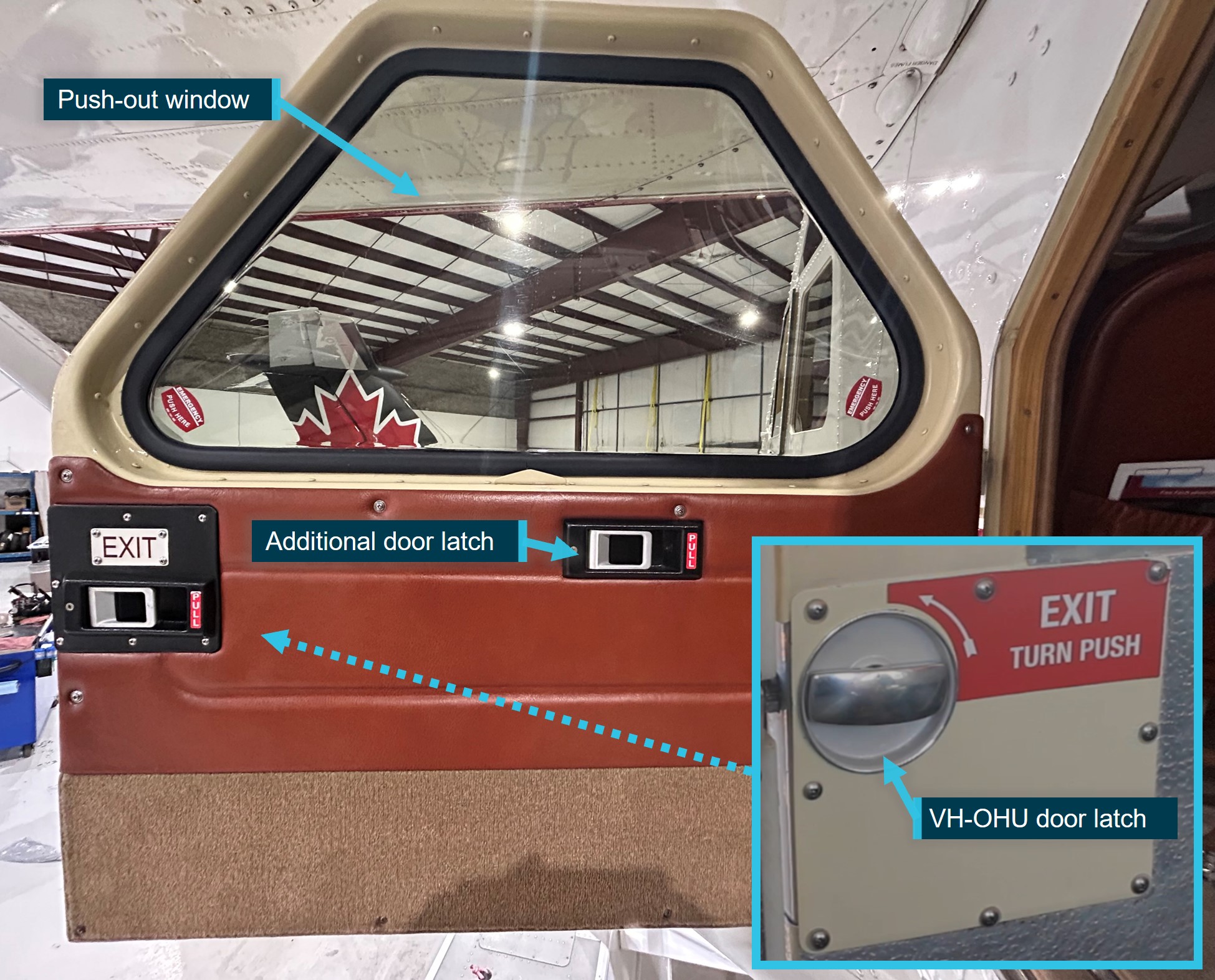
After striking the ridgeline, the aircraft cleared a small line of foliage before impacting the ground a second time and then sliding to rest. The two pilots on board were able to evacuate through a cockpit window before the aircraft was consumed by a post-impact fire.
“The ATSB’s investigation found that the aircraft was conducting a drop at a low height and airspeed over descending terrain, which required the use of the idle thrust engine power setting and a high rate of descent,” ATSB Chief Commissioner Angus Mitchell said.
“Towards the end of the drop, the aircraft’s height and airspeed decayed as it approached rising terrain that had not been detected, and was not expected, by the aircraft captain.”
While the aircraft’s thrust levers had been advanced mid-way through the drop, there was insufficient time for engine power to increase to allow the aircraft to climb away and safely clear the ridgeline crossing the aircraft’s exit path.
The report notes the ridgeline had likely not been detected as the captain, who was the pilot flying, had declined a ‘Show Me’ run from the Birddog aircraft, had conducted right hand circuits (restricting their visibility of the target area as they were seated in the left seat on the flightdeck), likely had no visibility of the ridgeline during the go-around from the first drop, and was led by the Birddog to the target through smoke on the second drop.
“Not detecting the rising terrain likely contributed to the captain allowing the aircraft to enter a low energy state during the drop.”
Further, the co-pilot did not identify nor announce any deviations during the retardant drop, which could have alerted the aircraft captain to the low-energy state of the aircraft.
“Notably, the operator and tasking agency had not published a minimum drop height for large air tankers,” Mr Mitchell said.
“This resulted in the co-pilot, who did not believe there was a minimum drop height, not making any announcements about the aircraft’s low energy state prior to the collision.”
The accident occurred when the aircraft was conducting a second drop after releasing three-quarters of its retardant load on the prior run.
“The operator’s practice of the pilots recalculating, and lowering, their target drop speed after a partial load drop also contributed to the aircraft’s low energy state.”
The investigation found that neither the operator nor the relevant Western Australian Government Departments had published a drop height for large air tankers (whereas the US Forest Service has a minimum large air tanker drop height of 150 ft).
This meant that aircraft captains could exercise their own judgement for drop heights to improve accuracy.
Bomber 139 was operating in Australia under a contract with the National Aerial Firefighting Centre, which did not impose a minimum drop height, but required the operator to comply with the standard operating procedures (SOPs) of the member state for the aircraft’s nominated operational base, in this case Western Australia.
In turn the Western Australia large air tanker SOPs did not impose a minimum drop height limit.
Since the accident Coulson Aviation implemented a minimum drop height of 200 ft for its airtankers, while the Western Australian Department of Fire and Emergency Services and the Department of Biodiversity, Conservation and Attractions are amending procedures to incorporate drop heights, including a large airtanker drop height of 200 ft.
Meanwhile, at a national level, the Australasian Fire and Emergency Services Authorities Council, the parent organisation for the National Aerial Firefighting Centre, has undertaken to develop national large air tanker SOPs.
Separately, the ATSB has issued a safety recommendation to Coulson Aviation to address crew resource management procedures for retardant drops to reduce the risk of the aircraft entering an unrecoverable state before the pilot monitoring alerts the pilot flying.
“This accident highlights that standard operating procedures and crew resource management should be implemented with the intent to prevent an unsafe situation from developing,” said Mr Mitchell.
“Safety standards should not be solely dependent on the performance of the pilot flying and recovery call-outs.”
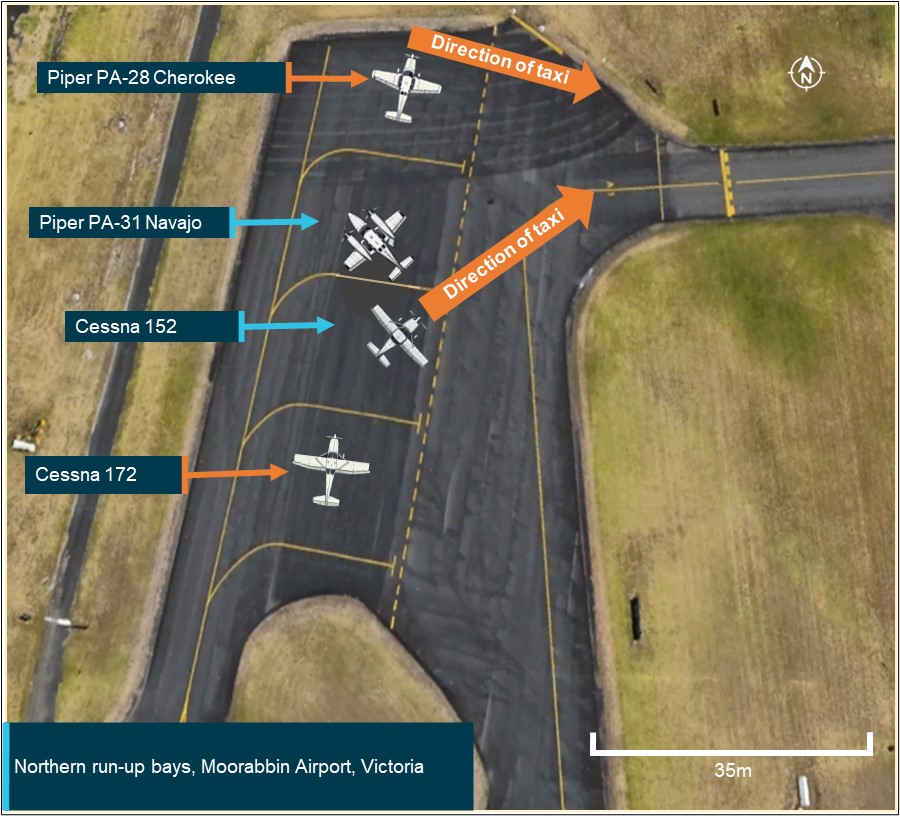
At about 1410 local time, a Cessna 152 aircraft with two crew from a local flight training facility was taxiing to the northern run-up bay at Moorabbin Airport, Victoria. The run-up bay is an area designated for pilots and engineers to perform high-power engine and pre-flight aircraft checks. The run-up bays were full and the Cessna queued behind a Piper PA-31 Navajo twin-engine aircraft that was positioned to conduct maintenance testing, involving high-power ground-running of the engines. A Piper PA-28 Cherokee was in the bay ahead of the Navajo, and another aircraft (a Cessna 172) was in the first bay before the Cessna 152 (Figure 1).
Figure 1: Position of the Cessna and Navajo aircraft immediately before occurrence
Source: Google Earth, annotated by the ATSB
By the time the pilot of the Cherokee had finished their checks and the aircraft vacated the bay, the pilot of the Cessna 152 (the Cessna) had already finished their checks and was given clearance to taxi behind the Cherokee to the runway.
As the Cessna started to taxi, the pilot of the Navajo increased the aircraft engines to full power as part of their engine inspection. The high intensity propeller wash[1] from the Navajo lifted the left wing of the Cessna, causing the aircraft to tip. Airport staff alerted the pilot of the Navajo to the incident, and they promptly shut down the aircraft engines. The Cessna sustained minor damage to the propeller and the wing tip of the aircraft as a result of the ground strike. No injuries were reported by the crew of the Cessna.
Safety message
Propeller wash from high-power engine tests can have serious consequences for light aircraft that can lead to loss of control and aircraft damage. Additionally, the propeller wash forces generated may result in flying debris which can cause damage to nearby people, equipment, or structures. To avoid this type of incident, pilots and ground crew must be vigilant of allowing safe distances to avoid propeller wash, particularly in congested apron areas. Flight and ground crews should also be aware of environmental conditions that can amplify the effects of propeller wash and always remain aware of their surroundings during operation or testing of an aircraft. This can include the re-evaluation of aircraft positioning during engine testing to prevent propeller wash from affecting nearby aircraft. Pilots taxiing in the vicinity of run-up areas should exercise caution, maintain situation awareness and avoid other aircraft conducting run-ups. Pilots are reminded to communicate directly to other aircraft if they believe an imminent safety risk exists to their operations.
About this report
Decisions regarding whether to investigate, and the scope of an investigation, are based on many factors, including the level of safety benefit likely to be obtained from an investigation. For this occurrence, no investigation has been conducted and the ATSB did not verify the accuracy of the information. A brief description has been written using information supplied in the notification and any follow-up information to produce a short summary report and allow for greater industry awareness of potential safety issues and possible safety actions.
[1]The disturbed mass of air generated by the propeller of an aircraft.
Occurrence summary
Mode of transport
Aviation
Occurrence ID
AB-2024-038
Occurrence date
24/09/2024
Location
Moorabbin Airport
State
Victoria
Occurrence class
Incident
Aviation occurrence category
Ground strike
Highest injury level
None
Brief release date
07/11/2024
Aircraft details
Manufacturer
Cessna Aircraft Company
Model
152
Sector
Piston
Operation type
Part 142 Integrated and multi-crew pilot flight training
On 2 November 2024, a GippsAero GA8-TC Airvan, registered VH-IDM and operated by Wave Air, was being used to conduct a scenic flight from Whitsunday Airport (Shute Harbour), Queensland. On board were a pilot and 7 passengers. During the landing the aircraft departed the upwind end of the runway before entering marshy ground and coming to a stop in a ditch. Neither the pilot nor any of the passengers were injured and the aircraft was substantially damaged.
What the ATSB found
The ATSB identified that the aircraft's approach was above profile with a high airspeed and the pilot had an incorrect understanding of the required approach speed. Subsequently, the pilot did not initiate a go‑around, resulting in a landing beyond the planned touchdown point. Additionally, despite having sufficient landing distance remaining, the pilot did not apply sufficient braking to prevent the aircraft departing the runway
It was also determined that the training, supervision and checking flights conducted by Wave Air did not identify that an excessive approach speed was routinely being used by the pilot. Additionally, the pilot’s initial training was not fully completed, and they were not assessed on several abnormal and emergency procedures prior to operating unsupervised.
The ATSB also identified that Wave Air’s weight and balance system used an incorrect empty weight moment arm to calculate the aircraft's centre of gravity, and passengers were not weighed in accordance with its procedures. Finally, it was determined that the decision height for assessing whether an aircraft met Wave Air’s stabilised approach criteria was too low.
What has been done as a result
Wave Air has taken the following proactive safety action:
The operations manual was modified to require that the stabilised approach criteria be met by 300 ft above airport elevation in visual meteorological conditions and 500 ft in when operating under instrument flight rules.
The empty weight moment arm of the aircraft was corrected in the weight and balance system and the data of other aircraft was reviewed.
Passenger scales have been serviced and made accessible for routine passenger weighing in accordance with the operator’s procedure.
The training and checking manual has been updated to more precisely detail training criteria.
A new head of training and checking has been appointed.
Pilots are required to complete examinations prior to commencing in command under supervision (ICUS) training and operating unsupervised.
Updates have been made to the remedial training processes.
6-month flight reviews are now required for all pilots.
Safety message
Pilots should always be prepared to promptly execute a go-around if an approach for landing does not proceed as expected. Accurate knowledge of the aircraft’s reference speeds, in addition to having pre‑determined stabilised approach criteria, assist the assessment of whether an approach should be discontinued. Furthermore, routine practice of this manoeuvre will ensure that it can be performed safely when needed.
The occurrence
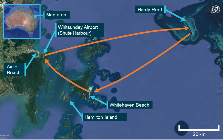
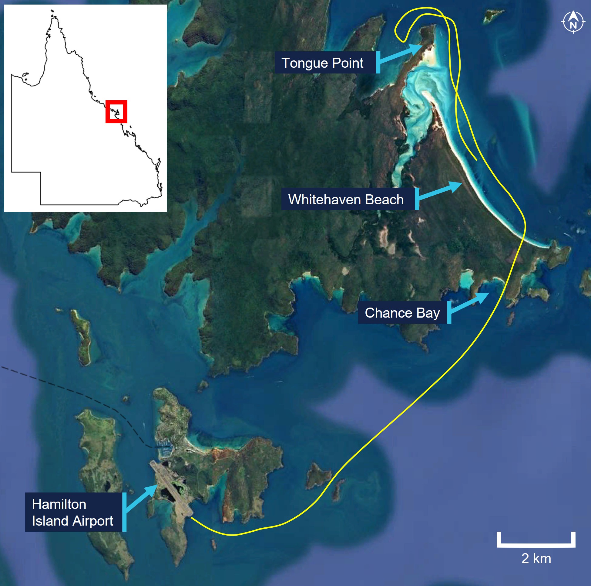
On 2 November 2024, a GippsAero GA8-TC Airvan, registered VH-IDM and operated by Wave Air, was being used to conduct a scenic flight with a pilot and 7 passengers on board. At 1120 local time, the aircraft departed from Whitsunday Airport (Shute Harbour), Queensland in‑company[1] with another of the operator’s aircraft as part of the same tour (Figure 1). Approximately one hour after departure, the 2 aircraft returned to the airport, joining the base leg of the circuit for a landing on runway 32.[2] VH‑IDM was leading the company and the pilot made positional broadcasts on behalf of both aircraft on the common traffic advisory frequency (CTAF).
Figure 1: Scenic flight route
Source: Google Earth, annotated by the ATSB
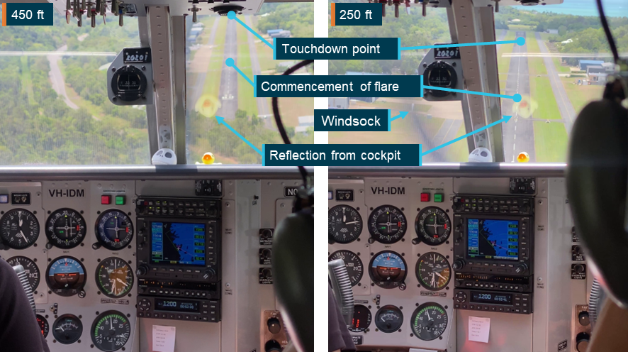
The airport did not have a dedicated Bureau of Meteorology (BoM) weather station, however the pilot recalled a cloud base at about 2,500 ft above ground level (AGL) and a 3–5 kt wind. Footage of the windsock at the time showed a light headwind on runway 32.
The pilot advised that, as the aircraft proceeded on the final approach to landing, they intended to maintain an airspeed of 80 kt and a flight path to arrive at the runway past the displaced threshold due to trees in the runway undershoot (see the section titled Whitsunday Airport (Shute Harbour)). However, the pilot reported that the aircraft did not descend as expected, resulting in it being above the intended approach path. In response, the pilot lowered the nose to increase the descent rate and regain the approach path, but as a result the airspeed increased from 80 to 90 kt.
At about this time, the trailing company aircraft contacted the pilot on the company frequency to request that they roll through to the end of the runway to exit after landing rather than backtracking. This was to avoid obstructing their landing. Because VH‑IDM could only broadcast on one of its 2 radios, the pilot selected the standby frequency (that was selected to the company frequency) on that radio, replied that they would roll through, and then reselected the CTAF frequency.
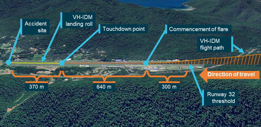
The aircraft continued the approach (Figure 2), remaining above the desired approach path while the airspeed varied between 85–95 kt. The aircraft passed over the displaced threshold of the runway at approximately 100 ft AGL. The pilot commenced the flare about 300 m beyond the displaced threshold, at an airspeed of approximately 90 kt. The aircraft then floated for about 640 m before touching down at a groundspeed of 65 kt with 370 m of runway remaining. The pilot recalled that throughout the approach and landing they did not consider conducting a go‑around[3] and were focused on landing the aircraft.
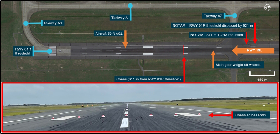
Figure 2: VH-IDM flight path and landing roll
Source: Google Earth, annotated by the ATSB
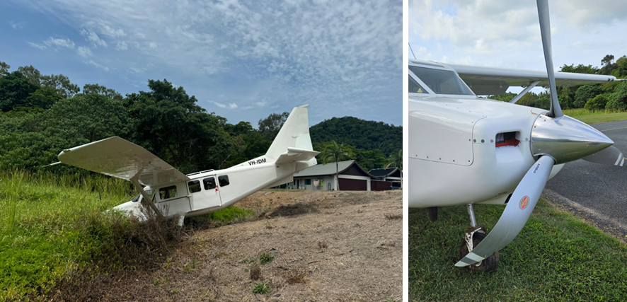
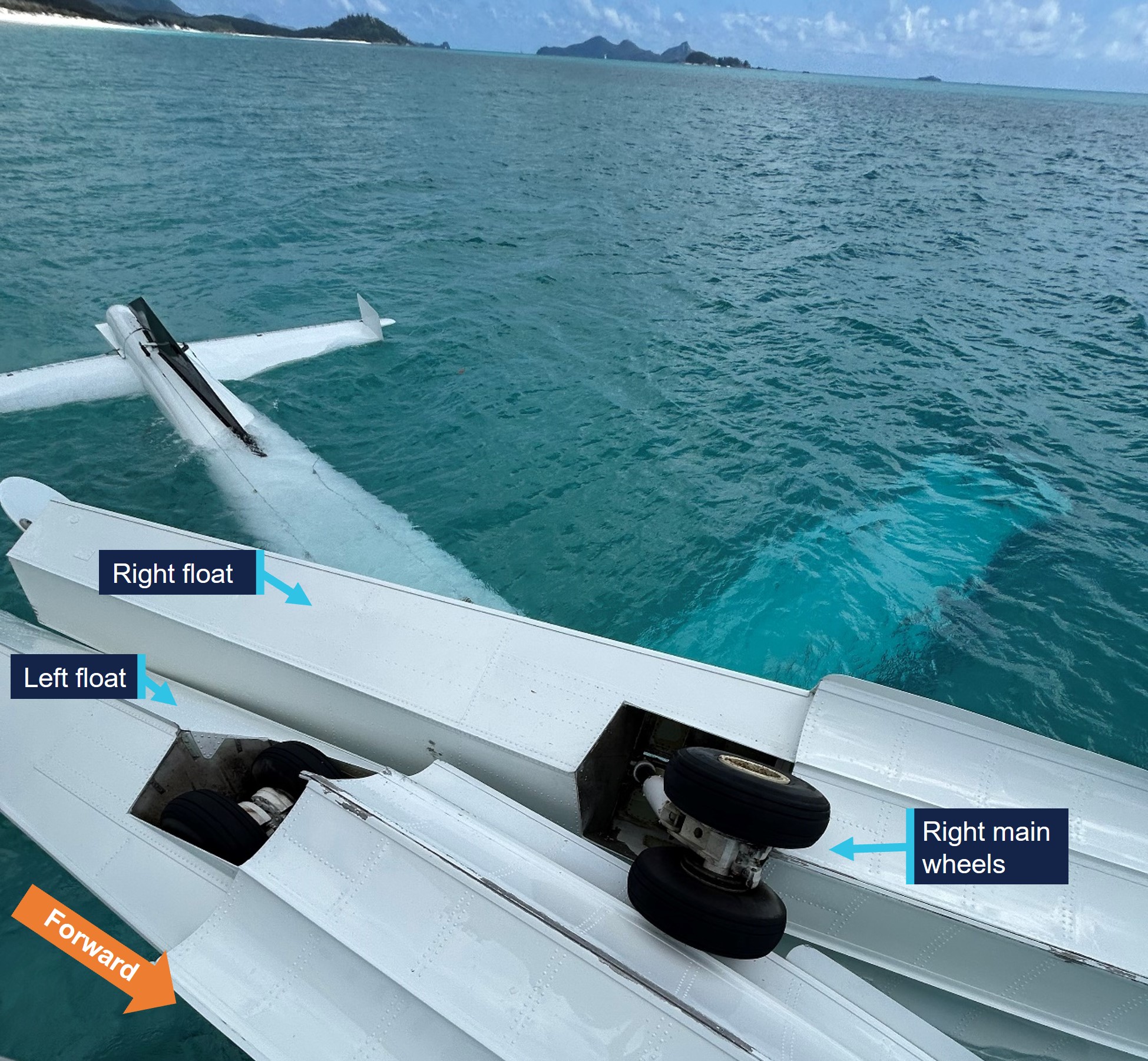
After touching down, the pilot retracted the flaps and recalled attempting to apply full braking pressure. They further recalled that the brakes did not perform as expected and they were unable to bring the aircraft to a stop. Subsequently, veering slightly right, the aircraft departed the end of the runway at a groundspeed of 24 kt. The aircraft travelled briefly across grass before entering marshy ground and coming to rest in a ditch, as the propellor struck the ground. Neither the pilot nor any of the passengers were injured and the aircraft received damage to the propellor and firewall (Figure 3)
Figure 3: VH-IDM damage
Source: Wave Air
After verbally confirming with the passengers that they were uninjured, the pilot advised the pilot of the trailing company aircraft via radio of the accident, before exiting and assisting the passengers to evacuate the aircraft. The trailing aircraft landed at approximately the same time as VH‑IDM came to a stop and taxied to the terminal after confirming the safety of the pilot and passengers of VH‑IDM.
Context
Pilot information
The pilot held a commercial pilot licence (aeroplane) issued in 2020 and a class 1 aviation medical certificate. They had accumulated 1,103 hours, of which 15 hours were operating the GA8‑TC Airvan and 225 hours were operating the non‑turbocharged GA8 Airvan. In the previous 90 days, the pilot had accumulated 170 hours, all in the GA8 and GA8‑TC. The pilot had been flying with the operator since June 2024 and had flown almost exclusively from Whitsunday Airport (Shute Harbour). The pilot had last conducted a flight review as part of an instrument proficiency check in December 2022.
While the pilot reported having limited sleep in the 24 and 48 hours prior to the accident, the ATSB examined the possible effect of fatigue and determined that they were not experiencing a level of fatigue known to affect performance.
Aircraft information
General information
VH-IDM was a GippsAero GA8-TC Airvan fitted with a Lycoming TIO‑540‑AH1A turbocharged piston engine. The aircraft was manufactured and first registered in 2009 and at the time of the accident had accumulated 1,240 hours total time in service.
A service bulletin that allowed an increased maximum take‑off weight of 1,905 kg and maximum landing weight of 1,860 kg had been completed on the aircraft. The aircraft was being maintained in accordance with the GA8‑TC‑320 maintenance schedule. A periodic inspection had been completed the morning of the accident and the maintenance release showed no outstanding items. The accident flight was the first flight following the inspection. The pilot advised that a different aircraft had originally been scheduled to be used for the occurrence flight, however the operator substituted VH‑IDM at the ‘last minute’.
Brake system
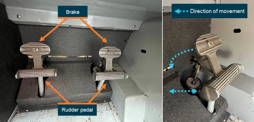
The aircraft’s brake system included toe brakes incorporated into the rudder pedals. Each rudder pedal was connected hydraulically to a brake unit on the corresponding main landing gear wheel and was engaged by applying pressure to the top of the pedal (Figure 4). During flight, a pilot’s feet rested on the floor in contact with the lower part of the rudder pedals to control the rudder. On the ground, a pilot would move their feet up on the pedal so that the top of the foot could be used to apply brake pressure. The heel was then used to maintain rudder control and nosewheel ground steering.
Figure 4: GA8-TC rudder pedals and brakes
Source: ATSB
The pilot did not report any issues with the braking performance of the aircraft prior to take‑off, and the ATSB was advised that no fault was found with the brakes during the post‑accident inspection. Additionally, there were no marks observed on the runway to indicate that the wheels had locked up and the aircraft had skidded. The pilot also advised that their seat position had been adjusted appropriately and that all controls, including the rudder pedals, could be used effectively.
Whitsunday Airport (Shute Harbour)
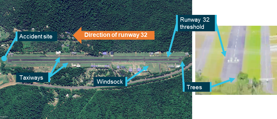
Whitsunday Airport (Shute Harbour) was a privately‑owned, uncertified airport (aircraft landing area) located in hilly terrain onshore from the Whitsunday Islands. The airport had a single sealed runway 14/32, which was 1,410 m long and 15 m wide (Figure 5). Runway 32 had a displaced threshold due to trees in the undershoot, which reduced the runway available for landing to 1,310 m. The displaced threshold and departure end of the runway were at elevations of approximately 80 ft and 20 ft respectively, giving it a downslope of approximately 1.4%.
Figure 5: Whitsunday Airport runway environment
Source: Google Earth and passenger video footage, annotated by the ATSB
The airport’s management published a Visiting pilot’s guide that provided information regarding operating at the airport and procedures for approaching and departing each runway. The arrival procedure for runway 32 specified that:
A straight in approach requires a slight right hand dog leg on final to maintain terrain clearance. After following the centre of Shute Harbour water in towards the valley, a right hand dogleg should be made prior to crossing Shute Harbour Road. When necessary to join base for runway 32, keep south of the Shute Harbour Jetty. Land after the displace threshold - this applies to both ends.
The airport management also had a website which contained the above information but also included detail that the:
Touchdown aiming point (Displaced Landing Threshold) is no shorter than the windsock on the lefthand side of the runway.
The pilot advised that landing on runway 32 required modifications to a standard approach. Firstly, as described in the pilot’s guide, high terrain to the south‑west required an oblique approach before aligning with the runway centreline to maintain terrain clearance. Secondly, trees near the arrival end of the runway necessitated a higher approach and could result in visual contact with the displaced threshold being lost. Lastly, due to the downslope of the runway it was necessary to touch down as early as possible to avoid an extended float. The pilot advised that due to the combination of the trees and the downslope they were required to get over the trees and then ‘chop the power’. The pilot of the trailing company aircraft provided similar advice regarding these considerations when landing on runway 32.
As an uncertified airport, Whitsunday Airport was not required to comply with any obstacle or terrain clearance standards. The Civil Aviation Safety Authority (CASA) Advisory Circular (AC) 91‑02 Guidelines for aeroplanes with MTOW not exceeding 5,700 kg - suitable places to take off and land providedguidance for pilots when determining the effect of obstacles on, and in the vicinity of, an uncertified aerodrome:
Pilots should be aware that uncertified aerodromes may declare an available runway length that begins and ends directly at an obstacle. Common examples might be small trees at the beginning or the end of the runway surface.
During landing, high ground or obstructions in the approach area can cause a pilot to adopt a higher than normal approach path to avoid the obstacle, but still achieve a touchdown early in the available runway length…In all cases, the likely outcome is a long landing and the subsequent psychological effect of continuing a landing from an unusual situation outside the experience of the pilot.
Recorded data
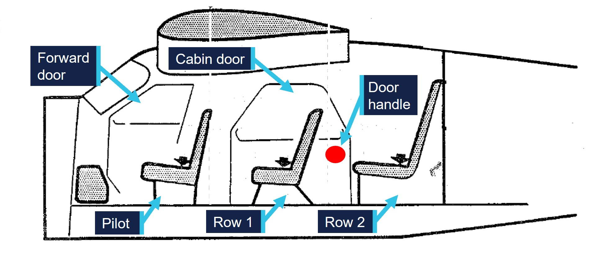
VH-IDM was equipped with ADS‑B out capability however flight data was not available for the approach and landing portion of the flight. Two passengers took video recordings of the landing and runway excursion on their mobile phones. Both passengers were seated on the right of the aircraft, one in the first row behind the pilot, and the second one row further back. The recordings showed the view through the front of the aircraft, as well as sections of the instrument panel and certain actions conducted by the pilot (Figure 6).
Figure 6: Passenger video footage
Note: Altitude is above mean sea level (AMSL). Adjustment of 30 ft applied to aircraft altimeter. Source: Passenger video annotated by the ATSB
From the passengers’ videos, the ATSB was able to determine the flight path and speed of the aircraft throughout the approach and landing. While the pilot advised their intended aim point was just past the displaced threshold, the aircraft maintained an average descent path of approximately 7° towards a landing spot 300 m beyond the displaced threshold. Overhead the displaced threshold, the aircraft was approximately 100 ft above ground level. Throughout the approach, the navigation unit displayed the groundspeed as between 90–95 kt. The airspeed indicator was also periodically visible and showed readings up to 95 kt.
After the commencement of the flare, the aircraft floated for approximately 640 m. During the float, the aircraft decelerated and with about 560 m of runway remaining was at the landing approach speed of 71 kt (see the section titled Landing Performance). Subsequently, the main wheels contacted the ground with approximately 370 m of runway remaining at a groundspeed of 65 kt. The aircraft took 18 seconds to reach the end of the runway, during which the groundspeed slowed from 65 kt to 24 kt.
The pilot was observed to reduce the throttle at several points during the final approach with the last reduction observed just prior to the flare. This indicated the approach was conducted with some power. The pilot was also observed to interact with the radio unit during the final approach, which was likely when responding to the trailing aircraft. The video confirmed that the flaps were set to 38° for landing and were retracted immediately upon touchdown. Also on touchdown, the pilot’s feet moved upwards on the rudder pedals and pressure was applied against the pedals during the landing roll. However, it could not be ascertained whether the pressure was maintained throughout the landing roll, or whether the pressure was being applied to the top of the pedals to apply brakes or to the bottom of the pedals for rudder and steering.
Weight and balance
Software
The operator used a third‑party system to calculate the weight and balance for each flight. In the system, each aircraft was configured with the weight and moment arm[4] when empty. Subsequently, for each flight, the fuel onboard, the pilot and passengers’ weights and their seating positions were recorded to calculate both the weight and centre of gravity of the aircraft at take‑off and landing. The system would provide an alert if the limits prescribed in the aircraft flight manual (AFM) were exceeded. A paper copy of the weight and balance calculation was provided to the pilot before each flight.
Aircraft empty weight
VH-IDM was last weighed on 12 August 2024 and the empty weight was determined to be 1,058 kg, with an empty weight moment arm of 1,202 mm. The operator advised that the aircraft was weighed in the freight configuration, therefore they added the weight of the operational equipment required for passenger carrying from the AFM, establishing the weight as 1,110.6 kg. The operator further advised that to provide a safety margin, a higher weight of 1,134 kg was configured in the system.
The ATSB identified that the empty weight moment arm was not adjusted to account for the added passenger operational items, with the freight configuration arm of 1,202 mm being used. Additionally, the operator had inadvertently added the weight of one passenger seat to each row, rather than 2. The ATSB calculated that the actual empty weight of VH-IDM in passenger configuration was 1,131.3 kg, with an empty weight moment arm of 1,275 mm. This was 2.7 kg less than the empty weight and 73 mm aft of the empty weight moment arm compared to that configured in the operator’s weight and balance system (Table 1).
Table 1: Operator vs ATSB empty weight and arm
Item
Operator weight (kg)
ATSB‑calculated weight (kg)
ATSB‑calculated moment arm (mm)
Aircraft empty weight (freight)
1,058
1,058
1,202
Passenger operational equipment
52.6
73.3
2,329
Aircraft empty weight (passenger)
1,110.6 (1,134 used)
1,131.3
1,275
Passenger weights
The operator’s standard operating procedures (SOPs) required that in determining the weight and balance of an aircraft:
Actual weights will be determined by weighing all occupants, equipment and other baggage.
The operator’s website also required that:
Full names and exact weights per passenger must be advised when booking due to flight weight availability.
The passengers reported that their weight was requested at the time of booking, but they were not weighed prior to the flight.
The CASA Multi-part AC 121‑05, AC 133‑04 and AC 135‑08 – Passenger crew and baggage weights described acceptable weight calculation methods that could be defined in operating procedures. The circular stated that:
The use of actual weights is the most accurate method of maximising payload capacity. Appropriately calibrated weighing scales should be used. Actual weighing is more commonly used by Part 133 and 135 operators. This is, in part, due to the smaller number of passengers being carried, which makes this option less disruptive than it is for Part 121 operators.
Operators should have procedures to identify when passenger-declared weights are not appropriate, such as when operating close to limitations. Under these circumstances, the use of actual weights may be required to ensure limitations are not exceeded.
Passenger-declared weights have inherent inaccuracies as passengers may not know their actual weight, especially when fully dressed. An adjustment allowance should be added to any passenger‑declared weight, as a factor or a fixed additional amount.
Take-off and landing weight
The ATSB requested actual weights from the pilot and passengers including the baggage they took with them on the flight. Using this information, in conjunction with the revised empty weight and moment arm, the take‑off and landing weight and balance of the aircraft was calculated and compared to that calculated by the operator (Table 2).
Table 2: Operator‑ vs ATSB‑calculated take‑off and landing weight – accident flight
Item
Operator‑calculated weight (kg)
Operator‑calculated moment arm (mm)
ATSB‑calculated weight (kg)
ATSB‑calculated moment arm (mm)
Aircraft empty weight
1,134
1,202
1,131
1,275
Row 1 (pilot row)
117
965
122
965
Row 2
135
1,772
132
1,772
Row 3
148
2,523
154
2,523
Row 4
150
3,247
146
3,247
Fuel
215
1,715
215
1,715
Take-off weight (Maximum 1,905 kg) (Allowable moment arm range 1,446 mm – 1,626 mm)
1,899
1,550
1,900
1,592
Fuel Used
41
1,715
41
1,715
Landing weight (Maximum 1,860 kg) (Allowable moment arm range 1,435 mm – 1,626 mm)
1,858
1,547
1,859
1,589
While the take‑off and landing weight differed by 1 kg, the actual moment arm was 42 mm aft of that calculated by the operator. This was still less than the maximum of 1,626 mm specified in the AFM. However, the ATSB identified loading scenarios where the operator’s configuration would present the weight and balance as acceptable, when the actual moment arm was aft of this limit (Table 3).
Table 3: Operator‑ vs ATSB‑calculated take‑off weight – aft centre of gravity limit scenario
Item
Operator‑calculated weight (kg)
Operator‑calculated moment arm (mm)
ATSB‑calculated weight (kg)
ATSB‑calculated moment arm (mm)
Aircraft empty weight
1,134
1,202
1,131
1,275
Row 1 (pilot row)
96
965
96
965
Row 2
100
1,772
100
1,772
Row 3
100
2,523
100
2,523
Row 4
259
3,247
259
3,247
Fuel
215
1,715
215
1,715
Take-off weight (Maximum 1,905 kg) (Allowable moment arm range 1,448 mm – 1,626 mm)
1,904
1,625
1,901
1,670 (44 mm aft of the allowable limit)
Pilot training
Operator proficiency check
Prior to conducting scenic flights unsupervised, the operator’s SOPs required the pilot to successfully complete an operator proficiency check (OPC). The flight component of the OPC was conducted without passengers and provided an assessment of the pilot’s competency in normal, abnormal and emergency procedures when operating the aircraft.
Upon starting with the operator, the pilot conducted a one‑hour supervised flight in a non‑turbocharged GA8 with the head of flying operations (HOFO),[5] where initial handling training was conducted. This was the pilot’s first flight operating a GA8. The pilot recalled that the flight included conducting steep turns, stall recovery and several circuits on runway 14 at Whitsunday Airport. They reported being uncertain whether a go‑around or a short field landing was conducted during that flight. The pilot also did not recall that they had practiced applying maximum braking, nor that they had done so subsequently.
At the conclusion of the flight, the HOFO completed an OPC assessment, which recorded that several items had been assessed as ‘competent’ including a go‑around and a short field landing. However, several items were marked as ‘not yet competent’ including low‑level flying, flapless landing, basic instrument flying, engine failure and forced landing and aircraft system malfunctions as these items were not conducted during the flight. While the OPC was not completed, no subsequent OPC was conducted prior to the pilot operating unsupervised.
The operator advised the ATSB that due to the nature of some of the flight sequences, a flight training organisation (FTO) had been engaged to conduct OPCs. The FTO had last conducted training and assessment for a group of the operator’s pilots in March 2024, prior to the accident pilot’s commencement with the operator. The operator further advised that due to the timing of their commencement, the pilot had not conducted an OPC with the FTO and that this was an oversight.
Line training and line check
The operator’s line training consisted of a series of flights with a supervising pilot, with passengers on board. Following line training, a line check was conducted, after which a pilot could operate unsupervised if an OPC had also been completed. Training records and the pilot’s logbook showed that 9 supervised flights totalling 9.9 hours were conducted in June 2024 prior to a line check flight. The flights were supervised by 3 different pilots including the HOFO. Following a line check conducted by the HOFO, the pilot commenced operating unsupervised.
General emergency training
The operator required the pilot to successfully complete a general emergency procedures competency check for the aircraft type being flown. This consisted of ground‑based topics and an in‑water practical component. While training records were not available, both the operator and the pilot recalled that the ground‑based training had been completed. However, the in‑water practical component was not conducted. The operator advised that the most recent in‑water training session had occurred in May 2024, prior to the pilot commencing, and that this was also an oversight.
The pilot reported that they had completed in‑water practical training with 2 previous operators, initially in August/September 2022 and subsequently in September/October 2023. They also completed the training with the current operator after the accident and advised that the training provided by all operators involved donning and inflating a lifejacket while in water. They also reported that the while the training conducted by the previous operators was conducted in a swimming pool, the training with the current operator was conducted in open water and included carrying an injured passenger and discussion of survival skills.
Differences training
The SOPs required that differences training was conducted prior to operating an aircraft of the same type with performance differences. Additional training was therefore required prior to operating a turbocharged GA8-TC, such as VH‑IDM, when initial training had been conducted in a non‑turbocharged GA8.
The operator had provided documentation to the pilot on the differences in operating the GA8‑TC and a supervised flight was conducted with the HOFO in October 2024, prior to operating the aircraft type unsupervised.
Recognition of prior learning
The operator’s procedures allowed flight crew members who had completed training with other operators to be eligible for recognition of prior learning (RPL). The procedures further advised that the training needed to have been completed within the previous 6 months, and could be applied to the following training events:
general emergency training
differences training
line training.
Approach speed
The operator reported that pilots were taught to conduct the final approach to land at an airspeed of 70 kt with 500 ft/min descent rate. They also advised that there was no difference between the approach and landing speeds when operating the GA8 compared to the GA8‑TC. Additionally, the operator’s SOPs stated that:
During the approach phase the pilot-in-command shall ensure that the aircraft is flown at the approach speeds (VREF) provided in the Aircraft Flight Manual for the aircraft being flown.
The FTO advised that pilots were taught and assessed in the non‑turbocharged GA8 on establishing a reference airspeed (VREF)[6] of 71 kt on final as per the AFM. They also advised that no training or assessment had been conducted in the GA8‑TC.
The pilot reported that they considered 80 kt as the appropriate final approach speed. However, they also stated that, following discussions with other pilots after the accident, they now understood that 70–75 kt was an appropriate final approach speed. The ATSB was also advised that the pilot had been observed landing long on previous occasions, however this had not been communicated to the operator or discussed with the pilot.
The pilot of the trailing aircraft reported they typically aimed for 80 kt on final and were ‘happy to get it down to about 75 [kt] on runway 32’. They also reported that for a short field landing they used 70–75 kt on final.
Landing Performance
The AFM provided performance charts to calculate the expected landing distance and ground roll. At a landing weight of 1,860 kg with a runway slope of −1.4% and the atmospheric conditions present at the time of the accident, the expected landing distance required was calculated to be 480 m, including a ground roll of 210 m. The AFM further described the reference speed and technique for achieving this performance:
airspeed at 50 ft of 71 kt
power off, 7° approach profile
38° (full) flap
aircraft approaches with idle power at the given airspeed appropriate to weight
after touch down maximum wheel braking is used to bring the aircraft to a stop
for maximum braking effectiveness the wing flaps should be retracted and back pressure applied to the control column.
The AFM also stated that:
Care must be taken to ensure airspeed is accurately maintained during the final landing approach. Timely and appropriate use of power should be exercised to maintain the desired flight path and airspeed. Excessively high approach speeds will result in prolonged floating and increased landing distance.
The AFM also provided performance charts for a 3° approach angle with power. In this circumstance the landing distance was expected to be higher due to the lower approach angle, with the ground roll remaining approximately the same.
Stabilised approach criteria
The operator’s procedures specified that aircraft should be on a stabilised approach as early as practical on the final approach path and that the following criteria were required for an approach to be stable:
• the aircraft is on (or close to) the correct flight path, only small changes in heading and pitch being required to maintain that path
• the aircraft speed is not more than Vref + 20 kt and not less than Vref
• the aircraft is in the proper landing configuration (except that full flap should not be selected until committed to land)
• sink rate is maximum 1,000 ft/min
• power setting appropriate to the configuration but not below any minimum power for approach specified in the Aircraft Flight Manual
• all briefings and checklist items have been performed.
In visual conditions, if these criteria were exceeded below 100 ft above airport elevation, the pilot was required to execute a go‑around.
The ATSB calculated that if an aircraft was 20 kt above the landing reference speed at the 100 ft decision height, in a power off 7° approach descent, the pilot had 2.7 seconds to reduce their speed to the landing reference speed. By comparison, a decision height of 300 ft would increase this time to 13.3 seconds while a decision height of 500 ft would increase the time to 23.9 seconds.
CASA provided guidance in AC 91‑02 on initiating go‑arounds in response to an unstable approach, stating that:
Pilot training emphasises that a safe landing is the result of a stabilised approach. If pre-determined stabilised approach criteria are exceeded, then a safe landing is not assured. The decision to execute a go-around should be made as early as possible to maximise the safety outcome. At the conclusion of an effective go-around, the pilot will then have an opportunity to consider what options are available to conclude the flight.
Additionally, the Flight Safety Australia article Quantifying the go-around (CASA, 2021) highlighted the importance of practicing go‑arounds:
It’s not enough to pass the test and fly a go-around only every couple of years when tasked by an instructor. Consciously ask yourself if you’re in the slot, judging your aeroplane’s state and trend all the way down final. By quantifying your performance, you can make the go-around decision before you are at the highest risk of loss of control.
Going around is as natural a part of flying as landing itself – or it will be, if you evaluate landing criteria every time and occasionally practice the go-around task.
The pilot advised that, in addition to not considering a go‑around during this approach, they could not recall having previously conducted a go‑around outside of training.
Related occurrences
The ATSB occurrence database contained 200 other reported occurrences of runway excursions during landing in Australia between January 2021 and December 2024. Of these, 12 resulted in injuries to the pilot and/or passengers, including 2 where the injuries were serious.
Included in these occurrences were 2 other runway excursions involving a GA8 Airvan, both of which were investigated by the ATSB:
Runway overrun involving GippsAero GA8, VH-WSB on 26 December 2021 (AO-2022-001)
During the landing, the aircraft floated significantly beyond the intended landing point. The pilot did not recognise the risk of a runway overrun and did not conduct a go‑around or apply sufficient braking to stop the aircraft on the remaining runway.
Runway excursion involving GippsAero GA8, VH-TBU on 6 April 2023 (AO-2023-016)
During the landing, the aircraft floated for a significant time and touched down approximately halfway down the runway, with insufficient remaining runway to stop. While the pilot recognised opportunities to conduct a go-around when they determined they were not on the correct approach profile, this was not conducted.
Safety analysis
Pilot actions
Approach and landing
During the approach to land, the aircraft’s flight path was significantly above that intended, with an aim point approximately one third down the runway. While the deviation was likely influenced by the associated terrain and obstacles, the pilot had conducted this approach regularly and was familiar with the required approach path to land safely. The deviation was also possibly influenced by distraction when interacting with the radio to respond to the pilot of the trailing aircraft and by implied pressure to minimise the time spent on the runway.
Attempting to regain the intended flight path, the pilot lowered the nose, but did not reduce the power to idle. Subsequently, the aircraft’s airspeed increased to approximately 95 kt. While the pilot planned 80 kt as the airspeed on final, the approach airspeed required by the operator was 70–71 kt. This approach speed was also the reference landing approach speed (Vref) in the aircraft flight manual (AFM). Therefore, the aircraft’s airspeed deviation was about 24 kt.
While recognising that the aircraft was above the intended flight path and faster than the intended airspeed, the pilot continued the approach. The operator’s procedures required a go‑around to be conducted when the aircraft was not on the correct flight path or was more than 20 kt faster than the landing approach speed below 100 ft. While the airspeed was within this limit based on the pilot’s incorrect understanding that the approach speed was 80 kt, the aircraft was not on the correct flight path and therefore a go‑around was required. However, the pilot did not consider a go‑around and commenced the flare well beyond the planned touchdown point at a high airspeed. Due to the high airspeed and the downslope of the runway, the aircraft floated significantly before touching down with less than a third of the runway remaining.
Contributing factor
The aircraft's approach was above profile with a high airspeed and the pilot had an incorrect understanding of the required approach speed. Subsequently, the pilot did not initiate a go‑around, resulting in a landing beyond the planned touchdown point.
Landing roll and braking
Despite the reduced runway available, performance calculations determined that sufficient runway remained for the aircraft to stop if maximum braking was applied. However, although the pilot was observed retracting the flap and applying pressure to the rudder pedals, the aircraft did not decelerate as expected. Given the braking system was functional prior to take‑off and after the accident and there was no indication that the aircraft skidded, maximum braking application was likely not conducted effectively. Subsequently, due to the insufficient braking, the aircraft departed the end of the runway.
Contributing factor
Despite having adequate landing distance remaining, the pilot did not apply sufficient braking to prevent the aircraft departing the runway.
Training and assessment
Initial training
The ATSB considered the effect of the training the pilot received from the operator prior to the accident. Given the elapsed time since their last flight review, additional training from a flight training organisation would have given them opportunity to practice procedures such as go‑arounds and short field landings. In addition, the operator did not complete the operator proficiency check and as a result the pilot was not assessed on several abnormal and emergency procedures in the GA8. However, the pilot was assessed as competent in both go‑arounds and short field landings during the initial handling training and had completed a number of line training flights that would have given them time to practice basic handling skills.
The general emergency training required an in‑water practical exercise that was not conducted. While recognition of prior learning was able to be applied to this training event, training with another operator was completed more than 6 months prior and so was not applicable. However, given the pilot had received this training twice in the preceding 26 months from other operators and the training was similar, it was likely that the pilot was competent in this area.
Other factor that increased risk
The pilot’s initial training was not fully completed, and they were not assessed on several abnormal and emergency procedures prior to operating unsupervised.
Approach speed
The pilot had received initial handling training and conducted line training flights supervised by 3 different pilots. They had also passed a line training check and had recently received differences training in the GA8‑TC. Notwithstanding this, the pilot’s pattern of using the incorrect approach speed was not identified or corrected.
Contributing factor
The training, supervision and checking flights conducted by Wave Air did not identify that an excessive approach speed was routinely being used by the pilot during the final approach to land. (Safety issue)
Weight and balance
The ATSB determined that the empty weight for the aircraft was calculated incorrectly, however as the operator had increased the weight in the system as a safety buffer, this did not have an effect. Additionally, the empty weight moment arm used to calculate if the aircraft’s centre of gravity was within the allowable limits, was not adjusted for the additional operational items. As a result, the system calculated the aircraft’s centre of gravity forward of the actual position. While the actual weight and centre of gravity of the accident flight was within limits for both take‑off and landing, the incorrect empty weight moment arm permitted the aircraft to be loaded in a way that the centre of gravity was aft of the limit, while presenting to the pilot as within.
Furthermore, passengers were not weighed prior to flight and instead passenger‑declared weights were used. This was not in accordance with the operator’s procedures and was not recommended when operating close to the weight limitations of the aircraft.
Other factor that increased risk
Wave Air's weight and balance system used an incorrect empty weight moment arm to calculate the aircraft's centre of gravity, and passengers were not weighed in accordance with their procedures. (Safety issue)
Stabilised approach criteria
It was determined that the decision height for assessing if the aircraft met the operator’s stabilised approach criteria was too low. As in this case, where an aircraft’s airspeed was 20 kt faster than Vref at 100 ft (the decision height), it was very unlikely that the aircraft could be slowed to the reference landing approach speed in 2.7 seconds, most likely leading to a go‑around.
While go‑arounds are a normal aspect of flying, as stated in AC 91‑02, ‘the decision to execute a go‑around should be made as early as possible to maximise the safety outcome’. However, in this case the pilot did not consider the operator’s stabilised approach criteria in their decision‑making.
Other factor that increased risk
The decision height for assessing whether an aircraft met Wave Air’s stabilised approach criteria was too low. (Safety issue)
Findings
ATSB investigation report findings focus on safety factors (that is, events and conditions that increase risk). Safety factors include ‘contributing factors’ and ‘other factors that increased risk’ (that is, factors that did not meet the definition of a contributing factor for this occurrence but were still considered important to include in the report for the purpose of increasing awareness and enhancing safety). In addition ‘other findings’ may be included to provide important information about topics other than safety factors.
Safety issues are highlighted in bold to emphasise their importance. A safety issue is a safety factor that (a) can reasonably be regarded as having the potential to adversely affect the safety of future operations, and (b) is a characteristic of an organisation or a system, rather than a characteristic of a specific individual, or characteristic of an operating environment at a specific point in time.
These findings should not be read as apportioning blame or liability to any particular organisation or individual.
From the evidence available, the following findings are made with respect to the runway excursion involving GippsAero GA8-TC, VH-IDM, at Whitsunday Airport (Shute Harbour), Queensland on 2 November 2024.
Contributing factors
The aircraft's approach was above profile with a high airspeed and the pilot had an incorrect understanding of the required approach speed. Subsequently, the pilot did not initiate a go-around, resulting in a landing beyond the planned touchdown point.
Despite having adequate landing distance remaining, the pilot did not apply sufficient braking to prevent the aircraft departing the runway.
The training, supervision and checking flights conducted by Wave Air did not identify that an excessive approach speed was routinely being used by the pilot during the final approach to land. (Safety issue)
Other factors that increased risk
The pilot’s initial training was not fully completed, and they were not assessed on several abnormal and emergency procedures prior to operating unsupervised.
Wave Air's weight and balance system used an incorrect empty weight moment arm to calculate the aircraft's centre of gravity, and passengers were not weighed in accordance with their procedures. (Safety issue)
The decision height for assessing whether an aircraft met Wave Air’s stabilised approach criteria was too low. (Safety issue)
Safety issues and actions
Central to the ATSB’s investigation of transport safety matters is the early identification of safety issues. The ATSB expects relevant organisations will address all safety issues an investigation identifies.
Depending on the level of risk of a safety issue, the extent of corrective action taken by the relevant organisation(s), or the desirability of directing a broad safety message to the Aviation industry, the ATSB may issue a formal safety recommendation or safety advisory notice as part of the final report.
All of the directly involved parties are invited to provide submissions to this draft report. As part of that process, each organisation is asked to communicate what safety actions, if any, they have carried out or are planning to carry out in relation to each safety issue relevant to their organisation.
Descriptions of each safety issue, and any associated safety recommendations, are detailed below. Click the link to read the full safety issue description, including the issue status and any safety action/s taken. Safety issues and actions are updated on this website when safety issue owners provide further information concerning the implementation of safety action.
Safety issue description: The training, supervision and checking flights conducted by Wave Air did not identify that an excessive approach speed was routinely being used by the pilot during the final approach to land.
Safety issue description: Wave Air's weight and balance system used an incorrect empty weight moment arm to calculate the aircraft's centre of gravity, and passengers were not weighed in accordance with their procedures.
Under section 26 of the Transport Safety Investigation Act 2003, the ATSB may provide a draft report, on a confidential basis, to any person whom the ATSB considers appropriate. That section allows a person receiving a draft report to make submissions to the ATSB about the draft report.
A draft of this report was provided to the following directly involved parties:
the pilot and operator
Whitsunday Airport (Shute Harbour)
Civil Aviation Safety Authority
Submissions were received from:
the pilot
the operator
The submissions were reviewed and, where considered appropriate, the text of the report was amended accordingly.
Purpose of safety investigations
The objective of a safety investigation is to enhance transport safety. This is done through:
identifying safety issues and facilitating safety action to address those issues
providing information about occurrences and their associated safety factors to facilitate learning within the transport industry.
It is not a function of the ATSB to apportion blame or provide a means for determining liability. At the same time, an investigation report must include factual material of sufficient weight to support the analysis and findings. At all times the ATSB endeavours to balance the use of material that could imply adverse comment with the need to properly explain what happened, and why, in a fair and unbiased manner. The ATSB does not investigate for the purpose of taking administrative, regulatory or criminal action.
About ATSB reports
ATSB investigation reports are organised with regard to international standards or instruments, as applicable, and with ATSB procedures and guidelines.
Reports must include factual material of sufficient weight to support the analysis and findings. At all times the ATSB endeavours to balance the use of material that could imply adverse comment with the need to properly explain what happened, and why, in a fair and unbiased manner.
An explanation of terminology used in ATSB investigation reports is available here. This includes terms such as occurrence, contributing factor, other factor that increased risk, and safety issue.
Publishing information
Released in accordance with section 25 of the Transport Safety Investigation Act 2003
Ownership of intellectual property rights in this publication
Unless otherwise noted, copyright (and any other intellectual property rights, if any) in this report publication is owned by the Commonwealth of Australia.
Creative Commons licence
With the exception of the Commonwealth Coat of Arms, ATSB logo, and photos and graphics in which a third party holds copyright, this report is licensed under a Creative Commons Attribution 4.0 International licence.
The CC BY 4.0 licence enables you to distribute, remix, adapt, and build upon our material in any medium or format, so long as attribution is given to the Australian Transport Safety Bureau.
Copyright in material obtained from other agencies, private individuals or organisations, belongs to those agencies, individuals or organisations. Where you wish to use their material, you will need to contact them directly.
[1]In-company: a group of aircraft that navigate and communicate as a single unit. Each aircraft self-separates from other aircraft within the group.
[2]Runway number: the number represents the magnetic heading of the runway.
[3]Go-around: a standard aircraft manoeuvre that discontinues an approach to landing.
[4]Moment arm: the horizontal distance from a reference datum to the centre of gravity of an item.
[5]The same person held the roles of HOFO and the head of training and checking for the operator.
[6]Reference Landing Approach Speed: the airspeed equal to 1.3 stall speed, and is the airspeed used on approach down to 50 ft above the runway when determining landing distances.
Occurrence summary
Investigation number
AO-2024-056
Occurrence date
02/11/2024
Location
Whitsunday Airport (Shute Harbour)
State
Queensland
Report release date
07/05/2025
Report status
Final
Investigation level
Defined
Investigation type
Occurrence Investigation
Investigation status
Completed
Mode of transport
Aviation
Aviation occurrence category
Runway excursion
Occurrence class
Accident
Highest injury level
None
Aircraft details
Manufacturer
Gippsland Aeronautics Pty Ltd
Model
GA8-TC320
Registration
VH-IDM
Serial number
GA8-TC 320-08-137
Sector
Piston
Operation type
Part 135 Air transport operations - smaller aeroplanes
A 737 entered a closed section of runway during its take-off from Brisbane Airport after its flight crew misinterpreted or missed dispatcher notes, a NOTAM and ATIS information detailing the shortened runway length available due to maintenance works.
On the morning of 30 November 2022, the Virgin Australia Boeing 737-800 commenced its take-off roll from Brisbane’s runway 19L for a flight to Melbourne, with 169 passengers and 8 crew on board. The flight crew comprised a training captain and a first officer undertaking ‘line flying under supervision’ as part of the first officer’s conversion onto the 737 aircraft.
The take-off thrust and speeds set by the flight crew were based on the full runway length being available. However, unrecognised by the crew, the take-off distance available for runway 19L was reduced at the upwind (01R threshold) end by 871 m due to runway works.
During the take-off roll, the aircraft briefly entered, and became airborne in, the closed section of runway. The aircraft completed the departure and continued on to Melbourne without further incident.
“The displaced threshold was detailed in dispatcher notes and in a NOTAM – notice to airmen advisory – included in pre-flight paperwork given to the crew prior to their previous flight from Melbourne to Brisbane, as well as in the paperwork for the Brisbane departure,” ATSB Director Transport Safety Stuart MacLeod explained.
“Further, the ATIS broadcast of recorded aeronautical information for Brisbane Airport at the time of the departure also alerted flight crews to the displaced threshold and reduced take-off distance at the time.
“However, during the pre-flight for the flight from Melbourne to Brisbane, the captain misinterpreted the dispatcher notes to mean there were no performance requirements for operations on runway 19L, then on reviewing the relevant NOTAMs headline, incorrectly dismissed the Brisbane NOTAM detailing the displaced runway threshold as not being relevant to their flight.”
An ATSB investigation report notes the crew’s belief that there were no performance requirements for runway 19L was reinforced by the absence of any visible runway works or other indications of restrictions during their landing on the runway after their flight from Melbourne.
“This, combined with time pressures and distractions from prioritising training needs, contributed to the flight crew then inputting the incorrect runway data during pre-flight calculations prior to the departure from Brisbane.”
This resulted in a departure with insufficient runway available due to the aircraft being overweight for that reduced runway length.
“This incident and investigation underscore the importance of flight crews considering possible variations to take-off and/or landing dimensions when determining runway performance data,” Mr Macleod said.
“This operator’s procedures did account for such changes through notification of performance requirements within their NOTAM system, however, due to a combination of distraction and misinterpretation, they were not identified.”
Since the occurrence, Virgin Australia has implemented a number of safety management, procedural and information-based changes designed to improve flight crew awareness.
“When presented with a number of NOTAMs, dismissing them based on the headline alone increases the risk of missing safety relevant information,” Mr Macleod concluded.
“As an additional defence, flight crews should ensure that the data input into performance data calculations is in conformance with other relevant information, such as the ATIS.”
The in-flight break-up of a Cessna 210 over the remote Northern Territory likely resulted from the charter aircraft entering an area of strong convective activity from a rapidly developing thunderstorm, an ATSB investigation has found.
On 24 December 2022, the Cessna 210N was conducting a charter flight under the visual flight rules from Gove to Katherine with a pilot and passenger on board.
A search and rescue was initiated when the aircraft failed to arrive at the planned time at Katherine Tindal Airport.
The following day, a wreckage field was located at a remote location in East Arnhem, approximately 237 km along the intended flight track. The pilot and passenger sustained fatal injuries.
“Weather satellite information showed the formation of a rapidly developing thunderstorm near to Bulman, during the time period the aircraft likely transited the region,” ATSB Chief Commissioner Angus Mitchell said.
“The aircraft likely entered an area of strong convective activity from the thunderstorm, subjecting it to severe turbulence and reducing visibility for the pilot.”
Analysis of the wreckage allowed the ATSB to determine that the aircraft’s right wing had separated from the fuselage in flight, probably due to a combination of turbulence from the thunderstorm, airspeed above the aircraft manoeuvring speed, and control inputs.
The report notes this was the pilot’s first period operating through a Northern Territory wet season.
“Why the pilot flew in close proximity to the storm could not be determined with certainty, however, it is possible that they were in the process of diverting or turning back when the break-up occurred and/or the severity of the storm was not apparent,” Mr Mitchell noted.
“Rapidly developing thunderstorms are a feature of the wet season in the Northern Territory, with associated severe turbulence presenting pilots with a challenging and hazardous operating environment.
“Identifying and maintaining adequate clearance from thunderstorms is therefore critical to safe flight.”
The US Federal Aviation Administration recommends remaining at least 20 NM (37 km) from thunderstorms.
“Weather radar and satellite imagery can assist planning and in‑flight storm avoidance, provided their limitations are understood, while contacting the duty BoM forecaster via the phone number on the relevant graphical area forecast is the best way for pilots to assess the viability of a planned route, particularly if the forecast is marginal and the weather is changing.”
As a result of this accident, operator Katherine Aviation, which has since ceased operating, provided tracking and communication devices for all its pilots to enable real-time satellite-based tracking and monitoring of its fleet.
It also presented the theory component of its wet season training material to its pilots, and required all pilots to complete the briefing program on an annual basis.
Finally, the operator developed flight assessment tools to provide its pilots with better decision-making capability when planning for operations during marginal weather.
On the morning of 26 October 2024, the pilot of a De Havilland Aircraft of Canada DHC‑2 Beaver aircraft, registered VH‑OHU, departed Hamilton Island aerodrome, Queensland, with 4 passengers on board, for a 10-minute scenic flight to Whitehaven Beach, Whitsunday Island. The aircraft touched down on the water with the right main gear not retracted into the float. As a result, the aircraft rapidly yawed to the right, nosed over and became submerged inverted. The pilot self-evacuated and then, when they found no one else on the water surface, promptly returned to help the passengers egress. The pilot and 4 passengers sustained minor injuries, and the aircraft was substantially damaged.
What the ATSB found
The ATSB found that, after departing Hamilton Island, the right main landing gear did not retract and had seized in the extended position, likely due to corrosion. For undetermined reasons, the pilot did not identify that the right main gear had remained extended during their pre-landing checks, either via the landing gear position indication panel, the amphibian gear advisory system (AGAS) annunciation or the wing-mounted mirror.
In addition, the ATSB noted that the AGAS annunciation alert for an asymmetric configuration, which required immediate pilot action, was similar to a normal gear position advisory. This increased the risk that a pilot would not recognise that the gear was in an unsafe condition for a water landing.
Following the collision with water, and with the aircraft submerged and inverted, the left rear cabin door could not be opened by the pilot or passengers, which delayed their egress. However, the pilot opened the right main door and assisted all passengers to evacuate.
As required by the operator, the pilot had completed helicopter underwater escape training about one month prior to the accident and credited this as a life-saving course.
Following several floatplane accidents in Canada, the Transportation Safety Board of Canada recommended the fitment of regular and emergency exits that allowed rapid occupant egress following a survivable collision with the water. Viking Air Limited subsequently developed push-out windows and revised more intuitive automotive-style door latches for the rear cabin door on the DHC‑2 aircraft. These modifications were not fitted to VH-OHU nor were they required by regulations.
What has been done as a result
In response to the accident, Hamilton Island Air advised it has implemented formal initial and refresher training for pilot maintenance tasks, as well as installation of a second mirror on the right wing of its current DHC‑2 aircraft. It has developed a sign-off form to document the daily washdown and preventative maintenance procedures. In addition, it incorporated a minimum weekly systems check flight, including landing gear cycle, where the aircraft had not been recently operated. Further, it introduced annual theory training and 180-day proficiency flight checks, conducted by authorised flight training organisations.
The Civil Aviation Safety Authority has developed airworthiness bulletin AWB 32-029 Issue 1 Supplementary Type Certificated Amphibian Float Main Gear Slide Wear in Marine Environments. The bulletin recommended enhanced vigilance and maintenance actions on the landing gear components to ensure reliability of the landing gear and the actuating system.
Safety message
As shown in this accident, inadvertent water landings in amphibian aircraft with one or more gear extended can rapidly result in the aircraft becoming submerged and inverted. This investigation reinforces the effectiveness of helicopter underwater escape training, not exclusively for helicopter pilots but also for pilots who operate any type of aircraft over water such as floatplanes.
Further, this accident highlights the value of having alternate means of exiting an aircraft post-accident. This is particularly important if the pilot is unable to assist and/or the fuselage is distorted, to increase the occupants’ chance of survival in the event of an impact with water.
The ATSB scopes its investigations based on many factors, including the level of safety benefit likely to be obtained from an investigation and the associated resources required. For this occurrence, the ATSB conducted a limited-scope investigation in order to produce a short investigation report, and allow for greater industry awareness of findings that affect safety and potential learning opportunities.
The occurrence
On the morning of 26 October 2024, a De Havilland Aircraft of Canada DHC‑2 Beaver amphibian floatplane, registered VH‑OHU and operated by Whitsunday Air Services (trading as Hamilton Island Air), was being prepared for a scenic flight from Hamilton Island to Whitehaven Beach (Whitehaven), Whitsunday Island, Queensland. The flight would typically be about 10–15 minutes, with about 75 minutes at Whitehaven, before returning to Hamilton Island.
Prior to boarding the aircraft, the 4 passengers viewed a pre-flight safety briefing video and were fitted with a pouch‑style constant wear lifejacket.[1] The pilot then conducted an additional briefing at the rear left cabin door of the aircraft. The passengers recalled this included being demonstrated how to use their seatbelts, don the lifejackets and operate the rear door handle, among other things. The passengers were seated, in pairs, in the middle and rear seat rows, with the seat to the right of the pilot not utilised.
The aircraft departed to the south-east and made a left turn to track toward Chance Bay, Whitsunday Island (Figure 1). The pilot reported that, during initial climb, they set climb power and selected the landing gear to retract (see Landing gear actuation system). The pilot noted the gear was cycling, as evidenced by the illuminated red ‘hydraulic pump’ lamps.
At about Chance Bay, the pilot spoke with the pilot of a company helicopter that was following, via very high frequency radio transmission, to coordinate with them as they were both heading toward Tongue Point. From this location, the pilot observed the water conditions and location of boats moored along Whitehaven. They described their observation as 7 kt, from the south-east and about 3 or 4 vessels on the water at Whitehaven. They then reported observing 4 blue ‘gear up’ lights on the landing gear panel and they did not see any of the main wheels extended in the mirror mounted on the left wing (see Mirror). The pilot then conducted an orbit over Tongue Point and Hill Inlet, before making a turn and doing a second pass so all passengers could view the beaches and inlets below.
After advising the passengers they would shortly be landing, the pilot commenced the pre-landing cockpit flow checks, including isolating the passengers from the aircraft audio system. The pilot advised they confirmed 4 blue lights, ‘saw no gear visible out the left window’, completed their flow checks and commenced the descent for landing. The pilot broadcast their intent to land at the south end of Whitehaven. They then completed the ‘finals checks’ from memory, which included checking the landing gear position again, before focusing on the landing.
Figure 1: Whitehaven Beach with reference to Hamilton Island, with approximate flight path depicted in yellow
Note: Approximate flight path derived from limited passenger images and video footage. Source: Google Earth, annotated by the ATSB
Upon touching down on the water, the aircraft bounced, then yawed sharply to the right, before nosing over and becoming submerged inverted. With the aircraft quickly filling with water, the pilot released their seatbelt and went to open their door, which they reported required some force. On exiting the aircraft, their leg was caught in the seatbelt, however, they were able to free themselves and swam to the surface. At the same time, 2 of the passengers had released their seatbelts and were both trying to open the left rear cabin door, which was adjacent to where they had both been sitting. They turned the door handle one way, and tried the other way, but could not open the door.
When the pilot did not see any of the passengers on the water surface, they returned to the aircraft to help them. They swam down and attempted to open the rear left door. Despite considerable effort, with their feet positioned on the airframe either side of the door, the door would not open, so they swam over to the right rear cabin door. The right door was able to be opened, again with a degree of force required, and the pilot pulled the nearest person out and took them to the surface. After taking a breath, the pilot returned and retrieved a second person, before assisting the remaining passengers.
One of the passengers, when they realised they could not open the left rear door, and with the cabin now almost completely filled with water, swam to the right side of the aircraft. They saw their partner was still in their seatbelt, so released it and continued to search for the door handle. They then felt their partner being pulled from them and out of the aircraft. They do not recall how they exited the aircraft but found themselves on the surface. The other passenger who was initially attempting to open the left rear door reported observing their partner, but it was very difficult to see. They then recalled being pulled from the aircraft, however, their partner could not remember how they exited the aircraft.
A nearby vessel rendered assistance to the pilot and passengers and transported them to Hamilton Island for medical attention. Once aboard the vessel, the pilot looked at the aircraft and observed the right main gear wheels had not retracted into the float (Figure 2).
Figure 2: VH-OHU underside of floats, showing right main wheels not retracted
Source: Used with permission, annotated by the ATSB
The pilot and passengers sustained minor injuries, and the aircraft was substantially damaged. It was reported that the aircraft sustained further damage during the retrieval from the water, before being transported to Mackay Airport, for storage.
Context
Pilot information
The pilot held a Commercial Pilot Licence (Aeroplane), with single and multi-engine class ratings and design feature endorsements including retractable undercarriage and floatplane. The pilot also held a current class 1 medical certificate with nil restrictions.
Prior to commencement with Whitsunday Air Services (trading as Hamilton Island Air), the pilot had accrued 563 hours total aeronautical experience, with 696 water landings, in a Cessna 182 aircraft on fixed floats. On 3 September 2024, the pilot underwent a familiarisation/transition flight in a fixed float DHC‑2 aircraft with an approved flight training organisation. The pilot was then employed with Hamilton Island Air. On 10 September 2024, the pilot commenced line training through the operator’s in‑command-under-supervision (ICUS) program, operating the DHC‑2 and the GippsAero GA8 Airvan[2] aircraft under the supervision of the operator’s ‘fixed wing specialist’ training pilot (see Operational information).
The pilot completed ICUS training with a line check on 8 October 2024. The training pilot set a 20 kt wind limitation for operations at Whitehaven for the next 25 flight hours, for the pilot to fine‑tune their skills ‘in the air and on the water’. The aircraft daily flight records indicated the pilot conducted solo flights on 15 and 25 October, consisting of circuit training at Hamilton Island. In addition, on 18 October they conducted a flight to Whitehaven, with 5 Hamilton Island Air staff as passengers, similar to the tour that was the accident flight. The accident flight was the pilot’s first flight with fare-paying passengers.
As of the morning of 26 October, the pilot had accrued 28 hours and 84 water landings in VH‑OHU. While the pilot had accrued 84 water landings in an amphibian aircraft, typically, the landing gear was not required to be extended and then retracted during training that consisted of multiple water landings in one session. As such, their gear actuation cycle experience was likely lower.
Helicopter underwater escape training (see Helicopter underwater escape training) was a Hamilton Island Air requirement, for all its helicopter and fixed-wing flight crew, to be completed during their induction and followed by recurrent training every 2–3 years. The pilot completed their initial underwater escape training on 24 September 2024.
The pilot self-reported to being well rested and feeling ‘fully alert’ on the morning of 26 October 2024. In addition, they advised they ‘felt comfortable with the aircraft’ and they had no distractions during the preparations for landing at Whitehaven.
Aircraft information
General
VH‑OHU was an amphibian De Havilland of Canada DHC‑2 Beaver, serial number 826, a predominantly all metal high-wing aircraft manufactured in 1956 and first registered in Australia in 2015.
The DHC‑2 was originally designed and manufactured by De Havilland Aircraft of Canada, Limited. Viking Air Limited was the type certificate holder from 2006 until2024. In August 2024, Viking Air Limited amalgamated with De Havilland Aircraft of Canada Limited, and De Havilland Aircraft of Canada Limited became the type certificate holder.
The aircraft was powered by a Pratt & Whitney ‘Wasp Junior’ R-985 9-cylinder, single row, air‑cooled radial engine, which drove a Hartzell HC B3R30-4B 3‑blade propeller. The aircraft was fitted with Wipline 6100 series amphibious floats, manufactured by Wipaire.
Cockpit and cabin configuration
There were 2 forward cockpit doors and 2 rear cabin doors. The cabin door handle was located along the aft edge of the door and required the row 1 passenger to reach behind the seat to open the door (Figure 3). The front seats were equipped with 3-point lap-sash style restraints and the 3-person cabin bench seats were equipped with 2-point lap-belt restraints.
Figure 3: Seat and door locations
Source: Pilot’s operating handbook, annotated by the ATSB
Maintenance history
The aircraft logbook statement showed the airframe, electrical, engine, instruments and radio were to be maintained in accordance with the Civil Aviation Safety Authority (CASA) Schedule 5.[3] The float system was to be maintained in accordance with Wipaire instructions for continued airworthiness.
On 6 December 2022, VH‑OHU was subject to a forced landing just after take-off from Hamilton Island. The aircraft was subsequently removed from service. The aircraft was partly disassembled and transferred to Mackay in July 2023. Between January and September 2024, the aircraft underwent scheduled maintenance conducted by a CASA‑authorised maintenance organisation. Additional maintenance included treatment of corrosion and replacement of corroded hardware and components. This included inspection of the landing gear carriage assemblies and replacement of both slide tubes and all proximity sensor switches (see Landing gear actuation system). A landing gear system retraction test was also performed at this time.
The current maintenance release was issued on 3 September 2024 and there were no recorded defects at the time of the accident. The aircraft had accrued about 18 hours on the maintenance release, with a total time of 18,342 hours. Landings were recorded on the maintenance release, however, there was no distinction between water or land, nor if the gear had been retracted during water landing training or circuits from Hamilton Island.
Landing gear system
General
The landing gear incorporated within the amphibious floats is a retractable, quadricycle type with 2 free castoring nose (or bow) wheels and 4 (2 sets of dual) main wheels (Figure 4). Steering on the water is accomplished by a water rudder located at the rear of each float, which is cabled into the existing aircraft rudder system. Steering on land is accomplished by differential braking on the main landing gear wheels.
Figure 4: VH-OHU showing the amphibious float components
Source: Maintainer, annotated by the ATSB
Landing gear actuation system
Landing gear operation is initiated by movement of the landing gear handle, with the extension and retraction accomplished by 2 electrically‑driven hydraulic pumps. When the pilot selects the gear handle to UP or DOWN, hydraulic pressure in the system will drop and pressure switches will automatically turn on the hydraulic pump motors to maintain operating pressure in the system. When the gear cycle is completed, pressure in the system will increase to the limit where the pressure switches automatically shut off the pumps. If the pressure in the system drops to a preset value, the pressure switches turn the pump motors back on and build up the pressure to the limit again. Only the main gear system operation will be detailed in this report.
The main gear is mechanically locked in both up and down positions. When the gear is selected to UP, the main gear down hook unlatches from the rear locking pin. Hydraulic pressure exerted on the actuator piston drives the carriage assembly to move forward along the slide tube, with the wheels moving aft, until the gear up hook latches on the forward locking pin (Figure 5). With no further movement once all 4 gear are retracted into the float, hydraulic pressure will increase until the pumps automatically switch off.
Figure 5: Main gear assembly diagrams, including VH‑OHU forward locking pin (inset)
Source: Wipaire and the maintainer (inset), annotated by the ATSB
The landing gear indication panel, to the right of the pilot’s seat (at the base of the control column), contained 10 lamps. Four blue to indicate the 2 nose and 2 main gear were up, 2 red to show hydraulic pump operation and 4 amber to indicate the gear was down. In addition to the standard equipment, VH‑OHU was also fitted with a hydraulic pressure gauge for pilot reference (Figure 6).
Each gear actuation operates independently (no set sequence) and therefore, the main gear UP and DOWN lamps are progressively activated by proximity switches, when the respective latch hook nests over the locking pin. The red hydraulic pump lights should extinguish shortly after all 4 UP or DOWN lamps are illuminated.
The airplane flight manual supplement for the amphibian floats described ‘bulb replacement during flight’. Where a lamp is not illuminated as expected, the pilot can readily remove the lamp and a known functioning lamp can be inserted into that location. This allows the pilot to determine if the non-illumination is a defective bulb, or other system issue.
Figure 6: Typical landing gear panel
Source: Used with permission, annotated by the ATSB
The airplane flight manual supplement for the amphibian floats included the following:
The supplement further included that, where cycling of the gear does not rectify an asymmetric condition, rather than landing on water, the preferred option is to conduct the landing on a hard surface or grass:
Landings of this sort produce little tendency to nose over when checklist procedures are used, even when conducted on hard surface runways, and will result in little or no damage to the floats.
Mirror
In addition to the landing panel gear position indication, the aircraft was also fitted with an optional mirror, installed on the left wing (Figure 7). Wipaire advised the mirror was not part of its float modification, however, it was aware it was a common addition to float planes.
This mirror allowed the pilot in the left seat to view the position of all 4 gear. This was particularly effective to confirm if the right main gear was retracted or extended from the underside of the right float, which was not possible without the mirror. The company pilots the ATSB spoke with reported varying opinions on the effectiveness for observing the right main gear via the mirror (see Operational information). However, all reported the mirror on the aircraft was correctly aligned following the recent maintenance and was effective in determining gear position.
Figure 7: Left wing mirror location, with representation of extended gear visible view
Source: Used with permission, annotated by the ATSB
Amphibian gear advisory system
The aircraft was also fitted with a Wipaire-authorised amphibian gear advisory system (AGAS), which provided the pilot with supplementary gear position information. Following departure, once the aircraft increased through a threshold airspeed, the system was armed. Upon slowing down through the threshold airspeed, in preparation for landing, the AGAS ‘Gear Advisory’ amber lamp (Figure 8), positioned on the instrument panel in front of the pilot, would illuminate. In addition, an audio annunciation, heard through the front seat headset/s, would commence. Where all 4 gear were retracted, the annunciation would consist of ‘gear up for water landing’ (female voice). Conversely, where all 4 gear were extended, the annunciation would be ‘gear down for runway landing’ (male voice). The audio annunciation would repeat every few seconds, until silenced by the pilot pressing the gear advisory lamp. The annunciation was a prompt for the pilot to check their gear configuration was correct for the intended landing surface.
Figure 8: Example of location of gear advisory lamp in DHC‑2 instrument panel
Note: the insert is taken from the AGAS airplane flight manual supplement. Source: Used with permission, annotated by the ATSB
The AGAS also had a ‘check gear’ advisory. In this case, when the aircraft slowed through the threshold airspeed, the gear advisory amber lamp would illuminate and the annunciation of ‘check gear’ would be heard in the same female voice and similar tone as that for the ‘gear up for water landing’ advisory. There were no additional tones associated with this alert. Check gear indicated an asymmetric condition in the landing gear, where one or more proximity switches had not closed. This was designed to prompt the pilot to abort the landing and troubleshoot the discrepancy. The airplane flight manual supplement for the AGAS included the warning:
In addition, to ensure the system was functioning prior to flight, the ‘operational checklists’ detailed the ‘before take-off’ checks as:
annunciator switch – PRESS and HOLD for 2-3 seconds
Wipaire advised that the ‘test’ audio check contained the gear up and gear down messages only. That is, the check gear annunciation was not included in the system test audio.
Wipaire maintenance documentation
The Wipaire instructions for continued airworthiness (ICA) described the general servicing of the floats and landing gear. The manual also included the following warnings to ensure corrosion from saltwater operations was kept to a minimum:
…
The ICA 25-hour maintenance requirements for the landing gear included washing the aircraft and floats with fresh water and inspecting surfaces and hardware for signs of corrosion, especially with saltwater use. In addition to specific nose gear maintenance actions, the main wheel bearings and main gear carriages were to be greased. This maintenance on VH‑OHU was typically conducted by the maintainer. The maintenance documentation recorded that a 25-hour float inspection was conducted by the maintainer on 5 October 2024, about 15 hours since the issue of the maintenance release.
The ICA inspection time limits and checklist section did not include a specific check for corrosion on the slide tube. Wipaire advised it was covered in the servicing section for ‘movable parts’, which detailed the inspection:
For lubrication, servicing, security of attachment, binding, excessive wear, safe-tying, proper operation, proper adjustment, correct travel, cracked fittings, security of hinges, defective bearings, cleanliness, corrosion, deformation, sealing and tension.
The 25-hour inspection was conducted with the aircraft on extended landing gear. In this configuration, the forward end of the slide tube could be inspected. However, the carriage assembly was positioned at the aft end of the slide tube, preventing inspection at this location. A gear retraction test, to check for correct operation of the gear up and down lock hooks, was to be conducted at 200-hour intervals. With the gear retracted, this then provided the opportunity to inspect the aft end of the slide tube.
Wipaire published service letter #80 AT-802 Fire Boss Slide Tube Corrosion in 2006. It described reports from operators of ‘sticking main gear actuators due to corrosion on the slide tube’. It noted that the corrosion was partially caused by gravel or debris from the main landing gear tyres eroding through the hard anodised surface of the slide tube, exposing the underlying aluminium, which was more susceptible to corrosion. Part of compliance included inspecting the slide tube for erosion and/or nicks and wiping the slide tube down with a clean rag soaked in lubricant. Wipaire advised there was no specific service letter to address corrosion for the 6000/6100 series floats.
Pilot maintenance
Due to the salt laden environment and exposure to seawater, the operator reported washing the aircraft with fresh water at the end of each operating day. In addition, greasing of the nose and main gear components, and other aircraft care activities, were periodically carried out. These additional tasks were to be carried out by an appropriately trained pilot, however, it was not recorded on the maintenance release or other formal record. It was also noted that there was no practice of washing the aircraft if it had not been operated for several days.
The maintainer conducted the pilot maintenance training, demonstrating the additional maintenance tasks. The pilot of VH‑OHU had not yet received the formal training prior to the accident but advised that they had been shown these tasks by their training pilots.
Meteorological information
The meteorological conditions reported by the pilot at the time of accident were consistent with the Bureau of Meteorology forecast, with east-south-east winds of about 7–8 kt and good visibility. In addition, the pilot’s report and passenger footage showed the water conditions were ideal for float plane operations and sun glare was not angled into the cockpit and across the instrument panel.
Wreckage information and component examination
The ATSB did not attend the accident site or wreckage examination in Mackay, instead the ATSB liaised with the maintainer and the maintenance organisation that conducted the post-accident examination of the landing gear. The ATSB also reviewed images and video footage taken during these examinations.
Initial examination
The maintainer examined the aircraft, in the presence of the insurance representative, after it was retrieved from the ocean and provided the following observations regarding the landing gear system:
the aircraft was significantly disrupted during the retrieval from the water, including damage to the landing gear panel, which prevented the landing gear selector position to be definitively established
the landing gear appeared undamaged
hydraulic fluid was drained and appeared to be of expected quantity, with no water contamination
the 4 blue lamps were removed for testing, however, their location prior to removal was not recorded
one of the blue lamps failed testing, however, it could not be determined if this was from seawater immersion or a pre-existing fault.
The wreckage was then transferred to Mackay for storage and further examination.
About 2 weeks after the accident, the landing gear was examined by the maintainer and an engineer from another CASA-authorised maintenance facility. They provided a report to the ATSB, with following general observations:
hydraulic pump 1 and 2, AGAS and gear lamps circuit breakers were engaged, indicating the system was operating as expected
it was not possible to carry out a continuity and functional check of the gear panel indication system due to corrosion and moisture from saltwater ingress
fuses for pumps 1 and 2 ‘ON’ lamps tested serviceable
both nose gear assemblies and the left main gear were observed to be up and locked, indicating a complete retraction
the right main gear was extended
some corrosion was noted on the forward face of both the left and right carriage assembly to slide tube interface.
The maintainer advised the ATSB that, when they tried to move the left main gear carriage, it initially did not move. However, ‘a small knock with a hammer freed the carriage’, which then moved freely. The carriage was likely held up by the observed minor corrosion at the slide tube interface. Further, there was ‘little to no damage’ on the slide tube, compared to the same location on the right slide tube.
Right main gear examination
Detailed examination and testing of the right main gear assembly was then conducted. The report included the following observations:
the down hook was found to be free of the locking pin (unlocked)
the right main gear was approximately 1.5–2 mm from fully down
gear position light proximity switches tested for resistance to ground with no issues
continuity testing of the proximity sensor switches showed UP and DOWN ‘open’, which was correct for the current configuration (gear mid travel).
Hydraulic pressure was then applied to the right main gear using a hand pump and calibrated pressure gauge. With 870 psi applied in the retraction direction, the carriage did not move along the slide tube. This was despite progressively adding oil to the slide tube/carriage interface, supplying grease to the carriage, disconnecting the shock strut and applying mechanical assistance via a pry bar.
The hydraulic pressure supply was then transferred to the extend direction. The carriage and slide tube moved together and closed the 1.5–2 mm gap. With this actuation, the actuator piston moved relative to the carriage assembly and the DOWN lock engaged as per design specifications. Testing of the proximity switch showed it to be closed, correct for the configuration. The direction of hydraulic pressure was reversed to retract and the DOWN lock was observed to disengage freely, with the proximity switch again testing correctly.
The report noted that at no time did the carriage move relative to the slide tube during the testing, establishing that the carriage assembly was seized on the slide tube. When the slide tube was removed from the float, a slide hammer and block of wood was successful in separating the carriage assembly from the slide tube. A significant amount of corrosion was then noted on the slide tube.
The ATSB then requested the left and right slide tubes and carriage assemblies be provided for further examination.
Component examination
The ATSB and Wipaire conducted testing and analysis to try to determine the circumstances that allowed the corrosion to develop. Examination of the left and right slide tubes and carriage assemblies was conducted at the ATSB’s technical facilities in Canberra, Australian Capital Territory.
The right slide tube had 2 bands of corrosion that corresponded with the bushing locations in the carriage, at about the fully extended location (Figure 9). The left slide tube showed no similar damage. Both carriage assemblies exhibited grease around the UP and DOWN hooks and internally. The components were not serialised, so the history of the carriages prior to the aircraft entering Australia could not be determined.[4]
Figure 9: Comparison of slide tubes, showing corrosion bands on the right slide tube (on the right) and location of bushings examined by the ATSB
Source: ATSB and used with permission, annotated by the ATSB
Detailed examination of the components was then conducted, with reference to the Wipaire-supplied specifications.
The slide tubes were manufactured from aluminium with an anodised coating. The slide tube dimensions were measured to be within specifications and the anodised layer was the correct thickness. The slide tube surface was non-conductive, as expected for an anodised layer.
The bushings were a tri-layer construction, with a base layer of steel, with sintered (porous) bronze and then coated in a PTFE[5] ‘sliding layer’. The bushing could be replaced and therefore, the carriage time in service did not necessarily correspond to the bushing time in service. The bushings of both carriages were examined, with observations including the internal diameters of all bushings were within drawing tolerances and the right bushings were more worn than the left (Figure 10).
Figure 10: Difference in bushing wear with the left (left) showing largely intact PTFE layer (grey) and right (right) showing significant exposure of the sintered bronze layer
Source: ATSB
The right carriage bushing located near the grease nipple was sectioned. Examination identified areas where the PTFE layer was not present, exposing the bronze layer and showing some evidence of scoring (Figure 11). The PTFE layer was non-conductive in contrast to the bronze.
Figure 11: Right carriage bushing surface showing Teflon/lead layer (grey), exposed bronze layer (copper) and some evidence of scoring (bright lines)
Source: ATSB
The slide tube corrosion patterns were consistent with galvanic corrosion between the exposed bushing bronze layer and the aluminium slide tube base metal, in the presence of salt from coastal operations. The difference in wear between the left and right carriage bushings likely influenced the degree of corrosion on the respective slide tubes. The bushings with a higher amount of retained, non-conductive PTFE layer showed significantly less corrosion on the corresponding slide tube.
The ATSB determined that there were no material or manufacturing issues identified with the slide tubes, and therefore the thin, hard anodised coating was likely damaged or worn through in this area, to allow for the dissimilar metal contact. This type of damage was also observed in discrete locations in deeper score marks on the slide tube, away from the main areas of corrosion.
Damage to the anodise was unlikely to have been directly from the worn bushings, since the bronze is softer than the hard anodise layer, but it was possible for dirt, sand or other abrasive debris to have become entrapped between the bushings and slide tube. While there was no significant entrapped material identified during the ATSB examination, the mechanism was shown to exist, as described in Wipaire service letter #80.
Operational information
Operator overview
Whitsunday Air Services, trading as Hamilton Island Air, conducted tourist charter flights to various locations in the Whitsundays, Great Barrier Reef and Hamilton Island areas, using a variety of fixed-wing and helicopter types. At the time of the accident, it operated a fleet of 17 helicopters and 3 fixed-wing aircraft: VH‑OHU, a GA8 Airvan and a Cessna 208.
Training pilot observations
The operator had an appointed fixed-wing specialist, who oversighted the fixed-wing operations and pilot training. The fixed-wing specialist (training pilot 1 – TP1) had advised the operator their intention to depart the organisation in September 2024. In August, they commenced correspondence with the accident pilot, in preparation for their employment and training.
TP1 collected VH‑OHU from the maintenance organisation in Mackay. Due to the aircraft coming out of extended maintenance, and TP1 having not operated it for a period of time, TP1 reported conducting a series of test flights, including water landings near Mackay and then en route to Hamilton Island. TP1 reported that the landing gear and AGAS were operating as expected. In addition, TP1 advised the mirror was correctly oriented to view all 4 gear. TP1 then commenced training the accident pilot on VH‑OHU, between 10 and 20 September 2024, before leaving the organisation.
Training was then conducted by the current fixed-wing specialist (training pilot 2 – TP2), from 5 October 2024. The training again included land and water landings, with TP2 advising the landing gear and AGAS systems were functioning correctly. TP2 advised the left mirror was correctly oriented, however, the right main gear could sometimes be difficult to distinguish from the background contrast (such as terrain, sky, water). TP2 reported their preference for having an additional right-side mirror, and they were in the process of procuring a second mirror at the time of the accident.
Pilot recollections
Accident day
With regard to the day of the accident, the pilot reported:
they did not feel any operational or time pressure
they were comfortable with operating the aircraft solo, and with passengers
the landing area only contained a few vessels, therefore, workload was not increased
there were no distractions from the passengers during the approach to land and landing
while there was a checklist available, the pre-landing checks were completed from memory, which was permitted by the operator’s procedures
they observed 4 blue lights indicating the gear was up for a water landing
they checked the mirror
they did not recall hearing the AGAS annunciator just prior to landing
during the accident sequence the aircraft flipped ‘within a second and I was underwater, upside down, almost instantly submerged, no air at all’.
Following the aircraft becoming submerged inverted, the pilot advised that, due to their recent helicopter underwater escape training, they ‘came right into action’ and ‘wasted no time’. The pilot advised that they would recommend the training to pilots operating sea planes or ‘any planes over water’.
Further, the pilot reported that, had they observed the extended right wheel, they would not have conducted the water landing, and would have returned the aircraft to Hamilton Island for a runway landing.
Training and aircraft systems
The pilot reported that they were happy with their training from both training pilots. In addition, they did not perceive any difficulties with training on the DHC‑2 and GA8 Airvan concurrently.
When discussing the mirror, the pilot described its importance in determining gear position. However, they also reported that there might be a blind spot that means the right main gear may be difficult to see.
When asked by the ATSB if the AGAS self-test was successful prior to the accident flight, the pilot reported to not being aware of this procedure. The pilot also reported to not have heard the AGAS ‘check gear’ annunciation during their training.
Seaplane operations guidance
The Seaplane Pilots Association published guidance on amphibious gear management best practices, to ‘enhance safe operations within the seaplane community’.[6] The guidance advocated the use of checklists and described triggers or cues, with each phase of flight, ‘to deter landing with the gear in the wrong position’. The ‘on water-based landing’ section included, in part:
several gear-position validation checks, during initial flyover, pre-landing operations (1st power reduction, setting flaps et cetera) and establishing on final approach to land
verbalise each gear position validation while visually confirming
pay attention to the gear advisory system, if installed.
In addition, the guidance stated, ‘it is very important to crosscheck the surface intended for landing with the gear position selected and where the gear actually is positioned’ and included:
As general guidance, an amphibious aircraft should be considered more vulnerable to a catastrophic accident, which may include serious injury and death, with the gear down. While all efforts should be taken to avoid landing on either a runway or a waterway with the gear in the wrong position, landing on a runway with the gear up tends to be much more benign, with minimal damage and injuries, compared with landing on water with the gear down. Avoiding either scenario is best done by being attentive and not complacent.
Survival aspects
Helicopter underwater escape training (HUET)
HUET has been in use around the world since the 1940s and is considered best practice in the overwater helicopter operating industry. HUET is designed to improve survivability after a helicopter ditches or impacts into water. Fear, anxiety, panic and inaction are the common behavioural responses experienced by occupants during a helicopter accident. In addition to the initial impact, in-rushing water, disorientation, entanglement with debris, unfamiliarity with seatbelt release mechanisms and an inability to reach or open exits have all been cited as problems experienced when attempting to escape from a helicopter following an in-water accident (Rice and Greear, 1973).
The training involves a module (replicate of a helicopter cabin and fuselage) being lowered into a swimming pool to simulate the sinking of a helicopter. The module can rotate upside down and focuses students on bracing for impact, identifying primary and secondary exit points, egressing the wreckage and surfacing.
The ATSB has previously emphasised the importance of HUET for all over-water helicopter operators in other investigations including AO-2018-022, AO-2019-008, AO‑2020-003 and AO-2023-044. Further, HUET is included in the ATSB’s Safety WatchReducing the severity of injuries in accidents involving small aircraft.
Safety briefing
The ATSB viewed the safety briefing video and noted it described the operation of door handles from across the operator’s fleet, although the aircraft associated with each handle was not explicitly stated. When the ATSB discussed the briefing process with the passengers, they recalled that the video had a lot of different door handles. One passenger also noted the video seemed to be focused more on helicopters, rather than the floatplane. However, the passengers recalled the pilot briefing them at the aircraft and showing them how the door handles worked on VH‑OHU.
Emergency egress
In this accident, the passengers required assistance from the pilot to egress from the submerged aircraft. Had the pilot been unable to assist, the outcome may have been more severe.
This possibility was reported by the Transportation Safety Board of Canada (TSB) in investigation A09P0397 Loss of control and collision with water involving a DHC‑2 on 29 November 2009. Following the collision with water, the pilot and one passenger survived, however, the other 6 passengers succumbed to injuries from immersion. The report included the following safety issue:
Over the last 20 years, some 70% of fatalities in aircraft that crashed and sank in water were from drowning. Many TSB investigations found that the occupants were conscious and able to move around the cabin before they drowned. In fact, 50% of people who survive a crash cannot exit the aircraft and drown.
The TSB recommended ‘the Department of Transport require that all new and existing commercial seaplanes be fitted with regular and emergency exits that allow rapid egress following a survivable collision with water’ (A11-05).
TSB report A18A0053 Loss of control and collision with water, involving a DHC‑2 on 11 July 2018 noted the aircraft became inverted during the accident sequence. One pilot escaped through the broken front windscreen. The other pilot was unable to open their forward right door nor the cabin door, however, the first pilot was able to open the cabin door from the outside. Neither pilot had undergone emergency egress training, nor was it required. Further, the report included:
Emergency door release mechanisms, better door handles, and push-out windows have been developed for certain types of floatplanes. Some floatplane operators have installed these modifications, but many have not.
Regulatory requirements for mandatory egress training for commercial floatplane pilots may result in some improvement in emergency egress from commercial seaplanes. However, if the regulator does not mandate or promote voluntary modifications to normal exits, seaplanes will continue to operate with exits that could become unusable following an impact, diminishing the chance occupants have to exit the aircraft following a survivable accident.
Push-out windows
Viking Air Limited (the type certificate holder at that time, now held by De Havilland Aircraft of Canada, see Aircraft information) developed ‘push-out windows’ (Figure 12) and published service bulletin V2/0003 New cabin door windows that incorporate a ‘push-out’ feature in July 2010. The service bulletin noted:
- A series of incidents involving float equipped aircraft has highlighted the need to improve emergency egress from the cabin.
- The Cabin Door Push-Out Window Kits contain a rubber-mounted right-hand and/or left‑hand passenger window which affords additional egress opportunities from the aircraft.
- Viking has designed new windows for the passenger doors that incorporate the same ‘push-out’ feature used for many years on helicopters operating overwater.
- Viking Air Limited strongly recommends that this safety improvement be incorporated on aircraft operating on floats and any wheeled aircraft operating over water, or as directed by the operator’s Regulatory Authority.
Figure 12: Example of main cabin door push-out window
Source: De Havilland Aircraft of Canada and Naomi Lacey (inset), annotated by the ATSB
De Havilland Aircraft of Canada advised it has supplied about 130 kits worldwide, with one kit to Australia. VH‑OHU was not fitted with the push-out windows, nor was it required by regulations.
Revised door latches
Viking Air Limited published service bulletin V2/0004 Installation of an automotive style cabin door latch system in November 2010. The service bulletin cited the reason as ‘the dual automotive (pull) style cabin door latch system provides better egress from the cabin in the event of an emergency’ (Figure 13). The service bulletin also noted:
- Viking Air Limited (Viking) has designed a dual automotive (pull) style cabin door latch system that is more familiar and intuitive to passengers. The existing single latch handle (rotating style) at the rear of the door has been replaced by one pull style latch handle at the same location and a second pull style latch handle in the forward portion of the door. This allows passengers in the forward and rear cabin seats to open the cabin doors in an emergency situation.
- Viking strongly recommends that this safety improvement be incorporated on all DHC‑2 aircraft or as directed by the operator’s Regulatory Authority.
De Havilland Aircraft of Canada advised it had supplied 70 door latch kits to date. VH‑OHU was not fitted with the modified door latch system, nor was it required by regulations.
Figure 13: Representation of revised door latches, with VH‑OHU door in inset
Note: the rotational-style door latch, as was in VH‑OHU, operates in one direction only. Source: De Havilland Aircraft of Canada and the operator, annotated by the ATSB
Similar occurrences
There have been a number of occurrences involving DHC‑2 where one or more wheels were extended during a water landing resulting in the aircraft nosing over and becoming inverted. This has been evidenced in several United States National Transportation Safety Board (NTSB) accident reports as summarised below.
N218RD at Oak Island, Minnesota, on 22 May 2021 (CEN21LA244)
The aircraft departed with a known hydraulic leak in the landing gear system. During the flight, the degraded hydraulic system resulted in the inadvertent extension of the left main gear. This was not identified by the pilot and the aircraft nosed over upon landing on the water and became inverted. The pilot and one passenger were not injured, and one passenger sustained serious injuries.
N9558Q at Stehekin, Washington, on 17 May 2008 (LAX08FA144)
The pilot did not raise the landing gear after take-off. The pilot also reported the flight was turbulent and bumpy, with slow airspeed due to the heavy load. This resulted in numerous AGAS annunciations, until the pilot pulled the circuit breaker to disable the ‘nuisance’ alerts. The pilot intended to reset the AGAS prior to landing but did not do so. When the aircraft landed on the water with the wheels extended, it abruptly nosed over and became inverted. The pilot and 2 passengers survived, and 2 passengers were unable to exit the aircraft and succumbed to immersion.
N60TF at Sitka, Alaska, on 30 May 2003 (ANC03LA054)
The pilot advised they forgot to raise the landing gear following departure from land. During the water landing, with the wheels extended from the floats, the aircraft nosed down in the water. The pilot was uninjured.
N4478 at Aleknagik, Alaska, on 28 August 2002 (ANC02FA106)
The NTSB found the pilot did not raise the landing gear following departure from land. During the water landing, with the wheels extended from the floats, the aircraft nosed over and became inverted. The 2 passengers escaped with minor injuries and the pilot sustained fatal injuries attributed to immersion.
Safety analysis
Introduction
On the morning of 26 October 2024, the pilot of a De Havilland Aircraft of Canada DHC‑2, registered VH‑OHU, departed Hamilton Island aerodrome, Queensland, with 4 passengers on board for a short scenic flight to Whitehaven Beach, Whitsunday Island. Upon touching down on the water, the aircraft yawed to the right, nosed over and became submerged inverted. The pilot and 4 passengers sustained minor injuries and the aircraft was substantially damaged.
This analysis will discuss the right main gear failing to retract, the unsafe configuration not being identified by the pilot and delayed egress of the passengers. In addition, the analysis will consider why the pilot did not hear the gear annunciation. Further, the pilot’s recent underwater escape training and availability of enhanced egress aircraft modifications will also be discussed.
Right main landing gear failed to retract
Immediately following the accident, the right main gear could be seen extended from the float. Examination of the aircraft found no evidence of leakage, loss or contamination of the hydraulic fluid, and all landing gear circuit breakers were engaged. Further, the nose and left main gear had successfully retracted, indicating the anomaly was likely isolated to the right main gear.
During retraction, the main gear travels aft as it swings up into the float. Had the gear been mid-travel, such as still cycling, the impact with the water would have forced the gear to retract up into the float. Therefore, it was unlikely the right main gear moved during the impact sequence. This was consistent with the post-accident examination, which identified that the right carriage assembly had seized on the slide tube at the almost fully extended position.
Once removed from the aircraft, forceful removal of the carriage resulted in the identification of advanced corrosion on the right slide tube. The 2 bands of corrosion were coincident with the location of the carriage bushings, near the full gear extension position. This would be expected as the aircraft was predominantly parked on land, with the gear extended.
The investigation considered scenarios conducive to the formation of this corrosion. The maintenance records prior to the aircraft entering Australia in 2015 were not available, as such, the service history of the main gear carriage assemblies, including the bushings, was unknown. While there was a significant difference in the condition of the left and right slide tubes, both tubes were installed at the same time and therefore subject to the same operational and environmental conditions.
The operator advised the aircraft was rinsed with fresh water at the end of the operating day, however, this was not formally recorded and there was no practice for rinsing when the aircraft was not operated for several days. The aircraft records showed the maintainer conducted a 25-hour float inspection on 5 October 2024 and grease was observed on the assemblies during post‑accident examination. However, as there was no requirement to retract the gear for this inspection, the position of the carriage assembly precluded visual examination of the slide tube at the location where the corrosion had developed.
Examination of the carriage bushings identified that the right bushings exhibited more wear and loss of the PTFE ‘sliding layer’, which runs along the slide tube. This had the potential for galvanic corrosion to form, however, required the degradation of the anodised layer on the slide tube to also be present. Insufficient cleaning, inadequate application of grease and/or accumulation of dust or dirt on the slide tube are known contributors to degradation of protective layers. While the extent to which they were contributory in this case was not able to be determined, it was likely that the identified corrosion resulted in the right main gear seizing.
Pilot did not identify extended right main gear
The pilot reported observing 4 blue ‘gear up’ lamps illuminated, at about Tongue Point, and during their pre-landing checks. The passenger footage showed sun glare was not angled in the direction of the landing gear panel and the pilot advised they were able to clearly identify what lamps were illuminated. However, when tested post‑accident, one blue lamp did not illuminate, although it could not be determined if this failure was due to seawater immersion or pre-existing. Further, the location of the failed lamp could not be determined as the lamps were not identified on removal from the landing gear panel. Despite this, failure of any lamp to illuminate requires troubleshooting by the pilot prior to landing. The pilot can readily determine if the lack of illumination of a lamp is due to a failed bulb or other system issue.
The main right gear UP and DOWN proximity switches tested serviceable during the post-accident examination. The examination also noted the right main gear had unlatched from the DOWN location and moved about 1.5–2 mm in the retract direction before becoming seized. During the landing gear retraction sequence, pressure in the hydraulic system would increase until the pumps automatically switched off and the red ‘in-transit’ lamps would extinguish. In this configuration, with nil movement in the right main gear due to the seizure, it was expected that only 3 blue lamps would have been illuminated. Therefore, the investigation could not reconcile the pilot’s recollection of there being 4 blue lamps illuminated.
The mirror provided an additional method to identify the landing gear configuration. Training pilot 1 advised they could observe all wheels in the mirror following the aircraft repairs. Training pilot 2 reported sometimes experiencing difficulty in observing the right main wheels from the mirror. The accident pilot reported a blind spot, which hindered their ability to see the right main gear in the mirror. However, during the pre‑landing checks, the accident pilot reported they checked the mirror and did not observe any wheels protruding from the floats and continued with the water landing.
Another method to identify the gear position was via the amphibian gear advisory system (AGAS), which provided a visual and audio annunciation as the aircraft slowed for landing. The pilot had been communicating via the radio with the helicopter pilot, thereby showing the audio system in VH‑OHU was operational and that the AGAS annunciation was able to be heard through the headset. However, the pilot reported they could not recall hearing any annunciation prior to landing on the water. Due to disruption of the floats during the accident, the system could not be functionally tested. The pilot advised they were not aware of the pre-flight self-test of the AGAS and therefore this was not conducted prior to the accident flight. While it remained a possibility that the AGAS did not alert the pilot to an asymmetric condition prior to the landing, all 3 pilots reported the AGAS had been functioning correctly in the preceding weeks. Therefore, while it could not be conclusively determined, it was more likely the system was operational.
The pilot’s 84 water landings in VH‑OHU did not necessarily represent the number of times they had actuated the landing gear, however, they did select the gear to retract after departing Hamilton Island. In addition, the pre-landing checks required the pilot to utilise the aircraft systems to ascertain gear position prior to each landing, regardless if the gear was cycled. Further, the pilot also reported no issues with distractions, workload or experiencing time pressures.
Therefore, while the aircraft was fitted with multiple systems to confirm the status of the landing gear, for undetermined reasons the pilot did not identify that the configuration was unsuitable for a water landing. This resulted in the aircraft yawing to the right, nosing over and becoming submerged and inverted, a known consequence of water landings with one or more gear extended.
Landing gear annunciator
The pilot advised the ATSB that they did not recall hearing the AGAS annunciation just prior to the landing. The ATSB’s analysis concluded the AGAS was more likely than not operational at the time of the accident. The investigation therefore considered potential reasons for the audio alert not being heard or being dismissed.
The ‘gear up for water landing’ and ‘gear down for runway landing’ are advisory only and an opportunity for the pilot to check the gear selection matches their intended landing surface. In contrast, the ‘check gear’ annunciation was alerting the pilot that the 4 gear were not all fully up or down and in an unsafe configuration for landing. However, the ‘gear up’ and ‘check gear’ both used a similar female voice and there were no additional tones to indicate the heightened importance of the ‘check gear’ alert. Further, when below the threshold airspeed, the amber ‘gear advisory’ lamp would illuminate, irrespective of the gear configuration.
The purpose of auditory warnings is to attract attention to a problem (Salvendy & Karwowski, 2021). Ideally, advisory annunciations would sound distinctly different to other alerts to assist pilots to recognise there is problem requiring their action. Making alerts distinctive from other sounds can also inform the pilot of the priority or urgency of the problem (Yeh et al. 2016, FAA, 2016). During approach to land, with the gear in an asymmetric configuration, the AGAS would have enunciated ‘check gear’, indicating an unsafe condition.
As the pilot would have expected to hear an annunciation with a female voice during landing, there was little to distinguish it from an alert that required action. In addition, the pilot reported they had not heard the ‘check gear’ alert during the training, reinforcing the female annunciation was to be expected and normal. This increased the risk that a pilot would not recognise that the landing gear was in an unsafe condition and removed an opportunity to consider a runway landing, the preferred option in this scenario. However, as the pilot reported not hearing any annunciation prior to landing, there was insufficient evidence to determine if the lack of distinction between the ‘gear up’ and ‘check gear’ annunciations contributed to the accident.
Passengers’ delayed egress
During the accident sequence, the aircraft rapidly filled with water, giving all on board little time to react. Despite being temporarily tangled in their seatbelt, the pilot readily exited the aircraft and swam to the surface. When no passengers appeared, the pilot swam back to the aircraft.
The 2 passengers seated next to the left rear cabin door reported they quickly released their seatbelts, and both attempted to open the door. The pilot was trying to open this door at the same time, without success. The 2 passengers recalled they attempted to locate the right rear cabin door, which was about coincident with the pilot’s decision to also try this door. The pilot managed to open the right rear door and assisted the passengers to the surface.
The ATSB considered the circumstances that prevented the left rear door from being easily opened following the accident. It was possible that water pressure from the outside was greater than inside the cabin, until equalising as the cabin filled with water. Alternatively, distortion to the airframe during the impact sequence could have prevented door operation. While the reason could not be determined, this contributed to the delayed evacuation from the submerged aircraft.
Underwater escape training
The pilot had completed operator-required helicopter underwater escape training about one month prior to the accident. They attributed this training to their prompt escape from the inverted and submerged aircraft, and subsequent assistance to the passengers. As evidenced in previous ATSB investigations, this training has been shown to significantly increase the chances of survival in the event of a collision with water.
Enhanced egress aircraft modifications
Following multiple similar accidents where occupants initially survived but were subsequently fatally injured from immersion, the Transportation Safety Board of Canada recommended the fitment of regular and emergency exits that allowed rapid egress in the event of a collision with water. Consequently, Viking Air Limited developed push-out windows and more intuitive automotive-style door latches for the main cabin door. These modifications were not fitted to VH‑OHU nor were they required by regulations.
In this accident, 2 of the passengers were actively searching for a means of escape, but ultimately required the pilot to open the door. However, if the pilot had been unable to assist, the accident could have resulted in dire consequences. Acknowledging that people behave differently in emergency situations, providing an alternative means of escape where one or more doors cannot be opened, increases the chance of survival. This is most relevant with submerged aircraft, yet can also expediate egress for land‑based accidents, particularly those involving a post-accident fire.
Findings
ATSB investigation report findings focus on safety factors (that is, events and conditions that increase risk). Safety factors include ‘contributing factors’ and ‘other factors that increased risk’ (that is, factors that did not meet the definition of a contributing factor for this occurrence but were still considered important to include in the report for the purpose of increasing awareness and enhancing safety). In addition ‘other findings’ may be included to provide important information about topics other than safety factors.
These findings should not be read as apportioning blame or liability to any particular organisation or individual.
From the evidence available, the following findings are made with respect to the landing gear malfunction and collision with water involving De Havilland Aircraft of Canada DHC‑2 Beaver, VH‑OHU, near Whitehaven Beach, Whitsunday Island, Queensland, on 26 October 2024.
Contributing factors
Likely due to corrosion, the right main landing gear assembly seized near the fully extended position, which prevented retraction after take-off from Hamilton Island.
During preparations for a water landing, for undetermined reasons, the pilot did not identify the landing gear was in an unsafe condition. As a result, the aircraft landed with the right main wheels extended and then yawed to the right, nosed over and became submerged inverted.
Other factors that increased risk
The cautionary 'check gear' annunciation was very similar to the advisory annunciation for a normal water landing, increasing the risk that a pilot would not recognise that the landing gear was in an unsafe condition.
Following the impact, and with the aircraft submerged, the rear left door was unable to be opened by either the pilot or the passengers. As a result, the evacuation of the passengers was delayed.
Other findings
As required by the operator, the pilot had recently completed helicopter underwater escape training, which aided with their prompt underwater egress and subsequent rescue of the passengers from the inverted and submerged aircraft.
Push-out windows and door handles designed to expedite egress in an evacuation were available for retrofit on the DHC‑2 Beaver aircraft. VH‑OHU did not have either fitted and nor were they required to by regulation.
Safety actions
Whether or not the ATSB identifies safety issues in the course of an investigation, relevant organisations may proactively initiate safety action in order to reduce their safety risk. The ATSB has been advised of the following proactive safety action in response to this occurrence.
Safety action by Hamilton Island Air
Hamilton Island Air advised the following safety action was undertaken:
installation of a second mirror on the right wing of its current DHC‑2 aircraft
formal initial and refresher training on the pilot maintenance tasks
implementation of a daily washdown and preventative maintenance procedure checklist, which included a sign-off section to formally record when the activities were completed and by whom
implementation of a minimum weekly systems check flight, including landing gear cycle, where the aircraft had not been recently operated
implemented initial and annual theory ground school training, flight characteristics training and 180-day proficiency flight checks for all floatplane pilots, conducted by authorised flight training organisations.
Safety action by the Civil Aviation Safety Authority
Following review of the draft investigation report, the Civil Aviation Safety Authority advised it was intending to release airworthiness bulletin AWB 32-029 Issue 1 Supplementary Type Certificated Amphibian Float Main Gear Slide Wear in Marine Environments. Reflecting the information contained in the ATSB’s investigation report, the bulletin contains advice to operators and maintainers highlighting the importance of inspection and preventative maintenance aspects for retractable landing gear carriages fitted to amphibious aircraft when operated in a marine environment. The bulletin recommended that:
during scheduled maintenance of the landing gear, particular attention should be applied during a visual inspection for evidence of corrosion or mechanical damage to the hard anodized surface of the slide tubes
during periods of extended non-service, the landing gear slide tubes are lubricated and visually inspected for damage along their full length prior to the aircraft returning to service
during approved pilot maintenance. the main gear slide tubes are wiped clean and lubricated and the gear carriages are completely refreshed with clean grease.
Sources and submissions
Sources of information
The sources of information during the investigation included:
the pilot and passengers of the accident flight
the operator and training pilots
the Civil Aviation Safety Authority
De Havilland Aircraft of Canada
Wipaire
the maintenance organisation for VH‑OHU
the maintenance facility that conducted the post-accident aircraft examination
Bureau of Meteorology
video footage from the accident flight and other photographs taken on the day of the accident.
References
Federal Aviation Administration. (2016). Human factors design standards. US Department of Transportation, United Sates Government.
Rice, E,V., & Greear, J.F. (1973). Underwater escape from helicopters. In Proceedings of the Eleventh Annual Symposium, Phoenix, AZ: Survival and Flight Equipment Association, 59-60. Cited in Brooks C. (1989) The Human Factors relating to escape and survival from helicopters ditching in water, AGRAD.
Salvendy, G., & Karwowski, W. (2021). Handbook of human factors and ergonomics (5th ed.). John Wiley & Sons, Inc, doi: 10.1002/9781119636113.
Yeh, M., Swider, C., Jin Jo, Y., & Donovan, C. (2016). Human factors considerations in the design and evaluation of flight deck displays and controls. Federal Aviation Administration, United States Government.
Submissions
Under section 26 of the Transport Safety Investigation Act 2003, the ATSB may provide a draft report, on a confidential basis, to any person whom the ATSB considers appropriate. That section allows a person receiving a draft report to make submissions to the ATSB about the draft report.
A draft of this report was provided to the following directly involved parties:
the pilot of the accident flight
the operator and training pilots
the maintainer of VH‑OHU
Civil Aviation Safety Authority
De Havilland Aircraft of Canada
Transportation Safety Board of Canada
Wipaire
United States National Transportation Safety Board.
Submissions were received from:
the operator
De Havilland Aircraft of Canada
Civil Aviation Safety Authority.
The submissions were reviewed and, where considered appropriate, the text of the report was amended accordingly.
Purpose of safety investigations
The objective of a safety investigation is to enhance transport safety. This is done through:
identifying safety issues and facilitating safety action to address those issues
providing information about occurrences and their associated safety factors to facilitate learning within the transport industry.
It is not a function of the ATSB to apportion blame or provide a means for determining liability. At the same time, an investigation report must include factual material of sufficient weight to support the analysis and findings. At all times the ATSB endeavours to balance the use of material that could imply adverse comment with the need to properly explain what happened, and why, in a fair and unbiased manner. The ATSB does not investigate for the purpose of taking administrative, regulatory or criminal action.
About ATSB reports
ATSB investigation reports are organised with regard to international standards or instruments, as applicable, and with ATSB procedures and guidelines.
Reports must include factual material of sufficient weight to support the analysis and findings. At all times the ATSB endeavours to balance the use of material that could imply adverse comment with the need to properly explain what happened, and why, in a fair and unbiased manner.
An explanation of terminology used in ATSB investigation reports is available here. This includes terms such as occurrence, contributing factor, other factor that increased risk, and safety issue.
Publishing information
Released in accordance with section 25 of the Transport Safety Investigation Act 2003
Ownership of intellectual property rights in this publication
Unless otherwise noted, copyright (and any other intellectual property rights, if any) in this report publication is owned by the Commonwealth of Australia.
Creative Commons licence
With the exception of the Commonwealth Coat of Arms, ATSB logo, and photos and graphics in which a third party holds copyright, this report is licensed under a Creative Commons Attribution 4.0 International licence.
The CC BY 4.0 licence enables you to distribute, remix, adapt, and build upon our material in any medium or format, so long as attribution is given to the Australian Transport Safety Bureau.
Copyright in material obtained from other agencies, private individuals or organisations, belongs to those agencies, individuals or organisations. Where you wish to use their material, you will need to contact them directly.
[1]Constant wear lifejacket: an uninflated lifejacket worn about the person in a pouch or harness for the duration of the flight.
[2]The GippsAero GA8 Airvan is a single piston-engine powered high-wing utility aircraft, with fixed tricycle landing gear that can seat up to 8 people, including the pilot.
[3]CASA Schedule 5 was developed to provide ongoing airworthiness requirements for certain aircraft with inadequate maintenance schedules. Civil Aviation Order 100.5 General requirements in respect of maintenance of Australian aircraft provided a list of aircraft whose maintenance schedules are inadequate, and the CASA Schedule 5 procedures must be followed. This list included several De Havilland aircraft however, the DHC-2 was not on that list.
[4]The maintenance records from prior to entry into Australia were not provided to the ATSB. In addition, advice from Wipaire indicated the colour of the anodising could vary and was not representative of the manufacture date.
[5]PTFE, commonly known as Teflon™: polytetrafluoroethylene; the plastic produced by the polymerisation of tetrafluoroethylene, which has a low coefficient of friction and high resistance to temperature, chemicals, and radiation and is used for laboratory utensils, bearings, gaskets, non-stick lining for cookware, and as a waterproof fabric.
The ATSB is investigating a mid-air collision between 2 light aircraft, a Jabiru and a Cessna 182, south-west of Sydney on 26 October 2024.
A team of transport safety investigators from the ATSB's Canberra office, with experience in aircraft operations and maintenance, was deployed to the accident sites of both aircraft to conduct evidence-collecting activities.
The evidence collection phase of the investigation involves interviewing witnesses and involved parties, site mapping, examination of the wreckage of both aircraft, and collect relevant recorded information including any air traffic control and flight tracking data, as well as pilot and aircraft maintenance records, and weather information.
The ATSB has commenced the examination and analysis of the initial evidence collected.
To date, the ATSB has:
examined the wreckage
examined aircraft components and other items recovered from the accident site
collected surveillance data from Airservices Australia
collected OzRunways data for relevant aircraft
collected pilot and aircraft records
conducted interviews with relevant parties
conducted detailed analysis of video recordings and radio transmissions
reviewed aircraft, pilot, aerodrome and operator documentation
conducted detailed analysis of the aircraft flight paths
reviewed procedures at non-controlled aerodromes
liaised with the NSW Police Force.
The investigation is continuing and will include, further:
analysis of video recordings
review of similar occurrences
review of previous flight tests conducted by the flight test examiner
review of procedures and practices relating to the conduct of flight tests
review of communication, electronic conspicuity and surveillance equipment, and interviews with relevant parties.
Preliminary and interim reports, which detail factual information established during the course of the investigation, have been released (see below).
A final report will be released at the conclusion of the investigation and will detail analysis and findings. Should a critical safety issue be identified during the course of the investigation, the ATSB will immediately notify relevant parties, so that appropriate safety action can be taken
Interim report
Report release date: 04/12/2025
This interim report details information relating to this accident, and has been prepared to provide timely information to the industry and public. This report contains no findings, which will be detailed in the investigation’s final report. The information contained in this interim report is released in accordance with section 25 of the Transport Safety Investigation Act 2003.
The occurrence
Overview
On the morning of 26 October 2024, a commercial pilot licence (Aeroplane) (CPL(A)) flight test was being conducted in a Cessna 182 aircraft, registered VH-APN (APN), departing from Shellharbour Airport, New South Wales. On board APN were a pilot under examination (the CPL candidate) and a Civil Aviation Safety Authority (CASA) approved flight test examiner (the examiner).
On the same morning, a private flight was being conducted in a Jabiru UL 450 aircraft, registered 19-4079 (4079), departing from The Oaks aerodrome (The Oaks), New South Wales. On board 4079 was a pilot (the pilot of 4079), who was the sole occupant.
Around midday, APN and 4079 collided in-flight and both aircraft impacted terrain. All occupants of both aircraft were fatally injured. The following describes the events that led up to the midair collision.
VH-APN pre-flight and departure from Shellharbour Airport
Three days earlier, on 23 October 2024, a ‘CPL task’ for the flight test and other instructions were sent by email from the examiner to the CPL candidate. The CPL task was a scenario that included instructions to plan and fly from Shellharbour Airport and land at Warnervale Airport flying via Macquarie Lighthouse for some aerial photography. The task then stipulated an onward flight from Warnervale Airport to land at Cessnock Airport, with a return leg to Shellharbour via the most direct track. A map recovered from the accident site showed a red path drawn upon it, consistent with the CPL task. This map indicated that the Cessnock to Shellharbour leg was planned via an inland route passing over Prospect Reservoir and Campbelltown.
A witness account indicated that, on 26 October 2024, the flight examiner and CPL candidate had planned to meet at a local bakery at around 0730 local time, prior to starting the ground component of the CPL flight test at Shellharbour Airport, at around 0800. National Airspace Information Planning System (NAIPS)[1] records indicated that the CPL candidate submitted a flight plan at about 1005. At 1018, a radio broadcast was recorded from APN on the Shellharbour Airport common traffic advisory frequency (CTAF),[2] indicating that APN was taxiing for runway 16 for a crosswind departure.
Flight data transmitted by the CPL candidate’s electronic flight bag (EFB)[3] device (APN flight data) indicated that at 1035, APN departed Shellharbour Airport, climbing to 1,500 ft above mean sea level.[4] At 1036, a radio call recorded on the CTAF stated that APN was departing crosswind and tracking north-east toward the sea cliff bridge, with the flight proceeding in this direction (Figure 1).
VH-APN flight along the coastline and diversion to Camden Airport
APN crossed the coastline near Wollongong beach, and subsequently descended to about 500 ft, following the coast toward Sydney and passing the sea cliff bridge at about 1047. At 1054, APN flight data showed the aircraft starting to track northbound along the visual flight rules route referred to as ‘Victor 1 South’ at about 500 ft (Figure 1). As APN approached Macquarie Lighthouse, flight data indicated that the aircraft tracked slightly further away from the coastline before conducting a large ‘S’ manoeuvre, consistent with the CPL aerial photography task planned prior to the flight. The flight continued tracking as planned until abeam Long Reef at 1106, APN started to track inland, consistent with a diversion from the planned route. The track followed published visual landmarks, intercepting and tracking in a south‑westerly direction toward Prospect Reservoir along the visual ‘lane of entry’[5] route for Bankstown Airport.
APN continued tracking in a south-westerly direction toward Bringelly township, an inbound reporting point for Camden Airport (Figure 1). At 1124, APN contacted Camden Tower air traffic control (ATC), requesting clearance for a touch-and-go and to conduct some circuits. ATC gave instructions to maintain 1,800 ft, join final for runway 24 and report when APN was 3 NM (5.6 km) from the runway threshold, with the aircraft starting to track toward this position. At 1128, APN reported being 2 NM (3.7 km) from runway24, with Camden Tower ATC clearing APN for a visual approach. Shortly after, APN called ATC again requesting to remain at 1,800 ft for a practice glide approach to runway 24, which was approved.
At 1129, the APN flight data indicated that the aircraft had joined the crosswind leg for runway 24 at 1,800 ft, with APN being cleared for a visual approach by ATC about 1 minute later. APN descended and tracked consistent with a glide approach, with a clearance for a touch-and-go issued at 1131. The pilots of APN continued in 2-way communication with Camden Tower for another circuit, followed by a request for an upwind departure from runway 24, which was approved by ATC and acknowledged by APN. At 1141, APN touched down on runway 24 for the third time and started to climb to about 1,300 ft while maintaining the runway direction. Tracking data showed that APN continued in this direction and altitude, departing the Camden Airport control zone to the west just after 1143.
19-4079 planned flight and departure from The Oaks aerodrome
On the same morning, the pilot of 4079 was conducting a private flight departing from The Oaks. The purpose of the flight was a social event to travel to Cessnock Airport and meet with other pilots who were also flying from The Oaks. The flight was arranged using a group message that invited pilots to join. The message stated that the planned departure from The Oaks was between 1000 and 1030.
During the evening prior, a message was sent by the pilot of 4079 at 1954 confirming that they intended to join the group of pilots flying to Cessnock. The group consisted of 3 pilots, each with their own aircraft that comprised 2 Jabiru aircraft, 4079 and 55-1837 (the other Jabiru), and a Sonex Legacy aircraft registered 19-2041 (the Sonex). All 3 aircraft travelling to Cessnock in the group were registered with Recreational Aviation Australia. The 2 other pilots flying to Cessnock recalled that, prior to the flight, it was decided that the pilot of the Sonex, which was a faster aircraft, would wait about 10 minutes before departing so that all aircraft would arrive at Cessnock at about the same time.
At 1124, around the same time that APN approached an inbound point for Camden Airport, video on board 4079 showed the aircraft rolling for take-off on runway 18 right (18R)[6] from The Oaks. The other Jabiru pilot recalled hearing a ‘rolling’ radio call from the pilot of 4079 around this time. Tracking data from the other Jabiru showed that this aircraft had departed about 30 seconds prior to 4079. At 1125, automatic dependent surveillance broadcast (ADS-B)[7] flight data showed 4079 on an initial climb from runway 18R. The flight data showed that the flight path was consistent with 4079 flying a right circuit for runway 18R or 18L and departing the aerodrome on the downwind leg in a northerly direction.
Figure 1: Flight paths of VH-APN, 19-4079 and accident location
Source: Google Earth and Geoscience Australia, annotated by the ATSB
19-4079 return to The Oaks aerodrome
At interview with the ATSB, the pilot of the other Jabiru flying to Cessnock reported that they decided to turn back due to experiencing turbulence. This pilot reported broadcasting that they were turning back to The Oaks on 2 frequencies, one corresponding to The Oaks CTAF (126.70) (The Oaks radio frequency) and another frequency that was pre-arranged for en route group chatter. Neither of the other pilots flying to Cessnock recalled hearing a broadcast from the pilot of 4079 in response. At 1133, the 4079 flight data showed that the aircraft started turning back towards The Oaks in a southerly direction. Due to the other Jabiru being further north, 4079 was ahead for the return to The Oaks.
During the return, the other Jabiru pilot recalled hearing the pilot of 4079 make a 7 NM (13.0 km) inbound call on The Oaks radio frequency. While inbound, this pilot also recalled hearing another call from an aircraft that was ‘really fuzzy’ and potentially related to another aerodrome. About 6 minutes after turning back, the flight data for 4079 showed that the aircraft had started a slow right turn to the west, and then tracked directly overhead The Oaks at about 1,800 ft. The other Jabiru pilot recalled hearing the pilot of 4079 broadcast that they were joining mid-field crosswind and observed the aircraft in that position. At this time, the other Jabiru pilot estimated that they were about 3 to 4 NM (5.6 to 7.4 km) behind 4079. At 1141, the ADS-B data showed 4079 crossing directly overhead The Oaks at about 1,900 ft before turning right and starting to descend.
The Sonex pilot reported hearing the pilot of 4079 broadcast that they were ‘established downwind for runway 18’. At 1142, the 4079 flight data and onboard video showed that the aircraft descended toward runway 18 left (18L). Around this time, the pilot of the other Jabiru recalled hearing the pilot of 4079 broadcast that they were on the base leg of the circuit. The track of 4079 was in a generally south‑easterly direction toward the threshold of runway 18L, however, instead of landing, the data showed the aircraft flying along the runway at about 100 ft.
Collision between VH-APN and 19-4079
At about 1143:30, shortly after APN departed the Camden Airport control zone, the onboard video and 4079 flight data indicated that the pilot of 4079 conducted a go‑around from runway 18L at The Oaks. The onboard video showed that the pilot of 4079 was transmitting a radio communication on The Oaks radio frequency. The Sonex pilot, who was in the run-up bay for runway 36, reported that they heard the pilot of 4079 transmit they were going around and observed 4079 from their position. Around this time, APN tracking data showed that this aircraft turned slightly right onto a track of 263° (true) while continuing to maintain about 1,250–1,350 ft.
At 1144:47, the tracking data for the other Jabiru showed this aircraft had turned right base, with a spacing of about 1.1 NM (2.0 km) north of the runway 18R threshold. Neither the Sonex or other Jabiru pilot reported hearing any radio transmissions from APN that morning. At 1145:16, the 4079 flight data showed this aircraft in a right climbing turn at about 1,700 ft, and mid-way through an ovalised crosswind leg of the circuit for runway 18L or 18R. Around this time, tracking data for APN indicated that this aircraft was about 1.1 NM (2.0 km) from the runway 18R threshold, continuing to track at 263° at 1,250 ft. At 1145:34, as 4079 continued the right climbing turn, APN tracking data showed that a level left turn was conducted onto a heading of 209°. Shortly after this turn was completed, at 1145:54, APN started a straight, steady climb from 1,350 ft (Figure 2).
At 1146:00, 4079 completed the right turn onto a northerly heading. At 1146:26, the onboard video and tracking data showed 4079 leveling out at 2,200 ft, about 1.5 NM (2.8 km) from runway 18R. After this time, APN and 4079 were on relatively constant flight path trajectories for about 8 seconds, with APN captured by the onboard video of 4079 in the lower right quadrant of the windscreen.
The onboard video and tracking data showed that the aircraft collided at 1146:34 on near reciprocal headings. Following the midair collision, the left wings of both aircraft separated, with closed-circuit television footage from a nearby residence showing both aircraft descending steeply. Both aircraft were destroyed in the subsequent collisions with terrain. All 3 pilots were fatally injured.
Figure 2: Flight paths and vertical profiles of VH-APN and 19-4079 prior to the accident
Source: Google Earth and Geoscience Australia, annotated by the ATSB
Context
Pilot information
CPL candidate
The CPL candidate in APN held a private pilot licence (aeroplane) issued in 2021 and was issued a multi-engine class rating in May 2024. As part of the pilot’s pre‑licence test preparation, the pilot reported having a total of 237 flight hours. The pilot held a class 1 aviation medical certificate, with no restrictions, valid until 19 March 2025.
Flight test examiner
The flight test examiner in APN held an air transport pilot licence (aeroplane) issued in 1997 and a flight examiner rating for the commercial pilot licence (aeroplane). The examiner’s CASA record showed they had conducted a total of 868 flight examinations. Most of the examinations were multi‑engine instrument proficiency checks, with the first of these performed in June 2009. Notably, there were 14 examinations, for the issue of either commercial, private, or recreational flight crew licences. The examiner started conducting these tests in June 2018. Additionally, the examiner held a low-level rating (aeroplane) and low-level (aeroplane) training was included in their flight instructor rating.
On 16 May 2024, as part of their aviation medical examination, the pilot reported having a total of 25,214 flight hours. The pilot held a class 1 aviation medical certificate, with a requirement for reading correction to be available, valid until 16 November 2024.
Pilot of 19-4079
The pilot of 19-4079 held a Recreational Aviation Australia (RAAus) pilot certificate,[8] with a cross‑country endorsement issued in June 2023, which also satisfied the requirements of a biennial flight review. On 4 April 2024, the pilot reported to RAAus having a total of 168 flight hours. The pilot had submitted a medical declaration to RAAus on 19 June 2022.[9]
Aircraft information
VH-APN
VH-APN (Figure 3) was a Cessna Aircraft Company 182P 4-seat, high‑wing (strut‑braced), single-engine aircraft equipped with a fixed tricycle landing gear. It had a Teledyne Continental Motors O-470 engine and was fitted with a McCauley 2-blade, constant‑speed propeller. APN was manufactured in the United States in 1976. It was placed on the Australian aircraft register that same year with a registration of VH‑RKC. The registration was changed to VH-APN in August 1996 and transferred to the current owner in 2021.
APN was painted in a yellow (wings) and grey (fuselage) livery. The aircraft was fitted with a mode A/C transponder and 2 very high frequency transceiver radios. It was not fitted with ADS-B, nor was this required.
Figure 3: VH-APN
Source: Supplied
19-4079
19-4079 (Figure 4) was a Jabiru UL 450 amateur-built high-wing (strut-braced) light aircraft with a fixed tricycle landing gear. It had a Jabiru 2200J, 4-cylinder engine. Construction of 4079 was completed in 2004 and it was placed on the RAAus aircraft register on 23 February 2004. The registration was transferred to the current owner in 2022. 4079 was painted white. The aircraft was fitted with one very high frequency radio and a SkyEcho II portable ADS-B transceiver.[10] It was not fitted with a transponder, nor was this required.
Figure 4: 19-4079
Source: Supplied
Meteorological information
The nearest available Bureau of Meteorology weather forecasts and observations to The Oaks was at Camden Airport.
At 1130, a routine report[11] of weather observations was issued for Camden Airport that reported light winds from a south-westerly direction (218° (magnetic) at 6 kt), with no cloud detected, visibility greater than 10 km, and the temperature was 18°C.
At 1154, following the accident, a special meteorological report[12] was published that showed light winds from the north-west (308° (magnetic) at 5 kt), visibility had reduced to 5 km in haze, no cloud was detected, and the temperature was 19°C.
The reported weather observations, which showed no cloud was detected, were consistent with the onboard video on 4079 (Figure 5). Additionally, at the time of the accident, the video did not show any notable reduction in visibility from any meteorological phenomena such as haze. Further, the Bureau of Meteorology weather observations at 1-minute intervals for Camden Airport showed that the visibility was greater than 10 km until shortly after the accident (at 1147) when it began slowly reducing.
The onboard video from 4079 also showed that, during the go-around on runway 18R at about 1143, the northern airport windsock was facing east indicating that there was minimal wind (Figure 5).
Figure 5: The Oaks windsock at 1143:28
Source: Airservices Australia and ATSB
Aerodrome and airspace information
The Oaks aerodrome
The Oaks aerodrome was a non-controlled aeroplane landing area,[13] located 7 NM (13 km) west‑south-west of Camden Airport. It had an elevation of 880 ft above mean sea level and 2 parallel grass runways aligned in a north-south direction. Runway 18R/36L was 900 m long, while runway 18L/36R was 800 m. All circuits were conducted to the west of the aerodrome to avoid overflying the township of The Oaks. The Oaks utilised the shared CTAF designated radio frequency of 126.7.
An icon and label for The Oaks aerodrome was published on all visual aeronautical charts. Additionally, a caution label, surrounded by a red box adjacent to The Oaks on the visual terminal chart stated:
CAUTION YOAS CCT ALTITUDE A019 RECOMMEND OVERFLY NOT BELOW A025
The caution label indicated to pilots that the potential circuit altitude for aircraft flying at The Oaks was up to 1,900 ft above mean sea level and recommended that they overfly the aerodrome above 2,500 ft.
Figure 6 is an extract of the visual terminal chart for Sydney showing the relative locations of The Oaks aerodrome and Camden Airport, and the caution placard.
Camden Airport
Camden Airport was a certified aerodrome with an elevation of 230 ft above mean sea level. The main runway, 24/06, was paved. Camden Tower had a part time control tower providing an air traffic control service in the surrounding class D airspace during operating hours. During the accident flight, the tower was active, with communications on the radio frequency 120.1. The class D airspace extended in a 2 NM (3.7 km) radius around the airport, represented by the blue dashed circle on Figure 6.
Figure 6: Extract of Sydney visual terminal chart dated 13 June 2024 showing The Oaks aerodrome and Camden Airport
Source: Airservices Australia, annotated by the ATSB
Airspace information
The accident flights were mostly conducted outside controlled airspace, designated as class G airspace. APN also operated in class D airspace while the aircraft was within 2 NM (3.7 km) of Camden Airport.
Airservices Australia’s Aeronautical Information Publication (AIP) ENR 1.6 – 7.1.4 required civil aircraft flying in class D airspace to set their transponder code to 3000. When operating in class G airspace, the AIP required pilots to set their transponder code to 1200.
The area extending beyond 2 NM (3.7 km) from Camden in the direction of The Oaks aerodrome was class G airspace below 4,500 ft above mean sea level.[14]
After leaving controlled airspace, such as when APN departed Camden class D airspace, pilots need to decide what radio frequencies will be required for future transmissions and what frequencies they should maintain a listening watch on. One of the frequencies in the area between Camden and The Oaks was the Sydney Centre area very high frequency, 124.55. This frequency was used by Airservices Australia to provide air traffic services. Additionally, pilots may broadcast their intentions on this frequency to assist with maintaining traffic separation.
Recorded information
Data sources
Neither aircraft was equipped with a flight data recorder or cockpit voice recorder, nor were they required to be. Broadcasts made on The Oaks CTAF were not recorded. The following data sources have been used for this investigation:
ADS-B data from 4079
ATC audio data for APN
CTAF audio data from Shellharbour Airport for APN
closed-circuit television footage from a nearby residence showing post‑collision dynamics
data transmitted/recorded from devices running electronic flight bag applications for APN, 4079 and 55-1837
transponder data for APN.
Transponder data
Transponder data for APN showed that the code was changed from 1200 to 3000 when the aircraft was approaching the Camden class D control zone. The transponder code continued to transmit on code 3000 until the collision.
19-4079 onboard video camera
4079 was fitted with an onboard video camera that was attached to a roof panel inside the cabin. The ATSB recovered the camera at the accident site, which was downloaded at the ATSB’s technical facility in Canberra. Initial observations from the video included:
the aircraft had no evident technical problems during the flight
the radio was selected to the frequency 126.7 at the time of the accident
lights on the radio, along with the push-to-talk button on the control yoke, indicated the pilot was transmitting and receiving radio calls during the flight
4079 and APN were both on relatively constant trajectories, with 4079 being straight and level and APN climbing at the time of the collision, with no avoiding action evident by either pilot
the aircraft were travelling on a generally reciprocal heading, impacting on the left side of each aircraft, with the fuselage of 4079 passing underneath the left wing of APN.
Wreckage and impact information
Wreckage location
The accident site was located about 2.7 km west of The Oaks aerodrome in heavily treed terrain. The 2 primary wreckage locations were approximately 520 m apart, with 4079 north of APN (018º true) (Figure 7). A debris field was located about halfway between the 2 main wreckage locations. Most wreckage items found in the central area were from the left wing of 4079, with a small number of components from APN. Most of the central wreckage was found within a radius of about 50 m.
Figure 7: Accident site location in relation to The Oaks
Source: Google Earth, annotated by the ATSB
Orientation of 19-4079 and VH-APN during the collision
Yellow paint was found on portions of the left wing and left-wing strut of 4079, consistent with being transferred from APN.These areas of the left wing of 4079 also showed signs of leading‑edge penetration to about halfway through the wing chord, at about the mid‑span position.
The left-wing strut of APN was found near the main wreckage of APN, consistent with being attached to this aircraft at the time of the collision with terrain. White paint was found in 2 places of this strut, with leading edge damage observed in these areas, consistent with being transferred from the left wing and left-wing strut of 4079.
A relatively small dent with light‑coloured paint transfer was located on the leading edge of APN’s left wing, with a longitudinal light-coloured paint transfer on the underside of the wing around this location. The relative orientation of the frontal left wing and left-wing strut damage on 4079 and left-wing strut damage on APN, was consistent with 4079 being upright during the collision. Based on the geometry of 4079, the coloured paint transfer on the underside of the left wing of APN was likely from the upper vertical fin section of 4079. The fin likely separated from the aircraft after being struck by the left wing of APN in the location of the light-coloured paint. The upper vertical fin section of 4079 was not located.
In summary, the paint transfer marks, and damage observed on site was consistent with APN and 4079 colliding on the left sides of each other on near reciprocal headings. The left wing and left-wing strut of 4079 primarily impacted the left strut of APN, and the upper fin of 4079 subsequently striking the left-wing leading edge of APN.
19-4079 wreckage
Examination of the main wreckage site and surrounding broken tree branches for 4079 indicated that the aircraft had impacted the ground at a steep angle, with little forward movement, resulting in a localised wreckage field. The ATSB inspection found no evidence of pre-accident flight control damage.
All of the aircraft was accounted for, excluding a section of the outboard left wing, and the upper vertical fin. An aileron fitting for 4079 was co-located with the left wing of APN.
VH-APN wreckage
Witness marks in surrounding trees showed that APN impacted terrain in a steep nose down attitude. There was a significant post-impact fire at the primary wreckage site, which limited the ATSB’s ability to examine the wreckage. The inspection of the available evidence did not identify any pre-accident flight control damage. The left wing of APN was located about 50 m from the main wreckage, consistent with this wing separating in‑flight during the accident sequence.
Operations around non-controlled aerodromes
See-and-avoid principles
The Oaks was a non-controlled aerodrome, where separation was maintained by ‘alerted see‑and-avoid’ principles guided by CASA advisory circulars AC 91‑10 Operations in the vicinity of non-controlled aerodromesand AC 91-14 Pilots’ responsibility for collision avoidance. These stated that pilots should broadcast position and intention information so that nearby traffic would have an awareness of the aircraft and be able to plan accordingly.
AC 91-14 also highlighted the ineffectiveness of pilots relying solely on visually detecting other aircraft that are on a conflicting flight path, referred to as ‘unalerted see-and-avoid’. It noted increased traffic density as one of the factors increasing the risk of collision, necessitating a pilot using ‘alerted see-and-avoid’ principles. Airspace in the vicinity of non-controlled aerodromes has a higher traffic density. The primary tool of alerted see‑and-avoid is radio communications that enhance pilot situational awareness.
Operations in the vicinity of non-controlled aerodromes
The AIP provided guidance for pilots flying in the vicinity of non-controlled aerodromes. The vicinity of non-controlled aerodromes was defined as a distance of 10 NM (19 km) horizontally and within a height above the aerodrome that could potentially result in conflict. It recommended that aircraft transiting in the vicinity should avoid flying over the aerodrome at an altitude that could result in conflict with operations, including the circuit area and the arrival and departure tracks.
Additionally, the CASA Civil Aviation Advisory Publication (CAAP) 166(3) outlined hazardous zones for operations near non-controlled aerodromes, including:
- The most hazardous area for collisions is within a space bounded by a cylinder of airspace 5 NM [9 km] in diameter and up to 3,000 ft above aerodrome elevation.
- Most collisions occur on downwind or on final approach. There are many distractions during this time, including configuring the aircraft, completing checklists, setting equipment and communicating...
When APN departed Camden controlled airspace, it was approximately 5 NM (9 km) from The Oaks aerodrome, already within the vicinity of the aerodrome and within the recommended 10 NM (19 km) inbound broadcast location.
Circuit pattern
A circuit is an established procedure for arriving and departing aerodromes. They assist pilots with configuring and positioning the aircraft to make a stabilised approach to the runway in use. A circuit when flown in its entirety includes upwind, crosswind, downwind, base, and final legs. When arriving and departing a non-controlled aerodrome, CASA recommended pilots join the circuit area via the methods highlighted in blue in Figure 8.
The key recommended methods to join the circuit depicted (Figure 8):
Overflying the aerodrome more than 500 ft above the circuit height before descending on the side not being used and joining the circuit over the middle of the runway (midfield crosswind).
Joining the circuit at circuit height on the downwind leg (including joining at 45° in the middle of the downwind leg).
CASA did not recommend joining the circuit on base or a 3 NM (5.6 km) straight in approach.
Figure 8: Circuit join methods with recommended circuit joins highlighted in blue
Source: Civil Aviation Safety Authority
Circuit procedures are well established, and pilots learn the circuit terminology during their early training. This allows them to know where to look when they hear a broadcast, which includes a certain leg of the circuit. Pilots should broadcast their position and intentions on the local radio frequency to assist other pilots with alerted searching.[15] Additionally, pilots can use the ‘look, talk, and turn’ strategy, which involves the pilot checking for traffic, making the broadcast and then carrying out the turn (AC 91-10). Other pilots in the area will hear the broadcast, know where to look, and will have an increased chance of visually acquiring the aircraft while it has the most surface area visible during a turn.
The CASA CAAP 166-2 Pilots’ responsibility for collision avoidance in the vicinity of non‑controlled aerodromes noted that variations in the recommended circuit join may increase the risk of collision. Additionally, climbing and descending in the circuit area was not recommended as visual acquisition of traffic could be difficult:
An aircraft (a small one in particular) will often be rendered difficult to see by the patterns in the surface of the earth when viewed from above, and particularly when over urban areas. Conversely, an aircraft when viewed from below can potentially be much more easily seen against a uniformly overcast cloud background or blue sky. All pilots would be aware of the difficulty seeing aircraft that have the sun directly behind them.
Circuit area
The size of a circuit area was not explicitly defined in Australian legislative instruments, procedures or guidance. However, various technical publications refer to distances from and heights above runways in certain operational circumstances. The Airservices Australia AIP stated that aircraft would normally be outside the circuit area when at least 3 NM (5.6 km) from the departure end of the runway, while the United States Federal Aviation Administration’s Airplane Flying Handbook defined the downwind leg of the circuit as a track approximately 1 NM (1.9 km) parallel to the intended landing runway.
Designated airspace in aeronautical charts showed airports with air traffic control towers had airspace reserved (control zones), to be used only by aircraft operating within the circuit. For Camden Airport, the control zone extended 2 NM (3.7 km) from the aerodrome reference point,[16] and is shown by the dashed-blue circle in Figure 6. In many other cases, control zones extended up to 3 NM (5.6 km) from the reference point.
The FAA’s Airplane Flying Handbook stated that, for a typical piston aircraft, a standard final approach would result in a 3° approach angle. Additionally, CASA required aircraft to be established on the final leg, no lower than 500 ft above ground level. To achieve a 3° approach angle, the aircraft would need to be positioned at 500 ft at approximately 1.5 NM (2.8 km) from the runway threshold. However, the AIP stated:
9.2.5 Pilots may vary the size of the circuit depending on:
(a) the performance of the aircraft;
(b) safety reasons; or
(c) in accordance with the Aircraft Flight Manual, Pilot’s Operating Handbook, or company Standard Operating Procedures.
The height at which the circuit legs are flown is dependent on aircraft performance. The AIP section 9.6.1 stated for medium performance aircraft, like APN and 4079, the standard circuit height was 1,000 ft above the aerodrome elevation. At The Oaks, this equated to 1,900 ft above mean sea level. As noted in the section ‘Circuit pattern’ above, aircraft may be joining the circuit at a height at least 500 ft above the circuit height. In this case, at The Oaks up to 2,400 ft above mean sea level. This is also highlighted in the caution label on the visual terminal chart for The Oaks (Figure 6), with a recommended minimum overfly height of 2,500 ft above mean sea level.
Based on this, the area where medium performance aircraft could be expected in The Oaks circuit ranged from overhead to a distance up to 3 NM (5.7 km) from the runway, and up to at least 1,500 ft above the aerodrome or 2,400 ft above mean sea level.
Circuit direction
A circuit is typically conducted to the left side of the runway in use and involves the aircraft making left turns (Figure 8), which assists the pilot who is normally sitting in the left seat to keep the runway in sight. However, some aerodromes such as The Oaks runway 18L and 18R had local procedures that required pilots to fly circuits to the right side of the runway in use and make right turns. Aerodromes where right circuits were required are listed in the En Route Supplement Australia.[17]
At non-controlled aerodromes, the runway in use was determined by pilots using the aerodrome. The runway selected should be the runway that was most closely aligned into wind and was serviceable. Pilots wishing to use a different runway for operational reasons were required to do so without conflicting with other aircraft using the most into wind runway.
At the time of the accident, the windsock at The Oaks was facing east and indicating minimal wind, so the wind direction did not favour any particular runway. Runways 18L and 18R were being used by 4079 and the other Jabiru.
Radio communications
Aircraft operating in the vicinity of a non-controlled aerodrome were required to make broadcasts on the aerodrome frequency whenever reasonably necessary to do so to avoid a collision (AIP 9.1.4). On receiving a broadcast of a potential conflict, a pilot was required to respond by transmitting their own callsign and, as appropriate, aircraft type, position, actual level and intentions. Additionally, when making a standard broadcast pilots should also address the station (location) being called.
While CASA did not require any additional broadcasts, the AIP did recommend pilots make broadcasts as detailed in Table 1.
Table 1: Recommended broadcasts at non-controlled aerodromes
Recommended calls in all circumstances
Situation
Broadcast
The pilot intends to take-off
Immediately before, or during taxi
The pilot is inbound to an aerodrome
10 NM [18.5 km] from the aerodrome or earlier, commensurate with aeroplane performance and pilot workload, with an estimated time of arrival (ETA) for the aerodrome
The pilot intends to fly through the vicinity of, but not land at a non-controlled aerodrome
10 NM [18.5 km] from the aerodrome or earlier, commensurate with aeroplane performance and pilot workload, with an estimated time of arrival
Recommended calls dependant on traffic
The pilot intends to enter a runway
Immediately before entering a runway
The pilot is ready to join the circuit
Immediately before joining the circuit
The pilot indents to make a straight-in approach
On final approach at not less than 3 NM [5.6 km] from the threshold
The pilot intends to join base leg
Prior to joining on base
Proximity between APN and the other Jabiru
APN tracked from Camden in a westerly direction towards The Oaks and entered the circuit area of The Oaks at low level. At the time there were 2 aircraft conducting circuits to land, 4079 and the other Jabiru (55-1837).
At 1143:07, the other Jabiru passed overhead runway 18L, entering the circuit area at about 1,900 ft. At 1145:00, the other Jabiru had completed a right turn onto the base leg for runway 18R and was descending through about 1,800 ft to land, heading in an easterly direction. At the same time, tracking data showed APN at about 1,350 ft and tracking in a westerly direction, on a near-reciprocal heading to the other Jabiru. At 1145:17, tracking data indicated the other Jabiru passed 375 m in front of and about 400 ft above APN. The position of each aircraft at that time is shown in Figure 9.
The pilot of the other Jabiru stated they did not see APN nor were they aware APN was in the area until after the collision with 4079.
Figure 9: Flight tracks of VH-APN and the other Jabiru (55-1837)
Source: Google Earth and ATSB
Radio communications
Radio communications from several sources were evaluated and combined to produce a detailed timeline. These included witness statements, the onboard video recording from 19-4079, flight tracking data, and available CTAF and ATC recordings. This section reviews the recorded data and interview recollections relating to radio communications by the pilots of APN, 4079, the other Jabiru and the Sonex during the accident flights.
The purpose of this section is to provide context about the effectiveness of radio communications between each aircraft involved.
Overview of radio communications during flight of 19-4079
The ATSB evaluated the recollections of the other Jabiru and Sonex pilots who were operating in the vicinity of The Oaks during the flight of 4079. The accounts were largely consistent, although there were some differences in recollection of radio call sequences. For some parts of the flight, each pilot remembered different aspects, which is considered normal. Where there were discrepancies, these were considered in relation to each other and the recorded data to determine the likely order and content of transmissions.
The onboard video showed transmissions being made and received by 4079 throughout the flight on The Oaks radio frequency (CTAF) and the pre-arranged group chatter frequency. Both pilot witnesses reported hearing radio calls from the pilot of 4079 throughout the flight. The method to identify the type, frequency, time and duration of these transmissions is documented in Appendix – Radio transmissions captured by 19‑4079.
The flight track of 4079 was synchronised with the radio transmission data from the onboard video, and this is shown in (Figure 10). The red coloured parts of the track show the position of 4079 when the pilot was transmitting and the green shows the locations of 4079 when receiving radio calls. The grey parts of the track show the locations when no radio transmissions were made or received by 4079. For context, Figure 10 also contains labels for key parts of the flight for 4079 that are cross-referenced in figures for orientation and discussed in the text below.
Figure 10: Flight track showing the position of 19-4079 when no transmission was detected (grey lines), and when radio calls were transmitted (red lines) and received (green lines) by 19-4079 during the accident flight
Source: Google Earth and ATSB
19-4079 departure and return to The Oaks aerodrome
Turn back call
When the decision was made to return to The Oaks, the other Jabiru pilot reported broadcasting this intention on both the CTAF and group chatter frequency. However, neither the other Jabiru or Sonex pilots heard a response, or a similar call from the pilot of 4079. As such, the ATSB evaluated the most plausible reason why both pilot witnesses did not hear the pilot of 4079 respond to the other Jabiru pilot’s decision to turn back.
The evaluation of the video evidence showed the pilot of 4079 receiving a call on the CTAF frequency, which was likely the turn back discussion. After this, the pilot of 4079 broadcast a transmission on the group chatter frequency, which may not have been monitored by the other pilots at that time. The timing of this transmission also aligned with the turn back of 4079, as shown by the recorded data.
Inbound call
The onboard video and tracking data showed that the pilot of 4079 made a transmission when 7 NM (13 km) from The Oaks on the CTAF. This was consistent with the recollection of the other Jabiru pilot who recalled hearing 4079 make an inbound call on The Oaks frequency.
Unintelligible call
When they were about 3–4 NM (5.6–7.4 km) from The Oaks, the other Jabiru pilot reported hearing a ‘really fuzzy’ radio call on CTAF. This transmission was correlated on the video recording with a 10.6 second radio transmission that was received by 4079 on the CTAF. At the same time as this transmission, flight data indicated APN was on the base leg of a touch-and-go at Camden Airport. As APN would have been on the Camden Airport frequency, the fuzzy call on the CTAF was not likely to be APN.
Communications on The Oaks frequency prior to the collision
While the likely content of each transmission was evaluated for the entire flight of 4079, a particular focus was during the period from 4079 joining the circuit for runway 18L or runway 18R on a mid-field crosswind leg until the collision with APN. The results of this evaluation are detailed in Table 2, Figure 11, Figure 12 and Figure 13.
Table 2details the time and duration of all radio transmissions received by 4079 based on the examination of the video, with the reference numbers correlating with reference numbers in Table A2 of the Appendix. The likely information communicated by each pilot on The Oaks frequency were estimated based on the combined analysis of the onboard video, tracking data and accounts from the 2 witness pilots. The results of this evaluation, including the relevant aircraft location are shown in the 2 right-most columns of Table 2.
The tracks of each aircraft in the circuit area of The Oaks with radio transmissions overlaid are shown in Figure 11 for 4079, Figure 12 for the other Jabiru and Figure 13 shows APN in proximity to the other Jabiru. These figures show the same type of information as Table 2, with colours of the tracks corresponding to transmissions by the pilot of 4079 in red, transmissions received in green, and no transmissions on frequency in grey. Transmissions are numbered sequentially in the direction of flight and correspond to rows in Table 2 and Table A2 of Appendix A. All transmissions during this phase of flight were on The Oaks frequency.
Table 2: Timing and duration of radio transmissions longer than 0.1 seconds, sent and received by the radio fitted to 19-4079 from when 19-4079 tracked west for a mid-field crosswind circuit join, combined with the likely content of transmissions
Reference number
Time (local)
(Duration in seconds)
Transmission type
Relevant aircraft location
Likely transmission content
1140:15
19-4079 tracks west for a mid-field crosswind circuit join
4079 tracking west about 1 NM (1.9 km) from The Oaks
4079: Midfield crosswind join
52
1141:16.4
(5.3)
Transmit
Just prior to 4079 turning north
4079: Downwind call
53
1141:57.5
(6.0)
Transmit
Just prior to 4079 starting to turn to the east
4079: Base call
54
1142:21.3
(6.0)
Receive
Other Jabiru turned west 1 NM (1.9 km) from The Oaks
Other Jabiru: Mid-field join
1142:59
VH-APN departs Camden airspace
55
1143:20.5
(4.6)
Transmit
4079 track aligned to runway 18L
4079: Go-around call
56
1144:09.7
(2.3)
Transmit
4079 passed the end of the runway and was climbing
4079 and Sonnex pilots discuss a possible runway change.
The pilot of 4079 called them on the radio, asking if it would be okay to land on runway 36. The Sonex pilot recalled broadcasting that the very light wind would allow 36 to be used, but that others (specifically the other Jabiru pilot) were using runway 18.
57
1144:14.7
(13.3)
Receive
4079 beginning crosswind turn
(other Jabiru on downwind)
58
1144:30.4
(1.8)
Transmit
4079 crosswind
(other Jabiru on downwind)
59
1144:33.1
(4.4)
Receive
Other Jabiru about to turn onto base
Other Jabiru: Base for a full stop landing on runway 18R.
Exchange between the Sonex and other Jabiru pilots: Sonex pilot had both 19-4079 and other Jabiru in sight and that it would be safe for other Jabiru to land.
(See section Evaluation of radio calls after go-around of 4079 for the assessment of calls references 59-64).
60
1144:43.5
(8.0)
Receive
4079 crosswind (Figure 11)
Other Jabiru on base (Figure 12)
Sonex on the ground
APN tracking west between 1-2 NM (1.9-3.7 km) from The Oaks (Figure 13)
61
1144:53.0
(2.2)
Receive
62
1144:56.2
(8.1)
Receive
63
1145:05.9
(2.2)
Receive
64
1145:08.4
(2.4)
Receive
65
1145:22.0
(4.5)
Receive
Other Jabiru turning onto final approach
Other Jabiru: Finals call for runway 18R
66
1146:15.6
(1.5)
Transmit
4079 mid-downwind
Other Jabiru close to runway 18R threshold
4079: Lost sight of the other Jabiru
67
1146:17.8
(1.6)
Receive
Other Jabiru: On short final for runway 18R
1146:34.0
Collision between VH-APN and 19-4079
Figure 11: Flight track showing the position of 19-4079 with no transmission was detected (grey lines), and when radio calls were transmitted (red lines) and received (green lines) by 19-4079 after returning to The Oaks to the collision
Source: Google Earth and ATSB
Figure 12: Flight track of the other Jabiru, showing positions with no transmissions detected (grey lines), and when signals were transmitted (red lines) and received (green lines) by 19-4079 after returning to The Oaks to the collision
Source: Google Earth and ATSB
Figure 13: Flight tracks of VH-APN and the other Jabiru, showing where no transmissions were detected (grey lines), and when signals were transmitted (red lines) and received (green lines) by 19-4079 after returning to The Oaks to the collision
Source: Google Earth and ATSB
Evaluation of radio calls after go-around of 4079
As 4079 was on the upwind and crosswind legs, 3 groups of transmissions occurred, with references 56–59, 60–64 and 65 in Table 2 and Table A2, and aircraft positions circled in Figure 11, Figure 12 and Figure 13. Around this time, the 2 pilot witnesses both recalled 3 communications exchanges, specifically:
an exchange between the pilot of 4079 and the Sonex pilot about changing the runway direction
a base turn call by the pilot of the other Jabiru
an exchange between the Sonex pilot and the other Jabiru pilot about the separation between 4079 and the other Jabiru.
As these communications occurred shortly prior to the collision, each of the 3 recalled communications exchanges, and radio calls until the final transmission by the other Jabiru pilot are discussed below.
Broadcasts about changing the runway
At 1144:04, the 4079 flight data indicated that the aircraft had passed the end of the runway and was climbing following the go-around. Five seconds later, a short 2.3 second radio call was broadcast by the pilot of 4079, followed by a 13.3 second broadcast received and another 1.8 second transmission by the pilot of 4079, with about 2‑second gaps in between transmissions (Figure 11 and Table 2 references 56-58). This was consistent with the Sonex pilot reporting that, as 4079 turned onto the crosswind leg of the circuit for runway 18R, the pilot of 4079 called them on the radio asking if it would be okay to land on runway 36. The Sonex pilot recalled broadcasting that the very light wind would allow runway 36 to be used, but that others (specifically the other Jabiru pilot) were using runway 18. The Sonex pilot noted that this was their last interaction with the pilot of 4079.
Broadcast as the other Jabiru turned onto base
At 1144:33, flight tracking data showed that the other Jabiru had just started to turn onto the base leg for runway 18R. The Sonex pilot recalled that, immediately after the previous radio exchange with the pilot of 4079, the other Jabiru pilot broadcast that they were on base for a full stop landing on runway 18R. This account aligned with the onboard video, which showed a 4.4 second radio call made at this time (Table 2, Table A2 and Figure 12 reference 59),[19] which was about one second after the broadcast by the pilot of 4079, likely regarding a potential runway change (Table 2 reference 58) .
The pilot of the other Jabiru recalled that their call on base was prior to the discussion about changing runway, but noted that they were not ‘really paying attention’ due to them being confident that no conflict existed between them and 4079. However, flight tracking data showed that the other Jabiru was still on the downwind circuit leg during the first 3 calls in this group (references 56–58 in Figure 12). Additionally, the pilot of 4079 made the first transmission in this group (reference 56 in Table 2), very likely about the runway change. Therefore, based on the factors discussed, it was considered more likely that the base call by the other Jabiru pilot occurred after both transmissions from the pilot of 4079.
Broadcasts about separation between 19-4079 and the other Jabiru
At 1144:44, about 5 seconds after a previous transmission, another 5 radio calls were received on The Oaks frequency over the next 30 seconds, with 2 radio calls being about 8 seconds long and 3 under 2.5 seconds (Table 2 references 60-64). During this time, flight tracking data showed that 4079 was on an ovalised crosswind leg (Figure 11 references 60-64), and the other Jabiru was on the base leg (Figure 12 references 60‑64), both for runway 18L or runway 18R.
The flight tracking and radio transmission data was consistent with the account of the Sonex pilot who reported that, after the base call by the other Jabiru pilot, they responded over the radio saying that they still had 4079 in sight and that the other Jabiru pilot would be safe to land. The Sonex pilot recalled the last time they saw 4079 was climbing to the west as 4079 was on the crosswind leg.
The other Jabiru pilot also recalled the Sonex pilot broadcasting that they could see both the other Jabiru and 4079 and that they were well separated. In contrast, the other Jabiru pilot recalled this communication occurring when they were on short final. Based on the available evidence, it was considered more likely that the exchange over the radio between the Sonex pilot and the other Jabiru were communications with reference 60–64 as listed in Table 2. This was as the other Jabiru was on the base leg (Figure 12) and 4079 was still in sight of the Sonex pilot on the crosswind leg (Figure 11).
The other Jabiru turns onto final approach
Although not mentioned explicitly during interview, the other Jabiru pilot stated that at The Oaks, they mainly only make base and final calls, indicating that these calls were normally performed. This was consistent with a transmission received by 4079 as the other Jabiru started to turn onto final (Figure 12 and Table 2 reference 65).
Communication between 4079 and the other Jabiru on short final
The onboard video showed the pilot of 4079 looking outside forward and to the right while transmitting over the flight radio on The Oaks frequency (Table 2 reference 66). The pilot of the other Jabiru recalled that the pilot of 4079 broadcast that they had lost sight of the other Jabiru. Tracking data showed that the other Jabiru was close to the threshold of runway 18 and 4079 was in the mid-downwind position at this time, with the pilot recalling that they responded via radio to say that they were on short final (for runway 18) (Table 2 reference 67). The relative positions of 4079 and the other Jabiru during these radio calls (references 66 and 67) are shown in Figure 10 and Figure 11. Following this exchange, the pilot of 4079 tapped the broadcast button twice (less than 0.1 seconds), consistent with acknowledging the transmission by the other Jabiru pilot. This was the last radio communication captured by the onboard video.
Breaks in transmissions
Broadcasts on The Oaks frequency after APN departed from Camden were arranged in groups of calls when there was less than 3 seconds between transmissions. The purpose was to characterise notable periods without transmissions where there may have been an opportunity for radio calls to be made by other aircraft if they were on the CTAF. The results of this grouping are shown in Table 3.
There were 2 notable periods of more than 40 seconds where there were no recorded transmissions:
Between the transmission coinciding with the go-around of 4079 and the subsequent transmission, starting at 1143:25.1 and shown by the grey track between references 55 and 56 in Figure 11, Figure 12 and Figure 13.
Following a transmission coinciding with the other Jabiru turning onto final approach until the final transmission by 4079 when on mid-downwind (between references 65 and 66 in Figure 11, Figure 12 and Figure 13).
Table 3: Broadcast and non-broadcast periods captured by the onboard video on 4079 radio on The Oaks frequency between APN departing Camden airspace until the collision
Start time (local)
Elapsed time (seconds)
Reference numbers
Transmissions received by 4079
Transmissions sent by 4079
1142:59
21.5
-
No transmissions (APN leaves Camden)
1143:20.5
4.6
55
0
1
1143:25.1
44.6
-
No transmissions
1144:09.7
27.8
56-59
2
2
1144:37.5
6.0
-
No transmissions
1144:43.5
27.3
60-64
5
0
1145:10.8
11.2
-
No transmissions
1145:22.0
4.5
65
1
0
1145:26.5
49.1
-
No transmissions
1146:15.6
3.8
66-67
1
1
1146:19.4
14.6
-
No transmissions until collision
1146:34.0
-
-
Collision
Radio communication information for VH-APN
This section examines recorded radio calls broadcast by APN from the initial contact with Camden Tower through to the collision. A total of 14 calls were recorded on the radio frequency for Camden Tower (120.10). No calls by APN were recorded after the aircraft departed Camden airspace on the Sydney area frequency (124.55), noting that transmissions were not recorded on The Oaks CTAF.
The last recorded transmission for APN occurred at 1138.36 with APN reading back the clearance for a touch-and-go on runway 24 for an upwind departure from Camden Airport.
The ATSB performed a qualitative assessment of the radio transmissions recorded for APN during the accident flight. The assessment was based on the ‘Plain-Language Radio Check Procedure Words’ (prowords) described in ACP 125(G).[20]An ATSB evaluation of the recorded radio transmissions made by APN indicated the signal strength was between good and loud and the signal readability was between readable and clear. This equated to a minimum score of 4 out of 5 on the assessment scales, with every recorded message able to be determined.
The ATSB also assessed the approximate range of APN from ground-based recording stations. The largest distance between APN and a ground-based station was at 1124:42, as APN approached Camden Airport. In the following 30 seconds, APN was transmitting and receiving radio calls to and from Camden Tower. The distance between APN and Camden Tower during this time was between 6 NM (11.1 km) and 7 NM (13.0 km). For these radio calls, the time between APN receiving a message from Camden Tower and responding was less than 1 second, with the readback of all instructions being accurate and correct. Therefore, from the available evidence, the radio fitted to APN was likely to be operational leading up to the accident.
Terrain shielding considerations
The ATSB examined the potential for high terrain to prevent radio signals being transmitted between 4079 and APN. A key time identified was during the go-around, when 4079 was about 100 ft above runway 18L, at a similar height to elevated terrain to the east and toward APN. At that time, there was very likely a direct line of sight between 4079 and APN. At all other times, 4079 was higher, meaning that there was clear line of sight between 4079 and APN until the collision.
The maximum distance between APN and 4079 after APN departed Camden airspace was about 4.5 NM (8.3 km) as APN departed Camden Airspace. This distance remained between 3 NM (5.6 km) and 4 NM (7.4 km) as APN approached The Oaks and 4079 was on the crosswind legs, before reducing to the collision. Therefore, based on the evidence available, it was considered likely that any transmission by APN on The Oaks frequency would have been detected by 4079 and have been visible in the onboard video.
During the same time, the other Jabiru and APN were also within line of sight. The other Jabiru was above the height of the surrounding terrain until on final approach, when APN had started to climb after remaining at about 1,250 ft above mean sea level since departing Camden. The distance between APN and the other Jabiru after transmission 56 by the pilot of 4079 and until the collision was less than 3.5 NM (6.5 km).
The ATSB identified that terrain shielding was possible between the Sonex and APN after APN departed Camden airspace. A notable period for potential shielding was around the time that APN turned left and started to climb, after radio call with reference 65 (Figure 13 and Table 2). The line of sight between the Sonex and APN has not been fully assessed. However, at the time of the radio calls with reference 60–64 (Figure 13 and Table 2), APN was likely in line of sight of the Sonex.
In conclusion, 4079 and the other Jabiru were likely within line of sight and range of APN for the entire period after APN departed Camden.
Safety action
Whether or not the ATSB identifies safety issues in the course of an investigation, relevant organisations may proactively initiate safety action in order to reduce their safety risk. The ATSB has been advised of the following proactive safety action in response to this occurrence.
Safety action by the owner of VH-APN
The owner of VH-APN reported that they have equipped one of their aircraft with an ADS-B transceiver. They also have plans to install 2 further ADS-B out units on 2 of their 3 other aircraft.
Further investigation
To date, the ATSB has:
examined the wreckage
examined aircraft components and other items recovered from the accident site
collected surveillance data from Airservices Australia
collected OzRunways data for relevant aircraft
collected pilot and aircraft records
conducted interviews with relevant parties
conducted detailed analysis of video recordings and radio transmissions
reviewed aircraft, pilot, aerodrome and operator documentation
conducted detailed analysis of the aircraft flight paths
reviewed procedures at non-controlled aerodromes
liaised with the NSW Police Force.
The investigation is continuing and will include, further:
analysis of video recordings
review of similar occurrences
review of previous flight tests conducted by the flight test examiner
review of procedures and practices relating to the conduct of flight tests
review of communication, electronic conspicuity and surveillance equipment, and interviews with relevant parties.
A final report will be released at the conclusion of the investigation. Should a critical safety issue be identified during the course of the investigation, the ATSB will immediately notify relevant parties so appropriate and timely safety action can be taken.
Appendix – Radio transmissions captured by 19‑4079
Overview
The ATSB performed measurements of the timing of radio transmissions sent and received by 19‑4079 during the accident flight. The measurements were performed using the onboard video fitted to 19-4079 that showed the 3 different states, based on a light fitted to the radio, where:
a red light indicated transmissions were being sent by the pilot of 4079
a green light indicated transmissions were being received by 4079
no light indicated that no transmission was being received on the selected frequency.
An example of screen captures from the onboard video for these 3 states is shown in Figure A1.
Figure A1: Screen captures of the radio fitted to 19-4079 during send (red light), receive (green light) and no transmissions (no light)
Source: ATSB
The ATSB also recorded the frequency that was selected against each transmission and the timing of any frequency changes that occurred during the flight. The radio instrument fitted to 4079 is shown in Figure A2, with an exemplar image showing the active (upper) and standby (lower) frequency that can be toggled by the user.
Figure A2: Radio instrument model fitted to 19-4079
Source: ATSB (left) and Microair Avionics Pty Ltd (right)
Methods
Frame measurements
The ‘Syntheyes’ computer program[21] was used to identify the exact frame the light turned on and turned off, which was tabulated. The identified frames were converted to an elapsed time for the associated video using the video frame rate (29.97).
Frequency changes
The times when frequency changes were selected by the pilot were identified. This was achieved through the frequency change dial on the instrument or the frequency flip button on the control yolk. The frequencies identified are shown under the ‘Frequency’ columns of Table A1 and Table A2. Legible frames in these intervals were identified.
Synchronisation of onboard video with UTC[22] time
The onboard video on 4079 also showed a tablet fitted to the left side of the aircraft dashboard. An application being used by the pilot (OzRunways) showed the UTC time to the nearest minute (hh:mm) in the top information panel. Time was corrected to the nearest second using the frames in the video when the minute changes occurred.
The tablet was intermittently visible in the video due to the pilot covering it in frame. However, there were 2 instances where a change in minute occurred on the tablet that was captured between video frames on the onboard video. The elapsed time between these 2 instances was less than 0.2 seconds, indicating that the elapsed time in the onboard video and the tablet were in close agreement. The time recorded by the tablet was synchronised with the flight data at the time of collision. The video creation time was also examined, however, it was not in agreement with the flight data or the time shown on the tablet and was not used for further analysis.
Radio transmissions to and from 19-4079
Results from the measurements of the time and duration of radio calls sent and received by 19-4079 are shown for the accident flight between take-off up to the point where 4079 returned to The Oaks (Table A1), and from the return to the accident (Table A2). Measurements shorter than one-tenth of a second (0.1 seconds) were excluded. The reference number included was used in the main body of this report, with the frequency and transmission type (receive or transmit) recorded for each. The reported time was at the start of each transmission.
Table A1: Timing and duration of radio transmissions longer than 0.1 seconds, sent and received by the radio fitted to 19-4079 during the accident flight, from start of the flight to the return to The Oaks
Table A2: Timing and duration of radio transmissions longer than 0.1 seconds, sent and received by the radio fitted to 19-4079 during the accident flight, after the return to The Oaks to the accident
Reference number
Time (local)
Duration (seconds)
Frequency
Transmission type
40
1134:43.7
4.4
126.70
Receive
41
1134:48.9
6.7
126.70
Receive
42
1134:57.4
6.3
126.70
Receive
43
1135:18.0
3.2
126.70
Receive
44
1135:23.8
6.6
126.70
Transmit
45
1135:31.9
2.0
126.70
Receive
46
1135:34.6
1.7
126.70
Transmit
47
1135:44.5
12.6
126.70
Receive
48
1136:59.9
7.6
126.70
Receive
49
1138:06.0
10.4
126.70
Transmit
50
1139:58.0
10.6
126.70
Receive
1140:15
19-4079 tracks west for mid-field crosswind circuit join
51
1140:22.1
6.9
126.70
Transmit
52
1141:16.4
5.3
126.70
Transmit
53
1141:57.5
6.0
126.70
Transmit
54
1142:21.3
6.0
126.70
Receive
1142:59
VH-APN departs Camden airspace
55
1143:20.5
4.6
126.70
Transmit
56
1144:09.7
2.3
126.70
Transmit
57
1144:14.7
13.3
126.70
Receive
58
1144:30.4
1.8
126.70
Transmit
59
1144:33.1
4.4
126.70
Receive
60
1144:43.5
8.0
126.70
Receive
61
1144:53.0
2.2
126.70
Receive
62
1144:56.2
8.1
126.70
Receive
63
1145:05.9
2.2
126.70
Receive
64
1145:08.4
2.4
126.70
Receive
65
1145:22.0
4.5
126.70
Receive
66
1146:15.6
1.5
126.70
Transmit
67
1146:17.8
1.6
126.70
Receive
1146:34.0
Collision between VH-APN and 19-4079
Purpose of safety investigations
The objective of a safety investigation is to enhance transport safety. This is done through:
identifying safety issues and facilitating safety action to address those issues
providing information about occurrences and their associated safety factors to facilitate learning within the transport industry.
It is not a function of the ATSB to apportion blame or provide a means for determining liability. At the same time, an investigation report must include factual material of sufficient weight to support the analysis and findings. At all times the ATSB endeavours to balance the use of material that could imply adverse comment with the need to properly explain what happened, and why, in a fair and unbiased manner. The ATSB does not investigate for the purpose of taking administrative, regulatory or criminal action.
About ATSB reports
ATSB investigation reports are organised with regard to international standards or instruments, as applicable, and with ATSB procedures and guidelines.
Reports must include factual material of sufficient weight to support the analysis and findings. At all times the ATSB endeavours to balance the use of material that could imply adverse comment with the need to properly explain what happened, and why, in a fair and unbiased manner.
An explanation of terminology used in ATSB investigation reports is available here. This includes terms such as occurrence, contributing factor, other factor that increased risk, and safety issue.
Publishing information
Released in accordance with section 25 of the Transport Safety Investigation Act 2003
Ownership of intellectual property rights in this publication
Unless otherwise noted, copyright (and any other intellectual property rights, if any) in this report publication is owned by the Commonwealth of Australia.
Creative Commons licence
With the exception of the Commonwealth Coat of Arms, ATSB logo, and photos and graphics in which a third party holds copyright, this report is licensed under a Creative Commons Attribution 4.0 International licence.
The CC BY 4.0 licence enables you to distribute, remix, adapt, and build upon our material in any medium or format, so long as attribution is given to the Australian Transport Safety Bureau.
Copyright in material obtained from other agencies, private individuals or organisations, belongs to those agencies, individuals or organisations. Where you wish to use their material, you will need to contact them directly.
[1]A multi-function, computerised, aeronautical information system that allows users, such as pilots, to obtain weather information and submit flight plans into the air traffic system.
[2]A common traffic advisory frequency is a designated frequency on which pilots make positional broadcasts when operating in the vicinity of a non-controlled airport, or within a broadcast area.
[3]An information system for flight crew members which allows storing, updating, delivering, displaying and/or computing digital data to support flight operations or duties.
[4]Above mean sea level (AMSL): all altitudes presented in this report are in AMSL unless otherwise specified.
[5]Lanes of entry are established to permit passage to and from a specific class D control zones without entering adjacent civil or military controlled airspace. The vertical limits of the lane provide separation from overflying control areas and military airspace. Class D zones are the controlled airspace that surrounds general aviation and regional airports equipped with a control tower.
[6]The Oaks aerodrome had 2 parallel runways oriented in a north-south direction, meaning that there were 2 runways available in the direction of take-off, runway 18 right (18R) and runway 18 left (18L).
[7]Automatic dependent surveillance-broadcast is a surveillance technology in which an aircraft determines its position via satellite navigation and periodically broadcasts it, enabling it to be tracked.
[8]An authorisation for individuals to fly RAAus registered recreational aircraft in Australia.
[9]Applicants for an RAAus licence are required to have a health standard equivalent to that required for the issue of a private motor vehicle driver licence in Australia and may self-declare their medical status.
[10]A transceiver is a radio device capable of transmitting and receiving signals, in this case ADS-B in and out.
[11]METAR: is a routine report of meteorological conditions at an aerodrome
[12]SPECI: is a special report of meteorological conditions, issued when one or more elements meet specified criteria significant to aviation. SPECI is also used to identify reports of observations recorded 10 minutes following an improvement (in visibility, weather or cloud) to above SPECI conditions.
[13]An aeroplane landing area is an aerodrome that has not been certified by CASA. These aerodromes are non‑controlled, unregulated facilities. It is the responsibility of pilots and operators to determine whether these aerodromes are suitable for use.
[14]To fly above 4,500 ft, a clearance from Sydney air traffic control was required until approximately 2 NM east of The Oaks, where flights up to 7,500 ft without a clearance was permitted.
[15]Alerted searching: an alerted search is visual scanning when air traffic information has been provided and a pilot knows where to look.
[16]Aerodrome reference point (ARP): the designated geographical location of an aerodrome.
[17]En Route Supplement Australia is an Airservices Australia publication, which provides information on all certified airports in Australia and limited information on some uncertified aerodromes such as The Oaks.
[18]References numbers are a continuation from the tabulation of all radio transmissions shown in Appendix A Table A1 and Table A2.
[19]This was also consistent with the relative position of the other Jabiru with the pilot broadcasting at the start of circuit turns during other radio broadcasts likely by them – Figure 12 reference 54 (crosswind join call) and reference 65 (finals call).
[20]ACP 125(G): Allied Communications Publication 125:Communications Instructions Radio Telephone Procedures, published by the Combined Communications Electronics Board on 28 November 2016.
[21]SynthEyes is a program for 3D camera tracking, also known as match-moving.
[22]Coordinated Universal Time (UTC): the time zone used for aviation. Local time zones around the world can be expressed as positive or negative offsets from UTC.
[23]The frequency for this transmission could not be determined due to the incoming call being received as the frequency dial was being adjusted and the dial and display being covered.
Preliminary report
Report release date: 20/12/2024
This preliminary report details factual information established in the investigation’s early evidence collection phase and has been prepared to provide timely information to the industry and public. Preliminary reports contain no analysis or findings, which will be detailed in the investigation’s final report. The information contained in this preliminary report is released in accordance with section 25 of the Transport Safety Investigation Act 2003.
The occurrence
Overview
On the morning of 26 October 2024, a Commercial Pilot Licence (Aeroplane) (CPL(A)) flight test was being conducted in a Cessna 182 aircraft, registered VH-APN (APN), departing from Shellharbour Airport, New South Wales. On board APN were a pilot under examination (the CPL candidate) and a Civil Aviation Safety Authority (CASA) approved flight test examiner (the examiner).
On the same morning, a private flight was being conducted in a Jabiru UL 450 aircraft, registered 19-4079 (4079), departing from The Oaks aerodrome (The Oaks), New South Wales. Onboard 4079 was a pilot (the pilot of 4079), who was the sole occupant.
Around midday, APN and 4079 collided in flight and both aircraft impacted terrain. All occupants of both aircraft were fatally injured. The following describes the events that led up to the mid-air collision.
VH-APN pre-flight and departure from Shellharbour Airport
Three days earlier, on 23 October 2024, a ‘CPL task’ for the flight test and other instructions were sent by email from the examiner to the CPL candidate. The CPL task was a scenario that included instructions to plan and fly from Shellharbour Airport and land at Warnervale Airport flying via Macquarie Lighthouse for some aerial photography. The task then stipulated an onward flight from Warnervale Airport to land at Cessnock Airport, with a return leg to Shellharbour Airport via the most direct track. A map recovered from the accident site showed a red path drawn upon it, consistent with the CPL task. This map indicated that the Cessnock to Shellharbour leg was planned via an inland route passing over Prospect Reservoir and Campbelltown.
A witness account indicated that on 26 October 2024 the flight examiner and CPL candidate had planned to meet at a local bakery at around 0730 local time, prior to starting the ground component of the CPL flight test at Shellharbour Airport, at around 0800. National Airspace Information Planning System (NAIPS)[1] records indicated that the CPL candidate submitted a flight plan at about 1005. At 1018, a radio broadcast was recorded from APN on the Shellharbour Airport common traffic advisory frequency (CTAF),[2] indicating that APN was taxiing for runway 16 for a crosswind departure.
Flight data transmitted by the CPL candidate’s electronic flight bag (EFB)[3] device (APN flight data) indicated that at 1035, APN departed Shellharbour Airport, climbing to 1,500 ft above mean sea level.[4] At 1036, a radio call recorded on the CTAF stated that APN was departing crosswind and tracking north-east toward the sea cliff bridge, with the flight proceeding in this direction (Figure 1).
VH-APN flight along the coastline and diversion to Camden Airport
APN crossed the coastline near Wollongong beach, and subsequently descended to about 500 ft, following the coast toward Sydney and passing the sea cliff bridge at about 1047. At 1054, APN flight data showed the aircraft starting to track northbound along the visual flight rules route referred to as ‘Victor 1 South’ at about 500 ft (Figure 1). As APN approached Macquarie Lighthouse, flight data indicated that the aircraft tracked slightly further away from the coastline before conducting a large ‘S’ manoeuvre, consistent with the CPL aerial photography task planned prior to the flight. The flight continued tracking as planned until abeam Long Reef at 1106, APN started to track inland, consistent with a diversion from the planned route. The track followed published visual landmarks, intercepting and tracking in a south‑westerly direction toward Prospect Reservoir along the visual ‘lane of entry’ route for Bankstown Airport.
APN continued tracking in a south-westerly direction toward Bringelly township, an inbound reporting point for Camden Airport (Figure 1). At 1124, APN contacted Camden Tower air traffic control (ATC), requesting clearance for a touch-and-go and to conduct some circuits. ATC gave instructions to maintain 1,800 ft, join final for runway 24 and report when APN was 3 NM (5.6 km) from the runway threshold, with the aircraft starting to track toward this position. At 1128, APN reported being 2 NM (3.7 km) from runway 24 at about 1,700 ft, with Camden Tower ATC clearing APN for a visual approach. Shortly after, APN called the tower again requesting to remain at 1,800 ft for a practice glide approach to runway 24, which was approved.
At 1129, the APN flight data indicated that the aircraft had joined the crosswind leg for runway 24 at 1,800 ft, with APN being cleared for a visual approach by ATC about one minute later. APN flight data showed the aircraft descending and tracking consistent with a glide approach, with a clearance for a touch-and-go issued at 1131. The pilots of APN continued in 2-way communication with Camden Tower for another circuit, followed by a request for an upwind departure from runway 24, which was approved by ATC and acknowledged by APN. At 1141, APN touched down on runway 24 for the third time and started to climb to 1,300 ft while maintaining the runway direction. APN tracking data showed that the aircraft continued in this direction and altitude, departing the Camden Airport control zone to the west just after 1143.
Figure 1: Flight paths of VH-APN, 19-4079 and accident location
Source: Google Earth and Geoscience Australia, annotated by the ATSB
19-4079 planned flight and departure from The Oaks aerodrome
On the same morning, the pilot of 4079 was conducting a private flight departing from The Oaks. The purpose of the flight was a social event to travel to Cessnock Airport and meet with other pilots who were also flying from The Oaks. The flight was arranged using a group message that invited pilots to join. The message stated that the planned departure from The Oaks was between 1000 and 1030.
During the evening prior, a message was sent by the pilot of 4079 at 1954 confirming that they intended to join the group of pilots flying to Cessnock. The group consisted of 3 pilots, each with their own aircraft that comprised 2 Jabiru aircraft, 4079 and another which was an LSA variant registered 55-1837 (the other Jabiru), and a Sonex Legacy aircraft (the Sonex). All 3 aircraft travelling to Cessnock in the group were registered with Recreational Aviation Australia. The 2 other pilots flying to Cessnock recalled that prior to the flight, it was decided that the pilot of the Sonex, which was a faster aircraft, would wait about 10 minutes before departing so that all aircraft would arrive at Cessnock at about the same time.
At around the same time that APN approached Camden Airport, video onboard 4079 (the onboard video) showed 4079 rolling for take-off on runway 18 right (18R) from The Oaks. The other Jabiru pilot recalled hearing a ‘rolling’ radio call from the pilot of 4079 around this time. Tracking data from the other Jabiru showed that this aircraft had departed about 30 seconds prior to 4079. At 1125, automatic dependent surveillance broadcast (ADS-B) data from 4079 (4079 flight data) showed 4079 on an initial climb from runway 18 at The Oaks. The flight data showed that the flight path was consistent with 4079 flying a right circuit for runway 18 at The Oaks, and departing the aerodrome on the downwind leg in a northerly direction.
19-4079 return to The Oaks aerodrome
At interview with the ATSB, the pilot of the other Jabiru flying to Cessnock reported that they decided to turn back due to experiencing turbulence. This pilot reported broadcasting that they were turning back to The Oaks on 2 frequencies, one corresponding to The Oaks CTAF (126.70) (The Oaks radio frequency) and another frequency that was pre-arranged for en route chatter. Neither of the other pilots flying to Cessnock recalled hearing a broadcast from the pilot of 4079 in response. At 1133, the 4079 flight data showed that the aircraft started turning back towards The Oaks in a southerly direction. Due to the other Jabiru being further north, 4079 was ahead for the return to The Oaks.
During the return, the other Jabiru pilot recalled hearing the pilot of 4079 make a 7 NM (13.0 km) inbound call on The Oaks radio frequency. While inbound, this pilot also recalled hearing another call from an aircraft that was ‘really fuzzy’ and potentially related to another aerodrome. About 6 minutes after turning back, the flight data for 4079 showed that the aircraft had started a slow turn to the right to the west, and then tracked directly overhead The Oaks at about 1,800 ft. The other Jabiru pilot recalled hearing the pilot of 4079 broadcast that they were joining mid-field crosswind and observed the aircraft in that position. At this time, the other Jabiru pilot estimated that they were about 3 to 4 NM (5.6 to 7.4 km) behind 4079. At 1141, the ADS-B data from 4079 showed the aircraft crossing directly overhead The Oaks at about 1,900 ft before turning right and starting to descend.
The Sonex pilot reported hearing the pilot of 4079 broadcast that they were ‘established downwind for runway 18’. At 1142, the 4079 flight data and onboard video showed that the pilot of the aircraft conducted a descent toward runway 18 left (18L) at The Oaks. Around this time, the pilot of the other Jabiru recalled hearing the pilot of 4079 broadcast that they were on the base leg of the circuit. The track of 4079 was in a generally south-easterly direction toward the threshold of runway 18 left, however, instead of landing, the data showed the aircraft flying along the runway at about 100 ft.
Collision between VH-APN and 19-4079
At about 1143:30, shortly after APN departed the Camden Airport control zone, the onboard video and 4079 flight data indicated that the pilot of 4079 conducted a go-around from runway 18L at The Oaks. The onboard video showed that the pilot of 4079 was transmitting a radio communication on The Oaks radio frequency. The Sonex pilot reported that they heard the pilot of 4079 transmit that they were going around and observed 4079 from their position in the run-up bay for runway 36. Around this time, APN tracking data showed that this aircraft turned slightly right onto a track of 263°T while continuing to maintain about 1,200–1,300 ft (Figure 2).
At 1144:04, the 4079 flight data indicated that the aircraft had passed the end of the runway and was climbing. The Sonex pilot reported that as 4079 turned on to the crosswind leg of the circuit for runway 18, the pilot of 4079 called them on the radio, asking if it would be okay to land on runway 36. The Sonex pilot recalled broadcasting that the very light wind would allow 36 to be used, but that others (specifically the other Jabiru pilot) were using runway 18. The Sonex pilot also recalled that immediately after this radio exchange, the other Jabiru pilot broadcast that they were on base for a full stop landing on runway 18. At 1144:47, the tracking data for the other Jabiru showed this aircraft had turned right base, with a spacing of about 1.1 NM (2.0 km) north of the runway 18 threshold. Neither the Sonex or other Jabiru pilot reported hearing any radio transmissions from APN that morning.
At 1145:16, the 4079 flight data showed this aircraft in a right climbing turn at about 1,700 ft, and mid-way through an ovalised crosswind leg of the circuit for runway 18. Around this time, tracking data for APN indicated that this aircraft was about 1.1 NM (2.0 km) from the runway 18 threshold, continuing to track at 263°T at 1,200 ft. At 1145:34, as 4079 continued the right climbing turn, APN tracking data showed that a level left turn was conducted onto a heading of 209°T. Shortly after this turn was completed, at 1145:54, APN started a straight, steady climb from 1,300 ft.
At 1146:00, 4079 completed the right turn onto a northerly heading. At 1146:26, the onboard video and tracking data for 4079 showed this aircraft leveling out at 2,200 ft, and about 1.5 NM (2.8 km) from runway 18L. Around this time, the onboard video showed the pilot of 4079 looking outside and transmitting over the flight radio on The Oaks frequency. The pilot of the other Jabiru recalled that the pilot of 4079 broadcast that they had lost sight of the other Jabiru. Tracking data for the other Jabiru showed that this aircraft was close to the threshold of runway 18 at about this time, with the pilot recalling that they responded via radio to say that they were on short final (for runway 18).
After this time, APN and 4079 were on relatively constant flight path trajectories for about 8 seconds, with APN captured by the onboard video of 4079 in the lower right quadrant of the windscreen. The onboard video and tracking data showed that the collision between the aircraft occurred at 1146:34 on near reciprocal headings. Following the mid-air collision, the left wings of both aircraft separated, with closed-circuit television footage from a nearby residence showing both aircraft descending steeply. Both aircraft were destroyed in the subsequent collisions with terrain. All 3 pilots were fatally injured.
Figure 2: Flight paths and vertical profiles of VH-APN and 19-4079 prior to the accident
Source: Google Earth and Geoscience Australia, annotated by the ATSB
Context
Pilot information
The CPL candidate in APN held a Private Pilot Licence (Aeroplane). As part of the pilot’s pre‑licence test preparation, the pilot reported having a total of 237 flight hours. The pilot held a Class 1 Aviation Medical Certificate, with no restrictions, valid until 19 March 2025.
The flight test examiner in APN held an Air Transport Pilot Licence (Aeroplane) and a flight examiner rating for the Commercial Pilot Licence (Aeroplane). On 16 May 2024, as part of their aviation medical examination the pilot reported having a total of 25,214 flight hours. The pilot held a Class 1 Aviation Medical Certificate, with a requirement for reading correction to be available, which was valid until 16 November 2024.
The pilot of 19-4079 held a Recreational Aviation Australia (RAAus) pilot certificate,[5] with a cross‑country endorsement. On 4 April 2024, the pilot reported to RAAus having a total of 168 flight hours. The pilot had submitted a medical declaration to RAAus on 19 June 2022.[6]
Aircraft details
VH-APN
The Cessna Aircraft Company 182P is a 4-seat, high‑wing (strut-braced), single-engine aircraft equipped with fixed tricycle landing gear. It has a Teledyne Continental Motors O-470 engine and is fitted with a McCauley 2-blade, constant-speed propeller. APN was manufactured in the United States in 1976. It was placed on the Australian register that same year with a registration of VH‑RKC. The registration was changed to VH-APN in August 1996 and transferred to the current owner in 2021. APN was painted in a yellow (wings) and grey (fuselage) livery. Relevant surveillance and electronic conspicuity equipment:
ADS-B not fitted
mode A/C transponder.
19-4079
The Jabiru UL-450 is an amateur-built high-wing (strut-braced) light aircraft with fixed tricycle landing gear. It has a Jabiru 2200J, 4-cylinder engine. Construction of 4079 was completed in 2004 and it was placed on the RAAus aircraft register on 23 February 2004. The registration was transferred to the current owner in 2022. 4079 was painted white. Relevant surveillance and electronic conspicuity equipment:
portable ADS-B transceiver
transponder not fitted.
Wreckage and impact information
Wreckage location
The accident site was located about 2.7 km west of The Oaks aerodrome in heavily treed terrain. The 2 primary wreckage locations were approximately 520 m apart, with 4079 north of APN (018º True) (Figure 3). A debris field was located about halfway between the 2 main wreckage locations. Most wreckage items found in the central area were from the left wing of 4079, with a small number of components from APN. Most of the central wreckage was found within a radius of about 50 m.
Figure 3: Accident site location in relation to The Oaks
Source: Google Earth, annotated by the ATSB
Orientation of 4079 and APN during the collision
Yellow paint was found on portions of the left wing and left-wing strut of 4079, consistent with being transferred from APN.These areas of the left wing of 4079 also showed signs of leading‑edge penetration to about halfway through the wing chord, at about the mid-span position along the wing.
The left-wing strut of APN was found near the main wreckage of APN, consistent with being attached to this aircraft at the time of the collision with terrain. White paint was found in 2 places of this strut, with leading edge damage observed in these areas, consistent with being transferred from the left wing and left-wing strut of APN.
A relatively small dent with light coloured paint transfer was located on the leading edge of APN left wing, with a longitudinal light coloured paint transfer on the underside of the wing around this location. The upper vertical fin section of 4079 was not located. The relative orientation of the frontal left wing and left-wing strut damage on 4079 and left-wing strut damage on APN, was consistent with 4079 being upright during the collision. Based on the geometry of 4079, the coloured paint transfer on the underside of the left wing of APN was likely from the upper vertical fin section of 4079. This likely separated from the aircraft after being struck by the left wing of APN in the location of the light-coloured paint.
In summary, the paint transfer marks and damage observed onsite was consistent with APN and 4079 colliding on the left sides of each other on reciprocal headings. The left wing and left-wing strut of 4079 primarily impacted the left strut of APN, with the upper fin of 4079 striking the left-wing leading edge of APN.
19-4079 wreckage
Examination of the main wreckage site and surrounding broken tree branches for 4079 indicated that the aircraft had impacted the ground at a steep angle, with little forward movement, resulting in a localised wreckage field. The ATSB inspection found no evidence of pre-accident flight control damage.
All of the aircraft was accounted for, excluding a section of the outboard left wing, and the upper vertical fin. An aileron fitting for 4079 was co-located with the left wing of APN.
VH-APN wreckage
Witness marks in surrounding trees showed that APN impacted terrain in a steep nose down attitude. There was a significant post-impact fire at the primary wreckage site for APN, which limited the ability to examine the wreckage. The ATSB inspection of the available evidence did not identify any pre-accident flight control damage. The left wing of APN was located about 50 m from the main wreckage, consistent with this wing separating in flight.
Recorded data
Neither aircraft was equipped with a flight data recorder or cockpit voice recorder, nor were they required to be.
Transmitted and external data sources
The following recorded data has been gathered for this investigation:
ADS-B data from 4079
ATC audio data for APN
CTAF audio data from Shellharbour Airport for APN
closed-circuit television footage from a nearby residence showing post collision dynamics
data transmitted/recorded from devices running electronic flight bag applications for APN, 4079 and 55-1837
transponder data for APN.
19-4079 onboard camera
4079 was fitted with an onboard video camera that was attached to a roof panel inside the cabin. The ATSB recovered the camera at the accident site, which was downloaded at the ATSB’s technical facility in Canberra. Initial observations from the video include:
4079 had no evident technical problems during the flight
the radio was selected to the frequency 126.7 at the time of the accident
lights on the radio, along with the push-to-talk button indicated the pilot was transmitting and receiving radio calls during the flight
4079 and APN were both on relatively constant trajectories, with 4079 being straight and level and APN climbing at the time of the collision, with no avoiding action evident by either aircraft
the aircraft were travelling on a generally reciprocal heading, impacting on the left side of each aircraft, with the fuselage of 4079 passing underneath the left wing of APN.
Aerodrome information
The Oaks aerodrome
The Oaks aerodrome was an aeroplane landing area,[7] located 7 NM (13.0 km) west-south-west of Camden Airport, New South Wales. It has an elevation of 880 ft above mean sea level and 2 parallel grass runways aligned in a north-south direction. Runway 18R/36L was 900 m long, while runway 18L/36R was 800 m. All circuits were conducted to the west of the aerodrome to avoid overflying the township of The Oaks. The Oaks utilised the shared CTAF designated radio frequency of 126.7.
The Oaks was a non-controlled aerodrome, where separation was maintained by ‘alerted see‑and-avoid’ principles guided by Civil Aviation Safety Authority advisory circulars AC 91‑10 Operations in the vicinity of non-controlled aerodromesand AC 91-14 Pilots’ responsibility for collision avoidance. These stated that pilots should broadcast position and intention information so that nearby traffic would have an awareness of the aircraft and be able to plan accordingly.
An icon and label for The Oaks aerodrome was published on all visual aeronautical charts.
Camden Airport
Camden Airport has an elevation of 230 ft above mean sea level. The main runway, 24/06, is paved. The airspace around Camden Airport was class D during towered hours when all aircraft were provided with an air traffic control service. During the accident flight the tower was active, with the tower communications on the radio frequency 120.1. The class D airspace extends in a 2 NM (3.7 km) radius around the airport.
Further investigation
To date, the ATSB has:
examined the wreckage
collected surveillance data from Airservices Australia
collected OzRunways data for relevant aircraft
collected pilot and aircraft records
conducted interviews with relevant parties
liaised with the NSW Police Force.
The investigation is continuing and will include consideration of the following:
examination of aircraft components and other items recovered from the accident site
further review of aircraft, pilot, aerodrome and operator documentation
further analysis of video recordings and radio transmissions
analysis of aircraft flight paths
a review of similar occurrences
analysis of procedures at non-controlled aerodromes
further review of communication, electronic conspicuity and surveillance equipment, and interviews with relevant parties.
A final report will be released at the conclusion of the investigation. Should a critical safety issue be identified during the course of the investigation, the ATSB will immediately notify relevant parties so appropriate and timely safety action can be taken.
The ATSB SafetyWatch highlights the broad safety concerns that come out of our investigation findings and from the occurrence data reported to us by industry. One of the safety concerns is Reducing the collision risk around non-towered airports | ATSB.
Acknowledgements
The ATSB would like to acknowledge the significant assistance provided during the initial investigation response by the NSW Police Force.
Purpose of safety investigations
The objective of a safety investigation is to enhance transport safety. This is done through:
identifying safety issues and facilitating safety action to address those issues
providing information about occurrences and their associated safety factors to facilitate learning within the transport industry.
It is not a function of the ATSB to apportion blame or provide a means for determining liability. At the same time, an investigation report must include factual material of sufficient weight to support the analysis and findings. At all times the ATSB endeavours to balance the use of material that could imply adverse comment with the need to properly explain what happened, and why, in a fair and unbiased manner. The ATSB does not investigate for the purpose of taking administrative, regulatory or criminal action.
Terminology
An explanation of terminology used in ATSB investigation reports is available here. This includes terms such as occurrence, contributing factor, other factor that increased risk, and safety issue.
Publishing information
Released in accordance with section 25 of the Transport Safety Investigation Act 2003
Ownership of intellectual property rights in this publication
Unless otherwise noted, copyright (and any other intellectual property rights, if any) in this report publication is owned by the Commonwealth of Australia.
Creative Commons licence
With the exception of the Commonwealth Coat of Arms, ATSB logo, and photos and graphics in which a third party holds copyright, this report is licensed under a Creative Commons Attribution 4.0 International licence.
The CC BY 4.0 licence enables you to distribute, remix, adapt, and build upon our material in any medium or format, so long as attribution is given to the Australian Transport Safety Bureau.
Copyright in material obtained from other agencies, private individuals or organisations, belongs to those agencies, individuals or organisations. Where you wish to use their material, you will need to contact them directly.
[1]A multi-function, computerised, aeronautical information system that allows users, such as pilots, to obtain weather information and submit flight plans into the air traffic system.
[2]A common traffic advisory frequency is a designated frequency on which pilots make positional broadcasts when operating in the vicinity of a non-controlled airport, or within a broadcast area.
[3]An information system for flight crew members which allows storing, updating, delivering, displaying and/or computing digital data to support flight operations or duties.
[4]Above mean sea level (AMSL): All altitudes presented in this report are in AMSL unless otherwise specified.
[5]An authorisation for individuals to fly RAAus registered recreational aircraft in Australia.
[6]Applicants for an RAAus licence are required to have a health standard equivalent to that required for the issue of a private motor vehicle driver licence in Australia and may self-declare their medical status.
[7]An aeroplane landing area is an aerodrome that has not been certified by the Civil Aviation Safety Authority. These aerodromes are non-controlled, unregulated facilities. It is the responsibility of pilots and operators to determine whether these aerodromes are suitable for use.
Occurrence summary
Investigation number
AO-2024-054
Occurrence date
26/10/2024
Occurrence time and timezone
11:46 Australian Eastern Daylight Time
Location
2.7 km west of The Oaks
State
New South Wales
Report release date
04/12/2025
Report status
Interim
Anticipated completion
Q3 2026
Investigation level
Defined
Investigation type
Occurrence Investigation
Investigation phase
Examination and analysis
Investigation status
Active
Mode of transport
Aviation
Aviation occurrence category
Collision
Occurrence class
Accident
Highest injury level
Fatal
Aircraft details
Manufacturer
Cessna Aircraft Company
Model
182P
Registration
VH-APN
Serial number
18264798
Sector
Piston
Operation type
Part 91 General operating and flight rules
Activity
General aviation / Recreational-Instructional flying-Instructional flying - dual
Departure point
Shellharbour Airport, New South Wales
Destination
Shellharbour Airport, New South Wales
Injuries
Crew - 1 (fatal)
Damage
Destroyed
Aircraft details
Manufacturer
Jabiru Aircraft Pty Ltd
Model
UL 450
Registration
19-4079
Serial number
572
Sector
Piston
Operation type
Part 103 Sport and recreational aircraft
Activity
General aviation / Recreational-Sport and pleasure flying