Occurrence Briefs are concise reports that detail the facts surrounding a transport safety occurrence, as received in the initial notification and any follow-up enquiries. They provide an opportunity to share safety messages in the absence of an investigation. Because occurrence briefs are not investigations under the Transport Safety Investigation Act 2003, the information in them is de-identified.
What happened
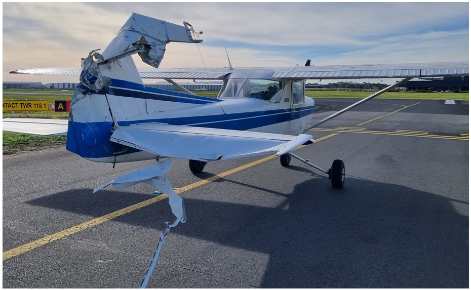
On 21 July 2025, at approximately 1000 Eastern Standard Time, a Cessna 152, with an instructor and student on board, taxied for circuit training operations on runway 35R at Moorabbin Airport, Victoria. While stationary at holding point A, a privately-operated Piper PA-32R-300 taxied into position behind the Cessna 152, awaiting departure for a flight to Broken Hill, New South Wales. After a brief pause, the PA-32R began rolling forward until the propeller contacted the 152’s tail structure. The collision resulted in minor damage to the PA-32R’s propeller and substantial damage to the 152’s tailplane structures, including the rudder, vertical stabiliser and right elevator (Figure 1). With the force from the propeller contact, debris was also spread along the taxiway. Neither of the 152 crew nor the PA-32R pilot sustained any injuries.
The PA-32R pilot reported that immediately prior to the collision, they had been conducting preparatory navigation-related tasks inside the cockpit and had not held sufficient pressure on the aircraft brakes to prevent the aircraft from moving. With their attention inside the cockpit, they had not realised the aircraft had begun to slowly move forward until the collision occurred.
Figure 1: Post‑incident damage to the Cessna 152
Source: Aerodrome operator
Safety message
This incident highlights the importance of pilots maintaining vigilance and situational awareness throughout all phases of flight – including ground operations and taxiing. While manoeuvring in proximity to other aircraft or obstacles, attention must remain outside the aircraft, with ancillary activities such as navigational preparation limited to periods where inadvertent aircraft movement would not create a collision risk.
About this report
Decisions regarding whether to conduct an investigation, and the scope of an investigation, are based on many factors, including the level of safety benefit likely to be obtained from an investigation. For this occurrence, no investigation has been conducted and the ATSB did not verify the accuracy of the information. A brief description has been written using information supplied in the notification and any follow-up information in order to produce a short summary report, and allow for greater industry awareness of potential safety issues and possible safety actions.
On 23 July 2025 at 2345, Matthew Flinders III was in transit between Bridport and Lady Barron, Tasmania, when a rudder angle feedback failure in its autopilot system caused a loss of steering. The failure caused both rudders to lock in the hard to port position and caused an uncontrolled turn to port. In response the ship’s master reduced engine power and alerted the engineer.
The crew attempted to rectify the problem but were initially unable to identify the cause of the failure. Unable to reinstate steering using the rudders – and rolling heavily in the moderate swell – the crew disconnected the steering gear from the rudder crossbar and centred the rudder manually, after which they regained limited heading control using different power settings on the ship’s twin propellers.
The ship slowly made its way back to Bridport, while the crew continued investigating the problem. At about 0815 the engineer identified a loose linkage arm associated with the steering control system. After re-tightening, steering was restored and the ship continued its voyage to Lady Barron.
What the ATSB found
The ATSB investigation found that the loose linkage arm caused a loss of rudder feedback to the autopilot system. This meant that neither the autopilot nor the follow-up manual steering modes were available.
The ship was fitted with a non-follow-up (or ‘toggle steering’) backup control system that was not dependent on the failed sensor. The toggle steering system was available throughout the occurrence and was engaged by the engineer in an attempt to reinstate rudder control. However, the master was unfamiliar with the toggle steering controls on the bridge and was unable to regain steering.
The ATSB also identified that induction training for new personnel did not adequately address the use of the backup control system and that the ship’s safety management system (SMS) did not include clear instructions on its use. Additionally, controls on the bridge were not labelled, and a simple changeover procedure was not posted as required.
Finally, emergency steering drills, which would have served to increase crew proficiency with the ship’s systems, did not include actual operation of the steering system in backup mode. Also, drills were not conducted at the required intervals, which meant that the master had not participated in any emergency steering drills.
What has been done as a result
Bass Strait Freight (BSF) has improved its familiarisation and induction processes to ensure its deck officers and engineers have a thorough understanding of the ship’s steering system. This included the employment of an experienced master in a checking role to assess competency of new crew. The ATSB has assessed that this safety action should adequately address the safety issue.
The company has developed and posted a simple procedure for switching between steering modes, which is posted on the bridge and in the engine room. However, this action does not adequately address the safety issue and further action through appropriate emergency steering procedures is necessary. Therefore, the ATSB has issued a recommendation to BSF to address this issue.
Safety message
Shipping companies are reminded of the importance of the availability of clear and simple instructions and procedures as part of their SMS. These procedures should include robust familiarisation processes. This is especially important on ships with non‑standard design features or unusual operational characteristics and for operators who may have a high turnover of casual crew.
Additionally, regular and thorough emergency drills are an essential part of ensuring and maintaining crew familiarity with their ship’s systems and emergency procedures. For steering emergencies, these drills should include practising steering in all available modes under controlled conditions while underway. This will greatly improve the chances of successfully dealing with an emergency situation.
The occurrence
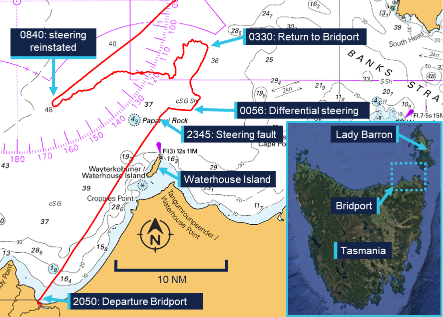
At 2050 local time on 23 July 2025, Matthew Flinders III departed Bridport, Tasmania (Figure 1) carrying a cargo of fertiliser in bulk bags and agricultural machinery. The ship was bound for Lady Barron on Flinders Island. Its crew of 5 comprised the master, chief engineer (engineer), chief mate (mate) – who was also acting as second engineer – and 2 deck ratings.
Following departure, the master manually steered through the confined Bridport channel towards the mouth of the Brid River. At 2115, after clearing the river mouth and entering Bass Strait, the master selected a heading of 033° (T) on the autopilot and remained on watch. The master later reported the wind was west-north-west at about 25 knots with a westerly swell of about 2 m.
Figure 1: Section of navigational chart Aus 487 showing the location of key events
Source: Australian Hydrographic Office, annotated by the ATSB
At about 2345, the ship was approximately 4 miles1 north of Waterhouse Island when an alarm activated on the autopilot system, indicating a loss of rudder response. At the same time, the master noticed that the rudder angle indicator for the ship’s twin-rudders was showing the ‘hard to port’ position and the ship was turning to port. The master immediately responded by reducing engine power and placing the engine controls in neutral, before notifying the engineer and requesting emergency steering to be engaged.
The engineer and mate proceeded to the engine room to diagnose the fault and restore steering. The engineer initially attempted to rectify the fault by resetting the ship’s autopilot and global positioning system (GPS) unit. When this did not clear the fault, the engineer activated the emergency hydraulic steering system. This involved starting the electrically-driven stand-by pump, changing over the manual selector valve and switching control solenoids. The changeover to the emergency pump had no effect, with the rudders remaining hard to port.
Meanwhile, the master phoned a nearby fishing vessel, informing its master of the situation and requesting that they stay nearby to assist if required. The master also directed the deck ratings to prepare the anchors for deployment. With no headway, the ship began rolling heavily on the westerly swell.
When interviewed, the engineer stated that they switched the steering control source switch from ‘autopilot’ to ‘emergency toggle’ and informed the bridge. The master did not recall being informed and did not attempt using the emergency steering toggle.
At about 0015, the master requested the engineer to disconnect the hydraulic steering gear and centre the rudders manually. The master’s intention was to steer the ship using differential thrust settings2 on the ship’s engines, as described in the ship’s emergency procedures.
At 0022, the master contacted Lady Barron vessel traffic service3 (VTS) on VHF channel 14 and informed it of the steering failure. The master also contacted an approaching gas tanker, requesting that it give Matthew Flinders III a wide berth.
At 0056, the engineer and the mate completed disconnecting the steering gear and used a chain hoist to centre the rudders. The master then increased engine power and the ship started making way, with some steering regained through varying rpm settings between the port and starboard engines. While the sea conditions meant that it was not possible to maintain a steady course, the limited heading control did reduce rolling and allowed the ship to continue slowly on its intended track to Lady Barron.
The engineer continued to investigate the cause of the steering failure, assisted over the telephone by the operations manager ashore. At about 0330, the master and operations manager agreed that the ship should return to Bridport, where a shore-based electrician familiar with the ship was to board and render assistance. From 0340, the ship made slow progress towards Bridport, with the master steering a west-south-westerly course to maintain a safe distance from the lee shore of Waterhouse Island and the Tasmanian coastline.
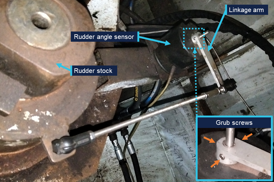
At about 0815, while the engineer was checking the rudder angle sensor (see the section titled Steering arrangement – Steering control signals), the master noticed a change in the indicated rudder angle on the autopilot control unit. The master informed the engineer, who then identified that the angle sensor linkage had slid down over its shaft, and that the grub screws securing it were loose. After the engineer and the mate re‑aligned the linkage and secured the grub screws, the autopilot system feedback functioned normally. After reconnecting the steering cylinders, automated steering was restored and the ship continued its voyage to Lady Barron without further incident.
Context
Matthew Flinders III
Matthew Flinders III was a roll-on roll-off cargo ship constructed in 1995 by Bridport Marine, Tasmania. In 2011 its length was extended from 34.9 m to 44.6 m. It was registered as a ‘regulated Australian vessel’ (RAV) under the Commonwealth’s Navigation Act 2012. The ship was of a monohull design with a width of 10.8 m, a maximum draught of 1.1 m and a gross tonnage (GT) of 298. It was specifically designed to navigate the shallow Brid River and strengthened to be safely beached and to rest on the seabed at low tide.
It was powered by 2 Cummins marine diesel engines producing 375 kW each, for a service speed of about 10 knots. The engines were fitted in compartments on the far port and starboard side of the hull, driving twin fixed-pitch propellers through a reversible gearbox.
The ship was operated by Bass Strait Freight (BSF) on routes between Bridport, Flinders Island and Cape Barren Island, Tasmania, and Welshpool, Victoria. It usually carried general cargo and supplies to the islands and cattle from the islands to the mainland. Cargo was loaded via a stern-mounted ramp onto the open cargo deck, with collapsible pens installed for loading cattle.
Crew
Master
The master of Matthew Flinders III held Australian master <45m near coastal (NC)4 and marine engine driver grade 2 NC (MED-2)5 certificates of competency. The master had about 40 years of marine experience, mostly on fishing vessels, with about 27 years as master on various fishing and fish farming vessels.
They had joined BSF about 6 months before the occurrence and had predominantly worked on Matthew Flinders III and, to a lesser extent, on the company’s other ship, Matthew Flinders IV.
Chief engineer
The chief engineer held Australian master <25m NC and MED-2 certificates of competency. They had worked for BSF for 3 years, both on deck and as engineer in relief roles, and had been appointed as regular engineer on board Matthew Flinders III about 6 months before the occurrence.
Chief mate
The chief mate held Australian master <45m and MED-2 certificates of competency. They had recently joined BSF and the occurrence voyage was intended to familiarise them with the operations of the ship before taking over as master.
Steering arrangement
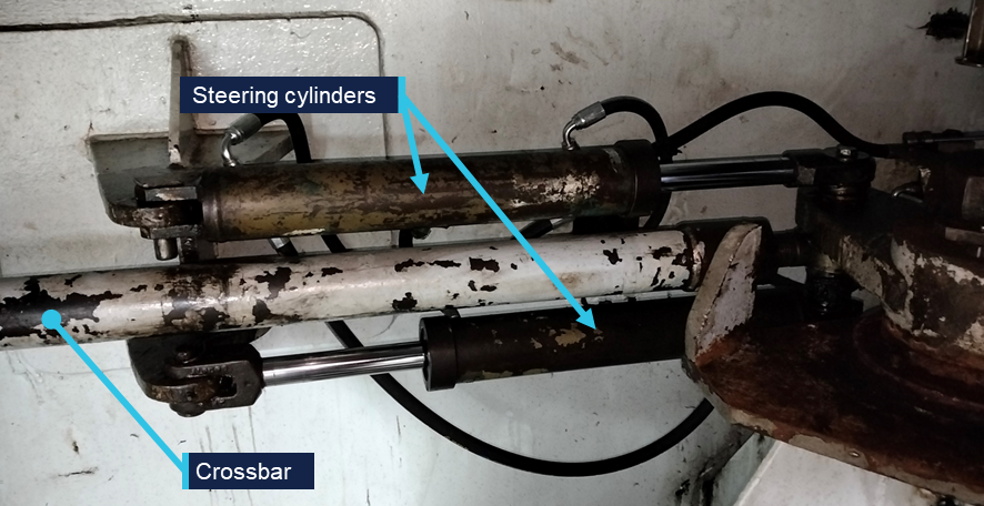
The ship’s twin rudders were interconnected with a crossbar and actuated by 2 double‑acting hydraulic steering cylinders, fitted in the port engine room (Figure 2).
Figure 2: Steering cylinders
Source: Bass Strait Freight, annotated by the ATSB
During normal operations, the ship was steered from the bridge using the autopilot system or manual steering using the follow-up6 controllers. Additionally, a non-follow-up7 backup mode could be used and the hydraulic solenoids could be operated locally from the engine room.
Further, the width of the ship and the outboard placement of the propellers, meant that the use of differential thrust could also provide effective control authority. This was especially the case when operating astern, as the rudders were not effective without forward thrust. Differential thrust was regularly used as the steering method when operating astern in the sheltered port areas on either end of the voyage to moor or beach the ship.
Hydraulic system
Hydraulic pressure for the steering system was provided by a mechanically-driven, constant-flow hydraulic pump mounted on the port engine.
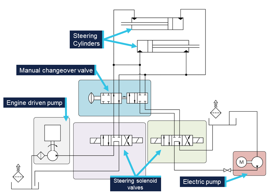
An electrically-driven emergency pump was fitted in case the mechanically driven pump failed. Although this system used the same hydraulic steering cylinders, it incorporated an independent hydraulic reservoir and a separate steering solenoid (Figure 3).
Activation of this system could only be done from the engine room and required the crew to take the following steps:
move manual changeover valve to the emergency position
start electric hydraulic pump
switch solenoid control selector switch to the electric pump position.
Activation of the emergency hydraulic system did not impact the steering control systems. That is, the ship could be steered using the autopilot/follow-up system or the non-follow-up system while using hydraulic power from either pump.
Figure 3: Hydraulic system
Source: ATSB
Steering control signals
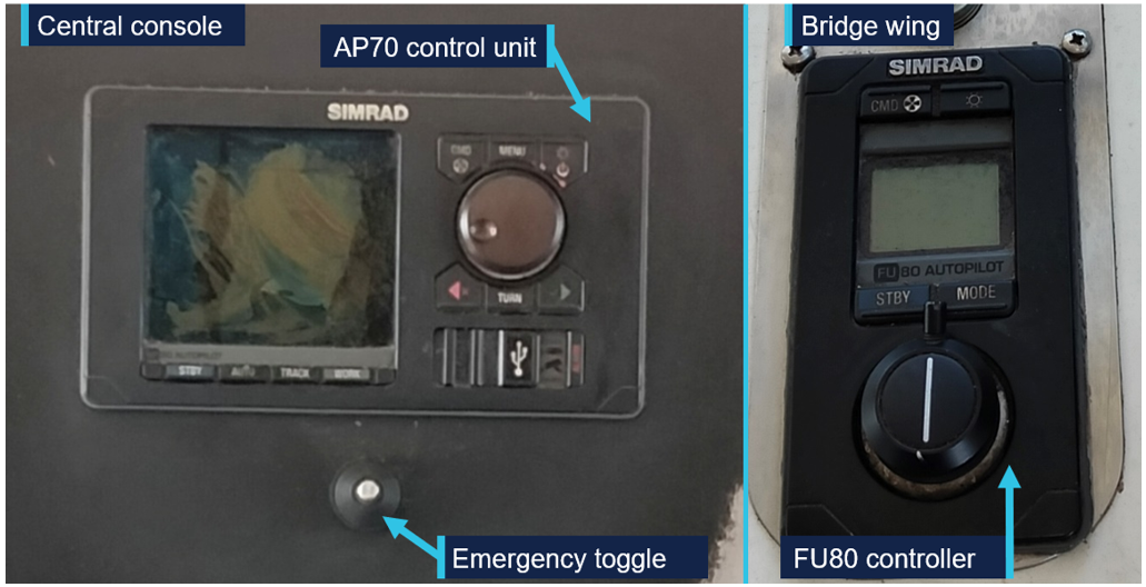
Matthew Flinders III was fitted with a Simrad AP70 autopilot system (Figure 4), which consisted of several interconnected parts, including:
an AP70 control unit
a fluxgate magnetic compass
a rudder interface unit
2 FU-80 follow-up steering controllers.
The AP70 control unit, mounted on the central control panel, controlled the ship’s heading while in autopilot mode. The FU80 controllers were mounted on each bridge wing and used for manual steering.
Figure 4: Autopilot control units and central console emergency toggle
Source: Bass Strait Freight
The interconnection of the manual controllers with the autopilot meant that, during normal operations, the control signals for both manual and autopilot steering were generated by the autopilot system.
Both the autopilot and follow-up modes were closed-loop systems that required a feedback signal. The required rudder angle set point value (as selected by the autopilot or the operator) was continuously compared to the actual (or feedback) value. The system then used the difference between these values to generate a control signal to the appropriate rudder solenoid, adjusting the rudder angle until it aligned with the selected setting.
The required feedback signal for both modes was provided by a single dedicated rudder angle sensor, actuated via a linkage arm off the port rudder stock (Figure 5). The linkage arm was secured on the angle sensor shaft by 3 grub screws.
Figure 5: Rudder angle sensor and grub screws
Source: Bass Strait Freight, annotated by the ATSB
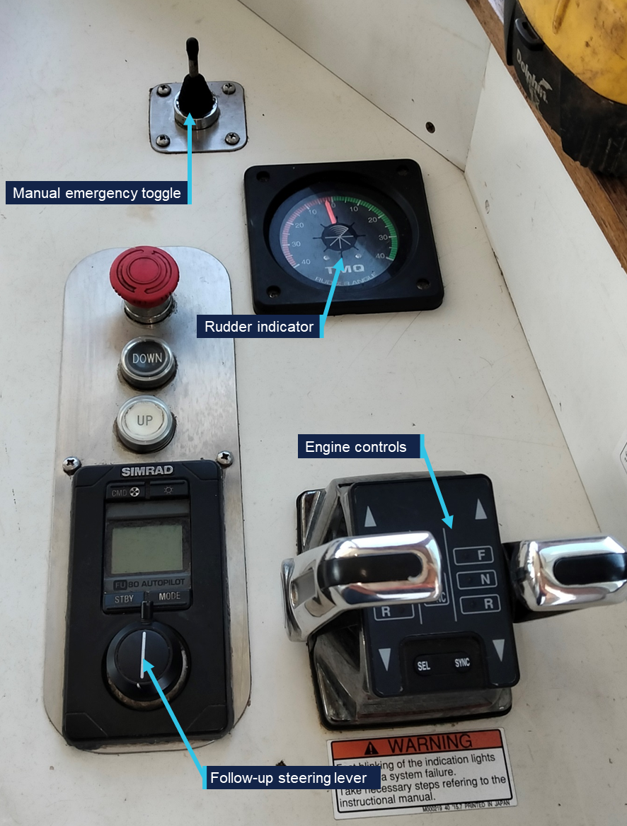
A backup control system was installed in case of autopilot system failure. It consisted of 3 unlabelled steering toggles, one mounted on the centre console and one at each wing control station (Figure 6).
The toggles activated the port or starboard solenoid of the selected (main or emergency) system, allowing for steering control in open-loop or non-follow-up mode. Activating any of the 3 toggle switches moved the rudder in the appropriate direction until the rudders reached their end stop, or the toggle was released.
Figure 6: Starboard wing control station
Source: Bass Strait Freight, annotated by the ATSB
Feedback to the operator was provided by 2 rudder angle indicators, one mounted at each wing control station, with their signals coming from a single rudder angle sensor that was additional to the autopilot rudder angle sensor.
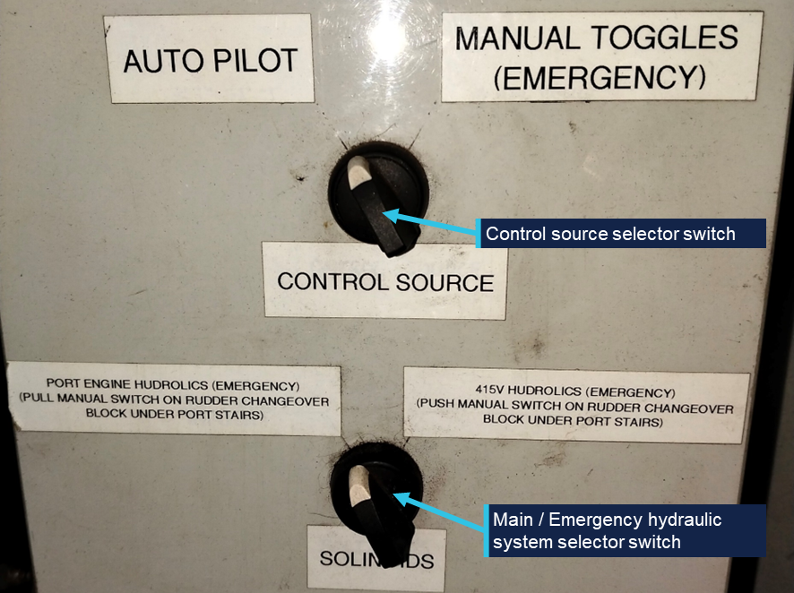
The backup control could only be activated from the rudder control panel in the engine room. This required switching the control source switch to the ‘manual toggles (emergency)’ position (Figure 7).
Figure 7: Engine room rudder control panel
Source: Bass Strait Freight, annotated by the ATSB
Regulations and guidance
Matthew Flinders III was constructed in accordance with the Uniform Shipping Laws (USL) Code in force at that time. As a RAV of less than 300 GT, it was not required to be certified to SOLAS8 requirements. Instead, it was issued with an Australian Maritime Safety Authority (AMSA) certificate of survey under schedule 2 (2.2) of AMSA’s Marine Order 31.9
Under Marine Order 31, non-SOLAS RAVs were required to comply with certain parts of the marine orders.10 This included Marine Order 21,11 which implements the steering gear testing and drill requirements of SOLAS V,12 including:
testing a ship’s steering gear before departure from port
providing clear operating instructions, including a block diagram showing changeover procedures to be displayed on the bridge
ensuring that all officers operating and maintaining steering gear were familiar with its operation
conducting 3-monthly emergency steering drills, which included alternative controls and power supplies.
Marine Order 31 also required BSF to develop and implement a safety management system (SMS) for Matthew Flinders III. The SMS was not required to be audited and certified as compliant with the International Safety Management (ISM) Code13 by an external recognised organisation. Instead, BSF could self-certify its SMS and issue a declaration that the ship’s SMS complied with Part A of the ISM Code as though Chapter IX of SOLAS applied.
Prescriptive requirements for the design of steering systems as per SOLAS II-1,14 including the requirement for the ability to change steering system modes from the helm position, did not apply to Matthew Flinders III as anon-SOLAS RAV.
Best practice requires controls and displays on ships’ bridges to be clearly and unambiguously marked according to their function, and promulgated by the International Maritime Organization (IMO).15
Bass Strait Freight
Bass Strait Freight, based in Bridport, operated freight and passenger services between Bridport, Flinders Island, Cape Barren Island, Tasmania, and Port Welshpool, Victoria. The company operated the 2021-built Matthew Flinders IV, which carried passengers and freight, as well as the older Matthew Flinders III, which was exclusively used for cargo.
The cargo transported was predominantly agricultural, including cattle, with strong seasonal variations in demand. Due to the irregular nature of operations, most of the crew were employed on a casual basis.
The company employed few onshore personnel; it was managed by a director and had appointed a marine operations manager about 6 months before the incident. The operations manager had worked previously as a deck hand and engineer on board both BSF ships. As part of their role, they sometimes conducted (part) of the familiarisation of new ships’ crew. Ship maintenance was mostly outsourced to local contractors who were familiar with the ship, having been involved in its construction and lengthening.
Safety management system
The ISM Code sets general standards on the content and purpose of a ship’s SMS. One of its requirements16 directs shipping companies to identify potential shipboard emergency situations and develop and implement appropriate instructions and procedures to prepare for and respond to them.
Matthew Flinders III’s SMS was contained in a single manual, which included company level policy documents, risk assessments, workplace health and safety requirements. It also contained ship‑ and port-specific instructions, procedures and information. There were several parts related to emergency preparedness and response.
Emergency steering procedures
A description of the emergency steering system was contained in a chapter covering safety features, practices and precautions. It contained a brief description of the steering system, including the option of changing over its hydraulic power source from the port engine to the electrically powered pump and the location of the hydraulic changeover valve. It also noted the location of the changeover switches from ‘pilot steering’ to ‘toggle steering’ in the engine room. The SMS did not describe the system in detail, and the location and usage of the bridge controls were not specified.
The emergency procedures chapter of the SMS manual contained a loss of steering procedure that consisted of a list of actions to take in case of a steering casualty. The list contained some general actions, including the need to be aware of other traffic and navigational hazards in the area, proactive communication and the consideration of dropping an anchor. It did note the use of emergency steering, but did not distinguish between the use of the emergency electric hydraulic steering pump and the non‑follow‑up control system.
The procedure included the following actions related to the steering gear:
• Upon the realisation of the loss of steering, maintain course and speed to the best of ability using the twin screw design of the vessel if navigationally safe to do so. (crew safety measure as to managing the vessels tack against the sea direction)
• Prompt engineer to engage emergency steering.
• Investigate the initial cause of the loss of main steering system.
• If main steering cannot be regained, abort voyage and return to homeport on emergency steering or by the use of the twin screw vessel design.
Following the loss of steering on this occasion, it was initially not possible for the master to maintain heading on differential steering due to the hard to port position of the rudders. Subsequent actions by the crew were consistent with the procedure – maintaining heading into the prevailing sea and returning to Bridport.
Drills
Regulations required the crew of Matthew Flinders III to conduct emergency steering drills at least once every 3 months.17 These drills were intended to test the emergency steering procedures, including direct control of the rudders from the steering gear compartment, communications with the bridge and the operation of alternative power supplies.
At the time of the occurrence, the last recorded drills were conducted on 20 March 2025 and did not include an emergency steering drill. The last recorded emergency steering drill was conducted on 27 October 2024, before the master and chief mate had joined the company. The 27 October drill had been conducted in conjunction with 8 other drills and involved the master at the time walking the crew around the ship and explaining the different emergency systems. There was no record of the backup control system being activated during the drill and, because the ship was alongside at the time, it was not actually steered.
New crew familiarisation
The SMS manual contained procedures for the induction and training of crew members. These included a safety induction procedure, a general safety induction form and department-specific induction forms for the bridge and engine room. Normally, new crew members were inducted by the crew member they were relieving or, alternatively, by shore management if the crew member being relieved was unavailable.
Section 1 of the general safety induction form covered emergency response and contained a total of 20 items, which the new crew member was required to sign in acknowledgment of receiving instruction for each. One of the line items covered the location and use of the emergency steering system. The bridge familiarisation and bridge induction forms referenced manual and autopilot steering, but they did not include the emergency steering or non-follow-up system.
During interview with the ATSB, the master stated that their familiarisation included an explanation of the function of the electric emergency hydraulic pump and how to switch over from the main (engine‑driven) pump. The master did not recall having been instructed about the toggle controls on the bridge and was unfamiliar with the central control toggle. They reported being aware of the emergency toggles on the bridge wing control panels, but were not familiar with their function.
During interview, the master, operations manager and director all indicated that they understood ‘emergency steering’ to mean the use of the electrical hydraulic pump. They all acknowledged that the ship could alternatively be steered using different power settings between the port and starboard engine. As this was the normal mode of steering when manoeuvring astern, the masters and mates were familiar with this method of emergency steering.
Safety analysis
On 23 July 2025, Matthew Flinders III was in transit between Bridport and Lady Barron when a rudder angle feedback failure in its autopilot system caused a loss of steering, locking both rudders hard to port. The ship’s crew were initially unable to identify the cause of the failure and made use of the main engines to regain some limited steering capacity to keep the ship clear of the coast. About 8 hours later, the crew identified the cause of the failure and restored steering.
This analysis will consider the triggering event for the loss of steering – the loose rudder angle sensor linkage – and the response by the crew to manage the emergency. It will also cover the documentation of the steering system, implementation of emergency procedures including drills and the familiarisation of the ship’s crew.
Steering system
Feedback failure
The autopilot system included both automatic heading and a follow-up steering modes. Both modes were closed-loop controls and relied on a single feedback signal from a shared rudder angle sensor.
The rudder angle sensor shaft was connected to the rudder stock via a linkage arm that was secured by 3 grub screws. Movements of the rudder would be transferred from the rudder to the angle sensor and then transmitted electronically to the autopilot system.
When the linkage connecting the rudder to the sensor slipped, the feedback angle was no longer aligned with the actual rudder angle. Consequently, the feedback signal to the autopilot froze in a fixed position, resulting in the autopilot system continuing to output a signal to the port solenoid. This resulted in the rudders locking hard over to port, a ‘rudder not responding’ alarm being generated by the autopilot system and an uncontrolled turn to port.
Contributing factor
Loose grub screws on the rudder angle sensor linkage arm led to a loss of the rudder feedback signal to the autopilot system. This resulted in the failure of the autopilot and non-follow-up steering system, locking the rudders hard to port.
Non-follow-up system
Matthew Flinders III was equipped with a backup non-follow-up (NFU) steering system that did not require a feedback signal to function. It controlled the rudder solenoids using one of 3 toggle switches mounted on the bridge. Feedback to the helmsman was provided through 2 rudder angle indicators, mounted on the bridge wing control station that used an angle signal from a single independent angle sensor.
However, NFU steering could only be activated from a control panel in the engine room. It was not used for routine operations, nor had its use been practised during drills. As a result, the ship’s crew and shore-based management personnel had little awareness of the system and its function.
The master, who was the only person on the bridge during the occurrence, was not familiar with any part of the NFU system. Consequently, the master was unaware of the requirement to use the NFU steering toggles when the engineer changed over the control switch as part of their trouble-shooting efforts.
Contributing factor
Crew on board Matthew Flinders III had a limited understanding of the steering system. This resulted in an incorrect response to the control failure.
Posted instructions and labels
Clear operating instructions, including a block diagram showing the procedures for changing between systems, were not displayed on the navigation bridge and in the steering compartment as required under the requirements of Marine Order 21. Additionally, industry guidance for bridge control design recommended that all control elements should be clearly labelled with their function.
Having relevant system information readily available on the bridge would have assisted the crew in identifying the correct steps to change over between control modes during the emergency. Additionally, it probably would have increased the master’s familiarity with NFU steering mode during his time spent on board the ship, as well as provide guidance during emergency steering drills.
Contributing factor
A simple emergency steering changeover procedure was not adequately documented and posted on bridge and engine room, as required under Marine Order 21, and the control elements on the bridge were not labelled. These contributed to the lack of understanding of the steering system by the crew.
As a non-SOLAS RAV, prescriptive requirements on the design of steering systems did not apply to Matthew Flinders III. This meant that it was not required to have controls for changing steering system mode at the helm position. However, the ability to switch steering modes on the bridge would allow for a rapid response to faults in the steering control system.
In combination with correct labelling and posted instructions, having a switch available on the bridge would probably have improved the crew’s understanding of the different available steering modes.
Other factor that increased risk
The switching of steering modes from the autopilot system to the non-follow-up toggles could only be done from the engine room. This delayed the recovery of steering following failure of the autopilot or the connected follow-up system.
Safety management
In accordance with Marine Order 31 for non-SOLAS regulated Australian vessels, Bass Strait Freight had in place a safety management system (SMS) that defined company‑specific policies and procedures and provided port and ship-specific information. The SMS included sections on emergency response actions as well as procedures for training and familiarisation of new crew members.
Familiarisation and drills
Newly joining crew members to Matthew Flinders III received an initial onboard induction intended to familiarise them with the operation of the ship’s systems and their roles in emergencies. Inductions were required under marine regulations, which included specific requirements for personnel involved in the operation or maintenance of steering systems.
The inductions were guided by several forms that were part of the ship’s SMS. The general induction form included a line item requiring the new crew member to be instructed in ‘the location and use of emergency steering’. However, no specific information was provided on what should be included. The bridge familiarisation and induction forms included autopilot and manual steering but did not include any reference to emergency steering modes.
The function of the NFU (or ‘toggle’) steering system was not well understood among both ship and shore-based staff. In combination with the limited documentation of the system, this meant that the inductions for new crew member did not adequately address the use of the system. This was compounded by the limited scope of emergency steering drills, which likely did not include actual steering using the alternative systems. Additionally, the low frequency of drills meant that neither the master nor the mate had ever participated in an emergency steering drill.
As a result, while the master was aware of the emergency hydraulic steering system, their induction did not include the use of the NFU system. Consequently, they were unfamiliar with its function and instead relied on steering using differential thrust during the occurrence, which limited control in the prevailing sea conditions.
Contributing factor
Training of new personnel on board Matthew Flinders III did not adequately cover the use of the different steering modes. Additionally, drills were not conducted in line with regulatory requirements, which meant critical crew had not participated in any steering drills. Training and drills focused on hydraulic failures and did not include the use of the emergency toggles nor practice local control in the engine room. These elements likely contributed to the lack of systems knowledge among the ship’s crew, resulting in an incorrect response to the failure. (Safety issue)
Inadequate emergency steering procedures
The ISM code required companies to identify potential emergencies and establish response procedures in its SMS. Bass Strait Freight had identified steering failure as an emergency and the SMS contained a description of the steering system as well as a ship-specific emergency steering procedure.
In the steering system description, reference was made to the electric emergency steering system and the manual changeover valve; it also identified the location of the NFU steering switch in the engine room. However, it did not include any further information on the use of the NFU system’s use and the location and nature of the controls on the bridge.
The emergency steering procedure required engaging the emergency steering system but did not specify whether this referred to the emergency pump or the NFU steering. It did not include any other guidance on activating the backup control system, instead focusing on maintaining the ship’s heading using differential thrust from the 2 engines.
The ambiguity and lack of details in the procedure and the checklist meant that the crew were not made aware of all the different steering modes. That resulted in the master being unable to switch over to the available non-follow-up mode when prompted by the engineer.
Contributing factor
The emergency steering section of Bass Strait Freight’s safety management system did not adequately explain the alternative non-follow-up control mode and instead emphasised the use of differential thrust for emergency steering. As a result, the master focused on controlling the ship using differential thrust, rather than changing over to a control mode, which would have restored rudder authority. (Safety issue)
Emergency response
Marine rescue services stress the importance of early, proactive communication when there is a potential for an emergency to arise. Early notification allows for timely mobilisation of rescue assets and reduces the communication workload in case of escalation.
In this case, Matthew Flinders III’s master promptly notified Lady Baron vessel traffic service (VTS) and nearby ships of the situation, after initial attempts to restore steering were unsuccessful. Even though the ship was outside the VTS area of responsibility during the occurrence, the master’s actions ensured that shore-based authorities were aware of the situation and increased the likelihood of timely assistance if it had been required.
Other finding
Though the ship was not in the Lady Barron vessel traffic service (VTS) area when the steering failure happened, the master communicated proactively with VTS and surrounding traffic, making sure that assistance was available in case of escalation.
Findings
ATSB investigation report findings focus on safety factors (that is, events and conditions that increase risk). Safety factors include ‘contributing factors’ and ‘other factors that increased risk’ (that is, factors that did not meet the definition of a contributing factor for this occurrence but were still considered important to include in the report for the purpose of increasing awareness and enhancing safety). In addition ‘other findings’ may be included to provide important information about topics other than safety factors.
Safety issues are highlighted in bold to emphasise their importance. A safety issue is a safety factor that (a) can reasonably be regarded as having the potential to adversely affect the safety of future operations, and (b) is a characteristic of an organisation or a system, rather than a characteristic of a specific individual, or characteristic of an operating environment at a specific point in time.
These findings should not be read as apportioning blame or liability to any particular organisation or individual.
From the evidence available, the following findings are made with respect to the steering failure involving Matthew Flinders III, 8 km north of Waterhouse Island, Bass Strait, Tasmania, on 23 July 2025.
Contributing factors
Loose grub screws on the rudder angle sensor linkage arm led to a loss of the rudder feedback signal to the autopilot system, this resulted in the failure of the autopilot and non-follow-up steering system, locking the rudders hard to port.
Crew on board Matthew Flinders III had a limited understanding of the steering system. This resulted in an incorrect response to the control failure.
A simple emergency steering changeover procedure was not adequately documented and posted on bridge and engine room, as required under Marine Order 21, and the control elements on the bridge were not labelled. These contributed to the lack of understanding of the steering system by the crew.
The switching of steering modes from the autopilot system to the non-follow-up toggles could only be done from the engine room. This delayed the recovery of steering following failure of the autopilot or the connected follow-up system.
Training of new personnel on board Matthew Flinders III did not adequately cover the use of the different steering modes. Additionally, drills were not conducted in line with regulatory requirements, which meant critical crew had not participated in any steering drills. Training and drills focused on hydraulic failures and did not include the use of the emergency toggles nor practice local control in the engine room. These elements likely contributed to the lack of systems knowledge among the ship’s crew, resulting in an incorrect response to the failure.(Safety issue)
The emergency steering section of Bass Strait Freight’s safety management system did not adequately explain the alternative non-follow-up control mode and instead emphasised the use of differential thrust for emergency steering. As a result, the master focused on controlling the ship using differential thrust, rather than changing over to a control mode, which would have restored rudder authority. (Safety issue)
Other findings
Though the vessel was not in the Lady Barron vessel traffic service (VTS) area when the steering failure happened, the master communicated proactively with VTS and surrounding traffic, making sure that assistance was available in case of escalation.
Safety issues and actions
Central to the ATSB’s investigation of transport safety matters is the early identification of safety issues. The ATSB expects relevant organisations will address all safety issues an investigation identifies.
Depending on the level of risk of a safety issue, the extent of corrective action taken by the relevant organisation(s), or the desirability of directing a broad safety message to the marine industry, the ATSB may issue a formal safety recommendation or safety advisory notice as part of the final report.
All of the directly involved parties were provided with a draft report and invited to provide submissions. As part of that process, each organisation was asked to communicate what safety actions, if any, they had carried out or were planning to carry out in relation to each safety issue relevant to their organisation.
Descriptions of each safety issue, and any associated safety recommendations, are detailed below. Click the link to read the full safety issue description, including the issue status and any safety action/s taken. Safety issues and actions are updated on this website when safety issue owners provide further information concerning the implementation of safety action.
Safety issue description: Training of new personnel on board Matthew Flinders III did not adequately cover the use of the different steering modes. Additionally, drills were not conducted in line with regulatory requirements, which meant critical crew had not participated in any steering drills. Training and drills focused on hydraulic failures and did not include the use of the emergency toggles nor practice local control in the engine room. These elements likely contributed to the lack of systems knowledge among the ship’s crew, resulting in an incorrect response to the failure.
Safety issue description: The emergency steering section of Bass Strait Freight’s safety management system did not adequately explain the alternative non-follow-up control mode and instead emphasised the use of differential thrust for emergency steering. As a result, the master focused on controlling the ship using differential thrust, rather than changing over to a control mode, which would have restored rudder authority.
The ATSB makes a formal safety recommendation, either during or at the end of an investigation, based on the level of risk associated with a safety issue and the extent of corrective action already undertaken. Rather than being prescriptive about the form of corrective action to be taken, the recommendation focuses on the safety issue of concern. It is a matter for the responsible organisation to assess the costs and benefits of any particular method of addressing a safety issue.
Safety recommendation description: The Australian Transport Safety Bureau recommends that Bass Strait Freight takes safety action to address this safety issue.
Glossary
AIS
Automatic Identification System
AMSA
Australian Maritime Safety Authority
BSF
Bass Strait Freight
IMO
International Maritime Organization
ISM
International Safety Management
GPS
Global Positioning System
GT
Gross tonnage
MSC
Maritime Safety Committee
NC
Near coastal
NFU
Non-follow-up steering
RAV
Regulated Australian Vessel
SMS
Safety management system. A systematic approach to organisational safety encompassing safety policy and objectives, risk management, safety assurance, safety promotion, third party interfaces, internal investigation and SMS implementation.
SOLAS
The International Convention for the Safety of Life at Sea, 1974, as amended.
USL
Universal Shipping Laws
VHF
Very high frequency
VTS
Vessel traffic service
Sources and submissions
Sources of information
The sources of information during the investigation included:
the master and chief engineer of Matthew Flinders III
the director and operations manager of Bass Strait Freight
Recorded Automatic Identification System (AIS) data
References
Australian Transport Council, 1993, Uniform Shipping Laws code – section 9, Engineering, AMSA, Canberra. Available at www.amsa.gov.au
International Maritime Organization, 2000, MSC. Circular 982–Guidelines on ergonomic criteria for bridge equipment and layout, IMO, London. Available at www.imo.org
International Maritime Organization, 2014, International Convention for the Safety of Life at Sea (SOLAS), 1974, as amended, IMO, London. Available at www.imo.org
International Maritime Organization (IMO) 1995, International Management Code for the Safe Operation of Ships and for Pollution Prevention (ISM Code) as amended, IMO, London. Available at www.imo.org
Australian Maritime Safety Agency, 2016, Marine Order 21 (Safety and emergency arrangements), AMSA, Canberra. Available at www.amsa.gov.au
Australian Maritime Safety Agency, 2019, Marine Order 31 (SOLAS and non-SOLAS certification), AMSA, Canberra. Available at www.amsa.gov.au
Submissions
Under section 26 of the Transport Safety Investigation Act 2003, the ATSB may provide a draft report, on a confidential basis, to any person whom the ATSB considers appropriate. That section allows a person receiving a draft report to make submissions to the ATSB about the draft report.
A draft of this report was provided to the following directly involved parties:
the master and chief engineer of Matthew Flinders III
Bass Strait Freight
Australian Maritime Safety Authority.
Submissions were received from:
the master of Matthew Flinders III
Bass Strait Freight.
The submissions were reviewed and, where considered appropriate, the text of the report was amended accordingly.
Purpose of safety investigations
The objective of a safety investigation is to enhance transport safety. This is done through:
identifying safety issues and facilitating safety action to address those issues
providing information about occurrences and their associated safety factors to facilitate learning within the transport industry.
It is not a function of the ATSB to apportion blame or provide a means for determining liability. At the same time, an investigation report must include factual material of sufficient weight to support the analysis and findings. At all times the ATSB endeavours to balance the use of material that could imply adverse comment with the need to properly explain what happened, and why, in a fair and unbiased manner. The ATSB does not investigate for the purpose of taking administrative, regulatory or criminal action.
About ATSB reports
ATSB investigation reports are organised with regard to international standards or instruments, as applicable, and with ATSB procedures and guidelines.
Reports must include factual material of sufficient weight to support the analysis and findings. At all times the ATSB endeavours to balance the use of material that could imply adverse comment with the need to properly explain what happened, and why, in a fair and unbiased manner.
An explanation of terminology used in ATSB investigation reports is available here. This includes terms such as occurrence, contributing factor, other factor that increased risk, and safety issue.
Publishing information
Released in accordance with section 25 of the Transport Safety Investigation Act 2003
Ownership of intellectual property rights in this publication
Unless otherwise noted, copyright (and any other intellectual property rights, if any) in this report publication is owned by the Commonwealth of Australia.
Creative Commons licence
With the exception of the Commonwealth Coat of Arms, ATSB logo, and photos and graphics in which a third party holds copyright, this report is licensed under a Creative Commons Attribution 4.0 International licence.
The CC BY 4.0 licence enables you to distribute, remix, adapt, and build upon our material in any medium or format, so long as attribution is given to the Australian Transport Safety Bureau.
Copyright in material obtained from other agencies, private individuals or organisations, belongs to those agencies, individuals or organisations. Where you wish to use their material, you will need to contact them directly.
^A yawing moment can be generated in a twin-screw ship by using different thrust settings between the port and starboard propellors as a method for steering the ship.
^The Lady Barron VTS area extends 3 miles from the port’s main wharf and Matthew Flinders III was not in its area of operations at the time of the occurrence.
^The master less than 45 metres near coastal (formerly ‘master 4’) certificate of competency allows the holder to work as master on commercial vessels up to 45 metres long within Australia’s exclusive economic zone.
^The marine engine driver grade 2 near coastal certificate of competency allows the holder to work as chief engineer on vessels with an inboard engine of up to 750kW.
^In follow-up steering mode the required rudder angle is set using a handwheel or lever, the controller operates the steering solenoids to match (and maintain) the rudder feedback angle with the commanded angle.
^In non-follow steering mode, the steering toggle or switches directly control the movement of the rudder, continuously activating the steering solenoids as long as the switch is activated.
^International Maritime Organization, 2014, The International Convention for the Safety of Life at Sea (SOLAS) 1974 as amended, IMO, London.
^Australian Maritime Safety Authority, 2019, Marine Order 31 – SOLAS and non-SOLAS certification, AMSA, Canberra.
^Marine orders, also described as regulatory instruments or legislative regulations, are legal instruments made by AMSA pursuant to powers under Commonwealth legislation.
^Australian Maritime Safety Authority, 2016, Marine order 21 – Safety and emergency arrangements, AMSA, Canberra.
^International Maritime Organization, 2018, International Management Code for the Safe Operation of ships and for Pollution Prevention (ISM Code) as amended, IMO, London.
A Saab 340 was started with a strap still attached to its left propeller following a series of missed checks, an ATSB investigation has found.
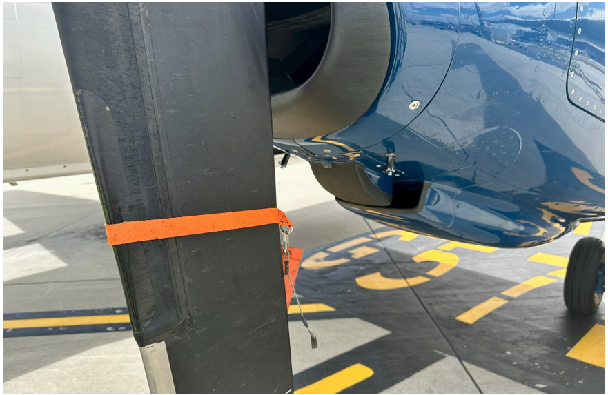
On 19 November 2024, the Regional Express aircraft was prepared for departure from Melbourne Airport. After the pilots started the engines, a passenger told the flight attendant they had seen a strap restraining the left propeller before it began to spin.
The flight attendant advised the pilots, who shut down the engines. The propeller strap was then found attached to the propeller, with the pins that connect it to the engine cowling broken on start-up.
ATSB Director Transport Safety Dr Stuart Godley said the strap was inadvertently left on the propeller after being missed in a series of pre-flight checks.
“Actions from multiple individuals contributed to the development of this incident, with the first officer, the captain and the ground handler, who was a trainee, all required to check for the presence of the strap prior to engine start,” Dr Godley said.
The ATSB final report notes the final external walkaround check of the aircraft required the first officer to remove the propeller strap from the propeller, before rotating the propeller to a required position.
However, the first officer inadvertently left the propeller strap attached, instead only disconnecting and removing the strap extension, which connects the propeller strap to the aircraft stairs to prevent them from being retracted while the strap is in place.
“The first officer completed their walkaround and boarded the aircraft, entering the flight deck with just the propeller strap extension in their hands, but without the strap itself,” Dr Godley said.
Once the first officer was in the flight deck, the ground handler assigned to the dispatch, who was a trainee, did not detect the propeller strap from their position at the nose of the aircraft, and provided the crew with a signal to start the engine.
Meanwhile, the pilots conducted the engine start checklist, which included a requirement for the captain to check that the left engine was clear. The captain also did not detect the propeller strap and proceeded to start the engine.
“The absence of a strap extension allowed the aircraft stairs to be retracted, and removed a visual cue, reducing the likelihood that either the captain or the trainee ground handler would detect the propeller strap,” Dr Godley noted.
While the individual actions of multiple personnel contributed to the incident, the ATSB’s investigation identified safety issues in the training and procedures for ground handling personnel.
“This incident highlights the critical safety role performed by ground handling personnel, who are often the last line of defence in ensuring commercial aircraft are prepared safely for departure,” Dr Godley said.
“Operators should seek to ensure that ground handling procedures and training are designed to effectively support the ability to check for safety critical items.”
In addition to the missed check by the ground handler trainee, the ATSB found the ground handler’s supervisor had left the apron before the trainee had completed the dispatch.
It also found Regional Express procedures did not define the roles and expectations of trainers during practical ground handling training.
In response, Regional Express has taken actions aimed at providing greater assurance that ground handling staff and flight crews are adequately checking for propeller straps during aircraft preparation.
“While it is valuable for new personnel to demonstrate their capability prior to being deemed competent, this incident highlights the potential for on-the-job training to introduce safety risks, and why it is critical that supervisors maintain oversight of trainees in safety critical contexts,” Dr Godley said.
“Operators should ensure they clearly articulate the roles and expectations of personnel supervising practical training for safety critical tasks.”
The incident was the second investigated by the ATSB involving a strap being inadvertently left on a Saab 340 propeller. In November 2022, a Link Airways Saab 340 was taking off from Canberra when a propeller strap was thrown free of the blade and embedded in the cabin wall. In addition, cowling pins penetrated the cabin, with one striking a passenger, resulting in a minor bruising injury.
“Both of these incidents highlight that ground handling procedures and training should be effectively designed to support the ability to check for safety critical items,” Dr Godley concluded.
“They should also remind operators to assess the conspicuity of items such as straps, tags and chocks which need to be detected and removed prior to flight, and how ground handling personnel are taught to look for them.”