Occurrence Briefs are concise reports that detail the facts surrounding a transport safety occurrence, as received in the initial notification and any follow-up enquiries. They provide an opportunity to share safety messages in the absence of an investigation. Because occurrence briefs are not investigations under the Transport Safety Investigation Act 2003, the information in them is de-identified.
What happened
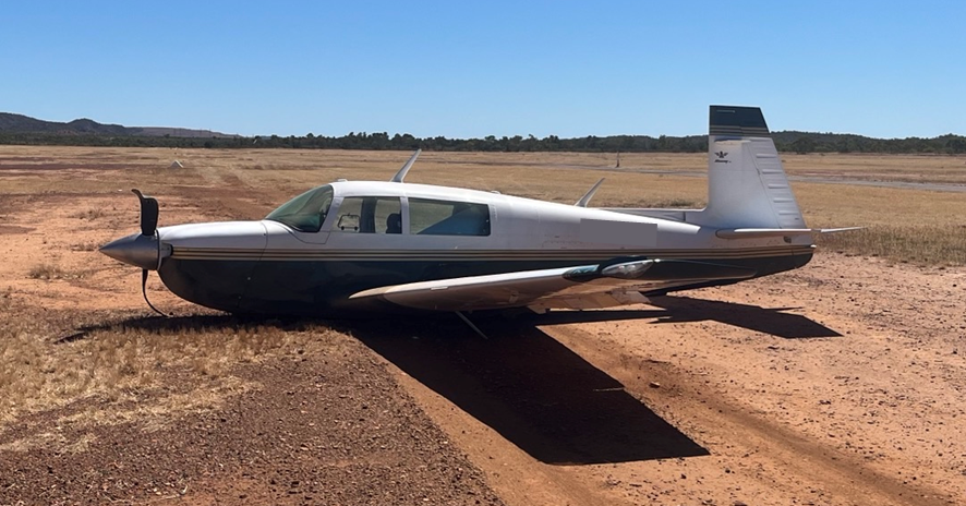
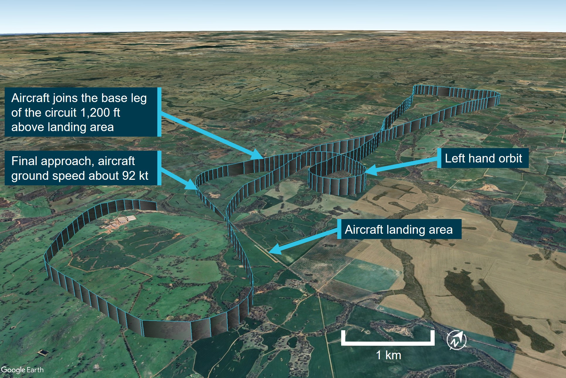
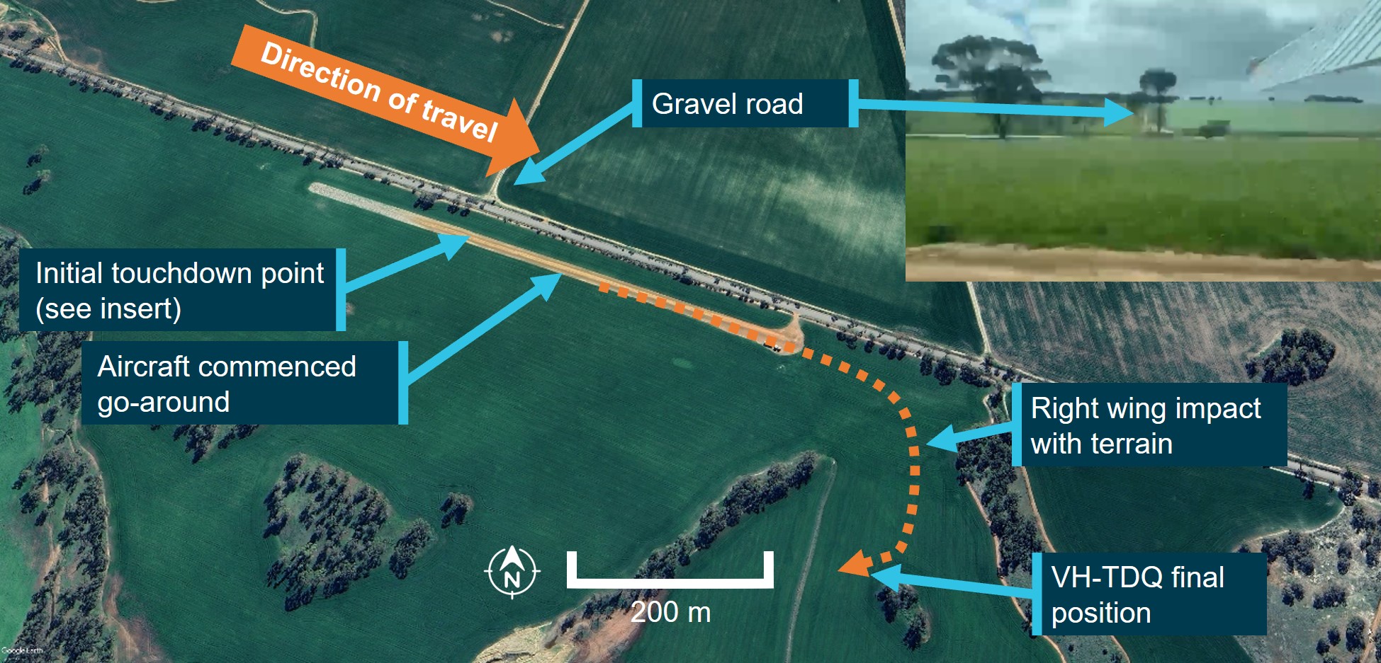
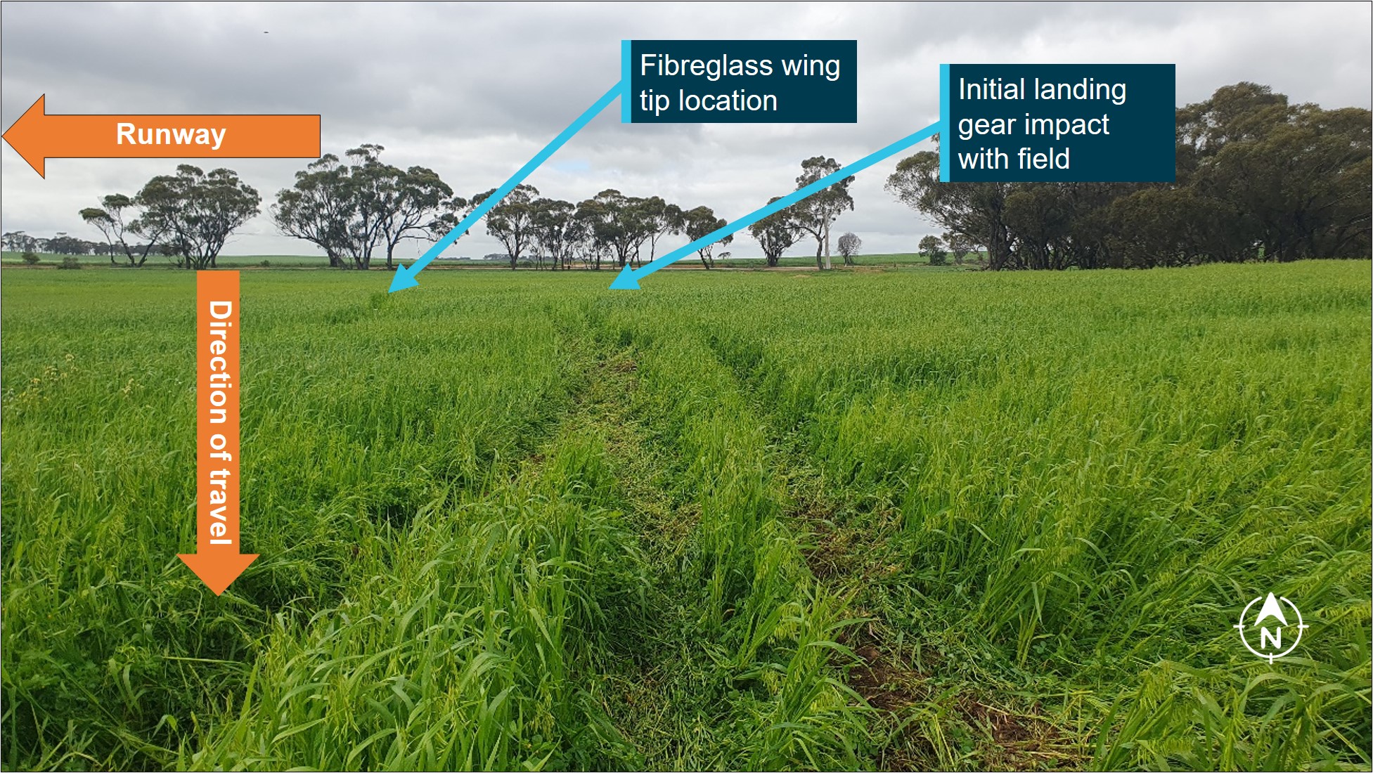
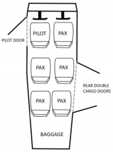
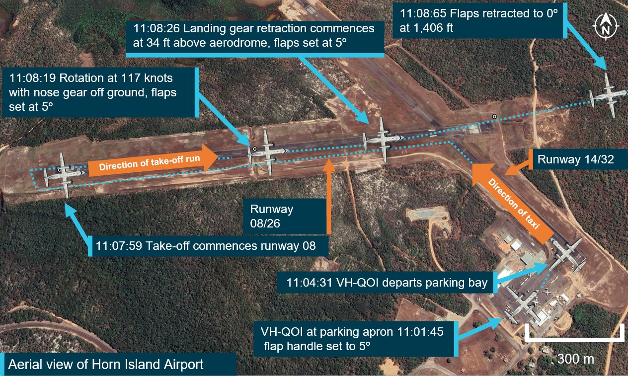
On 20 August 2025, a Mooney M20J, with a pilot and 2 passengers on board, was landing at Mount Isa Airport, Queensland following a private flight. The pilot reported that, at the time, the wind was gusty with some crosswind on the airport’s single runway. After discontinuing the first landing attempt, the pilot circled and conducted a second approach, targeting a landing speed of 65–70 kt. Subsequently, the aircraft landed and began to decelerate. Consistent with their normal procedure, the pilot raised the flap and turned off the fuel pump. The pilot reported that they then mistakenly moved the landing gear lever from the down to the up position. As a result, the landing gear started to retract while the aircraft was on the runway.
Recognising the situation, the pilot applied full power and raised the nose, resulting in the aircraft becoming airborne again. The aircraft banked left and climbed briefly before the pilot lowered the nose. The aircraft subsequently impacted the ground to the left of the runway and slid for several metres before coming to a stop. The pilot and passengers exited the aircraft without injuries, and the aircraft was substantially damaged.
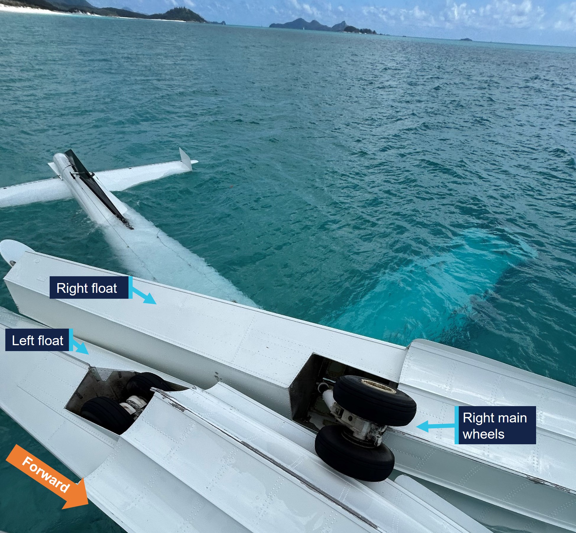
Figure 1: Aircraft post-accident
Source: Supplied, edited by the ATSB
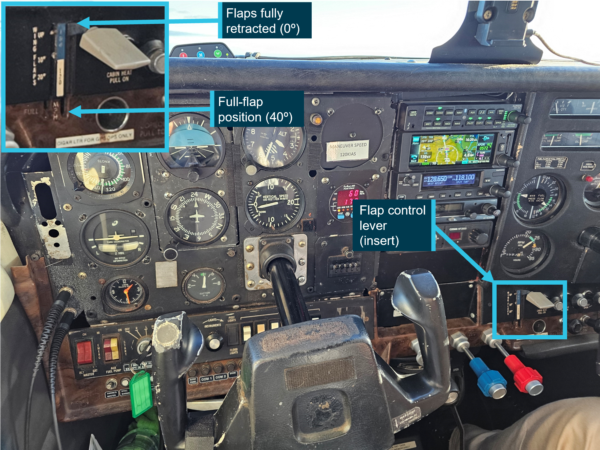
The aircraft’s maintenance manual stated that the aircraft was equipped with an airspeed‑activated landing gear safety system that was designed to prevent the gear from retracting when the aircraft was below 60 kt (±5 kt) indicated airspeed and airspeed was increasing. The manual further advised that when landing, the system may not engage until below 50 kt, and could allow the landing gear to retract if the gear switch was placed in the up position during the landing roll.
Safety message
This accident serves as a reminder to pilots that incidents and accidents can occur at any time during the operation of an aircraft, including the landing roll. Maintaining awareness, in conjunction with the consistent use of procedures, checklists and flows, minimises the opportunity for inadvertent or mistaken manipulation of an aircraft’s controls or systems.
About this report
Decisions regarding whether to conduct an investigation, and the scope of an investigation, are based on many factors, including the level of safety benefit likely to be obtained from an investigation. For this occurrence, no investigation has been conducted and the ATSB did not verify the accuracy of the information. A brief description has been written using information supplied in the notification and any follow-up information in order to produce a short summary report, and allow for greater industry awareness of potential safety issues and possible safety actions.
Occurrence Briefs are concise reports that detail the facts surrounding a transport safety occurrence, as received in the initial notification and any follow-up enquiries. They provide an opportunity to share safety messages in the absence of an investigation. Because occurrence briefs are not investigations under the Transport Safety Investigation Act 2003, the information in them is de-identified.
What happened
On 15 July 2025, the pilot of a Beech Aircraft Corp B200C aircraft, undertaking a medical transport flight, was conducting a required Navigation Performance Approach to runway 12 at White Cliffs Airport, New South Wales.
The pilot reported that, after becoming visual 200 ft above the approach minimum, they commenced their landing checks and identified that they had not extended the landing gear. They started actions to lower the landing gear as the Terrain Awareness and Warning System (TAWS) aural annunciation TOO LOW GEAR began. After the pilot then checked airspeed, rate of descent and tracking, they decided to extend the landing gear and continue the approach. The aircraft landed without further incident.
When the aircraft is not in landing mode, the TAWS system monitors the radio altitude, landing gear configuration, landing flaps configuration and airspeed, and generates a caution alert if there is insufficient terrain clearance. A TOO LOW GEAR caution is generated when radio altitude and airspeed are within the Too Low Gear envelope and the landing gear is not in a correct landing configuration. When generated, the caution annunciator lights, and TOO LOW GEAR is announced over the audio system. This caution is annunciated for as long as the condition exists.
The operator was able to determine that the TAWS alert began at a radio altitude of 469 ft and continued until a radio altitude of 374 ft. According to the operator’s stable approach criteria, the aircraft should have been completely configured for a landing by 500 ft. As this was not the case, the pilot should have conducted a missed approach when the TOO LOW GEAR caution was generated.
Safety message
The ATSB continues to stress the risks associated with unstable approaches. The Flight Safety Foundation cites a lack of go-arounds from unstable approaches as the number one risk factor in approach and landing accidents. The prompt execution of a go‑around will significantly reduce this risk.
About this report
Decisions regarding whether to conduct an investigation, and the scope of an investigation, are based on many factors, including the level of safety benefit likely to be obtained from an investigation. For this occurrence, no investigation has been conducted and the ATSB did not verify the accuracy of the information. A brief description has been written using information supplied in the notification and any follow-up information in order to produce a short summary report, and allow for greater industry awareness of potential safety issues and possible safety actions.
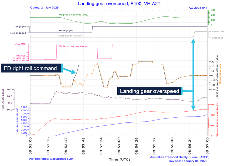
At 1851 local time on 24 July 2025, the crew of an Alliance Airlines Embraer ERJ 190, registered VH‑A2T, departed Cairns, Queensland, for a passenger transport flight to Brisbane. For the departure, the crew took off from runway 15 with a clearance to follow the AKROM 1 standard instrument departure (SID).
As the aircraft became airborne in darkness, the captain, acting as pilot monitoring, announced ‘pitch rate’ to alert the first officer, who was pilot flying, that the aircraft’s rotation had slowed. Both crewmembers then focused on the aircraft flight path, and the retraction of the landing gear was inadvertently omitted.
As the aircraft continued climbing and turning left to follow the SID, the flight crew received 2 radio altimeter annunciations and observed the flight director unexpectedly command a right turn. After completing the left turn to follow the SID, the first officer engaged the autopilot, and the aircraft started a right turn toward terrain. The captain identified the turn and instructed the first officer to turn left back to the required track.
As the aircraft then continued along the SID, the captain recognised that the landing gear was still extended and quickly retracted it. The landing gear completed retracting when the aircraft had reached a speed of 252 kt, 17 kt above the maximum landing gear retraction speed.
The flight continued and the aircraft landed at Brisbane without further incident at 2044. Following the flight, the aircraft was inspected and found to be undamaged.
What the ATSB found
The ATSB found that the 'pitch rate' announcement was made at a time when a ‘positive rate’ announcement would normally be expected. This resulted in both flight crewmembers focusing on the pitch angle and the first officer was not prompted to call for landing gear retraction.
As the aircraft turned left to follow the SID, the crew were presented with radio altimeter alerts and unexpected flight director indications. These distractions increased the flight crew's workload and delayed their identification of the extended landing gear. Upon recognising the still extended landing gear, the captain reflexively retracted it without first checking the aircraft speed.
What has been done as a result
Alliance Airlines accelerated its program to upgrade E190 aircraft from load 25 avionics to load 27 and at the time of the release of this report, all E190s in the Alliance Airlines fleet have been upgraded. This should prevent recurrence of the unexpected flight management system indications presented to the crew during this incident.
In addition, the load 27 avionics upgrade incorporated electronic checklists that require associated actions to be undertaken before the electronic checklist is completed.
Safety message
This incident highlights the impact a combination of omitted actions and distractions can have on aircraft operations, during what is often a high workload period. Such situations can create challenges in responding to the unexpected with potential for a reduction in safety when pilots act rapidly and reflexively. In these situations, pilots may not be able to effectively process information or consider all relevant factors, which reduces the ability to make good decisions.
Crews of Embraer ERJ 190 aircraft equipped with load 25 avionics should also be aware that, on occasion, these systems may provide unexpected indications. This has been observed on multiple occasions on the Cairns AKROM 1 SID. When faced with unexpected indications, crews should use primary instruments to ensure that flight path requirements are adhered to.
The investigation
The ATSB scopes its investigations based on many factors, including the level of safety benefit likely to be obtained from an investigation and the associated resources required. For this occurrence, the ATSB conducted a limited-scope investigation in order to produce a short investigation report, and allow for greater industry awareness of findings that affect safety and potential learning opportunities.
The occurrence
On the evening of 24 July 2025, the crew of an Alliance Airlines Embraer ERJ 190, registered VH‑A2T, prepared to operate a passenger transport flight from Cairns to Brisbane, Queensland. For the flight, the captain acted as pilot monitoring (PM), and the first officer as pilot flying (PF).[1] For the departure, the crew were provided with clearance to follow the AKROM 1 standard instrument departure (SID) (see the section titled Cairns runway 15 AKROM 1 standard instrument departure). While preparing for the flight, the captain advised the first officer that on previous flights, the first officer’s rotation[2] rate was slower than required and, as adherence to the SID climb requirements was essential for terrain avoidance, the rotation rate would be a point of focus for the departure.
In darkness at 1851 local time, the aircraft commenced a take-off from runway 15 with the lateral navigation flight guidance mode selected. After passing the rotation speed of 143 kt, the first officer commenced the rotation to the target pitch attitude of about 15° nose up. The aircraft became airborne, and the captain assessed that as the aircraft passed 10° pitch angle, the rotation rate slowed. To alert the first officer, the captain announced, ‘pitch rate’.
This announcement came at about the same time that the PM would normally announce ‘positive rate’ after checking that a positive rate of climb was indicated on the aircraft instrumentation. This ‘positive rate’ announcement would then trigger the PF to request the retraction of landing gear. On this occasion, the lateral navigation mode activated and, after the captain announced ‘pitch rate’, both crewmembers then focused on the aircraft flight path and the retraction of the landing gear was inadvertently omitted.
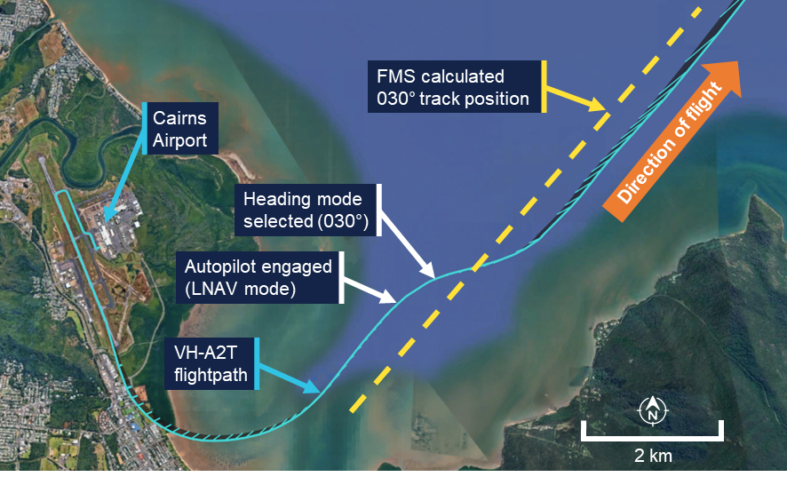
The aircraft continued climbing and turning left to follow the SID. As the aircraft climbed through about 840 ft above mean sea level (AMSL), the primary flight displays presented 2 radio altimeter alerts in quick succession and the engine indicating and crew alerting system (EICAS) presented ‘RADALT MISCOMPARE’ and ‘APPR 2 NOT AVAIL’ messages (see the section titled Radio altimeter). The crew noted these indications and determined that they were not relevant to that phase of flight and therefore took no action.
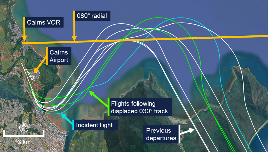
As the first officer manually turned the aircraft left to follow the SID, the aircraft followed a turn radius smaller than the flight management system’s (FMS) precalculated turn (see the section titled Flight instrumentation) and turned onto the SID 030° track[3] to the left of the FMS calculated track position (Figure 1). As the turn continued, the FMS targeted the wider track and the crew observed the flight director indications on the primary flight display unexpectedly command a right turn. The first officer briefly followed the right turn command by reducing the angle of bank from 24° left to 10° left before then increasing the angle back to 20° left to complete the turn.
Once the first officer established the aircraft on a 030° track, the autopilot was engaged while the flight director continued to indicate a right turn. The autopilot then started a right turn to intercept the FMS calculated 030° track position. At about the same time, air traffic control instructed the crew to change radio frequency. As the aircraft commenced the right turn, the captain identified the turn away from the SID track toward the high terrain and instructed the first officer to turn left to follow the 030° track. The first officer then engaged the autopilot heading mode and selected 030° and the aircraft turned left to a heading of 030° and continued climbing.
Figure 1: Departure flight path (initial)
Source: Recorded data from VH-A2T and Google Earth, annotated by the ATSB
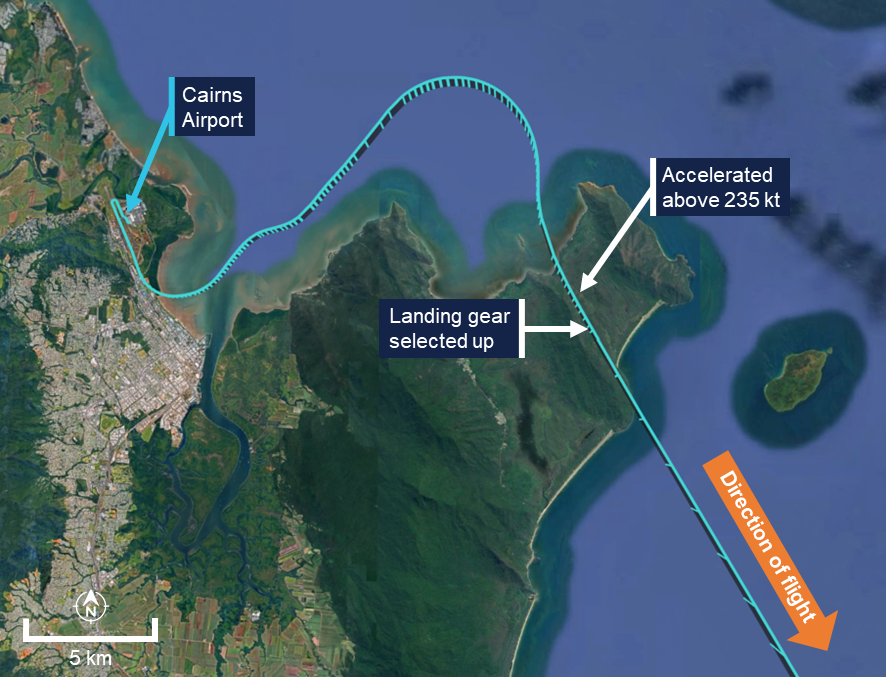
The aircraft then continued along the SID and after climbing above 4,000 ft AMSL, turned right toward the waypoint AKROM. As the aircraft continued climbing toward AKROM, the captain, whose headset was not noise-cancelling, noted that the ambient noise was louder than expected and recognised that the landing gear was still extended. At about the same time, the first officer noted the landing gear extended indication on the EICAS. In response, while the aircraft was accelerating through 243 kt – 8 kt above the maximum landing gear retraction speed of 235 kt – the captain retracted the landing gear without first checking the indicated airspeed. The landing gear completed retracting when the aircraft had reached a speed of 252 kt, 17 kt above the maximum retraction speed (Figure 2).
Figure 2: Departure flight path
Source: Recorded data from VH-A2T and Google Earth, annotated by the ATSB
The flight continued and, at 2044, the aircraft landed at Brisbane without further incident. Following the flight, the aircraft was inspected and found to be undamaged.
Context
Flight crew details
The captain held an Air Transport Pilot Licence (Aeroplane) and a class 1 aviation medical certificate. The captain had 15,192 hours of flying experience, of which 1,680 hours were on the Embraer 190 aircraft type, with 137 hours accrued in the previous 90 days.
The first officer held an Air Transport Pilot Licence (Aeroplane) and a class 1 aviation medical certificate. The first officer had 6,131 hours of flying experience, of which about 1,353 hours were on the Embraer 190 aircraft type, with 213 hours accrued in the previous 90 days.
The ATSB found no indicators that the flight crew were experiencing a level of fatigue known to adversely affect performance.
Operational information
Cairns Airport runway 15 AKROM 1 standard instrument departure
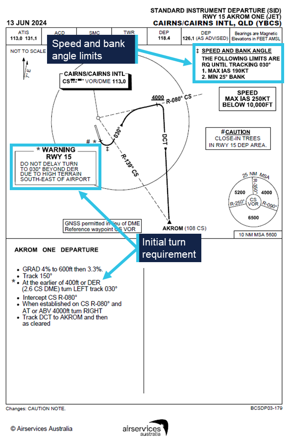
High terrain partly encircles Cairns Airport from the north-west through south-west and to the south-east. To avoid the high terrain, the AKROM 1 standard instrument departure (SID) required aircraft departing runway 15 to make a left turn at the earlier of either reaching 400 ft AMSL or passing the departure end of the runway (DER) (Figure 3). During the turn, flight crew needed to maintain a bank angle of at least 25° and a speed of no more than 190 kt until the aircraft was established on a track of 030°. The location of the 030° track was dependent upon both the position that the left turn was commenced and the radius of the turn. The departure required maintenance of the 030° track until intercepting the 080° radial of the Cairns very high frequency omni range navigation aid (VOR) and then followed that track until the aircraft climbed above 4,000 ft AMSL. The departure then turned to the waypoint AKROM.
Figure 3: Runway 15 AKROM 1 standard instrument departure
Source: Airservices Australia, annotated by the ATSB
Take-off standard operating procedures
The operator’s standard operating procedures manual (SOPM) required the pilot monitoring (PM) to verify a positive rate of climb immediately after take-off and then announce ‘positive rate’. After that announcement, the pilot flying (PF) confirmed the positive rate of climb and called for the landing gear to be retracted, and the PM then selected the landing gear ‘up’.
The SOPM also specified a normal rotation rate of 3° of pitch angle per second.
Aircraft information
The aircraft was an Embraer ERJ 190‑100 IGW, manufactured in Brazil in 2008 and issued serial number 19000179. It was registered in Australia as VH-A2T on 19 July 2024. The aircraft was fitted with 2 General Electric Company CF34-10E5 turbofan engines.
The maximum indicated airspeed at which the landing gear could be retracted or extended was 235 kt and the maximum airspeed with the landing gear in the extended position was 265 kt.
Flight instrumentation
The ERJ 190 was equipped with an integrated avionics system. VH-A2T was equipped with a ‘load 25’ version of the avionics. At the time of the incident, Alliance Airlines operated ERJ 190 aircraft equipped with both ‘load 25’ and upgraded ‘load 27’ avionics.
The flight management system (FMS) in ‘load 25’ equipped aircraft was designed to dynamically calculate the location of down path tracks, but only when these paths were inactive. Once the path became active, their location was fixed. The system should have predicted the 030° track leg of the AKROM 1 SID relative to where the system sequenced the 400 ft altitude crossing or departure end of the runway point. The avionics manufacturer, Honeywell, advised that in this case, the FMS sequenced the termination of the 400 ft altitude leg early and appeared to fix the location of the 030° track leg before it could be updated based on the position of the commencement of the left turn.
Subsequently, and as intended by design, the FMS did not recalculate the location of the 030° track during the turn. As a result, when the crew turned to the 030° track to the left of the FMS precalculated track, the FMS, still targeting the wider track, commanded a right turn to intercept that track (Figure 4).
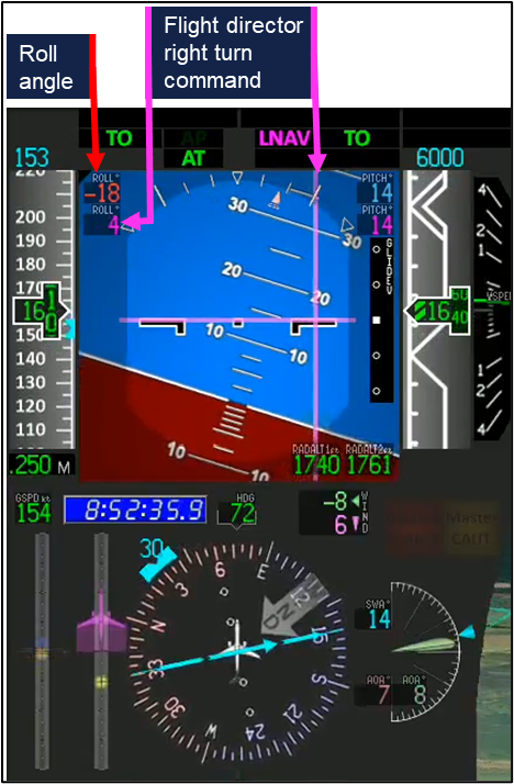
Figure 4: Representation of primary flight and navigation displays during the left turn
Note: The figure is based on an animation of the incident. The flight director representation is different to actual aircraft, and indications are included that are not presented in the actual aircraft. Negative roll values indicated a left turn, positive a right turn. Source: Embraer, annotated by the ATSB
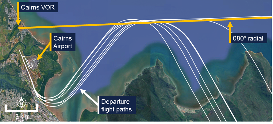
Recorded automatic dependent surveillance broadcast (ADS-B) data from previous AKROM 1 departures flown by VH-A2T identified 2 additional flights where the FMS had precalculated the 030° track at a wider location. On those occasions, the ADS-B data indicated that the flight crews followed the flight director commands and intercepted the wider track (Figure 5).
Figure 5: Departures of VH-A2T equipped with ‘load 25’ avionics
Source: Recorded data from VH-A2T and Google Earth, annotated by the ATSB
For ‘load 27’ equipped aircraft, the flight path was continuously updated as FMS track legs were flown and while in transition between them. This resulted in more accurate tracking of departure paths (Figure 6).
Figure 6: Departure paths of an E190 equipped with ‘load 27’ avionics
Source: Recorded data from VH-UYY and Google Earth, annotated by the ATSB
Radio altimeter
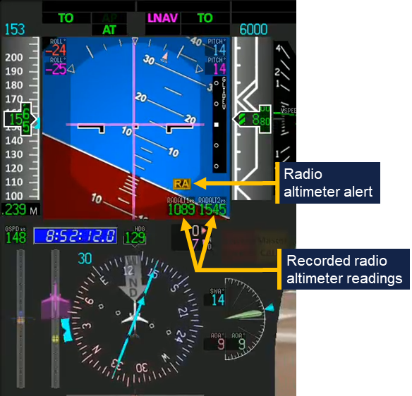
The Embraer ERJ 190 was fitted with 2 radio altimeters. These provided each crewmember with an indication of the height of the aircraft above underlying terrain measured using radio waves. When a difference in the height measured by the 2 radio altimeters exceeded a dynamic threshold, an ‘RA’ alert was presented on the primary flight display (Figure 7) and the RADALT MISCOMPARE alert was presented on the EICAS. Whenever this condition was detected, the associated EICAS message APPR 2 NOT AVAIL was also displayed.
Figure 7: Radio altimeter alert
Note: The figure is based on an animation of the incident and indications (such as the radio altimeter readings) are included that are not presented in the actual aircraft. Source: Embraer, annotated by the ATSB
United States Federal Aviation Administration Advisory Circular AC 25-7D Flight Test Guide for Certification of Transport Category Airplanes stated the following guidance and measurement conditions for radio altimeter certification:
32.1.5.5 Radio Altimeter System.
32.1.5.5.1 The radio altimeter system should display to the flightcrew, clearly and positively, the altitude information that indicates the airplane main landing gear wheel height above terrain.
32.1.5.5.2 Verify that the altimeters display altitude without loss of signal indications or excessive fluctuations, under the following measurement conditions:
• Pitch angle ±5° about the mean approach attitude.
• Roll angle zero to ±20°.
On departure from Cairns, the alerts were generated while the aircraft was operating over relatively flat terrain and when the aircraft’s pitch angle was about 14° nose up and the roll angle about 23° left. While the investigation did not determine the reason for the different radio altimeter readings that led to the radio altimeter alerts, the aircraft’s pitch and roll values at the time exceeded the guidance and measurement conditions specified in the FAA circular.
Light and meteorology
The departure was conducted in night visual meteorological conditions. The sun had set at 1802, 49 minutes before the departure, and the moon was below the horizon.
At the time of the departure, the Bureau of Meteorology automatic weather station at Cairns Airport recorded the temperature as 23°C and the wind as 9 kt from 161° magnetic. There was no recorded cloud, and visibility was recorded as 58 km.
Recorded data
Analysis of flight data from the flight data recorder fitted to VH‑A2T showed that the rotation rate during the take‑off was 1.49 degrees per second until the aircraft was pitched 9.7° nose up and then 1.73 degrees per second until 14.9° nose up. The pitch attitude stabilised at about 16° nose up during the turn.
As the aircraft turned left through a heading of 080°, the flight director began commanding a right turn (Figure 8). At 1853:08, the autopilot was engaged in the lateral navigation mode and while the flight director continued to command a right turn. The aircraft then rolled right, following that command. At 1853:20, while flying a heading of 058° the autopilot mode changed from lateral navigation mode to heading mode with 030° selected. The aircraft then began rolling left to turn to that heading.
At 1856:35, the landing gear was selected up at a speed of 243 kt. The landing gear completed the retraction sequence at 1856:47 as the aircraft accelerated to 252 kt.
Cockpit voice recorder data capturing the incident was not available as it had been overwritten.
Figure 8: Recorded flight data
Source: ATSB
Safety analysis
Non-retraction of landing gear
During the take-off, the first officer rotated the aircraft slower than required, prompting the captain to call for an increase in pitch rate. The captain’s attention then remained focused on monitoring the pitch attitude of the aircraft throughout the rotation manoeuvre to ensure the required pitch attitude targets were being achieved. Because of this, the captain likely did not have sufficient opportunity to move onto the next task, verifying the aircraft’s positive rate of climb, before it passed through 400 ft – the point at which the terrain avoidance turn was to be initiated. Consequently, the task step of verifying and announcing positive climb performance was not fully completed and the captain did not make the ‘positive rate’ announcement.
In the absence of the captain’s announcement, the first officer was not prompted to request landing gear retraction, and the landing gear remained extended. The captain’s announcement of ‘pitch rate’ at about the same time that the acoustically and semantically similar ‘positive rate’ announcement would normally be made, potentially caused interference in working memory (Lentoor 2023) and possibly gave both flight crew a false sense that the latter action had been successfully performed.
Delayed identification and overspeed
During the initial climb, which was a high workload phase of the flight, abnormal radio altimeter alerts and unexpected flight director indications further increased the flight crew’s workload. In particular, when the autopilot was engaged, it commenced a right turn toward high terrain in response to an unexpected flight director indication. This prompted the captain’s intervention and the crew’s attention then narrowed to focus on parameters which would enable them to verify the aircraft’s lateral tracking performance. Wickens (2009, 2021) notes that attentional tunnelling occurs under conditions of elevated stress and deliberate task focus and can cause other task-relevant stimuli to be ignored.
Consequently, increasing flight deck wind noise and abnormal engine indicating and crew alerting system (EICAS) indications, both of which provided an indication of the landing gear’s extended state, were not initially detected. Furthermore, the turn and speed restrictions of the departure also likely masked the performance degradation due to the extended landing gear, further reducing the likelihood of identifying that it was still extended.
As the flight crew’s workload decreased in the latter portion of the departure, the effects of attentional tunnelling reduced, and the noise from the landing gear increased as the aircraft accelerated. The captain (whose headset was not noise-cancelling) then detected the increased cockpit wind noise and was alerted to the misconfiguration of the landing gear. At about the same time, the first officer identified the landing gear extended indication on the EICAS.
As the aircraft had travelled well beyond the normal gear retraction point and was accelerating, the captain likely perceived some urgency to act upon noticing that the landing gear was still extended and experienced associated increased stress. Under such conditions research has shown that people often do not make optimal decisions and may act more reflexively (Dismukes and others, 2007).
Under time pressure and stress, experts may revert to a recognition primed decision mode (Klein, 2014), making rapid and intuitive interpretations of a situation and selecting actions based on their most familiar experiences.
The landing gear was normally retracted well below the retraction limiting speed, and this speed was not normally checked by the other crew member. Therefore, the captain reverted to their most familiar experience and initiated gear retraction without first confirming the action with the first officer and did not check the gear retraction limiting speed. Consequently, the landing gear retraction was initiated 8 kt above the 235 kt retraction limit speed and the retraction completed 17 kt above that speed.
Findings
ATSB investigation report findings focus on safety factors (that is, events and conditions that increase risk). Safety factors include ‘contributing factors’ and ‘other factors that increased risk’ (that is, factors that did not meet the definition of a contributing factor for this occurrence but were still considered important to include in the report for the purpose of increasing awareness and enhancing safety). In addition ‘other findings’ may be included to provide important information about topics other than safety factors.
These findings should not be read as apportioning blame or liability to any particular organisation or individual.
From the evidence available, the following findings are made with respect to the landing gear overspeed involving Embraer E190, VH-A2T on 24 July 2025.
Contributing factors
After take-off, the pilot monitoring made a 'pitch rate' announcement at a time when a 'positive rate' announcement would normally be expected. This resulted in both flight crewmembers focusing on the pitch angle and the pilot flying was not prompted to call for gear retraction. Subsequently the crew's attention was focused on following the departure flight path and the landing gear was not retracted.
As the aircraft turned left to follow the standard instrument departure, abnormal radio altimeter indications were presented, and the flight management system unexpectedly commanded a right turn. When the autopilot was engaged, the aircraft briefly followed the commanded turn before the captain intervened. These distractions increased the flight crew's workload and delayed their identification of the extended landing gear.
After recognising that the landing gear was still extended, the captain reflexively retracted the landing gear at a speed above the maximum landing gear retraction speed.
Safety actions
Whether or not the ATSB identifies safety issues in the course of an investigation, relevant organisations may proactively initiate safety action in order to reduce their safety risk. The ATSB has been advised of the following proactive safety action in response to this occurrence.
Safety action by Alliance Airlines
Alliance Airlines has accelerated its program to upgrade E190 aircraft from load 25 avionics to load 27 and at the time of the release of this report, all E190s in the Alliance Airlines fleet have been upgraded. This should prevent recurrence of the unexpected flight management system indications presented to the crew during this incident.
In addition, the load 27 avionics upgrade incorporated electronic checklists that require associated actions to be undertaken before the electronic checklist is completed.
Sources and submissions
Sources of information
The sources of information during the investigation included:
the flight crew
Alliance Airlines
the aircraft and avionics manufacturers
Bureau of Meteorology
recorded data from VH-A2T.
References
Dismukes, R., Goldsmith, T. E., & Kochan, J. A. (2015). Effects of acute stress on aircrew performance: literature review and analysis of operational aspects. National Aeronautics and Space Administration Technical Memorandum, NASA/TM-2015-218930.
Klein, G. (2014). The recognition-primed decision (RPD) model: Looking back, looking forward. In Naturalistic decision making (pp. 285-292). Psychology Press.
Lentoor, A. G. (2023). Cognitive and neural mechanisms underlying false memories: misinformation, distortion or erroneous configuration? AIMS neuroscience, 10(3), 255.
Wickens, C. D., & Alexander, A. L. (2009). Attentional tunnelling and task management in synthetic vision displays. The international journal of aviation psychology, 19(2), 182-199.
Wickens, C. D., & Carswell, C. M. (2021). Information processing. In Handbook of human factors and ergonomics (pp. 114-158). John Wiley & Sons.
Submissions
Under section 26 of the Transport Safety Investigation Act 2003, the ATSB may provide a draft report, on a confidential basis, to any person whom the ATSB considers appropriate. That section allows a person receiving a draft report to make submissions to the ATSB about the draft report.
A draft of this report was provided to the following directly involved parties:
the flight crew
Alliance Airlines
the aircraft manufacturer
the avionics manufacturer
Civil Aviation Safety Authority
the United States National Transportation Safety Board.
Submissions were received from:
the flight crew
Alliance Airlines
the aircraft manufacturer
Civil Aviation Safety Authority.
The submissions were reviewed and, where considered appropriate, the text of the report was amended accordingly.
Purpose of safety investigations
The objective of a safety investigation is to enhance transport safety. This is done through:
identifying safety issues and facilitating safety action to address those issues
providing information about occurrences and their associated safety factors to facilitate learning within the transport industry.
It is not a function of the ATSB to apportion blame or provide a means for determining liability. At the same time, an investigation report must include factual material of sufficient weight to support the analysis and findings. At all times the ATSB endeavours to balance the use of material that could imply adverse comment with the need to properly explain what happened, and why, in a fair and unbiased manner. The ATSB does not investigate for the purpose of taking administrative, regulatory or criminal action.
About ATSB reports
ATSB investigation reports are organised with regard to international standards or instruments, as applicable, and with ATSB procedures and guidelines.
Reports must include factual material of sufficient weight to support the analysis and findings. At all times the ATSB endeavours to balance the use of material that could imply adverse comment with the need to properly explain what happened, and why, in a fair and unbiased manner.
An explanation of terminology used in ATSB investigation reports is available here. This includes terms such as occurrence, contributing factor, other factor that increased risk, and safety issue.
Publishing information
Released in accordance with section 25 of the Transport Safety Investigation Act 2003
Ownership of intellectual property rights in this publication
Unless otherwise noted, copyright (and any other intellectual property rights, if any) in this report publication is owned by the Commonwealth of Australia.
Creative Commons licence
With the exception of the Commonwealth Coat of Arms, ATSB logo, and photos and graphics in which a third party holds copyright, this report is licensed under a Creative Commons Attribution 4.0 International licence.
The CC BY 4.0 licence enables you to distribute, remix, adapt, and build upon our material in any medium or format, so long as attribution is given to the Australian Transport Safety Bureau.
Copyright in material obtained from other agencies, private individuals or organisations, belongs to those agencies, individuals or organisations. Where you wish to use their material, you will need to contact them directly.
[1]Pilot flying (PF) and pilot monitoring (PM): procedurally assigned roles with specifically assigned duties at specific stages of a flight. The PF does most of the flying, except in defined circumstances, such as planning for descent, approach and landing. The PM carries out support duties and monitors the PF’s actions and the aircraft’s flight path.
[2]Rotation: the positive, nose-up, movement of an aircraft about the lateral (pitch) axis immediately before becoming airborne.
[3]All tracks and headings mentioned in the report are magnetic.
On the evening of 2 July 2025, a Virgin Australia Airlines Boeing 737‑800 aircraft, registered VH-YFZ, operated a scheduled passenger flight from Sydney, New South Wales, to Melbourne, Victoria.
During the arrival into Melbourne, the aircraft exceeded 2 speed limitations on the standard terminal arrival route, and air traffic control issued 2 speed reduction instructions, likely to maintain separation from traffic.
Perceiving the ATC instructions to be urgent, the crew hastened the conduct of the approach actions and missed arming the speedbrake and performing the landing checks. As the aircraft descended below 1,000 ft above airfield elevation the crew assessed the approach to be stable and continued, resulting in the aircraft landing with the speedbrake not armed, which resulted in it not automatically deploying. Noticing this, the captain moved their hand to the lever to raise it manually. However, the speedbrake simultaneously automatically deployed as the first officer selected reverse thrust. Thereafter the aircraft’s deceleration was sufficient, and the flight concluded without further incident.
What the ATSB found
The ATSB found that the flight crew allowed the aircraft to exceed speed limitations on the arrival, resulting in air traffic control requiring them to reduce speed. The crew were slow to take positive steps to reduce speed requiring ATC to instruct them to slow further. The crew’s attention became focused on achieving the requested speed reductions, which likely resulted in them omitting to arm the speedbrake and conduct the landing checks.
As the aircraft passed 1,000 ft above airfield elevation, neither flight crew recognised that the speedbrake was not armed and the landing checklist had not been completed, resulting in the approach continuing despite the stabilised approach criteria not being met.
Safety message
Threat and error management (TEM) principles state that flight crews' proactive management of workload throughout the flight is a key defence against capacity and attention-related errors.
Checklists are a vital defence against human error and are integral to maintaining flight safety. This occurrence highlights the importance of adhering to standard operating procedures and ensuring checklists are conducted at the appropriate times.
Many of the speed limitations built into approach procedures are designed to facilitate predictable traffic flows and manage both controller and flight crew workloads. Exceeding the published approach speeds without clearance compromises this risk control and introduces the threat of additional workload and demands on attentional resources.
Many transport jets, such as the 737-800, have a limited capacity to simultaneously descend and decelerate when in a clean configuration. In some modes and flight conditions the aircraft’s autopilot system will be unable to meet altitude and airspeed constraints contained in arrival and approach procedures. The flight crew must therefore be vigilant in monitoring and managing the aircraft’s descent profile and energy condition and be ready to intervene as necessary.
Correct management of the aircraft’s profile and energy during the descent is an effective countermeasure against approach and landing accidents. The Flight Safety Foundation (2000) provides guidance to flight crew on this matter (FSF ALAR Briefing Note 4.1 – Descent-and-approach Profile Management) as part of its broader approach and landing accident reduction (ALAR) toolkit.
The investigation
The ATSB scopes its investigations based on many factors, including the level of safety benefit likely to be obtained from an investigation and the associated resources required. For this occurrence, the ATSB conducted a limited-scope investigation in order to produce a short investigation report, and allow for greater industry awareness of findings that affect safety and potential learning opportunities.
The occurrence
On 2 July 2025, a Virgin Australia Airlines Boeing 737-800 aircraft, registered VH-YFZ, was operating a scheduled passenger flight,[1] VA882, from Sydney, New South Wales, to Melbourne, Victoria. On board were the captain as pilot monitoring (PM),[2] first officer as pilot flying (PF), 4 cabin crew and 170 passengers.
At 2040 local time the aircraft commenced an initial descent from its cruising altitude with a clearance from the Melbourne centre air traffic controller (ATC) to track via the BOOIN ONE ALPHA standard terminal arrival route (STAR) (Figure 1). ATC did not remove any of the speed restrictions associated with the arrival.
Seven minutes later, descending through flight level 140,[3] the aircraft was transferred to the Melbourne approach ATC, who cleared the flight for further descent via the STAR, initially to 5,000 ft, and soon after to 3,000 ft. ATC also issued a clearance for the ground based augmentation system (GBAS) landing system (GLS)[4] approach to runway 16, but again did not remove any speed restrictions.
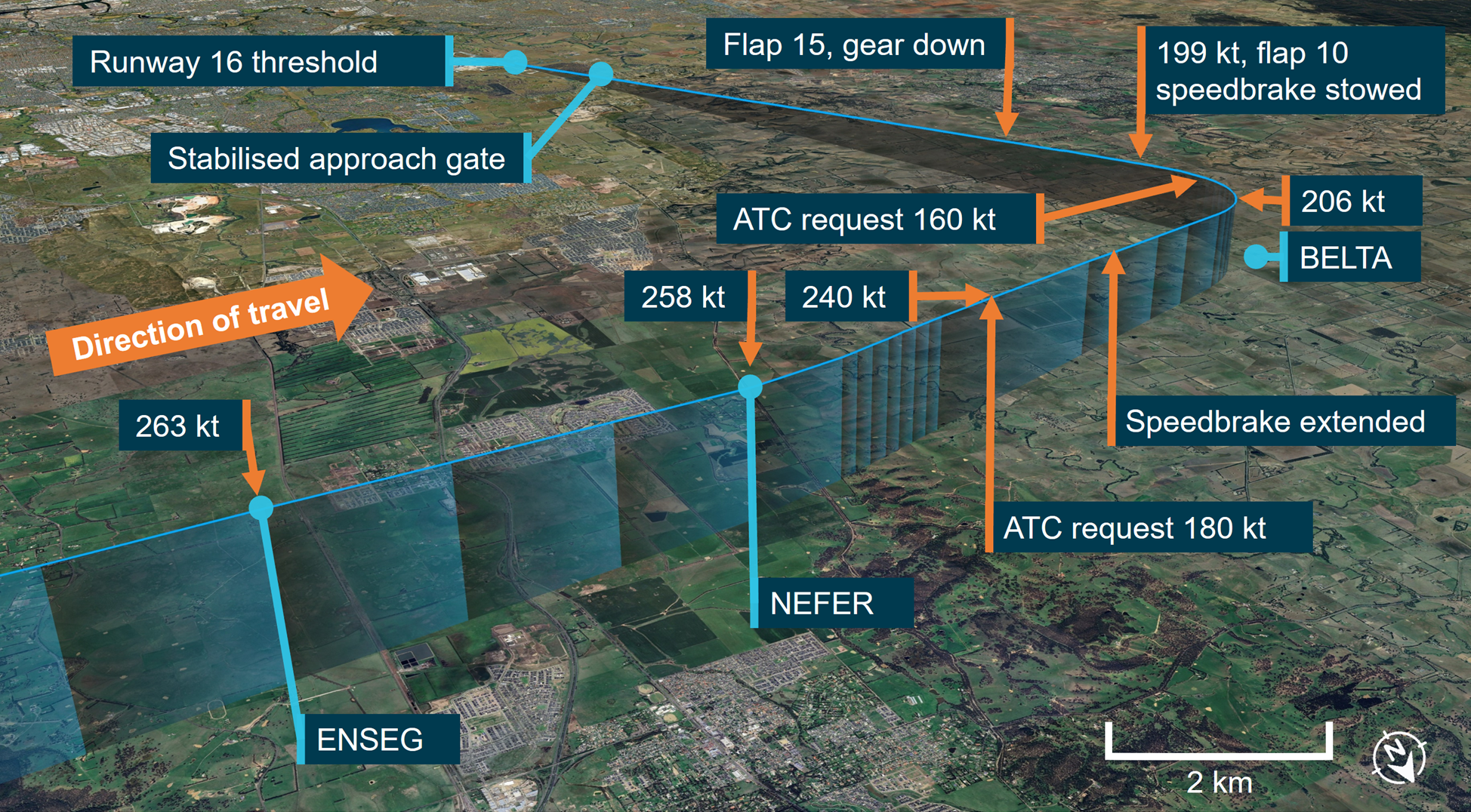
With the autopilot engaged in VNAV PTH pitch mode (see the section titled Automatic flight modes), the aircraft’s descent was momentarily arrested at 10,000 ft, to decelerate to less than the maximum speed constraint of 250 kt below that altitude. However, as the airspeed decreased to about 260 kt, the autopilot recommenced the descent, and the aircraft’s deceleration ceased. Subsequently, the aircraft crossed the ENSEG waypoint,[5] located approximately 21 track miles from the runway threshold at 263 kt, 33 kt above the speed required at that waypoint by the arrival procedure.
When the aircraft was approximately 15 track miles from the runway threshold, around 4 NM from initial approach fix BELTA and descending through 5,250 ft above mean sea level (AMSL), ATC instructed the flight crew to reduce their speed to 180 kt. At this stage, the aircraft was in a clean configuration[6] and slowly decelerating through 240 kt. Shortly thereafter the flight crew began to extend the initial stages of flap and deployed the speedbrake.
Figure 1: BOOIN ONE ALFA standard instrument arrival procedure chart
The chart shows graphical section of the STAR with the applicable speed restrictions highlighted in red by the ATSB. Source: Airservices Australia
Just over one minute later, as the aircraft was abeam BELTA and midway through the turn to the final approach course, ATC requested a further reduction in speed to 160 kt, likely for traffic separation. The crew perceived the ATC request to be urgent and began selecting flaps earlier than normal to arrest the aircraft’s speed. The aircraft passed abeam BELTA, with the speedbrakes still deployed, decelerating through 206 kt and descending through an altitude of 4,000 ft AMSL.
Shortly after passing BELTA at 199 kt, flap 10 was selected, and then the speedbrake was stowed. Twenty seconds later, at approximately 9.5 NM from the runway threshold and descending through 3,650 ft AMSL, flap 15 was selected and the landing gear was extended. While the operator’s standard procedures call for the speedbrake lever to be placed into the armed position after the selection of flap 15, it remained in the stowed position for the remainder of the approach.
The flight crew selected the landing flap configuration of 30, approximately 8.5 NM from the runway threshold at 3,330 ft AMSL, but did not action the landing checks, as called for in the operator’s standard procedures.
Figure 2: Aircraft flight path and key events during the transition from the arrival to the approach procedure
Source: Google Earth and Flightradar24, annotated by the ATSB
The aircraft descended through the 1,000 ft above airfield elevation stabilised approach gate (see the section titled Stabilised approach requirements) on the GLS course and glideslope, with the airspeed stable at 150 kt, but with the speedbrake lever still in the stowed position and the landing checks incomplete. The crew advised the ATSB that the stabilised approach criteria were assessed, but neither crewmember recognised that they had not been met. As a result, they continued the approach.
Upon touchdown, the captain sighted the speedbrake lever and noted that it had not automatically moved to the deployed position. As they moved their hand to the lever with the intention of manually extending the speedbrakes, the lever began to automatically deploy, coincident with the first officer selecting reverse thrust.
The aircraft decelerated normally and exited the runway. As the flight crew began their post‑landing actions, the captain noted that the line pointers on both yoke‑mounted checklists had not been moved below the bottom of the approach checks, signalling that the landing checks had not been completed. After manoeuvring the aircraft onto the stand and shutting down the engines, the flight crew discussed what they thought had probably happened. The first officer was unaware that the speedbrake had not been armed prior to landing, nor that the landing checks had not been performed.
Context
Flight crew background
The captain and first officer both held an air transport pilot licence (aeroplane) and a class 1 aviation medical certificate. The captain had around 13,600 total flight hours (5,500 on the 737), and the first officer had just over a total of 3,000 hours at the time of the incident. The flight was the captain’s first in almost a month, having been away from work on annual leave. They advised that although they were comfortable with the flight, they felt slightly below their normal performance capability.
Aircraft information
VH-YFZ was a Boeing 737-800, serial number 41005, manufactured in the United States in 2017. The 176-seat aircraft was fitted with 2 CFM International CFM56-7B24E turbofan engines.
Speedbrake system
The Boeing 737-800 speedbrake system is comprised of 6 hydraulically-actuated spoiler panels on the upper surface of each wing, 4 flight spoilers and 2 ground spoilers. In flight, only the flight spoilers may be extended, and are used symmetrically across the wings to increase drag. On the ground, both flight and ground spoilers may be extended to assist with deceleration.
The 737 NG Flight crew training manual stated that:
The use of speedbrakes with flaps extended should be avoided, if possible. With flaps 15 or greater, the speedbrakes should be retracted. If circumstances dictate the use of speedbrakes with flaps extended, high sink rates during the approach should be avoided. Speedbrakes should be retracted before reaching 1,000 feet AGL [above ground level].
Operation of the speedbrakes is achieved via the speedbrake lever. This lever can also be set in the ARMED position. In flight this will not result in speedbrake extension, however after landing, when the conditions are met, all spoiler panels will automatically raise to their maximum extent.
Normally, for the speedbrake system to operate automatically during landing, the following set of conditions must be met:
speedbrake lever in the armed position and the light illuminated
radio altitude less than 10 ft
landing gear strut compressed
both thrust levers retarded to idle
main landing gear wheels spun up (more than 60 kt).
However, if the speedbrake lever is not in the armed position during landing, the speedbrake system will also automatically operate when the following conditions are met:
main landing gear wheels spun up (more than 60 kt)
both thrust levers retarded to idle
reverse thrust levers positioned for reverse thrust.
Automatic flight modes
The aircraft’s automatic flight system consisted of the autopilot flight director system (AFDS) and autothrottle (A/T). They could be used together in a number of distinct modes to achieve lateral and vertical navigation, and speed management. For descents, a vertical navigation mode could be selected via the VNAV switch on the mode control panel (MCP). The aircraft’s flight management computer (FMC) would command the AFDS pitch and A/T to fly a pre‑programmed vertical profile, attempting to accommodate waypoint altitude and airspeed constraints.
In most scenarios, selecting VNAV engaged the VNAV PTH mode, where maintenance of vertical flightpath was prioritised over airspeed. In certain situations, such as steep descent profiles in clean configuration, the aircraft may be unable to decelerate or maintain airspeed limits, even with idle thrust. In these situations, VNAV PTH mode would seek to achieve the programmed descent path, including altitude constraints, and may allow the airspeed to increase within broad limits, before reverting to a speed prioritised mode (VNAV SPD).
Standard operating procedures
Approach configuration sequence
The operator’s 737 NG Flight Crew Operations Manual (FCOM) specified a normal sequence of flight crew actions for a GLS approach, as well as the areas of the flight deck for which each flight crew member was responsible.
When the first officer was operating as the pilot flying, it was their responsibility to move the speedbrake lever to the ARM position and verify the status of the corresponding annunciator, prior to landing. At around 2,000 ft above airfield elevation, the normal procedure specified that the speedbrake arming action should occur, immediately after the pilot flying called for ‘Gear Down’ and ‘Flaps 15’.
The normal procedure also specified that it was the pilot flying’s responsibility to call for the landing checklist to be completed at around 1,500 ft above airfield elevation. This should normally occur as part of a second block of configuration actions, immediately after the pilot flying called for the landing flap to be set and the threshold target speed to be bugged.
The Quick Reference Handbook (QRH) section of the FCOM specified the normal landing checklist, and contained the following items, all to be confirmed by the pilot flying:
Engine start switches………………………..CONT
Speedbrake………………………………......ARMED
Landing gear………………………………….Down
Flaps……………………………………..……Green light
A checklist and movable position marker were mounted to each of the aircraft’s control yokes. The occurrence happened at night in a darkened cockpit and the checklists did not have backlighting.
Stabilised approach requirements
The operator’s normal procedures for a GLS approach called for the flight crew to assess the approach against stabilisation criteria at 1,000 ft above airfield elevation and initiate a missed approach if the conditions were not met. The criteria were specified under the operator’s stabilised approach policy, contained within their general operating policies and procedures manual. They were as follows:
briefings and normal checklists completed
aircraft in the correct landing configuration
aircraft on the correct lateral and vertical flight path
sink rate, no greater than 1,000 fpm
thrust setting appropriate for the aircraft configuration and trajectory
speed within -5 kt to +10 kt of the speed target.
Instrument arrival procedure speed restrictions
The STAR contained several speed limitations (Figure 1). Airservices Australia’s Aeronautical Information Publication (AIP) Enroute 1.5 - 47 included the following requirements:
10.2.1 Unless explicitly cancelled or amended by ATC, the pilot must follow the vertical and lateral profile of the STAR and comply with any published speed restrictions.
On this occasion ATC did not cancel the speed restrictions when clearing the flight to conduct the STAR.
Safety analysis
The flight crew used the autopilot’s vertical navigation path (VNAV PTH) mode and auto throttle to manage the aircraft’s descent profile and airspeed for the arrival.
On this occasion, and as per expected system performance, in a clean configuration, the autopilot was unable to sufficiently reduce speed such that it could simultaneously meet the descent profile and airspeed requirements of the arrival procedure. With no additional drag added by the flight crew, the aircraft continued to maintain an airspeed around 30 kt higher than the speed restrictions in the STAR, until the air traffic controller issued a speed reduction instruction and the flight crew modified the aircraft’s configuration.
The crew perceived the ATC instruction to be urgent and advised that this increased their workload. It is likely the crew focused their attention on monitoring the airspeed and ensuring the flaps were extended promptly, but within their operational limits. Wickens (2021) describes attentional narrowing as a focus on a limited set of information at the expense of other sources. This focus can cause steps in the linear sequence of a procedure to be skipped.
As the aircraft was decelerated to final approach speed and configured for landing earlier than normal, it is probable that the crew omitted to arm the speedbrake and call for the landing checks because their attention was focused on achieving the ATC‑requested airspeed reduction. Compounding this, the captain perceived that their monitoring performance was modestly degraded due to a lack of recent flying experience.
During the final segment of the approach, while the aircraft was on the approach path and the speed had reduced to the required approach speed, the aircraft did not meet all the stabilised approach criteria since the landing checklist had not been completed, and the speedbrake was not in the armed position.
Findings
ATSB investigation report findings focus on safety factors (that is, events and conditions that increase risk). Safety factors include ‘contributing factors’ and ‘other factors that increased risk’ (that is, factors that did not meet the definition of a contributing factor for this occurrence but were still considered important to include in the report for the purpose of increasing awareness and enhancing safety). In addition ‘other findings’ may be included to provide important information about topics other than safety factors.
These findings should not be read as apportioning blame or liability to any particular organisation or individual.
From the evidence available, the following findings are made with respect to the incorrect landing configuration involving Boeing 737, VH-YFZ, near Melbourne Airport, Victoria, on 2 July 2025.
Contributing factors
The aircraft exceeded speed restrictions during the arrival and the crew did not take appropriate action to slow the aircraft in a timely manner. This resulted in the air traffic controller issuing instructions to reduce speed further and the crew subsequently not arming the speedbrake and performing the landing checks.
As the aircraft passed 1,000 ft above airfield elevation, neither flight crew recognised that the speedbrake was not armed and the landing checklist had not been completed, resulting in the approach continuing despite the stabilised approach criteria not being met.
Sources and submissions
Sources of information
The sources of information during the investigation included:
the pilots of the incident flight
operational documentation from Virgin Australia Airlines
Airservices Australia
ADS-B data from Flightradar24
recorded data from the aircraft Quick Access Recorder.
Wickens, C. (2021). Attention: Theory, principles, models and applications. International Journal of Human–Computer Interaction, 37(5), 403-417.
Submissions
Under section 26 of the Transport Safety Investigation Act 2003, the ATSB may provide a draft report, on a confidential basis, to any person whom the ATSB considers appropriate. That section allows a person receiving a draft report to make submissions to the ATSB about the draft report.
A draft of this report was provided to the following directly involved parties:
the pilots of the incident flight
Virgin Australia Airlines
Civil Aviation Safety Authority.
Submissions were received from:
the pilots of the incident flight
Virgin Australia Airlines.
The submissions were reviewed and, where considered appropriate, the text of the report was amended accordingly.
Purpose of safety investigations
The objective of a safety investigation is to enhance transport safety. This is done through:
identifying safety issues and facilitating safety action to address those issues
providing information about occurrences and their associated safety factors to facilitate learning within the transport industry.
It is not a function of the ATSB to apportion blame or provide a means for determining liability. At the same time, an investigation report must include factual material of sufficient weight to support the analysis and findings. At all times the ATSB endeavours to balance the use of material that could imply adverse comment with the need to properly explain what happened, and why, in a fair and unbiased manner. The ATSB does not investigate for the purpose of taking administrative, regulatory or criminal action.
About ATSB reports
ATSB investigation reports are organised with regard to international standards or instruments, as applicable, and with ATSB procedures and guidelines.
Reports must include factual material of sufficient weight to support the analysis and findings. At all times the ATSB endeavours to balance the use of material that could imply adverse comment with the need to properly explain what happened, and why, in a fair and unbiased manner.
An explanation of terminology used in ATSB investigation reports is available here. This includes terms such as occurrence, contributing factor, other factor that increased risk, and safety issue.
Publishing information
Released in accordance with section 25 of the Transport Safety Investigation Act 2003
Ownership of intellectual property rights in this publication
Unless otherwise noted, copyright (and any other intellectual property rights, if any) in this report publication is owned by the Commonwealth of Australia.
Creative Commons licence
With the exception of the Commonwealth Coat of Arms, ATSB logo, and photos and graphics in which a third party holds copyright, this report is licensed under a Creative Commons Attribution 4.0 International licence.
The CC BY 4.0 licence enables you to distribute, remix, adapt, and build upon our material in any medium or format, so long as attribution is given to the Australian Transport Safety Bureau.
Copyright in material obtained from other agencies, private individuals or organisations, belongs to those agencies, individuals or organisations. Where you wish to use their material, you will need to contact them directly.
[1]The flight departed Sydney at 1935 local time, 35 minutes later than the scheduled departure time, after weather conditions in the Sydney area had caused disruptions and delays to traffic movements.
[2]Pilot Flying (PF) and Pilot Monitoring (PM): procedurally assigned roles with specifically assigned duties at specific stages of a flight. The PF does most of the flying, except in defined circumstances; such as planning for descent, approach and landing. The PM carries out support duties and monitors the PF’s actions and the aircraft’s flight path.
[3]Flight level: at altitudes above 10,000 ft in Australia, an aircraft’s height above mean sea level is referred to as a flight level (FL). FL 140 equates to 14,000 ft.
[4]GLS: a GBAS Landing System (GLS) is an alternative to the Instrument Landing System and uses the Global Navigation Satellite System (GNSS), augmented by an airport ground station, to provided suitably equipped aircraft with precision approach guidance.
[5]Waypoint: a specific geographical location, defined by latitude and longitude coordinates, that is used to define an aircraft’s flight path
[6]Clean configuration: an aircraft is in a clean configuration when all external drag‑inducing equipment, such as landing gear, flaps and spoilers, are retracted.
On 12 February 2025, Alliance Airlines Embraer E190, VH-UYO, was operating Qantas flight QF1888 from Cairns, Queensland to Darwin, Northern Territory. At 1634 local time, passing the initial approach fix for the instrument landing system (ILS) approach to Darwin Airport’s runway 29, the auto‑flight system approach mode unexpectedly disarmed and reverted to basic flight director modes. The aircraft then deviated right and then left of the ILS course, before intercepting the lateral course at about the final approach fix.
Passing 1,000 ft above aerodrome elevation, the aircraft was above the glideslope, at a high rate of descent and high airspeed. The flight crew elected to continue the approach, as the aircraft was then in visual meteorological conditions. Passing 500 ft, the flight crew assessed that the aircraft was stabilised, although still too fast. The pilot monitoring subsequently identified that the flaps were not in the landing configuration and selected the correct position. The flight crew continued the approach and conducted an uneventful landing.
What the ATSB found
The ATSB found that on crossing the initial approach fix for the ILS approach, due either to a system synchronisation issue or the pilot flying inadvertently disarming the approach mode, the aircraft’s auto‑flight system reverted to roll and flight path angle modes.
Following the unexpected mode change, the pilot flying did not reengage approach mode or disconnect the autopilot. This likely contributed to the aircraft deviating outside the required lateral tolerance of the approach below the minimum safe altitude while in instrument meteorological conditions.
Additionally, the ATSB found that the flight crew did not discontinue the approach when the aircraft was unstable at the 1,000 ft stabilisation height as they incorrectly assessed that they could continue to 500 ft in visual meteorological conditions with multiple stabilised approach criteria unmet.
In the limited time available to stabilise the aircraft by 500 ft, the flight crew incorrectly assessed that the aircraft was stable and continued the approach, unaware that the pilot monitoring had inadvertently selected an incorrect flap configuration.
Finally, the ATSB found that Alliance Airlines' standard operating procedures were unclear about the criteria for continuing an unstable instrument approach to 500 ft when aircraft entered visual conditions.
What has been done as a result
Following this incident, Alliance Airlines issued an operations notice ‘to improve clarity and compliance’ with the stabilised approach criteria. The notice detailed the stabilised approach policy. It also amended the stabilisation height such that for 3‑dimensional and 2‑dimensional instrument approaches, and straight‑in visual approaches, the stabilised criteria were to be met by 1,000 ft above aerodrome elevation. The 500 ft stabilisation height applied only to a visual circuit or circling manoeuvre approaches. The notice reminded flight crew of Alliance’s ‘non punitive go‑around policy’ and required all unstable approaches to be reported. Finally, Alliance Airlines conducted a flight data review of unstable approaches over the previous 6 months operations to identify similar occurrences.
Safety message
The Flight Safety Foundation’s (FSF) Reducing the risk of runway excursions report found that, in the 16 years to 2009, the most common accident was a runway excursion, accounting for 33% of all aircraft accidents. The highest risk factor for runway excursions was identified as an unstable approach. Further, an FSF survey (Normalization of Deviance) identified that only 3–4% of approaches were unstable but that in over 97% of those, the flight crews did not conduct a go-around. It stated:
Noncompliance with standard operating procedures (SOPs) — especially tolerance of unstabilized approaches — is a serious impediment to further reduction of accident risk.
Guidance from the International Air Transport Association for preventing unstable approaches stated that pilots must be trained to understand the risks of an unstable approach, because an unstable approach can be completed successfully, which may reinforce bad practice.
Additionally, this incident highlights how important continuous attention to automatic flight system modes displayed on the primary flight display is to the maintenance of situation awareness.
This incident also illustrates the need for effective flight crew monitoring. The Flight Safety Foundation identified that monitoring can be improved by standard operating procedures, increased emphasis and practice, and stated:
One of the most important aspects of a safe flight operation is the requirement for crewmembers to carefully monitor the aircraft’s flight path and systems, as well as actively cross-check each other’s actions.
The investigation
The ATSB scopes its investigations based on many factors, including the level of safety benefit likely to be obtained from an investigation and the associated resources required. For this occurrence, the ATSB conducted a limited-scope investigation in order to produce a short investigation report, and allow for greater industry awareness of findings that affect safety and potential learning opportunities.
The occurrence
On the afternoon of 12 February 2025, Alliance Airlines (Alliance) Embraer ERJ 190‑100 IGW (E190), registered VH‑UYO, was operating Qantas flight QF1888 from Cairns, Queensland to Darwin, Northern Territory. On board were 2 flight crew, 2 cabin crew and 49 passengers. The captain was the pilot flying (PF), and the first officer was the pilot monitoring (PM).[1]
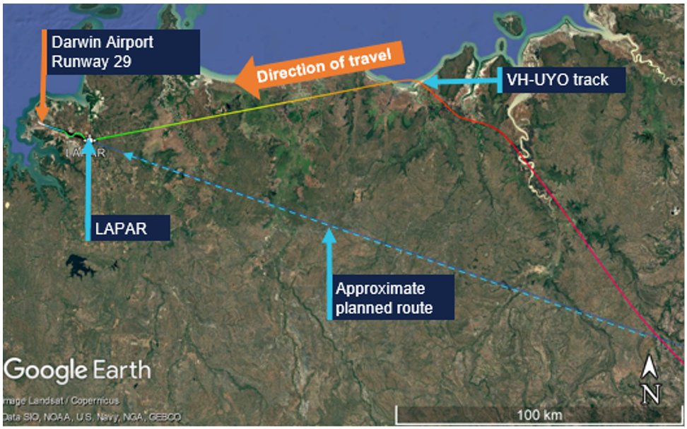
After departing Cairns, the aircraft climbed to cruise at flight level (FL) 340.[2] En route the flight crew obtained air traffic control (ATC) clearances, first to deviate up to 30 NM (56 km) left, and later up to 50 NM (93 km) right of the planned route to avoid hazardous weather. At 1614 Darwin local time the flight crew received clearance to descend to FL 120. Just over 2 minutes later they requested a further clearance to deviate up to 60 NM (111 km) right to avoid weather.
At 1619 the flight crew requested, and received, a clearance to deviate up to 70 NM (130 km) right of route and to track direct to waypoint LAPAR, once clear of the weather. About 2 minutes later, descending through FL 190, the aircraft turned left from a position about 30 NM (56 km) right of the planned route, to track 60 NM (111 km) direct to LAPAR (Figure 1).
Figure 1: VH-UYO recorded flight data showing weather diversion and tracking to LAPAR
Source: Google Earth overlaid with FlightRadar24 data, annotated by the ATSB
At 1622 the PM contacted Darwin Approach ATC, advised they were descending to FL 120, had received automatic terminal information service (ATIS) X‑ray (X), and were tracking direct to LAPAR. ATIS X included advice of:
the expectation of an instrument approach
wet runways
wind from 340° at 15 kt, with a maximum 15 kt crosswind on runway 29
visibility of 2,000 m
showers of rain
scattered[3] cloud 1,200 ft above aerodrome elevation.
The PM advised the approach controller when the aircraft was approaching FL 120, and received further clearance to descend to 9,000 ft and, 2 minutes later, to 7,000 ft. At 1629, as the aircraft descended through about 8,000 ft, the controller requested a reduction to ‘minimum clean speed’, as by radar VH‑UYO was showing a groundspeed of 270 kt, which exceeded the 250 kt maximum indicated airspeed below 10,000 ft. Although the aircraft’s airspeed at that time was 250 kt, the flight crew actioned the request to reduce speed, advised that they were approaching 7,000 ft, and were then cleared to descend to 5,000 ft.
At 1631, the approach controller cleared the flight crew to descend to 3,000 ft and conduct the instrument landing system (ILS)[4] -Z approach to runway 29. LAPAR was the initial approach fix[5] for the ILS and was aligned with the runway centreline (Figure 2).
Source: FlightRadar24 data overlaid on Google Earth, annotated by the ATSB
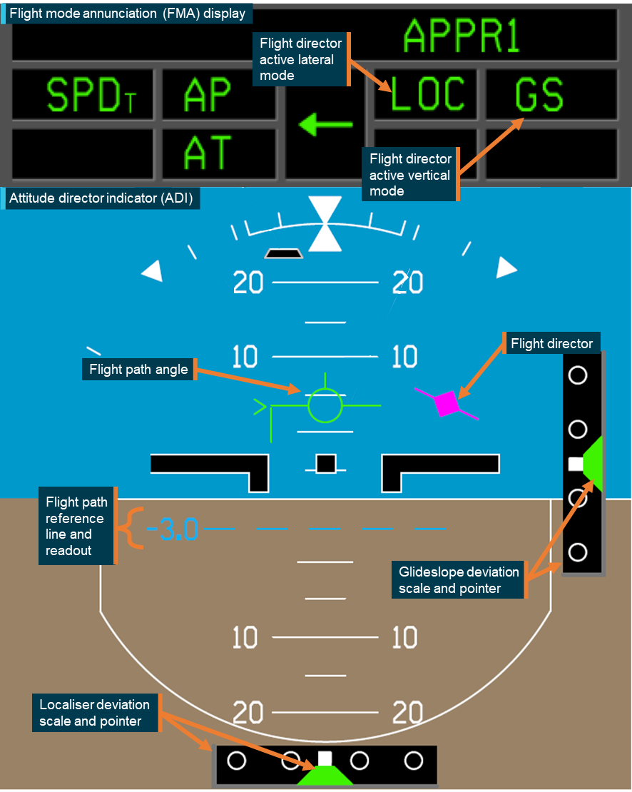
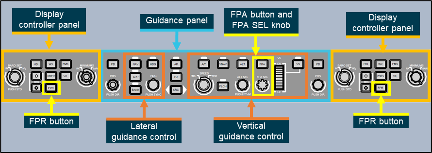
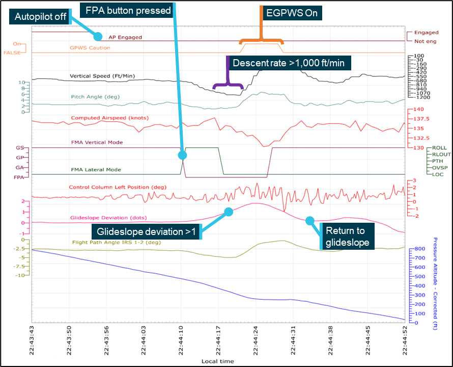
The PM selected flap 1 as the aircraft descended through about 4,600 ft. About 30 seconds later, the approach controller instructed the PM to contact the tower controller when leaving 3,000 ft. In preparation for the ILS, the PF then pressed the approach (APP) pushbutton on the aircraft’s guidance panel, arming the approach mode. This also armed flight director (FD) localiser (LOC) lateral and glideslope (GS) vertical modes. With approach mode armed, when the aircraft intercepted the localiser (at LAPAR), LOC should become the active lateral mode and when it subsequently intercepted the glideslope, GS should become the active vertical mode.
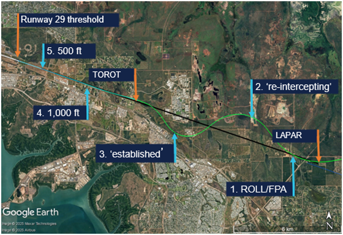
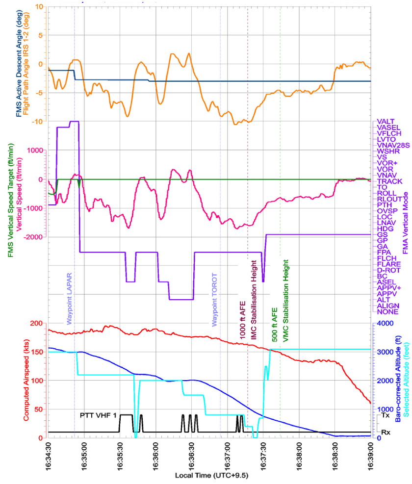
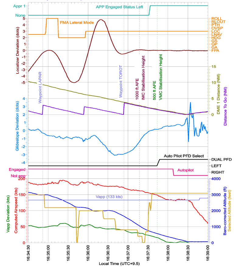
As LAPAR was a ‘fly-by’ (rather than a ‘flyover’) waypoint, the aircraft’s flight guidance and control system (FGCS) pre‑empted the turn and passed by LAPAR at 1634:51, at 183 kt airspeed and at the selected altitude of 3,000 ft. The selected altitude was then wound down to 2,200 ft and 2 seconds later, the FGCS captured the localiser and the recorded flight data showed LOC and flight path angle (FPA) modes became active. One second later, the lateral mode reverted to the basic FD ROLL mode (Figure 2 No 1 and Figure 3).
Figure 3: Flight mode annunciation display showing localiser (LOC) capture followed by reversion to basic modes (ROLL/FPA)
Recorded flight data showed LOC mode became active and then disarmed within 1 second. The active mode was recorded every second, but the armed mode was recorded every 2 seconds. Hence at 1634:56, the recorded data showed LOC as both the armed and active mode. Source: Embraer animation of recorded flight data, annotated by the ATSB
The FO recalled being very surprised seeing the ROLL/FPA modes. In those modes, the aircraft captured and maintained the roll angle and flight path angle it was in at the time of activation. At that time, the aircraft was:
aligned with the localiser
at a flight path angle of approximately 0°
half a dot above the glideslope
banked 20° right.
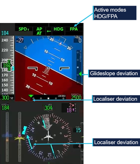
After intercepting the localiser, the ILS frequency became the active navigation source for the aircraft’s primary flight display (PFD), for the remainder of the flight. As such, lateral deviation from the localiser and vertical deviation from the 3° glideslope would be depicted on the PFD with 2 dots in each direction (left‑right/up‑down), with 2.5 dots representing full‑scale (or greater) deviation. Localiser deviation was also depicted by a course deviation indicator (CDI) and dots either side of the course on the compass instrument on the lower part of the PFD (Figure 4).
Figure 4: Compass instrument course deviation indicator aligned with the localiser at 1634:56
Source: Embraer animation of recorded flight data, annotated by the ATSB
Following activation of the ROLL/FPA modes, the aircraft deviated right of the localiser, maintaining approximately 20° roll for about 20 seconds, as it descended. After 14 seconds, the PM selected the landing gear down and the PF moved the heading bug and selected heading (HDG) mode to command the aircraft to turn left towards the localiser.
The CDI exceeded half scale deflection (1.5 deviation dots) at 1635:16. The aircraft was then outside the lateral flight tolerance for the ILS and below the 10 NM minimum safe altitude of 3,000 ft.
At 1635:30, the PM contacted the Darwin aerodrome (tower) controller and advised that they were ‘just slightly right of the localiser and re‑intercepting’ (Figure 2 No 2). The controller responded with the instruction to ‘maintain 2,000 [ft] until glidepath interception’. The PM read back ‘maintain 2,000’, but not ‘until glidepath interception’. The controller then stated: ‘once you’ve intercepted the glidepath, cleared the ILS’. The PM did not respond.
The controller later advised the ATSB that 2,000 ft was the highest minimum vector altitude around Darwin Airport, which assured terrain separation, and there was no conflicting traffic. The controller reported that although the PM did not complete the readback, they had read back the safe altitude. The controller assessed that the flight crew were ‘working really hard’ to get back onto the ILS and would let ATC know when they wanted further descent or commenced a missed approach. The captain reported that they wanted to get re‑established on the localiser so they could conduct the published missed approach under automation if required. On reaching the maximum deviation to the right of the localiser, the aircraft was (Figure 5):
banked 27° left
at full scale localiser deflection
one dot above the glideslope
at 2,470 ft above mean sea level (AMSL)
descending at 1,254 ft/minute (fpm).
Figure 5: Primary flight display at 1635:30 showing full‑scale localiser deviation (localiser left of the aircraft)
Source: Embraer animation of recorded flight data, annotated by the ATSB
Flap 2 was selected at 1635:55, at about 2,200 ft AMSL. The active lateral mode automatically changed from HDG to LOC mode one second later, but because the APP mode was not armed, GS mode did not become active although the aircraft was within one dot of the glideslope. The aircraft then passed through the localiser 52° off the runway heading, before entering a right turn, as the FGCS commanded re‑interception of the localiser course.
At 1636:22, 177 kt airspeed and 2,000 ft, the PF advised the controller that ‘Qantas 1888 is established’ (Figure 2 No 3). Established was defined as being within half full‑scale deviation of the specified track.[6] The aircraft was then (Figure 6):
at full-scale localiser deviation
banked 33° right
nearly 2 dots above the glideslope.
Figure 6: Primary flight display at 1636:22 showing full‑scale localiser deviation (localiser right of the aircraft) and nearly 2 dots glideslope deviation (glideslope below the aircraft)
Source: Embraer animation of recorded flight data, annotated by the ATSB
The PM then requested further descent, to which the controller replied, ‘cleared ILS runway 29’, and just below 2,000 ft, the PM selected flap 3.
At 1636:51, the aircraft passed the final approach fix (FAF) TOROT (Figure 2). At the FAF, the PM was required to call out ‘FAF, height checked, missed approach altitude set’. At that time:
the FAF procedure height was 1,330 ft and the aircraft was at 1,695 ft (AMSL)
the aircraft was at full‑scale deviation above the glideslope and descending at 1,331 fpm
the set altitude was 800 ft, and the missed approach altitude was 3,000 ft.
After the FAF, Alliance’s standard operating procedures required the aircraft to be within one dot of the localiser and glideslope. The procedures also stated that the aircraft should regain the 3° profile no later than 1,500 ft above aerodrome elevation. However, passing 1,500 ft, the aircraft was full‑scale deviation above the glideslope and descending at over 1,500 fpm.
Passing about 1,100 ft AMSL, the PM intended to select flap 5, but inadvertently selected flap 4. Flap 4 had the same flap and slat extension as flap 5, but flap 4 was a take‑off configuration not a landing configuration (see the section titled Flap configuration).
At 1637:16, the aircraft passed 1,000 ft radio altitude,[7] which coincided with Alliance’s stabilisation height of 1,000 ft above aerodrome level (AAL) for conducting an instrument approach. Contrary to the stabilised approach criteria, the:
airspeed was 162 kt, 29 kt above approach speed (VAP) – faster than the permitted VAP + 10
flap setting was 4 instead of flap 5 – not in the landing configuration
before landing checks had not been completed
aircraft was 1.4 dots above the glideslope – not within the allowable 1 dot of the glideslope
descent rate was 1,582 fpm – higher than the allowable rate of descent than 1,000 fpm.
Providing all other stabilisation criteria were met, Alliance permitted the airspeed to be higher than VAP + 10 until 500 ft in visual meteorological conditions (VMC)[8] by day.
The captain recalled that the aircraft entered VMC at about 2,500 ft. However, the FO reported that just prior to 1,000 ft, they were ready to call out ‘unstable’ approach, when the captain stated that they were now ‘visual’ and could therefore continue the approach and be stabilised by 500 ft. The captain later reported that the lower stabilisation height of 500 ft in VMC was the approved procedure at their previous company. The FO reported being uncertain about Alliance’s policy and deferred to the captain.
Alliance procedures stated that below 1,000 ft AAL, the descent rate ‘shall not normally’ exceed 1,000 fpm. The descent rate exceeded 1,000 fpm until 1637:29, when passing 723 ft radio altitude, with the PF arming the APP mode 3 seconds later and LOC/GS becoming the active modes. The selected altitude was then set to the missed approach altitude of 3,000 ft.
At 1637:42 and 500 ft radio altitude, contrary to the stabilisation criteria in VMC, the:
airspeed was 17 kt above VAP, with a maximum of VAP + 10 permitted
aircraft was not in the landing configuration (flap 4 was a take‑off setting).
The PM observed that although slightly fast, the speed was trending down, and the flight crew reported thinking the aircraft met the stabilised approach criteria at 500 ft. The PM reported having completed the before landing checklist (gear and flaps) at about 800 ft, but at 411 ft radio altitude, identified that the flap lever was in the flap 4 detent and quickly moved it to the flap 5 position. The flap transitioned to the flap 5 position at 345 ft radio altitude.
The aircraft decelerated to the target approach speed VAP (133 kt) at 264 ft radio altitude. The captain disconnected the autopilot at 212 ft radio altitude and manually flew the aircraft to an uneventful landing at 1638:32.
Context
Flight crew information
The captain and first officer each held an air transport pilot licence (aeroplane), Embraer E190 type rating and a class 1 aviation medical certificate.
The captain had a total flying time of 7,100 hours, 4,000 of which were on Embraer E190 aircraft, and 150 of those were accrued in the last 90 days. The captain had previously flown Embraer E120 aircraft for about 6 years and E190 aircraft for another 4–5 years with a different operator. As a direct entry captain to Alliance, the captain conducted 6 sectors and then a line check before operating for about 2 years with Alliance on the E190 aircraft. The captain was a training captain at their base and had conducted some of the first officer’s training.
The first officer had a total flying time of 16,325 hours, 274 of which were on the Embraer E190, and 130 of those were accrued in the last 90 days. The FO commenced ground training for the Embraer E190 type rating with Alliance in May 2024 and started operating for Alliance in late September 2024.
The captain reported having slept 7 hours the previous night, 6 hours the night before that, and assessed their fatigue as ‘Okay, somewhat fresh’. The FO reporting having slept 8.5 hours on each of the previous 2 nights and assessed their fatigue as ‘Very lively, responsive, but not at peak’.[9] There was no evidence that fatigue was a factor in this occurrence.
The captain assessed their workload during the approach as 8/10. Their workload was increased by diverting around weather and a thunderstorm building in the vicinity of the airport, flying the descent in manual speed mode and the approach in manual modes. The FO assessed their workload during the approach as 10/10, in attempting to achieve the stabilised approach criteria.
Approach mode disarming
VH-UYO had Load 27 Honeywell flight management system (FMS) software, which used flight director (FD) modes and non‑FMS navigation for the ILS approach. Provided the ILS approach was part of the flight plan and NAV 1 and 2 were in AUTO FMS mode, the system would transition from FMS navigation to ILS approach through the preview mode at 150 NM. The recorded flight data showed that both NAV 1 and 2 frequencies were selected to the Darwin runway 29 ILS‑Z, and the PM reported that preview mode selected as expected.
The transition from FMS to FD navigation could also be done manually by pressing the VOR/LOC (V/L) button on the guidance panel. The V/L button selects VOR or LOC as the primary navigation source for the on‑side PFD and toggles between VOR/LOC1 and VOR/LOC2. The recorded data showed that the primary navigation source was FMS1 until it changed to VOR/LOC1 at 1634:57, less than one second after LOC became active before dropping out, and remained VOR/LOC1 until after landing.
Embraer analysed the recorded flight data and identified that when the auto‑flight control system (AFCS) captured LOC mode, the display systems had not transitioned to the LOC navigation source. In that situation, the localiser capture is invalidated, and the autopilot reverts to ROLL/FPA. Although the navigation source only recorded every 4 seconds, Embraer advised that this was the most likely reason for the mode reversion. Honeywell advised that as the recorded data rate was less than the system update rate, there was insufficient information to assess whether a synchronisation issue existed. However, Honeywell will assess whether aircraft operators have reported any similar events.
Pressing the approach (APP) pushbutton arms approach mode if it is not armed or active, and disengages or disarms approach mode if it is armed or active. In interview several weeks after the incident, the captain reported that they pushed the APP button once to arm the approach mode after receiving ATC clearance for the ILS, and probably inadvertently pushed it again, disarming the mode, on receiving a second clearance for the ILS.
However, ATC recordings showed that the second ILS clearance was received about 50 seconds after the mode reversion and a third clearance 40 seconds later. The captain also reported having re‑armed approach mode as soon as they selected heading mode after the reversion (at about 2,700 ft), but a review of flight data identified that the approach mode was not re‑armed until 620 ft AAL.
The approach mode armed status was recorded every 2 seconds in the flight data and was armed 1 second before LOC captured and not armed (just less than) 1 second after LOC capture. Therefore, the possible second press of the APP button would have to have occurred within 1 second of the LOC capture.
Mode reversion
The E190 Aircraft Operations Manual described roll hold (ROLL) mode as the basic lateral mode. Depending on the bank angle at the moment of ROLL activation, the autopilot (AP) will maintain the following bank angles until another lateral mode is selected:
bank angle at 6° or below: AP levels the wings
bank angle above 6° and below 35°: AP holds the present bank angle
bank angle at or above 35°: AP maintains a bank angle of 35°
Relevant to this occurrence, roll mode is activated:
when there is no lateral mode active and a vertical mode is selected
by deselecting an active lateral mode.
Roll mode is deactivated when another lateral mode is activated.
Flight path angle (FPA) is the basic vertical mode, except during take‑off. The FPA can be used for vertical navigation by selecting a higher or lower altitude and then pressing the FPA button.
Alliance’s procedures required changes in lateral and vertical engaged modes to be announced by the pilots:
the pilot who changes the flight mode checks on the flight mode annunciator (FMA) and verbally confirms the selected mode
the other pilot verbally confirms the new flight mode.
The procedures also stated that:
When the aircraft does not perform as expected, the autopilot must be disconnected and manual flight promptly established.
Flap configuration
The E190 has slats on the leading edge of the wing and flaps on the trailing edge. There are 7 slat/flap control lever positions: up, 1–5 and full. Flap 4 is a take‑off configuration, and normal landing configurations are flap 5 or full. In flap 4 and flap 5 positions, the flaps extend to 20° and slats to 25°. Although the physical positioning of the flaps and slats is identical, the flight system logic triggers different warnings based on the selected position as follows:
Retard mode reduces the thrust levers to idle during flare on landing. This only occurs when the slat/flap lever position is at 5 or full and landing gear is down.
Enhanced ground proximity warning system (EGPWS) mode 2 – excessive terrain closure rate operates mode 2A when flaps are not in the landing position and 2B with flaps down and in the landing position. Violations of the alert envelopes produce aural ‘TERRAIN TERRAIN’ and ‘PULL UP’ alerts. Mode 2B has a desensitized alert envelope with a reduced upper height limit and a higher closure rate when:
flaps are in the landing position
on an ILS, the aircraft is within +/- 2 dots of the localiser and glideslope
within 5 NM and 3,500 ft of the runway (and terrain awareness is functioning)
during the first 60 seconds after take‑off.
EGPWS mode 3 alerts if a decrease in altitude occurs immediately after take‑off or during a go‑around when the flaps are not in a landing configuration (‘DON’T SINK’ aural and GND PROX PFD alerts).
EGPWS mode 4 unsafe terrain clearance depends on radio altitude, airspeed, landing gear and flap position. In mode 4B, with landing gear down and flaps not in the landing configuration, pilots hear a ‘TOO LOW, FLAPS’ alert and see a GND PROX alert on the PFD, when below 159 kt airspeed and 245 ft radio altitude. Mode 4C operates when the landing gear or flaps are not in the landing configuration and will trigger a ‘TOO LOW, TERRAIN’ aural alert.
On this occasion, had the flight crew continued towards landing with flap 4 configured, they would likely have received any or all of ‘TERRAIN TERRAIN’, ‘PULL UP’, ‘TOO LOW FLAPS’, and ‘TOO LOW TERRAIN’ aural alerts.
Threshold and approach speeds
The aircraft’s reference speed (VREF) is 1.3 times the stalling speed (VS) and is the minimum recommended speed at 50 ft over the threshold. It is used for landing distance calculation and is the speed to which the airspeed reference bugs are set before an approach. The approach speed (VAP) exceeds the reference speed to account for gusts or windshear. Alliance’s E190 standard procedures defined VAP = VREF = + 1/2 steady headwind component + gust increment, limited to a minimum of VREF + 5 kt and maximum VREF + 20 kt.
Meteorological conditions
Forecast
The Bureau of Meteorology (BoM) graphical area forecast encompassing the Darwin area, issued at 1359 and valid between 1430–2030 local time, stated:
visibility greater than 10 km, scattered cumulus/stratocumulus clouds with bases 4,000 ft above mean sea level and tops above 10,000 ft, and bases from 2,000 ft over sea to 30 NM (56 km) inland
1,000 m visibility in scattered heavy showers of rain, occasional towering cumulus clouds with bases at 2,000 ft and tops above 10,000 ft
500 m visibility in occasional heavy thunderstorms with rain, occasional cumulonimbus clouds with bases from 2,000 ft and tops above 10,000 ft, broken stratus between 500 and 1,500 ft
moderate turbulence below 400 ft in smoke and thermals over land until 1830.
There was a tropical cyclone off the northern coast of Western Australia but no SIGMET[10] for the Northern Territory.
The Darwin Airport forecast (TAF)[11] issued at 0851 was valid for 30 hours from 0930 on 12 February until 1530 on 13 February. Two subsequent TAF amendments were issued before the occurrence, one at 1148 and another at 1452. All TAF cloud heights are above aerodrome elevation. All had the same forecast for:
wind from 340° (True) at 12 kt
visibility greater than 10 km
light showers of rain
scattered cloud at 2,000 ft.
For the period of the aircraft’s approach, 1614–1638, the forecast and amendments included (intermittent) periods of up to 30 minutes of:
visibility reducing to 1,000 m in heavy showers of rain
broken cloud at 500 ft
scattered towering cumulus with bases at 2,000 ft.
Forecast to occur from 2330 on 11 April to 1330 on 12 April, there was a 30% probability of thunderstorms for periods up to 1 hour with:
variable direction winds of 15 kt winds gusting to 30 kt
visibility reducing to 500 m in thunderstorms and heavy rain
broken cloud at 400 ft
scattered cumulonimbus clouds with bases at 2,000 ft.
A third TAF amendment was issued at 1642 (4 minutes after the aircraft landed), which included an additional intermittent period lasting up to 30 minutes of:
visibility reducing to 500 m in thunderstorms and heavy rain
broken cloud at 400 ft
scattered cumulonimbus clouds with bases at 2,000 ft.
Observations
The following weather observations at Darwin Airport occurred during the time of the aircraft’s approach.
At 1617, a special report of meteorological conditions (SPECI)[12] was issued, which included:
3,000 m visibility
thunderstorms in the vicinity (lightning detected outside the 8 km radius of the airport)
few cloud at 1,500 ft
broken cloud at 2,600 ft
few cumulonimbus clouds at 2,000 ft.
At 1630, a SPECI was issued that included:
4,000 m visibility
heavy showers of rain
few cloud at 1,500 ft
scattered cloud at 1,900 ft
broken cloud at 4,000 ft
detail that 2 mm of rain had fallen in the previous 10 minutes.
At 1637, one minute prior to landing, a SPECI was issued that included:
8,000 m visibility
thunderstorms and rain
scattered cloud at 1,300 ft
broken cloud at 3,600 ft
few cumulonimbus clouds with bases at 2,000 ft
advice that 0.6 mm of rain had fallen in the previous 10 minutes.
Radar imagery
The BoM Darwin/Berrimah radar was located 7 km south‑east of Darwin Airport.
Radar images showed moderate rain in the Darwin Airport area at 1614, that reduced to light to no rain around the time of the approach. The associated cloud/cell was stationary, and according to the BoM, it was not unusual to have a stationary rain/storm sitting over the airport in the wet season. The BoM information about that radar included:
Heavy rain over the radar site will cause attenuation of all signals. Path attenuation also occurs when the radar beam passes through an intense thunderstorm cell; the returned signal from cells further along that path will be reduced...it may 'undershoot' high level storms and rain echoes may appear less intense than actual rainfall rate.
The BoM advised that due to attenuation, the light rainfall indicating on the radar image at 1634, may have been less intense than the actual rainfall rate.
Webcam
The BoM provided webcam images for each minute from 1634–1638 facing north and east.
At 1638, the aircraft would have been due east of the webcam on final approach, at about 300 ft, probably the light visible in the east view at 1638 (Figure 7).
Figure 7: BoM webcam image facing east at 1638 and probable aircraft light
Source: Bureau of Meteorology, annotated by the ATSB
The cell with heavier rain to the north was evident in the north view at 1638 (Figure 8).
Figure 8: BoM webcam image facing north at 1638
Source: Bureau of Meteorology
Figure 9 shows satellite imagery of cloud cover at Darwin Airport at 1640, and lightning strikes that occurred in the 10 minutes prior (red) and during the period 10–30 minutes prior (orange).
Figure 9: Cloud cover at 1640 and recorded lightning strikes
Source: Satellite image originally processed by the Bureau of Meteorology from the geostationary meteorological satellite Himawari-9 operated by the Japan Meteorological Agency. Lightning data sourced from Weather Zone Lightning Network
Automatic terminal information service
The Royal Australian Air Force’s Darwin Airport automatic terminal information service (ATIS)[13] X‑ray (X) was issued at 1610 and included advice to expect an instrument approach and that runways 29 and 36 were active for arrivals, with runway 29 in use for departures. The runways were wet, with surface condition code 555. ATIS X‑ray also detailed the following weather conditions:
wind from 340° at 15 kt, maximum 15 kt crosswind on runway 29
ATIS Yankee (Y) came into effect at 1624, with the only change being a temperature reduction to 27°C.
Based on the forecast and observed weather conditions at the time of the approach, the flight crew could not have anticipated VMC or expected to remain clear of cloud until below about 1,200 ft.
Recorded data
Flight data from the aircraft’s quick access recorder (QAR) for the incident flight was analysed by the ATSB and Embraer.
Key parameters in the vertical flight path, depicted in Figure 10, identified that between LAPAR and about 600 ft AAL, there were:
7 vertical mode changes (purple)
11 selected altitude changes (cyan)
significant variations in flight path angle (orange)
significant variations in vertical speed (pink) and rates of descent exceeding 1,600 fpm including below 1,000 ft AAL.
Figure 10: QAR data including key vertical flight path parameters
Source: Alliance Airlines QAR data, analysed by the ATSB
Although cockpit localiser and glideslope indications showed full‑scale deviation of 2.5 dots on the primary flight display and compass instrument, the recorded QAR data captured up to 5 dots deviation. Key parameters depicted in Figure 11 showed:
airspeed (red) remained above the target approach speed of 133 kt (VAP) (purple) until 1638 (deviation in kt – green)
5 dot left and right deviations from the localiser course between LAPAR and TOROT
3 dot deviation above the glideslope approaching TOROT.
Figure 11: QAR data depicting speeds and key lateral flight path parameters
Source: Alliance Airlines QAR data, analysed by the ATSB
Approach briefing
Alliance procedures required flight crew to conduct a briefing before commencing an approach. It detailed the requirements for an instrument approach briefing and a visual approach briefing. There was no policy on re‑briefing during an instrument approach if a transition to a visual approach occurred. Alliance advised that the expectation was for flight crew to continue an instrument approach even if visual reference was established.
Descent below lowest/minimum safe altitude
Alliance’s Operations Policy and Procedures Manual (OPPM) required all flights to be planned and conducted under instrument flight rules (IFR).[15] Company policy allowed the use of visual approaches and departures, but pilots were not permitted to downgrade to visual flight rules.
The OPPM section 7.4.11.1 stated that operation below the lowest/minimum safe altitude (LSALT/MSA) was permissible only when:
• under radar control;
• in accordance with a published [distance measuring equipment] DME arrival instrument approach or holding procedure;
• when necessary during climbing after departure from an airport, or
• when flying in VMC by day.
CASR Part 91 Plain English Guide stated that in accordance with sub‑regulation 91.305 Minimum heights – IFR flights, aircraft must not be flown below the lowest/minimum safe altitude except when taking off or landing in VMC by day, or in accordance with:
a published visual or instrument approach or departure procedure
an air traffic control clearance.
Instrument landing system approach
Darwin Airport runway 29 ILS-Z approach is depicted in Figure 12.
Figure 12: Darwin ILS-Z approach
Source: Jeppesen
The Aeronautical Information Publication (AIP)[16] stated that:
Unless authorised to make a visual approach, an IFR flight must conform to the published instrument approach procedure nominated by ATC.
During an instrument approach, flight crew were required to maintain the aircraft’s flight path within certain flight tolerances. For an ILS approach the AIP stated:
Pilots must conform to the following flight tolerances:
a) To ensure obstacle clearance, both [localiser/Ground based augmentation system (GBAS) landing system] LOC/GLS final approach course and glideslope should be maintained within half scale deflection (or equivalent on expanded scale).
b) If, at any time during the approach after the [final approach point] FAP, the LOC/GLS final approach or glideslope indicates full scale deflection, a missed approach should be commenced.
Although the AIP wording combined the terms ‘must’ and ‘should’, Airservices Australia confirmed that aircraft were required to comply with the vertical guidance of the glideslope when conducting an ILS approach, and that descent outside this vertical guidance could be safety critical.
Alliance’s Standard Operating Procedures Manual (SOPM) detailed the procedure for conducting an ILS approach. This included:
The standard profile assumes the aircraft will approach 3,000 ft AFE [above field elevation] with Flap 1 selected and will be configured with landing flap with checklists complete prior to stabilization altitude.
Standard calls were documented in the Alliance SOPM, which stated:
Deviation calls are to be made if the listed deviation limit is exceeded and no corrective action has been observed. Upon acknowledgement of a deviation, corrective action must be taken.
Table 1 is an extract of the standard calls relevant to this approach.
Any time the PNF [pilot not flying]/PM calls deviations from 'on slope' the PF should make corrections to avoid flight path excursions towards full scale.
The PNF/PM should continue slope deviation calls until the glideslope indicator stops moving toward full scale and whenever the indicator is at full scale.
…
When continuing the approach, continually cross-check visual profile indications against glideslope profile indications down to 100 ft AGL…Duties of the PNF/PM apply on all instrument approaches through to 100 ft above threshold height, even if visual flight conditions are encountered before reaching the minimum.
The same section stated:
During a visual approach using the ILS, the glideslope calls do not need to be given.
Visual approaches
The term ‘visual’ was used by:
ATC to instruct a pilot
a pilot to accept responsibility
to see and avoid obstacles while operating below the minimum vector altitude or minimum/lowest safe altitude.
Alliance permitted flight crew to conduct visual approaches by day and night in accordance with AIP requirements. The AIP required an IFR flight to conform to the published instrument approach procedure unless they were authorised by ATC to make a visual approach. By day, ATC could authorise an IFR aeroplane to conduct a visual approach when:
the aircraft is within 30 NM of the aerodrome
the pilot has established and can continue flight to the aerodrome with continuous visual reference to the ground or water
visibility along the flight path is not less than 5,000 m or the aerodrome is in sight.
If these conditions existed, the AIP stated:
the pilot need not commence or may discontinue the approved instrument approach procedure to that aerodrome…
In controlled airspace, an ATC clearance was required to conduct a visual approach. The pilot was required to report ‘visual’ to signify to ATC that the visual approach requirements could be met and maintained as part of any request for a visual approach. The pilot was then required to maintain the track or heading authorised by ATC until (by day) within 5 NM (9 km) of the aerodrome.
The Alliance OPPM stated that in VMC on a visual approach, the aircraft must join the circuit on the upwind, crosswind or downwind leg, or make a straight-in approach after establishing on final approach by 5 NM. During this occurrence, when 5 NM from the airport, the aircraft was about 1 km left of the extended runway centreline.
The required visual approach callouts at 500 ft stabilisation height were:
if stabilised criteria satisfied: PM verifies or calls out ‘500 STABLE’
otherwise: PM verifies or calls out ‘500 NOT STABLE’ and the PF initiates a go‑around.
The flight crew had not briefed for a visual approach, advised ATC they were visual or received clearance to conduct a visual approach.
Go-around and discontinued approach
The Alliance OPPM included Non punitive go around policies, and listed conditions which, if encountered, the PF should consider carrying out a go‑around. The conditions included those that could lead to stabilised approach requirements not being adhered to. The Alliance SOPM distinguished between a discontinued approach and a go‑around in which take‑off/go‑around (TOGA) thrust was applied.
SOPM 5.20.4 Discontinued approach included:
During the initial phase of the approach, there may be a situation where the approach needs to be discontinued. If the aircraft is at or near the missed approach altitude, far from the missed approach point and not fully configured for landing, a go around procedure may not be appropriate. The go around can lead to an excess thrust that may result in overshooting the missed approach altitude. For this situation, a discontinued approach is recommended.
NOTE
❖ A Go-around should be conducted:
o In Day VMC below 500FT AFE,
o In [instrument meteorological conditions] IMC[17] or at night below 1000ft AFE.
SOPM 5.20.3 Go-around included:
No approach should be initiated unless the prevailing conditions have been understood and the crew found that landing is acceptable without undue risk. Philosophically all approaches should be treated as approaches followed by missed approaches, and landing should be treated as the alternate procedure. This mindset depends on a good approach briefing, on the knowledge of the missed approach procedure and on proper programming of the FMS.
Alliance advised that in this incident, a discontinued approach at 3,000 ft (when the approach mode disarmed) would have been appropriate.
Stabilised approach criteria
A stabilised approach is one where an aircraft maintains a constant angle descent to the runway while other key flight parameters such as airspeed and aircraft configuration are controlled within specific ranges. An approach is stable when all the stabilisation criteria specified by the operator are met.
According to an International Air Transport Association report Unstable approaches: risk mitigation policies, procedures and best practices (IATA, 2017), historical commercial aviation accident data indicated that many accidents occurred during the approach and landing phases of flight. Frequent contributing factors were an unstable approach and subsequent failure to initiate a go‑around. Failure to maintain a stable approach could result in landing too fast or too far down the runway, a hard landing, runway excursion, loss of control, or collision with terrain. The report also highlighted the importance of callouts in enhancing situational awareness and encouraging rapid error correction.
The report described an operator’s minimum stabilisation height as a ‘gate’ at which if the aircraft was not stable on the approach path in the landing configuration, a go‑around must be executed. Additionally, although many operators have one gate for IMC and a lower gate for VMC, variations in stabilisation heights between operators, approach types and meteorological conditions (VMC/IMC) could cause confusion. As a result, many airlines implemented a single set of criteria and one gate for a particular approach type, such as 1,000 ft for an instrument approach, and 500 ft for visual circuit or circling approaches. Having a single gate also makes it easier for an operator to track compliance using flight data monitoring programs.
The Flight Safety Foundation’s Approach and landing accident reduction briefing note 7.1 – Stabilized Approach described the benefits of a stabilised approach as:
increasing the flight crew’s situational awareness of the:
horizontal
vertical
airspeed
energy state
more time and attention for monitoring communications, weather and aircraft systems
more time for monitoring by the PM
defined criteria to support land or go‑around decision‑making
consistent landing performance.
Alliance’s standard operating procedures required all flights conducting instrument approaches to be stabilised by 1,000 ft above aerodrome level, and an immediate go‑around was required for any approach that did not meet the following stabilised approach criteria:
a) the correct flight path;
b) only small changes in heading/pitch are required to maintain the correct flight path;
c) the aircraft speed is not more than VAPP + 10 knots indicated airspeed and not less than VREF;
d) the aircraft is in the correct landing configuration;
e) sink rate is no greater than 1,000 feet per minute
f) thrust or power setting is appropriate for the aircraft configuration;
g) all briefings and checklists have been completed;
h) specific types of approaches are stabilized if they also fulfil the following
i. instrument landing system (ILS) approaches must be flown within one dot of the glideslope and localizer
ii. a Category II or Category III ILS approach must be flown within the expanded localizer band
i) unique approach procedures or abnormal conditions requiring a deviation from the above elements of a stabilized approach require a special briefing to have been completed prior to beginning the approach.
• Note 1: A momentary excursion is permitted for points (c) & (e). A momentary excursion is defined as a deviation lasting only a few seconds and where every indication is that it will return to the stabilised criteria as listed in points (c) & (e).
• Note 2: Where the nominal descent path for a particular approach requires a descent rate greater than 1000 fpm. This is only permitted when expected rates of descent have been briefed prior to the approach being commenced.
Stabilized Heights
All flights shall meet all of the above stabilized approach criteria by 1,000 feet above aerodrome level except under the following circumstances:
Visual approach:
Speed may be higher than VAPP + 10, provided it is within limits and expected to reduce to Vapp+10 or below by no later than 500ft AAL.
Note 3: Visual conditions as defined by Jeppesen AUS or AIP - the pilot has established and can continue flight to the airport with continuous visual reference to the ground or water; and visibility along the flight path is not less than 5000m.
…[followed by Visual circuit, Circling approach and RNP-AR approach]
An approach that does not meet, or subsequently exhibits sustained deviations outside of these criteria requires an immediate go-around.
Alliance advised that the Note 3 under the Visual approach heading was supposed to clarify that the term ‘visual approach’ and the associated policy was not only for the situation where flight crew were cleared for a visual approach, but included when they encountered visual conditions during an instrument approach.
Alliance SOPM section Intercepting glideslope from above, included:
Several different situations, such as ATC restriction, may lead to a glideslope interception from above. If that happens, the pilots must take the appropriate actions to guarantee a stabilized approach. If the stabilized approach criteria are not met, the PF must initiate a Go Around. The approach must be stable before reaching 1000 ft AGL (IMC), 500 ft (VMC), or other altitude in accordance with company policies.
Alliance’s SOPM (5.16.7) Stabilised approach stated that the aircraft must meet the stabilised approach criteria in the OPPM, and included:
For a 3D instrument approach or a visual approach (except for a visual circuit or circling approach) the aircraft should be established on profile by 3000ft AFE. If, due to operational circumstances the aircraft is not on a 3° profile, an acceptable flight path should be maintained to regain profile no later than 1500ft AFE. Descent rate limits are outlined in the OPPM.
The OPPM specified ‘Descent rate limits’:
The following values for the rate of descent below the transition altitude shall not normally be exceeded:
• 3000 fpm down to an altitude of 3000 ft above aerodrome level (AAL).
• 2000 fpm down to an altitude of 2000 ft AAL transitioning to 1000 ft AAL
• 1000 fpm below 1000 feet AAL
The SOPM (5.16.7) Stabilised approach also stated:
On the normal profile, the aircraft should approach 3,000 ft AFE with Flap 1 selected. Flap 2 should be selected leaving 3000ft. The landing gear should be selected down and flap 3 selected no later than 2000ft AFE. Final landing flap should be selected such that all stable approach criteria can be satisfied.
Alliance advised that in the previous 4 years, almost all their approach incidents occurred following selection of flap 2 below the prescribed 3,000 ft. They reported that delayed selection of flap 2 ‘then compresses everything’.
Guidance material for Part 121.200 from CASR Part 121 Acceptable means of compliance/guidance material - Australian air transport operations—larger aeroplanes included discontinuing an approach to continue in VMC as one situation that reduced the likelihood of a stabilised approach and should be avoided where not operationally necessary.
Crew coordination
The captain reported being aware when the aircraft was outside half scale deflection of the localiser and more than half scale deflection above the glideslope, which was why they advised ATC and were cleared to maintain the minimum vector altitude. The captain could not recall whether they had advised ATC they were visual but assessed that they could continue the unstable approach below 1,000 ft as they were in visual conditions. The captain reported that there were no callouts from the PM and if they were not stable at 500 ft, the captain would have expected an ‘unstable’ callout from the PM and would have conducted a go‑around.
The FO (PM) reported that normally they would aim to be fully configured and stable by 1,500 ft and the ‘absolute latest’ by 1,000 ft for an instrument approach. In this case they were not, which is why the captain called ‘visual’ and said they would use the visual approach ‘gate’ of 500 ft. The FO reported that in that split second (passing 1,000 ft), they agreed with the captain to continue because they were visual, although the aircraft was above the glideslope and ‘slightly’ fast, the speed was trending down, and the FO thought that the aircraft was fully configured for landing. The FO assessed that the aircraft was stable at 500 ft, unaware that the flaps were incorrectly configured, and had they called ‘unstable’ at 500 ft, the captain would have been obliged to conduct a go‑around.
The FO also reported that the en route diversions and storms near the airport may have resulted in perceived time pressure to continue the landing. They had sufficient fuel to discontinue the approach and make a second attempt.
The cockpit voice recording was not retained for the investigation. The flight crew could not recall whether the PF called out mode changes after the mode reversion. The PM reported calling distance and heights for the profile, but did not make speed, slope or track deviation calls because the PF was taking corrective action.
The Alliance OPPM detailed task sharing and the responsibilities of the PF and PM and noted that this was particularly important in high workload phases of flight, including approach and landing. It also stated that the PM should:
query the PF actions that are not understood or considered inappropriate. He/she should also demonstrate assertiveness and express advocacy to share any concern on the flight progress.
Alliance OPPM defined authority gradient as ‘the relative authority of air crew in the chain of command … if the gradient is too steep, air crew may be unwilling or unable to express their beliefs to those in higher authority’.
Similar occurrences
Unstable approach involving Embraer 190, VH‑UZI, about 4 km north‑east of Brisbane Airport, Queensland, on 9 May 2024 (AO‑2024‑030)
During approach to Brisbane Airport, the aircraft automated ILS flight mode unexpectedly disengaged. The flight crew focused on troubleshooting the unexpected change and recapturing the ILS flight director mode, rather than conducting a go‑around. During that time, the flight crew did not effectively monitor the aircraft's flight path, and the aircraft exceeded the stabilised approach criterion of one dot glideslope deviation.
After recognising that the aircraft was low, the captain increased the aircraft pitch, resulting in an enhanced ground proximity warning system (EGPWS) glideslope warning. The flight crew did not perform the required terrain avoidance manoeuvre, instead continued the approach. The captain arrested the aircraft’s descent and re‑established the aircraft on the glidepath, before continuing the approach and landing.
Alliance took safety action in response to that occurrence including issuing an operational notice to remind flight crew of the stabilised approach criteria and go‑around requirements.
Descent below glideslope involving Fairchild SA227, VH‑VEU, about 17 km north‑east of Brisbane Airport, Queensland, on 2 July 2024 (AO‑2024-040)
During the ILS approach, the aircraft descended below the 3° glideslope, triggering an air traffic control ATC minimum safe altitude warning about 8 NM (14 km) from the runway. ATC advised the crew that they were observed below the glideslope, however the aircraft continued descent below the glideslope until 3 NM (6 km) when the descent rate was reduced. The aircraft then passed above the glideslope before the rate of descent increased again and subsequently the glideslope was re‑intercepted from above 1 NM (2 km) from the runway at 500 ft. The aircraft then followed a stabilised flight path to landing.
The investigation found that the pilot monitoring was not monitoring the glideslope and did not challenge the pilot flying to correct the deviation and reduce the aircraft’s descent rate.Additionally, the operator's standard operating procedures contained areas of inconsistency when an aircraft entered visual conditions during an instrument approach, and that the AIP was unclear as to whether pilots were required to comply with precision approach flight tolerances.
The aircraft operator subsequently amended its standard operating procedures as follows:
the instrument approach procedure has been updated:
the approach brief now requires discussion of expectations if visual conditions arise
the statement that ‘during a visual approach using the ILS, the glideslope calls do not need to be given’ has been removed
a requirement to make callouts using reference to visual slope indications has been added.
a note has been added to the visual approach procedures stating that crew require a clearance to discontinue an instrument approach in controlled airspace
increased focus on pilot monitoring skills during:
proficiency checks, which will now include standard instrument departure and standard arrival routes
line training for new flight crew
addition of a pilot monitoring sector to the annual line check.
Safety analysis
Mode reversion
Nearing the initial approach fix (LAPAR) for the Darwin Airport runway 29 instrument landing system (ILS)‑Z approach, the aircraft’s approach, localiser and glideslope modes were armed, with the correct ILS frequency set as the armed navigation source. As the aircraft flew by LAPAR, the localiser mode engaged for one second before the auto‑flight system reverted to lateral roll and vertical flight path angle modes.
It is possible that this occurred due to the captain inadvertently pressing the approach pushbutton at the same time the localiser captured. The captain recalled that this occurred because they received a second ATC clearance for the ILS, however, at that time, they had only been cleared for the ILS once. They received a second clearance about 50 seconds later and a third clearance 40 seconds after that. The pushbutton was not recorded in the data but pressing it when approach mode was armed would disarm approach mode consistent with the mode reversion.
Embraer's analysis of the recorded data found that the ILS navigation display source had not engaged at the time localiser mode became active. Therefore, it was most likely that this non‑synchronisation led the flight control and guidance system to invalidate the capture and revert to basic modes. The avionics manufacturer, Honeywell, advised that as the recorded data did not update as frequently as the system status, it was not possible to determine whether a synchronisation issue existed.
The mode reversion resulted in the aircraft maintaining the 20° right bank and approximately level flight path angle that were present at the time of the mode reversion.
Automation and approach continuation
Alliance’s procedures stated that if the auto‑flight system was not doing what the pilot expected, they were to disconnect the autopilot and manually fly the aircraft. However, following the unexpected mode change, the captain, who was the pilot flying (PF), did not re‑engage approach mode or disconnect the autopilot until about 200 ft above the aerodrome elevation, in accordance with normal landing procedures. This resulted in the aircraft deviating beyond the permitted tolerance from the localiser course and above the glideslope.
It took less than 3 minutes from the mode reversion at 3,000 ft, to the aircraft being established on the ILS and in the landing configuration, about 400 ft above aerodrome elevation. During that time, there were several changes to the lateral and vertical modes, selected heading and altitude, and significant variations in vertical speed, as the PF manipulated the auto‑flight system to recapture the localiser and glideslope.
There were also several triggers for the flight crew to discontinue the approach. The flight crew reported that their en route weather deviations and thunderstorms in the vicinity of the airport may have led to perceived pressure to continue the approach, but that there was adequate fuel on board to discontinue and conduct a second approach.
Once outside the lateral tolerance of the approach, the aircraft was operating contrary to the air traffic control (ATC) clearance and descended below the minimum safe altitude, likely while in instrument meteorological conditions (IMC). The pilot monitoring (PM) reported that they did not call out the course deviations, as the PF was actively working to correct them. Instead, after descending about 500 ft, the PM advised ATC they were re‑intercepting the localiser and was assigned the minimum vector altitude to ensure terrain separation. As a result, the aircraft then maintained altitude, while the glideslope diverged beneath the flight path.
The PM did not read back the ATC clearance to descend once they had intercepted the glideslope, consistent with being focused on monitoring tasks and their self‑assessed 10/10 workload during the approach. The PM selected flap 2 as the aircraft captured the localiser, about 800 ft below the normal (but not mandatory) 3,000 ft flap 2 selection height. Alliance reported that this late selection had a similar effect to other recent approach incidents, where the associated delayed speed reduction reduced the time available to stabilise the approach.
As the aircraft passed the final approach fix (FAF) and then descended through 1,500 ft, it was established on the localiser but 3 dots above the ILS glideslope. Alliance’s procedures required the ILS to be flown within 1 dot of the glideslope, and stated that aircraft ‘should be’ on the 3° glideslope no later than 1,500 ft.
The PF reported stating to the PM that they were visual at about 2,500 ft, but the PM reported this occurred just as the aircraft approached 1,000 ft. Without a cockpit voice recording, it could not be determined when visual flight conditions were established.
At 1,000 ft, which was the stabilisation height for an instrument approach, the PF incorrectly assessed that although several stabilised criteria were not met, as they were then in visual conditions, they could continue (unstable) to 500 ft. Although this had been the procedure at the PF’s former company, Alliance required all stabilised approach criteria, other than airspeed, to be met at 1,000 ft. The PM was sufficiently unsure of Alliance’s policy to defer to the captain’s experience, as the senior base training captain who had conducted some of the PM’s training.
At 500 ft, the PM assessed that the stabilised approach criteria were met as, although the airspeed was still slightly fast, it was trending down, and they continued the approach. Although the flight crew reported having completed the before landing checks prior to 500 ft, shortly afterwards, the PM identified that they had inadvertently selected a take‑off flap setting (passing about 1,100 ft) instead of a landing setting, which they had not detected earlier. The PM rectified the flap setting and an uneventful landing followed.
Although the landing was uneventful, had the incorrect flap setting not been rectified, thrust retard mode would not have engaged during the landing flare, and EGPWS warnings would have been triggered by the use of different tolerances than with the aircraft configured for landing. The use of selected heading and selected altitude to drive the aircraft’s trajectory meant that these may not have been set correctly had a go‑around been initiated either by the flight crew or ATC.
A coupled ILS approach should require minimal flight crew intervention other than monitoring. Continuing an approach using inappropriate modes increased the likelihood of an unstable approach. International research showed that unstable approaches and failure to initiate a go-around could result in landing too fast or too far down the runway, a hard landing, runway excursion, loss of control, or collision with terrain. Although visual conditions reduce the risk of collision with terrain, they do not mitigate against landing incidents resulting from poor energy management.
Alliance stabilisation heights
Alliance provided stabilised approach criteria consistent with international and Civil Aviation Safety Authority guidance, including airspeed, flight path and energy management parameters, to reduce the risk of landing accidents. However, Alliance’s minimum stabilisation heights at which these criteria were required to be met, varied between approach types and meteorological conditions, and were not clearly documented.
Alliance specified a stabilisation height of 1,000 ft for instrument approaches, but under the heading Visual approach, permitted a 500 ft stabilisation height for an instrument approach in VMC, provided only the airspeed exceeded the stable speed criterion, and all other stabilised approach criteria were met. Additionally, elsewhere in the procedures for intercepting a glideslope, it stated that an approach must be stable before reaching 1,000 ft in IMC, 500 ft in VMC ‘or other altitude in accordance with company policies’. Alliance did not have a policy for transitioning from an instrument approach to a visual approach and advised that its expectation was for flight crew to continue an instrument approach even when entering VMC.
In this incident, the lack of clarity regarding which of the stabilised approach criteria were not required before continuing to 500 ft, resulted in the flight crew incorrectly assessing that they could continue to 500 ft in VMC while the criteria were not met for:
speed
rate of descent
glideslope
landing configuration
before landing checks complete.
International Air Transport Association guidance stated that using a single stabilisation height for one type of approach, regardless of weather conditions, can reduce confusion and make it easier for operators to track stabilised approach compliance using flight data monitoring. Clear stabilisation heights also support flight crew decision-making to initiate a go‑around.
Findings
ATSB investigation report findings focus on safety factors (that is, events and conditions that increase risk). Safety factors include ‘contributing factors’ and ‘other factors that increased risk’ (that is, factors that did not meet the definition of a contributing factor for this occurrence but were still considered important to include in the report for the purpose of increasing awareness and enhancing safety). In addition ‘other findings’ may be included to provide important information about topics other than safety factors.
These findings should not be read as apportioning blame or liability to any particular organisation or individual.
From the evidence available, the following findings are made with respect to the unstable approaching involving Embraer E190, VH-UYO, near Darwin Airport, Northern Territory, on 15 February 2025.
Contributing factors
On crossing the initial approach fix for the instrument landing system (ILS) approach, due either to a system synchronisation issue or the pilot flying inadvertently disarming the approach mode, the aircraft’s auto‑flight system reverted to roll and flight path angle modes.
Following the unexpected mode change, the pilot flying did not re‑engage approach mode or disconnect the autopilot. This likely contributed to the aircraft deviating outside the required lateral tolerance of the approach below the minimum safe altitude while in instrument meteorological conditions.
The flight crew did not discontinue the approach when the aircraft was unstable at the 1,000 ft stabilisation height as they incorrectly assessed that they could continue to 500 ft in visual meteorological conditions, with multiple stabilised approach criteria unmet.
In the limited time available to stabilise the aircraft by 500 ft, the flight crew incorrectly assessed that the aircraft was stable and continued the approach, unaware that the pilot monitoring had inadvertently selected an incorrect flap configuration.
Alliance Airlines' standard operating procedures were unclear about the criteria for continuing an unstable instrument approach to 500 ft when aircraft entered visual conditions.
Safety actions
Whether or not the ATSB identifies safety issues in the course of an investigation, relevant organisations may proactively initiate safety action in order to reduce their safety risk. All of the directly involved parties are invited to provide submissions to this draft report. As part of that process, each organisation is asked to communicate what safety actions, if any, they have carried out to reduce the risk associated with this type of occurrences in the future. The ATSB has so far been advised of the following proactive safety action in response to this occurrence.
Safety action by Alliance Airlines
Alliance Airlines issued an operations notice ‘to improve clarity and compliance’ with the stabilised approach criteria. It detailed the stabilised approach policy. It also amended the stabilisation height such that for 3‑dimensional and 2‑dimensional instrument approaches, and straight‑in visual approaches, the stabilised criteria were to be met by 1,000 ft above aerodrome elevation.
The 500 ft stabilisation height applied only to visual circuit or circling manoeuvre approaches. The notice reminded flight crew of Alliance’s ‘non punitive go around policy’ and required all unstable approaches to be reported.
Alliance Airlines also conducted a flight data review of unstable approaches over the previous 6 months to identify similar occurrences.
Sources and submissions
Sources of information
The sources of information during the investigation included:
Civil Aviation Safety Authority (2025, January). CASR Part 91 Plain English Guide version 4.2. Retrieved May 15, 2025, from Part 91 plain English guide version 4.2
Flight Safety Foundation (2000). Approach and landing accident reduction Briefing Note 7.1: Stabilized Approach. Retrieved May 15, 2025, from FSF ALAR Briefing Note 7.1: Stabilized Approach
Under section 26 of the Transport Safety Investigation Act 2003, the ATSB may provide a draft report, on a confidential basis, to any person whom the ATSB considers appropriate. That section allows a person receiving a draft report to make submissions to the ATSB about the draft report.
A draft of this report was provided to the following directly involved parties:
the flight crew and air traffic controllers
Alliance Airlines
Airservices Australia
Civil Aviation Safety Authority
Bureau of Meteorology
Embraer
Honeywell
United States National Transportation Safety Board
Brazil Aviation Accident Investigation and Prevention Center.
Submissions were received from:
Airservices Australia
Alliance Airlines
the first officer
Embraer.
The submissions were reviewed and, where considered appropriate, the text of the report was amended accordingly.
Purpose of safety investigations
The objective of a safety investigation is to enhance transport safety. This is done through:
identifying safety issues and facilitating safety action to address those issues
providing information about occurrences and their associated safety factors to facilitate learning within the transport industry.
It is not a function of the ATSB to apportion blame or provide a means for determining liability. At the same time, an investigation report must include factual material of sufficient weight to support the analysis and findings. At all times the ATSB endeavours to balance the use of material that could imply adverse comment with the need to properly explain what happened, and why, in a fair and unbiased manner. The ATSB does not investigate for the purpose of taking administrative, regulatory or criminal action.
Terminology
An explanation of terminology used in ATSB investigation reports is available here. This includes terms such as occurrence, contributing factor, other factor that increased risk, and safety issue.
Publishing information
Released in accordance with section 25 of the Transport Safety Investigation Act 2003
Ownership of intellectual property rights in this publication
Unless otherwise noted, copyright (and any other intellectual property rights, if any) in this report publication is owned by the Commonwealth of Australia.
Creative Commons licence
With the exception of the Commonwealth Coat of Arms, ATSB logo, and photos and graphics in which a third party holds copyright, this report is licensed under a Creative Commons Attribution 4.0 International licence.
The CC BY 4.0 licence enables you to distribute, remix, adapt, and build upon our material in any medium or format, so long as attribution is given to the Australian Transport Safety Bureau.
Copyright in material obtained from other agencies, private individuals or organisations, belongs to those agencies, individuals or organisations. Where you wish to use their material, you will need to contact them directly.
[1]Pilot Flying (PF) and Pilot Monitoring (PM): procedurally assigned roles with specifically assigned duties at specific stages of a flight. The PF does most of the flying, except in defined circumstances, such as planning for descent, approach and landing. The PM carries out support duties and monitors the PF’s actions and the aircraft’s flight path.
[2]Flight level: at altitudes above 10,000 ft in Australia, an aircraft’s height above mean sea level is referred to as a flight level (FL). FL 340 equates to 34,000 ft.
[3]Cloud cover: in aviation, cloud cover is reported using words that denote the extent of the cover – ‘few’ indicates that up to a quarter of the sky is covered, ‘scattered’ indicates that cloud is covering between a quarter and a half of the sky, ‘broken’ indicates that more than half to almost all the sky is covered, and ‘overcast’ indicates that all the sky is covered.
[4]Instrument Landing System (ILS): a 3-dimensional precision instrument approach system comprising a VHF localiser providing horizontal guidance and a UHF glideslope providing vertical guidance.
[5]Initial approach fix (IAF): the commencement of an instrument approach.
[6]Airservices Australia’s Aeronautical Information Publication ENR 1.22.2.
[7]Radio altitude is the height of the aircraft above terrain immediately below the aircraft measured by a radio altimeter.
[8]The pilot has established and can continue flight to the airport with continuous visual reference to the ground or water; and visibility along the flight path is not less than 5,000 m.
[10]A SIGMET provides a concise description of the occurrence or expected occurrence of en route weather phenomena that are potentially hazardous to aircraft, in areas over which meteorological watch is being maintained.
[11]A TAF is a coded statement of meteorological conditions expected at an aerodrome and within a radius of five nautical miles (8 km) of the aerodrome reference point.
[12]SPECI is used to identify reports of observations when conditions are below specified levels of visibility and
cloud base, certain weather phenomena are present, or temperature, pressure or wind change by defined
amounts.
[13]The provision of current, routine information to arriving and departing aircraft by means of continuous and repetitive broadcasts during the hours when the unit responsible for the service is in operation.
[14]QNH: the altimeter barometric pressure subscale setting used to indicate the height above mean seal level.
[15]Instrument flight rules (IFR): a set of regulations that permit the pilot to operate an aircraft in instrument meteorological conditions (IMC), which have much lower weather minimums than visual flight rules (VFR). Procedures and training are significantly more complex as a pilot must demonstrate competency in IMC conditions while controlling the aircraft solely by reference to instruments. IFR-capable aircraft have greater equipment and maintenance requirements.
[16]Aeronautical Information Publication (AIP): A publication issued by or with the authority of a State and containing aeronautical information of a lasting character essential to air navigation.
[17]Instrument meteorological conditions (IMC): weather conditions that require pilots to fly primarily by reference to instruments, and therefore under instrument flight rules (IFR), rather than by outside visual reference. Typically, this means flying in cloud or limited visibility.
Occurrence summary
Investigation number
AO-2025-012
Occurrence date
12/02/2025
Location
Near Darwin Airport
State
Northern Territory
Report release date
26/08/2025
Report status
Final
Investigation level
Short
Investigation type
Occurrence Investigation
Investigation status
Completed
Mode of transport
Aviation
Aviation occurrence category
Incorrect configuration, Unstable approach
Occurrence class
Incident
Highest injury level
None
Aircraft details
Manufacturer
Embraer-Empresa Brasileira De Aeronautica
Model
ERJ 190-100 IGW
Registration
VH-UYO
Serial number
19000098
Aircraft operator
Alliance Airlines Pty Limited
Sector
Jet
Operation type
Part 121 Air transport operations - larger aeroplanes
Two separate Alliance Airlines crews operating Load 25 flight software Embraer ERJ 190‑100 IGW (E190) aircraft intended to land with the less commonly used full flap setting and entered that configuration, and the associated airspeeds, into the flight management system during the approach briefing prior to top of descent.
In both incidents, the crewmembers forgot that full flap had been briefed 25 minutes earlier, and with no requirement to crosscheck the flap setting, subsequently configured the aircraft for a flap 5 landing. This resulted in the aircraft targeting a slower airspeed than that required for a flap 5 landing.
What the ATSB found
Neither set of flight crew recalled briefing for the less common full flap configuration when actioning the before landing checklist, resulting in them landing with an incorrect flap setting. Although the landing flap setting briefed prior to commencing descent was entered into the flight management system, there was no requirement to crosscheck the briefed setting with the actual configuration selected during the before landing checklist.
What has been done as a result
Alliance Airlines has amended its Operations Policy and Procedures Manual to mandate that the before landing checklist includes a confirmation that the actual landing flap setting aligns with the planned flap configuration. Additionally, in E190 aircraft, the multifunction control and display unit page displaying required landing flap should be selected on the pilot flying side before the approach commences.
Finally, Alliance Airlines conducted a flight data review of unstable approaches over the previous 6 months operations to identify similar occurrences.
Safety message
These incidents highlight the importance in multi-crew operations of the role of the pilot monitoring in identifying if, and intervening when, the other flight crew member deviates from the briefed plan. It also illustrates the risk of reversion to routinely conducted actions, despite the intention to use a less-common configuration.
On 4 February 2025, an Alliance Airlines Embraer ERJ 190‑100 IGW aircraft, registered VH‑A2T, was operating scheduled passenger flight QQ3120 from Adelaide to Olympic Dam, South Australia. On board were the captain as pilot flying (PF), first officer as pilot monitoring (PM),[1] 2 cabin crew and 90 passengers.
Consistent with the operator’s standard operating procedures manual, the flight crew conducted their approach briefing prior to commencing the descent into Olympic Dam Airport. Due to the turbulent and windy conditions, the captain elected to use full flap[2] during the landing. The crew used the ePERF[3] tablet application and the PF entered the performance figures and associated speeds for a landing using full flap into the Landing page of the flight management system (FMS), which was crosschecked by the PM.
Around 25 minutes after the approach briefing, as the crew were configuring the aircraft for landing, the PF called for flap 5[4] rather than the previously briefed full flap, which was actioned by the PM. There was no crosscheck requirement to confirm the flap setting during the before landing checklist. At the time, neither flight crewmember recalled that the less-common full flap configuration had been briefed, nor identified that the landing speeds entered into the FMS were now incorrect (slower than required) for the selected flap setting.
During the later stage of the approach, the PF was required to manually override the auto thrust at times to keep the aircraft on profile. Both flight crewmembers later recalled that the pitch attitude on final seemed slightly high at times. They also stated that during the flare,[5] the aircraft encountered sink,[6] which the PF corrected with the appropriate control inputs. Both flight crewmembers reported recognising the profile, speed and thrust were not as expected, but assessed that this was due to the hot and turbulent conditions.
Following an uneventful landing, as the crew were completing the after‑landing flow, the captain realised that they had landed with flap 5 rather than full flap. Both crewmembers later reported having forgotten that full flap had been briefed.
Occurrence 2
On 8 March 2025, an Alliance Airlines Embraer ERJ 190‑100 IGW aircraft, registered VH‑A2V, was operating scheduled passenger flight QQ4801 from Alice Springs to The Granites, Northern Territory. The captain was PF, and the first officer was PM.
On the previous day, the threshold of runway 11[7]at The Granites Airport had been repaired. While there was no NOTAM[8] in place, the airport operator had requested that if an aircraft landed on runway 29, they try to stop by taxiway alpha (which led to the apron) if safe to do so. This was to avoid turning the aircraft on the newly repaired surface at the runway 11 threshold turning node. The captain had received an email from the operator the night prior to the flight requesting that they comply with the above request if possible.
Consistent with the operator’s procedures, prior to commencing their descent, the crew conducted their approach brief. The aerodrome weather information service (AWIS) indicated a 5 kt tailwind for runway 11, which was less than the maximum permitted of 10 kt. As the aircraft could not stop prior to taxiway alpha when landing on runway 29, and to avoid the repaired area, the flight crew elected to use runway 11 and full flap for the landing. The PM entered the performance figures and associated speeds for landing using full flap into the FMS Landing page and the PF crosschecked them.
During the approach, the PM was communicating with air traffic control via HF radio and making the required broadcasts on the common traffic advisory frequency. Additionally, they were regularly checking for updated AWIS information to ensure the tailwind remained within limits. The AWIS changed 3 times during the approach, with the tailwind component reaching 9 kt before dropping back to 8 kt.
The flight crew conducted a visual approach to runway 11 without incident. The operator’s flight data analysis program later detected that the aircraft had landed with flap 5, with full flap entered in the FMS. Both crewmembers later reported that they had forgotten that the use of full flap was briefed prior to top of descent.
Context
Flight crew information
Occurrence 1 crew
The captain and first officer both held an air transport pilot licence (aeroplane) and a class 1 aviation medical certificate. The captain had accumulated over 14,000 flight hours, including 1,500 on the Embraer E190, and the first officer had about 7,000 flight hours, including 800 on the E190.
Both flight crewmembers reported feeling well rested prior to the flight.
Occurrence 2 crew
The captain and first officer both held an air transport pilot licence (aeroplane) and a class 1 medical certificate. The captain had accumulated over 13,000 flight hours, including 1,500 on the Embraer E190. The first officer had about 4,000 flight hours, including 600 hours on the Embraer E190.
On the day of the incident, both flight crewmembers reported having sufficient sleep the night prior; however, both felt a little tired, having woken at approximately 0345 to commence duty at 0445.
Aircraft
Occurrence 1
The aircraft was an ERJ 190‑100 IGW, manufactured in Brazil in 2008 and issued serial number 19000179. It was registered in Australia as VH-A2T on 19 July 2024. The aircraft was fitted with 2 General Electric Company CF34-10E5 turbofan engines. It had an integrated avionics system with load 25 software installed.
Occurrence 2
The aircraft was an ERJ 190-100 IGW, manufactured in Brazil in 2009 and issued serial number 19000249. It was registered in Australia as VH-A2V on 29 April 2024. The aircraft was fitted with 2 General Electric CF34-10E6 turbofan engines. It had an integrated avionics system with load 25 software installed.
Software – Load 25 v Load 27
The operator operated Embraer E190 aircraft, most of which had Load 27 software installed. The remainder, primarily used for mining air transport operations, had Load 25 software installed.
For both software systems, flight crews would enter the relevant landing performance data into the landing page of the FMS during the approach briefing, prior to top of descent.
For E190s fitted with Load 25 software, crews were required to select manual speed mode when passing the final approach fix. In manual speed mode, the crew would manually enter the approach speeds, calculated on the ePERF tablet, into the flight management guidance control system (FMGCS), and the autopilot would target those manually entered speeds when active.
In Load 27 aircraft, flight crew would normally use FMS speed mode on approach. In this mode, the FMGCS would automatically target the appropriate speed for the aircraft’s configuration. In addition, in Load 27 aircraft, a CHECK LANDING FLAP message would appear on the FMS scratchpad[9] if there was a discrepancy between the flap position entered into the FMS landing page and the selected flap lever position in the landing configuration.
Standard operating procedures
Flap settings
The operator’s standard operating procedures manual stated that flap 5 was the preferred setting for landing as follows:
The use of flap 5 provides lower fuel consumption and reduced approach noise levels… Consider using flap full when the field length requires its use. Additional runway limitations, such as known slippery conditions may require its use.
The occurrence 2 captain stated that flap 5 was used around 90% of the time, and one of the FO’s stated that the only time they had ever used full flap was during training.
Relevant speeds
VREF
The landing reference speed (VREF) is the speed at 50 ft above the runway threshold in a normal landing configuration (thrust levers at idle, gear down and landing flaps). VREF is used for landing distance calculations and the operator’s crews used the ePERF iPad applications for calculating landing speeds.
The Embraer Airplane Operations Manual provided VREF speeds with flap 5 and full flap, for weights between 28–52 t. Because VREF is proportional to stall speed, and therefore aircraft weight:
For occurrence 1, VREF was 123 kt for full flap, aircraft weight 43 t.
For occurrence 2, VREF was 115 kt for full flap, aircraft weight 37.5 t.
From the reference speeds table:
at 43 t – VREF flap 5 = 131 kt
at 37.5 t – VREF flap 5 = 123 kt.
In both occurrences the flap 5 VREF was 8 kt higher than the full flap VREF.
Target approach speed
Target approach speed, VAPP, is the speed on the final approach in the landing configuration. The recommended method for approach speed calculation was to add one half of the steady headwind component plus the gust increment above the steady wind to the reference speed (VREF), with a minimum of +5 kt and a maximum +20 kt.
For occurrence 1, VAPP was 128 kt.
For occurrence 2, VAPP was 120 kt.
Before landing checklist
According to the operator’s procedures, by 1,500 ft above aerodrome elevation (AAL) the aircraft should be in a stable configuration with the landing gear extended, ready to configure for the final landing flap and configured for landing by 1,000 ft AAL. Consistent with this, both sets of flight crew stated that their preference, and usual practice, was to have the aircraft fully configured by 1,500 ft, to avoid rushing or if they encountered any distractions from air traffic control.
Once configured, including selection of landing flaps, the PF would call for the Before landing checklist. The before landing checklist comprised crosschecking the landing gear was down, and flaps were set.
This did not include checking the flap selected was the same as the flap setting entered into the FMS.
Stabilised approach criteria
According to the operator’s Operations Policy and Procedures Manual (OPPM):
Stabilised Approach Criteria:
a) the correct flight path
b) only small changes in heading/pitch are required to maintain the correct flight path
c) the aircraft speed is not more than VAPP + 10 knots indicated airspeed and not less than VREF
d) the aircraft is in the correct landing configuration
e) sink rate is no greater than 1,000 feet per minute
f) thrust or power setting is appropriate for the aircraft configuration
g) all briefings and checklists have been completed
Note 1: A momentary excursion is permitted for points (c) & (e). A momentary excursion is defined as a deviation lasting only a few seconds and where every indication is that it will return to the stabilised criteria as listed in points (c) & (e).
Flight data
Data from both aircraft’s quick access recorders (Figure 1 and Figure 2) was analysed by the ATSB.
Occurrence 1
Figure 1: QAR data from event 1
Source: ATSB
In the first occurrence, the aircraft was VAPP + 13 kt at 500 ft, which was 3 kt above the stabilised approach criterion at 500 ft (stabilised approach requirement in VMC). However, the speed was trending downwards and VAPP + 10 kt was achieved 1 second later. This exceedance was unlikely to be readily detected by the PF during a visual approach, when their focus would be outside.
Occurrence 2
Figure 2: QAR data from event 2
Source: ATSB
In the second occurrence, the aircraft met all stabilised approach criteria, other than flap 5 being set rather than full flap.
Memory
Memory is fallible, particularly when a given task is not practiced often or recently completed. Memory failures (lapses) often appear as omitted items in a checklist or forgotten intentions.
Procedural memory is a specific type of implicit memory for the process involved in completing an action. It is when individuals no longer need to consciously remember to perform an action they have performed many times before, instead they do so automatically. Each time you retrieve a memory and perform an action, the more easily and readily you will recall it next time, a phenomenon called the retrieval practice effect (Pyc & Rawson, 2009).
Prospective memory, or ‘remembering to remember’, is an intention to perform an action in the future. However, an individual is unlikely to remember do so unless they get a timely retrieval cue from the environment (Dismukes 2010). In situations of high workload (such as approach), memory performance is reduced (Van Benthem et al, 2015) meaning without a cue such as a checklist, individuals are more likely to revert to actions they have performed previously instead of the intended task. This tendency is associated with prospective memory (Nowinski et al, 2003).
Safety analysis
Introduction
In both occurrences, both sets of crewmembers intended to use the less commonly used full flap for landing and entered that configuration and the associated VREF and VAPP speeds into the flight management system (FMS). Subsequently, when configuring the aircraft for landing, both sets of crewmembers forgot that full flap had been briefed some 25 minutes earlier, with both crews selecting flap 5 for the landing.
While operating with a different configuration to what was planned can result in reduced margins for landing speeds, in both these occurrences there were still sufficient margins to safely complete the landing.
Aircraft configuration
As the landing reference speed (VREF) is dependent on flap setting, when full flap is used, VREF, and VAPP, are slower than if using flap 5. If the aircraft is then configured to land with flap 5, and the aircraft is flown using the VAPP for full flap, the aircraft would be slower than it should be for the configuration. In both incidents, VAPP was 8 kt slower than the speed required for a flap 5 landing.
Both sets of crewmembers rarely, if ever, operated Load 25 aircraft, and in both incidents, the crews reverted to setting the flaps to flap 5, an action they had performed many times previously (procedural memory), most likely as they did not have a retrieval cue to recall what they had briefed approximately 25 minutes prior (prospective memory).
Contributing factor
Neither sets of flight crew recalled briefing for the less commonly used full flap configuration when actioning the before landing checklist, resulting in them landing with an incorrect flap setting.
Configuration error defences
In aircraft fitted with Load 25 software, crew were required to manually set the calculated approach speed, and the aircraft would target that speed regardless of the flap configuration. So having the incorrect flap setting resulted in the incorrect approach speed for the configuration.
In addition, in contrast to the Load 27 aircraft, Load 25 aircraft had no ‘check landing flap’ message when a different flap setting was configured to what was entered into the FMS. As such, an incorrect flap setting was more likely to occur in a Load 25 aircraft.
The procedures in place at the time of both occurrences required crew to brief the landing flap setting prior to top of descent, and there was no further prompt or crosscheck to ensure that the briefed flap settings were selected when configuring the aircraft for landing, around 25 minutes later.
Flight crew write down important information such as the automatic terminal information service (ATIS) or aerodrome weather information service (AWIS). However, there was no requirement to write down a less commonly used flap setting or to crosscheck that the flap setting was as previously briefed, in the before landing checklist. Although the flap setting was entered into the landing page in the FMS, crews normally did not have that page selected prior to the before landing checklist to cross-reference the flap selection.
Contributing factor
Alliance Airlines had no procedure for flight crews to crosscheck the briefed flap setting entered into the flight management system with the actual configuration selected during the before landing checklist. (Safety issue)
Findings
ATSB investigation report findings focus on safety factors (that is, events and conditions that increase risk). Safety factors include ‘contributing factors’ and ‘other factors that increased risk’ (that is, factors that did not meet the definition of a contributing factor for this occurrence but were still considered important to include in the report for the purpose of increasing awareness and enhancing safety). In addition ‘other findings’ may be included to provide important information about topics other than safety factors.
Safety issues are highlighted in bold to emphasise their importance. A safety issue is a safety factor that (a) can reasonably be regarded as having the potential to adversely affect the safety of future operations, and (b) is a characteristic of an organisation or a system, rather than a characteristic of a specific individual, or characteristic of an operating environment at a specific point in time.
These findings should not be read as apportioning blame or liability to any particular organisation or individual.
From the evidence available, the following findings are made with respect to the incorrect configuration occurrences involving Embraer E190s, VH-A2T and VH-A2V, Olympic Dam Airport, South Australia, on 4 February 2025 and The Granites Airport, Northern Territory, on 8 March 2025.
Contributing factors
Neither sets of flight crew recalled briefing for the less commonly used full flap configuration when actioning the before landing checklist, resulting in them landing with an incorrect flap setting.
Alliance Airlines had no procedure for flight crews to crosscheck the briefed flap setting entered into the flight management system with the actual configuration selected during the before landing checklist. (Safety issue)
Safety issues and actions
Central to the ATSB’s investigation of transport safety matters is the early identification of safety issues. The ATSB expects relevant organisations will address all safety issues an investigation identifies.
Depending on the level of risk of a safety issue, the extent of corrective action taken by the relevant organisation(s), or the desirability of directing a broad safety message to the Aviation industry, the ATSB may issue a formal safety recommendation or safety advisory notice as part of the final report.
All of the directly involved parties are invited to provide submissions to this draft report. As part of that process, each organisation is asked to communicate what safety actions, if any, they have carried out or are planning to carry out in relation to each safety issue relevant to their organisation.
Descriptions of each safety issue, and any associated safety recommendations, are detailed below. Click the link to read the full safety issue description, including the issue status and any safety action/s taken. Safety issues and actions are updated on this website when safety issue owners provide further information concerning the implementation of safety action.
Flap configuration error detection
Safety issue number: AO-2025-010-SI-01
Safety issue description: Alliance Airlines had no procedure for flight crews to crosscheck the briefed flap setting entered into the flight management system with the actual configuration selected during the before landing checklist.
Whether or not the ATSB identifies safety issues in the course of an investigation, relevant organisations may proactively initiate safety action in order to reduce their safety risk. All of the directly involved parties are invited to provide submissions to this draft report. As part of that process, each organisation is asked to communicate what safety actions, if any, it has carried out to reduce the risk associated with this type of occurrence in the future. The ATSB has so far been advised of the following proactive safety action in response to this occurrence.
Additional safety action by Alliance Airlines
Alliance Airlines advised that the flight crew received retraining in the simulator on energy management and cross reference techniques.
In addition, Alliance Airlines conducted a flight data review of unstable approaches over the previous 6 months operations to identify similar occurrences.
Glossary
AWIS
Automated weather information service
ePERF
A tablet application designed by Embraer that calculates take-off and landing performance
FMGCS
Flight management guidance computer system
FMS
Flight management system
HF
High frequency is the designation for the band of radio waves with frequency between 3 and 30 megahertz (MHz)
MCDU
Multifunction control and display unit
NOTAM
Notice to airmen
PF
Pilot flying
PM
Pilot monitoring
VAPP
Target approach speed
VREF
Landing reference speed
Sources and submissions
Sources of information
The sources of information during the investigation included:
flight crew of both incident flights
the operator
recorded data from the incident flights
meteorological information provided by the Bureau of Meteorology
the aircraft manufacturer.
References
Alliance Airlines, ‘E190 standard operating procedures manual’, Issue 1.3, March 2024.
Alliance Airlines, ‘Operations policy and procedures manual’, v2.16, 1 September 2024
Dismukes, R.K. (2010) ‘Remembrance of things future: prospective memory in laboratory, workplace and everyday settings’
Embraer S.A., ‘Embraer E190 Airplane Operations Manual, Volume 1, AOM-1502-047, November 27 2020, Revision 5 – January 31, 2024
Van Benthem, K.D., Herdman, C.M., Tolton, R.G., & LeFevre, J.A. (2015), ‘Prospective memory failures in aviation: Effects of cue salience, workload, and individual differences.’ Aerospace Medicine and Human Performance, 86(4)
Submissions
Under section 26 of the Transport Safety Investigation Act 2003, the ATSB may provide a draft report, on a confidential basis, to any person whom the ATSB considers appropriate. That section allows a person receiving a draft report to make submissions to the ATSB about the draft report.
A draft of this report was provided to the following directly involved parties:
flight crews of the incident flights
Alliance Airlines
Civil Aviation Safety Authority
Brazilian Aeronautical Accidents Investigation and Prevention Center (CENIPA)
Embraer
A submission was received from Alliance Airlines. The submission was reviewed and, where considered appropriate, the text of the report was amended accordingly.
Purpose of safety investigations
The objective of a safety investigation is to enhance transport safety. This is done through:
identifying safety issues and facilitating safety action to address those issues
providing information about occurrences and their associated safety factors to facilitate learning within the transport industry.
It is not a function of the ATSB to apportion blame or provide a means for determining liability. At the same time, an investigation report must include factual material of sufficient weight to support the analysis and findings. At all times the ATSB endeavours to balance the use of material that could imply adverse comment with the need to properly explain what happened, and why, in a fair and unbiased manner. The ATSB does not investigate for the purpose of taking administrative, regulatory or criminal action.
Terminology
An explanation of terminology used in ATSB investigation reports is available here. This includes terms such as occurrence, contributing factor, other factor that increased risk, and safety issue.
Publishing information
Released in accordance with section 25 of the Transport Safety Investigation Act 2003
Ownership of intellectual property rights in this publication
Unless otherwise noted, copyright (and any other intellectual property rights, if any) in this report publication is owned by the Commonwealth of Australia.
Creative Commons licence
With the exception of the Commonwealth Coat of Arms, ATSB logo, and photos and graphics in which a third party holds copyright, this report is licensed under a Creative Commons Attribution 4.0 International licence.
The CC BY 4.0 licence enables you to distribute, remix, adapt, and build upon our material in any medium or format, so long as attribution is given to the Australian Transport Safety Bureau.
Copyright in material obtained from other agencies, private individuals or organisations, belongs to those agencies, individuals or organisations. Where you wish to use their material, you will need to contact them directly.
[1]Pilot Flying (PF) and Pilot Monitoring (PM): procedurally assigned roles with specifically assigned duties at specific stages of a flight. The PF does most of the flying, except in defined circumstances, such as planning for descent, approach and landing. The PM carries out support duties and monitors the PF’s actions and the aircraft’s flight path.
[2]Full flap on E190 is 37° of flap and 25° slat extension.
[3]ePERF: a tablet application designed by Embraer that calculates take-off and landing performance.
[4]Flap 5 on E190 is 20° of flap and 25° of slat extension.
[5]Flare: the final nose-up pitch of a landing aeroplane used to reduce the rate of descent to about zero at touchdown.
[7]Runway number: the number represents the magnetic heading of the runway. Runway 11 has a magnetic heading of 114 degrees.
[8]NOTAM (notice to airman): a notice issued by an aviation authority to alert pilots and other flight personnel to potential hazards or changes that may affect flight operations.
[9]FMS scratchpad: scratchpad messages generated by the FMS at the bottom of the FMS screen.
Occurrence summary
Investigation number
AO-2025-010
Occurrence date
04/02/2025
Location
Olympic Dam Airport, South Australia, and The Granites Airport, Northern Territory
Report release date
02/09/2025
Report status
Final
Investigation level
Defined
Investigation type
Occurrence Investigation
Investigation status
Completed
Mode of transport
Aviation
Aviation occurrence category
Incorrect configuration
Occurrence class
Incident
Highest injury level
None
Aircraft details
Manufacturer
Embraer S.A.
Model
ERJ 190-100 IGW
Registration
VH-A2T
Serial number
19000179
Aircraft operator
Alliance Airlines
Sector
Jet
Operation type
Part 121 Air transport operations - larger aeroplanes
Departure point
Adelaide Airport, South Australia
Destination
Olympic Dam Airport, South Australia
Damage
Nil
Aircraft details
Manufacturer
Embraer S.A.
Model
ERJ 190-100 IGW
Registration
VH-A2V
Serial number
19000249
Aircraft operator
Alliance Airlines
Sector
Jet
Operation type
Part 121 Air transport operations - larger aeroplanes
On the morning of 26 October 2024, the pilot of a De Havilland Aircraft of Canada DHC‑2 Beaver aircraft, registered VH‑OHU, departed Hamilton Island aerodrome, Queensland, with 4 passengers on board, for a 10-minute scenic flight to Whitehaven Beach, Whitsunday Island. The aircraft touched down on the water with the right main gear not retracted into the float. As a result, the aircraft rapidly yawed to the right, nosed over and became submerged inverted. The pilot self-evacuated and then, when they found no one else on the water surface, promptly returned to help the passengers egress. The pilot and 4 passengers sustained minor injuries, and the aircraft was substantially damaged.
What the ATSB found
The ATSB found that, after departing Hamilton Island, the right main landing gear did not retract and had seized in the extended position, likely due to corrosion. For undetermined reasons, the pilot did not identify that the right main gear had remained extended during their pre-landing checks, either via the landing gear position indication panel, the amphibian gear advisory system (AGAS) annunciation or the wing-mounted mirror.
In addition, the ATSB noted that the AGAS annunciation alert for an asymmetric configuration, which required immediate pilot action, was similar to a normal gear position advisory. This increased the risk that a pilot would not recognise that the gear was in an unsafe condition for a water landing.
Following the collision with water, and with the aircraft submerged and inverted, the left rear cabin door could not be opened by the pilot or passengers, which delayed their egress. However, the pilot opened the right main door and assisted all passengers to evacuate.
As required by the operator, the pilot had completed helicopter underwater escape training about one month prior to the accident and credited this as a life-saving course.
Following several floatplane accidents in Canada, the Transportation Safety Board of Canada recommended the fitment of regular and emergency exits that allowed rapid occupant egress following a survivable collision with the water. Viking Air Limited subsequently developed push-out windows and revised more intuitive automotive-style door latches for the rear cabin door on the DHC‑2 aircraft. These modifications were not fitted to VH-OHU nor were they required by regulations.
What has been done as a result
In response to the accident, Hamilton Island Air advised it has implemented formal initial and refresher training for pilot maintenance tasks, as well as installation of a second mirror on the right wing of its current DHC‑2 aircraft. It has developed a sign-off form to document the daily washdown and preventative maintenance procedures. In addition, it incorporated a minimum weekly systems check flight, including landing gear cycle, where the aircraft had not been recently operated. Further, it introduced annual theory training and 180-day proficiency flight checks, conducted by authorised flight training organisations.
The Civil Aviation Safety Authority has developed airworthiness bulletin AWB 32-029 Issue 1 Supplementary Type Certificated Amphibian Float Main Gear Slide Wear in Marine Environments. The bulletin recommended enhanced vigilance and maintenance actions on the landing gear components to ensure reliability of the landing gear and the actuating system.
Safety message
As shown in this accident, inadvertent water landings in amphibian aircraft with one or more gear extended can rapidly result in the aircraft becoming submerged and inverted. This investigation reinforces the effectiveness of helicopter underwater escape training, not exclusively for helicopter pilots but also for pilots who operate any type of aircraft over water such as floatplanes.
Further, this accident highlights the value of having alternate means of exiting an aircraft post-accident. This is particularly important if the pilot is unable to assist and/or the fuselage is distorted, to increase the occupants’ chance of survival in the event of an impact with water.
The ATSB scopes its investigations based on many factors, including the level of safety benefit likely to be obtained from an investigation and the associated resources required. For this occurrence, the ATSB conducted a limited-scope investigation in order to produce a short investigation report, and allow for greater industry awareness of findings that affect safety and potential learning opportunities.
The occurrence
On the morning of 26 October 2024, a De Havilland Aircraft of Canada DHC‑2 Beaver amphibian floatplane, registered VH‑OHU and operated by Whitsunday Air Services (trading as Hamilton Island Air), was being prepared for a scenic flight from Hamilton Island to Whitehaven Beach (Whitehaven), Whitsunday Island, Queensland. The flight would typically be about 10–15 minutes, with about 75 minutes at Whitehaven, before returning to Hamilton Island.
Prior to boarding the aircraft, the 4 passengers viewed a pre-flight safety briefing video and were fitted with a pouch‑style constant wear lifejacket.[1] The pilot then conducted an additional briefing at the rear left cabin door of the aircraft. The passengers recalled this included being demonstrated how to use their seatbelts, don the lifejackets and operate the rear door handle, among other things. The passengers were seated, in pairs, in the middle and rear seat rows, with the seat to the right of the pilot not utilised.
The aircraft departed to the south-east and made a left turn to track toward Chance Bay, Whitsunday Island (Figure 1). The pilot reported that, during initial climb, they set climb power and selected the landing gear to retract (see Landing gear actuation system). The pilot noted the gear was cycling, as evidenced by the illuminated red ‘hydraulic pump’ lamps.
At about Chance Bay, the pilot spoke with the pilot of a company helicopter that was following, via very high frequency radio transmission, to coordinate with them as they were both heading toward Tongue Point. From this location, the pilot observed the water conditions and location of boats moored along Whitehaven. They described their observation as 7 kt, from the south-east and about 3 or 4 vessels on the water at Whitehaven. They then reported observing 4 blue ‘gear up’ lights on the landing gear panel and they did not see any of the main wheels extended in the mirror mounted on the left wing (see Mirror). The pilot then conducted an orbit over Tongue Point and Hill Inlet, before making a turn and doing a second pass so all passengers could view the beaches and inlets below.
After advising the passengers they would shortly be landing, the pilot commenced the pre-landing cockpit flow checks, including isolating the passengers from the aircraft audio system. The pilot advised they confirmed 4 blue lights, ‘saw no gear visible out the left window’, completed their flow checks and commenced the descent for landing. The pilot broadcast their intent to land at the south end of Whitehaven. They then completed the ‘finals checks’ from memory, which included checking the landing gear position again, before focusing on the landing.
Figure 1: Whitehaven Beach with reference to Hamilton Island, with approximate flight path depicted in yellow
Note: Approximate flight path derived from limited passenger images and video footage. Source: Google Earth, annotated by the ATSB
Upon touching down on the water, the aircraft bounced, then yawed sharply to the right, before nosing over and becoming submerged inverted. With the aircraft quickly filling with water, the pilot released their seatbelt and went to open their door, which they reported required some force. On exiting the aircraft, their leg was caught in the seatbelt, however, they were able to free themselves and swam to the surface. At the same time, 2 of the passengers had released their seatbelts and were both trying to open the left rear cabin door, which was adjacent to where they had both been sitting. They turned the door handle one way, and tried the other way, but could not open the door.
When the pilot did not see any of the passengers on the water surface, they returned to the aircraft to help them. They swam down and attempted to open the rear left door. Despite considerable effort, with their feet positioned on the airframe either side of the door, the door would not open, so they swam over to the right rear cabin door. The right door was able to be opened, again with a degree of force required, and the pilot pulled the nearest person out and took them to the surface. After taking a breath, the pilot returned and retrieved a second person, before assisting the remaining passengers.
One of the passengers, when they realised they could not open the left rear door, and with the cabin now almost completely filled with water, swam to the right side of the aircraft. They saw their partner was still in their seatbelt, so released it and continued to search for the door handle. They then felt their partner being pulled from them and out of the aircraft. They do not recall how they exited the aircraft but found themselves on the surface. The other passenger who was initially attempting to open the left rear door reported observing their partner, but it was very difficult to see. They then recalled being pulled from the aircraft, however, their partner could not remember how they exited the aircraft.
A nearby vessel rendered assistance to the pilot and passengers and transported them to Hamilton Island for medical attention. Once aboard the vessel, the pilot looked at the aircraft and observed the right main gear wheels had not retracted into the float (Figure 2).
Figure 2: VH-OHU underside of floats, showing right main wheels not retracted
Source: Used with permission, annotated by the ATSB
The pilot and passengers sustained minor injuries, and the aircraft was substantially damaged. It was reported that the aircraft sustained further damage during the retrieval from the water, before being transported to Mackay Airport, for storage.
Context
Pilot information
The pilot held a Commercial Pilot Licence (Aeroplane), with single and multi-engine class ratings and design feature endorsements including retractable undercarriage and floatplane. The pilot also held a current class 1 medical certificate with nil restrictions.
Prior to commencement with Whitsunday Air Services (trading as Hamilton Island Air), the pilot had accrued 563 hours total aeronautical experience, with 696 water landings, in a Cessna 182 aircraft on fixed floats. On 3 September 2024, the pilot underwent a familiarisation/transition flight in a fixed float DHC‑2 aircraft with an approved flight training organisation. The pilot was then employed with Hamilton Island Air. On 10 September 2024, the pilot commenced line training through the operator’s in‑command-under-supervision (ICUS) program, operating the DHC‑2 and the GippsAero GA8 Airvan[2] aircraft under the supervision of the operator’s ‘fixed wing specialist’ training pilot (see Operational information).
The pilot completed ICUS training with a line check on 8 October 2024. The training pilot set a 20 kt wind limitation for operations at Whitehaven for the next 25 flight hours, for the pilot to fine‑tune their skills ‘in the air and on the water’. The aircraft daily flight records indicated the pilot conducted solo flights on 15 and 25 October, consisting of circuit training at Hamilton Island. In addition, on 18 October they conducted a flight to Whitehaven, with 5 Hamilton Island Air staff as passengers, similar to the tour that was the accident flight. The accident flight was the pilot’s first flight with fare-paying passengers.
As of the morning of 26 October, the pilot had accrued 28 hours and 84 water landings in VH‑OHU. While the pilot had accrued 84 water landings in an amphibian aircraft, typically, the landing gear was not required to be extended and then retracted during training that consisted of multiple water landings in one session. As such, their gear actuation cycle experience was likely lower.
Helicopter underwater escape training (see Helicopter underwater escape training) was a Hamilton Island Air requirement, for all its helicopter and fixed-wing flight crew, to be completed during their induction and followed by recurrent training every 2–3 years. The pilot completed their initial underwater escape training on 24 September 2024.
The pilot self-reported to being well rested and feeling ‘fully alert’ on the morning of 26 October 2024. In addition, they advised they ‘felt comfortable with the aircraft’ and they had no distractions during the preparations for landing at Whitehaven.
Aircraft information
General
VH‑OHU was an amphibian De Havilland of Canada DHC‑2 Beaver, serial number 826, a predominantly all metal high-wing aircraft manufactured in 1956 and first registered in Australia in 2015.
The DHC‑2 was originally designed and manufactured by De Havilland Aircraft of Canada, Limited. Viking Air Limited was the type certificate holder from 2006 until2024. In August 2024, Viking Air Limited amalgamated with De Havilland Aircraft of Canada Limited, and De Havilland Aircraft of Canada Limited became the type certificate holder.
The aircraft was powered by a Pratt & Whitney ‘Wasp Junior’ R-985 9-cylinder, single row, air‑cooled radial engine, which drove a Hartzell HC B3R30-4B 3‑blade propeller. The aircraft was fitted with Wipline 6100 series amphibious floats, manufactured by Wipaire.
Cockpit and cabin configuration
There were 2 forward cockpit doors and 2 rear cabin doors. The cabin door handle was located along the aft edge of the door and required the row 1 passenger to reach behind the seat to open the door (Figure 3). The front seats were equipped with 3-point lap-sash style restraints and the 3-person cabin bench seats were equipped with 2-point lap-belt restraints.
Figure 3: Seat and door locations
Source: Pilot’s operating handbook, annotated by the ATSB
Maintenance history
The aircraft logbook statement showed the airframe, electrical, engine, instruments and radio were to be maintained in accordance with the Civil Aviation Safety Authority (CASA) Schedule 5.[3] The float system was to be maintained in accordance with Wipaire instructions for continued airworthiness.
On 6 December 2022, VH‑OHU was subject to a forced landing just after take-off from Hamilton Island. The aircraft was subsequently removed from service. The aircraft was partly disassembled and transferred to Mackay in July 2023. Between January and September 2024, the aircraft underwent scheduled maintenance conducted by a CASA‑authorised maintenance organisation. Additional maintenance included treatment of corrosion and replacement of corroded hardware and components. This included inspection of the landing gear carriage assemblies and replacement of both slide tubes and all proximity sensor switches (see Landing gear actuation system). A landing gear system retraction test was also performed at this time.
The current maintenance release was issued on 3 September 2024 and there were no recorded defects at the time of the accident. The aircraft had accrued about 18 hours on the maintenance release, with a total time of 18,342 hours. Landings were recorded on the maintenance release, however, there was no distinction between water or land, nor if the gear had been retracted during water landing training or circuits from Hamilton Island.
Landing gear system
General
The landing gear incorporated within the amphibious floats is a retractable, quadricycle type with 2 free castoring nose (or bow) wheels and 4 (2 sets of dual) main wheels (Figure 4). Steering on the water is accomplished by a water rudder located at the rear of each float, which is cabled into the existing aircraft rudder system. Steering on land is accomplished by differential braking on the main landing gear wheels.
Figure 4: VH-OHU showing the amphibious float components
Source: Maintainer, annotated by the ATSB
Landing gear actuation system
Landing gear operation is initiated by movement of the landing gear handle, with the extension and retraction accomplished by 2 electrically‑driven hydraulic pumps. When the pilot selects the gear handle to UP or DOWN, hydraulic pressure in the system will drop and pressure switches will automatically turn on the hydraulic pump motors to maintain operating pressure in the system. When the gear cycle is completed, pressure in the system will increase to the limit where the pressure switches automatically shut off the pumps. If the pressure in the system drops to a preset value, the pressure switches turn the pump motors back on and build up the pressure to the limit again. Only the main gear system operation will be detailed in this report.
The main gear is mechanically locked in both up and down positions. When the gear is selected to UP, the main gear down hook unlatches from the rear locking pin. Hydraulic pressure exerted on the actuator piston drives the carriage assembly to move forward along the slide tube, with the wheels moving aft, until the gear up hook latches on the forward locking pin (Figure 5). With no further movement once all 4 gear are retracted into the float, hydraulic pressure will increase until the pumps automatically switch off.
Figure 5: Main gear assembly diagrams, including VH‑OHU forward locking pin (inset)
Source: Wipaire and the maintainer (inset), annotated by the ATSB
The landing gear indication panel, to the right of the pilot’s seat (at the base of the control column), contained 10 lamps. Four blue to indicate the 2 nose and 2 main gear were up, 2 red to show hydraulic pump operation and 4 amber to indicate the gear was down. In addition to the standard equipment, VH‑OHU was also fitted with a hydraulic pressure gauge for pilot reference (Figure 6).
Each gear actuation operates independently (no set sequence) and therefore, the main gear UP and DOWN lamps are progressively activated by proximity switches, when the respective latch hook nests over the locking pin. The red hydraulic pump lights should extinguish shortly after all 4 UP or DOWN lamps are illuminated.
The airplane flight manual supplement for the amphibian floats described ‘bulb replacement during flight’. Where a lamp is not illuminated as expected, the pilot can readily remove the lamp and a known functioning lamp can be inserted into that location. This allows the pilot to determine if the non-illumination is a defective bulb, or other system issue.
Figure 6: Typical landing gear panel
Source: Used with permission, annotated by the ATSB
The airplane flight manual supplement for the amphibian floats included the following:
The supplement further included that, where cycling of the gear does not rectify an asymmetric condition, rather than landing on water, the preferred option is to conduct the landing on a hard surface or grass:
Landings of this sort produce little tendency to nose over when checklist procedures are used, even when conducted on hard surface runways, and will result in little or no damage to the floats.
Mirror
In addition to the landing panel gear position indication, the aircraft was also fitted with an optional mirror, installed on the left wing (Figure 7). Wipaire advised the mirror was not part of its float modification, however, it was aware it was a common addition to float planes.
This mirror allowed the pilot in the left seat to view the position of all 4 gear. This was particularly effective to confirm if the right main gear was retracted or extended from the underside of the right float, which was not possible without the mirror. The company pilots the ATSB spoke with reported varying opinions on the effectiveness for observing the right main gear via the mirror (see Operational information). However, all reported the mirror on the aircraft was correctly aligned following the recent maintenance and was effective in determining gear position.
Figure 7: Left wing mirror location, with representation of extended gear visible view
Source: Used with permission, annotated by the ATSB
Amphibian gear advisory system
The aircraft was also fitted with a Wipaire-authorised amphibian gear advisory system (AGAS), which provided the pilot with supplementary gear position information. Following departure, once the aircraft increased through a threshold airspeed, the system was armed. Upon slowing down through the threshold airspeed, in preparation for landing, the AGAS ‘Gear Advisory’ amber lamp (Figure 8), positioned on the instrument panel in front of the pilot, would illuminate. In addition, an audio annunciation, heard through the front seat headset/s, would commence. Where all 4 gear were retracted, the annunciation would consist of ‘gear up for water landing’ (female voice). Conversely, where all 4 gear were extended, the annunciation would be ‘gear down for runway landing’ (male voice). The audio annunciation would repeat every few seconds, until silenced by the pilot pressing the gear advisory lamp. The annunciation was a prompt for the pilot to check their gear configuration was correct for the intended landing surface.
Figure 8: Example of location of gear advisory lamp in DHC‑2 instrument panel
Note: the insert is taken from the AGAS airplane flight manual supplement. Source: Used with permission, annotated by the ATSB
The AGAS also had a ‘check gear’ advisory. In this case, when the aircraft slowed through the threshold airspeed, the gear advisory amber lamp would illuminate and the annunciation of ‘check gear’ would be heard in the same female voice and similar tone as that for the ‘gear up for water landing’ advisory. There were no additional tones associated with this alert. Check gear indicated an asymmetric condition in the landing gear, where one or more proximity switches had not closed. This was designed to prompt the pilot to abort the landing and troubleshoot the discrepancy. The airplane flight manual supplement for the AGAS included the warning:
In addition, to ensure the system was functioning prior to flight, the ‘operational checklists’ detailed the ‘before take-off’ checks as:
annunciator switch – PRESS and HOLD for 2-3 seconds
Wipaire advised that the ‘test’ audio check contained the gear up and gear down messages only. That is, the check gear annunciation was not included in the system test audio.
Wipaire maintenance documentation
The Wipaire instructions for continued airworthiness (ICA) described the general servicing of the floats and landing gear. The manual also included the following warnings to ensure corrosion from saltwater operations was kept to a minimum:
…
The ICA 25-hour maintenance requirements for the landing gear included washing the aircraft and floats with fresh water and inspecting surfaces and hardware for signs of corrosion, especially with saltwater use. In addition to specific nose gear maintenance actions, the main wheel bearings and main gear carriages were to be greased. This maintenance on VH‑OHU was typically conducted by the maintainer. The maintenance documentation recorded that a 25-hour float inspection was conducted by the maintainer on 5 October 2024, about 15 hours since the issue of the maintenance release.
The ICA inspection time limits and checklist section did not include a specific check for corrosion on the slide tube. Wipaire advised it was covered in the servicing section for ‘movable parts’, which detailed the inspection:
For lubrication, servicing, security of attachment, binding, excessive wear, safe-tying, proper operation, proper adjustment, correct travel, cracked fittings, security of hinges, defective bearings, cleanliness, corrosion, deformation, sealing and tension.
The 25-hour inspection was conducted with the aircraft on extended landing gear. In this configuration, the forward end of the slide tube could be inspected. However, the carriage assembly was positioned at the aft end of the slide tube, preventing inspection at this location. A gear retraction test, to check for correct operation of the gear up and down lock hooks, was to be conducted at 200-hour intervals. With the gear retracted, this then provided the opportunity to inspect the aft end of the slide tube.
Wipaire published service letter #80 AT-802 Fire Boss Slide Tube Corrosion in 2006. It described reports from operators of ‘sticking main gear actuators due to corrosion on the slide tube’. It noted that the corrosion was partially caused by gravel or debris from the main landing gear tyres eroding through the hard anodised surface of the slide tube, exposing the underlying aluminium, which was more susceptible to corrosion. Part of compliance included inspecting the slide tube for erosion and/or nicks and wiping the slide tube down with a clean rag soaked in lubricant. Wipaire advised there was no specific service letter to address corrosion for the 6000/6100 series floats.
Pilot maintenance
Due to the salt laden environment and exposure to seawater, the operator reported washing the aircraft with fresh water at the end of each operating day. In addition, greasing of the nose and main gear components, and other aircraft care activities, were periodically carried out. These additional tasks were to be carried out by an appropriately trained pilot, however, it was not recorded on the maintenance release or other formal record. It was also noted that there was no practice of washing the aircraft if it had not been operated for several days.
The maintainer conducted the pilot maintenance training, demonstrating the additional maintenance tasks. The pilot of VH‑OHU had not yet received the formal training prior to the accident but advised that they had been shown these tasks by their training pilots.
Meteorological information
The meteorological conditions reported by the pilot at the time of accident were consistent with the Bureau of Meteorology forecast, with east-south-east winds of about 7–8 kt and good visibility. In addition, the pilot’s report and passenger footage showed the water conditions were ideal for float plane operations and sun glare was not angled into the cockpit and across the instrument panel.
Wreckage information and component examination
The ATSB did not attend the accident site or wreckage examination in Mackay, instead the ATSB liaised with the maintainer and the maintenance organisation that conducted the post-accident examination of the landing gear. The ATSB also reviewed images and video footage taken during these examinations.
Initial examination
The maintainer examined the aircraft, in the presence of the insurance representative, after it was retrieved from the ocean and provided the following observations regarding the landing gear system:
the aircraft was significantly disrupted during the retrieval from the water, including damage to the landing gear panel, which prevented the landing gear selector position to be definitively established
the landing gear appeared undamaged
hydraulic fluid was drained and appeared to be of expected quantity, with no water contamination
the 4 blue lamps were removed for testing, however, their location prior to removal was not recorded
one of the blue lamps failed testing, however, it could not be determined if this was from seawater immersion or a pre-existing fault.
The wreckage was then transferred to Mackay for storage and further examination.
About 2 weeks after the accident, the landing gear was examined by the maintainer and an engineer from another CASA-authorised maintenance facility. They provided a report to the ATSB, with following general observations:
hydraulic pump 1 and 2, AGAS and gear lamps circuit breakers were engaged, indicating the system was operating as expected
it was not possible to carry out a continuity and functional check of the gear panel indication system due to corrosion and moisture from saltwater ingress
fuses for pumps 1 and 2 ‘ON’ lamps tested serviceable
both nose gear assemblies and the left main gear were observed to be up and locked, indicating a complete retraction
the right main gear was extended
some corrosion was noted on the forward face of both the left and right carriage assembly to slide tube interface.
The maintainer advised the ATSB that, when they tried to move the left main gear carriage, it initially did not move. However, ‘a small knock with a hammer freed the carriage’, which then moved freely. The carriage was likely held up by the observed minor corrosion at the slide tube interface. Further, there was ‘little to no damage’ on the slide tube, compared to the same location on the right slide tube.
Right main gear examination
Detailed examination and testing of the right main gear assembly was then conducted. The report included the following observations:
the down hook was found to be free of the locking pin (unlocked)
the right main gear was approximately 1.5–2 mm from fully down
gear position light proximity switches tested for resistance to ground with no issues
continuity testing of the proximity sensor switches showed UP and DOWN ‘open’, which was correct for the current configuration (gear mid travel).
Hydraulic pressure was then applied to the right main gear using a hand pump and calibrated pressure gauge. With 870 psi applied in the retraction direction, the carriage did not move along the slide tube. This was despite progressively adding oil to the slide tube/carriage interface, supplying grease to the carriage, disconnecting the shock strut and applying mechanical assistance via a pry bar.
The hydraulic pressure supply was then transferred to the extend direction. The carriage and slide tube moved together and closed the 1.5–2 mm gap. With this actuation, the actuator piston moved relative to the carriage assembly and the DOWN lock engaged as per design specifications. Testing of the proximity switch showed it to be closed, correct for the configuration. The direction of hydraulic pressure was reversed to retract and the DOWN lock was observed to disengage freely, with the proximity switch again testing correctly.
The report noted that at no time did the carriage move relative to the slide tube during the testing, establishing that the carriage assembly was seized on the slide tube. When the slide tube was removed from the float, a slide hammer and block of wood was successful in separating the carriage assembly from the slide tube. A significant amount of corrosion was then noted on the slide tube.
The ATSB then requested the left and right slide tubes and carriage assemblies be provided for further examination.
Component examination
The ATSB and Wipaire conducted testing and analysis to try to determine the circumstances that allowed the corrosion to develop. Examination of the left and right slide tubes and carriage assemblies was conducted at the ATSB’s technical facilities in Canberra, Australian Capital Territory.
The right slide tube had 2 bands of corrosion that corresponded with the bushing locations in the carriage, at about the fully extended location (Figure 9). The left slide tube showed no similar damage. Both carriage assemblies exhibited grease around the UP and DOWN hooks and internally. The components were not serialised, so the history of the carriages prior to the aircraft entering Australia could not be determined.[4]
Figure 9: Comparison of slide tubes, showing corrosion bands on the right slide tube (on the right) and location of bushings examined by the ATSB
Source: ATSB and used with permission, annotated by the ATSB
Detailed examination of the components was then conducted, with reference to the Wipaire-supplied specifications.
The slide tubes were manufactured from aluminium with an anodised coating. The slide tube dimensions were measured to be within specifications and the anodised layer was the correct thickness. The slide tube surface was non-conductive, as expected for an anodised layer.
The bushings were a tri-layer construction, with a base layer of steel, with sintered (porous) bronze and then coated in a PTFE[5] ‘sliding layer’. The bushing could be replaced and therefore, the carriage time in service did not necessarily correspond to the bushing time in service. The bushings of both carriages were examined, with observations including the internal diameters of all bushings were within drawing tolerances and the right bushings were more worn than the left (Figure 10).
Figure 10: Difference in bushing wear with the left (left) showing largely intact PTFE layer (grey) and right (right) showing significant exposure of the sintered bronze layer
Source: ATSB
The right carriage bushing located near the grease nipple was sectioned. Examination identified areas where the PTFE layer was not present, exposing the bronze layer and showing some evidence of scoring (Figure 11). The PTFE layer was non-conductive in contrast to the bronze.
Figure 11: Right carriage bushing surface showing Teflon/lead layer (grey), exposed bronze layer (copper) and some evidence of scoring (bright lines)
Source: ATSB
The slide tube corrosion patterns were consistent with galvanic corrosion between the exposed bushing bronze layer and the aluminium slide tube base metal, in the presence of salt from coastal operations. The difference in wear between the left and right carriage bushings likely influenced the degree of corrosion on the respective slide tubes. The bushings with a higher amount of retained, non-conductive PTFE layer showed significantly less corrosion on the corresponding slide tube.
The ATSB determined that there were no material or manufacturing issues identified with the slide tubes, and therefore the thin, hard anodised coating was likely damaged or worn through in this area, to allow for the dissimilar metal contact. This type of damage was also observed in discrete locations in deeper score marks on the slide tube, away from the main areas of corrosion.
Damage to the anodise was unlikely to have been directly from the worn bushings, since the bronze is softer than the hard anodise layer, but it was possible for dirt, sand or other abrasive debris to have become entrapped between the bushings and slide tube. While there was no significant entrapped material identified during the ATSB examination, the mechanism was shown to exist, as described in Wipaire service letter #80.
Operational information
Operator overview
Whitsunday Air Services, trading as Hamilton Island Air, conducted tourist charter flights to various locations in the Whitsundays, Great Barrier Reef and Hamilton Island areas, using a variety of fixed-wing and helicopter types. At the time of the accident, it operated a fleet of 17 helicopters and 3 fixed-wing aircraft: VH‑OHU, a GA8 Airvan and a Cessna 208.
Training pilot observations
The operator had an appointed fixed-wing specialist, who oversighted the fixed-wing operations and pilot training. The fixed-wing specialist (training pilot 1 – TP1) had advised the operator their intention to depart the organisation in September 2024. In August, they commenced correspondence with the accident pilot, in preparation for their employment and training.
TP1 collected VH‑OHU from the maintenance organisation in Mackay. Due to the aircraft coming out of extended maintenance, and TP1 having not operated it for a period of time, TP1 reported conducting a series of test flights, including water landings near Mackay and then en route to Hamilton Island. TP1 reported that the landing gear and AGAS were operating as expected. In addition, TP1 advised the mirror was correctly oriented to view all 4 gear. TP1 then commenced training the accident pilot on VH‑OHU, between 10 and 20 September 2024, before leaving the organisation.
Training was then conducted by the current fixed-wing specialist (training pilot 2 – TP2), from 5 October 2024. The training again included land and water landings, with TP2 advising the landing gear and AGAS systems were functioning correctly. TP2 advised the left mirror was correctly oriented, however, the right main gear could sometimes be difficult to distinguish from the background contrast (such as terrain, sky, water). TP2 reported their preference for having an additional right-side mirror, and they were in the process of procuring a second mirror at the time of the accident.
Pilot recollections
Accident day
With regard to the day of the accident, the pilot reported:
they did not feel any operational or time pressure
they were comfortable with operating the aircraft solo, and with passengers
the landing area only contained a few vessels, therefore, workload was not increased
there were no distractions from the passengers during the approach to land and landing
while there was a checklist available, the pre-landing checks were completed from memory, which was permitted by the operator’s procedures
they observed 4 blue lights indicating the gear was up for a water landing
they checked the mirror
they did not recall hearing the AGAS annunciator just prior to landing
during the accident sequence the aircraft flipped ‘within a second and I was underwater, upside down, almost instantly submerged, no air at all’.
Following the aircraft becoming submerged inverted, the pilot advised that, due to their recent helicopter underwater escape training, they ‘came right into action’ and ‘wasted no time’. The pilot advised that they would recommend the training to pilots operating sea planes or ‘any planes over water’.
Further, the pilot reported that, had they observed the extended right wheel, they would not have conducted the water landing, and would have returned the aircraft to Hamilton Island for a runway landing.
Training and aircraft systems
The pilot reported that they were happy with their training from both training pilots. In addition, they did not perceive any difficulties with training on the DHC‑2 and GA8 Airvan concurrently.
When discussing the mirror, the pilot described its importance in determining gear position. However, they also reported that there might be a blind spot that means the right main gear may be difficult to see.
When asked by the ATSB if the AGAS self-test was successful prior to the accident flight, the pilot reported to not being aware of this procedure. The pilot also reported to not have heard the AGAS ‘check gear’ annunciation during their training.
Seaplane operations guidance
The Seaplane Pilots Association published guidance on amphibious gear management best practices, to ‘enhance safe operations within the seaplane community’.[6] The guidance advocated the use of checklists and described triggers or cues, with each phase of flight, ‘to deter landing with the gear in the wrong position’. The ‘on water-based landing’ section included, in part:
several gear-position validation checks, during initial flyover, pre-landing operations (1st power reduction, setting flaps et cetera) and establishing on final approach to land
verbalise each gear position validation while visually confirming
pay attention to the gear advisory system, if installed.
In addition, the guidance stated, ‘it is very important to crosscheck the surface intended for landing with the gear position selected and where the gear actually is positioned’ and included:
As general guidance, an amphibious aircraft should be considered more vulnerable to a catastrophic accident, which may include serious injury and death, with the gear down. While all efforts should be taken to avoid landing on either a runway or a waterway with the gear in the wrong position, landing on a runway with the gear up tends to be much more benign, with minimal damage and injuries, compared with landing on water with the gear down. Avoiding either scenario is best done by being attentive and not complacent.
Survival aspects
Helicopter underwater escape training (HUET)
HUET has been in use around the world since the 1940s and is considered best practice in the overwater helicopter operating industry. HUET is designed to improve survivability after a helicopter ditches or impacts into water. Fear, anxiety, panic and inaction are the common behavioural responses experienced by occupants during a helicopter accident. In addition to the initial impact, in-rushing water, disorientation, entanglement with debris, unfamiliarity with seatbelt release mechanisms and an inability to reach or open exits have all been cited as problems experienced when attempting to escape from a helicopter following an in-water accident (Rice and Greear, 1973).
The training involves a module (replicate of a helicopter cabin and fuselage) being lowered into a swimming pool to simulate the sinking of a helicopter. The module can rotate upside down and focuses students on bracing for impact, identifying primary and secondary exit points, egressing the wreckage and surfacing.
The ATSB has previously emphasised the importance of HUET for all over-water helicopter operators in other investigations including AO-2018-022, AO-2019-008, AO‑2020-003 and AO-2023-044. Further, HUET is included in the ATSB’s Safety WatchReducing the severity of injuries in accidents involving small aircraft.
Safety briefing
The ATSB viewed the safety briefing video and noted it described the operation of door handles from across the operator’s fleet, although the aircraft associated with each handle was not explicitly stated. When the ATSB discussed the briefing process with the passengers, they recalled that the video had a lot of different door handles. One passenger also noted the video seemed to be focused more on helicopters, rather than the floatplane. However, the passengers recalled the pilot briefing them at the aircraft and showing them how the door handles worked on VH‑OHU.
Emergency egress
In this accident, the passengers required assistance from the pilot to egress from the submerged aircraft. Had the pilot been unable to assist, the outcome may have been more severe.
This possibility was reported by the Transportation Safety Board of Canada (TSB) in investigation A09P0397 Loss of control and collision with water involving a DHC‑2 on 29 November 2009. Following the collision with water, the pilot and one passenger survived, however, the other 6 passengers succumbed to injuries from immersion. The report included the following safety issue:
Over the last 20 years, some 70% of fatalities in aircraft that crashed and sank in water were from drowning. Many TSB investigations found that the occupants were conscious and able to move around the cabin before they drowned. In fact, 50% of people who survive a crash cannot exit the aircraft and drown.
The TSB recommended ‘the Department of Transport require that all new and existing commercial seaplanes be fitted with regular and emergency exits that allow rapid egress following a survivable collision with water’ (A11-05).
TSB report A18A0053 Loss of control and collision with water, involving a DHC‑2 on 11 July 2018 noted the aircraft became inverted during the accident sequence. One pilot escaped through the broken front windscreen. The other pilot was unable to open their forward right door nor the cabin door, however, the first pilot was able to open the cabin door from the outside. Neither pilot had undergone emergency egress training, nor was it required. Further, the report included:
Emergency door release mechanisms, better door handles, and push-out windows have been developed for certain types of floatplanes. Some floatplane operators have installed these modifications, but many have not.
Regulatory requirements for mandatory egress training for commercial floatplane pilots may result in some improvement in emergency egress from commercial seaplanes. However, if the regulator does not mandate or promote voluntary modifications to normal exits, seaplanes will continue to operate with exits that could become unusable following an impact, diminishing the chance occupants have to exit the aircraft following a survivable accident.
Push-out windows
Viking Air Limited (the type certificate holder at that time, now held by De Havilland Aircraft of Canada, see Aircraft information) developed ‘push-out windows’ (Figure 12) and published service bulletin V2/0003 New cabin door windows that incorporate a ‘push-out’ feature in July 2010. The service bulletin noted:
- A series of incidents involving float equipped aircraft has highlighted the need to improve emergency egress from the cabin.
- The Cabin Door Push-Out Window Kits contain a rubber-mounted right-hand and/or left‑hand passenger window which affords additional egress opportunities from the aircraft.
- Viking has designed new windows for the passenger doors that incorporate the same ‘push-out’ feature used for many years on helicopters operating overwater.
- Viking Air Limited strongly recommends that this safety improvement be incorporated on aircraft operating on floats and any wheeled aircraft operating over water, or as directed by the operator’s Regulatory Authority.
Figure 12: Example of main cabin door push-out window
Source: De Havilland Aircraft of Canada and Naomi Lacey (inset), annotated by the ATSB
De Havilland Aircraft of Canada advised it has supplied about 130 kits worldwide, with one kit to Australia. VH‑OHU was not fitted with the push-out windows, nor was it required by regulations.
Revised door latches
Viking Air Limited published service bulletin V2/0004 Installation of an automotive style cabin door latch system in November 2010. The service bulletin cited the reason as ‘the dual automotive (pull) style cabin door latch system provides better egress from the cabin in the event of an emergency’ (Figure 13). The service bulletin also noted:
- Viking Air Limited (Viking) has designed a dual automotive (pull) style cabin door latch system that is more familiar and intuitive to passengers. The existing single latch handle (rotating style) at the rear of the door has been replaced by one pull style latch handle at the same location and a second pull style latch handle in the forward portion of the door. This allows passengers in the forward and rear cabin seats to open the cabin doors in an emergency situation.
- Viking strongly recommends that this safety improvement be incorporated on all DHC‑2 aircraft or as directed by the operator’s Regulatory Authority.
De Havilland Aircraft of Canada advised it had supplied 70 door latch kits to date. VH‑OHU was not fitted with the modified door latch system, nor was it required by regulations.
Figure 13: Representation of revised door latches, with VH‑OHU door in inset
Note: the rotational-style door latch, as was in VH‑OHU, operates in one direction only. Source: De Havilland Aircraft of Canada and the operator, annotated by the ATSB
Similar occurrences
There have been a number of occurrences involving DHC‑2 where one or more wheels were extended during a water landing resulting in the aircraft nosing over and becoming inverted. This has been evidenced in several United States National Transportation Safety Board (NTSB) accident reports as summarised below.
N218RD at Oak Island, Minnesota, on 22 May 2021 (CEN21LA244)
The aircraft departed with a known hydraulic leak in the landing gear system. During the flight, the degraded hydraulic system resulted in the inadvertent extension of the left main gear. This was not identified by the pilot and the aircraft nosed over upon landing on the water and became inverted. The pilot and one passenger were not injured, and one passenger sustained serious injuries.
N9558Q at Stehekin, Washington, on 17 May 2008 (LAX08FA144)
The pilot did not raise the landing gear after take-off. The pilot also reported the flight was turbulent and bumpy, with slow airspeed due to the heavy load. This resulted in numerous AGAS annunciations, until the pilot pulled the circuit breaker to disable the ‘nuisance’ alerts. The pilot intended to reset the AGAS prior to landing but did not do so. When the aircraft landed on the water with the wheels extended, it abruptly nosed over and became inverted. The pilot and 2 passengers survived, and 2 passengers were unable to exit the aircraft and succumbed to immersion.
N60TF at Sitka, Alaska, on 30 May 2003 (ANC03LA054)
The pilot advised they forgot to raise the landing gear following departure from land. During the water landing, with the wheels extended from the floats, the aircraft nosed down in the water. The pilot was uninjured.
N4478 at Aleknagik, Alaska, on 28 August 2002 (ANC02FA106)
The NTSB found the pilot did not raise the landing gear following departure from land. During the water landing, with the wheels extended from the floats, the aircraft nosed over and became inverted. The 2 passengers escaped with minor injuries and the pilot sustained fatal injuries attributed to immersion.
Safety analysis
Introduction
On the morning of 26 October 2024, the pilot of a De Havilland Aircraft of Canada DHC‑2, registered VH‑OHU, departed Hamilton Island aerodrome, Queensland, with 4 passengers on board for a short scenic flight to Whitehaven Beach, Whitsunday Island. Upon touching down on the water, the aircraft yawed to the right, nosed over and became submerged inverted. The pilot and 4 passengers sustained minor injuries and the aircraft was substantially damaged.
This analysis will discuss the right main gear failing to retract, the unsafe configuration not being identified by the pilot and delayed egress of the passengers. In addition, the analysis will consider why the pilot did not hear the gear annunciation. Further, the pilot’s recent underwater escape training and availability of enhanced egress aircraft modifications will also be discussed.
Right main landing gear failed to retract
Immediately following the accident, the right main gear could be seen extended from the float. Examination of the aircraft found no evidence of leakage, loss or contamination of the hydraulic fluid, and all landing gear circuit breakers were engaged. Further, the nose and left main gear had successfully retracted, indicating the anomaly was likely isolated to the right main gear.
During retraction, the main gear travels aft as it swings up into the float. Had the gear been mid-travel, such as still cycling, the impact with the water would have forced the gear to retract up into the float. Therefore, it was unlikely the right main gear moved during the impact sequence. This was consistent with the post-accident examination, which identified that the right carriage assembly had seized on the slide tube at the almost fully extended position.
Once removed from the aircraft, forceful removal of the carriage resulted in the identification of advanced corrosion on the right slide tube. The 2 bands of corrosion were coincident with the location of the carriage bushings, near the full gear extension position. This would be expected as the aircraft was predominantly parked on land, with the gear extended.
The investigation considered scenarios conducive to the formation of this corrosion. The maintenance records prior to the aircraft entering Australia in 2015 were not available, as such, the service history of the main gear carriage assemblies, including the bushings, was unknown. While there was a significant difference in the condition of the left and right slide tubes, both tubes were installed at the same time and therefore subject to the same operational and environmental conditions.
The operator advised the aircraft was rinsed with fresh water at the end of the operating day, however, this was not formally recorded and there was no practice for rinsing when the aircraft was not operated for several days. The aircraft records showed the maintainer conducted a 25-hour float inspection on 5 October 2024 and grease was observed on the assemblies during post‑accident examination. However, as there was no requirement to retract the gear for this inspection, the position of the carriage assembly precluded visual examination of the slide tube at the location where the corrosion had developed.
Examination of the carriage bushings identified that the right bushings exhibited more wear and loss of the PTFE ‘sliding layer’, which runs along the slide tube. This had the potential for galvanic corrosion to form, however, required the degradation of the anodised layer on the slide tube to also be present. Insufficient cleaning, inadequate application of grease and/or accumulation of dust or dirt on the slide tube are known contributors to degradation of protective layers. While the extent to which they were contributory in this case was not able to be determined, it was likely that the identified corrosion resulted in the right main gear seizing.
Pilot did not identify extended right main gear
The pilot reported observing 4 blue ‘gear up’ lamps illuminated, at about Tongue Point, and during their pre-landing checks. The passenger footage showed sun glare was not angled in the direction of the landing gear panel and the pilot advised they were able to clearly identify what lamps were illuminated. However, when tested post‑accident, one blue lamp did not illuminate, although it could not be determined if this failure was due to seawater immersion or pre-existing. Further, the location of the failed lamp could not be determined as the lamps were not identified on removal from the landing gear panel. Despite this, failure of any lamp to illuminate requires troubleshooting by the pilot prior to landing. The pilot can readily determine if the lack of illumination of a lamp is due to a failed bulb or other system issue.
The main right gear UP and DOWN proximity switches tested serviceable during the post-accident examination. The examination also noted the right main gear had unlatched from the DOWN location and moved about 1.5–2 mm in the retract direction before becoming seized. During the landing gear retraction sequence, pressure in the hydraulic system would increase until the pumps automatically switched off and the red ‘in-transit’ lamps would extinguish. In this configuration, with nil movement in the right main gear due to the seizure, it was expected that only 3 blue lamps would have been illuminated. Therefore, the investigation could not reconcile the pilot’s recollection of there being 4 blue lamps illuminated.
The mirror provided an additional method to identify the landing gear configuration. Training pilot 1 advised they could observe all wheels in the mirror following the aircraft repairs. Training pilot 2 reported sometimes experiencing difficulty in observing the right main wheels from the mirror. The accident pilot reported a blind spot, which hindered their ability to see the right main gear in the mirror. However, during the pre‑landing checks, the accident pilot reported they checked the mirror and did not observe any wheels protruding from the floats and continued with the water landing.
Another method to identify the gear position was via the amphibian gear advisory system (AGAS), which provided a visual and audio annunciation as the aircraft slowed for landing. The pilot had been communicating via the radio with the helicopter pilot, thereby showing the audio system in VH‑OHU was operational and that the AGAS annunciation was able to be heard through the headset. However, the pilot reported they could not recall hearing any annunciation prior to landing on the water. Due to disruption of the floats during the accident, the system could not be functionally tested. The pilot advised they were not aware of the pre-flight self-test of the AGAS and therefore this was not conducted prior to the accident flight. While it remained a possibility that the AGAS did not alert the pilot to an asymmetric condition prior to the landing, all 3 pilots reported the AGAS had been functioning correctly in the preceding weeks. Therefore, while it could not be conclusively determined, it was more likely the system was operational.
The pilot’s 84 water landings in VH‑OHU did not necessarily represent the number of times they had actuated the landing gear, however, they did select the gear to retract after departing Hamilton Island. In addition, the pre-landing checks required the pilot to utilise the aircraft systems to ascertain gear position prior to each landing, regardless if the gear was cycled. Further, the pilot also reported no issues with distractions, workload or experiencing time pressures.
Therefore, while the aircraft was fitted with multiple systems to confirm the status of the landing gear, for undetermined reasons the pilot did not identify that the configuration was unsuitable for a water landing. This resulted in the aircraft yawing to the right, nosing over and becoming submerged and inverted, a known consequence of water landings with one or more gear extended.
Landing gear annunciator
The pilot advised the ATSB that they did not recall hearing the AGAS annunciation just prior to the landing. The ATSB’s analysis concluded the AGAS was more likely than not operational at the time of the accident. The investigation therefore considered potential reasons for the audio alert not being heard or being dismissed.
The ‘gear up for water landing’ and ‘gear down for runway landing’ are advisory only and an opportunity for the pilot to check the gear selection matches their intended landing surface. In contrast, the ‘check gear’ annunciation was alerting the pilot that the 4 gear were not all fully up or down and in an unsafe configuration for landing. However, the ‘gear up’ and ‘check gear’ both used a similar female voice and there were no additional tones to indicate the heightened importance of the ‘check gear’ alert. Further, when below the threshold airspeed, the amber ‘gear advisory’ lamp would illuminate, irrespective of the gear configuration.
The purpose of auditory warnings is to attract attention to a problem (Salvendy & Karwowski, 2021). Ideally, advisory annunciations would sound distinctly different to other alerts to assist pilots to recognise there is problem requiring their action. Making alerts distinctive from other sounds can also inform the pilot of the priority or urgency of the problem (Yeh et al. 2016, FAA, 2016). During approach to land, with the gear in an asymmetric configuration, the AGAS would have enunciated ‘check gear’, indicating an unsafe condition.
As the pilot would have expected to hear an annunciation with a female voice during landing, there was little to distinguish it from an alert that required action. In addition, the pilot reported they had not heard the ‘check gear’ alert during the training, reinforcing the female annunciation was to be expected and normal. This increased the risk that a pilot would not recognise that the landing gear was in an unsafe condition and removed an opportunity to consider a runway landing, the preferred option in this scenario. However, as the pilot reported not hearing any annunciation prior to landing, there was insufficient evidence to determine if the lack of distinction between the ‘gear up’ and ‘check gear’ annunciations contributed to the accident.
Passengers’ delayed egress
During the accident sequence, the aircraft rapidly filled with water, giving all on board little time to react. Despite being temporarily tangled in their seatbelt, the pilot readily exited the aircraft and swam to the surface. When no passengers appeared, the pilot swam back to the aircraft.
The 2 passengers seated next to the left rear cabin door reported they quickly released their seatbelts, and both attempted to open the door. The pilot was trying to open this door at the same time, without success. The 2 passengers recalled they attempted to locate the right rear cabin door, which was about coincident with the pilot’s decision to also try this door. The pilot managed to open the right rear door and assisted the passengers to the surface.
The ATSB considered the circumstances that prevented the left rear door from being easily opened following the accident. It was possible that water pressure from the outside was greater than inside the cabin, until equalising as the cabin filled with water. Alternatively, distortion to the airframe during the impact sequence could have prevented door operation. While the reason could not be determined, this contributed to the delayed evacuation from the submerged aircraft.
Underwater escape training
The pilot had completed operator-required helicopter underwater escape training about one month prior to the accident. They attributed this training to their prompt escape from the inverted and submerged aircraft, and subsequent assistance to the passengers. As evidenced in previous ATSB investigations, this training has been shown to significantly increase the chances of survival in the event of a collision with water.
Enhanced egress aircraft modifications
Following multiple similar accidents where occupants initially survived but were subsequently fatally injured from immersion, the Transportation Safety Board of Canada recommended the fitment of regular and emergency exits that allowed rapid egress in the event of a collision with water. Consequently, Viking Air Limited developed push-out windows and more intuitive automotive-style door latches for the main cabin door. These modifications were not fitted to VH‑OHU nor were they required by regulations.
In this accident, 2 of the passengers were actively searching for a means of escape, but ultimately required the pilot to open the door. However, if the pilot had been unable to assist, the accident could have resulted in dire consequences. Acknowledging that people behave differently in emergency situations, providing an alternative means of escape where one or more doors cannot be opened, increases the chance of survival. This is most relevant with submerged aircraft, yet can also expediate egress for land‑based accidents, particularly those involving a post-accident fire.
Findings
ATSB investigation report findings focus on safety factors (that is, events and conditions that increase risk). Safety factors include ‘contributing factors’ and ‘other factors that increased risk’ (that is, factors that did not meet the definition of a contributing factor for this occurrence but were still considered important to include in the report for the purpose of increasing awareness and enhancing safety). In addition ‘other findings’ may be included to provide important information about topics other than safety factors.
These findings should not be read as apportioning blame or liability to any particular organisation or individual.
From the evidence available, the following findings are made with respect to the landing gear malfunction and collision with water involving De Havilland Aircraft of Canada DHC‑2 Beaver, VH‑OHU, near Whitehaven Beach, Whitsunday Island, Queensland, on 26 October 2024.
Contributing factors
Likely due to corrosion, the right main landing gear assembly seized near the fully extended position, which prevented retraction after take-off from Hamilton Island.
During preparations for a water landing, for undetermined reasons, the pilot did not identify the landing gear was in an unsafe condition. As a result, the aircraft landed with the right main wheels extended and then yawed to the right, nosed over and became submerged inverted.
Other factors that increased risk
The cautionary 'check gear' annunciation was very similar to the advisory annunciation for a normal water landing, increasing the risk that a pilot would not recognise that the landing gear was in an unsafe condition.
Following the impact, and with the aircraft submerged, the rear left door was unable to be opened by either the pilot or the passengers. As a result, the evacuation of the passengers was delayed.
Other findings
As required by the operator, the pilot had recently completed helicopter underwater escape training, which aided with their prompt underwater egress and subsequent rescue of the passengers from the inverted and submerged aircraft.
Push-out windows and door handles designed to expedite egress in an evacuation were available for retrofit on the DHC‑2 Beaver aircraft. VH‑OHU did not have either fitted and nor were they required to by regulation.
Safety actions
Whether or not the ATSB identifies safety issues in the course of an investigation, relevant organisations may proactively initiate safety action in order to reduce their safety risk. The ATSB has been advised of the following proactive safety action in response to this occurrence.
Safety action by Hamilton Island Air
Hamilton Island Air advised the following safety action was undertaken:
installation of a second mirror on the right wing of its current DHC‑2 aircraft
formal initial and refresher training on the pilot maintenance tasks
implementation of a daily washdown and preventative maintenance procedure checklist, which included a sign-off section to formally record when the activities were completed and by whom
implementation of a minimum weekly systems check flight, including landing gear cycle, where the aircraft had not been recently operated
implemented initial and annual theory ground school training, flight characteristics training and 180-day proficiency flight checks for all floatplane pilots, conducted by authorised flight training organisations.
Safety action by the Civil Aviation Safety Authority
Following review of the draft investigation report, the Civil Aviation Safety Authority advised it was intending to release airworthiness bulletin AWB 32-029 Issue 1 Supplementary Type Certificated Amphibian Float Main Gear Slide Wear in Marine Environments. Reflecting the information contained in the ATSB’s investigation report, the bulletin contains advice to operators and maintainers highlighting the importance of inspection and preventative maintenance aspects for retractable landing gear carriages fitted to amphibious aircraft when operated in a marine environment. The bulletin recommended that:
during scheduled maintenance of the landing gear, particular attention should be applied during a visual inspection for evidence of corrosion or mechanical damage to the hard anodized surface of the slide tubes
during periods of extended non-service, the landing gear slide tubes are lubricated and visually inspected for damage along their full length prior to the aircraft returning to service
during approved pilot maintenance. the main gear slide tubes are wiped clean and lubricated and the gear carriages are completely refreshed with clean grease.
Sources and submissions
Sources of information
The sources of information during the investigation included:
the pilot and passengers of the accident flight
the operator and training pilots
the Civil Aviation Safety Authority
De Havilland Aircraft of Canada
Wipaire
the maintenance organisation for VH‑OHU
the maintenance facility that conducted the post-accident aircraft examination
Bureau of Meteorology
video footage from the accident flight and other photographs taken on the day of the accident.
References
Federal Aviation Administration. (2016). Human factors design standards. US Department of Transportation, United Sates Government.
Rice, E,V., & Greear, J.F. (1973). Underwater escape from helicopters. In Proceedings of the Eleventh Annual Symposium, Phoenix, AZ: Survival and Flight Equipment Association, 59-60. Cited in Brooks C. (1989) The Human Factors relating to escape and survival from helicopters ditching in water, AGRAD.
Salvendy, G., & Karwowski, W. (2021). Handbook of human factors and ergonomics (5th ed.). John Wiley & Sons, Inc, doi: 10.1002/9781119636113.
Yeh, M., Swider, C., Jin Jo, Y., & Donovan, C. (2016). Human factors considerations in the design and evaluation of flight deck displays and controls. Federal Aviation Administration, United States Government.
Submissions
Under section 26 of the Transport Safety Investigation Act 2003, the ATSB may provide a draft report, on a confidential basis, to any person whom the ATSB considers appropriate. That section allows a person receiving a draft report to make submissions to the ATSB about the draft report.
A draft of this report was provided to the following directly involved parties:
the pilot of the accident flight
the operator and training pilots
the maintainer of VH‑OHU
Civil Aviation Safety Authority
De Havilland Aircraft of Canada
Transportation Safety Board of Canada
Wipaire
United States National Transportation Safety Board.
Submissions were received from:
the operator
De Havilland Aircraft of Canada
Civil Aviation Safety Authority.
The submissions were reviewed and, where considered appropriate, the text of the report was amended accordingly.
Purpose of safety investigations
The objective of a safety investigation is to enhance transport safety. This is done through:
identifying safety issues and facilitating safety action to address those issues
providing information about occurrences and their associated safety factors to facilitate learning within the transport industry.
It is not a function of the ATSB to apportion blame or provide a means for determining liability. At the same time, an investigation report must include factual material of sufficient weight to support the analysis and findings. At all times the ATSB endeavours to balance the use of material that could imply adverse comment with the need to properly explain what happened, and why, in a fair and unbiased manner. The ATSB does not investigate for the purpose of taking administrative, regulatory or criminal action.
About ATSB reports
ATSB investigation reports are organised with regard to international standards or instruments, as applicable, and with ATSB procedures and guidelines.
Reports must include factual material of sufficient weight to support the analysis and findings. At all times the ATSB endeavours to balance the use of material that could imply adverse comment with the need to properly explain what happened, and why, in a fair and unbiased manner.
An explanation of terminology used in ATSB investigation reports is available here. This includes terms such as occurrence, contributing factor, other factor that increased risk, and safety issue.
Publishing information
Released in accordance with section 25 of the Transport Safety Investigation Act 2003
Ownership of intellectual property rights in this publication
Unless otherwise noted, copyright (and any other intellectual property rights, if any) in this report publication is owned by the Commonwealth of Australia.
Creative Commons licence
With the exception of the Commonwealth Coat of Arms, ATSB logo, and photos and graphics in which a third party holds copyright, this report is licensed under a Creative Commons Attribution 4.0 International licence.
The CC BY 4.0 licence enables you to distribute, remix, adapt, and build upon our material in any medium or format, so long as attribution is given to the Australian Transport Safety Bureau.
Copyright in material obtained from other agencies, private individuals or organisations, belongs to those agencies, individuals or organisations. Where you wish to use their material, you will need to contact them directly.
[1]Constant wear lifejacket: an uninflated lifejacket worn about the person in a pouch or harness for the duration of the flight.
[2]The GippsAero GA8 Airvan is a single piston-engine powered high-wing utility aircraft, with fixed tricycle landing gear that can seat up to 8 people, including the pilot.
[3]CASA Schedule 5 was developed to provide ongoing airworthiness requirements for certain aircraft with inadequate maintenance schedules. Civil Aviation Order 100.5 General requirements in respect of maintenance of Australian aircraft provided a list of aircraft whose maintenance schedules are inadequate, and the CASA Schedule 5 procedures must be followed. This list included several De Havilland aircraft however, the DHC-2 was not on that list.
[4]The maintenance records from prior to entry into Australia were not provided to the ATSB. In addition, advice from Wipaire indicated the colour of the anodising could vary and was not representative of the manufacture date.
[5]PTFE, commonly known as Teflon™: polytetrafluoroethylene; the plastic produced by the polymerisation of tetrafluoroethylene, which has a low coefficient of friction and high resistance to temperature, chemicals, and radiation and is used for laboratory utensils, bearings, gaskets, non-stick lining for cookware, and as a waterproof fabric.
On the morning of 1 September 2024, the pilot of a Cessna U206F, registered VH-TDQ and operated by Fly Esperance, departed a private aircraft landing area 21 NM (39 km) southeast of Moora, Western Australia (WA) with 5 passengers onboard for a 15-minute local area flight. On return to the landing area, the aircraft bounced twice on landing before the pilot attempted a go‑around. During the go-around, the pilot incorrectly set the flap, and the aircraft lost height impacting its right wing with terrain, resulting in minor damage. The aircraft then touched down on the landing gear in a field adjacent to the runway.
The pilot then evacuated the passengers. The front seat and middle row passengers egressed through the pilot’s forward left cabin door. The pilot then proceeded to assist the egress of 2 passengers seated in the rear seat row of the aircraft through the right-side cargo door emergency exit. The aircraft’s flaps remained extended in the 10° position which blocked the forward half of the cargo door emergency exit. The pilot was unable to retract the flaps and the passengers, an older person and child, were then forced to climb over the middle row of seats and egress through the pilot’s forward left cabin door. None of the occupants reported injuries.
What the ATSB found
On return to the aircraft landing area, the pilot conducted a non-standard approach to join the circuit. This reduced the time available for the pilot to configure the aircraft, manage the airspeed and prepare for a short field landing.
As a result of excess speed on approach for a full flap, short field landing, the aircraft landed long and bounced twice, at which point the pilot elected to conduct a go-around. As the aircraft began to climb away, the pilot retracted the flap further than intended and as a result, the aircraft could not achieve adequate climb performance.
The rear emergency exit was the double cargo doors, which required the forward half of the door to be opened before the rear door could be opened. With the flaps extended in the 10° position when the aircraft came to rest, the full opening of the forward cargo door was not possible. The forward door could still be made ajar with the flaps extended, enough to reach and operate the rear door handle. However, the rear seat passengers were not fully aware how to do this and were unable to open the rear cargo door to enable an emergency exit.
The pilot attempted to assist the rear seat passengers’ egress from outside the aircraft, however they were unaware that the rear cargo door on the Cessna 206 could be opened from the outside when the front cargo door was blocked by the extended flaps. After the pilot unsuccessfully attempted to retract the flaps, they instructed the passengers to climb over the middle row seats to egress via the pilot’s forward left cabin door.
The ATSB found that the operator’s pre-flight passenger briefing did not include the demonstration of, and pilots were not trained how to operate, the emergency exit via the cargo door with the flaps extended.
Similar to previous ATSB and international investigations involving Cessna 206 accidents requiring emergency egress, it was found that without the installation of optional cargo door modifications or a reduction in passenger seats, the emergency egress of rear seat passengers was impeded when the flaps are extended. The difficulty in egressing via the cargo door emergency exit (when flaps were extended) increases risk to passenger survivability in the event of a post-accident fire or water ditching. This has been formally recognised in Canada where cargo door modifications are compulsory unless middle row passenger seating is reduced. However, this is not the case in the United States, where the Cessna 206 was certified, nor in Australia.
What has been done as a result
To advise Cessna 206 pilots and operators of the difficulties occupants have encountered egressing the rear cargo door as identified in several transport safety investigations, the ATSB issued safety advisory notice (AO-2024-049-SAN-001). The safety advisory notice encourages pilots and operators to ensure a thorough pre-flight passenger demonstration is conducted of the rear cargo emergency exit egress when the wing flap remains extended.
Fly Esperance Pty Ltd also advised that a staff training exercise had been conducted to demonstrate the process for operating the rear door in the event of post-landing flap extension and has advised that this procedure is to be emphasised on all pre-departure passenger briefings. The ATSB will monitor this safety action until the adoption of procedural changes to staff training and operational pre-flight safety briefings.
Furthermore, a second safety advisory notice was issued to strongly encourage operators and owners to review Transport Canada Airworthiness DirectiveCF-2020-10, and consider either the removal of a middle row seat to improve rear seat occupants’ access to the pilot’s forward left cabin door or the fitment of approved Cessna 206 emergency exit modifications to reduce the risk created by the extended flap preventing the immediate and unobstructed use of the rear cargo doors during an emergency exit.
Fly Esperance Pty Ltd advised it is in the process of investigating the various STCs mentioned in the report, to see which will be best suited to VH-TDQ in order to improve egress from the aircraft in the event of flaps being deployed.
After the occurrence, the operator conducted an internal review and has made the following amendments to the company operations manual:
Added pictorial for non-controlled aerodrome circuit procedure to clarify the joining procedure at non-controlled aerodromes.
To assist pilots to identify a stable approach an aircraft landing weight table has been added, indicating the recommended speeds for landing with aircraft flaps retracted and extended.
Company aircraft will now have portable GPS tracking devices improving the visibility of the aircraft when away from base.
The operator also reported that a greater emphasis will be placed on pilots-in-command under supervision training prior to a company line check, highlighting what can happen when standard procedures are not followed.
The operator advised that its updated operations manual had been provided to CASA for approval.
Safety message
This occurrence further demonstrates the difficulty occupants of the Cessna 206 face during an emergency egress via the cargo door, when the wing flaps remain extended. This highlights the importance of Cessna 206 pre-flight passenger briefings incorporating a demonstration of the limitations of the cargo door as an emergency exit with the flaps extended.
Furthermore, owners and operators of Cessna 206 aircraft are encouraged to review and assess changes to the aircraft passenger configuration implemented by Transport Canada with Airworthiness Directive CF-2020-10. As an alternative, several acceptable means of compliance for the Airworthiness Directive exist, providing modifications to the emergency exits of the aircraft and thereby improving the survivability in the event of an incident or accident.
Summary video
The occurrence
The day before the accident
On 31 August 2024, the pilot of a Cessna U206F, registered VH-TDQ and operated by Fly Esperance, departed Esperance Airport, Western Australia (WA). The aircraft was ferried to a private aircraft landing area (ALA), 50 NM (93 km) north‑west of Esperance to conduct a non‑scheduled air transport flight to a private ALA about 21 NM (39 km) south‑east of Moora. The 3 passengers and pilot would spend the night at the property with the intention of returning the following day.
On the first arrival at the destination ALA, the pilot made an approach to the westerly runway and configured the aircraft with 20° flap[1] for landing. During the first landing attempt, the aircraft bounced and the pilot conducted a go-around.[2] On the second landing attempt, the pilot configured the aircraft in a 40° full-flap configuration and landed without incident.
Accident flight
On the morning of 1 September 2024, the customers requested two 15-minute local flights for the family members they had been visiting. The pilot consulted the operator’s chief pilot by phone who approved the flights. The pilot then collected the passenger’s weights and assigned them to each flight.
The pilot gathered the passengers of both flights together and conducted a group safety briefing before the passengers on the first flight boarded the aircraft. With 5 passengers on board, the pilot took off on the western runway and departed about 1050 local time, tracked to the north before returning to the ALA a short time later (Figure 1). About 2 NM (3.7 km) north and within sight of the ALA, the pilot assessed that the aircraft was too high and conducted a left orbit to reduce height.
The pilot reported they were advised the previous day by the local agricultural pilots to utilise the uphill slope for landing using the easterly runway and recalled, as there were no other aircraft in the vicinity, directly joining the base leg of the circuit for the easterly runway. They observed a 75 kt airspeed on final approach before configuring the aircraft for a full flap final approach for landing.
Figure 1: VH-TDQ flight track
Source: Google Earth, annotated by the ATSB
The pilot landed the aircraft about 80 m (Figure 2) past the end of the easterly runway and bounced twice before they applied full power and commenced a go-around. The pilot was unable to recall their airspeed at the time of the flap reduction, however reported that the aircraft had probably dissipated a considerable amount of speed during the bounces prior to initiating a go‑around. As the aircraft began the initial climb the pilot reduced the flap setting, unknowingly mis-selecting the 10° setting.
Figure 2: Aircraft landing area
Source: Google Earth, annotated by the ATSB
As the flap retracted, the aircraft lost height and the pilot was unable to maintain control. The aircraft dropped the right wing and the right wingtip grazed the ground in the adjacent field.
The right wingtip then raised above the crop height, however the propeller and landing gear remained partially in the crop (Figure 3) increasing drag and reducing speed. Shortly after, the aircraft touched down on its landing gear with the propeller making full contact with the crop and stopping the engine. The aircraft came to a stop upright, about 250 m from the runway, with the flaps extended in the 10° position. The pilot recalled at this point they switched off the aircraft’s fuel and electrics.
Figure 3: Aircraft landing gear marks in field adjacent to the runway
Source: Fly WA Group, annotated by the ATSB
The pilot then checked on the welfare of the passengers and as a precaution, instructed them to evacuate the aircraft.
The pilot successfully egressed the front seat and middle-row passengers through the forward left cabin door. They then proceeded to the right side of the aircraft to assist the 2 passengers in the rear seats egress through the right-side cargo doors.
On approaching the rear of the aircraft, the pilot observed that the extended flap had blocked the forward half of the cargo door and therefore believed they would not be able to open the rear half of the cargo emergency exit. After an unsuccessful attempt to retract the flaps, the pilot reported they were no longer operational. They did not attempt to open the rear cargo door further and instructed the rear seat passengers, an older person and young child, to egress over the middle row seat and then through the pilot’s forward left cabin door.
The aircraft received minor damage to the right fibreglass wingtip and aileron. No injuries were reported, and all passengers successfully evacuated the aircraft.
Context
Pilot information
The pilot held a commercial pilot licence (aeroplane), issued in August 2016. At the time of the accident, the pilot had about 390 hours of total flying experience, with 134.4 hours as pilot in command and about 30 hours on the Cessna 206. The pilot had operated for 49.4 hours in the last 90 days and held a current class 1 medical certificate that was valid until 29 July 2025.
The pilot was employed by the operator in June 2024 and had flown scenic flights from Jandakot, Western Australia (WA), before gaining full time employment with the same operator to conduct flights from the operator’s Esperance base, where the pilot had been located since August 2024.
During their initial employment with the operator, the pilot received about 13 hours of line training. The training included:
emergency procedures
remote airfields
short fields
maximum all-up weight flight.
The pilot’s logbook indicated a check flight was conducted by the operator’s chief pilot on 19 July 2024. They then began commercial flights for the operator about 1 week later.
Although they had held a commercial licence since 2016, this was the pilot’s first aviation employment, having completed training and private flying before gaining employment with the operator. The logbook also indicated that prior to the pilot’s employment with the operator, limited flying was conducted, with a total of 4.2 hours flown in the 12 months before commencing with the operator.
Aircraft information
General information
The Cessna U206F is a single piston engine, high winged, 6-seat, unpressurised aircraft with fixed landing gear. The aircraft was powered by a Teledyne Continental IO-520 engine.
VH-TDQ was manufactured in the United States in 1975 and first registered in Australia in August 1975. Fly Esperance became the registration holder on 29 April 2023.
Cessna 206 variants
The Cessna 206 was produced between 1963 and 1986. In 1998, Cessna restarted production of the Cessna 206 and the aircraft remains in production.
The original model, named the Cessna 206 Super Skywagon, was produced between 1963 and 1965 and featured the rear right side double cargo doors. Subsequent models (Table 1)were also manufactured with the double cargo doors and included numerous different models between 1963 and 1986. Cessna aircraft company halted production of 206 aircraft between 1987 and 1997. Production resumed in 1998 with the current model 206H.
Table 1: Cessna 206 models manufactured with the double cargo doors
Year
Cessna 206 model name
1963/65
206 Super Skywagon
1966*
U206A 206 Super Skywagon
1967*
U206B Super Skywagon
1968*
U206C Super Skywagon
1969*
U206D Super Skywagon
1970/71*
U206E Skywagon 206/Stationair
1972-76*
U206F Stationair
1977-86*
U206G Stationair
1998-current*
206H Stationair
* Indicates model was also manufactured with a turbo variation
Aircraft flaps
The Cessna 206 has an electrically‑controlled flap system. This requires the battery master[3] to be on and also requires the cargo doors to be completely closed. Closed cargo doors trigger a micro‑switch, located in the doorframe, which completes the electrical circuit and then allows flap movement. As the Cessna 206 flaps extend across the closed forward cargo door (see Cabin layout and exits), this provides a protection so the flaps cannot be inadvertantly extended into an open cargo door and damage the aircraft.
The flap control lever in the Cessna U206F is located on the pilot’s right side (Figure 4) and is clearly visible from the pilot’s seat. The lever allows the flaps to be set in any position between 0° (flaps fully retracted) and 40° (full-flap extension) with an adjacent placard marking the flap position.
The pilot described on numerous occasions during an interview with the ATSB ‘hitting or flicking’ the flap selector lever, identifying that the flap selection was sometimes made without the time taken to confirm the flap selection was in the correct position.
The operator’s chief pilot reported they had not observed the pilot manipulating the lever like this during the 13 hours of in command under supervision (ICUS) flying they completed with the pilot.
Figure 4: Cessna U206F cockpit
Source: Pilot, annotated by the ATSB
Cabin layout and exits
VH-TDQ was operated in a 6-person configuration with 2 front row (pilot) seats, 2 middle row seats and 2 rear seats (Figure 5).
Figure 5: Cessna 206 standard cabin seating configuration
Source: TSB investigation report A18W0129,adapted by ATSB to match occurrence aircraft
VH-TDQ included 2 emergency exits, the pilot’s forward left cabin door and a double ‘clam shell’ style cargo door located at the rear right of the aircraft cabin. Passengers seated in the middle row seats are able to access the pilot’s forward left door when the pilot’s seat is moved into a forward position. The forward part of the cargo door overlaps the rear cargo door as a preventative measure to stop the rear door (rear hinged) from opening in flight and damaging the aircraft. The rear cargo door cannot be opened independently of the front cargo door.
Wing flap extension greater than 10° results in the flap blocking the forward part of the cargo door (Figure 6) and restricts the opening to about 8 cm. When the aircraft wing flaps remain extended, the forward cargo door must be opened as far as possible to then allow the rear door to be opened. Further detail is discussed below in Cessna 206 rear passenger emergencyegress.
The pilot reported that they assessed the local weather conditions via their NAIPS[4] account on the morning of the occurrence flight and recalled that the predicted wind at the aircraft landing area (ALA) was calm.
Bureau of Meteorology data from the nearest recorded locations at the time of the occurrence indicated local winds between 12–14 kt in a south-westerly direction (Figure 7).
Figure 7: Weather reporting locations in relation to the private aircraft landing area
Source: Google Earth, annotated by the ATSB
Aeroplane landing area information
The ALA was on privately‑owned farming land and was regularly used by agricultural pilots to conduct spraying of crops in the local area. The elevation of the ALA was about 800 ft above mean sea level (AMSL) and the runway orientation was about 120/300°[5] and had a gradual slope that increased towards the east, rising about 40 ft over the length of the runway. It was surrounded by waist-high crops, had a gravel surface and a useable length of about 570 m. The ALA did not have a windsock, nor was there a wind indicating device located nearby.
Prior to operating at the ALA, the operator spoke with the landowners to gain understanding of the recent landing area conditions, as they had not flown to the location previously. They were put in contact with the agricultural pilots who had been recently operating from the field and received a landing area condition report. The operator assessed that the area was suitable for the Cessna 206.
Standard circuit pattern
A circuit is the specified path to be flown by aircraft operating in the vicinity of an aerodrome (Figure 8). It comprises of upwind, crosswind, downwind, base and final approach legs.
Figure 8: Standard left-hand circuit pattern
Source: SKYbrary, modified by the ATSB
The Civil Aviation Safety Authority (CASA) Advisory Circular AC 91-10v1.3 advised pilots that joining a base leg of a circuit is not a standard procedure. Stating:
CASA recommends that pilots join the circuit on either the crosswind (midfield) or downwind leg. However, pilots who choose to join on base leg should only do so if they have familiarised themselves with the weather conditions to be expected and aerodrome serviceability.
The AC advised that pilots who join the base leg of the circuit increase the risk of a downwind landing and may conflict with other traffic using the into-wind runway. It also stated that late go‑around decisions and landings on a closed runway were more common.
Recorded data
Flight Radar 24 data[6] indicated that when the pilot commenced the left-hand orbit approaching the ALA, that the aircraft was about 2,000 ft AMSL and at the conclusion of the orbit, as the aircraft joined the base leg, it remained at about 2,000 ft AMSL, about 1,200 ft above the ALA. As the aircraft became established on final approach for the easterly runway, the aircraft height was recorded as 1,500 ft AMSL, 700 ft above the ALA and 1.6 NM from the runway threshold.
Flight Radar 24 showed that the aircraft’s ground speed had slowed to around 75 kt on the base leg of the approach to landing. As the aircraft turned onto final approach the ground speed increased, reaching 92 kt and indicated about 85 kt ground speed at the last data recording on short final for the easterly runway.
Video footage from a passenger seated in the rear left seat was obtained by the ATSB. Video footage showed that the initial touchdown point (Figure 2) was about 80 m past the runway threshold, reducing the remaining runway length to about 490 m. The footage also showed that during the go-round, the aircraft began to lose height shortly after the flaps were retracted and that this was followed by a roll to the right.
Operator’s internal review
On the day of the accident, the operator’s chief pilot attended the accident site, gathered images, reviewed the aircraft damage and debriefed with the pilot.
The chief pilot advised that post‑accident aircraft testing was carried out later that day and the flaps were tested and found to be operational.
From the pilot’s report, flight data and images gathered, the operator completed a detailed internal review of the accident. A summary of the findings included:
• the aircraft’s approach became unstable due to the excess speed
• the speed was more appropriate for a 20° flap setting
• the excess speed likely resulted in the aircraft ‘floating’ and landing long on the runway
• after an initial bounce on landing the pilot continued the approach to land before a second bounce
• inadvertent incorrect flap setting reduced the aircraft climb performance.
Cessna 206 procedures
Unstable approach procedure
The Cessna 206F aircraft flight manual (AFM) advised pilots that the approach speed for a full‑flap, short field landing should be 75 mph (65 kt).
The operator’s exposition stated that the airspeed for the stabilised approach criteria below 1,000 ft is not more than VREF[7] (65 kt) + 5 kt.
Data from Flight Radar 24 showed the aircraft ground speed had slowed to 75 kt on the base leg of the circuit, before increasing to 92 kt ground speed on final approach. The pilot reported the airspeed on final was 75 kt prior to selecting full flap for the landing.
Go-around procedure
The Cessna 206F AFM emergency section provided the balked landing (go-around) procedure:
Power – Full throttle and 2850 RPM
Wing Flaps – Retract to 20°
Airspeed 90 MPH (78 kt)
Wing flaps – Retract slowly
Cowl flaps – Open.
Additionally, the AFM provided further detail when conducting a go-around:
In a go-around climb, the wing flap setting should be reduced to 20° immediately after full power is applied. After all obstacles are cleared and once a safe altitude and airspeed are obtained, the wing flaps should only then be retracted further.
On initiating the go-around the pilot inadvertently reduced flap to the 10° setting resulting in a reduction of lift produced by the wing.
Ditching and forced landing procedure
The Cessna 206 ditching and forced landing procedure described in the AFM instructed pilots to configure the aircraft to the full-flap position so as to impact with water or terrain at the slowest possible speed. This procedure did not mention the retraction of the flaps on completion of the ditching or forced landing
Operator’s passenger safety briefing
The operator’s exposition stated that pilots shall brief passengers about the following matters and confirm they have an understanding:
• the pilot in command is responsible for passenger safety
• safety instructions and directions from the pilot in command must be followed
• smoking tobacco, electronic cigarettes or any other substance on the aircraft is prohibited
• when seatbelts are to be worn, and how to use them
• seat backs are to be upright during take-off and landing
• how and when to adopt the brace position
• how to approach and move away from the aircraft
• entry and egress from the aircraft, including in emergency situations
• where and how to stow baggage and personal effects
• use of survival equipment / ELT as appropriate
• use of life jackets and life rafts (if carried for the operation) and that life jackets must not be inflated inside the aircraft
• restriction on the use of PEDs (personal electronic devices) and when they can be used
• communications and headset use
• if the passenger is in a flight crew seat, the requirement to ensure controls are not manipulated or interfered with
• the location of the Safety Briefing Card located at each seat.
The pilot recalled that they conducted a group briefing of the passengers prior to the first planned local area flight, with the intention of providing the passengers for the second flight an additional briefing before they boarded.
The pilot reported they briefed the passengers on the aircraft’s seatbelts, location of the fire extinguisher, life jackets, first-aid kit and provided instruction to the front seat passenger regarding remaining clear of the flight controls. They also explained the use of both the forward left cabin door and the double cargo emergency exit doors, highlighting the red handle to open the rear cargo door. The pilot did not indicate that the passengers were briefed on actions in the event of the emergency exit being obstructed.
The adult passenger seated in the rear seat recalled seeing the handle for the forward cargo door, however they were unsure if the rear cargo door had a handle. As discussed (see Cessna 206 rear passenger emergency egress), the emergency handle is not readily visible from the rear seats in older Cessna 206 aircraft when the cargo doors are closed.
Regulatory information on emergency egress
The Cessna 206 was first certified in 1963 by the United States (US) Federal Aviation Administration (FAA). FAA regulation 14 CFR 23.2315 stated that an aeroplane is designed to:
(a)(2) Have means of egress (openings, exits, or emergency exits), that can be readily located and opened from the inside and outside. The means of opening must be simple and obvious and marked inside and outside the airplane.
There have been a number of revisions made to this FAA design standard over the years. However, once an aircraft has been certified, the design standard under which it was certified continues to apply.
Part 90 of Civil Aviation Safety Regulations (CASR) 1998 - Additional airworthiness requirements Subpart 90.005 sets out the airworthiness requirements for an aircraft that are in addition to the type certification basis for the aircraft.
Under regulation 90.020 of CASR 1998, the Manual of Standards (MOS) sets out the additional airworthinessstandards required for CASR Part 90 including, access to emergency exits.
Part 90 of the MOS stated that the minimum opening of an emergency exit must be unobstructed at all times.
CASR 90.135 stated that each passenger must have access to at least one exit that meets the requirements prescribed by Part 90 of the MOS.
Cessna 206 rear passenger emergency egress
Background
When configured as a 6 seat-passenger aircraft, the cargo door provided the closest emergency exit for passengers seated in the rear seats and an alternate exit if the pilot’s left front cabin door became obstructed.
As discussed above in Aircraft information, when the flaps are extended, they physically block the forward cargo door from being opened beyond about 8 cm, not enabling egress.
The internal forward cargo door handle has 3 positions:
when the lever is horizontal (with the lever facing forward), the door is locked
turned clockwise 90° to the vertical position, the door is closed
turned clockwise another 30°, the door is opened.
With the forward door handle in the locked position the door is unable to be opened from the outside. The pilot reported that the rear seat passengers attempted to open the forward cargo door, however due to the extended flap were unable to push the door open. As the passengers were unaware of the location of the rear door handle (see Operator’s passenger safety briefing), no attempt was made to open the rear cargo door.
For the earlier models (pre-H model), including VH-TDQ, the rear door handle is a red lever (Figure 9) located in the leading edge of the rear door, which is rotated forward (to horizontal position) to open. When the forward cargo door is blocked by the flaps and the rear door handle is in the horizontal position, the rear door can only be partly opened as the horizontal handle cannot pass the forward door. The handle must then be re-stowed in the vertical position to allow the rear cargo door to pass the obstructed forward cargo door. In an emergency situation, this can and has delayed or prevented egress from the aircraft. Once the forward cargo door is slightly opened, it is possible to access the rear door handle from outside the aircraft and open the door using this process.
The pilot advised the ATSB they were aware that the forward cargo door became blocked with the flaps in an extended position. They also advised that they were aware of the requirement to open the forward cargo door before the rear door could be opened and understood the operation of both the cargo door handles. However, the pilot believed that when the flaps remained extended and blocked the forward cargo door, that the rear cargo door was unable to be opened.
The operator’s chief pilot also reported that if the forward cargo door was blocked by the flap that passengers would be forced to egress the aircraft via the pilot’s forward left cabin door, which would be difficult for passengers seated in the rear seats.
Figure 9: Cessna U206G Cargo door
Source: TSB investigation report A18W0129, annotated by the ATSB
Cessna 206F aircraft flight manual
The emergency section of the aircraft’s flight manual contained instructions for the operation of the cargo door emergency exit which stated:
If it is necessary to use the cargo door as an emergency exit and the wing flaps are not extended, open the forward door and exit. If the wing flaps are extended, open the door in accordance with the instructions on the placard [see Figure 10] which is located on the forward cargo door.
Cessna cargo door latch service bulletin
In 1991, to assist in operating the rear cargo door from inside the aeroplane during night operations, Cessna issued Service Bulletin SEB 91-4 Cargo door latch improvement. The service bulletin recommended the installation of a return spring in the rear cargo door handle, automatically returning the handle to the closed position after opening. This assisted the rear cargo door to move freely past the blocked forward cargo door.
The service bulletin was not mandatory and was not installed on VH-TDQ.
Placard alternative
Prior to the service bulletin, due to demonstrated difficulties opening the cargo doors when the aircraft flaps remained extended during emergency situations in both Australia and overseas, the Civil Aviation Authority (CAA)[8] issued Airworthiness Directive 206/47 in 1988 that required the improvement of existing emergency exit placards for Cessna 206 aircraft in Australia (Figure 10). The placard drew attention via bold letters to step 3, to ensure the rear door handle was returned to the original position (vertical) before attempting to open the rear door (step 4).
In 1991, when Cessna issued Service Bulletin SEB 91-4, the CAA issued Airworthiness Directive Cessna 206/47 amendment 2, which allowed SEB 91-4 to be an alternate means of compliance to the CAA emergency exit placarding.
In 2011, CASA subsequently issued Airworthiness Directive Cessna 206/47 amendment 3, which clarified which Cessna 206 models the airworthiness directive applied to. This was due to SEB 91‑4 being incorporated by the manufacturer in some newer models, and because other models did not have the cargo door. SEB 91-4 remained as an alternate means of compliance.
The placard was installed on VH-TDQ.
Figure 10: Forward cargo door placard
Source: CASA Airworthiness Directive 206/47 Amendment 3
Canadian type certificate and airworthiness directive
In 1998, Cessna resumed manufacturing the 206 model aircraft with the 206H. The H model featured larger and more visible cargo door handles and incorporated SEB 91-4 for the return spring in the rear cargo door handle into the design. The forward cargo door remained blocked with flaps extended on this variant.
The 206H was certified under the US Federal Aviation Regulations 23.807. Transport Canada (TC) disagreed with the certification, stating that:
The design of the doors did not satisfy the (FAA) certification requirements that the method of opening the doors be simple and obvious and the door be readily opened, even in darkness.
As a result, in 2000 TC issued a type certificate reducing the Cessna 206H occupancy to 5 passengers.
In 2019, the Transport Safety Board of Canada issued safety advisory A18W0129-D1-A1 that stated that between 1999 and 2003, TC, the FAA and Cessna, had worked together in an effort to come up with a design change that could be applied to the Cessna 206H, which could also be used to retrofit older models of the Cessna 206 fleet. However, the matter remained unresolved and no acceptable solution was found.
In 2020 TC issued Airworthiness Directive CF-2020-10, applicable to Cessna 206 models that featured the double cargo door, stating that:
Earlier versions of the model 206 registered in Canada that feature the cargo doors have not been subject to occupancy limits, other limitations or corrective action requirements related to the cargo doors. These earlier versions of the model 206 have continued to operate in Canada without corrective or mitigating action despite the fact that the method of opening the cargo doors is essentially the same as the method for the 206H and T206H models. There is objective evidence that difficulty opening the cargo doors has contributed to fatalities during accidents in Canada involving the model 206.
The AD CF-2020-10 limited earlier model Cessna 206 to 5 occupants and required the removal of one of the middle row seats if either rear seat was to be occupied. The removal of a middle row seat provided access for passengers seated in the rear seats to the pilot’s forward left cabin door (Figure 11) for evacuation in the event the rear cargo door could not be opened quickly enough for egress. The AD also clearly stated that the vacant space left by the removal of a middle row seat must not be used for storage of cargo or baggage.
Figure 11: Seating configuration for Canadian Cessna 206
Source: TSB investigation report A18W0129, adapted to indicate seat removal, annotated by the ATSB
The AD also provided an alternative means of compliance through a supplemental type certificate (STC),[9]STC SA1470GL, for the installation of an additional door, on the forward right side of the cabin and was applicable to all models of the Cessna 206. This commercially available alternative means of compliance allowed Canadian registered aircraft to remain in the original 6‑seat configuration. If installed, the additional door provided immediate egress option for the passenger in the front right seat and an additional emergency egress for passengers seated in the middle row.
Australian acceptance of type certificate and supplemental type certificates
Since 1990 CASA has provided for the automatic acceptance of foreign aircraft type certificates and STC’s issued by a national aviation authority of recognised countries[10] including European Union Aviation Safety Agency (EASA).
CASA has accepted the type certificate of the national aviation authority issuing state (United States), for the following models of the Cessna 206: 206, P206, P206A, P206B, P206C, P206E, U206, U206A, 206H, U206B, U206C, U206D, U206E, U206F, U206G, T206H, TU206A, TU206C and TU206G (P206 models are not manufactured with the double cargo door).
ATSB safety recommendation
In 2020, after ATSB investigation (AO-2020-010), into an accident involving a Cessna U206G on Fraser Island, Queensland, the ATSB issued CASA with safety recommendation AO-2020-010-SR-018 recommending that CASA take safety action to address the certification basis for the design of the cabin doors in the Cessna 206, as wing extension beyond 10° will block the forward portion of the rear double cargo door, significantly hampering emergency egress.
In response CASA issued Airworthiness Bulletin 52‑006 in 2021, with a subsequent reissue in 2025. The bulletin advised pilots and operators of the impeded access from the cargo door emergency exit with the flaps extended and made recommendations that:
• Pilots should be aware that lowering the flaps may obstruct this exit and significantly increase the difficulty of opening the forward door section of the rear cargo door. All passenger pre-flight briefings should include a practical demonstration of how to open and egress the aircraft through a flap obstructed cargo door. This will require a demonstration with flaps lowered to at least 20 degrees to demonstrate the condition. Care should be taken to not damage the flap or door during this demonstration.
• Additionally, in the event that an emergency landing or water ditching is required, pilots should consider retracting the flaps if possible after the emergency landing or if operationally feasible, limit the amount of flap extension to a maximum of 10 degrees. This would of course be a judgement made by the pilot in command based on operational factors, severity of the emergency/damage to aircraft and if there are occupants seated in the rear of the aircraft.
• It is strongly recommended that registered operators and operators of affected Cessna 206, T206, TU206 and U206 aircraft series, review TC AD CF-2020-10 and give due consideration to compliance with the intent of this document, however compliance is not mandatory under CASR Part 39, because the AD is not from the state of design.
The ATSB investigation also issued Cessna a safety recommendation AO-2020-010-SR-017. The safety recommendation was to address the concern that although the Cessna 206 AFM ditching procedure required pilots to extend the flaps to the full-flap position, which resulted in a slower landing speed, this significantly impeded the emergency egress via the cargo door emergency exit and there was no warning in the AFM of the additional risk. In response, Cessna provided a temporary revision to only the Cessna 206H model AFM, providing a warning stating:
FLAP POSITIONS OF 10 DEGREES OR GREATER MAY IMPEDE EVACUATION FROM THE CARGO DOOR. FAILURE TO ADHERE TO ALL SAFETY INSTRUCTIONS CAN RESULT IN BODILY INJURY OR DEATH.
Cessna advised the warning would be incorporated into the next revision of the Cessna 206H AFM and a placard, with the same warning would be produced for older Cessna 206 models that featured the double cargo doors. In November 2024, mandatory service bulletin SEB-11-05 was released for all Cessna 206, and U206 models prior to the 206H, for the installation of the placard on the cockpit instrument panel or another location directly visible to the pilot. The service bulletin had not been released at the time of the occurrence.
Cessna 206 modifications to allow cargo door to open with flaps extended
Since the release of AD CF-2020-10, in 2020 TC also approved STC SA20-34 which allows the forward cargo door corner to be hinged (Figure 12). This allows the door to fold on a hinge and fully open with flap extended in any position and therefore creating no restriction to the rear cargo door.
Figure 12: Cessna split cargo door
Source: Coast Dog Aviation, annotated by the ATSB
Additionally, on 2 May 2023, TC approved STC SA23-21 to provide an additional handle that is installed internally on the forward cargo door. The handle is accessible to the rear seat passengers, which, when activated jettisons the front cargo door from the aircraft. The removal of the door provided egress to the middle row occupants when flaps remained extended. The release of the door from the aircraft also improved visibility of the rear cargo door handle and simplified opening the rear cargo door for occupants seated in the rear seats.
Both STC SA20-34 and STC SA23-21 are approved as alternative means of compliance to TC CF-2020-10 and allowed Canadian registered aircraft to retain the 6 seat configuration.
VH-TDQ was not modified with the approved STC’s for the cargo door and a second forward right side door was not fitted (STC SA1470GL) and the aircraft remained in the original 6 seat configuration.
Related occurrences
ATSB conducted a search of aviation investigation databases and other sources to identify accidents involving Cessna 206 aircraft (Appendix 1 – Cessna 206 occurrences). This search specifically looked at accidents where the impact was considered likely survivable, however where difficulties opening the cargo door resulted in significant delays during the emergency egress, or the cargo door had not been opened.
The ATSB identified 10 occurrences that included 23 fatalities between 1985 and 2020 globally. Highlighted during the search were multiple occurrences of Cessna 206 accidents that involved fatalities when Cessna 206 aircraft were equipped with floats and operated on water.
In March 1999, near Pitt Island, New Zealand, a Cessna 206 had an engine failure and ditched in the sea. The pilot was aware of the issue with the extended flap blocking the cargo doors and ditched the aircraft with the flaps retracted. Consequently, all the occupants escaped from the aircraft and swam to shore (New Zealand Transport Accident Investigation Commission, investigation report 99‑001) .
In January 2020, during a landing at a beach landing area on Fraser Island, Queensland, the Cessna U206G aircraft veered significantly to the left. Once airborne it was identified that the rudder was jammed in the full‑left position and the pilot had to apply full opposite aileron to maintain control. Shortly after, possibly due to fuel starvation the aircraft collided with water. Unable to open the pilot’s door the trainee pilot kicked the cargo door to force it open past the extended flap (ATSB investigation AO-2020-010).
Safety analysis
Introduction
On the morning of 1 September 2024, the pilot of a Cessna U206F, registered VH-TDQ, departed a private aircraft landing area (ALA), 21 NM (39 km) southeast of Moora, Western Australia (WA) with 5 passengers on board for a 15-minute local area flight. On return to the ALA the pilot conducted a full flap landing on the easterly runway and bounced twice. The pilot then commenced a go-around, however as the aircraft began the initial climb, the pilot inadvertently reduced the flap setting 10°. The aircraft lost height and the right wing dropped, making contact with terrain, removing the right wing tip and damaging the right aileron. The aircraft then lost speed and landed upright in a field adjacent to the runway.
Unstable approach
As the pilot approached the ALA and was about 2 NM (3.7 km) north, they assessed that the aircraft was too high and elected to conduct a left orbit with the intention of reducing the aircraft’s height. However, no reduction in height was recorded during the orbit.
The pilot conducted a non-standard approach to the easterly runway by joining the circuit on a base leg. This resulted in a reduction of available time for the pilot to assess the vertical descent profile effectively and likely contributed to the pilot mis-managing the short field landing with additional speed and height on the final approach.
Contributing factor
The pilot conducted a non-standard base leg join to the circuit for landing. This reduced the time available for the pilot to configure the aircraft, reduce the airspeed and prepare for a short field landing.
A combination of additional speed on final approach, the effects of a tailwind and the aircraft in the full-flap landing configuration, likely extended the aircraft’s flare. This resulted in the aircraft landing past the intended touchdown point. This also contributed to the aircraft bouncing on landing and further reduced the runway available to safely stop and likely resulted in the pilot‘s decision to go-around.
Contributing factor
Due to excessive speed on approach for a full flap, short field landing, the aircraft landed long and bounced twice.
Go-around
After the aircraft bounced a second time, the pilot commenced a go-around and applied full power to climb away. As the aircraft increased speed and began the climb out, the pilot intended to reduce the flap setting to 20° to reduce drag, but inadvertently reduced the flap setting to 10°. This resulted in a flap configuration below the prescribed setting for the aircraft’s balked landing (go‑around) procedure.
The aircraft had not achieved the required airspeed for the lower than intended flap setting and this developed into a lack of sufficient lift and a loss of climb performance. This resulted in the aircraft losing height and directional control which caused right wingtip contact with the ground.
Contributing factor
The pilot mis-selected the flap setting during the attempted go-around. As a result, the aircraft could not achieve adequate climb performance.
Passenger evacuation
After the aircraft came to a stop, the pilot instructed the passengers to evacuate. The front seat passenger and middle row passengers were able to egress through the pilot’s forward left cabin door. However, due to the flaps remaining extended in the 10° position, the forward half of the right-side cargo door (emergency exit) could not be fully opened. While the rear cargo door could have been opened (either from the inside or the outside), the blocking of the forward door increased the difficulty of opening the rear cargo door and caused confusion about how to evacuate the rear seat passengers.
From the inside, the rear door handle was not easily visible to passengers in the rear seats due to its obscured position and location relative to the middle row seats and the forward cargo door only able to be partially opened. Although the pilot reported providing a safety briefing to the passengers, and an aircraft placard provided instructions for the operation of the cargo door emergency exit when the flaps remained in an extended position, the adult rear seat passenger was not fully aware of the location of the rear cargo door handle.
Due to the forward cargo door being blocked by the extended wing flaps, and a rear door handle that was not easily accessible to the pilot outside the aircraft and not easily visible to passengers in the rear seats, the 2 rear seat passengers could not enact the opening of the rear emergency exit, and ultimately were required to climb over the middle row seats and egressed via the pilot’s forward left cabin door.
While this delayed a timely evacuation, in this case the rear passengers were an older adult and a young child but both capable of climbing over seats, and the pilot was able to assist from outside the aircraft. However, in emergency situations where the passengers may be less able-bodied or the pilot is incapacitated or unable to assist, the functioning of aircraft emergency exit systems must be quickly apparent and passengers must have enough awareness of their operation to ensure timely and unassisted evacuation.
Other factor that increased risk
With the flaps extended in the 10° position when the aircraft came to rest blocking the full opening of the forward cargo door, the rear seat passengers were unable to open the rear cargo door to enable an emergency exit.
In this case, there was an additional chance to evacuate via the rear emergency exit as the pilot could walk around to the outside of that exit.
As pilots of small passenger aircraft are responsible for the emergency egress of passengers, it is essential that the pilot has a full understanding of the operation of the emergency exits. Instructions for the operation of cargo door emergency exit when the flaps remained in an extended position were available on an aircraft placard.
The pilot understood that the operation of the rear cargo door was reliant on the forward door being open, and was also aware that extended flaps may block the forward cargo door. However, the pilot was unaware the rear cargo door could be opened after the forward cargo door had been made ajar (blocked by flaps). As a result, the pilot first tried (unsuccessfully) to retract the flaps, even though this was not required to open the rear cargo door. When that failed, likely due to the door remaining ajar preventing the micro‑switch activation of power to the flap system as designed, the pilot instructed the occupants to egress via the forward cargo doors over the middle row seats.
In this case, as the aircraft was not on fire nor floating on water, this lack of knowledge did not result in a worse consequence. However, in other circumstances, the inability to egress rear seat passengers from the rear emergency exit could have serious consequences.
Other factor that increased risk
The pilot was unaware that the rear cargo door on the Cessna 206 could be opened from the outside when the front cargo door was blocked by the extended flaps.
Previous ATSB and international investigations have highlighted the difficulty occupants of the Cessna 206 face egressing via the cargo door emergency exit when the aircraft flaps remain extended. While it is possible to open the rear cargo door from outside the aircraft when the forward door is blocked by the extended flaps, without training or demonstration the process is not simple or obvious. The pilot had limited experience on the aircraft type and was unaware of the process.
Although CASA Airworthiness Bulletin 52-006 advised operators to brief passengers on emergency egress with flaps blocking the forward cargo emergency exit, the chief pilot also was unaware it was possible to open the rear cargo door when the forward cargo door was blocked by the flaps. This meant that they were unable to educate company pilots on the additional complexity operating the rear cargo door with flaps extended.
Although the company operations manual stated that pilots were required to brief passengers entry and egress from the aircraft, including in emergency situations, the operator did not provide further documentation to pilots that the passenger briefing should also demonstrate the cargo door operation with the flaps extended as recommended by CASA Airworthiness Bulletin 52-006.
The knowledge involved to demonstrate this would have provided the pilot with the correct understanding of the operation of those doors as was needed in this case. Further, had such a demonstration been conducted, it is likely that passengers seated in the rear of the aircraft would have also been aware of the location of the rear cargo door handle and process when the flaps remained extended.
Passenger briefings therefore lacked in this regard, and in an emergency event where passengers were required to open the rear cargo/emergency doors quickly with the flaps extended, this increased the risk that the rear seat passengers would not be able to egress at all or quickly enough to escape injury.
Other factor that increased risk
The operator’s pre-flight passenger briefing did not include the demonstration of, and pilots were not trained how to operate, the emergency exit via the cargo door with the flaps extended. (Safety Issue)
Safety advisory notice
The Australian Transport Safety Bureau advises Cessna 206 pilots and operators that due to the difficulties occupants have encountered egressing the rear cargo door as identified in several transport safety investigations, to ensure they are familiar with CASA‑issued Airworthiness Bulletin 52‑006, and ensure passengers are provided with a thorough safety briefing demonstrating the cargo door emergency egress when the wing flaps remain in the extended position.
Cessna 206 emergency egress
The Cessna 206 cargo door emergency exit has featured in numerous transport safety investigations across the world. To date, Transport Canada remains the only regulatory body that has made significant changes that improve the ease of use during an emergency.
Transport Canada’s decision to issue an amended type certificate for the Cessna 206H when production was restarted, limited the aircraft to 5 occupants, with the required removal of a middle row seat if either rear seat was to be occupied. The subsequent release of the airworthiness directive CF-2020-10 mandated the same limitations and meant that occupants of older model Cessna 206 aircraft, particularly those seated in the rear seats, had improved access to the pilot’s forward left cabin door emergency exit. The removal of the middle row seat also improved the visibility and access to both cargo door handles for middle and rear seat occupants.
The Civil Aviation Safety Authority (CASA) required that the aircraft emergency exits remain unobstructed at all times. Passengers seated in the rear seats of the Cessna 206 with the double cargo door are obstructed by either:
the middle row seats, when attempting to access the pilots forward left cabin door
the flap blocking the forward cargo door when the flaps remain extended.
The majority of aircraft accidents happen during take-off or approach and landing phases of flight. During normal operation, these phases of flight usually require an amount of flap extension, therefore it becomes likely that, in the event of an accident or incident, the flaps would remain extended and hinder the use of the cargo door emergency exit.
Previous investigations into the Cessna 206 that included fatalities of pilots who had a required knowledge of the use of an emergency exit, have found that the extended flaps blocking the cargo door contributed to the occupant’s inability to exit the aircraft during emergency egress.
The successful ditching of a Cessna 206 in New Zealand in 1999 indicated the increased occupant survivability potential when both emergency exits are clear of any obstruction.
Transport Canada has approved several modifications that provided an exemption to the occupancy limitations set out by the type certificate and airworthiness directive. This allowed the aircraft to maintain its intended 6 passenger configuration. The modifications are commercially available and improve the functionality of the emergency exits and provide access to an alternative or unobstructed emergency exit with the flaps extended.
The extended flap blocking the forward cargo door has contributed to fatalities in previous accidents. The Cessna 206 ditching and forced landing procedure both prescribe a full-flap landing. However, unless the pilot is able to retract the flaps after the ditching or landing, the flaps would remain extended blocking the forward cargo door.
Transport Canada’s required restriction of the Cessna 206 occupancy, or the approved emergency exit modifications, reduces the risk created by the extended flaps preventing the immediate and unobstructed use of the rear cargo door emergency exit. This significantly improves the occupant’s likelihood of successful egress, during an emergency.
In Australia, CASA has provided warnings regarding the obstruction of the emergency exit and strongly recommended operators to comply with the changes that Transport Canada made. However, the aircraft’s certifying state (United States) has not mandated these changes.
The ATSB and international transport safety investigations have highlighted the increased difficulty faced by occupants attempting to egress the Cessna 206 when the flaps remain extended. Existing approved emergency exit modifications are available to reduce the risk created by the extended flap preventing the immediate and unobstructed use of the rear cargo emergency exit.
The approved modifications for the cargo door emergency exit would likely have resulted in occupants of the rear seats successfully opening the forward cargo door and therefore improving the ease of operation of the rear cargo door handle for the occupants or pilot. Alternatively, with a middle row seat removed, rear seat occupants’ path to the forward left cabin door would have been unobstructed.
Other factor that increased risk
The aircraft did not have the modifications detailed by CASA for Cessna 206 emergency exits, increasing the likelihood of impeded egress during emergency situations. (Safety Issue)
Safety advisory notice
The Australian Transport Safety Bureau strongly encourages operators and owners review Transport Canada Airworthiness DirectiveCF-2020-10, and consider either the removal of a middle row seat to improve rear seat occupants’ access to the pilot’s forward left cabin door or the fitment of approved Cessna 206 emergency exit modifications to reduce the risk created by the extended flap preventing the immediate and unobstructed use of the rear cargo doors during an emergency exit.
Findings
ATSB investigation report findings focus on safety factors (that is, events and conditions that increase risk). Safety factors include ‘contributing factors’ and ‘other factors that increased risk’ (that is, factors that did not meet the definition of a contributing factor for this occurrence but were still considered important to include in the report for the purpose of increasing awareness and enhancing safety). In addition ‘other findings’ may be included to provide important information about topics other than safety factors.
Safety issues are highlighted in bold to emphasise their importance. A safety issue is a safety factor that (a) can reasonably be regarded as having the potential to adversely affect the safety of future operations, and (b) is a characteristic of an organisation or a system, rather than a characteristic of a specific individual, or characteristic of an operating environment at a specific point in time.
These findings should not be read as apportioning blame or liability to any particular organisation or individual.
From the evidence available, the following findings are made with respect to the collision with terrain during go‑around involving Cessna U206F, VH-TDQ, 39 km south-east of Moora, Western Australia, on 1 September 2024.
Contributing factors
Due to excessive speed on approach for a full flap, short field landing, with a tail wind component, the aircraft landed long and bounced twice.
The pilot conducted a non-standard approach to the landing area by conducting a base leg join to the easterly runway which had a gradual upslope. This reduced the time available for the pilot to configure the aircraft, reduce airspeed and prepare for a short field landing.
The pilot mis-selected the flap setting during the attempted go-around. However, the aircraft could not achieve adequate climb performance.
Other factors that increased risk
The aircraft did not have the modifications recommended by CASA for Cessna 206 emergency exits, increasing the likelihood of impeded egress during emergency situations. (Safety issue)
The operator’s pre-flight passenger briefing did not include the demonstration of, and pilots were not trained how to operate, the emergency exit via the cargo door with the flaps extended. (Safety issue)
The pilot was unaware that the rear cargo door on the Cessna 206 could be opened from the outside when the front cargo door was blocked by the extended flaps.
With the flaps extended in the 10° position when the aircraft came to rest blocking the full opening of the forward cargo door, the rear seat passengers were unable to open the rear cargo door to enable an emergency exit.
Safety issues and actions
Central to the ATSB’s investigation of transport safety matters is the early identification of safety issues. The ATSB expects relevant organisations will address all safety issues an investigation identifies.
Depending on the level of risk of a safety issue, the extent of corrective action taken by the relevant organisation(s), or the desirability of directing a broad safety message to the Aviation industry, the ATSB may issue a formal safety recommendation or safety advisory notice as part of the final report.
All of the directly involved parties are invited to provide submissions to this draft report. As part of that process, each organisation is asked to communicate what safety actions, if any, they have carried out or are planning to carry out in relation to each safety issue relevant to their organisation.
Descriptions of each safety issue, and any associated safety recommendations, are detailed below. Click the link to read the full safety issue description, including the issue status and any safety action/s taken. Safety issues and actions are updated on this website when safety issue owners provide further information concerning the implementation of safety action.
Safety issue description: The operator’s pre-flight passenger briefing did not include the demonstration of, and pilots were not trained how to operate, the emergency exit via the cargo door with the flaps extended.
Safety advisory notice to operators and pilots of Cessna 206
SAN number:
AO-2024-049-SAN-001
The Australian Transport Safety Bureau advises Cessna 206 pilots and operators that due to the difficulties occupants have encountered egressing the rear cargo door as identified in several transport safety investigations, to ensure they are familiar with CASA issued Airworthiness Bulletin 52‑006, and ensure passengers are provided with a thorough safety briefing demonstrating the cargo door emergency egress when the wing flaps remain in the extended position.
Safety issue description: The aircraft did not have the modifications recommended by CASA for Cessna 206 emergency exits, increasing the likelihood of impeded egress during emergency situations
Safety advisory notice to operators and pilots of Cessna 206
SAN number:
AO-2024-049-SAN-002
The Australian Transport Safety Bureau strongly encourages operators and owners review Transport Canada Airworthiness DirectiveCF-2020-10, and consider either the removal of a middle row seat to improve rear seat occupants access to the pilots forward left cabin door or the fitment of approved Cessna 206 emergency exit modifications to reduce the risk created by the extended flap preventing the immediate and unobstructed use of the rear cargo doors during an emergency exit.
Safety action not associated with an identified safety issue
Whether or not the ATSB identifies safety issues in the course of an investigation, relevant organisations may proactively initiate safety action in order to reduce their safety risk. The ATSB has been advised of the following proactive safety action in response to this occurrence.
Safety action by Fly Esperance Pty Ltd
Following the occurrence Fly Esperance has made the following amendments to its operations manual:
Added CASA pictorial publication ‘non-controlled aerodrome circuit procedures’ to its Circuit and landing procedures and uncontrolled aerodromes section to better clarify the process.
Added a table to show the recommended aircraft speed and landing weight with the flaps retracted and extended.
Pilots will now carry portable GPS aircraft tracking devices to improve aircraft tracking when outside ADSB coverage.
Greater emphasis on training including ICUS training, highlighting what can happen when standard procedures are not followed.
The changes to the company operations manual are part of a larger amendment that will be under review by CASA in due course.
Glossary
AD
Airworthiness Directive
AFM
Aircraft flight manual
ALA
Aircraft landing area
AMSL
Above mean seal level
ATSB
Australian Transport Safety Bureau
AWB
Airworthiness Bulletin
CAA
Civil Aviation Authority (Australia)
CASA
Civil Aviation Safety Authority
CASR
Civil Aviation Safety Regulations
FAA
Federal Aviation Association
ft
Feet
kt
Knots
MOS
Manual of Standards
NAIPS
National Aeronautical Information Processing System
NM
Nautical miles
SEB
Service Bulletin
STC
Supplemental type certificate
VREF
Landing reference speed
Sources and submissions
Sources of information
The sources of information during the investigation included:
the pilot of the accident flight
Fly WA Group
the chief pilot of Fly WA Group
Civil Aviation Safety Authority
passengers of the accident flight
Textron Aviation
Bureau of Meterology
Flight Radar 24
accident witnesses
video footage of the accident flight and other photographs and videos taken on the day of the accident
United States Federal Aviation Administration
Transport Canada
Transport Safety Board of Canada
References
Australian Transport Safety Bureau. (2021). Collision with water involving Textron Aviation Inc. (Cessna) 206, VH-AEE, near Happy Valley, Fraser Island, Queensland, on 29 January 2020. Retrieved from /publications/investigation_reports/2020/aair/ao-2020-010#safetysummary0
Under section 26 of the Transport Safety Investigation Act 2003, the ATSB may provide a draft report, on a confidential basis, to any person whom the ATSB considers appropriate. That section allows a person receiving a draft report to make submissions to the ATSB about the draft report.
A draft of this report was provided to the following directly involved parties:
the pilot of the accident flight
Fly Esperance chief pilot
Textron Aviation
Civil Aviation Safety Authority.
Submissions were received from:
the pilot of the accident flight
Fly Esperance chief pilot
Civil Aviation Safety Authority.
The submissions were reviewed and, where considered appropriate, the text of the report was amended accordingly.
Appendices
Appendix 1 – Cessna 206 occurrences
Year
Injuries
Summary
Link
Country of Occurrence
2020
2 Persons on board
(pob)
2 minor injuries
During a landing at a beach landing area on Fraser Island, Queensland, the Cessna U206G aircraft veered significantly to the left. Once airborne it was identified that the rudder was jammed in the full‑left position and the pilot had to apply full opposite aileron to maintain control. The engine subsequently stopped, possibly due to fuel starvation and the aircraft collided with water. Unable to open the pilots door the trainee pilot kicked the cargo door to force it open past the extended flap.AO-2020-010
During a landing on water, a float equipped U206G nosed over. The pilot and one passenger survived. The three remaining passengers, who received no injuries during the accident, were unable to escape the fuselage and drowned. The passengers were found with their seatbelts unfastened but had not opened the cargo door, which was blocked by 20˚ flap.
During a landing on water, the float equipped 206 nosed over. The flaps were extended blocking the cargo door. The pilot and three passengers escaped by bending the cargo door. The fourth passenger, found in her seat with the seatbelt on, likely died through injuries caused by the accident.
During cruise, the engine failed, and the pilot conducted a ditching into Lake Michigan. The pilot did not lower the flap; however, the cargo door had not been opened. The pilot survived. Two passengers were found outside the aircraft however, their life jackets had failed. Of the two passengers found inside the cabin, one had removed their seatbelt.
During the landing on water, the float equipped 206 flipped over. Contrary to instructions provided by the pilot, the passenger made their way to the rear of the aircraft, was unable to exit, and drowned.
TSB aviation occurrence A03Q0083
Canada
2001
5 pob
1 fatality
During the landing, the aircraft collided with a hole in the runway, nosed over and slid into a river. The pilot and three passengers escaped with minor injuries, however, one of the passengers drowned trying to escape the aircraft.
During an aerial surveillance air transport flight around Pitt Island, New Zealand the aircraft had a sudden engine failure and ditched in the sea. The pilot and four passengers escaped from the aircraft and swam to shore without the aid of life-jackets. Aircraft flaps were not extended during the ditching.
Transport Accident Investigation Commission, New Zealand 99-001
New Zealand
1997
3 pob
2 fatalities
During the landing on water, the float‑equipped aircraft flipped as the landing gear had not been retracted. Two passengers were unable to exit the aircraft and drowned. The door handle was found in the upright closed position.
TSB Aviation investigation report A97C0090
Canada
1996
6 pob
4 fatalities
During the take-off on water, the aircraft capsized. The pilot and three passengers drowned in the rear of the aircraft, when the pilot could not open the cargo door. Two passengers escaped through the pilot door. There was evidence that an adult had attempted to open the cargo door.
During the landing on a dam, the float‑equipped 206 nosed over as the landing gear had not been retracted. The pilot and one passenger survived, but three passengers were fatally injured.
During the landing on a dam, the float‑equipped 206 nosed over as the landing gear had not been retracted. The pilot and one passenger survived, but three passengers were fatally injured.
The objective of a safety investigation is to enhance transport safety. This is done through:
identifying safety issues and facilitating safety action to address those issues
providing information about occurrences and their associated safety factors to facilitate learning within the transport industry.
It is not a function of the ATSB to apportion blame or provide a means for determining liability. At the same time, an investigation report must include factual material of sufficient weight to support the analysis and findings. At all times the ATSB endeavours to balance the use of material that could imply adverse comment with the need to properly explain what happened, and why, in a fair and unbiased manner. The ATSB does not investigate for the purpose of taking administrative, regulatory or criminal action.
Terminology
An explanation of terminology used in ATSB investigation reports is available here. This includes terms such as occurrence, contributing factor, other factor that increased risk, and safety issue.
Publishing information
Released in accordance with section 25 of the Transport Safety Investigation Act 2003
Ownership of intellectual property rights in this publication
Unless otherwise noted, copyright (and any other intellectual property rights, if any) in this report publication is owned by the Commonwealth of Australia.
Creative Commons licence
With the exception of the Commonwealth Coat of Arms, ATSB logo, and photos and graphics in which a third party holds copyright, this report is licensed under a Creative Commons Attribution 4.0 International licence.
The CC BY 4.0 licence enables you to distribute, remix, adapt, and build upon our material in any medium or format, so long as attribution is given to the Australian Transport Safety Bureau.
Copyright in material obtained from other agencies, private individuals or organisations, belongs to those agencies, individuals or organisations. Where you wish to use their material, you will need to contact them directly.
[1]Flap: lift devices mounted on the wing trailing edge.
[2]Go-around: a flight path taken by an aircraft after an aborted approach to landing.
[3]Battery master: provides electrical power from the battery to the aircraft systems.
[4]NAIPS: National Aeronautical Information Processing System
[5]Runway direction indicating a magnetic heading.
[6]Flight Radar 24 height data is accurate to within 100 ft.
[9]A supplementary type certificate (STC) is a form of regulatory approval of the design of a major modification, or collection of changes, to a type certificated aircraft, aircraft engine or propeller.
[10]Recognised countries include Canada, Federal Republic of Germany, New Zealand, The French Republic, Kingdom of the Netherlands, The United Kingdom and The United States of America.
Occurrence summary
Investigation number
AO-2024-049
Occurrence date
01/09/2024
Location
39 km south-east of Moora
State
Western Australia
Report release date
30/06/2025
Report status
Final
Investigation level
Defined
Investigation type
Occurrence Investigation
Investigation status
Completed
Mode of transport
Aviation
Aviation occurrence category
Collision with terrain, Control issues, Incorrect configuration, Missed approach
Occurrence class
Serious Incident
Highest injury level
None
Aircraft details
Manufacturer
Cessna Aircraft Company
Model
U206F
Registration
VH-TDQ
Serial number
U20602807
Aircraft operator
Fly Esperance Pty Ltd
Sector
Piston
Operation type
Part 135 Air transport operations - smaller aeroplanes
On 26 June 2024, a De Havilland Canada DHC-8-402 (Dash 8), was preparing to operate a QantasLink passenger flight from Horn Island to Cairns, Queensland. The flight crew identified that the take-off would be performance-limited due to the runway length at Horn Island and the high passenger and cargo weights. The crew determined that a flap setting of 15° and the bleed air system switched off was required for take-off.
During pre-flight preparation, the first officer (FO) was the pilot flying and inadvertently selected a flap setting of 5° instead of the required flap setting of 15°. The crew completed the after start checks and after start checklists in accordance with the standard operating procedures, however neither the first officer, nor the captain as pilot monitoring, detected the incorrect flap setting.
During the initial take-off run, the Dash 8 accelerated normally, however the crew noted that the aircraft’s rotation was slow and that the aircraft performance differed from their usual experience during take-off. The first officer’s application of continued back pressure to the controls during the take-off run resulted in the aircraft successfully becoming airborne slightly after the expected rotation speed. The first officer identified that the flaps were configured at a setting of 5° and immediately advised the captain. The captain instructed the first officer to continue to fly the aircraft. The first officer slightly lowered the nose of the aircraft to increase airspeed. The aircraft accelerated in response to this action and a positive rate of climb was maintained. The flight continued to Cairns without further incident.
What the ATSB found
During preparation for take-off from Horn Island, the FO inadvertently selected the flap lever to 5° instead of the required setting of 15°. This was likely due to habitual behaviour as the flap setting of 5° was the most common take-off flap setting for other sectors in the network and was the flap setting required on the 2 sectors flown prior to the incident. Standard pre‑flight checks and crosschecks were conducted, however the flight crew failed to identify the incorrect flap setting before take-off at Horn Island. This was likely due to automatic behaviour by the crew registering flap 5° to be the usual setting at take-off.
What has been done as a result
Following the occurrence, the operator implemented the following organisational and operational, changes:
Review of standard operations procedures as necessary to reduce the likelihood of erroneous flap selection and misidentification.
Review of relevant checklists to strengthen crosschecking in accordance with the computed take-off performance data.
Training for crew focusing on standard operating procedures and compliance.
Safety message
The preparation, taxi and take-off phases of flight involve high workload and demand heightened attention to ensure correct settings are selected as unintentional slips can easily occur without. To minimise the risk of slips going unnoticed, flight crews must carefully verify and methodically complete checks and checklists. Maintaining focus and staying mindful of potential deviations to usual settings is essential during periods of high workload for safe operations.
The investigation
Decisions regarding the scope of an investigation are based on many factors, including the level of safety benefit likely to be obtained from an investigation and the associated resources required. For this occurrence, a limited-scope investigation was conducted in order to produce a short investigation report and allow for greater industry awareness of findings that affect safety and potential learning opportunities.
The occurrence
On 26 June 2024, a De Havilland Canada DHC-8 402 (Dash 8) registered VH-QOI was being prepared to operate a QantasLink passenger flight from Horn Island, Queensland, following an arrival from Cairns. The aircraft arrived at Horn Island airport about 1015 local time and was scheduled to return to Cairns at 1055 with the same flight crew. The crew consisted of the first officer (FO), assigned as the pilot flying, the captain in the role of pilot monitoring and 2 cabin crew.
The flight crew followed standard pre-departure procedures in preparation for the flight. The FO loaded the flight plan into the flight management system (FMS)[1] and the captain confirmed the FMS was programmed in accordance with the flight plan. During the confirmation, the captain had to adjust performance data calculations that had previously been entered. This was prompted by a revised forecast for adverse weather conditions for arrival at Cairns and a full passenger load. The captain reported repeatedly checking the automatic weather information service due to changes in the prevailing wind and efforts to avoid offloading any passengers due to weight restrictions. The captain stated that they made several calls to load control and frequently checked the automated weather information service to calculate the headwind component for the final performance data which allowed for the uplift of all the passengers and their baggage.
The main runway length for runway 08 at Horn Island is considered performance limiting for Dash 8 operations at a length of 1,389 m, with higher terrain near the departure end presenting a potential obstacle. The captain was cognisant of the aircraft performance limitations as the aircraft was carrying a full load. The calculation of thrust requirements, and the corresponding FMS entries, were made prior to the engine start. The FO reported that each flight crew programmed their own Aerodata apps[2] on their iPads to calculate the airspeeds required for take-off, based on the weather information and the aircraft weight. The final weight of the aircraft was 27,800 kg and was close to the maximum regulated take‑off weight (RTOW). The Aerodata results produced a requirement to turn off the bleed air system to provide the increased thrust necessary for take-off with a flap[3] setting of 15°. The FO recorded this information on the take-off and landing distance card (TOLD)[4] card.
After the passengers were boarded, the flight crew conducted the before start procedure and then commenced taxiing to runway 08. The crew then conducted the after start checks and checklist, during which time the FO inadvertently selected flap 5° instead of 15°. The checklist is completed as a ‘challenge and response’ format. The FO calls the check which requires a verbal confirmation from the captain. One of the items on the list specifically called for is the flap setting. The FO called for ‘flaps’ and recalled that they checked that flap 5 was indicating for the flap lever and the digital indications. However, the captain did not recall the response given for this challenge during interview.
For the take-off run, the crew reported no issues with acceleration as the aircraft increased speed along the runway until the captain called for ‘V1’[5] and ‘rotate’. The FO described the rotation as slow but reported rationalising the heavy weight of the aircraft as the reason and continued to apply more pressure to the control column until the aircraft rotated about 5 kt after the planned rotation speed.
The flight crew noticed that aircraft performance was not what they would normally expect at the start of the climb. The captain checked the speeds and trim which were identified as being set correctly. At about the same time, the FO checked the flap setting and noticed that the flaps were configured to 5° and alerted the captain immediately.
By this time, the main landing gear was up and the captain instructed the FO to continue to fly the aircraft. The FO momentarily lowered the nose of the aircraft by a small amount to assist with increasing the airspeed. The aircraft accelerated and continued to Cairns without further incident.
Context
Aircraft information
VH-QOI was manufactured in Canada in 2008 and was powered by 2 Pratt & Whitney Canada PW150A (turboprop) engines.
Flight crew information
The captain held an air transport pilot licence (aeroplane) and had been flying for about 30 years with a total aeronautical time of about 8,450 hours, of which 5,800 hours were on the Dash 8.
The FO had been flying for 12 years and held a commercial pilot licence (aeroplane) with about 3,870 hours, of which 346 were on the Dash 8.
Both pilots had valid class one medical certificates.
Meteorological conditions
The meteorological aerodrome report provided the weather observations for Horn Island as warm and humid, with moderate south-east winds to 13 kt, good visibility and broken to overcast clouds. The valid terminal forecast for Cairns airport was issued at 0902 local time and identified a temporary forecast for showers of moderate rain and scattered cloud at 3,000 ft with periods of 30–60 minutes where showers of rain were forecast, potentially reducing visibility to 7,000 m.
Airport information
Horn Island airport is located at the northern end of Cape York Peninsula and is one of the primary airports for local transportation. The main runway orientation is 08/26 and is 1,389 m in length and has an elevation of approximately 13 m above mean sea level. Some higher terrain and trees are located at the of end of runway 08 and are a potential obstacle.
Recorded information
Flight data from the aircraft’s quick access recorder (QAR) was provided to the ATSB and contained about 70 seconds of data, recorded at one-second resolution, commencing at the beginning of the take-off on runway 08 at Horn Island (Figure 1). The data indicated that the Dash 8 had the flaps set to 5° prior to taxi and were retracted as the aircraft was flying through 1,406 ft above mean sea level.
Figure 1: QAR derived flight data depicting aircraft position and flap setting
Source: QAR data and Google Earth, annotated by the ATSB (all heights indicated as above mean sea level). Note: Dash 8 figures not to scale
Take-off distance
In the event of an engine failure during take-off, pilots must actively monitor several key speed parameters in order to ensure the aircraft can either continue or reject the take-off and stop on the runway if necessary. These are collectively referred to as ‘V speeds’.
Should an engine failure occur before V1 the aircraft should be able to stop within the distance of the remaining runway.
V2 is the speed that ensures that the aircraft can continue climbing safely with one inoperative engine in an emergency.
Vr is the speed at which the rotation of the aircraft is initiated to take-off attitude. This speed cannot be less than V1
The QAR data determined that the mismatch in actual versus intended take-off flap configuration meant that the calculated take-off reference speeds and aircraft performance differed. The Dash 8 aircraft scheduled speeds for flap settings are stipulated in the operator’s aircraft performance manual (APM) (Figure 2).
Flap settings for take‑off
Pilots use different flap settings to increase or decrease performance during take-off and landings. The flap setting deployed for the take-off phase contributes to the performance of the aircraft on the take-off roll and the initial airborne segment. The Dash 8 flap setting requirements for take-off are stated in the APM and are based on the performance data, such as the prevailing weather conditions and aircraft take-off weight.
The crew advised that the performance calculations for the Dash 8 at Horn Island on the day required a flap setting of 15° for take-off to account for the lift required due to the limiting factor of the short runway. This setting was unusual for the crew as they stated that the last two sectors flown, the flap setting of 5° had been used and that, in their experience, flaps of 5° was the normal setting for take-off at most of the airports in the airlines network.
Figure 2: APM specified take-off performance for flap settings 5 and 15 degrees
Source: APM provided by operator, annotated by the ATSB
Bleed air system
The bleed air system plays a role in multiple aircraft functions and operates through a network of ducts, valves, and regulators using high pressure air bled from the compressor section of the engine and auxiliary power unit. Turning off the bleed air system provides extra engine performance and maximises take-off power, which is beneficial for optimal performance on short runways with a high payload. The requirement to turn off the bleed air was not a routine occurrence, the FO reported they were very conscious of remembering ‘bleeds off’ for the take-off and so had written themselves a reminder note.
Procedures for pre-departure checks
At each critical phase of aircraft operation, pilots refer to checklists to guide them through specific items to configure the aircraft for the next planned phase of the flight. These enhance safety by providing an opportunity to confirm that the safety‑critical aspects of the aircraft configuration are correctly set. Consequently, any omissions or mistakes are more likely to be identified and rectified by the flight crew. Checklist deviations occur relatively frequently, compared to other forms of procedural deviation. A common form of checklist deviation includes responding without checking (Dismukes and others, 2010).
The company flight crew operating manual[6] (FCOM) states that many checklists are preceded by ‘checks’ which are memory items completed prior to actioning the checklist. For example, in the case of the after start checks, the captain will ask for the after start checks and the crew conduct their check flows, then the FO reads the after start checklist and the captain responds to the checklist. The standard operating procedures (SOPs) are outlined in the FCOM which documents 4 procedures that could potentially identify an incorrect flap setting:
departure briefing
take-off data crosscheck
after start checks
after start checklist.
Departure briefing
Crew departure briefings are intended to bring awareness of operational information and conditions that are not covered in the SOPs. The flap setting of 15° is an uncommon flap setting on the network and although there was no mandatory requirement to brief the take‑off flap setting, it did provide an opportunity to acknowledge the flap setting of 15° as an operational consideration or as a threat. Neither the FO nor the captain recalled if the flap setting was included as a threat in the content of the briefing. Calling out the flap setting as a threat would have provided a prompt to the crew which may have made the incorrect flap setting easier to detect. The crew stated that as they had previously flown out of Horn Island, the take-off flap setting of 15° was not considered abnormal unless a pilot had not previously flown from the aerodrome. The crew recalled that the ‘bleeds off’ procedure was briefed.
Take-off data crosscheck
The take-off data crosscheck required the captain to verify the take-off weight, runway distance intersection, and the flap setting from their Aerodata app while the FO was required to confirm the aircraft weight using the load sheet. The captain then ensured the correct take-off speeds were displayed on their primary flight display (PFD), which the FO cross referenced with their own PFD. The captain and the FO reported completing this step. Following this, the captain read the take-off speeds from the Aerodata and their PFD and the FO was required to verbally reiterate the speeds read from their own PFD.
After start checks
Among other items, the after start checks required the FO to set the flaps for take-off and that to complete this task, the Aerodata or TOLD card should be referenced to set and confirm the flap setting. The FO reported setting the flaps to 5° but could not remember referring to the Aerodata or the TOLD card to do this and recalled they may have had the load sheet or something else displayed on their iPad.
After start checklists
Directly following the after start checks, the after start checklist was a ‘challenge and response’ format which prompted for verification of the take-off data and flap settings among several other items. The captain and the FO reported they had no recollection of the response provided for the flap-setting challenge. On completion of this checklist, the captain and the FO had not detected that the flap setting was 5° which contrasted with the Aerodata display that showed a required flap setting of 15°.
Operator’s report
The findings from the operator’s internal safety investigation report stated that the flap setting of 5° increased the risk for tailstrike and reduced the margin for obstacle clearance. The aircraft would have been 2,112 kg overweight for take-off configured with a flap setting of 5° (Figure 3). The report determined that the required take-off distance with flap setting of 5° was 1,680 m which was greater than the available runway distance. However, the report concluded that as the aircraft was configured with flap 15° speeds set for take-off, the decision to reject the take-off would have been made with reference to the bugged[7] V1 speed of 116 kt and the accelerated stop distance required (ASDR)[8] would have been adequate. Therefore, the operator calculated that in the event of a rejected take-off, at or below the V1 that was set, the aircraft would have had sufficient deceleration to come to a stop before the runway threshold.
Figure 3: Aerodata performance calculations for VH-QOI for a flap settings of 15° and 5°
Source: Reproduction provided by operator, annotated by the ATSB
Fatigue
Fatigue is defined as a decrease in performance as a function of time on task (Salas and others, 2010). Fatigue can have a range of adverse influences on human performance and can lead to slips or lapses associated with attention, problem-solving, memory, vigilance and decision‑making. ATSB has identified that people experiencing fatigue are not able to accurately evaluate their own fatigue level or their ability to perform tasks, rather they tend to overestimate their abilities (ATSB, 2019). As such, fatigue is considered an important safety concern and an ATSB SafetyWatch priority.
The flight crew’s previous 72-hour roster allowed for regulated sleep opportunities. The flight crew commenced duty from Townsville at 0600 where they had stayed overnight. Their duty roster included three sectors for the day:
Townville–Cairns
Cairns–Horn Island
Horn Island–Cairns.
Both flight crew members had presented for duty that morning stating they were fit to fly, although both reported to the ATSB that the environmental conditions at their accommodation in Townsville were not conducive for sleep. The captain noted that their sleep was broken due to noise and air‑conditioning issues and self-reported being a little tired at the commencement of duty as their previous night’s sleep prior to the incident was poor. The FO described their alertness at the beginning of duty as very lively and their sleep quality as good but also reported sleep disruption due to unreliable air-conditioning in the room. The ATSB concluded that it was very unlikely that either crew were experiencing fatigue to a level that could influence performance.
Safety analysis
Introduction
During a scheduled sector from Horn Island to Cairns, a reduced aircraft performance during take‑off and the initial climb did not align with the flight crew’s expectations. The first officer (FO), as the pilot flying, discovered that the flap setting was incorrectly configured at 5° instead of 15° and advised the captain. The aircraft was established in a positive climb and continued the flight without further incident.
This analysis will discuss factors that contributed to the incorrect aircraft configuration and lack of detection during the pre-flight crosschecks.
Crew actions
The inadvertent selection of the flaps to 5° instead of 15° by the FO was likely influenced by habitual behaviour driven by prior experience. A flap setting of 5° had been used for the previous two sectors flown by the flight crew and was, in their experience, the most common setting for take-off at most of the airports in the operator’s network. It is likely therefore, that the FO developed an unconscious habit for a flap setting of 5°, and the setting of 5° was a result of a slip. A slip is a form of human error defined to be the performance of an action that was not intended (Reason, 1990). Slips often occur during the largely automatic performance of routine tasks, usually in familiar surroundings, and characteristically involve an incorrect implementation of an intention (Mylopoulos, 2022). If other factors are also present, such as distraction, then the chance of such errors occurring increases. This type of slip cannot be eliminated by training alone, however, improvements in system design can reduce the likelihood of occurrence and provide a more error tolerant environment, which is why checks of the flap setting are built into the pre-flight processes (the after start checklist).
The flight crew reported adhering to the procedures for the pre-departure checks which provided 4 occasions to potentially identify or rectify the incorrect flap setting. Flight crews are particularly vulnerable to checklist errors during the pre-flight sequence in the time‑compressed phase of pre‑departure (Loukopoulos, and others, 2001). Under normal pre‑flight procedures workload is usually at a high level and for this flight the extra calculations for weight, weather and performance limitations elevated the crew workload. When workload is high, automaticity can be amplified as the mind seeks to conserve energy by relying on well learned routines (Bermúdez and others, 2021). This can be detrimental when a situation requires mindful engagement. The flight crew likely conducted the after start checklist with a high degree of automaticity, rather than consciously verifying the flap setting against the Aerodata or TOLD card. In this case there was a breakdown of this normal layer of defence, which emphasises how safety measures can be degraded if crews are not consciously focused on the task. It was possible that the crew had diminished sensitivity for error detection due to completing the checklist without carefully ensuring the confirmation of each of the steps.
As a result, the crew performed the take‑off with the flaps inadvertently at 5° instead of 15°. The incorrect configuration reduced the intended performance envelope of the aircraft. The FO’s continued back pressure to the controls during the take-off run resulted in the aircraft successfully becoming airborne slightly after the expected rotation speed. The FO’s actions to reduce pitch during the take‑off increased the airspeed and the aircraft maintained a positive climb.
Findings
ATSB investigation report findings focus on safety factors (that is, events and conditions that increase risk). Safety factors include ‘contributing factors’ and ‘other factors that increased risk’ (that is, factors that did not meet the definition of a contributing factor for this occurrence but were still considered important to include in the report for the purpose of increasing awareness and enhancing safety). In addition ‘other findings’ may be included to provide important information about topics other than safety factors.
These findings should not be read as apportioning blame or liability to any particular organisation or individual.
From the evidence available, the following findings are made with respect to the incorrect configuration involving Bombardier DHC-8, VH-QOI, at Horn Island Airport, Queensland on 26 June 2024.
Contributing factors
The FO mistakenly set flaps to 5° for take-off at Horn Island when pre-flight planning identified flaps 15° should have been set.
Standard pre-flight checks and crosschecks were conducted, however the flight crew failed to identify the incorrect flap setting before take-off at Horn Island. This was likely due to automatic behaviour by the crew registering flap 5° to be the usual setting at take-off.
The incorrect configuration of the aircraft reduced the climb performance and potential obstacle clearance on departure from Horn Island.
Safety actions
Whether or not the ATSB identifies safety issues in the course of an investigation, relevant organisations may proactively initiate safety action in order to reduce their safety risk. All of the directly involved parties are invited to provide submissions to this draft report. As part of that process, each organisation is asked to communicate what safety actions, if any, they have carried out to reduce the risk associated with this type of occurrences in the future. The ATSB has so far been advised of the following proactive safety action in response to this occurrence.
Safety action by QantasLink
In response to this occurrence the ATSB was advised by QantasLink that the following actions had been undertaken:
Review of standard operating procedures to strengthen procedures as necessary to reduce the likelihood of erroneous flap selection and misidentification.
Review of relevant checklists to strengthen crosschecking in accordance with the computed take-off performance data.
Training for crew focusing on standard operating procedures and compliance.
Sources and submissions
Sources of information
The sources of information during the investigation included:
interviews with the captain and first officer
QantasLink internal safety report
recorded data from the aircraft QAR.
References
ATSB (2019) Fatigue experiences and culture in Australian commercial air transport
Bermúdez, J. P., & Felletti, F. (2021). Introduction: Habitual Action, Automaticity, and Control. Topoi, 40(3), 587-595.
Dismukes, R., & Berman, B. (2010). Checklists and monitoring in the cockpit: Why crucial defenses sometimes fail (No. ARC-E-DAA-TN1902).
Loukopoulos, L. D., Dismukes, R. K., & Barshi, I. (2001). Cockpit interruptions and distractions: A line observation study. In Proceedings of the 11th international symposium on aviation psychology (p.1-6). Columbus: Ohio State University Press.
Mylopoulos, M. (2022). Oops! I did it again: the psychology of everyday action slips. Topics in Cognitive Science, 14(2), 282-294.
Reason, J. (1990). Human error. Cambridge University Press.
Salas, E., & Maurino, D. (Eds.). (2010). Human factors in aviation. Academic Press.
Submissions
Under section 26 of the Transport Safety Investigation Act 2003, the ATSB may provide a draft report, on a confidential basis, to any person whom the ATSB considers appropriate. That section allows a person receiving a draft report to make submissions to the ATSB about the draft report.
A draft of this report was provided to the following directly involved parties:
flight crew consisting of captain and first officer
QantasLink
CASA
Submissions were received from:
QantasLink
flight crew – captain and first officer
CASA
The submissions were reviewed and, where considered appropriate, the text of the report was amended accordingly.
Purpose of safety investigations
The objective of a safety investigation is to enhance transport safety. This is done through:
identifying safety issues and facilitating safety action to address those issues
providing information about occurrences and their associated safety factors to facilitate learning within the transport industry.
It is not a function of the ATSB to apportion blame or provide a means for determining liability. At the same time, an investigation report must include factual material of sufficient weight to support the analysis and findings. At all times the ATSB endeavours to balance the use of material that could imply adverse comment with the need to properly explain what happened, and why, in a fair and unbiased manner. The ATSB does not investigate for the purpose of taking administrative, regulatory or criminal action.
Terminology
An explanation of terminology used in ATSB investigation reports is available here. This includes terms such as occurrence, contributing factor, other factor that increased risk, and safety issue.
Publishing information
Released in accordance with section 25 of the Transport Safety Investigation Act 2003
Ownership of intellectual property rights in this publication
Unless otherwise noted, copyright (and any other intellectual property rights, if any) in this report publication is owned by the Commonwealth of Australia.
Creative Commons licence
With the exception of the Commonwealth Coat of Arms, ATSB logo, and photos and graphics in which a third party holds copyright, this report is licensed under a Creative Commons Attribution 4.0 International licence.
The CC BY 4.0 licence enables you to distribute, remix, adapt, and build upon our material in any medium or format, so long as attribution is given to the Australian Transport Safety Bureau.
Copyright in material obtained from other agencies, private individuals or organisations, belongs to those agencies, individuals or organisations. Where you wish to use their material, you will need to contact them directly.
[1]FMS is an avionics system. It supports navigation, flight plans, positioning, guidance and other flight-related tasks.
[2]Aerodata software is QantasLink’s primary method for calculating take-off data.
[3]Flaps are hinged inboard trailing edge surfaces on an aircraft’s wings that can be extended down or retracted upwards.
[4]Take-off and Landing Distance card – a quick reference guide for data fields pertaining to take-off and landing.
[5]V1 is the maximum speed at which a rejected take-off can be initiated in the event of an emergency. V1 is also the minimum speed at which a pilot can continue take-off following an engine failure.
[6]The Flight Crew Operating Manual (FCOM 4.42, March 2024) is issued by the manufacturer as a guideline for operators to develop their own standard operating procedures (SOPs) in accordance with applicable requirements.
[7]Speed bugs are small pointers on the airspeed indicator, usually referred to as bugs. Pilots use the bugs as references for important take-off speeds.
[8]ASDR is the distance required to accelerate from brake release to V1, experience an engine failure at V1 and decelerate to a stop.
Occurrence summary
Investigation number
AO-2024-038
Occurrence date
26/06/2024
Location
Horn Island Airport
State
Queensland
Report release date
21/01/2025
Report status
Final
Investigation level
Short
Investigation type
Occurrence Investigation
Investigation status
Completed
Mode of transport
Aviation
Aviation occurrence category
Aircraft preparation, Incorrect configuration
Occurrence class
Incident
Highest injury level
None
Aircraft details
Manufacturer
Bombardier Inc
Model
DHC-8-402
Registration
VH-QOI
Serial number
4189
Aircraft operator
Sunstate Airlines (QLD) Pty. Limited
Sector
Turboprop
Operation type
Part 121 Air transport operations - larger aeroplanes
On 9 May 2024, an Embraer ERJ 190‑100 IGW aircraft, registered VH‑UZI and operated by Alliance Airlines, departed Cairns, Queensland (Qld) for Brisbane, Qld with 29 passengers and 2 flight crew on board.
As the aircraft approached Brisbane in darkness, and with the autopilot engaged, air traffic control cleared the aircraft for the instrument landing system (ILS) approach to runway 19 left. The captain (pilot flying) disconnected the autopilot and enabled the flight path reference (FPR) line on their primary flight display to assist with manually flying the approach. The captain asked the first officer (pilot monitoring) to adjust the FPR line to the ILS glideslope angle for the runway (3.0°). Shortly after, the aircraft’s automated ILS flight mode unexpectedly disengaged.
Over the next 10 seconds, and with the aircraft becoming unstable below 500 ft above aerodrome level, the flight crew focused on troubleshooting the unexpected change and recapturing the ILS flight director mode, rather than conducting a go‑around. During this time, the aircraft's glideslope deviation exceeded the stabilised approach criteria limit of 1.0 dot glideslope deviation. After recognising that the aircraft was low, the captain began to increase the aircraft pitch, and immediately after, the enhanced ground proximity warning system (EGPWS) generated a glideslope warning. The captain arrested the aircraft’s descent and re‑established the aircraft on the glidepath, before continuing the approach and landing.
What the ATSB found
The ATSB found that, in response to a request from the captain to adjust the FPR line on their primary flight display, the first officer inadvertently pushed the flight path angle (FPA) button which selected the FPA mode and disengaged the aircraft’s ILS approach mode. The first officer’s action constituted a ‘slip’ type error where an individual’s understanding of the situation is correct, but the wrong action is performed.
Following the unexpected change to the aircraft’s flight modes, the flight crew diverted their attention to recapturing the ILS approach mode and did not effectively monitor the aircraft's flight path. Consequently, the aircraft exceeded the glideslope limit requirement of the stabilised approach criteria undetected by the flight crew.
The aircraft continued to descend below the glideslope, resulting in the EGPWS glideslope alert activating. Subsequently, the flight crew did not perform the required terrain avoidance manoeuvre, and instead continued the approach.
What has been done as a result
In response to the occurrence, Alliance Airlines has:
added a discussion in the pre‑brief of the cyclic training program to include the EGPWS ‘glideslope’ activations and required procedures
issued an Operational Notice to remind crew of the stabilised approach criteria and go‑around requirements
conducted a thematic review of unstable approaches and analysed data for further review.
Safety message
When flight crew are faced with the unexpected, effective crew resource management, with each crewmember performing their procedurally assigned roles of flying and monitoring, is essential to ensuring the continued safety of flight while the disruption is investigated and managed. Additionally, in the case of aircraft equipped with auto flight systems, immediate reference to the flight mode annunciation display offers the best opportunity to promptly identify and resolve instances of inadvertent mode selection.
This incident highlights how quickly a disruption can result in an aircraft transitioning from a stable to unstable approach. If the disruption results in the exceedance of stabilised approach criteria, early recognition of the situation and prompt execution of a go‑around, rather than continuing the approach, will significantly reduce the risk of approach and landing accidents. Furthermore, flight crew must execute the correct response to ground proximity warning systems glideslope alerts without hesitation to ensure obstacles or terrain are avoided.
The investigation
Decisions regarding the scope of an investigation are based on many factors, including the level of safety benefit likely to be obtained from an investigation and the associated resources required. For this occurrence, a limited-scope investigation was conducted in order to produce a short investigation report, and allow for greater industry awareness of findings that affect safety and potential learning opportunities.
The occurrence
On 9 May 2024 an Embraer ERJ 190‑100 IGW aircraft, registered VH‑UZI, was being operated by Alliance Airlines on flight[1] QF1887 from Cairns, Queensland (Qld) to Brisbane, Qld with 29 passengers and 2 flight crew on board. The captain was the pilot flying, and the first officer was the pilot monitoring.[2]
The aircraft departed Cairns at 2101 local time. By about 2243, the aircraft was stabilised on the Brisbane runway 19L instrument landing system (ILS) approach, descending below 1,000 ft above aerodrome level (AAL) – 1,015 ft above mean sea level (AMSL) – in darkness and in visual meteorological conditions.[3] At 2243:49, air traffic control provided a landing clearance, and shortly after, the captain disengaged the autopilot to manually fly the approach.
To assist with following the approach glidepath, the captain enabled the flight path reference (FPR) line on their primary flight display (PFD) (see the section titled Flight guidance system and displays). The FPR displayed the aircraft’s flight path angle[4] reference line and digital readout on the PFD’s attitude indicator. The reference line was initially presented at 3.2° down, and the captain asked the first officer to adjust the line to present 3.0° (the ILS glideslope angle for Brisbane runway 19L). To do so, the first officer first needed to press the FPR button on their display controller panel to display the reference line on their attitude indicator, and then turn the flight path angle select (FPA SEL) knob to the requested value of 3.0°. At 2244:12, with the aircraft at about 460 ft AAL (475 ft AMSL), the first officer inadvertently pressed the flight path angle (FPA) button, which selected the FPA mode and changed the lateral and vertical navigation guidance for the flight director from localiser (LOC) and glideslope (GS) to aircraft roll angle (ROLL) and flight path angle (FPA).
The captain reported that the mode change was unexpected for the flight crew, while the first officer reported experiencing ‘startle’.[5] After the mode change, the flight crew focused on troubleshooting the unexpected change and recapturing the ILS flight director modes. With the captain still manually flying, the aircraft’s pitch angle began to decrease, with an associated increase in the descent rate. A few seconds later, the captain selected the approach (APP) navigation mode which armed the ILS approach mode but did not capture the LOC or GS navigation modes. One second later, at 2244:16, the aircraft’s glideslope deviation reached 0.5 dot below the ILS glidepath, and a second later, the vertical rate of descent exceeded the operator’s stabilised approach criteria limit of 1,000 feet per minute, reaching a maximum of 1,139 feet per minute at about 300 ft AMSL. At 2244:19, 7 seconds after the FPA button was pressed, the glideslope deviation increased to about 1.0 dot below, which was the stabilised approach criteria limit, and the lateral guidance (LOC) for the ILS approach mode was captured.
Over the next few seconds, as the aircraft descended to about 295 ft AAL (310 ft AMSL), the glideslope deviation increased to 1.5 dots. During this time, the captain felt that the aircraft’s nose was low and observed the low glideslope indications on their attitude indicator, as well as the precision approach path indicator (PAPI) system[6] showing 3 red lights, indicating the aircraft was below the glideslope. In response, the captain began to increase the aircraft pitch, and immediately after, with the aircraft still descending, the enhanced ground proximity warning system (EGPWS) generated a glideslope warning (see the section titled Enhanced ground proximity warning system (EGPWS)). The first officer reported calling out ‘slope’ at some point before the EGPWS activation (see the section titled Flight crew task sharing and standard calls). A maximum glideslope deviation of 1.8 dots was reached while the excessive descent rate was being arrested.
As the aircraft descended to about 235 ft AAL (250 ft AMSL), the vertical guidance (GS) for the ILS approach mode was captured. A few seconds later, when the aircraft was about 1 dot below the glideslope, the descent rate reduced to less than 100 feet per minute. The aircraft then levelled at 233 ft AAL (248 ft AMSL) and the glideslope warning deactivated. Over the next 5 seconds, the captain re‑established the aircraft on the glidepath, and then continued the approach, with the aircraft subsequently landing within the touchdown zone[7] at an appropriate speed without further incident. The circumstances of this occurrence meant that there was no air traffic control alert issued to the flight crew for the glideslope deviation and excessive descent rate.
Context
Flight crew
The captain and first officer both held an air transport licence (aeroplane) and class 1 aviation medical certificates. The captain had over 12,100 hours of flying experience, of which 2,100 hours were on the E190 aircraft type, with 110 hours accrued in the previous 90 days. The first officer had almost 8,200 hours of flying experience, of which 975 hours were on the E190, with 154 hours accrued in the previous 90 days.
Fatigue
At interview, both pilots reported that they obtained poor quality sleep the night before the day of the incident flight. While the captain was uncertain about why they slept poorly, the first officer reported that they went to sleep about 2.5 hours past their usual bedtime and generally did not sleep well outside of their usual pattern. The captain reported obtaining 8–9 hours of sleep in the previous 24 hours and 17.5–19.5 hours in the previous 48 hours while the first officer reported 5.5–6 hours and 13.5–14 hours respectively.
The crew also reported feeling ‘moderately’ tired towards the later stage of the flight and that flight crew fatigue was identified in the approach briefing as a threat to be managed. While the incident occurred during the approach, both crew remarked that it was not a high workload situation at the time.
The ATSB conducted an assessment of the flight crew’s sleep opportunity, actual sleep obtained, and quality of sleep leading up to the flight as well as other fatigue‑related factors, identifying that:
the flight crew had an adequate rest opportunity of about 14hours before the incident flight
the rest opportunity was overnight which coincided with the circadian rhythm cycle and was unlikely to increase the risk of fatigue
although the flight crew reported poor sleep quality, the conditions at the hotel accommodation where they spent the night were suitable and therefore conducive to obtaining restful sleep
biomathematical modelling[8] of the flight crew’s roster data for the 2weeks leading up to the flight indicated a low likelihood of fatigue.
In addition, research indicated that:
the crew’s reported hours of sleep in the previous 24and 48hours were within limits that were unlikely to increase the risk of fatigue
the time the flight crew had been on duty at the time of the incident was unlikely to have increased the risk of fatigue
the time the flight crew had been awake at the time of the incident was not associated with significant performance degradation
the time the incident occurred (2245 local time) would not have increased the risk of fatigue as it was outside the window of circadian low.[9]
The assessment concluded it was unlikely the flight crew were experiencing a level of fatigue known to adversely affect performance.
Instrument landing system
An instrument landing system (ILS) is an instrument approach procedure that provides lateral (localiser) and vertical (glideslope) position information using angular deviation signals from the localiser antennas (located past the upwind end of the runway) and the glideslope antennas (located approximately 1,000 ft from the runway threshold). Aircraft systems detect these radio signals and provide instrument indications which, when utilised in conjunction with the flight instruments, enable an aircraft to be manoeuvred along a precise final approach path.
The Brisbane runway 19L ILS approach provided the typical 3° glideslope to the runway (Figure 1).
Figure 1: Brisbane runway 19L ILS approach chart
Source: Airservices Australia, annotated by the ATSB
Flight guidance system and displays
The E190 featured an integrated automatic flight control system (AFCS) that processed inputs from several aircraft systems and sensors. The AFCS supplied this processed data to the flight guidance control system (FGCS), which provided visual and aural information to the flight crew.
The E190 FGCS also provided flight guidance information to the primary flight display (PFD) flight director (Figure 2) and the autopilot. The flight mode annunciation (FMA) display was located at the top of the PFD and displayed autothrottle, autopilot, approach status, and flight director lateral and vertical mode indications.
The attitude director indicator (ADI) was located below the FMA display on the PFD, and presented the following:
flight director represented by a magenta diamond providing lateral and vertical guidance
glideslope and localiser deviation pointers with scales (1 dot spacing), independent of flight director guidance
flight path angle symbol that showed the current flight path angle in reference to the horizon line
flight path reference line (FPR) and readout which indicated a manually selected flight path angle for reference.
Figure 2: E190 flight mode annunciation and attitude director indicator displays
Source: Alliance Airlines, annotated by the ATSB
The flight director provided guidance based on pilot selections on the guidance panel (Figure 3). When a mode change was selected by the flight crew, the selected mode was armed and, when certain conditions were met, became active. This active mode was displayed on the FMA display which temporarily flashed in reverse video (black text on green background) to highlight the change.
Pressing the ‘APP’ button armed approach navigation modes, and when on an ILS approach, activated the ILS approach mode, providing vertical (glideslope) and lateral (localiser) flight director guidance. This navigation mode was displayed on the FMA as ‘LOC’ and ‘GS’.
Figure 3: Guidance panel and display controller panel
Source: Alliance Airlines, annotated by the ATSB
Pressing the FPA button selected the flight path angle vertical mode and the aircraft roll hold (ROLL) lateral mode. When the FPA mode was active, it commanded the flight director to a flight path angle reference and the flight path reference (FPR) line was displayed as a solid line. The FPA SEL control knob was then used to manually select the desired flight path angle, represented by the FPR line.
The FPR line feature could also be used by pilots to assist with flight path management when manually flying an ILS approach and was activated by pressing the FPR button located on the display controller panel. The FPR line was then presented as a dashed line when activated and adjusted using the same FPA SEL control knob on the guidance panel (Figure 3). When the FPR button was pressed, the line and numerical flight path angle value presented was that of the aircraft’s flight path angle at that time.
The first officer reported that they had previous experience using the FPR function, but it was not a feature commonly used by the operator’s flight crew.
The aircraft manufacturer advised the ATSB that it had not received any previous flight crew reports of a similar inadvertent selection of FPA instead of FPR as occurred during this incident.
Enhanced ground proximity warning system (EGPWS)
The aircraft was fitted with a Honeywell EGPWS, which used aircraft position and configuration information, along with a radio altimeter and a terrain database, to provide flight crew with increased awareness of the terrain along the projected flight path via aural and visual alerts and warnings. These included a mode that alerted pilots to excessive glideslope deviation during an ILS approach (Figure 4), and excessive descent rate (Figure 5).
When the aircraft descended more than 1.3 dots below the glideslope while at a radio altitude less than 1,000 ft, an aural ‘GLIDESLOPE’ would be generated and an amber ‘GND PROX’ alert displayed on each PFD (‘soft’ glideslope alert). If the descent continued to less than 300 ft and the glideslope deviation was 2 dots below, the ‘GLIDESLOPE’ aural alert would be louder and faster (‘hard’ glideslope alert). The aural and visual alerts continued until the aircraft exited the alert envelope.
Figure 4: EGPWS descent below glideslope alert
Source: Alliance Airlines
When the aircraft altitude was lower than 2,450 ft above ground level, aural and visual alerts were generated when the EGPWS calculated that the aircraft had an excessive descent rate towards terrain (Figure 5). When the outer limit of the descent rate envelope was breached, an aural ‘SINKRATE’ would be generated with an amber ‘GND PROX’ alert displayed on each PFD. If the inner limit was breached, a ‘PULL UP’ aural and visual alert was generated.
Figure 5: EGPWS excessive descent rate alert
Source: Alliance Airlines
Recorded data
The ATSB was notified of the incident 4 days after it had occurred. By this time, the cockpit voice recorder audio covering the time of the incident had been overwritten and was unavailable to the investigation.
The flight data from the aircraft’s quick access recorder was analysed by the ATSB and the aircraft manufacturer, Embraer (Figure 6). The data showed that at 2243:57, the autopilot was disconnected, and the aircraft closely followed the glideslope until 2244:12, when the first officer inadvertently selected the FPA mode. At that time, the aircraft’s flight path angle was 3.3° down with a pitch angle of about 2.5° up. Over the next 10 seconds, the control column pitch up input reduced, with a subsequent reduction in aircraft pitch up angle, and the descent rate and deviation from the glideslope both increased.
Between 2244:18 and 2244:23, the descent rate exceeded 1,000 feet per minute, reaching a maximum of 1,139 feet per minute at about 300 ft above ground level. This was outside of the EGPWS excessive descent rate activation envelope and, therefore, no ‘SINKRATE’ alert was generated. At 2244:21, the glideslope deviation reached 1.0 dot, and 2 seconds later, the captain pitched the aircraft up, with the EGPWS ‘GLIDESLOPE’ alert activating immediately after. Three seconds later, a maximum glideslope deviation of 1.8 dot was recorded and the EGPWS alert deactivated after a further 5 seconds. The glideslope deviation reduced below 1.0 dot at 2244:31, and about 5 seconds later, the aircraft recaptured the glideslope at around the approach minima (220 ft AMSL). The maximum deviation below the glideslope was approximately 60–70 ft during the EGPWS activation.
Figure 6: VH-UZI recorded flight data during the approach
Source: ATSB
Operator procedures
Approach briefing
The objective of an approach briefing is to ensure all flight crew understand and share a common mental model for the proposed plan of action. The approach briefing was normally performed by the pilot flying with the pilot monitoring reviewing and checking the information.
The operator’s procedures required that the flight crew cover several topics during the briefing such as the expected manoeuvring to the initial approach fix, nomination of navigation aids required for the approach (for example, ILS), terrain, weather, obstacles, and any threats.
The captain stated that the approach briefing for the occurrence flight was ‘normal’ other than fatigue being identified as a threat (see the section titled Fatigue). The captain stated that they did not brief the use of the FPR line feature during the approach briefing as they only decided to use it after the approach had already commenced and following the autopilot disconnection.
Stabilised approach criteria
An approach is stable when all of the stabilisation criteria specified by the operator are met and an unstable approach is any approach which does not meet these criteria. According to an International Air Transport Association (IATA) report published in 2017, historical commercial aviation accident data indicated that many accidents occur during the approach and landing phase of flight, with frequent contributing factors being an unstable approach together with a subsequent failure to initiate a go‑around. Failure to maintain a stable approach could result in a landing that is too fast or too far down the runway, leading to a hard landing, runway excursion, loss of control, or collision with terrain.
The operator’s standard operating procedures required all flights conducting instrument approaches to be stabilised by 1,000 ft above aerodrome level, and an immediate go‑around was required for any approach that did not meet the following stabilised approach criteria:
a) the correct flight path;
b) only small changes in heading/pitch are required to maintain the correct flight path;
c) the aircraft speed is not more than VAPP + 10 knots indicated airspeed and not less than VREF;
d) the aircraft is in the correct landing configuration;
e) sink rate is no greater than 1,000 feet per minute
f) thrust or power setting is appropriate for the aircraft configuration;
g) all briefings and checklists have been completed;
h) specific types of approached are stabilized if they also fulfil the following
i. instrument landing system (ILS) approaches must be flown within one dot of the glideslope and localizer
ii. a Category II or Category III ILS approach must be flown within the expanded localizer band
i) unique approach procedures or abnormal conditions requiring a deviation from the above elements of a stabilized approach require a special briefing to have been completed prior to beginning the approach.
• Note 1: A momentary excursion is permitted for points (c) & (e). A momentary excursion is defined as a deviation lasting only a few seconds and where every indication is that it will return to the stabilised criteria as listed in points (c) & (e).
• Note 2: Where the nominal descent path for a particular approach requires a descent rate greater than 1000 fpm. This is only permitted when expected rates of descent have been briefed prior to the approach being commenced.
Flight crew task sharing and standard calls
During a manually flown approach, the pilot flying was responsible for controlling the aircraft flight path. The pilot monitoring was responsible for performing actions requested by the captain and monitoring the aircraft status (for example, configuration, altitude, speed, and flight path). For precision approaches, such as an instrument approach, the pilot monitoring was required to call out flight path deviations, such as glideslope deviations, below the stabilisation height:
Any time the [pilot monitoring] calls deviations from 'on slope' the PF should make corrections to avoid flight path excursions towards full scale.
The [pilot monitoring] should continue slope deviation calls until the glideslope indicator stops moving toward full scale and whenever the indicator is at full scale.
Defined phraseology was used to standardise communication of critical items in high workload situations. Deviation calls were to be made if a deviation limit was exceeded, and no corrective action had been observed (Table 1).
Table 1: Relevant standard calls
Situation / Deviation
Pilot monitoring
Pilot flying
Glideslope 0.5 dot
“SLOPE”
“CHECKED”
Glideslope 1.0 dot
“SLOPE LIMIT”
“GO AROUND…”
Unstable approach
“UNSTABLE”
“GO AROUND…”
EGPWS
The operator’s E190 EGPWS policies and procedures required the crew to take the following action in response to an EGPWS alert:
If an EGPWS alert is associated with a PFD AMBER visual message of ‘GND PROX’, the EGPWS WARNING CORRECTIVE MANEUVER must be performed unless on daylight operations with clear visual conditions (not IMC), and a positive visual verification ensures that no obstacle or terrain hazards exist.
…During daylight in VMC, with terrain and obstacles clearly in sight, the alert may be considered cautionary. Take positive corrective action until the alert ceases or a safe trajectory is ensured.
Perform the appropriate GPWS warning or alert procedure at all other times and climb the aircraft to the [lowest safe altitude] when enroute or to the [minimum safe altitude] when in the terminal area.
The ‘EGPWS WARNING CORRECTIVE MANEUVER’ required the pilot flying and pilot monitoring to perform various actions and callouts (Figure 7).
Figure 7: EGPWS warning corrective manoeuvre
[1] After stabilising, pitch may be increased above 20°, limited to pitch limit indicator.
Source: Alliance Airlines
The operator advised that flight crew received training on the EGPWS during initial type training and through recurrent cyclic simulator training sessions. The training involved different scenarios involving an EGPWS alert that required the corrective manoeuvre to be performed, with the training focus being on ensuring that the procedure was executed correctly. The operator advised that while EGPWS glideslope alerts were probably not simulated as frequently as other EGPWS alerts, the response to almost all EGPWS alerts, as specified in the operator’s procedures, was to perform the corrective manoeuvre.
The captain reported being surprised when the EGPWS glideslope alert activated as they could see they were ‘very near the place they needed to be’ and assessed that the safest course of action was to continue the approach.
Safety analysis
Incorrect mode selection
While manually flying the Brisbane runway 19L instrument landing system (ILS) approach, the captain enabled the flight path reference (FPR) line function and requested the first officer adjust the FPR value to the runway ILS glideslope angle of 3.0°. This required the first officer to press the FPR button and then turn the FPA SEL knob to the requested value. Instead, the first officer inadvertently pressed the FPA button.
The first officer’s action constituted a ‘slip’ type error that is a failure of an execution of an action (Reason, 1990). Specifically, slips occur when an individual’s understanding of the situation is correct, but the wrong action is performed (Wickens et al, 2022). Characteristics of this error also occur when people accept a match for the proper object, something that looks like it, is in the expected location or does a similar job. Specifically, it can occur when some characteristics of either the stimulus environment or the action sequence itself are closely related to the wrong action. It occurs during well practiced tasks where the operator may not be carefully monitoring their own action selections (Salvendy and Karwowski, 2021).
The first officer’s prior intention was to press the FPR button, which was a routine action, but this did not go as planned. In addition, the FPA and FPR buttons were both used in conjunction with FPA SEL control knob, which the first officer would have needed to turn after pressing either button. The aircraft manufacturer reported they were unaware of any similar occurrences that would indicate that this was a significant ergonomic issue.
The captain had not briefed the use of the FPR line function during the approach briefing and therefore the flight crew did not have a shared mental model regarding the use of this function during the approach. However, it was unlikely that this influenced the first officer’s ‘slip’ type error as the first officer knew, and intended to press, the correct button.
Pressing the FPA button disengaged the ILS approach mode and changed the active flight director modes from glideslope and localiser to flight path angle and roll mode on the flight mode annunciator display. As a result, the flight director moved to the aircraft’s flight path angle at the time of the button press (3.3° nose down), and the flight path reference line turned solid with the readout indicating 3.3°. Although the ILS approach can be flown without the flight director guidance, the change to the flight director mode was unexpected and resulted in the crew diverting their attention to correct the mode change.
Diversion of attention
Although the first officer reported being ‘startled’ when the flight director mode change occurred, they were more likely experiencing ‘surprise’, which is when a mismatch is detected between what is observed and what is expected (Rankin et al, 2013). Surprise can be described as a ‘… combination of physiological, cognitive, and behavioural responses, including increased heart rate, increased blood pressure, an inability to comprehend/analyse, not remembering appropriate operating standards, “freezing,” and loss of situation awareness’ (Rivera et al, 2014).
At the time, the flight crew did not expect a mode change and were surprised when it occurred. After the mode change, the flight crew diverted their attention from monitoring the flight path and became preoccupied with resolving the mode change and recapturing the ILS flight director modes. As a result, the aircraft descended below the glideslope and the approach became unstable with respect to glideslope deviation, which was not recognised by either flight crewmember. The descent rate also exceeded the stabilised approach criteria limit of 1,000 feet per minute for about 6 seconds, although the criteria allowed for ‘momentary excursions’ of this parameter.
The first officer reported calling out ‘slope’, however they did not make the ‘slope limit’ or ‘unstable’ call to indicate that a go‑around was required. Furthermore, the time of the ‘slope’ call in relation to the glideslope deviation could not be determined. However, if these calls were made, they were unlikely to have affected the outcome given that the captain began to recover the aircraft’s descent shortly after the 1.0 dot glideslope criteria was exceeded.
Research has highlighted the difficulties in understanding the aircraft’s present state following a surprising event, which includes an inadvertent mode change (Rankin et al, 2016). As a result, there are also challenges in identifying which response is appropriate. In such circumstances, immediate reference to the flight mode annunciation display offers the best opportunity to promptly identify and resolve the situation. When focus is diverted to a primary task such as manual flying or emergency actions, attention narrows to that task, and so monitoring of other sources degrades (CAA, 2023). This degradation of monitoring often occurs without the flight crew realising it.
Response to ground proximity warning system alert
Shortly after the aircraft exceeded 1.0 dot glideslope deviation, the captain recognised that the aircraft was too low and initiated a pitch up manoeuvre to correct the deviation. Immediately after, the enhanced ground proximity warning system (EGPWS) glideslope alert activated, which was heard by the flight crew. As the alert occurred at night, procedures required that the EGPWS corrective manoeuvre be performed. The EGPWS glideslope alert also indirectly indicated to the flight crew that the aircraft had exceeded the stabilised approach criteria for glideslope deviation. However, the flight crew did not perform the required EGPWS corrective manoeuvre and continued the unstable approach until the aircraft landed. The decision not to perform the corrective manoeuvre and to continue the approach increased the risk of landing too fast or too far down the runway, which in turn increased the risk of a hard landing, runway excursion, loss of control, or collision with terrain.
Findings
ATSB investigation report findings focus on safety factors (that is, events and conditions that increase risk). Safety factors include ‘contributing factors’ and ‘other factors that increased risk’ (that is, factors that did not meet the definition of a contributing factor for this occurrence but were still considered important to include in the report for the purpose of increasing awareness and enhancing safety). In addition ‘other findings’ may be included to provide important information about topics other than safety factors.
These findings should not be read as apportioning blame or liability to any particular organisation or individual.
From the evidence available, the following findings are made with respect to the unstable approach involving Embraer 190, VH‑UZI, about 4 km north‑east of Brisbane Airport, Queensland on 9 May 2024.
Contributing factors
In response to a request from the pilot flying to adjust the flight path reference line on their primary flight display, the pilot monitoring inadvertently disengaged the aircraft’s instrument landing system approach mode by mis‑selecting the flight path angle mode.
Following the unexpected change to the aircraft’s flight modes, the flight crew diverted their attention to recapturing the instrument landing system approach mode and did not effectively monitor the aircraft's flight path. Consequently, the aircraft exceeded the glideslope limit requirement of the stabilised approach criteria undetected by the flight crew.
The aircraft continued to descend below the glideslope, resulting in the Enhanced Ground Proximity Warning System ‘GLIDESLOPE’ alert. Subsequently, the flight crew did not perform the required terrain avoidance manoeuvre, and instead continued the approach.
Safety actions
Whether or not the ATSB identifies safety issues in the course of an investigation, relevant organisations may proactively initiate safety action in order to reduce their safety risk. All of the directly involved parties are invited to provide submissions to this draft report. As part of that process, each organisation is asked to communicate what safety actions, if any, they have carried out to reduce the risk associated with this type of occurrences in the future. The ATSB has so far been advised of the following proactive safety action in response to this occurrence.
Safety action by Alliance Airlines
Following the occurrence, the operator conducted an internal review of the incident, including interviews with the flight crew and analysis of flight data to assess procedural adherence and identify contributing factors.
In response to the occurrence, Alliance Airlines implemented the following to enhance safety and learning:
a discussion was added in the pre‑brief of the cyclic training program to include the EGPWS ‘glideslope’ activations (hard and soft) and required procedures
issued an Operational Notice to remind crew of the stabilised approach criteria and go‑around requirements
conducted a thematic review of unstable approaches and analysed data for further review.
Sources and submissions
Sources of information
The sources of information during the investigation included:
the flight crew
quick access recorder data
Alliance Airlines
the aircraft manufacturer (Embraer)
Airservices Australia.
References
Civil Aviation Authority (CAA) (2023) Flight-crew human factors handbook, Civil Aviation Authority, United Kingdom Government.
Rankin A, Woltjer R, Field J and Woods D (25–27 June 2013) ‘Staying ahead of the aircraft’ and managing surprise in modern airliners [conference presentation], 5th Resilience Engineering Symposium, The Netherlands, accessed 16 October 2024.
Rankin A, Woltjer R and Field J (2016) ‘Sensemaking following surprise in the cockpit—a re-framing problem’, Cognition, Technology & Work, 18:623–642, doi: 10.1007/s10111-016-0390-2.
Reason J (1990) Human error, Cambridge University Press, Cambridge, United Kingdom.
Rivera, J., Talone, A. B., Boesser, C. T., Jentsch, F., & Yeh, M. (2014). Startle and Surprise on the Flight Deck: Similarities, Differences, and Prevalence. Proceedings of the Human Factors and Ergonomics Society Annual Meeting, 58(1), 1047-1051. https://doi.org/10.1177/1541931214581219
Salvendy G and Karwowski W (2021) Handbook of human factors and ergonomics, 5th edn, John Wiley & Sons, New Jersey.
Wickens CD, Helton WS, Hollands JG and Banbury S (2022) Engineering psychology and human performance, 5th edn, Routledge, New York.
Submissions
Under section 26 of the Transport Safety Investigation Act 2003, the ATSB may provide a draft report, on a confidential basis, to any person whom the ATSB considers appropriate. That section allows a person receiving a draft report to make submissions to the ATSB about the draft report.
A draft of this report was provided to the following directly involved parties:
the flight crew
Alliance Airlines
Qantas Airways
Embraer
United States National Transportation Safety Board
Brazilian Aeronautical Accidents Investigation and Prevention Center
Civil Aviation Safety Authority
Airservices Australia.
Submissions were received from:
Alliance Airlines
Civil Aviation Safety Authority.
The submissions were reviewed and, where considered appropriate, the text of the report was amended accordingly.
Purpose of safety investigations
The objective of a safety investigation is to enhance transport safety. This is done through:
identifying safety issues and facilitating safety action to address those issues
providing information about occurrences and their associated safety factors to facilitate learning within the transport industry.
It is not a function of the ATSB to apportion blame or provide a means for determining liability. At the same time, an investigation report must include factual material of sufficient weight to support the analysis and findings. At all times the ATSB endeavours to balance the use of material that could imply adverse comment with the need to properly explain what happened, and why, in a fair and unbiased manner. The ATSB does not investigate for the purpose of taking administrative, regulatory or criminal action.
Terminology
An explanation of terminology used in ATSB investigation reports is available here. This includes terms such as occurrence, contributing factor, other factor that increased risk, and safety issue.
Publishing information
Released in accordance with section 25 of the Transport Safety Investigation Act 2003
Ownership of intellectual property rights in this publication
Unless otherwise noted, copyright (and any other intellectual property rights, if any) in this report publication is owned by the Commonwealth of Australia.
Creative Commons licence
With the exception of the Commonwealth Coat of Arms, ATSB logo, and photos and graphics in which a third party holds copyright, this report is licensed under a Creative Commons Attribution 4.0 International licence.
The CC BY 4.0 licence enables you to distribute, remix, adapt, and build upon our material in any medium or format, so long as attribution is given to the Australian Transport Safety Bureau.
Copyright in material obtained from other agencies, private individuals or organisations, belongs to those agencies, individuals or organisations. Where you wish to use their material, you will need to contact them directly.
[1]The flight was operated under Civil Aviation Safety Regulations Part 121 (Air transport operations – larger aeroplanes)
[2]Pilot Flying (PF) and Pilot Monitoring (PM): procedurally assigned roles with specifically assigned duties at specific stages of a flight. The PF does most of the flying, except in defined circumstances, such as planning for descent, approach and landing. The PM carries out support duties and monitors the PF’s actions and the aircraft’s flight path.
[3]Visual meteorological conditions (VMC) are expressed in terms of inflight visibility and distance from cloud (horizontal and vertical) and are prescribed in the Civil Aviation Safety Regulations (CASR).
[4]Flight path angle: the angle between the flight path vector (where the aircraft is going), and the horizon; the aircraft's climb/descent angle.
[5]Startle is a stress response to a sudden intense event. It can cause involuntary reflex and cognitive impairment and can last from 0.3 seconds at the low end, to 1.5 seconds for a high intensity response (Rivera et al, 2014).
[6]The PAPI is a system of lights on the side of an airport runway threshold that provides visual descent guidance information during final approach.
[7]Touchdown zone means the portion of a runway, beyond the threshold, where landing aeroplanes are to first contact the runway.
[8]A biomathematical model of fatigue predicts the effect of different patterns of work on measures such as subjective fatigue, sleep, or the effectiveness of performing work, using mathematical algorithms. Each model uses different types of inputs and assumptions and produces different types of outputs, each having limitations. The ATSB used the biomathematical modelling software SAFTE-FAST and FAID Quantum for the analysis.
[9]Window of circadian low (WOCL): Time in the circadian body clock cycle when fatigue and sleepiness are greatest and people are least able to do mental or physical work. The WOCL occurs around the time of the daily low point in core body temperature – usually around 0200–0600 when a person is fully adapted to the local time zone. However, there is individual variability in the exact timing of the WOCL.