Occurrence Briefs are concise reports that detail the facts surrounding a transport safety occurrence, as received in the initial notification and any follow-up enquiries. They provide an opportunity to share safety messages in the absence of an investigation. Because occurrence briefs are not investigations under the Transport Safety Investigation Act 2003, the information in them is de-identified.
What happened
On the early morning of 15 February 2026, a Kavanagh Balloons E240 hot air balloon with a pilot and 10 passengers aboard was conducting a scenic flight over the inner eastern suburbs of Melbourne, Victoria. After launching from Mayer Park, Thornbury, the balloon followed a predominantly southerly track, and after around 40 minutes of flight, was approaching a landing at Fawkner Park, South Yarra. Describing the approach as stable at 100 ft on a track of 195 degrees towards the targeted landing point at the northern end of the park, the pilot reported noting that several other balloons had already landed in that area, so elected to extend towards the park’s south-west.
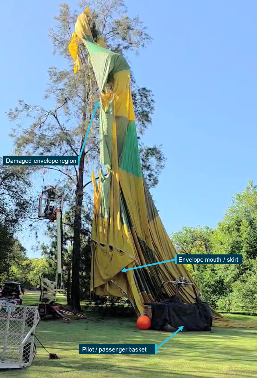
On final approach, the balloon encountered an abrupt wind direction change, with the track shifting right to 214 degrees. Judging that a landing was still possible ahead of the new direction of travel, the pilot transitioned to a landing, however there was insufficient space available to accommodate the balloon’s envelope, which contacted and became entangled with a tree as it deflated upon landing (Figure 1).
Neither pilot nor passengers were injured during the landing, however the envelope sustained substantial damage from the tree contact, with several fabric panels punctured and torn around the equatorial region.[1]
Figure 1: Entangled balloon envelope after landing
Source: Witness, annotated by the ATSB
Safety message
The ATSB SafetyWatchhighlights the broad safety concerns that come out of our investigation findings and from the occurrence data reported to us by industry. One of the safety concerns is Reducing passenger injuries in commercial ballooning operations.
Commercial ballooning operations was added to SafetyWatch after the ATSB identified a trend toward a heightened exposure to risk in the sector, as compared to other forms of charter aviation.
This occurrence reinforces the need for all hot air balloon pilots to be prepared to discontinue a landing approach if changing conditions result in an increased risk of contact with ground obstacles and hazards in the direction of flight.
The risks associated with landing profiles can change markedly with varying wind conditions. Pilots must plan onboard fuel loads and projected downwind tracks to ensure options remain open and viable for continued safe flight and subsequent landing/s, should an initial landing be rejected for any reason.
About this report
Decisions regarding whether to conduct an investigation, and the scope of an investigation, are based on many factors, including the level of safety benefit likely to be obtained from an investigation. For this occurrence, no investigation has been conducted and the ATSB did not verify the accuracy of the information. A brief description has been written using information supplied in the notification and any follow-up information in order to produce a short summary report, and allow for greater industry awareness of potential safety issues and possible safety actions.
[1]Balloon envelope equatorial region: the band of fabric panels extending around the circumference of the balloon envelope at its widest point.
On 5 January 2026, a Helicorp Leonardo Helicopters AW139 with 4 crew on board departed from its Canberra base in the Australian Capital Territory on a medical transport task to the Snowy Mountains, New South Wales. The task was the retrieval of a sick/injured hiker. While in the hover, after commencing to winch the paramedic down to the hiker’s location, the main rotors struck a tree, which had been previously identified by the crew as the nearest obstacle to the helicopter.
What the ATSB found
The crew positioned the helicopter with the nearest obstacle (a tree) in the pilot's blind spot prior to the pilot assuming sole responsibility for clearances to allow the air crew officer and paramedic to prepare for winching. Subsequently, the helicopter started to drift to the left prior to the air crew officer resuming responsibility for clearances.
The pilot did not detect and correct the helicopter’s drift towards its nearest obstacle while in the hover, which resulted in the main rotor striking the tree.
What has been done as a result
Following this occurrence, the operator:
released an operations manual bulletin to provide additional guidance on helicopter clearance limits and included an increased minimum lateral clearance of 20 ft (6 m) for the main rotors under all conditions
initiated a working group with the tasking agency to improve their operations
undertook post-incident assurance activities with the flight crew prior to their return to operations
conducted an updated refresher session on verbal escalation during sterile cockpit procedures
included methods and terminology for escalation in its current human factors training program.
Safety message
Always consider and plan for escape path options in mountainous terrain wherever practicable. In preparation to conduct the winch, the crew positioned the helicopter facing downslope, in the opposite direction to the approach. This provided the pilot with an escape path option for the helicopter, which they used immediately after the main rotor strike occurred.
In addition, the use of minimum clearances in confined areas should be limited to those occasions when the nearest obstacle(s) can be actively monitored by appropriately trained crew. If this is not achievable, then use greater margins wherever practicable.
The investigation
The ATSB scopes its investigations based on many factors, including the level of safety benefit likely to be obtained from an investigation and the associated resources required. For this occurrence, the ATSB conducted a limited-scope investigation in order to produce a short investigation report and allow for greater industry awareness of findings that affect safety and potential learning opportunities.
The occurrence
On 5 January 2026, at 1616 local time, a Helicorp (Toll Helicopters) Leonardo Helicopters AW139 with 4 crew members on board departed from its Canberra base in the Australian Capital Territory on a medical transport task to the Snowy Mountains, New South Wales. The task was a likely winch retrieval of a sick/injured hiker. The crew consisted of the pilot in the front right seat, air crew officer (ACO) in the front left seat, paramedic in the forward right cabin seat, facing rearwards, and doctor in the forward left cabin seat, facing rearwards.
En route to the reported location, the pilot assessed the helicopter’s performance and estimated that they would be 200 kg overweight for a winching operation. Consequently, the crew decided to conduct a search first, to confirm the hiker’s location and burn fuel, before conducting a power check and deciding if the doctor could remain on board for the winching. About 30 minutes after take-off, the paramedic detached from their harness and transitioned to a wander lead1 to prepare for the winching. The pilot also cleared the ACO to transition from the front left seat to the cabin and onto a wander lead.
On approach to the reported location, the low flying checks were completed, and the ACO opened the right cabin door for the search. The pilot then saw a flare appear below them on the right side of the helicopter and the ACO identified the hiker near a waterfall in a re-entrant,2 which was the reported location. They assessed that the helicopter would need to be flown slowly up the re-entrant towards the waterfall and then turned around prior to winching, to provide an escape route down the valley.
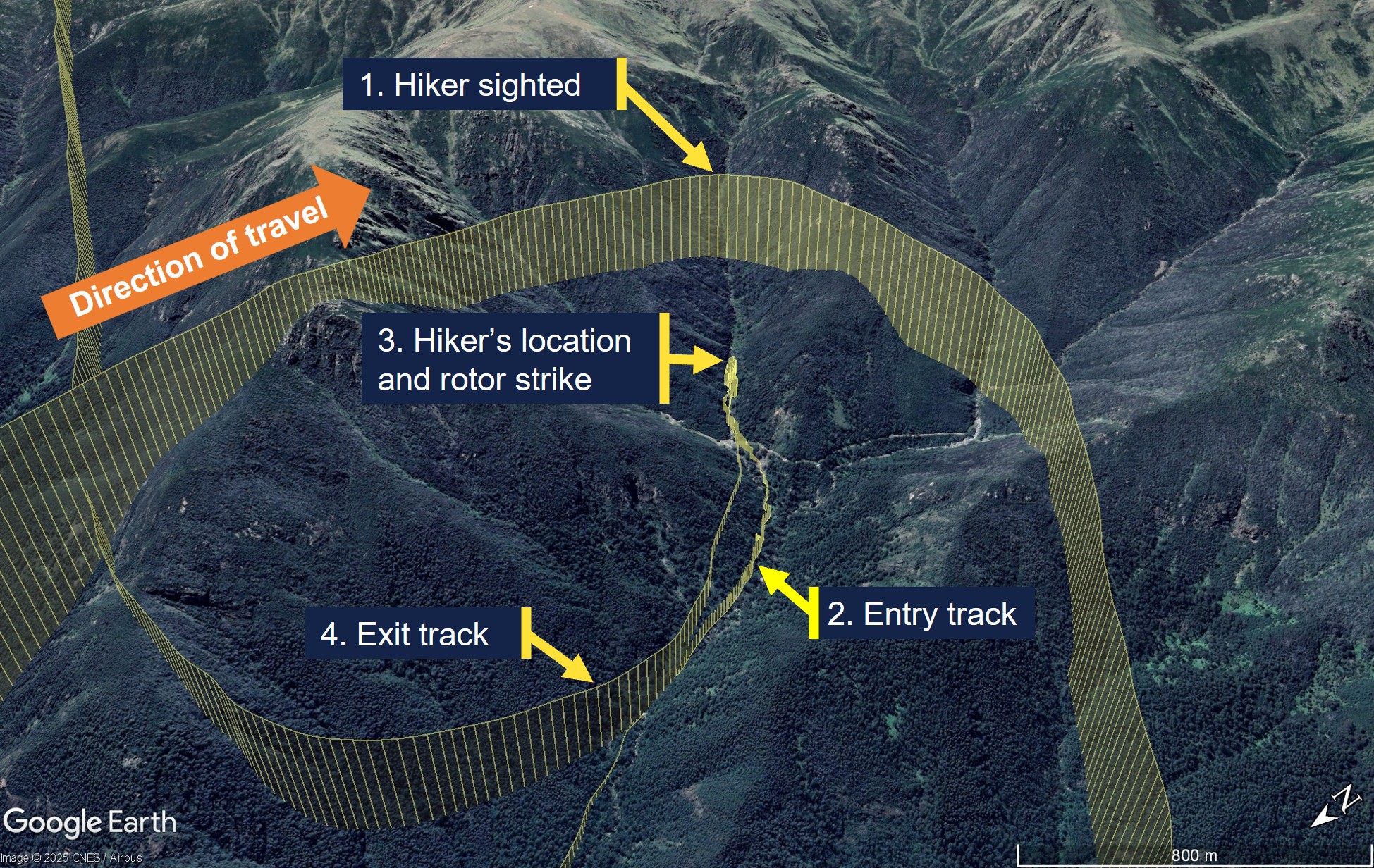
The crew conducted their winch checks and then the pilot conducted the power check and confirmed that the helicopter had sufficient power margin to keep the doctor on board for the winching. The helicopter then descended into the re-entrant and transited up the left side at slow speed (Figure 1). Before they reached the hiker’s location, the pilot momentarily stopped the transit as they experienced a ‘power-suck’3 and assessed that they had a tail wind. When the power stabilised, the pilot turned the helicopter around and reversed the helicopter into the re-entrant for the final 200 m to the hiker’s location.
Figure 1: Entry and exit tracks to the hiker’s location and rotor strike
Source: Toll Group and Google Earth, annotated by the ATSB
After turning the helicopter around, the left cabin door was opened to facilitate the ACO providing obstacle clearances to the pilot who reported that abort options were now down the valley. The crew took about 5 minutes to position the helicopter, assess the power and confirm that they were ready to winch. During this period, the ACO alternated between the open left and right cabin doors and announced clearances to the pilot, identifying the respective door from which they were provided.
The ACO briefed the pilot that the nearest obstacle was 20 ft away in the 8–9 o’clock position (left side) and directed the paramedic to the right cabin door to assess the ground below and plan the winching operation. The pilot subsequently asked if they could descend further and the ACO moved to the left door and instructed the pilot to descend 20 ft and move back 10 ft. This reduced the risk of a conical spin developing, due to the wind conditions in a narrow insertion point. After descending and backing further into the re-entrant, the pilot reported to the crew that they were starting to experience recirculation4, which was increasing the power requirements. Once all indications were normal and within limits, the pilot confirmed the winch operation could proceed. The paramedic and ACO then agreed on their winching location.
Prior to starting the winching, the left door was closed for cabin security. Before the ACO closed the left door, they briefed the pilot that the nearest obstacle was now a tree, 10 ft ‘above and to the left’ (this was 10 ft laterally in the 7–8 o’clock position and above the main rotor disk), and that there were also treetops about 35 ft below on the left. After the ACO closed the left cabin door, they pointed to the nearest obstacle through the window while instructing the doctor ‘that’s yours [name], keep an eye on that’, which the doctor acknowledged.
The ACO asked the pilot if they had a good hover reference, to which the pilot responded in the affirmative. The ACO then announced they were bringing the winch in to get the paramedic ready and that their ‘eyes are inside’, to which the pilot responded, ‘I’ve got the scan’. The ACO and paramedic conducted their pre-winch checks, and the paramedic was brought outside the right door on the winch, at which point the ACO confirmed with the pilot that they were clear to winch. However, before they started to winch, the ACO announced they needed to do the pre-winch brief and aircraft performance brief.
While the ACO was conducting the brief, the doctor was becoming concerned about the obstacle clearance on the left side but did not want to interrupt the ACO during safety‑critical checks. As soon as the ACO completed the briefs and started to winch the paramedic down, the doctor announced they had moved left ‘slightly’, and the ACO immediately cleared the pilot to move right ‘10’. This was followed by escalating calls from the ACO to the pilot to move right. As the pilot attempted to correct to the right, the main rotor struck the tree, and the calls from the ACO immediately changed to ‘move forward’. The pilot then transitioned the helicopter to forward flight while the ACO recovered the paramedic on the winch back into the cabin.
After the helicopter transitioned to forward flight, the pilot conducted a control check, and the ACO detected a clicking noise. The pilot announced that Perisher was the closest pad and requested confirmation of what struck the tree. The ACO and doctor confirmed it was the main rotor that struck the tree in the 7–8 o’clock position and not the tail rotor. The pilot made a PAN call to air traffic control, and the paramedic notified their base of the incident and that they would land at Perisher. The helicopter landed at Perisher at 1737 with minor damage. The hiker subsequently walked out and declined medical assistance.
Context
Personnel information
Pilot
The pilot spent 17 years in Army aviation as a line pilot and instructor. They held an Air Transport Pilot Licence (Helicopter), a class 1 medical certificate without restrictions, and had accumulated 6,880 hours flight experience, which included 2,065 hours on the AW139 with 84 hours in the previous 90 days. They joined the operator in 2016, completed the AW139 type rating in Italy, and started on the helicopter emergency medical service contract in 2017.
Air crew officer
The ACO spent 6 years in Army aviation before joining the operator about 4 years prior to the incident. They had accumulated about 1,700–1,800 hours flight experience, which included 800–900 hours on the AW139. The ACO’s 4 years with the operator included 1 year as a human factors instructor at their previous base.
Retrieval doctor
The doctor started with the emergency medical service 5 years prior to the incident as a registrar. They completed 1.5 weeks of aviation training with the operator, which included winch training and assessment. They conducted cyclic training 3 times per annum, which included human factors and safety management systems discussions with an incident case study. Crew resource management was incorporated in the human factors training.
The doctor reported that the incident flight was their first experience of being asked to monitor an obstacle in a confined area. They were not trained to provide clearances in their aviation training but were taught the safety call ‘climb, climb, climb’ if they had an immediate safety concern. Leading up to the main rotor strike they thought about the safety call but considered it was not appropriate with the obstacles above them and instead alerted the crew to the movement left.
Helicopter information
General information
The helicopter was a Leonardo Helicopters (formerly Agusta Westland) AW139, manufactured in Italy in 2015 and registered in Australia in December 2015. It was powered by 2 Pratt & Whitney Canada PT6C-67C gas turbine engines and fitted with 5 main rotor blades and 4 tail rotor blades.
To simplify the pilot’s instrument scan, a power index (PI) indicator is presented on the primary flight display for each engine. The PI combines the torque, temperature and gas generator speed instruments into a single indicator. While the PI is in the green range, no engine limits are exceeded. Above the green range, there is a yellow cautionary range, which indicates the take-off power range and above that, there are 2 red lines indicating maximum take-off PI and maximum transient PI.
Damage
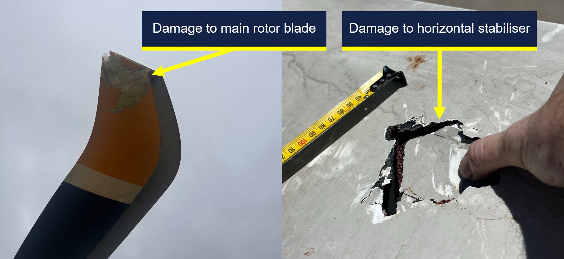
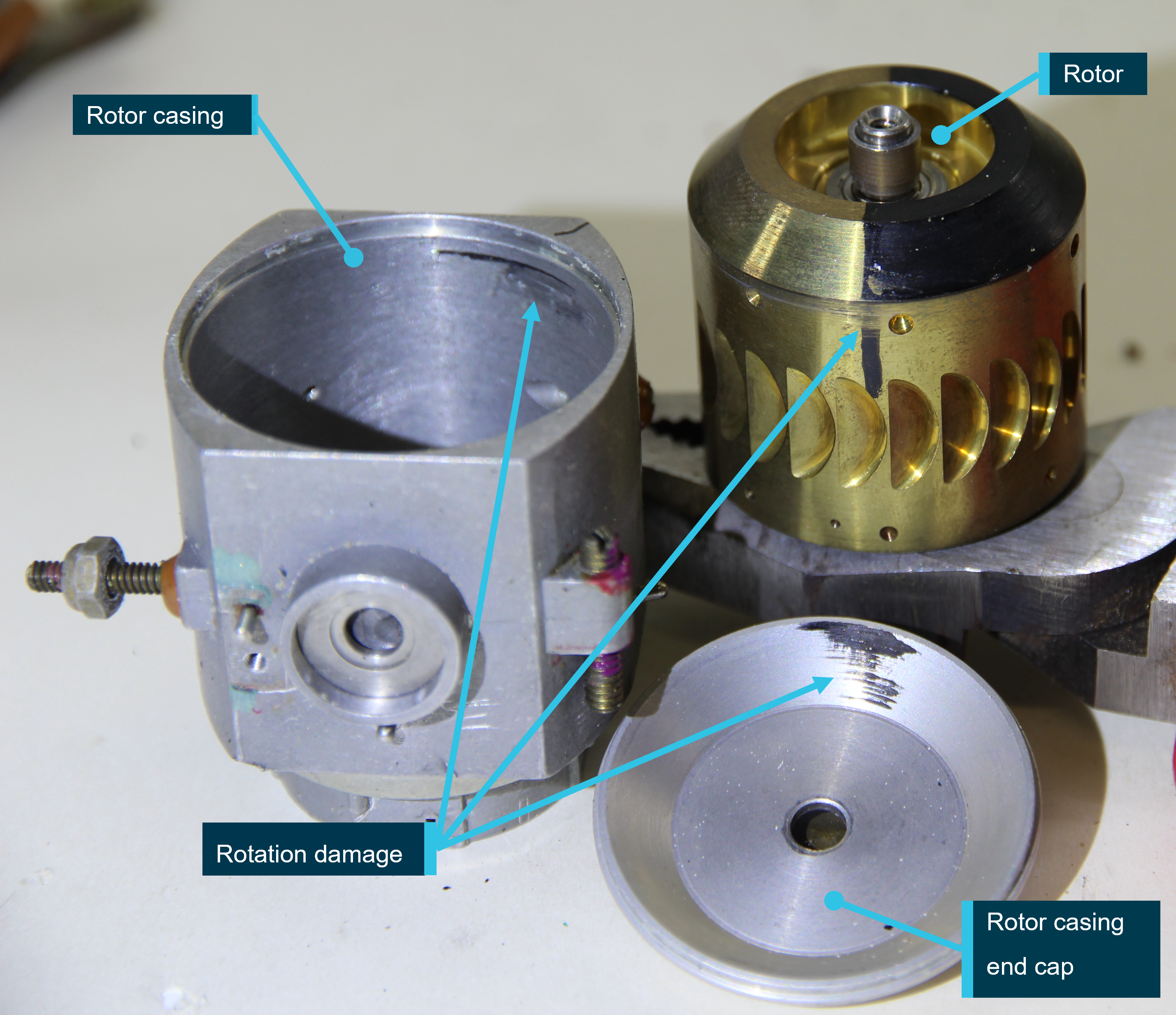
The operator reported minor repairable damage to 3 main rotor blade tips (Figure 2). In addition, there was minor damage to the horizontal stabiliser and tail boom, which were struck by debris from the tree struck by the main rotor.
Figure 2: Main rotor blade damage (left) and horizontal stabiliser damage (right)
Source: Toll Group, annotated by the ATSB
Recorded data
The aircraft was fitted with a Curtis-Wright Multi-Purpose Flight Recorder (MPFR), which contained the cockpit voice recorder and flight data recorder. The MPFR was provided to the ATSB and was successfully downloaded at the ATSB’s Canberra facilities on 7 January 2026. After download, the MPFR data was uploaded to the Flight Animation Software (FAS) program where the flight data and cockpit voice data were synchronised for analysis.
The FAS program revealed that the PI was fluctuating between the green and yellow ranges while the helicopter was in the hover in preparation for winching. However, the vertical speed was steady with only isolated momentary fluctuations of 50 ft/min rate of climb recorded.
When the ACO cleared the pilot to move right, away from their nearest obstacle, the helicopter rolled level from its left wing low hover attitude, the PI for both engines exceeded the maximum take-off PI red line momentarily and the vertical speed recorded a 100 ft/min rate of climb, followed by the main rotor strike.
The helicopter was also fitted with video-audio recording equipment in several locations, which included the cabin. A copy of the recordings for the accident flight were provided to the ATSB for review and analysis of the sequence of events in the cabin.
Operational information
Operations Manual Volume 2 – Rotary Wing
Volume 2 of the operator’s operations manual provided the rotor clearance requirement of 20 ft (6 m) horizontally from all obstacles. However, the manual also stated that by day only, and once established in the hover, the clearance could be reduced to 10 ft if it allowed for a more suitable winching position.
Operations Manual Volume 6 – Winching Operations
Volume 6 of the operations manual provided the following information for winching operations:
• Once established in the hover the PF [pilot flying] will normally be able to maintain position within the target area. However, there is often a requirement for minor repositioning whilst winching. During this precision manoeuvring the PF is relying on instruction from the ACO to accurately position the aircraft whilst remaining clear of any obstructions.
• A check of the left side of the aircraft must be conducted to identify the closest obstacle and ensure clearances are adequate. If the left door is opened to achieve this clearance, it must be closed prior to committing to the winch. At any time the ACO has their scan / eyes inside or checking the left, they are to advise this and receive acknowledgment from the PF.
• Once the ACO is back on the right side of the aircraft cabin, they are to ask the PF 'HOW IS YOUR HOVER REFERENCE?' If suitable references are available, the PF will respond with ‘HOVER REFERENCES ARE GOOD’ or request manoeuvring to improve references.
• WARNING: If suitable error tolerant hover references cannot be achieved by the PF, winching is not to be commenced.
The winching emergencies section of the manual included the emergency keywords ‘climb, climb, climb’ with the following caveat:
If not appropriate due to obstacles or terrain to call “CLIMB, CLIMB, CLIMB” a call for immediate aircraft movement is to be used in the required direction. For example: “LEFT, LEFT, LEFT”, “RIGHT, RIGHT, RIGHT” OR “MOVE FORWARD NOW.”
Safety analysis
The winch location was in a re-entrant near a waterfall, which required the pilot to turn and reverse the helicopter in for an assessment, before descending to a lower hover height for the planned winching operation. This provided the pilot with an escape route downslope and reduced the risk of a conical spin developing from a high winch but resulted in the nearest obstacle in the 7–8 o'clock position being in the pilot’s blind spot.
This obstacle was a tree with the nearest branch located above the main rotor disk and laterally clear of it by about 10 ft, which complied with the operator’s minimum clearance requirements. However, the proximity and height of the surrounding trees resulted in recirculation disturbing the helicopter from a stable hover position, which increased the control inputs required by the pilot compared with their initial higher hover height.
The ACO provided the pilot with obstacle clearances behind the helicopter until it was time to conduct their pre-winch checks with the paramedic, at which point nobody qualified was available to provide clearances to the rear of the helicopter. While the ACO and paramedic prepared for the winching, the doctor was monitoring their nearest obstacle to the rear left. When the ACO moved onto the pre-winch and aircraft performance briefs, the pilot was aware the ACO had returned to the right door, and the doctor started to sense the helicopter was drifting left towards their nearest obstacle. However, the ACO had not resumed providing clearances and the doctor’s training had reinforced the importance of not interrupting safety‑critical checks.
Due to the risk of a person descending on the winch snagging on the airframe, the ACO would not resume their scan to provide clearances until after the paramedic had descended below the airframe. However, when the ACO started their pre-winch brief at the right door, it was possible that either the pilot anticipated the ACO resuming their scanning role and relaxed their own scan, or that their attention was diverted from their external scan by the briefs, such that they did not detect and correct the helicopter’s drift.
The doctor alerted the crew to the fact that they appeared to be drifting to the left as soon as the ACO started to winch the paramedic down, which triggered a ‘move right’ call from the ACO to the pilot. In response, the pilot applied a small roll input to the right combined with a small increase in collective and the main rotors struck the nearby tree.
Findings
ATSB investigation report findings focus on safety factors (that is, events and conditions that increase risk). Safety factors include ‘contributing factors’ and ‘other factors that increased risk’ (that is, factors that did not meet the definition of a contributing factor for this occurrence but were still considered important to include in the report for the purpose of increasing awareness and enhancing safety). In addition, ‘other findings’ may be included to provide important information about topics other than safety factors.
These findings should not be read as apportioning blame or liability to any particular organisation or individual.
From the evidence available, the following findings are made with respect to the main rotor strike involving Leonardo Helicopters AW139, VH-TJF, 42 km south-east of Corryong Airport, New South Wales, on 5 January 2026.
Contributing factors
The crew positioned the helicopter with the nearest obstacle (a tree) in the pilot's blind spot prior to the pilot assuming sole responsibility for clearances to allow the air crew officer (ACO) and paramedic to prepare for winching. Subsequently, the helicopter started to drift prior to the ACO resuming responsibility for clearances.
The pilot did not detect and correct the helicopter’s drift towards its nearest obstacle while in the hover, which resulted in the main rotor striking a nearby tree.
Safety actions
Whether or not the ATSB identifies safety issues in the course of an investigation, relevant organisations may proactively initiate safety action in order to reduce their safety risk. The ATSB has been advised of the following proactive safety action in response to this occurrence.
Safety action by Helicorp
The operator released an Operations Manual Bulletin in response to the incident, which addressed the following points:
increased their rotor clearance limit to 20 ft (6 m) in all circumstances
provided additional guidance on determining spacing from overhanging obstacles
provided additional guidance on the requirements for error tolerant references
emphasised the need to prioritise error tolerant hover reference(s) selection over escape and downwash considerations.
A working group was initiated between the operator and tasking agency to improve interagency operations. Additionally, post-incident assurance activities were undertaken with the flight crew prior to their return to operations and an updated refresher session on verbal escalation during sterile cockpit procedures was conducted. Methods and terminology for escalation have also been included in their current human factors training program.
Sources and submissions
Sources of information
The sources of information during the investigation included the:
ACT Ambulance Service
cabin video footage and audio of the incident flight
operator, its head of aviation safety and quality, and its investigator
pilot, air crew officer and retrieval doctor of the incident flight
recorded data from the MPFR unit on the aircraft.
Submissions
Under section 26 of the Transport Safety Investigation Act 2003, the ATSB may provide a draft report, on a confidential basis, to any person whom the ATSB considers appropriate. That section allows a person receiving a draft report to make submissions to the ATSB about the draft report.
A draft of this report was provided to the following directly involved parties:
Agenzia Nazionale Per La Sicurezza Del Volo (ANSV, Italy)
air crew officer
Civil Aviation Safety Authority
Leonardo Helicopters
operator
pilot
retrieval doctor.
Submissions were received from:
air crew officer
Civil Aviation Safety Authority
operator
pilot.
The submissions were reviewed and, where considered appropriate, the text of the report was amended accordingly.
Purpose of safety investigations
The objective of a safety investigation is to enhance transport safety. This is done through:
identifying safety issues and facilitating safety action to address those issues
providing information about occurrences and their associated safety factors to facilitate learning within the transport industry.
It is not a function of the ATSB to apportion blame or provide a means for determining liability. At the same time, an investigation report must include factual material of sufficient weight to support the analysis and findings. At all times the ATSB endeavours to balance the use of material that could imply adverse comment with the need to properly explain what happened, and why, in a fair and unbiased manner. The ATSB does not investigate for the purpose of taking administrative, regulatory or criminal action.
About ATSB reports
ATSB investigation reports are organised with regard to international standards or instruments, as applicable, and with ATSB procedures and guidelines.
Reports must include factual material of sufficient weight to support the analysis and findings. At all times the ATSB endeavours to balance the use of material that could imply adverse comment with the need to properly explain what happened, and why, in a fair and unbiased manner.
An explanation of terminology used in ATSB investigation reports is available here. This includes terms such as occurrence, contributing factor, other factor that increased risk, and safety issue.
Publishing information
Released in accordance with section 25 of the Transport Safety Investigation Act 2003
Ownership of intellectual property rights in this publication
Unless otherwise noted, copyright (and any other intellectual property rights, if any) in this report publication is owned by the Commonwealth of Australia.
Creative Commons licence
With the exception of the Commonwealth Coat of Arms, ATSB logo, and photos and graphics in which a third party holds copyright, this report is licensed under a Creative Commons Attribution 4.0 International licence.
The CC BY 4.0 licence enables you to distribute, remix, adapt, and build upon our material in any medium or format, so long as attribution is given to the Australian Transport Safety Bureau.
Copyright in material obtained from other agencies, private individuals or organisations, belongs to those agencies, individuals or organisations. Where you wish to use their material, you will need to contact them directly.
1
^ A wander lead is a flexible safety tether used by crew members to maintain a secure connection to the aircraft while allowing them to move freely around the cabin.
2
^ A re-entrant appears on the map as a U or V shape in the contour lines, pointing back into a hillside rather than sticking out of the hill (as would a spur).
3
^ A sudden increase in the power required to maintain the desired flight path.
4
^ Recirculation is a condition in which a helicopter’s rotor system ingests its own downwash, reducing rotor efficiency and degrading lift and control response.
Occurrence summary
Investigation number
AO-2026-002
Occurrence date
05/01/2026
Occurrence time and timezone
17:25 Eastern Daylight-saving Time
Location
42 km south-east of Corryong Airport
State
New South Wales
Report release date
19/05/2026
Report status
Final
Investigation level
Short
Investigation type
Occurrence Investigation
Investigation phase
Final report: Dissemination
Investigation status
Completed
Mode of transport
Aviation
Aviation occurrence category
Controlled flight into terrain (CFIT), Forced/precautionary landing
Occurrence class
Serious Incident
Highest injury level
None
Aircraft details
Manufacturer
Leonardo Helicopters
Model
AW139
Registration
VH-TJF
Serial number
31710
Aircraft operator
Helicorp Pty Ltd
Sector
Helicopter
Operation type
Part 133 Air transport operations - rotorcraft
Activity
Commercial air transport-Non-scheduled-Medical transport
Departure point
Southcare Base Helicopter Landing Site, Australian Capital Territory
On 18 September 2025, the pilot of a Cirrus SR20, registered VH-TEL, planned to conduct a personal flight under visual flight rules (VFR) from Bankstown Airport, New South Wales, to Mount Kosciuszko (without landing) and return. The pilot was the sole occupant on board.
The pilot took off from Bankstown Airport and flew south to, and then around, Mount Kosciuszko. The pilot then flew to Mallacoota Airport, Victoria, tracking overhead various aerodromes.
Once passing Mallacoota Airport the pilot began to descend while tracking north towards Merimbula Airport, New South Wales. Recorded data indicated that the pilot began to receive warnings about a high engine cylinder head temperature in cylinder 4. Additionally, there was low cloud in the area ahead.
While descending towards Moruya Airport, the pilot contacted Melbourne Centre air traffic control stating an intention to land. There were no further radio calls from the pilot. The pilot continued to track towards Moruya Airport before diverting to the west, continuing north-west towards the Great Dividing Range.
The pilot continued north-west for 13 minutes at 2,500 ft. For the remainder of the flight, the pilot maintained an altitude between 2,000 and 2,700 feet above mean sea level (AMSL), with intermittent climbs and descents. The mountainous area had fluctuating terrain heights, with a maximum terrain height of about 2,900 ft.
At 1458 the aircraft collided with terrain in dense forest in the Budawang National Park. The aircraft was destroyed, and the pilot was fatally injured.
What the ATSB found
The commencement of an approach to land at Moruya was not part of the flight plan and most likely the result of the warning and/or cloud ahead. It is unclear why the pilot made the decision to continue the flight rather than land at Moruya, as poor weather was present ahead of the aircraft and the pilot would have been seeing fluctuating cylinder temperature warnings. However, with limited prior experience in cross-country flights and facing deteriorating weather conditions, the pilot would have been less able to objectively weigh the cumulative hazards of continuing into adverse weather.
The decision to deviate inland from the initial planned track and toward higher terrain was likely influenced by the perceived presence of a clear area ahead in the cloud layer. This gap, evident at the approximate time the aircraft passed to the west of Moruya Airport, would have presented a visually clearer path to the pilot. Furthermore, there was cloud over Moruya Airport and the pilot may have considered that maintaining VMC throughout an approach and landing there might not have been feasible. The cylinder head warnings were likely spurious but, even if the pilot had understood this, the warnings would have been an ongoing source of distraction.
Following the decision to continue, tracking data showed the aircraft proceeding into the mountainous area of the Great Dividing Range, then almost reversing course at low altitude along a valley within the Great Dividing Range, consistent with an attempt to avoid cloud. Once in the valley, it is likely that the pilot did not know what direction to take away from the mountainous areas and cloud or, if they did, became trapped between the rising terrain and the low cloud base.
It is therefore likely that the pilot inadvertently entered instrument meteorological conditions (IMC) and became unable to regain visual references, which led to a loss of terrain awareness and the subsequent controlled flight into terrain.
Safety message
Research and investigations by the ATSB continue to show that weather‑related accidents remain one of the most persistent accident types in general aviation. When operating under visual flight rules (VFR), pilots must always be prepared to make conservative decisions when weather conditions begin to deteriorate. If visibility is reducing or the cloud base is lowering, pilots should strongly consider landing at the nearest suitable location rather than continuing into worsening conditions. Making an early decision to land, delay, or turn back can prevent a situation where safe flight cannot be maintained.
Attempts to maintain visual contact with the ground in marginal weather, commonly referred to as ‘scud running’, significantly increase the risk of controlled flight into terrain (CFIT). Reduced visibility, low cloud, and poor contrast can quickly lead to disorientation or collision with unseen obstacles or terrain. Continuing flight in these conditions often provides little margin for error, especially at low altitude.
Pilots are reminded to maintain situational awareness and resist the pressure to continue to a planned destination (commonly referred to as ‘get-there-itis’) when conditions no longer support safe visual flight. Additionally, if VFR pilots find themselves in marginal weather and becoming disoriented or lost, they should seek whatever help is available. Air Traffic Services (ATS) may be able to provide assistance, especially if the aircraft is in ATS surveillance coverage. There have been a number of reported occurrences where this simple action has averted potential disaster.
The investigation
The ATSB scopes its investigations based on many factors, including the level of safety benefit likely to be obtained from an investigation and the associated resources required. For this occurrence, the ATSB conducted a limited-scope investigation in order to produce a short investigation report, and allow for greater industry awareness of findings that affect safety and potential learning opportunities.
The occurrence
On 18 September 2025, the pilot of a Cirrus SR20, registered VH-TEL, planned to conduct a pleasure flight under visual flight rules (VFR)[1] from Bankstown Airport, New South Wales, to Mount Kosciuszko (without landing there) and return. The pilot would be the sole occupant.
The pilot arrived at Bankstown Flying School (BFS), from which the aircraft was being hired, at about 0900. The owner of the flying school recalled the pilot requested assistance in how to add locations with no designated waypoints (Mount Kosciuszko and Thredbo) into their flight plan. After assisting with their flight plan, the owner asked the pilot about the weather for their planned route and information about last light.[2] The pilot had reported the weather was good for the flight and that last light was at 1800, however they planned to be back by 1700.
At 0910 the pilot took the aircraft out of the hangar and had it refuelled. The owner recalled the aircraft should have been filled to full prior to the flight.
At approximately 1113 local time, the pilot took off from Bankstown Airport. Recorded data from the onboard GPS showed that once airborne, the pilot tracked to waypoint CAMB (Campbelltown University), passing 2,500 ft above mean sea level (AMSL) at 1121. The aircraft continued climbing through 4,500 ft while passing waypoint PIC (Picton) and at 1131 the aircraft was levelled off at 6,500 ft (Figure 1).
At 1150 the pilot began climbing to 8,500 ft and levelled off just prior to flying over the former Braidwood aircraft landing area (ALA).[3] The pilot continued to fly to and then around Mount Kosciuszko before climbing again to 9,500 ft. The pilot then flew for approximately 40 minutes to (overhead) Mallacoota Airport, Victoria, tracking overhead various aerodromes.
Figure 1: Flight path overview
Source: Google Earth, annotated by the ATSB
Once passing Mallacoota Airport at 1342, aircraft flight data showed the pilot began to descend while tracking towards Merimbula Airport, New South Wales, and then continued further north.
At about 1426, the pilot contacted Melbourne Centre air traffic control (ATC) stating:
Moruya traffic Cirrus Tango Echo Lima is one zero miles south inbound with a straight in approach runway 36 thanks
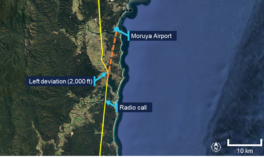
There were no further radio calls from the pilot. The pilot continued to track towards Moruya Airport at 2,000 ft before diverting left and climbing to 2,500 ft passing the airport to the west at 1431 (Figure 2).
Figure 2: Diversion from Moruya Airport approach track
Source: Google Earth, annotated by the ATSB
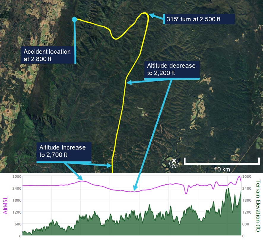
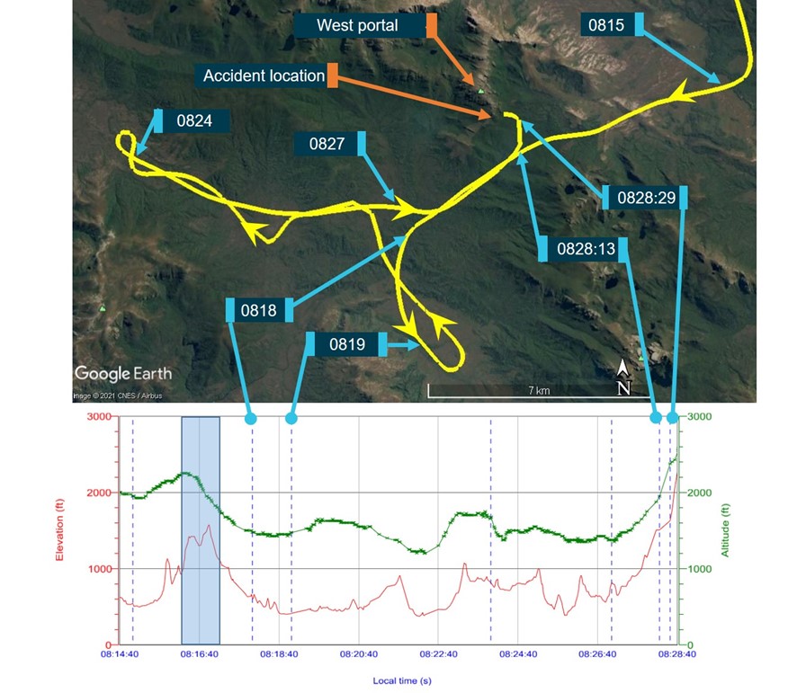
The pilot continued north-west for 13 minutes at about 2,500 ft AMSL. For the remainder of the flight, the pilot maintained an altitude between 2,000 and 2,700 feet AMSL, with intermittent climbs and descents (Figure 3). The mountainous area had fluctuating terrain heights, with a maximum terrain height in the area of about 2,900 ft.
Approximately one minute prior to the collision, the aircraft’s speed decreased to 69 kt before rapidly increasing to 101 kts just prior to the collision with terrain.
At 1454 the aircraft collided with terrain in dense forest in the Budawang National Park at 2,800 ft AMSL. The aircraft was destroyed, and the pilot was fatally injured.
The aircraft’s emergency locator transmitter (ELT) activated in the accident, alerting the Australian Maritime Safety Authority (AMSA) Joint Rescue Coordination Centre (JRCC).
A rescue helicopter located the wreckage at about 1700 on 18 September, however rescue crews were unable to access the site due to the weather. The site was first accessed the following day by winch at about 1300. Rescue crew and police confirmed the occupant was deceased.
Figure 3: Flight path of the last 15 minutes of the flight
The lower plot does not show the point of impact, because the data recording ceased prior to that point. Source: Google Earth, annotated by the ATSB
Context
Pilot information
License and endorsements
The pilot held a Civil Aviation Safety Regulation Part 61 Private Pilot (Aeroplane) Licence, single-engine aeroplane class rating, night VFR rating for single-engine aeroplanes, and endorsements for manual propeller pitch control and retractable undercarriage. The pilot had held a licence since 1979. Their last flight review was on 2 November 2023 in VH-TEL and was valid until 30 November 2025.
Flying history
The pilot ceased flying between mid-1988 and early 2008. Between January 2008 and February 2021, 6 flights were recorded, all conducted as in command under supervision (ICUS).
The pilot had accumulated 306.5 hours experience through to 10 February 2021. On 19 October 2021, the pilot commenced a PPL refresher course with BFS for the purpose of completing a flight review.
The pilot’s logbook indicated flights beginning in June 2024 and noted that their prior logbook had been stolen. It recorded that at the time of the accident the pilot had approximately 443.7 flight hours, including 4.5 hours in VH-TEL in the last 90 days.
Additional flight data retrieved from the flying school on the pilot’s flight prior to June 2024 indicated that, at the time of the accident, the pilot had accumulated approximately 515 total flight hours.[4] Of these, approximately 60 hours were on the Cirrus SR20 aircraft since the pilot’s initial flight in the Cirrus in June 2023. All of these flights were conducted in VH-TEL.
Flight review and training
In October 2021 the pilot completed a training area flight and circuits flight. Additionally, the pilot completed 3 navigation flights in November 2021, January 2022 and February 2022 with a BFS Grade 2[5] flight instructor, in preparation for the pilot’s flight review for the PPL refresher course. On completion of the third navigation flight, the instructor recommended the pilot fly with a Grade 1 instructor to assess their ability relative to the flight review standards required.
The Grade 1 instructor conducted 2 navigation flights with the pilot and reported the flight review was successfully completed after the second navigation flight with the remark that the pilot needs to ease back into flying. This flight review was completed on 18 May 2022, which was the signatory date for the pilot’s application to transfer their licence from Civil Aviation Regulations 1988 (CAR) Part 5 to Civil Aviation Safety Regulations 1998 (CASR) Part 61. The flight review had been conducted in a Piper PA‑28 Archer II (VH‑NRM).
The pilot enrolled in the CirrusSR20Perspective Transition (VFR) course[6] on 13 May 2023. The flights were conducted in June and July 2023, which was prior to the pilot’s flight review in VH-TEL on 2 November 2023. None of the 5 flight lessons included instrument meteorological conditions (IMC)[7] recovery as a task.
In addition to the flights, the pilot completed the Cirrus SR Series Manoeuvres Course, which was a series of videos, which included the following topics:
• VFR into IMC
• Straight and Level
• Level Turns
• Climbs and Descents
• Find Your Way Out [of IMC]
• Flight Into IMC Demo.
Following the completion of their SR20 conversion training in November 2023, the pilot operated the SR20, specifically VH-TEL, on an average of 2 flights per month until March 2025. From March to June 2025, the pilot transitioned to flying the Piper PA-28 on a biweekly basis.
Due to the pilot’s recent absence from operating the SR20 during this timeframe, a currency flight was required in July 2025. This flight was conducted on 4 July 2025 in VH‑TEL, under the supervision of an instructor. The instructor recorded in the student progress record and advised the ATSB that several technique errors occurred during the flight, which resulted in the instructor assessing the pilot as not competent. The pilot returned to flying the PA-28, completing 2 flights in the Sydney area, both scenic.
On 6 August 2025, the pilot conducted a second currency flight in VH-TEL with a different flight instructor. This was a flight into the training area before returning for circuits. The instructor recorded on the progress record that the pilot’s groundwork was good, and radio calls were well executed. The departure was performed satisfactorily, the approach was adequate, and the landing was described as very good and smooth. The instructor noted that the pilot flew the aircraft satisfactorily but required further attention to airspace management. Following this flight, the pilot was assessed as competent to operate the SR20.
There was no record of the pilot having conducted or completing any other relevant instrument flying training or qualifications.
Medical information
The pilot held a valid class 2 aviation medical certificate which was approved in March 2025. The only limitation to the pilot’s medical certificate was for reading correction to be available while exercising the privileges of their licence.
The owner of BFS reported that the pilot looked healthy and displayed normal behaviour on the morning of the flight.
Post-mortem examination and toxicology reports were not available to the ATSB at the time of publishing this report.
Aircraft information
The Cirrus SR20 is a low-wing general aviation aircraft with 5 seats. VH-TEL had a single, Continental IO-360-ES26B reciprocating piston engine driving a constant-speed propeller. The aircraft was certified for day and night VFR and instrument flight rules (IFR)[8] operations.
VH-TEL was manufactured in 2014 and was first registered in Australia on 5 September 2014. The aircraft had been registered with BFS since April 2020, and at the time of the accident had accumulated 1,725.8 hours total time in service.
The aircraft was fitted with the Cirrus airframe parachute system (CAPS). This was designed to lower the aircraft and its passengers to the ground in the event of a life‑threatening emergency and could be activated by the pilot. The CAPS system consisted of a parachute, a solid-propellant rocket used to deploy the parachute, an activation handle, and a parachute harness embedded within the fuselage structure.
Meteorological information
Bureau of Meteorology forecasts
The applicable graphical area forecasts (GAF) available to the pilot for the flight were both issued at 0804 local and valid for the periods 0900–1500 and 1500–2100. The location of the accident was in Area A on the GAF. Area A for the period 0900–1500 forecast broken cumulus/stratocumulus from 3,000–7,000 ft.
The TAF[9] for Canberra was CAVOK[10] conditions. The TAF for Moruya[11] included light showers of rain and a broken cloud base at 3,000 ft AGL. The TAF for Jervis Bay was a broken cloud base at 1,600 ft AGL becoming scattered at 3,000 ft AGL from 1100–1300 but with TEMPO periods from 0700–1200 for visibility reduced to 4,000 m with a scattered cloud base at 600 ft AGL and a broken cloud base at 1,000 ft AGL.
Bureau of Meteorology observations
At 1430, the meteorological aerodrome report (METAR)[12] for Moruya Airport reported wind from the east-north-east at 7 kt (60°), visibility greater than 10 km and cloud overcast at 4,900 ft AGL. The METAR at Jervis Bay Airfield reported wind from the west‑south-west at 8 kt (240°), visibility greater than 10 km and cloud scattered from 2,100 ft and overcast above 2,900 ft AGL.
At 1500, the cloud cover had changed at both locations (Table 1).
Table 1: Reported METAR/SPECI[13] cloud layers at nearest airports
Location
Time
1400
1430
1500
Moruya Airport
OVC 3,300ft AGL
SCT 3,600ft AGL
BKN 4,300ft AGL
OVC 4,900ft AGL
SCT 3,200ft AGL
BKN 4,700ft AGL
OVC 5,300ft AGL
Jervis Bay Airfield
OVC 2,100ft AGL
OVC 2,700ft AGL
SCT 2,100ft AGL
OVC 2,900ft AGL
FEW 3,100ft AGL
BKN 5,100ft AGL
BKN: broken; OVC: overcast; SCT: scattered
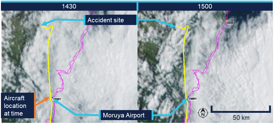
Bureau of Meteorology satellite images (Figure 4 – left) showed cloud covering the Budawang National Park mountains at 1430. At 1500 (Figure 4 – right) the satellite imagery indicated a reduction in cloud cover, with partial clearing evident and some breaks observed in the cloud layer. The images provided no information on cloud height, or density at a given height.
Figure 4: Satellite image showing cloud formation on 18 September at 1430 and 1500 local time
The flight path was overlaid on the satellite image to illustrate the route relative to the weather. The actual flight occurred below the cloud base. Source: Bureau of Meteorology, annotated by the ATSB
Witness observations of weather
A witness located approximately 3 km west of the accident site reported hearing the aircraft, however, was unable to locate it in the sky due to fog.[14] They reported that prior to the fog, low lying cloud had been covering the tops of the mountains in the area where the collision with terrain occurred from approximately 1130.
Another witness who was in Wog Wog (10 km north of the accident site) stated that there had been low cloud and drizzle from 1100. They described the visibility to have been ‘okay’ at ground level but poor near the tops of the mountains.
Additionally, the operator for the rescue helicopter reported they were unable to access the site due to low lying cloud (Figure 5).
Figure 5: Cloud over the accident site between 1640 and 1703 local time
Top left and top right: cloud coverage to the north of the accident site. Bottom left: overhead the accident. Bottom right: view of the accident site and surrounding weather from the east. Source: ACT Emergency Services Agency, annotated by the ATSB
Accident site and wreckage
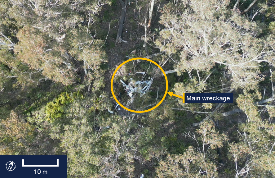
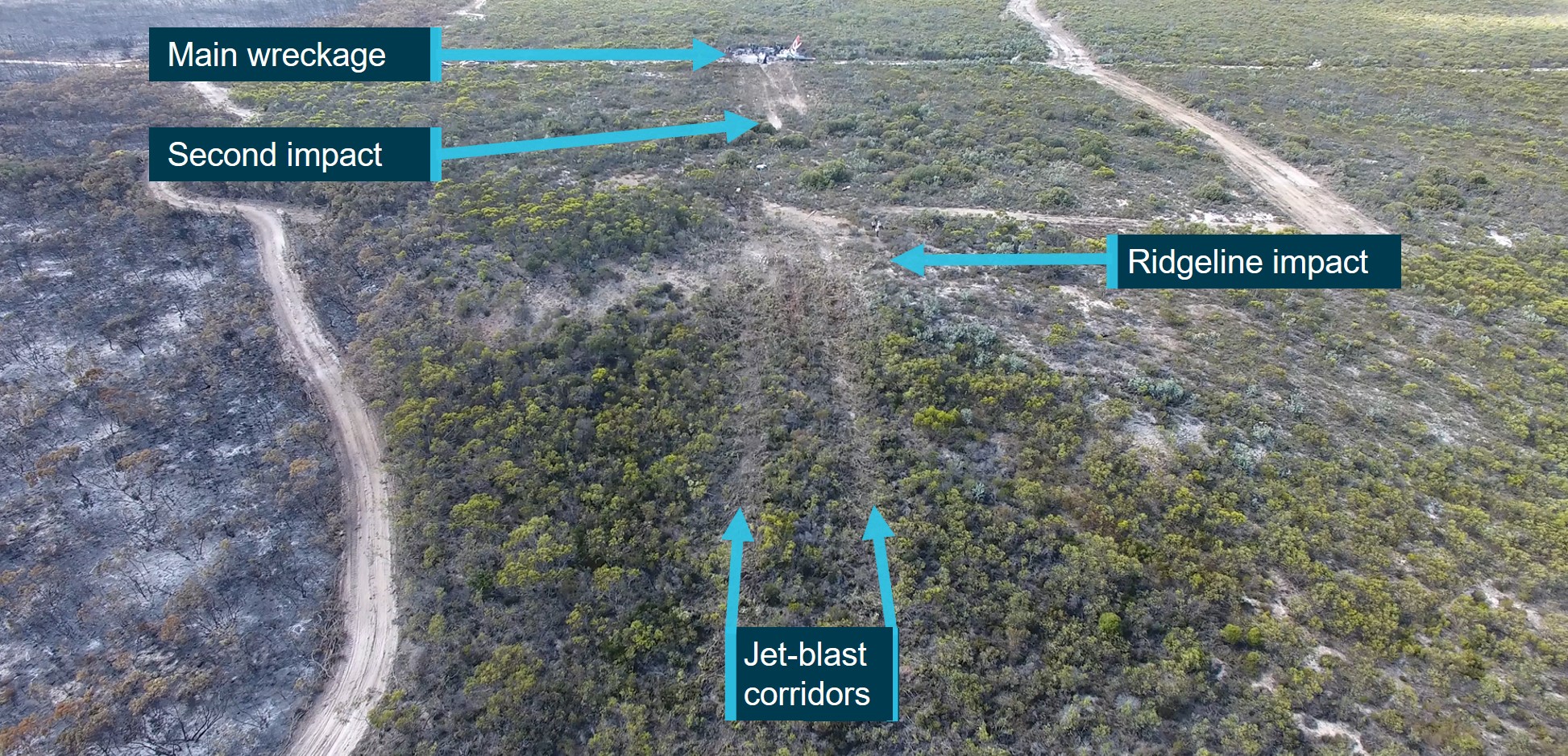
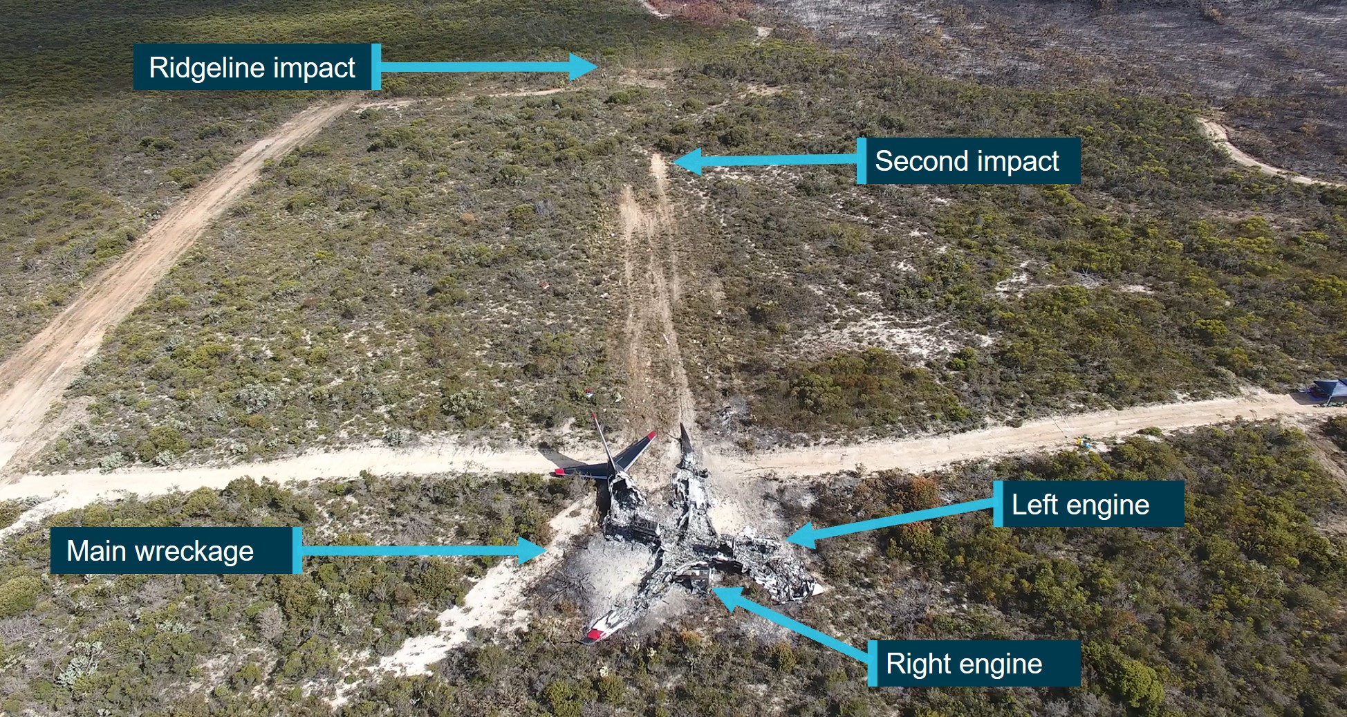
The aircraft wreckage was located in heavily vegetated, steep, mountainous terrain (Figure 6).
Figure 6: Overhead view of accident site
Source: ATSB
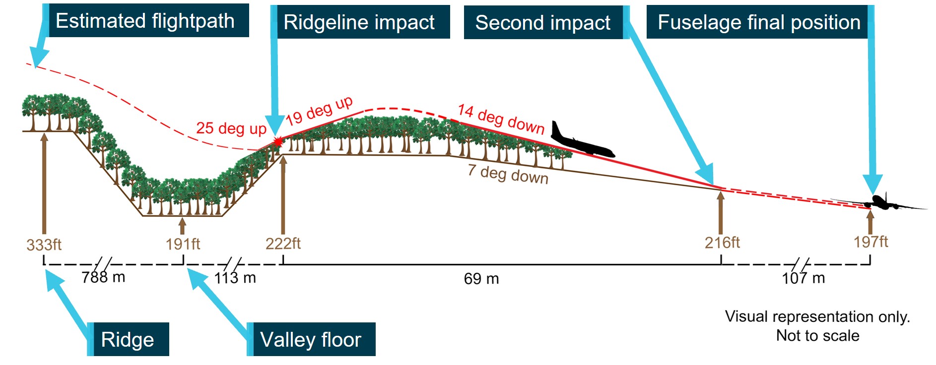
The ATSB conducted an examination of the accident site and wreckage on 21 September. The aircraft impacted the side of the mountain and slid backwards from the direction of travel until supported on the slope by some small trees. Ground impact marks and impact marks on the trees indicated the aircraft entered the trees with wings and fuselage almost level.
All of the flight controls and surfaces were accounted for on site and no evidence of in‑flight break‑up or pre-impact control issues was identified.
Onsite examination of the engine did not reveal any pre-impact mechanical issues. The propeller assembly had separated from the engine crankshaft, with propeller deformation consistent with the engine producing power at impact. The left- and right-wing fuel tanks had both been compromised and a fuel odour was present.
Data cards from a Garmin G1000 electronic flight instrument system and the aircraft’s data recovery module (RDM)[15] were recovered from the accident site (see Recorded data).
Cockpit assessment revealed the fuel selector was on the right tank, the flaps were set at 50%[16] and the fuel pump was off.[17]
The CAPS had not been activated.
Recorded data
Garmin 1000
The aircraft was fitted with a Garmin G1000 electronic flight instrument system consisting of one primary flight display and one multi-function display (MFD). The G1000 had a 58‑channel flight and engine parameter data logging capability at a rate of one data point per second. A memory card was retrieved from the device, which contained recorded data from multiple flights, including the accident flight.
The final recorded data point was 2 seconds prior to impact and indicated that the engine was producing normal power until impact. Additionally, the data indicated there was sufficient fuel flow to the engine and there was approximately 10.8 US gallons in the left tank and 7.4 US gallons in the right tank of fuel remaining. This was consistent with ATSB estimates of fuel usage, which also indicated that the aircraft would have had about 48 minutes endurance on landing if the flight had been able to continue to Bankstown Airport with the same engine power applied.
Cylinder head temperature
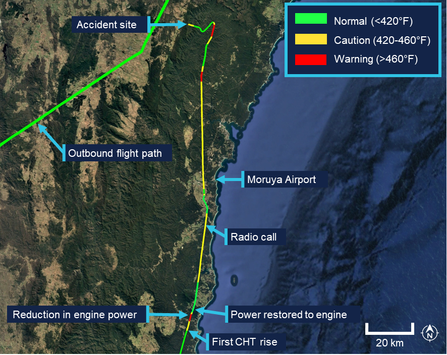
Recorded engine data indicated the number 4 cylinder head temperature (CHT) increased from the normal operating range into the caution range when the aircraft was about 33 NM (61 km) south of Moruya Airport. Approximately one minute later, the temperature increased into the warning range.
The MFD installed in the cockpit displays CHT information and cautions/warnings. The MFD typically displays individual cylinder CHT as a vertical bar graph scaled from 100°F to 500°F in 100°F increments on the left-hand side of the MFD (Figure 7). Additionally, an engine information page can be selected by the pilot displaying individual cylinder CHT as a vertical bar graph with the current temperature value displayed numerically above the bar. An upward or downward trend arrow is shown below the numeric value to indicate whether the temperature is rising or falling. The G1000 did not record which pages were selected by the pilot at any given time.
Figure 7: MFD engine indication system (EIS) panel, showing the vertical coloured bars indicating a CHT warning state for engine cylinder 4 temperature
Source: Garmin, annotated by the ATSB
The pilot operating handbook (POH) published limits for the CHT were as follows, with the bar graph coloured accordingly:
Normal range < 420°F (green)
Caution range 420–460°F (yellow)
Warning range > 460°F (red)
According to the POH:
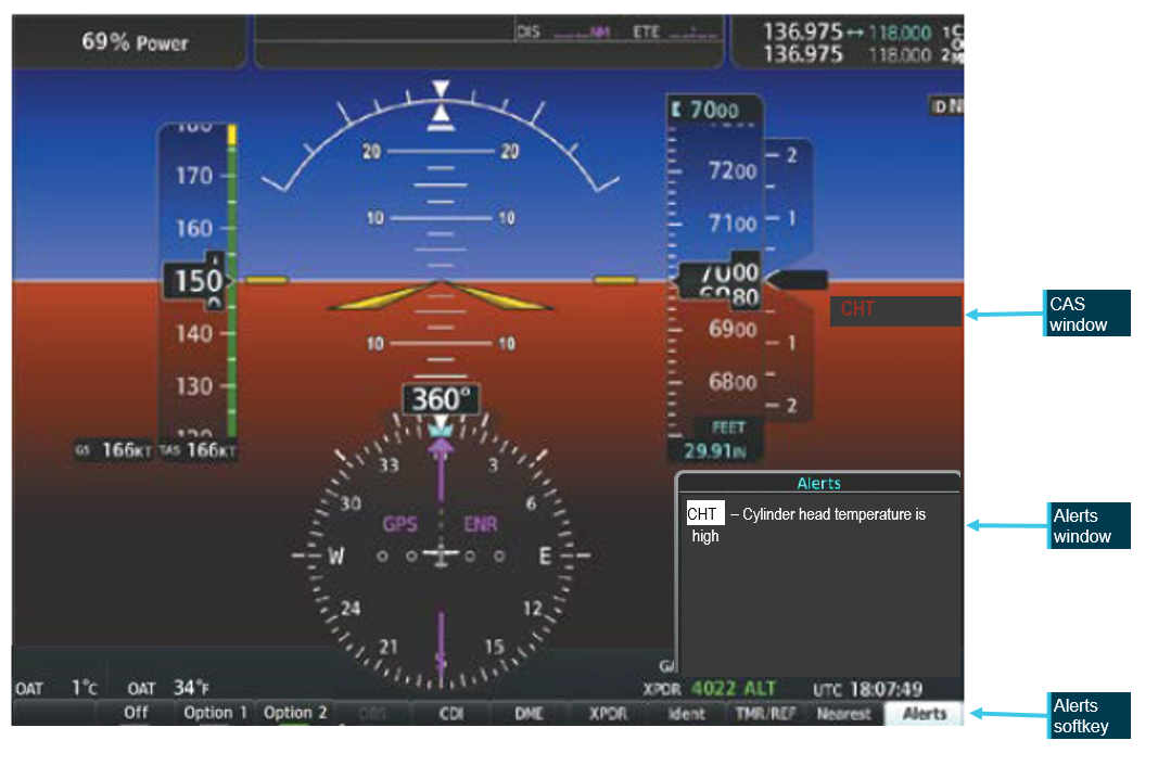
In the event CHT exceeds 420°F, the MFD will display “Check CHT” in a yellow advisory box in the lower right corner of the MFD. In the event CHT exceeds 460°F, the MFD will display “Check CHT” in a red advisory box in the lower right corner of the MFD.
Figure 8: Exemplar window showing the crew alerting system (CAS) location and text for a CHT warning, the highlighted alerts softkey, and related alerts window text
Source: Garmin, annotated by the ATSB
The emergency procedure for a high cylinder head temperature from the Cirrus SR20 Airplane Flight Manual (AFM) indicated that if the CHT is in the caution range to land as soon as practical, and if it is in the warning range to land as soon as possible.[18]
For the remainder of the flight, the CHT of cylinder 4 continued to fluctuate, repeatedly moving between the normal (green), caution (yellow), and warning (red) ranges (Figure 9).
Following the initial rise in CHT into the warning range, the recorded engine data showed the pilot commanded a reduction in engine power over an approximately 30 second period, maintaining the reduced power for about one minute further. This is consistent with standard practice for managing elevated CHT. Approximately one minute after the power was reduced, as the CHT decreased and stabilised within the normal (green) operating range, and the data indicated the pilot then restored engine power to the previous level.
Figure 9: Number 4 cylinder head temperature readings throughout the last 1.5 hours of the flight
Source: Google Earth, annotated by the ATSB
The ATSB compared the recorded CHT and exhaust gas temperature (EGT) data for cylinder 4 in order to determine whether the observed high CHT indications were consistent with an overheating cylinder or were more likely the result of a faulty CHT probe. In normal engine operation, a genuine rise in cylinder head temperature is typically accompanied by a corresponding rise in EGT for the affected cylinder, as both parameters respond to increased combustion temperatures and heat rejection. Conversely, a significant increase in indicated CHT with little or no corresponding change in EGT is characteristic of a failing or erratic CHT sensor.
The analysis indicated that the EGT for cylinder 4 remained relatively stable and within normal operating limits throughout the period when CHT repeatedly entered the yellow and red advisory ranges. This suggested that the anomalies were most likely caused by a faulty cylinder 4 CHT probe. The ATSB presented this information to Cirrus Aircraft which agreed that ‘the CHT sensor was giving faulty information as there were no other indications that there was an engine issue in the data.’
Other recorded data
AvPlan
The pilot was using AvPlan electronic flight bag (EFB)[19] software for the flight. The EFB recorded flight data up until and after the collision with terrain. This flight path data was consistent with the data retrieved from the Garmin G1000. AvPlan uses a device built‑in GPS or an external Bluetooth/wi-fi GPS source for the aircraft position.
Flightradar24, FlightAware and ADS-B Exchange
The aircraft’s track was independently corroborated using data from FlightAware, Flightradar24 and ADS-B Exchange. All 3 services provided consistent position reports, derived from received ADS-B transmissions, for the duration of the flight until the aircraft reached the Budawang National Park.[20] After this point the tracks from the 3 providers began to diverge slightly, primarily due to differences in receiver coverage, data processing and extrapolation algorithms[21] when direct ADS-B signals were no longer received. None of the 3 services recorded any further validated ADS-B positions corresponding to the final portion of flight leading to the accident site.
Operational information
General
The owner of BFS reported that the pilot had intended to conduct a flight to Mount Kosciuszko approximately 6 weeks prior to the accident flight and several times afterwards. However, on each occasion the flight was planned, the pilot either rescheduled or cancelled due to adverse weather conditions. The owner stated that these cancellations were typically attributed to icing conditions in the vicinity of Mount Kosciuszko. The owner noted that the pilot demonstrated a high level of weather awareness.
Prior to the accident flight, the owner confirmed with the pilot that the pilot had checked the weather conditions. However, the owner did not independently verify the weather, as the flight was not a training operation, and they considered the pilot competent in assessing weather conditions.
Previous flights
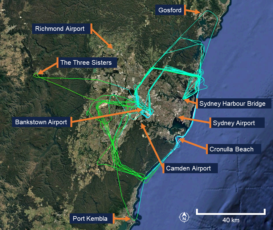
In the 12 months preceding the accident, the pilot had accumulated 31.9 hours of flight time between the Cirrus SR20 and the Piper PA-28 Cherokee. The pilot’s longest flight during this period was 1.9 hours in duration, with an average flight time of 1.4 hours. All flights were conducted within the Sydney area, with the furthest north being Gosford, the furthest south being Port Kembla, and the furthest west being the mountainous area around the Three Sisters landmark in the Blue Mountains (Figure 10). The accident flight was the pilot’s first flight of more than 4 hours since January 2023.
Figure 10: Previous flight data
Source: Google Earth, annotated by the ATSB
Flight plan
Flight plans are only required for a VFR flight under certain conditions. One of the instructors recalled that the pilot would routinely submit a search and rescue time (SARTIME) and not file a flight plan. The instructor recalled they had discussed with the pilot the benefits of lodging a flight plan, including that in the event the aircraft became overdue, a flight plan would provide search and rescue authorities with valuable information to assist in determining the intended route and location to commence search efforts.
Under the Civil Aviation Safety Regulations (CASR) Part 91 General Operating and Flight Rules Manual of Standards (MOS) 2020: 9.02 Flight notification requirements, a pilot in command must ensure that one of the following has occurred if flying into a designated remote area:
• the submission of a flight plan;
• the nomination of a SARTIME for arrival;
• the leaving of a flight note with a responsible person.
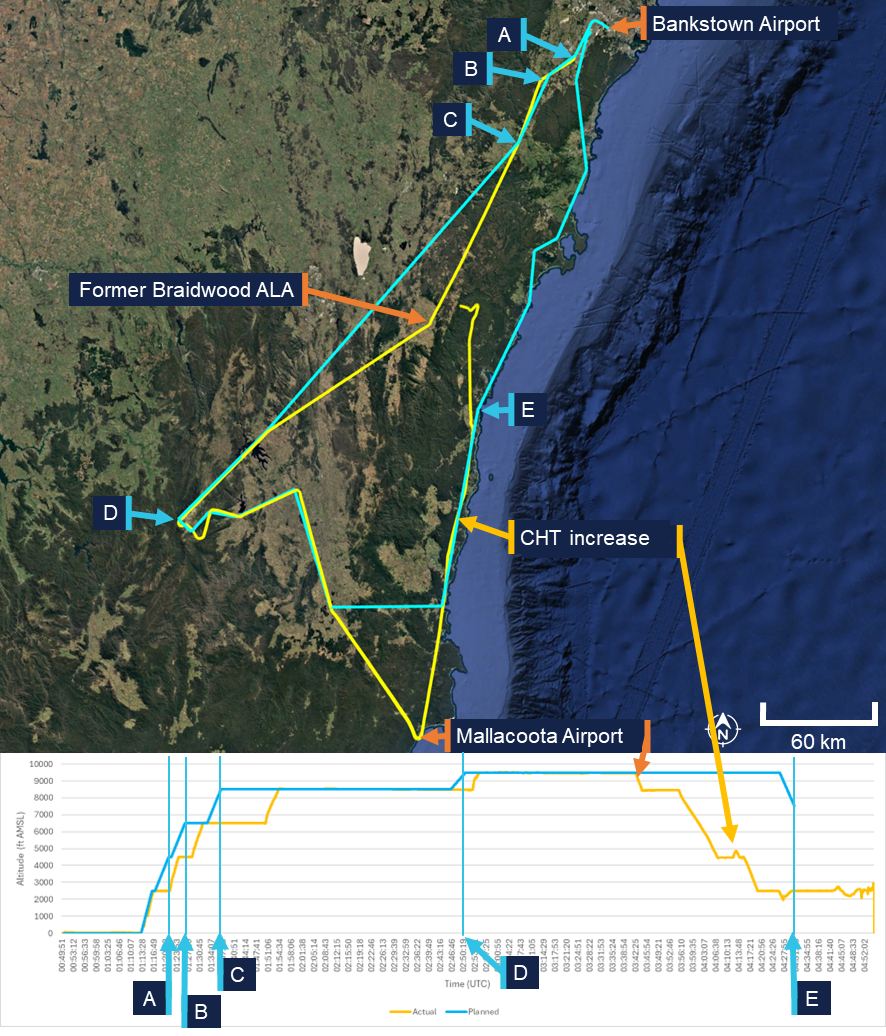
For this flight, the pilot had filed a VFR flight plan via the National Aeronautical Information Processing System (NAIPS) prior to departure as the planned route transited a designated remote area of the Snowy Mountains.
The flight plan indicated the pilot would fly south to Mount Kosciuszko before turning towards the coast to Merimbula Airport (Figure 11). The pilot would then head north through a VFR lane, using VFR waypoints, over the coastline (east of the Great Dividing Range) back to Bankstown Airport. When reaching Merimbula Airport the aircraft would be at an altitude of 9,500 ft AMSL and begin a decent to 7,500 ft AMSL reaching the altitude at Moruya Airport before further descending to 2,000 ft when reaching Ulladulla. Pilots are required to notify air traffic services (ATS) if the route, cruising level, or cruising speed changes from a submitted flight plan. Although the actual flight varied from the plan, the pilot did not notify ATS of the changes.
When the pilot’s instructor was asked what pilots are taught in such circumstances, they stated that pilots are instructed to notify ATS of any change in plan or if they intend to deviate from their planned route. However, the instructor noted that the pilot had obtained their private pilot licence in the 1980s and was unsure whether this topic had been recently discussed with the pilot, as they had never observed the pilot submit a flight plan during their conversion training.
Figure 11: Planned flight (blue) comparison to actual flight (yellow)
A. Bankstown Airport; B. Campbelltown University waypoint; C. Picton waypoint; D. pilot chosen waypoint using lat/long; E. Moruya Airport. Source: ATSB
Visual meteorological conditions
Visual meteorological conditions (VMC) are expressed in terms of in-flight visibility and distance from cloud (horizontal and vertical) as prescribed in the CASR Part 91 (General Operating and Flight Rules) Manual of Standards (MOS) 2020: 2.07 VMC criteria. These conditions allow pilots to operate the aircraft primarily by visual reference to the terrain and horizon, maintaining situational awareness and separation from other aircraft without reliance on instruments.
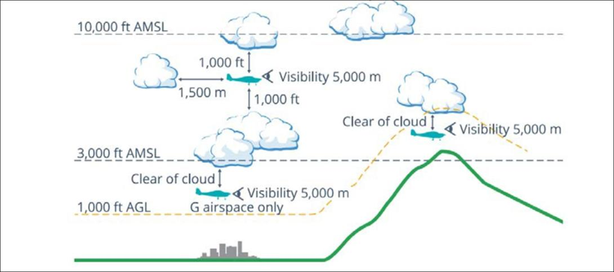
For flight below 10,000 ft AMSL, the Part 91 MOS prescribed that pilots maintain a minimum visibility of 5 km, and remain at least 1,000 ft vertically and 1,500 m horizontally clear of cloud. In areas below 3,000 ft AMSL or 1,000 ft above ground level (AGL), and within uncontrolled airspace, VFR flights may operate clear of cloud and in sight of the ground or water, provided visibility remains at or above the required minima. These criteria ensure that pilots have sufficient external visual references to maintain safe flight and effective traffic separation.
Pilots should not initiate VFR flight on top of more than SCT [scattered][22] cloud when weather conditions are marginal. Before committing to operate VFR flight on top of more than SCT cloud, pilots should be confident that meteorological information used is reliable and current, and clearly indicates that the entire flight will be able to be conducted in VMC.
and
Pilot decision-making, particularly regarding weather and flight, is often complex; however, the solution to avoiding VFR into IMC [instrument meteorological conditions] when weather is marginal before take-off is not to depart. During flight, it is to turn back or divert before it becomes impossible to do so.
Figure 12, taken from the CASA Visual Flight Rules Guide, provides a visual depiction of the VMC criteria for aeroplanes below 10,000 ft.
Figure 12: VMC criteria below 10,000 ft
Source: Civil Aviation Safety Authority
Pilot response to weather
When questioned about how the pilot typically obtained weather information for the flight, the instructor stated that the weather would have been checked prior to departure using TAFs and GAFs. The instructor expected that the pilot would also have been monitoring the automatic terminal information service (ATIS) while en route.
The instructor further recalled a previous flight (in May 2022) with the pilot during which the pilot descended to avoid entering cloud. At that time, the instructor questioned the pilot on the VMC requirements for the flight. The pilot became overwhelmed and elected to return to the departure aerodrome. The instructor recalled that there were no subsequent discussions between them regarding operations in adverse weather, and none of the remaining training flights were conducted in cloudy conditions. The instructor noted that the pilot avoided flying into or near clouds and had previously cancelled multiple flights due to weather.
Pilots can confirm destination weather in flight using multiple approved sources. The aerodrome weather information service (AWIS) is available on a published VHF frequency or by telephone. Review of the aircraft data indicated the radios were not changed to published AWIS VHF frequencies at any stage of the flight, and the pilot was not carrying a mobile phone that could have been used to obtain an AWIS broadcast by telephone.
Where fitted with ADS-B In and a suitable display (such as an EFB),[23] pilots may receive real-time weather data including METAR, TAF, airmen's meteorological information (AIRMET),[24] significant meteorological information (SIGMET),[25] and GAF forecasts within coverage. An approved EFB can also provide these products via internet or satellite subscription. The pilot carried an EFB running AvPlan, which was capable of displaying current meteorological information however, there was no recorded data to confirm whether the pilot accessed this information at any stage of the flight.
Communication
The aircraft was equipped with 2 independent VHF communication transceivers (COM 1 and COM 2). Each transceiver could display and store 1 active frequency and 1 standby frequency simultaneously, resulting in a total of 4 frequencies available to the pilot. The instructor stated that at BFS they teach students to use COM 1 as the primary radio used for monitoring towers and ATS and COM 2 is used for secondary frequencies such as the common traffic advisory frequency (CTAF) and ground frequencies.
The pilot had configured COM 1 as the active radio and COM 2 as standby. Prior to departure, COM 2 was set to the Bankstown Airport ground frequency and left on this frequency for the entirety of the flight. COM 1 was initially set to the Bankstown Airport tower/CTAF frequency and changed throughout the flight. When flying south-east near Braidwood, the pilot changed frequencies multiple times within 9 minutes. They first selected an unknown frequency (125 MHz), then Sydney Tower (120.5 MHz), and then a second unknown frequency (120.15 Mhz), before selecting Melbourne Centre (120.75 MHz). The pilot then maintained 120.75 MHz (Melbourne Centre) as the active frequency after passing Braidwood ALA and continued using this frequency for the remainder of the flight.
The only recorded inflight radio transmission was made on the Melbourne Centre frequency with the pilot indicating a decision to land at Moruya.
VFR into IMC research
The ATSB, in conjunction with research published by CASA, has identified that VFR pilots continuing flight into IMC remains one of the most consistently fatal types of general aviation occurrence. These events are characterised by a loss of visual reference resulting in spatial disorientation, loss of control, or controlled flight into terrain. The onset of IMC during VFR flight is often sudden, and pilots without instrument training or recent instrument experience typically have little time to recover once visual cues are lost.
ATSB occurrence data showed that many VFR into IMC accidents follow a consistent pattern of decision‑making and flight progression. Pilots often either depart into marginal weather conditions and/or continue as conditions deteriorate, influenced by a strong ‘press-on’ mindset to reach their destination. A 2005 ATSB research publication – General Aviation Pilot Behaviours in the Face of Adverse Weather (B2005/0127) – concluded that the likelihood of encountering IMC increases significantly during the final stages of flight, particularly within the last 20% of the planned route.
CASA’s associated AvSafety - Flying into bad weather card[26] supports these findings, noting that poor weather-related decision-making and underestimation of meteorological risks remain persistent issues across the VFR pilot population. The education programs, including CASA’s online Pilot safety hub[27] encourage pilots to establish and adhere to personal weather minima, obtain updated forecasts before and during flight, and avoid reliance on visual cues when conditions are near or below VMC limits.
Related occurrences
Recent examples of VFR into IMC accidents are provided below.
Collision with terrain involving Beechcraft 35-C33 Debonair, VH-KZK, 12 km east of Khancoban, New South Wales, on 15 July 2025 (AO-2025-040)
On 15 July 2025, a Beechcraft 35-C33 Debonair, registered VH-KZK, departed Wangaratta Airport, Victoria, for a private flight under the visual flight rules (VFR) to Moruya Airport, New South Wales. Soon after entering the Snowy Mountains area, itis very likely that the pilot, who did not hold an aircraft instrument rating, experienced spatial disorientation after flying into instrument meteorological conditions. The aircraft entered a spiralling descent to the right that continued until the aircraft collided with terrain. The pilot was fatally injured, and the aircraft was destroyed.
VFR into IMC, loss of control and collision with terrain involving Socata TB‑20, VH-JTY, 65 km west of Mackay Airport, Queensland, on 28 October 2023 (AO‑2023-052)
On the morning of 28 October 2023, a SOCATA-Groupe Aerospatiale TB-20, registered, VH‑JTY, departed Montpelier aircraft landing area, Queensland, for a visual flight rules private flight to Palmyra aircraft landing area, Queensland. After encountering cloud en route, the pilot elected to continue along the intended flight path through cloud instead of diverting around or remaining on top of it.Shortly after, it is very likely the pilot entered weather conditions not suitable for visual navigation, leading to spatial disorientation and a descent into mountainous terrain. The aircraft was destroyed and both occupants received fatal injuries.
VFR into IMC, loss of control and collision with terrain involving Airbus Helicopters EC130 T2, VH-XWD, near Mount Disappointment, Victoria, on 31 March 2022 (AO-2022-016)
On 31 March 2022, at about 0741 local time, 2 Microflite Airbus EC130 helicopters, registered VH‑WVV and VH-XWD, departed the Batman Park helicopter landing site in Melbourne, for the town of Ulupna, Victoria. Both helicopters were operated in accordance with the VFR and departed in VMC conditions. Cloud was forecast along the route, but the pilots elected to continue to the destination. The helicopters encountered IMC over Mount Disappointment and VH-WVV conducted a U-turn to avoid entering cloud. While also attempting to conduct a U-turn, VH-XWD entered cloud, developed a high rate of descent, and collided with terrain. The helicopter was destroyed, and the 5 occupants were fatally injured.
VFR into IMC and in-flight break-up involving Van's Aircraft RV-7A, VH-XWI, 90 km south of Charters Towers, Queensland, on 23 April 2021 (AO‑2021‑017)
On 23 April 2021, a Van’s Aircraft RV-7A, registered VH-XWI, was being operated on a private flight under the VFR from Winton to Bowen, Queensland. During the flight, the pilot most likely entered IMC and lost control of the aircraft several times. This led to the airspeed limitations for the aircraft being exceeded and the aircraft sustained an in-flight break-up. The pilot was fatally injured, and the aircraft was destroyed.
Safety analysis
Examination of the wreckage and flight data indicated that the aircraft’s engine was producing power until impact. All major sections of the aircraft were located at the accident site, and there was no evidence of an in-flight break-up or structural failure. The flight data and the presence of all major components at the scene indicate that the aircraft did not experience a pre-impact mechanical or airframe issue that would have contributed to the collision with terrain.
The flap setting of 50% would be used in low and slow manoeuvring such as looking for a landing site under deteriorating weather or manoeuvring through valleys. Flying slower reduces the radius of turns and the use of the flap gives the aircraft a buffer to the stall speed. This setting might be considered a compromise configuration between flying clean and flying full flap, giving these advantages while retaining a greater capability to climb at short notice without the drag of a full flap.
Cylinder temperature fluctuations and cockpit distraction
When passing Mallacoota Airport, the pilot commenced a descent from about 9,000 ft above mean sea level (AMSL). At that time, the pilot would have seen low cloud ahead and probably descended in order to fly below it or in preparation for an approach and landing at one of the aerodromes along the planned flight route.
Flight data showed fluctuating temperature indications from the number 4 cylinder throughout the latter part of the flight. These temperature fluctuations would have generated warnings displayed to the pilot on the multi-function display, alerting them to a potential engine issue.
The first indications of this fluctuation occurred prior to the initial approach to Moruya Airport. The recorded engine data showed that the CHT rose to the caution range and subsequently progressed to the warning range. There was a reduction in engine power over an approximately 30‑second period, before maintaining reduced power for about a minute further. This was likely to have been initiated by the pilot in response to the high CHT warnings and was consistent with the appropriate response to a genuine warning. The engine was then returned to normal power after the CHT levels dropped back into the normal range.
Shortly thereafter, the CHT again increased, entering the caution range for a second time. After an 8‑minute period with the CHT in the caution range the pilot radioed ATC with their intention to land at Moruya Airport. Given that a landing at Moruya was not planned, it is most likely that the pilot initiated the approach as a result of the warning and/or cloud ahead.
The ATSB assessed that these warnings were very likely spurious, and an attentive pilot with a good understanding of engines could doubt their validity based on the engine instruments. The pilot may have thought the warnings were genuine or spurious, and this understanding could have changed throughout the flight.
In any case, the persistence of these warnings throughout the remainder of the flight would have been a continuing source of distraction, potentially increasing workload and reducing their capacity to monitor other operational factors such as navigation, weather conditions, and terrain clearance.
Decision to continue flight past Moruya Airport
After commencing an approach to Moruya Airport, and making a radio broadcast to that effect, the pilot discontinued the approach and continued the flight below the cloud base. Satellite and meteorological data indicated areas of low cloud around the Moruya area, with instrument meteorological conditions (IMC) present as the pilot approached the airport. Additionally, poor weather was observed along the planned route of flight (along the east coast) beyond Moruya. There were no further radio transmissions or position reports from the pilot following the initial call indicating their intention to land at Moruya. Given that poor weather was present ahead of the aircraft and the pilot would have been seeing fluctuating cylinder temperature warnings, it is unclear why the pilot made the apparent decision to continue the flight rather than land at Moruya.
This decision may have been influenced by the perceived presence of a completely clear area in the cloud layer ahead. Analysis of satellite imagery revealed a temporary gap or break in the extensive cloud cover extending from Moruya Airport towards the Great Dividing Range. This gap, evident at the approximate time the aircraft passed to the west of Moruya Airport, would have presented a visually clearer path to the pilot. There was cloud over Moruya Airport and the pilot may have considered that maintaining VMC throughout an approach and landing there might not have been feasible.
In any case, the decision to deviate inland from the initial planned track and towards higher terrain was likely influenced by this break in cloud. Given previous observations from the instructor indicating an aversion to flight near conditions of reduced visibility, it is probable that the pilot elected to manoeuvre towards this apparent break in order to remain in VMC. However, this deviation towards rising terrain significantly increased the risk of controlled flight into terrain, particularly in the prevailing low-visibility environment where visual assessment of terrain clearance could not be assured.
The pilot may have elected to continue the flight partly due to ‘get-there-it is,’ which describes a mindset in which a pilot becomes fixated on reaching the destination, often disregarding deteriorating weather, aircraft anomalies, fatigue, or other risk factors (ATSB, 2011). This self-induced pressure can lead to continued operation into conditions that a more objective assessment would deem unsafe, as the perceived pressure to complete the trip overrides sound aeronautical decision‑making.
The pilot’s limited experience with long distance flights may have exacerbated the effects of this phenomenon. Having completed only the second flight of approximately 4 hours duration in their flying career, the pilot had minimal exposure to the progressive challenges associated with extended cross-country operations, including the management of fatigue and evolving weather systems over prolonged periods, and in‑flight technical anomalies.
With limited prior experience in calibrating risk in deteriorating conditions, the pilot would have been less able to objectively weigh the cumulative hazards of continuing into adverse weather while managing the fluctuating indicated engine cylinder head temperature (or being distracted by the spurious warnings, depending on how the pilot understood them). This increased their susceptibility to get-there-itis, such that their established safety decision-making processes were outweighed by the perceived attainability of the destination.
Continued flight into poor weather
Following the decision to continue the flight, tracking data indicated that the aircraft proceeded into the mountainous area of the Great Dividing Range, then almost reversed course at low altitude along a valley, consistent with the pilot attempting to remain below the cloud base and/or avoid cloud ahead. It is therefore likely that the pilot misjudged the extent and density of the cloud or the height of the cloud base. While continuing at low level, with an altitude lower than the surrounding terrain, the aircraft likely entered IMC. The subsequent flight path was consistent with attempts to avoid cloud, and it is probable that the pilot did not know what direction to take away from the mountainous areas and cloud or, if they did, became trapped between the rising terrain and the low cloud base.
Findings
ATSB investigation report findings focus on safety factors (that is, events and conditions that increase risk). Safety factors include ‘contributing factors’ and ‘other factors that increased risk’ (that is, factors that did not meet the definition of a contributing factor for this occurrence but were still considered important to include in the report for the purpose of increasing awareness and enhancing safety). In addition ‘other findings’ may be included to provide important information about topics other than safety factors.
These findings should not be read as apportioning blame or liability to any particular organisation or individual.
From the evidence available, the following findings are made with respect to the VFR into IMC and controlled flight into terrain involving Cirrus SR20, VH-TEL,12 km east of Braidwood/Percheron aircraft landing area, New South Wales, on 18 September 2025.
Contributing factors
After commencing an unplanned approach to Moruya Airport, likely due to an engine warning and/or observed cloud ahead, the pilot discontinued the approach for undetermined reasons. The pilot, with limited cross-country experience, then continued the flight underneath the cloud base towards rising terrain.
The pilot very likely entered weather conditions not suitable for visual navigation, leading to a loss of situational awareness and collision with terrain.
Other factor that increased risk
The aircraft’s number 4 cylinder fluctuating temperature warnings, likely resulting from a faulty sensor probe, occurred prior to the pilot electing not to land and continued until the collision with terrain. The ongoing warnings likely distracted the pilot, increasing workload and reduced their capacity to monitor and respond to other operational factors.
Sources and submissions
Sources of information
The sources of information during the investigation included:
Under section 26 of the Transport Safety Investigation Act 2003, the ATSB may provide a draft report, on a confidential basis, to any person whom the ATSB considers appropriate. That section allows a person receiving a draft report to make submissions to the ATSB about the draft report.
A draft of this report was provided to the following directly involved parties:
Bankstown Flying School
Civil Aviation Safety Authority
Cirrus Aircraft
maintenance organisation for VH-TEL.
Submissions were received from:
Civil Aviation Safety Authority
Cirrus Aircraft.
The submissions were reviewed and, where considered appropriate, the text of the report was amended accordingly.
Purpose of safety investigations
The objective of a safety investigation is to enhance transport safety. This is done through:
identifying safety issues and facilitating safety action to address those issues
providing information about occurrences and their associated safety factors to facilitate learning within the transport industry.
It is not a function of the ATSB to apportion blame or provide a means for determining liability. At the same time, an investigation report must include factual material of sufficient weight to support the analysis and findings. At all times the ATSB endeavours to balance the use of material that could imply adverse comment with the need to properly explain what happened, and why, in a fair and unbiased manner. The ATSB does not investigate for the purpose of taking administrative, regulatory or criminal action.
About ATSB reports
ATSB investigation reports are organised with regard to international standards or instruments, as applicable, and with ATSB procedures and guidelines.
Reports must include factual material of sufficient weight to support the analysis and findings. At all times the ATSB endeavours to balance the use of material that could imply adverse comment with the need to properly explain what happened, and why, in a fair and unbiased manner.
An explanation of terminology used in ATSB investigation reports is available here. This includes terms such as occurrence, contributing factor, other factor that increased risk, and safety issue.
Publishing information
Released in accordance with section 25 of the Transport Safety Investigation Act 2003
Ownership of intellectual property rights in this publication
Unless otherwise noted, copyright (and any other intellectual property rights, if any) in this report publication is owned by the Commonwealth of Australia.
Creative Commons licence
With the exception of the Commonwealth Coat of Arms, ATSB logo, and photos and graphics in which a third party holds copyright, this report is licensed under a Creative Commons Attribution 4.0 International licence.
The CC BY 4.0 licence enables you to distribute, remix, adapt, and build upon our material in any medium or format, so long as attribution is given to the Australian Transport Safety Bureau.
Copyright in material obtained from other agencies, private individuals or organisations, belongs to those agencies, individuals or organisations. Where you wish to use their material, you will need to contact them directly.
[1]Visual flight rules (VFR): regulations that permit a pilot to operate an aircraft in conditions whereby navigation and orientation of the aircraft by visual reference is possible.
[2]Day VFR flights may be conducted to the end of civil twilight, the point at which the sun is 6° below an ideal horizon.
[3]The Braidwood ALA was operational until 2024 at its original location. The current Braidwood/Percheron ALA is located approximately 15 km north-east of the former ALA.
[4]The ATSB was unable to determine whether the pilot conducted any flights in aircraft not registered to the flight school.
[5]A Grade 2 flight instructor is an intermediate-level qualification and is not able to approve a flight review, which requires a Grade 1 flight instructor.
[6]The course is an instructor-led course for non-instrument rated pilots who are new to flying a Cirrus and is intended to provide opportunities to enhance their flying skills while becoming familiar with the Cirrus.
[7]Instrument meteorological conditions (IMC): weather conditions that require pilots to fly primarily by reference to instruments, and therefore under instrument flight rules (IFR), rather than by outside visual reference. Typically, this means flying in cloud or limited visibility.
[8]Instrument flight rules (IFR): a set of regulations that permit the pilot to operate an aircraft in instrument meteorological conditions (IMC), which have much lower weather minimums than visual flight rules (VFR).
[9]Aerodrome Forecast (TAF): a statement of meteorological conditions expected for a specific period of time in the airspace within a radius of 5 NM (9 km) of the aerodrome reference point.
[10]Ceiling and visibility okay (CAVOK): visibility, cloud and present weather are better than prescribed conditions. For an aerodrome weather report, those conditions are visibility 10 km or more, no significant cloud below 5,000 ft, no cumulonimbus cloud and no other significant weather.
[11]Moruya Airport and Jervis Bay Airfield are close to sea level.
[12]METAR (Meteorological Aerodrome Report) is a routine aerodrome weather report issued at half hourly time intervals. The report ordinarily covers an area of 8 km radius from the aerodrome reference point.
[13]SPECI is used to identify reports of observations when conditions are below specified levels of visibility and cloud base, when certain weather phenomena are present, and when the temperature, pressure or wind change by defined amounts. SPECI is also used to identify reports of observations recorded 10 minutes following an improvement in visibility, weather or cloud to METAR conditions.
[15]The RDM is designed to record flight data in a crash and fire-resistant housing. The unit records flight, engine, and autopilot parameters. Data is logged once per second and stored internally inside the crash-hardened enclosure. When the storage limit of the memory device is reached, the oldest recording is overwritten.
[16]This level of flap would be expected when conducting a low and slow manoeuvring flight such as looking for a landing site under deteriorating weather or if manoeuvring in valleys.
[17]The fuel pump is on for take‑off, landing, climb and when switching fuel tanks.
[18]The general definition for land as soon as possible is to land at the nearest site that a safe landing can be made, whereas land as soon as practical means extended flight is not recommended but the landing site and duration of the flight are at the pilot’s discretion.
[19]AvPlan is a tablet-based application for flight planning, navigation, and real-time situational awareness.
[20]ADS-B data from public community-based networks (such as those used by FlightAware, Flightradar24 and ADS-B Exchange) may not have coverage at low altitudes or in areas distant from populated receiver locations.
[21]In the absence of continued reception, some providers extrapolate or ’coast’ the last known position and speed for a limited period, while others cease plotting the aircraft entirely.
[22]Cloud cover: in aviation, cloud cover is reported using words that denote the extent of the cover – ‘few’ indicates that up to a quarter of the sky is covered, ‘scattered’ (SCT) indicates that cloud is covering between a quarter and a half of the sky, ‘broken’ (BKN) indicates that more than half to almost all the sky is covered, and ‘overcast’ (OVC) indicates that all the sky is covered.
[23]VH-TEL was not configured to show this information on the Garmin G-1000 display.
[24]AIRMET information concerns the occurrence, or expected occurrence, of certain phenomena that have not been included in the graphical area forecast (GAF).
[25]A SIGMET provides a concise description concerning the occurrence or expected occurrence, in areas over which meteorological watch is being maintained, of en route weather phenomena that are potentially hazardous to aircraft.
On 7 July 2025, a Kavanagh Balloons G-450, registered VH-FGC, was conducting a morning scenic flight near Beaudesert, Queensland, carrying 20 passengers and the pilot.
Shortly after launch when climbing above a ridge, the pilot identified a change in the expected wind direction and the presence of fog. The pilot considered the safest option available was to proceed to an alternate landing site in reduced visibility. However, on approach to land, a low-level wind shift changed the balloon direction. The pilot elected to conduct a landing at a different landing site rather than continue flight over populous areas.
On landing, the balloon basket was carried forward with momentum, it skipped several times before it came to a stop. However, the balloon envelope made contact with a dead tree, resulting in minor damage to the envelope. No injuries were reported.
What the ATSB found
The ATSB found that the pilot reassessed operational and safety decisions as unexpected weather impacted the flight (wind direction and fog). Ultimately the pilot was unable to avoid contact with a dead tree in the final stages of landing in reduced visibility.
However, comprehensive passenger safety briefings meant that passengers adopted brace positions prior to landing which likely prevented injury.
Safety message
The formation, movement and depth of fog is difficult to predict with accuracy, which can lead to pilots inadvertently flying into reduced visibility.
If contemplating ballooning operations in conditions conducive to fog development, even if it is not forecast, pilots are strongly encouraged to not only be aware of the possible formation of fog, but to plan for its likely effect on their flight.
This accident highlights the importance of effective safety briefings and how passengers adopting the correct body position during landing substantially reduces the likelihood and severity of injury. The pre-flight briefing is critical in ensuring passenger preparation, particularly as opportunities to reinforce this information during flight may be limited.
Pilots should use all available resources (such as passenger demonstrations and safety briefing cards) to ensure that each passenger understands the landing position and its importance.
The ATSB SafetyWatch highlights the broad safety concerns that come out of our investigation findings and from the occurrence data reported to us by industry. One of the safety concerns is Reducing passenger injuries in commercial ballooning operations.
The investigation
The ATSB scopes its investigations based on many factors, including the level of safety benefit likely to be obtained from an investigation and the associated resources required. For this occurrence, the ATSB conducted a limited-scope investigation in order to produce a short investigation report, and allow for greater industry awareness of findings that affect safety and potential learning opportunities.
The occurrence
On 7 July 2025, a Kavanagh Balloons G-450, registered VH-FGC, operated by Hot Air Pty Ltd was conducting a morning scenic flight near Beaudesert, Queensland.
The pilot conducted multiple weather assessments prior to the flight (see Pre-flight observations), and the balloon was set-up with the assistance of ground crew at The Overflow Estate (Figure 1).
At approximately 0623 local time, the balloon departed The Overflow Estate, at Wyaralong Dam in a north-easterly direction, carrying 20 passengers and one pilot. Based on their pre‑flight weather assessment, the pilot originally intended to land in a south-east landing site near Bromelton (Figure 1) and the ground crew had been instructed to make their way via car to assess the wind conditions near the intended landing site. However, after take‑off the balloon maintained a north-east flight path towards Woodhill and Cedar Grove.
Figure 1: Flight path overview
Source: Google Earth, annotated by the ATSB
About 13 minutes after launch, the balloon had passed over the dam when the pilot climbed the balloon over a ridge line. At about 500 ft above ground level (AGL), the pilot described encountering fog in the direction of travel (Figure 2). The pilot discounted nearby options for an early landing and considered that the safest option available, in the reduced visibility, was to select a new landing site clear of hazards in the north-east (Figure 3).
Figure 2: Fog visible after climbing a ridge at 0636
Source: Operator, annotated by the ATSB
Figure 3: Flight path details
Source: Google Earth, annotated by the ATSB
While en route to that preferred landing site, the fog thickened, before the pilot climbed the balloon above the fog (Figure 4).
Figure 4: Fog conditions below the balloon at 0640
Note: Two other balloons from a separate (unidentified) operator were visible above the fog at this time. Source: Operator
At about 0703, while on approach to the preferred landing site (Figure 3), the balloon encountered a low-level wind change at about 200 ft, increasing in strength from 4–6 kt. The wind change tracked the balloon 90 degrees left, and made landing unfeasible due to a dam and trees.
The wind shift was unexpected to the pilot as they described that surface conditions looked calm, with the fog not appearing to move. Due to ground crew traveling back from the first intended landing site, the pilot did not have information usually available via a surface wind assessment on the ground.
The pilot reconsidered the safest options available considering the reduced visibility and selected a different landing site further north, which was used infrequently by the operator, was closer to a populated area and isolated trees, but with no identified powerlines (Figure 3). The pilot burned[1] to lift the balloon over a wet area before descending towards the new landing site.
On approach, the pilot burned again to lift the balloon over a boundary fence (Figure 5) before they commenced deflation to descend for landing and instructed the passengers to adopt their pre-briefed brace positions. While approximately 5 m from the ground, the pilot visually detected a dead tree (Figure 5). In response they rapidly deflated the balloon in an attempt to stop short of the tree. The pilot further reinforced the brace instruction to the passengers. At 0709, the balloon basket touched down, however was carried forward with the balloon’s resultant air mass momentum. The basket skipped 4 times before it stopped moving (Figure 5), however the balloon envelope inertia continued until the envelope contacted a dead tree (to the left of the basket), resulting in minor damage.
Figure 5: Onboard video of the approach (left) and the final approach flight path (right)
Source: Operator and Google Earth, annotated by the ATSB
The pilot and passengers were uninjured, and due to the delayed arrival of the ground crew, the pilot sought the help of 3 volunteer passengers to recover the envelope from the tree. There was no resultant damage to the basket, however envelope damage included 15 large tears due to contact with the dead tree.
Context
Personnel information
The pilot held a commercial pilot licence (balloon), with 1,253.2 hours total flying time, of which 1,174 hours were flown as pilot in command. In the previous 90 days, the pilot had flown 40.2 hours as pilot in command, including 7.2 hours on the G-450.
The pilot held a current CASA class 2 aviation medical certificate with no conditions.
The pilot reported starting work at 0430 on the day of the occurrence, having obtained about 6 hours of sleep the night before, and an additional 30‑minute nap the previous morning. They recalled feeling fully alert at the time of the occurrence.
Aircraft information
VH-FGC was a Kavanagh Balloons G-450 manned free balloon, manufactured in 2017 by Kavanagh Balloons Australia Pty Ltd. The aircraft was certified in the manned free balloon category and operated with a valid certificate of airworthiness.
The G-450 balloon has an envelope capacity of 450,000 cubic feet and a maximum take‑off weight of 3,700 kg. At the time of the occurrence, the balloon envelope had accumulated a total time of 662.6 hours in service, while the basket had accumulated 1,614.1 hours. The basket was designed to carry a maximum of 24 passengers per basket (6 per passenger compartment).
The balloon was fuelled with 358 L of liquid petroleum gas propane at the start of the flight, with 135 L remaining at landing.
Operator information
Hot Air Pty Ltd operates in the Scenic Rim area of South East Queensland and also the Atherton Tablelands in north Queensland. The organisation has agreements in place with landowners to access several launch and landing locations in a circular pattern near Beaudesert, referred to as the operator’s flying area. The locations include private and commercial properties.
Recorded information
The balloon was equipped with the following equipment capable of recording:
a GPS which records the flight track
a ‘flight tablet’ which included an electronic Google Earth satellite map (Figure 6). The satellite map was overlaid with the operator’s flying map layer which was maintained/updated via an electronic register. The flying map included the following operational information:
launch and landing areas / property boundaries (dark blue)
sensitive zones (SZs), with restricted operation (red)
powerlines (yellow)
other relevant landowner information (white text).
An onboard camera recording the front facing view of the flight.
Figure 6: Operator flying map showing the balloon flight path
Note: Property names were blurred to maintain landowner privacy. Source: Operator, modified by the ATSB
The final landing site was designated an ‘emergency landings only’ area on the Operator flying map (Figure 6) in Woodhill. The operator occasionally used this site when necessary, but it was not used frequently.
Meteorological information
Observations for surrounding area
The Beaudesert automatic weather station (AWS) provided the air temperature (°C), dew point temperature (°C), and relative humidity (%) along with other information and showed conditions conducive to fog formation (Table 1), that is:
temperature and dew point less than 1°C difference
winds were calm
high relative humidity (above 95%)
no significant weather movement.
Table 1: Beaudesert AWS information for 7 July 2025
A local graphical area forecast was valid for a six-hour period from 0300–0900 which indicated visibility of about 300 m with scattered fog.
At 0503, the Bureau of Meteorology (BoM) issued an updated aerodrome forecast (TAF)[2] for Amberley, which indicated fog and reduced visibility of 500 m up until 0700 at which time the conditions could be expected to improve.
At 0607, the BoM issued a further update to the TAF, which forecast shallow fog with visibility of 8,000 m, and a 30% probability of fog reducing visibility to 800 m and scattered cloud at 200 ft, until 0900 that day.
Satellite imagery
Satellite imagery was obtained from the BoM, valid as of 0500. The imagery depicted areas of fog or low cloud around, but clear of the original intended area of balloon operation (see Appendix A – satellite images).
Pre-flight observations
The pilot also reviewed several sources of weather information in the preceding hours prior to launch, as required by the operator’s exposition[3] (Version 1, 11 November 2024) and CASR Part 131[4] (Table 2).
Table 2: Pilot weather observations
Approx. time
Location
Information source or method
Assessment
Previous night
Near Beaudesert
Windy.com application
Wind conditions suitable for flight.
0415
Near Beaudesert
Visibility by sight
BoM Brisbane (Mt Staplyton) Radar Loop
Visibility clear for flying area[1].
Rain showers would be clear by launch time (0623).
0430
Operator Base, Beaudesert
Visibility by sight
BoM Beaudesert AWS
BoM Brisbane (Mt Staplyton) Radar Loop
Windy.com application
NAIPS[2] account local GAF and surrounding aerodrome TAFs
Visibility clear for intended flight path.
Calm surface conditions with a temperature of 12°C.
Rain showers had cleared the flying area.
Light and variable surface winds, becoming south‑westerly 5 kt at 1000ft then westerly 16 kt at 3,000 ft.
Light winds at nearby stations, and most clear except for Amberley that indicated a chance of surface fog, however not operationally relevant being more than 48 km away from Beaudesert.
0445
Bromelton observation point
Visibility by sight
Pibal
Visibility clear for intended flight path. Fog present in the south of the flying area around Laravale, more than 14 km south of Beaudesert.
Very light southerly for 300 ft, then turning into a west‑north-westerly wind of approximately 6-8 kt before swinging back to a westerly wind of approximately 10–15 kt (as the Pibal climbed).
0530
Launch site at Wyaralong Dam
Visibility by sight
Pibal
Visibility clear for intended flight path.
No change to previous Pibal wind readings.
This location sits on elevated land and provides visibility of a proportion of the operator’s flying area.
Airservices NAIPS Internet Service (free registration required)
Based on the observations the pilot decided to depart from The Overflow Estate launch site (west of Beaudesert) with the plan to fly in a south-east direction back into their operational flying area (and towards Beaudesert).
Regulatory requirements and guidance
Balloon pilots and operators must also comply with Part 131 of the Civil Aviation Safety Regulations (CASR), pre-flight weather assessment rules in section 12.02 of the Part 131 Manual of Standards (MOS).[5]
Balloon operations can occur in Class G airspace with at least 100 m visibility below 500 ft AGL when outside 10 NM from an aerodrome (such as in the case of Beaudesert). However, CASA highly recommends that pilots and operators exercise this significant reduction in the visibility requirements with caution and only if sufficient flight preparation has taken place. Further balloon guidance is available at Advisory Circular 131-02 v4.0.
Survivability
Pre-flight passenger safety briefing
One consideration in balloon accidents is the basket tipping during landing, which can increase the risk of injury. Tipping is more likely if a basket contacts, or lands on, a tree or fence.
Passengers were provided with safety briefings and instructions prior to boarding as required by the operator’s exposition. These included:
entry/exit to the basket
remaining in the basket until instructed by crew
securing and stowing personal items
prohibited dangerous goods
use of rope handles
landing/brace positions (for normal/upright landing and emergency/hard landing).
The passengers included several foreign tourists from non-English speaking backgrounds. Verbal information was supported by physical demonstrations (of the required landing position) and graphical briefing cards with basic diagrams and translations in simplified Chinese, Japanese, Korean, and German.
One passenger reported receiving pre-flight safety information via email at multiple points leading up to the flight, which was then supported by the safety demonstration on the day of the flight.
Related occurrences
A search of the ATSB occurrence database found that in the 10 years to July 2025 there were 37 balloon hard landings, ground strikes, or collisions with terrain in Australia, resulting in 17 injuries. Of these, 13 occurrences involved contact/collision with trees.
Further information on some of these occurrences can be found in Appendix B – Related occurrences.
Safety analysis
As is often required in balloon operations, the pilot was required to reassess operational and safety decisions at multiple points before and during the flight.
This analysis will explore the assessment of weather, launch location, contingency options, and landings in reduced visibility.
Fog encountered in flight
Fog was forecast for a wide area that included the operator’s flying area and the local conditions were conducive to fog. Satellite images support the pilot’s report by confirming that fog was likely not visible in the immediate flying area when the pilot travelled to the launch site before the flight. Based on their visibility assessment and pre-flight observations, the pilot determined it was safe to fly.
However, after take-off and on climbing above the ridge line over the dam, the pilot identified fog in the direction of flight, and the balloon subsequently entered fog.
Approach to land
Once lined up and on approach to land at the preferred landing site, the balloon was affected by an unexpected low-level wind shift and tracked about 90 degrees to the left.
Subsequently, the pilot considered other landing locations and associated risks, and selected an emergency landing site, used infrequently by the operator.
Reduced visibility
Once committed to landing in the final landing area in significantly reduced visibility, the pilot visually detected a tree through the fog in front of the balloon. In an attempt to take avoiding action, they rapidly deflated the envelope to land the balloon, however due to inertia, the balloon envelope made contact with the tree and was damaged.
Comprehensive safety briefings
The passengers were provided with comprehensive safety information leading up to, and before the flight. The ground crew and pilot also ensured understanding of the brace positions prior to launch.
As a result of the proper brace position, effective briefing and re-enforced communication during landing, no injuries were sustained.
Findings
ATSB investigation report findings focus on safety factors (that is, events and conditions that increase risk). Safety factors include ‘contributing factors’ and ‘other factors that increased risk’ (that is, factors that did not meet the definition of a contributing factor for this occurrence but were still considered important to include in the report for the purpose of increasing awareness and enhancing safety). In addition ‘other findings’ may be included to provide important information about topics other than safety factors.
These findings should not be read as apportioning blame or liability to any particular organisation or individual.
From the evidence available, the following findings are made with respect to the controlled flight into terrain involving Kavanagh Balloons G-450, registration VH-FGC, 12 km north‑north-west of Beaudesert, Queensland, on 7 July 2025.
Contributing factors
After clearing a ridge line, fog was encountered in the direction of the flight path.
During the approach to land in low visibility, an unexpected low-level wind shift diverted the balloon away from the preferred clear landing area, and required the pilot to select an alternate unplanned landing site in the final stages of landing.
Due to reduced visibility, the pilot was unable to see hazardous obstacles in the final landing area and therefore unable to take timely avoiding action.
Other findings
Comprehensive passenger safety briefings meant passengers adopted brace positions prior to landing which likely prevented injury.
Sources and submissions
Sources of information
The sources of information during the investigation included:
the pilot of the accident flight
the chief pilot of the operator
Civil Aviation Safety Authority
Bureau of Meteorology
accident witnesses
video footage of the accident flight and other photographs and videos taken on the day of the accident
recorded data from the GPS unit on the aircraft.
References
CASA (Civil Aviation Safety Authority), (2025), Part 131 Aircraft – Operations, Advisory Circular AC 131-02v4.0, CASA
CASA (Civil Aviation Safety Authority), (2025), CASR Part 131 – Guide for balloons and hot air airships, v1.2, CASA
Submissions
Under section 26 of the Transport Safety Investigation Act 2003, the ATSB may provide a draft report, on a confidential basis, to any person whom the ATSB considers appropriate. That section allows a person receiving a draft report to make submissions to the ATSB about the draft report.
A draft of this report was provided to the following directly involved parties:
the pilot
the operator
Civil Aviation Safety Authority
Bureau of Meteorology.
Submissions were received from:
Civil Aviation Safety Authority
Bureau of Meteorology.
The submissions were reviewed and, where considered appropriate, the text of the report was amended accordingly.
Appendices
Appendix A – satellite images
High resolution visible satellite imagery
Satellite imagery was obtained from the Bureau of Meteorology and was valid at 0500 (Figure A1) showing fog/low cloud as light blue areas.
Figure A1: High resolution visible satellite imagery from 0500
Note: This imagery was not available to the pilot at the time of the event. Source: The Bureau of Meteorology, annotated by the ATSB
Appendix B – Related occurrences
Hard landing involving balloon, VH-EUA, near Yarra Glen, 8 February 2018 (AO-2018-016)
On 8 February 2018, a Kavanagh B-350 hot-air balloon, registration VH-EUA, departed Glenburn, Victoria, for a scenic charter flight with a pilot and 15 passengers on board. About 45 minutes into the flight, over the Yarra Valley, the balloon experienced a sudden wind change with associated turbulence. The pilot decided to land immediately rather than continue over rising and heavily vegetated terrain. The resulting landing was hard and fast and 11 passengers were injured, with 4 of them receiving serious injuries.
Collision with terrain involving Kavanagh E-240 Balloon, VH-LUD, near Yamanto, Queensland, on 8 October 2021 (AO-2021-042)
On 8 October 2021, a Kavanagh Balloons E-240 balloon, registered VH-LUD and operated by Floating Images Aust. Pty Ltd was conducting a morning scenic flight about 45 km south‑west of Brisbane, Queensland. On board were a pilot and 9 passengers. About 55 minutes into the flight, the pilot commenced a descent to locate a suitable landing area. During the descent, the balloon entered an area of localised fog where visibility reduced to 10 m.
The pilot continued the descent into the fog until a tree was observed in the path of the balloon. The pilot attempted to avoid the tree by initiating a climb, but the balloon collided with, and came to rest on the side of, the tree, damaging the lower part of the balloon envelope. The pilot subsequently climbed the balloon off the tree and above the fog. The flight continued to an uneventful landing in a nearby paddock that was clear of fog. There were no injuries.
Controlled flight into terrain involving Kavanagh Balloons G-525, VH-HVW, Pokolbin, New South Wales, on 30 March (AO-2018-027)
At about 0710 Eastern Daylight-saving time on 30 March 2018, a Kavanagh Balloons G‑525 balloon, registered VH-HVW (HVW) and operated by The International Balloon Flight Company (Australia), launched from a site near Pokolbin, New South Wales, for a planned 1-hour scenic flight. HVW was one of three balloons launched by the company from the same site. After climbing through fog to about 2,000 ft and realising how far the fog layer extended, the pilot of HVW, along with the other 2 pilots, decided to abort the flight and descend for a landing at the nearest suitable site. On approach to land in low‑visibility conditions, HVW collided with trees, which caused the basket to rotate 180 degrees. It then landed heavily, resulting in injuries to 16 of the 24 passengers, 3 of them serious. The pilot was uninjured and 74 of the balloon’s panels required patching or repair.
Purpose of safety investigations
The objective of a safety investigation is to enhance transport safety. This is done through:
identifying safety issues and facilitating safety action to address those issues
providing information about occurrences and their associated safety factors to facilitate learning within the transport industry.
It is not a function of the ATSB to apportion blame or provide a means for determining liability. At the same time, an investigation report must include factual material of sufficient weight to support the analysis and findings. At all times the ATSB endeavours to balance the use of material that could imply adverse comment with the need to properly explain what happened, and why, in a fair and unbiased manner. The ATSB does not investigate for the purpose of taking administrative, regulatory or criminal action.
About ATSB reports
ATSB investigation reports are organised with regard to international standards or instruments, as applicable, and with ATSB procedures and guidelines.
Reports must include factual material of sufficient weight to support the analysis and findings. At all times the ATSB endeavours to balance the use of material that could imply adverse comment with the need to properly explain what happened, and why, in a fair and unbiased manner.
An explanation of terminology used in ATSB investigation reports is available here. This includes terms such as occurrence, contributing factor, other factor that increased risk, and safety issue.
Publishing information
Released in accordance with section 25 of the Transport Safety Investigation Act 2003
Ownership of intellectual property rights in this publication
Unless otherwise noted, copyright (and any other intellectual property rights, if any) in this report publication is owned by the Commonwealth of Australia.
Creative Commons licence
With the exception of the Commonwealth Coat of Arms, ATSB logo, and photos and graphics in which a third party holds copyright, this report is licensed under a Creative Commons Attribution 4.0 International licence.
The CC BY 4.0 licence enables you to distribute, remix, adapt, and build upon our material in any medium or format, so long as attribution is given to the Australian Transport Safety Bureau.
Copyright in material obtained from other agencies, private individuals or organisations, belongs to those agencies, individuals or organisations. Where you wish to use their material, you will need to contact them directly.
[1]The action of activating the burner to heat the air within the balloon, increasing internal temperature and causing the balloon to rise or maintain altitude.
[2]Aerodrome forecasts are a statement of meteorological conditions expected for a specific period of time, in the
airspace within a radius of 5 NM (9 km) of the aerodrome.
[3]A CASR Part 131 Balloon Transport Operation Exposition, also known as an ‘Operations Manual’.
[4]CASR Part 131 requires balloon operators to obtain a weather forecast from an authorised source, such as the Bureau of Meteorology, valid for a period extending 2 hours beyond their landing time.
[5]The Part 131 Manual of Standards (MOS) outlines the operational standards and requirements for operators of balloons and hot air airships in Australia to ensure safety and compliance with aviation regulations.
Occurrence summary
Investigation number
AO-2025-037
Occurrence date
07/07/2025
Location
12 km north-north-west of Beaudesert
State
Queensland
Report release date
26/11/2025
Report status
Final
Investigation level
Short
Investigation type
Occurrence Investigation
Investigation status
Completed
Mode of transport
Aviation
Aviation occurrence category
Controlled flight into terrain (CFIT), VFR into IMC
Occurrence Briefs are concise reports that detail the facts surrounding a transport safety occurrence, as received in the initial notification and any follow-up enquiries. They provide an opportunity to share safety messages in the absence of an investigation. Because occurrence briefs are not investigations under the Transport Safety Investigation Act 2003, the information in them is de-identified.
What happened
On 1 June 2024, an Aerospatiale AS.350BA helicopter with a pilot and observer on board, was tasked to conduct a welfare search for some hikers in Kakadu National Park in the Northern Territory. The crew of 2 (pilot and crewman/spotter) had been briefed that 2 vehicles carrying up to 10 people had entered the park and were hiking in an area that had recently been burned as part of ongoing aerial incendiary operations.
The flight departed Jabiru Airport at 1516 local time, and the 2 vehicles and 6 hikers were located a short time later. The helicopter flew up a small valley to locate the additional hikers. Finding none, the decision was made to land and make positive contact with the hikers to determine if these 6 were the entire group or if there were others unaccounted for. The pilot identified an area on a rock shelf in a creek bed which they assessed as suitable for landing. A reconnaissance was carried out during a descending orbit, making a final approach into wind facing the nearby hikers.
Approaching the hover, the pilot noted a rocky outcrop to the right; assessing it to be far enough away to clear the main rotor the pilot then focused on the uneven touchdown area below. Just prior to touchdown there was a loud noise and a jolt followed by severe vibration. Realising that the main rotor had contacted the rock outcrop, the pilot manoeuvred the helicopter about 1–2 metres to the left and landed immediately.
The helicopter was shut down and the crewman instructed to exit once movement had stopped. The pilot then exited and, noticing that the helicopter began to rock backwards, stood on the right front landing gear skid while the crewman and hikers propped the left rear skid shoe with loose rocks to secure it (Figure 1).
There was significant damage to the helicopter tail boom and main rotor blades, as shown in Figures 2 and 3.
Following this accident, the company has implemented the following:
Review of the company operations manual (COM) procedures for the selection, assessment, and use of unprepared helicopter landing sites.
Develop a specific ‘GO – NO GO’ guidance tool for pilots to assess the urgency of landing against the complexity of the landing site available.
Develop specific advice in the COM regarding acceptable distance and buffers from obstacles having regard to the nature of the obstacle (e.g. tall grass vs. trees vs. rocks) as well as varying capabilities and experience of pilots.
Review of confined area sites used in training at the company offsite location to determine if these are adequately ‘complex’ to reflect those likely to be encountered operationally.
Incoming pilots to receive practical refresher training based on this occurrence including crew resource management.
The occurrence will be used as a flight training case study.
Safety message
This accident highlights the need tothoroughly assess the suitability of all landing sites and complete a 360° reconnaissance prior to landing. A full reconnaissance of the landing site probably would have allowed the pilot to make a better assessment of the height of the rock shelf and the limited size of the landing area.
About this report
Decisions regarding whether to conduct an investigation, and the scope of an investigation, are based on many factors, including the level of safety benefit likely to be obtained from an investigation. For this occurrence, no investigation has been conducted and the ATSB did not verify the accuracy of the information. A brief description has been written using information supplied in the notification and any follow-up information in order to produce a short summary report, and allow for greater industry awareness of potential safety issues and possible safety actions.
On 6 February 2023 at about 1532 local time, a Coulson Aviation Boeing 737-3H4 large air tanker (LAT), callsign Bomber 139 and registered N619SW, departed from Busselton Airport, Western Australia (WA) on a firefighting task to Fitzgerald River National Park, WA. There were 2 pilots on board, the aircraft captain in the left seat as the pilot flying and a co‑pilot in the right seat as the pilot monitoring. At about 1614, during the go-around from a second partial retardant drop, the aircraft impacted a ridgeline at an elevation of about 222 ft. The pilots suffered minor injuries and the aircraft was destroyed.
What the ATSB found
The ATSB found that the accident drop was conducted at a low height and airspeed downhill, which required the use of idle thrust and a high descent rate. The delay in the engines reaching go-around thrust at the end of the drop resulted in the aircraft’s height and airspeed (energy state) decaying as it approached rising terrain, which was not expected or detected by the pilot flying. Consequently, the aircraft’s airspeed and thrust were insufficient to climb above a ridgeline in the exit path, which resulted in a controlled flight into terrain. The operator’s practice of recalculating, and lowering, their target drop speed after a partial load drop also contributed to the low energy state of the aircraft leading up to the collision with terrain.
The ATSB also found that the operator and tasking agency had not published a minimum drop height, which resulted in the co-pilot, who did not believe there was a minimum drop height, not making any announcements about the low energy state prior to the collision. The ATSB found the operator’s pilot monitoring duties were reactive to the development of a low energy state and did not include call-outs either before or at the minimum target parameters to reduce the risk of a low energy state developing.
The ATSB benchmarked the WA, New South Wales and National Aerial Firefighting Centre standards against the United States Forest Service and United States National Wildfire Coordinating Group standards and found inconsistencies between the Australian agencies’ standards but not among the United States agencies’ standards. This was likely a result of each Australian state participating in the LAT program independently producing their own standards.
What has been done as a result
As a result of this accident, the operator developed a master corrective action plan to address the following topics:
minimum drop speed and height
recalibration of airspeed during partial load drops
pre-drop planning and familiarisation
pilot situational awareness
flight training exercises
exit flight path
communication and coordination with Birddog
adherence to standard operating procedures
crew resource management
human factors
continuous training and proficiency assessment.
The Birddog operator reported that as part of their continuous improvement they removed their Lead Plane procedures from an annex in their Company Operations Manual and introduced a Lead Plane Standard Operating Procedures manual with expanded procedures in October 2023.
In November 2023, the WA Department of Fire and Emergency Services, and Department of Biodiversity, Conservation and Attractions released the Western Australian Aerial Fire Suppression Procedures 2023-2024. The draft version of this document was reviewed by their contracted operators and included a chapter for Large Air Tanker (LAT) Operating Procedures. The document included standard drop heights for all the aircraft types employed, procedures for task rejection, standdown and reinstatement of aviation resources after a safety incident, and a section on tactical flight profiles with the addition of the Lead and Chase-Position profiles.
In response to the draft report, the WA Department of Biodiversity, Conservation and Attractions reported they would review the 2024–25 published drop heights with the intent of prescribing a ‘minimum’ safe drop height, noting the actual drop height to safely achieve the objective is the pilot-in-command’s decision.
In response to the draft report, the Australasian Fire and Emergency Services Authorities Council committed to develop a national standard for LAT Operating Procedures. This was delegated to the Aviation Safety Group through the National Aerial Firefighting Centre Strategic Committee within the purview of the Consistent Doctrine working group.
Finally, the ATSB has issued a safety recommendation to Coulson Aviation to take safety action to address their crew resource management procedures for retardant drops to reduce the risk of the aircraft entering an unrecoverable state before the pilot monitoring alerts the pilot flying.
Safety message
The history of aerial firefighting includes collisions with terrain accidents during the descent, retardant (or water) drop and go-around that have primarily manifested as controlled flight into terrain and loss of control accidents. The history of accidents needs to be understood within the context of the effect of drop height and speed on the firefighting effort, and the environmental conditions at the fireground, which may lead to an elevated level of risk tolerance.
The lessons from this accident indicate that standard operating procedures and crew resource management should be implemented with the intent to prevent an unsafe situation from developing. While they should also include recovery actions, there may be insufficient safety margin available for a successful recovery and therefore the safety standards should not be solely dependent on the performance of the pilot flying and recovery call-outs.
At a large fireground, it is likely there will be personnel and assets from multiple organisations and jurisdictions interacting. In this scenario, non-standard procedures and practices may result in unforeseen risks emerging. It is therefore important for tasking agencies to take the lead, with the support of stakeholders, in developing the quality and safety standards they require for the firefighting effort to mitigate operational risks.
The occurrence
On 6 February 2023 at about 1532 local time, a Coulson Aviation Boeing 737-3H4 large air tanker (LAT), callsign Bomber 139 and registered N619SW, departed from Busselton Airport, Western Australia (WA) on a firefighting task to Fitzgerald River National Park, WA (Figure 1). There were 2 pilots on board, the aircraft captain in the left seat as the pilot flying and a co‑pilot in the right seat as the pilot monitoring.[1]
Figure 1: Bomber 139 flightpath from Busselton to Fitzgerald River National Park
Source: FlightAware, annotated by ATSB
Earlier in the day, at 1015, and then again at 1215 and 1310, the WA Department of Biodiversity, Conservation and Attractions (DBCA) submitted aerial fire suppression requests to the State Operations Air Desk (SOAD). The request was for fixed-wing assets to the location of a fire 24 km west-north‑west of Hopetoun, WA under the criteria of ‘known high fuel loads and likelihood of excessive ROS [rate of spread] and/or extreme fire danger’. In response, the SOAD:
identified the aerial assets available
established a fire common traffic advisory frequency (F-CTAF)
spoke to the pilots
sent tasking messages at 1012, 1127, 1407 and 1505.
Bomber 139 was included in the 1127, 1407 and 1505 taskings. The SOAD LAT SARWATCH log[2] recorded that Bomber 139 departed from Busselton on these taskings at 1208 and 1330 and returned to Busselton each time before departing on the accident flight at 1530.
At 1519 the Birddog[3] (BD) responsibility for the LATs at the fireground transferred from Birddog 125 (BD125) to Birddog 123 (BD123) due to BD125 refuel requirements, with Birddog 682 (BD682) stationed above as the primary air attack aircraft.[4] Before BD125’s departure, a familiarisation flight of the fire zone was conducted in company with BD123 to discuss the layout of the fire, tactics, retardant drops, and objectives for the drops. The pilot of BD123 reported that no hazards were discussed. Bomber 139’s captain contacted BD123’s crew when they were 15 minutes from the fireground, and the Birddog pilot acknowledged their call and advised an altimeter QNH[5] setting of 1003 hPa. The captain acknowledged the altimeter setting and informed BD123’s pilot they would contact BD682 when they were 5 minutes from the fireground.
The pilot of BD682 subsequently cleared Bomber 139 to enter the F-CTAF not above an altitude of 2,500 ft and the captain notified BD682 they would be working with BD123 on an altimeter setting of 1003. The crew of BD123 queried BD682 if the line was clear and were advised that no ground personnel had been sighted and that they were not expected for about another hour. At this stage, Bomber 139’s co-pilot advised the captain of their drop speeds, which included a target drop speed (VDROP) of 133 kt (1.25 Vs[6]).[7] When the captain reported BD123 in sight, the Birddog pilot asked Bomber 139 if they wanted a Show-Me[8] run or to follow BD123 straight to the drop, which would be a Lead profile.[9] The captain responded that they would follow BD123 straight to the drop. BD123’s pilot then obtained confirmation from the captain that right-hand circuits would be acceptable to avoid reduced visibility in smoke.
BD123’s pilot briefed Bomber 139 that the plan was to use a road (Figure 2) as the start point and tag and extend the existing line of retardant, while keeping the smoke off to the left side, and that the line for the drop was clear of ground personnel. Bomber 139’s captain subsequently reported to BD123 that they were in position and the captain called for the co-pilot to complete the pre-drop checklist, which included:
The captain notified BD123 that their target speed would be 135 kt for final and then set the flaps to flap-40 (full flap). BD123’s crew then briefed Bomber 139 on the drop, which included advice of:
a straight exit
no hazards
a downhill approach
target altitude initially of 500 ft descending to 400 ft.
Bomber 139’s co-pilot subsequently reported to the captain that the checklist was complete. The captain then queried the co-pilot about the flightpath BD123 was leading them on to the target and commented that their approach appeared to be high.
BD123’s pilot reported turning onto final for the drop, which was on a heading of 155º, and that visibility would be good after they cleared the smoke. About 15 seconds later, the captain queried the co-pilot where the road was for the start of the drop and the co-pilot responded that it was just ahead of them. BD123’s pilot then briefed Bomber 139 to ’start at the road and keep all smoke to the left, 3, 2, 1, start, your target altitude is 500 descending to 400’. The captain then confirmed sighting the road.
Bomber 139 descended to a minimum height[11] of 78 ft and completed a 9-second partial drop[12] of three-quarters of their tank at about 70% N1[13] with a minimum computed airspeed[14] of 124 kt before the captain stopped the drop because their retardant line was starting to enter area that was already burnt. The captain reported the partial drop to BD123, and another Lead profile was set up to tag and extend the first drop with the remaining retardant, with the captain remarking to the crew of BD123 ‘…and head down off the hill’.
The captain instructed the co-pilot to conduct the pre-drop checklist for the second drop and the co‑pilot recalculated and reported that 118 kt would be their revised drop speed. On the second circuit the captain again queried the co-pilot about the flightpath they were taking to the final approach. The captain requested BD123 slow to 120 kt for the next drop, which was acknowledged. The Birddog pilot then briefed Bomber 139 to ‘tag and extend all existing retardant, it is start at the hill as it pushes down, target altitude 500 descending 400’.
The co-pilot reported that flap-40 was set, and the pre-drop checklist was completed. The captain again reported uncertainty to the co-pilot about the approach path BD123 was taking. The Birddog pilot then provided the following commentary, ‘this is final, fully retardant drop out here in a second, standby, [pause], retardant’s right at our 12 o’clock, [pause], 3, 2, 1, tag and extend existing retardant’. The captain reported at interview that the second approach was conducted through drift smoke from the fire, and they were unable to identify the target until they exited from the smoke, which was at the start of the drop. The co-pilot reported not being able to see the target on final until BD123 deployed smoke over the location.
During the second drop, Bomber 139 descended to a minimum height of 57 ft at 110 kt and about 30% N1 (engines at high idle)[15] as the retardant line was extended downhill. The aircraft recovered to a height of 81 ft at 107 kt at the end of the drop at which stage the captain had started to advance the thrust levers as the rate of descent peaked at about 1,800 ft/min. The co‑pilot had their hand on the flap lever in anticipation of the flap retract call from the captain as soon as they started to climb for the go-around.
The engines did not immediately respond to the movement of the thrust levers and the captain started to pitch the nose up, which resulted in a reversal of the rate of descent and a decay of the airspeed. The captain then announced ’fly airplane’ followed immediately, at about 1614,[16] by the activation of the stick shaker[17] and an abrupt vertical acceleration associated with the aircraft impacting a ridgeline at an elevation of about 222 ft at 104 kt with the engines at 85–89% N1.
The co-pilot did not announce any deviations during the drop and accident sequence and later reported their focus of attention was likely on the airspeed indicator and radio altimeter, monitoring for any adverse trends. After the impact with the ridgeline, the aircraft cleared a small line of foliage before impacting the ground a second time and then sliding to rest (Figure 2). In response to the collision, BD123’s pilot broadcast an all-stations MAYDAY[18] call.
Figure 2: Bomber 139 retardant drops and accident site
Source: Department of Fire and Emergency Services, annotated by ATSB
After motion had ceased, the co-pilot started the evacuation checklist. Both pilots were unable to open the cabin door as it had buckled and the co-pilot was unable to open the right-side window. The captain observed out of the left side window that a post‑impact fire had started and managed to open that window on their second attempt. Both pilots then exited out of the left window and moved clear of the wreckage and fire. They were subsequently rescued by a helicopter involved in the fire control activities after 2 single-engine air tankers had dropped water with foam on the aircraft fire, believing the crew were still inside. The crew suffered minor injuries and the aircraft was destroyed. Figure 3 depicts Bomber 139’s recorded accident flightpath.
Figure 3: Bomber 139 recorded accident flightpath at Fitzgerald River National Park
Source: Google Earth, annotated by ATSB
Context
Personnel information
Aircraft captain
The aircraft captain joined the operator, Coulson Aviation, in 2016 with a United States Department of Agriculture Forest Service (USFS) Air Tanker Training Pilot qualification. The captain became their director of fixed-wing operations in 2017, having flown several multi-engine airtanker types over about 20 years. The captain held an airline transport pilot certificate, reissued by the US Federal Aviation Administration (FAA) on 6 October 2020 with a rating for Boeing 737 (B737) and a current first class medical certificate with no limitations. The captain had accumulated 8,233 hours of flying experience, which included 1,399 hours on the B737 and about 5,500 hours aerial firefighting experience. In the previous 90 days the captain had accumulated 84 hours, all on the B737.
The captain’s last pilot-in-command proficiency check on the B737 (in accordance with the FAA regulations) was on 30 November 2022, with a satisfactory result. The captain conducted 2 company check flights on 11 May 2022, which were simulated initial attack mission training flights for a new co-pilot. These flights were part of the operator’s annual northern hemisphere spring season training program. Both reports indicated no assistance was required and no deficiencies were recorded.
Co-pilot
The co-pilot joined Coulson Aviation on 18 April 2022 with prior aerial firefighting experience flying the air tactical group supervisor, but no previous low flying or large air tanker (LAT) experience. The co-pilot attended the operator’s 2022 spring season ground training and occupied the jump seat as an observer in the B737 for the flying training. Between 1–7 June 2022, the co-pilot completed a B737 type rating course with a satisfactory result recorded for the check on 7 June 2022. The co-pilot was issued with their USFS qualification on completion of their B737 type rating, which was an administrative process for co-pilots and did not require an evaluation flight.
The co-pilot held an airline transport pilot certificate, reissued by the FAA on 7 June 2022, with a rating for B737 and a current first class medical certificate with no limitations. On 12 September 2022, the co-pilot participated in an initial attack evaluation flight as the co-pilot on the B737. The co-pilot had accumulated 5,852 hours of flying experience, which included 128 hours on the B737, about 500 hours aerial firefighting experience and 36.9 hours on the B737 in the previous 90 days.
Crew work-rest history
The captain reported they had 6 and 14 hours sleep in the previous 24 and 48 hours respectively. They self‑assessed that their level of mental fatigue at the time of occurrence was 2 - Very lively. Responsive, but not at peak.[19] The co-pilot reported they had 8 and 18 hours sleep in the previous 24 and 48 hours respectively and a self‑assessed mental fatigue level at the time of occurrence of 2 - Very lively. Responsive, but not at peak.
The crew’s tour of duty started on 20 January 2023. They had flown 7.3 hours and conducted 13 drops (including partial drops) on the current tour prior to the day of the accident. The accident occurred on their third flight and fourth retardant drop of the last day of their tour after flying about 3.3 hours that day. The pilots’ self-assessments and work-rest history did not indicate that mental and physical fatigue were likely to have been contributing factors to the accident.
Aircraft information
General information
The aircraft was a Boeing 737-3H4, serial number 28035, registration N619SW, issued with a certificate of airworthiness in the transport category[20] by the FAA on 9 November 1995 and fitted with 2 CFM56-3 turbofan engines. It entered service with a US airline on 12 November 1995 and accumulated 69,016 hours before transfer of ownership to Coulson Aviation on 8 August 2017. The latest certificate of registration was issued on 14 November 2017 and was valid until 30 November 2023.
Tanker modification
On 10 November 2018, Coulson Aviation were issued with a supplemental type certificate (ST04050NY) by the FAA for the installation of the Coulson Aerial Firefighter Tanker Modification (retardant aerial delivery system – RADS) to Boeing model 737-300 series aircraft, which limited passengers to persons related to firefighting mission‑essential activities. The RADS modification was completed on 30 May 2022. At the time of the accident, the airframe had accumulated 69,187.6 hours.
The RADS incorporated 2 tanks on either side of the centre fuel tank with a total capacity of 36,000 pounds (lb).[21] The cockpit had a primary and secondary user interface installed and push button drop switches on both the pilot and co-pilot controls. According to the flight manual supplement:
When the flight crew activates either switch, the primary user interface software will produce a door position command based on the predefined Coverage Level (CL) requirement, drop quantity, tank levels, ground speed and aircraft height above the ground.
The RADS design included an emergency dump switch that provided full system hydraulic pressure to dump the full load in less than 2 seconds. To avoid nuisance audio alerts during a retardant drop, the RADS modification incorporated an audio inhibit switch, which inhibited the landing gear configuration, ground proximity warning system and traffic collision avoidance system for 5 minutes.
Flight instruments
The captain and co-pilot instrument panels were fitted with radio altimeter indicators to display the aircraft height above terrain when below 2,500 ft above ground level. A decision height (DH) could be set on each of the radio altimeters, which activated a DH light on the respective attitude indicator when that height was reached, but did not include an audio alert.
The altimeters and airspeed indicators incorporated bugs that could be set to reference altitudes and airspeeds. The operator reported that the orange airspeed bug was used for the target drop speed. The altimeter bug was not used because the retardant drop was conducted at a height above terrain and not at an altitude. Figure 4 illustrates the co-pilot’s instrument panel with the radio altimeter DH set at 50 ft.
Figure 4: Co-pilot’s partial instrument panel
Source: Operator, annotated by ATSB.
Head-up guidance system
Under previous ownership, the aircraft was fitted with a Rockwell Collins flight dynamics model 2300 head-up guidance system (HGS) for the left seat pilot (captain’s seat), which was approved for use as a supplemental display. The HGS permitted the flying pilot to scan the airspeed and radio height, while maintaining an external visual scan of the environment during the retardant drop. Consequently, the captain reported that they considered the DH light on the instrument panel to be of no benefit while flying the retardant drop with the HGS.
The HGS had 4 modes of operation. All 4 modes could provide an airspeed error symbol, to indicate the difference between the aircraft’s actual airspeed and the reference airspeed set by the pilot on the mode control panel. A DH annunciation was also available in the mode used by the captain. The captain set the target drop speed on the mode control panel to provide a reference airspeed during the retardant drop but did not use the DH setting.
Boeing 737-300 engine acceleration requirements
According to the engine manufacturer, CFM (GE and Safran partnership):
An acceleration check is defined in Boeing 737-300/400/500 AMM Task 71-00-00-715-015-C00. This demonstration test requires the engine to accelerate from high idle to the fan speed corresponding to approximately 95% of static take-off thrust within 7.4 seconds.[22] The target fan speed is corrected for pressure altitude and outside air temperature. However, there are multiple factors that can impact the expected engine acceleration time during flight, including but not limited to:
1) The 7.4-second requirement is for a rapid throttle movement (1 second or less) from idle to take-off power. Slower throttle movements may result in a longer acceleration time.
2) The 7.4-second requirement is with engine bleeds and electrical loads OFF. Engine bleeds ON can extend the acceleration time.
3) Mach number can impact the acceleration time, but an airspeed of 110 kts at low altitude would likely have an insignificant impact.
Meteorological information
On the day of the accident there was a low-pressure trough crossing southern WA, resulting in thunderstorms and wind direction changes from the north-east to the south-east to the south-west. The graphical area forecast for the accident site included moderate turbulence from the surface to 10,000 ft with thermals. A SIGMET[23] was issued at 1400 for frequent thunderstorms associated with the trough (Appendix A – SIGMET thunderstorm activity). While the north-western boundary of the SIGMET was close to the accident site, satellite and radar imagery indicated there were no thunderstorms in the vicinity of the accident site at the time of occurrence.
The Hopetoun North weather station, located about 24 km east‑north‑east of the site, did not record any rainfall and the 10-minute weather data from the station is provided in Table 1. With reference to Figure 2, the smoke from the fire and accident site indicated the retardant drops were conducted into wind, which the Bomber 139 captain reported was about 10–15 kt.
Table 1: Hopetoun North weather station recordings
Time (local)
Air temperature (ºC)
Dew point temperature (ºC)
Average 10-minute wind speed (kt)
Highest 10-minute wind speed (kt)
Average 10-minute wind direction
Rainfall in last 10 minutes (mm)
1550
23.4
18.7
14.8
20.4
ESE
0
1600
23.2
18.7
14.0
19.6
SE
0
1610
23.1
18.6
11.6
17.1
SE
0
1620
23.4
18.7
11.4
15.0
ESE
0
1630
23.1
18.8
11.5
14.4
SE
0
1640
23.1
19.0
9.9
15.0
SE
0
Pre-flight risk assessment
The aircraft captain completed the operator’s flight risk assessment tool (FRAT) at 1015. The FRAT score was 14, which was an acceptable level of risk with no mitigation or escalation required. If the FRAT had been reviewed between each flight, the SIGMET issued at 1400 would have added 8 points, resulting in a FRAT score of 22 for the accident flight that departed from Busselton at about 1530.
A score greater than 21 required mitigation or escalation, noting the operator’s procedures prohibited an elevated FRAT from being approved by the aircraft captain. While the weather conditions, including the thunderstorm activity advised in the SIGMET, were not considered to be a factor in this accident, this has been included in the report to raise awareness of how a risk management process could miss a developing flight hazard.
Wreckage and impact information
The aircraft’s approach to the ridgeline left 2 distinct jet-blast lines, evidenced by trees broken in the opposite direction of travel (Figure 5). Closer to the ridgeline, trees were broken in the direction of travel, likely from contact with the aircraft’s engines and airframe with evidence of retardant transfer from the airframe to the foliage just below the ridgeline. The length of the jet‑blast lines were about 74 m and 62 m respectively for the left and right engines. After contacting the ridgeline, the aircraft became airborne for about 69 m, shedding engine, wing, and fuselage debris before impacting a second time in a slight nose down attitude on a heading of about 140º.
Figure 5: Jet-blast corridors and ridgeline impact
Bulldozer fire tracks constructed after the accident. Source: ATSB
The aircraft came to rest about 176 m from the ridgeline and yawed left to the direction of travel onto a heading of about 080º. The fuselage had a main fracture near the tail and the left engine had separated from the left pylon and was resting adjacent to the forward fuselage (Figure 6). The left engine pylon exhibited a 70º upward bend, which was likely from the impact with the ridgeline, noting the left engine debris field started from the ridgeline and there was no evidence of left engine drag marks. The aircraft was consumed by fire, but there was no evidence of:
fire trail[24] or fuel spill before the aircraft came to rest
any debris separating from the aircraft before it impacted the ridgeline.
Figure 6: Second impact and main wreckage
Bulldozer fire tracks constructed after the accident. Source: ATSB
The flight data recorder (FDR) and cockpit voice recorder (CVR) were recovered on the first day of the site and wreckage inspection and retained by the ATSB for examination and download. Due to the extensive fire damage, only a limited inspection of the aircraft was achievable. This included establishing the positions of the leading-edge flaps, trailing-edge flaps, and horizontal stabiliser, with no anomalies found. The trailing-edge flap ballscrews were in the fully extended position, consistent with a flap-40 setting.
The left main landing gear was found adjacent to the aircraft and part of its support structure was in the debris field indicating it was torn from the aircraft prior to it coming to rest. The nose and right main landing gear were retracted in place. The extent of the fire damage precluded an inspection of the cockpit and flight instruments. Figure 7 depicts the horizontal distances and elevations (measured with a differential global positioning system), and the angles presented by the foliage damage associated with the accident sequence.
Figure 7: Accident sequence distances and elevations
Source: ATSB
Recorded information
The CVR (Honeywell SSCVR P/N 980-6022-001) and FDR (Honeywell SSFDR P/N 980‑4700‑001) were transported by a recorders specialist from the accident site to the ATSB’s Canberra technical facility. The condition of the CVR prior to disassembly is depicted in Figure 8. The condition of the FDR prior to disassembly is depicted in Figure 9.
Figure 8: CVR prior to disassembly
Source: ATSB
Figure 9: FDR prior to disassembly
Source: ATSB
As a result of fire damage to the recorders the data recovery process required disassembly, inspection, and repair of the memory boards inside the crash survivable memory unit. The FDR memory board exhibited discoloration, melting and flow of the conformal coating with multiple controller pins desoldered. The CVR exhibited discoloration of the heat indicator, several controller pins had separated from the memory board and multiple short-circuits were identified.
Following repairs to both memory boards, successful downloads of data were achieved. The FDR provided 25.5 hours of flight data and the CVR 30 minutes of audio on 4 channels (pilot, co-pilot, public address, and cockpit area microphone). The FDR plot of the final 30 seconds before the impact with the ridgeline, with the approximate position of the accident retardant drop inserted, is shown at Figure 10. The time parameter in the figure (UTC)[25] is an approximate calculation based on the aircraft’s auxiliary telemetry unit global positioning system recording of the retardant drops. Appendix B contains the FDR plot of the last 5 minutes of flight with the 2 drops conducted on the accident flight.
During the final low-level retardant drop the thrust levers were positioned at high idle (0°) while at a radio height above the ground of less than 100 ft. As the engine N1 speed decreased to about 30%, the rate of descent increased to 1,800 ft/min before the thrust levers were advanced while the aircraft continued to descend. About 2 seconds prior to impact, at a radio altitude of about 28 ft with the flaps at 40°, an increasing aircraft nose-up pitch attitude resulted in both angle of attack vanes exceeding 20° (maximum 23.6°), which triggered the stick shaker. The aircraft attained a positive rate of climb just before impact with terrain.
Boeing provided the ATSB with a copy of their preliminary flight data analysis report of the accident, which was used to validate ATSB flight data output. Noting the aircraft attained a positive rate of climb with high engine N1 speed just prior to impact, Boeing reported in their preliminary findings that ‘Had there been sufficient altitude remaining, the airplane would have likely climbed away without impacting the ground.’
Figure 10: FDR plot of final 30 seconds of accident drop
Final 30 seconds of flight data showing corrected altitude, radio height, pitch angle, angle of attack (same scale), thrust lever angle, engine N1 speed, computed airspeed, groundspeed, vertical speed, stick shaker and approximate position of the retardant drop. The vertical acceleration spike indicates the initial impact. Source: ATSB
Engine acceleration performance and drop times
According to the FDR data, the captain started to advance the thrust levers about 7 seconds before the collision and took about 5 seconds to advance them from 0° to 30° thrust lever angle. The engines started to accelerate from 30% N1 (high-idle) about 1 second after the captain started advancing the thrust levers and reached about 85–89% N1 in a 6-second acceleration period that coincided with the first impact. The acceleration performance depicted by the recorded data was consistent with the Boeing 737-300 engine acceleration check requirements, discussed previously.
According to the operator’s flight crew operations manual (FCOM) take-off procedure, after the pilot flying has aligned the aircraft with the runway, the thrust levers are initially advanced to 40% N1 and the engines allowed to stabilise, then TO/GA [take-off / go-around] is selected and thrust levers advanced to take-off N1. The accident FDR plots depicted a distinct change in the engine acceleration curve from about 40% N1 (at 0813:46 in Figure 10). The engines took about 4 seconds to accelerate to 41–43% N1 and another 3 seconds to accelerate to 85–89% N1.
Noting the FCOM take-off procedure and the distinct engine acceleration profile, the ATSB asked the operator if the take-off procedure was related to engine acceleration time and how this was managed during a retardant drop. The operator clarified that the FCOM take-off procedure to allow the engines to momentarily stabilise at 40% N1 before advancing to take-off thrust was in accordance with the Boeing 737 flight crew training manual, which provided the following explanation:
Allowing the engines to stabilize provides uniform engine acceleration to take-off thrust and minimizes directional control problems. This is particularly important if crosswinds exist or the runway surface is slippery. The exact initial setting is not as important as setting symmetrical thrust.
For the management of engine acceleration during retardant drops, the operator reported that if the terrain at a drop site was level, then the engines would likely be set at 60–65% N1 and they would quickly accelerate to the go-around thrust at the end of the drop. However, to control the airspeed during a downhill drop, they could not prescribe a minimum N1 setting, and the pilot flying may need to use flight idle thrust to control the drop speed.
In this situation pilots were trained to advance the thrust levers about halfway through the drop so that the engines could quickly accelerate to go-around thrust at the end of the drop. The operator acknowledged that if the pilot was late advancing the thrust levers from idle, it would result in a delay of about 3 seconds before the engines could be accelerated up to the go-around thrust setting.
On the accident drop, the FDR recorded that the captain advanced the thrust levers about halfway through the drop. However, the accident drop was a quarter load, which took 5 seconds to release. In comparison, the first partial drop of three-quarters of the load took 9 seconds to release. The 2 previous drops on the day of the accident were both full loads at coverage level 3 and took 12 and 15 seconds, respectively. Two days earlier, 7 full or partial drops were conducted at coverage levels 6 and 8. The full drops at coverage level 6 were released in 6–7 seconds and the full drops at coverage level 8 were released in 5 seconds. This indicated that, given the typical engine spool‑up time, either a partial drop or a drop at a high coverage level with the engines at idle could result in a post-drop delay in engine acceleration to go-around thrust.
Tactical flight profile
First and second flight taskings
The first retardant drop of the day for Bomber 139 at the fire ground was with BD125 and started with a left-hand circuit Show-Me profile about 500 ft above the subsequent drop height in a northerly direction on the western flank of the fire. The overfly of the target was followed by a close left-hand circuit with BD125 in the Chase-Position profile[26] and a full load release at coverage level 3 over 12 seconds.
On the second drop, on the eastern flank of the fire, another Chase-Position profile left-hand circuit was flown with a tag and extend full load release in a southerly direction at coverage level 3 over 15 seconds but without a Show-Me profile. Figure 11 depicts the flight profiles and Figure 12 shows imagery of the first drop, which started at the same road as the accident flight, and the second drop tag and extend an existing line of retardant.
Figure 11: First and second drop flight profiles on 6 February 2023
Source: Google Earth, annotated by ATSB
Figure 12: First drop (left) starting at road and second drop (right) tag and extend
Source: Department of Fire and Emergency Services, annotated by ATSB
Accident flight tasking
When Bomber 139 returned to the fire ground for the third drop of the day, BD123 had replaced BD125. The BD123 pilot reported having prior experience working in terrain with more extensive vertical relief in Canada and considered the accident flight target and exit to be relatively flat. They further advised being aware of a 40–50 ft change in the elevation and, as a matter of practice, would not conduct uphill drops.
The Birddog pilot assessed the altitudes for the drop were about 450 ft at the start and 400 ft at the end, which they estimated would provide 100–150 ft height above terrain. However, the pilot provided the altitudes in hundreds of feet and therefore briefed 500 ft as the start altitude. At follow-up, the pilot confirmed they briefed a safe altitude(s) for Bomber 139 to transit through the run and that they levelled their aircraft at their briefed altitude over the target as a visual reference for Bomber 139’s captain.
The Birddog pilot reported that it was not uncommon for the Show-Me profile not to be flown if the LAT had conducted previous drops in the area. A right-hand circuit was not their preferred option but they did not consider it would be a problem because they were providing a Lead profile to the target. However, they reported a ‘slightly longer final’ was conducted to ensure that they could line up on their visual cues and see the target.
After the first partial drop, BD123 conducted a sharp right turn to assess the drop while Bomber 139 conducted the go-around. When Bomber 139’s captain reported the need for a second drop the Birddog pilot offered the captain the choice of either another Lead or Chase-Position profile. The captain had no preference and the Birddog pilot elected to conduct another Lead profile, which required Bomber 139 extend their circuit until BD123 could regain the Lead position. The Birddog pilot reported that this resulted in another ‘slightly longer final’.
The Coulson Aviation fixed-wing flight operations manual did not include detail of the setup and conduct of retardant drops and the Bomber 139 captain referred the ATSB to the US National Wildfire Coordinating Group (NWCG) aerial supervision standards for how they expected a Lead Plane (Birddog) would conduct operations in the US. The Birddog operator’s standard operating procedures (SOPs) for Lead Plane Operations (2009 and 2023) provided the same tactical flight profiles and descriptions as those published by the NWCG.[27] Their SOPs also stated that drops ‘should be downhill’, that they were to provide ‘the final heading for the run and the altitude for the drop start point’, the drop height ‘minimum is 150 ft above the top of the vegetation for heavy tankers’ and that ‘The airtanker pilot is responsible for maintaining safe drop heights.’
Bomber 139’s captain’s preference for the circuit, and what they reported teaching, was to fly a close circuit that kept the target in sight. To achieve this, the captain would initiate a descending base turn abeam the drop start point and maintain visual contact with the target through the first half of the base turn. About halfway through the base turn, the captain would extend their visual scan from the target to include the exit and on roll-out to wings level, the aircraft would be positioned on short final close to the start of the drop.
On the first drop of the accident flight the captain reported the large circuit was due to the manoeuvring required to join up with BD123. The captain recalled that this resulted in a very wide base but final was flown clear of the smoke on the right side of the fire-line and at a normal angle of approach (Figure 13).
However, in the low ground of the depression the fire-line had extended further west, which resulted in a climbing right turn away from the fire before the downhill section of the drop and the captain did not see the exit before starting the second circuit. Subsequently, BD123 led them further east into the drift smoke for the next approach to turn the line in a more westerly direction. This resulted in Bomber 139 approaching the target through the smoke and the captain did not identify the target until they were at the start of the drop and had not seen the exit.
Figure 13: Accident flight first and second drops
Source: Google Earth, annotated by ATSB
Energy management
United States Federal Aviation Administration handbook
The FAA provided a description of aircraft energy management in their Airplane Flying Handbook (FAA-H-8083-3C) Chapter 4: Energy Management: Mastering Altitude and Energy Control. The introduction to the chapter described it as ‘about managing the airplane’s altitude and airspeed using an energy-centered approach.’ While this chapter was not written for a LAT rapid inflight weight reduction, it included 4 concepts of relevance to the accident. They were: Irreversible Deceleration and/or Sink Rate, Total Mechanical Energy,Energy Height or Total Specific Energy and Specific Excess Power, which were described as follows:
Irreversible Deceleration and/or Sink Rate
Unrecoverable depletion of mechanical energy as a result of continuous loss of airspeed and/or altitude coupled with insufficient excess power available under a given flight condition. Failure to recover above a certain critical AGL [above ground level] altitude results in the airplane hitting the ground regardless of what the pilot does.
Total Mechanical Energy
Sum of the energy in altitude (potential energy) and the energy in airspeed (kinetic energy).
Energy Height or Total Specific Energy
Measured in units of height (e.g., feet), it represents the airplane’s total energy per unit weight. It is found by dividing the sum of potential energy and kinetic energy by the airplane’s weight. It also represents the maximum height that an airplane would reach from its current altitude, if it were to trade all its speed for altitude.
Specific Excess Power
Measured in feet per minute or feet per second, it represents rate of energy change—the ability of an airplane to climb or accelerate from a given flight condition. Available specific excess power is found by dividing the difference between power available and power required by the airplane’s weight.
The FAA’s equation for specific excess power was Ps = (T-D) * V / W, where Ps = specific excess power, T = engine thrust, D = total drag, V = airspeed, and W = aircraft weight.
Flight data review
The ATSB reviewed the 4 retardant drops conducted by Bomber 139 on the day of the accident (including the third partial drop followed by the fourth accident drop), and analysed the height, vertical speed, airspeed, angle of attack and N1 parameters. The 2 states compared for each run were at the minimum drop height and at the go-around thrust lever setting on completion of each drop (based on the thrust levers reaching a stable setting after being advanced at the end of each drop). The data for the 4 drops was as follows:
On the first drop, Bomber 139 reached a minimum height of 46 ft with 120 ft/min rate of descent at 113 kt and 61–66% N1. Minimum airspeed was 109 kt at 50 ft and maximum angle of attack was 19.7° at 64 ft.[28] On reaching the go-around thrust lever setting, the height was 64 ft with 360 ft/min rate of climb at 128 kt and 77–86% N1. Idle thrust was employed intermittently near the start of the drop, which resulted in a V-shaped airspeed trace during the drop (Figure 14) and in BD125 closing on Bomber 139 during the drop (Figure 15).
On the second drop, Bomber 139 reached a minimum height of 69 ft with 120 ft/min rate of descent at 132 kt and 67–70% N1. Minimum airspeed was 129 kt at 77 ft. On reaching the go‑around thrust lever setting, the height was 140 ft with 480 ft/min rate of climb at 136 kt and 85–88% N1.
On the third drop, Bomber 139 reached a minimum height of 78 ft with 600 ft/min rate of descent at 126 kt and 70–71% N1. Minimum airspeed was 124 kt at 82 ft. On reaching the go‑around thrust lever setting, the height was 153 ft with zero vertical speed at 129 kt and 87–88% N1.
On the accident drop, Bomber 139 reached a minimum height (before initiating the go‑around) of 57 ft with 1,800 ft/min rate of descent at 110 kt and 30–31% N1. Minimum airspeed was 106 kt at 59 ft. On reaching the go-around thrust lever setting, the height was about 30 ft with 480 ft/min rate of descent at 105 kt and 55–60% N1.
Figure 14: FDR plot of first drop with minimum airspeed reference
Source: ATSB
Figure 15: Aspect change of Bomber 139 from start of first drop (left) to go-around (right)
Birddog 125 closing on Bomber 139 during the first drop. Source: Department of Fire and Emergency Services, annotated by ATSB
The effects of the FAA‑specific excess power equation were evident in the 4 retardant drops on the day of the accident. The high engine thrust (N1) and large weight reduction on the first 3 drops resulted in a positive reversal of the vertical speed and airspeed at the end of those drops. However, the idle thrust and smaller weight reduction on the accident drop resulted in the airspeed and height decaying at the end of the drop as the captain arrested the aircraft’s significantly higher rate of descent.
This was consistent with a negative specific excess power (drag greater than thrust) and the FAA’s description of an Irreversible Deceleration and/or Sink Rate. Table 2 summarises the parameters from the flight data review of the 4 drops.
Table 2: Summary of parameters
Drop
Minimum drop height parameters
(height; vertical speed; airspeed; N1)
Go-around parameters
(height; vertical speed; airspeed; N1)
1
46 ft; -120 ft/min; 113 kt; 61–66%
64 ft; +360 ft/min; 128 kt; 77–86%
2
69 ft; -120 ft/min; 132 kt; 67–70%
140 ft; +480 ft/min; 136 kt; 85–88%
3
78 ft; -600 ft/min; 126 kt; 70–71%
153 ft; 0 ft/min; 129 kt; 87–88%
4 (accident)
57 ft; -1,800 ft/min; 110 kt; 30–31%
30 ft; -480 ft/min; 105 kt; 55–60%
After the accident, the operator informed the ATSB that they had increased their minimum drop height from 150 ft to 200 ft and their target drop speed to 1.3 Vs for downhill drops with flaps-40 and 1.35 Vs for flat terrain drops with flaps-30. They later reported to the ATSB that they believed the recalculation and lowering of drop speeds between partial drops was a ‘significant contributing factor to the accident.’
The Bomber 139 captain reported that reducing the target drop speed (1.25 Vs) following a partial drop provided them with the same stall speed safety margin at the start of each drop as the stall speed also reduced following a partial drop.
If a performance problem occurred in the go-around from the first drop of a split load, the crew could jettison the remaining load to gain an airspeed safety margin equivalent to the loss of the full load. However, if a performance problem occurred on the final drop of a split load, then the additional safety margin was reduced as it was limited to the weight of the remaining partial load.
The release of the entire load on the first drop of the accident flight would have reduced the aircraft weight by about 28% (124,640 lb to 89,440 lb), whereas jettisoning the second drop reduced the aircraft weight by about 9% (97,850 lb to 89,440 lb).[29] In consideration of the implications of recalculating the drop speed between partial drops for a LAT, the ATSB used the FAA’s mechanical energy formulas to assess the potential gain in energy-height from higher drop speeds.
The drop speed at the end of the accident drop was used as the datum and compared with the target drop speed lower deviation limit (refer Figure 17), target drop speed, the previous end of drop speed, which was also the minimum airspeed during that drop, and previous target drop speed. The results are presented in the following table.
Table 3: Drop speed energy-height differences
Description
Drop speed
Energy-height difference
Accident end of drop speed
109 kt
datum
Accident target drop speed lower deviation limit (-5 kt)
113 kt
+39 ft
Accident target drop speed
118 kt
+90 ft
Previous end of drop speed
124 kt
+155 ft
Previous target drop speed
133 kt
+257 ft
From Table 3, the actual airspeed at the end of the accident drop resulted in a loss of about 90 ft in energy-height compared to the target drop speed. However, the recalculation of the target drop speed resulted in a loss of about 167 ft in energy-height from the full load target drop speed. Therefore, a comparison between the full load target drop speed and the accident drop speed found that about 65% of the energy-height loss was from recalculating and lowering the drop speed and about 35% of the energy-height loss was from flying slower than the target drop airspeed.
The divergence in the go-around performance of Bomber 139 between the end of the third drop and the final drop is presented in the following FDR plot (Figure 16), in which the parameters are aligned with the end of each drop. The ATSB noted the following from the plot:
the third drop (RETARDANT DROP 1) exits with a higher N1, airspeed, vertical speed, and lower angle of attack (AOA) than the final drop (RETARDANT DROP 2)
the pitch attitudes and radio heights diverge at the exit, noting the third drop overflew the depression
the airspeeds diverge as the vertical speeds and N1 converge.
Figure 16: FDR plot of the third (left labels) and final (right labels) drops
Source: ATSB
Crew resource management
Introduction
Crew resource management (CRM) and controlled flight into terrain (CFIT) prevention training were LAT contract requirements in Australia and the US. It was the responsibility of the contractor and not the contracting agency to deliver the training and provide evidence of completion. The operator, Coulson Aviation, delivered these training programs to their personnel during their northern hemisphere spring training in April 2022. The relationship between CRM and SOPs was described in FAA advisory circular AC 120‑71B (2017): Standard Operating Procedures and Pilot Monitoring Duties for Flight Deck Crewmembers, as follows:
Effective crew coordination and crew performance depend on the crew’s having a shared mental model of each task. That mental model, in turn, is founded on SOPs.
Monitoring performance can be significantly improved by: (1) developing and implementing effective SOPs to support monitoring and cross-checking functions, and appropriate interventions, (2) by training crews on monitoring strategies, and (3) by pilots following those SOPs and strategies.
Coulson Aviation standard operating procedures
Target drop height
The Coulson Aviation B737 flight crew operations manual (FCOM Volume 1, July 2019) RADS flight pre-drop checklist, included a step to ‘Set the DH REF [decision height reference]/radio altimeter minimums to target drop height.’ However, their B737 Fireliner quick reference handbook normal checklist (QRH - FCOM Volume 3, August 2019) abbreviated this checklist item to ‘Altimeters set’, as per the FAA approved flight manual supplement for the Fireliner modification. The CVR revealed several instances of the pilots cross-checking their altimeter pressure settings with each other and other aircraft, and confirming their drop speeds to bug, as per their QRH pre‑drop checklist. However, there was no reference to a target drop height or decision height setting.
The aircraft captain confirmed that the decision height setting on the radio altimeter was not used because it did not provide an aural alert and because the pilot flying is predominantly ‘eyes-out’ during the drop and therefore not monitoring the decision height light on the attitude indicator. The co-pilot did not use the decision height on the radio altimeter and did not believe it was a SOP to use it because it could cycle on-and-off during a retardant drop over undulating terrain.
The operator confirmed that, despite the documented FCOM requirement, the decision height setting was not used. They further stated that it could be a distraction if it activated intermittently during a retardant drop.
According to the aircraft captain, 150 ft was the standard target drop height, with the caveat that ‘drifting down’ to lower drop heights was not uncommon at lighter coverage levels. The operator confirmed that while they used the USFS LAT minimum drop height of 150 ft as their standard target drop height at coverage level 3 (accident drop setting), it was not published in their fixed‑wing flight operations manual or their B737 and C-130 FCOMs. The operator also reported that pilots may be tempted to drop below the standard target drop height at light coverage levels as the retardant will be subjected to less wind interference and this will improve the accuracy of the drop.
At their initial interview, the co-pilot stated they did not believe there was a minimum drop height, but also reported having limited industry knowledge.
At a follow-up interview, the co-pilot confirmed that none of the captains had briefed a target drop height and that they had flown with all the operator’s B737 captains. The co-pilot reported understanding that 150 ft was the standard drop height figure, but also stated that ‘150 ft is the highest you want to be for that coverage level [3] depending on wind drift.’ The co‑pilot also reported that the altitudes briefed by BD123 were for terrain clearance on the approach and exit and indicated it would be a downhill drop, and that they were not target drop heights. Finally, the co‑pilot advised that they felt confident about speaking up if something felt unsafe and, on that day, ‘there was nothing that seemed unsafe’.
Monitoring duties
The aircraft captain reported the co-pilot’s duty was to scan inside and out and call deviations, such as airspeed, if different from what was briefed, and confirmed the 150 ft drop height published by the USFS was a minimum height. The CVR indicated that the target drop speed was the only parameter briefed and the last announcement from the co-pilot was about 70 seconds before impact to inform the captain that the pre-drop checklist was complete. The co-pilot reported their focus of attention was inside on the airspeed, which they recalled was on their target drop speed of 118 kt, and on the radio altimeter, which they could not recollect but believed ‘would have been about 100 ft’. The co-pilot was listening to the engine noise but was not monitoring engine thrust and couldn’t recall the thrust lever settings.
A colleague of the co-pilot confirmed the operator’s CRM philosophy was not to overcommunicate – ‘brief first, then only communicate if there is a deviation from the brief’. Figure 17 depicts the operator’s B737 Fireliner FCOM Volume 1 Retardant drop procedure. With reference to the tolerances in Figure 17, the FDR data indicated that the aircraft descended below their standard target drop height deviation limit of -25 ft about 13 seconds before impact, and remained below it until impact. The airspeed was below their target speed deviation limit for about 11 seconds before impact and 4–5 seconds before the captain started to advance the thrust levers.
Figure 17: Retardant drop procedure
Source: Coulson Aviation
Crew resource management training
The operator’s CRM training package, delivered in April 2022, included material on the following topics:
training objectives
introduction to CRM
current SOPs
discussion
roles and responsibilities.
The training objectives topic highlighted one of the challenges in their industry as follows:
Given the dynamic nature of fire, SOPs allow a relatively wide range of individual preferences among captains, this can and does lead to a level of confusion within the cockpit, especially among new/inexperienced crew members…
The introduction to CRM topic indicated that human error is a contributing factor to most accidents, and highlighted the following factors:
Problems are associated with poor group decision making, ineffective communication, inadequate leadership and poor task or resource management.
The ‘current SOPs’ topic within the CRM training package included detail of the FCOM Volume 1 Retardant drop procedure (Figure 17) and the QRH Pre-drop checklist. The FCOM Volume 1 Pre‑drop checklist procedure, which included setting the radio altimeter decision height to the target drop height was not included.
The ‘discussion’ topic listed the following items:
callouts
calling a go-around
when and how to communicate discomfort
identifying hazards
when should FO/FE [first officer/flight engineer] hit the button [emergency dump]?
The ‘roles and responsibilities’ topic included, but was not limited to, the following:
captain – Position aircraft on Show-Me to observe line and start/stop point
co-pilot – Backup captain on configuration/altitude/airspeed/checklist/drop/escape.
Controlled flight into terrain prevention training
The operator’s CFIT prevention training package, also delivered in April 2022, included material on the following topics:
What is CFIT?
Why does it happen?
How can I avoid CFIT?
What are some of the contributing factors to CFIT?
CFIT accident reviews [which included a general aviation accident, an airliner accident and 3 airtanker accidents].
The first 3 topics were based on material from the FAA’s general aviation joint steering committee (GAJSC) that defined CFIT as follows:
CFIT is defined as an unintentional collision with terrain (the ground, a mountain, a body of water, or an obstacle) while an aircraft is under positive control.
The operator had highlighted several sections of the FAA’s material, which included the following:
…the General Aviation Joint Steering Committee (GAJSC) observed that a clear majority of the CFIT accidents in a typical year occur in daylight, and with visual conditions.
Other top causes of CFIT are…unrealistic aircraft performance expectations (e.g., high density altitude, tailwinds on approach).
While the operator’s accident case studies included multi-crew operations, their introductory material from the GAJSC was directed at single-pilot general aviation operations. Consequently, the avoidance strategies focused on assisting single-pilot operations, such as a FRAT and technological devices such as moving maps with terrain overlays. The slides in their CFIT training package did not include CRM and SOPs as prevention strategies in the retardant drop.
The role of multi-crew CRM to prevent CFIT was described in FAA advisory circular AC 120-51E (2004): Crew resource management training, as follows:
Effective monitoring and cross-checking can be the last line of defense that prevents an accident because detecting an error or unsafe situation may break the chain of events leading to an accident. This monitoring function is always essential, and particularly so during approach and landing when controlled flight into terrain (CFIT) accidents are most common.
The FAA advisory circulars (AC 120-51E and AC 120-71B) were directed towards the commercial transport sectors to assist operators with the development and implementation of their CRM training, SOPs, and pilot monitoring duties. Consequently, they addressed the multi-crew environment and followed recommendations from a 1994 US National Transportation Safety Board safety study (NTSB/SS‑94/01): A review of flightcrew-involved, major accidents of U.S. air carriers, 1978 through 1990. The NTSB’s review found that 23% of the contributing errors were monitoring and/or challenging errors, which occurred in 84% of the accident sequences. They reported that ‘Most of the errors that were not monitored or challenged played very important roles in the accidents.’
Tasking agency standard operating procedures
National Aerial Firefighting Centre
The National Aerial Firefighting Centre (NAFC) was formed by the Australasian Fire and Emergency Services Authorities Council (AFAC) in 2003 through a partnership between the federal and state/territory governments to deliver cooperative national arrangements for the provision of aerial firefighting resources. The states and territories recognised that if they had one contract for operators to follow then they could easily be moved around the country as necessary to facilitate the sharing of the resource and associated cost. To support this process, the NAFC produced Operational Standards, which provided the minimum standards for a NAFC contract. These were procurement standards, with the respective state/territory emergency services having responsibility for operational policies and procedures.
The NAFC contracted about 150 firefighting aircraft, including LATs, for use by state and territory emergency service and land management agencies across Australia. At the time of the accident, the NAFC Members participating in the LAT program were New South Wales (NSW), WA, Victoria, and Queensland.
The NAFC-contracted aircraft were assigned a nominated operational base where they were tasked by the NAFC Member’s emergency services. Each of the NAFC Members participating in the LAT program confirmed to the ATSB that they had developed their own SOPs for aerial firefighting, which included LAT SOPs.[30] A LAT service provider (such as Coulson Aviation) therefore operated under a NAFC contract, which required them to comply with the NAFC Standards and the Member state’s SOPs associated with their base.[31] However, their base could change throughout the season in response to the fire threat, which was acknowledged in the National Aerial Firefighting Strategy 2021–26 section on risk management and resource sharing, as follows:
During any single fire season, it is highly likely that risk factors will lead to Commissioners and Chief Officers wanting to redeploy assets within jurisdictions and potentially redeploy assets across jurisdictional borders. Aerial assets offer the greatest flexibility to redeploy both within and across jurisdictions. LATs and strategic mapping aircraft can operate in more than one jurisdiction on the same day.
To date all aircraft have been assigned to a state or territory in line with the co-contribution commitment which has been part of the NAFC Resource Management Agreement since its inception. The 2020 Royal Commission into National Natural Disaster Arrangements introduced the notion that national assets, particularly LATs and Type 1 Rotary Wing, be tasked according to ‘greatest need’ and their deployment and application would be considered on a national rather than jurisdictional basis.
The NSW Rural Fire Service (RFS), which had their own LAT and could have multiple additional LATs on contract in any season, reported that if one of their LATs was re-deployed to a non‑participating Member state or territory, then it would be operated in accordance with the NSW RFS LAT SOPs, but not inconsistent with local requirements. However, the RFS acknowledged that the non-participating Member state or territory would need to brief the LAT and Birddog operators on any differences, which would require that Member to be familiar with the NSW LAT SOPs.
The federal government contributed funding to the NAFC national fleet of firefighting aircraft but the primary responsibility for aerial firefighting remained with the states and territories and therefore, Member states produced their own SOPs. However, AFAC stated that their Member states and territories would be undertaking greater resource sharing in the future. Therefore, they concluded that the industry should develop national standards and that the NAFC business unit, under the AFAC banner, is a mechanism for this as they had existing areas of Member collaboration in contracts and innovation for aerial firefighting.
Following the C-130 LAT accident in NSW on 23 January 2020 (AO-2020-007), a statement of intent for aviation safety by the NAFC led to the formation of the Aviation Safety Group (ASG). The ASG was supported by the NAFC and had Members from agencies in all jurisdictions, including New Zealand and a representative from the Civil Aviation Safety Authority. During the B737 LAT accident investigation, the NAFC advised the ATSB that the ASG had developed a list of priorities that included:
airspace management, including cross-border operations
human factors and CRM training – for agency personnel, especially those who interface with aviation
consistent doctrine – review and national standardisation (where practical) of standards and operational procedures
safety information framework – reporting and sharing of safety information and messaging
common cross-border radio operations, including hardware innovations and frequency management
a national LAT Lead Plane pilot training standard.
At the time of writing, the ASG had not identified a national LAT SOP as a priority item.
United States Forest Service standards
The USFS has managed wildland fires on national forests and grasslands for over 100 years, working with federal, state, tribal and local partners. In 1976 the National Wildfire Coordinating Group (NWCG) was established to provide national leadership for these partners. The NWCG had an Executive Board comprised of 12 member entities and their role was described as follows:
The Executive Board works in a collective, collaborative and consensus-seeking manner to accomplish the NWCG mission. NWCG develops the interagency standards that are core to implementing its mission, which the member agencies then choose to implement through their own directive systems.
The USFS reported that federally‑owned lands made up most of the western US and some states had adopted the USFS SOPs as their de facto standard where they had a small area of state responsibility. Local requirements were addressed with a briefing package at each airtanker base. In illustrating the multi‑jurisdictional nature of aerial firefighting, the USFS provided an example operational scenario where a LAT could be employed on a fire in Montana in the morning, in Southern California in the afternoon and end the day in Washington state on another fire.
They reported that these movements across geographical boundaries required national standards to be in place, and that most of the aviation standards were lessons learned from accidents. The national standards were accepted as a better way of operating and they considered the first 30 days after an operator moved between jurisdictions to be a high-risk period due to the change in rules. Therefore, given the movement of aerial firefighting aircraft and operating personnel between the US and Australia, they considered that closer harmonisation of standards would likely bring safety benefits across the industry.
Benchmarking of tasking agency standards and procedures
Following the C-130 LAT accident in 2020, the ATSB obtained a copy of the NSW RFS LAT SOPs (Operating guidelines for air tankers operations 2018) for review. That review included benchmarking the NSW SOPs against the USFS SOPs, noting the accident aircraft was a US registered LAT and the operator was also contracted by the USFS during their fire season.
The ATSB found several procedures in the USFS SOPs, relevant to the C-130 accident, which were omitted from the NSW SOPs. They were a task rejection policy and procedure, known as a ‘turn down’ in the USFS SOPs under their policy of ‘Risk Refusal’, and procedures for deploying a LAT without aerial supervision. These omissions were raised as safety issues by the ATSB in August 2022 and directed to the NSW RFS for action. The safety issues were closed on 2 May 2023 as adequately addressed.
Following the B737 LAT accident, the ATSB reviewed the WA LAT SOPs (Large air tankers operational procedures 2021-22 version 3.3), current at the time of the accident. This was a joint publication between the WA Department of Fire and Emergency Services and the WA Department of Biodiversity, Conservation and Attractions. The ATSB compared procedures relevant to the C‑130 and B737 accidents from the WA SOPs with the 2018 NSW RFS LAT SOPs and the USFS airtanker SOPs (Standards for airtanker operations 2019) and NWCG aerial supervision SOPs (Interagency aerial supervision guide 2017).[32],[33] While the USFS airtanker and NWCG aerial supervision SOPs were separate documents, the WA and NSW LAT SOPs also incorporated the LAT aerial supervision procedures.
The WA SOPs included 3 target identification techniques (tactical flight profiles), but they did not include the Lead or Chase-Position profiles, which were employed on the day of the accident. They also did not include a drop height and there was no task rejection policy or procedure. However, they did include the following requirements:
The BRDG [Birddog] AAS [air attack supervisor] is to confirm the drop zone clear with the Primary AAS or Ground Controller prior to the LAT commencing the final drop run.
The LAT must not drop until DROP ZONE CLEAR has been confirmed.
The NSW SOPs included the same target identification techniques as the WA SOPs and therefore they also did not include the Lead or Chase-Position profiles. However, the NSW SOPs did include reference to a LAT drop height and stated the following:
The Birddog aircraft will assess the Air Tanker for drop height to ensure a height of approximately 150 feet above the canopy or bare ground is attained. Low drop heights should be avoided to minimise the risk during low level flight operations and ground crews in the vicinity of the drop.
The NWCG SOP tactical flight profiles consisted of the Show-Me profile, Chase-Position profile, and Lead profile. All 3 of these profiles were flown on the day of the accident. The USFS and NWCG SOPs both stated the drop height for a LAT was a ‘minimum’ of 150 ft above the top of the vegetation. Below the minimum drop height reference in the NWCG SOPs were the following notes:
It is important for the retardant to “rain” vertically with little or no forward movement. The airtanker pilot is responsible for maintaining safe drop heights.
The preference for downhill drops was captured in the NWCG and WA SOPs. The NWCG SOPs stated that the approach should be ‘downhill, down canyon, down sun’. The WA SOPs stated, ‘implement where possible that all exits are downhill’. The NSW SOPs did not include an explicit statement to this effect but their flight safety considerations included ‘Terrain may limit firebombing run directions and the availability of exits.’
While not a factor in either the C-130 or B737 accidents, the NWCG SOPs included emergency overrun procedures (as did the Birddog operator). In the Lead profile (accident flight profile), the Birddog pilot cannot see the LAT and therefore there is a risk of the LAT overrunning the Birddog. The WA and NSW SOPs did not include procedures for how to mitigate the risks associated with an overrun, which include wake turbulence-induced loss of control for the smaller aircraft, mid-air collision and terrain collision associated with an avoidance manoeuvre.
Development of the target drop height and speed
Background
The NAFC contract for the operator’s multi-engine airtankers required their aircraft to have US Interagency Airtanker Board (IAB)[34] approval in addition to any local NAFC Member approval requirements. Multi-engine airtankers were approved for use in the US by the IAB, which was a contract requirement of US government agencies at the federal, state, and local level. The current Interagency Airtanker Boardprocedures and criteria for evaluating aircraft and dispensing systems used in aerial firefighting were published in 2013. According to the USFS, the theory of aerial application of retardant was as follows:
For proper aerial application of retardant to the fuel (vegetation), all forward momentum of the retardant cloud should stop, and the liquid should rain down vertically. This allows an even coating and better vertical penetration into the tree or brush canopy.
Section 7 (B) of the IAB procedures on tank system criteria, described the retardant coverage levels as the gallons per 100 square feet (gpc) and that the flow rate from an aerial delivery system is ‘the most significant controllable factor’ in determining the level of coverage obtained. The USFS considered drop tests to be the most accurate means of measuring ground pattern performance. The IAB procedures defined a drop test as a ‘dynamic flying test of the aircraft retardant delivery system over a cup/grid matrix, which is used to determine the coverage level production of the system for each drop type.’ According to the USFS:
A balance of factors is required for airtankers to meet the coverage level requirements. This balance is established during the IAB testing and is done in a controlled environment with little to no wind on flat terrain. Multiple passes are made over a test grid at different tank controller settings, airspeeds, and heights. This establishes the flight profile and tank controller settings that produce acceptable ground pattern performance under test conditions.
Section 3 (H) of the IAB procedures on multi-engine airtanker requirements included a descent profile requirement as follows:
Aircraft shall be capable of descending at Board-approved maximum operating weight along a 13 percent (7.4°) slope for 30 seconds to 5,000 ft pressure altitude in the drop configuration without exceeding maximum drop speed. At the 25 second mark, a full load of water shall be dispensed at coverage level 6 and again at coverage level 8 and demonstrate no more than 7% difference in average flow rate from grid results.
Drop height requirements
Section 3 of the IAB procedures on multi-engine airtanker requirements did not include a minimum drop height. However, section 7 (B) of the IAB procedures on tank system criteria stated that the requirement was that drops ‘shall be made at a 200-foot drop height or the minimum safe drop height if greater than 200 feet.’ The operator had conducted IAB drop testing with their B737 Fireliner and described the process as follows:
The IAB grid test evaluates the performance of the drop tank in negligible wind conditions at various coverage levels, aircraft configurations, ground speeds, and drop heights. As part of that process, high speed video was evaluated to determine the optimal drop height which is the lowest height that allows the forward trajectory of the retardant to cease, thus minimizing shadowing effect so that the fuels are evenly coated.
As part of the grid test evaluation, the IAB provided the operator with a table of the recommended minimum grid test drop heights under the heading of ‘minimum altitude above the height of the fuel to eliminate the forward momentum, i.e. eliminate shadowing[35] (feet).’ Each drop height corresponded with a controller setting for the coverage level to be achieved. For the operator’s B737 Fireliner, the minimum drop heights were over the range of 150–200 ft for the controller settings 1–8 (150–185 ft for the C-130). For all the LATs listed in the table, the recommended minimum grid test drop height was 150 ft for controller settings 1–3 (setting 3 was used on the day of the accident). The operator reported that they adopted the heights in the table as their standard target drop heights for training and operations.
The USFS clarified that the table drop heights were for determining ground pattern performance during testing only and were not operational requirements. The operational drop heights were identified in the contracts, which may reference interagency operational handbooks. They reported that environmental variables, such as wind, terrain, fire behaviour and suppression tactics may require a drop height higher than was demonstrated during testing.
The USFS Airtanker Services contract standards[36] stated a minimum drop height of 150 ft, which was consistent with their airtanker SOPs and the NWCG aerial supervision SOPs. Their contract standards also stated that ‘Retardant shall be dropped as accurately as possible on the designated target areas of the fire.’ The USFS confirmed that if an operator conducted drops below 150 ft, they would be non-compliant with the contract. However, they acknowledged that operators have dropped lower to improve their accuracy or with the assumption that it will assist the ground firefighters by providing a thicker line of retardant.
In March 2000, the USFS published the results of a research project into safe drop heights for fixed-wing airtankers (Lovellette). The purpose of the project was to examine the cessation of the forward momentum of the retardant cloud, which served 2 purposes:
prevent shadowing of the fuel (as discussed above)
reduce the risk to ground personnel from flying debris struck by the retardant cloud.
Video analysis of drop tests from the project led to the development of a relationship between safe drop height, load size, and the peak flow rate (Lovellette, 2000). The danger to ground firefighters was minimised if the retardant lost its forward momentum and fell vertically (Lovellette, 2000). This provided a safe drop height that increased with higher controller settings that use a higher flow rate to achieve the required coverage level.
Another review of drop patterns by the USFS found that lower coverage level patterns showed distortion under higher wind speeds while the higher coverage levels were relatively unaffected (Suter, 2005). Suter (2005) noted that higher drops increased the retardant cloud susceptibility to wind erosion and the maximum coverage levels tended to decrease as the drop height increased. While the analysis of drop patterns showed disadvantages to increasing drop height, Suter (2005) also noted that increasing drop height is ‘safer for flight crew and ground personnel.’
The USFS confirmed that Lovellette’s (2000) safe drop height project was for the safety of ground personnel and not the airtankers. The focus on the safety of ground personnel was reinforced with their interagency aviation safety alert in 2019 (IASA 19-02)[37] on the subject: Retardant Safe Drop Height, area of concern: Safety of Ground Personnel. From the safety alert:
The force of the retardant dropped from too low of an altitude can topple trees up to 90 feet in height and a trunk a foot in diameter.
Pilots must remember that lower is not always better. Drops that are too low fail to provide retardant in an efficient manner with the desired coverage level. This is not only dangerous but fails to provide the support ground crews require.
Drop speed requirements
Section 3 (E*)[38] of the IAB procedures on multi-engine airtanker requirements included the following points about the effect on flight conditions from the release of retardant:
Release of retardant in all normal drop configurations and at all normal drop speeds does not result in dangerous or seriously objectionable flight conditions.
1. The minimum drop speed is not less than the Vmc (minimum control speed), nor 1.25 Vs (stall speed), both speeds being evaluated in the drop configuration.
2. The maximum drop speed does not exceed Va (design maneuvering speed).
According to the USFS, environmental variables may require an increase in the drop speed of 10–20 kt, but excessive drop speeds could adversely affect the firefighting effort as per the following description:
At higher airspeeds, the retardant can shear at the tank opening and not drop in a column, thus reducing coverage levels. If the retardant cloud has too much forward momentum the retardant will coat only one side and create a shadowing effect, allowing fire spread. Forward momentum creates a hazard to ground crews if they are inadvertently in the path of the drop. Too slow of a release speed is a safety of flight issue.
The USFS reported the drop test airspeed requirements dated back to 1976 and the rationale for the prescribed parameters could not be found. However, they reported that the speed is not limited to the maximum load the applicant is seeking approval for and the relevant condition was ‘Release of retardant in all normal drop configurations and at all normal drop speeds does not result in a dangerous or seriously objectionable flight condition.’ They further stated that:
Release can be one drop of the entire volume or split drops up to 4 drops so all normal drop configurations could be between the full volume down to a quarter volume. To produce the desired coverage level the speed may change but not go below the minimum drop Vmc nor 1.25Vs or above the maximum of Va.
The operator incorporated tables for weights and speeds in their B737 Fireliner QRH normal checklist. The weights column was based on 5,000 lb increments in the aircraft operating weight from 85,000 lb to 135,000 lb. There were 4 columns for airspeeds, which included a column for 1.25 Vs that was also annotated as V-drop (target drop speed). This table provided a quick reference for the crew to update their drop speed between partial drops and was consistent with the IAB minimum drop speed requirements for evaluating multi-engine airtankers.
Emergency dump
Section 7 of the IAB procedures on tank system criteria required ‘features that enhance safety in the event of an in-flight emergency.’ These features included an independently‑controlled emergency dump system. The operator’s flight manual supplement for the B737 RADS indicated the emergency dump system could jettison a full load in 2 seconds.
Previous controlled flight into terrain accidents
The ATSB reviewed several LAT and multi-engine water-bomber CFIT accidents during the investigation. The following 3 LAT accidents from Canada and the US were discussed with various personnel during the investigation.
Canada
Cranbrook, British Columbia – 2003
On 16 July 2003, a Lockheed L-188 Electra (Tanker 86) collided with terrain, fatally injuring the 2 crewmembers, during the go-around from a first partial retardant drop (A03P0194). In the final seconds before impact there were 2 separate retardant drops into the trees and ground witnesses heard the engine noise level increase significantly. The Transport Safety Board (TSB) of Canada noted that the ‘ridge that the aircraft struck blended into the rising terrain and was not obviously separate from its surroundings.’ The TSB published the following findings as to causes and contributing factors:
For undetermined reasons, the Electra did not climb sufficiently to avoid striking the rising terrain.
Given the flight path and the rate of climb chosen, a collision with the terrain was unavoidable.
The characteristics of the terrain were deceptive, making it difficult for the pilots to perceive their proximity and rate of closure to the rising ground in sufficient time to avoid it.
Lytton, British Columbia – 2010
On 31 July 2010, a Convair 580 (Tanker 448) collided with terrain, fatally injuring the 2 crewmembers, while crossing the edge of a ravine in the side of the Fraser River canyon before descending on the fire located in the ravine (A10P0244). The TSB findings as to causes and contributing factors included the following:
Visual illusion may have precluded recognition, or an accurate assessment, of the flight path profile in sufficient time to avoid the trees on rising terrain.
Visual illusion may have contributed to the development of a low energy condition which impaired the aircraft performance when overshoot action was initiated.
United States
Modena, Utah – 2012
On 3 June 2012, a Lockheed P2V-7 (Tanker 11) collided with terrain while following the Lead Plane onto final for its second retardant drop of the day at the same location (WPR12GA243), fatally injuring the 2 crewmembers. From their analysis of the 2 drops using the flight recorders, the NTSB made the following observation:
The most significant difference between the first drop approach and the accident drop approach was that Tanker 11's first approach into the drop zone was initiated from a higher altitude, about 1,000 feet above the ridge line surrounding the west side of the fire, and had a relatively steady rate of descent on to the final drop course. In comparison, the accident flight approached the final drop course from a lower altitude that approximated the elevation of the ridge lines surrounding the west side of the drop zone in level flight while it turned onto the final drop course.
The CVR revealed an ‘airspeed’ call from the first officer about 2 seconds before impact but no altitude or height calls. The NTSB determined the probable cause(s) of the accident to be:
The flight crew’s misjudgement of terrain clearance while maneuvering for an aerial application run, which resulted in controlled flight into terrain. Contributing to the accident was the flight crew’s failure to follow the lead airplane’s track and to effectively compensate for the tailwind condition while maneuvering.
The hidden hill visual illusion
The ATSB discussed previous LAT CFIT accidents and the topic of visual illusions in the low-level environment with the Bomber 139 captain. The TSB of Canada explored the problem of visual illusions during low-level flight in their reports of CFIT LAT accidents at Cranbrook, British Columbia (2003) and Lytton, British Columbia (2010). The Cranbrook accident was during the go‑around from a partial drop and the Lytton accident was during the approach to the drop zone. They concluded that visual illusion may have contributed to the accidents by delaying the crew’s recognition of the terrain.
The Bomber 139 captain presented lessons learned from the NTSB’s report into the LAT accident at Modena, Utah (2012) at the US National Aerial Firefighting Academy for a period of 3–4 years. During this period, the captain developed a belief that the crew of Tanker 11 experienced the ‘hidden hill’ illusion, which occurs when the terrain in the foreground blends into the terrain in the background, consistent with the TSB reports. The captain reported that ‘hidden hill’ was a common industry term they used in their annual CFIT prevention training and the ATSB noted the Tanker 11 accident was one of the case studies in the operator’s CFIT prevention training package.
While the ATSB was at the B737 LAT accident site in WA, the Bomber 139 captain visited the site with senior management personnel from the operator. At the start of the visit, the ATSB escorted them to the location of the start of the accident drop, which provided them with a view of the accident site from across the depression. The captain later reported the following observation:
If you looked away from where the airplane hit to where the vegetation still existed. It was hard to see any depth or any descent throughout that at all or the fact that there was a rise on the other side.
Safety analysis
Introduction
On 6 February 2023, a Coulson Aviation Boeing 737 large air tanker (LAT), callsign Bomber 139, was tasked to conduct fire retardant drops in the Fitzgerald River National Park, Western Australia (WA). The aircraft was tasked by the WA Department of Fire and Emergency Services (DFES) at the request of the WA Department of Biodiversity, Conservation and Attractions (DBCA). The captain was the pilot flying, in the left seat, and the co-pilot was the pilot monitoring, in the right seat.
Bomber 139 conducted 3 flights on that day, which was the last day of the flight crew’s tour of duty. The first 2 flights each comprised a single full load drop at the fire ground with a return to Busselton. On the third flight, following an initial partial drop, the crew conducted a second drop, which released all the remaining retardant. The aircraft collided with terrain during the go-around from the second drop. The wreckage and site examination, meteorological information, flight data recorder (FDR), cockpit voice recorder (CVR) and flight crew interviews found no technical fault with the aircraft, evidence of flight crew fatigue or hazardous weather condition that contributed to the accident.
This analysis will discuss the operational and human factors at the fire ground that influenced the accident, in addition to the operator and tasking agency standard operating procedures (SOPs). It will also discuss the need for national LAT SOPs following this accident and a previous collision with terrain of a Lockheed C-130 LAT during the go-around from a partial load drop in New South Wales on 23 January 2020 (ATSB investigation AO-2020-007).
Accident sequence
On Bomber 139’s arrival at the fire ground on the first flight of the day, Birddog 125 (BD125) provided a Show-Me profile for Bomber 139 before Bomber 139 conducted a close left-hand circuit to the target with BD125 in the Chase-Position. The fire was burning on the right side of the drop line, which kept the circuit clear of smoke.
On arrival for the second drop, BD125 once again set Bomber 139 up with a left-hand circuit to the target for a drop flown by BD125 in the Chase‑Position, but this time without a Show-Me profile. The left-hand patterns clear of the smoke provided Bomber 139’s captain with a clear view of the drop zone and exit during the approach to the target.
When Bomber 139 arrived at the fire ground on the third (accident) flight, BD123 had replaced BD125. In preparation for the drop, BD123 briefed Bomber 139 that the drop zone was clear of ground crew, there were no hazards, and that it was a downhill drop. The captain declined BD123’s offer of a Show-Me profile, consistent with the second flight. However, the captain accepted a Lead profile right-hand circuit, which was inconsistent with the earlier flights.
The right‑hand pattern was chosen to keep them clear of smoke, as the plan was to tag and extend an existing line of retardant downhill into a depression towards the south with the fire burning to the east of the line. It also meant that the captain, in the left seat, was sitting on the outside of the circuit, which made it more difficult to view the drop zone on the downwind and base legs.
Bomber 139 then followed BD123 on a ‘wide’ right-hand circuit pattern with a final approach and descent to the target down the right side of the smoke. The captain, who preferred a closer circuit pattern to maintain visual contact with the drop zone and exit during the approach, had trouble identifying the start of the drop (a road crossing) on the first approach. The captain’s difficulty identifying the road was likely due to the wide right-hand circuit pattern and resulted in the captain’s attention becoming focussed on sighting it for the start of the drop.
During the drop the captain detected that they were not on the correct line to keep the retardant drop clear of the burnt area. Therefore, they stopped the drop and conducted a go-around from the high ground with the fire in the depression burning across their path. The elevation of the terrain beneath at the time of that go-around was higher than the elevation of the terrain at the accident site, which was on the far side of the depression. Therefore, the accident ridgeline remained below the horizon for the crew on the first drop, potentially obscured by smoke from the fire in the depression and likely indistinguishable from the surrounding terrain due to the relatively consistent vegetation coverage.
The captain’s decline of the Show-Me profile, wide right-hand circuit, Birddog brief of a downhill drop and subsequent go-around from the high ground, meant that the captain did not expect, or detect, rising terrain in the exit path prior to attempting the second drop.
The operator had adopted 150 ft as their standard target drop height. However, a low drop height and speed would improve the accuracy of a drop at a low coverage level. The crew was using a low coverage level [3] throughout the day and on the 2 previous flights that day, Bomber 139 recorded minimum drop height parameters of 46 ft and 69 ft with the engines at 60–70% N1. When the thrust levers were advanced at the end of each drop, there was an immediate positive response in N1, airspeed and vertical speed. The minimum parameters on the first (partial) drop of the accident flight were 78 ft and 124 kt at about 70% N1. Following the partial drop, when the captain advanced the thrust levers for the go-around there was once again an immediate positive response in N1, airspeed and vertical speed.
The performance response from the aircraft on the previous drops, expectation of a downhill drop with no hazards and no personnel on the ground, likely contributed to the captain’s confidence that the aircraft could be safely flown and recovered from a low drop height and speed. The minimum parameters recorded on the accident drop were 57 ft and 106 kt. However, this time, the captain used the idle thrust setting of 30% N1 at the start of the drop to control the airspeed for the downhill run, which required a relatively high rate of descent that peaked at about 1,800 ft/min. At this setting, the engines required 7–8 seconds after the thrust levers were advanced before they would reach go-around thrust.
The captain was aware of the need to advance the thrust levers before the end of a drop if idle thrust was used. However, the accident drop was a partial load that only took 5 seconds and encompassed a downhill section with rising terrain in the exit that the captain was not aware of. Consequently, when the captain advanced the thrust levers about mid-way through the drop, there was a delay in the engines accelerating to go-around thrust which resulted in a low and decreasing aircraft energy state at the end of the drop and the collision with rising terrain in the exit path.
Energy management
A comparison of the drops conducted by Bomber 139 on the day of the accident indicated that N1 was a key parameter for a successful go-around and no performance problems were evident when N1 was in the region of 60–70% at the end of the drop. Variation in the N1 acceleration profile data at about 40% on the accident drop indicated that a slower engine acceleration occurred below this point, which was consistent with an idle thrust setting. However, the industry preference was for drops to be conducted downhill and consequently, the operator reported it was not practical to prescribe a minimum N1. Instead, they trained their pilots to advance the thrust levers during the drop if idle thrust was required at the start of the drop.
During the accident drop, Bomber 139’s captain advanced the thrust levers about mid-way through the drop, which provided insufficient time for the engines to respond. The ATSB found this would likely be the case for partial drops and drops conducted at higher coverage levels, due to the shorter drop time. If idle thrust was used in these scenarios, a safe go-around would depend on the LAT having sufficient energy, in terms of height and airspeed, to maintain terrain clearance until the engines accelerated to go-around thrust.
When considering the drop height parameter, the ATSB found that the US Interagency Airtanker Board (IAB) had investigated and determined that 150 ft was a LAT minimum safe drop height for their airtanker evaluation process. This was the reference drop height in the US airtanker and aerial supervision standards for a LAT.
Minimum drop heights were developed to reduce the forward momentum of the retardant cloud such that it would rain down vertically over the vegetation to prevent shadowing and minimise the hazard to ground personnel from falling debris. However, the retardant cloud can be subject to wind‑induced drift during the drop, which makes higher drop heights unsuitable due to the loss in coverage and incentivised lower drop heights over light fuel loads to improve accuracy.
Given the above factors, and noting that Bomber 139 was conducting drops significantly below 150 ft, there was no evident justification for changing the use of 150 ft as a LAT minimum drop height standard. Nevertheless, any increase in drop height would improve the aircraft energy state and therefore the safety of the flight crew.
The operator used a drop speed of 1.25 Vs for their drop configuration, which was based on the IAB minimum drop speed for their testing. The drop configuration was based on the flap setting and weight of the aircraft at the start of each drop. If a series of partial drops were conducted, then the flight crew would lower the target drop speed between each drop in accordance with the table of aircraft weights and speeds on their checklist.
While the IAB drop testing permitted drop speeds between 1.25 Vs and Va, the US Forest Service (USFS) explained that higher drop speeds can shear the retardant column at the tank opening and reduce the coverage level. Therefore, while an increase in the drop speed would improve the energy state of the aircraft, it would also require testing to ensure the required coverage level for effective fire suppression was maintained.
While the target drop speed was 1.25 Vs and the operator had published a lower deviation limit of ‑5 kt, the recorded data from the 4 drops on the day of the accident revealed that it was only on the second drop that Bomber 139 maintained the target drop speed within the tolerance. During the first drop, the airspeed decayed about 25 kt below the estimated target drop speed before recovering to within the tolerance at the end of the drop. On the third and fourth drops, the airspeed decayed about 9 kt below the target drop speed during the drops.
The retardant drop is a manually flown contour flight manoeuvre in potentially rough air and over undulating terrain across a drop zone that has not been formally surveyed for obstacle clearance and gradient. Therefore, airspeed and height deviations could be expected. If a performance problem developed before the entire load was released, then the crew had the option to conduct an emergency dump to reduce the weight and increase the airspeed safety margin. However, if the drop speed was recalculated and lowered between partial drops, the safety margin for the go‑around was also reduced.
During the investigation, the operator reported to the ATSB that they believed the recalculation and lowering of the target drop speed was a ‘significant contributing factor to the accident.’ It was also noted by Boeing, from their analysis of the recorded data, that had Bomber 139 avoided the ridgeline, there was nothing to preclude the aircraft climbing away from the ground.
The ATSB’s analysis of energy-height revealed Bomber 139 would have gained about 39–90 ft if the recalculated target drop speed lower tolerance of 113–118 kt was maintained during the final run. As such, even considering the low operating height of the final drop, if the aircraft had been flown at or above the lower deviation limit (113 kt) of the reduced target speed of 118 kt, the ground collision would probably have been avoided.
The energy analysis also identified that when the accident end-of-drop speed was compared with the previous drop, the recalculation of the drop speed was a greater proportion of the energy‑height loss (65%) than flying slower than the recalculated target speed (35%). The full load target drop speed would have provided them with +167 ft of energy-height to their target accident drop speed and +257 ft of energy height to their accident drop speed. Therefore, while the ATSB concluded that lowering of target drop speed between partial drops was not a contributing factor to the accident, it significantly reduced the terrain clearance energy‑height safety margin.
Crew resource management
Analysis of the cockpit voice recorder (CVR) for the accident flight revealed the Bomber 139 captain and co-pilot were working cooperatively with a division of duties during the set-up for the first drop. Between the first and second drop, they were again working cooperatively to track the position of BD123, update their checks and set their aircraft up for the second drop. However, the CVR also revealed that the co-pilot was silent in the cockpit for about the last 70 seconds of the flight, during which Bomber 139 was flown below the operator’s standard target drop height and speed deviation limits published in their flight crew operations manual (FCOM) Retardant drop procedure and with the engines at idle. In accordance with the FCOM procedure, deviating outside of the limits of either of these parameters required a ‘call-out’ from the pilot monitoring, which was the co-pilot.
The co-pilot had been employed by the operator for less than a year and was aware of the 150 ft standard for drop heights, although they also expressed a belief that the accident drop height was about 100 ft. The co-pilot also believed there was no minimum drop height and indicated that they had interpreted the 150 ft standard as a maximum drop height to mitigate the potential adverse effects of the wind on the fall of the retardant. On the day of the accident, all 4 drops were conducted significantly below 150 ft, which likely reinforced the co‑pilot’s interpretation of 150 ft as a maximum height and was consistent with the idea that the wind could reduce the accuracy and coverage level at higher drop heights.
The operator’s FCOM pre-drop checklist included setting the radio altimeter decision height bug to the target drop height. The 150 ft drop height was assumed knowledge in the operator’s organisation as they had adopted the IAB recommended minimum drop heights, which complied with their USFS contract requirements. However, the setting of the decision height bug to the drop height was not included in their quick reference handbook normal checklist and was not practiced by them.
Despite the published FCOM requirement, the operator believed that setting the decision height bug at their target drop height would result in a distraction if the decision height light cycled on and off over undulating terrain. Therefore, as the captain had not briefed a target drop height and the co-pilot had interpreted the 150 ft as a maximum drop height, the co-pilot did not have a minimum reference drop height to monitor against the deviation limits in the FCOM. This probably led to the co‑pilot’s silence about the low height during the accident drop.
The co-pilot reported the airspeed indicator was one of their primary flight instruments they were scanning during the drop, and that they believed it was indicating their target drop speed of 118 kt throughout the run. Recorded data indicated the airspeed went below, and remained below, the lower deviation limit about 2 seconds before the start of the drop after fluctuating intermittently above and below the lower limit during the approach. However, the co-pilot did not detect and announce the low and decreasing airspeed.
The second approach was flown through the smoke and the CVR indicated the captain was having trouble identifying the start of the drop. As the co-pilot was also looking for the target and observed BD123 deploy smoke over the target, they were potentially distracted from the airspeed indicator during the approach.
Within 2–3 seconds of the start of the drop, the captain started to advance the thrust levers at which stage the co-pilot was anticipating the flap retract call for the go-around. The ATSB was unable to determine why the co-pilot did not recognise the low and decaying airspeed. However, it is possible that the short duration of the drop might have resulted in the co-pilot shifting their attention to the vertical speed indicator, altimeter and flap lever in preparation for the go-around once the captain started to advance the thrust levers.
The operator reported their crew resource management (CRM) philosophy was to brief first and then only announce deviations as this minimised distractions during the retardant drop. However, this practice did not employ all the resources at their disposal to mitigate the risk of a low energy state developing. While they considered the decision height bug to be a distraction if it was set at the target drop height, they had not considered setting the bug at the lower deviation limit to assist the pilot monitoring duties. They also did not brief a target drop height if the captain planned to vary the drop height from their 150 ft standard, which resulted in the co-pilot being left ‘out‑of‑the‑loop’ in terms of their responsibility to monitor the target drop height.
The pilot monitoring call-outs in the operator’s retardant drop procedure were reactive to exceeding the target drop height or drop speed deviation limits. They did not include proactive ‘approaching target height/speed’ or ‘on height/speed’ call-outs. Proactive announcements confirm to other crewmembers that the pilot monitoring is conducting their duties and alerts the pilot flying to the flight path and energy state of the aircraft.
The operator’s expectations of pilot monitoring duties were presented in their CRM training but their controlled flight into terrain prevention training package did not present their CRM and SOPs as prevention strategies. Retardant drops are conducted to unsurveyed areas, which may result in lower safety margins than an approach to, or departure from, an airport. Hence the application of CRM and SOPs to managing the energy state of the aircraft should be as important for a retardant drop as for a departure or an arrival.
According to the US Federal Aviation Administration’s (FAA) advisory circular on standard operating procedures and pilot monitoring duties for flightdeck crewmembers, effective CRM is founded on SOPs. Therefore, while the operator’s pilot monitoring announcements were reactive to a low energy state, the ATSB could not conclude that this CRM-related aspect contributed to the accident due to the conflict between the operator’s procedures and actual practice. However, the ATSB concluded that the reactive nature of the pilot monitoring duties in their retardant drop procedure increased the risk of their aircraft entering an unrecoverable energy state and therefore have assessed it as a safety issue for Coulson Aviation.
Standard operating procedures
During the ATSB’s 2020 C-130 LAT accident investigation, it was apparent that the crew had developed an elevated level of risk tolerance for hazardous weather conditions. While the loss of the crews’ lives and lack of CVR data limited the ATSB’s ability to explore their pre-flight and tactical decision-making, the ATSB did note that there were no ‘circuit-breakers’ in the system to mitigate the crews’ acceptance of a task in the prevailing conditions. The operator had not imposed weather limits or a pre-flight risk assessment and the tasking agency did not have a policy and procedure to manage the task rejections that unfolded throughout the day.
Following the Bomber 139 accident, the co-pilot reported to the ATSB that they did not believe there was a minimum drop height. The ATSB subsequently found that neither the operator nor the tasking agency had published a drop height. While the operator had adopted their USFS contract standard of 150 ft as their standard target drop height, this was assumed knowledge within the organisation and was not published as a SOP. Consequently, captains could exercise their own judgement to improve accuracy if there was no contractual limit imposed. Their contract for services with the National Aerial Firefighting Centre (NAFC) did not impose a minimum drop height but required the operator to comply with the Member SOPs for their nominated operational base. The WA LAT SOPs did not impose a drop height limit and therefore the Bomber 139 crew could conduct their drops below 150 ft without breaching their contract or published SOPs.
The history of the development of airtanker drop heights revealed the primary aims were to minimise the risk to ground personnel from falling debris and prevent shadowing of the vegetation. The drop height safety requirement for ground personnel was published by the USFS in 2000 (Lovellette) and was later reiterated with a safety alert in 2019 following the fatal injury of a ground firefighter from a retardant drop in 2018. The WA LAT SOPs managed the safety risk to ground personnel by prohibiting drops before the drop zone was confirmed clear. This confirmation was communicated between the Birddog aircraft and Bomber 139 on the accident flight, which meant that the ground personnel safety requirement was not applicable to the drop height on this occasion.
The history of drop tests also revealed that wind speed and drop height affected the drop pattern and consequently the effectiveness of the drop. Greater wind speeds distorted the drop pattern at the lower coverage levels (Suter, 2005). When released from a sufficient height to stop the forward momentum of the retardant, Suter (2005) noted that the cloud was susceptible to wind erosion. Therefore, lower drop heights improve the drop pattern at low coverage levels. This knowledge may incentivise pilots to conduct lower drops, and operators and tasking agencies to accept this practice.
In this accident, the ATSB found that a low drop height was a contributory factor to the low energy state and collision with terrain during the exit from the drop. According to the FAA’s AC 120-71B (2017) Standard Operating Procedures and Pilot Monitoring Duties for Flight Deck Crewmembers, crew performance is founded on SOPs and pilot monitoring performance can be improved with the development of effective SOPs. Without a published SOP, the Bomber 139 captain could exercise drop height discretion and the co-pilot did not have a deviation parameter to monitor and call-out. Therefore, the ATSB has assessed the lack of a minimum drop height SOP as a safety issue for Coulson Aviation.
Furthermore, the fireground is an area of operations where multiple operators are required to interact. This introduces the problem of non-standard procedures between operators and the potential for unforeseen risks to emerge. In this accident, the Birddog operator had published a minimum drop height SOP. However, neither the LAT operator, nor the relevant WA government tasking agencies— the WA Department of Fire and Emergency Services and Department of Biodiversity, Conservation and Attractions—had published a minimum drop height.
The tasking agency SOPs provide a mechanism for the integration and standardisation of their aerial firefighting operation and for them to take the lead on setting the quality and safety criteria they require from the aerial firefighting effort. Therefore, the lack of a minimum drop height SOP is considered to be a safety issue for the WA Department of Fire and Emergency Services and Department of Biodiversity, Conservation and Attractions.
National large air tanker standard operating procedures
Aviation is a federally regulated activity but there is no federal authority with the operational responsibility for aerial firefighting. In 2003, the National Aerial Firefighting Centre (NAFC) was formed by the Australasian Fire and Emergency Services Authorities Council with the support of federal, state and territory governments. Their state and territory Members agreed that a single contract for each operator would facilitate the movement of assets between jurisdictions. However, the operating procedures that applied in each jurisdiction remained each Member’s responsibility.
While this may not increase risk for aerial firefighting assets that remain within a single jurisdiction throughout the season, LATs have been identified as having the capability to operate in more than one jurisdiction on the same day. Furthermore, the 2020 Royal Commission into National Natural Disaster Arrangements identified LATs as assets that should be tasked according to ‘greatest need’ on a national rather than jurisdictional basis.
The LATs and their aerial supervision do not operate in isolation and must be integrated into each jurisdiction where they operate. Therefore, any inconsistencies or omissions between tasking agencies’ SOPs will increase the complexity of risk management activities as it will be more difficult to assess and manage the associated risks. On the day of the Bomber 139 accident, the LAT and Birddog aircraft were conducting tactical flight profiles at the fireground, which were consistent with the Birddog operator and US National Wildfire Coordinating Group SOPs, but were not reflected in the WA LAT SOPs. Bomber 139 was also conducting drops without a prescribed minimum safe drop height or emergency overrun procedures under their contract for services.
The WA LAT target identification procedures (tactical flight profiles) were consistent with the 2018 NSW LAT procedures published at the time of the C-130 accident. However, NSW had published a LAT drop height of 150 ft but WA had not published a drop height, and where WA had prescribed the drop exits should be downhill, NSW had not made this explicit. Consequently, a different standard or no standard existed in each agencies’ document, which indicated an inconsistent approach to the development and implementation of LAT SOPs.
In contrast, the US standards for LAT and aerial supervision operations reviewed by the ATSB consistently reported a 'minimum drop height of 150 ft’ for LATs. The USFS reported that the move in 1976 towards the development of national standards was accepted as a better way of operating. They captured the lessons learned from accidents and facilitated the movement of airtankers across state borders to operate at multiple firegrounds on the same day.
The ATSB noted that the US aerial firefighting standards were a collaborative effort with multiple signatories on each document. One of the challenges in compiling a standard is understanding what should, and should not, be included. The current process of each NAFC Member developing their own standards hampers an inter-agency collaborative process with stakeholder consultation to develop a set of best-practice SOPs.
The differences in the NAFC Members’ LAT SOPs, noted by the ATSB, were not based upon a complete review, only the circumstances surrounding the C-130 and B737 accidents. A comprehensive review of all Member LAT SOPs, while beyond the scope of this ATSB investigation, would likely find further inconsistencies and omissions. This work is best conducted by the key stakeholders, who are the NAFC Members, with input from the LAT operators, aerial supervision operators and air attack supervisors.
At the time of the C-130 and B737 accidents, there was no agency responsible for producing national aerial firefighting SOPs. Following the Royal Commission into the 2019/2020 bushfire season, a national Aviation Safety Group (ASG) was formed from the NAFC Members and a priority list developed, which included standardised doctrine. However, the ASG’s list of priorities did not explicitly identify LAT SOPs, despite the 2 recent LAT accidents and the intent for them to be deployed on a national ‘greatest need’ basis.
The ATSB considers the absence of national LAT SOPs a safety issue and considers the Australasian Fire and Emergency Services Authorities Council collaboration model through the NAFC Strategic Committee the most appropriate pathway to address this deficiency. The safety issue has been raised with the understanding that the LAT SOPs will either incorporate the LAT aerial supervision procedures or that the LAT aerial supervision procedures will be developed and implemented concurrently, noting the ASG has already prioritised a national LAT Lead Plane pilot training standard.
Findings
ATSB investigation report findings focus on safety factors (that is, events and conditions that increase risk). Safety factors include ‘contributing factors’ and ‘other factors that increased risk’ (that is, factors that did not meet the definition of a contributing factor for this occurrence but were still considered important to include in the report for the purpose of increasing awareness and enhancing safety). In addition, ‘other findings’ may be included to provide important information about topics other than safety factors.
Safety issues are highlighted in bold to emphasise their importance. A safety issue is a safety factor that (a) can reasonably be regarded as having the potential to adversely affect the safety of future operations, and (b) is a characteristic of an organisation or a system, rather than a characteristic of a specific individual, or characteristic of an operating environment at a specific point in time.
These findings should not be read as apportioning blame or liability to any particular organisation or individual.
From the evidence available, the following findings are made with respect to the controlled flight into terrain involving Coulson Aviation Boeing 737-3H4, registered N619SW, at Fitzgerald River National Park, Western Australia on 6 February 2023.
Contributing factors
During the retardant drop downhill, the aircraft descended significantly below the operator’s standard target drop height and airspeed and entered a high rate of descent with the engines at idle. While the engines were starting to accelerate at completion of the drop, the airspeed and thrust were insufficient to climb above a ridgeline in the exit path, which resulted in the collision with terrain.
Prior to the retardant drop, the aircraft captain (pilot flying) did not detect there was rising terrain in the exit from the drop, which likely contributed to the captain allowing the aircraft to enter a low energy state during the drop.
After arrival at the fireground, the aircraft captain (pilot flying) declined a ‘Show-Me’ run and was briefed by the Birddog pilot that it would be a downhill drop. Bomber 139 then conducted a go-around from the high ground after the first drop and was led to the target through the smoke on the second drop. These factors likely contributed to the captain not expecting or detecting the rising terrain in the exit path.
The co-pilot (pilot monitoring) did not identify and announce any deviations during the retardant drop, which could have alerted the aircraft captain (pilot flying) to the low-energy state of the aircraft when it descended below the target drop height with the engines at idle.
The flight crew did not brief a target retardant drop height and, contrary to published standard operating procedures, did not set it as a decision height reference on the radio altimeter. Subsequently, the co-pilot (pilot monitoring), who did not believe there was a minimum drop height, did not alert the aircraft captain (pilot flying) to the low-energy state of the aircraft.
Coulson Aviation and the relevant Western Australian Government Departments had not published a minimum retardant drop height in their respective operating procedures for large air tankers. Consequently, the co-pilot (pilot monitoring), who did not believe there was a minimum drop height, did not alert the aircraft captain (pilot flying) to a drop height deviation prior to the collision. (Safety issue)
Other factors that increased risk
The Coulson Aviation practice of recalculating the target retardant drop speed after a partial drop reduced the post-drop stall speed and energy‑height safety margins. (Safety issue)
The Coulson Aviation crew resource management practice of limiting the pilot monitoring (PM) announcements to deviations outside the target retardant drop parameter tolerances increased the risk of the aircraft entering an unrecoverable state before the PM would alert the pilot flying. (Safety issue)
Australian states and territories that engage in Large Air Tanker (LAT) operations have developed their own separate standard operating procedures (SOPs) for LATs and aerial supervision assets. This can result in safety requirements being omitted or misunderstood by the different tasking agencies, such as a minimum drop height, resulting in inconsistencies in the development and application of LAT SOPs. (Safety issue)
Safety issues and actions
Central to the ATSB’s investigation of transport safety matters is the early identification of safety issues. The ATSB expects relevant organisations will address all safety issues an investigation identifies.
Depending on the level of risk of a safety issue, the extent of corrective action taken by the relevant organisation(s), or the desirability of directing a broad safety message to the aviation industry, the ATSB may issue a formal safety recommendation or safety advisory notice as part of the final report.
All of the directly involved parties were provided with a draft report and invited to provide submissions. As part of that process, each organisation was asked to communicate what safety actions, if any, they had carried out or were planning to carry out in relation to each safety issue relevant to their organisation.
Descriptions of each safety issue, and any associated safety recommendations, are detailed below. Click the link to read the full safety issue description, including the issue status and any safety action/s taken. Safety issues and actions are updated on this website when safety issue owners provide further information concerning the implementation of safety action.
Safety issue description: The Coulson Aviation practice of recalculating the target retardant drop airspeed after a partial drop reduced the post-drop stall speed and energy‑height safety margins.
Safety issue description: Coulson Aviation and the relevant Western Australian Government Departments had not published a minimum retardant drop height in their respective operating procedures for large airtankers. Consequently, the co-pilot (pilot monitoring), who did not believe there was a minimum drop height, did not alert the aircraft captain (pilot flying) to a drop height deviation prior to the collision.
Safety issue description: Coulson Aviation and the relevant Western Australian Government Departments had not published a minimum retardant drop height in their respective operating procedures for large airtankers. Consequently, the co-pilot (pilot monitoring), who did not believe there was a minimum drop height, did not alert the aircraft captain (pilot flying) to a drop height deviation prior to the collision.
Safety issue description: The Coulson Aviation crew resource management practice of limiting the pilot monitoring (PM) announcements to deviations outside the target retardant drop parameter tolerances increased the risk of the aircraft entering an unrecoverable state before the PM would alert the pilot flying.
Safety recommendation description: The Australian Transport Safety Bureau recommends that Coulson Aviation takes safety action to address their crew resource management procedures for retardant drops to reduce the risk of the aircraft entering an unrecoverable state before the pilot monitoring alerts the pilot flying.
National Large Air Tanker standard operating procedures
Safety issue description: Australian states and territories that engage in Large Air Tanker (LAT) operations have developed their own separate standard operating procedures (SOPs) for LATs and aerial supervision assets. This can result in safety requirements being omitted or misunderstood by the different tasking agencies, such as a minimum drop height, resulting in inconsistencies in the development and application of LAT SOPs.
Safety action not associated with an identified safety issue
Whether or not the ATSB identifies safety issues in the course of an investigation, relevant organisations may proactively initiate safety action in order to reduce their safety risk. The ATSB has been advised of the following proactive safety action in response to this occurrence.
Additional safety action by Coulson Aviation
3 May 2023
Coulson Aviation increased the safety margins for large air tanker drops in Australia from 150 ft and 1.25 stall speed to 200 ft and 1.35 stall speed. This was promulgated on Operations Bulletin 2023-01 on 8 February 2023 and their B737 Fireliner normal checklist was amended accordingly.
October 2023
In October 2023, Coulson Aviation provided the ATSB with a copy of their master corrective action plan (CAP) document, which they had developed in response to the Bomber 139 accident. This comprised flight activities, ground activities, Operations Bulletins and Flight Operations Manual amendments under the following topics:
CAP 1: raise minimum drop speed and height
CAP 2: recalibration of airspeed during partial load drops
CAP 3: pre-drop planning and familiarization
CAP 4: pilot situational awareness
CAP 5: flight training exercises
CAP 6: exit flight path
CAP 7: communication and coordination with Birddog
CAP 8: adherence to standard operating procedures
CAP 9: crew resource management
CAP 10: human factors
CAP 11: continuous training and proficiency assessment.
Additional safety action by the Birddog operator
The Birddog operator reported that as part of their continuous improvement they removed their Lead Plane procedures from an annex in their Company Operations Manual and introduced a Lead Plane Standard Operating Procedures manual with expanded procedures in October 2023.
Additional safety action by the Western Australian Department of Fire and Emergency Services and Department of Biodiversity, Conservation and Attractions
In November 2023, the Department of Fire and Emergency Services, and the Department of Biodiversity, Conservation and Attractions released the Western Australian Aerial Fire Suppression Procedures 2023–2024. The draft version of this document was reviewed by their contracted operators and included a chapter for Large Air Tanker (LAT) Operating Procedures. The document included standard drop heights for all the aircraft types employed, procedures for task rejection, standdown and reinstatement of aviation resources after a safety incident, and a section on tactical flight profiles with the addition of the Lead and Chase-Position profiles.
Additional safety action by the Western Australian Department of Biodiversity, Conservation and Attractions
The Western Australian Department of Biodiversity, Conservation and Attractions advised that published drop heights for 2024–25 will be reviewed with the intent of prescribing a ‘minimum’ safe drop height, noting the actual drop height to safely achieve the objective is the pilot‑in‑command’s decision.
Glossary
AC
Advisory circular
AFAC
Australasian Fire and Emergency Services Authorities Council
AGL
Above ground level
ASG
Aviation Safety Group
BD
Birddog
CFIT
Controlled flight into terrain
CRM
Crew resource management
CVR
Cockpit voice recorder
DBCA
Department of Biodiversity, Conservation and Attractions (WA)
DFES
Department of Fire and Emergency Services (WA)
DH
Decision height
FAA
Federal Aviation Administration (US)
FCOM
Flight crew operations manual
FDR
Flight data recorder
FRAT
Flight risk assessment tool
IAB
Interagency Airtanker Board (US)
LAT
Large air tanker
NAFC
National Aerial Firefighting Centre
NSW
New South Wales
NTSB
National Transportation Safety Board (US)
NWCG
National Wildfire Coordinating Group (US)
PF
Pilot flying
PM
Pilot monitoring
QRH
Quick reference handbook (FCOM Volume 3)
RADS
Retardant aerial delivery system
SOAD
State operations air desk
SOP
Standard operating procedure
US
United States
USDA
United States Department of Agriculture
USFS
United States Forest Service
WA
Western Australia
Sources and submissions
Sources of information
The sources of information during the investigation included:
Australasian Fire and Emergency Service Authorities Council
Birddog 123 pilot
Bomber 139 captain and co-pilot
Coulson Aviation
General Electric Aerospace
National Aerial Firefighting Centre
New South Wales Rural Fire Service
Queensland Fire and Emergency Services
The Boeing Company
United States Forest Service
United States National Transportation Safety Board
Victorian Department of Energy, Environment and Climate Action
Western Australian Department of Fire and Emergency Services.
References
Australian Transport Safety Bureau (2022), Collision with terrain involving Lockheed EC130Q, N134CG, 50 km north-east of Cooma-Snowy Mountains Airport (near Peak View), New South Wales, on 23 January 2020 (AO-2020-007). Retrieved from https://www.atsb.gov.au
Federal Aviation Administration (2004), Crew Resource Management Training (AC 120-51E). Retrieved from https://www.faa.gov
Federal Aviation Administration (2017), Standard Operating Procedures and Pilot Monitoring Duties for Flight Deck Crewmembers (AC 120-71B). Retrieved from https://www.faa.gov
Federal Aviation Administration (2018), Flight Test Guide for Certification of Transport Category Airplanes (AC 25-7D). Retrieved from https://www.faa.gov
Federal Aviation Administration (2021), Airplane Flying Handbook Chapter 4: Energy Management: Mastering Altitude and Airspeed Control (FAA-H-8083-3C). Retrieved from https://www.faa.gov
Interagency Airtanker Board (2013), Procedures and Criteria for the Interagency Airtanker Board (IAB). Retrieved from https://www.nwcg.gov
Lovellette G (2000), Safe Drop Height for Fixed-Wing Airtankers. Retrieved from https://www.fs.usda.gov
National Aerial Firefighting Centre (2021), National aerial firefighting strategy 2021-26. Retrieved from https://www.nafc.org.au
National Transportation Safety Board (1994), Safety study: A review of flightcrew-involved, major accidents of U.S. air carriers, 1978 through 1990 (NTSB/SS-94/01). Retrieved from https://www.ntsb.gov
National Transportation Safety Board (2014), Low altitude operation/event involving Lockheed P2V-7, N14447, Modena, Utah, 3 June 2012 (WPR12GA243). Retrieved from https://www.ntsb.gov
National Wildfire Coordinating Group (2017), Interagency Aerial Supervision Guide (PMS 505). Retrieved from https://gacc.nifc.gov
New South Wales Rural Fire Service (2018), Operating guidelines for air tankers operations. RFS, Sydney.
Suter A (2005), Aerial Delivery Systems User Information: Wind speed and drop height. Retrieved from https://www.fs.usda.gov
Transportation Safety Board of Canada (2004), Collision with Terrain, Air Spray (1967) Ltd., Lockheed L-188 Electra C-GFQA, Cranbrook, British Columbia 2.5 nm south, 16 July 2003 (A03P0194). Retrieved from https://www.tsb.gc.ca
Transportation Safety Board of Canada (2004), Collision with Terrain, Conair Group Inc., Convair 580 C–FKFY, Lytton, British Columbia, 9 nm SE, 31 July 2010 (A10P0244). Retrieved from https://www.tsb.gc.ca
United States Department of Agriculture Forest Service (2019), Standards for Airtanker Operations. Retrieved from https://www.fs.usda.gov
United States Department of Agriculture Forest Service (2019), Interagency aviation safety alert: Retardant safe drop height (IASA 19-02). Retrieved from https://www.fs.usda.gov
Western Australian Department of Fire and Emergency Services and Department of Biodiversity, Conservation and Attractions (n.d.), Large air tankers operational procedures 2021-22, v3.3.
Submissions
Under section 26 of the Transport Safety Investigation Act 2003, the ATSB may provide a draft report, on a confidential basis, to any person whom the ATSB considers appropriate. That section allows a person receiving a draft report to make submissions to the ATSB about the draft report.
A draft of this report was provided to the following directly involved parties:
Australasian Fire and Emergency Service Authorities Council
Birddog 123 pilot
Bomber 139 captain and co-pilot
Civil Aviation Safety Authority
Coulson Aviation
National Aerial Firefighting Centre
New South Wales Rural Fire Service
United States National Transportation Safety Board
Western Australian Department of Fire and Emergency Services
Western Australian Department of Biodiversity, Conservation and Attractions.
Submissions were received from:
Australasian Fire and Emergency Services Authorities Council
Birddog 123 pilot
National Aerial Firefighting Centre
Western Australian Department of Biodiversity, Conservation and Attractions.
The submissions were reviewed and, where considered appropriate, the text of the report was amended accordingly.
Appendices
Appendix A – SIGMET thunderstorm activity
Figure 18: Lightning strikes (red) at 1600
Appendix B – Flight data recorder plot
Figure 19: FDR plot of last 5 minutes of the accident flight with the last 2 drops
Purpose of safety investigations
The objective of a safety investigation is to enhance transport safety. This is done through:
identifying safety issues and facilitating safety action to address those issues
providing information about occurrences and their associated safety factors to facilitate learning within the transport industry.
It is not a function of the ATSB to apportion blame or provide a means for determining liability. At the same time, an investigation report must include factual material of sufficient weight to support the analysis and findings. At all times the ATSB endeavours to balance the use of material that could imply adverse comment with the need to properly explain what happened, and why, in a fair and unbiased manner. The ATSB does not investigate for the purpose of taking administrative, regulatory or criminal action.
Terminology
An explanation of terminology used in ATSB investigation reports is available here. This includes terms such as occurrence, contributing factor, other factor that increased risk, and safety issue.
Publishing information
Released in accordance with section 25 of the Transport Safety Investigation Act 2003
Ownership of intellectual property rights in this publication
Unless otherwise noted, copyright (and any other intellectual property rights, if any) in this report publication is owned by the Commonwealth of Australia.
Creative Commons licence
With the exception of the Commonwealth Coat of Arms, ATSB logo, and photos and graphics in which a third party holds copyright, this report is licensed under a Creative Commons Attribution 4.0 International licence.
The CC BY 4.0 licence enables you to distribute, remix, adapt, and build upon our material in any medium or format, so long as attribution is given to the Australian Transport Safety Bureau.
Copyright in material obtained from other agencies, private individuals or organisations, belongs to those agencies, individuals or organisations. Where you wish to use their material, you will need to contact them directly.
[1]Pilot Flying (PF) and Pilot Monitoring (PM): procedurally assigned roles with specifically assigned duties at specific stages of a flight. The PF does most of the flying, except in defined circumstances, such as planning for descent, approach and landing. The PM carries out support duties and monitors the PF’s actions and the aircraft’s flight path.
[2]SARWATCH log: record of movement times for managing aircraft search and rescue times.
[3]The birddog is an intelligence-gathering aircraft, used to assess the fireground, determine the best flightpath and then lead the air tankers across the fireground and show them where to drop with a smoke generator. It is crewed by a birddog pilot and air attack supervisor.
[4]The primary air attack aircraft maintains a strategic overview of the situation, which includes communications with ground personnel, objectives for the air tanker operation and aircraft separation protocols.
[5]QNH: the altimeter barometric pressure subscale setting used to indicate the height above mean sea level.
[6]Vs: The stall airspeed or the minimum steady flight airspeed for the aircraft configuration.
[7]Prior to the first drop, the recorded flight management computer gross weight was 124,640 lb before being re-entered and reduced to 89,440 lb. The difference of 35,200 lb was equivalent to the aircraft’s retardant payload.
[8]A Show-Me run or Show-Me profile is a low-level pass made over the target using the physical location of the aircraft to demonstrate the line and start point of the retardant drop.
[9]The Lead profile is a low-level (below 500 feet AGL) airtanker drop pattern, made with the lead plane [Birddog] approximately 0.25 miles ahead of the airtanker.
[10]Coverage Level: The amount of retardant covering the ground or foliage expressed in gallons per 100 square feet.
[11]Minimum heights are in reference to the recorded radio altimeter height.
[12]All report references to drop times are based on the aircraft’s auxiliary telemetry unit data.
[13]N1: the rotational speed of the low-pressure compressor in a turbine engine.
[14]Computed airspeed is the airspeed recorded from the airplane air data inertial reference unit, which is the airspeed source for the flight crew (analog synchro) and Flight Data Recorder (digital databus).
[15]HIGH IDLE: The high idle speed is set at a level above the low idle setting to assure rapid engine acceleration during go-around and to assure adequate anti-ice performance. In flight, only high idle speed is allowed.
[16]The clock input to the flight data recorder was the captain’s clock, which was about 11.5 minutes ahead of actual time.
[17]The flap-40 stick shaker activation threshold was 20° angle of attack.
[18]MAYDAY: an internationally recognised radio call announcing a distress condition where an aircraft or its occupants are being threatened by serious and/or imminent danger and the flight crew require immediate assistance.
[19]The score is based on the Samn-Perelli 7-point fatigue scale, where 1 indicates fully alert and 7 indicates completely exhausted.
[20]Transport category: an airworthiness categorisation that applies to multi-engine aircraft primarily intended for regular public transport and/or cargo for hire or reward.
[21]The aircraft and retardant weights were published in pounds (lb), where 1 lb is approximately 0.4536 kg.
[22]The acceleration check time was consistent with the FAA Flight Test Guide for Certification of Transport Category Airplanes (AC 25-7D), in which the go-around thrust is the thrust available 8 seconds after starting to advance the thrust levers from flight idle to the go-around setting.
[23]Significant meteorological information (SIGMET): a weather advisory service that provides the location, extent, expected movement and change in intensity of potentially hazardous (significant) or extreme meteorological conditions that are dangerous to most aircraft, such as thunderstorms or severe turbulence.
[24]Isolated burnt patches were evident in the wreckage trail where engine parts had separated.
[25]Coordinated Universal Time (UTC): the time zone used for aviation. Local time zones around the world are expressed as positive or negative offsets from UTC.
[26]The Chase-Position profile is an observation position in trail of, and above the airtanker, at a position of 5 to 7 o'clock. It is used to verbally confirm or adjust the position of the airtanker when on final, and to evaluate the drop.
[27]The Birddog operator started to develop their SOPs in 2009 with input from the US National Interagency Fire Center. The NWCG is one of the National Interagency Fire Center programs.
[28]Using similar weights to the accident flight of 125,000 lb at the start of the drop and 90,000 lb at the end of the drop, Vs would have reduced from 107 kt at the start of a drop to 88 kt at the end of the drop. There was no stick shaker activation recorded during this drop as neither of the angle of attack sensors reached 20°.
[30]Queensland Fire and Emergency Services clarified their document was a guide, which was developed for the use of their contracted LAT provider (not the accident operator) as well as any others that come into the state. They developed it in conjunction with their contracted LAT pilots and LAT-endorsed Air Attack Supervisors.
[31]NAFC reported that there were 2 LAT providers in Australia with one aligned to the USFS model and the other closer to the Canadian model.
[32]The preface for this document stated, ‘The Interagency Aerial Supervision Guide standardizes federal agencies, state agencies and local agencies in the accomplishment of aerial supervision positions as defined by the Incident Command System (ICS).’ It was subsequently renamed NWCG Standards for Aerial Supervision in February 2020.
[33]The NSW, USFS and NWCG documents were the versions current at the time of the C-130 LAT accident and have since been amended.
[34]The Interagency Airtanker Board (IAB) promotes standardization and cooperation among NWCG member agencies and airtanker-related industries in all aspects of aerial delivery systems utilisation. The IAB evaluates airtankers against established performance criteria and recommends their approval for use.
[35]Shadowing: where a combination of the forward velocity of the retardant and the height of the fuel/vegetation results in only one side of the fuel/vegetation being covered.
[36]The USFS provided example copies of 2010 and 2023 contracts to the ATSB during the C-130 and B737 LAT accident investigations.
[37]Safety alert IASA 19-02 followed the death of 1 and injury to 3 ground firefighters from a retardant drop that uprooted a tree and fell branches at California’s Mendocino Complex Fire in August 2018.
[38]Paragraphs bearing an asterisk (*) were subject to FAA certification testing.
Preliminary report
Report release date: 03/05/2023
This preliminary report details factual information established in the investigation’s early evidence collection phase and has been prepared to provide timely information to the industry and public. Preliminary reports contain no analysis or findings, which will be detailed in the investigation’s final report. The information contained in this preliminary report is released in accordance with section 25 of the Transport Safety Investigation Act 2003.
The occurrence
On 6 February 2023 at about 1532 local time, a Coulson Aviation Boeing 737-3H4 large air tanker (LAT), callsign Bomber 139 and registered N619SW, departed from Busselton Airport, Western Australia (WA) on a fire-fighting task to Fitzgerald River National Park, WA (Figure 1). There were 2 pilots on board, the aircraft captain in the left seat as the pilot flying and a co‑pilot in the right seat as the pilot monitoring.[1]
Figure 1: Bomber 139 flightpath from Busselton to Fitzgerald River National Park
Source: FlightAware, annotated by ATSB
Earlier on the day, at 1015, and then again at 1215 and 1310, the WA Department of Biodiversity, Conservation and Attractions (DBCA) submitted aerial fire suppression requests to the State Operations Air Desk (SOAD). The request was for fixed-wing assets to the location of a fire 24 km west-north‑west of Hopetoun, WA under the criteria of ‘known high fuel loads and likelihood of excessive ROS [rate of spread] and/or extreme fire danger’. In response, the SOAD:
identified the aerial assets available
established a fire common traffic advisory frequency (F-CTAF)
spoke to the pilots
sent tasking messages at 1012, 1127, 1407 and 1505.
Bomber 139 was included in the 1127, 1407 and 1505 taskings. The SOAD LAT SARWATCH log[2] recorded Bomber 139 departing from Busselton on these taskings at 1208 and 1330, returning each time before departing on the accident flight at 1530.
At 1519 the bird-dog[3] responsibility for the LATs at the fireground transferred from bird-dog 125 (BD125) to BD123 (due to BD125 refuel requirements) with BD682 stationed above as the primary air attack aircraft.[4] Before BD125’s departure, a familiarisation flight of the fire zone was conducted with BD123 to discuss the layout of the fire, tactics, retardant drops, and objectives for the drops. No hazards were discussed. The crew of Bomber 139 contacted BD123 when they were 15 minutes from the fireground. The crew of BD123 acknowledged and advised an altimeter QNH[5] setting of 1003 hPa. Bomber 139’s crew acknowledged the altimeter setting and informed BD123 they would contact BD682 when they were 5 minutes from the fireground.
The pilot of BD682 subsequently cleared Bomber 139 to enter the F-CTAF not above an altitude of 2,500 ft and Bomber 139’s crew notified them they would be working with BD123 on an altimeter setting of 1003. The crew of BD123 queried BD682 if the drop zone was clear and were advised that no ground personnel had been sighted and that they were not expected for about another hour. At this stage, Bomber 139’s co-pilot advised the captain of their drop airspeeds, which included a target drop airspeed (VDROP) of 133 kt (1.25 VS[6]). When the crew of Bomber 139 reported BD123 in sight, they were asked if they wanted a ‘show-me’ run or to follow BD123 straight to the drop. Bomber 139’s crew responded that they would follow them and go straight to the drop. The crew of BD123 then obtained confirmation that right-hand circuits would be acceptable due to visibility.
Bomber 139 was briefed by the bird‑dog that the plan was to tag and extend the existing line of retardant while keeping the smoke off to the left side. Bomber 139’s crew subsequently reported to BD123 that they were in position and the captain called for the pre-drop checklist from the co-pilot. The crew of Bomber 139 notified BD123 their target speed would be 135 kt for final and then set their flaps to flap-40 (full flap). Bomber 139’s crew was then briefed on the drop by BD123, which included a straight exit, no hazards, a downslope, and target altitude initially of 500 ft descending to 400 ft. The co-pilot subsequently reported to the captain that the checklist was complete and BD123 reported turning onto final for the drop, which was on a heading of 155º.
Once on final, BD123’s crew advised Bomber 139 to ’start at the road and keep all smoke to the left, 3, 2, 1, start, your target altitude is 500 descending to 400’. Bomber 139 descended to about 400 ft and completed a partial drop of three-quarters of their tank at about 70% N1[7] before the captain stopped the drop because their retardant line was starting to enter area that was burnt. The partial drop was reported to BD123, and another circuit commenced to tag and extend the line with the remaining retardant, with the captain remarking to the bird‑dog ‘…and head down off the hill’.
The captain instructed the co-pilot to conduct the pre-drop checklist for the second drop. The co‑pilot reported that 118 kt would be their drop airspeed and the captain requested BD123 slow to 120 kt for the next drop, which they acknowledged. BD123’s crew then briefed Bomber 139 to ’tag and extend all existing retardant, it is start at the hill as it pushes down, target altitude 500 descending 400’. The co-pilot reported that flap-40 was set and the pre-drop checklist completed. The crew of BD123 then provided the following commentary, ‘this is final, fully retardant drop out here in a second, standby, [pause], retardant’s right at our 12 o’clock, [pause], 3, 2, 1, tag and extend existing retardant’.
During the second drop, Bomber 139 descended through 400 ft altitude (80 ft radio height) at about 110 kt computed airspeed[8] and 30% N1 (engines at high idle)[9] as the retardant line was extended downslope (Figure 2). The captain started to advance the throttle levers about 2 seconds before the aircraft’s rate of descent peaked at about 1,800 ft/min and started to pitch the nose up.
The nose up pitch preceded the acceleration of the engines, resulting in a reversal of the rate of descent, but also a decay of the airspeed. The captain then announced ’fly airplane’ followed immediately, at about 1614,[10] by the activation of the stick shaker[11] and an abrupt vertical acceleration associated with the aircraft impacting a ridgeline at an elevation of about 222 ft at 104 kt computed airspeed with the engines at 85-89% N1.
Figure 2: Accident retardant drop
Bulldozer fire tracks constructed after the accident.
Source: ATSB
The co-pilot did not announce any deviations during the drop and accident sequence and later reported their focus of attention was likely on the airspeed indicator and radio altimeter, monitoring for any adverse trends. After the impact with the ridgeline, the aircraft cleared a small line of foliage before impacting the ground a second time and then sliding to rest. In response to the collision, BD123’s crew made an all-stations mayday[12] call.
After motion had ceased, the co-pilot started the evacuation checklist. Both pilots were unable to open the cabin door as it had buckled and the co-pilot was unable to open the right-side window. The captain observed out of the left side window that a post‑impact fire had started and managed to open that window on their second attempt. Both pilots then exited out of the left window and moved clear of the wreckage and fire. They were subsequently rescued by a helicopter involved in the fire control activities after 2 single-engine air tankers had dropped retardant on the aircraft fire believing the crew were still inside. The crew suffered minor injuries and the aircraft was destroyed. Figure 3 depicts Bomber 139’s recorded flightpath at Fitzgerald River National Park.
Figure 3: Bomber 139 recorded flightpath at Fitzgerald River National Park
Source: FlightAware, annotated by ATSB
Context
Aircraft information
The aircraft was a Boeing 737-3H4, serial number 28035, registration N619SW, issued with a certificate of airworthiness in the transport category[13] on 9 November 1995 and fitted with 2 CFM56-3 turbofan engines. It entered service with a United States airline on 12 November 1995 and accumulated 69,016 hours before transfer of ownership to Coulson Aviation on 8 August 2017. The latest certificate of registration was issued on 14 November 2017 and was valid until 30 November 2023.
On 10 November 2018, Coulson Aviation were issued with a supplemental type certificate (ST04050NY) for the installation of the Coulson Aerial Firefighter Tanker Modification to Boeing model 737-300 series aircraft, which limited passengers to persons related to firefighting mission‑essential activities. The tanker modification was completed on 30 May 2022. At the time of the accident, the airframe had accumulated 69,187.6 hours.
Meteorological information
On the day of the accident there was a low-pressure trough crossing southern WA, resulting in thunderstorms and wind direction changes from the north-east to the south-east to the south-west. The graphical area forecast for the accident site included moderate turbulence from the surface to 10,000 ft with thermals. A SIGMET[14] was issued at 1400 for frequent thunderstorms associated with the trough. While the north-western boundary of the SIGMET was close to the accident site, satellite and radar imagery indicated there were no thunderstorms in the vicinity of the accident site at the time of occurrence. The Hopetoun North weather station, located about 24 km east‑north‑east of the site, did not record any rainfall and the 10-minute weather data from the station is provided in Table 1.
Table 1: Hopetoun North weather station recordings
Time (WST)
Air temp (ºC)
Dew point temp (ºC)
Average 10 min wind speed (kt)
Highest 10 min wind speed (kt)
Average 10 min wind direction
Rainfall in last 10 min (mm)
1550
23.4
18.7
14.8
20.4
ESE
0
1600
23.2
18.7
14.0
19.6
SE
0
1610
23.1
18.6
11.6
17.1
SE
0
1620
23.4
18.7
11.4
15.0
ESE
0
1630
23.1
18.8
11.5
14.4
SE
0
1640
23.1
19.0
9.9
15.0
SE
0
Wreckage and impact information
The aircraft’s approach to the ridgeline left 2, distinct jet-blast lines evidenced by trees broken in the opposite direction of travel (Figure 4). Closer to the ridgeline trees were broken in the direction of travel, likely from contact with the aircraft’s engines and airframe with evidence of retardant transfer from the airframe to the foliage just below the ridgeline. The length of the jet‑blast lines were about 74 m and 62 m respectively for the left and right engines. After contacting the ridgeline, the aircraft became airborne for about 69 m, shedding engine, wing, and fuselage debris before impacting a second time in a slight nose down attitude on a heading of about 140º.
Figure 4: Jet-blast corridors and ridgeline impact
Bulldozer fire tracks constructed after the accident.
Source: ATSB
The aircraft came to rest about 176 m from the ridgeline yawed left to the direction of travel onto a heading of about 080º. The fuselage had a main fracture near the tail and the left engine had separated from the left pylon and was resting adjacent to the forward fuselage (Figure 5). The left engine pylon exhibited a 70º upward bend, which was likely from the impact with the ridgeline, noting the left engine debris field started from the ridgeline and there was no evidence of left engine drag marks. The aircraft was consumed by fire, but there was no evidence of:
fire trail[15] or fuel spill before the aircraft came to rest
any debris separating from the aircraft before it impacted the ridgeline.
Figure 5: Second impact and main wreckage
Bulldozer fire tracks constructed after the accident.
Source: ATSB
The flight data recorder (FDR) and cockpit voice recorder (CVR) were recovered on the first day of the site and wreckage inspection and retained by the ATSB for examination and download. Due to the extensive fire damage, only a limited inspection of the aircraft was achievable. This included establishing the positions of the leading-edge flaps, trailing-edge flaps, and horizontal stabiliser, with no anomalies found. The trailing-edge flap ballscrews were in the fully extended position, consistent with a flap-40 setting.
The left main landing gear was found adjacent to the aircraft and part of its support structure was in the debris field indicating it was torn from the aircraft prior to it coming to rest. The nose and right main landing gear were retracted in place. The extent of the fire damage precluded an inspection of the cockpit and flight instruments. Figure 6 depicts the horizontal distances and elevations (measured with a differential global positioning system), and the angles presented by the foliage damage associated with the accident sequence.
Figure 6: Accident sequence distances and elevations
Source: ATSB
Recorders
The CVR (Honeywell SSCVR P/N 980-6022-001) and FDR (Honeywell SSFDR P/N 980-4700-001) were transported by a recorder specialist from the accident site to the ATSB’s Canberra technical facility (Figure 7).
Figure 7: FDR and CVR as recovered and prior to disassembly
Source: ATSB
As a result of fire damage to the recorders the data recovery process required disassembly, inspection, and repair of the memory boards inside the crash survivable memory unit. The FDR memory board exhibited discoloration, melting and flow of the conformal coating with multiple controller pins desoldered.
The CVR exhibited discoloration of the heat indicator, several controller pins had separated from the memory board and multiple short-circuits were identified. Following repairs to both memory boards, successful downloads of data were achieved. The FDR provided 25.5 hours of flight data and the CVR 30 minutes of audio on 4 channels (pilot, co-pilot, public address, and cockpit area microphone). A preliminary flight data recorder plot with the first and second drops is shown at Figure 8. The time parameter (UTC)[16] is an approximate calculation based on the aircraft’s auxiliary telemetry unit (ATU) global positioning system recording of the retardant drops.
Figure 8: Flight data recorder plot with first and second retardant drop identified
Source: ATSB
During the final low-level retardant drop the throttle levers (TLA) were positioned at high idle (0°) while at a radio height above the ground of less than 100 ft. As the engine N1 speed decreased to about 30%, the rate of descent increased to 1,800 ft/min before the thrust levers were advanced while the aircraft continued to descend. About 2 seconds prior to impact, at a radio altitude of about 28 ft with the flaps at 40º, an increasing aircraft nose-up pitch attitude resulted in the vane angle of attack exceeding 20°, which triggered the stick shaker. The aircraft only attained a positive rate of climb just before impact with terrain. Figure 9 provides a plot of the final 30 seconds before the impact with the ridgeline with the approximate position of the accident retardant drop inserted.
Figure 9: Flight data recorder plot of final 30 seconds
Final 30 seconds of flight data showing corrected altitude, radio height, pitch angle, angle of attack (same scale), throttle lever angle, engine N1 speed, computed airspeed, groundspeed, vertical speed, stick shaker and approximate position of the retardant drop.
Source: ATSB
Safety action
Following the accident, Coulson Aviation issued operations bulletin 2023-01 advising their large air tanker pilots operating in Australia that their minimum retardant drop heights and VDROP airspeeds had been increased from 150 ft above ground level and 1.25 VS to 200 ft above ground level and 1.35 VS. Their B-737 normal checklist was amended accordingly to reflect their new minimum VDROP airspeeds.
Further investigation
To date, the ATSB has:
completed the onsite wreckage examination
interviewed the accident flight crew and bird-dog crew
recovered the flight data recorder and cockpit voice recorder files
collected documents and recorded data from Coulson Aviation
collected records from the WA Department of Fire and Emergency Services (DFES)
liaised with the United States National Transportation Safety Board (NTSB) and Boeing.
The investigation is continuing and will include validation of the recorded data and a review of the:
communication procedures for bird-dog and large air tanker pilots
operator’s crew resource management procedures and practices
standards and safety margins for the Boeing 737 Fireliner retardant drop.
Should a critical safety issue be identified during the course of the investigation, the ATSB will immediately notify relevant parties so appropriate and timely safety action can be taken.
A final report will be released at the conclusion of the investigation.
Acknowledgements
The ATSB acknowledges the support provided by the Hopetoun Police, WA Department of Fire and Emergency Services (DFES), WA Department of Biodiversity, Conservation and Attractions (DBCA), the United States National Transportation Safety Board (NTSB), Boeing, and Coulson Aviation for their assistance with the investigation.
Purpose of safety investigations
The objective of a safety investigation is to enhance transport safety. This is done through:
identifying safety issues and facilitating safety action to address those issues
providing information about occurrences and their associated safety factors to facilitate learning within the transport industry.
It is not a function of the ATSB to apportion blame or provide a means for determining liability. At the same time, an investigation report must include factual material of sufficient weight to support the analysis and findings. At all times the ATSB endeavours to balance the use of material that could imply adverse comment with the need to properly explain what happened, and why, in a fair and unbiased manner. The ATSB does not investigate for the purpose of taking administrative, regulatory or criminal action.
Terminology
An explanation of terminology used in ATSB investigation reports is available here. This includes terms such as occurrence, contributing factor, other factor that increased risk, and safety issue.
Publishing information
Released in accordance with section 25 of the Transport Safety Investigation Act 2003
Ownership of intellectual property rights in this publication
Unless otherwise noted, copyright (and any other intellectual property rights, if any) in this report publication is owned by the Commonwealth of Australia.
Creative Commons licence
With the exception of the Coat of Arms, ATSB logo, and photos and graphics in which a third party holds copyright, this publication is licensed under a Creative Commons Attribution 3.0 Australia licence.
Creative Commons Attribution 3.0 Australia Licence is a standard form licence agreement that allows you to copy, distribute, transmit and adapt this publication provided that you attribute the work.
The ATSB’s preference is that you attribute this publication (and any material sourced from it) using the following wording: Source: Australian Transport Safety Bureau
Copyright in material obtained from other agencies, private individuals or organisations, belongs to those agencies, individuals or organisations. Where you wish to use their material, you will need to contact them directly.
[1] Pilot Flying (PF) and Pilot Monitoring (PM): procedurally assigned roles with specifically assigned duties at specific stages of a flight. The PF does most of the flying, except in defined circumstances; such as planning for descent, approach and landing. The PM carries out support duties and monitors the PF’s actions and the aircraft’s flight path.
[2] SARWATCH log: record of movement times for managing aircraft search and rescue times.
[3] The bird-dog is an intelligence-gathering aircraft, used to assess the fireground, determine the best flightpath and then lead the air tankers across the fireground and show them where to drop with a smoke generator. It is crewed by a bird‑dog pilot and air attack supervisor.
[4] The primary air attack aircraft maintains a strategic overview of the situation, which includes communications with ground personnel, objectives for the air tanker operation and aircraft separation protocols.
[5] QNH: the altimeter barometric pressure subscale setting used to indicate the height above mean seal level.
[6] VS: The stall speed or the minimum steady flight speed for the aircraft configuration.
[7] N1: the rotational speed of the low pressure compressor in a turbine engine.
[8] Computed airspeed is the airspeed recorded from the airplane air data inertial reference unit. This may differ slightly from the indicated airspeed on the analog instrument panel due to instrumentation errors.
[9] HIGH IDLE: The high idle speed is set at a level above the low idle setting to assure rapid engine acceleration during go-around and to assure adequate anti-ice performance. In flight, only high idle speed is allowed.
[10] The clock input to the flight data recorder was the captain’s clock, which was about 11.5 minutes ahead of actual time.
[11] The flap-40 stick shaker activation threshold was 20° angle of attack.
[12] MAYDAY: an internationally recognised radio call announcing a distress condition where an aircraft or its occupants are being threatened by serious and/or imminent danger and the flight crew require immediate assistance.
[13] Transport category: an airworthiness categorisation that applies to multi-engine aircraft primarily intended for regular public transport and/or cargo for hire or reward.
[14] Significant meteorological information (SIGMET): a weather advisory service that provides the location, extent, expected movement and change in intensity of potentially hazardous (significant) or extreme meteorological conditions that are dangerous to most aircraft, such as thunderstorms or severe turbulence.
[15] Isolated burnt patches were evident in the wreckage trail where engine parts had separated.
[16] Coordinated Universal Time (UTC): the time zone used for aviation. Local time zones around the world are expressed as positive or negative offsets from UTC.
Late evening 29 May 2021, a Leonardo Helicopters AW139, registered VH-TJK, operated by Toll Helicopters, was tasked as single-pilot helicopter emergency medical service (HEMS) flight ‘Rescue 208’. Onboard the helicopter were 2 aircrew and 2 medical crew.
During the later stages of the approach into an unimproved helicopter landing site, the aircraft’s tail rotor struck a small tree. The contact was not identified by the crew. Having assessed the landing site as unsuitable, the crew discontinued the approach and diverted to a landing site about 1 km away. After shutting down, the flight crew conducted a walkaround inspection of the helicopter and identified evidence of foliage contact on the vertical fin.
What the ATSB found
The ATSB found that while manoeuvring to land within a confined area, unintended yaw and drift of the helicopter was not identified by the crew and stopped prior to the tail rotor striking a tree.
What has been done as a result
The operator has completed the following proactive safety actions:
amended their operational guidance on minimum clearances from terrain when operating in confined areas
issued guidance on site selection during primary missions
a final internal safety report was provided to the ATSB and proactively shared among the emergency helicopter network
installed the A800 Trakkabeam high‑intensity searchlights onto the fleet of aircraft.
Safety message
This incident highlights the need for flight crew to have a heightened situational awareness when operating into a confined area and unfamiliar location in the vicinity of obstacles, as there is very little to no margin to recover from any unexpected event(s).
Crew coordination plays a vital role in HEMS operations and ensures improved situational awareness, reduced errors, and the fostering of effective teamwork. Effective coordination and communication (including of concerns) minimises the risk of misinterpretation, ensures accurate transmission of information, and reduces the likelihood of mistakes.
The investigation
Decisions regarding the scope of an investigation are based on many factors, including the level of safety benefit likely to be obtained from an investigation and the associated resources required. For this occurrence, a limited-scope investigation was conducted in order to produce a short investigation report, and allow for greater industry awareness of findings that affect safety and potential learning opportunities.
The occurrence
On 29 May 2021, at about 2325 local time, a Leonardo Helicopters AW139, registered VH-TJK (callsign ‘Rescue 208’) and operated by Toll Helicopters, was tasked to conduct a helicopter emergency medical service (HEMS)[1] flight. The flight was planned under night visual flight rules (NVFR)[2] supplemented with the use of a night vision imaging system (NVIS).[3] The aircrew comprised a pilot and aircrew officer (ACO). The medical crew included a New South Wales health department (NSW Health) flight paramedic and an emergency specialist doctor.
The NSW Health aeromedical control tasked Rescue 208 to transit from Bankstown Airport to Shelly Beach (Figure 1) to assist with retrieval, stabilisation and transport of a patient to the Royal North Shore Hospital, NSW. After accepting the task, conducting pre-flight planning and briefing on the operation (including a planned winching retrieval), the pilot started the helicopter engines at about 2343.
Figure 1: Aircraft flight path
Source: Google Maps annotated by the ATSB
At about 2348, the aircrew and flight paramedic transitioned to using night vision goggles (NVG) and about a minute later, Rescue 208 departed Bankstown Airport, with the ACO in the rear cabin of the helicopter. While outbound at 1,500 ft, the paramedic was in contact the ground crew at the scene while the aircrew completed their checks. The aircrew had difficulties hearing the paramedic due to issues with the internal communication system.
The paramedic was informed by the scene commander on the ground at Shelly Beach that the plan had changed and was now for the crew to land in a playing field at Bear Cottage (Figure 2), instead of winching at the site. However, during that communication exchange, a second, closer landing option near the carpark at Shelly Beach was proposed, with the crew being advised that a HEMS helicopter had previously landed in the area (see the section titled Helicopter landing site).
Figure 2: Helicopter landing site options
Source: Google Earth annotated by the ATSB
Between 2352 and 2354, during the cruise, the doctor and flight paramedic discussed the equipment required for the rescue operation. A preparatory briefing was then conducted between the flight paramedic, the doctor and the ACO. At about 2355, the pilot acknowledged the briefing and subsequently briefed the crew on the weather, stating that there were light showers and the visibility was 5 km. Thirty seconds later, the pilot conducted the pre-landing checks, including lowering the landing gear, configuring and selecting the landing/search lighting system to ON (see the section titled Lighting and scan technique).
The aircraft arrived overhead Manly Beach at about 700 ft. The pilot then turned the helicopter south to parallel the beach and continued descent towards the proposed alternate landing area, while slowing the helicopter to an airspeed of 80 kt (Figure 3).
Figure 3: Aircraft flight path over Manly
Source: ATSB
At 2358, the pilot cleared the ACO to open the rear doors and continued descent while slowing to 60 kt. The ACO opened the right rear door and subsequently selected the winch power to ON, which also turned on the winch light. The pilot completed the pre-landing checks. The crew then received a radio call from the scene commander explaining the status of the patient, with a request that they land in the area near the Shelly Beach carpark if possible. The crew advised that they would assess that location and, if unable to land, they would reposition and land at Bear Cottage. About 30 seconds later, the helicopter was hovering at about 300 ft radio altitude (RA) adjacent to the proposed helicopter landing site (HLS).[4] From this position, the aircrew located the proposed landing area, primarily using the white search light rather than NVG.
At 0001, the pilot established the helicopter in a lower hover (between 100–130 ft RA) to assess the landing area. The ACO verbalised a description of the area, including the size, obstacles (advising that there were no power lines and that the trees were small), and available access. An approach plan was then discussed and the ACO then confirmed with the pilot and flight paramedic that they were happy to continue into the area. The pilot then handed over verbal control of the helicopter movement to the ACO, who then had responsibility for assisting the pilot by guiding them into the confined area HLS.[5]
The left rear cabin door was opened at about 0002 by the paramedic, who took up a position to ensure obstacle clearance to the left and rear of the helicopter. About 10 seconds later, the helicopter commenced an approach to the HLS on a heading of about 177°.
At 0003, as the helicopter descended, the ACO called ‘well clear of trees’ and guided the pilot through the movement of the tail through 20° right before stating ‘tail well clear’. The pilot then continued the descent, while undetected the helicopter yawed (see the section titled Helicopter movement) about 10° left to 145°. About 5 seconds later while at around 13 ft, the pilot asked the ACO about the slope of the site to which the ACO responded that it was ‘flat, or maybe a little bit nose to tail’. The flight paramedic responded to the comment of the slope stating it was ‘pretty heavy left’, this was not acknowledged by the other crew. During this conversation, the aircraft continued to gradually yaw further left.
Noticing the movement, the ACO told the pilot that they were drifting right and to move left. The ACO then advised that the tail was clear before again telling the pilot they were drifting to right. The ACO subsequently assessed that the helicopter was closer to the trees than they expected and called ‘climb climb climb’ and when the pilot did not respond, repeated the instruction. The pilot immediately responded to the second instruction and climbed the helicopter vertically to 100 ft (RA). Given the proximity of the trees, the ACO considered the possibility that the helicopter may have contacted them, however there had not been any indication of airframe contact (such as increased vibration).
Once out of the confined area, the pilot mentioned that they were happy to attempt another landing and the ACO agreed. The ACO did not mention the possibility the aircraft might have contacted the tree. However, the flight paramedic reiterated the increased slope on the left side of the aircraft and, after checking a second landing site in the car park, the crew diverted and landed at Bear Cottage.
After shutting down, the ACO and pilot conducted a walkaround inspection of the helicopter using hand-held torches. While inspecting the vertical fin, green material indicating contact with foliage was identified (Figure 4). The pilot then briefed the medical crew that the aircraft would be offline and notified the operator’s management of the incident.
Figure 4: Evidence of foliage contact on the vertical fin
Source: Toll Helicopters ACT/NSW
Context
Helicopter personnel
Pilot
The pilot had previously been employed by the operator for about 2 years from 2017–2019 and had recently returned to the role. They were cleared back to line flying on 29 April 2021. The pilot had a total of 4,594.8 flying hours, of which 1,219.7 were on the AW139. They had a total of 174.7 hours NVG flying time and since their return they had completed 16.1 NVG hours. An NVG/NVIS Capability Check Flight (CCF)[6] was completed 14 April 2021.
Aircrew officer
The ACO had 5,691 flying hours of which 2,001.1 were on the AW139. The ACO had 459 hours of NVG time at the time of the occurrence. They had completed an NVG/NVIS CCF on 19 May 2021.
Medical crew
The flight paramedic had previous experience in HEMS operations while working with another operator from mid-2015 to 2018. They started working with the operator in 2018 in road operations and in 2019 transitioned to flight paramedic. The flight paramedic was using NVG on the occurrence flight and had completed 3 hours of NVG flying within the last month.
The doctor had worked as an aeromedical doctor with another operator between August 2020 and February 2021 before joining the operator. At the time of the occurrence, they had about 10 months experience working in the HEMS operational environment. The majority of operations experienced during this time did not include night operations. The doctor was not using NVG on the occurrence flight.
Aircraft information
General
The Leonardo S.p.A AW139 is a medium-sized, multi-role helicopter, powered by two Pratt & Whitney Canada PT6C-67C turboshaft engines. The aircraft has a length of 16.66 m and a rotor diameter of 13.8 m. The AW139 aircraft is primarily used for emergency medical services (EMS) within Australia.
The tail rotor of the AW139 is a critical component of the aircraft’s flight control system, providing the necessary lateral force to counteract the torque generated by the main rotor system. Figure 5 outlines the aircraft dimensions and the area of foliage contact.
Figure 5: Area of impact with tree
Source: Leonardo Helicopters (Augusta Westland 139), annotated by the ATSB
Helicopter movement
Two important aspects of helicopter movement, especially in the context of hover operations are yaw and drift. Yaw refers to the rotation of the helicopter around its vertical axis. This is controlled by input to the tail rotor, which generates a lateral force to counteract the torque produced by engine/s driving the main rotor. The amount of yaw is adjusted by the pilot using the anti‑torque (tail rotor) pedals, which control the pitch (and therefore thrust) of the tail rotor blades. Yaw is important for controlling the heading of the aircraft and for maintaining balance in forward flight.
Drift refers to the (usually) unintended lateral movement of the aircraft as a result of wind/turbulence, flight control inputs and lateral tail rotor thrust (particularly in hovering flight). Drift can occur without the aircraft yawing and vice versa.
VH-TJK was fitted with an active vibration control system (AVCS). The system worked by sensing vibrations of the aircraft rotor system and using advanced algorithms to automatically adjust the pitch of the main rotor blades to reduce the amplitude of the vibration. The system could adjust the pitch of the blades up to 20 time per second, allowing it to quickly respond to changes in vibration levels.
External lighting
The aircraft was fitted with two pilot-steerable landing (search) lights mounted on the underside of the helicopter. Additionally, the aircraft was fitted with an ACO-steerable hoist light and each crew member had handheld torches available.
At low level, the operator required crews to make use of the external lights (white light), to assist the detection of wires and other obstacles and maintain terrain separation. This required the crew to conduct their scan with both the use of NVG and without.
Visual scan technique
Pilot
The pilot advised that during the approach their NVG goggles were in position, however they were also looking underneath and around them to use the white light to scan, and then doing a general scan through their NVG. To ensure they had adequate reference points, the pilot had one light directed to the front of the helicopter, with the second directed in the 3 o’clock[7] position.
The pilot also reported using lit houses in front and to their right, as reference points. During the descent, they used a dead tree in front of the helicopter and another identifiable tree to their right. They then transitioned to using ground references visible through the helicopter’s clear chin bubble. The pilot identified that the ground was sloping and decided they would assess the magnitude of the slope when they got to a low hover. The pilot also stated that they thought the inadvertent yaw occurred during a reduction in power associated with lowering the collective. They assessed this most likely happened when they brought their gaze down to the ground and were not using the identified trees as references. They did not believe that the unintended yaw was due to inadequate illumination of the confined area.
Aircrew officer
The ACO advised they used both NVG and the winch light to identify visual cues when descending into the HLS. They reported keeping the closest obstacle, being the contacted trees, to their right so they could observe and avoid them. They estimated the helicopter was 15‑20 ft away from the trees during the initial descent. The ACO moved from the right to left inside the helicopter and also lay on the floor to check underneath for clearance from obstacles. While monitoring the ground clearance, the ACO looked up and identified that the tail of the helicopter was significantly closer to the trees than expected, assessing that they may have misinterpreted yaw as drift when lying on the floor.
The ACO stated that they did not observe an excessive ground slope and were surprised by the paramedic’s assessment. They also advised that they were not relying on the paramedic to give advice on the helicopter clearance from objects. Finally, the ACO advised they did not consider visibility of the HLS was an issue, assessing the conditions as a relatively high visibility night.
Paramedic
The paramedic advised they were positioned on the left side of the helicopter during the approach to the confined area and, while they had NVG, they had better vision using the white light and a handheld torch. They advised that the role of the paramedic was to give negative clearances when asked, and to identify and call out potential hazards in the area. On the night, the paramedic recalled having a large clearance on the left side of the tail and they could see the ground dropping off behind the tail in the white light. They recalled that due to the references outside the aircraft they thought the aircraft had drifted.
The paramedic assessed that the underbelly lighting of the aircraft was not ideal for landing into the HLS and that with more white light the crew might have been able to identify more of the terrain.
Briefings
The crew arrived at the base at approximately 1930, for an overnight shift. They completed a shift hand-over, checked the local weather conditions and conducted a pre-flight inspection of the helicopter. The crew then went to bed at about 2200.
At 2325, the paramedic received a phone call for a priority job and woke the pilot. The pilot conducted a pre-flight operational risk assessment considering the:
weather that included moderate to strong winds, turbulence and showers
time of night
moon illumination
possibility of a winch.
The pilot determined the risk was within the appropriate levels to conduct the operation and woke the doctor and ACO.
The ACO completed an online reconnaissance of the area, to assess possible landing locations. The pilot completed the aircraft’s weight and balance and performance calculations and confirmed they allowed for an out of ground effect hover and winch, without the need for internal configuration changes.
During the transit to the scene a brief was completed, which included the crew duties, available equipment, possible landing locations, and weather.
The operator’s operations manual outlined that when a crew was operating to an unknown HLS, NVIS crews were required to conduct a thorough reconnaissance of the landing area with a white light prior to committing to an approach. This could be done either while conducting an orbit over the area or during a high hover over the site.
The crew completed 2 hovers, a high hover at approximately 300 ft and a low hover at approximately 100 ft (Figure 6).
Figure 6: Hover heights prior to entry into HLS
Source: ATSB
As a minimum, the reconnaissance and brief was required to assess the required power, wind, any obstacles and a plan for the approach and departure, typically based on the acronym PSWATP:
P – Power available/required and therefore performance margin
S – Size, shape, slope and surrounds
W – Wind direction, strength and any turbulence
A – Approach profile, departure and overshoot options
T – Terrain, turbulence relevant to the area
P – The plan, including crew duties, based on the reconnaissance
The pilot was to give a brief on the relevant information of the PSWATP briefing requirements and the ACO was expected to contribute to the reconnaissance.
Table 1 outlines the 6 sections of the PSWATP and at what point during the mission they were completed and by whom.
Table 1: Completion of Briefings
Section of PSWATP
Prior to departure
During flight
During reconnaissance hover
Power available/required and therefore performance margin
Pilot – completed the aircraft’s weight and balance and performance calculations. They also analysed the hover out of ground effect and confirmed it was acceptable for the mission.
Size, shape, slope and surrounds
ACO – discussed size, shape, and obstacles.
Pilot and Paramedic – confirmed ACO observations.
Wind direction, strength and any turbulence
Pilot – conducted a pre-flight risk assessment based on the weather that included moderate to strong winds, turbulence and showers, time of night, moon illumination and a possible NVIS winch
Pilot – communicated information on wind and rain
Pilot – confirmed wind direction with crew
Approach profile, departure and overshoot options
Pilot and ACO – discussed initial approach into HLS
Terrain, turbulence relevant to the area
ACO – completed an online reconnaissance of the area, to assess possible landing locations
ACO – described the terrain to the crew
The plan, including crew duties, based on the reconnaissance
Paramedic & Doctor – Discussed crew duties and what equipment would be brought based on a winching
The crew – discussed the planned approach and the revised plan for each crew member after receiving an update on the patient’s condition
Helicopter landing site
The landing site was adjacent to Shelly Beach carpark and was an ‘unimproved’ or ‘non‑conforming’ HLS.[8] The open area was about 21.5 m wide and 41.5 m at its longest point (Figure 7).
The air crew and the flight paramedic recalled the area was a confined area and a ‘tight fit’, however after a low-level reconnaissance at 100 ft, they determined that although there were some obstacles (foliage and trees) in the area, it was a suitable place to land.
When manoeuvring into the landing site, the ACO did not communicate the proximity of the obstacles at the rear of the aircraft and as such both the pilot and the flight paramedic were unaware of the hazard they posed.
The HLS had a slope of 10° towards the west, which was undetected by the ACO (Figure 7). The pilot advised that slope was difficult to detect using both NVIS and white light. The operator’s operations manual indicated that the slope limitation for the helicopter was 10° in all directions. The pilot advised that they had intended to check the slope in a low hover and even if there had been no other concerns, they may not have landed in the HLS due to the slope.
The operator required a minimum safety distance of 10 ft laterally around the main and tail rotor disk, with aircraft fuselage to be maintained clear of obstacles however, 20 ft lateral separation was preferred. A minimum safety distance of 6 ft vertically below the rotor disk was recommended and landing with any obstacle under the rotor disk was to be avoided wherever practical. Under night operations, crews were asked to increase safety margins depending on the situation, aircraft configuration, operating crew and environmental conditions.
The operator stated that once the aircraft was in a low hover in a confined area, manoeuvring should be minimised as it was difficult to maintain adequate visibility and obstacle recognition in all directions, particularly rearwards.
Figure 7: HLS slope and obstacle location
Source: Toll Helicopters annotated by the ATSB
Figure 8 shows the approach and intended landing directions. The plan was that when the helicopter was established in a low hover over the landing site, the nose would be turned right so the tail would fit in the cut-out area.
The ATSB did not attend the site, however the operator’s report advised that:
At night, with an approach to the south, it would be difficult to land in the pad due to the slope at the south-eastern corner requiring the aircraft to be close to the obstacles on the non-active side of the aircraft (the side opposite to where the PIC [pilot in command] and ACO are operating). However, at the time of the incident, the crew believed that they could achieve the required minimum operating procedure of a 10-foot obstacle clearance. This assessment reduced the margins of any drift or yaw as experienced by the incident crew. Had the crew planned to achieve the preferred 20-foot obstacle clearance, it is likely that the contact with the tree may not have occurred.
The operator confirmed that the same confined area had been used for a task by day, in good conditions, on 26 January 2021, however it was approached from the reciprocal direction. The reciprocal direction allows a larger landing area with more obstacle clearance due to the reduced slope.
The pilot advised the operator that the decision to approach the HLS was influenced by the information that a company helicopter had landed at the site previously. However, they also advised the ATSB that they were not influenced by this information when assessing the HLS. The paramedic recalled that the information played a part in deciding to go to the HLS. The ACO, recalled there had been an aircraft in the HLS previously, however, they did not state if that affected their decision to whether to conduct the approach.
Figure 8: Approach and intended landing orientation
Source: Google Earth annotated by the ATSB
Weather
Prior to the flight, the pilot reviewed the weather using the Bureau of Meteorology (BOM) meteorological aerodrome report (METAR) and terminal aerodrome forecast (TAF) for Sydney Airport. At the time of the incident, the METAR showed the wind from the south-south‑west at 18 kt, 10 km visibility, showers of rain in the vicinity, few clouds[9] at 1,800 ft and broken cloud at 3,300 ft.
The astronomical conditions at the time of occurrence included moon illumination of about 87%. The moon angle was at 50.03°, which produced a shadow length of about 25 m when at 100 ft. There was a possibility of reduced moon illumination due to the extent of the cloud and localised light rain in the area. The low angle of a rising or setting moon may reduce contrast detail and create strong shadowing effects which can mask hazards when operating under NVG. The crew reported ambient lighting generated from surrounding residential properties was present on approach to the HLS.
The operator’s operations manual states the minimum visibility for NVIS flight was 5,000 m and there should be no more than scattered cloud below 2,000 ft above ground level (AGL) within a 2 NM corridor either side of track. The weather at the time of this occurrence was above the minimum requirements for NVIS flight.
Flight data
The aircraft was fitted with a multi-purpose flight recorder (MPFR).[10] The MPFR data was found to contain the occurrence flight from Bankstown Airport to Bear Cottage, however the audio recording of the occurrence had been overwritten. Additionally, the operator provided the ATSB recorded rear cabin footage and the associated audio.
The MPFR data indicated that in the 30 seconds prior to the ACO instructing the pilot to climb, the aircraft experienced a 30° yaw to the left, a 2 ft lateral drift to the right followed by an 8 ft drift to the left, and a 3.5 ft longitudinal drift rearwards before a slight forward movement of 1 ft, as outlined in Figure 9.
Figure 9: Aircraft flight data
Source: ATSB
Training
Australian regulations required a minimum 6-month NVIS recency interval. However, the operator implemented a requirement for additional NVIS training, specifically ‘complex operations’ to confined areas, including winching in areas devoid of cultural lighting,[11] at least every 3 months. Further, 6-monthly recency flights were to be conducted with a training and checking pilot and/or ACO ‘to improve standardisation, enhance crews comfort levels and further develop the skills and knowledge required to operate on NVIS’.
The operator advised that the choice of NVIS training and checking locations was constrained by several factors, including proximity to the operator’s base (due required response time), the permission of various landowners, the presence of hazards, and to ensure sites were devoid of cultural lighting to maximise training effectiveness. As such, the operator also used simulators for recurrent pilot and ACO training and during clearance-to-line training. This included low level flying, winching, and manoeuvring into confined areas. Simulators were also used for ‘complex operations’ training for both pilots and ACOs.
Safety analysis
During the cruise, the crew were given 2 options for landing locations. The occurrence HLS was explained as a site where the operator had previously landed and had the advantage of being closer to the mission location. The advice that a company AW139 had previously landed at the site may have also influenced the crew’s decision to conduct the approach to that location.
The crew completed a reconnaissance in a hover, however they did not conduct an orbit of the site. Although not required by the operator’s procedures, an orbit would have allowed the crew to view the site from different angles and may have enabled them to identify the sloping ground, which was on the limits of the slope allowed for the helicopter type. It would also have provided an opportunity to fully assess the extent of the obstacles/available clearances. However, the crew advised that due to the prevailing weather conditions and avoiding the residential area close‑by they did not conduct an orbit.
Following the reconnaissance, the crew completed a briefing in the hover before approaching the HLS. They discussed the size and shape of the proposed HLS, they also discussed the approach and obstacles, ensuring all members of the crew were consulted. Although the non-standard HLS met the requirements of the operators 10 ft obstacle clearance, the crew were aware it was tight. As such, only small, controlled helicopter movements were allowable once established within the confined area.
During the approach, the communication between the ACO and the pilot was continual and clear. Additionally, once established inside the confines of the landing area, the ACO actively moved within the rear cabin to assess the lateral and vertical clearance to obstacles. Despite that, unintended movement of the helicopter – both yaw and drift (lateral and rearwards) was not identified by the crew and stopped prior to the tail rotor contacting foliage.
The crew did not identify the tail rotor strike until after the helicopter was shutdown at the alternate landing site. This may have been due to the relatively light foliage that was contacted, with the active vibration control system also possibly dampening any rotor vibrations from the collision.
The ACO suspected that the tail may have contacted the tree during the initial approach however, there was no physical confirmation in the aircraft airframe of this occurring. Despite this, if the ACO had advised the rest of the crew that a strike may have occurred, it would have allowed discussion and informed decision making on subsequent actions.
Findings
ATSB investigation report findings focus on safety factors (that is, events and conditions that increase risk). Safety factors include ‘contributing factors’ and ‘other factors that increased risk’ (that is, factors that did not meet the definition of a contributing factor for this occurrence but were still considered important to include in the report for the purpose of increasing awareness and enhancing safety). In addition ‘other findings’ may be included to provide important information about topics other than safety factors.
These findings should not be read as apportioning blame or liability to any particular organisation or individual.
From the evidence available, the following findings are made with respect to the tail rotor blade strike involving Leonardo Helicopters AW139, VH-TJK.
Contributing factors
While manoeuvring to land within a confined area, unintended yaw and drift of the helicopter was not identified by the crew and stopped prior to the tail rotor striking a tree.
Safety actions
Whether or not the ATSB identifies safety issues in the course of an investigation, relevant organisations may proactively initiate safety action in order to reduce their safety risk. The ATSB has been advised of the following proactive safety action in response to this occurrence.
Safety action by Toll Helicopters
The operator has completed the following proactive safety actions:
The operator has amended their operational procedures stipulating aircrew maintain the following minimum clearances from terrain when operating in confined areas:
20 ft from the main and tail rotors
by day only, 10 ft from main and tail rotors if operationally necessary
for obstacles below the main rotors, 6 ft vertically
3 ft from aircraft fuselage including antennas and ancillary equipment.
The operator issued guidance on site selection during primary missions outlining:
aircrew to prioritise lower risk landing and winching sites (i.e. large open areas, playing fields, parks etc.)
confined areas at or close to the scene should only be used if other options are not viable
recommended or directed sites from emergency services on scene are not mandatory and should be regarded as guidance information only
proximity to a scene should be regarded as secondary consideration.
A final internal safety report was provided to the ATSB and proactively shared among the emergency helicopter network.
Installed the A800 Trakkabeam high‑intensity searchlight onto the fleet of aircraft.
Sources and submissions
Sources of information
The sources of information during the investigation included:
the crew of the occurrence flight
Toll Helicopters (ACT/NSW)
Bureau of Meteorology
recorded data from the MPFR unit on the aircraft.
cabin video and audio recordings
References
The Federal Aviation administration (FAA) 2019, Helicopter Flying Handbook Chapter 2: Aerodynamics of Flight
Submissions
Under section 26 of the Transport Safety Investigation Act 2003, the ATSB may provide a draft report, on a confidential basis, to any person whom the ATSB considers appropriate. That section allows a person receiving a draft report to make submissions to the ATSB about the draft report.
A draft of this report was provided to the following directly involved parties:
Civil Aviation Safety Authority
Toll Helicopters (ACT/NSW)
Crew of VH-TJK
Transportation Safety Board of Canada
No submissions were received.
Purpose of safety investigations
The objective of a safety investigation is to enhance transport safety. This is done through:
identifying safety issues and facilitating safety action to address those issues
providing information about occurrences and their associated safety factors to facilitate learning within the transport industry.
It is not a function of the ATSB to apportion blame or provide a means for determining liability. At the same time, an investigation report must include factual material of sufficient weight to support the analysis and findings. At all times the ATSB endeavours to balance the use of material that could imply adverse comment with the need to properly explain what happened, and why, in a fair and unbiased manner. The ATSB does not investigate for the purpose of taking administrative, regulatory or criminal action.
Terminology
An explanation of terminology used in ATSB investigation reports is available here. This includes terms such as occurrence, contributing factor, other factor that increased risk, and safety issue.
Publishing information
Released in accordance with section 25 of the Transport Safety Investigation Act 2003
Ownership of intellectual property rights in this publication
Unless otherwise noted, copyright (and any other intellectual property rights, if any) in this report publication is owned by the Commonwealth of Australia.
Creative Commons licence
With the exception of the Coat of Arms, ATSB logo, and photos and graphics in which a third party holds copyright, this publication is licensed under a Creative Commons Attribution 3.0 Australia licence.
Creative Commons Attribution 3.0 Australia Licence is a standard form licence agreement that allows you to copy, distribute, transmit and adapt this publication provided that you attribute the work.
The ATSB’s preference is that you attribute this publication (and any material sourced from it) using the following wording: Source: Australian Transport Safety Bureau
Copyright in material obtained from other agencies, private individuals or organisations, belongs to those agencies, individuals or organisations. Where you wish to use their material, you will need to contact them directly.
[1] Helicopter Emergency Medical Service (HEMS): the use of helicopters to provide various kinds of medical care.
[2] Night Visual Flight Rules (VFR): a set of regulations that permit a pilot to operate an aircraft at night, in weather conditions generally clear enough to allow the pilot to see where the aircraft is going.
[3] Night vision imaging system (NVIS): a system of internal and external lighting, combined with night vision goggles, which provides enhanced vision to crew for operation at night.
[4] Helicopter Landing Site (HLS): an area (not located on an aerodrome) wholly or partly used for the arrival or departure of helicopter.
[5] Confined area: an area where the operation of the helicopter is limited in some direction/dimension by terrain or the presence of obstructions or obstacles, man-made or natural.
[6] Capability Check Flight (CCF): periodic check (6-monthly) regarding the capability of an NVIS aircrew member in accordance with Civil Aviation Order 82.6
[7] O’clock: the clock code is used to denote the direction of an aircraft or surface feature relative to the current heading of the observer’s aircraft, expressed in terms of position on an analogue clock face. Twelve o’clock is ahead while an aircraft observed abeam to the right would be said to be at 3 o’clock.
[8] Unimproved helicopter landing site (HLS): a place that has not been prepared or supplemented with guidance infrastructure, identified for use as a temporary landing site for the purposes of landing and take-off.
[9] Cloud cover: in aviation, cloud cover is reported using words that denote the extent of the cover – ‘few’ indicates that cloud is covering less than a quarter of the sky, if the sky is covered between 5/8 and 7/8 with clouds, it's reported as ‘broken’.
[10] Multi-purpose flight recorder (MPFR): includes a cockpit voice recorder (CVR) and flight data recorder (FDR)
[11] Cultural lighting: the illumination caused by the reflection of a major metropolitan area's lighting.
On 11 March 2020, a Cessna 404 aircraft, registered VH-OZO, was being operated by Air Connect Australia to conduct a passenger charter flight from Cairns to Lockhart River, Queensland. On board were the pilot and 4 passengers, and the flight was being conducted under the instrument flight rules (IFR).
Consistent with the forecast, there were areas of cloud and rain that significantly reduced visibility at Lockhart River Airport. On descent, the pilot obtained the latest weather information from the airport’s automated weather information system (AWIS) and soon after commenced an area navigation (RNAV) global satellite system (GNSS) instrument approach to runway 30.
The pilot conducted the first approach consistent with the recommended (3°) constant descent profile, and the aircraft kept descending through the minimum descent altitude (MDA) of 730 ft and passed the missed approach point (MAPt). At about 400 ft, the pilot commenced a missed approach.
After conducting the missed approach, the pilot immediately commenced a second RNAV GNSS approach to runway 30.
During this approach, the pilot commenced descent from 3,500 ft about 2.7 NM prior to the intermediate fix (or 12.7 NM prior to the MAPt). The descent was flown at about a normal 3° flight path, although about 1,000 ft below the recommended descent profile. While continuing on this descent profile, the aircraft descended below the MDA. It then kept descending until it collided with terrain 6.4 km (3.5 NM) short of the runway. The pilot and 4 passengers were fatally injured, and the aircraft was destroyed.
What the ATSB found
The weather conditions when the aircraft reached the MAPt for the first approach could not be determined. It is possible that the conditions were better than the landing minima at that point but then deteriorated as the approach continued and when the aircraft was at a lower altitude.
The indicated airspeed during the latter part of the first approach was about 140 kt, which significantly exceeded the operator’s preferred speed after the final approach fix (FAF) (about 110 kt) and the operator’s stabilised approach criteria speed (about 110 kt at 300 ft above aerodrome elevation). Whether the pilot made the decision to conduct the missed approach based on the weather conditions, airspeed, descent rate or some combination of those factors could not be determined.
The aircraft probably entered areas of significantly reduced visibility during the second approach. In particular, there was a period of heavy rainfall at the airport after the first approach, and it is likely the aircraft entered the rain during the second approach.
There was no evidence of any conditions or circumstances likely to induce a medical problem or incapacitation for the pilot and the aircraft appeared to be in controlled flight up until the time of the impact. There was also no evidence of any aircraft system or mechanical anomalies that would have influenced the accident. Therefore, based on the available evidence, the accident was very likely the result of controlled flight into terrain (CFIT).
The most likely scenario to explain the descent 1,000 ft below the recommended descent profile on the second approach could not be determined. Regardless of the exact scenario, it is evident from the continued descent that the pilot did not effectively monitor the aircraft’s altitude and descent rate for an extended period.
In addition, when passing the FAF (5 NM prior to the MAPt), the aircraft significantly exceeded the operator’s required (lateral) navigational tolerance for the instrument approach for an extended period. This should have resulted in a second missed approach but, although the pilot was correcting the lateral deviation, a missed approach was not conducted. The aircraft’s speed after the FAF also increased to 140 kt, before increasing to 150 kt towards the end of the flight.
The ATSB found that the pilot was probably experiencing a very high workload during periods of the second approach. In addition to the normal high workload associated with a single pilot hand flying an approach in instrument meteorological conditions (IMC), the pilot’s workload was elevated due to conducting an immediate entry into the second approach, conducting the approach in a different manner to their normal method, the need to correct lateral tracking deviations throughout the approach, and higher than appropriate speeds in the final approach segment.
The pilot had the required qualifications and had been regularly logging RNAV GNSS approaches, although these approaches were almost all conducted in visual meteorological conditions. However, their workload was potentially further exacerbated by having limited recent experience in conducting RNAV GNSS approaches in IMC.
The aircraft had sufficient fuel to conduct the flight from Cairns to Lockhart River and return, with additional fuel for holding on both sectors if required. In addition, there was no evidence to indicate any organisational or commercial pressures on the pilot to complete the flight, but the extent to which self-imposed pressures or incomplete knowledge of procedural requirements influenced the pilot’s performance could not be reliably determined.
The aircraft was not fitted with a terrain avoidance and warning system (TAWS). Given the aircraft’s descent profile on the second approach, if a TAWS had been fitted and been operational, it would have provided the pilot with both visual and aural alerts of the approaching terrain for an extended period.
There was no requirement in Australia for piston-engine aeroplanes (such as VH-OZO) to be fitted with a TAWS. Although the Civil Aviation Safety Authority (CASA) had been considering changes to TAWS requirements since 2008, the Australian requirements at the time of the accident for some types of small aeroplanes being used for air transport operations were less than those of comparable countries and they were not consistent with International Civil Aviation Organization (ICAO) standards or recommended practices.
More specifically, although there was a TAWS requirement in Australia for turbine-engine aeroplanes carrying 10 or more passengers under the IFR, there was no requirement for piston-engine aeroplanes authorised to carry 10 or more passengers (an ICAO standard adopted as a requirement by many comparable countries) and no requirement for turbine-engine aeroplanes authorised to carry 6 to 9 passengers (an ICAO recommended practice adopted as a requirement by many comparable countries). However, even if these changes had been introduced in Australia prior to the accident, it is unlikely they would have resulted in an aeroplane such as VH-OZO being fitted with a TAWS.
The aircraft was fitted with 2 Garmin GNS 430W GPS units that provided navigation and radio communication capability. As part of the unit’s navigation capability, there was also a terrain awareness function capable of providing visual pop-up terrain alerts. However, that functionality was not to the same standard required for a TAWS installation. It could not be determined whether this function was selected on by the pilot during the accident flight.
Although the GNS 430W unit was suitable for an RNAV GNSS approach and other non-precision instrument approaches, it did not provide vertical guidance information, which would have explicitly indicated that the aircraft was well below the recommended descent profile.
CFIT accidents have been a significant problem over many years, although the rate of such accidents has been decreasing. However, risk factors still remain, particularly for smaller operators. Ideally, in order to minimise the risk of CFIT, operators conducting passenger transport operations under the IFR would use aircraft fitted with a TAWS and/or have a GPS/navigational system that provides vertical guidance during non-precision instrument approaches.
Nevertheless, even without these systems, there are other means available for such operators to minimise CFIT risk. In this case, the operator had specified a flight profile for straight-in instrument approaches and stabilised approach criteria in its operations manual, and encouraged the use of stabilised approaches, but there were limitations with the design of these procedures.
In particular, the operator’s stabilised approach criteria specified an applicable height of 300 ft above aerodrome elevation for operations in IMC. A similar problem has also been identified in multiple other operators conducting passenger transport operations under the IFR. Although an applicable height of 1,000 ft in IMC has been widely recommended by ICAO and many other organisations for over 20 years, CASA had not provided formal guidance information to operators in Australia regarding the content of stabilised approach criteria.
There were also limitations with the operator’s other risk controls for minimising the risk of CFIT, including no procedures or guidance for the use of the terrain awareness function on the aircraft’s GNS 430W units, and limited monitoring of the conduct of line operations.
What has been done as a result
On 2 December 2021, Civil Aviation Safety Regulation (CASR) Part 121 (Australian air transport operations – larger aeroplanes) and CASR Part 135 (Australian air transport operations – smaller aeroplanes) commenced. Associated with these regulations, piston-engine aircraft being used for air transport with a maximum operational passenger seat configuration (MOPSC) of 10 or more were required to have a TAWS and operate under Part 121, with the applicable dates dependent on the MOPSC and other factors.
In December 2021, CASA also published guidance material for CASR Part 121 and Part 135. This included guidance information about stabilised approach criteria, including advice regarding applicable heights for stabilised approach criteria in IMC, including an example height of 1,000 ft above aerodrome elevation in IMC.
Associated with the introduction of CASR Part 135 in December 2021, air transport operators of smaller aeroplanes were required to conduct a flight crew member proficiency check at intervals of 6 months (for IFR or night VFR operations) or 12 months (for day VFR operations).
Safety message
All operators conducting air transport operations under the IFR should evaluate the risk of CFIT in their operations. In addition, any such operators that do not currently have a TAWS fitted to their aircraft should recognise the substantial benefits of a TAWS, and be actively seeking to install a TAWS to maximise the safety of their operations.
In addition, there are many other lessons for operators of small aircraft to reduce their CFIT risk. These include:
If a TAWS is not currently viable but they have aircraft with a GNS 430 or similar system that provides a terrain awareness function, fully understand the nature and limitations of this function and develop procedures and guidance for pilots about its operation (particularly for instrument approaches or operations in IMC).
If not already fitted, actively seek to upgrade their GPS/navigational system to one that provides vertical guidance information on non-precision instrument approaches.
Develop (or review) flight profiles for instrument approaches that provide clear guidance regarding the expected configuration, speed and other requirements at key stages of the approach.
Develop (or review) stabilised approach criteria in line with best-practice industry guidance and ensure that the applicable heights or reference points are suitable for straight-in approaches and operations in IMC.
Review the frequency and content of flight crew member proficiency checks to ensure they provide sufficient opportunities to monitor the way instrument approaches are being conducted during line operations (noting that such checks for IFR operations conducted under CASR Part 135 are now required every 6 months). In addition, such operators should consider options for obtaining and reviewing recorded flight data of normal line operations for continuous learning purposes.
The occurrence
Overview
On 11 March 2020, a Cessna 404 aircraft, registered VH-OZO, was being operated by Air Connect Australia to conduct a passenger charter flight from Cairns to Lockhart River, Queensland. On board were the pilot and 4 passengers. The flight was being conducted under the instrument flight rules (IFR).[1]
Consistent with the forecast, there were areas of cloud and rain that significantly reduced visibility at Lockhart River Airport. After arriving at Lockhart River, the pilot commenced an area navigation (RNAV) global satellite system (GNSS) instrument approach to runway 30. The aircraft descended to an altitude of about 400 ft before the pilot conducted a missed approach. The pilot immediately commenced a second RNAV GNSS approach to runway 30, and during the descent the aircraft collided with terrain.
Planned flight
The passengers were contracted to carry out work at the local school at Lockhart River. The client arranged with the operator for the aircraft to depart Cairns at 0730 Eastern Standard Time[2] on 11 March 2020, wait on the ground at Lockhart River for about 5 hours, then depart at 1430 with the same passengers for the return flight. The operator assigned the pilot who regularly conducted the operator’s charter flights.
For the arrival at Lockhart River, the forecast weather was for light winds and rain and low cloud with periods of visibility reducing to 3 km in rain. There was also a 30% probability of thunderstorms. The pilot had submitted a flight notification, which specified IFR and capability for an RNAV instrument approach. The aircraft had sufficient fuel to conduct an approach at Lockhart River and return to Cairns and hold at Cairns for 1 hour if required.
Flight to Lockhart River
The aircraft departed Cairns at 0719 and tracked for the first planned waypoint on climb to its cruise level of 10,000 ft above mean sea level. Based on the forecast winds, the estimated time of arrival at Lockhart River was 0852. As the flight progressed, the pilot amended the estimated time of arrival to 0904. The aircraft’s track during the flight is shown in Figure 1.
Figure 1: VH-OZO recorded flight path from Cairns to Lockhart River, Queensland
Source: Google Earth overlaid with OzRunways data, annotated by the ATSB
At 0836, the pilot advised air traffic control that the aircraft was approaching top of descent, then tracking direct for the runway 30 RNAV GNSS instrument approach at Lockhart River, and the pilot requested traffic information. The controller responded there was no reported IFR traffic. At 0840, the pilot reported leaving 10,000 ft on descent and, at 0842, the controller advised the pilot of the very high frequency (VHF) and high frequency (HF) radio frequencies applicable to the rest of the flight. That was the controller’s last contact with the pilot and no further routine interactions with the controller were expected.[3]
During descent, the pilot transmitted on the common traffic advisory frequency (CTAF) for Lockhart River to activate the runway lighting for a period of 30 minutes. At 0852, the aerodrome frequency response unit (AFRU) broadcast ‘Lockhart River CTAF, runway lights are on’.
At about this time, the pilot very likely obtained weather information from the automated weather information service (AWIS) via VHF radio. Notes taken by the pilot indicated the wind was calm, visibility was at least 10 km, there was broken cloud[4] at 1,800 ft, broken cloud at 3,500 ft and overcast cloud at 5,300 ft, and the QNH was 1,008 hPa (see Automated weather information service).
At about 0857, the aircraft levelled off at 5,500 ft. At this time the aircraft was heading to waypoint LHREB, one of 3 initial approach fixes (IAFs) for the RNAV GNSS instrument approach to runway 30 (Figure 2). The weather information indicated that the conditions were better than the landing minima (which were a cloud ceiling of 730 ft and visibility 4,200 m).[5]
Figure 2: Lockhart River RNAV GNSS runway 30 approach chart
Source: Airservices Australia, annotated by the ATSB
First approach at Lockhart River
Figure 3 depicts the aircraft’s recorded flight track for the first approach and missed approach at Lockhart River. The altitudes described throughout the report are truncated to the nearest 100 ft.[6]
At 0859:38, the aircraft passed abeam LHREB, commenced descent from 5,400 ft and turned left to track to the runway in accordance with the RNAV GNSS procedure. At 0901:25, the pilot made a radio broadcast on the CTAF, advising the aircraft was 10 NM[7] to the south-east of the aerodrome, inbound to runway 30 and on descent passing 4,000 ft. Shortly afterwards, the aircraft passed the intermediate fix (IF) LHREI at 4,000 ft.
Figure 3: Flight track of VH-OZO during first RNAV GNSS approach at Lockhart River Airport with times, feature labels, and approach parameters superimposed
Source: Google Earth overlaid with OzRunways data, annotated by the ATSB
At about 0903, one of the passengers sent a text message that contained an image of conditions outside the aircraft (Figure 4). At that time, the aircraft was over halfway between LHREI and the final approach fix (FAF) LHREF, at an altitude between 3,100 and 2,500 ft. The photograph had been taken through a passenger window on the right side of the aircraft cabin and, although there was significant cloud in the vicinity, some terrain/coastline was visible near the intersection of the wing’s leading edge and the engine cowl.
Figure 4: Image recorded by a passenger looking forward over the right engine and sent via text message at 0903
Source: Supplied, lower section of image cropped by the ATSB
The aircraft continued the descent on the approach track and passed LHREF on descent through 2,300 ft. At 0904:27, the pilot broadcast on the CTAF that the aircraft was at 5 NM and on final (approach) to runway 30.
The minimum descent altitude (MDA) was 730 ft.[8] The aircraft arrived at the missed approach point (MAPt) LHREM at 0906:17 on descent through about 600 ft. The descent continued to about 400 ft then, about 1,000 m from the runway, the aircraft started to climb. The aircraft was passing 600 ft as it crossed the runway threshold in the early stages of a missed approach. In accordance with the missed approach procedure, the aircraft was turned slightly right to track towards the turning fly-over waypoint LHREH.
At 0907:22, the pilot broadcast on the CTAF that they were conducting a missed approach for runway 30, tracking to the west then turning back to the east and climbing towards 3,500 ft (as specified for the missed approach procedure). After passing LHREH at 0907:43 on climb through 1,200 ft, the aircraft turned right to track east as prescribed by the approach chart.
At 0909, the pilot contacted Flightwatch[9] on HF and advised:
[VH-OZO] conducting a missed approach runway three zero [30] at Lockhart River, and we’ll be joining the approach on runway three zero [30], ops normal time two three three zero [2330]
The middle part of this radio transmission, as recorded by Airservices Australia, was unclear, which is not uncommon for HF radio communication.
Second approach at Lockhart River
The aircraft continued the climb to 3,800 ft before descending to level out at 3,500 ft, heading towards the closest IAF, LHREA. At 0912:51, the AFRU recorded runway lights on, consistent with the pilot reactivating the runway lights for another 30-minute period. About 2.0 NM prior to reaching LHREA, at 0913:53, the aircraft commenced a right turn towards the IF, and initially was right of the inbound track to LHREI (Figure 5).
Figure 5: Flight track of VH-OZO during second RNAV GNSS approach at Lockhart River Airport with times, feature labels, and approach parameters superimposed
Source: Google Earth overlaid with OzRunways data, annotated by the ATSB
At about 0914, while the aircraft was tracking towards LHREI on a south-westerly heading at 3,500 ft, an image was uploaded to social media by one of the passengers (Figure 6). The camera was oriented to the west, which was in the general direction of Lockhart River. An associated message indicated very low visibility and that the pilot was circling while waiting for a break in the weather. Another passenger sent a text message at 0914 stating that the first attempt at landing was unsuccessful, the runway was not visible and there was heavy rain.
Figure 6: Image recorded by a passenger looking over the right wing and uploaded to social media at 0914
Source: Supplied
At about 0914:43, when about 2.7 NM from LHREI, the aircraft started descending from 3,500 ft. At this time, the aircraft was tracking towards the initial approach track between LHREA and LHREI (Figure 5).
At 0915:50, the pilot made another inbound broadcast on the CTAF advising:
ten miles [10 NM] to the south-east on descent passing three thousand eight hundred [3,800 ft] correction two thousand eight hundred [2,800 ft], straight-in approach runway three zero [30], circuit area two one [time 0921].
The recorded height was about 2,800 ft at this time.
The aircraft continued descending and passed over LHREI and turned right to fly parallel to the intermediate approach track at about 2,800 ft. According to the recommended flight profile for a 3° approach (Figure 2), the aircraft should have descended from 3,500 ft at about 4.2 NM from the FAF (9.2 NM from the MAPt). At this point, the aircraft was at about 2,500 ft.
The descent continued at a similar gradient to the first approach although at about 1,000 ft lower than that approach. About halfway between LHREI and LHREF, the aircraft descended below the intermediate segment minimum safe altitude of 1,800 ft and continued to descend on the same descent profile.
When the aircraft passed LHREF at 0918:23, it was on descent through about 1,100 ft (below the 3° approach profile height of 2,160 ft). The aircraft was right of the final approach track and, shortly after passing LHREF, the aircraft started turning back towards the final approach track.
From LHREF to LHREM, the altitude limitation was the MDA of 730 ft and, at 09:18:55, the aircraft was approaching 700 ft. The aircraft then descended below the MDA and, soon after, the aircraft’s flight path crossed the final approach track (on a ground track about 20° left of the final approach track).
Collision with terrain
The aircraft’s track and descent continued until it impacted a sand dune on the coastline at about 0919:41. The pilot and 4 passengers were fatally injured, and the aircraft was destroyed. Due to the impact forces, the accident was not survivable.
Context
Pilot information
Qualifications and experience
The pilot held a commercial pilot licence (aeroplane) with an instrument rating and multi-engine aeroplane endorsement. They had recorded a total of 3,220 hours before the accident flight.
The pilot obtained the multi-engine endorsement in June 2014 (on a Cessna 310 aircraft), and had accrued 1,177 hours on multi-engine aircraft, including 399 hours on the Cessna 404 aircraft type. In June 2014, the pilot also obtained their initial (multi-engine) instrument rating, and their total instrument time was recorded as 148 hours.
The pilot operated as a commercial pilot in remote locations for about 5 years. Up until March 2016, they operated single-engine aircraft. In March 2016 they received training and were found competent on the Piper PA31 aeroplane type. Between March 2016 and February 2018, the pilot conducted flights for a charter company that operated Cessna 310 and Piper PA-31 aircraft, usually under visual flight rules (VFR[10]) with occasional instrument flights. They were approved by the Civil Aviation Safety Authority (CASA) as chief pilot of this operator in December 2016.
From October 2018, the pilot was employed by Air Connect Australia on a casual basis. Prior to joining the operator, the pilot’s recorded total flying time was 2,800 hours. The pilot completed induction then conducted a flight for type-specific training in a Cessna 421 from an independent CASA-approved flight examiner that the operator frequently used for proficiency checks. This flight was about 1.6 hours and the examiner recalled that the pilot managed the transition to the 400-series Cessna without any problems. Other than the pressurisation system in the Cessna 421, the examiner considered it was operationally equivalent to the unpressurised Cessna 404.[11]
Following this type-specific training, the chief pilot of Air Connect Australia supervised the pilot on 4 flight sectors in VH-OZO and conducted an operator proficiency check (OPC) over 2 further sectors on 29 October 2018. The chief pilot noted that the pilot’s planning was satisfactory, and operation of the aircraft was above standard.
From November 2018 to the accident flight, the pilot was based in Cairns and conducted most of the operator’s charter flights, normally in VH-OZO. In December 2019, the chief pilot organised for the pilot to undertake some supervised flying at night with an instructor in a Piper PA-44 Seminole in order for the pilot to maintain night recency. The operator rarely conducted night flights.
In the 90 days prior to the accident (11 March 2020), the pilot had conducted 59 flights (60 flight hours), all in VH-OZO. This included 4.5 hours recorded instrument flying time. In the last 30 days, the pilot had conducted 12 flights (13.5 flight hours), including 1.0 hour recorded instrument flying time. The most recent flights were on 18 February 2020.
Since joining the operator in late 2018, the pilot had logged 69 RNAV GNSS approaches to various aerodromes. These included 21 RNAV GNSS approaches in the previous 6 months, 12 in the previous 90 days, and 2 in the previous 30 days (with the last on 18 February 2020). Only one of the approaches in the previous 6 months was conducted to some extent in instrument meteorological conditions (IMC),[12] and this approach resulted in a missed approach (see Prior missed approach during an RNAV GNSS approach (22 January 2020).
Lockhart River experience
Since the start of 2019, the pilot had flown into Lockhart River 8 times, 6 of which were logged as RNAV GNSS approaches, with the most recent being on 14 October 2019.
The recorded data for previous RNAV GNSS approaches into Lockhart River were reviewed by the ATSB, with the details provided in Table 1. A review of recorded weather information indicated that none of these previous approaches at Lockhart River were conducted in IMC. For the 17 January 2019 approach, there may have been reduced visibility in the early part of the approach.[13]
Table 1: Pilot’s prior flights to Lockhart River 2019–2020
Date
Departure location
Approach type recorded
ATSB comments
17 January 2019
Cairns
RNAV GNSS
Aircraft passed over MAPt for runway 30 at 1,500 ft and then conducted a circling approach to land on runway 12
21 March 2019
Cairns
RNAV GNSS
Missing flight data for the approach and landing though appeared to be heading for runway 30 IAF
23 March 2019
Cairns
RNAV GNSS
Flight data shows an RNAV approach to runway 30 from the FAF but missing flight data before that point
24 March 2019
Coen
RNAV GNSS
Flight data shows an RNAV approach to runway 30 from the FAF but missing flight data before that point
24 March 2019
Coen
VFR
Logged as VFR flight, so data was not reviewed
18 April 2019
Cairns
VFR
Logged as VFR flight, so data was not reviewed
9 October 2019
Cairns
RNAV GNSS
No flight data available
14 October 2019
Cairns
RNAV GNSS
No flight data available
Proficiency checks and flight reviews
The pilot conducted initial instrument flight training in 2014. During training it was noted that the pilot needed to scan faster, improve situation awareness and improve radio phraseology. On one simulator training exercise it was noted the pilot was too high on the RNAV GNSS MDA and minimum altitudes.
The pilot did not pass their first attempt at attaining an instrument flight rating (in a Cessna 310) on 2 June 2014 for not maintaining altitude within +100 ft and -0 ft at the MDA, not using accepted navigation procedures, not being within half-scale deflection of glideslope, and not demonstrating sound command judgement. On the next day, 3 June 2014, the pilot passed on their second attempt.
Under Civil Aviation Safety Regulation (CASR) 61.650, pilots need to have completed an instrument proficiency check (IPC) in the previous 12 months to fly a multi-engine aircraft under the instrument flight rules (IFR). The IPC must also be done in a multi-engine aircraft of the same category.
The pilot undertook 6 IPCs with 3 different independent CASA-approved flight examiners between 2016 and 2019. These are detailed in Table 2.
Table 2: Pilot instrument proficiency checks 2016–2019
Date
Outcome
17 March 2016
Competent
14 May 2017
Not competent on a ground component (underpinning knowledge) with no assessment of flying capability
27 July 2017
Competent
4 August 2018
Not competent due to misread of altimeter by 1,000 ft (under-read)
5 August 2018
Competent
7 August 2019
Competent
The pilot’s last 3 IPCs were conducted on 4 August 2018, 5 August 2018 and 7 August 2019, all with the same CASA-approved flight examiner (who also conducted the IPC in March 2016).
On 4 August 2018, the pilot did not pass the IPC due to misreading the altimeter. The flight examiner recalled that they were on descent to the minima on a circling approach and, when the aircraft was at 1,000 ft above the MDA, the pilot asked whether they were visual. It then became apparent that the pilot had misread the altimeter by 1,000 ft (that is, they thought the aircraft was 1,000 ft lower than it was). The pilot successfully passed the check the following day.
The pilot’s most recent IPC was conducted on 7 August 2019 and was valid until 7 August 2020. The flight examiner who conducted this check was selected by the pilot; it was not the flight examiner regularly used by the operator (and who was familiar with the Air Connect Australia operations manual and could also conduct OPCs).
For each of the IPCs in 2018 and 2019, the pilot conducted a training flight with an instructor prior to the test flight, using the same Cessna 310 aircraft as in the test flights. The instructor commented that the pilot flew significantly better in 2019. Between the 2 checks in 2018 and 2019, the Cessna 310 aircraft was fitted with a GPS/navigational system and electronic flight instruments comprising an attitude display indicator (ADI) and a horizontal situation indicator (HSI). The ADI displayed aircraft attitude information, together with a secondary display of air data information (airspeed, altitude and vertical speed). The ADI and HSI each provided course and advisory vertical guidance during RNAV GNSS approaches.[14]
As already noted, the pilot undertook an operator proficiency check (OPC) on 29 October 2018 before commencing line operations with Air Connect Australia. This was the last OPC carried out on the pilot (see also Operator proficiency checks).
Between February and June 2018, prior to joining the operator, the pilot undertook training with an airline in a multi-crew environment and high-performing (turboprop) aircraft. Although the pilot obtained high marks in theory and written tests, they did not obtain satisfactory ratings during 3 proficiency assessments in a simulator (with remedial training given after each of the first 2 assessments). A common identified problem was instrument approaches, with issues identified including inefficient instrument scan, fixation (on some parameters), speed control, workload management, insufficient situational awareness and ineffective profile management. The ATSB notes that the training and checking environment at the airline was different to the pilot’s previous experience and the operational environment at Air Connect Australia.
Observations of the pilot’s approach to safety
The chief pilot (and managing director) of Air Connect Australia described the pilot as being a good pilot who would not have gone into an approach if they thought the weather was going to be poor, and that there was never any pressure to fly in poor weather. The pilot was trusted to make safety decisions, which would be supported by the chief pilot. This was consistent with the recollection of a previous pilot who flew with the operator, who reported that there was never any operational pressure (from the operator’s key personnel).
Another pilot stated that the pilot of the accident flight had ‘good stick and rudder skills’ and that everything was done ‘by the book’. It was also reported that the pilot had not expressed any concerns about the operator, including its approach to safety.
Former colleagues from when the pilot was chief pilot at a previous operator described the pilot as smart, diligent, and methodical with good knowledge of the rules and regulations. They reported that the pilot did not take shortcuts or unnecessary risks and had good hand-flying skills.
With reference to instrument approaches, one pilot advised that they had many conversations with the pilot of the accident flight regarding aircraft accident reports and safety, and the pilot of the accident flight had stated that they would conduct instrument approaches using the published constant-descent profile and would not intentionally deviate below published segment minimum safe altitudes in order to get visual early in an approach.
During January 2020, the pilot spent a week conducting a series of charter flights between Aurukun and Weipa, Queensland, in VH-OZO with the same group of passengers (see also Prior missed approach during an RNAV GNSS approach (22 January 2020)). Their perception was that the pilot was a good, competent pilot who was diligent, professional, and responsible and that they never felt unsafe. They also advised that they observed the pilot reviewing forecast and actual weather conditions regularly and that the pilot would delay flights due to weather conditions if necessary. Some of the passengers reported observing the pilot make weather-based decisions and did not display any indications of external pressure to fly in poor weather. One of the passengers reported that the pilot had said they would only ever make 2 attempts at landing and, after that, would return to the departure aerodrome or divert to an alternate.
Recent history
The pilot had recently returned from annual leave, with their last flights before leave conducted on 18 February 2020. The 3 days prior to the accident flight were reported to be uneventful. It was described that the pilot ate and exercised regularly and had been sleeping well with a standard time to sleep about 2230 and wake time about 0700–0730. The night before the accident flight, the pilot went to bed at about 2230 and woke at about 0530. There was nothing of note from the pilot’s recent history to suggest they were experiencing a level of fatigue known to affect performance.
The pilot was notified about the 11 March 2020 flight a few days in advance. It was reported that the pilot had been in a good mood in the days prior to the flight and was looking forward to flying again. On the day before the flight, the pilot went to Cairns Airport and started the aircraft’s engines to re-familiarise themselves and ensure everything was ready for the next day’s flight.
Medical information
The pilot’s Class 1 Aviation Medical Certificate was renewed on 14 February 2020 and was valid until 14 February 2021. There were no indications of any significant medical problems in the pilot’s aviation medical records. There was no evidence to suggest the pilot had any current or ongoing medical issues at the time of the accident.
A post-mortem examination was conducted by a forensic pathologist on behalf of the Queensland Coroner. The pathologist found that there was ‘No obvious natural disease to contribute to the cause of death within limits of examination …’. Forensic toxicology screening returned negative results (that is, no alcohol or substances were detected). The sample was unsuitable for analysis for carbon monoxide.
Aircraft information
General information
The Cessna 404 Titan is an unpressurised, low-wing, twin piston-engine aircraft with retractable landing gear. The maximum take-off weight (MTOW) is 3,810 kg, and the aircraft was certified to be flown by a single pilot.
VH-OZO was manufactured by the Cessna Aircraft Company in 1980. It was reported that the aircraft was first operated in Australia before being transferred to Papua New Guinea and registered as P2-ALG. In December 2009, a CASA Certificate of Airworthiness was issued, and the aircraft was registered as VH-OZO. At that time, the aircraft’s total time in service was 28,193 hours.
Seating
The type certificate data sheet for the Cessna 404 stated the aircraft type had 11 total seats (2 pilot seats and 9 passenger seats). In 1980, VH-OZO was configured with a modified seating configuration with 13 seats (2 pilot seats and 11 passenger seats).[15]
During an audit of Air Connect Australia in June 2017, CASA identified that the Airplane Flight Manual stated a maximum of 9 passenger seats aft of the pilot seats but there was 11 on the aircraft. In its initial audit response, the operator stated that the seating change was approved many years ago and it was attempting to find supporting documentation. In a subsequent response, the operator stated that it had previously operated and would continue to operate with a maximum of 9 passengers. It noted that the extra seating would remain in the aircraft as it formed part of the aircraft’s current weight and balance data.
During the investigation, the chief pilot confirmed that the operator never operated the aircraft with more than 9 passengers and normally operated with significantly less than 9 passengers.
Photos taken during the accident flight indicated that no passengers were seated in the front right seat next to the pilot.
Aircraft instruments and systems
On arrival into Australia, the aircraft was fitted with aerial geophysical survey equipment and was operated in that configuration until the equipment was removed in March 2012. Concurrently, the aircraft were modified in accordance with an engineering order to install new types of avionics and integrate those with existing units. The post-modification avionics, including existing equipment, consisted of:
Bendix/King KR87 automatic direction finder (ADF) and Bendix/King KI-227 ADF indicator
Collins HF radio
Cessna 400B Navomatic autopilot
Bendix weather radar (monochrome display).
These units were still installed at the time of the accident except for the transponder, which had been replaced by an automatic dependent surveillance-broadcast (ADS-B) compliant unit in April 2017.
VH-OZO was not fitted with a terrain avoidance and warning system (TAWS), nor was it required to be under legislation in place in Australia at the time of the accident. Further information is provided in Terrain avoidance and warning systems.
An assigned altitude indicator was fitted to the aircraft, which was designed to be used as a reminder of the designated altitude. Altitudes could be manually set by means of individual thumb wheels and no aural or visual alerts were provided when reaching or leaving the set altitude. The aircraft did not have an altitude alerting system, nor was it required for the type of aircraft and operation.[16]
The 400B autopilot was one of the standard equipment options for the Cessna 404 type. It could provide pitch and roll control with heading and altitude hold (on command). A navigation function provided the autopilot with inputs from an associated CDI (the GI-106A), which in this case received data from the number‑1 GNS 430W.
For an RNAV GNSS approach, a pilot could ‘couple’ the autopilot for lateral navigation and manage vertical navigation by adjusting the autopilot pitch wheel to achieve the intended rate of descent. For a level segment, the pilot could select altitude hold on reaching the intended altitude. Several pilots who had flown VH-OZO advised that they routinely hand flew instrument approaches due to autopilot constraints.
The aircraft was fitted with the instrumentation required for operations under the IFR. These flight instruments were conventional analogue indicators and reflected the original specifications for the aircraft. The second artificial horizon/attitude indicator and altimeter were located on the right side of the co-pilot panel (far side of the instrument panel relative to the pilot) (Figure 7).
Figure 7: VH-OZO instrument panel
Source: Supplied, annotated by the ATSB
A closer view of the instrument panel is depicted in Figure 8. It had the standard 6 flight instruments directly in front of the pilot’s seat on the left. These include the attitude indicator, which depicts the aircraft’s basic roll and pitch attitude, and the primary performance instruments – altimeter, airspeed indicator and vertical speed indicator (VSI). Below those were 2 (GI-106A CDI) instruments[17] that provided course deviation indication provided either by the GNS 430’s digitally-tuned VOR/localiser and glideslope receiver or GPS input to conduct an RNAV GNSS approach. One CDI instrument was coupled to the aircraft’s number-1 GNS 430W GPS unit and the other to the number-2 GPS unit.
The basis of cockpit design is to have the primary instruments within a small arc of the pilot’s forward line of sight. Navigation systems such as the GPS units may be located next to the primary instruments, as was the case in VH-OZO. While conducting an RNAV GNSS approach, it is imperative that the pilot includes the GPS units in the scan.
Figure 8: Instrument panel of VH-OZO
Source: Supplied, annotated by the ATSB
Altimeters
VH-OZO was equipped with two 3-pointer altimeters (Figure 9), including one directly in front of the pilot. They had a 100-ft pointer (long and narrow), 1,000-ft pointer (short and wide) and 10,000-ft pointer (long and thin with a triangle at the end). The diagonal hashing indicated when below 10,000 ft and was gradually covered above that height.
These types of 3-pointer altimeters are very common in general aviation aircraft, including small aeroplanes used for passenger transport activities. Research has shown that such altimeters can be associated with misreading errors, including misreading the altitude by 1,000 ft, although accidents known to be associated with such errors seem relatively rare. Accordingly, such altimeters (and some other altimeter designs) are no longer allowed to be used on air transport certificated aircraft. Further information about requirements and guidance regarding altimeters is provided in Appendix A – Research and guidance regarding design of altimeters.
The aircraft was not fitted with a radio altimeter, nor was it required for the type of aircraft and operation.
Figure 9: Example of the 3-pointer type of altimeter fitted in VH-OZO
This altimeter shows an altitude of 1,210 ft (10,000 ft pointer indicating 0, 1,000 ft pointer indication 1,000 ft and 100 ft pointer indicating 210 ft.
Source: avioelectronica.com
GNS 430W overview
The Garmin GNS 430W is a panel-mounted unit that provides GPS navigation, instrument landing system or VHF omnidirectional radio range navigation, and VHF radio communication. It was approved for IFR operations, including RNAV GNSS approaches, and was used in conjunction with a CDI.
Although the ‘W’ designated wide area augmentation system capabilities[18] that facilitated GPS approaches with vertical guidance, Australia did not have the associated satellite-based augmentation system to enable this functionality at the time of the accident. As such, the GNS 430W was approved to provide distance and track information only for RNAV GNSS non-precision approaches.
Information was displayed to the pilot on an 8.4 cm by 4.6 cm (240 by 128 pixel) high-contrast colour LCD. A pilot could select the pages and menus to display relevant information during various flight stages. Those included the default navigation page and additional pages including:
a 2-dimensional representation of terrain relative to the aircraft position
information for vertical navigation of the aircraft
a moving map display
information about the status of the GPS satellite constellation
information relevant for the navigation and communication functions of the unit.
When used for an RNAV GNSS approach, the navigation page would display a graphic CDI together with the active leg of the approach and 6 user-selectable data fields.[19] After passing the waypoint it was tracking to, the unit would automatically sequence to the next waypoint.
When approaching a waypoint such as an initial approach fix (IAF), if a turn was required, the unit would display the recommended flight path (turn) to intercept the next track segment. The unit would also display a flashing message about 10 seconds prior to the start of the recommended turn, alerting the pilot that a turn was required and the track to intercept.
To use the unit for RNAV GNSS approaches, it was a requirement that the NavData card[20] was valid and the approach procedure was loaded from the database. The operator subscribed to the Jeppesen NavData service that provided monthly updates. It was reported that the pilot updated the NavData card using a laptop computer in the 24 hours prior to the flight. There were no changes in the update that would have been relevant to the accident flight.
The terrain, obstacle and airport terrain database was loaded on a terrain data card. The operator did not subscribe to an update service for terrain/obstacle data. Obstacle data was updated on a 56-day cycle and updates to the terrain database were released on an ‘as-needed’ basis. There was no requirement to have current obstacle or terrain databases to use the GNS 430W for flight under the IFR and/or during an RNAV GNSS approach. A June 2018 photograph of VH‑OZO’s GNS 430W receivers indicated the obstacle database installed at that time was dated October 2011.[21]
Fault detection and exclusion was incorporated into the GNS 430W software to detect satellite failure and exclude failed satellites from usage.
In addition to their experience with VH-OZO, the pilot of the accident flight had experience using GNS 430 units during their time flying Cessna 310 and PA-31 aircraft with a previous operator, which included units with a terrain awareness function.
Garmin TERRAIN function
Garmin TERRAIN was a non-certified[22] terrain awareness system, provided as a standard feature of 400W-series units, to increase pilot situation awareness and help reduce the risk of controlled flight into terrain (CFIT). The functions required a valid 3D GPS position and a valid terrain and obstacle database. Terrain and obstacle information was advisory only and was not equivalent to warnings provided by TAWS. The Garmin 400W SeriesPilot’s Guide & Reference manual stated:
CAUTION: The Terrain feature is for supplemental awareness only. The pilot/crew is responsible for all terrain and obstacle avoidance using information not provided by the 400W-series Terrain feature.
When the GNS 430’s terrain page was selected, it presented a 2-dimensional colour-coded display of terrain tiles and obstacles from its database, relative to the aircraft’s current position/altitude. Red (warning) indicated terrain/obstacles above and up to 100 ft below the aircraft’s current altitude, yellow (caution) between 100 ft and 1,000 ft below the current altitude, and black more than 1,000 ft below the current altitude. The terrain page would not normally be selected when conducting an RNAV GNSS approach.
Terrain advisory and alert messages were provided when flight conditions met specific parameters. The advisories/alerts comprised a visual annunciation in the lower left corner of the unit’s LCD display, accompanied by a larger pop-up advisory/alert on the current display page (except the page displaying terrain). To clear the pop-up advisory/alert, the pilot would either acknowledge the message to return to the selected page or acknowledge the advisory/alert and display the terrain page. The system did not provide auditory alerts.
A pilot could use an ’inhibit mode’ to deactivate the terrain advisory/alert message system and pop-up messages would not be generated. The terrain page was still selectable and would display colour-coded terrain and obstacle information relative to the aircraft’s position. Once inhibited, the terrain annunciator field displayed a ‘TER INHIB’ annunciation and the terrain alert system remained deactivated until reselected. The GNS 400W-Series manual stated that the terrain inhibit mode could be used when the advisories/alerts were deemed unnecessary by the pilot. The manual also stated:
Flying VFR into an area where unique terrain exists could cause the system to annunciate a nuisance alert. Pilots should use discretion when inhibiting the TERRAIN system and always remember to enable the system when appropriate.
According to the GNS 400W-Series manual, the terrain system issued a premature descent alert (PDA) when the aircraft was significantly below the normal approach path to a runway. The manual indicated that this alert would activate depending on the aircraft’s height above terrain and distance from the runway threshold (for example, it would be triggered if the aircraft was about 400 ft above terrain when 10 NM from the runway threshold, 350 ft at 5 NM, 320 ft at 4 NM, and 280 ft at 3 NM). PDA alerts were not provided when the aircraft was within 0.5 NM of the runway or less than 125 ft above terrain within 1.0 NM of the runway.
Based on this information and the recorded data for the accident flight (Recorded flight data), provided that the terrain advisory/alert function was enabled, a yellow and black ‘TERRAIN’ annunciation would be generated in the lower left corner of the LCD display, accompanied by a yellow and black ‘TOO LOW – TERRAIN’ PDA pop-up alert (Figure 10), about 15 seconds prior to the terrain collision.
Figure 10: Premature descent alert on the GNS 430W display
Source: Garmin GNS 400W Series Pilot’s Guide & Reference
The terrain system also provided forward-looking terrain avoidance (FLTA) alerts. Provided the terrain system was enabled, a FLTA terrain alert was generated when the predicted or present aircraft altitude above terrain or obstacles was below the minimum clearance value for that phase of flight. During an approach, the clearance value was 150 ft during level flight and 100 ft when descending.[23] The terrain/obstacle advisory alert comprised a yellow and black ‘TERRAIN’ annunciation in the lower left corner of the LCD display, accompanied by a yellow and black ‘TERRAIN ADVISORY’ or ‘CAUTION OBSTACLE’ pop-up message. The pop-up advisory alert would be displayed on all selectable pages (except the terrain page) and remained visible until the message was cleared/acknowledged by the pilot, or the minimum clearance value was no longer infringed.
If the minimum clearance value for terrain/obstacles remained, a terrain/obstacle ahead alert would be generated. The alert consisted of a flashing yellow and black ‘TERRAIN’ annunciation in the lower left of the LCD panel display and a flashing yellow and black ‘TERRAIN AHEAD’ or ‘OBSTACLE AHEAD’ pop-up alert. The pop-up alert would be displayed on all selectable pages, except the terrain page and remained visible until the message was cleared/acknowledged by the pilot, or the minimum clearance value was no longer infringed.
The GNS 400W-Series manual did not specify the warning period for FLTA alerts. However, an earlier version of the 430/430A-Series manual indicated the ‘TERRAIN ADVISORY’ or ‘OBSTACLE ADVISORY’ pop-up terrain alert would be displayed when approximately 60 seconds from potential impact and the ‘TERRAIN AHEAD’ or ‘OBSTACLE AHEAD’ flashing pop-up terrain alert when 30 seconds from potential impact.
On the accident flight, the descent rate when the aircraft reached 5 NM from the runway threshold (or 3.6 NM from the MAPt) is unclear (see Recorded flight data). However, soon after, the descent rate was about 1,200 ft/min and the predicted flight path would have resulted in an FLTA alert to be generated. Therefore, if the terrain awareness/alert system was enabled, an FLTA alert should have been generated about 30 seconds (or longer) prior to the collision.
Air Connect Australia did not have any operational guidance or procedures regarding the use of the terrain awareness function on the GNS 430W units. The chief pilot reported that, when they were the pilot flying VH-OZO, they would generally leave the function turned on, even though it could be annoying in some locations. However, they did not regularly fly the aircraft and had not conducted the most recent flights in the aircraft.
The ATSB spoke to several pilots who were familiar with GNS 430 units with a terrain awareness function. Some advised that the terrain awareness function would often be inhibited, whereas others would use the function on one 430 unit and inhibit it on the second 430 unit. None of the pilots were aware of operators having specific procedures and guidance for using the terrain function.
Pilots stated that the main reason for the terrain awareness function to be inhibited was the perception that it could issue nuisance alerts, with some of these pilots clarifying that this would only occur (or be a valid concern) when conducting visual approaches at non-licenced aerodromes. One pilot advised that they had heard of some pilots in one operator being concerned about using the terrain function if the terrain/obstacle database was not current. However, 2 experienced flight examiners advised that, in their experience, these databases were commonly not current on aircraft they encountered in their roles and that having a current database was not critical; the advantages of the terrain awareness function were more significant than any potential problem with a terrain/obstacle database not being current.
There was no information available regarding what the pilot of the accident flight normally did with the terrain awareness function when flying VH-OZO. Based on the available information, the ATSB could not establish if the terrain awareness function was enabled or inhibited during the accident sequence, or to what extent the pilot had previously encountered terrain alerts when conducting operations in the aircraft.
Configurations and speeds
The flap settings on the Cessna 404 included ‘UP’, ‘T.O. & APPR’ (take-off/approach) and ‘LAND’ (landing). The take-off/approach setting was often referred to as ‘approach flap’ and sometimes called ‘10° flap’.[24]
According to the Cessna 404 Pilot’s Operating Handbook (POH), which included the Airplane Flight Manual approved by the US Federal Aviation Administration, the maximum landing gear extension speed (and operating speed) was 182 kt, the maximum speed to select approach flap was 182 kt, and the maximum speed to select landing flap was 152 kt.
The POH specified a recommended minimum approach speed (or Vref[25]) at 50 ft of 91 kt (all engines operating, landing flaps, weight 8,100 lb or 3,6764 kg). For all aircraft weights of 7,500 lb (3,402 kg) and lower, the POH stated approach airspeeds (at 50 ft) of 88 kt. Consistent with the POH, the operator’s operations manual provided values for VAPP[26](approach speed) of 91 kt at 8,100 lb and 88 kt at 7,500 lb and lower weights.
The POH stated the minimum control speed (VMCA) with approach flap selected was 78 kt. In addition, the one-engine inoperative best rate-of-climb speed for the aircraft type was 102 kt (flap in the take-off/approach position and gear up) and 109 kt (flap and gear up).
Aircraft maintenance
The aircraft logbook statement specified that VH-OZO was to be maintained in accordance with the system of maintenance developed by the aircraft owner and approved by CASA. The key elements of the system were:
daily inspection in accordance with the Cessna 404 POH
engine and airframe inspections every 100 +/- 10 hours in accordance with the Cessna 404 progressive care program (Operations 1 and 2 plus 3 and 4 completed within 12-month period)
electrical and instrument inspections every 220 hours or 12 months in accordance with system of maintenance schedules
IFR avionics inspections every 220 hours or 12 months in accordance with system of maintenance schedules
special inspections, supplemental inspection documents, and corrosion prevention control program as required
altimeter and pitot-static system inspection and test every 24 months
maintenance release issue for a period of up to 220 hours or 12 months, whichever occurred first.
Scheduled engine and airframe maintenance was carried out by the CASA-approved maintenance organisation associated with the aircraft owner. While the aircraft was based in Cairns, electrical, instrument, and radio maintenance as well as unscheduled maintenance was contracted to licensed aircraft maintenance engineers.
The most recent maintenance was the scheduled 100-hour inspection based on Operations 3 and 4 of the Cessna 404 progressive care program. That was completed on 16 February 2020 at 31,066 hours total time. A maintenance release was issued with the next scheduled maintenance being the oil/filter change after 50 hours operation and compass swing in July 2020.
Other key maintenance was:
19 January 2020 at 31,050 hours: inspection of the electrical, instrument and IFR avionic systems certified as satisfactory
29 January 2019 at 30,750 hours: inspection and test of the pitot-static system and check of altimeters certified as satisfactory.
The current maintenance release was not found at the accident site. Operator records showed that the aircraft had been operated for 3.8 hours between maintenance release issue and the accident flight. The operator and aircraft owner both advised that no aircraft defects had been reported.
The ATSB identified that the vacuum pumps had been in service for a relatively long period and internal wear had not been inspected at the recent 100-hour inspection. Also, there was no record of testing or replacement of the vacuum manifold in the previous 10 years. Although these aspects increased the likelihood of a vacuum system failure, there was no evidence that the vacuum-powered instruments were adversely affected. Further information regarding the maintenance and serviceability of the vacuum system (associated with the attitude indicators and directional gyro) is provided in Appendix B – Vacuum system analysis.
Terrain avoidance and warning systems
General description
A terrain avoidance and warning system (TAWS) provides visual and aural alerting including a look-ahead terrain function. The aircraft’s height above terrain can be based on GPS or radio altitude information. TAWS is a generic term that also includes a ground proximity warning system (GPWS) with a forward-looking terrain avoidance function.
A TAWS is an important tool to help minimise the risk of controlled flight into terrain (CFIT). It provides an independent and unambiguous warning of proximity to the ground or obstacles, regardless of any navigational uncertainty or error such as mis-setting or misreading the altimeter.
Multiple levels or classes of TAWS are defined and internationally recognised. Class B TAWS (TAWS B) includes a minimum of the following alerts:
reduced required terrain clearance
imminent terrain impact
premature descent
excessive rates of descent
negative climb rate or altitude loss after take-off
descent of the aeroplane to 500 ft above the terrain or nearest runway elevation (voice callout ‘Five hundred’) during a non-precision approach.
Class B+ TAWS also has a terrain awareness display that shows surrounding terrain/obstacles relative to the aircraft. Class A TAWS (TAWS A) has all the requirements of Class B+ TAWS, plus 3 additional alerts. Both Class A and class B TAWS have a forward-looking terrain avoidance function.
To maximise its effectiveness, an aircraft operator should have standard operating procedures for the use of a TAWS and for actions to take in response to TAWS alerts.
Australian requirements
Civil Aviation Order (CAO) 20.18 (Aircraft equipment — basic operational requirements), which was in force at the time of the accident, stated that for Australian aircraft:
9.1C A turbine-engined aeroplane that:
(a) has a maximum take-off weight [MTOW] of more than 15 000 kg or is carrying 10 or more passengers; and
(b) is engaged in RPT [regular passenger transport], or charter, operations;
must not be operated under the I.F.R. unless it is fitted with
(c) an approved ground proximity warning system that has a predictive terrain hazard warning function…
(e) if the aeroplane has a maximum take-off weight of 5 700 kg or less, but is carrying 10 or more passengers – a TAWS-B+ system.
In effect, this meant that turbine-engine aeroplanes being used to conduct passenger transport operations under the IFR were required to have a TAWS if the aeroplane was carrying 10 or more passengers or it was a larger air transport aeroplane.[27] There was no requirement for a piston-engine aeroplane (such as VH-OZO) to be fitted with a TAWS.
International requirements for turbine-engine aeroplanes
The Australian TAWS requirements for turbine-engine aeroplanes were consistent with the standards included in International Civil Aviation Organization (ICAO) Annex 6 (Operation of Aircraft) Part I (International Commercial Air Transport – Aeroplanes), which included a standard[28] for all turbine-engine aeroplanes with a MTOW of more than 5,700 kg or authorised to carry 10 or more passengers to have a TAWS. In addition to Australia, this standard had been adopted by comparable countries, including the United States, Canada, New Zealand and Europe.
In 1996, the US National Transport Safety Board (NTSB) issued a recommendation to the US Federal Aviation Administration (FAA) to require that all turbojet-powered airplanes equipped with 6 or more passenger seats have an operating GPWS installed. In 1999 it also recommended that all turbine-powered aeroplanes of the same size be fitted with a TAWS.
In response, the FAA commissioned a report that examined 44 CFIT accidents that occurred between 1985 and 1994 in the US involving turbine-powered aeroplanes with 6 to 10 passenger seats. Of the 44 aeroplanes, 11 were powered by turbojets and 33 were powered by turboprops. None were fitted with a GPWS system. Computer modelling techniques used to analyse the data showed that, had GPWS been fitted, 33 accidents could have been prevented; had enhanced GPWS been fitted, 42 accidents could have been prevented.
Accordingly, the FAA introduced a requirement for all turbine-powered aeroplanes with 6 or more passenger seats to be fitted with a TAWS B (in Federal Aviation Regulations 91.223 and 135.154). The requirement commenced in March 2002 for new aircraft and March 2005 for older aircraft.
The FAA did not propose to introduce the same requirement for piston-engine (or reciprocating-engine) aeroplanes. In its final rule summary in 2000, the FAA stated:
The General Aviation Manufacturers Association (GAMA) is against requiring TAWS on reciprocating-powered [piston-engine] airplanes because the costs would be high (e.g., “TAWS equipment would cost more than the hull value of the aircraft”), and the panel space for installing TAWS with a situational display is not available in these airplanes.
The FAA did not receive any comments that would justify undertaking a new rulemaking project to mandate TAWS for reciprocating-powered airplanes.
However, regarding the issue of panel space, the FAA knows of at least one manufacturer who has developed a complete TAWS unit that was designed to replace an existing panel instrument.
Following the US introduction, from November 2006, ICAO Annex 6 Part I included a recommendation that turbine-engine aeroplanes with an MTOW of 5,700 kg or less and authorised to carry 6–9 passengers should be equipped with a TAWS. This recommended practice was introduced as a regulatory requirement in other countries, including New Zealand (from 2007 for air transport operations under the IFR), Canada (from 2014 for operations other than day VFR flights), and in Europe (for such aeroplanes with an individual certificate of airworthiness issued after 1 January 2019).[29]
International requirements for piston-engine aeroplanes
Applicable from January 2007, ICAO Annex 6 Part I included a standard for TAWS B to be fitted to piston-engine aeroplanes with a MTOW greater than 5,700 kg or authorised to carry 10 or more passengers.
Subsequently, TAWS requirements were introduced in Canada (from 2014 for air transport operations other than day VFR flights), New Zealand (from 2007 for air transport operations under the IFR) and Europe (from 2012 for air transport operations) for piston-engine aeroplanes. No such requirements for piston-engine aeroplanes were introduced in the United States.
Canada also introduced the same requirement for piston-engine aeroplanes with a passenger seating capacity of 6–9 conducting air transport operations other than day VFR flights from 2014. As far as could be determined, no other countries had introduced a TAWS requirement for piston-engine aeroplanes with a passenger seating capacity less than 10.
In its notice of amendments about TAWS requirements in 2012, Transport Canada indicated that the cost for installing a TAWS B on small aeroplanes conducting air taxi (charter) operations in aircraft with a passenger seating capacity of less than 10 was about Can$23,000. It also noted that the expected benefits of TAWS (in terms of reduced fatalities, serious injuries and accidents due to CFITs) were significantly higher than the costs.[30]
Considerations of changes in Australia
In March 2006, the ATSB issued safety recommendation R20060008:
The Australian Transport Safety Bureau recommends that the Civil Aviation Safety Authority review the requirements for Terrain Awareness Warning Systems for Australian registered turbine-powered aircraft below 5,700 kgs, against international standards such as ICAO Annex 6 and regulations such as FAR 91.223, with the aim of reducing the potential for CFIT accidents.
CASA accepted the recommendation and stated that it would examine the capital/installation costs and benefits. This work was initiated as part of CASA’s notice of proposed rule making (NPRM) 0808OS (Passenger transport services and international cargo operations – Small aeroplanes) published in February 2009. The proposed requirements included that small aeroplanes (regardless of engine type) conducting passenger transport operations carrying 6 or more passengers under the IFR to be fitted with a TAWS B. In terms of benefits and costs, the NPRM stated:
The costs and benefits of mandating TAWS B equipment for IFR aeroplanes carrying 6 to 9 passengers has been assessed by CASA. Equipment and fitment costs are forecast to be approximately $23,000 per aeroplane. Options to offset these additional costs are under consideration by the Government. Benefits are expected to flow to the industry from increased public confidence with this equipment fit to small aeroplanes in which passenger operations are conducted, as the overall accident rate is expected to reduce.
Accordingly, the ATSB recommendation was closed.
Subsequently, CASA released a consultation draft of Civil Aviation Safety Regulation (CASR) Part 135 (Australian air transport operations—smaller aeroplanes) in 2012. This contained a requirement for a TAWS for aeroplanes conducting passenger transport operations with a maximum operational passenger seat configuration (MOPSC)[31] of 6 or more. The proposed requirement’s applicability had expanded to include all flights (not just IFR flights) and was based on the passenger seat capacity rather the actual number of passengers carried on a flight.
Following further consultation, the 2012 proposal was amended to a MOPSC of 10 or more. In the summary of proposed change for CASR Part 135 (published in August 2018), CASA stated:
CASA had originally proposed the fitment of a minimum of TAWS-Class B for aeroplanes with a MOPSC greater than 5 which aligned with the Federal Aviation Administration of the USA (FAA) and Transport Canada rules however this was changed after discussion with the Aviation Safety Advisory Panel Technical Working Group.
In the 2018 explanatory statement in for the introduction of CASR Part 135, CASA outlined the options it considered (in its regulatory impact statement) regarding the implementation of TAWS. It noted that the estimated cost of installing a TAWS was about $21,000 (including about $12,000 for the system and additional costs for installation and training). One option (named option 2) was to only require a TAWS for all aeroplanes with a MOPSC of 10 or more or a MTOW greater than 5,700 kg. It was determined that this would affect 18 aeroplanes (in addition to those that already had or required a TAWS). Another option (option 3) was to require a TAWS for all aeroplanes with a MOPSC of 6–9 as well. In terms of option 3, the statement noted:
The types of aircraft that are within this category include, the piston powered AeroCommander 680, Beech 95 and Cessna 421 and the turbine powered aeroplanes that include the Cessna 208, Fairchild SA 226 and Pilatus PC 12. CASA estimates that there are approximately 323 of these types of aircraft. Based on 323 aircraft within the six to nine seat range and the 18 aircraft with MTOW>5700kg of option 2 this would result in an estimated cost impact of $7.2m for 341 aircraft... [as well as $0.72m annually]
The statement noted that initially CASA had proposed option 3 to industry but, following initial consultation, it did not pursue this option. Feedback associated with the initial consultation on TAWS (and other proposed regulatory changes) included that charter businesses were operating in a difficult marketplace with many not being profitable.
As a result of this regulatory reform process, the Australian requirements for TAWS changed from December 2021, such that piston-engine aeroplanes with a MOPSC of 10 or more conducting air transport operations were required to have a TAWS, with the applicable date being December 2021 or December 2022 dependent on various factors (see Safety issues and actions).
For VH-OZO and its seating configuration at the time of the accident, CASA advised the MOPSC was 12.[32]As such, if the operator had continued operating the aircraft for passenger transport flights with that seating configuration, the aeroplane would have been required to have a TAWS by December 2022 and, from December 2024, the operator would have had to operate the aeroplane under CASR Part 121 (and conduct all flights with 2 pilots under the IFR, as well as meet additional requirements compared to Part 135). Alternatively, the aeroplane would not have been required to have a TAWS or be operated under Part 121 if some seats were removed such that the MOPSC was 9 or less.[33]
Aerodrome information
Lockhart River Airport had one sealed runway (12/30), which was 1,500 m long and 30 m wide. It was not serviced by an air traffic control (ATC) tower and it was outside of ATC radar coverage. The airport had a common traffic advisory frequency (CTAF), which was used by pilots to advise intentions and arrange separation with other traffic.
The elevation of the runway was 76 ft at the threshold for runway 30 and 48 ft at the threshold for runway 12. The runway was equipped with low-intensity runway lights, and there was no visual approach slope guidance.
At the time of the accident there were 3 instrument approaches available at the airport:
NDB approach to runway 30
RNAV GNSS approach to runway 12
RNAV GNSS instrument approach to runway 30 (Figure 2).
The airport was located on a coastal plain 4.5 km west of the Lockhart River township. The Great Dividing Range was nearby with the terrain rising to over 800 ft to the south-west and west within about 8 km of the airport.
Lockhart River was known to experience low cloud and poor visibility conditions. The average (mean) rainfall at Lockhart River is 2,058 mm. In the month of March, the average rainfall is 446 mm and 19.5 days have rainfall of more than 1 mm.
The ATSB interviewed several pilots with experience conducting RNAV GNSS approaches, including some who had conducted multiple approaches at Lockhart River due to poor visibility conditions. The pilots had several suggestions for reducing workload for a second approach, including holding or diverting to Coen or Weipa to wait for weather to pass.
Meteorological information
Weather forecasts - overview
The Bureau of Meteorology produced aviation forecasts, observations, warnings and advisories. As the official provider of the Aeronautical Information Service, Airservices Australia delivered the bureau’s aviation meteorological products to pilots through National Aeronautical Information Processing System (NAIPS).
For the flight from Cairns to Lockhart River, the meteorological forecast information consisted of aerodrome forecasts (TAFs), graphical area forecasts (GAFs), grid point wind and temperature charts (GPWTs) and any warnings (such as SIGMETs[34]). These could be supplemented by aerodrome weather reports (METARs), ground-based weather radar imagery, and satellite imagery.
According to the weather forecasts, the pilot would have expected mostly visual meteorological conditions (VMC)[35] during the day at Cairns with some periods of rain showers and low cloud. For the arrival at Lockhart River, the forecast weather was predominantly VMC but there were overlapping periods of rain and low cloud with 30% probability of thunderstorms.
Aerodrome forecasts
A TAF for Lockhart River was issued at 0449 EST[36] and was valid from 0600 to 1800. The expected weather conditions were:
From 0600 to 1000: wind variable at 3 kt with visibility 10 km or greater. Light rain showers and cloud scattered at 1,000 ft.[37]
Between 0600 and 1000: TEMPO[38] - visibility reduced to 3,000 m with rain and broken cloud at 500 ft.
From 0600 to 0800: 30% probability of fog with visibility reduced to 500 ft and broken cloud at 100 ft.
From 1000 to 1800: wind from the north-east at 5 kt with visibility 10 km or greater. Light rain showers with scattered cloud at 1,000 ft.
Between 1000 and 1800: TEMPO - visibility reduced to 3,000 m with rain showers and broken cloud at 800 ft.
For the whole forecast period, 0600 to 1800: 30% probability TEMPO - winds gusting 25 to 35 kt and visibility reduced to 1,000 m due to thunderstorms and rain. This was associated with broken cloud at 500 ft and scattered cumulonimbus cloud with the base at 1,000 ft.
Based on this forecast a pilot arriving at Lockhart River was required to plan for 60 minutes holding or diversion to an alternate aerodrome. The aircraft had more than sufficient fuel for that purpose (see Fuel calculations).
An amended TAF for Lockhart River was issued at 0925 (5 minutes after the accident) and was valid from 0900 to 1800. The expected weather conditions were:
From 0900 to 1300: wind variable at 3 kt with visibility 10 km or greater. Light rain showers with cloud scattered at 1,000 ft and broken at 2,000 ft.
For whole forecast period, 0900 to 1800: TEMPO – winds gusting from 20 to 35 kt and visibility reduced to 1,000 m due to thunderstorms and rain. This was associated with broken cloud at 500 ft and scattered cumulonimbus cloud with the base at 1,500 ft.
Graphical area forecasts
A GAF was issued at 0835 and was valid from 0900 to 1500 and applicable from surface to 10,000 ft. This covered the Queensland-North region, which was divided into 6 areas for this forecast. Most of the flight including the arrival at Lockhart River was within one area that was forecast to have the following conditions:
Broken stratus 1,000 ft to 2,000 ft with broken cumulus/stratocumulus above that. Visibility reduced to 6,000 m in widespread rain.
Isolated towering cumulus from 2,000 ft, broken stratus from 800 to 2,000 ft, and broken cumulus/stratocumulus from 2,000 ft. Visibility reduced to 2,000 m in scattered rain showers.
Isolated cumulonimbus from 2,000 ft and broken status between 500 ft and 1,000 ft. Visibility reduced to 500 m in isolated thunderstorm rain showers.
A GPWT forecast was issued at 0538 and was valid to 1000. Lockhart River was located near the intersection of 4 data boxes and therefore roughly equidistant from 4 forecast locations. Taking 2,000 ft as a reference height for the approaches and coastal data as more relevant, the wind was forecast to be from the north-west at 9 kt increasing to 21 kt north of Lockhart River.
There were no significant weather warnings applicable to the flight.
Weather conditions - overview
The Bureau of Meteorology provided an overview to the ATSB of the actual weather conditions at Lockhart River on the day of the accident. It stated that a developing monsoon trough extended across Cape York Peninsula crossing the coast near Weipa and Lockhart River. A tropical low was embedded in the trough and was near Weipa at 1000, moving slowly eastward. The monsoon trough and low were causing scattered to widespread rain and isolated thunderstorms over much of Cape York Peninsula.
The surface winds at Lockhart River Airport were generally light and variable. Automatic weather sensors detected rain and heavy rain reducing visibility to 800 m and scattered to broken layers of cloud as low as 1,100 ft above ground level.
Aerodrome weather reports for Lockhart River
The METARs for Lockhart River were automatically generated every 30 minutes for routine reports and were issued as a special report (SPECI) at other times when one or more elements met specified criteria for degradation and improvement. For the period from 0830 to 0929 on 11 March 2020, the reports included:
0830: nil wind, visibility[39] 10 km or greater with rain and scattered cloud from 3,000 ft. Temperature and dewpoint were both 25 °C. Rainfall in the previous 10 minutes was 0.4 mm.
0900: nil wind, visibility 10 km or greater with rain and broken cloud at 2,000 ft, 3,500 ft, and 4,100 ft. Temperature and dewpoint were both 25 °C. Rainfall in the previous 10 minutes was 0.4 mm.
SPECI 0910: nil wind, visibility 10 km or greater with rain and broken cloud at 1,800 ft and 3,400 ft then overcast at 4,200 ft. Temperature and dewpoint were 26 and 25 °C respectively. Rainfall in the previous 10 minutes was 0.4 mm.
SPECI 0913: nil wind, visibility 3,800 m with rain and broken cloud at 1,800 ft and 3,400 ft, overcast at 4,200 ft. Temperature and dewpoint were 26 and 25 °C respectively. Rainfall in the previous 10 minutes was 2.2 mm.
SPECI 0929: wind westerly at 5 kt, visibility 8,000 m with heavy rain and scattered cloud at 1,200 ft, broken cloud at 1,900 ft, and broken cloud at 3,600 ft. Temperature and dewpoint were both 25 °C. Rainfall in the previous 10 minutes was 0.4 mm and rainfall since 0900 was 3.8 mm.
The QNH remained at 1,008 hPa during this period.
Automatic weather station
The Bureau of Meteorology (BoM) provided data from the Lockhart River Airport automatic weather station (AWS) recorded at 1-minute intervals. Table 3 details 1-minute rainfall, 30-minute cloud and 10-minute visibility data for the period encompassing the aircraft’s first approach prior to the final approach fix (FAF) at 0904 to the accident at 0920. The last column in the table indicates the 1-minute visibility associated with the telephone message for the aerodrome’s automated weather information service (see following section section). More detailed information from the Lockhart River AWS for the period 0850 to 0930 is provided in Appendix C – Detailed 1-minute weather data Lockhart River 0850–0930.
Table 3: Extract of 1-minute weather data from Lockhart River Airport AWS
The first shaded area indicates when the aircraft was at the MAPt on the first approach and the second shaded area indicates the time of the accident on the second approach. The 1-minute visibility data was that recorded to be broadcast by the AWIS by telephone. The times have been displaced by 1 minute (back) to align with the 1-minute rainfall data provided by BoM. The cloud data was averaged over the previous 30 minutes (see description in report text).
Source: Bureau of Meteorology
The cloud information was derived using a sky condition algorithm. This involved taking a sample (using a ceilometer at the aerodrome) at least every 30 seconds and averaging the data over a 30-minute period, with samples taken in the last 10 minutes provided double weighting.[40] Although this algorithm provided more stable estimates of cloud than each sample, the reported cloud for any given minute did not necessarily reflect the cloud level at that specific point in time.[41]
The visibility meter estimated atmospheric visibility based on the continuous sampling of a single point, providing a measurement of the prevailing visibility at the sensor. However, it sampled a relatively small volume of air in the immediate vicinity of the instrument and, unlike a human observer, was not capable of estimating visibility in different directions or over longer distances. One-minute data was based on the last 60 seconds of sensor output, as an average based on a processing algorithm. The 10-minute data recorded each minute was the average value over the previous 10 minutes.
A number of factors can affect the accuracy of the reported visibility, including:
discrete air masses, such as a shower of rain or a bank of fog, will not be identified unless the sensor is engulfed, and if the phenomenon is not of uniform density the visibility will be misreported
stationary localised patches of fog will remain undetected if the sensor is clear of fog, or if the sensor is within the patch of fog the reported visibility may be less than actual.
The temperature and dewpoint were about 25 °C for the duration with the relative humidity at 99% (increasing to 100% from 0917).
The reported wind speeds and directions were the mean values at 10 m above ground level, averaged over the last 1-minute period. The recorded wind was 0 kt until 0914, with speeds of 3–4 kt from the west, between 0916 and 0921.
Automated weather information service
Lockhart River was equipped with an automated weather information service (AWIS) that transmitted AWS data in text-to-speech format on a discrete VHF frequency. A new AWIS message was generated every minute in a similar format to the METAR reports. To produce the reports from the AWS 1-minute data, some averaging and rounding of the information occurred. The broadcasts were not recorded.
In addition, AWIS data at Lockhart River could also be accessed by telephone. A different phone message based on the AWS data was produced every minute and this was recorded. However, the AWIS information available by telephone was processed differently to the AWIS information available by VHF, and therefore there could be slight differences in the information produced at the same time.
During the flight, the pilot recorded the following data in the space allocated for arrival weather information in the flight plan/log:
calm (nil wind)
10 km (visibility)
B1800 (broken cloud at 1,800 ft)
B3500 (broken cloud at 3,500 ft)
OV 5300 (overcast cloud at 5,300 ft)
1008 (QNH 1,008 hPa)
25 (temperature 25 °C).
This information closely matched the recorded AWS 1-minute data at 0854, which stated (with expected transmitted message in brackets):
wind 0 kt at 023° (wind calm)
visibility 10 km (visibility one zero)
(present weather – rain)
cloud 4 oktas[42] at 1,800 ft (cloud broken one thousand eight hundred)
cloud 5 oktas at 3,500 ft (broken three thousand five hundred)
cloud 7 oktas at 5,300 ft (broken five thousand three hundred)
temperature 25.4 °C (temperature two five)
dewpoint 25.2 °C (dewpoint two five)
QNH 1,008.5 hPa (QNH one zero zero eight hectopascals)
rainfall last 10 minutes 0.4 mm (rainfall last ten minutes zero decimal four millimetres).
The pilot’s recorded weather information was also broadly consistent with the recorded AWIS messages available by phone for the period 0853–0855. It did not closely match any of the other recorded AWS 1-minute data or the recorded AWIS messages available by phone during 0840–0920. Accordingly, it is very likely that the pilot wrote down the AWIS data accessed by VHF radio at about 0854. It could not be determined whether the pilot additionally accessed the AWIS data prior to this time and/or after this time.
The AWIS broadcasted the most recent 1-minute visibility data measured by the AWS (see Table 3, last column). This data indicated visibility below the landing minima (4,200 m) at the AWS site between 0911 and 0915, and at 0917.
BoM operated a network of weather watch radars around Australia that detected water droplets in the atmosphere. Information from the weather radar was displayed on a map, with different colours depicting the approximate rainfall/precipitation intensity.
The nearest weather radar was at Weipa, approximately 150 km west of Lockhart River. Coverage in the vicinity of Lockhart River was affected by the distance from the radar and terrain, reducing the radar’s ability to detect low-level showers. However, precipitation at higher altitudes would still produce radar echoes.
Figure 11 provides an indication of the weather around Lockhart River at 0918 on the morning of the accident (during the second approach), with Figure 12 displaying an extract of radar images from the time of the first approach and the time of the accident. The weather radar depicted areas of moderate precipitation in the vicinity of Lockhart River. In addition, an analysis of a sequential series of images showed precipitation moving through the area at a speed of about 30 kt (55 km/h) from the north-west.
The minute-by-minute data from the AWS around the time of the accident (see Automatic weather station and Table 3) recorded no significant surface wind. However, there was a short period of rainfall between 0910 and 0916, including moderate to heavy rainfall between 0912 and 0914. If this rainfall persisted and continued moving in a direction/speed consistent with the observed radar returns, it would have been in the vicinity of the accident site about the time of the accident.
Figure 11: Weipa radar image at 0918 EST (about 2 minutes prior to the accident) showing weather in Lockhart River area (circled, approximate radius 25 NM/46 km)
Source: Bureau of Meteorology, annotated by the ATSB
Figure 12: Extract of Weipa radar images at 0906 (time of the first approach) and 0918 EST showing rain rate on the approach path to runway 30 at Lockhart River Airport
Source: Bureau of Meteorology, annotated by the ATSB
Local weather observations
Two pilots were operating aircraft in the Lockhart River area before and after the accident. The first pilot, operating before the accident, tracked to Lockhart River from the south and conducted the RNAV GNSS runway 30 approach, landing at 0810. There were intermittent rain showers in the area and the pilot advised that the end of the runway was visible while descending through 1,000 ft. The pilot remained on the ground at Lockhart River until later in the day and heard an aircraft (VH-OZO) fly over at high engine power. They recalled that, at that time, there was scattered low cloud at 500–1,000 ft with reduced visibility in rain showers.
The following pilot, operating after the accident, tracked to Lockhart River from the south-west and diverted 15 NM to the right of track due to weather. On arrival, the pilot conducted the Lockhart River RNAV GNSS runway 30 approach and landed at 0953. The pilot reported that there was rain in the area and, although the conditions allowed visual navigation after the final approach fix (FAF) while descending through 1,500 ft, the runway was not visible until later in the approach.
A person who was near the airport at the time of the accident described the conditions as an unusual morning with mist coming from the rainforest, and that there was about 5 to 10 minutes of heavy rain at about the time the aircraft would have been in the area. At that time, there was low-lying cloud (north-west of the airport) and no wind.
Fishermen who were in the area at the time reported that, at about the time of the second approach, there was a ‘wall’ of heavy rain that came across from the north-west.
Instrument approach
Overview
An instrument approach is a published procedure that allows for safe navigation of an aircraft operating in instrument meteorological conditions (IMC) to descend from the lowest safe altitude to a specified position (missed approach point - MAPt) near the aerodrome. If the conditions are suitable, the approach can be continued to land. If the conditions are not suitable, the pilot must conduct a missed approach in accordance with the procedure.
There are 2 general categories of instrument approach:
2-dimensional (2D) – lateral/tracking guidance only, also known as non-precision approaches or LNAV (lateral navigation)
3-dimensional (3D) – lateral/tracking and vertical guidance, including precision approaches such as an instrument landing system (ILS) approach and a (non-precision) approach with vertical guidance (APV).
Both categories of instrument approaches were only conducted utilising ground-based navigation aids until RNAV GNSS[43] approaches were available in Australia from 1998.
An RNAV GNSS approach is a 2D instrument approach that utilises an on-board GPS receiver (or flight management system - FMS) to generate lateral/tracking guidance and distance information. These approaches are pre-programmed in a GPS/navigation system’s database. Other types of non-precision approaches use ground-based aids such as a non-directional beacon (NDB) or a VHF omni directional radio range (VOR).
The transition in Australia from navigation reliant on ground-based navaids to performance-based navigation is continuing. As part of that process, Airservices Australia has been implementing barometric vertical navigation (Baro-VNAV) APV approaches since 2016. These 3D approaches are restricted to runways with a validated (LNAV/VNAV RNP APCH) procedure and aircraft with the applicable avionics, typically an FMS. Although these approaches were available at Lockhart River from 3 December 2020, VH-OZO was not Baro-VNAV capable.[44]
RNAV GNSS approach design
RNAV GNSS approaches in Australia have a Y-pattern, runway-aligned design. The Lockhart River runway 30 RNAV GNSS approach uses this typical layout, as shown in Figure 13.
Figure 13: Extract from Lockhart River RNAV GNSS runway 30 approach chart showing layout of waypoints
Source: Airservices Australia, annotated by the ATSB
The approaches have 3 initial approach fixes (IAFs, in this case, LHREA, LHREB and LHREC), followed by an intermediate fix (IF, LHREI), final approach fix (FAF, LHREF) and missed approach point (MAPt, LHREM).
The segment between an IAF and the IF is the initial approach segment, the segment between the IF and the FAF is the intermediate approach segment, and the segment between the FAF and the MAPt is the final approach segment. Each segment is typically 5 NM.
The intermediate approach track is normally aligned with the final approach track. One of the IAF waypoints is also aligned with the intermediate/final approach track (in this case, LHREB) and the other IAFs are located 70° off the intermediate/final approach track (LHREAS and LHREC). A pilot can commence an approach by flying to one of the 3 IAFs within the capture region for that waypoint. The capture region is a 140° arc for the IAF on the intermediate/final approach track and a 180° arc for the IAFs not on the intermediate/final approach track (with the extreme points parallel to the intermediate/final approach track).
Instrument approach waypoints can either be fly-by waypoints (which require turn anticipation to allow tangential interception of the next segment) or flyover waypoints (at which the turn is initiated). For RNAV GNSS approaches, the IAFs, IF and FAF are fly-by waypoints and the MAPt is a flyover waypoint.
The approaches are recommended to be flown using a continuous descent angle.
The recommended profile published on approach charts consists of an initial approach altitude which then joins a constant descent to 50 ft above the runway threshold. The approach path angle of the descent is normally (and ideally) 3°. Depending on the approach, the initial approach altitude joins the constant descent profile at about the FAF or earlier.
For example, the approach chart for the Lockhart River runway 30 approach (Figure 14) had an initial approach altitude of 3,500 ft leading to an approach path angle of 3°, which commenced 0.8 NM after the IF (4.2 NM prior to the FAF and 9.2 NM prior to the MAPt).
Figure 14: Excerpt from Lockhart River RNAV (GNSS) runway 30 approach chart showing recommended vertical profile and segment minima safe altitudes
The full approach chart is provided in Figure 2.
Source: Airservices Australia, annotated by the ATSB
Each segment of an RNAV GNSS approach has one or more specified segment minimum safe altitudes, depicted by shading on the chart’s profile diagram and the relevant altitude with a solid line underneath. For example, between the IF and the FAF on the runway 30 approach, the segment minimum safe altitude was 1,800 ft. The last segment minimum safe altitude, in the final approach segment, is the minimum descent altitude (MDA).
During an instrument approach, a pilot is able to descend below the recommended descent profile, but they are not allowed to descend below a segment minimum safe altitude, except for the MDA if certain conditions are met (as discussed below).[45] However, as stated in the Civil Aviation Advisory Publication (CAAP) 178-1(2) (Non-precision approaches (NPA) & approaches with vertical guidance (APV)):
While some pilots in the past have flown NPAs as a series of descending steps conforming to the minimum published altitudes, (a technique colloquially referred to as the ‘dive and drive’), CASA recommends a constant angle descent in a stabilised configuration. Many Controlled Flight into Terrain (CFIT) accidents have been attributed to the ‘dive and drive’ technique, due to human errors such as early descent before a step or failing to arrest descent. In addition, the aircraft’s descent is more difficult to manage due to changes in airspeed, rate of descent and configuration.
If the recommended descent profile starts prior to the FAF, the RNAV GNSS approach chart includes an advisory crossing altitude (or procedure height) at the FAF (and if required the IF) to assist pilots with maintaining the recommended descent profile (for example, 2,160 ft at the FAF in Figure 14). In addition, a pilot is provided with a distance/altitude scale on the approach chart that provides guidance for the recommended descent profile (see top of Figure 14). The distance specified is the distance to the next waypoint.
Approach waypoint naming convention
The waypoints documented on an RNAV GNSS approach chart are identified by a unique identifier comprising the airport identifier (in this case LHR), compass quadrant from which the approach is flown (E - east), and position on the approach (A, B, C, I, F, M or H).
During the investigation, some flight examiners stated that pilots occasionally misidentified waypoints (due to their similar names) and believed that they were on a different segment of the approach than they actually were. One flight examiner noted that this was more likely to occur when coming straight in via the IAF ‘B’ rather than when coming via one of the other 2 IAFs. This flight examiner also noted that one operator they worked with had introduced call-out requirement for pilots to annunciate that they were tracking from one waypoint to another in order to minimise this risk.
Conducting an approach
Before conducting the approach, the pilot must ensure they are qualified for RNAV GNSS approaches and satisfy the recent experience requirements. The aircraft must be equipped with an approved GPS receiver with a valid aeronautical database. It is also essential that the availability of receiver autonomous integrity monitoring (RAIM) is checked pre-flight and before entering the approach.[46]
To conduct the approach, the pilot selects the specific approach and IAF in the GPS unit (or FMS) and tracks towards the applicable IAF within the capture region. Prior to passing the IAF, a pilot must set the QNH to either the actual aerodrome QNH (from an approved source such as AWIS) or the aerodrome/area forecast QNH.
As the approach proceeds, the GPS (or FMS) will automatically sequence through the waypoints, displaying the next waypoint and distance to that waypoint. The pilot maintains the track with reference to the associated course deviation indicator (CDI).
To maintain the recommended descent profile (without electronic vertical guidance), pilots are required to:
establish a 3° descent by managing the descent rate proportional to the groundspeed (through engine power and pitch angle)
with reference to the altimeter, monitor the aircraft’s altitude - relative to the distance from the next waypoint with reference to the table on the approach chart and/or when passing waypoints with advisory altitudes
adjust the descent rate and/or groundspeed as required to correct the profile
level at the MDA and continue tracking to the MAPt unless the conditions are suitable for continuation of the approach.
The height of the MDA above the aerodrome elevation and the required visibility (in km) to complete the approach were included as bracketed figures after the MDA. If the minima label boxes on the approach chart were shaded, the MDA could be reduced by 100 ft when the actual aerodrome QNH was set. For example, for the accident flight, the pilot had noted the actual QNH so the 830 ft MDA could be reduced to 730 ft (Figure 15). At the lower MDA, the aircraft would be 653 ft above the aerodrome elevation and the minimum required visibility was 4.2 km. Practically, if the visibility was at the minima value, the pilot would see the runway threshold before the MAPt and, if the aircraft was on the recommended profile, by the MDA.
Figure 15: Excerpt from Lockhart River RNAV GNSS runway 30 approach chart showing minima table
The full approach chart is provided in Figure 2.
Source: Airservices Australia
The Aeronautical Information Publication (AIP) outlined several instructions or methods for pilots regarding the conduct of instrument approaches, in addition to those specified by an operator’s operations manual. CAO 20.91 (Instructions and directions for performance-based navigation, Instrument 2014) also applied to the operation of Australian aircraft using performance-based navigation (which included RNAV approaches during IFR flight), providing instructions/directions to operators and pilots conducting those operations. Relevant CAO and AIP requirements, instructions and methods are outlined in subsequent sections below.
Descent below the minimum descent altitude
After passing the FAF, a pilot is permitted to descend to the MDA (provided the aircraft is within navigational tolerances). Further descent below the MDA must not be made without the required visual reference. There may be different MDAs specified for a straight-in or circling approach. Descent below the straight-in approach MDA could only be conducted (AIP ENR 1.5, 1.8.2)[47] when:
visual reference can be maintained;
all elements of the meteorological minima are equal to or greater than those published for the aircraft performance category…; and
the aircraft is continuously in a position from which a descent to a landing on the intended runway can be made at a normal rate of descent using normal flight manoeuvres that will allow touchdown to occur within the touchdown zone of the runway of intended landing.
The AIP also stated that, if visual reference is not established at or before reaching the MAPt, a missed approach must be executed (ENR 1.5, 1.10.1).
The competencies and standards required for an initial instrument rating and IPCs were specified in the CASR Part 61 Manual of Standards (MOS). For a 2D approach, the required tolerance was within +100 ft at the MDA but not below it.
Lateral tolerances
The AIP stated that instrument approach procedures were based on specific navigation aids, ‘with the applicable navigation tolerances associated with the aids being used in the development of the procedure’s obstacle protection surfaces.’ For an RNAV GNSS approach, CAO 20.91 stated that the lateral tracking tolerances were 1.0 NM (1,852 m) for the initial, intermediate and missed approach segments (terminal area operations) and 0.3 NM (556 m) for the final approach segment.
Navigational equipment could be designed so that full-scale deflection on the CDI represented the required navigation performance (RNP) lateral tracking tolerance during that phase of flight. For an RNAV GNSS approach, this would typically be represented as a lateral 1 NM displacement being represented as a full-scale CDI deflection during the initial segment and most of the intermediate segment, then transitioning from about 2 NM (3,704 m) prior to the FAF to a 0.3 NM displacement being full-scale deflection about 1 NM after reaching the FAF (Figure 16).
The GNS 400W-series manual indicated that the CDI full-scale deflection varied during the final approach segment.[48] When conducting an RNAV GNSS approach using a GNS 400W-series unit, the full-scale deflection was 350 ft (0.06 NM or 107 m) at the MAPt, diverging back to the FAF at an angle of either 2° to the final approach track, or an angle such to achieve 0.3 NM full-scale deflection at the FAF, whichever was less (Figure 16).[49] For 5 NM final approach segments, the angular 2° would always be less than the lateral 0.3 NM CDI full-scale deflection at the FAF.
Figure 16: Conventional transition from RNP 1.0 to RNP 0.3 NM during final approach segment (represented by full-scale CDI deflection) compared to the full-scale CDI deflection provided by the GNS 400W-series GPS
Source: ATSB, derived from information contained in ICAO Doc 8168 Procedures for Air Navigation Services-Aircraft Operations, Vol II − Construction of Visual and Instrument Flight Procedures and the Garmin GNS 400W-Series Pilot’s Guide & Reference manual.
For the 5 NM final approach segment for the runway 30 approach at Lockhart River, an angular 2° to the final approach track displaced 350 ft (107 m) at the MAPt equated to 0.23 NM (430 m) at the FAF. The transition from 1.0 NM full-scale deflection during the intermediate segment to the 2° automatic rescaling full-scale deflection for the final approach segment commenced 2 NM prior to reaching the FAF and was completed by the FAF. In other words, during the final approach segment, GNS 400W series units presented CDI full-scale defection that was less than the lateral tracking limit specified in CAO 20.91 for the final approach segment. This difference was relatively minor at the FAF (0.3 NM versus 0.23 NM) but increased significantly as the aircraft got closer to the MAPt.
When using the GNS 400-series units, if the CDI exceeded a full-scale deflection, a green arrow and distance was displayed on the default navigation page’s CDI, indicating the direction (left or right) and distance the aircraft was displaced (in NM) from the required track.
For a straight-in, area navigation-based approach (such as the RNAV GNSS approach to runway 30 at Lockhart River), the AIP (ENR 1.5, 1.21) stated that an aircraft was required to:
…pass the waypoint, and when established on the specified track, descend to not below the specified altitude….
Note: “Established” means being within half full scale deflection for the ILS, VOR and GNSS... [50]
The AIP (ENR 1.5, 1.10.1) also stated that a missed approach had to be conducted if:
…during the final segment of an instrument approach, the aircraft is not maintained within the applicable navigation tolerance for the aid in use…
CAO 20.91, Appendix 6, contained operating standards for conducting an RNAV GNSS approach, which included the requirement to commence a missed approach if the cross-track error/deviation equalled or was reasonably likely to equal the RNP for that segment of the approach (that is, 1.0 NM for the initial and intermediate segments and 0.3 NM during the final approach segment).
In other words, to comply with the AIP, after passing the FAF, the aircraft needed to be established within half full-scale deflection before descending below the previous segment’s MSA. If the aircraft was established within half full-scale deflection, the descent could continue to an altitude not below the segment minimum safe altitude, which in this case was the MDA.[51] In addition, to comply with CAO 20.91, a pilot was required to conduct a missed approach if the aircraft was laterally displaced 0.3 NM or more from the final approach track.
CASA advised the ATSB that there was, in the aviation community, a commonly held misconception that half full-scale deflection was the required tracking tolerance limit. This was potentially related to a number of factors, such as:
CAO 20.91 included a note that stated ‘So far as practicable, the cross-track error/deviation for normal operations should be limited to 0.5 NM (½ x RNP) for the initial segment, the intermediate segment and a missed approach, and to 0.15 NM (½ x RNP) for the final approach segment. Brief deviations are acceptable during and immediately after turns where accurate cross-track information is not provided during the turn.’ This reference to half the RNP was providing a target level of safety rather than a minimum acceptable level of safety.
The CASR Part 61 MOS required tolerance when assessing a pilot’s competency for a 2D approach was within half full-scale deflection.
CAAP 179A-1(1) (Navigation using the Global Navigation Satellite Systems (GNSS)), issued in 2006, stated (erroneously) that for an RNAV GNSS approach that ‘The tracking tolerance is half of full-scale deflection regardless of the CDI scale’.[52]
CASA advised that operators could choose to specify a more restrictive lateral tracking requirement than that stated in CAO 20.91. If an operator specified a more restrictive limit (such as half RNP or half full-scale deflection), and included that in its operations manual, then that limit would be the applicable limit for that operator.
As discussed in Operator’s stabilised approach criteria, the operator of VH-OZO specified in its operations manual that a missed approach was required if an aircraft on an RNAV approach was not within ‘half scale deflection’ at the FAF. The ATSB is aware through its investigations that a number of other operators also specified a similar requirement for initiation of a missed approach.
Handling speeds
The AIP (ENR 1.5, 1.16) stipulated handling airspeeds for aircraft during instrument approaches based on the aircraft’s performance category. Aircraft performance categories were based on an indicated airspeed at the runway threshold (VAT).[53]
The Cessna 404 VAT was 91 kt. Therefore, the performance category for the Cessna 404 was category B, which applied to aircraft with a VAT of 91–120 kt.
The relevant handling speeds for instrument approaches for category B aircraft were:
120 to 180 kt for the initial and intermediate approach segments
85 to 130 kt for the final approach segments
maximum 150 kt for the missed approach.
A note in the AIP stated that a pilot was permitted to reduce the speed below the minimum in the initial/intermediate segments ‘to enable the final approach speed to be achieved prior to the commencement of the final segment’. In other words, for a category B aircraft, a pilot could operate below 120 kt prior to reaching the FAF but they could not operate above 180 kt.
The AIP handling speeds are broad speed bands used for purposes such as ensuring aircraft remain within the design tolerances for instrument approach procedures. Operators should provide more specific guidance regarding the appropriate speeds to use during instrument approaches for their aircraft types (see Flight profiles).
The AIP also stated that the descent rate after the FAF ‘should not normally exceed’ 1,000 ft/min.
Instrument flying and workload
Single pilot IFR operations are widely regarded to be among the most difficult and/or involve the highest workload. As stated by the US Aircraft Owners and Pilots Association (AOPA) in 2006:
No type of flying requires greater skill or longer periods of concentration than [single-pilot IFR] SPIFR…
Very simply, the problem is pilot workload, aggravated by the need for multi-tasking. A single IFR pilot also serves as navigator, radio operator, systems manager, onboard meteorologist, record keeper, and sometimes, flight attendant. En route flight in benign weather is usually not too stressful, but add high-density traffic in poor weather conditions or a significant equipment malfunction, and overload may not be far away.
In instrument flight, the pilot maintains an awareness of the aircraft’s spatial position by reference to instruments rather than outside visual references. The fundamental skills of instrument flight are instrument scanning and instrument interpretation. Instrument scanning is ‘the continuous and logical observation of instruments for attitude and performance information’ (FAA 2012).
In any phase of flight or manoeuvre, there are primary instruments that give the most pertinent information and supporting instruments that assist in their continued correct interpretation. For example, even when the aircraft is established in a constant-rate descent, and trimmed to remove control pressure on the yoke, it is necessary for the pilot to continuously check relevant instruments and make appropriate control adjustments to maintain aircraft performance and control.
With proficiency, a pilot scans at an appropriate rate and is able to interpret the instruments to maintain an accurate mental picture of what is happening. An ineffective scan, such as fixation on one instrument or the omission of another, or misinterpretation of the displayed information, can result in a pilot having an incorrect mental model of the aircraft’s position or flight path.
More generally, workload is described by Wickens and others (2013) as follows:
Mental workload characterizes the demands of tasks imposed on the limited information processing capacity of the brain in much the same way that physical workload characterises the energy demands upon the muscles. In any resource-limited system, the most relevant measure of demand is specified relative to the supply of available resources...
People experience workload differently, based on their individual capabilities and the local conditions at the time such as training and experience in the situation at hand and the operational demands during that phase of flight (Orlady and Orlady 1999). When workload gets too high for the available resources task shedding occurs (Wickens and others 2013).
Dismukes and others (2007) discussed task shedding in this context, explaining that a pilot may move from a proactive assessment of the situation, commonly referred to in aviation as ‘being ahead of the aircraft’, to a reactive situation, where the pilot is responding to events as they occur without an overall strategy to manage the situation (that is, being behind the aircraft). Wickens and others (2013) further explained that task shedding can result in some tasks being shed altogether, and others being shed in a non-optimal manner. In addition, tasks such as internal and external communication are often shed during periods of high workload.
Holmes and others (2003) stated that distractions and high workload can result in a pilot scanning fewer instruments and checking them less frequently. High workload can also lead to a reduction in the number of information sources that an individual will search, as well as the frequency or amount of time these sources are checked (Staal 2004). Additionally, vigilance tasks, such as monitoring flight instruments, require sustained attention with the associated eye movements being fatiguing (Wickens and others 2013).
The United Kingdom Civil Aviation publication, Monitoring Matters, provided information regarding monitoring and stated:
… whilst you are ahead of the game, concentrating on the next event, keeping an eye on all the flight parameters, system modes etc, everything runs fairly smoothly. But as soon as something draws your attention away and you become out of the loop it becomes difficult to play catch up.
Although it is possible to attend to more than one task using selective attention techniques, there is a limit to cognitive capacity. If tasks consume this capacity, that is when task shedding will occur. This publication further advised that under high workload, especially during approach and descent, attention capacity diminishes. This includes the ability to detect when the configuration of the aircraft is not correct, even when there is an aural or visual alert, particularly in the case of single-pilot operations as:
…the processes and procedures will be equivalent to multi crew operation except there will only be one person in the cockpit and the systems may be less automated. Hence the need to monitor the flight profile, flight instruments, fuel state, engines, radios, etc. diligently. The instrument scan must be carried out very frequently, especially during departure and approach in order to monitor the aircraft state and planned profile.
In addition to being a complex skill to acquire, instrument flying skills needs to be maintained by frequent practice (Newman 2007). As stated by CASA in 2016 (Changes to instrument proficiency checks):
Conducting IFR operations is a relatively high risk activity and so requires dedicated knowledge and practical flight training… Skill-based qualifications, like the instrument rating, require the qualification holder to maintain their skills and operational knowledge. Skills and knowledge degrade over time. In the interests of safety, rules are put in place to ensure pilots are sufficiently competent conducting IFR operations.
Accordingly, there are requirements in place for pilots conducting IFR operations to regularly undertake proficiency checks (Proficiency checks and flight reviews) and have recent experience (Monitoring of pilot recency). In general, skill decay or skill degradation increases as the retention interval (or time since learning) increases, and it also increases depending on the quantity and quality of the initial and recurrent training and the amount of task exposure (Arthur and others 1998, Sanli and others 2018, Vlasblom and others 2020). Skill decay has various effects, such as preventing the development of further expertise and decreasing spare mental capacity. As noted by the European Aviation Safety Agency (2021):
Proficiency decay in only a few skills may lead to time management issues, reduced situation awareness, and the ability to keep ahead of the situation. In non-normal situations or emergencies, appropriate actions may not be taken due to one’s inability to analyse the situation as a result of the cognitive overload.
RNAV GNSS approach workload
There has been limited research that has compared different types of instrument approaches, and specifically looked at RNAV GNSS approaches. Research was conducted by the ATSB following a CFIT accident on an RNAV GNSS approach at Lockhart River in 2005 (Godley, 2006). The study found that, for pilots of smaller single-engine and twin-engine aircraft, pilot workload was perceived as being higher, and reported losses of situational awareness were more common, for RNAV GNSS approaches compared to other approach types except for NDB non-precision approaches.
In contrast, pilots of larger aircraft found that RNAV GNSS approaches were not as problematic, with the workload only being higher than ILS (precision) approaches. The different aircraft category responses were likely to have been due to high capacity aircraft having advanced automation capabilities and operating mostly in controlled airspace. Such aircraft were also more likely to have an FMS rather than a GPS unit.
The concern most respondents had regarding the design of RNAV GNSS approaches was that they did not use references for distance to the missed approach point on the approach chart and cockpit displays (in contrast to previous types of approaches). Other problems raised were short and irregular segment distances and multiple minimum segment altitude steps, that the RNAV GNSS approach chart was the most difficult chart to interpret, and that five letter long waypoint names differing only by the last letter can easily be misread. The most common incident reported with RNAV GNSS approaches was commencing the descent too early due to a misinterpretation of position.
It should be noted that at the time of this research, many GPS units displays only provided numerical data rather than a map view of the aircraft’s lateral position (such as with the GNS 430W). In addition, RNAV GNSS approaches have become more common and pilots have become more familiar with them, and the design of RNAV GNSS approach charts has improved.
Recorded flight data
General information
The aircraft was not fitted with a flight data recorder or cockpit voice recorder, nor was it required for the type of aircraft and operation.
The ATSB obtained data broadcast by the automatic dependent surveillance broadcast (ADS-B)[54] equipment fitted to the aircraft and GPS data from the pilot’s iPad with the OzRunways[55] application installed. The data included:
timestamp
latitude and longitude
pressure altitude (from the ADS-B data) – rounded to the nearest 100 ft (for example, 498 ft would be rounded to 500 ft)
GPS altitude (from OzRunways) – truncated to 100 ft (for example, 498 ft would be presented as 400 ft)
groundspeed.
The lateral location (latitude and longitude) from OzRunways and ADS-B-based data were in close agreement. This indicated that the data from OzRunways was sufficiently reliable to show the aircraft’s lateral flight path.
The pressure altitude data from the ADS-B data was fairly consistently 100 ft higher than the OzRunways GPS height, which was partially due to the ADS-B data being rounded to the nearest 100 ft and the OzRunways data being truncated to the nearest 100 ft. In addition, the local QNH was 1,008.5 to 1,008.9 hPa during the period from 0900 to 0921, lower than the standard 1,013.25 hPa datum for pressure altitude. This would result in an altimeter set to the local QNH reading about 130–140 ft lower than the pressure altitude.[56] Thus, within the applicable errors, the altitudes from the 2 sources were consistent.
The OzRunways data points were provided at 5-second intervals, with some data points missing, and they covered the whole flight (including all of the 2 approaches), whereas the ADS-B data points were only available for parts of the approaches and/or were provided at less frequent intervals. As such, the OzRunways data is used in this report.
Figure 17 depicts the recorded data for the first and second approaches from the initial approach fix (IAF), through the intermediate fix (IF) and final approach fix (FAF) and to the missed approach point (MAPt). The top panel displays the aircraft’s altitude, the middle panel displays the lateral position, and the bottom panel displays the groundspeed. All distances on the horizontal axes are relative to the next waypoint, as would be displayed to the pilot on the GPS unit during the approach.
Figure 17: Recorded data for first and second approaches to Lockhart River
The upper panel shows altitude, the middle panel shows lateral deviation from the instrument approach path and the lower panel shows groundspeed. The purple bands on the groundspeed panel refer to the handling speeds (for indicated airspeed) specified in the Aeronautical Information Publication for a category B aircraft, such as the Cessna 404 (see Handling speeds).
Source: OzRunways data overlaid with Airservices approach information, annotated by the ATSB
Altitude during approaches
The top panel of Figure 17 shows the 3° approach path guidance (recommended descent profile) to the MAPt, which commenced from the initial approach altitude of 3,500 ft about 9.2 NM from the MAPt. As previously noted, the minimum descent altitude (MDA) was 730 ft unless the pilot had the required visibility. Key aspects regarding the recorded altitude data included:
The first approach (in blue) was flown at or slightly above a 3° approach to the MAPt from significantly prior to the IAF until reaching 700 ft just prior to the MAPt. The average descent rate during the first approach from the IAF to the MAPt was about 720 ft/min.
Although not indicated on the figure, the aircraft kept descending and reached a recorded altitude of 400 ft[57] at about 0.5 NM past the MAPt or 0.9 NM (1,700 m) before the runway threshold. It remained at that recorded altitude over 3 data points, or until it was 0.5 NM (900 m) from the runway threshold. The next 2 data points were not recorded, with the subsequent recorded data point indicating an altitude of 600 ft as the aircraft passed the runway threshold.
ADS-B data was available for the latter part of the first approach, and this data indicated that the aircraft had still been descending when it reached the second of the 400-ft data points (0.7 NM or 1,300 m from the runway threshold), and had started climbing just before the third of the 400-ft data points (1,000 m from the threshold). The ADS-B data also provided recorded values of geometric altitude rate of change. This data indicated that just before and just after the MAPt the descent rate was about 900 ft/min, and at about the second 400-ft data point the descent rate was about 960 ft/min.
The second approach (in red) was flown at about 3,500 ft prior to and after passing the IAF, with the aircraft starting to descend at about 0914:48 when about 2.7 NM from the IF. From about 1.6 NM prior the IF (at 0915:18 and an altitude of 3,300 ft), this descent was flown at about a 3° flight path, although about 1,000 ft below the recommended descent profile.
The radio call commencing at 0915:50, when the pilot stated the position (10 NM) and altitude of the aircraft (3,800 ft then corrected to 2,800 ft), started about 0.4 NM prior to the IF. At 0915:58, about 0.2 NM prior to the IF, the aircraft was at a recorded height of 2,800 ft.
For the second approach, the descent rate was about 700 ft/min during the descent from 3,300 ft to about 700 ft (at 0919:08 and 3.3 NM before the MAPt). From 700 ft until 100 ft, the descent rate was about 1,200 ft/min. Given this last part of the descent was over a 30-second period, it probably indicates an actual change rather than the effect of truncated data.
During both approaches, there were several instances during descent where 2 data points in succession were at the same recorded altitude. There were also 2 occasions during the second approach where 3 data points in succession were at the same recorded altitude (at 700 ft and at 2,200 ft). Although this could indicate that the descent rate decreased to some extent at those altitudes, such patterns could also occur (at least in part) due to the data being truncated to the nearest 100 ft and the small amount of error associated with each GPS data point. A descent rate of about 700 ft/min would equate to about 60-ft difference every 5 seconds, whereas a descent rate of 600 ft/min would equate to about a 50-ft difference every 5 seconds.
Lateral position during approaches
Figure 17 depicts the lateral paths flown on the 2 approaches relative to the lateral track prescribed for the approach (shown as a dash-dot line). Dotted lines depict the full-scale CDI deflection on the Garmin GNS 430W and show the scale transitioning from 1 NM full-scale deflection during the intermediate approach segment to 0.23 NM full-scale deflection at the FAF, narrowing to 0.06 NM full-scale deflection at the MAPt. The aircraft’s position is based on GPS data; the actual CDI values displayed to the pilot were not recorded.
Key aspects regarding the lateral position data include:
The flight paths for both approaches were consistent with the pilot hand-flying the aircraft, rather than the autopilot maintaining a programmed track.
The first approach passed the IAF LHREB in the middle of the capture region for that waypoint. The whole approach was contained within half full-scale deflection of the CDI.
For the second approach, the aircraft was just within the 180° capture region for the IAF LHREB when the pilot commenced the turn towards the IF LHREI (Figure 5). Prior to turning towards the initial approach track, the aircraft was on a track that was about 100° to the initial approach track.
On the second approach, the turn onto the track between the IAF and the IF resulted in the aircraft initially being displaced full-scale CDI deflection to the right, which was corrected soon after. The aircraft was also turned slightly late at the IF and overshot the waypoint, before being corrected back to the intermediate approach track.
About 3 NM before the FAF, the aircraft started deviating right of the intermediate approach track. About 2 NM before the FAF, the sensitivity of the CDI began increasing (as indicated by the dotted lines, see also Figure 17).
When passing the FAF on the second approach, the aircraft was at about full-scale CDI deflection (0.23 NM to the right), and it continued deviating further right of the final approach track for 25 seconds before starting to return closer to the final approach track. The aircraft remained outside full-scale deflection in the final approach segment for about 55 seconds and outside half-full scale deflection for an additional 5 seconds. From about 17 to 32 seconds after passing the FAF, the aircraft’s deviation equalled or slightly exceeded 0.3 NM to the right of the final approach track (the lateral tracking tolerance specified in CAO 20.91 for the final approach track).
The aircraft started to deviate left of the final approach track at about 2.5 NM prior to the MAPt and it continued left until the end of the recorded data.
Groundspeed during approaches
Deriving an estimate of indicated airspeed from groundspeed involves considering several factors. In this case:
The recorded wind at ground level indicated nil wind during the first approach and 3–4 kt from about 280° during the second approach. However, a review of wind and temperature forecast and analysis charts from multiple sources indicated that there would have been more wind at higher altitudes. Acknowledging that this was forecast and analysis data rather than recorded data, the ATSB estimated that there would have probably been about 10 kt headwind on the intermediate/final approach track at 2,300 ft and 5 kt at 1,000 ft. In addition, when the aircraft was heading towards the IAF on the second approach at 3,500 ft, and when the aircraft was heading from the IAF to the IF, there would have been a tailwind.
Air pressure and temperature differences from a standard atmosphere meant that calibrated airspeed would have been lower than the true airspeed, with this difference increasing as the altitude increased. The difference was about 10 kt at 3,500 ft and 5 kt at 1,100 ft.
The Cessna 404 Pilot’s Operating Handbook (POH) stated that the indicated airspeed at 140 kt was 1 kt higher than the calibrated airspeed with gear and flap up, 3 kt higher with gear down and flap selected to the take-off/approach position, and 5 kt higher with gear down and flap selected to the landing position. During the descent part of an approach, the operator’s flight profile stated the landing gear should be down and the flaps in the approach position (Flight profiles).[58]
Overall, the ATSB estimated that the indicated airspeed would have probably been close to (within 0 to +5 kt) of the recorded groundspeed during the 2 approaches while the aircraft was on or close to the intermediate/final approach track. For simplicity in this report, the groundspeed was considered to be equivalent to the indicated airspeed during these periods.
Key aspects of the recorded groundspeed (and estimated indicated airspeed) data for the 2 approaches include:
The groundspeed (and estimated indicated airspeed) for the first approach was about 130–140 kt for the whole approach between the IAF and the IF, and 130 kt at the FAF. It then increased to 140 kt before the aircraft reached 1,000 ft and then remained at about that speed as the aircraft passed through the MDA, passed the MAPt and passed the runway threshold.
For the second approach, the groundspeed when the aircraft was heading toward the IAF was about 185 kt, but the indicated airspeed was about 160 kt. After making the turn towards the IF, the groundspeed was about 160 kt and the indicated airspeed was about 145 kt.
Before commencing descent from 3,500 ft, at 0914:43, the groundspeed was about 150 kt and the indicated airspeed was about 135 kt. Soon after, there was a decrease in speed, which was probably associated with the pilot selecting approach flap and lowering the landing gear. The subsequent increase was probably associated with the aircraft’s descent.
Between the IF and the FAF, the groundspeed (and estimated indicated airspeed) was about 135 kt. It increased to 140 kt soon after passing the FAF and, when the aircraft was 3 NM from the MAPt, the groundspeed increased to about 150 kt (associated with the aircraft’s increased descent rate).
Wreckage and impact information
The accident site was located on a sand bank adjacent to the beach, about 6.4 km (3.5 NM) south-east of the runway 30 threshold at Lockhart River Airport and 500 m to the south-west of the specified final approach track. This location was about 2.1 NM (3.9 km) from the missed approach point (MAPt).
The accident site was in line with the aircraft’s recorded track over the previous 3 data points. It was about 200 m beyond the last recorded data point (which had a recorded height of 100 ft), and its location indicated that the impact occurred less than 3 seconds after the last recorded data point.
The wreckage trail was spread over a distance of about 20 m from the initial impact point and the trail indicated that the aircraft was on a heading of about 280° (magnetic), with the impact point about 30 ft above mean sea level (Figure 18).
Figure 18: Overview of accident site
Source: ATSB
The ATSB’s on-site examination of the wreckage, damage to surrounding vegetation and ground markings indicated that at initial impact the aircraft was:
upright and close to wings level
at a flight path angle of about 5° nose down
at relatively high speed.
An area of foliage around the aircraft displayed signs of chemical burn from avgas, indicating that the aircraft had a significant amount of fuel on board. There was no evidence of any structural or mechanical defects, but the examination was limited by the extensive damage.
The damage to the recovered propellor blades indicated significant rotational energy at impact consistent with both engines operating normally with substantial power.
The landing gear was extended at the time of impact. Other aircraft configuration information such as flap position, trim settings and switch selections could not be validated due to the impact damage.
The only components on the aircraft that may have recorded data were a digital fuel flow indicator/totaliser and a transponder, and the ATSB recovered these components. After consideration of the damage to these components and the potential value of any data, no further examination was undertaken.
Survivability aspects
Given the aircraft’s speed at impact (about 150 kt or 278 km/h) and the resultant impact forces (as evidenced by the nature of the wreckage), the accident was not considered survivable.
The aircraft was not fitted with a fixed emergency locator transmitter (ELT), nor was it required to be under the current regulations. A personal locator beacon (PLB) was in the pilot’s flight bag. Post-accident onsite examination noted it was within its expiry date and it passed a function test. PLBs do not have an inertial g-switch to automatically switch them on when an accident occurs, so the PLB did not activate during the accident sequence.
At 0934 and 0938, air traffic control (ATC) attempted to contact the pilot of VH-OZO after they had not cancelled or amended the SARTIME[59] of 0930. ATC also requested that the pilot of an inbound aircraft attempt to contact VH-OZO on the CTAF.
At 0939, an INCERFA was declared (which is a situation where uncertainty exists regarding the safety of an aircraft and its occupants) and soon after ATC transferred management of the situation to the Joint Rescue Coordination Centre (JRCC). At 1020, the JRCC advised ATC that it had declared a DETRESFA or distress phase (which is a situation where there is reasonable certainty that an aircraft and its occupants require immediate assistance). At 1251, the JRCC advised the ATSB that the wreckage at been located.
Organisational information
Air Connect Australia
Air Connect Australia was issued with an Air Operator’s Certificate (AOC) by the Civil Aviation Safety Authority (CASA) in March 2017 with an expiry date of 31 March 2020. It authorised the certificate holder to operate Cessna C310/340, C404, C402/421 and Raytheon Baron/Travelair twin piston-engine aeroplane types as well as single piston-engine aeroplane types with a MTOW not exceeding 5,700 kg on charter and aerial work operations.
At the time of the accident, CASA was assessing the operator’s application to renew the AOC, which was subsequently issued on 1 May 2020 with an expiry date of 30 September 2023.
From April 2017, the operator dry-leased VH-OZO from the aircraft owner, who was based in Western Australia. In this arrangement, the aircraft owner was responsible for the continuing airworthiness of the aircraft and the operator managed the operational aspects, such as fuel and flight crew.
Initially the operator’s personnel consisted of a chief pilot and the managing director, who was also the head of aircraft airworthiness and maintenance control. The chief pilot and managing director were the operator’s only line pilots. The chief pilot left in 2018, and the manager director became the chief pilot following an assessment by CASA.
In the 18 months prior to the accident, VH-OZO was the only aircraft operated and the operator employed one pilot (the pilot of the accident flight) additional to the chief pilot. As previously stated, the pilot of the accident flight conducted most of the operator’s flights.
Operator proficiency checks
To conduct IFR flights in a multi-engine aircraft, a pilot was required to complete an instrument proficiency check (IPC) every 12 months. The checks had to be conducted by a CASA-approved flight examiner. There were no additional requirements for proficiency checks for pilots conducting passenger charter operations under the IFR unless the operator had a check and training organisation as specified in Civil Aviation Regulation 217 (Training and checking organisation), which did not apply to operators such as Air Connect Australia.
CASR Part 135 (Australian air transport operations—smaller aeroplanes) was registered in December 2018 and commenced on 2 December 2021. It included a requirement for operators to conduct proficiency checks on pilots, with the requirements for such checks to be specified in the Manual of Standards (MOS). The draft Manual of Standards (MOS) for Part 135, publicly consulted in September 2018, included specific requirements for recurrent proficiency checks. For operators conducting IFR flights or flights at night, an operator proficiency check (OPCs) was required about 6 months after commencing unsupervised line operations for the operator and subsequently at intervals of 6 months. The MOS for Part 135 that came into effect in December 2021 had effectively the same requirements (with an OPC now called a ‘flight crew member proficiency check’).
Version 2 of the operator’s operations manual (February 2018) required an OPC to be conducted ‘every year’, with another section stating these needed to be completed ‘within the previous 12 months’. Version 3 of the manual (February 2020) required an OPC be conducted at the chief pilot’s discretion at periods not exceeding 24 months.[60] The manual stated that the OPC could be conducted by the chief pilot or a designated flight examiner.
The chief pilot noted that the flight examiner who regularly conducted IPCs for the operator (and was designated to conduct OPCs) would effectively conduct an OPC when they did an IPC. The change to every 24 months was done to provide more flexibility for scheduling checks.
In terms of the nature or content of the OPC, the operations manual stated that an OPC was required to be conducted
…on a flight encompassing all operations in which the pilot would normally be engaged. These flights will cover flight planning, refuelling, aircraft weight and balance, passenger briefing, forced landings and all emergency operations.
The manual also included an OPC form, which listed 23 items to be evaluated.
As previously discussed (Qualifications and experience), after the pilot of VH-OZO was cleared for line operations on 29 October 2018 (which included an OPC), the operator did not conduct any OPCs on the pilot. In addition, the chief pilot did not conduct any flights with the pilot after October 2018.
The pilot’s IPC in August 2019 was conducted with a flight examiner who was not familiar with the operator’s operations manual and therefore did not cover all aspects of an OPC, and the additional supervised training in December 2019 for night recency was done by an external provider and did not evaluate line operations.
Monitoring of pilot recency
CASR Part 61 outlined several different recency requirements. With relevance to the accident flight, these included a pilot not being able to:
conduct a flight with passengers by day in a particular category of aircraft unless had conducted 3 take-offs and landings within the previous 90 days in that category of aircraft (CASR 61.395 (1))
conduct a flight under the IFR unless had conducted at least 3 instrument approaches within the previous 90 days (CASR 61.870 (2))
conduct a flight under the IFR in a particular category of aircraft unless had conducted at least 1 instrument approach in the previous 90 days in that category of aircraft (CASR 61.870 (3))
conduct a 2D instrument approach unless had conducted at least one such approach in the previous 90 days (CASR 61.870 (4))
conduct a flight under the IFR in a single-pilot operation unless had conducted at least one single-pilot flight under the IFR in the previous 6 months that had a duration of at least 1 hour and involved one instrument approach (CASR 61.875).
The CASA website stated:
We use recent experience requirements to maintain a pilots knowledge and skills when conducting instrument approach operations.
When conducting an approach to satisfy a recent experience, pilots should recognise the purpose of the approach is to maintain their competency to conduct such operations.
Simulating IMC, when safe to do so, will enhance the purpose of the approach. Conducting the approach provides some effective practice…
As previously noted, the pilot had been regularly logging the conduct of RNAV GNSS approaches (Qualifications and experience) as well as other types of instrument approaches. The pilot met all required recency requirements listed above.
The operator used the Aerotrack aviation management tool. The tool could be used to manage flight scheduling, fleet operations, and crew recency and rostering to meet regulatory requirements. It also created an online pilot logbook, as it tracked all flights conducted for the operator, and totalled recency requirements such as IFR flight time and instrument approaches.
The Aerotrack system correctly tracked all of the recency requirements except for CASR 61.875. The system tracked the total number of single-pilot IFR flight hours over a rolling 6-month period, calculated as a sum of all hours logged including partial hours (such as 0.5 hours).[61] However, it was not programmed to track if a single-pilot flight under the IFR (of at least 1 hour duration) was conducted.
Regulatory oversight
In June 2017, CASA conducted a level-1 surveillance event on Air Connect Australia. CASA concluded that the operator was:
an overall compliant organisation with sufficiently equipped facilities and suitable qualified personnel conducting operations in accordance with its legislative authorisations and responsibilities.
The audit identified 5 non-compliance notices, including 3 relating to operations manual content regarding transponders, daily inspections and oil consumption records, and 2 relating to incomplete staff induction records for one pilot and the emergency proficiency checks for one pilot carried out by a person who was not the chief pilot. Other findings included 2 observations relating to job descriptions and one aircraft survey report finding. These findings were addressed by the operator.
In June 2018, CASA conducted a level-2 airworthiness and maintenance system surveillance activity relating to VH-OZO, prior to a flying operations inspector flying on the aircraft for the purpose of a chief pilot assessment. The surveillance report found there were no anomalies identified in either the technical documentation assessment or the physical inspection of the aircraft and the chief pilot assessment was then conducted.
In February 2020, CASA conducted a desk-top surveillance activity to determine if the AOC could be subsequently re-issued. The surveillance considered the organisation’s surveillance and compliance history, the management structure and operational oversight effectiveness. The review did not indicate any matter that would preclude a subsequent issue of the organisation’s AOC.
In May 2020, CASA conducted a post-accident regulatory and safety review. This review concluded that VH-OZO was correctly registered, certified for flight, maintained by qualified people, flown by a qualified person to a qualified aerodrome using a correctly validated approach. The review stated that past and current surveillance events had not detailed safety concerns with the operation of VH-OZO.
Operational information
Pre-flight planning and in-flight monitoring
Civil Aviation Regulation 239 (Planning of flight by pilot in command) stated:
Before beginning a flight, the pilot in command shall study all available information appropriate to the intended operation, and, in the cases of flights away from the vicinity of an aerodrome and all I.F.R. flights, shall make a careful study of:
a. current weather reports and forecasts for the route to be followed and at aerodromes to be used;
b. the airways facilities available on the route to be followed and the condition of those facilities;
c. the condition of aerodromes to be used and their suitability for the aircraft to be used; and
d. the air traffic control rules and procedure appertaining to the particular flight;
and the pilot shall plan the flight in relation to the information obtained.
AIP ENR 1.10 (Flight Planning) also stated these requirements. In addition, it stated a pilot was required to review NOTAMs[62] applicable to the flight.
At 1326 on the day before the accident flight, the pilot accessed a location briefing for Lockhart River from the National Aeronautical Information Processing System (NAIPS) via an electronic flight bag (EFB) application. This type of briefing typically displayed current forecasts, reports, and ‘notice to airmen’ (NOTAM) applicable to the nominated location.
Later that day, at 1830, the pilot requested grid point wind and temperature charts (GPWT) and a specific pre-flight information bulletin (SPFIB) from NAIPS via flight planning software. The SPFIB request was for Cairns to Lockhart River and return with the estimated time of departure nominated as 1930 the same day. This bulletin was valid until 1830 on the day of the accident.
A printout of the SPFIB found at the accident site showed aerodrome forecast (TAF) and weather reports (METAR) for Cairns. The weather for the next day (day of accident flight) at Cairns Airport was expected to be a visibility of 10 km or greater and showers of light rain with scattered cloud at 1,800 ft in the morning lifting to 2,500 ft. In addition, the forecast imposed a TEMPO for the next day to specify periods of visibility reduced to 2,000 m with showers of moderate rain and broken cloud at 1,000 ft.
On the printout of the SPFIB, a METAR for Lockhart River for 1800 (10 March 2020) showed light winds, visibility 10 km or greater and nil cloud detected. Since 0900 that morning, recorded rainfall was 1.8 mm.
No TAF was provided on the SPFIB for Lockhart River as the time of the request was outside the issue and validity period. There were no predicted outages of global positioning system/global navigation satellite system (GPS/GNSS) capability for Cairns or Lockhart River. NOTAM information included a change to Lockhart River runway distance and gradient data and no other notices with significance for the planned flight.
After the SPFIB was received, at 1942, the pilot submitted a flight notification for the planned departure from Cairns at 0730 the next morning to Lockhart River followed by a departure at 1430 for the return sector. Both sectors were planned under IFR with nominated capability for instrument approaches using GPS/GNSS equipment.
After the pilot requested the SPFIB and submitted the flight notification on the evening before the accident flight, there was no record of further requests for meteorological information from NAIPS. Such information was also available from the Bureau of Meteorology website and other sources without any user registration requirements. The ATSB was advised that the pilot was aware of the current weather forecasts for Lockhart River and Cairns on the morning before the flight.
A damaged and partly illegible copy of the pilot’s flight plan/log was found at the accident site. This was a printout from flight planning software showing key navigational data and pilot notes on progress of the flight. There was no indication of any operational abnormalities.
Fuel calculations
On the morning of the flight, the pilot refuelled the aircraft with 650 L of avgas. A tabulated fuel plan showed 1,040 L on board at engine start at Cairns and expected fuel consumption of 285 L for the planned 94-minute flight to Lockhart River. The pilot had included provision for 45 minutes fixed reserve (124 L), 40 L variable reserve and 60 minutes holding (110 L) if required (consistent with the forecast TEMPO conditions in the TAF, see Aerodrome forecasts). If the variable reserve and holding allowance was consumed on the outbound sector (in addition to the calculated flight fuel), the remaining 605 L was sufficient to return to Cairns with allowance for 60-minutes holding on arrival.
In summary, the aircraft had sufficient fuel to conduct the flight from Cairns to Lockhart River and return, with additional fuel for holding on both sectors if required. The pilot was probably not intending to refuel at Lockhart River, although avgas was available if required.
Weight and balance
The pilot completed the operator’s passenger/cargo manifest form and calculated the aircraft’s weight and balance with reference to individual passenger weights and baggage. The take-off weight was recorded as 3,678 kg and nominal landing weight as 3,366 kg (7,421 lb). The aircraft’s maximum take-off weight was 3,810 kg and maximum landing weight was 3,674 kg. The graphical trimsheet showed the centre of gravity was within limits throughout the flight.
A copy of the operator’s in-flight monitoring form was found at the accident site. When the pilot completed the form in cruise at 10,000 ft, all of the recorded engine parameters for each engine were comparatively similar with no indication of any aircraft-related problems.
Communications during approaches
The AIP (ENR 1.1, 10.1) recommended radio calls at an uncontrolled aerodrome. These included:
the pilot being inbound to an aerodrome (10 NM or earlier, commensurate with aeroplane performance and pilot workload, with an estimated time of arrival)
during an instrument approach:
departing the FAF or established on the final approach segment (including details of position and intentions)
terminating the approach or commencing the missed approach (including details of position and intentions).
The Air Connect Australia operations manual stated the following for communications at non-towered aerodromes:
When operating within the vicinity of a non-controlled aerodrome, a known training area or authorised low flying area, Company pilots are to broadcast their intentions, listening out and communicate with any possible conflicting aircraft in accordance with the requirements of the AIP.
Additionally, for straight-in approaches at non-towered aerodromes, the manual stated:
Monitor / broadcast on CTAF shall be made by 10 NM and include aircraft type, position, callsign and include the intention to make a straight-in approach.
Monitor / broadcast at 3 NM that the aircraft is established on the final approach.
During both of the approaches at Lockhart River, the pilot of VH-OZO made broadcasts when at 10 NM (that is, at about the IF). During the first approach, the pilot also made a broadcast at 5 NM (at the FAF) and during the missed approach. There was no call recorded when the aircraft was at 5 NM on the second approach.
Electronic flight bag and approach charts
During the flight, the pilot was using an iPad with an electronic flight bag (EFB) application (OzRunways) and was carrying a second iPad as a backup. The operator’s operations manual (section 2A1.3.2.2) stipulated that all EFB devices permitted for use were class 1 (portable electronic device) and functionality level 1, which meant that it could be one or more of the following:
held in the hand
mounted on an approved mount
attached to a stand-alone kneeboard secured to a flight crew member
connected to the aircraft power for battery re-charging
connected to an installed antenna intended for use with the EFB for situational awareness but not navigation.
Furthermore, unless secured in accordance with b or c above, the EFB was required to be stowed during take-off, landing, instrument approach and when flying less than 1,000 ft above terrain. It was also only to be used:
…as a source of navigational data e.g. Departure and Approach plates and airport information.
The operator did not have an approved mount for the iPad. Accordingly, the operator required paper approach charts to be used when conducting an instrument approach. The chief pilot stated that the pilot subscribed to the departure and arrival procedure charts published by Airservices Australia. There was a clamp on the control column where a paper approach chart could be placed (Figure 8). There were no paper approach charts identified at the accident site, although the flight plan/log was found. Due to the disruption of the wreckage, it could not be determined whether the pilot carried the paper charts on board.
A friend of the pilot stated that they had provided the pilot with a mounting device that could be used to mount an iPad on a control column. The pilot’s iPad EFB was on[63] during the approach, however there were differing reports about how the pilot used the iPad during previous flights and whether it was mounted on the control column, placed on their knee or placed on the vacant seat next to the pilot. Due to disruption of the aircraft in the accident, only the second (backup) iPad was found at the accident site.
Flight profiles
The operator’s operations manual included flight profiles to be used for various situations for the Cessna 404, and stated that the profiles were required to be used for all operations. The prescribed flight profile for an RNAV GNSS approach (and other straight-in instrument approaches) is shown in Figure 19.
The indicated airspeed was required to be below 180 kt at the IAF and at 130 kt (+ or - 5 kt) at the start of the descent after passing the IAF (with the landing gear down and approach flap selected). The airspeed was also required to be Vref to Vref +10 kt at the FAF. As noted in Configurations and speeds, the Vref at maximum landing weight (8,100 lb) for the Cessna 404 was 91 kt and at weights 7,500 lb and below was 88 kt. In effect, the operator’s flight profile requirement to be at Vref to Vref + 10 kt at the FAF equated to an indicated airspeed of about 90–100 kt.
Figure 19: Flight profile for Cessna 404 RNAV GNSS approach
In another section titled ‘Final approach & threshold speeds’, the operations manual stated:
The [pilot] shall conduct the final approach in accordance with the stabilised approach criteria… [see next section]
These were the ‘handling speeds’ referred to the AIP for instrument approaches for a category B aircraft, such as the Cessna 404 (see Handling speeds). In effect, these speeds meant that the maximum allowed indicated airspeed after passing the IAF for the Cessna 404 was 180 kt and the maximum airspeed after passing the FAF was 130 kt.
The chief pilot recalled that the flight profiles were included in the operations manual by the previous chief pilot, who had based them on profiles used by another operator. The chief pilot stated that they advised the pilot of the accident flight to be at about 5,000 ft at the start of an approach (at the IAF) and then use a continuous descent to the runway from the IAF, and they demonstrated this to the pilot during their supervised flying in October 2018.
The chief pilot recalled that, when they flew the aircraft, they would select approach flap and landing gear early in the descent and be stabilised at a speed of 120 kt and a descent rate of 600 ft/min[64] well before the FAF. The chief pilot stated that the speed at the FAF should be about Vref + 20 kt (which equates to about 110 kt) but that the 100 kt specified in the flight profile would be acceptable. They stated that 130 kt at the FAF was too fast.
The previous chief pilot also recalled that the operator’s flight profile was most likely obtained from another operator. They noted their recollection of speeds was limited given the time since they flew the aircraft, but they recalled that they would be at least at Vref + 10 kt (that is, 100 kt) but not faster than 120 kt at the FAF, then slowing the aircraft down by 1,000 ft.
The flight examiner regularly used by the operator also worked with another operator of Cessna 404 aircraft (which was a different operator to that referred to by the previous chief pilot). The examiner stated that at the IF they would normally be at 130 kt with gear down and approach flap selected. The normal speed they used at the FAF was 110 kt (Vref + 20 kt), and 100 kt would be a little slow at that point on the approach. The examiner advised that these speeds were also used by the other Cessna 404 operator.
In summary, the ATSB concluded that the operator’s published flight profile speed of 90–100 kt at the FAF was probably not the operator’s preferred speed during flight operations. Rather, it appeared that the preferred speed at the FAF was probably about 110 kt. However, the extent to which this was clearly communicated to the pilot of the accident flight could not be determined.
Stabilised approach criteria
Guidance regarding stabilised approach criteria
A stabilised approach is one in which all criteria specified in the operations manual are met, at or before the applicable height or reference point. The Flight Safety Foundation (FSF) has for many years recommended that operators have stabilised approach criteria. Detailed guidance was provided by the FSF in its approach and landing accident reduction (ALAR) briefing note 7.1 (Stabilized approach, 2000a). The recommended criteria were summarised in a list, as reproduced in Figure 20.
Figure 20: FSF recommended elements of a stabilised approach
Source: ALAR briefing note 7.1 (Flight Safety Foundation 2000a)
The FSF briefing note also stated:
The flight crew must “stay ahead of the aircraft” throughout the flight. This includes achieving desired flight parameters … during the descent, approach and landing. Any indication that a desired flight parameter will not be achieved should prompt immediate corrective action or the decision to go around.
The minimum stabilization height constitutes an approach gate on the final approach; a go-around must be initiated if:
The required configuration and airspeed are not established, or the flight path is not stabilized when reaching the minimum stabilization height;
The aircraft becomes unstabilized below the minimum stabilization height.
ICAO Annex 6 Part I applied to international commercial air transport operations in aeroplanes. Since 1998, it included a standard stating an operator’s operations manual had to include stabilised approach procedures.
ICAO document 8168 (Procedures for Air Navigation Services, Aircraft Operations, known as PANS-OPS) provided recommendations on procedures for flight crew. Since 2001, PANS-OPS included content on stabilised approaches and stabilised approach criteria. It stated:
Studies have shown that the risk of controlled flight into terrain (CFIT) is high on non-precision approaches. While the procedures themselves are not inherently unsafe, the use of the traditional step down descent technique for flying non-precision approaches is prone to error, and is therefore discouraged. Operators should reduce this risk by emphasizing training and standardization in vertical path control on non-precision approach procedures…
Operators should use the CDFA (continuous descent final approach) technique whenever possible as it adds to the safety of the approach operation by reducing pilot workload and by lessening the possibility of error in flying the approach…
This technique requires a continuous descent, flown either with vertical navigation (VNAV) guidance calculated by on-board equipment or based on manual calculation of the required rate of descent, without level-offs. The rate of descent is selected and adjusted to achieve a continuous descent to a point approximately 15 m (50 ft) above the landing runway threshold or the point where the flare manoeuvre should begin for the type of aircraft flown...
The guidance document also stated:
The primary safety consideration in the development of the stabilized approach procedure shall be maintenance of the intended flight path as depicted in the published approach procedure, without excessive manoeuvring.
PANS-OPS stated the types of information that should be included in stabilised approach criteria (such as speeds, minimum power settings, attitudes, crossing altitude deviation tolerances, aircraft configuration, maximum sink rate and competition of checklists and briefings). In addition, the document stated that an operator’s procedures should include, as a minimum:
a) that in instrument meteorological conditions (IMC), all flights shall be stabilized by no lower than 300 m (1 000 ft) height above threshold; and
b) that all flights of any nature shall be stabilized by no lower than 150 m (500 ft) height above threshold.
Although the FSF and ICAO guidance may be considered most applicable to larger air transport aircraft with multi-crew operations and turbine engines, similar guidance (with the same applicable heights of 1,000 ft for operations in IMC and 500 ft for operations in VMC) has also been widely recommended for operations in smaller aircraft (Appendix D – Guidance to industry regarding stabilised approaches). This guidance has emphasised the benefits of using a CDFA technique with stabilised approach criteria in terms of reducing workload and increasing the time to monitor, detect and react to problems.
In Australia, since 2014, the Civil Aviation Advisory Publication (CAAP) 215-1 (Guide to the preparation of operations manuals) stated that an operator’s manual should include stabilised approach criteria in its section on approach and landing procedures. Guidance regarding applicable heights or reference points for such criteria were not specified in the CAAP or other CASA guidance documents.[65]
CASA advised the ATSB that specific Australian guidance was not provided prior to 2021 since there was no direct legislative requirement for operators to use such criteria, and it was considered that there was readily available and significant global guidance on this topic available from a wide range of authoritative sources.
Operator’s stabilised approach criteria
The Air Connect Australia operations manual stated:
Stabilised Approach Criteria are as follows:
(a) All flights, other than training flights, must be stabilised by 300 feet above aerodrome elevation in both IMC and VMC.
(b) An approach is stabilised when the following criteria are met:
The aircraft is on the correct flight path;
Only small changes in heading and pitch are required to maintain the correct flight path;
The aircraft is not more than Vref + 20 kts and not less than Vref indicated airspeed
The aircraft is in the correct landing configuration;
Sink rate is no greater than 1000 fpm [ft/min];[66] if an approach requires a sink rate greater than 1000 fpm, a special briefing should be conducted;
Power setting is appropriate for the aircraft configuration and is not below the minimum power for approach as defined by the aircraft operating manual;
All briefings and checklists have been conducted;
Instrument approaches are stabilised by the final approach fix, if they also fulfil the tracking requirements – established within ‘half scale deflection’ for the ILS, VOR and GNSS, within + or – 5 degrees for the NBD; during a circling approach, wings should be level on final by 300 feet above aerodrome elevation;
Unique approach procedures or abnormal conditions requiring a deviation from the above elements of a stabilized approach require a special briefing.
Missed Approach Procedure is as follows:
(a) Other than on training flights, an approach that is not stable below 300 feet aerodrome elevation in both IMC and VMC requires an immediate GO-AROUND. The procedure for a go around / missed approach is as follows:
Should be flown as per the approach chart missed approach procedure, or as advised by ATC;
The aircraft handling technique will be as per the relevant AFM for the appropriate aircraft…
The manual further stated:
If an approach does not meet the criteria for a stabilised approach…, the Pilot-in-Command shall conduct a missed approach.
To meet these stabilised approach criteria, the maximum indicated airspeed in a Cessna 404 needed to be Vref + 20 kt or about 110 kt at 300 ft above aerodrome elevation.
The chief pilot advised the ATSB that the published applicable height of 300 ft was too low to be effective, as it was normally below the MDA. They believed approaches should be stabilised much earlier, ideally at height of about 1,000 ft or even earlier. The chief pilot also stated that all configuration changes should be done early in the approach, with only the selection of landing flap to be completed late in the approach at the pilot’s discretion. The flight examiner used by the operator noted that stabilised approach criteria for most piston twin-engine and single-engine aeroplanes needed to acknowledge that the last stage of flap (or landing flap) should generally not be selected until about 300 ft due to aircraft performance considerations.
The chief pilot also recalled that they had discussed the importance of being stabilised early in the approach to the pilot of the accident flight on multiple occasions, and they had stated the importance of conducting constant angle descents down to the MDA at 600 ft/min. The chief pilot also noted that they had emphasised to the pilot the importance of gradual reductions in power and therefore speed during approaches in order to minimise undesirable cylinder head temperatures, and use slow descent rates for passenger comfort.
Additional information
During its investigation into the 2005 CFIT accident of a Metro aircraft at Lockhart River involving an operator that conducted passenger transport operations in Metro turboprop aircraft, the ATSB identified that that operator did not have stabilised approach criteria.[67] Of 5 other operators conducting operations in Metro aircraft, all had stabilised approach criteria, with 1 having an applicable height of 200 ft, 2 having an applicable height of 300 ft and 2 having an applicable height of 1,000 ft.
The ATSB also identified that an operator conducting passenger transport operations in a DHC-8 aircraft in 2012 had stabilised approach criteria based on an applicable height of 300 ft.[68] In addition, during another investigation commenced in 2021, the ATSB recently identified another operator of turboprop aircraft conducting passenger transport operations (charter) that had stabilised approach criteria with an applicable height of 300 ft. The ATSB has also identified that major airlines and some operators of single-pilot IFR operations in Australia have criteria based on 1,000 ft above ground level in IMC.
Prior missed approach during an RNAV GNSS approach (22 January 2020)
A review of the pilot’s logbook identified one other flight since the pilot joined the operator that involved 2 instrument approaches (and therefore a missed approach following an instrument approach). This occurred on a flight from Weipa to Aurukun, Queensland, on 22 January 2020, after which the pilot logged 2 RNAV GNSS approaches. Recorded data confirmed that the pilot conducted 2 approaches to runway 34 at Aurukun.
Analysis of the weather conditions and interviews with the passengers identified that there was a storm in the vicinity at the time, and interviews and recorded flight data indicated that the pilot was trying to avoid the weather. The passengers recalled observing the pilot using the onboard weather radar as well as an iPad with the weather on it to track the movement of the storm.
Passenger recollections regarding the weather during the first approach were varied; some recalled that they could not see the runway at times whereas others recalled the runway was still visible though restricted. The ground appeared to be visible most of the time. Images taken by a passenger during the first approach confirmed that there was significant cloud in the area though the ground could be seen to the left of the aircraft.
Review of the recorded flight data indicated that, on the first approach, the aircraft commenced descent on the recommended descent profile from about 1,600 ft, slightly below the initial approach altitude of 1,800 ft. The aircraft passed the FAF at an indicated airspeed of about 140 kt, and it was about 200–300 ft below the recommended descent profile when it passed the MDA at an indicated airspeed of about 145 kt. The aircraft descended to a recorded altitude of about 200–300 ft (at about 140 kt) before starting to climb.
The missed approach did not conform to the published missed approach procedure, with the aircraft flying to the right of the MAPt rather than maintaining the runway heading. However, the conditions may have been visual at this time. After the missed approach, the pilot circled for some time, remaining in VMC and waiting for the storm to pass, before conducting a second approach (about 31 minutes after the first approach). Images taken by a passenger during the second approach confirmed that the weather conditions were significantly better than on the first approach.
The exact reasons for the missed approach could not be determined (that is, whether it was due to reduced visibility of the runway or also due to the aircraft’s speed not meeting the operator’s stabilised approach criteria at 300 ft above aerodrome elevation).
Further details of these 2 approaches are provided in Appendix E – Aurukun incident flight – 22 January 2020.
Review of the pilot’s recent RNAV GNSS approaches
General aspects
The ATSB reviewed the available recorded data for the pilot’s flights in the previous 6 months for which the pilot had logged an RNAV GNSS approach (that is, 21 approaches). Recorded data was available for 16 of these approaches. Of these 16 approaches:
10 involved straight-in approaches to the runway
5 were flown to past the FAF and then a circling approach was flown from above the specified circling minima to the opposite (reciprocal) runway
1 was not an RNAV GNSS approach as it did not fly near the designated waypoints (and it was therefore not considered for further analysis).
Based on a review of available weather information, all 21 approaches were very likely conducted in VMC except for the first approach conducted at Aurukun on 22 January 2020 (which was potentially in IMC for a brief period). For those approaches conducted in VMC, the pilot was not specifically required to conduct an RNAV GNSS approach, except for the purpose of meeting recency requirements.
The published approach charts for all the approaches had 5 NM segments between the IAF and IF, IF and FAF, and FAF and MAPt. Most of the approaches were conducted at locations where the recommended descent profile commenced at about the FAF, except for one approach to runway 11 at Cooktown (where the recommended descent profile commenced at the IAF).
Vertical profiles
For most of the 15 RNAV GNSS approaches with recorded data available, the data showed the pilot typically descended to about 5,000–5,300 ft and then levelled out for a short period prior to the IAF. When passing the IAF, the pilot commenced a continuous descent to join the approach’s recommended descent profile on about a 3° approach.
The only exceptions to this method were the 2 approaches conducted at Aurukun on 22 January 2020 (when the pilot commenced descent on the approaches from close to the published initial approach altitude of 1,800 ft). As noted in Recorded flight data, the second approach at Lockhart River during the accident flight was also commenced at a lower altitude (that is, the published initial approach altitude of 3,500 ft) when the aircraft was between the IAF and the IF).
In general, the approaches were conducted close to the recommended descent profile. The only exception was the first approach at Aurukun on 22 January 2020, which reached the MDA about 200–300 ft below the recommended profile.
Lateral positions
The pilot generally entered each approach via the nearest of the 3 IAFs. In most cases, the aircraft passed the IAF from close to the middle of the capture region for that waypoint, or at least on a track that was less than 45° difference to the initial approach track. On one approach (at Cooktown), they entered from a similar position as the second approach at Lockhart River, although from about 65° right of the extended initial approach track to the IAF labelled ‘A’ (as opposed to about 100° at Lockhart River).
For all the straight-in runway approaches (except the second approach at Lockhart River), the aircraft remained close to the intermediate approach track and final approach track. In most cases, the aircraft also remained close to the initial approach track. The only exceptions were:
the Cooktown approach (when the aircraft flew over the IAF then, while descending, deviated left of the initial approach track by 0.9 NM and remained left until close to the IF)
the first approach at Aurukun on 22 January 2020 (when the pilot commenced the approach from slightly more than 1 NM west of the IAF and flew direct to the IF from that position, while remaining close to the initial approach altitude).
Indicated airspeeds
The ATSB reviewed the indicated airspeeds during the pilot’s 8 previous straight-in RNAV GNSS approaches to evaluate their consistency with the operator’s speed requirements and preferences, and these were compared with the 2 approaches at Lockhart River on the day of the accident (Figure 17). The 8 other approaches included the 2 approaches conducted at Aurukun on 22 January 2020 (Figure 25), and 6 other approaches that the pilot conducted from December 2019 to February 2020 and logged as RNAV GNSS approaches.
For the 10 approaches, the ATSB estimated the indicated airspeeds based on the recorded groundspeed, forecast and analysis wind charts and other relevant information. The actual wind speeds above the aerodrome on each occasion were not known, and as a result there could have been some differences between the estimated indicated speeds and the actual indicated airspeeds.
The results for key points on the approaches are shown in Table 4. In general terms:
In all 10 cases, the approaches did not exceed (and were well below) the maximum AIP handling speed of 180 kt in the initial and intermediate approach segments.
In all 10 cases, the approaches exceeded the operator’s preferred speed of 110 kt at the FAF. Most of the approaches were about 130–140 kt at the FAF, and 7 of the approaches appeared to exceed the maximum AIP handling speed of 130 kt at or after passing the FAF by 10 kt or more.
In most cases, the approaches appeared to be close to the operator’s maximum stabilised approach speed of 110 kt at or approaching 300 ft. However, in 3 cases there was a significant exceedance. These included the first approach at Aurukun on 22 January 2020 (which was followed by a missed approach), and the 2 approaches at Lockhart River (with the first followed by a missed approach).
Table 4: Summary of estimated indicated airspeeds during the pilot’s recent RNAV GNSS approaches (in kt)[69]
IF
FAF
FAF
1,000 ft
300 ft
Operator requirement or preference
(180 max)
110 preferred
(130 max)
(130 max)
110 max
Mornington Island, 2 Dec 2020 (VMC)
145
140
140
140
120
Normanton, 9 Dec 2020 (VMC)
145
145
145
145
125
Cooktown, 4 Jan 2020 (VMC)
140
140
140
140
115
Aurukun, 22 Jan 2020 (potential IMC, missed approach)
140
140
140
140
140
Aurukun, 22 Jan 2020 (VMC, second approach)
135
135
135
125
105
Aurukun, 3 Feb 2020 (VMC)
150
145
145
145
115
Kowanyama, 13 Feb 2020 (VMC)
140
120
120
120
115
Pormpuraaw, 18 Feb 2020 (VMC)
150
130
130
120
115
Lockhart River, 11 Mar 2020 (IMC, missed approach)
135
130
130
140
1401
Lockhart River, 11Mar 2020 (IMC, second approach, accident)
135
135
135
140
150
The requirement at 300 ft above aerodrome elevation is from the operator’s stabilised approach criteria. The maximum requirements for the IF, FAF and 1,000 ft above aerodrome elevation are from the AIP handling speeds for a category B aircraft (also referred to in the operations manual). The operator preferred speed at the FAF is based on interviews. All speeds rounded to nearest 5 kt. Green shading indicates the speed was consistent with the requirement or preference (within 5 kt), orange shading indicates a small exceedance (within 10 kt), and red shading indicates a significant exceedance (15 kt or more).
1Descent to just above 300 ft above aerodrome elevation (or just below that height) on this approach occurred after passing the MAPt.
In summary, the pilot was not conducting RNAV instrument approaches in the Cessna 404 in accordance with the operator’s preferred speed of 110 kt at the FAF. In some cases, the pilot appeared to be complying or was close to the AIP handling speed requirement to be at a maximum speed of 130 kt in the final approach segment, but in some cases they exceeded this requirement. The chief pilot advised that they were unaware that the pilot was conducting RNAV approaches with a speed that was significantly above 110 kt at the FAF.
Controlled flight into terrain
CFIT accident data
The ATSB research report CFIT: Australia in context 1996 to 2005 (ATSB, 2007), defined a controlled flight into terrain (CFIT) as an in-flight collision with terrain, water, or obstacles, in which:
the aircraft is under the control of the pilot(s)
there is no defect or unserviceability that would prevent normal operation of the aircraft
the pilot(s) had little or no awareness of the impending collision.
In the 10-year reporting period for that research (1996–2005), there were 27 CFIT occurrences in Australia. Of these 27 occurrences:
25 were accidents, including 15 fatal accidents, resulting in a total of 47 fatalities.
19 involved aeroplanes (including 18 accidents and 12 fatal accidents) and 8 involved helicopters (including 7 accidents and 3 fatal accidents)
17 (63%) occurred during the approach phase, with 8 during a visual approach and 9 during an instrument approach
1 occurred during a low-capacity regular public transport flight (RPT), 8 during charter flights, 4 during aerial work flights and 14 during private/business flights.
only one aircraft of the 27 occurrences was fitted with a TAWS – the Fairchild SA227-DC (Metro) aircraft involved in the low-capacity RPT CFIT accident at Lockhart River in May 2005.[70] This GPWS was not a predictive or enhanced TAWS, which became required for turbine aircraft like the Metro by the end of June 2005.
Of the 9 CFIT occurrences that occurred during an instrument approach:[71]
all 9 were accidents, including 7 fatal accidents, resulting in a total of 31 fatalities
all 9 involved aeroplanes
4 occurred during an RNAV GNSS approach, 2 during a GPS arrival and 3 during an NDB approach.
1 occurred during a low-capacity RPT flight, 3 during charter flights, 2 during aerial work flights and 3 during private/business flights.
Further details of some of these accidents are provided in Appendix F – Related occurrences.
A review of the ATSB database for the 15-year period 2006–2020 identified only 1 CFIT involving an aeroplane on an instrument approach (that is, VH-OZO at Lockhart River, resulting in 5 fatalities). There were also 5 other CFITs involving aeroplanes on visual approaches, which resulted in 2 accidents, including 1 fatal accident with 4 fatalities.
The International Air Transport Association (IATA) (2018) published a report on worldwide CFIT accidents from 2008 to 2017 involving aircraft with a MTOW of at least 5,700 kg (12,540 lb). During that period, there were 47 CFIT accidents, which accounted for 6% of total accidents. Most (42 or 89%) of the CFIT accidents involved fatalities, and CFIT was the second highest fatal accident category (after loss of control in-flight), accounting for 28% of all fatal accidents.
Of the 47 CFIT accidents, 24 (51%) occurred during the approach phase of flight, 7 (15%) during landing, and 4 (9%) during a go-around. Turbo-prop aircraft had a much higher CFIT rate (per million flights) than jet aircraft. Older generation aircraft were also involved in more CFIT accidents.
The IATA report found that the rate of CFIT accidents was significantly lower in the last 5 years (2013–17) compared to the first 5 years (2008–12). The report stated:
It is generally accepted that the reduction in CFIT accidents can be traced back to the introduction of Ground Proximity Warning System (GPWS), and Terrain Awareness Warning System (TAWS). Other improvements, may have also contributed directly or indirectly to the reduction of the likelihood of CFIT accidents, including aircraft design, replacing non-precision with precision approach procedures, pilot training, improved flight standards, Continuous Descent Final Approach (CDFA) technique, approach lightning, visual approach guidance and procedures, ground-based Minimum Safe Altitude Warning (MSAW) system, visual and instrument approach guidance and procedures.
In addition, the IATA report noted common contributing factors to CFIT accidents, including poor visibility or IMC (49%) and lack of visual reference (33%). Unstable approaches were cited in 10% of accidents. The report stated:
Unstable approaches increase the possibility of diverting a flight crew’s attention away from the approach procedure to regain better control of the airplane. Stabilized approach policies broadly concur in stating that a safe approach requires the flight path angle, configuration, and airspeed to be stabilized. Once one or more of these parameters are violated, the approach becomes unstable and the margin for a safe landing is decreased to a level requiring flight crew action; a go-around should be initiated.
Since the CDFA techniques contribute to a stabilized approach, the industry should also as soon as, and wherever, possible to develop procedures and train pilots to fly a stabilized CDFA…
The report also stated:
It is evident that most of the CFIT accidents result from a pilot’s breakdown in situational awareness (SA) instead of aircraft malfunction or a fire. In other words, these accidents are, for the most part, entirely preventable by the pilot. SA refers to the accurate perception by flight crew of the factors and conditions currently affecting the safe operation of the aircraft, and their vertical and/or horizontal position awareness in relation to the ground, water, or obstacles. The data shows that 49 percent of CFIT accidents had vertical, lateral or speed deviations as a contributing factor to CFIT accidents. One method to provide pilots with a greater level of safety through enhanced situational awareness and, more reliable warnings of possible terrain conflicts such as EGPWS that is equipped with accurate navigation systems like global positioning system (GPS) for both navigation and terrain surveillance.
Research conducted for the Netherlands Directorate-General of Civil Aviation, under the auspices of the Flight Safety Foundation, identified a fivefold increase in accident risk in commercial aircraft flying a non-precision approach compared with a precision approach (Enders and others, 1996).
Other research conducted into the human factors associated with CFIT accidents between 2007 and 2017 found that 24 out of 50 accidents reviewed (48%) occurred during the approach phase of flight (Kelly and Efthymiou, 2019). This research also found that ‘Breakdown of the Visual Scan’ occurred in 84% of accidents and that, in 42 of the analysed accident reports, a critical parameter such as altitude was ignored, and an unsafe situation occurred through ‘distraction’, ‘complacency’ or ‘lack of skill’.
Efforts to reduce CFIT accidents
In 1995 an international CFIT task force, whose major goal was to prevent CFIT accidents, completed its work after creating several unique products for the Flight Safety Foundation (FSF) including a CFIT Education and Training Aid. The training aid described GPWS (now known as TAWS) as ‘one of the major weapons in the growing arsenal of CFIT prevention methods.’ It further recommended every aircraft be fitted with such a system, as a GPWS warning ‘is normally the flight crew’s last opportunity to avoid CFIT’.
The training aid recommended standard operating procedures and/or guidance from the aircraft manufacturer that specified flight crew actions in the event of a terrain warning. In the absence of these, the aid provided a standard escape manoeuvre for flight crew to follow in the event of a terrain warning.
The CFIT task force identified 2 ‘basic causes’ of CFIT accidents – a lack of flight crew’s vertical position awareness and their lack of horizontal position awareness in relation to the ground, water, or obstacles. More than two-thirds of all CFIT accidents were the result of altitude error or lack of vertical situational awareness. To mitigate against this, the training aid emphasised the importance of flight crew training and discipline.
CFIT mitigation strategies
In 1994, the international CFIT task force also designed a CFIT checklist for the FSF, aimed at reducing CFIT accidents (Appendix G – Flight Safety Foundation CFIT Checklist). The checklist had 3 parts:
Part I enabled a calculation of the CFIT risk factors for the planned destinations (including air traffic control capabilities and the types of approaches available) and risk multipliers (such as the type of operation and weather conditions). Some of the risk factors relevant to this accident included no ATC at the airport and a non-precision approach type. Risk multipliers included passenger-carrying charter operation, IMC, and a single-pilot flight crew.
Part II of the checklist listed CFIT risk-reduction factors in 4 areas: company culture, flight standards, hazard awareness and training, and aircraft equipment.
Part III calculated the CFIT risk score by adding the destination CFIT risk factors (which are negative values) multiplied by the calculated risk multiplier to the risk-reduction factors.
The ATSB included copies of the FSF checklist in several of its accident reports, and also referred to the checklist in the research report CFIT: Australia in context 1996 to 2005 (ATSB, 2007).
In addition to the checklist, the FSF developed a CFIT Education and Training Aid in the 1990s, which included an example CFIT training program (albeit focussed on larger aircraft operations). It also developed a video training aid (for regional and business aircraft operators) and the ALAR Tool Kit, which included a number of briefing notes, such as the briefing note on stabilised approaches (see Guidance regarding stabilised approach criteria).
More recently, the FSF also developed a basic aviation risk standard (BARS) program that was designed to provide organisations that engaged contracted aircraft operators with a standard to assist in the risk-based management of aviation activities. It advised that the standard was suited to any organisation that used aircraft operators to provide contracted aviation support for its operations, particularly within remote and challenging environments. The program was used by several large mining/resource companies and other organisations. Participating aircraft operators could be audited against the standard.
The standard document stated:
All national and international regulations pertaining to aviation operations must be followed. This Standard is designed to supplement those requirements.
With regards to CFIT, the following risk controls were specified:
2 pilots for flights to be flown at night or ‘in IFR’
multi-engine aircraft to be used for flights flown at night or ‘in IFR’
aircraft operators to include type-specific stabilised approach requirements in their operations manual
aircraft that fly under IFR or at night and on long-term contract to be fitted with an approved and serviceable Class A TAWS when an approved modification exists for the aircraft type (and the operator must have related procedures to be followed by the flight crew in the event of an alert).
The BARS implementation guide outlined guidance for stabilised approach criteria, based on the ALAR briefing note 7.1.
Operator’s CFIT risk mitigation
General aspects
At the time of the accident, Air Connect Australia was not required to have a safety management system (SMS). At the core of an SMS is a formal risk safety management process, which is used specifically to:
identify hazards associated with an organisation’s operations
analyse and assess the risks associated with those hazards
implement control, to prevent future accidents, incidents or occurrences (CASA, 2018).
The operator advised it had an SMS incorporated into its operations manual, which included a requirement for 6-monthly safety meetings as well as a hazard, incident and accident report form. However, this did not include a detailed hazard identification and mitigation process. Without a documented hazard identification process, Air Connect Australia had not explicitly identified CFIT as a hazard nor detailed how it would mitigate the risk.
Based on the FSF CFIT checklist, the ATSB assessed that a single-pilot passenger transport operation involving non-precision approaches to airports without ATC and radar coverage (such as Lockhart River) in IMC carried a significant CFIT risk. Many of the risk-reduction factors listed in the checklist were specific to multi-crew operations and would not be appropriate or viable for a small operator conducting single-pilot operations such as Air Connect Australia. However, the checklist highlighted the CFIT risk for such an operation and provided some ways to mitigate the risk.
The ATSB further assessed Air Connect Australia and the aircraft (VH-OZO) against the suggested risk-reduction factors, as outlined in the following sections.
Section 1 – Company culture
The checklist items included aspects such as the operator placing safety before schedule and placing no negative conations on diversions or missed approaches. The chief pilot advised the ATSB that they often cancelled or postponed flights due to adverse weather. They also stated that they had frequent discussions with the pilot, and they were approachable and open to discussions with the pilot about any safety issues or concerns. Friends of the pilot were not aware of the pilot having any concerns about the chief pilot or the operator and confirmed that the pilot and chief pilot had frequent discussions about operational matters before flights.
Section 2 – Flight standards
The CFIT checklist did not specifically refer to stabilised approach criteria (which were introduced in later FSF guidance material). However, it listed a number of other items. Those potentially applicable to single-pilot operations included:
Reviewing approach or departure plates
Reviewing significant terrain along intended approach or departure course…
Briefing and observing MSA circles on approach charts as part of plate review
Checking crossing altitudes at IAF positions
Checking crossing altitudes at FAF and glideslope centering…
Use of 500-foot altitude call and other enhanced procedures for NPAs…
The operator’s operations manual stated, for all arrivals:
Before descending to an ALA [aircraft landing area], the Pilot-in-Command shall study available charts of the proposed ALA and surrounding area and make a note of hazards indicated on the charts.
The manual also required pilots to check the existing conditions in flight to determine their suitability for the approach and landing (including in terms of the MDA and required visibility on the approach charts). In addition, the manual included a requirement for crew to self-brief prior to the approach and also before landing:
Instrument Approaches – A self-briefing is to be carried out before every landing regarding the intentions of the Pilot-in-Command before / after the commitment point.
…
An emergency self-briefing is to be carried out before the landing regarding:
(a) the intentions of the Pilot-in-Command before / after the commitment point; and
(b) identifying missed approach track or heading.
As previously noted, the flight profile for a straight-in instrument approach also required a pilot to check the altimeter at the FAF. No other checks or altitude calls were explicitly stated.
Section 3 – Hazard awareness and training
The FSF checklist outlined various requirements for CFIT hazard awareness, including:
Your company’s pilots are reviewed annually about the following:
Flight standards operating procedures
Reasons for and examples of how the procedures can detect a CFIT “trap”
Recent and past CFIT incidents/accidents
Audiovisual aids to illustrate CFIT traps
Minimum altitude definitions…
The operator did not conduct formal hazard awareness training and there were no records of any training relating specifically to CFIT. There was no specific regulatory requirement for the operator to conduct such training.[72]
The checklist also included items regarding incident reporting and investigation:
You have an incident/exceedance review and reporting program
Your organization investigates every instance in which minimum terrain clearance has been compromised
The company culture items also referred to fostering a culture where CFIT incidents could be reported. The chief pilot advised they had frequent discussions with the pilot and believed there was a high level of mutual trust, such that that if the pilot had a concern they would feel comfortable coming to talk to the chief pilot about it. However, the chief pilot was not aware of the circumstances associated with the missed approach at Aurukun in January 2020.
The chief pilot advised that the pilot used their own tablet device (iPad) and OzRunways subscription. As a result, the chief pilot did not have access to the recorded data.
Section 4 – Aircraft equipment
The CFIT checklist referred to GPWS, radio altimeter, various types of displays and autopilot functions. The checklist was not up-to-date and not targeted to the needs and potential current opportunities for small aircraft.
As previously noted, VH-OZO was not fitted with a TAWS or radio altimeter, nor were these mandated by the regulatory requirements at the time. The aircraft’s GPS units did not provide vertical guidance for RNAV GNSS approaches and the autopilot was not capable of maintaining a vertical profile without pilot input.
CFIT risk score
Based on the total CFIT risk factors for the destination and risk multipliers, then consideration of the available risk-reduction factors, the total CFIT risk score calculated for the operator was less than zero and indicated a significant CFIT risk. However, as already noted, other operators conducting single-pilot charter flights involving non-precision approaches in IMC to airports without ATC and radar coverage (such as Lockhart River) would also be exposed to a significant CFIT risk as assessed by this checklist.
Safety analysis
Introduction
After conducting an area navigation (RNAV) global navigation satellite system (GNSS) approach to runway 30 at Lockhart River and then a missed approach, the pilot of the Cessna 404 aircraft (VH-OZO) immediately commenced a second RNAV GNSS approach to runway 30. The aircraft’s descent gradient was similar to the first approach but significantly lower than the recommended profile in the approach chart. This descent continued until the aircraft collided with terrain 6.4 km short of the runway.
There was no evidence of any conditions or circumstances likely to induce a medical problem or incapacitation for the pilot, who had been in good health and was well rested. Also, based on the recorded flight data and impact information, the aircraft appeared to be in controlled flight up until the time of the impact. Accordingly, it is very unlikely that the pilot was incapacitated or impaired during the flight.
There was no evidence of any aircraft system or mechanical anomalies that would have influenced the accident. However, as a consequence of extensive aircraft damage, it was not possible to be conclusive about the aircraft’s serviceability.
Therefore, based on the available evidence, the accident was very likely the result of controlled flight into terrain (CFIT). That is, an airworthy aircraft under the control of the pilot was flown unintentionally into terrain, probably with no (or very limited) prior awareness by the pilot of the aircraft’s proximity to terrain.
As evidenced in this case, a CFIT accident generally results in significantly adverse consequences for the occupants of an aircraft, and thus operators conducting operations in instrument meteorological conditions (IMC) or degraded visual conditions need to have robust risk controls to minimise the risk of such accidents.
This analysis considers the weather and sequence of events, followed by the factors that likely influenced the pilot’s performance. It also discusses risk controls for CFIT relevant to this accident.
Weather conditions
The weather conditions at Lockhart River at the time of the 2 approaches were consistent with the forecast, with periods of reduced visibility due to rain and cloud. The conditions had been suitable for the pilot of one aircraft to land about 1 hour prior to the accident and allowed another to land about 30 minutes afterwards.
Although the pilot of VH-OZO had not obtained the latest weather forecast for Lockhart River on the morning prior to the flight using their National Aeronautical Information Processing System (NAIPS) account, they could have obtained the forecast from other sources and they were reportedly aware of the current weather information. In any case, the pilot had ensured the aircraft had sufficient fuel to hold, divert or return to Cairns if necessary.
The landing minima for the runway 30 approach at Lockhart River included a cloud ceiling (for broken cloud or worse) of 730 ft and a visibility of 4,200 m. On arrival at Lockhart River, the pilot listened to the automated weather information service (AWIS) via VHF radio, and received information that the reported conditions were above the landing minima (with 10 km visibility and broken cloud at 1,800 ft).
The conditions recorded by the airport’s automatic weather station (AWS) at the time of the first approach’s final segment (0904–0907) included a visibility of 10 km, some rainfall (0.2 mm at 0904) and nil wind. The visibility was measured in the immediate vicinity of the sensor and may not have reflected the conditions experienced by the pilot during the approach. The recorded cloud base was 1,800 ft, however the recorded values for cloud were averaged over the preceding 30-minute period, and the cloud conditions at any specific time may have been worse than recorded.
Based on a witness report, it appeared as though the conditions at times were probably worse than recorded, with periods of reduced visibility due to cloud and rain. Messages sent by 2 of the passengers at 0914 indicated there was low visibility and one stated there was heavy rain, however it was not clear whether these comments were related to the conditions during the first approach or were observations of the conditions closer to 0914, which was about 7 minutes after the aircraft passed the missed approach point (MAPt).
Therefore, although the AWS observations indicated the weather was above the landing minima, there were areas of reduced visibility in the vicinity of the airport and it was not possible to conclusively determine the actual conditions experienced by the pilot when they reached the MAPt during the first approach.
The recorded visibility deteriorated to 800 m at 0912 and was below the landing minima for most of the period 0911–0917. This aligned with recorded rainfall between 0910–0916, including moderate to heavy rain during 0912–0914. Weather radar images from the Bureau of Meteorology (BoM) also showed rain passing through the Lockhart River area during both approaches, with heavier rain during the second approach. The radar images were consistent with the weather observations by people in the area, including that a ‘wall’ of heavy rain passed through at about the time of the accident. Given the direction the radar returns were moving, it is likely the aircraft entered the rain during the second approach.
In summary, while the pilot was operating in the vicinity of Lockhart River Airport, there were areas of cloud and rain that significantly reduced visibility and increased the risk of CFIT. In particular, the aircraft probably entered areas of significantly reduced visibility during the second approach. As a result of the reduced visibility, the pilot would have been reliant on the aircraft’s flight instruments and GPS units during both approaches.
Conduct of the approaches
First approach and missed approach
On the first approach, the pilot levelled at about 5,000 ft prior to the initial approach fix (IAF), which in this case was LHREB, then established the aircraft on a 3° descent from the IAF. This was consistent with the pilot’s normal method and conformed to the operator’s recommendations and the guidance shown on the approach chart. The pilot conducted the approach consistent with the recommended (3°) constant descent profile, and the aircraft kept descending through the minimum descent altitude (MDA) of 730 ft and passed the missed approach point (MAPt).
There were no significant lateral deviations from the published track, and the indicated airspeed when passing the final approach fix (FAF) was about 130 kt. However, after the FAF, the airspeed increased to about 140 kt, which was sustained throughout the remaining descent. This was significantly in excess of the operator’s preferred airspeed for such approaches (about 110 kt at the FAF), and it also exceeded the applicable handling speed limit specified in the Aeronautical Information Publication (AIP) of 130 kt in the final approach segment.
After passing the MAPt, the aircraft’s recorded descent rate was 900 to 960 ft/min. When the aircraft reached about 400 ft, the pilot initiated a missed approach. The airspeed at that time significantly exceeded the operator’s stabilised approach criteria speed (that is, about 110 kt at 300 ft above aerodrome elevation).
The reason for the non-conforming airspeed on this approach could not be determined. It is possible that this was intentional, and the pilot was expediting the arrival in response to the visible weather. Alternatively, it could have been inadvertent and associated with a focus on other flying tasks in this phase, such as maintaining track (with reduced tolerances) and/or searching for visual cues such as the runway threshold in reduced visibility (see also Awareness of procedural requirements). Whatever the reason, the high airspeed would have made it difficult to configure the aircraft for a stabilised final approach and landing.
Although the descent rate was just within the operator’s limit for a stabilised approach (that is, 1,000 ft/min), it was higher than the 600 ft/min that would be typical for this stage of a final approach. It was also higher than the 750 ft/min that would be commensurate with a 3° profile at 140 kt. Similar to the high airspeed, the reason for the relatively high descent rate could not be determined. It is possible that the pilot was attempting to maintain visual reference.
As previously noted, the weather conditions when the aircraft reached the MAPt could not be determined. It is possible that the conditions were better than the landing minima at that point but then deteriorated as the approach continued and when the aircraft was at a lower altitude.
Irrespective of the conditions, this was not a stable approach due to the relatively high airspeed and a missed approach was necessary. Ultimately, the pilot commenced the missed approach when the aircraft reached about 400 ft. Whether the decision to conduct the missed approach at that time was based on the weather conditions, airspeed, descent rate or some combination of those factors could not be determined.
After initiating the missed approach, the pilot was required to select one of 4 options:
immediately conduct another instrument approach
hold in the area, monitor the weather at Lockhart River and, if suitable, conduct another instrument approach
divert to a nearby airport, monitor the weather at Lockhart River and, if suitable, return for another approach
return to Cairns.
Having descended to 400 ft then overflown the airport during the missed approach, it is expected that the pilot had an appreciation of the low-level weather conditions. Then, during the missed approach, the aircraft tracked initially to the north-west, which was in the direction of weather that was moving towards Lockhart River. Given heavy rain was recorded at the airport about 5–7 minutes after the aircraft had been overhead, the boundary of this rain area may have been visible to the pilot. The rain should also have been displayed on the aircraft’s weather radar display and potentially also the iPad the pilot was using during the flight, although exactly what information was displayed to (or observed by) the pilot could not be determined.
As reported by a passenger in a text message at 0914, at some point during the missed approach or transition to the second approach, the aircraft was in or near heavy rain. Although the AWS between 0911 and 0917 was indicating below-minima weather at the airport, it is unlikely that the pilot had spare capacity to access the AWIS in that period.
Given this context, the pilot may have considered there was a window of opportunity to conduct a second approach before there was heavy rain at the airport and, accordingly, they expedited the second approach.
Second approach – vertical profile
The pilot tracked directly towards the IAF LHREA at 3,500 ft to commence the second approach. After passing the IAF, the aircraft remained at that altitude while heading to the IF. The pilot then commenced descent from 3,500 ft about 2.7 NM prior to the IF. From about 1.6 NM before the IF, the descent was flown at about a normal 3° flight path, although about 1,000 ft below the recommended descent profile. The aircraft descended through the intermediate segment minimum safe altitude of 1,800 ft and passed the FAF at about 1,100 ft. When the aircraft reached a recorded altitude of 700 ft, the descent rate increased from about 700 ft/min to about 1,200 ft/min until the collision with terrain.
The investigation considered 3 main scenarios to explain the vertical profile of the second approach. The first scenario is the pilot misunderstood their position along the approach (or misidentified the waypoints) and believed they were one segment (5 NM) further along the approach than they actually were. Figure 21 shows the vertical profile of the second approach (in red) and it also shows the vertical profile moved 5 NM to the left (in green), as if the pilot thought they were one segment further along the approach. With regard to this scenario:
The scenario does not provide a good explanation of the recorded data as the aircraft remained about 600 ft above the recommended profile for an extended period and there was no indication of any attempt to correct such a perceived problem prior to reaching the perceived MAPt.
The waypoint names on RNAV approaches are similar and there is some potential for confusion. However, in this case the pilot had significant cues to indicate their position along the approach, given they were turning at the IF (10 NM from the MAPt), and they had broadcasted they were at this position just prior to the turn. Although the absence of a subsequent broadcast by the pilot at the FAF (5 NM) could indicate a loss of awareness of the aircraft’s position at that time, it could also have been omitted because the pilot assessed it was unnecessary due to the lack of other aircraft in the vicinity, and/or the pilot was experiencing high workload.
Figure 21: Second approach to runway 30 (red), second approach displaced 5 NM (green) and second approached raised 1,000 ft (yellow)
The second scenario is the pilot believed they were 1,000 ft higher than they actually were during most of the descent. This scenario is shown on Figure 21 (in yellow). With regard to this scenario:
The scenario closely matches the recommended descent profile in terms of commencing the 3° descent at about the right point for a constant descent and then continuing the descent past the IF and FAF.
When the pilot commenced the descent from 3,500 ft, they were correcting the aircraft’s lateral position (right of the initial approach track) and would therefore have been experiencing a high workload. The potential to mis-read instruments (such as an altimeter) is significantly increased under high workload, and the ability to subsequently detect and correct such an error would also be reduced, given that high workload can lead to scanning information sources less frequently and also scanning them for shorter durations.
Just prior to passing the IF, the pilot broadcasted that they were at ‘3,800 correction 2,800 ft’, and this correction was an accurate broadcast of the aircraft’s altitude at the time. This indicated an initial mis-reading of the altimeter, but it also indicated that the pilot had correctly read the altimeter at that time. However, this correction occurred at one point in time for the purpose of making the radio broadcast, and the pilot may not have fully assimilated the information for the purpose of monitoring their descent profile.
The pilot should have been regularly checking the altimeter during the descent as part of their instrument scan, so for this scenario to be viable the pilot would need to mis-read the altimeter multiple times, or at least not detect a problem when scanning the altimeter after an initial error. This would seem unlikely over an extended period. However, as noted before, the pilot may have been scanning instruments less frequently and for shorter durations due to workload. They may also have been focussing more on the vertical speed indicator than the altimeter after commencing the descent.
The aircraft was fitted with a 3-pointer altimeter, which are widely used in small aircraft. Research has shown that pilots can mis-read this type of altimeter, including mis-reading by 1,000 ft, although accidents known to be associated with such errors seem relatively rare.
The scenario does not specifically explain why the descent rate increased in the last 30 seconds of the approach. However, the pilot was probably experiencing a very high workload at that time associated with correcting the aircraft’s lateral position (see Second approach - lateral position). The pilot may also have started increasing the amount of time they were looking outside the aircraft for visual cues, and/or their attention was diverted when entering heavy rain. In addition, heavy rain on a windshield is known to create refraction effects that can lead a pilot to perceive that the aircraft is too high, which can result in an unwarranted nose-down correction and flight below the desired flight path (Flight Safety Foundation 2000).[73]
The third scenario is the pilot intentionally descended below the recommended descent profile and segment minimum safe altitude in order to maximise the chances of becoming visual before reaching the MAPt. For this type of scenario, it is unlikely a pilot would intentionally descend below the MDA before the MAPt unless there were some visual references. With regard to this scenario:
There were no indications in the pilot’s recent RNAV GNSS approaches of descending this early on an approach or descending below segment minimum safe altitudes, although it is acknowledged that the pilot had limited experience with having to conduct a second approach in IMC. There was also no indication that the pilot took unnecessary risks in interviews with other pilots who had flown with the pilot.
Lockhart River is a location widely known to be problematic in terms of the weather conditions and terrain. Although the pilot had flown to Lockhart River on several occasions, as far as could be determined they had not previously encountered IMC at this location before. Nevertheless, given the location’s reputation, it would be reasonable to expect that the pilot would be conducting approaches cautiously and therefore less likely to descend below altitude limits.
If the pilot was intentionally descending early, it is not exactly clear why they would choose to conduct a 3° descent that was about 1,000 ft below the recommended descent profile. However, it is possible the pilot wanted to reach the MDA over water (to ensure more clearance from terrain) and had calculated that such a profile would enable the aircraft to be over water just after reaching the FAF.
There was some indication in the recorded data that the aircraft’s descent rate may have briefly reduced near the MDA, with 3 successive data points recorded at 700 ft. This might be associated with an attempt to level out at about the MDA. Alternatively, the descent rate may have only briefly reduced from 700 ft/min to 500–600 ft/min due to the pilot’s workload and attention been focussed on the aircraft’s lateral position at that time, or due to the pilot’s attention being diverted when they entered heavy rain. It is also possible that the 3 data points at the same level were an artefact of the recorded data and there was no significant change in descent rate.
If the pilot was attempting to level out at about 700 ft, it is unclear why the aircraft kept descending for over 30 seconds after reaching this altitude at a descent rate of 1,200 ft/min. It is possible the pilot did not retrim the aircraft after levelling out and then did not effectively monitor the altimeter due to other tasks, including looking outside to gain visual references.
In summary, following the missed approach, the pilot immediately conducted another approach to the same runway that was on a similar gradient to the recommended descent profile but displaced about 1,000 ft below that profile. While continuing on this descent profile, the aircraft descended below a segment minimum safe altitude and the minimum descent altitude, then kept descending until the collision with terrain about 6 km before the runway threshold.
Based on the available evidence, it is unlikely that the pilot thought they were one segment out on the approach and there was no specific evidence to indicate that the pilot had or would intentionally descend below the recommended descent profile and below a segment minimum safe altitude. Overall, mis-reading the altimeter by 1,000 ft appears to be the most likely scenario, although there was insufficient evidence to provide a definitive conclusion. Regardless of the exact scenario, it is evident from the continued descent that the pilot did not effectively monitor the aircraft’s altitude and descent rate for an extended period.
Second approach - lateral position
The aircraft was just within the capture region for the IAF LHREA when the pilot commenced the turn towards the IF, and it was then initially significantly to the right of the initial approach track. The pilot corrected the aircraft’s heading, but the aircraft was still more than half full-scale deflection on the course deviation indicator (CDI) at the time it started descending from 3,500 ft. The descent was paused soon after and then recommenced, before the IF, with the aircraft within the required half full-scale deflection in order to descend.
Before reaching the IF, the aircraft was close to the initial approach track. The pilot then turned slightly late at the IF and the aircraft was left of the intermediate approach track, reaching about half full-scale deflection on the CDI. The pilot promptly took corrective action, though the aircraft then started deviating to the right of the approach track about 3 NM prior to the FAF. However, the lateral deviation at that stage was less than half full-scale deflection.
Nearing the FAF, the sensitivity of the CDI increased, and when the aircraft passed the FAF it was at about full-scale deflection on the CDI (as presented by the Garmin GNS 430W), and then it exceeded full-scale deflection for about 55 seconds (and was outside half-scale deflection for about 60 seconds). The aircraft’s change of track to the left during the final 30 seconds of the approach suggests the pilot had observed the CDI and attempted to correct the situation, but had then flown through the final approach track and, before a further correction back to the right could be conducted, the aircraft impacted terrain.
Given the aircraft was more than half full-scale deflection on the CDI when it reached the FAF, the pilot was required to conduct a missed approach in accordance with the operator’s stabilised approach procedures. It is acknowledged that the GNS 430W presented full-scale CDI deflection more restrictively than the required navigation performance (RNP) requirements specified in Civil Aviation Order (CAO) 20.91 (that is, 0.23 NM compared to the RNP of 0.3 NM at the FAF). Nevertheless, given that the aircraft’s position was at full-scale deflection (rather than half-scale deflection), this difference should not have affected the pilot’s decision.
In addition, the aircraft was at 0.3 NM lateral displacement shortly after passing the FAF (for about 10 seconds). This would have been displayed to the pilot as more than full-scale CDI deflection, and the lateral displacement distance would also have been displayed on the graphical CDI on the default NAV page of the GNS 430W. Accordingly, the pilot was also required to conduct a missed approach in accordance with the CAO 20.91 requirements at that time.
Finally, with reference to the AIP, the pilot was also required to be within half full-scale deflection on the CDI after passing the FAF before continuing the descent below the previous segment minimum safe altitude (1,800 ft). This should have precluded further descent when passing the FAF (actual altitude 1,100 ft) or soon after (when the actual height was 800 ft and the perceived height may have been 1,800 ft).
It is possible the pilot may not have promptly detected the lateral deviation due to other workload, or they may not have fully realised the extent of the change in the sensitivity of the CDI near the FAF. Alternatively, it is possible that the lateral deviation was due, in part, to the pilot attempting to avoid the most adverse weather.
In summary, the pilot experienced some difficulty controlling the aircraft’s lateral position throughout the second approach. In particular, when passing the FAF and after passing the FAF, the aircraft reached or exceeded the required limits to conduct a missed approach, and a missed approach was not conducted. Regardless of the reason for the lateral deviations, by continuing the approach the pilot significantly increased their workload and the risk of collision with terrain/obstacles.
Second approach - indicated airspeed
The aircraft was at about 135 kt when it passed the FAF, before increasing to 140 kt soon after the FAF. It then increased to 150 kt towards the end of the flight, which was associated with the increased descent rate.
By exceeding the operator’s preferred speed of 110 kt at the FAF, the pilot significantly increased their workload and reduced the time available in the final approach segment to detect and identify other problems with the conduct of the approach (in terms of altitude, descent rate or lateral deviation). More specifically, if the airspeed had been about 110 kt at the FAF, and remained at or below that speed, the pilot would have had over 20 seconds more time prior to the collision to identify problems with the aircraft’s flight path (as well as additional time prior to reaching the FAF). A lower speed would also have made it easier to effectively correct the aircraft’s lateral position.
Unstable approach
Overall, at times during the conduct of the second approach, the pilot appeared to experience difficulty controlling the aircraft’s lateral position, and after passing the FAF they did not effectively control the aircraft’s altitude, descent rate, lateral position and airspeed. As already noted, the approach did not meet the operator’s stabilised approach criteria for lateral deviation at the FAF, and the pilot was required to conduct a missed approach at that point.
In addition, the second approach did not meet the stabilised approach criteria for airspeed (110 kt maximum) or descent rate (1,000 ft/min) at the operator’s applicable height of 300 ft above aerodrome elevation. At this point, the aircraft was travelling at about 150 kt and descending at 1,200 ft/min. However, given that the pilot may have believed the aircraft was 1,000 ft higher than it actually was during the approach, or may have thought they were in level flight near the MDA, they may have not yet considered these stabilised approach criteria.
Factors influencing pilot performance
Introduction
As previously noted, there was no evidence to indicate that the pilot was incapacitated during the accident flight. There was also no evidence to indicate the pilot was experiencing fatigue. The investigation considered a range of other factors that could have influenced the pilot’s performance, including workload, instrument flying proficiency, awareness of procedural requirements, and operational, social or organisational pressures.
Workload and monitoring
Single-pilot operations under the instrument flight rules (IFR), conducting instrument approaches in poor visibility and hand flying an aircraft are all demanding tasks. A pilot needs to be regularly scanning and interpreting the flight instruments, GPS unit (or navigational display) and approach chart, and assimilating the information from multiple sources. As they near the MAPt, they also need to be looking outside to evaluate the visual conditions.
It could not be determined with certainty whether the pilot was using a paper approach chart clamped to the control column and/or was referring to an iPad with the approach chart displayed. Based on the evidence available, it was more likely the pilot was using an iPad, but it was not clear whether it was secured to the control column or if it was on the pilot’s knee. If they were routinely scanning an iPad that was not fixed to the control column, this would have increased the difficulty of the pilot’s scanning and exacerbated the inherent workload associated with the tasks.
Overall, the pilot’s workload on the second approach was elevated throughout the approach compared to the first approach (and other recent instrument approaches conducted by the pilot). Initially the workload was elevated because they joined the approach directly after conducting the missed approach and from just within the capture region of the IAF LHREA. This limited their time to prepare for the approach, and also required more manoeuvring than normal at the IAF.
After turning at the IAF, the pilot’s workload was further elevated by the need to correct the aircraft’s track while also reducing airspeed. As previously noted, it was during this period that the pilot decided to commence the descent from 3,500 ft, which also involved selecting the approach flap and lowering the landing gear soon after.
The pilot’s workload after turning at the IF was also elevated due to the turn being slightly late and then needing to correct the aircraft’s track. This workload would have been significantly elevated after passing the FAF, with the deviation from the final approach track needing more significant correction, as well as due to potentially starting to look more outside the aircraft to assess the visual conditions.
At some point the aircraft probably entered rain, and this would also have increased the pilot’s workload and the difficulty of their task. The presence of rain decreases contrast in the visual environment, making it more difficult to detect terrain features. This effect is exacerbated when approaching or flying over water. In addition, as already discussed, heavy rain on a windshield can lead to a perception of being too high. Light rain can also result in a pilot misperceiving their aircraft to be higher than it is, resulting in a tendency to pitch down (Gibb and others 2010, Flight Safety Foundation 2000b, Previc 2004).
A further factor potentially increasing the difficulty of the pilot’s task after passing the FAF was the increasing sensitivity of the Garmin GNS 430W’s CDI. At and just past the FAF, where a decision to conduct a missed approach should have been made, full-scale deflection on the 430W was not significantly different to the RNP. Towards the MAPt, the 430W was significantly more restrictive than the RNP. The pilot should have been familiar with the system, although the extent to which they fully appreciated the effect of the increasing sensitivity could not be determined.
As previously noted, the omission of the broadcast at 5 NM could be an indication of the pilot’s high workload at that time. In addition, the aircraft’s increased descent rate and speed in the final 30 seconds as the pilot was correcting the lateral deviation is also consistent with the effects of high workload, reducing the ability to monitor and effectively control multiple flight parameters at the same time.
As previously discussed, the pilot’s workload could have been reduced by conducting the approach at a lower airspeed prior to and after the FAF. In addition, there were other available options after conducting the missed approach, including taking more time prior to conducting the second approach and commencing it from another position (for example, tracking further away from the IAF and then approaching it from closer to the centre of its capture region). Alternatively, the pilot could have conducted a holding pattern and waited for the weather to pass before attempting the second approach.
Such options would have provided more time to prepare for the approach and minimise the potential for altitude, descent rate or lateral deviations or other workload problems. These options may also have provided the pilot more opportunity to use the autopilot to reduce their sustained workload prior to initiating the second approach.
Instrument flying proficiency
Many pilots experience some difficulty with developing instrument flying skills and then consistently maintaining those skills. The pilot of the accident flight experienced some difficulties obtaining their initial instrument rating in 2014, and also experienced some difficulties in subsequent instrument proficiency checks (IPCs) in 2016 (underpinning knowledge) and 2017 (mis-reading the altimeter), before passing subsequent assessments. The pilot also experienced significant difficulties in conducting instrument approaches, including the management of multiple flight parameters at the same time, when being assessed in an airline simulator in early 2018, albeit in a much different environment to their previous operations.
The pilot’s last IPC was conducted in August 2019, 7 months prior to the accident, and no problems were noted. However, on that occasion, the Cessna 310 aircraft used for the check was fitted with a navigational system capable of providing vertical guidance for an RNAV GNSS approach. As far as could be determined, the pilot’s instrument flying skills using VH-OZO (a Cessna 404 with GNS 430 GPS units) or similar aircraft had not been observed by the chief pilot or a flight examiner pilot since they were cleared for line operations in October 2018.
Since their last IPC, the pilot had regularly logged RNAV GNSS approaches in VH-OZO and these approaches were generally flown accurately. However, these approaches were almost all conducted in VMC, which would have provided the pilot with cues to identify and correct problems with the aircraft’s position.
The pilot had only conducted one previous approach since the last IPC that potentially encountered IMC for a brief period, at Aurukun on 22 January 2020. This approach was not initiated in the pilot’s normal manner (with a descent from about 5,000 ft at the IAF). In addition, the aircraft reached the MDA 200–300 ft below the recommended descent profile and there were problems with speed control, with the speed after the FAF reaching 145 kt.
Overall, it was difficult to assess the pilot’s instrument flying skills at the time of the accident. Given the limited number of recent RNAV GNSS approaches in IMC or simulated IMC, it is conceivable that the pilot would have experienced significant workload in conducting an approach in IMC, particularly in circumstances where the approach required them to use a different method to normal. They would probably also have had limited ability to manage any additional problems or tasks that occurred during the conduct of an approach in IMC.
Awareness of procedural requirements
The operator’s published flight profile for an RNAV GNSS approach required a Cessna 404 to be at an indicated airspeed of about 90–100 kt at the FAF. However, interviews with the operator’s relevant personnel suggested that the operator’s preferred speed was probably about 110 kt. Given that the one-engine inoperative best rate of climb speed for the aircraft type was 102 kt (flap in the take-off/approach position and gear up), 110 kt was a more appropriate speed at the FAF. The pilot’s approaches routinely exceeded the operator’s preferred speed by a significant margin, with speeds of 130–140 kt being common.
Although the pilot should have been familiar with the contents of the operations manual, it is unclear to what extent they were aware of the flight profile speed or the operator’s preferred speed, and, if they were aware, the extent to which they thought these were reasonable expectations. In other regards, the pilot appeared to be conducting RNAV GNSS approaches in a manner consistent with the chief pilot’s expectations, using a constant descent from about 5,000 ft at the IAF in order to maximise the potential for a stabilised approach.
Having held an instrument rating since 2014, and been subject to many IPCs since then, the pilot should have been aware of the requirement to be to be no faster than 130 kt after the FAF while conducting an RNAV GNSS approach. They should also have been aware of the operator’s requirement to be within half-scale deflection of CDI in the final approach segment.
There were no indications from interviews with various people who flew with the pilot to suggest that the pilot routinely or intentionally deviated from procedural requirements. Given many of the pilot’s previous instrument approaches were conducted in VMC, it is possible the pilot did not consider that some procedural requirements, such as keeping the speed below 130 kt, were essential during such approaches. The pilot may have then become familiar with using such speeds and, when actually conducting approaches in IMC, did not fully recognise the problem. Alternatively, as already discussed, these speed deviations on the approaches in IMC may have been unintentional and were symptoms of high workload and/or limited proficiency.
Operational, social and organisational pressures
Pilots conducting passenger charter flights can experience or perceive a range of social and organisational pressures that can influence the potential to conduct or continue flights in unsuitable conditions (Paletz and others 2009, Michalski and Bearman 2014). These can include not wanting to disappoint customers, reluctance to admit defeat or time-related pressures.
Although such pressures can exist in operational environments, the ATSB identified no evidence to indicate the pilot was subject to any pressure to conduct this flight, complete the flight as quickly as possible, or to deviate from procedural requirements. The chief pilot had previously cancelled flights due to poor weather, but the forecast conditions in this case did not necessitate that the flight be cancelled.
As previously noted, the pilot had ensured the aircraft had sufficient fuel to conduct holding after arrival at Lockhart River, and divert or return to Cairns. They had also conducted holding for an extended period after a missed approach on a previous flight to Aurukun while waiting for a storm to pass, without any apparent negative social or organisational consequences.
As noted above, it is possible that, following the missed approach during the accident flight, the pilot assessed that the weather conditions were worsening and they had limited time to conduct a second approach before a more extensive delay. It is also possible that the pilot was worried about some aspect of the aircraft’s serviceability and did not want to delay the flight further. However, as previously noted, there was no evidence available to indicate a problem with the aircraft’s serviceability.
The pilot had previously commented to a passenger that they would only ever attempt 2 approaches prior to diverting. To what extent this may have placed self-imposed pressure on the pilot on this occasion to continue the approach could not to be determined.
Summary
In summary, the pilot was probably experiencing a very high workload during periods of the second approach. In addition to the normal high workload associated with a single pilot hand flying an approach in IMC, the pilot’s workload was elevated due to conducting an immediate entry into the second approach, conducting the approach in a different manner to their normal method, the need to correct lateral tracking deviations throughout the approach, and higher than appropriate speeds in the final approach segment. The workload was potentially further exacerbated by the pilot having limited recent experience in conducting RNAV GNSS approaches in IMC.
There was no evidence to indicate any organisational or commercial pressures on the pilot to complete the flight, but the extent to which self-imposed pressures or incomplete knowledge of procedural requirements influenced the pilot’s performance could not be reliably determined.
Risk controls for minimising the likelihood of controlled flight into terrain
Introduction
CFIT accidents have been a significant problem over the years, although the rate of such accidents has been decreasing. In Australia, the number of CFIT accidents during instrument approaches decreased from 9 in the 10-year period 1996–2005 and only 1 in the subsequent 15 years (that is, the accident involving VH-OZO at Lockhart River).
This decrease can be attributed, at least in part, to improved instrument approach designs, the increased use of better equipment to display relevant lateral and vertical navigational information, the increased fitment of a terrain warning system (TAWS), and greater use of constant descent angle approaches. However, risk factors still remain, particularly for smaller operators.
Air Connect Australia was a very small operator, with effectively only 2 pilots and one conducting almost all of the operator’s flights. Nevertheless, it conducted passenger transport operations in an aircraft with up to 9 passengers, and multiple factors existed that indicated a significant CFIT risk. These factors included:
single-pilot operations under the IFR
many of the operator’s destination aerodromes were in uncontrolled airspace and outside radar coverage
most of the destination aerodromes offered only non-precision approaches with limited runway lighting systems and without visual approach slope indicating systems
some of the destination aerodromes (such as Lockhart River) were associated with frequent rainfall or adverse weather conditions.
Although the operator had started introducing a safety management system (SMS), it had not developed a formal hazard register and a formalised approach to addressing the risk of hazards such as CFIT. The operator had introduced various measures to manage CFIT risk, such as a flight profile and stabilised approach criteria. However, there were limitations with these and some of the operator’s other risk controls.
Design of the flight profile
The operator’s operations manual included a flight profile for RNAV GNSS and other straight-in runway approaches. Such a flight profile can be an effective way of summarising an operator’s requirements and expectations for pilots regarding how an approach should be conducted.
However, as previously noted, the stated speed on the profile at the FAF (Vref to Vref + 10 kt) was very conservative and unrealistic in most situations. In addition, it did not appear to reflect the expectations of the operator’s key personnel (which equated to Vref + 20 kt or about 110 kt). The flight profile also did not include any requirements or expectations at the IF, which increased the potential for ambiguity.
Design of stabilised approach criteria
An essential and effective means of minimising the risk of CFIT accidents is for an operator to publish clear and relevant stabilised approach criteria, and then ensure that flight crew are aware of and comply with these criteria. Air Connect Australia’s stabilised approach criteria covered relevant parameters and factors, such as airspeed, configuration, descent rate, lateral tracking and briefings/checklists. The chief pilot also reportedly promoted the use of stabilised approaches to the pilot.
However, other than for lateral flight path deviations, the operator’s published criteria had an applicable height of 300 ft above aerodrome elevation for operations in both IMC and VMC. Such a height will have limited effectiveness for non-precision (or 2D) instrument approaches conducted in IMC, particularly given that the MDA for such approaches will often be above 300 ft. An applicable height of 1,000 ft above aerodrome elevation in IMC is widely recommended, including for operations in small aeroplanes. This will enable pilots to ensure that an approach is stable well before reaching the MAPt, reducing workload and maximising the time available to monitor the approach and identify and correct any problems.
The pilot of the accident flight generally appeared to be close to the stabilised approach speed of 110 kt at 300 ft in most of the instrument approaches examined by the ATSB, with 2 main exceptions being the first approach at Aurukun on 22 January and the first approach at Lockhart River, both of which resulted in missed approaches. Based on this information, the pilot appeared to be generally complying with the stabilised approach criteria. Therefore, had the operator specified an applicable height of 1,000 ft in IMC, it seems likely that the pilot would generally have been conducting approaches with a lower speed at this height.
However, it is not clear whether an applicable height of 1,000 ft would have influenced the pilot’s performance and changed the outcome of the second approach on the accident flight. As previously discussed, the exact reasons why the aircraft was descending below the recommended descent profile could not be determined. The pilot may have believed the aircraft was 1,000 ft higher than it was, and therefore thought the aircraft was still above 1,000 ft in the period immediately prior to the collision. Nevertheless, if they were effectively monitoring the flight instruments and complying with the criteria, they should have been slowing down well before reaching an altitude of 1,100 ft (the applicable height at Lockhart River given the aerodrome elevation).
An applicable stabilised approach height of 1,000 ft has been widely recommended by organisations such as the International Civil Aviation Organization (ICAO), the Flight Safety Foundation (FSF) and overseas regulators. However, as of the time of the accident, no formal guidance regarding the content of stabilised approach criteria had been published for Australian operators by the Civil Aviation Safety Authority (CASA). The ATSB has identified a number of Australian operators over the years conducting passenger transport operations under the IFR with applicable heights for all approaches of 300 ft. Accordingly, providing more specific formal guidance in Australia should reduce the likelihood that other operators will use such heights as the reference point for their criteria for all approaches.
It is acknowledged that operators need to tailor stabilised approach criteria to their specific aircraft and operations, and the use of 300 ft may be appropriate for some criteria on some types of approaches. In particular, circling approaches could involve a turn onto final approach at about 500 ft, and therefore cannot meet all stabilised approach criteria until about 300 ft (which is acknowledged in the FSF’s recommended criteria). In addition, it may not be appropriate to select full flap on many smaller aeroplanes until much lower than 1,000 ft on an approach (although other criteria could be met at a different height).
Nevertheless, with greater use of straight-in approaches, all operators should ensure the applicable heights for their stabilised approach criteria are consistent with contemporary guidance where possible for such approaches, particularly for operations in IMC.
Fitment of a terrain avoidance and warning systems
The use of a terrain avoidance and warning system (TAWS) has been shown to significantly reduce the risk of a CFIT. However, VH-OZO was not fitted with a TAWS, nor was one required to be fitted.
Given the aircraft’s descent profile on the second approach, if a TAWS had been fitted and been operational, it would have provided the pilot with both visual and aural alerts of the approaching terrain for an extended period. Accordingly, it is very likely that the accident would not have occurred.
The requirements for a TAWS have been increasing over time. However, the requirements in Australian have lagged behind those in comparable countries, and they were also not consistent with ICAO standards and recommended practices. In Australia there was a requirement for turbine-engine aeroplanes carrying 10 or more passengers on air transport flights under the IFR to be fitted with a TAWS, whereas the ICAO standard required aeroplanes authorised to carry 10 or more passengers to be fitted with a TAWS, regardless of the number of passengers carried on a flight. More importantly:
There was no requirement for piston-engine aeroplanes conducting air transport operations to be fitted with a TAWS, even though this had been an ICAO standard since 2007 for such aeroplanes authorised to carry 10 or more passengers, and this standard had been adopted as a requirement in many comparable countries.
There was no requirement for turbine-engine aeroplanes conducting air transport operations that were authorised to carry 6–9 passengers to be fitted with a TAWS, even though this had been an ICAO recommended practice since 2007, and this recommended practice had been adopted as a requirement in many comparable countries.
CASA had been consulting on applying TAWS requirements to more aircraft since 2008, and had proposed introducing a TAWS requirement for aeroplanes conducting air transport operations (turbine- and piston-engine) with a maximum operational passenger seat configuration (MOPSC) of 6 or more in 2012. However, following consultation with industry, this proposal was amended in 2018 to only require aeroplanes with a MOPSC of 10 or more to be fitted with a TAWS, with the application date being December 2021 or December 2022 depending on various factors.
VH-OZO had 12 seats that could be used by passengers and therefore it had a MOPSC of 12 when used for single-pilot operations. If it remained in that configuration, the operator would have had to have fitted a TAWS to the aircraft by December 2022 and, by December 2024, operated the aircraft under CASR Part 121 (which imposed additional requirements, including 2 pilots for all flights). Given that context, it is likely that an operator in this situation would have chosen to modify such an aircraft so that its MOPSC was 9 or less. Consequently, even if the changes to the TAWS requirements had been introduced in Australia earlier, they probably would not have resulted in an aircraft such as VH-OZO being fitted with a TAWS.
In terms of other comparable countries, only Canada has introduced a requirement for piston-engine aeroplanes with a passenger seating capacity of 6–9 seats to be fitted with a TAWS. However, it is noted that Canada generally experiences more adverse weather conditions than most areas of Australia.
In summary, there was no requirement for VH-OZO to be fitted with a TAWS, and piston-engine aeroplanes with a passenger seating capacity of 6–9 seats were not required to have a TAWS in most comparable countries. Accordingly, it would probably have been difficult to justify mandating that such aeroplanes be fitted with a TAWS in Australia.
Nevertheless, the lessons from the VH-OZO accident (and many previous accidents) are clear: all operators conducting passenger transport operations under the IFR in aircraft that do not currently have a TAWS should recognise the substantial benefits of a TAWS, and be actively seeking to install a TAWS in their aircraft to maximise the safety of their operations.
Use of the GNS 430W terrain awareness function
Although not developed to the same standard and with the same functionality as a TAWS, the Garmin GNS 430W units fitted to VH-OZO had a terrain awareness function that was capable of providing visual pop-up terrain alerts. If the function was selected on, then the system should have displayed a terrain alert to the pilot within the last 30 seconds of the flight (and potentially longer).
However, the terrain awareness function could be inhibited by a pilot, in which case no terrain alerts would be displayed. It could not be determined whether the function was selected or inhibited during the approaches at Lockhart River.
Given the pilot had significant experience using GPS units with a terrain awareness function, it would be expected that they were aware of the function and had seen terrain alerts in the past. However, the investigation could not determine how the pilot normally used the function (that is, whether they normally had it selected on or inhibited).
The Garmin 400W SeriesPilot’s Guide & Reference manual explicitly stated that the system’s terrain awareness function was to be used for supplemental awareness only and was not to be relied upon for terrain avoidance. Nevertheless, although not as effective as a TAWS, the terrain awareness function could still be a valuable tool during instrument approaches in IMC if an operator (and its pilots) had clearly-defined procedures, training and guidance on how to effectively and safely use the function.
For example, an operator could require its pilots to confirm that the function was selected on as part of the descent checklist (particularly when conducting an instrument approach). However, the operator of VH-OZO did not have any explicit procedures or guidance, and this was similar to other operators who used the same type of equipment.
Vertical guidance information
At the time of the accident, the approaches available to the pilot at Lockhart River were RNAV GNSS approaches available for runways 12 and 30, and an NDB approach for runway 30. These were non-precision approaches that did not provide vertical guidance to pilots.
More advanced GPS/navigational systems than the GNS 430W, such as that fitted to the aircraft in which the pilot conducted their most recent IPC, can provide vertical guidance to aid in maintaining the correct vertical profile for a non-precision RNAV GNSS approach.
Vertical guidance information (showing the aircraft’s vertical position during the approach) would have significantly assisted the pilot in maintaining awareness of the aircraft’s vertical position and would have provided a salient indication that the aircraft was dangerously low for an extended period. Having vertical guidance available would also have reduced the pilot’s workload, such as reducing the extent of the mental calculations required to ascertain the aircraft’s position versus altitude and any necessary corrections to the descent rate.
There was no requirement for VH-OZO to be fitted a GPS/navigational system that provided vertical guidance information. However, in the absence of a TAWS, such a system could have significantly reduced the risk of CFIT during instrument approaches.
Monitoring of line operations
The pilot generally conducted instrument approaches in a manner that was consistent with the chief pilot’s preferred method. However, the approaches were also conducted at speeds significantly higher than the operator’s preferred speed. Although they were having regular discussions with the pilot about their flights, the chief pilot had no awareness that this was occurring.
One means of identifying potential problems with the conduct of line operations is through regular proficiency checks. The pilot had not received an operator proficiency check (OPC) since being checked to line in October 2018, and the chief pilot (or the designated flight examiner who could conduct OPCs) had also not flown with the pilot since that time. The pilot had completed an IPC in August 2019, although with a flight examiner who was not familiar with the operator’s procedures and in a different aircraft, with different navigational equipment, than the operator used.
At the time of the accident, there was no specific regulatory requirement for most charter operators to conduct OPCs on their pilots (though pilots conducting IFR operations still needed to undertake an IPC every 12 months). However, as of December 2021, such operators needed to conduct OPCs (or flight crew member proficiency checks) every 6 months.
It is acknowledged that OPCs will not necessarily identify all problems, and pilots may sometimes perform differently when being observed compared to when they are not being observed. However, such checks provide a valuable opportunity for identifying potential misunderstandings regarding the operator’s expectations about how key aspects of flight operations should be conducted.
Another option now readily available to small operators is the use of GPS-based flight data, either through an electronic flight bag application (EFB) or via other sources. Such data may only include some basic flight parameters, which is not as useful as a flight data recorder or other device specifically designed for monitoring flight operations. However, it could still assist with evaluating some aspects of flight operations, including the way instrument approaches are conducted.
Reviewing recorded GPS-based flight data would require a chief pilot or other designated person to be aware of the limitations of the data, and the process would be best done cooperatively with pilots. Nevertheless, the process would not require significant resources and, if done on a regular basis, could help identify potential misunderstandings regarding the operator’s expectations and also provide useful feedback and learning opportunities for pilots.
Hazard awareness training
As stated by the FSF, another useful mitigator for reducing the risk of CFITs is hazard awareness training. The operator had not developed any hazard awareness training material relating to CFIT, and it would be difficult for a small operator to develop a detailed and tailored training program. Nevertheless, various resources from the FSF could be selected and used to provide some guidance information to pilots, together with focussed discussions regarding flight profiles and stabilised approach criteria.
Summary
Ideally, in order to minimise the risk of CFIT, operators conducting passenger transport operations under the IFR would use aircraft fitted with a TAWS and/or have a GPS/navigational system that provides vertical guidance during a non-precision instrument approach. However, without such equipment being a regulatory requirement, it would be difficult for some operators to justify the cost, including in cases where they are leasing the aircraft from another organisation (as was the case with Air Connect Australia).
Nevertheless, there are other means available for such operators to minimise CFIT risk. In this case, the operator had included stabilised approach criteria and flight profiles in its operations manual, and it encouraged the use of stabilised approaches. However, there were problems with the applicable height for the criteria (that is, not 1,000 in IMC) and the flight profile for straight-in approaches did not fully reflect the operator’s requirements or preferences. The operator had also not developed clear procedures and guidance for the use of the terrain awareness function in the aircraft’s 430W GPS/navigational units, and had not conducted regular OPCs or other checks of line operations. Overall, improving these procedural controls would have reduced the operator’s CFIT risk and probably reduced the likelihood of this particular accident.
It is likely that many of these limitations will also exist in other small operators conducting passenger transport operations in small aircraft. Accordingly, this accident has provided many important lessons to such operators regarding ways they can minimise their CFIT risk during IFR operations. These are summarised in the Executive summary.
Findings
ATSB investigation report findings focus on safety factors (that is, events and conditions that increase risk). Safety factors include ‘contributing factors’ and ‘other factors that increased risk’ (that is, factors that did not meet the definition of a contributing factor for this occurrence but were still considered important to include in the report for the purpose of increasing awareness and enhancing safety). In addition ‘other findings’ may be included to provide important information about topics other than safety factors.
Safety issues are highlighted in bold to emphasise their importance. A safety issue is a safety factor that (a) can reasonably be regarded as having the potential to adversely affect the safety of future operations, and (b) is a characteristic of an organisation or a system, rather than a characteristic of a specific individual, or characteristic of an operating environment at a specific point in time.
These findings should not be read as apportioning blame or liability to any particular organisation or individual.
From the evidence available, the following findings are made with respect to the controlled flight into terrain involving a Cessna 404 aircraft, registered VH-OZO, which occurred near Lockhart River Airport, Queensland, on 11 March 2020.
Contributing factors
While the pilot was operating in the vicinity of Lockhart River Airport, there were areas of cloud and rain that significantly reduced visibility and increased the risk of controlled flight into terrain. In particular, the aircraft probably entered areas of significantly reduced visibility during the second approach.
After an area navigation (RNAV) global satellite system (GNSS) approach to runway 30 and missed approach, the pilot immediately conducted another approach to the same runway that was on a similar gradient to the recommended descent profile but displaced about 1,000 ft below that profile. While continuing on this descent profile, the aircraft descended below a segment minimum safe altitude and the minimum descent altitude, then kept descending until the collision with terrain about 6 km before the runway threshold.
Although the exact reasons for the aircraft being significantly below the recommended descent profile and the continued descent below the minimum descent altitude could not be determined, it was evident that the pilot did not effectively monitor the aircraft’s altitude and descent rate for an extended period.
When passing the final approach fix (FAF), the aircraft’s lateral position was at about full-scale deflection on the course deviation indicator (CDI), and it then exceeded full-scale deflection for an extended period. In accordance with the operator’s stabilised approach procedures, a missed approach should have been conducted if the aircraft exceeded half full-scale deflection at the FAF, however a missed approach was not conducted.
The pilot was probably experiencing a very high workload during periods of the second approach. In addition to the normal high workload associated with a single pilot hand flying an approach in instrument meteorological conditions, the pilot’s workload was elevated due to conducting an immediate entry into the second approach, conducting the approach in a different manner to their normal method, the need to correct lateral tracking deviations throughout the approach, and higher than appropriate speeds in the final approach segment.
The aircraft was not fitted with a terrain avoidance and warning system (TAWS). Such a system would have provided visual and aural alerts to the pilot of the approaching terrain for an extended period, reducing the risk of controlled flight into terrain.
Although the aircraft was fitted with a GPS/navigational system suitable for an area navigation (RNAV) global satellite system (GNSS) approach and other non-precision approaches, it was not fitted with a system that provided vertical guidance information, which would have explicitly indicated that the aircraft was well below the recommended descent profile.
Although the operator had specified a flight profile for a straight-in approaches and stabilised approach criteria in its operations manual, and encouraged the use of stabilised approaches, there were limitations with the design of these procedures. In addition, there were limitations with other risk controls for minimising the risk of controlled flight into terrain (CFIT), including no procedures or guidance for the use of the terrain awareness function on the aircraft’s GNS 430W GPS/navigational units and limited monitoring of the conduct of line operations. (Safety Issue)
Other factors that increased risk
Although an applicable height of 1,000 ft for stabilised approach criteria in instrument meteorological conditions has been widely recommended by organisations such as the International Civil Aviation Organization for over 20 years, the Civil Aviation Safety Authority had not provided formal guidance information to Australian operators regarding the content of stabilised approach criteria. (Safety issue)
The Australian requirements for installing a terrain avoidance and warning system (TAWS) were less than those of other comparable countries for some types of small aeroplanes conducting air transport operations, and the requirements were not consistent with International Civil Aviation Organization (ICAO) standards and recommended practices. More specifically, although there was a TAWS requirement in Australia for turbine-engine aeroplanes carrying 10 or more passengers under the instrument flight rules:
There was no requirement for piston-engine aeroplanes to be fitted with a TAWS, even though this was an ICAO standard for such aeroplanes authorised to carry 10 or more passengers, and this standard had been adopted as a requirement in many comparable countries.
There was no requirement for turbine-engine aeroplanes authorised to carry 6–9 passengers to be fitted with a TAWS, even though this had been an ICAO recommended practice since 2007, and this recommended practice had been adopted as a requirement in many comparable countries. (Safety Issue)
Other findings
The forecast weather at Lockhart River for the time of the aircraft’s arrival required the pilot to plan for 60 minutes holding or diversion to an alternate aerodrome. The aircraft had sufficient fuel for that purpose; and the aircraft had sufficient fuel to conduct the flight from Cairns to Lockhart River and return, with additional fuel for holding on both sectors if required.
There was no evidence of any organisational or commercial pressure to conduct the flight to Lockhart River or to complete the flight once to commenced.
Based on the available evidence, it is very unlikely that the pilot was incapacitated or impaired during the flight.
There was no evidence of any aircraft system or mechanical anomalies that would have directly influenced the accident. However, as a consequence of extensive aircraft damage, it was not possible to be conclusive about the aircraft’s serviceability.
The aircraft was fitted with Garmin GNS 430W GPS/navigational units that could be configured to provide visual (but not aural) terrain alerts. However, it could not be determined whether the terrain awareness function was selected on during the accident flight.
Safety issues and actions
Central to the ATSB’s investigation of transport safety matters is the early identification of safety issues. The ATSB expects relevant organisations will address all safety issues an investigation identifies.
Depending on the level of risk of a safety issue, the extent of corrective action taken by the relevant organisation(s), or the desirability of directing a broad safety message to the aviation industry, the ATSB may issue a formal safety recommendation or safety advisory notice as part of the final report.
All of the directly involved parties were provided with a draft report and invited to provide submissions. As part of that process, each organisation was asked to communicate what safety actions, if any, they had carried out or were planning to carry out in relation to each safety issue relevant to their organisation.
Descriptions of each safety issue, and any associated safety recommendations, are detailed below. Click the link to read the full safety issue description, including the issue status and any safety action/s taken. Safety issues and actions are updated on this website when safety issue owners provide further information concerning the implementation of safety action.
Safety issue description: Although the operator had specified a flight profile for a straight-in approaches and stabilised approach criteria in its operations manual, and encouraged the use of stabilised approaches, there were limitations with the design of these procedures. In addition, there were limitations with other risk controls for minimising the risk of controlled flight into terrain (CFIT), including no procedures or guidance for the use of the terrain awareness function on the aircraft’s GNS 430W GPS/navigational units, and limited monitoring of the conduct of line operations.
Safety issue description: The Australian requirements for installing a terrain avoidance and warning system (TAWS) were less than those of other comparable countries for some types of small aeroplanes conducting air transport operations, and the requirements were not consistent with International Civil Aviation Organization (ICAO) standards and recommended practices. More specifically, although there was a TAWS requirement in Australia for turbine-engine aeroplanes carrying 10 or more passengers under the instrument flight rules:
There was no requirement for piston-engine aeroplanes to be fitted with a TAWS, even though this was an ICAO standard for such aeroplanes authorised to carry 10 or more passengers, and this standard had been adopted as a requirement in many comparable countries.
There was no requirement for turbine-engine aeroplanes authorised to carry 6–9 passengers to be fitted with a TAWS, even though this had been an ICAO recommended practice since 2007, and this recommended practice had been adopted as a requirement in many comparable countries.
Regulatory guidance for stabilised approach criteria
Safety issue description: Although an applicable height of 1,000 ft for stabilised approach criteria in instrument meteorological conditions has been widely recommended by organisations such as the International Civil Aviation Organization for over 20 years, the Civil Aviation Safety Authority had not provided formal guidance information to Australian operators regarding the content of stabilised approach criteria.
Safety action not associated with an identified safety issue
Whether or not the ATSB identifies safety issues in the course of an investigation, relevant organisations may proactively initiate safety action in order to reduce their safety risk. All of the directly involved parties are invited to provide submissions to this draft report. As part of that process, each organisation is asked to communicate what safety actions, if any, they have carried out to reduce the risk associated with this type of occurrences in the future. The ATSB has so far been advised of the following proactive safety action in response to this occurrence.
Additional safety action by Aerotrack
The owner of Aerotrack has made a change to the tool to ensure compliance with Civil Aviation Safety Regulation 61.875. As a result, only instrument flight rules (IFR) flights with over 1 hour IFR flight time were included in the calculation of recency, and decimals were not included in the calculation.
A barometric vertical navigation (Baro-VNAV) approach with vertical guidance (APVs) enables a suitably-equipped aircraft’s systems to compute and display a vertical guidance path. Accordingly, they are a 3D instrument approach. Airservices Australia has been implementing Baro-VNAV APV approaches since 2016. After the accident (in December 2020), a Baro-VNAV approach was implemented at Lockhart River (and several other airports in Australia). However, this type of approach requires the aircraft to have a flight management system and VH-OZO was not equipped to conduct a Baro-VNAV approach.
On 2 December 2021, CASR Part 135 (Australian air transport operations – smaller aeroplanes) commenced. Air transport operations included passenger transport operations, regardless of whether they were scheduled or charter operations.
It included a requirement for operators to conduct proficiency checks on pilots, with the requirements for such checks to be specified in the Manual of Standards (MOS). The MOS for Part 135 defined a flight crew member proficiency check as:
… an assessment, conducted by an aeroplane’s operator in accordance with the operator’s exposition, of whether a person is competent to safely carry out the person’s duties as a flight crew member in the aeroplane, which relates to the matters mentioned in subsection 12.05(2).
Standard 12.08 stated:
(3) The flight crew member must successfully undertake the operator’s flight crew member proficiency check, for the relevant type or class of aeroplane, as follows:
(a) for a flight crew member only conducting a flight under the VFR by day — subject to subsections (4) and (5), initially 6 months after first commencing unsupervised line operations for the operator, and then at intervals of 1 year after the previous proficiency check;
(b) otherwise — subject to subsections (4) and (5), initially 6 months after first commencing unsupervised line operations for the operator, and then at intervals of 6 months after the previous proficiency check.
For the 1-year requirement, the check could be done within 90 days of the required date and for the 6-months requirement the check could be done within 30 days of the required date.
The matters specified in 12.05(2) were:
(a) training in the duties and responsibilities for the flight crew member’s position;
(b) training in the standard operating procedures for the type or class of aeroplane used for the flight;
(c) training in the normal, non-normal and emergency procedures for an aeroplane of that type or class;
(d) training in any flight procedures or manoeuvres, conducted in an aeroplane of that type or class, for which the operator holds an approval under regulation 91.045, or 135.020, of CASR;
Note: Examples of approvals issued under regulation 91.045, or 135.020, of CASR include approvals to conduct low visibility operations and flights using certain PBN navigation specifications.
(e) training in the procedures for any other operations conducted by the operator in an aeroplane of that type or class that the flight crew member has not previously experienced, for example, precision runway monitor operations or land and hold short operations.
Glossary
ADS-B Automatic dependent surveillance-broadcast
AFRU Aerodrome frequency response unit
AGL Above ground level
AIP Aviation information publication
AOC Air operator’s certificate
APV Approach with vertical guidance
ATC Air traffic control
AWIS Automated weather information service
AWS Automatic weather station
BARS Basic aviation risk standard (a Flight Safety Foundation program)
BoM Bureau of Meteorology
CASA Civil Aviation Safety Authority
CASR Civil Aviation Safety Regulations
CDI Course deviation indicator
CFIT Controlled flight into terrain
CTAF Common traffic advisory frequency
DETRESFA Distress phase
EFB Electronic flight bag
EST Eastern Standard Time
ETA Estimated time of arrival
FAF Final approach fix
FLTA Forward looking terrain avoidance (a function of the Garmin GNS 430W unit)
FMS Flight management system
FSF Flight Safety Foundation
GAF Graphical area forecast
GNSS Global navigation satellite system
GPS Global positioning system
GPWS Ground proximity warning system
GPWT Grid point wind and temperature chart
HF High frequency
IAF Initial approach fix
ICAO International Civil Aviation Organization
IF Intermediate fix
IFR Instrument flight rules
ILS Instrument landing system
IMC Instrument meteorological conditions
INCERFA Uncertainty phase
IPC Instrument proficiency check
JRCC Joint Rescue Coordination Centre
LCD Liquid crystal display
LNAV Lateral navigation
MAPt Missed approach point
MDA Minimum descent altitude
METAR Meteorological aerodrome report
MOPSC Maximum operational passenger seat configuration
NAIPS National Aeronautical information Processing System
NM Nautical miles
NOTAM Notice to airmen
NPRM Notice of proposed rule making
OPC Operator proficiency check
PDA Premature descent alert (a function of the Garmin GNS 430W unit)
PLB Personal locator beacon
POH Pilot’s operating handbook
QNH That pressure setting which, when placed on the pressure setting sub‑scale of a sensitive altimeter of an aircraft located at the reference point of an aerodrome, will cause the altimeter to indicate the vertical displacement of the reference point above mean sea level.
RAIM Receiver autonomous integrity monitoring
RNAV Area navigation
RNP Required navigation performance
SIGMET Significant meteorological information
SMS Safety management system
SPFIB Specific pre-flight information bulletin
TAF Aerodrome forecast
TAWS Terrain avoidance and warning system
VFR Visual flight rules
VHF Very high frequency
VMC Visual meteorological conditions
VNAV Vertical navigation
Vref Reference landing speed
VSI Vertical speed indicator
Sources and submissions
Sources of information
The sources of information during the investigation included the:
operator/chief pilot of Air Connect Australia
aircraft owner and maintainer for VH-OZO
GPS unit manufacturer (Garmin)
Civil Aviation Safety Authority
Queensland Police Service
Airservices Australia
Bureau of Meteorology
OzRunways flight data.
References
Arthur W, Bennett W, Stanush PL and McNelly TL (1998) ‘Factors that influence skill decay and retention: A quantitative review and analysis’, Human Performance, 11:57-101.
Civil Aviation Authority (2013) Monitoring matters: guidance on the development of pilot monitoring skills, CAA Paper 2013/02.
Dismukes RK, Berman BA & Loukopoulos LD (2007) The limits of expertise: Rethinking pilot error and the causes of airline accidents, Ashgate, Aldershot UK.
Enders JH, Dodd R, Tarrel R, Khatwa R, Roelen ALC & Karwal AK (1996) Airport safety: a study of accident and available approach-and-landing aids, Flight Safety Foundation, Flight Safety Digest, 15(3).
European Union Agency Safety Agency (2021), Safety issue report – Skills and knowledge degradation due to lack of recent practice, downloaded from www.easa.europa.eu.
Federal Aviation Administration (2012) Instrument flying handbook, FAA-H-8083-15B
Gibbs R, Gray R & Scharff L (2010) Aviation visual perception: Research, misperception and mishaps, Ashgate, Aldershot UK.
Godley ST (2006) Perceived pilot workload and perceived safety of RNAV (GNSS) approaches, Australian Transport Safety Bureau.
Hoekstra HD, Perry EB & Huang S (1972) Altimetry display study Part 2 – Analysis of altitude accidents, Report No. FAA-RD-72-46 II, prepared by the Flight Safety Foundation for the US Department of Transportation, Federal Aviation Administration.
Holmes S, Bunting A, Brown D, Hiatt K, Braithwaite M & Harrigan M (2003) ‘Survey of spatial disorientation in military pilots and navigators’, Aviation, Space, and Environmental Medicine, 74:957-965.
International Air Transport Association (IATA) (2018) Controlled flight into terrain accident analysis report 2008–2017 data, Montreal, Canada
Kelly D & Efthymiou M (2019) ‘An analysis of human factors in fifty controlled flight into terrain aviation accidents from 2007 to 2017’, Journal of Safety Research, 69:155-165.
Michalski DJ & Bearman C (2014) ‘Factors affecting the decision making of pilots who fly in Outback Australia’, Safety Science, 68:288-293.
Mitchell TR (1972) Altimetry display study Part 1 – Summary report, Report No. FAA-RD-72-46 I, prepared by The Mitre Corporation for the US Department of Transportation, Federal Aviation Administration.
Orlady HW & Orlady LM (1999) Human factors in multi crew operations, Ashgate, Aldershot, UK.
Paletz SBF, Bearman C, Orasanau J & Holbrook J (2009) ‘Socializing the human factors analysis and classification system: Incorporating social psychological phenomena into a human factors error classification system’, Human Factors, 51:435-445.
Previc FH (2004) ‘Visual illusions in flight’, in FH Previc & R Ercoline (Eds) Spatial disorientation in aviation, American Institute of Aeronautics and Astronautics, Reston VA.
Sanli EA and Carnahan H (2018) ‘Long-term retention of skills in multi-day training contexts: A review of the literature’, Industrial Journal of Ergonomics, 66:10–17.
Shrager JJ (1972) Altimetry display study Part 3 – Review of R&D on display readability, Report No. FAA-RD-72-46 III, prepared by the Navigational Aviation Facilities Experimental Center for the US Department of Transportation, Federal Aviation Administration.
Staal MA (2004) Stress, cognition, and human performance: A literature review and conceptual framework, National Aeronautics and Space Administration Technical Memorandum NASA/TM-2004-212824.
Vlasblom JID, Pennings HJM, Van der Pal J and Oprins EAPB (2020) ‘Competence retention in safety-critical professions: A systematic literature review’, Educational Research Review, 30:10.1016.
Wickens CD, Hollands JG, Banbury S & Parasuraman R (2013) Engineering psychology and human performance, 4th edition, Pearson Boston, MA.
Submissions
Under section 26 of the Transport Safety Investigation Act 2003, the ATSB may provide a draft report, on a confidential basis, to any person whom the ATSB considers appropriate. That section allows a person receiving a draft report to make submissions to the ATSB about the draft report.
A draft of this report was provided to the following directly involved parties:
the aircraft operator
the aircraft owner/maintainer
the Civil Aviation Safety Authority
Airservices Australia
Bureau of Meteorology
Aerotrack
United States National Transportation Safety Board
the aircraft manufacturer
Garmin.
Submissions were received from:
the aircraft operator
the Civil Aviation Safety Authority
Bureau of Meteorology
Garmin.
The submissions were reviewed and, where considered appropriate, the text of the report was amended accordingly.
Appendices
Appendix A – Research and guidance regarding design of altimeters
Civil Aviation Order (CAO) 20.18 (Aircraft equipment — basic operational requirements) required that aeroplanes engaged in passenger charter operations under the instrument flight rules (IFR) be equipped with 2 sensitive pressure altimeters. As already noted in Aircraft instruments, VH‑OZO was fitted with two 3-pointer altimeters that met this requirement.
A series of research studies have compared the effectiveness different types of altimeter display. In summarising the research from 1960 to 1972 for the United States Federal Aviation Administration (FAA), Shrager (1972) concluded:
3. Comparative laboratory, simulator, and flight tests of 3P [3-pointer], DP [drum-pointer], CP counter-pointer], and CDP [counter drum pointer] altimeter displays[76] indicate that the least preferred was the 3P and the most desirable was the CDP by subject opinion. This order of ranking is most pronounced when the subjects used were pilots as opposed to nonpilots. The subjective display preference was further accentuated when random dynamic changes in altitude and secondary tasks were introduced into the experiment.
4. The 3P display required the longest time to interpret and produced the largest number of errors among all the production-type displays evaluated. The misreading errors included both those of l,000- and 10,000-foot altitudes. The experimental test results have been supported by significant actual flight experiences on the part of both the military and commercial aviation.[77]
5. A majority of the air carriers and the military have or are converting to displays other than the 3P. The principal display selected has been the CDP.
6. The most prevalent type of altimeter display in general aviation is the 3P. The 10,000-foot error of the 3P display has not been supported by significant actual flight experience by general aviation. However, the 1,000-foot error is a problem in the 3P display.
As part of a related research program, Hoekstra and others (1972) reviewed civil and military accidents during 1964–1970. They noted that problems with misreading an altimeter were cited in a small number of accident investigation reports. For the examples provided, where the type of altimeter was stated or otherwise known, the majority involved 3-pointer altimeters. This study also conducted a survey of various organisations. Its conclusions included:
1. Official investigations have cited altimetry as a causal factor in approximately 1% of all accidents; considering accidents of unknown causes and those where altimetry could possibly have been a factor, it is estimated that altimetry contributes to a maximum of 3% of all accidents. This estimate includes mechanical malfunctions and human errors.
2. Ten to twenty percent of all accidents are "altitude-related" as they involve altitude displacement for some reason.
3. "Altitude-related" accidents occur more frequently in conditions where it is difficult to see the terrain, i.e., at night and in restricted visibility.
4. The majority of "altitude-related" accidents occur during the landing approach. Most are without benefit of vertical guidance from any source other than the altimeter and pilot visual contact with the terrain.
5. Although a few accidents occurred in landing approaches where precision aids were used, they were characterized by a deviation from the glide path after the pilot gained visual contact.
6. Survey comments indicated that the three-pointer altimeter is susceptible to frequent misreading by 1,000 or 10,000 feet, but the number of accidents known to have been caused or possibly could have been caused, by this type of misreading was small. However, several incidents of misreading were reported.
7. Small improvements in the accident rate could be achieved by improving altimetry display, static/pitot systems and setting procedures, but greater improvement would result from the provision of more precision aids and visual warning systems in the ground environment.
A report summarising the FAA research program (Mitchell 1972) concluded that retrofitting of aircraft was not justified. However, it recommended that an advisory circular should be distributed, suggesting that all 3-pointer and drum-pointer altimeters be replaced with counter-drum pointer altimeters where feasible, and that counter-drum pointer altimeters should be required for all yet-to-be-constructed transport category aircraft and more expensive general aviation aircraft.
In 1991, the Flight Safety Foundation launched a campaign to reduce the number of controlled flight into terrain (CFIT) accidents and, together with other organisations, it formed a task force. As part of its work, the FSF CFIT task force made 8 recommendations to the International Civil Aviation Organization (ICAO), including a warning against the use of 3-pointer and drum-pointer altimeters.
ICAO Annex 6 (Operation of Aircraft) Part I (International Commercial Air Transport – Aeroplanes) paragraph 6.9.1 required that aeroplanes operated in accordance with IFR (for commercial air transport) be equipped with 2 sensitive pressure altimeters. Since 1998, it also required that these altimeters have ‘counter drum-pointer or equivalent presentation’. A note under this requirement stated that 3-pointer or drum-pointer altimeters did not satisfy this requirement.[78]
All modern transport aircraft are equipped with vertical altimeter displays or, for some older transport aircraft, counter-drum pointer altimeters. However, 3-pointer altimeters are still very common in general aviation aircraft, including small aeroplanes used for passenger transport activities.
Several experienced pilots interviewed by the ATSB during the investigation reported that misreading a 3-pointer altimeter is more commonly seen in pilots undergoing initial instrument training.
Appendix B – Vacuum system analysis
System overview
VH-OZO had 2 artificial horizon (attitude indicator) instruments and one directional gyro instrument that were powered through hoses connected to a common manifold with 2 sources of power from a vacuum pump on each engine, controlled by in-line regulators. An analogue suction indicator (vacuum gauge) located on the lower left pilot-side instrument panel showed the pilot the net amount of suction at the manifold and ‘dolls eye’ indicators showed if each vacuum pump was operating or not.
Maintenance history
Both artificial horizon instruments and directional gyro instrument as well as vacuum regulators were not subject to service life or maintenance requirements, other than regulator garter filter changes that were being carried out. According to a service bulletin issued by the manufacturer of the vacuum pumps, the vanes could be inspected through a wear indicator port and it recommended the pump be replaced at the wear limit.
The left vacuum pump had been in service for about 1,076 hours and the right for about 911 hours, which exceeded the life of the previous pumps (711 hours and 880 hours respectively). The previous pumps were replaced due to failing in service rather than due to wear. Inspection of pump wear through a port was not carried out consistently by the aircraft maintainer and it is unlikely it was conducted at the previous periodic inspection.
The ATSB identified that the vacuum system manifold had not been tested in the previous 5 years or replaced in the previous 10 years, as specified by the component manufacturer. This was due to an oversight in the maintenance tracking system that was subsequently rectified. A search of the aircraft logbooks did not identify any recorded replacement of the manifold and markings that might indicate component life were indistinct.
Pilots and engineers can carry out an informal test of the manifold by alternating the engine that is started (and/or shut down) first and verifying that either vacuum pump by itself can maintain adequate supply. This was not noted at the recent 100-hour inspection and it is not known if the pilot routinely monitored the operation of each vacuum pump at engine start or shutdown. Damage sustained in the accident prevented functional testing and examination of the internal condition of the manifold.
Although the vacuum manifold was outside its specified service life and its condition could not be verified, if there was an age-related defect there was no effect on aircraft operation unless one of the vacuum pumps failed.
Post-accident inspection
Both vacuum pumps were recovered from the aircraft after the accident and examined.
The right vacuum pump showed evidence of casing deformation and damage consistent with a heavy impact sustained during the accident sequence. When the right vacuum pump was removed from the engine the drive shaft was observed to have sheared. An accurate wear measurement could not be ascertained due to internal damage within the unit. Inspection of the internal components indicated that the pump vanes were intact, and the carbon block had fractured. The support pin had also failed in overload. Inspection of the frangible drive shaft showed damage indicative of overload. Further examination of the frangible shaft fracture surface under a microscope did not identify any features indicative of surface-to-surface rotation contact that may be possible when the engine is running and the pump is seized. Post-accident examination concluded that it was highly likely the pump failed due to the impact with terrain.
The left vacuum pump showed no sign of external damage and the drive shaft was intact. The pump did not show any signs of accident damage. An accurate wear measurement could not be conducted because the pump did not have an inspection port. Inspection of the internal components indicated that the pump vanes and carbon block were intact. The pump internal components were rotated and observed to work as designed. There were no pre- or post-impact defects identified within the left vacuum pump that would make it incapable of supplying pressure as required.
The left artificial horizon instrument and directional guidance instrument were recovered from the aircraft after the accident, disassembled and examined. The left artificial horizon instrument was significantly damaged, however detailed examination of the components did not identify any pre-impact defects. Rotational scoring was noted between the rotor, the casing and the end cap with metal transfer evident (Figure 22). This indicates that the rotor was rotating with significant speed, highly likely produced by suction from the vacuum pump(s), when the aircraft impacted with terrain.
The directional gyro instrument was significantly damaged, with detailed examination producing no identified pre-impact defects with the components that were available for inspection. There was evidence of rotational scoring on the rotor case end and the rotor end. There was no scoring evidence in the rotor case. The rotational scoring indicates that the directional gyro was rotating at significant speed, highly likely produced by suction from the vacuum pump(s), when the aircraft impacted with terrain.
Appendix C – Detailed 1-minute weather data Lockhart River 0850–0930
Appendix D – Guidance to industry regarding stabilised approaches
Overview
This appendix provides examples of guidance provided regarding stabilised approach criteria for flight operations in addition to that provided by the Flight Safety Foundation.
Transport Canada guidance
Transport Canada’s Advisory Circular AC700-028 (Vertical path control on non-precision approaches, issued 2013) was applicable to all flight crew and types of operations. It was issued in 2013, at the same time that NAV CANADA introduced non-precision approach (NPA) charts with constant descent angles. In terms of stabilised approaches, the AC stated:
Many air operators require their crews to use a stabilized approach technique which is entirely different from that envisaged in the original NPA procedure design. A stabilized approach is calculated to achieve a constant rate of descent at an approximate 3° flight path angle; with stable airspeed, power setting, and attitude; and with the aircraft configured for landing. The safety benefits derived from a stabilized final approach have been recognized by many organizations including ICAO, the Federal Aviation Administration, and Transport Canada Civil Aviation (TCCA). Those air operators not already doing so are encouraged to incorporate stabilized approach criteria into their Standard Operating Procedures (SOPs) and training syllabi.
With regard to reference points for stabilised approach criteria, the AC stated:
Stabilized approach criteria should be defined for all approaches and may include:
that flights shall be stabilized by no lower than 1,000 feet (ft.) above the threshold when in instrument meteorological conditions (IMC);
that all flights shall be stabilized by no lower than 500 ft. above the threshold;
that the flight remain stabilized until landing
that if an approach is not stabilized in accordance with these requirements, or has become destabilized afterwards, a go-around is required.[79]
The AC also provided detailed comments regarding step-down versus constant descent angle approach techniques. It noted that step-down techniques were inherently unstable and resulted in higher workload. They also resulted in inconsistent rates of descent and at times high rates of descent, and also extended periods with the aircraft flown at minimum safe altitudes. In contrast, constant descent angle approaches were inherently stable and associated with lighter workload.
In 2015, Transport Canada also issued a Civil Aviation Safety Alert 2015-04 (Stabilized approach) for all commercial air operators (including airline, commuter, air taxi and aerial work). It reiterated the key points of the AC, and noted that:
Rushed and unstabilized approaches remain a significant factor in Controlled Flight Into Terrain (CFIT) and other Approach-and-Landing Accidents (ALA). The safety benefits derived from a stabilized final approach have been recognized by many organizations including ICAO, the FAA, EASA and TCCA. These benefits include:
Increased flight crew situational awareness;
More time and attention for monitoring ATC communications, weather conditions and systems operation;
More time and attention for flight path and energy monitoring;
Defined flight parameter deviation limits and minimum stabilization heights to support the decision to land or to go-around; and,
Landing performance consistent with expected performance values.
It also stated:
Stabilized approach criteria should be defined for all approaches and should include that:
Approaches be stabilized by no lower than 1,000 feet (ft) above aerodrome elevation (AAE) when in instrument meteorological conditions (IMC);
All approaches be stabilized by no lower than 500 ft AAE in visual meteorological conditions (VMC);
A call be made upon reaching 1000 ft AAE in IMC or 500 ft AAE in VMC as to whether the approach is stabilized or not;
The approach remain stabilized until landing;
If an approach is not stabilized in accordance with these requirements, or has become destabilized afterwards, a go-around is required.
Federal Aviation Administration guidance
The United States Federal Aviation Administration issued guidance for general aviation pilots regarding CFIT in Advisory Circular AC 61-134 (General aviation controlled flight into terrain awareness), issued in 2003. The background section stated:
According to FAA information, general aviation CFIT accidents account for 17 percent of all general aviation fatalities. More than half of these CFIT accidents occurred during IMC…
Because a single-piloted, small GA aircraft is vulnerable to the same CFIT risks as a crewed aircraft but with only one pilot to perform all of the flight and decision-making duties, that pilot must be better prepared to avoid a CFIT type accident…
Under a section regarding GA operations in IMC on an IFR flight, the AC stated:
These operations also pose special risks. Whether it is failure to follow safe takeoff and departure techniques, recommended en route procedures ― which includes loss of situational awareness ― or failure to maneuver safely to a landing, IFR operations can be dangerous for those not prepared to operate or not current and proficient in the IMC and IFR environments. Many of these accidents result in fatalities. Techniques or suggestions for avoiding some of these IFR risk factors include…
s. The importance of flying a stabilized approach. A common definition of a stabilized approach is maintaining a stable speed, descent rate, vertical flightpath, and configuration throughout the final segment of the approach. Although originally designed for turbojet aircraft, a stabilized approach is also recommended for propeller-driven aircraft. The idea is to reduce pilot workload and aircraft configuration changes during the critical final approach segment of an approach. The goal is to have the aircraft in the proper landing configuration, at the proper approach speed, and on the proper flightpath before descending below the minimum stabilized approach height. The following are recommended minimum stabilized approach heights.
(1) 500 feet above the airport elevation during VFR weather conditions.
(2) MDA or 500 feet above airport elevation, whichever is lower, for a circling approach.
(3) 1,000 feet above the airport or touch down zone elevation during IMC.
In 2011, the United States Federal Aviation Administration (FAA) issued AC 120-108 (Continuous descent final approach), providing guidance for operators on the continuous descent final approach technique for NPAs. The AC was intended for airline and air taxi operators, though it noted the guidance was beneficial to all operators. The background section stated:
Controlled flight into terrain (CFIT) is a primary cause of worldwide commercial aviation fatal accidents. Unstabilized approaches are a key contributor to CFIT events. Present NPAs are designed with and without stepdown fixes in the final approach segment. Stepdowns flown without a constant descent will require multiple thrust, pitch, and altitude adjustments inside the final approach fix (FAF). These adjustments increase pilot workload and potential errors during a critical phase of flight. NPAs designed without stepdown fixes in the final segment allow pilots to immediately descend to the MDA after crossing the FAF. In both cases, the aircraft remains at the MDA until descending for the runway or reaching the missed approach point (MAP). This practice, commonly referred to as “dive and drive,” can result in extended level flight as low as 250 feet above the ground in instrument meteorological conditions (IMC) and shallow or steep final approaches.
In terms of stabilised approaches, the AC 120-08 stated:
A stabilized approach is a key feature to a safe approach and landing. Operators are encouraged by the FAA and the International Civil Aviation Organization (ICAO) to use the stabilized approach concept to help eliminate CFIT. The stabilized approach concept is characterized by maintaining a stable approach speed, descent rate, vertical flightpath, and configuration to the landing touchdown point. Depart the FAF configured for landing and on the proper approach speed, power setting, and flightpath before descending below the minimum stabilized approach height; e.g., 1,000 feet above the airport elevation and at a rate of descent no greater than 1,000 feet per minute (fpm), unless specifically briefed. (Refer to AC120-71.)
The FAA also issued guidance regarding stabilised approaches in AC 91-79A (Mitigating the risks of a runway overrun upon landing), issued in 2014 and last updated in 2018. The intended audience was all pilots, flight crew and operators. The AC stated in part:
Stabilized on Profile. The airplane should be stabilized on profile before descending through the 1,000-ft window or through the 500 ft above touchdown zone elevation (TDZE) window in visual meteorological conditions (VMC). Configuration, trim, speed, and glidepath should be at or near the optimum parameters early in the approach to avoid distractions and conflicts as the airplane nears the threshold window. The electronic or visual glidepath or an optimum glidepath angle of 3 degrees should be established and maintained…
Indicated Airspeed. Indicated airspeed should be not more than VREF + 5 or the POH published approach airspeed, with appropriate adjustments for wind or other factors, and never less than VREF or the appropriate airspeed in order to avoid the loss of aircraft control.
United States Aircraft Owners and Pilots Association
The United States Aircraft Owners and Pilots Association (AOPA) stated in a 2000 article (The stabilized approach):
Most of us don’t have to worry about the vagaries of turbine aircraft and their response to power and speed changes on approach. But there are plenty of good reasons to fly stabilized approaches regardless of whether you fly a Cessna Skyhawk or Golden Eagle, Beech King Air or Piper Super Cub. Here are a few:
It reduces workload…
It gives us more opportunity to see the big picture…
It slows the aircraft down earlier, allowing more time to think…
It allows more time to react...
It makes it easier to fly the VOR, ILS, or ADF needles...
It allows the pilot more opportunity to detect changes in the wind on approach…
It reduces the variables and thus reduces our required reactions to these changes. When you have the airspeed nailed early, you have one less variable to worry about, freeing you to focus on other things. If we can set the power and mostly forget it, we don't have to constantly change power in response to our configuration and speed changes.
It creates the time to finish your before-landing checklist and to really look around the airplane for other things you might have missed or neglected when rushed...
It makes the approach—and thus the landing spot—predictable because you do it the same every time.
Notice that time is the major benefit when we fly a stabilized approach. Time allows us to more easily perceive changes and then make corrections to course, altitude, or airplane management.
Most airlines set the stabilized approach point at 500 feet in visual conditions and 1,000 feet when the weather is IMC. These 500- and 1,000-foot target points might be a good starting place when establishing your own stabilized approach minimums. You might also want to use 1,000 feet for night approaches and landings because the fewer visual cues at night reduce your ability to perceive differences and changes.
Appendix E – Aurukun incident flight – 22 January 2020
Introduction
On 22 January 2020, on a flight from Weipa to Aurukun, the pilot conducted 2 RNAV (GNSS) approaches to runway 34 at Aurukun in VH-OZO, with the first approach followed by a missed approach.
An extract of the relevant Airservices Australia approach chart is depicted in Figure 23. As indicated in the chart, the recommended initial approach altitude was 1,800 ft, with the recommended 3° approach profile to the runway threshold commencing just prior to the final approach fix (FAF). The minimum descent altitude (MDA) for a pilot with an actual QNH was 450 ft.
The ATSB analysed OzRunways GPS data from the 2 approaches and the missed approach (Figure 24). The data was recorded at 5-second intervals. Recorded altitude, lateral position and groundspeed data for the 2 approaches from the initial approach fix (IAF) to the missed approach point (MAPt) is shown in Figure 25.
The recorded altitudes were slightly below the recommended approach profile during the 2 approaches. Aurukun Airport has an elevation of about 30 ft above sea level, and one of the passengers recalled observing the altimeter reading 50–100 ft when the aircraft was on the ground after landing. This indicated the QNH set on the altimeter may not have accurately reflected the actual QNH when the aircraft landed,[80] and the altimeter may have been slightly overreading during the approaches. In addition, the recorded altitude data was truncated to the nearest 100 ft.
Figure 23: Extract of the Aurukun RNAV (GNSS) RWY 34 approach
Source: Airservices Australia, annotated by the ATSB
Figure 24: VH-OZO recorded data 22 January 2020 at Aurukun, Queensland
Source: Google Earth overlaid with OzRunways data, annotated by the ATSB
First approach
The data showed that the aircraft approached from the north and about 1,100 ft and overflew the runway 34 threshold before continuing to track south. After passing about 3 NM west of the initial approach fix (IAF) AURSB at 1,500 ft, the aircraft turned 180° then passed 1 NM to the west of the IAF and then tracked direct towards the intermediate fix (IF) AURSI at 1,500 ft. About 1 NM prior to AURSI, the aircraft climbed to 1,700 ft and passed over the IF.
The aircraft was at 1,600 ft when it reached the FAF AURSF, and it then commenced the descent on about a 3° profile (Figure 25). The aircraft was about 200–300 ft below the recommended 3° descent profile when it reached the MDA, about 1.8 NM prior to the MAPt AURSM. The minimum recorded altitude the aircraft descended to (1 data point) was 200 ft when 1.2 NM prior to the MAPt, and it was at a recorded altitude of 200–300 ft over 4 data points (15–20 seconds) prior to reaching the MAPt.
Figure 25: Recorded data for 2 RNAV approaches to Aurukun 22 January 2020
Source: ATSB
The descent rate from the FAF (recorded height 1,600 ft) until the aircraft reached 900 ft was about 650 ft/min, and the descent rate for the remainder of the descent was about 1,050 ft/min.
A review of wind and temperature forecast and analysis charts from multiple sources and other information indicated that the indicated airspeeds would have been about 5 kt higher than the recorded groundspeeds during the 2 approaches while the aircraft was on or near the intermediate/final approach track. Therefore, on the first approach the indicated airspeed was about 140 kt when the aircraft passed the FAF, about 145 kt when the aircraft passed through the MDA and about 140 kt when the aircraft reached a height of 300 ft above aerodrome elevation.
Missed approach
A missed approach was commenced prior to the MAPt, with the aircraft climbing and passing 0.2 NM to the right of the MAPt. The aircraft passed over the Aurukun township at an altitude of about 800 ft, then turned left and heading south, climbing to 1,900 ft.
The published missed approach commenced at AURSM and required the aircraft to maintain runway direction for 3 NM before turning left to heading 170° and climbing to 1,700 ft. Based on witness reports, it is possible that the pilot was avoiding a nearby thunderstorm during the missed approach and/or was in visual conditions at the time.
The exact reasons for the missed approach could not be determined (that is, whether it was due only to reduced visibility of the runway at the time or also due to the aircraft’s speed not meeting the operator’s stabilised approach criteria at 300 ft above aerodrome elevation).
Second approach
The aircraft then headed south to about 8 NM south-south west of AURSB, before turning back to the IAF and then doing a holding pattern before again approaching the IAF. The pilot then commenced a second RNAV approach about 31 minutes after the first approach from an altitude of about 1,900 ft. The aircraft was close to the published descent profile throughout the approach and also within the required lateral tolerances.
Given the indicated airspeeds were about 5 kt higher than the recorded groundspeeds, the indicated airspeeds were 135 kt at the FAF and 105 kt at 300 ft above aerodrome elevation. Overall, the approach appeared to comply with the operator’s stabilised approach criteria.
Appendix F – Related occurrences
Collision with Terrain involving Fairchild Metro 23 aircraft, VH-TFU, 11 km north-west of Lockhart River Airport, Queensland, on 7 May 2005
On 7 May 2005, a Fairchild Aircraft Inc. SA227-DC Metro 23 turbo-prop aircraft, registered VH-TFU, with 2 pilots and 13 passengers, was being operated on an instrument flight rules (IFR) regular public transport service from Bamaga to Cairns, with an intermediate stop at Lockhart River, Queensland. At 1143:39 local time, the aircraft impacted terrain 11 km north-west of the Lockhart River Airport. At the time of the accident, the crew was conducting an area navigation global navigation satellite system (RNAV GNSS) non-precision approach to runway 12. The occupants were fatally injured and the aircraft was destroyed.
The accident was almost certainly the result of a controlled flight into terrain. Weather conditions in the Lockhart River area were poor and necessitated the conduct of an instrument approach procedure for an intended landing at the aerodrome. The cloud base was probably between 500 ft and 1,000 ft above mean sea level and the terrain to the west of the aerodrome, beneath the runway 12 RNAV GNSS approach, was probably obscured by cloud.
The investigated identified a significant number of contributing factors and other safety factors associated with the crew’s performance, local conditions, the operator’s procedures and regulatory oversight. With relevance to the findings of the 2020 accident involving VH-OZO, these included the aircraft descending below the segment minimum safe altitude for the aircraft’s position on the approach (after passing the final approach fix) and the speeds and descent rate exceeding those appropriate for a stabilised approach. The operator’s procedures did not provide clear guidance on approach speeds, when to select aircraft configuration changes during an approach and clear criteria for a stabilised approach. There were also problems with the operator’s processes for supervising the standard of flight operations, and the operator did not have a structured process for managing safety-related risks.
The aircraft was fitted with a ground proximity warning system (GPWS), but there would have been insufficient time for the crew to effectively respond to the GPWS alert and warnings that were probably annunciated during the final 5 seconds prior to impact with terrain. The aircraft was not fitted with a terrain avoidance and warning system (TAWS).
The GPS unit fitted to the aircraft (Garmin GPS 155XL) also had several limitations compared with more recent models available at the time. These included the limited usefulness of the moving map display because of the vertical size of the screen size, the lack of an option to display a distance to the missed approach point (MAPt) throughout the approach, and the lack of any form of vertical advisory guidance.
Additional CFIT investigations in Australia
The ATSB has investigated a number of other CFIT accidents in Australia, all involving aircraft that were not fitted with a TAWS. These included the following occurrences.
On 10 December 2001, a Raytheon Beech 200C Super King Air was being operated under the IFR to Mt Gambier, South Australia, on an aeromedical flight with the pilot and a medical crew member on board. At approximately 2333 local time, the pilot reported to air traffic control that they were in the circuit at Mt Gambier and would report after landing. At approximately 2336, the aircraft impacted the ground at a position 3.1 NM from the threshold of the runway. The pilot was fatally injured and the medical crew member sustained serious injuries.
Dark night conditions existed in the area. The available evidence indicated that the pilot was conducting a GPS arrival procedure.
On 15 May 2003, a Raytheon Beech 200C Super King Air was being operated under the IFR to Coffs Harbour, New South Wales, on an aeromedical flight with a pilot, 2 medical crew and a patient on board. The pilot conducted a missed approach from a low height and the aircraft impacted the sea, or a reef, approximately 3.2 NM north of the airport at about 0833 local time. During the missed approach, the aircraft narrowly avoided a breakwater and an adjacent restaurant. During the subsequent landing the aircraft was substantially damaged.
The pilot was conducting a GPS non-precision approach. Instrument meteorological conditions (IMC) existed at the time, including heavy rain and restricted visibility.
On 28 July 2004, a Piper PA-31T Cheyenne, with one pilot and 5 passengers, was being operated on a private IFR flight from Bankstown, New South Wales, to Benalla, Victoria. The aircraft collided with terrain 18 NM south-east of Benalla. All occupants were fatally injured and the aircraft was destroyed.
IMC existed at the time and the pilot had reported commencing a GPS non-precision approach to Benalla.
On 28 July 2004, a Piper PA31-350 Navajo Chieftain was being operated under the IFR to Mount Hotham, Victoria on a passenger charter flight with the pilot and 2 passengers on board. The aircraft collided with terrain 5 km south-east of the aerodrome and to the left of the extended centreline of runway. All occupants were fatally injured and the aircraft was destroyed.
IMC existed at the time and the pilot had reported commencing an RNAV GNSS approach.
Appendix G – Flight Safety Foundation CFIT Checklist
Purpose of safety investigations
The objective of a safety investigation is to enhance transport safety. This is done through:
identifying safety issues and facilitating safety action to address those issues
providing information about occurrences and their associated safety factors to facilitate learning within the transport industry.
It is not a function of the ATSB to apportion blame or provide a means for determining liability. At the same time, an investigation report must include factual material of sufficient weight to support the analysis and findings. At all times the ATSB endeavours to balance the use of material that could imply adverse comment with the need to properly explain what happened, and why, in a fair and unbiased manner. The ATSB does not investigate for the purpose of taking administrative, regulatory or criminal action.
Terminology
An explanation of terminology used in ATSB investigation reports is available here. This includes terms such as occurrence, contributing factor, other factor that increased risk, and safety issue.
Publishing information
Released in accordance with section 25 of the Transport Safety Investigation Act 2003
Ownership of intellectual property rights in this publication
Unless otherwise noted, copyright (and any other intellectual property rights, if any) in this report publication is owned by the Commonwealth of Australia.
Creative Commons licence
With the exception of the Coat of Arms, ATSB logo, and photos and graphics in which a third party holds copyright, this publication is licensed under a Creative Commons Attribution 3.0 Australia licence.
Creative Commons Attribution 3.0 Australia Licence is a standard form licence agreement that allows you to copy, distribute, transmit and adapt this publication provided that you attribute the work.
The ATSB’s preference is that you attribute this publication (and any material sourced from it) using the following wording: Source: Australian Transport Safety Bureau
Copyright in material obtained from other agencies, private individuals or organisations, belongs to those agencies, individuals or organisations. Where you wish to use their material, you will need to contact them directly.
[1] Instrument flight rules (IFR): a set of regulations that permit the pilot to operate an aircraft in instrument meteorological conditions (IMC), which have much lower weather minimums than visual flight rules (VFR). Procedures and training are significantly more complex as a pilot must demonstrate competency in IMC conditions while controlling the aircraft solely by reference to instruments. IFR-capable aircraft have greater equipment and maintenance requirements.
[2] Eastern Standard Time (EST): Coordinated Universal Time (UTC) + 10.0 hours.
[3] In the Lockhart River area, VHF contact with air traffic services was not generally available below 4,500 ft. Outside of VHF coverage, pilots communicated with Flightwatch using HF radio.
[4] Cloud cover: in aviation, cloud cover of the sky is reported using words/abbreviations that denote the extent of the cover. ‘Sky clear’ (SKC) indicates no cloud, ‘few’ (FEW) indicates 1–2 oktas (or eighths) is covered, ‘scattered’ (SCT) indicates 3–4 oktas is covered, ‘broken’ (BKN) indicates 5–7 oktas is covered, and ‘overcast’ (OVC) indicates that 8 oktas is covered.
[5] Landing minima: specified meteorological conditions of cloud ceiling and visibility. In order for an aircraft to land at an aerodrome, the actual weather conditions need to be at or above the landing minima.
[6] The ATSB obtained data broadcast by the automatic dependent surveillance broadcast (ADS-B) equipment fitted to the aircraft and GPS data transmitted from the pilot’s iPad with the OzRunways application installed. Further information on the aircraft’s recorded flight path during the 2 approaches is provided in Recorded flight data.
[8] The MDA published on the instrument approach chart was 830 ft and was based on the aerodrome forecast (TAF) QNH being set on the subscale of the aircraft’s pressure-sensitive altimeter. For this chart, the MDA could be reduced by 100 ft (to 730 ft) when using the actual QNH from an approved source. With the aircraft above the aerodrome and the actual QNH set, the altimeter indicates the approximate height above mean sea level. The aerodrome’s AWIS was an approved source for actual QNH and valid for a 15-minute period from the time of receipt.
[9] Flightwatch: on-request flight information service used to provide operational information including weather, aerodromes and navigational aids.
[10] VFR: a set of regulations that permit a pilot to operate an aircraft only in weather conditions generally clear enough to allow the pilot to see where the aircraft is going.
[11] The operator’s operations manual stated: ‘Due to the possibility of engine damage, asymmetric training in Company Cessna 404 aircraft is to be undertaken only where strictly necessary. Abrupt or large power changes are to be avoided where possible.’
[12] Instrument meteorological conditions (IMC): weather conditions that require pilots to fly primarily by reference to instruments, and therefore under instrument flight rules (IFR), rather than by outside visual reference. Typically, this means flying in cloud or limited visibility.
[13] The aerodrome forecast for that flight included periods of reduced visibility (3,000 m) in rain showers and cloud at 1,200 ft. Data from the aerodrome’s automatic weather station indicated the 1-minute visibility was 2,500 m at the airport when the aircraft passed the initial approach fix (IAF). However, the visibility had improved to 4,200 m by the time the aircraft reached the final approach fix (FAF) and continued to improve, to more than 10 km by the missed approach point (MAPt). There was no recorded rainfall during this period. The forecast and observed wind favoured a landing on runway 12.
[14] This aircraft retained the conventional airspeed indicator, altimeter and vertical speed indicator flight instruments, which were mounted in their usual positions relative to the ADI display. Those instruments were similar to the instruments fitted to VH-OZO.
[15] A number of other Cessna 404 aircraft introduced to Australia at about the same time also had modified seating arrangements with 11 passenger seats.
[16] An altitude alerting system provides an aural alert (tone) and/or a visual alert when an aircraft on climb/descent approaches the designated altitude and when deviating from that altitude during cruise. They are generally used to assist pilots monitor adherence to the ATC assigned level in controlled airspace, rather than mitigate the risk of controlled flight into terrain. Civil Aviation Order (CAO) 20.18 required aircraft conducting IFR operations in controlled airspace to have either an assigned altitude indicator or an altitude alerting system. For piston-engine aircraft, an altitude alerting system was only required for IFR operations above flight level 150 (which is 15,000 ft measured according to a standard atmosphere).
[17] Second CDI is partially hidden behind control column and clamp in Figure 8.
[18] The wide area augmentation system (WAAS) was developed by the US Federal Aviation Administration. The system provided augmentation information to GPS receivers, which improved the position accuracy and enabled localiser performance with vertical guidance (LPV) approaches to the runway. Those approaches took advantage of the increased position accuracy and were flown to a decision altitude, similar to a Category I instrument landing system procedure. The WAAS system covered most of the US, parts of Canada and Mexico.
[19] The default settings for the user-selectable fields were distance to the next waypoint, desired track, bearing to waypoint, groundspeed, ground track and estimated time en route.
[20] The navigation and terrain data were contained on 2 removable data cards, which slotted into the front face of each unit.
[21] One of the GNS 430W units was swapped with that from another aircraft in July 2018. The last terrain/obstacle database update of that unit was not determined.
[22] The series of Technical Standard Orders (TSO) C151 stipulated the minimum operational performance standards that a terrain awareness and warning system (TAWS) must meet to comply with regulatory requirements for the fitment and use of those systems.
[23] FLTA alerts were automatically inhibited when the aircraft was less than 200 ft above terrain while within 0.5 NM of the runway, or less than 125 ft above terrain within 1.0 NM of the runway.
[24] With approach flap selected, the inboard flap surface extended 10° and the outboard flap surface extended 8°.
[25] Vref: reference landing speed. It is normally defined as the speed required when crossing the runway threshold at 50 ft given the landing weight and configuration of the aircraft. It is usually calculated as 1.3 times the stalling speed in the landing configuration and at the prevailing aircraft weight.
[26] The operations manual used the term VAPP and Vref interchangeably. Often VAPP is used to refer to Vref plus additions for wind and other factors.
[27] Turbo-prop aeroplanes such as the SAAB 340 (maximum 37 passengers) and the Embraer EMB 120 (maximum 30 passengers) had a MTOW less than 15,000 kg.
[28] ICAO annexes specified standards and recommended practices (SARPS).
[29] In its notice of proposed amendment, the European Aviation Safety Agency (EASA) noted that the absence of a TAWS had been noted as a factor in 2 accidents in Europe for these types of aircraft in the previous 10 years. It also noted that new aeroplanes were already fitted with a TAWS and that a significant number of older aeroplanes had already been retrofitted with a TAWS or equivalent system. EASA also noted that the cost of fitting a TAWS in Europe was between €20,000 to €50,000.
[30] Transport Canada also noted that it had considered only introducing this requirement for turbine-engine aeroplanes (as per the US FAA) but that some stakeholders noted that some operators may discontinue using turbine-engine aeroplanes in favour of (less reliable) piston-engine aeroplanes to eliminate the cost of installing TAWS.
[31] MOPSC was defined at that time as the maximum passenger seat capacity of the aircraft, excluding pilot seats, flight deck seats and cabin crew seats.
[32] When the aeroplane was operated by a single pilot, this included the 11 passenger seats in the cabin and the front right seat, as that could also be used by a passenger. CASA further advised that an aeroplane with 2 seats at the front and 9 seats in the cabin (such as a Cessna 404 with the seating configuration specified in its type certificate data sheet) would be considered to have a MOPSC of 9 and the front right seat would not have to be removed.
[33] CASA advised that the definition of MOPSC referred to the number of passenger seats fitted to an aircraft available to be used by a passenger. An operator could not elect to limit the number of seats of an aircraft with a MOPSC of 10 or more through administrative or operational controls in order to have a MOPSC of 9 or less. Rather, seats would have to be physically removed from the aircraft.
[34] A SIGMET provides a concise description concerning the occurrence or expected occurrence, in areas over which meteorological watch is being maintained, of en-route weather phenomena that are potentially hazardous to aircraft.
[35] Visual meteorological conditions (VMC): an aviation flight category in which visual flight rules (VFR) flight is permitted – that is, conditions in which pilots have sufficient visibility to fly the aircraft while maintaining visual separation from terrain and other aircraft.
[36] In aviation meteorological products, time is expressed as coordinated universal time (UTC) and the data is generally expressed in coded terms. For ease of reference, the time has been converted to EST and the data has been decoded.
[37] In aerodrome forecasts and reports, the height datum for cloud is aerodrome elevation.
[38] TEMPO: a significant temporary variation from the prevailing conditions previously given in the TAF, expected to last for periods of between 30 and 60 minutes.
[39] Visibility reported in METARs/SPECIs was a 10-minute average.
[40] This improved the ceilometer’s response time to report changing conditions.
[41] In May 2012, BoM published a pamphlet Ceilometers and Visibility Meters as part of their aviation reference material series (available from www.bom.gov.au). The pamphlet provided information about the measurements made by these instruments and the associated advantages and limitations of the equipment.
[42] The term okta is used to refer to one eighth of cloud cover.
[43] From 9 September 2021, the naming of RNAV (GNSS) charts in Australia was progressively changed to RNP (required navigation performance) in alignment with an international convention.
[44] APV Baro-VNAV procedures required a navigation system capable of continuously computing a barometric VNAV path and displaying the relevant information on the instrument display.
[45] Civil Aviation Regulation 178 (Minimum height for flight under I.F.R.) stated that a pilot could not fly below a published lowest safe altitude except under certain conditions, such as during arrival if the aircraft was being flown in accordance with any instructions in the AIP, during an authorised instrument approach procedure, or if the aircraft was being flown by day in VMC.
[46] Availability of RAIM during the conduct of an RNAV GNSS approach provides an assurance of the integrity of the navigation system and that the calculated position is within the required tolerance for the procedure being flown.
[47] This paragraph and other AIP references were correct for the edition current at the time of the accident. That paragraph numbering may have changed during subsequent revisions of the publication.
[48] As discussed in the section GNS 430W overview, these receivers used satellite or ground-based augmentation (in regions where augmentation was available) to improve the position accuracy, enabling approaches providing localiser performance with vertical guidance (LPV) that could be flown to a decision altitude, similar to a Category I instrument landing system procedure.
[49] GPS units in the manufacturer’s 400 series without the ‘W’ designation (for example GPS 400, GNS 430/430A) used 0.3 NM CDI full-scale during the final approach segment. Those units could not be used to conduct LPV procedures.
[50] The approach procedure instructions published in the AIP to be established on the specified track before commencing descent were different to the navigation tolerances specified for the approach.
[51] For an aircraft conducting the Lockhart River RNAV (GNSS) runway 30 approach, descending on the recommended constant angle 3° profile, the aircraft crosses the FAF about 360 ft above the intermediate segment MSA.
[52] The CASA CNS/ATM resource kit (Chapter 9: Instrument flight rules operations, Flying the approaches), on the CASA website, also stated that ‘The tracking tolerance is half of full-scale deflection regardless of the CDI scale’. This resource kit content was based on the pre-December 2021 legislation but remained on the CASA website after December 2021.
[53] VAT is the indicated airspeed at the runway threshold (50 ft), which is equal to the stalling speed with landing gear extended and flaps in the landing position multiplied by 1.3. It is calculated at the aircraft’s maximum landing weight. At the maximum landing weight, VAT and Vref are the same.
[54] The aircraft was fitted with on-board Automatic Dependent Surveillance Broadcast (ADS-B) equipment, transmitting real-time operational data that enabled air traffic service providers to track aircraft. Airservices Australia recorded the transmissions received by its network of ADS-B receivers. That data could also be received by privately-operated equipment used to feed information to flight tracking websites.
[55] OzRunways is an electronic flight bag application that helps flight crew perform flight management tasks without the need for paper-based information. The OzRunways application also recorded flight data via a built-in GPS receiver. The data used in this investigation was transmitted from an iPad during the flight.
[56] 1 hPa difference equates to an altitude difference of about 30 ft.
[57] As previously noted, due to recorded altitude being truncated, this data have meant an altitude of 400–499 ft. The elevation of the terrain in the area was about 100 ft.
[58] According to the POH, the maximum gear extension speed was 182 kt, the maximum speed to select take-off and approach flap was 182 kt, and the maximum speed to select landing flap was 152 kt.
[59] Search and rescue time (SARTIME): the time nominated by a pilot for the initiation of search and rescue (SAR) action. If the pilot does not contact the SARTIME holder by the allotted time the search and rescue response will begin.
[60] The chief pilot advised the ATSB that, at some point prior to 29 October 2019, a Notice to Aircrew (number 13) was issued which outlined the operator’s change of requirements for OPCs to a period not exceeding 24 months.
[61] In this case, the pilot had conducted multiple flights under the IFR of over 1-hour duration in the last 6 months. On such flights, they had recorded a maximum of 30 minutes IFR flight time on these flights in their logbook.
[62] NOTAM: a notice distributed by means of telecommunication containing information concerning the establishment, condition or change in any aeronautical facility, service procedure or hazard, the timely knowledge of which is essential to personnel concerned with flight operations.
[63] The flight data used in this investigation was transmitted from the iPad during the approach.
[64] A descent rate of 600 ft/min requires a groundspeed of 113 kt to achieve a 3° approach path angle.
[65] CASA’s Air Operator’s Certificate Handbook: Volume 2 – Flying Operations stated in version 3.0 (November 2018) that ‘The use of the stabilised approach concept is mandatory for all approach operations.’ No further guidance regarding the contents of this guidance was included.
[66] The AIP also stated that, after passing the FAF, the descent rate ‘should not normally’ exceed 1,000 ft/min.
[67] ATSB Aviation Occurrence Report 200501977, Collision with Terrain, 11 km NW Lockhart River Aerodrome, 7 May 2005, VH-TFU, SA227-DC.
[69] The ATSB also reviewed the recorded data for 2 other straight-in approaches that the pilot logged as RNAV GNSS approaches in September to October 2019. The recorded groundspeeds were 145–150 kt at the FAF, 140–155 kt at 1,000 ft and 115–135 kt at 300 ft. A full review of winds and indicated airspeeds was not conducted.
[70] ATSB Occurrence Report 200501977, Collision with Terrain, 11 km NW Lockhart River Aerodrome, 7 May 2005, VH-TFU, SA227-DC (Metro 23).
[71] In addition to these accidents, notable CFIT accidents during non-precision instrument approaches resulting in multiple fatalities also occurred on 11 June 1993 (Piper PA-31 piston-engine aircraft on scheduled passenger transport flight to Young, New South Wales, on an NDB/circling approach, 7 fatalities) and 27 April 1995 (Israel Aircraft Industries Westwind 1124 turbojet aircraft on scheduled freight flight to Alice Springs, Northern Territory, on a twin locator NDB approach, 3 fatalities).
[72] Between October 1999 and December 2000, there was a requirement for passenger transport operators under the IFR in turbine-engine aeroplanes with a MTOW more than 15,000 kg or carrying more than 9 passengers to conduct CFIT hazard awareness if the aircraft was not fitted with a GPWS or TAWS. After that time, all such aircraft were required to have a GPWS or TAWS. Some operators continued to include CFIT hazard awareness training as a requirement in their operations manual. Further details are provided in ATSB Occurrence Report 200501977.
[73] The operator’s operations manual also stated: ‘Extreme caution should be exercised in low visibility operations. Note that when encountering low visibility conditions due to rain, it is important to be aware that an illusion of being too high can occur, with a resulting undershoot being a possibility.’
[74] The MOPSC for an Australian operator was defined as the maximum passenger seat capacity of the aircraft approved by CASA as part of the approval of the operator’s exposition under CASR Part 119 and specified in the operator’s operations manual.
[75] That is, aeroplanes certified to be operated by a single pilot in accordance with the type certificate data sheet and whose flight manual provided that the flight crew could consist of a single pilot.
[76] A drum pointer altimeter has a single pointer that indicates tens and hundreds of feet, while a single drum indicates thousands and tens-of-thousands of feet (and fractions thereof) in numerals. A counter-drum pointer altimeter includes a single pointer that indicates tends and hundreds of feet while one or more coupled drums (or counters) indicated hundreds, thousands and tens-of-thousands of feet.
[77] Previous research conducted by Fitts and Jones (1947) also identified similar problems with misreading of 3-pointer altimeters, particularly in terms of misreading by 1,000 ft and misreading by 10,000 ft. They found that misreading of altimeters was the most common error in interpreting aircraft instruments at that time.
[78] The same exclusion for 3-pointer and drum-pointer altimeters was not stated in ICAO Annex 6 Part II International General Aviation – Aeroplanes.
[80] 1 hPa difference equates to an altitude difference of about 30 ft.
Preliminary report
Report release date: 11/06/2020
This preliminary report details factual information established in the investigation’s early evidence collection phase and has been prepared to provide timely information to the industry and public. Preliminary reports contain no analysis or findings, which will be detailed in the investigation’s final report. The information contained in this preliminary report is released in accordance with section 25 of the Transport Safety Investigation Act 2003.
The occurrence
First phase of the flight
On 11 March 2020, Air Connect Australia was operating a Cessna 404, registered VH-OZO, on a passenger charter flight from Cairns to Lockhart River and return (Figure 1). The client arranged for the aircraft to depart Cairns at 0730 Eastern Standard Time[1] with four passengers, wait on the ground at Lockhart River for about 5 hours, then depart at 1430 with the same passengers for the return flight. The operator assigned the pilot who regularly conducted the client’s charter flights.
Figure 1: Location of Cairns and Lockhart River in north Queensland, Australia
Source: Google Earth, annotated by the ATSB
According to the weather forecasts, the pilot could expect mostly visual meteorological conditions (VMC)[2] during the day at Cairns with some periods of rain showers and low cloud. For the arrival at Lockhart River, the forecast weather was predominately VMC but there were overlapping periods of rain and low cloud with 30 per cent probability of thunderstorms.
The pilot had submitted a flight notification, which specified instrument flight rules (IFR)[3] and capability for an area navigation (RNAV) instrument approach. On the morning of the flight, the pilot refuelled the aircraft with 650 L of avgas.
The aircraft departed Cairns at 0719 and the pilot tracked for the first planned waypoint on climb to 10,000 ft above mean sea level. Based on the forecast winds, the estimated time of arrival (ETA) at Lockhart River was 0852. As the flight progressed, the pilot amended the ETA to 0904.
At 0840, the pilot advised air traffic control that he was leaving 10,000 ft on descent to Lockhart River. A couple of minutes later, the controller advised the pilot of the very high frequency (VHF) and high frequency (HF) radio frequencies applicable to the rest of the flight. That was the controller’s last contact with the pilot and no further routine interactions with the controller were expected.[4]
During descent, the pilot transmitted on the common traffic advisory frequency (CTAF) for Lockhart River to enable the pilot activated lighting (PAL) for a period of 30 minutes. At 0852, the aerodrome frequency response unit (AFRU) broadcast ‘Lockhart River CTAF, runway lights are on.’
As the aircraft was descending, the pilot tracked to waypoint LHREB, one of three initial approach fixes for the RNAV (GNSS) runway 30 instrument approach at Lockhart River.
First approach at Lockhart River
Note: Figure 2 and Figure 4 provide information on the pilot’s first approach and Figure 3 and Figure 4 provide information on the second approach. Figure 11shows the applicable approach chart, and key parameters for the approachesare incorporated into Figures 2, 3 and 4.
The aircraft flightpath parameters referenced in the following text and shown in Figures 2, 3, and 4 are taken from transmitted GPS data recorded at 5-second intervals by an electronic flight bag application. The quoted heights are geometric altitudes rather than barometric altitudes indicated by an altimeter, which is the primary altitude reference for this approach. The ATSB notes that GPS altitude was transmitted as a rounded value so the recorded altitude could vary up to 100 ft from the actual GPS-computed geometric altitude. Preliminary validation of the flight data indicates that the recorded geometric altitudes correlate with barometric altitude data that is available for part of the flight.
The pilot passed abeam LHREB at 0859:38 on descent through 5,400 ft and turned left to track to the runway in accordance with the RNAV procedure.
At 0901:25, the pilot made a radio broadcast on the CTAF, advising the aircraft was 10 NM to the south-east of the aerodrome, inbound to runway 30 and on descent passing 4,000 ft. Shortly afterwards, the aircraft passed intermediate approach fix LHREI at 4,000 ft.
The pilot continued the descent and inbound track to pass the final approach fix LHREF on descent through 2,300 ft. At 0904:27, the pilot broadcast on the CTAF that he was 5 NM out and on final (approach) to runway 30.
The aircraft arrived at the missed approach point LHREM at 0906:17 and 570 ft. The specified minimum descent altitude (MDA) was 830 ft, which could be lowered by 100 ft if the pilot set the current aerodrome QNH[5] from the automated weather information service (AWIS). The pilot continued the descent to 500 ft then climbed to 600 ft and maintained the approach track for a further 2 NM. Coincident with passing over the aerodrome facilities, the pilot initiated a missed approach and, while climbing, turned slightly right to track to the missed approach turning fix LHREH.
At 0907:22, the pilot broadcast on the CTAF that he was conducting a missed approach for runway 30, tracking to the west then turning back to the east and climbing to 3,500 ft.
After passing LHREH at 0907:43 on climb through 1,200 ft, the pilot made a right turn to track to the east as prescribed by the approach chart. At 0908, the pilot contacted Flightwatch on HF to advise of the missed approach and his intention to provide an update of ‘operations normal’ by 0930. The middle part of this radio transmission, as recorded by Airservices Australia, was unclear, which is not uncommon for HF radio communication. Based on the fragments and context, the pilot was probably advising his intention to conduct another approach.
The pilot continued the climb to 3,500 ft as specified for the missed approach procedure.
Figure 2: Flight track of VH-OZO during first RNAV (GNSS) approach at Lockhart River Aerodrome with time stamps, feature labels, and approach parameters superimposed
Source: Google Earth, annotated by the ATSB
Second approach at Lockhart River
Following the missed approach, the pilot levelled the aircraft at 3,500 ft and turned from the easterly heading towards the closest initial approach fix LHREA. At 0912:51, the AFRU recorded runway lights on, consistent with the pilot reactivating the runway lights for another 30-minute period.
About 2 NM from LHREA, the pilot turned right toward the general direction of intermediate approach fix LHREI and tracked to the south-west for about 2 NM then turned left to intercept the defined inbound track to LHREI. The pilot started descent from 3,300 ft at 0915:18.
At 0915:50, the pilot made another inbound broadcast on the CTAF advising:
10 miles [NM] to the south-east on descent passing three thousand eight hundred [3,800 ft] [unclear phrase, possibly ‘correction’] two thousand eight hundred [2,800 ft], straight-in approach runway three zero [30], circuit area two one [time 0921].
At the start of the transmission, the aircraft was on descent through 2,900 ft. The ATSB notes that the recorded transmission sounded routine; no further transmissions from VH-OZO were recorded.
After passing over LHREI, the pilot flew parallel to the defined RNAV approach track and continued the descent at a similar gradient to the first approach. About halfway between LHREI and final approach fix LHREF, the aircraft descended through the segment minimum safe altitude of 1,800 ft.
When the aircraft passed LHREF at 0918:23, the aircraft was on descent through 1,100 ft. From LHREF to LHREM, the altitude limitation was the MDA of 730 ft (assuming the pilot had set the current QNH). About 30 seconds later, the aircraft was approaching 700 ft with an apparent decrease in the descent rate for a short period. The aircraft then descended below the MDA and the aircraft track diverged to the left, crossing the inbound track at an angle of about 20°.
The divergent aircraft track and descent continued until the aircraft impacted a sand dune on the coastline at 0919:40. The pilot and four passengers were fatally injured and the aircraft was destroyed.
Figure 3: Flight track of VH-OZO during second RNAV (GNSS) approach at Lockhart River Aerodrome with time stamps, feature labels, and approach parameters superimposed
Source: Google Earth, annotated by the ATSB
Profile and speed information
The descent profile of the aircraft on the first approach was slightly higher than the nominal 3° approach gradient specified on the approach chart. The descent profile of the aircraft on the second approach had a similar gradient but was generally displaced 1,200 ft lower.
The ATSB calculated the average groundspeed of the aircraft from the distance travelled between data points in the specified time. This is provisional data that requires further adjustment for the effects of wind, altitude, and temperature to derive estimates of aircraft airspeed.
On the first approach, the groundspeed was between 130 and 140 kt until the missed approach was initiated. On the second approach, the groundspeed was also between 130 and 140 kt until it increased to 150 kt as the aircraft descended below the MDA up to the collision with terrain.
Figure 4: Profile of VH-OZO during the two RNAV (GNSS) approaches to Lockhart River Aerodrome with approach parameters and features incorporated.
Note: Short periods of constant altitude represented in the diagram do not necessarily indicate a constant altitude because the transmitted/recorded data is rounded.
Source: ATSB
Site and wreckage
The accident site was located on a sand bank adjacent to the beach, about 6 km south-east of Lockhart River Aerodrome and 300 m to the south-west of the specified RNAV track. The wreckage trail was about 20 m from the initial impact point (Figure 5), and indicated that the aircraft was on a heading of about 280° (magnetic), with the impact point about 30 ft above mean sea level.
Figure 5: Overview of accident site
Source: ATSB
The ATSB’s on-site examination of the wreckage, damage to surrounding vegetation and ground markings indicated that at initial impact the aircraft was:
upright and close to wings level
about 5° nose down
at relatively high speed.
An area of foliage around the aircraft displayed signs of chemical burn from avgas, indicating that the aircraft had a significant amount of fuel on board.
There was no evidence of any structural or mechanical defects, but the examination was limited by the extensive damage (Figure 6). All but one of the propeller blades were located at the site; damage to the recovered blades indicated significant rotational energy at impact consistent with both engines operating normally with substantial power.
The landing gear was extended at the time of impact. Other aircraft configuration information such as flap position, trim settings and switch selections could not be validated due to the impact damage. The serviceability of the flight instruments and associated systems could also not be verified.
Figure 6: Impact points of VH-OZO and main wreckage
Source: ATSB
The only components on the aircraft that may have recorded data were a digital fuel flow indicator/totaliser and a transponder, and the ATSB recovered these components. After consideration of the damage to these components and the potential value of any data, no further examination was undertaken.
Context
Pre-flight planning and in-flight monitoring
At 1326 on the day before the accident flight, the pilot accessed a location briefing for Lockhart River from the National Aeronautical Information Processing System (NAIPS) via an electronic flight bag (EFB) application. This type of briefing typically displayed current forecasts, reports, and ‘notice to airmen’ (NOTAM) applicable to the nominated location.
Later that day, at 1830, the pilot requested grid point wind and temperature charts (GPWT) and a specific pre-flight information bulletin (SPFIB) from NAIPS via flight planning software. The SPFIB request was for Cairns to Lockhart River and return with the estimated time of departure nominated as 1930 the same day. This bulletin was valid until 1830 on the day of the accident.
A printout of the SPFIB found at the accident site showed aerodrome forecast (TAF) and weather reports (METAR) for Cairns. The weather for the next day (day of accident flight) at Cairns Airport was expected to be visibility of 10 km or greater and showers of light rain with scattered[6] cloud at 1,800 ft[7] in the morning lifting to 2,500 ft. In addition, the forecast imposed a TEMPO[8] for the next day to specify periods of visibility reduced to 2,000 m with showers of moderate rain and broken[9] cloud at 1,000 ft.
On the printout of the SPFIB, a METAR for Lockhart River for 1800 (10 March) showed light winds, visibility 10 km or greater and nil cloud detected. Since 0900 that morning, recorded rainfall was 1.8 mm.
No TAF was provided on the SPFIB for Lockhart River as the time of the request was outside the issue and validity period. There were no predicted outages of global positioning system/global navigation satellite system (GPS/GNSS) capability for Cairns or Lockhart River. ‘Notice to airmen’ (NOTAM) information included a change to Lockhart River runway distance and gradient data and no other notices with significance for the planned flight.
After the SPFIB was received, at 1942, the pilot submitted a flight notification for the planned departure from Cairns at 0730 the next morning to Lockhart River followed by a departure at 1430 for the return sector. Both sectors were planned under instrument flight rules (IFR) with nominated capability for instrument approaches using GPS/GNSS equipment.
A damaged and partly illegible copy of the pilot’s flight plan/log was found at the accident site. This was a printout from flight planning software showing key navigational data and pilot notes on progress of the flight. There was no indication of any operational abnormalities.
A tabulated fuel plan showed 1,040 L on board at engine start at Cairns and expected fuel consumption of 285 L for the planned 94-minute flight to Lockhart River. The pilot had included provision for 45 minutes fixed reserve (124 L), 40 L variable reserve and 60 minutes holding (110 L) if required (consistent with TEMPO conditions). If the variable reserve and holding allowance was consumed on the outbound sector (in addition to the calculated flight fuel), the remaining 605 L was sufficient to return to Cairns with allowance for 60-minutes holding on arrival.
In summary, the pilot was not intending to refuel at Lockhart River, and the aircraft had sufficient fuel to conduct the flight from Cairns to Lockhart River and return, with additional fuel for holding on both sectors if required. Avgas was available at Lockhart River.
The pilot completed the operator’s passenger/cargo manifest form and calculated the aircraft’s weight and balance with reference to individual passenger weights and baggage. The take-off weight was recorded as 3,678 kg and nominal landing weight as 3,366 kg. The aircraft’s maximum take-off weight was 3,810 kg and maximum landing weight was 3,674 kg. The graphical trimsheet showed the centre of gravity was within limits throughout the flight.
A copy of the operator’s in-flight monitoring form was found at the accident site. When the pilot completed the form in cruise at 10,000 ft, all of the recorded engine parameters for each engine were comparatively similar with no indication of any aircraft-related problems.
After the pilot requested the SPFIB and submitted the flight notification on the evening before the accident flight, there was no record of further requests for meteorological information from NAIPS. Such information is also available from the Bureau of Meteorology website and other sources without any user registration requirements. It was reported that the pilot was aware of the current weather forecasts on the morning before the flight.
During the flight, the pilot was using an iPad with an electronic flight bag (EFB) application and was carrying a second iPad as a backup.
Meteorological information
Introduction
The Bureau of Meteorology produced aviation forecasts, observations, warnings and advisories. As the official provider of the Aeronautical Information Service, Airservices Australia delivered the bureau’s aviation meteorological products to pilots through NAIPS.
For the flight from Cairns to Lockhart River, the essential meteorological data was aerodrome forecast (TAF), graphical area forecast (GAF), grid point wind and temperature chart (GPWT) and any warnings (such as SIGMET). This could be supplemented by aerodrome weather reports (METAR), ground-based weather radar imagery, and satellite imagery.
Forecasts for Lockhart River
On 11 March 2020 (day of accident), the initial TAF for Lockhart River was issued at 0449 EST[10] and was valid from 0600 to 1800. The expected weather conditions were:
From 0600 to 1000: wind variable at 3 kt with visibility 10 km or greater. Light rain showers and cloud scattered at 1,000 ft (all heights are above the aerodrome elevation).
Between 0600 and 1000: TEMPO - visibility reduced to 3,000 m with rain and broken cloud at 500 ft.
From 0600 to 0800: 30 per cent probability of fog with visibility reduced to 500 ft and broken cloud at 100 ft.
From 1000 to 1800: wind from the north-east at 5 kt with visibility 10 km or greater. Light rain showers with scattered cloud at 1,000 ft.
Between 1000 and 1800: TEMPO - visibility reduced to 3,000 m with rain showers and broken cloud at 800 ft.
For the whole forecast period, 0600 to 1800: 30 per cent probability TEMPO - winds gusting 25 to 35 kt and visibility reduced to 1,000 m due to thunderstorms and rain. This was associated with broken cloud at 500 ft and scattered cumulonimbus cloud with the base at 1,000 ft.
Based on this forecast, for a flight expected to arrive at between 0900–1000, the pilot was required to plan for 60 minutes or diversion to an alternate. The aircraft had more than sufficient fuel for that purpose.
An amended TAF for Lockhart River was issued at 0925 and was valid from 0900 to 1800. The expected weather conditions were:
From 0900 to 1300: wind variable at 3 kt with visibility 10 km or greater. Light rain showers with cloud scattered at 1,000 ft and broken at 2,000 ft
For whole forecast period, 0900 to 1800: TEMPO – winds gusting from 20 to 35 kt and visibility reduced to 1,000 m due to thunderstorms and rain. This was associated with broken cloud at 500 ft and scattered cumulonimbus cloud with the base at 1,500 ft.
Other forecasts
A GAF was issued at 0853 and was valid from 0900 to 1500 and applicable from surface to 10,000 ft. This covered the Queensland-North region, which was divided into six areas for this forecast. Most of the flight including the arrival at Lockhart River was within one area that was forecast to have the following conditions:
Broken stratus 1,000 ft to 2,000 ft with broken cumulus/stratocumulus above that. Visibility reduced to 6,000 m in widespread rain.
Isolated towering cumulus from 2,000 ft, broken stratus from 800 to 2,000 ft, and broken cumulus/stratocumulus from 2,000 ft. Visibility reduced to 2,000 ft in scattered rain showers.
Isolated cumulonimbus from 2,000 ft and broken status between 500 ft and 1,000 ft. Visibility reduced to 500 m in isolated thunderstorm rain showers.
A GPWT forecast was issued at 0538 and was valid to 1000. Lockhart River was located near the intersection of four data boxes and therefore roughly equidistant from four forecast locations. Taking 2,000 ft as a reference height for the approaches and coastal data as more relevant, the wind was forecast to be from the north-west at 9 kt increasing to 21 kt north of Lockhart River.
There were no significant weather warnings applicable to the flight.
Aerodrome weather reports for Lockhart River
The METARs for Lockhart River were automatically generated every 30 minutes for routine reports and were issued as a special report (SPECI) at other times when one or more elements met specified criteria for degradation and improvement. For the period from 0830 to 0930 on 11 March 2020:
0830: nil wind, visibility 10 km or greater with rain and scattered cloud from 3,000 ft. Temperature and dewpoint were both 25 °C. Rainfall in the previous 10 minutes was 0.4 mm.
0900: nil wind, visibility 10 km or greater with rain and broken cloud at 2,000 ft, 3,500 ft, and 4,100 ft. Temperature and dewpoint were both 25 °C. Rainfall in the previous 10 minutes was 0.4 mm.
SPECI 0910: nil wind, visibility 10 km or greater with rain and broken cloud at 1,800 ft and 3,400 ft then overcast at 4,200 ft. Temperature and dewpoint were 26 and 25 °C respectively. Rainfall in the previous 10 minutes was 0.4 mm.
SPECI 0913: nil wind, visibility 3,800 m with rain and broken cloud at 1,800 ft and 3,400 ft, overcast at 4,200 ft. Temperature and dewpoint were 26 and 25 °C respectively. Rainfall in the previous 10 minutes was 0.2 mm.
SPECI 0929: westerly at 5 kt, visibility 8,000 m with heavy rain and scattered cloud at 1,200 ft, broken cloud at 1,900 ft, and broken cloud at 3,600 ft. Temperature and dewpoint were both 25 °C . Rainfall in the previous 10 minutes was 0.4 mm.
SPECI 0930: westerly at 5 kt, visibility 9,000 m with heavy rain and scattered cloud at 1,200 ft, broken cloud at 1,900 ft and broken cloud at 3,600 ft. Temperature and dewpoint were both 25 °C . Rainfall in the previous 10 minutes was 0.4 mm.
The QNH remained at 1,008 hPa during this period, except at 0929 when it was reported as 1,009.
During the next 30 minutes, there were four SPECI issued with variations to visibility between 5,000 m and 10 km or greater. The wind varied in direction and strength no greater than 7 kt. The temperature and dewpoint both remained at 25°. There was persistent rain, and scattered to broken low cloud.
Automated weather information service
Lockhart River was equipped with an automated weather information service (AWIS) that transmitted text-to-speech on a discrete VHF frequency. A new AWIS message was generated every minute in a similar format to the METAR reports. This data was also available from a telephone service.
The pilot recorded the following data in the space allocated for arrival weather information in the flight plan/log:
calm (nil wind)
10 km (visibility)
B1800 (broken cloud at 1,800 ft)
B3500 (broken cloud at 3,500 ft)
OV 5300 (overcast cloud at 5,300 ft)
1008 (QNH)
25 (temperature 25 °C).
Radar information
Figure 7 provides an indication of the weather around Lockhart River at 0930 on the morning of the accident.
Figure 7: Weipa radar image at 0930 WST (shortly after the accident) showing weather in Lockhart River area (circled, approximate radius 25 NM/46 km)
Source: Bureau of Meteorology, annotated by the ATSB
Local weather observations
Two pilots were operating aircraft in the Lockhart River area before and after the accident. The first pilot, operating before the accident, tracked to Lockhart River from the south and conducted the RNAV (GNSS) RWY 30 approach, landing at 0810. There were intermittent rain showers in the area and the pilot advised that the end of the runway was visible while descending through 1,000 ft. The pilot remained on the ground at Lockhart River until later in the day and heard an aircraft (VH-OZO) fly over at high engine power. At that time, there was scattered low cloud at 500–1,000 ft with reduced visibility in rain showers.
The following pilot, operating after the accident, tracked to Lockhart River from the south-west and diverted 15 NM to the right of track due to weather. On arrival the pilot conducted the Lockhart River RNAV (GNSS) RWY 30 approach and landed at 0953. There was rain in the area and, although the conditions allowed visual navigation after the final approach fix while descending through 1,500 ft, the runway was not visible until later in the approach.
A person who was near the aerodrome at the time of the accident described the conditions as an unusual morning with a bit of mist coming from the rainforest, and that there was about 5 to 10 minutes of heavy rain around the time the aircraft would have been in the area. At that time, there was low-lying cloud and no wind.
Two of the passengers recorded and shared images during the flight, including one image from each passenger while the aircraft was in the Lockhart River area. The first image (Figure 8) was sent by text messaging at 0903, which was during the first approach while the aircraft was over halfway between intermediate approach fix LHREI and final approach fix LHREF at an altitude between 3,100 and 2,500 ft. The camera is orientated to the north so the foreground, if visible, would be the ocean to the east of Lockhart River.
In a subsequent text message sent at 0914, the passenger advised that the first attempt at landing was unsuccessful and the runway was not visible due to heavy rain. This was followed a couple of minutes later by a text to advise of another attempt. No further communication was received.
Figure 8: Image recorded by a passenger looking forward over the right engine and sent via text message at 0903
Source: Provided to the ATSB, lower section of image cropped by the ATSB
The second image (Figure 9) was uploaded at 0914 during the early stages of the second approach, while the pilot was tracking towards LHREI on a south-westerly heading at 3,500 ft. The camera is oriented to the west, which is in the general direction of Lockhart River. An associated message indicated very low visibility and the pilot was circling while waiting for a break in the weather. No further communication was recorded.
Figure 9: Image recorded by a passenger looking over the right wing and uploaded to social media at 0914
Source: Provided to the ATSB
Operator information
The Civil Aviation Safety Authority (CASA) issued Air Connect Australia with an Air Operator’s Certificate (AOC) in March 2017 with an expiry date of 31 March 2020. It authorised the certificate holder to operate Cessna C310/340, C404, C402/421 and Raytheon Baron/Travelair aircraft types on charter and aerial work operations. At the time of the accident, CASA was assessing the operator’s application to renew the AOC.
From April 2017, the operator dry-leased VH-OZO from the aircraft owner based at Jandakot Airport, Western Australia. In this arrangement, the aircraft owner was responsible for the continuing airworthiness of the aircraft and the operator managed the operational aspects, such as fuel and flight crew.
The managing director carried out the key roles in the operator’s organisational structure, such as chief pilot and head of aircraft airworthiness and maintenance control. In the 18 months prior to the accident, Air Connect Australia operated one aircraft (VH-OZO) with one pilot additional to the chief pilot (that is, the pilot of the accident flight).
Pilot information
The pilot held a Commercial Pilot Licence (Aeroplane) with an instrument rating and multi-engine aeroplane endorsement. On 7 August 2019, the pilot completed an instrument proficiency check for multi-engine aeroplanes conducted by an independent CASA-approved flight examiner. This was valid until 7 August 2020 and deferred the requirement for a flight review up to August 2021.
Prior to joining the operator in October 2018, the pilot’s recorded total flying time was 2,800 hours. He had been operating as a commercial pilot in remote locations for 5 years, including a total of 3 years based in Arnhem Land, Northern Territory. Between March 2016 and February 2018, he was chief pilot for a charter company that operated Cessna 310 and Piper PA-31 aircraft.
The pilot completed operator induction in October 2018 and received type-specific training in a Cessna 421 from an independent CASA-approved flight examiner. The examiner recalled that the pilot managed the transition to the 400-series Cessna without any problems. Other than the pressurisation system in the C421, the examiner considered it was operationally equivalent to the unpressurised Cessna 404.
Following this, the chief pilot supervised the pilot in command on four flight sectors in VH-OZO and conducted an operator proficiency check (OPC) over two further sectors. The chief pilot noted that the pilot’s planning was satisfactory and operation of the aircraft was above standard. No further OPC was recorded, which was consistent with the operator requirement for an OPC within a 2-year period.
From November 2018 to the accident flight, the pilot was based in Cairns and conducted most of the operator’s charter flights in VH-OZO. During this period, the pilot recorded 70 RNAV (GNSS) approaches to various aerodromes including six at Lockhart River, most recently in October 2019. On one flight, the pilot recorded two RNAV (GNSS) approaches (to Aurukun), which indicates that the pilot conducted a missed approach after the first attempt and landed after a second approach.
In the 2 months prior to the accident flight, the pilot conducted a number of flights (56 sectors). Prior to the day of the accident, his most recent flights were on 18 February 2020. These flights included a RNAV (GNSS) approach and an instrument landing system (ILS) approach.
The pilot had recorded a total of 3,220 hours before the accident flight, including a total of 1,177 hours on multi-engine aircraft with 399 hours on the Cessna 404 aircraft type. Total instrument time was recorded as 148 hours, including 4.5 hours in the 90 days prior to the accident flight.
The pilot’s Class 1 (Commercial Pilot) Medical Certificate was renewed on 14 February 2020 and was valid until 14 February 2021. There were no indications of any significant medical problems in the pilot’s aviation medical records. It was reported that the pilot had been sleeping well in the nights preceding the accident and exercising regularly. He had been on a holiday in the weeks before the accident and was described to be in good health and looking forward to flying again.
Aircraft history and avionics
The aircraft was manufactured by the Cessna Aircraft Company in 1980. It was reported that the aircraft was first operated in Australia before being transferred to Papua New Guinea and registered as P2-ALG. In December 2009, after the aircraft was flown to Australia, a CASA certificate of airworthiness was issued and the aircraft was registered VH-OZO. At that time, the aircraft total time was 28,193 hours.
On arrival into Australia, the aircraft was fitted with aerial geophysical survey equipment and was operated in that configuration until that equipment was removed in March 2012. Concurrently, the avionics were modified in accordance with an engineering order to install new types of avionics and integrate those with existing units. The post-modification avionics, including existing equipment, consisted of:
Garmin GMA340 audio panel
Dual Garmin GNS430W GPS/Nav/Com
Dual Garmin GI-106A CDI Indicator
Garmin GTX327 Transponder
Bendix/King KR87 ADF and
Bendix/King KI-227 Indicator
Collins HF
Cessna 400B Navomatic Autopilot
Bendix non-colour weather radar.
These units were installed at the time of the occurrence except for the transponder, which was replaced by an automatic dependent surveillance-broadcast (ADS-B) compliant unit in April 2017.
The 400B autopilot was one of the standard equipment options for the C404 type. It can provide pitch and roll control with heading and altitude hold (on command). A navigation function provided the autopilot with inputs from an associated CDI instrument, which in this case received data from the number‑1 GNS430W. For a RNAV (GNSS) approach, the pilot could ‘couple’ the autopilot for lateral navigation and manage vertical navigation by adjusting the pitch control or selecting altitude hold.
The aircraft was fitted with the instrumentation required for operations under IFR. These instruments were conventional analogue indicators and reflected the original specifications for the aircraft. It was noted that the second artificial horizon/attitude indicator and altimeter were located on the right side of the co-pilot panel (far side of the instrument panel relative to the pilot).
Figure 10: VH-OZO instrument panel
Source: Provided to the ATSB
Aircraft maintenance
The aircraft logbook statement specified that VH-OZO was to be maintained in accordance with the system of maintenance (SOM) developed by the aircraft owner and approved by CASA. The key elements of the SOM were:
daily inspection in accordance with the Cessna 404 Pilot’s Operating Handbook
engine and airframe inspections every 100 +/- 10 hours in accordance with the Cessna 404 Progressive Care Program (Operations 1 and 2 plus 3 and 4 completed within 12-month period)
electrical and instrument inspections every 220 hours or 12 months in accordance with SOM schedules
IFR avionics inspections every 220 hours or 12 months in accordance with SOM schedules
Special inspections, Supplemental Inspection Documents, and Corrosion Prevention Control Program as required
altimeter and pitot-static system inspection and test every 24 months
maintenance release issue for a period of up to 220 hours or 12 months, whichever occurred first.
Scheduled engine and airframe maintenance was carried out by the CASA-approved maintenance organisation associated with the aircraft owner. While the aircraft was based in Cairns, electrical, instrument, and radio maintenance as well as unscheduled maintenance was contracted to licensed aircraft maintenance engineers.
The most recent maintenance was the scheduled 100-hour inspection based on Operations 3 and 4 of the Cessna 404 Progressive Care Program. This was completed on 16 February 2020 at 31,066 hours total time. A maintenance release was issued with the next scheduled maintenance being the oil/filter change after 50 hours operation and compass swing in July 2020.
Other key maintenance was:
19 January 2020 at 31,050 hours: inspection of the electrical, instrument and IFR avionic systems certified as satisfactory
29 January 2019 at 30,750 hours: inspection and test of the pitot-static system and check of altimeters certified as satisfactory.
The current maintenance release was not found at the accident site. Operator records showed that the aircraft had been operated for 3.8 hours between maintenance release issue and the accident flight. The operator and aircraft owner both advised that no aircraft defects had been reported.
Garmin GNS 430W
The Garmin GNS 430W is a panel-mounted unit that provided for GPS navigation, instrument landing system (ILS) or VHF omnidirectional radio range (VOR) navigation, and VHF radio communication. It was approved for IFR operations including RNAV (GNSS) approaches and was used in conjunction with a course deviation indicator (CDI) instrument.
Although the ‘W’ designates wide area augmentation system (WAAS) capabilities that allow for GPS approaches with vertical guidance, Australia does not have the associated infrastructure. As such, the GNS 430W was approved to provide distance and track information only for RNAV (GNSS) non-precision approaches.
To use the unit for RNAV (GNSS) approaches, it was a requirement that the NavData card was valid and the approach was loaded from the database. The operator subscribed to the Jeppesen NavData service that provided updates on a monthly basis. It was reported that the pilot updated the NavData card using a laptop computer in the 24 hours prior to the flight, although this is yet to be confirmed by the ATSB.
The GNS 430W has a terrain function that requires a valid 3D GPS position solution and a valid terrain and obstacle database to operate properly. Terrain information is advisory only and can include:
display of altitudes of terrain and obstructions relative to the aircraft’s altitude
pop-up terrain alert messages issued when flight conditions meet parameters set within the terrain system software algorithms
forward looking terrain avoidance alerts in all phases of flight
premature descent alerting on approach to land (including RNAV approaches).
The ATSB has not yet established if the terrain function was operable and the status of any user and system inhibitions.
Fault detection and exclusion was incorporated into the GNS 430W software to detect satellite failure and exclude failed satellites from usage.
Lockhart River RNAV (GNSS) RWY 30 approach
It was reported that the pilot subscribed to the departure and arrival procedures published by Airservices Australia. A copy of the Lockhart River RNAV (GNSS) RWY 30 approach chart as published by Airservices Australia is shown in Figure 10.
To enable the approach, the pilot loads the approach waypoints and approach tracks from the GPS database. All altitudes specified for the Lockhart River RNAV (GNSS) RWY 30 approach are barometric and are managed by the pilot with reference to the altimeter. In addition to the various minimum safe altitudes for different segments of the approach, the pilot is provided with a distance/altitude scale that provides guidance for the optimum descent angle of 3°.
After the final approach fix LHREF, the pilot is permitted to descend to the MDA provided the aircraft is within tracking tolerances. Further descent is only allowed if the pilot has at least 4,200 m visibility and is able to continue the approach and land on the runway. If the pilot arrives at the missed approach point and is unable to continue the approach to land by visual reference, the pilot is required to conduct a missed approach by initiating a climb to the specified altitude and tracking in accordance with the procedure.
Figure 11: Lockhart River RNAV (GNSS) Runway 30 approach chart
Source: Airservices Australia
Further investigation
The investigation is continuing and will include further review and examination of:
recorded flight data for the accident flight
meteorological data at the time of the accident
recorded flight data as available for selected RNAV (GNSS) approaches conducted by the pilot at Lockhart River and other aerodromes
regulatory oversight processes for Air Connect Australia
software version and operation of Garmin GNS 430W units fitted to VH-OZO
training and checking practices related to RNAV (GNSS) approaches, including missed approaches and subsequent approaches
occurrences involving RNAV (GNSS) approaches, including at Lockhart River
existing and potential risk controls for controlled flight into terrain
human factors considerations
potential pilot incapacitation risk factors.
Should a critical safety issue be identified during the course of the investigation, the ATSB will immediately notify relevant parties so appropriate and timely safety action can be taken.
A final report will be released at the conclusion of the investigation.
Acknowledgements
The ATSB acknowledges the significant assistance provided by the Queensland Police Service during the on-site phase of this investigation.
The information contained in this preliminary report is released in accordance with section 25 of the Transport Safety Investigation Act 2003 and is derived from the initial investigation of the occurrence. Readers are cautioned that new evidence will become available as the investigation progresses that will enhance the ATSB's understanding of the accident as outlined in this preliminary report. As such, no analysis or findings are included in this report.
Purpose of safety investigations
The objective of a safety investigation is to enhance transport safety. This is done through:
identifying safety issues and facilitating safety action to address those issues
providing information about occurrences and their associated safety factors to facilitate learning within the transport industry.
It is not a function of the ATSB to apportion blame or provide a means for determining liability. At the same time, an investigation report must include factual material of sufficient weight to support the analysis and findings. At all times the ATSB endeavours to balance the use of material that could imply adverse comment with the need to properly explain what happened, and why, in a fair and unbiased manner. The ATSB does not investigate for the purpose of taking administrative, regulatory or criminal action.
Terminology
An explanation of terminology used in ATSB investigation reports is available here. This includes terms such as occurrence, contributing factor, other factor that increased risk, and safety issue.
Publishing information
Released in accordance with section 25 of the Transport Safety Investigation Act 2003
Ownership of intellectual property rights in this publication
Unless otherwise noted, copyright (and any other intellectual property rights, if any) in this report publication is owned by the Commonwealth of Australia.
Creative Commons licence
With the exception of the Coat of Arms, ATSB logo, and photos and graphics in which a third party holds copyright, this publication is licensed under a Creative Commons Attribution 3.0 Australia licence.
Creative Commons Attribution 3.0 Australia Licence is a standard form licence agreement that allows you to copy, distribute, transmit and adapt this publication provided that you attribute the work.
The ATSB’s preference is that you attribute this publication (and any material sourced from it) using the following wording: Source: Australian Transport Safety Bureau
Copyright in material obtained from other agencies, private individuals or organisations, belongs to those agencies, individuals or organisations. Where you wish to use their material, you will need to contact them directly.
On 8 April 2019, at 0650 Eastern Standard Time, a Cessna Aircraft Company 182 aircraft, registered VH-DJN, departed Cloncurry Airport on a private flight to Mount Garnet aerodrome, Queensland (Qld), under visual flight rules (VFR). On board were the pilot and one passenger. The aircraft landed in Mount Garnet at 0920, where the passenger disembarked and left the aerodrome. The passenger planned to return to the aerodrome at about 1500 for an onward flight (in VH-DJN) to Charters Towers, Qld.
At 0934, the aircraft departed Mount Garnet for a 62 km VFR flight to Atherton Airport, where the pilot intended to refuel the aeroplane before returning to collect the passenger from Mount Garnet. However, 15 minutes after departing Mount Garnet and about 14 km from Atherton, the aircraft impacted trees and terrain on the Herberton Range. The impact fatally injured the pilot and the aircraft was destroyed.
What the ATSB found
The ATSB found that the pilot, who was qualified only to operate in visual meteorological conditions, flew toward and entered an area of low cloud and reduced visibility, which obscured rising terrain. This almost certainly resulted in the pilot losing visual reference with the ground and a controlled flight into terrain.
While it could not be determined whether it influenced the accident, the pilot had taken medication that had the potential to affect performance and was therefore required to be disclosed to the Civil Aviation Safety Authority (CASA). This medication had not been disclosed to the pilot's Designated Aviation Medical Examiner or recorded on the pilot's CASA medical file.
Safety message
The ATSB is concerned about the frequency of accidents, many fatal, which involve pilots flying with reduced visual cues. The risks associated with operating under the visual flight rules in adverse weather appear to be under-estimated. The ability to understand weather-related hazards and how to assess and mitigate them, are vital skills for pilots, particularly those who fly in challenging environments like mountainous terrain.
Weather conditions must be considered during pre-flight planning, assessed and reassessed during flight and pilots should have a rehearsed plan in case weather deteriorates.
VFR pilots should use a ‘personal minimums’ checklist to help control and manage flight risks through identifying risk factors that include marginal weather conditions and only fly in environments that do not exceed their capabilities.
During flight, pilots must continuously assess the weather for conditions that may adversely affect the safety of the flight and be prepared to use an alternative course of action if conditions deteriorate. They should make timely decisions to turn back, divert or hold in an area of good weather.
Pressing on into instrument meteorological conditions without a current instrument rating and a suitably-equipped aircraft, carries a significant risk of disorientation and a loss of spatial awareness from reduced visual cues. This can easily affect any pilot, no matter what their level of experience.
The occurrence
Accident day
On 8 April 2019, at 0652 Eastern Standard Time,[1] a Cessna 182G aircraft, registered VH-DJN, departed Cloncurry aerodrome on a private flight to Mount Garnet, Queensland, under the visual flight rules (Figure 1).[2] On board were the pilot and one passenger, who was the aircraft owner.
Figure 1: Map of Queensland locations relevant to the occurrence showing the approximate track of VH-DJN on the accident day
Source: Google Earth and aircraft GPS, annotated by ATSB
The aircraft landed at Mount Garnet aerodrome at 0920, where the passenger disembarked. The passenger left the aerodrome, intending to return at about 1500 for an onward flight to Charters Towers. In the interim, the pilot planned to fly to Atherton Airport to refuel and then return to Mount Garnet. Atherton Airport, elevation 2,460 ft above mean sea level (AMSL), was 63 km north-east of Mount Garnet aerodrome, elevation 2,156 ft AMSL. Between these locations lay the Herberton Range, where the highest peaks in the vicinity of the direct track reached about 4,000 ft AMSL.
The aircraft took off from Mount Garnet at 0934:31, with the pilot as the sole occupant. Based on the aircraft’s GPS data, it initially tracked directly towards Atherton Airport for about 4 minutes, before diverging east of the direct route (Figure 2).
Figure 2: Recorded flightpath of VH-DJN (red) and direct track (yellow)
Source: Google Earth overlaid with aircraft’s recorded GPS track, annotated by ATSB
The aircraft made small deviations right and left as it tracked north-east and passed overhead Wondecla at 0947:13 climbing through 4,144 ft. Over the next 30 seconds, the aircraft climbed to about 4,400 ft, which was the maximum height reached, before starting to descend. As the aircraft descended about 500 ft over the next 76 seconds, small changes in direction and two short climbs were made (Figure 3).
The aircraft’s last recorded GPS position was at 0949:02 at an altitude of 3,916 ft and heading north-north-east. The terrain elevation at that position was 3,774 ft[3] and the terrain and GPS altitudes were each correct to within about 100 ft.
The aircraft impacted the tree canopy and subsequently terrain, fatally injuring the pilot. The 130-metre-long wreckage trail was consistent with significant forward speed at impact (about 240 km/h ground speed based on GPS data) and the aircraft was destroyed. No radio transmissions by the pilot were recorded on any available frequency.
Figure 3: Terrain elevation (green) and VH-DJN GPS altitude (blue) for the accident flight
Source: Geoscience Australia and aircraft GPS recorded data
Previous day
The flights conducted on the day prior to the accident flight, 7 April, are depicted in Figure 4. The pilot operated VH-DJN alone from Townsville Airport, departing at 0557 and arriving at Charters Towers aerodrome at 0624. The (same) passenger joined the pilot at Charters Towers and after refuelling the aircraft, the pilot and passenger flew to Elrose Station, arriving at 0849. Later that day, the aircraft departed Elrose Station for a 27-minute flight to Cloncurry, where the pilot and passenger stayed overnight.
Figure 4: Map of Queensland locations relevant to the occurrence and previous day’s flights including the aircraft track
Source: Google Earth and aircraft GPS, annotated by ATSB
The pilot held a private pilot (aeroplane) licence that was issued under Civil Aviation Safety Regulations Part 61 in November 2014. The Civil Aviation Safety Authority (CASA) reported that the pilot’s original licence was issued in 1975. The ATSB was unable to obtain the pilot’s logbook after the accident. However, as at 8 July 2017, the pilot’s logbook had recorded 6,532 hours total aeronautical experience, at which time the pilot had recorded 3,967 hours on the Cessna 182 aircraft type.
The pilot’s last review was a night visual flight rules (VFR)[4] and single-engine aeroplane class rating fight review, conducted in April 2018 and valid until April 2020. Night VFR operations are based on visual procedures in visual meteorological conditions (VMC).[5] Additionally, the CASA advisory circular (AC) 61-05 Night VFR rating stated:
4.3.2 Night operations require proficiency in instrument flight (IF)…
4.3.3 Instrument flying skills are intrinsic to night flying; therefore, it is also desirable that IF proficiency be demonstrated before commencing actual night flying.
4.3.4 While NVFR flight must be conducted in VMC, a visual horizon is often not available and a sudden loss of visual reference is also possible (i.e. when turning away from a well-lit area, reduced visibility or even following inadvertent entry into cloud). Night flying training should therefore emphasise the importance of flying the aircraft by reference to the flight instruments integrated with visual flying, even in conditions where external lighting provides adequate visual reference.
The pilot had previously held a multi-engine aeroplane instrument flight rules (IFR) [6] rating, with the last renewal recorded in the logbook conducted in October 2010.
Medical and pathological information
The 73-year-old pilot held a Class 2 Medical Certificate, valid until September 2020. The certificate required the pilot to wear distance vision correction and a headset while flying and have vision correction available for reading.
The autopsy report identified that the pilot had coronary artery atheroma of a severity that could have led to a cardiac event. This was consistent with the general practitioner’s assessment that the pilot had a history of moderately high cardiovascular risk. However, it could not be determined whether this had occurred or had any influence on the pilot’s actions.
Post-mortem toxicological examination of the pilot’s blood revealed the presence of a benzodiazepine, a hypnotic sedative medication, consistent with a therapeutic dosage and a blood alcohol concentration (BAC) of 0.03 per cent. The pilot’s BAC reading may have been due at least in part to post-mortem alcohol production and no alcohol was detected in the urine. The pilot was reported to have consumed two alcoholic drinks with dinner the previous evening. This was not in accordance with patient guidelines for the sedative medication. Additionally, in some people, alcohol intake could increase the effects of the medication and make it harder for the body to break it down, but it was not known whether this was the case for the pilot.
The medication, which had been prescribed for the pilot, was listed by CASA as being ‘hazardous in aviation’ as it had effects and side-effects that could impair pilot performance. It was therefore not to be used without clearance by CASA or the pilot’s designated aviation medical examiner (DAME). Under the clinical practice guidelines for DAMEs, risk assessment protocols allowed consideration of a pilot’s need for medication use. That assessment involved reviewing the condition, symptoms, compliance with medications and treatments, and any relevant side effects.
The prescribed medication had not been disclosed by the pilot in the self-declaration required for medical certification or at any time subsequent to the pilot’s last CASA medical. The DAME was unaware of the pilot’s use of the medication and had therefore not conducted an aeromedical risk assessment.
Aircraft information
The Cessna 182G is an all-metal, four-seat, externally braced high-wing single-engine aircraft equipped with tricycle landing gear and designed for utility purposes. VH-DJN was manufactured in the United States and registered in Australia in 1964.
The aircraft was powered by a six-cylinder, normally aspirated, horizontally opposed and air-cooled engine. In such engines, fuel and air are mixed via a carburettor before flowing to the cylinders for ignition. Auxiliary fuel tanks were installed in the wing tips in 1991, in accordance with a Supplemental Type Certificate, which increased the usable fuel capacity from 270 to 358 L.
The pilot had owned and operated the aircraft from about 1985, until the registration was changed to the current owner (at the time of the accident) in March 2018. Following the change of registration, the pilot had continued to operate the aircraft for the owner and organise its maintenance.
The last maintenance release was issued following a periodic aircraft inspection conducted on 5 December 2018 at 9,392.1 aircraft hours. The last recorded engine maintenance was on 8 March 2019 at 9,422.7 aircraft hours, when the time-expired carburettor was replaced, and ground runs, idle adjustment and a test flight were conducted. While inconsistent recording of aircraft hours had previously been identified by CASA, there was no evidence of current issues with the maintenance of the aircraft.
The aircraft had previously been operated in the IFR category but was no longer approved for operations under IFR. This ceased when the pilot advised the maintainer that it was no longer required and the necessary maintenance for IFR approval had been discontinued. As such, it was still equipped with vacuum-driven instrumentation to allow a suitably qualified and experienced pilot to control the aircraft with reference to these instruments, such as in the case of inadvertent entry into instrument meteorological conditions (IMC).[7] The calibration and accurate functioning of these instruments, however, could not be assured by pre-accident maintenance or confirmed by post-accident inspection. The aircraft was also fitted with an autopilot.
Accident site and aircraft wreckage information
The accident site was located at an elevation of approximately 3,800 ft above mean sea level (AMSL) in the Herberton Range National Park. This was about 200 ft below the highest peak in the vicinity.
The aircraft wreckage was distributed in a linear pattern 130 m long, on a heading of 030 degrees. The debris trail started with the wheel faring then the lower section of the right wing; consistent with the aircraft being upright on first impact with the tree canopy. As the aircraft passed through the trees, the wings and fuselage had progressively disintegrated.
The distribution of the wreckage indicated that there was no pre-impact damage or in-flight breakup prior to the initial collision with the tree canopy. The wreckage trail and aircraft damage were consistent with significant forward inertia at the time of impact. Additionally, damage to the propeller was indicative of the engine delivering power when the aircraft entered the trees. Disruption to the aircraft limited complete flight control continuity checks, however, continuity was established where access was possible. Further, there was no evidence of the aircraft being in a stall condition, nor was there evidence of pre- or post-impact fire or a major oil leak.
The accident site and wreckage was consistent with a controlled flight into terrain. That is, the aircraft was under the control of the pilot when it impacted terrain, with no defect or unserviceability that would have otherwise prevented the normal operation of the aircraft.
Meteorological information
Graphical area forecast
The Bureau of Meteorology (BoM) provides aviation weather forecasts for ten graphical forecast areas in Australia. Weather areas and sub areas are used to highlight differing conditions within a graphical forecast area. Cloud heights in area forecasts are AMSL.
The flight from Cloncurry to Mount Garnet and the accident flight from Mount Garnet were in the Queensland – North (QLD-N) area. The BoM provided ATSB with area forecasts valid from 0300 to 0900 and from 0900 to 1500 EST. The flight from Cloncurry to Mount Garnet spanned the two validity periods, and the accident flight was in the later period.
Within the QLD-N area, for both validity periods, there were weather areas A and B and sub areas A1 and A2 within area A. About the first half of the flight from Cloncurry to Mount Garnet was in area B, the aircraft then entered area A and the final segment to Mount Garnet was in sub area A2 (Figure 5). The entire accident flight from Mount Garnet was within sub area A2.
Figure 5: Image from the graphical area forecast for area QLD-N issued at 0831 and valid from 0900 to 1500 EST
Source: Bureau of Meteorology, annotated by ATSB
Areas B and A (but not sub area A1 or A2)
The forecast weather was similar for areas B and A (but not sub area A1 or A2), with visibility greater than 10 km and scattered[8] cumulus/stratocumulus cloud with bases between 5,000 and 6,000 ft (AMSL), and tops at 9,000 ft. In the earlier forecast period only (valid until 0900), area A (but not sub area A1 or A2) additionally had scattered stratus clouds forecast, with bases at 1,500 ft and tops at 3,000 ft.
Sub area A2
The forecast for sub area A2, valid for, and relevant to the vicinity of the accident flight, included:
scattered to broken stratus clouds, with bases at 1,500 ft and tops at 3,000 ft
scattered to broken cumulus and stratocumulus clouds, with bases at 2,000-2,500 ft and tops at 8,000-9,000 ft.
The forecast visibility was greater than 10 km, reducing to 2,000-3,000 m in isolated[9] to scattered[10] moderate showers of rain. Moderate turbulence below 6,000 ft was also forecast for the sub area.
Grid-point wind and temperature forecast
Grid-point wind and temperature forecasts were obtained for the relevant period. Due to the terrain elevation in the area of the accident flight, the lowest grid-point wind and temperature data was for 5,000 ft AMSL. The forecast valid from 0700 to 1000 included wind from 090° True (easterly) at 26 kt and temperature 14 °C.
Aerodrome forecasts
The aerodrome forecast (TAF) for Cloncurry Airport valid for the morning’s departure, was south-easterly winds at 10 kt, CAVOK,[11] temperature 22 °C and the QNH[12] 1016.
There was no TAF for Mount Garnet or Atherton airports. Cairns and Innisfail are coastal airports close to sea level and located about 60 km north-east and south-east respectively, from the accident site. Those airports were also located in the graphical forecast sub area A2.
The TAF for Cairns Airport included 10 kt south-easterly winds, visibility greater than 10 km, light showers of rain, scattered cloud at 2,500 ft above aerodrome elevation (AAE) and broken cloud at 3,500 ft.
Innisfail TAF included 8 kt south-easterly winds, visibility greater than 10 km, scattered cloud at 2,000 ft AAE, broken cloud at 4,000 ft AAE. Between 0600 and 1200 for intermittent periods of up to 30 minutes, visibility was forecast to reduce to 3,000 m in showers of rain, with few cloud at 1,000 ft AAE and broken cloud at 1,800 ft AAE.
Bureau of Meteorology observations
Weather observations nearest the accident site were recorded at Mareeba Airport, about 35 km to the north-east. At 0900, the temperature at Mareeba Airport was 23.1 °C, the dew point temperature was 18.4 °C, wind south-easterly at 10 kt and the QNH was 1018.4 hPa.
Aerodrome weather observation reports for Innisfail and Cairns airports at 0930 and 1000 were consistent with the forecast, with two to three layers of cloud.
Weather radar images from Cairns (Saddle Mountain) radar between 0934 and 0957 showed light rain in Atherton (Figure 6).
Figure 6: Weather radar image from Cairns at 0951 showing light rain in Atherton
Source: Bureau of Meteorology, annotated by ATSB
Satellite imagery
Satellite imagery showed scattered to broken cloud coverage at the time of the accident flight, moving from the south-east. Based on the cloud top infrared satellite temperatures, the cloud base was likely at ground level in the vicinity of the accident site. Figure 7 depicts the aircraft track overlaid on colour satellite images taken at 0940 and 0950. Within the limitations of the depicted cloud positions, these images show that the aircraft tracked along areas of more broken cloud until the top of descent. Between the top of descent and the accident site at 0950, the cloud appears as an unbroken cell.
Figure 7: Aircraft track overlaid on satellite imagery at 0940 and 0950 EST
Source: Bureau of Meteorology, annotated by ATSB
Witness observations
The passenger reported that on the approach to Mount Garnet from Cloncurry, the pilot made minor deviations around and under scattered cloud.
Several pilots operating near Atherton Airport on the morning of 8 April 2019 reported low cloud and drizzle over the range. A flight instructor on a training flight tracking south-east towards Atherton around the time of the accident observed thick cloud to the ground on the range and assessed that there was no way to maintain VMC, so changed course to remain to the north, clear of the weather.
Another training aircraft approached Atherton Airport from Mareeba Airport at the time of the accident and the flight instructor on board reported low cloud and rain with reduced visibility moving in from the south. Shortly after landing, they experienced a very heavy rain downpour, which lasted for about 15 minutes.
Carburettor icing
The atmospheric conditions recorded at the Bureau of Meteorology Mareeba station (the closest station) at the time of the accident were applied to the Civil Aviation Safety Authority Carburettor icing probability chart. Based on this chart, the likelihood of carburettor icing[13] was ‘moderate icing for cruise or serious icing for descent’. A reduction in power that could result from carburettor icing was inconsistent with the aircraft damage sustained at impact. Therefore, it was concluded that carburettor icing was not a factor.
Pre-flight planning
Visual flight rules
VFR flights are required to be conducted in visual meteorological conditions (VMC) that ensure sufficient visibility to fly the aircraft while maintaining visual separation from terrain and other aircraft. Additionally, when operating at or below 2,000 ft above the ground (or water), the pilot was required to be able to navigate by visual reference to the ground (or water).
The VMC criteria, including minimum flight visibility and distance from cloud, were specified in the Airservices Australia Aeronautical Information Publication (AIP). Relevant to this flight, the AIP En Route 1.2 Section 2.5 Non-Controlled Airspace – Class G stipulated that, for aeroplanes operating at or below 3,000 ft AMSL or 1,000 ft above ground level (whichever is higher), a minimum flight visibility of 5,000 m must be maintained, including a requirement to remain clear of cloud and in sight of the ground or water.
No flight plan or search and rescue time[14] were lodged with air traffic services for the accident flight, nor were they required to be for VFR flights.
Weather planning
The pilot had a National Aeronautical Information Processing System (NAIPS) user identification to allow access to the NAIPS briefing and flight notification functions including access to weather information. NAIPS was able to be remotely accessed, including from electronic flight planning software OzRunways,[15] which was installed on the pilot’s iPad. Information provided by Airservices indicated that the pilot’s last logon to NAIPS was on 2 April 2019 (six days before the accident). However, although the pilot did not use NAIPS for weather planning close to the accident flight, this does not preclude the pilot having accessed weather forecast information through another means.
Fuel planning
On the morning of the accident flight, as neither the pilot nor the passenger had a fuel account self-service card, they were unable to refuel the aircraft in Cloncurry. Therefore, the pilot planned to fly from Mount Garnet to Atherton Airport, refuel the aeroplane and then return, while the passenger conducted business in Mount Garnet. The pilot had flown to Atherton to refuel on previous occasions, including from Mount Garnet.
Fuel records for the time the aircraft was on the ground in Charters Towers on April 7, show that 165 L of fuel was pumped from the bowser. The passenger reported that this had filled the main and auxiliary tanks to their 358 L capacity. Since refuelling, the aircraft had been airborne for 4 hours and 58 minutes and travelled 1,209 km (653 NM) before landing at Mount Garnet.
The passenger estimated there would have been 60 to 90 minutes of fuel remaining after landing in Mount Garnet; sufficient for the return flight to Atherton. Due to disruption of the fuel tanks and cockpit instruments, the amount of fuel on board at the time of the accident could not be determined. Fuel exhaustion was not considered probable given the aircraft’s forward speed at impact and propeller damage.
Visual flight into instrument meteorological conditions
Adverse weather conditions and reduced visual cues
By definition and legislation, flight under the VFR requires sufficient visual reference for a pilot maintain geographical, situational and spatial orientation. In less than VMC, pilots must be qualified, proficient and well-prepared to operate by reference to the aircraft instruments and under the instrument flight rules and the aircraft must be equipped and maintained to the required standard. Significant risks face VFR pilots flying into IMC. Research for the ATSB Avoidable Accidents publication Accidents involving Visual Flight Rules pilots in Instrument Meteorological Conditions found that about 10 per cent of VFR into IMC occurrences reported to the ATSB between 2009 and 2019 resulted in a fatal outcome. The resulting collision with terrain following VFR into IMC events have occurred in both controlled and uncontrolled flight.
Controlled flight into terrain
The ATSB (2007) has defined a controlled flight into terrain (CFIT) as one in which:
the aircraft is under the control of the pilot(s) and collides with terrain, water or obstacles
there is no defect or unserviceability that would prevent the otherwise normal operation of the aircraft
the pilot(s) have little or no awareness of the impending collision.
The aviation community has invested considerable time and resources in an attempt to reduce the risk of CFIT, particularly in the commercial sector. Measures such as terrain awareness warning systems have substantially reduced these types of accidents.
In the 10-year period up to the accident flight, 32 CFIT occurrences involving VH-registered aircraft were recorded in the ATSB database. Seventeen of those were classified as accidents, six of which involved fatal injuries to occupants. The fatal accidents occurred during general aviation operations, five of which were private flights, and one was a passenger-carrying charter operation.
The ATSB Aviation Research and Analysis Report CFIT: Australia in context 1996 to 2005 found that CFIT accidents occur most often in conditions of reduced visibility and mountainous terrain. Loss of situational awareness has been identified as a key contributing factor, particularly a loss of vertical situational awareness or ‘altitude error’.
Spatial disorientation and loss of control
Although not consistent with the accident site and wreckage or flight profile in this accident, the other risk associated with VFR into IMC is a loss of control due to spatial disorientation. Spatial disorientation occurs when the brain receives conflicting or ambiguous information from the body’s sensory systems. It is likely to happen in conditions in which visual cues are poor or absent, such as in cloud. Gibb and others (2010) explain that seeing the horizon is ‘crucial for orientation of the pilot’s sense of pitch and bank of the aircraft.’ In conditions of low visibility, the horizon may not be visible to the pilot, which can lead rapidly to disorientation.
Spatial disorientation presents a danger to pilots, as the resulting confusion can often lead to incorrect control inputs resulting in a loss of aircraft control. Gibb and others (2010) stated that ‘spatial disorientation accidents have fatality rates of 90–91 percent, which indicates how compelling the misperceptions can be.’
Factors contributing to VFR into IMC
A study by Wiegmann and Goh (2000) identified factors that may contribute to instances of VFR flight into adverse weather conditions. These included:
situation assessment – an inaccurate assessment by a pilot of the conditions
risk perception – a pilot may not appreciate the risks involved with continuing the flight
motivational factors – ‘get-home-itis’ or personal/social pressures to complete the flight.
In particular, the study found that, during the conduct of a simulated cross-country flight, a significant proportion of participants overestimated the visibility and cloud base. That is, they perceived the conditions to be better than what they actually were and continued into IMC rather than turning back.
Related occurrences
The ATSB has investigated numerous fatal accidents resulting from VFR into IMC occurrences that resulted in either spatial disorientation and associated loss of control, or controlled flight into terrain. Three of these are summarised here.
ATSB investigation AO-2015-131: Collision with terrain involving Airbus Helicopters EC135 T1, VH-GKK, 10 km NNW of Cooranbong, New South Wales, 7 November 2015
On 7 November 2015, the owner-pilot of an Airbus Helicopters EC135 T1, departed on a private flight from Breeza Terrey Hills, New South Wales. The flight was conducted under the visual flight rules and there were two passengers on board. About 40 km south-west of the Liddell mine in the Hunter Valley, the pilot diverted towards the coast, probably after encountering adverse weather conditions. Witnesses observed the helicopter overfly the Watagan Creek valley in the direction of higher terrain, then return and land in a cleared area in the valley. After 40 minutes on the ground, the pilot departed to the east towards rising terrain in marginal weather conditions. About 7 minutes later and approximately 9 km east of the interim landing site, the helicopter collided with terrain. The pilot and two passengers were fatally injured. The pilot likely encountered reduced visibility conditions leading to loss of visual reference leading to the collision with terrain.
ATSB investigation AO-2013-186: Collision with terrain involving Cessna 182, VH-KKM, 19 km WSW of Mount Hotham Airport, Victoria, 23 October 2013
On 23 October 2013, the pilot of a Cessna 182Q aircraft, operating under the visual flight rules, departed Moruya Airport, New South Wales on a private flight to Mangalore Airport, Victoria. The pilot was qualified for visual flight rules and had minimal total and recent flying experience. The flight route encompassed the Alpine National Park, where the forecast and actual weather included extensive thick cloud and severe turbulence. It was very likely that these conditions were encountered while flying over the Alpine National Park, shortly after passing Mount Hotham Airport. The pilot likely experienced reduced visibility to the extent that terrain avoidance could not be assured, resulting in the aircraft colliding with terrain in controlled flight. The pilot sustained fatal injuries and the aircraft was destroyed.
ATSB investigation AO-2012-130: VFR flight into IMC involving de Havilland DH-84 Dragon VH-UXG, 36 km SW of Gympie, Qld, 1 October 2012
On 1 October 2012, a de Havilland DH-84 Dragon Mk 2 aircraft took off on a private flight from Monto to Caboolture, Queensland. The pilot was not qualified for, and the aircraft was not equipped for instrument flight. About 2 hours after departure, the pilot contacted ATC and advised that the aircraft was in cloud. Over the next 50 minutes ATC provided assistance to the pilot but it was apparent that he was unable to navigate clear of the cloud. The aircraft wreckage was located on 3 October in high terrain; there were no survivors. The ATSB found that:
With no or limited visual references available in and near cloud, it would have been very difficult for the pilot to maintain control of the aircraft. After maintaining control in such conditions for about an hour and being unable to navigate away from the mountain range, the pilot most likely became spatially disoriented and lost control of the aircraft before it impacted the ground.
Loss of visual reference and controlled flight into terrain
The pilot held current qualifications to operate in day and night visual meteorological conditions and neither the pilot nor the aircraft were authorised to operate in instrument meteorological conditions (IMC). No flight plan or search and rescue time were lodged for the accident flight, and no radio calls were broadcast by the pilot. This was consistent with the pilot intending to operate the flight under the visual flight rules (VFR).
The forecast weather for the accident flight included low cloud extending to the ground in areas of higher terrain, and low visibility in cloud and showers of rain. The planned 20-minute flight was contained within a sub area of weather considerably worse than the previous flight the pilot conducted that day (from Cloncurry to Mount Garnet). Although the pilot did not access aeronautical weather forecasts via the NAIPS system, it could not be determined if the pilot accessed any weather forecast before departing Mount Garnet for Atherton. However, observed conditions were consistent with those forecast. In any event, it was likely apparent to the pilot shortly after take-off that there was a risk of encountering cloud, as several deviations were made from the direct route—consistent with tracking to avoid cloud.
The pilot had experience flying locally, had flown from Mount Garnet to Atherton previously and the aircraft was fitted with a GPS, but the cloud and low visibility almost certainly precluded the pilot from navigating by ground reference. The subsequent changes in aircraft direction and altitude were indicative of the pilot manually flying the aeroplane rather than having the autopilot engaged. These changes in track were also consistent with what would be expected if attempting to avoid weather, as the aircraft’s four previous recorded flights tracked direct to Atherton, except for one deviation due to cloud approaching Mount Garnet.
As the aircraft approached the Herberton Range it climbed to an altitude about 400 feet higher than the highest terrain in the area, but this was very likely not above the cloud tops. It could not be known whether the pilot then descended in an attempt to get under the cloud (having lost visual reference with the ground), or due to geographical disorientation, had assessed the aircraft was beyond the range and closer to Atherton. Either way, low cloud and reduced visibility obscured rising terrain, and this almost certainly resulted in the pilot losing visual reference with the ground and the aircraft colliding with terrain in level flight, under power and pilot control.
Undisclosed medication
The pilot was taking medication that had the potential to affect flying performance. There is a documented pathway for the Civil Aviation Safety Authority (CASA) and a Designated Aviation Medical Examiner (DAME) to manage certain medical conditions and medications, including the one being taken. The pathway requires an assessment of the associated risk and does not necessarily preclude a pilot from maintaining a medical certificate. However, the CASA medical process requires pilots to disclose medications and conditions so they can be assessed and managed.
The medication and associated condition had not been disclosed to the pilot's DAME or recorded on the pilot's CASA medical file. Although the medication had also not been taken in accordance with the patient guidelines, there was no evidence as to whether it influenced the pilot’s spatial awareness and decision-making performance on the accident flight.
Findings
ATSB investigation report findings focus on safety factors (that is, events and conditions that increase risk). Safety factors include ‘contributing factors’ and ‘other factors that increased risk’ (that is, factors that did not meet the definition of a contributing factor for this occurrence but were still considered important to include in the report for the purpose of increasing awareness and enhancing safety). In addition ‘other findings’ may be included to provide important information about topics other than safety factors.
These findings should not be read as apportioning blame or liability to any particular organisation or individual.
From the evidence available, the following findings are made with respect to the collision with terrain involving Cessna 182, VH-DJN, 14 km south-south-west of Atherton Airport, Queensland, on 8 April 2019.
Contributing factors
The pilot, who was qualified only to operate in visual meteorological conditions, flew toward, and entered an area of low cloud and reduced visibility, which obscured rising terrain. This almost certainly resulted in the pilot losing visual reference with the ground and a controlled flight into terrain.
Other factors that increased risk
The pilot was taking medication that had the potential to affect performance, and as such, was required to be disclosed to the Civil Aviation Safety Authority (CASA). This medication had not been disclosed to the pilot's Designated Aviation Medical Examiner or recorded on the pilot's CASA medical file.
Other findings
The pilot had an elevated risk of incapacitation due to heart disease.
Sources and submissions
Sources of information
The sources of information during the investigation included the:
passenger
Bureau of Meteorology
Civil Aviation Safety Authority
Queensland Police Service
maintenance organisation for VH-DJN
Airservices Australia
recorded data from the GPS unit on the aircraft
Queensland Health Forensic and Scientific Services
Medicare and Pharmaceutical Benefits Scheme
General Practitioner
Designated Aviation Medical Examiner.
References
ATSB, 2007, CFIT: Australia in context 1996–2005, Aviation Research and Analysis Report B2006/0352. Available from www.atsb.gov.au
ATSB, 2011, Accidents involving visual flight rules pilots in instrument meteorological conditions, Aviation Research an Analysis Report AR-2011-050. Available from www.atsb.gov.au
Gibb, R, Gray, R and Scharff, L, 2010, Aviation Visual Perception: Research, Misperceptions and Mishaps, Ashgate Publishing Limited, Surrey, United Kingdom.
Wiegmann D & Goh J 2000, Visual flight rules (VFR) flight into adverse weather: An empirical investigation of factors affecting pilot decision making, Technical report ARL-00-15/FAA-00-8, Aviation Research Lab Institute of Aviation, Illinois.
Submissions
Under section 26 of the Transport Safety Investigation Act 2003, the ATSB may provide a draft report, on a confidential basis, to any person whom the ATSB considers appropriate. That section allows a person receiving a draft report to make submissions to the ATSB about the draft report.
A draft of this report was provided to the following directly involved parties:
the passenger
the aircraft maintainer
the Bureau of Meteorology
the Civil Aviation Safety Authority
Queensland Health Forensic and Scientific Services
General Practitioner
Designated Aviation Medical Examiner.
Submissions were received from the:
Bureau of Meteorology
aircraft maintainer
forensic pathologist.
The submissions were reviewed and, where considered appropriate, the text of the report was amended accordingly.
Purpose of safety investigations
The objective of a safety investigation is to enhance transport safety. This is done through:
identifying safety issues and facilitating safety action to address those issues
providing information about occurrences and their associated safety factors to facilitate learning within the transport industry.
It is not a function of the ATSB to apportion blame or provide a means for determining liability. At the same time, an investigation report must include factual material of sufficient weight to support the analysis and findings. At all times the ATSB endeavours to balance the use of material that could imply adverse comment with the need to properly explain what happened, and why, in a fair and unbiased manner. The ATSB does not investigate for the purpose of taking administrative, regulatory or criminal action.
Terminology
An explanation of terminology used in ATSB investigation reports is available here. This includes terms such as occurrence, contributing factor, other factor that increased risk, and safety issue.
Publishing information
Released in accordance with section 25 of the Transport Safety Investigation Act 2003
Ownership of intellectual property rights in this publication
Unless otherwise noted, copyright (and any other intellectual property rights, if any) in this report publication is owned by the Commonwealth of Australia.
Creative Commons licence
With the exception of the Coat of Arms, ATSB logo, and photos and graphics in which a third party holds copyright, this publication is licensed under a Creative Commons Attribution 3.0 Australia licence.
Creative Commons Attribution 3.0 Australia Licence is a standard form licence agreement that allows you to copy, distribute, transmit and adapt this publication provided that you attribute the work.
The ATSB’s preference is that you attribute this publication (and any material sourced from it) using the following wording: Source: Australian Transport Safety Bureau
Copyright in material obtained from other agencies, private individuals or organisations, belongs to those agencies, individuals or organisations. Where you wish to use their material, you will need to contact them directly.
On 8 December 2018, the pilot of a Pilatus Britten-Norman BN2A-20 Islander, registered VH‑OBL and operated by Airlines of Tasmania, was conducting a positioning flight from Cambridge Airport to Bathurst Harbour, Tasmania, under the visual flight rules. The aircraft departed Cambridge and was scheduled to arrive at Bathurst Harbour about 45 minutes later to pick up five passengers for the return flight. The aircraft did not arrive and the Australian Maritime Safety Authority received advice that an emergency locator transmitter allocated to VH-OBL had activated. That evening, the wreckage was located near the Western Arthur Range in the Southwest National Park. The pilot was fatally injured and the aircraft was destroyed.
What the ATSB found
The ATSB found that the pilot was using a route through the Arthur Range due to low cloud conditions and had continued over a saddle in the range at a lower altitude than previous flights. During this, the pilot likely encountered reduced visual cues, as per the forecast conditions. This led to controlled flight into terrain while attempting to exit the range.
Specific guidance provided by Airlines of Tasmania to their pilots for the Bathurst Harbour operations was primarily given verbally and was not well documented. This resulted in the pilots having varied understanding of the expectations regarding in-flight weather-related decision-making at the Arthur Range saddle.
Although not contributory, the ATSB identified that Airlines of Tasmania’s safety management processes for identifying hazards extensively relied on safety occurrence reports. This limited the opportunity to proactively identify the risks in all operational activities and assess the effectiveness of any controls in place.
Further, and also not contributory, the Civil Aviation Safety Authority did not conduct any formal surveillance activities relating specifically to the operator’s safety management system, despite having repeat safety findings system and hazard identification in the year prior to the accident. However, it was noted that there were ongoing communications with the operator throughout this time. In addition, it was identified that the Civil Aviation Safety Authority’s processes for acquitting repeat safety findings were not effective in ensuring that earlier findings were appropriately assessed prior to the current findings being acquitted.
What has been done as a result
In January 2020, the operator introduced specific guidance for the south‑west operations, which introduced visibility requirements for pilot’s using the direct route through the Arthur Range saddle. Additionally, further information and guidance has been added to the training syllabus, and the safety management system around weather assessment criteria and seeking further guidance when required. The operator has also implemented a number of changes to make the safety management system more proactively assess risks from sources other than safety reports.
Safety message
This accident highlights the hazards associated with flying in mountainous terrain, the challenges of in-flight weather-related decision‑making and the importance of maintaining an escape route. Further, it demonstrates the importance of using multiple sources to identify the hazards potentially affecting the safety of an organisation, rather than relying on one key source. Such sources include safety occurrence reports, inspections, audits, flight data, and expert judgment. Likewise, it is equally important to monitor and evaluate the ongoing effectiveness of existing risk controls to ensure that they remain appropriate.
The occurrence
On 8 December 2018, the pilot of a Pilatus Britten-Norman BN2A-20 Islander, registered VH‑OBL and operated by Airlines of Tasmania, was conducting a positioning flight under the visual flight rules[1] from Cambridge Airport to the Bathurst Harbour aeroplane landing area (ALA), Tasmania. The aircraft departed Cambridge at about 0748 Eastern Daylight‑saving Time[2] and was scheduled to arrive at Bathurst Harbour about 0830 to pick up five passengers for the return flight. The passengers were part of a conservation project that flew to south‑west Tasmania regularly, and it was the pilot’s only flight for that day.
Automatic dependent surveillance broadcast (ADS-B) [3] position and altitude data (refer to the section titled Recorded information) showed the aircraft tracked to the south-west towards Bathurst Harbour (Figure 1). At about 0816, the aircraft approached a gap in the Arthur Range known as ‘the portals’. The portals are a saddle (lowest area) between the Eastern and Western Arthur Range, and was an optional route that Airlines of Tasmania used between Cambridge and Bathurst Harbour when the cloud base prevented flight over the mountain range. After passing through the portals, the aircraft proceeded to conduct a number of turns below the height of the surrounding highest terrain. The final data point recorded was at about 0828.
Figure 1: Track of VH-OBL from Cambridge Airport towards Bathurst Harbour, showing the accident location
Source: Google earth and Aireon, modified by the ATSB
At about 0829, the Australian Maritime Safety Authority received advice that an emergency locator transmitter allocated to VH-OBL had activated. They subsequently advised the Tasmanian Police and the aircraft operator of the activation, and initiated search and rescue efforts. The rescue efforts included two helicopters and a Challenger 604 search and rescue jet aircraft. The Challenger arrived over the emergency locator transmitter signal location at around 0925, however, due to cloud cover the crew were unable to visually identify the precise location of VH‑OBL. A police rescue helicopter arrived at the search area at about 1030. The pilot of that helicopter reported observing cloud covering the eastern side of the Western Arthur Range, and described a wall of cloud with its base sitting on the bottom of the west portal.
Multiple attempts were made throughout the day to locate the accident site, however, due to low‑level cloud, and fluctuating weather conditions, the search and rescue operation was unable to confirm visual location of the aircraft until about 1900. The aircraft wreckage was found in mountainous terrain of the Western Arthur Range in the Southwest National Park (Figure 2) . The search and rescue crew assessed that the accident was unlikely to have been survivable.
The helicopter crew considered winching personnel to the site, however, due to a number of risks, including potential for cloud reforming, the time of day and lighting, and other hazards associated with the mountainous location, the helicopter departed the area. The aircraft wreckage was accessed the following day, when it was confirmed that the pilot was fatally injured.
Figure 2: Accident location of VH-OBL in the Western Arthur Range
The pilot held a valid Commercial Pilot Licence (Aeroplane) that was issued on 29 May 2017. The licence included the following ratings and endorsements:
single-engine and multi-engine aeroplane class ratings
low-level rating
manual propeller pitch control and retractable undercarriage design feature endorsements.
The pilot had also completed a multi-engine instrument rating on 14 November 2017, however, it was not current at the time of the accident.
The pilot’s logbook, combined with the operator’s records, showed a total flying experience of 540.9 hours to the last recorded flight on 7 December 2018. The pilot’s total flying experience on the Pilatus Britten-Norman BN2A-20 Islander (Islander) aircraft was 80.4 hours. In the previous 90 and 30 days, the pilot had flown 65.5 hours and 26.5 hours respectively on this aircraft.
Training
The pilot underwent training at the Airlines of Tasmania flight school, and upon completion, started working for the operator in the office and then transitioned to flight duties. The records indicated that the pilot:
started in-command under supervision (ICUS) training on the single-engine Cessna 206 on 2 October 2017 and conducted 22.8 hours before commencing solo commercial flights
completed ground-based training for the Islander on 26 April 2018 and commenced flight training, which included 1.5 hours with an instructor and 13.4 hours ICUS before a line check on 26 September 2018
completed the first solo commercial flight to Bathurst Harbour in the Islander on 27 September 2018.
Bathurst Harbour flight experience
The chief pilot stated that the accident pilot was experienced on the route from Cambridge to Bathurst Harbour and had flown it five times in the previous 7 days. It was also reported by the operator that the pilot had completed about 180 return flights on that route in the current and previous seasons.[4]
Observations of the pilot’s decision making
The accident pilot was described by the chief pilot and other Airlines of Tasmania pilots as being competent and conscientious. The pilot was reported to be a high achiever who liked a challenge and was considered a good decision maker. It was also mentioned several times that the pilot had demonstrated a willingness to turn back when weather conditions were unfavourable.
72-hour history
The pilot was reported to normally wake at around 0600 and go to bed around 2130 most nights. Table 1 summarises the pilot’s flight and duty times in the preceding days. The accident occurred on the pilot’s fifth day of the duty period.
Table 1: Summary of pilot’s duty and flight times
Date
5 December 2018
6 December 2018
7 December 2018
Duty time
1100 – 1500 (4 hours)
0700 – 1730 (10.5 hours)
0600 – 1000 (4 hours)
Flight time
1.6 hours
3.9 hours
1.6 hours
The 1.6-hour flight time on 7 December was a return flight to Bathurst Harbour conducted by the pilot in a Cessna 206. On the morning of the accident, the flight to Bathurst Harbour was the only one scheduled for the pilot that day, as it was reported they had requested the afternoon off to attend a social engagement.
The pilot’s specific personal routine in the 3 days prior to the accident was largely unknown. However, a flatmate reported that, on the night prior to the accident, the pilot went to bed at their usual time of around 2130. One of the company pilots reported receiving the last text from the pilot at about 2000. On the morning of the accident flight, the flatmate reported hearing the pilot in the kitchen at about 0600. Although an entire sleep and wake history was not available, there were no indications to suggest that the pilot was experiencing a level of fatigue known to have an effect on performance.
Aircraft information
General
VH-OBL was a Pilatus Britten-Norman BN2A-20, twin-engine piston-powered aircraft with constant speed variable pitch propellers and a fixed landing gear system. The aircraft was manufactured in 1986 and first registered in Australia on 4 July 1995.
The aircraft’s current maintenance release was issued on 17 August 2018 at a total time‑in‑service of 12,344.8 flight hours. The most recent maintenance, a scheduled 50-hourly service, was carried out on 6 November 2018. The aircraft was approved for operation under both the instrument and visual flight rules during the day and night.
At the time of the accident, the aircraft had accumulated a total of about 12,428 flight hours. From the evidence available, no outstanding defects were identified in the maintenance documentation.
Garmin GNS 430 global positioning system
The aircraft was fitted with a Garmin GNS 430 global positioning system (GPS) that incorporated a non‑certified terrain awareness and warning system to increase pilot situational awareness. The operator’s guidance on the use of this system specifically stated that ‘This particular system is an aid only to help assist in the prevention of controlled flight into terrain [CFIT]’. The operator advised that this statement was predominantly applicable when performing flights under instrument flight rules.
The system’s main pages were divided into four separate page groups (navigation, waypoint, auxiliary and nearest), with each page group having a number of sub‑pages. The navigation page included a terrain sub-page,[5] which had two selectable display settings; a 360° view of the aircraft from above depicting the surrounding terrain on all sides, and a 120° degree view of the terrain ahead of, and 60° either side of, the aircraft (Figure 3 top). The terrain page display included the following:
the aircraft’s GPS-derived mean sea level altitude and range marking rings
aircraft ground track and heading indicator
terrain range, indicating the terrain elevation in colours relative to the aircraft’s altitude:
black: the terrain/obstacle was more than 1,000 ft below
yellow: the terrain/obstacle was between 100 ft and 1,000 ft below
red: the terrain/obstacle was above or within 100 ft below
range marking rings for various distances
obstacles and potential impact points.
Terrain alerts were issued to the pilot when the flight conditions met the parameters set within the system. When the terrain page was selected, a visual annunciation would appear in the left corner of the display. The alerts were either advisory, displayed as constant black text on a yellow background, or cautionary with flashing black text on a yellow background. However, if the terrain page was not selected, a pop-up alert would appear, which required the pilot to action (Figure 3 bottom).
Figure 3: GNS430 alert functions in 360° (left) and 120° (right) views above; alert types below
Source: Garmin, annotated by the ATSB
The forward looking terrain avoidance alert would be issued when the aircraft was above the terrain but projected to come within a certain distance of the terrain/obstacle, or when the aircraft was below the elevation of the terrain/obstacle in the aircraft’s projected flight path.
A number of company pilots reported that they would often select the terrain inhibit mode, which would deactivate the forward looking terrain avoidance alert, as the flights to the south-west were under visual flight rules. They also reported that, if the terrain mode was selected, they would often receive alerts as the aircraft approached the higher ground near Bathurst Harbour , which would make the navigation page disappear, and could potentially be disconcerting to the passengers.
From the evidence available, the ATSB was unable to determine if the pilot was using the GPS during the flight, or if they were, what page was selected or if the terrain alerts were inhibited. If the terrain page was displayed, depending on the range selected, the majority of the display would have been yellow, as the aircraft was generally tracking between 300-700 ft above ground level. Patches of red would also have been visible at various points. It should be noted however, that for at least the last 2 minutes of the flight, the aircraft was manoeuvred within 700 ft of multiple areas of terrain higher than the aircraft’s altitude. If the GPS was on, this would have resulted in terrain alerts throughout this section of the flight.
Meteorological information
Bureau of Meteorology
Forecasts
A Bureau of Meteorology (BoM) graphical area forecast was issued at 0342 and was valid for the period 0400 to 1000, encompassing the accident flight. The forecast was applicable for all of Tasmania. The BoM reported that the forecast included mist (visibility reduced to 2,000 m) and broken[6] stratus cloud with a base of 200 ft above mean sea level (AMSL) for areas within 20 NM (37 km) of the coast (encompassing the Bathurst Harbour ALA),[7] associated with the low‑level moist onshore flow. The forecast also included areas of scattered light rain (visibility reduced to 7,000 m) throughout the entire area from a layer of broken altocumulus/altostratus cloud at 9,000 ft, and scattered stratus cloud between 500 ft and 1,000 ft. The forecast indicated that severe turbulence below 8,000 ft and widespread sea fog was expected.
The subsequent graphical area forecast issued at 0348 and valid from 1000 to 1600 was divided into two regions and showed a deterioration in the conditions in the south-west. Broken cumulus and stratocumulus cloud was between 2,000 ft and 8,000 ft, and visibility reduced to 7,000 m in scattered light rain.
The search and rescue helicopter pilot advised that the forecast on the day:
…was quite unusual (I have not seen one like it to date) which had broad brushed the entire state. This made me wonder if there was a technological issue behind it…
As a result, the pilot contacted the BoM who advised that the:
forecast for the South West region was poor, as the weather would be pushing inland from the south west and there was a high probability of low cloud but they could not quantify an accurate cloud base.
The closest aerodrome forecasts[8] (TAF) were available at Strahan (about 145 km north-west of the accident site) and Hobart (about 100 km east-north-east of the accident site).
The TAF for Hobart, issued at 0405, indicated 8 kt winds from the west and CAVOK [9] conditions, with a 30 per cent probability of deteriorations of less than 30 minutes due to thunderstorms and rain until 0900. From this time, the TAF indicated a change to the prevailing weather conditions, with a reduction in visibility, and increasing rain and cloud.
The Strahan TAF was issued at 1737 (the day before the accident) and indicated that the conditions were deteriorating at 0300 the next day. The cloud base was broken stratus cloud with a base at 500 ft. It was subsequently updated at 0005 showing a deterioration at 0400, with broken stratus cloud with a base of 200 ft. A special report of the meteorological conditions at Strahan, issued at 0800 and 0830 on 8 December 2018, indicated that there was overcast cloud at 1,300 ft above ground level (AGL). At 0900, the cloud had deteriorated to include broken cloud at 600 ft.
Analysis of the conditions
There were no recorded observations of the conditions at the location of the accident. The BoM provided the following analysis based on satellite imagery, forecasts, and observations. Specifically, they noted that:
On the night of 7 December 2018, Tasmania was under a very moist north-easterly airstream, with dew point temperatures in excess of sea surface temperature thus sea fog, coastal mist and very low cloud were expected to develop around the coastal areas of Tasmania. A surface trough moving over the southwest in the morning of 8 December 2018 was expected to extend low cloud over southern Tasmania during the morning.
The satellite images showed that there was an ‘extensive layer of middle and high cloud associated with the passage of the trough’. Similarly, high-resolution images also indicated the presence of low-level cloud in the area, including the accident location (Figure 4).
Figure 4: Visible satellite image at 0800 showing the approximate accident location
Source: Bureau of Meteorology, annotated by the ATSB
The aerological diagram from Hobart indicated ‘a likelihood that cloud would form via orographic ascent[10] on the windward side of ranges’. Likewise, the relative humidity at other nearby locations was also high during the morning.
The nearest cloud and visibility observation sites to the accident location were at Hobart (100 km to the north-east) and Strahan Airports. However, Strahan Airport was considered to be more representative of the onshore flow at the accident site in the wake of the trough. Between 0345 and 0840, the cloud base at Strahan was between 1,000 ft and 2,000 ft. After this time, the cloud base lowered to below 1,000 ft, before gradually lifting later in the day. In addition, there were several instances where the visibility reduced to below 5,000 m during the night and morning, likely associated with areas of mist.
In summary, the BoM concluded that:
Conditions on the morning of 8 December 2018 were characterised by coastal sea fog and mist, low orographic cloud developing and the passage of a mid-level cloud band with light rain and virga.[11]
The relevant forecasts were consistent with the weather conditions in the area of the incident.
Weather observations
Early in the accident flight, the pilot took a photograph as the aircraft passed near Huonville (about 40 NM (74 km) south-west of Cambridge Airport) and sent this to a colleague. Another company pilot viewed the photograph and reported that there was a ‘little bit of low-lying stratus cloud around, but it was blue skies’ (Figure 5).
Figure 5: Photograph captured by the pilot as the aircraft passed near Huonville
Source: Supplied
After being notified that one of their aircraft was missing, a helicopter pilot from Airlines of Tasmania flew to the site about 1.5-2 hours after the accident. The pilot reported that, on departure from Cambridge, it was looking like a nice day. However, when they arrived at the Arthur Range, the cloud base was initially down to the tree tops (Figure 6) at the portals and there was nil wind. The pilot reported that, it looked like there was light coming through the cloud and they tried to pass through the portals. However, they only got part way through before they encountered a ‘wall of cloud’ and had to turn back (Figure 6). The pilot spent over an hour trying to find a different way to enter the area where the emergency locator transmitter signal was detected, however, in each direction they were stopped by low cloud.
Figure 6: Photograph taken from the company helicopter in the vicinity of the accident location at about 1100
Source: Supplied
Similarly, the search and rescue helicopter pilot advised that, when they arrived on-site near the accident area at 1030, they:
…observed cloud (orographic in nature) engulfing the Eastern side of the Western Arthurs (a wall of cloud with its base sitting on the bottom of the West Portal). The saddle between the West and East Portal (Eastern Arthur Range) is a low point between the Ranges and sits approximately 1500 feet (above mean sea level). The saddle was not visible on our approach.
They also reported that the cloud base continued to fluctuate all afternoon, but was never high enough to locate the aircraft until that evening.
A passenger who was familiar with the local area, having conducted in excess of 100 flights with the operator, was waiting at Bathurst Harbour for the return flight. They stated that the weather in the morning was overcast, with the occasional blue patch, showers passing to the south, and nil wind. There was cloud to the east of their location, which was reported to be ‘right down in the valleys at the north and east’. The passenger reported that it was not unusual for the aircraft not to turn up as a result of weather, and given the ‘marginal’ conditions that morning, they did not necessarily anticipate the flight to go ahead. However, if it had, they would have expected the aircraft to arrive from the coastal direction.
Accessing meteorological information
The operator’s aircraft operations manual stated that the National Aeronautical Information Processing System[12] (NAIPS) was to be the only source for weather forecasting and reports used to make operational decisions. Pilots were also ‘encouraged to use other forms of weather information, including alternate weather modelling services and weather camera observations to aid interpretation of authorised weather information’.
It was reported that the company pilots would normally print the meteorological aerodrome report[13] (METAR) and TAF for Hobart Airport and graphical area forecast and would generally check the weather information at Maatsuyker Island[14] . The pilots also routinely accessed the web cameras at Bathurst Harbour to check the conditions at the destination as well as checking the online application ‘Windy’.[15]
The operator advised that the pilot had logged into the NAIPS between 0705 and 0710 on the morning of the accident to submit the flight plan. While it could not be confirmed, it was considered likely that the pilot would have also accessed the relevant weather information at that time.
Bathurst Harbour web cameras
Bathurst Harbour ALA was equipped with web cameras, which were owned and operated by Airlines of Tasmania. There were normally four cameras oriented in different directions, however, on the day of the accident, only two were operational as a result of exposure to severe weather conditions. While neither of the operational cameras were directed towards the north-east, and even if they were, they did not provide a view of the Arthur Range due to several mountains in between Bathurst Harbour and the range. As a result, there were no images available showing the aircraft’s expected approach from the north‑east after passing through the portals, or images of the weather in that direction.
The cameras were able to be accessed by the company pilots prior to departing Cambridge, to obtain an indication of the actual weather conditions at Bathurst Harbour. The flight planning computer used by the pilots was reviewed to determine if the accident pilot had accessed the web camera, however, there was no information available. It was also possible that the pilot may have accessed it from a mobile phone or tablet, which was the normal practice of many company pilots. Therefore, it was not known if the accident pilot had accessed the cameras prior to departing Cambridge.
Following the accident, the chief pilot accessed the cameras and recorded a number of images. The images during the earlier part of the day were not saved by the camera. Figure 7 was taken from the south facing camera at 1020 on 8 December 2018, looking out toward the landing area.
Figure 7: Web camera image from Bathurst Harbour
Source: Airlines of Tasmania
Requirements for visual flight rules
Visual meteorological conditions are the minimum conditions in which a VFR flight is permitted. These conditions ensure pilots have sufficient visibility to control the aircraft and maintain visual separation from terrain and other aircraft.
The Aeronautical Information Publication, En Route, section 1.2 Visual Flight Rules required that pilots operating under the VFR below 10,000 ft AMSL have a minimum of 5,000 m flight visibility, and 1,500 m horizontal and 1,000 ft vertical separation from cloud in non‑controlled airspace. However, when operating at or below 3,000 ft AMSL or 1,000 ft AGL (whichever is the higher), the pilot must have a minimum of 5,000 m flight visibility and be clear of cloud and in sight of the ground or water.
Recorded information
The aircraft was not fitted with a cockpit voice recorder or flight data recorder, nor was it required to be. Airlines of Tasmania used Spidertracks[16] to monitor aircraft operations, which recorded an aircraft’s position every 2 minutes. As a result, this data provided a general aircraft track, however, it did not provide high fidelity information about the accident flight.
The aircraft was fitted with a Mode S transponder that broadcast automatic dependent surveillance broadcast (ADS-B) data. The ADS-B information included the position and altitude of the aircraft and was received by Airservices Australia. However, due to the lack of ground receivers in the south-west of Tasmania, the Airservices ADS-B coverage in that area was limited. Instead, the ATSB was able to contact a third-party ADS-B provider, Aireon, who provided satellite-based tracking data, including coverage of the accident location, as well as publicly available ADS-B data (Flight Aware).
The ADS-B data recorded data points at a higher frequency[17] than that recorded by Spidertracks. Analysis of that data showed that (Figure 8):
The aircraft approached the portals at about 0816 and 2,100 ft AMSL (1,400 AGL). This meant the aircraft was below the height of the east and west portal on either side of the saddle (3,100 ft and 3,800 ft AMSL respectively).
The aircraft’s altitude continued to decrease as it passed through the portals (from about 0816:30), despite the rising terrain at the saddle. At times, the aircraft came within about 500 ft of the terrain.
At about 0818, after the aircraft passed through the portals, the pilot made a controlled left turn and continued down the valley in a south-easterly direction.
Shortly after, at about 0819 (3 minutes after passing through the portals), the pilot initiated a controlled 180° left turn. The aircraft then continued to track north-west back along the valley.
At about 0824, the pilot initiated a second controlled left turn, after which the aircraft tracked in a south-easterly direction along the valley.
At about 0827 and 12 minutes after the aircraft had entered through the portals, the pilot made a turn to realign with the saddle and proceeded to track toward the portals.
At 0828:08, the data showed the aircraft was at 1,875 ft AMSL (about 350 ft AGL).
The next recorded data point was 08:28:13, and the aircraft was on a slight climb, and had initiated a turn to the left.
The next data point following this was 16 seconds later, at 08:28:29, and in that time the aircraft had climbed 380 ft (to about 730 ft AGL). Due to the longer time between the data points, the exact flight path was unable to be determined. However, when considering the ground speed of the aircraft and distance travelled, it was unlikely to have deviated substantially from the apparent course.[18]
At 0828:29, the aircraft was observed turning toward the ridge of the Western Arthur Range. Over the next 7 seconds, the aircraft climbed about 50 ft at an approximate ground speed of 90 kt.
In the final 5 seconds of the recording, the aircraft was climbed from 2,425 ft to 2,550 ft AMSL (a climb rate of about 1,500 ft/min) at a ground speed of about 90 kt. The recording stopped at 0828:41.
Figure 8: Aircraft track within the valley (yellow track) and height above ground level (lower graph)
Note: The yellow line on the Google earth images shows the track of the accident flight. The lower graph shows the aircraft’s altitude (green) compared with the elevation of the terrain (red), with the approximate location of the portals shaded blue.
Source: Google earth, Aireon and GeoScience Australia, annotated by the ATSB
Wreckage and impact information
The aircraft wreckage was located on the south-eastern side of the west portal at an elevation of about 855 m (2,805 ft AMSL) (Figure 9). This was about 50 m below the ridgeline. The site was described as steep terrain, almost vertical in nature, and in a densely forested area.
Review of evidence provided by Tasmania Police
Due to the remote location, access difficulties, and other risks associated with the mountainous location of the wreckage, the ATSB did not attend the accident site. Tasmania Police first accessed the site by winching officers from a helicopter at about 1100 on 9 December 2018. At that time, they photographed the site and collected several items from the aircraft. They returned on 22 December 2018 to collect additional information related to the aircraft and engine components, and to perform further examination of the wreckage. All evidence collected by Tasmania Police was provided to the ATSB.
The ATSB’s review of the accident site photographs and statements by Tasmania Police officers, indicated that the aircraft impacted the terrain while heading in a westerly direction. The location of the wings in the photographs and the narrow line of fire damage indicated that the aircraft impacted the terrain in a relatively steep, left angle of bank. The aircraft was destroyed by the impact and a post-impact fuel-fed fire.
The empennage (tail) section of the aircraft was detached from the main wreckage and came to rest inverted, but appeared mostly intact and not affected by the post-impact fire.
Figure 9: Accident site
Source: Tasmania Police, annotated by the ATSB
Wreckage examination
The wreckage was removed from the accident site on 26 February 2019 and re-located to the National Parks and Wildlife depot at Lake Pedder. The ATSB inspected the wreckage on 8‑10 March 2019. During the 3-month period between the accident and the ATSB’s examination, the wreckage was subjected to the elements with no preservation. This, combined with the post‑impact fire, severely degraded the available evidence as fracture surfaces and components were corroded.
Major components recovered from the site included the left and right engines and propellers, the empennage, about two-thirds of the left wing, the forward section of the fuselage, and a large number of small sections of the aircraft and various components (Figure 10).
Figure 10: Recovered wreckage
Source: ATSB
The following observations were made from the wreckage examination:
The left wing was mostly intact from the wing root to outboard of the flaps. Some continuity of the flap and aileron system was identified.
The right wing was severely fragmented and subjected to post-impact fire.
The fuselage from the aircraft nose, including the cockpit and cabin to the wing box section was severely and uniformly compressed.
The empennage section was relatively intact, and some continuity of the elevator, trim tabs and rudder was established.
The position and movement of the flight controls could not be established.
Overall, continuity of the flight controls in their entirety could not be determined due to the severe disruption and post-impact fire.
From the examination conducted on the wreckage, there were no pre-existing faults identified that may have contributed to the accident. However, a significant portion of the wreckage was fragmented or consumed by post-impact fire.
Medical and pathological information
The pilot had a Class 1 Aviation Medical Certificate issued on 11 February 2018 and valid to 26 February 2019. There were no restrictions indicated on the medical and no indications of any medical issues in the pilot’s aviation medical records. In addition, a number of people described the pilot as having a high level of health and fitness.
Due to the disruption to the aircraft, the accident was not considered survivable.
Operational information
South-west operations
Airlines of Tasmania conducted charter operations to the remote south-west region of Tasmania, which predominantly consisted of sightseeing tours and passenger transport (for bushwalkers and conservation volunteers). During the peak season (from about December to March), the passenger transport operations occurred in the early morning (departing Cambridge around 0800) and late afternoon (departing Cambridge around 1600). The tours operated in the middle of the day (departing Cambridge around 1000) and included a boat tour on Bathurst Harbour and a return flight to Cambridge.
Training and checking requirements
The operator maintained a training and checking program to ensure company pilots remained current and competent in the conduct of the operation. According to the Airlines of Tasmania operations manual, to conduct VFR charter operations to Bathurst Harbour, new pilots were required to complete specific training for that location. In addition, the manual stated that ‘Due to the operational hazard associated with the limited runway length [430 m] at YBHB [Bathurst Harbour] an additional company line check is required before VFR charter operations are conducted into YBHB [Bathurst Harbour]’.
The chief pilot reported that, due to the difficulties of flying in the south-west of Tasmania, which included reduced and changing visibility conditions in an area of mountainous terrain, and the short runway length, the operator did considerable training for pilots commencing flights to the south‑west. This included completing additional ICUS flights beyond the minimum required by the Civil Aviation Safety Authority (CASA).[19] This was to ensure that pilots were aware of the unique hazards associated with flying to the south-west, and that the operator was comfortable with a pilot’s decision-making prior to being approved for in-command operations.
Route selection
Operations into south-west Tasmania were generally conducted via two standard routes between Cambridge and Bathurst Harbour (Figure 11):
The ‘direct’ route was approximately on a straight line between Cambridge and Bathurst Harbour. This route was a distance of about 68 NM (126 km) and about 30 minutes in duration. When the weather was fine, with a high cloud base, the route was south of Mount Picton and Federation Peak. However, in lower cloud conditions, the route passed north of Mount Picton and then through ‘the portals’ gap between the Western and Eastern Arthur Range.
The ‘coastal route’ was about 90 NM (167 km) and about 40 minutes duration. The route tracked south from Cambridge, past Bruny Island and then along the southern coastline to Bathurst Harbour.
Figure 11: Routes commonly used between Cambridge and Bathurst Harbour
Note: The white track is the coastal route, the blue track is the direct route in high cloud conditions and the yellow track is in lower cloud conditions via the portals.
Source: Google earth and Spidertracks, annotated by the ATSB
The route selected was at the pilot’s discretion based on their assessment of the weather and type of flight being performed. For the sightseeing tours, it was reported that, weather permitting, the pilot might fly coastal one way, and direct on the return flight to provide the optimum tour experience for the passengers. However, if it was a charter for transporting passengers and/or freight to Bathurst Harbour, normally the direct route was chosen. The accident pilot had selected the direct route, and the flight track showed that the aircraft had passed through the portals, which indicated that the cloud base was not high enough to pass directly over the mountain range.
Operator guidance
There was no guidance in the Airlines of Tasmania Operations Manual, Volume 3 Aerodrome & Routes on the routes to the south-west, from Cambridge Airport to Bathurst Harbour. However, the manual did include details of the ALA’s used in regular operations, of which the Bathurst Harbour ALA was included.
The operator reported that they provided some informal verbal guidance during ICUS flights to its pilots’ when flying to the south-west, which included information about the different weather conditions that may be encountered, and the implication for route selection. However, there was no record of what information was provided to pilots regarding weather, nor what weather conditions were encountered during these flights. They were also advised of the various tools available to assist in assessing weather conditions. However, the operator’s pilots reported that if the weather was suitable at Hobart, the pilots were generally encouraged to depart Cambridge for flights to the south-west, even if the weather forecast indicated there was a chance of encountering marginal weather. It was mentioned that the weather was always changing, and that sometimes the forecast could be unreliable.
As discussed above, the portal route was used in lower cloud conditions. The operator advised, that, while a diversion or turn back could be made at any point in the flight, it was noted by the ATSB that the portals were considered to be a critical location on the route, due to the surrounding mountainous terrain. In discussion with the chief pilot, and a number of other company pilots who regularly flew to the south-west, the general procedure was to approach the portals at a safe altitude no lower than 500 ft AGL. The pilots were directed to pass to the west of Mt Picton (Figure 11) to allow sufficient room to manoeuvre for a turnback if required. If the pilot could maintain visual contact with Bathurst Harbour (the water) the flight could proceed through the portals. If visual contact was unable to be established or maintained, the pilot was to divert to Bathurst Harbour via the coastal route. It was also reported that there was an emphasis on always having an ‘escape’ route.
However, during interviews, there appeared to be differences between the company pilots’ perceptions on how far to continue with the direct route through the portals. Some of the pilots reported that the portals was their decision point, and if they were unable to see through to Bathurst Harbour due to weather, they would not continue and instead try the coastal route. However, one pilot mentioned passing through the portals to ‘take a look’, and another pilot reported passing through the portals and having to turn around and come back out. Some of the pilots also mentioned a number of routes, including a number of river valleys that led out to the coast.
In addition, there was no written guidance or procedure for VFR flights that encountered deteriorating weather conditions or inadvertent instrument meteorological conditions (IMC) during the flight. The chief pilot reported that there were some discussions about using other river valleys as escape routes if pilots got into trouble and slowing the aircraft down to increase decision‑making time. However, there was a reluctance to be too prescriptive or detailed, as each situation might require a different course of action, and it was also felt this may have suggested entering through the portals in marginal weather was an option.
Spidertracks data
The ATSB conducted a review of the operator’s Spidertracks data for flights performed to the south-west from December 2017 to December 2018. The altitudes of these aircraft at similar locations[20] were analysed for comparison with the accident flight. The data showed that:
Over the year prior to the accident, the operator conducted about 690 flights from Cambridge to Bathurst Harbour. Of these:
About 430 (62 per cent) flights went via the coastal route.
About 128 (19 per cent) flights tracked via the direct route, straight over the top of the mountains.
About 80 (12 per cent) flights used the direct route through the portals.
Four flights approached the portals, but then backtracked to around Huonville and the coast and followed that route to Bathurst Harbour.[21]
An additional 13 flights deviated as they approached the portals to track over Federation Peak.
There were about 36 flights that did a round trip, where the aircraft arrived at Bathurst Harbour, but did not land and returned to Cambridge.
Of the 80 fights that used the direct route through the portals, the accident flight descended lower than all other flights after it entered the portals:
the accident flight crossed the portals (saddle) at about 2,100 ft AMSL and descended to about 1,500 ft over the next 2 minutes, with the next closest flight descending from about 2,000 ft to about 1,700 ft
a total of 63 flights went through the portals between 2,000 and 3,500 ft
a further 16 flights tracked through the portals over 3,500 ft.
While four other flights were lower than the accident flight at the comparison points prior to reaching the portals, these flights appeared to have a relatively stable altitude as they approached the mountains. Two of the flights were on 29 November 2018, one on 15 May 2018 and the other on 28 March 2018. From a review of the pilot’s logbook, the accident pilot did not conduct any of those flights.
Five flights in the dataset showed the aircraft taking non-standard routes through the portals area (Figure 12). On one occasion, when two aircraft were in convoy, the aircraft appeared to track on a similar route to the accident flight (shown in green and orange in Figure 12), in that they turned left after passing through the portals. However, they were about 1,000 ft higher when at the same position as the accident flight. In this instance, the aircraft tracked all the way to the coast along a valley. This flight occurred 1 month prior to the accident, and the accident pilot was in the lead aircraft (green).
Figure 12: Comparison of aircraft tracks through the valley, including about 1 month prior to the accident (green – lead aircraft; orange – second aircraft) and the accident track (pale yellow)
Source: Google Earth and Spidertracks, annotated by the ATSB
Influences on in-flight weather-related decision-making
VFR into instrument meteorological conditions
Weather-related general aviation accidents remain one of the most significant causes for concern in aviation safety (ATSB, 2005; ATSB, 2019). Between 1 July 2009 and 30 June 2019, 101 VFR into instrument meteorological conditions (IMC) occurrences were reported to the ATSB. Of these, nine were accidents resulting in 21 fatalities. That is, about one in 10 VFR into IMC events resulted in a fatal outcome. While flying into IMC can occur in any phase of flight, the ATSB’s 2005 study into General Aviation Pilot Behaviours in the Face of Adverse Weather concluded that the chances of a VFR into IMC encounter increased as the flight progressed until they reached a maximum chance occurring during the final 20 per cent of the flight distance. This result highlighted the danger of pilots ‘pressing on’ to reach their destination. The research also noted:
A VFR pilot may exhibit a range of behaviours when faced with adverse weather. For example, at the first hint that conditions are deteriorating, a pilot may decide that discretion is the better part of valour and immediately return to their point of departure…At the other extreme, a pilot may ‘press on’ into deteriorating weather, either unable or unwilling to see the increasing danger of their actions, until the aircraft suddenly enters IMC...A more typical scenario might involve a pilot who, in response to deteriorating conditions, initially continues the flight as planned, but subsequently decides to return, divert, or perhaps even carry out a precautionary landing.
A study by Wiegmann and Goh (2000) suggested a number of possible factors that contribute to instances of VFR flight into adverse weather conditions. These included situation assessment (an inaccurate assessment by a pilot of the conditions), risk perception (a pilot may not appreciate the risks involved with continuing the flight) and motivational factors (‘get-home-itis’ or personal/social pressures to complete the flight). The study also found that, during the conduct of a simulated cross-country flight, a significant proportion of participants overestimated the visibility and cloud base. That is, they perceived the conditions to be better than what they actually were.
A United States National Transportation Safety Board (NTSB) study (2005) also stated that one class of decision making in weather-related occurrences was the presence of plan continuation error. This was defined by Orasanu and others (2001) as the continuation of the original flight plan in the face of cues that suggested changing the course of action.
Rather than revisiting the intended route by making a decision such as returning to the departure airport, pilots ‘may opt to press on in deteriorating weather’. Wiegmann and Goh (2000) explained that ‘pilots may diagnose and perceive the risks accurately, but other motivational factors bias their decisions’.
Pilot experience
Pilots’ in-flight weather decision-making relies on past experience and similar circumstances. This type of decision-making is based on the naturalistic decision-making process, which focuses on how people with domain expertise use their knowledge to make decisions, typically in safety‑critical environments (Cannon-Bowers and others, 1996; Zsambok & Klein, 1997, cited in Orasanu, 2010). Part of this type of decision-making involves situation assessment, which is developing an adequate solution to manage the perceived risks. In addition, Oritz and others (2017) stated that:
…a pilots’ ability to choose an optimal course of action out of a variety of potential responses is thought to be naturally developed through experience (Campbell & Bagshaw, 2002). However, “experts do not merely possess more knowledge, they are better at using it” (Tsang & Vidulich, 2006, p. 261).
Achieving an effective situation assessment involves the ‘recognition and response to a familiar pattern of environmental features’, which is seen to be the basis of weather-related expertise. This enables ‘accurate and rapid responses’ even in situations of high workload (Wiggins and others, 2014). Developing some useful cues can help shortcut the decision-making process, but these cues only come with increasing expertise. Therefore, as pilots have differing experiences, and subsequently, understandings of weather conditions, there will be differences in their situation assessment and decision‑making.
Risk perception
Pilots who appear to be intentionally engaging in what could be considered ‘risky behaviour’ may actually be making choices they believe to be safe (NTSB, 2005). Wiegmann and Goh (2000) explained why pilots may fly into deteriorating weather conditions, outlining that:
…decision-making under uncertainty also involves the perception of risk…In the case of VFR flight into IMC, pilots may assess the situation accurately…but they may not realize the risks involved in continuing with the flight.
Hunter (2006) outlined that, in some cases, a person will not perceive the risk inherent in a situation, and therefore does not mitigate the risk adequately. In other circumstances, the risk is simply not considered sufficiently threatening, demonstrating a greater risk tolerance in that individual.
Risk assessment can also vary with factors such as experience and prior exposure to a similar event. Research by McMurtie and Molesworth (2017) indicated that more experienced and older pilots were more conservative in their risk estimates. Schuch (1992) showed that a pilot’s repeated exposure without an incident may make them more likely to perceive a lower risk.
Perceived pressure to complete flights
When making weather-related flight decisions, it is possible that, in some situations pilots may perceive that there are pressures to continue a flight, as opposed to returning or diverting. In small commercial operations, there can be a risk that ‘balancing the competing demands of safety and productivity [becomes] difficult for many small operators, which places a heavy reliance on the decision making of individuals’ (Bearman, et al., 2009). The paper also stated that, as well as managers discouraging pilots to take, or continue with flights in marginal conditions, operators can mitigate the pressures with organisational practices. This included paying pilots regardless of whether they were able to complete a flight and educating customers so that they develop realistic expectations. The operator reported that, pilots were paid regardless of whether they flew or not. They also stated that they reduced perceived pressures on the pilots by managing customer expectations. This included cancelling flights as early as possible, offering alternative tours or refunds, and clearly stating in advertising material that flights and tours were subject to weather. The operator’s pilots were asked about whether they had felt pressure to proceed with a flight. Some commented that they had never perceived any pressure from the company to either depart, or to continue on a specific route, one said that it was always their decision as the pilot, and another cited examples of where they had cancelled flights. The chief pilot stated that a lack of detailed localised weather information for the Bathurst Harbour ALA, meant that it was not always practical to make a decision from Cambridge. It was further reported that the philosophy was generally to encourage pilots to depart, and if the weather was not conducive to completing the flight, then to just turn around and come back. The majority of pilots who operated to the south-west confirmed that it was their understanding that if conditions at Cambridge Airport were suitable, they were strongly encouraged to at least take-off to assess if the conditions were suitable if there was uncertainty about the weather.
Overall, although many pilots reported that they perceived some organisational pressure to depart and assess the weather conditions en route, there was not necessarily any pressure to take a particular route or continue the flight if they did encounter marginal conditions. Further, as stated above, the operator advised that they had strategies in place to mitigate the risk of perceived company pressure, including paying pilots regardless of whether or not they flew, and managing customer expectations. However, ultimately, it was the pilot’s decision to select an appropriate course of action, with no repercussions for deciding to turn back.
Organisational information
Airlines of Tasmania
Airlines of Tasmania, operating as Par Avion, commenced operation in 1978. They operated regular public transport services, charter, and scenic flights across a number of locations in Tasmania and conducted aerial work and flight training. At the time of the accident, they operated single-engine and multi-engine aircraft, including the Cessna 206, Cessna 404, Piper Navajo, Beechcraft Duchess and the Islander.
Air operator’s certificate
A CASA air operator’s certificate (AOC) was re-issued to the operator on 9 November 2018, valid until 30 November 2021. The AOC included authorisations for regular public transport operations using other than high-capacity aircraft. The operator was approved to conduct flight training, training and checking, aircraft maintenance activities, and provide continuing airworthiness services.
Safety management system
The operator’s AOC included authorisations for regular public transport operations using aircraft other than high capacity. Therefore, under the requirements of Civil Aviation Order 82.3 - Conditions on Air Operators’ Certificates authorising regular public transport operations in other than high-capacity aircraft, they were required to have a safety management system (SMS). While only needed for the regular public transport services, the operator’s SMS was designed to be implemented across the various operations, including charter. The International Civil Aviation Organization (2018) and CASA (2007) defined an SMS as:
A systematic approach to managing safety, including the necessary organizational structures, accountability, responsibilities, policies and procedures.
A Safety Management System is an integrated set of work practices, beliefs and procedures for monitoring and improving the safety and health of all aspects of your operation. It recognises the potential for errors and establishes robust defences to ensure that errors do not result in incidents or accidents.
A safety management system comprised of 12 elements within four components (Table 2).
Table 2: Elements of a safety management system
Component
Element
Safety policy and objectives: a safety policy outlines what the organisation will do to manage safety and safety objectives state an intended outcome.
Management commitment
Safety accountability and responsibilities
Appointment of key personnel
SMS documentation
Safety risk management: the identification, analysis, and elimination (and/or mitigation to an acceptable or tolerable level) of the hazards, as well as the subsequent risks, that threaten the viability of an organisation.
Hazard identification
Safety risk assessment and mitigation
Internal safety investigations
Safety assurance: the systematic and ongoing monitoring and recording of safety performance, and evaluation of the safety management processes and practices.
Safety performance monitoring and measurement
The management of change
Continuous improvement of the SMS
Safety promotion: communicating lessons learned, broader safety information, and the distribution of the SMS manual and safety procedures in the organisation.
Training and education
Safety communication
Source: ICAO and CASA, modified by the ATSB
The operator was required to demonstrate their safety management capability in relation to each of the SMS elements. This was to be demonstrated through the:
operating effectiveness of the SMS
competence of each of the operator’s relevant personnel with respect to the SMS elements
comprehensive nature of the information, procedures and other material contained in the SMS manual that is relevant to the SMS elements.
Continuous improvement of the SMS
The operator’s SMS manual stated that the organisation should continually seek to improve their safety performance. Continuous improvement can be achieved by (Civil Aviation Authority, 2014):
proactive evaluation of day to day operations, facilities, equipment, documentation and procedures through safety audits and surveys
reactive evaluations in order to verify the effectiveness of the system for control and mitigation of risk e.g. incidents, accidents and investigations
tracking organisational changes to ensure that they are effective
regular review of the organisation’s safety performance and safety action plans.
Safety risk management process
At the core of an SMS is a formal risk safety management process (Civil Aviation Authority, 2014), which is used specifically to:
identify hazards associated with an organisation’s operations
analyse and assess the risks associated with those hazards
implement controls, to prevent future accidents, incidents or occurrences (Civil Aviation Safety Authority, 2018).
The operator’s SMS manual provided an overview of the risk management process to be applied based on the Australian risk management standard (AS/NZS ISO 31000:2009) (Figure 13). The SMS process started with identifying the hazards affecting the safety of the organisation and then assessing the risks associated with the hazards in terms of likelihood and severity. Once the level of risk was identified, appropriate remedial action or mitigation measures could be implemented to reduce the level of risk to as low as reasonably practical.
A risk assessment form was developed and included in the manual, where the risk, its assessed rating, mitigations, and an action plan would be recorded. The risk management process was to be conducted for safety occurrence reports, change management, and other activities as required.
Figure 13: Risk management process
Source: Airlines of Tasmania
As recognised by the International Civil Aviation Organization (2018), the safety risk management process is continuous, as systems are constantly changing new hazards can be introduced, and some hazards and associated risks may change over time. Further, ‘the effectiveness of implemented safety risk mitigation strategies must be monitored to determine if further action is required’.
The operator’s SMS manual stated that the safety manager would review the SMS every 12 months. This process involved reviewing the hazard identification and hazard register,[22] any risk assessments conducted, and investigations completed (refer to sections titled Hazard identification and Hazard register).
Hazard identification
A hazard can be considered a dormant potential for harm, which is present in one form or another within the system or its environment (International Civil Aviation Organization, 2018). Hazards exist at all levels in the organisation and are detectable through many sources including safety occurrence reporting systems, inspections, audits, brainstorming sessions, and expert judgment. Hazard identification may also consider hazards that are generated outside of the organisation and those that are beyond their control, such as weather. The three main methods for identifying hazards are:
Reactive: involves analysis of past outcomes or events, and through the investigation of safety occurrences.
Proactive: involves the assessment of normal operations and objectively determining possible outcomes.
Predictive: involves collecting safety data for trends to try and identify, and mitigates risks before they become evident.
The operator’s SMS manual identified potential internal sources of safety information in the hazard identification process. These included safety occurrence reports, change management, internal investigations, audits, analyses of safety data, safety culture surveys, safety committee meetings, and brainstorming. Any identified hazards were to be recorded in the hazard register and assigned actions as appropriate.
Hazard register
The operator kept a hazard register in a spreadsheet, which was transitioned into a system called Air Maestro,[23] by mid-2018. The SMS manual outlined that all hazards must be documented in the hazard register and would contain information relating to:
hazard details and associated safety reports
risk rating attributed to the hazard
existing controls to mitigate the hazard.
The safety manager’s annual review of the hazard register was to determine whether there had been any changes to the nature and extent of each recorded hazard and its associated risk. The review was also to identify hazards that appeared systemic in nature and warranted further investigation or consideration by the operator’s safety review committee. The annual review of the 2018 risk register was completed in 2019.
The ATSB reviewed the operator’s hazard register for the period 2013 to 2018 and found that:
The register was mostly populated by safety occurrence reports sourced internally or from Airservices Australia, with very little other sources of safety information included.
In 2018, none of the hazards identified included risk mitigators or action plans, and there was no content related to weather-related hazards.
Over the period, there were only two reports related to weather, both of which occurred during training flights:
On 19 October 2016, a ‘pilot divert due weather and penetrated controlled airspace’.
On 8 September 2015, there was a ‘diversion to maintain VMC [visual meteorological conditions][24] on training flight’.
Both included a risk rating, a recommendation action date and date completed, however, there was no detail on what these actions included.
Safety reporting culture
The effectiveness of a safety reporting system partly relies on the promotion of a positive reporting culture and proactive identification of safety deficiencies. One way of achieving this is by clearly stating that reported information will be used solely to support the enhancement of safety (International Civil Aviation Organization, 2018). This also included a culture where people can report without fear of punishment (Reason, 1998).
The operator’s pilots reported that, generally the organisation had a good reporting culture. However, there appeared to be some different opinions on when to report turn-backs due to weather when conducting operations to the south-west. It was mentioned that some pilots would submit a safety report for any turn back or believed that one should be submitted. However, a number of other pilots felt that it did not constitute a safety report as it was a routine decision made by pilots and the safety of flight was never compromised.
In addition, one of the company pilots recalled a previous situation where they had inadvertently entered IMC during a VFR flight in the mountainous area near the portals. The pilot mentioned that this incident had not been entered into the safety reporting system, as it had happened prior to the implementation of Air Maestro, but it had been mentioned to the pilot’s supervisor.
Safety committee meetings
Safety committee meetings were held quarterly and were chaired by the managing director and attended by the chief pilot, safety manager, chief flying instructor, and other managers. These meetings would review safety occurrence reports, discuss new hazards, review management of change requirements, review training requirements, discuss aviation security, and address other SMS‑related business.
An ATSB review of the safety committee meeting minutes found that various aspects of the south‑west operations had been discussed during the years prior to the accident. The minutes for the December 2016 committee meeting stated that a review meeting with all south‑west pilots raised at the September committee meeting had been held in October. It was noted that nothing new had been raised, but the chief pilot had added weather to the hazard register. It was also mentioned that more work was required on weather and risk for south‑west operations, This was subsequently added to the action items for the meeting. The chief pilot was to develop a weather risk model and to conduct a further review, to be completed by 31 March 2017.
The south-west operations were further discussed in a committee meeting in March 2017. It was noted that the planned review by the chief pilot had been put on hold until the end of the season due to possible changes in personnel. There was no further mention of south-west operations in subsequent meetings.
Airlines of Tasmania have operated in the south-west area of Tasmania for more than 30 years. While a number of hazards had been identified during that time, they were of the belief that these hazards had not changed in many years.
The operator reported that they had introduced a number of weather-related risk mitigation strategies in the previous years. These included fitment a GPS unit with terrain alerting in all aircraft, the installation of internet facilities and web cameras to assist in understanding the weather situation at Bathurst Harbour, and the use of Spidertracks. There was no accompanying guidance in the operations manual to support the pilots in the use of these tools.
This equipment was introduced to address the risks associated with the changing weather and mountainous terrain during operations in the south-west. The safety manager at the time noted that, while no new risks had been identified in the past 15 years, these measures would provide pilots with more information about their environment. The introduction of this equipment was noted in a CASA surveillance event in 2016, but there were no further details about its ongoing effectiveness.
On 29 December 2014, a Cessna 172 operated by Airlines of Tasmania, collided with water during a low‑level aerial photography flight, resulting in the pilot and photographer sustaining fatal injuries. While not contributory to the accident, the ATSB’s investigation found that:
…the operator’s safety risk management processes and practices were not sufficient to facilitate the identification of all key operational risks associated with low-level flying that was being conducted on Sydney Hobart race yachts.
In reviewing components of the operator’s SMS, it was evident that the ability to identify operational risks associated with this type of flight was affected by the following factors:
The main source of safety risk information were safety reports submitted by crew, in an environment where the reporting culture had only recently improved amongst the small flight crew workforce.
The risk management process was only utilised for managing operational or organisational changes, which precluded the proactive identification of risks in existing operational activities such as low-level flying.
The ability for managers to be aware of existing operational risks was reduced due to the narrow application of documented risk management processes and tools (including the risk register).
Quality assurance
Internal audit
As stated above, the Airlines of Tasmania operations manual stated that safety performance monitoring and measurement activities, such as quality and safety audits, were to be undertaken to determine the organisations safety performance and to effectively manage risks. The objectives of these audits are detailed in Table 3.
Table 3: Objectives of internal audits
Quality audits
Safety audits
assess regulatory compliance
the SMS has a sound structure and adequate staffing levels
assess conformance with organisational manuals
approved procedures and instructions are complied with
identify deficiencies which may affect compliance, quality or safety
the required level of competency and training to operate equipment and facilities, and to maintain their levels of performance, is achieved
recommend remedial, corrective and preventative actions where necessary
equipment performance is adequate for the safety levels of the service provided
identify systemic or administrative vulnerabilities or deficiencies that may impact on operational quality or safety
effective arrangements exist for promoting safety, monitoring safety performance and processing safety issues
adequate arrangements exist to handle foreseeable emergencies
The operator contracted an external auditor to perform a ‘full-scale’ audit, which occurred over a 5‑day period in April 2018. That audit identified that:
A formalised risk assessment for all operations had not been performed or reviewed in the last 6 months.
The risk register was not updated when there were changes to circumstances and/or during periodical reviews.
Reported risks were not rectified in accordance with the risk analysis.
An annual review of the SMS had not been conducted in the previous 12 months.
The Air Maestro system was being used for reporting hazards and occurrences, and reports were being regularly reviewed to identify potential hazards.
Civil Aviation Safety Authority
Overview
The Civil Aviation Safety Authority (CASA) had two primary means of oversighting a specific operator’s aviation activities: regulatory services and conducting surveillance of its activities. They also used a scale of prioritisation, based on risk, to determine where to focus resources. This prioritisation was based on several factors, such as the sector of operation, organisational changes and challenges.
To maintain oversight across Australian operators (authorisation holders), CASA had a number of certificate management teams in different locations, made up of CASA officers, including flying operations inspectors, safety systems inspectors, and airworthiness inspectors. Each of these teams oversighted multiple authorisation holders. At the time of the accident, the team responsible for the oversight of Airlines of Tasmania comprised of one certificate team manager, three flying operations inspectors, four airworthiness inspectors and one safety system inspector. The team had oversight of 58 AOC holders, 50 aviation maintenance organisations and four delegates.[25]
Regulatory services processes
Regulatory services included assessing applications for the issue or variation to an operator’s AOC and associated approvals, key personnel approvals, maintenance personnel approvals, and check pilot approvals and renewals. Regulatory services provided by CASA for Airlines of Tasmania in 2014–2018 included:
a review of changes to the SMS manual (2014, 2017–2018)
approval of the chief pilot (2016)
approval of the safety manager (2016 and 2018).
Surveillance processes
The Civil Aviation Safety Authority developed a surveillance program to oversight authorisation holders and monitor adherence to the regulatory requirements. The surveillance policies, processes, and procedures were detailed in the CASA surveillance manual (CSM).[26] The CSM stated:
Surveillance is the mechanism by which CASA monitors the ongoing safety health and maturity of authorisation holders. Surveillance comprises audits and operational checks involving the examination and testing of systems, sampling of products, and gathering evidence, data, information and intelligence. Surveillance assesses an authorisation holder’s ability to manage its safety risks and willingness to comply with applicable legislative obligations.
The principal obligation of conducting surveillance activities is to ‘detect and mitigate threats to aviation safety as they manifest themselves in an authorisation holder’. To achieve this, CASA applied a systems and risk-based approach, which:
…aims to encourage the development of authorisation holders’ systems and to encourage and guide the aviation industry to fully understand their responsibility for safety. This is achieved by highlighting the following to industry management:
- management’s responsibility for safety as specified in the civil aviation legislation
- deficiencies in existing safety systems with regard to applicable civil aviation legislation
- areas where the authorisation holder should be doing more to reduce the potential for deficiencies.
Risk-based surveillance adopts a structured process and is used by CASA in its oversight of authorisation holders and prioritisation of its surveillance activities based on authorisation holders’ risk profiles. It focuses on an authorisation holder’s effectiveness in managing its systems risks and enables targeted surveillance of high-risk areas of an authorisation holder’s systems. It is also a method by which CASA can evaluate that all activities conducted by an authorisation holder are as safe as reasonably practicable.
Along with the CSM, CASA used Sky Sentinel, an information technology tool designed to assist in the management of surveillance activities. Specifically, surveillance events:
…are recorded and tracked in the supporting IT system and the results analysed, which allows CASA to evaluate the authorisation holder’s safety performance. The surveillance program is dynamic, regularly reviewed and updated, taking the following issues into consideration:
- significant changes that could affect an authorisation holder, including changes to management or organisational structure, policy, technology; special projects; changes to authorisation holder’s service providers; global and/or local threats and regulatory requirements
- application of the authorisation holder’s Safety Management System (SMS) where applicable
- results of previously conducted surveillance and/or investigations
- surveillance resource requirements
- the authorisation holder’s willingness and ability to identify and control its aviation safety-related risks.
In July 2018, CASA made changes to the oversight surveillance program with the introduction of the national surveillance selection process (NSSP). The NSSP formed part of the national oversight plan, which was an overarching operating model incorporating four pillars of safety oversight, being:
planned surveillance (NSSP)
response activities
regulatory services
national sector campaigns.
CASA stated that the NSSP was an objective, evidence-driven approach to creating a national schedule that prioritised planned surveillance activities across CASA. It included:
a system for prioritising the planned surveillance of authorisation holders
a CASA-wide annual planned surveillance schedule
a process that facilitated prioritisation, scheduling, and monitoring of planned surveillance.
Using a classification and ranking approach, a prioritised list of authorisation holders was created and used as the basis for the annual development of a CASA-wide annual planned surveillance schedule.
Types of surveillance
The CSM outlined two levels of surveillance events and the associated activities. A level 1 surveillance event was a structured, forward-planned, larger-type, surveillance event, which examined an authorisation holder’s systems, safety risk controls, and processes, and covered:
Systems audits: an audit based on a defined scope taking into account the specific activities conducted by the authorisation holder and their associated systems.
Health checks: similar to a systems audit, but usually shorter in scope and duration.
Post-authorisation reviews: conducted within 6-15 months following the initial issue of an authorisation.
Level 2 surveillance events were less formal interactions with authorisation holders and were more compliance-based to verify the process in place. These events were significantly shorter in duration than level 1 surveillance events and included:
Operational checks: the inspection of an aircraft, documentation, and preparation for flight (ramp inspection); site inspections; observation (en route) flights; a review of operating manuals; key personnel interviews; and safety meetings with the operator.
Unscheduled checks: occurrence investigations and events requested by the CASA Executive.
Surveillance findings
In accordance with the CSM, once a surveillance event was completed, the surveillance team members ‘review the evidence obtained for each assessed system risk to determine the level of effectiveness of the associated controls’. Depending on the nature of the deficiencies identified in these controls, written notices in the form of a safety observation or safety finding are issued to the authorisation holder to highlight potential and/or actual breaches.
Safety observations advise an authorisation holder of latent conditions resulting in system deficiencies that have the potential to result in a breach if not addressed. They also identify potential areas of improvement in safety performance. Safety observations do not require a response from the authorisation holder.
Safety findings (previously known as a notice of non-compliance or NCN), were issued for the ‘purposes of identifying a breach of a legislative provision or a provision of the authorisation holder’s written procedures’. These findings will generally be issued when CASA is satisfied that the authorisation holder has the willingness and ability to take remedial and corrective actions to address this.
When a safety finding was issued, the authorisation holder was required to respond to CASA within a specified period of time, providing evidence of any remedial action, root cause analysis, and corrective action taken. The response and associated evidence would be reviewed to determine whether the authorisation holder ‘has returned to a compliant state’ and ‘is actively working towards implementing the corrective action to mitigate the potential of recurrence of the identified deficiency’. If CASA rejected the response, the authorisation holder would be provided another opportunity to respond. If the response was accepted by CASA, the safety finding was acquitted and the authorisation holder notified accordingly.
However, if CASA could not be satisfied that the authorisation holder was willing or able to do so, the finding would be issued and the CASA coordinated enforcement process would be initiated.
A repeat safety finding was issued when the same breach was identified during subsequent audits. To issue a repeat finding, the criteria of the breach had to be exactly the same, that is, the same section of the regulations was not being complied with. The CSM provided limited details about assessing and acquitting repeat safety findings aside from referring the operator to coordinated enforcement. The CSM and CASA Enforcement Manual stated that:
When conducting the post-surveillance review and analysis, if the authorisation management team identify repeated breaches of a similar nature from the review of previous surveillance events, the authorisation management team, in conjunction with the Controlling Office Manager, must initiate the Coordinated Enforcement Process (CEP)...The CEP will provide a forum for better informed decision making and for discussing alternative options. [CSM]
This [process] may identify which particular enforcement tool or combination of tools that would be most likely to achieve the optimal safety outcome…However, the most appropriate response may ultimately involve a combination of: enforcement and compliance tools, compliance tools alone, or voluntary action initiated by the industry participant. [Enforcement Manual]
Periodic assessment tool
The authorisation holder performance indicator (AHPI) was a questionnaire-based tool used by CASA to assess ‘the apparent risk to safety presented by an authorisation holder’. According to the CSM, an AHPI assessment was to be conducted:
at least every 6 months
where a significant operational change had occurred or an area of concern had arisen
after completing a surveillance event or after surveillance findings had been finalised or acquitted.
Specifically, the tool assessed the authorisation holder against 19 parameters using word pictures with a one to five scoring system, where one indicated a lower apparent risk to safety and five indicated a higher risk to safety. These parameters focussed on a number of behavioural factors that were commonly recognised as affecting or relating to safety performance. While the score itself did not have a particular meaning in terms of further action required, it was reported that the entry in the Sky Sentinel system will change colour if the score is above about 150, which indicated a heightened risk.
The score was used to assist the certificate management team to assess whether any risk-based surveillance of an organisation was required, and to scope the areas for that assessment. The results would then be discussed either monthly, or 6-monthly, depending on the category of the operator.
A summary of the overall scores and comments made during AHPI assessments for Airlines of Tasmania in 2017 (AOC only)[27] are shown in Table 5. In these assessments, high scores were given for the parameters under ‘safety outcomes’, which included regulatory history breaches and enforcement. This related to repeat safety findings and the associated unsatisfactory responses (refer to the section titled Surveillance events for Airlines of Tasmania). There were also several comments in the assessments that noted the SMS was not operating effectively. There were no AHPI assessments conducted in 2018.
Table 4: AHPI assessments on Airlines of Tasmania AOC in 2017
Enforcement underway re safety management recurring NCNs and unsatisfactory responses.
18 July 2017
133
Safety-related decision-making (SMS having various issues)
Regulatory history - breaches (Breaches in relation to the SMS).
Regulatory history - enforcement (safety management)
Other safety issues or concerns (weaknesses in SMS and limited training and checking capacity).
Improvements in the management of South West operation[s] noted.
19 December 2017
164
Control - SMS capability not effective
Safety occurrences - repeat findings; lack of management commitment with recruitment of safety manager and ensuring SMS is effective.
Source: CASA, modified by the ATSB
Frequency of surveillance activities
It was reported by CASA that, while a level 1 surveillance event required approval by the controlling office manager, a certificate management team was able to carry out as many level 2 surveillance events as they deemed required. The recommended frequency of surveillance activities in the CSM for regular public transport and small charter (aircraft with a maximum take‑off weight less than 5,700 kg), and when these were conducted for Airlines of Tasmania is detailed in Table 5.
Table 5: Flight operations surveillance frequency guide
Type of operation
Type of surveillance
Recommended frequency
Last conducted for Airlines of Tasmania
Regular public transport
Level 1 - systems audit
1 per year
July 2017
Level 2 - operational check
1 per year
December 2017
Small charter
Level 1 - health check
1 per year
September 2016
Level 2 - operational check
1 per year
December 2017
Training and checking
Level 2 - operational check
1 per year
October 2018
Source: CASA, modified by the ATSB
Surveillance events for Airlines of Tasmania
Overview
In reference to the scheduling of surveillance activities, and taking into account current enforcement action and organisational changes, the CSM stated:
CASA’s surveillance program scheduling is driven by the risk to safety posed by authorisation holders and is based on an assessment of a number of factors. These factors include the assessment of an authorisation holder’s safety performance, taking into account assessment factors indicated by the Authorisation Holder Performance Indicator (AHPI) assessment results and time since the last assessment, outstanding Safety Findings and findings history, time since the last surveillance event and safety-related risks specific to each authorisation holder. Based on this consolidated information, CASA has the ability to prioritise surveillance activities commensurate with resources available.
In the 4 years prior to the accident (2014-2018), CASA conducted a number of surveillance events of Airlines of Tasmania. These included two level 1 system audits, one level 1 health check and 14 level 2 operational checks. Of these events, four included a review of the SMS. A summary of all the surveillance events are shown in Appendix A – Summary of CASA surveillance activities for Airlines of Tasmania between 2014-2018. Relevant details from each of these events for each year is presented below.
Surveillance events in 2014
In February 2014, CASA conducted a level 2 - operational check, which reviewed the elements of the SMS. Several non-conformances were found and safety findings were issued relating to:
Safety risk management: occurrence investigation and the occurrence/hazard reporting system and risk register. The latter included a mismatch between the risk matrix used in the organisation’s occurrence/hazard reporting system database and risk register compared to the approved Airlines of Tasmania matrix (NCN 708925).
Safety promotion: safety management system training.
Safety policy and objectives: safety management system manual and the emergency response plan. The audit report also mentioned that the safety findings ‘indicate broader issues associated with the continuous improvement of the organisation’s management systems’. Airlines of Tasmania subsequently conducted a significant rewrite of their SMS manual and all of the safety findings were acquitted by CASA in July 2014.
In August 2014, Airlines of Tasmania, who were the operators of Cambridge Airport, changed the designation of one of its three runways without advising stakeholders in advance. In response, CASA conducted a level 2 - operational check, which included a desktop review of the operator’s assessment of the runway change through the SMS, followed by a site assessment. As part of that review, CASA requested the operator’s risk and change management records, and associated materials to support the change. The review noted that the operator’s SMS did not proactively address this matter and it was recommended that the performance of the SMS be reviewed closely through a separate surveillance event.
In October 2014, CASA conducted a level 1 - systems audit (AOC). The safety systems aspects was assessed through an interview with the safety manager, and a review of safety reports and internal audit records. There were 20 safety/hazard reports raised in 2013 and 22 safety/hazard reports raised in 2014. A review of the safety reports suggested an appropriate level of reporting for the size and complexity of the operations. The content of the reports also suggested that there was a relatively open reporting culture. Based on the sampling of the safety meetings, safety survey and newsletters, the safety activities carried out by Airlines of Tasmania was thought to be appropriate for their operations at the time.
Surveillance events in 2015
In 2015, CASA conducted several surveillance activities, such as site and ramp inspections, but none included audits of the SMS.
Surveillance events in 2016
In September 2016, CASA conducted a level 1 – health check. Overall, it was found that the operator’s SMS was not operating effectively across all four SMS elements. The audits stated that Airlines of Tasmania ‘should focus on identifying and addressed the root cause rather than the active failure and any mitigating action should take a systems approach and be accompanied by relevant supporting evidence’.
The audit identified repeat findings related to widespread non-conformance of the SMS, with eight safety findings and two observations issued relating to:
Safety assurance: the effectiveness and continuous improvement of the SMS. The latter was a repeat finding from February 2014.
Safety policy and objectives: emergency response plan (a repeat finding), and control of SMS documentation and processes.
Safety risk management: limited scope and effectiveness of the risk register (NCN 715369), management of safety decisions and actions, and risk assessments not embedded into safety risk management processes (all were repeat findings from February 2014). For the finding relating to the scope and effectiveness of the risk register (NCN 715369: repeat finding, refer to NCN 708925) it was identified that the risk register was only used for change management, rather than all operational risks. Furthermore, all operational safety hazards had not been added to the risk register and mitigations not included in the hazard and occurrence list. This led to difficulties in tracking what actions had been implemented to prevent re‑occurrence, and disagreement between personnel about the consequences for occurrences listed in the system.
Safety promotion: deficiencies found in the SMS training documentation (a repeat finding).
There was also a safety observation issued under safety policy and objectives relating potential disconnects between ‘SMS channels of information’.
Surveillance events in 2017
In early 2017, based on continued unsatisfactory responses to safety findings about ‘management of safety decisions and actions’, ‘safety management system - continuous improvement’, ‘safety management system training’, and ‘safety management system - risk register’, CASA coordinated enforcement was initiated.
In March 2017, CASA informed the operator that the responses received for the safety findings were unsatisfactory. The operator subsequently provided CASA with additional evidence and the safety findings ‘safety management system – continuous improvement’ and ‘management of safety decisions and actions’ were acquitted.
To address the outstanding safety findings, the CASA safety system inspector recommended that surveillance be scheduled to follow-up on the evidence for these findings, assess the new safety manager, and assess the capability of the SMS. The certificate management team manager indicated that before additional surveillance would be completed, the operator would be subject to the CASA enforcement meeting process as they were under enforcement, and the plan would be for a level 1 surveillance audit.
In July 2017, as part of a level 2 systems audit, it was identified that the operator had implemented various changes to the management of VFR charter flights into Bathurst Harbour. This included upgrading the airstrip facility and equipment to enhance the remote surveillance and communication capability, and the introduction of Spidertracks real-time aircraft tracking. The audit identified a safety management - risk management deficiency related to fatigue risk management.
In December 2017, a level 2 - operational check was conducted. In preparation for that audit, the inspector completed a surveillance checklist. Part of this checklist required that the inspector review the following:
authorisation holder assessment
previous surveillance history
findings
any follow-up items from previous audits, including findings with status of ‘Verification Required by CASA’
An additional document, ‘surveillance scoping and planning’ was also completed prior to this audit. This document contained a list of the previous NCNs, including the number and details. There were five NCNs on the list, including NCN 715369 - ‘Safety Risk Management Risk Register’. The document had a hand-written cross next to this entry, however, as there were no further details, the ATSB was unable to determine the meaning of this.
The post-surveillance event report stated that the operator’s SMS was not operating effectively as they had only demonstrated partial effectiveness. Specifically, the report issued four safety findings and one safety observation:
Issues relating to the incomplete transfer of the risk register into Air Maestro, and the previous ‘action hazard register’ spreadsheet contents being used within the quarterly safety committee minutes (instead of Air Maestro). The risk register also had items but no associated actions (SF 718040). This was a repeat finding from the audit conducted in 2016, titled ‘risk register’ (NCN 715369).
Outdated references in the SMS manual and the additional role of document controller not added to the safety manager role. This was a repeat finding from the audit conducted in 2016.
There were two safety findings issued regarding assurance of the SMS effectiveness and emergency response plan exercises.
An observation was raised relating to the safety manager role. The report stated that the safety manager did not feel empowered or authorised in fulfilling their role.
Surveillance events in 2018
Only one surveillance event was completed in 2018, a level 2 - operational check (site inspection). The scope of that event did not include items related to the operator’s SMS or hazard and risk identification. A second site inspection was scheduled for November 2018, however, it was cancelled.
The operator’s new safety manager, who commenced in 2018, had several interactions with the certificate management team throughout the year. The inspector who conducted the last surveillance activity believed that the SMS was functioning well. This was based on interactions with the new safety manager and the continuing work relating to re-writing the SMS. The safety manager resigned from the position in October 2018, and at the time raised a number of issues with CASA, relating to the safety manager role, the flying training school and maintenance.
Acquittal of outstanding safety findings
In February 2018, the operator submitted their responses to the safety findings from the audit in December 2017. In response, the CASA inspector who issued the findings requested further evidence. After receiving that evidence, all these findings were acquitted by March 2018. This included the repeat findings of SF 718040 (issued in 2017) and NCN 715369 (issued in 2016).
The information supplied to address the repeat finding (SF 718040) was directly related to the incomplete transfer of the risk register into Air Maestro, the previous ‘action hazard register’ contents being used within the quarterly safety committee minutes, and the risk register having items but no associated actions. However, despite the previous finding (NCN 715369) also being acquitted, from the records supplied to the ATSB by CASA, it did not appear that any information had been submitted by the operator to address the deficiencies identified in this finding. This finding related to:
The occurrence/hazard reporting system database and risk register was only used for change management. The intent of the risk register was to capture all operational safety risks including occurrences, audit findings and any proactive hazard capture.
All operational safety hazards have not been added to the risk register.
The Civil Aviation Safety Authority reported that, for repeat findings, only the most recent one will be directly acquitted, as once a repeat finding was issued, it effectively replaced any earlier findings. The planning and scoping forms were to ensure that any outstanding items from previous surveillance events would be reviewed and assessed at the upcoming surveillance event. In this case, once SF 718040 had been issued and then acquitted, this meant that the previous finding (NCN 715369) was also acquitted, potentially without being fully assessed.
As a result of the outstanding safety finding being acquitted, the coordinated enforcement case was closed in August 2018.
Civil Aviation Safety Authority comments
On 6 August 2021, in response to the draft report, CASA stated that the four safety findings identified in the December 2017 audit were regarding items of a more administrative nature related to the continuous improvement of the operator’s development of their SMS. Therefore, CASA did not consider these findings to be of an operational nature. Also, CASA indicated that their engagement with the operator to acquit the findings in February 2018 was considered formal surveillance activity. Consequently, they did not agree with the ATSB’s statement that no formal surveillance activities were conducted in the year prior to the accident.
In addition, regarding the operator’s surveillance history, CASA indicated they had conducted seven level 1 and 17 level 2 surveillance events from March 2012 up until the accident. They stated that this level of oversight was considered ‘suitable’ for the nature of operations conducted by Par Avion and that it reflected their continued positive engagement with CASA to improve the SMS.
Further, the regulatory service activities also demonstrated CASA’s ongoing oversight and provided valuable insight into the operator’s safety health. CASA stated that, this, combined with the surveillance activities, demonstrated a ‘completely appropriate oversight posture for an operator conducting flight training, charter and low capacity RPT [regular public transport] flight operations’.
Post-accident safety assurance review
After the accident, CASA conducted a safety assurance review. This type of review was undertaken after an incident or accident as part of CASA’s continuous improvement activities. It was not a function of the review to investigate the incident or accident. The CASA terms of reference for the review were to examine:
CASA’s oversight of the operator at the time of the accident, including recent surveillance, regulatory services, and recent audit activity.
Any immediate action CASA might consider necessary in the interests of aviation safety.
Any significant learnings for CASA from the accident.
Any further matters that might be considered relevant by the Regulatory Services and Surveillance Division given the circumstances of the accident.
The review noted that all findings from the surveillance report in December 2017 had been acquitted. Although concerns regarding the operator’s SMS were identified, the review noted that:
Audit scoping to test the ongoing effectiveness of the operator’s SMS, including qualifications and experience of key personnel was not evident in planned surveillance events. As an effective Safety Management System is a key safety mitigator for small air transport operations, it is imperative that CASA utilises a robust and consistent approach to surveillance.
There is an opportunity for CASA to review the apparent disconnect between the AHPI process and its relationship to the surveillance planning and scoping for this operator.
As a result of this accident and another ATSB investigation, the CSM was amended in July 2019 to include a detailed description of the surveillance technical officer role, which has an important part in the planning and scoping of audits. In addition, given the repeat findings related to the operator’s SMS, CASA considered reviewing the process around audit team composition to include inspector disciplines in relation to identified areas of risk.
Overall, the report concluded that there were no immediate actions or significant learnings from the review. It noted that the oversighting certificate management team was regularly engaging in surveillance and regulatory service activities with the operator, however, it was noted that ‘opportunities to focus surveillance on the SMS outputs of the operator were not fully realised’.
Previous investigations with surveillance and hazard identification findings
Previous ATSB investigations have identified findings relating to CASA surveillance events, activities and/or processes. These included two collision with terrain accidents in 2017 involving a Cessna 441 and another involving a Cessna 172M, and the ditching of an Israel Aircraft Industries Westwind 1124A in 2009. Specifically, the findings were:
In the 5 years leading up to the accident, the Civil Aviation Safety Authority had conducted numerous regulatory service tasks for the air transport operator and had regular communication with the operator’s chief pilots and other personnel. However, it had not conducted a systemic or detailed audit during that period, and its focus on a largely informal and often undocumented approach to oversight increased the risk that organisational or systemic issues associated with the operator would not be effectively identified and addressed. [ATSB investigation AO-2017-057]
The Civil Aviation Safety Authority’s procedures and guidance for scoping a surveillance event included several important aspects, but it did not formally include the nature of the operator’s activities, the inherent threats or hazards associated with those activities, and the risk controls that were important for managing those threats or hazards. [ATSB investigation AO-2017-005]
Although the Civil Aviation Safety Authority (CASA) collected or had access to many types of information about a charter and/or aerial work operator, the information was not integrated to form a useful operations or safety profile of that operator. In addition, CASA’s process for obtaining information in the nature and extent of an operator’s operations were limited and informal. These limitations reduced its ability to effectively prioritise surveillance activities. [ATSB investigation AO‑2009-072]
The Civil Aviation Safety Authority’s procedures and guidance for scoping an audit included several important aspects, but it did not formally include the nature of the operator’s activities, the inherent threats or hazards associated with those activities, and the risk controls that were important for managing those threats or hazards. [ATSB investigation AO-2009-072]
In addition to the above findings:
Although the operator’s safety management processes were improving, its processes for identifying hazards extensively relied on hazard and incident reporting, and it did not have adequate proactive and predictive processes in place. In addition, although the operator commenced air ambulance operations in 2002, and the extent of these operations had significantly increased since 2007, the operator had not conducted a formal or structured review of its risk controls for these operations. [ATSB investigation AO-2009-072]
Flying in mountainous terrain
A Civil Aviation Authority of New Zealand booklet titled Mountain Flying (2012) discussed operations in mountainous terrain. The booklet described those operations as challenging and cautioned that the weather conditions in that terrain can be severe and change rapidly. Specifically, a small change in the outside air temperature towards the dewpoint temperature can produce cloud almost instantaneously and an increase in wind strength can increase the intensity and extent of downdrafts and turbulence, often found in the lee of the mountain ranges.
The booklet further emphasised the need for a greater level of navigational accuracy when flying in the mountains. This, combined with poor weather conditions, can significantly increase pilot workload and result in a reduced mental capacity to make decisions and manage new tasks or problems. Additionally, in low visibility conditions, navigation will be complicated by difficulty in identifying features and normal waypoints along the route. Therefore, weather is a very important consideration for pilots when operating in the mountains.
To reduce the risk of inadvertent VFR flight into IMC, there are a number of strategies that pilots can use to avoid weather, and a framework of actions to assist recovery if they inadvertently fly into IMC (SKYbrary, 2020);
Effective pre-flight planning, including gathering all available weather information to determine most suitable route options.
Calculating the ‘minimum VFR altitude to continue’, which is typically at least 500 ft above the expected terrain/obstructions. Once airborne, this can act as a trigger for the pilot if required to descend to this level due to a lowering cloud base.
Ensuring that sufficient fuel is carried to allow for holding and/or diversions.
Further, the Mountain Flying booklet (2012) highlighted the importance of always having an escape route, specifically:
The golden rule of mountain flying is to always have an escape route regardless of whether you are flying a fixed-wing aircraft or a helicopter. The aircraft must never be placed in a situation where there is insufficient room to turn back safely, or to recover from an encounter with turbulence or downdraught, or to make a successful forced landing in the event of an engine failure.
When flying in mountainous terrain, the risks associated with encountering IMC are significant. While no advice in any manual can cover all scenarios, the general advice is for pilots to consider how they might handle such a situation should it arise. Consideration should be given to:
The use of aircraft instruments and terrain displays (including EGPWS) to retain situational awareness and assist in avoiding terrain.
Obtaining appropriate external assistance where available (e.g. air traffic services).
Controlled flight into terrain
The aviation community has invested a considerable amount of time and resources to reduce the risk of CFIT, particularly in the commercial sector. The preventative strategies have focused on three key areas: technological advancements, education and training, and research and recommendations. While these measures have substantially reduced these types of accidents, CFIT continues to occur. The ATSB’s research report titled CFIT: Australia in context 1996 to 2005 defined a CFIT as one where:
the aircraft was under the control of the pilot(s)
there was no defect or unserviceability that would have prevented normal operation of the aircraft
there was an in-flight collision with terrain, water or obstacles
the pilot(s) had little or no awareness of the impending collision.
Overall, the research found that the likelihood of a CFIT accident occurring was rare, with CFIT accidents accounting for only 1.5 per cent of all accidents recorded during the 10-year reporting period. However, 60 per cent of CFITs resulted in fatal injuries to the aircraft occupants, underscoring the severity of this type of occurrence. In summary, while infrequent, CFIT accidents have a high risk of fatal injuries.
Carriage of lightweight recorders
The benefits of onboard recording devices have long been recognised as an invaluable tool for investigators in identifying the factors behind an occurrence and assisting with the identification of important safety issues. However, in many cases, investigations involving light aircraft are hampered by a lack of definite information about the circumstances that lead to the occurrence. This contrasts with the case for large commercial aircraft that are required to be fitted with a flight data recorder and cockpit voice recorder.
Retrofitting traditional crash protected flight recorders to lighter aircraft is expensive and technically difficult. However, recent technological advancements have meant that cost-effective lightweight recorders are available and require only aircraft power to be connected. These recorders typically record cockpit audio and video. As such, they can provide additional information about the state and operation of the aircraft, the operating environment, and the actions of the crew, potentially allowing for timely and appropriate safety action.
The absence of an onboard recording device has resulted in undetermined findings for a number of ATSB investigations. Recent accidents where a lightweight recorder would have benefitted the investigation included a:
Collision with water involving a de Havilland Canada DHC-2 aircraft, VH‑NOO, at Jerusalem Bay, Hawkesbury River, New South Wales, on 31 December 2017 (AO‑2017‑118).
Loss of control and collision with terrain involving a Cessna 441, VH-XMJ, 4 km west of Renmark Airport, South Australia, on 30 May 2017 (AO-2017-057).
In contrast, there have been investigations where the availability of recording devices, although not crash protected, have greatly assisted in determining the contributing safety factors and ultimately the identification of safety issues. These included a:
Rotor revolutions per minute decay and hard landing involving a Robinson R44, VH‑HGX, 5 km south of Ayers Rock Airport, Northern Territory, on 17 January 2018 (AO‑2018‑006). A rear seat passenger captured a portion of the flight on video.
Collision with terrain following an engine power loss involving a Cessna 172M, VH‑WTQ, 22 km north-west of Agnes Water, Queensland, on 10 January 2017 (AO‑2017‑005). The front right seat passenger recorded a video of the entire flight on a mobile phone.
Collision with terrain involving a Cessna U206, VH-UYB, Willowbank, Queensland, on 2 January 2006 (200600001). Two digital video camera recorders were found in the aircraft wreckage and provided footage of a previous flight, pre-flight briefings, and elements of the accident flight.
Collision with terrain involving a de Havilland Canada DHC-6-300, P2-KSF, 12 km north‑north-east of Port Moresby, Papua New Guinea, on 20 September 2014 (14‑1005). The aircraft was fitted with an Appareo Vision 1000 video camera/data logger, which recorded visual and aural data.
Recommendations for the fitment of lightweight recording devices
The need for onboard recording devices in other than large aircraft has been recognised by other investigation agencies, who have made various recommendations for these devices to be fitted. These agencies have included the United States National Transportation Safety Board (NTSB), Transportation Safety Board of Canada, United Kingdom Air Accidents Investigation Branch, European Union Aviation Safety Agency and New Zealand Transport Accident Investigation Commission.
In 2017, the European Aviation Safety Agency issued a Notice of Proposed Amendment (NPA 2017-03) for ‘In-flight recording for light aircraft’. The proposal was for the mandated carriage of lightweight recorders for light aircraft (maximum take-off weight less than 5,700 kg) involved in commercial operations. Although not mandated yet, following consultation, an updated proposal (Opinion 2019/02) recommended new requirements for aeroplanes and helicopters that;
are used for commercial operations
are manufactured on or after the date of entry into force + 3 years
are not specified by the current flight data recorder carriage requirements and
have a maximum operational passenger seating configuration of more than nine (for aeroplanes).
On 29 January 2021, as part of the investigations into the collision with water involving a de Havilland Canada DHC-2 aircraft (AO‑2017‑118), the ATSB released the following safety recommendation to CASA (AO‑2017‑118-SR-049) regarding the carriage of lightweight recorders:
The Australian Transport Safety Bureau recommends that the Civil Aviation Safety Authority consider mandating the fitment of onboard recording devices for passenger-carrying aircraft with a maximum take-off weight less than 5,700 kg.
Similarly, on 9 February 2021, as a result of its investigation (AAR-21-01) into the fatal accident involving a Sikorsky S-76B helicopter at Calabasas, California, on 26 January 2020, the NTSB reiterated a previously issued recommendation to the United States Federal Aviation Administration:
Require all existing turbine-powered, nonexperimental, nonrestricted-category aircraft that are not equipped with a flight data recorder or cockpit voice recorder and are operating under 14 Code of Federal Regulations Parts 91, 121, or 135 to be retrofitted with a crash-resistant flight recorder system. The crash-resistant flight recorder system should record cockpit audio and images with a view of the cockpit environment to include as much of the outside view as possible, and parametric data per aircraft and system installation, all as specified in Technical Standard Order C197, “Information Collection and Monitoring Systems.” (A-13-13) Classified “Open—Unacceptable Response”
Similar occurrences
A search of the ATSB’s database showed there had been 48 CFIT occurrences in the previous 10 years (26 November 2010 to 2020), some of which involved collisions with obstacles during visual flight. However, throughout this period, there were six fatal accidents, five of which were categorised as private operations and the other as charter. Three of the fatal accidents were the result of VFR flight into IMC in mountainous terrain. The ATSB also identified two international investigation reports, which had similarities to the accident involving VH-OBL and are summarised below.
On 8 April 2019, at 0650 Eastern Standard Time, a Cessna 182 aircraft, registered VH-DJN, departed Cloncurry Airport on a private VFR flight to Mount Garnet aerodrome, Queensland. On board were the pilot and one passenger. The aircraft landed in Mount Garnet at 0920, where the passenger disembarked and left the aerodrome. The passenger planned to return to the aerodrome at about 1500 for an onward flight in VH-DJN to Charters Towers.
At about 0934, the aircraft departed Mount Garnet for a 62 km flight to Atherton Airport, where the pilot intended to refuel the aircraft before returning to collect the passenger. However, 15 minutes after departing, the aircraft impacted trees and terrain on the Herberton Range. The impact fatally injured the pilot and the aircraft was destroyed.
The ATSB found that the pilot, who was qualified only to operate in visual meteorological conditions, flew toward and entered an area of low cloud and reduced visibility, which obscured rising terrain. This almost certainly resulted in the pilot losing visual reference with the ground and a CFIT.
National Transportation Safety Board investigation (NTSB/AAR-17/02)
On 25 June 2015, about 1215 local time, a single-engine turbine-powered, de Havilland DHC-3 floatplane, registered N270PA, collided with mountainous, tree‑covered terrain about 24 miles east‑north‑east of Ketchikan, Alaska. The pilot and eight passengers sustained fatal injuries and the aircraft was destroyed.
The investigation determined that the flight encountered deteriorating weather conditions, with the terrain at the accident site likely obscured by overcast cloud and visibility restricted due to rain and mist. The pilot had climbed the aircraft to an altitude that would have provided safe terrain clearance. However, the pilot deviated from the typical short route, which required the flight to pass two nearly identical mountains before turning west. This deviation placed the aircraft on a collision course with a 1,900 ft mountain, which it impacted at an elevation of about 1,600 ft.
In the final 2 seconds of the flight, the aircraft pitched up rapidly before colliding with terrain. This strongly supported the scenario that the pilot continued the flight into near-zero visibility conditions. However, as soon as the pilot realised that the flight was on a collision course, the pilot attempted to avoid the terrain.
On 23 October 2013, the pilot of a Cessna 182Q aircraft, registered VH-KKM, departed Moruya Airport, New South Wales on a private VFR flight to Mangalore Airport, Victoria. The flight route encompassed the Alpine National Park, where the forecast and actual weather included extensive thick cloud and severe turbulence. Shortly after passing Mount Hotham Airport, Victoria, the aircraft collided with terrain on the eastern side of Mount Blue Rag, at about 5,000 ft AMSL. The pilot sustained fatal injuries and the aircraft was destroyed.
The investigation found that the pilot had departed Moruya with less than visual meteorological conditions forecast along the planned route. It was very likely that these conditions were encountered while flying over the Alpine National Park, where the pilot likely experienced reduced visibility to the extent that terrain avoidance could not be assured. This accident highlighted the risks associated with operating VFR in adverse weather, particularly when flying in a challenging environment such as mountainous terrain.
Papua New Guinea Accident Investigation Commission investigation (AE‑2009-050)
On 11 August 2009, a de Havilland Canada DHC-6 Twin Otter aircraft, registered P2-MCB, with two pilots and 11 passengers, was being operated on a scheduled regular public transport service from Port Moresby to the Kokoda airstrip, Papua New Guinea. At about 1113 local time, the aircraft impacted terrain on the eastern slope of the Kokoda Gap at about 5,780 ft AMSL in heavily-timbered jungle about 11 km south-east of the Kokoda airstrip. The flight was planned under the instrument flight rules but was flown using visual procedures.
The investigation determined that, when the crew commenced the descent through the Kokoda Gap in the reported rapidly changing weather conditions, they committed themselves to a course of action that they could not be assured of completing safely. Further, the surrounding mountainous terrain and evident cloud in the Kokoda Gap had the potential to severely limit the crew’s escape options, increase their workload, and test their situational awareness. A reduction in situational awareness and the presence of mountainous terrain during an approach are known risk factors in instances of CFIT.
In addition, the investigation concluded that the operator did not have a published emergency recovery procedure for application in the case of inadvertent flight into IMC. In response, the operator provided additional guidance to pilots in respect of the risk of inadvertent flight into IMC. Specifically, it was noted that:
A key to safely recovering to VFR [visual flight rules] conditions, should you inadvertently find yourself in IFR [instrument flight rules] conditions, is prior planning as to how you would handle this for different conditions. No advice in any manual can cover all the scenarios...
While en route from Cambridge Airport to Bathurst Harbour, Tasmania, the aircraft entered through a gap in the Arthur Range known as the portals. The aircraft was manoeuvred below the height of the surrounding terrain and shortly after, collided with Western Arthur Range during a turn, under power and pilot control.
Due to the extent of impact damage, the ATSB was unable to verify the operation of every aircraft system. However, there were no known defects with the aircraft, and examination of the accident site photographs and recovered wreckage indicated that it was highly unlikely that a mechanical problem contributed to the accident.
The weather at Cambridge Airport and earlier in the flight suggested the conditions were initially suitable for departure, but deteriorated as the flight progressed, consistent with the graphical area forecast. While several of the operator’s pilots reported some expectation to at least take-off to examine the weather conditions, there was no evidence to suggest that they felt pressured to continue these flights if the conditions were unfavourable. Further, the pilot had no other flights for the day, and the passengers waiting at Bathurst Harbour were regulars who knew that flights might not always get through.
A number of people interviewed mentioned that the Bureau of Meteorology forecast for that morning was unusual, in that it covered the whole of Tasmania without any sub-divisions. In addition, there was no dew point reading from the closest Bureau of Meteorology weather station (Maatsuyker Island) to the destination. However, the forecast provided sufficient information that there was some adverse weather in the coastal regions, which included Bathurst Harbour, and in close proximity to the accident site. This may have influenced the pilot’s decision to choose the direct route instead of the coastal route. The forecasts were also consistent with information supplied by the operator’s pilots, who reported that adverse weather was not unusual for the south-west region.
This analysis will examine the conditions under which the accident developed, and the guidance provided by the operator to their pilot’s operating to the south-west, particularly relating to deteriorating weather conditions. The operator’s safety management system including hazard identification, and the Civil Aviation Safety Authority’s oversight will also be discussed.
Encountered reduced visibility
The aircraft’s track indicated that the pilot had selected the direct route to Bathurst Harbour. Passing through the portals in the Arthur Range, suggested altitude‑limiting cloud conditions for visual flight were present at that time. The Bureau of Meteorology’s forecast and subsequent analysis of the actual weather conditions, which were consistent, showed the presence of extensive low cloud in the accident area.
Similarly, the observations of the passenger waiting at Bathurst Harbour also indicated that the conditions were marginal and that they were expecting the aircraft to arrive from the coastal direction, if at all. Further, although almost 2 hours later, the pilots searching for the aircraft also reported low cloud and reduced visibility. While there was no onboard recording device to definitively show what the pilot encountered, given the above, it was likely that reduced visibility conditions were present when passing through the Arthur Range.
After passing through the portals, flight data showed the aircraft being manoeuvred in the valleys, before tracking back towards the portals. That aircraft movement was consistent with the pilot assessing different options for possible routes through to Bathurst Harbour before deciding that the best, or only available, course of action was to backtrack. With limited visibility, the pilot would have had reduced positional awareness of the surrounding terrain. The data also indicated that the pilot appeared to be in control, and there were no indications of a mechanical problem with the aircraft. The wreckage examination noted that the aircraft collided with terrain with a relatively steep angle of bank, which may suggest that the pilot became aware of the mountain just prior to the collision. This was consistent with controlled flight into terrain.
Entered portals at a lower altitude
When compared with other company aircraft that had been flown on the direct route in the year prior, VH-OBL passed through the portals at the lowest altitude and with a descending altitude. Given the actual weather conditions in the accident area discussed above, and without any other reasons for this, it was likely that the pilot was flying lower due to the presence of cloud. Further, about 12 minutes later, as the aircraft was exiting back through the portals, it impacted terrain. This indicated that the weather conditions had likely deteriorated in the time that the pilot spent assessing possible routes through to Bathurst Harbour.
The flight data showed that the pilot conducted two controlled 180° turns in the valleys, rather than continuing directly to Bathurst Harbour. For comparison, about 1 month prior, the accident pilot had flown the same route, but after entering through the portals, diverted down a valley to the coast and then continued to Bathurst Harbour. While the weather conditions on that flight were unknown, it was possible that this influenced the pilot’s decision to continue into the valley on the accident flight. According to ATSB research, this was considered the more typical scenario, where a pilot would continue the flight as planned, rather than return, divert or land when faced with adverse weather.
In practice, much pilot decision-making relies on accurate situation assessment that typically comes from past experience in similar circumstances. Achieving an effective situation assessment involves the ‘recognition and response to a familiar pattern of environmental features’, which is seen to be the basis of weather-related expertise. This enables ‘accurate and rapid responses’ even in situations of high workload. According to Ortiz and others (2017):
…a pilots’ ability to choose an optimal course of action out of a variety of potential responses is thought to be naturally developed through experience (Campbell & Bagshaw, 2002). However, “experts do not merely possess more knowledge, they are better at using it” (Tsang & Vidulich, 2006, p. 261).
The accident pilot was experienced in the type of operation and had flown to Bathurst Harbour many times, including recently, although it was unknown how many flights were via the portals. The pilot was also aware of the changing weather conditions that could be experienced in the south-west.
Further, although there were some observations that the pilot liked a challenge, there was no suggestion that pilot engaged in what was considered to be risky behaviour. More so, the pilot was considered a good decision maker who was willing to turn back when the weather conditions were adverse and had done so in the past.
While the actual conditions perceived by the pilot were unknown, based on the above, it was reasonable to conclude that the pilot would not have deliberately chosen to fly in adverse weather conditions. As noted by Hunter, et al. (2003), ‘meteorological conditions may change rapidly and generally require a continuous reappraisal and reinterpretation of the information available’. This not only highlights the dynamic nature of the aviation environment, but the challenges faced by pilots with in-flight weather-related decision-making. Despite this, given the surrounding mountainous terrain, the cloud evident in the area around the time of the accident would have limited the options available for the pilot to exit the valley.
South-west operations guidance
At the time of the accident, Airlines of Tasmania did not have formal procedures for their south‑west operations. Rather, most of the guidance was being provided informally during in‑command under supervision flights. According to the International Civil Aviation Organization (2015), standard operating procedures ‘are universally recognized as being basic to safe aviation operations’. They are designed to help reduce variation within a given process and ensure operations are performed correctly. Without formal procedures, pilots are required to exercise judgement to the best of their abilities, based on their experience, skills and knowledge.
In this case, if the weather was suitable at Cambridge, the operator’s pilots were strongly encouraged to depart to assess the weather in-flight, even if the forecast indicated they might not be able to get through. However, the pilots reported having a different understanding of how far to continue with the direct route through the portals when deteriorating weather conditions were encountered and what the decision points were.
This was evident from the pilot interviews and the ATSB’s analysis of the Spidertracks data for the south-west flights, where approaching the portals, some flights diverted down the valleys and tracked to the coast (including the accident pilot 1 month earlier), while others tracked over Federation Peak. There was also mention of passing through the portals to have a look. As previously highlighted by the Civil Aviation Authority of New Zealand, pilots should ensure they have an escape route when flying in mountainous terrain. However, noting that this route was typically chosen when lower cloud was present, some of these flights potentially limited the pilot’s escape options if the conditions had deteriorated.
In addition, despite encouraging their pilots to commence a flight, even when the forecasts indicated they may likely encounter adverse weather conditions en route, the operator did not provide any formal guidance on recovery options in the case of inadvertent entry into instrument meteorological conditions. This, combined with the changing weather conditions in the mountainous terrain in the south-west, lack of accurate localised forecasts, and the operator’s option of a low-cloud base route through the Arthur Range might suggest that an effective recovery procedure should be considered.
Such a procedure should not be seen as routinely applicable to such operations, nor as a replacement for sound pre-flight planning and in-flight decision-making. However, while the investigation into a controlled flight into terrain (CFIT) in Kokoda, Papua New Guinea noted that it was not practical to capture all possible scenarios in a procedure, in the south-west context, it could offer a final safety defence against CFIT. Having documented guidance for pre-flight assessment of weather, consideration of minimum continuation VFR altitudes and en route decision points would assist pilots with in-flight weather‑related decision-making. However, while it was unlikely that the pilot would have chosen to fly in adverse weather, without an appreciation of the pilot’s decision-making process at the time based on the actual conditions they encountered, the ATSB was unable to determine if having such documented guidance would have prevented this accident.
Hazard identification
As part of their safety management system (SMS), Airlines of Tasmania had some risk management practices in place, including regular safety committee meetings and the use of the hazard register. While the ATSB’s review noted that new hazards were discussed in these meetings, this, along with the register, predominately relied on safety occurrence reports for hazard identification. That practice was generally consistent with the operator’s SMS manual where the risk management process appeared to focus more on safety occurrence reports.
It was noted that other potential sources of safety information for hazard identification were also mentioned in the manual. However, the Civil Aviation Safety Authority (CASA) had also identified repeat findings relating to the limited scope and effectiveness of the register. As safety reports are one method (reactive) for identifying hazards, this may not reflect the likely risks of all their operational activities.
While adverse weather conditions were a known hazard in their south-west operations, there were very few safety occurrence reports relating to this in the register. For example, analysis of the Spidertrack data and pilots’ reports identified a number of occurrences of diverting, turning back or conducting a round trip due to the prevailing weather conditions. However, there were only two weather-related reports in the register over a 5-year period. In part, this may have been due to the differing understandings among the pilots about when to report such events. Irrespective, this emphasises the importance of utilising multiple methods of hazard identification.
Furthermore, there was limited records of the operator utilising proactive or predictive methods for assessing the risks of current operations, including flights to the south-west. The internal audit conducted in early 2018 also noted that a formalised risk assessment for all operations had not been recently performed.
While related to low flying operations, a previous ATSB investigation of an accident involving the same operator (AO-2014-192) also identified areas for improvement regarding risk identification. However, the ATSB also recognises that the operator had made a number of enhancements to their SMS since that accident.
Another ATSB investigation (AO-2009-072) similarly found that another operator extensively relied on hazard and incident reporting, and, while improving, they did not have adequate proactive and predictive SMS processes in place.
It was acknowledged that the operator of VH-OBL had introduced equipment to improve pilot awareness of the weather conditions in the south-west and allowed flights to be monitored. However, there was no record of any continuous monitoring to evaluate whether these controls were working as intended. Monitoring the effectiveness of the risk controls in place, as part of continuous improvement, is another key component of an SMS (safety assurance).
Although the SMS processes and practices were not considered to have contributed to the accident, primarily using one method of hazard identification limited the operator’s ability to identify and address associated risks across all operational activities. This was also a missed opportunity for the operator to evaluate the ongoing effectiveness of existing risk controls.
Regulatory management of repeat safety findings
In the 4 years prior to the accident, CASA had issued a number of safety findings to the operator about their SMS, including the risk register. As some of these findings were applicable to the same regulation and were identified across different surveillance events, these had become repeat findings. As a result, the operator had been referred to CASA coordinated enforcement.
For example, there were repeat findings identified in 2016 and 2017 regarding the risk register (NCN 715369 and SF 718040 respectively). When the operator provided evidence to CASA indicating action had been taken against the 2017 finding, both findings were acquitted in early 2018, 9 months prior to the accident. However, the ATSB’s review established that the specific details of the deficiencies identified in each finding differed. Further, CASA did not appear to have all the required evidence to assess the earlier finding. Therefore, some of the deficiencies identified in this finding had not been fully addressed when acquitted. This was supported by the subsequent results of the 2018 internal audit and the ATSB’s post-accident SMS review, where similar deficiencies were still present.
The CASA surveillance manual provided comprehensive material on the acquittal process for individual safety findings. However, aside from referring the authorisation holder to coordinated enforcement, there was limited guidance to CASA staff on how to manage and acquit repeat findings. This was consistent with comments received from CASA personnel who also mentioned that only the most recent finding would be acquitted for repeat findings.
While it was noted that there were some controls in place to address this shortcoming, such as the surveillance team oversight, and the surveillance planning and scoping worksheets used in preparation for a surveillance event, these were not fully effective. Therefore, without providing specific guidance, CASA’s acquittal process was not effective in ensuring that all previous findings of a similar nature were appropriately assessed before being acquitted.
No recent safety systems surveillance
In 2017 and 2018, the operator was under CASA coordinated enforcement due to repeat safety findings relating to the SMS. Despite this, CASA conducted only one formal surveillance event in 2018. In addition, records provided to the ATSB indicated that the SMS was not assessed as part of that event. Although it was noted that there were ongoing communications between CASA and the operator, which included two regulatory services for the approval of the safety manager, and review of changes to the SMS manual, an event scheduled for late 2018 had been cancelled. As there were no surveillance planning and scoping worksheets available for these events, the ATSB was unable to establish if either would have considered the SMS. Similarly, the CASA post‑accident safety assurance review mentioned that there was regular contact with the operator, however, ‘opportunities to focus surveillance on the SMS outputs of the operator were not fully realised’.
In addition, the CASA surveillance manual stated than an authorisation holder performance indicator assessment should be conducted every 6 months or if there was a significant change in the organisation, such as the acquittal of safety findings. However, despite this, and the fact that the operator’s last assessment had a high score, key personnel had changed, and there had been a revision of the SMS, no assessment was conducted on the air operator’s certificate in 2018.
Previous ATSB investigations have identified deficiencies with CASA surveillance activities, including not conducting systemic or detailed audits, or not considering the nature of the operator’s activities. For VH-OBL, no formal surveillance events relating to the SMS had been conducted in the year prior to the accident, nor had an authorisation holder performance indicator assessment been undertaken. These were missed opportunities for CASA to prioritise surveillance activities, to monitor the ongoing safety health of the operator, assess the effectiveness of the SMS in the time since the repeat safety findings had been acquitted, and identify additional potential areas for improvement.
Lack of recorded data
There was no regulatory requirement for the aircraft to be fitted with a cockpit voice recorder or flight data recorder. However, this, and previous investigations, have shown that a lack of such devices has hampered the determination of factors that contributed to the accident. In turn, important safety issues that present a hazard to current and future operations were potentially not identified. Conversely, other investigations where some form of recording device was on board, provided valuable information regarding the accident.
In this investigation, the ADS-B data provided important information about the aircraft’s flight track. However, ultimately, the ATSB was unable to determine the exact circumstances of the accident. This included what the weather conditions were as the aircraft approached the portals and how this influenced the pilot’s decision to continue, or what occurred in the cockpit.
The use of lightweight recorders on smaller aircraft conducting commercial operations has the potential to provide a relatively simple and cost-effective way of achieving many of the benefits that are provided by traditional recorders fitted to large aircraft.
Findings
ATSB investigation report findings focus on safety factors (that is, events and conditions that increase risk). Safety factors include ‘contributing factors’ and ‘other factors that increased risk’ (that is, factors that did not meet the definition of a contributing factor for this occurrence but were still considered important to include in the report for the purpose of increasing awareness and enhancing safety). In addition, ‘other findings’ may be included to provide important information about topics other than safety factors.
Safety issues are highlighted in bold to emphasise their importance. A safety issue is a safety factor that (a) can reasonably be regarded as having the potential to adversely affect the safety of future operations, and (b) is a characteristic of an organisation or a system, rather than a characteristic of a specific individual, or characteristic of an operating environment at a specific point in time.
These findings should not be read as apportioning blame or liability to any particular organisation or individual
From the evidence available, the following findings are made with respect to the controlled flight into terrain involving Pilatus Britten-Norman BN2A, VH-OBL, 101 km west-south-west of Hobart, Tasmania, on 8 December 2018.
Contributing factors
The pilot continued descending over the Arthur Range saddle to a lower altitude than previous flights, likely due to marginal weather. This limited the options for exiting the valley surrounded by high terrain.
While using a route through the Arthur Range due to low cloud conditions, the pilot likely encountered reduced visual cues in close proximity to the ground, as per the forecast conditions. This led to controlled flight into terrain while attempting to exit the range.
Other factors that increased risk
Airlines of Tasmania did not provide any documented guidance for the south-west operations, despite encouraging pilots to commence the flight, even when forecasts indicated they may be likely to encounter adverse weather en route. This resulted in the pilots having varied understanding of the expectations regarding in‑flight weather‑related decision making at the Arthur Range saddle, and increased the risk that some pilots continued into an area of high terrain in marginal conditions, where options to escape were limited. (Safety issue)
Airlines of Tasmania's safety management processes for identifying hazards extensively relied on safety reports. This limited the opportunity to proactively identify the risks in all operational activities and assess the effectiveness of existing risk controls. (Safety issue)
The Civil Aviation Safety Authority’s acquittal process for repeat safety findings was not effective in ensuring that all previous findings of a similar nature were also appropriately assessed prior to being acquitted. (Safety issue)
The Civil Aviation Safety Authority did not conduct any formal surveillance activities related to the operator's safety management system, including an authorisation holder performance indicator (AHPI) assessment for the year before the accident. This was despite a history of repeat findings related to the safety management system and the previous AHPI assessments indicating increased risk. This was a missed opportunity to monitor the ongoing effectiveness of the system and identify additional areas for improvement.
General finding
While flight tracking data was available, the aircraft was not fitted with an onboard recording device. This would have provided valuable information to better understand the pilot’s in-flight weather-related decision-making.
Safety issues and actions
Central to the ATSB’s investigation of transport safety matters is the early identification of safety issues. The ATSB expects relevant organisations will address all safety issues an investigation identifies.
Depending on the level of risk of a safety issue, the extent of corrective action taken by the relevant organisation(s), or the desirability of directing a broad safety message to the aviation industry, the ATSB may issue a formal safety recommendation or safety advisory notice as part of the final report.
All of the directly involved parties are invited to provide submissions to this draft report. As part of that process, each organisation is asked to communicate what safety actions, if any, they have carried out or are planning to carry out in relation to each safety issue relevant to their organisation.
The initial public version of these safety issues and actions will be provided separately on the ATSB website on release of the final investigation report, to facilitate monitoring by interested parties. Where relevant, the safety issues and actions will be updated on the ATSB website after the release of the final report as further information about safety action comes to hand.
All of the directly involved parties were provided with a draft report and invited to provide submissions. As part of that process, each organisation was asked to communicate what safety actions, if any, they had carried out or were planning to carry out in relation to each safety issue relevant to their organisation.
Safety issue description: Airlines of Tasmania did not provide any documented guidance for the south-west operations, despite encouraging pilots to commence the flight, even when forecasts indicated they may be likely to encounter adverse weather en route. This resulted in the pilots having varied understanding of the expectations regarding in‑flight weather‑related decision making at the Arthur Range saddle, and increased the risk that some pilots continued into an area of high terrain in marginal conditions, where options to escape were limited.
Safety issue description: Airlines of Tasmania's safety management processes for identifying hazards extensively relied on safety reports. This limited the opportunity to proactively identify the risks in all operational activities, and assess the effectiveness of any controls in place.
Safety issue description: The Civil Aviation Safety Authority’s acquittal process for repeat safety findings was not effective in ensuring that all previous findings of a similar nature were also appropriately assessed prior to the current and all associated safety findings being acquitted.
Glossary
ADS-B Automatic dependent surveillance broadcast
AGL Above ground level
AHPI Authorisation holder performance indicator
ALA Aeroplane landing area
AMSL Above mean sea level
AOC Air operator's certificate
BoM Bureau of Meteorology
CASA Civil Aviation Safety Authority
CEP Coordinated enforcement process
CFIT Controlled flight into terrain
CSM CASA surveillance manual
EDT Eastern Daylight-saving Time
GPS Global positioning system
ICUS In-command under supervision
IMC Instrument meteorological conditions
METAR Meteorological aerodrome report
NAIPS National Aeronautical Information Processing System
NSSP National surveillance selection process
NTSB National Transportation Safety Board
SMS Safety management system
TAF Terminal aerodrome forecast
UTC Coordinated Universal Time
VFR Visual flight rules
Sources and submissions
Sources of information
The sources of information during the investigation included:
Airlines of Tasmania
Civil Aviation Safety Authority
Tasmania Police
Airservices Australia
Bureau of Meteorology
Spidertracks
Aireon
Flight Aware.
References
Alabaster, C. B., 2000. Golden Rules for Operations in Mountainous Areas. In: D. o. F. S. -. A. D. Force, ed. Operations in Tropical Mountainous Areas. Fourth ed. Laverton: Defence Publishing Service, p. 55.
ATSB, 2005. General aviation pilot behaviours in the face of adverse weather, Canberra: Australian Transport Safety Bureau.
ATSB, 2007. CFIT: Australia in context 1996 to 2005, Canberra: Australian Transport Safety Bureau.
Bearman, C., Paletz, S., Orasanu, J. & Brooks, B., 2009. Organizational Pressures and Mitigating Strategies in Small Commercial Aviation: Findings from Alaska. Aviation Space and Environmental Medicine, pp. 1055-1058.
Civil Aviation Authority, 2014. CAP 795 Safety Management Systems (SMS) guidance for organisations, London: CAA.
Civil Aviation Safety Authority, 2007. Safety Management Systems: An Aviation Business Guide, Australia: CASA.
Civil Aviation Safety Authority, 2018. CAAP SMS-01 v1.1 Safety Management Systems for Regular Public Transport Operations, Canberra: CASA.
Hunter, D., 2006. Risk Perception Among General Aviation Pilots. The International Journal of Aviation Psychology, pp. 135-144.
International Civil Aviation Organization, 2015. Model advisory circular for air operator's: Standard Operating Procedures for Flight Deck Crewmembers, Montreal: ICAO.
International Civil Aviation Organization, 2018. Safety Management Manual, fourth edition, Montréal: International Civil Aviation Organization.
McMurtie, K. & Molesworth, B., 2017. The Variability in Risk Assessment Between Flight Crew. The International Journal of Aerospace Psychology, pp. 65-78.
National Transportation Safety Board, 2005. Risk factors associated with weather-related general aviation accidents (Safety Study: NTSB/SS-05/01), Washington: National Transportation Safety Board.
Orasanu, J. M., 2010. Flight Crew Decision-Making. In: Crew Resource Management. s.l.:s.n., pp. 147-179.
Orasanu, J., Martin, L. & Davison, J., 2001. Cognitive and contextual factors in aviation accidents: decision errors. In: E. Salas & G. Klein, eds. Linking Expertise and Naturalistic Decision-Making. New York: Psychology Press.
Ortiz, Y., Blickensderfer, B. & King, J., 2017. Assessement of General Aviation Cognitive Weather Tasks: Recommendations for Autonomous Learning and Training in Aviation Weather. s.l., s.n., pp. 1861-1865.
Reason, J., 1998. Achieving a safe culture: theory and practice. Work & Stress, 12(3), pp. 293-306.
Shuch, P., 1992. The Influence of Flight Experience on Midair Collision Risk Perception. Accident Analysis and Prevention, pp. 655-660.
Wiegmann, D. & Goh, J., 2000. Visual Flight Rules (VFR) Flight into Adverse Weather: An Empirical Investigation of Factors Affecting Pilot Decision Making, Savoy: Aviation Research Lab Institute of Aviation.
Wiggins, M. et al., 2014. Cue-utilisation typologies and pilot's pre-flight adn in-flight weather decision-making. Safety Science, pp. 118-124.
Submissions
Under section 26 of the Transport Safety Investigation Act 2003, the ATSB may provide a draft report, on a confidential basis, to any person whom the ATSB considers appropriate. That section allows a person receiving a draft report to make submissions to the ATSB about the draft report.
A draft of this report was provided to the following directly involved parties:
Airlines of Tasmania
Civil Aviation Safety Authority
Bureau of Meteorology
United States National Transportation Safety Board
United Kingdom Air Accidents Investigation Branch.
Submissions were received from:
Airlines of Tasmania
Civil Aviation Safety Authority
Bureau of Meteorology
United Kingdom Air Accidents Investigation Branch.
The submissions were reviewed and, where considered appropriate, the text of the report was amended accordingly.
Appendix
Appendix A – Summary of CASA surveillance activities for Airlines of Tasmania between 2014-2018
Date
Activity
Notes
20-21 February 2014
Level 2 - Operational check (other)
Scope of audit included safety policy, objectives and planning, safety risk management, safety assurance, and safety training and promotion.
7 May 2014
Level 2 - Operational check (manual review)
Review of documents and training in relation to the transition into the new Civil Aviation Order 48.1 duty and flight time limitations for regular public transport and charter.
1 August 2014
Level 2 - Operational check (site inspection)
Reviewing change to runway designation. Recommendation to review the SMS at next available opportunity.
6 August 2014
Level 2 - Operational check (site inspection)
On-site surveillance of the operator’s regular public transport port.
20-23 October 2014
Level 1 - Systems audit
Four safety systems of the safety system were reviewed: safety policy and objectives, safety promotion, safety assurance, and safety risk management.
3 December 2014
Level 2 - Operational check (manual review)
Review of operations manual amendment.
1-2 April 2015
Level 2 - Operational check (other)
Inspections related to the accident involving VH-PFT on 29 December 2014.
2 June 2015
Level 2 - Operational check (site inspection)
Dangerous goods inspection.
30 June-1 July 2015
Level 2 - Operational check (site inspection)
Ground operations inspection.
30 July 2015
Level 2 - Operational check (ramp check)
Aircraft ramp inspection.
30 October 2015
Level 2 - Operational check (site
inspection)
Aircraft and dangerous goods inspection.
28 April 2016
Level 2 - Operational check (en route check)
Route check from Cambridge - Wynyard.
13-15 September 2016
Level 1 - Health check
Scope included AOC operations, flight system, crew scheduling, operational standards, safety policy, objectives and planning; safety risk management; safety assurance and safety training and promotion.
1 August 2017
Level 2 - Operational check (en route check)
Surveillance of the Launceston - Cape Barren Island RPT service.
11-13 July 2017
Level 1 - Systems audit
(including CASR Part 42 Continuing Airworthiness Management Organisation and Part 145 Approved Maintenance Organisation).
To interview safety manager. Included audit of SMS.
16 October 2018
Level 2 - Operational check
Sector surveillance – aeromedical, transport training and checking organisation.
Purpose of safety investigations
The objective of a safety investigation is to enhance transport safety. This is done through:
identifying safety issues and facilitating safety action to address those issues
providing information about occurrences and their associated safety factors to facilitate learning within the transport industry.
It is not a function of the ATSB to apportion blame or provide a means for determining liability. At the same time, an investigation report must include factual material of sufficient weight to support the analysis and findings. At all times the ATSB endeavours to balance the use of material that could imply adverse comment with the need to properly explain what happened, and why, in a fair and unbiased manner. The ATSB does not investigate for the purpose of taking administrative, regulatory or criminal action.
Terminology
An explanation of terminology used in ATSB investigation reports is available here. This includes terms such as occurrence, contributing factor, other factor that increased risk, and safety issue.
Publishing information
Released in accordance with section 25 of the Transport Safety Investigation Act 2003
Ownership of intellectual property rights in this publication
Unless otherwise noted, copyright (and any other intellectual property rights, if any) in this report publication is owned by the Commonwealth of Australia.
Creative Commons licence
With the exception of the Coat of Arms, ATSB logo, and photos and graphics in which a third party holds copyright, this publication is licensed under a Creative Commons Attribution 3.0 Australia licence.
Creative Commons Attribution 3.0 Australia Licence is a standard form licence agreement that allows you to copy, distribute, transmit and adapt this publication provided that you attribute the work.
The ATSB’s preference is that you attribute this publication (and any material sourced from it) using the following wording: Source: Australian Transport Safety Bureau
Copyright in material obtained from other agencies, private individuals or organisations, belongs to those agencies, individuals or organisations. Where you wish to use their material, you will need to contact them directly.
Preliminary report
Report release date: 04/02/2019
This preliminary report details factual information established in the investigation’s early evidence collection phase and has been prepared to provide timely information to the industry and public. Preliminary reports contain no analysis or findings, which will be detailed in the investigation’s final report. The information contained in this preliminary report is released in accordance with section 25 of the Transport Safety Investigation Act 2003.
What happened
On 8 December 2018, a Pilatus Britten-Norman BN-2A-20 Islander, registered VH-OBL, operated by Par Avion, was conducting a positioning leg under the visual flight rules[1] from Cambridge Aerodrome to Bathurst Harbour, Tasmania. The aircraft departed the aerodrome at 0748 Eastern Daylight Time (EDT),[2] and was scheduled to arrive at Bathurst Harbour about 0845 to pick up five passengers for the return flight to Cambridge Aerodrome.
At 0829, the Australian Maritime Safety Authority (AMSA) received advice that an emergency locator transmitter (ELT) allocated to VH-OBL had activated. AMSA advised the Tasmanian Police and the aircraft operator of the activation, and initiated search and rescue efforts. The rescue efforts included two helicopters and a Challenger 604 search and rescue jet aeroplane. The Challenger arrived over the beacon signal location at around 0925; however, due to cloud cover it was unable to visually identify its precise location. Multiple attempts were made throughout the day to locate the accident site, however, due to low-level cloud, the search and rescue operation was unable to confirm visual location of the aircraft until about 1900. The aircraft wreckage was located in mountainous terrain near the Western Arthur Ranges in the Southwest National Park. The search and rescue crew determined that the accident was unlikely to have been survivable. The search and rescue helicopter crew considered winching personnel to the site; however, due to a number of risks, including potential for cloud reforming, the time of day and lighting, and other hazards associated with the mountainous location, the helicopter departed the area. The aircraft wreckage was accessed the following day, when it was confirmed that the pilot, the sole occupant of the aircraft, was fatally injured.
Position and altitude information was obtained from FlightAware, which recorded a combination of ADS-B[3] and Spidertracks[4] data. The data showed the aircraft tracking to the southwest towards Bathurst Harbour (Figure 1). At approximately 0816, the aircraft entered a valley near the West Portal in the Western Arthur Ranges and proceeded to conduct a number of turns. The final ADS‑B data point recorded was at 0828.
Figure 1: Track of VH-OBL from Cambridge Aerodrome towards Bathurst Harbour, showing the accident location
Source: Google earth and FlightAware, modified by ATSB
Site and wreckage
ATSB investigators travelled to Hobart, Tasmania as part of this investigation. However, due to the remote location and access difficulties, and other risks associated with the mountainous location of the wreckage, the ATSB did not attend the accident site. Investigators conducted numerous interviews, gathered relevant information and worked closely with the Tasmanian Police to gain an understanding of the accident. A number of items recovered from the wreckage and detailed photographs by the Tasmania Police forensic investigators will be examined by the ATSB.
Figure 2: Accident location of VH-OBL in the Western Arthur Ranges
Source: Tasmania Police
Pilot information
The pilot held a current Commercial Pilot Licence (Aeroplane) and had completed a flight review on 25 May 2017. The pilot also held a Class 1 Aviation Medical Certificate that was valid until 26 February 2019. The available information indicated that the pilot had about 540 hours total aeronautical experience, with 82.5 hours on Islander aircraft.
Ongoing investigation
The investigation is continuing and will include examination of the following:
recovered components and available electronic data
aircraft maintenance documentation
weather conditions
pilot qualifications and experience
operator procedures
research and previous occurrences.
Acknowledgements
The ATSB acknowledges the support of Tasmania Police for their assistance during this investigation.
_______________
The information contained in this preliminary report is released in accordance with section 25 of the Transport Safety Investigation Act 2003 and is derived from the initial investigation of the occurrence. Readers are cautioned that new evidence will become available as the investigation progresses that will enhance the ATSB's understanding of the accident as outlined in this report. As such, no analysis or findings are included in this update.
Purpose of safety investigations
The objective of a safety investigation is to enhance transport safety. This is done through:
identifying safety issues and facilitating safety action to address those issues
providing information about occurrences and their associated safety factors to facilitate learning within the transport industry.
It is not a function of the ATSB to apportion blame or provide a means for determining liability. At the same time, an investigation report must include factual material of sufficient weight to support the analysis and findings. At all times the ATSB endeavours to balance the use of material that could imply adverse comment with the need to properly explain what happened, and why, in a fair and unbiased manner. The ATSB does not investigate for the purpose of taking administrative, regulatory or criminal action.
Terminology
An explanation of terminology used in ATSB investigation reports is available here. This includes terms such as occurrence, contributing factor, other factor that increased risk, and safety issue.
Publishing information
Released in accordance with section 25 of the Transport Safety Investigation Act 2003
Ownership of intellectual property rights in this publication
Unless otherwise noted, copyright (and any other intellectual property rights, if any) in this report publication is owned by the Commonwealth of Australia.
Creative Commons licence
With the exception of the Coat of Arms, ATSB logo, and photos and graphics in which a third party holds copyright, this publication is licensed under a Creative Commons Attribution 3.0 Australia licence.
Creative Commons Attribution 3.0 Australia Licence is a standard form licence agreement that allows you to copy, distribute, transmit and adapt this publication provided that you attribute the work.
The ATSB’s preference is that you attribute this publication (and any material sourced from it) using the following wording: Source: Australian Transport Safety Bureau
Copyright in material obtained from other agencies, private individuals or organisations, belongs to those agencies, individuals or organisations. Where you wish to use their material, you will need to contact them directly.