Engine power loss, VH-OXY, Avions Pierre Robin R-2160

Analysis

Data contained in the engine manufacturer's operator's manual confirmed that, when operated at the power settings associated with the conduct of the manufacturer-recommended engine break-in flight, the engine was capable of using all of the 118 L of fuel confirmed by the pilot as available for the flight. The higher power settings reported as used by the pilot during the flight would have consumed even more fuel. That, and the lack of fuel in the aircraft's fuel tank, or of a significant spillage of fuel at the accident site, indicated that the engine failure was most probably the consequence of fuel exhaustion.

A visible fuel quantity warning light might have assisted the identification by the pilot of the developing low fuel quantity.

Factaul Information

Sequence of events

On 5 March 2005, at about 1240 Western Standard Time, an Avions Pierre Robin R-2160 aircraft, registered VH-OXY, was inbound to Jandakot Airport, WA. The flight was being conducted in the private category and the pilot was the sole occupant of the aircraft.

The pilot recalled that the aircraft was about 2 ½ NM west of the aerodrome and at an altitude of 1,200 ft when the engine suddenly lost power. The pilot was attempting to make an emergency landing on a residential street, when the outboard portion of the right wing collided with a suburban power pole. The aircraft rolled inverted before impacting the ground. The aircraft was substantially damaged. The pilot sustained minor injuries and vacated the aircraft without assistance. There was no spillage of fuel at the accident site and no post-impact fire. The maintenance personnel who attended the accident site inspected the aircraft's fuel tank and found that it did not contain any fuel.

An overhauled engine had just been fitted to the aircraft and the pilot reported that he was carrying out the engine manufacturer's procedure for engine break-in1. That procedure included that, after reaching cruise altitude, a pilot conducting the recommended 2.5 hours break-in flight should:

  • Reduce the engine power setting to 75% maximum rated for the first hour of the flight. Data contained in the engine manufacturer's operator's manual indicated that 75% power was obtained at 2,450 RPM, and that the fuel consumption at that power was about 38 L/hour.
  • Alternate the engine power between 65% and 75% during the second hour. The engine manufacturer's operator's manual indicated that 65% power was obtained at 2,350 RPM and resulted in a fuel consumption of about 34 L/hour.
  • Operate the engine at 100% power for 30 minutes, provided that the engine and aircraft are performing within the published operating manual specifications. Data extracted from the engine manufacturer's operator's manual indicated that 100% power would be achieved at 2,700 RPM and resulted in a fuel flow of about 53 L/hour.

Based on data contained in the engine manufacturer's operator's manual, it was estimated that the recommended engine break-in flight could have consumed between about 108 and 137 L of fuel.

The pilot reported that, during the engine break-in flight, he operated the aircraft's engine as follows:

  • between 2,500 and 2,600 RPM for the first 2 hours of the flight
  • at 2,700 RPM for the remainder of the flight before returning to Jandakot. The aircraft engine lost power 2 hours 41 minutes after take-off.

The pilot stated that he used a calibrated dipstick to dip the aircraft's fuel tanks prior to the flight, and that the tanks contained 118 L of fuel. He had expected the aircraft to use 35 L/hr, which was the standard fuel consumption used by the company for flight planning in that aircraft type.

The aircraft was equipped with an annunciator panel that included a warning light to indicate a low fuel quantity. However, black adhesive tape had been stuck over that panel, preventing the pilot's view of the low fuel quantity warning light. Neither the aircraft's owner/operator nor the relevant maintenance organisation could explain why the tape was stuck over the panel.

  1. First in-flight run of a newly overhauled engine.

Summary

At about 1240 Western Standard Time on 05 March 2005, an Avions Pierre Robin R-2160 aircraft, registered VH-OXY, crashed on a residential street, about 2 ½ NM west of Jandakot Airport, Western Australia.

The pilot reported that he was inbound to Jandakot when the engine suddenly lost power. The outboard portion of the right wing collided with a suburban power pole during the approach for the emergency landing and the aircraft rolled inverted and impacted the ground. The pilot, who was the sole aircraft occupant, sustained minor injuries and vacated without assistance. There was no spillage of fuel at the accident site and no post-impact fire. Personnel at the accident site inspected the aircraft’s fuel tank and observed that it did not contain any fuel.

The aircraft was on its first flight following maintenance, which had included the installation of an overhauled engine. During the flight the pilot completed the procedure for break-in of an overhauled engine. At the time of the accident, the aircraft had been airborne for 2 hours 41 minutes.

The circumstances of the engine failure were consistent with fuel exhaustion. Contributing to the fuel exhaustion were the higher than normal power settings, and therefore fuel consumption, associated with the conduct of the break-in flight.

Occurrence summary

Investigation number 200500993
Occurrence date 05/03/2005
Location 2 km W Jandakot, Aero.
State Western Australia
Report release date 13/06/2006
Report status Final
Investigation type Occurrence Investigation
Investigation status Completed
Mode of transport Aviation
Aviation occurrence category Fuel exhaustion
Occurrence class Accident
Highest injury level Minor

Fokker B.V. F27 MK 50, VH-FNB

Summary

The report presented below was prepared principally from the information supplied to the Bureau.

REPORTED INFORMATION

On 3 March 2005, at about 0700 Western Standard Time, the crew of a Fokker BV F27 Mark 50 (F50) aircraft, registered VH-FNB, was being operated on a scheduled passenger service from Perth to Esperance, WA with four crew and 31 passengers. About 1 minute after take-off the right engine failed. The crew reported that the failure was accompanied by a triple chime alert, and the illumination of the right engine-out light on the flight-deck centre main instrument panel. At the same time, they observed that the right engine torque had exceeded 120%. The crew carried out engine failure procedures, broadcast a PAN,1 and returned the aircraft to Perth.

The aircraft was fitted with propeller auto feathering systems designed to automatically feather a propeller during take-off when engine torque falls below 25%. An electronic inhibit prevented the propeller on the other engine from moving to feather when one propeller was feathered. The light in the right engine fuel shutoff lever remained illuminated after the flight, indicating that the auto feathering system was still armed. Maintenance engineers completed fault isolation action and replaced the right engine auto feathering control unit (AFCU).

Fokker Service Bulletin (SB) F50-61-011 and Pratt and Whitney SB No. 2104613 were incorporated in 1992. Both SBs required all AFCUs from certain serial numbered aircraft, including VH-FNB, to be replaced with a modified unit to prevent a torque sensor failure initiating an inadvertent auto feather incident during take-off. The SB action on VH-FNB was completed on 12 November 1992. There have been no reports of a faulty AFCU causing propeller auto feathering during take-off in Australia prior to this occurrence.

The manufacturer of the AFCU examined the removed unit. The manufacturer's report indicated that internal circuit board failures within the AFCU could initiate an auto-feather in flight. The damage within the unit suggests that the unit sustained a power spike or lightning strike. However, the operator had no record of such an event. There was no defect within the AFCU that would cause an indication of a torque sensor failure. The manufacturer recommended that the AFCU be scrapped given its use on an aircraft involved in regular public transport operations. The operator has subsequently scrapped the unit.

  1. Radio broadcast indicating uncertainty or alert.

Occurrence summary

Investigation number 200500925
Occurrence date 03/03/2005
Location 11 km ENE Perth, Aero.
State Western Australia
Report release date 03/11/2005
Report status Final
Investigation type Occurrence Investigation
Investigation status Completed
Mode of transport Aviation
Aviation occurrence category Engine failure or malfunction
Occurrence class Incident
Highest injury level None

Aircraft details

Manufacturer Fokker B.V.
Model F27
Registration VH-FNB
Serial number 20107
Sector Jet
Operation type Air Transport High Capacity
Departure point Perth WA
Destination Esperance WA
Damage Nil

Icing event, 130 km north-west Brisbane, Queensland, on 10 February 2005, VH-SBI, de Havilland Canada DHC-8-315

Summary

On 10 February 2005, a de-Havilland Canada Dash 8-315 aircraft, registered VH-SBI, was enroute from Gladstone to Brisbane Airport, Qld, on a regular public transport service. The aircraft was operating in instrument meteorological conditions and had accumulated ice on the airframe, wings, and propellers.

During the climb out of Gladstone, the anti-ice and de-icing equipment were selected ON in response to the inclement weather. While in the cruise at flight level 210, air traffic control (ATC) instructed the crew to 'set course Maleny time 24'. The flight crew acknowledged ATC and reduced power, in order to make good the instruction.

When the flight crew reduced speed in order to comply with the ATC instruction, they noticed a number of indications that they suspected were as a result of ice accretion. After initially increasing power, the crew again reduced power in response to an engine temperature warning. That power reduction was accompanied by the activation of the aircraft's stick shaker warning. The crew recovered the aircraft and landed at Brisbane without further incident.

Following a company investigation, the operator provided additional training for the flight crew and amended the company operations manual to specifically address the minimum speeds for operations in and out of icing conditions.

Occurrence summary

Investigation number 200500860
Occurrence date 10/02/2005
Location 45 km WNW Maleny, (VOR)
State Queensland
Report release date 29/06/2007
Report status Final
Investigation type Occurrence Investigation
Investigation status Completed
Mode of transport Aviation
Aviation occurrence category Abnormal engine indications
Occurrence class Incident
Highest injury level None

Aircraft details

Manufacturer De Havilland Canada/De Havilland Aircraft of Canada
Model DHC-8
Registration VH-SBI
Serial number 605
Sector Turboprop
Operation type Air Transport Low Capacity
Departure point Gladstone, Qld
Destination Brisbane, Qld
Damage Nil

de Havilland Canada DHC-8-102, VH-TQR

Safety Action

As a result of this occurrence, the aircraft operator advised the Australian Transport Safety Bureau that it would:

  • align all documents defining the marshalling process to comply with the International Civil Aviation Organization standard and issue instructions to staff to ensure compliance
  • use marshalling equipment when it is available
  • recommend to the airport operator that parking bays be renamed.

In addition, The Civil Aviation Safety Authority advised that it will take the following action:

  • ascertain if any airports have procedures that require aircraft to reverse park on a bay
  • determine if any other airports use the term 'reverse bay'
  • ensure that the term 'reverse bay' is discontinued
  • discuss with operators the use of marshalling bats
  • ensure all operators use standard marshalling signals in accordance with CAO 20.3.

Analysis

Although uncertain as to the meaning of 'reverse bay', the flight crew thought the term was used to indicate the method of positioning the aircraft on the bay. Any uncertainty about the reverse manoeuvre should have been resolved by the crew before the aircraft was reversed.

The stop signal used by the marshaller was ambiguous as the arms were repeatedly crossed at chest height and not over the head. The operator's ground handling manuals included information that the use of marshalling bats would minimise the risk of misidentification. The opportunity for any misinterpretation of the stop signal used may have been minimised if marshalling bats had been used in this instance.

The intervention of the off-duty marshaller was timely and appropriate. Had he not taken this action, it is likely that the aircraft would have collided with the terminal building. The crew's uncertainty with parking on a reverse bay, and the marshaller's use of an unfamiliar hand signal combined to create doubt in the minds of the crew as to what the marshaller's intentions were.

Factaul Information

On 19 February 2005 at 1310 Eastern Daylight-saving Time, a de Havilland Canada DHC-8-102 aircraft, registered VH-TQR, was being operated on a scheduled regular public transport service from Canberra, ACT, to Sydney, NSW. On arrival at the terminal the crew was given marshalling instructions from ground staff to taxi onto bay 57R and stop. The pilot in command (PIC) then reversed the aircraft until instructed to stop by an off-duty marshaller who had seen that the tail of the aircraft was very near to the Terminal 2 building.

While en route to Sydney, the crew had contacted the operator's movement control officer to request a parking bay and to advise that the weather radar was unserviceable. The crew were advised to expect a 'reverse bay'. The crew discussed the requirement to park on a reverse bay. They were uncertain if the aircraft was to be reversed onto the correct stopping point. There was no discussion about the marshalling signals they would expect to see. The PIC referred to the aircraft's parking bay diagrams (see Appendix A) and was satisfied that the lead in lines painted on the tarmac and the signals of the marshaller would provide sufficient guidance.

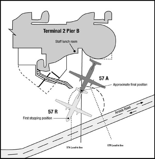
After vacating runway 34 left, the crew was advised by the operator to park on bay 57 reverse (57R) so that engineers could repair the weather radar. Bay 57R is located near the southern end of Terminal 2 Pier B (see Figure 1) and required aircraft to park with the nose pointing away from the terminal.

Figure 1: Parking bay 57 (for illustrative purposes only)

aair200500778_001.jpg

The bay is also marked 57A for aircraft parked facing the terminal. Bay 57R was used to park aircraft in conditions of strong westerly winds, or if engineering staff required the nose of the aircraft to be facing away from the terminal building. The bay was commonly referred to by both ground staff and flight crew as 57 reverse or a reverse parking bay.

The PIC taxied the aircraft to Bay 57R, where it was marshalled into position and stopped by the crew when they observed the marshaller cross his arms once at approximately chest height. The position of the aircraft at that stage was correct for Bay 57R. However, the crew were concerned that the aircraft was positioned too close to a vehicle access road marked on the movement area and after briefly discussing between themselves the meaning of the signal used by the marshaller, decided that the instruction was to reverse. The PIC then reversed the aircraft and anticipated that the marshaller would signal them to stop at the correct point. The crew noted that the marshaller was walking toward the aircraft as it reversed, using hand signals which they interpreted as confirmation of the reverse manoeuvre, but which the marshaller intended as a signal to stop.

The marshaller had been told that the aircraft had a problem with the weather radar, which required that the ground power unit (GPU) be positioned away from the aircraft's nose. When the aircraft started to reverse the marshaller thought the crew were also positioning the aircraft away from the GPU.

Three off-duty marshallers were in a lunchroom, adjacent to bay 57R, when the shift supervisor observed the aircraft being marshalled onto the bay. He then saw the aircraft reversing and alerted the other two marshallers in the room to the situation. They observed the aircraft marshaller signal the PIC to stop the aircraft, by crossing his arms repeatedly at chest height. One of the off-duty marshallers ran out onto the tarmac to the aircraft's two o'clock position1 and signalled the crew to stop by crossing his arms over his head. The tail of the aircraft was estimated by that off-duty marshaller to be within 1 m of the terminal. The shift supervisor also went onto the tarmac and marshalled the aircraft forward to the correct bay 57R stop position.

The on-duty aircraft marshaller had received training on aircraft ground marshalling in accordance with the operator's ramp handling course document. The description for 'stop' in that document was in accordance with the Civil Aviation Safety Authority Civil Aviation Order (CAO) 20.3 Issue 5, Air Service Operations, Marshalling and Parking of Aircraft.

Stop is indicated by the arms to be repeatedly crossed above the head. (the rapidity of the arm movement related to the urgency of the stop, ie. the faster the movement the quicker the stop).

Other documentation used by the operator that included marshalling signals were a Customer Service Ground Handling Manual and a Flight Deck Engineering Manual that both stated:

Arms extended to full length above head in vertical position with bats or wands held steady. Widely accepted signal for use when there is no urgent stop requirement.

Although not in accordance with CAO 20.3, this signal was recognised by ground staff and by flight crew to indicate stop.

All of the manuals reviewed as part of the investigation stated that marshalling bats should be used to minimise the risk of misinterpretation. However, marshalling conducted by the operator during daylight was conducted without the use of marshalling bats.

1. The numbers on a clock are used to describe relative position, where 12 o'clock is directly in front. For example, a person or object observed abeam to the left of an aircraft would be said to be at 9 o'clock.

Summary

On 19 February 2005 at 1310 Eastern Daylight-saving Time, a de Havilland Canada DHC-8-102 aircraft, registered VH-TQR, was being operated on a scheduled regular public transport service from Canberra, ACT, to Sydney, NSW. On arrival at the terminal the crew was given marshalling instructions from ground staff to taxi onto bay 57R and stop. The pilot in command (PIC) then reversed the aircraft until instructed to stop by an off-duty marshaller who had seen that the tail of the aircraft was very near to the Terminal 2 building.

Occurrence summary

Investigation number 200500778
Occurrence date 19/02/2005
Location Sydney, Aero.
State New South Wales
Report release date 13/09/2005
Report status Final
Investigation type Occurrence Investigation
Investigation status Completed
Mode of transport Aviation
Aviation occurrence category Ground handling
Occurrence class Incident
Highest injury level None

Aircraft details

Manufacturer De Havilland Canada/De Havilland Aircraft of Canada
Model DHC-8
Registration VH-TQR
Serial number 208
Sector Turboprop
Operation type Air Transport Low Capacity
Departure point Canberra, ACT
Destination Sydney, NSW
Damage Nil

Fairchild SA227-DC, VH-MYI

Summary

The Australian Transport Safety Bureau did not conduct an on-scene investigation of this occurrence. The report presented below was prepared principally from information supplied to the Bureau.

REPORTED INFORMATION

At 1139 eastern standard time on 2 February 2005, the crew of a Fairchild Industries Incorporated SA227 aircraft, registered VH-MYI, landed at Julia Creek aerodrome on a scheduled regular public transport service from Richmond, Queensland. At that time the runway was not available due to aerodrome line marking works, which had been notified in a notice to airmen (NOTAM) issued on 26 January 2005. There was no equipment or personnel on the runway at the time the aircraft landed.

The pilot in command (PIC) had read the NOTAM prior to commencement of his duty, but he only noticed that the line marking works were in progress and not that the runway was not available. The copilot did not read the NOTAMs prior to departure, nor was he required to by the company operations manual.

The aerodrome operator had issued a method of working plan (MOWP), YJLC Number 2, 18 October 2004 that detailed the works to be undertaken, the expected dates and the NOTAMs to be issued for the various stages. The runway was only to be closed for resurfacing during Stage 1 of the MOWP. There were to be no operational restrictions on use of the aerodrome during line marking, which was to be undertaken during Stage 2.

The Civil Aviation Safety Authority (CASA) Manual of Standards Part 139-Aerodromes Chapter 10, paragraph 10.10.2.8 stated that an:

operator must not close the aerodrome to aircraft operations due to aerodrome works, unless a NOTAM giving notice of the closure has been issued not less than 14 days before the closure takes place.

The NOTAM issued for the line marking was not in accordance with that requirement, or Stage 2 of the MOWP.

The operator of the Fairchild has amended the operations manual for all aircraft types to require both pilots to read NOTAMs prior to departure.

Occurrence summary

Investigation number 200500857
Occurrence date 02/02/2005
Location Julia Creek, (ALA)
State Queensland
Report release date 19/05/2005
Report status Final
Investigation type Occurrence Investigation
Investigation status Completed
Mode of transport Aviation
Aviation occurrence category Aircraft preparation
Occurrence class Serious Incident
Highest injury level None

Aircraft details

Manufacturer Fairchild Industries Inc
Model SA227
Registration VH-MYI
Serial number DC-869B
Sector Turboprop
Operation type Air Transport Low Capacity
Departure point Richmond, QLD
Destination Julia Creek, QLD
Damage Nil

Boeing 767-338ER, VH-OGO, on 20 February 2005

Summary

The Australian Transport Safety Bureau did not conduct an on-scene investigation of this occurrence. The report presented below was prepared principally from information supplied to the Bureau.

REPORTED INFORMATION

At 2020 Eastern Summer Time on 20 February 2005, a Boeing Company 767-338ER aircraft, registered VH-OGO was being operated on a scheduled passenger service between Sydney and Melbourne. The copilot reported feeling unwell during cruise and was physically ill during descent through FL 200. A flight attendant was called to the flight deck to assist and the flight continued under the control of the pilot in command with the copilot assuming a monitoring role for the remainder of the flight.

After a 2-day recovery period and having discussed his illness with the company medical practitioner, the copilot was declared fit and returned to duty.

Occurrence summary

Investigation number 200500838
Occurrence date 20/02/2005
Location 93 km NE Melbourne, (VOR)
State Victoria
Report release date 08/04/2005
Report status Final
Investigation type Occurrence Investigation
Investigation status Completed
Mode of transport Aviation
Aviation occurrence category Flight crew incapacitation
Occurrence class Serious Incident
Highest injury level None

Aircraft details

Manufacturer The Boeing Company
Model 767
Registration VH-OGO
Serial number 25577
Sector Jet
Operation type Air Transport High Capacity
Departure point Sydney, NSW
Destination Melbourne, VIC
Damage Nil

Suspected flight control problem, Boeing 737-838, VH-VXN

Analysis

ANALYSIS

Following the landing at Adelaide on the previous flight, the flight crew inadvertently engaged the 'B' system autopilot in the control wheel steering mode. This inadvertent selection occurred when the 'B' system flight director switch was being moved to the OFF position while the crew were carrying out the 'taxi in' normal procedure. The inadvertent engagement of the autopilot was not detected by the crew.

With an autopilot engaged in the control wheel steering mode, the stabiliser trim wheel would have moved in response to forward or rearward movement of the control column. This movement of the trim wheel and the sounding of the autopilot warning horn during engine shutdown apparently led the crew to assume that there was a fault in the stabiliser trim system.

The next flight was the occurrence flight, which was operated by a different crew. During the climb, the crew noticed the stabiliser trim wheel moving opposite to the direction of the control column movement and they concluded that the apparent fault had recurred in the stabiliser trim system. As a result, the crew performed the non-normal procedure for a runaway stabiliser trim when the trim wheel movement was due to normal activation of the speed trim system.

Factaul Information

On 17 February 2005, a Boeing Company 737-838 aircraft, registered VH-VXN, with seven crew and 150 passengers, was being operated on a scheduled passenger flight from Adelaide, SA to Sydney, NSW. The crew reported that, as the aircraft was climbing through flight level (FL) 180 (18,000 ft), they noticed the stabiliser trim wheel moving opposite to the direction of the control column (elevator) movement.

The pilot in command was the handling pilot for the sector and was manually flying the aircraft when the movement was observed. The crew considered that the trim movement was uncommanded and consequently completed the non-normal procedure for a runaway stabiliser. As the non-normal checklist did not contain the words 'Plan to land at the nearest available airport', the crew levelled the aircraft at FL270 and continued the flight to Sydney.

Following the occurrence, a built in test equipment check was carried out on the flight control system and no faults were found. The two flight control computers were subsequently removed from the aircraft and tested at the operator's avionics workshop with no faults being found in either unit.

Previous flight

A different flight crew operated the aircraft on the preceding flight to Adelaide. That crew reported uncommanded stabiliser trim wheel movement while the aircraft was being taxied to the terminal, after landing at Adelaide. The crew also reported that when the aircraft was shutdown, the autopilot warning horn sounded. They did not notice any autoflight flight director system status annunciations on their respective Electronic Attitude Director Indicator (EADI), nor did they observe the illumination of the autopilot disengage indicator lights on the pilot and copilot instrument panels when the warning horn sounded. The operator's engineering personnel were advised about the apparent uncommanded movement of trim. A built-in test equipment check was subsequently carried out prior to the flight to Sydney but no fault was detected in the flight control system.

Stabiliser trim

The horizontal stabiliser is positioned by the main electric trim motor and is controlled through either of the stabiliser trim switches on each pilot's control column, or by the autopilot trim servo motor. The stabiliser may also be positioned by manually rotating the stabiliser trim wheels located on the control stand between the two pilots.

Pitch control of the aircraft includes a speed trim system. This system is used to improve flight handling characteristics during operations with low gross weight, rearward centre of gravity and high thrust when the autopilot is not engaged. The system provides positive speed stability characteristics to the pilot by adjusting the control column force so that the pilot must provide a significant amount of 'pull' force to reduce airspeed, or a significant amount of 'push' force to increase airspeed. The system trims the stabiliser in the direction calculated to provide the pilot positive speed stability characteristics. Since pilots typically attempt to trim control column force to zero and the speed trim system attempts to trim to positive stick force, the speed trim system operation may be opposite to the direction the pilot is trimming.

Autopilot flight director system

The autopilot flight director system is a dual system consisting of two individual flight control computers and a single mode control panel. The two flight control computers are identified as 'A' and 'B'. For autopilot operation, the computers send control commands to their respective pitch and roll hydraulic servos, which operate the flight controls through two separate hydraulic systems. For flight director operation, each computer positions the flight director command bars on the respective EADI located on the instrument panel for each pilot.

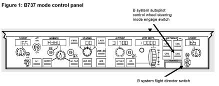
Either autopilot can be engaged in command mode or control wheel steering mode by pushing the appropriate engage switch on the mode control panel, which is located on the glare shield in front of each pilot (Figure 1).

aair200500719_001.jpg

If the autopilot flight director system is engaged in control wheel steering mode, the following system status annunciations will appear above the attitude indications on each pilot's EADI:

FD(the flight director is ON and the autopilot is either OFF or engaged in control wheel steering mode)
CWS P(the autopilot is engaged in control wheel steering pitch mode)
CWS R(the autopilot is engaged in control wheel steering roll mode)

Flight data recorder information

Following the occurrence, data from the aircraft's flight data recorder (FDR) was downloaded and analysed by the aircraft manufacturer and the Australian Transport Safety Bureau (ATSB). The data indicated that during the previous flight the autopilot was engaged after landing at Adelaide. The autopilot was engaged by pushing the control wheel steering mode autopilot engage switch for the 'B' autopilot flight director system. The autopilot engagement occurred when the 'B' system flight director switch was selected to the OFF position while the aircraft was taxiing to the terminal. The flight director switches are usually selected to the OFF position by the crew while carrying out the 'taxi in' normal procedures when the aircraft has vacated the runway after landing.

The 'B' system flight director switch and the control wheel steering engage switch are in close proximity to each other on the glare shield mode control panel, above the centre instrument panel (Figure 1).

The data showed that various up and down trim movements were commanded by the autoflight flight director system following engagement of the control wheel steering mode after landing at Adelaide. The data also showed that the 'B' autopilot flight director system remained engaged when the FDR recording ended for that flight. The aircraft manufacturer advised that 'it is expected that it [the autopilot] disengaged later on (with warning horn) when additional power switching or configuration changes occurred.' The aircraft operator advised that the autopilot would have disengaged when the engines were shutdown and the electrical power source to the autoflight flight director system transferred from the engine driven generators to the auxiliary power unit driven generator.

The aircraft manufacturer also advised that, from their review of the FDR data, 'no trim anomalies could be seen on the following climb out [the occurrence flight]'.

Summary

On 17 February 2005, a Boeing Company 737-838 aircraft, registered VH-VXN, with seven crew and 150 passengers, was being operated on a scheduled passenger flight from Adelaide, SA to Sydney, NSW. The crew reported that, as the aircraft was climbing through flight level (FL) 180 (18,000 ft), they noticed the stabiliser trim wheel moving opposite to the direction of the control column (elevator) movement.

The pilot in command was the handling pilot for the sector and was manually flying the aircraft when the movement was observed. The crew considered that the trim movement was uncommanded and consequently completed the non-normal procedure for a runaway stabiliser. As the non-normal checklist did not contain the words 'Plan to land at the nearest available airport', the crew levelled the aircraft at FL270 and continued the flight to Sydney.

Following the occurrence, a built-in test equipment check was carried out on the flight control system and no faults were found. The two flight control computers were subsequently removed from the aircraft and tested at the operator's avionics workshop with no faults being found in either unit.

Occurrence summary

Investigation number 200500719
Occurrence date 17/02/2005
Location 83 km E Adelaide, (VOR)
Report release date 27/06/2006
Report status Final
Investigation type Occurrence Investigation
Investigation status Completed
Mode of transport Aviation
Aviation occurrence category Flight control systems
Occurrence class Incident
Highest injury level None

Aircraft details

Manufacturer The Boeing Company
Model 737
Registration VH-VXN
Serial number 33484
Sector Jet
Operation type Air Transport High Capacity
Departure point Adelaide, SA
Destination Sydney NSW
Damage Nil

Warning device event – Hamilton Island, Queensland, VH-TNX

Summary

On 15 February 2005, a de Havilland Canada DHC-8-102 (Dash 8) aircraft, registered VH-TNX, was being operated on a scheduled passenger service from Hamilton Island to Cairns, Qld. The aircraft was in instrument meteorological conditions with significant turbulence reported by the pilot in command, who was the pilot flying (PF).

During the climb from Hamilton Island, the PF engaged the autopilot while manoeuvring to intercept the outbound track. During a right turn at 2,624 ft above mean sea level, the Enhanced Ground Proximity Warning System (EGPWS) bank angle advisory activated. That advisory was in the form of an aural alert to the flight crew of 'BANK ANGLE, BANK ANGLE' when a roll angle of 35 degrees was exceeded, and the aircraft was greater than 156 feet above ground level.

Recorded flight data indicated that, while the aircraft was being manually flown, the angle of right bank was increasing as the autopilot was engaged. The angle of bank momentarily reached a maximum of 34.9 degrees, which activated the EGPWS. The PF briefly disengaged and re-engaged the autopilot a number of times during the manoeuvring. That included disengaging the autopilot during a subsequent left turn that was required to make good the outbound track, before re-engaging the autopilot for the remainder of the flight.

A post-flight engineering inspection found no fault with the aircraft's number one Attitude Heading Reference System (AHRS) or with the flight guidance computer system (FGC1). However, as a precautionary measure, these systems were replaced.

Occurrence summary

Investigation number 200500654
Occurrence date 15/02/2005
Location Hamilton Island, Aero.
State Queensland
Report release date 31/07/2007
Report status Final
Investigation type Occurrence Investigation
Investigation status Completed
Mode of transport Aviation
Aviation occurrence category E/GPWS warning
Occurrence class Incident
Highest injury level None

Aircraft details

Manufacturer De Havilland Canada/De Havilland Aircraft of Canada
Model DHC-8
Registration VH-TNX
Serial number 033
Sector Turboprop
Operation type Air Transport Low Capacity
Departure point Hamilton Is, Qld
Destination Cairns, Qld
Damage Nil

Boeing 747 cargo aircraft conducted emergency landing Adelaide Aero.

Summary

Discontinued Investigation

Statement of Reasons

Occurrence investigations commenced from 1 July 2003 are initially categorised as category 4 unless agreed by the ATSB Executive to be above this level at the outset. As detailed in Section 21 (2) of the TSI Act 2003, the Executive Director is empowered to discontinue an investigation at any time. Section 21 (3) of the TSI Act 2003 requires the Executive Director to publish a statement setting out the reasons for discontinuing an investigation (commenced from 1 July 2003) within 28 days of discontinuing the investigation. To obtain a copy of the Brief Print Public for Discontinued Investigations prior to 1 July 2003.

Factaul Information

Information was provided to the ATSB indicating that the crew of a foreign registered Boeing 747 cargo aircraft conducted an emergency landing at Adelaide aerodrome on the morning of 9 February 2005, during the curfew period. Emergency services were placed on local standby and the aircraft landed at 0438 CSuT. The information included claims that the emergency was fuel related.

The ATSB commenced a category 4 investigation to determine if safety was compromised. Following a comprehensive assessment of available information, including air traffic control communications recordings, no safety issues were found to have been involved. When the aircraft landed, it contained fuel sufficient for about 100 minutes flight.

Status: Downgraded the occurrence to category 5 and investigation discontinued.


Occurrence summary

Investigation number 200500506
Occurrence date 09/02/2005
Location Adelaide, Aero.
Report release date 10/02/2005
Report status Discontinued
Investigation type Occurrence Investigation
Investigation status Discontinued
Mode of transport Aviation
Aviation occurrence category Low fuel
Occurrence class Incident
Highest injury level None

Aircraft details

Manufacturer The Boeing Company
Model 747
Registration N715CK
Operation type Charter
Destination Adelaide
Damage Nil

Examination of Teledyne Continental Motors GTSIO520M engine

Factual information

aair200500620_002.jpg

Report No. 24/05

Task No. BE/200500003

Occurrence No. BO/200500620

Examination of failed thrust bearings from a Teledyne Continental Motors GTSIO520M engine

Factual Information

1.1 Examination brief

The Australian Transport Safety Bureau (ATSB) was requested by officers from the Civil Aviation Safety Authority (CASA) to conduct an examination and analysis of several damaged thrust bearing elements from the propeller drive shaft of a Teledyne Continental Motors model GTSIO520M aircraft engine (serial number 810712). Information received indicated that the bearings and accompanying propeller shaft were removed from service during maintenance activities; the discovered damage prompting the aircraft operator to submit a defect report / service difficulty report (SDR) to CASA. A second similar instance of bearing failure and shaft damage was also reported, having occurred on a similar engine (serial number 239168R) approximately one month previously.

The assessment of bearing compliance with the manufacturer's specifications or the direct applicability of the particular bearing part to the engine within which they were installed was not within the scope of the investigation.

1.2 Items received

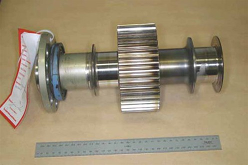
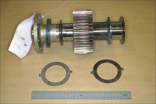
The ATSB received the full set of thrust bearing elements and the propeller shaft from engine serial number (ESN) 810712 (figure 1). The propeller shaft from the earlier occurrence was also provided (figure 2), however the associated thrust bearing set was not available.

Figure 1. Propeller shaft and thrust bearings from engine serial number 810712.

Figure 1. Propeller shaft and thrust bearings from engine serial number 810712

Figure 2. Propeller shaft from engine serial number 239168R.

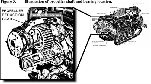
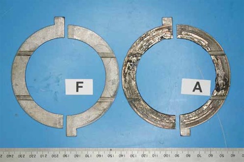
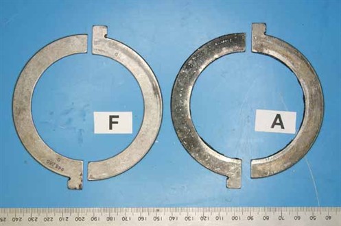
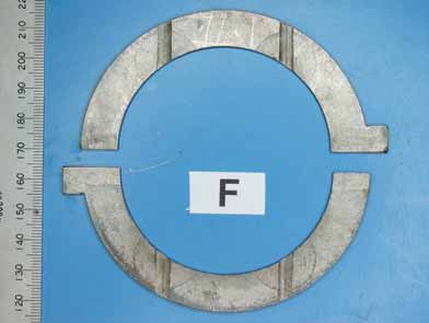
As installed, the thrust bearings comprised two sets of semicircular opposing plates, located against flange elements at the rear of the propeller shaft (figure 3 ). The rear bearings, carrying the primary propeller thrust loads, had sustained extensive mechanical and thermal damage, whereas the forward bearings showed little evidence of abnormal service and were visibly sound (figures 4, 5). The undamaged (forward) bearing set carried the rear surface identification '646260 G'. Damage to the rear bearings prevented the recognition of any similar markings on those items.

figure 3 illustration of propellor shaft and bearing loccation


Figure 4. Contact (bearing) surfaces of thrust bearings as-received.

Figure 4. Contact (bearing) surfaces of thrust bearings as-received

Figure 5. Rear (backing) surfaces of thrust bearings as-received.

Figure 5. Rear (backing) surfaces of thrust bearings as-received

The thrust bearings were understood to be of tri-metal construction, comprising a surface layer of lead-tin babbit, over a copper-lead intermediate layer on a steel backing. The SDR document indicated the bearing set had operated for 433.4 hours since new installation (TSN).

1.1 Examination findings

1.1.1 Rear thrust bearings

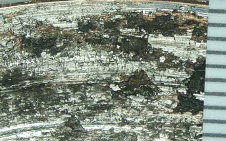
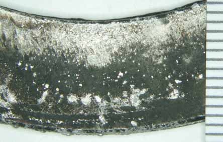
Close visual examination of the set of failed bearings (attachments A - D) showed heavy scoring, gross disruption and partial loss of the bearing alloy from the bearing running (contact) surfaces (figure 6). Partial melting of the surface alloys and other evidence of elevated temperatures was prevalent, as was the blackening and discolouration of the surfaces where alloy loss had occurred. The rear (back) faces of the bearings also showed blackening and the accumulation of melted alloy (figure 7). The lubrication channels on one bearing were partially filled with transferred material that had been melted and dislodged from adjacent areas.

Figures 6 and 7. Low-power microscopic view of a damaged area on the contact and backing surfaces of a damaged thrust bearing.

Figures 6 and 7. Low-power microscopic view of a damaged area on the contact and backing surfaces of a damaged thrust bearing

Figures 6 and 7. Low-power microscopic view of a damaged area on the contact and backing surfaces of a damaged thrust bearing

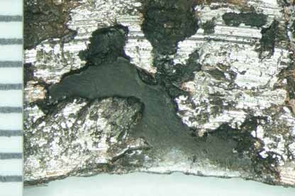
In isolated regions, the bearing alloy had completely separated from the steel backing, with the affected areas characterised by exposure of the comparatively flat, featureless interfacial surfaces (figure 8).

Figure 8. Area on a damaged bearing showing complete separation of the bearing alloy from the steel backing.

Figure 8. Area on a damaged bearing showing complete separation of the bearing alloy from the steel backing

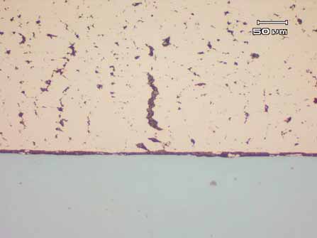
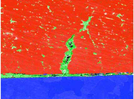
Several metallographic sections taken transversely through one bearing confirmed the basic tri-metal construction, with the intermediate layer presenting as a coarse intermittent network of lead within a copper alloy matrix. In numerous areas, the lead network had interconnected, creating filled fissures (figure 9), the larger of such broaching the external surface. Evidence of lead migration to the steel backing interface was observed at and adjacent to the areas of alloy separation, creating a continuous lead boundary layer approximately 5-10 m thick.

Figure 9. Cross-sectional microstructure of a damage bearing, showing the agglomeration of lead (dark phase) within the copper bearing alloy and along the backing interface. Unetched.

Figure 9. Cross-sectional microstructure of a damage bearing, showing the agglomeration of lead (dark phase) within the copper bearing alloy and along the backing interface. Unetched

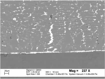
Scanning electron microscopy of the prepared sections confirmed the metallographic observations, with back-scattered electron imaging (figure 10) and x-ray dot mapping (figure 11) graphically illustrating the lead agglomeration and migration to the backing interface.

Figure 10. SEM image of the metallographic section, illustrating the lead migration.

Figure 10. SEM image of the metallographic section, illustrating the lead migration

Figure 11. SEM X-ray map confirming the lead migration (green phase) within the copper alloy (red phase) and at the steel (blue phase) interface.

Figure 11. SEM X-ray map confirming the lead migration (green phase) within the copper alloy (red phase) and at the steel (blue phase) interface

1.2.1 Forward thrust bearings

In contrast with the rear elements, the forward bearings presented in an essentially undamaged condition (figure 12), with very little evidence of metal-to-metal surface contact and no evidence of thermal distress, overheating or physical degradation. The rear surfaces were not fretted or rubbed to any significant extent and showed no indication of improper seating, movement or miss-installation.

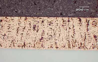
Several metallographic sections, taken in a similar sense to those from the rear bearings, presented a similar general microstructure, with the intermediary alloy layer showing a distinct as-cast (dendritic) distribution of lead within the copper alloy matrix (figure 13). No evidence of fissuring or lead migration to the backing interface was observed within the cross-sections studied.

Typical thicknesses of the bearing component layers and backing were established by measurement under the SEM, i.e.
Surface Pb-Sn babbit: 7 - 10 m (0.007 - 0.010 mm)
Intermediate Cu-Pb alloy: 715 - 725 m (0.715 - 0.725 mm)
Steel backing: 1,650 m (1.65 mm)

Figure 12. Undamaged running surfaces of the forward bearing set.

Figure 12. Undamaged running surfaces of the forward bearing set

Figure 13. Metallographic cross-section through an undamaged bearing - no lead migration to the alloy interface.

Figure 13. Metallographic cross-section through an undamaged bearing - no lead migration to the alloy interface

1.2.2 Propeller shafts

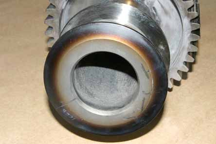
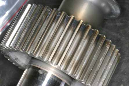
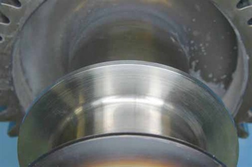
Both propeller shafts showed distinct discolouration and evidence of localised heating in a band around the back face of the rear thrust flange (figure 14). Similar discolouration was also noted in a band around the rearmost ends of the reduction gear teeth (figure 15), however the tooth contact surfaces themselves showed no evidence of distress, uneven wear or excessive localised friction.

The inside (bearing) surfaces of the rear shaft flanges (those working against the failed bearing elements) showed heavy wear and circumferential scoring around the contact path (figure 16). In contrast, the opposite flange faces (figure 17) showed little if any physical manifestation of service - abnormal or otherwise.

Figure 14. Discolouration of the rear thrust flange surface typifying the localised overheating.

Figure 14. Discolouration of the rear thrust flange surface typifying the localised overheating

Figure 15. Discolouration (similar to figure 12) evident on the ends of the reduction gear teeth.

Figure 15. Discolouration (similar to figure 12) evident on the ends of the reduction gear teeth

Figure 16. Appearance and extent of scoring and wear sustained by the propeller shaft rear thrust flange contact surface.

Figure 17. Forward thrust flange (opposite that shown above), presenting in sound condition.

aaFigure 17. Forward thrust flange, presenting in sound condition

Analysis

Damage to the propeller shaft thrust bearing assembly was limited to the rear bearings and shaft flanges, those being the components carrying the primary propeller thrust loads when under power. The forward bearings and shaft flanges were undamaged and showed no indication of anomalous service.

The rear propeller shaft thrust bearings from ESN 810712 had failed as a result of gross localised overheating. The local discolouration of the shaft flanges and adjacent surfaces and the partial melting and microstructural changes within the bearing alloy attested to the excursion in temperatures to a level well above the normal component operating range. The physical loss of sections of bearing alloy from the backing material was a direct manifestation of the overheating, with the elevated temperatures causing the lower melting point lead alloy to agglomerate and migrate to the steel interface, where it weakened the normal bond and allowed the break-up and separation of the bearing material. There was no evidence of a deficiency within the construction or make-up of the bearings examined, nor was there any evidence that the bearings had been improperly installed.

In a general sense, the overheating of bearings results from the generation of frictional heating at a rate greater than the assembly and environment is able to conduct it away. Heating, from surface and lubricant frictional effects, is a function of numerous interrelated factors including:

  • bearing operating (transmitted) loads
  • clearances
  • lubricant properties
  • lubricant quantities and flow rates
  • relative surface speeds
  • surface conditions and finishes
  • bearing materials

The investigation was not able to directly identify which of the identified factors were contributory to the failures sustained, however it is suggested that issues relating to the initial bearing clearances, lubricant and operating (thrust) loads would be the most likely in terms of the general nature and function of the assembly.

Conclusions

The following conclusions, in terms of the bearing failures, were drawn from the examination of the supplied components:

  1. The bearings from ESN 810712 had failed as a result of gross, localised frictional overheating, resulting in the physical and microstructural degradation of the bearing alloy.
  2. There was no evidence that a manufacturing defect, material anomaly or other deficiency within the bearing components themselves had contributed to the failure.
  3. There was no evidence found to suggest that the bearings had been improperly installed.
  4. The investigation was not able to directly identify the proximate cause/s of bearing failure, however it is suggested that initial bearing clearances, lubrication and loading were most likely in terms of the nature of the failure and the general function of the assembly.

Summary

The Australian Transport Safety Bureau (ATSB) was requested by the Civil Aviation Safety Authority (CASA) to conduct an examination and analysis of several damaged thrust bearing elements from the propeller drive shaft of a Teledyne Continental Motors model GTSIO520M aircraft engine (serial number 810712). Information received indicated that the bearings and accompanying propeller shaft were removed from service during maintenance activities; the discovered damage prompting the aircraft operator to submit a defect report / service difficulty report (SDR) to CASA. A second similar instance of bearing failure and shaft damage was also reported, having occurred on a similar engine (serial number 239168R) approximately one month previously.

The assessment of bearing compliance with the manufacturer's specifications or the direct applicability of the particular bearing part to the engine within which they were installed was not within the scope of the investigation.

Occurrence summary

Investigation number 200500620
Occurrence date 14/02/2005
Location Tamworth
Report release date 31/10/2005
Report status Final
Investigation type Occurrence Investigation
Investigation status Completed
Mode of transport Aviation
Aviation occurrence category Miscellaneous - Other
Occurrence class Technical Analysis