On 15 July 2013, at about 1500 Central Standard Time, a Robinson R44 helicopter, registered VH-ZON (ZON), departed from the helipad at Arkaroola, South Australia on a short scenic flight. On board were the pilot and two passengers.
During the return leg, when only a few minutes from the helipad, the pilot heard a loud noise from the rear of the helicopter. The helicopter yawed to right and began to descend. The helicopter did not respond to the pilot’s attempt to correct the yaw, so he conducted an autorotation onto a suitable area in the rugged terrain. The helicopter touched down on the rocky ridge and sustained substantial damage. The pilot and passengers did not sustain any injury.
An engineering report found the left magneto had failed. The Civil Aviation Safety Authority (CASA) is aware of the existing problem with Teledyne Continental Motors and Champion Aerospace (Slick) magnetos. A search of the CASA Service Difficulty Report (SDR) database over the 24 months to June 2013 revealed nearly 45 per cent of ignition failures were attributed to magneto failures.
This accident also highlights the importance of thorough pre-flight safety briefs as conducted by the pilot in this situation. The ATSB safety research and analysis report B20040238, Public Attitudes, Perceptions and Behaviours towards Cabin Safety Communications, stated that when safety briefs are thoroughly and professionally delivered, the chances of survival for passengers increase.
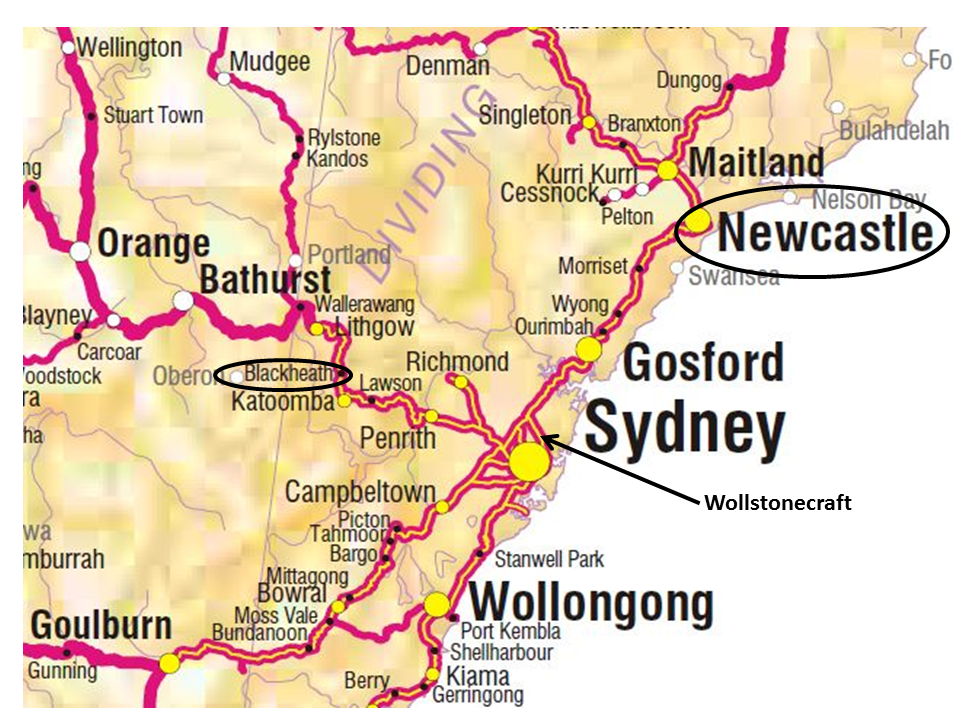
During June and July 2013, three separate safeworking breaches occurred on the Sydney Trains Network in NSW involving the application of Network Rule NWT 308 (Absolute Signal Blocking) and Network Procedure NPR 703 (Using Absolute Signal Blocking). The incidents occurred at Blackheath on 13 June 2013, Newcastle on 13 July 2013 and Wollstonecraft on 17 July 2013.
In each case, trains were being excluded from worksites, as part of worksite protection arrangements, using the Absolute Signal Blocking (ASB) rule and procedure. The rule and procedure were not adhered to during the authorisation of the ASB resulting in trains entering or passing through the worksites from which they should have been excluded.
What the ATSB found
The three incidents were the result of the requirements of the Network Rule and Procedure not being complied with; particularly full train-in-section checks were not being conducted or the location of worksites was not clearly identified. Also, the Sydney Trains’ systems used to monitor the application of ASB were not consolidated. Instead, the systems made a very limited number of isolated and generally non-safety related findings without identification of how the findings or proposed corrective actions were to be recorded, analysed or implemented.
What's been done as a result
Immediately after the third incident, Sydney Trains suspended use of the ASB rule and procedure for some categories of track work. The suspension was conditionally lifted on 23 July 2014 with some additional procedural requirements and an emphasis on complying with existing requirements for clear communications.
In September 2014, Sydney Trains commenced a trial of a ‘Coded Authorisation Process for Absolute Signal Blocking’. The trial seeks to address the common types of errors identified in ASB incidents by testing a ‘job aid’ which requires improved train-in-section checks, improved identification of work site locations and consistency in the implementation process between the Signaller and the PO for any ASB request. It also requires that a unique code number be issued to the Protection Officer by the Signaller upon any request for ASB. Work cannot commence on track without this code and the code is surrendered back to the Signaller when the ASB is fulfilled.
On the matter of the monitoring and assurance, the ATSB has recommended that Sydney Trains undertake further work to improve its focus on the potential issues involving ASB and its continued safety.
Safety message
ASB is one of five methods of worksite protection which are designed to provide workers with safe track access. It is paramount that track access using any of the methods is properly planned with adequate defence(s) against error, has the Network Rules and Procedures applied consistently and is constantly monitored for compliance.
The occurrences
Introduction
In each incident, trains were to be excluded from worksites, as part of worksite protection arrangements, using the Absolute Signal Blocking (ASB) in accordance with Network Rule NWT 308 (Absolute Signal Blocking) and Network Procedure NPR 703 (Using Absolute Signal Blocking). ASB requires protecting signals to be held at stop to prevent trains from entering the section and protect the workers on track. However, the rule and procedure requirements were not adhered to during the implementation of ASB resulting in trains entering or passing through the worksites while workers were on or about the track.
Blackheath 13 June 2013
At 0838[1], the PO of a six man workgroup working on the Down Main line at 123.456 km point,[2] between Blackheath and Mt Victoria (Figure 1), requested to use ASB for 10 minutes from the Signaller at Katoomba to record track gauge measurements previously marked on various sleepers on the adjacent Up Main line. However, with the Dubbo-bound CountryLink XPT passenger train service WT27 approaching Katoomba, the Signaller denied the request. Instead, the signaller offered the PO a five minutes window which he accepted.
Implementation of ASB requires the signaller to ascertain the precise location of the proposed worksite, confer with the Train Controller[3] regarding the request for ASB, give an assurance to the PO that there are no trains within the section approaching the worksite and apply blocking facilities[4] on the controlled signals and points providing entry into the section. The Signaller conferred with the Train Controller at Sydney West Control at 0841 before applying blocking facilities on controlled signals 68.3 and 68.5 at Katoomba. He additionally applied blocking facilities on No. 23 points at Katoomba after ensuring they were set in the normal position so that a route could not be set into the section from Katoomba to Mt Victoria.
At 0842, the Signaller contacted the PO and informed him that ASB had been granted and implemented from 0842 to 0847. The PO read back the details of the ASB to the Signaller and the workgroup commenced recording the measurements as marked.
The task was completed and the workers cleared the danger zone without incident before the PO fulfilled the ASB with the Signaller at 0846. Two minutes later, the workgroup observed a CityRail interurban passenger train pass their location on the Down Main line at line speed. As the section between Katoomba and the worksite is 13 kilometres long and 14 minutes in running time, they realised that, despite an assurance from the Signaller at the time, a train must have been in the section between Katoomba and their location when the ASB was granted.
At 0849, the PO rang the Signaller and informed him of the passing train. This confused the Signaller who replied that he had not observed any trains in the section on the display screens of the Train Visibility System (TVS), although WT27 was at the platform at Katoomba and the signals were at stop. The PO suggested the TVS should therefore be checked then added that he would be reporting the incident to a local manager.
At 0858, the PO alerted the Blue Mountains Network Operations Superintendent (NOS) of the incident. The NOS then contacted the Train Controller at Sydney West Control who informed the Shift Manager at the Rail Management Centre (RMC) in Sydney about the incident.
After discussion between the NOS, Train Controller and the Shift Manager, the Signaller was placed under the immediate supervision of the Katoomba Station Manager until a replacement signaller relieved him of his duties. During this time, he was not permitted to authorise or issue any forms of worksite protection or on-track authorities.
At 0935 the NOS informed the Blue Mountains Area Manager of the incident. Both he and the Area Manager deployed to Katoomba where the Signaller was relieved of safeworking duties before being drug and alcohol tested. Both tests returned negative results.
Newcastle 13 July 2013
At about 0800, the PO for a contractor workgroup comprising of six workers commenced a pre-work briefing for the planned litter reduction on track between the platforms at Newcastle Station (Figure 1).
At 0817, the PO rang the Signaller at Newcastle requesting access to the track to clean the track area between Platforms 3 and 4 but did not specifically ask for an ASB. The Signaller advised the PO that he would put ‘a block on 3 and 4’ platform tracks[5] and that he had ten minutes before the next train was due to arrive into Platform 4. He also recorded the PO’s contact number. Although a requirement of ASB, the Signaller did not nominate to which signals or points the blocking facilities were being applied. This surprised the PO but went unchallenged by him. Furthermore, the signaller did not confer with the Train Controller about the request as required for an ASB.
Believing trains had been excluded, the PO and the workgroup entered the danger zone between the platforms and commenced their task. Lookouts were positioned on both Platforms 2/3 and 4 in accordance with the worksite protection plan and company directive. [6]
At about 0830, NSW TrainLink passenger service V712 from Telarah approached Newcastle Station to terminate in Platform 4. Approaching the platform, the driver observed workers on or about the track and sounded the train whistle in accordance with Network Rule NTR 408 (Using Train Whistles). In response to a warning from the lookouts of an approaching train, the workgroup immediately cleared to a safe place.
The Signaller heard the train whistle and realised that the workgroup was still on track and had not cleared after the agreed 10 minutes. He attempted to call the PO but the calls went unanswered going through to a message bank service.
The PO realised an incident had occurred but was unsure of reporting procedures. He rang the North Corridor Manager who advised him to report the incident to the Duty Manager at Newcastle. The Duty Manager advised the PO to report the incident to the North Train Controller in Sydney who, in response, called an Incident Response Commander to investigate.
The Signaller and PO were relieved of safeworking duties before being drug and alcohol tested with both returning negative results.
Wollstonecraft 17 July 2013
Two workgroups were working simultaneously on track on the North Shore line between Chatswood and Waverton. One workgroup was repairing a broken signal cable connection on the Up Shore track at Waverton while the second workgroup, comprising of four workers, was conducting a scheduled walking inspection of the overhead wiring on the Down Shore line between Gordon and Waverton.
After arriving at St Leonards Station, at 1234 the PO for the second workgroup informed the Area Controller (Signaller) operating the North Sydney Panel at Homebush Signalling Complex that the workgroup was using Lookout Working in accordance with Network Rule NWT 310 but may also make a couple of requests for ASB as they proceeded down the track towards the next station Wollstonecraft (Figure 1).
Shortly after arriving at the Russell Street overbridge, at 1254 the PO contacted the Area Controller requesting ASB for the bridge crossing. He made the ASB request as there was no designated safe area[7] on the bridge. The PO nominated Signal SH3.87 (at Waverton) to be used as the protecting signal for the ASB and advised that a lookout would also be used. Signal SH3.87 was the nearest signal to their location that could be controlled with blocking facilities applied. However, he did not provide the name or exact kilometrage of the bridge the workgroup was about to cross; nor did he implement any protection arrangements for the live, adjacent Up Shore track.
The Area Controller advised the PO to wait as there was a train ‘just clearing the section as we speak’ and that he would call him back when he could.
At 1255, the Area Controller informed the Train Controller of the ASB request. In the phone call, the Area Controller indicated that the location of the workgroup was just at the country end of Waverton. This was several hundred metres away from the location where they were about to cross. The Train Controller sought an assurance from the Area Controller that blocking facilities had been applied and granted the request commencing at 1256.
At 1256, the Area Controller called the PO to advise that ASB had been granted. He assured the PO that the blocks were applied to Signal SH3.87 and the section was clear. The PO repeated back this information before advising that he would call the Area Controller once over the bridge.
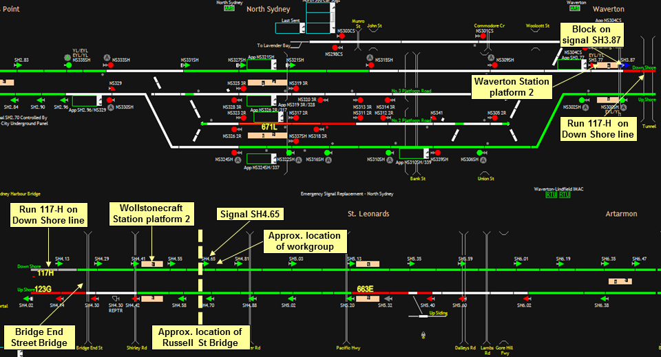
Unbeknown to the PO, the Area Controller had mistakenly identified from the Advanced Train Running Information Control System (ATRICS)[8] that the workgroup was about to cross the Bridge End Street bridge 6.822 km point at Waverton instead of the Russell Street bridge. Despite four road overbridges being marked on the ATRICS, the Russell Street bridge, the only road underbridge in the section, was not. Also, the Area Controller had applied the blocks to Signal SH3.87 at 1255:50 aware that Run 117-H was still in the section about to depart Waverton station. The Area Controller was expecting that Run 117-H would have passed the Bridge End Street bridge before the ASB was authorised. Run 117-H had departed Waverton station towards Wollstonecraft at 1255:22.
Without realisation that the train mentioned by the Area Controller as ‘just clearing the section as we speak’ had not passed, the workgroup commenced to file across the Russell Street bridge using the Down Shore track.
At 1257:52, Run 117-H departed Wollstonecraft station with its wheels flanging audibly on the 240 metre right hand track curve leading towards the Russell Street bridge. The workgroup identified the noise as an approaching train. At the same time, they also observed a train approaching the bridge from the opposite direction on the Up Shore track. Backtracking hastily off the bridge, the workgroup climbed onto a safe place on top of the signal troughing adjacent to Signal SH4.65 and remained there until both trains had passed. Signal SH4.65 is located at the 7.451 km point, approximately 20 metres north of the Russell Street bridge.
According to the PO, Run 117-H passed the workgroup without slowing or the driver sounding the whistle in acknowledgement of an all clear hand signal being given by the PO.
Immediately after the train had passed, the PO rang the Area Controller to report the incident. During the call, the Area Controller indicated that he had identified the wrong bridge when granting the ASB. He then granted permission for the workgroup to complete their crossing.
The Area Controller self-reported the incident to the Train Controller at 1259. He was immediately relieved of safeworking duties before being drug and alcohol tested. Both tests returned a negative result.
The ASB was fulfilled by the PO at 1301 after the workgroup had completed the crossing of the bridge. He was then directed to proceed (return) to Chatswood for drug and alcohol testing. Both tests returned a negative result.
Figure 1: Location of incidents
Source: Geoscience Australia annotated by the ATSB
In response to the Wollstonecraft incident, the Manager of Train Operations Sydney Trains suspended the use of ASB in worksite protection applications immediately at 1440 on 17 July 2013.
All three incidents under investigation occurred on the NSW electrified network. The Blackheath incident occurred prior to a NSW Government restructure of RailCorp, the infrastructure manager of the Metropolitan Rail Area (MRA) network, on 1 July 2013. Under the restructure, Sydney Trains became the accredited rail operator of the electrified network under the Rail Safety National Law (NSW) and assumed responsibility for maintenance and network control on it. It is also a rolling stock operator along with CityRail, CountryLink and NSW TrainLink who are mentioned within this report.[9]
Location and track layout
Blackheath
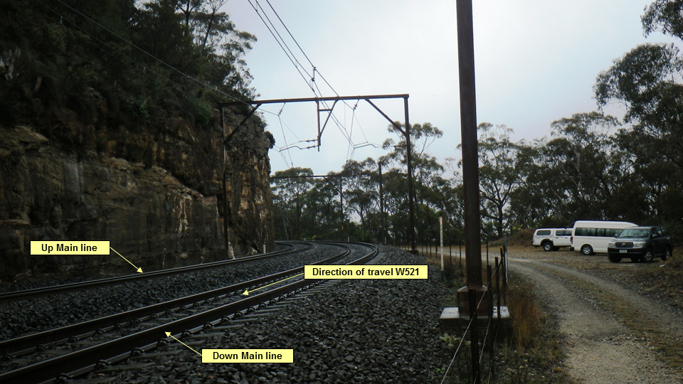
The track at Blackheath (Figure 2) consists of dual electrified lines with a maximum posted track speed of 65 km/hr. It is located in the Blue Mountains on the Main West line in the section between Katoomba and Mt Victoria.
The worksite was located at the 123.456 km point on a 280 metre right hand curve with a gradient of 1:80.
Figure 2: Worksite at Blackheath
Source: OTSI
Newcastle
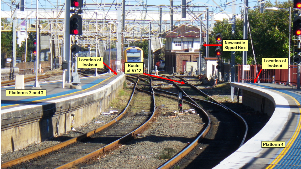
The city of Newcastle is located in the Hunter Region and is the terminus for the NSW Trains’ electrified services in the north and local diesel multiple unit services from around the region. Newcastle station (Figure 3) consists of four platforms and a number of storage roads with a maximum track approach speed of 30 km/hr.
Figure 3: Worksite at Newcastle
Source: OTSI
Wollstonecraft
Wollstonecraft is located on the North Shore line between Waverton and St Leonards stations. The track consists of dual electrified lines which reverse curve through various rock cuttings on a ruling gradient of 1:48 and a maximum track speed of 50 km/hr.
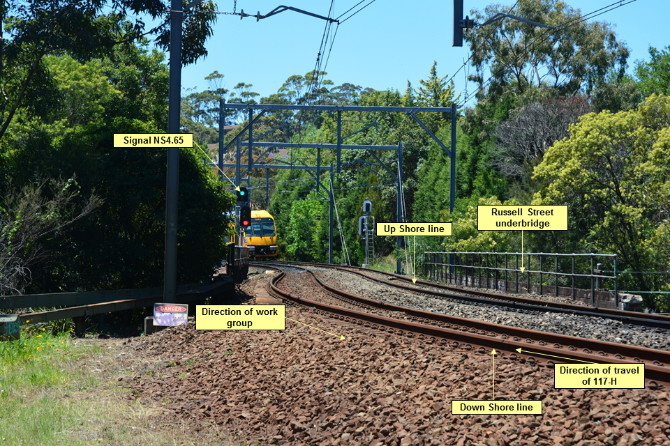
The Russell Street bridge (Figure 4) is a road underbridge located at 7.451 km point and is approximately 50 metres in length. Four road overbridges and a tunnel are also located in the section between St Leonards and Waverton including the Bridge End Street bridge located at 6.822 km point.
The workgroup cleared the track to signal NS4.65 which is located about 20 metres past the northern (St Leonards) end of the bridge at the 7.519 km point.
Figure 4: Worksite at Wollstonecraft
Source: OTSI
Environmental conditions
Blackheath
Weather conditions at the time of the incident were described by the PO as wet and misty. Bureau of Meteorology (BOM) records from Mt Boyce, located in the general incident area, indicated that, at 0900, the temperature was 6.6 °C with 22 km/hr winds. It was also recorded that 5.4 mm of rain had fallen over the 24 hour period.
Newcastle
Weather conditions on the morning of the incident were described by the PO as dry and clear. BOM records from Newcastle indicated that, at 0900, the temperature was 12.7 °C with 6 km/hr winds. It was also recorded that 0.2 mm of rain had fallen over the 24 hour period.
Wollstonecraft
Weather conditions on the morning of the incident were described by the PO as dry and clear. BOM records indicated that the maximum temperature had reached 24.3 °C with winds up to 22 km/hr. It was also recorded that 4.8 mm of rain had fallen over the 24 hour period.
It was determined that the environmental conditions at the locations did not contribute to any of these incidents.
System of safeworking
The system of safeworking used for train control at all three incident locations is prescribed under Network Rule NSY500 (Rail Vehicle Detection System). [10] Absolute (controlled) signals for entry into the sections are controlled and monitored from local signal boxes or centralised signalling complexes. Permissive (automatic) signals throughout the sections are positioned to maintain train separation but cannot be monitored from all signal boxes and control centres.
Signal boxes are located at Katoomba and Mt Victoria for the control and monitoring of signals through the section including Blackheath. A signal box also provides control and monitoring of the signals at Newcastle. At Wollstonecraft, the signals into the section and through the location are controlled and monitored from the North Shore Panel and the North Sydney Panel at Homebush Signalling Complex.
The signalling and points equipment at Katoomba are controlled by electro-mechanical large lever frame while Newcastle signalling and points are controlled by electro-mechanical miniature lever frame. Mechanical sleeves are used to provide blocking facilities and prevent any unintended movement of the levers. The control system at the Homebush Signalling Complex is computer-aided with the operation of all points, signals and blocking facilities facilitated by computer key strokes.
Train monitoring systems
Introduction
Various monitoring systems are provided for signallers and Train Control to monitor the passage of trains on the network and provide information about the locality of trains within sections. These include track diagrams, Train Visibility System (TVS) screens, Train Location Systems (TLS) screens and Advanced Train Running Information Control Systems (ATRICS).
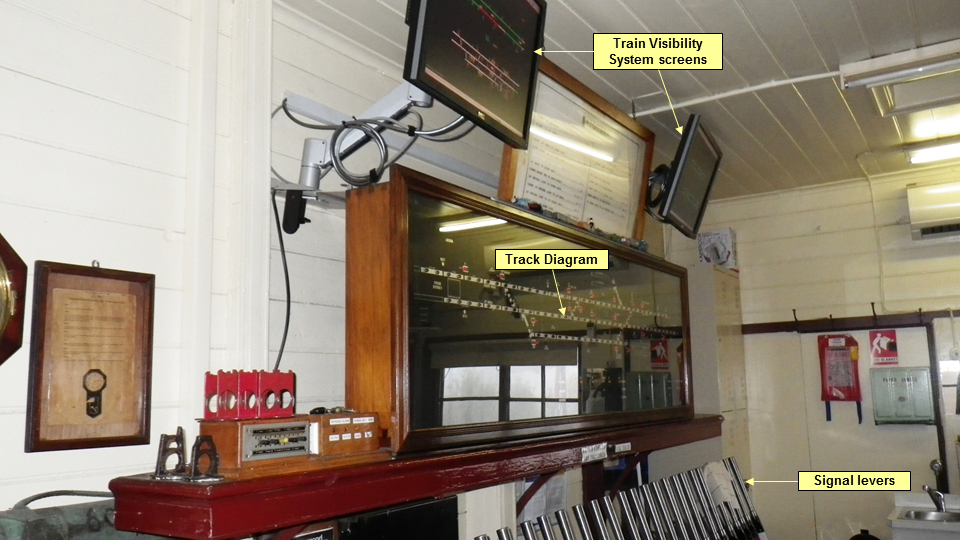
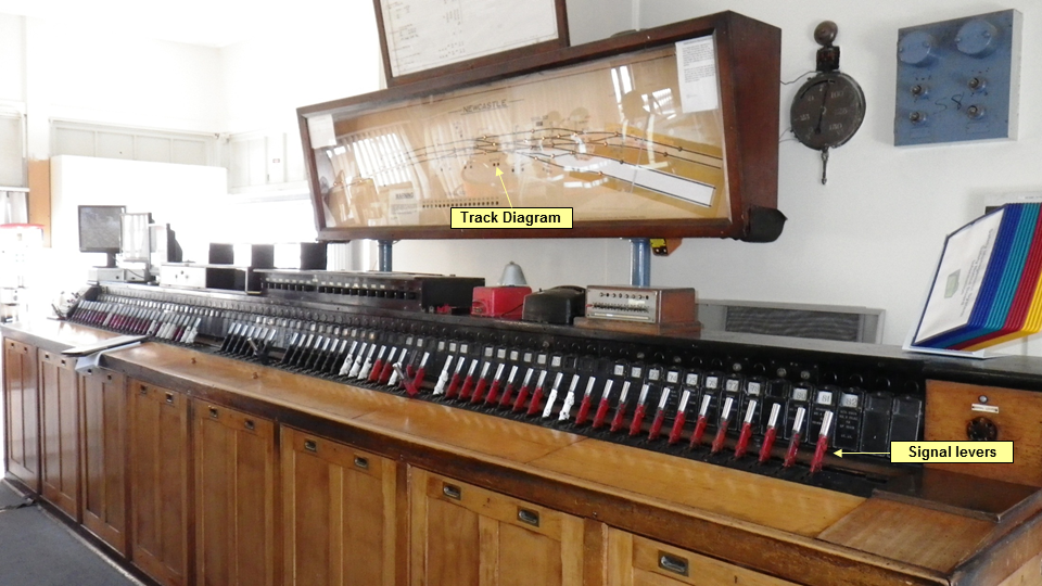
TVS screens and a signalling diagram were provided at Katoomba, a track diagram at Newcastle and ATRICS with a TLS screen at Homebush.
Train Visibility System (TVS)
The TVS at Katoomba (Figure 5) is a non-vital indication system[11] designed to provide Signallers with visibility of trains in the long, permissive signalled sections on the Blue Mountains. The system was installed in response to a recommendation stemming from the judicial inquiry into the Glenbrook accident which occurred in December 1999. The accident happened when an interurban train collided with the rear of the Indian Pacific killing 7 passengers and injuring 51 others.
The TVS display is a straight line graphical representation of the permissive track sections between Katoomba and the neighbouring signal boxes at Springwood and Mt. Victoria. It is additional to the existing conventional track diagram at Katoomba. The line on the screen changes from a green aspect, when the route is clear, to a red aspect as trains occupy the track circuits while progressing through the section. Being a guide only and lacking in infrastructure details, it is not a recognised safety system and cannot be utilised for safe working purposes. As the signaller has no control over any equipment or its functions, other methods must be employed to ascertain the actual location of trains and the status of signals and points.
Figure 5: Katoomba signal box
Source: OTSI
Train Location System (TLS)
The Train Location System (TLS) (Figure 7) is used extensively across the Sydney Trains and NSW Trains networks by both the RMC and the newer signal control centres. It is a large graphical representation of the entire Sydney Trains network providing staff monitoring the network with on time running information that assists in the planning and execution of the daily rail program during normal and degraded operations. It is also a non-vital indication system and, like the TVS, is not a recognised safety system so cannot be utilised for safe working purposes.
Track diagram
Both Katoomba and Newcastle Signal Boxes (Figure 6) are equipped with track diagrams to provide signallers with information regarding the location of trains and the status of track circuits, absolute signals and points in their area of control. Although the diagrams are simplistic, they are permitted for use in safeworking as they indicate the actual location of trains and the state of the equipment controlled by the signal box.
Figure 6: Newcastle Signal Box
Source: OTSI
Advanced Train Running Information Control System (ATRICS)
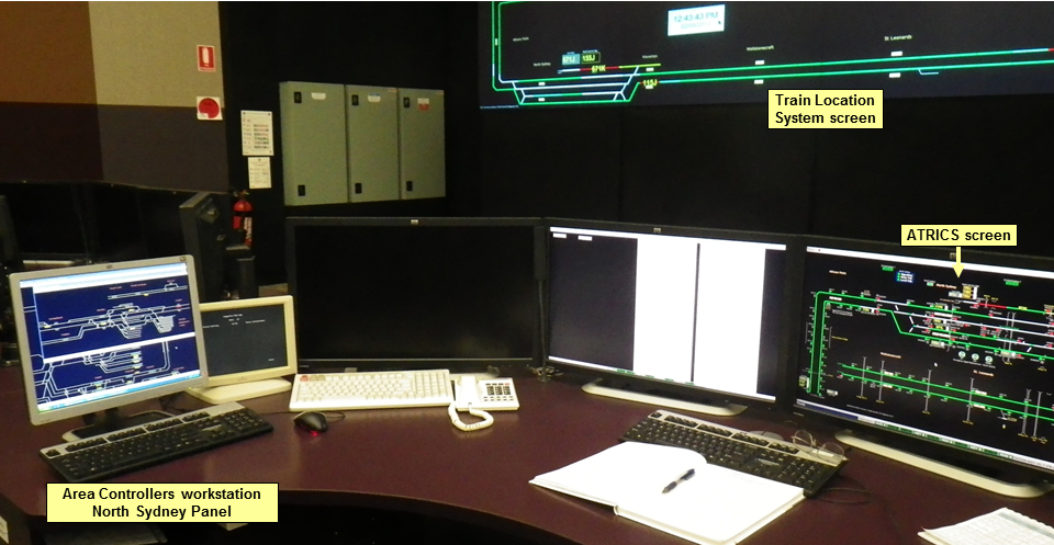
The Wollstonecraft incident involved the use of the Advanced Train Running Information Control System (ATRICS) controlled from the Homebush Control Centre. The Homebush Control Centre controls the North Shore line, the Main North line between Rhodes and Normanhurst, the Epping to Chatswood Rail link and the Olympic Park line.
ATRICS is used throughout the Sydney Trains network to provide a graphical display that allows controllers to interact directly with the rail network by controlling signals, points and other signalling equipment through the click of a mouse. It is also a non-vital centralised traffic control system which enables real time monitoring and control of the signals and points. However, it is limited in its details of localities and track-borne infrastructure.
The area controller’s area of responsibility is displayed over multiple computer monitors. The North Sydney control panel is shown in Figure 7.
The system permits the area controller to operate or block the signals and points in their area of control by either clicking directly on the onscreen symbols representing the signalling/points equipment or using a drop down menu from the menu bar at the top of the screen. The permissive signals are controlled by the presence of a train on the track circuits and in most cases cannot be controlled or blocked by the area controller.
ATRICS has a replay function which can be used to review the status of its operation should there be a failure of the system or an incident on track.
Figure 7: Homebush signal complex – North Sydney control panel
Source: OTSI
Applicable ASB Rules and Procedure
Safeworking rules and procedures are implemented to ensure the safe operation of multiple train movements and/or track occupancies on a rail network. A key principle for any railway safeworking system is to maintain adequate separation between rail traffic and any other rail vehicles or track workers occupying or working on the running lines. The safeworking rules relating to ‘working on track’ for the Sydney Trains’ Network in New South Wales are distributed over a number of documents.
Network Rule NWT 300 - Planning Work in the Rail Corridor
NWT 300 prescribes the rules for planning work in the rail corridor and assessing the work for safety. Before any workgroup enters the rail corridor, the PO must plan and document the worksite in accordance with NWT 300. The rule prescribes that work planned in the corridor must be assessed for safety and it’s potential to intrude on the Danger Zone. Work cannot be carried out unless a safe place can be easily reached and safety measures are in place.
A worksite must have a PO whose primary duty is to keep the worksite and workers safe. POs must be satisfied that other work will not interfere with their primary duty. The PO is responsible for conducting the safety assessment of the worksite, briefing the workers of the protection arrangements, ensuring the works are conducted in a safe manner, keeping records of the protection arrangements and communicating with Network Control about the protection.
When conducting the safety assessment, the PO must consider, amongst other factors, the method of protecting the worksite, the resources required for its protection and the communication requirements. The PO must also ensure that the planning of the worksite is documented and all workers are adequately briefed on the safety requirements.
Network Rule NWT 308 – Absolute Signal Blocking
ASB is a method of worksite protection used to exclude rail traffic from a worksite. It is intended for use where any required tools can be easily removed from the tracks by a single person. ASB can also be used to allow vehicles to cross the track at network access level crossings.
When requesting an ASB, the PO must tell the signaller the location of the worksite and the intended start and finish times. All points of entry must be protected and the PO must arrange for:
at least two consecutive controlled absolute signals at STOP with blocking facilities applied, or
manual points control mechanisms to be used to set controlled absolute signals at STOP, or
at least one controlled absolute signal at STOP with blocking facilities applied, and
points secured to prevent access to the tracks, or
there must be an easily reached safe place available and a lookout provided.
A signaller may grant the ASB method only for signals in their respective area of control. Before setting controlled signals at Stop, the Signaller must tell the Train Controller about the request to exclude rail traffic. The Signaller must ensure that;
the protecting controlled absolute signals are at STOP, and
blocking facilities have been applied, and
there is no approaching rail traffic between the protecting signals and the proposed worksite, and
that any rail traffic that has passed complete beyond the worksite will not return.
The PO must confirm these actions with the Signaller as well as the agreed start and finish times.
At the end of the working the PO must tell the Signaller that the work is completed, the workers and equipment are clear of the danger zone, all manual points control mechanisms have been returned to normal and any points that were secured are available for use. After being assured the track is clear by the PO, the signaller may remove the blocking facilities that were applied.
Although there is a requirement that a permanent record of the ASB details be made by the Signaller and the PO, no forms or checklists accompany the rule.
Network Procedure NPR 703 – Using Absolute Signal Blocking
Network Procedures describe how particular actions are to be done to apply the Network Rules. NPR 703 prescribes the requirements when using ASB, in accordance with NWT 308.
As with NWT 308, NPR 703 requires the Signaller to ensure that all absolute signals allowing entry to the worksite are at stop with blocking facilities applied, there is no rail traffic approaching the worksite and all rail traffic that has passed complete beyond the proposed work location will not return. However, neither the network rule nor the procedure gives any guidance to the signaller on the methods used for determining the location of rail traffic in the section or confirming the clearance of rail traffic past the proposed work location.
Employee information
Blackheath
The Signaller, the PO and the Train Controller all held appropriate current qualifications for their respective positions.
The Signaller was an employee of Sydney Trains and RailCorp since August 2011. He was deemed competent after completing the Signallers Safeworking Levels 2 to 6 in September 2011 before he was posted to Penrith Signalling Complex. In June 2012 he was appointed as a Signaller Grade 3 at Katoomba Signal Box.
The PO was an employee of Sydney Trains and RailCorp since 2001 in the track and infrastructure maintenance function. He qualified as a Worksite Protection Officer Level 3 in 2006.
The Train Controller was an employee of Sydney Trains and RailCorp having commenced within the signalling discipline in June 2005. Progressing through a three month Train Control Training Program, the Train Controller was then appointed to a position at the Rail Management Centre (RMC) in Sydney in September 2012.
Newcastle
The Signaller and the PO both held appropriate qualifications for their respective positions.
The Signaller was an employee of Sydney Trains and its predecessors since September 1981. He was employed in various Station Assistant positions before undergoing training as a Signaller. He was appointed as a Signaller Grade 2 in 2000 and Area Controller 2 at Hornsby Signal Centre in 2009.
After the functions at Hornsby Signal Centre were consolidated and transferred to Homebush Signal Centre in 2011, the Area Controller became a relief at various smaller signal boxes located along the Central Coast and Hunter line.
The PO was an employee of Swetha International, a labour hire organisation contracted by Sydney Trains to remove litter from the tracks at various stations throughout its network. He was a qualified Protection Officer Class 4 with in excess of 30 years rail experience. He had been employed by Swetha International since 2000 and had undergone recertification as a PO Class 4 in July 2012.
Wollstonecraft
The Area Controller was an employee of Sydney Trains and its predecessors since July 2000. He was qualified as an Area Controller Class 3 and was deemed competent to operate the ATRICS workstations at Homebush Signalling Complex.
The PO was an employee of Sydney Trains and its predecessors since 1998. He had been employed in various roles as an authorised electrical traction worker and Protection Officer Class 3 and was qualified and assessed competent as a Protection Officer Class 4 in April 2013.
Rosters and fatigue
Factors that may have affected the performance of key personnel were considered for each of the three incidents. Fatigue is one area which is focussed on in investigations as fatigue can have a range of influences on performance, such as decreased short-term memory, slowed reaction time, decreased work efficiency, reduced motivational drive, increased variability in work performance, and increased errors of omission.[12]
The work rosters for the signallers and POs were examined for the fortnight prior to the incident and they were interviewed about their sleep patterns and general well-being. The time of day and the length of time on task were also considered. This analysis suggested that, based on the above information, the key personnel were unlikely to have been impaired by fatigue.
Number of ASBs granted daily
At interview, two of the Signallers stated that they considered that ASB was one of the most requested forms of worksite protection made for work on track. They also stated that it was common to issue some form of track access throughout most shifts.
Records for each of the three signalling centres involved in the incidents indicated that the number of ASBs granted daily generally ranged from none up to two although on some days, numbers spiked to 14. The high number probably indicated that an out of course repair or defect had been located on track on that day. On the day of the incidents, the Signallers at Blackheath and Newcastle had only granted single ASBs during their shift while the Area Controller operating the North Sydney Panel had granted four.
ASB is used in territories where train movements are controlled under the Rail Vehicle Detection (RVD) system. Trains are detected on the tracks and electronic visibility of their location is provided in various forms to the signaller. Although train locations are visible, RVD cannot detect the presence of workers on track. Consequently, it is essential for the signaller and the PO to verbally communicate all information that is critical to the ASB process so as to ensure safe separation between rail traffic and track workers. For example, the signaller cannot ‘see’ the workers, so relies on information from the PO regarding the exact location of the worksite. Conversely, the PO does not know the whereabouts of trains, so relies on information being communicated by the Network Control Officer (NCO). [13] Both sets of information are critical to safe work on track.
The process for applying ASB requires the Signaller to ensure that all absolute signals allowing entry to the worksite are at stop with blocking facilities applied to prevent inadvertent clearing of the signals or train entry into the section. The signaller must also ensure there is no rail traffic approaching the worksite and any rail traffic in the section has passed complete beyond the proposed work location will not return.
ASB implementation at Blackheath, Newcastle and Wollstonecraft
Radio and telephone communications between signallers and POs are recorded. The recordings associated with these three incidents were provided by Sydney Trains. Analysis of the recordings identified a number of deficiencies when implementing ASB, including:
No kilometrages or exact locations were provided by the POs in the Newcastle and Wollstonecraft incidents resulting in the Signaller, in the Wollstonecraft incident, believing that the work group was at another location within the section. In the Newcastle incident, the Signaller had full view of the proposed worksite.
Despite planning to use ASB in one incident, the alternate arrangements proposed by the signaller were not challenged by the PO. Although listing the signal numbers or points numbers to be used for the ASB on the Worksite Protection Plan (WPP), they and the application of blocking facilities were not identified or confirmed with the signaller.
Despite a request for ASB at Newcastle, no advice was given to the train controller as required.
At Newcastle, despite the Signaller giving permission to go on track, no warning was provided to the workgroup that a route had been set for trains to enter the station and worksite location. The clearing of the route also indicated that blocking facilities had not been applied as required despite a statement to the contrary.
Similarly, the standard of communications used in the incidents did not comply with Network Rule NGE 204 (Network Communication) and Network Procedure NPR 721 (Spoken and Written Communication). Instead they were conversational and informal with parties being identified on first name basis or read back being given in one continuous block without being itemised or verified correct.[14] Despite clear and concise communications being a fundamental requirement in the exchange of safety critical information, no reference is made to NGE 204 or NPR 721 in NWT 308, NPR 703 or any of the other worksite protection rules and procedures.
It was evident that information critical to the application of ASB was not communicated between the signaller and the PO. While the required information is documented in the ASB rules and procedures, neither give any guidance on acceptable methods for determining the location of rail traffic in the section nor confirming the clearance of rail traffic past a proposed work location.
Similarly, ASB requires that a permanent record be made of its details by the Signaller and the PO. However, no forms or checklists accompany the rule. Where records are to be kept, it is relatively common for a form to be provided. A form not only provides an auditable record of the process, it can also provide practical guidance for completing the steps required by a process.
Time taken in granting ASB
When a request for ASB is made by a PO, the signaller must undertake a number of tasks before granting the request. The tasks include phone calls, identification of the worksite location, identification of train locations, identification of signals, the nature of the work being undertaken, the operation of signal levers, the application of blocking facilities and record keeping. Despite the number of tasks, they are generally done from recall by the signaller as there is no specific checklist or forms used for ASB.
Voice tape evidence in each incident indicated that ASB was granted by the signaller within two minutes of the completion of the initial request made by the PO. However, it was identified that a number of steps were omitted in the process of granting ASB. They included:
the exact location of nearby trains not being verified by or communicated to the PO
the exact location of worksites not being adequately verified by the signaller
non-reference to track maps by the signallers
the confirmation of signal numbers, points numbers and the application of blocking facilities not being requested or given (in the Newcastle incident).
blocking facilities not being applied (in the Newcastle incident)
Additional time was also taken up in negotiating the change in duration of the ASB at Blackheath.
In all cases, there was only a short window of opportunity in which to complete the work between the request for ASB and the arrival of the next train. However, in all three cases, longer windows of opportunity existed after the next approaching trains had passed the sections.
ASB analysis for Blackheath, Newcastle, Wollstonecraft
Blackheath
The Signaller at Katoomba monitored train movements in his area of control using the signal diagram and a TVS screen mounted each side of the diagram (Figure 5). However, as the TVS screens are non-vital equipment, Sydney Trains directives do not permit their use to ascertain the location of trains for safeworking purposes e.g., the granting of ASB.
At 0838 when the PO at Blackheath requested ASB for his worksite, the Signaller monitored the left hand TVS screen for trains approaching Katoomba from Sydney. The ASB request came approximately three minutes after W521 had departed Katoomba Station for Mt Victoria. Observing that WT27 XPT service to Dubbo was approaching Katoomba the Signaller advised the PO that he could only have the ASB for five minutes instead of the 10 requested. No details of previous trains were provided by the Signaller or requested by the PO.
Having departed Katoomba, W521, at best, would have only been displayed on the last two indication lights of the track diagram and/or the first couple of track circuits depicted on the top left corner of the right hand TVS screen for the Katoomba to Mt Victoria section (Figure 5). As such, it was at this stage that the Signaller had the least visibility of W521 and he did not establish its precise location directly from either the driver or the Signaller at Mt Victoria. It was also at this stage that the Signaller commenced the most active period of the ASB; when he was required to set signals and points, apply blocking facilities, telephone various parties and record information in the Train Register Book (TRB). Although a guide only, it should be noted that the TVS screen for the Katoomba to Mt Victoria section also faced slightly away from the view of the Signaller and was not positioned for clear visibility from near the TRB and the telephone in the box.
Differing train identification methods being used by signallers and POs at Blackheath
Voice tape evidence from the Blackheath incident indicated that neither the PO nor the signaller could properly identify the train which had passed the worksite. There was only one train, WT27, indicated on the displays, and it was standing at the Katoomba platform. Train W521, by this time, had disappeared off the displays at Katoomba and into territory controlled by the next signal box.
The PO identified the passing train as V20 by the target plate at its rear and communicated this number to the signaller. V20 was the train set-number that was operating the scheduled timetable service identified as run-number W521. Neither the signaller nor the PO had any information that cross-referenced train set-numbers with train run-numbers. As a result, neither party could immediately identify the train to each other. It was not until later during initial investigation of the incident that V20 was eventually identified as operating on run W521.
Although not an issue in the other two incidents, it was noted that a similar potential still existed for confusion between the PO and the signaller when trying to identify trains passing worksites.
Newcastle
At Newcastle, train movements are monitored on the track diagram encompassing the section to Civic, the next station. There is no indication of a train on the diagram until it occupies the track circuits that extinguish lights on the diagram. Generally, there is only two to three minutes indication on the diagram of a train approaching Newcastle station.
Without blocking facilities applied, the Signaller cleared the route earlier for V712 to enter Newcastle station. This was done prior to any indication of V712 on the diagram. Subsequently, he did not monitor the diagram and it was not until the driver of the train sounded the whistle in warning to the workgroup that the Signaller remembered their presence on track.
Wollstonecraft
Similarly with Blackheath, ASB was granted by the Area Controller while a train was still in the section.
When the workgroup conducting the inspection of the overhead wiring arrived at the Russell Street bridge the PO correctly requested ASB to continue the inspection as there was no safe place on the bridge. Also correct was the nomination of Signal SH3.87 at Waverton by the PO for application of blocks as this was the nearest controlled signal to the workgroup. However, neither the PO nor the Area Controller came to a clear understanding about the location for the bridge crossing as no location, kilometrage or even bridge name was mentioned by the PO or requested by the Area Controller.
As ATRICS indicated Run 117-H was between North Sydney and Waverton, travelling towards the workgroup, the Area Controller initially declined the ASB request. However, after Run 117-H departed Waverton and passed Signal SH3.87, the block was applied to the signal and the ASB granted to the PO (Figure 8). He granted the ASB on the assumption that the workgroup was intending to cross the bridge at Bridge End Street (6.822 km point) near Waverton. Observing that this was the first bridge marked on the ATRICS screen after Signal SH3.87 he assumed that the train would have completely passed the workgroup and the bridge by the time the ASB was granted.
Figure 8: ATRICS replay at 1256 depicting status of trains and signals at Wollstonecraft
Source: Sydney Trains
While four road overbridges and the Waverton Tunnel are marked on the ATRICS screen, the Russell Street road underbridge is not. At interview the Area Controller stated that he was unaware of the existence of the Russell Street bridge or the workgroup’s intention to cross it. He also stated that he was unaware of any other infrastructure in the section other than that marked on the screen as he had not undergone any familiarisation in the field.
In this case, there was an inconsistency in the information provided to the signaller by the ATRICS screen.
Limitations in monitoring trains
In each incident, there were limitations or inconsistencies associated with the train monitoring systems available to the signallers. Display screens were either not positioned appropriately, information was missing or information was not clearly visible to the signaller. The track diagrams had a limited view of the field necessitating constant monitoring for the presence of trains and not all relevant infrastructure was marked on the ATRICS screens. This, along with the absence of documented guidance in the network rules and procedures for signallers to determine the position of trains, increased the risk of error with respect to the management of ASB protection.
Planning issues for work on track
Unlike the requirements for worksites using higher forms of worksite protection, there was no planning or coordination requirements between the infrastructure engineering group and the operations group for access to the track. Instead, the only coordination occurred when the workgroup arrived at the worksite and requested ASB from the signaller.
Before the commencement of any work on track, the PO must conduct an assessment in accordance with Network Rule NGE 300 and Procedure NPR 721 to identify all hazards and risks at the worksite location. The purpose of the assessment is to identify the method of worksite protection to be used and the control measures required to maintain the safety of workers on or about the track. Details of the protection arrangements i.e., hand signallers, lookouts, tracks, signal numbers, points, infrastructure or kilometre posts are then documented on the WPP form. The PO also documents the results of the safety assessment on a Pre-Work Briefing (PWB) form to inform all work group members of the protection arrangements, the hazards identified and control measures to be implemented at the site. Copies of the WPP and PWB forms were provided for the three worksites by Sydney Trains.
Each of the worksites had been assessed, planned and documented by the POs in accordance with the network rule and procedure. Each PWB had listed the generic hazard of ‘struck by train’ for which ‘worksite protection plan’, ‘as per protection plan and Network Rules’ or ‘use correct protection procedures (ASB as required)’ had been nominated as the sole control measure. No other hazards or controls relating to the use of ASB were listed on the forms.
The nomination of those control measures indicated that the POs were either doing a generic assessment of the hazards or anticipating an error or violation by a Signaller or train crew. This was despite ASB being meant to exclude trains during its use. The control measures, as well as the lack of details for any other hazards related to the use of ASB, indicated that the planning of the worksites was deficient and solely focussed on the protection arrangements. Instead, the WPP should have also included assessment of the following:
Suitability of the work window. No prior consultation was made with the Signallers or the Working Timetable regarding the best times to access the tracks. Instead, the requests for ASB were made during peak or higher volume traffic periods with one during the weekday morning peak, one pending a train arrival and the last with trains delayed on an adjacent line. In the Blackheath incident, a 30 minute window of opportunity existed immediately after the XPT service passed. It should also be noted that, in each incident, the Signaller could have delayed or refused the request for ASB had it impacted on train services.
Time Constraints. The granting of each ASB was for a period of 10 minutes or less. While this time period was sufficient for the bridge crossing at Wollstonecraft, at Blackheath and Newcastle, any overrun in time was likely to cause delay to approaching train services.
Urgency of work. All three workgroups were conducting minor, scheduled maintenance tasks which did not require immediate rectification or emergency access to the track.
Error by the Signaller. Although the POs listed the network rule and procedure as the control measure for ‘struck by train’ on the PWB, no formal verification was made before entering the danger zone regarding the clearance time for last train into the section or the precise locations of the next approaching trains. Had this verification been made, particularly at Blackheath and Wollstonecraft, it should have alerted the POs and the Signallers that a train was still in the section.
Long section lengths. In the Blackheath and Wollstonecraft incidents, no assessment was made regarding the long section lengths where the worksites were being established or the running times of trains through the section. Further, no additional assessment was made regarding the distance between the worksites and the controlling signals or whether ASB was the most appropriate method of worksite protection for the location.
Surrounding environment. The Blackheath and Wollstonecraft worksites were established in proximity to live adjacent tracks and sharp curvatures. At Blackheath, the task required the workgroup to encroach onto the live Up Main to read measurements. At Wollstonecraft, the ATRICS replay showed Run 117-H and another train passing on the Russell Street bridge at the same time the workgroup was attempting to clear the track; a situation confirmed by the PO. Despite the hazards associated with the live tracks, neither workgroup planned or implemented any adjacent line protection to ensure workgroup members did not stray onto those lines.
From these deficiencies, it was evident that, had a rigorous assessment been made when formulating the WPP, it should have been evident that the short window for track access was unsafe and that the workgroup needed to either wait until a suitable window became available or implement a higher level of worksite protection. Further, had the POs established the exact positions of the last trains into the section, they would have identified that trains were approaching the worksites. Instead, the worksites were planned to accommodate the available time constraints and without rigorous assessment of the risks associated with ASB.
Suspension of ASB working
Immediately after the Wollstonecraft incident, the Manager of the Sydney Trains’ Rail Management Centre issued instructions to all area controllers that ‘engineering staff (track workers) must not be issued with Absolute Signal Blocking Authority under any circumstances’. The instructions, issued in accordance with Network Rule NSY 518 (Suspending a System of Safeworking), directed that ‘any engineering works must instead be conducted under Track Work Authority conditions or a higher level of Worksite Protection’.
The instructions remained in force until 23 July 2014 when Sydney Trains reached agreement with the Office of the National Rail Safety Regulator (ONRSR) and the unions about the conditional reintroduction of the ASB method of protection. The agreement included the following interim measures;
the provision of Lookouts at worksites
the requirement for clear communications between the Signaller/Area Controller and PO about the exact location of the proposed worksite
the requirement for a clear understanding between the Signaller/Area Controller and PO regarding worksite protection arrangements
the introduction of a mandatory checklist for Absolute Signal Blocking authorities for all Sydney RMC Train Controllers, Supervisors and Shift Managers.
The conditional interim measures were not subjected to any risk assessment or change management review by Sydney Trains to determine if there were consequential changes in safety risk. Sydney Trains considered that the interim measures were only reinforcements to the existing rule and procedure rather than a change. The interim measures were introduced via a safety alert; they have not been formalised in the normal manner by way of a Safe Notice or amendments to NWT 308 or NPR 703.
ASB is used to exclude rail traffic from a section of track. The interim measures do not improve signallers’ visibility of trains. Rather, reliance may be placed on lookouts detecting rail traffic already in, or subsequently entering, the section. This implies that confidence should not be placed in ASB succeeding in its primary purpose.
The addition of a checklist in the process formalises a recording requirement at the RMC. The checklist does not contain additional specific questions to those the train controllers asked the signallers in accordance with the rule and procedure in both the Blackheath and Wollstonecraft incidents.
Specific requirements for track clearance times and for minimum sighting times and distances are contained in the rule and procedure for Lookout Working (Network Rule NWT 310 and Network Procedure NPR 721). However, the Safety Alert issued by the Director Maintenance permitted the use of lookouts at worksites protected by ASB where such criteria could not be achieved.
Auditing and monitoring
Auditing is designed to test elements of a management system for compliance with standards or processes. It is also used to ensure consistent application of processes.
The Network Rules and Procedures are an integral part of the Sydney Trains’ Safety Management System (SMS). The SMS is a requirement for the accreditation of operations in NSW under the Rail Safety National Law (NSW). Auditing is another element within the SMS.
Sydney Trains indicated it used a number of different types of audits to monitor the application of the Network Rules and Procedures. Audits used included the following:
Signal Box Compliance Inspection Checklists
Audio Safety Recording Assessments
RMC Monitoring Compliance of Communication Protocols
Corridor Safety System Audit Logs
Team Management Audits
Worksite Protection Program ASB.
Some of these audits are conducted by immediate supervisors e.g., Signal Box Compliance Inspection Checklist, RMC Monitoring Compliance of Communication Protocols, Team Management Audit. Others are part of centralised programs that remotely assess collected documents or recordings against a template or standard criteria. However, none of the audits are integrated and each type is conducted in total isolation to the others.
Various audit reports were supplied by Sydney Trains as evidence of the above audit processes. However, assessment of these audits observed that some types did not monitor or ensure compliance with the safety critical aspects being targeted. Of particular relevance were the following:
Signal box compliance inspection checklists which did not verify the availability and currency of information publications i.e., track diagrams, in accordance with Network Rule NGE 212 (Network Information Publications) and Safe Notice 364-2013
Signal box compliance inspection checklists which did not verify the critical steps i.e., the application of blocking facilities, the methods used to ensure trains are clear or excluded from the section or the location of the workgroup, when implementing ASB
Audio recording assessments which did not propose any corrective actions or escalation of matters despite nine occasions being identified where a signaller did not confirm the location of trains before granting ASB
The RMC Monitoring Compliance of Communication Protocols forms which were only being used to monitor non-safety related communications i.e., the supply of train time details from the signaller to the train controller, instead of any safety related communications
A team audit conducted at the time of the incident at Blackheath which, although rightly recognising that the ASB had been granted while a train was still in the section, did not identify the omission of adjacent line protection despite potential encroachment of the worksite onto the Up Main line or the use of the un-authorised drivers diagrams by the PO
The scoring of a WPP and a PWB utilising ASB with a mark of 80% despite the lack of safety critical details, i.e., track details, emergency assembly points, access/egress points, protecting signals/points or first aid points, not being recorded on the forms or marked on unauthorised driver diagrams.
Although six different types of audits were being used, they were not consolidated. Singularly, none were being used to the full potential to identify any safety critical issues or procedural non-conformances when granting ASB. Instead, the audit system made a very limited number of isolated and generally non-safety related findings without identification of how the findings or proposed corrective actions were to be recorded, analysed or implemented within the organisation.
In all three incidents, the POs assessed that the work could be conducted by excluding rail traffic using ASB in accordance with Network Rule NWT308 and Network Procedure NPR 703. However, the granting of ASB was made by the signallers while trains were either approaching the worksites or still in the section.
Although the immediate circumstances of the three incidents were dissimilar, a number of recurring themes were identified and, from the evidence available, the following findings are made with respect to the incidents. These findings should not be read as apportioning blame or liability to any particular organisation or individual.
Safety issues, or system problems, are highlighted in bold to emphasise their importance. A safety issue is an event or condition that increases safety risk and (a) can reasonably be regarded as having the potential to adversely affect the safety of future operations, and (b) is a characteristic of an organisation or a system, rather than a characteristic of a specific individual, or characteristic of an operating environment at a specific point in time.
Contributing factors
The POs and Signallers did not effectively communicate all information that was critical to the implementation of Absolute Signal Blocking (ASB).
Rule NWT 308 Absolute Signal Blockingand procedure NPR703 Using Absolute Signal Blocking did not provide any guidance on acceptable methods for determining the location of rail traffic in the sectionor confirming the clearance of rail traffic past a proposed work location. [Safety issue]
There were no forms or checklists to provide practical guidance for completing the steps required to implement Absolute Signal Blocking (ASB) or to provide an auditable record of the process. [Safety issue]
The worksites were established to accommodate the available time constraints and without rigorous assessment of the likely hazards or risks associated with using Absolute Signal Blocking (ASB)as a form of safeworking.
Other factors that increase risk
Differences exist in the way Signallers and Protection Officers (POs) identify trains to each other. [Safety issue]
Not all major infrastructure was marked on the ATRICS screens for the North Shore panel. [Safety issue]
POs are implementing generic hazard control measures for the ‘struck by train’ risk, without understanding that Absolute Signal Blocking (ASB)relies on the total exclusion of trains from the section where the worksite is located.
The Sydney Trains regime for auditing worksite protection arrangements was not effective in identifying emerging trends or safety critical issues when using Absolute Signal Blocking (ASB). [Safety issue]
Other findings
Although conditional, the re-introduction of Absolute Signal Blocking (ASB) following a period of suspension, was not subjected to any risk assessment or change management review for potential changes in risk.
Safety issues and actions
Depending on the level of risk of the safety issue, the extent of corrective action taken by the relevant organisation, or the desirability of directing a broad safety message to the [aviation, marine, rail - as applicable] industry, the ATSB may issue safety recommendations or safety advisory notices as part of the final report.
Where relevant, these safety issues and actions will be updated on the ATSB website as information comes to hand. The initial public version of these safety issues and actions are in PDF on the ATSB website.
Insufficient guidance in Absolute Signal Blocking
Rule NWT 308 Absolute Signal Blocking and procedure NPR703 Using Absolute Signal Blockingdid not provide any guidance on acceptable methods for determining the location of rail traffic in the sectionor confirming the clearance of rail traffic past a proposed work location.
There were no forms or checklists to provide practical guidance for completing the steps required to implement Absolute Signal Blocking (ASB) or to provide an auditable record of the process.
The Sydney Trains regime for auditing worksite protection arrangements was not effective in identifying emerging trends or safety critical issues when using Absolute Signal Blocking (ASB).
Battelle Memorial Institute (1998), An Overview of the scientific literature concerning fatigue, sleep, and the circadian cycle, Report prepared for the Office of the Chief Scientific and Technical Advisor for Human Factors, US Federal Aviation Administration.
Independent Transport Safety Regulator (2013). ITSR Rail Industry Safety Report 2011−2012.
Independent Transport Safety Regulator (2010), Transport Safety Alert 34 - Use of bio-mathematical models in managing risks of human fatigue in the workplace.
Independent Transport Safety Regulator (2011), Transport Safety Alert 35 - Use of bio-mathematical models of human fatigue.
Rail Industry Safety and Standards Board (RISSB, Dec 2010). National GuidelineGlossary of Rail Terminology.
RailCorp Engineering Standard − NSW Signalling SGS 01 Infrastructure Engineering Manual – Glossary of Signalling Terms.
RailCorp General Rule NGE 200 − August 2005.
RailCorp General Rule NGE 204 − November 2008.
RailCorp General Rule NGE 212 − November 2008.
RailCorp General Rule NGE 234 − August 2005.
RailCorp General Rule NGE 236 − August 2005.
RailCorp Network Rule NSY 500 − August 2005.
RailCorp Network Rule NSY518 – August 2005
RailCorp Network Rule NSG 614 − August 2005.
RailCorp Network Procedure NPR 703 − July 2012.
RailCorp Network Procedure NPR 712 − July 2012.
RailCorp Network Procedure NPR 721 – December 2010.
RailCorp Operator Specific Procedures OSP 21 – May 2012
RailCorp Sydney Trains ‘Interim Arrangement for Application of Absolute Signal Blocking’ (Version 2 dated 6 August 2013)
RailCorp Safety First No: 2013/18 Working under an ASB − June 2013.
RailCorp Train Working NTR 408 − June 2010.
RailCorp Work on Track Rule NWT 300 − July 2012.
RailCorp Work on Track Rule NWT 308 − July 2012.
RailCorp Work on Track Rule NWT 310 − July 2012.
Rail Safety National Law National Regulations (2012) − Made under the Rail Safety National Law (NSW).
Train Operating Conditions (TOC) Manual – April 2013
Submissions
Under Part 4, Division 2 (Investigation Reports), Section 26 of the Transport Safety Investigation Act 2003, the ATSB may provide a draft report, on a confidential basis, to any person whom the ATSB considers appropriate. Section 26 (1) (a) of the Act allows a person receiving a draft report to make submissions to the ATSB about the draft report.
A draft of this report was provided to:
The Office of the National Rail Safety Regulator
Sydney Trains
Swetha International
The Swetha protection officer
The Sydney Trains area controller
The Sydney Trains protection officers
The Sydney Trains signallers
The Sydney Trains train controller
Transport for NSW
Submissions were received from all parties, with the exception of the Sydney Trains protection officers, the Sydney Trains signallers and the Sydney Trains train controller. The submissions were reviewed and where considered appropriate, the text of the draft report was amended accordingly.
Purpose of safety investigations
The objective of a safety investigation is to enhance transport safety. This is done through:
identifying safety issues and facilitating safety action to address those issues
providing information about occurrences and their associated safety factors to facilitate learning within the transport industry.
It is not a function of the ATSB to apportion blame or provide a means for determining liability. At the same time, an investigation report must include factual material of sufficient weight to support the analysis and findings. At all times the ATSB endeavours to balance the use of material that could imply adverse comment with the need to properly explain what happened, and why, in a fair and unbiased manner. The ATSB does not investigate for the purpose of taking administrative, regulatory or criminal action.
Terminology
An explanation of terminology used in ATSB investigation reports is available here. This includes terms such as occurrence, contributing factor, other factor that increased risk, and safety issue.
Publishing information
Released in accordance with section 25 of the Transport Safety Investigation Act 2003
Ownership of intellectual property rights in this publication
Unless otherwise noted, copyright (and any other intellectual property rights, if any) in this report publication is owned by the Commonwealth of Australia.
Creative Commons licence
With the exception of the Coat of Arms, ATSB logo, and photos and graphics in which a third party holds copyright, this publication is licensed under a Creative Commons Attribution 3.0 Australia licence.
Creative Commons Attribution 3.0 Australia Licence is a standard form licence agreement that allows you to copy, distribute, transmit and adapt this publication provided that you attribute the work.
The ATSB’s preference is that you attribute this publication (and any material sourced from it) using the following wording: Source: Australian Transport Safety Bureau
Copyright in material obtained from other agencies, private individuals or organisations, belongs to those agencies, individuals or organisations. Where you wish to use their material, you will need to contact them directly.
On 10 July 2013, a pre-planned and advertised Local Possession Authority (LPA) was implemented on the Up Main line between Revesby and Turrella.
Approximately 30 minutes after the LPA was implemented, passenger train 709C entered the limits of the possession area and immediately ran over railway track signals (detonators) and was brought to a stand. There were no injuries or damage.
What the ATSB found
The ATSB’s investigation found that an LPA was an appropriate method of authorising the work to be performed. However, a combination of individual actions and systemic issues contributed to the incident. Two Special Train Notices (STNs) were published, one highlighting the limits of the LPA (called the proforma) and the other advising of altered train running (or pathing) arrangements. When implementing the LPA, two Sydney Trains area controllers working the Revesby control panel incorrectly assumed the limits of the LPA were at the city end of Revesby (clear of 51 points) rather than the country end (clear of 55 points). As a result blocking facilities were applied at the wrong location. These actions were partly influenced by a deficiency in the train pathing STN, which routed city-bound trains via 51 points. A final amendment to the proforma STN, extending the possession limit to 55 points, was not accounted for in the pathing STN, resulting in the two STNs being incompatible and contrary to engineering and pathing requirements when implemented.
A number of Sydney Trains’ procedures were examined to determine if any area of the planning, advertising and implementation of the LPA contributed to the incident. The ATSB found that the key parties involved in the implementation of the LPA did not come to a mutual understanding of the possession limits and other potential entry points or impact to train running arrangements. Documented procedures were not accurately followed and critical safety information was not confirmed by train control. The ATSB also found that there was an over-reliance on informal and verbal handover procedures amongst area controllers.
What's been done as a result
As a result of the incident, Sydney Trains implemented changes to STN production and validation processes. Sydney Trains also updated the signal box phone list and the Protection Officers Handbook which were published on their RailSafe website. Sydney Trains proposes to undertake targeted assurance in relation to adherence to safety critical communications protocols in LPAs in order to determine whether the non-compliances revealed in this investigation represent a systemic failure.
Safety message
In order to minimise errors prior to implementing LPAs, key parties should come to a mutual understanding of the possession limits and impact on train running, and ensure that altered train running (pathing) is compatible with the advertised possession limits. Rail operators should also recognise that handovers leading up to or during the implementation of an LPA increase exposure to the possibility of error and that this risk can be mitigated if train controllers, signallers and protection officers comply with documented procedures, protect all entry points and repeat back safety critical information.
In the evening of 4 July 2013 at 2040 Eastern Standard Time, a loss of separation occurred between an Airbus A320 operated by Jetstar, registered VH‑VFJ (VFJ), conducting a missed approach from a VOR approach to runway 36 at Avalon Airport, Victoria and a Bell 412, registered VH‑VAO (VAO), departing Avalon for Warrnambool, Victoria.
As the air traffic control tower at Avalon was closed, the airspace immediately above Avalon to a height of 700 ft was classified as Class G. From 700 ft to 4,500 ft the airspace was Class E, and above that was Class C. Air traffic services were being provided by a controller also responsible for Melbourne Departures. Aircraft in Class G were required to make broadcasts on the Common Traffic Advisory Frequency (CTAF). Due to the airspace configuration, pilots of IFR aircraft operating into and out of Avalon were required to monitor both the Avalon CTAF and the Avalon Approach frequency.
As a result of this occurrence, Jetstar has advised the ATSB that a technical newsletter will be sent to company flight crew highlighting the incident and emphasising the joint responsibility for maintaining separation assurance; providing guidance with regard to correct controller / flight crew interactions, specifically in relation to a clearance to leave and re-enter controlled airspace in the event of a missed approach at CTAFs with low overlying controlled airspace; and providing guidance with regard to controller expectation of the transfer of responsibility for separation from within the CTAF (on approach) to controlled airspace (in the event of a missed approach).
As a result of this occurrence, Airservices is currently undertaking a review of the risk profile associated with Avalon operations and airspace design. Of concern are the small layers of differing airspace classes with different service levels and frequency requirements. Pending the findings of the review, Airservices may request that the Civil Aviation Safety Authority (CASA) conduct an aeronautical study of the airspace surrounding Avalon Airport.
This incident demonstrates that, while expediting traffic is an important objective for a controller, safety must always be the first consideration. The incident also highlights the joint separation and communication responsibilities between flight crews and controllers in the Avalon airspace when Avalon Tower is not active.
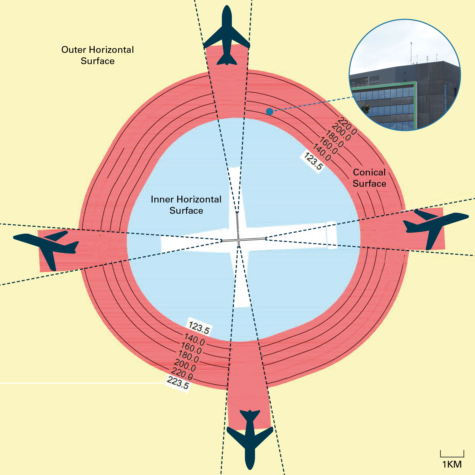
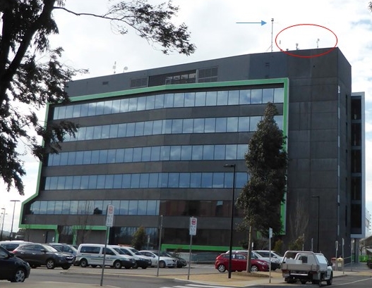
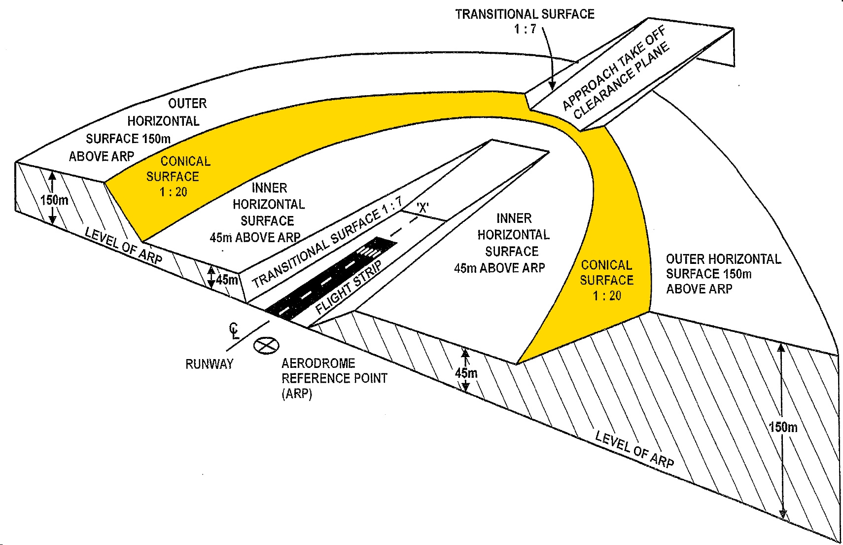
In October 2009, the operator of Essendon Airport (now Essendon Fields Airport) received an application from the Hume City Council (HCC) to construct a radio mast on top of the council office building at Broadmeadows, Victoria. The application was made under the Airports (Protection of Airspace) Regulations 1996 (APA Regulations) which was only applicable to leased, federally-owned airports, such as Essendon. The application identified that the building and existing masts had not been approved under the regulations. The regulations required any proposed construction that breached protected airspace around specific airports to be approved by the Secretary of the then Department of Infrastructure and Transport (Department). Protected airspace included airspace above a boundary defined by the Obstacle Limitation Surface (OLS). The Secretary was required to reject the application if the Civil Aviation Safety Authority (CASA) determined that the application would have an ‘unacceptable effect on safety’.
CASA’s initial response to the HCC application stated that the building and existing masts represented a hazard to aircraft and should be marked and lit, while the proposed radio mast represented a further hazard and, as such, would not be supported. The advice was considered inadequate by the Department, who instructed CASA that they required advice that either the application for the mast had an unacceptable effect on safety, or it did not. CASA subsequently determined that the application did not have an unacceptable effect on safety, and in addition, advised the Department of specific lighting and marking requirements to mitigate any risk presented by the mast. The Department approved the HCC application on 28 February 2011 conditional on appropriate marking and lighting being affixed to the radio mast and building. The ATSB has since been advised that the radio mast has been removed due to reasons unrelated to aviation safety.
What the ATSB found
The scope of this investigation was limited to the processes associated with protecting the airspace at leased, federally owned airports, and in particular the application of safety management principles as part of that process. The investigation used the HCC application for examining the APA Regulations processes, and as a result identified an issue specifically associated with that application. However, the investigation did not consider whether or not the aerial on the HCC building was unsafe.
The Airports Act 1996, which was administered by the Department, was the principal airspace safety protection mechanism associated with a leased, federally-owned airport’s OLS. The Australian Government had committed to using a safety management framework in the conduct of aviation safety oversight (that is, a systemic approach to ensuring safety risks to ongoing operations are mitigated or contained). In contrast, the conduct of safety oversight of an airport’s airspace under the Airports Act used a prescriptive approach (that is, the obstacle was either acceptable or unacceptable). This approach met the requirements of the Airports Act, but was not safety management-based. With respect to the assessment of the HCC application under the Airports Act, a safety management approach was not used.
What's been done as a result
The Department, now known as the Department of Infrastructure, Regional Development and Cities, has advised that it will confer with key stakeholders in the APA Regulations process regarding relevant risk management practices. The intent is to implement a more systematic approach to risk management, guided by the Commonwealth Risk Management Policy.
The Department has also identified the need to reform the current airspace protection regime based around the Airports Act. In a paper titled ‘Modernising Airspace Protection’, the Department identifies that current airspace protection regulation under the Civil Aviation Act 1988 and the Airports Act requires improvement, and has initiated public consultation regarding reforms into this particular regulatory system.
Safety message
A safety management system approach is considered ‘best practice’ by the International Civil Aviation Organization and has been adopted by Australia as the core method of aviation safety oversight through the State Aviation Safety Program. The Airports Act processes need to adopt safety management principles to the assessment of construction applications involving breaches of prescribed airspace, but rather, used a prescriptive regulatory approach. Construction proposals can impinge on aviation safety margins, such as those represented by the OLS. A fully informed, safety management-based approach should be used to ensure that safety is not compromised.
Safety issues and actions
The safety issues identified during this investigation are listed in the Findings and Safety issues and actions sections of this report. The Australian Transport Safety Bureau (ATSB) expects that all safety issues identified by the investigation should be addressed by the relevant organisation(s). In addressing those issues, the ATSB prefers to encourage relevant organisation(s) to proactively initiate safety action, rather than to issue formal safety recommendations or safety advisory notices.
All of the directly involved parties were provided with a draft report and invited to provide submissions. As part of that process, each organisation was asked to communicate what safety actions, if any, they had carried out or were planning to carry out in relation to each safety issue relevant to their organisation.
The initial public version of these safety issues and actions are repeated separately on the ATSB website to facilitate monitoring by interested parties. Where relevant the safety issues and actions will be updated on the ATSB website as information comes to hand.
The use of risk management principles when considering an application under the Airports (Protected Airspace) Regulations
Safety issue: AI-2013-102-SI-01
The Department of Infrastructure, Regional Development and Cities adopted a prescriptive approach to the Hume City Council building application within the obstacle limitation area of Essendon Airport, which was in accordance with the process prescribed under the Airports (Protection of Airspace) Regulations 1996, but did not require the application of risk management principles to the department’s consideration.
Sources and submissions
Sources of information
The sources of information during the investigation included the:
the Department of Infrastructure, Regional Development and Cities
the Civil Aviation Safety Authority
Essendon Airport Pty Ltd
Hume City Council
Submissions
Under Part 4, Division 2 (Investigation Reports), Section 26 of the Transport Safety Investigation Act 2003 (the Act), the ATSB may provide a draft report, on a confidential basis, to any person whom the ATSB considers appropriate. Section 26 (1) (a) of the Act allows a person receiving a draft report to make submissions to the ATSB about the draft report.
A draft of this report was provided to the Department of Infrastructure, Regional Development and Cities and the Civil Aviation Safety Authority.
Submissions were received from the Department of Infrastructure, Regional Development and Cities and the Civil Aviation Safety Authority. The submissions were reviewed and where considered appropriate, the text of the report was amended accordingly.
Safety analysis
On 28 February 2010, the (then) Department of Infrastructure and Transport (Department) issued two decisions in response to a building application from the Hume City Council (HCC). The decisions, issued under the Airports (Protection of Airspace) Regulations 1996 (APA Regulations), granted approval for the:
existing HCC building and associated antennas to breach the Essendon Airport protected airspace
construction of an additional radio mast on top of the building that would further impact that protected airspace.
The HCC application concerned man-made construction that penetrated the Obstacle Limitation Surfaces (OLS). The APA Regulations required approval be given for particular activities which intruded, or were planned to intrude, into prescribed airspace. Prescribed airspace included the airspace above any part of an OLS (as defined by the International Civil Aviation Organization (ICAO) Annex 14).
Prescriptive application approach
The Airports Act 1996, which was administered by the Department, was the principal method of facilitating the airspace safety protection mechanism associated with a federally-owned leased airport’s OLS. The APA Regulations enabled the Secretary of the Department to prevent the penetration of the OLS on grounds that included safety, meeting the intent of Annex 14.[11]
Examination of the approval process identified the following:
The process did not include a requirement for safety management principles to be applied in determining the effect of a proposal on the safety of aviation.
Department officials stated that the Department did not have the necessary expertise or resources to make a safety assessment and therefore was reliant on advice from CASA.
The Department weighted CASA’s opinion regarding the safety of a proposal above all other submissions.
While CASA was a recipient of the application, there was no process through which CASA would be provided with all relevant safety information before making their safety assessment.
The Department obtained internal legal guidance on how CASA’s advice and opinion should be constructed. The guidance indicated that CASA could not reject an application based on risk or hazard identification alone. For CASA to reject an application, it was required to state that the proposal was ‘unacceptable to safety’. CASA was also required to provide evidence as to the reasons for this decision. If the application was not unacceptable to safety, then CASA was required to identify any risk mitigating actions that would also need to take place. The Department notified CASA of the internal guidance.
The Department’s assessment process under the APA Regulations was prescriptive in nature in order to meet the regulatory requirements. The APA Regulations assessment process did not require a risk-based approach. However, the Airports Act and the APA Regulations were performing a safety function with respect to the protected airspace of a limited number of airports. A risk-based approach has been demonstrated as an effective approach to aviation safety risk management, and therefore should have been applied to the assessment of an application under the APA Regulations. Additionally, there was no guidance to CASA on the structure of their safety advice that could support a risk-based approach to the management of aviation safety. Further, the Department’s requirement for ‘probative evidence’ and a binary ‘unacceptable to safety or not’ decision did not align with the intent of ICAOs safety management system requirements regarding safety risk assessments.
In the ICAO advocated risk-based approach (also supported by CASA), the identification, assessment and treatment of risk is recognised as offering the best means to use all available information to manage risk. It does not rely on the demonstration of proof of a certain outcome before addressing underlying risk. As such, the approval process undertaken on the HCC application did not meet the safety management approach.
An airport is designed for a particular purpose. That purpose defines the type of operations envisaged at that airport and therefore the specific requirements for the airport’s construction. Other factors, such as the local geography and meteorological conditions, also affect the specifics of an airport’s design. These various factors determine the runway(s) dimension, which allow for particular types of approaches to and departures from the runway(s).
While natural features are considered in the initial design of an airport, man-made constructions, both inside and outside of the airport boundary, can significantly influence airport operations. The penetration of the airspace around the airport by man-made constructions may:
result in limitations on the distances available for take-off and landing
result in limitations on the range of meteorological conditions in which take-off and landing can be undertaken
affect the minimum safe altitudes for instrument procedures to and from an airport
represent a danger to aircraft operating at the airport during visual operations.
The airspace around an airport therefore forms an integral component of the airport, affecting not only the airport’s economic viability but also the safety of operations at that airport.[3]
International standards for civil aviation for the planning for, and operations of airports, are contained in the International Civil Aviation Organization (ICAO) Annex 14. Annex 14 includes standards and recommended practices that state that new objects or extensions of existing objects are not to be permitted within airspace above Obstacle Limitation Surfaces (OLS). An exception is when an ‘…aeronautical study … determined that the object would not adversely affect the safety…of aeroplanes.’ More details on the specific requirements of Annex 14 are provided in Appendix A: The Annex 14 OLS.
Legislative approach to protecting an Australian airports’ airspace
Australia utilises both a national consultative scheme as well as legislation in protecting an airport’s airspace. However, the consultative approach[4] is not relevant to this investigation as the HCC application fell within the jurisdiction of the Airports Act 1996.
The HCC application was made under the APA Regulations, a set of regulations that support the Airports Act. The Department was the agency responsible for the administration of this act and the APA Regulations.
The Airports Act 1996
The Airports Act created a comprehensive framework for the regulation of leased, federally owned airports, and other airports as listed in the Airports Regulations 1997. Part 12 of the Airports Act provided for the protection of airspace around these airports through the declaration of certain airspace to be prescribed airspace, and particular activities that affect that airspace to be controlled activities. These specific terms were defined as follows:
Prescribed airspace. Airspace that was to be protected where it was in the interests of the safety, efficiency or regularity of existing or future air transport operations.
Controlled activities. Activities that intruded into, or were planned to intrude into, prescribed airspace—such as the construction of a building or a structure on top of that building.
At the time of the HCC application, the airports that fell within the jurisdiction of Part 12[5] included Essendon Airport.
Part 12 required approval before carrying out a controlled activity. The process for obtaining that approval was governed by the APA Regulations.
In addition, s. 190 of the Airports Act stated that Part 12 operated in addition to, and not instead of, regulations made under the Civil Aviation Act (see Appendix B: Civil Aviation legislation and regulations).
Airports (Protection of Airspace) Regulations 1996
The Airports Act required approval for the conduct of controlled activities. The APA Regulations established the system under which an application to conduct controlled activities was assessed and either approved or rejected. These regulations also identified what type of airspace was included under the definition of prescribed airspace. Prescribed airspace included airspace as defined by the OLS, with Annex 14 cited as the source of the OLS dimensions, and what are termed PANS-OPS surfaces.[6]
The APA Regulations required that an application to conduct controlled activities be forwarded to the airport operator. The operator was required to notify the Civil Aviation Safety Authority (CASA), Airservices Australia (Airservices) and the building authority of that application.
The decision on an application to conduct controlled activities was assigned to the Secretary of the Department (Secretary). In assessing a proposal, the Secretary was required to consider the opinions of the proponent of the activity (the applicant), the airport operator, CASA, Airservices and the building authority, but only with respect to the efficiency and regularity of air transport operations at the airport. The Secretary could also consider any other matter considered relevant. The decision process required the Secretary to approve a proposal unless carrying out the controlled activity interfered with the safety, efficiency or regularity of existing or future air transport operations into or out of the airport concerned. There were also two triggers that required the rejection of a proposal:
the proposal entailed a long term controlled activity that penetrated PANS-OPS surfaces
when CASA advised the Secretary that the proposed controlled activity would have an unacceptable effect on the safety of air transport operations.
Separately, CASA had the capacity under the APA Regulations to:
advise the Secretary that a proposal had an ‘unacceptable effect on aviation safety’ and, on receipt of that advice, the Secretary was required to reject the proposal (the safety veto)
provide a submission about the activity.
Safety management principles
Around 2006, ICAO required that States establish a State Safety Programme, which included the safety management method of conducting aviation safety oversight. In 2011, the Department published Australia’s State Aviation Safety Program (SASP). The SASP committed Australia to adopting the ICAO approach of using safety management principles in the oversight of aviation safety. A key component of this approach was the adoption of a risk-based approach to the management of aviation safety.
The Australian SASP identified specific legislation, regulations and other material that were relevant to the oversight of safety in aviation. That legislation included the Civil Aviation Act 1988, and a number of supporting regulations and manuals. Of note, the Airports Act and its supporting APA Regulations were not included within that legislation.
The APA Regulations application process
The role of the airport operator
The airport operator was responsible for gathering all relevant information concerning the application. This information included submissions from CASA, Airservices and the building authority, as well as any opinions on the effect that the controlled activity will have with respect to the efficiency and regularity of air transport operations into and out of the airport, existing and in the future. Once all relevant information, submissions and opinions were gathered, they were forwarded on to the Department, with the application for determination.
The role of CASA
CASA was responsible for the safety assessment of a proposal. It was reported that, when notified of an application under the APA Regulations, CASA commenced their safety determination by making a Civil Aviation Safety Regulation (CASR) Part 139 hazard assessment with respect to the application.[7] That assessment also included an analysis of whether the application affected the PANS-OPS surfaces, which was guided by advice provided from Airservices. CASA would recommend an application be rejected (or ‘vetoed’) if the assessment concluded that it would have an unacceptable effect on aviation safety, or if the PANS-OPS surfaces were affected.
CASA advised that:
They did not seek input from the airport operator or relevant aircraft operators when making their safety assessment, as they understood that these matters would be addressed by other stakeholders in the application process.
While they may be given safety data from other parties as part of the application package, their safety advice was produced using internal advice supplemented by advice from Airservices.
On completion of the internal assessment of the application, the resultant advice to the Department was compiled using a standard template form to ensure that all required considerations, as identified by the Department, were addressed in their safety advice.
CASA also advised that it did not support any infringement of the OLS. In assessing prescribed airspace intrusions, CASA would determine that the proposal was either:
acceptable without mitigation
acceptable with mitigation such as lighting, marking or operational restrictions
unacceptable.
The role of the Department
The Department administered and conducted the decision-making process under the APA Regulations. The Department published its policies and procedures regarding applications for controlled activities in prescribed airspace on its website. These policies and procedures reflected the content and requirements of the APA Regulations. The Secretary was required to approve a proposal, except in circumstances which included the following:
The carrying out of the controlled activity would interfere with the safety of existing or future air transport operations into or out of the airport.
CASA has advised the Secretary that the carrying out of the controlled activity would have an unacceptable effect on the safety and efficiency of existing or future air transport operations into and out of the airport.
The Department stated that it did not have the expertise to determine the safety effect of an application under the APA Regulations, and relied on advice from CASA for that purpose. The Department internally determined that CASA could not reject an application based on risk or hazard identification alone, and that CASA must either declare a proposal to be ‘unacceptable to safety’ or ‘not unacceptable to safety’. If the proposal was unacceptable to safety, then specific evidence identifying the reasons for that determination was required. If the proposal was not unacceptable to safety, then CASA was required to advise of any specific requirements that were to be attached to an approval.
The Hume City Council application
In preparation for the application for approval to construct the proposed radio mast on top of the existing HCC building, the council conducted a survey of the building. The HCC building is located 4.52 km (2.44 NM) on a bearing of 031° magnetic from the threshold of runway 17 at Essendon Airport. In respect of the OLS, the building is located between the 140 m (459 ft) and 150 m (492 ft) reduced levels (RL) of the OLS conical surface (Figure 2).[8] That survey identified that the building and two existing antennas on top of the building penetrated the Essendon Airport protected airspace, and in particular the conical surface of the Essendon OLS. The council also identified that the building and the existing antennas had not been granted approval under the APA Regulations when constructed. As a result, the HCC application included the proposed radio mast as well as the existing building and antennas.
Figure 2: Simplified depiction of the Essendon Airport OLS showing the location of the Hume City Council building.
Source: Essendon Fields Airport, modified by the ATSB. The contours and levels are reduced levels in metres to the Australian Height Datum. The aerodrome reference point is near the runway intersection, and is at about 78 m RL.
In accordance with the APA Regulations, in early October 2009 the Hume City Council (HCC) notified Essendon Airport of the proposed construction of the new radio mast. The airport operator notified the Department, CASA and Airservices of the HCC application. The notification also identified the issue of the existing building and antennas. The airport operator also advised CASA that the building and existing antennas were not fitted with obstacle marking or lighting. Additional survey data was submitted by the council in support of the application in June and July 2010, which was subsequently passed onto CASA and Airservices.
CASA and Airservices submissions
CASA’s evaluation of the proposal to construct the mast focused on how the existing building and antennas, as well as the proposed mast, individually interacted with the OLS and the PANS-OPS surfaces. CASA waited for the Airservices assessment of the impact of the application on the PANS-OPS surfaces before finalising its own assessment.
CASA’s preliminary evaluation identified that the building and proposed radio mast came close to, but did not breach, the Category B[9] visual manoeuvring (circling) areas[10] around Essendon Airport.
On 20 August 2010, Airservices advised the airport operator that the proposed radio mast would not ‘affect any sector or circling altitude, nor any approach or departure at Essendon or Melbourne airports’. Airservices also advised that the radio mast would not impact navigation aids, communications services or any other service associated with air navigation. Airservices also advised CASA of this assessment.
While three CASA Flying Operations Inspectors assessed the HCC application, the process applied by CASA did not include safety management principles in that assessment. This was evidenced by the fact that there was no indication of the level of residual risk deemed to be unacceptable from a safety perspective.
On 2 September 2010, CASA advised the airport operator that the building’s intrusion into the OLS represented a hazard to aviation safety, as defined by CASR Part 139 r. 139.370, due to its proximity to the Category B circling area at Essendon Airport. CASA recommended that the building be marked and lit in accordance with the Part 139 Manual of Standards (MOS). The advice also stated that CASA did not support the addition of any antennas and/or masts on the building due to the resulting further penetration of the OLS. However, CASA recommended that, should the Department approve the radio mast, it should be marked and lit in accordance with the MOS.
Essendon Airport submission
Based on the airport operator’s understanding that the HCC application required three separate decisions by the Secretary, the Essendon Airport submission was divided into the following three parts:
The building. With respect to the building itself, the airport operator raised a number of matters to support their recommendation that the building be marked and lit in accordance with the MOS. First, it was noted that the purpose of the OLS was to provide manoeuvring room for landing and departing aircraft. In addition, the airport operator stated that:
The proposed application [for the building] is located in the direction that an aircraft with an engine out [loss of engine power] on a northerly departure may elect to travel (to provide climb time) due to the presence of Melbourne International Airport to the west of the proposal and the hill upon which the suburb of Glenroy is built (located to the north east of Essendon Airport).
Finally, the airport operator identified that the building was just below the Category A and B visual manoeuvring (circling) areas for aircraft operations.
Existing antennas. In respect of the existing antennas atop the building, the airport operator stated that these increased the risk of collision and that the airport operator did not support their approval.
Proposed radio mast. The airport operator considered that the proposed radio mast further increased the risk of collision and for that reason did not support that application.
If the building was approved by the Department, the airport operator supported CASA’s view that it should be marked and lit in accordance with CASR r. 139.370. A number of other conditions on the Department’s approval of the building were proposed by the airport operator.
Department response to the combined submission
As required under APA Regulations r. 11, Essendon Airport submitted the HCC application to the Secretary for decision, along with the submissions from Airservices and CASA and their own submission regarding the application.
On 29 November 2010, the Department responded to the airport operator about the combined submission (copied to CASA). In its response, the Department stated that, notwithstanding the airport operator’s reasoning in respect of the existing antennas and the proposed radio mast:
Our legislation requires probative evidence that the risk is unequivocal. CASA has stated that all of the ancillary structures on top of the building are hazards and then goes on to offer a mitigating strategy by invoking MOS part 139 for each part. Unless CASA can definitively state that the antennae WILL result in increase of collision and remove the mitigating strategy then our only course is to recommend approval.
After discussions between the Department and CASA, CASA limited its submission on the building and proposed radio mast to a hazardous object assessment under CASR Part 139. CASA later provided further clarification to the airport operator on the marking and lighting requirements contained in its 2 September 2010 advice.
The Department’s correspondence with the airport operator of 29 November 2010 appears to have initiated discussion between the Department and the airport operator concerning the type of advice that should be provided within an APA Regulations submission. On 10 December 2010, the airport operator advised the Department that, under the current CASA submission, the Department was required to decide whether to either:
accept the risk associated with permitting the obstacles, which may be mitigated somewhat with lighting and marking
respond to the development through adjustment to the runway operations, such as shortening the runway to eliminate risk.
The airport operator also advised that if the Department approved the obstacles, the operator was, in any case, required to conduct a risk assessment on the obstacles in accordance with its safety management system.
The Department notified all relevant parties on 28 February 2011 of two decisions made under the APA Regulations concerning the HCC application. The decisions:
approved the HCC application to construct the radio mast
provided retrospective approval for the existing building and antennas.
The approvals were conditional on appropriate marking and lighting being affixed to the radio mast and building.
Summary of the application decision
The Essendon Airport submission to the Department included advice of a specific hazard (engine out after take-off scenario) believed to provide grounds for refusal of the HCC building application. The Department’s guidance concerning the structure of a safety opinion by CASA, as well as the Department’s practice of weighting its consideration of safety advice primarily towards that provided by CASA, appeared to influence the Department’s decision to overlook the hazard identified by the airport operator.
In this case, CASA officers considered the safety implications of a circling approach which was a lower safety risk than posed by the collision risk of the building and masts following an engine out after take-off scenario (as considered by the airport operator). However, CASA did not consult with the airport operator as it was assumed that the airport operator’s submission would be considered by the Department. In addition, the information on this hazard was not referred to CASA by the Department for consideration as part of its safety advice. As a result, CASA’s consideration of safety risks as part of the building application process was not fully informed.
The Department’s requirement for CASA to state that the controlled activity (antennae in this case) will result in an increased risk of collision as a means to reject an application set an expectation of unequivocal proof against which an assessment of any safety risk would be measured.
From the evidence available, the following findings are made with respect to the building approval process for structures in the vicinity of Australian airports as applied to an application by the Hume City Council to construct a radio mast on their council building at Broadmeadows, Victoria. These findings should not be read as apportioning blame or liability to any particular organisation or individual.
Safety issues, or system problems, are highlighted in bold to emphasise their importance. A safety issue is an event or condition that increases safety risk and (a) can reasonably be regarded as having the potential to adversely affect the safety of future operations, and (b) is a characteristic of an organisation or a system, rather than a characteristic of a specific individual, or characteristic of an operating environment at a specific point in time.
Contributing factors
The Department of Infrastructure, Regional Development and Cities adopted a prescriptive approach to the Hume City Council building application within the obstacle limitation area of Essendon Airport, which was in accordance with the process prescribed under the Airports (Protection of Airspace) Regulations 1996, but did not require the application of risk management principles to the department’s consideration. [Safety Issue]
Background
On 28 February 2011 the (then) Department of Infrastructure and Transport (Department)[1] issued two decisions regarding an application by the Hume City Council (HCC) to construct a radio mast on top of the council office building at 1079 Pascoe Vale Road, Broadmeadows, Victoria (Figure 1).
Figure 1: Hume City Council building showing the existing antennas (circled in red) and the (then) proposed radio mast (indicated with a blue arrow).
Source: ATSB.
The application was made under the Airports (Protection of Airspace) Regulations 1996 (Cwth) (APA Regulations). The APA Regulations required any proposed construction that breached protected airspace around specific airports, referred to as controlled activities, to be approved by the Secretary of the Department (the Secretary). Protected airspace included airspace as defined by the airport’s obstacle limitation surfaces (OLS), which were in turn defined within Annex 14 to the Convention on International Civil Aviation.
In September 2012 the ATSB received a REPCON[2] report concerning the HCC application. The reporter expressed concern that a proper safety case was not conducted on the HCC radio mast proposal, and that the location of the antennas had implications for aviation safety. The ATSB notified the Civil Aviation Safety Authority, the airport operator and the Department of the REPCON report, and liaised with the affected parties during its initial examination of the approval process for structures that penetrate the OLS. That examination identified a possible underlying transport safety matter in respect of the approval process in this case and, in July 2013, the ATSB commenced an investigation under the Transport Safety Investigation Act 2003.
The scope of the investigation was limited to the processes associated with protecting airspace at leased, federally owned airports—that is, airports covered by the APA Regulations—and in particular the application of safety management principles, established by the International Civil Aviation Organization and adopted by Australia, as part of that process. The investigation used the HCC application for examining the APA Regulations processes. The investigation did not consider whether or not the proposed aerial on the HCC building, or the building and associated attached structures, were unsafe.
International standards for civil aviation are published by the International Civil Aviation Organization (ICAO) in Annexes to the Chicago Convention. The planning for and operations of airports is contained in Annex 14. Annex 14 standards and recommended practices (SARPs) establish the Obstacle Limitation Surfaces (OLS) as a tool to ensure that an airport’s airspace is protected, for both economic and safety reasons.
At the time of the Hume City Council (HCC) application decision by the Department , the fifth edition of Annex 14 was in effect.[12] Included in Annex 14 was a section on Obstacle Restriction and Removal, which had the objective to:
… define the airspace around aerodromes to be maintained free from obstacles so as to permit the intended aeroplane operations at the aerodromes to be conducted safely and to prevent the aerodromes from becoming unusable by the growth of obstacles around the aerodromes. This is achieved by establishing a series of obstacle limitation surfaces that define the limits to which objects may project into the airspace.[13]
The Annex 14 definition of an obstacle was:
All fixed (whether temporary or permanent) and mobile objects, or parts thereof, that … extend above a defined surface intended to protect aircraft in flight …[14]
Over the various editions of Annex 14, the dimensions of the individual surfaces that make up the OLS have become more complex. In the fifth edition, the dimensions of the individual surfaces were based on the:
intended runway use
types of instrument approaches for that runway
runway classification.
The final dimensions of the OLS were determined by the most stringent requirements relating to these criteria. The general structure of an OLS is shown in Figure 3.
Annex 14 includes standards that state that new objects or extensions of existing objects shall not be permitted above an approach, transitional or take-off climb surface. Annex 14 also includes recommended practices with respect to within the inner horizontal surface and the conical surface of the OLS (Figure 3). In respect to the conical surface, these recommended practices identified that:
New objects or extensions of existing objects should not be permitted above the conical surface … except when, in the opinion of the appropriate authority, the object would be shielded by an existing immovable object, or after aeronautical study it is determined that the object would not adversely affect the safety or significantly affect the regularity of operations of aeroplanes.
Implementation of the recommended practices required the capacity to prohibit objects that could or do penetrate the conical surface. The recommended prohibition against the penetration of the OLS included an important exception, that is when an ‘…aeronautical study … determined that the object would not adversely affect the safety…of aeroplanes.’ Guidance material associated with Annex 14 advocated that the OLS be made permanent through means such as legislation, or as part of a national planning consultation scheme.[15]
Figure 3: General structure of an OLS, with the conical surface highlighted in yellow.
Source: Department of Infrastructure and Regional Development, modified by the ATSB.
Appendix B: Civil Aviation legislation and regulations
The Civil Aviation Act 1988
While the HCC application was made under the Airports Act, Australia’s State Aviation Safety Program (SASP) identified CASA as being responsible for matters relating to Annex 14. CASA administers the Civil Aviation Act 1988 and supporting regulations. As noted in the body of the report, the Airports Act was not included in the SASP. The following sets out the regime under the Civil Aviation Act and Regulations related obstacles around an airport.
The Civil Aviation Act s. 3A stated that the main object of the act was to establish a regulatory framework for maintaining, enhancing and promoting the safety of civil aviation. The powers of the act to make regulations were prescribed in s. 98. Subsection 98 (3) identified specific areas where regulation could be made, which included:
(g) the prohibition of the construction of buildings, structures or objects, the restriction of the dimensions of buildings, structures or objects, and the removal in whole or in part or the marking or lighting of buildings, structures or objects, (including trees and other natural obstacles) that constitute or may constitute obstructions, hazards or potential hazards to aircraft flying in the vicinity of an aerodrome, and such other measures as are necessary to ensure the safety of aircraft using an aerodrome or flying in the vicinity of an aerodrome.
Relevant regulations that included the capacity to affect obstacles around an airport included the Civil Aviation (Building Control) Regulations 1988 (CABCR), the Civil Aviation Regulations (1988) (CAR) and the Civil Aviation Safety Regulations 1998 (CASR).
The Civil Aviation (Building Control) Regulations 1988
The CABCR provided a regulatory regime for the control of buildings around certain aerodromes. The aerodromes that fell within the jurisdiction of the CABCR were identified through relevant schedules and were limited to Sydney (Kingsford Smith), Bankstown, Melbourne, Moorabbin, Essendon and Adelaide.
The regulations required CASA’s approval for the construction of buildings or structures that exceeded certain heights above the ground. The regulations created three types of zones based on three height restrictions that were to be applied to specific land areas:
a zone adjoining the aerodrome, in which approval was required for any construction above 25 ft above ground level (AGL)
the next zone out, which required approval for any construction up to 50 ft AGL
the zone furthest from the aerodrome, which required approval for any construction up to 150 ft AGL.
While still in force at the time of the occurrence, CASA advised that the CABCR were outdated and rarely, if ever, used. CASA also advised that the HCC building and proposed radio mast did not fall within the requirements of the CABCR.
The Civil Aviation Regulations 1988
Part 9 of the CAR, titled Aerodromes, contained regulations that enabled the protection of an aerodrome’s airspace. Under CAR r. 95 CASA could prevent, or direct the removal of, intrusions into a defined volume of airspace around an aerodrome.
Two limitations applied to the scope of r. 95:
The first related to the aerodromes that fall within the regulation’s jurisdiction. This was defined under r. 95(1), which limited the affected aerodromes to those that are ‘open to public use by aircraft engaged in international air navigation or air navigation within a Territory’.[16] The sub-regulation also excluded aerodromes covered by the CABCR.
The second concerned the dimensions of the airspace that was protected. This airspace, as defined under r. 95(5), equated to only a small subset of the possible dimensions of the OLS as promulgated in Annex 14.
The Civil Aviation Safety Regulations 1998
Part 139 of the CASR dealt with the operation of aerodromes. Subpart 139.E was concerned with obstacles and hazards in airspace around an aerodrome. These regulations required the aerodrome operator to establish an OLS in accordance with guidance in the Manual of Standards Part 139 – Aerodromes (MOS). The MOS reproduced the method of constructing the OLS as stated in Annex 14.
Subpart 139.E required an aerodrome operator to monitor the airspace around their aerodrome. If an obstacle was identified, or a proposed construction was likely to become an obstacle, then the operator was required to notify:
the relevant authorities
pilots, by issuing a notice to airmen (NOTAM).[17]
Subpart 139.E also enabled CASA to determine that certain obstacles were hazards due to their location, height or lack of marking or lighting. If an object was determined to be a hazard, CASA was able to request the obstacle’s owner to mark and/or light the obstacle.[18] Specific requirements for obstacle lighting and marking were contained in the MOS.
Finally, CASR r. 139.035 stated that nothing in Part 139 affected the operation of the Airports (Protection of Airspace) Regulations 1996.
The Part 139 regulatory framework did not contain any provision for preventing the construction of, or removing existing, objects deemed to be a hazard. Should a runway become unsafe as a result of an obstacle, CASA advised that it would enforce CAR r. 92. That regulation made it an offence:
for an aircraft to take-off or land from a place where this cannot be done with safety, or
to contravene a CASA direction relating to the safety of air navigation for that aerodrome.
On 8 July 2013, an Avions de Transport Regional ATR72-212A, operated by Virgin Australia Regional Airlines Pty Ltd (VARA) and registered VH-FVY, touched down at Moranbah Airport, Queensland. During the landing roll, the aircraft changed direction a number of times. At one point, the aircraft departed the right side of the runway. One passenger reported a minor injury. The aircraft was not damaged as a consequence of the runway excursion.
What the ATSB found
During the landing roll, the rudder and nose wheel steering control inputs over corrected the heading deviations, leading to the runway excursion. Furthermore, the positioning of the rudder pedals could have contributed to the captain inadvertently over-controlling the rudder to counter the aircraft yaw.
What's been done as a result
As a result of this occurrence, VARA released Safety Message SAM-ATR-004/13. The safety message advised pilots of the hazards associated with crosswind landings. In addition, VARA has included this scenario as part of its regular simulator training programme.
Safety message
This occurrence highlights the importance of the correct cockpit set-up and use of correct control inputs during the landing roll, especially at high speed. Correct positioning of primary flight controls can reduce the risk of inadvertent control inputs.
The occurrence
On the morning of 8 July 2013, the crew of an ATR-GIE Avions de Transport Regional ATR72-212A (ATR72), registered VH-FVY and operated by Virgin Australia Regional Airlines Pty Ltd, commenced their tour of duty in Gladstone, Queensland. The crew were scheduled to fly from Gladstone to Brisbane, on to Moranbah and then back to Brisbane. The captain was the pilot flying[1] for the first two sectors.
During the flight to Moranbah, the crew obtained the current weather forecast. The forecast indicated a crosswind of about 15 kt (28 km/h) from the right at 110 °(M) on arrival. At 1108 Eastern Standard Time[2], the aircraft touched down on runway 34[3] at 112 kt or 207 km/h airspeed (about 110 kt or 204 km/h ground speed). The aircraft was rolled slightly right by the crew to counter the crosswind. As the ground speed slowed through 100 kt, the crew felt the aircraft veer to the right. The aircraft was returned to the centre-line by the captain applying rudder input. As the aircraft reached about 80 kt the captain handed over the control yoke to the first officer while maintaining directional control with the nose wheel steering tiller. Shortly after, the aircraft turned right again and departed the runway. The captain regained directional control as the aircraft approached 20 kt (37 km/h) (Figure 1 and appendix A).
One passenger reported receiving a minor injury during the occurrence. That injury was consistent with a ‘whiplash’ from lateral acceleration.
Subsequent examination found no aircraft damage. Runway tyre marks associated with the landing showed that at least one of the right main landing gear wheels had departed from the runway.
Figure 1: Aircraft path along runway 34 during the landing roll
The aircraft’s path during the touchdown and landing roll are derived from recorded flight data, and matched the runway tyre marks.The aircraft touched down in the correct location and the changes in direction did not start immediately. The aircraft had a number of larger changes in direction before slowing to taxi speed before the end of the runway.
The flight crew flew the aircraft from Brisbane to Gladstone on the previous afternoon. The aircraft and the flight crew remained at Gladstone overnight.
Captain
The captain had a total aeronautical experience of about 5,000 hours, of which about 4,500 hours was on the aircraft type. The captain reported being on duty for 4.5 hours at the time of the occurrence. They did not report any fatigue-related concerns associated with the occurrence flight.
First officer
The first officer (FO) had a total aeronautical experience of about 2,600 hours, of which about 1,800 hours was on the aircraft type. The FO also reported being on duty for 4.5 hours at the time of the occurrence. The FO did not report any fatigue-related concerns associated with the occurrence flight.
Aircraft information
Wheel braking system and tyre marks
The wheel brakes for each main landing gear are applied by pressing the top of the respective rudder pedal. This allows for differential braking across the aircraft.
The wheel brake system is designed to prevent the wheels from locking up in order to retain wheel brake effectiveness for slowing the aircraft. This is achieved through the following functions:
Touchdown protection – this prevents activation of the wheel brakes until there is weight on the wheels after landing and:
- either 5 seconds have elapsed
- or the wheels have attained a rotational speed of 35 kt or more.
Anti-skid protection – this operates on the wheels at speeds above 10 kt via the normal braking system. The system relieves brake pressure on wheels that have stopped rotating to the point of incipient wheel lock.
Locked wheel protection – this protection operates on the wheels at speeds above 23 kt. If a wheel is rotating at less than half the speed of the corresponding wheel on the opposite side of the aircraft, the protection system relieves brake pressure on that wheel. This allows the slowing wheel to rotate faster and retain symmetrical deceleration.
Aircraft examination
After the occurrence and prior to departure from Moranbah, the aircraft was subjected to a range of engineering assessments. The assessments were nominated by the aircraft manufacturer to ensure the aircraft was serviceable. These checks found no evidence of damage to the aircraft as a result of the occurrence.
No defects or aircraft conditions were identified that could have contributed to the directional instability during the landing roll.
Meteorological information
The forecast and reported wind on arrival at Moranbah indicated a 15 kt crosswind from the right. This crosswind was well within the normal crosswind landing capabilities of the aircraft.
Airport information
Moranbah Airport is an uncontrolled airport with one runway, servicing regional airlines and local general aviation traffic. The runway was 30 m wide and 1,524 m long, which was adequate for a normal approach and landing in this aircraft.
The landing at Moranbah was the first landing of the day where it was necessary to apply crosswind landing technique.
Aircraft handling
Crosswind landing and deceleration technique
The aircraft landed at Moranbah with a crosswind from the right. The recommended ATR72 technique for a right crosswind landing involved the application of left rudder and a small amount of right roll. These control inputs aligned the landing gear with the direction of movement over the runway immediately before touchdown.
Once an aircraft touches down in a crosswind, the weather-cocking effect of the fin is controlled by maintaining the applied rudder input. In this case, left pedal.
After touchdown, the aircraft is normally decelerated aerodynamically during the first part of the landing roll. This is done by adjusting the propeller pitch so that the propellers create high aerodynamic drag. Propeller pitch is adjusted symmetrically to support deceleration and is not used to provide directional control.
As the aircraft slows, the propeller aerodynamic drag becomes less effective and wheel brakes are progressively applied to achieve the desired rate of deceleration.
Directional control is initially maintained using rudder inputs. This method works well while the aircraft is moving fast enough for the rudder’s aerodynamic forces to be effective. As the aircraft slows, directional control is maintained using steering inputs to the nose wheel. The steering inputs are controlled by the tiller in the cockpit.
Directional control during the landing at Moranbah
Shortly after touchdown, a small, quick rudder input was applied that made the aircraft turn slightly right. Following that, changes in direction were corrected by the application of full rudder that in each case initiated a rapid turn. As each turn was corrected, the rudder control input was not reduced until after the aircraft had reached the runway heading. At that point, opposite full rudder input was then applied, and the turn was reversed. After the initial turn, each subsequent turn was larger for the next three corrective turns as the aircraft slowed to taxi speed (see the section Touchdown and rollout).
During the third turn, the aircraft slowed through 80 kt. At that time, the captain relinquished control of the control yoke to the FO and then used the tiller to control the nose wheel steering. As the aircraft slowed further, the rudder became less effective for controlling the aircraft’s direction. The captain reported sensing the rudder’s decreasing effectiveness from the reducing force needed on the rudder pedals.
The two largest heading changes happened when the aircraft was at a speed where the rudder and the nose wheel steering were available to the captain. However, as the nose wheel steering control inputs are not recorded, it was not possible to determine which input had the greatest influence on controlling the aircraft’s direction.
Flight recorders
Approach
Data obtained from the aircraft’s flight recorder showed the control inputs immediately before touchdown at Moranbah. At that time, the aircraft was flying 3°–4° right wing-low and with 5°–10° left rudder applied. These control inputs changed the aircraft heading 1°–2° left to align the landing gear with the direction of movement over the runway (appendix A).
Touchdown and rollout
Recorded data indicated that neither brake was depressed during the touchdown sequence, although left rudder was being used.
Two seconds after touchdown, the left rudder input changed to a small right rudder input for less than 1 second. At the same time, a very small amount of right wheel brake pressure was applied. There was no indication that asymmetric wheel brake had a significant influence on directional control. The aircraft yawed right by less than 2°.
The right yaw was controlled by the application of full left rudder at 100 kt airspeed for about 2 seconds. The aircraft yawed left until beyond the runway centre-line.
Full right rudder was then applied at 90 kt airspeed, which stopped the left yaw. However, the aircraft then started a faster right yaw.
There was a momentary application of wheel brakes, with more brake pressure applied to the right landing gear. Again, there was no indication that asymmetric wheel brake had a significant influence on directional control. About 3 seconds later, after the aircraft had turned past the runway heading, full left rudder was applied at 80 kt airspeed. The right yaw was stopped after a 15° heading change.
During the next 4 seconds with full left rudder application, the aircraft yawed left through the runway heading. During this time, the aircraft continued right, departing the runway for a short period. The left wheel brake was increasingly applied until the aircraft passed through the runway heading. From then, symmetrical wheel braking was applied to the wheel brakes.
After the 4-second period and the aircraft had turned past the runway heading, rudder input was changed from full left to full right over 2 seconds at about 40 kt airspeed. The left yaw stopped after a 26° left heading change. The aircraft had slowed to about 40 kt ground speed by this time.
The aircraft then yawed 20° right as the aircraft slowed to a taxi speed. Full left rudder input was then applied and the left wheel brake pressure increased while the right wheel brake pressure reduced to zero.
Engine power was applied symmetrically to both engines throughout the landing sequence.
Tests and research
Tyre marks
An examination of the runway tyre marks was carried out. Striation marks running in the same direction as the tyre marks indicated that the main wheels were braking. However, the tyres were approaching their limits of adhesion.
There was no evidence of any oblique striation patterns. This indicated that there was sufficient friction available to overcome the cornering forces exerted at the tyre/runway interface.
The darker edges on the outside of the turn indicated a shift of the weight to the outside of the tyres. There was no indication that any of the wheels locked up. This indicated the correct operation of the aircraft anti-skid system (Figure 2).
Figure 2: Runway tyre marks
The four tyre marks preceding the runway excursion were produced by the main landing gear.
They indicated:
hard wheel braking was applied
the braking did not exceed the limits of adhesion on any tyre
the aircraft was turning left exerting more force on the outside-right of the tyre
at least one wheel left the runway surface and rolled onto the adjacent grass.
Source: Moranbah Airport, modified by the ATSB
Additional information
Rudder pedal position adjustment
The captain stated that the rudder pedal position was adjustable fore and aft and that he normally adjusted the rudder pedal position on the first flight in a particular aircraft. This meant that normally the rudder position needed to be adjusted forward to suit his size.
The captain’s preferred rudder pedal position enabled rudder control inputs using the heel of his feet with his feet in a natural position. The captain reported that in this position he operated the rudder with his heels off the floor. This ensured that inadvertent force would not be applied to the top of the rudder pedal by the balls of the feet. When the captain operated the wheel brakes, he moved the balls of his feet to the top of the rudder pedals.
The captain did not recall adjusting the rudder pedal position before departing Gladstone. However, the captain and first officer flew the aircraft on the day before and the pedals were likely still in the captain’s preferred position after the flights that day.
Related occurrences
On 5 October 2005, an ATR72 that was operated by a different operator departed the runway during a landing roll at Queenstown Airport, New Zealand. In that incident, the aircraft touched down without incident, but was then exposed to a strong crosswind gust that exceeded the aircraft’s maximum crosswind limit. The aircraft turned and continued its landing roll on the grass adjacent to the runway. Forecasts and observations at Queenstown immediately before the landing did not indicate the potential for a crosswind that exceeded the aircraft’s maximum crosswind limit.
In 2008, the ATSB produced two research reports related to runway excursions. One encompassed a worldwide review, and the other provided an Australian perspective. Between them, they identified a number of risks that can increase the likelihood of a runway excursion. The reports also identified tools for mitigating the risk. However, the identified risks were not relevant to this occurrence.
Safety analysis
Introduction
VH-FVY had a number of heading variations of increasing magnitude shortly after touchdown on runway 34 at Moranbah. The aircraft momentarily departed the runway before being recovered by the flight crew. This analysis discusses the factors that influenced the aircraft’s directional stability during the landing, leading to a runway excursion.
Crosswind landing technique
The occurrence happened at the end of the second flight in a series of sectors by the same flight crew that day. The landing was the first landing of the day that required crosswind control input during the touchdown and rollout. The captain commenced applying the expected control inputs to manage a crosswind landing.
After touchdown, wheel brakes are not normally applied until the aircraft is first slowed by aerodynamic drag created by the propellers at higher landing speeds. However, small rudder control inputs are applied to maintain directional control at the higher speeds during the touchdown and initial rollout.
Directional control during the landing rollout
Following a small rudder input after touchdown, the captain applied a sequence of full rudder inputs to correct a number of heading changes during the landing roll. These inputs were initially applied at a high airspeed, when rudder forces are highly effective for turning the aircraft.
Directional control is primarily achieved by rudder and nose wheel steering as the aircraft slows. There were some short, asymmetric wheel brake applications during the landing roll. However, this would have a relatively minor effect on directional control, compared with the effectiveness of the rudder and nose wheel steering inputs.
The captain’s rudder inputs were not reduced until the aircraft had reached the intended heading. The turns therefore overshot the runway heading for the next three corrections as the aircraft slowed.
Pilot induced oscillations occur ‘when the pilot unintentionally commands an increasing series of control corrections in opposite directions…each one in an attempt to counteract the aircraft’s response to the previous input’ and result in an over correction in the opposite direction (Harris, 2011). They occur due to ‘a mismatch between the frequency of the pilot’s inputs and the response frequency of the aircraft’ and ‘…are a product of a large response lag in the system…’ (Harris, 2011). Management of such oscillations can be achieved through a number of strategies. These include varying the sensitivity of aircraft controls at the design stage as well as pilot training, which highlights the importance of not over controlling the aircraft.
As the aircraft slowed through about 80 kt airspeed, the captain followed normal procedures and used the tiller to control the aircraft’s direction via nose wheel steering.
During the occurrence, directional control was not regained until the aircraft had reached a relatively low airspeed.
Rudder pedal adjustment
The captain normally checked and adjusted the rudder pedal neutral position to ensure the angle of his foot on the rudder pedals enabled unrestricted control of both rudder and wheel brakes. On the morning of the occurrence, the captain did not recall adjusting the rudder pedal position.
Despite this, there was no reason for the rudder pedal position to have been moved between the occurrence flight and the flights on the previous day. Those flights were operated by the same crew. Furthermore, an inappropriate rudder pedal adjustment would be expected to be detected during the flight control check performed before take-off. However, the captain recalled unusual muscular feedback when operating the rudder pedals during the occurrence flight. This recollection could be explained by the rudder pedal position being different than that normally applied by the captain, or by the rudder reaching its mechanical stops. A different rudder pedal position could have contributed to the captain inadvertently over-controlling the rudder to counter the aircraft yaw.
Findings
From the evidence available, the following findings are made with respect to the runway excursion involving ATR72-212A, registered VH-FVY, at Moranbah Airport, Queensland on 8 July 2013. These findings should not be read as apportioning blame or liability to any particular organisation or individual.
Contributing factors
Consistent with pilot-induced oscillations, the captain's rudder and nose wheel steering inputs overcorrected heading deviations during the landing roll.
Other findings
The landing required crosswind control input, which was applied.
Safety actions
Whether or not the ATSB identifies safety issues in the course of an investigation, relevant organisations may proactively initiate safety action in order to reduce their safety risk. The ATSB has been advised of the following proactive safety action in response to this occurrence.
Proactive safety action taken by Virgin Australia Regional Airlines Pty Ltd
As a result of this occurrence and Virgin Australia Regional Airline Pty Ltd’s internal investigation, a safety alert message SAM-ATR-004/13 was promulgated internally that highlighted the risks associated with inadvertent application of wheel brake during touchdown.
Virgin Australia Regional Airline Pty Ltd also implemented a review of flight crew feet position during landing through its training staff and included training to manage the risks of runway excursions during landing in its training programme.
Sources and submissions
Sources of information
The sources of information during the investigation included:
Virgin Australia Regional Airline Pty Ltd (VARA)
the flight crew of VH-FVY
a number of passengers
the aircraft’s Digital Flight Data Recorder.
References
Harris, D 2011, Human performance on the flight deck. Ashgate Publishing Ltd, Surrey, England.
Submissions
Under Part 4, Division 2 (Investigation Reports), Section 26 of the Transport Safety Investigation Act 2003, the ATSB may provide a draft report, on a confidential basis, to any person whom the ATSB considers appropriate. Section 26 (1) (a) of the Act allows a person receiving a draft report to make submissions to the ATSB about the draft report.
A draft of this report was provided to the flight crew, VARA, the Bureau d'Enquêtes et d'Analyses, ATR and the Civil Aviation Safety Authority.
Submissions were received from the flight crew, VARA and ATR. The submissions were reviewed and where considered appropriate, the text of the report was amended accordingly.
Appendices
Appendix A - Recorded flight data
Purpose of safety investigations
The objective of a safety investigation is to enhance transport safety. This is done through:
identifying safety issues and facilitating safety action to address those issues
providing information about occurrences and their associated safety factors to facilitate learning within the transport industry.
It is not a function of the ATSB to apportion blame or provide a means for determining liability. At the same time, an investigation report must include factual material of sufficient weight to support the analysis and findings. At all times the ATSB endeavours to balance the use of material that could imply adverse comment with the need to properly explain what happened, and why, in a fair and unbiased manner. The ATSB does not investigate for the purpose of taking administrative, regulatory or criminal action.
Terminology
An explanation of terminology used in ATSB investigation reports is available here. This includes terms such as occurrence, contributing factor, other factor that increased risk, and safety issue.
Publishing information
Released in accordance with section 25 of the Transport Safety Investigation Act 2003
Ownership of intellectual property rights in this publication
Unless otherwise noted, copyright (and any other intellectual property rights, if any) in this report publication is owned by the Commonwealth of Australia.
Creative Commons licence
With the exception of the Coat of Arms, ATSB logo, and photos and graphics in which a third party holds copyright, this publication is licensed under a Creative Commons Attribution 3.0 Australia licence.
Creative Commons Attribution 3.0 Australia Licence is a standard form licence agreement that allows you to copy, distribute, transmit and adapt this publication provided that you attribute the work.
The ATSB’s preference is that you attribute this publication (and any material sourced from it) using the following wording: Source: Australian Transport Safety Bureau
Copyright in material obtained from other agencies, private individuals or organisations, belongs to those agencies, individuals or organisations. Where you wish to use their material, you will need to contact them directly.
The ATSB was advised of two turbulence related events that occurred on 5 July 2013 and 7 July 2013, involving VH-VZY and VH-QOP respectively.
VH-VZY
On 5 July 2013, a Boeing 737 aircraft, registered VH‑VZY, departed Perth, Western Australia on a scheduled passenger service to Canberra, Australian Capital Territory. While descending through 8,000 ft, the aircraft encountered severe turbulence for about 2 minutes. The flight crew reported that they experienced difficulties with maintaining their assigned altitude of 7,500 ft for about 1 minute and the aircraft descended to 7,200 ft. A cabin crew member positioned in the rear of the aircraft sustained minor injuries.
VH-QOP
On 7 July 2013, a Bombardier DHC-8-402 aircraft, registered VH-QOP, was being operated on a scheduled passenger service from Wagga Wagga to Sydney, New South Wales.
During the cruise, while in clear conditions, maintaining flight level (FL) 210, the aircraft experienced severe turbulence. The turbulence ceased for about 2 seconds and moderate turbulence was then experienced. The aircraft pitched upwards by 5°, the right wing dropped by 7°, and the airspeed increased by about 20 kt. The seat belt sign was turned on. Overall, the turbulence encounter lasted for about 6 seconds. It was reported that a passenger sustained a broken or dislocated ankle, and a cabin crew member sustained an ankle injury.
Research conducted by the Australian Transport Safety Bureau (ATSB) identified that 99 per cent of people on board an aircraft receive no injuries during a typical turbulence event. However, passengers and cabin crew not wearing a seat belt can be thrown around without warning.
Section 21 (2) of the Transport Safety Investigation Act 2003 (TSI Act) empowers the Australian Transport Safety Bureau (ATSB) to discontinue an investigation into a transport safety matter at any time. Section 21 (3) of the TSI Act requires the ATSB to publish a statement setting out the reasons for discontinuing an investigation.
On 5 July 2013, the ATSB commenced an investigation into an airspace related event involving a Cessna 208B, registered VH-WZJ, and an unknown aircraft, later identified as VH-BSL, a Pilatus Britten-Norman BN2A-20 aircraft, at Horn Island, Queensland on 31 May 2013.
Examination of the voice recordings collected during the investigation indicated that the pilots of both aircraft had made broadcasts on the common traffic advisory frequency (CTAF). Furthermore, the pilot of VH-BSL indicated that he was holding short on runway 08, to allow VH-WZJ to land on the cross runway (14).
Accordingly, the ATSB decided that there was limited potential to enhance transport safety by continuing this investigation, and has elected to discontinue it.
On 21 June 2013, an Embraer ERJ 190 aircraft operated by Virgin Australia, registered VH‑ZPC (ZPC), was being operated on a scheduled passenger flight from Perth to Broome, Western Australia. The first officer (FO) was designated as the pilot flying and the captain was the pilot monitoring. During the pre-flight checks, the crew discussed which runway they would use for the take-off.
The captain advised that they should use 03 and use ‘Kilo’ intersection to make it worthwhile. This placed the thought in the FO’s mind that ‘Kilo’ was longer than ‘Lima’, as there were no take‑off figures for ‘Kilo’. The FO entered the data for a departure from the intersection of taxiway ‘Lima’ on runway 03, into the flight management system (FMS). Those figures would have included a buffer tor the take-off for anything longer than ‘Lima’, including ‘Kilo’, as the FO was then under the impression that ‘Kilo’ was longer than ‘Lima’.
The FO requested a taxi clearance to the taxiway ‘Kilo’ intersection of runway 03, and that clearance was given by air traffic control (ATC). The captain then taxied the aircraft as per the ATC clearance, across runway 06 via taxiway ‘Juliet 1’, then via taxiway ‘Alpha’ to ‘Kilo’ from where they were cleared to take off on runway 03. The FO conducted the standard take-off review, which included checking that the departure runway was correct, but did not have a requirement to verify the intersection.
During the take-off run, the aircraft was approaching V1 when the captain thought that something did not appear correct. Once airborne, the crew realised that the planned departure was from the intersection of taxiway ‘Lima’ but they had inadvertently departed from the ‘Kilo’ intersection.
The FO had previously operated other aircraft from Perth, frequently departing from the ‘Kilo’ intersection.
On 29 June 2013, a Janus glider, registered VH‑IZI (IZI), departed from runway 27 at the Bacchus Marsh aeroplane landing area (ALA) to conduct a local flight. During the flight, the wind direction at the ALA changed, resulting in runway 19 becoming the active runway. At about the same time, the pilot of a McDonnell Douglas 500N helicopter, registered VH‑KXS (KXS), was conducting circuits. He was on his fifth circuit and had reported broadcasting a call on the common traffic advisory frequency (CTAF) immediately prior to turning base for runway 19.
At about 1430 Eastern Standard Time, IZI joined the downwind leg of the circuit for runway 19. After ensuring the radio volume was turned up, the pilot reported broadcasting a downwind call on the CTAF. Towards the end of the downwind leg, while descending through about 500 ft, the passenger in the front seat of IZI observed KXS in his 12 o’clock position. The pilot then observed KXS below him, on a diagonal track for runway 19. The pilot estimated that KXS passed about 100 ft below IZI. He further reported that he did not hear any calls from the pilot of KXS on the CTAF.
When established on late base, at 500 ft, the pilot of KXS reported sighting IZI on downwind, in his 10 o’clock position, about 100 ft above and 100 m away. The pilot stated that he did not believe there was any risk of a collision with IZI and continued with the circuit. He reported that he did not hear a downwind call from IZI.
This incident highlights the importance of broadcasting radio calls to alert pilots and assist them to see-and-avoid other aircraft. It is also a reminder to be aware of different types of aircraft with differing performance and requirements that may share use of an aerodrome.