Loss of control during landing involving a Diamond DA40, VH-CGT, Bankstown Airport, New South Wales, on 16 May 2014

Summary

On 16 May 2014, a DA40 aircraft, registered VH-CGT departed Bankstown Airport, New South Wales, for the local training area. On board the aircraft were an instructor and student.

Once the training area exercises had been completed, CGT returned to Bankstown, with the student conducting the landing. The instructor reported the landing as satisfactory, but felt the student was still not flaring the aircraft sufficiently, prior to touchdown. He authorised the student to conduct four practice solo circuits.

With the weather CAVOK and minimal wind, the student commenced the first solo circuit. The initial, crosswind and downwind legs were reported as normal. Maintaining 80 knots on base, the turn onto final was between 600 and 700 ft.

The approach was steeper than usual, and as the student commenced the flare, it was evident that the aircraft was still too high above the ground. The student initiated a go-around. Almost immediately, the aircraft tail struck the runway. The aircraft rolled rapidly to the left and stalled. It then turned further left and continued across the taxiway and through a wire perimeter fence. The student was uninjured but the aircraft sustained substantial damage.

The flying school has reviewed the training emphasis related to control input during go-around procedures, and stabilised approaches. It is also amending the selection process for intake to the flying program.

Aviation Short Investigation Bulletin - Issue 35

Occurrence summary

Investigation number AO-2014-090
Occurrence date 16/05/2014
Location Bankstown Airport
State New South Wales
Report release date 15/10/2014
Report status Final
Investigation level Short
Investigation type Occurrence Investigation
Investigation status Completed
Mode of transport Aviation
Aviation occurrence category Runway excursion
Occurrence class Accident
Highest injury level None

Aircraft details

Manufacturer Diamond Aircraft Industries
Model DA 40
Registration VH-CGT
Serial number 40.1108
Sector Piston
Operation type Flying Training
Departure point Bankstown, NSW
Destination Bankstown, NSW
Damage Substantial

Fatality at Heyington Railway Station, Toorak, Victoria, on 22 February 2014

Final report

Safety summary

What happened

At about 2355 on 22 February 2014, an 18 year old male was fatally injured at Heyington Railway Station in Toorak, Victoria when he fell between a moving train and the platform. He was running alongside the moving train when he fell attempting to board it, while passengers inside the train were forcibly holding the carriage doors open.

What the ATSB found

The train was equipped with a traction interlocking device to prevent the train from moving while its carriage doors were open. The device, as designed, deactivated after a period of time and allowed the train to depart with the doors held open.

Due to the curvature of the track, a wide gap existed between the mid-body of the carriage and the platform.

What's been done as a result

Metro Trains Melbourne (MTM) has commenced a risk review of the door open traction interlock timing on their rolling stock.

In order to minimise the gap between the train and platform, MTM has realigned the track at Heyington railway station and a rubber finger coping has been installed along the entire edge of the platform face. Further, a barrier has been constructed at the platform entrance to deter passengers from running for the train.

MTM has also completed a survey of all the stations with curved track and platforms of higher risk have been identified. In the short term these platforms have had ‘Mind the Gap’ signs painted on them. Announcements are also made to warn passengers of the gap. Works plans have been developed to institute further risk measures in the long term.

Safety message

Rail operators should ensure that safety systems fitted to passenger trains are designed and operate to ensure the safety of patrons in the event of interference with the normal operation of train doors.

The occurrence

On 22 February 2014, a Metro Trains Melbourne (MTM)[1] passenger train was operating the scheduled 2328 service TD2100 from Glen Waverley Railway Station to Flinders Street Station.

Figure 1 – Extract of Melbourne metropolitan rail network depicting Glen Waverley line

Figure 1 – Extract of Melbourne metropolitan rail network depicting Glen Waverley line

Source: Copyright Metro Trains Melbourne with annotations by Chief Investigator, Transport Safety (Vic)

The 6-car[2] X’Trapolis Electrical Multiple Unit (EMU) train was operated on the Melbourne metropolitan rail network by a single driver. The driver signed on at about 1400 and after operating several services took a meal break between 1730 and 1830 before resuming his driving duties. After operating several other services, the driver took over the service from Glen Waverley to Flinders Street Station at about 2320. He conducted the prescribed safety checks and departed the Glen Waverley Railway Station at about 2328. The train stopped at several railway stations before arriving at the Heyington Railway Station, Toorak at about 2351.

Shortly after arrival, the train driver activated the left side door open command and the doors[3] opened at 23:51:13. Passengers boarded the train, including a group of youths who boarded through the centre door of the fourth car (162M). This door was located approximately in line with the platform entrance. After boarding, several youths stood in and around the doorway, with two youths standing on either side of the door opening.

The driver activated the door close command at 23:51:24 and shortly after made two attempts to apply traction. The train did not move as the traction interlock system had detected the open door and inhibited the application of power to the motors. The end doors of the fourth car and the doors on all the other cars had closed, but the centre doors of the fourth car were held open by the two youths. After a short delay, the driver made an announcement for passengers to keep the doors clear. During this period, as designed, the doors attempted to close several times, but were held open.

The driver then applied traction again at about 23:53:30 and the train commenced moving along the platform with the doors held open, as the traction interlock system had timed out as designed.

The train had travelled about 20 metres when another group of youths entered the platform. One member of the group successfully boarded the now moving train through the doors being held open. A second young male ran alongside the train and subsequently fell between the train and platform, sustaining fatal injuries. The doors were released by the youths and they closed at 23:53:56. The train was travelling at about 58 km/h at the time the doors closed. The passenger emergency intercom (PEI) devices in the carriage were not activated by the passengers.

At the time of the incident the station was unmanned. At about 2355 a member of the public made a call on the platform emergency intercom to the MTM Glen Waverley Control Centre reporting the accident and requesting emergency services. A second call was made by the same person to the control centre at about 2357 seeking confirmation that services on the rail line had been terminated. The operator confirmed that the services on the Glen Waverley line had been terminated.

Train TD 2100 continued to Flinders Street Station and arrived at about 0010 on 23 February 2014 without further incident. At this time, the driver of the train was informed of the accident.

__________

  1. MTM is the franchise contract manager for the Melbourne metropolitan rail network. MTM is also responsible for asset maintenance on the network.
  2. Two 3-car sets.
  3. Each carriage has three doors located at the front, centre and rear of the cars.

Context

Location

The incident occurred at Heyington Railway Station, Toorak, located approximately seven km from Flinders Street Station, Melbourne (Figure 2).

Figure 2 – Location of Heyington Railway Station

Figure 2 – Location of Heyington Railway Station

Source: Copyright Melway Publishing 2014, with annotations by the Chief Investigator, Transport Safety (Vic)

Heyington Railway Station

Heyington Railway Station is on the Glen Waverley Line and is located in a cutting (Figures 3 & 4). The station was opened in 1890 and has two side platforms connected by a footbridge. Access to the platforms was via stairs and the footbridge. Both the Up[4] and Down[5] platforms were about 158 m in length. The height of platform 1 from the design rail level ranged from 1070 mm to about 1140 mm.

The Up line track followed the curve of the concave platform 1 and transitioned into the straight section at the Up end of the platform (Figures 3 & 4). The curve of platform 1 had a radius of approximately 380 m.

Single Person Operations Television (SPOT) monitors were located about 1.3 m from the end of the platform. The 6-car stopping marker was about 6.0 m before the SPOT monitors. The passenger entrance to the platform was about 93 m from the Up end of the platform.

Figure 3 – Heyington Railway Station platform configuration

rid27-picture-3.jpeg

Source: PASS Assets Public Transport Victoria – Annotations by the Chief Investigator, Transport Safety (Vic)

Figure 4 – Platform 1 of Heyington Railway Station (3–car set at platform)

Figure 4 – Platform 1 of Heyington Railway Station (3–car set at platform)

Source: Chief Investigator, Transport Safety (Vic)

Sighting of platform from front of train

Platform 1 at Heyington Railway Station is a concave platform and the driver is unable to view the platform in its entirety along the length of the train using the train mirrors (Figure 5). This platform was equipped with four CCTV cameras that displayed sectors of the platform on four SPOT monitors. The SPOT monitors are located on the platform such that the driver is able to view the four monitors when stopped at the 6-car stopping marker. SPOT Monitor cameras were located to show the view along the train/platform length, on curved platforms rather than individual doors.

Figure 5 – Sighting of platform from front of train

Figure 5 – Sighting of platform from front of train

Source: Chief Investigator, Transport Safety (Vic)

The train

The X’Trapolis EMU is operated as a 3 or 6-car set. TD 2100 was a 6-car set and consisted of 102M-1351T-101M-162M-1381T-161M passenger cars[6]. The car body modules were designed and constructed in France and assembled at Alstom Australia, in Ballarat, Victoria. The M cars are 24.46 m in length, 4210 mm in height and 3046 mm in width. The nominal floor height of the car is 1190 mm above top of the rail. Each car has three entrances, located at the front, middle and rear of the cars. The EMU is capable of a maximum speed of 130 km/h.

Traction and brake control

The Master controller is operated by moving the handle back and forth between four positions– motor, coast, brake and emergency brake. The reverser is a three positon switch that can be moved to forward, neutral and reverse positions. In order to get forward traction, the Reverser must be moved to the forward position and the Master controller moved from the brake to the motor position. The position of the Master controller between the coast and motor positions dictates the tractive effort.

Figure 6 – Driver control console of X’Trapolis EMU

Figure 6 – Driver control console of X’Trapolis EMU

Source: Chief Investigator, Transport Safety (Vic)

Door operation

The driving cab at each end of the EMU contains the equipment and devices to enable the driver to operate and monitor the train doors. Located on the driver’s control console are two yellow pushbuttons that open the left and right hand side doors respectively and a blue pushbutton that closes doors on both sides (Figure 6). Further, each carriage door has a passenger operated door open button (Figure 7). All of these pushbuttons incorporate indicator lamps that illuminate and extinguish according to their activation status.

When the train doors are closed and locked the blue pushbutton lamp is illuminated, displaying a steady light. The two yellow pushbutton lamps on the console are not illuminated, nor are the pushbutton lamps on both the inside and outside of the passenger car doors.

According to the platform location the driver will apply the appropriate side ‘door opening authorisation’ by pushing the yellow pushbutton, which will then display a steady light. When the train speed drops below three km/h, the door opening system is activated. The blue pushbutton lamp flashes three times and turns off to indicate that doors may be operated by passengers. The passenger car door control units (DCU) located at the carriage doors emit a beep for 1.5 seconds and the passenger operated door pushbutton indicator lamp (Figure 7) illuminates in green, to indicate that passengers may now open the door. When the door pushbutton is activated by passengers entering or exiting the carriage, the DCU is activated and the passenger operated door pushbutton lamp illuminates red and the doors open.

To close the doors, the driver presses the blue pushbutton on the console. An intermittent beep sounds at the DCU for three seconds to warn passengers of imminent door closure. The yellow pushbutton lamp at the control console is extinguished and the doors close while emitting an intermittent beep at the doors. When the doors are successfully closed, the beep ceases and the pushbutton lamp on the door is extinguished. The blue pushbutton lamp on the console illuminates and flashes continuously until the doors are detected closed and then displays a steady blue light.

Figure 7 – X’Trapolis doors

Figure 7 – X’Trapolis doors

Source: Chief Investigator, Transport Safety (Vic)

Door operation with obstruction

Each door is equipped with an obstacle/obstruction detection device. During the door closing sequence if an obstruction is detected, the doors will open once and then make three further attempts to close at three second intervals. If unable to close, the doors will then revert to the obstructed/open position. The blue pushbutton lamp on the driver’s console will continue flashing, to indicate to the driver that a door is detected open and unlocked. The yellow pushbutton lamp stays extinguished during this sequence.

Traction interlocking system

Pressing the blue pushbutton at the console initiates door closing and a 60 second time delay for traction authorisation. Detection of all doors closed and locked before the 60 seconds elapse, activates traction authorisation. Should the doors fail to close and lock after 60 seconds, the system is designed such that traction is authorised, despite the possibility that the doors have not closed. Once traction is authorised and applied the train will move. In this situation the blue pushbutton lamp will continue to flash. When the train speed exceeds three km/h and should the door obstruction be removed, the door closing mechanism activates and the doors will close, with the blue pushbutton lamp then displaying a steady blue light.

Detection of flashing light indicators

The flash rate for the door open button on the X’Trapolis locomotive was one flash per second, with a duration of 0.5 seconds resulting in a duty cycle of 50 per cent. That is, the time the light was ‘on’ was equal to the time ‘off.’ 

The Australian Standard for Ergonomics[7] recognises two acceptable flash rates, being 0.4 to 0.8 flashes per second for a slow flash rate, and 1.4 to 2.8 flashes per second for normal flash rate[8]. The X’Trapolis door open button’s flash rate was therefore within the range of acceptable rates. Further, the 50 per cent duty cycle is consistent with research.[9] [10] People start to experience difficulty distinguishing a flashing light from a steady light when the flash rate reaches 30 per second, (known as the flicker-fusion frequency).[11]

On-board passenger emergency intercom (PEI) and CCTV systems

The interior of the carriages of the train can be observed by the driver using the on-board CCTV system (Figure 7). A selector switch on the driver’s control console permits the driver to select vision of each carriage. CCTV cameras are located at the front, middle and rear of each carriage. Vision of the carriage doors can be observed on the CCTV display unit on the driver’s control console. CCTV vision is available to the train driver when the train is stationary or moving at up to eight km/h. Above this speed the vision automatically cuts out unless a PEI call is made.

An on-board surveillance recording function operates automatically and continuously without the need for driver intervention.

Passenger emergency contact with the train driver is available via three PEI units situated in each car; each unit consisting of a microphone, speaker, and indicator. When a PEI call button is pressed the associated camera switches to recording at the rate of eight frames per second for a two-minute period, and displays on the driver console.

Train Driver

The train driver was qualified to drive EMUs from July 2012. His driving performance was audited regularly by MTM driver supervisors and was last audited in January 2014. No non-conformances were recorded during these audits. Medical certification for the driver was valid and current at the time of the incident. No alcohol or drugs were detected during post incident tests conducted on the driver.

Platform departure procedures and driver training

The MTM platform departure procedure requires train drivers to ensure that a steady indication of the blue pushbutton lamp on the driver’s console is observed and to check that passengers and articles are clear of the saloon doors, prior to the application of traction power and releasing the brake. Further, in the case of a door fault, a procedure outlines specific requirements that drivers are required to follow, in order to rectify the door fault or temporarily secure the door in a closed position, prior to the application of traction. Although the driver training manual includes a section ‘Door Closing Obstacle’ which states that a one-minute time delay is initiated when the door close pushbutton is activated, there is no specific reference to the time delay being in relation to the door open traction interlock.

__________

  1. Platform on track heading towards Melbourne.
  2. Platform on track heading away from Melbourne.
  3. The letter M denotes a motor car unit and the letter T denotes a trailer car unit.
  4. Standards Australia (1994). Ergonomics – The human factor. A practical approach to work systems design; Standards Association of Australia, NSW 2140. SAA HB59 – 1994.
  5. Ibid 7, P.35.
  6. Ibid 7, P.35.
  7. Sanders and McCormick (1993). Human Factors in Engineering and Design (7th ed.). New York: McGraw-Hill. pp 148-150.
  8. Ibid 10, pp. 150.

Appendices

Appendix A – VICERS Data logger analysis

rid35-picture-3.jpeg

Source: Chief Investigator, Transport Safety (Vic)

Safety analysis

In this incident a young male person ran alongside the moving train in an attempt to board it and fell between the train and platform, sustaining fatal injuries. He was encouraged by passengers in the train who held the carriage doors open. Forcibly holding the train carriage doors open was both reckless and unsafe.

Door open traction interlock

MTM operates Comeng, X’Trapolis and Siemens trains on its network. The traction interlocking systems on the Comeng and X’Trapolis trains in Melbourne are designed such that the interlocking system is deactivated automatically after a period of time. MTM advised that the train’s traction interlock system was designed to deactivate to enable trains to be moved in case of door faults. In cases where door faults were identified, MTM operational procedures required the driver to manually secure the faulty doors before moving the train. In this instance the deactivation of the traction interlock permitting the movement of the train with the doors open, increased risk and was contributory to this accident.

Post incident testing found that the door open indication light on train TD 2100 functioned as designed and changed from ‘flashing’ to ‘steady’ only when the doors were closed. Although the flashing state of the indication light identified that the doors may be open it did not provide warning to the driver of the deactivation of the traction interlock control. Where the design of a safety system such as a traction interlock times out automatically, it would be prudent to have additional indications/alarms to warn a driver of a change of state in the vehicle controls, particularly during passenger boarding at a station. Further, formally documenting the operation of the traction interlock override systems in the MTM training manuals would increase driver awareness of the risks associated with these systems.

The traction interlocking system on the Siemens type trains, also operated in the MTM fleet, would not allow the train to move with the doors open without driver intervention to override the interlock. Traction override systems on similar types of passenger rolling stock managed by other operators also required drivers to intervene and operate a switch if they are required to override a traction interlock. In most cases, procedures require the use of the override when there is a failure of the door closed detection equipment or electrical circuitry. Prior to operating the manual override, drivers are required to follow procedures to ensure doors are closed and locked, and to verify this action by seeking authority from a train control centre. Further, to deter unauthorised or accidental usage, the train data recorder logs the time and duration of the override selection. This type of traction interlock system improves passenger safety through the provision of an increased defence against human error.

Factors affecting the actions of the train driver

Human performance is highly variable and subject to a number of influencing factors. Unlike services where the driver is assisted by a guard for passenger boarding and exiting the train, for driver only operations, the driver is responsible for not only the safe operation of the train but must also attend to passenger safety and security issues.

Interview evidence indicated that the driver had regularly experienced incidents of passengers forcibly holding carriage doors open during his employment at MTM. He reported that on previous occasions he had resolved this issue via an announcement instructing passengers to move away from the doors, which normally resulted in compliance. He had also experienced issues where doors were obstructed and he had been required to leave the cab to manually inspect and remove obstructions to close the doors.

The driver recalled that in this instance, he had made an announcement to passengers to move away from the door, but that the passengers holding the door open had not complied. The driver recalled that he had been about to make a call to the Metropolitan Train Control Centre (METROL)[12] to inform them of the delay, after which he intended to leave the cab to speak to the passengers face to face and close the door so that the train could depart the station. However, it was his recollection that during this time, he observed a steady light on the blue pushbutton, indicating that the door was now closed. He then applied traction power and departed Heyington Railway Station. It was not until the train arrived at Flinders Street station, that the driver was made aware of the accident.

Driver’s mental model[13] of the door-open traction interlock

There was no in-cab camera fitted to the train to confirm the indications displayed on the driver’s console on this occasion. However, post-accident testing did not reveal any technical faults in the operation of the train’s door open traction interlock and associated displays at the driver console. Based on the evidence available, the ATSB concluded that the display was functioning correctly.

During the interview, it became evident that the driver’s understanding of the traction interlock was that it would not permit the train to be moved if the doors were open. He was not aware of the design feature which would, after 60 seconds, authorise traction despite the doors remaining open. The data recorder indicated (Appendix A) that the driver had moved the master controller to the ‘motor’ position five seconds after initiating the door close command and, as the traction interlock was active, he did not get traction. After another 25 seconds the driver applied traction again and once again the interlock prevented traction. Two minutes and six seconds after activating the door close command he applied traction for the third time and, as the interlock had now timed out, got traction. It is possible that the driver’s recollection of his observation of the steady light was influenced by his mental model of the operational parameters of the interlocking system.

During the period in which the driver made the second and third attempt at applying traction, he also made the announcement to the passengers to keep the doors clear and visually checked the in-car CCTV and SPOT monitors. He stated that he attempted to observe the door that was being held open utilising the in-car CCTV, but the vision was unclear due to the group of people standing near the door. Further, the driver’s vision of the platform via the SPOT monitors was unavailable as soon as the train commenced departure, preventing him from observing passengers on the platform as the train departed the station, which was the time when the youth attempted to board the moving train. The in-car CCTV also cut out as soon as the train started moving. With an inaccurate understanding of the parameters of the interlocking system’s override mechanism, and with limited information to dispel his view that the train could proceed, the driver departed Heyington station.

Fatigue

In the context of human performance, fatigue is a physical and psychological condition which can arise from a number of different sources, including time on task, time awake, acute and chronic sleep debt, and circadian disruption (disruption to normal 24-hour cycle of body functioning). Fatigue can have a range of influences on performance, such as decreased short-term memory, slowed reaction time, decreased work efficiency, reduced motivational drive, increased variability in work performance, and increased errors of omission.[14] Fatigue impairment has been identified as contributory in a significant number of rail accidents and incidents. Research has indicated that anything less than 5 to 6 hours sleep in 24 hours and 12 hours sleep in 48 hours is likely to lead to fatigue impaired performance.[15] [16] Based on the evidence provided to the ATSB, the driver of the train obtained about 7-8 hours of sleep in the 24 hours leading up to the occurrence (from 2355 on 21 Feb 2014) and about 16-18 hours of sleep in the 48 hours prior (from 2355 on 20 February 2014). If the driver awoke at 1000 on 22 February, his period of wakefulness at the time of the occurrence would have totalled approximately 14 hours. There was no evidence to suggest that the quality of the driver’s sleep in the preceding days had been compromised. Further, the sleep opportunity periods provided while driving the afternoon shift had significant overlap with the circadian trough (around 0200 to 0600), when sleep is generally at its most restorative.

As a supplement to the above fatigue likelihood analysis, the ATSB also conducted fatigue modelling, incorporating the driver’s rostered work hours, as well as his reported obtained sleep for the days leading up to the accident.[17] [18] Modelling indicated that during the latter part of the driver’s shift on 22 Feb 2014, and thus at the time of the occurrence at Heyington Station, the driver’s alertness was likely to have dropped to a level at which his performance was at least at mildly increased risk for fatigue impairment. The biomathematical modelling indicated that this was due mainly to time-of-day effects. Notably, it is difficult to avoid this increased fatigue risk during the early morning hours, and this prediction was understandably also a feature of the modelling for each of the shifts on 17 February 2014 and 21 February 2014, despite the driver having reported obtaining solid 8-9 hour sleep periods preceding these shifts.

Considering all of the available evidence in regard to quantity and quality of sleep obtained and reported alertness on duty, as well as the outcomes of the fatigue modelling, the driver’s cognitive performance was likely to have been at a manageable level at the time of the event. The available evidence did not support a contention of fatigue impairment as contributory to this accident.

Platform-train interface

The Victorian Rail Industry Operators Group[19] (VRIOG) standards apply to the upgrading and maintenance of structures and facilities of the metropolitan railway stations. Public Transport Victoria (PTV)[20] requires transport operators to comply with the Victorian Rail Industry Operators Group[21] (VRIOG) Standards for the maintenance and upgrade of rail infrastructure.

The VRIOG standard VRIOGS 001 - Structure Gauge Envelopes issued in June 2012 specifies the minimum clearances required to safely separate rolling stock from trackside infrastructure. The standard specifies the horizontal distance from the track centre line to the platform edge (H) and the vertical height from the design rail level to the top of the platform edge (V) [Figure 8]. For existing track infrastructure the standard specifies a horizontal distance of 1550 mm with a construction tolerance of +10 mm and vertical height of 1043 mm for tangent track.[22]

Figure 8 – Horizontal and vertical clearances between platform and track

Figure 8 – Horizontal and vertical clearances between platform and track

Source: VRIOGS 001, modified by Chief Investigator, Transport Safety (Vic)

Where a platform is curved, extra horizontal clearance is required to allow for:

  • the end throw of rolling stock
  • the dynamic effects such as car body roll
  • body displacement due to lateral deflection of suspension and wheel flange wear.

Further, track centre misalignment, gauge variations and rail wear are other factors that have to be allowed for during platform design and installation.

For curved track, the VRIOG Standard[23] requires that an additional standard clearance be added to the horizontal clearance stipulated for tangent track (1550 mm). The curve radius of Platform 1 of Heyington railway station was 380 m, and the applicable increase to the required clearance is 135 mm[24] giving a required standard horizontal clearance of 1685 mm.

The standard also provides an equation[25] for deriving an absolute minimum clearance. The applicable increase to the required clearance using this method is 85 mm. This gives a total minimum required horizontal clearance of 1635mm.

The VRIOG Standard only specifies the minimum clearance required and does not specify a maximum clearance between a platform and the train as its purpose is to ensure a clear operating envelope is provided for rolling stock on the network.

At the absolute minimum horizontal clearance required by the VRIOG Standard (1635 mm) and a construction tolerance (+10 mm), a gap of 297 mm would exist between the X’Trapolis car mid-body and the platform. At the standard horizontal clearance required by the VRIOG standard (1685 mm) and the construction tolerance, a gap of 347 mm would exist between the mid-body and the platform. The largest measured gap between platform 1 and the X’Trapolis car mid-body was about 390 mm at the station entrance. The gap in the area that the person fell between the platform and train was about 320 mm. This gap lies between the two gaps (297 mm and 347 mm) derived using the absolute minimum clearance and the standard clearance.

From 2013, the Structures and Facilities Standard developed by MTM defined the requirements for the design and construction of stations for the suburban metropolitan railway. This standard required that all new platforms be either tangent or convex with a radius of not less than 1000 m. The standard did not provide for the construction of concave platforms. For existing platform renewal, MTM developed a ‘design practice note’ (DPN) effective from January 2014. This document provides guidelines on the permissible construction tolerances applicable to platform renewal works.

Figure 9 – Schematic showing clearance between platform and train

rid33-picture-14.jpeg

Source: Metro Trains Melbourne with annotations by Chief Investigator, Transport Safety (Vic)

__________

  1. The control centre for train operations on Melbourne's metropolitan rail network.
  2. A mental model (or schema) refers to the knowledge structures stored in memory, which represent particular combinations of cues and their meanings. A person’s mental model for a given situation is developed through experience but is also influenced by knowledge gained through training or briefings. Mental models assist us to recognise and assess situations and thus guide our decisions and behaviour. (Flin, R., O’Connor, P & Crichton, M. (2008). Safety at the Sharp End. A guide to nontechnical skills. Ashgate: Aldershot. P 26-27).
  3. Battelle Memorial Institute (1998). An Overview of the scientific literature concerning fatigue, sleep, and the circadian cycle. Report prepared for the Office of the Chief Scientific and Technical Advisor for Human Factors, US Federal Aviation Administration.
  4. Dawson, D. & McCulloch, K. (2005). Managing fatigue: It’s about sleep. Sleep Medicine Reviews, 9, 365-380.
  5. Thomas, MJW. & Ferguson, SA. (2010). Prior sleep, prior wake, and crew performance during normal flight operations. Aviation, Space, and Environmental Medicine, 81 (7), 665-670.
  6. This modelling was conducted using the Fatigue Avoidance Scheduling Tool (FAST). FAST is a bio-mathematical model, underpinned by the Sleep, Activity, Fatigue and Task Effectiveness (SAFTE) model which asserts that (a) a circadian process influences both performance and sleep regulation, and (b) sleep regulation is dependent on hours of sleep, hours of wakefulness, current sleep debt, the circadian process, and fragmentation (awakenings during a period of sleep). The normative dataset for FAST is made up of rail industry workers.
  7. Biomathematical models are typically based on averaged fatigue data from a limited range of individuals. Results of biomathematical fatigue modelling should therefore be interpreted with caution when being used to estimate individual performance. No model has the capacity to fully account for individual differences in sleep and/or performance. (Civil Aviation Safety Authority, (2014). Biomathematical Fatigue Models Guidance Document. Available from: http://casa.gov.au/wcmswr/_assets/main/aoc/fatigue/fatigue_modelling.pdf.
  8. Victorian Rail Industry Operators Group consists of Public Transport Victoria, Vic Track, MTM, Yarra Trams, V/Line and the Australian Rail Track Corporation.
  9. PTV is the statutory authority responsible for providing and coordinating public transport in Victoria.
  10. Victorian Rail Industry Operators Group consists of Public Transport Victoria, Vic Track, MTM, Yarra Trams, V/Line and the Australian Rail Track Corporation.
  11. VRIOGS 001, section 8, (K) b).
  12. In VRIOGS 001, section 4.2.
  13. VRIOGS 001, section 4.2 (l).
  14. VRIOGS 001, section 11.1.

Safety issues and actions

The safety issues identified during this investigation are listed in the Findings and Safety issues and actions sections of this report. The Australian Transport Safety Bureau (ATSB) expects that all safety issues identified by the investigation should be addressed by the relevant organisation(s). In addressing those issues, the ATSB prefers to encourage relevant organisation(s) to proactively initiate safety action, rather than to issue formal safety recommendations or safety advisory notices.

All of the directly involved parties were provided with a draft report and invited to provide submissions. As part of that process, each organisation was asked to communicate what safety actions, if any, they had carried out or were planning to carry out in relation to each safety issue relevant to their organisation.

The initial public version of these safety issues and actions are repeated separately on the ATSB website to facilitate monitoring by interested parties. Where relevant the safety issues and actions will be updated on the ATSB website as information comes to hand.

The train could be moved with the carriage doors open

As designed, the traction interlock automatically deactivated after a period of time. This allowed traction to be applied and the train to depart with the carriage doors open.

ATSB Safety Issue: RO-2014-005-SI-01

ATSB Safety  Recommendation: RO-2014-005-SR-030

Inadequacy of the doors open warning device

The train door open/close indicator on the driver’s control console was inadequate as a warning device once the traction interlock had deactivated.

ATSB Safety Issue: RO-2014-005-SI-02

ATSB Safety Recommendation: RO-2014-005-SR-031

Standards for train/platform clearances

The existing standards stipulated minimum clearances between trains and platforms but did not consider the effect of the resulting gaps with respect to safe accessibility.

ATSB Safety Issue: RO-2014-005-SI-03

Train / platform clearances

Due to the curvature of the track, a wide gap existed between the platform and train at the Heyington Railway Station. There are several stations on the Melbourne metropolitan rail network where wide gaps exist between platforms and trains due to track curvature. These gaps pose a risk to passengers.

ATSB Safety Issue: RO-2014-005-SI-04

ATSB Safety recommendation: RO-2014-005-SR-035

Findings

The following findings are made with respect to the incident involving a young male person, who sustained fatal injuries when attempting to board the Glen Waverley train to Flinders Street Station. These findings should not be read as apportioning blame or liability to any particular organisation or individual.

Safety issues, or system problems, are highlighted in bold to emphasise their importance. A safety issue is an event or condition that increases safety risk and (a) can reasonably be regarded as having the potential to adversely affect the safety of future operations, and (b) is a characteristic of an organisation or a system, rather than a characteristic of a specific individual, or characteristic of an operating environment at a specific point in time.

Contributing factors

  • An individual attempted to board the moving train and fell between the train and the platform.
  • The train doors were held open by a group of passengers.
  • As designed, the traction interlock automatically deactivated after a period of time. This allowed traction to be applied and the train to depart with the carriage doors open. (Safety Issue)
  • Due to the curvature of the track, a wide gap existed between the platform and train at the Heyington Railway Station. There are several stations on the Melbourne metropolitan rail network where wide gaps exist between platforms and trains due to track curvature. These gaps pose a risk to passengers. (Safety Issue)

Other factors that increased risk

  • The train door open/close indicator on the driver’s control console was inadequate as a warning device once the traction interlock had deactivated(Safety Issue)

The existing standards stipulated minimum clearances between trains and platforms but did not consider the effect of the resulting gaps with respect to safe accessibility. (Safety Issue)

Sources and submissions

Sources of information

The sources of information during the investigation included:

  • Metro Trains Melbourne
  • Public Transport Victoria
  • Transport Safety Victoria
  • Train driver
  • Witnesses.

References

Battelle Memorial Institute (1998). An Overview of the scientific literature concerning fatigue, sleep, and the circadian cycle.Report prepared for the Office of the Chief Scientific and Technical Advisor for Human Factors, US Federal Aviation Administration.

Civil Aviation Safety Authority (2014) Biomathematical Fatigue Models Guidance Document.

Dawson, D. & McCulloch, K. (2005). Managing fatigue: It’s about sleep. Sleep Medicine Reviews, 9, 365-380.

Flin, R., O’Connor, P & Crichton, M. (2008). Safety at the Sharp End. A guide to nontechnical skills. Ashgate: Aldershot.

Thomas, M.J.W. & Ferguson, S.A.. (2010). Prior sleep, prior wake, and crew performance during normal flight operations. Aviation, Space, and Environmental Medicine, 81 (7), 665-670.

Submissions

Under Part 4, Division 2 (Investigation Reports), Section 26 of the Transport Safety Investigation Act 2003, the ATSB may provide a draft report, on a confidential basis, to any person whom the ATSB considers appropriate. Section 26 (1) (a) of the Act allows a person receiving a draft report to make submissions to the ATSB about the draft report.

A draft of this report was provided to Metro Trains Melbourne, Public Transport Victoria, Transport Safety Victoria, Office of the National Rail Safety Regulator and the train driver.

Submissions were received from Metro Trains Melbourne, Public Transport Victoria, Transport Safety Victoria and the Office of the National Rail Safety Regulator. The submissions were reviewed and where considered appropriate, the text of the draft report was amended accordingly.

Purpose of safety investigations & publishing information

Purpose of safety investigations

The objective of a safety investigation is to enhance transport safety. This is done through:

  • identifying safety issues and facilitating safety action to address those issues
  • providing information about occurrences and their associated safety factors to facilitate learning within the transport industry.

It is not a function of the ATSB to apportion blame or provide a means for determining liability. At the same time, an investigation report must include factual material of sufficient weight to support the analysis and findings. At all times the ATSB endeavours to balance the use of material that could imply adverse comment with the need to properly explain what happened, and why, in a fair and unbiased manner. The ATSB does not investigate for the purpose of taking administrative, regulatory or criminal action.

Terminology

An explanation of terminology used in ATSB investigation reports is available here. This includes terms such as occurrence, contributing factor, other factor that increased risk, and safety issue.

Publishing information 

Released in accordance with section 25 of the Transport Safety Investigation Act 2003

Published by: Australian Transport Safety Bureau

© Commonwealth of Australia 2016

image_5.png

Ownership of intellectual property rights in this publication

Unless otherwise noted, copyright (and any other intellectual property rights, if any) in this report publication is owned by the Commonwealth of Australia.

Creative Commons licence

With the exception of the Coat of Arms, ATSB logo, and photos and graphics in which a third party holds copyright, this publication is licensed under a Creative Commons Attribution 3.0 Australia licence.

Creative Commons Attribution 3.0 Australia Licence is a standard form licence agreement that allows you to copy, distribute, transmit and adapt this publication provided that you attribute the work.

The ATSB’s preference is that you attribute this publication (and any material sourced from it) using the following wording: Source: Australian Transport Safety Bureau

Copyright in material obtained from other agencies, private individuals or organisations, belongs to those agencies, individuals or organisations. Where you wish to use their material, you will need to contact them directly.

Occurrence summary

Investigation number RO-2014-005
Occurrence date 22/02/2014
Location Heyington
State Victoria
Report release date 27/04/2016
Report status Final
Investigation level Systemic
Investigation type Occurrence Investigation
Investigation status Completed
Mode of transport Rail
Occurrence class Incident
Highest injury level Fatal

Train details

Train operator Metro Trains Melbourne
Train number TD2100
Type of operation Passenger
Departure point Glen Waverly Railway Station
Destination Flinders Street Railway Station
Train damage Nil

Safeworking irregularity involving train 5SM2, near Springhurst, Victoria, on 6 March 2014

Final report

What happened

On 6 March 2014, Pacific National superfreighter (5SM2) left Sydney, New South Wales, bound for Melbourne, Victoria. The train consisted of three locomotives hauling 18 wagons of containerised freight. It had a total length of 635.4 m and a trailing weight of 1635.4 t.

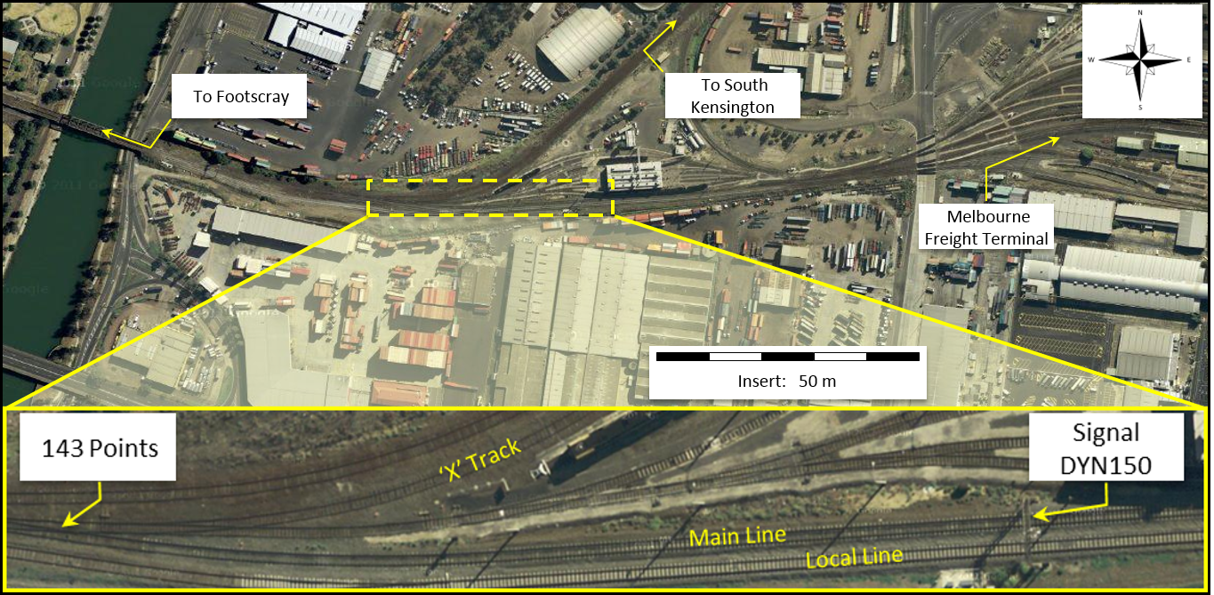
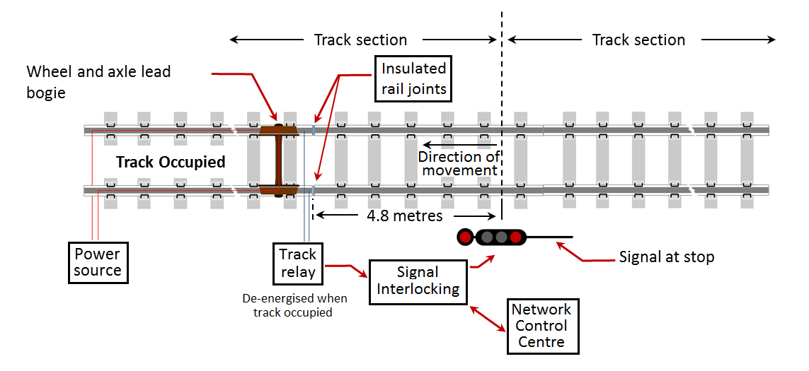
At about 1345, train 5SM2 approached Springhurst on the East Track, a location where work was being carried out on the West Track under Absolute Occupation. Due to the occupation on the West Track, protection of the parallel line was in place on the adjacent East Track. This was in the form of Track Force Protection (TFP) which was managed by a third party Track Force Protection Coordinator (TFPC).

Train 5SM2 approached the outer flagman displaying a yellow flag indicating that there was an obstruction ahead requiring the train to stop at an inner flagman. Three Audible Track Warning Signals (ATWs) had been placed 10 m apart on the track by the outer flagman and as 5SM2 went over the ATWs, the train crew sounded the horn and started to manage the train in anticipation of stopping at the inner flagman protecting the worksite 2,000 m ahead.

After 5SM2 had travelled a further 1,100 m, the train crew observed the inner flagman and determined that the train was not going to stop in time. The driver made an emergency brake application and the train came to a stop about 100 m beyond the inner flagman.
At the time of the incident, the East Track TFPC did not consider that the occurrence was an incident or ‘near miss’ that required reporting.

The train crew considered that the incident had been ‘dealt with and reconciled’ by the TFPC onsite and, therefore did not report it. However, the train crew and the TFPC both had an obligation to report the incident as soon as reasonably practicable.

As a result of this occurrence, the ARTC has advised that they are taking the following safety actions:

  • The Australian Rail Track Corporation will review the placement of outer and inner warnings given to train crews approaching worksites within Victoria as a priority. The review will consider the requirements specified in the rules applicable to other areas of the Defined Interstate Rail Network with the preferred outcome being alignment across all jurisdictions.
  • All ballast rehabilitation program staff have been reminded of the requirement under TA44 to immediately report incidents to Network Control.   

Occurrence summary

Investigation number RO-2014-004
Occurrence date 06/03/2014
Location Springhurst
State Victoria
Report release date 13/06/2014
Report status Final
Investigation level Short
Investigation type Occurrence Investigation
Investigation status Completed
Mode of transport Rail
Rail occurrence category Safe Working Irregularity/Breach
Occurrence class Incident
Highest injury level None

Train details

Train operator Pacific National
Train number 5SM2
Type of operation Freight
Departure point Sydney, NSW
Destination Melbourne, Vic.
Train damage Nil

Derailment of train 3WB3, at Nambucca Heads, New South Wales, on 14 May 2014

Preliminary report

Preliminary report released 12 September 2014

This preliminary report details factual information established in the investigation’s early evidence collection phase and has been prepared to provide timely information to the industry and public. Preliminary reports contain no analysis or findings, which will be detailed in the investigation’s final report. The information contained in this preliminary report is released in accordance with section 25 of the Transport Safety Investigation Act 2003.

The occurrence

At 1355[1] on 14 May 2014, freight train 3WB3 entered the Nambucca Heads crossing loop. The route was set for a through movement via the loop because of trackside work being performed adjacent to the main line.

At 1404:20, the trailing wheel set of the leading bogie on wagon RCOF20375S derailed to the right-hand-side in the direction of travel while the train was travelling through the crossing loop at a speed of 21 km/h. The derailed wagon was located fourth from last in the 44 wagon consist.

The train continued to travel with a derailed wagon for about 1,397 m. It passed over two bridges and reached a speed of 44 km/h before wagon RCOF20375S tipped on its side (Figure 1). The train then parted between the fourth and fifth last wagons. As the wagons parted, the train brake pipe separated, allowing air to vent to atmosphere and the train brakes to apply, bringing the train to a stop in about 320 m.

The train crew notified the network controller and arrangements were made to begin investigative and restoration work. The main line was subsequently reopened at 1816 on 16 May. The crossing loop line remained closed until further repairs could be conducted.

Figure 1: Derailed wagon RCOF20375S


RO2014007_Fig1

Source: ATSB

Context

The location

Nambucca Heads is located on the main north rail corridor between Sydney and Brisbane, about 565 track kilometres from Sydney Central Station. Nambucca Heads is a crossing location with a 1,615 m crossing loop.

Track information

The ARTC manages the railway corridor where the derailment occurred. Authorised movement of rail traffic is controlled from the ARTC’s Network Control Centre located at Broadmeadow, New South Wales.

The standard gauge[2] track at the derailment location consisted of 53 kg/m rail fastened by resilient clips to timber sleepers, spaced at about 667 mm centres. The sleepers were supported on a bed of ballast to a nominal design depth of 250 mm.

Approaching from the southern end, the track through the derailment site consisted of a series of curves between 480 m and 360 m radii on reasonably level track. The posted maximum track speed was 75 km/h although this speed would rarely be reached, due to the restriction of speed through the points.

On-site examination and preliminary analysis of track condition found no indication of any serious anomalies in the track geometry leading up to the point of derailment in the crossing loop.

Train information

Train 3WB3 was a steel products freight service operated by Pacific National between Wollongong and Brisbane. At the time of the derailment, the train consisted of two locomotives (NR94 leading and AN9 trailing) hauling 44 freight wagons. It was 817 m in length and had a trailing mass of 3,363 t.

The train was operated by two qualified drivers. They had both been assessed as fit for duty in accordance with the requirements of the National Standard for Health Assessment of Rail Safety Workers.

RCOF wagons are 15.1 m long and capable of carrying up to 80 gross tonnes at speeds of up to 80 km/h (depending on track speed limits). On the day of the derailment, wagon RCOF20375S (the wagon which derailed) was carrying 40 coils of rod, each weighing on average 1.5 t. The coils were arranged, two wide by two high, in each of the 10 bays (Figure 2). The coils were contained within the wagon, but they were not individually restrained.

On-site inspection and preliminary examination of the derailed wagons found no indication of any serious anomalies in rolling stock condition. Similarly, preliminary analysis of train data indicated that there were no anomalies in the train speed, train handling or operational performance leading up to the derailment.

However, evidence of load shifting had been observed in wagons not affected by the derailment, but carrying the same rod-in-coil product.

Figure 2: Loaded RCOF wagon on train 3WB3 carrying rod-in-coil product


RO2014007_Fig2

Source: ATSB.

Ongoing investigation activities

The ATSB’s investigation is continuing and will focus on:

  • the integrity of the rolling stock involved
  • the possibility of load shifting en route
  • the policies and procedures relating the securing of loads
  • the integrity of the track structure

Purpose of safety investigations

The objective of a safety investigation is to enhance transport safety. This is done through:

  • identifying safety issues and facilitating safety action to address those issues
  • providing information about occurrences and their associated safety factors to facilitate learning within the transport industry.

It is not a function of the ATSB to apportion blame or provide a means for determining liability. At the same time, an investigation report must include factual material of sufficient weight to support the analysis and findings. At all times the ATSB endeavours to balance the use of material that could imply adverse comment with the need to properly explain what happened, and why, in a fair and unbiased manner. The ATSB does not investigate for the purpose of taking administrative, regulatory or criminal action.

Terminology

An explanation of terminology used in ATSB investigation reports is available here. This includes terms such as occurrence, contributing factor, other factor that increased risk, and safety issue.

Publishing information

Released in accordance with section 25 of the Transport Safety Investigation Act 2003

Published by: Australian Transport Safety Bureau

© Commonwealth of Australia 2014

image_5.png

Ownership of intellectual property rights in this publication

Unless otherwise noted, copyright (and any other intellectual property rights, if any) in this report publication is owned by the Commonwealth of Australia.

Creative Commons licence

With the exception of the Coat of Arms, ATSB logo, and photos and graphics in which a third party holds copyright, this publication is licensed under a Creative Commons Attribution 3.0 Australia licence.

Creative Commons Attribution 3.0 Australia Licence is a standard form licence agreement that allows you to copy, distribute, transmit and adapt this publication provided that you attribute the work.

The ATSB’s preference is that you attribute this publication (and any material sourced from it) using the following wording: Source: Australian Transport Safety Bureau

Copyright in material obtained from other agencies, private individuals or organisations, belongs to those agencies, individuals or organisations. Where you wish to use their material, you will need to contact them directly.
[1]    The 24 hour clock is used in this report. Local time was Australian Eastern Standard Time (EST).

[2]     The name given to gauge of  track of 1435mm

Final report

Safety summary

What happened

At about 1404 on 14 May 2014, the fourth wagon from the end of train 3WB3 derailed whilst exiting the Nambucca Heads crossing loop. The train travelled a further 1,397 m before the derailed wagon tipped on its side causing the train to separate and subsequently stop.

What the ATSB found

The ATSB found that the rod-in-coil load had likely shifted, mostly to the left in the direction of travel. The effect of a load shift to the left would have been to transfer vertical forces from the wagon’s right side-bearer to the left side-bearer, causing the right-hand wheels to unload.

At the point of derailment, the track geometry was transitioning out of a left-hand curve which had a relatively high superelevation with respect to the actual speed of train 3WB3 (about 21 km/h). The relatively high superelevation and subsequent twist as the superelevation ramped down through the transition, likely resulted in additional transfer of vertical force from the wagon’s right side-bearer to the left side-bearer, resulting in a further unloading of the right-hand wheels.

The combination of superelevation, twist and (more importantly) uneven lateral loading, combined to unload the right-hand wheels which, when steering through a left-hand curve, resulted in flange climb and derailment of wagon RCOF20375S.

What's been done as a result

Following the occurrence, Pacific National Assets and Infrastructure Services engaged a consultant to conduct an audit of procedures and operational processes relating to the development and implementation of the Freight Loading Manual (FLM). The audit was scoped specifically to include a gap analysis in relation to current steel loading processes.

In addition, PN have advised that they will be arranging an external engineering group to undertake a twist test and/or computer simulation modelling of an RCOF wagon to record its wheel loading performance characteristics during scenarios based on operational data. It is expected that the outcomes of this work will be used to further refine the FLM and associated procedures and loading practices.

Safety message

The ability for a load to shift during transit is an undesirable condition that can affect the dynamic behaviour of the rail vehicle. All rail freight operators should consider the safety implications of shifting/moving loads and should ensure that all loads are restrained and/or enclosed in such a way that prevents movement in any direction relative to the wagon.

Context

The location

Nambucca Heads is located on the Main North Coast rail corridor between Sydney and Brisbane, about 565 track kilometres from Sydney Central Station. Nambucca Heads is a crossing location with a 1,951 m crossing loop.

The track at the location of the derailment was standard gauge, 53 kg/m rail mounted with resilient fastenings on timber sleepers spaced at about 667 mm centres.

The Australian Rail Track Corporation (ARTC) manages the railway corridor where the derailment occurred. Authorised movement of rail traffic is controlled from the ARTC’s Network Control Centre located at Broadmeadow, New South Wales.

Approaching from the southern end, the track through the derailment site consisted of a series of reverse curves between 480 m and 360 m radii on reasonably level track. While the posted maximum track speed was 75 km/h, most rail traffic traversing the loop would travel at considerably lower speed due to 25 km/h speed restrictions over the turnouts.

Train information

Train 3WB3 was a steel products freight service operated by Pacific National between Whyalla and Brisbane via Melbourne, Wollongong, and Morandoo (Newcastle). At the time of the derailment, the train consisted of two locomotives (NR94 leading and AN9 trailing) hauling 44 freight wagons. It was 817 m in length and had a trailing mass of 3,363 t.

Two qualified drivers operated the train. Both had been assessed as fit for duty in accordance with the requirements of the National Standard for Health Assessment of Rail Safety Workers.

Analysis of locomotive data logger indicated that there were no anomalies in the train speed, train handling or operational performance leading up to the derailment.

Rolling stock

RCOF wagons are 15.1 m long and approved to carry up to 80 gross tonnes at speeds up to 80 km/h (depending on track speed limits). On the day of the derailment, wagon RCOF20375S (the wagon which derailed) was carrying 40 coils of steel rod, each weighing 1.5 t on average. The coils were arranged two-wide by two-high, in each of the wagon’s 10 bays (Figure 2). The coils were contained within the wagon, but they were not otherwise restrained. Wagon RCOF20375S was one of six wagons added to the train at Morandoo for travel to Brisbane.

On-site inspection and preliminary examination of the derailed wagons found no indication of any serious anomalies in rolling stock condition. However, evidence of load shifting was observed in wagons not affected by the derailment, but carrying the same rod-in-coil product.

A number of wagons were quarantined, including RCOF20375S. The bogies of wagon RCOF20375S were transferred to Newcastle where they were examined in more detail by Pacific National.

The examination noted that:

1.Wheelsets on wagon RCOF20375S were inspected and measurements recorded. All wheelsets were in good condition and wheels were within Pacific National requirements. There was nothing evident from inspection of the wheelsets that could have contributed to the wagon derailing.

2.Wagon RCOF20375S bogie and wagon condition was inspected, with no obvious wear or pre incident damage observed that could have contributed to the derailment.

3.A bolster drop test was conducted and the bogies of wagon RCOF20375S. The test confirmed that the overall friction damping was satisfactory.

Based on the available evidence, it was concluded that the mechanical condition of wagon RCOF20375S did not contribute to the derailment.

Figure 2: Loaded wagon RCOF20526B on train 3WB3 carrying rod-in-coil product

Figure 2: Loaded wagon RCOF20526B on train 3WB3 carrying rod-in-coil product

Source: ATSB.

Pacific National freight loading manual

The Pacific National freight loading manual (FLM) is a document that provides information to employees and third parties on loading requirements for goods transported on Pacific National trains, to ensure the safe carriage of freight. The manual includes guidance on factors that may affect the stability of the wagon, such as composition, mass and distribution of the load, and the method of securing the load.

Section 01-10_07 documents the general requirements for mass and distribution of load. The FLM requires the load to be evenly distributed and the centre of gravity (including the weight of the bogies) shall not exceed 2,130 mm. Calculations indicate that a wagon fully loaded with road-in-coil product would likely result in a centre of gravity at or near the limit documented in the FLM.

The FLM also provides loading guidelines for specific products and wagons. Section 5-13_07 of the manual (dated 3 July 2013) documented the specific requirements for transporting rod-in-coil product on RCOF and RCWF wagons, and stated:

Where possible, the top and bottom layer MUST cover the full width of the wagon’s frame to ensure the load cannot collapse.

Where the load does not cover the full width, the bundles are to be loaded as follows:

The bottom two bundles must be placed so that all gaps are consistent.

The top two bundles are to be placed against the side walls of the cage.

If the bottom bundles are too wide to allow all three gaps, place bundles against side walls of frames/stanchions.

Coil bundles placed on the on bottom tier MUST be of sufficient strength to ensure coil collapse will not occur in transit.

Figure 3 illustrates the requirements specified above and has been reproduced from Pacific National’s freight loading manual.

Figure 3: Loading requirements for rod-in-coil product on RCOF wagons

Figure 3: Loading requirements for rod-in-coil product on RCOF wagons

Source: Pacific National freight loading manual (Section 5-13_07, dated 3 July 2013).

On site observations indicated that rod-in-coil product on both RCOF and RQRY wagons exhibited inconsistent gaps on the lower level, with the upper level having collapsed towards the centre of the wagon (Figure 4).

Figure 4: Loaded wagon RCOF20526B with shifted coils

Figure 4: Loaded wagon RCOF20526Bwith shifted coils

Source: ATSB.

Examination of the track post-derailment

An onsite inspection was conducted on 15 May 2014 by the ATSB investigation team, ARTC, and an officer from the Office of the National Rail Safety Regulator (ONRSR).

Evidence of flange climb was found on the high rail in a curve exit (Figure 5) at the 565.577 km point. The flange mark ran across the rail head and dropped off the field side of the high rail about 7 m further along the track. The rail did not show any signs of unusual wear.

Figure 5: Point of climb and derailment

Figure 5: Point of climb and derailment

Source: ATSB

The site was surveyed to record the track geometry on the approach and departure to the point of derailment. The measurements were recorded at 2 m intervals from 40 m on approach and 14 m on departure. The measurements were compared against the design parameters documented in the ARTC Engineering (Track & Civil) Code of Practice, Section 5, Track Geometry (CoP).

It was evident from the measured track geometry that the derailment had occurred in the curve transition[2] where the curve superelevation[3] runs-out to zero for the section of track leading to the turnout.

Track geometry parameters for curve design are largely dependent on train speed. In this case, the posted track speed was 75 km/h, though trains would rarely exceed 25 km/h due to the turnout (located about 200 m from the point of derailment). Analysis of the track measurements found that, at the point of derailment, a number of design parameters were approaching their recommended limits, especially at track speeds lower than 75 km/h. Despite this, there was no evidence of irregular track wear that can occur where trains regularly traverse track at speeds significantly lower than design.

Maintenance and inspection

The section of track at Nambucca Heads was maintained in accordance with ARTC’s CoP. The manual outlined two complementary inspection and assessment types:

• scheduled inspections, and

• unscheduled inspections.

At the time of derailment, the ARTC mandated that scheduled inspections for this section of track be performed by track patrols (at intervals not exceeding 7 days, or 28 days on crossing loops), ‘front-of-train inspections’ (at intervals not exceeding 6 months), and the track geometry car (at intervals not exceeding 4 months, or 24 months on crossing loops). Defects identified during inspections were to be recorded, assessed, and actioned in accordance with criteria documented in the CoP.

Previous track inspections did not record any defects in the vicinity of the derailment point. The previous track geometry car inspection, conducted on 14 January 2014, had not recorded any defects that required immediate rectification.

Examination of the survey data showed some variation in superelevation, track gauge and lateral alignment. While the variations in track geometry indicated a possibility of track movement in this area, when assessed against the CoP the magnitude of the measured geometry variations had not reached levels that would have required maintenance intervention.

Post-incident repairs

The ARTC performed rectification work on the track. The work involved the replacement of sleepers beyond the point of derailment, including part of the curve on the loop line. As part of the rectification work, the track was realigned and tamped which resulted in a reduction of superelevation and removal of the minor alignment variations through the curve near the point of derailment.

Mechanism of derailment

A flange climb derailment (as was evident in this case) occurs when a wheel has climbed up and over the top of the railhead. Flange climb is likely to occur in situations where the wheel experiences high lateral forces combined with a reduction in vertical force. The ratio of lateral to vertical force is often referred to as the L/V ratio. As this ratio increases, the likelihood of flange climb (derailment) also increases.

Flange climb derailments often occur on curves or track exhibiting alignment irregularities. A moving mass will try to continue moving in a straight line unless an external force is applied. On curved track, the external force occurs at the wheel flange/rail interface, in order to steer the wheel (and bogie) through the curve. The magnitude of lateral force is influenced by factors such as curve radius, vehicle speed, wheel/rail profiles and suspension characteristics.

As a vehicle traverses a curve, the vehicle is also subjected to overturning forces acting towards the outside of the curve. To limit the overturning forces on a vehicle, superelevation is applied whereby the outer rail is raised to a higher level than the inner rail. The magnitude of the overturning force is dependent on the radius of the curve, the amount of superelevation, and the speed of the vehicle.

In this case, train 3WB3 was negotiating a relatively tight curve at a relatively low speed. The superelevation of the left-hand curve at Nambucca Heads was high with respect to the actual speed of train 3WB3 of about 21 km/h. This would likely result in overturning forces acting towards the inside of the curve. That is, a transfer of vertical force from the wagon’s right side-bearer to the left side-bearer, resulting in a corresponding unloading of the right-hand wheels. For wagons exhibiting a high centre of gravity, such as RCOF class wagons loaded with rod-in-coil product, the wheel unloading effect would be further enhanced.

At the point of derailment, wagon RCOF20375S was negotiating a curve transition. Transitions apply a twist to the track as the superelevation is ramped in or out at the entry and exit of the curve. Any variation in track superelevation under the bogies of a wagon is another factor that can contribute to wheel unloading.

It was also evident that the rod-in-coil product loaded on train 3WB3 (and most likely on wagon RCOF20375S) had collapsed (in most cases) to the left in the direction of travel. It could not be ascertained whether the load in wagon RCOF20375S had shifted prior to arriving at Nambucca Heads, or if it had dynamically shifted when passing through the curve. Regardless of when the load moved however, the effect of a load shift to the left would also transfer vertical forces from the wagon’s right side-bearer to the left side-bearer, compounding the unloading of the right-hand wheels. A dynamic shift would also result in a lateral shock load, which could have added undesirable wagon dynamics and additional wheel unloading effects.

Dynamic modelling of wagon RCOF20375S

Following the derailment at Nambucca Heads, PN engaged consultants to undertake dynamic modelling of a RCOF wagon loaded with rod-in-coil product. However, the consultant noted that due to the limited data provided, a number of assumptions were required for both the vehicle and track models.

The analysis results over the measured track geometry showed that L/V ratios for the lead axles in each bogie were tending towards the criterion limit considered acceptable for stable vehicle behaviour. As expected, the L/V ratios were higher for laterally unbalanced loads than for balanced loads. The modelling also indicated that cyclic track irregularities exhibited wavelengths similar to the roll resonance of the vehicle when travelling at a speed of 23 km/h. However, the modelling did not specifically predict values high enough to suggest derailment.

The consultant suggested a need for further refinement to the model to better understand the propensity for derailment under various loading conditions.

ATSB assessment of derailment mechanism

While the dynamic modelling predicted an increase in unstable vehicle behaviour for wagon RCOF20375S when traversing the track geometry measured at Nambucca Heads, it did not specifically predict derailment. Of note however, was the analyst’s statement that with further refinement of the model, the propensity for derailment under unbalanced load conditions is likely to increase.

As discussed previously, while the assessment of track geometry against the CoP found the variations were not of a magnitude that would have required maintenance intervention, it was evident from the modelling that variations in track geometry had probably influenced the behaviour of wagon RCOF20375S.

The ATSB concluded that a combination of superelevation, twist and (more importantly) uneven lateral loading had combined to unload the right-hand wheels of wagon RCOF20375S, which, when steering through a left-hand curve, resulted in flange climb and derailment. Regardless of whether the rod-in-coil load shifted before or during the train’s passage through Nambucca Heads, its ability to shift in relation to the wagon was an undesirable condition that likely adversely affected the wagon’s dynamic behaviour.

__________

  1. Track of variable radius, usually applied between tangent track and curved track or track comprising curves of different radii.
  2. The height difference, at a common location, between the running surfaces of two rails.

Findings

From the evidence available, the following findings are made with respect to the derailment of train 3WB3 at Nambucca Heads, New South Wales, on 14 May 2014. These findings should not be read as apportioning blame or liability to any particular organisation or individual.

Safety issues, or system problems, are highlighted in bold to emphasise their importance. A safety issue is an event or condition that increases safety risk and (a) can reasonably be regarded as having the potential to adversely affect the safety of future operations, and (b) is a characteristic of an organisation or a system, rather than a characteristic of a specific individual, or characteristic of an operating environment at a specific point in time.

Contributing factors

  • The derailment of wagon RCOF20375S likely occurred due to imbalance effects stemming from uncontrolled shifting of the rod-in-coil load.
  • The relatively high track superelevation and twist at the point of derailment, in conjunction with some minor variations in track geometry leading up to the point of derailment, exacerbated the uneven loading and the dynamic behaviour of wagon RCOF20375S.
  • The Pacific National freight loading manual, and application of it, was ineffective at preventing load shift of rod-in-coil product. [Safety issue]

Safety analysis

Rolling stock loading

Evidence indicated an issue with rod-in-coil load shifting while the train was en route. Closed circuit television camera (CCTV) footage from Telarah, Maitland, Wallarobba, and Dungog stations was analysed. The footage, through Maitland particularly, shows evidence of load-shift on the wagon RCOF20375S. It was also evident that this was not an isolated instance, as video evidence of other trains travelling to Brisbane showed similar movement and collapsing of rod-in-coil product into the central void (in most cases to the left in the direction of travel). Given the tendency of rod-in-coil product to move (and possibly bounce), it is very likely that the load within wagon RCOF20375S had shifted during the journey from Morandoo, or possibly as train 2WB3 travelled through Nambucca Heads.

Figure 6: Rod-in-coil product on another train

Figure 6: Rod-in-coil product on another train

Source: ARTC

Pacific National freight loading manual

An introduction to Pacific National’s freight loading manual stated ‘it is essential that the load is restrained to prevent any movement in any direction relative to the wagon’. While the manual also provided specific instructions on the positioning of rod-in-coil product when loaded on RCOF and RQRY wagons, there were no particular instructions or requirements to otherwise restrain the load and prevent it from shifting.

Following the incident, Pacific National reviewed the manual and published an update (FLM 05-13_08) dated 15 August 2014. The update added some detail as to how rod-in-coil must be loaded, but the requirements largely remained the same as the superseded version.

On 13-14 January 2015 an Office of National Rail Safety Regulator (ONRSR) audit noted that rod-in-coil product had been shifting en route – in a manner very similar to that shown in Figure 6. Accordingly, while it is almost certain that trains had been arriving in Brisbane with shifted rod-in-coil loads, there was no indication that the condition of arriving loads had been regularly reported back to Pacific National for consideration and corrective action.

During a subsequent inspection, the ONRSR observed that the wagons were loaded predominately from the left side with a fork lift. The loading did not generally conform to the freight loading manual, which required equal lateral spacing of coils on the bottom layer. This was most likely due to the loading method and lack of specific awareness of Pacific National requirements. Post-loading inspections did not detect the loading irregularity and were mainly focussing on out-of-gauge (uncontained) product or rolling stock running gear defects.

Uneven distribution of load on rail wagons can result in undesirable dynamic behaviour when traversing normal (within tolerance) track geometry. Consequently, it is essential that freight is restrained from shifting, to ensure that the load is not redistributed during its journey. In this case, it is likely that the shifted load significantly affected the lateral load distribution within the wagon, with this being enough to critically affect the vehicle handling dynamics around the curve where the derailment subsequently occurred.

Safety issues and actions

The safety issues identified during this investigation are listed in the Findings and Safety issues and actions sections of this report. The Australian Transport Safety Bureau (ATSB) expects that all safety issues identified by the investigation should be addressed by the relevant organisation(s). In addressing those issues, the ATSB prefers to encourage relevant organisation(s) to proactively initiate safety action, rather than to issue formal safety recommendations or safety advisory notices.

All of the directly involved parties were provided with a draft report and invited to provide submissions. As part of that process, each organisation was asked to communicate what safety actions, if any, they had carried out or were planning to carry out in relation to each safety issue relevant to their organisation.

Where relevant, safety issues and actions will be updated on the ATSB website as information comes to hand. The initial public version of these safety issues and actions are in PDF on the ATSB website.

Loading rules and procedures

The Pacific National freight loading manual, and application of it, was ineffective at preventing load shift with rod-in-coil product.

ATSB Safety Issue: RO-2014-007-SI-01

Sources and submissions

Sources of information

The sources of information during the investigation included the:

  • Australian Rail Track Corporation Engineering (Track and Civil) Code of Practice, Section 5 – Track Geometry
  • Pacific National Freight Loading Manual

Submissions

Under Part 4, Division 2 (Investigation Reports), Section 26 of the Transport Safety Investigation Act 2003 (the Act), the Australian Transport Safety Bureau (ATSB) may provide a draft report, on a confidential basis, to any person whom the ATSB considers appropriate. Section 26 (1) (a) of the Act allows a person receiving a draft report to make submissions to the ATSB about the draft report.

A draft of this report was provided to Pacific National, the Office of National Rail Safety Regulation, and the Australian Rail Track Corporation.

Submissions were received from Pacific National, the Office of National Rail Safety Regulation, and the Australian Rail Track Corporation. The submissions were reviewed and where considered appropriate, the text of the report was amended accordingly.

The occurrence

At about 1355[1] on 14 May 2014, freight train 3WB3 entered the Nambucca Heads crossing loop. The route was set for a through movement via the loop because of trackside work being performed adjacent to the main line.

At about 1404, the trailing wheel set of the leading bogie on wagon RCOF20375S derailed to the right-hand-side in the direction of travel. The train was travelling at a speed of 21 km/h through a left hand curve. The derailed wagon was located fourth from last in the 44 wagon consist.

The train continued to travel with the derailed wagon for 1,397 m, passing over two bridges and reached a speed of 44 km/h before wagon RCOF20375S tipped on its side (Figure 1). The train then parted between the fourth and fifth last wagons. As the wagons parted, the train brake pipe separated, allowing air to vent to atmosphere and the train brakes to apply, bringing the train to a stop in about 320 m.

The train crew notified the network controller and arrangements were made to begin investigative and restoration work. The main line was subsequently reopened at 1816 on 16 May. The Nambucca Heads crossing loop line remained closed until further repairs could be conducted.

Figure 1: Derailed wagon RCOF20375S

rId23 Figure 1.JPG

Source: ATSB

__________

  1. The 24 hour clock is used in this report. Local time was Australian Eastern Standard Time (EST).

Purpose of safety investigations & publishing information

Purpose of safety investigations

The objective of a safety investigation is to enhance transport safety. This is done through:

  • identifying safety issues and facilitating safety action to address those issues
  • providing information about occurrences and their associated safety factors to facilitate learning within the transport industry.

It is not a function of the ATSB to apportion blame or provide a means for determining liability. At the same time, an investigation report must include factual material of sufficient weight to support the analysis and findings. At all times the ATSB endeavours to balance the use of material that could imply adverse comment with the need to properly explain what happened, and why, in a fair and unbiased manner. The ATSB does not investigate for the purpose of taking administrative, regulatory or criminal action.

Terminology

An explanation of terminology used in ATSB investigation reports is available here. This includes terms such as occurrence, contributing factor, other factor that increased risk, and safety issue.

Publishing information 

Released in accordance with section 25 of the Transport Safety Investigation Act 2003

Published by: Australian Transport Safety Bureau

© Commonwealth of Australia 2015

image_5.png

Ownership of intellectual property rights in this publication

Unless otherwise noted, copyright (and any other intellectual property rights, if any) in this report publication is owned by the Commonwealth of Australia.

Creative Commons licence

With the exception of the Coat of Arms, ATSB logo, and photos and graphics in which a third party holds copyright, this publication is licensed under a Creative Commons Attribution 3.0 Australia licence.

Creative Commons Attribution 3.0 Australia Licence is a standard form licence agreement that allows you to copy, distribute, transmit and adapt this publication provided that you attribute the work.

The ATSB’s preference is that you attribute this publication (and any material sourced from it) using the following wording: Source: Australian Transport Safety Bureau

Copyright in material obtained from other agencies, private individuals or organisations, belongs to those agencies, individuals or organisations. Where you wish to use their material, you will need to contact them directly.
Occurrence summary

Investigation number RO-2014-007
Occurrence date 14/05/2014
Location Nambucca Heads
State New South Wales
Report release date 23/09/2015
Report status Final
Investigation level Systemic
Investigation type Occurrence Investigation
Investigation status Completed
Mode of transport Rail
Rail occurrence category Derailment
Occurrence class Accident
Highest injury level None

Train details

Train operator Pacific National
Train number 3WB3
Type of operation Freight
Departure point Woollongong, NSW
Destination Brisbane, Qld

Derailment of ore train 4413, Bonnie Vale, Western Australia, on 14 May 2014

Preliminary report

Preliminary report release 28 August 2014

The occurrence

The information contained in this Preliminary report is released in accordance with section 25 of the Transport Safety Investigation Act 2003 and is derived from the initial investigation of the occurrence. Readers are cautioned that new evidence will become available as the investigation progresses that will enhance the ATSB's understanding of the accident as outlined in this Preliminary report. As such, no analysis or findings are included in this report.

At 0100[1] on 14 May 2014, train 3416, a scheduled bulk iron ore service, departed from the Binduli Triangle (650 km[2]), Western Australia, for Koolyanobbing East (458 km). The train, crewed by two drivers,[3] travelled empty to Koolyanobbing East.

On arrival at Koolyanobbing East, the train was loaded with iron ore and made ready for departure as train 4413. At 0755, it departed Koolyanobbing East for the port of Esperance.

En route, train 4413 crossed with the Prospector passenger train at Beckwith (470 km) and then with train 3033 at Mount Walton (534 km). It continued on its journey towards Esperance, stopping at the Wallaroo loop (562 km) to cross with empty ore train 4414.

Figure 1: Location map – Western Australia

RO-2014-008_Fig1

Source: NatMap Railways of Australia

 At 1010, train 4413 departed the Wallaroo loop. The passage of the train through to Stewart (587 km) was uneventful. As the train entered the Stewart to Bonnie Vale section, the driver gradually accelerated towards 90 km/h, the maximum permitted track speed for ore trains in this section. From the 596 km to 599 km mark the track descended slightly. To limit the train from exceeding 90 km/h, the driver put the train into light dynamic braking,[4] to maintain a speed of about 85 km/h.

At about 1048, just after traversing a culvert at 600.657 km, the locomotive shuddered. The train travelled a further 600 m when the driver felt a series of jerks of increasing severity throughout the train. Almost immediately, he observed that the end-of-train monitor[5] was showing a zero reading. He did not observe a decrease in the train’s brake pipe pressure or hear any audible alarm which would normally accompany a train parting event.[6]

The driver looked back in the rear vision mirror and observed clouds of dust and realised that the rear portion of the train had probably derailed. He slowed the train, bringing it to a stand about 3 km beyond the initial point of derailment (PoD). He then advised the train controller that the train was at stop within the Stewart to Bonnie Vale section, had probably derailed and that the second driver was going back to investigate.

Figure 2: Train 4413 End of Train – Derailed Ore Wagons

RO-2013-021_Fig2

Source: ATSB

Events post derailment

The second driver walked towards the rear of the train and progressively reported to the driver the extent of the derailment and associated damage (Figure 2). The driver relayed the information to the train controller.

The Stewart to Bonnie Vale section was subsequently closed and recovery personnel were dispatched from Kalgoorlie. The two drivers were also relieved and returned to Kalgoorlie.

On 15 May, track and train maintenance crews commenced recovery and restoration works. The track was re-opened to traffic on 17 May.

Context

Location

The derailment occurred between Stewart and Bonnie Vale, about 54 km west of Kalgoorlie, at 600.729 km on the Defined Interstate Rail Network (DIRN) in Western Australia (Figure 1). The DIRN through this area runs in an east-west direction and links Western Australia with the eastern States.

Environmental conditions

The environmental conditions leading up to the incident were not considered exceptional and were unlikely to have contributed to the derailment.

Train and train crew information

Train 4413 was a regular Aurizon iron ore service that operated between Esperance and Koolyanobbing East. The train was configured as a distributed power unit[7] (DPU) and comprised two locomotives at the head of the train (AC4301 leading and ACB4404 trailing) followed by 106 wagons then two locomotives mid-section (Q4017 leading and AC4304 trailing) followed by a further 54 wagons. The train had an overall length of 1,792 m and a gross mass 14,731 t.

Rolling stock

Examination of the derailed wagons primarily focused on wagon WOE33548K, which was considered as the first wagon to have derailed. It was evident that the leading wheel-set of its lead bogie had derailed to the left (in the direction of travel) and had travelled about 2.5 km past the PoD.

The wagon was examined by the ATSB both on site and at Aurizon’s West Kalgoorlie maintenance facilities and found to be in compliance with maintenance specifications and operationally fit for purpose.

The ATSB concluded that there was no obvious indication of any mechanical deficiency with the train that may have contributed to the derailment. However, post derailment braking performance requires further examination because the available evidence indicates that the loss of brake pipe integrity (loss of air) did not result in immediate brake activation.

Train crew

The train crew comprised two drivers. The driver at the time of the derailment had about 14 years train driving experience. The second driver had 9 years train driving experience. Both drivers held the required qualifications to operate the train, were route certified and assessed as medically fit for duty.

Following the derailment both drivers underwent mandatory drug and alcohol testing, the results of which were negative. The available evidence also indicates that the performance of the drivers was not affected by fatigue.

Track Information

The track from Koolyanobbing East through to West Kalgoorlie substantially comprised a single line (bi-directionally signalled) with crossing loops strategically located throughout its length.

The track through the derailment site was standard gauge (1,435 mm) and consisted of 60 kg/m continuously welded rail[8] (CWR). The rail was fixed to concrete sleepers at approximately 667 mm spacing and secured by resilient fastenings.[9] It was supported on a bed of ballast having a nominal depth of 300 mm under the sleepers. The track had been relayed with new 60 kg/m rail about 1 year earlier.

The track leading into the derailment site was straight (tangent track) with a slight downgrade of about 0.2% in the direction of travel.

Track condition

An examination of the track at the PoD showed evidence of flange climb on the left side running rail (direction of travel) and witness marks over a distance of about 5 m which indicated that the wheel flange crossed over the rail head (Figure 3).

Figure 3:   Witness marks caused by a wheel flange at PoD (600.729 km) shown by line of stones on rail head


RO-2014-008_Fig3

Source: ATSB

Damage to sleepers was observed only after the point where the wheel(s) subsequently dropped off the rail head. Beyond the drop off point, the wheels and bogies of derailed wagons advancing along the sleepers, progressively damaged the track structure both within the four foot[10] and on the field side of the rail (left side direction of travel). This resulted in the loss of track structural integrity and the subsequent destruction of the track, with rolling stock ploughing into the ballast and resulting in the multi-wagon pile-up (Figure 2 and 3).

There was no evidence of spread in the section of track leading up to the PoD, so gauge widening was not considered to have been a factor in the derailment. Similarly, there were no signs of any broken/fractured rail immediately at or before the PoD.

Although the track structure leading into/out of the derailment site appeared to be in good condition, there were signs of lateral vehicle oscillations along the length of track leading up to PoD. This was characterised by flange contact wear along the head of the rails at regular intervals. There was also evidence of a vertical twist defect immediately after a culvert at 600.657 km.

The potential influence of the observed track conditions were supported by:

  • Statements from the train drivers, who both indicated that the track was rough (side-to-side oscillations) leading into the derailment site and that the train had kicked heavily at or near the PoD
  • Forward facing video evidence from train 4414[11] which had passed through the site earlier that morning (about 0940) and showed evidence of a sizeable track misalignment at or near the PoD
  • Rear facing video from train 4413 (mid-section trailing locomotive AC4304) showing evidence of a substantial sideways kick as wagons behind locomotive AC4304 passed over the PoD.

Derailment - summary

The available evidence, as detailed above, indicates that the derailment of ore train 4413 near Bonnie Vale in Western Australia was the result of flange climb.

There was evidence of lateral track vehicle oscillations along the length of track leading up to the PoD and a twist defect immediately after the culvert at 600.657 km. Although the locomotives and ore wagons appeared to be in good condition it is considered that the vehicle oscillations may have been of sufficient magnitude to cause the leading wheel of wagon WOE33548K to unload, mount the rail head at 600.729 km and derail.

Ongoing investigation activities

The ATSB investigation is continuing and will focus on:

  • The dynamic behaviour of WOE class wagons.
  • Train braking performance, in particular when configured with mid-power locomotives.
  • Track inspection and maintenance procedures, including defect reporting processes used by the infrastructure manager and the rolling stock operator.

Purpose of safety investigations

The objective of a safety investigation is to enhance transport safety. This is done through:

  • identifying safety issues and facilitating safety action to address those issues
  • providing information about occurrences and their associated safety factors to facilitate learning within the transport industry.

It is not a function of the ATSB to apportion blame or provide a means for determining liability. At the same time, an investigation report must include factual material of sufficient weight to support the analysis and findings. At all times the ATSB endeavours to balance the use of material that could imply adverse comment with the need to properly explain what happened, and why, in a fair and unbiased manner. The ATSB does not investigate for the purpose of taking administrative, regulatory or criminal action.

Terminology

An explanation of terminology used in ATSB investigation reports is available here. This includes terms such as occurrence, contributing factor, other factor that increased risk, and safety issue.

Publishing information

Released in accordance with section 25 of the Transport Safety Investigation Act 2003

Published by: Australian Transport Safety Bureau

© Commonwealth of Australia 2014

image_5.png

Ownership of intellectual property rights in this publication

Unless otherwise noted, copyright (and any other intellectual property rights, if any) in this report publication is owned by the Commonwealth of Australia.

Creative Commons licence

With the exception of the Coat of Arms, ATSB logo, and photos and graphics in which a third party holds copyright, this publication is licensed under a Creative Commons Attribution 3.0 Australia licence.

Creative Commons Attribution 3.0 Australia Licence is a standard form licence agreement that allows you to copy, distribute, transmit and adapt this publication provided that you attribute the work.

The ATSB’s preference is that you attribute this publication (and any material sourced from it) using the following wording: Source: Australian Transport Safety Bureau

Copyright in material obtained from other agencies, private individuals or organisations, belongs to those agencies, individuals or organisations. Where you wish to use their material, you will need to contact them directly.
[1]     The 24-hour clock is used in this report and is referenced from Western Standard Time (WST), UTC + 8.0 hours.
[2]     Distances are track kilometres measured from Perth terminus.
[3]     Two drivers operate alternately as a driver/observer pair.
[4]     The trains’ electric traction motors are used for regenerative/electric braking.
[5]     The end-of train monitor works in conjunction with an end-of-train marker, a device fitted to the trailing end of the last vehicle of a train. The system is used to indicate that the train is intact by monitoring brake pipe pressure.
[6]     A train parting event normally results in a loss of brake pipe integrity and an associated loss of brake pipe pressure.
[7]     The placing of additional locomotives at intermediate points within a train and remotely controlling these locomotives from the lead locomotive.
[8]     Continuous welded rail (CWR) – Track where the rail is joined by welding (and other non-moveable joints such as glued insulated joints) in lengths greater than 300 metres.
[9]     A fastening that provides a degree of elasticity between the sleeper and rail with the aim of avoiding the loosening of the fastening due to vibration, as well as enhancing the ability of the fastening system to resist longitudinal creep forces and buckling forces associated with continuously welded rail (CWR).
[10]    The area between the rails of a standard gauge railway.
[11]    Forward facing video evidence was not available from train 4413, train that derailed, due to a technical failure of the train’s forward facing video recorder.

Final report

Safety summary

What happened

On 14 May 2014, train 4413 – a bulk iron ore service operated by Aurizon, derailed on the Defined Interstate Rail Network (DIRN) between Stewart and Bonnie Vale, about 54 km west of Kalgoorlie in Western Australia. As a result of the derailment there was significant damage to track and rolling stock. There were no injuries.

What the ATSB found

The ATSB determined that the derailment of train 4413 was most likely initiated by lateral harmonic vehicle oscillation induced by a combination of minor cyclic cross-level and lateral track irregularities just in advance of the point of derailment. As a result of these irregularities, it was likely that the roll of wagon WOE33548K caused the left hand wheels to unload at a time when the leading left wheel came into contact with the left rail face – resulting in flange climb and derailment.

While the wagon type that derailed (WOE class) had passed prescribed dynamic performance testing, and the wagons and track complied with mandated engineering requirements, post-derailment computer modelling showed the onset of lateral harmonic wagon oscillation of sufficient magnitude to increase the likelihood of derailment at this location. Simulations showed that iron ore wagons, with their short length, react more severely to 22 m wavelength cyclic irregularities (as evident at this site) than do the typically longer intermodal wagons. The ATSB concluded that undertaking computer modelling when changing rolling stock and/or track working conditions offers rail transport operators an opportunity to identify potential areas of risk exposure before implementing new service arrangements.

Track maintenance and inspection was found to be in compliance with engineering requirements, however the track leading into the derailment site was known (to train drivers) as an area of rough ride. It was found that the systems in place between the train operator and track maintainer for the reporting of track irregularities (in particular the rough riding of trains) was ineffective, and hence the opportunity was lost to check for uncharacteristic track qualities through the derailment site – before such qualities contributed to a derailment.

While not influencing the derailment, it was noted that the loss of the train’s brake pipe integrity (loss of air), including activation of the end-of-train monitor, had not resulted in the immediate and full automatic activation of the train brake.

What's been done as a result

Brookfield Rail and Aurizon have developed enhanced procedures for reporting track irregularities and have jointly committed, through the Rail Industry Safety and Standards Board, to ongoing industry support and research into the cause of this type of derailment. Aurizon is examining, with the intent of rectifying, the train braking irregularity (brakes not activating) that occurred following the loss of brake pipe integrity.

Safety message

To reduce the potential for unforeseen dynamic stability issues affecting the safety of rolling stock operations, it is essential that train operators and track maintainers:

Appropriately test and model rolling stock dynamic characteristics and the effects of changed track conditions before implementing new service arrangements.

Develop proactive interface management strategies that promote the prompt reporting, capture and feedback of uncharacteristic track qualities.

Context

Location

The derailment occurred between Stewart and Bonnie Vale, about 54 km west of Kalgoorlie, at 600.729 km on the Defined Interstate Rail Network (DIRN) in Western Australia (Figure 1). The DIRN through this area runs in an east-west direction and links Western Australia with the eastern states.

Train crew and train information

Train 4413 was a regular Aurizon iron ore service that operated between Koolyanobbing East and the port of Esperance. The train was configured as a distributed power unit[7] and comprised two locomotives at the head of the train (AC4301 leading and ACB4404 trailing) followed by 106 wagons, two further locomotives (Q4017 leading and AC4304 trailing) and a final 54 wagons. The train had an overall length of 1,792 m and a gross mass 14,731 t.

Locomotives AC4301 and AC4304 were each equipped with data loggers (loco-log) and CCTV. These systems were used for capturing information such as date/time, speed, brake pipe pressure, throttle position, distance travelled and video imagery.

Rolling stock

Examination of the rolling stock primarily focused on wagon WOE33548K, located towards the rear of the train, at position 146 in a consist of 164 vehicles (count includes locomotives). It was determined that this was the first wagon to have derailed (leading wheel set of the lead bogie derailed to the left in the direction of travel). The wagon had travelled about 2.5 km past the point of derailment (PoD) by the time the train was brought to a stand.

Figure 3: Gauging of centre bowl, wagon WOE33548K

Figure 3: Gauging of centre bowl, wagon WOE33548K

Source: ATSB

The wagon was initially examined on site and later at Aurizon’s West Kalgoorlie maintenance facilities. The wagons were fully inspected including bogie frames, centre bowl centricity (Figure 3) sidebearer assemblies, friction wedges, lead bogie’s wheelsets and wheel profiles. All were found to be operationally fit for purpose and in compliance with maintenance specifications.

Examination of trackside monitoring data (RailBAM[8] and WILD[9]) did not uncover any evidence of wagon overloading or wheel defects that may have contributed to the derailment.

Train braking

Analysis of data extracted from the train’s loco-log established:

  • The train was travelling at 88 km/h (2 km/h below track speed) as the lead locomotive AC4301 passed over the PoD. The driver was actively controlling and maintaining the train’s speed by applying a range of throttle commands.

Figure 4: Graph derived from extract of loco-log data from AC4301

Figure 4: Graph derived from extract of loco-log data from AC4301

Source: Data source Aurizon, graphed by ATSB

  • The train was travelling at 87 km/h as wagon WOE33548K (first to derail) passed over the PoD. At that time, locomotive AC4301 was in idle/coasting, after coming out from light dynamic braking.
  • About 3 seconds after wagon WOE33548K passed over the PoD, the end-of-train monitor (EoT) registered a complete loss of brake pipe pressure. This event probably coincided with wagons breaking away from the main body of the train, and was about the time the driver recalled observing the EoT alert.
  • Although the EoT provided an alert, this was not reflected as a loss of brake pipe pressure on the driver’s cab controls. The loss of brake pipe pressure that was registered by the EoT did not automatically activate entire train braking. As a consequence, the driver initially assumed a malfunction of the EoT until he observed dust in the train’s rear vision mirror.
  • The driver slowed the train using dynamic braking, coming to a standstill about 2 km after the initial EoT alert.

While there was no apparent maintenance deficiency that contributed to the derailment, and recorded braking performance was consistent with the operation of the dynamic braking system, the fact that the loss of brake pipe integrity did not automatically activate the train brakes is an operational concern. The loss of brake pipe integrity (loss of air) should always result in the prompt activation of train brakes along the entire length of the consist.

Train crew

The driver in control at the time of the derailment had about 14 years train driving experience. The second driver (observer) had 9 years train driving experience. Both drivers held the required qualifications to operate the train and were route certified.

An examination of the drivers’ records confirmed that both had been assessed as meeting the medical standards prescribed by the National Standard for Health Assessment of Rail Safety Workers. Following interview and an examination of the drivers’ rosters, the ATSB determined that fatigue impairment was unlikely to have affected their performance. Both drivers said they felt well when signing on for duty and subsequently, at the time of the derailment.

After the derailment, both drivers underwent drug and alcohol testing, the results of which were negative.

Available evidence indicates that the drivers’ performance was unlikely to have been a factor in the derailment.

Environmental conditions

At the time of the derailment the weather at the Kalgoorlie-Boulder airport was fine. Temperature was about 21°C with the wind blowing from the south at a speed of 4 km/h. The recorded lowest temperature for the day (0600) was fractionally below 7°C. No rain had fallen in the preceding 24 hours.

Environmental conditions leading up to the derailment were not considered extraordinary and were unlikely to have contributed to the derailment.

Track information

The track from Koolyanobbing East through to West Kalgoorlie substantially comprised a single line (bi-directionally signalled) with crossing loops strategically located throughout its length.

The track through the derailment site was standard gauge (1,435 mm), 60 kg/m continuously welded rail[10] (CWR), fixed by resilient fastenings[11] to concrete sleepers at approximately 667 mm spacing. The rails were supported on a bed of ballast with a 300 mm nominal depth under the sleepers. The track leading into the derailment site was straight (tangent track) on a slight downgrade of about 0.2% in the direction of travel. When the track was re-laid with 60 kg/m rail about a year earlier, the infrastructure manager (Brookfield Rail) increased the maximum track speed to 90 km/h for loaded ore trains operating through the area.

Examination of the track

There was no evidence of track spread before the PoD, so gauge widening was not considered to have been a factor in the derailment. Similarly, there were no signs of any broken/fractured rail immediately at or before the PoD.

There was evidence of flange climb[12] on the left side running rail (direction of travel) at 600.729 km, followed by witness marks over a distance of about 5 m that were consistent with a wheel flange crossing over the rail head (Figure 5). Damage to sleepers was observed only after the point where the wheel(s) dropped off the rail head. Beyond the drop off point, the wheels and bogies of derailed wagons advancing along the sleepers had progressively damaged the track structure both within the four foot[13] and on the field side of the rail (left side direction of travel). This led to the loss of structural integrity and the subsequent destruction of the track, with rolling stock ploughing into the ballast giving rise to the multi-wagon pile-up shown at Figure 2.

Figure 5: Witness marks at PoD (600.729 km) shown by line of stones on rail head

Figure 5: Witness marks at PoD (600.729 km) shown by line of stones on rail head

Source: ATSB

Although the track leading into the derailment site appeared to be in good condition, there were signs of pre-existing lateral vehicle oscillations (characterised by flange contact wear along the gauge face of the rails at regular intervals), and evidence of minor cyclic cross level (Figure 6) and lateral track irregularities before the PoD.

Figure 6: Evidence of minor twist defect in advance of PoD at 600.729 km

Figure 6: Evidence of minor twist defect in advance of PoD at 600.729 km

Source: ATSB

These observations were supported by:

  • Statements from the train drivers, who both indicated that the track was rough (side-to-side oscillations) leading into the derailment site and that the train shuddered at or near the derailment site.
  • Forward facing video (Figure 7) from train 4414,[14] which had passed through the site earlier that morning (about 0940), showed very little evidence of any lateral track misalignment at, or near the derailment site.

Figure 7: Video image from train 4414 (left) and photo post derailment (right)

Figure 7: Video image from train 4414 (left) and photo post derailment (right)

Source: Aurizon (left image) and Brookfield Rail (right image)

  • Rear facing video from train 4413[15] showed wagons directly behind AC4304 oscillating sideways (laterally) when approaching the derailment site, followed by heavy shuddering as wagons passed over (or near) the derailment site.

Post-derailment, the track was surveyed by Brookfield Rail (unloaded) for a distance of 100 m leading into the PoD. The plot at Figure 6 cross level variation (mm)[16] was derived from survey measurements and substantiated observations of a minor cyclic twist defect in advance of the PoD. The plot shows a cross level variation of near zero about 100 m before the PoD, which then increases in magnitude to about 22 mm at a location 6 m back from the PoD. Under the Westrail S.G. Code of Practice Track and Civil Infrastructure (CoP),it is unlikely that this specific magnitude of cross level variation would have triggered remedial action by Brookfield Rail. However, the CoP (Table 6.2, Note [7]) also identifies that the onset of a rough ride caused by a combination of laterally induced vehicle oscillations in an area of track with a cyclic twist defect may present a heightened derailment risk and should not be ignored.

Wagon - lateral stability

The conical shape of the railway vehicle wheel/tread tends to cause lateral oscillation of the wheelset along the length of tangent track. At low speed, these oscillations are effectively damped. As speed is increased, the lateral oscillations initiated by a minor track irregularity take longer to damp out, and above a critical speed, oscillations continue indefinitely until a curve or another track irregularity causes them to temporarily cease. This behaviour is commonly referred to as hunting.

If a vertical, lateral, or cross level track irregularity is cyclic and is encountered at a speed corresponding to the natural frequency of vehicles traversing the track, there is a risk of vehicle resonant harmonic oscillation developing. This can be particularly hazardous if the cyclic motion, set up by cross level variations, results in a wheel becoming sufficiently unloaded such that the guidance provided by the wheel flange is no longer adequate – allowing the flange to climb up onto the rail head. Harmonic behaviour is characterised by large amplitude oscillations at specific train speeds, with a significant sideways force that can damage the track and in severe cases result in derailment. Hunting can also exert high lateral forces on the track, but normally only results in derailment when a track irregularity causes the wheel to be unloaded at the same time as it is in contact with the rail.

Examination of the track (post-derailment) found that there was a pattern of wear on the rail gauge face corner at a regular interval of about 6 – 8 m (an indication of lateral vehicle oscillation in a consistent pattern at 12 to 16 m wavelength) and corresponding ballast disturbance along the length of the track leading into the PoD.

Although the ore wagons were determined to be in good condition and had passed mandated dynamic performance tests, it was likely that wagon excitation and associated resonant phenomenon induced by the track in advance of the PoD, was probably of sufficient magnitude for the lead wheel of wagon WOE33548K to unload, mount the rail head at 600.729 km and derail.

Post-derailment computer modelling

To assist in understanding the mechanism of derailment, the dynamic behaviour of the WOE class ore wagon was modelled using two computer simulation packages; Vampire[17] and NUCARS.[18] Track criteria was based on survey work undertaken post-derailment and assumed a continuation of the track shape beyond the PoD. The WOE class wagon was modelled at a range of simulation speeds, including the derailment speed of 87 km/h.

Inspection and measurements post-derailment showed that both the track and WOE class wagons met the required engineering and maintenance requirements. However, the computer modelling showed the WOE-class wagons were susceptible to the onset of lateral harmonic oscillation (increasing with speed) over track similar in characteristics to that through the derailment site. It was evident from the modelling that the dynamic behaviour of the WOE class wagon when traversing a cyclic track irregularity at about 86 km/h, could give rise to wheel unloading at a time when the wheel came into contact with the rail face, resulting in a flange climb derailment.

Actual on-track physical testing[19] of the WOE class wagon in 2001 had not identified issues with wagon instability; though dynamic wagon behaviour over cyclic track irregularities was not part of the test regime at that time. Post-derailment computer modelling showed that the wagon would also pass the current harmonic roll test specified in section 9.2.5 of AS7509.2. However, when modelled over a continuous cross level variation with a 22 m wavelength (as was measured at the derailment site), severe roll and wheel unloading was evident with conditions close to derailment at speeds of 87 km/h (similar to that of train 4413).

It is apparent that, when changing infrastructure (vehicle/track) working conditions, computer modelling offers rail transport operators a valuable opportunity to identify potential areas of elevated derailment risk before new service arrangements are implemented.

Track inspection

Inspection of track visually, and by use of mechanised track geometry vehicles, are two of the main methods for assessing track geometry and identifying defects. Brookfield Rail applies the CoP as the criteria for assessing and recording the condition of track and determining mandatory remedial maintenance actions. The CoP mandates that inspections are carried out weekly (intervals not exceeding 7 days) by track patrol (road/rail vehicle), and by train cab ride (foot-plate inspection) every 12 months. The interval between track geometry vehicle inspections is 4 monthly.

A review of maintenance records established that the track near the PoD (600.729 km) had been:

  • Regularly inspected by track patrol (road/rail vehicle). The last inspection was done on 10 May 2014, four days before the derailment. No defects were identified, and it was unlikely that a track patrol would have identified the minor track irregularity near the PoD because of differing dynamic characteristic of the road/rail vehicle compared to a train.
  • Examined by way of train cab ride on 10 May 2013, about 12 months before the derailment. While there were no defects (including rough ride) identified near the derailment site, it was evident from the cab ride inspector’s notes, that his observations were effective in detecting some other track irregularities that had been missed by other inspection regimes.
  • Regularly examined using a track geometry car. The last inspection was done on 14 February 2014. No defects were identified, and it is possible that an inspection closer to the time of derailment may not have activated a maintenance response, as track measurements after the derailment did not exceed CoP alert criteria.

Other occurrences involving vehicle/track interaction

The ATSB has investigated several occurrences involving vehicle/track interaction, including the derailment of train 4VM9V near Benalla, Victoria on 23 September 2004 (RO-2004-005), the derailment of train 3MR2 near Roopena, South Australia on 22 May 2007 (RO-2007-003) and the derailment of train 5WX2 near Winton, Victoria on 31 July 2008 (RO-2008-009).

Interaction between rolling stock and track is complex, and mitigating the risk of derailment may not be fully achieved by applying standards and codes of practice in isolation. A common and recurring theme with the occurrences listed above and this latest derailment, relates to envisaging the dynamic performance of compliant, poorer ride quality rolling stock, over conforming track that exhibits low level cyclic track irregularity.

The analysis undertaken following each of these previous occurrences demonstrated that computer modelling/simulation was an effective way of examining and predicting derailment scenarios. Computer modelling/simulation may thus offer rail transport operators an effective tool in predicting and mitigating the risk of derailments when implementing new service arrangements.

__________

  1. The placing of additional locomotives at intermediate points within a train and remotely controlling these locomotives from the lead locomotive.
  2. RailBAM® is a predictive monitoring system that detects and ranks wheel bearing faults and out-of-shape wheels (wheel flats) by monitoring the noise they make.
  3. WILD is an acronym for ‘Wheel impact and load detection’. The WILD system is primarily used for detecting wheel flats but can be used for calculating the weight of rolling-stock.
  4. CWR – Track where the rail is joined by welding (and other non-moveable joints such as glued insulated joints) in lengths greater than 300 metres.
  5. A fastening that provides a degree of elasticity between the sleeper and rail with the aim of avoiding the loosening of the fastening due to vibration, as well as enhancing the ability of the fastening system to resist longitudinal creep forces and buckling forces associated with CWR.
  6. A derailment in which a wheel flange will climb to the rail head.
  7. The area between the rails of a standard gauge railway.
  8. Forward facing video evidence was not available from train 4413 (train that derailed) due to a technical failure of the train’s forward facing video recorder.
  9. The mid-section trailing locomotive AC4304 on train 4413 had a rear facing video camera.
  10. Cross level variation is a measurement of the difference in level of the two rails at a single point along the track.
  11. Vampire is a computer based rail vehicle dynamics simulation package allowing the modelling of a virtual rail vehicle traversing measured track geometry. Vampire modelling was done by Brookfield Rail.
  12. NUCARS is a computer program that simulates the dynamic response of railroad vehicles to specified track conditions. Both Vampire and NUCARS are recognised as world leading rail vehicle simulation packages. NUCARS modelling was done by Aurizon.
  13. Testing was done in accordance with the Railways of Australia (ROA) code ‘Road Worthiness Acceptance Standards for Rail Freight Vehicles’. The code did not include testing for cyclic track irregularities which has been included in the more recent Australian Standard AS7509.2.

Findings

From the evidence available, the following findings are made with respect to train 4413 that derailed between Stewart and Bonnie Vale, about 54 km west of Kalgoorlie, Western Australia, on 14 May 2014. These findings should not be read as apportioning blame or liability to any particular organisation or individual.

Safety issues, or system problems, are highlighted in bold to emphasise their importance. A safety issue is an event or condition that increases safety risk and (a) can reasonably be regarded as having the potential to adversely affect the safety of future operations, and (b) is a characteristic of an organisation or a system, rather than a characteristic of a specific individual, or characteristic of an operating environment at a specific point in time.

Contributing factors

  • The derailment of train 4413 was most likely initiated by lateral harmonic vehicle oscillation induced by a combination of minor cyclic cross level and lateral track irregularities, just in advance of the point of derailment.
  • When travelling at speeds near 90 km/h on track having particular track irregularities, the WOE class wagons appear to be susceptible to harmonic oscillations of sufficient magnitude to produce wheel unloading, flange climb and derailment. [Safety issue]
  • After re-railing the track, permitted train speed was increased without due consideration of the effects of cyclic track irregularities on the dynamic performance of the WOE class wagon. [Safety issue]
  • The frequency of driver reporting and locomotive cab rides by track inspectors had been insufficient for identifying rough track through the derailment site. [Safety issue]

Other factors that increased risk

  • The loss of brake pipe integrity during the derailment event did not result in the train brakes automatically activating. [Safety issue]

Safety analysis

Vehicle dynamic behaviour

Based on the train driver’s observations and supported by site evidence and computer modelling, the ATSB concluded that the derailment of train 4413 was initiated by lateral harmonic vehicle oscillations induced in the consist’s WOE class wagons, by a cyclic track cross-level defect. It was found that although the WOE class wagons and track complied with engineering and maintenance requirements, the cyclic track twist defect in combination with the wagon oscillations was large enough to promote wheel unloading at a time when the leading left wheel of wagon WOE33548K came into contact with the left running rail, resulting in flange climb and derailment.

A review of evidence established that the WOE class of wagon had passed prescribed dynamic performance testing. While the wagons and track complied with mandated engineering requirements, computer modelling after the derailment showed the potential for an onset of lateral harmonic wagon oscillation of sufficient magnitude to result in derailment at the site of the event. As a result of these findings, it was apparent that undertaking computer modelling before changing infrastructure working conditions (vehicle/track), offers rail transport operators a valuable opportunity to identify potential areas of derailment risk exposure.

Track condition reporting

Although the track condition leading into the derailment site was compliant with the CoP, it was known to train drivers as an area of poor ride quality. The drivers of train 4413 stated that they thought the ride approaching and through the derailment site was quite rough. They went on to suggest that other drivers may also have complained about rough ride, but most did not lodge reports because of a perceived lack of response and feedback. The ATSB’s examination of driver reports confirmed that there had been no notification to the track owner that would have alerted them to the problem in the area of concern.

Unscheduled inspections by the track owner can be programmed at any time, in response to defined events, such as slips, flooding, irregularity reports and train driver reports. The lack of driver reporting in this instance resulted in missed opportunities for the track owner to undertake such unscheduled inspections (including train cab rides), which may have confirmed the track irregularity through this location and averted the subsequent derailment event.

Train braking

While the ATSB found that there was no maintenance deficiency with train 4413 that contributed to the derailment, a loss of brake pipe integrity (loss of air) should result in the immediate, automatic activation of the train brake. That this did not occur in this event warrants further investigation and resolution.

Safety issues and actions

The safety issues identified during this investigation are listed in the Findings and Safety issues and actions sections of this report. The Australian Transport Safety Bureau (ATSB) expects that all safety issues identified by the investigation should be addressed by the relevant organisation(s). In addressing those issues, the ATSB prefers to encourage relevant organisation(s) to proactively initiate safety action, rather than to issue formal safety recommendations or safety advisory notices.

All of the directly involved parties were provided with a draft report and invited to provide submissions. As part of that process, each organisation was asked to communicate what safety actions, if any, they had carried out or were planning to carry out in relation to each safety issue relevant to their organisation.

Where relevant, these safety issues and actions will be updated on the ATSB website as information comes to hand. The initial public version of these safety issues and actions are in PDF on the ATSB website.

WOE class wagon, dynamic performance

When travelling at speeds near 90 km/h on track having particular track irregularities, the WOE class wagons appear to be susceptible to harmonic oscillations of sufficient magnitude to produce wheel unloading, flange climb and derailment.

ATSB Safety issue: RO-2014-008-SI-01

Increasing train speed

After re-railing the track, permitted train speed was increased without due consideration of the effects of cyclic track irregularities on the dynamic performance of the WOE class wagon.

ATSB Safety issue: RO-2014-008-SI-02

Driver reporting and cab ride arrangements

The frequency of driver reporting and locomotive cab rides by track inspectors had been insufficient for identifying rough track through the derailment site.

ATSB Safety issue: RO-2014-008-SI-03

Train braking performance

The loss of brake pipe integrity during the derailment event did not result in the train brakes automatically activating.

ATSB Safety issue: RO-2014-008-SI-04

Sources and submissions

Sources of information

The sources of information during the investigation included the:

  • Aurizon
  • Data loggers and CCTV from locomotives AC4301 and AC4304
  • Brookfield Rail

References

ARA Glossary for the National Codes of Practice and Dictionary of Railway Terminology

Bureau of Meteorology - Weather Observations for Kalgoorlie-Boulder (14 May 2014)

RISSB Glossary of Railway Terminology – Guideline

Track Stability and Buckling – Rail Stress Management, Zayne Kristian Ole (Oct 2008)

Submissions

Under Part 4, Division 2 (Investigation Reports), Section 26 of the Transport Safety Investigation Act 2003, the ATSB may provide a draft report, on a confidential basis, to any person whom the ATSB considers appropriate. Section 26 (1) (a) of the Act allows a person receiving a draft report to make submissions to the ATSB about the draft report.

A draft of this report was provided to Aurizon, Brookfield Rail, Office of the National Rail Safety Regulator, Office of Rail Safety Western Australia and the train drivers.

Submissions were received from Aurizon, Brookfield Rail, Office of the National Rail Safety Regulator, Office of Rail Safety Western Australia and train crew. The submissions were reviewed and where considered appropriate, the text of the report was amended accordingly.

The occurrence

At 0100[1] on 14 May 2014, train 3416, a scheduled bulk iron ore service operated by Aurizon, departed from the Binduli Triangle, Western Australia (650 km),[2] for Koolyanobbing East (458 km). The train, crewed by two drivers,[3] travelled empty to Koolyanobbing East.

On arrival at Koolyanobbing East, the train was loaded with iron ore and made ready for departure as train 4413. At 0755, it departed Koolyanobbing East for the port of Esperance.

En route, train 4413 crossed with the Prospector passenger train at Beckwith (470 km) and then with train 3033 at Mount Walton (534 km). It continued its journey towards Esperance, stopping at the Wallaroo loop (562 km) to cross with empty ore train 4414.

Figure 1: Location map –Western Australia

Figure 1: Location map –Western Australia

Source: NatMap Railways of Australia

While waiting for the empty ore train, the two drivers operating train 4413 exchanged their respective driver/observer roles. This was the last driver exchange before the occurrence.

At 1010, train 4413 departed the Wallaroo loop. The passage of the train through to Stewart (587 km) was uneventful. As the train entered the Stewart to Bonnie Vale section, the driver gradually accelerated towards 90 km/h, the maximum permitted track speed for loaded ore trains in this section. From the 596 km to 599 km mark the track grade descended slightly. To prevent the train from exceeding 90 km/h, the driver put the train into light dynamic braking.[4]

Just after traversing a culvert at 600.657 km, the locomotive shuddered. As the train continued, the second driver (observer) commented on the roughness of the ride and the likelihood of a temporary speed restriction (TSR) being required for that area in the future. The train then travelled about 2 km at which time the driver felt a series of jerks of increasing severity from the train. Almost immediately, at about 1048 the driver observed that the end-of-train monitor[5] (EoT) was showing an alert. He immediately checked the train’s brake pipe pressure on the driver’s cab controls, but did not observe any decrease which would normally accompany a train parting event.[6] However, on looking in the rear vision mirror he observed clouds of dust and realised that the rear portion of the train may have derailed. He slowed the train, using the dynamic brakes, bringing it to a stand about 2 km beyond the initial EoT alert. He then advised the train controller that the train was at stop within the Stewart to Bonnie Vale section, had probably derailed, and that the second driver was going back to investigate.

Figure 2: Derailed ore wagons and destroyed track infrastructure

Figure 2: Derailed ore wagons and destroyed track infrastructure

Source: ATSB

Events post-derailment

The second driver walked towards the rear of the train and progressively reported to the driver the extent of the derailment and the damage sustained to the track infrastructure and rolling stock (Figure 2). The driver relayed the information to the train controller.

The Stewart to Bonnie Vale section was subsequently closed and recovery personnel were dispatched from Kalgoorlie. The two drivers were relieved and returned to Kalgoorlie.

On 15 May, track and train maintenance crews commenced recovery and restoration works. The track was re-opened to traffic on 17 May. Following the re-opening of the track a speed restriction of 60 km/h was put in place approaching and through the site until resolution of the underlying issues that caused the derailment were identified.

__________

  1. The 24-hour clock is used in this report and is referenced from Western Standard Time (WST)
  2. Distances are track kilometres measured from Perth terminus.
  3. Two drivers operate alternately as a driver/observer pair.
  4. The trains’ electric traction motors are used for regenerative/electric braking.
  5. The end-of train monitor works in conjunction with an end-of-train marker, a device fitted to the trailing end of the last vehicle of a train. The system is used to indicate that the train is intact by monitoring brake pipe pressure.
  6. A train parting event normally results in a loss of brake pipe integrity and an associated loss of brake pipe pressure.

Purpose of safety investigations & publishing information

Purpose of safety investigations

The objective of a safety investigation is to enhance transport safety. This is done through:

  • identifying safety issues and facilitating safety action to address those issues
  • providing information about occurrences and their associated safety factors to facilitate learning within the transport industry.

It is not a function of the ATSB to apportion blame or provide a means for determining liability. At the same time, an investigation report must include factual material of sufficient weight to support the analysis and findings. At all times the ATSB endeavours to balance the use of material that could imply adverse comment with the need to properly explain what happened, and why, in a fair and unbiased manner. The ATSB does not investigate for the purpose of taking administrative, regulatory or criminal action.

Terminology

An explanation of terminology used in ATSB investigation reports is available here. This includes terms such as occurrence, contributing factor, other factor that increased risk, and safety issue.

Publishing information 

Released in accordance with section 25 of the Transport Safety Investigation Act 2003

Published by: Australian Transport Safety Bureau

© Commonwealth of Australia 2015

image_5.png

Ownership of intellectual property rights in this publication

Unless otherwise noted, copyright (and any other intellectual property rights, if any) in this report publication is owned by the Commonwealth of Australia.

Creative Commons licence

With the exception of the Coat of Arms, ATSB logo, and photos and graphics in which a third party holds copyright, this publication is licensed under a Creative Commons Attribution 3.0 Australia licence.

Creative Commons Attribution 3.0 Australia Licence is a standard form licence agreement that allows you to copy, distribute, transmit and adapt this publication provided that you attribute the work.

The ATSB’s preference is that you attribute this publication (and any material sourced from it) using the following wording: Source: Australian Transport Safety Bureau

Copyright in material obtained from other agencies, private individuals or organisations, belongs to those agencies, individuals or organisations. Where you wish to use their material, you will need to contact them directly.
Occurrence summary

Investigation number RO-2014-008
Occurrence date 14/05/2014
Location Bonnie Vale
State Western Australia
Report release date 27/03/2015
Report status Final
Investigation level Systemic
Investigation type Occurrence Investigation
Investigation status Completed
Mode of transport Rail
Rail occurrence category Derailment
Occurrence class Accident
Highest injury level None

Train details

Train operator Aurizon
Train number 4413
Type of operation Derailment - Running Line

Technical assistance to the Department of Civil Aviation, Malaysia. Collision with terrain involving an S-76 Helicopter, 9M-STE, 12 December 2013

Summary

On 12 December 2013, a Sikorsky S-76C helicopter, registered 9M-STE, collided with the sea during bad weather off the Bintulu coast, Malaysia.  Both pilots and six oil platform workers were rescued. An investigation into the circumstances of the accident is being conducted by the Malaysian Air Accident Investigation Board (MAAIB).

The MAAIB requested assistance from the Australian Transport Safety Bureau (ATSB) in the download and analysis of the helicopter’s cockpit voice recorder (CVR).

To facilitate this support and to provide the appropriate protections for the CVR information, the ATSB appointed an accredited representative in accordance with paragraph 5.23 of ICAO Annex 13 and commenced an investigation under the Australian Transport Safety Investigation Act 2003.

The CVR unit from the accident helicopter, a Universal Avionics Systems Corporation model CVR-30A, was brought to the ATSB’s Canberra technical facilities by two Malaysian air safety investigators on 20 May 2014. Subsequent disassembly showed evidence of water ingress into the recorder’s crash-protected module. Following cleaning and drying, a download in accordance with the CVR manufacturer’s specifications, was attempted. However the download was unsuccessful.

Following a dialogue with the CVR manufacturer a supplementary procedure for the data recovery was developed and agreed to by all parties. The supplementary procedure involved removal and download of all 66 memory devices from the module that was involved in the accident. The data from each device was then written to new memory devices, which were then mounted on a new memory module.

A full download of the recorded CVR information was made on the 14 October 2014 and the MAAIB was immediately advised of the successful recovery of the information. The digital audio files relating to each of the four channels were then provided to the MAAIB via secure file transfer.

The MAAIB is responsible for releasing the final investigation report regarding this accident.

The MAAIB can be contacted via: www.mot.gov.my/en/aviation/air-incident-investigation

Occurrence summary

Investigation number AE-2014-089
Occurrence date 12/12/2013
Location off Bintulu coast - Malaysia
State International
Report release date 12/04/2017
Report status Final
Investigation level Defined
Investigation type External Investigation
Investigation status Completed
Mode of transport Aviation
Aviation occurrence category Collision with terrain
Occurrence class Accident
Highest injury level Unknown

Aircraft details

Manufacturer Sikorsky Aircraft
Model S-76C
Registration 9M-STE
Serial number 760398
Sector Helicopter
Operation type Charter
Damage Destroyed

Collision between Royal Pescadores and Da Heng Shan at anchor, Gage Roads Anchorage, Fremantle, Western Australia, on 8 May 2014

Preliminary report

Preliminary report released 27 August 2014

The occurrence

The information contained in this preliminary report is released in accordance with section 25 of the Transport Safety Investigation Act 2003 and is derived from the ongoing investigation of the occurrence. Readers are cautioned that new evidence will become available as the investigation progresses that will enhance the ATSB's understanding of the accident as outlined in this preliminary report. As such, no analysis or findings are included in this report.

On 28 April 2014, the 148 m geared bulk carrier Royal Pescadores (Figure 1) anchored at Kwinana ‘No 5’ anchorage, about 4 miles from Fremantle Port (Figure 2). While at anchor, the ship’s cargo holds were surveyed and found to be unfit for the carriage of its next cargo.

Figure 1: Royal Pescadore

Royal Pescadores

Source: ATSB

At about 1755[1] on 30 April, Royal Pescadores anchor was weighed and the ship proceeded to a berth in the Fremantle inner harbour. By about 1852, the ship was all fast alongside and, with shore side assistance, the ship’s crew began to descale and clean the holds.

On 2 May, an Australian Maritime Safety Authority (AMSA) surveyor boarded the ship to conduct a Port State Control (PSC) inspection. On completion of the inspection, the surveyor detained the ship because of multiple International Safety Management (ISM) Code deficiencies. All of the deficiencies had to be rectified and re-inspected by an AMSA surveyor before the ship would be permitted to leave port limits.

On 6 May, cleaning of the holds was completed. Fremantle Ports then instructed Royal Pescadores’ master to depart the berth and proceed to Gage Roads ‘A’ Anchorage (Figure 2) while waiting for further loading instructions.

At about 2112, Royal Pescadores was anchored at Gage Roads ‘A’ anchorage and the port anchor was brought up with 6 shackles[2] of cable in the water.

At about 0800 on 7 May, the 106 m asphalt / bitumen tanker Da Heng Shan (Figure 3) anchored in Gage Roads ‘B’ anchorage, about 0.5 miles[3] east of Royal Pescadores.

Figure 2: Gage Roads Anchorage


Fig2_Cage Roads Anchorage

Source: Australian Hydrographic Service

Figure 3: Da Heng Shan


fig3_Da heng Shan

Source: ATSB

At about 0300 on 8 May, the Fremantle Vessel Traffic Service (VTS) recorded the weather as stormy conditions with a wind speed of 21 knots from the west-northwest.

At about 0335, a bulk carrieranchored at Gage Roads ‘N2’ anchoragestarted to drag its anchor. VTS advised the ship’s master to weigh anchor and re-position in ‘N2’ anchorage. Later in the morning, the planned inbound pilotage of a ship was cancelled due to the deteriorating weather conditions.

At about 0500, Royal Pescadores port anchor cable began to pay out. However, this was not observed by the officer of the watch (chief mate).

At about 0534, a squall (wind speeds of up to 50 knots) moved through Gage Roads anchorage. The increasing noise from the wind and rain woke Royal Pescadores’ master. He telephoned the bridge and asked about the ship’s position. The chief mate informed him that the ship was holding position.

At about 0535, Da Heng Shan’s officer of the watch (chief mate) observed on the radar that Royal Pescadores was dragging its anchor towards his ship. He tried to contact Royal Pescadores by VHF radio on channels 12 and 16, but received no answer. He then operated the ship’s whistle in an attempt to alert the watchkeeper on board Royal Pescadores, telephoned the ship’s master and operated the general alarm.

Shortly afterwards, Royal Pescadores’ chief mate realised that the ship was dragging its anchor at a speed of about 1.5 knots. He then called the master to inform him. The master immediately went to the bridge and announced over the public address system that all crew should go to their mooring stations. He then told the chief mate to go to the forecastle.

When the chief mate arrived on the forecastle, he saw that the port anchor had been lost. He informed the master and then prepared the starboard anchor for letting go.

Meanwhile, Da Heng Shan’s master ordered his chief mate to proceed to the forecastle and veer[4] more cable out on the starboard anchor.

At 0537, VTS contacted Royal Pescadores to relay Da Heng Shan’s broadcast about its dragging anchor.

At 0540, VTS contacted Royal Pescadores again and asked the master to heave in the anchor immediately and take action to avoid Da Heng Shan. Shortly after, Royal Pescadores’ master contacted VTS to acknowledge the request.

At about 0545, Royal Pescadores’ chief mate let go the starboard anchor.

At about the same time, Da Heng Shan’s main engine was started and the chief mate began to veer more cable on the port anchor. The master used the main engine to sheer[5] the ship to port in an attempt to manoeuvre it away from the approaching Royal Pescadores.

Shortly afterwards, Da Heng Shan’s chief mate retreated from the forecastle as Royal Pescadores closed on the ship’s bow. At 0548, Royal Pescadores’ starboard quarter collided with Da Heng Shan’s bow.

About a minute later, Royal Pescadores’ starboard quarter collided with Da Heng Shan for a second time.

At about 0551, Royal Pescadores’ main engine was started and the master ordered slow ahead. He then began to dredge[6] the starboard anchor, clearing Da Heng Shan.

RoyalPescadores’ master reported to VTS that the ship had lost its port anchor. VTS then advised the master to proceed to an outer anchorage and await further instructions.

At about 0900, Royal Pescadores’ starboard anchor was let go in the Outer Anchorage and the ship was brought up to anchor with 8 shackles of cable in the water.

Context

Royal Pescadores

At the time of the incident Royal Pescadores was registered in Panama, classed with Nippon Kaiji Kyokai (Class NK) and managed by Shih Wei Navigation, China.

The ship was crewed by 20 Chinese and Burmese nationals all of whom were appropriately qualified for the positions they held on board the ship.

The master had 21 years of seagoing experience, of which the last 5 had been in command of this type of ship. He had been on board Royal Pescadores for about 2 months.

Windlass and Anchoring equipment

Royal Pescadores was fitted with two 4.89 tonne stockless anchors, each attached to10 shackles of 54 mm diameter anchor cable.

The bitter end[7] of each anchor cable was secured to the ship by a clench system inside the chain locker. A forged steel fitting was welded to the bulkhead and an anchor cable retaining pin was passed through one side of the fitting through an open cable link of the cable and through the other side of the fitting. A split pin was inserted in the retaining pin to prevent its accidental removal.

The anchor cable passed up the spurling[8] pipe, over the windlass gyspy[9] and through the hawse[10] pipe over the side of the ship (Figure 4).

Figure 4: Royal Pescadores forecastle head anchor and cable arrangement

Figure 4

Source: ATSB

The incident

Sometime between 0500 and 0530 on 8 May 2014, Royal Pescadores’s port anchor windlass cable guillotine bar securing pin worked free and the bar opened. In the prevailing conditions, the windlass brake alone was not sufficient to hold the port anchor in place.

As a result, the anchor cable paid out until it was being held by the bitter end. At about 0535, the bitter end was ripped out as a result of the strain placed on it and the anchor and cable were lost overboard.

With no holding capacity, the ship turned beam on to the wind and began to drift astern at a rate of about 1.5 knots towards Da Heng Shan. At 0548, Royal Pescadores’ starboard quarter collided with Da Heng Shan’s bow.

Investigation activities

The investigation is ongoing and will focus on determining:

  • how the port anchor paid out to the bitter end despite securing arrangements in place
  • the on board maintenance of Royal Pescadores’ anchoring equipment
  • the anchor watch arrangement on board the Royal Pescadores
  • monitoring of the ships position at anchor
  • the role of VTS in the monitoring of ships within port limits during periods of deteriorating weather.

Purpose of safety investigations

The objective of a safety investigation is to enhance transport safety. This is done through:

  • identifying safety issues and facilitating safety action to address those issues
  • providing information about occurrences and their associated safety factors to facilitate learning within the transport industry.

It is not a function of the ATSB to apportion blame or provide a means for determining liability. At the same time, an investigation report must include factual material of sufficient weight to support the analysis and findings. At all times the ATSB endeavours to balance the use of material that could imply adverse comment with the need to properly explain what happened, and why, in a fair and unbiased manner. The ATSB does not investigate for the purpose of taking administrative, regulatory or criminal action.

Terminology

An explanation of terminology used in ATSB investigation reports is available here. This includes terms such as occurrence, contributing factor, other factor that increased risk, and safety issue.

Publishing information 

Released in accordance with section 25 of the Transport Safety Investigation Act 2003

Published by: Australian Transport Safety Bureau

© Commonwealth of Australia 2014

image_5.png

Ownership of intellectual property rights in this publication

Unless otherwise noted, copyright (and any other intellectual property rights, if any) in this report publication is owned by the Commonwealth of Australia.

Creative Commons licence

With the exception of the Coat of Arms, ATSB logo, and photos and graphics in which a third party holds copyright, this publication is licensed under a Creative Commons Attribution 3.0 Australia licence.

Creative Commons Attribution 3.0 Australia Licence is a standard form licence agreement that allows you to copy, distribute, transmit and adapt this publication provided that you attribute the work.

The ATSB’s preference is that you attribute this publication (and any material sourced from it) using the following wording: Source: Australian Transport Safety Bureau

Copyright in material obtained from other agencies, private individuals or organisations, belongs to those agencies, individuals or organisations. Where you wish to use their material, you will need to contact them directly.
[1]     All times referred to in this report are local time, Coordinated Universal Time (UTC) + 8 hours

[2]     One shackle equals 90 feet or 27.43 m

[3]     A nautical mile of 1,852 m

[4]     To pay out anchor cable under power using the windlass.

[5]     When applied to a vessel at anchor, sheer is the angular movement of the vessel about the hawse pipe point. It can be deliberately produced by applied helm to port or starboard.

[6]     A dredging anchor will hold the bow steady while allowing a ship to move forward or aft. The ship’s pivot point moves to the position of the hawse pipe and, to overcome the anchor’s drag, propulsive power is used giving good steering at low speed. The intention is for the anchor to drag and not to dig in

[7]     The bitter end is the inboard end of the anchor cable that is secured to a strong point.

[8]     The cable passes through the spurling pipe from the windlass to the chain locker.

[9]     The vertical wheel on the windlass which the cable passes over. The cable is held in segments of the wheel known as the snug. The gypsy is held by the clutch plate (when in gear) or by the brake (when about to be let go).

[10]   The section of the ship’s bow through which the anchor cable passes through from the windlass to overboard.

Final report

Safety summary

What happened

At some time before 0530 on 8 May 2014, in adverse weather conditions at Fremantle anchorage, the securing pin worked free from Royal Pescadores’ port anchor chain cable stopper bar. The bar then opened and the windlass brake took the cable load. The brake did not hold and the cable ran out to its bitter end.

At about 0535, the securing arrangement of the bitter end gave way and the entire anchor cable was lost into the sea. With the anchor no longer holding it, the ship turned beam on to the wind and drifted towards Da Heng Shan anchored nearby.

At 0548, Royal Pescadores’ stern collided with the bow of the other ship. Shortly after 0550, Royal Pescadores’ main engine was started and it was manoeuvred clear. Both ships suffered minor collision damage.

What the ATSB found

The ATSB found that the poor condition of Royal Pescadores’ anchoring equipment was indicative of inadequate maintenance. As routine rounds to check the anchor cable had not been undertaken, no one detected the cable stopper’s securing pin as it worked free. Further, the ship’s main engine was not in an appropriate state of readiness for the adverse weather conditions forecast.

Although not contributing to the collision, Royal Pescadores’ anchor cable bitter end securing arrangement was not in accordance with the recognised and recommended design that would allow it to be slipped from outside the chain locker.

The investigation also identified that Fremantle vessel traffic service’s (VTS) precautionary measures for adverse weather conditions were triggered by Bureau of Meteorology (BoM) issued weather warnings. The VTS procedures contained no mechanism to trigger those measures in response to local wind speed conditions. As a result, there was a delay in implementing the measures in deteriorating weather conditions on 8 May.

What's been done as a result

Royal Pescadores’ manager advised the ATSB that it has taken safety action to improve the implementation of its shipboard safety management system (SMS). The action includes measures to improve crew familiarisation with the SMS, greater company oversight of planned shipboard maintenance, and highlighting the incident to ships in its fleet through a safety circular.

The ship’s managers also advised that all post-2013 built ships in its fleet are equipped with bitter end release arrangements in accordance with the recognised design recommendations. Further, the company intends to ensure this recommendation is applied to ships that it builds in the future.

Fremantle VTS has revised its weather-related procedures with the aim of ensuring that defined wind speed limits trigger precautionary measures. A range of new equipment and appropriate training for operators complements the revised procedures.

Safety message

Weather conditions associated with high wind speeds expose ships at anchor to the risk of dragging anchor and damage to anchoring equipment, and can result in grounding or collision. Therefore, it is imperative that the masters of ships take all necessary precautions to avoid such serious incidents. In waters covered by a vessel traffic service (VTS), the VTS can assist masters in managing those risks by providing weather and other relevant information.

Appendices

Appendix A – Australian Government Bureau of Meteorology Marine weather services

The Australian Bureau of Meteorology (BoM) provides weather forecasts, warnings and observations for coastal waters areas and high seas around Australia.

Marine forecasts

Forecasts for wind speed and direction, and sea and swell heights are issued twice daily for:

  • coastal waters – areas within 60 miles of the coast
  • high seas – areas beyond the coastal waters.
Marine weather warnings

Marine weather warnings are issued whenever strong winds, gales, storm force or hurricane force winds are expected. The following warnings are provided:

  • coastal waters wind warnings
  • ocean wind warnings – issued to ships at sea whenever gale, storm or hurricane force winds are expected
  • severe weather warnings – provided for potentially hazardous or dangerous weather that is not directly related to severe thunderstorms, tropical cyclones or bushfires.

Marine wind warnings aim to provide around a 24-hour lead time and are normally renewed every six hours.

Wind speed criteria

Within the coastal and ocean weather warnings, the BoM use the following wind speed criteria:

  • Strong wind: 26 to 33 knots, Force 6 to 7 (Beaufort scale)
  • Gale: 34 to 47 knots, Force 8 to 9
  • Storm force wind: 48 to 63 knots, Force 10 to 11
  • Hurricane force wind: 64 knots or more, Force 12.
Severe weather warnings

Severe weather warnings are issued for:

  • sustained winds of gale force (63 km/h, 34 knots) or more
  • damaging wind gusts of 90 km/h (48 knots) or more
  • destructive wind gusts of 125 km/h (67 knots) or more
  • very heavy rain that may lead to flash flooding
  • abnormally high tides (or storm tides) expected to exceed highest astronomical tide by 0.5 m
  • unusually large surf waves expected to cause dangerous conditions on the coast.

These warnings are updated every 6 hours.

Severe thunderstorm

A severe thunderstorm is defined by the Bureau of Meteorology as one which produces:

  • hail, diameter of 2 cm or more
  • wind gusts of 90 km/h (48 knots) or greater
  • flash floods
  • tornadoes
  • any combination of these.

Severe thunderstorm warnings do not include tide or wave information. These warnings are issued if the severe phenomena are directly caused by the thunderstorm and are usually issued every 3 hours.

Terms used

Wind speed is the average speed of the wind over a 10-minute period at a height of 10 metres above the surface level.

Gusts are increases in wind speed lasting for just a few seconds. The speeds are typically 30 to 40 per cent higher than the average wind speed, but stronger gusts are likely in the vicinity of showers, thunderstorms and frontal systems.

A squall is an abrupt and large increase in wind speed that usually only lasts for minutes then diminishes rather suddenly.

Wind direction is given in 8 compass points for forecasts and 16 for observations and is the direction the wind is coming from.

Recipients are further cautioned that maximum wave heights may be up to twice the height of those forecast (average).

More information is available from the BoM website.

Context

Royal Pescadores

At the time of the incident, Royal Pescadores was registered in Panama, classed with ClassNK and managed by Shih Wei Navigation, Taiwan. Including the master, the ship had a crew of 20 Chinese and Burmese nationals.

The master held a Chinese master’s certificate of competency and had 21 years of seagoing experience, of which the last five had been in command of ships similar to Royal Pescadores. He had been on board Royal Pescadores for about 2 months.

The chief mate held a Burmese master’s certificate of competency and had 10 years of seagoing experience, of which the last five had been on ships similar to Royal Pescadores. He had been on board the ship for about 4 months.

Anchoring equipment

Royal Pescadores was equipped with two 4.89 tonne anchors, each fitted with 10 shackles of 54 mm diameter anchor chain cable (cable). Each anchor cable’s bitter end[10] was secured by a clench system inside the chain locker (Figure 3). Steel lugs were welded to the aft bulkhead in the locker and the open chain link at the end of the cable was attached to the lugs by a retaining pin.

Figure 3: Bitter end arrangement

Figure 3: Bitter end arrangement

Source: ATSB 

Figure 4: Anchoring equipment on deck

Figure 4: Anchoring equipment on deck

Source: ATSB 

Royal Pescadores’ windlasses were fitted with a manual band brake system (Figure 4). Turning the brake handle tightened the band around the brake drum. When properly tightened, the brake lining should provide the necessary friction to prevent the drum and the gypsy[11] from turning.

A ship’s windlass is not designed to take the load on the cable while it is at anchor. When the windlass is in gear (normally for veering or heaving in the cable) excessive load on the cable will force the gypsy to turn faster than designed and result in damage to its motor. The windlass brake (with the gear disengaged) will hold the cable until it begins to slip at loads beyond its holding capacity. These potentially high loads on the anchor cable are intended to be taken by the cable stopper and transfer the load to the ship’s structure, thus preventing damage to the windlass.

Royal Pescadores’ was fitted with hinged bar, guillotine-type cable stoppers, with a grooved track for the chain to pass through (Figure 5). Securing the cable required the guillotine bar to be fully lowered onto a horizontal chain link, with the next inboard vertical link bearing down on the bar. The bar was locked in this position by a securing pin.

Figure 5: Royal Pescadores’ port windlass and chain cable stopper arrangement

Figure 5: Royal Pescadores’ port windlass and chain cable stopper arrangement

Source: ATSB

Da Heng Shan

At the time of the incident, Da Heng Shan was registered in Hong Kong, classed with Bureau Veritas and managed by Tianjin Southwest Maritime, China. Including the master, the ship had a crew of 20 Chinese nationals.

The master held a Chinese master’s certificate of competency and had 20 years of seagoing experience, of which the last three had been in command of ships similar to Da Heng Shan. He had been on board the ship for about 4 months.

The chief mate held a Chinese master’s certificate of competency and had 12 years of sea going experience, of which the last seven had been on ships similar to Da Heng Shan. He had been on board the ship for about 4 months.

Port of Fremantle

Fremantle is the principal commercial port for Western Australia and is situated at the mouth of the Swan River. The port comprises the inner harbour, within the estuary of the Swan River, and an outer harbour with three open anchorages.

Fremantle Ports, the port authority, maintains a 24-hour vessel traffic service (VTS)[12] which aims to provide vessels using the port with an information service (INS)[13] and a traffic organisation service (TOS)[14] – in accordance with international guidelines. As part of its function, the VTS organises and manages traffic within its VTS area, and provides essential information related to ship movements.

The duty VTS officer (VTSO) is required to maintain a continuous watch, monitoring shipping traffic and provide information to ships, pilots, tugs and other users. The VTSO also provides information of ship movements, berth allocations and other matters related to the safety of navigation and weather within port waters.

Marine Weather Warnings

The Bureau of Meteorology (BoM) provides weather forecasts, warnings and observations for marine users in coastal and local water areas and high seas off Australia (see Appendix A). Weather warnings for coastal waters are issued on a defined schedule and updated whenever strong winds, gales, storm-force or hurricane-force winds[15] are expected. The initial warnings aim to provide 24 hour lead times, and warnings are updated every 6 hours.

The warnings are broadcast via VHF radio channels 16 and 67 at 0718 and 1918 every day. The warnings are also transmitted at 0400 and 1600 daily as enhanced group calling (EGC) messages via the maritime satellite communication network. Normally these messages are automatically received and printed on board ships.

__________

  1. The inboard end of the anchor cable that is secured to a strong point normally with some form of quick-release arrangement to allow the cable to be safely slipped in the event of an emergency.
  2. A segmented vertical wheel on a windlass that is designed to hold the chain cable passing over it.
  3. A service implemented by a Competent Authority, designed to improve the safety and efficiency of vessel traffic and to protect the environment. The service should have the capability to interact with the traffic and to respond to traffic situations developing in the VTS area.
  4. An information service is a service to ensure that essential information becomes available in time for on-board navigational decision-making.
  5. A traffic organization service is a service to prevent the development of dangerous maritime traffic situations and to provide for the safe and efficient movement of vessel traffic within the VTS area.
  6. The Bureau of Meteorology wind warning categories are based on the Beaufort scale of wind force, that is strong wind (26 to 33 knots), gale (34 to 47 knots), storm force (48 to 63 knots, hurricane force (64 knots or more).

Findings

From the evidence available, the following findings are made with respect to the collision between Royal Pescadores and Da Heng Shan that occurred at 0548 on 8 May 2014, during adverse weather conditions while at anchor off Fremantle, Western Australia. These findings should not be read as apportioning blame or liability to any particular organisation or individual.

Safety issues, or system problems, are highlighted in bold to emphasise their importance. A safety issue is an event or condition that increases safety risk and (a) can reasonably be regarded as having the potential to adversely affect the safety of future operations, and (b) is a characteristic of an organisation or a system, rather than a characteristic of a specific individual, or characteristic of an operating environment at a specific point in time.

Contributing factors

  • At some time before 0530 on 8 May 2014, in adverse weather conditions, the securing pin from Royal Pescadores’ port anchor chain cable stopper bar worked free. As a result, the bar opened and the cable’s load came onto the windlass brake.
  • The windlass brake did not hold and the anchor cable ran out to its inboard (bitter) end. At about 0535, the securing arrangement of the bitter end gave way and the entire cable was lost into the sea.
  • The poor condition of Royal Pescadores’ anchoring equipment was indicative of inadequate maintenance. The shipboard management team were not aware of the equipment’s maintenance history nor able to provide relevant documents from the ship’s planned maintenance system. [Safety Issue]
  • As the sole watchkeeper, Royal Pescadores’ officer of the watch was required by the ship’s procedures to remain on the navigation bridge at all times. As such, routine rounds of the forecastle deck were not undertaken and no one detected that the cable stopper’s securing pin was working free.
  • Royal Pescadores’ main engine was not in an appropriate state of readiness for the adverse weather conditions forecast and the warnings issued by the Bureau of Meteorology (BoM).

Other factors that increased risk

  • The International Association of Classification Societies (IACS) recommendation for having a means of slipping the anchor cable bitter end outside the chain locker had not been provided on board Royal Pescadores. Further, the ship’s classification society, ClassNK, does not consider that the IACS recommended slipping arrangement is necessary for reducing safety risk. [Safety Issue]
  • While the Fremantle vessel traffic service (VTS) operational procedures were aimed at having precautionary measures in place for adverse weather conditions, the triggers specified in the procedures only referred to BoM-issued severe weather and gale warnings. As no wind speed limits were specified, the gale force winds recorded throughout the early hours of 8 May did not trigger the procedural responses until 0600, after the receipt of BoM-issued warnings. [Safety Issue]

Other findings

  • While the Australian Maritime Safety Authority advises port authorities when ships are detained under Port State Control, those advisories do not routinely include information on the reasons or deficiencies for the detention. Unless specific inquiries are made in this regard, port authorities are unable to consider the implications of any such detentions when arranging for the subsequent movement of detained ships within the port limits.


Safety Analysis

The incident

At some time before 0530 on 8 May 2014, in adverse weather conditions, Royal Pescadores’ port anchor cable stopper bar’s securing pin worked free. The stopper bar opened and the windlass brake took the cable load. In the prevailing conditions, the brake did not hold and the cable ran out to its bitter end.

At about 0535, the bitter end securing arrangement gave way and the entire anchor cable was lost into the sea. With the anchor no longer holding it, the ship turned beam on to the wind and drifted towards Da Heng Shan anchored nearby.

At 0548, Royal Pescadores’ stern collided with the bow of the other ship. Shortly after 0550, Royal Pescadores’ main engine was started and it was manoeuvred clear. Both ships suffered minor damage as a result of the collision.

Loss of Royal Pescadores’ anchor and cable

The loss of Royal Pescadores’ port anchor and cable resulted from a combination of factors, including the adverse weather conditions and the failure of its anchoring equipment.

A visual inspection of the ship’s anchoring equipment found that the port anchor cable stopper, including the guillotine bar and its securing pin and brackets, was corroded and worn. The securing pin and its guide holes were sufficiently corroded for the pin to be a loose fit. The pin itself was slightly bent and its thickness varied noticeably over its length. The securing chain attaching the pin to the stopper structure was missing.

The stopper’s physical condition described above allowed sufficient movement of the bar for its securing pin to work free in certain conditions. The constantly changing load on the cable when riding to the anchor in adverse weather, and the resultant movement of the bar, provided a mechanism for the securing pin to move forward and out of its guide holes. The pin did not have any device (such as a split pin or a drop-nose pin) to prevent it from working free and falling out.

On 7 May, the boatswain (bosun) found that the guillotine bar’s securing pin had almost worked free and he reinserted it. After the anchor cable was lost the following day, the bosun found the securing pin on the deck near the stopper. It is evident that the pin fell out after working free in the manner described above, allowing the bar to lift and the load on the cable to come onto the windlass brake. The brake did not hold and the cable ran out to its bitter end.

The following conditions (Figure 6) indicated the overall poor condition of the windlass brake:

  • band brake lining was hard, polished and thinned, with exposed securing rivet ends
  • band brake backing plate was deformed
  • brake drum surface was heavily scaled in places and pitted in others.

Figure 6: Port windlass band brake drum and lining after the incident

Figure 6: Port windlass band brake drum and lining after the incident

Source: ATSB

The deformed brake band meant that significantly less surface area of the lining could contact the drum when the brake was applied – reducing the brake holding capacity. The holding capacity was further reduced because of the hard polished lining, irregular drum surface and exposed rivet heads. These conditions are indicative of inadequate maintenance over a period of time, rather than being attributable to wear on the lining when the cable ran out on 8 May.

Royal Pescadores’ planned and other maintenance

The planned maintenance system (PMS) listed equipment that was to be checked at regular intervals. The anchoring equipment, including the windlass was to be checked every 3 months and a report sent to the ship’s managers, Shih Wei Navigation, detailing the:

  • condition of brake linings
  • condition of hydraulic systems
  • date when all grease points were greased
  • date when open gears and brake controller were greased.

The PMS also required that the windlass and its hydraulic pump be inspected and maintained during regular 5-yearly dry dockings.

At interview, Royal Pescadores’ master and crew could not provide evidence or documents to indicate that the anchoring equipment had been checked, inspected or repaired in accordance with the PMS. The chief mate advised that the anchor cables had been ranged[16] during the last dry dock in March 2014, but could not provide any supporting documentary evidence.

Subsequent investigation by the ATSB led to ClassNK, the ship’s classification society, providing relevant documents for the ship’s anchoring equipment. This information indicated that the port anchor and cable had also been lost previously (in December 2013) when the brake failed to hold during a routine anchoring. The anchor and cable were replaced in March 2014.

However, no documents related to the 2013 loss of the anchor and cable (or their replacement) were provided to ATSB investigators attending the ship after the collision. Furthermore, the ship’s management team including the master on board during the 2014 dry dock, did not provide or volunteer any information about the previous loss of the anchor or the anchoring equipment’s maintenance history.

When the ATSB contacted Shih Wei Navigation, the ship’s managers, to follow up the information provided by ClassNK, it provided some anchoring equipment maintenance and repair documents. These documents stated that the port windlass was opened for inspection in January 2012 and that the brake lining was replaced in July 2013. The records also indicated that the windlass brakes were inspected and tested in dry dock in March 2014. The ship’s 3-monthly maintenance reports since 2010 indicated that the crew had not identified any deficiencies with these systems.

In submission to the ATSB draft investigation report, Shih Wei Navigation acknowledged shortcomings in the implementation and completion of planned maintenance on board the ship. The ship’s managers attributed these shortcomings to a lack of familiarisation with the ship’s safety management system (SMS), its implementation on board, and the company’s oversight of planned maintenance.

Royal Pescadores’ anchor watch

Royal Pescadores’ SMS procedures for anchoring referenced the Bridge Procedures Guide.[17] This publication is acknowledged as the principal industry guidance on the subject and is widely used internationally to support a shipboard SMS.

The ship’s procedures required the OOW to use the anchor watch checklist provided in the Bridge Procedures Guide. Amongst other checks, the checklist stated that while at anchor, the OOW should:

  • ensure that inspection rounds of the ship are made periodically
  • observe meteorological and tidal conditions and the state of the sea
  • ensure that the state of readiness of the main engines and other machinery is in accordance with the master’s instructions.

The OOW and duty seaman were on a 4-on, 8-off schedule for navigation watches, including those at anchor. In addition to maintaining a proper lookout, periodic inspection rounds were to be carried out by the duty seaman, and were to include checks on the anchor cable, the cable stopper and the windlass brake. The OOW was required to remain on the bridge at all times.

After anchoring Royal Pescadores on 6 May, the master stood down the duty seamen from bridge watchkeeping duties. He had decided to rest them because of their earlier long working hours when cleaning the cargo holds.

When ringing finished with engines after anchoring, the master advised the chief engineer that the main engine would not be required until preparations for berthing in Kwinana. At interview, Royal Pescadores’ master indicated that it usually took about 1 hour to prepare the main engine for manoeuvring.

On 7 May, a number of BoM forecasts and warnings for strong winds were received. In the time leading up to the incident, the weather recorded in Royal Pescadores’ deck log book indicated north-westerly winds between force 5 and force 7 (that is, up to 33 knots) with 4 to 5 m seas and a 2 m swell.

The master’s night orders for the OOW on 7-8 May night stated:

Vessel only one anchor; keep a sharp lookout and check anchor position on time.

Notify all vessels movements nearby.

Keep watch on channels 12 and 16.

Carry out safety and fire patrol.

Call me if there is any doubt.

The night orders did not provide for any regular rounds to be made on deck during a watch, nor was there a specific reference to the adverse weather conditions or the status of the main engine. As the sole watchkeeper, the OOW could only make safety or fire rounds (and possibly rounds on deck) at the change of a watch, that is, every 4 hours. The requirement to ‘call the master if there is any doubt’ loosely covered any contingencies, including a deterioration in weather conditions.

The requirement for the OOW to remain on the bridge resulted in no one making rounds of the forecastle deck to check the anchor cable and cable stopper. Consequently, the open stopper bar and its unsecured pin went undetected. While the master’s night orders loosely included some provisions for contingencies, they were ineffective and the OOW did not call the master as the weather continued to deteriorate.

At 0534 on 8 May, the noise from the wind and rain woke the master. He then checked with the chief mate, who indicated that the ship was maintaining position. However, even at that late stage, no one considered placing the main engine in a state of readiness appropriate for the weather conditions.

In contrast, Da Heng Shan’s master had the ship’s main engine at 10 minutes readiness due to the forecast weather. The short notice made it possible for the engine to be used in an attempt to avoid the collision.

In response to the emergency,Royal Pescadores’ main engine was hurriedly prepared. However, by the time it was started, about 15 minutes after the anchor cable was lost, the collision had already occurred. Had the engine been available at short notice appropriate for the weather conditions, it could have been used to avoid the collision.

Bitter end securing arrangement

While it did not contribute to the incident, Royal Pescadores’ anchor cable bitter end securing arrangement was contrary to recognised design recommendations intended to reduce risk. The relevant International Association of Classification Societies (IACS) recommendation states:

The fastening [that is, the securing arrangement of the bitter end] is to be provided with a means suitable to permit, in case of emergency, easy slipping of the cable to sea, operable from an accessible position outside the chain locker.[18]

The IACS recommendation is intended to provide a safe means of releasing the cable in an emergency from outside the chain locker, to ensure no one enters the locker. The locker is an enclosed space designed to self-stow the anchor cable and it is dangerous to enter the space, particularly if the cable is under load.

The bitter end securing arrangement on board Royal Pescadores could only be released from inside the chain locker (Figure 7). Therefore, releasing it would involve entering the locker and an exposure to high risk of serious injury, particularly in an emergency.

Figure 7: Royal Pescadores’ bitter end securing arrangements inside the chain locker

Figure 7: Royal Pescadores’ bitter end securing arrangements inside the chain locker

Source: ATSB

In its submission to the draft investigation report, the ship’s managers, Shih Wei Navigation, advised that it had consulted ClassNK on the matter. ClassNK advised Shih Wei Navigation that there was no requirement for the ship to have been fitted with a bitter end release arrangement outside the chain locker.

Further, in submission to the draft report, ClassNK advised the ATSB that:

We consider that there is no connection between this incident and the ship's anchor cable's bitter end securing arrangement. Moreover, we don't think that any action is necessary based on this matter considering the above situation.

This arrangement has been specified in IACS Recommendation No.10 since 1982 and it remains as a recommendation (not a mandatory requirement) because there have been no reports of casualties caused due to the lack of an easy slipping arrangement of the cable so far.

However, the response from ClassNK does not adequately address the issue of higher exposure to risk by not following the IACS recommendation. Further, the response does not recognise best practice and implies that the recommendation is unnecessary.

Port State Control inspection

A Port State Control (PSC) inspection is undertaken by a national maritime regulator in its country’s ports to verify that the condition of a foreign ship and its equipment complies with international regulations, and that it is manned and operated in compliance with those regulations. During the inspection, the inspector conducts an initial inspection,[19] which usually requires 3 to 5 hours, depending on ship type, condition, and the nature of any deficiencies identified. This inspection’s findings determine if a subsequent, more detailed inspection[20] is required.

At the time of the incident, Royal Pescadores was detained by AMSA under PSC and required to remain within port limits. The PSC inspection of the ship on 2 May had identified multiple deficiencies, including maintenance, housekeeping and record-keeping issues. A more detailed inspection was then undertaken in accordance with PSC procedures[21] and the ship was subsequently detained. The deficiencies had to be rectified and re-inspected by AMSA before the ship could be released and leave port limits.

When AMSA detains a ship, its master is served with the detention document, which describes the grounds for its detention. The ship’s release, after specified requirements have been complied with, is formalised by serving the master with an order for its release. When a ship is detained or released, AMSA also notifies the flag State and the relevant classification society.[22]

In most cases, it is usual for the port authority, harbour master, VTS, pilotage provider and others responsible for managing port operations to become aware of the circumstances of a ship’s detention. The information can come from the ship’s master or agent, or the regulator, and allows relevant parties to better manage the ship’s port stay, including any safety aspects.

Fremantle Ports received verbal advice from AMSA that Royal Pescadores had been detained, and this information was promulgated to the port’s marine operations staff and VTSOs. However, Fremantle Ports was not made aware of the nature of the ship’s deficiencies and their implications, if any. Before the ship was shifted from its berth to the anchorage though, the duty harbour master did request and receive approval from AMSA for the ship to be shifted.

In submission to the draft report, AMSA advised that it considers any outstanding deficiencies before allowing a detained ship to be taken to anchorage. Should concerns exist, such as anchorage locations, those concerns are raised with the port authority. Additionally, AMSA also advised that it routinely verbally advises the port authority about a ship’s detention, which offers the opportunity for open discussion on the nature of the detention.

While AMSA advises port authorities when ships are detained under PSC, those advisories do not routinely include information on the reasons or deficiencies for the detention. Unless specific inquiries are made in this regard, port authorities are unable to consider the implications of any such detentions when arranging for the subsequent movement of detained ships within the port limits.

Weather related matters

On 7 May, the BoM-issued strong wind warnings for the Perth local waters, which include Fremantle, were promulgated at 0400, 1100 and 1600. The strong wind warning was cancelled at 2200 but later re-issued at 0400 on 8 May. The warning was effective until midnight that day and winds of 28 to 33 knots were predicted. It is important to note that all BoM-issued warnings include the following caveat as a preamble.

Please be aware: Wind gusts may be a further 40 per cent stronger than the average given here, and maximum waves may be up to twice the height.

Weather forecasts issued at 0800 and 1500 on 7 May for the general area provided information on the weather system causing the strong winds, and stated:

Satellite imagery shows a vigorous cold front and an associated cloud band out to the west of the state that will impact the south-west and west coasts tonight, before pushing through the state tomorrow. This front will produce widespread rain with heavy falls possible, isolated thunderstorms, and fresh to strong winds.

Expect fresh N/NW winds this afternoon, becoming strong W’ly overnight tonight and throughout tomorrow, tending SW’ly and moderating on Friday morning. Also expect widespread showers and isolated, gusty thunderstorms from this afternoon, continuing throughout tonight and tomorrow before gradually easing on Friday and Saturday.

Therefore, mariners in Fremantle port and the VTS had information at hand to sufficiently inform them of the likely weather conditions, including the strong winds and adverse weather expected.

Fremantle Ports

Fremantle Ports’ Port Marine Safety Risk Assessmentdocumentidentifies a number of risk events and prescribes risk controls to manage those events. Events related to the outer harbour include ships dragging anchor, contacting other anchored ships or grounding. The risk level associated with these events was stated as ‘low’ and are managed by routine procedures.

The risk control for the events noted above are included in the VTS operational procedures and refer the VTSO to BoM-issued weather warnings. The relevant part of the procedure states:

Upon receipt of a severe weather or gale warning, VTSOs are to ensure that a standby tug has been fully crewed both in the Inner Harbour and the Outer Harbour…

Therefore, a BoM warning for winds exceeding 34 knots should trigger the above response by the VTSO. During adverse weather, when unintended vessel movements can occur, the procedures require the VTSO to monitor anchored ships with increased vigilance using the ‘anchor watch’ function of the monitoring system. Should any doubt arise, or a developing situation cause concern, the VTSO is required to contact the duty harbour master.

Real-time wind information is available to VTSOs, and 10-minute average speed, direction and maximum gust at the Fremantle Ports Signal Station is recorded (the sensors are located on top of the station building). The VTSO regularly records these readings in the VTS log.

Between 1800 and midnight on 7 May, the VTS log indicated that the local wind speed ranged from 9 to 21 knots, with gusts up to 34 knots. Recorded wind speeds were in the range of strong to gale force winds.

At 0335 on 8 May, the duty VTSO asked a ship dragging its anchor to re-anchor. Shortly thereafter, an inbound pilotage was cancelled due to the deteriorating weather. At 0535, when Royal Pescadores lost its anchor and cable, the wind speed recorded by VTS was 37 knots with gusts to 56 knots (that is, gale and storm force winds). However, these conditions did not result in the VTSO either mobilising the tug crews or contacting the duty harbour master.

At 0547, the BoM issued a ‘severe thunderstorm’[23] warning with ‘damaging winds’[24] accompanied by gusts to 55 knots. At about 0600, the VTSO called the duty harbour master and informed him regarding the situation. However, it was not until 0645 that instructions (ordered by the duty harbour master) were issued to crew the standby tugs. The tugs were manned after about 45 minutes.

The Fremantle vessel traffic service operational procedures were aimed at having precautionary measures in place for adverse weather conditions. However, the triggers specified in the procedures only referred to BoM-issued severe weather and gale warnings. As no local wind speed limits were specified, the gale force winds recorded at Fremantle port throughout the early hours of 8 May did not trigger the procedural responses until 0600 – after the receipt of BoM-issued warnings.

In submission to the ATSB draft investigation report, Fremantle Ports Authority stated their operational procedures already detailed the actions to be taken upon receipt of weather warnings. However, they acknowledged the procedures did not detail the actions to be taken when experiencing actual gale force winds (34 to 47 knots, Force 8 to 9), without a weather warning.

These procedures were initially written with the expectation that the warning is received ahead of the actual bad weather, and as such, if action is taken when the message is received then it will be implemented and in place at the actual time of onset of the strong or severe weather.

__________

  1. To lay out the cable on deck, or a wharf, or a dry dock.
  2. International Chamber of Shipping (ICS), London, 2007, Bridge Procedures Guide, Fourth Edition 2007.
  3. Requirements for the windlass and its associated fittings. Recommendation No. 10, 1.2.2 (b) of ‘IACS Rec. 84/Corr. 2004/Rev.2 2005’.
  4. An initial inspection comprises of a visit on board to verify the ship carries the necessary valid certificates and documentation. Inspectors also examine areas critical to the safe operation of the ship in order to form an opinion as to whether the vessel is in compliance with those certificates and the overall condition of the ship, its equipment and its crew.
  5. A more detailed inspection is carried out whenever there are clear grounds for believing, during an inspection, that the condition of the ship or of its equipment or crew does not substantially meet the relevant requirements of a relevant instrument.
  6. IMO Resolution A.1052 (27).
  7. Details of all detentions are also forwarded to the International Maritime Organization. As Australia is a party to the Memoranda of Understanding (MOU) on Port State Control in the Asia-Pacific and Indian Ocean regions, information on detained ships is published on the respective MOU websites.
  8. BoM defines a severe thunderstorm as a thunderstorm that produces two or more of the following: a tornado, hail greater than 2 cm in diameter, wind gusts of 90 km/h (48.5 knots) or greater, very heavy rain leading to flash flooding.
  9. ‘Damaging winds’ is defined by the Bureau of Meteorology as sustained wind speeds between 63 km/h and 88 km/h with gusts between 90 km/h and 125 km/h.

Safety issues and actions

The safety issues identified during this investigation are listed in the Findings and Safety issues and actions sections of this report. The Australian Transport Safety Bureau (ATSB) expects that all safety issues identified by the investigation should be addressed by the relevant organisation(s). In addressing those issues, the ATSB prefers to encourage relevant organisation(s) to proactively initiate safety action, rather than to issue formal safety recommendations or safety advisory notices.

All of the directly involved parties were provided with a draft report and invited to provide submissions. As part of that process, each organisation was asked to communicate what safety actions, if any, they had carried out or were planning to carry out in relation to each safety issue relevant to their organisation.

Planned and other maintenance

The poor condition of Royal Pescadores’ anchoring equipment was indicative of inadequate maintenance. The shipboard management team were not aware of the equipment’s maintenance history nor able to provide relevant documents from the ship’s planned maintenance system.

ATSB Safety Issue number: MO-2014-003-SI-01

Bitter end securing arrangement

Proactive safety action taken by Shih Wei NavigationThe International Association of Classification Societies (IACS) recommendation for having a means of slipping the anchor cable bitter outside the chain locker had not been provided on board Royal Pescadores. Further, the ship’s classification society, ClassNK, does not consider that the IACS recommended slipping arrangement is necessary for reducing safety risk.

ATSB Safety Issue number: MO-2014-003-SI-02

ATSB Safety Advisory Notice: MO-2014-003-SAN-020

Weather related matters

While the Fremantle vessel traffic service (VTS) operational procedures were aimed at having precautionary measures in place for adverse weather conditions, the triggers specified in the procedures only referred to BoM-issued severe weather and gale warnings. As no wind speed limits were specified, the gale force winds experienced at Fremantle throughout the early hours of 8 May did not trigger the VTS procedural responses until 0600 – after the receipt of BoM-issued warnings.

ATSB Safety Issue number: MO-2014-003-SI-03

__________

  1. The ShoreTension is a flexible stand-alone mooring system, based on a permanent tension of shore mooring lines without the need of external energy. It reduces the movements of a moored vessel caused by strong wind, current or passing vessels.

Sources and submissions

Sources of information

On 8 May 2014, investigators from the Australian Transport Safety Bureau (ATSB) attended Da Heng Shan and Royal Pescadores while the ships were at anchor off Fremantle, Western Australia. The master and directly involved crew members from both ships were interviewed and each provided their account of the incident. In addition, Fremantle Ports Deputy Harbour Master and the duty VTS officer were interviewed and each provided their account of the incident. Photographs of the ship and copies of relevant documents were obtained, including log books, statutory certificates, reports, manuals and procedures.

A draft of this report was provided to Royal Pescadores’s master, chief mate, its managers, Shih Wei Navigation, Da Heng Shan’s master and chief mate, the Australian Maritime Safety Authority (AMSA), Fremantle Port Authority (FPA) and duty VTSO, ClassNK and the Hong Kong Marine Accident Investigation office.

Submissions were received from Shih Wei Navigation, AMSA, FPA, ClassNK and the Hong Kong Marine Accident Investigation office. The submissions were reviewed and where considered appropriate, the text of the report was amended accordingly

The occurrence

On 28 April 2014, the 148 m bulk carrier Royal Pescadores (cover) anchored at Kwinana anchorage, about 4 miles[1] from the Port of Fremantle. The ship’s cargo holds were surveyed, and it was found that making them fit for the carriage of grain needed descaling and cleaning operations. As shore assistance was required for this operation, the ship needed to berth in Fremantle, where shore cleaning equipment and workers would be used to prepare for another hold survey.

At 1755[2] on 30 April, the anchor was weighed, and the ship proceeded to a berth in Fremantle inner harbour. By 1852, it was all fast and hold cleaning started the following day.

On 2 May, an Australian Maritime Safety Authority (AMSA) surveyor boarded Royal Pescadores and conducted a Port State Control inspection. The inspection identified multiple deficiencies, including maintenance, housekeeping and record-keeping issues and the ship was consequently detained under the International Safety Management (ISM) Code.[3] All deficiencies had to be rectified and the ship re-inspected before it would be permitted to leave port limits.

At 1800 on 6 May, after completion of cleaning, the ship’s cargo holds were re-surveyed and found fit for the next cargo. The ship was scheduled to shift to an anchorage until loading orders were received. It was allocated anchorage A in Gage Roads (Figure 1) by Fremantle vessel traffic services (VTS).

Figure 1: Section of navigational chart Aus 117 showing Gage Roads Anchorage

Figure 1: Section of navigational chart Aus 117 showing Gage Roads Anchorage

Source: Australian Hydrographic Service with ATSB annotations

At 2015, Royal Pescadores departed its berth. At 2112, the ship brought up[4] to its port anchor with six shackles[5] of anchor chain (cable) in the water. The bridge watchkeeping seamen were then stood down as the crew had worked long hours while cleaning the cargo holds.

At 0800 on 7 May, the 106 m asphalt/bitumen tanker Da Heng Shan (Figure 2) let go its starboard anchor in anchorage B, about 0.5 miles east of Royal Pescadores. The wind throughout the day was from the west-northwest at force[6] 5 or 6 (17 to 27 knots)[7] with gusts up to 33 knots.

Figure 2: Da Heng Shan at anchor

Figure 2: Da Heng Shan at anchor

Source: ATSB

In the early hours of 8 May, a number of line squalls with wind gusts up to 44 knots, accompanied by rain, passed across the anchorage from west to east. At 0300, the duty VTS officer (VTSO) recorded stormy weather conditions with a west-northwest wind at 21 knots.

At 0335, Bellatrix, a ship anchored at N2 anchorage (Figure 1) started dragging its anchor. The VTSO contacted the ship and asked the officer of the watch (OOW) to weigh anchor and re-position the ship in its designated anchorage. Shortly after, the inbound pilotage (and pilot boarding) of another ship was cancelled due to the worsening weather.

At 0534, a squall with wind gusts up to 56 knots moved across the anchorage. The increased noise from the wind and rain woke Royal Pescadores’ master in his cabin. He telephoned the OOW, the chief mate, who confirmed that the ship was maintaining position.

At 0535, Da Heng Shan’s OOW, the chief mate, observed on radar that Royal Pescadores was moving towards his ship. His calls to Royal Pescadores on VHF radio channels 12 and 16 went unanswered. He next attempted to attract Royal Pescadores’ OOWs attention by sounding his ship’s whistle. The chief mate then phoned the master and sounded the ship’s general alarm.

Royal Pescadores’ chief mate had heard the VHF radio calls. He checked the ship’s position and realised that it was moving eastwards. He phoned the master and reported that the ship was dragging its anchor and moving at 1.5 knots. The master immediately went to the bridge and, using the ship’s public address system, ordered the crew to their mooring stations. He instructed the chief mate to go to the forecastle deck (forecastle).

At 0537, the VTSO unsuccessfully attempted to make radio contact with Royal Pescadores to relay Da Heng Shan’s earlier radio warning calls.

When Royal Pescadores’ chief mate arrived on the forecastle, he saw that the port anchor cable was missing and informed the master that it had been lost. The master instructed him to let go the starboard anchor.

Meanwhile, Da Heng Shan’s master ordered his chief mate to proceed to the forecastle and veer[8] more anchor cable.

At 0540, the VTSO contacted Royal Pescadores and asked the master to weigh anchor immediately and take action to avoid colliding with Da Heng Shan.

At 0541, Royal Pescadores’ master advised the VTSO that he was taking avoiding action and would let go the ship’s starboard anchor. At 0545, the anchor was let go.

At 0547, Da Heng Shan’s main engine was started as the chief mate continued to veer more cable. The master used the main engine in an attempt to manoeuvre the ship’s bow to port, away from the closing Royal Pescadores. Shortly afterwards, with collision imminent, Da Heng Shan’s chief mate retreated from the forecastle.

At 0548, Royal Pescadores’ starboard quarter collided with Da Heng Shan’s bow. Shortly after, the two ships again made contact in the same areas.

At 0550, Royal Pescadores’ main engine was started and run at slow ahead. The master began to dredge[9] the starboard anchor and move clear of Da Heng Shan. He reported to VTS that the ship’s port anchor had been lost. A few minutes earlier, the VTSO had received weather warnings issued by the Bureau of Meteorology (BoM).

At about 0600, the VTSO called the duty harbour master and discussed the situation and preceding events with him. At 0608, the VTSO asked Royal Pescadores’ master to weigh anchor and proceed north to the outer anchorage and await further instructions.

At 0619, Royal Pescadores’ anchor was aweigh, and it proceeded towards the outer anchorage.

Shortly after, Da Heng Shan’s master reported to VTS that the ship’s bow and deck structure had been damaged. Royal Pescadores’ master had reported minimal damage to the starboard quarter shell plating.

At 0645, the duty harbour master instructed the VTSO to notify standby tug crews in the inner and outer harbour to maintain a gale watch. The wind speed had consistently been about 30 knots with stormy weather, including squalls and rain.

At 0700, the inner harbour tug had been manned. The outer harbour tug was manned about 30 minutes later.

By 0900, Royal Pescadores’ was anchored in the outer anchorage.

__________

  1. A nautical mile is 1,852 m.
  2. All times referred to in this report are local time, Coordinated Universal Time (UTC) + 8 hours.
  3. The Code is mandatory under SOLAS, the International Convention for the Safety of Life at Sea, 1974, as amended.
  4. When a ship is riding to its anchor cable and the anchor is holding.
  5. One shackle equals 90 feet or 27.43 m.
  6. The Beaufort scale of wind force, developed in 1805 by Admiral Sir Francis Beaufort, enables sailors to estimate wind speeds through visual observations of sea states.
  7. One knot, or one nautical mile per hour equals 1.852 kilometres per hour.
  8. To pay out anchor cable under power using the windlass.
  9. Term used to describe the towing of an anchor at a short stay.

Purpose of safety investigations & publishing information

Purpose of safety investigations

The objective of a safety investigation is to enhance transport safety. This is done through:

  • identifying safety issues and facilitating safety action to address those issues
  • providing information about occurrences and their associated safety factors to facilitate learning within the transport industry.

It is not a function of the ATSB to apportion blame or provide a means for determining liability. At the same time, an investigation report must include factual material of sufficient weight to support the analysis and findings. At all times the ATSB endeavours to balance the use of material that could imply adverse comment with the need to properly explain what happened, and why, in a fair and unbiased manner. The ATSB does not investigate for the purpose of taking administrative, regulatory or criminal action.

Terminology

An explanation of terminology used in ATSB investigation reports is available here. This includes terms such as occurrence, contributing factor, other factor that increased risk, and safety issue.

Publishing information 

Released in accordance with section 25 of the Transport Safety Investigation Act 2003

Published by: Australian Transport Safety Bureau

© Commonwealth of Australia 2015

image_5.png

Ownership of intellectual property rights in this publication

Unless otherwise noted, copyright (and any other intellectual property rights, if any) in this report publication is owned by the Commonwealth of Australia.

Creative Commons licence

With the exception of the Coat of Arms, ATSB logo, and photos and graphics in which a third party holds copyright, this publication is licensed under a Creative Commons Attribution 3.0 Australia licence.

Creative Commons Attribution 3.0 Australia Licence is a standard form licence agreement that allows you to copy, distribute, transmit and adapt this publication provided that you attribute the work.

The ATSB’s preference is that you attribute this publication (and any material sourced from it) using the following wording: Source: Australian Transport Safety Bureau

Copyright in material obtained from other agencies, private individuals or organisations, belongs to those agencies, individuals or organisations. Where you wish to use their material, you will need to contact them directly.

Occurrence summary

Investigation number 308-MO-2014-003
Occurrence date 08/05/2014
Location Gage Roads anchorage, Fremantle
State Western Australia
Report release date 13/10/2015
Report status Final
Investigation level Systemic
Investigation type Occurrence Investigation
Investigation status Completed
Mode of transport Marine
Marine occurrence category Contact
Occurrence class Serious Incident
Highest injury level None

Ship details

Name Royal Pescadores
IMO number 9151400
Ship type Marine shipboard
Flag Panama
Manager Shih Wei Navigation (Taiwan)
Departure point Surabaya, Indonesia
Destination Kwinana

Ship details

Name Da Heng Shan
IMO number 9564815
Ship type Marine shipboard
Flag Hong Kong
Manager Tianjin Southwest Maritime
Departure point Singapore
Destination Fremantle

Collision with terrain involving Robinson R22, VH-HEP, 40 km north-east of Hughenden, Queensland, on 13 May 2014

Summary

On 13 May 2014, the pilot of a Robinson R22 helicopter, registered VH-HEP, was conducting aerial mustering operations on a property about 40 km north-east of Hughenden, Queensland.

As the pilot was mustering a herd of cattle, a number of cattle retreated to a protected area beneath trees. The pilot descended in what appeared to be a clear area adjacent to the trees in an attempt to keep the cattle moving, but as the aircraft descended the main rotor blade struck a dead tree.

The pilot was immediately aware of the blade strike, and could feel vibration through the helicopter cyclic control. Concerned about the extent of damage to the helicopter and possible loss of control, the pilot elected to make a controlled descent to the ground immediately beneath. A fire ignited in the grass beneath the engine behind the cockpit area after the helicopter settled on the ground. The pilot was able to retreat to a safe area and was uninjured, but the fire grew rapidly and destroyed the helicopter.

This incident highlights the importance of continuous awareness of obstacles during aerial mustering operations, particularly when manoeuvring in relatively confined areas. Although the pilot had little choice on this occasion, this incident serves as a reminder of the fire hazard associated with landing in long grass.

Aviation Short Investigations Bulletin - Issue 34

Occurrence summary

Investigation number AO-2014-087
Occurrence date 13/05/2014
Location 40 km NE of Hughenden
State Queensland
Report release date 03/09/2014
Report status Final
Anticipated completion Q3 2014
Investigation level Short
Investigation type Occurrence Investigation
Investigation status Completed
Mode of transport Aviation
Aviation occurrence category Collision with terrain
Occurrence class Accident
Highest injury level None

Aircraft details

Manufacturer Robinson Helicopter Co
Model R22 BETA
Registration VH-HEP
Serial number 3255
Sector Helicopter
Operation type Aerial Work
Departure point Warwombie Station, Qld
Destination Warwombie Station, Qld
Damage Destroyed

In-flight break-up involving Cicaré CH-7B, VH-SWQ, 43 km north-west of Barcaldine Airport, Queensland, on 12 May 2014

Final report

What happened

On 12 May 2014, the pilot of a Cicaré CH-7B amateur-built helicopter, registered VH-SWQ, was involved in spotting operations for a cattle muster on a private station 43 km north-west of Barcaldine, Queensland. After communication with the helicopter was lost during the muster, a search party found the crashed helicopter inverted by a dry creek bed. The private pilot, who was the sole occupant, died in the accident and the helicopter was destroyed.

What the ATSB found

The wreckage and its distribution pattern were consistent with an in-flight break-up.

The ATSB found that the stabiliser assembly separated from the tail boom inflight and contacted the tail rotor blades. The resulting imbalance from the damaged tail rotor blades led to separation of the tail rotor gearbox assembly from the helicopter, and subsequent loss of control and collision with terrain.

The ATSB’s technical examination found that the stabiliser assembly failed due to cracking associated with metal fatigue.

What's been done as a result

On 6 March 2015, in consideration of the potential fleet implications of the failure mechanism of the stabiliser assembly on VH-SWQ, the ATSB sent an advisory letter to all Australian registered CH-7B owners alerting them to the circumstances of the accident. The letter highlighted the importance of maintaining and operating their helicopter in accordance with the manufacturer’s requirements. The letter also advised owners to discuss any serviceability concerns with the manufacturer before further flight. Owners were also reminded to seek advice from an appropriately licenced aircraft engineer and/or the Civil Aviation Safety Authority.

In addition, registered owners were notified on 6 August 2015 of an accident involving another CH-7B, which occurred on 28 July 2015. This accident is also being investigated by the ATSB (investigation AO-2015-089) and has identified a second cracked stabiliser. The ATSB is working to establish the origin of the stabiliser failures.

Safety message

Helicopter pilots and operators should be aware of the potential dangers of abnormal vibration levels. Changes in vibration may indicate an impending failure of a component or structural part. While experience will assist a pilot to determine what vibration is normal, accurate assessment can only be made by qualified personnel using specialised equipment.

Various dynamic components need to be balanced within the manufacturer’s limits during maintenance to enable the service life to be achieved and ensure the safety of the helicopter and its occupants.

Ongoing safety requires aircraft owners and maintainers to operate and maintain the aircraft in accordance with relevant regulations, including those specific to experimental aircraft. While the regulations allow for an experimental aircraft builder to be granted approval to conduct ongoing maintenance, the builder must have sufficient engineering skill and knowledge.

 CH-7B helicopter example

CH-7B helicopter example

Source: Cicaré Helicopters SA, modified by ATSB CH-7B 

Appendices

Appendix A –Technical Analysis Report

Technical examination of the tail rotor assembly

General examination

A detailed examination of the fins, tail rotor, aft tail boom section, and tail rotor gearbox (TGB) was conducted at the ATSB’s technical facilities in Canberra (Figure A1). The examination indicated that the TGB had separated from its installed position at the rear of the tail boom. The fracture surfaces of the TGB only exhibited features associated with gross overstress. The recovered sections of blade from the tail rotor presented damage signatures that were consistent with having struck the aerofoil sections of the stabiliser. Matching contact marks were identified on the lower vertical and horizontal fin surfaces (Figure A2).

Figure A1: Dismantled tail rotor assembly components

Figure A1: Dismantled tail rotor assembly components

Source: ATSB

Figure A2: Matching witness marks indicate that a tail rotor blade contacted the lower fin

Figure A2: Matching witness marks indicate that a tail rotor blade contacted the lower fin

Source: ATSB

Stabiliser mount

The fins were removed from the stabiliser assembly in order to completely expose both portions of the fractured stabiliser mount (Figure A3).

Figure A3: Fractured stabiliser mount with fins removed

Figure A3: Fractured stabiliser mount with fins removed

Source: ATSB

The stabiliser mount was comprised of three main sections; a clamp for attaching to the tail boom, a conical support and three oval-shaped, thin-walled metal tubes that were used to locate and secure the fins into position. During manufacture at the factory the three tubes had been cut to fit and then welded together at the apex of the support cone. The appearance of the weld beads indicated that a tungsten inert gas welding method had been used to join the tubes during fabrication. Some surfaces surrounding the welded tube junction displayed evidence of having been bead blasted.

It was noted that the tube junction contained four areas that had been weld repaired. The surface of three of the weld repairs had been bead blasted, while one of the repairs had been ground flat. This was indicative that the welding was conducted subsequent to the other repair. The presence of the weld repairs was consistent with the reported service history of the helicopter, where the owner discovered that the stabiliser mount was cracked at a number of locations surrounding the tube junction. The owner had those cracks welded on two separate occasions (Figure A4).

Figure A4: Fracture surface detail of the stabiliser mount (view looking outboard) with locations of previous weld repair identified

Figure A4: Fracture surface detail of the stabiliser mount (view looking outboard) with locations of previous weld repair identified

Detailed microscopic examination of the stabiliser mount fracture surfaces was accomplished using a binocular microscope. The examination revealed that the fracture path primarily followed the welded portions of the tube junction. One half of the fractured component revealed the presence of a finely spaced series of continuous progression marks (Figure A5). Such features are entirely consistent with a fatigue crack growth mechanism that was propagated due to cyclic loading of the tail rotor components. Fatigue cracking was identified to have progressed around 40 to 50 per cent of the tube circumference. The origin of the fatigue cracking could not be clearly identified due to post-accident damage from metal-to-metal contact that had smeared some of the finer fracture surface details. No obvious defects or anomalies were observed in the welded regions that might have otherwise contributed to the growth of the fatigue cracking.

Figure A5: High magnification view of a portion of the stabiliser mount fracture surface with clearly defined fatigue progression bands (arrowed)

Figure A5: High magnification view of a portion of the stabiliser mount fracture surface with clearly defined fatigue progression bands (arrowed)
 
Source: ATSB

In-flight failure sequence

It can be concluded that, moments prior to the accident, fatigue cracking of the stabiliser mount reached a critical length, which then led to overstress and fracture of the welded tube structure. Based on the positions of the recovered debris in combination with witness marks identified during the examination, the attached lower and outboard fins then contacted the tail rotor blades causing the blades to fragment. The resulting rotor blade imbalance led to the overstress fracture and separation of the tail rotor gearbox from the helicopter.

Context

Pilot information

The pilot was issued with a Private Pilot (Aeroplane) Licence in 1999, a Private Pilot (Helicopter) Licence in 2013, and was endorsed to fly Robinson R22 and Bell 47 helicopters. As the pilot held these helicopter endorsements, in accordance with Civil Aviation Order (CAO) 40.3.0, the pilot was authorised to fly SWQ in the small single-engine helicopter class. The pilot also held a valid Class 2 Aviation Medical Certificate.

A review of the pilot’s aeroplane logbook showed inconsistent recording of hours flown, with no entries between April 1999 and July 2004. The last record was on 29 August 2004, indicating a total of 399.9 hours flying experience in aeroplanes. In July 2013, the pilot indicated on his aviation medical questionnaire that he had accumulated a total of about 9,000 hours. The last entry in the pilot’s helicopter logbook was on 16 October 2013 indicating that he had accrued a total of 50.5 hours helicopter flying experience.

Using the pilot’s helicopter logbook, one completed maintenance release and the aircraft’s hour meter,[3] it was determined the pilot had attained about 385 hours flying experience in helicopters, with 333.9 hours in SWQ. All of the experience in SWQ was gained in the last 6 months and the pilot had flown about 160 hours in the previous 90 days. Relatives reported that the pilot was well rested and had not flown in the days prior to the accident.

Post-mortem and toxicological examinations did not reveal any preconditions or substances that would have affected the pilot’s ability to fly the helicopter.

Aircraft information

SWQ was a single seat, amateur-built[4] Cicaré CH-7B helicopter, serial number 011, that was powered by a Rotax 912 ULS four-cylinder piston engine. It had a two–blade, semi-rigid main rotor system and a two-blade tail rotor system. The helicopter manufacturer is located in Argentina with the kits and product support available through an Australian distributor.

Construction and certification

The helicopter was built in Australia in 2011 from a kit supplied by the manufacturer and issued with Special Certificate of Airworthiness (SCOA) PVL/SWQ/01 on 16 December 2011 to enable the conduct of ‘Initial Flight Test in Restricted Areas’. Following successful completion of 25 hours of required flight testing, SCOA PVL/SWQ/02 was issued on 13 October 2012. The helicopter was designated in the Experimental Category for the purpose of ‘Operating an Amateur Built Aircraft’ and was subject to conditions that were noted on the certificate, including that:

In the event that the ownership of this helicopter should pass to anyone other than the current owner/builder, all subsequent maintenance is to be performed by a suitably licenced LAME (Licenced Aircraft Maintenance Engineer).

As the occurrence pilot had purchased the helicopter from the original owner/builder, he was not permitted to conduct maintenance on SWQ.

Airworthiness and maintenance

The Civil Aviation Safety Authority (CASA) logbook statement indicated the helicopter was to be maintained in accordance with the manufacturer’s maintenance schedule, with a periodic inspection to be conducted every 100 hours or 12 months, whichever came first.

After completion of the 25-hour flight test phase on 13 October 2012, the helicopter was not flown again until 13 December 2013 and was reported to have been stored in a hangar. The pilot purchased the helicopter from the original owner/builder in July 2013 and then commenced helicopter flying training, before taking possession of SWQ in December of the same year. Between July and December 2013, various maintenance tasks were carried out on SWQ by suitably-licenced engineers.

A 100-hourly (periodic) inspection was completed on the day of the accident at 351.4 hours time in service and a new maintenance release was issued. No significant maintenance items were recorded as being carried out on the airframe or engine at this time beyond replacement of clutch shoes and a tail rotor gearbox output seal. The last maintenance on the engine was recorded as a 300-hourly service that was carried out as part of the periodic inspection. During that servicing one exhaust spring was replaced and new spark plugs were fitted, as well as other general engine maintenance.

Tail rotor gearbox

The tail rotor gearbox (TGB) assembly consisted of the TGB, tail rotor hub and two tail rotor blades. The TGB was supplied by the kit manufacturer already assembled and only required fitment to the tail boom. The manufacturer advised this assembly was statically and dynamically balanced at the factory before shipment with the kit. The build manual provided with the kit included the following statement:

The critical main and tail rotor blade assemblies are supplied master balanced from the factory ready to fit on the CH-7B with little or no further balancing required.

The inspection schedule for the CH-7B did not require ongoing main or tail rotor vibration level checks.

The first record of a tail rotor balance being carried out on SWQ was during a periodic inspection on 8 March 2014 at 130.0 airframe hours. The licenced aircraft maintenance engineer (LAME) that conducted that maintenance advised that the tail rotor balance was checked and found to be about 1.5 IPS[5] before adjustment back to within limits. The tail rotor teeter bearings and TGB input shaft seal were also replaced at this time.

The TGB was replaced on 4 April 2014 at 227.2 airframe hours with a TGB from another CH-7B kit, due to output shaft movement that was observed by the pilot. A tail rotor balance was carried out at that time. It was reported that the pilot contacted the LAME about 1 week after the TGB replacement stating that the new TGB output shaft was also showing signs of movement.

An entry in the aircraft logbook on 16 April 2014 at 295.0 hours indicated a further tail rotor balance was carried out. The LAME who made this certification advised that during that maintenance the TGB pinion gear was re-tensioned; however, there was no entry on the worksheets or in the aircraft logbook certifying this maintenance action.

A periodic inspection entry in the aircraft logbook on the day of the accident, at 351.4 hours, indicated that the TGB output seal was replaced. The pilot had advised the LAME that the TGB was leaking oil and required monitoring and regular topping up. While not recorded on the worksheets, the LAME advised that a check of the tail rotor balance was again carried out at this time, with no adjustment required.

Stabiliser assembly

The stabiliser assembly consisted of two vertical and one horizontal aerodynamic fins fitted to the rear of the helicopter tail boom. The fins generate aerodynamic forces during forward flight that keep the helicopter level and reduce the thrust required from the tail rotor. The manufacturer and Australian distributor advised that the CH-7B kits for Australia were supplied with the horizontal and vertical stabiliser assembly as a prefabricated component (Figure 2).

Figure 2: Stabiliser identification and location on the tail boom

Stabiliser identification and location on the tail boom

Source: ATSB and Cicaré, modified by ATSB

The CH-7B kit build manual provided instructions for locating the stabiliser on the tail boom. A factory pre-drilled ‘locator hole’ in the stabiliser mount was to be positioned 115 mm forward of the TGB mount and aligned with the top centre-line of the tail boom (Figure 3). A hole was then to be drilled into the boom skin, using the locator hole as a guide, and a bolt inserted through the mount and boom. Properly placed, the bolt ensured that the stabiliser assembly was always correctly positioned.

On SWQ, the position of the drilled locator hole and bolt was measured to be 88 mm from the TGB mount reference point, 27 mm further aft on the boom than its intended position (Figure 3). SWQ’s builder advised that the stabiliser had been fitted as per the build manual instructions. The manufacturer advised that early versions of the CH-7B helicopter had the locator hole at 87 mm. Following modification of the tail rotor control the position of the locator hole was altered by the manufacturer to 115 mm from the reference point.

The relocation of the stabiliser assembly about 27 mm aft of design specifications had the potential to affect the aerodynamic and vibration characteristics of the helicopter. However, the manufacturer advised that 115 mm was now the fleet standard.

Figure 3: Stabiliser locator hole position dimensions

Stabiliser locator hole position dimensions

The pilot reportedly identified evidence of movement within the stabiliser structure and mentioned this to a LAME in early March 2014. Specifically, he was said to have identified ‘working’ rivets—typically a black or silver-like powder deposit on the structure surface around the rivet head.

During the next periodic inspection, the pilot removed the stabiliser and the three fins, exposing significant cracking of the stabiliser fin mount tubing (Figure 4). In response, the pilot arranged for the stabiliser mount to be weld repaired by a local welder. That welder did not hold a CASAissued aviation welding authority. Following repair, the pilot reassembled and refitted the stabiliser to SWQ.

Figure 4: Cracks in the welded tube junction of the stabiliser mount

Cracks in the welded tube junction of the stabiliser mount

Source: Cicaré S.A., modified by ATSB

In April 2014, after about 295 airframe hours (Table 1), further cracking of the tubing was noted while other maintenance was being conducted on SWQ. The pilot again arranged for the stabiliser mount to be welded at the same facility. The welder advised that they had carried out a dye penetrant crack check of the welded area following each repair with both checks indicating ‘a sound and satisfactory weld’. Following advice to the manufacturer of the first weld repair, images of the post-weld crack check that had been carried out by the welder were requested. The manufacturer reported that these images were not provided.

There were no procedures in the maintenance manual for the disassembly of the fins from the stabiliser mount and no authorised repair scheme for the weld repair. Removal, welding and refitment of the stabiliser was not endorsed in the aircraft logbook for either repair.

The pilot contacted the manufacturer on 7 May 2014 and informed them that a second weld repair had been conducted. In response, the manufacturer recommended to the pilot that the helicopter should not be operated until the stabiliser was replaced. Shipment of a replacement stabiliser was being organised at the time of the accident.

Table 1: Timeline between stabiliser mount weld repairs

DateAircraft HoursTime between weld repairs/accident
13 Dec 201325.0Current owner took possession of helicopter
8 Mar 2014130.0130 hours – first weld repair
16 Apr 2014295.0165 hours – second weld repair
12 May 2014358.963.9 hours at the time of the accident
Landing gear

The CH-7B helicopter skid-landing gear was fitted with a hollow aluminium insert inside the midjoin splice of the cross-tubes (Figure 5). In the event of a hard landing, the insert was designed to distort and provide visual identification of damage by misalignment of the cross-tube halves. As a hard landing has the potential to apply excessive forces into the airframe, the manufacturer’s maintenance manual contained inspection procedures that were to be conducted following such an event.

During a periodic inspection on 4 September 2013, a LAME noticed that the rear cross-tube midjoin splice was misaligned consistent with a previous hard landing. A replacement insert was subsequently machined by the maintenance organisation using dimensions supplied by the manufacturer on 29 October 2013. No record of a hard landing inspection or the insert manufacture and replacement was identified in the aircraft’s logbook. The ATSB was provided with documented detail of the repair. However, it indicated that the repair was conducted 2 weeks prior to receiving the insert dimensions from the manufacturer. The LAME later advised that the repair certification contained a typographical error. The certification was intended by the LAME to record the repair as being carried out about 2 weeks after the dimensions were received from the manufacturer.

The circumstances of the apparent heavy landing and the reason for the apparent discrepancy in the maintenance documentation could not be determined. The original owner of SWQ advised that they had not experienced any heavy landings in the helicopter.

Figure 5: VH-SWQ cross-tube and inserts

Figure 5: VH-SWQ cross-tube and inserts

Source: SWQ maintainers and Cicaré, modified by ATSB

Heli-baskets

A pair of aluminium mesh style baskets (heli-baskets) were locally manufactured on 5 March 2014 at the request of the pilot (Figure 6). The heli-baskets were fitted to the left and right side of the helicopter, between the fore and aft skid-landing gear cross-tubes.

The aircraft logbook contained no endorsement or information on these baskets and the ATSB could not determine who fitted the baskets.

Figure 6: Heli-baskets

Heli-baskets

Source: ATSB

Helicopter landing gear is designed to provide energy absorbing capabilities during normal or emergency landings. Fixing external loads to the landing gear can result in forces applied to the landing gear in excess of the design limit. The attachment of extra weight can also increase the inflight dynamic loads due to increased vibration. The ATSB could not determine whether the potential effects on the in-flight loads, flight characteristics and operating weight were considered prior to the fitment of the heli-baskets.

Carburettor throttle cross shaft support

On 3 September 2014 the manufacturer released mandatory service bulletin BSC005 detailing an improvement to the carburettor throttle cross shaft support. While this service bulletin was issued after the accident, the ATSB reviewed it for potential relevance to this investigation.

The bulletin’s background information suggested that ‘a high frequency vibration associated with the engine crankshaft’ could be transmitted to the airframes of helicopters incorporating a oneway sprag clutch[6].

The manufacturer further indicated that:

…specific to the CH-7B helicopter is a tail rotor drive system resonance vibration which may be a combination of engine crankshaft vibration and out of balance carburettors…On the CH-7B series the resonance may cause the tail rotor to chatter and wear rod ends and teeter bearings…One of the contributing causes to this issue is when the Rotax 912/914 engine carburettors are not matched/rigged correctly.

The manufacturer offered an option to replace the carburettor supports with ones of a different design and material specification. Examination of SWQ identified that the right carburettor support was not the original one that was supplied with the kit. The pilot reportedly advised a LAME via a phone call on 7 March 2014 that he had made a new support to replace one that had cracked. This maintenance action was not documented in the aircraft logbook.

Replacement of the tail rotor teeter bearings at 130.0 hours was recorded in the aircraft logbook. Additionally, the replacement of the right carburettor support link may indicate that the engine induced vibration, highlighted in service bulletin BSC005, was present. However as this repair was not documented it could not be ascertained if this was the case, or if the carburettors were correctly rigged and synchronised post replacement. The damage sustained to the engine and airframe in the accident prevented an assessment of whether the engine was inducing vibration into the airframe.

Other maintenance

The ATSB identified evidence of other maintenance actions having been conducted on SWQ. These included fitment of larger fuel tanks and fitment of a horn to the high/low rotor rpm indicating system. Additionally, replacement of the longitudinal throttle shaft, with a locally manufactured shaft, and relocation of the cockpit door hinges were also noted. There were no associated certifications of these maintenance actions in the aircraft logbook.

Weight and balance information

A weight and balance check of the helicopter was carried out as part of the Special Certificate of Airworthiness process. Accurate weight and balance, and performance considerations could not be determined due to an absence of documented calculations for the installation of the larger fuel tanks, removable doors, and heli-baskets. However, based on estimated weights, the helicopter was within weight and balance and performance limitations immediately prior to the accident.

The manufacturer advised that the stabiliser assembly weighed about 2.5 kg and the TGB about 5 kg. A weight and balance calculation in the event of TGB and stabiliser separation was estimated to place the helicopter beyond the allowable forward centre of gravity limit.

Flight characteristics

The manufacturer’s flight manual included procedures to be followed in defined emergency situations. Included were procedures for loss of tail rotor effectiveness in forward flight. The flight manual also stated that the vertical stabiliser was capable of providing enough directional stability to execute an emergency landing following the loss of tail rotor directional control.

The manufacturer advised the following with regards to their flight testing of the helicopter without the stabiliser assembly fitted:

…proving that for hovering flight condition and low speeds, the change in controllability was verily [really] noticeable and for translational flight over 30 knots the helicopter showed a light instability in pitch and yaw that can be easily corrected by the pilot, a pilot with standard training is able to execute the emergency maneuver [sic]

With regard to the failure of the tail rotor/gearbox, the manufacturer advised:

In case of tail rotor or tail rotor gearbox failure, due to the variety of conditions that may occur it’s not possible to determine the exact behaviour of the aircraft.

Fuel

The helicopter was approved to use premium unleaded fuel or 100LL aviation gasoline. The station owner advised that 117 L of premium unleaded fuel had been purchased at a nearby fuel station and was stored in a 200 L drum that had been provided by the pilot a few days prior to the muster. Witnesses advised that the pilot refuelled the helicopter, using a hand-operated pump, several times throughout the day but the times and quantities were not recorded.

Emergency locator transmitter

The helicopter was not fitted with an automatic emergency locator transmitter (ELT), nor did the pilot carry a personal ELT. As SWQ was a single seat aircraft, regulations[7] did not require an ELT to be carried.

Meteorological information

The police officers who attended the accident site described the weather conditions on the day as fine and clear with no wind. Those observations were consistent with a Bureau of Meteorology analysis that described local conditions at about the time of the accident to be clear with light winds, good visibility and a temperature of around 28 °C.

On 12 May 2014 sunset was recorded to be at 1750 and last light[8] at 1814. An absence of recent communication with the aircraft was noticed about 1630 and failed attempts to contact the pilot were around 1700. Based on these timings, it was considered unlikely that weather and available light conditions were a contributing factor to the accident.

Wreckage and impact information

Accident site

The ATSB did not attend the accident site before removal of the helicopter; however, an examination of the site and wreckage was carried out between 2325 June 2014. All initial accident site detail and photography was provided by the Queensland Police Service.

The helicopter was located about 1 km north-north-west of the station’s homestead, among a stand of trees that follow a seasonal creek, about 755 ft above sea level. There were no powerlines or other obstacles in the immediate area. Either side of the creek and adjacent tree line was mostly open grassland with low bushes and the occasional tree.

The stabiliser assembly and several tail rotor blade fragments were the first items found in the accident trail, in an area about 25 m to the east of the dry creek bed (Figure 7). A tree located in this area had a mark on it about 5 m above the ground and there was a large branch located near the base. The ATSB determined that the contact mark and branch were not related to the event.

The TGB was located about 63 m from the stabiliser. The main part of the helicopter with the main gearbox, engine and tail boom still attached, were located a further 40 m from the TGB, amongst trees. The fuselage was inverted. The main rotor blades had partially-fragmented and were spread out over an area of about 40 m amongst vegetation.

The accident trail and wreckage distribution was in a northerly direction over a distance of about 100 m and was consistent with an in-flight break-up.

Figure 7: VH-SWQ accident site and wreckage distribution

VH-SWQ accident site and wreckage distribution

Source: Google earth, modified by ATSB

The helicopter was located by the search party primarily due to the presence of a strong fuel smell. When examined, both fuel tanks were found to be empty. However, the filler caps had detached resulting in the tank contents being open to the atmosphere. This, and the helicopter being inverted, meant that the fuel tank contents at the time of the accident could not be determined. Based on the indications of fuel at the site it was considered likely that the fuel tanks contained fuel at the time of the accident. First responders and the police reported that the electric fuel pump was still operating when they attended the site. The fuel pump was deactivated by a Queensland Fire and Rescue Service officer at 2130.

Wreckage examination

On 13 May 2014, the wreckage was relocated via truck to a storage yard in Longreach, Queensland, where the wreckage was later examined by the ATSB. Examination of the engine and its related systems did not identify any issues that would have contributed to the accident. Continuity of the flight controls was established. All damage observed was consistent with an inflight break-up and collision with terrain.

Several components from the helicopter were retained by the ATSB for further examination. This included the stabiliser assembly, tail rotor gearbox, tail rotor blade fragments and rear section of the tail boom (Figure 8 and Figure 9).

Figure 8: Tail rotor components retained for further examination

Figure 8: Tail rotor components retained for further examination

Source: ATSB

Figure 9: Stabiliser point of fracture

Figure 9: Stabiliser point of fracture

Source: ATSB

Technical examination of the tail rotor assembly

Detailed examination of the retained tail components was conducted at the ATSB’s technical facilities in Canberra. The examination found that the TGB had separated from the rear of the tail boom. The fracture surfaces of the TGB exhibited features associated with gross overstress.

The recovered sections of blade from the tail rotor presented damage signatures that were consistent with having struck the aerofoil sections of the stabiliser. Matching contact marks were identified on the lower vertical and horizontal fin surfaces.

Examination of the fractured stabiliser mount showed evidence that it had been welded on at least two occasions post manufacture (Figure 10). Detailed microscopic examination of the stabiliser mount fracture revealed metal fatigue cracking that primarily followed the welded portions of the tube junction. The fatigue crack had progressed around 40 to 50 per cent of the tube circumference.

Figure 10: Fracture surface detail of the stabiliser mount (view looking outboard) with the locations of previous weld repairs identified

Figure A4: Fracture surface detail of the stabiliser mount (view looking outboard) with locations of previous weld repair identified

Refer to appendix A for further detail of the technical examination of the tail components.

Survival aspects

The damage to the helicopter and surrounding vegetation indicated an inverted, almost vertical descent. The windshield, which was a one piece Perspex moulded dome with side pillars, had shattered on impact and reduced the available survivable space.

The pilot was wearing a fourpoint harness and a flight helmet at the time of the accident. However, the orientation of the wreckage and the pilot’s post-mortem report indicated the accident was not survivable.

Operational aspects

Aerial stock mustering and spotting

Operations involving stock mustering and spotting can involve significant manoeuvring requiring the application of multiple control inputs. Abrupt control inputs can produce high stresses on the helicopter, which may in turn contribute to premature and/or catastrophic failure of critical components.

CASA Airworthiness Bulletin (AWB) 02-15 Helicopter – Effects on fatigue on life limited components (available at CASA website) explained the potential effects on components by different types of operation. Similar advice was contained in a safety notice (SN) produced by the Robinson Helicopter Company, who manufactures the R22 helicopter. This helicopter is also used extensively in mustering operations. SN37 -Exceeding approved limitations can be fatal (available at Robinson Helicopter website) explained how exceeding approved flight and power limitations can induce stresses to the helicopter that can reduce service life, with possible fatal results.

Ground handling

The flight manual contained the procedures for ground handling the helicopter using the wheels provided, which attach to the landing gear. These procedures stipulated that the helicopter is to be pushed or pulled by holding the tail rotor gearbox. Additionally, the flight manual included the following caution:

Do not move [the] Cicaré CH-7B by holding either the horizontal or vertical stabiliser, or from the tail rotor, or the tail rotor controls, or tail skid[[9]].

Of note, manoeuvring the helicopter via the tail skid, especially over rough terrain, can induce unintended forces on the stabiliser mount.

Operation and maintenance regulations

Commercial flying

In order to conduct commercial operations, including aerial spotting and aerial stock mustering, the pilot was required to hold a commercial pilot licence. Additionally, Civil Aviation Regulations 1988 (CAR) regulation 206[10] stated that an Air Operators Certificate (AOC) was also required to conduct commercial operations. The pilot did not hold a commercial pilot licence for aeroplanes or helicopters, and did not hold an AOC. As the pilot was conducting aerial work in an experimental helicopter, as per CAR 262AP, they were required to hold an appropriate AOC. The special airworthiness certificate that was issued for SWQ also detailed a condition that the helicopter was not to be flown for commercial operations, and the aircraft logbook statement listed the operational category for the aircraft as private/experimental.

Despite not holding the appropriate licences or certificates, the pilot had regularly conducted commercial flying operations in both aeroplanes and helicopters, including at the time of the accident.

Low flying

Witnesses advised that the pilot was regularly engaged by station owners for aerial spotting and/or mustering operations. One witness stated during their last sighting of SWQ on the day of the accident, the pilot was observed to be operating at about 300 ft above ground level (AGL).

Flight below 500 ft AGL requires a specific approval as detailed in CAR 157. This includes specific low-level endorsements for aerial mustering. In addition, Civil Aviation Order (CAO) 29.10 defined the requirements for mustering operations. A review of the pilot’s current licence and log books did not identify any low-level or mustering endorsements.

Pilot maintenance

CASA Instrument 33/13 detailed that, in some circumstances, a person who builds or has previously built an amateur built aircraft of a similar type, may be authorised to conduct maintenance on that aircraft. The authorisation only applied to the builder and did not pass to any subsequent owner of the amateur-built aircraft. As such, the authorisation did not extend to the occurrence pilot.

As the holder of a private pilot licence that was valid for Class B aircraft, the pilot was authorised to conduct only the maintenance specified in CAR 1988, Schedule 8. All maintenance conducted by the pilot under this authorisation was to be certified for on the maintenance release and/or aircraft logbook.

It was reported that the pilot conducted maintenance on at least two occasions that he was not authorised to conduct. The first was where the pilot advised a LAME that he had replaced the right carburettor throttle shaft support mount with one that he had manufactured. This non-standard component was identified during the wreckage examination. Additionally, on the day of the accident a witness observed the pilot making an adjustment to a bolt on the tail rotor pitch change system.[11] There was no certification for this maintenance in either the logbook or maintenance release. There was also no evidence of an independent inspection of this work, which was required when any part of the flight control system had been disturbed, as detailed in CAR 42G.

Training

The builder of a VH-registered amateur-built aircraft had to undergo training from the Sport Aircraft Association of Australia (SAAA) or other authorised training provider before being granted an authorisation to maintain their aircraft. Training topics included the regulations regarding maintenance and operations, covering general regulations and those specific to amateur-built aircraft. The training also provided information in topics such as human factors, safety in the aircraft workplace and safety management systems.

There is no requirement for a subsequent owner of an amateur-built aircraft to undergo this training. While the second owner may not be authorised to conduct maintenance on their aircraft, many of the topics were relevant to the pilot of SWQ. Similar training may also benefit other purchasers of amateur-built aircraft.

Dynamic balancing of helicopter rotor systems uses specialised and calibrated equipment. An owner/builder with a maintenance authorisation would have to purchase or have access to this equipment and have received training on its use. Builders of amateur-built helicopters should also consider whether they have suitable experience with which to apply such training, or maintain rotary wing aircraft and their associated critical components.

Maintenance release

When an authorised person signs a maintenance release, they are confirming that all the required maintenance has been performed and certified for, as required by CAR 43. This certification also indicates that the maintenance has been carried out in accordance with approved procedures.

With the exception of the maintenance release valid at the time the pilot purchased SWQ, all subsequent maintenance releases contained no pilot entries, either for hours flown or clearing maintenance due items. The requirement to record the hours flown at the end of each day was detailed in CAR 43B. In addition, CAR 47 stated that a maintenance release would cease to be in force if the aircraft continued to be flown past a due maintenance requirement.

The maintenance release issued on the day of the accident was considered invalid. This was due to the required independent inspection after disturbing the flight controls during the scheduled maintenance not having been endorsed by either the pilot or another licenced engineer. This endorsement is required by CAR 42ZE and CAR 42G.

Maintenance regulations

The ATSB identified multiple maintenance actions that were not recorded in the aircraft logbook. These records were required by CAR 42ZE and CAR Schedule 6. Under CAR 42ZC, it was the responsibility of the holder of the Certificate of Registration and the pilot in command to ensure all required maintenance was carried out by a person authorised to do so.

Although required by CAR 41 (Maintenance schedule and maintenance instructions), the maintenance schedule for the CH-7B did not include inspection schedules for main and tail rotor balancing or for the calibration of instruments.

Amateur-built experimental aircraft maintenance regulations

CASA allows the manufacture of components for amateur-built experimental aircraft in some circumstances. Instrument number CASA EX180/12 Exemption - maintenance on limited category and experimental aircraft applies to the person carrying out the maintenance and the registered operator of the aircraft. Schedule 1, paragraph 2 stated:

In relation to replacement of aircraft components, the exemption only has application if no replacement component is available to the registered operator.

The manufacturer advised that replacement parts were available from the factory. A selection of parts was also available from the distributor in Australia to reduce aircraft unserviceability time.

Any part manufactured in the course of maintenance needs to be identical with the replaced component. The requirements covering this manufacture were detailed in CAR 42W(2)(b)(i) and airworthiness bulletin AWB 02-047. The engine’s longitudinal throttle shaft was replaced with a locally manufactured shaft on 8 March 2013. It was reported that the replacement shaft was of a different material specification to the original part.

In relation to modifications and repairs, CASA EX180/12 Schedule 2 stated that an authorised person (AP) must approve a modification or repair that is considered to be a major design change before further flight. CASA defined a major design change as that which has a significant effect on:

  • the weight and balance of the aircraft; or
  • the structural strength of the aircraft; or
  • the performance of the aircraft; or
  • the operational characteristics of the aircraft; or
  • other characteristics that may affect the validity of the special certificate of airworthiness for the aircraft.

This instrument required the helibasket fitment and stabiliser mount repair to have been assessed and approved by an AP. The ATSB could find no evidence that either occurred.

Approval to conduct welding on amateur-built aircraft is contained within CASA Instrument 33/13 Authorisation of persons to carry out maintenance on certain amateur-built, kitbuilt and light sport aircraft with a special certificate of airworthiness. Schedule 1 of that instrument stated a person must not carry out manual welding unless the welding is carried out:

  • by the person who performed the welding during the fabrication of the aircraft; or
  • by a person who is the sole owner of the aircraft and performed the welding during fabrication of an aircraft that is essentially similar to the aircraft; or
  • in accordance with an aircraft welding authority granted under regulation 33D of CAR 1988.

The builder of SWQ advised they had not carried out any welding during the assembly of the helicopter. The two weld repairs to the stabiliser mount were carried out by a person who was not authorised by CASA to do so.

In addition to the above requirements, special certificate of airworthiness (SCOA) PVL/SWQ/02 included the following condition:

Any repairs, alterations or modifications are to be inspected by an SAAA approved person prior to being returned to service

The ATSB could find no record of any such inspections following the stabiliser weld repairs, fitment of larger fuel tanks, fitment of heli-baskets or the manufacture of the skid-landing gear cross-tube insert.

During the investigation, several LAMEs reported that they were advised by an AP that certification for the completion of maintenance on an aircraft in the experimental category must be done under the engineer’s own licence number and not ‘for and on behalf of’ an approved maintenance organisation’.

CASA advised that a LAME may individually certify for an experimental aircraft if that aircraft is within the scope of their licence. Alternately there are no restrictions to a LAME certifying on behalf of a maintenance organisation if the aircraft is within the scope of the maintenance approval for that organisation. CASA also advised that there is the opportunity to ensure authorised persons have an understanding of the current regulations through annual refresher training and auditing.

Reporting of defects

The ATSB administers a voluntary aviation confidential reporting scheme (REPCON) that allows any person who has an aviation safety concern such as:

…a procedure, practice or condition that a reasonable person would consider endangers, or, if not corrected, would endanger, the safety of air navigation or aircraft operations...

to report the matter (see ATSB website).

In addition, the reporting of defects to CASA through the Service Difficulty Reporting (SDR) scheme can permit timely airworthiness and safety oversight of Australian-registered aircraft. Civil Aviation Advisory Publication (CAAP) 51-1(2) Defect reporting provides guidance on determining what needs to be reported and how it should be reported.

Defect reporting helps identify and treat potential safety issues and enables dissemination of these issues and their resolution to manufacturers, maintainers and aircraft owners. As an example, through collected data, inspections can be developed on components with emerging issues, thereby capturing and preventing defects resulting in incidents or accidents.

Related occurrences

AO-2015-089 Collision with terrain involving Cicaré CH-7BT, VH-JEW

At the time of writing, the ATSB is investigating another fatal accident involving another Cicaré CH7 series helicopter that occurred on 28 July 2015, near Roy Hill Station, Western Australia. Preliminary technical examination indicated that the stabiliser failed due to cracking associated with metal fatigue in a similar manner to the stabiliser of SWQ.

While the ATSB is working to establish the factors that led to the failures, Australian Cicaré owners are advised to exercise extreme caution in the operation of their helicopters. Additionally, a news item on the failure of these Cicaré CH-7 series helicopter stabilisers is available on the ATSB website.

AO-2013-193 Collision with terrain involving Lancair Legacy, VH-ICZ

On 25 October 2013 an amateur-built Lancair Legacy, registered VH-ICZ, collided with terrain alongside Shepparton Airport, Victoria. Both occupants were fatally injured, and the aircraft was destroyed. The ATSB found that shortly after take-off, and for reasons that could not be determined, the aircraft entered a steep climb, likely entered an aerodynamic stall, and began a descending right turn that continued until the aircraft collided with terrain.

The ATSB found a number of instances where the regulatory requirements relating to the maintenance and operation of the aircraft had not been appropriately complied with. While the ATSB found no evidence that those non-conformances had brought about, or directly contributed to the accident, they did individually and collectively increase the risk associated with the aircraft’s operation.

While amateur-built experimental aircraft are not required to comply with the full range of safety regulations that are applicable to commercially manufactured aircraft, the regulations that do apply are fundamentally important and have been introduced to control and reduce (as much as possible) the risks associated with the operation of this category of aircraft.

Research

Two ATSB research investigations have identified that amateur-built aircraft are overrepresented in aviation accidents and incidents in Australia.[12]. While these investigations did not include amateur-built helicopters due to the small numbers in operation at that time, much of the data and outcomes of the reports are relevant to aeroplanes and helicopters. The prevalence of amateur built helicopters in Australia is also increasing.

__________

  1. The hour meter records engine operating time and displays hours and tenths of an hour.
  2. An amateur-built aircraft is an aircraft, the major portion (more than 50 per cent) of which has been fabricated and assembled by a person who undertook the construction project solely for their own education or recreation (Civil Aviation Safety Authority definition).
  3. The measure 1.5 IPS equates 1.5 inches per second measured dynamic imbalance. Standard maximum permissible vibration level in helicopter rotor systems is generally less than 0.2 IPS.
  4. A type of freewheel unit that transmits torque in one direction only. In helicopters the freewheel unit transfers power from the engine to the main rotor but disengages in the event of engine failure. This allows the rotors to continue to turn without engine power (autorotation), enabling an emergency landing to be executed.
  5. See Civil Aviation Regulation 1988, regulation 252A
  6. Last light is the time when the centre of the sun is at an angle of 6° below the horizon following sunset. At this time large objects are not definable but may be seen and the brightest stars are visible under clear atmospheric conditions. Last light can also be referred to as the end of evening civil twilight.
  7. Refer to REF _Ref415737685 \h Figure 2 for the location of the tail skid.
  8. Flight crew licencing regulations noted in this report were current at time of the accident and may have since been superseded through the Civil Aviation Safety Authority’s ‘Regulation Reform’ process. See www.casa.gov.au.
  9. The witness identified the bolt from an image of a CH-7B tail rotor assembly.
  10. See AR-2007-043(1) Amateur-built and experimental aircraft - Part 1: A survey of owners and builders of VH registered non-factory aircraft and AR2007043(2) Amateur-built aircraft Part 2: Analysis of accidents involving VH-registered non-factory-built aeroplanes 1988-2010 at www.atsb.gov.au.

Findings

From the evidence available, the following findings are made with respect to the in-flight break-up of a Cicaré CH-7B helicopter, registered VH-SWQ, which occurred 43 km northwest of Barcaldine Airport, Queensland on 12 May 2014. These findings should not be read as apportioning blame or liability to any particular organisation or individual.

Contributing factors

  • The stabiliser mount failed due to overstress following propagation of a fatigue crack, leading to in-flight breakup.
  • Following failure of the stabiliser mount, the stabiliser aerofoils contacted and damaged the tail rotor blades, causing an imbalance which lead to the tail gearbox assembly separating from the tail boom and loss of control of the helicopter.

Other factors that increased risk

  • The helicopter had undergone repairs and modifications that were not approved by the Civil Aviation Safety Authority and/or the kit manufacturer, which could have affected helicopter serviceability and flight characteristics.
  • The pilot was conducting lowlevel commercial flying operations and aircraft maintenance without the required Civil Aviation Safety Authority authorisations, which increased the safety risk.

Safety analysis

Introduction

Examination of the site and wreckage determined that an in-flight break-up of the stabiliser assembly initiated the accident sequence. The pattern and length of the debris trail indicated the helicopter was above tree height at the time of the break-up and the engine was providing power to the rotor systems. Available information indicated that it was unlikely that the pilot became incapacitated during the flight, and pilot fatigue and weather were not considered factors.

This analysis will examine the potential factors that may have led to the in-flight break-up, and discuss a number of issues concerning maintenance of amateur built aircraft.

In-flight break-up

Technical analysis of the tail components identified that the stabiliser assembly mount was significantly weakened by cracking associated with metal fatigue. While ultimate failure of the mount was due to overstress, the fatigue crack was found to have propagated around approximately half of the mount’s circumference. Failure of the mount led to contact between the stabiliser aerofoils and the tail rotor blades that caused imbalance and subsequent separation of the tail rotor gearbox.

The aircraft flight manual provided separate procedures for managing detachment of the stabiliser assembly and loss of tail rotor effectiveness. While recognising that the failure of the stabiliser should be controllable, the manufacturer advised that, if this took place in combination with separation of the tail rotor gearbox, it was difficult to determine if the helicopter would remain controllable.

Loss of either the stabiliser assembly or tail rotor effectiveness requires prompt and effective control input from the pilot to overcome the resulting altered flight characteristics and centre of gravity change. The operating altitude and airspeed at the time of the breakup may also have impacted the successful management of the malfunction. Emergency procedures training and overall flying experience would also influence the ability of a pilot to identify the malfunction and respond effectively within the time available.

Considering the likely short period between the loss of the stabiliser and the tail rotor gearbox, and the advice from the manufacturer, it is not possible to conclude that the helicopter would have been controllable.

Stabiliser mount cracking

The investigation considered the potential factors that contributed to the cyclical loading that resulted in fatigue cracking of the stabiliser mount. These included:

  • alteration of the location of the stabiliser assembly along the tail boom
  • possible engine vibration, as indicated by replacement of the cracked carburettor support
  • fitment of the heli-baskets and larger fuel tanks
  • continued operation of the helicopter with abnormal vibration
  • possible operations exceeding the manufacturer’s limitations.

The effect of altering the location of the stabiliser on the loading applied to the helicopter structure could not be determined. The extent to which the possible engine vibration, relating to the replacement of the cracked carburettor support, may have affected the airframe vibration characteristics was also not possible to quantify. As the fitment of the larger fuel tanks and helibaskets were unauthorised, the ATSB was unable to determine their effect, if any, on the development of the fatigue cracking.

A statement in the build manual advised that the main and tail rotor assemblies were supplied ‘master balanced from the factory ready to fit on the CH-7B with little or no further balancing required’. This could have led to confusion as to whether post-build balancing of the rotors was required. Shipment and handling of components during the build had the potential to affect the tail rotor balance. The updated maintenance manual advised that if there was any doubt, it was to be balanced again. However, this statement about rebalancing the rotor was not included in the maintenance manual that was current at the time of the accident.

The pilot appeared to have been concerned about airframe vibration in SWQ from the time of purchasing the helicopter. Several components associated with the tail rotor drive system were replaced, including the complete tail rotor gearbox assembly. It was reported that after each rectification, the pilot was initially satisfied with the ‘smoothness’ of the helicopter; however, the vibration issue reportedly returned. While balancing the tail rotor to within defined limitations will reduce vibration levels, it is important to find and eliminate the source of any recurring vibration.

A number of systems in a helicopter may induce a high frequency vibration[13] into the airframe, including the engine, drive train, and main and tail rotor systems. Ongoing vibrations, if not maintained within manufacturer-prescribed limits, can affect the wear of rotating and stationary components and can lead to failure of components on the helicopter well before the expected service life limits. Operating a helicopter outside the manufacturer’s limitations also has the potential to induce stresses on the airframe and components, leading to premature wear and possible failure.

Helicopter maintenance

Limited maintenance documentation and information was available to examine any maintenance related events that may have contributed to the commencement and propagation of the stabiliser mount fatigue cracking. While the initiation point of the crack could not be determined, there were several missed opportunities to identify, and thereby prevent, propagation of the crack.

Recognising that cracking of the stabiliser mount occurred prior to the initial weld repair, the unauthorised welding carried out on the mount did not prevent further inservice metal fatigue cracking. An authorised aviation welder has been trained to identify and understand the consequences of welding on critical components. If both of the weld repairs had been carried out by an authorised welder, it is likely they would have been done in accordance with an approved repair scheme. Such a scheme would either be supplied by the helicopter manufacturer or approved by an authorised person before the welding took place. The ATSB did not identify any approved stabiliser repair schemes for the welding conducted on SWQ.

There was no maintenance certification detailing the removal, disassembly or reassembly and fitment of the stabiliser assembly relating to either weld repair. This indicated that the helicopter was not maintained in accordance with the applicable maintenance and inspection documentation. In addition, the repairs carried out on SWQ were not approved by a Sport Aircraft Association of Australia (SAAA) authorised person, as was required by the special certificate of airworthiness.

There was a requirement for any Licenced Aircraft Maintenance Engineer (LAME) who undertook work on SWQ to ensure that all maintenance was carried out correctly and certified. However, the ultimate person responsible for the airworthiness of the aircraft was the owner of SWQ.

The lack of documentation of numerous maintenance actions prevented an accurate airworthiness record being maintained. However, the ATSB identified a number of modifications and repairs that were not conducted within the scope of the regulations. These known maintenance issues were not reported to either the Civil Aviation Safety Authority (CASA), via the Service Difficulty Reporting scheme, or if appropriate to the ATSB via the aviation confidential reporting scheme (REPCON). This non-reporting by either the pilot or the LAMEs that worked on SWQ resulted in a missed opportunity to ensure its ongoing airworthiness.

During a phone call 5 days before the accident, and after the pilot had advised them of the second weld repair, the manufacturer recommended not to fly the helicopter until the stabiliser had been replaced. Pilot correspondence with the manufacturer and witness statements indicated that the pilot was reluctant to ground the helicopter while waiting for the replacement stabiliser assembly. The in-flight break-up of the stabiliser assembly occurred on the first day of flight after this recommendation.

Aircraft documentation and regulatory aspects

Compliance with operational and maintenance regulations is necessary to ensure aviation activities are conducted safely. Specifically, appropriate authorisation for the aerial work being undertaken in SWQ would have required the pilot to receive further training in commercial flying, and meet various organisational aspects associated with operating under an air operators certificate (AOC), including the management of fatigue. Further flight training would have included areas such as flying at low level and safe mustering manoeuvres. Operating under an AOC, as required for commercial operations, may have provided more oversight from CASA. This may have helped to identify any possible issues with the operation, pilot or aircraft, and allowed CASA to work with the pilot to remedy any identified issues.

It was the responsibility of the owner of the aircraft, and the LAMEs who maintained the helicopter, to familiarise themselves with the specific regulations that cover operations and maintenance of amateur-built experimental aircraft. While the pilot’s decision not to follow certain regulations may not have directly influenced the in-flight break-up of the stabiliser assembly, it did increase risk to the pilot and those working around the helicopter during the flying operations.

__________

  1. A high frequency vibration is in the range of 2,000 cycles per minute and above.

Safety issues and actions

Whether or not the ATSB identifies safety issues in the course of an investigation, relevant organisations may proactively initiate safety action in order to reduce their safety risk. The ATSB conducted the following proactive safety action in response to this occurrence.

Advisory letter sent to registered Cicaré CH-7B owners

On 6 March 2015, in consideration of the potential fleet implications of the failure mechanism of the stabiliser assembly on VH-SWQ, the ATSB wrote to all registered owners of the CH-7B. The content of that letter follows.

Advisory letter sent to registered Cicaré CH-7B owners

Advisory letter sent to registered Cicaré CH-7B owners

Provision of the final investigation report to all registered CH-7B owners

The ATSB intends providing all registered Cicaré CH-7B owners with a copy of the final investigation report for their information.

Sources and submissions

Sources of information

The sources of information during the investigation included the:

data recovered from the pilot’s personal global positioning system (GPS)

Civil Aviation Safety Authority (CASA)

Queensland Police and Coroner

helicopter manufacturer and Australian kit importer

Bureau of Meteorology

manufacturer of the heli-baskets

maintainers of VH-SWQ.

Submissions

Under Part 4, Division 2 (Investigation Reports), Section 26 of the Transport Safety Investigation Act 2003 (the Act), the ATSB may provide a draft report, on a confidential basis, to any person whom the ATSB considers appropriate. Section 26 (1) (a) of the Act allows a person receiving a draft report to make submissions to the ATSB about the draft report.

A draft of this report was provided to the CASA, the helicopter manufacturer, Australian kit importer and the maintainers and welder who conducted repairs on VHSWQ.

Submissions were received from CASA, the helicopter manufacturer, the Australian kit importer and the maintainers of VH-SWQ. The submissions were reviewed and where considered appropriate, the text of the report was amended accordingly.

The occurrence

At about 0630 Eastern Standard Time[1] on 12 May 2014, a pilot flew an aeroplane from his home near Barcaldine to Longreach Airport, Queensland, arriving about 0700. The purpose of the flight was to allow the pilot to collect his Cicaré CH-7B helicopter, registered VH-SWQ (SWQ), following scheduled maintenance.

At about 0800, the pilot departed Longreach Airport in SWQ, for a property, about 43 km northwest of Barcaldine (Figure 1), arriving about 0845. The pilot was to provide aerial spotting services in support of a cattle muster while remaining in radio contact with the musterers situated on motorbikes.

At about 0900,[2] the pilot refuelled the helicopter from a 200 L drum containing premium unleaded fuel. Around this time the pilot was observed using a spanner to make an adjustment to a bolt in the tail rotor gearbox area. The pilot then started the helicopter and was observed flying to the northern side of the property to commence spotting operations. Witnesses advised that the pilot refuelled the helicopter several more times during the day. All personnel had lunch from about 1315 until 1345.

Following lunch, mustering operations continued with regular sightings of SWQ and ongoing radio communication between the pilot of the helicopter and those on the ground. The final sighting of SWQ was at about 1600. At about that time one musterer also reported hearing a ‘screeching’ noise on the radio but was uncertain of its origin. Sometime between 1630 and 1700 members of the mustering party became concerned that they had not heard from the pilot for some time. After several further attempts to re-establish radio contact failed, a search of the property was initiated.

At about 1800, with available light reducing, emergency services were contacted, and a search party was formed. At about 1955, alerted by the smell of fuel, a member of the search party located the helicopter inverted, by a dry creek bed. The pilot was fatally injured and the helicopter was destroyed. There was no fire.

Figure 1: VH-SWQ accident site location, about 43 km northwest of Barcaldine Airport

Figure 1: VH-SWQ accident site location, about 43 km northwest of Barcaldine Airport

Source: Google earth, modified by the ATSB

__________

  1. Eastern Standard Time (EST) was Co-ordinated Universal Time (UTC) + 10 hours.
  2. All times relating to activities on the station are approximate.

Purpose of safety investigations & publishing information

Purpose of safety investigations

The objective of a safety investigation is to enhance transport safety. This is done through:

  • identifying safety issues and facilitating safety action to address those issues
  • providing information about occurrences and their associated safety factors to facilitate learning within the transport industry.

It is not a function of the ATSB to apportion blame or provide a means for determining liability. At the same time, an investigation report must include factual material of sufficient weight to support the analysis and findings. At all times the ATSB endeavours to balance the use of material that could imply adverse comment with the need to properly explain what happened, and why, in a fair and unbiased manner. The ATSB does not investigate for the purpose of taking administrative, regulatory or criminal action.

Terminology

An explanation of terminology used in ATSB investigation reports is available here. This includes terms such as occurrence, contributing factor, other factor that increased risk, and safety issue.

Publishing information 

Released in accordance with section 25 of the Transport Safety Investigation Act 2003

Published by: Australian Transport Safety Bureau

© Commonwealth of Australia 2016

image_5.png

Ownership of intellectual property rights in this publication

Unless otherwise noted, copyright (and any other intellectual property rights, if any) in this report publication is owned by the Commonwealth of Australia.

Creative Commons licence

With the exception of the Coat of Arms, ATSB logo, and photos and graphics in which a third party holds copyright, this publication is licensed under a Creative Commons Attribution 3.0 Australia licence.

Creative Commons Attribution 3.0 Australia Licence is a standard form licence agreement that allows you to copy, distribute, transmit and adapt this publication provided that you attribute the work.

The ATSB’s preference is that you attribute this publication (and any material sourced from it) using the following wording: Source: Australian Transport Safety Bureau

Copyright in material obtained from other agencies, private individuals or organisations, belongs to those agencies, individuals or organisations. Where you wish to use their material, you will need to contact them directly.
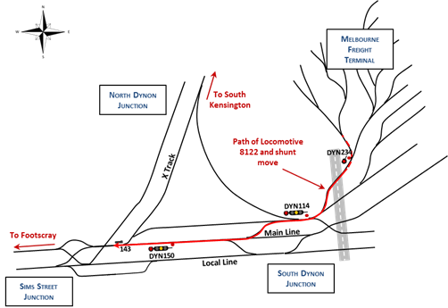
Occurrence summary

Investigation number AO-2014-086
Occurrence date 02/05/2014
Location 43 km NW of Barcaldine Airport
State Queensland
Report release date 05/02/2016
Report status Final
Investigation level Defined
Investigation type Occurrence Investigation
Investigation status Completed
Mode of transport Aviation
Aviation occurrence category In-flight break-up
Occurrence class Accident
Highest injury level Fatal

Aircraft details

Manufacturer Amateur Built Aircraft
Model Cicare CH-7B
Registration VH-SWQ
Serial number 0011
Sector Helicopter
Operation type Aerial Work
Damage Destroyed

Engine power loss involving Airbus A330, VN-A371, at Melbourne Airport, Victoria, on 6 May 2014

Final report

What happened

On 6 May 2014, an Airbus A330 aircraft, operated by Vietnam Airlines and powered by Pratt and Whitney PW4168A engines, was conducting a regular passenger service from Melbourne, Victoria to Ho Chi Minh City, Vietnam. During the take-off roll, the crew received indications that the right engine had failed. The flight crew responded by discontinuing the take‑off. There were no injuries to passengers or crew.

Examination of the right engine determined that it had sustained an uncontained failure of the stage four low‑pressure turbine. Fragments of the turbine exited the engine via perforations in the low-pressure turbine front case but were retained within the engine cowls. Turbine debris exiting the exhaust duct damaged the right inboard and outboard flaps, flap fairings and a spoiler.

What the ATSB found

The ATSB found that the engine failed due to high-cycle fatigue cracking and the fracture of a single stage four low-pressure turbine blade. Release of the fractured blade resulted in the subsequent failure of the turbine. The fatigue crack initiation point on the remaining blade stub of the fractured blade was obscured by damage from rotational contact that occurred during the engine failure sequence. This prevented the ATSB from determining whether any pre-existing material anomaly or damage contributed to the crack initiation.

No similar failures in Pratt and Whitney PW4168A engines were identified.

The ATSB found the flight crew’s handling of the rejected take-off reduced the risk of a runway excursion, preventing further damage to the aircraft or injury to passengers or crew.

Safety message

Although in this case the cause of the turbine blade failure could not be identified, this occurrence highlights the benefits of timely and appropriate flight crew action in response to an unexpected engine failure on take-off.

PW4168A engine S/N P733510

PW4168A engine S/N P733510Source: United States National Transportation Safety BoardPW4168A engine S/N P733510Source: United States National Transportation Safety Board
Source: United States National Transportation Safety Board

The occurrence

At 1052 Eastern Standard Time[1] on 6 May 2014 the flight crew of an Airbus A330 aircraft, registered VN-A371, commenced a take-off roll on runway 27[2] at Melbourne Airport, Victoria (Figure 1). The flight was a regular passenger service to Ho Chi Minh City, Vietnam and was operated by Vietnam Airlines.

Figure 1: Melbourne Airport runway diagram

Figure 1: Melbourne Airport runway diagram

Source: Airservices Australia, En Route Supplement Australia. Modified by the ATSB

After positioning the aircraft at the runway threshold, the flight crew advanced the thrust levers for take-off. Both engines spooled up[3] normally, accelerating the aircraft toward a V1[4] airspeed of 120 kt.

As the aircraft reached an airspeed of 89 kt, a loud ‘bang’ was heard in the cockpit. In response, the flight crew initiated the rejected take‑off procedure by fully retarding the thrust levers.

Retarding the thrust levers initiated maximum autobraking and activated the aircraft’s spoilers. The crew then selected reverse thrust, further decelerating the aircraft. The flight crew maintained directional control and brought the aircraft to a stop at the intersection of runways 09/27 and 16/34 using manual braking.

After shutting down both engines, the flight crew advised air traffic control of the reason for the rejected take-off. Fire and emergency services were mobilised to the aircraft where, after inspection, they informed the flight crew that no engine or wheel brake fire was apparent. The attending ground staff informed the flight crew and control tower that there was debris along the runway and near the right engine. There were also patches of smouldering grass adjacent to the runway.

The aircraft was towed to a terminal gate to disembark passengers. Both runways were re-opened following removal of the aircraft and associated debris. There were no reported injuries as a result of the occurrence.

A subsequent technical examination determined that the right engine had sustained an uncontained failure of the low-pressure turbine (Figure 2).

Recorded information showed that the flight crew did not verbalise any operational anomalies with the aircraft prior to take-off or during the initial take-off roll. Similarly, there were no significant discrepancies recorded in the aircraft’s recorded engine data.

Figure 2: Right engine low-pressure turbine damage, looking forward from the exhaust duct

Figure 2: Right engine low-pressure turbine damage, looking forward from the exhaust duct

Source: ATSB

__________

  1. Eastern Standard Time (EST) was Coordinated Universal Time (UTC) + 10 hours.
  2. The runway number represents the magnetic heading of the runway.
  3. Acceleration in engine rpm, normally in respect of turbofan or turbojet engines.
  4. V1: the critical engine failure speed or decision speed required for take-off. Engine failure below V1 should result in a rejected take-off; above this speed, the take-off should be continued.

Safety analysis

Introduction

At 89 kt during the take-off roll, the aircraft’s right engine failed. The flight crew responded appropriately, successfully bringing the aircraft to a stop on the runway. Although the failure was uncontained, debris that exited via the low-pressure turbine (LPT) front case perforations was retained within the engine cowls. Debris exiting via the exhaust duct, damaged several flight control surfaces, however, this did not affect their operation.

This analysis will consider the engine failure sequence and the possible origins of the fatigue cracking in the stub of turbine blade 120 in stage four of the LPT. In addition, the high-cycle fatigue (HCF) cracking identified with 19 of the engines other stage four LPT blades will be discussed.

Engine failure

Turbine blade 120 failed as a result of HCF crack initiation and progression from the blade’s leading edge, to the point where the remaining material failed in overstress. The crack origin could not be examined for material anomaly or damage due to clashing damage from a number of stage four vane clusters. However, metal smearing over the HCF crack surface indicated that the cracking preceded the clashing damage. Despite being unable to determine the factors contributing to the cracking of blade 120, the extent of the cracking indicated that it was most likely the first blade to be released in the failure sequence.

The ATSB and Pratt and Whitney were not able to conclusively determine why the vane clusters contacted the fourth stage LPT blades. The case tear resulting from the failure of blade 120 was in the same location as the vane clusters that were identified as being loose and disengaged. It is possible that distortion and damage to the structure retaining the stage four vane clusters resulted in their contact with the rotating blades of the stage four LPT rotor. However, it is also possible that the vane clusters were displaced by an unidentified mechanism resulting in contact with the stage four blades and the initiation of HCF fatigue cracking in blade 120. In this scenario, further aft movement followed, resulting in the metal smearing observed on the fracture surface of blade 120.

In addition to blade 120, HCF cracking was found in 19 other stage four LPT blades. These blades exhibited minor cracking when compared to blade 120 but also exhibited similar clashing damage as sustained by blade 120. Less oxidisation on blade 18, compared to blade 120, indicated that the blade 18 fracture surface was exposed to the gas stream for less time than blade 120. Further, the HCF fracture surface on blade 18 was less advanced at the same distance from the blade’s leading edge compared to blade 120. This supports the cracking in blade 18 occurring later in the engine failure sequence than the cracking in blade 120, probably after the clashing commenced. It was therefore considered that the most likely initiator of the minor fatigue cracking in the 19 other blades resulted from their contact with the fourth stage vanes.

The ATSB did not identify any other similar failures that would indicate a systemic issue with the Pratt and Whitney PW4168A engines. No anomalies with the previous maintenance and repair of the LPT module or blade 120 were identified.

Crew actions

Recorded aircraft data indicated that the flight crew’s preparation of the aircraft for take-off was appropriate. During the rejected take-off, the flight crew responded effectively and communicated with the control tower and attending emergency services.

Context

Aircraft information

Engine description

The aircraft was powered by two Pratt and Whitney PW4168A high-bypass ratio turbofan engines. The PW4168A is a twin‑spool engine consisting of high-and low-pressure rotors (Figure 3). The low-pressure rotor consists of a single stage fan and a 5-stage compressor that is driven by a 5-stage turbine on a common shaft. The high-pressure rotor consists of 11 compressor stages that are driven by a 2-stage turbine.

Numbering in all engine modules is from the front to the back of the engine. The fan is stage 1 of the compressor while the low-pressure compressor stage numbers are 1.3, 1.6, 2, 3, and 4. The high‑pressure compressor stages are numbered 5 through 15. The high-pressure turbine stages are numbered 1 and 2 and the low-pressure turbine (LPT) stages are numbered 3 through 7. Numbering convention in the compressor sections is that the rotor and stator following it share the same stage number. In the turbine sections, the guide vanes and following rotors share the same stage number.

All directional references in relation to the engine rotors are made from aft, looking forward. Blade numbering is in the circumferential direction starting with number one at the 12 o’clock position and progressing sequentially clockwise. The engine rotates in the clockwise direction.

Figure 3: Cross-section view of the PW4168A engine

Figure 3: Cross-section view of the PW4168A engine

Source: Pratt and Whitney

Engine maintenance

As part of their investigation of this occurrence, Pratt and Whitney reviewed the engine records for the last overhaul of the LPT, which occurred in 2011. The document review was focused on the stage four LPT blades and vane clusters and the front case. All repairs were found to be consistent with the module’s component inspection and repair manual.

Damage to the aircraft

The engine cowls contained liberated LPT fragments that exited the engine radially via a 38 cm perforation in the LPT front case. There was no other damage associated with the LPT case rupture.

LPT debris exited the exhaust duct and damaged the right inboard and outboard flaps, flap fairings, and the No. 2 spoiler. This damage did not affect the operation of any aircraft systems.

Initial engine disassembly and examination

The right engine, serial number P733510, was removed from the aircraft and shipped to a maintenance facility in Singapore for disassembly and examination under the supervision of the United States National Transportation Safety Board (NTSB). The examination determined that the engine lost power due to a failure in stage four of the LPT. Turbine blade stub number 120 (of 130) exhibited a fracture surface that was visually different to the remainder of the fractured blades (Figure 4).

Additionally, stage four LPT vane clusters numbered 40-44 were loose and askew near their originally-installed positions. This area coincided with the tear at the 11–12 o’clock position in the LPT front case (Figure 5).

The ATSB conducted a preliminary examination of the set of fractured stage four LPT blade stubs. All of the blades were fractured close to the blade platform and exhibited similar leading edge damage. This was consistent with rotational contact or ‘clashing’ between the blades’ leading edges and a stationary component.

The fracture surface of the stub of turbine blade 120 contained a significant region of high-cycle fatigue cracking, probably originating from the leading edge (Figure 6). The fatigue crack origin had been machined away by the clashing damage and, as a result, the presence of any pre-existing material anomaly or damage in the blade could not be determined.

The stage four LPT blade stubs, vane clusters and front case were subsequently forwarded to Pratt and Whitney in the United States for detailed examination under the supervision of the NTSB.

Figure 4: A number of the fractured stage four low‑pressure turbine blade stubs, with the stub of blade 120 highlighted

Figure 4: A number of the fractured stage four low‑pressure turbine blade stubs, with the stub of blade 120 highlighted

Source: NTSB, annotated by the ATSB

Figure 5: Case tear and the location of the loose vane clusters (vane clusters 40–44 are not present in the image)

Figure 5: Case tear and the location of the loose vane clusters (vane clusters 40–44 are not present in the image)

Source: NTSB, annotated by the ATSB

Pratt and Whitney component examination

Stage four low‑pressure turbine blades

In addition to confirming the high-cycle fatigue cracking in turbine blade 120, detailed examination by Pratt and Whitney identified evidence of fatigue crack progression adjacent to the leading edge damage in 19 other blades. However, blade 120 exhibited 0.7 inches (18 mm) of fatigue progression, which was significantly greater than the 0.01 to 0.089 inches (0.25–2.3 mm) on the other 19 blades. The fatigue region of blade 120 was also more heavily oxidised, due to exposure to the gas stream, than the next most fatigued blade (blade 18). Blade 120 was therefore considered likely to have been the first to fracture (Figure 6).

The origin of the fatigue cracks in each blade had been machined away by clashing damage (Figure 7). Blade material was also smeared over portions of the fatigue region of blade 120, adjacent to the clashing damage. This indicated that the fatigue cracking preceded the clashing damage (Figure 8). By contrast, no smearing was observed over the fracture surface of blade 18 (Figure 9).

Figure 6: Blade 120 fracture surface, showing the region of high-cycle fatigue, the clashing damage and the final overstress fracture

Figure 6: Blade 120 fracture surface, showing the region of high-cycle fatigue, the clashing damage and the final overstress fracture

Source: Pratt and Whitney, annotated by the ATSB

Figure 7: Blade 120 fatigue region, with leading edge clashing damage indicated on the left

Figure 7: Blade 120 fatigue region, with leading edge clashing damage indicated on the left

Source: Pratt and Whitney, annotated by the ATSB

Figure 8: Blade 120 fracture surface, showing metal smearing

Figure 8: Blade 120 fracture surface, showing metal smearing

Source: Pratt and Whitney, annotated by the ATSB

Figure 9: Blade No. 18, showing a fatigue progression of 0.089 inches (as compared to 0.7 inches in blade No. 120 before failure)

Figure 9: Blade No. 18, showing a fatigue progression of 0.089 inches (as compared to 0.7 inches in blade No. 120 before failure)

Source: Pratt and Whitney, annotated by the ATSB

Low‑pressure turbine front case

The LPT front case exhibited a 38 cm circumferential tear, with associated outward deformation, from the 11 to the 12 o’clock position in the stage four rotor’s plane of rotation. A single, unidentified airfoil was wedged in the breach (Figure 10). In addition, a 2.5 cm circumferential puncture was observed at the 6 o’clock position of the front case in the stage four rotor plane of rotation (Figure 11).

Sections of the LPT front case adjacent to the 38 cm and 2.5 cm perforations were tested for hardness, wall thickness and grain size. The results of these tests found that the:

  • hardness measurements were consistent with applicable standards
  • wall thickness and grain size measurements for both sections conformed to Pratt and Whitney specifications.

Figure 10: Low‑pressure turbine front case tear at the 11–12 o’clock position. Note that the scale is in inches and the view is looking aft

Figure 10: Low‑pressure turbine front case tear at the 11–12 o’clock position. Note that the scale is in inches and the view is looking aft

Source: NTSB

Figure 11: Low‑pressure turbine front case tear at the 6 o’clock position. Note that the scale is in inches and the view is looking aft

Figure 11: Low‑pressure turbine front case tear at the 6 o’clock position. Note that the scale is in inches and the view is looking aft

Source: NTSB

Figure 12: Stage four low‑pressure turbine vane cluster showing clashing damage to the inside diameter of the shroud and aerofoils

Figure 12: Stage four low pressure turbine vane cluster showing clashing damage to the inside diameter of the shroud and aerofoils
Source: NTSB
Stage four low‑pressure turbine vanes

Nine consecutive stage four LPT vane clusters from positions 36–44 exhibited clashing damage on the aft end of their inside diameter shrouds. Of these clusters, three also exhibited trailing edge clashing damage on the vane aerofoils (Figure 12). The clashing damage resulted from contact with the rotating stage four LPT blades.

Previous occurrences

Pratt and Whitney advised the ATSB of three previous stage four LPT failures in the PW4000 fleet of engines which includes PW4168A engine. Although the reported events occurred in stage four of the LPT, the failure mechanisms differed from this event.

Sources and submissions

Sources of information

The sources of information during the investigation included the:

  • United States National Transportation Safety Board
  • Pratt and Whitney
  • Vietnam Airlines
  • Airbus.

Submissions

Under Part 4, Division 2 (Investigation Reports), Section 26 of the Transport Safety Investigation Act 2003 (the Act), the ATSB may provide a draft report, on a confidential basis, to any person whom the ATSB considers appropriate. Section 26 (1) (a) of the Act allows a person receiving a draft report to make submissions to the ATSB about the draft report.

A draft of this report was provided to the aircraft operating flight crew, Airbus, Vietnam Airlines, the Civil Aviation Authority of Vietnam, Pratt and Whitney, the United States National Transportation Safety Board, the Bureau d'Enquêtes et d'Analyses pour la sécurité de l'aviation civile and the Civil Aviation Safety Authority.

Submissions were received from Airbus, Pratt and Whitney, Vietnam Airlines and the Civil Aviation Safety Authority. The submissions were reviewed and where considered appropriate, the text of the report was amended accordingly.

Findings

From the evidence available, the following findings are made with respect to the uncontained engine failure in Airbus A330, registered VN-A371 and operated by Vietnam Airlines, which occurred at Melbourne Airport, Victoria on 6 May 2014. These findings should not be read as apportioning blame or liability to any particular organisation or individual.

Contributing factors

  • The engine failure was initiated by the failure of a blade in stage four of the low-pressure turbine due to high-cycle fatigue cracking, which originated at the aerofoil’s leading edge.
  • Cascading fracture and release of stage four turbine blades resulted in perforation of the low‑pressure turbine front case and damage to the airframe from debris exiting via the exhaust duct.

Other findings

  • The flight crew’s handling of the rejected take-off reduced the risk of a runway excursion, preventing further damage to the aircraft and/or injury to passengers or crew.

Purpose of safety investigations & publishing information

Purpose of safety investigations

The objective of a safety investigation is to enhance transport safety. This is done through: 

  • identifying safety issues and facilitating safety action to address those issues
  • providing information about occurrences and their associated safety factors to facilitate learning within the transport industry.

It is not a function of the ATSB to apportion blame or provide a means for determining liability. At the same time, an investigation report must include factual material of sufficient weight to support the analysis and findings. At all times the ATSB endeavours to balance the use of material that could imply adverse comment with the need to properly explain what happened, and why, in a fair and unbiased manner. The ATSB does not investigate for the purpose of taking administrative, regulatory or criminal action.

Terminology

An explanation of terminology used in ATSB investigation reports is available here. This includes terms such as occurrence, contributing factor, other factor that increased risk, and safety issue.

Publishing information

Released in accordance with section 25 of the Transport Safety Investigation Act 2003

Published by: Australian Transport Safety Bureau

© Commonwealth of Australia 2017

image_5.png

Ownership of intellectual property rights in this publication

Unless otherwise noted, copyright (and any other intellectual property rights, if any) in this report publication is owned by the Commonwealth of Australia.

Creative Commons licence

With the exception of the Coat of Arms, ATSB logo, and photos and graphics in which a third party holds copyright, this publication is licensed under a Creative Commons Attribution 3.0 Australia licence.

Creative Commons Attribution 3.0 Australia Licence is a standard form licence agreement that allows you to copy, distribute, transmit and adapt this publication provided that you attribute the work.

The ATSB’s preference is that you attribute this publication (and any material sourced from it) using the following wording: Source: Australian Transport Safety Bureau

Copyright in material obtained from other agencies, private individuals or organisations, belongs to those agencies, individuals or organisations. Where you wish to use their material, you will need to contact them directly.
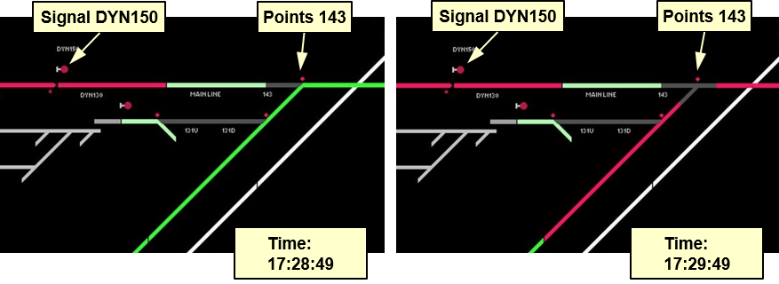
Occurrence summary

Investigation number AO-2014-081
Occurrence date 06/05/2014
Location Melbourne Airport
State Victoria
Report release date 01/06/2017
Report status Final
Investigation level Systemic
Investigation type Occurrence Investigation
Investigation status Completed
Mode of transport Aviation
Aviation occurrence category Engine failure or malfunction
Occurrence class Incident
Highest injury level None

Aircraft details

Manufacturer Airbus
Model A330-223
Registration VN-A371
Serial number 275
Aircraft operator Vietnam Airlines
Sector Jet
Operation type Air Transport High Capacity
Departure point Melbourne, Vic.
Destination Ho Chi Minh City, Vietnam
Damage Substantial