On 13 April 2013, an Indonesian registered B737-800 aircraft collided with water on approach to Denpasar Airport, Indonesia.
As the accident took place in Indonesia, the Indonesian National Transportation Safety Committee (NTSC) is responsible for investigating this occurrence, consistent with Indonesia’s obligations as State of Occurrence under Annex 13 to the Convention on International Civil Aviation Aircraft Accident and Incident Investigation (Annex 13).
The NTSC requested ATSB assistance to seek weather and visibility reports from Australian flight crews operating into Denpasar close to the time of the accident. To facilitate this support, the ATSB appointed an accredited representative in accordance with paragraph 5.23 of Annex 13 and, in order to protect the information supplied by the NTSC, commenced an external investigation under the Transport Safety Investigation Act 2003. The ATSB completed its work as accredited representative on 26 April 2013.
The National Transport Safety Committee of Indonesia is responsible for releasing the investigation report.
National Transportation Safety Committee Ministry Of Transportation Republic Of Indonesia Transportation Building 3rd Floor Jalan Medan Merdeka Timur No. 5 Jakarta Pusat 10110 Indonesia
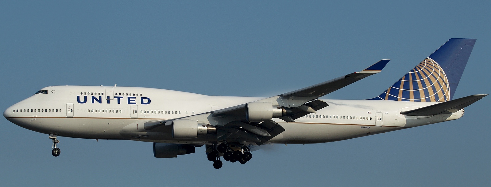
On 22 April 2013, the flight crew of a United Airlines Incorporated Boeing 747-422, registered N119UA, flew from Sydney, New South Wales to Melbourne, Victoria. At Melbourne, the crew taxied to gate D5 and stopped, applying the parking brake. Shortly after stopping, the aircraft started to move forward again slowly. The flight crew realised the aircraft was moving and re-applied the brakes. The aircraft’s left wing collided with the aerobridge before the movement had stopped. No one was injured during the occurrence and the aircraft sustained minor damage.
What the ATSB found
After stopping at the gate, the aircraft parking brake was likely inadvertently released before the nose wheels were chocked and the engines shut down. The flight crew’s attention was inside the cockpit, focused on shutting down the engines. As such they were not actively monitoring aircraft movement, nor was that required at this stage. In addition, the parking guidance system at the gate was set to emergency stop mode by ground personnel when the aircraft first arrived, removing the possibility of an alert for the flight crew that the aircraft had moved. The flight crew became aware of the movement when the captain detected motion through peripheral vision. The very slow acceleration, combined with a lack of visual cues available to the flight crew made it difficult for the crew to detect the movement in time to prevent the collision.
Safety message
This occurrence highlights the importance of flight crew remaining aware of the possibility of aircraft movement whenever the engines are running as aircraft movement, particularly if it is slow, is difficult to detect. Additionally, ground support crew are reminded of the need to leave the parking guidance system in normal mode, unless an emergency stop is required.
Boeing 747 N119UA
Source: Benedikt Mathweis
Context
Personnel information
Flight crew
The captain had about 28,000 hours aeronautical experience with 15 years flying Boeing 747 aircraft.
The first officer (FO) had about 10,000 hours aeronautical experience and had recently completed training for the Boeing 747 type rating, having 16 hours experience on this aircraft type. The flight from Sydney to Melbourne was part of the initial operating experience[4] requirement and was the FO’s first flight as pilot monitoring under the captain’s supervision.
Fatigue
Both crew reported that they were well rested after having about 25 hours rostered time off prior to commencing duty for the 1.5 hour flight from Sydney to Melbourne. They had been rostered together for the previous 3 days. The FO’s roster and reported sleep during that period indicated that fatigue should not have been an issue.
The captain’s sleep history was not obtained. However, as they had been working to the same rostered schedule as the FO, there was nothing to indicate that fatigue would have been an issue.
Workload
The captain reported feeling that there was a slight increase in their workload because this was the FO’s first flight as pilot monitoring. That workload increase was expected and the captain reported no problem in handling it.
Aircraft information
Wheel brake system
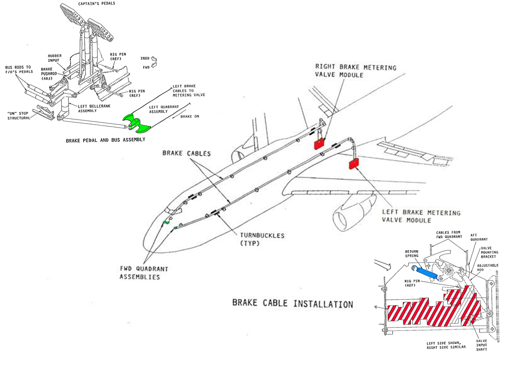
The Boeing 747 has independent left and right side, hydraulically-powered wheel brakes to all the main landing gear wheels.
The wheel brakes are controlled by applying force at the top of the captain’s or FO’s rudder pedals. The rudder pedals for each pilot are mechanically interconnected. Therefore, either pilot can apply input to all wheel brakes as required.
Activating the brakes allows the brake metering valves to supply hydraulic pressure to the wheel brakes. Removing the force from the tops of the rudder pedals returns the metering valves to neutral through the action of the return springs (Figure 2). This relieves the hydraulic pressure to the wheel brakes.
Flight crew normally position their feet to operate the rudder with their heels on the floor. In that position, the height of the rudder pedals above the floor makes it necessary for them to slide their feet up the rudder pedals to apply the wheel brakes.
Figure 2: Boeing B747-400 wheel brake system schematic. The upper-left image shows the mechanical interconnection between depressing the top of the rudder pedal and the movement of the brake cables, the centre image the wheel brake cables’ layout and the lower-right image a hydraulic metering valve (the return spring is shown in blue)
Source: Boeing, modified by the ATSB
Parking brake
The 747-400 wheel brake system incorporates a parking brake function that retains hydraulic pressure in the wheel brakes. The parking brake is used during:
the installation or removal of chocks after an aircraft stops or is about to move in the bay
taxi manoeuvres, when the aircraft must wait for other traffic to clear
short-term parking.
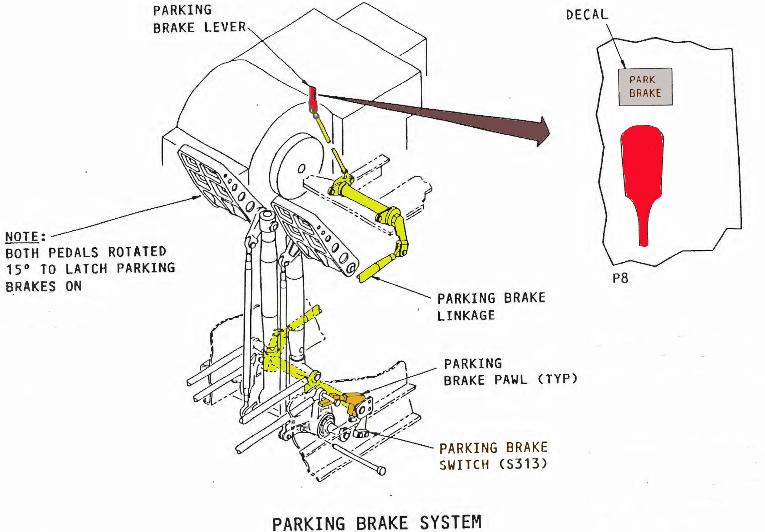
The parking brake system is controlled using a parking brake lever situated on the left (captain’s) side of the flight deck centre console. The lever is connected mechanically to a pawl at the rudder pedals (Figure 3). Once the tops of either pilot’s rudder pedals are pressed to at least 15°, the lever can be raised allowing engagement of the pawl. The pawl retains the rudder pedals in this position and the metering valves allow continued supply of hydraulic pressure to the brakes.
The pawls are themselves held in position by the force applied by the metering valve return springs. Applying additional force to the tops of the rudder pedals results in the pawls moving away from the ‘locked’ position, releasing the wheel brakes.
The parking brake also activates an isolation valve to trap the hydraulic pressure in the brake lines at the wheel brakes. As a result, once the parking brake is set, fluctuations in hydraulic system pressure do not have an effect on the wheel brakes.
Figure 3: Boeing B747-400 Parking brake system, showing the mechanical interconnection (in yellow) between the parking brake lever (in red) and the parking brake pawl (in orange) and the location of parking brake switch (switch S313)
Source: Boeing, modified by the ATSB
Parking brake engagement activates the parking brake switch that in turn annunciates the ‘Park brake set’ message on the engine indicating and crew alerting system (EICAS)[5]. The captain reported seeing this message when the parking brake was engaged.
Aircraft wheel brake system examination
Following the occurrence, a review of data recorded on the aircraft’s central maintenance computer found no defects for the aircraft’s wheel brake system.
United Airlines Incorporated (United) inspected the aircraft’s wheel brake system and conducted a number of functional tests in accordance with the manufacturer’s maintenance manual. No anomalies or defects were found in the aircraft’s wheel brake and parking brake systems.
Airport information
Visual docking guidance system
Gate D5 was equipped with a visual docking guidance system (VDGS). The VDGS provided guidance for crew in terms of aircraft centre-line position and nose wheel position.
Crew use the guidance system to bring the aircraft to a stop at the correct point for an aerobridge disembarkation of passengers. After the aircraft has stopped, the aerobridge is moved forward to the aircraft fuselage.
The normal sequence of operation for the VDGS is as follows:
prior to an aircraft’s arrival, a ground engineer selects the aircraft type on the VDGS control panel
the VDGS starts scanning for the aircraft
the VDGS matches the approaching aircraft with the selected aircraft type and:
- if correct, the VDGS guides the aircraft using directional and speed arrow messages
- if incorrect, the VDGS displays STOP and the aircraft is stopped short (up to about 20 m).
at the correct stop position, the VDGS displays STOP and:
- if the aircraft stops in time, the VDGS waits for 5 seconds and then signals OK, alerting flight crew that parking is complete
- if the aircraft does not stop in time or moves forward more than 30 cm within 5 seconds, the VDGS displays TOO FAR, alerting flight crew that the aircraft has overshot the stop position.
The VDGS control panel includes an emergency stop button that can be activated by ground crew at any time. Once the emergency stop button is activated, the VDGS displays the STOP signal and ceases monitoring the aircraft’s position and movement.
The displayed STOP signal is the same for normal and emergency stopping conditions. However, the STOP signal is displayed for more than 5 seconds for an emergency selection.
Flight crew procedures for use of the VDGS
The VDGS instructions available to the flight crew stated that the OK signal indicated that the aircraft was parked in the correct position but did not provide information about the TOO FAR signal display. The flight crew’s procedures also stated that once the aircraft was chocked, ground staff would manually change the display to CHOCK ON. However, the CHOCK ON message was not available at gate D5. This meant that any communication about the position of the chocks would be verbal.
Ground procedures and actions for use of the VDGS
The ground standard operating procedures (SOP) applicable to gate D5 stated that ground personnel could initiate the emergency stop signal if required. Under those circumstances, once the emergency had been addressed, the ground engineers would marshal the aircraft to complete the parking procedure manually.
As an aircraft approaches the relevant gate, one of the ground crew stands near the VDGS control panel, ready to press the emergency stop button if the need arose. In this occurrence, the VDGS equipment log recorded that, almost immediately after the normal STOP signal was displayed, the emergency stop button was pressed. As a result, the STOP message remained displayed, even though the aircraft started to move again shortly after and collided with the aerobridge about 15 seconds later.
The ground engineers stated that they sometimes pressed the emergency stop button to ensure the STOP message was displayed in good time.
Flight Recorders
Cockpit voice recorder
The aircraft’s cockpit voice recorder[6] continued to record for some time after the aircraft collided with the aerobridge as it remained powered. As a result, the recorder had recorded over the events from the time of the aircraft’s arrival at gate D5, until the collision.
Recorded flight data
The aircraft was equipped with a digital flight data recorder, and a digital aircraft condition monitoring system recorder[7]. Analysis of data from those media showed:
slight movement of the rudder pedals while the aircraft was stopped at the gate
all four engines were running at idle thrust while the aircraft was stopped at the gate
the aircraft was stationary for 4 seconds before commencing forward movement
the forward movement commenced at the same time as the speed brakes were stowed
once the aircraft started to move, there was hardly any further movement on the rudder pedals
all engines were shut down about 5 seconds after the aircraft started to move
about 15 seconds after the aircraft commenced moving, it collided with the aerobridge
at the same time as the aerobridge collision, the wheel brakes were applied.
Flight recorder sampling of the parking brake lever position data occurred once every 64 seconds. At the time the aircraft started to move, the parking brake lever was recorded as being ‘not on’. However, as the occurrence happened between two recorded samples, the actual position of the parking brake lever for the 4 seconds between when the aircraft stopped and commenced movement again, could not be determined.
Additionally, the recorded data indicated that sufficient hydraulic pressure was available to the aircraft wheel brake systems throughout the occurrence.
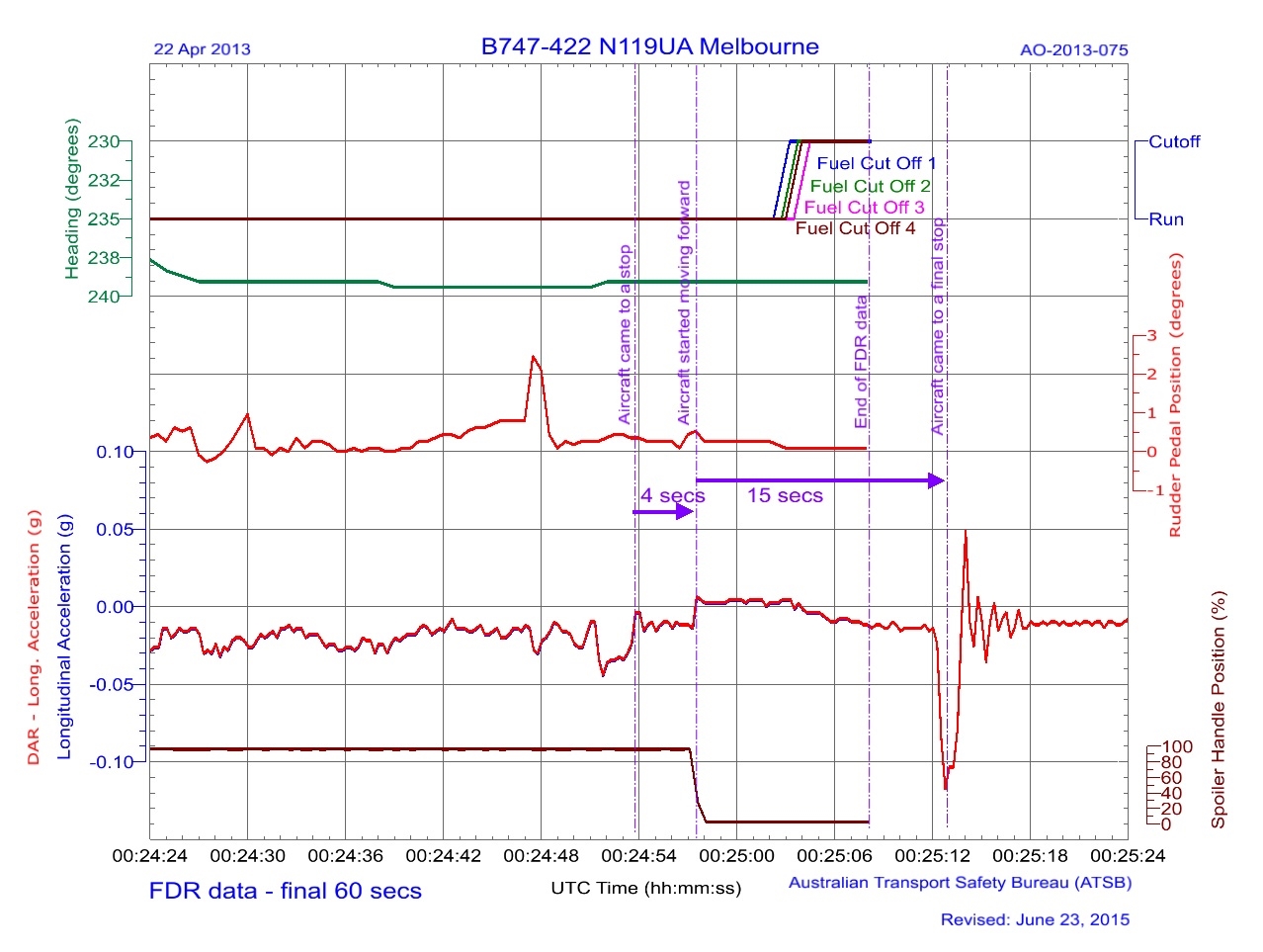
Selected parameters from the recorded flight data are at appendix A.
Wreckage and impact information
Damage to the aircraft
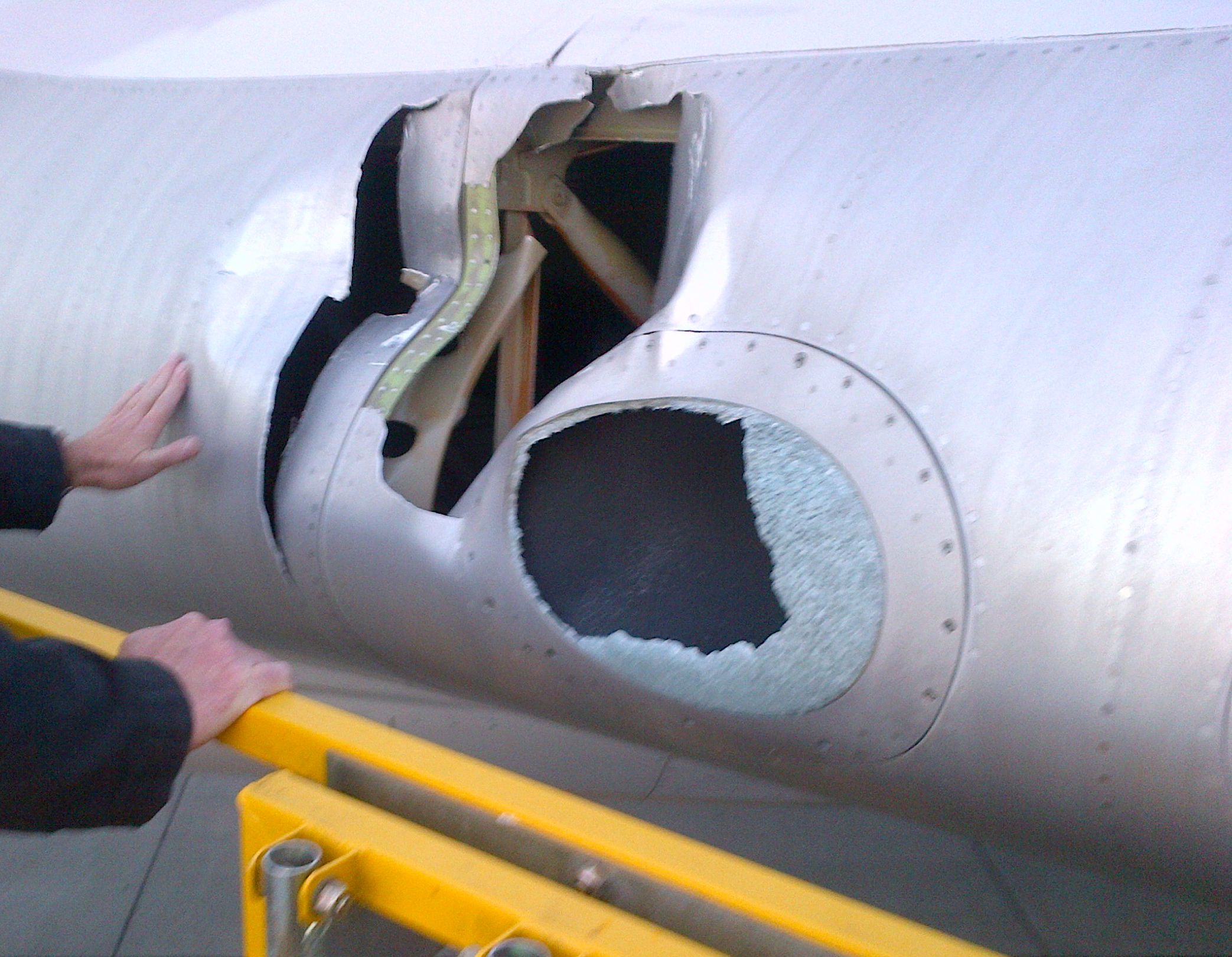
The left wing inboard leading edge was damaged by the collision with the aerobridge (Figure 4). A landing light cover was also damaged. Before the aircraft was ferried to United’s home base, the leading edge and landing light covers were temporarily repaired. Permanent repairs were carried out in the United States.
Figure 4: Close up of the damage to the left wing inboard leading edge and landing light cover
Source: United
Organisational and management information
Ground handling
Another airline was contracted to provide ground handling services to United at Melbourne Airport. There were three ground engineers awaiting the arrival of the aircraft at gate D5. They included a licenced aircraft maintenance engineer (LAME) and two unlicensed aircraft maintenance engineers. Other ground crew were located outside the aircraft’s designated parking area. Additionally, ground staff were positioned at the entrance and halfway along the aerobridge.
The SOP for ground personnel actions upon arrival of an aircraft contained the following steps (in part):
…
4.When meeting an arriving aircraft the person who is assigned to communicate with the flight
crew on the headset must ensure:
a. The aircraft has stopped and brakes are on before connecting the headset.[[8]]
b. All engines are shut down and no abnormal conditions exist (such as tail pipe fire, wheel
or brake fire etc) before disconnecting from the headset.
c .Chocks are placed just Fwd and Aft of the tires on the nose landing gear once the park
brake has been set.
Place chocks Fwd and Aft of the outboard (or inboard) set of tires of each main landing
gear.
…
The engineers stated that they provided ground handling services for a number of different operators and aircraft types. They stated that some operators were proactive with communicating to the ground crew on arrival while others were not.
The LAME reported that the aircraft came to a stop at the designated parking location. The two aircraft mechanical engineers then moved into a position to place a chock at the rear of the nose wheel.[9] After placing the rear chock, they moved to place the forward chock in position. At that moment, the aircraft started to move forward. The engineers expected the aircraft to stop again quickly, but it did not. They became aware of the aircraft’s engines nearing their positions and abandoned any further attempt to chock the wheels.[10] Instead, they rapidly moved clear of the aircraft.
The LAME also reported that they had not spoken to the flight crew before the aircraft started to move again. The LAME stated they had insufficient time or opportunity[11] to connect ground communications to the aircraft.
Flight crew after landing procedures
According to United’s procedures, the after landing flow can be conducted any time after landing, when time permits. The flight crew indicated that it was usually conducted as soon as the aircraft had exited the runway. The procedures stated that the captain’s first action was to stow the speed brake by moving the speed brake lever to the forward stowed position (see the section titled Additional information).
Recorded flight data indicated that all the after landing flow actions were completed by the crew soon after landing, except for retracting the speed brakes. The speed brakes were retracted by the captain after the aircraft stopped at the gate.
The concept of prospective memory is described as ‘remembering to perform an action that cannot be executed when the intention is formed’ (Dismukes, 2006), and is typified by:
an intention to perform an action at some later time when circumstances permit
a delay between forming and executing the intention, typically filled with activities not directly related to the deferred action
the absence of an explicit prompt indicating that it is time to retrieve the intention from memory.
The crew reported that after landing, their focus was on remaining clear of ground traffic and on specific aircraft parking requirements. This focus on different activities may have distracted the crew from retracting the speed brakes until the aircraft arrived at the gate. The captain’s retraction of the speed brake after arriving at gate D5 was consistent with a lapse in prospective memory.
Flight crew parking procedures
The flight crew parking procedures required that once the aircraft had stopped at its intended parking position, the flight crew were to start the parking flow sequence of actions. In this sequence, the captain conducted 11 actions and the FO conducted nine actions. A notice at the start of the actions stated that:
Ground personnel expect the right engines to be shut down, or ready for immediate shut down, upon arrival at the parking location.
The captain’s first action was to set the parking brake lever. The procedure for setting the parking brake stated:
The parking brake lever is pulled to set the brakes, after both pedals are fully depressed.
The captain stated that when applying the parking brake they feel for the ‘click’ in the parking brake lever, and felt that had occurred in this case. In order to feel a click in the parking brake lever, the parking brake lever would already have to be pulled when the brake pedals were pressed. This would have meant that the engaging pin was in contact with the pawl as the pin was moved by pedal depression. That action may have influenced the likelihood of an incomplete parking brake engagement.
To minimise the likelihood of the parking brake not being engaged, the procedure incorporated the following verification actions:
The captain was to check:
- the parking brake lever position - an EICAS memo message PARK BRAKE SET was displayed - the BRAKE SOURCE light was off - there was no aircraft movement.
The FO’s second action was to verify:
- the parking brake lever position - there was no aircraft movement.
Aside from the status of the BRAKE SOURCE light, which was not mentioned at interview, the crew stated that they conducted all of these actions to verify that the parking brake was set and the aircraft was not moving.
The remaining actions directed both pilots’ attention inside the cockpit. They mostly involved the overhead control panel or the centre console between the pilots’ seats. None related to aircraft movement, brake or chock status. Despite both crew having their attention inside, the captain did notice aircraft movement through peripheral vision and the FO reported that the VDGS STOP indication appeared closer, although any change was insidious. In the event, the captain’s perception of the aircraft’s movement did not occur in sufficient time to prevent the collision.
Additional information
Parking brake and speed brake controls
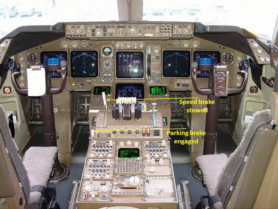
The speed brake lever and the parking brake lever are in the same area of the flight deck, however they are different in size and shape (Figure 5). While the speed brake lever can be moved without any additional action, the parking brake lever only operates in coordination with pressing the brake pedals.
The FO reported paying specific attention to the captain setting the parking brake in Melbourne because of the unintended wheel brake disengagement at Sydney. The FO recalled the parking brake lever remained raised (brake engaged) after the captain removed their hand from the lever.
Figure 5: Cockpit control layout, showing the location of the speed brake and parking brake controls
Source: Boeing, modified by the ATSB
Other occurrences
The aircraft manufacturer reported that it had been notified of an occurrence when a Boeing 747‑400 aircraft started to move after the parking brake had been incompletely engaged. No defect was identified in the aircraft.
A review of the ATSB occurrence database identified seven reported occurrences between 2008 and 2013 in which jet aircraft moved after coming to a stop during parking. Of these:
In one occurrence, the park brake was reportedly set and the aircraft rolled forward on a downslope during engine shutdown. No fault was found with the brake system.
Another occurrence involved a mechanical issue with the park brake, which led to it disengaging.
The remaining five occurrences involved the wheels not being chocked prior to park brake release or having the chocks in the incorrect position.
There were no occurrences relating to inadvertent park brake release.
A review of past occurrences showed that undetected movement following inadvertent disengagement of the parking brake is a rare event. In this occurrence, the aircraft started moving 4 seconds after it was stopped at the gate.
The flight crew reported that the parking brake was set after stopping and an inspection of the aircraft’s wheel brake system and a number of functional checks by United Airlines Incorporated found no anomalies or defects with the aircraft’s wheel or parking brake systems to explain the unintended aircraft movement. The application of the wheel brakes by the captain on detecting the movement would have disengaged the park brake. This was consistent with the as-found position of the park brake handle after the aircraft collided with the aerobridge.
This analysis will examine the defences in place to prevent such an occurrence and the human performance factors identified during the investigation as having influenced the flight crew’s actions and ability to detect the aircraft movement.
Parking brake
When parking at an aerobridge, the wheel brakes are applied and locked on with the parking brake system. The parking brake is the primary means of restraint for the aircraft and is regularly used when the engines are operative.
The captain’s parking brake engagement technique was not entirely consistent with the documented procedure. Despite this, the crew’s subsequent verification checks should have identified if the parking brake did not engage properly. The crew reported that the engine indication and crew alerting system indicated that the parking brake had engaged and both crew reported verifying visually that the aircraft was not moving. As such, it is likely the parking brake had engaged correctly.
The reason why the parking brake disengaged could not be determined. However, recorded data showed rudder pedal movement when the aircraft started to move after the parking brake was initially set. A properly-engaged parking brake cannot be released unless force is applied to the brakes at the top of the rudder pedals. However, the recorded flight data does not record brake pedal movement, preventing confirmation of this action from the recorded data.
Sufficient force to disengage the parking brake is more likely to be applied if a crew member has their feet positioned on the top of the rudder pedals. The captain would have had their feet in this position a short time before, in order to apply the parking brake on arrival at the gate.
The speed brakes were lowered at the same time as the aircraft started to move and this action would have put a demand on the hydraulic system. However, recorded data indicated that sufficient hydraulic pressure remained available to operate the wheel brakes. The parking brake system was independent of the hydraulic supply system, therefore changes to hydraulic pressure would not have affected the parking brake engagement.
Reason (1990) stated that ‘a necessary condition for the occurrence of a slip of action is the presence of attentional “capture” associated with either distraction or preoccupation. This means that wherever else the limited attentional resource is being directed at that moment, it will not be focused on the routine task at hand’. Reason outlined that there are two conditions necessary for a slip of action: the performance of some largely automatic task in familiar surroundings, and a marked degree of attentional capture by something other than the job in hand. The concept of ‘automatic’ action refers to the way that certain tasks can be executed without conscious oversight, thereby limiting the use of processing resources.
Stowing the speed brake was not part of the captain’s usual actions after stopping at the gate. However, this out of sequence action may have been sufficiently distracting to result in the captain’s slip of action to unintentionally activate the wheel brake pedals and release of the parking brake. At other times (such as when setting the parking brake), activating the wheel brake pedals would be intentional.
Aircraft movement
Installation of the wheel chocks
Ground staff normally installed the nose wheel chocks once the aircraft stopped and the parking brake was set. They were in the process of placing them in position when the aircraft moved forward, preventing installation of the forward chock.
The only means of communication between the ground and flight crews on the status of the wheel chocks was via hand or other visual signals, or after the ground crew plugged in their headset. The height of the pilots’ seating, and position of the ground crew generally below the aircraft, meant that visual signalling was generally not practicable in the busy/congested tarmac environment because:
one of the ground crew would need to move away from underneath the nose of the aircraft and into one of the pilot’s view
that pilot would need to establish and maintain visual contact with the ground crew member.
The ground crew’s headset could not be plugged into the nose wheel landing gear intercom socket to allow communication with the flight crew until the aircraft stopped and the parking brake was engaged. The movement of the aircraft before the forward chock was in place prevented ground crew from establishing the intercom link with the crew. This lack of communication, and therefore flight crew understanding of the status of the wheel chocks, emphasised the flight crew’s reliance on the parking brake and on comprehending any subsequent aircraft movement should that brake fail or disengage.
If the ground crew had been able to complete the installation of the nose wheel chocks before the aircraft recommenced moving, the chocks may have prevented that movement. Alternately, if the chocks were unable to prevent the aircraft’s movement, the ‘bump’ as the aircraft rolled up or over the forward chock would likely have alerted the flight crew of the movement.
Flight crew focus
After commencing the parking flow actions, the flight crew’s focus was predominantly inside the flight deck. These actions involved shutting down the engines, which at that stage remained at idle but, until shut down:
given the aircraft’s weight, provided sufficient thrust to move the aircraft if unrestrained
prevented ground crew from approaching the main landing gears and installing the associated wheel chocks.
Therefore, although not inherently conducive to looking outside the flight deck, shutting down the engines was a priority task for the flight crew.
The captain first detected movement via peripheral vision when moving their attention from the overhead panel down to the centre console. One of the main functions of peripheral vision is to detect motion (Monaco and Kalb, 2007). This ability depends on the velocity and duration of the movement, the size of the moving object and its location in the peripheral vision.
Consistent with the first officer’s report of the insidious nature of any movement when glancing out of the cockpit and seeing the VDGS, there was no salient visual stimulus when looking forward from the flight deck. The aircraft’s movement was too slow for the terminal wall to appear to move and, as a result of the ground crew activating the emergency stop function on the visual docking guidance system (VDGS), the VDGS displayed the same STOP message as when the crew first stopped the aircraft.
Utility of the VDGS
Activation of the emergency stop button on the VDGS by the ground crew provided a means for the ground crew to instruct the flight crew to stop immediately. This function was only available until the aircraft stopped at its intended parking position.
In this case, the emergency stop button was pressed immediately after the aircraft stopped the first time. As a result, in addition to the ongoing display of the STOP message, display of the TOO FAR message in the case of the aircraft recommencing moving was inhibited. This meant that, although the first officer reported periodically glancing outside the flight deck and seeing the VDGS, its display would not have assisted the crew identify any aircraft movement.
Findings
From the evidence available, the following findings are made with respect to the collision between an aerobridge and a Boeing Company B747-422, registered N119UA, at Melbourne Airport, Victoria on 22 April 2013. These findings should not be read as apportioning blame or liability to any particular organisation or individual.
Contributing factors
A likely inadvertent disengagement of the parking brake, prior to the aircraft being chocked and while the engines were operating at idle thrust, allowed the aircraft to recommence moving forward.
While the crew were conducting the parking flow, procedural task requirements drew both flight crew members’ attention inside the flight deck. This, combined with the limited visual cues available, reduced their ability to detect the aircraft’s movement in time to prevent the collision.
Other factors that increased risk
The activation of the Visual Docking Guidance System emergency stop function inhibited display of a 'TOO FAR' message, reducing the cues available to crew and increasing the risk that any aircraft movement would not be detected.
Sources and submissions
Sources of information
The sources of information during the investigation included:
the flight crew of N119UA
United Airlines Incorporated (United)
ground staff
Melbourne airport
data from the flight recorders on N119UA.
References
Dismukes, K 2006, ‘Concurrent task management and prospective memory: pilot error as a model for vulnerability of experts’ Proceedings of the Human Factors and Ergonomics Society 50th Annual Meeting – 2006, pp.909-913.
Monaco, W & Kalb, J 2007, Motion detection in the far peripheral visual field, U.S. Army Research Laboratory, Maryland, United States.
Reason, J 1990 Human Error, Cambridge University Press, Cambridge, United Kingdom.
Submissions
Under Part 4, Division 2 (Investigation Reports), Section 26 of the Transport Safety Investigation Act 2003 (the Act), the ATSB may provide a draft report, on a confidential basis, to any person whom the ATSB considers appropriate. Section 26 (1) (a) of the Act allows a person receiving a draft report to make submissions to the ATSB about the draft report.
A draft of this report was provided to United, the flight crew of N119UA and the Civil Aviation Safety Authority.
A submission was received from United. The submission was reviewed and where considered appropriate, the text of the report was amended accordingly.
Appendices
Appendix A - Selected parameters from the recorded flight data when the aircraft arrived at gate D5
Source: ATSB
Explanation
Recorded data
In accordance with the normal aircraft shut down procedures, the digital flight data recorder ceased recording shortly after the engines were shut down. The digital aircraft condition monitoring system recorder is normally switched off later in the shut down sequence. Therefore, the digital monitoring system recorder continued to record information including the longitudinal g[12] parameter. The plot of recorded data above shows data from both flight recorder systems and indicates the sequence of events beginning with the aircraft turning into the parking bay.
Movement
The ATSB derived the aircraft’s speed from variations in longitudinal g, correlated with video recordings from the airport terminal. This showed that:
From 0024:24, the aircraft turned into the parking bay, turning slightly right. As the aircraft approached the parking bay, there were variations in rudder pedal position and longitudinal g.
At 0024:52, there was an increasing negative longitudinal g, or deceleration, which reduced as the aircraft stopped at 0024:54. About 4 seconds later, a positive change of about 0.02 longitudinal g indicated that the aircraft began to move forward again.
The aircraft gradually decelerated as the engines were shut down by the fight crew actioning the fuel cut-off for each engine, although a video recording indicated the aircraft continued to move forward.
At 0025:13, a sharp deceleration indicated the aircraft was being stopped.
Rudder pedal position
Rudder pedal position has no influence on the aircraft when taxying at slow speed. At this speed, the aircraft is steered by a separate control, the tiller, which controls nose wheel steering. However, while taxying an aircraft, the handling pilot’s feet rest on the rudder pedals. This is done so the pilot can operate the wheel brakes by applying force to the tops of the respective rudder pedals. The continuous slight movement in the rudder pedals between when the aircraft came to a stop until the aircraft started to move again is consistent with someone having their feet resting on the rudder pedals until that time.
Speed brake position
The speed brakes are hinged panels on the upper surface of the wing that may be extended to reduce aerodynamic lift from a wing. A speed brake may also be called a spoiler, as can be seen in this plot. The spoiler handle position was moved from 100 per cent to 0 per cent, commanding a retraction of the spoilers at the same time as the aircraft started to move.
The objective of a safety investigation is to enhance transport safety. This is done through:
identifying safety issues and facilitating safety action to address those issues
providing information about occurrences and their associated safety factors to facilitate learning within the transport industry.
It is not a function of the ATSB to apportion blame or provide a means for determining liability. At the same time, an investigation report must include factual material of sufficient weight to support the analysis and findings. At all times the ATSB endeavours to balance the use of material that could imply adverse comment with the need to properly explain what happened, and why, in a fair and unbiased manner. The ATSB does not investigate for the purpose of taking administrative, regulatory or criminal action.
Terminology
An explanation of terminology used in ATSB investigation reports is available here. This includes terms such as occurrence, contributing factor, other factor that increased risk, and safety issue.
Publishing information
Released in accordance with section 25 of the Transport Safety Investigation Act 2003
Ownership of intellectual property rights in this publication
Unless otherwise noted, copyright (and any other intellectual property rights, if any) in this report publication is owned by the Commonwealth of Australia.
Creative Commons licence
With the exception of the Coat of Arms, ATSB logo, and photos and graphics in which a third party holds copyright, this publication is licensed under a Creative Commons Attribution 3.0 Australia licence.
Creative Commons Attribution 3.0 Australia Licence is a standard form licence agreement that allows you to copy, distribute, transmit and adapt this publication provided that you attribute the work.
The ATSB’s preference is that you attribute this publication (and any material sourced from it) using the following wording: Source: Australian Transport Safety Bureau
Copyright in material obtained from other agencies, private individuals or organisations, belongs to those agencies, individuals or organisations. Where you wish to use their material, you will need to contact them directly.
On 11 April 2013, at about 0851 Eastern Standard Time, an Aero Commander 500 aircraft, registered VH-TQA (TQA), departed Townsville, Queensland on a private flight to Moorabbin, Victoria, under the instrument flight rules (IFR).
After take-off, passing through 200 ft, the pilot attempted to establish communications with Townsville Approach ATC, but no response was received. The Approach controller reported they did not hear this call.
While passing through 400 ft, the pilot checked his radios to confirm the correct frequency had been selected. At the same time, the Tower controller alerted the Approach controller that TQA did not appear to be turning left at 1 NM, as per the published standard instrument departure (SID) procedure. As TQA passed through 500 ft, the pilot again contacted the Approach controller. The Approach controller responded and was about to question the pilot regarding the aircraft’s track, when he noted that TQA’s predicted tracking line on the radar display indicated that a turn in the direction of the SID had commenced.
At the same time, the pilot suspected TQA may have had a partial engine failure, and started troubleshooting actions.
When at about 3 NM, the Approach controller noted that the aircraft’s predicted tracking line had changed and was pointing to the south, indicating the aircraft was not on the SID. The Approach controller reminded the pilot of the SID requirement to turn onto a track of 105o at 1 NM.
Believing this was a radar vector, the pilot read back ‘left 105°’ and commenced a turn onto that heading. The aircraft was 4 NM from Townsville Airport when it turned and about 2,000 ft when it turned, putting it in close proximity to Mount Stuart.
This incident highlights the importance of maintaining situational awareness. Much of the research on this topic provides loss of situational awareness mitigation concepts.
On 18 April 2013, a Robinson R22 helicopter registered VH‑HLY (HLY), departed from Cloncurry tracking to the north. At the same time, a Bombardier DHC‑8 aircraft, registered VH‑QOB (QOB), was conducting a scheduled service from Townsville, Queensland to Cloncurry.
The pilot of HLY broadcast his intentions and about 2 minutes later, while taxiing towards the runway intersection he looked ahead and to the left along the main runway in the most common direction of arriving aircraft operations into Cloncurry.
The pilot in command (PIC) of QOB made inbound broadcasts at 30, 10 and 3 NM on the common traffic advisory frequency (CTAF) and conducted a straight-in approach to land on runway 30.
As the helicopter crossed the runway, the pilot realised that he had not heard a response from the aerodrome frequency response unit (AFRU) on the CTAF. Simultaneously, he heard a call from QOB, which was in the landing flare on short final for runway 30, stating that he should get off the runway.
The pilot of HLY then looked to his right and observed QOB on the runway. He realised he had been broadcasting on the ultra-high frequency (UHF) radio, although he could hear calls on the very high frequency (VHF) CTAF.
HLY departed across the runway at about 100 feet. The pilot of HLY estimated that, when QOB had touched down, the distance between the aircraft and HLY was about 1,000 m horizontally. The PIC of QOB estimated that the horizontal separation reduced to about 200 m.
This incident highlights the importance of conducting pre-flight checks thoroughly and maintaining vigilance particularly at non-controlled aerodromes.
On 24 March 2013, a Vans RV-12 amateur-built aircraft collided with terrain shortly after take-off from Lismore Airport, New South Wales. The pilot was fatally injured.
The NSW police service was responsible for investigating the accident on behalf of the state Coroner. On 10 April 2013, investigating officers contacted the ATSB and requested assistance with the recovery of data from the aircraft’s Dynon Avionics Skyview system. The display unit and control module were subsequently sent to the ATSB for examination and an investigation was initiated under the provisions of the Transport Safety Investigation Act 2003.
The ATSB liaised with the manufacturer of the display unit and was able to successfully disassemble and download flight data stored on the unit. The flight data contained the accident flight, however the flight data ended moments before the aircraft collided with terrain. An archive file, containing the downloaded flight data is released as Appendix A to this report and contains four comma-separated value (.csv) files. Attention is directed to the Data Limitations section of the main report, should any analysis of the recorded information be undertaken.
The ATSB report and the associated data were prepared by the ATSB to assist the NSW police investigation. The ATSB report, including the referenced data files, has been released under section 25 of the Transport Safety Investigation Act 2003 (the Act). Per section 27(1) of the Act, this report and the appended data files are not admissible in evidence in any civil or criminal proceedings. The device containing the original data was returned to the NSW Police Service on 13 November 2013.
On 17 April 2013, the crew of a Piper PA31-350 aircraft, registered VH‑EDV (EDV), were conducting a flight from Flinders Island, Tasmania to Moorabbin Airport, Victoria under instrument flight rules (IFR). During the descent to Moorabbin, the aircraft entered visual meteorological conditions, and the crew advised that they intended to track visually via the visual flight rules (VFR) reporting point at Carrum to Moorabbin.
At about the same time, a Cessna R172K, registered VH‑JQQ (JQQ), was in transit via the VFR Coastal Route for the Tyabb, Victoria area. To remain in gliding distance of the coast, the pilot of the single-engine aircraft JQQ, elected to cross the coastline at Ricketts Point. With a clearance obtained from Moorabbin Tower, JQQ transited the western edge of the Moorabbin control zone flying about 1.5 NM off the coast, from Ricketts Point to Carrum at 1,500 ft.
EDV called Moorabbin Tower at Carrum, at about 1,500 ft on a descent profile to arrive at the entry of Moorabbin control zone at the required altitude of 1,000 ft.
Less than a minute later, at about 1022, just over 5 NM south-west of Moorabbin, the pilot of JQQ saw EDV on a reciprocal track and the ICUS pilot in EDV saw the lights of JQQ. EDV commenced a descending turn to the right, as JQQ commenced a climb to the right, resulting in JQQ passing over EDV with about 200 ft vertical separation.
As a result of this occurrence, the operator of JQQ has advised the Australian Transport Safety Bureau (ATSB) that they are looking at the safest route to track from Westgate Bridge to Tyabb and have initiated consultation with Moorabbin Tower to determine the correct altitude for this leg.
This incident highlights the importance of good flight planning and preparation, in particular complying with tracking instructions for VFR routes. It also highlights the importance of being aware of other aircraft potentially operating in the area, particularly around VFR approach points.
On 8 March 2013, during climb after departure from Tyabb aerodrome, Victoria, the pilot and sole occupant of a Jabiru J430 aircraft, registered VH-TJP, reported the onset of vibration through the airframe. As a precaution, the pilot began to turn the aircraft back towards Tyabb. During the turn, the propeller separated from the aircraft, necessitating a forced landing upon tidal flats at the western edge of Westernport Bay. The pilot was not injured and was able to disembark the aircraft safely.
What the ATSB found
The ATSB investigation found that most of the cap screws connecting the propeller mounting flange to the engine crankshaft had failed by bending fatigue fracture – principally due to repeated relative movement between the mounted components. This movement was traced to a combination of an ineffective, multi-step torqueing method and the relaxation of tension within the crank–flange joint due to the compression of multiple layers of paint within the joint. It was also found that there were some anomalies within the maintenance documentation that related to these areas.
After attempting to analyse the origin of the worsening vibration in the aircraft, the pilot correctly followed emergency procedures both before and after the propeller loss. The over-water return decision limited the risks associated with the forced landing, and the pilot effectively maintained control of the aircraft throughout the descent and landing.
What's been done as a result
In July 2011, the manufacturer had improved the strength and reliability of the crank–flange joint by adding positive-location dowels in all new-production engines. However, that modification was not extended to earlier design assemblies, which included VH-TJP. The current (revised) issue of the Engine Overhaul Manual has an added, strong recommendation for inclusion of these dowels at the next full overhaul or at bulk strip of engines manufactured prior to July 2011. Furthermore, in addition to the earlier requirement for no paint on mating faces or where screw heads bear, a broad requirement was introduced to ensure that no paint, thread-locking compound or contaminants remain in the propeller flange joint. The fastener torqueing method has been amended to a single-step process in which the required torque is to be obtained dynamically while the fastener is being turned.
Finally, the manufacturer’s Propeller Flange Attachment Service Bulletin now refers maintainers directly to the engine overhaul manual for installation procedures – removing the variability that previously existed between documents.
Safety message
A potentially serious accident was avoided by the pilot’s adherence to emergency procedures and maintaining control of the aircraft after a significant mechanical failure.
Regarding the mechanical assembly, the ATSB encourages manufacturers and maintainers to consider older and legacy operating assemblies when designs are optimised or improved to enhance safety and reliability.
On 11 April 2013, a Piper PA-24-260, registered VH-DRB (DRB), departed Albany Airport, Western Australia, to conduct an annual aeroplane flight review, with the pilot and testing officer on board.
After conducting the aerial work component of the flight review, DRB returned to the circuit and did two touch and go circuits on runway 14. On take-off the testing officer informed the pilot that the circuit would be at low-level for a full stop landing. On early downwind, the testing officer asked the pilot if a glide approach could be made for runway 23 and the decision was made to conduct a practice forced landing on runway 23. The pilot moved the throttle lever to reduce engine power and extended the flaps to slow the aircraft. On final, the testing officer thought she saw the pilot move his hand to the landing gear selector. The aircraft subsequently landed with the landing gear retracted just past the intersection with runway 14/32, skidded and then came to a stop. The pilot and testing officer were not injured and the aircraft sustained minor damage.
As the landing for runway 23 was initiated during a low-level circuit and on early downwind, the pilot reported that he was not following his normal pre-landing sequence.
The approach appeared a little fast, however, the pilot reasoned that it was because the aircraft type normally floated a little on landing and there was a slight crosswind that may have had a small tailwind component.
The testing officer also reported the approach looked a little fast and reasoned that was because the runway has a slight down slope, there may have been a small tailwind component and it was similar to the speed of the prior flapless landing.
This accident highlights that when practicing emergency procedures the defences that are usually in place, such as having a normal place in the circuit to put the gear down, audible alarms and checklist items can be missed or go un-actioned.
Shortly after take-off, as the landing gear retracted, the crew heard a loud bang. The crew detected a potential issue with the landing gear and began troubleshooting the problem. The crew noted that the red landing gear transit warning light had remained illuminated. They cycled the landing gear on several occasions, which resulted in the green main landing gear down indicator lights illuminating, but not the nose landing gear (NLG) light. The transit light also remained illuminated.
The aircraft arrived at Toowoomba, Queensland and a pass over the runway confirmed that the NLG had extended but was not in the locked position. The crew then referenced the wheels up landing procedure and formulated a plan.
During the subsequent landing, the aircraft’s nose lowered and slid along the runway. The aircraft came to a stop and the crew exited.
An examination of the aircraft determined that the rod end on the NLG forward retract rod assembly had separated from the plunger tube on the NLG plunger assembly. The affected components were further examined by the aircraft manufacturer who determined that copper braze had not been placed inside the plunger tube before the rod end had been inserted during the manufacturing process, which was conducted by an external supplier.
As a result of this occurrence, the aircraft manufacturer released a Mandatory Service Bulletin for the inspection, and if necessary, replacement of the affected plunger assemblies. They further advised the ATSB that the manufacture of the plunger assembly will now be conducted in‑house, and that they are reviewing all braze process specifications and other brazed components manufactured by the external supplier.
While the crew were faced with an unfortunate situation, this accident highlighted the benefits of using time to your advantage. The crew took the time to formulate a strategy for the landing, assigned responsibilities to each crew member, and then rehearsed the plan. This ensured that they were well prepared and ended in a safe outcome.
At about 2119 on 9 April 2013, freight train 331 derailed while travelling between Burnie and Boyer in Tasmania. The train travelled for about 2.5 km while derailed and came to a stop at Lowdina, about 48 km north of Hobart.
What the ATSB found
The ATSB investigation found that a large twist defect in the track near Lowdina caused the leading wheelset of the third wagon’s trailing bogie to unload and derail.
The investigation further found that it is likely that a previously undetected, small to medium sized twist defect, either at or near the derailment site, developed under the passage of train 331.
What's been done as a result
Prior to this incident, the network owner/manager (TasRail) had identified the need to renew the track infrastructure in the area of the derailment and anticipates that the track between Colebrook and Campania should be renewed by June 2014.
Safety message
Early detection and conscientious management of track defects is critical in maintaining safe rail operations.