On 4 July 2016, at about 0940 Eastern Standard Time (EST), a Piper PA31‑325 aircraft, registered VH-ETW (ETW), departed from Birdsville Airport, Queensland for a scenic flight to Lake Eyre, South Australia and refuelling at Marree. The pilot and four passengers were on board the charter flight.
On the return flight to Birdsville, at about 1410, the pilot broadcast on the common traffic advisory frequency (CTAF) indicating that they were about 30 NM south-west of Birdsville for a landing on runway 32. Later a pilot of a SAAB 340 aircraft also broadcast on the CTAF that they were about 15 NM east of Birdsville for a straight in approach, landing on runway 32, with a similar arrival time to ETW.
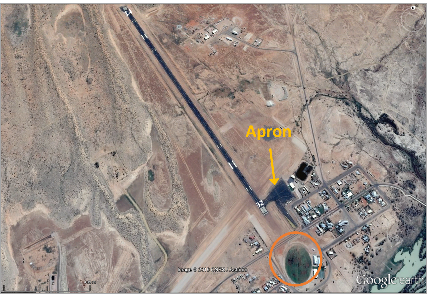
The pilot of ETW overflew the airport at about 2,500 ft on the upwind end of runway 32 to reduce the possibility of a conflict with the arriving SAAB (Figure 1). ETW joined for a wide downwind leg of the circuit and the pilot lowered the landing gear. The pilot observed that the SAAB that had now landed had not vacated the runway, so the pilot retracted the landing gear and extended the downwind leg to allow further time for the SAAB to vacate the runway.
Figure 1: Birdsville airport showing the location of runway 32, the parking apron and where the birds (hawks) were generally located off the end of runway 32 (orange circle).
Source: Google earth, modified by the ATSB
The pilot conducted the downwind checklist that included checking that the landing gear was down and locked, however, as the landing gear was in the up position, this part of the checklist was not conducted. When the aircraft was towards the end of the downwind leg, the pilot selected the landing gear handle down. The pilot noticed that the landing gear selector moved out more easily than normal, but the pilot identified that three landing gear down green lights were illuminated, indicating that the landing gear was down and locked.
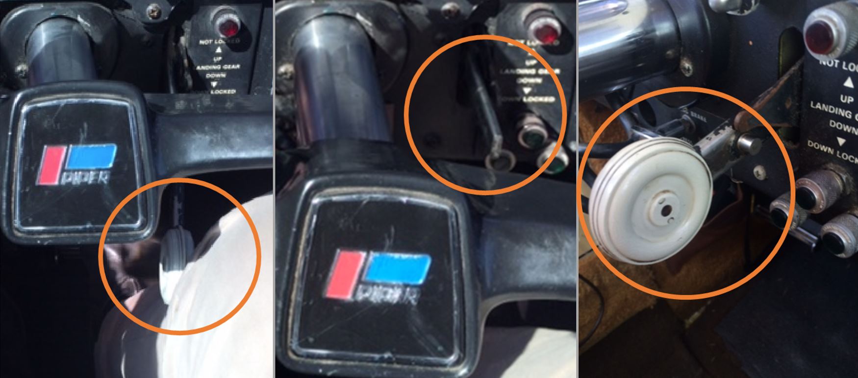
While the pilot was scanning out the window, they noticed a flicker of the instrument lights. When they looked back inside the cockpit, they observed that the GPS had gone back into initialising mode, which indicated that it may have lost power. During the turn onto the base leg of the circuit, the pilot gave a broadcast on the CTAF and conducted the base leg checklist items (they did not include checking the landing gear). The pilot noticed that the SAAB had not vacated the runway, but was getting close to exiting onto the apron. As the aircraft completed the turn onto the base leg, the pilot felt something against their right knee. The pilot reached down and found that it was the landing gear selector handle, which had become partially detached from the selector lever (Figure 2). The pilot took hold of the handle to ensure it was not lost and confirmed that there were three green landing gear down lights illuminated.
The pilot inserted the handle back into the landing gear selector lever and retracted and extended the landing gear to ensure that everything was operating correctly. The pilot removed the handle and kept hold of it and then gave a final leg broadcast, turned onto the final leg and conducted the finals checklist items. This checklist included a landing gear check, but the pilot could not remember clearly if there were three green lights.
At about 200 ft on final approach, the pilot observed a significant number of birds (hawks) (see orange circle in Figure 1). Due to a 15kt crosswind, as the pilot flared the aircraft for landing, the aircraft moved to the right side of the runway and the pilot then noticed that the aircraft had a slightly higher nose attitude than normal. As the attitude kept increasing, the pilot slowly advanced the throttles, then the rear footstep touched the runway and made a scraping noise. The pilot decided not to close the throttles as the aircraft was not on the runway centreline and they continued to advance the throttles. As the speed increased, the aircraft attitude adjusted and the propellers struck the runway. The aircraft speed had increased to take off speed and the pilot assessed that the safest option was to continue with a take-off. The pilot did not notice any abnormalities with the engines.
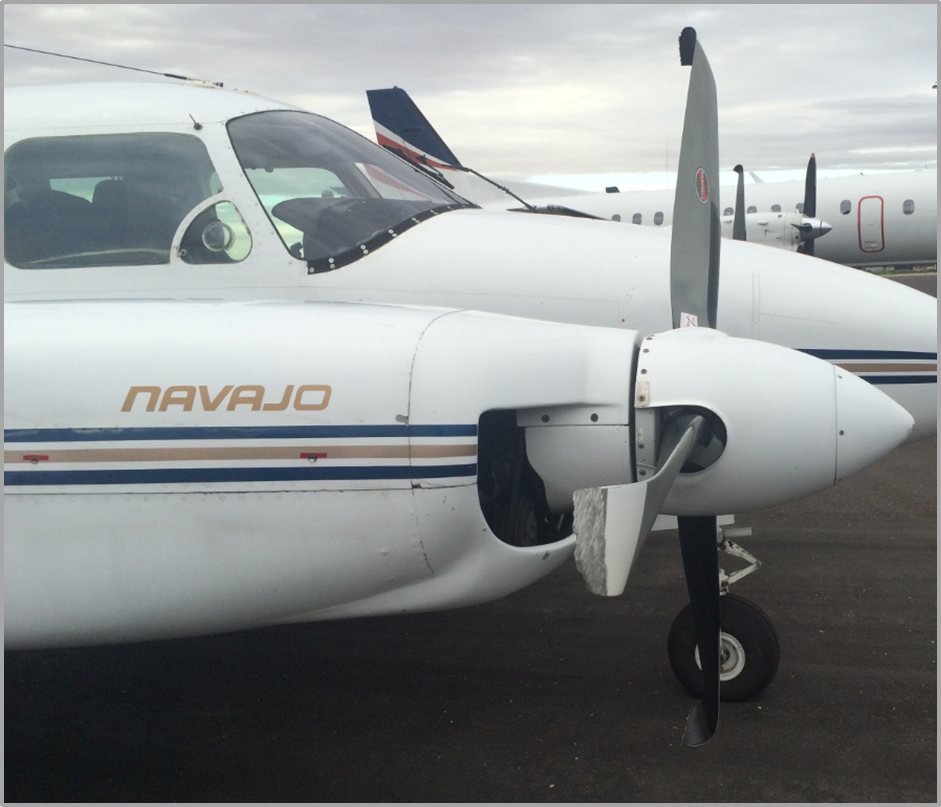
The pilot conducted a circuit, selected and held the landing gear handle in the down position and the aircraft landed without further incident. The pilot and passengers were uninjured and the aircraft had minor damage to the propellers (Figure 3).
Figure 3: Damage to ETW propellers
Source: Pilot, modified by the ATSB
Pilot comment
The pilot reported that when the landing gear was selected down when on the final approach, the landing gear selector was easier than usual to pull out and move past the neutral stop to the gear down position.
The pilot reported hearing a continuous horn sounding while in the landing flare just as the throttle was advanced and believed that it was the stall warning horn. The pilot believed that the landing gear horn would not have sounded as the throttles were not decreased past the location of the limit switches, which is where the throttles are almost closed (see Landing gear system below).
The pilot indicated that after parking the aircraft on the apron, when the avionic switch was moved to the off position, the avionics remained on and it was not until the switch had been cycled several times between the on and off position did the avionics turn off.
The pilot returned to the aircraft a few days later and noted that when the electrical master switch was turned on there were no green landing gear indicator lights despite the wheels being down, indicating the aircraft still had an avionics defect.
The pilot indicated that a maintenance release inspection (the periodic (100 hourly or 12-month) maintenance inspection) had been completed on 13 May 2016 and about 15 hours prior to the occurrence. The pilot had been the only pilot to fly the aircraft since the 100 hourly inspection and had flown a flight earlier that day and not noticed any issues with the aircraft.
Landing gear system
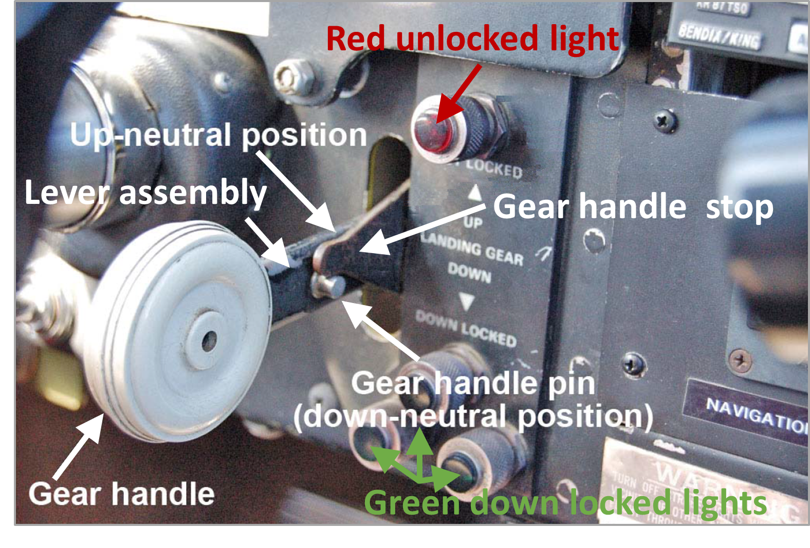
The landing gear handle is attached to the landing gear lever by a sleeve that fits over the end of the lever and is held in place by a pin, which is retained by a split pin. In this incident, the pin and split pin had fallen out of the landing gear handle and lever. In addition to connecting the handle to the lever, the pin also interacts with a gear handle stop (Figure 4). The landing gear handle is designed so the handle is spring-loaded to a forward position (towards the instrument panel). The pin on the inboard side of the handle rests against the gear handle stop for the neutral up and neutral down position. This ensures that the landing gear handle cannot unintentionally be moved beyond the neutral stop.
To select the landing gear down, the gear handle is pulled away from the instrument panel, down and over the gear handle stop to the full down position. When the landing gear is fully extended and locked, the landing gear handle will then return automatically to the down-neutral position where it is held by the pin against the gear handle stop.
Located on the instrument panel, above and to the right of the landing gear handle are one red and three green indicator lights (Figure 4). The red light will illuminate when the gear is not locked and the gear handle is either in the up or down position. When each of the individual gear is down and locked the respective green light will illuminate. There is no indication light when the gear is up and locked. When power from either engine is reduced below 10 to 12 inches of manifold pressure, a horn in the cockpit should sound if the gear is not down and locked.
Figure 4: Landing gear selector handle showing the gear handle, lever assembly, gear handle pin and the up and down neutral positions. In addition, the red unlocked light and the green down locked lights.
Source: Canada Transport Safety Board, modified by the ATSB
Operator report
The operator conducted an investigation into the occurrence and determined that the aircraft’s avionics were found to start up with the battery master switch, even though the avionics master switch was selected off. In addition, although the landing gear was down and locked, there were no green lights to indicate that this was the case. There was no indication of what the mechanical fault was in this system.
An inspection of the aircraft determined that when the gear handle was moved to the landing gear down position, it would normally return to the down neutral position. However, on the occurrence flight, the gear handle pin fell out. Without the gear handle pin to stop the landing gear lever at the gear handle stop, the lever continued to the gear up position (past the down neutral position to the up position) The landing gear retracted without the pilot being aware. However, the gear down and locked lights should have still illuminated prior to landing if the landing gear was down and locked.
Distractions for the pilot included the landing gear handle becoming detached, an issue with the avionics on downwind, numerous birds (kite hawks) that were flying around on final and the 15 kt crosswind.
Safety analysis
When the pilot had discovered that the landing gear selector handle had become detached, they used the detached handle to move the lever to retract and extend the landing gear to determine that there were no issues with the landing gear prior to the landing. The pilot then removed the handle to ensure that it did not fall and become inaccessible in flight, just in case the landing gear needed to be retracted and extended again. They believed that there were three green landing gear down indicator lights but was unaware that with the stop pin missing, the landing gear would self-retract after the landing gear handle was released. As a result, the pilot was not aware that the landing gear had retracted prior to landing.
There were a number of interruptions and distractions during the approach and landing phase of the flight. These included waiting for another aircraft to vacate the runway and subsequent alteration of the circuit to accommodate separation, issues with the GPS, the landing gear handle becoming free, large birds under the final approach and the crosswind during the landing. The combination of these interruptions, distractions and abnormal conditions likely contributed to the pilot flaring the aircraft for landing without realising the landing gear was in the retracted position.
Findings
These findings should not be read as apportioning blame or liability to any particular organisation or individual.
The landing gear selector handle became detached and the landing gear retracting without the pilot’s knowledge.
Numerous distractions existed during the approach and landing that may have contributed to distract the pilot resulting in the aircraft landing with the landing gear in the retracted position.
Safety action
Whether or not the ATSB identifies safety issues in the course of an investigation, relevant organisations may proactively initiate safety action in order to reduce their safety risk. The ATSB has been advised of the following proactive safety action in response to this occurrence.
Aircraft operator
As a result of this occurrence, the aircraft operator has advised the ATSB that they are taking the following safety actions:
The pilot has undertaken comprehensive successful flight checks.
Aircraft defect rectification to ensure the aircraft is serviceable before further flight.
The aircraft operations manual will be amended to include actions to be taken when experiencing any abnormality with the aircraft’s landing gear. This will refer to the emergency procedures checklist and the aircraft flight manual. The procedure will require the pilot to:
abort the landing
climb to 1,500 ft
redo the pre-landing landing checklist to confirm green lights are on/or use the emergency landing gear hand pump to lower the landing gear.
conduct a visual inspection of landing gear to ensure it is down and locked.
All pilots will be informed of the incident via email or a safety alert to inform them:
of the importance of the gear control handle locking mechanism
to inspect the gear control handle on a regular basis for faults or damage
to look at additional options for confirming that the landing gear is down with the use of active control towers or having contact details of ground crew readily available to inspect the landing gear during a fly over.
Safety message
In the flying environment, interruptions and distractions can be subtle and brief and can interrupt the normal flow in the cockpit resulting in a preoccupation and distraction with one task to the detriment of another task.
The Flight Safety Foundation Approach and Landing Accident Reduction (ALAR) briefing note ‑ 2.4 - interruptions/distractions discuss that interruptions/ distractions may be subtle or brief where even a minor equipment malfunction can turn a routine flight into a challenging event. The primary effects of interruptions/distractions is to break the flow pattern of ongoing cockpit activities such as normal checklists and problem-solving activities. The briefing contains guidance that may assist in managing interruptions/ distractions.
Decisions regarding whether to conduct an investigation, and the scope of an investigation, are based on many factors, including the level of safety benefit likely to be obtained from an investigation. For this occurrence, a limited-scope, fact-gathering investigation was conducted in order to produce a short summary report, and allow for greater industry awareness of potential safety issues and possible safety actions.
Publishing information
Released in accordance with section 25 of the Transport Safety Investigation Act 2003
Ownership of intellectual property rights in this publication
Unless otherwise noted, copyright (and any other intellectual property rights, if any) in this report publication is owned by the Commonwealth of Australia.
Creative Commons licence
With the exception of the Coat of Arms, ATSB logo, and photos and graphics in which a third party holds copyright, this publication is licensed under a Creative Commons Attribution 3.0 Australia licence.
Creative Commons Attribution 3.0 Australia Licence is a standard form licence agreement that allows you to copy, distribute, transmit and adapt this publication provided that you attribute the work.
The ATSB’s preference is that you attribute this publication (and any material sourced from it) using the following wording: Source: Australian Transport Safety Bureau
Copyright in material obtained from other agencies, private individuals or organisations, belongs to those agencies, individuals or organisations. Where you wish to use their material, you will need to contact them directly.
The ATSB has completed examination of the JRA-445-1 wing attachment fitting supplied by the Civil Aviation Safety Authority (CASA). In addition, an original Cessna wing attachment fitting (part no. 0811350-10), also supplied by CASA, was examined for comparison of the material properties and manufacturing methodology. A report detailing the examinations and findings was prepared and provided to CASA on 28 September 2016.
For further information regarding the wing fittings or airworthiness bulletin AWB 57-015, please contact CASA on 131 757 or www.casa.gov.au.
Updated: 30 June 2016
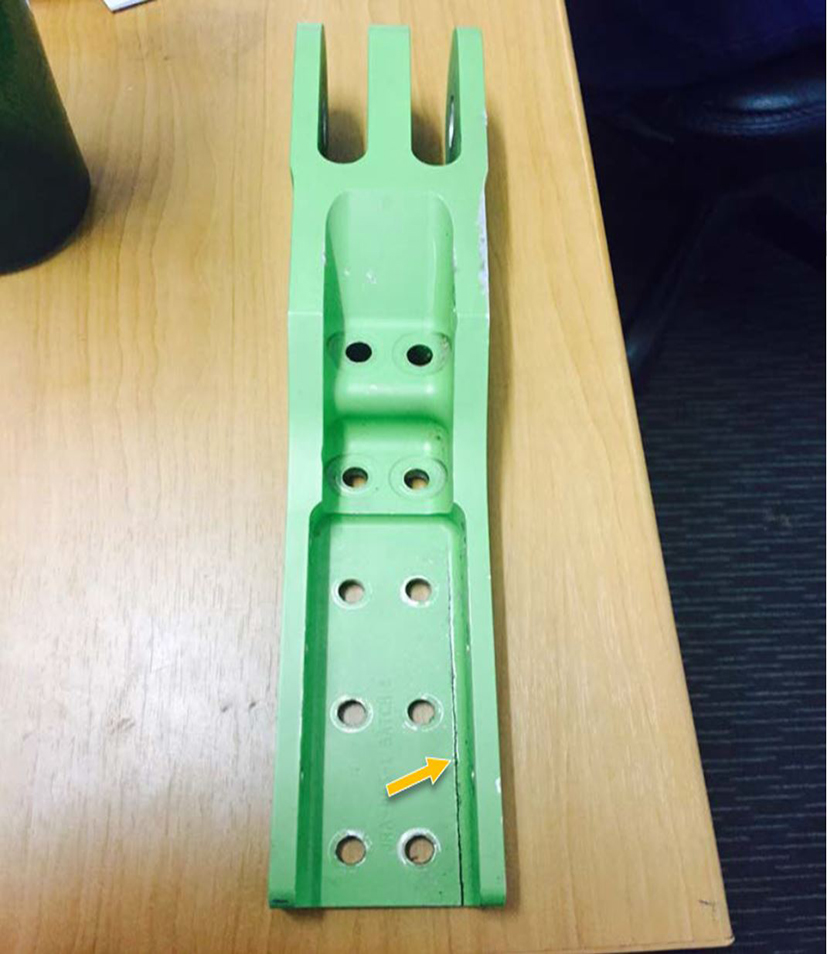
During an inspection of the wing attachment fittings of a Cessna 402C in accordance with Civil Aviation Safety Authority (CASA) airworthiness directive AD/CESSNA 400/92, a crack was identified in the inboard lower attachment fitting (Figure 1). The cracked attachment fitting (part number JRA‑445‑1) was manufactured by J&R Aerospace as a replacement for the original Cessna fitting.
Figure 1: Cessna 402C lower inboard wing main spar attachment fitting showing an approximate 100 mm (4 inch) crack (indicated by orange arrow) Source: CASA, annotated by ATSB
AD/CESSNA 400/92 specified inspection of the outboard attachment fittings, but not the inboard fittings. Compliance with the airworthiness directive was required prior to the component exceeding 5,000 hours time in service. The cracked JRA‑445‑1 fitting had accumulated 2,831 flight hours time in service.
On 17 June 2016, CASA issued airworthiness bulletin AWB 57‑015 to alert operators and maintainers of Cessna 400 series aircraft of premature cracking in a Cessna 402C wing attachment fitting manufactured by J&R Aerospace.
As part of their investigation, CASA requested the technical assistance of the Australian Transport Safety Bureau (ATSB) to conduct a metallurgical examination of the cracked fitting.To facilitate this assistance, the ATSB initiated an external investigation under the provisions of the Transport Safety Investigation Act 2003.
On 20 June 2016, a captain and first officer, employed by Cobham Aviation Services, conducted a QantasLink flight from Sydney Airport, New South Wales, to Canberra Airport, Australian Capital Territory, in a Boeing 717-200 aircraft, registered VH-YQV.
The aircraft arrived in Canberra at about 0720 Eastern Standard Time (EST), and the first officer then conducted an external inspection of the aircraft, while the captain prepared the cockpit including the take-off data for the next sector to Sydney. The captain wrote the reduced-thrust take-off data onto the take-off and landing data (TOLD) card, including a flex temperature[1] of 40 °C, which was obtained from a table in the regulated take-off (RTO) book, an engine pressure ratio (EPR)[2] of 1.39, aircraft take-off weight, flap setting 5, and the take-off reference speeds (V speeds).[3] As the runway was wet, the V speeds were obtained manually from a table in the RTO book.[4]
After completing the external inspection, the first officer returned to the cockpit and the flight crew checked the take-off data in accordance with standard procedures. The first officer assessed that based on the environmental conditions, the flex temperature should be 39°. The first officer amended the TOLD card by striking through the 40 and writing 39 next to it, and similarly amended the V speeds based on the manual V speeds provided in the table for that flex temperature.
The captain was the pilot flying[5] for the sector to Sydney, so commenced briefing for the flight. The captain read out the data from the TOLD card, including the flex temperature and EPR, and the first officer entered the flex temperature and V speeds into the take-off page of the flight management system (FMS), which then calculated an EPR.
The flight crew then completed the cockpit checklist down to the last four items, in accordance with standard procedures. At that time, a member of the cabin crew entered the cockpit to advise the flight crew that an additional 22 passengers would be boarding the flight. As the aircraft take-off weight would increase by about 2 tonnes, the first officer recalculated the take-off data. The newly derived flex temperature was 34°, and as there was not much room left on the TOLD card, the first officer overwrote the previous figure of 39 with 34. The first officer then obtained the new V speeds, which the captain crosschecked and the first officer wrote them on the TOLD card.
The aircraft communications, addressing and reporting system (ACARS) then chimed with the loadsheet coming through on the printer, and at about the same time, a cabin crewmember entered the cockpit to confirm passenger numbers and ground personnel communicated over the intercom with the flight crew about removing the wheel chocks. After entering the zero fuel weight from the loadsheet into the FMS and crosschecking the take-off weight in the FMS against the take-off weight derived on the TOLD card, the captain called for the first officer to enter the revised manually derived V speeds from the TOLD card into the FMS.
The standard procedure then was for the captain to call ‘re-flex’ before entering the amended flex temperature and flap setting from the TOLD card into the FMS. The captain was holding the TOLD card and reported stating ‘39’ as the flex temperature, having misread the ‘34’. The first officer could not recall checking the flex temperature in the FMS at that time, and thought it may have been omitted due to the interruptions.
The crew reported that the EPR calculated by the FMS based on the flex temperature and environmental conditions was 1.39. (The flight data showed that the commanded EPR at that stage was actually 1.38.) The EPR obtained from the RTO book (for flex temperature of 34°) and written on the TOLD card was 1.41. The flight crew crosschecked the FMS EPR with the TOLD card EPR, and although there was a discrepancy of 0.2, it was within the 0.3 margin allowed at that stage.[6]
After obtaining the required air traffic control clearances, the captain taxied the aircraft to the runway and commenced the take-off at about 0812. In accordance with standard procedures, the captain then moved the thrust levers forward and checked for an even spool-up of the engines to an EPR of 1.2. The captain then called ‘auto flight’ and the first officer engaged the auto-flight system. This action caused the thrust levers to move to a position where the EPR from the FMS was achieved. The captain then called ‘check thrust’ and the first officer saw that the EPR was 1.38, instead of the required EPR of 1.41 as written on the TOLD card. In accordance with standard procedures, the first officer then moved the thrust levers forward to achieve 1.41 EPR.
The flight crew thought that the aircraft was then correctly configured for the take-off, with the correct EPR, thrust and flap settings and V speeds, and the captain continued the flight. However, after about 4 seconds at 1.41, the EPR returned to 1.38 for the take-off as the thrust lever position returned to that set by the auto-flight system based on the EPR value in the FMS.
During the initial climb, the first officer identified that the flex temperature set in the FMS was 39 instead of 34. As the short sector to Sydney was busy, the crew waited until the aircraft had arrived in Sydney before discussing the incident. Both members of the flight crew assessed that tiredness due to the early start may have contributed to the flex temperature error, but that they were fit to continue to operate for the remainder of the day’s duty.
Flight data
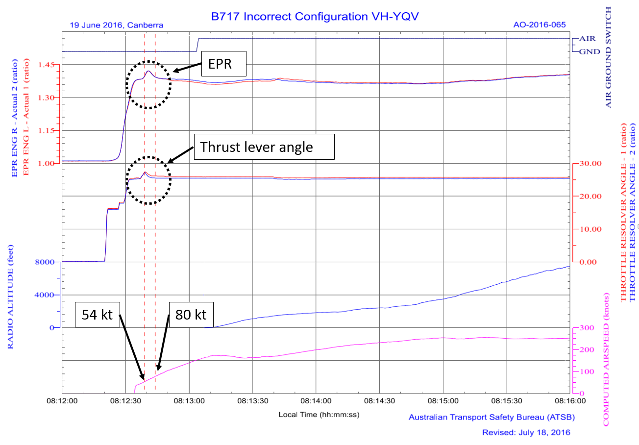
The aircraft operator provided the ATSB with a copy of the quick access recorder (QAR) data for the incident flight. As depicted in Figure 1, the data showed the thrust lever angle set at about 25° and the EPR at 1.38 early in the take-off run. After about 4 seconds at that setting, the thrust lever angle increased to about 26° as the commanded EPR, followed closely by the actual EPR, increased to 1.41. However, after about 4 seconds at 1.41 and a further 6 seconds at 1.39, the EPR reduced to 1.38 and thrust lever angle to about 25°, where they remained for the take-off.
This indicates that although the first officer manually moved the thrust levers forward, as the auto-throttle system was engaged, it then overrode the manual thrust lever position and returned the EPR to the value set in the FMS, which was the target thrust setting. At the time, the computed airspeed was 54 kt. When the airspeed reaches 80 kt in the take-off roll, the auto-throttle system mode changes from ‘take-off thrust’ to ‘take-off clamp’ mode. In clamp mode, the auto-throttle servo does not have power and the thrust levers do not move automatically. However, in take-off thrust mode (prior to 80 kt), the flight crew would have to disengage the auto-throttle system to set the thrust manually, or maintain pressure on the levers until the airspeed reached 80 kt.
Figure 1: Graph of flight data from the incident flight
Source: QAR data supplied by the aircraft operator analysed by the ATSB
Flight crew comments
During the approach into Canberra from Sydney, the cloud base was at the minima.[7] The captain commented that the workload on an instrument approach down to the minima was high, and would generally result in a reduced state of arousal after landing and shutdown in response.
The flight crew commented that a combination of distraction by cabin crew and ground personnel while re-entering data, a reduced state of arousal following high workload instrument approach, and possibly tiredness from an early start may have contributed to their omitting to enter the correct flex temperature into the FMS.
Although the captain recalled misreading 39 instead of 34, the first officer could not recall the captain calling ‘re-flex’, and commented that it was unlikely to have been called and then not completed. The first officer thought it was more likely that they entered the new V speeds but had omitted to check that the flex temperature written on the TOLD card matched that in the FMS.
Normally by the time they are getting to the third set of amended numbers, the first officer would start a new TOLD card. However, as it was approaching the scheduled departure time, the first officer elected to overwrite the existing figures. The captain further commented that in future, if there were any more than two corrections made to the supplement data on the TOLD card, they would write out a new card.
The captain commented that this incident provided a good example of how adherence to standard operating procedures helps to mitigate errors. While the initial crosscheck prior to taxiing showed a discrepancy between the TOLD card and FMS EPR values, as it was within the permitted tolerance, the flex temperature error was not identified at that time. When the first officer checked the thrust (and EPR) during the take-off run, the too-low EPR setting was identified and the thrust levers set to obtain the correct EPR. Hence following the standard operating procedures provided sufficient risk control to identify and correct the error.
Tiredness
The flight crew signed on at 0505 for a four-sector flight duty from Sydney. The scheduled departure time for their first flight from Sydney was 0620 and the flight crew were required to sign on 1 hour and 15 minutes prior. In addition, the crew had to allow 30 minutes to transfer from the long-term carpark, pass through airport security, and sign on in the crew room in the domestic terminal at Sydney Airport.
The captain reported waking up at 0340 and the first officer at 0305, and both crewmembers reported conducting a self-assessment of their fitness to fly. The first officer reported feeling ‘somewhat tired’ having had a broken night’s sleep, but had the previous four days off work and did not feel fatigued. The captain also reported feeling tired having woken up early, they assessed they were not fatigued, and were fully fit to fly. Both the captain and first officer commented that the early start times generally caused a feeling of tiredness, but did not affect their ability to operate the aircraft.
Cobham operates flight and duty time limitations based on Civil Aviation Order 48 and an exemption, and had not, nor was required to have, implemented a fatigue risk management system. The flight crew reported that the company operations manual included a statement that it is the flight crew’s responsibility to determine their fitness to fly.
Safety action
Whether or not the ATSB identifies safety issues in the course of an investigation, relevant organisations may proactively initiate safety action in order to reduce their safety risk. The ATSB has been advised of the following safety action in response to this occurrence.
Aircraft operator
As a result of this occurrence, the aircraft operator has advised the ATSB that they are taking the following safety actions:
Communication to flight crew
The operator will remind pilots to use a new TOLD card in the event that the card data is being changed and comprehension of these changes is not clear. Pilots will be advised of the investigation by its inclusion in the company’s staff safety magazine.
Safety message
Inaccurate take‑off reference data has potentially serious consequences. ATSB Aviation Research and Analysis Report AR-2009-052 (Take-off performance calculation and entry errors: A global perspective) documents a number of accidents and incidents where take‑off performance data was inaccurate. The report analyses those accidents and incidents, and concludes:
… it is imperative that the aviation industry continues to explore solutions to firstly minimise the opportunities for take‑off performance parameter errors from occurring and secondly, maximise the chance that any errors that do occur are detected and/or do not lead to negative consequences.
The ATSB SafetyWatch highlights the broad safety concerns that come out of our investigation findings and from the occurrence data reported to us by industry. One of the safety concerns relates to data input errors.
Decisions regarding whether to conduct an investigation, and the scope of an investigation, are based on many factors, including the level of safety benefit likely to be obtained from an investigation. For this occurrence, a limited-scope, fact-gathering investigation was conducted in order to produce a short summary report, and allow for greater industry awareness of potential safety issues and possible safety actions.
Publishing information
Released in accordance with section 25 of the Transport Safety Investigation Act 2003
Ownership of intellectual property rights in this publication
Unless otherwise noted, copyright (and any other intellectual property rights, if any) in this report publication is owned by the Commonwealth of Australia.
Creative Commons licence
With the exception of the Coat of Arms, ATSB logo, and photos and graphics in which a third party holds copyright, this publication is licensed under a Creative Commons Attribution 3.0 Australia licence.
Creative Commons Attribution 3.0 Australia Licence is a standard form licence agreement that allows you to copy, distribute, transmit and adapt this publication provided that you attribute the work.
The ATSB’s preference is that you attribute this publication (and any material sourced from it) using the following wording: Source: Australian Transport Safety Bureau
Copyright in material obtained from other agencies, private individuals or organisations, belongs to those agencies, individuals or organisations. Where you wish to use their material, you will need to contact them directly.
----------
[1] Flex temperature is a calculated outside temperature used for a reduced thrust take-off. The flex temperature (which is hotter than actual outside temperature) is used for generating take-off parameters rather than the actual outside temperature. It takes into account the runway length and aircraft weight to ensure the aircraft can take off within the runway distance available and maintain the required obstacle clearance during the subsequent climb. The aim is to prolong engine life.
[2] The engine pressure ratio, or EPR, is a pressure ratio indicative of engine thrust. The pressure is sensed by two probes, one ahead and one aft of the jet engine fan.
[3] Take-off reference speeds or V speeds assist pilots in determining when a rejected take-off can be initiated, and when the aircraft can rotate, lift-off and climb.
[4] For a dry runway, the V speeds used would have been automatically generated by the flight management system.
[5] Pilot flying (PF) and pilot monitoring (PM) are procedurally assigned roles with specifically assigned duties at specific stages of a flight. The PF does most of the flying, except in defined circumstances; such as planning for descent, approach and landing. The PM carries out support duties and monitors the PF’s actions and aircraft flight path.
[6] A change in bleed configuration, such as selecting air conditioning packs on or off, can change the EPR value. Therefore there is a small discrepancy allowed while parked and during taxi, but the two figures must match at take-off
[7] For a precision approach, the minima is defined as a decision altitude at which a missed approach must be initiated if the required visual reference to continue the approach has not been established.
On Monday 27 June 2016, the Indonesian National Transportation Safety Committee (NTSC) commenced an investigation into damage sustained by ATR 72 aircraft, registered PK-WGL. Initial examination of this damage suggested similarities with that found on an Australian-registered ATR 72, registered VH-FVR, which is being investigated by the ATSB (see ATSB investigation AO-2014-032 at ATSB website). On 29 June 2016, the NTSC requested the appointment of an ATSB accredited representative to the NTSC investigation in accordance with clause 5.23 of Annex 13 to the Convention on International Civil Aviation Aircraft Accident and Incident Investigation. This was a result of the ATSB’s experience with the ATR during investigation AO-2014-032 and an accredited representative was appointed to the NTSC investigation that day. To facilitate this support, the ATSB initiated an investigation under the Australian Transport Safety Investigation Act 2003.
The ATSB has completed their role in assisting the Indonesian NTSC.
The NTSC is responsible for, and will administer the release of the final investigation report into the occurrence involving PK-WGL. Any enquiries regarding the NTSC investigation should, in the first instance, be directed to the:
National Transportation Safety Committee Ministry Of Transportation Republic Of Indonesia Transportation Building 3rd Floor Jalan Medan Merdeka Timur No. 5 Jakarta Pusat 10110 Indonesia
On 21 June 2016, a Qantas Airways Boeing 747-438 aircraft, registered VH-OJS, operated flight QF11 from Los Angeles, California, United States to New York, New York, United States.
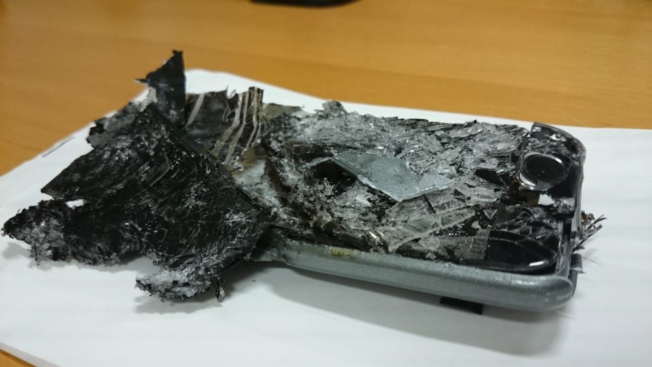
At about 0700 Coordinated Universal Time (UTC), a cabin crewmember responded to a request for assistance from a passenger seated in business class seat 3A. The passenger advised the crewmember of a missing personal electronic device (PED). The PED was identified as containing a lithium type battery. The crewmember, along with the passenger, searched around the seat for the missing PED. While searching, the seat position was moved. As the seat moved, the passenger in the next seat observed the PED within the seat mechanism. The seat was then inadvertently moved, resulting in the PED being crushed (Figure 1). The crushed PED immediately began hissing and emitting smoke. Moments later, the PED ignited. A second crewmember then initiated the basic fire drill.
The second crewmember obtained a fire extinguisher, and as they proceeded toward seat 3A, they advised a third crewmember of the incident and requested assistance. This crewmember also obtained a fire extinguisher and proceeded toward seat 3A. The customer service manager (CSM) and another crewmember observed the activity and also followed, providing additional support.
When the cabin crewmembers carrying fire extinguishers arrived at seat 3A, they observed an orange glow emanating from the seat. A crewmember discharged a fire extinguisher into the seat, extinguishing the glow. At this time, the CSM acted as a communicator with the flight crew to inform them and keep them updated on the incident.
After confirming the PED fire had been extinguished, the cabin crew attempted to remove the PED in order to place the device in water, in accordance with lithium type battery fire procedures. The PED could not be removed without further damage and risk of fire. Therefore, the cabin crew elected to leave the device in place and position a crewmember with a fire extinguisher near seat 3A for the remainder of the flight. About 10–15 minutes after the incident, this crewmember identified further heat coming from the crushed PED. They again discharged the fire extinguisher onto the PED, eliminating the heat.
After confirming the incident was contained, the CSM advised the captain that the situation was under control. The captain discussed the incident with the first officer and considered the event had been dealt with appropriately. The flight proceeded to New York and landed about 40 minutes later without further incident.
Two passengers reported feeling unwell after the event, but it was unclear if this was as a result of the incident. The aircraft seat sustained minor damage.
Figure 1: Crushed PED after removal from seat
Source: Qantas
Cabin crew comment
The responding cabin crewmember commented that the provision of designated storage close to the charging port could assist in preventing PEDs entering seat structure.
Passenger comment
The passenger in seat 3A commented that the amenities pack provided to passengers in this seat type could be changed to include PED storage. This could assist preventing PEDs entering the seat structure.
Operator investigation report
The aircraft operator investigated the incident and provided a copy of their investigation report to the ATSB. The report included the following:
A review of reported events revealed 22 similar occurrences of trapped or crushed PEDs. Seven of these occurrences resulted in smoke and/or heat being produced. This incident was the first event to result in fire.
The investigation determined that the likely area for the PED to intrude into the seat mechanism was adjacent to the seat belt anchor point. This area becomes more exposed as the seat reclines towards the flat position.
Mesh netting within the seat structure is designed to capture objects that fall behind the seat. Damage to seat 3A consisted of an approximate 5 cm melt area to this mesh netting. There was no other damage noted to the seat structure.
Lithium batteries are capable of ignition and subsequent explosion due to overheating. Overheating may be caused by shorting, rapid discharge or overcharging. Overheating results in thermal runaway, which is a chemical reaction within the battery causing the internal temperature and pressure to rise. The result is the release of flammable electrolyte from the battery and, in the case of disposable lithium batteries, the release of molten burning lithium. Once one battery cell goes into thermal runaway, it produces enough heat to cause adjacent battery cells to also go into thermal runaway. This produces a fire that repeatedly flares up as each battery cell in turn ruptures and releases its contents.
SAFO 09013 Supplement also details the following information on fighting fires caused by lithium type batteries:
Relocate passengers away from the device.
Utilise a halon, halon replacement, or water fire extinguisher to prevent the spread of the fire to adjacent battery cells and materials.
Pour water, or other non-alcoholic liquid, from any available source over the cells immediately after knockdown or extinguishment of the fire.
Only water or other non-alcoholic liquid can provide sufficient cooling to prevent re-ignition and/or propagation of the fire to adjacent batteries. Water, though it may react with the tiny amount of lithium metal found in a disposable battery, is most effective at cooling remaining cells, stopping thermal runaway and preventing additional flare-ups. Significant cooling is needed to prevent the spread of fire to additional cells in a battery pack.
Safety action
Whether or not the ATSB identifies safety issues in the course of an investigation, relevant organisations may proactively initiate safety action in order to reduce their safety risk. The ATSB has been advised of the following proactive safety action in response to this occurrence.
Seat manufacturer
As a result of this occurrence, the aircraft operator has advised the ATSB that the seat manufacturer is developing design solutions to prevent ingress of PEDs into the seat structure.
Aircraft operator
The aircraft operator has advised the ATSB that they are taking the following safety actions:
Changes to passenger briefings
An enhanced passenger briefing has been released to include:
If you lose your electronic devices at any time, it’s important you don’t move your seat as this could severely damage your device and may be a fire hazard. Please contact a crew member who will be able to recover your device.
A cabin crew service brief has been released which includes:
Passenger announcement to remind passengers not to move seats when devices have been lost.
Individual interactions between cabin crew and passengers when preparing the bed to include a discussion to raise passenger awareness of the possibility that the PED could be crushed if it is lost during the flight.
Establishment of working group
A working group has been established to develop further solutions for this issue.
Safety message
This incident serves as an excellent example of an effective response to an emergency situation. The cabin crew quickly implemented the basic fire drill procedure. This defined the roles and responsibilities of the responding crew, enabling a rapid and coordinated response to the incident using all available resources. As a result, the incident was quickly and effectively contained. The effective implementation of this procedure also ensured the flight crew were kept informed as the situation developed.
This incident also highlights the hazards of transporting lithium-ion battery powered PEDs aboard aircraft. The Civil Aviation Safety Authority has released information on the safe carriage of lithium type battery powered devices aboard aircraft in the web page: Travelling safely with batteries and pamphlet: Is your luggage safe?
Decisions regarding whether to conduct an investigation, and the scope of an investigation, are based on many factors, including the level of safety benefit likely to be obtained from an investigation. For this occurrence, a limited-scope, fact-gathering investigation was conducted in order to produce a short summary report, and allow for greater industry awareness of potential safety issues and possible safety actions.
Publishing information
Released in accordance with section 25 of the Transport Safety Investigation Act 2003
Ownership of intellectual property rights in this publication
Unless otherwise noted, copyright (and any other intellectual property rights, if any) in this report publication is owned by the Commonwealth of Australia.
Creative Commons licence
With the exception of the Coat of Arms, ATSB logo, and photos and graphics in which a third party holds copyright, this publication is licensed under a Creative Commons Attribution 3.0 Australia licence.
Creative Commons Attribution 3.0 Australia Licence is a standard form licence agreement that allows you to copy, distribute, transmit and adapt this publication provided that you attribute the work.
The ATSB’s preference is that you attribute this publication (and any material sourced from it) using the following wording: Source: Australian Transport Safety Bureau
Copyright in material obtained from other agencies, private individuals or organisations, belongs to those agencies, individuals or organisations. Where you wish to use their material, you will need to contact them directly.
Occurrence summary
Investigation number
AO-2016-066
Occurrence date
21/06/2016
Location
500 km WNW of John F. Kennedy International Airport, United States
On 27 June 2016, the pilot of an Airparts (NZ) FU-24-950 aircraft, registered VH-TTD, was conducting agricultural operations from an airstrip about 50 km east-south-east of Tamworth Airport, New South Wales. The pilot was the only person on board the aircraft.
The airstrip elevation was about 3,200 ft and sloped downhill in the direction used for take‑off, with a steep slope at the end of the runway. The surrounding terrain was below the elevation of the airstrip and the first obstacle in the take-off direction was a fence at the end of the runway.
At about 1130 Eastern Standard Time (EST), after having completed about 35 flights for that morning, the pilot started their next take-off run with the flaps[1] in the normal take-off setting of 20°. The aircraft handled normally until shortly after lift-off, when at an airspeed of about 60 kt, the pilot heard a ‘bang’. The aircraft sank rapidly and the tail struck the runway surface. As the runway sloped steeply downhill, the aircraft became airborne again. Due to the proximity of the fence at the end of the runway, the pilot elected to continue the take-off and dump the fertiliser load. As the load was being dumped, the aircraft struck the fence, but continued to fly.
The pilot quickly detected that there was no response from the elevator[2] to their control inputs. They could move the control column fore and aft, but the aircraft pitch[3] did not respond. They also observed that the flap was fully retracted even though the cockpit flap lever was still set to 20°. The pilot elected to divert to Tamworth Airport, which was below the elevation of the airstrip. The pilot used engine power and elevator trim[4] to control the pitch of the aircraft.
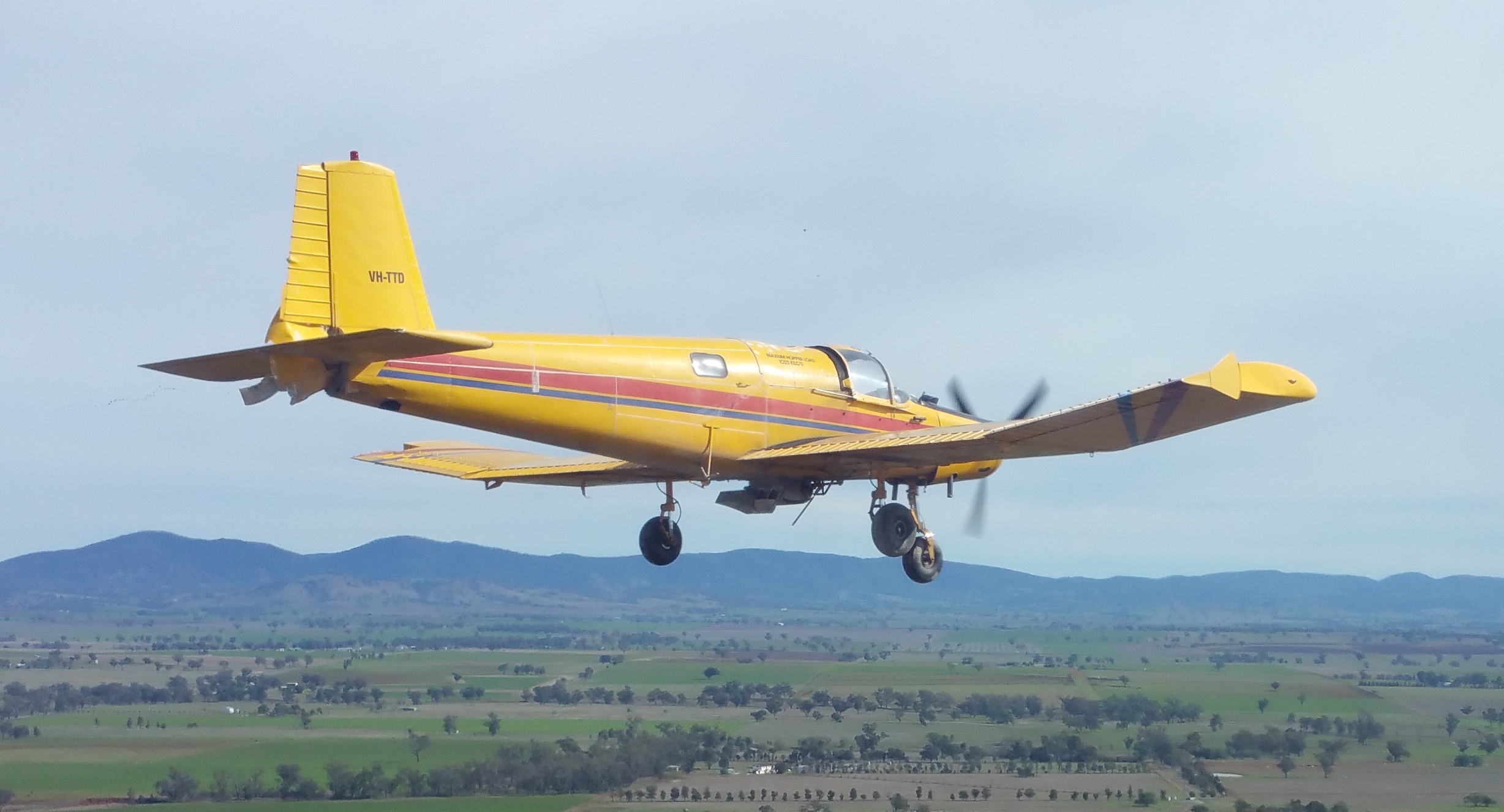
The pilot contacted Tamworth air traffic control (ATC) and informed them that they had a ‘bit of an issue’. They also advised that they had no elevator control, but still had the aircraft under control (Figure 1). ATC cleared the pilot to manoeuvre as required to approach and land on the main runway at Tamworth.
The pilot conducted a long and low straight-in approach to runway 12 left at Tamworth with the aircraft trimmed in the approach attitude, which was slightly nose up. At about 10 ft above the runway, the pilot reduced the throttle to idle for the landing. The aircraft then pitched nose down and the nose wheel contacted the runway first and burst the nose wheel tyre. The aircraft stopped on the runway with minor damage and the pilot was not injured.
Figure 1: VH-TTD flying towards Tamworth Airport on the incident flight
Source: BAE Systems Flight Training Tamworth
Repair organisation findings
The repair organisation that performed the post-incident inspection found damage to the propeller, tailplane and underside of aircraft consistent with impact with the runway and fence during the take-off. A detailed inspection inside the airframe revealed the following:
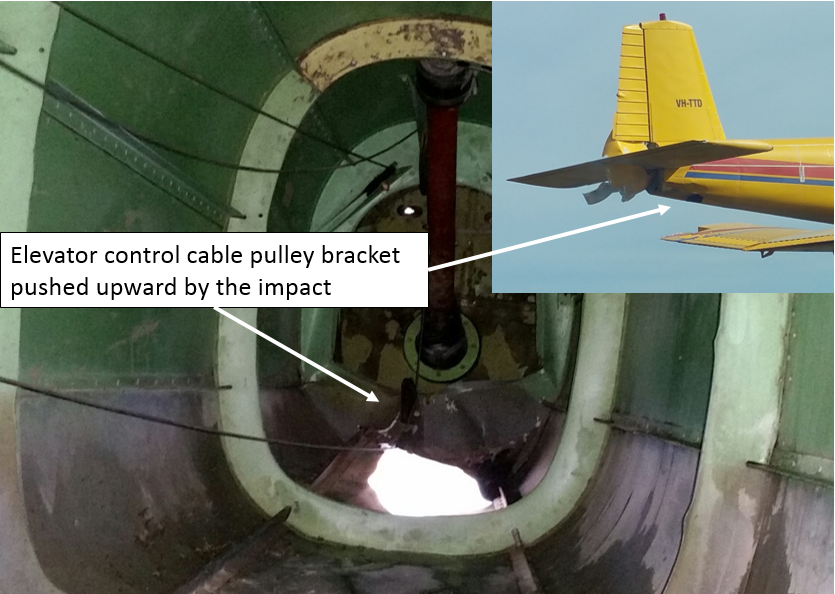
The structural frame supporting the lower elevator control cable pulley was pushed up about 10 cm (Figure 2).
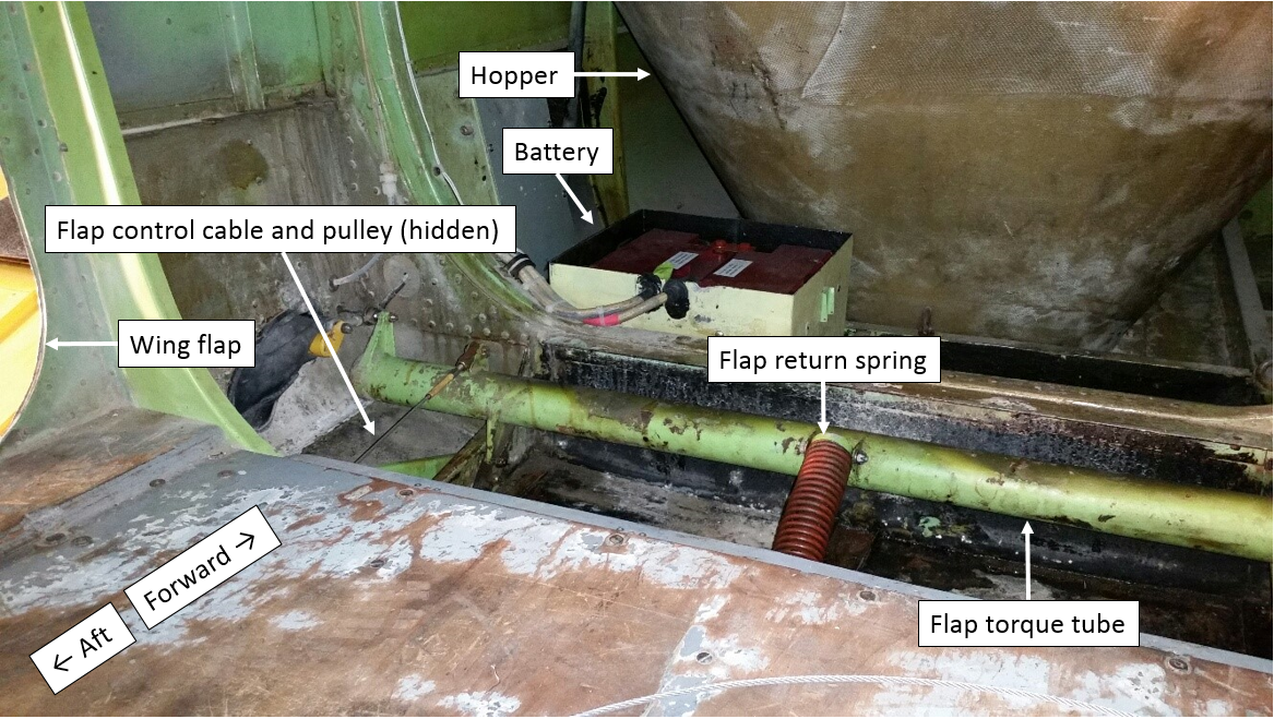
The centre section just aft of the hopper (Figure 3) had about 12 mm of water in it and the drain hole for the centre section was blocked by fertiliser. The repair organisation assessed that the size of the drain hole was inadequate and that a larger hole with a removable bung would be preferable.
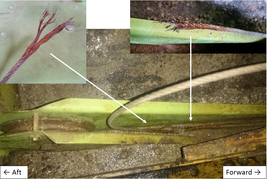
The flap control cable had failed at the rear flap pulley and the failure appeared to be due to corrosion (Figure 4).
Figure 2: VH-TTD elevator control cable pulley
Source: Repair organisation and BAE Systems Flight Training Tamworth annotated by ATSB
Figure 3: VH-TTD centre section
Source: Repair organisation annotated by ATSB
Figure 4: VH-TTD broken flap cable
Source: Repair organisation annotated by ATSB
Maintenance schedule
The aircraft system of maintenance used was the Civil Aviation Safety Authority (CASA) Schedule 5 with 100-hourly periodic inspections. CASA Schedule 5 includes the following inspections relevant to this incident:
Item 3 (j) for the airframe periodic inspection: ‘inspect the control wheels, control columns, rudder pedals, control levers, control system bellcranks, push pull rods, torque tubes and cables.’
Item 17 for the daily inspection: ‘check that the drain holes are free from obstruction.’[5]
Previous maintenance inspections
The last 100-hourly periodic inspection was certified on 19 May 2016 in accordance with CASA Schedule 5. The previous periodic inspection was on 21 April 2016, and a corrosion inspection was performed on 23 November 2015, which included CASA Airworthiness Directive FU24/2: structural component – corrosion – inspection. No findings were recorded against the flap control cable for these inspections. During the periodic inspections, the flap cable was inspected by moving a cloth along the cable and no broken strands were detected, and there was no water present in the centre section of the aircraft aft of the hopper. However, the maintenance organisation indicated that they did not remove the flap cable for inspection, nor apply corrosion protection to the flap cable during the inspections.
Recommended practices
CASA Airworthiness Bulletin 27-001 issue 7 includes the following recommendation:
…flight control cables should be periodically inspected in accordance with manufacturer’s data and FAA AC 43-13-1B Chapter 7, AIRCRAFT HARDWARE, CONTROL CABLES AND TURNBUCKLES, section 8, paragraph 7.149d. To inspect all surfaces of a cable throughout its entire length for wear and fatigue (broken wires) usually requires that the cable be disconnected and removed...
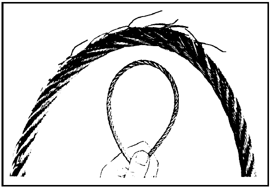
United States Federal Aviation Administration Advisory Circular 43-13-1B chapter 7, section 8, paragraph 7.149 states that: ‘deterioration, such as corrosion, is not easily seen, therefore, control cables should be removed periodically for a more detailed inspection and any cable with a broken strand in a critical fatigue area[6] must be replaced.’ See Figure 5 below.
Paragraph 7.149i states that: ‘Areas especially conducive to cable corrosion are battery compartments…etc.; where a concentration of corrosive fumes, vapours, and liquids can accumulate.’
Paragraph 7.152 states that where control cables pass over pulleys: ‘Provide corrosion protection for these cable sections by lubricating with a light coat of grease or general purpose, low-temperature oil.’
Figure 5: Cable inspection technique
Source: FAA AC 43.13-1B page 7-35
ATSB comment
The ATSB notes that the corrosion present on the flap control cable at the location of the failure takes a considerable amount of time to develop. The corrosion was confined to the working length of the cable that was in contact with the flap control system rear pulley, which is considered to be a critical fatigue area. The failed cable was comprised of woven steel wires plated with zinc or tin. The cable was confirmed to be the correct type for the application.
Over time, in the absence of a suitable lubricant, the plating can wear due to frictional contact with the pulley. This will render the cable susceptible to corrosive attack and elevate the likelihood of a fatigue failure. The flap control cable was not removed during the last periodic inspection, which could have detected the corrosion damage. Nor was grease applied to the working length of the cable, or the rear flap pulley, during the last few inspections to mitigate against the development of corrosion.
Entrapped water, fertiliser and potentially, the previous use of an unsealed lead-acid battery,[7] all contributed to a corrosive environment within the centre section of the aircraft, and corrosion of the flap cable.
Safety action
Whether or not the ATSB identifies safety issues in the course of an investigation, relevant organisations may proactively initiate safety action in order to reduce their safety risk. The ATSB has been advised of the following proactive safety action in response to this occurrence.
Maintenance organisation
As a result of this occurrence, the maintenance organisation has advised the ATSB that they are taking the following safety actions:
Maintenance practices
The FU-24 rear flap control system pulley will be removed during CASA Schedule 5 periodic inspections to facilitate inspection of the flap control cable.
Safety message
This incident highlights the need for maintenance organisations to periodically review the recommended practices published by both the manufacturer and the regulatory authorities. The Schedule 5 system of maintenance details what inspections are required, but does not prescribe how they should be performed. Reference to the relevant industry standard practices can improve the quality of maintenance conducted and ensure an organisation’s practices remain up-to-date with the respective standards, which are periodically updated to incorporate new knowledge.
Decisions regarding whether to conduct an investigation, and the scope of an investigation, are based on many factors, including the level of safety benefit likely to be obtained from an investigation. For this occurrence, a limited-scope, fact-gathering investigation was conducted in order to produce a short summary report, and allow for greater industry awareness of potential safety issues and possible safety actions.
Publishing information
Released in accordance with section 25 of the Transport Safety Investigation Act 2003
Ownership of intellectual property rights in this publication
Unless otherwise noted, copyright (and any other intellectual property rights, if any) in this report publication is owned by the Commonwealth of Australia.
Creative Commons licence
With the exception of the Coat of Arms, ATSB logo, and photos and graphics in which a third party holds copyright, this publication is licensed under a Creative Commons Attribution 3.0 Australia licence.
Creative Commons Attribution 3.0 Australia Licence is a standard form licence agreement that allows you to copy, distribute, transmit and adapt this publication provided that you attribute the work.
The ATSB’s preference is that you attribute this publication (and any material sourced from it) using the following wording: Source: Australian Transport Safety Bureau
Copyright in material obtained from other agencies, private individuals or organisations, belongs to those agencies, individuals or organisations. Where you wish to use their material, you will need to contact them directly.
On 18 June 2016, at about 0136 Western Standard Time (WST), the pilot flying and a check pilot (who was the pilot in command) of a Pilatus PC-12 47E aircraft, registered VH-OWA (OWA), prepared to conduct a medical retrieval flight from Meekatharra Airport to Paraburdoo, Western Australia, under the instrument flight rules.[1] Due to the remote area, the terrain surrounding the airport was dark, although the night was moonlit. The pilot flying was seated in the left seat, the check pilot in the right seat, and a flight nurse was also on board.
The pilot flying completed the pre-start, start and after-start checks. As the aircraft had been parked under a metal roof, the aircraft’s two GPS units had not acquired enough satellites to complete their initialisation. The pilot flying therefore taxied the aircraft a short distance onto the taxiway before stopping. GPS 1 located all satellites as required, but GPS 2 failed to initialise and the crew received an UNABLE FMS-GPS MON caution message.[2] The pilot flying followed the quick reference handbook actions in response to that message, following which GPS 2 initialised and the caution cleared. The pilots then continued for a normal take-off from runway 09, at about 0145.
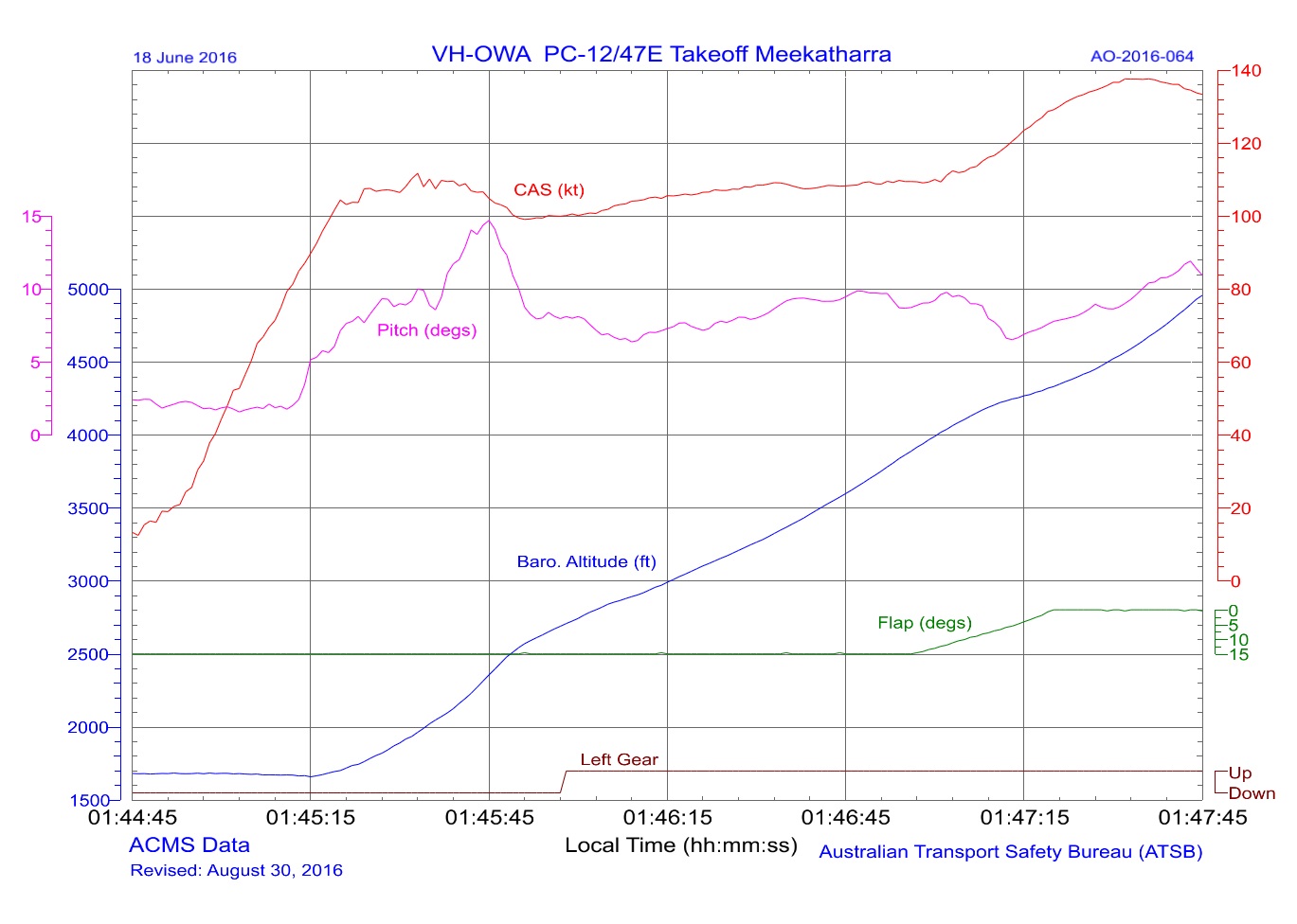
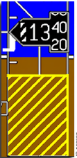
About 18 seconds after take-off, as the aircraft climbed through about 250 ft above ground level at an airspeed of about 110 kt, the pilots observed the radio altimeter (radalt) wind down to zero (see Radio altitude). The radalt low altitude awareness display rose to meet the altitude readout.
The synthetic vision image (see Synthetic vision system) on both pilots’ primary flight displays (PFDs) then showed the runway move rapidly left and off the screen, and the ground representation on the PFD appeared to rise rapidly up to meet the zero pitch reference line (ZPRL).[3] As a result, the pilot flying pulled back on the control column and the flight data showed the flight path indicator (see Aircraft reference symbols) moved up to about 15°. No warnings or cautions were displayed, the stick shaker stall warning did not activate (as the aircraft angle of attack was not in the shaker range), and the crew did not receive any oral alerts from the terrain awareness and warning system (TAWS).
The pilot flying reported that the synthetic vision image created the impression that the aircraft was sinking rapidly towards the ground, and they responded by instinctively pulling back on the control column. There was no vestibular sensation[4] that the aircraft was descending, nor had there been any indication of a strong wind that may have caused the aircraft to drift off the runway centreline. The resulting sensory confusion caused the pilot flying to experience a level of motion sickness.
The check pilot immediately looked outside (there was no standby instrument on the right side of the cockpit), and was able to discern a visible horizon due to the moonlight. The check pilot cautioned the pilot flying that the aircraft had a nose-high attitude, which prompted the pilot flying to switch their focus to the electronic standby instrumentation system (ESIS) and closely monitor the attitude and the airspeed tape (see Electronic standby instrumentation system). The pilot flying lowered the aircraft nose to regain an 8° pitch[5] attitude and the flight data showed that the airspeed, which had reduced to 101 kt, increased back to the target airspeed of 110 kt. The aircraft had continued to climb throughout the event.
Climbing through about 850 ft, the synthetic vision display corrected itself and all indications returned to normal. After retracting the landing gear and flap, the pilot flying deselected the synthetic vision mode on the left PFD. The check pilot continued to monitor the synthetic vision on the right PFD, and the issue did not recur during the flight. The aircraft subsequently landed at Paraburdoo Airport without further incident.
Flight data analysis
The flight data was downloaded from the aircraft condition monitoring system and analysed by the ATSB. Figure 1 depicts the calibrated airspeed and pitch angle from the start of the take-off roll. The change in pitch (pink line) from the pilot pulling back on the control column in reaction to the synthetic vision started at about 0145:30 in Figure 1.
Figure 1: Plot of selected data from the incident flight
Source: Aircraft flight data analysed by ATSB
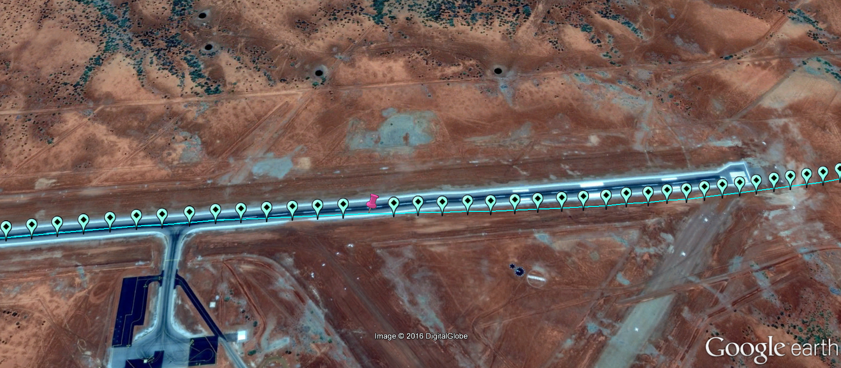
Figure 2 shows the aircraft recorded GPS track, with the pink marker indicating the first significant increase in pitch attitude, and therefore the approximate point of radalt failure. The aircraft was then at about 250 ft above the runway.
Figure 2: Deviation of OWA (travelling from left to right) from runway centreline showing the estimated point of the radalt failure (in pink)
Source: Google earth and aircraft flight data analysed by ATSB
Incorrect instrument indications
After the incident, an engineering assessment determined that both antennas associated with the radalt system (one for transmit and one for receive) had failed, and had been in service for over 9,000 hours. The antennas did not have a life limit, but were required to be replaced ‘on condition’, which essentially meant that the antennas remained in service until they failed. After consultation with the avionics manufacturer, engineers replaced both radalt antennas and also the radar transmitter/receiver. No subsequent similar event has occurred on the aircraft. The engineers also replaced the GPS 2 antenna due to slower than normal acquisition of satellite navigation after power up, and updated the GPS databases, although it was considered that these did not contribute to the incident.
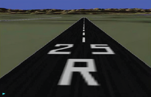
The engineers reported that this failure of the radalt antennas was likely to have resulted in the radalt winding down to zero, and the radalt low altitude diagonal bars to appear on the altitude tape to show the aircraft was close to the ground (below 550 ft) (see Figure 4 in Radio altitude below). Additionally, the radalt information was used in conjunction with the runway (and obstacle) information in the database to provide the synthetic vision system display. This resulted in the runway appearing to rise up towards the aircraft reference symbol on the PFD.
The movement of the runway to the left of the screen was probably associated with a small displacement of the aircraft to the right of the runway centreline. The wind at the time was from 094° at 9–11 kt, therefore largely a headwind component and the lateral displacement of the aircraft was unlikely to be a result of the wind.
As the radalt senses that the aircraft is nearing the ground, smaller lateral deviations from the runway centreline generate significant movement of the synthetic vision runway image.
Radio altitude
The radalt display is shown in green numbers on the PFD when the radalt data is valid and less than 2,500 ft (Figure 6). If the radalt data becomes invalid, the radalt digital readout is replaced with a radar altitude data (‘RAD’) annunciator and an amber RA 1 FAIL crew alerting system (‘CAS’) message is displayed. The crew did not receive any annunciations during this incident to indicate that the radalt had failed.
When the altitude displayed on the radalt is below 550 ft above ground level, low altitude awareness is displayed using diagonal yellow lines (Figure 3). During this incident, the crew noticed that the low altitude awareness symbology was displayed.
Figure 3: Radalt low altitude awareness display
Source: Honeywell
Synthetic vision system
The synthetic vision system fitted to the aircraft is depicted in Figure 4. It supplies a three-dimensional view of surrounding terrain, obstacles and runways based on a terrain database. Normal attitude, altitude and airspeed information is overlayed on top of the terrain display. The TAWS terrain database provides geometric altitude (obtained from the GPS) in order to display synthetic vision terrain and terrain related items such as runways and obstacles. During this incident, the synthetic vision system provided no failure annunciations.
Figure 4: Synthetic vision system example display
Source: Honeywell
Figure 5 shows a sample image of the runway scale for an aircraft on final approach for reference.
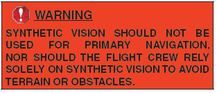
The synthetic vision system was not to be used for primary input or navigation, with the following warning issued by Honeywell in the Pilot’s Guide (used by the operator) to the avionics system:
A similar warning was contained in the Primus Apex Smart View supplement to the aircraft flight manual.
Both crew reported they were aware that the synthetic vision should not be used for primary navigation. When installed, the synthetic vision system is automatically activated at start-up but can be deselected by the pilot.
Aircraft reference symbols
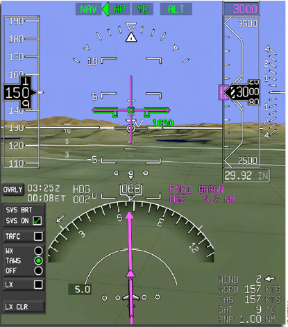
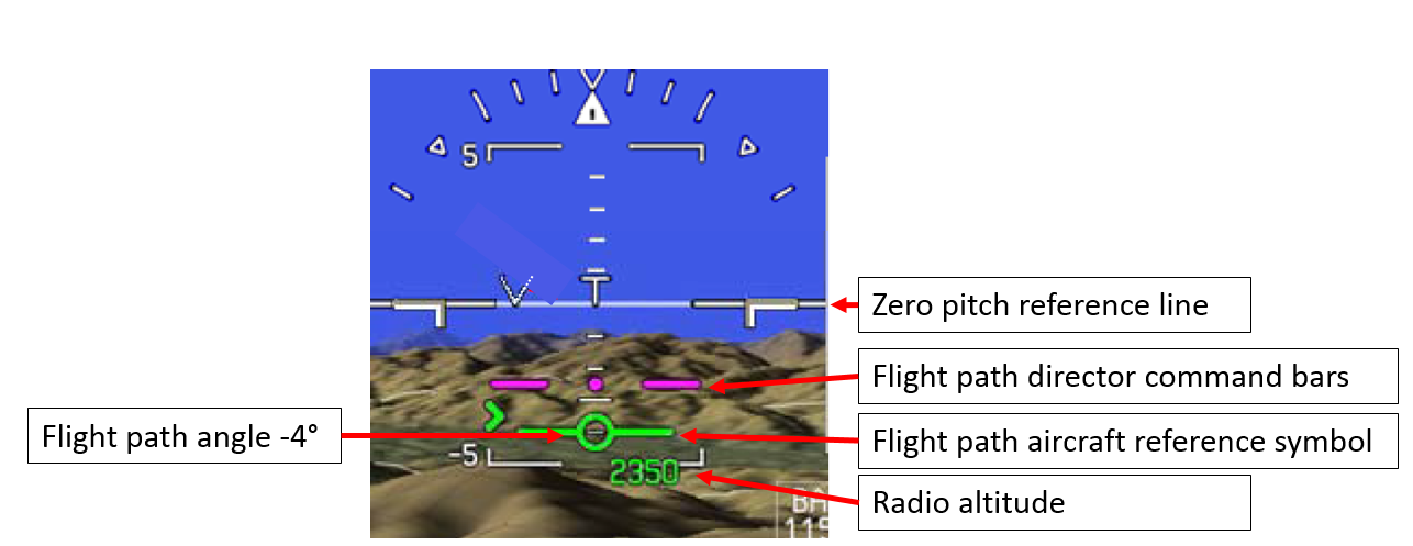
The pilot flying was using the flight path indicator on the synthetic vision system. This consists of the flight director command bars (magenta symbol in Figure 6) and the flight path aircraft reference symbol (green symbol in Figure 6). The flight path indicator is a path-based mode and depicts the aircraft’s predicted flight path (not just aircraft pitch) and is affected by pitch attitude and the aircraft’s ground speed. It shows flight path angles[6] – up for increasing and down for decreasing flight path angles, whereas the traditional pitch-based mode depicts aircraft pitch angle. The flight path angle depicted in Figure 6 is -4°.
Figure 6: Synthetic vision and flight path indicator symbols
Source: Honeywell
Electronic standby instrumentation system
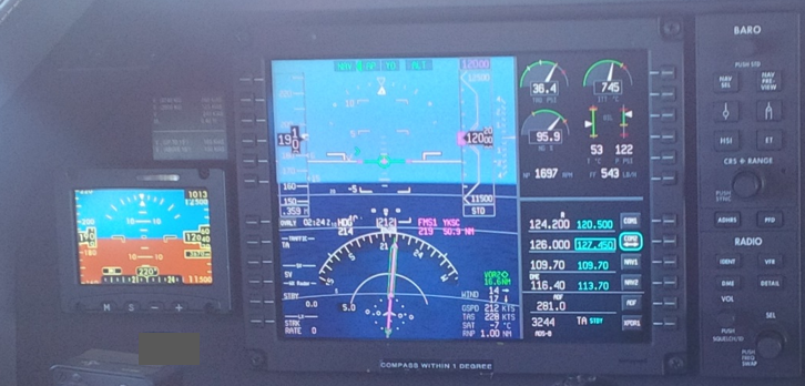
An electronic standby instrumentation system (ESIS) (or electronic standby indicator (ESI)), was fitted to the left of the pilot flying’s PFD. Figure 7 shows the pilot’s side PFD with the ESIS to the left of the main screen in another Pilatus PC-12 aircraft (not OWA). Note in this photo, the synthetic vision is on and the aircraft is over water.
Figure 7: Electronic standby indicator and main PFD in flight (not OWA)
Source: ATSB
Pilot comments
The two pilots were highly experienced; the pilot flying had over 11,000 hours total aeronautical experience and over 2,600 on the aircraft type, and the check pilot had over 15,000 hours total experience and 3,000 hours on type.
Both pilots commented that they had previously experienced failure of primary flight instruments at low level and at night in different aircraft (without synthetic vision systems). They had been able to disregard the erroneous or failed instruments and reference the standby instruments to maintain control of the aircraft and situational awareness. However, the prominence of the synthetic vision display is such that it is difficult to ignore erroneous information and locate valid information. Additionally, the pilot flying reported feeling a level motion sickness, probably associated with the combined effects of the prominent synthetic vision display and conflicting vestibular sensory information.
The combination of the runway and the radalt speed tape moving up gave the very strong illusion that the aircraft was going to hit the ground. The pilot flying reported that they realised something was wrong but could not initially figure out what it was. The image of the ground rising up and the runway disappearing rapidly sideways took the focus of the pilot flying away from anything else.
The pilot flying commented that the check pilot’s caution ‘attitude’ helped to redirect the pilot flying’s attention to the standby indicator. The check pilot could not easily see the standby indicator. Both pilots commented that the situation may have been more serious if operating single pilot or if they had already flown more sectors that night and been more tired.
The pilots commented that it was impossible to discern the valid attitude information on the PFD (overlaid on top of the synthetic vision) and revert to flying ‘power and attitude’ given the prominence of the erroneous synthetic vision information. While it is possible to deselect the synthetic vision, it requires two button presses or the use of the cursor control device to do so. That is very difficult to do at low level while maintaining control of the aircraft – keeping the right hand on the thrust lever and the left hand on the control column.
The Pilot Advisory Letter issued in response to this incident (see Safety action) reminded pilots to look at the primary flight indications presented on the PFD at all times. The pilot flying commented that it should refer pilots to the standby attitude indicator instead. The screen at the time of failure was simply too confusing to start looking for two small, white attitude bars. Similarly, to break the fixation on the erroneous information, it is important to look somewhere else at a different instrument – the standby indicator.
Most of the pilots’ training is done on board the aircraft, as they do not have access to a Pilatus PC-12 simulator. Although some system failures can be simulated, it is not possible to generate a false display as occurred in this incident.
Spatial disorientation
Spatial disorientation can occur when visual cues provide sensory inputs that are not matched by the motion sensed by the pilot through the vestibular senses. The discrepancy between the visual display showing the aircraft apparently descending towards the ground, and the lack of any consistent physical sensation, led to disorientation. The flight was conducted at night, and the pilot flying did not look outside for a visual reference. The check pilot did look outside and found that there was enough moonlight to provide some visual reference, sufficient to show the aircraft pitch and roll attitudes relative to the horizon.
ATSB research report ‘An overview of spatial disorientation as a factor in aviation accidents and incidents’describes this type of spatial disorientation as ‘recognised’. That is, the pilot identified that they were sensing erroneous information. The conflict between their own perceptions and that given by the instruments alerted them to a problem, which they were then able to address. However, the crew reported feeling some level of disorientation stress, or motion sickness, which is indicative of a disagreement between the senses.
The visual system provides around 80 per cent of orientation information, hence the overriding presence of incorrect visual information deprived the pilots of the majority of orientation information.
Other factors such as tiredness or fatigue, and high workload, can contribute to a pilot’s ability to assess and effectively deal with spatial disorientation. Both pilots commented that they wanted to share their experience because if they had been operating single pilot or near the end of a long shift, recovery from the instrumentation failure may have been much more difficult.
In addition, if the outside light conditions had been completely dark due to a lack of any moonlight in an area without terrain lighting, or the aircraft was in cloud, recognition of the spatial disorientation would have been reliant on the pilots being able to either extract the basic attitude, altitude and airspeed information from the primary display ignoring the background image, or revert to the accurate information depicted on the smaller standby indicator.
Pilots operating under instrument flight rules are trained to focus their attention on the visual information presented by the aircraft instruments and to ‘believe’ that information rather than the sensory information from the vestibular system, which can provide misleading cues.
The ATSB research report further states that:
…instrumentation should present a clear and intuitive sense of position, which the pilot under conditions of high stress and workload can instantly achieve an idea of what the aircraft is doing.
Failure of the aircraft instruments should hopefully never occur. However, in the event that it does, the pilot needs to receive clear and non-ambiguous indications of instrument failure. If a key instrument fails, such as the attitude indicator, the pilot needs to know that it has failed so they no longer depend on its information.
Manufacturer investigation
An investigation by the synthetic vision system manufacturer, Honeywell, found that the radio altimeter sent incorrect radio altitude data to the synthetic vision system while still indicating that the data was valid. Therefore, the synthetic vision display system continued to display the terrain information using incorrect data.
Safety action
Whether or not the ATSB identifies safety issues in the course of an investigation, relevant organisations may proactively initiate safety action in order to reduce their safety risk. The ATSB has been advised of the following safety action in response to this occurrence.
Aircraft operator
The aircraft operator has advised the ATSB that they have taken safety actions including the following:
Engineering replaced the RADALT aerials across the fleet.
The minimum equipment list has been amended to include synthetic vision.
Flight crew were alerted to the potential hazard of a synthetic vision failure during flight through a safety communication on 1 July 2016. The potential for confusion or spatial disorientation during an event, particularly at night or in low visibility environmental conditions was highlighted.
The event has been discussed by the Training and Check Department. They are reviewing the possibilities of incorporating scenarios related to ambiguous/incorrect information from the primary flight display into check flights and have commenced trialling a scenario.
Honeywell – avionics manufacturer
As a result of this occurrence, the avionics system manufacturer has advised the ATSB that they are taking the following safety actions:
Pilot advisory letter
Honeywell issued a Pilot Advisory Letter (PAL-APEX-01) to all pilots, chief pilots and flight operations managers on 11 August 2016. The letter included a description of the event. The letter also advised pilots that the use of synthetic vision is for situational awareness and should not be utilised for the indication of attitude or altitude in lieu of the primary flight display indications for pitch, roll, yaw, or altitude. The letter advises pilots to follow the primary flight indications presented on the PFD at all times.
The letter was also made available on the Pilatus ‘my pilatus’ website and all subscribers to that website were notified by email.
System solution
Honeywell is investigating ways to make the synthetic vision system more robust against a similar failure. The focus of their investigation is to prevent the synthetic vision display from continuing to display the image when the data is incorrect but assessed as valid by the Radalt.
Safety message
Incorrect instrument indications that are not associated with a failure mode present pilots with a complex and challenging situation. This situation may be exacerbated during single-pilot (rather than multi-crew) operations, where there is a lack of external visual references (such as at night or in instrument meteorological conditions), under high pilot workload conditions, or where a pilot is experiencing an elevated level of fatigue.
The image of terrain on the primary flight display is powerful and compelling. This incident highlights the manner in which an inaccurate synthetic vision image can rapidly lead to a degree of spatial disorientation. Pilots need to ensure that they are familiar with the limitations of the synthetic vision system and how to effectively deal with erroneous information as well as system failure modes. Organisations that operate aircraft fitted with similar technology should ensure that appropriate information and training is available to pilots, including when and how it should be used when it is not approved for primary navigation.
Decisions regarding whether to conduct an investigation, and the scope of an investigation, are based on many factors, including the level of safety benefit likely to be obtained from an investigation. For this occurrence, a limited-scope, fact-gathering investigation was conducted in order to produce a short summary report, and allow for greater industry awareness of potential safety issues and possible safety actions.
Publishing information
Released in accordance with section 25 of the Transport Safety Investigation Act 2003
Ownership of intellectual property rights in this publication
Unless otherwise noted, copyright (and any other intellectual property rights, if any) in this report publication is owned by the Commonwealth of Australia.
Creative Commons licence
With the exception of the Coat of Arms, ATSB logo, and photos and graphics in which a third party holds copyright, this publication is licensed under a Creative Commons Attribution 3.0 Australia licence.
Creative Commons Attribution 3.0 Australia Licence is a standard form licence agreement that allows you to copy, distribute, transmit and adapt this publication provided that you attribute the work.
The ATSB’s preference is that you attribute this publication (and any material sourced from it) using the following wording: Source: Australian Transport Safety Bureau
Copyright in material obtained from other agencies, private individuals or organisations, belongs to those agencies, individuals or organisations. Where you wish to use their material, you will need to contact them directly.
On 21 March 2016, a Cessna 172L, registered VH-XZZ, disappeared from radar about 7 NM (13 km) north-east of Byron Bay, New South Wales (NSW). The pilot was the sole occupant and, despite initial search efforts, the aircraft was reported as missing.
The accident is being investigated by the NSW Police Force on behalf of the NSW Coroner. The ATSB did not initiate a separate accident investigation; however, on 14 June 2016, the police advised the ATSB that the wreckage had been located and video recorded by the Royal Australian Navy. In addition, the police requested ATSB assistance with their examination the video footage of the wreckage.
To facilitate this support, on 15 June 2016 the ATSB initiated an external investigation under the provisions of the Transport Safety Investigation Act 2003. The ATSB completed its review of the video footage and provided a report to the NSW Police Force on 30 August 2016.
Any enquiries as to the planning for, or conduct or progress of the Coroner’s investigation into this accident should be directed to the:
State Coroner’s Court of New South Wales 44–46 Parramatta Road Glebe NSW 2037
Phone: (02) 8584 7777
_________________
The information contained in this web update is released in accordance with section 25 of the Transport Safety Investigation Act 2003.
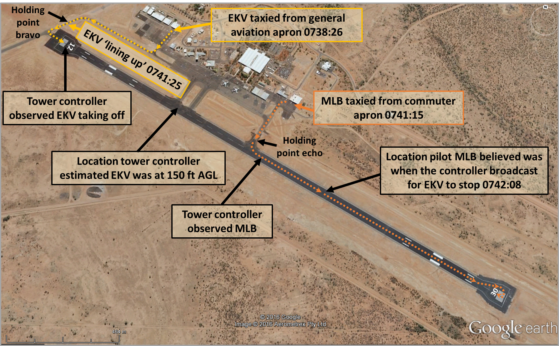
At about 0738 Central Standard Time (CST), a Cessna 172 aircraft, registered VH-EKV (EKV), taxied to depart from runway 12 at Alice Springs Airport, Northern Territory for Ayers Rock. The pilot and two passengers were on board the private flight. The air traffic control Tower was scheduled to open at 0800. At the time of departure, procedures for operating in the vicinity of non-controlled aerodromes applied at Alice Springs Airport. The airport has a common traffic advisory frequency (CTAF) when the Tower is closed.
The aircraft was located on the general aviation apron and taxied for holding point bravo for runway 12 (yellow line in Figure 1). The pilot of EKV broadcast a taxi call on the CTAF.
Figure 1: Alice Springs Airport showing the taxi routes and relevant locations of EKV (yellow line) and MLB (orange line)
Source: Google earth, modified by the ATSB
The transcripts of the relevant CTAF recordings are shown below, with the time, who made the broadcast, the transmission, and readability.[1]
Time
Source
Broadcast
Readability
0738:26
EKV
All stations EKV Cessna 172 taxiing for the runway 12 [AFRU[2] ‘Alice Spring CTAF’]
5. Perfectly readable
Following the broadcast by the pilot of EKV, several broadcasts were made on the CTAF where the airport rescue and firefighting service were conducting routine radio checks.
At 0741:15, the pilot of a Beech 58 aircraft, registered VH-MLB (MLB), broadcast a taxi call on the CTAF (the readability was 2, as the call was badly broken and very hard to understand). The aircraft was located on the commuter apron and taxied for holding point echo with the intention of then backtracking on the runway in preparation for a runway 30 departure (for a flight to Nyirripi) (orange line in Figure 1). The pilot and two passengers were on board the charter flight.
0741:15
MLB
Alice springs traffic MLB taxiing and backtracking runway 30 for Nirripi Alice Springs [AFRU tone]
2. Readable now and then
At 0741:25, the pilot of EKV broadcast that they were lining up on runway 12 (Figure 1).
0741:25
EKV
EKV lining up on 12 [No AFRU tone]
5. Perfectly readable
The pilot of MLB reported that they did not hear this broadcast from EKV, nor the earlier broadcast that they were taxiing for runway 12.
At 0741:30, the pilot of a Piper PA32 broadcast a taxi call (the readability was 3, with a loud squeal). The PA32 was located at the general aviation apron, close to where EKV had taxied earlier, and was taxiing for runway 12.
0741:30
PA32
Alice springs traffic [registration] taxiing runway 12 Alice Spring [AFRU tone]
3. Readable but with difficulty
The pilot of MLB responded to the broadcast by the pilot of the PA32, asking if they were happy for MLB to taxi (which included entering and backtracking the runway) for runway 30, and advised that they were ‘shortly to depart’.
0741:38
MLB
Aircraft taxiing runway 12 you happy for me to taxi runway 30 shortly to depart [No AFRU tone]
5. Perfectly readable
The pilot of the PA32 responded to that broadcast by indicating that they would hold short of runway 12.
0741:43
PA32R
Affirm [registration] will hold short [No AFRU tone]
4. Readable
The pilot of MLB responded, thanking the pilot of the PA32.
0741:47
MLB
MLB thank you [No AFRU tone]
5. Perfectly readable
Following this exchange between the pilot of the PA32 and the pilot of MLB, several broadcasts were made on the CTAF, where the airport fire and rescue service were conducting radio checks (at 0741:53, 0741:59, and 0742:02).
The pilot of MLB approached holding point echo and reported looking for other aircraft on approach or lined up on either runway (12 or 30). The pilot of MLB did not see any other aircraft and had not heard any other aircraft on the CTAF except for the PA32, so entered the runway and commenced backtracking runway 30 (orange line in Figure 1).
At about the same time, the pilot of EKV commenced take-off on runway 12. At about take-off speed, the pilot reported observing another aircraft enter the runway and start taxiing on runway 12 (away from them). The pilot assessed that it would be more dangerous to stop, so continued with the take-off.
An air traffic controller arrived in the control tower (which was due to open at 0800) and observed a Cessna 172 aircraft (EKV) taking off on runway 12 and a Beech 58 aircraft (MLB) taxiing on the same runway, about half way down the runway (Figure 1). The controller advised the pilot of EKV to stop immediately.
The pilot of EKV reported not hearing the advice to stop immediately, but was busy with the take-off. The controller reported that EKV was airborne approximately 500 m before the position of MLB and passed overhead MLB at about 150 feet above ground level. The pilot reported banking the aircraft to the north at about 500 feet and two-thirds of the way down the length of the runway to avoid any possible conflict with the aircraft (MLB) on the runway.
The pilot of MLB heard the controller’s advice to another aircraft to stop, but was not aware of the reason. During the turn at the end of the runway to line up on runway 30, the pilot noticed a Cessna 172 (EKV) in a left turn toward the north. The pilot broadcast on the CTAF for the aircraft in the Alice Springs circuit area to notify their intentions.
0743:57
MLB
Aircraft in circuit area at Alice Springs MLB just request your intentions [AFRU tone]
5. Perfectly readable
The pilot of EKV then gave a departure call at 0744:14 (readability was 4).
0744:14
EKV
EKV on climb to 3,000 departed time 14 [AFRU tone]
4. Readable
The pilot of MLB believed that the pilot of the Cessna 172 (EKV) had responded to their broadcast, and reported that the readability from the Cessna 172 was very poor. The pilot of MLB responded to the Cessna 172 at 0744:27, but that broadcast was over-transmitted by another aircraft making a taxi broadcast.
The next broadcast recorded from MLB was at 0747:19, where the pilot broadcast a departure call. The pilot reported having made lining-up and holding broadcasts, which may have been over-transmitted, and also making a rolling broadcast that was not recorded on the CTAF.
Both aircraft departed without further incident.
Pilot comment VH-EKV
The pilot reported generally operating at Alice Springs Airport when the tower was open, so would normally communicate with the tower controller. At the time of the occurrence, the Tower had not opened and the pilot reported hearing radio calls, but commented that radio calls from aircraft were not as clear as those made from the tower controllers. The pilot was aware that there was another aircraft departing to Nyirripi (destination of MLB).
Pilot comment VH-MLB
The pilot reported identifying the location of the PA32 as they approached holding point echo. The pilot commented that there were some white buildings in the distance behind the threshold of runway 12 that may have made it difficult to see EKV. The pilot indicated that the runway, although long, it is quite flat, and the whole runway was visible. The pilot also indicated that they were focused on known traffic. The pilot recognised the aircraft registration of the PA32 and the voice of the pilot, and confirmed the location of that aircraft before entering the runway.
The pilot reported that the winds were calm. They elected to use runway 30 as it was the most convenient runway for their departure.
Radio communication - Alice Springs airport
A study was conducted in 2010 by the Civil Aviation Safety Authority (CASA) to review the airspace classification above Alice Springs, Aeronautical Study of Alice Springs (YBAS) January 2010, and is available from the CASA website. The study consulted with stakeholders and did not identify any radio transmission ‘black spots’.
ATSB comment
The relevant communication recordings for the Alice Springs CTAF were obtained by the ATSB from Airservices Australia and the relevant broadcasts were given a readability level by the ATSB using the standard in radiotelephony communications as published in the AIP. The communications recorded are not necessarily what a pilot hears in their respective aircraft.
The ATSB could not establish why the pilots of both aircraft did not hear the broadcasts from the other aircraft.
Safety message
The ATSB SafetyWatch highlights the broad safety concerns that come out of our investigation findings and from the occurrence data reported to us by industry. One such concern is Safety around non-controlled aerodromes, which highlights that it is difficult for pilots to detect another aircraft through visual observation alone. The ATSB has identified that insufficient communication between pilots operating in the same area is the most common cause of safety incidents near non-controlled aerodromes.
This incident highlights the fundamental importance of effective communication, particularly during operations at a non-controlled aerodrome. The Civil Aviation Safety Authority (CASA) has produced several publications and resources that provide important safety advice related to operations in the vicinity of non-controlled aerodromes. Relevant guidance and explanatory material provided by CASA includes the following:
Decisions regarding whether to conduct an investigation, and the scope of an investigation, are based on many factors, including the level of safety benefit likely to be obtained from an investigation. For this occurrence, a limited-scope, fact-gathering investigation was conducted in order to produce a short summary report, and allow for greater industry awareness of potential safety issues and possible safety actions.
Publishing information
Released in accordance with section 25 of the Transport Safety Investigation Act 2003
Ownership of intellectual property rights in this publication
Unless otherwise noted, copyright (and any other intellectual property rights, if any) in this report publication is owned by the Commonwealth of Australia.
Creative Commons licence
With the exception of the Coat of Arms, ATSB logo, and photos and graphics in which a third party holds copyright, this publication is licensed under a Creative Commons Attribution 3.0 Australia licence.
Creative Commons Attribution 3.0 Australia Licence is a standard form licence agreement that allows you to copy, distribute, transmit and adapt this publication provided that you attribute the work.
The ATSB’s preference is that you attribute this publication (and any material sourced from it) using the following wording: Source: Australian Transport Safety Bureau
Copyright in material obtained from other agencies, private individuals or organisations, belongs to those agencies, individuals or organisations. Where you wish to use their material, you will need to contact them directly.
_____________________________
[1] As outlined in the Airservices aeronautical information publication (AIP), the readability scale is as follows: 1. Unreadable, 2. Readable now and then, 3. Readable but with difficulty, 4. Readable, 5. Perfectly readable.
[2] Alice Springs Airport has an aerodrome frequency response unit (AFRU) installed. The AFRU is to provide an automatic response to CTAF broadcasts to indicate to an operator that the correct radio frequency was selected and to confirm the operation of the radio’s transmitter and receiver, and the volume setting. If a broadcast has not been made on the CTAF in the preceding five minutes, and this transmission is over 2 seconds in length, a voice identification from the ARFU ‘Alice Springs CTAF’ is generated. If a broadcast has been made on the CTAF in the preceding five minutes, a 300-millisecond tone will be generated after each transmission over two seconds long.
On 15 June 2016, Sydney Trains’ maintenance staff identified the 64 crossover points[1] (64 points) at Clyde yard as unfit for service and arranged to book the points out of use. 63B points on the Up Main line were also booked out of service to prevent rail traffic from operating over 64 points.
On 18 June 2016, Sydney Trains’ maintenance staff obtained a Track Occupancy Authority (TOA) to protect civil rectification work on 64 points. The protective limits of the TOA extended only to defined clearance points on either side of 64 points and did not include 63B points.
At approximately 0530, as the repairs neared completion, two members of a signal maintenance team (SMT) tasked to test and certify the operation of 64 and 63B points, arrived at Clyde yard. Both members of the team entered the danger zone near 63B points where train W510 struck and fatally injured one worker.
What the ATSB found
Sydney Trains’ work-planning process, involving multiple work groups, did not assure the consideration of worksite safety for all tasks undertaken by each involved party over the duration of the work and when returning the rail infrastructure into service.
The Protection Officer (PO), who was part of the civil maintenance team, was aware of the signal team’s work tasks but did not consider these in his worksite protection arrangements. The PO had briefed the civil maintenance team, but did not brief the signal team, and the signal team did not seek a pre-work briefing before commencing work on-track. The PO was not provided with a briefing on the scope of the signal team work and did not provide protection at 63 points.
The signal team assumed their workplace was within the limits of the TOA and did not plan their own worksite protection. The signal team entered the danger zone unprotected and unaware of the approach of W510, and the Clyde Signaller did not recognise the signal team were in an unprotected area.
Network communications by various parties in Sydney Trains were not in accordance with the principles underpinning the network rules.
Although not contributing to the accident, the ATSB also found that Sydney Trains’ preference to keep the Up Main operational influenced the selection to use the clipped and locked 63B points to protect the worksite at 64 Points. The worksite protection method presented an increased risk in that if track workers inadvertently exited the worksite, they would be in the immediate vicinity of operational main line rail traffic.
The Sydney Trains worksite briefing process did not compel a new work group to seek a worksite protection pre-work briefing when accessing an existing worksite.
Finally, the lack of use of train headlights at night and the absence of any supplementary lighting (such as beacons) may have increased the likelihood of a train driver not seeing workers in the danger zone.
What has been done as a result
Sydney Trains delivered on a number of safety actions and commitments following the incident.
Some of the direct actions to address the contributing factors to the incident were:
Review and validation of proposed worksite protection plans is required through Sydney Trains’ Corridor Safety Centre.
Increased numbers of rail safety coaches and mentors, with a required coaching session for all Protection Officers at least once per year.
Protection Officers are required to implement a form of worksite protection at least once every quarter to remain eligible to be re-certified as a Protection Officer, this activity is monitored by the Corridor Safety Centre.
Additionally, Sydney Trains established a Post Incident Assurance Group (PIAG) to respond to the incident. This group established key focus areas to promote the safety of workers and avoid future incidents. These areas included; Worksite protection, Culture, Planning for maintenance work and Safety critical communications.
The PIAG later established the Safety Focus Program, which included key initiatives:
Safety Focus Sessions
Safety Culture Program
Improvements to Protection Officer selection and training
Signal Key Switch Project
Safety Critical Communication Enterprise Wide Program
Maintenance Access Planning Project, and
ATRICS ASB.
Safety message
This accident highlights the importance of planning and integrating safety across the entire scope of work. It also highlights the importance of briefing all workers and all workers seeking a safety briefing about the worksite protection plans before work commences and when circumstances change.
In the early morning of 18 June 2016, a civil maintenance team (CMT) neared completion of their work to replace sleepers under the crossover at 64 points in the Clyde Yard, New South Wales. A Track Occupancy Authority (TOA) protected the civil team’s worksite from approaching rail traffic.
A signal maintenance team (SMT) comprised of an electrician and mechanic were to then test and certify the operation of 64 points, and another set of points (63B) that had been booked out of service previously. During the testing, both members of the SMT left the area protected by the TOA to work on 63B points. As the SMT worked on the track at 63B points, an interurban passenger train (W510) travelling along the same track struck and fatally injured the SMT Mechanic.
Events triggering the civil task at 64 points
On 15 June 2016, a team of civil and signal engineering staff from Sydney Trains’ Clyde Network Base undertook an inspection of track infrastructure at Clyde Yard in response to ongoing drainage issues causing damage to the track and signalling equipment.
During the inspection, team members identified deficiencies associated with 64 points involving subsidence in the track formation material and decaying timber sleepers. The team categorised the deficiencies as an E2[2] defect and arranged Infrastructure Booking Authorities[3] (IBA) to remove 64 points and other signalling infrastructure from service. As an E2 defect required action to minimise risk within 24 hours, the team also recommended booking 63B points out of service to prevent trains accessing 64 points from the Up[4] Main Line (Figure 1).
On 16 June at 1020,[5] network based signal staff booked 63 points (A and B end) out of service and applied a point clip[6] to the ‘B’ end. On completion, the signal staff issued the signaller at Clyde Signal Box (Clyde Signaller) with IBA number 160616TPA, recording that 63B points were out of service. At 1340, network-based civil workers applied point clips to 64 points, issuing a separate IBA number 160616 to the Clyde Signaller.
The Clyde Signaller later identified the train plan could not be met for the Rosehill race event scheduled for 18 June 2016, as the IBA 160616 affected access to the siding leading off 64 points to allow storage of additional passenger trains on race day.
Planning of the civil task
On 17 June, the Assistant Area Manager, West Signal Box operations, sought advice from civil maintenance staff about the possibility of returning 64 points to service in time for the scheduled race day trains. Maintenance staff relayed the request to the manager for civil works based at the Clyde Network Base (Manager Civil), who initially denied the request due to the unavailability of sufficient materials, labour and plant.
After another request from train operations staff, the Manager Civil contacted the civil maintenance team leader (CMT Leader) who agreed to arrange labour for the repairs to the track at 64 points as an ‘emergency call-out’. Later that afternoon, the CMT Leader confirmed the availability of resources for the repair work to commence that night.
The civil maintenance team (CMT) were tasked with replacing a pattern of four timber sleepers under 64 points that had rotted, potentially affecting the safe operation of train services. The replacement of the sleepers would restore the condition of the track to comply with the Sydney Trains infrastructure standard. The Manager Civil allocated work tasks to the Protection Officer (PO) and CMT Leader near the end of their day shift. The expectation was that the work later that night would take about three hours to complete.
At 1442, the Signals Team Leader e-mailed the night shift SMT Electrician informing him the civil team would be fixing civil issues on 63 and 64 points that night and identified where the SMT Electrician would find the IBA and a handwritten disconnection list for various signalling infrastructure.
Figure 1: Site map of Clyde showing area of civil works and involved points
Source: Sydney Trains, annotated by ATSB
Arranging worksite protection for the civil task
At about 1900, the PO telephoned the Clyde Signaller to discuss the planned work and to enquire whether a Track Occupancy Authority (TOA) (see Network Rules) was required from the Clyde Signaller or if protections through the Pacific National Clyde Yard Master (PN Clyde Yard Master) were sufficient, as the PO understood 64 points to be within the PN yard[7]. The Clyde Signaller referred the PO to Pacific National for clarification.
About an hour later, the PO telephoned the Clyde Signaller to discuss further the rail infrastructure affected by the work. After confirming that the Clyde Signaller controlled 64 points, the PO discussed the requirement for a TOA to protect the worksite. There were several interruptions during the telephone call while the Clyde Signaller attended to other tasks. The PO informed the Clyde Signaller that he and the CMT Leader had to postpone discussions, as they needed to attend to a call-out at another location. They agreed to meet at the Clyde signal box on their return to continue planning the protection arrangements. In the meantime, the Clyde Signaller informed the Train Controller for the Goods Board (Goods Controller) of the PO’s plan for protecting the work in the Clyde Yard.
At about 2100, the SMT members commenced their rostered shift and began planning their night’s work, including reviewing e-mails from the signals team leader. About 30 minutes later, all of the CMT members had returned to work and signed on for their overtime shift at the Clyde Network Base. Shortly after, the SMT Electrician spoke to CMT members seeking additional information about the proposed work, who advised the SMT Electrician to contact the PO.
At about 2200, the PO provided a worksite protection pre-work briefing to the five members of the CMT, who each signed the worksite protection pre-work briefing form recording their attendance. The SMT were not asked and did not attend this briefing. However, the SMT Electrician reported making multiple attempts to contact the civil team in an attempt to understand the scope of works and timings. The SMT Electrician also recalled that around this time he contacted the PO who advised that the start time for the work on track was unknown.
At 2215, the Goods Controller contacted Infrastructure Control staff (ICON) enquiring if they knew of the civil work at Clyde Yard 64 points. ICON was not aware as Clyde Network Base had not informed them of the work. ICON undertook to confirm what was happening and contacted the CMT Leader to establish if they were to work on 64 points. ICON called the Goods Controller back to confirm that the civil team were working out protection with the Clyde Signaller, and to expect to hear from them.
Shortly after, the PO contacted ICON enquiring if they knew of the work at 64 points and again discussed the possible requirements for implementing a TOA. The PO and ICON discussed whether this required possession of the Main line as the PO maintained that the protecting signal must be greater than 500 m from the worksite[8] even though locking 63B points in the normal position already excluded rail traffic accessing 64 points from the main line. ICON questioned whether the PO really needed to take possession of the Up Main line referring the PO back to the Goods Controller.
The PO contacted the Goods Controller advising the need to take possession of the Up Main line and explaining that while locking 63B points in the normal position prevented rail traffic accessing 64 points, the points were within 500 m of the worksite. The Goods Controller referred the PO back to the Clyde Signaller to determine the TOA requirements.
Shortly after, the PO and the CMT members signed a ‘permit to work’ enabling access to the Pacific National (PN) managed portion of the Clyde yard. Around the same time, the PO contacted the Goods Controller advising the PN Clyde Yard Master would place blocking facilities[9] (blocks) in Clyde Yard preventing access to the worksite from the east and that the last PN train into the yard would arrive at approximately 0130.
While waiting for the last PN train to arrive, the CMT commenced some preparatory work in the PN yard area under the permit to work. During these preparations, members of the CMT accessed the track at 64 points to mark out the pattern for sleeper replacement and to remove some track fastenings. The work to remove the sleepers did not commence until after the last train had cleared and protection arrangements were in place for an excavator to cross tracks and access the worksite at 64 points (see Civil task at 64 points below).
At 2306, the Clyde Signaller and the Train Controller for the Outer Board (Outer Controller) discussed the protection needed for the work. The Outer Controller sought clarification of why a TOA would include the Up Main line to which the Clyde Signaller identified the 63B points were within 500 m of the worksite. The Outer Controller expressed the view that with 63B points clipped and locked in the normal position he could not see a risk, as trains could not access the worksite. The Clyde Signaller sought clarification if additional signal protections on the main line were necessary. The Outer Controller repeated that the only identified risk was from rail traffic entering from the east end of the yard, as the clip and lock on 63B points prevented rail traffic entering from the west end of the yard.
Shortly after, the Clyde Signaller contacted the PO confirming the work could go ahead with 63B points clipped and locked in the normal position. The PO again questioned the proposed protections, as 63B points were within 500 m of the worksite. The Clyde Signaller told the PO of the discussion with the Outer Controller and that they could not see a problem as long as 63B points were in the normal position and locked. The Clyde Signaller then advised the PO that the Outer Controller wanted to talk to him.
The PO contacted the Outer Controller repeating his view that protections had to be located 500 m from the worksite for a TOA. The Outer Controller replied ‘not necessarily’ and discussed with the PO that 63B points locked in the normal position ‘eliminated the risk’. The PO understood that the points excluded trains from the worksite but expressed an uncertainty about what protections were required and who would be approving them (Goods Controller or PN Clyde Yard Master). The Outer Controller informed the PO that an authority (TOA) was required, and advised he would talk to the Clyde Signaller about it.
The PO and Clyde Signaller then met at the Clyde signal box to discuss the details of the TOA in person before the Clyde Signaller called the PN Clyde Yard Master to inform him of the proposed arrangements for the TOA. The PN Clyde Yard Master was satisfied with the arrangements as long as it did not affect train movements in Clyde yard.
At 0005 on 18 June, the Clyde Signaller called the Outer Controller[10] to seek authorisation for the TOA. After going through the TOA details, and confirming the section was clear of traffic, and the signals had been set and blocks applied, the Outer Controller advised that TOA 35 had been authorised at 0011.
Civil task at 64 points
There was a delay to the start of the civil works until 0131 to clear a freight train movement into the PN yard before the CMT’s excavator could cross the tracks to access the worksite. After the freight train cleared, the Clyde Signaller advised the PO that he had placed blocks on several points (54, 56, 57, 60) to exclude rail traffic and protect the excavator as it accessed the worksite. The PO repeated the point numbers and recorded their details on the worksite protection plan.
At 0222, the Clyde Signaller informed the Outer Controller the IBA on 63B points would impact on the Race day program as the points were required to access the Up-storage siding. In a subsequent three-way telephone hook-up between them and ICON, the ICON representative informed the Clyde Signaller and the Outer Controller that he would get signals staff on the following day shift from Clyde Network Depot to book 63B points back in at about 0630. Around this time, the SMT Electrician contacted the PO advising they were in transit to the worksite when the PO asked them to collect a chainsaw en-route. The SMT arrived at Clyde yard at about 0318 and delivered the chainsaw before departing about 20 minutes later and returning to Homebush to wait for the work on 64 points to be completed.
At 0420, the PO called the Clyde Signaller to request an extension of TOA 35 by one hour to 0600, as the work was taking longer than expected. The Clyde Signaller confirmed the request with the Outer Controller before contacting the PO and extending the TOA.
Completion of the civil task and commencement of electrical testing of points 63 and 64
At 0523, the SMT Electrician contacted the PO to enquire on the progress of the civil works. He reported that he informed the PO that the SMT would not return until the TOA was back in place. The PO confirmed that the civil works were just about finished. Shortly after, the SMT arrived at the worksite and the SMT Electrician recalled that the PO told him there was a TOA in operation that would expire at 0600, but did not go into the details of the area that the TOA covered. The SMT Electrician recalled that there was no pre-work briefing provided by the PO and the SMT did not sign the pre-work briefing form. The PO recalled that he did not meet with the SMT on their return, so no pre-work briefing was possible.
At 0541, the SMT Electrician telephoned the Clyde Signaller to test the operation of 64A/B points. After removing a clip and lock, the SMT Electrician confirmed the correct operation of that point to the reverse and normal positions. The SMT Electrician then told the Clyde Signaller he would call him back when he got to the other end of 64 points.
At 0547, the PO contacted the Outer Controller to inquire if he could get a second extension to TOA 35. The extension of time was required to inspect the track before booking it back in to service. The Outer Controller advised the PO to contact the Clyde Signaller to arrange, as they could not extend a TOA more than once. The PO contacted the Clyde Signaller who then called the Outer Controller to arrange the second TOA, which was authorised as TOA 36. The Clyde Signaller then called the PO to provide details of the new TOA, confirming it was authorised and to fulfil TOA 35.
At 0604, the SMT Electrician telephoned the Clyde Signaller to complete testing of 64 points. The SMT Electrician then told the Clyde Signaller, ‘okay, I’m finished with 64…. Just got to take the point clip off 63’. The SMT Electrician then commenced walking toward 63B, while maintaining the mobile telephone connection with the Clyde Signaller. The Clyde Signaller asked the SMT Electrician to ‘hold on a minute’ while he contacted the Outer Controller to advise the time that TOA 35 was fulfilled.
Around the same time, the SMT Electrician had begun removing the point clip and lock from 63B points but had difficulty, so he called out to the SMT Mechanic to bring a podger (metal crow bar).
At 0607, the SMT Mechanic arrived at 63B point with the bar and took over removal of the point clip and lock. Both members of the SMT had entered the danger zone unprotected and unaware of approaching train movements. Concurrently, train W510 travelling on the Up Main line at a speed of about 67 km/h passed through Clyde Station and approached 63B points.
The SMT Electrician recalled he was conversing with the Clyde Signaller regarding the IBA for 63B points while opening the lid to the point machine to check for lock and detection when he noticed the approaching train and yelled a warning to the SMT Mechanic. About the same time, train W510 passed over 63B points, striking and fatally injuring the SMT Mechanic.
Figure 2: 63B points in normal position prevents movements towards 64 points
Source: ATSB
Post-collision
The collision caused the air brakes on the train to apply[11] and the train came to a stand about 20 seconds and 200 m later. The train driver contacted the Clyde Signaller informing him that the train had come to a stand after striking something then losing the air, and he could not build air pressure back up. The Clyde Signaller informed the train driver that the train had struck a worker on the track.
At 0611, the Clyde Signaller called the Outer Controller and requested the emergency services to attend to the site. The Outer Controller commenced notifications, initiated incident management procedures and commenced diverting other rail traffic from the area. He arranged with the Clyde Station Duty Manager and Sydney Trains Security for Police and Ambulance to arrive on site. At 0615, the Incident Response Commander received notification and arrived on site at 0653. A supporting Incident Response Commander arrived on site at 0720.
Clyde Yard is located in the Main Western rail corridor approximately 20.660 km[12] by rail from Sydney Terminal (Figure 3). Clyde is a junction of the Main West and Carlingford rail lines.
Figure 3: Location of Clyde
Source: NatMap, Railways of Australia, Geoscience Australia, annotated by ATSB
Clyde Yard is on the northern side of the Main Western line and is utilised by Sydney Trains for through movements and stabling of passenger trains and by Pacific National for the stabling of freight trains and limited maintenance activities.
Track layout at Clyde
The Up and Down Main lines and Up and Down Suburban lines at Clyde, between Auburn (18.551 km)[13] and Granville (21.148 km), are part of the Sydney Trains-controlled Metropolitan Rail Area network. Sydney Trains was responsible for track maintenance, signalling, network control and incident management functions in this corridor. The posted track speed for the Up Main line through Clyde station and over 63B points was 80 km/h for electric passenger services.
The Clyde signal box provided the control and monitoring function for all signals and points on the Up Main line around the 63 and 64 points together with other signalling equipment within the area of control. This area encompassed the Main West line spanning approximately 1.2 km to include the entry/exit to/from the Carlingford line, Pacific National freight yard (Country end) and Auburn Maintenance Centre (Country end). The control area abutted Auburn signal box (on the Sydney side) on the Down Main, Suburban, Relief and Through Roads, Granville signal box (on the Countryside) on the Up Main and Suburban lines, and Parramatta Road signal box on the Carlingford line.
The Pacific National rail freight yard consisted of a system of tracks used for shunting and marshalling of freight trains (Figure 1). The PN Clyde Yard Master[14] was responsible for coordinating, managing and directing the safety of all rail movements within the PN yard area.
Operational interfaces and staff involved
Train Controller
The primary responsibility of train controllers is to manage train paths for the safe and efficient transit of rail traffic. Train controllers and their supervisory staff were located within the Rail Management Centre (RMC) at Sydney Central Station along with representatives of other supporting functions including ICON, customer and information services, security, train crewing and train monitoring. The RMC provided 24/7 integration and coordination of all operational train services (both Sydney Trains and non-Sydney Trains services) in the area bounded by Nowra, Macarthur, Newcastle and Lithgow. For the works at Clyde on 17–18 June, the train controllers (Goods Controller and Outer Controller) had visibility of the layout and status of the points, signals and other monitored equipment at Clyde via an overview (mimic) panel.
Signaller at Clyde Signal Box
The primary responsibility of the Signaller is to issue Occupancy Authorities and control points, signals and other signalling equipment to manage routes for the safe and efficient transit of rail traffic through the area of their control. The Signaller is also responsible for issuing work on track authorities (LPA and TOA) and work on track methods.
The signaller at the Clyde signal box (Clyde Signaller) was a Sydney Trains employee with 34 years’ rail experience. The Clyde Signaller held the required qualifications and competency for the role performed and was assessed fit for duty in accordance with the requirements of the National standard of Health Assessment for Rail Safety Workers.
Although the Clyde Signal Box was located in close proximity to the worksite, the Clyde Signaller could not physically see the civil worksite at 64 points or persons moving within the worksite or yard area on 17-18 June 2016. This is because the signalling system is an electronic system that does not require a line of sight for the signaller to operate. In this instance, the Clyde Signaller’s work station faced away from the windows that looked out to the Clyde Yard and the worksite location (Figure 4 and 5). The Clyde signaller was not required or expected to watch the actual work activities in the Yard.
Figure 4: Clyde Signaller’s workstation
Source: ATSB
Figure 5: Daylight view of Clyde yard from Clyde Signal Box
Source: ATSB
Civil Maintenance Team
The civil maintenance team (CMT) comprised:
A PO (responsible for managing worksite protection)
an acting team leader (CMT Leader) responsible for managing the rectification work
three civil infrastructure workers under the direction of the CMT Leader
a third party contract excavator operator.
All members of the CMT, except the excavator operator, were Sydney Trains employees based at the Clyde Network Base. All the Sydney Trains CMT members had worked their rostered day shift between 0700 and 1500 prior to returning to work at 2130 to repair 64 points on an overtime shift.
The Protection Officer
A Protection Officer (PO) was responsible for managing the rail safety component of worksite protection to keep the work site and the workers in the work site safe from rail track movements. The PO was a Sydney Trains employee with five years rail experience. The PO held the required qualifications including a worksite protection competency (protection officer level 2) for the role performed and was assessed fit for duty in accordance with the requirements of the National standard of Health Assessment for Rail Safety Workers.
On 17 June, the PO commenced his rostered shift at 0539, although the PO was not involved in the planning of the repair work, he concluded his shift at 1500 with the understanding that the CMT would return later the same day and commence an overtime shift at 2130 and he would be arranging protection for this emergency work.
Signal Maintenance Team
The Clyde Network Base signals work group comprised two signal electricians and two signal mechanics, a Senior Signals Engineer and Signals Team Leader. The signals work group were responsible for checking signals and points were operable before going back into service, conducting out-of-course repairs and minor routine maintenance to signalling equipment and points throughout the rail network bounded by Clyde, Macdonaldtown, North Strathfield, Sefton and Marrickville. Additional areas of responsibility included the Up and Down Yards at Clyde, the Carlingford line, the Olympic Loop line, the Goods line at Chullora and Enfield Yard. The signals work group regularly worked with the civil maintenance teams undertaking repairs to track and other civil infrastructure.
General supervision and tasking of signal maintenance staff was the responsibility of the Senior Signals Engineer and Signals Team Leader. However, as these positions worked weekday business hours, there was little interaction outside business hours, with tasking routinely made via notes or e-mail.
The signal maintenance team members (SMT) involved in the accident included a signal electrician (SMT Electrician) and a signal mechanic (SMT Mechanic).
On the 17 June 2016, the Signals Team Leader emailed the SMT Electrician with the tasking and instructions for their shift that night. The Signals Team Leader wrote:
Tonight [CMT] will be chucking a few new timber in points in Clyde Up Yard. They are planning on starting at 2200. They will only be fixing the civil issues on 63 and 64 points not cleaning the rusty rails. On my shelf there is a disconnection list and IBA for you. Hopefully it goes smoothly. Also I’ve chucked a two Loc’s at CLJ onto T4 but it won’t let me attach them to this email so I sent a different one.
The SMT Electrician was a Sydney Trains employee with 13 years’ rail experience. The SMT Electrician held the required qualifications for the role performed as well as competencies in worksite protection (protection officer level 3). The SMT Electrician was assessed fit for duty in accordance with the requirements of the National standard of Health Assessment for Rail Safety Workers.
The SMT Mechanic was a Sydney Trains employee with 26 years’ rail experience. The SMT Mechanic held the required qualifications for the role performed as well as competencies in worksite protection. The SMT Mechanic was assessed fit for duty in accordance with the requirements of the National standard of Health Assessment for Rail Safety Workers.
Network Rules
The Sydney Trains Network Rules prescribe the requirements to manage safety on the network for train operations and working in the rail corridor.
NWT 300 Planning work in the rail corridor
Network Rule NWT 300 Planning Work in the Rail Corridor required a safety assessment of the work and of its potential to intrude on the danger zone. Work in the danger zone must use one of the protection methods listed below and not begin until the required safety measures were in place:
one of three authorities:
Local Possession Authority (LPA)
Track Occupancy Authority (TOA)
Track Work Authority (TWA)
or method of protection:
Absolute Signal Blocking (ASB)
or safety measure:
Lookout Working.
The level of safety must not be reduced to allow rail traffic movements and each work on track method had mandatory minimum safety measures with the highest protections provided by an LPA to the least provided by Lookout Working.
The preferred methods for working on track were the LPA and TOA. In addition to the safety assessment and selection of protection method, Network rule NWT 300 required the PO to:
brief workers about the rail safety component of worksite protection
make sure that the rail safety component of the work is done safely
keep records about the method used for working safely on track and protection arrangements, and
communicate with the Network Control Officer about the work.
Sydney Trains form NRF 015 Worksite Protection Plan defined the type and format of information recorded by an assigned PO. In completing the worksite protection plan for the civil works at Clyde 64 points, the PO had several discussions with operational staff to determine the protection arrangements for the work.
The PO’s initial plan for the TOA included locating worksite protection (track signals, flags/lights) on the main line, to provide the specified distance of 500 m between the worksite and the worksite protections. However, the Train Controller advised that there was no need for an occupancy on the main line, as with the 63B points clipped and locked in the normal position trains could not access the worksite area from the main line.
To clip and lock points, a qualified rail safety worker fits and secures a mechanical clamp to the track securing the point blades to the desired lie (normal or reverse). Once installed, the lie of the points cannot change until the point clamp is removed; ensuring the direction of any rolling stock movement is only possible in the configured direction (Figure 6).
Figure 6: Application or removal a point clip
Source: Sydney Trains, annotated by ATSB
NWT 304 Track Occupancy Authority
The basic principle of work-on-track rules is to provide clear separation between track workers and trains. A Track Occupancy Authority (TOA) achieves this by authorising exclusive occupation of track within specified limits for undertaking work on track, for an agreed period. Sydney Trains’ Network Rule NWT 304 Track Occupancy Authority prescribed the rules for authorising, issuing and using a TOA. The rule defines the TOA limits as being between yard limits, or between defined clearance points,[15] or may be a combination of the two. The worksite lies within the TOA limits and has defined boundaries/limits.
The network rule (NWT 304) defined the requirements for protecting both the TOA limits and for protecting the worksite. The rule stated:
Protecting TOA limits
- All points of entry into the TOA limits must be protected.
- The Signaller must apply blocking facilities[16] to prevent unauthorised rail traffic entry into the TOA limits.
In addition:
Protecting Worksites
- Worksites must be protected by three Railway Track Signals and red flags/red lights placed at least 500m from each side of each worksite.
Worksite within 500m of TOA limits
- Unless a set of points can be clipped and locked to prevent access to the portion of track within the TOA limits, the distance between the signal protecting the limits of the TOA and the worksite must not be less than 500m.
A second document, NPR 701 Using a Track Occupancy Authority, provides additional information regarding the procedures for using a TOA, including some examples illustrating the methods for protecting worksites.
Figure 7 illustrates the typical protection arrangements for a worksite on straight track. A signal at least 500 m from the worksite is required for the ‘Protecting Controlled Absolute Signal’. Blocking facilities applied to the protecting controlled absolute signal provides the primary method for excluding rail traffic from the worksite.
If a train driver inadvertently passes the protecting controlled absolute signal, the train would subsequently pass over the worksite protection (track signals, flags/lights) 500 m before reaching the worksite. This, in effect, provides a second layer of defence whereby the train driver receives a warning that they are approaching a worksite and must take action to prevent entry into the worksite.
Figure 7: Worksite protection
Source: NPR 701 Using a Track Occupancy Authority
Figure 8 illustrates the protection arrangements for a worksite where the protecting controlled absolute signal is within 500 m of the worksite, but a set of points is available to route trains on a track other than the one containing the worksite. In this scenario, the points must be set, clipped and locked for the alternative route to prevent trains accessing the TOA limits and the worksite contained within. The signaller could also apply blocking to the point controls as part of the protection arrangements.
Figure 8: Worksite protection
Source: NPR 701 Using a Track Occupancy Authority
When implementing the TOA on the night of 17 June 2016, the PO thought protection had to be implemented as per the scenario illustrated in Figure 7. That is, the facilities providing worksite protection were to be located on the main line, at least 500 m from the worksite.
However, after several discussions with train controllers, signallers and ICON, the PO was made aware the application of protections could be done as illustrated by the scenario in Figure 8. That is, since the IBA on 63B points meant they were set, clipped and locked for the main line, rail traffic was excluded from the track containing the worksite. The scenario also negated the requirement to place worksite protections (track signals, flags/lights) 500 m from the worksite. The solution proposed by Sydney Trains’ operations staff provided the operational advantage of not occupying the main line, leaving it active for the passage of rail traffic.
Worksite protection arrangements
The Network Rules for work on track require the PO to brief the workers about the site-specific hazards and the protection measures in place before work begins. The Site Supervisor may also provide a briefing of the work planned. The PO must record details of the worksite protection pre-work briefing and the workers who attended the briefing, or amendment to the briefing, on the Network Form NRF 014 Worksite Protection Pre-work Briefing.
Additionally, the Sydney Trains’ guidance document Working Safely Handbook advised it was a responsibility of all workers to ensure they attend a pre-work brief before starting work.
Implementation of the worksite protection and pre-work briefing for civil works
The PO undertook the worksite protection pre-work briefing with the CMT members at the Clyde Yard. The briefing documentation included the Worksite Protection Plan (WPP), Pre-work Briefing form (PWB) and documentation specific to the use of an excavator under live overhead wiring.
The WPP and PWB required the PO to produce or attach a diagram/map to represent the worksite protection arrangements. The PO in this instance used a Drivers Route Knowledge Diagram (DRKD) to illustrate the location of points, signals, tracks, protections and safe areas.
The DRKD did not identify all signals and points used by the PO and Clyde Signaller to protect the movement of the excavator when crossing the tracks to access the worksite (Figure 9).
Figure 9: Photograph of PO’s work plan with annotation on the DRKD
Source: ATSB, annotated by ATSB
The PO annotated the DRKD to record that the Clyde Signaller applied blocking facilities to 54, 56, 57 and 60 points that were outside the limits of TOA 35. The limits of TOA 35 were the Clyde end of Storage Siding to Down through Road between 23L Signal and 24R Signal and indicated by a light green highlighted area on the DRKD (Figure 9). In order to protect the limits of the TOA, the Clyde Signaller placed 23L and 24R signals at stop and applied manual blocking facilities on the route and track (including points) ahead of those signals. The application of the blocking facilities was a second layer of control to prevent the inadvertent clearing of the signals and movement of points.
NGE 204 Network communication
The procedure NGE 204 Network communication prescribed the rules for spoken and written communication in the network. In principle, Sydney Trains required that communications must be clear, brief and unambiguous, relevant to the task, and agreed as to its meaning before being actioned.
If the communications related to safeworking arrangements, parties must utilise the 24-hour clock, phonetic alphabet, spoken numbers and standardised terminology to identify items such as train and signal identifiers.[17] The procedure mandated the receiver of the message repeat the message back to the sender for communications such as a work on track authority and work on track train running information. NGE 204 contained a ‘WARNING’ that:
Qualified Workers must not assume that a receiver has understood a message before the receiver confirms that the message has been understood.
After returning to work, the PO communicated with various train controllers and the Clyde Signaller to discuss the civil work requirements, and establish the work location in the Clyde yard relative to areas of control and the method for applying worksite protections. Similarly, the train controllers, Clyde Signaller and PO communicated to establish and record details of the safeworking arrangements associated with the TOA’s.
Passenger service W510 and train crew
Train W510 was an intercity electrical multiple unit passenger service operated by NSW Trains. W510 was crewed by a driver and a guard. It consisted of the lead set V26 made up of cars 8081 (lead car), 9105, 9037 and 8077; and the rear set V21 made up of cars 8032, 9032, 9036 and 8036.
The service departed from Lithgow at 0338 and was on schedule. The service, carrying 49 passengers, had just departed from a scheduled stop at Granville and was travelling according to ‘proceed’ signal indications on the Up Main Line toward the next scheduled stop at Strathfield. The train was travelling at 67 km/h at the time of the accident. The collision activated a trip mechanism causing the release of brake pipe air and automatic application of the train brakes. The train continued for a further 19 seconds travelling approximately 200 m before coming to a stop.
Train crew
The driver had 20 years’ rail experience, which included 16 years’ driving passenger and freight trains. The driver, from the NSW Trains depot at Lithgow held the required qualifications for the role performed. The driver was assessed fit for duty in accordance with the requirements of the National standard of Health Assessment for Rail Safety Workers.
The guard was travelling in the last carriage 8036, and did not have any involvement in the accident sequence.
External train lighting
The Rail Industry Safety Standards Board (RISSB) coordinated the development of Australian Standards, Codes of Practice, Guidelines and Rules for the rail industry.[18] RISSB developed a standard for rail traffic lights and markers.[19] Adoption of the RISSB product was not mandatory and it was the responsibility of the Rail Transport Operator to develop a train lighting standard relevant to the safety risks being managing within its network. Sydney Trains, as an accredited rail transport operator,[20] developed a train lighting standard specific to its network requirements.
Sydney Trains lighting standard
Network rule NTR 406 Using train lights prescribed the use of train headlights for the Sydney Trains Network requiring:
Trains must have a working headlight fitted to the leading locomotive, and travel with the headlight switched on, when the train travels beyond the:
- Sydney area, including intermediate branch lines, bounded by Helensburgh, Macarthur, Emu Plains and Cowan, or
- Newcastle area, including intermediate branch lines, bounded by Newcastle, Fassifern and Islington Jct, or
- Wollongong area, including intermediate branch lines, bounded by Thirroul and Unanderra.
NOTE Unless headlights are needed for safety, trains fitted with headlights must have their headlights switched off when travelling through the areas prescribed above.
Switching headlights offHeadlights must be switched off during approach to another train.Headlights must be switched off or dimmed during approach to:
- A motor vehicle on a nearby road
- A platform
- A signal box
- A location where shunting is in progress
Headlights may be switched off to prevent back-reflection into a driver’s or track vehicle operator’s eyes.
Before headlights are temporarily switched off, visibility lights, if fitted, must be switched on.
Sydney Trains rules therefore required the driver of train W510 must, unless needed for safety, have the headlights switched off as it was operating within the Sydney metropolitan area and near the Clyde Station platform and Clyde Signal Box.
Event recorders from W510 and the Clyde Station CCTV footage confirmed the driver had extinguished the headlights of train W510. The leading car displayed two white marker lights; two visibility (ditch) lights and one coupler light (Figure 10).
The marker lights (top left and right) indicated the front (white) or rear (red) of a train. Ditch lights (bottom left and right) illuminated the track immediately in front and improved detectability of the train. The coupler light provided illumination to assist train crew in coupling/uncoupling passenger cars when required.
Figure 10: Train lighting on front of W510 as it approached Clyde Station
Source: Sydney Trains, annotated by ATSB
The primary purpose of visibility lights was to improve detectability of the train by road users. The engineering standard detailing the minimum operating standards for rolling stock[21] specified the visibility lights were to project at least 25 m in front of the vehicle at top of rail and then be aimed/turned cross-eyed to between a minimum of 7.5 degrees and maximum of 15 degrees to the longitudinal centreline of the vehicle (Figure 11).
Figure 11: Side view and Top view of visibility light aiming
Source: RSU 600 Series – Minimum Operating Standards for Rolling Stock – Multiple Unit Train Specific Interface Standards v 1.0
Figure 12, taken from a similar Sydney Trains K-Set type car showing the typical illumination pattern and forward illumination of the track provided by the visibility lights.
Figure 12: Similar train type showing visibility (ditch) lights illuminating track ahead
Source: ATSB
Environmental factors
The morning of 18 June 2016 was cool and cloudy with 4.8 mm of rainfall recorded in the 24 hours to 0900. The overnight minimum temperature was 12.4 °C as recorded by the Bureau of Meteorology at Sydney Olympic Park, approximately 5.3 km (East) from Clyde station.
At the approximate time of the accident, there was little ambient lighting in the area around 63B points. The floodlighting used by the CMT during the sleeper replacement works was off and the CMT team leader and SMT were working on the tracks using torchlight.
CCTV footage from Clyde Station and the nearby Auburn Maintenance Centre illustrated the likely level of ambient lighting present and the presence of steady rainfall around the time of the accident (Figure 13).
Figure 13: CCTV footage depicting environmental conditions as W510 passed through Clyde station moments before the accident
Source: Sydney Trains, annotated by ATSB
A site visit on 22 June 2016 conducted at a similar time to the accident photographed the ambient lighting conditions at 63B points (Figure 14). The train service shown had a similar lighting configuration to the lead car on train W510. A slight increase in illumination in close proximity to the front of the train due to the visibility lights is evident.
Figure 14: Ambient lighting near 63B points on 22 June 2016
Source: ATSB
Conspicuity of workers on or about the track
All rail safety workers when on or about the track, are required to wear approved Personal Protective Equipment which included high-visibility safety vests/wet weather attire with reflective markings.
The SMT Electrician was wearing standard cotton drill pants and high visibility reflective shirt and the SMT Mechanic was in similar attire but additionally wearing a recommended wet weather jacket that also had high-visibility reflective striping over the shoulders, with a cross on the back and strips around the cuffs. In darkened conditions, reflective clothing exhibit little utility unless they were self-illuminating, or exposed to some form of external light source that caused them to reflect.
To mitigate risk in low light conditions, Sydney Trains Safe Work Instruction D2015/7605 Use of Flashing Beacons in the Danger Zone at night[22] required workers to display a flashing beacon when entering the Danger Zone at night. Sydney Trains identified the use of flashing beacons as an effective means of improving the visibility of workers operating within the danger zone at night. The beacons were designed to increase rail traffic driver’s visibility of workers at night. Each workgroup required at least one beacon, with additional beacons displayed where there was a distance of more than 50 m between workgroups. Positioning of the beacons were required to ensure they are clearly visible to approaching train drivers.
The Sydney Trains instruction and related SafeTracks bulletins identified that:
The use of flashing beacons does not reduce or replace the requirements in the Network Rules or Procedures relating to worksite protection.
Neither the CMT nor SMT members deployed flashing beacons at the worksite or wore them individually during the works at the Clyde yard on the 17 and 18 June 2016.
Fatigue management
The National Transport Commission (2008) defines fatigue as:
A human condition primarily caused by prolonged wakefulness and/or insufficient or disturbed sleep. It includes physical, cognitive, psychological and physiological dimensions that interact with each other to reduce human performance and lead to uncontrollable sleep onset.
Humans cycle through numerous circadian rhythms with daily peaks and troughs. The National Rail Safety Guideline on Management of Fatigue in Rail Safety Workers (NTC 2008) highlights aspects of circadian rhythms that are relevant to fatigue management of rail safety workers. Alertness, physical and mental performance both reach their circadian low in the early morning (between about 0300 and 0500) when the physiological drive for sleep is greatest. The occurrence happened shortly after the circadian low.
Sydney Trains were required to manage the risk of fatigue in its rail safety workers. This included scheduling of work to allow for sufficient sleep opportunity as well as systemic management of fatigue through Fatigue Risk Management Systems. The Sydney Trains Fatigue Risk Management program included procedures on how to manage fatigue risk and the rostering principles outlined the safe hours of work (maximum of 12 hours) and rest (minimum of 12 hours) for typical hours of duty and planned overtime.
The operating procedure for the management of fatigue risks[23] outlined a risk management approach to identify, assess and implement control measures to mitigate risk exposure to rail workers in workgroups and worksites where shift work and extended hours’ arrangements were undertaken.
The investigation explored the possibility that the time of day, working during the circadian low point (3am to 5am) and the rostered work hours may have contributed to an increased feeling of fatigue in some of the workers on duty that night.
The ATSB assessed the probable fatigue levels of the SMT members, the CMT Leader, the PO and Clyde Signaller. Information taken into account included sleep (quantity and quality) in the previous 24 hours, workload, time at work, work break (rest and food) opportunities, and the use of two bio-mathematical fatigue models (FAST and FAID).
Of the workers assessed, shift duration and the time of day affected them equally and were assessed to have a moderate likelihood that their alertness on duty may have been affected.
Only the PO and the CMT Leader were assessed as likely to be experiencing a level of fatigue known to affect performance. However, in the context of the work tasks they were involved in on the night and their performance of these tasks, the ATSB did not consider their level of fatigue influenced decisions made on the night of the accident.
Drug and alcohol testing
The Rail Safety National Law (NSW) prescribed the post-incident testing of a rail safety worker for the presence of a proscribed drug or alcohol. The legislation required rail safety workers involved in a prescribed incident to undergo a breath test and provide a sample (oral, blood, or urine) within 3 hours of an incident. The Shift Manager within the RMC coordinated the testing of Sydney Trains rail safety worker/s directly involved in a prescribed incident.
Between 0640 and 1000 on 18 June 2016, the two-crew members from W510, PO, Clyde Signaller and the SMT Electrician undertook the testing and all parties returned a negative result.
The toxicology results from the post-mortem showed no presence of alcohol or other drugs in the deceased.
For any track rectification work, the section of track requiring work needs: firstly, to be booked out of service; secondly, worked upon and rectified; and thirdly, tested and booked back into service. At each stage, where workers are required to access or occupy the rail track, suitable safety measures are implemented to protect those people on track.
Each phase of work can be and was often completed independently.
For the work on 64 points crossover, 63 and 64 points were booked out of service on 16 June 2016. The signals team booked out and clipped 63 points and arranged their own protection to do this safely. The civil team booked out 64 points and arranged their own protection to do this safely.
For the rectification works on 64 points crossover, the civil team implemented safety measures that protected the workers at 64 points.
For the electrical testing of 63 and 64 points prior to booking them back into service, the SMT could have done this independently of the civil team. However circumstances on the night meant the two work teams and their tasks interacted.
At no point prior had there been any discussion about planning for the work teams to interact and how to manage safety of the workers should this scenario occur.
Sydney Trains’ system controlled this scenario by requiring the PO or Supervisor to provide a pre-work brief and for the PO to ensure all workers sign the pre-work briefing form. In the vast majority of cases, this singular control had been effective.
For the work on 64 points crossover, the local management chose to conduct the work under emergency provisions and planning was completed close to the start of works.
The job did not go to plan with significant delays to the start time and during the job. At the time the SMT arrived on site to electrically test points and “support the civil team”, the PO and Supervisor were pre-occupied managing the work and did not brief the SMT.
Sydney Trains’ planning process for emergency works was ineffective in that it tolerated local management at Clyde Network Base triggering the repair of the defective sleepers under emergency work provisions to expedite the return of a siding track into service for stabling race day trains the following day without consideration of the full scope of work.
The responsibility for coordinating access to the track for the repair work and planning for worksite protection subsequently transferred on the night of the works from local managers to the CMT team leader, SMT team leader and PO respectively. The CMT team leader and PO were directly involved in planning the sleeper rectification work and its worksite protection. The SMT members were not involved in planning the work and the SMT Electrician only received instruction from the Signals Team Leader via an e-mail read at the commencement of the SMT Electrician’s night shift.
The instruction contained in the e-mails from the Signal Team Leader to the SMT Electrician were ambiguous appearing to link 63 and 64 points to the proposed civil works. This likely influenced the perception of the SMT Electrician that the 63B points were part of the civil task and the assumption that they would therefore be within the limits of the protections implemented by the PO.
Although the PO was aware of the requirement for the SMT to attend at the Clyde yard toward the end of the civil work, the PO directed his attention to the immediate task of accessing the track and implementation of worksite protections for the commencement of civil work at 64 points. The SMT members were not asked and did not attend the pre-work briefings involving the CMT workgroup conducted by the PO at either the Clyde yard or PN yards.
It was likely that the PO considered the SMT were functioning as a separate workgroup managing their own protections. Consequently, there was no consideration in the planning for the civil work, or the associated worksite protections, of the scope of work intended by the SMT as a part of the civil workgroup or as a separate workgroup interfacing with the civil group to remove an IBA and return rail infrastructure into service.
Fatigue management
Circadian effects, time on task (including breaks between shifts) and inadequate sleep opportunity are some of the recognised primary risk factors for fatigue related performance degradation. The Signal Mechanic and the Signal Maintainer were working to their normal rostering pattern and mostly likely the least affected, if at all, by fatigue.
The Civil Protection Officer and the Civil Team Leader were rostered on a day shift and then after a 4-5 hour break returned for the emergency overtime shift. The length of the break in between shifts was significantly less than that applied from the Sydney Train’s typical rostering principles requiring a minimum of 12 hours’ rest to allow for recovery and sleep. The break, considering time allocated for commuting, meals and hygiene, allowed for considerably less than 5 hours sleep, which according to Dawson and McCulloch (2005), would be ‘inconsistent with a safe system of work’. With the limited sleep obtained and limited sleep opportunity provided between shifts; it is likely that the Protection Officer and Civil team Leader were experiencing levels of fatigue known to affect performance. However, in the context of the work tasks they were involved in on the night and their performance of these tasks, the ATSB did not consider their level of fatigue influenced decisions made on the night of the accident.
The planning and approval processes for the emergency works at Clyde yard did not consider, in the case of the PO and Civil team leader, the possibility and consequences of worker fatigue during the emergency overtime works arising from limited rest opportunity between shifts, time on task and extended wakefulness increasing the risk of fatigue and fatigue-related errors. With the absence of oversight by line management, the risk control for the management of fatigue relied solely on self-assessment by the workers onsite.
Worksite protection arrangements
At about 1900 on 17 June 2016, the PO contacted the Clyde Signaller to initiate discussion about the night’s work. At that point, the PO was seeking advice whether the permit to work within the PN yard adequately protected the worksite and the need to take out a TOA from Sydney Trains. Over the following 5 hours, multiple phone conversations between the PO and various parties discussed the work and necessary protection arrangements.
While the PO participated in a number of these discussions, many were between various operations staff to determine how to apply the proposed protection arrangements. By about 2320, the train controller confirmed that a TOA was required and advised the PO there was no problem with using 63B points clipped and locked in the normal positon as protection against trains entering the worksite from the main line.
The PO repeatedly raised his understanding that if the protecting controlled absolute signal was within 500 m of the worksite, an occupancy of the main line was required to provide a 500 m separation between the worksite and the worksite protections, he was not aware the Network Rules afforded an alternative option but accepted the advice of other operations staff.
Following the completion of the pre-work briefing and an hour later, the PN permit to work, members from the civil work group accessed the danger zone at 64 points to undertake preparatory work. Although no trains were in the area at that time, and with points 63B clipped in the normal positon mechanically preventing access by trains from the main line, CMT personnel had entered the danger zone and commenced work around 2 hours before the required safety measures were in place through the authorisation of TOA 35.
By the time civil works neared completion, there was no record of the SMT members participating in a pre-work briefing with the PO before accessing the worksite to commence their work. At this time, the civil workgroup members were preoccupied with packing up equipment. Around the same time, the PO was arranging with operations staffs to take out another TOA (as TOA 35 was to expire), so the civil team leader could complete a final inspection of the track before returning it to service. The civil team member’s and PO’s attention was almost certainly directed toward completing their tasks as soon as possible and not the activity of the SMT.
There were recollections of discussions between SMT and CMT members upon the SMT entering the civil group’s worksite area and when commencing tests of the electrical functionality of 64 points. None of the discussions pertained to the limits of the TOA or extent of worksite protections.
There were variances in recollections between the civil team leader, SMT Electrician and PO of the content of the verbal exchanges that occurred regarding the TOA and worksite protection arrangements in place. It is likely that:
The PO understood the SMT and their task were separate to the civil task and workgroup, and therefore assumed they would arrange their own worksite protections to undertake the electrical testing of points as experienced on previous occasions when a signals work group were involved with a civil work group.
The SMT members were aware a TOA was in place protecting the civil worksite but were not alerted to the TOA limits and details of worksite protections during the verbal exchanges with civil team members onsite.
The SMT members had formed an assumption, based on information provided to them at the beginning of their rostered shift that, points 63B were included in the civil scope of work and would therefore lie within the limits of the TOA.
There was no evidence that the SMT received, or sought to receive, a formal pre-work briefing from the PO about the rail safety component of worksite protection prior to commencing their work on 64 points. The Sydney Trains’ network rules for work in the rail corridor placed responsibility on the PO and Site Supervisor to brief workers, but did not similarly compel a worker arriving at a worksite to ensure they sought out the PO/Site Supervisor, explained their task, and did not commence any work until the requirements of pre-work briefing were completed.
The absence of an understanding of the TOA limits and its associated protections, together with the lack of track signals, flags/lights or any additional facility to remind/alert workers of the worksite limits, the SMT members unknowingly exited the protected worksite area and into the immediate vicinity of operational main line rail traffic.
The SMT Electrician commenced the removal of the point clip potentially compromising the effectiveness of the protections associated with TOA 36. Although the SMT Electrician was in mobile phone contact with the Clyde Signaller and narrating his intended actions, the Clyde Signaller did not realise the SMT had exited the protected worksite area. This was likely due to the Clyde Signaller directing attention toward fulfilling TOA 35 with the Outer Board Controller.
Following the fulfilment of TOA 35 at 0600, the subsequent issuance of TOA 36 maintained worksite protections for the Sydney Trains network. However, the authority to occupy the track provided by the PN permit to work expired at 0500. There is no record of an extension of the PN permit to work between 0500 and the fulfilment of TOA 36 at 0654.
Worksite protections of a TOA
The fundamental principles of the work-on-track rules were to provide clear separation between track workers and trains. A TOA achieved this through providing exclusive track occupancy for track workers undertaking work on track.
Under a TOA, worksite protection (track signals, flags/lights) was normally placed at least 500 m from the worksite and blocking facilities applied to all entry points into the TOA limits. In effect, this provided a buffer zone of at least 500 m outside a worksite, plus a further train exclusion zone in excess of 500 m from the worksite. That is, trains must stop at the protecting controlled absolute signal. If a train inadvertently passes the protecting signal, then the train will trigger the audible track signal warning devices at least 500 m before reaching the worksite (Figure 15). This delivered an additional level of control to track workers by providing advice of an approaching train.
Figure 15: Worksite protection
Source: NPR 701 Using a Track Occupancy Authority – modified and annotated for clarity
The TOA rule (NWT 304) and procedure (NPR 701) also provide for a scenario where the protecting controlled absolute signal may be less than 500 m from the worksite, so long as points can be clipped and locked for a different route. It was this scenario that was considered for the night of 17 June 2016.
In this case, the authority (TOA 35) defined the limits as the track between 23L signal and 24R signal. This also reflected the worksite boundaries since both signals were relatively close to 64 points. No further protection was provided on the main line, since 63B points were already clipped and locked. Consequently, the main line remained available for unrestricted rail traffic while work was undertaken on 64 points (Figure 16). This method did not provide advice of approaching trains on the Up Main.
Figure 16: Worksite protection
Source: ATSB
Under the arrangements implemented on 17/18 June 2016, the buffer zone between the worksite and unrestricted main line rail traffic was considerably less than 500 m, noting the distance between the worksite and 63B points was about 50 m. It is evident that under this arrangement, there is an increased probability, a track worker could move along the track, inadvertently exit the worksite, and subsequently be in the immediate vicinity of operational main line rail traffic. The arrangement did not include any additional audible or visual warning devices for approaching trains, or any facilities for reminding track workers of the worksite limits.
In addition, the arrangement allowed main line rail traffic to operate normally over the facilities used for protecting the TOA limits and worksite, a condition not permitted under any other protection arrangement defined in the TOA rules.
The worksite protection method presented an increased risk, in that track workers might inadvertently exit the worksite, and subsequently be in the immediate vicinity of operational main line rail traffic. Sydney Trains network rules and procedures for a Track Occupancy Authority did not identify the increased risk associated with the chosen worksite protection method.
Conspicuity of track workers on or about the track
Unless needed for safety, Sydney Trains network rules required drivers to extinguish train headlights within selected metropolitan areas. At the time, Sydney Trains was accredited to operate with headlights off based upon a risk assessment that highlighted the potential hazards of the headlight glare dazzling approaching train crews or other persons in or adjacent to the railway.
In low ambient light conditions, high-visibility garments rely on light reflected from their surface to be directed back along the path of the incoming light beam. An observer will not gain the benefit of a retroreflective article unless he/she is observing it from a position closely aligned with, usually just behind, the light source.[24]
On the morning of 18 June 2006, the area near 63B points presented as a low light condition. The SMT members were using handheld torchlights directed towards their work (63B points).
Although the Sydney Trains safe work instruction mandated the use of flashing beacons at a fixed worksite or by individual workers in the danger zone, neither the CMT nor SMT members deployed flashing beacons at the worksite or worn individually during the works at the Clyde yard on the 17 and 18 June 2016.
Since the accident, Sydney Trains engaged a team of human factors specialists to conduct a review of the use of personal flashing beacons. The study found that personal flashing beacons were ineffective in many situations due to the beacon being lost within other artificial lights within the driver’s field of view. They also found use of beacons transfers the responsibility of safety to the driver and may provide a false sense of security to the rail safety worker. The study further found the beacon may be out of the driver’s line of site depending on the location the beacon is worn on the rail safety worker.
While addressing risks associated with headlight glare, the practice of extinguishing the headlights and reverting to visibility lights may have increased the risk that a train driver would not sight workers on or about the track during times of low ambient light conditions.
Effective communications
Network procedures prescribing the rules for spoken and written communication in the network acknowledged that effective written, radio and telephone communication was essential for safety in the network. The voice recordings of the telephone conversations between the train controller/s, Clyde Signaller and PO in determining the method for applying worksite protections associated with the TOA were conversational, centred toward discussing pros and cons of the protection options available under the rules for using a TOA. The conversations occurred over a five-hour period between the parties (at remote locations from each other) and featured some minor misunderstandings/confusion, which resulted in several repeat exchanges to clarify views. While there was a considerable exchange of information, combined with sporadic distractions to perform other functions associated with the individuals’ respective roles, the parties understood and agreed on the requirement for an authority and that the clip on 63B points provided worksite protection within the TOA, avoiding an occupancy on the main line.
Other voice recordings between the parties addressing the safeworking arrangements for the TOA were also primarily conversational and in some instances subjected to sporadic distractions. Although the parties did not adhere to the procedures for spoken and written communication, the information relayed and recorded on the TOA’s was correct and understood by the Clyde Signaller and the Civil Team.
A telephone conversation occurred between the SMT Electrician and the Clyde Signaller immediately before the collision during which the SMT Electrician asked the Clyde Signaller to operate 64 points to confirm the correct operation. The SMT Electrician advised testing of 64 points was complete before commenting that he had to take the point clip off 63. The Clyde Signaller did not respond to the SMT Electrician, remaining silent as the SMT Electrician walked towards 63B points. As occurred on previous occasions, the Clyde Signaller’s attention diverted briefly during the call toward another task, which was to communicate the fulfilment of TOA 35 to the Outer Controller. When returning to the call with the SMT Electrician, in which the SMT Electrician mentioned difficulty in removing the point clip, the Clyde Signaller did not recognise that the SMT members were in the danger zone and unprotected from the approaching train W510.
Although the network procedures require spoken communication to be clear, unambiguous and agreed to its meaning before being acted upon, the information relayed during the telephone conversation between the SMT Electrician and the Clyde Signaller during testing of the points was insufficient to alert either party that 63B was an unprotected work area.
From the evidence available, the following findings were made with respect to the track worker fatally injured when struck by train W510, Clyde, New South Wales on 18 June 2016. These findings should not be read as apportioning blame or liability to any particular organisation or individual.
Safety issues, or system problems, are highlighted in bold to emphasise their importance. A safety issue is an event or condition that increases safety risk and (a) can reasonably be regarded as having the potential to adversely affect the safety of future operations, and (b) is a characteristic of an organisation or a system, rather than a characteristic of a specific individual, or characteristic of an operating environment at a specific point in time.
Contributing factors
Sydney Trains’ work-planning process, involving multiple work groups, did not assure the consideration of worksite safety for all tasks undertaken by each involved party over the duration of the work and when returning the rail infrastructure into service. [Safety Issue]
The PO civil was aware of the signal team’s work tasks but did not consider these in his worksite protection arrangements.
The PO had briefed the civil team, however did not brief the signal team, and the signal team did not seek a pre-work briefing before commencing work on-track.
The PO civil was not provided with a briefing on the scope of the SMT work and did not provide protection at 63 points.
The signal team assumed their workplace was within the limits of the TOA and did not plan their own worksite protection.
The signal team entered the danger zone unprotected and unaware of the approach of W510.
The Clyde Signaller did not recognise the signal team were in an unprotected area during his communication with the signal team, possibly due to being distracted on other tasks.
The network rules and procedures require communications to be clear, brief and unambiguous. Network communications by various parties in Sydney Trains were not in accordance with the principles underpinning the network rules. [Safety Issue]
Other factors that increased risk
Sydney Trains’ preference to keep the Up Main operational influenced the selection to use the clipped and locked 63B points to protect the worksite at 64 Points.
The worksite protection method presented an increased risk, in that track workers might inadvertently exit the worksite, and subsequently be in the immediate vicinity of operational main line rail traffic. Sydney Trains network rules and procedures for a Track Occupancy Authority did not manage the increased risk for the chosen worksite protection method. [Safety Issue]
The Sydney Trains worksite briefing process did not compel a new work group to seek a worksite protection pre-work briefing when accessing an existing worksite [Safety issue]
Other findings
The workers were conducting work during the circadian low and in poor environmental conditions. It is possible that this contributed to an increased level of fatigue in some of the workers on duty that night, but was unlikely to have influenced decisions made contributing to the accident.
The lack of use of train headlights at night and the absence of any supplementary lighting (such as beacons) may have increased the likelihood of a train driver not seeing workers wearing reflective clothing and subsequently sounding the train horn.
Safety issues and actions
The safety issues identified during this investigation are listed in the Findings and Safety issues and actions sections of this report. The Australian Transport Safety Bureau (ATSB) expects that all safety issues identified by the investigation should be addressed by the relevant organisation(s). In addressing those issues, the ATSB prefers to encourage relevant organisation(s) to proactively initiate safety action, rather than to issue formal safety recommendations or safety advisory notices.
Depending on the level of risk of the safety issue, the extent of corrective action taken by the relevant organisation, or the desirability of directing a broad safety message to the rail industry, the ATSB may issue safety recommendations or safety advisory notices as part of the final report.
All of the directly involved parties were provided with a draft report and invited to provide submissions. As part of that process, each organisation was asked to communicate what safety actions, if any, they had carried out or were planning to carry out in relation to each safety issue relevant to their organisation.
Descriptions of each safety issue, and any associated safety recommendations, are detailed below. Click the link to read the full safety issue description, including the issue status and any safety action/s taken. Safety issues and actions are updated on this website when safety issue owners provide further information concerning the implementation of safety action.
Safety issue description: The Sydney Trains’ work-planning process, involving multiple work groups, did not assure the consideration of worksite safety for all tasks undertaken by each involved party over the duration of the work and when returning the rail infrastructure into service.
Safety issue description: The network rules and procedures require communications to be clear, brief and unambiguous. Network communications by various parties in Sydney Trains were not in accordance with the principles underpinning the network rules.
Safety issue description: The worksite protection method presented an increased risk, in that track workers might inadvertently exit the worksite, and subsequently be in the immediate vicinity of operational main line rail traffic. Sydney Trains network rules and procedures for a Track Occupancy Authority did not manage the increased risk for the chosen worksite protection method.
Safety issue description: The Sydney Trains worksite briefing process did not compel a new work group to seek a worksite protection pre-work briefing when accessing an existing worksite.
Additional safety actions
Sydney Trains delivered on a number of safety actions and commitments following the incident.
Some of the direct actions to address the contributing factors to the incident were:
Review and validation of proposed worksite protection plans is required through Sydney Trains’ Corridor Safety Centre.
Increased numbers of rail safety coaches and mentors, with a required coaching session for all Protection Officers at least once per year.
Protection Officers are required to implement a form of worksite protection at least once every quarter to remain eligible to be re-certified as a Protection Officer, this activity is monitored by the Corridor Safety Centre.
Additionally, Sydney Trains established a Post-Incident Assurance Group (PIAG) to respond to the incident. This group established key focus areas to promote the safety of workers and avoid future incidents. These areas included; Worksite protection, Culture, Planning for maintenance work and Safety critical communications.
The PIAG later established the Safety Focus Program, which included key initiatives;
Safety Focus Sessions
Safety Culture Program
Improvements to protection officer selection and training
Signal Key Switch Project
Safety Critical Communication Enterprise Wide Program
Maintenance Access Planning Project, and
ATRICS ASB.
Sources and submissions
Sources of information
The sources of information during the investigation included:
NSW Police
NSW Trains
Pacific National
Rail Industry Safety and Standards Board (RISSB)
Sydney Trains
The Bureau of Meteorology
The Office of the National Rail Safety Regulator
The Sydney Trains protection officer
The Sydney Trains work group leader (Civil Worksite Supervisor)
The Sydney Trains Signaller Clyde signal box
The Sydney Trains Work Group Leader (Signal Electrician)
The Sydney Trains Train Controller
The Sydney Trains Team Leader signals
The Sydney Trains Group Manager, Safety and Standards
The Sydney Trains Group Manager, Rail Corridor Safety
The Sydney Trains Systems Support and Assurance Specialist
Transport for NSW, Asset Standards Authority.
References
RailSafe Glossary July 2012 Version 7.0
Rail Industry Safety and Standards Board (RISSB, Dec 2010). National GuidelineGlossary of Rail Terminology.
Sydney Trains General Rule NGE 200 − July 2014.
RailCorp General Rule NGE 204 − November 2008.
RailCorp General Rule NGE 212 − November 2008.
Sydney Trains Network Local Appendices NLA 200.
Sydney Trains Network Local Appendices NLA 206.
Sydney Trains Network Procedure NPR 701 − March 2016
Sydney Trains Network Procedure NPR 703 − March 2016
RailCorp Network Procedure NPR 707 − July 2012.
RailCorp Network Procedure NPR 711 − December 2010.
Rail Safety National Law National Regulations (2012) − Made under the Rail Safety National Law (NSW).
Sydney Trains Network Form NRF 002 − July 2014
Sydney Trains Network Form NRF 003 − July 2014
RailCorp Network Rule NSY 500 − August 2005.
Sydney Trains Network Rule NTR 406 – July 2014.
Sydney Trains Driver Route Knowledge Diagrams – Main West Line, maps 02 to 05.
Sydney Trains Work on Track Rule NWT 300 − July 2014.
Sydney Trains Work on Track Rule NWT 304 − March 2016.
Sydney Trains Work on Track Rule NWT 308 − March 2016.
Sydney Trains Work on Track Rule NWT 310 − July 2012.
Sydney Trains Working Safely Handbook – June 2014
Technical Note – TN 036:2015 Update to passenger trainstop braking, braking, and traction performance requirements
Train Operating Conditions (TOC) Manual – April 2016
Transport NSW Engineering standard ESR 0001 – 600 RSU – Minimum Operating Standards for Rolling Stock – Multiple Unit Train Specific Interface Standards, Version 1.5, December 2012.
Duncan, J., Martens, S., Ward R. (1997) Restricted attentional capacity within but not between sensory modalities. Nature 387, 808-810. www.nature.com/articles/42947
Redick, T. S., Shipstead, Z., Meier, M. E., Montroy, J. J., Hicks, K. L., Unsworth, N., Kane, M. J., Hambrick, D. Z., Engle, R. W. (2016). Cognitive predictors of a common multitasking ability: Contributions from working memory, attention control, and fluid intelligence. Journal of Experimental Psychology: General, 145(11), 1473–1492. http://dx.doi.org/10.1037/xge0000219
Taoka, George T, Brake Reaction Times of Unalerted Drivers, ITE Journal, March 1989
Under Part 4, Division 2 (Investigation Reports), Section 26 of the Transport Safety Investigation Act 2003 (the Act), the Australian Transport Safety Bureau (ATSB) may provide a draft report, on a confidential basis, to any person whom the ATSB considers appropriate. Section 26 (1) (a) of the Act allows a person receiving a draft report to make submissions to the ATSB about the draft report.
A draft of this report was provided to:
NSW Coroner
NSW Police
NSW Trains
Pacific National
Sydney Trains
The Office of the National Rail Safety Regulator
The Sydney Trains Protection Officer
The Sydney Trains Work Group Leader (Civil Worksite Supervisor)
The Sydney Trains Signaller Clyde signal box
The Sydney Trains Work Group Leader (Signal Electrician)
The Sydney Trains Train Controller
The Sydney Trains Team Leader Signals
Transport for NSW.
Any submissions from those parties will be reviewed and where considered appropriate, the text of the draft report will be amended accordingly.
Appendices
Appendix A – Bio mathematical modelling
Bio-mathematical models are tools for predicting operator fatigue levels, performance levels and the provision of opportunity for rest, based on an understanding of scientific relationships between work hours, sleep and performance. All bio-mathematical models have limitations that must be understood to ensure their appropriate use within an FRMS.
Sydney Trains’ assessment of rosters for managing fatigue risk is based primarily on the use of a bio-mathematical fatigue-modelling program known as Fatigue Audit Interdyne (FAID).
FAID requires hours of work as a single input.
“It assigns a recovery value to time away from work based on the amount of sleep that is likely to be obtained in non-work periods, depending on the length and time of day that they occur” (Roach, Fletcher and Dawson, 2011)
FAID does not predict fatigue but rather predicts sleep opportunity, demonstrating only that the organisation has provided employees with an adequate opportunity to sleep (Dawson and others, 2011).
The ATSB used FAID and Fatigue Avoidance Scheduling Tool (FAST®). FAST is a software decision aid designed to assess and forecast performance changes induced by sleep restriction and time of day. No planning software, including FAST, can predict fatigue or fatigue-induced errors in all cases for all individuals.
Both FAID and FAST have been applied in investigation RO-2016-008 for consideration, with full awareness of the limitations of these systems.
Purpose of safety investigations
The objective of a safety investigation is to enhance transport safety. This is done through:
identifying safety issues and facilitating safety action to address those issues
providing information about occurrences and their associated safety factors to facilitate learning within the transport industry.
It is not a function of the ATSB to apportion blame or provide a means for determining liability. At the same time, an investigation report must include factual material of sufficient weight to support the analysis and findings. At all times the ATSB endeavours to balance the use of material that could imply adverse comment with the need to properly explain what happened, and why, in a fair and unbiased manner. The ATSB does not investigate for the purpose of taking administrative, regulatory or criminal action.
Terminology
An explanation of terminology used in ATSB investigation reports is available here. This includes terms such as occurrence, contributing factor, other factor that increased risk, and safety issue.
Publishing information
Released in accordance with section 25 of the Transport Safety Investigation Act 2003
Ownership of intellectual property rights in this publication
Unless otherwise noted, copyright (and any other intellectual property rights, if any) in this report publication is owned by the Commonwealth of Australia.
Creative Commons licence
With the exception of the Coat of Arms, ATSB logo, and photos and graphics in which a third party holds copyright, this publication is licensed under a Creative Commons Attribution 3.0 Australia licence.
Creative Commons Attribution 3.0 Australia Licence is a standard form licence agreement that allows you to copy, distribute, transmit and adapt this publication provided that you attribute the work.
The ATSB’s preference is that you attribute this publication (and any material sourced from it) using the following wording: Source: Australian Transport Safety Bureau
Copyright in material obtained from other agencies, private individuals or organisations, belongs to those agencies, individuals or organisations. Where you wish to use their material, you will need to contact them directly.