On 10 June 2016, the pilot of an Agusta S.P.A A109S helicopter, registered VH-XPB, prepared to conduct a private flight under the instrument flight rules[1] from Sydney Airport to Ellerston, New South Wales (NSW), with three passengers on board. As the planned arrival time at Ellerston was after dark, the pilot contacted ground personnel at Ellerston before departure, who advised there was lighting at the helicopter landing site (HLS). The pilot also entered the coordinates of the HLS into the helicopter’s global positioning system (GPS). The elevation of the HLS was 1,720 ft above mean sea level (AMSL).
The helicopter departed Sydney at about 1738 Eastern Standard Time (EST). During the cruise at 8,000 ft AMSL, the helicopter entered cloud, with the cloud base at about 4,500 ft. When about 10 NM from Ellerston, the pilot commenced a descent to the calculated lowest safe altitude[2] of 6,500 ft.
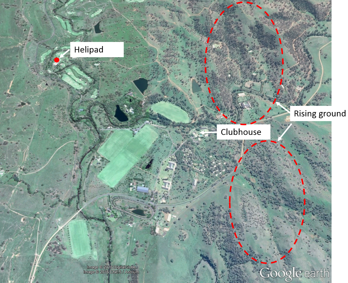
When about 3 NM from Ellerston, with the property in sight, the pilot commenced a descent to 3,500 ft, to ensure adequate terrain clearance for arrival overhead the GPS position of the helipad (Figure 1). During the descent, the pilot sighted the lights from the buildings at Ellerston and visually confirmed they were at the intended location.
Figure 1: Ellerston property
Source: Google earth – annotated by ATSB
At about 1838, the helicopter arrived overhead the GPS position for the helipad. The pilot sighted a red beacon, but as they had expected to see the illuminated hangar and helipad, became unsure of the location of the HLS. The pilot reported that they then descended to about 2,500–3,000 ft and tracked to the west and north-west towards other lit buildings and then to the east back over the red light, but did not see any illumination indicative of a HLS. The pilot then elected to track towards the buildings of the homestead and descend to verify their exact location.
At about 1841, the helicopter descended to 2,286 ft (according to recorded data) in the vicinity of the Ellerston clubhouse and nearby buildings which the pilot reported were all well illuminated and visible. The elevation of the terrain at that point was 1,770 ft with rising ground to the north and south-east up to 2,250 ft (Figure 1). The pilot reported that they were then sure of their exact location, and assessed that the red light must be on the hangar next to the HLS.
The pilot then commenced a right turn to position for an approach from 2 NM to the north-east of the HLS. At about 1842, as the aircraft was positioning for the approach, the pilot received a ‘landing gear’ warning from the radio altimeter. This warning is generated whenever the helicopter is below 200 ft above ground level (AGL) without the landing gear extended. The pilot immediately raised full collective and commenced a climb to 4,000 ft AMSL tracking towards the south. A low rotor RPM occurrence was recorded on the aircraft computer at 1842, indicative of a rapid raising of the collective.[3]
After climbing to 4,000 ft, the pilot turned to track towards the red light from the south-south-west, and saw a flashing bright torch light near the red light indicating the HLS. The pilot then positioned the helicopter to the north-east of the HLS and commenced an approach. During the approach, ground personnel shone car headlights from the sealed area, which confirmed to the pilot that the helicopter was approaching the helipad. At about 50 ft AGL, the pilot was able to identify ground features at the helipad and continued with the landing.
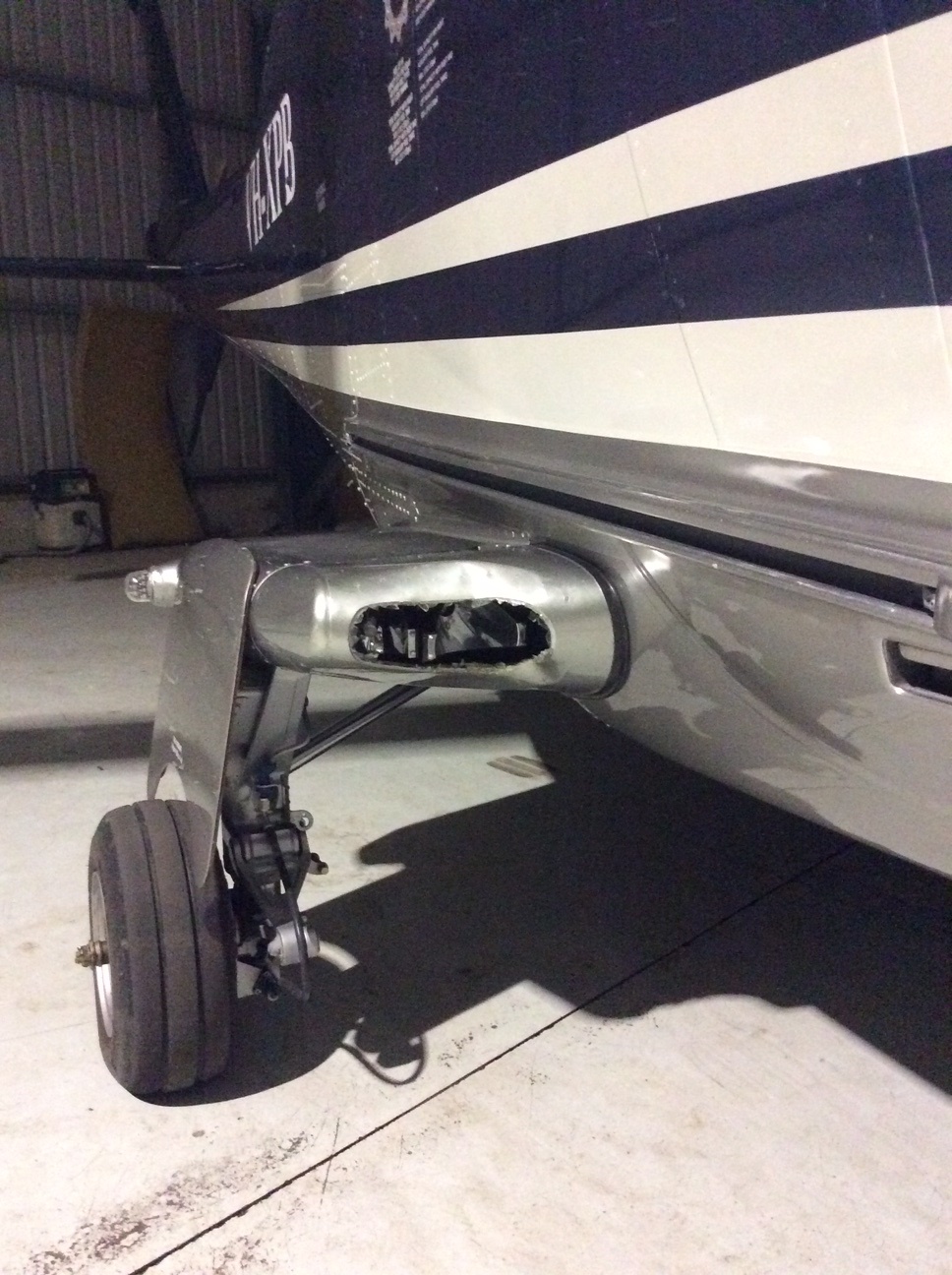
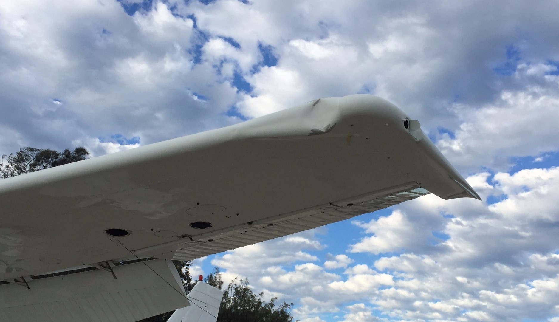
After landing, the passengers disembarked and the pilot refuelled the helicopter. The pilot then conducted a ferry flight to Camden Airport, NSW. After arriving in Camden, the helicopter was pushed into a well-lit hangar, at which stage damage to the helicopter was detected. It was apparent that the helicopter had struck a tree branch, causing damage to the right-side landing lights, horizontal stabiliser, vertical fin and rotating beacon (Figure 2). It was unclear exactly when the helicopter had struck a tree.
Figure 2: Damage to right landing light of VH-XPB
Source: Helicopter operator
Pilot comments
After overflying the buildings and positively establishing the helicopter’s position, the pilot turned right to track north. A line of hills ran north-south from that area. The pilot was then attempting to maintain about 500 ft AGL and when the 200 ft radio altimeter ‘landing gear’ warning sounded, the helicopter was either descending (without the pilot realising) or maintaining altitude, but heading towards rising ground.
The pilot assessed that the helicopter probably struck a branch when the 200 ft warning sounded. The pilot did not hear or feel the collision, but at the time the warning sounded, the pilot rapidly raised full collective and their workload was high. If the collision with the tree branch had occurred later during the approach to the helipad, the pilot thought they would have heard or felt it due to lower airspeed and engine power settings. The pilot was not aware of having struck anything and no damage was detected during refuelling at Ellerston.
The pilot had landed at Ellerston three times previously in daylight but had not been there at night. After speaking to ground personnel prior to the flight, the pilot was expecting the sealed area and helipad to be illuminated. When there was no illumination visible from above, in the vicinity of the helipad, the pilot became confused as they could see the red light but not the helipad. In response, they orbited to confirm their position and then to determine where the helipad was in relation to that position. They were then trying to get visual reference with the landing site and remain at a safe height above the terrain and any obstacles.
Due to the overcast cloud, there was no celestial illumination, and as the area was surrounded by high ground, it was a black hole. In that situation, the pilot’s attention was split between looking outside to establish their position relative to the landing area, and inside at the instruments to maintain altitude and speed.
On a dark night, pilots need to apply greater safety margins such as use of the autopilot to reduce pilot workload, and maintaining a greater height above terrain until the landing site has been positively identified and an approach commenced.
Aircraft satellite tracking data
The helicopter was fitted with a satellite tracking system which recorded the time and the helicopter’s position, height and speed, at 2-minute intervals. The 200 ft warning occurred between two of the recorded points, so the exact position and altitude of the helicopter at that time was not recorded.
Operator report
The helicopter operator conducted an investigation and found the following factors contributed to the incident:
It was assumed by the company that the pilot was familiar with the layout and positioning of the Ellerston village and helipad because they had operated there on multiple occasions during daylight in the same aircraft, and they had discussed lighting arrangements with ground staff prior to the flight.
The helipad did not have the appropriate edge lighting to identify it as a HLS for night operations.
After flying overhead and realising the need to orbit to identify the helipad, the pilot should have nominated a vertical limit of 3,500 ft and a horizontal limit of 2 or 3 NM to prevent inadvertent controlled flight into terrain. A descending turn while scanning between ground lights and instruments in a pitch-black environment creates a very high workload. Planning the descent with absolute limits is critical to maintaining situational awareness. The use of autopilot in this situation can also aid in reducing workload while scanning outside.
Although the pilot was highly experienced and current with regard to regulatory requirements, lack of training in the conduct of ‘black hole’ approaches (recognised as a particularly demanding exercise) was identified as a factor.
Safety action
Whether or not the ATSB identifies safety issues in the course of an investigation, relevant organisations may proactively initiate safety action in order to reduce their safety risk. The ATSB has been advised of the following safety action in response to this occurrence.
Helicopter operator
As a result of this occurrence, the helicopter operator has advised the ATSB that they are taking the following safety actions:
Introduction of night, black hole approach training and controlled flight into terrain avoidance technique training for all pilots who conduct night and IFR operations. This is to include both inflight and simulator training.
No company pilot will be authorised to fly into the Ellerston helipad at night without specific familiarisation training from the local pilot.
It is recommended that the Ellerston HLS be assessed against standard HLS lighting requirements for any future night operations.
All private helipads with potential for night operations are to be risk assessed and documented procedures produced.
Adjustment of the radio altimeter warning decision height for the A109 is limited to the standard 200 ft and 150 ft alerts. A variable decision height warning device is to be investigated.
The company will increase the reporting rate on the satellite-tracking device from 2-minute to 1-minute intervals.
The extra risks inherent in visual flight at night are from reduced visual cues, and the increased likelihood of perceptual illusions and consequent risk of spatial disorientation. Situational awareness with respect to the relative position of terrain and obstacles is fundamentally important during the conduct of limited visibility operations.
Decisions regarding whether to conduct an investigation, and the scope of an investigation, are based on many factors, including the level of safety benefit likely to be obtained from an investigation. For this occurrence, a limited-scope, fact-gathering investigation was conducted in order to produce a short summary report, and allow for greater industry awareness of potential safety issues and possible safety actions.
Publishing information
Released in accordance with section 25 of the Transport Safety Investigation Act 2003
Ownership of intellectual property rights in this publication
Unless otherwise noted, copyright (and any other intellectual property rights, if any) in this report publication is owned by the Commonwealth of Australia.
Creative Commons licence
With the exception of the Coat of Arms, ATSB logo, and photos and graphics in which a third party holds copyright, this publication is licensed under a Creative Commons Attribution 3.0 Australia licence.
Creative Commons Attribution 3.0 Australia Licence is a standard form licence agreement that allows you to copy, distribute, transmit and adapt this publication provided that you attribute the work.
The ATSB’s preference is that you attribute this publication (and any material sourced from it) using the following wording: Source: Australian Transport Safety Bureau
Copyright in material obtained from other agencies, private individuals or organisations, belongs to those agencies, individuals or organisations. Where you wish to use their material, you will need to contact them directly.
On the morning of 16 June 2016, a student and instructor planned to conduct a training flight in a Piper PA-28-161 aircraft, registered VH-IPO (IPO), from Mangalore Airport, Victoria.
The planned flight included time in the Mangalore training area before returning to the airport for circuit training. The aircraft departed Mangalore at about 0940 Eastern Standard Time (EST).
After completing the planned training area manoeuvres, the instructor conducted an orbit and asked the student to identify significant geographical points within the training area. At this time, the instructor noticed the tachometer indicated a slightly lower engine power output than expected for the selected throttle position. The instructor suspected carburettor icing[1] and applied carburettor heat.[2] This resulted in an immediate further drop in power and the instructor also reported the engine running slightly rough. After 10–15 seconds the power level returned to normal. After a further 10–15 seconds, the instructor selected the carburettor heat off and instructed the student to return to Mangalore. During the return flight, the instructor periodically applied carburettor heat without further indications of carburettor icing.
As the aircraft descended to Mangalore, the student selected carburettor heat on and joined the circuit for runway 36. Due to traffic in the circuit, the student conducted two go-arounds.[3] After the second go-around, the aircraft re-joined the circuit, and the student prepared the aircraft for another approach. As the student prepared to turn onto the base leg, they applied the carburettor heat. At that time, the instructor observed a large drop in RPM. The instructor then took control of the aircraft and immediately turned onto the base leg. During the turn, the engine failed, and the instructor continued the turn to track directly to runway 36. The instructor carried out the engine failure checklist, but was unable to restart the engine. The instructor then broadcast MAYDAY[4] on the Mangalore common traffic advisory frequency.
As the aircraft descended toward runway 36, the instructor assessed that they did not have sufficient altitude to glide to the runway. The instructor identified a field to the south of runway 36 and outside of the airport perimeter as suitable for a forced landing. As the aircraft descended through about 200 ft above ground level, the instructor conducted the shutdown checklist and landed the aircraft in the selected field.
The instructor and student were not injured in the incident and the aircraft was not damaged.
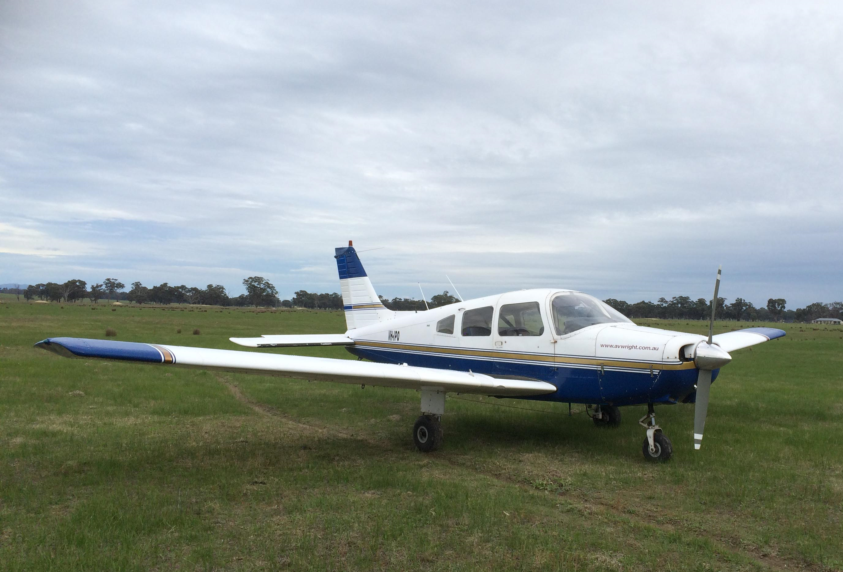
VH-IPO
Source: Aircraft operator
Operator comment
The operator of IPO provided the following comment:
An engineer inspected the aircraft after the incident. The exhaust system, engine controls, fuel system and ignition system were inspected. Engine tests and a flight test were also performed. All checks indicated no faults with the aircraft or contaminants in the fuel system.
Carburettor icing
Induction icing, often referred to as carburettor icing, is the accumulation of ice within the induction system of an engine fitted with a carburettor. This ice forms as the decreasing air pressure and introduction of fuel reduces the temperature within the induction system. The temperature may reduce sufficiently for moisture within the air to freeze and accumulate. This build-up of ice restricts airflow to the engine, leading to a reduction in engine performance.
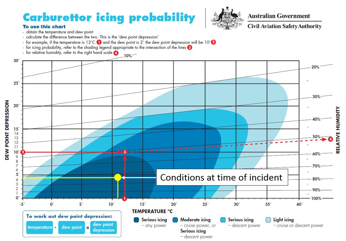
Environmental conditions influence the likelihood of carburettor ice forming, as shown by the Civil Aviation Safety Authority (CASA): Carburettor icing probability chart.
On the morning of the engine failure, the Mangalore aerodrome weather information service reported the following weather conditions.
Table 1: Weather conditions at Mangalore Airport on 16 June
Time
Temperature
Dew point
1000
8.6 °C
8.6 °C
1015
9.4 °C
9.1 °C
1030
9.6 °C
7.5 °C
1045
10.1 °C
7.3 °C
1100
10.6 °C
6.9 °C
1115
10.9 °C
6.5 °C
The carburettor icing probability chart shows the conditions at Mangalore Airport placed IPO in the serious icing zone for carburettor icing at the time of the incident (Figure 1). Carburettor icing could be expected at any power setting.
Figure 1: Carburettor icing probability chart showing prevalent conditions in yellow
Source: CASA modified by ATSB
The first indication of carburettor icing is normally a reduction in power produced by the engine. If not corrected by the pilot this may lead to rough running of the engine and engine failure.
When operating in conditions conducive to carburettor icing, pilots should use carburettor heat to prevent and remove ice build-up. After selecting carburettor heat, engine performance may deteriorate further as the ice is melted before engine performance returns to normal. This may take up to 30 seconds.
Instructor comment
The instructor of IPO provided the following comments:
On the two circuits prior to the engine failure, the student selected carburettor heat on prior to turning onto the base leg of the circuit with no indications of carburettor icing.
After the second go-around, the student joined a shortened downwind. The time period when the carburettor heat was selected off, where the carburettor ice appeared to form was very short and occurred at a very high-power setting.
Safety action
Whether or not the ATSB identifies safety issues in the course of an investigation, relevant organisations may proactively initiate safety action in order to reduce their safety risk. The ATSB has been advised of the following proactive safety action in response to this occurrence.
Aircraft operator
As a result of this occurrence, the aircraft operator has advised the ATSB that they are taking the following safety actions:
The operator has increased instructor and student awareness of carburettor icing probability and symptoms for early detection. The operator has issued all instructors and students with a copy of the CASA article Ice kills.
The operator will review relevant company briefs to include carburettor ice probability and prevention.
The operator has recommended the company operations manual be reviewed to mitigate against flying outside of gliding distance to the runway during circuit training.
Safety message
This incident highlights the insidious nature of carburettor icing and the speed with which carburettor icing can occur in favourable environmental conditions. The incident also reinforces the need for pilots to be aware of the risk of carburettor icing at all times during the operation of aircraft fitted with a carburettor.
The article Piston engine icing produced by the European Strategic Safety Initiative provides in-depth information to assist pilots in identifying and managing carburettor icing.
Decisions regarding whether to conduct an investigation, and the scope of an investigation, are based on many factors, including the level of safety benefit likely to be obtained from an investigation. For this occurrence, a limited-scope, fact-gathering investigation was conducted in order to produce a short summary report, and allow for greater industry awareness of potential safety issues and possible safety actions.
Publishing information
Released in accordance with section 25 of the Transport Safety Investigation Act 2003
Ownership of intellectual property rights in this publication
Unless otherwise noted, copyright (and any other intellectual property rights, if any) in this report publication is owned by the Commonwealth of Australia.
Creative Commons licence
With the exception of the Coat of Arms, ATSB logo, and photos and graphics in which a third party holds copyright, this publication is licensed under a Creative Commons Attribution 3.0 Australia licence.
Creative Commons Attribution 3.0 Australia Licence is a standard form licence agreement that allows you to copy, distribute, transmit and adapt this publication provided that you attribute the work.
The ATSB’s preference is that you attribute this publication (and any material sourced from it) using the following wording: Source: Australian Transport Safety Bureau
Copyright in material obtained from other agencies, private individuals or organisations, belongs to those agencies, individuals or organisations. Where you wish to use their material, you will need to contact them directly.
On 17 June 2016 at about 0055 Eastern Standard Time, a Boeing 737-376, registered VH-XMO and operated by Express Freighters Australia, departed Melbourne Airport, Victoria, on a freight service to Launceston, Tasmania. After arriving overhead Launceston, the flight crew proceeded to conduct an instrument approach for runway 32L. However, due to adverse weather condition, the crew were unable to land and a missed approach was conducted.
On completion of the missed approach, the captain (CA) initiated a left turn to re-position the aircraft for a second approach. A short time later, while responding to a call from the airport groundsman about the weather conditions, the CA handed control of the aircraft to the first officer (FO).
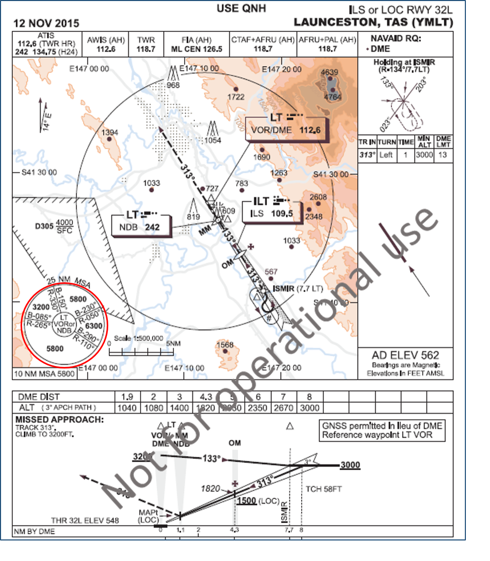
While the captain instructed the FO to maintain the turn, subsequent manoeuvring had not been discussed. The resultant flight path led to the aircraft entering an area with a minimum permitted altitude of 5,800 ft. While the crew had commenced a climb, the aircraft had not reached that minimum altitude and entered the area at about 4,400 ft. In response, air traffic control issued a safety alert for terrain and instructed the crew to climb the aircraft above the minimum safe altitude.
What the ATSB found
The ATSB found that the instrument approach briefing conducted by the flight crew did not ensure that there was a shared understanding of how the aircraft would be manoeuvred on completion of the published missed approach. That resulted in the aircraft being operated in an area below the prescribed minimum safe altitude.
The ATSB also identified that flight path monitoring and safety alerts issued by air traffic control, provided the flight crew with clear and timely minimum altitude requirements and ensured the aircraft was operated well clear of terrain.
What's been done as a result
In response to this occurrence the operator issued a flight standing order that drew flight crew’s attention to the runway 32L instrument approach procedure’s missed approach and the requirements for subsequent manoeuvring. In addition, the approach briefing requirements were amended to include intentions for manoeuvring following the completion of a published missed approach.
The effective management and manipulation of the aircraft, following a missed approach, was included as a discussion item and exercise in the operator’s recurrent simulator training program.
Safety message
This occurrence highlights the value of having a clear, and where appropriate, shared plan. A common understanding between flight crew prevents additional workload associated with clarifying intentions during busy events, such as during and after missed approaches.
Operators and flight crew should consider including appropriate missed approach considerations, such as intended flight path, crew actions, terrain clearance and air traffic control requirements, into their approach briefings, regardless of the existing environmental conditions.
The occurrence
On 17 June 2016 at about 0055 Eastern Standard Time[1], a Boeing 737-376, registered VH-XMO and operated by Express Freighters Australia, was scheduled to operate a freight service from Melbourne, Victoria, to Launceston, Tasmania. The flight crew consisted of a training captain (CA) as the pilot flying[2] and a first officer (FO) under training as the pilot monitoring. This flight was the FO’s ninth sector operating the B737 aircraft.
The flight crew signed on for duty in Melbourne at about 1910. The duty included a return flight to Sydney, New South Wales, followed by a return flight to Launceston. A review of the weather for the duty indicated relatively benign conditions for Melbourne and Sydney. However, the Launceston forecast included cloud at 1,500 ft above the ground and periods of light rain. A temporary reduction in visibility to 4,000 m and cloud down to 1,000 ft were also forecast, together with heavier rain showers. Those weather conditions required the flight crew to carry an alternate. In this case, the aircraft carried sufficient fuel to operate to Launceston and return to Melbourne.
The flight to Sydney and return was uneventful. Approaching Melbourne, the flight crew obtained a weather update for Launceston. That update forecast cloud at 1,000 ft, reducing temporarily to 500 ft with continuing rain showers. Automated weather observations for Launceston at 0000, recorded visibility of 5,000 m in rain and overcast cloud at 100 ft. While the observed weather conditions were below those required to land, the CA reported that adverse weather conditions at Launceston historically fluctuated.
The flight departed Melbourne for Launceston at about 0055. On board the aircraft was sufficient fuel to operate the flight to Launceston, conduct three instrument approaches and, if required, return to Melbourne. The flight crew continued to monitor the Launceston weather conditions en route. Subsequent automated observations showed little or no improvement to the weather.
Prior to descent, the flight crew conducted an approach briefing for Launceston. That briefing included discussions covering the expected instrument landing system[3] (ILS) approach for runway 32L (Figure 1), and the missed approach should it be required. The operator’s low visibility procedures were also covered. Those procedures required that, approaching the minima, the CA was to scan both the aircraft instruments and outside for the runway. The FO’s primary task was to monitor instruments and the aircraft’s flight path.
Descent was commenced at about 0125. Automated weather observations for Launceston at 0113, recorded visibility of 9,000 m in rain showers and overcast cloud at 200 ft. At about 0131, air traffic control (ATC) advised the crew that, based on the latest automated weather observations, conditions on the ground were, 300 m visibility and overcast cloud at 200 ft. The crew were subsequently cleared to leave controlled airspace on descent and to conduct an instrument approach to runway 32L.
Launceston tower control services were generally available between the hours of 0600 and 2200. As the tower was closed, the controlled Class D airspace below 1,500 ft above mean sea level (AMSL) had reverted to non‑controlled Class G airspace. In the event of a missed approach, the aircraft would re-enter Launceston Class C and D controlled airspace above 1,500 ft AMSL and a clearance would be required prior to any subsequent manoeuvring on completion of the published missed approach.
The aircraft passed overhead Launceston at about 0136. The flight crew then proceeded to descend the aircraft in accordance with the prescribed ILS approach procedure. The minimum altitude for landing of 750 ft (202 ft above the runway threshold) was reached at about 0145. As the crew could not see the runway, a missed approach was conducted.
At about 0147, the aircraft levelled off at the missed approach altitude of 3,200 ft. About 20 seconds later, the CA initiated a left turn by selecting the autopilot heading bug to a south‑westerly heading. The CA’s intention was to continue the left turn and position the aircraft overhead the airport for a second instrument approach. The FO reported being surprised by the turn and immediately thought that they should climb the aircraft.
Figure 1: Launceston instrument landing system approach chart for runway 32L with relevant minimum safe altitudes required for manoeuvring, in instrument meteorological conditions or at night, circled in red.
Source: Airservices Australia modified by the ATSB
After advising ATC that they had conducted a missed approach, ATC asked the crew to confirm that they were on the published missed approach. The flight crew confirmed this and advised ATC that they were turning back towards Launceston. At about the same time, the CA responded to a radio call from the Launceston Airport groundsman and handed control of the aircraft to the FO. While the CA did instruct the FO to keep the turn going, to where, or onto what heading was not discussed.
While the CA was talking to the groundsman about the weather, the FO observed the radio altimeter become active. The radio altimeter provides an indication of aircraft height above the ground up to 2,500 ft. In response to the radio altimeter activation, the FO advised the CA that they should climb the aircraft.
By about 0148, the aircraft was turning left through a heading of 140 degrees and climbing through 3,900 ft. The aircraft was also approaching the boundary of the 3,200 ft minimum sector altitude[4] (MSA). At about the same time, ATC asked the crew to confirm that they would be remaining within the 3,200 ft sector and advised that otherwise they needed to be at 5,800 ft. The crew responded by advising they were climbing to 5,800 ft.
The aircraft subsequently entered the 5,800 ft MSA sector at about 4,400 ft, on a steady heading of about 110 degrees, and about 3.5 NM (6.5 km) southwest of the airport. As the aircraft was below the required MSA, ATC issued a safety alert for terrain and instructed the crew to climb immediately to 5,800 ft.
In response, at about 0149, the crew advised ATC that they were climbing to 6,000 ft. ATC acknowledged the call and asked the crew if they would be entering the holding pattern overhead Launceston. The crew reported that they were maintaining 6,000 ft and asked ATC to standby.
At about 0150, the aircraft was in a left turn, maintaining 6,000 ft and about 5 NM (9 km) to the southeast of the airport. ATC advised the crew that they were about to enter an area with a higher MSA and to climb immediately to 6,300 ft or higher. The crew acknowledge the altitude requirement and advised ATC that they would be returning to Melbourne. A short time later, as the aircraft had not yet reached 6,300 ft, ATC reissued the instruction to climb immediately to 6,300 ft.
The aircraft was subsequently cleared to climb to its cruise altitude and returned to Melbourne.
Flight below the minimum sector altitude (MSA) occurred following a missed approach that was conducted due to poor weather conditions. While the flight crew assessed that the safety of the aircraft was never in doubt, there was confusion as to how the aircraft was to be manoeuvred on completion of the missed approach.
This analysis will examine the aircraft’s flight path following the missed approach, and factors that contributed to the flight below MSA.
Prior to commencing descent, the crew conducted a normal approach briefing. The prevailing weather conditions at Launceston airport were such that the flight crew were required to conduct an instrument landing system (ILS) approach. The weather conditions also meant that it was reasonably foreseeable that they would need to conduct a missed approach. While an instrument approach briefing was conducted prior to descent, and covered the standard components including the missed approach segment, there was no discussion of how the aircraft would be subsequently manoeuvred.
A missed approach following an ILS approach is not common as the associated low weather minima usually permits the landing to be completed. As such, planning how the aircraft is to be manoeuvred in the event of a missed approach may not always be considered in detail. Additionally, tracking and altitude requirements following a missed approach are often provided by air traffic control (ATC), particularly in the case of larger commercial aircraft such as VH‑XMO.
Additionally, with the exception of situations such as simulator training, missed approaches are often unexpected. Consequently, the safe conduct of a go‑around and subsequent manoeuvring relies on a shared appreciation to avoid the need to clarify intentions during an already busy period. Irrespective of the weather conditions, a thorough go‑around briefing, that gives consideration to factors such as initial and subsequent flight paths, crew actions and co‑ordination, terrain clearance and ATC requirements, offers an effective means of ensuring that a common appreciation exists.
Although air traffic control (ATC) services were available en route and during descent, Launceston Tower was closed when the aircraft arrived. Consequently, the normally tower‑controlled Class D airspace below 1,500 ft became non-controlled Class G airspace. This meant that, in the event of a missed approach, the aircraft would re-enter Launceston Class C and D controlled airspace at 1,500 ft and an ATC clearance would be required prior to manoeuvring beyond the published missed approach.
The approach and missed approach flight paths were aligned to enable the aircraft to descend and climb clear of terrain. The missed approach path positioned the aircraft within a sector that had an MSA of 3,200 ft. Any manoeuvring outside of that sector required the crew to climb the aircraft to the relevant sector MSA prior to entry. In this case, the left turn was towards a sector that had an MSA of 5,800 ft. Alternatively, climbing straight ahead on the missed approach track to 5,800 ft would have enabled the crew to manoeuvre the aircraft as required within 10 NM (19 km) of the airport.
On completion of the missed approach, the captain commenced a left turn with the intention of positioning the aircraft for a second approach. While a continuous left turn may have maintained the aircraft within the 3,200 ft sector, this manoeuvre had not been discussed during the approach briefing. As a result, when the CA handed control of the aircraft to the FO, the left turn was stopped on a south-easterly heading.
The south-easterly flight path resulted in the aircraft tracking towards a sector with a MSA of 5,800 ft while at an altitude of 3,200 ft. Although the crew had commenced a climb, the aircraft had only achieved an altitude of 4,400 ft when it entered the 5,800 ft sector. As a result, ATC issued a safety alert for terrain proximity. ATC also issued instructions for an immediate climb to 5,800 ft and later, to 6,300 ft.
Although the aircraft was never in immediate danger of colliding with terrain, it was operated over an area and at an altitude less than that prescribed for safe flight. Had the required clearance been obtained prior to manoeuvring, ATC would have provided the crew with appropriate tracking and altitude requirements. Additionally, without the flight path monitoring and timely altitude alerts provided by ATC, the risk of collision with terrain may have increased.
Had the approach briefing included a discussion about subsequent manoeuvring, both crew members would have had a shared understanding of the expected flight path. Such a discussion would have provided the crew with an opportunity to discuss alternative tracking, minimum safe altitude requirements, and the need to obtain a clearance.
Findings
From the evidence available, the following findings are made with respect to the flight below lowest safe altitude involving Boeing 737, registered VH-XMO at Launceston Airport, Tasmania on 17 June 2016. These findings should not be read as apportioning blame or liability to any particular organisation or individual.
Contributing factors
The instrument approach briefing conducted by the flight crew did not ensure there was a shared understanding of how the aircraft would be manoeuvred following completion of the published missed approach.
The absence of an established, and shared, manoeuvring plan, resulted in the aircraft being operated in an area below the prescribed minimum safe altitude.
On completion of the missed approach, the flight crew did not obtain an onwards airways clearance prior to further manoeuvring. That negated the terrain clearance assurance that would otherwise have been provided and increased the risk of conflict with other aircraft.
Other findings
The flight path monitoring and safety alerts issued by air traffic control, provided the flight crew with clear and timely minimum altitude requirements and ensured the aircraft was operated well clear of terrain.
Safety issues and actions
Proactive safety action
Whether or not the ATSB identifies safety issues in the course of an investigation, relevant organisations may proactively initiate safety action in order to reduce their safety risk. The ATSB has been advised of the following proactive safety action in response to this occurrence.
The aircraft operator, Express Freighter Australia, has made the following amendments to their training and procedures:
A flight standing order was issued that drew flight crew’s attention to the runway 32L instrument approach procedure’s missed approach and the requirements for subsequent manoeuvring.
The approach briefing requirements were amended to include intentions for manoeuvring following the completion of a published missed approach.
A ‘Hot Topic’ discussion item – post missed approach manoeuvring and management, was added to the recurrent simulator training program.
The recurrent simulator training program, released in December 2016, included exercises that reinforce the enhanced arrival and approach briefing requirements. Crews were required to demonstrate appropriate inflight management and manipulation subsequent to completion of a published missed approach.
Sources and submissions
Sources of information
The sources of information during the investigation included the:
flight crew
aircraft operator
Airservices Australia.
Submissions
Under Part 4, Division 2 (Investigation Reports), Section 26 of the Transport Safety Investigation Act 2003 (the Act), the Australian Transport Safety Bureau (ATSB) may provide a draft report, on a confidential basis, to any person whom the ATSB considers appropriate. Section 26 (1) (a) of the Act allows a person receiving a draft report to make submissions to the ATSB about the draft report.
A draft of this report was provided to the flight crew and operator of VH-XMO, Airservices Australia and the Civil Aviation Safety Authority (CASA).
Submissions were received from CASA and the aircraft operator. The submissions were reviewed and where considered appropriate, the text of the report was amended accordingly.
Purpose of safety investigations
The objective of a safety investigation is to enhance transport safety. This is done through:
identifying safety issues and facilitating safety action to address those issues
providing information about occurrences and their associated safety factors to facilitate learning within the transport industry.
It is not a function of the ATSB to apportion blame or provide a means for determining liability. At the same time, an investigation report must include factual material of sufficient weight to support the analysis and findings. At all times the ATSB endeavours to balance the use of material that could imply adverse comment with the need to properly explain what happened, and why, in a fair and unbiased manner. The ATSB does not investigate for the purpose of taking administrative, regulatory or criminal action.
Terminology
An explanation of terminology used in ATSB investigation reports is available here. This includes terms such as occurrence, contributing factor, other factor that increased risk, and safety issue.
Publishing information
Released in accordance with section 25 of the Transport Safety Investigation Act 2003
Ownership of intellectual property rights in this publication
Unless otherwise noted, copyright (and any other intellectual property rights, if any) in this report publication is owned by the Commonwealth of Australia.
Creative Commons licence
With the exception of the Coat of Arms, ATSB logo, and photos and graphics in which a third party holds copyright, this publication is licensed under a Creative Commons Attribution 3.0 Australia licence.
Creative Commons Attribution 3.0 Australia Licence is a standard form licence agreement that allows you to copy, distribute, transmit and adapt this publication provided that you attribute the work.
The ATSB’s preference is that you attribute this publication (and any material sourced from it) using the following wording: Source: Australian Transport Safety Bureau
Copyright in material obtained from other agencies, private individuals or organisations, belongs to those agencies, individuals or organisations. Where you wish to use their material, you will need to contact them directly.
On 7 June 2016 at about 1000 Western Standard Time (WST), a Fokker F28 MK 0100 aircraft, registered VH-NHF, departed on a charter flight from Christmas Creek to Perth, Western Australia. On board were five crewmembers and 28 passengers.
The aircraft was on climb to the planned cruise altitude of FL 340[1] and the weather was generally clear and smooth with intermittent icing conditions. The first officer was the pilot flying (PF) and the captain was the pilot monitoring (PM) for this flight.[2]
As the aircraft climbed through FL 200, the flight crew heard a ‘whistling’ noise. They did not notice any other abnormal indications and after about one minute, the noise stopped. At about FL 305, a loud ‘whooshing’ noise was heard by the flight crew on the flight deck and the three cabin crewmembers who were standing in the forward galley.
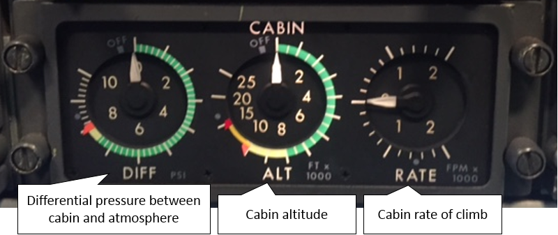
The cabin crew believed the noise was coming from the forward lavatory, so one cabin crewmember inspected the lavatory, but could not identify where the noise was coming from. The PM checked the aircraft pressurisation indications located on the cockpit overhead panel and noticed that the cabin altitude[3] indicated 6,000 ft as expected, but the cabin pressure rate of climb had increased from about 200–300 ft/min to about 500 ft/min[4] (Figure 1). This indicated to the PM that they were losing cabin air faster than the pressurisation system could pressurise the aircraft.
Figure 1: F28 cabin pressure gauges
Source: Operator annotated by ATSB
The PM contacted air traffic control (ATC) to request a level-off at FL 320, rather than their planned level of FL 340. At about this time, the cabin manager informed the flight crew that the cabin crew had heard a ‘suction’ noise from the forward lavatory, but could not identify the source of the noise. The PM asked the cabin manager to cautiously inspect the forward lavatory again. The flight crew then received a ‘PACK 1’[5] level 2 warning[6] in the cockpit and the associated emergency procedure displayed on the multi-function display unit (MFDU). The first step of the procedure was to turn off the affected air-conditioning pack and wait two minutes for the pack to cool before attempting a reset. When the PM turned off air-conditioning pack 1, they noticed the cabin pressurisation rate of climb increase to in excess of 2,000 ft/min.
The PM contacted ATC again and requested a descent to FL 250 and received a clearance from ATC to initially descend to FL 290 due to an airspace boundary. Before the PF was able to start the descent, the flight crew received an ‘auto-throttle 1’[7] level 1 warning. At about this time, the PM informed the cabin manger that they were about to activate the seat-belt sign because an ‘excessive cabin altitude’ warning was imminent and the emergency oxygen would deploy.
Before the two minutes passed for the air-conditioning pack reset, the ‘excessive cabin altitude’[8] level 3 warning activated. The flight crew performed their initial drill,[9] which included donning their oxygen masks. The PM then checked the cabin altitude, noticed it was indicating in excess of 25,000 ft and that the passenger emergency oxygen had deployed, and made a PAN[10] call to ATC. They received a clearance for an immediate descent to 10,000 ft, and the PF initiated an emergency descent.
As the aircraft descended, the cabin crew performed their ‘sit-fit-advise’[11] drills for deployment of passenger emergency oxygen and the flight crew performed their ‘emergency descent procedure’. The flight crew completed their ‘excessive cabin altitude’ procedure during the descent and then discussed their requirements for flight at 10,000 ft, which included alternate destination options. The PF levelled the aircraft at 10,000 ft and the flight crew completed the ‘emergency descent procedure’, which included a public address that emergency oxygen was no longer required.
The flight crew completed the air-conditioning pack and auto-throttle emergency procedures. After air-conditioning pack 1 was selected on, the cabin altitude decreased to 1,500 ft and the PACK 1 fault did not return for the rest of the flight. The PM left the seat belt light on for the remainder of the flight, but gave permission for the cabin crew to leave their seats to check on the needs of the passengers.
The cabin crew checked on the condition of the passengers and noted that one passenger wished to continue using supplemental oxygen. The cabin crew facilitated the passenger’s request and provided them with portable oxygen for the remainder of the flight.
ATC contacted the aircraft for a progress update and provided the latest weather details for Newman, Meekatharra and Perth. The flight crew diverted the aircraft to Newman Airport, which was the closest option with company ground services. The crew advised ATC that an ambulance was required on arrival.
The aircraft landed at Newman at about 1100. Paramedics were available on arrival at Newman to provide assistance, but were not required.
F28 pressurisation – general description
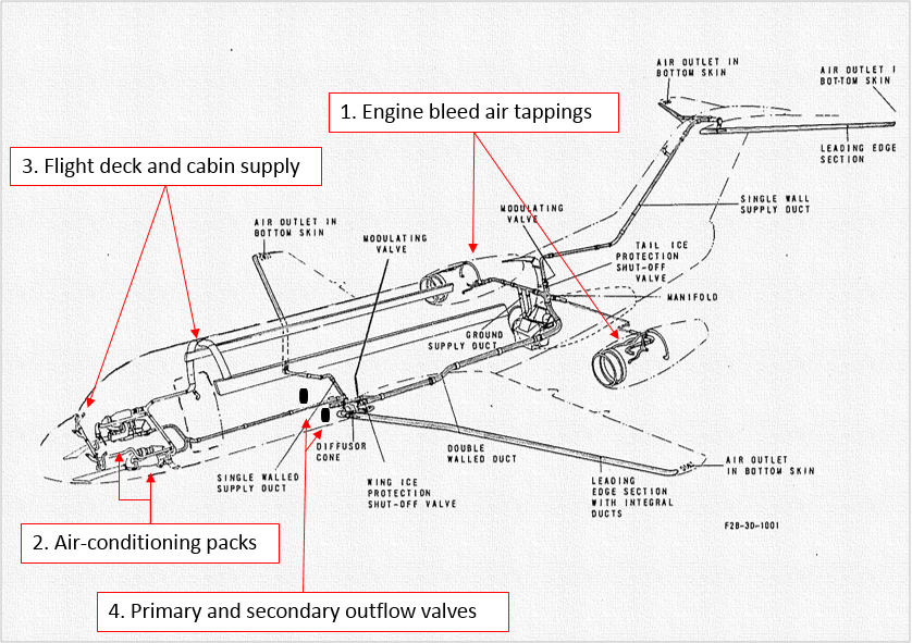
Bleed air is compressed air taken from the compressor stage of the engine. Bleed air is used for several functions including pressurisation, air-conditioning and anti-icing. For pressurisation, the bleed air is supplied to the two air-conditioning packs located underneath the floor of the flight deck, which are used to control the temperature of the air prior to distribution into the flight deck and cabin (Figure 2).
Cabin pressure is regulated by the outflow valves, which control the outflow of air from the cabin in either automatic or manual mode. Controls for automatic and manual mode of operation are located on the flight deck. In automatic operation, the differential pressure[12] of 7.46 psi provides a cabin pressure altitude of 8,000 ft at an aircraft altitude of 35,000 ft (FL 350). The outflow valves will normally limit the maximum pressure differential in automatic and manual mode to 7.65 psi and the cabin pressure altitude to 12,000 ft plus or minus 1,500 ft, provided airflow from the air-conditioning pack(s) is available. An excessive cabin altitude warning is presented at 10,000 ft. The cabin is automatically depressurised upon landing and there are two negative pressure relief valves to prevent negative cabin pressure.
When one pack is selected off, the respective pack main valve shuts off bleed air supply and the other pack increases its output flow rate to 140 per cent of the normal flow rate. A single pack is capable of maintaining cabin altitude by itself at the maximum operating altitude of FL 350. Air-conditioning pack 1 is located underneath the floor of the flight deck on the left-hand side, which is just forward of the forward lavatory.
Figure 2: F28 bleed air supply
Source: ATSB
Captain (PM) comments
The captain provided the following comments:
No systems associated with air-conditioning/pressurisation were recorded as unserviceable before the flight.
The emergency unfolded ‘very quickly’ with multiple faults and therefore knowledge of the emergency drills and procedures needed to be ‘second-nature’. By the time they had performed their initial drills and checked the deployment of the passenger emergency oxygen, the cabin pressure altitude was already indicating in excess of 25,000 ft.
The loud ‘whooshing’ noise was similar to the noise heard in the simulator during rapid decompression training.
They did not feel any physiological effects during the loss of pressure and responded in accordance with their training.
Their simulator training was comprehensive, allowing them to follow procedures while maintaining sufficient ‘spare mental capacity’ to deal with all the problems that unfolded in a logical and methodical manner.
Cabin manager comments
The cabin manager provided the following comments:
One passenger reported to them there was an unusual smell and the PM indicated to them that this was probably from the failed air-conditioning pack.
Prior to the oxygen mask deployment, they felt a sensation in their ears, ‘like on a descent’. Another cabin crewmember commented to the cabin manager that they looked pale, and another cabin crewmember reported to them that they felt a loss of breath.
After the instruction to sit down for the expected excessive cabin altitude, they were concerned that the sleeping passengers might not get their oxygen masks on when they deployed.
About two minutes after sitting down, they heard a loud bang and the passenger emergency oxygen deployed.
Some passengers had trouble fitting their oxygen mask, so the cabin crew used a combination of hand signals and verbal communication to assist them while remaining in their jump seats.
They felt that the incident was managed in a ‘textbook’ manner.
Another member of the cabin crew reported to them that they saw sticky tape covering the emergency oxygen in the forward lavatory, which prevented its deployment.
Maintenance findings and corrective actions
The operator’s maintenance investigation of the incident found the following:
There was a visual indication of duct over-temperature on air-conditioning pack 1.
There was a controller fault on air-conditioning pack 1 and the flight deck temperature control was not working. The controller was replaced.
A ‘heavy leak’ was found from the recirculation duct during investigation of air-conditioning pack 2. The recirculation duct was replaced.
One of the outflow valves was found to be a ‘bit sticky’. The primary and secondary outflow valves were replaced. However, this did not have any effect on the pressurisation test results.
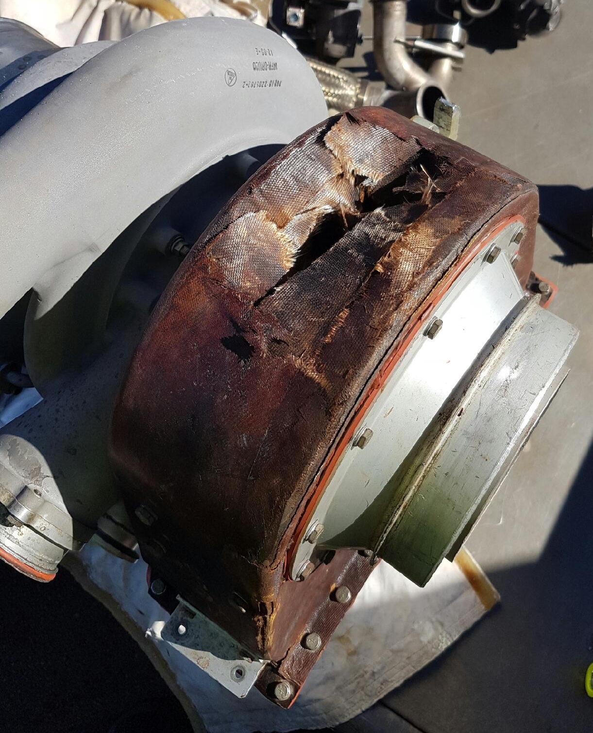
There was a ‘massive leak’ from the inlet and outlet of air-conditioning pack 1. Pack 1 was removed and a large hole found in the plenum duct[13] (Figure 3). The plenum duct and primary and secondary heat exchanger were replaced on pack 1. Aircraft pressurisation was then tested and found to be serviceable (including operations with either pack 1 or pack 2 turned off).
Figure 3: Ruptured plenum duct
Source: Operator
Operator comments
The airline operator provided the following comments:
The pack 1 fault was triggered by a compressor outlet overheat switch, which is located in the compressor outlet duct of the number 1 air-conditioning pack.
The auto-throttle 1 fault was probably linked to the leaks in the air-conditioning ducts, which resulted in a conflict between the demands of the pressurisation computers and the operation of the auto-throttle system.
The reason why the passenger emergency oxygen did not deploy in the forward lavatory is under investigation.
The depressurisation can be attributed to pack 2, being the sole air supply, having a ‘heavy’ recirculation duct leak, which would not allow pack 2 to pressurise the aircraft.
Similar occurrence
On 11 April 2016 VH-NHF suffered a number 2 bleed valve fault, which was reset once and then failed a second time. The pilots initiated a return to Perth. During the transit, the number 1 bleed valve failed. The pilots initiated their emergency drills, which included the use of emergency oxygen and a precautionary descent to FL 140. The excessive cabin altitude warning did not activate and during the descent, the number 1 bleed valve was reset. A normal approach and landing was performed at Perth.
ATSB comment
Air-conditioning pack 1 is located on the left side of the aircraft underneath the floor of the flight deck, just aft of the left seat, which places it close to underneath the floor of the forward lavatory. The pack 1 plenum duct likely ruptured at about FL 305 to produce what the aircraft captain described as a loud ‘whooshing’ noise and what the cabin manager described as a ‘suction’ noise. According to Flight Safety Foundation Human Factors and Aviation Medicine, the immediate donning of oxygen masks by the flight crew, following an ‘excessive cabin altitude’ warning, is the essential first step to surviving a high-altitude depressurisation.
The subsequent maintenance investigation found duct leaks from both air-conditioning systems. However, only the leak from air-conditioning pack 1 triggered an alert to the pilots, and that fault was associated with an overheat condition. In accordance with the operator comments, the rapid increase in the cabin pressure altitude rate of climb, which occurred when the flight crew turned pack 1 off, indicates that pack 2 alone could not supply a sufficient quantity of air to the distribution ducting to maintain cabin altitude. The systems were only able to re-pressurise the aircraft following the descent to 10,000 ft (the demands on the pressurisation system were substantially reduced) [14] and the successful reset of pack 1.
Safety action
Whether or not the ATSB identifies safety issues in the course of an investigation, relevant organisations may proactively initiate safety action in order to reduce their safety risk. The ATSB has been advised of the following proactive safety action in response to this occurrence.
Operator
As a result of this occurrence, the operator has advised the ATSB that they are taking the following safety action:
All parts removed from the number 1 air-conditioning pack will be forwarded to the manufacturer, or authorised repair organisation, for further technical investigation to determine the cause of the failure of the plenum duct.
Safety message
The incident started in a subtle manner as an unusual noise, then quickly escalated to a compound emergency. After some initial uncertainty regarding the noise, the flight crew quickly recognised the true nature of the emergency that was unfolding. The captain and cabin manager both commented that the emergency then unfolded in accordance with their expectations and there were several factors that assisted their emergency management. These factors included:
their training experiences, which they felt closely matched their emergency experience
procedural knowledge of their initial drills
the fact that their colleagues were trained to the same level as themselves.
This incident highlights the importance and value of high-quality training for both flight crew and cabin crew. Quality training clearly assists in equipping crewmembers with the required knowledge and confidence to effectively respond to a time critical emergency. A sound understanding of emergency procedures is particularly important in ensuring that crews not only respond to an emergency appropriately, but also retain the capacity to deal effectively with other potentially complicating factors. Similarly, a sound understanding of aircraft systems supports effective crew decision making with respect to the best course of action when confronted with abnormal circumstances.
Additional information regarding how to respond to an aircraft depressurisation is provided in the following ATSB education bulletins:
Decisions regarding whether to conduct an investigation, and the scope of an investigation, are based on many factors, including the level of safety benefit likely to be obtained from an investigation. For this occurrence, a limited-scope, fact-gathering investigation was conducted in order to produce a short summary report, and allow for greater industry awareness of potential safety issues and possible safety actions.
Publishing information
Released in accordance with section 25 of the Transport Safety Investigation Act 2003
Ownership of intellectual property rights in this publication
Unless otherwise noted, copyright (and any other intellectual property rights, if any) in this report publication is owned by the Commonwealth of Australia.
Creative Commons licence
With the exception of the Coat of Arms, ATSB logo, and photos and graphics in which a third party holds copyright, this publication is licensed under a Creative Commons Attribution 3.0 Australia licence.
Creative Commons Attribution 3.0 Australia Licence is a standard form licence agreement that allows you to copy, distribute, transmit and adapt this publication provided that you attribute the work.
The ATSB’s preference is that you attribute this publication (and any material sourced from it) using the following wording: Source: Australian Transport Safety Bureau
Copyright in material obtained from other agencies, private individuals or organisations, belongs to those agencies, individuals or organisations. Where you wish to use their material, you will need to contact them directly.
On 7 June 2016, at 0418 Eastern Standard Time (EST), the pilot of a Fairchild SA227-DC, registered VH-HPE (HPE), departed Brisbane Airport, Queensland, for a flight to Mount Isa, Queensland. The flight included intermediate stops at Rockhampton and Richmond. The pilot was the only person on board the scheduled freight flight.
Prior to commencing the flight, the pilot reviewed the weather and NOTAM[1] information. The pilot noted there was no NOTAM information for Richmond Airport for the expected arrival time.
After completing the first leg of the flight, HPE departed Rockhampton for Richmond 30 minutes later than scheduled, at about 0615. The expected arrival time for Richmond was about 0810.
At about 0800, the aerodrome reporting officer (ARO) arrived at Richmond Airport with a work crew to undertake pre-planned work. The planned work was to remove plant growth from around the runway lights. The ARO conducted a pre-work safety briefing which included the work crew actions in the event of an aircraft arrival. The ARO then gave the two available hand-held VHF radios to the workers in the two works vehicles working within the runway strip. The ARO did not have a VHF radio in their vehicle and they were the only person qualified to broadcast on the common traffic advisory frequency (CTAF) used by aircraft, which uses VHF. All other works vehicles carried UHF radios.
At about the same time, the pilot of HPE broadcast on the Richmond CTAF advising they were 40 NM to the east and conducting a straight-in approach to runway 27. The pilot received a full response from the aerodrome frequency response unit (AFRU).[2]
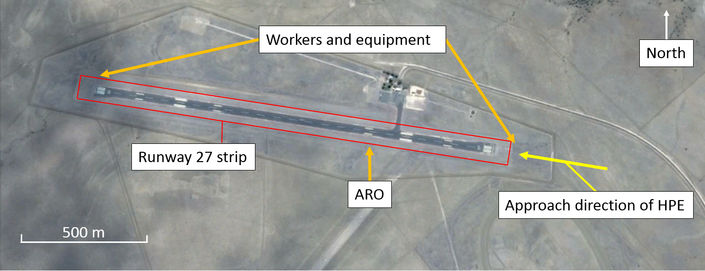
After the brief, the workers undertook the required task in three groups. One group positioned at the eastern end of the runway and a second group at the western end of the runway while the ARO remained at a mid-point along the runway (Figure 1). While the work groups conducted the plant removal, the pilot of HPE activated the pilot activated lighting.[3] The workers in the groups at each end of the runway observed the lights illuminating and immediately began to vacate the runway strip.[4] The pilot made a further broadcast when 20 NM east of Richmond, and received only a short response from the AFRU.
At about 0815, as the aircraft joined a 5 NM final approach to runway 27, the pilot reported that they sighted a vehicle on the runway threshold moving clear of the runway strip. The pilot then broadcast on the Richmond CTAF and broadcast again passing 3 NM on final approach to the runway. They received no response to the broadcasts apart from the AFRU short response.
As HPE approached the runway, the pilot reported that they noticed vehicles and equipment at the far end of the runway and witches hats along the edge of the bitumen. As the vehicles and equipment had moved clear of the runway strip, the pilot continued the approach. At a height of about 100-200 ft above ground level, the pilot reported that they observed a person inside the runway strip near the bitumen of the runway and conducted a go-around.[5]
The pilot then re-joined the circuit, and observed that all workers and equipment were clear of the runway. The pilot conducted a second approach and landed without incident.
No persons were injured, and the aircraft was not damaged in the incident.
Figure 1: Richmond Airport
Source: Google Earth, modified by the ATSB
Aerodrome reporting officer (ARO) comment
The aerodrome reporting officer provided the following comments:
The works procedures for Richmond Airport require a NOTAM to be provided for all works within the runway strip exceeding 30 minutes duration. As the ARO did not expect the works to exceed 30 minutes duration, no NOTAM was provided.
The ARO elected to conduct the works on a Tuesday, as no passenger service was scheduled for that day.
The ARO receives no notification of the actual expected arrival time of the scheduled daily freight service, therefore they were not aware that the service was running late and did not check the airport movement log. Had the ARO checked the log they would have delayed the works until after the aircraft had departed.
The work crews carried two hand-held VHF radios for communicating with aircraft. While broadcasts from aircraft further than 5 NM from Richmond Airport may not be heard, calls within 5 NM are generally received.
The runway lights were activated about 15 minutes prior to the aircraft landing.
HPE conducted a straight-in approach to runway 27. In the past, aircraft arriving overflew the airport prior to approaching to land which the ARO believes is a safer procedure.
All workers and equipment were clear of the runway strip at the time HPE arrived. However, the workers and equipment positioned themselves just outside the runway strip. It may have appeared to the pilot that the workers and equipment were not clear.
Pilot comment
The pilot of HPE provided the following comments:
When approaching Richmond Airport an inbound radio broadcast was made. The AFRU provided a full response, which confirmed that their radio was working correctly and no radio broadcasts from other sources had been recently made within the Richmond CTAF.
No radio call was received from the work crew before or after the incident.
Safety action
Whether or not the ATSB identifies safety issues in the course of an investigation, relevant organisations may proactively initiate safety action in order to reduce their safety risk. The ATSB has been advised of the following proactive safety action in response to this occurrence.
Airport operator
As a result of this occurrence, the airport operator has advised the ATSB that they are taking the following safety action:
Change to works procedure
Prior to conducting works within the runway strip, the flight log is to be reviewed to ensure no flights are scheduled to arrive while work is in progress.
Safety message
The ATSB SafetyWatch highlights the broad safety concerns that come out of our investigation findings and from the occurrence data reported to us by industry. One identified concern is Safety around non-controlled aerodromes.
This incident shows the importance of communication and ensuring that the systems exist and are used to minimise the likelihood of communication break downs. Effective communication between all parts of the aviation system, along with robust systems in place to support the individuals, is essential for safe operations.
The Airservices Australia document An airside driver’s guide to runway safety provides information to assist ground personnel to operate safely at both controlled and non-controlled aerodromes.
Decisions regarding whether to conduct an investigation, and the scope of an investigation, are based on many factors, including the level of safety benefit likely to be obtained from an investigation. For this occurrence, a limited-scope, fact-gathering investigation was conducted in order to produce a short summary report, and allow for greater industry awareness of potential safety issues and possible safety actions.
Publishing information
Released in accordance with section 25 of the Transport Safety Investigation Act 2003
Ownership of intellectual property rights in this publication
Unless otherwise noted, copyright (and any other intellectual property rights, if any) in this report publication is owned by the Commonwealth of Australia.
Creative Commons licence
With the exception of the Coat of Arms, ATSB logo, and photos and graphics in which a third party holds copyright, this publication is licensed under a Creative Commons Attribution 3.0 Australia licence.
Creative Commons Attribution 3.0 Australia Licence is a standard form licence agreement that allows you to copy, distribute, transmit and adapt this publication provided that you attribute the work.
The ATSB’s preference is that you attribute this publication (and any material sourced from it) using the following wording: Source: Australian Transport Safety Bureau
Copyright in material obtained from other agencies, private individuals or organisations, belongs to those agencies, individuals or organisations. Where you wish to use their material, you will need to contact them directly.
-------
[1] A Notice To Airmen (NOTAM) advises personnel concerned with flight operations of information concerning the establishment, condition or change in any aeronautical facility, service, procedure, or hazard, the timely knowledge of which is essential to safe flight.
[2] Aerodrome frequency response unit provides an automatic response when pilots transmit on the traffic frequency for that particular aerodrome. If no other transmissions have been received by the AFRU within the previous 5 minutes the AFRU will respond with a pre-recorded voice message comprising aerodrome identification followed by ‘CTAF’. If a transmission has been received within the previous 5 minutes the AFRU will respond with only a short tone.
[3] Pilot activated runway and taxiway lighting is activated by a series of timed transmissions using the aircraft’s very high frequency radio, on either a discrete or the local airport communication frequency.
[4] Runway strip is a prepared area provided around the runway to reduce risk of damage to an aircraft running off of a runway and also provide an obstacle-free area for aircraft using the runway during take-off and landing.
[5] Go-around, the procedure for discontinuing an approach to land, is a standard manoeuvre performed when a pilot is not completely satisfied that the requirements for a safe landing have been met. This involves the pilot discontinuing the approach to land and may involve gaining altitude before conducting another approach to land.
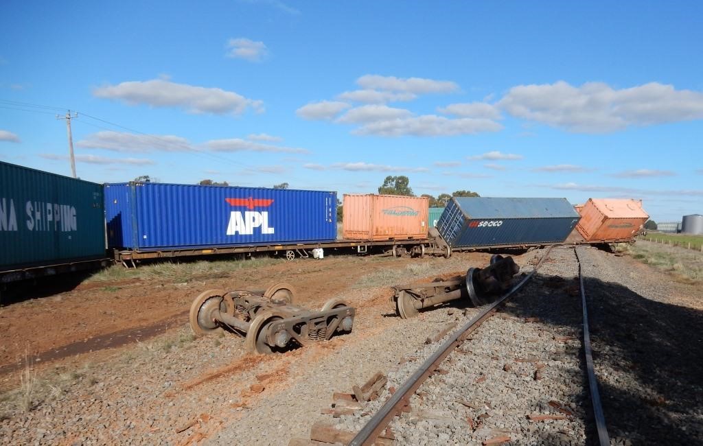
At about 0025 on 30 May 2016, freight train 9305 derailed at a fractured welded rail joint at Katunga in northern Victoria. The train consisted of two locomotives and 37 flatbed wagons carrying empty containers. Twelve wagons located mid-consist (wagon positions 6 to 17) derailed resulting in severe damage to about 350 m of track. There were no injuries.
What the ATSB found
The ATSB found that the fracture was at a flash butt weld joining early twentieth century rail. The weld contained microscopic defects within the crystalline material structure that indicated improper material processing during flash butt welding, and had probably existed for many years.
It was concluded that the fracture was probably the result of higher than normal loading due to inadequate support of the rail. The loss of effective support was probably the result of deteriorated sleeper condition. The deferral of the replacement of select sleepers through the location had increased the potential for rail fracture, although it was not possible to directly link this decision to this fracture.
The condition of the fracture surfaces indicated that the fracture was probably present for several days prior to the passage of train 9305. After the rail’s fracture, the loosening of the track fasteners allowed the lateral misalignment of the rail ends that led to the derailment of the train. The regime that may have detected the fractured rail before the track deteriorated to an extent that would result in derailment was ineffective for this track and its condition.
What's been done as a result
V/Line has revised their Technical Maintenance Plan schedule to clarify that front of train inspections cannot be used to replace hi-rail patrols on the Tocumwal line.
Further, V/Line intends undertaking a risk review of the appropriateness of its current condition based responses for sleeper condition, as set out the V/line standard for inspection and assessment. The ATSB has recommended that V/Line completes the risk review and implements safety actions to reduce the likelihood of derailment following a rail fracture.
Safety message
Systems of inspection should be designed to ensure detection of rail fractures before track deteriorates to a condition that results in train derailment.
The Occurrence
Train journey
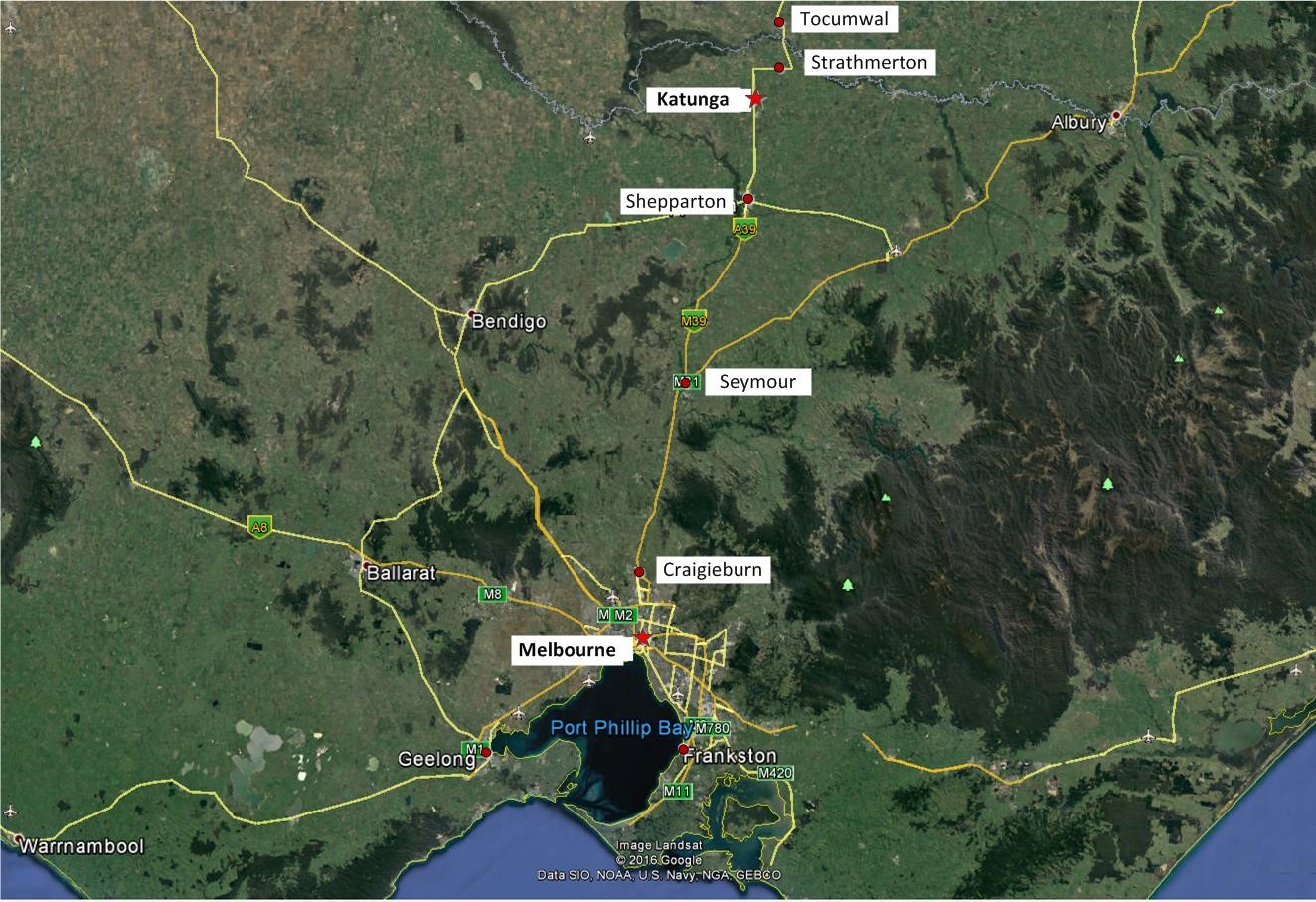
At about 1915[1] on 29 May 2016, Pacific National freight train 9305 departed Tottenham Yard, Melbourne, bound for Tocumwal in New South Wales (Figure 1). The train was being operated on the V/Line broad gauge network by a crew of two and consisted of two locomotives hauling 37 flatbed wagons carrying empty containers.
Figure 1: Route of freight train 9305
Source: Copyright Map Data Google 2016 with annotations by Chief Investigator, Transport Safety (Victoria)
The train proceeded to Craigieburn and then onto Seymour. From Seymour all trains are required to work to safeworking by train order.[2] A train order was issued at about 2215 to travel from Seymour to Shepparton and the train arrived at Shepparton without incident. A second train order was issued at about 2335 at Shepparton for the journey to Tocumwal.
At about 0025 when travelling through Katunga at about 61 km/h, the train crew felt a ‘bump’ and rough riding near the 228 km rail post. Shortly after there was a loss of brake pipe pressure resulting in a brake application. In response to this, the driver released the locomotive independent brake[3] and continued powering to maintain the train couplings in a draft condition.[4] The train then came to a stand with the lead locomotive about 295 m past the 228 km post.
Once the train had stopped, a crew member investigated the cause of the brake application. On observing the derailed wagons, the crew advised Centrol[5] and secured the train. There were no injuries to the public or the train crew.
The derailment and damage
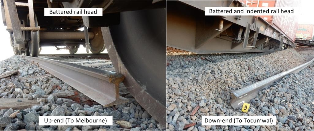
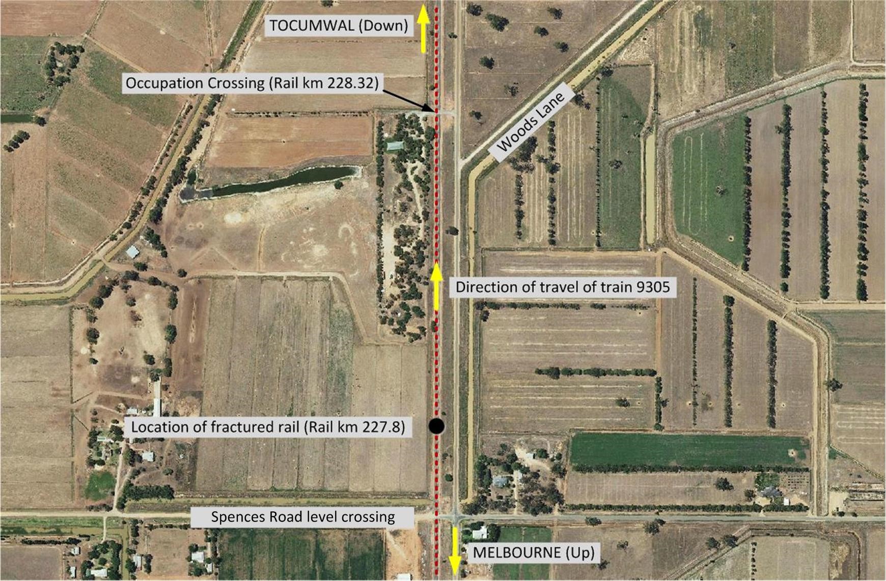
The train had derailed at a fractured flash butt welded rail joint in the east rail at about the 227.8 km mark (Figure 2).
Figure 2: Fractured rail
Source: Chief investigator, Transport Safety (Victoria)
The passage of train 9305 over the fractured rail had disturbed the joint sufficiently to laterally misalign the rail ends, such that a wheel flange impacted with the rail head on the Down-end. This resulted in further disarrangement of the rail and a loss of guidance for the following wagons. It is probable that the trailing axle of the leading bogie of wagon six was the first to derail.
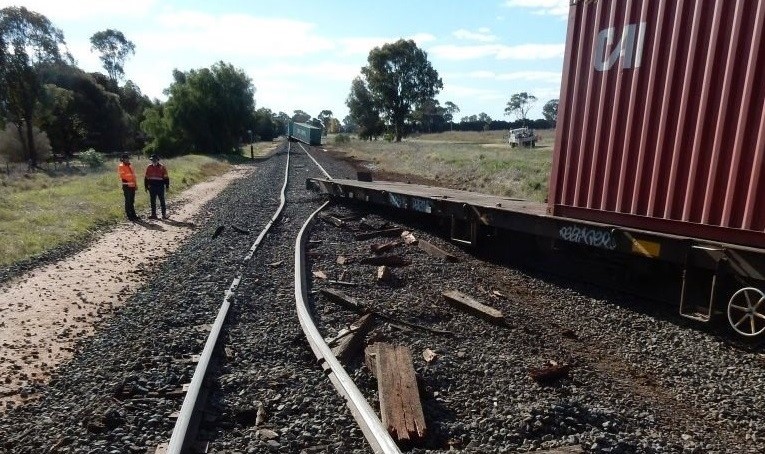
Of the twelve wagons that derailed, wagon six, seven and eight stayed upright and generally followed the track alignment, while the rear bogie of wagon nine veered to the east of the track. The tenth wagon and the following eight wagons veered to the east of the line causing a separation between the ninth and tenth wagons. The separation caused the loss of brake pipe pressure and the subsequent application of the train brakes. The locomotive and the first nine wagons travelled about 137 m from the separated section of the train (Figure 3).
Figure 3: Separated section of train and track damage, looking towards Tocumwal
Source: Chief investigator, Transport Safety (Victoria)
Wagons 10 to 17 ended in various states of disarrangement (Figure 4). The leading end of wagon 18 had lifted off the bogie centre bowl while the last nineteen wagons remained on the track. The derailment resulted in about 350 m of track damage.
Figure 4: Disarranged wagons separated bogies and damaged track
Source: Chief investigator, Transport Safety (Victoria)
----
[1] The 24-hour clock is used in this report and is referenced from Eastern Standard Time (EST), UTC +10 hours.
[2] Railway safeworking by train order involves the use of a paper instrument issued by a train controller authorising the driver to proceed into and through the nominated single-line section.
[3] An air brake system that operates on the locomotive independent of the train air brake system.
[4] A condition that maintains the coupler forces throughout the train in tension.
[5] Central Control - The operational control centre for Victoria's regional rail network.
Context
Location
The derailment occurred on a section of tangent track about 180 m north of the Spences Road level crossing (Figure 5).
Figure 5: Derailment location in Katunga, Victoria
Source: MapInfo Professional annotated by Chief Investigator, Transport Safety (Victoria)
Infrastructure
The line between Shepparton (182 km) and Tocumwal (252.6 km) was classified by V/Line as Class 4[6] track. The V/Line standard[7] for Class 4 track construction specified timber sleepers with non-resilient fasteners, sleeper plates, 47 kg/m rail (80 lb/yd[8] for existing track) in maximum lengths of 82 m mechanically jointed. The load limit for the Shepparton to Tocumwal line was 19 t axle load at a maximum speed of 65 km/h. Higher axle loads were allowed for approved locomotives.
At the derailment location, the track (considered ‘existing track’) consisted of 80 lb/yd rail that had been welded to form approximately 27.5 m lengths that were mechanically joined by fishplates. Rail was secured to timber sleepers using base plates and dog spikes. The sleeper spacing from centre to centre was 600 mm at the location of the fracture. The rolling marks indicated that the rail through the area was manufactured in Lorain, USA in the period 1911-1913. The rolling marks on the fishplates indicated that they had been manufactured by BHP in Australia in 1958. The topography of the incident area was flat, with sand and gravel soil with good drainage. The 27.5 m section of rail at the derailment location had been fabricated by flash butt welding two 7.7 m lengths to either end of a 12.1 m length of rail.
The flash butt welding process consists of heating the rail ends by means of an electric arc struck between the ends, and when in a plastic state forcing the rail ends together to effect the weld. Flash butt welding was usually undertaken in a factory facility. The date these welds were made is unknown, but was probably within the first half of the twentieth century.
Rail traffic
From January to May 2016, the freight rail traffic in the Up direction averaged 1.2 trains per day and the average tonnage was about 2000 t, mostly loaded. Under loaded conditions, the maximum wagon axle load is about 19 t. In the same period, the rail traffic in the Down direction also averaged 1.2 trains per day and the average tonnage was about 700 t, mostly unloaded.
Metallurgical examination of rail
Rail Chemistry
The steel rail had a carbon content varying between 0.50 and 0.75 per cent. The steel also contained small percentages of manganese, silicon, phosphorus and sulphur.
The rail head hardness was typical of rail material utilised in Australia before 1985 and was appropriate for the application.
Weld fracture
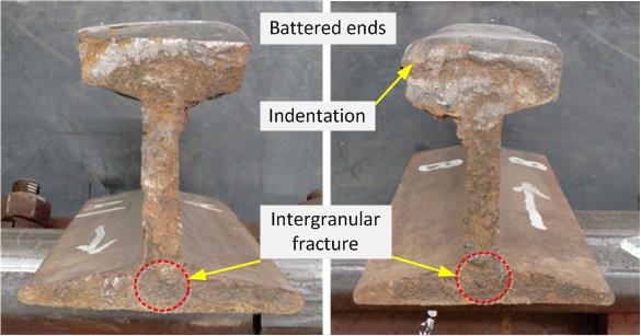
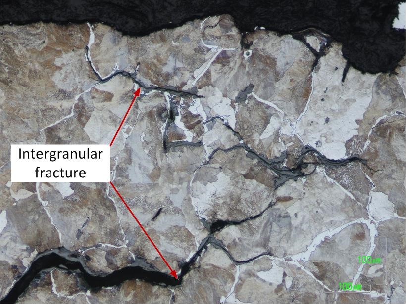
The rail head at the fractured weld had been battered on both sides of the break. Both ends were battered to a depth of about 10 mm. Mechanical damage to this depth indicated the passage of bi-directional rail traffic over the broken joint after fracture. There was also significant mechanical damage to the fracture surfaces and corrosion. At the intersection of the web and the foot, the fracture surface exhibited a region of predominantly intergranular fracture where significant grain boundary oxidation was observed (Figure 6).
Figure 6: Fractured weld ends, the Up-side rail is on the left and the Down-side rail on the right. The area of intergranular fracture is identified.
Source: ALS Global annotated by Chief Investigator, Transport Safety (Victoria)
The damage to the fracture surfaces had destroyed a significant amount of the fracture detail. The undamaged fracture surfaces of the rail head and web exhibited a coarse dimpled appearance consistent with instantaneous overload fracture. These features were indicative of ductile-fast fracture.
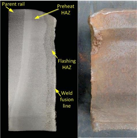
The fractured rail was longitudinally sectioned and evaluated by macro etching. The macro etching confirmed that the rail had been flash butt welded at the failed point. The macro etching revealed that the parent material was homogenous with no significant segregation of non-metallic inclusions.
In addition to the parent material, the evaluation revealed three distinct areas; a weld fusion line, a weld flash Heat Affected Zone (HAZ) and a HAZ produced during pre-heating prior to welding (Figure 7). The two Heat Affected Zones are consistent with in-plant flash butt welding processes. The fusion line hardness of the subject rail was consistent with the parent-rail material hardness. The peak HAZ hardness was 264HV (Vickers), 2.5 mm from the break and is not excessive for the application.
Figure 7: Macro etched longitudinal section of rail on the left showing that the fracture had occurred predominantly in the HAZ adjacent to the weld fusion line. The rail prior to sectioning is shown on the right.
Source: ALS Global annotated by Chief Investigator, Transport Safety (Victoria)
Laying rail and managing stress
Mechanical joints
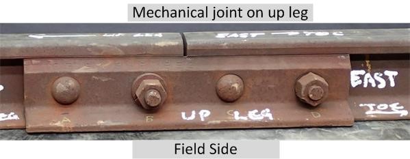
In jointed track, the mechanical joints have an expansion gap (Figure 8) that results in stress free rail within a defined temperature range. This longitudinal rail movement at the joint reduces the probability of rail fractures in cold temperatures due to rail contraction. Correct joint set-up and ongoing maintenance is required to ensure joints perform this function.
A mechanical joint adjacent to the fractured weld on the east rail was visually and mechanically examined (Figure 8). Based on bolt torques and wear on the fishing surfaces, the examination concluded that the rail had been expanding and contracting at the mechanical joint.
Figure 8: Mechanical joint adjacent to fractured weld on the East rail
Source: Chief Investigator, Transport Safety (Victoria)
A mechanical joint on the west rail opposite the joint on the east rail was also examined. Again, the abrasive wear on the fishing surfaces was consistent with the expansion and contraction of the rail at the mechanical joint.
V/Line construction standards[9] specified the method of laying rail to achieve design levels of maximum tensile and compressive stress. For jointed rail of 27 m length, the standard specified that the gap between rail ends should be 11 mm (the nominal maximum gap) for rails laid at a rail temperature between -2 °C to 7 °C, and fully closed (rail ends butted together) when laid at rail temperatures of 35 °C to 38 °C. The standard also specified other gap requirements for installation temperatures between 7 °C and 35 °C. If laid in this manner, at temperatures below the lower range (-2 °C to 7 °C) the rails would be in tension, and at temperatures above the upper range (35 °C to 38 °C) the rails would be in compression.
Gaps at seven pairs of mechanical joints on the Up side (towards the crossing) of the fractured weld were measured following the derailment, at an ambient temperature of about 15 °C. Gaps on the Up leg averaged 12 mm[10] and the gaps on the down leg averaged 10 mm. There was no indication that these joints had been recently lubricated, however there were signs that the joints were working.[11]
Creep measurements
Creep is the longitudinal movement of rail caused by the motion of rail traffic on the line. Creep typically takes place on grades, where trains brake and in the direction of predominant or loaded traffic. Rail creep can affect the stress condition of the rails. Creep monitoring points (monuments) are located alongside the track (one kilometre apart) and regular measurements are taken to ensure that the longitudinal movement of the rail is within acceptable limits.
Creep measurements recorded at the 228 km point between 2009 and April 2016 indicated a slow movement of the rails in the Up direction (towards Melbourne). The location of the weld fracture (227.8 km) was between the Spences Road level crossing and 228 km. The creep measurements indicated movement towards the fixed point of the crossing.
Track inspection
V/Line’s track inspection and maintenance procedure required trackpatrol inspections, general inspections and detailed inspections to be carried out at specified frequencies. For the Shepparton to Tocumwal line, track patrol inspections were required to be performed by road-rail vehicle or front of train riding once a week. General inspections by track walking and detailed inspections by a track geometry recording vehicle were to be carried out annually. Ultrasonic testing using a rail flaw detection (RFD) vehicle was to be conducted every two years.
The maintenance procedures provided specific guidelines for the assessment of non-welded joints (mechanical) and welded joints. Cracks in fishplates, loose or damaged bolts, rail-end batter and joint gaps are identified as areas for assessment in mechanical joints. For general inspection of rails and welded joints, corrosion, gauge corner or other cracking, piped rail, corrugations, shelling, rust streaks, and damaged rail were specified areas of assessment.
The most recent track patrol inspection before the incident was completed on 24 May 2016. This inspection, conducted from the front of a train, did not identify any defects at the derailment location.
A ‘Work Order’ for the most recent track walking inspection before the derailment for this section (182 to 253 rail km) records that it was completed on 30 October 2015 with no noted defects at the derailment location.
Measurement of the track geometry was carried out in March 2016 and no abnormal readings were recorded in the vicinity of the broken rail weld (227.8 km).
Rail flaw detection
The annual ultrasonic testing for internal rail defects involved operating an RFD vehicle. When a defect was detected by the RFD car, the location was noted and a manual inspection using hand-held ultrasound equipment was carried out. The defect was then categorised according the class of rail line, type and size of defect.
The last RFD inspection on the Shepparton to Tocumwal section of track was carried out about 12 months before the derailment on 5 May 2015 and no defects were observed at the location of the weld fracture. Following the derailment, recordings of the ultrasonic response at the fracture location were reviewed and there were no identifiable indications of microscopic material defects at the fracture location.
Detailed track condition inspection
A detailed asset inspection was conducted in 2014. The inspection identified 13 ineffective sleepers from 227.700 and 228.000 km, including three nominally within 50 m of the fractured weld. The Work Orders to replace the sleepers were subsequently cancelled, and V/Line advised that the sleeper replacement did not occur.
Train and crew information
Pacific National freight train 9305 consisted of two locomotives XR553 and XR554 hauling 37 flatbed wagons carrying empty containers. The containers were interspersed evenly on the wagons along the train. The trailing load of the consist had a total mass of 971 t, and the total mass including locomotives was 1215 t. The total length of the train was 768 m.
Train 9305 was crewed by two drivers who were appropriately qualified and certified for the route. The drivers were tested for the presence of alcohol after the derailment and returned zero results.
Post-incident rolling stock inspection
Inspection of the leading bogie of the first wagon that derailed identified the presence of wear in the friction wedge pockets. This wear was within condemning limits[12] and there were no signs that the bogie had been hunting. Wheel tread damage was the result of the derailment. The condition of the rolling stock did not contribute to the derailment.
[10] While the nominal maximum (nominal) joint gap is 11 mm, greater gaps can exist in practice due to variations in bolt diameter and wear or elongation of rail holes. It is not uncommon to find joints that can extend to a gap of 15 mm.
[11] Expansion and contraction of the rail at the mechanical joint.
[12] A permissible limit determined by the use of a specific gauge.
Safety analysis
Derailment
The derailment occurred as a result of a fracture at a flash butt welded rail joint. The condition of the fracture surfaces indicated that the fracture had occurred prior to the passage of train 9305. Battering of the fractured rail indicated bi-directional traffic across the fracture, and corrosion and fracture surface damage suggested the fracture had been present for several days.
The battering of rail head ends indicated that vertical displacement of the rail had been possible in the period following the fracture. In addition, dog spikes on the Up-side of the fracture had been lifted and were loose suggesting that the passage of trains had resulted in the deterioration of rail fixings around the fracture. This deterioration was sufficient to allow the development of a lateral discontinuity at the fracture during the passage of train 9305 resulting in the derailment of the train.
Weld fracture mechanism
The fracture occurred predominantly in the Heat Affected Zone adjacent to the weld fusion line and fracture surfaces were consistent with instantaneous overload fracture.
Pre-existing defect
Metallographic examination of the fracture exhibited a mixed mode (transgranular and intergranular) cracking mechanism. The fracture surface at the foot-web intersection of the fractured weld exhibited a predominantly intergranular brittle fracture mode (Figures 6 and 9).
Figure 9: Photomicrograph of the etched microstructure of the rail fracture surface. The foot-web intersection of fractured weld exhibited an intergranular fracture mode.
Source: ALS Global annotated by Chief Investigator, Transport Safety (Victoria)
Intergranular brittle fracture occurs by separation at or adjacent to the grain boundaries (where significant oxidation was observed). This type of fracture is indicative of improper material processing during flash butt welding.
History of weld failures
V/Line advised that there were about 330,000 flash butt welds and about 180,000 thermit welds[13] on their operating network. From 2005 to 2015, there were 59 flash butt weld failures, 27 thermit weld failures and a range of other fractures (Figure 10). The flash butt failures represented 15 per cent of the total annual rail failures and the failure rate is similar to other welded connections on the network.
Figure 10: Rail failures from 2005 to 2015.
Source: V/Line Pty Ltd, annotated by Chief Investigator, Transport Safety (Victoria)
Loading of rail
Rail tension
There was no evidence to suggest that rail creep or frozen joints had resulted in higher than normal rail tension. The rail joints between the fracture and level crossing were ‘working’ and so provided for rail expansion and contraction. In addition, the recorded rail creep was southwards towards the crossing making high rail tension in cold weather less likely.
Temperatures recorded at Tocumwal (24 km from Katunga) indicated low overnight temperatures during the last week of May, with a minimum of 3 °C. Considering the measured joint gaps between the fracture and the crossing, these low overnight temperatures probably resulted in some tension in the Up (east) rail. However, this tension is unlikely to have been excessive and would have been within the normally expected range. It was therefore concluded that excessive rail tension was not likely to have contributed to the fracture.
Bending stress
In the absence of excessive rail tension, higher than normal bending stress within the rail most likely led to the fracture. The failure mechanism by instantaneous overload, as confirmed by metallurgical examination, is consistent with this loading scenario.
Bending stresses are developed in a rail during the passage of a train and increase when the support provided to the rail is inadequate or uneven. Site observations identified that support of the rail was probably compromised by the deteriorated condition of sleepers.
Following a period of dry weather, the month of May received more than double its normal rainfall and this may have had some influence on the condition of the support.
Asset condition
Inspections
A walking inspection seven months prior to the derailment and weekly track patrols were scheduled in accordance with network procedural requirements and there was no specific deficiency in the application of the inspection regime identified.
However, in this instance these inspections did not identify a deterioration in track support at the derailment location. The absence of any rail top defects or other track geometry anomalies through this location may have reinforced a belief that sleepers were providing adequate support.
Deferment of sleeper replacement
Asset assessments in 2014 had identified several ineffective sleepers through this location and work orders were raised for sleeper replacement. V/Line advised that these work orders were subsequently cancelled. It was not possible to identify whether those sleepers identified for replacement directly influenced the rail fracture leading to this derailment. However, the action to defer sleeper replacement probably increased the risk of rail fracture through the location.
The documentation clarifying the rationale for cancelling the replacement of sleepers could not be identified by V/Line. Several factors might influence decisions to cancel work orders including judgements as to the serviceability of the track, risks associated with the type and volume of traffic, funding and resource allocation. In this instance, the rationale for the deferment of the work program could not be ascertained due to the lack of documentation. Assessing the risk of deferring a work program and documenting the process is crucial to ensuring a verifiable and transparent decision making process.
The fracture
Pre-fracture weld defect
It is unlikely that the defects found within the weld would be detected by ultrasonic testing used in an automated RFD vehicle or currently available train borne monitoring equipment. The defects that were located on grain boundaries within the crystalline material structure were small and discontinuous and would produce specular multi-directional ultrasonic responses. These responses would produce a multi peak indication similar to lower level ‘noise’ signals and would be expected to be below the threshold that would cause a defect alarm. The microscopic defects observed would need to propagate by fatigue to produce a macroscopic planar defect before a detectable ultrasonic return signal could be produced. While some microscopic fatigue was observed, it had not progressed to macroscopic levels in this case.
Fracture detection
The condition of the fracture surfaces indicated that the fracture was probably present for at least two days prior to the derailment. Rail fractures cannot be completely eradicated and the network has about 30 fractures per annum. Therefore, there is a strong imperative to identify the presence of the fracture before the track deteriorates to a condition that could cause derailment.
The fracture was present during the passage of several trains. In the previous 48 hours, three Melbourne-bound and one Tocumwal-bound trains had traversed the location, one in daylight hours. There were about two trains per day preceding this. However, there were no rough riding or track irregularities reported by train drivers prior to the derailment even though other trains had travelled over the fracture. Given the section was jointed, it may have been difficult for train crew to detect the presence of the fracture.
A track patrol inspection was carried out by front of train riding on 24 May 2016, six days before the derailment. It is unknown whether the fracture was already present, although track patrol by hi-rail may have been a more effective means of detecting the fracture. If the fracture occurred after this patrol, there were no other means of identifying this fracture.
Once the rail had fractured, the configuration and condition of the track meant that dog spikes probably became dislodged relatively quickly reducing the opportunity for the fracture to be identified by track patrol prior to the loss of gauge. Risk mitigation measures used to identify fractured rail were not effective for the configuration and condition of this track.
------
[13] Exothermic welding using molten metal to join rail ends. This method of connection is normally conducted on site and uses an Aluminothermic reaction to create the heat necessary to melt the joining metal.
Findings
The following findings are made with respect to the derailment of freight train 9305 at Katunga, Victoria on 30 May 2016. These findings should not be read as apportioning blame or liability to any particular organisation or individual.
Safety issues, or system problems, are highlighted in bold to emphasise their importance. A safety issue is an event or condition that increases safety risk and (a) can reasonably be regarded as having the potential to adversely affect the safety of future operations, and (b) is a characteristic of an organisation or a system, rather than a characteristic of a specific individual, or characteristic of an operating environment at a specific point in time.
Contributing factors
There were microscopic defects within the weld zone that were probably the result of improper material processing during the flash butt welding of the joint.
The loading of the rail at the weld was probably higher than normal due to inadequate support of the rail, and this inadequate support was not identified.
The rail fracture was not detected before the passage of train 9305.
The inspection regime to identify rail fractures was ineffective for the condition of this track. [Safety Issue]
During the passage of train 9305, the rail ends at the already fractured weld laterally misaligned resulting in the derailment of the train.
Other factors that increase risk
Remediation works to replace deteriorated sleepers was deferred by V/Line.
Safety issues and actions
The safety issues identified during this investigation are listed in the Findings and Safety issues and actions sections of this report. The Australian Transport Safety Bureau (ATSB) expects that all safety issues identified by the investigation should be addressed by the relevant organisation(s). In addressing those issues, the ATSB prefers to encourage relevant organisation(s) to proactively initiate safety action, rather than to issue formal safety recommendations or safety advisory notices.
Depending on the level of risk of the safety issue, the extent of corrective action taken by the relevant organisation, or the desirability of directing a broad safety message to the rail industry, the ATSB may issue safety recommendations or safety advisory notices as part of the final report.
Safety issue description: The inspection regime to identify rail fractures was ineffective for the condition of this track.
Safety recommendation description: The ATSB recommends that V/Line completes the risk review and implements safety actions to reduce the likelihood of derailment following a rail fracture.
Additional safety action
Whether or not the ATSB identifies safety issues in the course of an investigation, relevant organisations may proactively initiate safety action in order to reduce their safety risk. The ATSB has been advised of the following proactive safety action in response to this occurrence.
V/Line has advised that, since the derailment of freight train 9305, a joint servicing program has been completed, with all mechanical joints lubricated, bolts repaired, and fishing surfaces lubricated. V/Line has also redeveloped its ultrasonic inspection and assessment standard to include more specific instructions and requirements for ultrasonic testing, including a requirement to report non-sizable defects in more detail. Further, it has conducted ultrasonic inspections of an additional 100 flash butt welds and 50 thermit welds on the Tocumwal line. They reported that no defects were detected during these inspections.
Sources and submissions
Sources of information
The sources of information during the investigation included:
V/Line Pty Ltd
ALS Industrial Pty Ltd
Asciano Limited
Speno Rail Maintenance Australia Pty Ltd
References
Use and Laying of Rail – NIST 2650 – V/Line Procedural document.
Submissions
Under Part 4, Division 2 (Investigation Reports), Section 26 of the Transport Safety Investigation Act 2003 (the Act), the Australian Transport Safety Bureau (ATSB) may provide a draft report, on a confidential basis, to any person whom the ATSB considers appropriate. Section 26 (1) (a) of the Act allows a person receiving a draft report to make submissions to the ATSB about the draft report.
Submissions were received from V/Line Pty Ltd and The Office of the National Rail Safety Regulator (ONRSR). The submissions were reviewed and where considered appropriate, the text of the report was amended accordingly.
Purpose of safety investigations
The objective of a safety investigation is to enhance transport safety. This is done through:
identifying safety issues and facilitating safety action to address those issues
providing information about occurrences and their associated safety factors to facilitate learning within the transport industry.
It is not a function of the ATSB to apportion blame or provide a means for determining liability. At the same time, an investigation report must include factual material of sufficient weight to support the analysis and findings. At all times the ATSB endeavours to balance the use of material that could imply adverse comment with the need to properly explain what happened, and why, in a fair and unbiased manner. The ATSB does not investigate for the purpose of taking administrative, regulatory or criminal action.
Terminology
An explanation of terminology used in ATSB investigation reports is available here. This includes terms such as occurrence, contributing factor, other factor that increased risk, and safety issue.
Publishing information
Released in accordance with section 25 of the Transport Safety Investigation Act 2003
Ownership of intellectual property rights in this publication
Unless otherwise noted, copyright (and any other intellectual property rights, if any) in this report publication is owned by the Commonwealth of Australia.
Creative Commons licence
With the exception of the Coat of Arms, ATSB logo, and photos and graphics in which a third party holds copyright, this publication is licensed under a Creative Commons Attribution 3.0 Australia licence.
Creative Commons Attribution 3.0 Australia Licence is a standard form licence agreement that allows you to copy, distribute, transmit and adapt this publication provided that you attribute the work.
The ATSB’s preference is that you attribute this publication (and any material sourced from it) using the following wording: Source: Australian Transport Safety Bureau
Copyright in material obtained from other agencies, private individuals or organisations, belongs to those agencies, individuals or organisations. Where you wish to use their material, you will need to contact them directly.
On 5 June 2016, the pilot of a Cessna 206 floatplane, registered VH-NTK, was taking off from the Southport Broadwater about 6 km south-east (SE) of Southport Airport, Queensland, for a charter flight with two passengers on board.
The wind was blowing from the west-north-west (WNW) at about 18 kt, with gusts of variable speed. The take-off direction to the north-west (NW) was too restrictive due to the presence of boats in the area, so the pilot elected to begin the take-off towards the south-west (SW) (Figure 1). Taking off to the SW would be through a jet-ski course and a crosswind from the right. Once clear of the jet-ski course, the pilot intended to veer right onto a more westerly (into wind) heading to complete the take-off.
The pilot set 20° flap and left the water rudders[1] in the down position to assist with directional control at the start of the take-off run. The pilot applied full power to start the take-off run and the aircraft pitched[2] backwards into the plowing position.[3] The pilot retracted the water rudders about five seconds into the take-off run, and about two seconds later, pitched the aircraft forward from the plowing position into the step position.[4] As the aircraft pitched forward onto the step it veered to the left onto a south-south-west (SSW) heading (this increased the crosswind experienced – see textbox 4 in Figure 1). The pilot maintained the aircraft on this heading until they sighted barrels in the water that were used to mark the jet-ski course.
The pilot could not prevent the veer to the left, even with full right rudder, so after sighting the jet-ski course barrels, the pilot pitched the aircraft backwards into the plowing position to improve directional control on the water.[5] The pilot then alternated pitching the aircraft between the plow and step position in order to gradually veer to the right onto a more westerly heading (textbox 5 in Figure 1).
As the aircraft was passing a SW heading and was turning towards WSW, the right wing lifted and the aircraft rolled[6] to the left. The roll continued, despite the application of full right aileron by the pilot, until the left wing impacted the water. The aircraft rotated to the left through about 270° and the nose and propeller ploughed into the water. The aircraft then came to a stop in an upright position, facing in a westerly direction (Figure 1).
The pilot assessed the condition of the aircraft and elected not to evacuate the passengers. The aircraft was then towed to shore by a jet-ski. There were no injuries and the aircraft was substantially damaged (Figure 2 and 3).
Figure 1: Approximate take-off path and key events
Source: Google earth modified by ATSB
Figure 2: VH-NTK left wing damage
Source: Owner
Figure 3: VH-NTK rear strut fracture (view of the left float facing forwards)
Source: Owner
Pilot comments
The pilot provided the following comments:
the force that veered the aircraft to the left occurred when they pitched the aircraft forward from the plow position to the step position
they were turning the aircraft right through SW towards WSW when it rolled
they were holding full into wind (right) aileron control and therefore expected the left wing to lift prior to the right wing
when they rolled to the left they were ‘shocked’ by the crosswind and ‘surprised’ they could not control the floatplane
they estimated the strength of the gust that lifted the right wing was about 8–10 kt
they had about 110 litres of fuel in the left wing tank and about 60 litres in the right wing tank, which may have contributed to the left roll
the floatplane rolled left at about 30–35 kt airspeed
the crosswind limit is 20 kt
the take-off speed is 41 kt with 20° flap set.
Left turn effect
There are four distinct propeller forces, each of which produce a left turning force on an aeroplane, as follows:
Torque effect: As the engine internal parts and propeller rotate clockwise, as viewed by the pilot, an equal force tries to rotate the aircraft in the opposite direction. This force places more weight and consequently more hydrodynamic drag on the left float of a floatplane.
Slipstream effect: The clockwise spiralling motion of the propeller slipstream means that the slipstream strikes the left side of the vertical fin. This produces a yawing[7] moment to the left.
P-factor: In a nose high attitude the ‘bite of air’ of the downward moving blade of the propeller is greater than the ‘bite’ of the upward moving blade, which moves the centre of thrust to the right side of the propeller disc. This also produces a yawing moment to the left.
Gyroscopic effect: The rotating propeller behaves like a gyroscope. As such, any time a force is applied to deflect the propeller from its plane of rotation, the resultant force is 90° ahead in the direction of rotation, and in the direction of the effective force (Figure 4). As such, the gyroscopic effect results in a yawing motion to the left when the aircraft is pitched forward from the plow position to the step position.
Figure 4: Gyroscopic effect
Source: FAA pilot’s handbook of aeronautical knowledge
According to the FAA Seaplane operations handbook, crosswinds can present special difficulties for floatplane pilots. If the aircraft turns towards the wind during a crosswind take-off, then centrifugal force will combine with the wind force to produce a rolling moment in the opposite direction to the turn (Figure 5). If strong enough, the combination of wind and centrifugal force may lift the upwind wing and submerge the downwind float, rolling the aircraft until the downwind wingtip strikes the water. This is known as a water‑loop (Figure 6).
Centre of gravity[8] location also affects the floatplane’s handling characteristics on the water. If the centre of gravity is located to one side of the centre-line, such as a fuel imbalance between the tanks, one float must support more weight and therefore displace more water than the other float, resulting in more water drag on that side (Figure 7).
Figure 5: Effect of wind force and centrifugal force
Source: FAA seaplane operations handbook
Figure 6: Water-loop
Source: FAA seaplane operations handbook
Figure 7: Effect of fuel imbalance on centre of gravity
Source: FAA seaplane operations handbook
ATSB comment
The pilot reported that it was the force from the forward pitching motion of the aircraft from the nose-high plowing position to a nose-level step position that resulted in the aircraft veering left from the planned take-off path. The force that produces this motion is the gyroscopic effect. At the time of the uncommanded roll to the left the aircraft was turning right with a strong crosswind from the right and more fuel distributed in the left tank than in the right tank. These factors probably combined to elevate the risk of submerging the downwind float and lifting the upwind wing, resulting in a water-loop.
Safety action
Whether or not the ATSB identifies safety issues in the course of an investigation, relevant organisations may proactively initiate safety action in order to reduce their safety risk. The ATSB has been advised of the following proactive safety action in response to this occurrence.
Operator
As a result of this occurrence, the aircraft operator has advised the ATSB that they are taking the following safety actions:
Changes to operating procedures
The operator is updating their operations manual to incorporate the following procedural changes:
The channel at the operating base is orientated north-south, which restricts movements orientated east-west, therefore if the wind is forecast to gust more than 20 kt from the west, or within 30° either side of west, the take-off must be rejected.
If the aircraft veers to the left during the take-off run and requires full control inputs, then reject the take-off.
Safety message
This accident highlights the risk of a water-loop event during a crosswind take-off in a floatplane. The combined forces acting on a floatplane have the potential to significantly reduce the margin of control available to the pilot. The FAA Seaplane operations handbook provides several recommended crosswind take-off techniques, including the considerations associated with arcing manoeuvres during take-off. If an arcing manoeuvre is to be attempted then the FAA handbook recommends placing the centrifugal force and wind force on opposite sides, and reducing the radius of the arc as the floatplane speed increases.
Refer to the FAA Seaplane operations handbook for a detailed explanation of the recommended crosswind take-off techniques.
Decisions regarding whether to conduct an investigation, and the scope of an investigation, are based on many factors, including the level of safety benefit likely to be obtained from an investigation. For this occurrence, a limited-scope, fact-gathering investigation was conducted in order to produce a short summary report, and allow for greater industry awareness of potential safety issues and possible safety actions.
Publishing information
Released in accordance with section 25 of the Transport Safety Investigation Act 2003
Ownership of intellectual property rights in this publication
Unless otherwise noted, copyright (and any other intellectual property rights, if any) in this report publication is owned by the Commonwealth of Australia.
Creative Commons licence
With the exception of the Coat of Arms, ATSB logo, and photos and graphics in which a third party holds copyright, this publication is licensed under a Creative Commons Attribution 3.0 Australia licence.
Creative Commons Attribution 3.0 Australia Licence is a standard form licence agreement that allows you to copy, distribute, transmit and adapt this publication provided that you attribute the work.
The ATSB’s preference is that you attribute this publication (and any material sourced from it) using the following wording: Source: Australian Transport Safety Bureau
Copyright in material obtained from other agencies, private individuals or organisations, belongs to those agencies, individuals or organisations. Where you wish to use their material, you will need to contact them directly.
At 0856 Central Standard Time (CST) on 25 May 2016, a Piper PA-32, registered VH-NKA (NKA), departed Darwin Airport, Northern Territory (NT) for a business flight to Oenpelli Airport, NT. On board were a pilot under supervision, a supervising pilot and two passengers. The pilot under supervision was the pilot flying (PF), with the supervising pilot acting as pilot monitoring (PM),[1] observing the flight and providing assistance.
At 0926, a Cessna 210, VH-SQT (SQT), departed Jabiru Airport, NT, for a scenic flight over Kakadu National Park and the East Alligator River, NT. On board were the pilot and five passengers. SQT initially proceeded in an easterly direction before progressing north along the river (Figure 1).
At about 0930, the PF in NKA assessed the expected weather conditions at Oenpelli and elected to make a straight-in[2] approach to runway 12. At this time, the PF made an inbound broadcast on the Jabiru-Oenpelli common traffic advisory frequency (CTAF), advising their position as 50 NM west of Oenpelli. The PF then descended the aircraft from the cruising altitude of 9,500 ft and made a further broadcast on the Jabiru-Oenpelli CTAF as the aircraft reached 15 NM from Oenpelli. The pilots of NKA received no response to these broadcasts.
Figure 1: Overview of incident location
Source: Google Earth, annotated by ATSB
As SQT reached Cahill’s Crossing, 7 NM south of Oenpelli Airport, the pilot broadcast on Jabiru-Oenpelli CTAF, advising that they would be tracking north via the East Alligator River towards Flying Fox Island and operating not above 800 ft. The pilot did not receive a response to this broadcast.
At 0952, the PF in NKA established the aircraft on a 5 NM final approach leg to the runway at Oenpelli Airport at an altitude of 1,000 ft and configured the aircraft for landing. At the same time, the pilot of SQT continued to follow the East Alligator River north making continuous shallow turns left and right to maximise their passenger’s view. As SQT began a right turn, the pilot observed the shadow of another aircraft (subsequently determined to be NKA) tracking towards the shadow of their own aircraft. The pilot of SQT continued the right turn and assessed the position of the sun in relation to the shadow on the ground to establish the position of NKA. The pilot of SQT sighted NKA in close proximity and instinctively descended the aircraft to avoid a collision.
At this time, the PM in NKA, observing the high workload of the PF, elected to broadcast advising they were 4 NM from Oenpelli conducting a straight-in approach for runway 12.
At about the same time, the pilot of SQT broadcast on the CTAF to establish contact with NKA and advise of the near collision. The pilots of each aircraft communicated without difficulty following the incident.
The pilot of SQT estimated that the aircraft passed at the same altitude and a distance less than 100 m at the closest point. The pilots of NKA did not see SQT.
The pilots and passengers of both aircraft were not injured in the incident and the aircraft were not damaged.
Pilot Comment
The pilot of VH-NKA:
The supervising pilot of NKA provided the following comments:
No radio calls were heard from the pilot in SQT prior to the incident, despite having experienced no communication difficulties prior to, or after the incident.
Their view of SQT would have been obscured by the aircraft’s right wing as SQT approached their aircraft.
The change to the Jabiru-Oenpelli CTAF was made slightly later than the usual distance of about 70 NM from Oenpelli Airport. This may have led to the pilots missing the departure call from the pilot in SQT.
The pilot in command expressed concern at the planning of a low-level scenic flight through the extended centreline[3] of an aerodrome at a distance of 3 NM.
The pilot of VH-SQT:
The pilot of SQT provided the following comments:
No radio calls were heard from the pilots in NKA prior to the incident despite hearing calls from other aircraft. The radio in use was tested immediately afterward and found serviceable.
The incident occurred at the point they would normally make a radio call for transiting abeam Oenpelli Airport. The pilot spotted the shadow of NKA just as they were about to make the call.
The avoiding action required was forceful, inducing slight negative ‘G’.[4] Had the pilot taken no avoiding action the two aircraft would have collided.
The pilot did not expect an aircraft on approach to Oenpelli airport at a distance of 4 NM from the runway to be as low as 800 ft.
Safety action
Whether or not the ATSB identifies safety issues in the course of an investigation, relevant organisations may proactively initiate safety action in order to reduce their safety risk. The ATSB has been advised of the following proactive safety action in response to this occurrence.
Operator of VH-SQT
As a result of this occurrence, the operator of SQT has advised the ATSB that they have taken the following action:
Communications procedure
The communication procedures for scenic flights using this route have been changed. They will now include a broadcast when the aircraft are 3 NM from Oenpelli Airport, stating that the aircraft will be passing through the extended centreline of runway 12, operating at not above 800 ft.
Safety message
This occurrence highlights the importance of effective communications. Where this effectiveness is compromised, pilot lookout becomes increasingly important. The ATSB publication Limitations of the See-and-Avoid Principle provides information on developing effective lookout techniques.
ERSA - GEN - SP contains a fly neighbourly advice for pilots operating in the Kakdau National Park. Pilots intending to fly over Kakadu National Park should obtain, read and comply with the Kakadu Fly Neighbourly Agreement.
Decisions regarding whether to conduct an investigation, and the scope of an investigation, are based on many factors, including the level of safety benefit likely to be obtained from an investigation. For this occurrence, a limited-scope, fact-gathering investigation was conducted in order to produce a short summary report, and allow for greater industry awareness of potential safety issues and possible safety actions.
Publishing information
Released in accordance with section 25 of the Transport Safety Investigation Act 2003
Ownership of intellectual property rights in this publication
Unless otherwise noted, copyright (and any other intellectual property rights, if any) in this report publication is owned by the Commonwealth of Australia.
Creative Commons licence
With the exception of the Coat of Arms, ATSB logo, and photos and graphics in which a third party holds copyright, this publication is licensed under a Creative Commons Attribution 3.0 Australia licence.
Creative Commons Attribution 3.0 Australia Licence is a standard form licence agreement that allows you to copy, distribute, transmit and adapt this publication provided that you attribute the work.
The ATSB’s preference is that you attribute this publication (and any material sourced from it) using the following wording: Source: Australian Transport Safety Bureau
Copyright in material obtained from other agencies, private individuals or organisations, belongs to those agencies, individuals or organisations. Where you wish to use their material, you will need to contact them directly.
On 20 May 2016, the pilot of an Airbus Helicopters EC 130 T2 helicopter, registered VH-ZVO (ZVO), was conducting a ferry flight from Port Kembla to Bankstown Airport, New South Wales, with an engineer, who was also a crewmember, on board. At about 1437 Eastern Standard Time (EST), the pilot of ZVO contacted Bankstown Tower air traffic control (ATC), advising they were at 2RN approach point at 1,000 ft and inbound to Bankstown (Figure 1). The aerodrome controller (ADC) cleared ZVO to track to Bankstown via the Choppers South approach point at 500 ft.
Figure 1: Bankstown Airport and Choppers South
Source: Airservices Australia, annotated by the ATSB
At the same time, an instructor and student of a Piper PA-28-181 aeroplane, registered VH-MJT (MJT), were conducting circuit training on runway 29 left (29 L) at Bankstown Airport. At about 1438, the instructor advised the ADC that they were on the downwind circuit leg for a glide approach,[1] and a touch-and-go landing. The ADC cleared MJT for the touch-and-go landing in response. Soon after, the instructor set the throttle to idle to simulate an engine failure, and the student commenced a glide approach.
At about 1439, the pilot of ZVO called at Choppers South at 500 ft and the ADC cleared ZVO to overfly the runways midfield (which included crossing all three runways – 29 left, centre and right), at 500 ft and then to join the circuit on the downwind leg for a landing at taxiway N1 (Figure 2). The ADC also advised the pilot of ZVO of traffic, which was another helicopter then overhead the runways and outbound via Choppers South. The pilot of ZVO saw, and reported sighting, that helicopter.
The ADC reported that they then observed MJT on final approach, about 100 m short of the runway threshold, and assessed that they were on a normal approach path. The ADC also observed ZVO pass the outbound helicopter and then, concerned about the outbound helicopter’s proximity to restricted airspace (R555), had a brief look at the tower situational awareness display (TSAD) to check their track.
The instructor of MJT reported that as the aeroplane approached the runway threshold on final approach, it was still at about 400–500 ft above the runway, which they assessed as too high to safely complete the landing. The student therefore commenced a go-around[2] procedure, applied full power, and moved to the left of the runway centreline. The radar data showed MJT descended to about 300 ft during final, and an off-duty controller who observed the incident, estimated MJT then continued to descend to between 100 and 200 ft on short final before conducting a go-around.
The controller looked up from the TSAD and sighted MJT in the go-around. The controller estimated that MJT was at about 250–350 ft above the runway and about 250–300 m beyond the runway threshold.
As ZVO crossed the airport boundary, the engineer sighted the aeroplane (MJT) and alerted the pilot. The pilot then saw MJT in the go-around, at the same height as ZVO, and immediately conducted a left turn to increase separation between the helicopter and the aeroplane. MJT was about midfield (half way along the runway) when the instructor sighted the helicopter (ZVO) taking avoiding action.
At about 1441, the controller advised the pilot of ZVO of MJT as relevant traffic, and watched as the helicopter turned through 360° and passed MJT.
At that time, the instructor of MJT reported that they broadcast, stating that they were going around. On the recorded audio from the ADC frequency, about 8 seconds after the ADC advised ZVO of MJT, the instructor of MJT can be heard to start to broadcast, but was then over-transmitted by another radio broadcast.
The instructor of MJT estimated that the helicopter was within about 30–50 m horizontally and at the same height as MJT. The pilot of ZVO estimated the aeroplane was about 200 m away, and the ADC estimated the proximity to be about 120 m.
ZVO then continued to land at N1 as cleared. MJT continued to conduct circuits.
Source: Airservices Australia, annotated by the ATSB
Aerodrome control and radio frequencies
There were two tower frequencies and ADC positions at Bankstown, with ADC1 having responsibility for arrivals and departures on runways 29 right/11 left and 29/11 centre; ADC2 was responsible for the training circuit with runway 29 left/11 right. However, these were combined when the traffic volume allowed. When not combined, the two aerodrome controllers were required to coordinate with each other if helicopters were operating inbound or outbound via Choppers South and therefore crossing the circuit traffic midfield over the runways.
The two Tower frequencies at Bankstown were combined at the time of the incident, and one controller occupied the ADC position. When combined, pilots of aircraft operating on either the circuit Tower frequency or the other Tower frequency would have been able to hear transmissions on the other frequency. Although the pilots of ZVO and MJT had different radio frequencies selected, they were combined such that the transmissions on both frequencies could be heard on either.
Pilot comments
Instructor of VH-MJT
The instructor of MJT commented that they were not aware of ZVO before sighting it after the pilot of ZVO had taken avoiding action and the ADC had issued the traffic alert. Despite having heard a couple of radio calls regarding helicopters, they were not aware of ZVO tracking via Choppers South or that they would be crossing the runways at 500 ft.
There was a tailwind component, which may have contributed to the aircraft being high on final. The automatic terminal information service (ATIS) current at the time indicated an occasional downwind of 4 kt. The ATIS was changed about 10 minutes after the incident, and the runway direction changed to 11, with the wind reported to be from 150° at 8 kt.
The instructor stated that if an approach is unstable,[3] conducting a go-around is standard procedure. The instructor also stated that it would be valuable for aircraft in the circuit to be advised by ATC if a helicopter is approaching from Choppers South and crossing midfield at 500 ft. Additionally, advising the helicopter pilot when there is an aircraft on final would be valuable information.
After the incident, the instructor spoke to the Tower controller by telephone, and reported that they were advised that to avoid a similar situation, pilots should broadcast that they are going around before commencing the go-around. The instructor commented that a pilot’s priority is to aviate first and control the aircraft, then to communicate later.
The instructor also commented that at a non-towered aerodrome, there would not be an aircraft passing across the midfield at 500 ft (without a broadcast). The procedure could be addressed such that either the helicopters do not pass directly through the circuit, or the aircraft on final approach and the helicopter pilot are both given traffic information regarding each other.
Pilot of VH-VZO
The pilot of VZO provided the following comments:
They did not hear any call from the pilot of the aeroplane, nor was there any call from Tower that the aeroplane was conducting a go-around.
Even if a pilot broadcasts conducting a go-around, sometimes the aircraft can be hard to see on finals. They did not see the aeroplane at first, but their passenger saw it going around. They do not expect to see another aircraft at the same height when crossing the runways at 500 ft.
They were not aware of the other aircraft at all before they saw it – they had not heard a call and were not aware of any aircraft in the training circuit. They did not know to look there for other aircraft traffic.
Controller comments
The aerodrome controller reported that they were monitoring an outbound helicopter on the TSAD when MJT commenced the go-around. As soon as they sighted the potential conflict, VZO had commenced a left turn and the ADC gave MJT as traffic to VZO.
An off-duty controller, who was in the ATC tower at the time of the incident, commented that in Class D airspace, pilots have responsibility to see and avoid VFR aircraft and ATC has a responsibility to provide relevant traffic information to assist them to do that. In normal circumstances, an aircraft in the circuit and a helicopter tracking across the runway at 500 ft would not need to know where each other was as they are ‘segregated’. Additionally, providing traffic information that was not useful, may lead pilots to switch off to essential information. However, in the go-around procedure, they were relevant traffic and the controller would pass the traffic. Usually their response would be to pass traffic to the helicopter first as they were generally in a stage of flight with a lower workload and are more manoeuvrable than fixed wing aircraft.
En Route Supplement Australia
The ERSA entry for Bankstown included the following under the heading Class D:
‘CAUTION: HELICOPTERS OVERFLY RUNWAYS MIDFIELD AT 500FT.’
Safety action
Whether or not the ATSB identifies safety issues in the course of an investigation, relevant organisations may proactively initiate safety action in order to reduce their safety risk. The ATSB has been advised of the following proactive safety action in response to this occurrence.
Airservices Australia
As a result of Airservices internal investigation into the occurrence, a Standardisation Directive (SD) has been developed for publication on 28 June 2016. The SD aims to educate controllers on the key lessons learned from the occurrence.
Specifically, the SD Clarifies that
an aircraft cleared to land is also cleared to conduct a go-around
helicopter tracking which crosses an operational runway as described in ERSA must not be relied on to assure segregation of overflying helicopter traffic from the possible go-around or missed approach of aircraft using the runway
where the possible go-around or missed approach path of a landing aircraft is in potential conflict with a helicopter overflying, controllers are required to provide traffic to both aircraft in anticipation of the possible go-around or missed approach rather than in response to the go-around or missed approach.
Operator of VH-MJT
As a result of this occurrence, the operator of MJT has advised the ATSB that they are taking the following safety actions:
Induction training amendment
Company induction training will be expanded to cover more details with regards to helicopter activities at each base.
Safety message
The possibility that an aircraft will go around from an approach should always be considered by ATC and pilots, with respect to the separation of air traffic.
The adage ‘aviate-navigate-communicate’ remains a fundamentally effective prioritisation guide for pilots. Nonetheless, under some circumstances, it may be prudent to broadcast intentions early, particularly when those intentions vary from an expected or anticipated course of action. This may be particularly important where the potential for a conflict with other traffic is elevated, such as in an area of high traffic density. Timely broadcasts provide greater opportunity for other pilots to focus their lookout, and for ATC to react to the changing circumstances.
The Civil Aviation Safety Authority booklet, Class D airspace, advises pilots that when operating in Class D airspace, they must sight and maintain separation from other aircraft. Pilots and ATC have a dual responsibility to maintain situational awareness of other traffic.
Decisions regarding whether to conduct an investigation, and the scope of an investigation, are based on many factors, including the level of safety benefit likely to be obtained from an investigation. For this occurrence, a limited-scope, fact-gathering investigation was conducted in order to produce a short summary report, and allow for greater industry awareness of potential safety issues and possible safety actions.
Publishing information
Released in accordance with section 25 of the Transport Safety Investigation Act 2003
Ownership of intellectual property rights in this publication
Unless otherwise noted, copyright (and any other intellectual property rights, if any) in this report publication is owned by the Commonwealth of Australia.
Creative Commons licence
With the exception of the Coat of Arms, ATSB logo, and photos and graphics in which a third party holds copyright, this publication is licensed under a Creative Commons Attribution 3.0 Australia licence.
Creative Commons Attribution 3.0 Australia Licence is a standard form licence agreement that allows you to copy, distribute, transmit and adapt this publication provided that you attribute the work.
The ATSB’s preference is that you attribute this publication (and any material sourced from it) using the following wording: Source: Australian Transport Safety Bureau
Copyright in material obtained from other agencies, private individuals or organisations, belongs to those agencies, individuals or organisations. Where you wish to use their material, you will need to contact them directly.
On 15 May 2016, at approximately 1056 Australian Eastern Standard Time (AEST), an unmanned ‘675 J class’ tram (‘J’ class) collided with a ‘1054 Nagasaki’ tram (Nagasaki) at Sydney Tramway Museum (STM) in Loftus, New South Wales. The Nagasaki was approaching Loftus after completing a tourist operation between Sutherland and Loftus, when the crew noticed the unmanned ‘J’ class moving towards them on the same track. The crew responded by stopping the Nagasaki and evacuated all 16 passengers safely before the collision occurred.
What the ATSB found
The ATSB found that the ‘J’ class was parked on a downhill gradient towards Sutherland prior to the runaway and collision. It was also found that the tram’s handbrake had not been applied and instead, a hardwood wheel chock had been placed under the tram’s front wheel to restrain the vehicle’s movement.
What's been done as a result
Since the incident, STM has adopted a number of changes to manage the risk of tram runaway. These include but are not limited to the following:
STM has made the application of handbrakes mandatory.
STM’s Safety Management System (SMS) now requires trams to be stabled on level track.
STM has included yellow markings to delineate level track from a descending gradient.
STM has stopped using hardwood wheel chocks to stable its trams.
Safety message
Rolling Stock Operators need to consider the limitations of rolling stock brake systems, including brake retention times, when designing stabling procedures and locations to park rolling stock.
The risk of rolling stock runaway should be assessed, taking into account the context of the organisations railway operations, and should examine all existing and available risk controls.
Additionally, any changes made to a risk control should follow a change management process to ensure that the change does not reduce the risk control’s effectiveness.
Figure 1: 675 ‘J’ class and 1054 ‘Nagasaki’ class tram collision
Source: ATSB
The occurrence
At 0815 on the day of the incident, the driver and a second crew member signed on for work and boarded the Nagasaki tram in readiness for a tourist service. The crew completed the required pre-operation safety checks and moved the tram out of the running shed area (Figure 3). It was then halted at a stop board outside the running shed where the Nagasaki’s horn was sounded twice in accordance with STM’s procedures.
Figure 2: Incident location at Loftus
Source: Geoscience Australia, annotated by the ATSB
The crew then moved the Nagasaki in the Down[1] direction towards the Royal National Park (RNP) and stopped just before the Princes Highway level crossing (Figure 3). At the level crossing, the crew completed an inspection of the level crossing lights and prepared to move the Nagasaki in the Up direction (towards Sutherland) to the Railway Square Waiting Shed (RSWS) (Figure 3). While the crew of the Nagasaki were at the level crossing, another tram (611 ‘Y’ class) departed the running shed with two crew members on board. The ‘Y’ class was moved adjacent to the RSWS to on-load passengers for its operation to Sutherland and then the following journey to the RNP (Figure 3). Soon after this, the Nagasaki was moved from the level crossing and parked behind the ‘Y’ class.
Another tram (‘J’ class) also departed the running shed to the RSWS and was parked behind the Nagasaki (Figure 4). The ‘J’ class driver applied the air brakes[2] but did not apply the handbrake when stabling it adjacent to the RSWS which was on a level gradient. A single hardwood wheel chock was placed under the ‘J’ class’s left-hand leading wheel.
Figure 3: Yellow dotted line shows the depot mainline, red dotted line shows bidirectional lines, and blue dotted line shows the Up and Down mainlines at Loftus
Source: Google maps, annotated by the ATSB
The first tram in the sequence (‘Y’ class) departed for Sutherland at approximately 1005 and returned to Loftus at approximately 1013. The ‘Y’ class then departed for the RNP at approximately 1015.
Figure 4: Sequence of trams parked before the ‘Y’ class departed to Sutherland
Source: Sydney Tramway Museum, annotated by the ATSB
The ‘Y’ class returned to Loftus from the RNP at approximately 1040. It was then parked behind the ‘J’ class, which was parked behind the Nagasaki. At approximately 1048, the Nagasaki departed for Sutherland with 16 passengers and two crew members on board.
The track from Loftus to Sutherland begins as a double line track (Up and Down mainline) and then merges into a single bidirectional line further towards Sutherland (Figure 3). The safeworking system implemented on the bidirectional line was ‘staff and ticket’[3]. The Nagasaki driver was provided a staff (metal token) before departing in the Up direction towards Sutherland. This provided Nagasaki with exclusive access to the bidirectional line for that journey in the Up direction.
At approximately 1050, the ‘J’ class was moved forward towards Sutherland and parked just before Cross St junction to line up with a kerb (Figure 5). The air brakes were used to stop the tram however, the handbrake was not applied. In lieu of the handbrake, a STM staff member placed the hardwood wheel chock used previously under the front left-hand wheel of the ‘J’ class. The ‘J’ class was parked on a falling gradient facing towards Sutherland with the control key removed and was left unattended.
Figure 5: Sequence of trams parked while the Nagasaki tram was heading to Sutherland
Source: Sydney Tramway Museum, annotated by the ATSB
Shortly after arriving at Sutherland, the Nagasaki departed at approximately 1054 on its return trip to Loftus.
At approximately 1055, a STM staff member noticed that the unmanned ‘J’ class had begun to roll down the falling gradient towards Sutherland. The ‘J’ class left the Up mainline and crossed onto the bidirectional line towards Sutherland (Figure 3). The ‘J’ class then headed towards the Nagasaki that was travelling in the opposite direction on the same line.
As the crew of the Nagasaki negotiated a small curve, they noticed the unmanned ‘J’ class heading towards them. The Nagasaki driver immediately applied the emergency brake, which brought the Nagasaki to a halt. The driver then instructed all passengers to evacuate immediately and opened all doors. The crew assisted passengers to exit the Nagasaki as quickly as possible. All passengers and crew had exited the Nagasaki safely before the ‘J’ class collided with the Nagasaki.
The ‘J’ class had travelled in an unmanned state for approximately 283 m. Marks on the rail indicated that the collision force moved the ‘Nagasaki’ 13.5 m back towards Sutherland.
As a result of the collision, there was minimal damage to the steel-bodied exterior of the Nagasaki. The ‘J’ class’s floor hoist (support) was compressed and the wooden floor panels were damaged. The front exterior face of the ‘J’ class was damaged and broken wood was observed within and around the trams (Figure 6).
Immediately after the impact, the crew confirmed that there were no injuries and checked that all passengers had exited the Nagasaki. The driver then reported the incident to the STM shift manager. While waiting for assistance, the crew secured the Nagasaki by disconnecting its power feed pole and applying the service brake and handbrake.
This section examines the failed risk controls and likely contributing factors that resulted in the ‘J’ class running away unmanned and colliding with Nagasaki tram.
675 ‘J’ class tram braking systems
Air brake system
The ‘J’ class service brake uses a manual lapping air brake system. This system uses air pressure to stop or slow the tram. It functioned by directing air from a main air reservoir through a main brake pipe to driver controlled air valves. On command by the driver, the air valves direct a volume of pressurised air into the brake cylinder. The air pressure within the cylinder extends the brake cylinder rod, applying a force through the brake rigging and onto the brake shoes. Friction braking occurs when the brake shoes contact the wheel tread face on all four wheels (Figure 7). The driver may increase braking effort by feeding more air into the brake cylinder and similarly reduce it by releasing air. An electrically powered air compressor provides compressed air to the main air reservoir. A pressure sensitive switch will automatically stop and start the compressor to maintain the brake pipe pressure.
The driver control for the air valves on the ‘J’ class had three positions. These were:
Release (releases air from the brake cylinder) – Turned right.
Lap (does not release or feed any air into the brake cylinder) – Middle position.
Brake (feeds air into brake cylinder) – Turned left.
The manual lapping air brake system on the ‘J’ class does not retain air in its brake cylinder indefinitely. In the lap position, air gradually releases from the system and braking effort reduces over time after application. Therefore, a service brake application is not suitable as a park brake. This is different to a self-lapping air brake system where the air valve automatically feeds air into the system as brake cylinder pressure.
At approximately 1050, the ‘J’ class was parked adjacent to Cross St junction on a falling gradient with the air brakes applied and the driver controlled air valve in the lap position. The ‘J’ class was then left unattended. Air within the brake system likely released, which gradually reduced the ‘J’ class’ available braking effort. The braking effort holding the ‘J’ class from moving likely reduced to a point where the brake could not hold the mass of the tram on the downhill gradient and relied on the chock to restrain its movement. At approximately 1055, the ‘J’ class started to roll down the gradient.
The time between brake application and the tram rolling down the grade suggested the retention time of air within the brake cylinder was less than five minutes. STM later advised the retention time was approximately four minutes and thirty seconds.
The ATSB found the tram system was not equipped with a gauge to measure air pressure within the brake cylinder. The ATSB also found that at the time of the incident, the tram crew were not aware of the allowable air retention times and the possible effects on braking.
Handbrake
The handbrake on the ‘J’ class consisted of a gooseneck handle attached to a chain winch. A chain was fitted between the hand-driven chain winch and the brake rigging (Figure 7). To engage the handbrake, the driver was required to feed air into the brake cylinder (apply brakes) which engaged all the brake shoes on the tram and put slack in the chain. The driver was then required to wind the gooseneck handle, which removed slack from the chain. The retrieval of the chain applied a tension force to the brake rigging to maintain a friction force between the brake shoes and the wheel tread faces (Figure 7). The handbrake was locked in position by using a locking pawl and ratchet system.
To release the handbrake, the pawl was required to be unlocked, which released the tension in the system, and allowed the chain winch to unwind. The driver was required to exercise caution when releasing the handbrake to avoid injury from contact with the unwinding gooseneck handle.
The ATSB found that the handbrake was not applied to the tram prior to it running away on the falling gradient.
Emergency braking
Emergency braking on the ‘J’ class is completed by engaging the traction motor reverser. The reverser forces the motor to move the tram wheels in the opposite direction to their direction of travel. This braking system may only be applied when the tram is manned and therefore, could not be applied to the ‘J’ class.
A similar system exists on the Nagasaki and was used by the driver to stop the tram prior to the collision with the ‘J’ class.
Figure 7: Air brake and handbrake system on the 675 ‘J’ class tram. The yellow arrows denote force direction for applying braking effort
Source: Sydney Tramway Museum, annotated by the ATSB
675 ‘J’ class tram maintenance
The ‘J’ class was built in 1904 in Sydney with the tram’s electrical systems and air brake equipment originally imported from the United States of America (USA). The bogie was a Brill 21E type also imported from the USA. The tram was decommissioned in 1935 and was fully refurbished by Bendigo Tramways in 2007.
STM procured the tram from Bendigo Tramways in 2008 and completed further work for passenger operations at STM.
STM asset management system requires the ‘J’ class to undergo an intermediate inspection annually and an overhaul inspection every 20 years. The tram crew were also required to complete pre-inspection checks before operating the tram.
The last annual inspection for the ‘J’ class was completed on 30 April 2016 and the tram was certified fit for operations. The pre-inspection checklist completed on the day of the incident also supported that the tram was fit to operate.
The ATSB determined that STM had completed all of the required inspections on the ‘J’ class in accordance with their standards.
Tram operations and stabling
General operations
The museum operated approximately 5 out of their 20 operational ready trams annually. Trams scheduled for passenger operations were moved out of the running shed onto the depot mainline. Once on the depot mainline, the trams were moved in the Down direction towards the RNP. The trams then crossed over onto a bidirectional mainline. Once on the bidirectional mainline, crews were then required to change the direction of the roof-mounted power supply pole and proceed to the opposite end of the tram to operate it in the Up direction towards the RSWS. The trams were then parked, in single file, on the Up mainline opposite the RSWS. The trams were then operated in that order to Sutherland and back. Upon returning, trams then operated to the RNP and back to the RSWS (Figure 3).
The total length of track at STM was 3.6 km. The track comprised of a double line section (Up and Down mainlines) and bidirectional line sections on either ends (Figure 3). The bidirectional line sections were protected by the ‘staff and ticket’ method of safeworking, with each bidirectional line having its own unique staff.
A maximum of two trams were permitted to enter the same bidirectional line section as long as they travelled in convoy (the same direction). The first tram driver to enter a bidirectional line section was shown the unique staff (metal token) for that section and was provided a ticket permitting entry into that section of track. The second tram driver trailing behind the first was then provided the staff and permitted to enter the same section. Convoy operations were conducted at low speed (20 km/h) and both tram crews were required to be in sighting distance of each other.
For single tram operations on the bidirectional lines, tram crews were provided the unique staff for that bidirectional line section only. This gave the crew operating the tram exclusive access to that section. This was the process applied on the day of the incident.
Tram crewing requirements
STM required at least two crew members (driver and conductor) to be on board trams during operations. Some trams required a third person (observer), where the conductor could take control of the tram if the driver became incapacitated. The Nagasaki and ‘Y’ class trams required two crew members, while the ‘J’ class required three.
ATSB found that STM complied with the crewing requirements for the ‘Y’ class and Nagasaki trams, but not for the ‘J’ class. Two crew members were on board the ‘J’ class for its journey between the running shed and the RSWS. In addition to this, it was found that movements near the RSWS on the double line track for the ‘J’ class were completed by one crew member only.
The ATSB determined that although the crewing requirements were not complied with for the ‘J’ class, the absence of the third crew member was not a contributing factor to the incident.
Stabling of the ‘J’ class tram near the RSWS
The track between depot junction and the RNP end of the RSWS was on a falling gradient towards Sutherland. The track then levelled out between the RNP end and Sutherland end of the RSWS. The track then continued on a falling gradient after that towards Sutherland (Figure 5).
Prior to the runaway, the ‘J’ class was moved and parked on the falling gradient adjacent to Cross St junction (Figure 5). The service air brake was applied and a single hardwood wheel chock was placed under the front left-hand wheel. The handbrake was not applied when parking the ‘J’ class both times on the day of the incident.
STM’s operating procedure specified that unattended trams, which were parked at the kerb near Cross St Junction (falling gradient), were required to either be chocked or have the handbrake applied. The operating procedure also specified that drivers were required to release air from the brake cylinders or they would release over time. The ‘J’ class crew complied with the requirements of the operating procedure with respect to applying a chock but did not release air from the brake cylinders.
The ATSB found that STM complied with the operating procedure requirement with respect to placing a chock under the ‘J’ class wheel, however did not release the service brake (air from the brake cylinders). If the service brake had been released, the driver would have likely had an opportunity to identify that the chock could not sufficiently restrict movement of the ‘J’ class on the gradient. This would have been a better outcome than the brakes gradually releasing and the ‘J’ class rolling when it was unmanned.
The ATSB also found that although the falling gradient near Cross St junction had been identified within its SMS documents, it was likely difficult for drivers to observe visually.
Chocks
The ATSB identified that the chock type used to stable the ‘J’ class on the day of the incident was newly adopted by STM. It was a triangular wedged hardwood chock (Figure 8). Applying this type of chock required the crew member to visually line up the wedge with the curve tread face of the wheel.
ATSB investigators noted that the ‘J’ class had a lowered footboard which hindered the access to install the chock. This meant that lining up the triangular wedged hardwood chock with the wheel would have required the crew to get down lower than usual to visually line it up and place it against the wheel.
The ATSB replicated the process to install the hardwood chock under the ‘J’ class. The ATSB found that the chock could not be installed against the wheel adequately due to the chock fouling the brake gear. The ATSB determined it was likely the chock was incorrectly installed and did not function as intended.
The older chock type was a 600 mm long rectangular softwood block (Figure 8). Applying this type of chock required the crew member to place it under the wheel and ensure that the wheel flange deformed the softwood to provide a tight wedge. The new design chock being hard wood did not likely provide this tight wedge as it would not have deformed like the softwood chock. The large longitudinal face of the older chock enables reliable contact with the wheel tread face. In comparison, the new design chock’s narrow contact area required precision when installing the chock against the wheel tread face. At the time of the incident, STM were using both soft and hardwood wheel chocks.
After the incident, the chock was found in the four foot with witness marks on it consistent with that of a tram having driven over it at an angle (Figure 8). This was likely due to the ‘J’ class wheel rolling over the chock.
STM’s change management procedure (STM6012) requires risks to be assessed for any changes to operations made which can affect safety. The procedure required a change request form to be completed and approved by the rail safety manager. All changes which were made were also required to be entered into a change register (STM6170) which is reviewed by the board periodically. Based on the evidence provided, it was not evident that STM complied with its change management procedure when it adopted the new hardwood chock.
It is likely that if the change management procedure had been followed, STM would have had an opportunity to identify the risks associated with the newly adopted hardwood chock.
Figure 8: Comparison of the old and new type chock
Source: ATSB
Handbrake use
STM staff advised that it had become a work place practice not to apply the handbrake due to the risk of a wrist injury when releasing it. STM’s operating procedure did not require tram crews to apply both a handbrake and install a wheel chock.
The ATSB also found that the training program for tram crews did not include information on the correct use of handbrakes.
The ATSB determined that it is likely that the handbrake was not applied due to insufficient training on its correct use, as well as, the lack of a requirement to do so. It is likely that the ‘J’ class would not have rolled away when the air brakes released had the handbrake been applied correctly.
Risk management
Risk assessment
The ATSB reviewed STM’s risk register and found that STM had identified the risk of ‘unmanned tram runaway and collision’. The risk controls listed by STM included;
Trams to be parked on a level surface
Trams chocked
Trams attended (Person on tram unless stable)
Driving key secured (Ensures only qualified staff can move the tram).
Risk controls one to three failed on the day of the incident and risk control four was implemented but was not applicable to the unmanned runaway of the ‘J’ class.
All STM operational ready trams have a working handbrake (an existing risk control), which was not captured in the risk register. Additionally, STM’s operational procedures only required staff to either install a chock or apply a handbrake when stabling trams.
The ATSB found that the use of handbrakes was avoided by STM tram crews because of:
The lack of a requirement to do so as long as chocks were applied
The risk of injury when releasing the handbrake.
Risk control effectiveness
The ATSB found that STM did not appropriately manage risk control effectiveness for the risk controls protecting the ‘J’ class from running away with respect to the following:
Although an incline near Cross St was referenced in SMS documentation, it was likely difficult for drivers to determine where the flat gradient ended and the incline began to safely park trams.
It was not evident that STM had followed its change management process when adopting the new hardwood chock and installing it under the ‘J’ class.
It was not evident that tram crews had been adequately trained in the correct use of handbrakes.
Drivers were unaware of the retention times for air within the tram’s brake cylinder and the consequences of air escaping.
Findings
From the evidence available, the following findings were made regarding the unmanned runaway of the ‘J’ class which collided with Nagasaki at Loftus NSW on 15 May 2016. These findings should not be read as apportioning blame or liability to any particular organisation or individual.
Safety issues or system problems are highlighted in bold to emphasise their importance. A safety issue is an event or condition that increases safety risk (a) can reasonably be regarded as having the potential to adversely affect the safety of future operations, and (b) is a characteristic of an organisation or a system, rather than a characteristic of a specific individual, or characteristic of an operating environment at a specific point in time.
Contributing factors
The ‘J’ class tram was parked on a downhill gradient and left unattended.
The tram’s manual lapping air brake system was not designed to automatically feed air into its brake cylinder and therefore braking force could not be restored when air leaked to atmosphere.
STM did not follow its change management process for adopting the new hardwood chock type. Subsequently, the hardwood chock could not be applied reliably under the ‘J’ class wheel and could not restrict its movement [Safety Issue].
STM did not follow its operations handbook when stabling the ‘J’ class with respect to releasing air from the brake cylinder.
STM did not comply with its risk control in ensuring that trams were attended when parked [Safety Issue].
STM did not require the application of all available and reasonably practicable risk controls when parking trams with respect to their location and handbrake application [Safety Issue].
Other factors that increased risk
There was no delineation separating inclined and level surfaces, and drivers were required to visually determine gradients.
Safety issues and actions
The safety issues identified during this investigation are listed in the Findings and Safety issues and actions sections of this report. The Australian Transport Safety Bureau (ATSB) expects that all safety issues identified by the investigation should be addressed by the relevant organisation(s). In addressing those issues, the ATSB prefers to encourage relevant organisation(s) to proactively initiate safety action, rather than to issue formal safety recommendations or safety advisory notices.
Depending on the level of risk of the safety issue, the extent of corrective action taken by the relevant organisation, or the desirability of directing a broad safety message to the rail industry, the ATSB may issue safety recommendations or safety advisory notices as part of the final report.
All of the directly involved parties were provided with a draft report and invited to provide submissions. As part of that process, each organisation was asked to communicate what safety actions, if any, they had carried out or were planning to carry out in relation to each safety issue relevant to their organisation.
The initial public version of these safety issues and actions are repeated separately on the ATSB website to facilitate monitoring by interested parties. Where relevant the safety issues and actions will be updated on the ATSB website as information comes to hand.
Change management process implementation for safety critical changes
Safety issue description: STM did not follow its change management process for adopting the new hardwood chock type. Subsequently, the hardwood chock could not be applied reliably under the ‘J’ class wheel and could not restrict its movement.
Safety issue description: STM did not require the application of all available and reasonably practicable risk controls when parking trams with respect to their location and handbrake application.
Sources and submissions
Sources of information
Submissions
Under Part 4, Division 2 (Investigation Reports), Section 26 of the Transport Safety Investigation Act 2003 (the Act), the Australian Transport Safety Bureau (ATSB) may provide a draft report, on a confidential basis, to any person whom the ATSB considers appropriate. Section 26 (1) (a) of the Act allows a person receiving a draft report to make submissions to the ATSB about the draft report.
Any submissions from those parties will be reviewed and where considered appropriate, the text of the draft report will be amended accordingly.
Purpose of safety investigations
The objective of a safety investigation is to enhance transport safety. This is done through:
identifying safety issues and facilitating safety action to address those issues
providing information about occurrences and their associated safety factors to facilitate learning within the transport industry.
It is not a function of the ATSB to apportion blame or provide a means for determining liability. At the same time, an investigation report must include factual material of sufficient weight to support the analysis and findings. At all times the ATSB endeavours to balance the use of material that could imply adverse comment with the need to properly explain what happened, and why, in a fair and unbiased manner. The ATSB does not investigate for the purpose of taking administrative, regulatory or criminal action.
Terminology
An explanation of terminology used in ATSB investigation reports is available here. This includes terms such as occurrence, contributing factor, other factor that increased risk, and safety issue.
Publishing information
Released in accordance with section 25 of the Transport Safety Investigation Act 2003
Ownership of intellectual property rights in this publication
Unless otherwise noted, copyright (and any other intellectual property rights, if any) in this report publication is owned by the Commonwealth of Australia.
Creative Commons licence
With the exception of the Coat of Arms, ATSB logo, and photos and graphics in which a third party holds copyright, this publication is licensed under a Creative Commons Attribution 3.0 Australia licence.
Creative Commons Attribution 3.0 Australia Licence is a standard form licence agreement that allows you to copy, distribute, transmit and adapt this publication provided that you attribute the work.
The ATSB’s preference is that you attribute this publication (and any material sourced from it) using the following wording: Source: Australian Transport Safety Bureau
Copyright in material obtained from other agencies, private individuals or organisations, belongs to those agencies, individuals or organisations. Where you wish to use their material, you will need to contact them directly.