On 20 July 2016, the pilot of a Schweizer 269C helicopter, registered VH-NTZ, conducted aerial spraying operations near Deloraine, Tasmania.
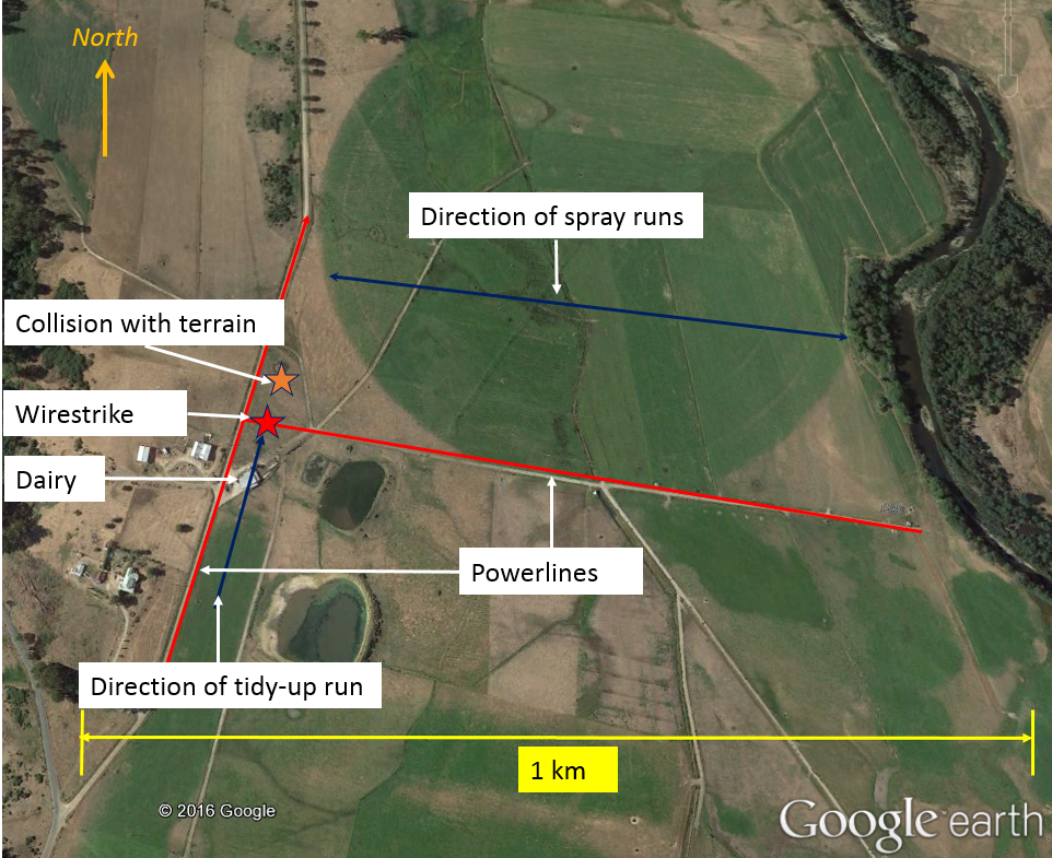
The pilot completed spraying one area, and prior to commencing spraying another, overflew it to assess the site. During that inspection, the pilot sighted two sets of powerlines, one running approximately north-south, and the other branching off to the east. Based on the location of the powerlines and the wind, which was a light northerly, the pilot elected to spray the paddock in an east-west direction (Figure 1). The helicopter was operating north of the powerline running east-west, and in each run, was overflying and remaining clear of the powerlines at the western end of the paddock.
Figure 1: Area of operations showing powerlines
Source: Pilot
At about 1230 Eastern Standard Time (EST), after completing two spray loads, the pilot tracked south over the powerline and turned to conduct a tidy-up run to the north along the road and powerlines running north-south.
After overflying a dairy building, the helicopter descended as the pilot intended to commence spraying. However, the helicopter struck the powerlines running east-west and subsequently collided with terrain.
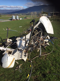
The pilot, who was the sole occupant of the helicopter, sustained serious injuries and the helicopter was destroyed (Figure 2).
Figure 2: Accident site
Source: Tasmania Police
Pilot comments
Prior to commencing the day’s operations, the pilot had obtained a map of the area and identified hazards including the powerlines. During the aerial inspection of the property prior to commencing spraying, the pilot had sighted those hazards.
The pilot commented that in the tidy-up run they should have been thinking ‘over the dairy and over the powerlines then descend’, but had momentarily forgotten about the powerlines and descended after passing over the dairy. Usually, they overflew the whole paddock again to check for hazards before commencing a tidy-up run, but had omitted to do it on this occasion.
The pilot was wearing a helmet at the time of the accident. The helmet was found some distance from the wreckage and was badly damaged.
Safety message
ATSB research indicates that in 63 per cent of reported wirestrike incidents, pilots were aware of the position of the wire before they struck it.
The Aerial Application Association of Australia (AAAA) suggests a way to keep focus is to ask yourself:
Where is the wire now?
What do I do about it?
Where am I in the paddock?
For further risk management strategies for agricultural operations, refer to the AAAA Aerial application pilots manual.
US military research[1] analysed helicopter accidents that were at least partially survivable. It found that occupants not wearing a protective helmet were significantly more likely to sustain severe and fatal head injuries. The US National Transportation Safety Board (NTSB) also acknowledged that the use of head protection can reduce the risk of injury and death. The NTSB issued Safety Recommendation A-88-009, recommending that crewmembers of emergency medical services helicopters wear protective equipment including helmets.
The ATSB investigation report (AO-2014-058) into an accident involving a Robinson R22 helicopter where the pilot sustained a serious head injury, reminded pilots and operators to consider the benefit of occupants wearing helmets to reduce the risk of head injury.
Decisions regarding whether to conduct an investigation, and the scope of an investigation, are based on many factors, including the level of safety benefit likely to be obtained from an investigation. For this occurrence, a limited-scope, fact-gathering investigation was conducted in order to produce a short summary report, and allow for greater industry awareness of potential safety issues and possible safety actions.
Publishing information
Released in accordance with section 25 of the Transport Safety Investigation Act 2003
Ownership of intellectual property rights in this publication
Unless otherwise noted, copyright (and any other intellectual property rights, if any) in this report publication is owned by the Commonwealth of Australia.
Creative Commons licence
With the exception of the Coat of Arms, ATSB logo, and photos and graphics in which a third party holds copyright, this publication is licensed under a Creative Commons Attribution 3.0 Australia licence.
Creative Commons Attribution 3.0 Australia Licence is a standard form licence agreement that allows you to copy, distribute, transmit and adapt this publication provided that you attribute the work.
The ATSB’s preference is that you attribute this publication (and any material sourced from it) using the following wording: Source: Australian Transport Safety Bureau
Copyright in material obtained from other agencies, private individuals or organisations, belongs to those agencies, individuals or organisations. Where you wish to use their material, you will need to contact them directly.
On the morning of 16 July 2016, a Kavanagh Balloons E-300 hot-air balloon, registered VH-LPG, departed for a one-hour scenic flight from Irishtown, Western Australia (WA). On board were the pilot and 16 passengers.
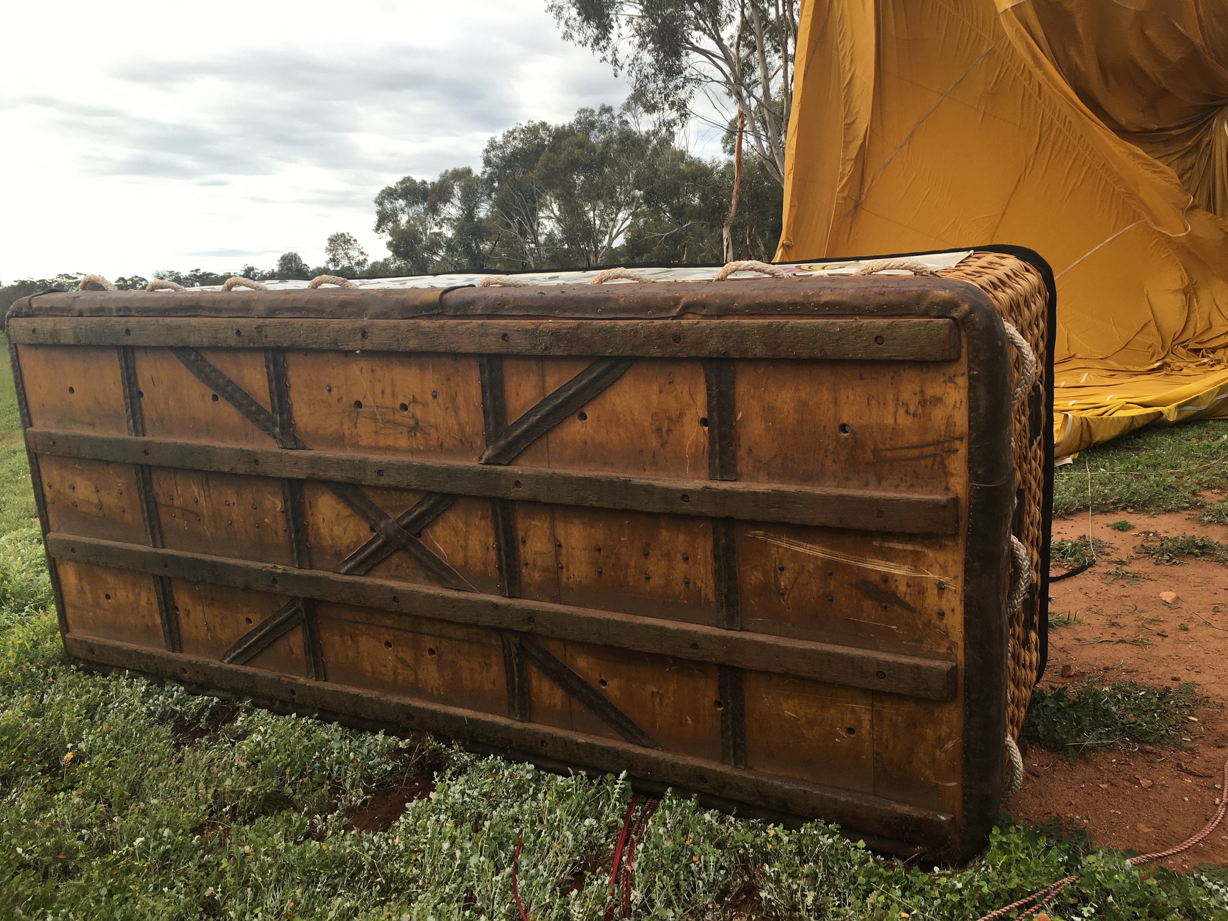
The balloon departed at about 0700 Western Standard Time (WST), and reached a maximum altitude and speed of about 3,500 ft above mean sea level (AMSL) and 39 kt, respectively. The balloon tracked in a south-easterly direction. During the flight, the pilot instructed the ground crew to proceed to the racecourse at York, WA, to meet the balloon for the landing. After about 52 minutes of flight covering a distance of about 33 km, the pilot made an approach to a vacant paddock near York. The balloon made an initial ground contact with about 15 kt forward speed. When the balloon struck the ground, the pilot was ejected from the balloon basket. The basket was then dragged over the top of the pilot as the balloon envelope continued to deflate. The balloon envelope came to rest draped over trees and a fence with the basket lying on its side (Figure 1).
The pilot was seriously injured, and air lifted to the Royal Perth Hospital. One passenger received a minor injury and the balloon sustained minor damage.
Figure 1: Final resting position of VH-LPG
Source: WAPOL
Weather
The weather forecast for the area (ARFOR)[1] predicted wind at 3,000 ft AMSL to be from the north-north-west at 40 kt. The closest recorded aerodrome forecast (TAF)[2] or regular report (METAR)[3] was Cunderdin, about 49 km to the north-east. The forecast wind at Cunderdin was from the north-north-west at 10 knots. At 0630 the recorded wind was north-north-easterly at 12 kt and at 0700 from the same direction at 6 knots.
Kavanagh Balloons flight manual
The procedures for the security of the pilot and passengers for a Kavanagh Balloon are incorporated into the Kavanagh Balloons flight manual, Section 4 – Normal Procedures.
Paragraph 4.11.10 Pilot restraint harness, states ‘If a pilot restraint harness is fitted, it should be worn during take-off and for the duration of the flight including the landing... The restraining strap should be shortened to restrict the movement of the pilot within the compartment in preparation for the landing. This will maintain the correct pilot position during the landing.’
Paragraph 4.12 Approach to landing, states ‘When horizontal landing speed is expected, passengers should be made aware that the basket may tip forward and they should take a lower-than-normal landing position to avoid being thrown forwards out of the basket.’
Civil Aviation Regulation 251
Civil Aviation Regulation (CAR) 251 details the circumstances in which pilots and passengers must wear a seat belt or safety harness, which includes during take-off and landing.
Ballooning exemption
Civil Aviation Order 95.53 section 3 Exemption 3.1 (f) specifically exempts manned balloons engaged in charter operations from CAR 251. However, the Civil Aviation Safety Authority have indicated that the use of a pilot restraint in passenger transport balloons is a proposal under consideration, which is subject to consultation.
ATSB comment
The pilot of the balloon was seriously injured during this accident and therefore not able to participate in an interview. There was no pilot restraint harness fitted to the balloon on the incident flight.
Safety action
Whether or not the ATSB identifies safety issues in the course of an investigation, relevant organisations may proactively initiate safety action in order to reduce their safety risk. The ATSB has been advised of the following proactive safety action in response to this occurrence.
Operator
As a result of this occurrence, the balloon operator has advised the ATSB that they are taking the following safety actions:
Pilot safety harnesses
The operator has modified all their hot-air balloons and fitted them with pilot restraint harnesses.
Safety message
Landing with forward speed in a balloon poses the risk of personnel thrown forwards out of the balloon basket, which can then place them in the path of the basket. Passengers are briefed about this risk and are able to use both hands to secure themselves to a handhold for landing. However, the balloon pilot is required to continue using their hands to control the balloon throughout the landing sequence and is therefore exposed to a higher risk of being thrown out of the balloon basket.
Installation and use of a pilot restraint harness, in accordance with the balloon and harness manufacturers’ recommendations, will reduce the risk of a pilot being thrown out of the balloon basket during landing.
Decisions regarding whether to conduct an investigation, and the scope of an investigation, are based on many factors, including the level of safety benefit likely to be obtained from an investigation. For this occurrence, a limited-scope, fact-gathering investigation was conducted in order to produce a short summary report, and allow for greater industry awareness of potential safety issues and possible safety actions.
Publishing information
Released in accordance with section 25 of the Transport Safety Investigation Act 2003
Ownership of intellectual property rights in this publication
Unless otherwise noted, copyright (and any other intellectual property rights, if any) in this report publication is owned by the Commonwealth of Australia.
Creative Commons licence
With the exception of the Coat of Arms, ATSB logo, and photos and graphics in which a third party holds copyright, this publication is licensed under a Creative Commons Attribution 3.0 Australia licence.
Creative Commons Attribution 3.0 Australia Licence is a standard form licence agreement that allows you to copy, distribute, transmit and adapt this publication provided that you attribute the work.
The ATSB’s preference is that you attribute this publication (and any material sourced from it) using the following wording: Source: Australian Transport Safety Bureau
Copyright in material obtained from other agencies, private individuals or organisations, belongs to those agencies, individuals or organisations. Where you wish to use their material, you will need to contact them directly.
On 17 July 2016, at about 1039 Central Standard Time, a McDonnell Douglas Corporation 369D helicopter, registered VH-PLY, experienced fuel exhaustion and a collision with terrain while performing powerline inspections 36 km north-west of Hawker, South Australia. There were three crew on board the helicopter. One pilot in the front left seat, one line-worker in the front right seat and one line-worker in the rear left seat. The three crew members were seriously injured, and the helicopter was substantially damaged.
What the ATSB found
The ATSB found that ground staff mistakenly told the pilot that the aircraft had been refuelled and through distraction, omitted a crosscheck of the fuel quantity before flight. The pilot’s monitoring of the fuel in-flight was based on anticipated endurance, which resulted in him not detecting a low fuel level.
The helicopter was operating with an auxiliary fuel tank system, which did not include a fuel quantity indicator. The Civil Aviation Safety Authority and Design Approval Holder provided responses to the ATSB, which indicated that a misunderstanding likely occurred during the design review and approval process. This resulted in the auxiliary fuel tank system approval migrating from the restricted category to the normal category without a fuel quantity indicator.
The ATSB also found the requirements for the development of fuel policy by operators were dispersed throughout the aviation legislation—14 legislative and three guidance material requirements were found—but they did not require the operator to publish procedures for determining fuel on board before and during flight for commercial operators of aircraft less than 5,700 kg maximum take-off weight.
What's been done as a result
The operator immediately removed all auxiliary fuel tanks from their helicopter fleet and restricted their powerline patrols and inspection flights to main fuel tank fuel only. They developed a corrective actions plan, which included modifications to the auxiliary fuel tank system; permanent installation of a remote warning device; and amended their operations manual to include prescriptive fuel check instructions.
To provide clarity for fuel policy requirements for pilots and operators, in 2016 the Civil Aviation Safety Authority initiated a project to change the fuel regulations and guidance material. The Civil Aviation Amendment (fuel and oil requirements) Regulations 2018 are planned to be implemented in November 2018 as CASA 29/18 – Civil Aviation (Fuel Requirements) Instrument 2018.
The ATSB has issued a Safety Advisory Notice (AO‑2016‑078‑SAN-009) for Air Operator Certificate holders of aircraft not greater than 5,700 kg regarding fuel management.
Safety message
This accident highlights the importance of crosschecking fuel before flight and in-flight fuel monitoring by pilots to prevent fuel exhaustion accidents. It also highlights the potential consequences of distraction breaking the flow of ongoing activities. In this case, it resulted in the fuel quantity of the auxiliary fuel tank not being visually checked prior to flight. After recognising that a distraction has occurred, it is crucial that pilots re-establish situation awareness.
Operators of aircraft not greater than 5,700 kg maximum take-off weight are advised they can reduce their risk of a fuel exhaustion accident by providing published procedures and crew training for crosschecking fuel on board before and during flight.
The occurrence
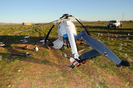
On 17 July 2016, at about 1039 Central Standard Time,[1] a McDonnell Douglas Corporation 369D helicopter, registered VH-PLY, collided with terrain after experiencing fuel exhaustion while performing powerline inspections 36 km north-west of Hawker, South Australia (Figure 1). There were three crew on board the helicopter. One pilot in the front left seat, one line-worker (data recorder) in the front right seat and one line-worker (inspector) in the rear left seat. The three crew members were seriously injured, and the helicopter was substantially damaged.
Figure 1: VH-PLY accident site
Source: South Australian Police
On 16 July 2016, two powerline inspection flights were recorded in the helicopter flight log (involving the same crew as the accident flight). The first flight was from 0830 to 1130. It started with 350 L of fuel and ended with 40 L. The helicopter was then refuelled from an intermediate bulk container.[2] As recorded by the pilot on the flight log, the second flight, conducted from 1206 to 1406, started with 350 L of fuel and ended with 170 L of fuel.
On the next day, the crew started their duty at about 0800. They arrived at Port Augusta Airport at about 0814 where they conducted pre-flight checks of the helicopter and established contact with the customer for permission to access the powerlines, and completed the on-site safety management form. The pilot reported he requested full fuel from the operator’s ground support person who replied that he had refuelled the helicopter the day before.
The pilot was observed by other team members performing fuel quality checks during the pre-flight inspection, but was not observed conducting fuel quantity checks. The pilot reported he was approached by another helicopter crew at the airport while conducting his pre-flight inspection, which interrupted his inspection and resulted in him omitting a visual fuel quantity check of the helicopter’s auxiliary fuel tank (see the Helicopter fuel system modification section in this report).
The ground support person departed the airport with the intermediate bulk container at about 0834 to travel to the planned refuel location with a 3-hour SARTIME[3] for the helicopter, nominated by the pilot. Before engine start, the pilot was observed performing his normal scan of the instruments and reported to the ATSB that he thought the fuel quantity indicator indicated full. The helicopter departed the airport at about 0849.
The first phase of their task was a ferry flight to a small transmission substation. They arrived at the substation at about 0923 and started their inspection. The pilot reported that at about 50 minutes into the flight he activated the auxiliary fuel tank solenoid valve to start the gravity transfer of fuel from the auxiliary fuel tank to the main fuel tank. He could not recall if he checked to confirm there was fuel transferring.
At about 1035, the helicopter arrived at powerline structure 228 to perform an inspection. The pilot reported that at a height of about 100 ft, as the helicopter started to move from structure 228 to 229, the engine ‘just stopped’. The pilot veered the helicopter away from the powerline towards a clear area, called ‘brace’, but was unable to arrest the rate of descent, resulting in a collision with the terrain.[4]
The line-worker data recorder regained consciousness in the helicopter and activated the Spidertracks[5] emergency signal at 1039. The line-worker inspector regained consciousness and found himself outside of the helicopter attached to his harness. The harness was still attached to the helicopter. Neither of the line-workers were able to walk or assist the pilot. The pilot was unable to extricate himself from the helicopter and was eventually removed by the first responding police officer.
Helicopter fuel system inspection
The ATSB inspected the wreckage after it was removed to Port Augusta and spoke to the first responders whom attended the accident site. The ATSB investigation identified:
no post-impact fire
no smell of fuel in the wreckage
no evidence of entrapped fuel within the wreckage
no usable fuel in the main tank fuel bladder
main tank bladder was intact and the only identifiable puncture mark was at the top of the bladder and considered to be the result of the impact
no residual fuel in the fuselage cavity housing the fuel bladder
minimal fuel found in the airframe and engine fuel filter bowls
auxiliary fuel tank was empty
the fuel indicator, showing low fuel level, and fuel transfer systems were found to be serviceable.
The ATSB also established the helicopter was not refuelled after the second flight on 16 July and the accident flight on 17 July.
Helicopter fuel system modification
The operations manual fuel policy indicated the helicopter had a main fuel tank capacity of 242 L and auxiliary fuel tank capacity of 115 L (total of 357 L). Fuel consumption was published as between 100 L/h for patrolling and 120 L/h for prolonged high hover.
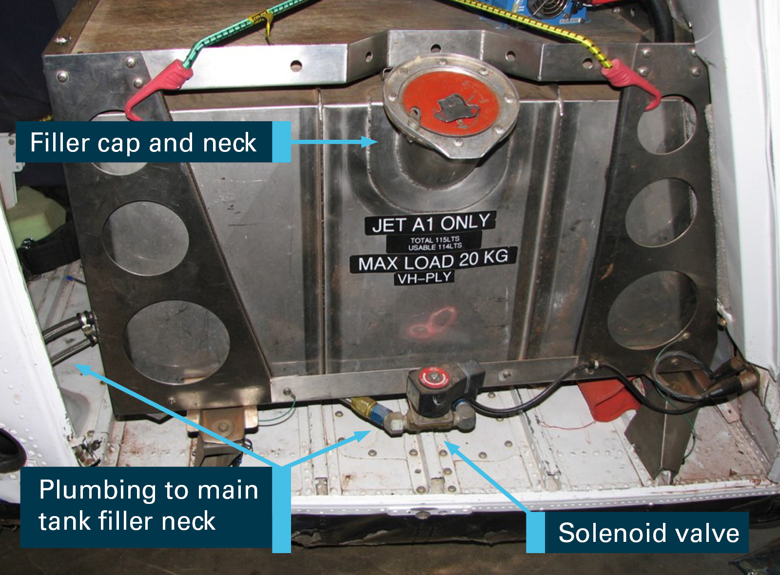
The operator’s fleet of McDonnell Douglas 369 helicopters have had several modifications incorporated,[6] which included the auxiliary fuel tank (Figure 2).
Figure 2: Auxiliary fuel tank fitted to VH-PLY
Source: ATSB
The auxiliary fuel tank was manufactured from stainless steel. It had a volume of 125 L, but a specified capacity of 115 L when filled to the bottom of the filler neck. The tank was located in the rear right side of the cabin. Fuel transfer was controlled by the pilot operating the solenoid valve switch, located on the instrument panel, marked ‘AUX. FUEL TRANSFER’. A green indicating light, located next to the fuel transfer switch would illuminate when the switch was selected to the transfer position. When selected, fuel would gravity drain from the auxiliary tank to the main tank. The main fuel tank provided the fuel supply to the engine.
The pilot reported the transfer of fuel from the auxiliary to the main tank could be verified by the fuel quantity indicator needle not moving, as the fuel would gravity transfer at about the same rate as the engine consumed fuel. He normally activated the fuel transfer switch at about 200–250 lbs (110–130 L) fuel remaining, or 50 minutes of flight time. The pilot reported that he was always taught not to trust fuel quantity indicators and he would therefore manage the helicopter’s endurance ‘on the clock’.[7]
The auxiliary fuel tank system did not include a fuel quantity indicator or sight glass or dip stick to check the fuel quantity. Only the main fuel tank system incorporated a fuel quantity indicator. The pilot reported that the auxiliary fuel tank quantity would normally be visually checked by removing the fuel cap before flight, but could not explain how the quantity was verified by a visual check if the tank was filled to less than full.
The pilot reported the decision to use the auxiliary fuel tank was based on the proposed length of the task and the environmental conditions. If no more than two hours of fuel was required or the helicopter performance would be marginal with the extra weight of fuel on board, then the auxiliary fuel tank would not be filled. A review of VH-PLY’s flight logs for the week prior to the accident indicated the auxiliary fuel tank was routinely used during powerline inspections.
The ATSB received two separate independent reports during the course of the investigation that the auxiliary fuel tank was routinely used for flying operations, which included flying training. The reports included the practice of managing fuel endurance ‘by the clock’ with the auxiliary fuel tank.
Design advice
The auxiliary fuel tank design, installation and use started in 1993. The approval holder of the design (the design organisation) changed three times from 1993 to the accident date. Several Design Approvers (CAR 35 authorised persons working for the approval holder) were involved in the various iterations of the tank design and associated documentation. None of those approvers were employed with the current approval holder at the time of the investigation. As a result, historical documents and professional judgement were relied upon, by the design organisation, to provide responses to ATSB questions.
The auxiliary fuel tank design was originally approved in 1993, which required operations to be conducted under a special flight permit.[8] However, the repeated use of the auxiliary fuel tank for repositioning helicopters made the special flight permit process unacceptable for operations. In 2003, the auxiliary fuel tank was approved for restricted category[9] operations. The reason for restricted category was recorded as ‘tank filled from within cabin & no vapour proof barrier around tank.’
In 2009, a job planning approval form was raised by the approval holder for issue 4 of the auxiliary fuel tank engineering order (EO),[10] which incorporated a 2.9 L expansion space on top of the tank, which cannot be inadvertently filled. This was in accordance with the helicopter certification basis: United States (US) Civil Air Regulations Part 6-Rotorcraft airworthiness: normal category (CAR 6[11]); CAR 6.423 Fuel tank details – (a) Expansion space:
Fuel tanks shall be provided with an expansion space of not less than 2 percent of the tank capacity. It shall not be possible to fill the fuel tank expansion space inadvertently when the rotorcraft is in the normal ground attitude.
It was determined in the job planning approval form that the change in type design was ‘major’, rather than ‘minor’, which required a request to be submitted to the Civil Aviation Safety Authority (CASA). The reason for the decision was ‘some non-compliances with the installation required restricted category approval.’ The form identified several factors for consideration, which included ‘temporary’, ‘restricted category’ and ‘flammability issues’. It required a design advice submission to CASA with a CAR 6 compliance matrix, and to comply with CASA response’s before proceeding to approval.
In support of the job planning approval process, an email exchange took place between the Design Approver and CASA’s Airworthiness and Engineering Branch to clarify non-compliance issues. This focussed on the need for a tank expansion space (CAR 6.423(a)). The exchange began in September 2009 with the approval holder’s explanation that the tank was only used for repositioning the helicopter and their intent was to approve it in the restricted category. In December 2009, CASA clarified that ‘approval of a non-compliant design simply because the aircraft is to be operated under a restricted [category] is not considered acceptable’. This resulted in a modification to the auxiliary fuel tank to incorporate an expansion space and resubmission of the design advice to CASA.
The latest issue design advice[12] was submitted to CASA on 12 January 2010 under Australian Civil Aviation Regulation 35 (CAR 35).[13] In accordance with CAR 35: Approval of design of modification or repair, an application for a modification must satisfy CASA ‘that the design conforms with any relevant design standard in respect of the type of aircraft or aircraft component to which the application relates.’ The design advice informed CASA that the Design Approver intended to approve the modification in the restricted category. The reason given for the auxiliary fuel tank was:
To provide fuel endurance for positioning the helicopter on specific tasks such as powerline patrolling and inspection.
In addition to a CAR 6 compliance matrix, the design advice included the following restrictions, which would apply in the restricted category:
the fuel tank is to be installed and used only for repositioning the helicopter in connection with the aerial work operations (powerline washing, inspection, repair, etc.)
the fuel tank must be removed for all other operations (including the aerial work operations conducted)
essential crew only on board when fuel tank is fitted
maximum cabin ventilation must be provided when operating with the fuel tank installed
either doors off or all available vents open
the helicopter must at all times have sufficient fuel (including required reserves) in the main fuel tank to reach a safe landing site.
Within the compliance matrix there was no reference to CAR 6.604 – Powerplant instruments (a) (1), which required a fuel quantity indicator be installed for each engine or tank. However, there was reference to CAR 6.429 – Fuel quantity indicator. CAR 6.429 provided the following standard:
The fuel quantity indicator shall be installed to indicate clearly to the flight crew the quantity of fuel in each tank while in flight. When two or more tanks are closely interconnected by a gravity feed system and vented, and when it is impossible to feed from each tank separately, only one fuel quantity indicator need be installed.
The compliance matrix provided the following statement for CAR 6.429:
The current indication will alert to remaining fuel. Even if the current valve does fail; the pilot can see the fuel is there and increasing.[14]
The approval holder reported that the Design Approver likely believed that the auxiliary tank modification met the criteria of CAR 6.429, and therefore CAR 6.604 was deemed not applicable. Based on contemporary practices, in determining the certification basis of a modification to which compliance must be shown, only affected requirements are cited.
CASA reported that their response to the design advice was in the context of allowing for the repositioning of the helicopter (ferry flights) prior to undertaking normal flying activities and was conditional upon the limitations documented. In this circumstance, where a fuel quantity indicator was not to be enforced, CAR 6.429 was considered appropriate. CAR 6.604 was appropriate for a permanently installed auxiliary fuel tank.
Issue 3 of the design advice was accepted by CASA on 18 January 2010 and ‘found to be compliant with the relevant requirements of CAR 6 (including 6.423(a)) as per the compliance matrix as supplied to CASA by email on 12 Jan 2010.’ CASA did not request the associated engineering order (EO) or flight manual supplement (FMS), which were the documents published by the approval holder for the operator. CASA advised the ATSB the decision to review an EO and FMS is dependent upon the experience of the approval holder making the submission. In this case, they were satisfied with the experience of the approval holder and approver.
Engineering order and flight manual supplement
On 9 March 2010, the job planning approval form was updated to include EO issue 5 and FMS issue 3. The reason provided was to clarify the tank capacity on the EO (115 L total and 114 L usable, as measured by the operator) and remove the classification of ‘restricted category’ from the FMS as the tank complied with CAR 6. When EO issue 5 and FMS issue 3 were published on 9 March 2010 and the restricted category was removed, the operator was allowed to install the auxiliary fuel tank in the helicopter as a permanent fit.
The operating restrictions listed in the design advice submitted to CASA were not published in the FMS or EO. However, the approval holder reported that the removal of the restricted category was contingent upon compliance with EO issue 5, which required the expansion tank to be installed. As the expansion tank was not found fitted, the accident helicopter was not entitled to be operated with the auxiliary fuel tank as a permanent fit.
United States Federal Aviation Administration advisory circular
In 1999, the US Federal Aviation Administration (FAA) published advisory circular (AC) 27‑1B on Code of Federal Regulations Part 27 (CFR 27), certification of normal category rotorcraft, the replacement for CAR 6.[15] AC 27-1B provided an acceptable means, but not the only means, of compliance with CFR 27 and included the following information about the location of fuel tanks:
Separation of fuel tanks and occupiable areas. Fuel tanks should be located as far as practicable from all occupiable areas. This minimizes the potential post-crash fire sources in occupiable areas and the potential for occupant saturation with fuel on impact. The design should be reviewed to minimize these potential hazards.
The following information was provided in reference to preventing occupant injuries:
Elimination of injurious objects within striking distance of the head and other vital parts can be accomplished by removal of objects with sharp edges or rigid surfaces from within striking distance of vital parts of the occupant.
In 2014, the US FAA issued AC 27-1B change 4, which included an explanation for CFR 27.1337 (b) (2),[16] which was equivalent to CAR 6.429, as follows:
Consistent with the requirements of 27.1337(b)(2), a separate fuel quantity indication is necessary for any interconnected fuel tank that has a flow control device, such as a fuel transfer pump or flapper valve, which could fail and trap fuel. This requirement also applies to auxiliary fuel tanks. A sight quantity indicator that is readable by the flight crew in flight may be acceptable for use with auxiliary fuel tanks.
CASA advised that they consider the solenoid valve fitted to the auxiliary fuel tank plumbing to act as a flow-control device. However, they considered it acceptable for the helicopter not to meet the design standards for the purpose of repositioning flights under a special flight permit or in the restricted category. If the auxiliary fuel tank was to become a permanent fit and used for other modes of operation, then it would be expected that the standards in CAR 6 (6.429 and 6.604) should be met following any modifications.
Neither CASA nor the approval holder provided a record to show CASA was informed of the decision to remove the restricted category.[17] If it was determined that the design was compliant with CAR 6, as per CASA’s response to the design advice, then the approver could proceed to approval without notifying CASA.
The initial issue of AC 27-1B included the explanation for the purpose of a flight manual with a recommended format, which included the following information:
Section 2 – Normal Procedures:
(a) Pre-flight Checks. This paragraph would include any exterior, interior, and any system checks prior to starting the engine(s).
(c) System Checks. This paragraph would include any system check procedures…which should be accomplished before take-off.
(e) Cruise and/or Level Flight. This paragraph would include any procedures applicable to cruise and/or level flight operation.
The normal procedures in the FMS did not provide any instructions for checking fuel quantity before flight or for checking the operation of the fuel transfer either before flight or in-flight, despite the fact that there was no fuel quantity indicator included in the design. The FMS also did not include a fuel transfer rate, which could be influenced by pressure differences and helicopter attitude changes.
The approval holder advised that the inclusion of the auxiliary fuel tank does not negate the requirement to establish the current fuel state of the helicopter prior to take-off or in-flight. They indicated the auxiliary fuel tank installation included a toggle switch for operation of the fuel-transfer solenoid valve and a ‘fuel transfer’ indicating light on the instrument panel for the verification of fuel transfer inflight (see the instrument lights section in this report).
Fuel policy requirements
Legislation and guidance
As a result of the fuel exhaustion, the ATSB was interested in the legislative requirements which applied to the development of the operator’s fuel policy and procedures. CASA’s Air Operator’s Certificate (AOC) handbook, Volume 2, Flying Operations - Fuel policy and related requirements was referenced to identify and locate relevant legislation and guidance material. The ATSB identified the following two requirements from the AOC handbook as of interest to the investigation:
A method for determining the fuel on board pre-departure, during and after the flight.
A method to cross-check the fuel quantity on board prior to departure.
Regarding a method to crosscheck the fuel quantity on board before departure, the following two legislative references from the AOC handbook were of interest to the investigation:
(1) The pilot in command [PIC]…must not commence a flight…if he or she has not taken reasonable steps to ensure that the aircraft carries sufficient fuel…to enable the proposed flight to be undertaken in safety.
(2) An operator…must take reasonable steps to ensure that an aircraft does not commence a flight as part of the operator’s operations if the aircraft is not carrying sufficient fuel…to enable the proposed flight to be undertaken in safety.
Civil Aviation Order (CAO) 20.2, Air service operations – safety precautions before flight:
Subsection 6 of CAO 20.2 required the operator to include in their operations manual instructions and procedures for the PIC of an aircraft that has an MTOW [Maximum Take-Off Weight] above 5,700 kilograms to verify the quantity of fuel on board the aircraft before flight.
Regarding a method for determining the fuel on board during flight, the only reference found during the investigation was Civil Aviation Advisory Publication (CAAP) 215-1(2): Guide to the preparation of operations manuals. CAAP 215-1(2) appendix B9: Fuel management, provided the following guidance:
The operator is to develop procedures to ensure that in-flight fuel checks and fuel management are carried out during the flight. Procedures relevant to the operation should include:
Monitoring for fuel leakage.
How fuel checks are carried out and at what regular intervals during the flight.
How the quantity of remaining fuel is compared with actual consumption to ensure the remaining fuel at any time is sufficient to complete the flight.
The operator’s fleet of helicopters were not greater than 5,700 kg MTOW, and in accordance with CAO 20.2, the operator was not required to publish procedures for the verification of fuel on board before flight. CAAP 234-1(1): Guidelines for aircraft fuel requirements, provided guidance on crosschecking fuel quantity before flight and applied to all operators of Australian aircraft, but was written as guidance material, as was CAAP 215-1(2).
CASA reported that, in respect to CAO 20.2, it was determined that there was insufficient grounds to justify the requirement being applied to aircraft with a MTOW less than 5,700 kg. It was assessed as being overly burdensome for many operators within that sector of the industry. Increased requirements are applied as aircraft size or complexity increases.
The CASA AOC handbook on fuel policy listed 14 references from legislation and three from guidance material, in addition to CAAP 215-1(2), which could be applicable to the development of an operator’s fuel policy and procedures. With respect to what constituted a requirement, CASA reported that the AOC handbook has no legislative power and only those requirements that are empowered by legislation are enforceable.
Operations manual
The operator’s operations manual included a fuel policy with flight planning data for each helicopter type in the operator’s fleet. The policy included allowances being made for fuel reserves in flight planning, and a note for McDonnell Douglas 369 pilots to refer to the respective FMS if using the auxiliary fuel tank. The refuelling procedures included instructions for post-refuelling checks, which included the pilot in command’s responsibility to ensure ‘the required amount has been placed aboard the helicopter’. This last statement was in accordance with pilot’s responsibilities under CAR 234.
CAR 215: Operations manual required the operator to provide CASA with a copy of their operations manual and to forward to CASA any amendments to the operations manual. The operator’s fuel policy and fuel procedures were amended in 2015, but at the time of the accident, there were no procedures for determining the fuel on board before or during flight. No evidence was found to indicate that CASA required the operator to publish these procedures. CASA reported that the standard in CAO 20.2 is deliberately less complex for smaller aircraft than for larger aircraft, and in consideration of the protections contained in other regulatory requirements, there was no need to issue a direction under CAR 215 in relation to fuel-system quantity checks.
Civil Aviation Safety Authority surveillance
The last CASA surveillance of the operator prior to the accident flight was dated 19 June 2015. This was a one-day audit with one CASA Flying Operations Inspector (FOI) and was initiated after a lengthy period since the last audit in 2009. The scope of the audit was:
flight operations – flight system (process in practice)
operational personnel – crew scheduling (management responsibility) (process in practice).
The CASA surveillance manual indicated that much of the information for auditing the ‘flight system’ was contained in the operations manual. However, the operations manual was not listed as a reference document in the surveillance report. The audit report concluded that the operator’s ‘internal audits, processes in practice, monitoring and improvement with the aid of [safety information system database] are sound.’ No findings were issued.
Cockpit ergonomics
Tablet mount installation
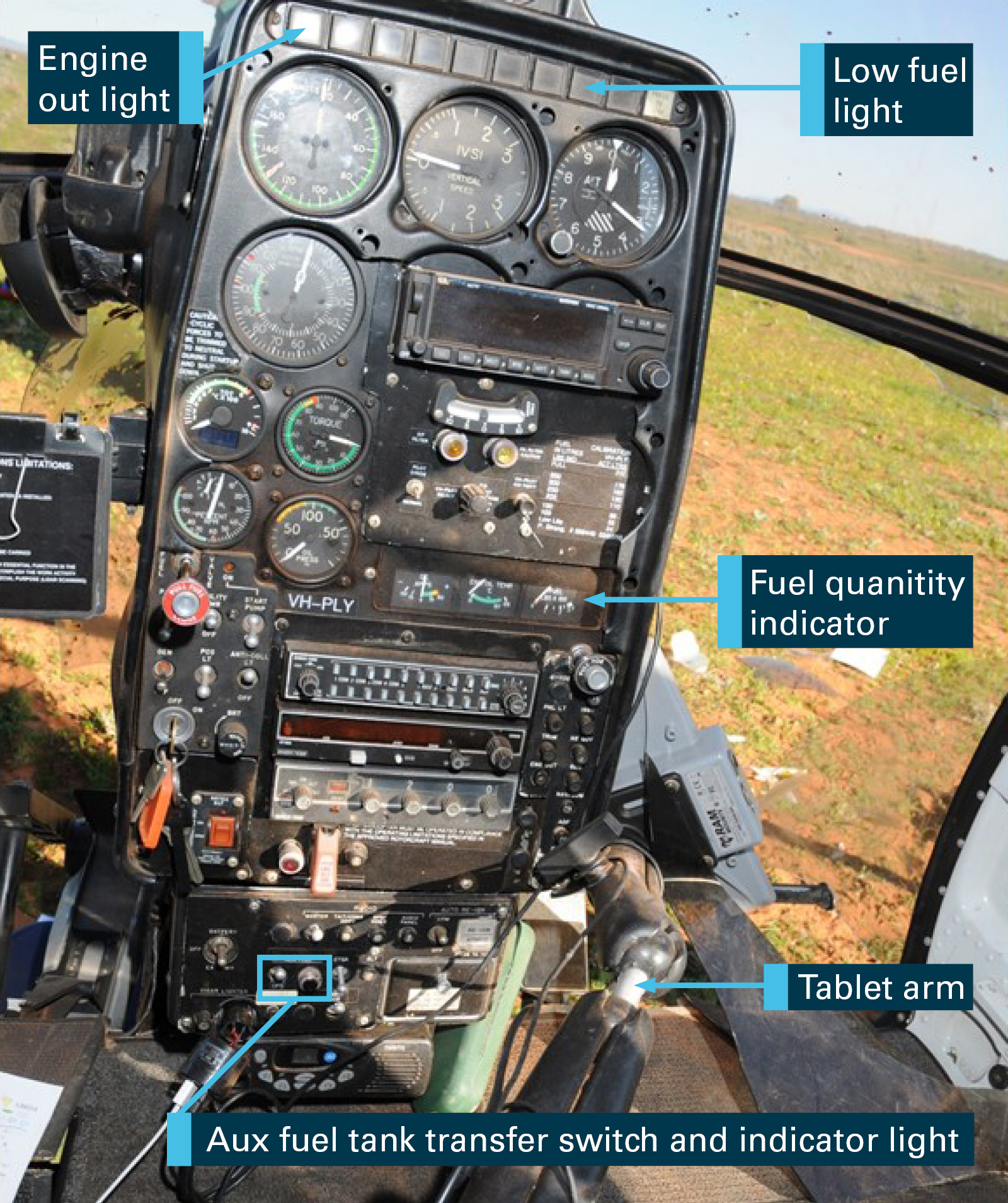
The helicopter was manufactured to be flown by the pilot in command from the left seat instead of the normal right seat helicopter pilot position. The primary flight instruments were located on the left side of the centrally mounted instrument panel and the secondary instruments, including the fuel quantity indicator and low fuel level caution light, on the right side (Figure 3).
Figure 3: VH-PLY instrument panel
Source: South Australian Police, annotated by ATSB
The crew member in the rear left seat performed the role of powerline inspector while the crew member in the front right seat performed the role of data recorder. To assist the crew with the powerline inspection the helicopter was modified with three tablet-mounting arms, two arms located between the front seats and one in the rear. The respective flight manual supplement indicated the tablet-mounts must be stowed for take-off and landing. The pilot must also ensure they do not interfere with any existing systems. Paragraph 2.5 of the operating limitations stated the tablet ‘may not be manipulated to a position which obstructs the pilot’s view of the instrument panel.’
The pilot reported he had the tablet-mount extended for use and a moving map displayed with the agreed refuelling location marked, which did not obstruct his view of the fuel quantity indicator. Prior to the accident, the right seat crew member was performing his data recorder duties. Neither the pilot nor the data recorder observed the low fuel level caution light or a low fuel quantity indication prior to the accident.
It was not determined if the front right seat crew member had positioned his tablet-mount in a position which would have obstructed his view of the fuel quantity indicator or low fuel level caution light. At the time of the accident, the right seat crew member was conducting data recorder tasks on his computer with his tablet mount extended. During the investigation, the ATSB adjusted the right seat tablet and found that it could be positioned in a way that would obscure the fuel quantity indicator or low fuel level caution light.
Instrument lights
The master caution panel dimmer system was inspected after the accident and found to be loose and able to be pulled off. The chief engineer reported that when power is turned off, then on, the master caution dimmer is reset to full bright. To dim the master caution panel, the dimmer knob must be pushed in. The pilot reported that during the accident sequence he observed the ‘engine-out’ light illuminate, which was a red warning light on the far left of the caution/warning panel. This indicated the master caution panel was probably not dimmed.
Position of the sun
The operator reported the low fuel level caution light would activate intermittently at about 30 L fuel remaining and remain on constantly at about 25 L fuel remaining; about 15 minutes of flight time. The sun was in the range of the twelve o’clock position at a low angle leading up to the accident.[18] In this position, the sun would have been in the same general field of view as the instrument panel lights for the pilot in the left seat, who was wearing a helmet with dark visor.
Auxiliary fuel transfer light
The auxiliary fuel tank shutoff solenoid valve had a green indicating light positioned next to the auxiliary fuel transfer switch on the instrument panel. The light was positioned in the circuit between the transfer switch and the solenoid valve and labelled as ‘aux fuel transfer’ on the wiring diagram. The auxiliary fuel transfer switch was also a circuit breaker. When the switch was selected to transfer, the circuit between the helicopter’s electrical power and the solenoid valve closed and the valve powered open. Illumination of the light only indicated that the circuit was closed. It did not indicate the position of the solenoid valve or that fuel was transferring. This was not explained in either the FMS or EO.
Remote warning device
The operator also had an FMS for operating the helicopter with a remote warning device (RWD). According to the FMS, the RWD provided a remote indication of the illumination of any instrument panel caution/warning light within the pilot’s field of view[19] and minimised the pilot workload during low altitude, high intensity, operations. However, the RWD was not fitted to the helicopter during the accident flight. According to the operator, it was only fitted for specific operations, such as washing powerline insulators.
Fuel quantity indicator
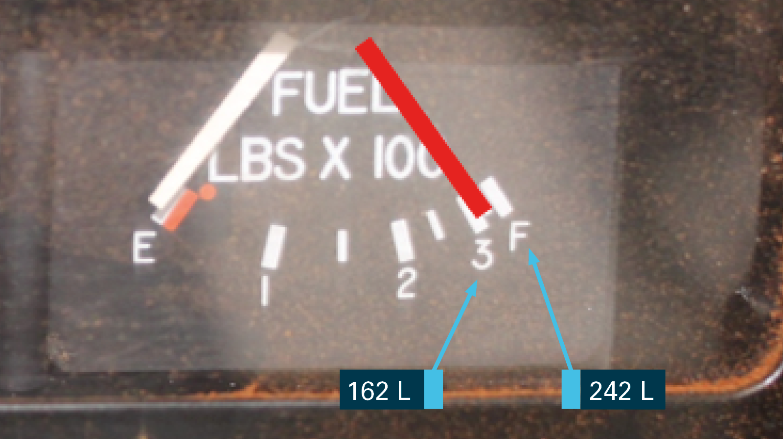
The helicopter’s main fuel tank quantity indicator was a nonlinear indicator, which was more sensitive at lower fuel levels than at higher fuel levels (Figure 4). At the previous routine 100 hourly maintenance inspection, the fuel tank quantity indicator sensor was replaced and a fuel calibration performed. On the fuel quantity indicator, the three hundred pounds’ marker (3) was the equivalent of 162 L and the full marker (F) was 242 L.
The pilot reported he was told the helicopter had been refuelled before flight. He was also observed by the right seat crew member performing his normal pre-start instrument scan and he reported he thought the fuel quantity indicator indicated full. The flight log from the previous day was closed with 170 L of fuel remaining after a 2-hour flight and the pilot transferred the auxiliary fuel tank contents into the main fuel tank during the flight.[20] In this scenario, the fuel quantity indicator would have indicated close to the red line in Figure 4.
Figure 4: VH-PLY main fuel tank quantity indicator (graduated in pounds x 100)
Source: ATSB
Previous fuel exhaustion events
A search of the ATSB database for the period from 2003 to 2017 found 76 reports of ‘fuel exhaustion’, which included four accidents with fatalities, three accidents with serious injuries and two accidents with minor injuries, with some accident reports including more than one injury classification. The operations represented in the occurrences included sport aviation, private, aerial work, training, charter and air transport–low capacity. From the 76 occurrences, 26 were for commercial operations, and all reports were for aircraft not greater than 5,700 kg MTOW.
In 2009, the final investigation report into a fuel exhaustion occurrence involving a charter flight in a Cessna 404 in 2007,[21] the ATSB raised a safety issue against CASA as follows:
Guidance promulgated by the Civil Aviation Safety Authority (CASA) in Civil Aviation Advisory Publication 234-1 regarding aircraft fuel requirements allowed for a fuel quantity cross-check to be conducted after refuelling and without reference to an independent source of onboard fuel quantity information.
At the time, CASA reported they were considering reviewing the information in CAAP 234-1(1) Guidelines for Aircraft Fuel Requirements that refers to fuel quantity crosschecking.
Survivability factors
The ATSB provided the three crew members with the ‘iBrace Survivor Questionnaire’.[22] The purpose of the questionnaire was to review crash survivability factors. All crew members provided returns, summarised as follows.
The pilot was seated upright in the front left seat with a four-point harness fitted loosely, wearing a helmet. His hands and feet remained on the controls throughout the accident sequence. The impact resulted in a broken back and spinal cord injury. He could not evacuate from the wreckage.
The front right seat crew member was secured firmly in a four-point harness, wearing a helmet. He bent forwards into a brace position during the accident sequence with his feet on the floor. The impact resulted in a broken back, spinal cord injury, and cuts to the hand and temporary loss of consciousness. He was able to evacuate from the wreckage after regaining consciousness.
The rear left seat crew member was wearing helmet and a dispatcher harness with a wander-lead attached to the helicopter. He could not recall what position his body was in during the crash sequence. He was thrown around during the accident sequence and sustained head and spinal injuries, cuts and bruises to the chest and abdomen, and cuts, bruises and fractures of the limbs. He was able to evacuate from the wreckage after regaining consciousness.
Prior to departure the pilot requested full fuel for the main and auxiliary fuel tanks from the ground support person. He reported at interview the ground support person replied the helicopter was refuelled the previous day. The only record of a refuel for the previous day occurred between the two flights flown. It is likely that the ground support person confused the sequence of events the day before and believed the helicopter’s tanks were full when reporting this to the pilot.
The pilot reported his omission to visually inspect the contents of the auxiliary fuel tank before departure may have been the result of a distraction during his pre-flight inspection. Being told the helicopter had been refuelled the day before would have also given the pilot the expectation that tanks were full, and may have contributed to missing the fuel check during his pre-flight inspection.
Before starting the engine, the pilot was observed conducting his normal instrument scan; however, the fuel quantity indicator had a nonlinear scale, which indicated close to the full (242 L) level mark at 170 L. The expectation that the tanks were full as indicated by the ground support person meant that when he scanned the flight instruments before flight, he would have been expecting to see a full indication. Combined with the nonlinear scale, this would have made it easy to misperceive the main tank as full. In turn, perceiving the main tank as full would have reinforced his belief that the auxiliary fuel tank (which had no fuel gauge) was also full. The helicopter subsequently departed with about 170 L of fuel on board, but the pilot believed it was carrying about 350 L.
It had become normal practice for the pilot to manage the helicopter’s endurance ‘on-the-clock’. This practice was consistent with the reports from other pilots who had flown with the auxiliary fuel tank fitted. In the absence of a fuel quantity indicator for the auxiliary fuel tank, it was not possible to compute fuel consumption once fuel transfer was started, because the contents remaining in the auxiliary fuel tank became an unknown factor. Hence, there was a need to use a predictive endurance until fuel transfer was completed.
The auxiliary fuel tank transfer light was found serviceable following the accident. Illumination of the transfer light would have provided an immediate response to the pilot when the fuel transfer switch was operated, whereas monitoring the fuel quantity indicator for movement would have provided a delayed response. Therefore, when the pilot selected the fuel transfer in-flight, the auxiliary fuel tank indicator light may have confirmed his expectation that the system was transferring fuel when there was actually no fuel in the auxiliary tank to transfer. The absence of crosschecks between the clock and the fuel quantity indicator resulted in inadequate in-flight fuel monitoring.
The low fuel level caution light was set to illuminate with about 15 minutes of fuel remaining and found to be serviceable following the accident. However, it was possible the position and luminance of the sun reduced the pilot’s visual sensitivity to the low fuel level caution light. The operator’s remote warning device, used to alert the pilot to the activation of a caution or warning light on the master caution/warning panel, was not fitted. Leading up to the accident sequence, the pilot’s hover reference was the powerline on the left side of the helicopter and the front right seat crew member was performing his data recorder duties. Therefore, it was likely that the low fuel level caution light was not detected because neither of the front seat crew members were scanning the instrument panel leading up to the accident.
The power loss occurred at about 1 hour and 50 minutes after departure. The pilot reported that, while in the hover at about 100 ft, the engine went quiet and the ‘engine-out’ warning light was flashing. Following the accident both helicopter fuel tanks were found empty, which was consistent with a fuel load on departure of about 170 L. No damage was found to the fuel tanks, which would have resulted in an in-flight fuel leak, therefore it was concluded the power loss and collision with terrain was the result of fuel exhaustion.
Design approval of the auxiliary fuel tank
The helicopter’s fuel system was modified with an auxiliary fuel tank fitted in the rear right side of the cabin, in an occupiable area, and without any device for fuel quantity indication. The Design Approver’s 2010 design advice submission to the Civil Aviation Safety Authority (CASA) included a compliance matrix for the fuel tank against what they identified as the relevant airworthiness standards. In his email communication and design advice submission, the Design Approver indicated his intent to approve the fuel tank in the restricted category and that it was to be used only for repositioning flights. CASA’s Airworthiness and Engineering Branch reviewed the design advice within this context, but responded that the restricted category was not justification for non-compliance with airworthiness criteria, with specific reference to the requirement for a tank expansion space.
In consideration of CASA’s position, the Design Approver elected to address the identified non-compliance issue (tank expansion space). The subsequent modification of the fuel tank with an expansion space resulted in a response from CASA that the design complied with the relevant requirements of CAR 6 and the Design Approver may approve the modification. CASA did not enforce the fuel quantity indicator criteria with the understanding that the fuel tank was only to be used for ferry flights, and removed for aerial work operations. However, it was likely that the Design Approver interpreted CASA’s response to the effect that there were no CAR 6 non-compliances and therefore the restricted category was unnecessary. An approval in the normal category allowed the fuel tank to become a permanent fit and avoided the additional maintenance burden of removing the auxiliary fuel tank between repositioning flights and the start of aerial work operations.
In 1999, US Federal Aviation Administration advisory circular (AC) 27-1B was published, which provided an explanation and means of compliance for the US Code of Federal Regulations Part 27. Since Part 27 replaced CAR 6, many of the CAR 6 requirements were replicated in Part 27. AC 27-1B indicated that there were risks associated with locating a fuel tank in an occupiable area of the helicopter, which it was desirable to avoid. They included the risks of flailing injuries to occupants and saturation with fuel in the event of an accident. Although not required, a review of AC 27-1B in addition to CAR 6 may have led to the conclusion that the restricted category was more appropriate than the normal category for the accident helicopter with the modified fuel system. Particularly in consideration of the nature of the powerline inspection operation, which involved the helicopter operating for extensive periods in the height/velocity avoid area.
In 2014, AC 27-1B provided an explanation for the equivalent Part 27 standard to CAR 6.429, which indicated that separate fuel quantity indicators were required if there was a flow control device installed between fuel tanks. A single fuel quantity indicator would be unsuitable for the accident helicopter’s modified fuel system, because a failure of the solenoid valve in the closed position prior to completion of transfer would result in the fuel quantity indicator over-reading the fuel available for the engine.
On review of AC 27-1B during the investigation, CASA considered the solenoid valve to be a flow control device, but accepted the configuration for operations under a special flight permit or in the restricted category. Since the design advice submission process did not include a copy of the flight manual supplement, CASA’s Airworthiness and Engineering Branch did not have visibility of the removal of the restricted category.
Development of fuel policy
The operator had a fuel policy and procedures published in their operations manual at the time of the accident. Their fuel policy and procedures were updated to revision 1 status the year prior to the accident. This would have provided CASA with visibility as it is a Civil Aviation Regulation (CAR) 215 requirement for the operator to provide them with a copy of the operations manual and forward them any amendments.
CAR 234 (2) indicated the operator had a responsibility to ensure there was sufficient fuel on board before flight. The CASA Air Operator’s Certificate handbook indicated that the operator’s responsibility is demonstrated by publishing procedures and providing training in accordance with those procedures. However, Civil Aviation Order (CAO) 20.2 did not require commercial operators of aircraft not greater than 5,700 kg maximum take-off weight (MTOW) to have published procedures for the verification of fuel on board before flight. Therefore, CAO 20.2 was not consistent with CAR 234 (2) for those operators.
CASA reported that the apparent non-alignment of CAO 20.2 with CAR 234 (2) was based on an assessment that the CAO 20.2 requirements would be overly burdensome for operators of less complex aircraft. In addition, the material published in Civil Aviation Advisory Publication 215 and 234 was provided as guidance material. Hence, no direction was issued to the operator by CASA to direct a change to their operations manual.
An ATSB aviation occurrence database search for fuel exhaustion events, from 2003 to 2017, found commercial operators represented about one-third of all reports (26 reports from a total of 76), which were all for aircraft not greater than 5,700 kg MTOW. The presence of commercial operators indicated that the applicable fuel regulations may be less than adequate, and shows that commercial operators may not implement effective fuel policies and training to prevent fuel exhaustion events.
Findings
From the evidence available, the following findings are made with respect to the fuel exhaustion and collision with terrain involving a McDonnell Douglas Corporation 369D, registered VH-PLY, 36 km north-west of Hawker, South Australia, on 17 July 2016. These findings should not be read as apportioning blame or liability to any particular organisation or individual.
Safety issues, or system problems, are highlighted in bold to emphasise their importance. A safety issue is an event or condition that increases safety risk and (a) can reasonably be regarded as having the potential to adversely affect the safety of future operations, and (b) is a characteristic of an organisation or a system, rather than a characteristic of a specific individual, or characteristic of an operating environment at a specific point in time.
Contributing factors
The Civil Aviation Safety Authority (CASA) accepted that the design advice for the auxiliary fuel tank complied with the relevant requirements of the United States Civil Air Regulation 6. This was within the context of a proposed restricted category approval to permit repositioning flights. However, the response from CASA was likely interpreted by the Design Approver to permit approval in the normal category, which resulted in the auxiliary fuel tank becoming a permanent fit without a fuel quantity indicator.
The pilot omitted to conduct a visual check of the auxiliary fuel tank contents before departure, which resulted in the helicopter departing with insufficient fuel for the planned flight.
During the flight, the pilot managed the helicopter endurance ‘by the clock’, which resulted in him not detecting a low fuel level.
While conducting powerline inspections the helicopter's fuel supply was exhausted, which resulted in a forced landing.
Other factors that increased risk
The current legislation does not require commercial operators of aircraft notgreater than 5,700 kg maximum take-off weight to provide instructions and procedures for crosschecking the quantity of fuel on board before and/or during flight. This increases the risk that operators in this category will not implement effective fuel policies and training to prevent fuel exhaustion events.
Safety issues and actions
The safety issues identified during this investigation are listed in the Findings and Safety issues and actions sections of this report. The Australian Transport Safety Bureau (ATSB) expects that all safety issues identified by the investigation should be addressed by the relevant organisation(s). In addressing those issues, the ATSB prefers to encourage relevant organisation(s) to proactively initiate safety action, rather than to issue formal safety recommendations or safety advisory notices.
Depending on the level of risk of the safety issue, the extent of corrective action taken by the relevant organisation, or the desirability of directing a broad safety message to the aviation industry, the ATSB may issue safety recommendations or safety advisory notices as part of the final report.
All of the directly involved parties were provided with a draft report and invited to provide submissions. As part of that process, each organisation was asked to communicate what safety actions, if any, they had carried out or were planning to carry out in relation to each safety issue relevant to their organisation.
Descriptions of each safety issue, and any associated safety recommendations, are detailed below. Click the link to read the full safety issue description, including the issue status and any safety action/s taken. Safety issues and actions are updated on this website when safety issue owners provide further information concerning the implementation of safety action.
Air Operator Certificate holder fuel policy requirements
The current legislation does not require commercial operators of aircraft not greater than 5,700 kg maximum take-off weight to provide instructions and procedures for crosschecking the quantity of fuel on board before and/or during flight. This increases the risk that operators in this category will not implement effective fuel policies and training to prevent fuel exhaustion events.
Fuel policy requirements: Air Operator Certificate holders operating aircraft not greater than 5,700 kg
Whether or not the ATSB identifies safety issues in the course of an investigation, relevant organisations may proactively initiate safety action in order to reduce their safety risk. The ATSB has been advised of the following proactive safety action in response to this occurrence.
Operator
The helicopter operator has advised the ATSB that they have taken the following safety action:
Corrective actions plan
The operator completed an investigation, implemented interim safety controls and developed a corrective actions plan. Their plan included:
modifications to the auxiliary fuel tank system
permanent installation of the remote warning device
amendment to their operations manual to include prescriptive fuel check instructions.
General details
Pilot details
Licence details:
Commercial Pilot (Helicopter) Licence, issued 13 February 2015
Endorsements:
Gas turbine engine (GTE)
Ratings:
Single engine helicopter (SEH); Night VFR (H); Flight Instructor: Grade 1 training (H), Flight instructor (H), Low level (H), Sling, Grade 2 training (H), CLR (SEH), Design feature; Low level: Sling, Helicopter
Medical certificate:
Class 1, valid to 22 March 2017
Aeronautical experience:
6,679.0 hours
Last flight review:
25 August 2014
Sources and submissions
Sources of information
The sources of information during the investigation included the:
Under Part 4, Division 2 (Investigation Reports), Section 26 of the Transport Safety Investigation Act 2003 (the Act), the Australian Transport Safety Bureau (ATSB) may provide a draft report, on a confidential basis, to any person whom the ATSB considers appropriate. Section 26 (1) (a) of the Act allows a person receiving a draft report to make submissions to the ATSB about the draft report.
A draft of this report was provided to the Civil Aviation Safety Authority, the design organisation, the helicopter operator, Line-worker (data recorder), Line-worker (inspector) and the pilot in command of the accident flight.
The submissions from those parties were reviewed and where considered appropriate, the text of the draft report was amended accordingly.
Purpose of safety investigations
The objective of a safety investigation is to enhance transport safety. This is done through:
identifying safety issues and facilitating safety action to address those issues
providing information about occurrences and their associated safety factors to facilitate learning within the transport industry.
It is not a function of the ATSB to apportion blame or provide a means for determining liability. At the same time, an investigation report must include factual material of sufficient weight to support the analysis and findings. At all times the ATSB endeavours to balance the use of material that could imply adverse comment with the need to properly explain what happened, and why, in a fair and unbiased manner. The ATSB does not investigate for the purpose of taking administrative, regulatory or criminal action.
Terminology
An explanation of terminology used in ATSB investigation reports is available here. This includes terms such as occurrence, contributing factor, other factor that increased risk, and safety issue.
Publishing information
Released in accordance with section 25 of the Transport Safety Investigation Act 2003
Ownership of intellectual property rights in this publication
Unless otherwise noted, copyright (and any other intellectual property rights, if any) in this report publication is owned by the Commonwealth of Australia.
Creative Commons licence
With the exception of the Coat of Arms, ATSB logo, and photos and graphics in which a third party holds copyright, this publication is licensed under a Creative Commons Attribution 3.0 Australia licence.
Creative Commons Attribution 3.0 Australia Licence is a standard form licence agreement that allows you to copy, distribute, transmit and adapt this publication provided that you attribute the work.
The ATSB’s preference is that you attribute this publication (and any material sourced from it) using the following wording: Source: Australian Transport Safety Bureau
Copyright in material obtained from other agencies, private individuals or organisations, belongs to those agencies, individuals or organisations. Where you wish to use their material, you will need to contact them directly.
Section 21 (2) of the Transport Safety Investigation Act 2003 (TSI Act) empowers the ATSB to discontinue an investigation into a transport safety matter at any time. Section 21 (3) of the TSI Act requires the ATSB to publish a statement setting out the reasons for discontinuing an investigation. The statement is published as a report in accordance with section 25 of the TSI Act, capturing information from the investigation up to the time of discontinuance.
Overview of the investigation
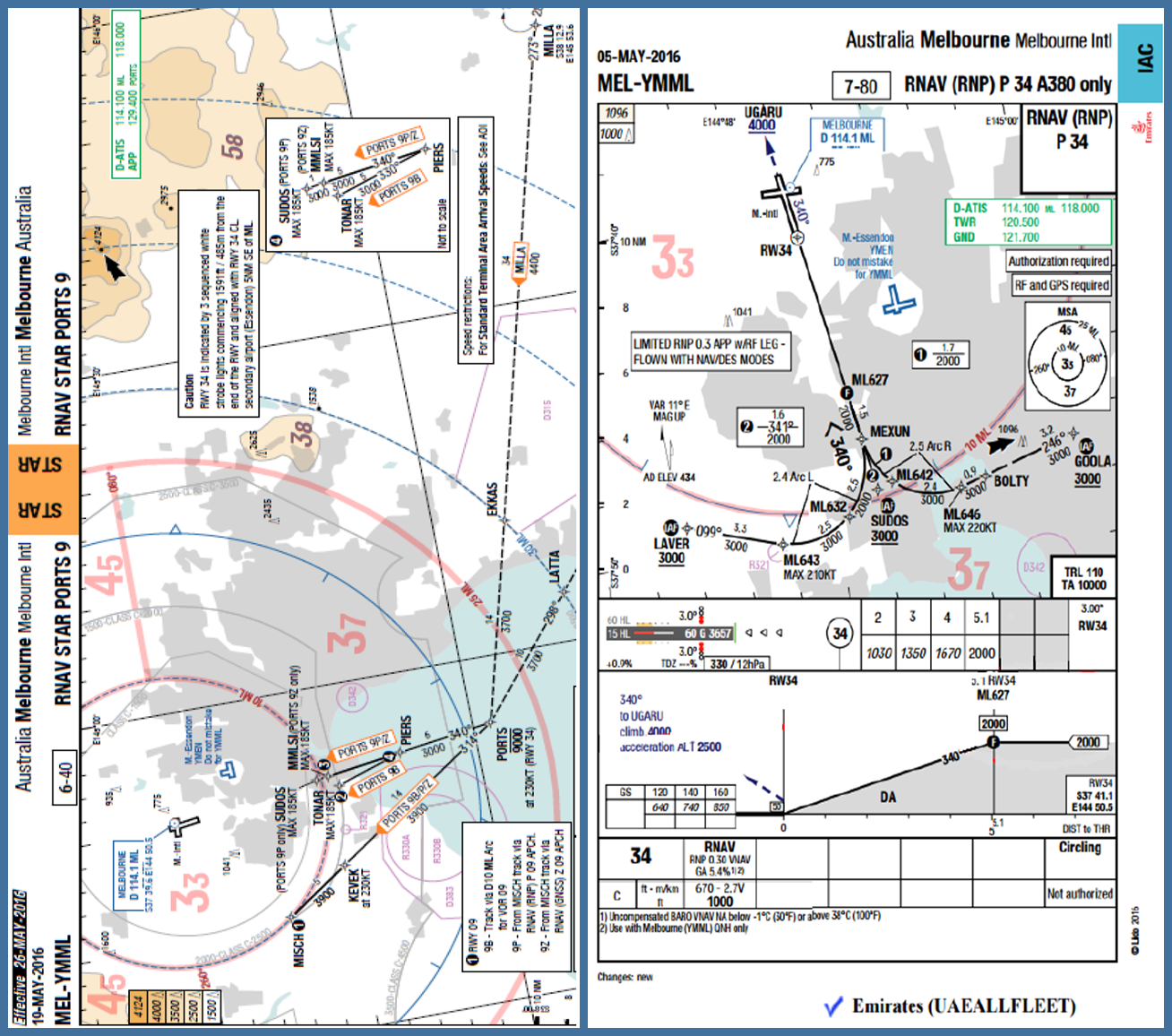
On 25 June 2016, at approximately 1857 Eastern Standard Time,[1] the flight crew of EK407, an Emirates A380 aircraft, registered A6-EDD was conducting a PORTS NINE PAPA standard arrival route (STAR) for the runway 34 required navigation performance (RNP) instrument approach to Melbourne Airport (Figure 1).
Figure 1 - Emirates Charts – Ports 9 STAR (left) and RNAV (RNP) Runway 34 Approach (right)
Source: Emirates
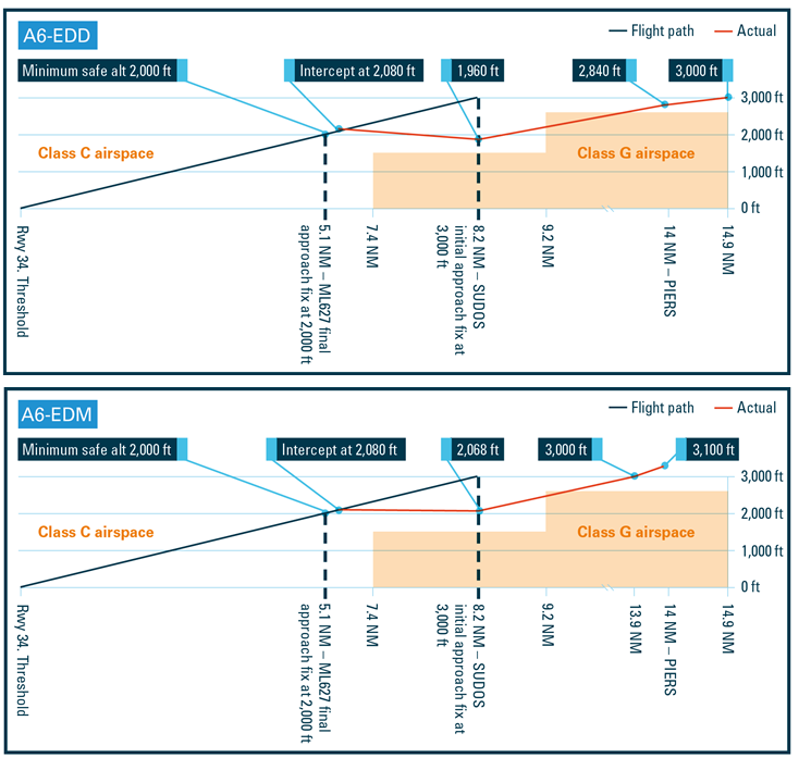
While on a track shortened arrival route, prior to waypoint SUDOS, the transition point between the STAR and the approach, the air traffic controller cleared the aircraft for the approach. The flight crew began the approach immediately. This resulted in the aircraft descending below the minimum assigned altitude for the STAR, and briefly operating outside of controlled airspace (Figure 2). While outside controlled airspace there were no observed traffic conflicts or terrain proximity issues.
On 14 July 2016, at approximately 1940, the flight crew of EK407, an Emirates A380 registered A6-EDM, flew the same STAR, with similar track shortening, and the same approach to the same airport. This flight crew also descended below the minimum assigned altitude for the STAR just prior to the initial approach fix, operating briefly outside of controlled airspace, in a similar location to the aircraft on the 25 June (Figure 2).
Figure 2 - A profile view of the Melbourne airspace to a distance of 14.9 NM along the route taken by A6-EDD on 25 June 2016 and A6-EDM on 14 July 2016
Source: ATSB
In both incidents, the controller intervened to ensure the aircraft stopped further descent until the aircraft reached SUDOS. Once past SUDOS, both aircraft completed the rest of the approach as published, and landed without further exceedances.
During the investigation, the ATSB:
interviewed the flight crew and air traffic controllers
reviewed flight and radar data
examined the operator’s arrival and approach charts, policies, procedures and training for the RNP type approach.
In these two incidents, each crew believed that they were conducting the approach and that descent below 3,000 ft was permitted by the clearance issued by the controller, while the controller believed the clearance would prepare the flight crew, but they would still fly the remainder of the STAR procedure, at the last assigned altitude until passing SUDOS. The plan identified by flight crew was to descend and stabilise the aircraft at 2,000 ft, the minimum safe approach altitude marked on the approach chart between SUDOS and the final approach fix, before commencing the final approach.
The investigation identified a difference in the profile view of the approach charts used by Airservices Australia and those used by Emirates, which may have contributed to the occurrence (Figure 3).
Figure 3 - Comparison between the profile view of the AIP and Emirates Runway 34 RNP approach chart
Source: Airservices Australia and Emirates, annotated by ATSB.
Due to the size of an A380, the aircraft had to land on runway 34, despite runway 27 being in use for all other arrivals. This requirement led to track shortening being issued by the controllers in both incidents to keep the aircrafts’ place in the arrival sequence, and to ensure separation from other arriving and departing aircraft. Analysis of the flight data showed that both aircraft were operating in pilot selected modes as they descended out of controlled airspace, chosen by the flight crew to manage the reduced track distance flown. This meant that protections in the Airbus flight management system which would automatically level the aircraft at the 3,000 ft restriction were inhibited.
Following the incidents, the operator prohibited their A380 flight crew from conducting RNP approaches in Australia and New Zealand.
In May 2017, Melbourne Airport reassessed the standard instrument approach paths in operation at the airport, as part of the implementation of a ground based augmentation system, and the Runway 34 RNP approach was removed.
Additionally, in November 2017, Airservices Australia aligned production of their charts, and the associated phraseology, to International Civil Aviation Organisation standards. This meant that all speed restrictions were published directly onto the chart, and that climb and descent clearances issued via a SID or STAR included an altitude clearance level, in addition to the published limit on the charts.
ATSB comment
Based on a review of the available evidence, the ATSB considered it was unlikely that further investigation would identify any systemic safety issues.
Additionally, the ATSB strives to use its limited resources for maximum safety benefit, and considers that in this case, due to proactive safety action by the operator and air services provider, the ongoing risk is minimal. Consequently, the ATSB has discontinued this investigation.
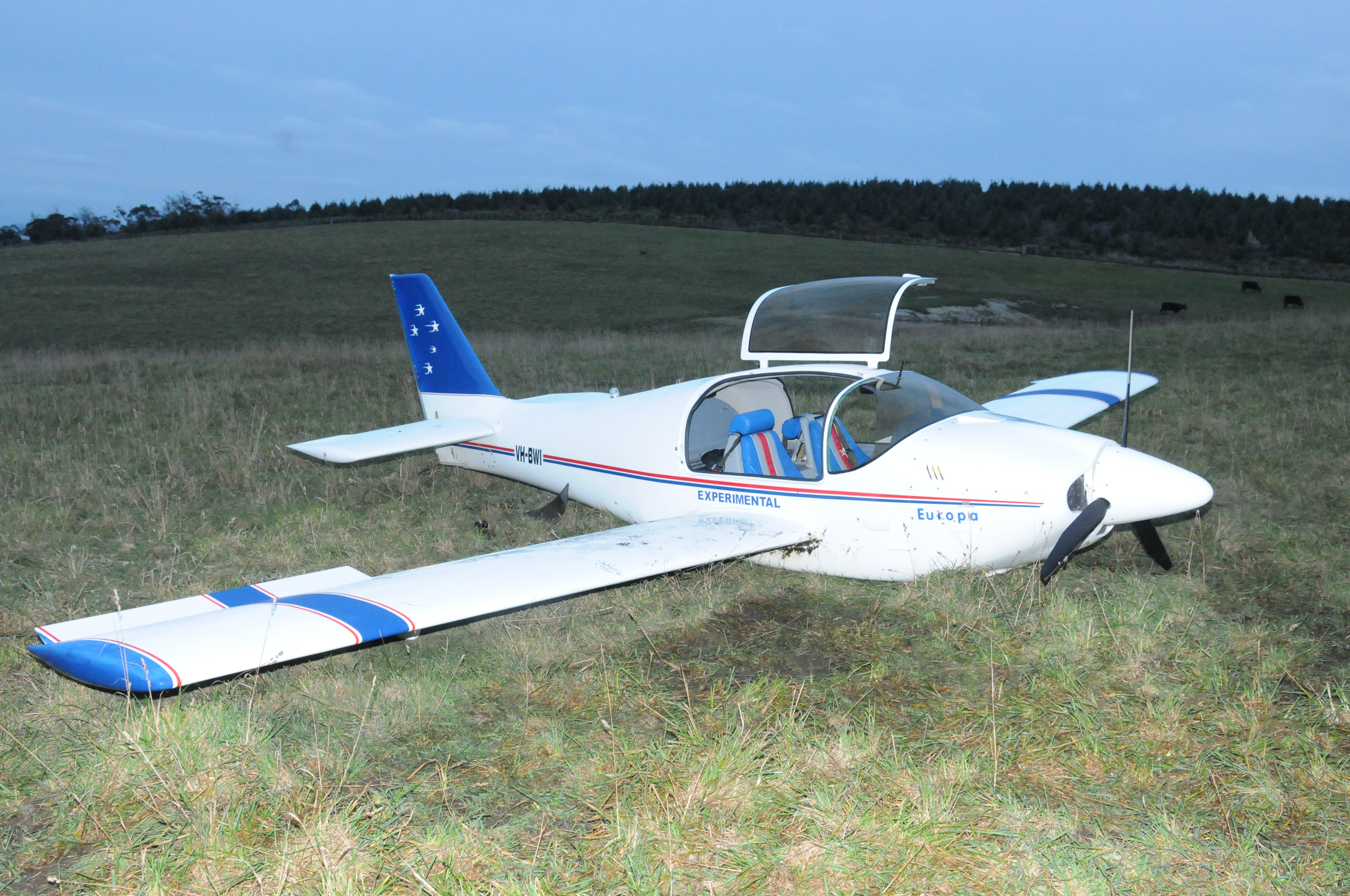
On the afternoon of 17 July 2016, two pilots departed Bridport Aerodrome in Tasmania in an amateur-built, Europa Aircraft Classic registered VH-BWI and operated in the experimental category. The ownership of the aircraft had recently been transferred and the purpose of the flight was a familiarisation flight for the new owner. After flying to the north-east of Tasmania, the aircraft returned to Bridport and completed two touch-and-go circuits. Shortly after take-off on the third circuit the engine spluttered for a short time, before stopping completely. A forced landing was conducted in a nearby paddock. One pilot sustained spinal injuries and the aircraft was moderately damaged.
What the ATSB found
There was inadequate communication between the pilots, which resulted in VH-BWI departing Bridport Aerodrome with no defined flight plan, no pre-flight brief and each pilot believing the other was in command. The lack of a flight plan prevented the pilots from ensuring there was sufficient fuel and reserves available to ensure safe flight. In addition, in-flight fuel monitoring was not sufficient to identify low fuel quantity and ensure fuel supply to the engine was not interrupted.
The ATSB also identified instances of misinterpretation of a number of the regulations concerning the maintenance of amateur-built experimental aircraft. This has the potential to affect the safety of this aircraft and those on board.
Safety message
All flights, even those conducted for private purposes, should be conducted with due consideration of operational needs and requirements, including appropriate experience, training and licencing on type. This accident highlights the importance of pre-flight planning. Pilots should ensure that every flight is appropriately planned for, utilising accurate flight times and fuel calculations. Once airborne, the continual monitoring of time and remaining fuel should be conducted. The Civil Aviation Safety Authority (CASA) published Civil Aviation Advisory Publication (CAAP) 234 Guidelines for aircraft fuel requirements, which recommends private, visual flight rules (VFR) flights plan for 45 minutes of fixed fuel reserves.
Good communication between pilots, observing recommended operating procedures and effective flight planning, will all help to reduce risk and enable safe flying.
Finally, ongoing safety requires aircraft owners and maintainers to operate and maintain the aircraft in accordance with relevant regulations, including those specific to experimental aircraft.
Photograph VH-BWI
Source: Tasmanian Police
The occurrence
On the afternoon of 17 July 2016, two pilots departed Bridport Aerodrome, Tasmania, on a local flight, in an amateur-built Europa Aircraft (Europa) Classic, registered VH-BWI (BWI). The aircraft was operated in the ‘experimental category’.
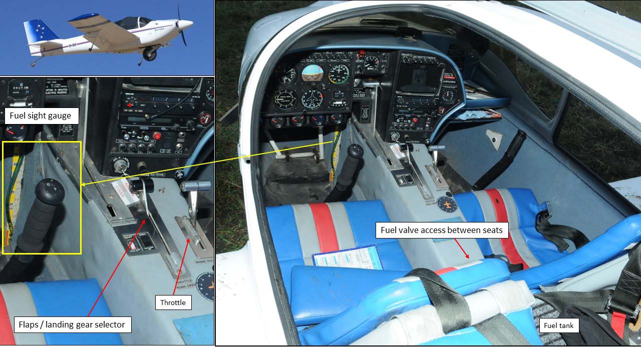
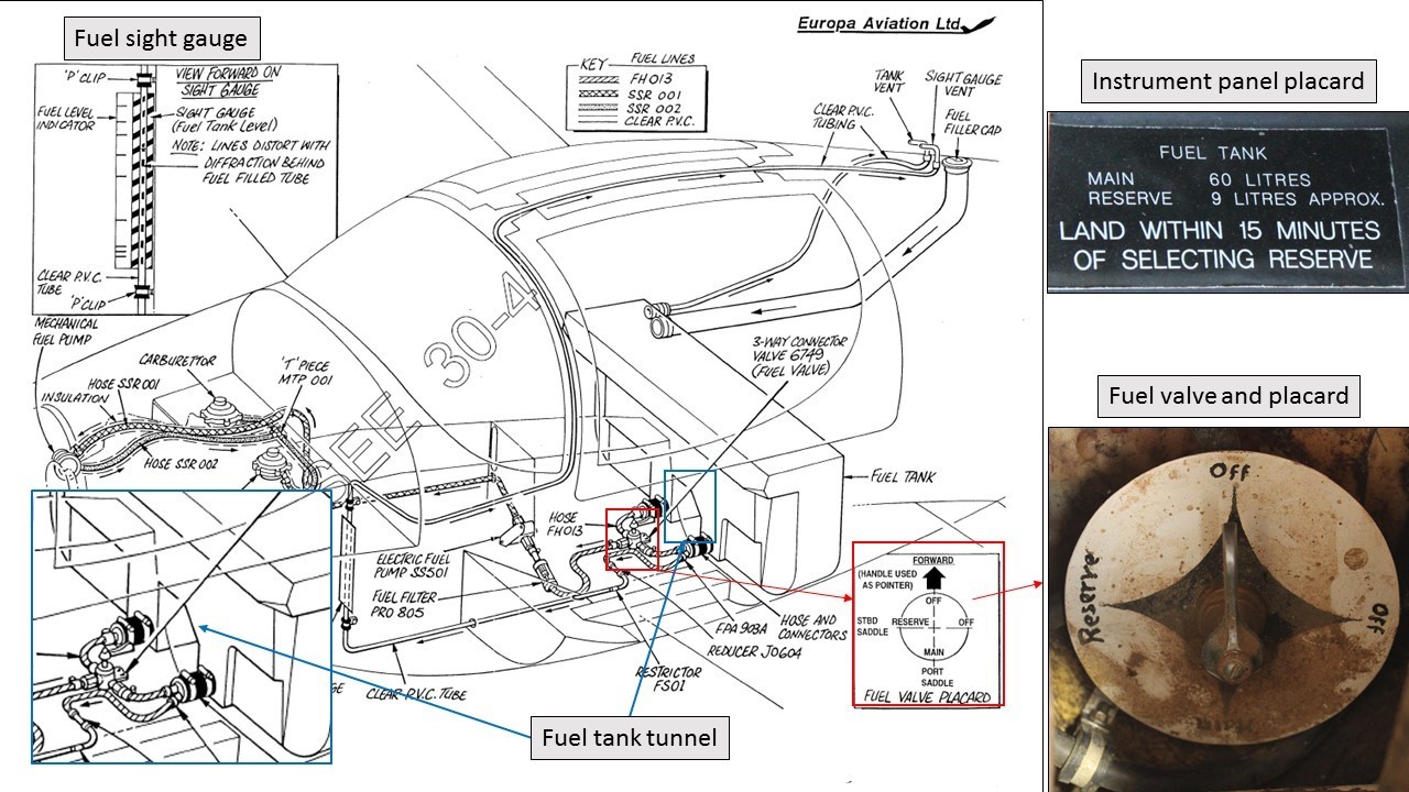
BWI was a two-seat, low-wing, composite kit aircraft. The aircraft could be flown from either seat, however, the fuel sight gauge and instrument panel were oriented primarily for left[1] seat operation (Figure 1). The landing gear consisted of a monowheel and small outrigger castors which were raised or lowered, simultaneously, with operation of the flap lever. A small tailwheel offered directional control on the ground.
Figure 1: VH-BWI and cabin interior showing component locations. Note the instrument panel and fuel sight gauge orientation toward the left pilot. Refer to Appendix A for further detail on the fuel sight gauge.
Source: Used with permission, modified by the ATSB
BWI was first registered in 1998 and was owned by the builder until November 2013. The aircraft had accumulated about 58 hour’s total time when it was purchased by the second owner (pilot B). Pilot B then sold BWI to the current owner (pilot A) on 27 June 2016. However, the transfer of ownership had not yet been completed and therefore pilot B was still the registered owner and operator at the time of the occurrence.
Pilot A flew their Savannah VG from Cranbourn Airport to Bridport in order to conduct a flight in BWI, with pilot B. The two pilots conducted a pre-flight examination of the aircraft together and an engine ground run was conducted, before being shut down. The top engine cowl was fitted and the engine was then started again for the intended flight. Pilot A was in the left seat and pilot B was in the right seat. Engine run-up checks were conducted prior to departure from Bridport Aerodrome, with no anomalies noted by either pilot.
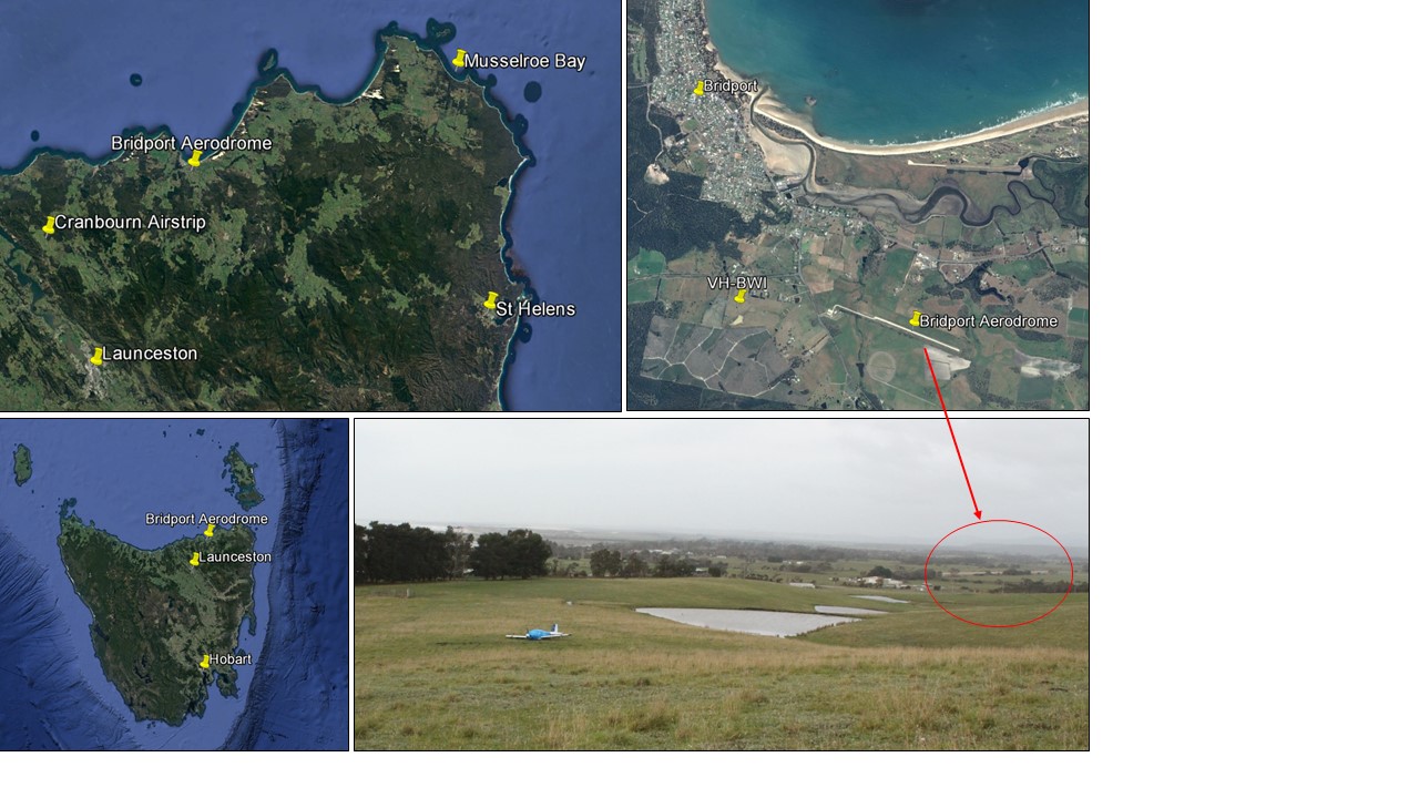
After departure from Bridport, BWI was initially flown toward St Helens,[2] before adverse weather conditions were observed by the pilots. BWI was then flown to the Musselroe Bay area on the north-east tip of Tasmania, about 37 nautical miles (NM) north of St Helens and about 30 NM north-east of Bridport (refer Figure 2 for localities). Upon arrival back in the Bridport area, several circuits involving touch‑and‑gos[3] were conducted by pilot A. The published standard circuit for Bridport is 1,000 ft above ground level, to the north of the aerodrome. However, the circuits in this instance were conducted to the south of the aerodrome, to minimise aircraft noise over Bridport town.
Figure 2: Google Earth map showing Bridport Aerodrome location and other locations mentioned in the report. VH-BWI forced landing location, about 1.5 km west of Bridport Aerodrome.
Source: ATSB and Google Earth, modified by ATSB.
Shortly after the third take-off, when pilot A reported to have retracted the flaps and landing gear and switched off the electric fuel ‘boost’ pump, the engine started to splutter and run rough. At the time, the aircraft was reportedly climbing, with an altitude of between 200 and 500 ft.
Pilot A recalled:
deciding they were too low for a return to the aerodrome, so prepared for a straight ahead forced landing
choosing to keep the flaps and landing gear retracted
concentrating on maintaining control of the aircraft
selecting a nearby paddock, that was relatively clear of trees and fences, for the forced landing.
When the engine started to run rough pilot B reported saying to pilot A that he believed they had run out of fuel, however from the right seat he could not see the fuel sight gauge to confirm this suspicion. Pilot B recalled:
removing the centre console cover (refer Figure 1) to access the fuel selector valve. Pilot B was in the unfamiliar right seat and was unsure of the direction required to turn the fuel valve to select the other tank. Confirmation was sought from pilot A, before moving the handle through 90˚.
switching the electric fuel pump on to assist in getting a sufficient fuel flow to the engine
believing they did not have sufficient height for engine power recovery
‘putting in some aileron control’ when suspecting that the current trajectory had them ‘going into the dam’.
The engine initially appeared to recover a little before it and the propeller stopped completely, just prior to the forced landing. The aircraft bounced once, then slid for about 40 m before coming to a stop. BWI landed on an upward sloping paddock, about 1.5 km to the west of Bridport Aerodrome (Figure 2).
Pilot A was uninjured and phoned emergency services, who then transferred pilot B to Hobart by helicopter for suspected spinal injuries. After the landing, pilot A reported moving the fuel valve handle through 180˚, to be pointing forward in the ‘off’ position. When interviewed by the ATSB, pilot A could not recall the in-flight fuel quantity prior to the engine rough running.
During the course of the investigation there were multiple differences identified in the recollections of the involved pilots, which the ATSB was unable to reconcile.
Investigation
Examination of the wreckage identified no pre‑existing mechanical defects that may have contributed to the engine stoppage and hard landing. The three-blade propeller had rearward bending to one blade only, consistent with the propeller not turning at the point of impact.
Conduct of the forced landing
The Europa Owners Manual contained procedures for emergency situations. The engine failure procedures included the following pilot actions:
Trim for 75 kt
Fuel pump on – select reserve
Check ignition on both
Assess height
…
If less than 1,000 feet:
Choose an area straight ahead
Land with gear and flaps down
The manual stated, ‘glide in the clean configuration (gear and flaps up) to achieve best glide range’ and ‘do not try to stretch your glide’. In addition, it was advised ‘only if there is time and you have maintained control of the aircraft should you try to restart the engine’.
The ATSB published Avoidable Accidents No. 3: Managing partial power loss after takeoff in single-engine aircraft[4] to increase awareness about aspects such as the importance of pre-flight decision making and planning for emergencies and abnormal situations for the particular aerodrome. It outlines that:
It may be advantageous to conduct a forced or precautionary landing as if experiencing a total engine failure, as it removes the variability and unknown reliability of some engine power, particularly where there are suitable landing options available. Moreover, all pilots are specifically assessed and trained to deal with a complete engine failure after takeoff.
When the forced or precautionary landing is beyond the aerodrome, the publication advised:
…a pilot faced with an unsuitable area in which to stop should attempt to slow the aircraft as much as possible. Protecting the occupants from injury should be your highest priority, rather than preventing damage to the aircraft.
Using the landing gear…to absorb energy on impact… Avoiding direct contact of the fuselage with solid objects reduces the risk of serious injury.
Pilot A elected to leave the landing gear / flaps retracted for the forced landing, which was not in accordance with the manufacturer’s procedures. However, the off-aerodrome forced landing was conducted almost straight ahead, which was in line with best practice and reduced the risk of a loss of control had a turn back to the runway been attempted.
Fuel system
The fuel tank installed in BWI consisted of one large polymer tank located behind the pilots’ seat backs. The lower section of the tank was divided in two by a tunnel to allow for the passage of flight controls to the aircraft’s empennage. The volume on one side of the tunnel was designated as the reserve tank and the volume on the opposite side of the tunnel, plus the volume above the tunnel, was the main tank (although the volume above the tunnel was available to either tank). A detailed examination of the fuel system is covered in Appendix A.
The pertinent findings from the examination were that:
The fuel sight gauge reflected the fuel quantity available to the engine with the main tank selected. There were no other fuel quantity indicators. In addition, the fuel sight gauge was accurate in flight (level attitude) only.
The fuel sight gauge scale in BWI included reserve fuel in the indicated quantities, which is not in line with industry best practice.
An unofficial fuel calibration had been conducted by pilot B to determine fuel quantity when reading the gauge on the ground, with the aircraft in a tail-low attitude. The unofficial calibration resulted in additional marks on the fuel sight gauge that were to be read in conjunction with associated marks on the pilot check card.
During the unofficial fuel calibration, pilot B reported that 35 litres of fuel was required to be added to the tank to bring the sight gauge to the 5 litre, level (in-flight) mark. This demonstrated that a significant quantity of fuel could be present in the tank, but unavailable to the engine in tail-low attitudes, such as during climb.
The fuel valve was likely set on the reserve tank for the flight (considering the final position of the valve and both pilot’s recollection regarding movement of the valve).
The fuel sight gauge (main tank) would not have indicated the reducing fuel levels in the selected reserve tank when the fuel level dropped below the height of the tunnel.
About 16 litres of fuel was recovered after the forced landing, with approximately equal amounts from each tank drain point. Considering the fuel tank setup and likely movement (sloshing) of the fuel during landing, there was likely to have been about 10 litres on one side of the tunnel and six litres on the other prior to the engine stoppage. The six litres in the selected tank had the potential to allow the fuel to un-port and interrupt fuel flow to the engine.
Inadequate fuel records for the aircraft had been maintained.
The aircraft’s log book was incomplete with respect to fuel system maintenance and the aircraft’s fuel filter had been replaced with an unapproved part.
With respect to the aircraft’s electric fuel boost pump, the Europa Owners Manual Normal Operations section stated that following take off, the pump was to be selected to ‘off’ after the aircraft reached 1,000 ft above ground level. The Pilots Check Card and Flight Planner ‘climb’ check differed from the Owner’s Manual, indicating that the electric fuel pump was to be switched off after the flaps and landing gear were selected up and before a cruise climb of 90-100 kt was established. No altitude guidance was provided on the check card for this action. Pilot A reported that they would normally have the electric fuel pump on for standard circuits. In this instance however, pilot A wanted to practice departure and approach procedures. This involved retracting the flaps and landing gear and switching off the pump at about 500 ft as part of the departure climb. This procedure was completed in reverse during the approach.
Weather conditions
The Bureau of Meteorology (BoM) observations from Bridport weather station at about 1500, indicated a temperature of 13 ˚C, relative humidity of 68% and a wind speed of 7 kt from the west. In addition, the BoM area forecast incorporating Bridport indicated isolated showers. The dew point was between 5.1 and 5.6 ˚C at the time of the occurrence.
Both pilots indicated their awareness of carburettor icing conditions and standard mitigating procedures. The recorded temperature, dew point and relative humidity at the time of the occurrence were conducive for serious carburettor icing at any power. However the following conditions indicated that carburettor icing in this occurrence was unlikely:
In this installation, both carburettors were located on top of the engine, at the rear of the engine compartment. This resulted in air passing through the radiators and over the hot engine before being drawn into the carburettors. The introduction of warm air into the carburettors reduces the likelihood of icing.
Carburettor icing more commonly occurs at lower engine power settings.[5] In low power settings, the airflow through the carburettor is partially impeded by the throttle valve. This valve provides more area for the ice to form and also increases the partial vacuum downstream of the valve, resulting in further chilling of the air and water droplets. The engine in this occurrence was at a high power setting, prior to the stoppage.
A search of Australian and several major international aviation databases found that carburettor icing events on Europa aircraft were rare. From more than 120 Europa occurrences worldwide, only one was identified as a possible carburettor icing event.
Regulations
Airworthiness and maintenance
BWI was built in Australia in 1998 from a kit supplied by Europa Aircraft and was issued with a Special Certificate of Airworthiness (SCOA) on 17 August 1999. The log book statement issued at this time required a periodic inspection to be conducted every 12 months, in accordance with the Civil Aviation Safety Authority (CASA) maintenance schedule (Schedule 5).[6] An updated SCOA was issued 27 November 2002 and was subject to the operational and maintenance-related conditions detailed in the associated Annex. The conditions in the Annex included, in part:
...
6. No person shall operate this aircraft unless, within the preceding 12 calendar months, it has had a condition inspection performed in accordance with CASA Maintenance Schedule Number 5, and has been found to be in a condition for safe operation.
7. Condition inspections may be performed by an eligible builder or by a LAME, in accordance with any conditions entered on this special airworthiness certificate.
8. Condition inspections shall be recorded in the aircraft maintenance records showing the following or a similarly worded statement:
-I certify that this aircraft has been inspected on (date) in accordance with the CASA Maintenance Schedule and any conditions on the Experimental Certificate, and has been found to be in a condition for safe operation...
CASA advised the ATSB that, other than a number of specific exemptions, aircraft which are built and operated in the experimental category are to be maintained in accordance with the regulations and any other additional instructions detailed in the SCOA annex. In addition, the regulations document who may carry out maintenance.
The holder of a pilot licence, valid for the aircraft, is authorised to conduct certain maintenance as specified in Civil Aviation Regulation (CAR) Schedule 8 (Schedule 8). In addition, CASA Instrument 15/16 Authorisation of persons to carry out maintenance on certain amateur‑built, kit‑built and light sport aircraft with a special certificate of airworthiness detailed that, in some circumstances, a person who builds or has previously built an amateur‑built aircraft of a similar type (essentially similar),[7] may be authorised to conduct certain maintenance and issue a maintenance release for that aircraft.
Pilot B was the second owner of BWI and had not built it or an essentially similar aircraft and was therefore not authorised to conduct maintenance beyond that permitted under Schedule 8. Pilot B reported that he had sought clarification from representatives of CASA, Recreational Aviation Australia (RAAus) and the Sports Aircraft Association of Australia of the requirements for privileges as per Instrument 15/16, and therefore believed he was authorised, per the essentially similar aircraft clause.[8] The ATSB could not verify the nature of the clarification sought or the response reportedly provided by these organisations. In addition, CASA advised the ATSB that, once an aircraft build has been completed, any task that could affect the continuing airworthiness, (including repairs or reconstruction) is considered to be maintenance.
Maintenance carried out on an aircraft is required to be certified complete in accordance with the regulations. BWI’s log book had multiple occurrences of maintenance that had incomplete certification or was uncertified in its entirety (refer to Appendix A for additional information). In addition, scheduled and unscheduled maintenance had been conducted by a person who was not authorised to do so.
The engine log book contained an incomplete entry, indicating that a periodic inspection was completed on 25 June 2016. There was no corresponding entry in the aircraft log book, as would be expected for this type of inspection. A new maintenance release had been raised at about this time, however it had no certification by an authorised person and was therefore not valid. In addition, details of the accident flight had been endorsed on the previous similarly invalid, and expired, maintenance release.
Ultimately, per CAR 42CB Experimental aircraft, the certificate of registration holder is responsible for ensuring the aircraft is maintained in accordance with the regulations. In addition, CAR 133 Conditions of flight requires the pilot in command to ensure that all the required maintenance has been completed and is appropriately certified.
Recreational Aviation Australia
CASA oversights several self-administering organisations within the sport and recreational aviation sector. Many self-administering organisations operate under a series of exemptions and delegations. This allows specialised craft such as balloons and aircraft that don’t meet certification standards to operate through exemptions from some of the regulations that apply to broader aviation activities. These exemptions also define how the recreational aircraft may be used and where they can be operated.
RAAus administers ultralight, recreational, weight shift microlight and light sport aircraft. RAAus train and certify pilots, flying instructors and maintainers, register their aircraft fleet and oversee a large number of flight training schools across Australia. The Europa Classic can be registered with either RAAus or CASA. BWI was a CASA registered aircraft, and as such, was required to comply with the published CASA regulations.
Pilot licencing requirements for Australian aircraft
RAAus administers the issuing of certificates to pilots to permit them to act as pilot in command of RAAus registered aircraft. Pilot A held a current RAAus pilot certificate which allowed him to operate his other, RAAus registered aircraft. Pilot B had previously held a RAAus pilot certificate however, it was not current at the time of the occurrence.
As BWI was VH-registered, the regulations required it be operated by the holder of a CASA pilot licence. At the time of the occurrence pilot A did not hold any type of CASA issued pilot licence. CASA issued pilot B with a Recreational Pilot (Aeroplane) Licence[9] (RPL) on 12 February 2015. The licence authorised pilot B to operate manual propeller pitch control and retractable undercarriage, single engine aircraft. The licence did not include a navigation endorsement,[10] which was required for operations in excess of 25 nautical miles from the departure aerodrome. While the pilot held the requisite training and documentation to receive this endorsement, the application documentation was insufficient. Pilot B believed they were authorised for navigational flight and therefore any violation in this instance was likely unintentional. This highlights the importance of careful review of documentation for correctness, particularly when transitioning of licences and authorisations.
Pilot A was preparing to apply for a CASA RPL at the time of the occurrence. CASA will issue a RPL to RAAus pilot certificate holders, on the basis of completion of a medical and English test. However, a flight review must be completed with flight instructor to exercise the privileges of the RPL.
Pilot roles on the occurrence flight
At the time of the occurrence, the Civil Aviation Regulations 1988 (CAR) and Civil Aviation Safety Regulations 1998 (CASR) were in force.
CAR Part 2(1) defined the operator of an aircraft as ‘a person, organisation, or enterprise engaged in, or offering to engage in, an aircraft operation’. The CASR defined the operator of an aircraft as ‘the person, organisation or enterprise that make the aircraft available to the aircraft’s pilot in command for a flight’. When an aircraft is registered on the Australian aircraft register, the details of the registered operator are included to ensure that the legal entity of the operator, as specified in the CAR and CASR, is known.
CAR 224 (1) Pilot in command applied to the flight and stated:
For each flight the operator shall designate one pilot to act as pilot in command.
Once designated, the pilot in command had specific obligations under the regulations that directly related to the safe operation of the aircraft. These included ensuring the amount of fuel on board the aircraft was sufficient to safely conduct the flight. That responsibility for fuel was also shared with the operator of the aircraft under CAR 234.
The transfer of ownership of BWI had not yet been submitted to CASA and as such pilot B was the registered operator of the aircraft at the time of the accident flight. Pilot B was therefore responsible for the nomination of the pilot in command for the flight. Although the nomination of a pilot in command was to meet a regulatory requirement, it was also essential to ensure the safe conduct of the flight.
The two pilots had flown together in BWI on three previous occasions, before the transfer of ownership. Pilot A reported he flew the aircraft from the left seat on the second and third flights. Pilot B reported all three flights were conducted with pilot A in the right seat. Pilot A had no formal training or experience flying either a Europa or similar performing low‑wing aircraft other than during these three flights.
Pilot B reported knowing that pilot A did not hold a pilot licence, yet reported telling pilot A, prior to departure, that they (pilot A) would be the pilot in command for the flight. Pilot B indicated that pilot A accepted the role of pilot in command, but wanted pilot B along for confidence, due to their limited experience in the aircraft. Pilot B advised he was not ‘instructing’ pilot A, but rather, offering ‘reassurance’. Pilot A reported that, as pilot B was the previous owner and held a pilot licence, they had the necessary qualifications to act as pilot in command and therefore pilot B was ‘the pilot in charge’.
During the pre-flight preparation most of the time was taken up with running the engine and conducting an examination of the aircraft. Both pilots reported that the aircraft had 45-50 litres of fuel on board and considered that it would be sufficient for the flight. However, neither pilot reported confirming the exact amount of fuel on board, nor conducting specific planning for the flight in terms of actual endurance and reserve fuel amounts.
As there was no agreed confirmation by either pilot as to who was the pilot in command, neither pilot ensured that any of the actions required by the regulations, to ensure a safe flight, were completed.
Despite the aircraft being equipped with dual controls, BWI’s instrument panel and fuel sight gauge were oriented primarily for left seat command operation. Therefore pilot B, in the right seat, was not in an ideal position to act as pilot in command, or to assist if it were required, during flight.
Related occurrences
AO-2009-026 Fuel starvation event involving Bell 206 helicopter, VH-JTI
The pilot was conducting a 20-minute scenic flight with four passengers, from a helipad at an entertainment facility at Coomera, Queensland. After about 15 minutes flying the fuel boost pump low pressure warning light illuminated briefly. The pilot believed he had sufficient fuel on board and continued the flight. While the helicopter was descending to land at the helipad the engine lost power, resulting in autorotation[11] and a forced landing. Two passengers sustained serious injuries.
The investigation found that the helicopter departed with insufficient fuel to complete the flight. The low fuel quantity approaching the helipad increased the risk that any unusual attitudes or out‑of‑balance may uncover the fuel boost pump(s) and starve the engine of fuel.
The pilot was the sole occupant and departed for a private local flight to inspect a number of paddocks at a nearby property. After about 2 hours and 40 minutes the engine began to run rough. The pilot attempted to regain engine performance however, the engine stopped completely a short time later. A forced landing was conducted resulting in serious damage to the aircraft. The pilot was not injured.
The pilot did not conduct a formal fuel plan prior to the flight and his estimates of the flight’s fuel consumption were not consistent with manufacturer published information. In addition, the pilot had not referred to the fuel gauge at any stage of the flight.
The report included the following safety message:
All flights, even those conducted for private purposes, should be conducted with due consideration of operational needs and requirements. This accident highlights the vital importance of pre-flight planning. Pilots should ensure that every flight is appropriately planned for, using accurate flight times and fuel calculations. Once airborne, the continual monitoring of time and remaining fuel should be conducted.
Research
Two ATSB research investigations have identified that amateur-built aircraft are overrepresented in aviation accidents and incidents in Australia. The research shows pilots involved in accidents in amateur-built aircraft had significantly less experience on the aircraft type they were flying at the time of the accident than pilots involved in accidents in factory built aircraft, despite having higher overall flying experience.
Twenty per cent of amateur-built accidents had pilots with less than 10 hours experience on the aircraft type. More than half of all amateur-built aircraft accidents occur prior to the pilot accumulating 35 hours on the aircraft type. This included owner-builders and recent purchasers of second-hand, amateur-built aircraft.
The ATSB[12] has also published a series of Avoidable Accidents information booklets. Booklet 3, Managing partial power loss after takeoff in single-engine aircraft, identified that most fatal and serious injury accidents resulting from partial power loss after takeoff are avoidable. The key message in this booklet stated the benefits of:
pre-flight decision making and planning for emergencies and abnormal situations for the particular aerodrome
conducting a thorough pre-flight and engine ground run to reduce the risk of a partial power loss occurring
taking positive action and maintaining aircraft control, either when turning back to the aerodrome or conducting a forced landing, until on the ground.
Booklet 5, Starved and exhausted, discussed the procedures that pilots can use before and during a flight to help them be absolutely sure they will have sufficient fuel to land at their destination aerodrome, with reserve fuel intact. The key messages in this booklet stated:
Accurate fuel management starts with knowing exactly how much fuel is being carried at the commencement of a flight. This is easy to know if the aircraft tanks are full, or filled to tabs. If the tanks are not filled to a known setting, then a different approach is needed to determine an accurate quantity of usable fuel.
Accurate fuel management also relies on a method of knowing how much fuel is being consumed. Many variables can influence the fuel flow, such as changed power settings, the use of non‑standard fuel leaning techniques, or flying at different cruise levels to those planned. If they are not considered and appropriately managed then the pilot’s awareness of the remaining usable fuel may be diminished.
Keeping fuel supplied to the engines during flight relies on the pilot’s knowledge of the aircraft’s fuel supply system and being familiar and proficient in its use. Adhering to procedures, maintaining a record of the fuel selections during flight, and ensuring the appropriate tank selections are made before descending towards your destination will lessen the likelihood of fuel starvation[13] at what may be a critical stage of the flight.
The ATSB research paper Australian Aviation Accidents Involving Fuel Exhaustion and Starvation was published in December 2002. This paper identified that fuel exhaustion[14] and fuel starvation accounted for over 6 per cent of all accidents between 1991 and 2000. The private and agricultural categories were found to have the highest rates of fuel exhaustion and fuel starvation accidents. In addition, pilots with fewer hours on type are more likely to be involved in fuel‑related occurrences. Mismanagement of fuel (including running one tank dry and incorrect positioning of fuel system controls) contributed to 42 per cent of total starvation accidents. Inattention to fuel supply contributed to 16 per cent total starvation accidents.
The Federal Aviation Administration (FAA) published a series of Aviation Safety Program publications which included, Time in Your Tanks.[15] This publication provided general tips on determining and managing the ‘time’ in your aircraft fuel tank. It also identified that fuel gauges are subject to malfunctions and errors and added, ‘…unless restricted by the gross weight or centre of gravity limits, it is considered good judgment to "top off" the tanks at fuel stops’. ATSB weight and balance calculations concluded it was possible for the occurrence flight to be undertaken with full fuel tanks. In addition, the weight of the occupants could be increased by 28.9 kg, before reaching maximum takeoff weight.
The ATSB database identified 41 occurrences involving RAAus and VH registered Europa aircraft. Four notifications involved partial or total engine power loss.
Database research[16] of Europa incidents and accidents identified about 120 events and that most Europa occurrences were related to operational events. The research identified only a few occurrences related to possible technical issues.
While on a local flight, the two pilots on board an amateur-built Europa Classic, registered VH-BWI (BWI) were conducting a series of touch-and-go circuits at Bridport Aerodrome, Tasmania. Shortly after lifting off for the third circuit the engine began to run rough, before stopping completely. A forced landing was conducted in a nearby paddock. One pilot sustained spinal injuries and the aircraft was moderately damaged.
This analysis will examine the operational and maintenance aspects, including associated risk controls, and discuss their role in the occurrence.
Operational
Fuel management
The investigation identified that neither pilot completely understood the operation of the fuel system, as pilot B reported not fully understanding the system, and pilot A had only recently purchased the aircraft. There was no flight plan, either formal or informal, identifying a track, distance, or time intended to be flown, to allow for fuel endurance calculation. This prevented the pilots from being able to ensure they had sufficient fuel, and reserves, for any flight beyond local circuits.
Both pilots reported a pre-flight quantity of about 45-50 litres of fuel on board. However, due to the non-standard scale, unapproved fuel calibration (combining the main and reserve quantities) and lack of other fuel quantity verification methods, the accuracy of this indicated fuel quantity could not be determined.
The RAAus 2015 Clear mind, clear prop safety publication[17] provided guidance on fuel planning, stating that ‘fuel mismanagement, exhaustion and/or starvation continues to be a major factor in serious and fatal accidents’. The advice provided to their pilots included:
have a clear understanding of the fuel system, including fuel tap positions, cross feeding issues, water drains and a realistic fuel use per hour
flights in the local area may give you a false impression about the number of litres per hour the aircraft uses, because different power settings may be used locally than those flying long distances, and
if fuel planning is not based on confirmed amounts of fuel via dipstick or number of litres added, an engine failure from fuel exhaustion may result, with pilots then having to deal with the extra pressure of an emergency landing.
The fuel valve was likely selected to the reserve tank for the duration of the flight. Due to the design of the tank, the fuel sight gauge would have continued to indicate (in level flight) the remaining 10 litres of fuel in the main tank as the reserve tank was depleted. A casual observation of the fuel gauge while in this condition would not have led to any significant concern about the fuel quantity remaining (10 litres in the main tank and about 10 litres in reserve provided over an hour’s endurance). If the fuel selector was on the main tank for the flight, the same amount of usable fuel would have been available, however the fuel sight gauge would have correctly reflected the depletion of fuel from that tank.
The amount of fuel that could be in the main tank in a nose-up attitude and not available to the fuel outlets was significant and was demonstrated by the unofficial on-ground fuel calibration. Immediately prior to the engine stoppage, the fuel remaining in the selected tank was likely to have been about 6 litres, including up to 4 or 5 litres of unusable fuel. This amount of fuel in the climb attitude of the third circuit, would have likely resulted in the forward-facing fuel outlet being uncovered. This would have introduced air to the fuel lines and engine, leading to the rough running of the engine, as reported by the pilots.
Switching off the electric fuel pump below 1,000 ft, at a height lower than recommended and during a period of increased engine power, may have also introduced low fuel flow to the engine, resulting in the observed rough running. That scenario could not be discounted during the investigation.
Pilot risk assessment
The RAAus 2016 safety publication provides a definition of normalisation of deviance as ‘the gradual process through which unacceptable practice or standards become acceptable. As the deviant behaviour is repeated without catastrophic results, it becomes the social norm for the pilot’. Normalisation of deviance is a known phenomenon in aviation accidents and incidents, where known risks are taken by pilots before and during flight which have no adverse outcome, and eventually become a standard practice.
The normalisation of deviance is not necessarily an intentional violation, but rather part of a series of factors which affect decision making. Orasanu and Martin (1998) discuss the underestimation of risk as ‘if somewhat similar risky situations have been encountered in the past and the crew has successfully taken a particular course of action, they will expect also to succeed this time with the same course of action’.
The two pilots involved in this incident demonstrated the underestimation of risk and associated normalisation of deviance, in many of the risks they accepted in operating the flight, compared to RAAus and CASA best-practice guidance and flight training standards.
Neither pilot was authorised by CASA to operate as pilot in command on the flight in this instance, due to pilot A only holding a RAAus pilot certificate and pilot B not holding a navigational endorsement on their CASA RPL that was required for flights greater than 25 nautical miles from the aerodrome. In addition, pilot B could not be an effective pilot in command from the right seat, nor act as a flight instructor. The two pilots had not communicated effectively about the nature of the flight, their roles in the aircraft, or the roles they were to take in emergency situations. This inadequate communication increased the risk of an unintended outcome of the flight.
Pilot A had limited experience on, and no formal training on, the Europa, which increased his workload during the flight and increased the risk of certain procedures being overlooked. Pilot B had operational knowledge and experience flying BWI but the location of the fuel sight gauge meant that only pilot A could monitor the fuel quantity during the flight. When the engine started to run rough, pilot B believed they had run out of fuel. Pilot A could not recall the fuel quantity remaining prior to the engine trouble, which was consistent with insufficient fuel monitoring practices. Checking that the fuel is selected to ‘MAIN’ is a check listed item in the owner’s manual and on the pilot’s check card. It is possible that, since the fuel lever was reportedly never moved, that this check was overlooked by the pilots.
Meteorological conditions present at the time of the occurrence were conducive to formation of carburettor ice. The extent to which either pilot considered this risk could not be determined. However, the location of the carburettors, at the rear of a warm engine compartment and the high power setting at take-off reduced the risk of carburettor ice formation. Therefore, while the formation of ice in the carburettors and its associated effect on engine performance remains a possibility, it was found to be unlikely in this occurrence. In any event, pre-flight assessment of the conditions and alertness to early indication, combined with a prompt and effective response can reduce the risk of carburettor ice affecting engine operation.
It is likely that both pilots were experienced in flying local flights in their own aircraft during benign weather conditions, without a lot of abnormal challenges to the flight. The ATSB Avoidable Accidents Booklet 6:Experience won’t always save you provided the guidance to pilots that:
A pilot’s total flying experience is not necessarily an indication of good decision-making ability. In some instances, that experience and familiarity can persuade a pilot to take greater risks in the belief that it will enable them to achieve an objective, despite the improbability, that a less experience pilot would not event contemplate.
In addition, the ATSB recommends that owners of amateur-built aircraft should ensure they have adequate training on type before operating newly built or purchased aircraft.
Maintenance
The ATSB has identified instances of misinterpretation and misuse of regulations concerning the maintenance of amateur-built experimental aircraft in a number of occurrence investigations. In several instances, the regulation breaches were identified as contributing to those occurrences.
This investigation identified multiple occurrences of uncertified and unauthorised maintenance having been conducted on BWI. In addition, the flight was conducted on an uncertified and unauthorised maintenance release and details of the flight were endorsed on an invalid maintenance release that had also expired.
It is the responsibility of the person conducting maintenance to ensure it is within the scope and privileges of their authorisation. It is also the responsibility of the aircraft owner and/or pilot in command, prior to each flight, to ensure that all required maintenance has been completed and correctly certified. Undocumented maintenance reduces the information available for others to make informed decisions regarding serviceability of the aircraft. In addition, the use of up-to-date manufacturer documentation is in line with industry best practice to ensure aircraft serviceability and safety of its occupants.
There was insufficient evidence to indicate that the uncertified and unauthorised maintenance directly contributed to this occurrence. However, adhering to regulations and best practice minimises associated risk and increases the likelihood of continued safe operation.
From the evidence available, the following findings are made with respect to the loss of engine power and forced landing involving an amateur-built Europa Classic, registered VH-BWI that occurred near Bridport Aerodrome on 17 July 2016. These findings should not be read as apportioning blame or liability to any particular organisation or individual.
Contributing factors
Inadequate flight and fuel planning, limited understanding of the fuel system and in-flight management issues led to an unrealised low fuel condition.
The loss of engine power and forced landing likely occurred as a result of a fuel starvation event.
Other factors that increased risk
A non-standard fuel gauge scale, combined with an unapproved fuel quantity calibration, increased the likelihood of a misinterpretation of available fuel.
Uncertified and unauthorised maintenance carried out on VH-BWI increased the risk to flight safety.
Sources and submissions
Sources of information
The sources of information during the investigation included the:
Civil Aviation Safety Authority
Tasmanian Police
Airservices Australia
Bureau of Meteorology
Light Aircraft Association, United Kingdom
aircraft kit manufacturer
pilots of VH-BWI
References
Orasanu and Martin, L, 1998, Errors in Aviation Decision Making: A Factor in Accidents and Incidents, Human Error, Safety and Systems Development Workshop 1998
Submissions
Under Part 4, Division 2 (Investigation Reports), Section 26 of the Transport Safety Investigation Act 2003 (the Act), the Australian Transport Safety Bureau (ATSB) may provide a draft report, on a confidential basis, to any person whom the ATSB considers appropriate. Section 26 (1) (a) of the Act allows a person receiving a draft report to make submissions to the ATSB about the draft report.
A draft of this report was provided to the Civil Aviation Safety Authority, the Air Accidents Investigation Branch (UK), the Light Aircraft Association (UK), the aircraft kit manufacturer and the pilots of VH-BWI.
Submissions were received from the Air Accidents Investigation Branch (UK), the Light Aircraft Association (UK) and the pilots of VH-BWI. The submissions were reviewed and where considered appropriate, the text of the report was amended accordingly.
Appendices
Appendix A – Fuel system additional information
Fuel Tank
The fuel tank installed in BWI consisted of one large polymer tank located behind the pilots’ seat backs. The lower section of the tank had a tunnel in the middle to allow for the passage of flight controls to the aircraft’s empennage. The fuel system components and their locations are shown in Figure A1.
FigureA1: Fuel system components
Source: Manufacturer, modified by the ATSB
The Europa Owner’s Manual stated the aircraft had a fuel capacity of 68 litres.[18]The left side of the tunnel was identified by Europa as the main tank and the right side of the tunnel was identified as the reserve tank. The amount of fuel contained in the main tank side of the tunnel was about 10 litres and the reserve side about 9 litres, depending on aircraft build.
Fuel was drawn from each tank separately and flow to the engine was controlled by the tank selector valve. Fuel flow was provided by the engine driven ‘mechanical’ pump and an ‘electric’ fuel boost pump, which was located in the centre console, downstream of the fuel selector valve (Figure A1). The fuel tank outlets were located on the forward face of the tank, on each side of the tunnel, approximately near the tank base. The holes for the outlets are moulded-in bosses that are drilled open by the builder before the tank is fitted to the airframe. The height of the outlets above the fuel tank base determined the unusable fuel quantity.
Europa reported that when the fuel level was below the tunnel it was possible for fuel to ‘slosh around’ between the main and reserve, as there were no tank baffles. Additionally, the fuel tank outlets were oriented high during take-off and other ‘nose up’ aircraft attitudes. These conditions could result in 4 or 5 litres per tank being unavailable to the fuel outlets. The unusable fuel quantity could vary between aircraft, depending on the differences in each build, turbulence and aircraft attitude.
The fuel system included a fuel sight gauge, located forward of the fuel tank, on the left side of the centre console, under the instrument panel. That sight gauge was a clear polyurethane tube that was directly connected to the main tank outlet. There were no other fuel quantity indicators installed on the fuel system of BWI. A schematic of the fuel tank and associated fuel sight gauge is shown at Figure A2.
Figure A2: VH-BWI fuel tank schematic (not to scale), as viewed from the rear of the aircraft. The reserve tank is shown shadedandthe remainderis themaintank.
Source: ATSB
The fuel system was designed so that the fuel level in the sight gauge was a direct reflection of the fuel available in the main tank, when the aircraft was in a level attitude. If the fuel selector was moved to the reserve tank position, the fuel sight gauge would only indicate correctly until the fuel level reached the level of the top of the tunnel, where the gauge would continue to indicate the amount of fuel remaining in the main tank only. A placard located on the instrument panel advised the pilot to land the aircraft within 15 minutes of selecting the reserve tank (Figure A1).
The placement of the fuel filler was such that it ensured the reserve tank was completely filled before fuel became available to the main tank. The fuel filler line had a number of turns in it, preventing a visual or dipstick determination of the fuel level. The fuel sight gauge was therefore the only means to determine fuel quantity, unless the tank was filled to capacity.
Manufacturer’s fuel calibration instructions
When the Europa kit was first introduced, the fuel sight gauge feed line was located downstream of the fuel tank selector valve. Following kit modifications in 1997, the sight gauge feed line was moved to a single location, coincident with the outlet port on the main tank only. Onsite examination of the fuel system of BWI indicated that it had been constructed to the post-1997 configuration. The modifications to the fuel system introduced a modified fuel sight gauge calibration procedure. That procedure accounted for the inability of the fuel sight gauge to indicate available fuel in the reserve tank. The procedure was as follows:
Fuel sight gauge calibration
When the time comes to calibrate the fuel sight gauge, ensure that the valve is positioned to take fuel from the port side of the tank, which is the ‘Main’ side. Set the aircraft level to simulate level flight then pour in sufficient fuel to fill both sides of the tank, 25 litres minimum will be required to do this.
Now empty the port side of the tank only, so that you can calibrate the gauge without the effect of the reserve side filling up causing anomalies. Next, pour in fuel in equal quantities, 5 litres at a time for example. Mark off the gauge after each 5 litres has been added, bearing in mind that due to the tunnel in the tank and the variations in cross-section, the marks will not be equally spaced.
Another point to consider is that, after the fuel has been used down below the top of the tunnel, the sight gauge will indicate the level of the port side of the tank (main) only.
The fuel tank is designed to hold approximately 9 litres of reserve fuel. However, this amount may be reduced in turbulent conditions. There will be a small quantity of unusable fuel.
There was no fuel quantity calibration procedure provided by Europa that would allow fuel quantity indications to be determined for the aircraft while it was in the ground configuration (tail low).
Initial fuel quantity calibration
A fuel calibration was conducted during the aircraft build and was certified by a Licenced Aircraft Maintenance Engineer (LAME). That calibration was recorded in the aircraft logbook and indicated that the usable fuel quantities were 60 litres main tank and 9 litres reserve tank. Following this calibration, a fuel quantity scale was manufactured by the builder and installed behind the fuel sight gauge (Figure A3).
Figure A3: Fuel quantity scale located behind the fuel sight gauge. Four black marks correspond with the Pilot Check Card marks and figures that were developed following pilot B’s fuel calibration.
Source: ATSB
The scale showed fuel quantity available in 5 litre increments up to 60 litres. Towards the bottom of the sight gauge, the quantities of 20 and 10, and 15 and 5 were displayed in pairs against the same mark on the scale (refer right sections of Figure A3). The figures 5 and 10 represented the quantity of fuel in the main tank. The figures 15 and 20, and the remaining figures on the scale, included the reserve and therefore represented the total fuel on board. For example, when the scale indicated 30 litres, only 20 litres was available in the main tank and the fuel valve would need to be selected to access the remaining approximately 10 litres from the reserve.[19]The ATSB was advised that Europa intended the fuel quantity scale show fuel in the main tank only. There was no advice on or near the scale qualifying this non-standard method of indicating fuel quantity. In addition, there was no method of monitoring fuel level in the reserve, and this was highlighted by the instrument panel placard advising to land with 15 minutes of selecting reserve (Figure A1).
Fuel system modification and recalibration
Pilot B reported to not fully understanding the fuel system on BWI. In addition, pilot B noted that there was no method of determining the amount of fuel in the tank while the aircraft was on the ground in a tail‑low attitude. Pilot B therefore conducted another fuel calibration, shortly after purchasing the aircraft. However, that calibration was not in accordance with the Europa documented procedure. It was also not recorded in the aircraft logbook and the calibration figures noted within the aircraft. Pilot B’s method of calibration involved draining both sides of the fuel tank and then adding fuel in five litre increments. They reported that it took the addition of about 35 litres of fuel to the tank before the sight gauge displayed a fuel quantity.
Marks equal to the incremental fuel amounts were drawn on the bottom of the fuel sight gauge tubing. There were no quantities of fuel recorded on either the tube or scale, however corresponding marks were annotated ‘35’, ‘40’, ‘45’ and ‘50’ on the back of the aircraft checklist card. The intent was to align the card with the black marks on the sight gauge tubing, which would then indicate the on-ground fuel quantity in litres. It was also noted that the words ‘ON GROUND’ were included next to the marks on the card (Figure A3).
The lowest mark of ‘35’ was adjacent to the original 5 litre (main tank) scale indication. This clearly demonstrated the significant quantity of fuel that could move toward the rear of the tank in nose up (tail-low) attitudes. As both sides of the tank were drained prior to the calibration, the 35 litres also included the reserve tank volume, however it was unclear if this was taken into consideration, based on the on-ground marks.
Fuel tank selection
The fuel valve was located inside the central console, between the two pilot seats. It was accessible via an easy to remove cover. It was a manually operated valve with the handle also representing the pointer. A schematic of the fuel valve, placard and associated hoses in VH-BWI is detailed below in Figure A4.
Figure A4: Schematic of fuel valve, placard and associated flexible hoses.
Source: ATSB
There were two positions marked OFF, either of which would stop fuel flow to the engine. These are marked ‘Off – A’ & ‘Off – B’ in Figure A4. To access all usable fuel on board, a positive change of tank from main to reserve, or vice-versa was required. Post-accident examination of the fuel selector valve by the ATSB revealed no abnormalities with the system and that the placard correctly depicted the valve positions.
It was noted that the hose from the main tank to fuel valve was looped around the valve. This was not a Europa-defined arrangement and the reason for it was not determined. It was also noted that if using only the valve handle and hose orientation as a guide, it would be possible to misinterpret the system. This was because the handle orientation was unrelated to the hose supplying fuel.
Pilot B had a copy of the Engine Installation Manual (1995), which he subsequently passed to the new owner. The fuel system diagram in the manual indicated that the main tank was on the right side. This could have further contributed to any confusion around the fuel system and fuel valve. Up to date technical publications were freely available on the Europa Aircraft website.
Pilot B reported that the only time they moved the fuel valve was to conduct the unapproved fuel calibration. Neither pilot reported moving the fuel tank selector during the flight or could positively recall which fuel tank had been selected prior to the engine issue. Pilot B reported that he moved the fuel selector 90 degrees from one tank to the other, following the engine issue. Pilot A reported that he moved the fuel tank selector 180 degrees, to the OFF position, following the accident, as directed by emergency services to isolate the fuel system and render the aircraft safe. Post‑accident examination of the fuel tank selector found it in the ‘Off – A’ position (Figure A4). Based on this, the fuel selector was likely to have been in the reserve tank position for the flight.
Fuel records
Pilot B reported that they did not keep fuel records versus flight times as a method of determining fuel consumption rates. They indicated that they always flew with more fuel than was required for the flight and added fuel to the aircraft as required. The fuel quantity on board was generally reported to be a maximum of 50 litres, using the on-ground calibration marks.
Many of the flights undertaken were about an hour or less and generally did not involve cross country flying. Pilot B reported their normal planned fuel consumption for the aircraft was about 13 litres per hour. The owner’s manual advised that an indicated cruise speed of 120 kt would result in a typical fuel burn of about 18-20 litres per hour. The manual also stated an ‘economy cruise’ of about 100 kt could result in a fuel burn of 11-12 litres per hour. The pilot’s logbook and aircraft maintenance release did not record a significant flight, near the maximum endurance of the aircraft (about 4.4 hours before needing to access reserve fuel). It was therefore likely that pilot B had never operated BWI with flight times and fuel quantities that would have revealed any issues with interpretation of the unapproved fuel calibration.
When the aircraft was sold, pilot B reported that they stopped adding fuel to the aircraft as it was no longer their aircraft. As refuelling records were not kept, the investigation was unable to determine when the aircraft tank was last filled to full. The last reported fuel addition was about 20 litres (after the last flight, about a month before the accident). That amount was reported to not have filled the tank.
Accident flight fuel usage
Both pilots reported that the pre-flight fuel quantity on board was between 45-50 litres, using the on-ground fuel calibration marks, and that fuel was not added to the aircraft during pre-flight preparation. The pilots also indicated that the engine had been run on the ground for about 10‑15 minutes before the flight commenced. Pilot A reported that the engine hour meter indicated 100.8 hours when they commenced the flight. The maintenance release recorded the hour meter as 100.4 at the completion of the previous flight. This indicated that the engine had been operated on the ground for at least 0.4 hour (24 minutes) since the last flight. The power settings during this time could not be recalled by either of the pilots, however as the engine was operating it did indicate that fuel was being used.
The engine hour meter read 102.35 following the accident. Therefore, the aircraft had been flying for about 1.55 hours (1 hour 33 minutes). The longer than normal flight time, combined with touch‑and-go induced varying engine power settings and an extra person on board, increased the difficulty of calculating likely fuel burn and flight time remaining.
Additional fuel system maintenance
In 2008 Europa published a ‘highly recommended’ modification to introduce a fuel filter to each tank outlet, before the fuel selector valve. This modification would allow the selection of the alternate tank in the event of a filter blockage, to enable continued fuel flow to the engine. BWI did not have this modification incorporated.
Pilot B reported to replacing the sole fuel filter, with a locally purchased automotive type. This maintenance was not certified in the aircraft logbook. The Europa recommended PRO 805 filter was cleanable and encased in transparent toughened glass. It reportedly filtered to 52 micron and had a maximum pressure of 7 psi. The automotive Ryco Z200 filter was reported to filter at a nominal 6-7 micron. Use of a non-standard filter could inadvertently affect fuel system operation. The filter element was examined by the ATSB and found to contain debris in the form of fine dust. The amount of debris in this instance was not considered to be sufficient for filter blockage. However, if left unchecked, accumulation of debris in the original single filter installation, had the potential to interrupt fuel flow to the engine.
Pilot B also reported to conducting a ‘five year’ replacement of rubber hoses and fitment of heat resistant sheathing to fuel and oil flexible hoses.[20]This maintenance could not be verified due to the absence of corresponding logbook certification.
The objective of a safety investigation is to enhance transport safety. This is done through:
identifying safety issues and facilitating safety action to address those issues
providing information about occurrences and their associated safety factors to facilitate learning within the transport industry.
It is not a function of the ATSB to apportion blame or provide a means for determining liability. At the same time, an investigation report must include factual material of sufficient weight to support the analysis and findings. At all times the ATSB endeavours to balance the use of material that could imply adverse comment with the need to properly explain what happened, and why, in a fair and unbiased manner. The ATSB does not investigate for the purpose of taking administrative, regulatory or criminal action.
Terminology
An explanation of terminology used in ATSB investigation reports is available here. This includes terms such as occurrence, contributing factor, other factor that increased risk, and safety issue.
Publishing information
Released in accordance with section 25 of the Transport Safety Investigation Act 2003
Ownership of intellectual property rights in this publication
Unless otherwise noted, copyright (and any other intellectual property rights, if any) in this report publication is owned by the Commonwealth of Australia.
Creative Commons licence
With the exception of the Coat of Arms, ATSB logo, and photos and graphics in which a third party holds copyright, this publication is licensed under a Creative Commons Attribution 3.0 Australia licence.
Creative Commons Attribution 3.0 Australia Licence is a standard form licence agreement that allows you to copy, distribute, transmit and adapt this publication provided that you attribute the work.
The ATSB’s preference is that you attribute this publication (and any material sourced from it) using the following wording: Source: Australian Transport Safety Bureau
Copyright in material obtained from other agencies, private individuals or organisations, belongs to those agencies, individuals or organisations. Where you wish to use their material, you will need to contact them directly.
At 1446 Eastern Standard Time (EST) on 12 July 2016, a Westwing Aviation Cessna 208 aircraft, registered VH-NTQ (NTQ), departed Horn Island Airport, Queensland (Qld), for a scheduled passenger flight to Cairns, Qld, with a pilot and seven passengers on board.
As the aircraft climbed towards the planned cruising altitude of 9,000 ft, the pilot began to feel light-headed, dizzy and short of breath. The pilot levelled the aircraft at 9,000 ft and engaged the autopilot. They then attempted to identify a reason for the symptoms, selected air conditioning off, opened a fresh air vent and ate a snack. No reason for the symptoms could be identified. As the flight continued, the symptoms intensified, the pilot felt tingling in their hands and fingers, and large head movements caused severe nausea.
About 20 NM north of Lockhart River, the aircraft approached a significant over-water segment. The pilot assessed that the symptoms would not pass and elected to divert to Lockhart River (Figure 1).
The aircraft landed at Lockhart River without further incident, the pilot and passengers were not injured, and the aircraft was not damaged.
Figure 1: Overview of planned flight
Source: Google Earth, modified by ATSB
Pilot comments
The pilot of NTQ provided the following comments:
They were well rested and fit to fly prior to commencing the day’s duties.
Prior to departing Horn Island, they were well nourished and hydrated.
While conditions were not perfect, they elected to conduct a visual approach as large head movements exacerbated their symptoms.
They had no pre-existing conditions which may have contributed to the incident.
After landing, the symptoms quickly subsided and have not recurred.
Operator comments
The operator of NTQ provided the following comments:
An engineering inspection of NTQ identified no defects. The aircraft has returned to service with no abnormalities reported.
The operator interviewed the passengers the following day. No passenger reported experiencing symptoms similar to the pilot.
After landing, an inspection of passenger baggage and aircraft cargo identified no dangerous goods.
Medical examinations
The pilot underwent medical examinations after landing in Lockhart River and the following day in Cairns. No contributing irregularities were identified.
ATSB comment
While the pilot did not return to Horn Island at the onset of the symptoms, the pilot’s decision to divert to an en route airport as the symptoms intensified rather than continuing to the intended destination demonstrates appropriate cautiousness in the face of uncertainty about their own ability to continue the flight.
Safety message
The ATSB safety education publication Pilot incapacitation occurrences 2010–2014 (AR-2015-096) documents recent pilot incapacitation occurrences in high-capacity air transport, low-capacity air transport, and general aviation to help educate industry about the causes and risks associated with inflight pilot incapacitation.
The ATSB report Pilot incapacitation: Analysis of medical conditions affecting pilots involved in accidents and incidents examined medical conditions and incapacitation events between 1 January 1975 and 31 March 2006. This report concluded that the majority of pilot incapacitation events do not involve a chronic or pre-existing medical condition. They are largely unforeseeable events, often involving acute illnesses or injury. Many are not in themselves life-threatening, but are capable of impairing a pilot’s performance to the extent that safe operation of the aircraft may be adversely affected.
Decisions regarding whether to conduct an investigation, and the scope of an investigation, are based on many factors, including the level of safety benefit likely to be obtained from an investigation. For this occurrence, a limited-scope, fact-gathering investigation was conducted in order to produce a short summary report, and allow for greater industry awareness of potential safety issues and possible safety actions.
Publishing information
Released in accordance with section 25 of the Transport Safety Investigation Act 2003
Ownership of intellectual property rights in this publication
Unless otherwise noted, copyright (and any other intellectual property rights, if any) in this report publication is owned by the Commonwealth of Australia.
Creative Commons licence
With the exception of the Coat of Arms, ATSB logo, and photos and graphics in which a third party holds copyright, this publication is licensed under a Creative Commons Attribution 3.0 Australia licence.
Creative Commons Attribution 3.0 Australia Licence is a standard form licence agreement that allows you to copy, distribute, transmit and adapt this publication provided that you attribute the work.
The ATSB’s preference is that you attribute this publication (and any material sourced from it) using the following wording: Source: Australian Transport Safety Bureau
Copyright in material obtained from other agencies, private individuals or organisations, belongs to those agencies, individuals or organisations. Where you wish to use their material, you will need to contact them directly.
At about 1541 on 13 July 2016, a Warrnambool-bound passenger train collided with a semi-trailer at the Phalps Road level crossing in Larpent, Victoria. The level crossing was fitted with Stop signs and the truck entered the crossing in front of the train.
As a result of the collision, the train’s locomotive and all passenger cars derailed. The locomotive driver, train conductor, 18 passengers and the truck driver were injured. There were no fatalities.
What the ATSB found
The ATSB found that when the truck driver stopped to look for trains, his view along the track was restricted due to the acute road-to-rail angle and the limited view through the truck passenger-side window. The driver’s view was less than that required to see the train and the truck driver entered the crossing and into the path of the train unaware of the train’s approach.
The acute road-to-rail angle of the intersection at the Phalps Road level crossing also meant that the required viewing angle from a road vehicle exceeded the requirements of the Australian Standard for crossing design. At the time of the incident, many other public road crossings on the V/Line regional rail network, including 35 on passenger lines, were also non-compliant with the Australian Standard for crossing design due to their acute road-to-rail angle.
In February 2015, the Phalps Road level crossing was approved for upgrade to active protection. However, neither V/Line nor the Colac Otway Shire Council took measures to mitigate the known risks associated with the sighting limitations at the crossing, pending this upgrade.
At many other acute-angle crossing locations on the network, processes used by V/Line did not result in the deployment of available risk controls.
The train was operated within the speed limit and the handling of the train did not contribute to the collision.
What's been done as a result
The Phalps Road level crossing was upgraded to active protection in August 2016.
V/Line has taken several further safety actions. Of the 35 passenger line crossings non-compliant with sighting angles, 24 have been either upgraded to active protection, had train speed restrictions applied, or in one instance, restricted access gates fitted. Safety actions on the remaining 11 crossings were pending. Several other crossings with sighting non-compliance have been prioritised for upgrade. One has been reassessed as compliant with the standard.
In addition, the Victorian Level Crossing Safety Committee has established a Passive Crossing Working Group. The Group’s activities will include work around low cost technologies for active crossing protection, and exploring the option of including ‘limited sighting’ crossings on the VicRoads heavy vehicle network maps.
Safety message
Rail infrastructure and road managers should ensure that risk assessment processes take account of available risk controls for hazards stemming from poor sighting at acute-angle level crossings and actively pursue their implementation.
Road users should be particularly cautious at passively-controlled acute-angle level crossings where their vision to the left may be affected by the road vehicle cabin design.
The occurrence
On 13 July 2016, V/Line train 8753 was the 1321[1] passenger service from Melbourne to Warrnambool. It consisted of an N Class locomotive and four passenger cars and was crewed by a locomotive driver and conductor.
The Phalps Road level crossing was located in Larpent about 85 km west of Geelong. The crossing was 163.886 rail-kilometres from Melbourne on the Broad-Gauge line connecting Melbourne and Warrnambool (Figure 1).
Figure 1: Melbourne to Warrnambool line, and the location of Larpent
The figure depicts the route between Melbourne and Warrnambool. It shows the locations of stations between Geelong on Colac and of the Phalps Road level crossing in Larpent, west of Colac.
Source: Google Earth 2016, annotated by Chief Investigator, Transport Safety (Vic)
The train departed Southern Cross station on schedule. It travelled to Geelong and then to Waurn Ponds where there was a change of driver.
The train departed Waurn Ponds at about 1447. It then stopped at Winchelsea, Birregurra and Colac Railway Stations and departed Colac one minute behind schedule at 1535. Departing Colac, the train was carrying 99 passengers.
On the same day, a truck was to transport stock feed to a farm on Phalp’s Road in Larpent, west of Colac. The truck first travelled to Brooklyn in inner western Melbourne in a stag B Double[2] configuration. In Brooklyn, the truck’s lead trailer was loaded with 26.5 t of bulk stock feed and the rear (stag) trailer remained unloaded.
After departing Brooklyn, the truck travelled to Colac to drop-off the empty rear trailer at the company depot. It then continued towards its destination with the prime mover and lead trailer in a semi-trailer configuration.
Both vehicles were fitted with devices allowing their final approaches to be analysed. The locomotive was fitted with a data logger that recorded train speed and key actions by its driver. The truck location was monitored by a GPS based system.[3]
At around 1540, the truck was travelling south along Phalps Road at mostly between 40 and 50 km/h[4] and the train was travelling west (Figure 2).
Figure 2: Overview of truck and train approach to the Phalps Road level crossing
The figure shows an aerial view of the level crossing location, and the direction of each vehicle approaching the crossing.
Source: Image courtesy of MapInfo annotated by Chief Investigator, Transport Safety (Vic)
When the train was about 520 m from the level crossing, the locomotive driver commenced sounding the locomotive’s country horn.[5] At this point the train was travelling at about 109 km/h. The locomotive driver reported observing a truck appear from behind a line of trees along Phalps Road and stop at the level crossing.
The truck stopped 8-to-10 m before the track for about 3 seconds. It then started to move to cross when the train was between 220 and 260 m from the crossing. On observing that the truck had started moving, the locomotive driver again sounded and held the country horn. At this point, the train was about 178 m from the crossing and travelling at about 106 km/h. When the train was about 139 m from the crossing, the locomotive driver made an emergency brake application and braced for collision.
The truck was travelling in first gear and was crossing at around 10 km/h.
When the train arrived at the crossing, the prime mover had cleared the track but its semi-trailer had not. The truck driver heard the train horn shortly before impact and recorded data indicated that the truck speed increased to about 15 km/h in the moment before the collision. The truck driver did not see the train.
At 1541, the locomotive collided with the truck’s semi-trailer at a speed of 95 km/h. The truck was rotated anticlockwise by the collision, and the left side and front corner of the prime mover impacted the side of the train.
The locomotive and all four passenger cars derailed but stayed upright. Both the locomotive driver and the truck driver were seriously injured. The train conductor and 18 passengers sustained minor injuries.
The locomotive sustained significant damage and came to a rest about 120 m beyond the crossing (Figure 3). The collision resulted in severe damage to the prime mover and the semi-trailer (Figure 4).
Figure 3: The damaged locomotive following the collision
The image shows the resting position of the locomotive, its angle of around 45 degrees to the longitudinal direction of the track and the severe impact damage to its leading end. The locomotive and passenger cars remained upright.
Source: Chief Investigator, Transport Safety (Vic)
Figure 4: The damaged prime mover and semi-trailer following the collision
The image shows the severe damage to the prime mover and semi-trailer. The damage to the driving cab was most severe on its left side and the left-front corner.
Source: Chief Investigator, Transport Safety (Vic)
The rail infrastructure was managed by V/Line. The Warrnambool-bound rail approach to the crossing was on tangent track with a true bearing[6] of 253 degrees. The track was on an ascending grade of about 1:63 and the line speed limit was115 km/h. A whistle board was located about 400 m from the crossing.
Drivers of west-bound trains had a direct, straight-ahead view of the level crossing but their view of road traffic on Phalps Road approaching from the north was obstructed by a line of trees along the eastern edge of the road (Figure 5).
Road approach
The road was unsealed gravel and had a posted speed limit of 80 km/h. The level crossing was about 2.3 km south of the Princes Highway and the approach from the north was on a true bearing of about 190 degrees. The line of trees on the eastern edge of Phalps Road extended to within about 50 m of the crossing. The road manager for Phalps Road was the Colac Otway Shire Council.
At the time of the collision, the weather was fine with good visibility. The sun was behind the truck driver and did not affect his observations (Figure 5).
Phalps Road level crossing
Level crossing standard
At the time of the incident, the applicable standard for level crossings was Australian Standard, Manual of uniform traffic control devices, Part 7: Railway crossings (AS 1742.7:2016).[7] The Standard included detailed specifications for level crossing signage and methodologies for evaluating the sighting needs of road users. Compliance with the Standard was not mandated.[8]
Level crossing protection
The movement of road traffic across the Phalps Road level crossing was managed by passive protection[9] that consisted of approach warning signage and Stop signs at the crossing. Road users were required to stop and detect the approach of a train by observation.
The signage provided on Phalps Road approaching the level crossing was consistent with AS 1742.7:2016. Warning signage on the northern approach included Railway Crossing Ahead (W7-7) signs located 220 m before the crossing and a Stop Sign Ahead (W3-1) sign as the second warning sign (Figures 6 and 7). The W3-1 sign was located about 167 m in advance of the crossing, within the 120-180 m specified in the Australian Standard.
Figure 5: Signage on approach to Phalps Road level crossing from the north
This figure depicts an aerial view of the level crossing and the distances to road signage.
Source: Pass Assets, Public Transport Victoria, annotated by Chief Investigator, Transport Safety (Vic)
Figure 6: Signage on Phalps Road approaching from north.
The image shows the view for a road-user about 250 m from the crossing. The Railway Crossing Ahead signs (W7-7) are in the foreground, and the Stop Sign Ahead sign (W3-1) beyond.
Source: Chief Investigator, Transport Safety (Vic)
Signage at the crossing was in good condition. It included a Railway Crossing Stop Assembly (RX-2) and Railway Crossing Width Marker Assembly (RX-9) located a short distance in advance of the crossing (Figure 7).
Figure 7: Signage at the crossing when approaching from the north
The image is a close-up view of the crossing showing the level crossing signage.
Source: Chief Investigator, Transport Safety (Vic)
Level crossing geometry
Following this incident, an independent[10] survey was made of the Phalps Road level crossing. The results were compared with a previous survey conducted in 2009 as part of the Australian Level Crossing Assessment Model (ALCAM) process (Figure 8).
The table shows the measured bearings of track and road at the Phalps Road level crossing, and the substantial errors of up to 41 degrees in the survey conducted in 2009.
Source: ALCAM data from VicTrack, post-incident survey contracted by the Office of the Chief Investigator, Transport Safety (Vic).
The measurements from the post-incident survey were verified as accurate. The geometry at the site had not altered since the August 2009 survey. At that survey, road and track bearings were made using range/bearing binoculars that were subsequently found to produce inconsistent readings due to magnetic influence and battery condition.[11]
Sighting requirements
AS 1742.7:2016 specified the definitions, methodology and formulae for calculating the sighting distance required by a driver of a road vehicle stopped at a crossing (Figure 9).
Figure 9: Sighting distances and angles as defined in AS 1742.7:2016
The diagram shows the definition of key geometric features including the acute angle between track and road (Z), the viewing angle from the driving cab (X2L) and the sighting distance along the track (S3).
Source: Based on Figure D2 in AS 1742.7:2016, Appendix D and modified by Chief Investigator, Transport Safety (Vic)
The calculated sighting distance along the track (S3) was designed to ensure sufficient time for a vehicle to start from stop and clear a crossing before the arrival of a train
Using the assumptions contained in the Australian Standard for a vehicle of the maximum length allowed for this road (design vehicle),[12] the calculated required sighting distance for such a vehicle stopped on the north side of the Phalps Road level crossing was 537 m. For a vehicle with similar specifications to the accident vehicle, the calculated sighting distance requirement was 508 m.
To achieve the required sighting distance of 537 m looking to the driver’s left, the required sighting angle (X2L) was 116 degrees (Figure 9). This exceeded the maximum of 110 degrees, specified in the Australian Standard, for level crossings protected by passive controls.[13]
Of note, the driver of the incident vehicle could not see to an angle of 110 degrees from the forward direction of the truck cab. In this and similar cab configurations, a driver may be limited to an angle of between 100 to 110 degrees. The Standard may therefore not fully reflect the limitations that may exist with some cab configurations.
When outside a vehicle, there was a clear view along the track (Figure 10).
Figure 10: The view to the track when not encumbered by the road vehicle structure
The image shows the view from Phalps Road along the track in the east. When not restricted to the specified maximum viewing angle, or the structure of the road vehicle, the view along the track exceeded 500 m.
Source: Chief Investigator, Transport Safety (Vic)
Assessment of hazards and risks at Phalps Road level crossing
Australian Level Crossing Assessment Model (ALCAM) survey
ALCAM background
The Australian Level Crossing Assessment Model (ALCAM) was the primary tool for collecting information on each level crossing in Victoria. ALCAM is an assessment tool used to identify hazards and risks at level crossings, and to assist the prioritisation of level crossing upgrade. The project to establish ALCAM commenced in 1999 and was overseen by a committee of representatives from Australian states and territories and New Zealand.
In 2003, the Australian Transport Council (ATC) and the Standing Committee on Transport (SCOT)[14] Rail Group agreed that ALCAM be adopted nationally. In Victoria, the collection and assessment of level crossing data was managed by VicTrack.[15]
Since it was first developed, there have been several modifications made to ALCAM and its risk methodology. The initial model determined a Risk Score that was a measure of the risk posed to each driver approaching a crossing. Exposure in terms of train and road traffic volumes was not directly incorporated into this score, but rather considered when assessing a crossing’s score against limit scores for installation (new crossings) and intervention (existing crossings).
About 2008, significant changes were made to the model’s treatment of exposure with the intention to achieving alignment with the risk management standard AS/NZ4360. An Exposure Factor equal to the product (VxT) of road traffic volume (V) and train traffic volume (T) was incorporated as a multiplier in the Risk Score. This change resulted in substantial re-ordering of the ALCAM-based level crossing upgrade priority list, with a stronger emphasis towards upgrading crossings with high volumes of road and rail traffic. Crossings with low traffic generally moved lower on the priority list.
Release of revised ALCAM in 2014
In 2014, further modifications were made to the ALCAM model. A review commissioned in 2011 found that the (VxT) approach used for exposure did not best replicate the observed collision record, nor adequately consider the effect of the type of crossing on the collision rate. As a result, the ALCAM Exposure Factor was modified using new algorithms. In addition, methodologies for the Infrastructure Factor and Consequence Factor were also updated and a substantially revised ALCAM model released in November 2014 (Figure 11). This had the effect of a further re-ordering of the ALCAM-based level crossing priority list.
Figure 11: ALCAM risk score as defined in the model released in November 2014
ALCAM Risk Score = Infrastructure Factor X Exposure Factor X Consequence Factor
Where the Infrastructure Factor X Exposure Factor = Likelihood
Source: ALCAM in Detail, An introduction to the new ALCAM models (2014), 6 May 2015
The revised ALCAM model was validated by February 2015. The performance of the model was tested using observations of its general behaviour against expected risk factors and statistical comparisons with incident history. The report concluded that the scoring gave due weight to the risk factors known to cause incidents and allowed for the greater consequence known to be possible when certain combinations of factors come into play, such as high speed passenger trains and heavy vehicles. Further, the new ALCAM model was found to perform well against references and to be appropriate for its current use as a level crossing risk assessment tool.[16]
In addition to its risk rating system, ALCAM used flags to highlight specific characteristics or risks that may result in an unacceptable situation, such as queuing, sighting and short stacking. ALCAM flagged areas for further assessment and non-compliance with the requirements of AS 1742.7.
ALCAM assessment of Phalps Road level crossing
Prior to this incident, the most recent ALCAM survey of the Phalps Road level crossing was in August 2009. This assessment identified that there was insufficient sighting to the left of road users when stopped at the crossing. It estimated an S3 sighting distance of 61 m (when stopped to the north) and 63 m (when stopped to the south), compared to the required sighting distance of over 500 m. The S3 measurements were made using the maximum permitted sighting angle (X2L) of 110 degrees.
In 2008, the Phalps Road level crossing had a priority ranking of 217[17] in the State’s list of passive level crossings. A risk ranking report run on 6 July 2016 using the revised (2014) ALCAM methodology showed the crossing was ranked 103.
Contracted level crossing assessment in 2014
In 2014, V/line engaged a contractor to undertake a review of several passively protected level crossings including the Phalps Road crossing. The review included identifying hazards and potential controls but did not include an assessment against V/Line’s safety obligations.
The contractor’s review of the Phalps Road level crossing identified that it did not meet the sighting distance required by AS1742.7-2007.[18] The contractor explored a number of treatment options with the Colac Otway Shire Council including road closure, restricted access and road realignment. The contractor, V/Line and the Shire Council also conducted a joint site inspection in October 2014. The contractor reported that the Shire Council did not support the road treatment options. The outcomes of the contractor’s review and findings were provided to V/Line.
Additional V/Line sighting assessment in 2016
V/Line conducted a further line of sight assessment at the Phalps Road level crossing on 14 February 2016 that indicated that the S3 sighting requirements of the Australian Standard were met. This assessment was in error, as the S3 measurements that were made were not restricted to the maximum permitted sighting angle (X2L) of 110 degrees.
Level crossing safety coordination and decision to upgrade
V/Line – Colac Otway Shire Council interaction
Legislation[19] (2006) introduced the requirement for a safety interface agreement (SIA) between rail and road managers. This then took the form of a requirement for an interface agreement (IA) when the Rail Safety National Law commenced in Victoria in May 2014. ONRSR described the purpose of the interface coordination provisions of the Rail Safety National Law as ensuring rail transport operators and road managers identify risks to safety arising from rail or road crossings, determine measures to manage, so far as is reasonably practicable, those risks and seek to enter into interface agreements to manage the risks.
An SIA was endorsed by the Colac Otway Shire Council, V/Line and VicTrack in 2011.[20] This interface agreement listed the rail-road interface locations[21] within the Shire and required all parties to the agreement to undertake inspections and/or audits to identify risks and facilitate any required remedial action. The agreement stated that the parties were to ensure that a risk management process was established, implemented and maintained.
V/Line and the Colac Otway Shire Council (Shire Council) had met prior to this formal agreement. In July 2009 and following a review of level crossings in the district, V/Line recommended to the Shire Council that several level crossings, including the Phalps Road level crossing, be realigned or closed. The Shire Council expressed the opinion that it was difficult to close this crossing, as it provided access between farms and the Princes Highway. The Shire’s preferred option was to upgrade the crossing to active protection. V/Line opined that closure was their preferred option and that it would be some years before the crossing would be upgraded due to the light vehicle traffic on the road.
The Victorian Railway Crossing Safety Steering Committee (VRCSSC) was established in 2005 under section 36 of the Transport Act 1983 (Vic) to advise and make recommendations to the Minister of Transport on policy, management and standards for road and pedestrian crossings in Victoria. The VRCSSC had four sub-groups: the Railway Crossing Technical Group (RCTG); the Railway Crossing Human Factors Group (RCHFG), the Railway Crossing Safety Awareness Group (RCSAG) and the Rail Crossing Project Delivery Group (RCPDG).
The RCPDG was responsible for delivering the government’s program of level crossing upgrades. The group was chaired by VicTrack and its membership included Public Transport Victoria (PTV), road authorities, rail operators and rail infrastructure managers. The rail regulator, Transport Safety Victoria (TSV), was an observer to this group.
Phalps Road upgrade
In February 2015, the VRCSSC endorsed a new 4-year Better Roads for Regional Communities – Road Level Crossing Program (2015-2019) that had been submitted by the RCPDG. The new program included the upgrade of the Phalps Road level crossing to active protection.
Documentation supporting the upgrade proposal indicated that there had been three reported near-collisions at the Phalps Road level crossing.
Regulatory oversight of level crossing safety management
2013 compliance inspection of V/Line by Transport Safety Victoria
Prior to May 2014, the rail safety regulator in Victoria was Transport Safety Victoria (TSV) operating under the statutory authority of the Director, Transport Safety.[22] Following a collision at a passively protected level crossing in September 2013,[23] TSV conducted a rail safety compliance inspection of V/Line. The key audit finding was that TSV was unable to determine whether V/Line was ensuring the safety, so far as is reasonably practicable (SFAIRP),[24] of passive railway level crossings without assessing the risk specific to each crossing. The final inspection report was issued to V/Line on 14 April 2014. In its cover letter, TSV advised V/Line that TSV was not entirely satisfied with the adequacy of the safety management of passive level crossings and flagged an intention to look further into the issue. The finding was closed within the TSV audit and compliance system, and a Projected Compliance Activity Plan (PCAP) raised as a trigger for future audit activity.
V/Line responded to the inspection report on the 28 April 2014, stating that it believed it was managing the risk SFAIRP. V/Line argued that substantial work had been completed on the management of safety risks at passive level crossings and advised of further site-specific assessments on a prioritised basis.
Transition to Office of National Rail Safety Regulator
On 19 May 2014, the regulation of rail transport in Victoria transitioned from TSV to the Office of the National Rail Safety Regulator (ONRSR). From that point, ONRSR became the agency responsible for rail regulation in Victoria, supported in day-to-day regulatory functions by TSV under a Service Level Agreement.
The outcomes of the September 2013 compliance inspection of V/Line, together with the inspection report, was provided to ONRSR on 16 April 2014. In response, ONRSR advised TSV that it was developing a policy position on level crossings, and that ONRSR expectations around risk assessment of level crossings would be considered as part of that process.
ONRSR has advised that it took, and continues to take, a risk-based approach to its regulatory effort. In practical terms, ONRSR advised its focus was on those issues that presented the highest overall risk and its resources were allocated to achieve the greatest safety benefit.
From the time regulatory oversight changed to ONRSR in May 2014, to the time of this occurrence on 13 July 2016, ONRSR regulatory activity regarding level crossing safety was focussed primarily on crossings with active protection that ONRSR advised presented a higher overall risk than passive level crossings. ONRSR advised that during this period Victoria had a number of significant incidents involving active level crossings that required their sustained attention. Regarding passive crossings, ONRSR advised liaising with V/Line on its management of risks associated with corrosion of buried rail,[25] and conducting post-incident compliance inspections at Dunbar Road, Merrigum in June 2016. ONRSR did not engage with V/Line on its risk assessment of passive level crossings, the matter raised with ONRSR in April 2014 following TSV’s compliance inspection of V/Line.
Road vehicle
The road vehicle was a 2013 Kenworth K200 ‘cab-over-engine’ prime mover (Figure 12) that was hauling a semi-trailer. The overall length of prime mover with trailer was about 14.6 m.[26]
The vehicle was certified to Australian Design Rules (ADR) 64/00 standard for Road Train and/or B-Double use and was fitted with an ADR compliance plate. Maintenance was up-to-date.
ADR 42/04 – General Safety Requirements also applied to this prime mover. It specified that a motor vehicle must not be constructed or equipped in such a manner as to prevent the driver from having an adequate view of traffic on either side of the vehicle and in all directions in front of the vehicle to enable the vehicle to be driven safely. There was no detail in the design rules on a required viewing arc rearward of ‘either side’ of the vehicle.
Figure 12: A similar Kenworth prime mover to that involved in the collision
Source: Kenworth Trucks
At the time of the collision, the truck was running in a semi-trailer configuration with stag trailer removed (Figure 13). Its semi-trailer was loaded with 26.5 t of Canola meal giving the truck a total mass of approximately 45 t.
Figure 13: Schematic of truck in semi-trailer configuration and with stag trailer
Source: Adapted by Chief Investigator, Transport Safety (Vic)
Previous incidents at level crossings with acute road-to-rail angle
Trawalla 2006
On 28 April 2006, a Diesel-Multiple-Unit passenger train collided with a semi-trailer on the Ercildoune Road level crossing near Trawalla, about 40 kilometres west of Ballarat. The train was derailed and two persons sustained fatal injuries.
Ercildoune Road was an acute-angle level crossing with passive protection (Stop signs). The road-to-rail angle to the truck driver’s left was about 52 degrees. There is no public report with detailed findings.
Lake Charm 2013
On 12 February 2013, a locomotive-hauled passenger train collided with a semi-trailer on the B. McCann Road level crossing near Lake Charm, in northern Victoria. There were no injuries.
The level crossing was equipped with Give Way signs. The angle between the truck’s direction of approach and the railway line to the truck driver’s left was about 65 degrees. The ATSB investigation[27] into the incident found that the truck driver’s view to the left along the track was restricted due to the acute angle.
Following the collision, the road was ‘squared up’ to the railway, and the level crossing added to the Safer Country Crossings program for upgrade. The crossing was subsequently upgraded in 2017.
Regulatory response to these events
Transport Safety Victoria advised that there was no specific audit or inspection activities initiated following the Trawalla (2006) or Lake Charm (2013) level crossing collisions. __________
The truck was travelling south along Phalps Road towards the level crossing at the same time that the passenger train was approaching from the east. Data from the truck and train were used to estimate the timelines for the approach of each vehicle to the point of collision.
When the truck initially stopped at the crossing, the train was more than 300 m away. The truck commenced moving towards the track when the train was between 220 and 260 m from the crossing. While the truck was stopped, the train was beyond the truck driver’s view through the truck’s passenger-side window.
Unaware that there was a train approaching beyond his line of sight, the truck driver proceeded to enter the level crossing. The driver heard the train’s horn shortly before the locomotive impacted the truck’s semi-trailer. The data suggests that the driver may have attempted to accelerate the truck just prior to impact. The truck driver did not hear the first sounding of the locomotive horn nor the commencement of the second sounding when the train was 178 m away, probably due to noise within the cabin of the prime mover and a closed passenger-side window.
There was no evidence to suggest that the truck driver was fatigued or that in-cab distractions influenced his ability to observe the train. The driver was unfamiliar with this crossing. In hindsight, he may have taken additional steps to improve his view by angling the truck cab further left. However, there was also no advice provided at the crossing that may have prompted or guided this behaviour.
The train was travelling within the permitted line speed and the locomotive driver took appropriate actions by sounding the horn and making an emergency brake application. The first horn was sounded prior to the whistle board at 400 m, however this was not considered a factor in this event.
Restrictions to viewing train
Road-to-rail angle and driver viewing angle
When stopped at a level crossing, the ability of a road user to see along the railway track to their left can be affected by in-cab obstructions. Crossing design considered that viewing in this direction may be restricted. AS 1742.7:2016 specified that when stopped at a Stop sign, the viewing angle for a driver looking to their left should not exceed 110 degrees from the straight-ahead direction.[28] The standard specified that if this angle is exceeded, passive level crossing controls shall not be used.
For a road vehicle stopped on the northern side of the Phalps Road level crossing, the viewing angle to achieve the required sighting distance was 116 degrees,[29] which exceeded the specified maximum viewing angle of 110 degrees.
View through truck’s passenger-side window
Post-incident sighting trials utilising the same model prime mover as that involved in the collision were conducted on the northern approach to the Phalps Road level crossing. The purpose was to gain a better understanding of the potential restrictions to viewing to the left from the driving cab. The prime mover was stopped aligned with the road direction, and with the front of the cab 10 m back from the track centreline.
The general finding of the trials was that the view along the track was restricted by the structure of the cab, and the absence of windows rearward of the driver (Figure 14).
Figure 14: The restricted view along the track with the truck stopped 10 m from the track
The image shows a typical view from the truck driving position, taken during the trials. It shows a severely restricted view towards the track. The view is limited tothe size and location of the cab’s passenger-side window.
Source: Chief Investigator, Transport Safety (Vic)
With the truck at its stopped location, achievable sighting distances (along the track to the left) and the viewing angles (of the driver towards the track) were determined using laser measuring equipment. The measurements were taken for the driver upright (αU), leant forward (αL) and hunched forward (αH) (Figure 15).
Figure 15: Plan view showing driver viewing angles for a range of driver postures
Source: Chief Investigator, Transport Safety (Vic)
For these three driver positions, the achievable sighting distances ranged from 29 to 60 m, and the achievable viewing angle from 90 to 104 degrees (Figure 16). The maximum distance and viewing angle achieved were with the driver hunched forward over the steering wheel. The rear edge of the passenger-side window was the limit of the view towards the track.
Figure 16 Viewing angles and sighting distances with the truck about 10 m from track
Sighting angle and distance measurements from three driving postures
Position
Angle (α)
Sighting distance
Upright
90°
29 m
Lean
96°
46 m
Hunched
104°
60 m
The table summarizes the measured viewing angles and sighting distances achieved from the driving cab during trials.
Source: Chief Investigator, Transport Safety (Vic)
Implications of the restricted view
The extent to which the driver of the incident truck leant forward to look for trains, or may have squared his driving cab towards the track[30] to improve the view, is uncertain. However, based on the post-incident measurements and available evidence, it is very probable that when stopped and looking left through the passenger window, the driver’s view was restricted. This restriction was a consequence of the acute road-to-rail angle at this location and the design of the truck’s cab. Similar sighting restrictions would exist for other vehicles not fitted with passenger-side windows rearward of the driving position or a rear window in the cab.
The implications of the restricted view was that the driver did not observe the approaching train when stopped prior to moving towards the crossing. The view along the track was significantly less than that required to observe the train, probably at least 60 m but no further than 220 m (Figure 15).
Figure 17: The position of the train when the truck started moving towards the crossing.
The figure is an aerial view of the level crossing and the track to the crossing’s east. The figure depicts the estimated position of the train at the time the truck started moving from its stopped position, the minimum distance of 60 m that the truck driver could probably see, and the observation triangle to a distance of 220 m. The train was 220-260 m from the crossing, and is shown at 240 m.
Source: Pass Assets, Public Transport Victoria, annotated by Chief Investigator, Transport Safety (Vic)
Risk management of the Phalps Road level crossing
Decision to upgrade
The ALCAM risk ranking was not sufficient to have this crossing prioritised for upgrade within the 4-year program of 29 passive crossing upgrades. Its elevation was in response to three reported near-collision incidents. In addition, there had been long-term discussions between V/Line and the Shire Council regarding the sighting deficiencies at the crossing. The decision to upgrade the Phalps Road level crossing was endorsed by the VRCSSC in February 2015.
Managing risk so far as is reasonably practicable
The Rail Safety National Law (RSNL)[31] applied to the management of risk and safety at the Phalps Road level crossing. Under rail safety national law, duty holders are required to eliminate risks so far as is reasonably practicable (SFAIRP); and if it is not reasonably practicable to eliminate risks to safety, to minimise those risks SFAIRP. In this case, as the crossing was not closed and the risk eliminated, then the risks would need to be minimised SFAIRP.
The Office of the National Rail Safety Regulator (ONRSR) established under the RSNL provided guidelines[32] on the background, intent and application of the concept of SFAIRP. The guidance points out that although what is reasonably practicable is ultimately assessable by a court of law, that in minimising risks SFAIRP, duty holders would need to consider:
the likelihood of the hazard or the risk concerned occurring;
the degree of harm that might result from the hazard or the risk;
what the person concerned knows, or ought reasonably to know, about the hazard or risk, and ways of eliminating or minimising the risk;
the availability and suitability of ways to eliminate or minimise the risk; and
after assessing the extent of the risk and the available ways of eliminating or minimising the risk, the cost associated with available ways of eliminating or minimising the risk, including whether the cost is grossly disproportionate to the risk.
Available risk controls not deployed
The sighting deficiencies due to the acute road-to-track interface at the Phalps Road level crossing were identified in the ALCAM survey of 2009 and were discussed between the V/Line and the Colac Otway Shire Council from that time. Further site assessments in 2014 confirmed the sighting issues. However, available controls were not applied to the level crossing even though the hazards were known. There was an opportunity for V/Line and/or Colac Otway Shire Council to implement available risk controls prior to and after the decision to upgrade.
Interface agreement
Management of the risks associated with level crossings is a shared responsibility between rail and road managers. An interface agreement (IA)[33] between V/Line and the Colac Otway Shire Council existed and provided a basis for dialogue and risk management of the Phalps Road level crossing. Active dialogue had commenced in 2009 and a formal interface agreement signed in 2011.[34]
Even though an interface agreement existed, it was not an effective mechanism for achieving timely safety outcomes. All parties to the agreement were aware of the sighting issues at the Phalps Road level crossing for at least seven years prior to the collision. However, their interaction was ineffective at addressing the identified level crossing hazards.
Limitations of the interaction between road and rail managers included the difficulty in achieving an agreed position on timely risk treatments. The rail and road managers had competing operational and resource priorities that led to an impasse on what actions should be taken and by whom, and as a result level crossing upgrade became the default solution.
Network exposure to acute-angle crossings
Acute-angle crossings
A driver typically needs to be able to look parallel along a track to check for approaching trains. Therefore subtracting the AS1742.7:2016[35] maximum viewing angle (to the left) of 110 degrees from 180 degrees gives a nominal minimum road-to-track crossing angle (Z in Figure 9) of 70 degrees. Crossings with an acute interface angle (to the left) of 70 degrees or greater would typically comply with the viewing angle requirement of the standard and those with lower values would generally not meet the standard.
At the time of this incident, there were a reported 166[36] passively protected level crossings (35 at intersections of passenger lines and public roads) in the V/Line regional network[37] with a road-to-track interface angle to an approaching driver’s left of less than 70 degrees,[38] and therefore unlikely to comply with the Australian Standard specified maximum viewing angle of 110 degrees. There were also a further 76 level crossings with left-side road-to-track angles of between 70 and 80 degrees. Based on the measured maximum viewing angle of 104 degrees from a prime mover similar to the incident truck, some of these crossings may also have restricted viewing from some types of road vehicle.
Strategy used for managing network exposure to acute-angle crossings
ALCAM was the primary tool used to evaluate level crossing risk in Victoria. The methodology used to evaluate the ALCAM risk score has changed significantly since the model was first introduced. This has meant that the ALCAM system of prioritisation has also changed over time. Prior to the 2014 model update, the prioritisation was excessively weighted toward crossings with higher traffic volumes. This may have contributed to a reduced safety focus on regional passive level crossings with low traffic, including those crossings with acute road-rail angles.
Following further review of the model’s methodology, there was a new release in 2014 that validation has showed improved correlation between risk score and incident history. The supporting ALCAM guidelines[39] to this release described ALCAM as a comprehensive tool for the assessment of level crossing hazards.
Consistent with ALCAM guidelines, collision, and near-collision, data was also analysed by the Rail Crossing Project Delivery Group (RCPDG) to moderate the ALCAM-based priority list. Incident data provided an additional indicator of the likelihood of an event and was used in conjunction with ALCAM prioritisation to identify a final listing of those crossing proposed for upgrade. The committee process was then the final filter used to arrive at those crossings listed and approved for upgrade in any given program cycle.
ALCAM flags for hazards and non-compliance
To support risk assessment and treatment processes, ALCAM also identified particular hazards at level crossings for consideration regardless of the overall ALCAM Risk Score. Flags were used to highlight specific characteristics or hazards (such as queuing, sighting and short stacking). The ALCAM system also included flags indicating non-compliance with the Australian Standard.
ALCAM guidelines stated that ALCAM did not attempt to define a ‘safe’ or acceptable level of risk. It also provided the guidance that any risk assessment and treatment also needed to consider other factors, including:
Collision and near-collision history
Engineering experience (both rail and road)
Local knowledge of driver or pedestrian behaviour
Social and economic assessment
Standards and international best practice.
However, other than collision and near-collision history being considered for upgrade prioritisation, there was no evidence of broad and consistent consideration by V/Line of the other factors identified in the ALCAM guidelines. In addition, the ALCAM Australian Standard non-compliance flags were not used as a trigger for prioritising action by either the rail or road managers.
The high cost of upgrade from passive to active protection meant that a limited number of passive crossings on the V/Line regional network were upgraded each year. The 2015-19 Better Roads upgrade program scheduled 29 upgrades from passive to active protection over the four year period, equating to about seven crossings per year. Based on the number of acute-angle passive crossings on the regional network, and this rate of upgrade, a considerable number of passively protected crossings continued to have restricted sighting due to an acute road-to-track interface.
It is probable that the low traffic volumes at many of these crossings led them to be assessed as low risk and other available risk treatments were not deployed.
That many of these untreated acute-angle passive crossings were on passenger rail corridors also increased risk to the travelling public. Between 2006 and 2016 there were three collisions[40] between heavy transport (trucks) and passenger trains at acute-angle crossings with restricted sighting to the road user’s left.
Other available controls for managing this risk
Grade separation and upgrade to active protection are effective risk controls for acute-angle level crossings. However, cost and the annual rate of upgrade means that other risk treatments should be considered for low-use acute-angle passive crossings in regional areas (Figure 18).
Figure 18: Other potential risk treatments at acute-angle level crossings
Control
Potential outcome
Potential barriers
Closure of crossing
Risks eliminated.
Community resistance due to the loss of a road access.
Road realignment
Compliance with AS1742 and reduction in hazard and risk.
Feasibility and cost will vary from site to site. May require land acquisition.
Rail speed restrictions
Reduction in hazard and the consequence of a collision.
Impact on passenger service delivery (timetables). Less impact on freight lines.
Alternative forms of active protection with lower cost[41]
Reduction in hazard and risk.
May not meet same standards as full active protection.
Exclusion of heavy vehicles from transiting crossing
Reduction in hazard and risk.
Restricted access for some vehicle types.
Systems that require users to seek permission to cross[42]
Reduction in hazard and risk.
Reduced ease of crossing use.
Source: Chief Investigator, Transport Safety (Vic)
Depending on site-specific characteristics, these risk treatments might be applied as long-term risk control measures, or to assist the management of risk pending an upgrade to active protection.
Regulatory oversight of management of passive level crossings
A compliance inspection of V/Line by TSV in late 2013 concluded that V/Line was rarely assessing passive level crossings on a location-by-location basis and, as a result, TSV was unable to be satisfied that risks were being managed so far is reasonably practicable (SFAIRP). V/Line responded that they believed that they were managing the risk SFAIRP and that a program of level crossing inspections was scheduled.
ONRSR was advised of the key finding of the compliance inspection shortly before the transition to national rail regulation in Victoria in May 2014. From May 2014 to the occurrence in July 2016, ONRSR did not engage with V/Line on the concerns raised by TSV in April 2014. ONRSR advised that it had taken (and continues to take) a risk-based approach to determine its regulatory effort. It described the application of a systematic decision making framework that prioritises regulatory activity and informs decision outcomes based on an assessment of risks to rail safety.
ALCAM surveys in 2009
The ALCAM survey of the Phalps Road level crossing in 2009[43] contained inaccuracies in bearing measurements of up to 41 degrees. This significantly exceeded the ALCAM Crossing Assessment Handbook (of that time) that specified a measurement precision to the nearest 5 degrees.[44] The bearings were taken using bearing/range finding binoculars that were subsequently replaced by the surveying firm due to inaccuracies with this measurement equipment.
At the Phalps Road level crossing, the measurement errors resulted in an estimated acute road-to-rail angle 7 degrees less than actual. This measured value resulted in a worse scenario that the actual configuration and the survey error at Phalps Road had no consequence.
However, errors due to using this survey equipment at other locations remained latent within the ALCAM database.
From the evidence available, the following findings are made with respect to the collision between a truck and semi-trailer and V/Line passenger train 8753 at the Phalps Road level crossing at Larpent Victoria on 13 July 2016. These findings should not be read as apportioning blame or liability to any particular organisation or individual.
Safety issues, or system problems, are highlighted in bold to emphasise their importance. A safety issue is an event or condition that increases safety risk and (a) can reasonably be regarded as having the potential to adversely affect the safety of future operations, and (b) is a characteristic of an organisation or a system, rather than a characteristic of a specific individual, or characteristic of an operating environment at a specific point in time.
Contributing factors
The truck driver entered the Phalps Road level crossing unaware that there was an approaching train beyond his line of sight.
For southbound road traffic approaching the Phalps Road level crossing, the view along the track to the left was restricted due to the acute road-to-rail angle.
Available risk controlsto manage the risk posed by known sighting deficiencies at the Phalps Road level crossing were not deployed by V/Line or the Colac Otway Shire Council.[Safety Issue]
The interaction between V/Line and the Colac Otway Shire Council wasineffective at addressing identified sighting issues at the Phalps Road level crossing. [Safety Issue]
Other factors that increased risk
More than 100 level crossings in the V/Line regional rail network(including 35 at the intersection of passenger lines and public roads)were non-compliant with the left-side viewing angle requirements of AS 1742.7:2016. These crossingshad an acute road-to-rail angle that affected the ability of drivers to sight trains approaching from their left. [Safety issue]
V/Line’slevel crossing assessment processes did not result in deployment of available risk controls at many passively protected acute-angle level crossings. [Safety Issue]
From May 2014 to the occurrence in July 2016, ONRSR did not engage with V/Line on its approach to risk assessment of passive level crossings, the matter raised with ONRSR by TSV in April 2014. Regulatory resources were directed to other safety priorities.
Errors remained within the ALCAM database due to the type of equipment used to measure road and rail bearings during ALCAM surveys in 2009. [Safety Issue]
Other findings
The handling of the train did not contribute to the collision.
The truck driver stopped at the crossing and attempted to observe for trains.
Safety issues and actions
The safety issues identified during this investigation are listed in the Findings and Safety issues and actions sections of this report. The Australian Transport Safety Bureau (ATSB) expects that all safety issues identified by the investigation should be addressed by the relevant organisation(s). In addressing those issues, the ATSB prefers to encourage relevant organisation(s) to proactively initiate safety action, rather than to issue formal safety recommendations or safety advisory notices.
Depending on the level of risk of the safety issue, the extent of corrective action taken by the relevant organisation, or the desirability of directing a broad safety message to the rail industry, the ATSB may issue safety recommendations or safety advisory notices as part of the final report.
All of the directly involved parties were provided with a draft report and invited to provide submissions. As part of that process, each organisation was asked to communicate what safety actions, if any, they had carried out or were planning to carry out in relation to each safety issue relevant to their organisation.
Descriptions of each safety issue, and any associated safety recommendations, are detailed below. Click the link to read the full safety issue description, including the issue status and any safety action/s taken. Safety issues and actions are updated on this website when safety issue owners provide further information concerning the implementation of safety action.
Safety issue description: Available risk controls to manage the risk posed by known sighting deficiencies at the Phalps Road level crossing were not deployed by V/Line or the Colac Otway Shire Council.
Safety issue description: The interaction between V/Line and the Colac Otway Shire Council was ineffective at addressing identified sighting issues at the Phalps Road level crossing.
Risks at other acute-angle level crossings on network
Safety issue description: More than 100 level crossings in the V/Line regional rail network (including 35 at the intersection of passenger lines and public roads) were non-compliant with the left-side viewing angle requirements of AS 1742.7:2016. These crossings had an acute road-to-rail angle that affected the ability of drivers to sight trains approaching from their left.
Risk assessment and deployment of available risk controls
Safety issue description: V/Line’s level crossing assessment processes did not result in deployment of available risk controls at many passively protected acute-angle level crossings.
Safety issue description: Errors remained within the ALCAM database due to the type of equipment used to measure road and rail bearings during ALCAM surveys in 2009.
Additional safety actions
Whether or not the ATSB identifies safety issues in the course of an investigation, relevant organisations may proactively initiate safety action in order to reduce their safety risk. The ATSB has been advised of the following proactive safety action in response to this occurrence.
The Victorian Level Crossing Safety Steering Committee (VLCSSC) has established a Passive Crossing Working Group. Of relevance to this report is work around low cost technologies, and an action to explore the option of including the details of ‘limited sighting’ crossings on the VicRoads heavy vehicle road network maps.
General details
Train details
Train operator:
V/Line Pty Ltd
Registration:
8753
Type of operation:
Passenger service
Persons on board:
Crew – 3
Passengers – 99
Injuries:
Crew – 2
Passengers – 18
Damage:
Substantial
Road vehicle details
Vehicle type:
Prime mover and semitrailer
Registration:
Private
Persons on board:
Driver – 1
Injuries:
Driver – 1
Passengers – 0
Damage:
Significant
Sources and submissions
Sources of information
The sources of information during the investigation included:
V/Line
Colac Otway Shire Council
VicTrack
The rail safety regulator
The truck company
The truck driver
The locomotive driver.
Submissions
Under Part 4, Division 2 (Investigation Reports), Section 26 of the Transport Safety Investigation Act 2003 (the Act), the Australian Transport Safety Bureau (ATSB) may provide a draft report, on a confidential basis, to any person whom the ATSB considers appropriate. Section 26 (1) (a) of the Act allows a person receiving a draft report to make submissions to the ATSB about the draft report.
A draft of this report was provided to V/Line and its level crossing contractor, VicTrack, Colac Otway Shire Council, TSV, ONRSR, the locomotive driver, the truck driver and the truck company. Submissions from those parties were reviewed and where considered appropriate, the text of the draft report amended accordingly.
Purpose of safety investigations
The objective of a safety investigation is to enhance transport safety. This is done through:
identifying safety issues and facilitating safety action to address those issues
providing information about occurrences and their associated safety factors to facilitate learning within the transport industry.
It is not a function of the ATSB to apportion blame or provide a means for determining liability. At the same time, an investigation report must include factual material of sufficient weight to support the analysis and findings. At all times the ATSB endeavours to balance the use of material that could imply adverse comment with the need to properly explain what happened, and why, in a fair and unbiased manner. The ATSB does not investigate for the purpose of taking administrative, regulatory or criminal action.
Terminology
An explanation of terminology used in ATSB investigation reports is available here. This includes terms such as occurrence, contributing factor, other factor that increased risk, and safety issue.
Publishing information
Released in accordance with section 25 of the Transport Safety Investigation Act 2003
Ownership of intellectual property rights in this publication
Unless otherwise noted, copyright (and any other intellectual property rights, if any) in this report publication is owned by the Commonwealth of Australia.
Creative Commons licence
With the exception of the Coat of Arms, ATSB logo, and photos and graphics in which a third party holds copyright, this publication is licensed under a Creative Commons Attribution 3.0 Australia licence.
Creative Commons Attribution 3.0 Australia Licence is a standard form licence agreement that allows you to copy, distribute, transmit and adapt this publication provided that you attribute the work.
The ATSB’s preference is that you attribute this publication (and any material sourced from it) using the following wording: Source: Australian Transport Safety Bureau
Copyright in material obtained from other agencies, private individuals or organisations, belongs to those agencies, individuals or organisations. Where you wish to use their material, you will need to contact them directly.
On 12 July 2016, the pilot of a Cessna 150 aircraft, registered VH-RXU, was conducting cattle spotting operations at New Crown Station, about 270 km south-east of Alice Springs, Northern Territory. The aircraft was observed conducting turning manoeuvres over the cattle at a reported altitude of about 500 ft.
A stockman recalled that, immediately preceding the accident, the pilot was directing them by radio to a breakaway herd of cattle in a nearby riverbed. The stockman observed the aircraft in a right turn moments before hearing it impact the ground, meters from their position.
For reasons that could not be determined, the pilot lost control of the aircraft and was unable to arrest the descent before the aircraft impacted the ground heavily. The pilot was the sole occupant on-board the aircraft and was fatally injured. The aircraft sustained significant damage.
What the ATSB found
The pilot lost control of the aircraft after commencing a right turn. While the actual events preceding the loss of control could not be concluded, the aircraft was likely operated at a slow airspeed with reduced stall margins. In the absence of other physical evidence, it was possible that control inputs made by the pilot induced a stall and incipient spin at an altitude that was not recoverable.
The pilot was not using the full lap/sash occupant restraint at the time of impact. The extent of injuries sustained by the pilot during the impact probably would have reduced if the sash portion of the restraint were used. This would likely have improved pilot survivability.
The fuel type used by the operator and pilot was not approved for use in VH-RXU. Although probably not contributing to the loss of control, it increased the risk of carburettor icing and formation of vapour in the fuel system.
What's been done as a result
The operator advised that since the accident, only the grade/type of fuel approved for use in the aircraft would be used.
Safety message
Turning manoeuvres at or close to the aircraft’s critical angle of attack, if mishandled, can lead to a stall that may result in the aircraft entering a spin. Recovery from this condition will take a considerable amount of altitude, dependant on the speed of response by the pilot and the use of appropriate control inputs.
Pilots need to assess the operational risks associated with not using full lap/sash restraints. The appropriate use of these restraints would prevent more serious deceleration injuries in the event of an accident.
To ensure engine performance, pilots and operators must ensure that the fuel used is of the correct grade/type for the aircraft, and is free of contaminants.
The occurrence
On 12 July 2016, the pilot of a Cessna 150 aircraft, registered VH-RXU (RXU), was conducting cattle spotting operations at New Crown Station, about 270 km south-east of Alice Springs, Northern Territory (Figure 1). At about 0700 Central Standard Time,[1] the pilot departed the property to a remote runway called Mosquito airfield, about 60 km to the south. On arrival, the pilot was reported to have discussed the morning’s operations with two groups of stockmen.
Figure 1: Accident site location
Source: Google earth modified by ATSB
The stockmen were tasked with conducting ground-based mustering activities using motorbikes. The pilot of RXU was to assist with locating the cattle and directing the two mustering groups toward them. The property owner stated that ground based mustering supported by aerial spotting was preferred, as it did not stress the cattle as much as aerial mustering.
It was reported that the pilot and stockmen commenced mustering/spotting activities a short distance to the north of Mosquito airfield at about 0730. The pilot was reported to have been operating between the two groups for some time before one of the stockmen noted the aircraft leaving the area. The stockman assumed that the pilot departed the area for Mosquito airfield to refuel.
The operator reported that the original plan was to use a Robinson R44 helicopter for the days mustering but it became unserviceable. The drum fuel positioned at Mosquito airfield was intended for use with the Robinson R44. Consequently, the operator expected the pilot would return to New Crown homestead to refuel during the morning. However, it was determined that the pilot refuelled using the drum fuel at Mosquito airfield instead.
The stockmen reported the aircraft appeared to be operating normally on resuming spotting operations. Further, the pilot, who was in frequent radio contact with the stockmen, did not report having trouble with the operation of the aircraft.
The pilot continued spotting and directing the stockmen to cattle along a thickly wooded creek bed when some cattle broke away from the main cattle herd. Soon after, the stockman unexpectedly exited the creek bed and sought direction from the pilot back to the cattle. The stockman recalled observing the aircraft flying away from them before it commenced a right turn back toward the cattle herd.
The stockman turned the motorbike around to re-enter the creek bed when seconds later a loud ‘bang’ was heard. The stockman stopped and immediately looked toward the direction of the sound, observing the aircraft to have crashed about 30 m away.
The stockman radioed that the aircraft had crashed and immediately proceeded to the aircraft. The pilot had sustained fatal injuries.
The pilot held a Private Pilot (Helicopter) and (Aeroplane) Licence and was qualified to fly the Cessna Aircraft Company C150G (C150) aircraft. The pilot was also endorsed on the Robinson R44 and R22 helicopter.
In 1998, the pilot completed a low-level safety course for which 10 hours flying was completed. The pilot did not hold a low-level flying or mustering endorsement, however, those endorsements were not required unless the aircraft was conducting spotting/mustering activities at an altitude lower than 500ft above ground level.
The pilot’s total aeronautical experience at the time of the accident could not be determined as the pilot’s logbooks were incomplete. The last recorded entry on 27 June 2016 indicated 2,676 total flying hours, of which 496 hours were on helicopters. The pilot’s logbook showed that from 1988, the pilot had predominantly flown single engine Cessna aircraft. The pilot last flew a C150 aircraft on the day prior to the accident, conducting aerial spotting operations.
Since obtaining a helicopter rating in 2014, the Robinson R44 helicopter was the primary aircraft flown. Although the operational characteristics of flying a helicopter would have differed from a fixed wing aircraft, there was no conclusive evidence that this adversely effected the pilot’s flying ability on the day of the accident.
A review of the pilot’s training records identified that the pilot had satisfactorily completed a biennial aeroplane flight review on 7 April 2014. The review was conducted under Civil Aviation Regulation (CAR) 1988, Part 5 in a Cessna 172 aircraft. Since that flight review, Civil Aviation Safety Regulation (CASR) Part 61 was introduced, and the pilot was overdue for a biennial flight review in accordance with those regulations.
On the day prior to the accident, while flying RXU, the pilot discontinued flying for the day after feeling a degree of motion sickness. The pilot reported this to the operator and discussed being more susceptible to motion sickness after having a medical procedure some years ago. The medical procedure was recorded in the pilot’s aviation medical file. A stockman and operator reported the pilot as appearing well on the morning of the accident.
The pilot held a valid Class 2 Aviation Medical Certificate with no restrictions.
Aircraft information
General information
The aircraft, VH-RXU, a C150, serial number 15066748, was manufactured in 1967 and entered the Australian register on 8 August 1968. The C150 is a single engine, all-metal, fixed tricycle-gear aircraft with a seating capacity of two.
Maintenance history
Review of the aircraft’s documentation showed it had a valid maintenance release with no open defects.
The aircraft logbooks show the last periodic inspection was conducted on 23 Sept 2015. At that time it had completed 6733.4 hours since manufacture.
The last periodic inspection identified some minor defects, which were rectified. Included in the maintenance tasks carried out during that inspection was the replacement of the seatbelts/lap sash occupant restraints and an airworthiness directive to test the stall warning system for which was certified as having no identified defects.
Meteorological information
Stockmen and ground crew operating in the area recalled the weather conditions as being fine with overcast cloud and a light to moderate breeze with some gusts. There were no ‘dust-devils’ reported in the area of operation.
Recorded meteorological information at Oodnadatta Airport, about 185 km to the south-east, indicated the temperature at 1130 was 13.0 °C. The wind was from the south-west at about 35 km/h and there was no recorded rain for the period. The area was under the influence of a high-pressure system with a recorded barometric pressure of 1023 hPa.
The elevation of the accident site was about 150 to 300 m above mean sea level.
While there were indications of light to moderate south-westerly winds with occasional gusts, the wind conditions were likely consistent with that experienced by the pilot during other in-flight manoeuvres. The wind was considered unlikely to have had an adverse effect the pilot’s ability to maintain control the aircraft during the right turn.
Wreckage information
Accident site
Photographic evidence provided to the ATSB indicated that the aircraft impacted the ground and slid approximately six meters before coming to rest upright, with the right-wing tip resting on the ground, and the left wing in the air. Despite significant damage, all major components remained attached to the aircraft, and the wreckage was not subjected to a post impact fire (Figure 2).
Figure 2: Photograph showing the accident site terrain and impact damage to the aircraft.
Source: SA police
Ground marks consistent with a left wheel and left-wing impact and sliding, was observed to the left of the wreckage. As a result of the ground impact, the pilot who was the sole occupant sustained fatal injuries.
There was no evidence of upward movement of the tailplane as would have been expected had the impact angle been steep. This indicates the aircraft’s nose impact angle was low (less than 45 degrees).
The left wing displayed a high level of impact damage to the lower outboard surface of the leading edge from the wing tip to approximately 1/3 its length (Figure 2). Crumpling and upward bending of the wing was evident behind the leading edge impact area and toward the wing root. It was probable that the left wing was part of the initial impact sequence of the aircraft. The right wing displayed significantly less damage, which was limited to the wingtip. Both wing fuel caps were in place and fuel seepage was observed from around the over-wing refill points.
Engine and propeller
From the evidence obtained from the accident site, there were no identified mechanical issues with the engine or propeller, that prevented normal operation of the aircraft. Bending and scratch marks on the propeller blades was consistent with the engine producing a level of power on impact.
Flightcontrols
The South Australia (SA) Police report indicated the control yoke was jammed in position. Operation of the ailerons, elevator, and rudder was not possible due to the impact damage. Continuity of the flight controls was not confirmed on-site. The flaps were in a partially extended position. The flap actuator extension was not measured, however, the flap indicator showed a position close to a 10-degree setting.
Fuel
On-site examination by the SA Police confirmed fuel was present in both aircraft wing tanks; however, the quantity could not be ascertained. The fuel appeared straw-coloured, and the samples taken did not show signs of particulate contamination. A combination of automotive unleaded fuel and aviation gasoline (Avgas) was identified in the fuel sample during testing. Traces of petroleum distillate were identified in the fuel samples. The operator indicated that no additives were used in the fuel. As such, the traces of distillate were considered fuel contamination. The fuel sample was identical to a drum fuel sample obtained from Mosquito airfield.
The operator advised that an unleaded fuel bulk storage tank was located at the homestead, and that the drum fuel supply at Mosquito airfield had been mixed with unleaded fuel and avgas in the ratio 2:1, (2 parts unleaded fuel to 1 part Avgas) to create a Mogas[2] variant. The operator advised that an Avgas drum fuel supply was sourced from a fuel distribution facility located at Alice Springs, and was normally used with the fixed wing aircraft.
Mogas utilisation
The operator advised Mogas was primarily used with the Robinson R44 helicopter but had been used in RXU on previous occasions. The C150 was capable of flying on Mogas fuel, with some countries providing approval for its use on the aircraft type. Where an Australian registered aircraft was to use Mogas, individual approval in the form of a supplemental type certificate was required. RXU did not have a supplemental type certificate issued for that purpose.
Due to variability of unleaded fuels used in Mogas, fuel volatility and susceptibility to carburettor icing and vapour locks was different from that of Avgas.
Carburettor icing
Mogas is generally higher in volatility than Avgas and will therefore absorb more heat from the mixing air when vaporising. This results in ice forming at higher ambient temperatures. As a consequence, the likelihood of carburettor icing while using Mogas is increased, with the onset of icing likely to occur at higher ambient temperatures and lower humidity than with Avgas.
Vapour lock
Vapour lock because of vaporisation of fuel is more critical with Mogas due to the increased volatility of the fuel. When engine shut down takes place, the engine compartment increases in temperature due to the sudden loss of cooling air flow and the thermal mass of the hot engine. If the engine is started shortly after, the fuel temperature in the engine compartment may be beyond its boiling point and therefore the risk of vapour lock is high.
A vapour lock in flight would result in an increased exhaust gas temperature, interrupted fuel supply, and rough running of the engine (similar to running too lean).
Survival aspects
In general, survival in the case of an aircraft accident depends on four separate aspects, the:
impact forces imparted on the aircraft occupants must be within human tolerance
occupants being restrained to prevent flail-type injuries
liveable space inside the aircraft being maintained
occupants having a means of escape.
Occupant restraints
The occupant restraints in RXU consisted of lap sash seatbelts. The seatbelts had a sash (shoulder) portion connected to the lap belt at an attachment buckle. The seatbelts were inspected by the SA police and were determined to be in a serviceable condition. Examination of the on-site evidence and injuries sustained by the pilot indicated the sash portion of the seatbelt harness system was not worn at the time of the accident.
Cessna aircraft information manuals recommended that for normal flight, the occupant adjust the harness tight enough to prevent excessive forward movement and contact with objects in the event of sudden deceleration. However, pilots sometimes disconnect or do not use the sash portion of the seatbelt harness during flight. This meant that the pilot’s upper torso was essentially unrestrained in the event of the aircraft decelerating quickly during an off-field forced landing, or impact with terrain.
The US National Transportation Safety Board published research paper SR 85-01 titled Impact Severity and Potential Injury Prevention in General Aviation Accidents. The paper highlighted the potential benefits of shoulder harnesses in reducing injury as follows:
There were five survivable accidents in which shoulder harnesses were worn by only one of two front‑seat occupants. A comparison was made of the relative injuries of each occupant. It was found in each case that injury severity was less for the occupant who wore the shoulder harness.
For example, in one accident each of two occupants sustained serious injuries, but the pilot, wearing a shoulder harness, sustained a broken leg and a slight concussion while the passenger without a shoulder harness sustained severe head injuries. The differences in the injuries in these comparisons were related to head and upper body injuries. Those persons who wore shoulder harnesses had markedly fewer head injuries.
The research also showed that if an aircraft occupant wore a shoulder harness, they increased their chances of survival by 20 per cent. Further, the chance of serious injury decreased by 32 per cent.
Liveable space
From photographs obtained of the wreckage, the occupied cabin area within the fuselage was compromised by the impact sequence. Figure 3 shows how the forward floor of the cabin under the instrument panel was crushed when the nose gear collapsed. The impact had buckled the floor under the seats, and the fuselage was breached behind the rear cabin bulkhead. The instrument panels had become dislodged and pushed rearward as a result of the nose impacting the ground. The cabin roof and wings had moved forward as a result of the nose section of the aircraft impacting the ground, reducing the cabin height. All of this damage reduced the survivable space within the cabin area.
Figure 3: Crush damage to accident aircraft compared to exemplar Cessna 150
Source: SA police modified by ATSB
Impact forces and pilot injury
A number of methods are available for measuring the impact forces an occupant is likely to experience during impact. While the outcome gives an appreciation of whether an accident is potentially survivable, the results should be interpreted with caution, as a number of variables do exist during an accident sequence. From the available data, the pilot would have sustained severe to fatal injuries as a result of the calculated impact forces.
The stall/spin condition
TheAerial Mustering Code of Practice[3] included a discussion on a specific stall/spin type of accident that had been observed in a number of low-level fatal accidents involving mustering operations. The common theme was a stall leading to the aircraft impacting terrain in a steep nose down pitch attitude. The sequence of events in these type of accidents followed a similar path to the accident aircraft.
Recovery from these stall/spin conditions required significant altitude. A figure of about 400 ft or more is often quoted. From an accident perspective, the strongest indication of a stall/spin is the steep nose down attitude, particularly when the aircraft was operating at low altitude. Without the spin entry, a Cessna stall typically will not drop the nose to a steep pitch down attitude.
Related/previous occurrences
The ATSB has investigated a number of accidents where a Cessna type aircraft have stalled and impacted terrain. Each of these accidents identify that, while the stalling characteristics of these aircraft types is benign, the stall condition is exacerbated through mishandling of the aircraft during the stall, which can result in entry into a spin. The stall/spin will result in a steep pitch down and rotation towards the stalled wing. Recovery from this condition will take a considerable amount of altitude, the magnitude of which is dependent on the speed of response by the pilot and the use of appropriate control inputs.
AO-2010-047: Cessna 172H, VH-RZV, Loss of control 30 June 2010, 21 km NNW of Cunnamulla, Queensland
While orbiting a water trough at about 500 ft, the pilot lost control of the aircraft. The aircraft impacted the ground and sustained serious damage.
The damage to RZV was consistent with the right-wing colliding with a tree branch followed by the aircraft impacting the ground inverted, with a steep nose-down attitude.
The pilot sustained serious injuries as a result of the impact and was unable to clearly recall the accident. The pilot reported that although he does not recall hearing the aircraft’s stall warning system, the most likely reason for the accident was an inadvertent stall. This probably occurred while the pilot was performing a steep turn with his attention divided between flying the aircraft and looking for cattle.
Investigation number 200506306: Cessna 150G, VH-KPQ, Loss of control 6 December 2005, 156 km north of Broken Hill, NSW.
At about 0835 Eastern Daylight-saving Time, the pilot was observed to circle some sheep at about 250 ft above ground level. Shortly after, ground mustering personnel noticed smoke nearby and found that the aircraft had impacted the ground and there was an intense fire. The pilot, who was the sole occupant of the aircraft, was fatally injured.
The aircraft wreckage was found approximately 400 m to the south-east from where the pilot was circling. The aircraft was upright with evidence of severe impact damage to the left wing, nose section and rear fuselage.
Examination of the aircraft, including the flight control systems and engine, did not reveal any evidence of pre-impact defects. Damage to the propeller indicated that the engine was operating at ground impact. The wing flaps observed in the retracted position.
The steepness of the angle of bank and the nose-down pitch attitude at the aircraft's point of ground impact indicated that the aircraft was in a steep left turn at that time. Those indications and the minimal forward movement of the aircraft after ground contact were consistent with the aircraft having stalled and slipped out of the turn. The lack of aircraft rotation at impact indicated that there had been insufficient time for the stall to develop into a spin, consistent with it occurring at low level.
The investigation concluded that the aircraft possibly stalled at a height from which the pilot was unable to recover.
This analysis will examine the operational factors surrounding the accident involving VH-RXU (RXU). Evidence from witnesses and inspection of the aircraft wreckage indicate that the pilot most likely lost control of the aircraft while executing a right turn. A lack of direct evidence needed to determine the aircrafts final stages of flight meant a reliance was placed on examining:
accident site observations
witness accounts
the operation of the aircraft, and
stall/spin characteristics of Cessna aircraft.
While there was no conclusive evidence that the pilot lost control of the aircraft by aerodynamically stalling during the right turn, the aircraft’s nose-down, and left-wing low attitude on impact could indicate a partial recovery following a stall or early stages of a spin (incipient spin). The pilot may have attempted to recover from this abnormal flight condition, however the aircraft’s altitude was insufficient, and the aircraft impacted terrain. The analysis will consider the circumstances that preceded the event.
Flight during cattle spotting operations
Aircraft handling
The mustering operations required aerial cattle spotting in support of stockmen mustering cattle. Unlike other mustering operations that relied upon aircraft flying at low level (below 500 ft) to herd cattle, aerial spotting did not require the pilot to fly that low. The primary use of the aircraft was to identify cattle and direct the ground-based stockmen to them. It was therefore likely that the pilot was flying at about 500 ft before the accident.
Witnesses reported that while spotting, the pilot conducted a series of turns or orbits overhead to locate the cattle and direct the stockmen to them by radio. Moments before the accident the aircraft was observed in a right turn. The stockman considered this a deliberate manoeuvre by the pilot to reposition the aircraft back toward the creek bed, behind the ground mustering crew.
To facilitate the turn, it was likely that the pilot applied flap and increased the aircraft’s angle of bank. The application of the observed 10 degrees flap selection would have allowed the pilot to fly the aircraft at a lower airspeed while maintaining a margin above the stall. However, the introduction of bank and/or unbalanced control inputs would have decreased the stall margin. Consequently, an adequate airspeed through appropriate power application during increased bank angles was essential to maintain the stall margin.
Distraction during manoeuvring
It was possible that during the turn the pilot’s primary focus was on manoeuvring the aircraft back toward the direction of the creek bed attempting to reacquire the cattle. Research has shown that when a pilot becomes distracted, the tendency for not monitoring the aircrafts energy state and/or adding unbalanced control inputs is increased. This has the potential to induce a stall or entry into a spin from low altitude. In this case, it could have led to the pilot losing control of the aircraft. A review of similar accident investigations highlighted that this was particularly evident when conducting turns during mustering operations or when conducting other tasks that require the pilots attention to ground based activities.
It has been highlighted in other accident investigation reports that Cessna considers that the height required to recover the aircraft from the stall/spin condition is significant, and at least in the order of 400 ft. It was therefore important that the pilot monitors and maintains an appropriate margin above the stall during a turn, be cautious with manoeuvring, and was balanced with control inputs when flying at lower altitudes.
While the degree of manoeuvre that led to the loss of control of the aircraft could not be determined, it was possible that in an attempt to reacquire the cattle, the pilot’s control inputs induced a stall leading to a possible incipient spin and collision with terrain. Had a stall/spin condition occurred or been imminent, the aircraft’s low impact angle may indicate a partial recovery, or is indicative of the early stages of a spin.
Seatbelt use while conducting in-flight manoeuvres
A number of studies and accident investigations have examined the use and effectiveness of various occupant restraints. The ability for the occupant to sustain less life-threatening injuries relied upon the use and appropriate fitment of the seatbelt or harness restraint. Lap/sash or full harness restraints are shown to reduce the incidence of flail type injuries during an accident.
Although in this case, the likelihood of the pilot sustaining flail related injuries would have reduced if the sash portion of the seatbelt restraint had been used, it could not be determined if it would have changed the outcome of the accident.
This accident highlights the importance of the appropriate use of restraints by pilots and passengers during all phases of flight. This is particularly the case during aircraft operations at low altitudes where little time exists to refit the restraint in the event of an abnormal inflight condition or emergency.
The use of unapproved fuel
It was reported by the operator that the fuel primarily used in VH-RXU was Avgas, sourced from an authorised refuelling facility in drums. However, the fuel sample taken from RXU after the accident was identified as a combination of Avgas and unleaded fuel (referred to as Mogas by the operator). This was consistent with the drum contents at Mosquito airfield.
Research has shown that using Mogas can have an effect on the formation of vapour lock in the fuel system, and carburettor icing. Despite this, the pilot successfully climbed the aircraft after refuelling from Mosquito airfield and recommenced spotting operations. There were no reported difficulties with aircraft performance.
It was considered that, despite the known issues with the use of Mogas, it was unlikely that in this case it resulted in poor engine performance or contributed to a loss of aircraft control.
Findings
From the evidence available, the following findings are made with respect to the loss of control and impact with terrain involving the Cessna Aircraft Company 150G, registered VH-RXU, that occurred 270 km SE Alice Springs, Northern Territory on 12 July 2016. These findings should not be read as apportioning blame or liability to any particular organisation or individual.
Contributing factors
While conducting a right turn at low altitude, the pilot lost control of the aircraft and was unable to recover before impacting terrain.
Other factors that increased risk
The pilot of the aircraft did not use the installed shoulder harness (sash), resulting in a greater risk of injury during the collision with terrain.
The use of unapproved fuels in aircraft increases the risk of engine performance related issues.
Sources and submissions
Sources of information
The sources of information during the investigation included the:
Pastoralists & Graziers Association (PGA) of WA (Inc), Aerial Mustering Code of Practice, West Perth, Western Australia. Cited in ATSB B2005/0055.
Submissions
Under Part 4, Division 2 (Investigation Reports), Section 26 of the Transport Safety Investigation Act 2003 (the Act), the Australian Transport Safety Bureau (ATSB) may provide a draft report, on a confidential basis, to any person whom the ATSB considers appropriate. Section 26 (1) (a) of the Act allows a person receiving a draft report to make submissions to the ATSB about the draft report.
A draft of this report was provided to the aircraft operator, Civil Aviation Safety Authority and the South Australia police.
Submissions were received from the aircraft operator, Civil Aviation Safety Authority and the South Australia police. The submissions were reviewed and where considered appropriate, the text of the report was amended accordingly.
Purpose of safety investigations
The objective of a safety investigation is to enhance transport safety. This is done through:
identifying safety issues and facilitating safety action to address those issues
providing information about occurrences and their associated safety factors to facilitate learning within the transport industry.
It is not a function of the ATSB to apportion blame or provide a means for determining liability. At the same time, an investigation report must include factual material of sufficient weight to support the analysis and findings. At all times the ATSB endeavours to balance the use of material that could imply adverse comment with the need to properly explain what happened, and why, in a fair and unbiased manner. The ATSB does not investigate for the purpose of taking administrative, regulatory or criminal action.
Terminology
An explanation of terminology used in ATSB investigation reports is available here. This includes terms such as occurrence, contributing factor, other factor that increased risk, and safety issue.
Publishing information
Released in accordance with section 25 of the Transport Safety Investigation Act 2003
Ownership of intellectual property rights in this publication
Unless otherwise noted, copyright (and any other intellectual property rights, if any) in this report publication is owned by the Commonwealth of Australia.
Creative Commons licence
With the exception of the Coat of Arms, ATSB logo, and photos and graphics in which a third party holds copyright, this publication is licensed under a Creative Commons Attribution 3.0 Australia licence.
Creative Commons Attribution 3.0 Australia Licence is a standard form licence agreement that allows you to copy, distribute, transmit and adapt this publication provided that you attribute the work.
The ATSB’s preference is that you attribute this publication (and any material sourced from it) using the following wording: Source: Australian Transport Safety Bureau
Copyright in material obtained from other agencies, private individuals or organisations, belongs to those agencies, individuals or organisations. Where you wish to use their material, you will need to contact them directly.
On the morning of 3 July 2016, a Cessna 150M aircraft, registered VH-TDZ (TDZ), and a Cessna 152 aircraft, registered VH-KTL (KTL), departed from the Exmouth aircraft landing area (ALA), Western Australia, to conduct whale shark spotting on the western side of the Exmouth peninsula. Each aircraft had only the pilot on board.
The east and west coasts of the Exmouth peninsula are separated by ranges with peaks of about 600 to 1,100 ft. The weather forecast for Learmonth Airport, located about 10 NM south of the Exmouth ALA,[1] included easterly winds and TEMPO[2] periods for reduced visibility and a cloud base of 800 ft. However, both aircraft were able to depart directly to the west from Exmouth ALA and track over the ranges in visual meteorological conditions (VMC).[3]
On the western side of the peninsula, they were joined by two other aircraft, also engaged in whale shark spotting. The four pilots set up vertical and horizontal separation between their aircraft for their whale shark spotting.
At about 1045 Western Standard Time (WST), the pilot of the aircraft operating to the north decided to return to Exmouth due to deteriorating weather approaching from the north. The other three pilots decided to continue whale shark spotting[4] and reported that the weather conditions improved temporarily after the first aircraft departed. However, about one hour later, the cloud base lowered and visibility reduced on the western side of the peninsula, and the three pilots collectively agreed to return to Exmouth.
As the deteriorating weather was approaching from the north, the pilots decided to track to the south and then east across the coastline and peninsula at an altitude of about 1,000 ft. As the aircraft flew eastward, the cloud base and visibility continued to lower. The pilot of TDZ assessed it was unsuitable to continue in that direction and the three aircraft turned around and headed west back to the coastline.
The first aircraft then returned to Exmouth ALA by flying over water around the north of the peninsula below the cloud base. The pilots of KTL and TDZ considered the weather conditions to the north to be unsuitable and therefore they decided to orbit overhead Yardie Creek Road (Figure 1) near the western coast of the peninsula to see if the weather conditions would improve. The pilot of KTL identified a straight section of the road, orientated north-south, as suitable for a precautionary landing. The pilot of TDZ also orbited over the road below the cloud base of about 500 ft.
While orbiting overhead the road, the pilots assessed the weather conditions to the north were continuing to deteriorate and unsuitable to attempt a return flight northward, either around the peninsula or to the Yardie homestead airstrip, located at the north-western end of the peninsula (Figure 1). After about 5–6 orbits, the pilot of KTL assessed that the weather was deteriorating, and after confirming that the road was clear of vehicles and other obstacles, conducted a landing on the road in a southerly direction. The pilot of KTL parked their aircraft at the southern end of the straight section of road and attempted to block the road while waiting for the pilot of TDZ to land.
The pilot of TDZ conducted three approaches to the road and performed go-arounds from the first two approaches due to vehicles on the road and the strength of the easterly wind. At about 1215, on their third approach, the pilot of TDZ landed the aircraft on the road. Both aircraft were subsequently moved clear of the road to allow vehicles to pass. The aircraft did not sustain any damage and the pilots were not injured.
Local police attended the scene and blocked the section of road when the pilots were ready to depart. The pilots inspected their aircraft, and after the weather conditions improved, they took off from the road and returned to Exmouth ALA.
Figure 1: Exmouth peninsula with key locations
Source: Google earth, annotated by ATSB
Visual Meteorological Conditions (VMC)
The whale shark spotting flights were local flights in Class G airspace in accordance with VMC procedures. This class of airspace required the following weather conditions when operating an aeroplane below 3,000 ft above mean sea level or below 1,000 ft above ground level, whichever was higher:
visibility of 5,000 m
clear of cloud and in sight of ground or water.
The pilots reported that at times when there is low cloud, which prevents them crossing the ranges in VMC, they fly coastal around the peninsula below the cloud base.
Weather forecast
The pilots’ flight planning included reviewing the Aerodrome Forecast (TAF)[5] for Learmonth Airport and the area forecast (ARFOR).[6] Learmonth was the closest airport to Exmouth ALA with a dedicated weather forecast service and the pilots used the TAF as an indication of local weather conditions for the eastern side of the peninsula. The pilots reported noting the TEMPO periods for reduced cloud base to 800 ft on the TAF (Figure 2).
The highlighted section of Figure 2 indicates the weather may deteriorate for periods between 30 and 60 minutes between 3 July 0800 WST and 4 July 0800 WST for visibility reduced to 3,000 m in rain with a broken[7] cloud base at 800 ft.
Figure 2: Learmonth TAF
Source: Bureau of Meteorology, annotated by ATSB
The ARFOR indicated rain and low cloud in the area with the possibility of heavy rain offshore. The minimum visibility forecast was 7 km in light rain, reducing to 1,000 m in heavy rain, and the minimum cloud base forecast was broken between 800 ft and 2,000 ft. The forecasted wind was easterly at the surface, but was between north-east and north-west from 1,000 to 10,000 ft.
Actual weather
At the time of their departure, the pilots noted that the cloud base was ‘well clear’ of the tops of the ranges, which permitted a VMC track to the west from Exmouth ALA. At about 1145, the pilots noted low cloud approaching from the north, which led to their decision to attempt to track south and east across the peninsula.
Figure 3 depicts the rainfall detected by the Learmonth weather radar at 1210, about the time that the pilots conducted their precautionary landing on the west coast.
The pilot of KTL reported that the cloud base was ‘about 300 ft’ and visibility was ‘about 4 km’, but reduced to ‘about 3 km to the north’ at the time of their precautionary landing. The pilot of TDZ, which landed after KTL, reported that the cloud base was ‘about 500 ft’ and visibility was ‘about 2‑3 NM’ at the time of their precautionary landing.
When the weather deteriorated, the pilots initially attempted to return to Exmouth by tracking across the southern end of the Exmouth peninsula. The deteriorating weather conditions were driven by the northerly winds, which meant that the northern end of the peninsula, including the Yardie homestead airstrip, would be affected by the low cloud and reduced visibility before it reached the southern end of the peninsula.
Safety action
Whether or not the ATSB identifies safety issues in the course of an investigation, relevant organisations may proactively initiate safety action in order to reduce their safety risk. The ATSB has been advised of the following proactive safety action in response to this occurrence.
Operator of VH-TDZ
As a result of this occurrence, the aircraft operator of TDZ has advised the ATSB that they have taken the following safety action:
Operations manual amendment
The whale shark spotting section of the operations manual was amended to highlight the following:
Pilots are to use their judgement to make an early decision on deteriorating weather conditions. The Yardie Creek Homestead Caravan Park airstrip is to be used as the alternate landing site during periods of rain showers or low cloud and pilots are not to attempt to fly over the range in low cloud.
Operator of VH-KTL
As a result of this occurrence, the aircraft operator of KTL has advised the ATSB that they are taking the following safety action:
Operations manual amendment
Company pilots conducting aerial work operations are to maintain an awareness of meteorological conditions. In the event of deteriorating conditions due to cloud or rain, pilots will make an early decision and depart from the area that is potentially affected by loss of VMC. Pilots are to have an alternate plan in the event of deteriorating weather.
Safety message
This incident highlights the need for pilots to interpret the weather forecast within the context of their planned operation. In this case the ARFOR indicated low cloud, rain and visibility below VMC could approach their operating area from a northerly direction and affect the pilots’ poor‑weather exit strategy. Fortunately, during their attempt to cross the peninsula, the pilots had a return path to the coast open and were eventually able to safely land on a road and avoid entering instrument meteorological conditions.[8] There are several key factors for a VFR pilot to consider to avoid inadvertently entering IMC, which include:
thorough pre-flight planning
having alternate plans in the event of deteriorating weather
making timely decisions to turn back or divert.
An explanation of what the ARFOR message structure means for pilots is available from the Bureau of Meteorology’s Aviation Weather Products: Area Forecasts.
Further information about pre-flight planning considerations is available from the Civil Aviation Safety Authority’s Visual Flight Rules Guide.
Decisions regarding whether to conduct an investigation, and the scope of an investigation, are based on many factors, including the level of safety benefit likely to be obtained from an investigation. For this occurrence, a limited-scope, fact-gathering investigation was conducted in order to produce a short summary report, and allow for greater industry awareness of potential safety issues and possible safety actions.
Publishing information
Released in accordance with section 25 of the Transport Safety Investigation Act 2003
Ownership of intellectual property rights in this publication
Unless otherwise noted, copyright (and any other intellectual property rights, if any) in this report publication is owned by the Commonwealth of Australia.
Creative Commons licence
With the exception of the Coat of Arms, ATSB logo, and photos and graphics in which a third party holds copyright, this publication is licensed under a Creative Commons Attribution 3.0 Australia licence.
Creative Commons Attribution 3.0 Australia Licence is a standard form licence agreement that allows you to copy, distribute, transmit and adapt this publication provided that you attribute the work.
The ATSB’s preference is that you attribute this publication (and any material sourced from it) using the following wording: Source: Australian Transport Safety Bureau
Copyright in material obtained from other agencies, private individuals or organisations, belongs to those agencies, individuals or organisations. Where you wish to use their material, you will need to contact them directly.
On 2 July 2016, at about 1420 Eastern Standard Time (EST), a de Havilland DH-82A aircraft, registered VH-ARU, departed Shute Harbour aircraft landing area (ALA), Queensland, for an aerobatic joy flight. On board were a pilot and one passenger.
When the aircraft reached about 4,500 ft over water, the pilot advised air traffic control (ATC) that they were commencing aerobatic operations. The pilot reported that they then raised the aircraft nose and reduced the throttle to idle. The aircraft then pitched nose-down and the pilot initiated a rotation to the left. After about one and a half rotations, the pilot levelled the aircraft wings and stopped the rotation. As the airspeed was then about 110 kt, which was the entry speed for the next manoeuvre (a loop), the pilot raised the aircraft nose and applied full power as the nose passed the horizon.
The aircraft was then passing about 3,500 to 4,000 ft on climb, when the pilot and passenger heard a bang. The pilot saw a small object fly past to their left in close proximity, and the passenger saw that the on-board camera had been knocked.
The pilot discontinued the manoeuvre and stabilised the aircraft in a glide attitude. As the aircraft continued to descend, the pilot elected to return to Shute Harbour ALA. The pilot reported that the aircraft was not vibrating and the tachometer was indicating maximum RPM. The pilot also assessed that the engine was not producing any thrust, regardless of the throttle position. The pilot advised ATC that they had completed operations and were returning to Shute Harbour. At no time did the pilot inform ATC that there was an emergency.
As the aircraft passed the highest terrain en route to Shute Harbour ALA, the pilot assessed that they were not going to be able to reach the ALA (Figure 1). The pilot then turned the aircraft to land on the beach at Funnel Bay, but sighted boats moored on the beach. The pilot therefore aimed to land the aircraft at Funnel Bay on the mudflats. The pilot conducted a forced landing onto the mud and the aircraft continued onto some rocks. After landing, as the pilot inspected the aircraft, they noticed that the propeller was missing.
Figure 1: Shute Harbour ALA and Funnel Bay
Source: Google earth – annotated by ATSB
The pilot was uninjured, and the passenger sustained minor injuries. The aircraft sustained substantial damage (Figure 2).
Figure 2: Accident site showing damage to VH-ARU
Source: Aircraft owner – modified by ATSB
Pilot comments
The pilot had completed a daily inspection of the aircraft earlier in the day and had subsequently flown it for about 6 minutes to assess the weather conditions. The incident flight was the first commercial flight of the day. During the pre-flight inspection, the pilot reported having made a visual check of the propeller for defects, gravel rash and any chips, but had not detected anything abnormal.
The pilot had asked the passenger their weight prior to the flight, and although they did not complete a weight and balance calculation, assessed that the aircraft was within its weight and balance limitations for aerobatic flight.
At the time of the incident, they were operating about 4 to 5 NM from the ALA, and over water. The pilot thought that the aircraft probably struck a bird resulting in the propeller failing.
When they realised that the aircraft was unable to reach the runway at Shute Harbour, the pilot had a secondary plan to land on the beach at Funnel Bay. They commented that their training helped to deal with the situation by being aware of their surroundings and having a series of plans in case of emergency.
Engineering report
The aircraft maintenance engineer assessed the aircraft after the incident and sent the remnants of the (timber) propeller that had remained attached to the aircraft to the ATSB. The engineer also spoke to the manufacturer of the propeller and was able to trace its history. The manufacturer suggested the propeller failure was indicative of a propeller overspeed, although they did not inspect the propeller remnants. The propeller was not retrieved as it failed when the aircraft was over water.
ATSB analysis
Video footage
The ATSB analysed the data card from the on-board camera. The camera was facing rearwards and no evidence of a birdstrike was visible on the footage when viewed frame-by-frame. Analysis of the sound component of the recording was conducted to determine the engine frequency at the time of the propeller failure, but the results were inconclusive due to background noise including a radio transmission.
From the video footage, it was evident that the aircraft entered a spiral manoeuvre that involved substantial rudder and aileron input such that the aircraft was in balance (not skidding or slipping sideways). The wings were then levelled and the aircraft pulled out of the dive. The propeller failed just as the aircraft nose passed back up through the horizon at the start of the next manoeuvre and power was applied. The propeller was under substantial load at this stage.
Propeller remnants
The ATSB examined two fragments of the propeller that were identified as parts of the hub section. An area of interest, depicted in Figure 3, showed evidence of bending consistent with the blade breaking away from the hub while under load. No bird remains were found on the fragments. The factors contributing to the propeller failure could not be determined from the timber fragments.
Figure 3: Propeller remnants
Source: ATSB analysis
ATSB comment
One of the findings of ATSB investigation AO-2013-226, In-flight break-up involving de Havilland DH82A Tiger Moth, VH-TSG, 300 m E of South Stradbroke Island, Queensland, 16 December 2013, was that ‘publicly-available video recordings showed that some Australian commercial Tiger Moth operators conducted aerobatic flick (otherwise known as ‘snap’) rolls and tailslide manoeuvres, which were prohibited by the Type Design Organisation’. However, the on-board video recording showed that the types of aerobatic manoeuvres conducted during the accident flight were all permitted for the aircraft type.
The ATSB cautions commercial vintage aircraft operators about the risks associated with aircraft age and the importance of understanding the originally-intended use of the design before commencing their operations.
Safety message
This incident highlights the value of always having a consideration of landing areas available in case a forced landing is required. Alerting air traffic control as emergencies arise enables them to provide the necessary and appropriate assistance.
Decisions regarding whether to conduct an investigation, and the scope of an investigation, are based on many factors, including the level of safety benefit likely to be obtained from an investigation. For this occurrence, a limited-scope, fact-gathering investigation was conducted in order to produce a short summary report, and allow for greater industry awareness of potential safety issues and possible safety actions.
Publishing information
Released in accordance with section 25 of the Transport Safety Investigation Act 2003
Ownership of intellectual property rights in this publication
Unless otherwise noted, copyright (and any other intellectual property rights, if any) in this report publication is owned by the Commonwealth of Australia.
Creative Commons licence
With the exception of the Coat of Arms, ATSB logo, and photos and graphics in which a third party holds copyright, this publication is licensed under a Creative Commons Attribution 3.0 Australia licence.
Creative Commons Attribution 3.0 Australia Licence is a standard form licence agreement that allows you to copy, distribute, transmit and adapt this publication provided that you attribute the work.
The ATSB’s preference is that you attribute this publication (and any material sourced from it) using the following wording: Source: Australian Transport Safety Bureau
Copyright in material obtained from other agencies, private individuals or organisations, belongs to those agencies, individuals or organisations. Where you wish to use their material, you will need to contact them directly.