At about 1035 on 11 July 2017, a Pacific National freight train (8426N) departed Broken Hill, New South Wales (NSW) toward Condobolin (NSW). Train 8426N consisted of two locomotives (8184, 8249) and 27 wagons loaded with lead and zinc. The train was 437 m in length with a trailing mass of 1,998 t.
At about 1540 Eastern Standard Time,[1] train 8426N was entering the Ivanhoe crossing loop and approaching the Cobb Highway level crossing, located about 2.1 km south-east of the Ivanhoe township. The Cobb Highway level crossing was equipped with flashing lights, an audible warning device (bell) as well as passive warning signs posted on the road approaching the crossing.
The Cobb Highway level crossing flashing lights activated at 15:43:16 with the approach of train 8426N. The train was travelling at 69 km/h and was about 300 m from the crossing when the train driver sighted the warning lights ahead were operating. The driver also saw a truck hauling two trailers (road-train) approaching the crossing from the south. The road-train was a Mack Superliner loaded with 43.7 t of road-base material.
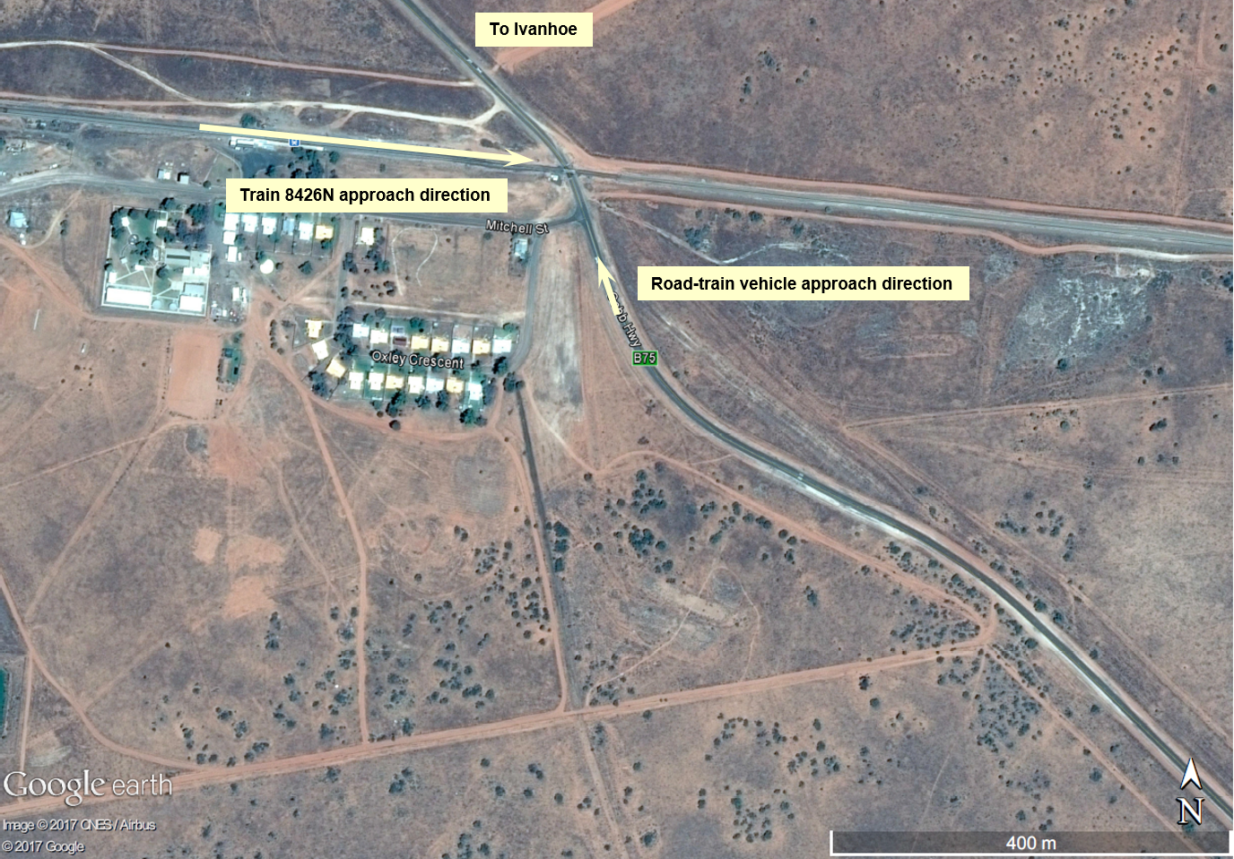
The road-train driver was negotiating a sweeping right-hand bend before the road alignment straightened toward the crossing (Figure 1). The road-train driver reported travelling at about 70 km/h approaching the crossing (the posted speed limit was 80 km/h).
Figure 1: Aerial view of Cobb Highway level crossing and road approaches
Source: Google Earth, annotated by ATSB
According to the road-train driver, he saw the flashing lights when the road-train was within 180 m of the crossing. He started to brake but assessed that the road-train might not stop in time, so accelerated to cross ahead of the train.
The train driver saw the road-train decelerate and then increase speed. The driver reported that he sounded the locomotive’s horn when it was about 190 m from the crossing. Shortly after, he saw the road-train enter the level crossing. Data from the train’s event recorder showed that about 100 m from the crossing, the train driver made an emergency brake application and activated the ‘emergency in progress’ alarm on the train radio. The train crew then relocated to the floor of the locomotive cab in preparation for a collision.
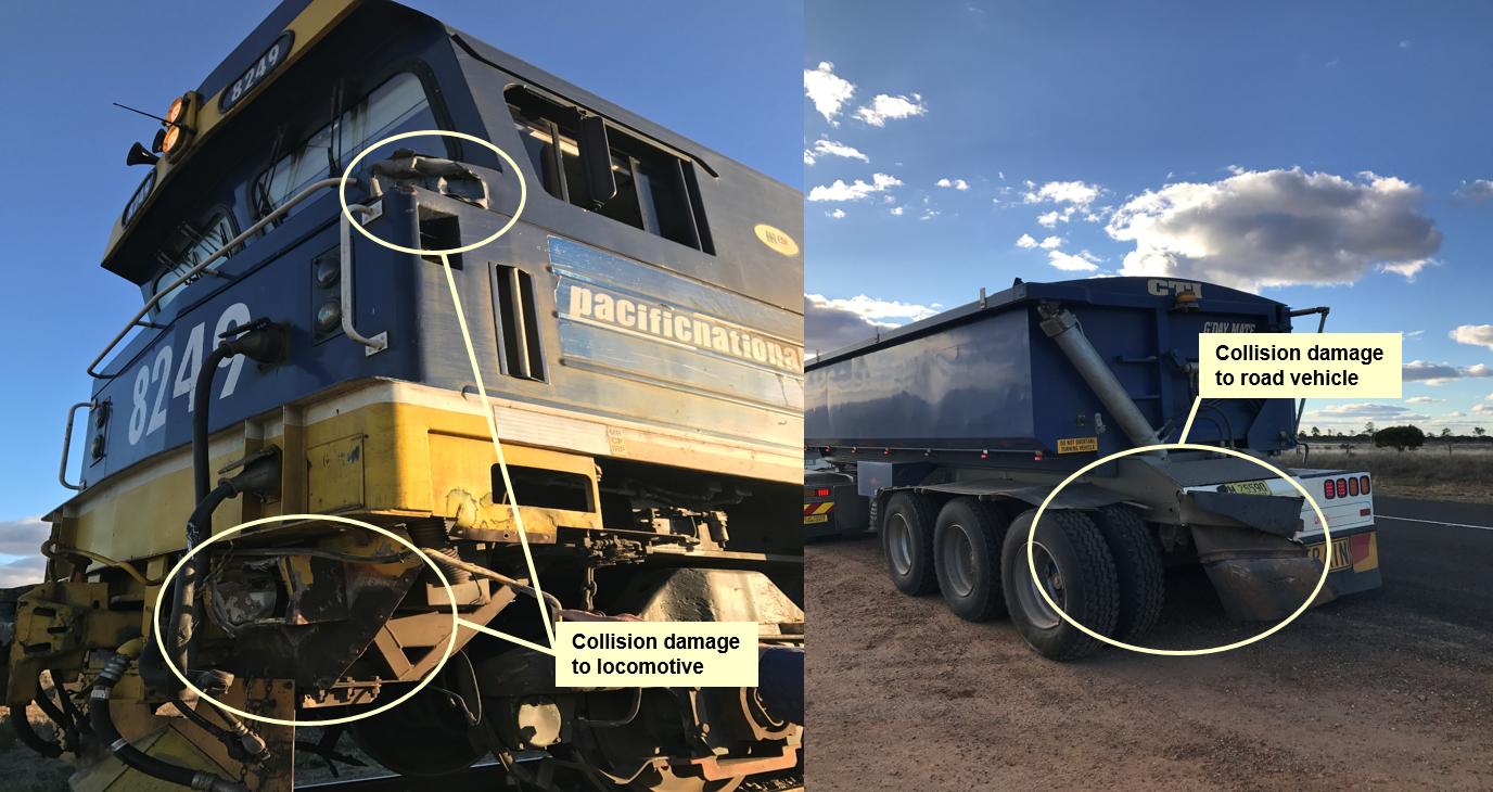
Train 8426N subsequently collided with the near side rear corner of the last trailer of the road-train (Figure 2), travelling a further 319 m before stopping. Shortly after, the train driver reported the collision to the Australian Rail Track Corporation Junee Network Control Centre. The train crew and the driver of the road-train were shaken but otherwise unhurt.
Figure 2: Collision damage to the locomotive and the last trailer of the road-train
Source: NSW Police, annotated by ATSB
Australian Standards
Australian Standard AS 1742.7:2016 Manual of uniform traffic control devices – Railway crossings prescribes the requirements for road markings, roadside signs and configuration of active traffic controls at railway crossings throughout Australia.
The traffic controls installed at the Cobb Highway railway crossing comprised flashing lights, an audible warning device (bell) as well as road surface markings and passive warning signs on the road approaches to the crossing. The active traffic controls at the Cobb Highway railway crossing were consistent with the requirements of AS 1742.7.
Australian Standard AS 1742.7:2016 required that flashing signals commence activation a minimum of 20 seconds prior to the arrival of a train. Australian Standard AS 7658:2012 Railway Infrastructure -Railway Level Crossings stipulated that flashing light warning signals commence activation a minimum of 25 seconds prior to the arrival of a train.
The intent of the two standards (when lights commence flashing) is to allow road vehicles:
to stop before entering the crossing,
if unable to stop, to traverse and clear the crossing, before a train arrives.
AS 7658:2012 – item ‘4. Track & Civil’, section 4.1 clause 2(a) and 2(b) refers to the Austroads guidelines and at clause 3(a) sight distances, obstructions, and clause 3(b) time for road vehicles to traverse and clear the railway crossing. However, there are no specific guidelines for assessing sighting distance requirements for locations with active/flashing light control, or for locations where the requirement to negotiate curved approaches creates potential for compromised driver perception.
The flashing lights at the Cobb Highway level crossing were operating for 39 s before the arrival of train 8426N at the crossing. NSW Road Rules 2014, Part 10, Section 123 stipulates that a road user must not enter a railway crossing if the warning lights (or bell) are operating.
Road-train driver
The driver of the road-train reported being very familiar with the crossing, having used it on many occasions over the previous month, including multiple times on the day of the occurrence. During this time, the driver recalled only two instances of encountering a train.
On the day of the occurrence, the driver had completed a number of trips across the Cobb Highway level crossing. He noted that when travelling in a westerly direction later in the afternoon, a combination of sun glare and dust on the prime mover’s windscreen can reduce visibility ahead.
The driver stated that the alignment of the sweeping ‘S’ bend road approach and roadside vegetation meant that sighting of the flashing lights was also restricted until the vehicle had travelled through the bend and was within 180 m from the crossing. On sighting the level crossing operating, the driver assessed that there was now insufficient distance to stop the road‑train prior to it entering the crossing.
Previous occurrences
The ATSB has investigated 28 accidents at level crossings since 2002, many involving heavy road vehicles. On 23 September 2015, a collision occurred between a road-train and grain train at a protected level crossing near Narromine, NSW. The road approach to the level crossing contained a sweeping right-hand curve. The road-train driver sustained fatal injuries in the collision. The ATSB report, RO-2015-016Collision involving road-train truck andtrain 8834N is available from the ATSB website.
The ATSB found that although the truck driver was probably travelling too fast for the prevailing conditions, the driver’s attention was probably focused on negotiating a sweeping right-hand curve that preceded the crossing, at a critical time when he needed to check for the activation of the crossing. The ATSB concluded that it was likely that when the driver perceived that the flashing lights were operating, he was too close to the crossing to stop, and collided with the train.
The ATSB identified a number of areas of potential improvement related to road design signage and standards associated with railway crossing traffic control, especially with respect to curved approaches before railway crossings. In response to the ATSB findings, Standards Australia commenced a review of AS 1742.7:2016, with respect to railway crossing approaches, in particular curved approaches, and the location signage.
Standards Australia received the project proposal for a Revised Text Amendment (RTA) to AS 1742.7:2006 in early 2017. The committee met on 9 August 2017 to initiate the project and established a working group to commence drafting the RTA. It is anticipated the standard will be published in the last quarter of 2018 subject to Standards Australia standards development process. The committee reviewed a draft of the ATSB investigation report for the 11 July 2017 occurrence and concluded there was no need to carry out any further amendment for update to AS 1742.7 beyond the scope of the current revision.
Safety analysis
The active level crossing warning equipment was consistent with the requirements of both AS 1742.7:2007 and AS 7658:2012. The driver of the road-train was traversing a sweeping bend on the approach to the Cobb Highway level crossing when he noticed the flashing lights were operating during his approach. The driver believed there was now insufficient time to stop the vehicle before entering the level crossing. He accelerated in an attempt to clear the level crossing ahead of the approaching train 8426N and avoid the potential for a collision between the prime mover or trailers and the train. However, the train collided with the rear trailer of the road-train. It is likely that one or more of the following factors affected the truck driver’s timely recognition of the flashing lights:
focus on negotiating the curved approach to the crossing
roadside vegetation
frequent use of the level crossing combined with infrequent train presence.
Findings
These findings should not be read as apportioning blame or liability to any particular organisation or individual.
It is likely that the truck driver did not look for, or sight, the activated flashing lights until relatively close to the crossing. This was probably due to one or more of: focus on negotiating the curved approach to the crossing, roadside vegetation and/or not expecting a train to be present.
On sighting the level crossing lights and approaching train, the truck driver assessed there was insufficient available distance to stop the heavily laden road-train truck before the level crossing. Consequently, the truck driver accelerated and entered the crossing while the flashing lights were operating, contrary to the New South Wales road rules.
Safety message
It is imperative that road vehicle drivers always approach railway crossings with extreme care. The level of care and attention required increases as road vehicle gross mass increases.
Although motorists are primarily responsible for avoiding a collision with a train at railway crossings, prudent road design and/or advance warning of a train’s presence at railway crossings should be considered as a strategy to lower the risk of road and rail vehicle collisions.
Road and rail authorities should consider measures to enhance the awareness of motorists approaching railway crossings, especially at locations with restricted sighting due to curved approach roads.
Decisions regarding whether to conduct an investigation, and the scope of an investigation, are based on many factors, including the level of safety benefit likely to be obtained from an investigation. For this occurrence, a limited-scope, fact-gathering investigation was conducted in order to produce a short summary report, and allow for greater industry awareness of potential safety issues and possible safety actions.
Publishing information
Released in accordance with section 25 of the Transport Safety Investigation Act 2003
Ownership of intellectual property rights in this publication
Unless otherwise noted, copyright (and any other intellectual property rights, if any) in this report publication is owned by the Commonwealth of Australia.
Creative Commons licence
With the exception of the Coat of Arms, ATSB logo, and photos and graphics in which a third party holds copyright, this publication is licensed under a Creative Commons Attribution 3.0 Australia licence.
Creative Commons Attribution 3.0 Australia Licence is a standard form licence agreement that allows you to copy, distribute, transmit and adapt this publication provided that you attribute the work.
The ATSB’s preference is that you attribute this publication (and any material sourced from it) using the following wording: Source: Australian Transport Safety Bureau
Copyright in material obtained from other agencies, private individuals or organisations, belongs to those agencies, individuals or organisations. Where you wish to use their material, you will need to contact them directly.
On March 12, 2017, at about 1015 UTC a pilot and a passenger departed on a private flight from Margate Airport (FAMG) to Light flight Airfield, Cato Ridge, South Africa in a Jabiru UL registered ZU-FIC. The pilot reported that twelve minutes into the flight the aircraft started to lose airspeed. The pilot then set the power to idle and observed the propeller detach from the engine. During the subsequent forced landing in a cane field, the right main wheel broke off. The aircraft then veered to the right and impacted an embankment at which point the nose gear collapsed. The pilot and passenger both sustained minor injuries while the aircraft sustained substantial damage. The South African Civil Aviation Authority (SACAA) commenced an investigation.
As Australia is the State of Design of the aircraft, the ATSB requested to be appointed as an accredited representative to the SACAA investigation in accordance with clause 5.18 of Annex 13 to the Convention on International Civil Aviation Aircraft Accident and Incident Investigation. An ATSB investigator was appointed as accredited representative to the SACAA. To facilitate support to the SACAA investigation, the ATSB also initiated an investigation under the Australian Transport Safety Investigation Act 2003.
The CAA have released the final report into this investigation. Any enquires relating to the investigation should be directed to the SACAA at: http://www.caa.co.za/Pages/Default.aspx
At 0901 Eastern Standard Time[1] on 14 July 2017, the Spirit of Queensland (tilt train V976) departed Cairns bound for Roma Street station in Brisbane. The train travelled largely on schedule apart from some minor delays at Tully, Townsville, Bowen Junction, Proserpine, and Mackay.
At about 0047 hours (about 8 minutes ahead of schedule) on 15 July 2017, the train approached the intersection of Denison and William Streets, Rockhampton at 21 km/h (below the posted train speed limit of 25 km/h). Both of the train’s drivers identified that the intersection and its approaches were clear. When the train was in the intersection, both drivers heard a loud bang and a jolt to the power car[2] cab. The operating driver immediately applied the brakes and the train stopped after travelling about 40 m. The driver alighted from the train and found that the train had struck a road vehicle, a white Toyota Camry (Figure 1).
Figure 1: Vehicle and train front cowling damage
Source: Queensland Rail
The train struck the driver’s side of the vehicle causing it to spin and collide with the right-hand side of the train in the direction of travel.
Shortly afterwards, the Queensland Police Service (QPS), Queensland Ambulance Service (QAS) and Queensland Fire and Emergency Services attended the scene.
There were four occupants in the vehicle, two females and two males. The three passengers were conveyed by QAS to Rockhampton Base Hospital with non-life-threatening injuries. The vehicle’s driver was breath tested by QPS and returned a reading below the blood alcohol concentration limit. The vehicle driver also underwent drug testing returning a zero reading. The QPS issued the driver of the road vehicle with a traffic infringement notice.
Both train drivers underwent a QPS breath test for alcohol at the scene, and were also tested for alcohol and other drugs by an authorised Queensland Rail (QR) tester, at Rockhampton station. All tests returned zero readings.
Road vehicle
The vehicle involved was a white, 2015 Toyota Camry rental vehicle. A suitably licensed driver was operating the vehicle. The driver did not live in Rockhampton but visited regularly for work. The driver had previously used another active level crossing over Denison Street but had never used the passive William Street intersection.
According to the driver, the vehicle’s windows were open at the time of the incident. Its occupants were actively engaged in conversation and none of them heard the train’s horn. The driver stated that the vehicle was slowed almost to a stop as it approached the intersection before accelerating to cross it. Neither the driver nor the passengers noticed the train until immediately before the collision.
Train V976
Train V976 was the QR-operated tilt train passenger service travelling from Cairns to Roma Street station, Brisbane. The train consisted of two power cars and seven passenger cars, in a push-pull configuration (that is, power car, seven passenger cars, power car). It had a gross mass of 448 t and a length of about 200 m. The train was carrying 148 passengers, with six QR on-board personnel and two drivers.
The train was fitted with a forward-facing video camera and a data event recorder. The video camera footage (Figure 2, sequential frames as identified) showed that the:
A. Train entered a clear crossing with no signs of approaching traffic.
B. Vehicle (indicated by the red arrow) entered the crossing from William Street, ahead of the approaching train.
C. Vehicle continued across the intersection.
D. Vehicle continued with no indication of slowing.
E. Vehicle moved in front of the train, just prior to impact.
F. Train collided with the right-hand side of the vehicle (the smashed glass from the vehicle sprayed over the train windshield).
The data event recorder from the train records various parameters, including time, speed, horn, and lights. The recorded data confirmed that the train’s:
speed was 21 km/h (below the limit of 25 km/h)
driver used the horn in accordance with the rules and procedures, including the approach to the William Street intersection
headlight was on and the flashing visibility lights were activated
driver reacted immediately by applying the brake.
Figure 2: Forward-facing train video camera sequential frames (red arrow shows the position of the road vehicle)
Source: Queensland Rail, annotated by ATSB
The level crossing
The level crossing at William Street, Rockhampton was a public level crossing located at the 639.805 km mark on the North Coast Line, Rockhampton. The North Coast Line at this location consisted of a single bi‑directional track, which runs between and parallel to the two vehicle carriageways on Denison Street. The designated maximum track speed was 25 km/h. There were about 28 train movements per day on this section of the track. The majority of those movements were freight.
The intersection of Denison and William Streets was a level crossing with passive controls (stop and warning signs), Figure 3. Queensland Rail defined passive control as:
Control of the movement of road vehicles or pedestrians across a crossing by signs and devices, none of which are activated by the approach of a train and rely entirely on the road user / pedestrian observing the signs and detecting the approach or passage of a train by observation.
Figure 3: The level crossing intersection (the red arrow indicates the train movement and the yellow arrow indicates the movement of the road vehicle)
Source: Google Maps
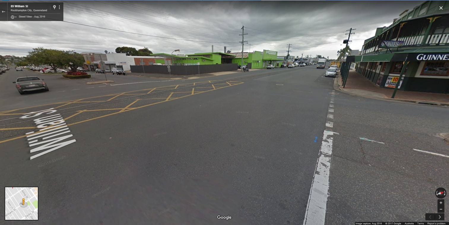
There were warning signs on William Street situated appropriately along the road in the approach to Denison Street (Figure 4). The designated speed limit on Denison Street was 50 km/h and 60 km/h on William Street. Queensland Rail found the approach signage was serviceable and appropriate.
Figure 4: Intersection signage
Source: Google Maps
Additionally, the required sighting distances met the minimum requirements for the type of protection and road rail approach speeds. The intersection of Denison and William Streets level crossing had undergone regular inspections and maintenance by QR.
Figure 5: Intersection sighting
Source: Google Maps
Previous incident
At 0225 on 23 February 2012, the southbound tilt train collided with a vehicle at the intersection of Denison and William Streets. Three occupants of the vehicle suffered non-life-threatening injuries. The circumstances of that past incident were very similar to this one in 2017.
Following that occurrence, on 22 March 2012, QR surveyed the intersection using the Australian Level Crossing Assessment Model (ALCAM). The survey identified several minor non-conformances with sighting distance and signage. Queensland Rail and the Rockhampton Region Council resolved these issues by March 2013.
Safety analysis
Level crossings are the physical interface between road and rail traffic. Both modes of transport operate as separate entities and have different rules, procedures, characteristics and operational limitations. Most importantly though, neither vehicle has advance knowledge of when the other will be encountered at the crossing.
Level crossings with active warning devices are intended to provide road users with a higher level of safety. Even at crossings with active devices (for example, flashing lights and bells), however, the warning of an approaching train is available to the motorist at, not in advance of, the crossing.
Passive control level crossings control the movement of vehicular or pedestrian traffic using signs and devices (such as Give Way and Stop signs), none of which are activated during the approach or passage of a train. These controls rely on motorists (and pedestrians) detecting the approach or presence of a train by direct observation. There are more than 6,000 passive level crossings in Australia. This type of protection is generally used where the volume of road and rail traffic makes the risk of a collision relatively low.
Stop sign traffic control is used at level crossings where the sighting distance is such that a motorist is unable to see an approaching train in time to stop before its arrival at the crossing. This traffic control method requires a motorist to stop at the crossing, visually look in both directions and, if no train is seen or heard, then safely proceed. If a train is seen or heard, the motorist must remain stationary at the Stop sign until it is safe to proceed. Motorists are required to have this knowledge for a driver’s license and drivers encounter Stop signs routinely and follow the same process of stop, check, and wait/go. Despite that requirement, there have been many accidents at Stop sign-protected crossings because of the motorist’s failure to stop.
Findings
These findings should not be read as apportioning blame or liability to any particular organisation or individual.
The driver of the road vehicle did not see or hear train V976 approaching the level crossing and drove in front of the train immediately before the collision.
Safety action
Whether or not the ATSB identifies safety issues in the course of an investigation, relevant organisations may proactively initiate safety action in order to reduce their safety risk. The ATSB has been advised of the following proactive safety action in response to this occurrence.
Queensland Rail
Queensland Rail has advised the ATSB that the Manager, Road Rail Interface will conduct a review of the level crossing at the intersection of Denison and Williams Streets, Rockhampton.
Safety message
This incident is a reminder that all road vehicle drivers using railway level crossings equipped with passive controls need to be vigilant, observe road-warning signs, obey road rules and look out for trains.
The objective of a safety investigation is to enhance transport safety. This is done through:
identifying safety issues and facilitating safety action to address those issues
providing information about occurrences and their associated safety factors to facilitate learning within the transport industry.
It is not a function of the ATSB to apportion blame or provide a means for determining liability. At the same time, an investigation report must include factual material of sufficient weight to support the analysis and findings. At all times the ATSB endeavours to balance the use of material that could imply adverse comment with the need to properly explain what happened, and why, in a fair and unbiased manner. The ATSB does not investigate for the purpose of taking administrative, regulatory or criminal action.
Terminology
An explanation of terminology used in ATSB investigation reports is available here. This includes terms such as occurrence, contributing factor, other factor that increased risk, and safety issue.
Publishing information
Released in accordance with section 25 of the Transport Safety Investigation Act 2003
Ownership of intellectual property rights in this publication
Unless otherwise noted, copyright (and any other intellectual property rights, if any) in this report publication is owned by the Commonwealth of Australia.
Creative Commons licence
With the exception of the Coat of Arms, ATSB logo, and photos and graphics in which a third party holds copyright, this publication is licensed under a Creative Commons Attribution 3.0 Australia licence.
Creative Commons Attribution 3.0 Australia Licence is a standard form licence agreement that allows you to copy, distribute, transmit and adapt this publication provided that you attribute the work.
The ATSB’s preference is that you attribute this publication (and any material sourced from it) using the following wording: Source: Australian Transport Safety Bureau
Copyright in material obtained from other agencies, private individuals or organisations, belongs to those agencies, individuals or organisations. Where you wish to use their material, you will need to contact them directly.
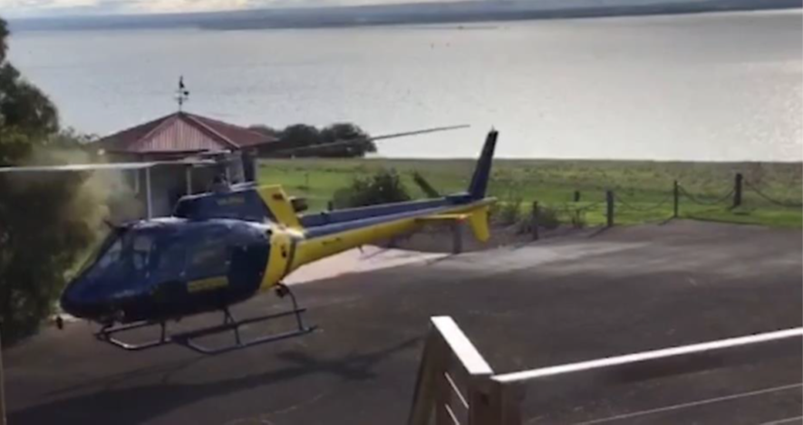
On 4 July 2017, a Eurocopter AS350-BA helicopter, registered VH-PHU and operated by Professional Helicopter Services, was chartered to conduct a flight between Moorabbin Airport and the Jack Rabbit Vineyard helicopter landing site (HLS)[1],[2] on the Bellarine Peninsula, Victoria. At about 1415 Eastern Standard Time,[3] while landing at the HLS, the tips of the helicopter’s main rotor blades struck an encroaching bush (Figure 1).
Figure 1: Smart phone footage of the main rotor blade tip strike (into bush)
Source: Allister Gleeson
History of the flight
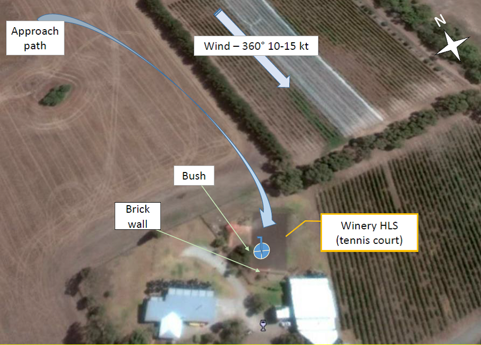
At about 1310, the pilot volunteered at short notice to conduct the charter flight to the Jack Rabbit Vineyard. As the pilot had not previously flown to this HLS (a tennis court), he discussed the landing site with another experienced company pilot. Their discussions included consulting Google earth and ascertaining the safest way in and out of the landing site (Figure 2). The pilot also spoke with staff at the vineyard to inform them of his planned arrival and, at their request, confirmed that he would make his approach from the north, so as not to overfly the vines.
At about 1340, the flight departed Moorabbin Airport about 40 minutes later than originally planned. With two passengers on board, the pilot flew south for a scenic coastal flight via Port Phillip Heads, to the Bellarine Peninsula. The reported weather for the flight was for visibility greater than 10 km and a northerly wind at 10-15 kt.
On arrival, the pilot recognised the features of the HLS from his pre-flight planning and conducted a north-to-south, downwind approach,[4] which was appropriate for the conditions on the day.
During the approach, the pilot identified the key boundaries of the landing site, which included a brick wall at the southern end of the site, but he did not see a large bush that encroached into the HLS. When established in the HLS, and believing that he had to make way for another helicopter, the pilot slowly hover-taxied the helicopter forward towards the south‑west corner of the landing site. During this, the pilot reported that he remained focused on the brick wall ahead (Figure 2).
Figure 2: Jack Rabbit Vineyard HLS
Source: Google Maps, modified by the ATSB
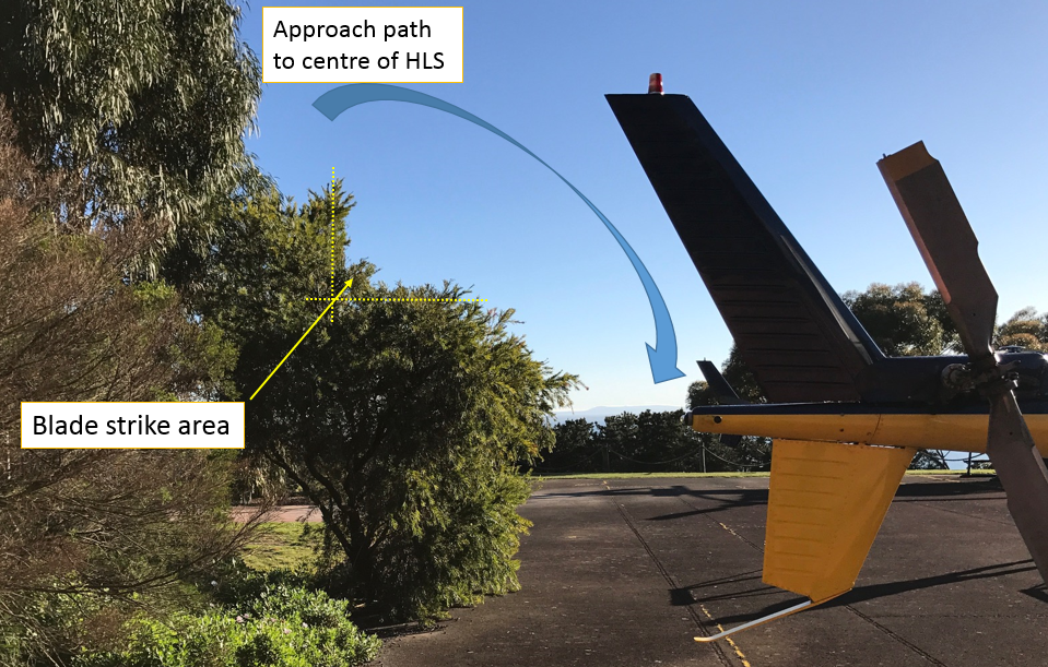
At about 1415, the tips of the helicopter’s main rotor blades struck the encroaching bush (now on the helicopter’s right side) (Figure 3). The pilot initially landed the helicopter, then soon after repositioned clear of the bush.
Figure 3: Encroaching bush in the HLS and the main rotor blade strike area
Source: Operator, modified by the ATSB
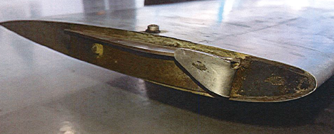
The helicopter was subsequently shut down and secured without further incident. There were no injuries. All three of the helicopter’s main rotor blade tip caps were found damaged (Figure 4). The sequence of the incident was captured on a smart phone and subsequently reviewed by the ATSB.
Figure 4: Damage to VH-PHU rotor tip caps
Source: Operator
Pilot comments
Aware of the operator’s mantra to ‘not let commercial pressures influence the way you fly’, the pilot was content to fly the charter and felt adequately prepared for the flight. However, the pilot reported that, as the HLS was easily recognisable from his pre-flight planning and due to over‑confidence, he elected to abbreviate the usual 360° reconnaissance[5] of the site. Instead, he conducted a sweeping 270° turn about the HLS, prior to his downwind approach into the landing site. The approach to the centre of the HLS was as anticipated.
Before manoeuvring within the HLS, the pilot ensured that the area around the helicopter was free of obstacles, but acknowledged that he did not notice the bush and how far it encroached into the landing site. The pilot commented that he was focusing on the brick wall as he moved forward and had discounted the right side of the helicopter.
Operator’s investigation
Professional Helicopter Services conducted an internal investigation into the incident and concluded the following:
The pilot lost situational awareness from focussing on the brick wall during the final stages of the landing sequence and did not ensure adequate clearance from obstacles on the right side of the helicopter.
The pilot, having recently been cleared to fly advanced manoeuvres, may have felt ‘overconfident’ in his general flying abilities at the time of the incident.
The operator was not aware that the pilot had not previously landed at the HLS.
The pilot had mistakenly believed that another helicopter was also required to use the HLS, which was his motivation to hover-taxi.
Safety analysis
The pilot’s confidence in his abilities influenced his decision to conduct an abbreviated reconnaissance of the HLS. This removed an opportunity to observe the encroaching bush. This, combined with the pilot’s focus of attention on the brick wall in front of the helicopter when landing, meant that he was not aware of the bush to his right.
Further, the pilot believed that another helicopter was also landing at the HLS and he elected to hover-taxi to the south-west corner of the site to provide room for that helicopter. However, as the pilot was not aware of the encroaching bush when conducting this manoeuvre, the helicopter’s main rotor blades struck the bush.
Findings
The findings should not be read as apportioning blame or liability to any particular organisation or individual.
An abbreviated reconnaissance of the helicopter landing site, along with a focus of attention on other obstacles within proximity, resulted in the pilot not being aware of a bush encroaching the helicopter landing site and the helicopter’s main rotor blades striking the bush.
Safety action
Whether or not the ATSB identifies safety issues in the course of an investigation, relevant organisations may proactively initiate safety action(s) in order to manage and mitigate their safety risk. The ATSB has been advised of the following safety actions in response to this occurrence.
Professional Helicopter Services
As a result of this incident, the operator has advised the ATSB that they have taken the following safety actions:
reviewed internal flight tasking processes
updated and upgraded internally provided HLS documentation, and provided this information electronically (iPad)
learning outcomes from this incident are to be incorporated into future practices and disseminated to all pilots and aircrew.
Safety message
This incident highlights the need for a heightened situational awareness by pilots when operating in the vicinity of obstacles as there is very little or no margin to recover from any unexpected event(s). This is particularly important when operating into a confined area and unfamiliar location.
Decisions regarding whether to conduct an investigation, and the scope of an investigation, are based on many factors, including the level of safety benefit likely to be obtained from an investigation. For this occurrence, a limited-scope, fact-gathering investigation was conducted in order to produce a short summary report, and allow for greater industry awareness of potential safety issues and possible safety actions.
Publishing information
Released in accordance with section 25 of the Transport Safety Investigation Act 2003
Ownership of intellectual property rights in this publication
Unless otherwise noted, copyright (and any other intellectual property rights, if any) in this report publication is owned by the Commonwealth of Australia.
Creative Commons licence
With the exception of the Coat of Arms, ATSB logo, and photos and graphics in which a third party holds copyright, this publication is licensed under a Creative Commons Attribution 3.0 Australia licence.
Creative Commons Attribution 3.0 Australia Licence is a standard form licence agreement that allows you to copy, distribute, transmit and adapt this publication provided that you attribute the work.
The ATSB’s preference is that you attribute this publication (and any material sourced from it) using the following wording: Source: Australian Transport Safety Bureau
Copyright in material obtained from other agencies, private individuals or organisations, belongs to those agencies, individuals or organisations. Where you wish to use their material, you will need to contact them directly.
Section 21 (2) of the Transport Safety Investigation Act 2003 (TSI Act) empowers the Australian Transport Safety Bureau (ATSB) to discontinue an investigation into a transport safety matter at any time. Section 21 (3) of the TSI Act requires the ATSB to publish a statement setting out the reasons for discontinuing an investigation.
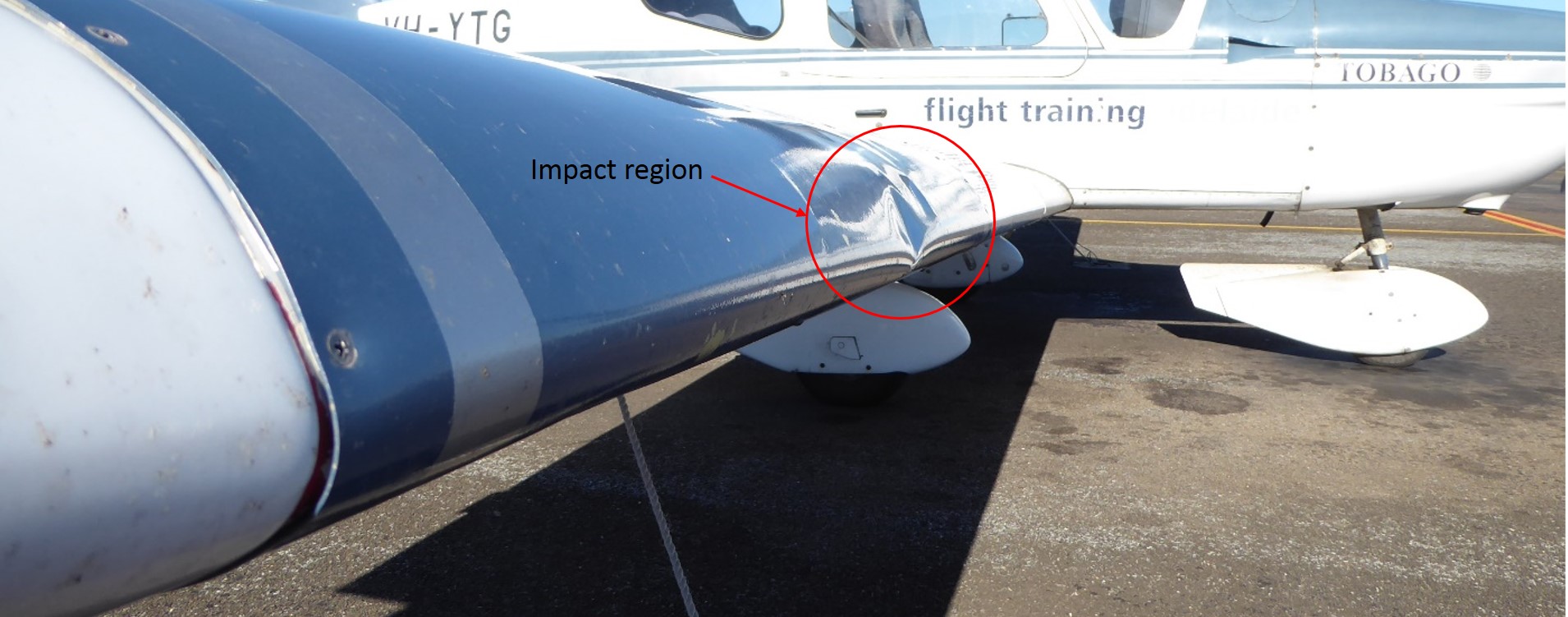
At about 1800 Central Standard Time[1] on 11 July 2017, a SOCATA TB-10 Tobago aircraft, registered VH-YTG, was conducting a scheduled night flying lesson at Parafield airport, near Adelaide, South Australia. On final approach and at about 500 ft above ground level, the aircraft’s right wing struck an object. The instructor heard a loud thud and the right wing suddenly dropped. He radioed the control tower requesting a full stop landing, as they might have hit a bird.
After landing, the instructor conducted an inspection of the aircraft and found minor damage to the right wing. As there were no visible signs of biological matter, he contacted the control tower and reported the incident as a possible drone strike.
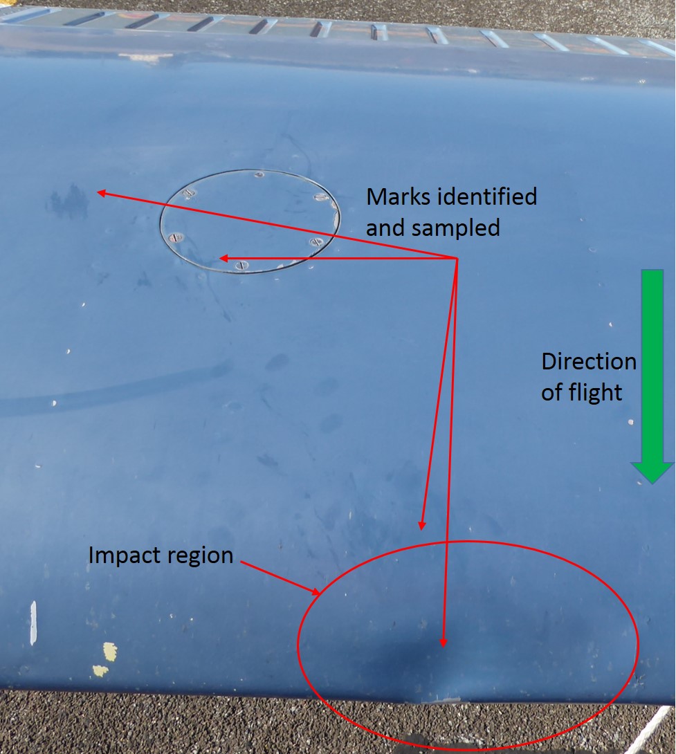
Figure 1: VH-YTG showing damage
Source: ATSB
Figure 2: Overhead image highlighting identified surface marks
Source: ATSB
The ATSB conducted an inspection of the aircraft, and swab samples of the impact area were taken by the airport operator, and sent to the Australian Museum for DNA testing. The subsequent DNA test results indicated the sample was most consistent with that of a grey-headed flying-fox, from the bat family.
The ATSB has assessed that there is little potential for the enhancement of transport safety through further investigation of this occurrence. The ATSB has discontinued the investigation.
On 28 June 2017, the pilot of a SOCATA TB-10 Tobago aircraft, registered VH-YTM, was conducting a community service flight from Mount Gambier Airport, South Australia, to Adelaide, South Australia. The flight was organised by the charity Angel Flight to transport a passenger for medical treatment and an accompanying family member. The aircraft took off at 1020 Central Standard Time as a private flight operating under visual flight rules. After reaching a height of 300 ft, the aircraft descended and impacted terrain about 70 seconds after take-off. The pilot and both passengers were fatally injured, and the aircraft was destroyed.
What the ATSB found
The ATSB found that the pilot took off in low-level cloud without proficiency for flight in instrument meteorological conditions. Shortly after take-off, the pilot likely lost visual cues and probably became spatially disorientated, resulting in loss of control of the aircraft and collision with terrain.
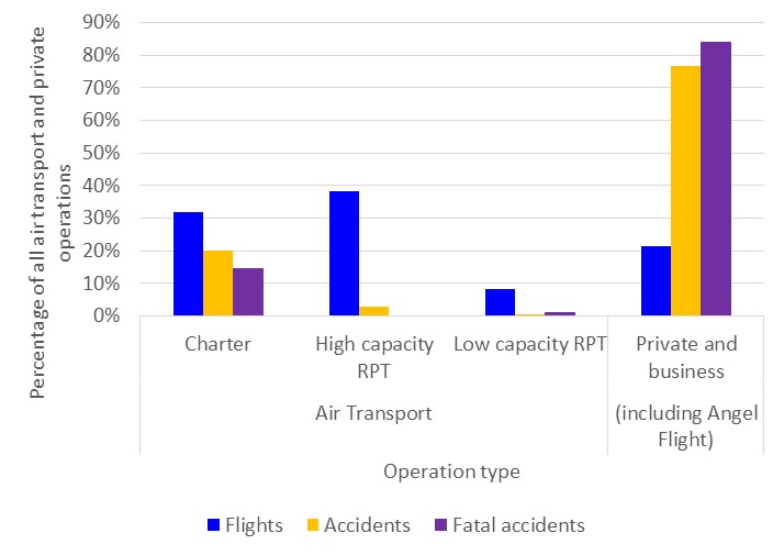
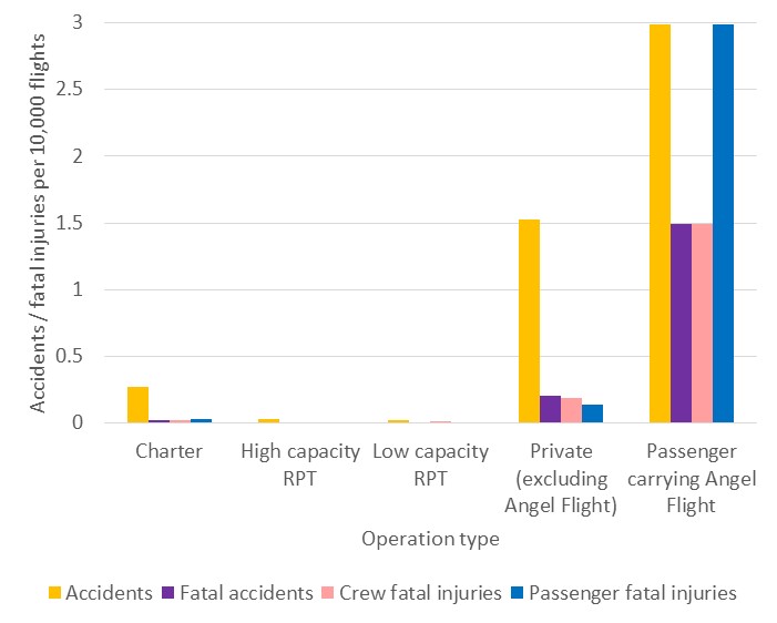
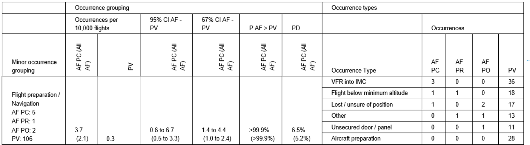
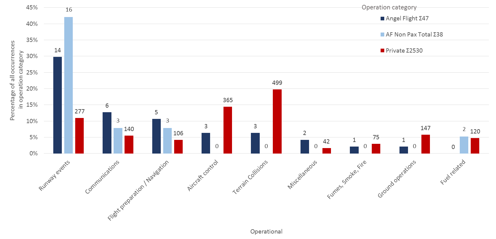
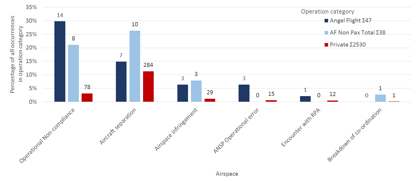
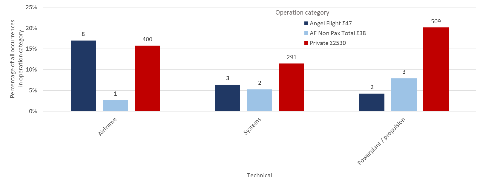
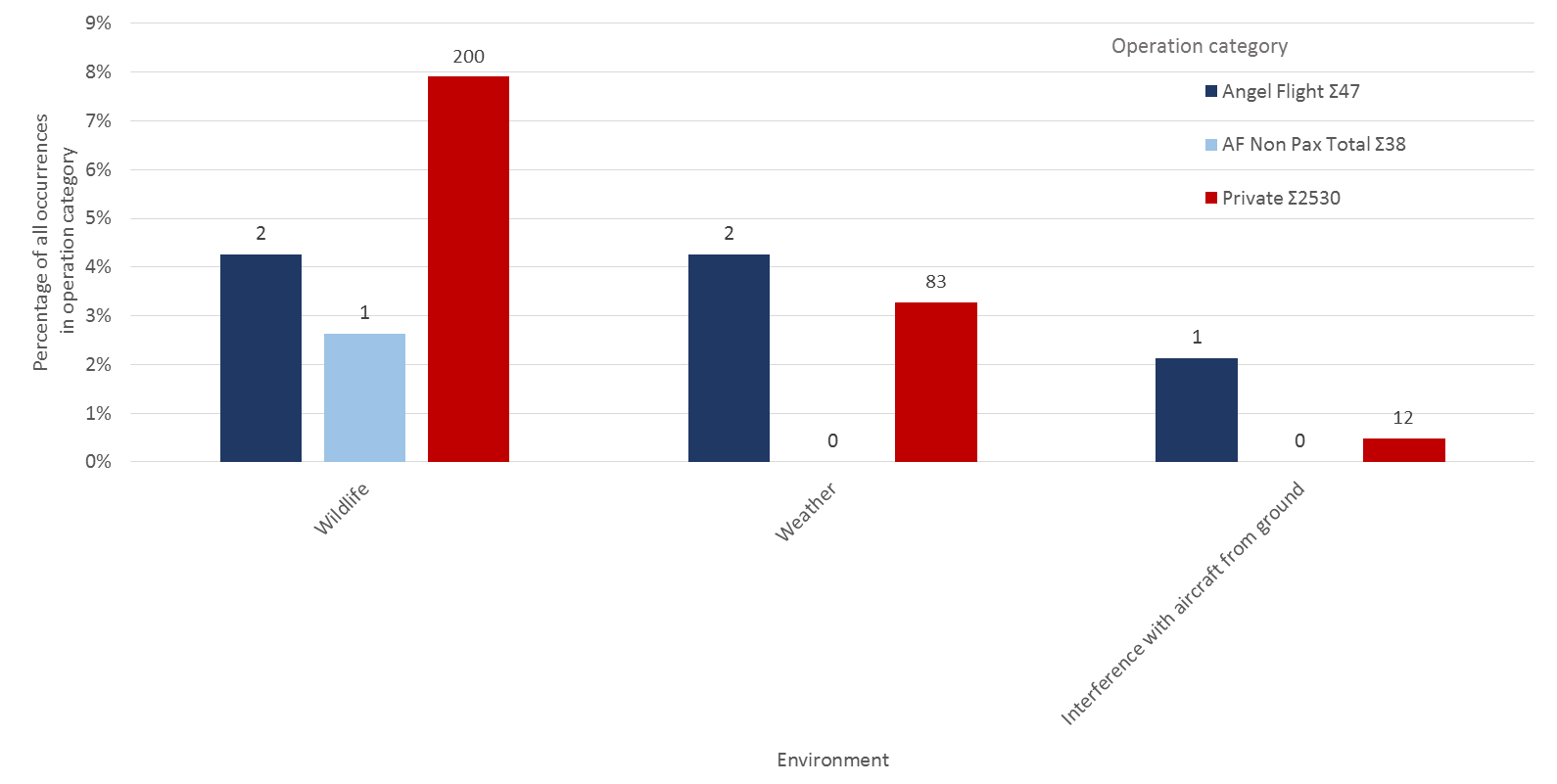
The ATSB has previously established that the fatal accident rate of private operations is substantially higher than commercial passenger transport (eight times higher than charter and 27 times higher than low-capacity regular public transport, with no fatal accidents on high capacity RPT). This ATSB investigation further established that community service flights conducted on behalf of Angel Flight Australia (Angel Flight) had substantially more occurrences, accidents and fatal accidents per flight than other private operations (including that the fatal accident rate was more than seven times higher per flight than other private flights).
It is almost certain this higher occurrence rate is due to community service flights being exposed to different operational risk factors when compared to other private operations. The ATSB found two aspects in particular likely contributed to this higher rate. These were the potential for some pilots to experience perceived or self-induced pressure by taking on the responsibility to fly ill, unknown passengers, at scheduled times to meet predetermined medical appointments, often with an expected same day return; and the required operation to unfamiliar locations, and limited familiarity with procedures in controlled airspace (associated with larger aerodromes). These factors were consistent with lessons learned from the US experience, the occurrence data analysis of Angel Flight organised flights, and submissions made to a Civil Aviation Safety Authority (CASA) public consultation on changes to community service flights.
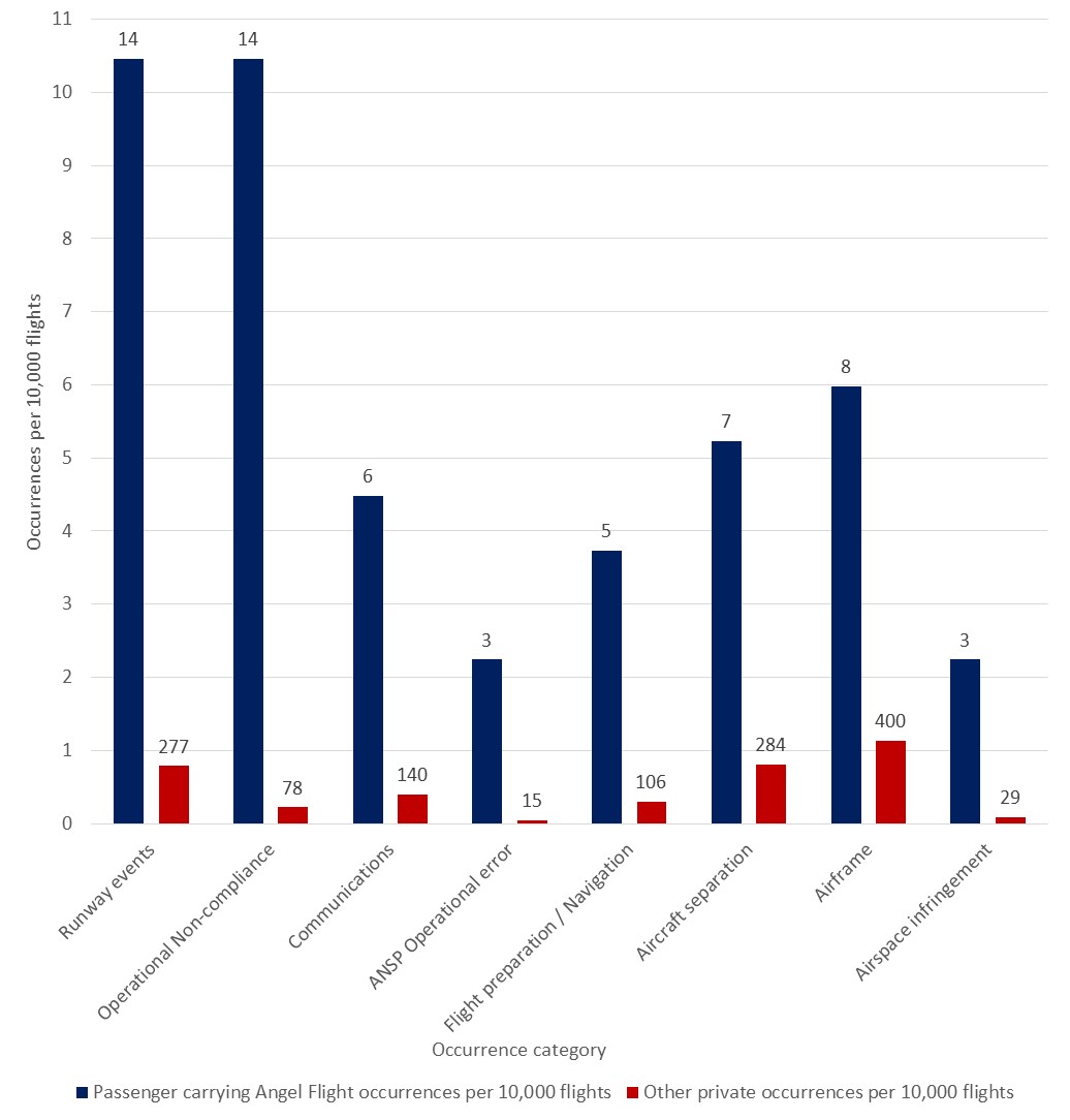
The types of occurrences where flights organised by Angel Flight were statistically over-represented (as a rate per flight) compared to other private operations were consistent with these operational differences. In particular, occurrences which involved pre- and in-flight planning and decision-making errors were over-represented, which was a factor in this accident as well as in a previous fatal accident in 2011 which involved an Angel Flight organised passenger flight. The higher occurrence rate in particular types of occurrences indicated an elevated and different risk profile in Angel Flight organised private community service flights compared with other private operations.
Angel Flight had insufficient controls in place, and provided inadequate guidance to pilots for addressing the additional operational risks associated with community service flights. Furthermore, the ATSB found that there were limited opportunities for Angel Flight to be made aware of any safety related information involving flights conducted on its behalf, restricting its ability to identify and manage organisational risks.
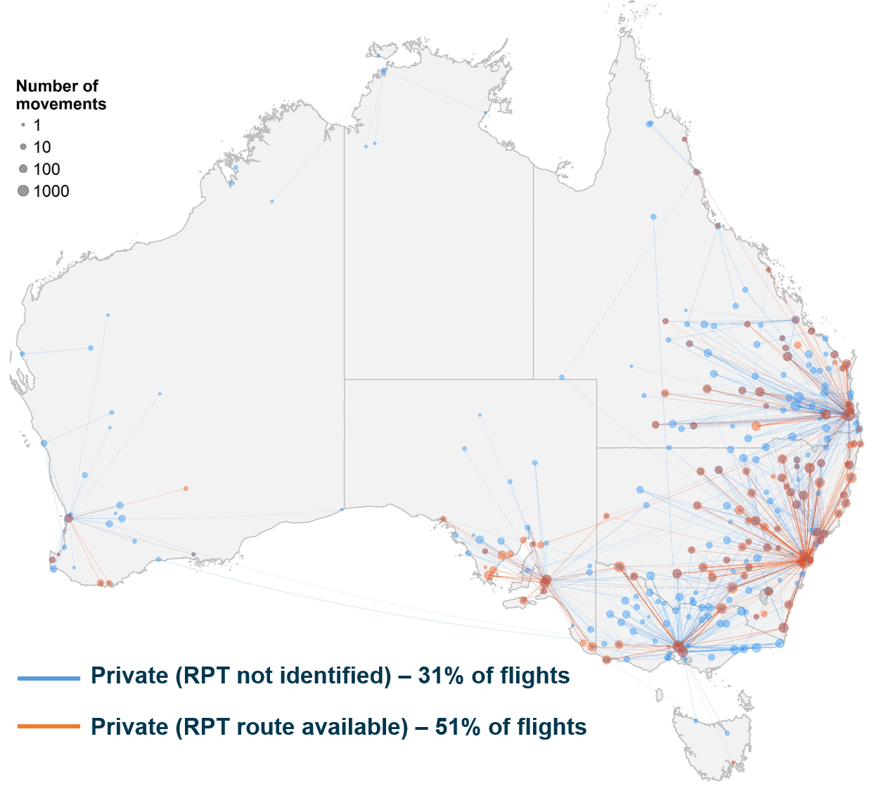
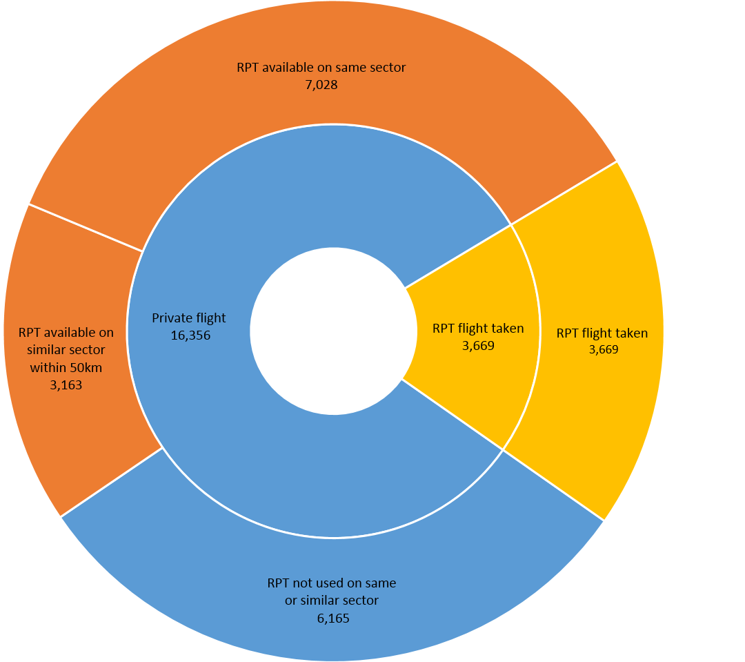
It was identified that Angel Flight did not consider the safety benefits of commercial flights when suitable flights were available. While Angel Flight arranged and paid for commercial flights (18 per cent of all flights) for capital city transfers, or when private pilots cancelled, it was estimated that nearly two-thirds of the private flights conducted for Angel Flight had a commercial regular public transport option available, which offered considerable safety benefits when compared to private operations. Of these, at least 22 per cent had suitable same day return flights four or five days a week, with at least two-thirds of these regular public transport flights being of comparable cost to Angel Flight when compared with the volunteer costs. The ATSB acknowledges that there will be passengers who cannot travel on regular public transport flights, and that there are times and locations where this option is not available or suitable. However, Angel Flight should still consider the use of suitable commercial flights as a primary option when arranging and paying for flights to assist financially disadvantaged people. On the day of the accident, suitable and cost-comparative commercial passenger flights were available.
CASA did not have a system to differentiate between community service flights and other private operations that would allow for ongoing oversight and review of the safety of these flights. Differentiation would allow for the identification of areas of specific concern through evidence-based analysis, and consideration of appropriate risk controls to be applied to all organisations offering community service flights. The lack of this differentiation limited CASA’s ability to identify and manage risks associated with community service flights.
What's been done as a result
Angel Flight Australia advised it had received permission for all registered pilots to access the community service pilot education online course Public Benefit Flying: Balancing safety and compassion, developed in the United States by the Aircraft Owners and Pilots Association Foundation’s Air Safety Institute, while an Australian course is developed. It also indicated it was facilitating the sharing of all CASA safety seminar schedules, with a request for feedback on attendance and the content presented, and engaging a volunteer to develop systems and processes to manage its safety risks. Additionally, pilot, passenger and health referrer guidelines had also been updated. The ATSB will monitor the progress of these safety actions.
The ATSB has issued a safety recommendation to Angel Flight Australia to take action to consider the safety benefits of using commercial flights where they are available to transport its passengers.
The ATSB was advised CASA had implemented a new safety standard regarding the conduct of community service flights. These requirements commenced on 19 March 2019 and included:
A flight notification (full flight notification or SARTIME) that identifies the flight as a community service flight to be submitted to Airservices Australia.
Pilots to annotate that the flight conducted was a community service flight in their personal logbook.
These changes will allow CASA to conduct ongoing identification and monitoring of risks associated with community service flights to be able to manage and control those risks.
CASA has also promoted its updated human factors education package to the industry broadly, including the community service flight sector, and refers to it on the community service flight landing page on its website. CASA also intends to release targeted guidance information to further assist the community service flight sector in the coming months.
Safety message
Organisations conducting community service flights and their pilots should be aware of the additional operational risks present. It is important that organisations have appropriate operational controls in place, and ensure pilots have access to guidance and education regarding the risks, to enable them to make objective decisions.
The occurrence
On 28 June 2017 at about 0800 Central Standard Time,[1] the pilot of a SOCATA TB-10 aircraft, registered VH-YTM (YTM), departed Murray Bridge Airport, South Australia (SA), for Mount Gambier Airport, SA. The charity Angel Flight Australia (Angel Flight) had arranged for the pilot to conduct a private flight for two passengers from Mount Gambier Airport at 1000, to facilitate the passengers’ access to specialist medical services in Adelaide, SA. Both trips were conducted as private flights under the visual flight rules (VFR).[2]
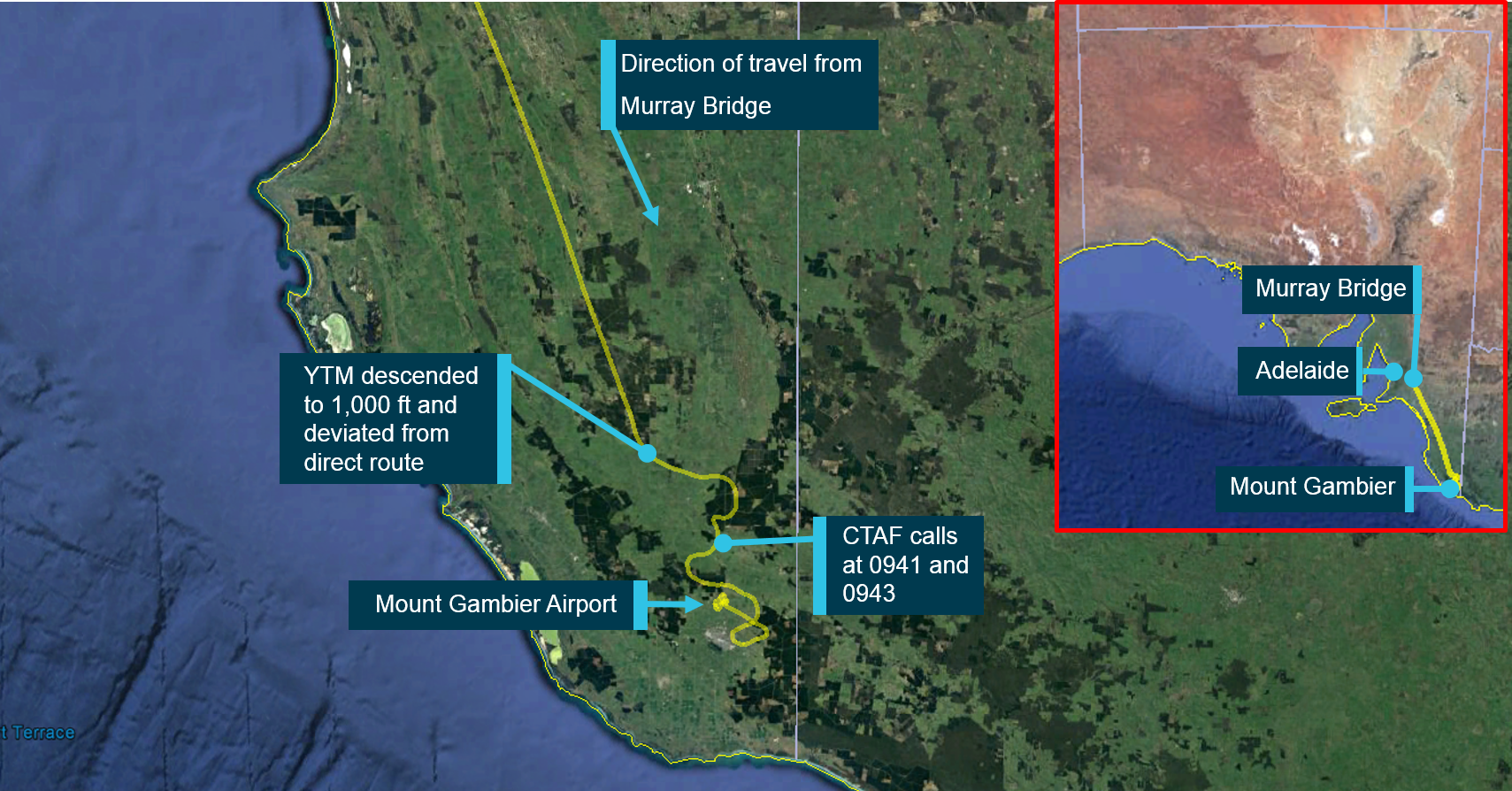
Position and altitude information obtained from OzRunways[3] showed that the aircraft initially tracked directly from Murray Bridge toward Mount Gambier, at an altitude of about 4,500 ft above mean sea level (AMSL). About 23 NM north-north-west of Mount Gambier Airport, the aircraft descended to approximately 1,000 ft AMSL and there was a significant deviation from the direct route (Figure 1).
Figure 1: Track of VH-YTM approaching Mount Gambier Airport from Murray Bridge, the track deviation and approximate locations when initial CTAF calls were made, and inset, a map of South Australia showing the relative positions of Adelaide, Murray Bridge and Mount Gambier
Source: Google Earth and OzRunways, annotated by ATSB
At 0941, the pilot of YTM broadcast on the common traffic advisory frequency (CTAF)[4] that the aircraft was 7 NM from the aerodrome at an altitude of 1,000 ft. This was followed by a second broadcast 2 minutes later, about 5 NM to the north-west of the aerodrome in which the pilot requested the cloud base over the airport. The pilot of an aircraft operating under the instrument flight rules (IFR)[5] that was taxiing out at Mount Gambier Airport, responded that the ‘cloud base is at the minima…we’re departing out to the east where it’s a bit clearer…it’s fairly well fogged in to the west and to the south…you should get in.’ The pilot of YTM replied to this asking the pilot to confirm that he could get in from the south or west, and the pilot of the IFR aircraft indicated possible better visibility to the north-west.
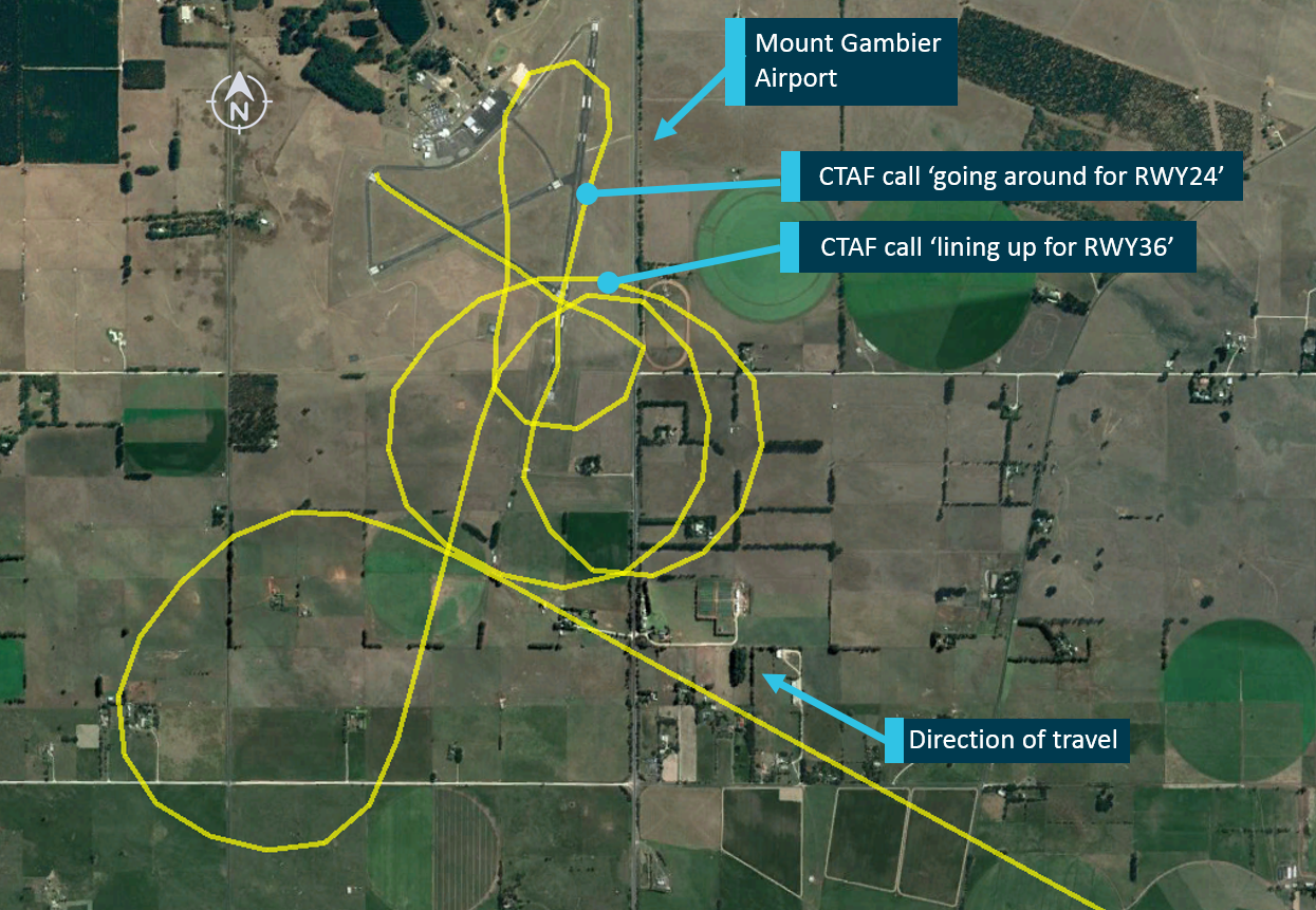
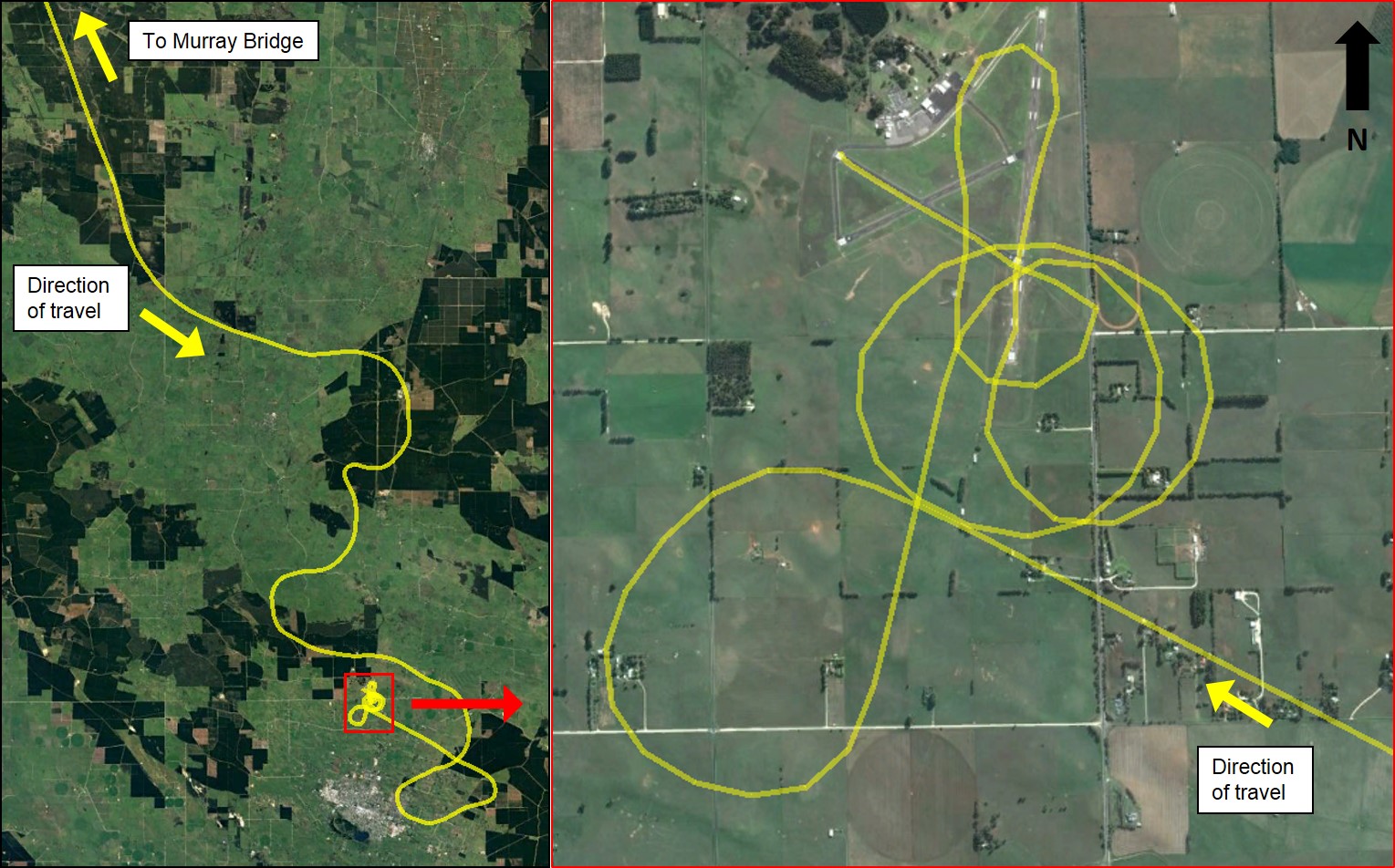
After approaching the airport from the south-east, the aircraft made several manoeuvres at a low height, including a series of turns at about 200 ft above ground level (AGL) (Figure 2). Witnesses near the airport reported hearing an aircraft, but due to the low, thick cloud, the aircraft was not visible.
At 1003, as YTM passed over the top of runway 36 in a westerly direction, the pilot made a CTAF broadcast ‘lining up for 36’, indicating that he intended to land on runway 36. Witnesses reported that the pilot then conducted a go around after initially touching down on runway 36, and witnesses reported then seeing the aircraft climb back into cloud. The pilot then broadcast on the CTAF ‘going around for runway 24’. After another two low-level turns over the airport, in which the aircraft was captured emerging from the cloud on closed‑circuit television (CCTV) at low altitude, the aircraft landed on runway 29 at about 1008.
Figure 2: Track of YTM approaching Mount Gambier Airport, low-level manoeuvres, and location of CTAF calls
Source: Google Earth and OzRunways, annotated by ATSB
The pilot then boarded the two passengers to conduct the flight to Adelaide. The pilot broadcast that he was lined up and rolling on runway 24, and the aircraft took off from Mount Gambier Airport at 1020, approximately 20 minutes later than the intended departure time. At the time YTM departed, CCTV footage and Bureau of Meteorology (BoM) live weather cameras showed the presence of low cloud and reduced visibility conditions.
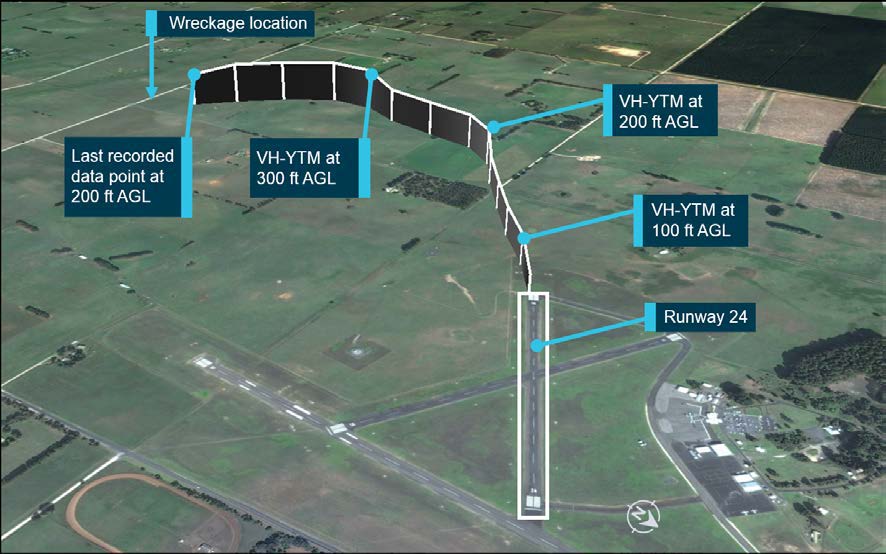
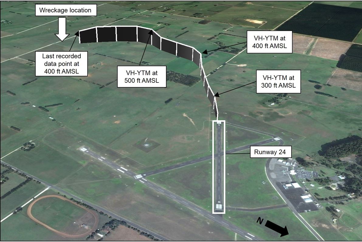
The OzRunways data showed that, just after take-off at an altitude of about 100 ft AGL, YTM’s track veered slightly to the left of the runway. The aircraft reached a maximum altitude of about 300 ft AGL, 45 seconds after take-off. The last recorded position, about 65 seconds after take-off, showed the aircraft at an altitude of 200 ft AGL (Figure 3). Soon after, the aircraft impacted terrain. A number of witnesses heard a loud bang, consistent with the ground impact.
Figure 3: Flight path of VH-YTM after departing runway 24 at Mount Gambier Airport. Each vertical line represents 5 seconds
Source: Google Earth and OzRunways, annotated by ATSB
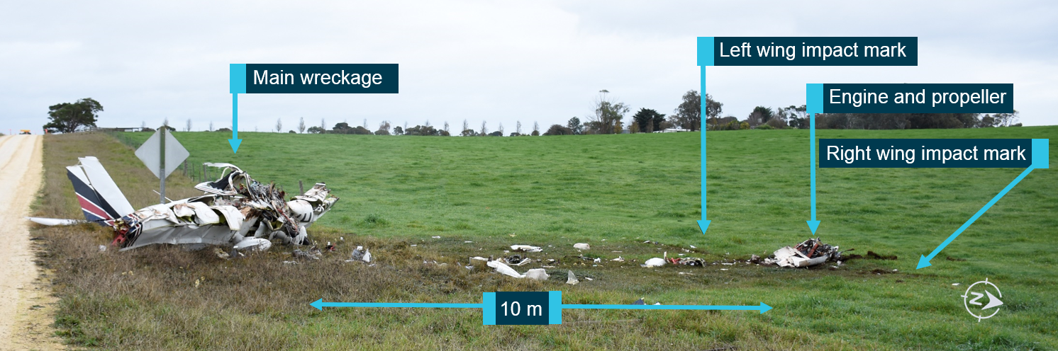
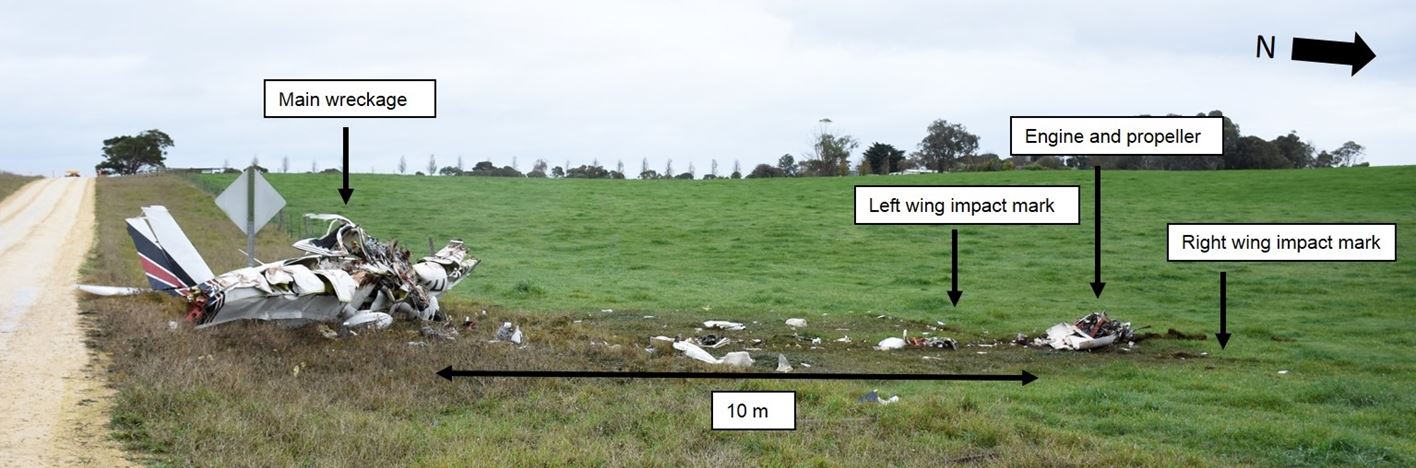
The aircraft wreckage was located just over 200 m south of the last recorded position, approximately 2 km from the departure runway (Figure 3). Minutes after impact the aircraft was found by witnesses passing the accident site (Figure 4), and emergency services responded to the scene shortly thereafter. The pilot and two passengers were fatally injured, and the aircraft was destroyed.
Figure 4: Accident site, showing the engine and propeller location, the left- and right-wing impact marks and the main wreckage
The pilot obtained a Private Pilot (Aeroplane) Licence in December 2014, and held the appropriate aircraft endorsements required to operate YTM. His logbook showed a total aeronautical experience of approximately 530 hours. In the 90 days prior to the accident flight, he had conducted the three take-offs and landings required by Civil Aviation Safety Regulation (CASR) 61.395 to permit the carriage of passengers. At the time of the accident, he held a valid Class 2 Aviation Medical Certificate renewed on 6 June 2017. This included a requirement for reading vision correction to be available while exercising the privileges of the licence.
The pilot commenced training for a Night Visual Flight Rules (VFR) rating in December 2015; this included about 3.5 hours recorded as instrument flight time. The pilot completed a total of 12 hours of training in flight under night VFR between December 2015 and May 2016, however he did not obtain this qualification. The pilot did not hold an instrument rating and his logbook recorded a total of 7 hours of instrument flight time, the latest of which was 0.1 hours in simulated flight conditions during an aeroplane flight review on 29 November 2016.
The ATSB assessed whether the pilot may have been experiencing a level of fatigue known to have an effect on performance. Consideration was made of the pilot’s sleep obtained, time awake at the time of the occurrence, time on task, potential workload and environmental factors. Based on the available evidence, the pilot was very unlikely to have been experiencing a level of fatigue known to affect performance.
Medical and pathological information
The pilot’s medical records, postmortem examination and toxicological analysis identified no acute or pre-existing medical conditions that may have contributed to the accident.
Aircraft information
General
YTM was a SOCATA TB-10 five-seat, low-wing, all-metal, unpressurised aircraft designed and manufactured in France, with a fixed undercarriage. Power was provided by a Lycoming O-360-A1AD four-cylinder piston engine, rated at 180 horsepower, through a McCauley three-bladed constant-speed propeller.[6]
Maintenance release
The aircraft maintenance release was issued on 4 May 2017 for 12 months or 100 hours flight time, whichever occurred first. The aircraft had flown for approximately 44 hours since the maintenance release at the time of the accident. The maintenance release was issued in the IFR category[7] and the aircraft was appropriately equipped. The documentation did not identify any unserviceable equipment or defects at the time of the accident.
The maintenance release indicated that a ‘portable emergency locator transmitter’ was required to be carried to satisfy the requirements of Civil Aviation Regulation (CAR) 252A requiring the installation of a 406 MHz emergency locator transmitter. A personal locator beacon was found in the cockpit, but had not been activated. The aircraft was not fitted with a flight data recorder or cockpit voice recorder; nor were either required.
Weight and balance
Seating positions, and approximate passenger and baggage weight were known at the time of the accident. From this information, and taking into account any fuel loading, it was calculated that the aircraft’s centre of gravity would have been within the manufacturer’s permitted range when departing Mount Gambier Airport. The aircraft weight was also calculated to be below the maximum take-off weight at the time of the accident.
Wreckage and impact information
Ground scars and evidence from the wreckage indicated that the aircraft impacted the ground nose down in an inverted attitude, approximately 30° from vertical, and that the engine was producing power at the time of impact. A strong smell and presence of fuel was evident at the accident site, however, there was no evidence of a pre- or post-impact fire. The impact sequence was not survivable.
On-site examination of the wreckage established continuity of all flight controls, and that all of the primary structural components were in the immediate area of the accident site. No pre-impact damage or failure of the primary structural components or the aircraft flight control system were identified.
A number of instruments and other components were recovered from the accident site for further technical examination at the ATSB facilities in Canberra. It was determined that there was no pre‑impact damage or failure of any of the components.
Carburettor icing
The conditions recorded at Mount Gambier Airport at the time of the accident were applied to a Civil Aviation Safety Authority (CASA) carburettor icing probability chart. Based on this chart, the probability of carburettor icing at any power setting was serious.
Due to accident damage, the carburettor heat control settings could not be determined. However, the recorded flight path, witness statements, the impact sequence, ground markings and wreckage analysis indicated the engine was performing normally before the accident. It was therefore concluded that carburettor icing was not a factor.
Airport information
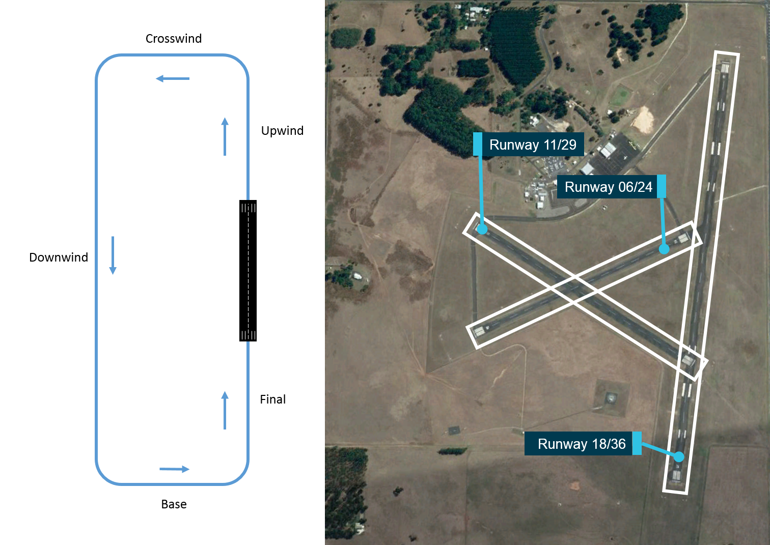
Mount Gambier Airport is located about 8 km to the north of the city of Mount Gambier. It was a non‑controlled aerodrome, in Class G airspace. As shown in Figure 5, it has three runways, aligned 18/36, 11/29 and 06/24. Instrument approaches were only available on runways 18/36.
Different minima[8] apply for aircraft depending on whether they are landing or departing, conducting flight under Instrument Flight Rules (IFR) or VFR, and the category of aircraft being flown.
As outlined in CASA’s Visual Flight Rules Guide, standard circuit procedure is normally a left‑circuit pattern (as shown in Figure 5). For aircraft such as YTM, the standard circuit height is 1,000 ft above the aerodrome elevation (Mount Gambier Airport elevation is 212 ft above mean sea level (AMSL)). To allow the aircraft to be stabilised for approach, the turn onto the final leg should be completed by not less than 500 ft above the aerodrome elevation.
For pilots operating under VFR, as was the case for YTM, for both landings and departures, they are required to remain clear of cloud, and have a visibility of at least 5,000 m.
Figure 5: A standard circuit approach is shown on the left, and alignment of Mount Gambier Airport runways is shown on the right
Source: Google Earth with ATSB annotations
For Category A,[9] Category B and Category C aircraft conducting an RNAV GNSS instrument approach,[10] the lowest approach minima was 518 ft AGL with a required visibility of 2,900 m. For aircraft conducting an approach using either non-directional beacon or VHF omnidirectional radio range the approach minima was 668 ft with a required visibility of 2,400 m (for Category A and B aircraft), or 768 ft AGL with a required visibility of 4,000 m for Category C aircraft.
For aircraft conducting a single engine IFR departure, a cloud ceiling of 300 ft and visibility of 2,000 m was applicable.
Meteorological information
Visual flight rules
CASA’s Visual Flight Rules Guide outlined that flight under VFR may only be conducted in visual meteorological conditions (VMC). For Class G airspace, as at Mount Gambier Airport, these conditions included:
For aircraft operating at or below 3,000 ft AMSL or 1,000 ft AGL (whichever is higher), a minimum visibility of 5,000 m, remaining clear of cloud and in sight of ground or water.
For aircraft operating below 10,000 ft, a minimum flight visibility of 5,000 m and a vertical and horizontal distance from cloud of 1,000 ft and 1,500 m respectively is required.
Forecast weather
The Bureau of Meteorology (BoM) provides observations, forecasts, warnings and advisories for aviation operations. For flight planning purposes, pilots are required to obtain the relevant information for the flight from Airservices Australia, the official provider of aeronautical information services.
Area forecasts (ARFOR)[11] for the proposed route included Area 50 and Area 30; Area 50 covered the proposed route from Murray Bridge to Mount Gambier Airport, and return to Adelaide, with Mount Gambier Airport located on the border of Area 50 and Area 30.
The ARFOR for Area 50 valid at the time of the pilot’s departure from Murray Bridge was issued by BoM at 0605 and was valid to 1730. The forecast included scattered showers, isolated thunderstorms and broken[12] low cloud until 1030, with isolated fog and mist forecast until 0930.
The ARFOR for Area 30 valid at the time of the pilot’s departure from Murray Bridge was issued by BoM at 0700 and was valid to 2030. The forecast included isolated to widespread showers, fog patches and broken low cloud.
The aerodrome forecast (TAF)[13] for Mount Gambier issued at 0744 included a forecast of fog, visibility of 500 m and broken low cloud at 300 ft AGL until 0930. It also included an INTER[14] from 0930 to 1230 for showers with associated visibility of 5,000 m and broken low cloud at 1,000 ft AGL.
An amended Mount Gambier TAF was released at 0942 while YTM was en route to Mount Gambier. The amended TAF included showers of rain, scattered cloud at 1,000 ft AGL, visibility of greater than 10 km, and included the same INTER as the previous TAF.
Shortly after 1030, a pilot operating in the vicinity of Mount Gambier telephoned the BoM aviation forecaster, to advise conditions at Mount Gambier Airport were worse than indicated by the TAF. In response to that call, at 1039 the TAF was again amended to include a forecast of fog and broken low cloud at 200 ft AGL with visibility of 800 m, from 1030.
From the evidence available, the ATSB could not determine if the pilot accessed the available weather forecasts or observations prior to departing Murray Bridge, or at any point en route.
Actual weather conditions
Weather recordings
Live weather observations were available to the pilot through the Automatic Weather Information System. Weather observations at Mount Gambier Airport were issued as a SPECI[15] every half an hour on the morning of the accident flight with the information seen in Table 1.
Table 1: Visibility and cloud height observation reports
Time of issue
Visibility (m)
Cloud (height AGL)
0730
350
Overcast at 200 ft
0800
350
Overcast at 200 ft
0830
450
Overcast at 200 ft
0900
1,500
Overcast at 200 ft
0930
1,800
Overcast at 200 ft
1000
3,400
Overcast at 200 ft
1030
4,000
Overcast at 200 ft
These observations indicated that visibility between 1000 and 1030 was still below the minimum required for VFR flight but was generally increasing as the morning progressed. The overcast (complete sky cover) cloud height observations also indicated that an aircraft would almost certainly not be able to remain clear of cloud or to keep the ground in sight above 200 ft AGL.
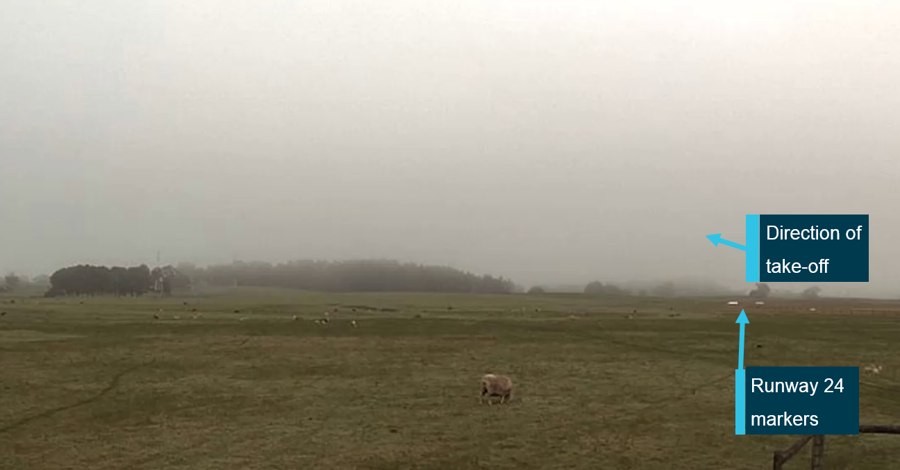
Observational weather data from the aerodrome automatic weather station (AWS) were recorded at 1-minute intervals, as were images from the live weather cameras. These were located near the runway junction, with images captured in four directions—north-east, north-west, south-east, and south-west. The AWS data and the weather camera images (Figure 6) indicated that low visibility conditions, with clouds broken or overcast at a ceiling of 200 ft, were present at the airport at the time of YTM’s approach and subsequent departure.
Figure 6: An image from the BoM weather camera at 1020, showing the direction of take-off
Source: Bureau of Meteorology, annotated by ATSB
An analysis of the local weather at the time of the accident flight was provided by BoM. The analysis concluded that:
…areas of patchy fog persisted until mid-morning then lifted into a mix of mist/haze and low cloud which persisted til late morning… It is considered likely that around the time of the incident conditions would have included broken low cloud and visibility reducing at times in mist.
Witness and camera observations
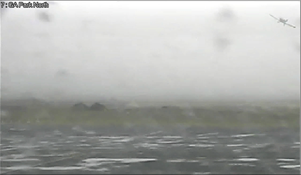
Airport closed‑circuit television (CCTV) footage of the approach, taxiing, and departure of YTM showed the aircraft passing in and out of cloud at low levels (Figure 7).
Figure 7: Mount Gambier Airport CCTV images of YTM conducting a low level manoeuvre on approach over the airport at 1006 with aircraft highlighted (top), and taxiing out to runway 24 at 1018 (bottom)
Source: Mount Gambier Airport, annotated by ATSB
A number of witnesses heard the aircraft in the vicinity of the airport (both when arriving and departing), however, due to low cloud, the aircraft was not visible. The cloud base was estimated by witnesses to the west of the airport be at about 200 ft AGL. Witnesses located at the airport observed the aircraft pass in and out of cloud during the low level manoeuvring on approach, and again on departure.
Pilots operating in the area at the time YTM approached, landed and took off, reported the weather was clearing to the east, but was below the required IFR minima (see Airport information section for minima) to the north and to the west. Due to the prevalent weather conditions at Mount Gambier Airport being below the VFR minima, witnesses assumed that YTM was operating under IFR, and the pilot responses on the CTAF referred to IFR criteria. The pilot of an aircraft that departed under IFR on runway 06 prior to YTM approaching the airport reported being in cloud with no visibility between 500 ft and 1,000 ft AGL.
Two regular public transport (RPT) flights were due to arrive at Mount Gambier Airport about the time YTM arrived and departed. Based on the forecast and observed weather conditions, one flight delayed its departure for Mount Gambier by approximately two hours, as the weather was below IFR minima for landing. The other aircraft, having attempted an approach to Mount Gambier Airport at 1030, conducted a missed approach, and remained in a holding pattern to the south of the airport for 50 minutes until the conditions cleared sufficiently to land. Both these RPT aircraft were operating under IFR. Another aircraft operating under IFR from Adelaide to Mount Gambier delayed its 0830 departure for two hours due to the forecast and observed weather. On approaching Mount Gambier Airport at approximately 1120, due to the weather present, the pilot was unable to sight the runway by the required minimum descent altitude and elected to divert to an alternate aerodrome.
Flight in low visibility conditions
Risks of flying in areas of reduced visual cues
The safety risks of VFR pilots flying from visual meteorological conditions (VMC) into instrument meteorological conditions (IMC)[16] are well documented. This has been the focus of numerous ATSB investigations and publications, as VFR pilots flying into IMC has been identified as a contributing factor in a considerable number of aircraft accidents and fatalities. The ATSB Avoidable Accidents series booklet (AR-2011-050) titled Accidents involving pilots in Instrument Meteorological Conditions outlines that:
In the 5 years 2006–2010, there were 72 occurrences of visual flight rules (VFR) pilots flying in instrument meteorological conditions (IMC) reported to the ATSB…About one in ten VFR into IMC events result in a fatal outcome.
Additionally, a study conducted by the United States’ National Transportation Safety Board (NTSB, 2005) found that reduced-visibility weather represents a particularly high risk to general aviation pilots, testing ‘the limits of pilot knowledge, training, and skill to the point that underlying issues are identified.’
The NTSB study also outlined that historically, about two-thirds of all general aviation accidents that occur in IMC are fatal; a rate much higher than the overall fatality rate for general aviation accidents. A study by Newman (2007) conducted for the ATSB titled An overview of spatial disorientation as a factor in aviation accidents and incidents outlined that there was a four times greater chance of fatality in a VFR flight into IMC accident than any other sort of accident (quoting Batt and O’Hare, 2005 and NTSB, 1989).
In the context of this accident, it is therefore important to outline why the risk of entering IMC is so high, which is linked directly to how and why pilots experience spatial disorientation when entering areas of low visibility.
Experiencing spatial disorientation
The ATSB Avoidable Accident booklet outlines that there are three sensory systems used by pilots to establish or maintain orientation relative to the environment. The visual system is by far the most important system, providing 80 per cent of orientation information. The remaining 20 per cent is split equally between the vestibular system, which obtains its information from the balance organs in the inner ear, and the somatic system, which uses the nerves in the skin and proprioceptive senses in our muscles and joints to sense gravity and other pressures on the body. In the absence of visual references, both the vestibular and somatic senses can be misinterpreted and are prone to illusions.
Spatial disorientation is defined by Benson (1999) as where ‘the pilot fails to sense correctly the position, motion or attitude of the aircraft or of him/herself’ with respect to the ground. For pilots flying under VFR, seeing the horizon is crucial for orientation of both the pilot’s sense of pitch and bank of the aircraft (Gibb and others, 2010). In conditions of low visibility, where the horizon may not be visible to the pilot, they can become rapidly disorientated.
Benson (1999) outlined that spatial disorientation would typically occur within 60 seconds of all visual cues being removed, while another United States study showed a loss of control by non-instrument rated pilots within an average of 178 seconds after the loss of all visual cues (Bryan, Stonecipher, and Aron, 1954).
Spatial disorientation presents a danger to pilots as the resulting confusion can often lead to incorrect control inputs and resultant loss of aircraft control. Gibb and others (2010) state that spatial disorientation accidents have a fatality rate of about 90 per cent, indicating how compelling the misperceptions can be.
A range of factors can influence the extent to which a pilot may experience or be able to recover from spatial disorientation. Common factors include limited or ambiguous visual cues outside the cockpit, not directing sufficient attention to the flight instruments due to workload or distraction, and not being proficient in instrument flying skills. The risk of experiencing spatial disorientation can be managed effectively in the absence of external visual cues by reference to suitable aircraft instrumentation. However, controlled flight by sole reference to cockpit instruments is a separate and complex learned skill from those skills associated with flight in visual conditions.
In the absence of visual information, a pilot’s perception (or lack of perception) of movement obtained from their vestibular system (inner ear) can lead to spatial disorientation. Two vestibular‑based illusions are the somatogravic and somatogyral illusions.
Somatogravic illusion
The vestibular illusion known as somatogravic illusion is associated with acceleration, particularly at take-off. Any vehicle that accelerates will push a forward-facing occupant backward in their seat. This generates a vestibular sense that is very similar to the sensation of tilting back. In the absence of supporting visual cues, it is possible for pilots to mistake this vestibular sense when accelerating (such as for take-off) with a sense of a pitch-up change in attitude. It is more pronounced with greater acceleration during the take-off run. A greater take-off speed, particularly if the aircraft continues to accelerate after take-off, can further amplify the illusion in the absence of significant external visual cues.
The risk of somatogravic illusion is that the pilot responds by pitching down, which is particularly dangerous soon after take-off. The illusion can be mitigated by pilots being aware of it and understanding it, and by effective use of flight instruments to control the aircraft in the seconds after take-off. This illusion is most prevalent and hazardous immediately after take-off in fixed wing aircraft, but can also occur when the aircraft is longitudinally accelerated.
Somatogyral illusion
This illusion relates to a pilot’s incorrect understanding of an aircraft’s angle of bank. The pilot’s vestibular system will register an angular acceleration (above a threshold level) when the aircraft’s angle of bank is changed. Once the aircraft is in a constant turn, the pilot’s vestibular system will stop registering any input because there is no angular acceleration. In the absence of any other sensory information or vestibular input a pilot may experience a sensation that the aircraft is no longer turning.
This sensation is normally overridden by the visual system that is influenced by seeing the world rotating as the turn continues. However, in the absence of external visual cues, successful orientation relies on the use of the information available from the aircraft’s flight instruments. The perceived conflict of information between the vestibular and the visual cues requires a pilot to disregard vestibular sensations in preference to flight by reference to the flight instruments alone.
If a roll movement occurs gradually, it may be below the level that a pilot can detect through the vestibular senses. The human threshold for detecting a short duration roll movement (5 seconds or less) is about 2° per second, and for longer durations, it is about 0.5° per second (Cheung, 2004). When flying, these sensory thresholds are often higher, particularly when a pilot’s attention is directed elsewhere (Benson, 1999). With limited or no external visual information, gentle rolls can continue unnoticed unless detected through the monitoring of instruments.
However, if noticed from instruments and corrected, the return roll to straight flight often occurs faster and is therefore perceived by the vestibular senses. The pilot may end up with the sensation that the aircraft is now in a turn (in the opposite direction). This can also occur in longer turns when the initial sense of roll stops during the turn. Commonly known as ‘the leans’, this sensation will wear off in time each occasion it is experienced, but unless the aircraft is flown solely by instruments, it has the potential to disorientate the pilot.
Instrument flying proficiency
Entering IMC conditions with no instrument rating carries a significant risk of severe spatial disorientation (Frederick, 2002; Batt and O’Hare, 2005; Transportation Safety Board of Canada, 1990; NTSB, 1989). Furthermore, Groff and Price (2006) found that the risk of an accident in reduced visibility increases nearly five-fold for pilots that did not hold an instrument rating.
When there are no external visual cues, the ability to fly on instruments is essential. The NTSB (1988) also noted that ‘tests and experience have shown that non-instrument-trained pilots or non‑proficient pilots are rarely successful in overcoming spatial disorientation’. Gibb and others (2010) add that a visual-only general aviation pilot encountering weather or night conditions is severely at risk because of their total inexperience, education, and training in using instruments.
Although instrument flying proficiency is a very important defence against spatial disorientation, many studies have shown overall flying hours has little, if any, influence on spatial disorientation accident rates (Gawron, 2000). Importantly, Gawron (2000) stated that the level of training and recency of the training to be factors, with those inexperienced in instrument flight, or with a lack of recent instrument flying, being at higher risk of spatial disorientation. In an effort to communicate how pilots can reduce the risk, Newman (2007) outlined:
It is advisable for pilots to undertake regular instrument flight exposures, preferably with an experienced instructor. This can be combined with some inflight disorientation demonstrations and upset/unusual attitude recovery practice (Braithwaite, 1997; Collins, Hasbrook, Lennon, & Gay, 1978).
Weather-related pilot decision making
A study by Wiegmann and Goh (2000) suggested a number of possible factors that contribute to instances of VFR flight into adverse weather conditions. These included:
situation assessment (an inaccurate assessment by a pilot of the conditions)
risk perception (a pilot may not appreciate the risks involved with continuing the flight)
motivational factors (‘get-home-itis’ or personal/social pressures to complete the flight).
That is, pilots are seen to engage in VFR flight into IMC because they do not accurately assess the hazard (that is, the deteriorating weather conditions).
Specifically, one of the reasons why pilots may decide to continue a VFR flight into adverse weather is that they make errors when assessing the situation. However, pilots are often simply trying to make decisions to the best of their ability. The NTSB (2005) outlined that:
Even if pilots are able to correctly assess current weather conditions, they may still underestimate the risk associated with continued flight under those conditions, or they may overestimate their ability to handle that risk.
When outlining how weather-related decision making could be improved, Wiggins and O’Hare (1995) stated:
Because of the variable nature of operations in the aviation environment, weather-related decision making is often considered a skill that cannot be prescribed during training. Rather it is expected to develop gradually through practical experience. However, in developing this type of experience, relatively inexperienced pilots may be exposed to hazardous situations with which they are ill‑equipped to cope.
Wiggins and O’Hare (2003) also evaluated the effectiveness of a cue-based training system, which was designed to equip VFR pilots with the skills to recognise and respond to the cues associated with deteriorating weather conditions during flight. VFR pilots were more likely to use the cues following the training, with subsequent improvements in their weather-related decision‑making. CASA produced a Weather to Fly[17] education program which focuses on topics such as the importance of pre-flight preparation, making decisions early and talking to air traffic control, along with initiatives to help pilots establish personal minimums.
Related occurrences
The US NTSB investigated four accidents involving community service flights[18] in 2007 and 2008, which resulted in three Safety Recommendations being issued (see Identified community service flight risks below).
The ATSB has investigated one other fatal accident and one incident involving flights organised by Angel Flight Australia, which are summarised below. Additionally, a number of recent ATSB investigations examined VFR into IMC accidents.[19] Of these, two are summarised below, as is the ATSB research report AR-2008-045Improving the odds: Trends in fatal and non-fatal accidents in private flying operations.
ATSB investigated Angel Flight Australia occurrences
On 15 August 2011, the pilot of a Piper PA-28-180 Cherokee aircraft, registered VH-POJ, was conducting a private flight arranged by Angel Flight Australia, transporting two passengers from Essendon to Nhill, Victoria under VFR. The flight was arranged to return the passengers to their home location after medical treatment in Melbourne.
Global Positioning System data recovered from the aircraft indicated that when about 52 km from Nhill, the aircraft conducted a series of manoeuvres followed by a descending right turn. The aircraft subsequently impacted the ground at 1820 Eastern Standard Time, fatally injuring the pilot and one of the passengers. The second passenger later died in hospital as a result of complications from injuries sustained in the accident.
The ATSB found that the pilot landed at Bendigo and accessed a weather forecast before continuing towards Nhill. After recommencing the flight, the pilot probably encountered reduced visibility conditions approaching Nhill due to low cloud, rain and diminishing daylight, leading to disorientation, loss of control and impact with terrain.
On 9 December 2011 a SOCATA TBM 700 aircraft, registered VH-VSV, departed Bankstown Airport for a private flight arranged by Angel Flight Australia to Merimbula, New South Wales. Onboard the aircraft were the pilot and one passenger.
The pilot was cleared to depart Bankstown control zone on a downwind departure from runway 11 left, however, the pilot mistakenly conducted an upwind departure. The aircraft penetrated Sydney controlled airspace by 2.3 NM and came within 1.2 NM horizontally with no vertical separation of another aircraft on approach into Sydney Airport and a loss of separation occurred.
The investigation highlighted the importance of developing a technique to ensure a clearance is processed, understood and actioned correctly. It is also important to clarify a clearance if any ambiguity exists. Finally, pre-flight planning is essential to ensure safe flight.
At about 1730 on 7 November 2015, the owner-pilot of an Airbus Helicopters (Eurocopter) EC135 T1, registered VH-GKK, departed Breeza, New South Wales, on a private flight to Terrey Hills, New South Wales. The flight was conducted under VFR and there were two passengers on board.
About 40 km to the south-west of the Liddell mine, the pilot diverted towards the coast, probably after encountering adverse weather conditions. Witnesses in the Laguna area observed the helicopter overfly the Watagan Creek Valley in the direction of higher terrain. The helicopter was then observed to return and land in a cleared area in the valley.
After 40 minutes on the ground, the pilot departed to the east towards rising terrain in marginal weather conditions. About 7 minutes later and approximately 9 km east of the interim landing site, the helicopter collided with terrain. The pilot and two passengers were fatally injured.
The ATSB found that the pilot departed an interim landing site under VFR in marginal weather conditions. The pilot likely encountered reduced visibility conditions leading to loss of visual reference leading to the collision with terrain.
On the morning of 29 January 2016, a Piper PA-28-235 aircraft, registered VH-PXD, was on a private flight from Moorabbin Airport, Victoria to King Island, Tasmania. After passing over Point Lonsdale, the aircraft entered an area of low visibility. The pilot conducted a 180° turn and initially tracked back towards Point Lonsdale, before heading south over the ocean. After about 2 minutes, the aircraft was again turned right before entering a rapid descent. The aircraft impacted the water 6.6 km south-west of Point Lonsdale. All four occupants of the aircraft were fatally injured.
The ATSB found that continuation of the flight beyond Point Lonsdale, and towards an area of low visibility conditions, was likely influenced by the inherent challenges of assessing those conditions.
The ATSB also found that due to the presence of low cloud and rain, the pilot probably experienced a loss of visual cues and became spatially disorientated, leading to a loss of control and impact with the water. The risk of a loss of control in the conditions was increased by the pilot’s lack of instrument flying proficiency.
The ATSB research report Improving the odds: Trends in fatal and non-fatal accidents in private flying operations found that 44 per cent of all accidents and over half of fatal accidents between 1999 and 2008 were attributed to private operations.[20] These figures far surpassed the proportions for any other flying category, even though private operations contributed to less than 15 per cent of the hours flown in that decade.
Problems with pilots’ assessing and planning were identified as contributing factors in about half of fatal accidents in private operations, and about a quarter involved problems with aircraft handling. Other contributing factors associated with fatal accidents to a smaller extent were visibility, turbulence, pilot motivation and attitude, spatial disorientation, and monitoring and checking. Non-fatal accidents were just as likely to involve aircraft handling problems, but had fewer contributing factors than fatal accidents.
Action errors and decision errors were both common to fatal accidents. Violations, while less frequently found, were mostly associated with fatal accidents.
In light of the contributing factors that were associated with fatal accidents in private operations, the report provides advice to pilots for improving the odds of a safe flight. Pilots are encouraged to make decisions before the flight, continually assess the flight conditions (particularly weather conditions), evaluate the effectiveness of their plans, set personal minimums, assess their fitness to fly, set passenger expectations by making safety the primary goal, and seek local knowledge of the route and destination as part of their pre-flight planning. In addition, becoming familiar with the aircraft’s systems, controls and limitations may alleviate poor aircraft handling during non-normal flight conditions. Finally, pilots need to be vigilant about following rules and regulations that are in place—they are there to trap errors made before and during flight. Violating these regulations only removes these ‘safety buffers’.
Organisational information
Angel Flight Australia
Background
Angel Flight Australia (Angel Flight) is a charity that assists financially disadvantaged people who cannot readily access financial assistance from other sources, to access medical services that are not available locally. It was established in 2003 and was based on the model operating in the United States at the time. The Angel Flight website described the operation as:
a charity which coordinates non-emergency flights to assist country people to access specialist medical treatment that would otherwise be unavailable to them because of vast distance and high travel costs. All flights are free and may involve travel to medical facilities anywhere in Australia.
The Australian Charities and Not-for-profits Commission (ACNC) lists Angel Flight’s constitution. The objects in that constitution stated that Angel Flight:
… assists financially disadvantaged people throughout Australia by:
a) Arranging carriage of financially disadvantaged people with medical conditions, in non-emergency circumstances;
b) Arranging carriage of such people in aircraft which contain no specialised medical fittings or equipment;
c) Arranging carriage of such people in aircraft without any requirement for medically trained personnel to be on board;
d) Arranging carriage of such people on the condition that they are sufficiently fit to undertake normal travel without assistance, and in the case of children or persons with a disability, to travel with a carer who can render any assistance required;
e) Arranging carriage of such people without any charge being made and without any form of reward being received by the pilot, aircraft owner or the Company [Angel Flight] in respect of that carriage, provided however, that the Company [Angel Flight] may, from time to time, authorise reimbursement of the cost of fuel for flights;
f) Arranging, where possible, free air transportation of blood and blood products and transplant organs to needy recipients; and
g) Arranging further support, monetary or otherwise, to financially disadvantaged people in need of medical treatment in Australia.
h) Arranging ground transport at city venues for transportation of such people to and from medical or treatment centres, either by commercial taxi service or volunteer drivers/vehicle owners, and in the case of private volunteer drivers/vehicle owners, that no charge be made or reimbursement being received by the driver/vehicle owner, provided however, that the Company [Angel Flight] may, from time to time, authorise appreciation gift cards to be provided to drivers/vehicle owners.
For passengers (a patient and their travelling companion—if any) to be considered for a flight, a formal request must be submitted by a health professional registered with Angel Flight. In submitting the request, the health referrer certifies the patient and any travelling companion meet Angel Flight’s criteria of requiring financial assistance to travel for medical treatment that is not available locally.
Most flights co-ordinated by Angel Flight are conducted using volunteer pilots on flights classified as private operations, and Angel Flight did not hold an Air Operator’s Certificate (see Civil Aviation Safety Authority below). However, about 18 per cent of the passenger flights co-ordinated by Angel Flight were conducted on commercial RPT flights, with the cost of these flights covered by Angel Flight.
To enable the private flights to be provided to the passengers free of charge, Angel Flight negotiated waivers of the Airservices Australia landing and air navigation charges, and reimburses pilot fuel costs. As at June 2017 Angel Flight had co-ordinated the conduct of about 20,000 passenger carrying flights, referred to as ‘missions’, and had 3,180 registered pilots. A handbook provided to Angel Flight pilots specified that ‘it is the objective of this organisation to assist as many people as possible that need our services, within the scope of the Angel Flight charter and standards.’
Pilot and aircraft requirements
To volunteer for Angel Flight, pilots needed to have a minimum of 250 hours as pilot in command (PIC), with either 5 hours as PIC on the aircraft type for flight to be conducted under VFR, or 10 hours on aircraft type for flights to be conducted under IFR. They also needed access to a VH‑registered aircraft,[21] with public liability insurance. Pilots need to provide copies of their licence, aviation security identification card, and any required flight reviews, proficiency checks and medical certificate. Prior to being assigned to any planned flight, pilots have to re-confirm their license and currency requirements were met, that the aircraft was insured for public liability and all maintenance complied with relevant statutory provisions.
For this accident, consistent with Angel Flight requirements the pilot of YTM was appropriately licensed for the planned private VFR flight, had maintained currency and recency on the TB10 aircraft, and had undertaken numerous Angel Flight missions in the recent past, including flying the passengers involved in the accident flight. The aircraft was appropriately insured and maintained to complete the planned flight.
Pilot documentation
Once the minimum criteria were satisfied and a pilot was registered to conduct flights on its behalf, Angel Flight would send pilots a number of documents including a pilot handbook, a pilot affirmation form, its code of conduct, and information regarding work health and safety for volunteers.
The pilot handbook contained guidelines on how to complete a flight successfully on behalf of Angel Flight. It contained advice relating to the safety of the flight such as:
Ability to cancel the flight: the pilot was responsible for the conduct of the flight and could cancel the mission for any reason. ‘No flight will be for time-critical or emergency situations…The passengers will be aware that the flight may be cancelled should the pilot have any safety concern.’
Pilot competency: ‘Be competent. The release form signed by your passengers will show that they recognise the gains and risk. Act in a reasonable manner and be able to show that you know what you are doing.’
Prepare alternate plans: ‘Even the best plans go astray. Develop a ‘Plan B’. For example, an alternate airport due to a NOTAM[22] being issued or a change in the weather’, and ‘get a full weather briefing immediately before flying the flight.’ ‘There are always alternatives, such as: waiting until later in the day, waiting until the next day…or even cancelling the flight.’
Regulatory compliance: ‘CASA regulations must be adhered to for the flight to be legal…Angel Flight does not attempt to cover this issue. ... All pilots volunteering for Angel Flight are required by law to prepare for a flight in accordance with CARs and CASRs including but not limited to flight planning, weather briefing, pre-flight, airworthiness inspections, licensing etc. These subjects will not be addressed in this document.’
Additionally, when applying online for a flight, the following comment was displayed:
‘Please Remember: Never compromise safety in any way in order to complete a flight. Cancelling a flight is considered a demonstration of good judgement and will never be criticized.’
Flight planning requirements
Guidance provided by Angel Flight to its volunteer pilots stated that the PIC was wholly responsible for the planning, operation and management of the flight. Any topics considered to be part of PIC responsibilities, including flight planning, weather briefing, pre-flight, airworthiness, and licensing requirements, were explicitly not addressed in any Angel Flight documentation.
Pilots and passengers were made aware that if a flight could not be completed, that Angel Flight would do its best to make alternative provisions for the passengers. Additionally, passengers were aware that they may be required to make their own alternative travel arrangements.
Flight requests and pilot assignment
To initiate an Angel Flight mission, a flight request would be submitted by an Angel Flight registered health professional, along with a referral regarding the passenger’s medical condition, and all required signed passenger documents (see Passenger documentation). Angel Flight mission co-ordinators then posted the request details on an e-bulletin board, accessible to registered pilots and drivers. Flight details included origin, destination, date and details of the proposed flight, number and weights of passengers, passenger medical condition, and baggage requirements. Pilots then registered their interest in a flight, and once all required passenger and pilot documentation were confirmed, the flight was assigned. If no applications were made and the flight date was approaching, mission co-ordinators contacted pilots based in the area via email in an attempt to assign the flight. Where the flight could not be assigned, or the pilot cancelled at short notice, RPT flights would then be considered as an alternative.
For this accident, consistent with the Angel Flight processes, an initial flight request and all required forms were submitted by the health referrer about 2 weeks prior to the passengers’ first Angel Flight in May 2017. Following this, a subsequent trip request for regular flights was submitted to Angel Flight. Based on the passenger’s needs and the frequency of the flights it was determined that return flights once a fortnight could be supported. Four private flights had been successfully completed, with one of these flights being conducted by the pilot involved in the accident.
On being assigned the accident flight, additional information provided to the pilot of YTM included passenger contact details, information regarding the ground transport to and from the medical facility, and return flight details. For the two passengers involved in the accident flight, one was accessing medical services in Adelaide, and the other was a family member.
Pilot and passenger communication
On being assigned a mission, pilots were advised to contact all parties involved and confirm the schedule.
On the day of the accident, between 0850 and 0900, text messages were sent between the pilot and passengers. A further message was sent by the passengers just prior to the arrival of YTM into Mount Gambier at 1006. The ATSB was unable to establish the content of the messages.
Passenger documentation
Passengers acknowledged, through a Patient Guidelines Form, that the flight was not a charter or ambulance flight, and that the pilots and aircraft did not meet commercial standards relating to qualifications, training or maintenance requirements, as they were not a commercial flying operation. The documents also stated that it is important the pilot stay on schedule as set by the appointment time, location of the passengers and location of the appointment, and the presence of connecting pilots or drivers at each destination.
Passengers were also required to sign a liability waiver noting acceptance of aviation related risks; however, there was no information provided in the documentation package outlining the comparative risks between flight operation types (see Safety comparison between private operations and commercial air transport), nor guidance or direction to where this information could be found. The Angel Flight briefing paper stated ‘our volunteer pilots’ flight credentials exceed the requirements of the Civil Aviation Safety Authority and the aircraft meet specified CASA and insurance minimums.’ This referred to the minimum number of PIC hours required, including at least 5 hours on the aircraft type for VFR flight and at least 10 hours on type for an IFR flight.
Reporting of flight safety occurrences
Air Operator’s Certificate (AOC) holders are required by CASA to have a safety management system (SMS). One standard aspect of an SMS is for the operator to maintain a record of incidents and accidents (occurrences)[23] and safety hazards which are reported to them by its pilots and others. The organisation must examine and investigate these occurrences and hazards where necessary, find ways of reducing risks identified, and/or provide awareness education for pilots, in order to improve the on-going safety of its operation.
As Angel Flight is a charity and not an aviation organisation, it is not required to hold an AOC. Therefore there was no regulatory requirement for pilots to report to Angel Flight any safety hazards or occurrences that took place during a flight operated for it. Angel Flight only required its pilots to notify them if a withdrawal or suspension of its licence, ratings or endorsements occurred.
Angel Flight had implemented a voluntary fuel report, through which pilots submitted fuel records for subsequent reimbursement, which also included a comment section. This section was predominantly used to comment on the fuel usage; there was no request for any safety related information.
In response to the ATSB investigation AO-2011-100 into the 2011 fatal accident of an Angel Flight organised flight (see Related occurrences above), Angel Flight provided information in June 2013 that showed that it was aware of three accidents (including AO-2011-100) and two incidents that had occurred during the conduct of Angel Flight missions. These occurrences had been communicated to Angel Flight through a variety of informal channels. In response to two of the four non-fatal occurrences, Angel Flight requested the pilots involved provide further information and documentation in relation to the occurrences and, in one case, required that the pilot undergo remedial training and provide evidence of its satisfactory completion prior to undertaking further missions. These responses were additional and separate to any regulatory action taken by CASA in response to these incidents.
Civil Aviation Safety Authority
CASA is an independent statutory authority with the primary function of conducting the safety regulation of civil air operations in Australia and the operation of Australian aircraft overseas.
Under the Australian civil aviation regulations there were four separate classes of operations:
regular public transport (RPT)
charter
aerial work
private.
Different regulatory requirements apply to each class of operation, with RPT operations having the highest minimum standards and regulatory oversight, and private operations having the most limited.
Previous CASA advice, in relation to ATSB investigation AO-2011-100, outlined flights conducted on behalf of Angel Flight were classified as private operations. For flights conducted under private operations, all operational responsibility for the flight remained with the pilot in command (PIC). This was consistent with advice received from Angel Flight that it was not (and never had been), an AOC holder or operator.
CASA completed a regulatory review of the safety requirements outlined in the Civil Aviation Regulations and Civil Aviation Orders in 1996, with the revised legislation to be termed Civil Aviation Safety Regulations (CASRs). Following this review CASA identified the change in the operation classification, from the current four-tier system to a three-tier system, where all passenger carrying operations (RPT and charter) are to be combined into the same tier. This created an issue in relation to how Angel Flight operations could continue as private operations while carrying passengers as a service.
Discussion paper DP1317OS: Safety standards for community service flights
As part of CASA’s ongoing regulatory reform process, for each of the areas affected by the regulatory development, stakeholders were identified and consulted. Part of the consultation included the publication of a discussion paper DP1317OS – Safety standards for community service flights conducted on a voluntary basis’ in August 2014, for industry consideration and input regarding community service flights, and how they should be regulated under the new CASRs. The discussion paper considered the concept of community service flights as:
flights that are provided on a voluntary basis for public benefit. The term refers only to non-emergency flights provided as part of an organised voluntary or charitable activity and does not include the ‘one-off’ type of flight in which a pilot provides a flight to a friend or family member.
Prior to this discussion paper being published, CASA held preliminary consultation meetings with two charities identified as operating community service flights, which included Angel Flight, in which the proposed CASR operational regulations were discussed, along with their potential impact on established practices.
The discussion paper was to ‘stimulate discussion and invite comment’ from the industry and public. It outlined the objectives, background, key risks, and potential regulatory options under the proposed regulatory framework. The discussion paper acknowledged the valuable societal benefits provided by community service flights. The paper noted that full compliance with the proposed new regulations could result in community service flights becoming untenable, and therefore sought to establish an appropriate safety standard. Some of the key regulatory risks identified were varying pilot qualifications and experience, aircraft certification and maintenance standards, and pilot and aircraft selection for each flight. It was recognised that as the use of community service flights increased, these risk factors would become more significant without regulatory oversight.
At the time (2003) Angel Flight was established, it indicated to CASA that there was an expectation that 250-300 pilots would be conducting approximately 800 flights per year when fully operational. As these flights were being conducted as private flights, and were expected to constitute a small percentage of this regulated sector, CASA considered the overall risk impact was negligible, and a formal risk assessment was not conducted. In the period 2008-2017, an average of 1,686 flights per year were being conducted, and as at June 2017 a pool of 3,180 volunteer pilots were registered. Since that time (2003) other operators providing similar flights have also been established.
The paper identified that there was a lack of visibility of the conduct of community service flights, which in turn prevented a more informed view for evidence‑based decision making in this sector of the industry. It proposed 10 main options for consideration, ranging from administrative options through operational requirements, with the potential to combine a range of the proposed options, or consider additional options suggested through the consultation process.
The submissions received in response to the discussion paper highlighted strong opposition to the prospect of any regulatory involvement in the sector, indicating that community service flying would no longer be financially viable if any of the options were applied. Based on the submissions received, no regulatory changes were initiated, with the flights remaining as private operations with no additional regulatory requirements and no additional organisational-based risk controls.
Guidance material
CASA has developed numerous publications, videos and other education material to highlight and address the flight safety risks in private operations. Some of these included video series’ such as Weather to fly and Out ‘n’ Back, personal minimums checklists, online e-learning modules through AviationWorx, the Flight Safety Australia magazine, and safety seminars and workshops. Further, based on investigation outcomes and research studies, the ATSB also developed the Avoidable Accident series, which outlines common contributing factors to fatal accidents, and how to minimise the risks associated with these factors. Additionally, both the Aircraft Owners and Pilots Association (AOPA) Australia and United States AOPA provide education materials and training courses to their members addressing flight safety risks in private operations. The US AOPA also has material which directly addresses community service flight risks.
While no material in Australia has been specifically developed for pilots conducting community service flights, information regarding many of the flight safety risks and potential mitigating strategies is contained in information available to all private pilots.
Community service flights in the United States
Numerous organisations in the United States, generally referred to as volunteer pilot organisations, provided community service flights similar to Angel Flight Australia. All community service flights in the US are conducted as private flights. Each organisation was administered separately and operated within different geographical areas.
Regulator
United States regulations required volunteer pilot organisations to apply for exemptions if the flights included reimbursement of some or all of the flight costs incurred.[24] These exemptions relate to the fact that these community service flights are conducted as private flights, but compensation is received, resulting in the pilot paying less than their pro rata share of the operating expenses for that flight. They allowed the volunteer pilot of a charity organisation to be reimbursed some or all of the costs associated with the private flight. In doing so, these exemptions added operational limitations to manage risks associated with these types of flights.
Having assessed the volunteer pilot organisation submissions and identified regulatory risks, the United States aviation regulator, the Federal Aviation Administration (FAA), issued exemptions that contained conditions and limitations intended to raise the level of safety for these flights. Additional clarification of the FAA position was provided through the publication of a policy on community service flights (charitable flights) in February 2013. The policy outlined that this activity can be conducted safely by applying limits to organisations, pilots and aircraft, with the limitations outlined in the exemptions issued to each organisation. The requirements and operational considerations differ to some extent for each organisation, however all impose additional requirements in the following areas:
pilot qualification and training programs
minimum pilot qualifications
documentation for each pilot and mission flown
mandatory passenger briefings
higher aircraft airworthiness requirements
higher instrument flight rules operational minima (where applicable).
The FAA continuously updates these exemptions for each charity as necessary to best ensure these operations meet the required level of safety.
Identified community service flight risks
The United States NTSB investigation of four accidents in 2007 and 2008, which occurred during community service flights, resulted in three safety recommendations addressed to the Air Care Alliance (ACA)[25] in 2010. The safety recommendations[26] addressed the following aspects:
The need to verify pilot currency prior to each flight.
A requirement to inform passengers that the flight would not be conducted under the same standards that apply to a commercial flight.
To develop, disseminate and implement written safety guidance, best practices, and training material addressing, at a minimum, aeronautical decision making, proper pre-flight planning, pilot qualification, training and currency, and self-induced pressure.
These areas were identified by the NTSB as increasing the risk of incidents and accidents involving community service flights.
While it was acknowledged that there was some constraint in the ability to address safety issues that are the responsibility of the PIC, it was also recognised that volunteer pilot organisations could provide tools to assist with making better decisions. In correspondence regarding the NTSB safety recommendation A-10-104, the ACA stated:
ACA seeks to strike that balance between leaving all decision making in the hands of the pilot in command, while still providing the tools through the [Volunteer Pilot Organisations] to assist them to make better decisions. The intent is to rely on the [Federal Administration Regulations] for requirements but also to provide the pilots with the tools to assess what is reasonable for their level of proficiency and the demands of the flight to be undertaken.
In response to these recommendations, and in conjunction with the Aircraft Owners and Pilots Association (AOPA) Foundation’s Air Safety Institute (ASI),[27] the online training course Public benefit flying: Balancing safety and compassion was developed. The course focused on pressures and risks associated with these flights, and included mitigation strategies to manage them. Some of the potential additional risks to flight safety when operating community service flights identified in this course were:
managing passengers and passenger expectations
proper pre-flight planning
perceived or self-induced pressure.
For a period of time, this course, and various tools developed alongside it, were included specifically in the conditions and limitations listed in the FAA issued exemptions. However, more recently, as the FAA was not responsible for the content or quality control of the course, it has removed references to the course and tools, but added specific areas in the training program to address the identified risks. While it has been removed as a regulatory requirement, many organisations still require their pilots to complete the course, in addition to the minimum requirements contained within the relevant exemption.
The United States AOPA training course highlighted some of the areas pressure can arise from, and outlined some objective decision making strategies to assist pilots with recognising and managing these risks. A summary of each of these risks as identified in the training course is outlined below.
Managing passengers: Passengers often have limited knowledge and experience with light aircraft used in general aviation. For nervous or first time flyers, the pilot needs to be aware of and manage anxiety levels of the passengers, to ensure this does not become a distraction, particularly at critical stages of flight. For all passengers, and particularly those with little exposure to general aviation, a thorough passenger briefing can assist by outlining the forecast and expected flight conditions, discussing general aircraft safety and expected sounds during the flight, such as engine changes and gear extension/retraction, and the need for a sterile cockpit at various points in the flight. Periodically reviewing the passenger’s needs during the flight and informing them of progress can also assist in managing a passenger’s anxiety levels. If they are nervous or concerned this allows an opportunity to identify and discuss the concerns, and allows for appropriate deviations or breaks if required. Pilots should also outline go/no go decisions points and explain any back-up plans. This enables determination of suitable alternatives that meet the passenger’s needs, while not compromising flight safety. Conservative planning will help reduce any time pressures associated with delays or passengers requiring breaks during the flight. If delays are unacceptable, ensure passengers have a plan B, and maintain contact with trip co-ordinators, as they can assist in determining alternatives and help alleviate any stress felt by pilots from cancellations or delay.
Pre-flight planning: Proper pre-flight planning in the context of community service flights takes into account the additional considerations and pressures associated with this type of flying. An assessment of a pilot’s current state of physical and mental health, and their own capabilities and proficiencies is important in regard to the expected flight conditions. Development and implementation of personal minimums,[28] with requirements beyond the specified regulatory minimums, can assist in making safe, objective decisions in marginal conditions. Conservative time planning can avoid hurried passenger briefings and additional stress when delays occur. It is important to travel prepared for unexpected layovers, which may be due to unexpected weather, or passenger related instances, so that objective decision making is not influenced by a lack of preparation. Flights into unusual environments such as busy terminal areas, or less familiar airports with different procedures require thorough pre-flight planning to ensure familiarity with requirements, and for remote airports, obtaining local knowledge of weather patterns, runway layout and conditions can assist with safe decision making at times of higher workload. Pre-flight planning minimises in-flight decision errors because it removes the unforeseen element from situations that arise during the flight. Failure to carry out this prior planning can result in decisions being made under a situation of considerable stress and increases the likelihood of poor or incorrect decision making.
Perceived pressure: Perceived pressure was identified in the course as one of the biggest issues facing volunteer pilots. The pressure was often self-induced and motivated by the desire to please passengers and complete an agreed trip. Additionally, knowledge of a patient’s condition can put additional psychological pressure on the pilot, and needed to be recognised as a negative influence on objective decision making. The language used, including ‘missions’ in the context of these flights can also be interpreted that it is imperative the flight be completed. Pilots must remain aware that the volunteer flight is not an emergency. Maintaining contact with trip co-ordinators during times of delay or cancellation can help alleviate any pressure felt by the pilot in these situations.
Australian evidence of perceived pressures
In Australia, from December 2018 to January 2019, CASA sought public comment on proposed changes to community service flights. A summary of the submissions was provided in Summary of consultation on proposed safety standard – community service flights, and some submissions are available on the CASA website. The responses came from both the community and pilots, so not all respondents could comment on operational matters.
The CASA summary noted that while 10 per cent of respondents (22) commented that they believed community service flights were far more complex than other private flights, 19 per cent (42) considered there was no difference in complexity between community service flights and other private operations.
While not a specific question, some respondents discussed their views on operational pressures. Of the publically available submissions, 18 respondents, at least 12 of who were pilots who had conducted community service flights, identified that there were additional pressures and operational differences associated with this type of flying, when compared with other private flights.
Twelve respondents, including pilots who had conducted community service flights, commented that they did not believe there were any operational differences between community service flights and other private flights. For example:
Why is a community service flight different to any other private flight? The fact that a passenger may or may not know the pilot prior to the flight is irrelevant.
If I can fly people privately and the regulations deem that as being safe, I see no difference when it comes to CSFs [community service flights].
There is no difference between a PPL [private pilot licence] pilot transporting passengers from A to B for charitable purposes, and a PPL pilot transporting passengers from A to B for recreational travel.
I totally reject the suggestion that these volunteer community flights are different to any other private flight.
Why is it different to any other flight a passenger is a passenger in the non-commercial way. Also long as the pilot in command obeys the rules of there [sic] endorsements and is current.
However, as discussed above, other pilots provided submissions that show evidence that perceived pressures from community services flights do affect some pilots:
Having flown both critical EMS [emergency medical service] operations and pressured CSF flights,…. the pressures involved with CSF flights can be as great or even greater than full EMS operations, as the aircraft are usually single engine, the operation is single pilot, crewed by less competent and lower time pilots and at times, it is obvious that the passengers on the CSF flights are critically ill.
There have been too many incidents involving flights where passengers are in need to arrive at a medical appointment by a certain deadline which imposes the need to get them there by the pilot. These pressures can force pilots to fly in conditions that they would normally not operate in, and inexperienced pilots can and do find themselves in situations they should not be in. As a charter pilot ….
I think the nature of this flying - the transport of medically fragile patients and dealing with emotive relatives could benefit from a training package. It should cover special considerations for the transport of people with differing conditions in the aviation environment, medical divert considerations, mission pressures (patient having an episode etc).
Managing non aviation strangers with medical needs and often in less than perfect weather is an order of magnitude of difference from typical private ops with family when you choose to fly in perfect VFR weather, and have the option to change or cancel the flight if the weather deteriorates - and your family understands that. Saying no to strangers who need to get to medical treatment is hard.
Carrying pax [passengers] who are not your friends is a huge change for the average PPL.
The psychological factors for the pilot of you must not let vulnerable people down and of doing good work, helping sick disadvantaged people... The irresistible conclusion is that any CSF flight involving long distance transport of ill patients and patient family member has a complexity beyond any normal private flight.
There is an increased sense of responsibility carrying people who you may have never met before and a possible self imposed pressure to meet what might be seen as a commitment. It could be argued that the reason for VFR into IMC is the pressure of ‘having’ to get someone somewhere at a particular time. I would agree that is possible.
Although it is almost certain that at least some pilots at least some of the time have experienced operational pressures from community service flights that were beyond what is usually experienced during other private operations, the extent of this is difficult to determine. The ATSB considered conducting a survey of Angel Flight pilots to determine the extent of perceived operational pressure on Angel Flight pilots. However, this was not conducted for the following reasons:
Obtaining accurate responses to questions designed to elicit insights into a pilot having experienced implicit social pressures depends on their awareness of it having happened. In that case, the validity of answers pilots give will be limited as some will only indicate an absence of awareness of their susceptibility to these influences rather than an absence of these influences.
The social desirability of admitting to have been influenced by goals other than those of safety may be a challenge for some pilots.
Due to publicity surrounding potential regulatory changes for community service flights after this accident (described above), there was a potential for some responses to be biased, either in an attempt to protect the reputation of Angel Flight, or to advocate for additional oversight or regulation.
A large number of responses would need to be gained across a representative sample of Angel Flight pilots to allow for valid statistical tests to be conducted.
Safety occurrences during flights organised by Angel Flight Australia
The per flight risks associated with Australian community service flights[29] had not been established prior to this investigation. Two fatal accidents occurring on passenger-carrying flights organised by Angel Flight suggested that further understanding of the nature of non-fatal occurrences was necessary, to identify if differences with other private operations existed. Similarly, it would also identify if any differences could provide context to potential systemic safety concerns that may be present during Australian community service flights.
The risk to passengers on community service flights was a particular focus of this analysis. This is because the ATSB’s focus is on the risk to travelling public[30] and Angel Flight passengers are regarded by the ATSB as being consistent with this statement, as supported by Recommendation 2 of the Australian Senate Inquiry completed 23 May 2013.[31] However, an additional assessment of non-passenger carrying repositioning flights (flights to or from the pilot’s base prior to and following passenger carrying flights) was conducted to provide further context to the risk profile of these operations.
The analysis presented in the following section was focused on establishing a baseline of the safety risks associated with these flights. As noted above, twice the number of respondents believed that community service flights have no additional complexity to other private operations than respondents who believed they introduced additional complexities. However, Angel Flight stated that there are differences in the operational environments for many Angel Flight organised flights compared to other private operations. This analysis was intended to establish if there were differences and identify if there are any areas where Angel Flight organised flights are exposed to additional safety risks. This was conducted in order to direct efforts to improve safety, rather than to attribute blame or liability.
Safety comparison between private operations and commercial air transport
As Angel Flight conduct community service flights as private operations, an evaluation of private operations against commercial air transport (RPT and charter)[32] operations was conducted to compare the relative risk per flight. In addition to community service flights, such as Angel Flight, private operations include flights for pleasure and personal transport, parachuting operations and aerobatics. Non‑commercial flights for business are also included in this analysis. Although there are large differences between the types of flying conducted in private operations, the regulatory regime is the same, and as such, all of these operations were included to provide a holistic context of the relative risk of an accident occurring during an Angel Flight organised flight.
An ATSB research investigation published in 2010 (AR-2008-045Improving the odds: Trends in fatal and non-fatal accidents in private flying operations) reviewed trends in accidents in private flying operations in Australia. This research found that 44 per cent of all accidents, and over 50 per cent of fatal accidents in the ten years 1999-2008 were attributed to private operations, even though they accounted for less than 15 per cent of hours flown in VH-registered aircraft in Australia.
This is consistent with data used in this analysis from 2008-2017 showing that private and business operations (including flights conducted on behalf of Angel Flight) in Australia have a disproportionate number of accidents compared to commercial air transport operations relative to the number of flights conducted (Figure 8). This shows that despite conducting only 21 per cent of flights, private and business operations had 77 per cent of accidents, and 84 per cent of fatal accidents from 2008 to 2017. Further data for the number of occurrences, flights and flight hours in each category are in Table B1 of Appendix B – Additional data.
Figure 8: Number of flights and accidents in private and air transport operations as a percentage of all air transport and private operations in Australia, 2008-2017
On average, flights conducted for private or business were at least:
five times more likely to end in an accident when compared to charter operations
more than 46 times more likely than high capacity RPT
69 times more likely than low-capacity RPT.
Furthermore, when considering fatal accidents, private and business operations were eight times more likely on average to end in a fatal accident compared to charter operations, and about 27 times more likely than low-capacity RPT. Note that there were no reported fatal accidents for high capacity RPT, and the single low capacity RPT accident (AO-2010-019) was during training with no fare-paying passengers on board.
Identification of Angel Flight related safety occurrences
Safety accidents and incidents (occurrences) must be reported by pilots and others to the ATSB in line with the Transport Safety Investigation Act and Regulations. It was unknown how many safety occurrences related to Angel Flight operations prior to this analysis, because safety occurrences were not always reported as involving a flight conducted for Angel Flight (nor were these required to be). To enable a safety comparison between Angel Flight and other types of operations, Angel Flight related occurrences needed to be identified. To achieve this, the ATSB obtained flight records from Angel Flight, which included departure and arrival locations, date and time of departure, and aircraft registrations covering the period between 2005 and 2017. Flights hours were not provided. Only data for the passenger carrying flights was provided, and Angel Flight was unable to provide data from 2003 and 2004.
Identification of occurrences relating to flights prior to, during and following privately conducted passenger carrying flights was performed by comparing the records provided by Angel Flight Australia and ATSB safety occurrence records. The identification process is described in Appendix A – Data analysis methods. A summary of each occurrence is located in Appendix C – Angel Flight occurrence summaries.
Through comparison with the ATSB aviation occurrence database, Angel Flight records served two primary purposes, to:
identify safety accidents and incidents that occurred on passenger carrying flights (and repositioning flights) organised by Angel Flight
calculate the likelihood of accidents and incidents per flight organised by Angel Flight.
A total of four accidents and 52 incidents were identified as occurring on 16,451 passenger carrying private flights conducted on behalf of Angel Flight between 2005 and 2017. A further 21 incidents prior to the passenger carrying flight and 28 incidents following passenger carrying flights were also identified.
For the purpose of the analysis, data from the most recent 10 years was used, from 2008-2017.[33] During this time, there were 47 Angel Flight occurrences identified from a total of 13,389 flights conducted as passenger carrying private flights. Of the 47, four were accidents (two of which resulted in fatalities, including this accident), and 43 were reportable safety incidents. This equated to about one occurrence every 2 and a half months between 2008 and 2017. Furthermore, during repositioning flights, 16 incidents and one serious incident were identified in flights prior to, and 21 incidents were identified in flights following passenger carrying flights conducted for Angel Flight during this period.
Normalisation for comparison of Angel Flight operations with others
The number of safety occurrences per 10,000 flights was used as the primary means for comparison of Angel Flight safety occurrences and other operations. Referred to as normalisation, dividing the number of occurrences by flights allows for comparisons between groups even when the overall level of activity differs between the groups.
As stated in the ATSB’s annual Aviation occurrence statistics report,[34] aircraft flights (or departures) are widely used as a measure of exposure, that is, the opportunity for an event to occur within a certain amount of flying activity. Flights were the appropriate normaliser for this analysis, as the focus was on the likelihood a passenger would encounter a safety occurrence during a flight. The number of flights are also generally considered a more appropriate normaliser measure than hours flown, as most accidents occur either during the approach and landing or departure phases of flight.[35] As such, flights are usually used for operational safety analysis by the ATSB and others (for example, the annual International Civil Aviation Organization Safety Report[36]). A further description of the rationale behind this selection can be found in Appendix A – Data analysis methods.
To allow comparison against other operations, data on flight hours and the number of flights in each operation was obtained from the Bureau of Infrastructure, Transport and Regional Economics (BITRE). The number of flights for private (including business), and charter operations was calculated by combining reported data from 2014 to 2017, and estimated data between 2008 and 2013. BITRE data between 2008 and 2013 was only available in-flight hours for each operation, with only an aggregated number of flights per year known for each aircraft. The estimation process for the earlier data is detailed in Appendix A – Data analysis methods.
For the purposes of this analysis, accidents involving passenger carrying[37] community service flights organised by Angel Flight were considered separately to accidents involving other private operations. The objective of this analysis was to understand the risk to passengers per flight.
Figure 9 shows the number of accidents, fatal accidents and fatal injuries per 10,000 flights for privately conducted passenger carrying flights organised by Angel Flight, commercial air transport, and remaining private operations. The number of flights in each category were used to identify the relative likelihood of accidents occurring per flight. Further data for the categories shown in Figure 9 can be found in Table B1 of Appendix B – Additional data.
Based on the two fatal accidents[38] occurring within 13,389 privately conducted passenger carrying Angel Flights between 2008 and 2017, statistical analysis showed it is very likely[39] that there is an increased likelihood of a fatal outcome during a community service flight conducted on behalf of Angel Flight compared to other private operations, and almost certainly higher than all commercial air transport. This indicates that it is almost certain that the nature of passenger carrying Angel Flight operations differ from the other operations, and that these differences have resulted in the higher likelihood of a fatal accident per flight. The average likelihood of a fatal accident involving an Angel Flight organised passenger carrying flight was more than seven times higher than other private flights (purple bars in Figure 9).
The accident rate per 10,000 flights in Angel Flight passenger carrying operations was likely39 to be greater than other private operations, with almost three accidents per 10,000 flights for Angel Flight operations compared to about 1.5 accidents per 10,000 flights in other private operations (yellow columns in Figure 9).38 The accident rate per 10,000 flights for both private operations for Angel Flight and other private operations were considerably higher than commercial air transport.
Figure 9 shows further comparisons between the different operational categories of the accident and fatal accident rates.
Figure 9: Total accidents, and fatal accidents and injuries, by type of operation per 10,000 flights in Australia between 2008 and 2017
Passenger carrying community service flights organised by Angel Flight always carried at least one passenger. Consequently, more people were likely to be exposed to the risk of a fatal injury during an accident involving an Angel Flight compared to other private operations (pink bars of Figure 9). As the two fatal accidents involving Angel Flight were not survivable, the four passenger fatal injuries between 2008 and 2017 presented a higher risk of fatal injury per flight than all other operations compared (blue bars of Figure 9). The average exposure to passenger fatality per flight was 98 times higher than charter operations, and there were no fatal injuries recorded for passengers in high or low capacity RPT.
Compared to other private flights, the passenger fatal injury rate per flight was 21 times higher for flights conducted on behalf of Angel Flight. This was driven by both the higher average occupancy of Angel Flight fatal accidents (2 passenger fatal injuries in each fatal accident) compared to other private flights (0.7 passenger fatal injuries per fatal accident) and higher fatal accident rate compared to other private operations, and is expected to represent an ongoing increased risk.
Characteristics of passenger carrying Angel Flight occurrences
All safety occurrences reported to the ATSB are classified in accordance with the ATSB’s three-tiered safety occurrence taxonomy.[40] Due to the relatively smaller number of Angel Flight occurrences, the statistical analysis conducted focussed on the second tier types of occurrences. The number of occurrences in each occurrence type category were calculated for Angel Flight and other private occurrences for comparison. Further details can be found in Appendix A – Data analysis methods.
Privately conducted passenger carrying community service flights organised by Angel Flight had an average likelihood of 35 occurrences23 per 10,000 flights based on the 47 safety occurrences (4 accidents and 43 incidents) between 2008 and 2017. This was considerably higher than other private operations with an average of seven occurrences per 10,000 flights.
Due to the disproportionate average rate of safety occurrences per flight in comparison to other private operations, an in-depth analysis was conducted. The aim was to identify if any systemic trends existed within Angel Flight operations that may provide opportunities for safety improvement, by identifying and explaining the more common types of occurrences contributing to the higher rate of safety occurrences.
To aid this process, statistical comparisons between passenger carrying Angel Flight operations and other private operations were conducted for the different types of occurrences.[41] Figure B1 in Appendix B – Additional data shows the main groups of reported occurrences for Angel Flight passenger carrying flights between 2008 and 2017. A complete list of results showing all differences in types of occurrences between reported Angel Flight occurrences and other private operations are shown in Appendix B – Additional data tables B2 to B7.
The following areas were identified where Angel Flight occurrences were disproportionately higher[42] than other private operations per flight, and are displayed in Figure 10:
runway events – incursions and landing/departing on the wrong runway
Figure 10 illustrates the rate of each category of reported occurrences per 10,000 flights for Angel Flight flights (shown in blue), and other private operations (shown in red). Numbers above each column are the total number of occurrences identified for each operation category.
Figure 10: Largest statistical differences between occurrence type categories where passenger carrying Angel Flight operations were greater than other private operations, 2008-2017, as a rate per 10,000 flights (numbers indicate number of occurrences)
Runway events included runway incursions, and landing, departing or approaching the wrong runway, at times resulting in consequential missed approaches for other aircraft.
Communication breakdown occurrences included incorrect read backs, not using the correct frequency and misinterpreting verbal instructions. These occurrences resulted in loss of communication, and additional co-ordination requirements for ATC to ensure required aircraft separation is maintained.
Air Navigation Service Provider errors were also elevated in comparison to other private operations. This probably relates to flights conducted on behalf of Angel Flight entering controlled airspace relatively more often per flight compared to the collective average of other private operations. However, while elevated, the Angel Flight rate is lower in contrast to other occurrences more likely to be reported in controlled airspace, such as operational non-compliance, runway events and communications. This probably indicates that the other elevated rate of other occurrence types cannot be explained by the increased frequency of flights into these locations alone, and that other factors are likely to be present.
Flight preparation and navigation occurrences during Angel Flight passenger carrying flights included VFR into IMC, being lost or unsure of position, and flight below minimum altitude. These types of occurrences were notable due to being identified in both fatal Angel Flight accidents. Further, VFR into IMC accidents result in a fatal accident in a quarter of the instances reported to the ATSB. Air traffic control (ATC) provided assistance in other cases, to assist in vectoring aircraft out of cloud or to provide navigational assistance. The risks to flight safety for these types of occurrences are significant, and discussed in Risks of flying in areas of reduced visual cues above.
Airspace related occurrences included entering controlled airspace without a clearance (airspace infringements), not maintaining assigned altitudes or headings and not complying with published procedures or verbal instructions (operational non-compliance), and flying too close to other aircraft (aircraft separation). Operational non-compliance and airspace infringement occurrences all resulted in an additional safety event, such as an additional workload for ATC to maintain separation standards, loss of separation, and diversion of other traffic.
Airframe‑related issues predominantly involved landing gear indications and included mechanical faults resulting in landing gear not retracting, landing gear failure to extend, and gear indication failures or misinterpretation. One of these occurrences resulted in the collapse of the undercarriage on touchdown, and substantial damage to the aircraft.
Although Figure 10 shows occurrence type categories where flights conducted on behalf of Angel Flight were statistically more likely compared to other private operations, there were a number of occurrence categories that were similar or less likely. Most notably, powerplant and propulsion issues, in particular engine failures or malfunctions, were considerably lower in flights conducted on behalf of Angel Flight compared to other private operations. Fuel related occurrences were also relatively lower in flights conducted on behalf of Angel Flight compared to other private operations, driven mainly by the absence of fuel starvation. All areas of comparison are shown in Appendix B – Additional data tables B2 through to B7 and are grouped by categories shown in Figure B1.
The considerably higher rate of safety occurrences during passenger carrying flights organised on behalf of Angel Flight compared to other private operations is likely indicative of a different overall operational environment. The occurrence category comparison indicated that it is almost certain that additional operational risk factors are present in Angel Flight community service flights. In particular, this is shown by relatively more occurrences related to runway events, airspace related issues, communications, flight preparation and navigation and airframe issues. Analysis of the occurrences indicated that they were not attributed to a small number of pilots, rather, that the occurrences are spread across the volunteer group, with many pilots having similar, single occurrences, and therefore probably due to broader systemic issues, rather than a small subset of pilots within the Angel Flight group.
Angel Flight repositioning flights occurrences
While passenger carrying Angel Flight occurrences were the focus of the analysis, the elevated occurrence categories identified in the repositioning flights analysis were consistent with the passenger carrying flight analysis, with the comparative data presented in Appendix B – Additional data.
While the occurrence rate was not as elevated as the passenger carrying flights, the repositioning flights were elevated in comparison to other private operations. The passenger carrying rate of occurrences per 10,000 flights was more than twice as high as the non-passenger carrying rate. Furthermore, the non-passenger carrying Angel Flight occurrence rate was more than twice as high as the average of other private operations, with passenger carrying Angel Flights being more than four times higher. This indicates that each of the three groups have a different safety risk profile, with Angel Flight passenger carrying flights having the highest likelihood of a safety occurrence per flight. Results of this comparison is shown in Table B2 of Appendix B.
Consideration of alternative options
The investigation identified that on the day of the accident, there was an RPT service on the same sector (Mount Gambier to Adelaide), scheduled to depart within 15 minutes of the planned private Angel Flight. As outlined in Safety comparison between private operations and commercial air transport, RPT flights have a lower relative safety risk than private operations.
In the overview section of Angel Flight’s Health professionals flight request forms document, there is acknowledgement that regular public transport (RPT) flights between capital cities are much more economical than using light aircraft:
For long haul or capital city to capital city transfers Angel Flight does not engage our volunteer pilots as commercial flights are much more economical. Angel Flight Australia does save some funds available to cover the cost of commercial flights however we reserve these funds for use when weather conditions prevent the flight of light aircraft and the travel date is imperative.
Angel Flight did not actively consider RPT flights as a primary option where they were available, unless the flights were for capital city transfers. This was confirmed by Angel Flight, who further stated that it considered using RPT flights, other than as a back-up or for long distance compassionate flights, as inappropriate and not aligned with the model for which the charity was constituted. Angel Flight stated that its ‘policy is to use volunteer pilots wherever possible;’ RPT flights are only considered if the pilot cancels the private flight, and the passengers are located at an RPT base, the RPT flights are available, and the times suitable.
Identification of alternative options
Considering the lower relative safety risk of RPT flights, the ATSB undertook further examination of RPT alternatives and comparative sector costs. A review of all completed Angel Flight private flights was conducted to determine how often an alternative option was available. Using Angel Flight records, the review identified that between 2005 and 2017,[43] 3,669 flights were conducted using RPT (18 per cent), and 16,356[44] as private flights (82 per cent) (inner circle Figure 12). Private flights were mainly conducted in south-eastern Australia, covering the states of Victoria, south-eastern Queensland, eastern New South Wales and the south-east of South Australia (Figure 11).
Figure 11: Passenger carrying private flights flown on behalf of Angel Flight 2005-2017
Figure 12: Breakdown of regular public transport options for flights flown on behalf of Angel Flight in 2005-2017
Financial considerations of RPT use
The Angel Flight constitution quoted above determined that passengers would not have to pay for their own flights. Further, although the Angel Flight constitution allowed for pilots to be reimbursed for fuel costs ‘from time to time’, Angel Flight reported that pilots did not claim for fuel costs for between 10 and 15 per cent of completed flights. As such, at least 85 per cent of privately-operated flights on behalf of Angel Flight have come at a cost to the charity.
It was evident that RPT options were available for a considerable percentage of flights (over two-thirds of all conducted flights). However, since the service is funded by a charity, the costs involved are relevant when considering the choice between RPT and private operations. The ATSB conducted a cost-analysis of available RPT flight costs compared to the estimated fuel cost of a light aircraft (which Angel Flight provide the volunteer pilots) for the accident sector. This was determined using data provided by Angel Flight.
The two passengers involved in the accident had been flown from Mount Gambier to Adelaide (return) on two previous occasions. For each of those four flights, fuel costs had been claimed by the pilots.[45] The total fuel costs claimed of the four flights was $2,021. Angel Flight documents also included information related to ground transport times. That is, the time required to travel from the airport to the appointment and the planned return to the airport for the return flight. A review of the available RPT schedules showed that suitable return flights were available on both of those days, accounting for the additional time requirements associated with RPT travel. According to the publically available costs, economy flights on these sectors were between $175 and $250 per person per flight. For two people for two return flights, the RPT option would have cost Angel Flight between $1,400 and $2,000, comparable to the privately claimed fuel costs.
The pilot flying the accident flight had previously flown these passengers, on the same sector (one way from Mount Gambier to Adelaide), using the same aircraft with similar repositioning flights, and had claimed $361 in fuel costs. On the morning of the accident flight, two RPT departures from Mount Gambier would have had the passengers arrive in time for the scheduled medical appointment, and this had been nominated as a backup in the case of the private pilot cancelling the flight. For two passengers on the RPT flight, the potential costs would have been between $350 and $500.
As this accident sector analysis demonstrated that suitable RPT flights were available for a comparable cost for this route, the analysis was extended to other sectors flown on behalf of Angel Flight. The purpose of the analysis was to provide a generalised indication of an RPT alternative being available where data analysis had confirmed that these services had been historically utilised by Angel Flight. Where an RPT option was available, the potential costs were compared with the estimated theoretical fuel costs.
To estimate the potential fuel costs for a private flight, the Angel Flight fuel reimbursement guidelines were used. Consistent with the evidence provided, a multiplier for the repositioning flights was included in calculating the total distance flown. This was a conservative estimate, with the distance between the departure and destination pairs based on a direct route, which did not consider IFR waypoints and approaches.[46] Fuel costs were based on the average June 2017 price per litre.
RPT costs were estimated by using publically available sources, planned for a same day return trip. The daily return trip was calculated as if purchased between 4 and 7 days ahead of the planned departure, consistent with the Angel Flight required notice. These return trips were then averaged to provide an average return cost per person.
To compare the costs between an RPT and private flight it was assumed two passengers (a patient and a companion) were travelling. The cost of a private flight was then compared to the cost for two people to fly that same sector using the averaged RPT option. This analysis was conducted using the 22 sector pairs, which accounted for the highest proportion of private flights flown where Angel Flight had previously used an RPT flight. This analysis showed that for two-thirds of the assessed sectors, the average RPT costs were cheaper than the potential fuel costs for a private flight. This conservatively indicated that of the 62 per cent of private flights where RPT options had previously been used, at least an additional 15 per cent of flights could have been conducted using RPT operations for a comparable or cheaper cost than a private flight.
Other considerations regarding the suitability of RPT
Angel Flight outlined the following reasons that it considered made the use of RPT unsuitable to assist its clients to attend appointments:
The Angel Flight constitution and its policy to use volunteer pilots in private aircraft.
The volunteer drivers’ ability to assist with carry-on luggage to and from the aircraft is limited at RPT ports.
Many passengers are not located nearby commercial airports.
Many regional locations only have RPT operating on certain days, and flights may not be available on required dates.
The RPT timetabling does not allow for lengthy cross-city travel.
Additional travel time for RPT flights – check in, luggage collection (if needed), ground transport delays.
Private flights allow passengers to travel to their appointment and return home in one day, avoiding accommodation costs in major cities.
Additional parking costs apply for volunteer drivers at RPT ports.
Passenger cancellation at last minute, with associated non-refundable RPT costs.
Not all passengers are recommended to travel RPT (e.g. immunocompromised).
Number of passengers travelling.
While Angel Flight stated its objective was to use volunteer pilots in private aircraft, this policy was not documented, nor was it a requirement in its constitution. Additionally, Angel Flight’s constitution indicated that commercial taxi services could be used for ground transport. Health referrer information and passenger guidelines indicated that Angel Flight did not automatically arrange for ground transportation at the destination, and that passengers and health referrers must endeavour to arrange ground transport before requesting this service from Angel Flight. Further, this transport was only to and from the treatment facility, and did not include assistance between the passengers’ home and the originating aerodrome. Passengers were also requested to keep their luggage requirements to a minimum, due to the limited space and weight requirements of light aircraft.
As outlined in Identification of alternative options, analysis of the flight sectors indicated 62 per cent of private flights were over sectors that had previously used an RPT option, either on the same sector or with 50 km. This implied that many passengers were located near commercial airports. Additionally, 43 per cent of those flights conducted privately were conducted on an identical sector to an RPT service, indicating that there would not be additional travel requirements for the passengers. The 22 per cent of private flights reviewed had suitable daily return RPT flight options 4 or 5 days a week. Moreover, Angel Flight passenger carrying sectors were required to be completed in daylight hours; with delay at any point risking the return flight not being completed in daylight hours—a constraint that does not apply to commercial flights.
From the evidence provided approximately 35 per cent of completed flights were for passengers travelling alone, with two travellers (patient and one companion) accounting for a further 31 per cent, and about one-third of organised flights carrying three or more travellers. Of the flights flown, about 45 per cent of aircraft used by Angel Flight had a maximum capacity of three passengers, and with limited aircraft size and weight restrictions, baggage was also limited.
There was no available evidence that indicated the rate of short-notice cancellation by passengers. While short-notice cancellation may result in non-refundable RPT costs, this is dependent on the cancellation policy in place. With respect to a private flight, a potential fuel cost may be associated with the repositioning flights of a late cancellation.
The ATSB identified that there were no mechanical defects present, and that the aircraft was serviceable at the time of the accident. A review of the pilot’s medical records and postmortem examination results did not identify any acute or pre-existing medical conditions that may have contributed to the accident. In that context, the safety analysis will examine the factors that led a visual flight rules (VFR) pilot to fly into instrument meteorological conditions, land, and subsequently depart in similar conditions. In addition, identified flight safety risks related to community service flights, Angel Flight Australia risk controls, and regulatory aspects of community service flights will be discussed.
Pilot decision to depart Mount Gambier
As part of the investigation, careful consideration was given to the possible reasons behind the pilot’s decision to depart Murray Bridge, and to then land and depart from Mount Gambier Airport in instrument meteorological conditions (IMC). On departure from Murray Bridge at about 0800, the weather forecasts indicated marginal visual meteorological conditions (VMC) at Mount Gambier, but with conditions expected to improve from 0930, with the pilot’s planned arrival between 0930 and 1000. The Mount Gambier aerodrome forecast (TAF) released at 0942 also indicated marginal but improving conditions compared with the previous TAF. However, the SPECI and live weather observations available to the pilot en route indicated that the observed conditions, while improving, were not suitable for VFR. While it could not be determined if the pilot accessed this information en route, weather-related diversions were noted in the recorded flight path, and radio calls requesting the cloud base at Mount Gambier were made.
It is not known if the pilot fully comprehended the unsuitability of the weather conditions for visual flight on approach to and at Mount Gambier, or if any other options were considered. However, the following are some of the possible reasons for deciding to continue to land, rather than divert or hold, and subsequently depart. These have been outlined to highlight the risks to others, and are based on the three factors listed by the Wiegmann and Goh (2000) empirical study of factors affecting pilot decision-making relating to VFR flight into adverse weather: situation assessment, risk perception and other motivational factors.
Situation assessment
The ability to assess a situation accurately depends on a number of factors, in particular; domain knowledge based on learning, training received, flying hours, and expectations based on exposure to a variety of situations (Gawron, 2000). Wiggins and O’Hare (1995) also stated that pilots with greater practical experience were able to make more informed decisions. In this case, the ability to assess the situation accurately would have been limited by the pilot not having an instrument rating, having had limited exposure to instrument flight conditions in training, and only holding his licence for about four years at the time of the accident.
Decisions are usually made with an individual’s best intentions and based on the information they have to conduct an assessment. In this case, the pilot may have interpreted information from pilots of other aircraft on the Mount Gambier common traffic advisory frequency to indicate that a landing was plausible, when in fact the conditions were observed to be marginal even for flight under the instrument flight rules (IFR). After conducting a non-standard, high-risk approach and landing, in conditions not suitable for VFR flight, the pilot should have had enough evidence available to assess that a departure soon after would very likely result in flight in the same conditions despite his limited flying experience and training. However, there is insufficient evidence to establish whether the pilot accurately assessed the conditions.
The pilot’s assessment of the conditions prior to departure could also have been informed by checking the forecast and reported actual weather conditions, but the short duration between landing and take-off (considering passenger loading occurred in this timeframe) indicated a limited opportunity to do so.
Risk perception
A United States National Transportation Safety Board (NTSB) study (2005) outlined that ‘even if pilots are able to correctly assess current weather conditions, they may still underestimate the risk associated with continued flight under those conditions, or they may overestimate their ability to handle that risk’.
In this case, the pilot’s perception of the risk associated with departure from Mount Gambier is not known. It is known that en route to Mount Gambier, the pilot conducted weather-related track diversions, which indicated an awareness of the adverse weather in the area. However, he then conducted a non-standard approach and landed into Mount Gambier in low visibility conditions, in which he encountered difficulty in sighting and selecting a runway. He then elected to depart 12 minutes later in conditions similar to that which he arrived. It is possible he perceived that being able to land was a positive indicator for being able to depart.
Given the significant risks associated with entering IMC as a VFR pilot, it was considered unlikely that the pilot willingly flew into IMC without some assurance that he was able to handle it. However, the ability to do so depends on pilots possessing instrument proficiency. It was considered very unlikely in this case that the pilot possessed the instrument proficiency to sustain flight in the conditions encountered on the day of the accident. The ability to underestimate these risks is not exclusive to this one case; it is prevalent throughout the industry, particularly in general aviation.
Motivational factors
In addition to an assessment of the weather conditions, and perception of risk associated with this, it is possible that the pilot was influenced in his decision to take off by other motivational factors (Wiegmann and Goh, 2000). After landing in Mount Gambier and loading the passengers, the pilot was about 20 minutes later than his initial flight plan indicated. It is possible that inherent pressures associated with the purpose of the flight increased the perceived need to get to Adelaide (as outlined in the Context, Identified community service flight risks, and discussed further below in Potential for perceived pressures). Angel Flights are only offered to those who require financial and medical assistance. The pilot was aware of the medical condition of the passenger and the timing of the medical appointment, and having flown these passengers previously had knowledge of the family.
As stated at the start of this section, it is not known what influenced the pilot’s decision to approach, land and depart into IMC. The widespread nature of VFR into IMC accidents show that it is a common error in judgement, and one that should not indicate inherent failings of someone’s overall abilities as a pilot. It should be noted, however, that community service flights have a disproportionately high rate of flight preparation and navigation occurrences when compared to private operations.
Pilot proficiency for flight in instrument meteorological conditions
Although the pilot’s experience and recency were appropriate for the planned VFR flight, he was not qualified or experienced in conditions requiring instrument flying proficiency, which was what the conditions on departure from Mount Gambier required for safe flight. It was unlikely that a VFR pilot could overcome the risks posed by low visibility conditions when climbing into thick cloud (including a lack of a horizon and a loss of visual cues), and avoid experiencing spatial disorientation.
Spatial disorientation resulting from a loss of visual cues
The aircraft track recorded a departure on runway 24 and YTM entered an area of low visibility almost immediately. The recorded aircraft track then showed the aircraft slowly turning left while continuing to climb to a height of 300 ft above ground level. The last recorded position of the track indicated that the aircraft had started to descend whilst in a left turn. The aircraft wreckage indicated that just prior to impact the aircraft had been inverted.
On entry into low cloud, the pilot of YTM would have lost visual cues, in particular the horizon and visual reference to the ground. It is well established that a loss of visual cues significantly increases the risk of spatial disorientation.
The time between departure (which is also approximately the same time as entering the low cloud) and the aircraft’s impact with the ground was about 70 seconds. This is consistent with the range of times indicated by research between the loss of visual cues, experiencing spatial disorientation and a subsequent loss of control. Further evidence that the pilot of YTM experienced spatial disorientation due to the lack of visual cues included:
the aircraft’s track and height were not consistent with the expected track if a pilot were departing for Adelaide
the aircraft had started to descend while in a left turn suggesting the pilot had lost reference to the horizon
inverted state of the aircraft prior to impact indicated a loss of control.
In summary, the ATSB found that shortly after take-off, while in low level cloud, the pilot likely experienced a loss of visual cues and probably became spatially disorientated, resulting in loss of control of the aircraft and collision with terrain.
Considerations of the use of alternative options
It was established that commercial passenger flights, consisting of charter and regular public transport (RPT) have a lower risk of adverse safety outcomes than private operations. The ATSB considered whether RPT options were available for the passengers of the accident flight to travel between Mount Gambier and Adelaide for the specialist medical appointment they were attending and return home on the same day. It was determined that there were RPT options that would have the passengers arrive at their appointment in a similar timeframe, and allow them to return home on the same day. It was also determined the costs to Angel Flight to cover the fuel component for a private flight (which it did for most private flights) were comparable to the costs for two people to fly on a commercially available RPT flight.
While Angel Flight noted that RPT flights between capital cities were more economical, RPT flights were not considered as a primary option where they were available on other sectors. From the evidence available, and confirmed by Angel Flight, its ‘policy is to use volunteer pilots in private operations wherever possible’, and RPT options were only explored when there were no private pilots available to conduct the flight.
However, while Angel Flight agrees that RPT flights were not considered as a primary means of transporting passengers, it has stated that this was because such considerations would be against its constitution. The primary stated objective of the constitution was ‘Arranging carriage of financially disadvantaged people with medical conditions, in non-emergency circumstances’. This appears to be independent of whether volunteer private pilots or commercial flights were used.
The constitution’s objectives made no reference to the safety of passengers. If Angel Flight considered the safety of passengers was an important consideration to take into account, then consideration could be expected to be given to the safety benefits of using commercial passenger transport, taking into account availability, passenger suitability, and comparative costs.
The ATSB acknowledges that there will be passengers who cannot travel on RPT, and that there are times and locations where RPT is not available or suitable for the reasons outlined previously. However, where those flights are available and suitable, using the safer transport option would reduce the overall safety risk, while still achieving the stated constitutional objective of assisting people to attend medical appointments where they are not available locally.
In relation to the accident flight, while an RPT option was identified as a backup, this would only be used if the private pilot cancelled. The RPT option was not selected because the policy was to use private pilots wherever possible. No consideration was given to the safety benefits of using the available RPT, nor were the comparative costs considered. It is unlikely that any of the considerations outlined previously would have prevented the use of a commercial flight.
Risks associated with community service flights
During this investigation, the ATSB determined that per flight, the likelihood of a safety occurrence during an Angel Flight community service flight was higher than flights conducted in other private operations. Furthermore, there was an increased risk of fatal injuries in passenger carrying flights conducted by Angel Flight. This was driven by both the expected average higher occupancy of these flights compared to other private operations, and the very likely higher fatal accident rate. There was an increased prevalence of flight preparation and navigation errors in Angel Flight community service flights, compared with other private operations. This is a known precursor to fatal accidents, and was identified in both fatal accidents involving Angel Flight. It is almost certain that the risk profile associated with flights conducted on behalf of Angel Flight are not the same as other private operations. The identified occurrence type categories show that other events or conditions that increase risk are present during Angel Flight community service flights which are either not present or are effectively mitigated during other private flights.
It was considered that there would be no notable differences in the pilot skills, recency and experience, or the aircraft equipment, maintenance and reliability, as both groups are licensed and regulated in the same way.
Therefore, the ATSB considered the potential for Angel Flight pilots being exposed to factors different to other private operations associated with the key differences between the flights conducted for Angel Flight and most other private operations. The key differences are:
the carriage of ill, unrelated (and often unknown) passengers, rather than friends and family
flying at times to meet scheduled medical appointments rather than times chosen by the pilot
flying to and from pre-arranged locations, generally requiring cross country navigation and often into controlled airspace
operational costs (fuel and landing fees) of the private flight are covered by a third party.
These factors included considerations such as:
Implicit (rather than explicit) pressures of flying a ‘mission’ where the pilot is responsible for transporting unrelated passengers to necessary medical appointments.
Flying in and out of locations with which they may have limited familiarity, including small aerodromes in areas outside of ones they perhaps routinely use, and limited familiarity with procedures in controlled airspace.
Per flight, Angel Flight pilots were shown to be more likely to make operational errors (particularly associated with flight preparation and navigation, airspace, runway events, and communications breakdowns) when compared to other private operations. This required further consideration, and therefore the above topics have been explored in more detail below.
Potential for perceived pressures
The safety investigations and research conducted in the United States, and highlighted in the Aircraft Owners and Pilots Association training course Public Benefit Flying: Balancing Safety and Compassion, identified that pilots conducting community service flights may be exposed to factors that are detrimental to safe decision making. This included the identification of the potential for perceived or self-induced pressure due to the nature of the flight being undertaken, and the impact this could have on objective decision making. Key areas identified by the US research and investigations included the terminology used, feelings of personal obligation to provide a service on an assigned trip, knowledge of passenger’s condition, and managing passengers and their expectations.
Perceived or self-induced pressure is specific to each pilot, may come from a range of sources, and may not be evident or easily identifiable by the pilot. Not every flight will result in potential for pilots to experience pressure; some pilots may not have experienced pressure due to the flights they have been involved in, and some pilots may not feel pressure in circumstances where other pilots do. This is evident from submissions about personal experiences made to Civil Aviation Safety Authority (CASA) by Australian pilots during the 2018-2019 consultation on proposed changes to community service flights. Some pilots indicated they saw no differences to other private flights, while others indicated that there were significant pressures associated with community service flights consistent with the above United States investigations and research. The ATSB consider the following aspects of community service flying will likely be sources of potential pressure perceived by some pilots:
The terminology used in this sector, including referring to the flights as ‘missions’ and pilots as ‘heroes.’
Desire to complete the trip, having been assigned a ‘mission,’ when completion of such flights can lead to ‘satisfaction that cannot be described.’
Knowledge of the patient’s condition may motivate the pilot to continue when other factors may otherwise have them altering their plans.
Managing passenger expectations, when passenger briefing notes indicate an on time flight according to the scheduled times to meet the medical appointment.
Belief that there are limited other options for the passengers to attend their medical appointments.
Passenger requirement to travel to the appointment and return home in one day.
While it could be demonstrated that most of the elements outlined above were present in the accident flight, there was insufficient evidence available to determine the influence of each of these on the pilot’s decision to continue to land, and subsequently depart, rather than diverting or holding, or delaying or cancelling the flight.
It was evident through interviews with key organisational staff, and in documentation such as the Pilot Handbook, that Angel Flight does not pressure pilots to complete assigned missions. However, pilots undertaking these flights do not necessarily have the benefit of education and exposure to compelling evidence of how motivational factors can override other safety considerations when they are making decisions. They are also alone in their decision making for a ‘go/no go’ situation, unlike in other sectors where support staff and other crew influence the outcomes, and tools and procedures have been implemented to manage the identified risks.
Flight preparation and navigation
According to Angel Flight documentation, the flight times and locations of community service flights are determined by the passenger’s needs. This generally means the pilot will be flying into a small aerodrome near the passenger’s home, and then to a major city centre, with time requirements that align with the passenger’s specialist appointments.
The pilot may not be familiar with, or may not have flown to either of the locations previously, and may have limited exposure to flying into controlled airspace surrounding larger airports, as many private pilots flying recreationally are not necessarily exposed to these circumstances on a regular basis. This results in pilots flying through controlled airspace and into airports with unfamiliar layouts, while carrying passengers, which can lead to an increased workload when compared with recreational flying.
Flight in unfamiliar airspace requires additional pre-flight planning. This includes knowledge and familiarity with established procedures, radio communication protocols, the limits of restricted and controlled airspace, and airport runway and taxiway layouts. Pre-flight planning minimises in-flight decision errors because it removes the unforeseen element from situations that arise during the flight. Failure to carry out this prior planning can result in decisions being made under a situation of considerable stress and increases the likelihood of poor or incorrect decision making.
The training to obtain a private pilot licence and the aeroplane flight review conducted biannually included the operational requirements and knowledge to conduct these flights. However, while pilots may demonstrate knowledge satisfactorily during the biennial flight review, not all of these areas are tested under the flight review, and not all these skills are practiced regularly during recreational flying, potentially resulting in reduced proficiency in these skills.
In summary, the increased occurrence and fatal accident rates were almost certainly a result of community service flight pilots being exposed to a range of operational differences because of the task being undertaken. These operational differences included the carriage of passengers according to a scheduled time, with specific location requirements involving cross country navigation and flight into controlled airspace, and often with a same day return expectation. As a result of the operational differences present in these flights, some of the factors identified which may impact decision making, and consistent with the occurrence categories where the Angel Flight occurrence rate was higher, included the potential for perceived pressures, and flying in unfamiliar locations, with a resulting impact on flight safety.
Angel Flight organisational controls
The community could reasonably expect that a provision of services such as the community service flight organised by Angel Flight would have at least a level of safety commensurate with other private operations, if not higher. However, this investigation has showed that they are actually less safe than other private operations, and previous research has shown that private operations are also less safe than charter and regular public transport. When compared with private operations, this indicates that there are risk factors which are not currently being managed. Analysis of the occurrence types where the greatest differences were identified between private flights and community service flights were predominantly operational.
As community service flights are exposed to additional operational risks, it is important that those organising these flights have appropriate operational controls in place, and these pilots have access to guidance and education in what these risks are, and how to avoid adverse influences.
In the United States, in response to the NTSB recommendations, guidance related to the identified safety risks in the community service flight sector was developed to help pilots identify and minimise the flight safety risks. Additionally, for those community service flights conducted privately but with reimbursement from a volunteer pilot organisation, the Federal Aviation Administration determined these flights could be safely conducted by applying operational limitations on each organisation through their exemption process. This required organisations to ensure minimum pilot qualifications were applied, increased recency requirements and required additional training to be undertaken, and increased required flight rule minimums above the minimum required for private flights. Documentation must also be maintained for each pilot and mission flown, including in some cases a pre-flight risk assessment tool, which reinforced the organisational applied minima, to assist pilots with decision making in marginal conditions. The United States model shows that organisations like Angel Flight can sustain operations with additional operational risk controls in place to address the specific risks associated with community service flights, and which are ongoing and apply to individual flights.
At the time of this accident, similar guidance and educational material to that developed in the United States had not yet been developed for the Australian context. Although there has been material developed by CASA and the ATSB for private pilots which addressed some of the flight safety risks, these did not target pilots conducting community service flights, nor address the different operational factors present.
Angel Flight operational controls were limited to 250 hours as pilot in command, VH-registered aircraft, and 5/10 hours on aircraft type for VFR/IFR flights respectively. These are basic measures for a base line level of entry for registration as a pilot with Angel Flight. There is limited evidence flying hours alone are sufficient to make informed decisions. As outlined by Gawron (2000) and Wiggins and O’Hare (1995), pilots with greater practical experience, particularly made up of domain knowledge based on learning, training received (and its recency) and expectations based on exposure to a variety of situations, make more informed decisions. While the current licensing and endorsement requirements for private pilots ensures the flight related knowledge and skills are taught, it is also valuable for them to receive regular education, training and practice to maintain many of the skills needed to safely conduct community service flights.
In addition, the Angel Flight PilotHandbook included comments outlining a pilot’s ability to cancel a flight for any reason. It also stated that any subjects related to pilot in command responsibilities would not be covered, and that the flight must be conducted legally.
During this investigation, the ATSB found that community service flights had a higher occurrence rate, and a different risk profile than other private operations, almost certainly due to exposure to different operational factors which influence decision making. This higher occurrence rate indicated that insufficient organisational controls had been implemented to address the risks to flight safety.
Under the current regulatory framework, there is no specific oversight of community service flights. Therefore, organisational controls to address the areas of elevated risk can only be implemented by the community service flight organiser. Similarly, only the community service flight organiser can undertake the targeted promotion of relevant material to its pilots.
The ATSB acknowledges that Angel Flight cannot be responsible for the pilots’ preparation and conduct of flights, and is limited in its ability to address decisions that are the responsibility of the pilot in command. However, the ATSB considers that Angel Flight is in a position to implement organisational requirements and controls, and to facilitate access to material and relevant information that can assist pilots to identify risk factors associated with these flights. Pilots would then have an increased opportunity to develop and implement appropriate mitigation strategies to address these risks.
Availability of safety information to Angel Flight
It is well-understood in the aviation industry that ‘the effective management of safety is highly dependent on the effectiveness of safety data collection [and] analysis...’ and that ‘reliable safety data and safety information is needed to identify trends, make decisions and evaluate safety performance…and to assess risk’ (International Civil Aviation Organisation (ICAO), 2018). Identifying and collecting this data should be aligned with the organisations’ role and scope of influence.
The nature of safety information in this context relates to any hazards or occurrences that arise during a pilot’s Angel Flight mission. The utilisation of safety information by an organisation like Angel Flight will differ significantly from aviation operators responsible for the management of flight operations. By identifying these hazards or occurrences, it can inform decisions about future pilot requirements, any guidance or educative material that could be helpful, or any other risk treatment measures possible within the scope of Angel Flight’s role.
At the time of the accident, occurrence notifications from pilots, air traffic control and aerodrome personnel received by the ATSB and CASA were reported as private flights, and generally were not further identified as community service flights; nor were they required to be. As these notifications were not identified as community service flights, neither CASA nor the ATSB had awareness of the incidents as occurring during community service flights, and further, the ATSB public database could not differentiate these occurrences from other private operations, and so community service flight organisations did not have visibility of these occurrences.
Angel Flight did not request or require any information regarding flight safety related incidents from its pilots. Therefore, the only way for Angel Flight to be aware of a safety occurrence apart from when the organisation was formally investigated as part of an ATSB investigation, was for the pilot, passenger(s) or other involved person to report it directly. This informal system was limited in the ability to capture safety related information because:
the passengers likely have limited knowledge or exposure to general aviation regulations or knowledge of flight safety
in the absence of an established just culture policy[47] in relation to reporting of safety occurrences, pilots may be reluctant to report a safety occurrence to Angel Flight as they may perceive it would have implications for being considered for future missions
other involved persons may not be aware the private flight is a community service flight
if pilots are not specifically asked or required to provide information on safety matters, there is a reduced likelihood that they will consider it necessary to do so.
Where Angel Flight had been notified of incidents or accidents, further information had been requested, and in some cases, additional action taken for specific pilots. However, this was limited to the known incidents which constituted less than 10 per cent of occurrences identified during this investigation. If Angel Flight had sought to identify and understand systemic risks relating to flights conducted on behalf of the charity, the limited availability of safety related information to Angel Flight would have prevented this. However, it must also be noted that where punitive action has been known to be taken, this increases the risk of non-reporting to the organisation. This is due to well recognised concerns amongst pilots that reporting errors results in subsequent punitive action. It also does not allow for identification of, or address the broader systemic risks, which are present in all privately conducted flights on behalf of Angel Flight. This in turn prevented Angel Flight from identifying and applying appropriate risk controls to manage the safety risks associated with these flights.
Regulatory differentiation between community service flying and private operations
In order to identify risks and monitor safety performance of any one sector of the industry, it is necessary to have systems to differentiate the sector from other similar activities. In Australia, the regulator facilitates this.
CASA had previously identified key regulatory risks applicable to community service flights and outlined potential mitigation methods, which were communicated to the public and industry through a discussion paper in 2014. Many responses to the discussion paper indicated there was no evidence to support the need for additional oversight; however, as identified in the discussion paper, there was a lack of visibility of the conduct of community service flights (as they were considered private operations). Due to the predominantly negative responses, no regulatory changes were initiated, and the flights remained as private operations. This prevented a more informed view for decision making in this sector of the industry, as lack of identification or differentiation of the flights from other private operations prevented the regulator identifying ongoing areas of sector specific concern.
At the time of the accident, there were no legislated minimum qualifications or experience requirements for community service flights. While not required by regulation, organisations providing community service flights are able to apply their own risk controls; for example, Angel Flight applied requirements of minimum pilot in command hours and VH‑registered aircraft. Other organisations coordinating community service flights also specified minimum requirements for their volunteer pilots, which differed substantially between each organisation. However, these risk controls were voluntary and unregulated, and were applied by each organisation to address organisational identified risks. Where organisations are not aviation operators, organisational controls required to identify or address flight safety risks associated with these flights, and they can be altered or removed with no reference to external parties or the regulator.
A system to differentiate these flights would allow for ongoing oversight and review of the safety of these flights. This would allow for the identification of areas of specific concern through evidence-based analysis, and consideration of appropriate risk controls to be applied to all organisations offering community service flights.
A previous fatal accident involving Angel Flight in 2011 was as a result of VFR flight into low visibility conditions. The lack of visibility of community service flights in occurrence data made quantifying the risk by Angel Flight, CASA and the ATSB not possible. However, analysis from data obtained under the Transport Safety Investigation Act 2003 for this investigation shows that flight preparation and navigation related occurrences are over‑represented in Angel Flight operations relative to other private operations. If community service flights could have routinely been identified in the ATSB occurrence database, this analysis could have been part of routine safety analyses by CASA. Such analysis could have demonstrated that there were ongoing additional risks faced by Angel Flight pilots beyond those faced by other private pilots, and provided the justification for mitigating those risks. As discussed, the additional risks such as perceived pressure to complete missions can have a strong influence on pilot decision making, resulting in decisions to operate in marginal weather conditions. Decisions made by the pilot of YTM that resulted in VFR flight into IMC leading to this fatal accident were consistent with risks apparent in the data.
From the evidence available, the following findings are made with respect to the loss of control and collision with terrain involving a SOCATA TB-10 Tobago aircraft, registered VH-YTM, that occurred near Mount Gambier Airport, South Australia, on 28 June 2017. These findings should not be read as apportioning blame or liability to any particular organisation or individual.
Safety issues, or system problems, are highlighted in bold to emphasise their importance. A safety issue is an event or condition that increases safety risk and (a) can reasonably be regarded as having the potential to adversely affect the safety of future operations, and (b) is a characteristic of an organisation or a system, rather than a characteristic of a specific individual, or characteristic of an operating environment at a specific point in time.
Contributing factors
The pilot took off from Mount Gambier into low-level cloud without proficiency for flight in instrument meteorological conditions.
Shortly after take-off, while in low-level cloud, the pilot likely experienced a loss of visual cues and probably became spatially disorientated, resulting in loss of control of the aircraft and collision with terrain.
Angel Flight did not consider the safety benefits of commercialpassenger flights when suitable flights were available. [Safety Issue]
Other factors that increased risk
Community service flights conducted on behalf of Angel Flight had considerably more occurrences per flight than other private operations. It is almost certain this higher occurrence rate is due to exposure to different operational factors as a result of the task being undertaken.
Angel Flight had insufficient controls in place, and provided inadequateguidance to pilots to address the additional operational risks associated with community service flights. [Safety Issue]
There were limited opportunities for Angel Flight to be made aware of any safety related information involving flights conductedon itsbehalf. [Safety Issue]
The Civil Aviation Safety Authority did not have a system to differentiate between community service flights and other private operations, which limited itsability to identify risks. This hindered the Civil Aviation Safety Authority's ability to manage risks associated with community service flights.[Safety issue]
Safety issues and actions
The safety issues identified during this investigation are listed in the Findings and Safety issues and actions sections of this report. The Australian Transport Safety Bureau (ATSB) expects that all safety issues identified by the investigation should be addressed by the relevant organisation(s). In addressing those issues, the ATSB prefers to encourage relevant organisation(s) to proactively initiate safety action, rather than to issue formal safety recommendations or safety advisory notices.
Depending on the level of risk of the safety issue, the extent of corrective action taken by the relevant organisation, or the desirability of directing a broad safety message to the aviation industry, the ATSB may issue safety recommendations or safety advisory notices as part of the final report.
All of the directly involved parties were provided with a draft report and invited to provide submissions. As part of that process, each organisation was asked to communicate what safety actions, if any, it had carried out or were planning to carry out in relation to each safety issue relevant to its organisation.
Descriptions of each safety issue, and any associated safety recommendations, are detailed below. Click the link to read the full safety issue description, including the issue status and any safety action/s taken. Safety issues and actions are updated on this website when safety issue owners provide further information concerning the implementation of safety action.
Angel Flight Australia consideration of commercial flights
Safety issue description: Angel Flight did not consider the safety benefits of commercial passenger flights when suitable flights were available.
Safety recommendation description: The Australian Transport Safety Bureau recommends that Angel Flight Australia takes action to enable it to consider the safety benefits of using commercial flights where they are available to transport its passengers.
Insufficient organisational risk controls implemented by Angel Flight Australia
Safety issue description: Angel Flight had insufficient controls in place, and provided inadequate guidance to pilots to address the additional operational risks associated with community service flights.
Availability of safety information to Angel Flight Australia
Safety issue description: There were limited opportunities for Angel Flight to be made aware of any safety related information involving flights conducted on its behalf.
Regulatory differentiation between community service flying and private operations
Safety issue description: CASA did not have a system to differentiate between community service flights and other private operations, which limited its ability to identify risks. This hindered the Civil Aviation Safety Authority's ability to manage risks associated with community service flights.
Additional safety actions
Whether or not the ATSB identifies safety issues in the course of an investigation, relevant organisations may proactively initiate safety action in order to reduce their safety risk. The ATSB has been advised of the following proactive safety action in response to this occurrence.
Civil Aviation Safety Authority
A legislative instrument imposing conditions on pilots conducting certain non-emergency medical community service flights arranged by third party organisations (CASA 09/19 — Civil Aviation (Community Service Flights — Conditions on Flight Crew Licences) Instrument 2019) was made on 12 February 2019 and came into force on 19 March 2019.
The instrument sets out new minimum licence, experience and recency standards for pilots operating community service flights that are conducted by volunteer pilots and coordinated by a charity or for a charitable or community service.
Community service flights are flights:
where patients and their families or carers are transported
to a destination for non-emergency medical treatment or services; or
from the treatment destination back to the place from which they departed or to a destination where they reside; and.
medical treatment is not provided on board a community service flight, passengers can receive medication and treatment for an unexpected medical emergency; and
no more than five passengers can be carried, including the patient; and
cannot be operated under the visual flight rules (VFR) at night.
In addition to the above requirements, community service flight requirements include:
licence must be PPL CPL or ATPL (not RPL)
for a multi-engine aeroplane, at least 25 hours of flight time as pilot in command of a multi-engine aeroplane
for PPL holders only, at least 400 hours of flight time and at least 250 hours of flight time as pilot in command (does not apply to CPL/ATPL holders)
a current class 1 or 2 medical certificate
for a flight conducted under the VFR, pilots must have at least 10 hours of flight time in an aeroplane of the same type as being used for the Community Service Flight
for a flight conducted under the IFR, pilots must have at least 20 hours of flight time in an aeroplane of the same type as being used for the CSF
landed the same class rated or type rated aeroplane within the previous 30 days
aircraft maintained to the CASA maintenance schedule must have a current maintenance release with a periodic inspection conducted every 100 hours or 12 months (whichever is earlier).
A community service flight cannot be flown in:
an amateur-built aircraft accepted under an Amateur Built Aircraft Acceptance
The sources of information during the investigation included:
Angel Flight Australia
The Civil Aviation Safety Authority
Witnesses
The Bureau of Meteorology
Airservices Australia
Bureau of Infrastructure, Transport and Regional Economics
Federal Aviation Administration
Air Care Alliance
National Transportation Safety Board
References
ATSB 2011, Avoidable Accidents No. 4 Accidents involving pilots in Instrument Meteorological Conditions, Australian Transport Safety Bureau, Aviation Research and Analysis publication AR-2011-050.
Batt, R and O’Hare, D 2005, General aviation pilot behaviours in the face of adverse weather, Australian Transport Safety Bureau, Aviation Research and Analysis Report B2005/0127
Benson, A (1999) Spatial disorientation – general aspects. In J Ernsting, AN Nicholson, DJ Rainford (Eds.) Aviation medicine (pp.419-436). London: Butterworths & Co. Ltd.
Bryan, L., Stonecipher, J., & Aron, K. (1954). 180-degree turn experiment (Vol. 54(11), pp. 1-52): University of Illinois Bulletin.
Cheung, B. (2004). Nonvisual spatial orientation mechanisms, in FH Previc & WR Ercoline (Eds.) Spatial disorientation in aviation, Lexington MA, American Institute of Aeronautics and Astronautics, pp. 37-94.
Frederick, M 2002, AOPA Air Safety Foundation. 2002 Nall report: Accident trends and factors for 2001: AOPA Air Safety Foundation.
Gawron, V 2000, ‘Psychological factors’, in FH Previc & WR Ercoline (Eds.) Spatial disorientation in aviation, Lexington MA, American Institute of Aeronautics and Astronautics, Inc, pp. 145-195.
Gibb, R, Gray, R and Scharff, L 2010, Aviation Visual Perception: Research, Misperceptions and Mishaps, Ashgate Publishing Limited, Surrey, United Kingdom.
Groff, LS & Price, JM 2006, ‘General aviation accidents in degraded visibility: A case control study of 72 accidents’, Aviation, Space, and Environmental Medicine, vol. 77, pp. 1062–7.
Newman, DG, 2007, An overview of spatial disorientation as a factor in aviation accidents and incidents, Australian Transport Safety Bureau, Aviation Research and Analysis Report B2007/0063.
NTSB 1988, Commercial emergency medical service helicopter operations, National Transportation Safety Board Safety Study NTSB/SS-88-01, Washington DC, United States.
NTSB 1989, Safety report: General aviation accidents involving visual flight rules flight into instrument meteorological conditions, National Transportation Safety Board NTSB/SR-89-01, Washington, DC, United States
NTSB 2005, Risk Factors Association with Weather-Related General Aviation Accidents, National Transportation Safety Board Safety Study NTSB/SS-05/01, Washington DC, United States.
Parson, S. (2006, May/ June). Getting the Maximum from Personal Minimums. FAA Aviation News, 1-8.
Transportation Safety Board of Canada. (1990). Report of a safety study on VFR flight into adverse weather (90-SP002.). Gatineau, Canada: Transportation Safety Board of Canada.
Wiegmann, D and Goh, J 2000, Visual Flight Rules (VFR) Flight into Adverse Weather: An Empirical Investigation of Factors Affecting Pilot Decision Making, Federal Aviation Administration research DTFA 00-G-010, Illinois, United States.
Wiggins, M and O’Hare, D 2003, Weatherwise: Evaluation of a cue-based training approach for the recognition of deteriorating weather conditions during flight, The Journal of Human Factors and Ergonomics Society, pp.337-345.
Wiggins, M and O’Hare, D 1995, Expertise in Aeronautical Weather-Related Decision Making: A Cross-Sectional Analysis of General Aviation Pilots, Journal of Experimental Psychology: AppliedVol. 1 No. 4, pp. 305-320.
Submissions
Under Part 4, Division 2 (Investigation Reports), Section 26 of the Transport Safety Investigation Act 2003 (the Act), the Australian Transport Safety Bureau (ATSB) may provide a draft report, on a confidential basis, to any person whom the ATSB considers appropriate. Section 26 (1) (a) of the Act allows a person receiving a draft report to make submissions to the ATSB about the draft report.
A draft of this report was provided to the Civil Aviation Safety Authority, Angel Flight Australia, the Bureau of Meteorology, the National Transportation Safety Board, and Bureau of Infrastructure, Transport and Regional Economics.
Submissions were received from the Civil Aviation Safety Authority, Angel Flight Australia, the Bureau of Meteorology, the National Transportation Safety Board, and Bureau of Infrastructure, Transport and Regional Economics. The submissions were reviewed and where considered appropriate, the text of the report was amended accordingly.
Appendices
Appendix A – Data analysis methods
Identification of Angel Flight occurrences
The ATSB undertook a data matching exercise between Angel Flight Australia (Angel Flight) records and the ATSB’s aviation occurrence database to find safety occurrences that occurred during an Angel Flight organised private flight. A number of techniques were employed to identify Angel Flight occurrences recorded as other operations, and provide assurance that the occurrence data was related to passenger carrying Angel Flights.
A total of 4,434 ATSB occurrence records were identified as having a registration match with Angel Flight used aircraft. To identify those records that occurred during flights conducted on behalf of Angel Flight, the following techniques were applied. Twenty-four ATSB occurrence records already identified as a flight operated for Angel Flight were also validated using these techniques and removed from analysis if a positive match could not be identified.
An evaluation was conducted by matching Angel Flight and ATSB occurrence records on the following parameters: departure aerodrome, arrival aerodrome, aircraft registration (country and registration mark), within the same day. The time difference between the Angel Flight recorded departure time and the occurrence time was recorded and used for ranking and assessment purposes. Ninety-two distinct occurrence records were identified using this technique.
Occurrence location name matching
A probable airport for each of the 4,434 potential occurrence locations were identified. Matches were performed on the following parameters: departure and arrival aerodrome with occurrence location name according to aircraft phase of flight and flight plan details; time within 6 hours. The time difference between the Angel Flight time and occurrence time was recorded for validation. Twenty-four distinct occurrences were identified for further review.
Spatio-temporal matching of flight paths
The location of occurrences compared to the great circle flight path between the departure and arrival airport for Angel Flight records was evaluated. These were considered for occurrences within 50 NM of the flight path and up to 1 day between the recorded occurrence time and Angel Flight record. A significant benefit of this approach was where the specific departure and arrival airports were not known for the ATSB occurrence and where the occurrence was not recorded relative to the departure or arrival airport. One hundred and fifty-five records were identified in addition to Angel Flight records identified using the aforementioned techniques.
A total of 271 distinct Angel Flight records were matched with 233 reported occurrences using the techniques described above. Included in these occurrences were probable passenger carrying flights and re-positioning flights. Each Angel Flight record combined with occurrence records were ranked where more than one match was found. A probable match weighting was assigned to each match based on the reported proximity of the occurrence to the flights, time between the reported occurrence and the nominated flight time in the Angel Flight dataset, and location name matches. These weighting techniques were also used to exclude records where a match could not be identified.
This was calculated according to the following priorities:
Matched flight pairs – these were prioritised because the flight legs matched exactly with those recorded in the ATSB occurrence.
Records identified using flight path proximity were calculated next by multiplying ratios of distance and time together. A higher (more favourable) weighting was assigned to records that were nearest the reported time and distance.
The small number of location name matched-records were weighted by time.
All paired Angel Flight records and ATSB occurrences were manually verified using the calculated metrics to assist in the assessment. This also allowed a review of a reasonable expected time difference between the reported Angel Flight departure times and the time of the safety occurrence, given the distance from the departure. Occurrence times preceding the Angel Flight time were noted as likely to be the flight prior if a positive match could not be established for the aerodromes of arrival and/or departure. In other cases, the destination airport for Angel Flight was recorded as the origin for the ATSB occurrence at some time after the Angel Flight time. These were recorded as the flight after the Angel Flight. Both flights prior and following Angel flights were excluded from the primary analysis, but have been documented in the following appendices for reference.
Further use of Angel Flight records in analyses
Flight records used as normalisers
All flights not specifically labelled by Angel Flight as ‘regular passenger transport (RPT)’ were used as the primary normaliser for Angel Flight safety occurrences. This ensured the largest, and most conservative result with respect to occurrences and accidents per 10,000 flights analyses. A total of 13,389 flight records were identified as privately conducted flights on behalf of Angel flight between 2008 and 2017. One record was excluded as the label ‘NonPaxFlight’ was recorded in the Registration field.
Flight records used in RPT analysis
All non-standard aircraft registrations with the exception of flights labelled as ‘RPT’ were excluded from the analysis of private compared to RPT flight utilisation. A total of 20,025 records were used in this case, with 3,669 recorded as RPT, and 16,356 as private. 85 flight records were excluded from private operations. This was performed to provide a conservative count of private flights, and did not have any significant effect on results.
Number of flights as primary normaliser
Although the number of flights and flight hours are both commonly used as normalisers in aviation safety analysis, each provide different benefits. The total number of flights in each category were selected as the primary normaliser in this case for the following reasons:
To provide an indication of the likelihood that an Angel Flight community service flight is involved in a safety occurrence. In other words the likelihood of a passenger being exposed to a reduced level of safety during a flight.
To help identify systemic factors related to the conduct of Angel Flight community service flights.
Flight hours were considered by the ATSB as a normaliser, however were assessed as more limited in answering the safety objectives of the analysis, in particular where the duration of a flight may be a factor in a safety occurrence. Additionally, the number of flights for passenger carrying Angel Flights was known providing more confidence in the calculated rate compared to the number of flight hours, which required estimation. However, for reference, a comparison of the overall occurrence and accident rates is presented in Table B1 of Appendix B – Additional data.
Normalising by the number of flights around towered airports was also considered by the ATSB for analysis. This was not considered appropriate for the holistic, non-attribution based focus of the analysis. While this may provide an indication of the likelihood of pilot versus air traffic control errors around these airports, a comparison would not be possible between occurrences away from these locations. Furthermore, the primary objective of identification of relatively more likely occurrences relating to airspace related occurrences may be mis-represented in comparison to other private operations. Put in another way, even if Angel Flight airspace occurrences are elevated because they fly into these locations relatively more often, this represents an elevated safety risk, explained in part by them flying into these locations.
Estimation of Private, Business and Charter landings: 2008 to 2013
As of 2014, BITRE collected landing data in each operation category for each registration. Prior to this, the number of flights in charter, private and business operations required estimation due to landings data being collected by BITRE in aggregate form for each aircraft registration. Landing data (for example, number of flights conducted) for 2008 to 2013 was required due to the number of flights being known and flight hours being unknown for flights conducted on behalf of Angel Flight. The following process described how this was estimated using the known number of flight hours for private, business and charter operations and the ratio of these flight hours to total landings for each operation where there was a high proportion of a single operation category.
The objective was to approximate the typical flight length in each operation category, with the aim being to determine the number of landings given the number of hours flown in each operation category. This model was applied to each aircraft record individually based on ratios generated from the entire set of data given the breakdown of hours for each operation type. This model has three main assumptions based on a fixed proportion of operation category hours to landings.
The subscripts below denoted as x, y and z represent different operation types such as private, business and charter. For example, Hoursx denotes hours for operation type x.
Assumption 1: Within each operation category, there is the same ratio of hours to departures within the category which remains constant over all aircraft. That is,
Since individual hours are known for each operation type, and the constant can be derived for each from the sole operation types for some aircraft, the approximate departures can be derived for each operation type. The fixed ratio of departures to hours is defined as the average from those aircraft where the hours flown belong to one operation type.
Assumption 2: All aircraft conducting a particular operation, conduct similar length flights to those only conducting that operation. For example, those aircraft only conducting charter flights would have a similar flight length to those conducting charter flights 10% of the time.
Thus, the total departures for operation types x, y and z could be represented as:
Due to uncertainty and inherent variability in aircraft flying hours, and the likelihood that aircraft flying hours will change over time and for different aircraft operators, this model will have a high level of uncertainty.
Assumption 3: These flights follow the same model derived, and therefore the same proportion will apply to the original departures as per the ratio of the derived departures within each operation type.
The final calculation against each individual aircraft registration means that the total of the estimated departures always equals the total actual departures. To account for large differences between airframes, four groups were created and calculated separately for the combinations of fixed and rotary wing aircraft, and single and multiple engines, and were derived from aircraft that solely performed each operation type. For example, the landings per hour rate for fixed wing single engine private operations was derived from aircraft only used for private operations.
Note that Angel Flight landings were subtracted from the estimated total of private flights for analysis purposes, accounting for Angel Flight community service flights being a sub-set of private operations.
Estimation of city flight pairs
An analysis was conducted comparing known regular public transport (RPT) flight routes to privately conducted Angel Flight routes to provide a general indication of RPT as an alternative. To achieve this, the flight sector pairs of sponsored Angel Flight RPT flights were compared to the sectors of privately conducted Angel Flights.
Due to some private and RPT flights using different airports in similar regions, it was desired to identify regions rather than the specific airports. This is because it is expected that it may be practical to travel to and from different airports in the same region. To account for this, airports within 50 kilometres of the published Angel Flight departure and arrival airport were considered as viable options. This is illustrated in Figure A1.
Figure A1: Diagram of the region identification for determining availability of RPT options
A list of flight routes using direct RPT flights was developed based on records of RPT flights used by Angel Flight. Each privately operated community service flight was classified into the following categories: no RPT option used, exact RPT match or RPT within 50 kilometres. A limitation of this approach is that the availability of RPT flights has not been quantified for the day of travel – and as such, there may not have been availability (or indeed the conduct of an RPT flight) on that day. In contrast, it is possible that RPT flights may have available for use in some regions, however, have not been previously utilised. Due to this analysis relying on RPT routes historically used by Angel Flight, sectors never used by Angel Flight are not identified using this approach. As such, it should be noted that the purpose of this analysis is to provide a generalised indication of an RPT alternative being available where it is confirmed that these services have been historically utilised by Angel Flight Australia.
Estimation of repositioning flight totals
A supplementary analysis was conducted to evaluate safety occurrences on repositioning flights – that is, those flights occurring prior to and following privately conducted passenger carrying flights on behalf of Angel Flight Australia, for the purposes of flying from the pilot’s location to the passenger meeting point, and return. This occurrence data required normalisation to compare and combine this with other analyses. As the number of these repositioning flights was unknown, they required estimation based on the passenger carrying flight information provided by Angel Flight Australia.
Analysis of the passenger carrying flights revealed cases where passenger carrying flights using the same aircraft would be conducted in consecutive segments within a relatively short period of time. This was assumed to be cases where Angel Flight passengers were transported to medical aid, followed by the medical appointment and transport back to their homes. For example, a flight from Port Lincoln to Adelaide, SA would be conducted followed 5 and a half hours later by a return flight from Adelaide to Port Lincoln. In these cases, it was considered probable that repositioning flights were not required in between these passenger carrying legs when the same aircraft was being used.
Passenger carrying flights with the same aircraft registration and matching arrival / departure location were grouped when the recorded departure times were within 24 hours. The total number of groups were calculated and used as the estimated figure for the number of repositioning flights, as illustrated by Figure A2. This shows two hypothetical groups of Angel Flights covering a scenario where a pilot and their aircraft conduct a single Angel Flight leg requiring a flight from a home base to the passengers’ location, the repositioning flight prior, followed by the passenger carrying leg from A to B, and a possible return home to C, if B is not the home-base location. The second scenario in Figure A2 covers the potential where a prior repositioning leg is flown to location A to collect Angel Flight passengers to location B. Followed by a break, and then a return flight from B to A. In this case, the pilot may not need to return home between flights. Consequently, there would be only two repositioning flights, rather than four.
Figure A2: Estimation of repositioning flight legs using known passenger carrying flights
The estimations performed are expected to have two main conflicting limitations. It may be possible that pilots would return or fly to another location between legs, however, noting that although a maximum of 24 hours was used, the median time taken between flights was 5 hours and a half hours from the first departure time – this is expected to be around the time taken for a medical appointment, including return ground transport to the medical centre from the airport. Furthermore, the home base for the pilot may actually be located at one of the locations. For example, there may be pilots based at a metropolitan airport used for the passenger ground transport to the medical centre. This would mean only one repositioning flight per leg, rather than two. As such, these factors are expected to provide some balance, however, the precise breakdown is not known.
The analysis conducted revealed 1,246 consecutive flight pairs, and 38 flight triplets. Summation of the groups with single legs revealed a total of 12,068 groups. Therefore, 12,068 flights were attributed to both the prior repositioning and post repositioning flights, a total of 24,136 flights.
Occurrence data set comparisons
The entire sets of both Angel Flight and other private safety occurrences were used for the analysis. Comparisons between subsets of the same category were conducted between Angel Flight organised flights and other private operations, normalised by the respective number of flights in each group. For example, a comparison of the total number of flight preparation and navigation occurrences or fatal accidents. All remaining private occurrences excluding those associated with Angel Flight operations were used as the main comparison group to allow focus on the safety outcomes, rather than attribution to specific parties. For example, safety occurrences related to runway events are identified in the study as being disproportionately higher per flight for Angel Flight organised flight compared to the private average, revealing that this is an area of safety concern for Angel Flight. Although the explanation of why this is the case is likely to be due to a combination of factors, such as exposure to the particular airports that Angel Flight pilots are flying to or other operational factors, the likelihood of this safety occurrence happening is of primary concern.
The reasons why specific safety indicators were elevated for Angel Flight were outside the scope of the investigation. This was because the safety baseline for Angel Flight community service flights was unknown, and the ATSB’s primary concern being the identification of the most prevalent areas of safety concern, regardless of attribution. The rational of the ATSB’s safety focus is discussed in depth in ATSB report AR-2007-053.[48] However, the areas of safety concern identified in this analysis are encouraged to be used as drivers for further analysis. In these cases, each safety indicator could be evaluated against various confounding factors which may include normalising by the number of flights into specific airports, or case-control type studies to isolate and control for known factors. However, it is important to note that controlling for these factors in the first case was expected to bias the data and may have prevented these safety risks from being identified.
Quantification of uncertainty and probability based assessments
The calculated average rate of safety occurrences per flight allows the quantitative comparison of the likelihood of a safety occurrence between different operational groups, revealing elevated safety risks in one operational group compared to another, and the overall probability of a safety occurrence per flight within a group. To assess the likelihood that observed differences in the rate of occurrences per flight were unlikely to occur through random chance, statistical analyses were performed. All statistical assessments were performed in the R programming language[49] using base level functions unless specified. The main objectives were to indicate the probability, or chances of different types of safety occurrences being more likely during flights conducted for Angel Flight Australia compared to flights in other operational groups, and to quantify the uncertainty in the difference between occurrence rates.
The main statistical test used assesses the probability that Angel Flight occurrences are more prevalent per flight compared to other private operations and other operations in various categories. Additionally, the assessment uses credible intervals of the difference in proportions to show the possible magnitude of these differences.
Thresholds used for statistical assessment
Using the same rationale as the ATSB’s approach to the identification of potential safety issues, statistical thresholds in this report use burdens of proof in line with ATSB’s safety focussed approach to identify potential safety issues. This is to allow problems to be solved, thereby assisting in improving safety and the prevention of further loss of life. As such, the statistical assessments described below were conducted using the thresholds of greater than 67%, and greater than 95%. In the same way as for the evaluation of a single occurrence, it is expected that the mid-range standard of 67% used in this analysis will produce a reasonable, useful and appropriately qualified picture of the nature of Angel Flight safety occurrences (AR-2007-053 section 6.3)48. Note also that this threshold is the same as applied in most civil court proceedings in Australia. Descriptions to a 95% probability or credible interval were included to provide reference to traditional statistical analyses.
The ATSB uses IPCC definitions to communicate uncertainty regarding technical information, as noted in section 2.6.3 of ATSB report AR-2007-05348. In the case of this quantitative data analysis, probability and credible intervals are described against these specific thresholds. These are presented as where the data probably lies, within a 67% probability, and also where it is highly likely that the rate difference lies, to a 95% probability. It should also be noted that these statistical tests are not used in isolation, and in many cases, the results meet traditional ‘significance’ levels.
Calculation of probability
All assessments of safety occurrences were conducted using the Bayesian model for a Binomial proportion to calculate the probability of the relevant Angel Flight occurrence category being greater than private or other operations. The Binomial model was assumed to represent the probability of an occurrence, given the number of flights in each group.
The test was performed using Monte-Carlo methods, randomly sampling and comparing binomial distributions representing the rate of occurrences for private or other operations rate with the binomial distribution from the relevant Angel Flight operation category. One-million paired samples were taken from each of the two distributions and assessed. If the sample from the Angel Flight binomial distribution x-axis value had a lower proportion (representing the rate), a 0 was recorded against the paired sample, and if higher, a 1 was recorded. The probability was calculated by taking the proportion of values recorded as one from the one-million paired samples. This is equivalent to summing the right side of the distribution greater than 0 generated by calculating the difference between the binomial distributions for Angel Flight and comparison operation. This represents a right-tailed statistical assessment alternate hypothesis Angel Flight greater than comparison operation.
Throughout this report the rate of all safety occurrences was derived from the probability of an occurrence (per flight) using prior beta distribution with the Haldane prior. The Haldane prior beta (0,0) is the most appropriate prior for minimising the influence of prior data on the posterior distribution for a beta binomial model.[50] Probability is presented as a calculated ‘point value’, indicating the overall confidence that Angel Flight operations were greater or smaller in the tested category. A value of 50% indicates confidence that it is about as likely as not that Angel Flight had a higher likelihood of this occurrence group per flight compared to the comparison group.
Calculation of uncertainty between rates – credible intervals
The magnitude of the difference in occurrence rates per 10,000 flights between Angel Flight and other operations is presented in terms of credible intervals (CIs). These are calculated from the difference in binomial proportions, from the upper and lower bounds of the Highest Density Interval of the binomial proportions from each operational group. These were calculated using Markov Chain Monte Carlo (MCMC) within R.[51] The Highest Density Interval (HDI) is the shortest interval which a specified proportion of the data is contained. Alternatively, it can be defined as the interval in which there is a specified probability that the mode of the data resides.
The thresholds used for credible intervals were 67% and 95%, as described in Thresholds used for statistical assessment. As the distribution being assessed is the difference between Angel Flight and a comparison operational group, if the lower bound of the 95% credible interval is above 0, this indicates where a traditional two-tailed statistical test would be labelled as ‘significant’. The 67% CI indicates the range where the rate difference between the Angel Flight and comparison operation probably lies. However, it should be noted that as this is a safety focussed analysis, the calculation of probability is a right-tailed assessment driven by the primary hypothesis of the likelihood of Angel Flight having more safety occurrences per flight compared to other operations.
Appendix B – Additional data
Occurrences and injuries across operations
Table B1 outlines the occurrences and accidents by operation over the ten-year period from 2008 to 2017. The calculated rate of total occurrences, accidents and fatal accidents is also shown per 10,000 flights and per 10,000 flight hours. The number of flights and flight hours used to calculate the rates required estimation in some operational categories. These processes are documented in Appendix A – Data analysis methods, and are annotated against relevant figures in Table B1. Safety occurrences for both passenger carrying and non-passenger carrying repositioning Angel Flights are also included in the table below.
Table B1: Occurrences, accidents and injuries by operation, 2008 to 2017
Table B2 shows results of statistical analyses using the approach documented in Appendix A – Data analysis methods: Quantification of uncertainty and probability based assessments. Comparisons between private flights on behalf of Angel Flight Australia compared to all other private operations are shown. The data in the table is grouped by the occurrence categories where statistical analysis was performed for all occurrences, accidents and fatal accidents.
Statistical tests were performed for the number of safety occurrences for all three types of Angel Flight legs, including aggregated totals. However, due to no accidents being identified in non-passenger carrying repositioning flights, only the passenger carrying and combined Angel Flight rate was calculated based on the aggregate of all calculated passenger carrying and repositioning Angel Flights.
The first six columns of data show the number of occurrences, number of flights and rate of occurrences per 10,000 flights in pairs for Angel Flight (labelled AF), and other private (labelled PV) operations in each group. Data for each specific Angel Flight operation is shown in the column Angel Flight Operation Category as follows:
Pax Angel Flight – Passenger carrying private flights on behalf of Angel Flight
Prior AF Non-Pax – Non passenger carrying repositioning flights prior to passenger carrying Angel Flights
Post AF Non Pax – Non passenger carrying repositioning flights following passenger carrying Angel Flights
All Non Pax AF – All non passenger carrying repositioning flights prior to and following passenger carrying Angel Flights
AF Combined – All non passenger carrying repositioning flights prior to and following passenger carrying Angel Flights, and passenger carrying Angel Flights
The columns labelled ‘Probable rate differences: Angel Flight – Other private’ toward the right side of Table B2 show results from the calculation of difference in binomial proportions between the labelled Angel Flight Operational category and other private operations, as described further in Appendix A – Data analysis methods: Quantification of uncertainty and probability based assessments. The data in columns 67% CI and 95% CI show the credible intervals calculated from the difference in the binomial proportions of Angel Flight compared to other private operations. This indicates the expected difference in the rate of Angel Flight occurrences compared to private occurrences per 10,000 flights providing an indication of where the rate difference probably (67%) lies, and where it is very likely (95%) to lie.
For example, from the first row of data, there are probably (67%) between 22.4 and 32.3 more safety occurrences per 10,000 flights for passenger carrying Angel Flights compared to other private operations.
The column ‘Probability (Angel Flight > Other Private)’ shows the calculated binomial probability that Angel Flight has more occurrences per flight compared to other private operations. These calculations are also discussed further in Appendix A – Data analysis methods: Quantification of uncertainty and probability based assessments. The probability presented represents the statistical expected likelihood Angel Flight occurrences per flight were greater than other private operations in each occurrence grouping.
For example, from the first row of data, a probability greater than 99.9% was calculated that safety occurrences were more common per flight for passenger carrying Angel Flight operations combined compared to other private operations. This statistical calculation accounted for the number of flights (13,389 for private passenger carrying flights conducted on behalf of Angel Flight, and approximately 3.5 million flights for private operations) to provide confidence, maximising the use of the data available.
Table B2 shows that the rate of total occurrences per 10,000 flights is almost certainly (>99%) higher for all Angel Flight operation categories compared to other private operations. It is highly likely that there are between 18.1 and 38.0 more safety occurrences per 10,000 flights for passenger carrying Angel Flights compared to the average of other private flights. This was a much larger difference compared to both prior and post non-passenger carrying Angel Flight operations. The combination of all non-passenger carrying Angel Flights were expected to have 3.7 to 13.6 more occurrences per 10,000 flights compared to other private flights.
The passenger carrying Angel Flight accident rate was probably higher (P=84.9%) compared to other private operations. When combining this with the estimated number of non-passenger carrying repositioning flights, it is unlikely (P=17.8%) that the accident rate was higher. In contrast, the fatal accident rate was calculated to be probably higher (P=82.0%) for Angel Flight operations when taking into account non passenger carrying repositioning flights, and very likely (P=96.8%) when considering passenger carrying flights alone. It is highly likely that the Angel Flight passenger carrying fatal accident rate ranges from -0.2 fewer to 3.4 more fatal accidents per 10,000 flights compared to other private operations.
Table B2: Comparison of Angel Flight occurrences with private operations flights prior to and following passenger carrying Angel Flights, 2008 to 2017
Angel Flight occurrence type analysis results
The following data displays the analysis results of the types of reportable safety occurrences (occurrence types) during flights conducted on behalf of Angel Flight in comparison to other private operations. A full list of occurrence types, along with their definitions, is available on the ATSB website Terminology page associated with the national aviation occurrence database.
Figure B1 displays the relative number of occurrences involving passenger carrying flights conducted on behalf of Angel Flight in five main categories, as shown in the inner ring. Secondary groupings shown in the outer ring of Figure B1 further refine the classification of these occurrences. It is common to have multiple occurrence types reported for each occurrence, therefore, these occurrences should not be aggregated by each sub-category. However, the total number of occurrences in each grouping are displayed in the left side column of tables B3 through to B7 below, with the grand-total occurrences in each table displayed in the title of each.
Relative proportions of occurrence groups in Angel Flight and other private operations (Figures B3 – B6)
Figures B3 – B6 show the proportion of occurrence types against the total occurrences in each operational category (as displayed in the legend). These figures are indicated as a pictorial illustration to complement the percentage difference column (labelled “PD”) in Tables B3 – B7 below, being the calculated difference of the percentages in each category.
This provides an indication of the relative prevalence of an occurrence group compared to all other safety occurrences between passenger carrying and non-passenger carrying Angel Flight operations, and other private operations. Numbers above each column show the total number of safety occurrences in each occurrence group. As for Figure B1, these occurrence groups should not be aggregated due to the possibility of multiple occurrence grouping per safety occurrence, however, the overall total presented in the legend can be used for this purpose. Note that the occurrence categories presented align with the outer ring in Figure B1, and in Tables B3 – B7 on the left side “Minor occurrence grouping” column.
For example, the total of five flight preparation and navigation forms about 10.6% (5/47) of all passenger carrying Angel Flight operations, compared to 4.2% (106/2530) of other private operations, equating to a percentage difference of 6.5% (rounded) as shown in Table B3. Note that non-passenger carrying flights are separated from passenger carrying Angel Flights in Figures B3 – B6 to compare and contrast these to each other and other private operations in each occurrence grouping. In contrast, Tables B3 – B7 present passenger carrying and the combined (passenger and non-passenger carrying total) for the statistical analysis due to the analysis focus on passenger carrying flights, and to reduce uncertainty in results.
Results of statistical analysis between Angel Flight and other private operations ordered by largest differences (Tables B3 to B7)
The five tables below B3 through to B7 display similar information to Figure B1, and compare the types of occurrences involving flights conducted on behalf of Angel Flight to all other private operations. Each table contains aggregates for each of the five major occurrence types, as shown in the inner circle of Figure B1. The left side of each table shows groupings of similar types of occurrences, as shown in Figure 10, the outer circle of Figure B1, and the horizontal axis categories of Figures B3-B6. This contains the number of occurrences (in brackets under the name), the rate of occurrences per 10,000 flights and two statistical measures – the beta-binomial probability, and the percentage difference between Angel Flight and other private operations. The occurrence groupings are ordered by the largest statistical differences where Angel Flight had more occurrences per flight compared to private operations.
Figure B2: Extract from Table B3 – Flight preparation and navigation safety occurrences
The following abbreviations are used in the column headings of Tables B3 – B7:
AF PC: Private passenger carrying flights on behalf of Angel Flight
AF PR: Repositioning flights prior to passenger carrying flights on behalf of Angel Flight
AF PO: Repositioning flights following passenger carrying flights on behalf of Angel Flight
All AF: All Angel Flight combined
PV: Other private flights
67%CI / 95%CI: Credible intervals – Probable range (67%) and Highly likely range (95%)
AF – PV: Angel Flight (Generalised) minus other Private
P AF > PV: Probability Angel Flight (Generalised) greater than other private
PD: Percentage difference between Angel Flight categories and other private operations.
The following describes the data under each column in Tables B3 – B7. To aid use of these tables, a sample interpretation using the known fatal accident pre-cursor flight preparation and navigation is also presented below. Reference data for the sample is contained in Figure B2.
Minor Occurrence Grouping: Description of the occurrence grouping containing similar occurrences. This shows the name of the occurrence grouping, for example “Flight preparation / navigation”, and shows the total number of occurrence in this group for each operational category, in this case, 5 passenger carrying, 1 prior and 2 post repositioning Angel Flights had flight preparation or navigational issues compared to 106 private flights.
AF PC (All AF): The five columns labelled AF PC (All AF) indicate where results of two parallel analyses are presented for Angel Flight occurrences; the primary passenger carrying analysis, labelled AF PC, and the combined analysis for all privately operated passenger and non-passenger carrying flights conducted on behalf of Angel Flight, presented in brackets.
Occurrences per 10,000 flights: The rate of nominated occurrences per 10,000 flights for Angel Flight, labelled AF PC (All AF), and all other private operations, labelled PV. In the example above: 3.7 (2.1), indicates the Angel Flight passenger carrying rate of 3.7 flight preparation or navigation safety occurrences per 10,000 flights, with a combined rate of 2.1 safety occurrences per 10,000 flights. For comparison, the private rate in this example is 0.3.
67%CI / 95%CI: The data in columns 67% CI and 95% CI show the credible intervals calculated from the difference in the binomial proportions of Angel Flight compared to other private operations. Further explanation of these can be found in the descriptions for Table B2, and Appendix A – Data analysis methods: Quantification of uncertainty and probability based assessments.
P AF > PV: Shows the calculated binomial probability that Angel Flight has relatively more occurrences per flight compared to other private operations. These calculations are discussed further in Appendix A – Data analysis methods: Quantification of uncertainty and probability based assessments, with other discussions explained for Table B2. In the example, a probability greater than 99.9% was calculated that flight preparation and navigation was more common per flight for both passenger carrying and all Angel Flight operations combined compared to other private operations.
Conversely, note also that a result of 37.2%, as shown in table B5 for occurrences relating to powerplant and propulsion, indicates a 62.8% chance that other private operations were greater. Records marked as N/A indicate where there were no Angel Flight occurrences identified producing an invalid statistical result with the techniques used. Statistical parameters used are discussed in Appendix A – Data analysis methods.
PD: Percentage differences shown indicate differences in each occurrence category between Angel Flight and other private operations against the total occurrences in each type of operation. This is calculated by subtracting the percentage of each operation in Angel Flight from Private operations percentage. It is also useful to provide an indication of the relative frequency of these occurrences where no Angel Flight occurrences were identified in a category (and no statistical result exists). For example, there were no reported fuel related occurrences for passenger carrying flights conducted on behalf of Angel Flight and this was 4.7% lower than fuel related occurrences in other private operations.
It is important to note that all percentages were calculated from the total of all occurrences in each operational group, for example, 47 occurrences from passenger carrying Angel Flights and 2,530 other private operations safety occurrences, shown in Table B1.
Further description for this calculation using the example of flight preparation and navigation can be found in the description for Figures B3-B6, where this is shown pictorially.
Occurrence types: Occurrence types shown on the right side of tables B3 to B7 display more specific information relating to the occurrence grouping. These are ordered by types of occurrence with the largest number of Angel Flight occurrences. This is shown for all four operational categories. For example, Flight preparation or navigation – VFR into IMC was recorded in three passenger carrying Angel Flights, 36 cases for private flights with no cases being recorded in either operational categories of non-passenger carrying Angel Flights.
Sample interpretation of data analysis – flight preparation and navigation
Tables B3-B7 are intended to be used as a tool to identify occurrence groups that are most different between the two types of operations, to drive safety actions in areas most likely to reduce the increased rate of occurrences for during flights conducted on behalf of Angel Flight. The following paragraph provides a brief interpretation of a comparison between Angel Flight and other private operations using the tabled data for the flight preparation and navigation occurrence grouping using the specific figures published. This rationale could be applied across all other occurrence groupings.
For both passenger carrying and the combination of all Angel Flight operations, there was a very high probability (more than 999 in 1,000 chance) that flight preparation and navigation occurrences were more likely to occur in comparison to other private operations. For every 10,000 flights conducted in each operational category, is very likely (95%CI) there would be at least 0.6 more flight preparation and navigation occurrences during passenger carrying Angel Flights compared to other private operations, probably (67%CI) ranging between 1.4 and 4.4. As the lower bound of the 95%CI is above zero, this also indicates statistical significance in this case.
Figure B3: Operational related safety occurrence groups by total proportion of operation category, 2008 to 2017
Table B3: Operational Angel Flight (Passenger carrying and combined) occurrences ordered by largest statistical differences to other private operations, 2008 to 2017 (Total occurrences: AF PC: Σ25, AF PR Σ7, AF PO: Σ13, PV Σ1,344)
Occurrence grouping
Occurrence types
Occurrences per 10,000 flights
95% CI AF - PV
67% CI AF - PV
P AF > PV
PD
Occurrences
Minor occurrence grouping
AF PC (All AF)
PV
AF PC (All AF)
AF PC (All AF)
AF PC (All AF)
AF PC (All AF)
Occurrence Type
AF PC
AF PR
AF PO
PV
Runway events AF PC: 14 AF PR: 7 AF PO: 9 PV: 277
10.5 (8.0)
0.8
4.5 to 15.3 (4.5 to 10.1)
6.5 to 11.8 (5.6 to 8.4)
>99.9% (>99.9%)
18.8% (24.3%)
Runway Incursion
11
5
8
72
Depart / App / Land Wrong Runway
3
2
1
20
Runway Excursion
1
0
0
182
Runway undershoot
0
0
0
6
Other
0
0
0
4
Communications AF PC: 6 AF PR: 2 AF PO: 1 PV: 140
4.5 (2.4)
0.4
0.9 to 7.7 (0.6 to 3.6)
1.9 to 5.2 (1.1 to 2.6)
>99.9% (>99.9%)
7.2% (5.1%)
Air-ground-air
6
2
1
128
Other
0
0
0
8
Transponder related
0
0
0
4
Flight preparation / Navigation AF PC: 5 AF PR: 1 AF PO: 2 PV: 106
3.7 (2.1)
0.3
0.6 to 6.7 (0.5 to 3.3)
1.4 to 4.4 (1.0 to 2.4)
>99.9% (>99.9%)
6.5% (5.2%)
VFR into IMC
3
0
0
36
Flight below minimum altitude
1
1
0
18
Lost / unsure of position
1
0
2
17
Other
0
1
1
13
Unsecured door / panel
0
0
1
11
Aircraft preparation
0
0
0
28
Miscellaneous AF PC: 2 AF PR: 0 AF PO: 0 PV: 42
1.5 (0.5)
0.1
-0.1 to 3.5 (-0.1 to 1.2)
0.1 to 1.7 (0.0 to 0.5)
98.8% (92.4%)
2.6% (0.7%)
Other
2
0
0
15
Security related
0
0
0
1
Unauthorised low flying
0
0
0
4
Warning Devices
0
0
0
22
Aircraft control AF PC: 3 AF PR: 0 AF PO: 0 PV: 365
2.2 (0.8)
1.0
-0.8 to 3.8 (-1.0 to 0.7)
-0.4 to 1.8 (-0.8 to 0.0)
83.6% (25.7%)
-8.1% (-10.9%)
Loss of control
3
0
0
143
Other
0
0
0
21
Stall warnings
0
0
0
1
Unstable approach
0
0
0
3
Wheels up landing
0
0
0
62
Airframe overspeed
0
0
0
1
Control issues
0
0
0
32
Hard landing
0
0
0
99
Incorrect configuration
0
0
0
17
In-flight break-up
0
0
0
4
Fumes, Smoke, Fire AF PC: 1 AF PR: 0 AF PO: 0 PV: 75
0.7 (0.3)
0.2
-0.3 to 2.0 (-0.3 to 0.6)
-0.2 to 0.6 (-0.2 to 0.1)
75.3% (45.2%)
-0.8% (-1.8%)
Fumes
1
0
0
22
Smoke
1
0
0
43
Fire
0
0
0
22
Terrain Collisions AF PC: 3 AF PR: 0 AF PO: 0 PV: 499
2.2 (0.8)
1.4
-1.2 to 3.4 (-1.3 to 0.3)
-0.7 to 1.4 (-1.2 to -0.4)
70.5% (10.3%)
-13.3% (-16.2%)
Collision with terrain
3
0
0
319
Ground strike
1
0
0
149
Wirestrike
0
0
0
30
Controlled flight into terrain
0
0
0
11
Ground operations AF PC: 1 AF PR: 0 AF PO: 0 PV: 147
0.7 (0.3)
0.4
-0.5 to 1.8 (-0.5 to 0.4)
-0.4 to 0.4 (-0.4 to -0.1)
57.3% (21%)
-3.7% (-4.6%)
Collision on ground
1
0
0
100
Foreign object damage / debris
0
0
0
13
Ground handling
0
0
0
2
Ground prox
0
0
0
1
Injury
0
0
0
2
Jet blast / Prop / Rotor wash
0
0
0
2
Other
0
0
0
7
Taxiing collision / Near collision
0
0
0
64
Ground proximity alerts / warnings AF PC: 0 AF PR: 0 AF PO: 0 PV: 1
0.0 (0.0)
0.0
0.0 to 0.0 (0.0 to 0.0)
0.0 to 0.0 (0.0 to 0.0)
N/A (N/A)
0.0% (0.0%)
Ground proximity alerts / warnings
0
0
0
1
Regulations and SOPs AF PC: 0 AF PR: 0 AF PO: 0 PV: 2
0.0 (0.0)
0.0
0.0 to 0.0 (0.0 to 0.0)
0.0 to 0.0 (0.0 to 0.0)
N/A (N/A)
-0.1% (-0.1%)
Other
0
0
0
1
Standard Operating Procedures
0
0
0
1
Aircraft loading AF PC: 0 AF PR: 0 AF PO: 0 PV: 4
0.0 (0.0)
0.0
0.0 to 0.0 (0.0 to 0.0)
0.0 to 0.0 (0.0 to 0.0)
N/A (N/A)
-0.2% (-0.2%)
Dangerous goods
0
0
0
1
Loading related
0
0
0
3
Significant event AF PC: 0 AF PR: 0 AF PO: 0 PV: 14
0.0 (0.0)
0.0
-0.1 to 0.0 (-0.1 to 0.0)
0.0 to 0.0 (0.0 to 0.0)
N/A (N/A)
-0.6% (-0.6%)
Other
0
0
0
14
Crew and cabin safety AF PC: 0 AF PR: 0 AF PO: 0 PV: 19
0.0 (0.0)
0.1
-0.1 to 0.0 (-0.1 to 0.0)
-0.1 to 0.0 (-0.1 to 0.0)
N/A (N/A)
-0.8% (-0.8%)
Depressurisation
0
0
0
5
Flight crew incapacitation
0
0
0
12
Unrestrained occupants / objects
0
0
0
2
Warning device AF PC: 0 AF PR: 0 AF PO: 0 PV: 27
0.0 (0.0)
0.1
-0.1 to 0.0 (-0.1 to 0.0)
-0.1 to -0.1 (-0.1 to -0.1)
N/A (N/A)
-1.1% (-1.1%)
Landing gear unsafe indication
0
0
0
27
Fuel related AF PC: 0 AF PR: 0 AF PO: 2 PV: 120
0.0 (0.5)
0.3
-0.4 to -0.3 (-0.3 to 0.9)
-0.4 to -0.3 (-0.3 to 0.3)
N/A (63.6%)
-4.7% (-2.4%)
Contamination
0
0
0
16
Exhaustion
0
0
0
12
Leaking or venting
0
0
0
14
Low fuel
0
0
0
6
Other
0
0
1
4
Starvation
0
0
1
70
Figure B4: Airspace related safety occurrence groups by total proportion of operation category, 2008 to 2017
Table B4: Airspace related Angel Flight (Passenger carrying and combined) occurrences ordered by largest statistical differences to other private operations, 2008 to 2017 (Total occurrences: AF PC: Σ20, AF PR Σ9, AF PO: Σ8, PV Σ369)
Occurrence grouping
Occurrence types
Occurrences per 10,000 flights
95% CI AF - PV
67% CI AF - PV
P AF > PV
PD
Occurrences
Minor occurrence grouping
AF PC (All AF)
PV
AF PC (All AF)
AF PC (All AF)
AF PC (All AF)
AF PC (All AF)
Occurrence Type
AF PC
AF PR
AF PO
PV
Operational Non-compliance AF PC: 14 AF PR: 4 AF PO: 4 PV: 78
10.5 (5.9)
0.2
5.1 to 15.8 (3.3 to 8.1)
7.1 to 12.4 (4.3 to 6.7)
>99.9% (>99.9%)
26.7% (22.8%)
Operational Non-compliance
14
4
4
78
Verbal instruction
9
3
3
22
Published information
3
0
0
13
ANSP Operational error AF PC: 3 AF PR: 0 AF PO: 0 PV: 15
2.2 (0.8)
0.0
0.2 to 4.7 (0.0 to 1.7)
0.6 to 2.8 (0.2 to 1.0)
>99.9% (>99.9%)
5.8% (2.9%)
Information / procedural error
3
0
0
14
Failure to pass traffic
0
0
0
1
Aircraft separation AF PC: 7 AF PR: 5 AF PO: 5 PV: 284
5.2 (4.5)
0.8
1.0 to 8.4 (1.7 to 5.9)
2.1 to 5.8 (2.5 to 4.6)
>99.9% (>99.9%)
3.7% (8.8%)
Loss of separation
6
3
0
46
Issues
1
2
3
152
Airborne collision alert system warning
0
1
0
12
Collision
0
0
0
3
Loss of separation assurance
0
0
2
7
Near collision
0
0
0
74
Airspace infringement AF PC: 3 AF PR: 1 AF PO: 2 PV: 29
2.2 (1.6)
0.1
0.1 to 4.7 (0.4 to 2.8)
0.6 to 2.8 (0.7 to 1.9)
>99.9% (>99.9%)
5.2% (5.9%)
Airspace infringement
3
1
2
29
PRD
2
0
1
2
Controlled airspace
1
0
1
13
Encounter with RPA AF PC: 1 AF PR: 0 AF PO: 0 PV: 12
0.7 (0.3)
0.0
-0.1 to 2.2 (-0.1 to 0.8)
0.0 to 0.8 (0.0 to 0.3)
95.6% (88.1%)
1.7% (0.7%)
Near encounter with RPA
1
0
0
12
Breakdown of co-ordination AF PC: 0 AF PR: 0 AF PO: 1 PV: 1
0.0 (0.3)
0.0
0.0 to 0.0 (0.0 to 0.8)
0.0 to 0.0 (0.0 to 0.3)
N/A (99%)
0.0% (1.1%)
Breakdown of co-ordination
0
0
1
1
Other AF PC: 0 AF PR: 0 AF PO: 0 PV: 4
0.0 (0.0)
0.0
0.0 to 0.0 (0.0 to 0.0)
0.0 to 0.0 (0.0 to 0.0)
N/A (N/A)
-0.2% (-0.2%)
Other
0
0
0
4
Figure B5: Technical failure safety occurrence groups by total proportion of operation category, 2008 to 2017
Table B5: Technical failures related to Angel Flight (Passenger carrying and combined) occurrences ordered by largest statistical differences to other private operations, 2008 to 2017 (Total occurrences: AF PC: Σ13, AF PR Σ3, AF PO: Σ3, PV Σ1,139)
Occurrence grouping
Occurrence types
Occurrences per 10,000 flights
95% CI AF - PV
67% CI AF - PV
P AF > PV
PD
Occurrences
Minor occurrence grouping
AF PC (All AF)
PV
AF PC (All AF)
AF PC (All AF)
AF PC (All AF)
AF PC (All AF)
Occurrence Type
AF PC
AF PR
AF PO
PV
Airframe AF PC: 8 AF PR: 1 AF PO: 0 PV: 400
6.0 (2.4)
1.1
1.1 to 9.0 (-0.2 to 2.9)
2.4 to 6.3 (0.3 to 1.8)
>99.9% (96.9%)
1.2% (-5.2%)
Landing gear / Indication
6
1
0
320
Objects falling from aircraft
1
0
0
31
Other
1
0
0
7
Windows
1
0
0
13
Rotors / tail rotor
0
0
0
1
Control surface
0
0
0
2
Doors / Exits
0
0
0
20
Furnishings and fittings
0
0
0
3
Fuselage / Wings / Empennage
0
0
0
4
Landing gear
0
0
0
64
Systems AF PC: 3 AF PR: 2 AF PO: 0 PV: 291
2.2 (1.3)
0.8
-0.6 to 4.0 (-0.5 to 1.7)
-0.2 to 2.0 (-0.2 to 0.9)
90% (79.9%)
-5.1% (-5.6%)
Avionics / Flight Instruments
1
0
0
98
Electrical
1
2
0
90
Other
1
0
0
8
Fire protection
0
0
0
1
Flight controls
0
0
0
27
Flight instruments
0
0
0
3
Fuel
0
0
0
32
Hydraulic
0
0
0
16
Air / Pressurisation
0
0
0
13
Anti-ice protection
0
0
0
3
Avionics
0
0
0
17
Powerplant / propulsion AF PC: 2 AF PR: 0 AF PO: 3 PV: 509
1.5 (1.3)
1.4
-1.4 to 2.1 (-1.1 to 1.1)
-1.2 to 0.4 (-0.8 to 0.3)
42.5% (37.2%)
-15.9% (-14.2%)
Engine failure or malfunction
2
0
2
411
Partial power loss / rough running
1
0
1
120
Propellers / Rotor malfunction
0
0
0
17
Total power loss / engine failure
0
0
0
107
Transmission and gearboxes
0
0
0
9
Abnormal engine indications
0
0
1
74
Other
0
0
0
27
Figure B6: Environmental related safety occurrence groups by total proportion of operation category, 2008 to 2017
Table B6: Environment related Angel Flight (Passenger carrying and combined) occurrences ordered by largest statistical differences to other private operations, 2008 to 2017 (Total occurrences: AF PC: Σ5, AF PR Σ0, AF PO: Σ1, PV Σ296)
Occurrence grouping
Occurrence types
Occurrences per 10,000 flights
95% CI AF - PV
67% CI AF - PV
P AF > PV
PD
Occurrences
Minor occurrence grouping
AF PC (All AF)
PV
AF PC (All AF)
AF PC (All AF)
AF PC (All AF)
AF PC (All AF)
Occurrence Type
AF PC
AF PR
AF PO
PV
Weather AF PC: 2 AF PR: 0 AF PO: 0 PV: 83
1.5 (0.5)
0.2
-0.2 to 3.3 (-0.2 to 1.1)
0.0 to 1.6 (-0.2 to 0.4)
95.9% (77.8%)
1.0% (-0.9%)
Other
1
0
0
37
Unforecast weather
1
0
0
9
Windshear / microburst
0
0
0
7
Turbulence / Windshear / Microburst
0
0
0
19
Icing
0
0
0
7
Lightning strike
0
0
0
7
Interference with aircraft from ground AF PC: 1 AF PR: 0 AF PO: 0 PV: 12
0.7 (0.3)
0.0
-0.1 to 2.2 (-0.1 to 0.8)
0.0 to 0.8 (0.0 to 0.3)
95.6% (88.1%)
1.7% (0.7%)
Interference with aircraft from ground
1
0
0
12
Wildlife AF PC: 2 AF PR: 0 AF PO: 1 PV: 200
1.5 (0.8)
0.6
-0.5 to 3.0 (-0.5 to 1.2)
-0.4 to 1.3 (-0.3 to 0.5)
82.3% (64.2%)
-3.7% (-4.4%)
Birdstrike
2
0
1
165
Other
0
0
0
10
Animal strike
0
0
0
26
Other AF PC: 0 AF PR: 0 AF PO: 0 PV: 1
0.0 (0.0)
0.0
0.0 to 0.0 (0.0 to 0.0)
0.0 to 0.0 (0.0 to 0.0)
N/A (N/A)
0.0% (0.0%)
Other
0
0
0
1
Table B7: Infrastructure related Angel Flight (Passenger carrying and combined) occurrences ordered by largest statistical differences to other private operations, 2008 to 2017 (Total occurrences: AF PC: Σ0, AF PR Σ0, AF PO: Σ0, PV Σ14)
Occurrence grouping
Occurrence types
Occurrences per 10,000 flights
95% CI AF - PV
67% CI AF - PV
P AF > PV
PD
Occurrences
Minor occurrence grouping
AF PC (All AF)
PV
AF PC (All AF)
AF PC (All AF)
AF PC (All AF)
AF PC (All AF)
Occurrence Type
AF PC
AF PR
AF PO
PV
Runway lighting AF PC: 0 AF PR: 0 AF PO: 0 PV: 4
0.0 (0.0)
0.0
0.0 to 0.0 (0.0 to 0.0)
0.0 to 0.0 (0.0 to 0.0)
N/A (N/A)
-0.2% (-0.2%)
Runway lighting
0
0
0
4
Aerodrome related AF PC: 0 AF PR: 0 AF PO: 0 PV: 7
0.0 (0.0)
0.0
0.0 to 0.0 (0.0 to 0.0)
0.0 to 0.0 (0.0 to 0.0)
N/A (N/A)
-0.3% (-0.3%)
Other
0
0
0
7
Other AF PC: 0 AF PR: 0 AF PO: 0 PV: 10
0.0 (0.0)
0.0
0.0 to 0.0 (0.0 to 0.0)
0.0 to 0.0 (0.0 to 0.0)
N/A (N/A)
-0.4% (-0.4%)
Other
0
0
0
10
Appendix C – Angel Flight occurrence summaries
The following tables show the summaries of each reported incident or accident identified as occurring on either a passenger carrying flight (Table C1), a repositioning flight prior to a passenger carrying flight (Table C2) or a repositioning flight post a passenger carrying flight conducted on behalf of Angel Flight Australia (Table C3). These incidents were identified using the techniques described in Appendix A, and all were reviewed manually to positively confirm the records related to Angel Flight organised flights.
Table C1: Summaries of reported safety occurrences during private passenger carrying flights conducted on behalf Angel Flight, 2005 to 2017
While the aircraft was en route at 7,500 ft in IMC, the alternator failed. The pilot elected to divert to Nowra for a landing without incident.
200506574
Incident
0
10 Dec 2005
19km E Chinchilla
Systems: Electrical
While en-route, the aircraft's alternator failed. The pilot advised ATC that the radio equipment had to be shut down due to the problem. They issued the pilot with a discreet transponder code and the aircraft proceeded to Archerfield without further incident.
200506905
Incident
0
27 Dec 2005
Coffs Harbour, Aerodrome
Runway events: Runway Incursion
While taxiing after landing, the aircraft crossed runway 10 without clearance.
During the landing roll, the right main tyre deflated. The pilot stopped the aircraft on the runway strip and the wheel fairing was removed before the aircraft was towed clear.
The pilot reported that shortly after turning onto the assigned SID heading within the GAAP CTR, his aircraft was overflown by another aircraft in close proximity.
When the landing gear was selected down, the pilot received an unsafe landing gear indication and diverted to Canberra. ATC declared a local standby for the aircraft's arrival.
200705246
Incident
0
11 Aug 2007
Bankstown Aerodrome
Runway events: Runway Incursion
The aircraft entered the runway without clearance. ATC instructed an aircraft on final approach to go around.
200707377
Incident
0
23 Oct 2007
Essendon Aerodrome, 050° M 15Km
Missed approach / go-around: Missed approach / go-around; Communications: Air-ground-air; Aircraft separation: Loss of separation assurance
While the aircraft was on approach, ATC could not establish communication with the pilot. A green light was displayed for a landing clearance, but the aircraft conducted a go-around. Communications were subsequently re-established.
200707648
Incident
0
5 Dec 2007
Bankstown Aerodrome
Runway events: Runway Incursion
The aircraft entered the runway without a clearance.
200800346
Incident
0
20 Jan 2008
Bankstown Aerodrome
Wildlife: Birdstrike
During final approach, the aircraft struck a bird that impacted the left main windscreen.
During the climb, the pilot incorrectly readback the assigned level. The trainee and supervising controller did not detect the incorrect readback. As the aircraft climbed through the assigned level the CLAM activated.
200806888
Incident
0
20 Oct 2008
Williamtown Aerodrome, N M 4Km
Aircraft separation: Loss of separation; Operational Non-compliance: Verbal instruction; Operational Non-compliance: Published information; Operational Non-compliance: Operational Non-compliance; ANSP Operational error: Information / procedural error
The pilot of the PA-28 was instructed to maintain runway heading after departure, but was subsequently observed to turn left. This resulted in an infringement of separation standards with a formation of F/A-18s operating in activated airspace 2 NM to the north. To avoid further conflict, the pilot of the PA-28 was given a heading away from the airspace, resulting in the aircraft operating below the minimum safe altitude in IMC.
200807761
Incident
0
1 Dec 2008
Benalla Aerodrome, E M 15Km
Interference with aircraft from ground: Interference with aircraft from ground; Encounter with RPA: Near encounter with RPA
During cruise at 7,000 ft, the pilot sighted a model aircraft at the same altitude. When the model aircraft turned towards the PA-34, the pilot took immediate evasive action.
During works on the runway 10 strip, the safety vehicle and the workers were located within the runway strip while an aircraft took off on runway 10. The safety officer did not hear the required taxi broadcast from the pilot.
While inbound, the pilot was instructed to join crosswind for runway 29R. The pilot read back the instruction correctly, but the aircraft was subsequently observed to be on a left downwind for runway 29L.
While inbound, the pilot reported at Prospect Reservoir and was issued tracking and circuit joining instructions relevant to the reported position. The aircraft was subsequently observed by ATC to be approximately 4 NM SSW of Prospect.
200907403
Accident
0
29 Nov 2009
Tara (ALA)
Aircraft control: Loss of control; Weather: Other; Ground operations: Collision on ground; Runway events: Runway Excursion; Terrain Collisions: Ground strike; Terrain Collisions: Collision with terrain
On touchdown, the aircraft encountered a small whirlwind which caused the aircraft to lift, rotate, and depart the runway. The aircraft subsequently collided with a drain and the propeller struck the ground. The aircraft was seriously damaged.
200907574
Incident
0
2 Dec 2009
Moorabbin Aerodrome
Runway events: Runway Incursion
After landing on runway 35R, the aircraft entered runway 31L without a clearance.
201000279
Incident
0
13 Jan 2010
Brewarrina Aerodrome, E M 19Km
Airframe: Windows; Airframe: Objects falling from aircraft
While on descent, the right emergency exit window detached from the aircraft.
201002067
Incident
0
20 Mar 2010
near Inverell Aerodrome
Systems: Other
During cruise, the vacuum pump failed. The pilot reported operations were normal and continued to Inverell.
The Cessna 210 (C210) was cleared outbound on the 200 omni radial and the SF-340 was cleared inbound on the 219 omni radial. The C210 tracked right and approached the 215 radial conflicting with the SF-340. Vertical separation was maintained throughout.
During taxiing, the crew did not comply with an instruction to hold position and the aircraft entered the runway without a clearance.
201103806
Incident
0
29 May 2011
Bankstown Aerodrome
Aircraft separation: Loss of separation; Aircraft separation: Loss of separation
The Cessna 550 was cleared to land while the Piper PA-28 was still partially within the runway strip resulting in a loss of runway separation.
201105079
Accident
3
15 Aug 2011
Horsham Aerodrome, 352.5° M 31Km
Flight preparation / Navigation: VFR into IMC; Terrain Collisions: Collision with terrain; Aircraft control: Loss of control
During the flight, the aircraft collided with terrain. The three occupants were fatally injured and the aircraft was destroyed. It was determined that the pilot probably encountered reduced visibility conditions approaching Nhill due to low cloud, rain and diminishing daylight, leading to disorientation, loss of control and impact with terrain.
The aircraft landed on an incorrect runway without a clearance.
201108462
Incident
0
9 Dec 2011
Sydney Aerodrome, 250° M 9Km
Aircraft separation: Loss of separation; Aircraft separation: Loss of separation; Airspace infringement: Controlled airspace; Airspace infringement: Airspace infringement; Operational Non-compliance: Operational Non-compliance
A S.O.C.A.T.A. Groupe Aerospatiale TBM 700 aircraft, registered VH-VSV (VSV) on a private flight was cleared to depart Bankstown control zone on a downwind departure from runway 11 left, however mistakenly conducted an upwind departure. The aircraft penetrated Sydney controlled airspace by 2.3 NM and came within 1.2 NM with no vertical separation of another aircraft on approach into Sydney Airport and a breakdown of separation occurred. This incident highlights the importance of developing a technique to ensure a clearance is processed, understood and actioned correctly. It is also important to clarify a clearance if any ambiguity exists. Finally, pre-flight planning is essential to ensure safe flight. CASA has published a Visual Pilot Guide for Archerfield, Jandakot, Melbourne, Parafield and Sydney areas to provide detailed assistance for operating in these areas.
During approach, the nose landing gear failed to extend and the aircraft returned to Moree. Engineers replaced an o-ring.
201206658
Incident
0
5 July 2012
Mangrove Mountain (ALA), 340° T 20Km
Powerplant / propulsion: Partial power loss / rough running; Powerplant / propulsion: Engine failure or malfunction
During the cruise, the left engine began to run roughly and the pilot shut down the engine. An inspection found a broken exhaust valve in the number two cylinder.
201300547
Incident
0
20 Jan 2013
Bankstown Aerodrome
Runway events: Runway Incursion
The aircraft entered a runway without a clearance.
201300955
Incident
0
31 Jan 2013
Sydney Aerodrome, 297° M 39Km
Flight preparation / Navigation: Lost / unsure of position; Airspace infringement: PRD; Airspace infringement: Airspace infringement
The aircraft entered controlled airspace without a clearance. ATC subsequently provided the crew with navigational assistance.
During climb, the pilot did not adhere to an ATC communication instruction.
201302684
Incident
0
20 Mar 2013
Oakey Aerodrome, W M 56Km
Flight preparation / Navigation: VFR into IMC
During cruise, the cloud layer became unbroken below the aircraft operating under VFR and the crew requested assistance from ATC to find a safe location to commence a descent. The aircraft subsequently descended through cloud with the assistance of ATC and the crew of a military helicopter operating in the area.
During the initial climb, the landing gear failed to retract. The crew conducted troubleshooting before returning to Bankstown. On short finals, the tower advised HPR to ‘check wheels’, the pilot confirmed that the green down and locked light was still illuminated and that the gear selector was in the down position. On landing, the landing gear collapsed and the aircraft sustained substantial damage. The landing gear mechanism was visually inspected and the worm drive was almost to the full retraction position, indicating the gear was retracted electrically. The reason for this electrical retraction despite the gear selector being in the down position was not determined.
During the approach, the pilot received unsafe landing gear indications and conducted a fly-by. Ground observers advised that the landing gear appeared to be down and locked. An investigation did not find any faults with the landing gear system and it was established that the three green indication lights were not visible due to the automatic dimming of the cockpit navigation lights.
201308964
Incident
0
16 Sept 2013
Moorabbin Aerodrome
Airframe: Landing gear / Indication
During approach, the crew recieved an unsafe nose landing gear indication. The engineering inspection revealed that a microswitch was not engaging due to a bent bracket.
201311746
Incident
0
27 Nov 2013
Jandakot Aerodrome
Airframe: Landing gear / Indication
During landing, a tyre deflated.
201401148
Incident
0
28 Jan 2014
near Jandakot Aerodrome
Systems: Electrical; Other: Other
During the cruise, the alternator failed. The pilot conducted a fly-by inspection to confirm that the landing gear was extended.
201407749
Incident
0
26 Aug 2014
Bankstown Aerodrome
Wildlife: Birdstrike
Passing 50 ft on final approach, the aircraft struck a bird.
201409556
Incident
0
4 Nov 2014
Bankstown Aerodrome
Aircraft separation: Loss of separation; Operational Non-compliance: Operational Non-compliance; Aircraft separation: Loss of separation
The inbound Piper PA-30 did not track as instructed by ATC which resulted in a loss of separation with the departing Beech 35.
201500555
Incident
0
22 Jan 2015
Cowra Aerodrome, WSW M 37Km
Powerplant / propulsion: Engine failure or malfunction
During cruise, the pilot detected abnormal engine indications and a loss of power from the right engine. The engineering inspection revealed a faulty inlet valve in the No. 1 cylinder.
The Piper PA-34 entered the runway without a clearance and the controller instructed the crew of the Bombardier DHC-8 on final approach to conduct a missed approach.
The Cessna 210 entered runway 29 without a clearance. The controller instructed the crew of the Alpha Aviation R2160 on approach to the same runway to conduct a missed approach.
201508190
Incident
0
25 Nov 2015
Williamtown Aerodrome
Aircraft separation: Loss of separation; Aircraft separation: Loss of separation
The controller cleared the Raytheon B200 to descend to FL 110 while the Beech 35 was in cruise at 10,000ft AMSL. This resulted in a loss of separation due to the QNH transition level at the time.
201505886
Incident
0
9 Dec 2015
Bankstown Aerodrome
Airframe: Landing gear / Indication; Miscellaneous: Other
During the descent, the landing gear extended uncommanded and the pilot conducted a fly-by inspection prior to landing. The engineering inspection revealed the pressure line to the undercarriage pressure switch had failed.
During approach in IMC, the aircraft descended below the lowest safe altitude on several occasions and ATC had difficulty contacting and maintaining communications with the pilot.
201602694
Incident
0
19 May 2016
Moorabbin Aerodrome
Runway events: Runway Incursion
During taxi, the aircraft entered runway 31L without a clearance.
201700715
Incident
0
9 Feb 2017
Adelaide Aerodrome
Airspace infringement: Airspace infringement; Aircraft separation: Loss of separation; Aircraft separation: Loss of separation
During cruise, the Diamond DA40 infringed controlled airspace resulting in a loss of separation with the Piper PA-32.
201702311
Incident
0
15 May 2017
Adelaide Aerodrome
Runway events: Runway Incursion
After landing, the pilot did not contact ATC for clearance and subsequently entered runway 12 without a clearance.
201702907
Accident
3
28 June 2017
Mount Gambier Aerodrome, 202.37° T 5Km (Suttontown)
Terrain Collisions: Collision with terrain; Flight preparation / Navigation: VFR into IMC; Aircraft control: Loss of control
The aircraft collided with terrain and the pilot and two passengers were fatally injured. The investigation is continuing.
Table C2: Summaries of reported safety occurrences during private flights prior to passenger carrying flights conducted on behalf Angel Flight, 2005 to 2017
ATSBReferenceNumber
Occurrence Category
Fatal Injuries
Date
Location
OccurrenceTypes
ATSBSummary
200502940
Incident
0
21 June 2005
Tamworth, Aerodrome
Flight preparation / Navigation: VFR into IMC
During the aircraft's arrival, ATC observed the VFR aircraft frequently fly through cloud in IMC. The pilot advised being IFR capable but did not change the flight category to IFR.
While the aircraft was en route, the transponder failed.
200605438
Incident
0
14 Sept 2006
Essendon, Aerodrome
Runway events: Runway Incursion
The aircraft was taxied for takeoff and entered runway 35 without a clearance.
200706488
Incident
0
15 Oct 2007
Mansfield (ALA), 217° M 20Km
Diversion / return: Diversion / return; Powerplant / propulsion: Partial power loss / rough running; Powerplant / propulsion: Engine failure or malfunction
While on climb passing FL130, the engine failed. Power was restored during the enforced descent. The aircraft diverted to an adjacent airfield and landed safely. Engineering inspection revealed a faulty waste gate controller and actuator.
200803246
Incident
0
14 May 2008
Moorabbin Aerodrome
Runway events: Runway Incursion
While taxiing for takeoff, the aircraft entered runway 35L without a clearance.
While the aircraft was en route, the electrical system failed. The pilot diverted the aircraft to Tamworth for a landing.
200808252
Incident
0
20 Dec 2008
Moorabbin Aerodrome
Runway events: Runway Incursion; Aircraft separation: Loss of separation; Aircraft separation: Loss of separation
The Cessna 172 was observed by ATC to have crossed the holding point for runway 17R without a clearance, resulting in an infringement of separation standards with a Cessna 182 departing from that runway.
200907176
Incident
0
19 Nov 2009
Sydney Aerodrome, 282° M 48Km
Airspace infringement: Controlled airspace; Aircraft separation: Loss of separation; Airspace infringement: Airspace infringement; Aircraft separation: Loss of separation
The Piper PA-28 was observed by ATC to have entered controlled airspace without a clearance, resulting in an infringement of separation standards with a Mooney M20J.
During the approach, the crew received an unsafe landing gear indication and conducted a missed approach. The subsequent engineering inspection revealed a sticking squat switch.
After landing on runway 35R the aircraft vacated onto runway 31R without a clearance.
201501073
Incident
0
5 Feb 2015
Gold Coast Aerodrome, 230° M 6Km
Runway events: Depart / App / Land Wrong Runway
The aircraft did not track in accordance with ATC instructions and joined the circuit for an incorrect runway.
201502590
Incident
0
13 May 2015
Archerfield Aerodrome, 260° M 24Km
Aircraft separation: Loss of separation; Aircraft separation: Loss of separation; Airspace infringement: Airspace infringement
The outbound Beech A36 entered controlled airspace without a clearance resulting in a loss of separation with the inbound Beech B200.
201505500
Incident
0
26 Nov 2015
near Armidale Aerodrome
Aircraft separation: Airborne collision alert system warning; Aircraft separation: Issues; Aircraft separation: Airborne collision alert system warning; Aircraft separation: Issues
During the approach, ATC advised the crew of the SAAB 340 of an aircraft on a conflicting track, that was subsequently identified at the Piper PA-28. The 340 crew established communication and mutual separation with the PA-28 crew. The 340 crew subsequently received a TCAS RA on the PA-28 and manoeuvred to ensure that separation was maintained.
During taxi, the aircraft entered runway 12 without a clearance.
201700806
Incident
0
15 Feb 2017
Adelaide Aerodrome
Runway events: Runway Incursion
After landing on runway 23, the aircraft vacated the runway onto runway 12 without a clearance.
Table C3: Summaries of reported safety occurrences during private flights following to passenger carrying flights conducted on behalf Angel Flight, 2005 to 2017
ATSB Reference Number
Occurrence Category
Fatal Injuries
Date
Location
Occurrence Types
ATSB Summary
200503504
Incident
0
21 July 2005
Essendon, Aerodrome
Runway events: Runway Incursion
While it was taxiing for departure, ATC observed the aircraft to cross the holding point and enter the runway strip without a clearance.
200602754
Incident
0
1 May 2006
7km W Moorabbin, Aerodrome
Fumes, Smoke, Fire: Fumes
While the aircraft was on approach, the pilot detected electrical fumes in the cabin. The aircraft was landed without incident and submitted for maintenance.
While the aircraft was en route, the pilot reported a loss of oil pressure and considered returning the aircraft for a landing. The pilot subsequently reported that all systems seemed normal and the flight would continue to Bankstown. The pilot also reported that the fault could have been an electronic monitoring problem rather than a mechanical problem.
The aircraft was observed on radar descending without clearance to below LSALT. The pilot did not respond to calls from ATC until the aircraft passed 7,800 ft on descent to 7,000 ft in VMC. The pilot reported that the immediate descent was to escape severe turbulence. The pilot had received the SIGMET forecasting severe turbulence.
On 14 February 2007 at about 1127 Eastern Daylight-saving Time, the pilot of a Cessna Aircraft Company 182T (182) was positioning to conduct a sector entry for an area navigation (RNAV) global navigation satellite system (GNSS) arrival procedure to runway 06 at Camden Aerodrome, NSW. The aircraft was approaching the aerodrome from the east. At the same time, the pilot of a Cessna Aircraft Company 210L (210) was approaching Camden from the south-west with the intention of conducting a Camden runway 06 straight-in RNAV (GNSS) approach. The two aircraft had similar estimated times of arrival at the approach commencement waypoint. They were both being operated under the instrument flight rules (IFR), in Class G airspace. The air traffic controller provided the pilots with mutual radar based traffic information. The pilot of the 210 contacted the controller and was provided with traffic information about the 182. The pilot of the 182 climbed the aircraft to minimise the risk of a collision as he was unsure of the intentions of the pilot of the 210. Recorded radar data showed that, when the aircraft passed, there was 500 ft vertically and 2.1 NM laterally between them.
200702530
Incident
0
21 April 2007
Moorabbin Aerodrome, 37Km 025° M
Operational Non-compliance: Operational Non-compliance; Flight preparation / Navigation: Other
The aircraft was inbound to Moorabbin from the north-east. ATC advised the pilot to expect an NDB approach due low cloud at 800 ft and visibility 6 km in rain. The pilot replied that he could not fly the approach due to his documentation and approach charts being in the back of the aircraft. With IMC prevailing and the aircraft only having approximately 60 minutes fuel remaining, ATC declared an Alert Phase. When the aircraft was overhead Moorabbin, the pilot advised he had the airport in sight and could descend visually. The aircraft landed safely.
During cruise, the pilot found that the throttle could not be moved. The pilot declared a PAN and continued to Moorabbin. During descent, the engine was shut down due to excessive power at lower altitude. While on downwind the pilot restarted the engine and the aircraft landed safely.
200802722
Incident
0
24 April 2008
Bankstown Aerodrome
Wildlife: Birdstrike
During the landing roll, the aircraft struck a plover.
200802738
Incident
0
24 April 2008
Griffith Aerodrome, E M 37Km
Powerplant / propulsion: Partial power loss / rough running; Diversion / return: Diversion / return; Powerplant / propulsion: Engine failure or malfunction
During the cruise, the crew reported a rough running engine. The aircraft was returned to Griffith.
200805056
Incident
0
4 Aug 2008
Moorabbin Aerodrome
Runway events: Runway Incursion
The aircraft was observed by ATC to have entered the runway 35L strip without a clearance.
200806797
Incident
0
20 Oct 2008
Essendon Aerodrome
Runway events: Runway Incursion
The aircraft was observed by ATC to have entered the runway 17 strip without a clearance.
200900479
Incident
0
27 Jan 2009
Bankstown Aerodrome
Runway events: Runway Incursion
The aircraft entered the runway 29R strip without a clearance.
The pilot did not comply with the route clearance direct to Essendon. ATC issued a visual heading to assist the pilot.
200906344
Incident
0
16 Oct 2009
Moorabbin Aerodrome
Runway events: Runway Incursion
The aircraft entered runway 22 without a clearance.
201007041
Incident
0
6 Oct 2010
Essendon Aerodrome
Operational Non-compliance: Verbal instruction; Runway events: Runway Incursion; Aircraft separation: Loss of separation assurance; Operational Non-compliance: Operational Non-compliance; Aircraft separation: Loss of separation assurance
The Beech 35 crossed runway 35 without clearance when the Beech 200 was on 1 NM final for the runway and had been cleared to land. ATC cancelled the Beech 200's landing clearance until the Beech 35 had vacated the runway.
The pilot had requested navigational assistance from the controller prior to aircraft entering restricted airspace without a clearance. The aircraft was returning to Essendon due to an open door.
During cruise, the pilot diverted to Chinchilla due to low fuel indications and subsequently landed on a closed runway.
201504794
Incident
0
29 Oct 2015
Wollongong Aerodrome
As the Piper PA-34 was landing on runway 08, the Jabiru J170 started crossing the runway. The PA-34 crew applied heavy braking and stopped the aircraft short of the J170's position. The J170 crew subsequently reported that they had assumed that the PA-34 was landing on runway 34.
201603962
Incident
0
25 Aug 2016
East Sale Aerodrome
Aircraft separation: Loss of separation assurance; Breakdown of co-ordination: Breakdown of co-ordination
ATC cleared the military aircraft to climb into the adjacent sector before coordinating with the sector controller. As a result, a loss of separation assurance occurred with the Piper PA-32 in the adjacent sector.
201702322
Incident
0
15 May 2017
Adelaide Aerodrome, 0° M 9Km
Communications: Air-ground-air
The aircraft was not in normal communication with ATC.
During approach, the aircraft descended below its assigned level, resulting in ATC issuing a safety alert to a formation of super hornets on approach. The aircraft climbed back to its assigned level to maintain separation.
The objective of a safety investigation is to enhance transport safety. This is done through:
identifying safety issues and facilitating safety action to address those issues
providing information about occurrences and their associated safety factors to facilitate learning within the transport industry.
It is not a function of the ATSB to apportion blame or provide a means for determining liability. At the same time, an investigation report must include factual material of sufficient weight to support the analysis and findings. At all times the ATSB endeavours to balance the use of material that could imply adverse comment with the need to properly explain what happened, and why, in a fair and unbiased manner. The ATSB does not investigate for the purpose of taking administrative, regulatory or criminal action.
Terminology
An explanation of terminology used in ATSB investigation reports is available here. This includes terms such as occurrence, contributing factor, other factor that increased risk, and safety issue.
Publishing information
Released in accordance with section 25 of the Transport Safety Investigation Act 2003
Ownership of intellectual property rights in this publication
Unless otherwise noted, copyright (and any other intellectual property rights, if any) in this report publication is owned by the Commonwealth of Australia.
Creative Commons licence
With the exception of the Coat of Arms, ATSB logo, and photos and graphics in which a third party holds copyright, this publication is licensed under a Creative Commons Attribution 3.0 Australia licence.
Creative Commons Attribution 3.0 Australia Licence is a standard form licence agreement that allows you to copy, distribute, transmit and adapt this publication provided that you attribute the work.
The ATSB’s preference is that you attribute this publication (and any material sourced from it) using the following wording: Source: Australian Transport Safety Bureau
Copyright in material obtained from other agencies, private individuals or organisations, belongs to those agencies, individuals or organisations. Where you wish to use their material, you will need to contact them directly.
Preliminary report
Report release date: 01/08/2017
This preliminary report details factual information established in the investigation’s early evidence collection phase and has been prepared to provide timely information to the industry and public. Preliminary reports contain no analysis or findings, which will be detailed in the investigation’s final report. The information contained in this preliminary report is released in accordance with section 25 of the Transport Safety Investigation Act 2003.
At about 0800 Central Standard Time[1]on 28 June 2017, a SOCATA TB-10 aircraft, registered VH-YTM (YTM), departed Murray Bridge Airport for Mount Gambier Airport, South Australia.
Position and altitude information obtained from OzRunways[2]showed that the aircraft’s inbound path (Figure 1) from Murray Bridge was straight and at an altitude of about 4,500 ft. At about 42 km north-north-west of Mount Gambier Airport, the altitude decreased and there was a significant deviation from the direct route. Several manoeuvres were then made at low altitude in the vicinity of the airport, including a possible attempted landing on runway 36. After a series of low-level turns, the aircraft landed on runway 29 at about 1008.
Figure 1: Approach path of VH-YTM showing the initial deviations from the direct flight path on the left, and the series of low level turns prior to landing on runway 29 on the right
Source: Google Earth and OzRunways, annotated by ATSB
The pilot then refuelled the aircraft and boarded two passengers, to conduct a flight to Adelaide arranged by the charity Angel Flight Australia.[3]The flight was to be conducted as a private flight under visual flight rules (VFR).
Witnesses in the vicinity of Mount Gambier Airport reported fog in the area at the time of landing and take-off. Similarly, CCTV footage showed the fog and reduced visibility conditions at the airport at the time of landing and take-off.
OzRunways data (Figure 2) and CCTV footage showed the aircraft took off from runway 24 at about 1020. Just after take-off, YTM veered to the left of the runway, at an altitude of approximately 300 ft above mean sea level (AMSL). The aircraft reached a maximum altitude of about 500 ft, 45 seconds after take-off. The last recorded information, about 65 seconds after take-off, showed the aircraft at an altitude of 400 ft.
A number of witnesses heard a loud bang, consistent with the aircraft’s impact with terrain.
Figure 2: Flight path of VH-YTM after departing runway 24 at Mount Gambier Airport, where each vertical line represents 5 seconds, and an indication of the wreckage location
Source: Google Earth and OzRunways, annotated by ATSB
Transmissions from the pilot of YTM on approach and take-off were recorded on the common traffic advisory frequency for Mount Gambier Airport. However, no emergency call was recorded. The aircraft was not equipped with a flight data recorder or cockpit voice recorder, nor was it required.
Minutes after impact the aircraft was found by witnesses passing the accident site, and emergency services responded to the scene shortly thereafter. The aircraft wreckage was located 212 m south of the last recorded position, just over 2 km from the departure runway (Figure 2). The pilot and two passengers were fatally injured, and the aircraft destroyed.
On-site examination of the wreckage and surrounding ground markings (Figure 3) indicated that the aircraft impacted terrain at approximately 30° from vertical, in an inverted attitude. The engine and propeller were located at the initial impact point. The fuselage and remainder of the aircraft had detached from the engine at the firewall, and came to rest in an upright position about 10 m beyond the engine, with the tail and wings attached. The wings had sustained significant impact damage to the leading edge. A strong smell and presence of fuel was evident at the accident site, however there was no evidence of fire. The aircraft did not have an emergency locator transmitter fitted, nor was it required. A portable locator beacon was found in the cockpit, but had not been activated.
Figure 3: Accident site looking north-west, showing the engine and propeller location alongside the left- and right-wing impact marks, about 10 m from the main wreckage, which is upright and facing in a north-north-easterly direction
Source: ATSB
Several components and documentation were removed from the accident site for further examination by the ATSB.
The investigation is continuing and will include examination of the following:
recovered components and available electronic data
aircraft maintenance documentation
weather conditions
pilot qualifications and experience
coordination and planning of the charity flight
the use of private flights for the transfer of passengers for non-emergency medical reasons
similar occurrences.
____________ The information contained in this web update is released in accordance with section 25 of the Transport Safety Investigation Act 2003 and is derived from the initial investigation of the occurrence. Readers are cautioned that new evidence will become available as the investigation progresses that will enhance the ATSB's understanding of the accident as outlined in this web update. As such, no analysis or findings are included in this update.
Purpose of safety investigations
The objective of a safety investigation is to enhance transport safety. This is done through:
identifying safety issues and facilitating safety action to address those issues
providing information about occurrences and their associated safety factors to facilitate learning within the transport industry.
It is not a function of the ATSB to apportion blame or provide a means for determining liability. At the same time, an investigation report must include factual material of sufficient weight to support the analysis and findings. At all times the ATSB endeavours to balance the use of material that could imply adverse comment with the need to properly explain what happened, and why, in a fair and unbiased manner. The ATSB does not investigate for the purpose of taking administrative, regulatory or criminal action.
Terminology
An explanation of terminology used in ATSB investigation reports is available here. This includes terms such as occurrence, contributing factor, other factor that increased risk, and safety issue.
Publishing information
Released in accordance with section 25 of the Transport Safety Investigation Act 2003
Ownership of intellectual property rights in this publication
Unless otherwise noted, copyright (and any other intellectual property rights, if any) in this report publication is owned by the Commonwealth of Australia.
Creative Commons licence
With the exception of the Coat of Arms, ATSB logo, and photos and graphics in which a third party holds copyright, this publication is licensed under a Creative Commons Attribution 3.0 Australia licence.
Creative Commons Attribution 3.0 Australia Licence is a standard form licence agreement that allows you to copy, distribute, transmit and adapt this publication provided that you attribute the work.
The ATSB’s preference is that you attribute this publication (and any material sourced from it) using the following wording: Source: Australian Transport Safety Bureau
Copyright in material obtained from other agencies, private individuals or organisations, belongs to those agencies, individuals or organisations. Where you wish to use their material, you will need to contact them directly.
On the night of 3 July 2017, AirAsia X[1] flight D7207, an Airbus 330 aircraft, registered 9M-XXT, taxied at Gold Coast Airport, Queensland for a scheduled passenger transport flight to Kuala Lumpur, Malaysia. On board the aircraft were two flight crew, 12 cabin crew and 345 passengers.
During the taxi to runway 32, all engine indications were normal.
At 2249 Eastern Standard Time, the flight crew commenced the take-off roll. Flight data recorder data shows that Engine 2 vibrations increased as the aircraft approached its take-off rotation speed. After take-off, passing approximately 2,300 ft, the electronic centralised aircraft monitor (ECAM) displayed an ENG 2 STALL alert. At the same time, loud banging noises associated with an engine stall could be heard in the aircraft. The flight crew commenced the ECAM actions for the ENG 2 STALL procedure and made a PAN PAN[2] call to air traffic control.
As the aircraft continued climb to 4,000 ft, the ECAM displayed an ENG 2 FAIL alert. About this time the flight crew received an interphone call from the cabin purser advising of a ‘starboard engine fire’, which was visible from the aircraft cabin and had been reported to the purser by a company pilot, who coincidentally was travelling as a passenger.
In response to the ECAM alert and report from the cabin purser, the flight crew carried out the ENG 2 FAIL procedure with damage actions, including discharging the fire suppression system.
The flight crew upgraded the distress phase to a MAYDAY[3] with air traffic control and requested a diversion and approach to runway 01 at Brisbane Airport for an overweight, single engine landing. The aircraft landed safely at 2310.
After the aircraft vacated the runway, the captain held the aircraft on the taxiway to allow the airport emergency services to inspect the engine before they taxied the aircraft to the arrival gate.
Information from the Gold Coast Airport operator
After the aircraft departed, the Gold Coast Airport operator performed a visual inspection of runway 32. Bird remains and engine debris were recovered on runway 32 around the intersection of taxiway D. This included one complete carcass, as well as additional debris from another bird. Other than the evidence of birds, no foreign objects were found with the potential to have resulted in the damage to the engine.
Video recordings of the runway were reviewed by the airport operator. That review identified flashes of flame emitted from the rear of engine 2 during the take-off ground roll, and the location of these flashes coincided with the area near where the bird remains and engine debris were collected. Tissue samples from the bird remains were sent to the Australian Museum, which identified the bird species as a masked lapwing (commonly known as a plover). A masked lapwing is a common medium-sized, 30–37 cm in length and weighing between 0.23–0.40 kg (see the ATSB Bird information sheet number 3 for more detail).
A post-mortem examination of the complete carcass by a veterinary specialist determined it was unlikely to have been struck by a moving object and its damage was likely the result of wake vortex. Examination of debris from the other bird identified no evidence of burning, which could be expected if the bird had been ingested into an aircraft engine.
Aerodrome bird hazard management
Part 139 of the Australian Civil Aviation Safety Regulations requires that aerodrome operators have procedures to deal with the danger to aircraft operations caused by the presence of birds on or near the aerodrome. This includes arrangements for assessing any bird or animal hazard and the removal of any such hazard. The operator of Gold Coast Airport had a comprehensive wildlife hazard management plan in place.
In 2017, the ATSB published a research report (AR-2016-063) titled Australian aviation wildlife strike statistics. The report provided information to pilots, aerodrome and airline operators, regulators, and other aviation industry participants to assist them with managing the risks associated with bird and animal strikes. For the 10-year period 2006 to 2015, this report stated that 480 birdstrikes (average of 48 per year) were reported to have occurred in the aerodrome confines at Gold Coast Airport. This equated to an average of 5.15 birdstrikes per 10,000 movements[4] at Gold Coast Airport.
Most birdstrikes involving large air transport aircraft do not result in damage (about 95 per cent). About 10 per cent of birdstrikes involving aircraft with turbofan engines result in the bird being ingested into an engine.
Across Australia, the lapwing/plover family of birds has been the third most common bird/bat struck by aircraft across the 10-year period (868 strikes). About 5 per cent of strikes involving lapwing/plover birds have resulted in some aircraft damage, and about 15 per cent involved more than one bird being struck.
The Australian Airports Association published Managing bird strike risk species information sheets focused on managing the strike risk of several bird species at Australian airports. The information sheet for the masked lapwing stated that risk assessments often ranked these birds as moderate to very high risk due to their presence on airfields, particularly in critical aircraft movement areas such as flight strips, and their highly territorial behaviour. The sheet also noted that masked lapwings often loaf at off-airport locations during daylight hours before moving to airports at night to forage. This results in increased numbers flying on and around airports during periods of decreased visibility, thereby increasing the probability of a strike.
Masked lapwings can occur in large flocks in periods just prior to their breeding season. The ATSB Australian aviation wildlife strike statistics report states that birdstrikes involving lapwing/plover birds peak between 1900 and 2100 in the evening and 0700 to 1000 in the morning.
Statistics provided by Gold Coast Airport indicated that over the previous 12 months (July 2016 to June 2017), 237 masked lapwings had been dispersed and 34 culled. The figures for previous years were generally similar, although the figures for the period July 2015 to June 2016 were much higher. It was not unusual for the birds to not require active management for several days at a time, and none had been dispersed or culled in the 4 days prior to the occurrence. Throughout the remainder of July 2017, 35 were dispersed and 45 culled.
Engineering examination of the engine
The aircraft was fitted with two Trent 700 engines, manufactured by Rolls Royce.
After the occurrence, an engineering examination at Brisbane Airport found a single fan blade-tip section, approximately 140 mm x 125 mm, had fractured from one fan blade and the fan rear seal was found broken into pieces and scattered throughout the bypass areas of the engine (Figure 1). There was also evidence of fire within the engine.
Figure 1: Damage to Rolls Royce Trent 700 engine fan blades
Source: Rolls Royce
A sample of visible organic debris was taken from engine 2 in Brisbane and sent for DNA analysis. Testing of this sample was unable to provide a result. The reasons for this could not be determined, but are usually associated with a sample being affected by heat or storage conditions.
The engine was later shipped to Hong Kong for a controlled engine strip and detailed inspection by the engine manufacturer. Some key results of the inspection related to the fan blades included:
The front section of the engine was subjected to an ultraviolet (UV) light inspection to highlight areas of organic debris for swabbing for DNA evidence of bird ingestion. The UV light identified that organic debris was present in a number of locations around the circumference of the fan blade set and in other areas of the engine. DNA analysis identified that this debris was from masked lapwing bird(s).
UV light inspection identified that blade 1 (the blade with the released tip) had organic debris in the area near the blade-tip release (Figure 2), and there was also organic debris on the blade- tip that was recovered at Brisbane Airport. DNA analysis confirmed the debris from the blade and the blade-tip was from a masked lapwing.
Based on the distribution of the debris and engine speed conditions, the engine manufacturer concluded that multiple birds had impacted the fan. However, the damage on or near blade 1 was consistent with impact with a single bird.
Blade 1 exhibited cupping damage consistent with soft body impact close to the point of material release. The radial height of the fracture on the blade was in a leading-edge impact cup at approximately 84 per cent blade-height (Figure 1 and Figure 2).
Laboratory analysis of the fracture surface of blade 1 confirmed the fracture mode as overload. There was no evidence of fatigue or pre-existing material deficiencies that could have contributed to the release of the blade-tip.
There was blade damage on a blade adjacent to blade 1 (see to the right of the red square in Figure 1). This damage to the adjacent blade was consistent with impact from a hard body, and laboratory analysis did not identify that any foreign object had impacted that blade.
Figure 2: Ultraviolet light showing bird remains on damaged fan blade
Source: Rolls Royce
The engine manufacturer conducted a theoretical analysis to determine under what conditions an impact with a bird with a mass of 0.85 lb (0.39 kg), such as a masked lapwing, could have resulted in the discovered condition of the engine fan blade. The analysis used the engine and aircraft speed conditions at the time of the event (88 per cent N1[5] and an aircraft speed of 120–140 kt) and modelled variations of strike position (radial height) and angle of incidence (bird orientation). Only one of the modelled scenarios matched the results of the occurrence event. This was a strike from a bird with the bird’s longitudinal axis aligned with the relative velocity of the blade[6] at a radial height of 83 per cent.
The engine manufacturer concluded that the release of the blade-tip was the result of an impact from a masked plover.
In terms of other aspects of the engine examination, the engine manufacturer advised:
The loss of material from a single blade caused the fan to run out of balance while the engine was at take-off thrust. This out of balance operation generated high levels of N1 vibration, as recorded on the aircraft’s flight data recorder.
It is most likely that the outboard section of the fan rear seal released following contact between the rotating and static members, as a result of high thrust engine operation with the fan out of balance. Fragments of this seal likely entered the core of the engine leading to significant damage to the compressors. This resulted in a series of compressor stalls, which prompted the flight crew to reduce the engine thrust setting to idle in response to the ECAM ENG 2 STALL alert.
At about the time of the ENG 2 STALL alert, the oil quantity on the affected engine diverged from that on engine 1. There was a loss of clamping across the front bearing chamber elastomeric oil seal, as a result of bolt unwinding. This loss of clamping allowed oil to leak from this location, and the oil ignited either by the frictional heat from the rubbing seals or the relative movement between the front bearing housing and the low-pressure roller bearing housing.
The resulting oil fed fire established in the cavity between the front bearing housing and the fan disc. This fire caused failure and melting of aluminium alloy components in this cavity but was not sufficient to affect the structural engine parts made from materials with higher melting points that were in the same region. It is likely that once the bolts had fully unwound, the air pressure and oil feed conditions changed sufficiently so that the fire self-extinguished.
Engine design requirements
The Rolls Royce Trent 700 engine met the engine certification standards for the ingestion of birds. These requirements were outlined in the European Joint Aviation Regulation JAR-E 800. For medium-sized and small birds, these requirements stated that:
It shall be established that when the front of the Engine is struck by a number of medium sized birds… or small birds… there is no unacceptable immediate or ultimate loss of Engine performance, no serious increase of Engine operating temperatures or deterioration of Engine handling characteristics, over the full range of Engine operating conditions, and no dangerous physical damage…
Medium sized birds were considered to have a weight of 0.7 kg (or 1.5 lb) and small birds up to 0.11 kg. The specified test required the impact with a number of birds to be tested over a short duration (not more than 1 second), with the number of birds dependent on the size of the engine and the size of bird.
According to the engine manufacturer, what occurred to the engine during the occurrence flight:
…is not as experienced during the medium bird certification test when 8 birds of at least 1.5lbs [0.68 kg] were fired into the engine at >168 kts with the bird trajectory longitudinally aligned with the engine...
The certification test point is intended to demonstrate a level of capability in a worst-case situation of aircraft above decision speed (V1[7]) but below 1500 ft, where the aircraft is committed to flight but has minimum amount of forward speed and is therefore dependent on engine thrust to climb safely…
The certification birdstrike test is a benchmark test which demonstrates a level of engine capability as required by certifying authorities. The findings of this event do not undermine the capability of the Trent 700 engine with respect to birdstrike and the engine today would be expected to replicate the behaviour demonstrated during the previous test. The Trent 700 has experienced over 430 reported in-service birdstrike events with only five events resulting in fan blade material loss, all except this event were caused by birds greater than 2.5lb [1.14 kg].
It is concluded that in this event a rare combination of 0.85lb bird ingestion at adverse forward speed during the take-off roll (close to V1 but lower than VR[8]) and angle of incidence combined to cause the release of a small section of blade which [led] to the engine producing only idle thrust after approximately 2 minutes and leading to commanded shutdown approximately 4 minutes after the release of fan blade material.
Safety analysis
Based on the available evidence, the engine failure was concluded to be the result of a birdstrike involving a masked lapwing. As the remains of the two birds found on the runway did not show signs of being involved in an engine ingestion, the engine failure was almost certainly a result of an additional bird.
The ATSB reviewed the aircraft’s flight data recorder, cockpit voice recorder and statements from the flight crew. From these data sources the ATSB determined that the flight crew effectively managed the abnormal situation and diversion. The cabin purser relayed to the flight crew relevant information about a possible number 2 engine fire observed from within the cabin. This information assisted the decision-making of the captain.
Although aircraft engines are designed to withstand most types of birdstrikes, including those involving medium-sized birds such as a masked lapwing, this event appeared to involve a rare scenario comprising a combination of aircraft and engine speeds, the height of the fan blade at which the birdstrike occurred, and its angle of incidence. It is extremely unlikely such a scenario would occur on multiple engines simultaneously.
Findings
These findings should not be read as apportioning blame or liability to any particular organisation or individual.
During the take-off the number 2 engine was subjected to a birdstrike, which resulted in the release of a small section of a fan blade.
Following an ECAM ENG 2 FAIL alert, the flight crew shut down number 2 engine, advised air traffic control of the situation and diverted to land as soon as possible at Brisbane Airport.
Safety action
Whether or not the ATSB identifies safety issues in the course of an investigation, relevant organisations may proactively initiate safety action in order to reduce their safety risk. The ATSB has been advised of the following proactive safety action in response to this occurrence.
Rolls Royce
Following this occurrence, the engine manufacturer met with the European Aviation Safety Agency, the certifying authority for the engine, to discuss the event and the manufacturer’s investigation.
The engine manufacturer also advised that its Trent 700 project team will review the design of the fan rear seal and the low-pressure roller bearing bolts to determine if there is a feasible solution to prevent the loss of a small section of fan blade leading imminently to an engine shutdown.
AirAsia X
As a result of this occurrence, AirAsia X advised the ATSB that it had conducted its own internal investigation. The occurrence information will be shared with flight crew in recurrent training programs and used to enhance simulator training exercises.
Safety message
This occurrence highlights the importance of effective crew resource management techniques, including cabin crew passing on pertinent information to flight crew, and robust emergency procedures. Additionally, regular proficiency checks in the simulator, including engine failure scenarios, allow flight crew to respond appropriately in the event of such an occurrence in flight.
About this report
Decisions regarding whether to conduct an investigation, and the scope of an investigation, are based on many factors, including the level of safety benefit likely to be obtained from an investigation. For this occurrence, a limited-scope, fact-gathering investigation was conducted in order to produce a short summary report, and allow for greater industry awareness of potential safety issues and possible safety actions.
Publishing information
Released in accordance with section 25 of the Transport Safety Investigation Act 2003
Ownership of intellectual property rights in this publication
Unless otherwise noted, copyright (and any other intellectual property rights, if any) in this report publication is owned by the Commonwealth of Australia.
Creative Commons licence
With the exception of the Coat of Arms, ATSB logo, and photos and graphics in which a third party holds copyright, this publication is licensed under a Creative Commons Attribution 3.0 Australia licence.
Creative Commons Attribution 3.0 Australia Licence is a standard form licence agreement that allows you to copy, distribute, transmit and adapt this publication provided that you attribute the work.
The ATSB’s preference is that you attribute this publication (and any material sourced from it) using the following wording: Source: Australian Transport Safety Bureau
Copyright in material obtained from other agencies, private individuals or organisations, belongs to those agencies, individuals or organisations. Where you wish to use their material, you will need to contact them directly.
On the morning of 15 June 2017, the pilot of a Beech 58 aircraft, registered VH-PBU, operated by Savannah Aviation, contacted a refueller at Mount Isa Airport, Queensland (Qld) and requested 400 L of fuel be added to the aircraft. The pilot then left the airport and was not present for the refuelling. The refueller attended the aircraft and provided 200 L of fuel. After the refuelling, the refueller completed a fuel delivery receipt (Figure 1). On this delivery receipt the refueller recorded fuel meter readings starting at 3,727 L and finishing at 3,927 L, a difference of 200 L. The refueller recorded the amount provided as 400 L and placed a copy of the delivery receipt through an aircraft window. The refueller then left the aircraft prior to the pilot returning.
After returning to the airport, the pilot of the aircraft collected the fuel delivery receipt and noted 400 L as the quantity listed. However, the pilot did not cross-check the meter readings recorded on the delivery receipt to verify the amount provided. The pilot recorded 400 L of fuel being added in the aircraft fuel log and calculated the total fuel on board to be 570 L. The pilot then cross-checked the fuel added by observing that the fuel gauges had risen since the last flight. The combined fuel capacity of the aircrafts main tanks was 628 L. The pilot then completed two short flights.
Figure 1: Extract of fuel delivery receipt
Source: Queensland Police Service
At the end of the day, the refueller totalled the daily fuel delivery quantities and detected a 200 L discrepancy between the recorded deliveries and the meter readings. The refueller identified that the discrepancy was due to an error in the refuelling of VH-PBU. The refueller immediately went to the aircraft to notify the pilot of the error, however the refueller was not able to locate the pilot. The refueller was then distracted by a phone call and forgot about the refuelling error.
On 19 June, the aircraft was ferried from Mount Isa to Burketown Airport, Qld.
On 20 June, a second pilot conducted a passenger charter flight in the aircraft from Burketown. As this pilot prepared to depart on this flight, a passenger commented on the low fuel level indicated on the aircraft fuel gauges. The pilot reviewed the fuel log which showed 332 L on board. The pilot then cross checked the fuel log calculations against the fuel gauges and was satisfied that the calculations were correct. After the flight, this pilot contacted the pilot who had organised the previous refuelling to confirm that the amount of fuel on board the aircraft was consistent with that in the fuel log. The refuelling pilot confirmed that the amount should be correct. The second pilot conducted three more flights that day. After the second flight, a further 100 L of fuel was added to the aircraft.
On the morning of 26 June 2017, the second pilot prepared to conduct a ferry flight in the aircraft from Burketown to Normanton Airport, Qld. The pilot checked the fuel log which showed 248 L to be on board the aircraft. At about 0815 Eastern Standard Time (EST), the flight departed Burketown, the pilot was the only person on board. The take-off and climb were uneventful.
About 10 NM north of Normanton, the aircraft descended through about 3,500 ft above mean sea level. At this time, the right engine began to surge and the pilot observed fluctuations in fuel flow for the right engine. The pilot selected the right engine low pressure fuel boost pump to on, however, the surging continued. The pilot then used the fuel selector to cross-feed fuel from the left fuel tank to the right engine. After selecting cross-feed from the left main tank, the surging stopped and the right engine resumed normal operation.
About 20 to 30 seconds after selecting cross-feed, both engines began surging. The pilot selected the high-pressure fuel boost pumps on for both engines, selected mixture to full rich, advanced the propeller control and advanced the throttles. As the aircraft descended through about 2,000 ft, the engines continued surging. About 20 to 30 seconds later, both engines failed.
After the engines failed, the pilot feathered[1] both propellers. The pilot determined that the aircraft had insufficient energy to glide to Normanton Airport and selected a clear paddock as suitable for a forced landing. The pilot observed a powerline on the southern boundary of the paddock and left the landing gear retracted until they were assured the aircraft would clear the powerline.
After determining that the aircraft would clear the powerline, the pilot lowered the landing gear and landed in the field. During the landing roll the aircraft impacted a number of bushes.
The pilot was not injured during the incident, however, the aircraft sustained substantial damage (Figure 2).
Figure 2: Damage to right wing
Source: Queensland Police Service, annotated by ATSB
Operator refuelling procedure
The operator’s operations manual contained the following guidance on recording fuel uplift following refuelling:
The crew member supervising refuelling is to note the fuel meter readings before and after fuel delivery and confirm that the correct amount is entered on the fuel record.
Beech 58 fuel system and management
Accurate fuel determination
Due to the design of the main fuel tanks, unless the tanks were full, it was not possible to determine fuel quantity in each tank by visual inspection or through the use of a dipstick. The exact quantity of fuel on board could only be determined when the tanks were filled. Fuel quantity was therefore estimated through the use of a fuel log.
Fuel usage calculations
The operator specified a cruise fuel flow rate of 128 L/hr for the aircraft, a cruise-climb fuel flow rate of 160 L/hr and an allowance of 10 L for engine start and taxi. Company pilots used these figures to calculate the amount of fuel used during flight and deducted this amount from the fuel on board at the start of the flight to calculate current fuel on board. After refuelling, the amount uplifted was added to the fuel log prior to the next flight.
Fuel calibration card
The pilots crossed-checked the fuel log against the aircraft fuel gauges to determine the accuracy of the fuel log calculations. To assist with this check, the aircraft had a fuel calibration card. The data for this card is compiled during maintenance, the aircraft is fuelled with known amounts and these amounts are checked against the aircraft gauge readings in order to calibrate the gauges. The results are recorded on the card. The fuel calibration card is mounted on the instrument panel immediately adjacent to the fuel gauges.
Figure 3: VH-PBU fuel calibration card
Source: Operator
The Beech 58 also provides external fuel gauges for the main tanks mounted on the wings. The use of these gauges is not specified in the operations manual. Company pilots did not use the external fuel gauges to verify fuel log calculations.
Unless assured that the aircraft tanks are completely full, or a totally reliable and accurately graduated dipstick, sight gauge, drip gauge or tank tab reading can be done, the pilot should endeavour to use the best available fuel quantity cross-check prior to starting. The cross-check should consist of establishing fuel on board by at least two different methods.
Refuelling pilot comments
The pilot who requested the refuelling on 15 June provided the following comments:
It would be beneficial to be present when the aircraft is being refuelled. In addition, more diligence should be taken to cross-check the meter readings when reviewing the fuel delivery receipt.
There were opportunities over the days following the refuelling error for the error to be communicated, however, this did not occur.
The fuel gauges in the aircraft generally showed an indication of full when the aircraft was loaded with more than three-quarters of tank capacity. After the refuelling on 15 June, the gauges indicated about three-quarters full, therefore the refuelling pilot believed the amount of fuel on board matched the amount calculated in the fuel log.
Forced landing pilot comments
The pilot who was in command of the aircraft at the time of the forced landing provided the following comments:
The normal method of verifying the accuracy of the fuel log was to cross-check against the fuel gauges. The only other way to accurately determine the fuel on board was to completely fill the main fuel tanks. The operator had no set schedule for filling the main fuel tanks to verify the accuracy of the fuel log. Filling the tanks to full only occurred when required by flight planning requirements.
Prior to the incident flight, the fuel gauges indicated about a quarter full. The pilot calculated that the flight from Burketown to Normanton would use about 80 L of fuel.
In normal operations, the right main fuel tank fed fuel to the right engine and the left main fuel tank fed fuel to the left engine.
The company operated a number of Beech 58 aircraft. The fuel indication calibrations were different in each aircraft. The pilot had not flown PBU regularly, and therefore was not familiar with the fuel gauge readings expected for different fuel loads in this aircraft. The aircraft contained a fuel gauge calibration card (Figure 3) which was only a general guide as to the fuel quantity indication.
On 14 August 2013, the pilot of a Beech BE58 aircraft, registered VH‑ECL, was preparing for a charter flight from Tindal to the Borroloola aeroplane landing area, Northern Territory.
Using the operator’s elected fuel flow rate for the aircraft of 125 L/hr, the pilot calculated that a minimum of 545 L of fuel was required. The pilot elected to carry 570 L. In preparation for the flight, the pilot referenced the fuel log, which indicated that about 267 L of fuel was on board the aircraft. Consequently, the pilot refuelled the aircraft, adding about 153 L into each of the main fuel tanks.
During the cruise, the pilot observed the fuel quantity gauge for the right main fuel tank reading zero, but the fuel flow, and engine temperature and pressure indications were normal. The aircraft landed at Borroloola and the passengers disembarked. The pilot re‑checked the fuel calculations and determined that there was sufficient fuel on board for the return trip. The pilot noted that the right fuel quantity gauge was still reading zero and the fuel quantity gauge for the left main tank was indicating about three-quarters full.
On the return flight, when about 50-60 NM from Tindal, the right fuel flow gauge dropped to zero. The pilot shut down the right engine, notified air traffic control and conducted a single-engine landing at Tindal.
This incident highlighted the importance of establishing known fuel status regularly and the need to use multiple sources to determine fuel quantity. This is particularly important for determining accurate fuel flow rate calculations and when the fuel quantity on board can only be accurately determined when the fuel tanks are full.
Safety analysis
On 15 June 2017, the aircraft was refuelled with 200 L of fuel, however, 400 L was recorded as being delivered. The pilot did not detect the discrepancy in the fuel delivery receipt and added 400 L to the aircraft fuel log.
The refuelling procedures did not require a cross-check to verify the amount of fuel provided and the error was not detected by the refueller until the end of the day. While an attempt to communicate this error was made, ultimately it was not communicated to the pilot or the operator.
Over the next 11 days, the aircraft completed a number of flights operated by both pilots without the discrepancy between the calculated and actual fuel on board being detected.
Prior to the flight on 26 June, the fuel log showed the aircraft as having 248 L on board. The pilot verified this value using the aircraft fuel gauges which indicated the tanks were about one quarter full. At this time, the actual fuel on board would have been about 48 L. The fuel calibration card indicated that for a reading of about one quarter full, the actual fuel on board should be 170 L. This indication corresponds more closely to the calculated fuel on board (248 L) than the actual amount of fuel likely to have been on board the aircraft at that time (48 L) and may have reinforced the pilot’s assumption that the fuel log calculation was correct.
The aircraft departed Burketown with insufficient fuel to complete the flight to Normanton. As the aircraft descended towards Normanton, the quantity of fuel in the right main tank was exhausted and the right engine began to fail. The pilot was able to keep the engine running momentarily by cross-feeding fuel from the left main tank. Shortly after selecting cross-feed, the quantity of fuel in the left main tank was also exhausted and both engines failed.
Findings
These findings should not be read as apportioning blame or liability to any particular organisation or individual.
The refueller recorded 400 L on the fuel delivery receipt when only 200 L had been provided. The refuelling procedures did not contain a cross-check to verify the amount of fuel provided and this error was only detected by the refueller at a later stage. The error was not communicated.
The refuelling pilot did not detect the discrepancy in the fuel delivery receipt and recorded an incorrect amount of 400 L added fuel in the fuel log. Over subsequent flights the discrepancy between the calculated and actual fuel on board was not detected by either pilot.
The engines failed due to fuel exhaustion.
Safety action
Whether or not the ATSB identifies safety issues in the course of an investigation, relevant organisations may proactively initiate safety action in order to reduce their safety risk. The ATSB has been advised of the following proactive safety action in response to this occurrence.
Fuel provider
As a result of this occurrence, the fuel provider has advised the ATSB that they are taking the following safety action:
Change to procedure
The fuel delivery procedure has been amended so that pilots must now review and sign the fuel delivery receipt after receiving fuel.
Safety message
This incident underlines the importance of communication once an error has been discovered. The refuelling error was discovered 11 days prior to the incident flight, however, this was not communicated to the operator or pilots. Knowledge of the error would have enabled the pilots to correct the fuel log and avoid the incident.
Accurate fuel management starts with knowing exactly how much fuel is being carried at the commencement of a flight. This is easy to know if the aircraft tanks are full or filled to tabs. If the tanks are not filled to a known setting, then a different approach is needed to determine an accurate quantity of usable fuel.
Accurate fuel management also relies on a method of knowing how much fuel is being consumed. Many variables can influence the fuel flow, such as changed power settings, the use of non-standard fuel leaning techniques, or flying at different cruise levels to those planned. If they are not considered and appropriately managed, then the pilot’s awareness of the remaining usable fuel may be diminished.
Keeping fuel supplied to the engines during flight relies on the pilot’s knowledge of the aircraft’s fuel supply system and being familiar and proficient in its use. Adhering to procedures, maintaining a record of the fuel selections during flight, and ensuring the appropriate tank selections are made before descending towards your destination will lessen the likelihood of fuel starvation at what may be a critical stage of the flight.
Decisions regarding whether to conduct an investigation, and the scope of an investigation, are based on many factors, including the level of safety benefit likely to be obtained from an investigation. For this occurrence, a limited-scope, fact-gathering investigation was conducted in order to produce a short summary report, and allow for greater industry awareness of potential safety issues and possible safety actions.
Publishing information
Released in accordance with section 25 of the Transport Safety Investigation Act 2003
Ownership of intellectual property rights in this publication
Unless otherwise noted, copyright (and any other intellectual property rights, if any) in this report publication is owned by the Commonwealth of Australia.
Creative Commons licence
With the exception of the Coat of Arms, ATSB logo, and photos and graphics in which a third party holds copyright, this publication is licensed under a Creative Commons Attribution 3.0 Australia licence.
Creative Commons Attribution 3.0 Australia Licence is a standard form licence agreement that allows you to copy, distribute, transmit and adapt this publication provided that you attribute the work.
The ATSB’s preference is that you attribute this publication (and any material sourced from it) using the following wording: Source: Australian Transport Safety Bureau
Copyright in material obtained from other agencies, private individuals or organisations, belongs to those agencies, individuals or organisations. Where you wish to use their material, you will need to contact them directly.
On 23 June 2017, at about 1549 Central Standard Time,[1] a QantasLink Bombardier DHC-8-315 aircraft, registered VH-TQH, was being operated on a scheduled passenger service from Port Lincoln to Adelaide, South Australia. There were two flight crew, two cabin crew and 46 passengers on board. The captain was designated as the pilot monitoring and the first officer (FO) was the pilot flying.[2]
When on final approach to runway 23 at Adelaide, at about 300 ft, the captain noticed fumes in the cockpit and mentioned this to the FO, who did not notice the smell. Shortly after, at about 200 ft, both crew detected the fumes, which smelt like electrical/chemical burning. They looked down at the centre console and noticed light grey smoke coming from the switch on the aileron/rudder trim control panel. The captain instructed the FO to focus on the landing and that they would manage the problem when they were on the ground. The captain notified air traffic control of smoke in the cockpit and requested emergency services. The controller considered this a ‘PAN PAN’[3] call.
After landing, the aircraft was stopped on the taxiway and the captain called for the Smoke checklist from the Quick Reference Handbook to be completed. This involved donning oxygen masks, switching the microphone to mask, and turning the recirculation fans off to prevent the smoke being circulated within the aircraft. The smoke had dissipated from the cockpit, but fumes were still present.
Air traffic control called back to ask if the flight crew could continue taxiing. The FO responded they were using oxygen masks and would be shutting down on the taxiway. The captain delivered a public address to the passengers advising there was an issue and to await further instructions. The captain then made a call to the cabin crew to inform them of the smoke, that they were using oxygen, and were planning to do a precautionary disembarkation. The cabin crew member indicated that passengers seated in rows 4 and 5 could also smell the fumes, but there was no smoke.
The FO retrieved the On ground non-normal checklist. The captain completed the checklist and made the ‘precautionary disembarkation’ public address to the passengers. The FO exited and directed the passengers outside to an area away from the aircraft. The cabin crew cleared the cabin to ensure all the passengers had disembarked and the captain switched off all power before they exited as per the Precautionary disembarkation and Evacuation checklists.
The captain spoke to the airport fire personnel and provided them a description of the issue and where it occurred. The fire personnel assessed the situation and determined there was no fire risk.
The captain briefed the passengers on the incident, describing what happened and why they disembarked. There were no reported injuries or ill effects from the smoke and fumes, and the aircraft was not damaged.
Aileron/rudder trim control panel inspection
Following the incident, engineers removed the aileron/rudder trim control panel for inspection. That inspection identified visible damage underneath the rudder trim switch. Specifically, the rudder trim potentiometer[4] was blackened and burnt (Figure 1). The trim control panel was subsequently replaced.
Figure 1: Burnt potentiometer in the aileron/rudder trim control panel (circled in red)
Source: Operator, modified by the ATSB
Additional comments
The following additional comments were made by the captain and operator:
When the smoke and fumes were detected, the aircraft was about 1 minute from landing. Consequently, the captain elected to continue the landing, rather than action the appropriate checklist. The captain reported that, if the checklist was commenced during the approach, the aircraft’s controls would have been handed between the crew while donning masks. The captain considered this to be dangerous while hand flying the aircraft and when close to landing.
While the crew were disembarking, the aviation rescue and firefighting personnel attempted to enter the aircraft, but unintentionally blocked the exit. This resulted in a minor delay for crew exiting.
The aviation rescue and firefighting personnel did not allow the cabin crew to remove the first aid kit from the aircraft, which contradicted the operator’s emergency procedures.
The operator reported that communications throughout the incident were well managed and the crew were commended for their response to the incident.
Airservices Australia comments
Airservices advised that the airport fire personnel were present at the exit only after all the passengers had disembarked and then attempted to enter the aircraft to talk to the crew and assess the internal conditions. The request not to remove the first aid kit was made in consideration that fire personnel carry first aid kits at all time. In addition, it was standard practice when securing a site not to remove anything from the aircraft until an internal assessment had been made. Airservices were not aware that it was company policy to remove the first aid kit.
Previous occurrences
A search of the ATSB’s database found the following occurrences involving smoke or fumes in DHC-8 aircraft originating from in the cockpit:
On 29 July 2013, the crew of a Bombardier DHC-8-315 were en route from Sydney to Wagga Wagga, New South Wales (ATSB investigation AO-2013-120) when they noticed a blank area in the centre of the flight management system screen. About 10 minutes later, the screen went completely blank and thick, light-grey smoke was observed coming from the unit. Examination of the unit found that two capacitors failed, resulting in the smoke and failure of the unit.
On 8 June 2014, the crew of a Bombardier DHC-8-202 were on take-off at Cairns, Queensland (ATSB occurrence 201405530). During the take-off, the FO’s electronic displays failed and fumes were detected in the cockpit. The take-off was rejected and the aircraft returned to the bay. An engineering inspection revealed water contamination to the No.2 symbol generator.
On 10 November 2016, the crew of a Bombardier DHC-8-315 were on approach to Adelaide, South Australia (ATSB investigation AO-2016-151). At about 9,000 ft, the FO noticed the captain’s electronic attitude director indicator screen had gone blank and the crew conducted the display failure checklist. After the crew were cleared to descend, they noticed an electrical smell, which was suspected to originate from the failed screen. The crew actioned the fuselage fire or smoke checklist and made a ‘PAN PAN’ call to air traffic control. After landing, a precautionary disembarkation on the taxiway was conducted. An engineering inspection found the fumes were caused by damage to a circuit card assembly due to a blown resistor on the video driver.
Findings
These findings should not be read as apportioning blame or liability to any particular organisation or individual.
The rudder trim potentiometer burnt in-flight, resulting in fumes and smoke in the cockpit during a critical phase of flight.
Shortly after landing, the crew conducted a precautionary disembarkation on the taxiway, which reduced the risk of fumes exposure to the aircraft’s occupants.
Safety message
This incident highlights the effective flight crew management of an in‑flight issue during a critical phase of flight. The ATSB has published a research report, An analysis of fumes and smoke events in Australia from 2008 to 2012, which found that, from a flight safety perspective, the majority of fumes/smoke events were minor in consequence and the most common source was aircraft systems issues. The research also identified that fumes and smoke events were generally appropriately managed by flight and cabin crew due to effectiveness of crew training and operational procedures, such as using checklists.
Decisions regarding whether to conduct an investigation, and the scope of an investigation, are based on many factors, including the level of safety benefit likely to be obtained from an investigation. For this occurrence, a limited-scope, fact-gathering investigation was conducted in order to produce a short summary report, and allow for greater industry awareness of potential safety issues and possible safety actions.
Publishing information
Released in accordance with section 25 of the Transport Safety Investigation Act 2003
Ownership of intellectual property rights in this publication
Unless otherwise noted, copyright (and any other intellectual property rights, if any) in this report publication is owned by the Commonwealth of Australia.
Creative Commons licence
With the exception of the Coat of Arms, ATSB logo, and photos and graphics in which a third party holds copyright, this publication is licensed under a Creative Commons Attribution 3.0 Australia licence.
Creative Commons Attribution 3.0 Australia Licence is a standard form licence agreement that allows you to copy, distribute, transmit and adapt this publication provided that you attribute the work.
The ATSB’s preference is that you attribute this publication (and any material sourced from it) using the following wording: Source: Australian Transport Safety Bureau
Copyright in material obtained from other agencies, private individuals or organisations, belongs to those agencies, individuals or organisations. Where you wish to use their material, you will need to contact them directly.
On 25 June 2017, an Airbus A330-343X aircraft, registered 9M-XXE and operated by AirAsia X departed Perth, Western Australia, on a scheduled passenger service to Kuala Lumpur, Malaysia. Approximately one hour into the flight, during a step change in altitude, the flight crew heard a metallic bang, significant vibration started through the airframe and ENG 1 [left] STALL warning was presented to the flight crew. The flight crew completed the relevant engine failure procedure and commenced a single‑engine return to Perth. Despite the flight crew’s attempts to reduce the vibration by varying the aircraft’s altitude and airspeed, the airframe continued to vibrate for the remainder of the return flight. After an event free landing at Perth, it was discovered that approximately three quarters of one fan blade was missing from the left engine.
What the ATSB found
The fan blade failed due to fatigue cracking located within a high stress region of the blade. Detailed structural analysis found that the primary drivers for the initiation of the fatigue crack were a small acute corner radius where the internal reinforcing membrane joins to the convex skin panel of the blade, together with an increased general stress state for the Trent 700 fan blades. This radius was not part of the design definition, but was an artefact of the blade manufacturing process. It was found that due to the complex manufacturing processes, there could be variation in this radius. The radius size could not be non-destructively measured, and as a result, the variation in this radius, and the effects it could have on the premature onset of fatigue cracking were not previously identified by the engine manufacturer.
As a result of a number of previous fan blade failures, the engine manufacturer had instigated a non-destructive inspection programme designed to detect internal cracking. Although the failed blade had been subjected to this inspection, the fatigue crack progressed to failure before its next scheduled inspection. As such, it was found that the inspection interval was too great to capture the crack that developed in this blade before it reached a critical size.
The flight crew decided to divert to Perth. While Perth was the nearest suitable aerodrome, at the time of the engine failure Learmonth was significantly closer. The fight crew’s decision to divert to Perth was influenced by the operator’s classification of Learmonth as an emergency aerodrome to be used in ‘dire emergency only’, a condition that the flight crew determined that was not applicable to their aircraft.
What's been done as a result
The engine manufacturer, Rolls-Royce, has taken a number of safety actions, including the revision of service bulletin RB.211-72-AH465 released in October 2017 to reduce the inspection interval from 2,400 to 1,200 cycles. This was supported by the release of European Aviation Safety Agency (EASA) Airworthiness Directive (AD) 2018-0188. Additionally, in November 2019, Rolls-Royce again revised RB.211-72- AH465 to introduce an enhanced inspection process thereby enabling the nominated inspection techniques to identify smaller cracks.
Rolls-Royce also issued service bulletin RB211-72-K096, to inspect a population of fan blades which showed defect indications at their last inspection, but were below the threshold for action. All of these blades were removed from service and were subjected to repeat inspections to confirm whether or not they were cracked. Additionally, it was intended that the blades would be sectioned (destructively examined) to confirm the nature of the indications. The data collected from these additional inspections was used by the manufacturer to refine the blade inspection process and introduce tighter acceptance limits.
Rolls-Royce have initiated a review of the design and manufacturing of the Trent 700 fan blade to address factors that could lead to failure and to make the blade more tolerant to the effects of the small acute corner radii. Additionally, Rolls-Royce is undertaking work to understand what manufacturing processes may influence the formation of the acute corner radii. This review activity has identified areas for improvement such as introducing local panel thickening to reduce blade panel stress in susceptible areas.
Safety message
During the complex manufacturing process of Rolls-Royce Trent 700 fan blades, a latent issue developed that was not realised for a number of years. This investigation demonstrates the importance for manufacturers of critical components, and regulators monitoring the manufacturers, to have systems in place to quickly identify core issues and put in place measurers to mitigate risk. This incident represents a good example of how manufacturers, through quick and positive actions can communicate engineering solutions and technical information to operators and maintenance providers through messages, service bulletins and service letters. It also demonstrates how regulatory authorities can work with manufacturers and incorporate mandatory safety solutions through communications including Airworthiness Directives.
The occurrence
At 0710 Western Standard Time (WST)[1] on 25 June 2017, an AirAsia X Airbus A330-343X, registered 9M-XXE, departed Perth, Western Australia, on the scheduled passenger service XAX237 to Kuala Lumpur, Malaysia. The flight crew consisted of the captain, as the pilot flying (PF),[2] and the first officer, as the pilot monitoring (PM).
The flight was planned as an extended diversion time operation (EDTO)[3] with a maximum diversion time of 120 minutes. The first EDTO segment commenced about 1 hour into the flight, and 8 NM before the NONOG waypoint.[4] The flight crew reported that they carried out an EDTO brief before entering the EDTO segment. The EDTO briefing included that, in the event of an engine failure, Perth Airport was the nearest suitable alternate.
The flight had been progressing normally with the autopilot and autothrust systems engaged, when at 0814, about 1 hour and 4 minutes into the flight, the flight crew initiated a planned climb from the initial cruising altitude of flight level (FL) 380[5] to climb to FL 400. Shortly after (and after passing NONOG), the flight crew reported hearing a ‘metallic’ bang. At about the same time, the electronic centralised aircraft monitor (ECAM) presented a number of alerts, including engine 1[6] control system fault (ENG 1 CTL SYS FAULT) and engine 1 stall[7] (ENG 1 STALL). The crew also reported that vibrations through the airframe commenced just after the ENG 1 STALL alert.
The flight crew immediately commenced the required procedures presented on the ECAM (referred to as the ‘ECAM actions’) associated with the ENG 1 STALL alert, including shutting the left engine down. The ECAM then displayed an amber ‘LAND ASAP’ alert.
About the same time as the left engine malfunctioned, air traffic control (ATC) requested the flight crew call on a new frequency. The flight crew did not respond. At 0816 the flight crew declared a MAYDAY to ATC, stating that they had an engine issue and could not maintain level.[8] ATC acknowledged the MAYDAY and cleared the aircraft to return to Perth, and operate in the block altitude[9] of FL 290 to 400.
At the same time that the crew commenced the descent, they also made a turn to the right. The crew discussed their options for a diversion. They reported that given the LAND ASAP was amber, not red, they would divert (return) to Perth, as they had briefed for shortly before entering the EDTO region. Regarding other diversion options, the flight crew reported that Learmonth Airport was not considered as it was not an EDTO suitable airport and it did not have any rescue and firefighting services.
At 0835, ATC advised the flight crew that Geraldton Airport was 172 NM south-east of their position and provided the current weather conditions and runway length. The flight crew discussed the option. There was no information on Geraldton in the aircraft database and they determined that the runway at Geraldton was too short for their current weight, so decided that they would continue to Perth (Figure 1).
Figure 1: Image of the western side of Australia, showing the flight track for XAX237 highlighting the location of engine failure and nearby airports
Source: Google earth, modified by ATSB.
The flight crew described the vibrations as initially being severe, but they lessened after the engine was shut down. As the aircraft descended, however, the flight crew noted that the vibrations increased. In an attempt to reduce the vibration, the flight crew varied the aircraft’s speed and altitude. The vibrations, however, remained, and with about the same intensity. The flight crew reported that, while the instruments were shaking as a result of the vibration, the flight instruments and the ECAM could still be read.
About 30 minutes after the left engine malfunctioned, a cabin crew member informed the flight crew that there was black smoke coming from that engine. In response to that observation, at 0843 the flight crew discharged one of the left engine’s two fire extinguisher bottles. There were no further reports of smoke from that engine.
The aircraft landed at Perth at 0957. A post-flight inspection revealed that approximately three quarters of one fan blade (serial number RGF35538) aerofoil was missing on the left engine (Figure 2). No damage to the airframe was identified.
Figure 2: Left engine failed fan blade, with adjacent damaged blades
AirAsia X is based in Kuala Lumpur, Malaysia, operating under an Air Operator’s certificate issued by the Department of Civil Aviation Malaysia. AirAsia X operates long haul air transportation services throughout the Asia-Pacific region and the Middle East.
Aerodrome information
Perth
The operator designated Perth as a destination aerodrome and included it within the list of company preferred alternates. The NOTAMs identified that the aerodrome’s rescue and firefighting services (RFFS) category[10] varied between CAT 9 and 10 on the day of the occurrence.
Port Hedland
Port Hedland was identified by the operator as a preferred alternate aerodrome.
Learmonth
Learmonth was identified by the operator as an emergency alternate. While it met the required runway criteria, it did not have any RFFS capability.
Geraldton
Geraldton was not listed as a preferred or an emergency alternate aerodrome by the operator. The runway’s available landing distance was 1,981 m. The aerodrome did not have any RFFS capability.
Operator procedures relevant to the diversion
The below provides a summary of the operator’s procedures relevant for the diversion decision made by the crew. For full background information on the aircraft systems that and procedures available to the crew for diverting during extended diversion time operations (EDTO), refer to Appendix A – Additional Operational information.
The engine shutdown resulted in an amber ‘land as soon as possible’ electronic centralised aircraft monitor (ECAM) message. The amber message required a less urgent response than a red message, and the Flight Crew Operation Manual defined the appropriate actions as:
If amber LAND ASAP is part of the procedure, consider landing at the nearest suitable airport.
Note: The suitability criteria should be defined in accordance with the Operator's policy.
The engine malfunction occurred shortly after the aircraft entered an EDTO segment of the flight. The operator’s EDTO procedures included a number of matters relevant to the flight crew’s diversion decision:
Specific aerodromes were nominated by the operator as preferred (suitable) alternates for use by flight crew should they determine that circumstances, such as an engine failure, required the flight to be diverted to an alternate aerodrome. Those aerodromes were designed to meet specific operational requirements for the A330 type aircraft. Perth and Port Hedland were the closest suitable alternates at the time of the engine failure.
As the north-western part of Australia had sparse coverage of available alternate aerodromes, the operator had included Learmonth in the list of nominated aerodromes, but specifically as an emergency alternate. While Learmonth was significantly closer at the time of the engine failure, an emergency alternate aerodrome was only to be used in the case of a dire emergency.
The flight crew had just completed a briefing that included the nomination of alternate aerodromes to be used if required during the EDTO segment. The initial intended diversion destination was Perth.
Following the engine malfunction, the flight crew determined that a dire emergency did not exist, and therefore Learmonth was not required as a diversion aerodrome.
As a result of the above factors, the flight crew decided to divert to Perth. While Geraldton was offered by air traffic control as an immediate diversion option early in the diversion, the flight crew stated that the absence of data available for that aerodrome and the short landing distance available, eliminated Geraldton as a diversion option.
The ATSB considered the decision by the crew to divert Perth was in line with the operator’s procedures. As a result, the remainder of the report will focus on the engine fan blade failure.
Engine information
The aircraft was powered by two Rolls-Royce Trent 772B-60 (Trent 700) engines. Each engine is a three-spool, high bypass turbofan with three compressor/turbine assemblies, identified as the low-pressure, intermediate-pressure and high-pressure assemblies (Figure 3). The low-pressure compressor is also referred to as the fan.
Figure 3: Trent 700 cutaway diagram
The cutaway identifies the Trent 700’s low pressure assembly (blue), the intermediate pressure assembly (yellow), the high-pressure assembly (orange) and the combustion chamber (red).
Source: Rolls-Royce, modified by ATSB
Left engine damage examination
The left engine, serial number 41778, was removed from the aircraft and sent to Hong Kong Aero Engine Services (HAESL), a joint owned Rolls-Royce maintenance and repair facility. The remaining section of released fan blade was sent to the United Kingdom for laboratory inspection by Rolls-Royce.
The engine strip inspection identified that the blade failure was contained within the engine. There was no evidence of internal or external fire, nor of pre-existing foreign object damage. Secondary damage was observed on the remaining fan blades as a result of impact damage and heavy tip rub. The engine inlet cowling suffered damage due to secondary debris impacting the inner barrel. The low pressure (LP) compressor (fan) shaft was bent by about 0.5 inches (13 mm) along its length and exhibited frictional heating damage between the shaft and the intermediate pressure (IP) front stub shaft. The IP compressor module front bearing house assembly was distorted and damaged by the contact of the LP compressor shaft/bearing housing assembly on to the front face.
Inspection of the mount system did not show any signs of distortion, however due to the magnitude of the loads transmitted through the mounts from vibrations, the hardware was deemed unserviceable.
Maintenance history of the failed blade
The failed fan blade, serial number RGF35538, was manufactured between December 2009 and February 2010. There was no record of the blade requiring rework during manufacture. It was installed new on engine serial number 41778, where it remained until failure.
The fan blade underwent a phased array inspection in accordance with NMSB 72‑AH465 (see Previous Trent 700 fan blade failures service management) on 11 September 2014 at 3,602 cycles since new. The blade accumulated a further 1,099 cycles between that inspection and the failure.
Trent 700 fan blade information
Wide-chord hollow-core fan blade description
The efficiency and cost of modern turbine engines has improved over the years through the use of high bypass ratios and fewer fan blades with a wider chord.[11] This has led to longer and wider fan blades with complex aerodynamic designs. These large fan blades must be of low weight, to enable the engine to withstand large out-of-balance forces should a fan blade fail, as well as ensuring that a blade failure is contained within the engine. The blades must also have sufficient strength to withstand high aerodynamic loads, low-cycle[12] and high-cycle[13] fatigue loads and foreign object damage.
One method of achieving this combination of strength and low weight was through the use of wide-chord hollow‑core titanium blades with an internal support structure. This was the method used in the Trent 700 fan blades which used a corrugation style internal support structure (Figure 4).
Manufacturing process
The manufacturing process for the Trent 700 fan blade used three sheets of a titanium alloy to form the outer panels of the blade and the inner support structure. Diffusion bonding[14] was used to join the panels, while the super-plasticity[15] of the titanium alloy enabled the forming an internal support structure and shaping of the blade. The manufacturing process involved diffusion bonding three titanium alloy sheets together at high temperatures. The aerofoil shape was then formed through inflating the cavity of the diffusion bonded construction at elevated temperature between contoured metal dies using an inert gas.
Product assurance standards for the blades were determined through various non‑destructive inspection techniques. These inspection techniques included ultrasonic and radiographic assessment of the diffusion bonds and structures formed during the superplastic forming. They also enabled determination of various internal structural dimensions.
Rolls-Royce investigation
Examination of failed fan blade RGF35538
Ultraviolet light assessment of the failed fan blade did not identify any evidence of major organic contamination, indicating that there had not been any recent bird‑strikes. A 3D scan and x-ray imaging of the retained section of blade did not show any unusual deviations or features consistent with impact damage.
Optical and electron microscope inspection identified a region of fatigue cracking on the inner surface of the convex panel of the fan blade, about mid-chord from the blade leading edge. The fatigue appeared to have initiated on the inner surface of the panel at the acute corner of a membrane-to-panel bond (Figure 4).
Figure 4: Overview of fracture surface showing the initiation point of the fatigue crack on the inner surface of the convex panel
Photograph of the remaining section of the failed blade identifies the initiation point of the stress crack that led to the blade failure.
Source: Rolls-Royce and ATSB.
Initial crack propagation was in a chordwise direction,[16] before propagating towards the outer aerofoil surface (Figure 5). The remaining fracture surface was comparatively duller and angled; consistent with a ductile overstress failure.
Figure 5: Magnified view of the fracture near the initiation point showing propagation of the fatigue crack from the inner surface of the convex panel
The blue cross indicates the crack initiation point, the red region is the initial chordwise propagation area, and the yellow arrows show the general propagation directions.
Source: Rolls-Royce.
A microstructural examination of the aerofoil did not reveal any anomalies that could be attributed to the initiation of the fatigue crack. It did, however, find that there were macrozones[17] in the material consistent with the manufacture of the panel by a rolling process. It appeared that the fatigue crack had propagated in a chordwise direction through one of these macrozones along the inner surface of the convex panel. This resulted in the elongated (20:1) crack shape shown in red in Figure 5. Trials undertaken by the manufacturer indicated that, had a crack of this size been present when the previous phased array inspection was undertaken it would have been detected. It was therefore concluded that it was most probable that the crack was smaller and below the rejection criteria in place at that time. It is considered likely that the crack was able to propagate more quickly due to the presence of the macrozone.
Previous fan blade failures
Rolls-Royce advised the ATSB of seven Trent 700 fan blades failure events prior to the failure of this fan blade, the first in August 2006. There was also another failure that occurred about eight months after this failure in February 2018. Rolls-Royce conducted an investigation on all nine of these failures.
The first six of the blade failure events were attributed to manufacturing issues. Most of these related to the use of an incorrect gas, or air ingress into the blade cavity, during the super plastic forming processes that resulted in changes in the properties of the internal layers of blade material. These changes made them more susceptible to premature failure. No such manufacturing issues had been identified with the subsequent fan blade failures.
The Rolls-Royce investigation found that the three most recent blade failures (including this one) were attributed to a fatigue crack that originated in an acute corner that is formed between the internal membrane and the convex panel (the ‘membrane-to-panel acute corner’).
Stress analysis
Effect of manufacturing geometry variations
Rolls-Royce reviewed the electronic manufacturing data for all Trent 700 fan blades produced since 2003. This data included measurements from post-manufacture inspection. The data enabled computer-based modelling of the location and magnitude of peak stress[18] for each manufactured blade in service. An analysis of that modelling determined that variation in the manufacture of the fan blades, although well within design tolerance, resulted in some variation to the peak stress location and magnitude. . The modelling showed that panel thickness distribution (between the root and tip of the blade) could influence the magnitude of the stress of individual blades at the peak stress location, and showed that two of the three most recent event blades were in the top three per cent of stress levels. Detailed modelling of manufactured blades had showed the stress could vary by plus or minus six per cent through manufacturing tolerance. The failed blade from this occurrence was estimated to have had a peak stress of 104% of nominal.
While the stress analysis provided some indication of a causal factor, Rolls-Royce advised that the increased stress was determined not to increase the localised stress enough to be the only contributor to the fatigue crack.
The acute corner radius
During the detailed laboratory examination of the failed blade geometry, and in comparison, with other high life blade geometries, it was identified that there was some variation in the radius formed in the acute corner where the internal membrane joins with the convex panel (Figure 5). Rolls‑Royce modelled the effects of the exact geometry of the failed blade, to examine the effect of this corner radius. The analysis found that the specific geometry of the failed blade resulted in a very localised stress concentration in the acute corner that had not been identified in the original stress modelling during design. The analysis found that the localised stress concentration effect had increased the stress by almost 170 per cent.
A similar analysis of the other two failed fan blades found that the stress levels within the acute corner were sensitive to the acute corner radius. Of the geometries examined, the stress increased up to 140 per cent in stress concentration. The acute corner radius was not measured during manufacture as it is located inside the blade and cannot by inspected by normal manufacturing inspection techniques. As such, Rolls-Royce were unaware of the variation in the size of the radii, and therefore did not know what effect this stress concentrating feature may have on the in-service fleet.
Trent 700 fan blade design
As part of the investigation, Rolls-Royce also reviewed the blade design, as while all Trent engine fan blades have the same wide chord, hollow-core construction, it was only the Trent 700 blades experiencing issues with aerofoil fatigue cracking. Rolls-Royce considered the differences between blades for each of the engine variants; finding that the panel stresses of Trent 700 blades were relatively high in comparison to other blades in the family. However, the stress levels in the panel were not high enough to be the only contributor to the failure. It was therefore considered that the high stress levels in the panel, in combination with the stress concentrating effects of the small acute corner radii, had sufficiently elevated the localised stresses to initiate cracks at the radius location – ultimately leading to blade failure.
Previous Trent 700 fan blade failures service management
The inspection requirements for the Trent 700 fan blade have progressively changed as a result of partial blade release events and have included a combination of changes to the inspection intervals and inspection method. Appendix B – History of Trent 700 fan blade failures and in-service management, with a detailed time sequence for the Trent 700 fan blade events, the identified cause, and subsequent changes in the maintenance inspection regimes. Below is a summary of that information.
In addition to the previously instructed in-service maintenance for the fan blade, on 15 July 2013, as a result of the first seven blade failures, Roll-Royce released non‑modification service bulletin (NMSB) RB.211-72-AH465. The NMSB stated that the reason for issue was:
Following in-service LP Compressor (LPC) blade release events it is recommended that an in-service inspection (ultrasonic) is undertaken to mitigate against release events. The ultrasonic inspection is capable of detecting sub-surface anomalies in the LP compressor blade aerofoil. This inspection is available for Trent 700 LP compressor blades at shop visit but the intervals between shop visits are too large to only use shop visit opportunities therefore on-going in-service repeat inspections are required.
The NMSB provided two ultrasonic inspection techniques for the fan blades:
C-scan – an automated technique used in overhaul facilities with the blades removed from the aircraft.
Phased array – a manual technique that could be used on-wing.
The threshold of the initial inspection was listed as 3,600 cycles since new, and the inspection was to be repeated every 2,400 cycles since the last inspection.
At the time of the blade failure in this occurrence, there were three revisions to the NMSB. The changes are presented in Table 1.
Table 1: NMSB RB.211-72-AH465 revisions
Revision
Issue date
Changes
0
15 July 2013
Initial issue
1
10 July 2015
Removal of non-required C-scan options, replacement of phased array procedures with reference to the applicable Aircraft Maintenance Manual, inclusion of a procedure for blades rejected from the phased array inspection, and update of the training requirements
2
11 May 2016
Reduced initial inspection threshold from 3,600 to 2,400 cycles since new, and phased array training requirements clarified.
3
27 April 2017
Updated references to the changes made in the C-scan and phased array inspection procedures, and update of vibration survey requirements to align with the Aircraft Maintenance Manual.
During a review of previous inspection results for the February 2018 event, Rolls‑Royce identified the presence of a low-level indication[19] that was below the threshold limit. As part of the investigations into the three most recent failure events, Rolls-Royce then also reviewed all available fan blade C-scan inspection results to identify other blades that may have had low-level indications at a similar location.
This review identified 24 possible affected blades, and Rolls-Royce released NMSB RB211-72-K096 on 9 August 2018, which instructed the removal and re-inspection of those blades. Where indications were identified, it was recommended that the affected blades undergo a phased array ultrasonic inspection, before being returned to an overhaul shop for a repeat C-scan inspection to determine if the previous indication had changed. Re-inspection of the blades removed from service found one blade where no crack indication was identified (suggesting the original indication was spurious), while the indication on the remainder were confirmed by repeat C-scan inspection. Three of these had increased in size and were subject to detailed laboratory examination. This work provided further evidence to support the Rolls-Royce analysis that it was not solely panel stress leading to cracking, but that other features such as the size of the acute corner radius, influenced the stress concentrations and the propensity of an individual blade to crack.
While enroute from Perth, Western Australia, to Kuala Lumpur, Malaysia, a low-pressure compressor (fan) blade from the left engine of an AirAsia X A330, registration 9M-XXE, failed. The blade failure in turn disrupted the operation of that engine. The flight crew completed the ENG 1 STALL procedure, shutting the engine down, and then initiated a diversion (in this case return) to Perth. The diversion to Perth was appropriate considering the operator’s procedures, their location and the status of other aerodromes in the area. As a result, this analysis will only examine the reasons behind the engine fan blade failure.
The failed fan blade
The fan blade failed at 4,701 cycles when a fatigue crack, which had initiated at an internal membrane-to-panel acute corner, grew to a size where the remaining strength in the blade could not sustain operational loads. The engine manufacturer, Rolls-Royce, carried out significant analysis to determine why this, and other Trent 700 blades had failed prematurely.
Detailed examinations did not identify any manufacturing defects or operational damage that would explain why fatigue cracking initiated in the blade. Nor did they identify any operational conditions that may have contributed to the failure.
Structural analysis of normal variations in blade geometry (within manufacturing tolerances) found that the stresses in the convex panel of the blade was about four per cent higher than the initially modelled blade stress. This placed the stress values in the top three per cent of the blade population produced since 2003; however, the level of stress was not sufficient, in itself, to account for the initiation of the fatigue crack.
Further analysis found that the radius in the internal membrane-to-panel acute corner produced a stress concentration, and that, in combination with the increased general stress state, could explain why a fatigue crack initiated at that location.
The crack shape (aspect ratio) was also examined to determine the effect that it had on growth rate. The early stages of the crack growth were predominantly along the internal surface of the panel, initially growing along the chord of the panel, before penetrating into its thickness. It was identified that this growth was characteristic of growth through a macrozone in the material texture. When assessing the effect of this initial crack propagation on the expected life of a fan blade, Rolls-Royce found that the elongated crack shape resulting from growth along a macrozone could, based on typical material properties, reduce the propagation life of the blade by up to 30%.
Rolls-Royce identified that the complex manufacturing processes used in the production of Trent 700 fan blades can result in a variation in the membrane-to-panel geometry; in particular the acute corner radius. Thus, there was potentially a population of Trent 700 fan blades with acute corner radii that made them susceptible to early onset fatigue cracking. The acute corner radius was an artefact of the super plastic forming process and could not be measured using normal production techniques, so Rolls-Royce was not able to identify the size of this population. As such, susceptible blades across the fleet were not able to be identified from the manufacturing records and individually managed.
At the time that the blade failed, there was an existing inspection regime to check for cracking in the fan blades of Trent 700 engines. That inspection had been completed for the failed blade 1,099 cycles prior to the in-service failure, at which time the blade was considered acceptable and returned to service.
The next inspection for the blade was not due for another 1,301 cycles. As such, the existing inspection interval was too great to capture the initiation and growth of the crack that developed in this blade due to the specific crack shape. Thus, the 2,400-cycle inspection interval that was in force at the time of this blade release event may have resulted in an in-service population of fan blades, with similar high stresses and small membrane-to-panel acute corner radii, at risk of premature in-flight failure.
Findings
From the evidence available, the following findings are made with respect to the 25 July 2017 in-flight engine failure on AirAsia X Airbus A330 registered 9M-XXE, and its subsequent diversion/return to Perth, Western Australia.
Safety issues are highlighted in bold to emphasise their importance. A safety issue is a safety factor that (a) can reasonably be regarded as having the potential to adversely affect the safety of future operations, and (b) is a characteristic of an organisation or a system, rather than a characteristic of a specific individual, or characteristic of an operating environment at a specific point in time.
These findings should not be read as apportioning blame or liability to any particular organisation or individual.
Contributing factors
A fan blade in the left engine failed due to fatigue cracking, which had initiated at the corner of a membrane to panel bond, leading to the engine failure, shutdown and diversion.
The Trent 700 blade manufacturing process produced a variation in internal membrane-to-panel acute cornergeometry that, in combination with the inherent high level of blade panel stress, could lead to increased localised stresses in those corner areas and the initiation and propagation of fatigue cracking. [Safety issue]
The scheduled inspections recommended by Rolls-Royce to detect cracking in Trent 700 fan blades, were insufficient to detect early onset fatigue cracks in the membrane to panel bond before those cracks could progress to failure. [Safety issue]
Other findings
Following a fan blade failure on the left engine, the flight crew returned to Perth as it was the nearest suitable aerodrome according to the operator’s procedures.
Safety issues and actions
The safety issues identified during this investigation are listed in the Findings and Safety issues and actions sections of this report. The Australian Transport Safety Bureau (ATSB) expects that all safety issues identified by the investigation should be addressed by the relevant organisation(s). In addressing those issues, the ATSB prefers to encourage relevant organisation(s) to proactively initiate safety action, rather than to issue formal safety recommendations or safety advisory notices.
Depending on the level of risk of the safety issue, the extent of corrective action taken by the relevant organisation, or the desirability of directing a broad safety message to the aviation industry, the ATSB may issue safety recommendations or safety advisory notices as part of the final report.
All of the directly involved parties were provided with a draft report and invited to provide submissions. As part of that process, each organisation was asked to communicate what safety actions, if any, they had carried out or were planning to carry out in relation to each safety issue relevant to their organisation.
Descriptions of each safety issue, and any associated safety recommendations, are detailed below. Click the link to read the full safety issue description, including the issue status and any safety action/s taken. Safety issues and actions are updated on this website when safety issue owners provide further information concerning the implementation of safety action.
Safety issue description: The Trent 700 blade manufacturing process produced a variation in internal membrane-to-panel acute corner geometry that, in combination with the inherent high level of blade panel stress, could lead to increased localised stresses in those corner areas and the initiation and propagation of fatigue cracking.
Safety issue description: The scheduled inspections recommended by Rolls-Royce to detect cracking in Trent 700 fan blades, were insufficient to detect early onset fatigue cracks in the membrane to panel bond before those cracks could progress to failure.
Additional details
Personnel information – Captain
Licence details:
Air Transport Pilot (Aeroplane) Licence (ATP(A)L)
Medical certificate:
Current Class 1
Aeronautical experience:
16,070 hours
Personnel information – First Officer
Licence details:
Air Transport Pilot (Aeroplane) Licence (ATP(A)L)
Medical certificate:
Current Class 1
Aeronautical experience:
3,385 hours
Sources and submissions
Sources of information
The sources of information during the investigation included:
the flight crew
Rolls-Royce plc
AirAsia X
Airservices Australia
References
Magerramova, L., Volkov, M., Afonin, A., Svinareva, M. and Kalinin, D., Application of Light Lattice Structures for Gas Turbine Fan Blades.
Submissions
Under Part 4, Division 2 (Investigation Reports), Section 26 of the Transport Safety Investigation Act 2003 (the Act), the Australian Transport Safety Bureau (ATSB) may provide a draft report, on a confidential basis, to any person whom the ATSB considers appropriate. Section 26 (1) (a) of the Act allows a person receiving a draft report to make submissions to the ATSB about the draft report.
A draft of this report was provided to the flight crew, AirAsia X, Rolls-Royce plc, Airbus, the Civil Aviation Safety Authority, the Air Accident Investigation Bureau Malaysia, the United Kingdom Air Accidents Investigation Branch, and the Bureau d'Enquêtes et d'Analyses pour la Sécurité de l'Aviation Civile.
Submissions were received from AirAsia X, Rolls-Royce plc, Airbus, the Air Accident Investigation Bureau Malaysia, the United Kingdom Air Accidents Investigation Branch, and the Bureau d'Enquêtes et d'Analyses pour la Sécurité de l'Aviation Civile. The submissions were reviewed and, where considered appropriate, the text of the report was amended accordingly.
Appendices
Appendix A – Additional operational information
Operational information
The Operations Manual suite
The Operations Manual (OM) suite contained the operator’s policies, instructions and procedures necessary for flight operations. There were four parts to the suite:
Part A General/Basic (OMA) contained non-type related operational policies, instructions and procedures, including operating procedures that covered flight preparation instructions, flight procedures and additional procedures applicable to extended diversion time operations
Part B Aeroplane Operating Manual (OMB) contained all of the type related airplane operating manuals, including the flight crew operating manual (FCOM) for the A330
Part C Route and Airport (OMC) contained route and airport information
Part D Training (OMD) contained training related information.
The electronic centralised aircraft monitor
The ECAM monitors the various aircraft systems, including the aircraft’s engines, and displays information about those systems to the flight crew. The components of the ECAM include the:
flight warning computers
engine/warning and the system display units
When the flight warning computers detect a system failure, they automatically trigger the appropriate ECAM alert level. That ECAM alert level will result in the:
display of the ECAM message attached with the condition on the engine/warning display
triggering of the alert level’s aural and visual attention-getters
display of the required emergency/abnormal procedure on the engine/warning display
system display showing the relevant system schematic.
There were three ECAM alert levels. From a systems perspective:
The most serious, a level 3 red safety priority alert, denoted a system failure that alters flight safety and required immediate flight crew action. The required action is displayed as a procedure on the lower left section of the engine/warning display (Figure A 1).
A level 2 amber abnormal priority alert denoted a system failure that does not have a direct consequence on flight safety but required crew awareness. Action in response to a level 2 alert should be taken without delay, time and situation permitting. The required action is displayed as a procedure on the lower left section of the engine/warning display.
A level 1 amber degradation priority alert required crew awareness and then monitoring.
Figure A 1: The cockpit front panels
The front panels showing the location and exploded view of the engine/warning display and system display, and the master warning/caution lights.
Source: Airbus, modified by ATSB.
Emergency and abnormal procedures
The triggering of an ECAM alert resulted in the required procedure being presented to the flight crew on the engine/warning display. The FCOM contained a detailed examination of the procedures required to be completed for the various ECAM alerts.
The engine control system fault (ENG CTL SYS FAULT) ECAM alert was a level 2 amber caution alert, triggered by the failure of any one of a number of engine control systems, including the loss of the N1 and/or N2 parameters. The flight crew response was dependent on the source of the failure, which was notified to the flight crew on the engine/warning display.
An engine stall would trigger the ENG 1(2) STALL level 2 alert. The displayed ECAM procedure required the flight crew to move the thrust lever to idle, then check the engine parameters.
When the engine’s core speed reduced to below idle while the ENG MASTER switch is ON, the ENG 1(2) FAIL level 2 ECAM message would trigger. The displayed ECAM procedure required the flight crew to move the engine’s thrust lever to idle and then wait for a period of time while the engine automatically attempts to relight. If a relight is not achieved, the procedure required the flight crew to select the ENG MASTER switch to OFF. The flight crew was then required to make a damage assessment. The FCOM provided guidance on indications of damage to an engine.
Placing the ENG MASTER switch to OFF resulted in the engine being shut down, which in turn triggered the ENG 1(2) SHUTDOWN ECAM message. When an engine was shut down, the amber LAND ASAP and ENG 1(2) SHUT DOWN ECAM messages are displayed, along with the associated shutdown procedure. The engine shut down procedure was designed to place the aircraft in a configuration that enabled single engine operation.
The FCOM included following definition for the LAND ASAP ECAM message:
If red LAND ASAP is part of the procedure, land as soon as possible at the nearest airport at which a safe landing can be made.
Note: red LAND ASAP information is applicable to a time-critical situation.
If amber LAND ASAP is part of the procedure, consider landing at the nearest suitable airport.
Note: The suitability criteria should be defined in accordance with the Operator's policy.
Aerodrome data available to the flight crew
The Flight Management Guidance and Envelope Computer
The aircraft was fitted with two Flight Management Guidance and Envelope Computers (FMGES). One of the functions of the FMGES was navigation. Each FMGES was able to compute the aircraft position and steer the aircraft along a pre-planned route using vertical and speed profiles or flight crew selected flight parameters. To perform these operations the FMGES used databases that provided navigation and aircraft performance data. As part of its navigation function, the FMGES was also able to provide the flight crew with a range of navigation information.
The FMGES navigation database included airports, runways, approach and departure procedures, company routes and alternate aerodromes. The aircraft operator was responsible for defining the database content. The operator advised that the FMGES data base contained information for all en route alternate aerodromes, including emergency aerodromes such as Learmonth.
Electronic Flight Bag
The operator provided each flight crew with an electronic flight bag (EFB),[20] in the form of an iPad. The EFB contained a database which included airport data and airport approach and departure procedures charts. The operator advised that the EFB included charts for all en route alternate aerodromes, including emergency aerodromes such as Learmonth.
Operator’s policies, procedures and guidance
In-flight procedures
The OMA stated that, after an engine failure, the pilot-in-command was required to divert to the nearest suitable airport. Where there was more than one suitable airport available, the nearest in-flight time was to be considered. The OMA provided a number of criteria to be considered by the flight crew in determining whether an airport was suitable or not, including weather, runway conditions and rescue and firefighting services (RFFS) category.[21] At the time of the engine failure, Perth Airport was the nearest suitable aerodrome using the required criteria specified in the OMA.
Extended Diversion Time Operations
The OMA required that two engine aircraft flying over remote areas and not operating in accordance with extended diversion time operations (EDTO) procedures, should be flown no more than 60 minutes flying time from an ‘adequate’ airport. Commonly referred to as the ‘threshold time’ for EDTO, the 60-minute limit equated to a distance of 430 NM (796 km), based on the A330 one engine inoperative cruise speed. The weather conditions for that adequate airport were required to meet specific requirements at the expected time of arrival. The OMA listed Australia as a remote area.
The occurrence involved an engine failure while the aircraft was operating as an EDTO flight. The OMA defined an EDTO flight as one where a point on the route was more than the threshold time from an authorised EDTO alternate airport. EDTO procedures enabled the threshold time to be exceeded, up to the maximum diversion time approved for that operation. The operational flight plan identified that the occurrence flight was authorised to operate up to 120 minutes at the one engine inoperative cruise speed from an EDTO alternate airport. The requirements to qualify as an EDTO alternate airport included:
aerodrome technical specifications that met those required for A330 operations
particular services to be available, including rescue and firefighting services (RFFS) at a minimum of CAT 4, during the expected times that the aerodrome could be required for use.
The EDTO in-flight procedures section of the OMA also contained the following requirement regarding the LAND ASAP ECAM message:
In cases leading to a LAND ASAP message on ECAM or QRH, the crew are to follow the ECAM procedures and land at the nearest suitable airport. LAND ASAP in RED requires greater urgency than LAND ASAP in AMBER.
Preferred alternate aerodromes
The operator published a list of company preferred alternate aerodromes in the OMC. Aerodromes that were company approved destinations were also included within the list of preferred alternates. To qualify as a preferred alternate, the operator published a set of criteria that included:
runway width of 45 m or better
landing distance available of 2,100 m or better
RFFS CAT 7 or better, except for an EDTO alternate, which required CAT 4 or better.
For routes where aerodrome coverage was stated as being remote or sparse, the operator also identified alternate aerodromes that were designated as emergency alternates. These aerodromes did not meet all of the requirements of an EDTO alternate. The OMA stated that emergency alternates were for use only in case of dire emergency.
The FMGES and the EFB databases contained information for specific aerodromes, including runway and approach procedures. Those specific aerodromes were designated as destination, destination alternates or approved en route alternate aerodromes for A330 operations.
Appendix B – History of Trent 700 fan blade failures and in-service management
Table B1 details a time sequence for the relevant information from the failed blade from this event, along with all Trent 700 fan blade events, the identified initiating factor, and in-service management.
Table B1: Timeline of Trent 700 fan blade failure events and in-service management
Date
Event/condition
11/08/2006
Blade failure 1 – 8,127 CSN, failure attributed to hot rework and air ingress during manufacturing
30/03/2008
Blade failure 2 – 3,174 CSN, failure attributed to incorrect gas during manufacturing
17/02/2010
Blade RGF35538 (Occurrence event: engine SN 41778) manufacturing completed. Blade not subject to hot rework
11/08/2010
Blade failure 3– 9,569 CSN, failure attributed to hot rework and air ingress
13/02/2011
Blade failure– 4,367 CSN, failure attributed to LOB together with high stress event
16/05/2011
Blade failure 5 – 7,082 CSN, failure attributed to incorrect gas
23/05/2011
Rolls-Royce NMSB RB.211-72-G702, Inspection of low pressure (LP) compressor blades
02/04/2012
Rolls-Royce NMSB RB.211-72-G872 Initial issue, Inspection of LP compressor Blades – This inspection was a once round the fleet for all blades over 3,000 cycles. EASA also issued AD 2012-0247 to require a one-time inspection of the higher life low pressure compressor blades.
02/07/2012
Rolls-Royce NMSB RB.211-72-G872 Rev 1
21/10/2012
Blade failure 6 – 13,444 CSN, failure attributed hot reshape and air ingress during manufacturing
08/03/2013
Rolls-Royce NMSB RB.211-72-G872 Rev 2
08/03/2013
Rolls-Royce RB.211-72-H311, Inspection of LP Compressor Blades – Released after identification of a population of blades that were incorrectly inspected. EASA issued AD 2013-0060 retaining the requirements of AD 2012-0247 to require a one-time reinspection of the affected blades
15/07/2013
Rolls-Royce NMSB RB.211-72-AH465 Initial Issue – Following in-service LP compressor blade release, it is recommended that an in-service ultrasonic inspection is undertaken. EASA issued AD 2014-0031, to require repetitive inspections of all affected LP compressor blades, and depending on findings, replacement
Blade failure 7 – 7,225 CSN, grouped with the current event blade
10/07/2015
Rolls-Royce NMSB RB.211-72-AH465 Rev 1 – Revision 1 of this NMSB was issued to remove some of the options to undertake C-scan inspection of LP compressor blades, which were no longer required. The inspection procedures for the phased array technique were replaced with a reference to the applicable Aircraft Maintenance Manual inspection procedure tasks. A procedure was added to the Accomplishment Instructions for LP Compressor blades rejected from phased array inspection. Additionally, the training requirements for inspection were updated
11/05/2016
Rolls-Royce NMSB RB.211-72-AH465 Rev 2 - Revision 2 of this NMSB was issued to reduce the initial inspection threshold from 3,600 cycles since new to 2,400 cycles since new. The Phased Array inspection training requirements were updated for clarification
27/04/2017
Rolls-Royce NMSB RB.211-72-AH465 Rev 3 - Revision 3 of this NMSB was issued to make reference to the changes implemented to the C-scan and Phased Array inspection procedures. The changes implemented did not however change the effectiveness of past or future inspections. The Accomplishment Instructions step 3.B.8 and the Note in 3.A. regarding the vibration survey requirements for replacement blades were also updated to be in line with the Aircraft Maintenance Manual (AMM).
Rolls-Royce NMSB RB.211-72-AH465 Rev 4 - Reduction in ultrasonic inspection interval from 2,400 to 1,200 cycles
7/02/2018
Blade failure 9– 7,223 CSN, grouped with the current event blade investigation
26/07/2018
Rolls-Royce NMSB RB.211-72-AH465 Rev 5 – Revision 5 of this NMSB was issued to specify the requirements for operators conducting Standard and Non-Standard Operations (as defined in Time Limits Manual, 05-00-01) in the Compliance section of this NMSB. Furthermore, additional changes have been applied to the Compliance Section to ensure all blades are inspected at an interval of 1,200 cycles by Dec.31/18.
29/11/2019
Rolls-Royce revised RB.211-72- AH465 Revision 6 introduced an enhanced inspection process which enabled the nominated inspection techniques to identify smaller cracks. Specifically, the revised water-coupled phased-array inspection has been shown to be a more reliable and repeatable technique whilst increasing detection sensitivity to identify smaller defects. The service bulletin also introduced improvements to the C-scan post-processing software and provided additional compliance limitations.
The objective of a safety investigation is to enhance transport safety. This is done through:
identifying safety issues and facilitating safety action to address those issues
providing information about occurrences and their associated safety factors to facilitate learning within the transport industry.
It is not a function of the ATSB to apportion blame or provide a means for determining liability. At the same time, an investigation report must include factual material of sufficient weight to support the analysis and findings. At all times the ATSB endeavours to balance the use of material that could imply adverse comment with the need to properly explain what happened, and why, in a fair and unbiased manner. The ATSB does not investigate for the purpose of taking administrative, regulatory or criminal action.
Terminology
An explanation of terminology used in ATSB investigation reports is available here. This includes terms such as occurrence, contributing factor, other factor that increased risk, and safety issue.
Publishing information
Released in accordance with section 25 of the Transport Safety Investigation Act 2003
Ownership of intellectual property rights in this publication
Unless otherwise noted, copyright (and any other intellectual property rights, if any) in this report publication is owned by the Commonwealth of Australia.
Creative Commons licence
With the exception of the Coat of Arms, ATSB logo, and photos and graphics in which a third party holds copyright, this publication is licensed under a Creative Commons Attribution 3.0 Australia licence.
Creative Commons Attribution 3.0 Australia Licence is a standard form licence agreement that allows you to copy, distribute, transmit and adapt this publication provided that you attribute the work.
The ATSB’s preference is that you attribute this publication (and any material sourced from it) using the following wording: Source: Australian Transport Safety Bureau
Copyright in material obtained from other agencies, private individuals or organisations, belongs to those agencies, individuals or organisations. Where you wish to use their material, you will need to contact them directly.