On 23 October 2017, a charter flight operated by Air Frontier using a Cessna C210L aircraft, registered VH-HWY (HWY), was tasked to transport a coffin with a deceased person from Darwin Airport to Elcho Island, Northern Territory. There were two pilots on board – the supervising pilot in command in the right seat and the pilot in command under supervision on the left. After departing Darwin at 1307 CST, the left seat pilot requested air traffic control (ATC) for a 5 NM diversion left or right of track to avoid adverse weather. The aircraft was cleared to divert right of track, and to climb to 9,500 ft. After four minutes, ATC asked whether further track diversions were required; first 10 NM, then 20 NM, which were accepted.
At 1332, the aircraft entered an uncontrolled descent before it collided with terrain. The pilots were fatally injured, and the aircraft destroyed.
What the ATSB found
Shortly after VH-HWY diverted to avoid adverse weather, the aircraft entered an area of strong convective activity and rapidly developing precipitating cells, which resulted in it experiencing severe turbulence and possibly reduced visibility for the pilots. While flying in these conditions, a combination of airspeed, turbulence and control inputs probably led to excessive loading on the aircraft’s wings, which separated from the fuselage in-flight before it collided with terrain.
The ATSB found that the pilots had no experience flying in the ‘build-up’ to the wet season in the Darwin area. Although pairing a supervisory pilot with a pilot new to the company was likely to reduce risk in other instances, in this case it did not adequately address the weather-related risks because neither pilot had experience flying in the region during the wet season.
Safety message
Recognising and avoiding tropical weather conditions that present significant hazards to flight can be particularly challenging for pilots without operational experience in the tropics. Knowing how to reduce the risk, including the appropriate distance to keep away from thunderstorms and cumulus clouds predominantly comes through exposure to those conditions. In many cases, deviations of 10 NM to avoid phenomena like towering cumulus clouds may not be sufficient.
Pilots are encouraged to use all available resources to avoid adverse weather, including forecasts and requesting ATC assistance. Awareness of the weather avoidance actions of other pilots in the area can also be useful. There is considerable value in ongoing education and guidance for pilots in recognising and responding to deteriorating weather conditions during flight. This can include additional (cue-based) training, guidance specific to the risks in the region, education initiatives from industry bodies, and learning from the knowledge and experience of peers.
Smaller operators employing pilots with limited exposure to local conditions, such as in the tropics, can better manage related risks by pairing new pilots with ones experienced in those conditions.
VH-HWY in Darwin
Source: Air Frontier
The occurrence
On 23 October 2017, a charter flight operated by Air Frontier using a Cessna C210L aircraft, registered VH-HWY (HWY), was tasked to transport a coffin with a deceased person from Darwin Airport to Elcho Island, Northern Territory. There were two pilots on board: the pilot in command under supervision (ICUS)[1] in the left seat (the ‘left seat pilot’), and the supervisory pilot in the right seat (the ‘right seat pilot’), the nominated pilot in command (PIC). The flight was operating under visual flight rules (VFR),[2] and the pilots submitted a flight plan that documented a planned cruising altitude of 7,500 ft to Elcho Island. They also checked the weather and NOTAMs,[3] and completed their flight planning at about 1045 Central Standard Time.[4]
At about 1100, a funeral services staff member arrived at Air Frontier’s hangars at the airport with the coffin. The two pilots, the company’s training manager and funeral services staff loaded the coffin into the aircraft’s cabin and secured it. At about 1115, HWY taxied out to the engine run-up bay. During the engine run-up procedure, the pilots identified a drop in the magnetos. They returned to the hangars where the chief engineer identified a fouled spark plug. He resolved the issue by running the engine at a high RPM for a short period.
Shortly after, HWY again taxied out for departure. The pilots requested the VFR route 2 to Elcho Island (Figure 1). At 1304, the left seat pilot called ‘ready’ to air traffic control (ATC)[5], and was cleared for take-off on runway 29 at 1307.
Figure 1: Darwin Airport and pertinent features on the visual terminal chart
Source: Airservices, annotated by ATSB
As the aircraft climbed through 700 ft, the left seat pilot contacted ATC and was cleared to climb to 7,500 ft and turn onto a heading of 320° (items 1 and 2 in Figure 2). About 5 minutes later, the controller cleared the aircraft to turn right onto a heading of 100° (item 3 in Figure 2).
At 1322, as the aircraft tracked east and climbed through 6,100 ft, the pilot requested diverting 5 NM left or right of track due to weather (item 4 in Figure 2), and to climb to 9,500 ft. Air traffic control advised that diverting left of track was unavailable due to the active restricted airspace nearby (Figure 1), and cleared a diversion up to 5 NM right of track, and a climb to 9,500 ft. At 1325, the controller asked the pilot to advise if further clearance was required. The pilot responded, ‘affirm, request up to 10 miles right of track’.
Soon after, the aircraft turned north-east and continued to climb for 4 minutes to about 10,000 ft. At 1329, the controller recalled observing that the aircraft abruptly turned to the south-west. The controller asked the pilot if they required alternate tracking (item 8 on Figure 2). The pilot replied ‘affirm’ and the controller cleared the aircraft to deviate up to 20 NM right of track. The aircraft continued to track south-west.
Figure 2: Aircraft track with pertinent broadcasts between HWY and ATC
Source: RAAF radar data overlaid on Google Earth, annotated by ATSB
Between 1329 and 1331, ATC radar recorded the aircraft descending and climbing between 9,600 and 10,100 ft (see Recorded data section). At 1332:20, its altitude information (radar mode ‘C’) showed the aircraft descending before it disappeared from the radar display (item 8 in Figure 2). The controllers quickly assessed its disappearance as abnormal.
About 10 seconds later, ATC audio recorded three short transmissions, possibly from separate ‘push-to-talk’ activations from the aircraft’s radio. At 1332:45, the controllers recalled that the aircraft’s altitude (mode C) briefly reappeared (local radar data indicates the aircraft was at approximately 5,000 ft). The controllers reported that the aircraft disappeared from the radar screen 15 seconds later. Over the next 10 minutes, they unsuccessfully attempted to call the pilot. They then declared a ‘distress phase’[6] and requested an aircraft in the area to assist with looking for the missing aircraft.
Witnesses near Howard Springs (Figure 1) reported sighting the aircraft (HWY) descending rapidly in a relatively flat attitude, possibly rotating, with a portion of each wing missing. One of the witnesses that saw the aircraft impact terrain called emergency services, and then attended the scene.
Emergency services started arriving within 10 minutes of the impact. The main fuselage was located less than 1 NM from the aircraft’s last recorded radar position. Both of its wings were found about 700 m south-east of the fuselage.
The pilots were fatally injured in the accident and the aircraft was destroyed.
The right seat pilot was the pilot in command of the aircraft and supervising the left seat pilot. He held a commercial pilot licence (aeroplane) issued in March 2016 and a class 1 medical certificate valid until December 2017. At the time of the accident, he had a total of 705.9 hours of aeronautical experience, including about 400 hours in C210 aircraft. He was appropriately endorsed to operate VH-HWY as pilot in command, and held an instrument rating for multi-engine aircraft. In the 7 months prior to the accident, he had not logged any instrument flight time.
After starting with Air Frontier in April 2017, the pilot had completed 415.8 hours of flying. He was based at Maningrida, NT from June 2017 onwards before being transferred to Elcho Island.
On the morning of 23 October before the accident flight, the pilot completed a proficiency check with the training manager to act as a supervisory pilot in single engine aircraft. The 0.9-hour check flight in the circuit at Darwin Airport included proficiency in aircraft handling, handover/takeover procedures and a discussion of aspects such as the potential for parallax error when viewing aircraft instruments, handling high workloads, supervisory pilot responsibilities and wet season operations. The pilot’s training record indicated covering VFR procedures, including cloud separation, maintaining visual meteorological conditions (VMC), cockpit procedures, and airmanship.
Left seat pilot
The left seat pilot was the pilot in command under supervision (ICUS). He held a commercial pilot licence (aeroplane) issued in September 2012 and a class 1 medical certificate valid until May 2018 (with a restriction for distance vision correction). At the time of the accident, the pilot had a total of 381.4 hours of aeronautical experience, including 12.7 hours in the C210 aircraft. He was appropriately endorsed to operate VH-HWY as pilot in command, and held an instrument rating for multi-engine aircraft obtained in 2012. The left seat pilot underwent an instrument proficiency check in May 2017. He had a total of 34.4 instrument hours in flight and 35 hours in a simulator.
The pilot’s first flight in a C210 aircraft was on 15 September 2017. He then logged a total of 5.4 hours dual time.
After moving to Darwin in early October 2017, the pilot conducted a number of observation flights. He started flying as pilot ICUS on October 14 and completed three flights with a total of 7.3 hours. He had not signed Air Frontier’s operations manual or completed what they called a Professional Pilot Development Course agreement in accordance with its procedures for pilots ICUS.
Fatigue
The ATSB obtained available evidence to assess the likelihood of the pilots experiencing fatigue. This included factors that affect the ability to maintain adequate alertness, rostering, other aspects that affect sleep opportunity and sleep obtained. There was insufficient evidence to ascertain whether either pilot was likely experiencing a level of fatigue known to affect performance.
Medical and pathological information
A prescription medication belonging to the left seat pilot was found in the wreckage. The pilot’s toxicology report confirmed the presence of this medication. The medication was not recorded in the pilot’s medical file with Civil Aviation Safety Authority (CASA).
The ATSB followed up available information sources, including the pilot’s DAME, but could not definitively determine why the medication was not recorded in the pilot’s medical files. Civil Aviation Safety Regulations (1998) Part 67 describe the requirements for aviation medicals. One of the criteria for a class 1 medical certificate prohibits the use of ‘any over‑the‑counter or prescribed medication or drug… that causes the person to experience any side effects likely to affect the person to an extent that is safety‑relevant’.
Further, medical certificate applicants are required to answer ‘every question asked by the examiner that the examiner considers necessary to help…CASA decide whether the applicant meets the relevant medical standard’. They are obliged to notify CASA of changes in medical conditions that impair their ability to ‘do an act authorised by the license’.
The following extracts from CASA-developed brochures are particularly relevant to pilot medicals.
DAMEs and pilots together should foster a culture where it is likely that pilots will feel comfortable disclosing medical problems, even if they may impact on their ability to maintain an aviation medical.
Your DAME…will expect you to answer both written and verbal questions, honestly and fully...
Under the clinical practice guidelines for designated aviation medical examiners (DAMEs), certain risk assessment protocols allowed them to take into account the pilot’s need for medication use. That assessment involved reviewing past and current symptoms of certain conditions, an applicant’s compliance with medications and treatments, and any relevant side-effects.
A CASA brochure states ‘only 0.29% of all initial and renewal medical certificates were refused by CASA during 2016-2017’. In the case of prescription medication, once it is declared the safety-relevance of the condition as well as medication can be considered.
Aircraft information
General overview
The Cessna Aircraft Company 210L is a six-seat, high cantilever wing, single-engine aircraft equipped with retractable tricycle landing gear and was designed for general utility purposes.
The accident aircraft, HWY, was manufactured in the United States (US) in 1974. It was first registered in Australia in 1988, with a total time in service of 1,456.1 hours. The aircraft was to operate in the charter category and maintained under a CASA-authorised system of maintenance.
The aircraft was powered by a Teledyne Continental IO-550P engine. The wing construction consisted of a forward spar, main spar, conventional formed sheet-metal ribs and aluminium skin. The inboard section of each wing, forward of the main spar, was sealed to form an integral fuel tank. The fuel system is essentially gravity-flow from the tank outlets to the selector valve, with pump augmentation from the valve to the engine.
The US Federal Aviation Administration’s (FAA) Airworthiness Directive (AD) 2012‑10-04 Wing main spar lower cap inspection applied to HWY. This AD required an inspection of the left and right wing lower main spar caps for cracks. An inspection of HWY conducted in accordance with the AD in June 2012 identified no defects. The aircraft did not fly between November 2014 and March 2016 (with a total time in service of 5,847 hours) and during this time, the wing main spar carry-through was replaced with a serviceable item due to corrosion. Since March 2017, HWY was operated and maintained by Air Frontier under an approved system of maintenance.
A review of the aircraft maintenance records did not identify any evidence of accident-related damage to the aircraft, including its wings. In addition, there was no evidence of overdue scheduled maintenance, including ADs.
On 26 September 2017, following a periodic inspection of the aircraft, a new maintenance release was issued (current at the time of the accident). A scheduled, 50-hourly inspection was conducted on the morning of the accident (6,499.2 airframe hours). There were no reported concerns with aircraft serviceability when it departed Darwin Airport before the accident flight nor did the pilots report any aircraft-related issues to ATC during the flight.
Aircraft load factors
The four forces acting on an aircraft in flight are lift, weight, thrust and drag. The ratio of lift to weight is the load factor (n). In straight and level flight, lift and weight are the same, so n=1 and the pilot experiences a force of 1 g. Lift can be calculated using the following equation.
L = CL ½ ρ V2 S
{that is, lift (L) is equal to the coefficient of lift (CL) x half the density (ρ) x velocity squared x the wing surface area (S)}.
For a given wing design, lift is proportional to the angle of the wing relative to airflow (angle of attack) and proportional to the square of wing velocity (airspeed). The pilot increases or decreases lift either by changing the angle of attack or the airspeed. As the aircraft’s wings produce lift, its structural limit is the strength of the wings. Structural limits are based on the load factor, which is affected by any one or combination of the following:
full or abrupt control movement above VA
banking or turning – for example, a 60-degree turn is 2 g[7]
windshear, turbulence or gusts – severe turbulence is defined as variations in vertical acceleration greater than 1 g
disorientation, unusual attitude and/or recovery can result in exceeding load factor limits
spiral dive and/or recovery.
Before an aircraft is certified, its structures must meet structural design standards. Section 2 of the Pilot Operating Handbook for HWY specified load limits with the flaps up as +3.8 g and -1.52 g, and flaps down as +2.0 g. The handbook stated that the ‘design load factors are 150 per cent of the above, and in all cases the structure meets or exceeds design loads’. Thus, the ultimate load for the aircraft was 5.7 g, and US Federal Aviation Regulation 23 (which governed its design) stipulated that the structure must be able to support ultimate loads without failure for at least 3 seconds.[8]
The operating flight strength presented in a V-n diagram (Figure 3) shows the flight envelope. The manoeuvring speed (VA) for HWY was 118 kt (at maximum take-off weight)[9], maximum structural cruise speed (VNO) was 165 kt and never exceed speed (VNE) was 196 kt. An aircraft must be operated within the envelope[10] to prevent structural damage, or stall.[11]
An envelope exists for gust loads to outline the aircraft’s limitations to withstand a 30 ft per second gust load. Moderate turbulence, for example, is defined as 20-35 ft per second gusts and severe is 36-49 ft per second.
Exceeding the flight load limit below VA results in a stall, whereas exceeding the flight load limit at a speed above VA has the potential to damage the aircraft’s structure.
Figure 3: Representation of operating flight strength (V-n) diagram
Source: ATSB
Operational information
Planned flight path
The flight plan documented a planned altitude of 7,500 ft and a magnetic track of 082° direct to Elcho Island. The recorded fuel upload was 336 litres, with a planned fuel burn of 55 litres over the estimated flight time of 1 hour 52 minutes. The planned departure time was 1130.
On departure, the pilot of HWY amended the plan to track via the published VFR route 2. Airservices Australia En Route Supplement Australia – Flight plan requirements, stated ‘VFR aircraft departing and arriving [Darwin] DN…are required to plan via a published DN VFR Route,’ VFR route 2 was the published route in the direction of Elcho Island.
Weight and balance
The aircraft was loaded within its weight and centre of gravity limitations for the flight. The recorded weight of the coffin was 95 kg. The estimated aircraft weight at take-off was 1,624 kg, and at its last position was 1,603 kg. There was no evidence to indicate any weight and balance issues, including a possible load shift in flight.
Meteorological information
Weather in the ‘build-up’ to the wet season
Weather conditions in Darwin and surrounding areas are typical of the Australian tropics, and in the wet season (October to April), the prevailing conditions are more hazardous to flying. Among the Bureau of Meteorology’s (BoM) weather advice pamphlets for pilots, Flying the Tropics (2012) is particularly relevant. It describes the wet season as ‘a time of unstable atmospheric conditions due to high humidity and temperatures’. The build-up to the monsoonal part of the wet season (October and November) is typified by a ‘gradual increase of the convective cloud and humidity’.
Thunderstorms and towering cumulus cells
According to BoM, weather conditions in Darwin during the build-up can include thunderstorms with clouds up to 45,000 ft that usually develop in the afternoons, and cells that develop rapidly. As a thunderstorm is growing, updrafts in the range of 15 to 30kts are common with potentially higher speeds. The BoM Flying the Tropics guide (2012) includes the following about thunderstorms in the area.
The peak frequency of thunderstorms is in the vicinity of Darwin with over eighty thunder-days per year…Thunderstorms in the transition periods tend to be more isolated than during the wet season. These frequently have high bases, flying below which may result in strong downdrafts being encountered…These updrafts can exist alongside downdrafts of similar strength…resulting in potential for severe turbulence and loss of aircraft control if flying into such conditions.
With regard to speed of development, BoM indicated that a cell could develop from ‘not much’ to a towering cumulus with a cloud top of 15,000 ft within 15-20 minutes. In the Howard Springs area (near the accident site), cells develop at least once a fortnight in the wet season.
Towering cumulus clouds are more prevalent in the wet season (Figure 4, left). They differ from cumulonimbus clouds (CBs) in that they are not accompanied by lightning and thunder. However, they have powerful updrafts, downdrafts and lateral air movements (Figure 4, right).
Figure 4: A towering cumulus (left) and the typical cycle of up- and down-drafts (right)
Source: namesofclouds.com and kiwi.atmos.colostate.edu
Risks of turbulence
The risks to flying posed during build-up conditions, and thunderstorms lie in the turbulence produced. The BoM’s Hazardous Weather Phenomena: Turbulence guide (2014) describes convective turbulence and its potential impact on flight safety. Although the guide references cumulonimbus clouds, the following information about turbulence is equally relevant to towering cumulus clouds.
Convective turbulence in association with cloud is initiated by surface heating and/or low-level convergence…The convection is enhanced by the release of latent heat during the process of condensation and subsequent warming and destabilisation of the cloud environs. All cumulonimbus clouds should be considered to be turbulent. Hence within an aviation weather forecast the mention of cumulonimbus flags severe turbulence…The most likely turbulent areas in cumulonimbus clouds are:
- the updraft/downdraft boundaries within the cloud - the leading edge of the gust front - above the cloud tops - in any funnel clouds extending from the cloud base... - in the upper parts of the updraft within the cloud.
Updrafts are generally stronger than downdrafts, and tend to be strongest in the middle and upper parts of the cumulonimbus.
In conditions such as towering cumulus clouds or thunderstorms, the speed of vertical updrafts has the potential to cause severe turbulence, which BoM defined as ‘large abrupt changes in attitude and/or altitude’ with a ‘momentary loss of control’.
Forecast weather
The area forecast for Darwin valid at the time of the accident flight, included winds of 10 kt from the south-east at 3,000 ft above mean sea level (AMSL) and from the south at 10,000 ft AMSL. Isolated cumulonimbus and towering cumulus clouds were forecast, with tops at 45,000 and 25,000 ft AMSL, respectively. The forecast included broken[12] stratus clouds in thunderstorms and showers of rain and scattered cumulus/stratocumulus. Thunderstorms with rain and visibility reducing to 1 km, and showers with visibility reducing to 2 km were forecast, along with smoke and ‘dust devils’ over land.
The aerodrome forecast (TAF) for Darwin issued at 0843 and valid from 0930 to 1530 included south-easterly wind at 5 kt, visibility greater than 10 km and few cloud at 3,000 ft. The temperature at 1230 was forecast to be 31°C and the QNH[13] 1009 hPa.
Weather encountered by the aircraft
On the day of the accident, the environment was typical of the start of the Northern Territory wet season known as the ‘build‑up’ period.
A thunderstorm to the north of Darwin, combined with the north-west sea breeze, triggered a convective cell to rapidly develop between 1300 and 1330, about 19 km to the north-east, that is, between Howard Springs and Koolpinyah (Figure 1). The top of the cell was 6,000 to 7,000 ft at 1300, 9,000 ft at 1320, 13,000 to 14,000 ft at 1330, and about 14,000 ft at 1340. The developing cumulus clouds likely produced strong updrafts or downdrafts.
Figure 5 shows the aircraft’s track superimposed on weather radar (showing precipitation) and the satellite images (showing cloud). These images indicate the aircraft tracking in close proximity to a precipitating cell and a rapidly developing towering cumulus cloud.
At about the same time (from 1300 to 1330), ATC data shows that other aircraft to the east of Darwin Airport deviated around the weather. An inbound aircraft from the east that deviated south to avoid a large cell reported it having a cloud top of 14,000 ft. Shortly after, another aircraft reported a large, black cell in the area.
Witnesses saw a large cumulus cell form over the Howard Springs area before the accident, and described it as a regular occurrence in the build-up season. Some recalled the cloud went ‘very black’ at the time of the accident.
The pilots of a number of aircraft arriving into Darwin at about 1300 recalled that the adverse weather in the region was ‘growing’. One pilot reported that the cell over Howard Springs had an anvil shape that was flattening out. This pilot also indicated that he may have had reservations flying at 9,500 ft, and would have requested a deviation of at least 20 NM south of their planned track. Another pilot inbound to Darwin on an IFR flight undertook a deviation around the storm.
Figure 5: Aircraft track superimposed on weather radar (left) and satellite image (right)
Source: Bureau of Meteorology, annotated by ATSB
Air traffic control
The Royal Australian Air Force (RAAF) provides air traffic control (ATC) services for Darwin. The ATSB interviewed a number of controllers on duty at the time of the occurrence. Audio recordings and other relevant information were also obtained.
Pilot requests for weather deviations
Audio data confirms that one of the pilots requested ‘five miles left and right of track due weather’ and ATC cleared HWY to ‘deviate up to five miles right of track only due Restricted airspace’. The Restricted airspace was active due to a military exercise but none of the aircraft involved in it were airborne at the time. Therefore, had the pilot of HWY indicated a need to deviate left of track only (by using the phraseology ‘require’), ATC indicated that it would have facilitated this request.
However, it could not be determined how the pilots perceived the weather to their left. Further, weather radar (Figure 5) also indicated significant cloud and precipitation to the left. The approach controller reported that a deviation right of track allowed HWY to deviate as far south as required, and at their cleared altitude of 9,500 ft, it would remain above incoming traffic. Additionally, the controller said that if the pilots wanted to return to Darwin, they would be able to track them via Lee Point without conflict with other aircraft.
All the RAAF controllers interviewed indicated that if HWY had requested a deviation left of track, this would have been granted. Some Darwin-based pilots said it was not well-known pilots could ‘require’ a specific deviation. During visits to the ATC facility that were sometimes arranged for new pilots in the region, the controllers encouraged pilots to be assertive with any requirements, especially as the pilots always have better visibility of the weather and the track deviations they need than ATC.
Weather avoidance responsibilities
The Airservices Australia Aeronautical Information Publication (AIP) Australia describes the respective responsibilities of pilots, meteorologist and air traffic services (ATS) to avoid hazardous weather as follows.
Pilots, meteorologists and ATS cooperate to ensure accurate information is promulgated to assist pilots in the avoidance of hazardous weather…and phenomena associated with thunderstorms.
The pilot must advise ATS promptly of any hazardous weather encountered, or observed either visually or by radar…Hazardous weather includes, in particular, thunderstorms, severe turbulence, hail, icing, line squalls, and volcanic ash cloud…Pilots are responsible for the safety of their own aircraft using advices and clearances passed by ATS and information obtained from their own visual or airborne radar observations.
In this case, there were no specific pilot reports provided by those in- or out-bound from Darwin.
Limitations of weather radar
The AIP states that ATS is responsible for the following.
…distributing reports of hazardous meteorological conditions to pilots as a part of the Flight Information Service. ATS also makes visual and limited radar weather observations for the information of meteorologists and pilots, and is responsible for relaying pilot weather reports to the BoM. At some locations, ATS may supplement weather advice with weather radar data.
The RAAF controller had only the BoM weather radar (set to 128 km range) displayed on a console screen. In addition to any difficulties monitoring these screens, an accurate understanding of the weather using the radar image is limited as only precipitation is displayed (not cloud) and also due to time delays.
A Federal Aviation Administration (2005) guide for weather planning and decision making, advises pilots to keep abreast of changing weather conditions by noting if other GA aircraft in the area are requesting diversions, and asking ATC for information. The guide also indicates that ATC’s ability to provide this information has the following limitations.
When you ask ATC for weather information, though, you need to be aware that radar – the controller’s primary tool – has limitations, and that operational considerations (e.g., use of settings that reduce the magnitude of precipitation returns) will affect what the controller can see on radar.
Radar “sees” only those entities that reflect energy. These include precipitation, the density of which is indicated by the strength of the return. Radar does not detect or “see” turbulence, but its existence may sometimes be implied by the intensity of a precipitation return: the stronger the return, the more likely the presence of turbulence.
In this case, several other aircraft to the east of Darwin requested track diversions due to weather.
Accident site information and wreckage examination
Wreckage location
The fuselage was located in scrub near Howard Springs, about 22 km east of Darwin Airport and about 700 m north of Gunn Point Road. The wings were located about 24 m apart from each other, and about 740 m south-southeast of the fuselage, consistent with an in-flight breakup (Figure 6). There was no evidence of fire. Various aircraft components were located between the fuselage and an area about 70 m beyond the wings, over 810 m in total.
On-site examination
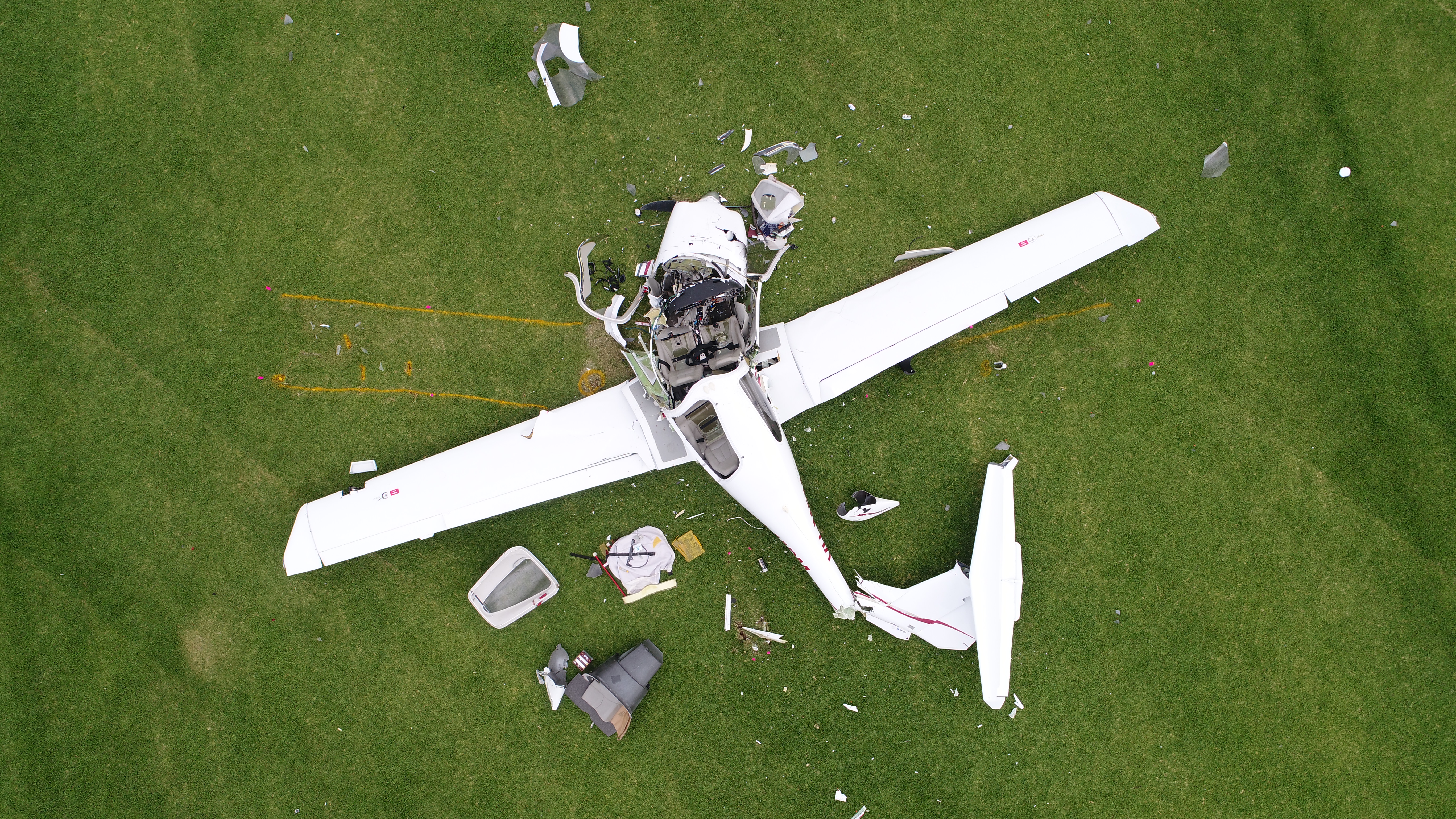
On-site examination of the severely impact-damaged fuselage (Figure 7), engine and propeller identified no pre‑existing faults or anomalies that could have contributed to the accident. Examination of the wreckage indicated that the aircraft impacted terrain from a vertical descent, right side slightly down, in an almost level attitude.
A number of aircraft components were retained for further examination and testing. The propeller did not exhibit any evidence of rotation at impact, consistent with fuel exhaustion resulting from the integral wing-fuel tanks rupturing with the separation of the wings.
The evidence indicated that both pilots were secured in their seats prior to impact. Notwithstanding the severe disruption to the airframe, examination identified that both pilot seats were about mid-travel with one locator pin on each seat still engaged in the seat rails.
Figure 6: The accident site and location of fuselage and wings
Source: Google Earth, modified by ATSB
Figure 7: The fuselage, left and right wings
Source: Northern Territory Police and ATSB, modified by ATSB
Examination of the aircraft wings
Both wings had separated between 0.5 and 1.5 m outboard from the wing-to-fuselage attachment. Morphology of all fractures within the wing spars indicated that they failed due to overstress, and exhibited bending deformation consistent with forces acting upwards and rearwards on the wings. Examination of the wings showed no evidence of pre-existing defects.
Figure 8: Fractured main spar caps from the right wing
Source: ATSB
The lower spar cap shows significant local deformation in an upwards and rearwards direction. The upper main spar caps had fractured at two points along their length. The left upper spar cap failed at the location shown in Figure 8. Further inboard, the same spar cap had sheared from the webbing that secured it to the rest of the wing spar. The deformation observed was consistent with buckling due to compressive loads, as the wings were bent upwards with forces in excess of the ultimate positive flight load (Figure 9). In short, the left upper main spar cap deformed enough to damage the wing skin, consistent with buckling due to compressive loads.
Figure 9: The left upper main spar cap deformation due to compressive loads
Source: ATSB
Survivability
Survival in an aircraft accident depends on various aspects, including impact forces imparted on the occupants being within human tolerance, occupant/seat restraints and liveable space inside the aircraft. The impact forces alone in this accident meant that it was not survivable.
Recorded information
Track data
The aircraft was not equipped with a flight data recorder or cockpit voice recorder, nor was it required to be. The aircraft’s GPS unit did not record any data. All recorded data to determine the aircraft’s track is based on ATC radar data (local and system) and OzRunways data. Analysis of this data indicated the following.
There were no apparent aircraft handling problems, up to the recorded point at 1332:28.
Between 1332:20 and 1332:28, there was a loss in height of 300 ft, and from this point, the speed of the vertical descent increased rapidly.
The aircraft impacted the ground approximately 30-40 s after it was at about 10,000 ft.
After the aircraft was below 8,000 ft, its average vertical speed exceeded 10,000 ft/min, with periods above 15,000 ft/min and up to 32,000 ft/min.
There were no on-board recording devices to accurately determine the aircraft’s actual airspeed. While the forecast winds can be used to estimate airspeed, the actual airspeed cannot be accurately determined given the likelihood of wind shear and turbulence in the air mass.
Manoeuvring speed
The aircraft’s manufacturer specified a manoeuvring speed of 118 kt at its maximum take-off weight. The aircraft’s weight at the time of the breakup was about 1,603 kg, which equates to a manoeuvring speed of 114 kt (calibrated airspeed), as shown in Figure 10.
At airspeeds above the manoeuvring speed, full or abrupt control inputs or turbulence may produce wing loading that can damage the aircraft’s structure. At airspeeds above about 145 kt, this loading can result in failure of the aircraft structure.
The following graph depicts the calibrated airspeed with wind corrections based on the forecast, noting that actual wind conditions were unavailable, and may be significantly different due to the proximity to a rapidly developing cell.
Figure 10: VH-HWY recorded altitude and groundspeed for the last 10 minutes of flight
Company information
Supervisory pilot role
Air Frontier’s new pilots often had limited exposure to the weather conditions of the tropics, and some had relatively low overall flying experience. In order to prepare them for the work and assess their suitability, Air Frontier had developed a line operational training process. In a March 2014 Notice to Aircrew (NOTAC), the chief pilot had outlined the pilot ICUS training, and the role of company appointed supervisory pilots as follows.
ICUS Operations [are when] potential pilot recruits (Trainee Pilots) may gain experience on Company aircraft and operations as Pilot In-Command-Under Supervision (ICUS) whilst under the supervision of an experienced Company-approved ICUS Supervisory pilot...
ICUS supervisory pilots are company-approved pilots for supervising Trainee Pilots while they are undergoing line operational training and suitability assessment…A supervisory pilot is not necessarily a qualified flight instructor and is expected only to provide training in regards to company procedures and routes.
Newly recruited pilots completed ground training first and at least one check flight with the chief pilot before conducting flights with supervisory pilots. Supervisory pilots were responsible for ensuring the ‘trainee’ followed regulatory requirements and the company’s standard operating procedures at all phases of flight. If the aircraft was approaching an ‘unsafe state’ during flight, supervisory pilots were to issue verbal instructions to the trainee but, if required, take over immediately. The supervisory pilot was considered the pilot in command at all times.
Supervisory pilots were selected by the chief pilot and managing director, after reviewing the pilots’ logbooks, proficiency check results, and their ‘standing’ in the company. The operator’s NOTAC outlined minimum requirements for supervisory pilots, and for single engine operations if the pilot had under 1,000 hours (as was the case with the accident flight), to have worked for the company for 6 months, have at least 400 hours as PIC and 50 hours on type. The operator had proactively implemented these minimum (non-mandatory) requirements for supervisory pilot experience and training to improve their capabilities. They then undertook a training and checking flight with the chief pilot or delegate, including a training and proficiency assessment in a take-off, landing and go-around from the right seat, recovery from unusual attitudes in VMC and (simulated) IMC.
Wet season guidance to pilots
Air Frontier provided pilots with policies and guidance relating to conditions experienced in the wet season, and the operations manual included the following.
…thunderstorms, line squalls and other conditions denoting areas of violent turbulence and/or hail must be regarded as extremely dangerous and be positively avoided. Avoid flying within 10 km horizontally of a fully developed cumulonimbus cloud and also directly below the base of the cloud wherever possible.
Vertical air movement capable of producing extremely severe turbulence is often present near the edge of the cloud’s base, or in clear air below the overhang of the top. An early decision to divert around a thunderstorm will need a relatively small heading change and result in minimal distances added to the flight.
About a week before the occurrence, Air Frontier distributed its Wet Season Guide, developed internally to assist pilots understand weather conditions to which they would be regularly exposed. The company aimed to ensure that its many new pilots were prepared to handle various ‘challenging scenarios’.
In its informal style, the Guide included the following topics.
The importance of planning: encouraged pilots to source forecasts and actual weather conditions from a range of sources including BoM (including their Rain Radar app) and OzRunways.
Fuel management: advised pilots they should ensure that holding and alternate requirements are met, and take into account additional fuel required to handle conditions indicated by TEMPOs[14] in the forecast.
Flying conditions during the wet season: advised pilots to ‘accept either low cloud or low visibility but not both’, and advising that if a cloud base is high, it is preferable to track lower through showers, although with cautions about the risks of lower visibility conditions. It stated that it is better to fly on the upwind side around a storm, and tracking over water if possible. See Figure 11 for an example of the images included in the guide.
The role of ATC: stated that ATC is there to help pilots, and to not be afraid of requesting left or right of track (by 3, 5, or 10 NM) and specific heights to avoid weather. It mentioned that an area around ‘Jacko’s Junction’ to the east of Darwin was known to have adverse weather.
Commercial considerations: ‘The decision to fly or not fly can at times be very tough and you have to use every resource available to you to help you make that decision.’
The training manager also mentioned that pilots received ‘extensive verbal training’ about the different weather conditions in NT.
A number of Air Frontier’s staff and pilots, and other operators in the region provided comment on the inherent challenges of the wet season. They knew thunderstorms could form rapidly, were not always easily detectable on weather radar (dependant on precipitation). They also acknowledged that pilots had to experience the conditions to get better at managing them and making ‘good judgements early’ was important.
Figure 11: Large storm cell images illustrated in Air Frontier’s Wet Weather Guide
Source: Operator, with permission
An Air Frontier pilot identified ‘command decision making in high stress environments’ including operating in Arnhem Land among the skills and knowledge that pilots had to develop after joining the company. Other company pilots indicated having an iPad with the OzRunways application installed to see weather radar during flight. They also identified reports from other pilots in the area or from ATC to manage weather conditions.
Comments about managing weather conditions from pilots working for other operators in the region included the following.
One pilot believed a Howard Springs cell was predictable during the wet season as it was an almost-daily occurrence, and recommended avoiding such cells by 20-40 NM.
One pilot noted the importance of carrying additional fuel in the wet season, as diverting to avoid a thunderstorm by 10 NM often was not enough. He had also encountered strong up- and down-drafts in these conditions.
Some pilots indicated that it was unlikely an aircraft such as a C210 could out-climb fast-developing cells that occur in the wet season, and ‘staying low’ was much more preferable.
A few pilots noted that the practice of ‘Territory VFR’ was prevalent amongst pilots in the Top End (a reference to VFR pilots briefly climbing through cloud for less turbulent conditions).
After this accident, Air Frontier’s chief pilot spoke with the pilots about the dangers of flying in the wet season. He encouraged them to inform ATC of their requirements, including the option to fly into Restricted airspace.
Next of kin notification
As part of the investigation, the ATSB was informed of a delay in being able to notify one of the pilot’s family. About 15 minutes after the aircraft’s disappearance from ATC radar, controllers informed Air Frontier’s chief pilot (the emergency point of contact). He called the police, which confirmed it was attending the accident site. The chief pilot next reported the accident to CASA and ATSB. He was then able to provide the police with the next of kin details for one pilot, but found that Air Frontier did not have the same details on file for the other pilot.
Consequently, there was a delay of several hours in informing that pilot’s family while the police worked to obtain information from alternate sources (previous employment history). On-site, ATSB investigators later found the pilot’s completed next of kin details form, which had not been provided to the company.
Regulatory oversight
The ATSB reviewed CASA’s surveillance activities and reports for Air Frontier from about 7 years leading up to this occurrence. These included some relevant findings and observations, mostly pertaining to operational document control, incomplete documentation on roles such as the supervisory pilots, and concerns about chief pilots not fulfilling all aspects of their role (mostly due to workload).
The CASA post-occurrence surveillance report (provided to the operator in November 2017) had 13 findings, and themes including the following.
Deficiencies in the record keeping for files associated with the new pilot, including flight and duty time information, licenses and qualifications.
Absence of evidence around the left seat pilot having acknowledged he had read the operations manual, or key NOTACs such as the March 2014 on ICUS and supervisory pilots.
Not having completed some updates to the operations manual to ensure procedures for cargo loading, ICUS flying, training programs and supervisory pilots were included.
Perceived deficiencies in the selection and management of supervisory pilots
The report’s summary stated that, based on the findings, there were perceived ‘deficiencies in the appropriateness of the operator’s organisation and the soundness of its management structure’. In its response to this report, Air Frontier raised some questions about the accuracy of observations relating to supervisory pilots but agreed to take all the remedial actions required.
Human performance considerations
The ATSB considered key human factors topics relating to this accident to explore possible influences on the pilots’ in-flight weather-related decision making and physiological effects associated with the adverse weather conditions.
Decision making
Naturalistic decision making
It is important to consider pilot decisions it in the context in which the sequence of events occurred. Orasanu (2000) outlines the concept of naturalistic decision making:
Naturalistic decision-making focuses on understanding how people with domain expertise use their knowledge to make decisions, typically in safety-critical environments (Cannon-Bowers et al., 1996; Zsambok & Klein, 1997).
The basis for recognising situations that requires decisions is knowledge (Orasanu, 2000). This includes ‘determining what information is relevant to the decision, and deciding on an appropriate course of action…in order to manage risk, threats must be perceived and accurately assessed.’
Orasanu asks, ‘how can flight crews be trained and supported to make the best decisions possible, especially under challenging high-risk conditions?’
Weather-related decision making
The ATSB (2005) report, General Aviation Pilot Behaviours in the Face of Adverse Weather, states that ‘weather-related general aviation accidents remain one of the most significant causes for concern in aviation safety’ which requires pilots to continuously evolve their decision making.
Pilots in general aviation often operate in an ‘uncertain and risky operational domain where they are confronted with a range of meteorological phenomena about which a series of in-flight decisions need to be made’ (Hunter, Martinussen and Wiggins, 2003). This information often comes from a range of sources ‘including meteorological briefings, inflight weather reports, visual information from the cockpit, and on-site reports.’
Wiggens and O’Hare (1995) define weather-related decision making as ‘those skills necessary to recognize and avoid meteorological phenomena that present a hazard to the flight.’ It is a skill which is developed ‘gradually through practical experience [but] in developing this type of experience, relatively inexperienced pilots may be exposed to hazardous situations with which they are ill-equipped to cope’.
One of the reasons why pilots may decide to continue a flight into adverse weather is that ‘they make errors when assessing the situation. That is, pilots are seen to engage in VFR flight into [instrument meteorological conditions] because they do not accurately assess the hazard (Wiegmann and Goh, 2000). Risk perception can be influenced by personal experience and ability (Sanders and McCormick, 1993).
The Federal Aviation Administration produced a guide in 2005 called General Aviation Pilot’s Guide to Pre-Flight Weather Planning, Weather Self-Briefings, and Weather Decision Making. They suggest that it is the abundance of weather information that may make it difficult for pilots to focus on key information and ‘correctly evaluate the risk resulting from a given set of circumstances’.
Weather-related cue-based training and guidance
It may be possible to provide pilots with greater knowledge of adverse weather conditions (and how the handle them) through training. Wiggins and O’Hare (2003) discussed the benefits of cue‑based training to help pilots ‘recognise and respond to deteriorating weather conditions during flight.’ Training ‘improved…pilots’ initial response times to deviate around the thunderstorm’ (Ball, 2008).
In recent times, pilots will often use information ascertained from apps on their tablets / iPads, including graphical weather displays based on radar information. However, Ball (2008) outlined that ‘previous research suggested that giving pilots the ability to see accurately the weather they are flying in and around may tempt some pilots to try to fly through small breaks in the convective activity’. Some pilots would attempt to navigate through or very close to the hazardous weather, and there are others that used the graphical information to plan and maintain a safe distance (20 NM or greater) from a storm.
Air Frontier’s chief pilot acknowledged that the wet season can be a very challenging time to fly. He said pilots should ‘never out-climb the weather’ and aim to be at least 10 NM away from the weather. The training manager said that during flights with their pilots, he tested them on their knowledge of weather conditions, and expected they brief on the weather conditions en route.
The CASA-conducted seminars in Darwin address risks of flying in the wet season. The seminars include briefings from BoM staff, and are designed for junior pilots, or those new to the region.
Effect of experience and familiarity
Blickensderfer and others (2018) assessed that ‘the manner in which expert pilots respond to hazardous weather scenarios differs from that of less experienced pilot.’ The NTSB (2005) furthered this by outlining that:
Errors in decision-making, such as plan continuation errors or incorrect assessments of weather-related risk, may be made by pilots who are unfamiliar with the climate of the local area, who lack total and/or recent experience identifying marginal weather conditions, or who lack experience accessing or reading weather reports.
Air Frontier’s training manager commented that many pilots start work with Air Frontier without having previously encountered the weather conditions in Darwin. Other pilots recalled their own encounters with the weather soon after they arrived in Darwin, where they were sometimes unsure of the best action to take when adverse weather was encountered.
Plan continuation bias
It is possible that pilots do not divert (or divert further) as it is perceived as a loss. Ball (2008) outlined that the pilots in their study ‘could see it was going to take longer to fly around the edge of the storm than it would take to cut through the areas of broken activity, which would result in a significant savings of time’.
An NTSB study (2005) outlined that one class of decision making in weather-related occurrences was the presence of plan continuation error, which is defined by Orasanu and others (2001) as ‘‘failure to revise a flight plan despite emerging evidence that suggests it is no longer safe’. Rather than revisiting the intended route by making a decision such as returning to the departure airport, pilots ‘may opt to press on in deteriorating weather’.
Perceived pressures to continue a flight
Pilots may perceive that there are some pressures to continue a flight, as opposed to returning or diverting. In small commercial operations, there can be a risk for pilots ‘balancing the competing demands of safety and productivity [becomes] difficult for many small operators, which places a heavy reliance on the decision making of individuals’ (Bearman and others, 2009). In a survey of pilots working for small Alaskan operators, they reported encountering ‘both explicit and implicit norms and expectations to fly in marginal conditions.
Orasanu (2009) supports this notion:
An organization’s emphasis on productivity may inadvertently set up goal conflicts with safety. Mixed messages, whether explicit or implicit in the norms and organizational culture, create conflicting motives, which can affect pilots’ risk assessment and the course of action they choose.
The owner of Air Frontier said he speaks with individual pilots to explain that there is no pressure to continue a flight, and they would be supported if they decided to return or divert. Likewise, the chief pilot of Air Frontier commented that from his standpoint, no job is worth pushing the limits for’. He felt, ‘if the weather’s no good get them to delay it’. He said they wanted the pilots to stay on the ground rather than try to push it in marginal weather situations.
Increased workload and stress
The ATSB considered whether the pilots likely experienced the effects of increased workload and stress in a situation where they were undertaking weather-related deviations in conditions they had limited (if any) exposure to in the past.
Orlady and Orlady (1999) define workload as ‘reflecting the interaction between a specific individual and the demands imposed by a particular task’. The outline that to understand the effect of workload, it is important to understand the strategies a pilot uses for managing tasks:
An individual has a finite set of mental resources they can assign to a set of tasks (i.e. performing a takeoff). The resources available to an individual can change given the experience and training they have had or the level of stress and fatigue they are experiencing…When workload becomes excessive, the individual must shed tasks.
Orlady and Orlady (1999) also outline that workload varies with ‘training, procedures, experience, and sometimes with stress levels…’. Morris and Leung (2006) build on this idea, outlining that pilots in higher mental workload conditions experience more errors in tracking and communication.
An increased workload can result in an increase in stress experienced. When in stressful situations (such as needing to take actions that are different to those planned), there can be some effect on the ability to consider all of one’s options. Staal (2004) adds that ‘individual judgment and decision making is degraded under stressful conditions’ and that ‘in addition to experiencing greater rigidity, individuals may tend to persist with a method or problem-solving strategy even after it has ceased to be helpful’.
In this case, the ATSB considered whether increased workload resulting from deviating from the track and aircraft handling in turbulence could have resulted in high stress levels, which in turn could have affected the pilots’ decision making. The air traffic controllers reported that they did not detect any signs of stress in the pilot’s voice, although the pilot’s responses became increasingly short in length and word use. However, apart from these considerations and information, there was insufficient evidence to identify to what extent increased workload or stress affected decision making.
Risk of spatial disorientation
Gibb and others (2010) explain that seeing the horizon is ‘crucial for orientation of the pilot’s sense of pitch and bank of the aircraft’. In conditions of low visibility, the horizon may not be visible to the pilot, during which time they can become rapidly disorientated. Newman (2007) found that ‘the major environmental factors [that contribute to spatial disorientation] are related to time of day and the ambient weather conditions. Poor visual cues are a function of most disorientation illusions, so flight…in conditions of bad weather can set a pilot up for a disorientation experience’.
In a discussion of spatial disorientation, Benson (1999) defined the experience as follows:
Spatial disorientation is…[where] the pilot fails to sense correctly the position, motion or attitude of the aircraft or of him/herself [resulting in] errors in perception by the pilot of their position, motion or attitude with respect to their aircraft...
Newman (2007) outlined that spatial disorientation can affect ‘any pilot, any time, any where, in any aircraft, on any flight, depending on the prevailing circumstances’. Extensive research on spatial disorientation indicates that loss of control will likely occur between 60 seconds (Benson, 1983 in Gibb and others, 2010) and 178 seconds (Newman, 2007) after the loss of visual reference. Gibb and others (2010) state that ‘spatial disorientation accidents have fatality rates of 90–91 percent’.
In this case, both pilots involved in this occurrence held a current instrument rating at the time, which may have reduced the risk of experiencing spatial disorientation in low visibility conditions. The ATSB considered whether the pilots were likely to have experienced spatial disorientation in any areas of reduced visibility, leading to either a loss of control and/or an unusual attitude, but there was insufficient evidence to demonstrate that the aircraft likely entered low visibility conditions.
Related occurrences
A review of the ATSB occurrence database found that since 1969 (which corresponds to the availability of electronic data), there had been 45 in-flight breakups, four involving Cessna 210’s, the most commonly-involved aircraft. Of those 45 occurrences, 10 were associated with adverse weather and/or turbulence. In the same period, there have been 47 occurrences reported to the ATSB considered to be ‘VFR into IMC’ occurrences.
As a basis of comparison, the US National Transportation Safety Board investigated seven in-flight breakups of Cessna 210 aircraft since 2000. All those occurrences involved flight into thunderstorms or associated turbulence, a loss of control following inadvertent flight into instrument meteorological conditions or a combination of both.
In one case, a Cessna T210L flew into IMC in 2005, where icing or spatial disorientation likely resulted in a loss of control. Excessive speed then resulted in the aircraft exceeding its design limits, resulting in the breakup. The right wing was found approximately 800 m from the main wreckage. Damage observed on one of the wings was similar to that in the HWY breakup.
Two in-flight break up occurrences investigated by the ATSB are summarised below.
The Cessna Silver Eagle aircraft, a turbine-powered, pressurised Cessna 210, was conducting a private flight from Maroochydore to Bankstown under the instrument flight rules (IFR), cruising at flight level (FL)[15] 160. The pilot faced adverse weather en route and requested a diversion around the weather, and then subsequent descents from their cleared flight level. The pilot reported an engine failure then a loss of generator power. No further broadcasts were received, and several hours later, the wreckage was found 380 m south-east of its last position.
Onsite investigation revealed that the right wing had failed before impact because of aerodynamic forces that exceeded the wing structural load limits. The empennage had also separated from the fuselage before impact. Interpretation of the en route weather reports suggested that the aircraft might have passed through a line of showers and thunderstorms.
The in-flight breakup resulted from the airframe being stressed beyond its design limit.
On 7 December 2011, the owner-pilot of a Cessna 210M, registered VH-WBZ, was conducting a private flight under the visual flight rules from Roma to Dysart in Queensland. Thunderstorms with associated cloud, rain and severe turbulence were forecast. About 30 minutes into the flight, the outer sections of the wings and parts of the tail separated and the aircraft collided with terrain, fatally injuring the pilot.
The ATSB established that ground-based weather radar showed thunderstorms in the vicinity of the accident site, and recorded engine data showed cruise power setting was maintained until recording ceased. Although the precise circumstances leading up to the accident were not known, a combination of aircraft airspeed with the effects of turbulence and/or control inputs generated stresses that exceeded the design limits of the aircraft structure.
Airspeed is a critical factor in the stress sustained by an aircraft. Pilots need to be aware of the manoeuvring speed (VA) for the aircraft weight, and to control airspeed so as not to exceed that value when full control deflection is required or severe turbulence or wind/gusts are encountered. Severe turbulence and wind gusts are among the hazards associated with thunderstorms.
When VH-HWY departed Darwin Airport at 1307 on 23 October, the area forecast indicated the presence of thunderstorms and reduced visibility. However, the weather conditions that the aircraft encountered developed rapidly meant that its pilots could not have accurately and easily predicted them before departure.
Fourteen minutes after departure, the left seat pilot requested a diversion left or right of track to avoid weather. The subsequent diversions of 10 and 20 NM were prompted by ATC through their transmission to HWY including ‘advise if you need further right of track’. While it was possible for ATC to clear HWY to divert left instead, there was adverse weather in that area too.
The aircraft’s recorded track during these weather-related diversions, when overlaid on the weather radar and satellite cloud images, showed that HWY tracking in close proximity to both a precipitating cell and a rapidly developing towering cumulus cloud. The last position of the aircraft at 1332 was in the rapidly developing cell, in an area likely to have strong convective activity including up- and down-drafts. The altitude changes in the final minutes indicate that the aircraft was likely experiencing severe convective turbulence.
It is possible the aircraft entered an area of reduced visibility associated with the precipitating cells and other clouds. This would meant an increased risk of the pilots losing visual cues to determine the horizon, and then experiencing spatial disorientation. This could lead to losing, or being unable to regain control of the aircraft in the case of an unusual attitude. Regardless, the load on the airframe could have been increased by any momentary loss of control.
In summary, shortly after VH-HWY diverted to avoid adverse weather, the aircraft entered an area of strong convective activity and rapidly developing precipitating cells, which resulted in it experiencing severe turbulence and possibly reduced visibility for the pilots.
Wing separation from fuselage in-flight
The aircraft’s track data as well as witness reports indicate a very high rate of descent from about 10,000 ft until it impacted terrain. The aircraft wings were found in close proximity to each other, likely tethered to each other until a low altitude or till they impacted trees. The deformation in the fractured wing spars was in an upward and rearward direction. The combination of this evidence indicates that the wings separated from the aircraft in flight, likely due to excessive wing loading beyond the wing loading limits.
In accordance with aircraft design load factors, the wing loading, relative to the airspeed, was too high. The evidence indicates that the aircraft likely encountered severe turbulence. The ATSB could not establish the precise airspeed before or at the point of the uncontrolled descent, nor what control inputs were made by the pilots. However, based on calculations of the calibrated airspeed and the recorded ground speed (albeit without known localised wind), the effects of turbulence, any control inputs (however small) would increase wing loading. Therefore, any control inputs would have increased aerodynamic load and, as such, any attempt by the pilot's to control the aircraft or avoid the cloud increased the load factor.
In summary, a combination of airspeed, turbulence and control inputs probably led to excessive loading on the aircraft’s wings, which separated from the fuselage in-flight before the aircraft collided with terrain.
Crew pairing in the wet season
It is possible that after diverting right of track to avoid weather, the pilots perceived an opportunity to return to the planned track, but then re-diverted south to avoid further hazardous conditions. However, this inadvertently positioned the aircraft in adverse weather that resulted in the separation of the wings. The ATSB considered whether the pilots’ in-flight weather-related decision making was influenced by certain motivational factors such as:
concern about having departed Darwin later than intended,
perceived need to deliver the coffin to Elcho Island in a timely manner, and/or:
perceived implicit pressures to continue, given they were new in their respective roles.
These factors could lead to a plan continuation bias. However, it was not possible to determine if any of these factors influenced their decision making. Nevertheless, a likely influence, supported through extensive research relating to in-flight weather-related decision making, was the level of operational experience the pilots had in the wet season.
The ‘build-up’ period to the wet season in Darwin is known for weather conditions hazardous to flying activities. Pilots in tropical areas need to recognise and respond to these conditions to avoid the hazards including turbulence, windshear and reduced visibility. However, this is more challenging when a pilot has not experienced these conditions, and therefore may not accurately assess the situation or perceive the risks. Ball (2008) states that the lack of hazardous weather flying experience plays ‘a role in the pilot’s ability to make timely and safe decisions about flying in and around hazardous weather’. Many of the pilots that the ATSB spoke with indicated that they only learned how to handle the weather during the wet season through their own exposure to the conditions, particularly the distance to keep from rapidly-developing cells. There were differences in the perception of how much distance to keep from them, ranging from 10 to 40 NM.
In this case, neither pilot had flown during a previous wet season in Darwin. Whilst the ATSB could not determine whether the pilots had ever experienced conditions similar to wet season conditions ever before, there was sufficient evidence to indicate that there were limited opportunities to have done so.
Orasanu (2000) outlined that when flying with other pilots, team members likely expand cognitive resources. For Air Frontier, supervisory pilots were paired with new company pilots to gain experience on their aircraft and operations. However, in this context as a risk mitigation, this can only be effective if one pilot has knowledge the other has not. It cannot be definitively stated that more experienced pilots would have avoided all hazardous weather that day, but there was an increased likelihood others would have recognised the risks posed to the safety of flight, and perhaps decided to take different actions.
In summary, the risk mitigation provided by pairing a supervisory pilot with a trainee did not adequately address the weather-related risks because neither pilot had experience flying in the region during the wet season.
Disclosure of medical history
The investigation identified that medication the left seat pilot was taking was not recorded in his medical file. However, there is no evidence that his performance, including decision making, was influenced by the medication or any medical condition, or otherwise contributed to this occurrence.
Notwithstanding the above, it is important to recognise that the purpose of declaring medical history is to address risks associated with medications or conditions that could affect performance. It is acknowledged that some pilots may often be concerned about not meeting medical certificate requirements if they declare using medications or have a medical condition. However, they then miss the opportunity to have their concerns addressed by a medical professional qualified in aviation medicine.
Documented pathways exist for managing certain medical conditions and medications that do not preclude a pilot from maintaining a medical certificate (including in this case). Both CASA and designated aviation medical examiners (DAME’s) have an important role in increasing pilot awareness about these pathways, and encouraging disclosure of medical history.
Findings
From the evidence available, the following findings are made with respect to the in-flight breakup involving a Cessna 210L, registered VH-HWY, that occurred 12 NM east of Darwin Airport, Northern Territory. These findings should not be read as apportioning blame or liability to any particular organisation or individual.
Contributing factors
Shortly after VH-HWY diverted to avoid adverse weather, the aircraft entered an area of strong convective activity and rapidly developing precipitating cells, which resulted in it experiencing severe turbulence and possibly reduced visibility for the pilots.
A combination of airspeed, turbulence and control inputs probably led to excessive loading on the aircraft’s wings, which separated from the fuselage in-flight before the aircraft collided with terrain.
Other factors that increased risk
The risk mitigation provided by pairing a supervisory pilot with a pilot new to the company did not adequately address the weather-related risks because neither pilot had experience flying in the region during the wet season.
While there is no evidence that it contributed to this occurrence, the left seat pilot was taking a medication that was not recorded in his medical file. The disclosure and recording requirements for a pilot’s medical certificate aim to address the risks associated with medications or conditions that could affect performance.
General details
Right seat pilot details – Supervisory pilot
Licence details:
Commercial pilot licence (aeroplane), issued March 2016
Single-engine and multi-engine aeroplane; Instrument – multi-engine and single-engine aeroplane, instrument approach 2 and 3 dimensional
Medical certificate:
Class 1, valid to May 2018
Aeronautical experience:
381.4 hours
Last proficiency check / flight review:
Instrument proficiency check May 2017, Night VFR single-engine aeroplane July 2017
Aircraft details
Manufacturer and model:
Cessna Aircraft Company 210L
Year of manufacture:
1974
Registration:
VH-HWY
Operator:
Air Frontier Pty Ltd
Serial number:
210-60263
Total Time In Service
6,499.2 hours
Type of operation:
Charter
Persons on board:
Crew – 2
Passengers – 0
Injuries:
Crew – 2 (Fatal)
Passengers – 0
Damage:
Destroyed
Sources and submissions
Sources of information
The sources of information during the investigation included:
Air Frontier
Airservices Australia (Airservices)
the Bureau of Meteorology (BoM)
the Civil Aviation Safety Authority (CASA)
a number of witnesses and other pilots in the region
Northern Territory Police
OzRunways
Royal Australian Air Force
Textron Aviation.
References
Ball, J., 2008, The Impact of Training on General Aviation Pilots' Ability to Make Strategic Weather-Related Decisions, Civil Aerospace Medical Institute, Oklahoma City, USA
Batt, R. and O'Hare, D., 2005, General aviation pilot behaviours in the face of adverse weather, ATSB Aviation Research Investigation Report B2005/0127, available at www.atsb.gov.au
Bureau of Meteorology, 2012, Weather Advice for your Safety: Flying the Tropics, available at www.bom.gov.au
Bureau of Meteorology, 2012, Hazardous Weather Phenomena: Thunderstorms, available at www.bom.gov.au
Bureau of Meteorology, 2012, Hazardous Weather Phenomena: Turbulence, available at www.bom.gov.au
Bearman, C., Paletz, S., Orasanu, J. and Brooks, B., 2009, Organizational Pressures and Mitigating Strategies in Small Commercial Aviation: Findings from Alaska, Aviat Space Environ Medicine, 80:1055-8
Blickensderfer, B., Lanicci, J., Guinn, T., King, J., Ortiz, Y. and Thomas, R., 2018, Assessing General Aviation Pilots' Understanding of Aviation Weather Products, The International Journal of Aerospace Psychology, Vol. 27
Federal Aviation Administration, 2005, General Aviation Pilot's Guide to Preflight Weather Planning, Weather Self-Briefings, and Weather Decision Making, available at www.faa.gov
Hunter, D., Martinussen, M. and Wiggins, M., 2003, Understanding How Pilots Make Weather-Related Decisions, International Journal of Aviation Psychology
National Transportation Safety Board, 2005, Risk Factors Association with Weather-Related General Aviation Accidents, Washington, D.C, USA
Newman, D., 2007, An overview of spatial disorientation as a factor in aviation accidents and incidents, ATSB Aviation Research and Analysis Report B2007/0063, available at www.atsb.gov.au
Morris, C. and Leung, Y., 2006, Pilot mental workload: how well do pilots really perform?, Ergonomics Journal Vol. 49 pp. 1581-1596.
Orasanu, J., 2010, Flight Crew Decision-Making, in Kanki, B., Helmreich, R. and Anca, J., Crew Resource Management, Elsevier, San Diego, USA
Orlady, H. and Orlady, M., 1999, Human Factors in Multi-Crew Flight Operations, Ashgate Publishing, Vermont, USA
Sanders and McCormack (1993) – Human Factors in Engineering and Design (7th edition)
Staal, M., 2004, Stress, Cognition and Human Performance: A Literature Review and Conceptual Framework, Ames Research Centre, California
Wiegmann, D. and Goh, J., 2000, Visual Flight Rules (VFR) Flight into Adverse Weather: An Empirical Investigation of Factors Affecting Pilot Decision Making, Federal Aviation Administration, Washington DC, USA
Wiggins, M., 2003, Weatherwise: Evaluation of a Cue-Based Training Approach for the Recognition of Deterioration Weather Conditions during Flight, University of Western Sydney, Sydney, Australia
Wiggins, M. and O'Hare, D., 1995, Expertise in Aeronautical Weather-Related Decision Making: A Cross-Sectional Analysis of General Aviation Pilots, Journal of Experimental Psychology: Applied, Vol. 1
Woods, D. and Patterson, E., , How Unexpected Events Produce An Escalation Of Cognitive And Coordinative Demands, Ohio State University, USA
Submissions
Under Part 4, Division 2 (Investigation Reports), Section 26 of the Transport Safety Investigation Act 2003 (the Act), the Australian Transport Safety Bureau (ATSB) may provide a draft report, on a confidential basis, to any person whom the ATSB considers appropriate. Section 26 (1) (a) of the Act allows a person receiving a draft report to make submissions to the ATSB about the draft report.
A draft of this report was provided to Air Frontier, the Civil Aviation Safety Authority (CASA), the Bureau of Meteorology (BoM), the Northern Territory Police and the next of kin of both pilots.
Submissions were received from Air Frontier, CASA, BoM, and the next of kin of both pilots. The submissions were reviewed and where considered appropriate, the text of the report was amended accordingly.
Purpose of safety investigations
The objective of a safety investigation is to enhance transport safety. This is done through:
identifying safety issues and facilitating safety action to address those issues
providing information about occurrences and their associated safety factors to facilitate learning within the transport industry.
It is not a function of the ATSB to apportion blame or provide a means for determining liability. At the same time, an investigation report must include factual material of sufficient weight to support the analysis and findings. At all times the ATSB endeavours to balance the use of material that could imply adverse comment with the need to properly explain what happened, and why, in a fair and unbiased manner. The ATSB does not investigate for the purpose of taking administrative, regulatory or criminal action.
Terminology
An explanation of terminology used in ATSB investigation reports is available here. This includes terms such as occurrence, contributing factor, other factor that increased risk, and safety issue.
Publishing information
Released in accordance with section 25 of the Transport Safety Investigation Act 2003
Ownership of intellectual property rights in this publication
Unless otherwise noted, copyright (and any other intellectual property rights, if any) in this report publication is owned by the Commonwealth of Australia.
Creative Commons licence
With the exception of the Coat of Arms, ATSB logo, and photos and graphics in which a third party holds copyright, this publication is licensed under a Creative Commons Attribution 3.0 Australia licence.
Creative Commons Attribution 3.0 Australia Licence is a standard form licence agreement that allows you to copy, distribute, transmit and adapt this publication provided that you attribute the work.
The ATSB’s preference is that you attribute this publication (and any material sourced from it) using the following wording: Source: Australian Transport Safety Bureau
Copyright in material obtained from other agencies, private individuals or organisations, belongs to those agencies, individuals or organisations. Where you wish to use their material, you will need to contact them directly.
Preliminary report
Report release date: 07/12/2017
This preliminary report details factual information established in the investigation’s early evidence collection phase and has been prepared to provide timely information to the industry and public. Preliminary reports contain no analysis or findings, which will be detailed in the investigation’s final report. The information contained in this preliminary report is released in accordance with section 25 of the Transport Safety Investigation Act 2003.
Sequence of events
On 23 October 2017, two pilots from Air Frontier were operating a Cessna C210L aircraft, registered VH-HWY (HWY), on a charter flight from Darwin Airport to Elcho Island, Northern Territory. The pilot in the left seat was the pilot in command, under supervision of the right seat pilot and the flight was operating under the visual flight rules (VFR).[1] The pilots had submitted a flight plan to track via ‘VFR route No. 2’ to Castle Point (Figure 1) and then direct to Elcho Island.
Figure 1: Darwin Airport and pertinent features on the visual terminal chart
Source: Airservices annotated by ATSB
The aircraft took off from runway 29 at about 1307 Central Standard Time.[2] Recorded air traffic control (ATC) data showed that as the aircraft climbed through 700 ft, the pilot[3] contacted ATC and was cleared to climb to 7,500 ft and turn onto a heading of 320° (items 1 and 2 in Figure 2). About 5 minutes later, the controller cleared the aircraft to turn right onto a heading of 100° (item 3 in Figure 2).
As the aircraft tracked east and passed through 6,100 ft on climb, the pilot requested clearance to divert 5 miles left or right of track due to weather (item 4 in Figure 2) and to climb to 9,500 ft. Air traffic control advised that left of track was unavailable due to the nearby active restricted airspace (Figure 1) and so was cleared to divert up to 5 NM right of track and to climb to 9,500 ft. Just over 2 minutes later, the controller cleared the aircraft to operate up to 10 NM right of track (item 6 on Figure 2).
At 1325, the aircraft turned north-east and continued to climb for another 4 minutes, to about 10,000 ft. At 1329, the controller recalled seeing the aircraft turn abruptly to the south west. The controller asked the pilot if they required alternate tracking (item 8 on Figure 2). The pilot replied ‘affirm’ and the controller cleared the aircraft to deviate up to 20 NM right of route. The aircraft continued to track south west.
Figure 2: Aircraft track with pertinent broadcasts from the aircraft and air traffic control
Source: RAAF radar data overlaid on Google earth, annotated by ATSB
At 1332, the aircraft’s recorded groundspeed increased from 130 kt to 150 kt. Air traffic control radar recorded the aircraft descending and climbing between 9,600 ft and 10,100 ft (see the section titled Recorded data). At 1332:20 while at 10,100 ft and a recorded groundspeed of 100 kt, the aircraft’s altitude (radar mode ‘C’) disappeared from the radar display (item 9 in Figure 2). The controllers immediately assessed the absence of this line as abnormal.
About 10 seconds later, three short transmissions were recorded, resulting from separate ‘push-to-talk’ activations, likely from the aircraft’s radio. At 1332:45, the aircraft’s altitude (mode C) briefly reappeared, recording the aircraft at 5,100 ft and 70 kt groundspeed, and 15 seconds later the controllers reported that the aircraft disappeared from the radar screen. The controllers attempted to make radio contact with the pilot, but were unsuccessful.
Witnesses in the vicinity of Howard Springs (Figure 1) saw the aircraft descend rapidly in a relatively flat attitude with a portion of each wing missing. The main fuselage was found less than 1 NM from the last recorded radar position and both aircraft wings were located about 700 m south-east of that site.
Both pilots were fatally injured and the aircraft was destroyed.
Weather and environmental information
On the day of the occurrence, the environment was typical of the Northern Territory early wet season or ‘build‑up’, with unstable conditions, and showers and storms expected.
A thunderstorm to the north of Darwin, combined with the north-west sea breeze, triggered a convective cell to develop rapidly between 1300 and 1330 between Howard Springs and Koolpinyah (19 km to the north east). Based on the cloud top temperature, the top of the cell was around 6,000–7,000 ft at 1300, 9,000 ft at 1320, 13,000–14,000 ft at 1330, and around 14,000 ft at 1340. The developing cumulus clouds may have produced strong updrafts or downdrafts.
The air traffic controller and supervisor reported that their observations of the weather radar, using the Bureau of Meteorology internet website, indicated a cell (painted yellow, indicating rain) but not one that was indicative of a thunderstorm.
Witnesses reported seeing a large cumulus cell form over the Howard Springs area, which they described as a regular occurrence in the build-up season in Darwin. Some reported that the cloud went ‘very black’ at the time of the accident, and that starting about 10 minutes after the accident, it rained heavily for about an hour.
Recorded data
The aircraft was not equipped with a flight data recorder or cockpit voice recorder, nor was it required to be.
The aircraft’s altitude and groundspeed were recorded by the Darwin ATC radar for the last 6 minutes of the flight (Figure 3).
The aircraft’s airspeed was not recorded. The forecast wind at 10,000 ft was 10 kt from 190°, so the aircraft’s airspeed may have been up to 10 kt higher than the recorded groundspeed in the last few minutes of the flight. However, the actual airspeed cannot be accurately determined, given the likelihood of wind shear and turbulence in the air mass.
Manoeuvring speed
The manoeuvring speed was specified by the aircraft’s manufacturer as 118 kt at the aircraft’s maximum take-off weight, shown as a dotted line in Figure 3. At airspeeds above the manoeuvring speed, control inputs or turbulence may produce wing loading that can damage the aircraft’s structure. At airspeeds above about 145 kt, this loading can result in failure of the aircraft structure.
The graph shows that shortly after the aircraft climbed to 10,000 ft, the aircraft’s groundspeed exceeded the manoeuvring speed. The groundspeed remained above the manoeuvring speed, increasing to a maximum of 150 kt in the final minute of the flight. During the same timeframe, the aircraft’s recorded altitude varied between 9,700 ft and 10,000 ft, above the cleared altitude of 9,500 ft.
Figure 3: VH-HWY recorded altitude and groundspeed for the last 6 minutes of flight
Source: RAAF radar data analysed by ATSB
Aircraft information
The Cessna Aircraft Company 210L is a six-seat, high cantilever wing, single-engine aircraft equipped with retractable tricycle landing gear and was designed for general utility purposes. The aircraft was powered by a Teledyne Continental IO-550P engine.
HWY was manufactured in the United States in 1974 and was first registered in Australia in 1988. The aircraft was operated in the charter category.
In 2012 the Federal Aviation Administration (FAA) published Airworthiness Directive (AD) 2012‑10-04 Wing main spar lower cap inspection. This AD was applicable to HWY and required an inspection of the left and right wing lower main spar caps for cracks. Aircraft technical documentation identified this AD was completed in June 2012 with no defects found. During scheduled maintenance completed in March 2016, the wing main spar carry through was replaced with a serviceable item due to corrosion. HWY was then operated by Air Frontier and maintained under an approved system of maintenance from March 2017.
A periodic inspection of the aircraft was completed on 26 September 2017 and a new maintenance release was issued, which was still current at the time of the occurrence. In addition, a scheduled 50 hourly inspection was completed on 23 October 2017. The maintenance release was current at the time of the occurrence and it was reported there were no concerns with aircraft serviceability prior to departure from Darwin Airport. In addition, the pilots did not advise ATC of any aircraft-related issues.
Wreckage and impact information
Examination of the aircraft wreckage indicated that the aircraft impacted terrain from a vertical descent, right side slightly down, in an almost level attitude. The wings were located about 24 m apart and about 740 m south-southeast of the fuselage, consistent with an in-flight breakup (Figure 4). There was no evidence of fire. Various aircraft components were located between the fuselage and an area about 70 m beyond the wings, over 810 m in total.
Figure 4: Google Earth images showing accident site and location of fuselage and wings
Source: Google Earth, modified by ATSB
Both wings had separated between 0.5 and 1.5 m outboard from the wing-to-fuselage attachment. The wing spars had fractured in over-stress, and exhibited bending deformation consistent with forces acting upwards and rearwards on the wings. Examination of the wings showed no evidence of pre-existing defects.
On-site examination of the severely impact-damaged fuselage (Figure 5), engine and propeller did not identify any pre‑existing faults or anomalies with the aircraft that could have contributed to the accident. However, a number of aircraft components were retained for further examination and testing. The propeller did not exhibit any evidence of rotation at impact, consistent with fuel exhaustion resulting from the ruptured integral wing-fuel tanks.
Figure 5: The fuselage, left and right wings
Source: Northern Territory Police and ATSB, modified by ATSB
Both pilots were secured in their seats prior to impact. Notwithstanding the severe disruption to the airframe, examination identified both pilot seats were about mid-travel with one locator pin on each seat still engaged in the seat rails.
Related occurrences
ATSB investigation AO-2011-160 involved a Cessna 210M aircraft, VH-WBZ, which broke up in flight. Although the precise circumstances were not known, a combination of aircraft airspeed with turbulence and/or control inputs generated stresses that exceeded the design limits of the aircraft structure.
The United States National Transportation Safety Board investigated seven in-flight breakups of Cessna 210 aircraft since 2000. All those occurrences involved flight into thunderstorms or associated turbulence, a loss of control following inadvertent flight into instrument meteorological conditions or a combination of both.
Continuing investigation
The investigation is continuing and will include examination of the following:
recovered components and available electronic data
aircraft and site survey data collected
further interviews with a number of witnesses and involved parties
weather conditions and its effect on the flight
pilot qualifications and experience
the aircraft’s maintenance and operational records
the operator’s training and professional development programs
previous research and similar occurrences.
Purpose of safety investigations
The objective of a safety investigation is to enhance transport safety. This is done through:
identifying safety issues and facilitating safety action to address those issues
providing information about occurrences and their associated safety factors to facilitate learning within the transport industry.
It is not a function of the ATSB to apportion blame or provide a means for determining liability. At the same time, an investigation report must include factual material of sufficient weight to support the analysis and findings. At all times the ATSB endeavours to balance the use of material that could imply adverse comment with the need to properly explain what happened, and why, in a fair and unbiased manner. The ATSB does not investigate for the purpose of taking administrative, regulatory or criminal action.
Terminology
An explanation of terminology used in ATSB investigation reports is available here. This includes terms such as occurrence, contributing factor, other factor that increased risk, and safety issue.
Publishing information
Released in accordance with section 25 of the Transport Safety Investigation Act 2003
Ownership of intellectual property rights in this publication
Unless otherwise noted, copyright (and any other intellectual property rights, if any) in this report publication is owned by the Commonwealth of Australia.
Creative Commons licence
With the exception of the Coat of Arms, ATSB logo, and photos and graphics in which a third party holds copyright, this publication is licensed under a Creative Commons Attribution 3.0 Australia licence.
Creative Commons Attribution 3.0 Australia Licence is a standard form licence agreement that allows you to copy, distribute, transmit and adapt this publication provided that you attribute the work.
The ATSB’s preference is that you attribute this publication (and any material sourced from it) using the following wording: Source: Australian Transport Safety Bureau
Copyright in material obtained from other agencies, private individuals or organisations, belongs to those agencies, individuals or organisations. Where you wish to use their material, you will need to contact them directly.
On 14 October 2017, a Boeing 777-300 aircraft, registered A6-ETR and operated by Etihad Airways, was on a scheduled passenger service from Abu Dhabi, United Arab Emirates (UAE) to Sydney, New South Wales. An augmented flight crew, consisting of two pilots in each crew (crew A and crew B) conducted the flight.[1]
At about 0407 Central Daylight-saving Time,[2] while in the cruise and with flight crew B flying the aircraft, the flight crew noticed a burning smell coming from an air vent. In an attempt to establish the source of the smell, they requested that cabin crewmembers check the forward galley. The cabin crew confirmed that the forward galley was clear of any burning smells or smoke. The flight crew then requested two other cabin crewmembers enter the flight deck, who confirmed the burning smell. Around this time, the aural fire bell activated, a master warning light illuminated and a warning message ‘FIRE CARGO FWD’ was displayed on the engine-indicating and crew‑alerting system.
In response, the flight crew actioned the non-normal checklist, which included arming the forward cargo fire switches located in the flight compartment overhead panel. This action resulted in numerous mechanical and electrical actions, including de-energising the recirculation fan[3] and closing the air vents in the forward cargo compartment. The flight crew then selected the cargo fire discharge switch, which discharged the two fire extinguisher bottles located in the forward cargo compartment.[4] The flight crew declared a MAYDAY[5] to air traffic control and advised of their intention to divert to Adelaide Airport, South Australia, as it was the nearest suitable airport for the aircraft type.
Flight crew A had just completed their scheduled rest period and entered the flight deck where they were briefed by flight crew B of the situation. Flight crew A assumed control of the aircraft as they were the designated crew for landing. Flight crew B remained on the flight deck to provide assistance. A rapid descent to flight level (FL)[6] 125 was conducted and the aircraft was diverted to Adelaide.
During the remainder of the flight, the cabin crew, operator and passengers were informed of the situation and the diversion. The flight crew also advised air traffic control that, if smoke or fire from the forward cargo compartment was confirmed by emergency services upon landing, they would evacuate the aircraft on the runway.
At 0455, the aircraft landed uneventfully. The emergency services advised the flight crew that they did not observe any smoke or fire emanating from the aircraft. The aircraft was taxied from the runway to taxiway ‘F6’, where the emergency services inspected the aircraft externally with a thermal imaging camera. They confirmed that there were no identified hot spots indicating an on‑going fire in the forward cargo compartment. Based on this information, as a precaution, the crew decided to conduct a rapid deplane of the passengers through passenger door 5L using mobile boarding stairs. All passengers and crew disembarked in a controlled manner and were transported to the passenger terminal. Nil injuries were reported during the disembarkation.
Initial engineering inspection
Once the forward cargo compartment was emptied of cargo, maintenance engineers inspected the cargo hold for evidence of fire. A small quantity of soot was identified in the cargo ceiling area, between the fiberglass ceiling panel and fiberglass joint sealing tape about aircraft body station (BS) 508 (Figure 1).
Figure 1: Illustration showing aircraft structure in the forward cargo hold in relation to heat damage from electrical arcing about BS 508
Source: The Boeing Company, modified by the ATSB
The ceiling panels were removed where soot was identified in the area between the lower side of the cabin floor and the upper side of the cargo-ceiling panel (Figure 2). Inspection of that area found heat damage and chafed 115-volt electrical wire in wiring loom P/N W5279-3002R-12 (W5279), which supplied power to the right lower recirculation fan. The chafing enabled the wire core to come in contact with a cargo ceiling panel retainer screw where the short circuited wire tracked through the polyetheretherketone resin (PEEK) stand-off brackets and carbon fibre floor beam.
Figure 2: Damaged floor beams, webs and wiring covered in soot with ceiling panel opened
Source: Etihad Airways, modified by the ATSB
In consultation with Boeing and operator’s aviation regulator, the United Arab Emirates General Aviation Authority, the operator temporarily repaired the wiring and the damage to the floor beams were evaluated. The operator conducted a non-revenue flight (nil passengers) where they flew the aircraft back to the UAE for the purpose of further inspections and permanent repairs.
Detailed engineering inspection
A detailed inspection between the forward cargo ceiling and passenger floor was conducted at the operator’s maintenance facility in the UAE. Wire bundle W5279, located at about BS 508 was found to have been incorrectly routed. Consequently, the wires had come into contact with screws and nutplates used to close out the cargo-ceiling panel to the ceiling standoff clips.
Over a prolonged period of time, the 115V recirculation fan wire located within that bundle chafed through the insulation coating, allowing the wire to short circuit. The electrical wiring and fourteen of the cargo ceiling panel standoff clips manufactured from PEEK were heat damaged. Sections of the carbon fibre beam web and beam flange at BS 508 between the left buttock[7] lines 40 to 60 were also found to be heat damaged and delaminated between 6 and 7 percent in three locations where the current tracked (Figure 3).
Figure 3: Boeing 777 aircraft showing the approximate location of the heat damaged ceiling panel, soot and heat damaged wiring loom
Source: The Boeing Company, modified by the ATSB
Boeing determined that the wiring loom W5279 was likely to have been incorrectly positioned during the aircraft build in 2013. Boeing reported that this was the fifth reported incident involving wire chafing and arcing in the cargo area of a Boeing 777 aircraft. However, this was the first event that triggered the cargo fire warning system and that had been detected in flight. In all of these cases, the wiring loom had been installed incorrectly during manufacture, allowing screws to chafe wires and short circuit.
Recirculation fan wiring protection system
The 115V recirculation fan wiring system is protected by an electrical load control unit (ELCU) that is located in the aircraft’s main equipment centre. The ELCU is designed to protect the electrical circuit from over-current or differential loads by automatically opening (‘tripping’) to remove power. In this incident, despite the damage sustained to recirculation fan wiring it was reported that the ELCU did not open.
The circuit was tested during the repair of the wiring loom where it was identified that the ELCU functioned as designed. Boeing surmised that in this case, it was possible that the chafed wire may have been intermittently shorting to earth through the PEEK stand-off brackets. It is likely that the insulation properties of the PEEK prevented sufficient current draw to trip the ELCU.
Boeing also surmised that it was likely that the crew’s action of arming the forward cargo fire switches de-energised the chafed wire within loom W5279, thereby preventing further current flow and short circuit.
Cargo compartment fire protection
Materials used in the construction of passenger compartment interiors and in the space between the cabin floor and cargo ceiling are required by the United States Federal Aviation Administration to be self-extinguishing (i.e. stop burning after the heat source has been removed) or better. For example, electrical wire and cable insulation must be self-extinguishing. Cargo liners form part of the passive fire protection feature. In addition, the primary purpose of a cargo liner is to prevent a fire, originating in a cargo compartment, from spreading to other parts of the aircraft and to seal the compartment to help contain the suppression agent in that area.
In Class C cargo compartments, which include the lower cargo compartments of all passenger aircraft, the sidewall and ceiling liner panel installations are fire tested to determine flame penetration resistance. All other materials must be self-extinguishing.
Safety analysis
The flight crew identified a burning smell in the flight deck and completed the appropriate actions to manage the situation. By arming the forward cargo fire suppression system, electrical power was removed from the recirculation fans, which prevented further arcing and damage to the structural carbon fibre beam, support brackets and wiring. Even though there was a significant amount of soot and electrical arcing, de-energising the electrical circuit manually before sufficient current went to ground negated the electrical load control unit from tripping. It was likely that, once the electrical current was deactivated by arming the forward cargo fire switches, the smoke had also stopped. Discharging the fire bottles in the forward cargo space, even though procedurally correct, had nil effect on this occasion as the source of the electrical arcing was in the sealed zone between the cargo ceiling panel and the passenger floor compartment, not in in the cargo compartment.
A post-incident inspection of the aircraft found an electrical wiring harness (W5279) was in an incorrect location. Consequently, one of the forward cargo ceiling liner retainer screws chafed on the wires, which resulted in the electrical current from the chafed wire dispersing through the passenger floor carbon fibre beam about body station 508. That electrical current generated significant heat where 14 of the cargo ceiling polyetheretherketone resin standoff brackets were heat damaged and several areas of the structural carbon fibre beam were chafed and delaminated. The smoke generated from the arcing was of a magnitude that it migrated through the forward cargo ceiling liner into the forward cargo compartment and activated the forward cargo fire detection system.
This incident was the fifth reported case where damage to the wire bundles in the forward (and aft) cargo compartment of a Boeing 777 aircraft has occurred from chafing on a ceiling liner screw and/or nutplate. This was the first event that triggered the cargo fire warning and the only event to have been detected in air. A subsequent investigation conducted by Boeing found that the wire bundle W5279 had been incorrectly routed, likely during aircraft manufacture, and had not been installed as per the design drawings. Slight variations of the wire bundle position allowed it to run directly above the screw and nutplate, which chafed the wire bundle over time.
Findings
These findings should not be read as apportioning blame or liability to any particular organisation or individual.
During cruise, a burning smell was detected in the flight deck and the forward cargo compartment fire warning activated. The flight crew armed and set the forward cargo fire suppression system and diverted the aircraft to the nearest airport for a safe landing.
A wiring loom situated above the forward cargo compartment about body station 508 was incorrectly routed, likely during manufacture of the aircraft. Over several years, wires in that loom chafed against the support structure and short circuited. Electrical arcing created smoke that activated the forward cargo smoke detector.
Safety actions
Whether or not the ATSB identifies safety issues in the course of an investigation, relevant organisations may proactively initiate safety action in order to reduce their safety risk. The ATSB was advised of the following proactive safety action in response to this occurrence.
Aircraft manufacturer
As a result of this occurrence, Boeing advised the ATSB that they have taken the following safety actions:
Fleet communication
Boeing issued a ‘Fleet Communication’, 777-FTD-24-18001 to all Boeing 777 aircraft operators informing them of this issue:
Boeing has received reports of five separate in-service events where a ceiling liner screw in the forward cargo compartment was found in contact with a wire bundle, resulting in a short to ground that damaged cargo ceiling standoffs, the wire bundle, and the floor beam in some cases.
Wire installation inspections
Boeing recommend interim action:
Operators can choose to inspect the wire bundle runs in the forward cargo compartment and locate instances where the ceiling liner screws and nutplates are in contact or do not have 0.13 Inch clearance with the wire bundle. Wire harnesses should have a minimum separation distance of 0.13 inch to sharp edges of structure and equipment per SWPM (D6-54446), Sec 20-10-11 Page 39, table 21 ‘Minimum Clearance’. If a riding condition is found, Boeing can provide technical assistance if required to provide corrective action. The wire routing installation drawings can be reviewed to determine the correct routing of wire bundles in the cargo compartment.
In addition, Boeing has issued Service Bulletin 777-24-0157, which would require operators to inspect for and correct similar conditions that led to this occurrence. Service Bulletin 777-24-0157 relate to all Boeing 777-200,777-200LR, 777-300ER aircraft line numbers 1-1527 inclusive.
Boeing Engineering performed an investigation of all cargo ceiling wire bundle installation engineering drawings. Boeing will add additional spacing as a precaution when wire bundles are in close proximity to ceiling liner screws.
…inspect and made changes to wire bundles near ceiling liner nutplate locations, in the forward and aft cargo compartments. If this service bulletin is not done, wire chafing can result in a short circuit and a system failure.
There have been five reports of wire chafing on ceiling liner screws or nutplates. Several ceiling liner support standoffs were damaged by heat which was caused by the grounding path. The floor beam was also damaged. Wire bundles near heat damaged ceiling liner support standoffs have also been damaged. The wire bundles that do not have the correct clearance from the ceiling liner screws, can result in chafing causing exposed conductors and shorting.
Boeing has also taken action in their production line by inspecting aircraft from line number 1529 for correct installation. Boeing are also considering installation and design changes to new production aircraft to alter the position of the effected wiring loom to prevent recurrence.
Safety message
Despite complex systems of design and manufacturing, training, and quality control, errors do occur during manufacturing that may not be apparent for some time. In this case, the aircraft was manufactured 4 years prior to the incident.
While this was a serious incident, the severity of the damage sustained was minimised through regulatory design requirements, material composition, system protections and crew actions. In response to this, and four other incidents, the aircraft manufacturer utilised their system of communication to alert all operators of the issue and took actions in an effort to prevent reoccurrence. Regardless of this, operators and maintenance providers are another line of defence for detecting errors. Due diligence during scheduled aircraft maintenance and defect rectification will assist with ensuring that aircraft systems meet the design intent and function accordingly.
About this report
Decisions regarding whether to conduct an investigation, and the scope of an investigation, are based on many factors, including the level of safety benefit likely to be obtained from an investigation. For this occurrence, a limited-scope, fact-gathering investigation was conducted in order to produce a short summary report, and allow for greater industry awareness of potential safety issues and possible safety actions.
Publishing information
Released in accordance with section 25 of the Transport Safety Investigation Act 2003
Ownership of intellectual property rights in this publication
Unless otherwise noted, copyright (and any other intellectual property rights, if any) in this report publication is owned by the Commonwealth of Australia.
Creative Commons licence
With the exception of the Coat of Arms, ATSB logo, and photos and graphics in which a third party holds copyright, this publication is licensed under a Creative Commons Attribution 3.0 Australia licence.
Creative Commons Attribution 3.0 Australia Licence is a standard form licence agreement that allows you to copy, distribute, transmit and adapt this publication provided that you attribute the work.
The ATSB’s preference is that you attribute this publication (and any material sourced from it) using the following wording: Source: Australian Transport Safety Bureau
Copyright in material obtained from other agencies, private individuals or organisations, belongs to those agencies, individuals or organisations. Where you wish to use their material, you will need to contact them directly.
At about 1736 Eastern Standard Time[1] on 12 October 2017, Queensland Rail (QR) empty suburban passenger train 2552 departed Kippa-Ring Station towards Bowen Hills. The train ran on Proceed signal indications (green) until slowing for a sweeping curve into Petrie Station. The driver of train 2552 recalled slowing the train approaching Petrie platform then following yellow signals. The Automatic Warning System (AWS) [2] generated an in-cab alert to the driver of the restricted signal indication ahead on signal PE54 on the departure side of Petrie Station platform 5. The driver acknowledged the AWS, passed signal PE54 (which displayed a restricted indication double yellow aspect)[3] and continued towards the next signal PE38. The driver did not recall acknowledging the AWS associated with PE54.
Figure 1: Train 2552 passing signal PE54 at 1748:53, travelling at a speed of 41 km/h
Source: Queensland Rail
Approaching signal PE38, the AWS activated again, indicating the next signal PE38 was also displaying a restricted indication (single yellow aspect). The driver acknowledged the AWS, passing signal PE38 at 41 km/h (Figure 2). Again, the driver could not recall acknowledging the AWS.
Figure 2: Train 2552 passing signal PE38 at 17:49:12 travelling at a speed of 41 km/h
Source: Queensland Rail
The train continued towards the next signal, PE28, at a stable speed of about 41 km/h, below the posted speed limits of 60 km/h and 70 km/h respectively.
At about 1750, train 2552 passed signal PE28 at STOP (Figure 3), and continued at a reduced cautious speed. The driver did not recall the red signal or acknowledging the associated AWS alarm. The driver commented that he was focussed on the preceding train and not the signal indication directly in front.
In response to exceedance of the STOP signal, an alarm activated in the QR Rail Management Centre. The network control officer (NCO) managing that sector immediately broadcast an emergency radio message calling for the driver of train 2552 Petrie to stop. The driver of train 2552 heard the emergency broadcast but thought the message was for another train. Specifically, the driver believed that the NCO was calling train 2Y52 at Petrie, not train 2552 that was nearer to Lawnton. The NCO broadcast another emergency message to the driver and guard of train 2552. The driver as a precaution slowed further to about walking pace, but did not completely stop. Due to the slow speed of the train, the guard advised the NCO that the train was stopping. A short time later however, the driver began to move off. In response, the guard opened the brake pipe cock, causing an emergency brake application that brought the train to a complete stop at 1751. The train stopped about 320 m past signal PE28, about 83 m prior to the converging points onto the up main line.
The adjacent up main line route had been set for the passage of passenger train TK74. At the time of the SPAD, when there was the possibility of train 2552 converging onto the main line route, train TK74 was several kilometres away. After the SPAD, the NCO returned protecting signals to STOP to protect the line and the approaching train TK74.
At 1808, train 2552 drove back clear of signal PE28. The NCO verified with the driver of train 2552 that he could continue to Bowen Hills. At 1815, the train continued its planned journey to Bowen Hills. The guard joined the driver in the cab at Lawton, the next station, and travelled until Strathpine. At Strathpine, a train operations inspector joined the train and supervised the driver for the remainder of the journey to Bowen Hills. At Bowen Hills, the train crew were removed from duty. The driver advised the ATSB that he was feeling unwell at the time of the occurrence and that he subsequently was diagnosed with a severe respiratory tract infection.
Figure 3: Train 2552 passing signal PE28 1750:02 travelling at a speed of at 42 km/h
Adjacent signal PE26 cleared (green) for train TK74.
Source: Queensland Rail
Signalling system
The QR signalling system at Petrie comprised of a four aspect signalling system, shown in Table 1.
Table 1: Four aspect signalling system indications
When passing Caution signals, drivers are required to reduce train speed to 75 per cent of the designated track speed. In this instance, the driver reduced speed to negotiate a curve approaching Petrie station, rather than because of the Caution signal. The driver maintained a reduced speed below 75 per cent of designated track speed until stopped.
Risk Triggered Commentary Driving (RTCD)
Risk Triggered Commentary Driving (RTCD) is a Queensland Rail risk mitigation procedure aimed to assist drivers to maintain vigilance and awareness when managing operational risks while driving trains.
Primarily, RTCD was developed to manage risks while running on restricted signals, but may also include managing adverse conditions or managing operational risks. Additionally, RTCD is used to reduce the risk of drivers automatically acknowledging the AWS. The RTCD involved drivers acknowledging the aspect of the restricted signal, and intended actions, by speaking aloud.
The driver of train 2552 reported that, while he was familiar with RTCD practices, he did not verbalise his thoughts about restricted signals encountered during the occurrence journey.
Driver training
Training records for the driver of train 2552 indicated that RTCD training was delivered in July 2012. However, other than periodic maintenance of competency (MoC) line checks, no other RTCD training or refresher had been provided, nor was it required to be. The most recent MoC line check was conducted on 27 July 2017.
The MoC line check involved written and practical components. The written component of the MoC consisted of four questions. Each question involved completing the missing word/s in a statement. The practical assessment consisted of a number of direct observations by an assessor and checked against listed competencies, which included aspects of RTCD and actions verbalised. In each component, the driver of train 2552 was assessed as competent.
SPAD history
Following the commencement of two SPAD-related investigations (RO-2017-012,[4] and (RO-2017-010)[5] involving QR operations, the ATSB reviewed past occurrence data to determine if there was an increase in the SPAD rate.
The Kippa-Ring line opened in October 2016. Signal PE28 formed part of the new infrastructure installed as part of the new Kippa-Ring line. Consequently, there was no SPAD history for signal PE28.
Within the QR Brisbane suburban passenger network, there were 17 SPAD events[6] recorded between 1 July and 30 November 2017. When compared to similar suburban passenger networks, Metro Trains Melbourne and Sydney Trains, the QR SPAD rate is comparable, as shown in Table 2.
Table 2: ONRSR SPAD data
July
August
September
October
November*
Ct
Rate
Ct
Rate
Ct
Rate
Ct
Rate
Ct
Rate
Metro Trains Melbourne
4
2.08
6
3.12
2
0.99
5
2.66
9
Queensland Rail
4
2.61
5
3.17
2
1.34
3
1.97
3
Sydney Trains
4
1.83
7
3.08
4
1.85
4
1.78
6
Note: data provided by Office of the National Rail Safety Regulator (ONRSR) based on information provided by rail operators. *Normalisation data for November was not available. Count (Ct) and rate (Rate) per 106 passenger train km.
Source: ATSB
Additional QR Brisbane suburban passenger network SPAD data was provided by the then-rail regulator, the Queensland Department of Transport and Main Roads (TMR),[7] and the Office of National Rail Safety Regulator (ONRSR). Within the data, the ATSB focused on analysing three types of train driver-related SPADs between January 2012 and December 2017: ‘starting against signal’,[8] ‘driver misjudged’,[9] and ‘driver completely missed’.[10] The results are shown in Figure 4.
Note: data provided by TMR and ONRSR based on information provided by the rail operator.
Source: ATSB
The highest proportion of driver-related SPAD occurrences was ‘driver misjudged’, followed by ‘completely missed’, then ‘starting against signal’. The ‘completely missed’ SPAD occurrence is considered by QR to be a higher risk. As a proportion of all driver-related SPADs, the ‘completely missed’ SPADs represented 9% in 2012, 23% in 2013, 24% in 2014, 46% in 2015, 18% in 2016 and 54% in 2017. Based on the five-year average of completely missed SPADs (2012-2016), the data showed an increasing proportion of ‘completely missed’ SPADs in 2017.
Although the increase in 2017 was higher than previous years, there was insufficient data to conclude whether this was an anomaly or indicative of an increasing trend. Ongoing monitoring of this occurrence type will resolve this.
Office of the National Rail Safety Regulator SPAD categories
From 1 July 2018, the way SPADs are categorised and reported to the Office of the National Rail Safety Regulator (ONRSR) will change. Under the new categorisation, SPADs will be assessed on possible consequence and categorised into eight subcategories.
Additionally, SPAD vulnerability data must be provided for each SPAD, based on consideration of the severity and probability of their actual and possible consequences.[11]
Under the new categorisation, this occurrence could be categorised as a ‘level H - Minor’:
H. SPAD rolling stock stopped more than 50 metres in rear of the first potential conflict point by the actions of the Network Control Officer (NCO) prior to incident.
Minor: significant escalation of SPAD required before incident could occur.
Safety analysis
The driver of train 2552 unknowingly passed signal PE28 at stop. The driver recalled he was planning the train handling with a focus on the movement of the train ahead, rather than the signalling system. He also reported feeling unwell. The extent to which the driver’s reported area of focus and his developing illness influenced the occurrence could not be determined. Both these elements however, had the potential to distract the driver’s attention from the light signals.
The driver was aware of RTCD practices and reported applying them internally.
The driver did not recall acknowledging the AWS alarms. Notwithstanding this, if the alarm was not acknowledged within a certain time, a penalty brake application would be made automatically. The recorded data did not show a penalty brake application. Therefore, the ATSB concluded that the AWS alarms were acknowledged.
In response to the exceedance of the signal, the network control officer broadcast an emergency message for train 2552 to stop. The response to that broadcast was delayed as the driver believed it was directed to the crew of another train. The action of the guard opening the brake pipe cock, causing an emergency brake application, was a positive action that prevented a potentially more serious incident.
Findings
These findings should not be read as apportioning blame or liability to any particular organisation or individual.
The driver of train 2552 did not recall seeing a red light as they approached signal PE28 resulting in that signal being passed at stop. The exceedance may have been influenced by a focus of attention on the preceding train and a developing respiratory illness.
The network control officer responded to the SPAD by broadcasting an emergency message for train 2552 to stop. The driver did not respond to that call as they believed it was directed to another train, however the guard responded to the broadcast by activating the emergency brakes.
Safety action
Whether or not the ATSB identifies safety issues in the course of an investigation, relevant organisations may proactively initiate safety action in order to reduce their safety risk. The ATSB has been advised of the following proactive safety action in response to this occurrence.
Queensland Rail
Queensland Rail advised the ATSB that as a result of a series of SPAD events, they are:
Conducting a qualitative analysis of the SPAD scenarios at RS57 using a bowtie model.
Presenting a health and wellbeing strategic plan to the Executive Leadership Team, which includes an organisational resilience and psychological wellbeing education and awareness program.
Conducting a human factors review of driver response to AWS audible indications and reaction times for green and restricted signals.
Facilitating the decrease in volume of the AWS audible indication at a proceed signal (green) and increasing the volume of an AWS audible indication at a restricted signal (double yellow, yellow, and red).
Seeking expressions of interest from market leaders to partner with Queensland Rail to implement European Train Control System (ETCS) on sections of the Queensland Rail network. ETCS incorporates automatic train protection that provides for monitoring of train speed and limits of authority to ensure trains stay within designated speed limits and authorised safeworking limits.
Safety message
Driving trains is a complex task, particularly during times of critical safety such as restricted signals. The AWS engineered system alerts the driver before a restricted signal indication. Regular activation of any warning system however, increases the risk that it will be acknowledged without consideration of the related hazard. The proposed introduction of ETCS by Queensland Rail removes the human element from the decision making process. If a train approaches a restricted signal too fast, and no or improper action is taken by the driver, the brakes are automatically applied, stopping the train before danger.
About this report
Decisions regarding whether to conduct an investigation, and the scope of an investigation, are based on many factors, including the level of safety benefit likely to be obtained from an investigation. For this occurrence, a limited-scope, fact-gathering investigation was conducted in order to produce a short summary report, and allow for greater industry awareness of potential safety issues and possible safety actions.
Publishing information
Released in accordance with section 25 of the Transport Safety Investigation Act 2003
Ownership of intellectual property rights in this publication
Unless otherwise noted, copyright (and any other intellectual property rights, if any) in this report publication is owned by the Commonwealth of Australia.
Creative Commons licence
With the exception of the Coat of Arms, ATSB logo, and photos and graphics in which a third party holds copyright, this publication is licensed under a Creative Commons Attribution 3.0 Australia licence.
Creative Commons Attribution 3.0 Australia Licence is a standard form licence agreement that allows you to copy, distribute, transmit and adapt this publication provided that you attribute the work.
The ATSB’s preference is that you attribute this publication (and any material sourced from it) using the following wording: Source: Australian Transport Safety Bureau
Copyright in material obtained from other agencies, private individuals or organisations, belongs to those agencies, individuals or organisations. Where you wish to use their material, you will need to contact them directly.
Section 21 (2) of the Transport Safety Investigation Act 2003 (TSI Act) empowers the ATSB to discontinue an investigation into a transport safety matter at any time. Section 21 (3) of the TSI Act requires the ATSB to publish a statement setting out the reasons for discontinuing an investigation.
Overview of the investigation
As part of the occurrence investigation into the In-flight upset, inadvertent pitch disconnect, and continued operation with serious damage involving ATR 72, VH-FVR (AO-2014-032) investigators explored the operator's safety management system (SMS), and also explored the role of the regulator in oversighting the operator's systems.
The ATSB collected a significant amount of evidence and conducted an in‑depth analysis of these organisational influences. It was determined that the topic appeared to overshadow key safety messages regarding the occurrence itself and therefore on 19 October 2017 a separate Safety Issues investigation was commenced to examine the implementation of an organisation's SMS during a time of rapid expansion, along with ongoing interactions with the regulator.
As part of its investigation, the ATSB:
interviewed current and former staff members of the operator, regulator and other associated bodies
examined reports, documents, manuals and correspondence relating to the operator and the methods of oversight used
reviewed other investigations and references where similar themes have been explored.
ATSB comment
Based on a review of the available evidence, the ATSB considered it was unlikely that further investigation would identify any systemic safety issues. Additionally, in the context that the investigation examined a time period associated with the early implementation of an SMS, it was also assessed that there was minimal safety learning that was relevant to current safety management practices. Consequently, the ATSB has discontinued this investigation.
The evidence collected during this investigation remains available to be used in future investigations or safety studies. The ATSB will also monitor for any similar occurrences that may indicate a need to undertake a further safety investigation. The ATSB will also continue to examine safety management systems, and their oversight, in other systemic investigations.
On 15 October 2017, at about 1152 Western Standard Time, the flight crew on board an AirAsia Indonesia Airbus A320-216, registered PK-AXD, initiated an emergency descent from FL 340 to 10,000 ft in response to a malfunction of the aircraft’s pressurisation system. The aircraft returned to Perth Airport, Western Australia, with no reported injuries or damage.
What the ATSB found
The manufacturer of the cabin pressure controllers identified an intermittent rare fault with cabin pressure controller 1 circuit board, which resulted in incorrect control of the outflow valve. This led to the over-pressurisation of the aircraft cabin and activation of the cabin safety valve(s). Following the activation of the safety valve(s), several warnings of excess cabin altitude were generated, which ultimately resulted in the flight crew conducting the emergency descent procedure. The ATSB found that the operator had reviewed and elected not to incorporate the manufacturers recommended, but not mandatory, improvements to the pressurisation system. The improvements were communicated to the airline by service bulletins. Incorporating the bulletins would have likely prevented the emergency descent incident.
In accordance with the manufacturer’s procedure, the flight crew deployed the passenger oxygen masks. However, several units either did not deploy, or deployed but did not provide oxygen. Consequently, several passengers moved around the cabin to secure a spare oxygen mask. As passengers were moving around while the seat belt sign was illuminated, the cabin crew shouted commands such as ‘BRACE’, ‘GET DOWN’ and ‘CRASH POSITION’. This probably increased the level of confusion and panic amongst some passengers.
The ATSB conducted a passenger safety survey following the incident. About half the respondents indicated they were unsure if oxygen was flowing from their oxygen masks, and several responses indicated a misunderstanding of how the equipment operates.
What's been done as a result
The aircraft manufacturer, Airbus, reviewed their A320 emergency procedures related to the circumstances in which it would be appropriate for flight crew to manually change the active cabin pressure controller. Airbus advised they would recommend a manual cabin pressure controller changeover in case of abnormal cabin altitude. This modification was implemented in the A320 Quick Reference Handbook revision March 2019.
The ATSB has issued AirAsia Indonesia with a safety recommendation to review its current passenger pre-flight safety briefing and safety information card to ensure passengers are provided with clear instruction on how to activate the flow of oxygen from the passenger oxygen masks and that the bag may not inflate when oxygen is flowing.
Safety message
An important aspect of managing abnormal passenger responses is the cabin crew’s ability to recall and use the appropriate standard commands. In this case, the passengers generally responded well when appropriate commands were used, but incorrect commands resulted in some confusion and panic among the passengers. Cabin crew emergency procedures training that include role-playing of the full range of expected passenger behaviour, including panic and confusion, can better prepare cabin crew when exposed to more complex real-world scenarios.
The occurrence
On 15 October 2017, at about 1152 Western Standard Time,[1] the flight crew on board an AirAsia Indonesia Airbus A320-216, registered PK-AXD, initiated an emergency descent from flight level (FL)[2] 340 to 10,000 ft in response to a malfunction of the aircraft’s pressurisation system.
Earlier, at about 1122, the aircraft departed Perth Airport, Western Australia, for the planned destination of Denpasar Airport (Bali), Indonesia, with two flight crew, four cabin crew and 146 passengers on board. On departure, air traffic control (ATC) issued the flight crew with a clearance to climb to FL 340. Prior to reaching FL 340, and while the aircraft was climbing through FL 250, the crew noticed repeated system 1 (CAB PR SYS 1 FAULT) fault messages for the pressurisation system appear and then disappear on the electronic centralised aircraft monitoring system. The flight crew reported that each time they accessed the flight management system’s pressure page the fault cleared. The captain queried the first officer as to whether a door could be open, and shortly afterwards both flight crew members commented feeling some discomfort, with the first officer indicating ear discomfort.
At about 1148, just after passing FL 300, the master caution activated for the opening of the cabin pressure system safety valve(s)[3] (CAB PR SAFETY VALVE OPEN). In accordance with the emergency procedures, the flight crew selected manual control (MAN) for the pressurisation system and, noting a high cabin pressure rate of climb[4] of 1,100 ft/min, they attempted to close the outflow valve to reduce the cabin pressure rate of climb to the target level of 500 ft/min. The first officer noted the cabin differential pressure[5] was 8.3 pounds per square inch and the cabin altitude was 8,900 ft (the target cabin altitude for FL 300 in manual control was 5,500 ft). Before the checklist actions could be completed the master caution cleared.
Following the flight crew’s selection of manual control of the pressurisation system, the senior cabin crew member (P1) contacted them and together they discussed experiencing ear discomfort. The captain queried P1 about the security of the cabin doors, which she reported as indicating that they were secure. The P1 reported that there were intermittent activations of the cabin seat belt signs, similar to the indications of a depressurisation.
At about 1151, the master warning activated intermittently for a high cabin altitude (CAB PR EXCESS CAB ALT). The warning initially activated intermittently and then remained on until 1209. The flight crew donned their emergency oxygen masks and requested a clearance from ATC to descend to FL 220 due to pressurisation problems.[6] The clearance request was then amended to an emergency descent to 10,000 ft. The captain then made a public address to announce the emergency descent to the cabin crew and passengers, which was repeated to the passengers by P1.
After securing herself in her seat, P1 noted the passenger emergency oxygen masks had not deployed and reported this to the flight crew. The flight crew manually deployed the passenger oxygen masks as part of the emergency descent procedure. During the descent, ATC first issued the flight crew with a clearance to return to Perth, and then provided them with radar vectors around active restricted airspace on their descent path. After reaching 10,000 ft, the flight crew announced the aircraft was at a safe altitude for oxygen masks to be removed, and informed the cabin crew and passengers of the aircraft’s return to Perth. The aircraft landed safely at Perth Airport at about 1248.
During the emergency descent there was an intermittent activation of the master caution for cabin low differential pressure (CAB PR LO DIFF PR). Figure 1 below depicts the flight data showing the activation of the alerts, and the descent from about FL 340 to 10,000 ft, which was at an average rate of about 2,300 ft/min (maximum of 4,300 ft/min). There were no reported injuries and the aircraft was not damaged. The post-flight maintenance tests identified a fault with the cabin pressure controller 1 (refer to Aircraft information).
Figure 1: Activation of alerts and start of emergency descent
Information from the flight data recorder depicting the activation of alerts and start of the emergency descent in UTC. [7]
For flight crew training and experience, refer to General details. For cabin crew training and experience, refer to Cabin safety.
Aircraft information
Throughout the normal operation of an aircraft, the crew and passengers must be kept in comfortable conditions regarding the temperature, humidity and pressure of the cabin air. This is managed by the various environmental control systems. The environmental system of interest to the investigation was the cabin pressurisation system. This system regulates the flow of air through the cabin and pressurises the cabin to an altitude that provides sufficient oxygen for normal human functions.
Pressurisation system
Cabin pressure can be set by the flight crew to operate in automatic, semi-automatic or manual mode. In automatic and semi-automatic mode, pressurisation is maintained by one of two independent cabin pressure controllers (CPCs), which communicate with each other via a discrete connection that indicates which system is in control. One CPC is in operational state while the other is in standby state. The operational CPC controls the cabin outflow valve position by means of its associated motor. This controls the cabin pressure and indirectly controls the difference in pressure between the cabin and external atmosphere (differential pressure).
If there is a problem with the automatic or semi-automatic mode of control, the flight crew can select manual mode and signal the outflow valve to open or close as desired to manage the differential pressure. In addition to the outflow valve, there are two independent pneumatic safety valves to prevent excessive excursions in differential pressure. They operate in the range of positive 8.6 plus or minus 0.10 pounds per square inch (psi) differential pressure.
The CPCs do not control the deployment of the passenger oxygen masks. They are controlled by an independent pressure sensor.
For an explanation of the alert messages provided to the flight crew during the incident, refer to Appendix A - Incident flight faults.
Manufacturer’s investigation
The aircraft’s two CPC’s and outflow valve were sent to the manufacturer, Nord-Micro, for inspections and tests. They isolated the source of the pressurisation system faults to the CPC 1 circuit board after excluding the pressure sensor fitted to CPC 1. The fault with the circuit board likely resulted in the intermittent incorrect calculation of cabin pressure by the CPC, which controlled the position of the outflow valve in automatic mode and produced spurious excessive cabin altitude warnings in the operational and standby state until it recorded a failure.
Cabin pressure controller 2 and the outflow valve were found to be serviceable with the exception of an intermittent fault with the outflow valve when tested in the manual mode. This fault was not associated with the automatic mode of operation and did not reoccur during a repeated test.
For further details about the manufacturer’s investigation and the calculation of cabin pressure values, refer to Appendix B - Manufacturer’s inspections and test results.
Previous related incidents
The Airbus Design Office reported that they had no similar cases of this specific mode of CPC malfunction. However, two previous serious incidents occurred in 2000 and 2006, in which the standby CPC did not take control from the operational CPC during a malfunction. The incidents were investigated by the Switzerland Aircraft Accident Investigation Bureau (AAIB) and the United Kingdom (UK) Air Accidents Investigation Branch (AAIB) respectively.
AAIB Switzerland
Pressurisation emergency, Final Report No. 1820 by the Aircraft Accident Investigation Bureau concerning the serious incident to the aircraft Airbus A321-111, HB-IOA, operated by Swissair under flight number SWR809 on 21 February 2000 during the flight.
According to the investigation report, at FL 330 the aircraft had a rapid increase in cabin altitude. CPC 2 was in control and indicating a malfunction without CPC 1 taking control. Shortly afterward, CPC 1 indicated a failure and the outflow valve remained half-open. An EXCESS CAB ALT warning was triggered, emergency descent initiated, and cabin pressurisation managed in manual mode. A defective cabin pressure sensor was subsequently identified.
AAIB United Kingdom
Serious incident involving an Airbus A320-232, registered G-MIDW, on 8 October 2006.
According to the investigation report, at FL380 the CAB PR EXCESS CAB ALT warning displayed, but the flight crew noted the cabin pressurisation system parameters were normal. Although not experiencing any physiological symptoms of hypoxia, the flight crew donned their oxygen masks. In accordance with their FCOM Pressurization: controls and indicators, the captain changed the operational CPC from 1 to 2.[8]
Note: If the pilot suspects that the operating pressurization system is not performing properly, he [she] can attempt to select the other system by switching the MODE SEL pushbutton to MAN, for at least 10 seconds, then returning it to AUTO.
After selecting CPC 2, the cabin altitude indicated it was above 10,000 ft. The captain suspected this to be in error and reselected CPC 1. After a few minutes the captain reselected CPC 2 for a cross-check and noted the cabin altitude indicated about 14,000 ft. The captain then reselected CPC 1. The AAIB concluded that the absence of any physiological symptoms of hypoxia, and the expectation of the automatic transfer of control in the event of a malfunction, suggested to the captain the fault was with CPC 2, which led to the decision to reselect CPC 1. The cabin crew then reported to the flight crew that the passenger oxygen masks had deployed. The flight crew declared a MAYDAY[9] and conducted an emergency descent to 10,000 ft.
Airbus confirmed an unspecified fault within the SYS 1 CPC and advised:
The failure scenario has been reviewed by the Airbus PSC (Product Safety Committee) in Feb 07. This scenario is rare (only one case reported up to now) but the information provided to Crew was confusing. This subject will be therefore further investigated by this Safety Committee to review possible improvement in the current architecture. (Next screening end of May 07).
Pressurisation system product improvements
Following the 2006 incident, investigated by the UK AAIB, several improvements to the system were introduced by Airbus. They included an amendment to the FCOM CAB PR EXCESS CAB ALT emergency procedure; consolidation of the CPC pressure information; and a new memo for the electronic centralised aircraft monitoring (ECAM) system when oxygen masks are deployed in the cabin.
Emergency procedure
The FCOM CAB PR EXCESS CAB ALT emergency procedure was amended to include the following information for the flight crew:
Rely on the CAB PR EXCESS CAB ALT warning even if not confirmed on the CAB PRESS SD [status display] page. The warning can be triggered by a cabin pressure sensor different from the one used to control the pressure and display the cabin altitude on the SD.
Consolidation of pressure information
Consolidation of the CPC pressure information for the A320 aircraft family was embodied through Airbus Service Bulletins (SBs) A320-21-1203 (outflow valve) and A320-21-1204 (CPC), introduced in February 2014. Service Bulletin A320-21-1203 introduced a modified outflow valve, which incorporated a pressure sensor within the Electronic Box (E/Box) to provide a second calculated cabin pressure value for comparison with the CPC calculated cabin pressure value to improve the system built-in-test capability. Service Bulletin A320-21-1204 introduced a modified CPC to communicate with the E/Box and allow the built-in-test-equipment to detect erroneous pressure data acquisition by comparison of the CPC pressure sensor value with the E/Box value (subject to embodiment of A320-21-1203). If the two values of calculated pressure differ too much, the active CPC will indicate a system fail and enable the standby CPC to take control of the pressurisation.
The SBs were recommended and not mandatory. The operator reported that they had reviewed the service bulletins and elected not to incorporate them in PK-AXD as they did not identify the potential consequences. The SBs included the potential consequence of incorrect control of the cabin pressure on their front page.
Electronic centralised aircraft monitoring system update
A further service bulletin, SB 35-1068, allowed the display of an ECAM message when the passenger oxygen masks are deployed in the cabin – OXY PAX ON. This message is displayed in green when both CPCs detect excessive cabin altitude and in amber when one CPC or both CPCs do not detect excessive cabin altitude.[10] This will alert the flight crew to the condition of the passenger oxygen masks, without the need to rely on a verbal report from a member of the cabin crew. The operator reported that it elected not to incorporate the service bulletin as it was classified as recommended, rather than mandatory. However, the incorporation of SB 35-1068 would probably not have influenced the incident.
ATSB follow-up
In response to an ATSB query whether the circumstances and procedure for flight crew to manually change the operational CPC would be worth considering for inclusion in the CAB PR SYS 1(2) FAULT emergency procedure, Airbus reported that:
A modification of the CAB PR SYS1(2) FAULT procedure to be displayed on the ECAM requires a new Flight Warning Computer (FWC) standard that means development time before all aircraft can be fitted with this standard (retrofit time). A much quicker solution is to reintroduce the philosophy of this old note into the operational documentation. It already exists as a recommended action within the Quick Reference Handbook in the case of abnormal vertical speed. In this event, we know that the CPC1 computed and displayed wrong and excessive cabin altitudes, but without any previous indications of abnormal cabin vertical speed. Therefore, we intend to recommend a manual CPC changeover in case of excessive cabin altitude. This modification will be implemented in the A320 Quick Reference Handbook revision March 2019.
The ATSB noted that although the incident flight fault was isolated to the CPC 1 circuit board, it resulted in incorrect cabin pressure values, and therefore queried whether the embodiment of SBs A320-21-1203 and A320-21-1204 would have affected the performance of CPC 1. In response, Airbus reported that:
The implementation of the two SBs improves the cabin pressure control by modifying (1) the outflow valve with the introduction of a second pressure sensor and (2) the CPC to enable it to detect pressure sensor discrepancies by comparison of the two cabin pressures calculated using the CPC pressure sensor on one side and the outflow valve pressure sensor on the other side. Note: the comparison is done at the level of the calculated cabin pressure and not at pressure sensor level.[11] It is therefore considered that the implementation of the SBs would have helped to detect the CPC 1 failure earlier and would have enabled an automatic changeover to CPC 2.
Cabin safety
The cabin crew consisted of a senior cabin crew member (P1) and cabin crew member P4, seated at the front of the cabin, and two cabin crew members, P2 and P3, seated at the rear of the cabin.
Events in passenger cabin
Cabin crew recollection of events
The cabin crew were preparing for the food service at the time the CPC 1 malfunctions started. At this time, P1 and P4 experienced some ear discomfort, but not P2 and P3. Before P1 spoke to the flight crew, the cabin emergency lighting, which included the seatbelt signs, activated intermittently. This was reported by P1 to the flight crew as ‘like an indication of depressurisation’. When the seatbelt signs illuminated, P3 checked to see if the passengers had fastened their seatbelts. P2, P3 and P4 reported that they initially believed the seatbelt signs were activated by the flight crew for turbulence.
Following her conversation with the flight crew about the symptoms in the cabin, P1 made a public address (PA) announcement for passengers to fasten their seatbelts, and began checking the passengers. When P1 heard the flight crew PA for the emergency descent, she moved from about row five to her seat at the front of the cabin and repeated the emergency descent PA - ‘EMERGENCY DESCENT, EMERGENCY DESCENT, EMERGENCY, EMERGENCY’ (in English only). She then called the flight deck and reported the oxygen masks had not deployed.
When the masks deployed, she donned her mask and announced three times to the passengers - ‘GRAB MASK, FASTEN SEATBELT, BREATHE NORMALLY’. In addition to her announcement, she used hand signals to demonstrate the instructions. This announcement and the use of hand signals were in accordance with the operator’s standard operating procedures.
At the rear of the cabin, P2 initially announced ‘SIT DOWN’, while waiting for the masks to deploy. When the masks deployed, P2 and P3 noted the passengers at the rear did not appear to know what to do, therefore the crew members announced the instructions, ‘GRAB MASK, FASTEN SEATBELT, BREATHE NORMALLY’, and demonstrated the actions, which appeared to elicit a positive response from the passengers.
Following the emergency descent, P1 heard the announcement that the aircraft was at a safe level and she then checked on the welfare of the other cabin crew members and confirmed there was no damage to the cabin. She instructed the other cabin crew to take the portable oxygen bottles for the passenger welfare checks and then contacted the flight crew to confirm there were no further problems. P1 then assisted the other cabin crew members with their passenger welfare checks and reported that no one needed medical assistance.
After arrival at Perth, P1 noted several passengers had donned their life jackets. During disembarkation she then received several passenger reports of the cabin crew members at the rear panicking, shouting and alarming the children. When P1 followed up with those members, P3 reported that she may have appeared to be panicking because she felt the oxygen mask was not providing sufficient oxygen. P2 and P3, at the rear of the cabin, reported that they were shouting as this was the procedure. P3 reported that she shouted at a passenger who stood up during the descent due to the risk of a fall.
Operator’s emergency announcement
When the passenger oxygen masks were released, an automatic recording was broadcast in seven different languages sequentially (English, Indonesian, Mandarin, Malaysian, Thai, Arabic and Japanese). The English instructions were:
Attention, Attention. There has been a loss of pressure in the cabin. Pull down firmly on the nearest mask, place over your nose and mouth, adjust the headband, and breathe normally. Attend to yourself before helping your child. If you are standing, go to the nearest seat, fasten your seatbelt, put on a mask and breathe normally. The cabin pressure will return to normal in a short time.
Although passengers reported hearing both the cabin crew commands and this automatic recording, it is not clear if they were at different times or at the same time. Given that the automatic recording starts when the oxygen masks drop on a sequential loop through the seven languages, it is probable that the cabin crew commands were given at the same time as the automatic recording was still playing.
Cabin crew procedures and training
Cabin crew depressurisation procedure
The operator’s Safety emergency procedures manual provided instructions for flight crew and cabin crew for a depressurisation. The action for the flight crew to alert the cabin crew of a depressurisation was the PA announcement ‘EMERGENCY DESCENT’. The cabin crew were then required to take the following action:
1. Grab and don nearest oxygen mask. Cabin crew must attend to their own oxygen needs first in order to be able to assist passengers.
2. Sit on nearest seat and fasten seatbelt. If necessary, sit on the floor and hold on to rigid structure.
3. If possible use the PA system or shout command to passengers through oxygen mask twice: ‘GRAB MASK, FASTEN SEATBELT, BREATHE NORMALLY’.
4. If descent not evident after masks drop, the nearest cabin crew to the Flight Deck shall contact the flight crew via interphone…
5. Remain seated until the PIC [pilot-in-command] advises cabin crew via PA that aircraft is at safe level.
After the aircraft has descended to a safe level, the flight crew were required to alert the cabin crew with a PA ‘CABIN CREW, AIRCRAFT AT SAFE LEVEL’, at which stage the cabin crew were required to attend to passengers and inspect the cabin.
Although not published in their emergency procedures manual, AirAsia had additional guidance in their training drills handbook if oxygen masks did not deploy. This included the announcement: ‘KEEP CALM, REMAIN SEATED, FASTEN SEATBELT’ [English and Bahasa].
Cabin crew training
P1 had been employed by the operator for 12 years and her most recent emergency drills training (including depressurisation drill) was conducted in February 2017.
P2 and P3 had been employed by the operator for three years and their most recent emergency drills training were in September and October 2017, respectively.
P4 had been employed by the operator for four years and his previous emergency drills training was in July 2017.
The operator provided their cabin crew with annual emergency training. This was in accordance with the International Civil Aviation Organization (ICAO) Annex 6 requirement for a recurrent training program to be completed annually. Their annual training was either classroom alone, or included the emergency drills module at a maximum interval of 24 months. According to the operator, the drills modules ‘require crew members to actually operate the items of emergency equipment (hands-on)’. The cabin crew members on board the incident flight were current for their emergency drills training at the time of the incident.
The ICAO Cabin crew safety training manual provides further guidance and explanatory material to the requirements of Annex 6. The manual explains that although there is a requirement for annual recurrent training, not all competency elements are required to be covered annually. It is the responsibility of each (ICAO Member) State to determine the cycle (time-period) within which all recurrent training must be completed. The manual provides a 36-month cycle as an example.
The ATSB noted from a review of the regulations from five different jurisdictions that the frequency for cabin crew emergency drills training is generally low when compared with flight crew.[12] Of those reviewed, the ATSB found the frequency of training for cabin crew emergency drills ranged from between a 12-month cycle to no requirement for recurrent drills training.[13][14]
The ATSB also noted that the ICAO Cabin crew safety training manual made several recommendations to improve simulated exercises. They included joint flight crew and cabin crew exercises and a solo exercise for cabin crew members, so they could demonstrate their ability to take command of a situation. It also recommended other cabin crew trainees and employees act the role of passengers during the exercises. The intent was to ‘offer an acceptable level of practical experience close to what can be expected in actual occurrences’.
To support the delivery of the depressurisation module of emergency drills training, the operator used a single-aisle cabin trainer with deployable passenger emergency oxygen masks. The training for depressurisation included the physiological symptoms of hypoxia and how to manage the scenario. This included cabin preparation and instructions to passengers. The operator provided the ATSB with a training video of cabin crew depressurisation drills, which included additional personnel acting as compliant passengers.
Within the aviation industry, incorporating scenarios within training has been used extensively with flight crew.[15] It has been found that crew who complete scenario-based training demonstrate scores higher in team co-ordination dimensions (such as communication) and make fewer errors in tasks compared to the crew who do not complete this type of training.[16]
Passenger safety information for oxygen masks
Safety information standards
The requirements for passenger safety information on the use of oxygen equipment on international flights are published in ICAO Annex 6. Annex 6 detailed the following:
4.2.12.1 The operator shall ensure that passengers are made familiar with the location and use of:
d) oxygen dispensing equipment, if the provision of oxygen for the use of passengers is prescribed.
To provide guidance material in support of the provisions of Annex 6, in 2018 ICAO published Doc 10086: Manual on information and instructions for passenger safety. Doc 10086 provided the following explanatory material for the safety demonstration of oxygen masks:
2.6.2 The safety demonstration should include information about the following items:
e) location and use of oxygen masks, if applicable, including:
1) The actions to be performed by a passenger to: i) obtain a mask; ii) activate the flow of oxygen; and iii) don and secure the mask; and
2) The requirement for a passenger to don and secure his/her mask before assisting another passenger with his/her mask.
Chapter 3: Passenger safety briefing card, provided the same guidance for the content of the safety briefing card, with respect to oxygen masks, as per the safety demonstration.
In 2003, the United States Federal Aviation Administration published Advisory Circular 121-24C: Passenger safety information briefing and briefing cards. In addition to the need to demonstrate to passengers how to start the flow of oxygen, the circular also advised operators that their safety briefing ‘should include the information that oxygen mask reservoir bags may not inflate, although sufficient oxygen is flowing into the bag’.[17]
In 2018, the Civil Aviation Safety Authority published version 2 of Civil Aviation Advisory Publication (CAAP) 253-02: Passenger safety information: Guidelines on content and standard of safety information to be provided to passengers by aircraft operators. CAAP 253-02 provided the following information about oxygen equipment for the pre-take-off oral brief:
Oxygen. Crew members must brief passengers on the use of oxygen where applicable:
i. This briefing should include locating, donning and adjusting the equipment, and any action that might be necessary to start the flow of oxygen. Passengers should also be given instructions regarding the automatic appearance of the masks (where applicable) and be advised to don their own oxygen mask before assisting others.
ii. It is suggested that passengers be advised (where applicable) that oxygen will flow through the mask even though the bag may not inflate.
CAAP 253-02 provided the following information for oxygen masks in the content of safety information cards:
Oxygen masks. The card should contain instructions on the location, donning and means for adjusting oxygen masks; any further actions needed to start the flow of oxygen; and instructions to passengers to don their own mask before assisting children.
The Civil Aviation Safety Authority assessed foreign air transport operators with Form 073-C, which was in accordance with the requirements of ICAO Annex 6.
Operator’s passenger safety information
The operator’s safety instructions to the passengers were provided in English and Bahasa before take-off (see Passenger attentiveness to the safety briefing). The announcement for oxygen masks included the following:
Should an OXYGEN MASK like this drop from the compartment above your seat, immediately pull the mask firmly towards you. Place the mask over your nose and mouth with the headband tightly around your head and breathe normally. Place your own mask [on] first, before assisting others under your care.
The operator provided a safety information card to every passenger seat. The operator’s safety information card content included instructions in English and Bahasa with images to demonstrate each of the three steps (Figure 2):
1. Pull the mask down towards you.
2. Place the mask over your nose and mouth, place strap behind your head and breathe normally.
3. Place mask on yourself before helping those under your care.
Figure 2: Passenger safety information card oxygen mask instructions
Source: AirAsia Indonesia, annotated by ATSB.
Passenger attentiveness to the safety briefing
The cabin crew delivered the passenger safety briefing after aircraft pushback from the gate. This was delivered without the support of audio-visual briefing media. The senior cabin crew reported the passenger attentiveness as normal. The cabin crew at the rear of the aircraft reported about 70 per cent of passengers were attentive to the safety briefing. The cabin crew members at the rear and over-wing exit noted several passengers were sleeping and asked some of the passengers to turn off their portable electronic devices, or remove headsets for the safety briefing. The cabin crew member at the front of the aircraft reported that the passengers were attentive.
Passenger oxygen units
Each row of seats in the passenger cabin had an emergency oxygen container installed above it. The container doors open automatically when the cabin altitude reaches 14,000 ft, or manually by flight crew selection. Each container had one chemical[18] oxygen generator canister, four masks with lanyards and associated supply hoses (Figure 3).
Figure 3: Deployed oxygen unit
Source: ATSB
All four lanyards were attached to one release pin, which, when removed, allowed a spring-loaded firing pin to strike a percussion cap and initiate the chemical reaction (Figure 3 & 4). Only one lanyard was required to be pulled to remove the release pin and drop all four masks for the unit. Oxygen gas was released as a product of the chemical reaction. A thermal indicator on the canister will turn black to indicate the chemical has burned, and a green stripe will appear in the supply hoses to indicate oxygen has flowed (Figure 4).
Figure 4: Release pin and lanyards (top) and hose connection (bottom)
Source: ATSB
There were 180 passenger seats in the aircraft,[19] and, with four masks for each row of three seats, there were 240 masks provided for the passenger seating. This ensured about a 33 per cent excess in the number of passenger oxygen masks. The certification requirement was for the number of dispensing units and outlets to exceed the seating capacity by 10 per cent, with the extra units distributed as uniformly throughout the cabin as practicable.[20] In the event that a container door does not open, the aircraft was equipped with a manual release tool, which may be used by the cabin crew to release a unit. This was not used in-flight as the cabin crew remained seated during the emergency descent.
Performance of the passenger oxygen units
The ATSB inspected the cabin of the aircraft, with attention to the performance of the passenger emergency oxygen system, and noted the following:
two containers did not open at seats 23 FED and 27 FED (Figure 5)
two canisters had the release pin removed, but did not activate to produce oxygen, at seats 29 CBA and 31 CBA
two containers were found deployed, but the masks were not pulled to remove the release pin at seats 17 CBA and 25 FED
all other passenger seat masks were deployed and their associated canister activated
all cabin crew and toilet masks were deployed
one portable oxygen unit appeared to have been removed from storage.
Figure 5: Passenger oxygen units
Depiction of the passenger oxygen units, as found by the ATSB after the incident aircraft landed. Source: ATSB
Airbus reported that incorrect mask packing could result in additional force on the container door which may prevent an automatic release of the door. In addition, there is a clearance limit between each container and adjacent panel, which could obstruct the automatic release of the door if the tolerance was infringed. According to the operator’s passenger manifest, there were passengers allocated to seats 17 BA (lanyards not pulled), 23 DEF and 27 EF (masks did not deploy), and 29 CB and 31 BA (masks did not provide oxygen).
The passenger oxygen system is subject to two separate maintenance checks. An operational check of manual mask release is required every 80 months or 8,500 flight hours. A functional check of the automatic release and detailed inspection of masks and oxygen generators is required every 72 months or 24,000 flight hours. The incident aircraft satisfactorily passed the operational check of the manual release during the last C06 inspection on 15 August 2016, and the functional check of the automatic release during the last C03 inspection on 17 July 2012.
Passenger survey information
The ATSB conducted a voluntary passenger survey about their experiences on the flight, which included the passenger emergency oxygen units. The survey included a section for parents to complete on behalf of their children. From 146 passengers on board, 67 responses were received, comprised of 57 adult and 10 children. The survey was completed within six months of the incident date with a response rate of 46 per cent.[21]
Analysis of the survey results showed the following information from the adult respondents about the safety information:
98 per cent reported that they paid attention to the pre-flight safety demonstration or safety information card, and 74 per cent reported they paid attention to both.
81 per cent reported the safety information for the use of the oxygen masks was either ‘easy’ or ‘very easy’ to understand. Seventeen per cent reported it as ‘neutral’ and 2 per cent reported it as ‘hard’.
The following information was received in response to the deployment of the oxygen masks:
In addition to the finding that the units in rows 23 DEF and 27 DEF did not deploy, it was reported that the units in rows 8 CBA, 10 CBA and 17 CBA did not automatically deploy, and were pulled down by passengers.
33 per cent reported the pre-recorded oxygen mask announcement was in a foreign language.
72 per cent reported their masks deployed automatically, 19 per cent reported they deployed automatically but had to pull them down, and 9 per cent reported their masks did not deploy.
56 per cent reported they were ‘somewhat confident’ in using their oxygen masks, and 32 per cent reported they were ‘very confident’. Twelve per cent reported they were ‘not confident’ due to not knowing if the oxygen was flowing, or feeling panicked, or not realising they had to pull down on the mask to start the flow of oxygen.
21 per cent reported oxygen was ‘not flowing’ from their mask, 21 per cent reported it was ‘flowing a little’, 5 per cent reported it was ‘flowing a lot’, and 53 per cent reported they could not tell if oxygen was flowing.
Six respondents provided comments about the oxygen mask bag, which included that they were uncertain if oxygen was flowing because the bag did not inflate, and that the instructions should include reference to the fact that the bag may not inflate when oxygen is flowing.
Two respondents reported the oxygen hose was required to be pulled to activate the flow of oxygen (this was a free text response, so it is possible the actual number was higher).
The following information was received in response to the cabin crew announcements and actions after the emergency descent started:
53 per cent reported that the cabin crew instructions included ‘emergency’, ‘brace’, ‘get down’ and ‘crash position’.
14 per cent reported that the cabin crew provided the instructions ‘sit down, fasten seatbelt, put masks on, and calm down’, repeatedly.
56 per cent reported the instructions provided during the emergency descent were not clear due to the cabin crew appearing distressed, which affected their ability to communicate with the passengers, limited English proficiency, the automatic broadcast was in a foreign language and there was no information provided about the reason for the emergency descent.
56 per cent reported they either felt panicked themselves, or observed others appearing to be panicking during the incident.
Several respondents acknowledged that this may have been the first time the cabin crew had experienced such an event. Three considered the cabin crew responded well, given the instructions they provided were in a second language. Seven reported that the flight crew could have provided more information about the situation.
The respondents with children provided the following information:
One reported there was no mask for their child and they provided their child with oxygen from their own mask.
One reported the oxygen ceased to flow before the alarm ceased.
One reported that there was no oxygen flow from the mask deployed for their child.
Three reported their child experienced emotional distress from the incident.
Previous related safety issue
Following the rapid depressurisation of a Boeing 747, carrying 369 passengers at FL 290 on 25 July 2008, the cabin crew reported that while most passengers began to use the oxygen masks appropriately, some passengers had to be given immediate and direct instruction how to use their masks.[22] As a result of this observation, the ATSB raised safety issue AO-2008-053-SI-02: Inadequate passenger safety briefing about oxygen masks, on 22 November 2010.
Safety issue
The safety information provided to passengers did not adequately explain that oxygen will flow to the masks without the reservoir bag inflating.
Proactive action by the operator
The operator indicated that the standard pre-flight safety video / briefings provided to passengers have been modified to reinforce the message that users must pull down on the mask firmly to activate oxygen flow, and to include the comment ‘Oxygen will flow without the bag inflating’.
In response to the pressurisation system malfunctions and emergency descent of AirAsia Indonesia Airbus A320, registered PK-AXD, on 15 October 2017, the ATSB undertook enquiries into the technical failure, performance of the flight crew and cabin safety, which included interviewing cabin crew and conducting a passenger safety survey. While the investigation findings for the technical failure relate to the A320 aircraft operated by AirAsia Indonesia, the cabin safety findings may be relevant to other aircraft types and other airline operators.
Pressurisation system performance and procedures
Emergency descent
At about 1122 local time, the aircraft departed Perth Airport for the destination of Bali, Indonesia, with cabin pressure controller 1 (CPC 1) controlling cabin pressurisation in automatic mode. While on climb, passing FL 250 at about 1141, the flight crew received a series of intermittent cabin pressure system 1 (CPC 1) fault messages. However, each time the flight crew selected the cabin pressure display page, the fault message cleared.
Eight fault messages were generated between 1141 and 1148. At 1148:14 the cabin differential pressure had increased to 8.4 pounds per square inch (psi). Five seconds later at 1148:19 the cabin differential pressure had reduced to 7.8 psi. In that time, CPC 1 (incorrectly) commanded the outflow valve to close from the 6 per cent open position to 2 per cent open. This led to the over-pressurisation of the aircraft cabin and activation of the cabin safety valve(s). It is likely that between the period of 1148:14 and 1148:19, the cabin differential pressure reached 8.5 psi, which was within the tolerance to activate the safety valve(s), but the actual time of opening was not traceable.
At 1148:29 the flight crew selected manual control of the pressurisation system, and noting the high rate of cabin altitude climb of 1,100 ft/min, they attempted to manually set 500 ft/min, which was the published target figure. Between 1151 and 1155, while in manual cabin pressure control, the excess cabin altitude alert triggered three times. As the passenger oxygen masks are automatically deployed in response to a sensor independent of the CPCs, and there were no further excess cabin altitude warnings after CPC 1 generated its failure message, it is likely the cabin altitude never exceeded 14,000 ft (the trigger for passenger oxygen masks) and therefore there was low risk of a hypoxia-related event.
The repeated excess cabin altitude warnings were likely the result of what the manufacturer described as ‘abnormal stepwise changes’ in CPC 1’s calculated cabin pressure values, which deviated from the raw cabin pressure values.
As a result of the excess cabin altitude alerts, the flight crew conducted the emergency descent procedure, starting the descent at about 1152:20. A review of operator’s procedures, A320 emergency procedures, cockpit and flight data recorders, found no significant discrepancies between the flight crew’s actions and published procedures. However, the flight crew reported that they should have stopped the climb when the cabin pressurisation system 1 fault messages started and given more attention to the cabin altitude.
The ATSB concur with the flight crews’ comment and note that if a depressurisation had occurred due to incorrect outflow valve control, in-lieu of over-pressurisation, stopping the climb at a lower level would have increased their time of useful consciousness in order to don their oxygen masks. The time of useful consciousness is considered to be the ‘amount of time an individual is able to perform useful flying duties in an environment of inadequate oxygen’, and, for example, this will decrease from 3–5 minutes at 25,000 ft to 30–60 seconds at 35,000 ft.[23]
Cabin pressure controller 1 fault
The aircraft’s CPC 1, CPC 2 and outflow valve were sent to the manufacturer for inspections and tests. They found that CPC 1 produced 12 intermittent fault messages between 1141 and 1151, before registering a failure at 1159. They concluded an automatic changeover from CPC 1 to CPC 2 would likely have occurred at 1159, following the CPC 1 failure code. However, the flight crew had already intervened and taken manual control of the system at 1148:29. Bench testing of CPC 1 reproduced the fault with and without the CPC 1 pressure sensor module, which isolated the fault to the CPC 1 main circuit board. The fault could not be isolated any further.
From the test results, the ATSB noted that if the flight crew had selected CPC 2 (manual changeover) during the initial period of cabin pressurisation system 1 fault messages, the subsequent alerts and emergency descent might have been avoided. Airbus have reviewed the incident flight faults and elected to amend the A320 Quick Reference Handbook to provide further instructions to flight crew as to when it would be appropriate to manually change the active the CPC, rather than rely on automatic change (see Safety issues and actions).
Service bulletins
Following a previous related incident, Airbus produced two service bulletins to improve the reliability of cabin pressure control. They required the modification of the cabin pressure controllers and outflow valve. Pre-modification, with only one pressure sensor, the system built-in-test-equipment could not detect incorrect cabin pressure values, used to schedule the position of the outflow valve. The incorporation of both service bulletins provided a second calculated pressure sensor value at the outflow valve, which the built-in-test-equipment could compare with the active CPC calculated pressure sensor value to detect a mismatch in calculated values. The incident aircraft did not have the service bulletins incorporated at the time of the incident.
The component manufacturer’s testing found that on several occasions the calculated cabin pressure deviated from the raw cabin pressure, with the calculated values identified as corrupted values. In addition, the crew reports of ear discomfort, which is a common symptom of pressure changes, and activation of the safety valve(s) suggested that CPC 1 was providing incorrect scheduling information to the outflow valve before the excess cabin altitude alerts. The incorrect scheduling of the outflow valve position suggested CPC 1 was using incorrect calculated pressure values, resulting in a cabin overpressure, before the flight crew had selected manual control of the system. Therefore, the ATSB requested, and received, analysis from Airbus about the likely effect of the incorporation of the service bulletins in this incident scenario. In response, Airbus concluded that the embodiment of the service bulletins by the operator would have helped to detect the CPC 1 failure earlier and that would have enabled an automatic changeover to CPC 2.
In consideration of the likelihood that incorrect calculated pressure values were used by CPC 1 prior to, and after, the flight crew selected manual control, and that incorporation of the service bulletins would have provided the system built-in-test-equipment with a different source of calculated pressure values for comparison, the ATSB concurred with Airbus. It was therefore considered likely that the incorporation of the service bulletins would have facilitated the earlier activation of a CPC 1 system fail, automatic changeover to CPC 2, and prevention of the nuisance warnings and associated emergency descent.
Cabin safety
Passenger oxygen mask instructions
A high percentage of passengers that responded to the survey indicated that they had given their attention to the operator’s safety information card and safety demonstration. They also reported the safety information card was easy to understand. However, despite the generally high positive response to the safety information presented, a number of respondents reported they were not confident in using the oxygen masks and a high number of respondents reported that oxygen was either not flowing, or could not tell if it was flowing (this number was far greater than the number of oxygen units that malfunctioned).
The operator’s safety information included the instruction to ‘Pull the mask down towards you’. This was the required action to start the flow of oxygen, which was consistent with several published standards for passenger safety briefing. However, as it did not state that this action would start the flow of oxygen, there was a risk that passengers would not understand the association. Two survey responses that the ‘oxygen hose’ was required to be pulled to activate the flow of oxygen, suggested a possible misunderstanding amongst some of the passengers.
In addition to the uncertainty surrounding the activation of oxygen flow, a number of passengers reported that the oxygen mask bag did not inflate. This was associated with the comment that they did not feel that there was oxygen flowing, and a significant percentage who reported they could not tell if there was oxygen flowing. The chemical oxygen generator is a constant flow device, which will not respond to passenger demand and therefore the relationship between the rate of flow and demand will determine if the mask bag inflates. Low breathing rates will allow the bag to inflate, whereas higher breathing rates, such as those experienced during an emergency, may result in the bag not inflating.
The International Civil Aviation Organization (ICAO) and various regulatory authorities have recognised that ‘Well-informed, knowledgeable passengers have a better chance of surviving a life-threatening situation that may occur on board an aircraft.’ While the operator’s passenger safety briefing and safety information card met the requirements of ICAO Annex 6 for passenger oxygen masks, the ATSB’s review of various passenger safety briefing standards, and a safety issue from a previous ATSB investigation, led to the conclusion that the oxygen mask information provided to passengers could be improved. In a depressurisation scenario, more specific information about the activation of oxygen flow, and that the oxygen mask bag may not inflate, will improve passenger knowledge and thereby likely reduce passenger anxiety and their susceptibility to a hypoxia-related event.
Passenger oxygen system
After the aircraft landed at Perth Airport, the ATSB inspected the passenger oxygen units and found two units had not deployed (23 FED and 27 FED) and two units had deployed and the release pin removed from the canister, but the firing pin had not activated (29 CBA and 31 CBA). The passenger survey results suggested that there were some additional units that were pulled-down manually by passengers.
Despite the numerous passenger reports of uncertainty about the flow of oxygen, the ATSB found that all canisters, with the exception of 29 CBA and 31 CBA, had activated and oxygen flowed in the hoses. All events where oxygen masks are deployed may experience some failures like this, which is why there is a requirement for a minimum of 10 per cent extra. The aircraft exceeded the certification requirement by providing about 30 per cent extra masks and there were no reported incidents of hypoxia, although some passengers had to move around the cabin to access a spare mask. Regarding the reported and observed malfunctions, the ATSB noted the following:
Airbus reported that a unit may not deploy if it is incorrectly packed or does not have the minimum separation with adjacent units.
The two units where the canister firing pin did not activate had their release pin removed, which suggested a possible internal fault with the firing pin spring.
Cabin crew response to the emergency descent
In the event of an emergency situation, the cabin crew are required to perform a safety leadership role for the passengers in the cabin. In a stressful situation, they are the individuals the passengers will turn to for directions. Their ability to effectively direct the passengers will depend on their own knowledge, skills, and composure under increased stress. According to the ICAO Cabin crew safety training manual, cabin crew members play an important proactive role in managing safety and the prevention of accidents. This includes preventing the escalation of risk associated with events in the cabin and informing the flight crew of abnormal situations observed such as pressurisation problems.
Prior to the emergency descent, the senior cabin crew (P1) noticed the intermittent activation of the emergency lighting and seatbelt signs in the cabin and contacted the flight crew to inform them of the indications. In addition to the lighting, P1 also discussed ear discomfort with the flight crew and suggested the indications were like a depressurisation. Following the captain’s announcement of an emergency descent, P1, upon noting the delay in the deployment of passenger oxygen masks, contacted the flight crew and informed them of the problem. These actions were consistent with the role of informing the flight crew of abnormal situations in the cabin, as described by the ICAO Cabin crew safety training manual.
At the time the captain announced the emergency descent, P1 was in the cabin aisle. She immediately returned to her seat at the front of the cabin and repeated the captain’s emergency descent announcement to the passengers. This announcement was not in accordance with the operator’s procedures for a depressurisation, but the passenger oxygen masks had not deployed at that stage. Although her intent may have been to ensure everyone was seated, the manner of its delivery may have increased passenger anxiety.
The cabin crew reported that when the oxygen masks deployed, they shouted at the passengers to ‘GRAB MASK, FASTEN SEATBELT, BREATHE NORMALLY’. However, about half of the passenger survey respondents reported additional commands from the cabin crew members, such as ‘BRACE’, ‘EMERGENCY’, ‘GET DOWN’ and ‘CRASH POSITION’. The CVR recording also included ‘EMERGENCY’ calls from cabin crew. In addition, about half of the respondents reported feeling, or observing other passengers, in a state of panic. Several passengers associated their panic with these additional commands from the cabin crew and that some of the cabin crew members themselves appeared to be distressed.
Following the deployment of the oxygen masks, several passengers reported moving about the cabin to locate a spare mask. They each reported a cabin crew member shouted an instruction at them to sit down when they moved. This included situations where a passenger either changed seats or reached over a row of seats to grasp a spare mask. Therefore, it is likely that some of the additional commands the cabin crew shouted were in response to passengers moving around the cabin.
The ATSB noted that, while the cabin crew were issuing commands in a second language, the use of the words ‘BRACE’ and ‘CRASH POSITION’, during an emergency descent, may have resulted in a misunderstanding by the passengers of the expected outcome. The command ‘BRACE’ is a command used when impact with land or water is imminent. This may have resulted in the misapprehension by some passengers that the aircraft was going to crash, rather than conduct a controlled descent to 10,000 ft. As a result, some passengers donned their life jackets during the emergency.
Passenger panic may result in increased difficulty following instructions at a time the cabin crew can only provide limited assistance. This could be alleviated by the cabin crew providing clear, concise, assertive instructions to the passengers during the emergency; and the flight crew providing a brief explanation of the nature of the problem and intended action as soon as practicable.
Cabin crew training
The cabin crew members were all considered current for their emergency drills training, which included depressurisation. The cabin crew involved reported that the depressurisation training included learning the signs and symptoms of depressurisation and how to manage it. They reported that recurrent training included revising the procedures for managing a depressurisation incident, including the emergency descent, the instructions to passengers and how to prepare the cabin.
The operator’s cabin crew department had published work instructions for their emergency training drills. The assessment criteria was in accordance with their published emergency procedures. According to the work instructions, two cabin crew trainees were assigned to perform the drill and one pilot trainee (if available) was assigned to perform the flight crew alerts to the cabin crew. While their work instructions did not include additional staff members assigned to role-play passengers, a training video showed that there were personnel used for this role. However, the role-playing passengers were compliant throughout the scenario, and the cabin crew may have had limited exposure to abnormal passenger behaviour during their drills. Therefore, the use of role-playing passengers in this instance may not have offered ‘an acceptable level of practical experience close to what can be expected in actual occurrences’ as recommended in the ICAO Cabin crew safety training manual.
During the emergency descent, the cabin crew were confronted with passengers acting in an unexpected manner when they moved about the cabin to obtain spare oxygen masks. This resulted in the cabin crew improvising their instructions to passengers and shouting commands, such as ‘GET DOWN’ and ‘BRACE’, which were appropriate for a crash landing or ditching, but unnecessary for a controlled descent to 10,000 ft. This suggested the operator’s current standard of assessment criteria, strictly against the published procedures, might not be adequate for scenarios that are more complex.
Role-playing abnormal passenger behaviour in emergency drills could offer the operator’s cabin crew assessors with the opportunity to expose their trainees to more complex scenarios, and provide a more realistic assessment of the trainee’s ability to take command of an emergency situation. While it may not be practical to routinely provide this resource during cabin crew emergency drills training, it may be feasible on a rotational basis, thereby providing them with the opportunity to practice their drills in a more realistic environment.
From the evidence available, the following findings are made with respect to the pressurisation event involving AirAsia Indonesia Airbus A320, registered PK-AXD, 160 nautical miles north of Perth, Western Australia, on 15 October 2017. These findings should not be read as apportioning blame or liability to any particular organisation or individual.
Safety issues, or system problems, are highlighted in bold to emphasise their importance. A safety issue is an event or condition that increases safety risk and (a) can reasonably be regarded as having the potential to adversely affect the safety of future operations, and (b) is a characteristic of an organisation or a system, rather than a characteristic of a specific individual, or characteristic of an operating environment at a specific point in time.
Contributing factors
During climb, the active cabin pressure controller produced a series of intermittent faults, which led to the cabin over-pressurising and the safety valve(s) opening. The malfunctioning controller then produced a series of intermittent excess cabin altitude alerts, which resulted in the flight crew performing the emergency descent in accordance with the procedure.
The source of the cabin pressurisation system faults was isolated to the main circuit board in cabin pressure controller 1, which was the master controller. Cabin pressure controller 1 declared itself in failure after the flight crew had selected manual control of the cabin pressurisation system and therefore cabin pressure controller 2 did not take control.
The operator had not incorporated two of the aircraft manufacturer's non-mandatory service bulletins for more reliable cabin pressure control, which likely would have facilitated the automatic changeover from cabin pressure controller 1 to cabin pressure controller 2, thereby preventing escalation of the malfunction.
Other factors that increased risk
The pre-flight safety briefing and safety information card did not include a clear instruction on how to activate the flow of oxygen from the passenger oxygen masks and that the bag maynot inflate when oxygen is flowing. This resulted in some passengers not understanding whether or not there was oxygen flowing in the mask[Safety issue].
The cabin crew provided additional commands to passengers that were inappropriate for a depressurisation, which had the potential to increase confusion in the cabin and likely increased the level of panic experienced by some passengers.
AirAsia Indonesia’s cabin crew emergency procedures training did not include the role-play of non-compliant passenger behaviour, which likely limited the cabin crew’s opportunity for exposure to more complex real-world scenarios, similar to what they encountered during the incident.
Other findings
Following activation of the passenger emergency oxygen system, at least two units did not deploy, and two units that did deploy, did not activate to produce oxygen when their release pins were removed. However, as there were about 30 per cent more oxygen masks available than seats, sufficient masks were still available for passengers and cabin crew.
Safety issues and actions
The safety issues identified during this investigation are listed in the Findings and Safety issues and actions sections of this report. The Australian Transport Safety Bureau (ATSB) expects that all safety issues identified by the investigation should be addressed by the relevant organisation(s). In addressing those issues, the ATSB prefers to encourage relevant organisation(s) to proactively initiate safety action, rather than to issue formal safety recommendations or safety advisory notices.
Depending on the level of risk of the safety issue, the extent of corrective action taken by the relevant organisation, or the desirability of directing a broad safety message to the aviation industry, the ATSB may issue safety recommendations or safety advisory notices as part of the final report.
Safety issue description: The pre-flight safety briefing and safety information card did not include a clear instruction on how to activate the flow of oxygen from the passenger oxygen masks and that the bag may not inflate when oxygen is flowing. This resulted in some passengers not understanding whether or not there was oxygen flowing in the mask.
Safety Recommendation description: The ATSB recommends that AirAsia Indonesia take further action to review its current passenger pre-flight safety briefing and safety information card to ensure passengers are provided with clear instruction on how to activate the flow of oxygen from the passenger oxygen masks and that the bag may not inflate when oxygen is flowing.
Other safety action
Whether or not the ATSB identifies safety issues in the course of an investigation, relevant organisations may proactively initiate safety action in order to reduce their safety risk. The ATSB has been advised of the following proactive safety action in response to this occurrence.
Airbus
As a result of this occurrence, Airbus has advised the ATSB that they have taken the following safety action:
Procedures
The Quick Reference Handbook and Flight Crew Operating Manual for the Airbus A320, A330 and A340 aircraft were amended to include abnormal cabin altitude as a circumstance when the manufacturer recommends the flight crew perform a manual changeover of the active cabin pressure controller. The recommended actions include the procedural steps for the flight crew to follow to perform the changeover.
AirAsia Indonesia
As a result of this occurrence, AirAsia Indonesia has advised the ATSB that they have taken the following safety action:
Procedures
The AirAsia Safety Emergency Procedures Manual was amended to include the following announcement for cabin crew:
If oxygen masks do not deploy, ‘KEEP CALM, REMAIN SEATED, FASTEN SEATBELT’ [English and Bahasa].
General details
Pilot details (Captain)
Licence details:
Airline Transport Pilot Licence
Endorsements:
A320 aircraft systems
Ratings:
Multi-engine command instrument, A320
Medical certificate:
Class 1
Aeronautical experience:
13,766 hours (3,604 hours A320)
Last flight review:
22 July 2017
Pilot details (First Officer)
Licence details:
Commercial Pilot Licence
Endorsements:
A320 aircraft systems
Ratings:
Multi-engine instrument, A320
Medical certificate:
Class 1
Aeronautical experience:
858 hours
Last flight review:
15 June 2017
Sources and submissions
Sources of information
The sources of information during the investigation included:
AirAsia Indonesia
Airbus
Civil Aviation Safety Authority
Nord-Micro (courtesy Airbus)
Operator’s flight crew and cabin crew
On-board recorders
Passengers (survey).
References
Civil Aviation Safety Authority, 2018. CAAP 253-02(2) Passenger safety information: Guidelines on content and standard of safety information to be provided to passengers by aircraft operators. Canberra; CASA.
Civil Aviation Safety Authority, 2015. Draft Part 121 Manual of Standards: Large aeroplane operations. Canberra; CASA.
Fowlkes J, Dwyer DJ, Oser RL and Salas E, 1998. Event-Based Approach to Training (EBAT). The International Journal of Aviation Psychology, 8(3), 209-221.
International Civil Aviation Organization, 2016. Annex 6 - Part I: International Commercial Air Transport – Aeroplanes, 10th edn. Montréal, Canada; ICAO.
International Civil Aviation Organization, 2014. Cabin Crew Safety Training Manual (Doc 10002). Montréal, Canada; ICAO.
International Civil Aviation Organization, 2018. Manual on Information and Instructions for Passenger Safety (Doc 10086). Montréal, Canada; ICAO.
Leedom, DK and Simon, R 1995. Improving team co-ordination: A case of behaviour-based training. Military Psychology, 7(2), 109-122.
Sheffield P and Heimbach R, 1996. Respiratory Physiology, in R DeHart (ed) Fundamentals of Aerospace Medicine, 2nd edn. University of Oklahoma, US; Williams & Wilkens.
United States Federal Aviation Administration, 2003. AC 121-24C: Passenger safety information briefing and briefing cards. US; FAA.
Submissions
Under Part 4, Division 2 (Investigation Reports), Section 26 of the Transport Safety Investigation Act 2003 (the Act), the Australian Transport Safety Bureau (ATSB) may provide a draft report, on a confidential basis, to any person whom the ATSB considers appropriate. Section 26 (1) (a) of the Act allows a person receiving a draft report to make submissions to the ATSB about the draft report.
A draft of this report was provided to AirAsia Indonesia, Airbus, Civil Aviation Safety Authority, French Bureau of Enquiry and Analysis for Civil Aviation Safety (BEA), Republic of Indonesia National Transportation Safety Committee (NTSC).
The submissions from those parties were reviewed and where considered appropriate, the text of the draft report was amended accordingly.
Appendices
Appendix A – Incident flight faults
From the start of the incident flight faults at about FL 250, the flight crew received 18 alerts related to the cabin pressurisation (CAB PR) system between 1141 and 1159 Western Standard Time. The alerts were a mixture of fault messages, cautions and warnings as per the following descriptions.
The CAB PR SYS 1 (or 2) FAULT triggers when the respective CPC has failed. The Flight Crew Operating Manual (FCOM) procedure indicated the alert was for ‘Crew awareness’ only and no action was required. In addition, the operator’s FCOM: Aircraft Systems – Pressurisation – Controls and Indicators, page 1/10, contained the following note:
Switching the MODE SEL pb to MAN [mode select pushbutton to manual], for at least 10 s, then returning it to AUTO will select the other system.
The CAB PR SAFETY VALVE OPEN caution triggers in-flight if either safety valve is not fully closed for more than 1 minute. The FCOM procedure indicated that if differential pressure was above 8.0 psi, then manual control of the outflow valve should be selected to reduce the differential pressure.
The CAB PR EXCESS CAB ALT warning triggers if the cabin altitude is above 9,550 ft. It may be triggered by the active or standby CPC, or, if both CPCs have failed, by an independent cabin pressure sensor. The FCOM procedure indicated that if the aircraft was above 10,000 ft, the flight crew are required to don their oxygen masks and initiate an emergency descent to 10,000 ft. If the cabin altitude exceeds 14,000 ft the flight crew are required to manually deploy the passenger oxygen masks, with the following note:
This action confirms that the passenger oxygen masks are released.
The CAB PR LO DIFF PR caution triggers if the time for the cabin to reach a differential pressure of 0.0 is less than 1.5 minutes and the aircraft is at least 3,000 ft above the landing elevation. The FCOM procedure indicated that vertical speed should be reduced, but with the note:
This line is not displayed in case of Emergency Descent due to Excessive Cabin Altitude.
Appendix B – Manufacturer’s inspections and test results
The two CPCs and outflow valve were sent to the manufacturer, Nord-Micro, for inspections and testing. A visual inspection of the three components did not identify any damage or irregularities which could affect system performance.
The aircraft’s flight data recorder and non-volatile memory of the pressurisation system components revealed the following:
0341 UTC first CPC 1 fault message
0348:14 cabin differential pressure of 8.4 psi recorded
CPC 1 commanded the outflow valve to close from 6 per cent to 2 per cent, increasing the cabin differential pressure
safety valve opened (the exact time of activation is not traceable)[24]
0348:19 cabin pressure differential of 7.8 psi recorded
0348:29 pressurisation system changed from automatic control to manual control
0359 CPC 1 fault with failure message (PC_SENSOR_FAIL) generated.
The manufacturer’s root cause analysis revealed a rare intermittent fault, in which the CPC 1 non-volatile memory remained in the operational state despite generating multiple fault messages (Figure 6).
Figure 6: Activation and frequency of alerts
The timings and frequency of activation of alerts of the cabin pressurisation system in UTC [GMT]. Blue line refers to Aircraft altitude, Grey line refers to Aircraft climb/descent rate.
Source: Nord-Micro (courtesy Airbus)
Cabin pressure controller 1 fault
As the master controller, CPC 1 stores in non-volatile memory if it is in either the operational or standby state. The CPC 1 non-volatile memory state must change from operational to standby for CPC 2 to take control. The message CAB PR SYS 1 FAULT is only generated if the system status of CPC 1, via ARINC[25] output label[26] 057, bit[27] 12 is set from ‘good’ (bit 12 = 0) to ‘fail’ (bit 12 = 1). According to the software logic, this should occur if the CPC is in fact faulty by the system fail flag (fault code 32_SYSTEM_FAIL). The CPC 1 eventually declared itself as faulty with fault code 61 PC_SENSOR_FAIL at 0359 after the twelfth CAB PR SYS 1 FAULT message.
From the repetitive fault messages it can be inferred that the system status bit 12 changed multiple times between ‘good’ and ‘fail’, without the setting of the system fail flag (no fault code 32_SYSTEM_FAIL). However, the bit 12 can also change to indicate ‘fail’ if the ARINC output label 057 is invalid as a result of an intermittent power interruption. Following a power interruption, CPC 1 will read the non-volatile memory state and maintain control of the pressurisation system if it has remained operational (no ‘fail’ stored in non-volatile memory).
The manufacturer concluded that it was likely that CPC 2 would have taken control at 0359 if the system was still in automatic mode. At this time the CPC 1 non-volatile memory state should have changed from operational to standby, with ‘fail’ recorded, however the flight crew had already selected manual control. The system misbehaviour and wrong information associated with CPC 1 (EXCESS CAB ALT alerts) was able to continue until this time.[28] Therefore, the manufacturer speculated that the circuit board may have been subjected to multiple power interruptions due to fatigue cracked solder joints or cracks in the conductor path within the circuit board.
Calculated cabin pressure
The CPC pressure sensor module provides a raw cabin pressure value to the main circuit board, which uses calibration data stored in the random-access-memory (RAM) to produce a calculated cabin pressure value. It is the calculated value that is used for system management. The CPC copies the calibration data from read-only-memory (ROM) to the RAM integrated circuits during the initialisation phase of the CPC. The manufacturer noted that several times during the incident flight, and subsequent tests, the ‘calculated cabin pressure values deviated substantially from the raw cabin pressure values and during the system check, the calculated cabin pressure values were recorded with abnormal stepwise changes…’.[29] This suggested the possibility that the relevant calibration data could not be successfully read from or stored in the CPC RAM, or successfully transferred via the ARINC bus.
Test results
After return to Perth Airport, CPC 1 was removed from slot 1 (Master Slot) and installed in slot 2 (Slave Slot), and subsequently failed with stored fault code 61 PC_SENSOR_FAIL. The raw cabin pressure value of +375 ft and calculated cabin pressure value of -12,841 ft were recorded.
After the components were returned to the manufacturer, several flight test scenarios were performed with CPC 1, using either the CPC 1 pressure sensor module or a simulation box for pressure values. A standard flight profile of take-off, climb to FL 390, cruise, descent and landing was simulated. The CPC 1 fault was reproduced under both pressure sensor input conditions (tests 1 and 3), which isolated the fault to the main circuit board of CPC 1 (excluded the CPC 1 pressure sensor module).
In test 1, CPC 1 transmitted abnormal stepwise changes of the cabin altitude between ‑15,000 ft and +28,000 ft within a few seconds and produced multiple excessive cabin altitude warnings, which were transmitted via ARINC output label 057. The test results also included sporadic changes in the CPC 1 flight mode, initially between the modes of ‘Take-Off’, ‘Climb’ and ‘Descent’. During the descent phase, the flight mode remained in ‘Cruise’, however, the CPC detected the descent and regulated the cabin to the scheduled landing field as expected. The failure of CPC 1 in test 1 included the fault codes 32 SYSTEM_FAIL, 42 PC_CAL_ROM_FAIL (invalid checksum of the RAM copy of the calibration data) and 61 PC_SENSOR_FAIL.
In test 3, a stepwise change from +8,000 ft to +256 ft resulted in an intermittent fault, which produced the command to open the outflow valve position in order to depressurise the cabin. After a power reset, the cabin altitude was initially recorded as +11,936 ft. The failure of CPC 1 in test 3 included the fault codes 32 SYSTEM_FAIL and 61 PC_SENSOR_FAIL.
The manufacturer reported that the outflow valve and CPC 2 passed their tests, with the exception that the outflow valve initially produced an intermittent fault in ‘Manual Motor Operation – Position Feedback Signalling Test’. The second test was passed.[30]
The objective of a safety investigation is to enhance transport safety. This is done through:
identifying safety issues and facilitating safety action to address those issues
providing information about occurrences and their associated safety factors to facilitate learning within the transport industry.
It is not a function of the ATSB to apportion blame or provide a means for determining liability. At the same time, an investigation report must include factual material of sufficient weight to support the analysis and findings. At all times the ATSB endeavours to balance the use of material that could imply adverse comment with the need to properly explain what happened, and why, in a fair and unbiased manner. The ATSB does not investigate for the purpose of taking administrative, regulatory or criminal action.
Terminology
An explanation of terminology used in ATSB investigation reports is available here. This includes terms such as occurrence, contributing factor, other factor that increased risk, and safety issue.
Publishing information
Released in accordance with section 25 of the Transport Safety Investigation Act 2003
Ownership of intellectual property rights in this publication
Unless otherwise noted, copyright (and any other intellectual property rights, if any) in this report publication is owned by the Commonwealth of Australia.
Creative Commons licence
With the exception of the Coat of Arms, ATSB logo, and photos and graphics in which a third party holds copyright, this publication is licensed under a Creative Commons Attribution 3.0 Australia licence.
Creative Commons Attribution 3.0 Australia Licence is a standard form licence agreement that allows you to copy, distribute, transmit and adapt this publication provided that you attribute the work.
The ATSB’s preference is that you attribute this publication (and any material sourced from it) using the following wording: Source: Australian Transport Safety Bureau
Copyright in material obtained from other agencies, private individuals or organisations, belongs to those agencies, individuals or organisations. Where you wish to use their material, you will need to contact them directly.
At about 1830 Eastern Daylight‑saving Time[1] on 14 October 2017, the flight crew of a Qantas Airways (Qantas) Boeing 737 boarded the aircraft at Sydney Airport, New South Wales. The aircraft was scheduled to operate a passenger flight to Melbourne, Victoria, with two flight crew, five cabin crew, and 174 passengers.
After boarding, the flight crew found the aircraft had no battery power, as the battery switch had inadvertently been left on. Consequently, another Boeing 737 aircraft, registered VH-VZZ (VZZ) was assigned for the flight. Catering had already been loaded on the originally assigned aircraft so a catering crew (driver and marshaller) were tasked to transfer the catering to VZZ.
At about 1910, a dispatch engineer (engineer) was assigned to the departure of VZZ, which was scheduled for 1930.
At about 1921, the engineer arrived at the aircraft, and received a handover from the other engineer who had been in attendance. The engineers discussed the aircraft status under the aerobridge as it had just started to rain. At this time, the catering vehicle (truck) was loading the forward galley through the right forward main entry door (Figure 1). The pushback vehicle’s (tug) towbar was already connected to the aircraft.
Figure 1: Catering truck loading via the aircraft’s right forward main entry door
Source: Qantas, annotated by the ATSB
At about 1922, the catering crew completed loading the forward galley. They then moved the truck to the right rear main entry door and began loading the rear galley.
The engineer completed his walk around of VZZ and stood under the wing waiting for the catering crew to complete loading. He saw the catering crew close the main entry door and then visually checked that the aircraft door was closed.
The engineer then proceeded towards the front of the aircraft. He put on his headset, which was connected to an external jack point, and contacted the flight crew who confirmed they were ready to depart. As it was still raining, the engineer entered the right side of the tug and sat in its cabin.
Meanwhile, the catering crew retracted the truck’s loading platform and began lowering the truck’s body.
At about 1930, air traffic control cleared VZZ for pushback, and its captain informed the engineer accordingly.
When the aerobridge had been retracted, the engineer leaned out of the tug cabin and completed a visual check of the left forward main entry door.
At 1932:23, the catering truck body had finished lowering and the stabilisers began to raise. The crew exited the truck body.
A few seconds later, the flight crew turned on the aircraft’s anti-collision light.
At 1932:43, the engineer looked left and right from the tug cabin to check for vehicles. He then gave the ‘thumbs up’ signal to the tug driver to commence pushback. When VZZ began reversing, the engineer approved the flight crew to start the right engine. The crew selected the engine start switch and the engine began rotating. The catering truck driver began reversing the truck at this time.
A few seconds later, the catering truck’s marshaller identified that VZZ was moving and tried to alert the truck driver. At the same time, the engineer saw that the catering truck was not clear and ‘yelled’ at the tug driver to stop. The tug driver immediately applied the brakes. The tug stopped but the pins in the towbar sheared and it separated from VZZ (Figure 2).
Figure 2: The catering truck behind the aircraft’s wing when the towbar separated
Source: Qantas, annotated by the ATSB
The flight crew heard a loud ‘bang’ and then saw VZZ moving away from the tug. The catering truck was reversing but still 5-7 m behind the aircraft’s right engine so the engineer asked the flight crew to apply the aircraft’s brakes. The captain applied the brakes as firmly as possible. The aircraft slowed but continued rolling back 3-4 m.
At 1932:53, the aircraft’s right wing collided with the truck (Figure 3) before it came to a stop. The flight crew then engaged the aircraft’s park brake and turned the right engine switch to OFF and the engine wound down as fuel had not been introduced.
Figure 3: Location of catering truck after the collision
Source: Qantas
By 2012, a new towbar was connected to VZZ and it was towed back to the bay. No one was injured in the incident and the passengers disembarked. The aircraft was inspected and found to have substantial damage to its right outboard flaps, wing structure between the flaps and aileron, and the aileron (Figure 4).
Figure 4: Damage to the aircraft’s right wing
Source: Qantas, annotated by the ATSB
Operator’s investigation
An investigation of this incident by Qantas included reconstructing the view of the catering truck from the tug’s location (Figure 5).
Figure 5: View of the catering truck (circled) from the tug in daylight
Source: Qantas, annotated by the ATSB
The investigation also reviewed the engineering dispatch procedures. The procedures stated that the dispatch engineer could conduct the pushback from the tug cabin or walking clear of the aircraft and tug. The procedures included the requirement to confirm that all ground equipment was clear of the aircraft, the aerobridge was retracted, the pushback path was clear and all doors and panels were secured and locked. Once those requirements were met, the engineer could then signal the tug driver to commence the pushback.
The investigation also looked at the sequence and the time usually taken for various ground support operations, such as catering and baggage loading. The baggage belt loader was normally the last ground support equipment to clear the aircraft before pushback, and typically that took less than 30 seconds. A catering truck took longer to move clear (as in this case) but was normally clear before the belt loader.
Safety analysis
The engineer made some checks before signalling the pushback to start. He thought the catering truck was clear but did not visually confirm that it was. In part, the engineer’s assumption that the truck was clear was based on the incorrect expectation that the time required for it to move away would be similar to the short time taken by a baggage belt loader. Additionally, the catering truck was not usually the last equipment to move clear.
There were a number of physical reasons why the engineer did not see the catering truck. He did not have his wet weather gear and, as it was raining, decided to sit in the tug’s cabin for pushback. Seated in the tug, the engineer’s view of the truck was largely obstructed by the aircraft’s wing and a panel door (Figure 5). These obstructions were white, the same colour as the truck and blended with the small, unobstructed parts of the truck. Additionally, these parts blended into white hangars in the background. The trucks lighting and reflective strips were not in view. The dark and rainy conditions with lights reflecting off the wet tarmac also made it difficult to see the truck.
By the time the engineer saw the catering truck a few seconds after pushback started, it was too late to stop it safely. Emergency action was taken but the towbar failed, and the aircraft rolled back and collided with the truck. Other than the truck’s marshaller, no one else was in a position, or had the opportunity, to identify the conflict.
Findings
These findings should not be read as apportioning blame or liability to any particular organisation or individual.
The dispatch engineer assumed that the catering truck was clear and did not visually confirm it was before he cleared VH-VZZ for pushback. In part, this assumption was based on an incorrect expectation of the time required for the truck to move clear.
The engineer’s view of the truck from the pushback tug’s cabin was largely obstructed by the aircraft. The dark and rainy conditions also made it difficult to see the truck, and the engineer saw it too late to prevent the collision.
Safety action
Whether or not the ATSB identifies safety issues in the course of an investigation, relevant organisations may proactively initiate safety action in order to reduce their safety risk. The ATSB has been advised of the following proactive safety action in response to this occurrence.
Qantas
As a result of this occurrence, Qantas advised the ATSB that it has taken, or proposed, the following safety action:
Issued a safety information notice to all staff involved in aircraft dispatch activities highlighting the specific visual limitation issues associated with B737 aircraft pushback operations, and the importance of physically ensuring the pushback path is clear.
Provided relevant training to the dispatch engineer involved in this occurrence.
The engineering aircraft receipt and dispatch-training package will be revised to highlight the visual limitations and the risks which may be present during aircraft pushback operations.
Lessons learned from aircraft pushback occurrences will be included in the human factors training program.
Initiated a trial of cordless headsets to improve visibility during aircraft pushback.
Conducted an assessment of the risk associated with the engineer sitting inside the tug during aircraft pushback.
Safety message
This accident illustrates the busy and dynamic environment of airport aprons with various visual limitations. While there is currently no substitute for visually confirming a clear pushback path for aircraft, aids to support available visual means in the complex environment can help reduce risk.
The ATSB conducted a study into Ground operations occurrences at Australian airports, which occurred over a 10-year period. Pushback occurrences represented about 26 per cent of the total, and the most frequent ones involved tug connection/disconnection. The report concluded that there were a variety of reasons for the occurrences, but the main theme was communication between the dispatcher, flight crew and pushback tug driver. Communication and a common understanding is vital between involved persons operating in the dynamic environment of an airport apron.
About this report
Decisions regarding whether to conduct an investigation, and the scope of an investigation, are based on many factors, including the level of safety benefit likely to be obtained from an investigation. For this occurrence, a limited-scope, fact-gathering investigation was conducted in order to produce a short summary report, and allow for greater industry awareness of potential safety issues and possible safety actions.
Publishing information
Released in accordance with section 25 of the Transport Safety Investigation Act 2003
Ownership of intellectual property rights in this publication
Unless otherwise noted, copyright (and any other intellectual property rights, if any) in this report publication is owned by the Commonwealth of Australia.
Creative Commons licence
With the exception of the Coat of Arms, ATSB logo, and photos and graphics in which a third party holds copyright, this publication is licensed under a Creative Commons Attribution 3.0 Australia licence.
Creative Commons Attribution 3.0 Australia Licence is a standard form licence agreement that allows you to copy, distribute, transmit and adapt this publication provided that you attribute the work.
The ATSB’s preference is that you attribute this publication (and any material sourced from it) using the following wording: Source: Australian Transport Safety Bureau
Copyright in material obtained from other agencies, private individuals or organisations, belongs to those agencies, individuals or organisations. Where you wish to use their material, you will need to contact them directly.
On the night of 28 September 2017, train 9T90 carrying about 1.67 million litres of sulphuric acid in GATX freight tanker wagons, derailed near Kimburra, Queensland. The train crew were initially unaware of the derailment as it had no noticeable effect on the performance of the train. Upon seeing sparks emanating from the derailed wagon, the driver applied the brake to stop the train gradually. The train stopped about 2,028 m from the derailment point. There were no injuries or sulphuric acid spill and the track and rolling stock sustained minor damage. The train was repaired and the rail line was reopened at about 1630 the following day.
On 15 August 2018, a second derailment involving the same type of train, train 9T92, occurred. The ATSB analysed evidence from the second derailment as part of the investigation. Both derailments were found to be the result of axle failure. The failed axles in both instances were of the same type (840P1), being used for the same operation and had similar failure locations on the axle shaft.
What the ATSB found
Detailed metallurgical examination of the failed axle identified that in‑service impact damage to the axle surface created a notch that led to the initiation of a fatigue crack. That crack propagated undetected until it reached a critical size, resulting in an overstress fracture of the axle. Fracture of the axle led to the separation of the axle halves and subsequent derailment of train 9T90.
The ATSB also identified that the fatigue crack existed and was of a detectable size at the time of the previous routine axle inspection. However, anomalies in the inspection procedures likely led to the crack not being identified prior to failure.
Finally, a review of past axle failures and in‑service defects identified that the GATX 840P1 axle was susceptible to fatigue cracking due to relatively minor damage that was not reliably detected prior to failure.
What's been done as a result
The organisation responsible for routine axle inspection advised that it had reviewed the inspection practices in all of its maintenance facilities, and raised awareness across its staff. The ATSB acknowledges the safety action taken to improve the effectiveness of the axle inspection however it was assessed that more could be done to ensure best practice. Consequently, a related safety recommendation was issued to the inspecting organisation.
Safety action was also taken to conduct more regular axle inspections while the axles are gradually replaced with an improved version. The ATSB will continue to monitor occurrences involving the GATX 840P1 axle but believes that, once fully implemented, this safety action will address the safety issue.
Safety message
Axles with undetected fatigue cracks that propagate to failure will usually result in a derailment. Recognising that axles should be resilient to fatigue cracking from in-service damage, effective axle inspection techniques that detect cracking prior to failure are fundamental to rail safety.
The occurrence
On the evening of 28 September 2017, train 9T90 carrying about 1.67 million litres of sulphuric acid in GATX freight tanker wagons, was travelling within Queensland, west from Townsville to Phosphate Hill, on the Great Northern Railway (Figure 1). At 2307 Eastern Standard Time,[1] the leading wheel set of the trailing bogie of the fourteenth wagon in the consist (OSZY44795) failed and derailed, at a recorded speed of 72 km/h, near Kimburra in the Charters Towers to Pentland section. Evidence of wheel strikes to the track infrastructure were found west from the 216.460 km mark, measured from Townsville. The train crew were initially unaware of the axle failure and derailment as it had no noticeable effect on the performance of the train.
Figure 1: Derailment location
Source: Geoscience Australia, annotated by ATSB.
Consequently, the train travelled about 1,300 m further at up to 75 km/h. At 2308, just after passing the Campaspe River Bridge, the driver looked in the rear vision mirror and saw sparks emanating from the derailed wagon. The driver applied the brake to stop the train gradually. The train stopped at about 2309, about 685 m after brake application (and 2,028 m after the derailment).
At 2310, the driver contacted the network control centre (NCC) in Townsville to report the train had stopped. He also advised that the other driver had exited the locomotive to inspect the train and determine the source of the sparks. A short time later, the driver confirmed to the NCC that an axle on the train had fractured, allowing one wheel set on the fourteenth wagon to derail (Figure 2).
Figure 2: Failed axle in-situ from train 9T90
Source: Incitec Pivot Limited
There were no injuries or sulphuric acid spill. The track and rolling stock sustained minor damage. The train was repaired and the Mount Isa line was reopened at about 1630 the following day.
Queensland Rail (QR) managed the railway where the derailment occurred, with the movement of rail traffic controlled from the QR Control Centre located at Townsville in Queensland.
The narrow gauge (1,067 mm) track at the derailment location consisted of 47 kg/m rail fastened to concrete sleepers by resilient clips with ballast to a nominal design depth of 200 mm. Heading west, approaching the derailment site, the track was largely tangent over undulating terrain.
Track condition
QR inspected the track regularly as part of its maintenance regime and no track anomalies were found that might have contributed to the broken axle.
QR applied a standard formula, known as track condition indices (TCI), to determine the overall condition of the track. The TCI was calculated by adding the condition index values of four track geometry parameters - top, twist, gauge and versine.[2] The resultant number represents the condition of one length of track. Weighted averages for all TCIs over a line section are known as overall track condition index (OTCI). Figure 3 shows the OTCI for the line between Charters Towers and Pentland. The lower the score, the better the general condition of the track. The figure shows a consistently low index, below the designated maintenance intervention level of 58 (red line).
Figure 3: Charters Towers to Pentland section OTCI
Source: Queensland Rail
The OTCI of the Mount Isa line, (Figure 4) from June 2011 until December 2017 similarly identified that the general condition of the track was below the intervention level.
Figure 4: Mt Isa line OTCI
Source: Queensland Rail
Train and crew information
Train 9T90 was a freight service operated by Australia Eastern Railroad (Aurizon) between Sun Metals Townsville and Phosphate Hill. It consisted of Aurizon locomotives (2832 leading) hauling 52 freight tanker wagons (GATX strings 6, 8, 11, 10). Incitec Pivot Limited (IPL) owned the GATX freight tanker wagons and the consignment. The train was about 730 m in total length and had a mass of about 4296 t. The consignment contained dangerous goods, including about 1.67 million litres of sulphuric acid.
The train was crewed by two drivers. Both drivers commenced work at Townsville at about 0245 on 28 September 2017. They were to take control of train 9T90 at Townsville and drive through to Hughenden (Figure 1), where they would finish their shift. After the incident, the train crew submitted to drug and alcohol testing and returned zero readings.
Rolling stock – locomotives
Aurizon was an accredited Queensland rolling stock operator. It owned and operated the diesel electric locomotives hauling train 9T90. Aurizon was providing a hook and pull service[3] to IPL for train 9T90 at the time of the derailment.
The locomotive was fitted with Ultra High Frequency (UHF) train control radio and a GPS. The GPS system enabled the monitoring of the locomotive location and speed by the NCO at the QR train control centre in Townsville. The following driver aids were also available:
station protection device
vigilance control system
automatic train protection
direct traffic control system.
Locomotive 2832 was also fitted with a data logger, which recorded various parameters including:
time
GPS position, speed and distance travelled
throttle position
driver vigilance
motor current
air reservoir/brake cylinder pressures.
There were no anomalies identified in the train speed, handling, or operational performance leading up to the derailment.
Rolling stock – tanker wagons
IPL was an accredited Queensland rolling stock operator and operated the United States‑designed, Australian‑made, GATX tanker wagons.
The tanker fleet comprised 145 wagons, classified as OSZY class wagons. The fleet operated as 11 13-wagon strings plus two spare wagons. A product hose interconnected each tanker wagon within a string. This configuration enabled the stabling of the strings at Phosphate Hill and decanting of product as required.
Each wagon, including the subject wagon OSZY44795, consisted of a tank mounted on two bogies with tare weight 22.26 t, gross weight of 80.66 t, and 12.9 m overall length. Each bogie consisted of two wheel sets. A wheel set was made up of two wheel discs, two roller bearings, and a solid axle shaft. The wheel discs were pressed onto the axle wheel seats and retained by an interference fit. Similarly, the bearings were pressed onto the axle bearing journals and retained by an interference fit.
Axles
The solid steel axles of the GATX fleet, designated as 840P1, are 1,879 mm long with a central barrel tapered from 154 mm in the centre to 170 mm towards the wheel seats, (Figure 5). Other operators also used rolling stock configurations with 840P1 axles.
The 840P1 axles are designed in accordance with Australian Standard AS1448, Carbon steel and carbon-manganese steels—Forgings (ruling section 300 mm maximum). The standard specifies minimum requirements in terms of chemical and mechanical properties of the steel.
Figure 5: 840P1 axle
Source: Incitec Pivot Limited, annotated by ATSB.
Wayside equipment
Wayside equipment was installed at several locations on the occurrence line. The equipment included dragging equipment detectors, overload imbalance load detectors, hot wheel and hot bearing detectors.[4]
A review of data sourced from those detectors did not reveal a condition with wagon OSZY44795 that contributed to the axle failure, or subsequent derailment.
GATX fleet maintenance
The IPL maintenance program included three levels of periodic wagon inspection:
Level one – a basic walk-around inspection that occurred at Mount Isa, Phosphate Hill and Townsville
Level two – An annual visual inspection undertaken at the maintenance facility in Townsville
Level three – a seven yearly inspection, including reline, undertaken at the maintenance facility in Townsville.
IPL engaged United Group Limited (UGL) to perform certain maintenance on the GATX fleet, which in turn engaged Aurizon for wheel set maintenance.[5] IPL provided the ATSB with records detailing the inspections undertaken for the previous 12 months. There were no defects noted by IPL that may have contributed to the axle failure.
Wheel sets
In addition to the periodic inspections, IPL had a planned maintenance program for the GATX fleet. This program included procedures for operation and maintenance of wheels sets, axles, and bearings.[6] In particular, the procedure detailed the operation and maintenance of axles, the relevant section being:
4 Operation and Maintenance - Axles
• Magnetic particle inspection of axle wheel seats and bearing journals including transition radii shall be performed whenever the wheels are removed from the axle.
• More frequent visual and ultrasonic inspection shall be carried out if necessary due to service conditions and axle designs.
• Axle wheel seats found to contain cracks less than 3mm long may be reclaimed by machining. Otherwise, cracked axles shall be scrapped.
• Visual inspection of the bearing journal fillets for corrosion, dents and cracking shall be performed whenever bearings are removed from the axle.
• Prior to inspection, axles must be cleaned and particular care should be taken when inspecting the critical zone, 300mm either side of the centreline. Axles grooved or gouged more than 3mm in depth must be condemned. All nicks, scratches or stampings, less than 3mm in depth must be machined or ground to a smooth contour.
Aurizon, the contracted wheelset maintainer, inspected and overhauled the GATX wheel sets at their wheel shop facility in Rockhampton, Queensland. Aurizon used their standards, procedures, and work instructions detailed in the Aurizon Incoming Inspection Work Instruction, in conjunction with IPL requirements, to inspect and overhaul wheel sets.
The Aurizon inspection process required wheel sets to be:
cleaned
inspected, measured, tested, and recorded
components repaired / replaced (if required)
machined (if required)
reassembled
condemned (if required).
Aurizon last inspected and overhauled the failed wheel set on 7 and 8 June 2017. The inspection included ultrasonic and magnetic particle inspection of the axle. During the inspection process, observations were noted on the Wheelset Incoming Inspection Form. The form noted that the axle passed both ultrasonic and magnetic particle inspections. The form also noted that the wheel set had new bearings fitted and both wheel treads machined. The wheel set was certified to re-enter service and subsequently installed under wagon OSZY44795. Wagon OSZY44795 travelled about 32,000 km prior to the axle failure.
Post incident examination
Material failure analysis
Failure analysis of both parts of the wheel set was conducted at the Queensland University of Technology (QUT) Central Analytical Research Facility in Brisbane under the supervision of the ATSB.
That examination identified that the axle fractured about 341 mm and 526 mm from the in-board side of each wheel disc, (Figure 6).
Figure 6: Fracture location on axle barrel
Source: QUT Central Analytical Research Facility.
QUT noted that the fracture surfaces were intact with minimal secondary damage. There was a 70-mm long fine circumferential white line present at the fracture initiation region at a depth of up to about 3 mm (Figure 7).
Figure 7: White paint on fracture surface near origin
Source: QUT Central Analytical Research Facility.
A scanning electron microscope (SEM) with an energy dispersive spectrometer (EDS) was used to determine the elemental composition of the white line. The SEM EDS analysis indicated the white line residue was rich in titanium, a pigment used in white paint. During the magnetic particle inspection process, white paint is applied to the axle barrel.
Both bearings, from the failed axle, appeared to be in a similar condition with their outer races having sustained secondary damage, most likely as the result of axle failure. The raceways and roller surfaces of the bearings displayed minimal operation-related damage. It was therefore considered likely that the condition of the bearings did not contribute to the axle failure.
Examination of the axle fracture surfaces also identified a single, distinct mechanical notch on the surface of the axle from which faint beach[7] marks originated (Figure 8).
Figure 8: Fatigue origin
Source: QUT Central Analytical Research Facility.
These beach marks indicated propagation of a fatigue crack. The fracture surface was flat and almost perpendicular to the axle barrel’s longitudinal axis. The fatigue fracture face displayed smooth texture indicating fatigue propagation. The fatigue area was relatively large, about 74 per cent of the fracture surface area, penetrating to a critical depth of about 94‑110 mm. Once the crack propagated that far, the remaining section could not support the load and failed rapidly due to overstress.
The mechanical notch measured about 1 mm in length and about 0.2 mm in depth (Figure 9). For this type of axle, the condemning limit is damage extending 3 mm deep or greater. IPL and Aurizon permitted repairs on notches up to 1.5 mm deep in the axle central area, and up to 2 mm deep elsewhere. There was no evidence that the coincident mechanical notch was detected or repaired during the last inspection on 7 June 2017. Although, given the shallow notch depth (0.2 mm), it may have been assessed as not requiring repair.
Figure 9: SEM image showing the initiating notch at the fatigue crack origin
Source: QUT Central Analytical Research Facility.
The microstructure of the axle material appeared banded and consisted predominantly of equiaxed pearlite and ferrite, indicating that it was likely in a normalised condition (correctly manufactured). Manganese sulphide inclusion stringers were observed in the sample. These stringers can contribute to corrosion fatigue, but would have a negligible effect on normal fatigue crack growth.
Non-destructive testing, consistent with the relevant Australian Standards, was conducted on the axle sections. Ultrasonic examination did not detect any major discontinuities within the axle body. Fluorescent magnetic particle inspection found small, isolated inconsequential surface flaws.
Samples taken from the axle were chemically analysed and found to be largely consistent with Australian Standard AS1448/K5.[8] These results were compared to the manufacturer’s test certificate for axle steel batch used during its manufacture in July 1999 (Table 1).
The results showed that carbon was slightly low (0.34 per cent rather than 0.37 per cent) and manganese was low (0.38 per cent rather than 0.69 per cent) in the axle sample. The low carbon reading was negligible and likely did not affect the overall mechanical strength of the axle or notch resistance. Similarly, there is no evidence that the low manganese reading affected the mechanical strength of the axle, (Table 2).
Samples from the failed axle were also mechanically tested and found to meet, or exceed, the minimum mechanical property requirements of the Australian Standard AS1448/K5 (Table 2).
Table 2: Mechanical analysis
Australian Standard AS1448/K5
Failed axle
Yield (MPa)
270
370
Tensile (MPa)
540
574
Elongation (%)
16
23
Magnetic particle inspection
Magnetic particle inspection (MPI) is a non-destructive testing process widely used to inspect ferromagnetic materials for surface cracks. The rail industry commonly uses MPI to inspect axles for cracks. IPL specified the use of applicable standards, including the Aurizon standards and work instructions. The Aurizon document suite also referred to the relevant Australian standards for axles and MPI, which included rail‑related standards.
The Rail Industry Safety and Standards Board is responsible for the development and management of rail‑related Australian Standards, rules, codes of practice and guidelines, all of which have national application. The Australian Standard AS7515:2014 Axles described the requirements for the design, manufacture and maintenance of rolling stock axles to prevent derailments caused by axle failures.
Part 7 of AS7515:2014 described the use of MPI during axle inspection and referred to Australian Standard AS1171:1998 Non-destructive testing – Magnetic particle testing of ferromagnetic products, components and structures. AS7515 stated that a risk‑assessed consideration of:
previous failures
service conditions
high failure consequences
axle designer recommendations.
may indicate that more frequent inspections were required.
AS1171 specified the requirements of magnetic particle testing for the detection of surface and near-surface discontinuities in ferromagnetic products, components and structures. The standard provided detail on:
testing personnel requirements
equipment and materials
methods of test
process control procedure and requirements
test records and reports.
Qualifications
The effectiveness of magnetic particle testing depends on the technical competence of the personnel performing the tests and on their ability to interpret indications, as specified in AS 1171. The testing personnel at Rockhampton were appropriately qualified and medically fit, including meeting the visual acuity requirements, for the task.
Equipment testing
Before use, the alternating current electromagnetic yoke (AC yoke) used for the magnetic particle testing was required to be performance checked using Aurizon Work Instruction – Inspection and Reconditioning of Wheelsets WI/2016017. The work instruction reflected the testing requirements contained in AS1171, which stated that a dead weight and standard test piece were to be used. The dead weight test involved the use of not less than a 4.5 kg sample of mild steel with the AC yoke pole spacing between 75 and 300 mm. A standard test piece with known discontinuities was also specified.
Equipment testing in practice
During a site visit to the Aurizon Rockhampton wheel shop, the ATSB observed that only the dead weight test was conducted. A standard test piece with known discontinuities was not used. Additionally, the local work instructions did not reflect the Aurizon and AS1711 requirements to performance check the AC yoke using the standard test piece.
Figure 10: AC yoke
Source: AS1171 Figure 3.2 (b).
Process
Maintenance personnel at the Rockhampton wheel shop had access to the following documents when conducting MPI:
Aurizon Heavy Maintenance – Rockhampton, In coming Inspection Work Instruction WI‑RO‑WAB-10-001
Aurizon Rockhampton Work Instruction – Wheel Shop work instruction for MPI of axles WI‑RO-WAB-10-014
Aurizon Inspection and Reconditioning of Wheelsets WI/2016017
Australian Standard AS1171:1998 Non-destructive testing – Magnetic particle testing of ferromagnetic products, components and structures
Australian Standard AS7515:2014 Axles.
Process in practice
During a site visit to the Rockhampton wheel shop, the ATSB noted that during the inspection/testing process, the magnetic ink media (Ardrox 800/3) was not reapplied in between AC yoke placements, nor was there the positional overlap between each test. Both of these processes were required and detailed in Australian Standard AS1171.
Figure 11: AC yoke measurement
The measured width of the AC yoke on the day of the site visit. Source: ATSB
The AC yoke poles are adjustable and the yoke used at the wheel shop had been set to a distance of about one third the length of the axle shaft. The AC yoke was placed on one end of the axle (perpendicular to the centre line), energy applied to create magnetic flux, checked for potential indications, and then moved to the next third and the process repeated. There was no overlap between consecutive tests observed during the ATSB site visit. Once one side of the axle was inspected, the work instruction specified that axle be rotated through 90° and the process repeated until the entire axle was tested (Figure 12). During the site visit, the ATSB noted that the axle was rotated 120° rather than 90°. This equated to nine tests for the axle instead of the required 12.
Figure 12: AC yoke placement
Source: Aurizon Heavy Maintenance – Rockhampton
Axle failures on the Mount Isa line
Between 2008 and 2013, 41 main line derailments occurred on the Mount Isa line. Due to the significant number of derailments, the then-rail regulator, Queensland Department of Transport and Main Roads (TMR) rail regulation unit, undertook a study titled Mount Isa Derailment Analysis 2008 -2013.[9] The study examined the causes with the aim of reducing their frequency and increasing the availability and capacity of the corridor. In October 2015, the rail regulation unit published the report.
The report focused on the operating practices of the:
rail infrastructure manager in terms of incident prevention, maintenance, repair and upgrade
rolling stock operators who used the Mount Isa line with respect to the age and suitability of rolling stock, inspection, maintenance practices and incident investigation.
The examination of the 41 derailments relevant to the scope of the report found 35 of these occurred on the main line, five when travelling through passing loops, and one when traversing a yard.
The rail regulation unit assessed each derailment to identify the principal causal factor, identifying rolling stock as the most frequent contributor, followed by track‑related defects (Figure 13).
Figure 13: Principal causal factors
Source: Queensland Department of Transport and Main Roads. Mount Isa Derailment Analysis 2008 -2013 report attachment B
The number of rolling stock-related causal factors was broken down into occurrence and train types (Figure 14).
Figure 14: Defect by train type
Source: Queensland Department of Transport and Main Roads. Mount Isa Derailment Analysis 2008 -2013 report attachment B
The rail regulation unit cited legacy issues associated with rail infrastructure and rolling stock, together with loading irregularities, and identified a series of recommendations to the rolling stock and rail infrastructure managers for consideration.
In response to the identified rolling stock defects/failures, it was recommended that rolling stock operators should:
improve record keeping and reporting of wheel set and bearing faults, including wayside alarms and derailment history
review the process for disseminating information regarding the service history of wheel sets to the staff that undertake non-destructive testing of the wheel sets
review their investigation practices and reporting to capture the history and types of wheel sets involved in catastrophic failures and derailments.
Following the release of the report, TMR established the Mount Isa Line Safety Working Group (SWG) in March 2016. A key objective of the SWG was to provide a platform to rail transport operators for jointly addressing specific recommendations. The SWG incorporated representatives from TMR and the rail transport operators that conducted rail safety work on the Mount Isa railway.
GATX axle failure analysis
In addition to this occurrence, IPL experienced four axle failures on the GATX fleet. Following each axle failure, IPL engaged a specialist consultant to determine the reason for each failure (Table 3).
Table 3: Axle failures, findings, and recommendations
Date
Finding of investigation
Recommendation from investigation
July 2012
Axle contained large fatigue cracks and failed near the centre. Although the fracture surface was damaged obscuring the exact location, the fatigue crack originated from a single point fatigue crack initiation site. (similar to this incident)
Investigate the cause of impact damage and corrosion damage on the outer surface of the axle/shaft especially adjacent to the fracture initiation area.
November 2014
Axle contained large fatigue cracks and failed near the centre. Although the fracture surface was damaged obscuring the exact location, the fatigue crack originated from a single point fatigue crack initiation site. (similar to this incident)
Conduct root cause analysis covering handling, storage, design, maintenance, and in-service damage.
July 2016
Axle contained large fatigue cracks and failed near the centre. Although the fracture surface was damaged obscuring the exact location, the fatigue crack originated from a single point fatigue crack initiation site. (similar to this incident)
Improving visual inspection of wagons, axle design, wayside detection, auditing wheel set maintenance procedures. Finite element analysis on axles.
August 2018 (Hughenden)
No report produced.
The ATSB obtained evidence from this derailment to analyse it as part of the investigation. The failed axles were the same type (840P1), same operation, and similar failure location.
No report produced.
Following the recommendations of each report, IPL implemented actions to address the failing axles. Notably, IPL commissioned a finite element analysis (FEA) of the 840P1 axle design.[10] The organisation that conducted the FEA detailed the fatigue assessment in the 840P1 axle and proposed a new axle design ‑ 840P2. The new axle design had a central barrel tapered from 165 mm in the centre to 174 mm towards the wheel seats. The FEA, suggested the maximum von-Mises[11] stresses at the centre of the axles were 28.26 and 15.45 MPa for the existing and proposed axles respectively. [12]
The stresses experienced by the axles were significantly lower than the 370 MPa yield strength of the material and the tensile strength of 574 MPa shown in Table 2. The endurance limit of steels is generally accepted to be 40 per cent of the tensile strength of the material. In this case, the calculated stresses were well below the endurance level for the material. Consequently, by that measure the axles had been designed appropriately and should have infinite life.
Fatigue crack size and growth rate
Based on the FEA report, the computed critical crack sizes[13] at the centre of both axles was:
existing 840P1 - 110 mm (consistent with the failed axles)
proposed 840P2 - 130 mm.
The critical crack size for the existing axle design correlated with the observed crack sizes in failed axles. Additionally, the FEA report performed fatigue analysis using software based on fracture mechanics idealisation and Paris’ Law.[14] The resulting fatigue lives are shown in Table 4.
Table 4: Computed fatigue lives
Life to grow crack to critical depth (cycles)
Life to grow crack to critical depth (hours)#
Existing 840P1 axle ^
19,660,018
612
Proposed 840P2 axle *
78,755,984
2,454
Notes: # Based on the assumption that the tanker wagon is travelling at 80 km/h and the wheel diameter is 800 mm.
^ Initial crack depth was 2 mm. Below this value resulted in no crack growth.
* Initial crack depth was 5 mm. Below this value resulted in no crack growth.
Based on the FEA report, and the average of two return trips per week, the existing axle design (840P1) with a 2 mm deep notch would be theoretically at critical risk of failure at 612 hours (26 weeks) of loaded operation. Additionally, the proposed axle design (840P2) with a 5 mm deep notch would be theoretically at critical risk of failure at 2,454 hours (100 weeks) of loaded operation.
The FEA report commented:
It has been shown that under normal operating loads the stress-levels in the axles (both the existing and proposed designs) are relatively low and indicate the axles are adequately designed. Therefore in an ideal environment these axles would not be expected to initiate defects, and therefore would not be expected to fail in the manner in which they have in the field.
Post-incident fleet-wide inspection
Following the derailment of train 9T92 at Hughenden on 15 August 2018, IPL performed in-situ MPIs on the entire GATX wagon fleet. By the end of September 2018, it had detected 17 cracked axles and removed them from service. IPL observed that the initiating notch in those instances was minimal (less than 2 mm) in depth.
Summary
In an operational environment, ballast and other objects can strike an axle possibly forming a notch. If the notch is more than 2 mm deep, it will likely initiate a fatigue crack and propagate to the critical size and fail, unless detected earlier. Conversely, based on the FEA report, notches less than 2 mm deep may not propagate. However, based on the results of fleet‑wide inspections, and given the depth of the coincident notch on the failed axle being 0.2 mm, it appears that in practice other stressors allow a notch less than 2 mm to initiate a crack and propagate until failure.
Train 9T90 derailed near Kimburra, as a result of a failed axle. There was no evidence that train speed, handling, or operational performance contributed to the derailment. Similarly, there was no indication that track condition played a part in the incident.
Incitec Pivot Limited (IPL) had four GATX axle failures in addition to this occurrence. Following each occurrence, IPL incrementally implemented safety actions. The following safety analysis will consider the axle failure mechanism, the susceptibility of the axle type to fatigue cracking and the effectiveness of risk controls to detect such cracks prior to failure.
Development of the occurrence
Failure mechanism
Detailed metallurgical examination of the failed axle identified that in-service impact damage to the axle surface created a notch that led to the initiation of a fatigue crack. That crack propagated undetected until it reached a critical size, resulting in an overstress fracture of the axle. Fracture of the axle led to the separation of the axle halves and subsequent derailment of train 9T90.
Fatigue crack detection
A magnetic particle inspection (MPI) was carried out on the axle three months prior to the failure/derailment. As part of that inspection, white paint containing titanium oxide was applied to the surface of the axle. Examination of the axle fracture surface found titanium oxide residue at a depth within the fatigue crack. That physical evidence indicated that the paint seeped into the fatigue crack during the last MPI and that therefore the fatigue crack was present at the time of the testing. Additionally, the length of the paint residue indicated that the size of the fatigue crack present at the time of the inspection should have been detectable under the MPI process.
A review of the magnetic particle procedure and practice found the following anomalies that likely led to the crack not being identified during the last axle inspection:
non-overlap of the yoke pole placement
non‑use of a standard test piece
non-reapplication of the ink.
There were no work instructions detailing where to place the yoke during the inspection and the adjustable alternating current (AC) yoke was set for one-third the width of the axle. The observed practice was that there was no overlap between the pole arms from one yoke placement to another. This meant that potential indications near or beneath the AC yoke poles may not be sufficiently energised to create enough magnetic flux to accurately and reliably indicate a potential crack. Furthermore, the AC yoke pole placement may also have physically obscured or masked potential crack indications. In the case of the failed axle, the location of the fracture closely correlated with the overlap point of the AC yoke poles.
Although the lift test was performed, the omission of the standard test piece during the equipment testing did not adequately verify the overall system performance. As a result, a defect that may have affected the ability to observe the crack would have been more difficult to identify.
The magnetic ink media was not re‑applied between tests. This increased the risk that the media may become diluted and not indicate a potential crack as obviously as it would with a higher magnetic ink concentration. Consequently, the tester may overlook inconspicuous indications and not detect a crack.
Axle fatigue susceptibility
Rail axles are designed to have an infinite life, with peak stress loading remaining below the endurance limit of material. In the absence of damage that increases localised stresses above that limit, fatigue cracking should not occur.
The finite element analysis commissioned by IPL prior to this occurrence indicated that a notch at least 2 mm deep was required to initiate fatigue cracking. In this occurrence, the initiating notch was only 0.2 mm deep. Furthermore, since 2012, there have been five GATX 840P1 axle fatigue failures that have resulted in a derailment. Following the last of these derailments, at Hughenden in August 2018, IPL conducted an accelerated fleet wide inspection of GATX axles. Those inspections found 17 axles with fatigue cracks. The crack sizes varied but the initiating notch was usually less than 2 mm deep.
That analysis of past derailments and in‑service defects identified that the GATX 840P1 axle was susceptible to fatigue cracking due to relatively minor damage that was not reliably detected prior to failure.
Findings
From the evidence available, the following findings are made with respect to the derailment of train 9T90 near Kimburra, Queensland, on 28 September 2017. These findings should not be read as apportioning blame or liability to any particular organisation or individual.
Safety issues, or system problems, are highlighted in bold to emphasise their importance. A safety issue is an event or condition that increases safety risk and (a) can reasonably be regarded as having the potential to adversely affect the safety of future operations, and (b) is a characteristic of an organisation or a system, rather than a characteristic of a specific individual, or characteristic of an operating environment at a specific point in time.
Contributing factors
In‑service impact damage to the axle initiated a fatigue crack that propagated until failure and resulted in the derailment of train 9T90.
Anomalies in the magnetic particle inspection procedures likelyled to the crack not being detected. [Safety issue]
The GATX 840P1 axle was susceptible to fatigue cracking due to relatively minor damage that was not reliably detected prior to failure. [Safety issue]
Other finding
The fatigue crack existed and was of a detectable size at the time of the previous routine magnetic particle inspection.
Safety issues and actions
The safety issues identified during this investigation are listed in the Findings and Safety issues and actions sections of this report. The ATSB expects that all safety issues identified by the investigation should be addressed by the relevant organisation(s). In addressing those issues, the ATSB prefers to encourage relevant organisation(s) to proactively initiate safety action, rather than to issue formal safety recommendations or safety advisory notices.
Depending on the level of risk of the safety issue, the extent of corrective action taken by the relevant organisation, or the desirability of directing a broad safety message to the rail industry, the ATSB may issue safety recommendations or safety advisory notices as part of the final report.
Descriptions of each safety issue, and any associated safety recommendations, are detailed below. Click the link to read the full safety issue description, including the issue status and any safety action/s taken. Safety issues and actions are updated on this website when safety issue owners provide further information concerning the implementation of safety action.
Safety issue description: Anomalies in the magnetic particle inspection procedures likely led to the crack not being detected.
Safety recommendation description: The Australian Transport Safety Bureau recommends that Aurizon addresses the non-use of standard test pieces during magnetic particle inspection.
Safety issue description: The GATX 840P1 axle was susceptible to fatigue cracking due to relatively minor damage that was not reliably detected prior to failure.
Sources and submissions
Sources of information
The sources of information during the investigation included the:
Incitec Pivot Limited
Aurizon
Queensland Rail
Office of the National Rail Safety Regulator
Queensland Department of Transport and Main Roads (Rail Regulation)
train crew of 9T90
Queensland University of Technology Central Analytical Research Facility.
Submissions
Under Part 4, Division 2 (Investigation Reports), Section 26 of the Transport Safety Investigation Act 2003 (the Act), the ATSB may provide a draft report, on a confidential basis, to any person whom the ATSB considers appropriate. Section 26 (1) (a) of the Act allows a person receiving a draft report to make submissions to the ATSB about the draft report.
A draft of this report was provided to Incitec Pivot Limited, Aurizon, Queensland Rail, Office of the National Rail Safety Regulator, Queensland Department of Transport and Main Roads (Rail Regulation), and the train crew of 9T90.
Submissions were received from Incitec Pivot Limited, Aurizon, Queensland Rail, and the Office of the National Rail Safety Regulator. The submissions were reviewed and where considered appropriate, the text of the report was amended accordingly.
Purpose of safety investigations
The objective of a safety investigation is to enhance transport safety. This is done through:
identifying safety issues and facilitating safety action to address those issues
providing information about occurrences and their associated safety factors to facilitate learning within the transport industry.
It is not a function of the ATSB to apportion blame or provide a means for determining liability. At the same time, an investigation report must include factual material of sufficient weight to support the analysis and findings. At all times the ATSB endeavours to balance the use of material that could imply adverse comment with the need to properly explain what happened, and why, in a fair and unbiased manner. The ATSB does not investigate for the purpose of taking administrative, regulatory or criminal action.
Terminology
An explanation of terminology used in ATSB investigation reports is available here. This includes terms such as occurrence, contributing factor, other factor that increased risk, and safety issue.
Publishing information
Released in accordance with section 25 of the Transport Safety Investigation Act 2003
Ownership of intellectual property rights in this publication
Unless otherwise noted, copyright (and any other intellectual property rights, if any) in this report publication is owned by the Commonwealth of Australia.
Creative Commons licence
With the exception of the Coat of Arms, ATSB logo, and photos and graphics in which a third party holds copyright, this publication is licensed under a Creative Commons Attribution 3.0 Australia licence.
Creative Commons Attribution 3.0 Australia Licence is a standard form licence agreement that allows you to copy, distribute, transmit and adapt this publication provided that you attribute the work.
The ATSB’s preference is that you attribute this publication (and any material sourced from it) using the following wording: Source: Australian Transport Safety Bureau
Copyright in material obtained from other agencies, private individuals or organisations, belongs to those agencies, individuals or organisations. Where you wish to use their material, you will need to contact them directly.
Interim report
Report release date: 30/11/2018
This interim report details factual information established in the investigation’s evidence collection phase and has been prepared to provide timely information to the industry and public. Interim reports contain no analysis or findings, which will be detailed in the investigation’s final report. The information contained in this interim report is released in accordance with section 25 of the Transport Safety Investigation Act 2003.
On the evening of 28 September 2017, train 9T90 carrying about 1.67 million litres of sulphuric acid in GATX freight tanker wagons, was travelling within Queensland, west from Townsville to Phosphate Hill, Mount Isa. At 2307 Eastern Standard Time,[1] the leading wheel set of the trailing bogie of the fourteenth wagon in the consist (OSZY44795) failed and derailed at a recorded speed of 72 km/h. Evidence of wheel strikes to the track infrastructure were found west from the 216.460 km mark, measured from Townsville. The train crew were initially unaware of the axle failure and derailment as it had no noticeable effect on the performance of the train.
Consequently, the train travelled about 1,300 m further at up to 75 km/h. At 2308, just after passing the Campaspe River Bridge, the driver looked in the rear vision mirror and saw sparks emanating from the derailed wagon. The driver applied the brake to stop the train gradually. The train stopped at about 2309, about 685 m after the brake application (and 2,028 m after the derailment).
At 2310, the driver contacted the network control centre (NCC) in Townsville to report the train had stopped. He also advised that the other driver had exited the locomotive to inspect the train and determine the source of the sparks. A short time later, the driver confirmed to the NCC that an axle on the train had fractured, allowing one wheel set on the fourteenth wagon to derail (Figure 1).
Figure 1: Failed axle in-situ from train 9T90
Source: Incitec Pivot
There were no injuries or sulphuric acid spill. The track and rolling stock sustained minor damage. The train was repaired and the Mount Isa line was reopened at about 1630 the following day.
Similar subsequent derailment
On 15 August 2018, some 10 months after this derailment, a second derailment involving the same type of axle occurred. Train 9T92, transporting GATX freight tanker wagons containing sulphuric acid, was en‑route from Townsville to Phosphate Hill. At about 0257, two of its wagons derailed at low speed near Hughenden, about 375 km from Townsville. There were no injuries or sulphuric acid spill, however there was minor to moderate track damage over several kilometres. The operator’s examination confirmed that an axle from GATX freight tanker wagon OSZY44729 had fractured, allowing the trailing wheel set of the trailing bogie to derail (Figure 2).[2] This caused all wheel sets on the following wagon to derail.
Figure 2: GATX freight tanker wagon OSZY44729 from train 9T92
Source: Incitec Pivot
The ATSB obtained evidence from the second derailment to analyse it as part of the investigation. The failed axles in both instances were the same type (840P1), same operation, and similar failure location.
Preliminary observations
The following preliminary observations are based on evidence analysed to date by the ATSB:
Examinations of the failed axle from train 9T90 indicate that it fractured as a result of a fatigue crack that propagated until it reached a critical size resulting in an overstress fracture. The fracture resulted in the separation of the axle halves (and subsequent derailment).
The ATSB determined that a fatigue crack in the axle from train 9T90 was likely of a detectable size at the time of its previous magnetic particle inspection (MPI) but it was not detected (hence the axle continued service).
Following the derailment of train 9T90, from April 2018, the operator increased MPI intervals to additional in-situ yearly intervals.
The axle from train 9T92 was due to be inspected by October 2018 in line with the increased inspection frequency (it failed about 2 months earlier, in August 2018).
The available evidence indicates that the failure mechanism of the axle from train 9T92 was probably the same as that of the axle from train 9T90 (and with similar consequences).
Safety actions
Proactive safety action
Whether or not the ATSB identifies safety issues in the course of an investigation, relevant organisations may proactively initiate safety action in order to reduce their safety risk. The ATSB has been advised of the following proactive safety action in response to this occurrence.
Incitec Pivot
Incitec Pivot (IPL) owns and maintains (through a maintenance provider) its GATX freight tanker wagon fleet. Following the derailment of train 9T92, IPL performed in-situ MPIs on the entire GATX wagon fleet. By the end of September 2018, it had detected 17 cracked axles and removed them from service. The company is considering further increasing non-destructive testing intervals, as well as an improved axle design for its GATX fleet.
Aurizon
Aurizon provided wheel set maintenance services to Incitec Pivot’s maintenance provider. These services included MPI of GATX freight tanker wagon axles during routine wheel set maintenance. Aurizon has advised that it has reviewed MPI practices in all of its maintenance facilities, and raised awareness across its staff.
Investigation progress
As part of the investigation activities conducted to date, the ATSB has:
examined the fractured axle from train 9T90 and reviewed materials failure analysis reports
conducted a review of the previous GATX freight tanker wagon axle failures, including failure analysis reports, from 2012, 2014, and 2016
analysed on-board and trackside recorded information for the train 9T90 and 9T92 derailments
attended the Rockhampton maintenance facility to observe, assess and review the GATX freight tanker wagon axle non-destructive inspection processes
communicated preliminary observations and potential safety issues directly with directly involved parties, including Incitec Pivot and Aurizon.
The ATSB continues to work closely with directly involved parties to gather further information and encourage proactive safety action.
_________
The information contained in this update is released in accordance with section 25 of the Transport Safety Investigation Act 2003 and is derived from the initial investigation of the occurrence. Readers are cautioned that new evidence will become available as the investigation progresses that will enhance the ATSB's understanding of the accident as outlined in this update. As such, no analysis or findings are included in this update.
Purpose of safety investigations
The objective of a safety investigation is to enhance transport safety. This is done through:
identifying safety issues and facilitating safety action to address those issues
providing information about occurrences and their associated safety factors to facilitate learning within the transport industry.
It is not a function of the ATSB to apportion blame or provide a means for determining liability. At the same time, an investigation report must include factual material of sufficient weight to support the analysis and findings. At all times the ATSB endeavours to balance the use of material that could imply adverse comment with the need to properly explain what happened, and why, in a fair and unbiased manner. The ATSB does not investigate for the purpose of taking administrative, regulatory or criminal action.
Terminology
An explanation of terminology used in ATSB investigation reports is available here. This includes terms such as occurrence, contributing factor, other factor that increased risk, and safety issue.
Publishing information
Released in accordance with section 25 of the Transport Safety Investigation Act 2003
Ownership of intellectual property rights in this publication
Unless otherwise noted, copyright (and any other intellectual property rights, if any) in this report publication is owned by the Commonwealth of Australia.
Creative Commons licence
With the exception of the Coat of Arms, ATSB logo, and photos and graphics in which a third party holds copyright, this publication is licensed under a Creative Commons Attribution 3.0 Australia licence.
Creative Commons Attribution 3.0 Australia Licence is a standard form licence agreement that allows you to copy, distribute, transmit and adapt this publication provided that you attribute the work.
The ATSB’s preference is that you attribute this publication (and any material sourced from it) using the following wording: Source: Australian Transport Safety Bureau
Copyright in material obtained from other agencies, private individuals or organisations, belongs to those agencies, individuals or organisations. Where you wish to use their material, you will need to contact them directly.
On 1 October 2017, a Pacific National loaded grain train 8838N was travelling on the Australian Rail Track Corporation (ARTC) rail network from Nevertire to Manildra in north-western New South Wales. The train consisted of two locomotives and 23 wagons. The train was travelling south at Narwonah when 11 loaded grain wagons located at the rear of the consist derailed. An emergency brake application occurred due to the uncoupling, which brought the front portion of the train to a stand. There were no injuries but there was substantial damage to nine wagons and track infrastructure.
What the ATSB found
The ATSB found that the derailment occurred at a location with identified poor track condition around a rail joint on the down rail. This, and a short twist defect at the point of mount, contributed to the vertical unloading of wheels on the twelfth wagon in the consist (NGPF35911) and the subsequent derailment of that wagon and 10 trailing wagons.
Previously, there were track defects identified near the derailment site. The maintenance of defects in this section of track was not successful in preventing the defects from re-occurring. The train crew were operating the train at a speed of approximately 80 km/h; this was in excess of the 60 km/h specified by ARTC.
The measurement of three wagons, post-derailment, found that two of the three wagons were loaded in excess of the 81 t as recorded on the consist and that the grain was not loaded evenly in the three wagons.
What's been done as a result
Approximately 300 m of rail, fasteners and sleepers were replaced and 150 m of new formation was required around the derailment site. Thirteen 12-m track panels were constructed on site and lifted into place by cranes. The rail joints were welded and the track readjusted.
Changes have been made to the ARTC maintenance system to address systemic issues. ARTC have also commenced a work program titled ‘Asset Management Improvement Program’; this work focusses on improving the functionality of the Enterprise Asset Management System and its supporting business processes.
The rail infrastructure manager, in consultation with the rolling stock operator, reiterated the requirement for rolling stock to travel within the maximum speed as advertised in the relevant notices and to provide correct train manifest information.
Safety message
The incident highlights the importance of ensuring the track is free from any defects and that trains travel at or below the speed specified in the standards.
Derailed grain wagons
Source: OTSI
The occurrence
What happened
On 1 October 2017, a two-person train crew signed on at the Pacific National Parkes depot at 0650,[1] the morning of the incident. They drove by car to Nevertire and relieved the train crew of 8838N. At the Nevertire siding, the locomotives were attached to the wagons. At 0920, 8838N departed Nevertire and proceeded towards Narromine. 8838N arrived at Narromine at 1025 and a run-around movement was conducted to reverse the locomotives to the opposite end of the train. This is normal practice for trains arriving from Nevertire and other locations on that line, and then proceeding towards Parkes.
Figure 1: Location map
This figure shows the path of 8838N from Nevertire to the location of the derailment at Narwonah and the intended path from Narwonah to Manildra.
Source: Geoscience Australia with annotations by ATSB
At 1055, the train departed Narromine and travelled approximately 20 km without incident. At 1123, in the section between Narwonah and Wyanga, at kilometrage 536.975,[2] the assistant driver noticed what he called a ‘kink’ in the track ahead as 8838N passed a 40 km/h speed warning board.[3] The train had partially travelled over the track irregularity when the driver noticed in his side mirror that there was dust coming from the rear of the train. A few seconds later, he saw derailed wagons (Figure 2).
Figure 2: Derailed wagons and grain spillage
Source: ATSB
At 1124, the driver of 8838N made a full emergency brake application and pressed the emergency button on the In-cab Communications Equipment (ICE) radio. This was to advise train control of the derailment. It is likely that due to uncoupling of the wagons, there was a loss of brake pipe pressure, which meant that an automatic emergency brake application had already commenced. A few minutes later, at 1126, the assistant driver called the Pacific National shift leader at Parkes to notify him of the derailment. The assistant driver then called the Pacific National integrated planning service.
At 1135, the driver secured the locomotive and joined the assistant driver in placing audible warning devices on the track to protect the front and rear of the train. Network control was advised that the audible warning devices had been placed on the track.
At 1145, the driver and the assistant driver inspected the derailment site and found the 12th to the 22nd wagon in the consist derailed. Nine wagons had derailed and were on their side and two wagons had derailed but remained upright. The last wagon, the 23rd wagon, did not derail.
The train crew were tested for drugs and alcohol following the derailment; all results were negative.
Narwonah is a rural location in north-western New South Wales, approximately 537 km by rail from Sydney. The incident occurred in a rural area bounded by farm paddocks on each side of the rail corridor (Figure 3).
Figure 3: View to derailment site
Source: ATSB
Environmental information
At 1130, on the day of the accident, the temperature was recorded by the Bureau of Meteorology at Dubbo as 19°C.[4] This temperature had increased from a low of 3°C shortly after 0700 that morning. Over the previous week, a number of days recorded temperatures in the mid-30s. Based on the temperature on the day of the incident and the previous days, it is not considered likely that any track defect was a result of high temperatures. There was no rainfall recorded in the previous 24-hour period and the previous week reported only trace amounts of rainfall.
Train crew
The train was operated by a crew of two: a driver and an assistant driver. Both had been driving with Pacific National since 2010 and were qualified and familiar with the route.
Train control
The ARTC managed the track where the derailment occurred, with the movement of rail traffic controlled by a network controller based at the ARTC Network Control Centre North at Broadmeadow in New South Wales.
Safety actions implemented
ARTC have advised that, in response to this incident, the following safety actions have been implemented:
All damaged infrastructure was removed and approximately 300 m of rail, fasteners and sleepers were replaced.
Approximately 150 m of new formation was repaired prior to establishing the bottom ballast on the capping layer.
Thirteen 12-m track panels were constructed on site and lifted into place by cranes.
The rail joints were welded and the track re-adjusted throughout the derailment site.
Included the cause ‘train over speed transporting heavier axle loads than permitted’ into the strategic risk of train derailment.
Reviewed Route Access Condition Notices 190007, 190008 and 190009. As a result, an amendment was made to the infrastructure assessment (below rail) section of procedures.
The ARTC consulted with Pacific National regarding:
The requirements for rolling stock to travel within the maximum speed as advertised within the relevant Route Access Condition notices.
The requirement for the operator to provide ARTC with the correct train manifest information prior to entering the ARTC network.
Also, as part of their strategic plan, ARTC have introduced a number of changes, including:
The introduction of a new role within the maintenance provisioning centres titled ‘Asset Assurance Engineer’. This engineering role specialises in the track and civil disciplines. Two key components of this role are:
To ensure that quality maintenance is undertaken on ARTC’s assets by maintaining a level of oversight of work performed; and
To utilise network condition, operational performance and reliability data to support decision-making and prioritisation for maintenance and project works.
These objectives are targeted at addressing systemic issues identified during the Narwonah derailment investigation by:
Ensuring that defect rectification work is undertaken to an acceptable quality;
Ensuring that inspection activities are thorough and network issues are captured within ARTC’s Enterprise Asset Management System for planning and future rectification; and
Interrogating network data to identify where reoccurring issues are developing and request project work to rectify.
ARTC has also commenced a work program titled ‘Asset Management Improvement Program’; this work focusses on improving the functionality of ARTC’s Enterprise Asset Management System and it’s supporting business processes. One of the key components of this program is the introduction of a review meeting at the maintenance provisioning centres. Here maintenance personnel, work coordinators and asset assurance engineers discuss network issues that have been raised or rectified since the previous meeting. This will provide an additional level of assurance that the appropriate priority has been assigned to network issues awaiting repair. It will also ensure that the repair works are scheduled to take place accordingly, and provides a forum where the asset assurance engineer is able to review work documentation to ensure quality maintenance is undertaken.
ARTC has continued to invest funding in the Central and North West areas of New South Wales in activities such as steel and concrete re-sleepering and rail joint removal programs. These upgrades are intended to improve the condition of the Central and North West track assets, as well as reducing the educed the likelihood of such defects that contributed to this derailment.
The derailment initiated when train 8838N travelled over a section of track at 536.989 km at approximately 80 km/h. Track observations showed evidence of the rail pumping[5] and movement of sleepers around a rail joint at this location on the down rail. Approximately 14 m further along the track, a short twist[6] defect of 22 mm was also identified. This section of the report will examine the interaction between the track and the train that led to the derailment.
Track condition
This track was standard gauge (1435 mm), consisted of 47 kg/m long welded rail, and had a curve of 3567 m radius at the point of mount (536.975 km). It was a mixture of steel and timber sleepers. The sleeper pattern was predominantly an alternating pattern of one steel sleeper to one timber sleeper. Occasionally, two steel sleepers or two timber sleepers were inserted into the pattern. According to the ARTC usage and installation standard,[7] variation in sleeper pattern is permitted as long as the pattern is generally maintained. In this case the pattern was generally maintained.
The steel sleepers were in good condition and were connected to the rail with standard resilient fasteners. Steel sleepers have inspection holes which allow for a visual or physical check of the level of ballast within the sleeper pod.[8] Steel sleepers have a lower mass than timber or concrete sleepers and depend on ballast to provide vertical and lateral support. The tamping[9] of ballast within the hollow section underneath the sleeper is an important aspect of steel sleeper performance. If the ballast is not tamped correctly, the result can lead to an inadequately filled pod or an unevenly filled pod.
A visual inspection was conducted of steel sleeper inspection holes on 75 steel sleepers leading up to the derailment. The majority (82%) of inspection holes showed ballast close to the top of the hole. The depth of ballast inside the other 18% appeared to be more than the required 50 mm from the top of the hole. The investigation determined the amount of ballast in the sleeper pods was unlikely to have contributed to the derailment.
The condition of the timber sleepers in the vicinity of the derailment was fair to poor. The tracks were supported by baseplates which were affixed to the timber sleepers with dog spikes. Some spikes were loose or missing from the timber sleeper fastenings (Figure 4). The poor condition of the timber sleepers was likely to have contributed to track instability in this area.
Figure 4: Track structure
This figure shows the track structure near the derailment at Narwonah.
Source: ATSB
The track was inspected and measured immediately following the derailment. The ATSB made the following observations at the rail joint on the down rail (536.989 km):
Evidence of the down rail pumping vertically around the joint
Movement of the timber sleepers around this joint
Loose or missing dog and lock spikes
Damage to the face of the joint
A joint gap of approximately 20 mm.
An independent track inspector commissioned by Pacific National attended the site the day after the derailment. Post-derailment track measurements were taken using an 81-class locomotive representing an axle load of approximately 21 t. A summary of these measurements is shown in Appendix A.
This load testing revealed a short twist defect of 22 mm at the point of mount (536.975 km). At the rail joint on the down rail (536.989 km), the load testing also identified another short twist defect of 13 mm.
The derailment sequence likely commenced at the rail joint on the down rail. As the wheels on the rear bogie on the 14 th wagon traversed the rail joint, the wheels on the front bogie were approaching a 22 mm change in superelevation.[10] This likely caused the wagon (NGFP 35911 S) to roll and the left wheel on the lead axle of the leading bogie to unload. Wheel marks on the rail head showed that the flange of this wheel climbed the up rail and travelled on the top of the rail head for approximately 8 m and then dropped to the left side of the up rail. The opposite wheel dropped into the four foot[11] and the derailment of this wheelset precipitated the other ten wagons travelling behind to derail (Figure 5). The track defects, in the vicinity of this rail joint, likely contributed to the initiation of the derailment.
Figure 5: Derailment mechanism
This figure shows the expansion gap at the rail joint on the down rail at 536.989 km.
Source: ATSB
According to ARTC’s code of practice,[12] short twists for the freight speed band of 60 km/h require a P1 maintenance response. The code of practice requires the track be inspected within 24 hours and repaired within 7 days. This action was taken.
According to the ARTC standard,[13] a gap at a rail joint should be between 0 mm to 12 mm at a neutral temperature between 25°C to 35°C. A measurement taken on the afternoon of the derailment, with the temperature at approximately 19°C, showed a gap of approximately 20 mm on the down rail joint at 536.989 km (Figure 6). The ARTC Track and Civil response code for this measurement specifies an A7 response which is defined as a routine inspection.[14]
Historical inspection records and track measurements were also provided by ARTC. The track had previously been inspected by an ARTC AK track geometry recording car and ultrasonic inspection vehicles; this took place on 6 September 2017, 22 days before the derailment. This electronic inspection revealed the presence of an 18 mm twist defect next to the rail joint on the down rail, and 11 m from the point of mount. This track geometry defect was notified to the track maintenance team who repaired the defect, with localised tamping, on the 7 September 2017.
ARTC track maintenance teams also patrol and inspect the track regularly to detect and repair defects. An ARTC track maintenance team had patrolled this section of track on 26 September 2017 and a track stability inspection was conducted on 28 September 2017. Both the track patrol and the track inspection recorded no defects in the section of track around the derailment.
The detailed track geometry inspection and the track patrols were conducted in accordance with ARTC’s Civil Technical Maintenance Plan ETE-00-03.
Figure 6: Rail joint
This figure shows the expansion gap at the rail joint on the down rail at 536.989 km.
Source: ATSB
Train information
The train involved in the incident was Pacific National freight service 8838N. The train consisted of 2 locomotives and 23 wagons, with a total mass of 1852 t. The total length of the train was 371 m. The two 81-class locomotives were positioned at the front of the train (locomotive 8132 and 8110) (Figure 7). Each locomotive had a total mass of approximately 129 t. Of the 23 grain hopper wagons, seven were NGKF-type with 16 wagons NGPF wagons (Figure 8).
Figure 7: 81-class locomotive at front of train 8838N
Source: ATSB
Figure 8: NGPF wagon
Source: ATSB
The wagons were inspected following the derailment. Apart from the damage sustained as a result of the derailment, the wagons, bogies and wheels were in good condition. The wheel rims of the first wagon to derail (NGPF 35911) were checked on site and no defects were observed. Wheel rim thickness, wheel tread and flange height were all within specification.
The dataloggers on both locomotives (8132 and 8110) were taken by the ATSB for examination. They were of the Hasler-type tape-recording device. They record the following parameters: time, speed, distance, power/idle for the brake handle position, vigilance, and brake pipe pressure.
The time trace on locomotive 8110 was not recorded. Minor alignment adjustments were required to correctly align the various traces for analysis. Wheel diameters were corrected to the diameters as measured on 3 October 2017. According to the recordings from the lead locomotive during the journey from Narromine, 8838N had a recorded maximum speed of 86 km/h. A speed of 82 km/h was recorded immediately prior to the brake pipe pressure dropping. Two seconds later, the power was reduced to idle. The brake pipe pressure began to drop 572 m before the train came to a stop.
According to the ARTC, notices are issued to operators on the network. These notices may advertise temporary or permanent changes to the standard. A Route Access Condition Notice issued on 27 April 2017 stated that operation of rollingstock to a maximum axle load of 21 t should travel at a maximum speed of 60 km/h between Dubbo and Goobang Junction.[15] The train 8838N was travelling above the specified speed for the axle loading of the wagons.
In relation to the speed of a train and the effect on a derailment. The Railcorp derailment handbook highlights that:
The effect of speed in the presence of a track irregularity is to increase the impact forces between wheel and rail, and increase the instability of a vehicle excited by the track defect. Every vehicle has a natural rhythm or frequency for each of its normal movements (roll, pitch, bounce and yaw). The vehicle responds when the track condition disturbs or excites the vehicle. The vehicle will respond most when the exciting rhythm matches the vehicle's natural frequency. Speed and load limits are set to match what the track structure can sustain.[16]
The train 8838N was travelling at 82 km/h immediately before the derailment, where the specified speed for this axle loading was 60 km/h. It is likely that this increased the risk of derailment. Also, if other wagons had travelled frequently over this track at increased speeds, this may have led to a more rapid deterioration of the track.
Following the derailment, the last three wagons were weighed on site by an independent contractor using a calibrated device. These three wagons had remained upright following the derailment. The axle loads and total weight for each wagons are shown below in Table 1.
Table 1: Static axle weights for last three wagons of 8838N
WAGON
AXLE D
AXLE C
AXLE B
AXLE A
TOTAL
NGPF35997
20.09 t
20.09 t
21.68 t
21.88 t
83.74 t
NGPF35941
19.48 t
19.58 t
21.32 t
21.88 t
82.26
NGPF36034
19.27 t
19.58 t
20.09 t
20.14 t
79.08
Source: ARTC
The actual weight for two of the three wagons was found to be higher than the recorded consist mass of 81 t (Appendix B). The consist shows wagon NGPF35997 as having a weight of 81 t while its actual measurement was 83.74 t. Wagon NGPF35941 was also over the recorded consist weight by one tonne, while NGPF36034 was approximately two tonnes under the consist weight. Variation between the wagon mass and the mass recorded on the train consist has been an issue in past rail investigations.[17] As this was only a sample of three wagons, it is unknown if the other wagons had an issue with wagons being loaded more than the consist.
The measured weight of the last three wagons has a weight disparity between axles, from a minimum of 19.27 t to a maximum of 21.88 t. This axle loading was in excess of the 70 km/h speed requirement of the ARTC Route Access Standards. This constituted a difference of more than 2.5 t, indicating a possibility of uneven loading of the grain into the wagons or of the load shifting as a result of the derailment forces. As only three of the 23 wagons in the consist were weighed, it could not be determined if the other wagons had any uneven loading. A rail derailment handbook states that:
Improperly distributed loading or eccentric loading creates unbalanced forces which, when combined with the dynamic forces of a moving train can cause derailment.[18]
Wagon loading imbalance, lateral or longitudinal, may be expressed as a percentage and too much of an imbalance can increase the risk of derailment. It has been found that: ‘longitudinal imbalance may also cause derailment. The bogie under the lighter end of the vehicle is more likely to derail when subjected to normal train action or cross level and profile irregularities than a bogie under a balanced load… an imbalance of 15% has been found to be the threshold of instability.’[19]
Calculations of the longitudinal loading imbalance of the last three wagons was approximately 4%. This level of imbalance is well below the threshold where it would be considered likely a contributory factor to a derailment.
According to the train consist, the gross mass of the wagons ranged from 81 t to 79.50 t. The sample of three wagons weighed following the derailment showed that the recorded weights on the consist was inaccurate. The recorded weights were based on an estimate made by the load operator when loading the grain at the GrainCorp loading point at Nevertire.
From the evidence available, the following findings are made with respect to the derailment of grain train 8838N at Narwonah, New South Wales on 1 October 2017. These findings should not be read as apportioning blame or liability to any particular organisation or individual.
Safety issues, or system problems, are highlighted in bold to emphasise their importance. A safety issue is an event or condition that increases safety risk and (a) can reasonably be regarded as having the potential to adversely affect the safety of future operations, and (b) is a characteristic of an organisation or a system, rather than a characteristic of a specific individual, or characteristic of an operating environment at a specific point in time.
Contributing factors
The poor track condition around the rail joint on the down rail (536.989 km) and the short twist defect at the point of mount (536.978 km) contributed to the vertical unloading of wheels on the twelfth wagon in the consist (NGPF35911) and the subsequent derailment of that wagon and 10 other wagons of train 8838N.
There were track defects identified in the vicinity of the derailment site prior to the derailment. The maintenance of defects in this section of track was not successful in preventing the defects from re-occurring. [Safety issue]
The train crew were operating the train at a speed of approximately 80 km/h; this was in excess of the 60 km/h specified by ARTC.
Other factors that increased risk
A post-derailment static measurement on the last three wagons revealed that the two of the three wagons were loaded in excess of the 81 t as recorded on the consist. One wagon, NGPF 35941, weighed 82.26 t and another wagon, NGPF 35997, weighed 83.74 t. It is possible that other wagons on train 8838N were also loaded in excess of the weight recorded on the consist.
There was a difference in measured axle loads on the last three wagons on train 8838N. These post-derailment measurements indicate that the grain was not loaded evenly in the wagons. It is possible that other wagons on the train were also unevenly loaded, however the load shifting may have been a result of the derailment forces.
There was no calibrated equipment to measure the weight of the commodity transferred to the wagons at the loading terminal at Nevertire. There was no other wayside point to determine the actual weight of the wagons. This means there was the potential to have overloaded wagons operating on the network.
Safety issues and actions
The safety issues identified during this investigation are listed in the Findings and Safety issues and actions sections of this report. The Australian Transport Safety Bureau (ATSB) expects that all safety issues identified by the investigation should be addressed by the relevant organisation(s). In addressing those issues, the ATSB prefers to encourage relevant organisation(s) to proactively initiate safety action, rather than to issue formal safety recommendations or safety advisory notices.
Depending on the level of risk of the safety issue, the extent of corrective action taken by the relevant organisation, or the desirability of directing a broad safety message to the [aviation, marine, rail - as applicable] industry, the ATSB may issue safety recommendations or safety advisory notices as part of the final report.
All of the directly involved parties were provided with a draft report and invited to provide submissions. As part of that process, each organisation was asked to communicate what safety actions, if any, they had carried out or were planning to carry out in relation to each safety issue relevant to their organisation.
Descriptions of each safety issue, and any associated safety recommendations, are detailed below. Click the link to read the full safety issue description, including the issue status and any safety action/s taken. Safety issues and actions are updated on this website when safety issue owners provide further information concerning the implementation of safety action.
Safety issue description: There were track defects identified in the vicinity of the derailment site prior to the derailment. The maintenance of defects in this section of track was not successful in preventing the defects from re-occurring.
Sources and submissions
Sources of information
The sources of information during the investigation included:
ARTC
Pacific National
Office of National Rail Safety Regulator.
References
ARTC Route Access Standard (RAS I5).
ARTC Standard ETM-06-09 welded track stability analysis. Version 1.0 issued 22 March 2017.
ARTC Steel sleepers – Usage and installation standard ETC-02-03, version 1.0, 4 May 2015.
ARTC Track and Civil Code of Practice Response Booklet ETW-00-01. Version 1.1 issued 21 April 2015.
ARTC TOC Waiver 17046 Six month extension to 21-TAL wagons at 60 km/h on Central and North West Routes. Issued 27 April 2017.
ATSB report RO-2017-001: Runaway of grain train 8960, Dombarton to Unanderra, NSW on 22 April 2017.
Office of the National Rail Safety Investigator, Incident Field Report Derailment Narwonah 1 Oct 2019, Doc. ID. A805760. 8 November 2017.
Pacific National and Opus Rail, Derailment Track Inspection Parkes – Narromine branch line, 30 October 2017.
Queensland Rail course notes, Derailment Cause Analysis version 2.4, August 2006.
RailCorp Engineering Manual, Derailment Investigation – Track and Rolling Stock, TMC 213 V 1.0, Issued June 2011.
Rail Industry Safety and Standards Board – Glossary of Railway Terminology, Version 1.0, 3 December 2010.
Submissions
Under Part 4, Division 2 (Investigation Reports), Section 26 of the Transport Safety Investigation Act 2003 (the Act), the Australian Transport Safety Bureau (ATSB) may provide a draft report, on a confidential basis, to any person whom the ATSB considers appropriate. Section 26 (1) (a) of the Act allows a person receiving a draft report to make submissions to the ATSB about the draft report.
A draft of this report was provided to the ARTC, Pacific National, the Office of National Rail Safety Regulator and Transport for New South Wales. Submissions were received from the ARTC, Pacific National and the Office of National Rail Safety Regulator. The submissions were reviewed and, where considered appropriate, the text of the report was amended accordingly.
Appendices
Appendix A – Post-derailment track measurements
Location (km)
Gauge (mm)
Super (mm)
Depress up rail (mm)
Depress down rail (mm)
Effective super (mm)
2m twist (mm)
2m twist defect category
14m twist (mm)
14m twist defect category
537.000
1437
17
3
9.5
23.5
-2
N
N
N
536.998
1436
17
9
5.5
13.5
10
N
N
N
536.996
1434
21
5.5
2
17.5
-4
N
N
N
536.994
1435
28
8.5
5
24.5
-7
N
3.5
N
536.992
1434
30
7.5
4
26.5
-2
N
9
N
536.990 (down rail joint)
1434
36
4
8
40
-13.5
N
21
N
536.988
1429
50
8
11.5
53.5
-13.5
N
32
N
536.986
1436
46
8.5
6
43.5
10
N
20
N
536.984
1437
38
4
6
40
3.5
N
26.6
N
536.982
1435
33
6
13
40
0
N
22.5
N
536.980
1436
26
6.5
16
35.5
4.5
N
11
N
536.978 (POM)
1437
11
8.5
11
13.5
22
P1
-13
N
536.976
1436
11
5.5
2
7.5
6
N
-32.5
N
536.974
1433
10
3.5
3.5
10
-2.5
N
-43.5
P2
536.972
1435
12
6
7.5
13.5
-3.5
N
-30
N
536.970
1435
15
6.5
6
14.5
-1
N
-25.5
N
536.968 (POD)
1434
15
3
6
18
-3.5
N
-22
N
536.966
1434
15
3
3.5
15.5
2.5
N
-20
N
536.964
1430
13
9
12
16
-0.5
N
2.5
N
536.962
1423
13
5.5
5.5
13
3
N
5.5
N
536.960
1422
14
11.5
9.5
12
1
N
2
N
536.958
1423
12
7
9
14
-2
N
0.5
N
Note: these measurements were taken using the static load of a locomotive.
Appendix B – Load diagram 8838N
Purpose of safety investigations
The objective of a safety investigation is to enhance transport safety. This is done through:
identifying safety issues and facilitating safety action to address those issues
providing information about occurrences and their associated safety factors to facilitate learning within the transport industry.
It is not a function of the ATSB to apportion blame or provide a means for determining liability. At the same time, an investigation report must include factual material of sufficient weight to support the analysis and findings. At all times the ATSB endeavours to balance the use of material that could imply adverse comment with the need to properly explain what happened, and why, in a fair and unbiased manner. The ATSB does not investigate for the purpose of taking administrative, regulatory or criminal action.
Terminology
An explanation of terminology used in ATSB investigation reports is available here. This includes terms such as occurrence, contributing factor, other factor that increased risk, and safety issue.
Publishing information
Released in accordance with section 25 of the Transport Safety Investigation Act 2003
Ownership of intellectual property rights in this publication
Unless otherwise noted, copyright (and any other intellectual property rights, if any) in this report publication is owned by the Commonwealth of Australia.
Creative Commons licence
With the exception of the Coat of Arms, ATSB logo, and photos and graphics in which a third party holds copyright, this publication is licensed under a Creative Commons Attribution 3.0 Australia licence.
Creative Commons Attribution 3.0 Australia Licence is a standard form licence agreement that allows you to copy, distribute, transmit and adapt this publication provided that you attribute the work.
The ATSB’s preference is that you attribute this publication (and any material sourced from it) using the following wording: Source: Australian Transport Safety Bureau
Copyright in material obtained from other agencies, private individuals or organisations, belongs to those agencies, individuals or organisations. Where you wish to use their material, you will need to contact them directly.
On 30 September 2017, shortly after midnight, the Australian Border Force cutter Roebuck Bay (ABFC Roebuck Bay) grounded on Henry Reef in the Great Barrier Reef, Queensland. The cutter was on a passage from Saibai Island in the Torres Strait Islands archipelago bound for Lizard Island, located about 71 NM south-east of Cape Melville. The cutter sustained substantial damage to the keel, stabiliser fins and propellers, with hull breaches in way of the storage void and tank compartment spaces. There were no reported injuries or oil pollution. The cutter was subsequently towed off the reef, stabilised and towed to Cairns, arriving on 5 October 2017.
What the ATSB found
The ATSB found that ABFC Roebuck Bay’s route plan was amended during the passage planning process resulting in the route being inadvertently plotted across Henry Reef, a potential navigational danger. The cutter’s electronic chart display and information system (ECDIS) identified the reef as a danger to the planned route. However, the ship’s deck officers did not identify the danger, either visually or using the ECDIS. It was also likely that the ECDIS look‑ahead function did not encounter Henry Reef’s chart symbol and therefore, did not generate an alarm before the grounding. The look-ahead was set-up based on Australian Border Force (ABF) work instructions, which also included other settings that likely reduced the ECDIS's effectiveness.
The effectiveness of the officers’ visual check was likely influenced by a misinterpretation of chart symbology and possible obscuration of the reef's chart symbol and label. In addition, the officers’ expected that the ECDIS would not save a route plotted across a chart danger, and had a misunderstanding of the ECDIS safety checking functions. The investigation found that the cutter’s officers did not possess an adequate level of knowledge to operate the cutter’s VisionMaster FT ECDIS as the primary means of navigation. The type‑specific ECDIS familiarisation training, as undertaken by ABF deck officers, was not effective in preparing the cutter’s officers for the operational use of the ECDIS. There was also no consistent provision of ECDIS annual continuation familiarisation training, as required by ABF procedures.
The ECDIS on board most ABF cutters, including ABFC Roebuck Bay, operated on a non-type-approved naval software version, although DNV GL (Det Norske Veritas - Germanischer Lloyd) certified them as using type-approved ECDIS as the primary means of navigation.
The cutters’ ECDIS were also not up‑dated to the latest International Hydrographic Organization (IHO) standards at the time of the grounding, specifically, the S-52 standard Presentation Library 4.0. Consequently, enhanced safety features of the new presentation library, which could have potentially alerted the officers to the danger posed by Henry Reef, were not available.
The ATSB also identified a risk associated with the hydrographic use of point feature objects to represent physical features of relatively significant spatial extent on an electronic navigational chart. The ATSB found that this could increase the risk of the hazard posed by such features being misinterpreted by mariners and potentially reduce the effectiveness of the ECDIS safety checking functions.
What's been done as a result
The ABF have advised the ATSB of several proposed and implemented measures aimed at improving fleet knowledge of ECDIS functions and features. There is an increased focus on passage planning, watchkeeping and use of ECDIS during the annual maritime operational compliance audits of vessels. These audits will now include training and information sessions and watchkeeper assessments. The training package and requirements for ECDIS annual familiarisation training has been updated. Task books have also been implemented for each role to reduce the effects of incorrect information being communicated by trickle-down training. Specific training documentation for the navigation officer’s role has also been improved.
The ABF is also engaged in ongoing work with the ECDIS manufacturer to improve ECDIS type‑specific familiarisation training.
The ABF also advised that a review of navigation related procedures and work instructions was undertaken and completed. This resulted in several work instructions being updated and re-issued with the lessons learnt from the investigation incorporated into the instructions.
The ABF undertook a program of software and hardware upgrades to update all cutters to the IHO’s S-52 Presentation Library 4.0. This was completed in September 2018.
The Australian Maritime Safety Authority have reminded all Recognised Organisations of the requirement that an ECDIS is only compliant when installed and operated in accordance with the type-approval issued. The authority have sought DNV GL’s internal review of their vessel survey and certification processes and any corrective action taken. The Australian Maritime Safety Authority have also received confirmation that ABF vessel management plans captured the non-type-approved nature of ABF ECDIS units.
The Australian Hydrographic Office has identified about 2,200 point features on 243 Australian Electronic Navigational Charts potentially affected by the identified point feature safety issue. Commencing in December 2018, these point features were updated by encoding an obstruction area around the existing underwater, awash rock, obstruction or isolated danger symbols. In addition, the AHO has published an online supplement to the Seafarers Handbook for Australian Waters that will be fully incorporated as a new chapter into the new edition of the handbook (Edition 5), due for publication in 2019. The supplement addresses the dangerous effects of overscaled ECDIS displays near features such as isolated danger symbols. The supplement also aims to address a number of misconceptions amongst mariners regarding the accuracy of bathymetry within Electronic Navigational Charts and the impact that accuracy should have upon route planning and conduct. The content has also been offered to the IHO for publication as an IHO standard.
Safety message
The safe and effective use of ECDIS as the primary means of navigation depends on the mariner being thoroughly familiar with the operation, functionality, capabilities and limitations of the specific equipment in use on board their vessel. ECDIS type-specific familiarisation should be designed, delivered and undertaken so as to ensure the transfer of knowledge required to confidently operate the ECDIS as the manufacturer intended it to be operated. ECDIS, as a complex software based system, is subject to constant change and improvement. In order for mariners to always have the best possible advantage in conducting safe navigation, ECDIS needs to be maintained so as to be compatible with the latest applicable standards mandated by the appropriate organisations.
While the use of ECDIS and ENCs as an essential tool for navigation provides many safety benefits, navigation with ECDIS is fundamentally different from navigation with paper charts. The implementation of ECDIS and the replacement of paper charts has introduced certain risks to the conduct of marine navigation, as highlighted in this investigation. While the challenges faced by regulators, manufacturers, hydrographic offices and other concerned parties in resolving these risks is acknowledged, the ultimate goal must be to eliminate significant risks or at least reduce them to an acceptable level in terms of navigational safety.
The occurrence
On 30 September 2017, at about 0025 Eastern Standard Time,[1] Australian Border Force cutter Roebuck Bay (ABFC Roebuck Bay) grounded on Henry Reef, a charted feature in the Great Barrier Reef, Queensland. The cutter was following a passage plan, with an amended route based on one that had been successfully used several times before. The amended route included a route leg plotted across Henry Reef.
Passage and grounding
Pre-departure activities
On 11 September 2017, the 38 m ABFC Roebuck Bay (Figure 1) was alongside in Cairns, Queensland, undergoing a routine crew change prior to commencing a 3-week patrol. Over the next 2 days, the crewmembers prepared the cutter for the patrol with several start-of-patrol and pre-departure checks being completed.
Figure 1: ABFC Roebuck Bay
Source: Australian Border Force
Start of patrol
On 13 September, ABFC Roebuck Bay departed Cairns to commence a patrol northward to the Torres Strait where it was to assume duties under the instructions of the Australian Maritime Border Operations Centre (AMBOC). The cutter was to remain in the strait until 29 September when it was to depart the area for Cairns for the conclusion of the patrol.
On 17 September, while underway, one of three electronic chart display and information system (ECDIS) and radar operation nodes[2] on the cutter’s bridge malfunctioned and shut down while in use as a radar display. Attempts to re‑boot the system failed and the cutter continued its patrol with two operational bridge displays, capable of being used interchangeably as an ECDIS or radar display.
On 25 September, at about 1549, ABFC Roebuck Bay dropped anchor off Saibai Island in the Torres Strait Islands archipelago. While at anchor, the cutter’s officers and crew performed routine duties and maintained anchor watches.
Passage planning
On 26 September, the navigation officer began to work on the passage plan for the cutter’s return voyage to Cairns. The passage plan, based on a previously used plan, initially consisted of a passage from Saibai Island directly to Cairns with some standing operational taskings en route. The passage plan and associated briefs were completed and then presented to the cutter’s commanding officer (master)[3] for approval.
The master reviewed the planned route on the ECDIS and made a few amendments. One of these amendments involved moving two planned course alteration positions (waypoints) in the vicinity of Wreck Bay in the Great Barrier Reef. One of the waypoints was moved about 0.2 NM south of its original position and designated waypoint 19 (W19) in the passage plan’s waypoint list. The other waypoint, designated waypoint 20 (W20), was moved about 1 NM west of its original position and resulted in the cutter’s route being inadvertently plotted across Henry Reef (Figure 2).
When the master tried to save the amended route, the ‘Errors’ tab in the route tab folder of the ECDIS’s ‘Edit Route’ menu turned yellow indicating an error in the route. The master advised the navigation officer of his desired amendments to the route and of the error encountered. The navigation officer reviewed the route’s waypoint list in the ECDIS’s route editor table and found the error to be an incorrect turn radius for one of the waypoints. The turn radius was amended, which cleared the error; the error tab reverted to its normal grey colour and changed to ‘No Error’. The master and navigation officer then reviewed the amended route visually and saved it.
Figure 2: Image from ABFC Roebuck Bay's ECDIS showing the section of the overall route with the amended route legs
Image from ABFC Roebuck Bay’s ECDIS display, taken after the grounding, showing the previously used route (orange) and the amended route (red) based on the changed waypoints, W19 and W20. Source: Australian Border Force, modified and annotated by the ATSB
The passage plan was subsequently split into two routes with a brief stop at Lizard Island, Queensland before continuing on to Cairns for the end of the patrol. The two routes were then saved on the cutter’s ECDIS and named ‘Saibai to Lizard via Outer Reef’ (Figure 3) and ‘Lizard to Cairns’. No further changes were made to the route plan.
Figure 3: Section of navigational chart Aus 4620 showing ABFC Roebuck Bay's planned route and key locations
Source: Australian Hydrographic Office, annotated by the ATSB
On 28 September, a passage plan briefing was conducted. The cutter’s master, engineering officers and officers of the watch were briefed on the details and requirements of the proposed passage from Saibai Island to Lizard Island and then through to Cairns.
Departure from Saibai Island
On 29 September, at about 0953, ABFC Roebuck Bay weighed anchor and departed Saibai Island. The cutter had a maximum draught[4] of about 1.85 m with the propellers and skegs drawing a further 0.2 m. The route plan ‘Saibai to Lizard via Outer Reef’ was loaded for monitoring on the cutter’s ECDIS. The cutter’s bridge watchkeeping teams comprised an officer of the watch (OOW) and an assistant OOW performing the duties of a designated lookout.[5] The bridge watchkeeping teams maintained a rotational 4-hour watch roster between 2000 and 0800 and a 3‑hour watch roster between 0800 and 2000.
At about 2048, ABFC Roebuck Bay passed the location of a historic shipwreck, HMS Pandora, and finding nothing of concern, continued its passage south. The cutter’s standing tasks during the passage also included surveillance for unauthorised incursions and activities in the Great Barrier Reef Marine Park.
At about 2345, the OOW and lookout for the next watch (between 0000 and 0400 on 30 September) arrived on the bridge and took over the watch shortly after. The OOW was also the cutter’s navigation officer. The cutter was on autopilot on a heading of about 191º with a speed[6] of about 16 knots.[7] The night was partly cloudy with visibility recorded as 6 to 8 NM and the wind from the south-east at 20 knots with a 1 m sea and swell.
While on watch, the OOW was seated with the non-functioning display to his front and the ECDIS display his right. The lookout was seated in front of the radar display (Figure 4). The OOW used the ECDIS to review the cutter’s expected passage over their coming watch and briefed the lookout accordingly. The OOW confirmed with the lookout that the depth sounder’s shallow water alarm was set at 10 m. The lookout was also advised to switch periodically between the radar’s 6 NM and 12 NM range scales on node-2.
Figure 4: Location of bridge team members at the time of grounding
Source: Australian Border Force, annotated by the ATSB
On 30 September, at about 0004, the OOW altered ABFC Roebuck Bay’s heading[8] to 132° when at waypoint 18 (W18) (Figure 5). A few minutes later, at 0012, the heading was altered to 107° when at W19. Each course alteration was performed by the navigation officer using the autopilot and was logged in the bridge logbook by the lookout. The ECDIS also alerted the OOW that the cutter was approaching a waypoint by displaying a waypoint approach ‘prompt’. These prompts were visual only as the ECDIS audible buzzer was silenced.
At about 0017, as ABFC Roebuck Bay approached W20 at a speed of about 16 knots, the OOW altered the cutter’s heading to 194°.
The grounding
At about 0025, with the cutter about 15 m to east of the planned route, the bridge team felt a bump and a shuddering sensation through the cutter’s hull. Almost immediately after, ABFCRoebuckBay abruptly grounded on Henry Reef and came to a complete stop (Figure 5). The OOW and lookout were thrown out of their seats onto the display screens in front of them.
Figure 5: Grounding of ABFC Roebuck Bay
Source: Australian Border Force, modified and annotated by the ATSB
The master, who was in his cabin and was woken by the impact of the grounding, went to the bridge and activated the general emergency alarm. The cutter’s crewmembers mustered and were all accounted for. They established that the cutter was aground on a reef and immediately began implementing damage control measures. Initial damage reports indicated that there was water ingress to the storage void space and the tank compartment immediately aft of it, while other spaces and compartments appeared to be intact (Figure 6).
Figure 6: Section of general arrangement plan showing affected spaces
Source: Australian Border Force, modified by the ATSB
Emergency response
By about 0032, bilge pumping was underway and shortly after, at about 0038, an urgency signal[9] and message was broadcast on the very high frequency radio channel 16, with no response received. A few minutes later, an urgency signal and message was broadcast on channel 14, the designated channel for vessels to contact REEFVTS.[10] No response was received to either call.
At about 0047, the master called AMBOC by satellite phone and advised them of the grounding. The master requested that AMBOC notify the Australian Maritime Safety Authority’s (AMSA) Joint Rescue Coordination Centre and the designated person ashore at the Australian Border Force (ABF).
At about 0050, ABFC Roebuck Bay broadcast a distress[11] alert over the cutter’s Inmarsat-C terminal and shortly after, the cutter’s anchor was lowered. Contact was also established with Joint Rescue Coordination Centre via satellite telephone and a situation report provided. Meanwhile, inspections by the cutter’s damage control party revealed hull breaches in the storage void space extending aft into the tank compartment. The damage control party also confirmed the integrity of the cutter’s fuel tanks and that there was no pollution. At the time, the cutter’s fuel tanks held about 18,000 litres of diesel.
At about 0115, the Joint Rescue Coordination Centre tasked AMSA’s emergency towing vessel Coral Knight to respond to ABFC Roebuck Bay’s distress alert. Coral Knight departed Normanby Sound, Queensland for Henry Reef about 15 minutes later with an estimated time of arrival of 1800 later that day. The merchant ship Toll Firefly and an Australian defence vessel were also tasked to divert and render assistance to ABFC Roebuck Bay.
By about 0514, Toll Firefly was on scene and standing by, with communications established. A few minutes later, the cutter started to shift and change heading as a result of the sea conditions and the imminent high water at about 0700. As a precaution, about ½ a shackle (14 metres)[12] of anchor chain was walked out to allow the cutter to be kedged[13] back onto the reef should it float into deeper water and start to sink.
At about 0605, shortly after first light, the cutter’s two tenders[14] were launched to conduct a cursory survey of the waters in the immediate vicinity of the grounding. The survey indicated that there was deep water with depths of between 20 to 30 m at a distance of about 20 m astern of the cutter.
At 1127, an ABF aircraft conducted several passes over Henry Reef to obtain aerial photographs of ABFC Roebuck Bay aground (Figure 7). The weather remained relatively fair with the wind from the south-east at about 14 knots and a 1 m sea and swell.
Figure 7: ABFC Roebuck Bay aground on Henry Reef
Source: Australian Border Force
By about 1306 that afternoon, the Australian Defence Vessel Cape Inscription (ADV Cape Inscription) had arrived on scene. A damage control team with equipment was transferred to the cutter and Toll Firefly was released to resume their passage.
Re-floating of ABFC Roebuck Bay
At about 1730, Coral Knight arrived on location. A 250 m long fibre tow line was connected to a towing point on the cutter’s stern and at about 1820, ABFC Roebuck Bay was towed stern first, off Henry Reef. The cutter’s anchor was also walked out and eventually slipped at the bitter end.[15] The anchor and chain were left on the reef with a marker buoy attached.
Coral Knight was manoeuvred alongside ABFC Roebuck Bay and made fast to it. Coral Knight used its anchor to arrest the drift of the two vessels while personnel and damage control equipment were transferred and consolidated between the two vessels. On board ABFC Roebuck Bay, the water level in the flooded storage void space appeared to be stable and the completely flooded tank compartment was sealed off. There were several other leaks in various spaces including the plant room and forepeak space, but these were controlled using the cutter’s built-in bilge system or available portable pumps.
Passage to Cairns
At about 2200, with the weather deteriorating to south-westerly winds at 20 knots and 2 m seas, a decision was made to commence towing ABFC Roebuck Bay immediately. By 2254, Coral Knight had weighed anchor and at about 2307, Coral Knight commenced towing ABFC Roebuck Bay in the general direction of Cairns. Regular rounds were conducted to inspect and pump affected spaces on board the cutter and shortly after midnight, all non-essential personnel were transferred to Coral Knight. The tow proceeded at an average speed of about 3.5 to 4 knots (Figure 8) and by midnight on 1 October, the tow had passed through LADS passage (Figure 3). Regular situation reports were provided by Coral Knight’s master at about 3-hour intervals to all involved parties including AMBOC, AMSA and ABF.
Figure 8: ABFC Roebuck Bay under tow by Coral Knight
Source: Master, Coral Knight
On 2 October, ABFC Roebuck Bay suffered a reduction in bilge pumping capacity with the failure of three pumps. The speed of the tow was immediately reduced while arrangements were made to reinstate the redundancy of the cutter’s pumping capability. At about 1400, a nearby vessel, Bhagwan Dryden, provided a portable electric pump and at about 1520, an AMSA aircraft airdropped two petrol driven pumps along with several lengths of hose. With the pumps tested and operational, the tow resumed.
Meanwhile, arrangements were made ashore for a vessel to deliver several submersible pumps and other damage control equipment to ABFC Roebuck Bay off Cooktown, Queensland the next day. Salvage and emergency response specialists from Ardent Global Marine Services (Ardent) were also engaged and scheduled to board the cutter off Cooktown.
On 3 October, at about 1820, personnel and equipment transfers were conducted off Cooktown. Two additional ABF personnel and a salvage specialist were embarked on board ABFC Roebuck Bay while two ABF personnel were disembarked for transfer ashore.
By about 1915, after an assessment by the salvage specialist, ABFC Roebuck Bay and Coral Knight’s masters agreed that it was safe to continue the tow to Cairns. AMBOC was advised and at about 2015, Coral Knight’s master was formally directed by AMBOC to proceed to Cairns.
At about 0847 on 5 October, ABFC Roebuck Bay arrived at a marine yard in Cairns and was lifted out of the water and transferred onto blocks ashore.
Damage
Damage to ABFC Roebuck Bay
ABFC Roebuck Bay sustained substantial damage as a result of the grounding rendering the cutter unseaworthy. The storage void space and tank compartment (Figure 9) were both breached and flooded in way of the keel section with significant seawater damage to all electrical fittings in the two spaces.
Figure 9: Damage to ABFC Roebuck Bay's keel
Source: ATSB
Externally, the port and starboard ride control fins were found holed and bent. Similarly, the port and starboard skegs were found breached with a loss of watertight integrity and both stern tubes had sustained misalignments. The port and starboard propeller blades were also found to have sustained extensive damage, especially to the blade tips, and both rudders showed minor deformation to the lower section of their trailing edges (Figure 10).[16]
Figure 10: Damage to ABFC Roebuck Bay's propellers, rudders and skegs
Source: ATSB
Damage to Henry Reef
In October 2017, officers from the Great Barrier Reef Marine Park Authority and Queensland Parks and Wildlife Service conducted a site assessment of Henry Reef. The assessment found that the maximum extent of physical reef damage occurred within an area of about 990 m2 on the north-western aspect of Henry Reef.[17] At the time of the assessment, ABFC Roebuck Bay’s 184 kg anchor and about 150 m of anchor chain remained on the reef (Figure 11).
Figure 11: ABFC Roebuck Bay's anchor and chain on Henry Reef
Source: Australian Border Force, modified by the ATSB
The assessment report concluded with recommendations to remove the anchor, chain and any other metal and anti-foul paint still on‑site and to stabilise coral debris on the reef. In November 2017, ABFC Roebuck Bay’s anchor and chain was removed from Henry Reef. There was no reported oil pollution as a result of the grounding.
The Australian Border Force (ABF) is an operationally independent agency under the Australian Government’s Home Affairs portfolio and is responsible for the protection of Australia’s border. The ABF was established on 1 July 2015, when the Australian Customs and Border Protection Service integrated with the Department of Immigration and Border Protection.
Australian Border Force (ABF) officers and assets form part of an enforcement body that patrol Australia’s air and seaports, remote locations, mail and cargo centres and Australia’s extended maritime jurisdiction. The ABF Marine Unit maintains an armed maritime capability around Australia’s coastline and responds to reported or suspected border incidents and illegal activity.
The ABF manages a fleet of patrol boats and specialist vessels that operate within and beyond Australia’s exclusive economic zone. The ABF marine fleet included eight Cape class patrol boats, two Bay class cutters, ABFC Ocean Shield, ABFC Thaiyak and about 51 other smaller vessels.
ABFC Roebuck Bay
ABFC Roebuck Bay was owned by the ABF and classed with DNV GL (Det Norske Veritas - Germanischer Lloyd). As an ABF vessel, ABFC Roebuck Bay was a regulated Australian vessel under the Navigation Act 2012.[18]
ABFC Roebuck Bay was the first of eight 38-m Bay class cutters that saw service with the ABF. The cutter was built and delivered by Austal Ships in 1999. From March 2013, eight new Cape class patrol boats began to replace the Bay class fleet, which were progressively stood down.
ABFC Roebuck Bay was removed from service in 2014. However, the cutter, along with another Bay class cutter, was brought back into service in 2015. Since then, the cutter has primarily been deployed in the Great Barrier Reef and Torres Strait.
Equipment
As a regulated Australian vessel, ABFC Roebuck Bay was subject to the requirements of the applicable Marine Orders[19] issued by the Australian Maritime Safety Authority (AMSA). Therefore, ABFC Roebuck Bay was required to comply with the navigation equipment requirements of Marine Order 27.[20] The cutter’s bridge navigation equipment included:
The cutter was not equipped with a voyage data recorder[23] nor was it required to be.
ABF procedures included checks of all navigation equipment prior to the cutter commencing the patrol. The navigation officer completed the electronic chart display and information system (ECDIS) start-up checklist, the navigation pre-departure checklist, and the bridge departure checklist while alongside in Cairns on 12 September 2017.
As part of the checks, an accuracy comparison was conducted for the two bridge differential GPS units, which were confirmed to be accurate to within 50 m. The cutter also carried two handheld GPS units and a GPS unit in each of the two tenders, which were also compared and found to be satisfactorily accurate.
Charts
As a regulated Australian vessel, ABFC Roebuck Bay was required to carry adequate and up‑to‑date official nautical charts for the intended voyage. At the time of the grounding, ABFC Roebuck Bay’s primary means of navigation, as recorded in the cutter’s record of equipment attached to its certificate of survey, was an ECDIS (see Electronic chart display and information system for details). Therefore, on board ABFC Roebuck Bay, ECDIS was being used to meet the chart carriage requirements of the regulations. Consequently, the equipment was required to comply with SOLAS[24] regulations and International Maritime Organization (IMO) standards for ECDIS, as referenced in Marine Order 27.
ABFC Roebuck Bay was using official Electronic Navigational Charts (ENCs) issued by the Australian Hydrographic Office (AHO).[25] The cutter’s ECDIS units were updated on 23 September 2017 to the latest Australian ENC updates available at the time (Week 38-2017).
Operating crew
The cutter had a crew of 11 Australian nationals. The cutter’s complement of watchkeeping officers comprised the master, a deputy commanding officer, a navigation officer and a communications officer. Other crew included two engineering officers, four marine tactical officers and a cook.
The master held a valid Australian Master’s (Master less than 500 gross tonnage) certificate of competency. He had about 27 years’ experience at sea, initially with the Queensland water police and then, from about 2004, with the ABF and its predecessor. He had sailed as master primarily on Bay class cutters, since 2015, although he had acted in the role several times before. The master had completed a generic ECDIS training course in July 2014 and online type-specific ECDIS familiarisation training in December 2014 (see ECDIS training requirements for details).
The navigation officer held a valid Australian Master’s (Master Class 4) certificate of competency and had about 21 years’ experience at sea in various roles including fisheries investigations and compliance. He had been in the ABF for about 5 years and had sailed as an officer of the watch (OOW), primarily on Bay class cutters, since December 2015. During this time, he served in the roles of navigation officer, deputy commanding officer and communications officer on a rotating basis. The navigation officer had completed generic ECDIS training in May 2016 and online type‑specific ECDIS familiarisation training in June 2016.
Both of ABFC Roebuck Bay’s other watchkeeping officers also held appropriate certificates of competency and had completed generic and type-specific ECDIS familiarisation training.
Fatigue
The ATSB analysed the master’s, navigation officer’s and lookout’s recorded hours of rest in the days leading up to, and at the time of the grounding.
The passage planning process including planning, amendment, checking and approval was conducted by the navigation officer and master while the cutter was at anchor over a period of several days. The ATSB analysed their recorded hours of rest in the days leading up to the grounding and found that they were compliant with the minimum hours of rest as required by ABF procedures and the relevant AMSA Marine Order. The ATSB analysis also indicated that fatigue levels during the time at anchor likely fluctuated depending on factors such as time of day for the task, time on task, workload and environmental factors. However, there was no evidence to indicate a high likelihood of either officer experiencing levels of fatigue known to have a demonstrated effect on performance during the stages of the passage planning process.
Recorded hours of rest for the navigation officer and lookout, after departing Saibai Island and up until the grounding also appeared to comply with the minimum hours of rest requirements. Analysis of the navigation officer’s hours of rest indicated that there was a low likelihood that he was experiencing a level of fatigue known to have a demonstrated effect on performance at the time of the grounding.
Safety management system
ABFC Roebuck Bay operated under the ABF safety management system (SMS). The SMS was applicable to all ABF vessels and associated personnel. The primary aim of the SMS was stated to be:
…the promotion of the development and application of an organisational safety culture.
The SMS was structured to be compliant with the International Management Code for the Safe Operation of Ships and for Pollution Prevention (ISM Code)[26] as well as AMSA’s National Standard for Commercial Vessels. The ABF also held a document of compliance[27] issued by Lloyd’s Register and most ABF vessels held safety management certificates,[28] on a voluntary basis. At the time of the grounding, ABFC Roebuck Bay did not hold a safety management certificate, nor was the cutter required to.
The SMS was divided into seven volumes. The first volume contained general policies, principles and documents called ‘work instructions’ applicable to all vessels and staff. These ‘work instructions’ were similar to standard operating procedures and provided instruction and guidance on the conduct of various vessel activities such as passage planning, use of ECDIS and the navigational standards expected of all ABF vessels. The other volumes contained forms and work instructions applicable to specific vessels or vessel classes.
ABF internal audits
ABF vessels were subject to annual internal audits by ABF auditors. They comprised a compliance audit of the vessel’s documentation followed by an operational assessment. The operational assessment was designed to assess the crew’s competency, skill, knowledge and understanding of compliance with relevant ABF policies, legislation, standards and practices. Internal audits focussed primarily on the assessment of the vessel’s operational readiness and emergency preparedness. There was little emphasis placed on specifically auditing vessel compliance with passage planning and navigational work instructions.
ABFC Roebuck Bay’s master and navigation officer were last audited while serving together on board ABFC Storm Bay in November 2016. At the time of the assessment, the navigation officer was acting in the role of OOW and therefore, not performing the duties of the navigation officer. The report concluded that the crew showed a high level of competency with regard to the execution of procedures, policies and the use of equipment on board the cutter.
Vessel management plan
A vessel management plan is a provision of the Navigation Act 2012(Cth) that allows for situations where an ABF vessel or person would not otherwise comply with certain provisions of the Act, such as those related to the safety of navigation. It requires that a plan be developed with specific requirements to be met by the vessel or person and for this plan to be reviewed and accepted by AMSA. At the time of the grounding, ABFC Roebuck Bay did not have a vessel management plan in place.
Australian Maritime Safety Authority
As a flag State, AMSA maintains the responsibilities and obligations imposed by international conventions for vessels flying the Australian flag. As such, AMSA is responsible for ensuring that Australian vessels comply with the relevant legislation.
AMSA delegates certain flag State administration functions to recognised organisations. These recognised organisations, known as classification societies, take on certain survey and certification functions on behalf of AMSA for vessels registered in Australia. These recognised organisations include classification societies such as DNV GL and Lloyd’s Register.
ABFC Roebuck Bay, like many other ABF vessels, was classed with DNV GL. As a recognised organisation acting on behalf of AMSA, DNV GL surveyed and certified ABF vessels to ensure their compliance with the relevant legislation.
Electronic chart display and information system
An electronic chart display system is a general term for a configuration of electronic equipment, software, and nautical chart data that is capable of integrating position, speed and heading data to display the vessel’s position and movement through the water, superimposed on an electronic chart.
There are two classes of electronic chart display systems - an electronic chart display and information system (ECDIS) and an electronic chart system (ECS). ECDIS can be used to meet SOLAS chart carriage requirements whereas an ECS can be used to assist navigation but does not meet the chart carriage requirements of SOLAS.
ECDIS and its use as the primary means of navigation at sea, is a relatively new development. ECDIS was first recognised as being able to meet the chart carriage requirements of the regulations in 2002. By July 2018, the fitting of ECDIS became mandatory for almost all passenger vessels and merchant ships.
An ECDIS, as defined in the IMO ECDIS performance standards,[29] means
a navigation system which, with adequate back-up arrangements, can be accepted as complying with the up-to-date chart required by regulations V/19 and V/27 of the 1974 SOLAS convention, as amended, by displaying selected information from a system electronic navigational chart (SENC) with positional information from navigation sensors to assist the mariner in route planning and route monitoring, and if required display additional navigation-related information.
The primary function of ECDIS is to contribute to safe navigation. Under the IMO’s performance standards, an ECDIS should offer the ability to execute all route planning, route monitoring and positioning as can be performed on paper charts and provide appropriate alarms or indications.
In general, where an ECDIS is being used to meet the chart carriage requirements of SOLAS, it must:[30]
be type-approved
use up-to-date official electronic nautical charts
be maintained so as to be compatible with the latest applicable International Hydrographic Organization (IHO) standards
have adequate, independent back-up arrangements in place.
The type-approval process ensures that ECDIS equipment complies with the IMO ECDIS performance standards. Type-approval is conducted by testing an ECDIS against several test requirements developed by the International Electrotechnical Commission. These type-approval tests are normally conducted by recognised type-approval organisations or by marine classification societies and result in the issue of a type-approval certificate.
ECDIS software that is not updated to the latest version of the IHO standards may not meet the chart carriage requirements of the regulations. This is because an ECDIS that is not upgraded to read ENCs based on the latest version of the IHO standards may not be capable of displaying all the relevant digital information contained in the ENC. For example, the ECDIS may be unable to correctly display the latest chart features. In addition, symbols, alarms and indications may not be activated for features even though they have been included in the ENC.
ECDIS safety settings
ECDIS safety settings such as the safety contour and safety depth allow the ECDIS display to be to be set up to reflect the vessel’s specific circumstances and characteristics. It also allows the ECDIS’s in-built safety functions to compare the safety settings with ENC’s depth information and to generate an alarm or indication where the safety settings have been contravened. As such, ECDIS has the potential to increase situational awareness and safety, allowing the OOW more time to concentrate on a visual lookout.[31]
The safety contour value, set by the user, is based on factors such as the vessel’s draft and required under-keel clearance. This is shown on the chart display as a bold black line, which marks the limit between navigable and non-navigable water for the vessel. Spot soundings shallower than the user‑entered safety depth value appear in a bold black font. There is a distinctive change in colour between waters that are deeper and shallower than the safety contour. When used in the four colour scheme, additional settings for ‘shallow’ and ‘deep’ contour values become available (Figure 12). Based on these settings, the ECDIS then displays waters between these contours in different colour shades allowing for an enhanced chart display. Other important ECDIS safety features such as conditional symbolisation and the chart dangers look‑ahead function also depend on appropriate safety depth settings to be effective.
Figure 12: ECDIS display in the two colour scheme (L) and four colour scheme (R)
Source: U.S. Chart No.1, National Oceanic and Atmospheric Administration and National Geospatial-Intelligence Agency, modified and annotated by the ATSB
ABFC Roebuck Bay’s ECDIS was set-up to use the four colour scheme and the safety depth was set at 5 m. The safety depth also provided the safety contour setting on ABFC Roebuck Bay’s ECDIS. The shallow contour was also set at 5 m and the deep contour was set at 10 m. Therefore, on ABFC Roebuck Bay’s ECDIS display, all waters deeper than 10 m would appear white, all waters between 5 and 10 m would appear grey, and all waters shallower than 5 m would appear dark blue. Based on these settings, there would have been no areas shaded light blue. The use of the same 5 m setting for the safety contour and shallow contour values removed any advantages offered by the four colour display scheme by reducing the ECDIS display to a three colour scheme. The 5 m contour (or the next deepest contour if there was no 5 m contour) would have appeared as a bold, black line. All spot soundings less than 5 m would have appeared in black while those deeper and unlikely to affect the vessel would have appeared in grey.
ECDIS display modes
ECDIS users can control the level of chart detail and features displayed using three different display modes common to all ECDIS. The three display modes are:
‘Base’ display: This is the minimum level of information required to be displayed on the ECDIS at all times. It is not intended to be sufficient for safe navigation.
‘Standard’ display: This display mode includes all features defined by the ‘Base’ display plus additional features. This display is usually considered to be the minimum information that should be displayed at all times. It should be possible to return to this display mode by a single key stroke.
Other: This display mode presents all available ENC information on the ECDIS display. This can result in the ECDIS display becoming very cluttered. Most ECDIS manufacturers allow the display to be customised to display information relevant to the mariner’s needs. This can be done by adding feature categories to the ‘Standard’ display or by progressively removing feature categories from the ‘Other/All’ information mode.
ABFC Roebuck Bay’s ECDIS was required to be set-up on the ‘Other’ display mode with all information selected. Feature categories could then be selected or de-selected depending on circumstances.
ECDIS alarms and indications
The IMO ECDIS performance standards require that an ECDIS generate alarms or indications in defined circumstances. An alarm, announced by audible means or, audible and visual means, the existence of a condition requiring attention. An indication gave information about the condition of a system or equipment by means of a visual indicator only.[32]
In the route planning stage, the standards required that the ECDIS provide an indication if a route was planned over the vessel’s safety contour or closer than a defined distance from certain areas or objects such as isolated dangers.
In the route monitoring stage, the ECDIS was required to provide an alarm if the vessel was going to cross the safety contour in a given time and an indication if the vessel was going to pass closer than a specified distance from a rock, wreck or obstruction.
Presentation Library
The actual appearance of an object on an ECDIS display is governed by the IHO standard S-52[33] Presentation Library. The presentation library is a large electronic document containing the rules and information that define how an object or attribute is displayed on an ECDIS. It controls the graphical display of the ENC in ECDIS, including the symbols used to depict the features and colours.
Following investigations into operational anomalies in certain ECDIS, the IHO undertook a review of its ECDIS standards in 2012. The review found that certain requirements of the IHO ECDIS standards had been interpreted and implemented in different ways by various manufacturers. As a result of the investigations, a number of improvements were identified to reduce the risk of implementation irregularities and to improve standards. The review led to the development of three new editions of IHO ECDIS related standards—the IHO S-52 ECDIS Presentation Library – Edition 4.0 (PresLib 4.0), IHO S-63 Data Protection Scheme – Edition 1.2 and IHO S-64 test Data Sets for ECDIS – Edition 3.0.
The IHO issued PresLib 4.0 in September 2014. An eventual implementation date of 31 August 2017 was agreed upon to allow manufacturers time to develop software compliant with the new standard. The new standard was extensively updated to address display anomalies associated with the previous presentation library and improve ECDIS user experience. Among the principal benefits of the new presentation library was a reduction in alarms to address alarm fatigue[34] and the introduction of an alert model to harmonise ECDIS alarm and indication behaviour. A number of new symbols were also introduced including symbology to highlight objects that posed a navigational hazard to the vessel.
In order to meet the chart carriage requirements of SOLAS, ECDIS needed to be maintained so as to be compatible with the latest applicable IHO standards. Therefore, the IHO S-52 standard Presentation Library – Edition 3.4 (PresLib 3.4) was to be replaced by PresLib 4.0 by 31 August 2017. After this date, PresLib 3.4 was no longer valid. Essentially, this meant that vessels with ECDIS running the old presentation library after 31 August 2017 might be unable to correctly display the latest ENC features and symbols or activate appropriate alarms and indications.
At the time of the grounding, ABFC Roebuck Bay’s ECDIS was operating on PresLib 3.4, although PresLib 4.0 was in force.
ECDIS on board ABFC Roebuck Bay
In the ABF marine fleet, the first use of ECDIS to meet the chart carriage requirements was on the Cape class cutters, which began to enter service in 2013. Prior to this, paper charts were the primary means of navigation. In addition, some cutters also carried an ECS as an aid to navigation.
In May 2017, ABFC Roebuck Bay was upgraded from using paper charts as the primary means of navigation (with an ECS as a navigation aid), to ECDIS. Like most other ABF cutters, it was equipped with a VisionMaster FT Naval ECDIS and radar system (VisionMaster FT) manufactured by Northrop Grumman Sperry Marine.
The VisionMaster FT system was installed and configured in a ‘Total Watch’ configuration. The system was operated as a multi-node system utilising four nodes and four associated multi‑function displays (three on the bridge and one on a deck below). The ‘Total Watch’ configuration allowed for redundancy and meant that each node could be presented either as an ECDIS or as a radar display, as required.
As the vessel’s owner, ABF had a responsibility to ensure that the installed equipment complied with the relevant ECDIS standards and regulations, including being type-approved, as referenced in Marine Order 27.
Survey and certification
Following initial installation of the ECDIS, DNV GL surveyed ABFC Roebuck Bay and the ECDIS was function tested during sea trials in June 2017. During the survey, a type‑approval certificate for the ECDIS, issued by Lloyd’s Register and listing software version 7.0.0, was presented to the surveyor. The survey statement recorded that a type-approved VisionMaster FT ECDIS operating on software version 7.0.0 had been installed on board, function tested and found satisfactory.
Consequently, on 16 June 2017, ABFC Roebuck Bay was certified by DNV GL as a vessel using a type-approved (commercial) ECDIS as its primary means of navigation.
ECDIS operating software
ATSB examination of ABFC Roebuck Bay’s ECDIS equipment after the grounding found that the ECDIS was operating with a naval software version (Ver. MA 1.10.0.62) that was not type‑approved. Evidence indicated that the VisionMaster FT system was installed on board ABFC Roebuck Bay pre-loaded with the non-type-approved naval software.
The manufacturer, Northrop Grumman Sperry Marine, advised that only commercial software versions were type‑approved. The naval software was then developed by adding naval features to the type-approved commercial software. The naval software retained the same functionality as the commercial ECDIS software with regard to chart display, safety checking, route planning and route monitoring. However, although based on the type-approved commercial software, these naval software versions were not type-approved, with no type-approval certificates available. The manufacturer indicated that this was because certain features of the naval software versions would not pass the tests required for type-approval. The additional naval features were largely tactical or operational features unrelated to navigational safety.
With regard to the cutter’s survey, the provision of correct information is understood to be a general obligation of classification. However, DNV GL advised that they were not informed that non-type-approved software, different to that listed on the type-approval certificate, was in use on the installed ECDIS. This discrepancy was also not identified during the survey on 16 June 2017.
Software updates
The naval software version in-use on board ABFC Roebuck Bay and the type-approved commercial software version it was based on (Ver. 8.0.0.2614) were first released by the manufacturer in March 2016. A new commercial software version (Ver. 9.0.0.390) was released by the manufacturer in May 2017. A key objective of this new software version was to introduce the new IHO S-52 standard and PresLib 4.0, which came into effect after 31 August 2017.
At the time of the grounding, the update to the naval software version introducing the new standard and PresLib 4.0 was not available from the manufacturer. Therefore, ABFC Roebuck Bay, and at least nine other ABF vessels, had not been updated and were still operating on PresLib 3.4. An updated naval software version (Ver. MA 2.0.0.60) was subsequently released in November 2017. This software and in some cases, necessary replacement hardware, became available to ABF vessels in May 2018.
AMSA required that ECDIS be maintained up-to-date and operate effectively in compliance with the latest applicable versions of the IHO standards. DNV GL recommended that vessel owners contact their ECDIS manufacturer to upgrade their ECDIS to ensure compliance with the new standards. Guidance from the manufacturer and other industry sources also emphasised the need for vessels to upgrade to the latest version of the IHO S-52 standard and PresLib 4.0 by 31 August 2017.
ABF ECDIS procedures
ABF work instructions[35] covering the use of ECDIS comprised operating procedures common to all classes of ABF vessels fitted with ECDIS. The instructions noted that ECDIS navigation was fundamentally different from navigation with paper charts and identified that the safe use of ECDIS required appropriately trained officers and bridge procedures.
The ABF ECDIS work instructions consisted of operating procedures for the use of ECDIS and seven annexes, named A to G, comprising equipment familiarisation diagrams and checklists for the set-up and use of ECDIS.
Annex A of the work instructions comprised an ‘ECDIS Start-up Checklist’ intended for use at the start of every patrol and after every system restart (Appendix A). However, there was no specific reference to the checklist in the body of the work instructions and no guidance as to whether the checklist needed to be retained for record keeping purposes.
Annex B consisted of an ‘ECDIS Management Card’, which could be filled out to provide the OOW with a summary of environmental information and ECDIS system settings. The work instructions did not mandate its use, stating only that it ‘may be used’. There was no evidence of its use on board ABFC Roebuck Bay.
Annex C comprised a document called ‘ECDIS Recommended Information Layers – Port/Coastal/Open Ocean’ (Appendix B). The checklist provided different ECDIS settings based on the nature of the waters in which the vessel was navigating and was divided into three categories—restricted waters, coastal waters and open ocean. There was no specific guidance or instructions on the use of this checklist in the work instructions, whether it applied to Bay class vessels, and no clear definition of what constituted the three categories of waters.
The master and navigation officer’s interpretation of the three categories was that they were to be set-up as three separate user-profiles. The appropriate user-profile and its associated settings could then be applied to the ECDIS depending on the waters in which the vessel was navigating. However, this understanding of the use and applicability of this checklist was not supported by the ECDIS work instructions, training, or operational experience. In any case, there were no equivalent user-profiles set-up on board ABFC Roebuck Bay.
Annexes D, E, F and G comprised bridge equipment familiarisation diagrams for the various vessel types in use with the ABF.
ECDIS configuration and settings
ECDIS start-up checklist
ABFC Roebuck Bay’s ECDIS was reported to have been set up according to the ‘ECDIS Start-up Checklist’ in Annex A.
Key settings as provided under the Annex A—ECDIS Start-up Checklist were:
node-3 un-silenced
scale bar – set to ‘Compilation scale’ and ‘Auto-scale’
chart settings – ‘Features’ set to ‘Other’ and select ‘All’
overscale pattern – checked
SCAMIN filtering – checked
‘Text’ – all boxes checked
safety depth – 5 m
shallow contour – 5 m
deep contour – 10 m
look-ahead span
look-ahead: time 3 minutes or distance 1 NM
proximity: added breadth 20 m
alarm – ‘Alarm on cautions’ checked.
The settings in the ‘ECDIS Start-up Checklist’ most closely resembled the recommended settings for the ‘restricted waters’ category of the Annex C checklist, with a few key differences. The most significant difference between the two checklists concerned the lateral extent of the safety look‑ahead function setting. The ECDIS start-up checklist prescribed the VisionMaster FT ECDIS’s default look-ahead added breadth setting of 20 m while the ‘restricted waters’ category of the Annex C checklist recommended a setting of 0.1 NM (about 185 m) and was referred to as the ‘Look Ahead (Anti-grounding cone – XTE)’.[36] While the Annex C checklist used a different term for the look-ahead added breadth setting, the fact that it pertained to the look-ahead function settings was clear. The effectiveness of the ECDIS look-ahead safety checking function could be significantly affected depending on the value of the setting.
Audible alert buzzer
At the time of the grounding, the audible alert buzzer on ABFC Roebuck Bay’s ECDIS was permanently silenced. The buzzer was silenced on the master’s orders to reduce alarm fatigue from ECDIS audible alerts and to prevent it distracting the officers during their watchkeeping duties. However, visual alerts would still be presented on the ECDIS. Other bridge equipment such as the depth sounder also contributed to the preponderance of audible alerts on the bridge. These alerts and possibly those from other equipment were likely replicated on the ECDIS thereby contributing to the number of audible alerts being generated and influencing the decision to silence the buzzer.
Compilation scale
The work instructions required that the primary ECDIS display node (node-3) should always remain in ‘compilation scale’ (See Electronic Navigational Charts below for details). Zooming and forward panning was only to occur on other display nodes. The ATSB could not establish the scale that was in use at the time of the grounding although the OOW reported that the ECDIS display was generally set to the compilation scale. However, this was sometimes increased to larger scales when navigating in relatively restricted waters such as those around Henry Reef.
The technical failure of node-1 meant that there were only two operational nodes on the bridge at the time of the grounding. Node-3 was being used by the OOW as the primary ECDIS display and node-2 was being used as a radar display. However, interview evidence and the ABF work instructions indicated that node-1 was normally used as a second radar display. Therefore, the unavailability of node-1 is unlikely to have influenced events on the night of the grounding.
Day-night mode
The preference as to whether the ECDIS display was used in the ‘day’ mode or ‘night’ mode was left to the OOW. At the time of the grounding, the ECDIS display was reported to have been in ‘day’ mode, but with the screen brilliance setting dimmed so as not to affect the watchkeepers’ (OOW and lookout’s) night vision.
ECDIS training requirements
The International Convention on Standards of Training, Certification and Watchkeeping for Seafarers (The STCW Code)[37] covers the minimum training and competency requirements for officers who carry out navigational tasks. The need for these officers to have a thorough knowledge of, and ability to use nautical charts and by extension, ECDIS, is clearly covered in Part-A of Chapter II of the Code. AMSA’s Marine Order 27 gives effect to these requirements. This means that masters and deck watchkeeping officers on vessels carrying ECDIS as the primary means of navigation must have completed an approved training course in its use. This requirement is usually met by the completion of an approved generic ECDIS training course.
The STCW Code also requires masters and officers to be familiar with the specific type of ECDIS fitted to their vessel. This requirement for equipment familiarisation is also recognised under the ISM Code and required by AMSA.
Generic ECDIS training
The objective of the generic ECDIS training course is to impart sufficient knowledge, skill and understanding of ECDIS navigation and ENCs to allow the mariner to undertake the duties of a navigational watchkeeping officer. AMSA-approved generic ECDIS training courses were based on, and conducted in accordance with the IMO Model Course 1.27.[38]
The generic ECDIS training course is usually conducted in a classroom setting with an instructor, usually over a period of about 5 days (40 hours). The course comprised lectures, guided and independent practice on ECDIS simulators, and an evaluation. The IMO model course syllabus was divided into five main topics:
elements of ECDIS
watchkeeping with ECDIS
ECDIS route planning and monitoring
ECDIS targets, charts and system
ECDIS responsibility and assessment.
The course syllabus then specified elements that were to be included within these five main topics. For example, the ‘Elements of ECDIS’ topic included an introduction to the purpose and value of ECDIS to navigation and the understanding of chart data, quality and accuracy. The ‘ECDIS route planning and monitoring’ topic covered the planning, checking and monitoring of routes on ECDIS. In particular, the syllabus covered the planning, checking and monitoring of routes for isolated dangers using ECDIS.
If the generic ECDIS training was conducted on the same make and model of ECDIS equipment installed on board, such training usually fulfilled the requirement for ECDIS type-specific familiarisation as well. However, where the shipboard ECDIS equipment was different, there was still a need for familiarisation specific to the type of ECDIS installed onboard.
Type-specific ECDIS familiarisation
At present, there are estimated to be more than 30 different makes and models of ECDIS available for use at sea. While most type-approved ECDIS can be expected to meet the minimum IMO performance standards, there can be significant variation in their design, operation, terminology and, most importantly, in the user interface used for reconciling route dangers to the user. It is a recognised fact that there are many different makes and models of navigation equipment, including ECDIS, each with differing displays, interfaces and controls. This variation poses a number of challenges for mariners. Apart from the need for familiarisation, the variation in equipment also has the potential to reduce efficiency, degrade situational awareness, hinder decision-making and jeopardise safety.[39] Efforts to address this issue are now advanced with agreement for a standardised mode common across all ECDIS models.[40]
Training and instructional experiences are always approached from a position of prior knowledge or skill. Trainees usually have existing mental models, which provide a basis for gaining new knowledge. However, these existing mental models can also be an impediment. Research shows that prior knowledge will not necessarily be discarded once new knowledge is provided. Instead, a combination of both may be retained, especially if experience is unlikely to yield any inconsistencies.[41] A mariner, either through training or during service at sea, can be exposed to multiple ECDIS models.
Operational knowledge of a particular ECDIS, if applied to a different system can have negative consequences. ECDIS type-specific familiarisation is intended to ensure that officers are familiar with the specific make and model of ECDIS in-use on board their vessel. This relies on an effective, structured type-specific familiarisation process.
AMSA guidance on type-specific ECDIS familiarisation stated that it should follow a structured plan and cover the following areas:
familiarisation with available functions
familiarisation with the menu structure
display setup
setting of safety values
recognition of alarms and malfunction indicators, and action to be taken
route planning
route monitoring
changing over to backup systems
loading charts and licenses
updating of software.
AMSA guidelines also stated that ‘trickle-down familiarisation’ (for example, one officer training another) was unacceptable as it was unstructured and led to incomplete knowledge of the system.
ECDIS training for ABF personnel
ABFC Roebuck Bay’s master and navigation officer had intermittently served on cutters equipped with ECDIS since they were introduced into the ABF fleet in 2013. Although they had previously used electronic chart systems as a navigation aid, most of their seagoing experience was on vessels using paper charts as the primary means of navigation. Furthermore, almost all navigation training and studies undertaken in the course of gaining their seagoing deck officer qualifications were predominantly conducted on paper charts, as was also the case for most watchkeeping officers in general.
With the introduction of ECDIS into the ABF fleet, deck watchkeeping officers were required to complete generic ECDIS training and type-specific ECDIS familiarisation training. In addition, ABF procedures required officers to complete task books for their roles, and undergo initial and annual continuation familiarisation training.
Generic ECDIS training
ABFC Roebuck Bay’s master completed generic ECDIS training utilising Endeavour Navigator ECDIS software. The navigation officer completed generic ECDIS training using a Kongsberg K‑Bridge ECDIS. The Kongsberg K-Bridge ECDIS was also used in the delivery of the generic ECDIS training for both the other watchkeeping officers on board ABFC Roebuck Bay.
Therefore, all four watchkeeping officers on board ABFC Roebuck Bay, including the master and navigation officer, had completed AMSA approved generic ECDIS training courses that were largely aligned with the guidance in the IMO Model Course 1.27.
Type-specific ECDIS familiarisation training
To meet the requirement for ECDIS familiarisation, ABF deck officers underwent type-specific ECDIS familiarisation training. Type-specific ECDIS familiarisation training for the VisionMaster FT ECDIS was provided in the form of an online computer based training course delivered by Safebridge.[42] The online course was approved by the manufacturer. The training was delivered using the manufacturer’s commercial ECDIS software rather than the naval version installed on ABFC Roebuck Bay, but the key navigational functions were identical in both software versions. The training course comprised a structured tutorial with guided learning content and a test. It also allowed the user a period of 3 weeks to familiarise themselves, and gain experience with, the use and operation of the ECDIS software in a ‘free play’ mode.
The tutorial phase consisted of several guided modules and sub-modules covering the operational use of the VisionMaster FT ECDIS including ECDIS display, route planning, route monitoring, alarms and the use of the look-ahead safety checking function. The training clearly distinguished between the route validation, route dangers and look-ahead safety checking functions. The route planning and route monitoring modules both described the correct use of the dangers tab folder to evaluate a planned route for dangers. In short, the tutorial reflected the correct use of the ECDIS, as intended by the manufacturer.
The course was structured to allow flexibility and to take into account each user’s existing level of familiarity with the equipment, allowing the user to skip or repeat steps in the tutorial as desired. This meant that, while the tutorial was designed to take 16 hours, it could be completed in less. The training, as undertaken by the master and navigation officer, did not require users to complete the tutorial or a percentage of the tutorial in order to progress to the test phase. The flexible nature of the course meant that the tutorial phase could be skipped entirely.
The test phase consisted of a number of interactive questions and required a minimum score of 70 per cent to pass. The test could be attempted twice in a 24-hour period with no limit on the total number of attempts.
Training records showed that the master did not undertake the guided tutorial phase of the training. He passed the test on his third attempt with a score of 71 per cent. The navigation officer completed 97 per cent of the guided tutorial and passed the test on his third attempt with a score of 71 per cent.
During interviews, the computer-based, online nature of the training was also raised as a possible factor that influenced the effectiveness of the training. The master completed the online familiarisation training on his personal computer and recalled his experience of the training as being very poor, convoluted and that although the test was completed successfully; little was gained from it. He also recalled that the system had been very slow with considerable lag between the user’s actions and the outcome on the screen, possibly due to poor internet connectivity. The navigation officer also described poor connectivity as a key recollection of the online type-specific training course.
Other ABF officers also noted that the training software was not user-friendly and that poor internet connectivity and the resulting lag hampered the effectiveness of the online training. The use of personal computers to undertake the training while at home may also have influenced the usefulness of the training. The general view among the officers interviewed was that, while the course was completed and the test passed, the online type-specific training course was of little practical value in learning to use the ECDIS.
ABF training requirements
ABF procedures required that every officer performing the role of a watchkeeping officer complete a task book and receive an endorsement for the position from a master. The navigation officer had successfully completed his task book and been endorsed to serve in the role of the OOW in February 2016 while on board ABFC Roebuck Bay. At the time, the cutter was not equipped with ECDIS and the task book reflected this. The master had not completed a task book, as the ABF requirement for one did not exist at the time of him gaining command.
ABF officers received varying levels of mentoring and shipboard training from dedicated training teams or from other officers considered proficient. Officers were mentored during the completion of their task books and when acting in their role prior to endorsement. Training processes and teams were also put in place to train personnel during the transition from the older Bay class vessels to the Cape class vessels.
The master and navigation officer both transitioned from the Bay class vessels equipped primarily with paper charts (and ECS) to Cape class vessels equipped with ECDIS, before returning to Bay class vessels in 2015.
During service on the Cape class vessels, the navigation officer, in training to become an OOW at the time, was mentored and trained by senior navigators in the use of the VisionMaster FT ECDIS and in watchkeeping. When the navigation officer transferred back to ABFC Roebuck Bay in the role of acting OOW, he was once again mentored by senior watchkeepers for about 12 months before being confirmed in the role of OOW. These periods of mentoring and training involved the navigation officer learning the operation of the ECDIS through observation and guided use while on the job.
Similarly, during ATSB interviews, the master emphasised on-the-job training and instruction, from his peers and other ABF officers, as the source of his understanding for the operational use of the ECDIS.
ABF annual continuation familiarisation training
ABF procedures required that all members of bridge teams undertake initial and annual continuation familiarisation training on their vessel’s specific type of ECDIS and radar. However, there was no evidence of such training being delivered to ABFC Roebuck Bay’s officers or to other ABF officers. ABF annual internal audits were reported as including an element of instruction and information delivery; however, this training delivery was not structured or consistent and was not documented.
ABF ECDIS work instructions also referred to a familiarisation checklist to assist with the provision of the annual ECDIS continuation familiarisation training. This checklist was found to contain incorrect guidance on the use of the ECDIS route dangers safety checking function. It described aspects of the ECDIS route validation mechanism, but used the term ‘dangers’ rather than ‘errors’.
Electronic Navigational Charts
An electronic chart is essentially a display of geographical and navigationally relevant information displayed on an electronic screen. There are two main types of electronic chart – raster charts and vector charts.
A raster navigational chart is essentially a passive, scanned image of an existing paper nautical chart. A vector chart is more sophisticated and, rather than comprising an image of a chart, it is a database containing the basic information of all the charted features in the chart. Often, both kinds of charts are produced by national hydrographic offices or other authorised government institutions, which then makes them ‘official’ charts. All other electronic nautical charts are, by definition, not official and are referred to as unofficial or private charts.
An ENC is an official, standardised, vector electronic chart conforming to IHO standards and issued for use with ECDIS. The chart information in an ENC is held as individual items (objects) in a database containing all the chart information necessary for safe navigation and possibly additional information to that contained in a paper chart. Most ECDIS convert the ENC dataset into the manufacturer’s internal ECDIS format known as a system electronic navigational chart, which is used for the generation of the chart display and other navigational functions.
The IHO standards are used by hydrographic offices to produce charts and their content, including ENCs. These standards are generally known by their publication reference numbers, such as the S-57[43] standard, used for the production of ENCs for ECDIS, or the S-52 standard, containing the specifications for ENC display aspects within ECDIS.
The AHO is responsible for providing Australia’s national charting service under SOLAS and the Navigation Act 2012. The AHO is part of the Department of Defence and, as the relevant hydrographic authority; charts (paper or electronic) that are produced by the AHO meet the requirements of marine navigation and are known as official charts. The ENC in-use on board ABFC Roebuck Bay when the cutter grounded was ENC AU413143.
Compilation scale of an ENC
The compilation scale of the ENC is the scale at which the ENC was designed to be displayed.[44] Hydrographic organisations compile ENC data for use at a certain scale for which the accuracy of the compilation is appropriate. The compilation scale is defined based on several factors, but will always take into account the scale at which the original source information was captured. ENCs are normally assigned to one of the recommended standard IHO scales as described in the IHO publication S-65.[45] The compilation scale of an ENC is also related to the navigational purpose assigned to the chart.[46] The compilation scale of ENC AU413143 was 1:90,000.
Unlike paper charts, which have to be used at a fixed scale, ECDIS allows the user to zoom in and thereby change the scale at which the ENC data is displayed. However, over zooming can give the user the impression that the chart data is more accurate than it actually is. This could result in the chart being inappropriately used for a purpose for which it was not intended. Zooming in introduces the further risk that any positional errors that may exist in the ENC data may be magnified to the point where the data becomes unsafe to use. To safeguard against this, the IMO ECDIS performance standards require that ECDIS provide an indication to the user if the information is displayed at a larger scale than that of the ENC.[47] This indication is provided by a textual overscale warning. Additionally, if the display is compiled from ENCs at different compilation scales and part of the display is automatically grossly overscaled[48] by the ECDIS, it is filled with an overscale pattern consisting of a series of parallel vertical lines. The overscale pattern should not generally appear when the operator manually zooms in. However, this is not necessarily the case for all ECDIS types.
On the VisionMaster FT ECDIS, depending on the display option, a ‘Primary Display Overscale’ or ‘Secondary Display Overscale’ prompt appeared in the upper right-hand corner of the display when the chart was displayed at a scale larger than its compilation scale (Figure 13). With regard to the overscale pattern, the VisionMaster FT user manual stated that the pattern was generated by the ECDIS if the scale of the display was more than double the compilation scale of any chart in the display.
Figure 13: Image of a VisionMaster FT ECDIS display overscale prompt and pattern
Image shows the overscale display prompt and overscale pattern demonstrated on a different ENC of the same navigational purpose code and compilation scale as ENC AU413143. Source: Northrop Grumman Sperry Marine, modified and annotated by the ATSB
During tests on chart AU413143, conducted by the ATSB and the manufacturer, it became apparent that, while the overscale text prompt appeared when the chart was viewed at scales larger than the compilation scale, the overscale pattern was not generated regardless of the scale at which the chart was viewed (Figure 14). However, the pattern did appear on other charts of the same compilation scale and navigational purpose as ENC AU413143 (see Figure 13).
Figure 14: Image of ENC AU413143 showing no overscale pattern
Image of a VisionMaster FT ECDIS display showing ENC AU413143 at a scale of 1:5,000 and displaying no overscale pattern.
Source: Northrop Grumman Sperry Marine, modified by the ATSB
Chart features
The ENC database encodes each real world, physical feature in the form of ‘feature objects’, with about 170 object classes defined in the S-57 standard, each denoted by a six letter code (for example, UWTROC is the code for an ‘Underwater/Awash Rock’). Each feature object then has a defined list of ‘attributes’ used to describe it. For example, the attribute ‘NATSUR’ is used to describe the ‘nature of surface’ of objects (such as rock or coral). The other information needed about a feature object is its geographical location and spatial form. Spatial forms are either:
a point feature such as a buoy or light
a linear feature such as a boundary or depth contour
an area feature such as a marine reserve.
Some object classes, such as wrecks, rocks and other obstructions including reefs, can be defined as points, lines or areas depending on the compilation scale of the ENC and other factors.
Point features only indicate that a certain feature object exists in a given location. This means that, unlike area features, the only positional information available for a point feature is its geographical position (a point represented by latitude and longitude coordinates).
A key difference to note between area features and point features on an ECDIS display is that, area features change size in proportion to the scale at which the ENC is being viewed whereas the symbols representing point features remain the same size (Figure 15). Unlike area features, the size or shape of the point feature’s symbol does not necessarily represent the size or shape of the physical, real-world feature it is depicting.
Figure 15: Comparison of area features and point features at different scales
The images demonstrate a key difference between area features, which change size proportionate to the scale at which the ENC is being viewed, and point features, which remain the same size regardless of scale. The top picture is at scale of 1:40,000 and lower picture is at 1:20,000. Source: Electrotech, modified by the ATSB
Conditional symbolisation
In certain cases, the display of a feature on the ECDIS is dependent upon automatic settings or settings designated by the user. This is called ‘conditional symbolisation’. For example, the way in which point feature symbology for wrecks, rocks and obstructions can display depends on the user-defined safety depth and safety contour settings. When the feature is situated in water shallower than the safety contour value, it displays as the applicable ENC point feature symbol. However, when one of these features sits in deeper waters beyond the safety contour and is known to have a depth less than or equal to the user-defined safety depth value (or where the exact depth is unknown), the feature is displayed using a new symbol, unique to ENCs—the ‘isolated danger symbol’ (see Figure 19 in Charting of Henry Reef below).
The isolated danger symbol
The isolated danger symbol is applied to submerged rocks, wrecks and other obstructions when the feature is a hazard to navigation located in otherwise ‘safe waters’ (Figure 16). While the symbol usually represents a point feature, it sometimes appears in the centre of an area obstruction feature.
Figure 16: The isolated danger symbol
Source: United Kingdom Hydrographic Office
Where the defined depth value for an isolated danger is of lesser depth than the surrounding water, the vessel’s safety depth will drive the conditional symbology. Features with a defined depth less than the vessel’s safety depth (and in navigable water) will be displayed as the magenta isolated danger symbol, whereas those deeper than the vessel’s safety depth will be displayed as the applicable ENC point feature symbol.
Where a depth value is not defined or the chart producer has indicated that the feature is shallower than the surrounding water, the ECDIS will assume the value to be zero and display the magenta isolated danger symbol. All isolated danger symbols should therefore be treated with caution and the feature interrogated on the ECDIS to obtain more information and determine the danger posed by the feature.
Zone of confidence
ENC data is only as accurate as the original survey data from what it was derived and in most cases, this is the same as the data used to derive the equivalent paper chart. On paper charts, information to evaluate the relative accuracy of the chart data is provided by the means of a source data diagram. In ENCs, the primary means used to communicate this information is known as the ‘category of zone of confidence in data’ (CATZOC).
ENC data is divided into areas of differing quality based on criteria such as survey characteristics, position accuracy, depth accuracy and seafloor coverage. Of these criteria, the most important is seafloor coverage. Each area in an ENC is then assigned to one of six categories and allocated one of six CATZOC attribute values - A1, A2, B, C, D and U (Appendix C). On the ENC, these CATZOCs are graphically depicted by ‘star’ symbols. For example, a six star symbol (A1) denotes an area with high accuracy survey data and full seafloor coverage while a two star symbol (D) denotes an area with low accuracy survey data where large depth anomalies may be expected. CATZOC U (unassessed) is reserved for areas where the quality of bathymetric data has not been assessed.
CATZOC does not drive conditional symbology or any specific attribute within the automated route checking function in ECDIS. Rather, it is intended to allow the mariner to make an informed decision as to how far away they should plan to remain from certain potential hazards during the visual inspection phase of route planning, as well as prior to significant deviations from the planned route.
The waters in the vicinity of Wreck Bay through which ABFC Roebuck Bay’s route was plotted, were categorised as CATZOC B meaning that, although unidentified hazards might exist, none were expected. ABF navigational standards generally considered waters of CATZOC A1, A2 and B to be acceptable for passage planning.
It is important to note that the CATZOC system only applies to bathymetry[49] such as depths, contours and submerged rocks and reefs. It does not apply to the accuracy of features such as the high water line, wharves, navigation aids and pipelines.
Henry Reef
Henry Reef (Figure 17) is located about 45 NM north-east of Lockhart River, Queensland on the south-western side of Wreck Bay in the outer Great Barrier Reef. The reef’s diameter ranges between 400 to 600 m and rises sharply out of the surrounding waters of a depth between 20 to 30 m. In places, the reef has a shallow shelf at a depth of about 5 to 8 m with the reef gently sloping up to the reef crest on the eastern flank at or about the lowest astronomical tide.[50]
Figure 17: Henry Reef
Source: Australian Border Force, modified by the ATSB
Charting of Henry Reef
Henry Reef was an identified geographical feature that was charted on official charts of the Great Barrier Reef. The original survey data, obtained in 1977, was compiled at a scale of 1:50,000 and then used to compile the paper chart Aus 836 at a scale of 1:150,000 (Figure 18).
Figure 18: Survey data (left) and section of paper chart Aus 836 (right)
Image shows Henry Reef as surveyed (left) and Henry Reef represented by the ‘coral pinnacle’ symbol (right) on the paper navigational chart Aus 836. Source: Australian Hydrographic Office, annotated by the ATSB
Based on the paper chart’s compilation scale and other factors, reefs of a certain size were represented as area feature objects while smaller sized reefs were represented by point feature objects. The AHO assessed that Henry Reef could be adequately represented by a point feature object. The symbol used to represent the reef was the ‘coral pinnacle’ symbol—a green, 5-pointed star-shaped symbol (Figure 18). The coral pinnacle symbol was used to represent coral reef point feature objects on Australian paper charts. This symbol was unique to Australian charts and has not been adopted into the IHO list of chart symbols and abbreviations.
Compilation of ENC AU413143
Data for the production of an ENC can be obtained in two ways. First, a survey can be conducted of the area to be charted and this data can be used to compile an ENC. The second method uses data from an existing paper chart, which is digitally converted to create a vector chart. The method used depends upon a number of factors including the nature and density of shipping in the area, time and commercial pressures involved, and the available survey resources and technology.
The AHO used data captured directly from the paper chart Aus 836 (1:150,000) to compile the ENC cell AU413143, based on rules and guidance in the IHO standards. ENC AU413143 was compiled by the AHO at a scale of 1:90,000.
In the course of compiling the ENC, area and point features on the paper chart were transferred as area and point features respectively to the ENC. Therefore, some reefs appeared as green area features while others were charted as point feature objects. There was no re‑assessment performed during the paper to electronic chart conversion process as to whether the form of feature objects continued to be suitable for the real world features they now represented on the ENC. However, there was also no expectation on the part of the AHO that mariners would routinely use ENCs at scales beyond the compilation scale.
The ENC was subsequently validated for distribution by the International Centre for ENCs, an independent organisation that provides validation services to national hydrographic offices to ensure ENC compliance with IHO standards.
Representation of Henry Reef on ENC AU413143
The IMO performance standards state that ECDIS should have at least the same reliability and presentation as the paper chart published by the government authorised hydrographic offices.[51] However, this does not equate to a requirement for ECDIS symbology to be identical to paper chart symbology. As noted in IHO standard S-52:[52]
The colours and symbols defined in this Specification are conceptually based on the familiar symbology of conventional paper charts. However, due to the special conditions of the ECDIS chart display as a computer generated image, the ECDIS presentation of ENC data does not match the appearance of a conventional paper chart closely. Instead, there are considerable differences in symbology in shape, colour and size, and in the placement of text in particular. The display of the ENC data and the conventional paper chart do not necessarily have to be identical in their appearance.
Henry Reef had been previously charted as a point feature object (coral pinnacle) on the paper chart. On ENC AU413143, the reef was charted using an equivalent ENC point feature object— an ‘underwater/awash rock’ (UWTROC). Additional information about Henry Reef was encoded as different attributes within the ENC and could be obtained by interrogating or querying the chart feature on the ECDIS (Appendix D).
As an ‘underwater/awash rock’, conditional symbology rules applied to the feature. Thus, when situated within the user-defined safety contour value, Henry Reef displayed as an asterisk-like symbol for an ‘underwater/awash rock’ (Figure 19 left). However, when situated in waters deeper than the safety contour, such as in otherwise ‘safe’ waters where one would expect to be navigating, Henry Reef’s symbol changed to an isolated danger symbol (Figure 19 right).
Figure 19: Henry Reef on ENC AU413143, displaying conditional symbology
Image on left shows Henry Reef displayed as a ‘rock awash’ symbol when lying within the user-defined safety contour. The image on the right shows Henry Reef displaying as an ‘isolated danger symbol’ when lying outside the user-defined safety contour. Source: Australian Hydrographic Office, annotated by the ATSB
The IHO presentation library applicable at the time of the grounding, PresLib 4.0, mandated that the user be given the option of displaying the isolated danger symbol even for features in waters shallower than the safety contour value. However, some ECDIS operating on previous versions of the presentation library, including the ECDIS on board ABFC Roebuck Bay, always displayed the isolated danger symbol for applicable features regardless of their location in relation to the safety contour. Therefore, on ABFC Roebuck Bay’s ECDIS, Henry Reef always displayed as an isolated danger symbol.
A cursory analysis of AHO survey data[53] obtained shortly after the grounding showed that, when superimposed on ENC AU413143 at compilation scale and, taking into account the position accuracy limits defined by the appropriate CATZOC, the isolated danger symbol appears adequately representative of the observed extent of Henry Reef (Figure 20). However, when viewed at scales progressively larger than the compilation scale, the symbol would progressively represent a smaller proportion of the reef on the ECDIS display.
Figure 20: AHO survey data (left), AU413143 (centre) and survey data overlaid on AU413143 (right)
Images show AHO survey data (left), section of ENC AU413143 (centre) and ENC AU413143 superimposed on survey data at compilation scale (right). Source: Australian Hydrographic Office, modified, annotated and superimposed by the ATSB
As a point feature, Henry Reef was charted in position 12º 13.381’S 143º 49.126’E on the ENC. Visually, this meant that the symbol representing Henry Reef would always be centred on this position (Figure 21). However, with regard to the ECDIS route checking functions (see Point features and ECDIS safety checking functions), the use of a point feature meant that the only information available for the system to detect Henry Reef was the charted position, regardless of the area covered by the symbol. On the ECDIS display, the symbol always maintains an absolute size of about 7 mm in diameter regardless of the scale at which the ENC is viewed.
Figure 21: Charted position of Henry Reef point feature object on ENC
Image showing the charted 'point' position of Henry Reef as encoded in the ENC in relation to the actual reef. Note that the relative size of the isolated danger symbol to the reef is approximate only and that on the ECDIS display, the isolated danger symbol always displays at its standard size of about 7 mm regardless of scale. Source: DigitalGlobe, Esri, modified and annotated by the ATSB
The Great Barrier Reef
In 1990, the IMO declared the Great Barrier Reef as the first ever particularly sensitive sea area [54] recognising the unique and pristine environment of the reef and the need to protect it from pollution.
Navigation in the Great Barrier Reef can be particularly challenging. Navigational channels in the reef north of Cairns can be particularly narrow with relatively shallow water depths. In 1991, Australia introduced compulsory pilotage for certain vessels when transiting the Great Barrier Reef. To complement coastal pilotage and other navigational safety measures, a coastal vessel traffic service known as the Great Barrier Reef and Torres Strait Vessel Traffic Service (REEFVTS) was introduced in 2004. In addition, other measures to reduce the risk of a shipping incident in the Great Barrier Reef included a comprehensive network of aids to navigation and the implementation of ship routing and reporting measures.
The Great Barrier Reef Marine Park Authority (GBRMPA) was established by the Great Barrier Reef Marine Park Act 1975 to provide for the long-term protection and conservation of the environment, biodiversity and heritage of the Great Barrier Reef region. GBRMPA achieves this objective by the management of the park and the various activities that occur within it, the formulation of policies, establishment of partnerships and the enforcement of regulations.
The Great Barrier Reef Marine Park is divided into areas that fall into one of seven zones with different activities allowed and/or prohibited in each zone. GBRMPA has also established a designated shipping area (Figure 22) and this, along with the general use zones, make up the area within which navigation through the Great Barrier Reef Marine Park is allowed.
Figure 22: Chartlet showing designated shipping area in relation to Henry Reef
Source: Great Barrier Reef Marine Park Authority, modified and annotated by the ATSB
As partner agencies, GBRMPA worked closely with the ABF to achieve its objectives. As such, ABFC Roebuck Bay had several standing patrol tasks dedicated to the detection and deterrence of vessels operating illegally within the various zones of the marine park. The successful conduct of these tasks and others within ABFC Roebuck Bay’s remit required the cutter to operate in waters well outside the designated shipping area.
On the night of the grounding, ABFC Roebuck Bay was navigating in a remote area of the Great Barrier Reef, well outside the confines of the designated shipping area and recommended routes. ABFC Roebuck Bay was not required to carry a pilot when operating in the Great Barrier Reef. Further, very high frequency radio coverage in the area was poor and the cutter was not participating in, or required to participate in, REEFREP reporting.[55] Consequently, REEFVTS were not monitoring the cutter and there were no limits set up in the REEFVTS monitoring system in the vicinity of Henry Reef.[56]
Passage planning
A passage plan is a comprehensive berth-to-berth navigation plan developed and used on board a vessel as a means of achieving a safe and efficient voyage. IMO guidelines state that the development and use of a passage plan is of essential importance for safety of life at sea, safety and efficiency of navigation and protection of the marine environment. A detailed passage plan is necessary to allow the bridge team to arrive at a shared understanding of what ‘should’ happen during the voyage and ensures appropriate margins of safety are maintained at all times. The vessel’s master is required to develop a berth-to-berth plan for its safe and efficient passage.[57] Detailed plans are needed to ensure appropriate margins of safety are maintained at all times.
ABF passage planning procedures
The ABF SMS required that passage planning on board ABF vessels be conducted in accordance with AMSA requirements[58] and ABF work instructions.[59] The general concept of passage planning in the ABF work instructions reflected the guidance on voyage planning provided by IMO,[60] AMSA and The International Convention on Standards of Training, Certification and Watchkeeping for Seafarers.[61]
ABF passage planning procedures placed a responsibility for passage planning upon the navigation officer, and upon the master for final approval of the plan. The procedures listed the minimum content to be included in the passage plan document. This included items such as planned track, courses and distances, wheel over positions, allowable off-track margins, under keel clearances, minimum expected depths and other information pertinent to the plan. While the plan for the passage from Saibai Island to Lizard Island included and documented most of this information, other information required by the procedures such as the minimum expected depths on each leg and expected under keel clearance was not. However, the requirement to record minimum depths and under keel clearances was stated to be the legacy of an older checklist applicable to paper charts and did not apply to ECDIS. It was reported that an equivalent safety outcome was achieved by the application of suitable safety depth and contour values, and compliance with ABF navigational standards.
The ABF passage planning work instructions used the term ‘validating the route’ to refer to the risk assessment of the route for possible dangers. This was inconsistent with the VisionMaster FT ECDIS route validation function, which only checked for errors not dangers (see Route planning on the VisionMaster FT ECDIS).
The work instructions also included a passage planning checklist, noting that it ‘…must be completed for every passage plan’. The checklist comprised a detailed list of checks covering the entire passage planning process. It included checks to ensure that relevant reference material such as the Admiralty Sailing Directions were consulted and that the route was checked, both visually and using the ECDIS route checking function. While it was reported that the checklist was used, its use was not documented nor was the completed checklist retained. However, other passage planning documents, such as the passage planning briefing card and departure briefing summary were retained.
Phases of passage planning
In general, passage planning is divided into four stages and this was reflected in the ABF work instructions:
appraisal
planning
execution
monitoring.
Appraisal
The ABF work instructions described appraisal as the process where all pertinent information was gathered and the foundation of the plan was built including an examination of the risks of the intended voyage. Information that needed to be considered included the vessel’s draught, operational taskings, availability of accurate and up-to-date charts of an appropriate scale, quality of chart data, information in sailing directions, and expected weather and tidal conditions. The work instructions included a list of reference materials that could be used to assist passage planning. The list comprised several publications including the Bridge Procedures Guide,[62]Admiralty Sailing Directions,[63]The Mariner’s Handbook and the Australian Seafarer’s Handbook.
The sailing directions provided information for safe navigation that was not available on charts or in other hydrographic publications. The sailing directions provided advice for small vessels on routes leading south through Wreck Bay (Figure 23). While the directions cautioned that these routes were not normally used, there were often operational reasons for ABF cutters to navigate in waters that would generally be beyond the scope of regular merchant vessels. The directions also advised that these routes could not be considered proven safe by regular use.
The directions also warned mariners that waters to the west and north of Wreck Bay were incompletely surveyed[64] and that entrances on these sides should only be used in clear visibility and with extreme caution. However, the route leg leading into Wreck Bay and the amended sections of the cutter’s route were plotted entirely in waters categorised as CATZOC B and were therefore considered suitable for navigation by ABF standards.
However, the pre-existing route, upon which the amended route was based, had been used successfully several times before and was therefore considered a proven route on board ABFC Roebuck Bay. As this route was plotted clear of Henry Reef, this would indicate that the appraisal for the pre-existing route likely did consider the presence of the reef and took into account the sailing directions.
The master and navigation officer were using what they considered a safe, proven route in waters of an acceptable navigational standard. The potential risks of the subsequent amendments to the plan were to be managed by visual and ECDIS checks of the route in the planning and monitoring phases. Therefore, it was considered unlikely that further effort at the appraisal stage of the passage planning process would have influenced the outcome of the grounding.
Figure 23: Section of ENC AU413143 showing CATZOCs and ABFC Roebuck Bay's routes compared to advice in the Admiralty Sailing Directions
Source: Australian Hydrographic Office, annotated by the ATSB using information from the Australian Border Force and from Admiralty Sailing Directions (NP15)
Planning
The planning phase involves plotting the intended route of the passage on appropriate charts based on the information gathered in the appraisal stage. A key part of the planning stage involves checking every leg of the planned route prior to the commencing the passage.
The passage plan was based on a route that had been used safely a number of times before by the navigation officer and master. When presented with the plan for the passage to Cairns, the master decided to amend certain parts of the route for various reasons. One amendment involved shifting two planned course alteration positions (waypoints) in the vicinity of Wreck Bay—waypoint 19 (W19) and waypoint 20 (W20). W19 was moved south to skirt an area of relatively shallow water and W20 was moved to the west with crew comfort in mind. In the master’s experience, the cutter usually experienced relatively rougher weather conditions on that particular leg of the route as it temporarily ventured seaward of the Great Barrier Reef. The waypoint amendment aimed to reduce the amount of time that the cutter would be exposed to these conditions. The shifting of W20 to the west resulted in the route leg from W20 to waypoint 21 (W21) being inadvertently plotted across Henry Reef. Further changes after this point, including the creation of two separate routes to include a brief stop at Lizard Island, did not affect the segment of the route in Wreck Bay.
Execution and monitoring
The execution and monitoring phases of the passage plan occur concurrently. The planned route, which has been checked and approved, is executed and the vessel’s progress against the route is monitored. ABF work instructions for the monitoring phase of the passage plan required the OOW to consider whether the route being followed was safe and what the nearest danger to the route was. These instructions aligned with The International Convention on Standards of Training, Certification and Watchkeeping for Seafarers (The STCW Code), which required the OOW to verify each leg of the route before following it.[65]
On taking over the watch, the OOW reported visually reviewing the route that the cutter was expected to transit over the 4 hours of his watch. This check did not detect Henry Reef on the cutter’s route.
The OOW briefed the lookout on the expected navigation during their watch and confirmed the status, settings and operation of other bridge equipment. Course alterations at waypoints were made by autopilot and prompted by the OOW’s watchkeeping and ECDIS waypoint approach prompts. These prompts were visual only as the ECDIS audible buzzer was permanently silenced. Apart from the waypoint approach prompts, the watchkeepers could not recall any other ECDIS alerts in the time leading up to the grounding.
The depth sounder was set up to alarm if depths less than 10 m were encountered. However, the speed of the cutter and the steep nature of Henry Reef in relation to the surrounding waters meant it was unlikely to provide any useful warning of the grounding. The watchkeepers reported no significant radar return off the reef nor were there any audible or visual signs such as from breaking waves.
Route planning on the VisionMaster FT ECDIS
Route planning on the VisionMaster FT ECDIS was conducted using the ‘Edit Route’ function. This function’s menu allowed waypoints to be inserted, deleted or amended. The menu also allowed the user to define other parameters for the route such as turn radius and cross track distance (XTD). Apart from representing the limit at which an off-track alarm is activated, the XTD value is also used to define the vessel’s route safety region.[66] The default setting for the XTD on the VisionMaster FT ECDIS was 100 m either side of the planned route.
The IMO performance standards for ECDIS required that an indication be given if the mariner planned a route across the ship’s defined safety contour or closer than a user-specified distance from a point object such as an isolated danger.[67] In the case of the VisionMaster FT ECDIS, this user-specified distance was defined by the route plan’s XTD settings.
When a route was planned on the VisionMaster FT ECDIS, the system automatically performed two checks on the route—a route validation check and a route dangers safety check.
The route validation check examined the geometry of the route and if there were no errors, a tab displayed the words ‘No Error’. If an error was detected (such as an incorrect turn radius),[68] the tab displayed the word ‘Errors’ with a yellow background (Figure 24). A route could be saved if it contained errors, but could not be loaded for monitoring until the errors had been rectified. The route validation process did not check the route for dangers
Figure 24: VisionMaster FT ECDIS route validation check displaying 'Errors'
Image shows a VisionMaster FT ECDIS displaying the ‘Errors’ highlighted in yellow due to an incorrect turn radius entered by ATSB investigators during testing. Source: Electrotech and ATSB
The route dangers safety check searched the chart database for dangerous objects or areas that intersected the route safety region. The identified dangers and cautions were listed in a directory tree against each leg of the planned route under the dangers tab folder of the ‘Edit Route’ menu. To check a route for identified dangers or cautions, the user was required to manually check each leg of the route in the dangers tab folder of the ‘Edit Route’ menu (see Detection of Henry Reef). Identified route dangers were not graphically highlighted on the chart automatically. To highlight an identified danger on the chart, the user had to select the danger in the dangers tab folder by clicking on it. A route could be saved and loaded for monitoring even if it contained dangers or cautions.
Route monitoring on the VisionMaster FT ECDIS
Once a route has been planned, saved and validated for errors, it can be loaded for monitoring. The ‘Monitor Route’ window allowed the user to monitor the vessel’s progress against all aspects of the planned route. The ‘Monitor Route’ window also contained a dangers tab folder that replicated the dangers and cautions identified in the ‘Edit Route’ menu’s dangers tab folder. A ‘Show Present Leg or Turn’ button enabled the user to view dangers and cautions identified on the current route leg in the ‘Monitor Route’ window’s dangers tab folder. The VisionMaster FT manual advised that the dangers tab folder of the ‘Monitor Route’ window should be checked whenever a new route was loaded and during the passage, when progressing to new legs.
Look-ahead safety checking function
The IMO performance standards for ECDIS require that an indication be given to the mariner if the ship, continuing on its present course and speed, over a specified distance or time set by the mariner, will pass closer than a user-specified distance from a danger such as a wreck, rock or obstruction.[69]
The VisionMaster FT ECDIS provided a look-ahead safety checking function to meet this requirement. Based on the contents of the chart, this function generated alerts for shallow water or other dangers in an area around the vessel, based on settings defined by the user. The extent ahead of the vessel was defined in either time or distance while the lateral extent of the look‑ahead was defined as a distance (Figure 25).
Figure 25: ECDIS look-ahead safety checking function
Image shows the key settings of the look-ahead safety checking function on a VisionMaster FT ECDIS. The rectangle represents the safety region ‘box’.
Source: Safebridge
The ECDIS’s default look-ahead setting was 15 minutes or 0.5 NM ahead of the vessel. A further setting, with a default value of 20 m, allowed a safety region breadth to be added to either side of the vessel’s beam. Based on these settings, a rectangular safety region ‘box’ was defined around the vessel’s course over ground. As these settings were increased or decreased, the safety region increased or decreased the area that the system checked. The software took a snapshot of where the look-ahead box was every 30 seconds, checked that chart area for dangers or areas of concern to the vessel, and generated appropriate alerts.
At the time of the grounding, ABFC Roebuck Bay’s look-ahead safety region was reported to have been set up to check an area of the chart 3-minutes ahead of the vessel with an added breadth of 20 m either side of the vessel’s projected course over ground.
VisionMaster FT ECDIS alerts
Alerts on the VisionMaster FT ECDIS were classified into alarms, warnings and cautions. All three generated visual alerts in the ECDIS display’s ‘Alert Status Indicator’ box. Alarms and warnings also generated audible alerts whereas a caution did not (by default). However, the VisionMaster FT ECDIS (operating on PresLib 3.4) gave the user the option for cautions to be treated and audibly presented as alarms.
Audible alerts for unacknowledged alarms and warnings consisted of three ‘beeps’ repeated at defined intervals. The specifications for the audible alerts differed to emphasise alarms over warnings. The length of the ‘beeps’ for alarms were longer and, intervals between sets of beeps shorter, than for warnings.
When the VisionMaster FT ECDIS look-ahead function detected a chart danger such as an underwater/awash rock, an alarm was raised. An audible alert sounded and a visual alert was raised on the ECDIS display. The ‘Alert Status Indicator’ box of the ECDIS display would have turned red with the word ‘Chart Dangers’ and the ‘Chart Dangers’ icon to the right of it would also have turned red. It is important to note that only the look-ahead function generated alarms for chart dangers. Dangers identified by the ‘Edit Route’ and ‘Monitor Route’ functions on the planned route required the user to engage with the respective dangers tab folders to be appraised of the identified dangers.
Detection of Henry Reef
The shifting of W20 resulted in an unsafe passage plan with a route leg plotted across Henry Reef. The detection of this potential navigational danger relied on the ECDIS and visual checks of the route required by ABF passage planning procedures and the general practice of passage planning.
Visual check of the route
The master and navigation officer reported visually checking the route after amending it. Both officers recalled seeing the words ‘Henry Reef’ but not the isolated danger symbol that represented the reef. They believed that the name applied to other reefs to the north-west of Henry Reef.
ABFC Roebuck Bay’s master and navigation officer reported that they were not aware of the isolated danger symbol that represented Henry Reef until after the grounding, when they scrutinised the ECDIS display. However, when they subsequently checked the paper chart of the area (Aus 836), they reported an immediate awareness of the reef. They attributed this to the green, star-shaped, coral pinnacle symbol that represented the reef on the paper chart (see Charting of Henry Reef). This symbology and colour was familiar to them (probably due to their considerably longer use of paper charts in their careers) and was similar to the green symbology used for drying coral reef area features, both on paper charts and ENCs.
The officers’ understanding of the isolated danger symbol was that it represented a rock, wreck or obstruction but not necessarily one that was dangerous to the navigation of their cutter. However, Henry Reef displayed as an isolated danger symbol to warn the mariner that a potential hazard to navigation existed in waters that were otherwise considered ‘safe’. The conditional nature of the symbol may not have been apparent due to the VisionMaster FT ECDIS’s property of always displaying the isolated danger symbol regardless of the safety contour value. This may have influenced the officers’ understanding of the symbol’s significance.
The symbol representing Henry Reef was situated in waters shaded white indicating depths greater than 10 m. The officers expected that isolated danger symbols representing features hazardous to navigation, would be surrounded by blue shading and/or contours on the ECDIS.[70] This likely reflected their knowledge of paper chart symbology, where rocks or wrecks considered hazardous to surface navigation were usually surrounded by blue shading when outside the safety contour. Nevertheless, the master and navigation officer agreed that sighting an isolated danger symbol on the planned route would certainly have triggered a chart query to assess the hazard posed by the feature. However, no such chart query of Henry Reef occurred. This indicated that neither officer sighted the isolated danger symbol during the visual check.
Clarity of symbols and labels
On a paper chart, symbology and text labels are positioned by the cartographer to allow for the best practical use of the chart based on its intended purpose. On ECDIS, the position of symbols and labels are determined by algorithms based on rules in the IHO standards. When only part of a large area feature (such as the Great Barrier Reef) is displayed on the ECDIS screen, the symbol and/or label defaults to the centre of the displayed area. At certain scales, when the ECDIS display was centred on Henry Reef, the reef’s symbol and label could be obscured by the symbols and labels for the ‘Great Barrier Reef’ and ‘nature reserve’ features present on the ENC (Figure 26). This effect could be exacerbated by the fact that the symbol and text label for the nature reserve were the same magenta colour as the isolated danger symbol representing Henry Reef.
Figure 26: Image of ENC AU413143 displaying text and symbol overlap
Image shows ENC AU413143 centred on Henry Reef, at a scale of 1:40,000 on a VisionMaster FT ECDIS, demonstrating text and symbol overlap. Note that all text is on display as required by the Annex A - ECDIS start-up checklist. Source: Electrotech and ATSB
Point features and the visual check of the route
At compilation scale, the isolated danger symbol was reasonably comparable to the physical extent of Henry Reef (see Figure 20). A visual assessment of ABFC Roebuck Bay’s planned route at compilation scale showed the route passing over Henry Reef (Figure 27, left). However, when viewed at progressively larger scales, the reef’s isolated danger symbol appeared further away from the route. This could potentially give a false sense of sea room and safety.
While the ATSB could not determine the exact scale at which the visual check was performed, the navigation officer and master confirmed that the ENC was likely viewed at several scales including scales larger than the compilation scale (Figure 27, right). However, there was no evidence that the use of scales larger than the compilation scale influenced the visual check of the route.
Figure 27: ABFC Roebuck Bay's planned route on the ECDIS showing the relative position of the isolated danger symbol representing Henry Reef at different scales
Image shows ABFC Roebuck Bay’s amended route legs on the ECDIS at the compilation scale of 1:90,000 (left) and at the largest viewable scale, 1:500 (right). Source: Electrotech and ATSB
ECDIS check of the route
When the master saved the amended route, the route validation process identified an error in the route. This was indicated by the highlighted ‘Errors’ tab. The master and the navigation officer incorrectly believed that this route validation process also checked the route plan for dangers. Their understanding was that an identified danger on the route would generate an ‘Error’, which would prompt them to check the dangers tab folder. However, ‘errors’ and ‘dangers’ were presented in completely different ways on the VisionMaster FT ECDIS.
When the identified error (an incorrect turn radius) was rectified, the ‘Errors’ tab changed to ‘No error’. This led the officers to believe, incorrectly, that there were no chart dangers identified by the ECDIS on the planned route either. Therefore, the route was not checked in the dangers tab folder of the ‘Edit Route’ menu. The officers’ understanding was further supported by their incorrect belief that the VisionMaster FT ECDIS would not allow a route to be saved if it was plotted across a chart danger. ABFC Roebuck Bay’s other watchkeeping officers also appeared to share a similar understanding and expectation of the ECDIS’s functions.
On ABFC Roebuck Bay’s departure from Saibai Island, the passage plan for the route ‘Saibai to Lizard via Outer Reef’ was loaded for monitoring in the ECDIS. The route consisted of 42 waypoints and was planned with the VisionMaster FT’s default XTD of 100 m. The ECDIS applied this setting to the vessel’s beam[71] and assigned a safety region of about 105 m on either side of the planned route. This meant that a route safety region, about 210 m in breadth, was checked by the ECDIS for route dangers and cautions. The charted position of the ‘underwater/awash rock’ point feature object that represented Henry Reef on the ENC lay about 55 m to the east of the planned route. Therefore, the isolated danger symbol fell well within the route safety region.
ATSB examination of ABFC Roebuck Bay’s ECDIS after the cutter’s arrival in Cairns confirmed that Henry Reef had been identified by the ECDIS and listed in the ‘Monitor Route’ menu’s dangers tab folder (Figure 28). As discussed previously, the ‘Monitor Route’ dangers tab folder replicates the dangers identified in the ‘Edit Route’ dangers tab folder. Therefore, it was almost certain that Henry Reef was identified as a danger by the ECDIS in the ‘Edit Route’ dangers tab folder as well. This was confirmed during ATSB testing (see Figure 29).
Figure 28: Image of ABFC Roebuck Bay's ECDIS showing the ‘Monitor Route’ window
Image of ABFC Roebuck Bay’s ECDIS showing an identified danger (Henry Reef) on the leg to W21 in the dangers tab folder of the ‘Monitor Route’ window. Selecting the danger highlights the reef graphically on the ECDIS display and provides available information on Henry Reef. Source: ATSB
ABFC Roebuck Bay’s ‘Saibai to Lizard via Outer Reef’ ECDIS route plan contained about 151 cautions and nine dangers. Of the nine identified dangers, eight alerted the user to depth areas on the route where the range of depth values posed a potential hazard. The other identified danger was Henry Reef. ATSB tests, conducted on a VisionMaster FT ECDIS set-up based on ABF work instructions, found that the ECDIS detected Henry Reef as a route danger and listed it in the ‘Edit Route’ menu’s dangers tab folder (Figure 29).
Figure 29: Danger identified on the amended route leg in the 'Edit Route' menu during testing
Image shows a danger (Henry Reef) identified by the ECDIS route dangers safety checking function on the amended route leg during ATSB testing. Note that the danger is not automatically highlighted on the chart and that the route validation function does not show any errors. Source: Electrotech and ATSB
Look-ahead safety checking function
Data logs were downloaded by the ATSB from ABFC Roebuck Bay’s ECDIS after the grounding. The logs contained position, course and speed data. Alarm and alerts data from the night of the grounding had been overwritten and were not available for analysis.[72] In the absence of a voyage data recorder, there was no other recorded data available to help establish if an ECDIS chart danger alarm was generated before the grounding.
The ECDIS manufacturer’s analysis of the data logs concluded that, assuming the look-ahead function was active and no changes were made to the settings after the grounding, the data was consistent with a 20 m added breadth setting and a time-based look-ahead setting. This concurred with the interview and documentary evidence that look-ahead settings were as prescribed in the ‘ECDIS Start-up Checklist’. Therefore, it was highly likely that ABFC Roebuck Bay’s ECDIS look-ahead function safety region was set up with a time setting of 3-minutes and an added breadth of 20 m.
ATSB tests showed that the look-ahead function generated the appropriate alarms when it detected a chart danger. However, the tests also confirmed that it was possible, based on the settings applied, that the Henry Reef point feature fell outside the look-ahead safety region and that therefore, the look-ahead function did not encounter the isolated danger symbol representing the reef (Figure 30). The manufacturer’s analysis also concluded that it was conceivable that the look-ahead function did not encounter the isolated danger symbol.
Figure 30: Image showing Henry Reef, undetected by the look-ahead function during testing
Image from ATSB testing showing Henry Reef going undetected by the ECDIS’s look-ahead function when set up with a 20 m added breadth based on settings in the Annex A – ECDIS start-up checklist of the ABF work instructions. Source: Electrotech and ATSB
ATSB tests using settings recommended in the ‘restricted waters’ category of the Annex C checklist in the ECDIS work instructions, namely the use of an added breadth of 0.1 NM (185 m), significantly increased the chances of the look-ahead function detecting the reef (Figure 31).
Figure 31: Image showing Henry Reef, detected by the look-ahead function during testing, based on the ‘restricted waters’ setting
Image from ATSB testing showing Henry Reef being detected by the ECDIS’s look-ahead function when set up with a 0.1 NM (185 m) added breadth based on settings in the Annex C – Restricted waters category checklist of the ABF work instructions. Selecting the danger highlights the reef graphically on the ECDIS display and provides available information on Henry Reef. Source: Electrotech and ATSB
ATSB analysis also found the use of a 3-minute setting for the ECDIS’s look-ahead function would have left limited time to take action in the event it did alert the OOW to the approaching reef. Calculations show that, given the 30-second interval of the look-ahead function, the cutter’s speed of 16 knots and the actual extent of the reef in relation to its charted position (see Charting of Henry Reef); the OOW would potentially have had about 2 ½ minutes to take action before grounding.
Presentation Library 4.0
The new presentation library (PresLib 4.0) introduced changes to the way in which dangers and hazards were defined and presented to the mariner on the ECDIS.
As discussed previously, the VisionMaster FT ECDIS required the user to manually check the dangers tab folder of the ‘Edit Route’ window to gain an awareness of dangers identified on the planned route. In order to view an identified danger on the ECDIS display, the user had to select it in the dangers tab folder.
PresLib 4.0 introduced new ‘indication highlight’ symbology for objects that posed a potential threat to the vessel. On ECDIS upgraded to PresLib 4.0, all navigational hazards identified on the route by the ECDIS route safety checking function could be automatically highlighted on the chart with the appropriate ‘indication highlight’ symbology (Figure 32). Identified hazards on the planned route could be highlighted during route planning and monitoring without the need for the user to manually select them in the danger tabs folder.
Figure 32: Route danger emphasised by new 'indication highlight' symbol in ECDIS updated to Presentation Library 4.0
Source: International Hydrographic Organization, annotated by the ATSB
In addition, one of the goals of PresLib 4.0 was to address the issue of alarm fatigue. This was achieved by the introduction of changes intended to reduce the number of alarms generated by the ECDIS look-ahead safety checking function. Under safety contour detection rules in the previous presentation library (PresLib 3.4), objects such as rocks, wrecks and obstructions (shallower than the safety contour) raised alarms by default. PresLib 4.0 introduced a new category for such objects which defined them as ‘navigational hazards’ and raised the appropriate indications rather than alarms, as required by the IMO performance standards.
On an updated VisionMaster FT ECDIS, alerts generated by the look-ahead function for navigational hazards such as Henry Reef were presented as a caution (by default) with a visual alert and the ‘indication highlight’ symbol rather than as an alarm. The VisionMaster FT gave the user the option of being able to present the cautions audibly, if required. In that case, the caution would be presented as a warning (with an audible alert that was less disruptive than that of an alarm).
PresLib 4.0 also gave the user the option of choosing whether the isolated danger symbol displayed for rocks, wrecks and obstructions in waters shallower than the safety contour whereas previously, it displayed them as such by default.
At the time of the grounding, ECDIS onboard ABFC Roebuck Bay, and most other ABF cutters operated with the superseded PresLib 3.4. An upgrade to the new PresLib 4.0 would have allowed ABFC Roebuck Bay’s bridge team access to enhanced safety features that could have aided the planning and monitoring phases of the passage plan. The visual check of the route leg from W20 to W21 would have shown Henry Reef, automatically highlighted as a navigational hazard by the new indication highlight symbol (Figure 33).
Figure 33: Images of ECDIS operating on PresLib 3.4 (left) and ECDIS updated to PresLib 4.0 showing indication highlight feature demonstrated on the amended route plan (right)
Image shows the amended route plan as it probably appeared on board ABFC Roebuck Bay (left) and as it might have appeared had the ECDIS been updated to PresLib 4.0 (right). Source: Electrotech and Northrop Grumman Sperry Marine, modified by the ATSB
The reduction in audible alerts resulting from the implementation of PresLib 4.0 may have influenced the master to reconsider his decision to silence the audible alert buzzer. However, given the re-classification of Henry Reef as a navigational hazard in PresLib 4.0, this would have made little difference because the detection of the reef by the look-ahead function would have resulted in a caution with no accompanying audible alert. However, if it had been assessed appropriate to present cautions audibly (similar to the ‘alarm on cautions’ setting in the work instructions), under the new rules, the system would have generated a warning. The audible alert for a warning was less disruptive than that of an alarm. Therefore, the updated ECDIS could still have alerted the officers to the reef audibly while also reducing alarm fatigue when compared to the previous presentation library.
Point features and ECDIS safety checking functions
The use of the route checking function to check a route for dangers is a fundamental safety benefit of ECDIS. The ECDIS route check complements the visual check of the route. Where passage planning is conducted on ECDIS, the use of the route checking function is a key component of the passage planning process.
The ECDIS route safety checking function checked the route safety region against the chart database for dangers. With regard to point features, the ECDIS route safety region could only be checked against the position of the point feature regardless of the actual extent of the physical feature it represented. Essentially, the ECDIS would only identify the feature as a danger to the planned route if its charted position in the ENC fell within the route safety region.
In the case of ABFC Roebuck Bay, the charted position of the ‘underwater/awash rock’ point feature representing Henry reef lay about 55 m to the east of the planned route and fell within the route safety region (Figure 34). The ECDIS accordingly detected the reef as a danger to the planned route and identified it in the dangers tab folder for the relevant route leg.
Figure 34: ABFC Roebuck Bay's planned route and route safety region
Figure showing ABFC Roebuck Bay’s approximate planned route and the ECDIS route safety region based on a 100 m XTD in relation to the ENC’s encoded position for Henry Reef. Note that the charted position of Henry Reef falls within the route safety region. Source: DigitalGlobe, Esri, modified and annotated by the ATSB
However, when a point feature represents a physical feature of relatively significant size, it is possible for a part of the ECDIS route safety region to be obstructed by the feature despite its charted position falling outside the route safety region. If a hypothetical route were plotted about 55 m further to the west, the charted position of the point feature would now fall outside the ECDIS route safety region. In this case, the ECDIS would not have detected the reef as a danger to the planned route and it would not have been identified in the dangers tab folder. Nevertheless, the planned route and a significant proportion of the route safety region would remain across the reef (Figure 35). In this situation, ABFC Roebuck Bay would have potentially run aground with the ECDIS showing no identified dangers on the planned route. A similar scenario, and associated safety implications, would equally apply to the ECDIS look-ahead function and safety region.
Figure 35: A hypothetical route and route safety region
Figure showing a hypothetical route laid about 55 m to the west of ABFC Roebuck Bay’s planned route and the ECDIS route safety region based on a 100 m XTD. Note that the charted position of Henry Reef now falls just outside the route safety region. In this case, the route is still laid across Henry Reef but the ECDIS will not identify the reef as a danger on the route leg. Source: DigitalGlobe, Esri, modified and annotated by the ATSB
Similar occurrences
Over the past two decades, flag administrations and agencies with a responsibility to investigate safety occurrences have investigated several groundings with certain common recurring themes.
Kea Trader
On 12 June 2017, the Malta registered container ship Kea Trader grounded on Durand Reef in the Pacific Ocean while on passage from Tahiti to New Caledonia. The ship’s primary means of navigation was ECDIS using Japan Radio Company JAN 901-B ECDIS units. The ship’s passage plan was amended during the passage with one waypoint shifted. This resulted in the amended route passing over the isolated danger symbol that represented Durand Reef (a point feature) on ENC GB204637 at a compilation scale of 1:700,000. The ship was then navigated into shallow waters where it grounded on the reef. The ship remained aground while salvage efforts ensued. On 4 December 2017, Kea Trader broke in two after being struck by heavy weather. At the time of writing, the ship remained stranded on Durand Reef.
Malta’s Marine Safety Investigation Unit investigated the grounding and published marine safety investigation report 14/2018. The investigation concluded that the revised route passed virtually over the isolated danger symbol representing Durand Reef and that the ECDIS route check function had not been enabled. It found that the second mate’s observation of the symbol outside of the planned route’s cross track limit of 0.5 NM due to an overscaled ECDIS display led to an incorrect assumption of safe water within the cross track limit. It also found that the detection vector (look-ahead function) settings were inadequate; the isolated danger symbol was not queried on the ECDIS, the audible alarm on the ECDIS had been switched off and that an ECDIS caution for the ship’s passage into waters of CATZOC D were overlooked. The master and navigation officer had completed generic ECDIS training and online type-specific familiarisation training.
Universal Durban
On 13 May 2017, the Malta registered bulk carrier Universal Durban grounded on a shoal south of the island of Pulau Serasan in the Indonesian archipelago while on passage from Australia to Malaysia. The ship’s primary means of navigation was ECDIS using Furuno model FEA-2107 ECDIS units. The ship was subsequently refloated with minor damage and no pollution or injuries reported.
Malta’s Marine Safety Investigation Unit investigated the grounding and published marine safety investigation report 10/2018. The investigation concluded that a required ENC was inadvertently deleted while placing a chart order and that a small scale chart was being displayed on the ECDIS. The investigation found that the passage plan deviated from the designated Indonesian archipelagic sea-lanes and that there was no evidence of reference to Admiralty Sailing Directions during the appraisal stage of the passage planning. It also found that the OOW’s visual check of the route was cursory and that the ECDIS route checking function did not trigger any navigational warnings. Significant positional and depth anomalies were also noticed on an ENC for the area. The master, second mate and third mate had all completed generic ECDIS training and type-specific familiarisation training.
Muros
On 3 December 2016, the Spain registered bulk carrier Muros grounded on Haisborough Sand off the East coast of England while on passage from the United Kingdom to France. The ship’s primary means of navigation was ECDIS using MARiS ECDIS900 MK 10 ECDIS units. The ship’s passage plan was amended by the second officer under the master’s instructions about 3 hours before the grounding. This amendment resulted in the planned route passing across Haisborough Sands. The master did not check the amended passage plan and the ship followed the planned route and grounded. The ship was refloated 6 days later with damage to the rudder but no reported injuries or pollution.
The United Kingdom’s Marine Accident Investigation Branch (MAIB) investigated the grounding and published Report No. 22/2017. The investigation concluded that the visual check of the route was not performed on charts of an appropriate scale and that it failed to identify that the route passed over Haisborough Sand. It found that the ECDIS’s route checking function identified the danger but that the function was not utilised to check the route. The investigation also found that the ECDIS audible alarm and guard zone (look-ahead function) had been disabled. All bridge watchkeeping officers had completed generic ECDIS training and online type-specific familiarisation training.
Nova Cura
On 20 April 2016, the Netherlands registered general cargo ship Nova Cura grounded on Lamnas Reef in the Mytilini Strait between Turkey and the Greek island of Lesbos. The ship was on a passage between the Turkish ports of Eregli and Izmir when it was required to divert to Aliaga. The ship’s primary means of navigation was ECDIS. The ship’s route was amended by the master to pass through the Mytilini Strait but no appraisal or further planning performed. The ship subsequently grounded on the reef although the ECDIS indicated a chart sounding of 112 m in that position. The vessel was eventually re-floated and towed to Piraeus, Greece where it was declared a total loss.
The Dutch Safety Board investigated the grounding and released a report titled, ’Digital navigation: old skills in new technology—Lessons from the grounding of the Nova Cura’. The investigation found that Lamnas Reef was incorrectly marked on the Greek navigational charts. The report stated that the ENC of the area had been compiled using data from an existing paper chart and that the waters in which the ship grounded were designated CATZOC U (Unassessed). The investigation also found that sector lights warning of the reef were marked differently on the paper charts and ECDIS. The report recommended that shipping companies amend their procedures to ensure CATZOCs were consulted during voyage planning and that all relevant voyage preparations be repeated when a route is amended. It also recommended that the IHO impose conditions on the age and reliability of data used to compile ENCs and that the IMO evaluate the inherent safety risks of ECDIS and make its practical use a factor in future development of the system.
Ovit
On 18 September 2013, the Malta registered chemical tanker Ovit grounded on the Varne Bank in the Dover Strait while on passage from the Netherlands to Italy. The ship’s primary means of navigation was ECDIS using MARiS 900 ECDIS units. The passage plan passed directly over the Varne Bank in the English Channel. The ship refloated on a rising tide about 2 ½ hours after grounding with only minor paint damage.
The United Kingdom’s MAIB investigated the grounding and published Report No. 24/2014. The investigation concluded that the passage had been planned over the Varne Bank by an inexperienced, junior officer. The plan was not properly checked for navigational hazards using the ECDIS route checking function nor was it checked by the master. The investigation also found that the ECDIS audible alarm was inoperative and that several features of the MARiS 900 ECDIS were either difficult to use or appeared not to comply with international standards. All bridge watchkeeping officers had completed generic ECDIS training and type-specific familiarisation training but did not possess the level of knowledge required to operate the system effectively.
CFL Performer
On 12 May 2008, the Netherlands registered dry cargo ship CFL Performer grounded on Haisborough Sand off the East coast of England while on passage from Suriname to the United Kingdom. The ship’s primary means of navigation was ECDIS using Furuno FEA-2107 ECDIS units. The ship’s route was planned across Haisborough Sand, a shoal about 10 NM long and 1 NM wide, where the charted depth of water was considerably less than the vessel’s draught. The ship grounded about 29 minutes after the OOW adjusted course to follow the ship’s planned route. The ship was refloated shortly after with no reported injuries, damage or pollution.
The United Kingdom’s MAIB investigated the grounding and published Report No. 21/2008. The investigation concluded that the route plan was not adequately checked for navigational hazards in either the planning or monitoring stages of the passage plan process. The ECDIS’s route check page was not used to check each leg of the route for navigational hazards. The investigation also found that none of the ship’s bridge watchkeeping officers had been trained in the use of ECDIS and that the ECDIS’s watch vector (look-ahead function) was not activated.
Design, functionality and use of ECDIS
In its investigation report into the grounding of the bulk carrier Muros, the United Kingdom’s MAIB stated that there was increasing evidence to suggest that first generation ECDIS systems were designed primarily to comply with IMO performance standards, with insufficient attention being given to the needs of the user. It noted that, ECDIS systems were often not intuitive to use and lacked the functionality needed for accurate passage planning in confined waters. This has resulted in seafarers using ECDIS in ways which are at variance with the intended use of the system by manufacturers and/or regulators.
The effectiveness of complex technology like ECDIS depends, in large part, on the design of the technology’s human-machine interface. Examples of problems encountered with regard to human-machine interaction include a lack of equipment standardisation and usability, insufficient operator training and ignoring human factors aspects in the design of the technology.[73] Standards can be too general or only establish minimum requirements. Usability means that operators who use the equipment can do so quickly and easily to accomplish the required tasks. On the other hand, operator training and support is needed to make sure users are aware of the capabilities and limitations of their systems.
The design of the VisionMaster FT’s route validation function, with its yellow ‘Error’ highlight indication, was demonstrated to be a practical and effective means of indicating the existence of errors in the route to a user. By contrast, there was no equivalent means of making the user aware of dangers on the route or of the introduction of a danger to a previously safe route. The dangers tab folder mechanism used for reconciling dangers identified on a route placed the responsibility solely on the user.
Similarly, while the ECDIS would not allow a route with errors to be loaded for monitoring, it would allow the loading and monitoring of a route with identified chart dangers. There was no system requirement for the dangers tab folder of a route to be checked before the route was released for execution and monitoring.
ECDIS safety study
As a result of several investigations into groundings, the United Kingdom MAIB, in collaboration with the Danish Maritime Accident Investigation Board, initiated a study designed to understand why operators were not using ECDIS as envisaged by the regulators and system manufacturers. The scope of the study included ECDIS development, implementation, training and lack of standardisation. The study aims to provide data that can be used to improve the design of future ECDIS systems. The findings of the study are expected in 2019, but preliminary observations[74] released have much in common with factors identified in this investigation. While ECDIS was found to contribute to safe navigation by saving time, reducing workload and allowing real-time positioning, concerns included:
issues with alarms and disabling of alarms to avoid distraction
duplication and relevance of alarms
variations in the way information was grouped in different ECDIS models
differing menu structures between systems
variation in the quality of training
diminished traditional skills/mental agility due to reliance on ECDIS and automatic radar plotting aids
significant variation among certified officers in the understanding of key features such as safety contour and safety depth
On 30 September 2017, shortly after midnight, Australian Border Force cutter Roebuck Bay (ABFC Roebuck Bay) grounded on Henry Reef, a charted feature in the Great Barrier Reef. The cutter sustained substantial damage but there were no reported injuries or oil pollution. ABFC Roebuck Bay’s officers held the appropriate qualifications for their positions and completed the mandatory ECDIS training required. Fatigue, workload, distraction and the loss of node-1 on the bridge were considered and discounted as factors that may have influenced the grounding.
As a vessel using an electronic chart display and information system (ECDIS) as the primary means of navigation, the functions, understanding and operation of the ECDIS were a central theme of this investigation. This analysis examines, among other factors, the passage planning process, the officers’ understanding of the ECDIS and properties of the ECDIS and Electronic Navigational Charts (ENC).
Amended route plan
The passage plan for the voyage from Saibai Island to Lizard Island was based on a pre-existing route. This route passed through Wreck Bay and had been successfully executed as part of several previous passage plans. However, amendments made to the route, in particular, the shifting of a waypoint resulted in the amended route being inadvertently plotted across Henry Reef, which was a potential navigational danger. The detection of this potential navigational hazard (Henry Reef) relied on the checking of the route, which was an integral part of the passage planning process.
Detection of Henry Reef
Once a route has been prepared on the ECDIS, it has to be checked for dangers to ensure that it is safe. This is done by inspecting the entire route visually and by using the ECDIS route safety checking function. The ABF passage planning checklist included checks to remind officers that the ECDIS check and berth-to-berth visual check of the route was required.
Visual check of the route
According to Wickens and Flach (1988), a person’s ability to gather information is critically influenced by that person’s knowledge state or mental model of a task.[75] A mental model is the picture operators have in their heads of the way a system works.[76] During the visual check, the officers searched the route for dangers and obstructions based on their mental model of the expected hazards.
The officers’ visual check focussed on looking for areas of green (indicating areas such as drying reefs) and areas of blue (indicating shallow water) on the amended route legs. The isolated danger symbol representing Henry Reef lay in waters shaded white indicating depths greater than 10 m.
The isolated danger symbol and its colour did not accord with ABFC Roebuck Bay’s master and navigation officer’s mental model of coral reef symbology. They expected reefs to be represented by green areas or to be surrounded by blue shading, similar to paper chart symbology. This interpretation of chart symbology likely influenced the focus of their visual check of the route.
The officers’ search focus and interpretation of chart symbology implied that the chances of them visually detecting the reef on the ECDIS would have been greatly increased had it been represented by an area feature shaded green or been surrounded by blue shading. Nevertheless, Henry Reef was a charted feature, represented by an accepted, standard, international symbol—the isolated danger symbol. Therefore, had the isolated danger symbol represented an obstruction other than a reef, it was likely that the outcome on board ABFC Roebuck Bay would have been no different. Furthermore, the officers understood that the symbol represented a potential hazard to safe navigation and agreed that sighting the symbol on the route would have triggered further checks. However, the isolated danger symbol was not sighted and the officers remained unaware of the presence of Henry Reef on the route until after the grounding.
Another factor that may have influenced the effectiveness of the visual check was the way in which symbols and text labels were positioned on an ECDIS display based on rules in the International Hydrographic Organization (IHO) standards. The ATSB analysis showed that the symbol and label for Henry Reef could be obscured on the ECDIS display when viewed under certain circumstances and ECDIS settings.
The visual monitoring of the route, which is part of normal watchkeeping practice, also did not detect the reef. It was highly likely that the same factors that influenced the visual check of the route during the planning stage also influenced the OOW’s visual monitoring of the route on the ECDIS.
ECDIS check of the route
ATSB tests and examination of ABFC Roebuck Bay’s ECDIS established that the cutter’s ECDIS detected and identified Henry Reef as a chart danger on the amended route plan. A check of the ‘Edit Route’ menu’s dangers tab folder would have shown that Henry Reef had been identified as a chart danger on the amended route leg from waypoint 20 (W20) to waypoint 21 (W21). Selecting the listed danger would have highlighted the isolated danger symbol representing Henry Reef and displayed it graphically on the ECDIS display.
The correct use of the ECDIS route dangers safety checking function would have alerted the master and navigation officer to the presence of Henry Reef on the planned route. However, the ECDIS route dangers safety checking function was not used. An inadequate knowledge of the ECDIS safety functions (see ECDIS knowledge below, stemming from ineffective training (see ECDIS type-specific training below), supported by the incorrect belief that the ECDIS would not allow an unsafe route to be saved resulted in a route being plotted across Henry Reef and the potential danger going undetected.
The failure in the planning phase to detect that the route was plotted across Henry Reef meant that an unsafe passage had been approved for use. The next opportunity to detect the reef would be during the monitoring phase of the passage plan process.
The dangers tab folder of the VisionMaster FT ECDIS’s ‘Monitor Route’ window replicated the information in the ‘Edit Route’ menu’s dangers tab folder. A check of the dangers tab of the ‘Monitor Route’ window at any time during the passage and especially before altering course at W20 would have alerted the officer of the watch (OOW) to the presence of Henry Reef. However, the OOW’s inadequate knowledge of the operation of the VisionMaster FT ECDIS and the use of its safety checking functions meant that the reef went undetected until the grounding.
This left the look‑ahead function as the last barrier to preventing the grounding.
Look-ahead safety checking function
It was very likely that ABFC Roebuck Bay’s ECDIS look-ahead safety checking function was set up according to the ‘ECDIS Start-up Checklist’, which prescribed a look-ahead setting of 3 minutes and an added breadth setting of 20 m.
Taking into account the 30-second interval of the look-ahead function, the charted position of the Henry Reef point feature and allowing for ABFC Roebuck Bay’s distance off the intended track, the 20 m added breadth setting could not guarantee the detection of Henry Reef. The manufacturer’s analysis and interview evidence supported this conclusion. It was therefore considered likely that the look-ahead function, as set-up based on ABF work instructions, did not encounter the isolated danger symbol representing Henry Reef and therefore, did not generate a chart danger alarm before the impending grounding. However, had the look-ahead function’s added breadth setting been wider, similar to the recommended setting for restricted waters in the Annex C checklist (0.1 NM or about 185 m), then it is very likely that Henry Reef would have been detected and a chart danger alarm generated.
The assessment that the look-ahead function likely did not detect the reef (and therefore, did not generate an alarm) is also consistent with watchkeeper recollections of the night and supported by the manufacturer’s analysis of the ECDIS data logs.
In addition, the ATSB also established that, based on the cutter’s speed, extent of the reef and charted position of the Henry Reef point feature, the 3-minute look-ahead setting would have offered limited time to take action in the event the system did alert the OOW to the reef.
The ECDIS audible alert buzzer
In the event the look-ahead function detected a chart danger, it would have generated an alarm with an audible and visual alert. However, the ECDIS audible alert buzzer on board ABFC Roebuck Bay had been permanently silenced thereby disabling audible alerts. This left the ECDIS’s visual alert indicator as the only means of alerting the OOW.
ECDIS knowledge
ABFC Roebuck Bay’s ECDIS identified a chart danger within the route plan’s safety region; however, this information could not be acted upon because the user was not aware of it. This was because their understanding and operation of the ECDIS differed from the manufacturer’s design and intended use of the system.
The cutter’s master and navigation officer understood that the ECDIS had the ability to alert them to the presence of a chart danger on a planned route. However, their understanding of how the ECDIS fulfilled this function was incorrect. They believed that the route validation process’ ‘Error’ function fulfilled this expectation. They expected that a danger identified on the route would generate a highlighted ‘Error’ message, which would prompt them to check the dangers tab folders. They also expected that the ECDIS would not allow them to save a route plotted across a chart danger, which likely provided a false sense of safety. ABFC Roebuck Bay’s officers did not have an adequate knowledge of the operation, capabilities and limitations of the VisionMaster FT ECDIS. Their expectations of the system’s capabilities were inaccurate and they depended on it to prevent them from having an accident in situations where the system was not capable of doing so.
The VisionMaster FT ECDIS met the minimum required standards for ECDIS. However, in this case, its design and usability did not meet the expectations of its users. A design taking into account the human factors of how mariners actually use the system in practice, including the user’s expectations can facilitate the interaction between the system and its users. This can significantly reduce the probability of erroneous actions thereby improving safety.[77] The users in turn, were not equipped with adequate knowledge of the system’s capabilities and limitations, which would have allowed them to use the system as designed and intended by the manufacturer.
ECDIS type-specific training
The VisionMaster FT ECDIS type-specific familiarisation training provided by Safebridge included a tutorial phase, which covered the relevant aspects of the system’s route validation process and route safety checking functions. This training should have provided ABFC Roebuck Bay’s officers with the correct understanding and working knowledge of the ECDIS. However, the training, as undertaken by ABF officers, did not require the tutorial phase of the training to be undertaken prior to progressing to the test phase.
Further, the use of personal computers to undertake the training, in some cases outside of work hours, using poor internet connections, also likely influenced the effectiveness of the training. Evidence from almost all the ABF officers interviewed was consistent and indicated that the online type‑specific familiarisation training was poor and relatively ineffective. This meant that most officers, including ABFC Roebuck Bay’s master and navigation officer, relied on training and instructions from their peers (trickle down training) for their practical understanding of the use and functions of the ECDIS.
Consequently, the type-specific training provided to ABF officers was ineffective in transferring the knowledge required to operate the VisionMaster FT ECDIS safely and effectively at sea.
ECDIS continuation familiarisation training
The ABF ECDIS work instructions required that all members of the bridge team undertake initial and annual continuation familiarisation training on their vessel’s specific type of ECDIS and radar. However, there was no evidence of this training requirement being consistently implemented across the ABF fleet. Furthermore, the ECDIS route checking function was incorrectly described in the ECDIS continuation familiarisation training checklist. This appeared to indicate that the incorrect understanding of these functions likely extended beyond ABFC Roebuck Bay.
ECDIS start-up checklist
All ABF vessels were required to comply with ABF work instructions, which formed part of the organisation’s safety management system. The ECDIS work instructions applied to all ABF vessels using ECDIS as the primary means of navigation and was therefore, applicable to ABFC Roebuck Bay. Annexes to the ECDIS work instructions contained two checklists relating to ECDIS settings—an ‘ECDIS Start-up Checklist’ (Annex A) and an ‘ECDIS Recommended Information Layers’ checklist (Annex C).
At the time of the grounding, the cutter was reported to have been set up according to the ‘ECDIS Start-up Checklist’. There were no specific instructions or guidance in the work instructions as to the applicability, documentation or retention of this checklist for record-keeping purposes. The checklist was used by the navigation officer to assist with the set-up of the ECDIS at the commencement of the patrol and after a system restart. However, certain ECDIS settings in the checklist likely reduced the effectiveness of the ECDIS. For example:
The use of the 5 m setting for both the safety depth (safety contour) and shallow contour values reduced the benefit of the ECDIS four colour display by reducing it to only three colours.
The requirement for the ‘Alarm on cautions’ function would have increased the number of alarms generated by the ECDIS, and thereby increasing the likelihood of ‘alarm fatigue’ and the chance that the audible alert buzzer was silenced.
The use of the default 20 m breadth setting in the look-ahead function (rather than a wider value) was likely to have influenced the effectiveness of the look-ahead function detecting Henry Reef (see Detection of Henry Reef above).
A separate checklist, in Annex C to the work instructions, comprised three lists of ECDIS settings categorised according to the navigational nature of the waters the cutter was operating in—restricted waters, coastal waters and open ocean. The work instructions contained no guidance on the applicability or use of this checklist.
The lack of guidance on the use of checklists in the ABF work instructions meant that there was no consistent means of interpreting or applying the annexed checklists. While certain settings in the ECDIS start-up checklist may have reduced the effectiveness of the ECDIS for this passage, the look-ahead settings in the Annex-C restricted waters checklist may have allowed for a more effective look-ahead safety checking function. However, there was no clear guidance or instructions on the adaptation of the ECDIS settings to suit the changing navigational conditions, as described in Annex C of the work instructions.
ECDIS survey and certification
The ECDIS onboard ABFC Roebuck Bay was installed and operated with a non-type-approved naval ECDIS software. After installation, the cutter was surveyed and subsequently certified by DNV GL, on behalf of the Australian Maritime Safety Authority, as using a type‑approved (commercial) ECDIS as its primary means of navigation. The type-approval certificate provided to DNV GL as part of the survey process was for a different software version to that installed on board. This meant there was a discrepancy between the ECDIS equipment installed on board and the ECDIS specifications based on which the cutter was certified. Further inquiries found that at least nine other ABF cutters were fitted with ECDIS operating on non-type-approved naval software, but were certified by DNV GL as using type-approved ECDIS to meet the chart carriage requirements of the regulations.
DNV GL were not made aware that non-type approved software was in use either during the survey or after. Nevertheless, the survey and certification process afforded an opportunity to identify that ABFC Roebuck Bay’s ECDIS did not meet the type-approval requirement of the regulations. Had this been identified, steps could have been be taken to determine the potential risks associated with the use of a non‑type-approved system. If it was determined that the naval ECDIS software was essential to the safe operation of ABF vessels, controls could have been put in place to ensure that the non‑type-approved naval ECDIS maintained on-going safety compliance equivalent to the commercial variant. One such possible mechanism might have been the use of an ABF vessel management plan. This would have allowed appropriate risk mitigation measures to be devised, documented and acknowledged by AMSA. However, ABFC Roebuck Bay did not have a vessel management plan in place until November 2017 and other ABF vessel management plans did not include any reference to ECDIS.
ECDIS software
PresLib 4.0 was introduced by the IHO in order to address display anomalies associated with the previous presentation library and to improve ECDIS usability at sea. Among the benefits of PresLib 4.0 were the addition of a number of new symbols, safety features and functionality as well as the introduction of a new alert model to address the issue of alarm fatigue while maintaining safety at sea.
When the ECDIS manufacturer released the Presentation Library 4.0 (PresLib 4.0) software update for the type-approved commercial VisionMaster FT ECDIS in April 2017, there was no equivalent update for the naval version. Guidance from the manufacturer indicated that only vessels required to comply with SOLAS were affected by the required upgrade to PresLib 4.0. It advised that naval systems and other non-type-approved products were not affected. However, as a regulated Australian vessel, the ECDIS onboard ABFC Roebuck Bay and other ABF cutters needed to meet SOLAS requirements, as referenced in the relevant AMSA marine orders. Therefore, the ECDIS needed to be type-approved and maintained to be compliant with the latest applicable standards of the IHO in order to meet the chart carriage requirements of the regulations.
The consequence of ABFC Roebuck Bay operating on the non-type‑approved naval version was that there was no update to PresLib 4.0 available by the compliance date of 31 August 2017. As a result, the cutter’s officers did not have access to the enhanced safety features offered by PresLib 4.0, such as the new ‘indication highlight’ symbol that could have aided the planning and monitoring phases of the passage plan. The visual check of the route leg from W20 to W21 would have shown Henry Reef, automatically highlighted as a navigational hazard by the indication highlight symbol (see Figure 33) and would likely have alerted the officers to the presence of the reef.
ENCs and hydrography
Paper charts were compiled at fixed scales with symbols, text and other information, placed by the cartographer to provide the best possible presentation for the various purposes of the mariner.
Advances in technology facilitated the development of electronic charts and chart display systems. While raster charts retained the familiar characteristics of paper charts, vector charts offered significant new features and functionality. ECDIS offered users the ability to monitor the position and progress of their vessel in real time. However, it also introduced new risks inherent to ECDIS that did not exist with paper charts.
The nature of the ECDIS chart display as a computer-generated image meant there were fundamental differences between the presentation of ENC data and the paper chart, particularly in the shape, colour, size and behaviour of symbols and in the placement of text. The ability to personalise the chart display also introduced the risk of vital information being lost if the system was not configured correctly.
The requirement for official charts also placed pressures on hydrographic offices to produce ENCs for their areas of responsibility. As a result, many ENCs were produced by a direct conversion from existing paper charts. While the use of such charts on ECDIS with electronic position fixing systems gave the impression of highly accurate navigation, the content and accuracy of these new ENCs still reflected that of the original paper charts. Further, the ability to zoom in while text and symbols stayed the same size could result in a false sense of safety that did not reflect reality.
Many of these risks are recognised but current control measures only extend as far as making the mariner aware of them, through system warnings, training or the use of barriers. Warning operators of the intrinsic risks or issues with a system is the least effective control measure. While training aims to implement best practice among crewmembers, it does not completely eliminate the problem and barriers can be bypassed, removed or subject to failures.[78]
The ATSB acknowledges the challenges faced by hydrographic offices, ECDIS manufacturers, regulators and training providers in the transition to navigation with ECDIS. However, the ultimate aim must be to eliminate significant risk or at least reduce them to an acceptable level in terms of navigational safety. The goal must be to provide mariners with ECDIS and charts that are capable of being used as humans would expect to use them.
ENC AU413143
The ENC in use at the time of the grounding, AU413143 was compiled from data captured directly from the pre-existing paper chart of the area, Aus 836. The ENC was compiled based on rules in the relevant IHO standards and rules and was independently validated. Henry Reef was an identified, surveyed feature, represented on the paper charts and ENCs of the area albeit by different symbols. The reef was represented as a point feature on both chart formats—using the ‘coral pinnacle’ symbol on the paper chart and by the ‘underwater/awash rock’ symbol or the isolated danger symbol, on the ENC.
Point features and chart symbology
Henry Reef was represented by a point feature object on the ENC. This meant that an area on the earth’s surface was represented by a single point in the ENC database with a visual symbol.
The ECDIS’s ability to allow the ENC to be displayed at scales larger than the compilation scale is a function likely often used by mariners and provides additional advantages over passive paper charts. However, it also introduced an inherent risk that was not present in paper charts. At compilation scale, the visible size of the point feature’s symbol is generally representative of the size of the physical feature it depicts. However, when the ENC is viewed at scales larger than the compilation scale, point features representing rocks, wrecks and obstructions appear progressively smaller in relation to the physical size of the features they represent. During route planning, this can give the impression that the obstruction is clear of the route or further away from it than is actually the case. There was no evidence to suggest that this was a factor in the grounding of ABFC Roebuck Bay. Nevertheless, navigation and route planning on ECDIS near point feature objects representing rocks, wrecks and obstructions requires particular caution, especially when the ENC is being viewed at scales larger than the compilation scale.
Electronically, the ECDIS route checking function treats a point feature as a single point with no consideration of the area covered by the symbol at compilation scale. This can reduce the effectiveness of the ECDIS route checking and look-ahead functions. It can result in situations where a vessel’s planned route lies across an obstruction while the charted position of the point feature remains outside the route safety region and therefore, goes undetected by the ECDIS. In ABFC Roebuck Bay’s case, Henry Reef was within the ECDIS route safety region and was clearly identified by the ECDIS as a danger. Therefore, this factor did not influence the grounding. Nevertheless, the use of point feature objects to represent physical features on the earth’s surface can adversely affect the ECDIS’s ability to detect navigational hazards affecting the planned route and can increase the risk of the hazard posed by such features being misinterpreted by mariners.
While the above analysis focused on Henry Reef, the use of a point feature to represent any potential navigational hazard of significant size in any ENC increases the risk of grounding when mariners use those ENCs. As may be inferred from the investigation into the grounding of Kea Trader in the Pacific Ocean, the use of point features to represent reefs or rocks of significant area can be shown to be linked to a significant grounding elsewhere.
ECDIS overscale indications
The VisionMaster FT ECDIS user manual indicated that a display overscale prompt and pattern was displayed on the ECDIS whenever any chart on the display was viewed at more than twice its compilation scale. However, during ATSB testing, the prompt appeared but there was no overscale pattern displayed on ENC AU413143 regardless of the scale at which it was viewed.
There was no evidence to suggest that the absence of the overscale pattern influenced the passage planning or route monitoring on board ABFC Roebuck Bay. However, the absence of the pattern could potentially be misleading to users of the VisionMaster FT ECDIS who were guided by the manual and accustomed to the overscale pattern as a safety precaution.
Emergency preparedness and response
Accounts of ABFC Roebuck Bay’s grounding and of the immediate events that followed were indicative of a calm, well-drilled response to the emergency. Damage control measures implemented were effective in stabilising the vessel, controlling water ingress and preventing further damage to the cutter. The master, officers and crew demonstrated high standards of seamanship in their emergency preparedness and response to the grounding.
The subsequent response, re-floating and safe recovery of the cutter to Cairns involved the coordinated actions of several different organisations, vessels and aircraft. The tasking of assisting vessels, including Coral Knight, was timely and effective in the successful recovery of ABFC Roebuck Bay.
From the evidence available, the following findings are made with respect to the grounding of ABFC Roebuck Bay on Henry Reef, Queensland on 30 September 2017. These findings should not be read as apportioning blame or liability to any particular organisation or individual.
Safety issues, or system problems, are highlighted in bold to emphasise their importance. A safety issue is an event or condition that increases safety risk and (a) can reasonably be regarded as having the potential to adversely affect the safety of future operations, and (b) is a characteristic of an organisation or a system, rather than a characteristic of a specific individual, or characteristic of an operating environment at a specific point in time.
Contributing factors
The amended route plan for the passage from Saibai Island to Lizard Island was inadvertently plotted across Henry Reef, which was a potential navigational danger.
The deck officers did not visually identify Henry Reef as a navigational danger on the ECDIS display during the passage planning and monitoring processes. The effectiveness of the visual check was likely influenced by a misinterpretation of chart symbology and possible obscuration of the reef's chart symbol and label. In addition, although the ECDIS detected Henry Reef as a navigational danger, this system function was also not correctly utilised. This was in part due to an expectation that the ECDIS would not save a route plotted across a chart danger and because of a misunderstanding of the ECDIS safety checking functions.
It was likely that the ECDIS look-ahead function, as set-up based on ABF work instructions, did not encounter the isolated danger symbol representing Henry Reef and therefore, did not generate a chart danger alarm before the impending grounding. Furthermore, the ECDIS audible alert buzzer was permanently muted leaving the ECDIS's visual alert indicator as the only means of alerting the officer of the watch.
The deck officers on board ABFC Roebuck Bay did not have an adequate level of knowledge to operate the VisionMaster FT ECDIS as the cutter’s primary means of navigation.
Although the online VisionMaster FT ECDIS type-specific familiarisation training included the relevant content, the training as undertaken by Australian Border Force deck officers was not effective in preparing ABFC Roebuck Bay's officers for the operational use of the ECDIS. [Safety issue]
The ABF ECDIS start-up checklist included settings that likely reduced the ECDIS's effectiveness and contained no guidance on the adjustment of these settings to suit the changing navigational environment. These settings included:
- a 20 m look-ahead added breadth setting - same depth value for safety contour and shallow contour settings - the requirement that cautions be presented as alarms.
Most Australian Border Force cutters, including ABFC Roebuck Bay, were installed with ECDIS operating on non-type-approved naval software. Subsequently, DNV GL, acting on behalf of the Australian Maritime Safety Authority, incorrectly certified these vessels as using type-approved ECDIS to meet the chart carriage requirements of the regulations. This removed an opportunity to put in place controls to ensure ongoing safety compliance. [Safety issue]
ECDIS on board most Australian Border Force cutters, including ABFC Roebuck Bay, operated with a non-type-approved naval software version that was not updated to the latest applicable standards of the International Hydrographic Organization. The ECDIS therefore did not comply with the minimum requirements of an ECDIS being used to meet the chart carriage requirements of the regulations.As a result, the enhanced safety features of the new presentation library, which would have potentially alerted the officers to the danger posed by the reef, were not available. [Safety issue]
Other factors that increased risk
ABF officers were not consistently provided with annual ECDIS continuation familiarisation training required by ABF procedures. Training resources referenced in the procedures contained incorrect guidance for the use of the VisionMaster FT ECDIS's route checking functions.
The hydrographic use of point feature objects to represent physical features of relatively significant spatial extent on an Electronic Navigational Chart can increase the risk of the hazard posed by such features being misinterpreted by mariners and potentially reduce the effectiveness of the ECDIS safety checking functions. [Safety issue]
The ECDIS did not display a chart overscale pattern when Electronic Navigational Chart AU413143 was viewed at scales larger than twice the compilation scale, as stated in the ECDIS manual. However, the ECDIS did display a text prompt when the chart was viewed at scales larger than its compilation scale.
Other findings
The Electronic Navigational Chart AU413143 was compiled by the Australian Hydrographic Office to International Hydrographic Organization standards and was based on data captured directly from the paper navigational chart Aus 836. Henry Reef was a charted geographical feature represented as a point feature object on both the paper and Electronic Navigational Charts of the area.
The master, officers and crew of ABFC Roebuck Bay demonstrated high standards of seamanship in their emergency preparedness and response to the grounding. Subsequent response efforts involving the Australian Maritime Safety Authority, Coral Knight and other assisting vessels and aircraft were timely and effective in the safe recovery of the cutter.
Safety issues and actions
The safety issues identified during this investigation are listed in the Findings and Safety issues and actions sections of this report. The Australian Transport Safety Bureau (ATSB) expects that all safety issues identified by the investigation should be addressed by the relevant organisation(s). In addressing those issues, the ATSB prefers to encourage relevant organisation(s) to proactively initiate safety action, rather than to issue formal safety recommendations or safety advisory notices.
Depending on the level of risk of the safety issue, the extent of corrective action taken by the relevant organisation, or the desirability of directing a broad safety message to the [aviation, marine, rail - as applicable] industry, the ATSB may issue safety recommendations or safety advisory notices as part of the final report.
All of the directly involved parties were provided with a draft report and invited to provide submissions. As part of that process, each organisation was asked to communicate what safety actions, if any, they had carried out or were planning to carry out in relation to each safety issue relevant to their organisation.
Descriptions of each safety issue, and any associated safety recommendations, are detailed below. Click the link to read the full safety issue description, including the issue status and any safety action/s taken. Safety issues and actions are updated on this website when safety issue owners provide further information concerning the implementation of safety action.
Safety issue description: Although the online VisionMaster FT ECDIS type-specific familiarisation training included the relevant content, the training as undertaken by Australian Border Force deck officers was not effective in preparing ABFC Roebuck Bay's officers for the operational use of the ECDIS.
Safety issue description: Most Australian Border Force cutters, including ABFC Roebuck Bay, were installed with ECDIS operating on non-type-approved naval software. Subsequently, DNV GL, acting on behalf of the Australian Maritime Safety Authority, incorrectly certified these vessels as using type-approved ECDIS to meet the chart carriage requirements of the regulations. This removed an opportunity to put in place controls to ensure ongoing safety compliance.
Safety issue description: ECDIS on board most Australian Border Force cutters, including ABFC Roebuck Bay, operated with a non-type-approved naval software version that was not updated to the latest applicable standards of the International Hydrographic Organization. The ECDIS therefore did not comply with the minimum requirements of an ECDIS being used to meet the chart carriage requirements of the regulations. As a result, the enhanced safety features of the new presentation library, which would have potentially alerted the officers to the danger posed by the reef, were not available.
Safety issue description: The hydrographic use of point feature objects to represent physical features of relatively significant spatial extent on an Electronic Navigational Chart can increase the risk of the hazard posed by such features being misinterpreted by mariners and potentially reduce the effectiveness of the ECDIS safety checking functions.
Additional safety action
Whether or not the ATSB identifies safety issues in the course of an investigation, relevant organisations may proactively initiate safety action in order to reduce their safety risk. The ATSB has been advised of the following proactive safety action in response to this occurrence.
Australian Border Force
The ABF have conducted a review of work instructions related to the use of ECDIS and radar, bridge watchkeeping and passage planning. The ECDIS work instructions have been updated to reflect the findings of the ATSB investigation into the grounding of ABFC Roebuck Bay and address the conflicting information in the annexes. The look-ahead added breadth setting has been increased to a setting of 200 m on either side of the ship. The updated work instructions were published in March 2019.
The ABF also advised that a navigation and ECDIS specific section has been included in the annual internal audit package.
Northrop Grumman Sperry Marine
In order to provide mariners more time to react to information, Northrop Grumman Sperry Marine has increased the frequency of the look-ahead danger checking function from every 30 seconds to every 15 seconds. This change was made in version 11 of the VisionMaster FT ECDIS (released in December 2018).
The ECDIS manufacturer advised the ATSB that a more recent software version showed the overscale pattern being generated on ENC AU413143 when viewed at scales larger than twice the compilation scale, as described in the ECDIS user manual.
General details
Ship details
Name:
ABFC Roebuck Bay
IMO number:
9193094
Call sign:
VNZJ
Flag:
Australia
Classification society:
DNV GL
Ship type:
Patrol vessel
Builder:
Austal Ships
Year built:
1999
Owner(s):
Australian Border Force
Manager:
Border Force Capability Division, Australian Border Force
Gross tonnage:
240
Displacement:
134 t
Draught:
1.85 m
Length overall:
38.2 m
Measured length:
34.95 m
Moulded breadth:
7.2 m
Moulded depth:
4.5 m
Main engine(s):
Twin MTU 16V 2000 M70
Total power:
2100 kW
Speed:
24 knots
Damage:
Hull breach resulting in flooding of two compartments and damage to stabiliser fins, skegs, propellers and rudders.
Appendices
Appendix A – Annex A – ECDIS Start-up Checklist
Extract from the Australian Border Force Work Instruction NS-1007 Use of ECDIS and RADAR on Australian Border Force cutters.
Appendix B – Annex C – ECDIS Recommended Information Layers – Port/Coastal/Open Ocean
Extract from the Australian Border Force Work Instruction NS-1007 Use of ECDIS and RADAR on Australian Border Force cutters.
Appendix C – Categories of zone of confidence in data table (CATZOC)
Appendix D - Henry Reef ENC information
A chart query of the isolated danger symbol representing Henry Reef on ABFC Roebuck Bay’s ECDIS provided the following information:
underwater rock/awash rock
object type: Henry Reef
latitude: 12º 13.381’ S
longitude: 143º 49.126’ E
database: SevenCs – S-57
chart: AU413143
scale minimum: 699999
value of sounding: 0
natural surface: coral
exposition of sounding: shoaler than range of depth of the surrounding depth area
object name: Henry Reef
water level effect: covers and uncovers
quality of sounding measurement: depth unknown.
Appendix E – Extract from supplement to the Seafarer’s Handbook for Australian Waters (AHP20)
Sources and submissions
Sources of information
The sources of information during the investigation included the:
ABFC Roebuck Bay’s deck officers
Australian Border Force (ABF)
Australian Maritime Safety Authority (AMSA)
Northrop Grumman Sperry Marine (NGSM)
Australian Hydrographic Office (AHO)
Electrotech (ECDIS sales and service providers)
DNV GL
Great Barrier Reef Marine Park Authority (GBRMPA)
REEF VTS
Maritime Safety Queensland (MSQ).
References
Abeysiriwardhane, Lützhöft, & Enshaei, 2014, Human factors in ship design; Exploring the bottom rung, cited in Oltedal, HA and Lutzhoft, M, 2018, Managing Maritime Safety (eds). Oxon: Routledge
Australian Hydrographic Service, 2015, Australian use of the object catalogues (AUoC), AHS, Wollongong. Available at www.hydro.gov.au
Australian Hydrographic Service, 2016, Seafarers Handbook for Australian waters, Edition 4, AHS, Wollongong.
Australian Hydrographic Service, 2017, Australian chart & publication maintenance handbook (AHP 24), 4th Edition, AHS, Wollongong. Available at www.hydro.gov.au
Australian Maritime Safety Authority, 2014, Marine Notice 17/2014 – Sound navigational practices, AMSA, Canberra. Available at www.amsa.gov.au
Australian Maritime Safety Authority, 2015, Marine Order 28 – Operations standards and procedures 2015, AMSA, Canberra. Available at www.amsa.gov.au
Australian Maritime Safety Authority, 2015, Marine Order 31 – Vessel surveys and certification, 2015, AMSA, Canberra. Available at www.amsa.gov.au
Australian Maritime Safety Authority, 2016, Marine Order 27 – Safety of navigation and radio equipment 2016, AMSA, Canberra. Available at www.amsa.gov.au
Australian Maritime Safety Authority, 2017, Marine Notice 06/2017 – Official Nautical Charts, AMSA, Canberra. Available at www.amsa.gov.au
Australian Maritime Safety Authority, 2017, Marine Notice 07/2017 – Guidance on ECDIS for ships calling at Australian Ports, AMSA, Canberra. Available at www.amsa.gov.au
Dr. Norris, A. 2010, Integrated Bridge Systems Volume 2 – ECDIS and Positioning, The Nautical Institute, London.
Great Barrier Reef Marine Park Authority, 2017, Site assessment of damage report: Australian Border Force vessel Roebuck Bay – Henry Reef (12-053), GBRMPA, Townsville. Available at www.gbrmpa.gov.au
Grech, MR, Horbery, TJ, and Koester T (2008). Human factors in the maritime domain. Boca Raton: Taylor and Francis.
ECDIS Ltd, Approved ECDIS systems
International Chamber of Shipping, 2007, Bridge Procedures Guide, Fourth Edition, Marisec Publications, London.
International Hydrographic Organization, 1994, Special Publication No. 32, Hydrographic Dictionary, 5th Edition, IHO, Monaco. Available at www.iho.int
International Hydrographic Organization, 2000, Special Publication No. 57, IHO transfer standard for digital hydrographic data, Edition 3.1, IHB, Monaco. Available at www.iho.int
International Hydrographic Organization, 2013, Regulations of the IHO for International (INT) Charts and Chart Specifications of the IHO, Edition 4.4.0, IHB, Monaco. Available at www.iho.int
International Hydrographic Organization, 2014, Publication S-52, Specifications for chart content and display aspects of ECDIS, Edition 6.1(.1), IHO, Monaco. Available at www.iho.int
International Hydrographic Organization, 2017, Publication S-58, ENC validation checks, Edition 6.0.0, IHO, Monaco. Available at www.iho.int
International Hydrographic Organization, 2017, Publication S-65, ENCs – Production, maintenance and distribution guidance, Edition 2.1.0, IHO, Monaco. Available at www.iho.int
International Hydrographic Organization, 2017, Publication S-67, Mariner’s guide to accuracy of Electronic Navigational Charts (ENC), Edition 0.5, IHO, Monaco. Available at www.iho.int
International Hydrographic Organization, 2018, Publication S-66, Facts about electronic charts and carriage requirements, Edition 1.1.0, IHO, Monaco. Available at www.iho.int
International Maritime Organization, 1999, Guidelines for voyage planning, Resolution A.893(21), IMO, London. Available at www.imo.org
International Maritime Organization, 2006, Revised performance standards for electronic chart display and information systems (ECDIS), Resolution MSC.232 (82), IMO, London. Available at www.imo.org
International Maritime Organization, 2012, Model Course on the Operational Use of Electronic Chart Display and Information Systems (Model Course 1.27), IMO, London.
International maritime Organization, 2014, The International Convention for the Safety of Life at Sea (SOLAS) 1974 as amended, IMO, London.
International Maritime Organization, 2017, ECDIS – Guidance for good practice, MSC.1/Circ.1503/Rev.1, IMO, London. Available at www.imo.org
International Maritime Organization, 2018, International Management Code for the Safe Operation of ships and for Pollution Prevention (ISM Code) as amended, IMO, London.
Kort and Matrikelstyrelsen, 2010, Behind the Nautical Chart, Danish Ministry of the Environment, Copenhagen.
National Oceanic and Atmospheric Administration and National Geospatial-Intelligence Agency, 2019, U.S. Chart No.1, 13th Edition, Maryland, United States.
Nautical Institute, 2012, Industry recommendations for ECDIS familiarisation, NI, London. Available at www.nautinst.org
Oltedal. HA and Lutzhoft, M (2018). Managing Maritime Safety (eds). Oxon: Routeledge.
Prince, M. 2012, Accuracy and reliability of charts, Australian Hydrographic Service, Wollongong. Available at www.hydro.gov.au
Prince, M. 2012, Getting the best from Electronic Navigational Charts (ENC) in the Great Barrier Reef, Australian Hydrographic Service, Wollongong. Available at www.hydro.gov.au
Rouse, WB and Morris, NM (1985). On looking into the black box: prospects and limits in the search for mental models (85-2). Arlington: Office of Naval Research.
State of Queensland (Department of Transport and Main Roads), 2017, Great Barrier Reef and Torres Strait Vessel Traffic Service (Reef VTS) – User Guide 2017, State of Queensland (Department of Transport and Main Roads). Available at www.msq.qld.gov.au
United Kingdom Hydrographic Office, 2015, Admiralty Sailing Directions - Australia Pilot Volume 3 (NP 15), 13th Edition, UKHO, Taunton.
United Kingdom Hydrographic Office, 2015, Guide to ENC symbols used in ECDIS (NP 5012), 2nd Edition, UKHO, Taunton.
United Kingdom Hydrographic Office, 2016, Guide to the Practical Use of ENCs (NP 231), UKHO, Taunton.
United Kingdom Hydrographic Office, 2016, The Mariner’s Handbook (NP 100), 11th Edition, UKHO, Taunton.
United Kingdom Hydrographic Office, 2018, Symbols and abbreviations used on Admiralty charts (NP 5011), 7th Edition, UKHO, Taunton.
Wickens, CD, and Flach, JM (1988). Information processing. In Werner EL and Nagel DC (Eds). Human factors in aviation (pp. 111-155). San Diego: Academic Press.
Wise, JA, Hopkin, VD, and Garland, DJ (2010). Handbook of aviation human factors. Boca Raton: CRC Press.
Submissions
Under Part 4, Division 2 (Investigation Reports), Section 26 of the Transport Safety Investigation Act 2003 (the Act), the Australian Transport Safety Bureau (ATSB) may provide a draft report, on a confidential basis, to any person whom the ATSB considers appropriate. Section 26 (1) (a) of the Act allows a person receiving a draft report to make submissions to the ATSB about the draft report.
A draft of this report was provided to the Australian Border Force, ABFC Roebuck Bay’s master, deck officers and lookout, Australian Maritime Safety Authority, Northrop Grumman Sperry Marine, Electrotech, REEF VTS, Maritime Safety Queensland, the Australian Hydrographic Office, DNV GL Det Norske Veritas - Germanischer Lloyd, the Great Barrier Reef Marine Park Authority, and Coral Knight’s master.
Submissions were received from Australian Border Force, ABFC Roebuck Bay’s master and navigation officer, Australian Maritime Safety Authority, Northrop Grumman Sperry Marine, the Australian Hydrographic Office, and DNV GL. The submissions were reviewed and where considered appropriate, the text of the report was amended accordingly.
Glossary
ABF
Australian Border Force
AHO
Australian Hydrographic Office
AMBOC
Australian Maritime Border Operations Center
AMSA
Australian Maritime Safety Authority
CATZOC
Category of zone of confidence in data
DNV GL
Det Norske Veritas Germanischer Lloyd
ECDIS
Electronic chart display and information system
ECS
Electronic chart system
ENC
Electronic navigational chart
EST
Eastern Standard Time
GBRMPA
Great Barrier Reef Marine Park Authority
GPS
Global positioning system
IHO
International Hydrographic Organization
IMO
International Maritime Organization
ISM
International Management Code for the Safe Operation of ships and for Pollution Prevention
MAIB
Marine Accident Investigation Branch
NGSM
Northrop Grumman Sperry Marine
OOW
Officer of the watch
REEFVTS
The Great Barrier Reef and Torres Strait Vessel Traffic Service
REEFREP
The Great Barrier Reef and Torres Strait Ship Reporting System
SOLAS
The International Convention for the Safety of Life at Sea (SOLAS) 1974 as amended
STCW
Standards of Training, Certification and Watchkeeping for Seafarers (STCW) Code
UWTROC
Underwater/awash rock
XTD
Cross track distance
Purpose of safety investigations
The objective of a safety investigation is to enhance transport safety. This is done through:
identifying safety issues and facilitating safety action to address those issues
providing information about occurrences and their associated safety factors to facilitate learning within the transport industry.
It is not a function of the ATSB to apportion blame or provide a means for determining liability. At the same time, an investigation report must include factual material of sufficient weight to support the analysis and findings. At all times the ATSB endeavours to balance the use of material that could imply adverse comment with the need to properly explain what happened, and why, in a fair and unbiased manner. The ATSB does not investigate for the purpose of taking administrative, regulatory or criminal action.
Terminology
An explanation of terminology used in ATSB investigation reports is available here. This includes terms such as occurrence, contributing factor, other factor that increased risk, and safety issue.
Publishing information
Released in accordance with section 25 of the Transport Safety Investigation Act 2003
Ownership of intellectual property rights in this publication
Unless otherwise noted, copyright (and any other intellectual property rights, if any) in this report publication is owned by the Commonwealth of Australia.
Creative Commons licence
With the exception of the Coat of Arms, ATSB logo, and photos and graphics in which a third party holds copyright, this publication is licensed under a Creative Commons Attribution 3.0 Australia licence.
Creative Commons Attribution 3.0 Australia Licence is a standard form licence agreement that allows you to copy, distribute, transmit and adapt this publication provided that you attribute the work.
The ATSB’s preference is that you attribute this publication (and any material sourced from it) using the following wording: Source: Australian Transport Safety Bureau
Copyright in material obtained from other agencies, private individuals or organisations, belongs to those agencies, individuals or organisations. Where you wish to use their material, you will need to contact them directly.
Interim report
Report release date: 09/10/2018
This interim report details factual information established in the investigation’s evidence collection phase and has been prepared to provide timely information to the industry and public. Interim reports contain no analysis or findings, which will be detailed in the investigation’s final report. The information contained in this interim report is released in accordance with section 25 of the Transport Safety Investigation Act 2003.
Sequence of events
On 30 September 2017, at about 0025 Eastern Standard Time,[1] the Australian Border Force cutter Roebuck Bay (ABFC Roebuck Bay) grounded on Henry Reef in the Great Barrier Reef, Queensland. The cutter was on a passage from Saibai Island in the Torres Strait Islands archipelago bound for Lizard Island, located about 71 nautical miles (NM) south-east of Cape Melville. The cutter sustained significant damage to the keel, stabiliser fins and propellers, with hull breaches in way of the storage void and tank compartment spaces. There were no reported injuries or pollution.
Pre-departure activities
On 11 September 2017, the 38 m long ABFC Roebuck Bay (Figure 1) was alongside in Cairns, Queensland undergoing a routine crew change prior to commencing a 3-week patrol. Over the next 2 days, the cutter was prepared for the patrol with several start-of-patrol and pre-departure checks being completed by the cutter’s various departments. As part of these checks, the navigation officer completed the electronic chart display and information system (ECDIS) start-up checklist, the navigation pre-departure checklist and the bridge departure checklist.
Figure 1: ABFC Roebuck Bay
Source: Australian Border Force
Start of patrol
On 13 September, ABFC Roebuck Bay departed Cairns to commence a patrol northward to the Torres Strait where it was to assume duties under the instructions of the Australian Maritime Border Operations Centre (AMBOC). The cutter was to remain in the strait, undertaking standing tasks and other duties as instructed by AMBOC, until 29 September when it was to depart the area for Cairns for the conclusion of the patrol.
On 17 September, while underway, at about 0200, one of three nodes[2] on the cutter’s bridge malfunctioned and shut down while in use as a radar display. Attempts to re‑boot the system failed and the cutter continued its patrol with two operational bridge displays, capable of being used interchangeably as an ECDIS or radar display.
On 25 September, at about 1549, ABFC Roebuck Bay dropped anchor off Saibai Island in the Torres Strait Islands archipelago. While at anchor, the cutter’s officers and crew performed routine duties and maintained anchor watches.
Passage planning
On 26 September, the navigation officer began to work on the passage plan for the cutter’s return voyage to Cairns. The passage plan, based on a previously used plan, initially consisted of a passage from Saibai Island directly to Cairns with some standing operational taskings en route. The passage plan and associated briefs were completed and then presented to the cutter’s commanding officer (master)[3] for approval.
The master reviewed the planned route on the ECDIS and made a few amendments. One of these amendments included moving a planned course alteration position (waypoint) about 0.2 NM south of its original position and another about 1 NM west of its original position (Figure 2) in the vicinity of Wreck Bay in the Great Barrier Reef. The amended waypoints were designated waypoint 19 (W19) and waypoint 20 (W20) in the passage plan’s waypoint list. When the master tried to save the amended route, the ‘Errors’ tab in the route tab folder of the ECDIS’s ‘Edit Route’ menu turned yellow indicating an error in the route. The master advised the navigation officer of his desired amendments to the route and of the error encountered. The navigation officer reviewed the route’s waypoint list in the ECDIS’s route editor table and determined the error to be an incorrect turn radius for one of the waypoints. The turn radius was amended, which cleared the error and the error tab reverted to its normal grey colour and changed to ‘No Error’. The master and navigation officer then reviewed the amended route visually and saved it with the master’s initials suffixed to the route name.
Figure 2: Image from ABFC Roebuck Bay's ECDIS
Image from ABFC Roebuck Bay’s ECDIS display taken after the grounding showing the previously used route and the amended route based on the changed waypoints W19 and W20. Source: Australian Border Force, annotated by the ATSB
The master subsequently advised the navigation officer that the passage was to be split into two legs with a brief stop at Lizard Island, Queensland before continuing on to Cairns for the end of the patrol. The navigation officer split the master’s amended route into two separate routes, from Saibai Island to Lizard Island (Figure 3) and then from Lizard Island to Cairns. No further changes were made to the route plan. The two routes were then saved on the cutter’s ECDIS and named ‘Saibai to Lizard via Outer Reef’ and ‘Lizard to Cairns’.
Figure 3: Section of navigational chart Aus 4620 showing ABFC Roebuck Bay's amended planned route and key locations
Source: Australian Hydrographic Service, annotated by the ATSB
On 28 September, a passage plan briefing was conducted. The cutter’s heads of department and officers of the watch were briefed on the details and requirements of the proposed passage from Saibai Island to Lizard Island and then through to Cairns.
Departure from Saibai Island
On 29 September, at about 0953, ABFC Roebuck Bay weighed anchor and departed Saibai Island. The cutter had a maximum draught[4] of about 2 m with the propellers and skegs drawing a further 0.2 m. The route plan ‘Saibai to Lizard via Outer Reef’ was loaded for monitoring on the cutter’s ECDIS. The cutter’s bridge watchkeeping teams comprised an officer of the watch (OOW) and an assistant officer of the watch performing the duties of a designated lookout.[5] The bridge watchkeeping teams maintained a rotational 4-hour watch roster between 2000 and 0800 and a 3-hour watch roster between 0800 and 2000.
At about 2048, that evening, ABFC Roebuck Bay passed the location of a historic shipwreck, HMS Pandora, and finding nothing of concern, continued its passage south. The cutter’s standing tasks during the passage also included surveillance for unauthorised incursions and activities in the Great Barrier Reef Marine Park.
At about 2345, the OOW and lookout for the next watch (between 2400 and 0400 on 30 September) arrived on the bridge and shortly after took over the watch. The OOW was also the cutter’s navigation officer. The cutter was on autopilot on a heading of about 191º with a speed of about 16 knots.[6] The night was partly cloudy with visibility recorded as 6 to 8 NM and the wind from the south-east at 20 knots with a 1 m sea and swell.
While on watch, the OOW was seated with the non-functioning display to his front and slightly to his left with the ECDIS display to his front and slightly to the right. The lookout was seated in front of the radar display (Figure 4). The OOW used the ECDIS to gain an appreciation of the cutter’s expected passage over their coming watch and briefed the lookout accordingly.
Figure 4: Locations of bridge team members at the time of grounding
Source: Australian Border Force, annotated by the ATSB
On 30 September, at about 0004, the OOW altered ABFC Roebuck Bay’s heading[7] to 132° when at W18. A few minutes later, at 0012, the heading was altered to 107° when at W19.
At about 0017, as ABFC Roebuck Bay approached W20 at a speed of about 16 knots, the OOW altered the cutter’s heading to 194°.
The grounding
At about 0025, with the cutter about 15 m to port of the planned route, the bridge team felt a bump and a shuddering sensation through the cutter’s hull. Almost immediately after, ABFC Roebuck Bay abruptly grounded and came to a complete stop. The OOW and lookout were thrown out of their seats onto the display screens in front of them.
The master, woken by the impact of the grounding, went to the bridge and activated the general emergency alarm. The cutter’s crew mustered, accounted for all personnel and immediately began implementing damage control measures. Initial damage reports indicated that there was water ingress to the storage void space and the tank compartment immediately aft of it, while other spaces and compartments appeared to be intact (Figure 5).
Figure 5: Section of general arrangement plan showing affected spaces
Source: Australian Border Force, modified by the ATSB
Emergency response
By about 0032, bilge pumping was underway and shortly after, at about 0038, an urgency signal was broadcast on the very high frequency (VHF) channel 16, with no response received. A few minutes later, an urgency signal was broadcast on VHF channel 14, the designated VHF channel for ships to contact REEFVTS.[8] No response was received.
At about 0047, the master called AMBOC by satellite phone and advised them of the grounding. The master requested that AMBOC notify the Australian Maritime Safety Authority’s (AMSA) Joint Rescue Coordination Centre (JRCC) and the designated person ashore at the Australian Border Force (ABF).
At about 0050, ABFC Roebuck Bay broadcast a distress call over the cutter’s Inmarsat-C terminal and shortly after, the cutter’s anchor was deployed. Contact was also established with JRCC via satellite telephone and a situation report (SITREP) provided. Meanwhile, inspections by the cutter’s damage control party revealed hull breaches in the storage void space extending aft into the tank compartment. The damage control party also confirmed the integrity of the cutter’s fuel tanks and that there was no pollution.
At about 0115, JRCC tasked AMSA’s emergency towing vessel Coral Knight to respond to ABFC Roebuck Bay’s distress call. Coral Knight departed Normanby Sound, Queensland for Henry Reef about 15 minutes later with an estimated time of arrival of 1800 later that day. The merchant ship Toll Firefly and an Australian defence vessel were also tasked to divert and render assistance to ABFC Roebuck Bay.
By about 0514, Toll Firefly was on scene and standing by, with communications established. A few minutes later, the cutter started to shift and change heading as a result of the sea conditions and the imminent high water at about 0700. As a precaution, about ½ a shackle[9] of anchor chain was walked out to allow the cutter to be kedged[10] back onto the reef should it float into deeper water and start to sink.
At about 0605, shortly after first light, the cutter’s two tenders[11] were launched to conduct a cursory survey of the waters in the immediate vicinity of the grounding. The survey indicated that there was deep water with depths of between 20 to 30 m at a distance of about 20 m astern of the cutter.
At 1127, an ABF aircraft conducted several passes of Henry Reef to obtain aerial photographs of ABFC Roebuck Bay aground (Figure 6). The weather remained relatively fair with the wind from the south-east at about 14 knots and a 1 m sea and swell.
Figure 6: ABFC Roebuck Bay aground on Henry Reef
Source: Australian Border Force
By about 1306 that afternoon, the Australian Defence Vessel Cape Inscription (ADV Cape Inscription) had arrived on scene. A damage control team with equipment was transferred to the cutter and Toll Firefly was released to resume their passage.
Re-floating of ABFC Roebuck Bay
At about 1730, Coral Knight arrived on location. A 250 m long fibre tow line was connected to a towing point on the cutter’s stern and at about 1820, ABFC Roebuck Bay was towed stern first, off Henry Reef. The cutter’s anchor was also walked out and eventually slipped at the bitter end[12] with a marker buoy attached.
Coral Knight and ABFC Roebuck Bay were manoeuvred alongside and made fast to each other. Coral Knight deployed its anchor to arrest the drift of the two vessels while personnel and damage control equipment were transferred and consolidated between the two vessels. On board ABFC Roebuck Bay, the water level in the flooded storage void space appeared to be stable and the completely flooded tank compartment was sealed off. There were several other leaks in various spaces including in the plant room and forepeak space but these were controlled using the cutter’s built-in bilge system or available portable pumps.
Passage to Cairns
At about 2200, with the weather deteriorating to south-westerly winds at 20 knots and 2 m seas, a decision was made to commence towing ABFC Roebuck Bay immediately. By 2254, Coral Knight had weighed anchor and at about 2307, Coral Knight commenced towing ABFC Roebuck Bay in the general direction of Cairns. Regular rounds were conducted to inspect and pump affected spaces on board the cutter and shortly after midnight, all non-essential personnel were transferred to Coral Knight. The tow proceeded at an average speed of about 3.5 to 4 knots (Figure 7) and by midnight on 1 October, the tow had passed through LADS passage (Figure 3). Regular SITREPs were provided by Coral Knight’s master at roughly 3-hour intervals to all involved parties including AMBOC, AMSA and ABF interests.
Figure 7: ABFC Roebuck Bay under tow by Coral Knight
Source: Master, Coral Knight
On 2 October, ABFC Roebuck Bay suffered a reduction in bilge pumping capacity with the failure of three pumps. The speed of the tow was immediately reduced while arrangements were made to improve the redundancy of the cutter’s pumping capability. At about 1400, a nearby vessel, Bhagwan Dryden, offered a portable pump, which was accepted, and at about 1520, an AMSA aircraft airdropped two petrol driven pumps along with several lengths of hose. With the received pumps tested and operational, the tow resumed.
Meanwhile, arrangements were made ashore for a vessel to deliver several submersible pumps and other damage control equipment to ABFC Roebuck Bay off Cooktown, Queensland the next day. Salvage and emergency response specialists from Ardent Global Marine Services (Ardent) were also engaged and scheduled to board the cutter off Cooktown.
On 3 October, at about 1820, personnel and equipment transfers were conducted off Cooktown. Several fresh ABF personnel and a salvage specialist were embarked on board ABFC Roebuck Bay while two ABF personnel were disembarked for transfer ashore.
By about 1915, after an assessment by the salvage specialist, ABFC Roebuck Bay and Coral Knight’s masters agreed that it was safe to continue the tow to Cairns. AMBOC was advised and at about 2015, Coral Knight’s master was formally directed by AMBOC to proceed to Cairns.
At about 0847 on 5 October, ABFC Roebuck Bay arrived at a marine yard in Cairns and was lifted out of the water and transferred onto blocks ashore.
ABFC Roebuck Bay
ABFC Roebuck Bay was owned by the Australian Border Force and classed with DNV GL (Det Norske Veritas - Germanischer Lloyd). The cutter was built and delivered by Austal Ships in 1999. Under the Navigation Act 2012, ABFC Roebuck Bay was a regulated Australian vessel (RAV).
At the time of the grounding, ABFC Roebuck Bay’s primary means of navigation, as recorded in the cutter’s certificate of survey, was ECDIS. The cutter was not equipped with a voyage data recorder nor was it required to be.
The cutter’s bridge navigation equipment also included:
At the time of the grounding, ABFC Roebuck Bay was using official electronic navigational charts (ENCs) issued by the Australian Hydrographic Service. The cutter’s ECDIS units were updated on 23 September 2017 to the latest Australian ENC updates available at the time (Week 38-2017).
Operating crew
At the time of the grounding, the cutter had a crew of 11 Australian nationals. The cutter’s complement of watchkeeping officers comprised the master, a deputy commanding officer, a navigation officer and a communications officer. Other crew included two engineering officers, four marine tactical officers and a cook.
The master held a valid Australian master’s certificate of competency and had 27 years at sea, initially with the Queensland water police and then, from about 2004, with the ABF and its predecessor. He had sailed as master primarily on Bay class cutters, since 2015 although he had acted in the role several times before. The master had completed a generic ECDIS training course in July 2014 and online type-specific ECDIS familiarisation training in December 2014.
The navigation officer held a valid Australian certificate of competency and had about 21 years at sea in various roles including fisheries investigations and compliance. He had been in the ABF for about 5 years and had sailed as an OOW, primarily on Bay class cutters, since December 2015. During this time, he served in the roles of navigation officer, deputy commanding officer and communications officer on a rotating basis. The navigation officer had completed generic ECDIS training in May 2016 and online type-specific ECDIS familiarisation training in June 2016.
The other two watchkeeping officers on board ABFC Roebuck Bay had also completed generic ECDIS training and type-specific ECDIS familiarisation training.
Damage to ABFC Roebuck Bay
ABFC Roebuck Bay sustained serious damage as a result of the grounding rendering the cutter unseaworthy. The storage void space and tank compartment (Figure 5) were both breached and flooded in way of the keel section with significant seawater damage to all electrical fittings in the two spaces.
Externally, the port and starboard ride control fins were found holed and bent. Similarly, the port and starboard skegs were found breached with a loss of watertight integrity and both stern tubes had sustained misalignments. The port and starboard propeller blades were also found to have sustained extensive damage especially to the blade tips and both rudders showed minor deformation to the lower section of their trailing edges.
The cutter has since been repaired and, after a period of sea-trials, has returned to active service.
Safety management system
ABFC Roebuck Bay operated under a safety management system (SMS) instituted by the ABF and applicable to all ABF ships and associated personnel. The primary aim of the SMS was stated to be the promotion of the development and application of an organisational safety culture. The SMS was structured to be compliant with the International Management Code for the Safe Operation of Ships and for Pollution Prevention (ISM Code)[15] as well as AMSA’s National Standard for Commercial Vessels. ABFC Roebuck Bay operated under the SMS and was subject to regular ABF internal audits to check the cutter’s compliance with the SMS.
The SMS was divided into seven volumes. The first volume contained general policies, principles, procedures and work instructions applicable to all vessels and staff. These included work instructions on passage planning, use of ECDIS and navigational standards expected of all ABF vessels. The other volumes contained procedures and instructions applicable to specific vessels or vessel classes.
ECDIS on board ABFC Roebuck Bay
At the time of the grounding, ABFC Roebuck Bay, like most other ABF vessels, was equipped with a VisionMaster FT Naval ECDIS and radar system manufactured by Northrop Grumman Sperry Marine (NGSM).
The cutter was initially equipped with a Transas electronic chart system as a navigation aid, with paper charts as the primary means of navigation. However, in May 2017, as part of an upgrade of the cutter’s navigation suite, this was replaced by the VisionMaster FT Naval ECDIS and radar system, which operated on a naval version of the manufacturer’s commercial software. The VisionMaster FT system was installed and configured in a ‘Total Watch’ configuration. The system operated as part of a multi-node system utilising four nodes and four associated multi-function displays (three on the bridge and one on a deck below). The ‘Total Watch’ configuration meant that each node could be presented as either an ECDIS or radar display, as required.
Henry Reef
Henry Reef (Figure 8) is located about 45 NM north-east of Lockhart River, Queensland on the south-western side of Wreck Bay in the outer Great Barrier Reef. The reef is roughly between 400 to 600 m in diameter and rises sharply out of the surrounding waters of a depth between 20 to 30 m. In places, the reef has a shallow shelf at a depth of about 5 to 8 m with the reef gently sloping up to the reef crest on the eastern flank at or about the lowest astronomical tide.
Figure 8: Aerial image of Henry Reef
Source: Great Barrier Reef Marine Park Authority, modified by the ATSB
Charting of Henry Reef
Henry Reef was an identified geographical feature that was charted on the official paper and electronic charts of the Great Barrier Reef.
The feature was charted on the relevant paper chart, Aus 836, based on survey data obtained in 1977 by HMAS Flinders. The original survey data was compiled at a scale of 1:50,000, which was used to compile Aus 836 at a scale of 1:150,000. Data from Aus 836 was then used to compile the ENC cell AU413143 at a scale of 1:90,000 based on guidance in IHO standards.
Damage to Henry Reef
In October 2017, officers from Great Barrier Reef Marine Park Authority (GBRMPA) and Queensland Parks and Wildlife Service conducted a site assessment of Henry Reef. The assessment found that the maximum extent of physical reef damage occurred within an area of about 990 m2 on the north-western aspect of Henry Reef.[16] At the time of the assessment, ABFC Roebuck Bay’s 184 kg anchor and about 150 m of anchor chain remained on the reef. The assessment report concluded with recommendations to remove the anchor, chain and any other metal and anti-foul paint still on‑site and to stabilise coral debris on the reef.
In November 2017, ABFC Roebuck Bay’s anchor and chain was removed from Henry Reef. There was no reported oil pollution as a result of the incident.
Ongoing investigation
Since commencing the investigation, the ATSB has identified that it was more complex than initially envisaged. This has expanded the scope and depth of the investigation, which in turn has influenced the time taken to complete the investigation.
As part of the investigation, the ATSB interviewed ABF officers and crew, ABF shore staff and hydrographers from the Australian Hydrographic Service. The ATSB also obtained and analysed available ECDIS data, conducted ECDIS simulations and tests, and liaised with the ECDIS manufacturer.
ECDIS is a complex system comprised of software and hardware components developed to meet IMO and International Hydrographic Organization standards. Furthermore, the effective use of ECDIS for safe navigation relies upon the operator being fully familiar with the capabilities and limitations of ECDIS and electronic navigational charts (ENC).
As of July 2018, the fitting of ECDIS has become mandatory for almost all large merchant vessels and passenger ships. Going forward, the ATSB recognises that the use of ECDIS as the primary means of navigation only stands to increase. The investigation into the grounding of ABFC Roebuck Bay afforded the ATSB an opportunity to explore aspects of the operational use of ECDIS with relevance to the wider maritime industry extending beyond the ABF.
In the course of the investigation, the ATSB reviewed several aspects of ECDIS, training and chart compilation. These included:
the route planning and route monitoring functions of the ECDIS
the understanding of these functions held by the cutter’s officers
the ECDIS software version installed and its implications
the process of ENC compilation and use of ENCs
the effectiveness of the various ECDIS training undertaken.
The investigation is nearing completion and is at a stage where the final report is being drafted. Once the draft report has been completed, it will be subject to internal review before directly involved parties (DIPs) will be offered the opportunity to review and comment on the factual accuracy of the report. The final report will be released following the review of any DIP submissions.
The ATSB will bring any safety issues identified during the course of the investigation to the attention of those affected and seek safety action to address the issue.
______________ The information contained in this interim factual report is released in accordance with section 25 of the Transport Safety Investigation Act 2003 and is derived from the initial investigation of the occurrence. Readers are cautioned that new evidence will become available as the investigation progresses that will enhance the ATSB's understanding of the accident as outlined in this update. As such, no analysis or findings are included in this update.
Purpose of safety investigations
The objective of a safety investigation is to enhance transport safety. This is done through:
identifying safety issues and facilitating safety action to address those issues
providing information about occurrences and their associated safety factors to facilitate learning within the transport industry.
It is not a function of the ATSB to apportion blame or provide a means for determining liability. At the same time, an investigation report must include factual material of sufficient weight to support the analysis and findings. At all times the ATSB endeavours to balance the use of material that could imply adverse comment with the need to properly explain what happened, and why, in a fair and unbiased manner. The ATSB does not investigate for the purpose of taking administrative, regulatory or criminal action.
Terminology
An explanation of terminology used in ATSB investigation reports is available here. This includes terms such as occurrence, contributing factor, other factor that increased risk, and safety issue.
Publishing information
Released in accordance with section 25 of the Transport Safety Investigation Act 2003
Ownership of intellectual property rights in this publication
Unless otherwise noted, copyright (and any other intellectual property rights, if any) in this report publication is owned by the Commonwealth of Australia.
Creative Commons licence
With the exception of the Coat of Arms, ATSB logo, and photos and graphics in which a third party holds copyright, this publication is licensed under a Creative Commons Attribution 3.0 Australia licence.
Creative Commons Attribution 3.0 Australia Licence is a standard form licence agreement that allows you to copy, distribute, transmit and adapt this publication provided that you attribute the work.
The ATSB’s preference is that you attribute this publication (and any material sourced from it) using the following wording: Source: Australian Transport Safety Bureau
Copyright in material obtained from other agencies, private individuals or organisations, belongs to those agencies, individuals or organisations. Where you wish to use their material, you will need to contact them directly.
This preliminary report details factual information established in the investigation’s early evidence collection phase and has been prepared to provide timely information to the industry and public. Preliminary reports contain no analysis or findings, which will be detailed in the investigation’s final report. The information contained in this preliminary report is released in accordance with section 25 of the Transport Safety Investigation Act 2003.
Sequence of events
On 30 September 2017, at about 0025 Eastern Standard Time,[1] the Australian Border Force cutter Roebuck Bay (ABFC Roebuck Bay) grounded on Henry Reef in the Great Barrier Reef, Queensland. The cutter was on a passage from Saibai Island in the Torres Strait Islands archipelago bound for Lizard Island, located about 71 NM south-east of Cape Melville (Figure 1). The cutter sustained significant damage to the keel, stabiliser fins and propellers, with water ingress in the forward and freshwater void spaces. There were no reported injuries or pollution.
Figure 1: Section of navigational chart Aus 4620 showing location of grounding
Source: Australian Hydrographic Service, annotated by the ATSB
The passage plan, based on a previously used plan, was prepared by ABFC Roebuck Bay’s navigation officer and presented to the commanding officer (CO) for approval on 26 September, while at anchor at Saibai Island. The plan initially consisted of a passage from Saibai Island directly to Cairns with several operational taskings en-route. The CO reviewed the passage plan and made a few amendments to the route, which included shifting one waypoint about 0.2 NM south of its original position and another about 1 NM west of its original position (Figure 2). The amended waypoints were designated waypoint 19 (WP 19) and waypoint 20 (WP 20) in the passage plan’s waypoint list. The CO also advised the navigation officer that the passage was to be split into two legs with a brief stop at Lizard Island before continuing on to Cairns for the end of the patrol. The navigation officer reviewed the amendments to the passage plan and saved the routes on the electronic chart display and information system (ECDIS). Subsequently, on 28 September, a passage plan briefing was conducted to brief the cutter’s heads of department and officers of the watch on the details and requirements of the proposed passage.
Figure 2: Image from ABFC Roebuck Bay's ECDIS
Image from ABFC Roebuck Bay’s ECDIS display showing the previously used route and the amended route based on the amended waypoints WP 19 and WP 20.Source: Australian Border Force, annotated by the ATSB
On 29 September, at about 0953, ABFC Roebuck Bay departed Saibai Island with a maximum draught[2] of about 2.2 m. The cutter’s bridge watchkeeping teams comprised an officer of the watch (OOW) and an assistant officer of the watch (AOOW) maintaining 4 hour watch rosters.
At about 2345 that night, the OOW and AOOW for the next watch (between 0001 and 0400 on 30 September) arrived on the bridge and shortly after took over the watch. The OOW on the 0001 to 0400 watch also happened to be the cutter’s navigation officer. The night was partly cloudy with visibility recorded as 6 to 8 NM and the wind from the south-east at 20 knots with a 1 m sea and swell.
At about 0004 on 30 September, the OOW altered ABFC Roebuck Bay’s heading[3] to 132° at WP 18. A few minutes later, at 0012, the heading was altered to 107° at WP 19. At about 0017, as ABFC Roebuck Bay approached WP 20 at a speed of about 16 knots, the OOW altered the cutter’s heading to 194°.
At about 0025, the bridge team felt a bump and a shuddering sensation before ABFC Roebuck Bay abruptly grounded and came to a complete stop. The OOW and AOOW were thrown out of their seats onto the bridge display screens in front of them. The general emergency alarm was sounded as the CO arrived on the bridge having been woken by the impact of the grounding. The crew was mustered, damage control measures initiated and emergency communications commenced.
A number of vessels provided support and assistance to ABFC Roebuck Bay over the following days.
ABFC Roebuck Bay was eventually re-floated at about 1830 on 1 October with assistance from the Australian Maritime Safety Authority’s emergency towing vessel Coral Knight. The cutter was towed to Cooktown where additional damage control equipment was obtained and a salvage specialist embarked. ABFC Roebuck Bay was then towed to Cairns arriving at the anchorage on 4 October. At about 0612 on 5 October, Coral Knight’s tow line was slipped and ABFC Roebuck Bay was taken under tow by harbour tugs. ABFC Roebuck Bay arrived at the Norship Marine yard in Cairns at about 1000 on 5 October and was subsequently lifted out of the water.
Preliminary observations
The ATSB attended ABFC Roebuck Bay at the shipyard in Cairns to collect electronic and physical evidence. The ATSB has also interviewed several Australian Border Force (ABF) officers with navigation and watchkeeping responsibilities on board ABFC Roebuck Bay.
Preliminary observations indicate that ABFC Roebuck Bay grounded on Henry Reef, a charted feature. ECDIS data showed that, at the time of the grounding, ABFC Roebuck Bay was about 15 m to port of the planned track, which was well within the passage plan’s cross track error[4] limit of 100 m for that leg of the passage. The cutter’s GPS, echo sounder and radar all appeared to be operating normally.
The CO, navigation officer and other officers of the watch on board ABFC Roebuck Bay were all appropriately qualified and had completed the required generic and type-specific ECDIS training.
Continuing investigation
The investigation is continuing and will include consideration of:
ABF navigation and passage planning procedures
analysis of ECDIS settings and data
use of ECDIS by ABF vessels
conduct and effectiveness of ECDIS training
understanding of chart accuracy and compilation.
_______________ The information contained in this update is released in accordance with section 25 of the Transport Safety Investigation Act 2003 and is derived from the initial investigation of the occurrence. Readers are cautioned that new evidence will become available as the investigation progresses that will enhance the ATSB's understanding of the accident as outlined in this update. As such, no analysis or findings are included in this update.
Purpose of safety investigations
The objective of a safety investigation is to enhance transport safety. This is done through:
identifying safety issues and facilitating safety action to address those issues
providing information about occurrences and their associated safety factors to facilitate learning within the transport industry.
It is not a function of the ATSB to apportion blame or provide a means for determining liability. At the same time, an investigation report must include factual material of sufficient weight to support the analysis and findings. At all times the ATSB endeavours to balance the use of material that could imply adverse comment with the need to properly explain what happened, and why, in a fair and unbiased manner. The ATSB does not investigate for the purpose of taking administrative, regulatory or criminal action.
Terminology
An explanation of terminology used in ATSB investigation reports is available here. This includes terms such as occurrence, contributing factor, other factor that increased risk, and safety issue.
Publishing information
Released in accordance with section 25 of the Transport Safety Investigation Act 2003
Ownership of intellectual property rights in this publication
Unless otherwise noted, copyright (and any other intellectual property rights, if any) in this report publication is owned by the Commonwealth of Australia.
Creative Commons licence
With the exception of the Coat of Arms, ATSB logo, and photos and graphics in which a third party holds copyright, this publication is licensed under a Creative Commons Attribution 3.0 Australia licence.
Creative Commons Attribution 3.0 Australia Licence is a standard form licence agreement that allows you to copy, distribute, transmit and adapt this publication provided that you attribute the work.
The ATSB’s preference is that you attribute this publication (and any material sourced from it) using the following wording: Source: Australian Transport Safety Bureau
Copyright in material obtained from other agencies, private individuals or organisations, belongs to those agencies, individuals or organisations. Where you wish to use their material, you will need to contact them directly.
On 26 September 2017, an instructor and student conducted a training flight in a Diamond Aircraft Industries DA40 aircraft, registered VH-MPM, from Archerfield Airport, Queensland. The flight training organisation was Aircrew Training and Support Pty Ltd, and the purpose of the flight was a simulated Recreational Pilot Licence (RPL) flight test to prepare the student for an upcoming RPL flight test.
The aircraft entered a developed spin during manoeuvres consistent with advanced stall recovery training which likely included intentional incipient spins. The spin continued until the aircraft collided with terrain. The instructor and student were fatally injured, and the aircraft was destroyed.
What the ATSB found
The ATSB found that the aircraft limitation prohibiting intentional spins was intended to include incipient spins. However, the manoeuvre was not defined and some operators considered that the manoeuvre was not an intentional spin. In addition, the aircraft was not certified for developed spin recovery, and the capability of the aircraft to recover from a developed spin had not been established nor was it required to be.
The ATSB also found that the instructor could not or did not prevent the aircraft from entering a developed spin, for reasons that could not be established.
The instructor’s flight records showed no evidence of spin training since his initial instructor training in January 2011. After this initial training, there was no requirement for an instructor to undergo any further spin training. However, a week before the accident flight, the student had mishandled the recovery from an incipient spin and the accident flight instructor had taken control of the aircraft and recovered, showing that he had the ability to recover from a spin at that stage of development.
What’s been done
The ATSB has issued a Safety Advisory Notice (AO‑2017‑096‑SAN-012) for training organisations conducting incipient spins in non-spin-permitted aircraft.
The Civil Aviation Safety Authority will review incipient spin recovery guidance provided in the Flight Instructor Manual.
Safety message
Although the reasons for the accident could not be fully established, the investigation identified varying interpretations of an ‘incipient spin’. Operators and pilots should clarify with manufacturers the extent to which the early stages of a spin are permissible and ensure that aircraft are always operated in accordance with limitations.
Furthermore, operators should have procedures, and instructors should take all steps, to ensure that they maintain the necessary skills to avoid unintentional spins and recover from both incipient and developed spins.
The New Zealand Civil Aviation Authority booklet, Spin Avoidance and Recovery provides valuable guidance for pilots in spin avoidance and recovery. The booklet provides the following advice for pilots regarding spin recovery:
To have a chance at recovery, the pilot must immediately recognise the spin, and its direction, know exactly what to do in the right order, and then execute the procedure correctly the first time.
VH-MPM accident site
Source: ATSB
The occurrence
What happened
On the morning of 26 September 2017, an instructor and student conducted a training flight in a Diamond Aircraft Industries DA40 aircraft, registered VH-MPM, from Archerfield Airport, Queensland. The flight training organisation was Aircrew Training and Support Pty Ltd, and the purpose of the flight was a simulated Recreational Pilot Licence (RPL) flight test to prepare the student for an upcoming RPL flight test.
At 0913 Eastern Standard Time (EST),[1] the aircraft departed Archerfield. The aircraft tracked towards the Archerfield training area and climbed to about 3,000 ft above mean sea level (AMSL).
At 0927, the aircraft entered the training area and commenced sequences consistent with a RPL flight test at altitudes between about 2,600 ft and about 4,500 ft AMSL (Figure 1).[2]
Figure 1: Overview of training area sequences
The figure shows the flight path of VH-MPM and location of accident site. Source: Google Earth and Airservices Australia, annotated by ATSB
From about 0939, radar data showed the aircraft conducted several short climbs followed by brief, rapid descents, which also included changes in heading. These manoeuvres were consistent with advanced stall[3] recovery training (see Wreckage examination).
At 0943:08, radar data showed the aircraft commence a climb to about 4,500 ft with a reducing groundspeed, consistent with further stall recovery training. The data then showed the aircraft’s flight path to be a near vertical descent with an average descent rate of about 6,000 feet per minute.
At 0943:44, as the aircraft descended, the instructor made a MAYDAY[4] broadcast on the area frequency stating ‘…the aircraft is in a sp…’ before the recorded transmission ended.
The descent continued until the aircraft descended below radar coverage with the last recorded radar position almost precisely above the accident site.
A witness, positioned 1.2 km west of the accident site, observed the aircraft turning and described the aircraft in a vertical, tight spiral descent with the aircraft’s nose slightly below horizontal, consistent with a spin (see Aircraft information). The witness described the spin continue for several complete turns until the aircraft collided with terrain.
Radar data indicates that the aircraft collided with terrain at about 0943:50. The instructor and student were fatally injured by impact forces and the aircraft was destroyed. There was no fire.
The instructor held an Air Transport Pilot Licence (Aeroplane), a flight instructor rating with a Grade 1 training endorsement and a Class 1 aviation medical certificate.
At the time of the accident flight, the instructor had over 3,200 hours of flying experience, of which over 170 hours were on the DA40.
Spin training and knowledge
The regulations required that an instructor complete training in developed spin recovery techniques prior to obtaining an instructor rating. After this initial training, there was no regulatory requirement for an instructor to undergo further spin training.
A review of the instructor’s training records showed he underwent developed spin recovery training on 18 January 2011, while training for his initial instructor rating. His employment records and logbooks show no subsequent spin training or assessment. However, there was no requirement to record spins or spin training in pilot logbooks.
Students of the flying school later reported that the instructor advised them of a recent incipient spin (see Spin classifications and recovery) occurrence. About a week prior to the accident flight, the same pairing of student and instructor as the accident flight entered an incipient spin during advanced stall recovery training. The instructor had described the student mishandling the recovery of the incipient spin which led to the aircraft entering an incipient spin in the opposite direction. The instructor then took control of the aircraft and recovered to stable flight.
On the day before the accident, the instructor conducted the ground school training of another pilot as part of the training for the issue of an instructor rating. During this training, the pilot presented a briefing on advanced stall recovery training to the instructor, which the instructor reviewed, took notes and provided feedback.
The ATSB assessment of the instructor’s feedback and notes indicated that the instructor’s knowledge of incipient spin recovery was consistent with established guidelines.
Student
The student was not required to hold, and did not hold, a flight crew licence. The student held a Class 2 aviation medical certificate and had 58 hours of flying experience, of which 19 hours were on the DA40.
Medical information
The ATSB found no indicators that increased the risk of either the instructor or student experiencing a level of fatigue known to have an effect on performance.
Witness reports from family and acquaintances indicate that the instructor and student were in good health and a good mental state prior to the flight. A review of the instructor and student’s medical history and the instructor’s mobile phone data found no indication that the health and or mental state of the instructor or student contributed to the accident. Post-mortem and toxicological examinations of the instructor and student did not reveal any medical issues that may have contributed to the accident.
Wreckage examination
The aircraft impacted terrain at an elevation of 167 ft above mean sea level. On-site examination of the wreckage and surrounding ground marks indicated that the aircraft impacted terrain left wing first, nose-down and rotating to the left at low forward speed. This was consistent with a left upright spin (Figure 2).
The forward fuselage separated at the engine firewall. The wings, centre fuselage, and rear fuselage all separated in a direction consistent with a left spin. Evidence from examination of the engine and propeller was consistent with the engine producing low power at the time of the accident. Although the throttle position could not be determined from the wreckage, evidence from the engine and propeller corresponds to the recommended power setting for spin recovery (idle).
The positions of the rudder, ailerons and elevator at the time of the accident could not be determined, however the wing flaps were retracted. Both fuel tanks were ruptured and the fuel selector was selected to the left fuel tank.
Figure 2: Wreckage comparison
The figure provides a comparison between the wreckage of VH-MPM and the expected wreckage pattern for a spin accident as described by Wood and Sweginnis (1995), Aircraft Accident Investigation. Source: ATSB and Endeavour Books
Examination of the wreckage and maintenance documentation found no evidence of a pre-existing problem that may have contributed to the accident. The accident was not survivable.
Purpose of the flight
The purpose of the flight was to prepare the student for an upcoming RPL flight test. On the day before the accident, the instructor and student conducted a simulated RPL flight test in accordance with Civil Aviation Safety Authority (CASA) form 61-1486 - Recreational Pilot Licence – Aeroplane. During this flight, the instructor determined that the student was not ready for the test. For the flight on the day of the accident, the instructor and student intended to conduct a similar flight to revise the sequences requiring attention.
A handwritten note (Figure 3) was found in the cockpit and was determined to relate to the accident flight. The note listed the following sequences to be conducted in the training area:
unusual attitudes
steep turns
stalls
advanced stalls
practice forced landing
precautionary search and landing.
The order of sequences and markings on the note aligned with the aircraft movements captured by radar. The note indicated that the sequences up to and including stalls had been completed. At the time the aircraft entered the spin, the instructor and student were likely conducting the next incomplete item on the list, which was advanced stall recovery training.
Figure 3: Instructor’s note from accident flight
Source: Queensland Police annotated by ATSB
The advanced stall recovery training component of the simulated RPL test required a student to demonstrate recovery from incipient spins (see Aircraft information) and stalls conducted with different engine power settings, aircraft configurations and entry attitudes.
This sequence requires an instructor or student to configure and manoeuvre an aircraft in a manner that is conducive to an incipient spin. An instructor may also deliberately induce an incipient spin. A student must then demonstrate the correct recovery to stable flight.
The aircraft should not be permitted to enter a developed spin, however, slow recovery action or mishandling during the incipient spin recovery may lead to an aircraft entering a developed spin. If the student does not demonstrate prompt and correct recovery actions, an instructor should take control to prevent the aircraft entering a developed spin.
Aircraft information
General information
The Diamond Aircraft Industries DA40-180 is a four-seat, low-wing, fixed-tricycle-undercarriage aircraft with a glass and carbon fibre reinforced polymer construction. It has a single reciprocating engine driving a variable pitch two bladed propeller (Figure 4). The aircraft was equipped with dual controls for the student and instructor and Garmin G1000 instrumentation. It was not equipped with an aircraft parachute system.
Figure 4: VH-MPM
Source: Operator
VH-MPM was manufactured in 2006 and had a total time in service of 678 hours. It had a valid maintenance release showing no outstanding issues and the last scheduled maintenance was completed on 22 August 2017.
Weight and balance
The aircraft was loaded within weight and longitudinal balance limits for the duration of the flight.
Fuel system and distribution
The aircraft was fitted with a main and auxiliary fuel tank with a combined capacity of 92.5 L in each wing, providing a total fuel capacity of 185 L. A fuel tank selector, positioned on the centre console between the student and instructor, provided for the selection to use fuel from the left or right fuel tanks or to select the fuel off.
Fuel records indicated that the aircraft was loaded with 139 L of fuel prior to departure, sufficient for the planned flight.
The aircraft flight manual contained the following fuel limitation:
Maximum permissible difference between right and left tanks: 8 US gallons (approximately 30 L)
It was not possible to determine the fuel level in each tank prior to take-off or during the flight. The fuel tanks ruptured during the accident and a significant amount of fuel escaped from each tank. Therefore, the distribution of fuel on board at the time of the accident could not be determined.
Intentional spinning limitation
The aircraft flight manual included a limitation stating that intentional spinning was not permitted in the aircraft.
The manufacturer provided the following comment regarding the conduct of incipient spins in VH-MPM:
The DA40 used in this accident is not approved for intentional spins, incipient or otherwise. Inducing a spin is outside of the approved envelope of the DA40.
The manufacturer also advised:
Using rudder deflection to enter an incipient spin, even if the aircraft is immediately recovered from that incipient spin, is an intentional spin and therefore not allowed to be performed with a DA40.
Certification spin testing
The aircraft type was certified in the Normal and Utility categories in accordance with European Aviation Safety Agency (EASA) Joint Aviation Regulations (JAR) part 23.
The aircraft was not approved for intentional spinning, but had been evaluated to meet the requirements of JAR Part 23.221, namely:
a. Normal Category aeroplanes. A single engined, normal category aeroplane must be able to recover from a one-turn spin or a three-second spin, whichever takes longer, in not more than one additional turn, after initiation of the first control action for recovery. In addition –
1. For both the flaps-retracted and flaps-extended conditions, the applicable airspeed limit and positive limit manoeuvring load factor must not be exceeded;
2. No control forces or characteristic encountered during the spin or recovery may adversely affect prompt recovery;
3. It must be impossible to obtain unrecoverable spins with any use of the flight or engine power controls either at the entry into or during the spin; and
4. For the flaps extended condition, the flaps may be retracted during the recovery but not before rotation has ceased.
b. Utility category aeroplanes. A utility category aeroplane must meet the requirements of sub-paragraph (a).
The certification report stated that the aircraft exhibited prompt incipient spin recovery behaviour within the certification requirements. The manufacturer was not required to and did not test the aircraft for fully developed spin behaviour and recovery.
Developed spin recovery
While, the flight manual prohibited intentional spinning, the manual provided the procedure shown in Figure 5 to assist in recovery from an unintentional spin.
Figure 5: Unintentional spin recovery checklist
Source: Diamond Aircraft
Aerodynamic spins
An aerodynamic spin is a sustained spiral descent in which an aircraft’s wings are in a stalled condition, with one wing producing more lift than the other. This difference in lift sustains the rotation and keeps the aircraft in the spin. The nose angle can also vary considerably. In a fully developed, upright, left spin, an aircraft will simultaneously roll[5] to the left while yawing[6] to the left, making a vertical corkscrew path through the air. A spinning aircraft will descend more slowly than one in a vertical dive and it will also have a lower airspeed, which may oscillate.
Incipient phase The incipient phase occurs from the time the airplane stalls and starts rotating until the spin has fully developed. This phase may take two to four turns for most airplanes. In this phase, the aerodynamic and inertial forces have not achieved a balance. As the incipient phase develops, the indicated airspeed will generally stabilize at a low and constant airspeed and the symbolic airplane of the turn indicator should indicate the direction of the spin. The slip/skid ball is unreliable when spinning.
The pilot should initiate incipient spin recovery procedures prior to completing 360° of rotation. The pilot should apply full rudder opposite the direction of rotation. The turn indicator shows a deflection in the direction of rotation if disoriented.
Incipient spins that are not allowed to develop into a steady-state spin are the most commonly used maneuver in initial spin training and recovery techniques.
Developed phase The developed phase occurs when the airplane’s angular rotation rate, airspeed, and vertical speed are stabilized in a flightpath that is nearly vertical. In the developed phase, aerodynamic forces and inertial forces are in balance, and the airplane’s attitude, angles, and self-sustaining motions about the vertical axis are constant or repetitive, or nearly so. The spin is in equilibrium. It is important to note that some training airplanes will not enter into the developed phase but could transition unexpectedly from the incipient phase into a spiral dive. In a spiral dive the airplane will not be in equilibrium but instead will be accelerating and G load can rapidly increase as a result.
The New Zealand Civil Aviation Authority booklet, Spin Avoidance and Recovery provides further useful information. The booklet also provides the following guidance regarding developed spin recovery:
The minimum altitude loss for a textbook recovery will be about 1000 to 1500 feet.
The Australian Civil Aviation Safety Authority did not provide guidance defining the incipient spin manoeuvre.
During the investigation, the ATSB discussed the manoeuvre with the operator’s Head of Operations, the operator’s previous Head of Operations and the Head of Operations of the instructor’s previous employer.
The operator’s Head of Operations described conducting ‘wing-drop’ manoeuvres in the DA40.
The previous Head of Operations commented that incipient spins in the DA40 were risky as spins were prohibited for the aircraft type. This made training in the aircraft difficult.
The Head of Operations of the instructor’s previous employer advised that the flight test requirement was to conduct ‘wing-drop stalls’ and that this did not constitute spinning.
Civil Aviation Safety Authority
Appropriate use of aircraft
CASA provided the following comment regarding training operations using aircraft which are not approved for intentional spins:
If the operator does not have a suitable type of aircraft for a particular kind of training, then CASA would expect the operator to make appropriate arrangements to acquire or loan a suitable aircraft. The Head of Operations of a training operator has the responsibility to ensure the proper allocation and deployment of aircraft.
Incorrect guidance
While the ATSB assessed that the instructor’s incipient spin recovery knowledge was consistent with established guidelines and did not contribute to the accident, the investigation identified incorrect incipient spin recovery guidance provided by CASA.
The CASA publication Flight Instructor Manual, provides the following guidance for incipient spin recovery:
RECOVERY FROM THE INCIPIENT STAGE
As soon as the aeroplane has stalled and commenced to yaw take the appropriate recovery action. Increase power, apply sufficient rudder to prevent further yaw and ease the control column forward sufficiently to un-stall the aeroplane. Point out that if power is to materially assist recovery action it must be applied before the nose of the aeroplane has pitched too far below the horizon otherwise its use will only increase the loss of height.
Increasing engine power prior to an application of sufficient rudder to prevent further yaw and applying sufficient nose-down elevator un-stall the wings as described is inconsistent with established guidelines and manufacturer guidance.
To accomplish spin recovery, always follow the manufacturer’s recommended procedures. In the absence of the manufacturer’s recommended spin recovery procedures and techniques, use the spin recovery procedures in the spin recovery template. If the flaps and/or retractable landing gear are extended prior to the spin, they should be retracted as soon as practicable after spin entry.
Spin recovery template:
1. Reduce the Power (Throttle) to Idle 2. Position the Ailerons to Neutral 3. Apply Full Opposite Rudder against the Rotation 4. Apply Positive, Brisk, and Straight Forward Elevator (Forward of Neutral) 5. Neutralize the Rudder After Spin Rotation Stops 6. Apply Back Elevator Pressure to Return to Level Flight.
The handbook also provides further guidance regarding power use during spin recovery:
Reduce the Power (Throttle) to Idle. Power aggravates spin characteristics. It can result in a flatter spin attitude and usually increases the rate of rotation.
CASA advised the ATSB that this matter will be referred to Safety Education for review and correction as required.
Meteorological information
Data recorded by the automatic weather station at Beaudesert, Queensland, 7 km southeast of the accident site, was provided by the Bureau of Meteorology. The site recorded observations at 30-minute intervals. The recorded observations from 13 minutes prior to, and 17 minutes after the accident, indicated that light winds and clear conditions prevailed.
Video footage obtained from another aircraft operating in the Archerfield training area at the time of the accident showed smooth flying conditions, visibility in excess of 10 km and no cloud at, immediately above, or below 4,500 ft.
Flight data recording
The aircraft was not required to be, and was not, fitted with a flight data recorder.
The aircraft was equipped with Garmin G1000 instrumentation. When fitted with a data card in the relevant port, this system was capable of recording multiple parameters relating to the operation of the aircraft and its systems.
The aircraft did not have a data card installed in the relevant port during the accident flight, therefore no data was recorded.
Similar occurrences
A review of the ATSB occurrence database for the period 2009 to 2019 found the following occurrences involving incipient spin training in aircraft are not approved for intentional spinning:
Occurrence 201704820 – VH-YTE – S.O.CA.T.A. – Groupe Aerospatiale TB-10
At the end of the advanced stalling lesson, the instructor was intending to observe the student’s wing drop recovery. The instructor initiated a right wing drop, however the student’s incorrect use of full aileron during recovery led to spin entry to the right. The instructor took control and recovered the aircraft. The aircraft completed two full rotations and lost 1,200 ft during recovery.
Occurrence 201403058 – VH-EZT – Czech Sport Aircraft – PIPERSPORT
While practicing incipient spins, the instructor initiated a left wing drop. Once the aircraft stalled, the student was asked to recover. The student reduced power with slight delay and applied the incorrect rudder input. The aircraft then turned further left and the instructor directed the application of right rudder. The student did not respond and the instructor took control and initiated spin recovery. The aircraft continued to rotate before recovering about 20 to 30 seconds later. During the recovery the aircraft maximum design load factor was exceeded by 0.1G.[7]
The instructor and student were conducting a simulated Recreational Pilots Licence test in preparation for an actual test. This flight included a sequence of advanced stalls that increased the risk of spin entry and likely included intentional incipient spins.
The instructor’s note, found within the wreckage, along with radar data, indicated that they were conducting an advanced stall sequence at about 4,300 ft above ground level when the aircraft entered a spin.
Sufficient height was available for the aircraft to recover under normal conditions, however, the flight crew did not recover from the spin before colliding with terrain. Examination of the wreckage showed that the aircraft was in a left spin when it impacted the ground.
The absence of recorded data limited the ability of the investigation to determine how the aircraft entered and why it did not recover from a developed spin. It was not possible to determine whether correct recovery inputs were made during the spin without recovery, or other factors prevented recovery.
Examination of the wreckage and aircraft maintenance history found no outstanding issues or defects which may have contributed to the developed spin, or prevented recovery from an incipient spin.
Instructor spin recovery technique
During the advanced stalling sequence, an instructor initiates an incipient spin, or operates the aircraft in a way which may induce an incipient spin. A student then must demonstrate a prompt recovery to stable flight. Should the student not effect prompt recovery, an instructor should take control of the aircraft and effect recovery prior to entering a developed spin.
The ATSB were advised that a week before the accident flight, the accident flight student had mishandled the recovery from an incipient spin leading to an incipient spin in the opposite direction. The accident flight instructor had taken control of the aircraft and recovered, showing that he had the ability to recover from a spin at that stage of development. However, the aircraft movement or instructor and student actions may have been different on the accident flight.
Intentional incipient spinning not permitted in the aircraft
The flight was being conducted as a simulated Recreational Pilots Licence test. This test requires that a student demonstrate an ability to recovery from an incipient spin. Therefore, the flight requires that an intentional incipient spin be induced in order for the student to demonstrate that ability.
The aircraft flight manual included an operational limitation that prevented intentional spinning in the aircraft. The aircraft manufacturer clarified that this limitation includes intentional incipient spins, even if the aircraft is immediately recovered.
There was no clear and consistent definition of the point at which a manoeuvre becomes a spin (or incipient spin) for the purposes of flying training. Discussions with the operator and other flight training organisations, along with the instructor’s previous incipient spin training in the aircraft type indicated that different interpretations of the intentional spin limitation existed. The investigation found that the incipient spin manoeuvre has been considered at least by some in industry to not be an intentional spin, as prohibited by some aircraft types. Furthermore, the conduct of the incipient spin manoeuvre using non-spin-permitted aircraft types has been occurring in Australia.
Aircraft spin certification
The aircraft was not certified for and had not been tested for recovery from a developed spin. While test pilots had demonstrated the aircraft type’s prompt recovery from a spin of not more than one turn, the capability of the aircraft type to recover from a spin of more turns was not proven. Therefore, the possibility remains that recovery using correct inputs beyond about one full turn or three seconds may not have been not possible.
Findings
From the evidence available, the following findings are made with respect to the collision with terrain involving Diamond DA40, VH-MPM that occurred 42 km west of Southport Aerodrome, Qld, on 26 September 2017. These findings should not be read as apportioning blame or liability to any particular organisation or individual.
Contributing factors
The instructor could not or did not prevent the aircraft from entering a spin. The spin continued until the aircraft collided with terrain.
Other finding
Immediately prior to the spin entry, the aircraft was conducting the advanced stalling sequence which likely included incipient spins. Intentional spins were not permitted in the Diamond DA40. The aircraft manufacturer stated that the intentional spin limitation included intentional incipient spins.
The aircraft was not certified for developed spin recovery and the capability of the aircraft to recover from a developed spin had not been established.
Safety action
Safety advisory notice
Safety advisory notice to training organisations
The ATSB identified concerns relating to the conduct of incipient spin training in aircraft types for which spinning is prohibited.
The DA40 aircraft type is certified to recover from a one-turn spin or a three-second spin (whichever takes longer), and is not proven or certified to be recoverable from a longer spin. The aircraft’s manuals state that intentional spins are prohibited. During the ATSB investigation, the aircraft manufacturer clarified that this limitation prohibits any action that is intended to induce a spin, even if the aircraft is immediately recovered.
Aircraft types with similar limitations are currently in use throughout the world for flying training. In Australia, the Civil Aviation Safety Authority requires the demonstration of recovery from an incipient spin during flight tests. However, there is no clear and consistent definition of the point at which a manoeuvre becomes a spin (or incipient spin) for the purposes of flying training.
Crucially, the ATSB found that there can be varying interpretations of an ‘incipient spin’, and this has led to aircraft not approved for intentional spins being used for incipient spin training and assessment.
Operating an aircraft within the stated limitations is essential to the safe conduct of a flight. Training organisations are required to conduct incipient spin recovery training, which includes intentionally inducing a spin and recovering before it fully develops. Some organisations may be conducting this training in aircraft not approved for intentional spinning. The Australian Transport Safety Bureau advises these training organisations to clarify with aircraft manufacturers the extent to which the intentional entry into the early stages of a spin, including an incipient spin, is permissible.
Additional safety action
Whether or not the ATSB identifies safety issues in the course of an investigation, relevant organisations may proactively initiate safety action in order to reduce their safety risk. The ATSB has been advised of the following proactive safety action in response to this occurrence.
Civil Aviation Safety Authority
CASA has advised the ATSB that they have taken the following safety action:
Guidance material review
CASA is reviewing the Spins and Spirals section of the Flight Instructor Manual for correction as required.
Under Part 4, Division 2 (Investigation Reports), Section 26 of the Transport Safety Investigation Act 2003 (the Act), the Australian Transport Safety Bureau (ATSB) may provide a draft report, on a confidential basis, to any person whom the ATSB considers appropriate. Section 26 (1) (a) of the Act allows a person receiving a draft report to make submissions to the ATSB about the draft report.
A draft of this report was provided to the instructor and student’s next of kin, the flight training organisation, the aircraft maintainer, the aircraft manufacturer, the Civil Aviation Safety Authority, the Austrian Safety Investigation Authority, the Transportation Safety Board of Canada, the Queensland Coroner’s representative and the Hong Kong Civil Aviation Department.
Any submissions from those parties were reviewed and where considered appropriate, the text of the draft report was amended accordingly.
Purpose of safety investigations
The objective of a safety investigation is to enhance transport safety. This is done through:
identifying safety issues and facilitating safety action to address those issues
providing information about occurrences and their associated safety factors to facilitate learning within the transport industry.
It is not a function of the ATSB to apportion blame or provide a means for determining liability. At the same time, an investigation report must include factual material of sufficient weight to support the analysis and findings. At all times the ATSB endeavours to balance the use of material that could imply adverse comment with the need to properly explain what happened, and why, in a fair and unbiased manner. The ATSB does not investigate for the purpose of taking administrative, regulatory or criminal action.
Terminology
An explanation of terminology used in ATSB investigation reports is available here. This includes terms such as occurrence, contributing factor, other factor that increased risk, and safety issue.
Publishing information
Released in accordance with section 25 of the Transport Safety Investigation Act 2003
Ownership of intellectual property rights in this publication
Unless otherwise noted, copyright (and any other intellectual property rights, if any) in this report publication is owned by the Commonwealth of Australia.
Creative Commons licence
With the exception of the Coat of Arms, ATSB logo, and photos and graphics in which a third party holds copyright, this publication is licensed under a Creative Commons Attribution 3.0 Australia licence.
Creative Commons Attribution 3.0 Australia Licence is a standard form licence agreement that allows you to copy, distribute, transmit and adapt this publication provided that you attribute the work.
The ATSB’s preference is that you attribute this publication (and any material sourced from it) using the following wording: Source: Australian Transport Safety Bureau
Copyright in material obtained from other agencies, private individuals or organisations, belongs to those agencies, individuals or organisations. Where you wish to use their material, you will need to contact them directly.


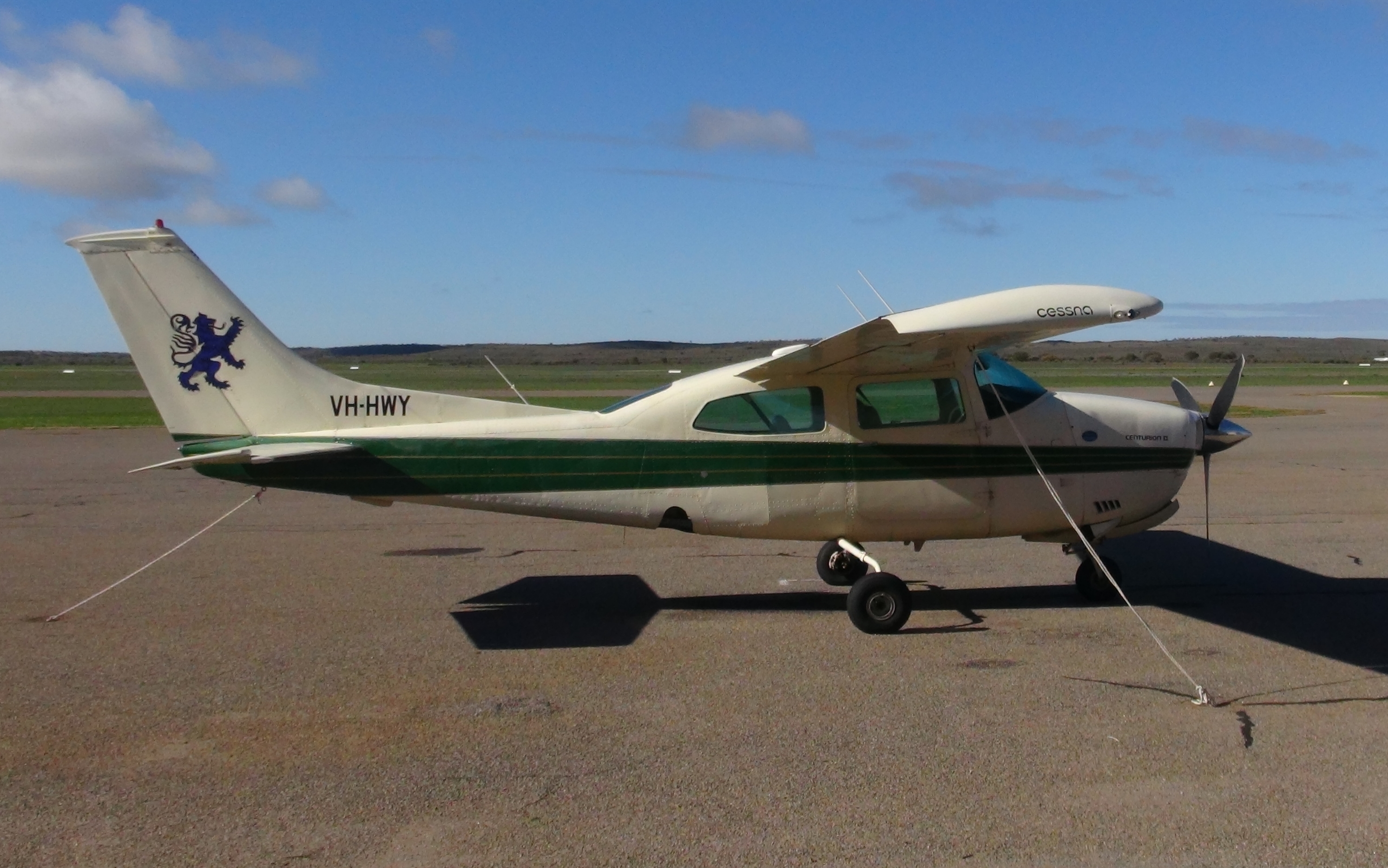
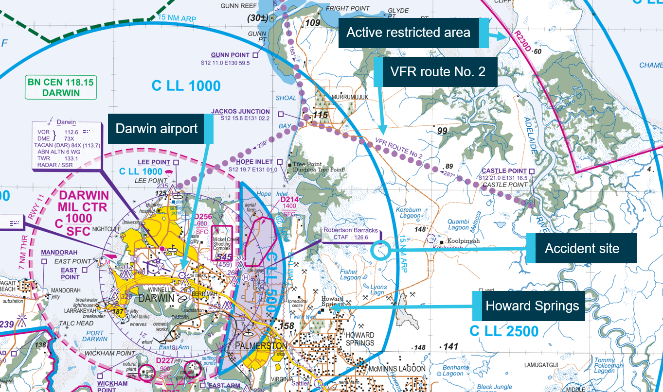
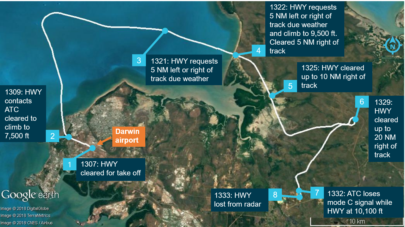
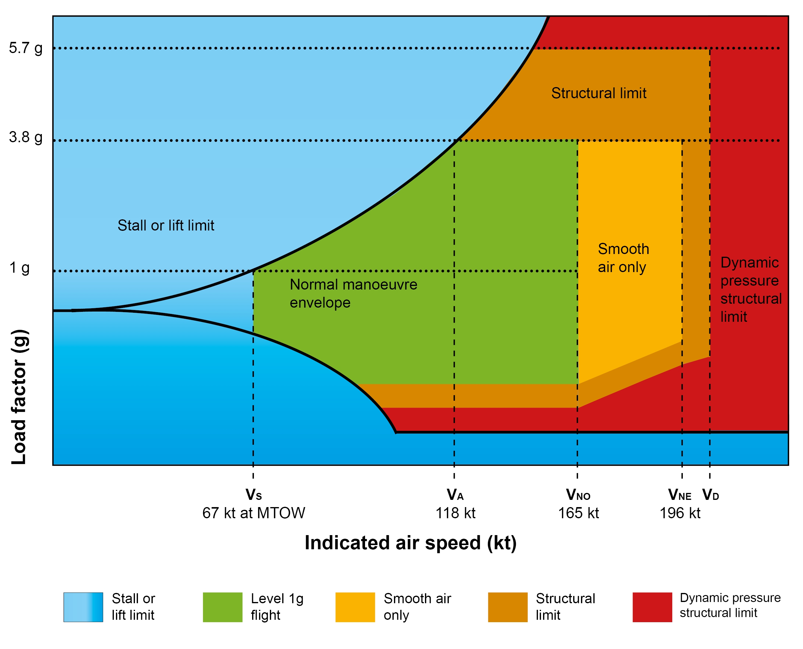
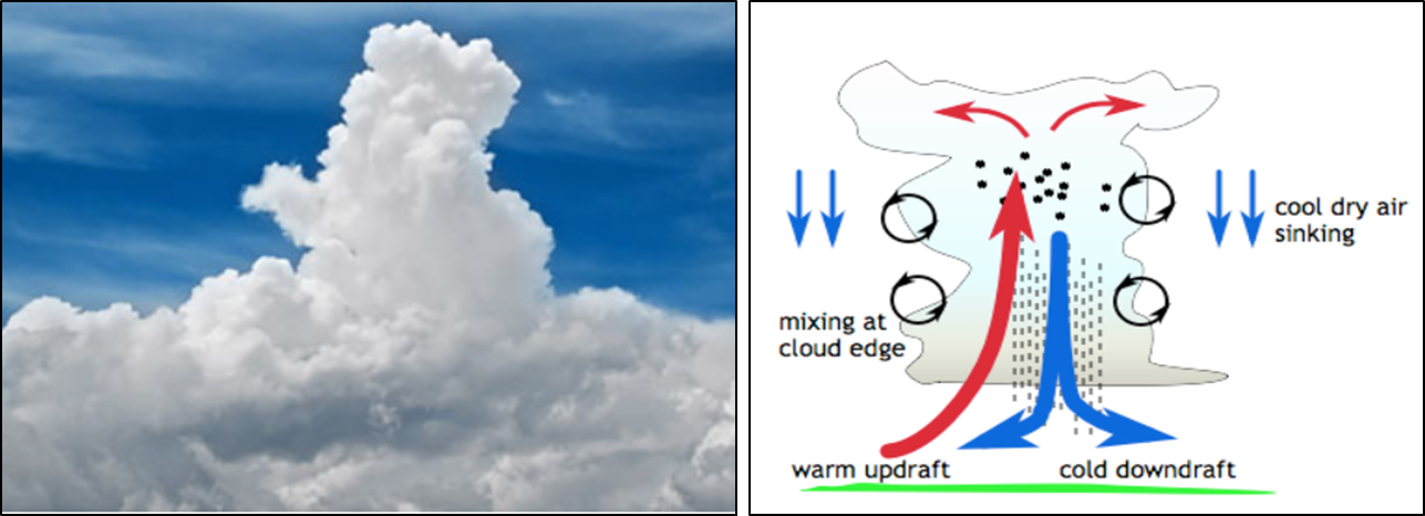
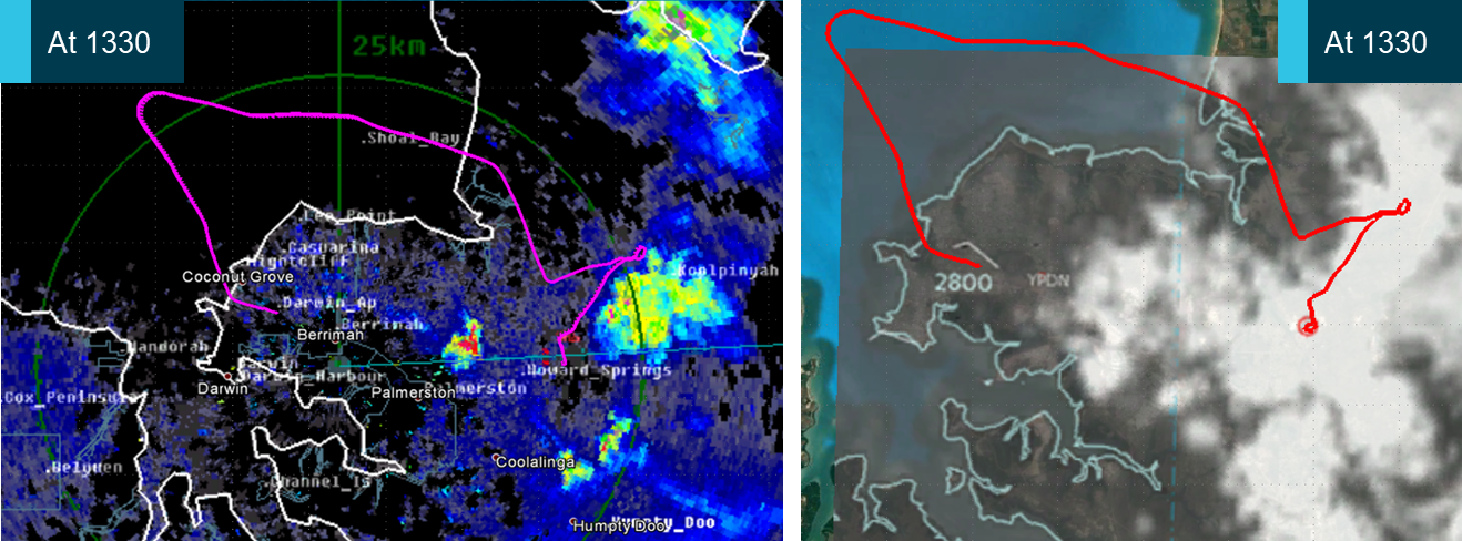
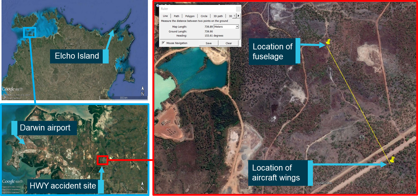
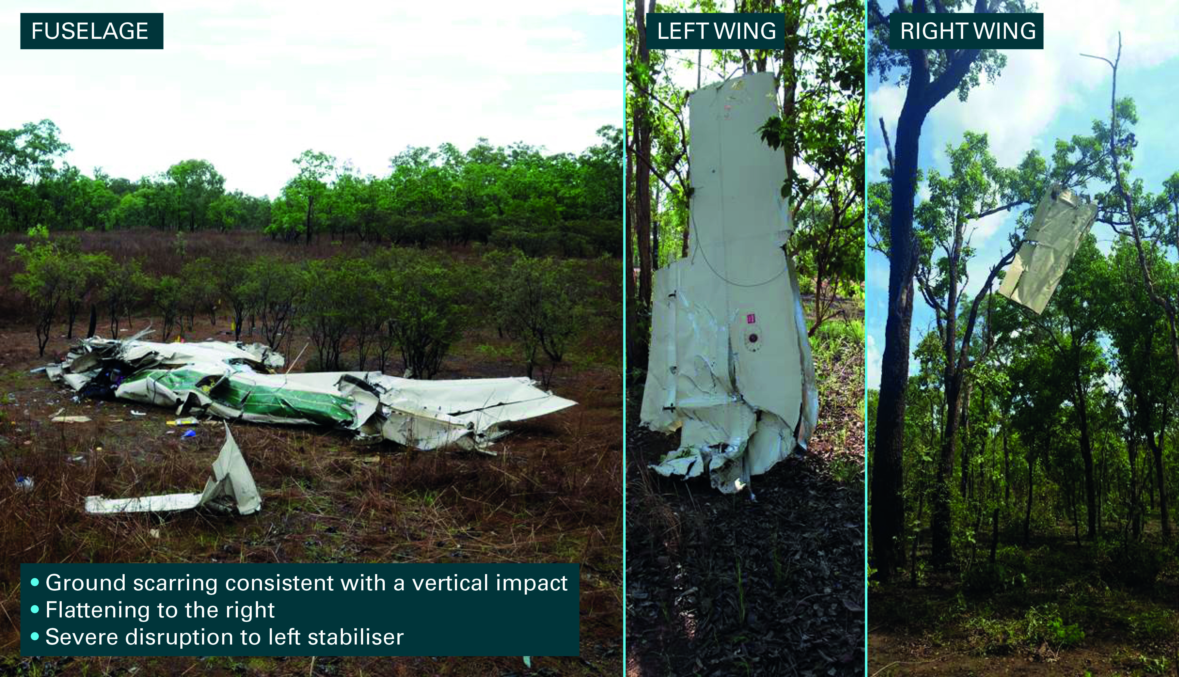
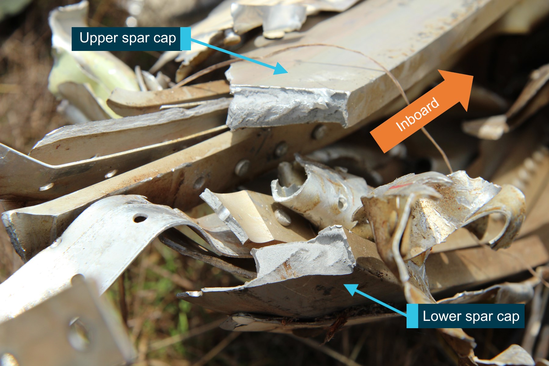
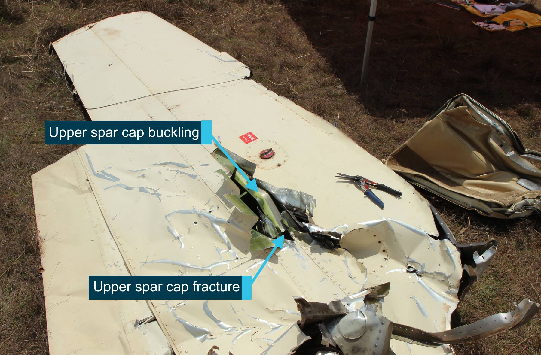
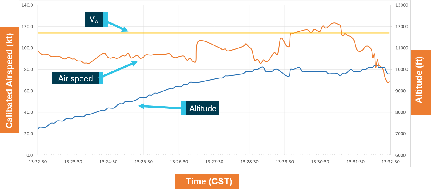
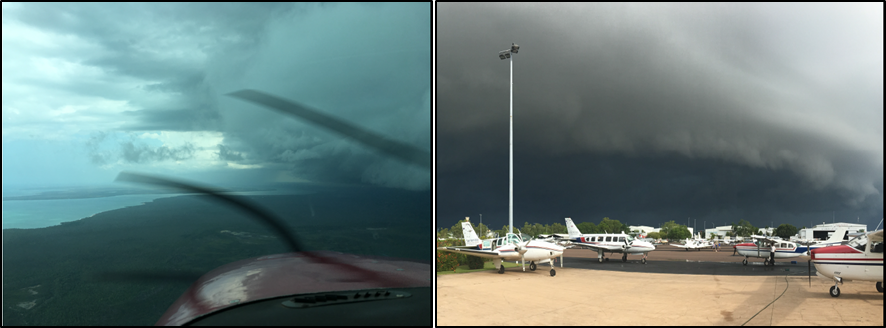

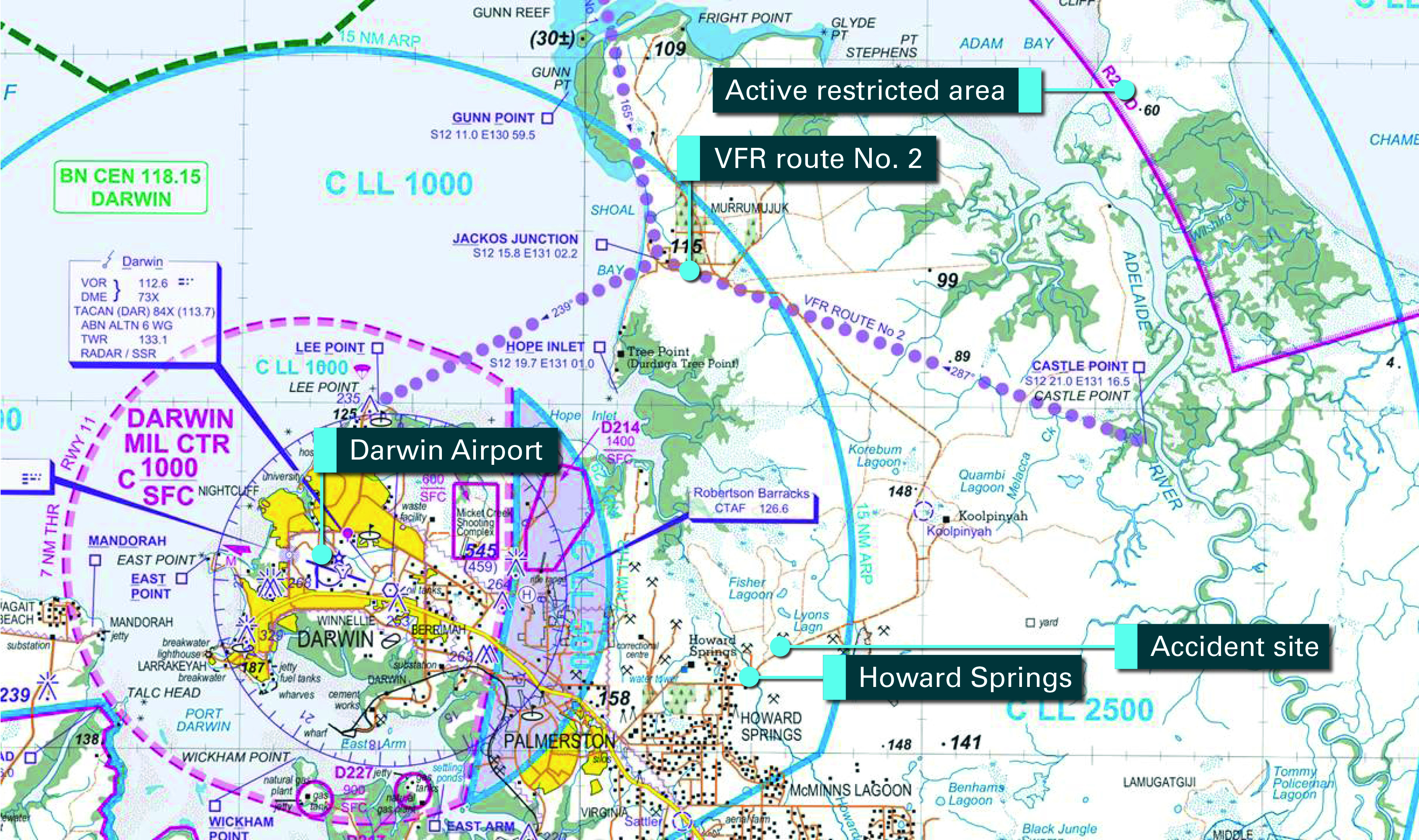
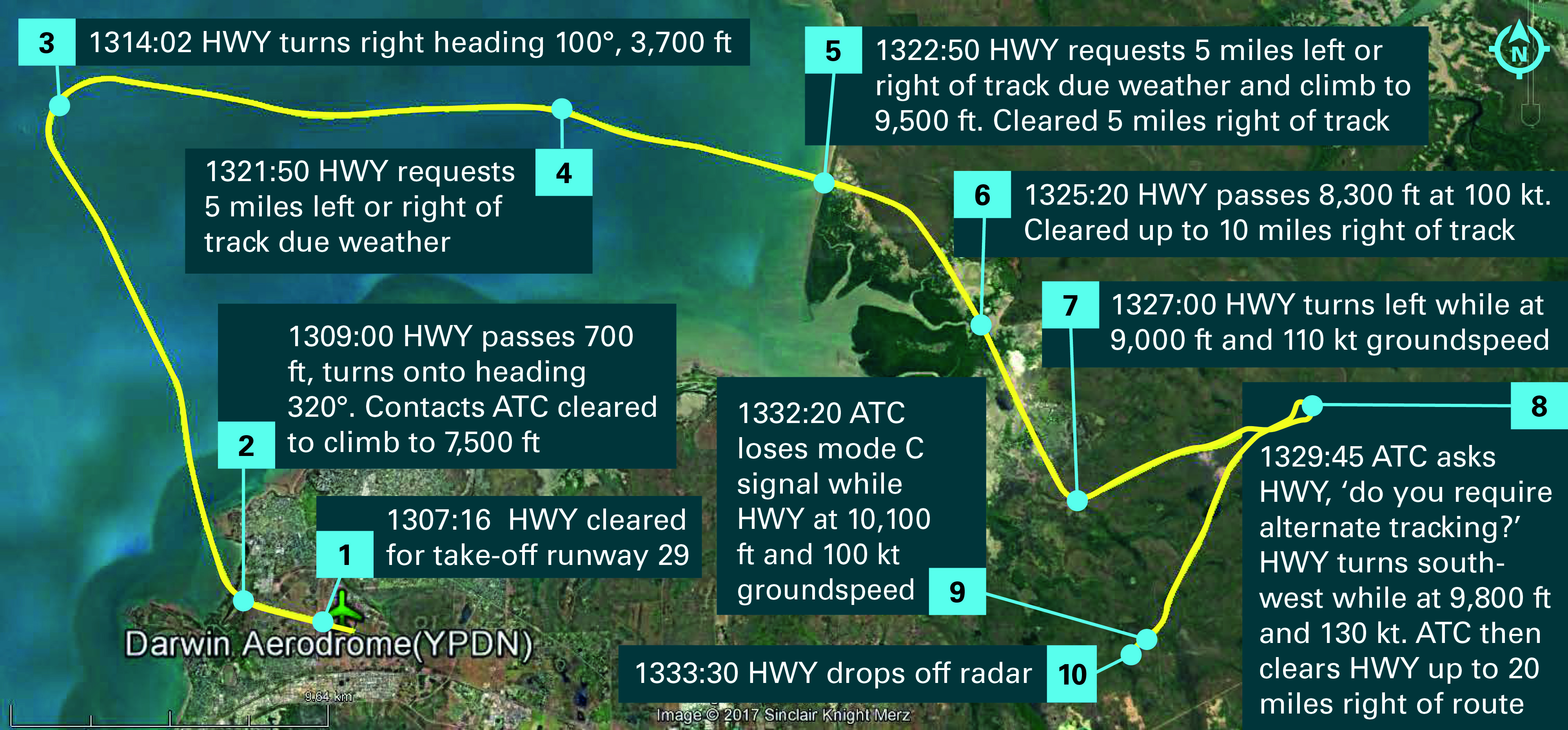
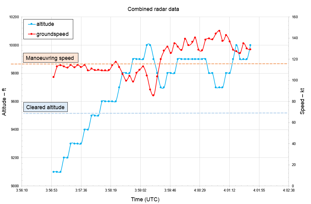
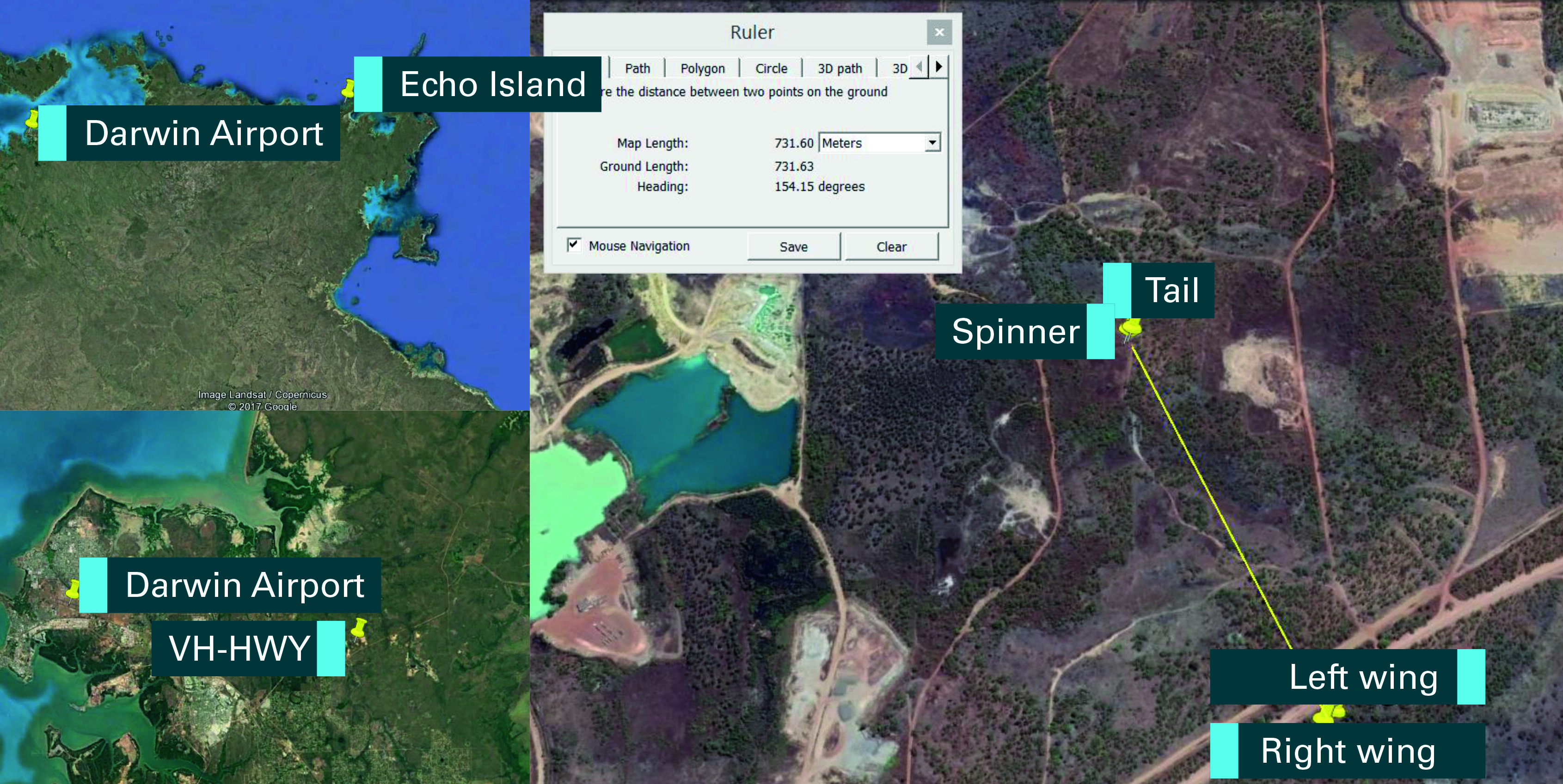
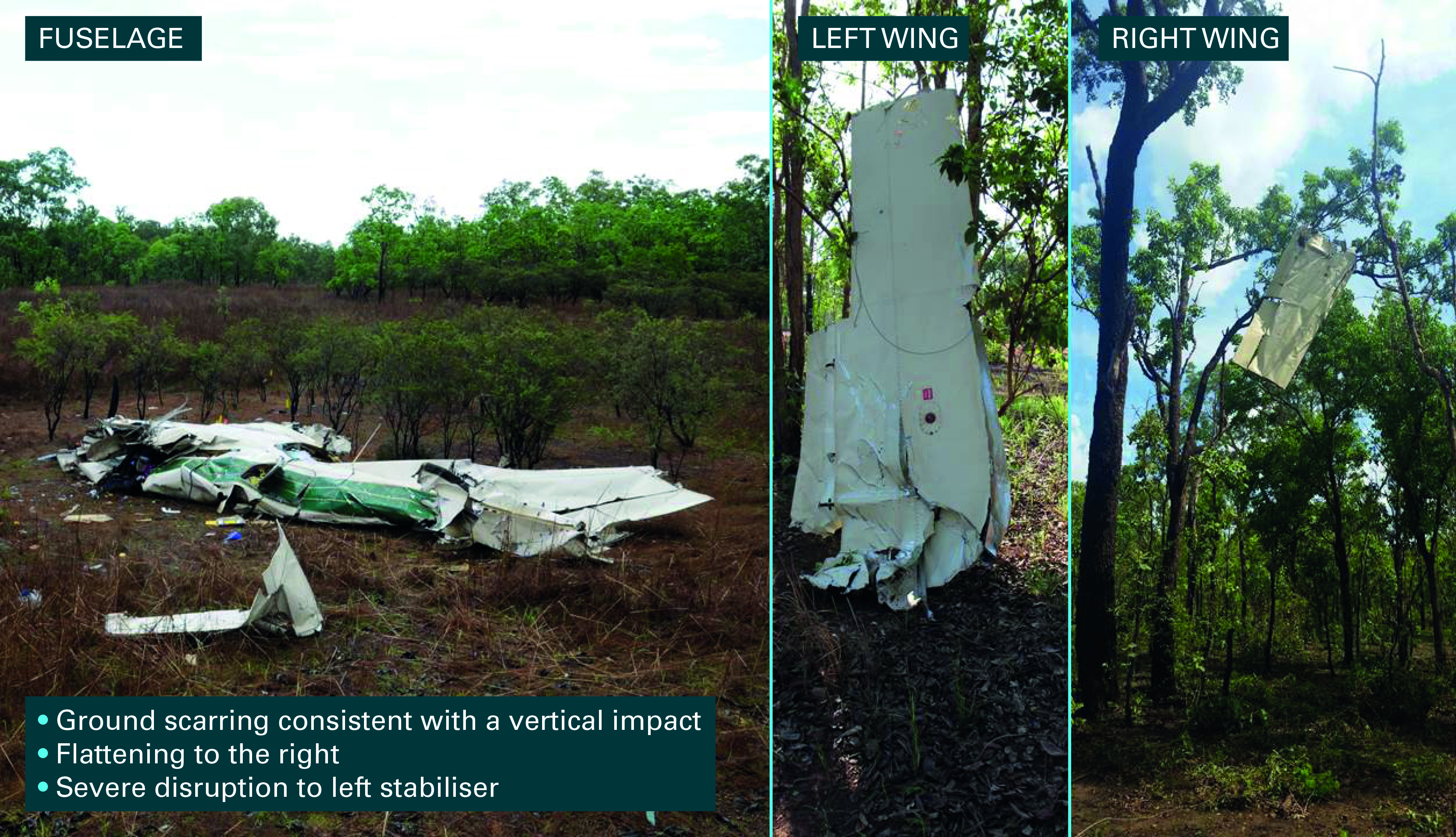
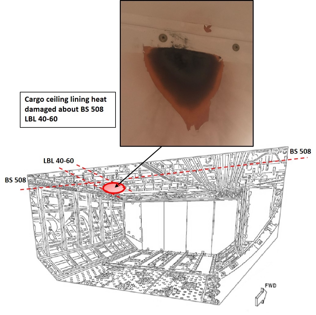
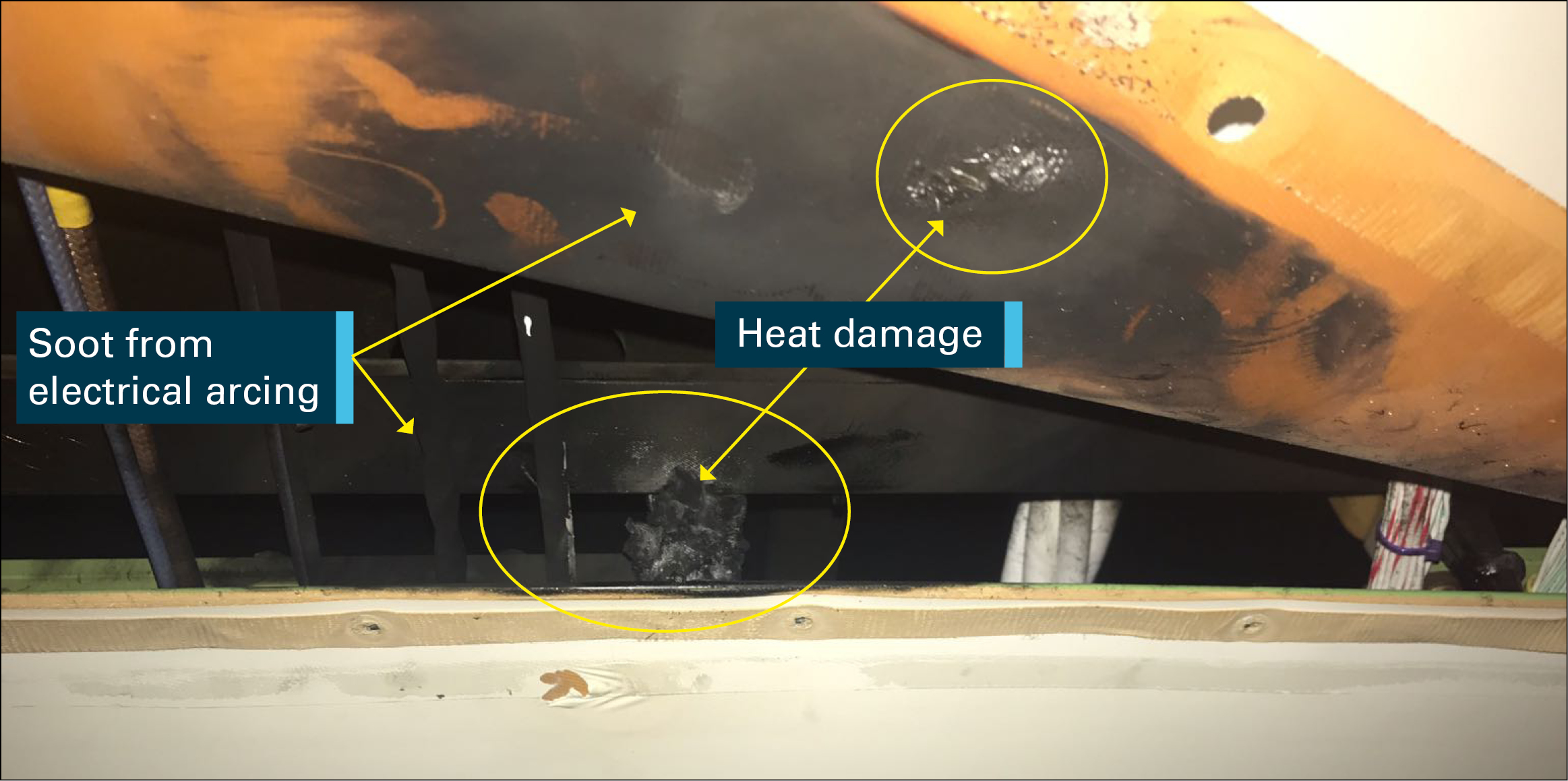
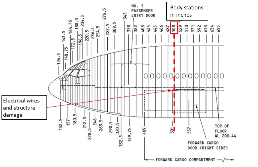
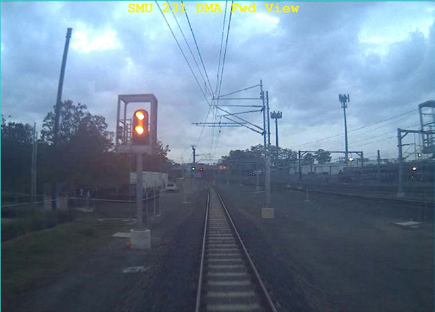


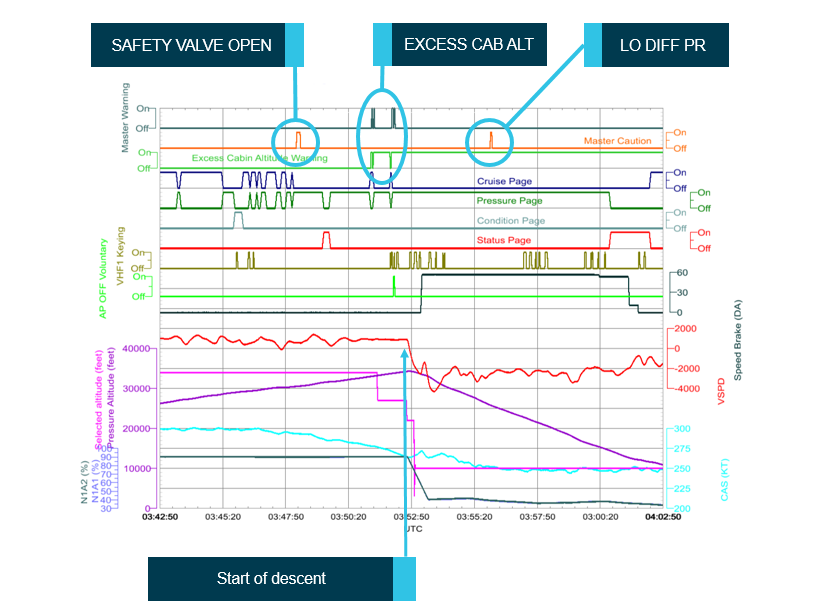
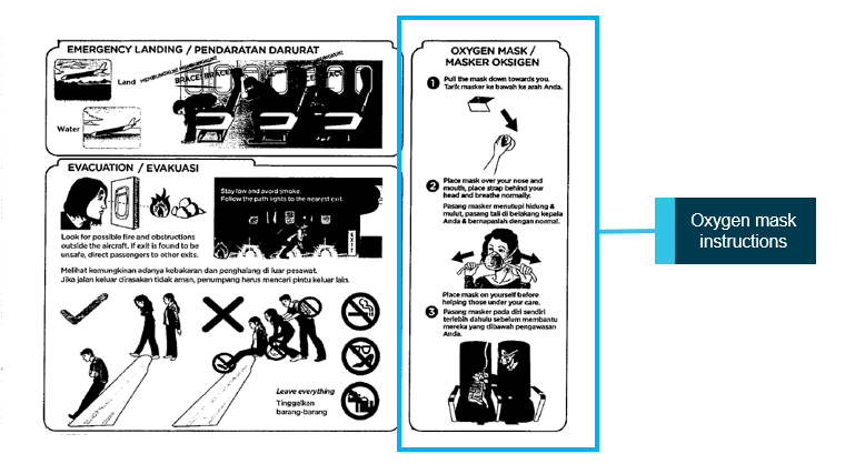
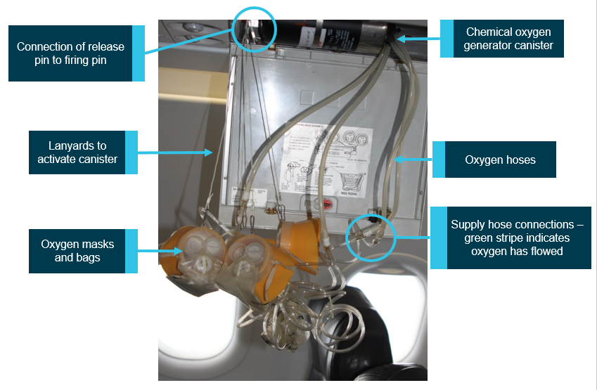
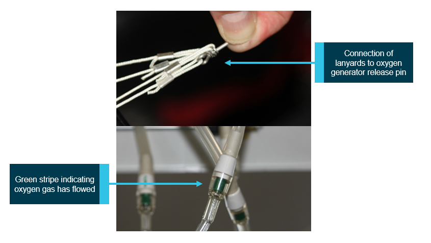
![Figure 6: Activation and frequency of alerts. The timings and frequency of activation of alerts of the cabin pressurisation system in UTC [GMT]. Blue line refers to Aircraft altitude, Grey line refers to Aircraft climb/descent rate. Source: Nord-Micro (courtesy Airbus)](/sites/default/files/media/5777025/ao2017098_figure-6_final.png)