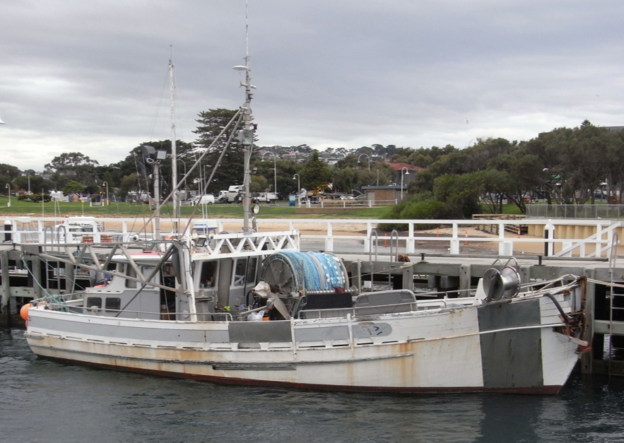
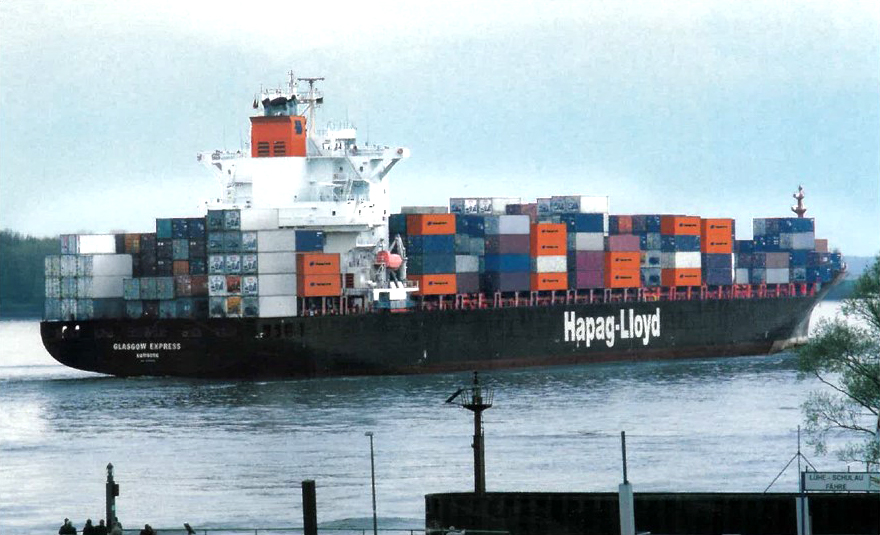
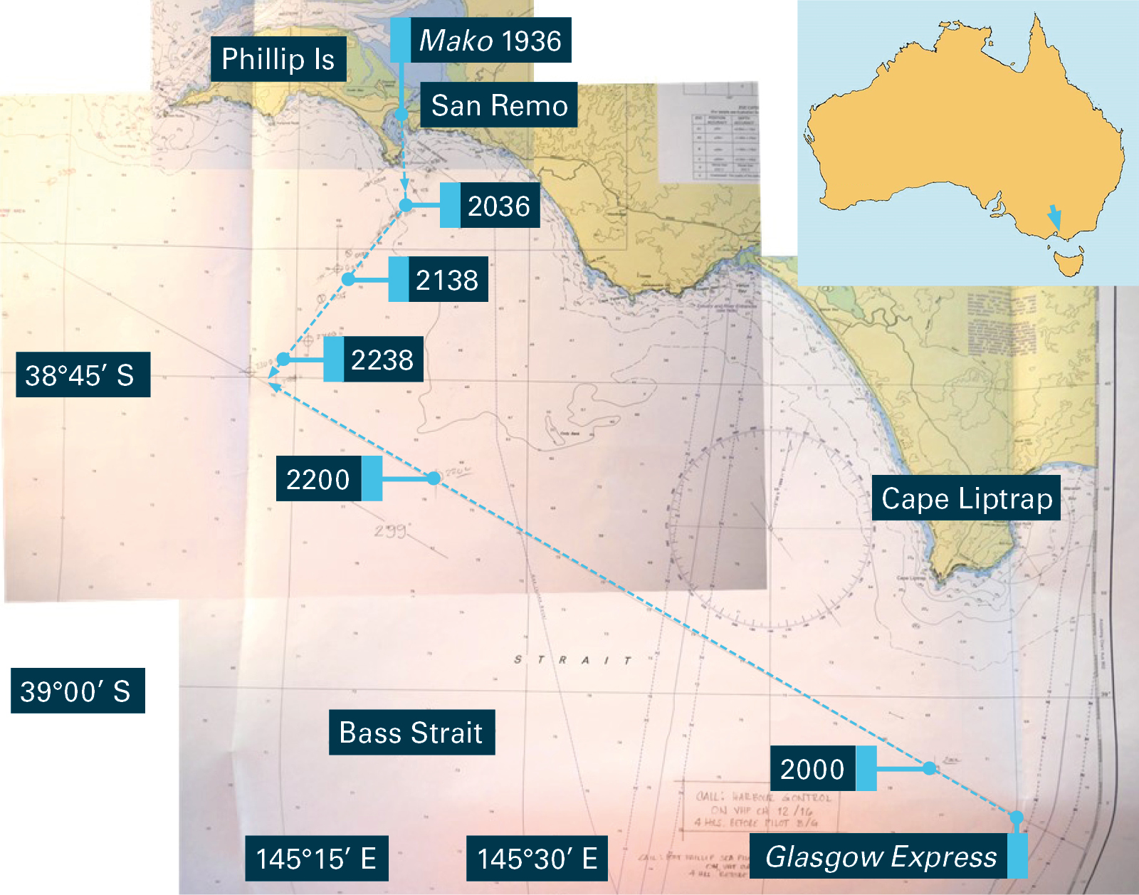
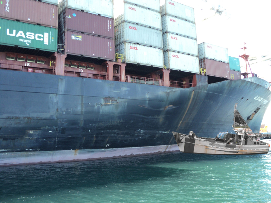
Section 21 (2) of the Transport Safety Investigation Act 2003 (TSI Act) empowers the Australian Transport Safety Bureau (ATSB) to discontinue an investigation into a transport safety matter at any time. Section 21 (3) of the TSI Act requires the ATSB to publish a statement setting out the reasons for discontinuing an investigation.
The ATSB commenced an investigation into a flight control system event that occurred on 25 May 2017 involving a Boeing Company 737-800, registered VH-YIJ and operated by Virgin Australia International, on a flight from Brisbane, Queensland to Wellington, New Zealand.
The captain was the pilot flying, and he was conducting the night arrival into Wellington. The weather conditions were fine, and the descent (below flight level 250) and approach were briefed to be flown with the autopilot and autothrottle disengaged for practice.
During the approach to runway 34, the flight crew progressively selected flaps 1 then flaps 15. The landing gear was selected down and then flaps 25. The right flap moved to flap 25 but the left flap initially remained at flap 15, before moving very slowly to flap 25, which was not initially detected by the flight crew. Flap 40 was then selected, however, the flaps remained in the 25 and 15+ positions.
While carrying out the landing checklist, the flight crew detected the flap asymmetry. The flight crew attempted to rectify the problem with various flap lever selections, which were unsuccessful. Approaching 1,000 ft, the aircraft did not meet the operator’s stable approach criteria, so the flight crew initiated a missed approach.
During the missed approach, the left flap slowly extended to flap 25, correcting the initial ‘Trailing Edge Flap Asymmetry’ to a ‘Trailing Edge Flap Disagree’ condition. The aircraft, still being manually flown, subsequently climbed above the cleared altitude of 5,000 ft (reaching 5,340 ft) and the flap limit speed was marginally exceeded on two occasions. The flight crew positioned the aircraft into a holding pattern, completed the ‘After Takeoff’ checklist and ‘Trailing Edge Flap Disagree’ non-normal checklist and briefed for a second approach to runway 34 with flaps 25.
Prior to leaving the holding pattern, the captain briefed the cabin supervisor about the situation. However, the format of that briefing was the same as what the cabin supervisor would expect for an emergency. As a result, the cabin supervisor perceived that the cabin needed to be prepared for an emergency landing, which was not the captain’s intention.
A second approach was conducted with the autopilot and autothrottle engaged to 136 ft. The aircraft landed without further incident.
Engineers later performed the required aircraft inspections. They could not reproduce the flap fault, however, replaced the left-hand trailing edge flap position transmitter as a precaution.
The ATSB obtained the operator’s investigation report, and interviewed the flight crew and the cabin supervisor. The ATSB also obtained data from the aircraft’s flight data recorder, aircraft maintenance records and relevant sections of the operator’s operations manual. Based on its review of this information, the ATSB concluded that the operator had conducted a detailed investigation and it was unlikely that further ATSB investigation would identify any systemic safety issues.
The ATSB noted that, although there were flight crew errors made during the approach and the subsequent missed approach, the missed approach was conducted at an appropriate time. In addition, while the cabin crew conducted the cabin preparation drill for a non-normal landing when it was not required, doing so was an example of the operation ‘failing safe’ rather than increasing risk.
The operator has subsequently used this incident as a basis for some recurrent training for its flight crew and cabin crew. Consequently, the ATSB has discontinued this investigation.
On the 5 September 2017, Queensland Rail suburban passenger train 1W33 was being transferred from Mayne Depot to Roma Street Station, Brisbane, Queensland, as a non-revenue operation. Nearing the Roma Street Station at 1628, train 1W33 passed signal RS57 at danger. Signal RS57 was displaying a stop indication (red aspect). Train 1W33 ran through points 226 and travelled east into platform 8. At the same time, another train (15X2) was approaching Roma Street Station on a converging route from the east.
As the train passed signal RS57 at danger, a ‘signal passed at danger’ (SPAD) alarm was generated in the Queensland Rail Management Centre. The Network Control Officer broadcast an emergency call to 1W33 and converging train 15X2. Both trains came to a stop approximately 550 m apart.
The rail infrastructure (points 226) was damaged by train 1W33. There were no reported injuries or damage to the rolling stock.
What the ATSB found
The ATSB found that the driver of 1W33 was distracted from his primary task of driving the train, including observing and reacting to signals, by personal emotional thoughts, when approaching signal RS57 displaying a stop indication.
What's been done as a result
Queensland Rail has initiated a number of strategies to manage the risk of SPADs, including administrative processes, human factors analysis, plus reviews and improvements to existing SPAD controls.
Longer term, Queensland Rail have sought expressions of interest from market leaders to partner with Queensland Rail to implement European Train Control System (ETCS) on sections of the Queensland Rail network. ETCS incorporates automatic train protection that provides for monitoring of train speed and limits of authority to ensure trains stay within designated speed limits and authorised safeworking limits.
Safety message
This incident highlights how distraction increases the risk of a SPAD event. Distractions can be external, but internal thoughts related to significant personal events or circumstances can take away a driver’s attention from their primary task of safely managing the train.
Queensland Rail suburban passenger train 1W33
Source: Queensland Rail
The occurrence
At about 1623 Eastern Standard Time on 5 September 2017, the Queensland Rail (QR) suburban non-revenue passenger train 1W33, departed Mayne Depot and travelled on the Exhibition loop towards Roma Street Station, Brisbane, Queensland (Figure 1).
Figure 1: Train 1W33 route from Mayne depot to Roma Street Station, Brisbane, Queensland
Image shows signal and station locations. Note that the colour of the signal markers denotes the aspect of the signal passed by 1W33. Source: Google Earth annotated by ATSB.
The penultimate signal prior to Roma Street Station (RS49) displayed a restricted indication (flashing yellow aspect[1]) for the driver. As train 1W33 approached signal RS49, the driver slowed down in preparation for a 25 km/h speed board placed adjacent the signal. The driver recalled that the Automatic Warning System (AWS)[2] generated an in-cab alert of the restricted signal RS49 indication ahead and that he acknowledged the AWS alert. At about 1628, train 1W33 continued past signal RS49 towards signal RS57, just west of Roma Street Station. Signal RS57 was displaying a stop indication (red aspect) to allow other train movements to clear Roma Street Station before train 1W33 would be authorised to continue.
Meanwhile, passenger train 1K56 was preparing to depart Roma Street Station from platform 8 (Figure 2). At about 1628, train 1K56 departed Roma Street Station travelling west towards the Springfield line via points 226 set normal.[3] About 11 seconds after train 1K56 cleared 226 points, train 1W33 proceeded past signal RS57 at danger. Train 1W33 ran through[4] points 226 about 26 seconds after passing RS57 at danger and travelled east into platform 8.
Figure 2: Western end Roma Street Station layout, Brisbane, Queensland
Image shows track infrastructure layout west of Roma Street Station with the directions of travel and path for trains 1W33 and 1K56. Source: Queensland Rail annotated by ATSB.
At approximately the same time, another train (15X2) had just departed Central Station and was travelling towards Roma Street Station on a converging route with train 1W33 from the east.
As train 1W33 passed signal RS57, an alarm activated at the QR Rail Management Centre. The Network Control Officer, broadcast an emergency radio message, calling for the driver of 1W33 and the driver of 15X2 to stop. At about 1630 the two drivers confirmed they had stopped.
Train 15X2 came to a stop approximately 25 m prior to signal RS102. Signal RS102 is the signal before the eastern entry signal (RS100) into platform 8 at Roma Street Station (Figure 3). Signal RS102 was displaying a single yellow caution[5] indication at this time due to signal RS100 displaying a stop indication. The signal interlocking system had restored Signal RS100 to stop when train 1W33 entered platform 8 at Roma Street Station. The two converging trains stopped approximately 550 m from each other.
Figure 3: Train 15X2 route from Central Station towards eastern entry of Roma Street Station, Platform 8
Image shows signal locations and stopping locations of train 1W33 and 15X2. Note that colour of the signal markers denote the aspects displayed after 1W33 entered the platform track circuit at Roma Street Station. Source: Google Earth annotated by ATSB.
The ATSB explored the following aspects which have been known as contributing factors in other signal passed at danger incidents.
Environmental conditions
A review of the CCTV[6] images from the time of the incident and driver comments indicated that the weather conditions were fine and clear. Further to this, no rainfall had been recorded for Brisbane on the day of the incident by the Bureau of Meteorology. The ATSB found that environmental conditions did not contribute to this incident.
Human performance
The ATSB reviewed the health assessment records, drugs and alcohol test results, rosters (with respect to fatigue) and competency records related to the driver of train 1W33. In conjunction with the driver comments, the ATSB found that these human performance factors did not contribute to this incident.
Rolling stock
Train 1W33 consisted of two coupled Suburban Multiple Units (SMU’s), with SMU 261 leading and SMU 279 trailing. Train 1W33 weighed approximately 256 tonnes and had a length of approximately 150 m.
As permitted by the Queensland Rail standard for operational integrity of trains, event recorders[7] for suburban multiple units SMU 261 and SMU 279 had both been temporarily removed for repairs and therefore did not record rolling stock inputs in relation to this incident (refer to ATSB comment below). However, driver comments and examination of available CCTV footage did not suggest any degradation of braking performance of train 1W33.
Visibility of signal RS57
Signal RS57 was a 4-aspect[8] main line signal fitted with a junction indicator and low speed shunt signal (Figure 4). Signal RS57 authorised train movements towards signals RS83 or RS85 located at the eastern end of Roma Street Station (platforms 8 and 7).
Figure 4: Signal configuration of RS57, at Roma Street Station, Brisbane
Source: Queensland Rail
Signal RS57 was located at the end of a left hand curve adjacent to Roma Street Station on the right hand side of the track in the direction of travel. Due to the curvature of the track and the placement of the overhead catenary masts, RS57 signal sighting was limited to approximately 103 m.
Queensland Rail managed the limited signal sighting with the application of a 25 km/h speed restriction from signal RS49 leading up to signal RS57 and LED signal lamps had recently been installed. In addition, other controls have been considered and implemented as part of Queensland Rail’s ongoing signal sighting reviews.
The ATSB found that the configuration and sighting of signal RS57 did not contribute to this incident.
Signal SPAD history
The ATSB found that signal RS57 had been passed at danger on six occasions since 2007. Queensland Rail records for these SPAD events noted varying sources of driver distraction as the causal factor for each event.
Figure 5: Signal RS57 10 year SPAD history
Image shows that in 2007 three reports for signals passed at danger for RS57 were recorded, plus three more each in 2009, 2012, and this event in 2017.Source: Queensland Rail records graphed by ATSB.
Following the three SPAD’s in 2007, Queensland Rail identified RS57 as a multi-SPAD signal and had undertaken SPAD risk studies and regular reviews of the signal sighting. These risk studies and reviews led to the identification and, where accepted, the implementation of additional controls. This incident is the first time RS57 had been passed at danger in five years.
Driver distraction
Driver distraction can be understood as a type of inattention and has been defined as ‘the diversion of attention away from activities critical for safe driving toward a competing activity (occurring) voluntarily or involuntarily’.[9] A physical source of distraction common in today’s society is the use of mobile phones. In this case, the driver reported he was not using his phone and there was evidence showing that his phone was not used at the time of the incident. Similarly, the driver reported no distractions from any radio chatter or noticing anything external to the train.
While the source of distraction can often be physical, it can also be non-physical. For example, a situation where task-irrelevant thoughts interfere with task-relevant thoughts can also contribute to distraction and decrease task performance.
A contributor to irrelevant thoughts is emotional mood states which have been described as providing a third processing layer on top of cognitive and physiological levels. ‘Emotions play an important role in motivating people to initiate and maintain a task in the first place, but they may also interfere with cognitive processing. In particular, under time pressure or threatening conditions, the regulation of our emotions is critical for efficient task performance’.[10]
A research study into the effects of emotional mood states on irrelevant thoughts and cognitive task performance concluded that ‘people produce more irrelevant thoughts during emotional mood states, and when the proportion of irrelevant thoughts to relevant thoughts increases, performance suffers.’[11]
In relation to this incident, the driver advised that prior to commencing work he recalled a significant past personal event that resulted in an emotional response. It is likely this contributed to an increase in task-irrelevant thoughts that led to the driver being distracted from observing and reacting appropriately when approaching signal RS57 displaying a stop indication.
ATSB comment
The function of a safety investigation is to identify and reduce safety-related risk, by gathering information and evidence to form conclusions based on the facts.
The ATSB noted that the Queensland Rail standard for operational integrity of trains permitted trains into service on their network without an operational event recorder. In this case, the ATSB relied on CCTV footage and the driver’s recollection for identifying the sequence of events. The absence of recorded data prevented further verification of the driver’s performance against operational practice.
From the evidence available, the following findings are made with respect to train 1W33 passing signal RS57 at danger near Roma St Station, Brisbane, Queensland, on 5 September 2017. These findings should not be read as apportioning blame or liability to any particular organisation or individual.
Contributing factors
The driver of 1W33 was distracted by personal emotional thoughts from his task of observing and reacting appropriately when approaching signal RS57 displaying a stop indication.
Other findings
A SPAD alarm activated at the QR Rail Management Centre prompting the network control officer to broadcast an emergency radio message stopping all affected trains.
Safety action
Whether or not the ATSB identifies safety issues in the course of an investigation, relevant organisations may proactively initiate safety action in order to reduce their safety risk. The ATSB has been advised of the following proactive safety action in response to this occurrence.
As a result of this occurrence, Queensland Rail has advised the ATSB they are taking the following safety actions:
A qualitative analysis of the SPAD scenarios at RS57 using a bowtie model.
Present a health and wellbeing strategic plan to the Executive Leadership Team which includes an organisational resilience and psychological wellbeing education and awareness program.
Human factors review of driver response to AWS audible indications and reaction times for green and restricted signals.
Facilitate the decrease in volume of the AWS audible indication at a proceed signal (green) and increase the volume of an AWS audible indication at a restricted signal (double yellow, yellow, and red).
Queensland Rail have sought expressions of interest from market leaders to partner with Queensland Rail to implement ETCS (European Train Control System) on sections of the Queensland Rail network. ETCS incorporates automatic train protection that provides for monitoring of train speed and limits of authority to ensure trains stay within designated speed limits and authorised safeworking limits.
Sources and submissions
Sources of information
The sources of information during the investigation included the:
Queensland Rail (QR)
Train driver involved in incident
Recorded data
Rail Industry Safety and Standards Board (RISSB)
Bureau of Meteorology.
References
Queensland Rail Observance of Signals Manual (MD-10-109).
Queensland Rail Event recorders for rolling stock specification (MD-10-217).
Queensland Rail Operational Integrity Of Trains standard (MD-10-106).
Rail Industry and Safety Standards Board, 2010, National Guideline Glossary of Railway Terminology.
Pennie S. Seibert and Henry C. Ellis, (1991), Memory & Cognition Irrelevant thoughts, emotional mood states, and cognitive task performance, 507-513.
Regan, M.A., Hallett, C. & Gordon, C.P. (2011). Driver distraction and driver inattention: Definition, relationship and taxonomy. Accident Analysis and Prevention, 43, 1771-1781.
Gaillard, A.W.K. (2001). Stress, workload and fatigue as three bio-behavioural states: A general overview. In P.A. Hancock, & P.A. Desmond (Eds.), Stress, workload, and fatigue. Mahwah, NJ: L. Erlbaum.
Submissions
Under Part 4, Division 2 (Investigation Reports), Section 26 of the Transport Safety Investigation Act 2003 (the Act), the Australian Transport Safety Bureau (ATSB) may provide a draft report, on a confidential basis, to any person whom the ATSB considers appropriate. Section 26 (1) (a) of the Act allows a person receiving a draft report to make submissions to the ATSB about the draft report.
A draft of this report was provided to Queensland Rail, the driver of train 1W33, and the Office of the National Rail Safety Regulator.
Any submissions from those parties will be reviewed and where considered appropriate, the text of the draft report will be amended accordingly.
Purpose of safety investigations
The objective of a safety investigation is to enhance transport safety. This is done through:
identifying safety issues and facilitating safety action to address those issues
providing information about occurrences and their associated safety factors to facilitate learning within the transport industry.
It is not a function of the ATSB to apportion blame or provide a means for determining liability. At the same time, an investigation report must include factual material of sufficient weight to support the analysis and findings. At all times the ATSB endeavours to balance the use of material that could imply adverse comment with the need to properly explain what happened, and why, in a fair and unbiased manner. The ATSB does not investigate for the purpose of taking administrative, regulatory or criminal action.
Terminology
An explanation of terminology used in ATSB investigation reports is available here. This includes terms such as occurrence, contributing factor, other factor that increased risk, and safety issue.
Publishing information
Released in accordance with section 25 of the Transport Safety Investigation Act 2003
Ownership of intellectual property rights in this publication
Unless otherwise noted, copyright (and any other intellectual property rights, if any) in this report publication is owned by the Commonwealth of Australia.
Creative Commons licence
With the exception of the Coat of Arms, ATSB logo, and photos and graphics in which a third party holds copyright, this publication is licensed under a Creative Commons Attribution 3.0 Australia licence.
Creative Commons Attribution 3.0 Australia Licence is a standard form licence agreement that allows you to copy, distribute, transmit and adapt this publication provided that you attribute the work.
The ATSB’s preference is that you attribute this publication (and any material sourced from it) using the following wording: Source: Australian Transport Safety Bureau
Copyright in material obtained from other agencies, private individuals or organisations, belongs to those agencies, individuals or organisations. Where you wish to use their material, you will need to contact them directly.
On 3 September 2017, a Fairchild SA227-AC aircraft, registered VH-SEZ, was operating Sharp Airlines flight SH843 from Portland to Essendon, Victoria. The first officer was pilot flying (PF) and the captain was pilot monitoring (PM).[1]
About 46 NM east of Portland, overhead Warrnambool, and in the cruise at flight level (FL) 170,[2] the left engine fire warning lights on the annunciator and fire warning panels started to momentarily illuminate. At 1608 Eastern Standard Time,[3] the flight crew contacted air traffic control (ATC) advising that they required a clearance to descend to 9,000 ft and that they would require a direct track to Essendon.
The fire warning lights continued to flicker and then both remained illuminated. As a result, the flight crew assessed that there was an engine fire. They conducted the memory checklist for in‑flight engine fire, which included:
shutting off the left fuel supply and hydraulic system
discharging the fire retardant.
The fire warning lights then extinguished.
The captain looked over his left shoulder at the left engine and could not see any smoke, flames or scorch marks. The flight crew then declared a MAYDAY[5] to ATC, and reported that they had experienced an engine fire and that the fire was extinguished.
The captain made a public address to the passengers, explaining that they had shut down the left engine due to suspected fire and asking any passengers who had seen smoke or flames to come forward and let him know. No one reported any visual indication of fire.
The flight crew assessed their options for landing, considering both Warrnambool and Avalon Airports. Although they were nearer to Warrnambool Airport, the runway there was shorter and narrower and the wind was gusty, so the crew elected to divert to Avalon Airport. The flight crew reported that a tailwind en route to Avalon and the presence of emergency services also influenced their decision.
At 1613, the flight crew advised ATC that they required direct tracking to Avalon Airport. They received a clearance to do so.
As the aircraft tracked to Avalon, and about 5 minutes after the fire warning lights had extinguished, the lights started to flicker and then came back on to a steady warning. By that time, the crew had tested the integrity of the fire warning loop, discharged the bottle of fire retardant and shut down and secured the left engine.
ATC advised the crew that Runway 36 at Avalon had an occasional 5 kt tailwind and Runway 18 had an occasional tailwind of 9 kt. The flight crew responded that they would require Runway 36. When the aircraft was about 15 NM from Avalon, the captain took over the pilot flying role. ATC provided heading guidance to the flight crew, and the aircraft landed at Avalon at about 1626.
After landing, firefighters advised that there was no sign of fire in the engine. Consequently, there was no need to conduct an emergency evacuation and the passengers and crew disembarked normally.
Engineering inspection
Engineering examination did not identify any signs of fire, smoke or heat damage in the left engine bay. Engineers inspected the four left engine fire sensor probes and all appeared to be functioning normally, but they replaced the lower rear sensor due to cracking of the ceramic insulator.
On the fire extinguisher control panel, each engine has a button and a tri-coloured light – red for fire, green to indicate system integrity of the fire loop, and yellow to indicate a bottle of fire retardant had been discharged and was empty. After the crew pressed the fire button, the empty (yellow) light did not illuminate. This was despite the fact that the fire bottle pressure gauge was indicating zero, after being full pre-flight, and there was indication of discharge into the engine. The yellow light did illuminate when the bulb was tested however, which indicated an issue with the circuit.
Engineers found that the logic control unit in the fire extinguisher control assembly had failed, resulting in erroneous illumination of the engine fire warning. The logic module was replaced, along with the fire extinguisher control panel.
Approach and landing
The captain commented that two out of their six cyclic biannual simulator checks included fire warnings, engine shutdowns and single engine actions. In this occurrence, the engine shutdown, diversion and single-engine approach and landing were consistent with the simulator training. There were no issues with controlling the aircraft or with its performance.
Findings
These findings should not be read as apportioning blame or liability to any particular organisation or individual.
The fire extinguisher control logic module failed, resulting in an erroneous engine fire warning.
Safety message
This incident highlights the importance of well-designed simulator training and robust threat and error management procedures. The captain commented that it was important to treat fire warnings as legitimate indications of fire. Additionally, the declaration of an emergency alerts air traffic control and enables the provision of appropriate assistance.
About this report
Decisions regarding whether to conduct an investigation, and the scope of an investigation, are based on many factors, including the level of safety benefit likely to be obtained from an investigation. For this occurrence, a limited-scope, fact-gathering investigation was conducted in order to produce a short summary report, and allow for greater industry awareness of potential safety issues and possible safety actions.
Publishing information
Released in accordance with section 25 of the Transport Safety Investigation Act 2003
Ownership of intellectual property rights in this publication
Unless otherwise noted, copyright (and any other intellectual property rights, if any) in this report publication is owned by the Commonwealth of Australia.
Creative Commons licence
With the exception of the Coat of Arms, ATSB logo, and photos and graphics in which a third party holds copyright, this publication is licensed under a Creative Commons Attribution 3.0 Australia licence.
Creative Commons Attribution 3.0 Australia Licence is a standard form licence agreement that allows you to copy, distribute, transmit and adapt this publication provided that you attribute the work.
The ATSB’s preference is that you attribute this publication (and any material sourced from it) using the following wording: Source: Australian Transport Safety Bureau
Copyright in material obtained from other agencies, private individuals or organisations, belongs to those agencies, individuals or organisations. Where you wish to use their material, you will need to contact them directly.
At about 0219 Western Standard Time[1] on 7 August 2017, a Pilatus PC‑12/47E aircraft, registered VH-OWS (OWS), taxied at Meekatharra Airport, Western Australia. The aircraft was operating as a Royal Flying Doctor Service (RFDS) air ambulance flight to Jandakot Airport, and had a pilot, two medical staff, and a patient on board.
At about 0227, OWS lined up and departed from runway 09. The night was clear with almost a full moon. At about 1,000 ft above ground level, when the pilot turned the aircraft to depart from overhead the airport, he noticed small beads forming on the outside of the windscreen. As there was no rain in the area, he shone a torch on the windscreen. The beads had formed into a steady stream of fluid moving up the windscreen, and noting its thickness, the pilot surmised that it was oil.
The pilot also knew that the aircraft’s propeller shaft seal had been replaced during maintenance on the previous day. Before this flight, he had followed his normal routine of checking the engine oil quantity and found that it was indicating ‘full’.
In assessing the situation, the pilot noted that all the engine parameters were in the normal range and he elected to return to Meekatharra Airport. He levelled the aircraft at an altitude of about 5,500 ft, and informed air traffic control of his intention to return for a landing on runway 09.
The pilot then conducted a wide descending circuit, slightly higher than normal to maintain glide capability in case the leak got worse and affected the engine’s operation. The visibility through the windscreen had reduced and by the time OWS turned onto the base leg of the circuit, oil was streaming down the side windows. On the final leg of the circuit, the pilot saw the runway lights blurring ‘like in heavy rain’. He conducted a normal landing, taxied to the parking bay, and shut down the engine. The aircraft was not damaged and no one was injured.
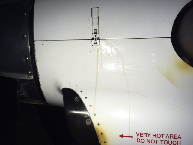
After landing, the pilot checked the aircraft and found oil on the engine cowling (Figure 1) and dripping/pooling on the tarmac. When the engine cowling was opened, a small amount of smoke could be seen coming from where oil had contacted hot engine parts.
Figure 1: Oil on the outside of the engine cowling
Source: RFDS
Propeller shaft seal replacement
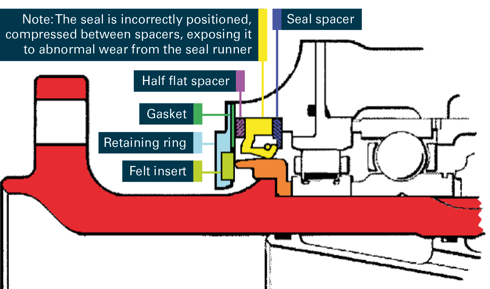
The aircraft operator (RFDS) investigated the incident and identified that the propeller shaft seal had been incorrectly assembled (Figure 2). The seal had been replaced at Jandakot on 6 August 2017 (the day before the incident) after which the aircraft had flown to Meekatharra, a flight of about 1 hour 40 minutes.
Figure 2: Propeller shaft seal assembly at the time of the incident
Source: Pratt & Whitney Canada, modified by the ATSB
The day before the occurrence, the on-call licensed aircraft maintenance engineer (engineer) at the Jandakot maintenance base was asked to check an engine oil leak on OWS. When he examined the engine, he found oil on the engine cowling and the forward part of the engine. Having removed the oil, he investigated further by running the engine three times without any further evidence of an oil leak.
The engineer then contacted the engineering manager to discuss the defect. Based on their experience and the signs of the oil leak, they decided that the engineer would replace the propeller’s shaft seal.
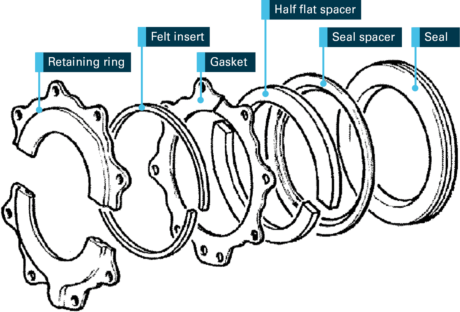
When replacing the seal, the engineer assembled the parts in the order that he recalled from disassembly, and the diagram in the engine manufacturer’s, Pratt & Whitney Canada (P&WC), illustrated parts catalogue (IPC). He recalled that the half flat spacer was located forward of the seal—the same as the IPC (Figure 3). After replacing the seal, he ran the engine and no oil leaks were evident.
Figure 3: Propeller shaft seal assembly parts diagram in the IPC
Source: Pratt & Whitney Canada, annotated by the ATSB
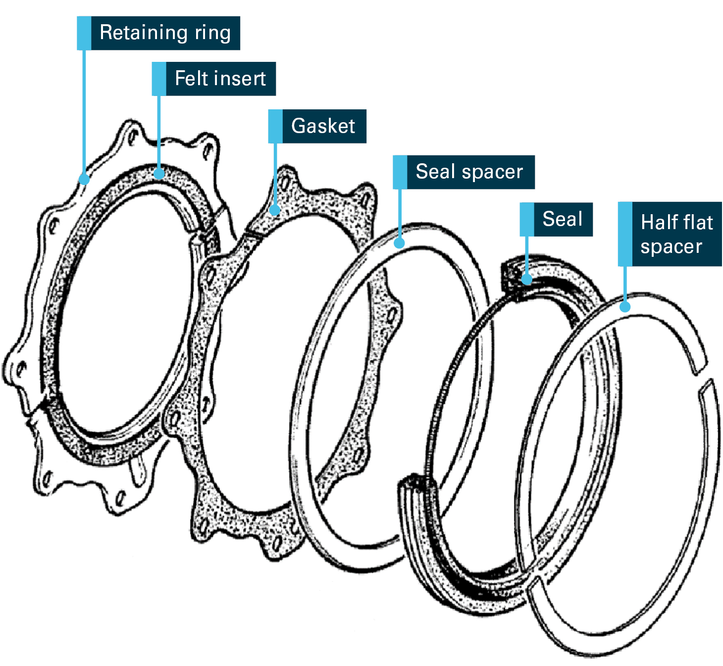
The RFDS investigation found that the IPC was not intended to be used for seal replacement nor did it show the correct order of parts in the seal assembly. Only the P&WC engine maintenance manual (EMM) was intended to be used for maintenance, including propeller shaft seal replacement. The diagram in the EMM showed the half flat spacer correctly located aft of the seal (Figure 4). The EMM assembly procedure permitted the positions of the seal and the seal spacer shown in Figure 4 to be interchanged. In both configurations however, the half flat spacer was to be installed aft of the seal. The engineer had referred to the EMM but had not identified the discrepancy between the seal assembly diagrams in the IPC and the EMM.
Figure 4: Propeller shaft seal assembly diagram in the EMM
Source: Pratt & Whitney Canada, annotated by the ATSB
The RFDS investigation also identified that in the time leading up to the incident the engineer had worked extended work hours, and had had 4 days off in the previous 27 days. The engineer also indicated to RFDS that he had been feeling tired when replacing the seal as he had not slept well the previous night. He also indicated receiving a work-related phone call while replacing the seal which he believed was a distraction.
Safety analysis
The oil leaked from the propeller shaft seal assembly because parts of the seal had not been assembled in the correct order. As the half flat spacer had been placed forward (instead of aft) of the seal, the seal was compressed and was pushed against the seal runner (Figure 2). In that configuration, the friction from the rotating seal runner resulted in abnormal wear of the seal allowing engine oil to leak.
When assembling the propeller shaft seal, the engineer had used the indicative diagram in the IPC instead of the diagram in the EMM, which showed the correct order of parts. He did refer to the EMM but did not notice that the assembly procedure and diagram in it were different to the diagram in the IPC. He also relied on his memory to recall the order in which the parts were removed, which may have been affected by fatigue associated with longer working hours and disrupted sleep.
Findings
These findings should not be read as apportioning blame or liability to any particular organisation or individual.
Shortly after VH-OWS took off from Meekatharra Airport the pilot saw oil leaking from the engine on to the windscreen. In response, he turned the aircraft back and safely landed at the airport.
Engine oil leaked from the aircraft’s propeller shaft seal as it had not been correctly assembled when replaced the previous day.
When assembling the propeller shaft seal, the engineer used an indicative (but technically incorrect) diagram in the engine manufacturer’s illustrated parts catalogue instead of the correct sequence detailed in the manufacturer’s maintenance manual. He also relied on his memory of disassembling the seal, which may have been affected by fatigue associated with disrupted sleep and recent longer working hours.
Safety action
Whether or not the ATSB identifies safety issues in the course of an investigation, relevant organisations may proactively initiate safety action in order to reduce their safety risk. The ATSB has been advised of the following proactive safety action in response to this occurrence.
Royal Flying Doctor Service
The aircraft operator, RFDS, advised the ATSB that the following safety action had been taken:
Maintenance engineers have been reminded that the use of memory, IPCs and engineering by comparison, are not suitable methods for conducting aircraft maintenance.
The engineers have also been reminded to use the EMM and associated diagrams for the maintenance, including the propeller shaft seal assembly.
Engineer’s overtime is being monitored while a more permanent solution for workplace fatigue management is being considered.
Transport Canada
Transport Canada, Canada’s transport safety regulator, advised the ATSB of the following safety action, which it believes will mitigate future risk of this type of occurrence.
Pratt & Whitney has initiated a manual revision for the IPC to add an illustration of the most current (post service bulletin) configuration of the seal assembly, and amend the EMM to add a caution in the reduction gearbox maintenance practices section.
Safety message
Maintenance engineers should ensure that the appropriate technical documents are used for any maintenance task (Civil Aviation Safety Authority (CASA) maintenance poster Check the data also refers). In this occurrence, use of the inappropriate technical document resulted in the incorrect assembly of the propeller shaft seal, which then leaked.
The CASA publication Safety Behaviours: Human Factors Resource Guide for Engineers, notes that many maintenance engineers use personal sources of unapproved technical documents. A common problem faced by engineers is the requirement to follow procedures and time pressures to complete maintenance. A better understanding of these demands to complete the maintenance by operators and maintenance organisations could help them identify informal work practices and areas for improvement, including the use of appropriate technical documents.
Purpose of safety investigations
The objective of a safety investigation is to enhance transport safety. This is done through:
identifying safety issues and facilitating safety action to address those issues
providing information about occurrences and their associated safety factors to facilitate learning within the transport industry.
It is not a function of the ATSB to apportion blame or provide a means for determining liability. At the same time, an investigation report must include factual material of sufficient weight to support the analysis and findings. At all times the ATSB endeavours to balance the use of material that could imply adverse comment with the need to properly explain what happened, and why, in a fair and unbiased manner. The ATSB does not investigate for the purpose of taking administrative, regulatory or criminal action.
Terminology
An explanation of terminology used in ATSB investigation reports is available here. This includes terms such as occurrence, contributing factor, other factor that increased risk, and safety issue.
Publishing information
Released in accordance with section 25 of the Transport Safety Investigation Act 2003
Ownership of intellectual property rights in this publication
Unless otherwise noted, copyright (and any other intellectual property rights, if any) in this report publication is owned by the Commonwealth of Australia.
Creative Commons licence
With the exception of the Coat of Arms, ATSB logo, and photos and graphics in which a third party holds copyright, this publication is licensed under a Creative Commons Attribution 3.0 Australia licence.
Creative Commons Attribution 3.0 Australia Licence is a standard form licence agreement that allows you to copy, distribute, transmit and adapt this publication provided that you attribute the work.
The ATSB’s preference is that you attribute this publication (and any material sourced from it) using the following wording: Source: Australian Transport Safety Bureau
Copyright in material obtained from other agencies, private individuals or organisations, belongs to those agencies, individuals or organisations. Where you wish to use their material, you will need to contact them directly.
On the morning of 29 August 2017, freight train 8279 (one locomotive and 23 wagons) was travelling north from Mackay, Queensland. At about 0945, after passing over the Wintons Road level crossing, about 64 km north of Mackay, the train driver observed a truck approaching the next level crossing. The unsealed crossing (ID 5318) provided vehicle access between Wagoora-Yalboroo Road and the Bruce Highway. It was equipped with passive traffic control devices (stop signs).
The train driver sounded the train horn while observing the truck slow and stop at the crossing. The train driver noticed that the truck appeared to be facing slightly away from the approaching train when stopped, before it then proceeded to cross the track in front of the train. The train driver gave a second sustained sounding of the horn, placed the brake handle into the emergency position, before moving to the foot-well for protection.
Soon after, train 8279 collided with the driver’s cab of the truck. The truck driver sustained fatal injuries. The train driver was shaken but otherwise unhurt.
What the ATSB found
The truck driver’s ability to sight the approaching train was probably restricted due to the truck’s cab-design and the likelihood that the vehicle stopped at an angle to the railway track. Once the truck proceeded into the path of the train, there was insufficient time for the train driver to stop the train before colliding with the truck.
The investigation also noted that road vehicles had progressively cut the corner when entering/exiting the private road, resulting in the gradual widening of junction at Wagoora-Yalboroo Road. This could influence the position of road vehicles when stopped at the crossing and in turn, affect the ability for drivers of some larger vehicles to sight an approaching train.
In considering the Queensland government’s long-term level crossing safety strategy, the ATSB found that private (occupation) crossings had been specifically excluded. However, the ATSB notes that providing unrestricted public access to a private (occupation) crossings could present a level of risk similar to that of a public road crossing. While the program has achieved a wide range of positive safety initiatives and improvements, the ATSB found that exclusion of private (occupation) crossings from the strategy potentially removes an opportunity to further improve safety outcomes for all level crossing users across Queensland.
What's been done as a result
While the Queensland Level Crossing Safety Group (QLCSG) focus remains on the higher risk public level crossings, they acknowledge that private (occupational) level crossings also require management under the Rail Safety National Law. Stakeholders of the QLCSG agree to review the status and treatment at private level crossings used by the public (such as in this case). Where appropriate, private crossings will be included as a subset of public level crossings for the purposes of their safety strategy.
Queensland Rail (QR) conducted an audit of level crossing ID 5318. The installation was found to be consistent with the QR standard. However, some enhancements were identified and programmed for installation under routine maintenance activities.
With respect to all private (occupation) crossings in Queensland, QR is liaising with private property owners to enter into licence or interface agreements to ensure the safe operation and use of the private level crossings. Where appropriate, private crossings would be closed or, if used by the general public, upgrade to public crossing status.
Safety message
Truck drivers are reminded that cabin designs can limit their view to the left out of the passenger window. As a result, when stopped at a rail level crossing, this can influence the distance away a train approaching from their left can be seen. Taking care to maximise this sighting distance is important to ensure a safe crossing.
Rail operators and governments should continue to implement programs for improved safety at railway level crossings. This should include considering safety strategies for private (occupation) crossings, especially where the level of risk may be similar to that of a public road crossing.
The occurrence
On 27 August 2017, train 8279 departed Acacia Ridge, Brisbane, Queensland, for Stuart Yard in Townsville. Train 8279 consisted of one locomotive (2813) and 23 wagons. The train was 480 m in length, with a total weight of 1370 t.
On the morning of 29 August 2017, train 8279 arrived at Mackay, about 964 km[1] north of Brisbane. A crew change was undertaken, before train 8279 departed Mackay at about 0845 Eastern Standard Time (EST), and continued traveling north.
At about 0937, train 8279 passed through a crossing loop at Calen (1018.590 km). The track largely runs parallel to the Bruce Highway (to the west) with sugar cane fields on both sides. About 8 km after the crossing loop, the track tops a rise before turning in a more westerly direction and descending towards Wintons Road level crossing. Wintons Road is a sealed road with active traffic control devices (flashing lights) at the level crossing.
At about 0945, train 8279 passed over the level crossing at Wintons Road (Figure 1). Soon after, while travelling at about 84 km/h,[2] the train driver observed a dust cloud ahead and assumed it was a vehicle travelling on the parallel unsealed road to the north—Wagoora-Yalboroo Road. The train driver then sighted a truck approach the next level crossing (1028.693 km). The unsealed level crossing was equipped with passive traffic control devices (Stop signs).
The train driver sounded the train horn while observing the truck slow and stop at the crossing. The train was about 230 m from the crossing. The train driver described the truck as having stopped at an angle facing away from the approaching train. The truck then proceeded to cross the track in front of the train. The train driver immediately gave a second sustained sounding of the horn (about 3 seconds), placed the brake handle into the emergency position, before moving to the foot-well for protection.
Figure 1: Aerial view of the level crossing approach and road alignment
The truck was travelling west along Wagoora-Yalboroo Road before turning left towards the railway crossing and the Bruce Highway. The train was also travelling west, parallel to the road. Source: Google Earth, annotated by ATSB
A few seconds later, train 8279 collided with the driver’s cab of the truck. The train travelled a further 640 m before stopping. Shortly after, the driver of train 8279 contacted the Queensland Rail Network Control Centre to report the collision.
The truck driver sustained fatal injuries. The train driver was shaken but otherwise unhurt.
Level crossings provide for traffic management where a railway line and road intersect. Crossings are usually categorised as either public crossings or private crossings. Public crossings provide unrestricted access to all road users (the general public) for everyday use. Private crossings (or ‘occupation’ crossings) are on private land and are often exclusively used by the landowner.[3]
The collision on 29 August 2017 occurred at a crossing defined by Queensland Rail (QR) as an Occupation/Private rail crossing, QR ID number 5318. The road provided vehicle access between Wagoora-Yalboroo Road and the Bruce Highway, and was about 120 m in length.
Standards for traffic control devices at railway crossings
Australian Standard 1742.7:2016 Manual of uniform traffic control devices, Part 7: Railway crossings, prescribes the requirements for road markings, roadside signs and configuration of traffic controls at railway crossings throughtout Australia. The standard states that the requirements are:
…not applicable to railway crossings provided for the exclusive use of the occupier of private land or by other people with the knowledge and agreement of the occupier (sometimes known as ‘occupation’ crossings).
While crossing ID 5318 was classified as an occupation crossing, the road provided unrestricted access between Wagoora-Yalboroo Road and the Bruce Highway. Consequently, the crossing was almost certainly used as a public thoroughfare, in which case the requirements of Australian Standard 1742.7:2016 may apply. The minimum treatment specified in the standard was a RX-1 assembly (Give-way sign), subject to documented conditions.[4]
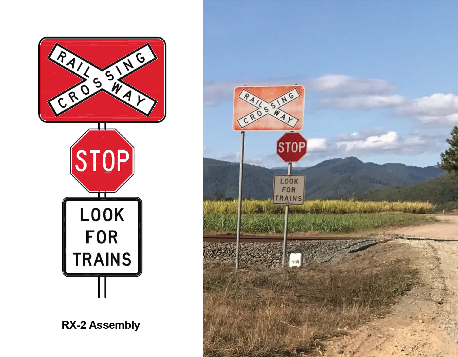
In 1997, QR engaged a consultant to develop an organisational standard for all occupation crossings on their rail network. The consultant report recommended a RX-2 assembly (Stop sign) as the standard for all occupation crossings. This recommendation exceeded the minimum treatment requirement of Australian Standard 1742.7:2016[5] and was consistent with the installation at crossing ID 5318 (Figure 2).
The consultant report also recommended minimum sighting distances at occupation crossings. For train speeds of 100 km/h on single track, the minimum sighting distance for a vehicle stopped at the stop sign was recommended as 450 m. QR records indicate that sighting distances at occupation crossing ID 5318 was in excess of 700 m.
In general, the traffic control devices installed at occupation crossing ID 5318 were consistent with the requirements documented in the QR organisational standard.
Figure 2: Traffic control devices at occupation crossing ID 5318
RX-2 assembly (Stop sign) to Australian Standard 1742.7:2016. Source: AS1742.7 and Queensland Rail
Environmental conditions
The closest Bureau of Meteorology (BOM) weather station was at Proserpine, about 56 km north of occupation crossing ID 5318. At 0900 (about 45 minutes before the collision), the weather was clear with a light south-easterly breeze and the temperature was about 22 °C.
The train driver reported seeing dust from a vehicle travelling on Wagoora-Yalboroo Road. Considering the road was north of the track and the wind was from the south-east, any dust would have been blown away from the railway line. It is very unlikely that the dust would have obscured the truck driver’s vision of the approaching train.
The weather conditions were unlikely to have been a factor in the collision.
The sun’s azimuth[6] and altitude[7] was 52° 09’ 51” and 43° 42’ 47” respectively. Therefore, the sun was relatively high in the sky, and to the north-east.
In this instance, train 8279 was approaching from the east. For a vehicle stopped at the crossing, the sun would have been almost directly behind the truck driver at an altitude of about 43° above the horizon (Figure 3).
It is unlikely that sun-glare or any other sun related effects would have been a factor in the collision.
Figure 3: Sun position and sighting direction of truck driver
The sighting direction for the truck driver was towards the east. The sun was almost directly behind the truck driver at an altitude of about 43° above the horizon. Source: Google Earth, annotated by ATSB
Road vehicle
The vehicle was a 1983 Scania model P112 series 2, twin-steer truck and had been fitted with a flat tray body in May 2017 (Figure 4). The vehicle had a tare mass of 12.2 t and a gross vehicle mass of 26.5 t. Inspection, registration, insurance and modification certificates were all current.
The ATSB noted that the truck had a relatively prominent B-Pillar (Figure 4). The B-pillar of heavy vehicles is a feature known to obscure a driver's vision. It is likely that, under some conditions, a driver of this truck would experience a restricted view to the left due to the vehicle’s B-pillar.
Figure 4: Road vehicle
The vehicle was a 1983 Scania model P112 series 2, twin-steer truck fitted with a flat tray body. The vehicle was loaded with a storage container, fuel tank and air compressor (inset). Note that under some conditions, it is very likely the truck driver’s vision to the left may be restricted due to the vehicle’s B-pillar. Source: Qld Police, Annotated by ATSB
At the time of the accident, the vehicle was loaded with a storage container, fuel tank and air compressor (Figure 4, inset). All were securely mounted on the flat tray body.
The storage container was relatively lightly loaded; an oil drum secured to the container frame, with a number of smaller fluid containers and hand tools stored on racks. The fuel tank[8] was found to be full (about 1650 lt).
There was no indication that the vehicle was overloaded. Similarly, and considering the fuel tank was full, it is unlikely that any load shift would have affected vehicle dynamics.
The damaged vehicle was examined by the Queensland Police Vehicle Inspection Unit. The inspection found an amount of water retained in the air (brake) system tanks. However, the report noted the train driver’s observations that the truck had stopped at the crossing before proceeding, suggesting the brakes appeared to have been operating immediately prior to the incident. The report concluded that there were no obvious or apparent mechanical defects that could have contributed to the cause of the incident.
Road vehicle driver
The truck driver was appropriately qualified and had extensive experience driving heavy vehicles.
Fatigue
In the context of human performance, fatigue is a physical and psychological condition primarily caused by prolonged wakefulness and/or insufficient or disturbed sleep.[9] Fatigue can have a range of influences on performance, such as decreased short-term memory, slowed reaction time, decreased work efficiency, reduced motivational drive, increased variability in work performance, and increased errors of omission.[10] Fatigue impairment has been identified as causal in many transport related accidents.
The truck driver’s work-hours were generally between 0630 and mid-afternoon. The driver had worked these times in the three days prior to the incident, having previously come off of a three-day break. It was evident that work was generally undertaken during daylight hours. There were also sufficient off-duty hours at night, providing ample opportunity for restorative sleep prior to commencing work the next day. In addition, full rest-days were provided, giving the opportunity for recovery away from the work environment.
On the day of the incident, the truck driver started work at 0630. He had worked in an on-site shed until about 0800 before travelling out to the cane fields in the truck. The accident occurred at about 0945, less than half way through the driver’s normal workday. It was considered unlikely that the effects of fatigue were present either leading up to or at the time of the collision.
Medical and toxicology
Post-mortem examination found no evidence of any significant natural disease. Similarly, toxicology testing revealed no evidence of alcohol or drugs in blood and urine.
Looked but did not see
Research has shown that, in road accidents, critical/important information may have been detectible but the motorist did not attend to or notice it because their mental resources were elsewhere.[11] Furthermore, research into a phenomenon known as ‘inattentional blindness’[12] has shown how a person may fail to detect an object even though they were looking directly at it.
The human mind has limited resources for perceptual and memory processing. To cope with this limitation, a mechanism called ‘attention’ acts as a filter to focus this resource on specific tasks. Research suggests that inattentional blindness can occur when attention is mistakenly filtered away from important information[13] and can be affected by mental workload, expectation, conspicuity and capacity.
In this case, the vehicle driver approached the railway crossing and was observed to have stopped at the stop sign, albeit at an angle facing away from the approaching train. It is possible that the driver looked towards the approaching train, but did not see or perceive its approach. Soon after stopping, the truck driver proceeded into the path of the train.
Expectancy
Expectancy can be understood as the extent to which an event or condition is expected to occur or be present at a particular time and place. An individual’s expectation can influence their attention to (and preparation for) that event or condition.[14]
Studies undertaken into motorist behaviour have found that drivers who are familiar with a railway crossing are more likely to be involved in a crossing incident than drivers unfamiliar with the crossing.[15] An influencing factor is where motorists familiar with a crossing with relatively low train frequencies, don’t expect a train since they are rarely seen.
The frequency of train movements across the railway crossing was relatively low—about 15 train movements per day. Therefore, while the truck driver was aware of the railway crossing due to regularly working in the area, the probability of him encountering trains was relatively low. It is therefore possible that the truck driver’s familiarity with the railway crossing and a low expectation of encountering a train contributed to him not noticing the approaching train.
Driver distraction
Distraction can be understood as a type of inattention, where a person’s attention is diverted by a particular event or object. Driver distraction has been more specifically defined as ‘the diversion of attention away from activities critical for safe driving toward a competing activity (occurring) voluntarily or involuntarily.’[16]
Driver distraction can involve a range of factors either inside or outside a vehicle that draw on limited human physical, visual and cognitive resources, and can result in a degradation of the driver’s performance. For example, eating, drinking, operating devices integral to (or brought into) the vehicle (such as a mobile telephone), and smoking, are all activities that may distract from the driving task.[17]
While the source of distraction may often be physical, it can also be non-physical. For example, a situation where task-irrelevant thoughts interfere with task-relevant thoughts, may contribute to distraction and decrease task performance. A research study into the effects of irrelevant thoughts and cognitive task performance concluded that ‘when the proportion of irrelevant thoughts to relevant thoughts increases, performance suffers.’[18]
The truck driver was the sole occupant, so distraction by another person did not occur. The truck driver had a mobile phone, but there was no evidence of it being used at the time of the incident.
Based on the available evidence, there was nothing to indicate that the truck driver’s attention had been diverted by a distracting object or event.
It is possible, however, that the truck driver’s thoughts were directed towards other tasks. That is, rather than thinking about the task of look for an approaching train, the driver’s attention may have been directed towards some other task-irrelevant thoughts.
Summary of driver behaviour
Other than witness observations, there was very little objective evidence for verifying driver behaviour. The truck was observed stopping at the crossing before the truck driver proceeded into the path of the train. There was no evidence to suggest that the effects of fatigue, drugs, alcohol, or any medical condition contributed to the collision.
In the absence of any evidence to the contrary, it is possible that the truck driver looked towards the approaching train but did not see or perceive its approach. It is also possible that distraction and a low expectation of encountering a train contributed to him not noticing the approaching train. However, the combination of the truck’s cab-design (B-pillar) and that it stopped at an angle facing slightly away from the approaching train likely restricted the truck driver’s ability to sight the train.
Rail vehicle
Freight train 8279 was operated by Aurizon and consisted of one locomotive (2813) and 23 wagons. The train was 480 m in length with a total weight of 1370 t.
The train was crewed by a single driver, who had about nine years’ train driving experience. At the time of the collision, the train driver was appropriately qualified, assessed as competent and medically fit for duty.
The train driver was rostered to start work on 29 August 2017 at 0700, having had the previous two days off. The driver took control of train 8279 at 0830, about 75 minutes before the accident. It was considered very unlikely that train driver fatigue contributed in any way to the collision.
Following the accident, the train driver undertook routine drug and alcohol testing which returned a negative result.
Conspicuity
Conspicuity refers to an object’s ability to capture attention. Physical factors that affect the conspicuity of an object include size, contrast and movement. The approaching train was large and travelling relatively quickly. However, from the truck driver’s perspective, the perception of size and speed are likely to have been low due to its distance away (more than 200 m) and angle of approach (almost directly towards the truck driver).
The Rail Industry Safety and Standards Board (RISSB) develop and publish Australian Standards for the rail industry. Australian Standard AS 7531:2015 Rolling stock standard – Lighting and Visibility documents the requirements for lighting and rolling stock visibility and is applicable to new and existing locomotives.
The Australian standards states that the front of locomotives shall have areas of high visibility colour, either yellow, orange, orange-red or red. Locomotives shall also have white marker lights and at least one white headlight, mounted at least 2.3 m above the rail. The standard also makes reference to a requirement for visibility lights. The RISSB standard stated:
The primary purpose of locomotive visibility lights is to enhance the visibility of the front-end locomotive of a train from the perspective of a driver of a motor vehicle approaching a level crossing.
The two white visibility lights are mounted on either side of the locomotive front, between 600 mm and 1200 mm above the top of the rail. The standard stated that lights must alternately flash on and off when the horn is sounded and continue flashing for at least fifteen seconds after the horn has been sounded.
QR also publish their Interface Standards (MD-10-194, dated 23 July 2014) which prescribes the minimum requirements for rolling stock operating on QR infrastructure. The QR standard was largely consistent with the RISSB standards regarding colour, headlights and marker lights. While the QR standard also included the requirement for visibility lights, it did not make mention of any requirement for visibility lights to flash when the horn is sounded.
In this case, the front of locomotive 2813 was painted yellow as per the RISSB and Queensland Rail visibility standards.
The operational condition of the 2800 class locomotives headlights is a parameter recorded on the locomotive data log. In this case, the data log for locomotive 2813 indicates the headlights were illuminated on hi-beam while approaching the level crossing. Figure 5 also shows that both the headlights and the marker lights were still illuminated after collision.
To improve conspicuity, the front of locomotive 2813 was painted yellow and its headlights were illuminated. Source: Qld Police
The 2800 class locomotives also have visibility lights, which sit to the side of the coupler behind a perforated protection plate (Figure 5). The lights are manually controlled by the train driver and operate continuously when switched on, but do not flash when the horn is sounded.
When photographed following the collision, one of the visibility light was destroyed as a consequence of the collision and the other was not illuminated (Figure 5). The ATSB noted that a photograph of the driver’s overhead console indicated the switch controlling the visibility lights was in the off position.[19] The train driver advised that it is normal to travel with the visibility lights on, and recalled that the lights were on in this case.
Discussions with other drivers of 2800 class locomotives noted that it is routine to operate the train with the headlights and visibility lights on. When stopping at a station or crossing loop, a driver might turn the visibility lights off and switch headlights to low beam to avoid light glare affecting an opposing train/driver. However, when departing, drivers usually turn on both the locomotive generator field and the visibility lights at the same time, since these switches are adjacent each other. In this case, it was not unexpected that the headlights remained on after the train stopped following the collision and the train driver had secured the locomotive, as this would be normal practice when stopping. However, it could not be confirmed at what time the visibility lights were switched on or off, since the operational condition of the visibility lights is not a parameter recorded on the locomotive data log.
Locomotive 2813 incorporated all lighting and visibility features documented in the QR interface standard. However, an enhancement documented in the Australian standard (flashing lights when the horn is sounded) was not included on locomotive 2813.
In this instance, the headlights were switched on, but the condition of the visibility lights could not be verified. While visibility lights, and their flashing feature if available, may capture a road vehicle driver’s attention under some conditions, it is unknown if it would have resulted in a different outcome in this case.
Audible devices
Given the size and weight of most trains it is not possible to brake at anywhere near the rate of a road vehicle. Heavy freight and locomotive hauled passenger trains normally take in excess of 1 km to stop from high track speeds, even if the train driver initiates an emergency application of the brakes.
In an event such as this, by the time the train driver observes a truck begin to move into the path of the train, there is insufficient time to take any avoiding action to prevent the collision other than sounding the whistle and applying the brakes. In this specific case, the brakes had only barely begun to take effect (speed reduced from 84 km/h to 83 km/h) as train 8279 traversed the crossing.
Historically, audible devices have been considered an important component in the systems used to warn motorists of an approaching train. However, soundproofing, air conditioning and entertainment systems in modern vehicles have generally reduced the effectiveness of audible warnings.[20] Similarly, surrounding sounds such as vehicle engine noise (potentially significant for heavy vehicles) and other road noises (nearby traffic) may reduce the ability for a vehicle driver to hear the sounding of a train horn.
In this case, the driver of train 8279 sounded the locomotive horn twice while approaching the level crossing. The first sounding was when the truck was observed having stopped at the crossing. The second sustained sounding was when the truck was observed starting to move into the path of the train, at which point the train driver placed the brake handle into the emergency position, before moving to the foot-well for protection.
Once the truck moved forward onto the crossing, a collision was inevitable considering the proximity of train.
For this accident, there was no evidence to suggest that factors such as sun-glare, mechanical defect, fatigue, drugs, alcohol, or medical condition contributed to the collision. Similarly, the traffic control devices installed at this location were consistent with Queensland Rail’s design standards for private (occupation) crossings.
In this case, the train driver described the truck as having stopped at an angle facing away from the approaching train. Consequently, the truck driver’s ability to sight a train approaching from the left was examined further.
The ATSB also examined the long-term programs and strategies for improving safety outcomes for all level crossing users across Queensland.
Vision obstructions due to vehicle
While most vehicles exhibit features that may obscure a driver's vision, it is particularly true for heavy vehicles. Considering the cab-design of the vehicle involved in this incident (Figure 4), it is very likely that under some conditions, the driver’s vision to the left would have been restricted due to the vehicle’s B-pillar.
The Queensland Police conducted visibility testing using a vehicle with very similar side window and B-pillar configurations.[21] Testing showed that clear visibility was available to 90° for a normally seated driver simply turning the head to look out the passenger side window. If the driver was to lean forward over the steering wheel, the angle of vision increased to about 100°. However, vision beyond 100° to the left was not possible through the passenger side window (Figure 6).
Figure 6: Road vehicle visibility testing
Road vehicle visibility testing indicated a complete restriction to driver visibility beyond 100°, when the driver was looking out the left side passenger window. Source: Qld Police, annotated by ATSB
Table 1 shows the results of the Queensland Police road vehicle visibility testing and is presented in terms of road vehicle angle relative to the rail line. As this angle decreases, a road vehicle driver is required to look further to the rear of 90° to sight along the rail line. It is evident from testing, that sighting objects through the passenger side window is significantly reduced if the road vehicle stops at an angle to the rail line. If the vehicle angle relative to the rail line was less than 80°, the driver would be unable to sight the full distance along the rail line, even when leaning forward over the steering wheel.
Table 1: Road vehicle visibility – test results
Vehicle angle relative to rail line and approaching train
Sighting distance along rail line for a truck driver seated normally and looking left
Sighting distance along rail line for a truck driver leaning forward and looking left
90°
Full train approach visibility
Full train approach visibility
85°
53 m
Full train approach visibility
80°
26 m
Full train approach visible
75°
17 m
54 m
70°
12 m
26 m
Results from road vehicle visibility testing on a vehicle similar in configuration to the incident vehicle, based on a stopping distance of 2.5 m before the rail line. Note, the measured results have been rounded to the nearest metre. Source: Qld Police
The Austroads Guide to Road Design provides guidance to road designers on the geometric design of all types of road intersections and crossings. The Queensland Department of Transport and Main Roads (TMR) publish their Road Planning and Design Manual that largely accepts the requirements documented in the Austroads publication.
The Austroads guide notes that there are no design rules dealing with visibility from vehicles, but makes reference to published information regarding restrictions due to vehicle design[22] (Figure 7). Considering the published restrictions due to vehicle design, TMR policy was that road centre lines should be designed to intersect at between 70° and 110° in both urban and rural situations.
Figure 7: Sight restrictions due to vehicle design
The Austroads guide notes that vision form the cab of a vehicle becomes increasingly difficult to the side and rear of the vehicle. The rectangle represents a vehicle; the circle represents the vehicle driver. Note the area highlighted indicating where vision from a truck may be restricted due to the vehicle’s B-pillar. Source: Austroads Guide to Road Design Part 4A: Unsignalised and Signalised Intersections, Annotated by ATSB
The tests undertaken by Queensland Police showed similar results to the limitations documented in the road design guidelines. That is, vision out the left side passenger window became increasingly difficult as the angle increased to 20° behind 90°. At an angle variation of 20°, a driver in the test vehicle would only be able to sight another vehicle approaching from the left when it was within about 26 m.
Road vehicles are capable of braking relatively quickly. In the context of a road intersection, the driver of an approaching road vehicle is likely to sight another vehicle starting to enter the intersection and take action to avoid an imminent collision.
However, given the size and weight of most trains it is not possible to brake at anywhere near the rate of a road vehicle, nor is it possible to rapidly accelerate or decelerate a train. Therefore, at railway level crossings, it is much more important for the driver of the road vehicle to take action to avoid a collision.
At level crossings protected by Stop signs, motorists are required to stop in order to look for any approaching trains. Consequently, sufficient sighting distance must be available for a motorist to see an approaching train in time to make an informed decision whether it is safe to proceed over the crossing. Australian Standard 1742.7:2016 includes design criteria for calculating sighting distance requirements at level crossings protected by Stop signs. For the configuration at occupation crossing ID 5318, at least 430 m sighting distance is required to provide adequate time for a large road vehicle to accelerate from stop and safely clear the crossing before the arrival of an approaching train. When considering the results of the visibility testing, this could only be achieved if the road vehicle has stopped at an angle greater than 80° to the rail line.
At the accident location, the private road intersected the rail line at an angle of about 90°. However, the junction between the private road and Wagoora-Yalboroo Road (approximately 19 m from the railway crossing signage) showed evidence of widening at its eastern corner. Both roads were unsealed, so widening probably occurred gradually as road vehicles progressively cut the corner when entering/exiting the private road. Consequently, the effective centre line of the road varied from the designed 90° (Figure 8). The ability for a road vehicle to cut the corner and enter the private road at an angle, combined with a relatively short distance to the crossing, may influence the positioning of larger vehicles when stopped at the crossing.
Figure 8: Road angle
The design angle for the road centre line at the level crossing was approximately 90° to the rail line. However, due to widening of the road junction eastern corner, the effective centre line of the road varied from the designed 90°. Source: Qld Police, annotated by ATSB
In this case, the train driver described observing the road vehicle having stopped at the crossing, but it appeared to be angled facing slightly away from the approaching train. Considering both the train driver observation and the geometry of the private road, the angle between the vehicle direction and the railway was very likely less than 90°. Visibility testing suggested that at almost any angle less than 90°, the truck driver’s ability to sight sufficient distance along the rail line would have significantly reduced. However, there is insufficient evidence to determine the exact angle the vehicle stopped, nor what action the truck driver may have taken to check for an approaching train before proceeding over the crossing.
Railway level crossing safety strategy
A 2009 study found there were about 21,800 road/railway level crossings in Australia. Of these, about 8,800 were public road crossings and 13,000 were classified as private/occupation crossings.[23] While the number of private crossings is relatively high, they are normally provided for the exclusive use of a landowner to access private land. Private crossings are not intended as a thoroughfare for access by the general public, consequently the lower usage of the road lessens the level of risk that may arise from the crossing.
The Office of the National Rail Safety Regulator (ONRSR) publishes a document titled Policy - Railway crossings. The policy focus is on addressing public crossings which are generally considered a greater safety risk to road users. However, it notes that the application of the policy with respect to private crossings should also be considered in relation to risk. That is, regardless of a level crossing being defined as public or private, a rail infrastructure manager is still required to eliminate or minimise the risk that may arise from railway crossings, so far as is reasonably practicable. The policy states that ONRSR expects to see continuous improvement in the safety of railway crossings and ultimately seeks a reduction in the number of railway crossings.
The ONRSR policy refers to a Rail Industry Safety and Standards Board (RISSB) guideline for the consolidation of level crossings.[24] The guideline acknowledges that managing risk so far as is reasonably practicable may include permanently closing the level crossing to road/pedestrian traffic. The guideline suggests that multiple level crossings in close proximity (within a five kilometre distance or less) present prime opportunities for consolidation.
In July 2012, the Queensland government (Department of Transport and Main Roads) published their Level Crossing Safety Strategy 2012-2021 as a ‘…commitment to further improve safety outcomes for all level crossing users’. The document detailed 12 key strategies, one of which is to ‘…eliminate level crossings where appropriate’.[25]
There are multiple stakeholders (state/local government and rail/road organisations) involved in managing safety risk at railway level crossings in Queensland. The Queensland Level Crossing Safety Group (QLCSG) provides a forum to bring these stakeholders together to work collaboratively to address the 12 key safety strategies. The QLCSG is chaired by the Department of Transport and Main Roads. Queensland Rail and the infrastructure manager for level crossing ID5318, is a stakeholder and active member of the group.
The QLCSG has documented[26] a number of achievements since the launch of the safety strategy. While increased education and enforcement has been significant, there has also been progress made with respect to reducing the number of level crossings in Queensland. This has been achieved by closing level crossings where possible, grade separations (overpasses), the closure of branch lines and by not introducing new level crossings onto the network.
It is evident that the strategy and actions to date are generally consistent with the ONRSR policy in that the removal of unnecessary or rarely used public level crossings has been considered.
However, the level crossing safety strategy and the QLCSG report both state that private (occupation) crossings are excluded and that private crossings are considered a workplace health and safety matter. Notwithstanding the exclusion, the QLCSG advised that issues in managing private (occupation) crossings has occurred informally in the past and will continue.
With respect to managing risk, the objective of work health and safety legislation[27] is largely consistent with that of rail safety legislation.[28] That is, the duty imposed is to eliminate or minimise the risk to health and safety, so far as is reasonably practicable.
As part of the management of risk at level crossings, Queensland Rail undertake data collection and assessment of all crossings (public and private) on their network. The data and assessments help guide Queensland Rail’s programs for ensuring level crossings (public and private) are maintained in accordance with their documented standards. While crossing ID 5318 provided vehicle access similar to that of a public crossing, the data recorded relatively low risk scores for most elements of the assessment. The ATSB noted that the annual average daily traffic recorded at the crossing was 100 vehicles per day, seasonal. The seasonal notation suggested that the traffic was very likely associated with cane production and less likely associated with general public. However, it was also likely that much of the traffic used the crossing as a thoroughfare between the two public roads, rather than for the sole purpose of accessing a small strip of cane field adjacent the railway track.
While crossing ID 5318 was classified as a private (occupation) crossing, its unrestricted access as a thoroughfare between two public roads likely presented a level of risk similar to that of a public road crossing. Consequently, the strategies for addressing the risk should be consistent for those used as a public thoroughfare whether the crossing is a public or a private (occupation) crossing.
It was reported that the truck driver in this case was travelling between properties located on the Wagoora-Yalboroo Road and another located on the opposite side of the Bruce Highway. It is evident that in this case, crossing ID 5318 was being accessed as a thoroughfare between Wagoora-Yalboroo Road and the Bruce Highway.
There were a number of level crossings in the relative vicinity of crossing ID 5318 (both public and private). Of specific relevance was the Wintons Road level crossing, located about 900 m east. Wintons Road is a sealed road with active traffic control devices (flashing lights) at the level crossing. For the truck in this case, traversing the railway track at the Wintons Road level crossing was a viable and safer alternative for crossing the railway track (Figure 9).
However, road related issues should also be taken into account when considering alternative routes. For example, information provided the truck operator (Fox Hall Harvesting Group) suggested that road signage near the Wintons Road – Bruce Highway road intersection may pose sighting issues for drivers of larger vehicles such as tractors and trucks.
Some cane harvesting vehicles are not permitted to operate on the highway. Consequently, in some cases, the sole access to property may be via a private (occupation) crossing. However, the ATSB notes that this scenario is consistent with the intention of a private (occupation) crossing and its provision should not encourage unrestricted public access as a thoroughfare.
Figure 9: Chosen route (red) and alternative route (orange)
The truck was travelling between properties located on the Wagoora-Yalboroo Road and another located on the opposite side of the Bruce Highway via crossing ID 5318. There was a viable and safer alternative for travelling to the intended destination via Wintons Road with active traffic control devices (flashing lights) at the level crossing. Source: Google Earth, annotated by ATSB
In the absence of measures preventing unrestricted public access and considering the proximity of an alternative crossing with active traffic control devices (flashing lights), it is possible that crossing ID 5318 might present an opportunity for Queensland Rail to consider consolidation as encouraged by documented level crossing safety policies and safety strategies.
The exclusion of private (occupation) crossings from the Queensland level crossing safety strategy potentially removes an opportunity to further improve safety outcomes for all level crossing users across Queensland. This is especially the case for crossing ID 5318 and other private (occupation) crossings with a similar configuration, where unrestricted public access may present a level of risk similar to that of a public road crossing.
From the evidence available, the following findings are made with respect to the collision between freight train 8279 and truck, at level crossing ID 5318 near Yalboroo, Queensland on 29 August 2017. These findings should not be read as apportioning blame or liability to any particular organisation or individual.
Contributing factors
After stopping at the stop sign, the road vehicle driver then proceeded onto the level crossing and into the path of the train.
There was insufficient time for the train driver to stop the train before colliding with the truck.
The combination of the truck’s cab-design and the likelihood that the vehicle stopped at an angle less than 90° to the railway track likely restricted the truck drivers sighting of the approaching train.
Other factors that increased risk
Some private (occupation) crossings in Queensland, such as crossing ID 5318, provide unrestricted public access between two public roads. These crossings present a level of risk similar to that of a public road crossing where either a higher level of treatment may be applicable with respect to traffic control devices, or closure may be a consideration.
The exclusion of private (occupation) crossings from the Queensland level crossing safety strategy potentially removes an opportunity to further improve safety outcomes for all level crossing users across Queensland. This is especially the case for crossing configurations where unrestricted public access may present a level of risk similar to that of a public road crossing.
The combination of the widening of junction at Wagoora-Yalboroo Road with the relatively short distance to the railway crossing could influence the position of road vehicles when stopped at the crossing and in turn, could affect the ability for drivers of some larger vehicles to sight an approaching train.
Other findings
While there is insufficient evidence to determine conclusively, there are a number of other factors that may have influenced why the truck driver proceeded onto the level crossing:
The truck driver looked towards the approaching train, but did not see or perceive its approach (inattentional blindness).
The truck driver’s familiarity with the railway crossing and a low expectation of encountering a train contributed to him not noticing the approaching train.
The truck driver’s attention may have been directed towards some other task-irrelevant thoughts.
The traffic control devices installed at occupation crossing ID 5318 were consistent with the requirements documented in the Queensland Rail organisational standard.
It is unlikely that sun-glare or any other environmental conditions contributed to the collision.
There were no obvious or apparent mechanical defects to the truck that could have contributed to the collision.
The locomotive was relatively conspicuous in colour (yellow), its headlights were illuminated and the train driver had sounded the train whistle twice while approaching the crossing.
For both the truck driver and the train driver, it is unlikely that the effects of fatigue, drugs, alcohol, or any medical condition contributed to the collision.
There was a viable and safer alternative for the truck to travel to the intended destination. This alternative involved traversing the railway track via a sealed road with active traffic control devices (flashing lights) at the level crossing.
Safety actions
Whether or not the ATSB identifies safety issues in the course of an investigation, relevant organisations may proactively initiate safety action in order to reduce their safety risk. The ATSB has been advised of the following proactive safety action in response to this occurrence.
Proactive safety action taken by Aurizon
External communications – Aurizon has ongoing engagement with local authorities (and in this case Mackay Regional Council) prior to sugar seasons, for the purpose of raising awareness of above rail operations during the sugar crushing.
Internal communications – In addition to the existing ‘pre-start’ and ‘tool box’ talks provided for rail traffic crew, specific information has been shared with rail traffic crew subsequent to this occurrence to reinforce procedures and re-remind rail traffic crew of increased presence of vehicles due to the cane crushing season and to continue to report all occurrences as required and to continue to report near misses as required.
Proactive safety action taken by Queensland Rail
On the 6 November 2017, Queensland Rail (QR) conducted an audit (site survey) to confirm site distances and the signage has been installed to the QR standard. The result of this audit found that the level crossing had appropriate sighting distance and signage for the controls in place in accordance with QR’s level crossing standard for private crossings. It is assumed that during cane season the crossing is used by the land owner’s trucks and harvesting equipment and it appears the crossing is well maintained.
Whistle boards are installed at the 428 m from the crossing to the south and 375 m from the north. The audit identified that additional whistle boards should be installed at 250 m either side of the crossing due to the rail line speed of 100 km/h and that the R26 sign has started to fade and should be replaced. These will be addressed by the local asset manager under routine maintenance activities.
Independently to this incident occurring, QR had already put in place an audit programme to assess all private crossings, upgrade them to the QR standard as necessary, and seek to enter into interface agreements. This programme was progressing at the time of the accident. Although the programme had not yet covered the specific location of this crossing at the time of the accident, QR is actively working towards improving or eliminating private crossings.
QR is requesting the relevant party (local government or landholder) enter into an appropriate licence or interface agreement with Queensland Rail for the safe operation and use of the private level crossings. Audits have so far been completed within the Far North, North West and Mackay regions of Queensland. To date, the audits have identified eight crossings for closure (as they are no longer required by any party) and eight crossings that will be changed from a private status to a public status crossing as they appear to be used by the general public. One crossing has been identified as requiring relocation. As at May 2018, licence/interface agreements for 85 crossings have been sent to relevant parties in the shire areas noted above and 15 licence/interface agreements have been formalised.
QRl reviews its level crossing standard on a 2 yearly basis and the current review is due to be completed in 2019. It has been identified in this review that consideration needs to be given to the frequency of audit of private level crossings.
Proactive safety action taken by Fox Hall Harvesting Group
Fox Hall Harvesting Group advised that they are prepared to erect no access signs as well as private property signs on both sides of the access road. They are also prepared to consider lockable gates and a fence on the boundary between the property and the railway easement to stop public use.
ATSB comment:
The ATSB acknowledges the willingness of the property owner to take action preventing public use of the private crossing. However, it is noted that any action should be done in consultation with the rail operator to ensure unintended hazards are not introduced.
Proactive safety action taken by the Queensland Level Crossing Safety Group (QLCSG)
At the QLCSG meeting held on 30 May 2018, the responsibilities under the Rail Safety National Law in relation to private (occupational) level crossings was acknowledged as being the primary means by which to manage safety at these locations. It was agreed that the QLCSG should remain focused on the higher risk public level crossings. However, in recognition of ATSB’s draft finding, it was also agreed that rail infrastructure managers would undertake a one-off review of private level crossings that are being used by the public (similarly to Yalboroo). The intent would be to review their status and treatment, and where assessed, include them as a sub-set of public level crossings for the purposes of the Strategy and QLCSQ functions.
Sources and submissions
Sources of information
The sources of information during the investigation included the:
Aurizon
Queensland Rail
Queensland Police Service
Office of the national rail safety regulator
Bureau of Meteorology
Crew of freight train 8279
References
Australian Government, Geoscience Australia
Australian Level Crossing Assessment Model ALCAM
Australian Standard 1742.7:2016 Manual of uniform traffic control devices, Part 7: Railway crossings
Australian Standard AS 7531:2015 Rolling stock standard – Lighting and Visibility
Austroads Guide to Road Design Part 4A: Unsignalised and Signalised Intersections
Ackerman C. (1989): Vehicle Characteristics (Course notes titled Traffic Engineering Practice edited by Ogden and Bennett for Monash University, Melbourne)
Battelle Memorial Institute (1998). An Overview of the scientific literature concerning fatigue, sleep, and the circadian cycle, Report prepared for the Office of the Chief Scientific and Technical Advisor for Human Factors, US Federal Aviation Administration.
Green, M (2004), Inattentional Blindness & Conspicuity. Retrieved 13 March 2007 from www.visualexpert.com
Green, M. & Senders, J. (2004). Human error in road accidents. Retrieved 13 March 2007 from www.visualexpert.com
Mack, A. & Rock, I. (1998), Inattentional Blindness. MIT Press: Cambridge, USA
National Transport Commission (2008). National Rail Safety Guideline. Management of Fatigue in Rail Safety Workers.
Office of the National Rail Safety Regulator – Policy: Railway crossings
Pennie S. Seibert and Henry C. Ellis, Memory & Cognition (1991), Irrelevant thoughts, emotional mood states, and cognitive task performance, 507-513.
Queensland Department of Transport and Main Roads Road Planning and Design Manual
Queensland Department of Transport and Main Roads Level Crossing Safety Strategy 2012-2021
Yeh, M. & Multzer, J. (2008). Driver Behaviour at Highway-Railroad Grade Crossings: A Literature Review from 1990-2006. Human Factors in Railroad Operations. United States Department of Transportation, Federal Railroad Administration: Washington DC.
Young, K.L., Regan, M.A., & Hammer, M. (2003). Driver Distraction: A review of the literature. Monash University Accident Research Centre. Available from: www.monash.edu.au
Submissions
Under Part 4, Division 2 (Investigation Reports), Section 26 of the Transport Safety Investigation Act 2003 (the Act), the Australian Transport Safety Bureau (ATSB) may provide a draft report, on a confidential basis, to any person whom the ATSB considers appropriate. Section 26 (1) (a) of the Act allows a person receiving a draft report to make submissions to the ATSB about the draft report.
A draft of this report was provided to the next of kin, the crew of train 8279, Aurizon, Queensland Rail, Queensland Police Service, the Queensland Department of Transport and Main Roads, the trucking company and the Office of the National Rail Safety Regulator.
Submissions were received from the crew of train 8279, Aurizon, Queensland Rail, Queensland Police Service, the Queensland Department of Transport and Main Roads, the trucking company and the Office of the National Rail Safety Regulator. The submissions were reviewed and where considered appropriate, the text of the report was amended accordingly.
Purpose of safety investigations
The objective of a safety investigation is to enhance transport safety. This is done through:
identifying safety issues and facilitating safety action to address those issues
providing information about occurrences and their associated safety factors to facilitate learning within the transport industry.
It is not a function of the ATSB to apportion blame or provide a means for determining liability. At the same time, an investigation report must include factual material of sufficient weight to support the analysis and findings. At all times the ATSB endeavours to balance the use of material that could imply adverse comment with the need to properly explain what happened, and why, in a fair and unbiased manner. The ATSB does not investigate for the purpose of taking administrative, regulatory or criminal action.
Terminology
An explanation of terminology used in ATSB investigation reports is available here. This includes terms such as occurrence, contributing factor, other factor that increased risk, and safety issue.
Publishing information
Released in accordance with section 25 of the Transport Safety Investigation Act 2003
Ownership of intellectual property rights in this publication
Unless otherwise noted, copyright (and any other intellectual property rights, if any) in this report publication is owned by the Commonwealth of Australia.
Creative Commons licence
With the exception of the Coat of Arms, ATSB logo, and photos and graphics in which a third party holds copyright, this publication is licensed under a Creative Commons Attribution 3.0 Australia licence.
Creative Commons Attribution 3.0 Australia Licence is a standard form licence agreement that allows you to copy, distribute, transmit and adapt this publication provided that you attribute the work.
The ATSB’s preference is that you attribute this publication (and any material sourced from it) using the following wording: Source: Australian Transport Safety Bureau
Copyright in material obtained from other agencies, private individuals or organisations, belongs to those agencies, individuals or organisations. Where you wish to use their material, you will need to contact them directly.
On 18 August 2017, the pilot of a Robinson R44 II helicopter, registered VH-LGN, was conducting a private flight from Noonamah, Northern Territory (NT) to Channel Point, NT, with three passengers on board. At about 1400 Central Standard Time,[1] after a 20-minute flight, the helicopter was flying about 500 ft above a beach at Channel Point in preparation for landing. Weight and balance information provided by the pilot indicated that the helicopter’s centre of gravity was toward the forward limit but within the allowable range.
The pilot reported that the helicopter’s airspeed was about 50 kt as he commenced a descending right turn, intending to land on the beach. During this time, a ‘bounce’ developed through the airframe. The pilot initially moved the cyclic[2] aft to reduce airspeed, the bounce increased to a violent shaking, both fore and aft, and side to side. The pilot then moved the cyclic forward to increase airspeed and lowered the collective,[3] with the intent to conduct an immediate landing.
Just prior to landing, the pilot raised the collective and flared the helicopter. Despite this, the helicopter landed heavily, damaging the skids and the main rotor blade severed the tail boom. The helicopter stopped in an upright position and all four occupants vacated the helicopter without injury.
Related occurrences
The nature of the airframe shaking, as described by the pilot, was similar to an occurrence investigated by the United States National Transportation Safety Board (NTSB) (ANC09GA040) in 2009. In that occurrence, the pilot described severe vibrations and oscillations to the point where the pilot felt like the helicopter was going to come apart. The pilot conducted an emergency landing and landed hard, with the main rotor contacting the tail boom. The NTSB report noted several other similar occurrences of severe airframe vibration from 2006 and 2007, which also resulted in the pilots conducting emergency landings. The vibrations or oscillations have also been referred to as ‘mast rocking’ or ‘chugging’.
Based on information provided by Robinson Helicopters, the NTSB report indicated that the oscillation was associated with fore and aft movement of the rotor mast (Figure 1). The manufacturer had conducted flight tests related to the oscillations and determined that they ‘may develop during operation at high gross weight, at about 90-100 kt airspeed’. Additionally, the tendency to develop oscillations was exacerbated by flying with a forward centre of gravity (although still within the approved envelope) and by entering a 30° left banked turn. A right banked turn could also exacerbate the oscillation, but it was more easily initiated in a left turn.
The mast oscillation was attributed to lack of firmness of newly-installed gearbox mounts and the manufacturer introduced stiffer mounts (part number A653-2) in June 2007 to counter the problem. The rubber in the mounts was found to harden with heat and compression during service and the issue was therefore more likely to affect low-hour helicopters. As such, there was only a requirement to change to the new, stiffer mounts during routine replacement of the original (A653‑1) parts.
In relation to oscillations, the following information was incorporated as Safety Tip 19 in the Robinson R44 Pilot’s Operating Handbook (October 2011):
Use caution when loading the helicopter near the forward CG limit and remember that CG shifts forward as fuel is burned. Near the forward CG limit, a fore-aft oscillation may develop during steep turns or autorotations. To stop this oscillation, return to straight and level powered flight. Oscillation may take several seconds to dissipate.
Figure 1: Location of the main rotor gearbox and forward gearbox mounts
Source: Robinson Helicopter Company, modified by the ATSB
Helicopter maintenance
Review of maintenance documentation showed that VH-LGN had 1,609 hours total time in service and 45 hours since the last 100-hour inspection on 14 July 2017. The airframe logbook indicated that replacement of the main rotor gearbox transmission mounts was conducted at that service. The airframe logbook recorded that the forward main rotor gearbox transmission mounts were replaced with the incorrect (superseded) part number A653-1, instead of the required A653-2 parts.
The A653-1 and A653-2 parts were the same size and shape. They were distinguished by the -2 parts having a large, handwritten ’H’ in yellow ink on the top and edge of the mount (Figure 2), in addition to the labelling on the parts’ packaging. The availability of the -1 part was due to their continued installation on the smaller, Robinson R22 helicopters. The engineer who had changed the mounts had referenced the correct maintenance information at the time, but was unable to recall or reconcile the circumstances that resulted in him obtaining and fitting the incorrect part number mounts.
Figure 2: A653-2 gearbox mount installed
Source: Robinson Helicopter Company
Analysis
The onset of the mast oscillations, as described during this occurrence, was largely consistent with the flight conditions described in Safety Tip 19 in the Robinson Pilot’s Operating Handbook. While the pilot’s actions in this occurrence did not follow the recommendation listed in the Safety Tip, his actions were consistent with those from previous occurrences and also in accordance with Safety Tip 7, which recommends making a safe landing if unusual sound or vibration begins in flight.
Incorrect forward main rotor gearbox mounts were installed in the R44 helicopter during recent maintenance. The manufacturer had previously found that these softer forward gearbox mounts increased the likelihood of the onset of oscillations associated with mast rocking in Robinson R44 helicopters. The onset of the airframe oscillations experienced by the pilot in this occurrence were therefore consistent with the manufacturer’s findings.
The circumstances that resulted in the installation of the incorrect parts was not clear. However, this type of error highlights the importance of extra vigilance around visually and dimensionally‑similar parts.
Findings
These findings should not be read as apportioning blame or liability to any particular organisation or individual.
As the pilot commenced a descending right turn, the unexpected onset of severe fore and aft mast oscillations resulted in the pilot conducting an immediate landing that significantly damaged the helicopter.
The maintainer had inadvertently installed incorrect forward main rotor gearbox mounts, which had previously been found to contribute to the initiation of fore and aft mast oscillation.
About this report
Decisions regarding whether to conduct an investigation, and the scope of an investigation, are based on many factors, including the level of safety benefit likely to be obtained from an investigation. For this occurrence, a limited-scope, fact-gathering investigation was conducted in order to produce a short summary report, and allow for greater industry awareness of potential safety issues and possible safety actions.
Terminology
An explanation of terminology used in ATSB investigation reports is available here. This includes terms such as occurrence, contributing factor, other factor that increased risk, and safety issue.
Publishing information
Released in accordance with section 25 of the Transport Safety Investigation Act 2003
Ownership of intellectual property rights in this publication
Unless otherwise noted, copyright (and any other intellectual property rights, if any) in this report publication is owned by the Commonwealth of Australia.
Creative Commons licence
With the exception of the Coat of Arms, ATSB logo, and photos and graphics in which a third party holds copyright, this publication is licensed under a Creative Commons Attribution 3.0 Australia licence.
Creative Commons Attribution 3.0 Australia Licence is a standard form licence agreement that allows you to copy, distribute, transmit and adapt this publication provided that you attribute the work.
The ATSB’s preference is that you attribute this publication (and any material sourced from it) using the following wording: Source: Australian Transport Safety Bureau
Copyright in material obtained from other agencies, private individuals or organisations, belongs to those agencies, individuals or organisations. Where you wish to use their material, you will need to contact them directly.
At 1136, on 12 August 2017, The Airplane Factory Sling 4 amateur-built aircraft, registered VH-BEG, departed Caloundra Aerodrome, Queensland, for a local private flight. There was a pilot and three passengers on board.
At 1143, the flight returned to Caloundra. Pilots of other aircraft reported that at the time wind conditions were light and aligned with runway 05.
The pilot positioned the aircraft to join the circuit for runway 12. The pilot of another aircraft advised runway 05 was in use and the pilot of VH-BEG then manoeuvred the aircraft to join the circuit for runway 05. While on the final leg of the circuit, the pilot selected full flap and observed parachutists descending to the right of the runway 05 threshold.
As the aircraft approached the runway, the pilot became concerned that the parachutists might drift into the path of the aircraft and focussed on the location of the parachutists. He then detected that the aircraft had deviated above and to the right of the desired approach path. The pilot then reduced power to idle and commenced a forward slip[1] to attempt to increase the approach angle and regain the desired approach path. As the aircraft approached the runway 05 threshold, he stopped the forward slip and began a left turn toward the threshold.
During the left turn, the aircraft aerodynamically stalled and the aircraft rolled to the left. Almost immediately, the left wing tip struck the ground and the aircraft collided with terrain. The fuselage fractured at the engine firewall, the engine was pushed rearward and intruded into the cabin.
The aircraft came to rest inverted and was destroyed (Figure 1). The pilot and all three passengers suffered serious injuries.
The figure shows the wreckage of VH-BEG after emergency services had attended. Source: Queensland Police
Video footage
Video footage taken by the passenger in the left rear seat captured the final eight seconds of the flight.
The footage showed the aircraft in a forward slip with the nose yawed[2] to the right and tracking parallel to, but right of, the runway extended centreline (Figure 2). The indicated airspeed was 58 kt,[3] and the tachometer indicated idle power. The forward slip then stopped and the aircraft turned left toward the runway threshold. At the same time, the descent rate increased.
Figure 2: Images from video footage
The figure shows images of the aircraft during the approach prior to the accident. The aircraft is shown in a forward slip (left) and at the beginning of the turn toward the runway 05 threshold (right). Source: Passenger, annotated by ATSB
The aircraft approached the runway threshold on a heading of about 010 degrees magnetic, and appeared to be undershooting the threshold. Pitch angle then increased, an aerodynamic stall occurred, and the aircraft rolled rapidly left. As the aircraft rolled, the slip indicator displayed a full right deflection, indicating that the aircraft had entered an incipient left spin. The footage stopped as the left wing impacted the ground.
Pilot comments
The pilot of the aircraft provided the following comments:
The pilot reported calculating the weight and balance of the aircraft prior to the flight using the aircraft electronic flight instrumentation system (EFIS) and using average weights for all occupants. He recalled the EFIS showing the aircraft weight and balance to be within the approved range.
He did not consider conducting a go-around.
The aircraft was fitted with a stall warning system, however, this did not activate prior to the accident.
Aircraft weight and balance
Weight and balance limitations were contained in the aircraft’s Pilot’s Operating Handbook (POH). The limitations defined the gross weight and centre of gravity limits. The maximum take-off weight of the aircraft was 920 kg and the aircraft was fitted with four seats.
The limits of the permissible centre of gravity range were defined as a percentage of mean aerodynamic cord (MAC):[4]
The forward limit of the permissible range was 18 per cent MAC up to a gross weight of 840 kg, above this weight, the forward limit was 24 per cent MAC.
The rear limit of the permissible range was 28 per cent MAC up to a gross weight of 700 kg, above this weight, the rear limit was 31 per cent MAC.
The empty weight of the aircraft was 461 kg. The weight of the front seat occupants was 190 kg and the weight of the rear seat occupants was 175 kg. The pilot estimated that at the time of take-off there was about 93 kg of fuel on board and reported that no items were carried in the baggage compartment.
Based on the above weights, the estimated take-off weight for the accident flight was 919 kg. The take-off centre of gravity position was 33.1 per cent MAC, and the zero fuel weight[5] centre of gravity position was 35.7 per cent MAC.
The centre of gravity position was outside of the permissible range for the entire flight (Figure 3).
Figure 3: Graphical representation of the aircraft centre of gravity for the accident flight
The graph shows the permissible centre of gravity range along with the calculated take-off and zero fuel weight centre of gravity positions. Source: Aircraft manufacturer, modified and annotated by ATSB
The pilot reported calculating the weight and balance to be within the permissible range using average weights.
The Civil Aviation Safety Authority advisory publication CAAP 235-1(1) Standard passenger and baggage weights provides the following guidance for using standard, or average, weights when calculating aircraft weight and balance:
Standard weights should not be used in aircraft with less than seven seats.
Because the probability of overloading a small aircraft is high if standard weights are used, the use of standard weights in aircraft with less than seven seats is inadvisable. Load calculations for these aircraft should be made using actual weights arrived at by weighing all occupants and baggage.
The New Zealand Civil Aviation Authority publication Weight and Balance contains the following information regarding the effects of operating an aircraft outside of the rear centre of gravity limit:
Your aircraft has centre of gravity limits, and any loading that puts the centre of gravity outside of those limits will seriously impair your ability to control the aircraft. The more aft the centre of gravity, the more unstable the aircraft. Forward pressure on the elevator control and full nose-down trim may be necessary to keep the aircraft from pitching up and stalling.
The further aft the centre of gravity is, the harder it is to recover from a stall.
ATSB comments
VH-BEG loading
Using the weight of the front seat occupants from the accident flight and allowing for no fuel and no baggage, the ATSB calculated that the maximum weight able to be carried in the rear seats of VH-BEG, while remaining within the allowable centre of gravity range, was just 118 kg. Using 105 kg of fuel as ballast, this weight increased to 148 kg. This allowed for 15 minutes of flight fuel and a 45-minute fuel reserve to be carried within the 920 kg maximum allowable take-off weight.
It was also found that when allowing for full fuel and any weight in the front two seats, the aircraft also required weight in the rear seats, or the baggage compartment, to ensure the centre of gravity was not located forward of the allowable range.
Warnings regarding weight and balance limitations included in the Sling 4 POH are shown in Figure 4:[6]
Figure 4: Warnings contained in POH
The figure shows warnings contained within the Sling 4 POH. Source: Aircraft manufacturer
Amateur-built aircraft regulations allow for some variance in construction which can lead to differences in the longitudinal balance and loading of individual aircraft. Pilots of amateur-built aircraft are reminded to be familiar with the weight and balance capabilities and limitations of their aircraft.
The weight and balance calculation blank form on page 6-13 lists the location of the front seats as 1959mm aft of the datum. The correct figure is 1902mm, as detailed on page 6-4.
The pilot did not use the POH to calculate the weight and balance, therefore the error did not contribute to the accident. However, pilots of Sling 4 aircraft should ensure that weight and balance calculations are conducted using the correct figure.
Safety analysis
The flight was conducted with the centre of gravity aft of the rear limit. This had the effect of making the aircraft less stable and more susceptible to an aerodynamic stall. This also made recovery from a stall more difficult.
After detecting that the aircraft had deviated from the desired flight path, the pilot attempted to continue the approach by manoeuvring the aircraft at low level and low speed. The aircraft was loaded outside of the permissible centre of gravity range, and the manoeuvring further reduced the remaining margins of controllable flight until the aircraft stalled and control was lost.
During the manoeuvring, the aircraft stalled and entered an incipient spin. The stall and incipient spin occurred at a height from which recovery was not possible and the aircraft collided with terrain.
Findings
These findings should not be read as apportioning blame or liability to any particular organisation or individual.
The aircraft centre of gravity position was aft of the rear limit.
During the approach, the aircraft stalled and entered an incipient spin at a height from which recovery was not possible and the aircraft collided with terrain.
Safety action
Whether or not the ATSB identifies safety issues in the course of an investigation, relevant organisations may proactively initiate safety action in order to reduce their safety risk. The ATSB has been advised of the following proactive safety action in response to this occurrence:
Aircraft manufacturer
As a result of this occurrence, the aircraft operator has advised the ATSB that they are taking the following safety action:
Change to documentation
The position of the front seats in the blank form on page 6-13 of the Sling 4 Pilot’s Operating Handbook, version 1.6 will be corrected to show 1902mm aft of the datum.
Safety message
This incident highlights the critical importance of operating an aircraft within prescribed limitations at all times.
After detecting that the aircraft had deviated from the desired approach path, the pilot did not conduct a go-around. While the aircraft centre of gravity was located outside of the permissible range, a go-around, rather than manoeuvring at low speed and low level, may have prevented the accident from occurring.
The Flight Safety Foundation Approach-and-landing accident reduction tool kit Briefing note 6.1 – Being prepared to go around, stated that the importance of being go-around-prepared and go-around-minded must be emphasised because a go-around is not a frequent occurrence.
Purpose of safety investigations
The objective of a safety investigation is to enhance transport safety. This is done through:
identifying safety issues and facilitating safety action to address those issues
providing information about occurrences and their associated safety factors to facilitate learning within the transport industry.
It is not a function of the ATSB to apportion blame or provide a means for determining liability. At the same time, an investigation report must include factual material of sufficient weight to support the analysis and findings. At all times the ATSB endeavours to balance the use of material that could imply adverse comment with the need to properly explain what happened, and why, in a fair and unbiased manner. The ATSB does not investigate for the purpose of taking administrative, regulatory or criminal action.
Terminology
An explanation of terminology used in ATSB investigation reports is available here. This includes terms such as occurrence, contributing factor, other factor that increased risk, and safety issue.
Publishing information
Released in accordance with section 25 of the Transport Safety Investigation Act 2003
Ownership of intellectual property rights in this publication
Unless otherwise noted, copyright (and any other intellectual property rights, if any) in this report publication is owned by the Commonwealth of Australia.
Creative Commons licence
With the exception of the Coat of Arms, ATSB logo, and photos and graphics in which a third party holds copyright, this publication is licensed under a Creative Commons Attribution 3.0 Australia licence.
Creative Commons Attribution 3.0 Australia Licence is a standard form licence agreement that allows you to copy, distribute, transmit and adapt this publication provided that you attribute the work.
The ATSB’s preference is that you attribute this publication (and any material sourced from it) using the following wording: Source: Australian Transport Safety Bureau
Copyright in material obtained from other agencies, private individuals or organisations, belongs to those agencies, individuals or organisations. Where you wish to use their material, you will need to contact them directly.
At 2000 on 12 August 2017, the fishing vessel Mako departed San Remo, Victoria, bound for fishing grounds about 3 hours away. Once clear of Cape Woolamai, Mako maintained a steady course (210°) and speed to the south-west. At the same time, the container ship Glasgow Express was passing Cape Liptrap heading north-west. The ship was bound for Melbourne, Victoria, and was maintaining a steady course (299°) and speed. From about 2030 the vessels were on a collision course.
No avoiding action was taken by either vessel and, at about 2246, they collided.
What the ATSB found
The ATSB found that a proper lookout by ‘all available means’ was not being maintained on either vessel.
Glasgow Express’s bridge team saw and monitored Mako visually from about 2200. However, a full appraisal of the situation using other instruments or means available on the bridge (such as radar) was not done. As a consequence, the situation was misinterpreted and the risk of collision was not identified. Therefore, no avoiding action was taken.
Prior to handing over the watch at 2230, Mako’s watchkeeper identified Glasgow Express by radar and visually. However, the information was misinterpreted and it was concluded that the Glasgow Express was passing clear, ahead of the fishing boat, and no avoiding action was taken. Then, after taking the watch, Mako’s second watchkeeper did not see the Glasgow Express until moments before the collision.
In addition, Mako was under way with all external lights on. This made the vessel more easily seen, but reduced the ability for Glasgow Express’s bridge team to accurately visually appraise the situation. The bright lights also reduced Mako’s watchkeeper’s night vision and ability to distinguish features beyond the glare of the lights.
The ATSB also noted that Mako, similar to other fishing vessels of this design, had a large fishing net winch drum mounted on deck forward of the wheelhouse. This winch drum restricts forward vision and may limit the ability to maintain a proper lookout unless accounted for in on-board procedures and training.
What's been done as a result
Glasgow Express’s operator undertook a fleet-wide information and education program which outlined the incident and emphasised the need to use all available means to maintain safe navigation in accordance with the collision regulations.
Safety message
The ATSB continues to see collisions between trading ships and small vessels. A common contributing factor has been the failure to use all available means to accurately appraise a situation and the risk of collision.
The ATSB reinforces to masters, owners, operators and skippers of all vessels the importance of a proper lookout by all available means including radar. Proper use of radar equipment including long range scanning and radar plotting allows for early detection, assessment and warning of vessels posing a risk of collision. This allows the watchkeeper sufficient time to take early and considered action to avoid collision in accordance with the International regulations for preventing collisions at sea, 1972 (as amended) (COLREGs).
The occurrence
Overview
On the evening of 12 August 2017, the timber-hulled fishing vessel, Mako, collided with the container ship Glasgow Express, about 15 NM south of Cape Woolamai, Victoria. Both vessels had been on settled courses and speeds for at least 2 hours before the collision. Despite both crews detecting and monitoring the other vessel, both vessels maintained their respective courses until they collided.
Mako
Earlier that evening, at 2000,[1] the 14.2 m long Mako (Figure 1) departed the fishing harbour in San Remo, Victoria, for a 3 day fishing trip. On board were the skipper and one deckhand. They had provisioned and fuelled the boat earlier in the day and were planning to be at their intended fishing grounds, in Bass Strait, at about 2300. In preparation for departure, the skipper had started and checked the boat’s navigational equipment (radar, chart plotter and VHF radio) and ensured the navigation lights were operating.
Figure 1: Mako alongside in San Remo after the collision
Source: ATSB
The crew reported that as they sailed out the channel, all deck working lights and external lights were on as they set the paravanes (stabilising arms). The lights remained on as the skipper steered the vessel out to sea. At about 2030, they passed the heads at San Remo at a speed of about 6 to 6.5 knots[2] and the skipper set a course of about 210°, which he intended to keep until nearing the destination. He took the watch while the deckhand settled in and went below for a rest.
The weather was overcast with light rain showers and about 15 knot winds from the south-west. The boat was rolling moderately in seas from the south-west and sea spray occasionally passed over the deck. The spray and light rain splattered the wheelhouse windows with water droplets.
At about 2230, the skipper roused the deckhand to take the watch while he rested prior to reaching the fishing grounds. During his watch the skipper had monitored a number of ships on the boat’s radar and visually. He passed on information regarding his last sighting of a ship that he determined was passing from port to starboard, ahead and well clear of Mako. All else seemed clear. He then lay down to rest on the bunk in the wheelhouse, immediately behind the conning position, and the deckhand took over. The deckhand reported that he did not verify the sighting of the ship or its echo on the radar as he settled in for the watch.
Glasgow Express
Meanwhile, at 2000, some 40 NM to the south-east of Mako, the 281 m long Glasgow Express (Figure 2) was en route from Sydney to Melbourne. At that time, the navigation watch changed and the second mate took over as officer of the watch (OOW), assisted by an ordinary seaman as lookout. The ship was south of Cape Liptrap, with a speed of 13.5 knots, on a course of 299°, bound for the pilot boarding-ground off the entrance to Port Phillip (Figure 3). The bridge log book recorded conditions as cloudy with good visibility, with the ship working moderately in rough seas with winds at Force 6[3] (22 to 27 knots) and a sea state of 5.[4]
Figure 2: Glasgow Express
Source: Hapag-Lloyd
At 2200, the lookout left the bridge to complete routine safety rounds. The second mate reported that, at about this time, he visually identified a well-lit vessel (Mako) about 3 points[5] to starboard of the bow. He watched the target and concluded it was on a similar course as the ship, and estimated it would pass more than 1 NM to starboard as Glasgow Express overtook it.
At about 2230 the lookout returned to the bridge and reported all was well on the safety rounds. He went to his lookout position on the starboard side of the bridge and also identified the vessel to starboard. The lookout reported the sighting to the second mate and together they agreed that the vessel was ahead of them, they were overtaking it, and that it would pass well clear of the ship. They also concluded the target was a fishing boat maintaining a similar course to their own. The lookout then maintained visual observation of the target. The second mate stated he did not attempt to identify, confirm and/or track the target on the radar located adjacent to the lookout’s position.
Following the collision, some data was downloaded from the Glasgow Express’s voyage data recorder (VDR). This data showed that, at 2222, an intermittent echo appeared on Glasgow Express’s S-band radar. This echo was Mako; 2.5 points to starboard and 5.5 NM from the ship. From 2232 onward, the echo would have been consistently visible on this radar.
The collision
At 2234, Mako and Glasgow Express were about 3 NM apart on converging courses. Mako’s deckhand had not observed the ship and was unaware of its presence. Glasgow Express’s bridge team continued to observe the brightly-lit Mako and to assumed that their ship would overtake and pass well clear, and to port of it. The Glasgow Express’s second mate continued to rely on visual observations for his understanding of the situation.
The fishing boat and the ship continued on their respective courses without change until, at 2246, in position 38° 45.5’ S 145° 13.6’ E, they collided (Figure 3).
Figure 3: Composite excerpt of Glasgow Express’s navigational chart (Aus 801) showing vessel tracks to collision
Source: Hapag-Lloyd; Australian Hydrographic Service; annotations by ATSB
Moments before the collision, Mako’s deckhand become aware of a light on the port beam, visible out the window of the portside wheelhouse door. He went to the door, shielded his eyes and looked out in time to see Glasgow Express’s bow bearing down on the fishing boat. He then saw the ship’s side and felt the impact. The skipper was immediately roused from his rest and moved the engine control lever to full astern. The boat was turned to starboard by the passing ship and the port stabiliser arm made contact with the ship’s side.
Shortly before impact, Glasgow Express’s second mate became aware of the immediate danger. He directed the lookout to take the wheel, engage hand steering and turn immediately, hard to port. At the same time, he sounded the ship’s whistle. The ship turned to port as the fishing boat contacted the hull on the starboard side in the region of cargo hold number 2—about 50 m aft of the bow.
After the collision
The fishing boat scraped down the starboard side and then passed aft of the ship. The fishing boat’s port stabiliser arm broke off and was dragged alongside by its lines. The skipper cut the stabiliser arm free and then attempted to determine the condition of the deckhand and the boat. The deckhand was shaken but otherwise unhurt. Inspection of the bow and forecastle revealed damage to the bow but no ingress of water.
GlasgowExpress continued to turn to port and slowed. The second mate called the master to report the collision and the master, who had been asleep in his cabin, hurried to the bridge. As the ship continued to turn, the second mate called Mako on the radio seeking information and offering assistance.
Over the following minutes the situation calmed. Radio contact continued between the ship’s master and the fishing boat skipper and shore authorities were alerted to the incident. The Australian Volunteer Coast Guard station at Hastings was alerted and activated its rescue boat to go to Mako’s assistance.
The ship’s master confirmed the condition of the fishing boat and crew and kept Glasgow Express standing by. The ship then escorted Mako back toward San Remo and the approaching coast guard boat. At 0130 on 13 August, Mako was taken under escort by the coast guard rescue boat and Glasgow Express was released. At 0200, the master resumed the ship’s passage toward Melbourne.
Mako was escorted to San Remo and at about 0300 was safely alongside.
Figure 4: Composite representative image showing the scale and approximate point of collision
Source: Hapag-Lloyd; ATSB
Damage
Mako suffered significant damage from the collision. The stem post was broken and the forecastle space was opened to the outside (Figure 5). However, the boat had remained otherwise watertight and did not take on any water. In addition, about 1 m of the bow was stoved in, the sheer strake[6] was marked and scratched for several metres along the port side, and the port stabiliser arm had broken away and the stabiliser arm mounting structure, including the boat’s main mast, had been pushed to starboard.
Figure 5: Damage to Mako
Source: ATSB
Glasgow Express was inspected while alongside in Melbourne. Scratch marks from Mako’s stabiliser arm were visible from the impact point, about 50 m aft of the bow on the starboard side, to the stern (Figure 6). No other damage was found.
Figure 6: Scratches along the side of Glasgow Express
The container ship Glasgow Express and the fishing vessel Mako collided at about 2246 on 12 August 2017. At the time the vessels were about 15 NM south of Cape Woolamai, Victoria. Both vessels had been settled on course and speed for at least 2 hours before the collision.
This analysis will examine the incident, collision avoidance requirements and the relationship to the lookouts kept on both vessels. It will also assess the relevance of automatic identification systems (AIS) and voyage data recorders (VDR) to this incident.
The collision
At 2036, Mako was settled on a course of about 210° at a speed of about 6 knots. At the same time, 31 NM to the south-east, Glasgow Express was settled on a course of 299° at a speed of 12 knots. From this point the two vessels were on a collision course unless some avoiding action was taken.
Glasgow Express’s officer of the watch (OOW) first sighted Mako at about 2200. Together, the OOW and the lookout mistakenly interpreted the visual information and agreed that they were overtaking the fishing vessel. No action was taken to use any other bridge equipment to confirm the actual situation, despite Mako being visible on the S-band radar intermittently from 2222, and continuously from 2232 (Figure 7).
On board Mako, visual and radar information was also misinterpreted, and it was assumed that Glasgow Express was passing well clear and ahead of the fishing vessel. As a consequence, the risk of collision was not identified and no avoiding action was taken.
At 2234 the two vessels were 3 NM apart and clearly visible to each other. However, the risk of collision was not identified on either vessel. As a consequence, no avoiding action was taken until the collision occurred 12 minutes later.
Figure 7: Glasgow Express's S-band radar image at 22:21:41 with the progress of Mako overlaid to the time of the collision
Source: Hapag-Lloyd with annotations by ATSB
Lookout and collision avoidance
Industry requirements and guidance
The International regulations for preventing collisions at sea, 1972 (as amended) (COLREGs) apply to all vessels at sea, including fishing vessels. The COLREGs require every vessel to maintain a proper lookout by ‘all available means’ so as to be able to make a full appraisal of the situation and to determine the risk of collision.
Specific mention is made in the regulations of the proper use of radar equipment to obtain early warning of the risk of collision. The regulations also warn against making assumptions based on scant information.
In addition, the COLREGs advise, among other things, that the risk of collision:
…shall be deemed to exist if the compass bearing of an approaching vessel does not appreciably change…
Other guidance and regulations[7] require that masters and all persons engaged in watchkeeping duties observe the standards and guidance regarding watchkeeping set out in Sections A-VIII/2 and B-VIII/2 of the International Convention of Training, Certification and Watchkeeping for Seafarers (STCW code).[8] The STCW code states that the officer in charge of the navigational watch is the master’s representative and is primarily responsible at all times for the safe navigation of the ship and for complying with the COLREGs.
STCW guidance on the principles to be observed in keeping a navigational watch require that:
a proper lookout must be maintained at all times
using all available means
fully appraising the situation and the risk of collision
in compliance with the COLREGs.
In performing a navigational watch, the STCW code requires that the OOW, among other things:
shall take frequent and accurate compass bearings of approaching vessels as a means of early detection of risk of collision
take early and positive action to avoid collision and ensure the actions are effective
use radar in compliance with the COLREGs
ensure that radar echoes are detected as early as possible
ensure that plotting and/or systematic analysis of radar echoes is commenced in ample time.
With regard to interaction between vessels, the COLREGs also state that any vessel overtaking any other shall keep out of the way of the vessel being overtaken. Furthermore, in a crossing situation where a risk of collision exists, the vessel which has the other vessel on its starboard side shall keep out of the way of that other vessel and shall as far as possible avoid crossing ahead of it.
Glasgow Express
The operator of Glasgow Express, Hapag-Lloyd Ship Management, has established and introduced a Safety Management (and Environmental Protection) System (SMS) throughout its fleet in accordance with the ISM Code.[9] This structured and documented system, in the form of a Safety Management Manual comprising the ISM Main Manual and ISM Emergency Plans, enables company personnel to effectively implement company policy.
The SMS includes guidance and procedures in relation to the navigation of the ship and maintaining a navigational watch. These procedures provide general guidelines for proper performance of the navigational watch, with reference to applicable and relevant rules, regulations and industry guidance. In particular, the SMS procedures require that at all times ships need to be navigated in compliance with the COLREGs, the master’s standing orders, and the STCW Code, as well as the knowledge and application of the guidance contained in the Bridge Procedures Guide.[10]
Glasgow Express’s OOW sighted the brightly-lit Mako at about 2200, at a distance of 11 NM. From that point, the OOW, and later the lookout, visually monitored it. They concluded, from their observations, that they were overtaking the fishing vessel, and believed the white lights were directed toward the stern of the fishing vessel and that one of them was its sternlight. Although the bright lights made Mako easily visible, initially this was at a distance significantly beyond that which its navigation lights are required to be visible (2 NM for sidelights and sternlight).[11]
As the vessels closed on each other, the bright decklights would have acted to obscure Mako’s navigation lights. In addition, the sidelights were positioned aft and inboard of Mako’s stabilising arms. In a seaway, these arms would have intermittently obscured the sidelight. To the observers on Glasgow Express, this would have made an accurate and complete appraisal of the situation, such as Mako’s heading, difficult based only on the vessel’s lights.
Having visually identified the presence of Mako, the OOW should then have made attempts to verify this target using other equipment, in particular the radar, and by monitoring its bearing over time. However, the OOW did not seek further information to confirm the visual sighting, including that he was seeing the fishing boat’s sternlight. A full appraisal of the situation using ‘all available means’ was therefore not made. Discussion between the OOW and lookout merely resulted in confirmation of the incorrect assumptions they had made.
Had the situation been confirmed by radar or by any other means, the overtaking scenario would quickly have been exposed as false. Confirmation by these means would have made it clear that the two vessels were in a crossing situation, with Glasgow Express as the give-way vessel. Regardless, the regulations required both the give-way vessel and the overtaking vessel—which Glasgow Express assumed that it was—to keep out of the way of the other vessel.
Furthermore, Figure 7 shows that for at least 25 minutes before the collision, Mako maintained an unchanging bearing in relation to Glasgow Express. As stated in the COLREGs, this is indicative of a collision situation. Glasgow Express’s OOW reported that he recalled first seeing the lights of Mako at about 2200. Mako’s bearing would have remained unchanged from this point. Therefore, there were more than 45 minutes in which the situation could have been clarified.
Notwithstanding this, the radar in operation on Glasgow Express was not set up to automatically acquire and track targets, in accordance with the practice of good seamanship. It is also usual practice to set up a radar guard zone, to provide warning of any target approaching within the minimum safe passing distance. Had this been done, an audible and visual alarm would have sounded as soon as the radar detected that the target, Mako, was on a collision course.
A proper lookout by ‘all available means’, as required by company and ship procedures, the master’s expectation and the regulations was not maintained on board Glasgow Express. Had the visual information, and the unchanging bearing of the target, been confirmed using radar, the risk of collision would have been clear. Effective avoiding action could have then been taken in time to prevent a collision.
Mako
As Mako departed San Remo, the skipper was aware that there was shipping traffic in the area through which Mako would pass. He set the radar and monitored a number of vessels both on the radar and visually. After the incident, the skipper recalled that he had seen a ship passing ahead and across Mako from port before he roused the deckhand to take the watch. He said he could see this ship’s starboard navigation light and concluded it would pass well clear of Mako. He passed this information on to the deckhand during handover at about 2230. The deckhand did not verify this sighting, or its echo, on the radar as he settled in for the watch.
Ship traffic information from AIS data and from Glasgow Express’s radar images show that there was a number of ships in the area on the evening of 12 August. However, after about 2100, the only ship passing port to starboard near Mako was Glasgow Express. It is likely, then, that the ship Mako’s skipper recalled observing was Glasgow Express. He had misinterpreted the situation and the danger posed by Glasgow Express when assuming it would pass clear.
Furthermore, Mako had all its decklights on throughout its voyage. Under the COLREGs, fishing vessels are not entitled to do this, and should have only their navigation lights on, unless actually ‘engaged in fishing’.[12] These bright floodlights served to reduce the effectiveness of Mako’s watchkeeper’s night vision and thus the ability to distinguish features beyond the glare of the lights. This was exacerbated by sea spray and light rain obscuring the windows. This reduced the likelihood that Mako’s watchkeeper would have visually identified the presence of Glasgow Express.
In addition, many fishing vessels are constructed with the working deck located forward of the wheelhouse. Some, such as Mako, are also fitted with fishing net winch drums on the working deck. These winch drums can be of substantial size and, as a result, create blind sectors and obscure the view forward from the wheelhouse (Figure 8). Current regulations[13] (available at www.amsa.gov.au) limit the extent of such obstructions. However, these regulations have not been applied retrospectively and consequently, older vessels, such as Mako, continue to have equipment mounted on the foredeck obscuring the field of vision from within the wheelhouse.
Large equipment mounted on the foredeck presents as a significant risk to maintaining a proper lookout by watchkeepers. However, in this case, given the relative bearing of the Glasgow Express, it is unlikely that the winch drum significantly affected the ability of Mako’s watchkeeper to detect the other vessel. Nevertheless, it is important that this limitation in vessel design is recognised and understood by fishing boat crews in order to account for blind sectors and prevent future collisions.
Figure 8: View from the conning position in Mako’s wheelhouse
Source: ATSB
In summary, Mako was brightly lit in contravention of the COLREGs and a proper lookout as required by the COLREGs and prudent seamanship was not being maintained. Misinterpretation of radar information and limitations posed by the glare from the decklights combined with other factors led to Glasgow Express not being identified as a collision risk. As a consequence, no avoiding action was taken.
Navigation equipment requirements for domestic commercial vessels
The Australian Maritime Safety Authority (AMSA) is responsible for the safety of vessels and the seafarers who are operating in the domestic commercial industry. At the time of the collision, Mako was in survey with AMSA as a Class 3B domestic commercial vessel (DCV). Under current legislation, Class 3B vessels are required to carry an AIS Class B receiver/transmitter unit. However, grandfathering of survey arrangements for older DCVs (built before July 2013) allows them to continue to operate under the survey requirements that existed before the introduction of the national standards. Built in 1980, Mako was not required to have an AIS unit fitted to comply with survey requirements, and an AIS unit was not fitted on Mako at the time of the collision.
AIS is a VHF radio broadcasting system that transfers packets of data including course, speed and other pertinent vessel details. The system enables AIS-equipped vessels and shore-based AIS stations to send and/or receive identification information that can be displayed on an electronic chart, computer display, compatible radar or standalone unit. In this way, the information received can provide the navigational watchkeeper with immediate information regarding traffic in the area. This information can then be used as part of the all available means to assist the watchkeeper in making a full appraisal of the situation and of the risk of collision.[14]
Had Mako been fitted with and used an AIS transceiver, and depending on how the equipment was configured, the watchkeeper could have been alerted to the presence of Glasgow Express on 12 August. This information could then have been used to correctly appraise the situation and the taking of necessary action to avoid a collision. For this reason, it would be prudent for older vessels, such as Mako, to carry and use this equipment.
Glasgow Express was fitted with an AIS Class A receiver/transmitter unit, as required by SOLAS.[15] Had Mako carried and been using an AIS this would have been detected by equipment on Glasgow Express. The ship’s radar could have automatically acquired and tracked Mako, triggering alarms if the vessel was to approach too closely, within a prescribed distance. The risk of collision would then have been readily apparent to the OOW and appropriate action could have been taken.
That said, the actions of Glasgow Express’s OOW, and the VDR recording, show that the ship’s radars were not set up to acquire and track AIS targets. It is, therefore, likely that even if Mako had been carrying an AIS, it would have made little difference to the actions on board Glasgow Express.
Previous collisions between ships and small vessels
The ATSB has been concerned about the number of collisions between trading ships and small vessels for many years. From 1990 to 2017, 63 collisions between trading ships and small vessels (excluding attending tugs) were reported to the ATSB or its predecessor. Of these, 38 were investigated. These safety investigations have consistently shown that keeping a proper and effective lookout and taking early avoiding action in accordance with the COLREGS could have prevented those collisions in almost every instance.
In a 2014 safety investigation report,[16] the ATSB issued a Safety Advisory Notice (MO-2014-006-SAN-019) to industry, which stated:
The Australian Transport Safety Bureau reinforces to masters, owners, operators and skippers of all vessels, the importance of taking all necessary measures to ensure that a proper and effective lookout, in accordance with the collision regulations, is kept at all times and early avoiding action in accordance with those regulations is taken to prevent collision.
Unfortunately, these types of collisions are still occurring. While measures to prevent collisions might appear straightforward, the recurrent contributing factors in collisions between ships and small vessels indicate that further effort is required from operators and crews to implement such measures.
Human performance aspects that are relevant to some of these collisions include expectancy and confirmation bias. Expectations are based on past experience and other sources of information, and they strongly influence where a person will search for information, what they will search for and their ability to notice and recognise a target or relevant aspect of a situation (Wickens and McCarley 2008). If the expectations are incorrect, then a person will be less likely to detect the target or a relevant aspect of the target (such as the heading or speed).
People generally seek information that confirms or supports their hypotheses or beliefs, and either discount or do not seek information that contradicts those hypotheses or beliefs. When the available information is ambiguous, it will generally be interpreted as supporting the hypothesis. This confirmation bias is an inherent aspect of human decision-making and has been demonstrated to occur in a wide range of contexts (Wickens and Hollands 2000).
If an assessment of another vessel’s heading and speed is based on limited or incomplete information, there is a significant likelihood it will be incorrect. However, aspects such as expectancy and confirmation bias mean an initial incorrect assessment may not be effectively identified and corrected. Accordingly, it is imperative that crews follow the relevant requirements and guidance, and use all available means when looking out for, and then monitoring, other vessels.
Small vessels can improve their detectability with aids such as AIS transceivers and radar reflectors. An AIS transceiver can also assist small vessel crews in the early detection of ships and provide important dynamic and static ship information.
For ships, allowance must always be made for crew errors, and systems must be robust enough to detect errors or omissions before an accident results. Configuring the ship’s radar to automatically acquire and track other vessels fitted with AIS and triggering alarms if the vessel was to approach too closely is one solution currently available to compensate for human fallibility.
In addition to many previous ATSB investigation reports, a number of ATSB safety bulletins also highlight collision risks to educate seafarers and mariners. These documents and other safety information about marine safety issues are available on the ATSB website.
Voyage data recorder data and recovery
All ships of 3,000 gross tonnage or more, constructed on or after 1 July 2002, are required to carry a VDR to assist with accident investigation. Glasgow Express was fitted with a Simplified Voyage Data Recorder (S-VDR). The S-VDR consisted of the final recording medium contained in the protective capsule, which held at least 12 hours of data, and a removable compact flash memory card, which could be preserved by the crew following an incident.
Glasgow Express’s crew initiated the save procedure following the collision on 12 August 2017, and removed the compact flash memory card from the system. The S-VDR continued in an operational state, with data on the protective capsule being overwritten. However, the compact flash memory card installed at the time the save function was initiated was not of sufficient size to record the previous 12 hours of data.
Upon ATSB investigators attending the vessel the data loss was identified, and a subsequent review and download of the data contained within the protective capsule was performed. Radar images and parametric data at the time of the incident were able to be retrieved, however, the bridge audio data had already been overwritten.
In addition to providing beneficial information to investigations following an incident or accident, appropriate use of the data recorded on VDRs can be of value to operators for such things as analysing vessel performance. Further, routine download of data by crews would ensure they are familiar with the operation and requirements of the system fitted to the vessel. This would then allow for effective recovery of data in the case of an incident or accident.
From the evidence available, the following findings are made with respect to the collision between the container ship Glasgow Express and the fishing vessel Mako on 12 August 2017 about 15 NM south of Phillip Island, Victoria. These findings should not be read as apportioning blame or liability to any particular organisation or individual.
Contributing factors
A proper lookout using ‘all available means’ was not maintained on board Glasgow Express. In particular, radar was not used and the relative bearing of the other vessel was not monitored over time.
A proper lookout was not maintained on board Mako. In particular, radar was not effectively used, and little if any visual sightings were conducted after it was (incorrectly) assessed that Glasgow Express was passing clear.
Mako was operating with all decklights on while under way. Although the bright lights increased the ability of Glasgow Express’s crew to detect the presence of the vessel, they also made it more difficult to determine its navigation lights and accurately and completely appraise the situation. In addition, glare from the lights likely made it more difficult for the crew of Mako to visually detect the presence of other vessels.
Other factors that increased risk
Mako did not have an Automatic Identification System (AIS) transceiver fitted, nor was such a unit required to be fitted because of the age of the vessel. Had an AIS been carried, the presence of Glasgow Express could have been alerted to Mako’s crew. In addition, relevant information about Mako, such as heading and speed, would have been available to the bridge team on Glasgow Express.
As with many other fishing vessels, Mako had a fishing reel mounted forward of the wheelhouse, which significantly obstructed the watchkeeper’s ability to maintain a visual lookout forward. This increased the risk of objects not being detected and therefore of collision.
Other key findings
Glasgow Express was fitted with a voyage data recorder, and the crew attempted to download the data following the collision. However, due to the use of an undersized memory card, not all of the available information was able to be effectively downloaded and made available to the safety investigation.
Safety actions
Whether or not the ATSB identifies safety issues in the course of an investigation, relevant organisations may proactively initiate safety action in order to reduce their safety risk. The ATSB has been advised of the following proactive safety action in response to this occurrence.
Hapag-Lloyd Ship Management
Hapag-Lloyd Ship Management, Glasgow Express’s operator, notified the ATSB that the incident had prompted a fleet-wide information program outlining details of the incident. The program emphasised that the officer of the watch was responsible for ensuring safe navigation at all times in accordance with collision regulations and using all available means.
In addition to this, voyage data recorder annual performance test procedures were amended to include ensuring the correct memory card is fitted.
Sources and submissions
Sources of information
The sources of information during the investigation included:
the master and watchkeepers of Glasgow Express
the owner, skipper and deckhand of FV Mako
Hapag-Lloyd (operator of Glasgow Express)
the Australian Maritime Safety Authority (AMSA)
the Australian Volunteer Coast Guard
the Federal Bureau of Marine Casualty Investigation (BSU), Germany
Marine and Safety Tasmania (MaST)
Maritime Safety Victoria.
References
Australian Maritime Safety Authority 2013, Information for Seafarers regarding Watchkeeping Standards, AMSA, Canberra. Available at www.amsa.gov.au.
Australian Maritime Safety Authority 2015, Marine Order 28 (Operating standards and procedures) 2015, AMSA, Canberra. Available at www.amsa.gov.au.
Australian Maritime Safety Authority 2016, National Standards for Domestic Commercial Vessels,Part C Design and construction, Section 1 Arrangement, accommodation and personal safety, AMSA, Canberra. Available at www.amsa.gov.au.
International Chamber of Shipping 2016, Bridge Procedures Guide, Marisec Publications, London.
International Maritime Organisation, The International Convention for the Safety of Life atSea (SOLAS) 1974 as amended, IMO, London.
International Maritime Organisation, The International Convention on Standards of Training, Certification and Watchkeeping for Seafarers (STCW), 1978, as amended, IMO, London.
International Maritime Organisation, 1995, International Management Code for the Safe Operation of Ships and for Pollution Prevention (ISM Code) as amended, IMO, London.
International Maritime Organisation, 1995, Seafarer’s Training, Certification and Watchkeeping (STCW) Code, 1995, as amended, IMO, London.
International Maritime Organisation, 1997, Resolution A.861(20) Performance Standards for Shipborne Voyage Data Recorders, IMO, London.
International Maritime Organisation, 2004, Resolution MSC.163(78) Performance Standards for Shipborne Simplified Voyage Data Recorders (S-VDRs), IMO, London.
International Maritime Organisation, 2006, Resolution MSC.214(81) Adoption of Amendments to the Performance Standards for Shipborne Voyage Data Recorders (VDRs) (Resolution A.861(20)) and Performance Standards for Shipborne Simplified Voyage Data Recorders (S-VDRs), IMO, London.
International Maritime Organisation 2012, MSC.333(90) Adoption of Revised Performance Standards for Shipborne Voyage Data Recorders (VDRs), IMO, London. Available at: http://www.imo.org/en/KnowledgeCentre/
Lee WU, Parker J 2007, Managing Collision Avoidance at Sea, The Nautical Institute, London.
The United Kingdom Hydrographic Office (UKHO), 2004, The Mariner’s Handbook, 8th edn, UKHO, Taunton, England.
Wickens CD & Hollands JG, 2000, Engineering psychology and human performance, 3rd edition, Prentice-Hall International Upper Saddle River, NJ.
Under Part 4, Division 2 (Investigation Reports), Section 26 of the Transport Safety Investigation Act 2003 (the Act), the Australian Transport Safety Bureau (ATSB) may provide a draft report, on a confidential basis, to any person whom the ATSB considers appropriate. Section 26 (1) (a) of the Act allows a person receiving a draft report to make submissions to the ATSB about the draft report.
A draft of this report was provided to the master and watchkeepers of Glasgow Express, the owner, skipper and deckhand of FV Mako, Hapag-Lloyd, the Australian Maritime Safety Authority (AMSA), the Federal Bureau of Marine Casualty Investigation (BSU), Germany and Marine and Safety Tasmania (MaST).
Submissions were received from AMSA and Hapag-Lloyd. The submissions were reviewed and where considered appropriate, the text of the report was amended accordingly.
Purpose of safety investigations
The objective of a safety investigation is to enhance transport safety. This is done through:
identifying safety issues and facilitating safety action to address those issues
providing information about occurrences and their associated safety factors to facilitate learning within the transport industry.
It is not a function of the ATSB to apportion blame or provide a means for determining liability. At the same time, an investigation report must include factual material of sufficient weight to support the analysis and findings. At all times the ATSB endeavours to balance the use of material that could imply adverse comment with the need to properly explain what happened, and why, in a fair and unbiased manner. The ATSB does not investigate for the purpose of taking administrative, regulatory or criminal action.
Terminology
An explanation of terminology used in ATSB investigation reports is available here. This includes terms such as occurrence, contributing factor, other factor that increased risk, and safety issue.
Publishing information
Released in accordance with section 25 of the Transport Safety Investigation Act 2003
Ownership of intellectual property rights in this publication
Unless otherwise noted, copyright (and any other intellectual property rights, if any) in this report publication is owned by the Commonwealth of Australia.
Creative Commons licence
With the exception of the Coat of Arms, ATSB logo, and photos and graphics in which a third party holds copyright, this publication is licensed under a Creative Commons Attribution 3.0 Australia licence.
Creative Commons Attribution 3.0 Australia Licence is a standard form licence agreement that allows you to copy, distribute, transmit and adapt this publication provided that you attribute the work.
The ATSB’s preference is that you attribute this publication (and any material sourced from it) using the following wording: Source: Australian Transport Safety Bureau
Copyright in material obtained from other agencies, private individuals or organisations, belongs to those agencies, individuals or organisations. Where you wish to use their material, you will need to contact them directly.
Occurrence summary
Investigation number
333-MO-2017-007
Occurrence date
12/08/2017
Location
About 15 NM south of Cape Woolamai in the Bass Strait
On 15 August 2017, the pilot of a Robinson R44 helicopter, registered VH-HBV (HBV), conducted a private ferry flight from Cooktown to Mossman, Queensland. After refuelling in Mossman, the helicopter departed for a short ferry flight to Julatten, Queensland. The pilot was the sole occupant of the helicopter.
At about 1520 Eastern Standard Time,[1] the helicopter approached the landing site in a northerly direction. The pilot conducted an orbit at about 300–500 ft above the site to assess the conditions and then commenced the approach.
Just prior to touchdown, the pilot pulled back on the cyclic.[2] As a result, the tail rotor struck the ground behind the helicopter. The pilot felt the tail contact the ground through the airframe and pedals. The helicopter shuddered violently and yawed[3] rapidly to the right.
As the helicopter completed a 360 degree turn with the skids about 3–5 ft above the ground, the pilot lowered the collective[4] in an attempt to land on the helipad. The helicopter was still yawing as the skids contacted the helipad. It rolled over, the main rotor blades struck the ground and the helicopter came to rest on its left side.
The pilot was uninjured, and the helicopter sustained substantial damage (Figure 1).
Figure 1: Accident site showing damage to VH-HBV
Source: CASA
Pilot comments
The pilot commented that there were trees along the approach to the landing site, but it did not require a steep approach path and consequently he conducted a shallow approach. The wind at the time was from the south-east at 10 to 15 kt, but, due to the sheltered location, there was no wind at the landing site.
A company helicopter had landed shortly before HBV, and was parked on the front of the pad. The pilot commented that he may have looked at that helicopter as he touched down, which led to pulling back on the cyclic. HBV was an older model R44 helicopter than the pilot had flown previously and he reported that when the cyclic was in the neutral position, it sat slightly further forward than he was accustomed to. The pilot also commented that had he rolled off the throttle immediately after the tail rotor struck the ground, it would have reduced the helicopter’s rate of rotation and potentially prevented the rollover. He stated, however, that he did not recognise the developing situation, and roll off the throttle, before the helicopter began yawing. He also reported being unable to land the helicopter until it had rotated through 360° due to concern about terrain contact. Finally, the pilot recalled that he rolled off the throttle upon lowering the collective but the yaw did not stop completely prior to the skids contacting the ground.
The chief pilot, who witnessed the accident, indicated that the helicopter came in with the tail a bit lower than normal, the tail rotor struck a small mound of dirt, and the tail rotor and gear box detached. He commented that the pilot only weighed about 65 to 70 kg and, without any passengers or gear on board, the centre of gravity of the R44 is quite aft and the tail is therefore lower than when more heavily loaded. He further stated that the fuel tank was about three-quarters full, and the helicopter was within weight and balance limitations.
Safety analysis
The pilot applied aft cyclic just prior to touchdown, which resulted in a slightly tail-low attitude for landing. The tail stinger would normally contact the ground and prevent a tail rotor strike. However, because the ground sloped away behind the concrete landing pad, the stinger was over the slope, allowing the tail rotor to strike the ground and detach without prior warning (Figure 2).
Following separation of the tail rotor and gearbox, the helicopter yawed rapidly to the right through 360° in response to the torque associated with the still‑powered main rotor. As the pilot did not roll the throttle off quickly enough to reduce the rate of yaw of the helicopter prior to lowering the collective, the helicopter was still yawing when the skids contacted the ground. Consequently, it rolled over and the main rotor blades struck the ground.
Figure 2: Sloping ground away from helipad and tail rotor strike marks
Source: Queensland Police
Findings
These findings should not be read as apportioning blame or liability to any particular organisation or individual.
The pilot applied aft cyclic just prior to touchdown, resulting in a tail-low attitude.
The ground sloped downwards away from the landing pad and as a result, the tail stinger did not protect the tail rotor from ground contact.
The tail rotor struck the ground and detached, resulting in the helicopter yawing rapidly to the right. The pilot did not roll off throttle to reduce the yaw rate prior to lowering the collective, which probably led to the helicopter rolling over as the skids contacted the ground.
Safety action
Whether or not the ATSB identifies safety issues in the course of an investigation, relevant organisations may proactively initiate safety action in order to reduce their safety risk. The ATSB has been advised of the following safety action in response to this occurrence.
Helicopter operator
As a result of this occurrence, the helicopter operator has taken the following safety actions:
Company pilots were briefed immediately following the accident, and subsequently trained, with regard to flying alone or with very little cargo. R44s are inclined to have a nose-high attitude when light, which often results in tail and stinger encroaching too close to terrain.
The company hazard register was updated to highlight the issue and company pilots were required to read the updated register. Pilots were advised that higher flare and slower approaches can mitigate the hazard.
Company pilots were briefed regarding hazards associated with helicopter landing sites and bush landing sites with sloping terrain and any obstacle that may come into contact with tail rotor or helicopter.
Retraining of company pilots in special procedures, including the conduct of hovering autorotations was conducted between October and November 2017. The operator assessed that use of this technique would have reduced the damage to the helicopter.
Safety message
This occurrence highlights that a loss of tail rotor thrust at low speed and low height above the ground requires an immediate and correct response to maintain control of the helicopter. It is therefore important that pilots are primed for this emergency, particularly during the approach and departure phases of flight.
The United States National Transportation Safety Board Safety Alert Loss of tail rotor effectiveness in helicopters states that due to safety concerns, training for loss of tail rotor effectiveness (LTE) is rarely conducted in an actual helicopter. While this incident involved the detachment of the tail rotor rather than aerodynamic LTE, the stated pilot responses to LTE are applicable here and consistent with the manufacturer’s emergency procedures.
The US Federal Aviation Authority Advisory Circular 90-95 stated under effective recovery techniques (for LTE), that collective pitch reduction will aid in arresting yaw rate but may cause an increase in the rate of descent. If the rotation cannot be stopped and ground contact is imminent, an autorotation (i.e. rolling off throttle) may be the best course of action. While the pilot’s action in lowering the collective during this occurrence may have reduced the yaw rate, following the manufacturer’s emergency procedure for a loss of tail rotor thrust during hover will provide the best outcome when close to the ground. That is, if uncommanded yaw is experienced that cannot be stopped by application of opposing tail rotor pedal:
fully roll off the throttle and allow the helicopter to settle while controlling any drift
raise the collective just before touchdown to cushion the landing.
About this report
Decisions regarding whether to conduct an investigation, and the scope of an investigation, are based on many factors, including the level of safety benefit likely to be obtained from an investigation. For this occurrence, a limited-scope, fact-gathering investigation was conducted in order to produce a short summary report, and allow for greater industry awareness of potential safety issues and possible safety actions.
Publishing information
Released in accordance with section 25 of the Transport Safety Investigation Act 2003
Ownership of intellectual property rights in this publication
Unless otherwise noted, copyright (and any other intellectual property rights, if any) in this report publication is owned by the Commonwealth of Australia.
Creative Commons licence
With the exception of the Coat of Arms, ATSB logo, and photos and graphics in which a third party holds copyright, this publication is licensed under a Creative Commons Attribution 3.0 Australia licence.
Creative Commons Attribution 3.0 Australia Licence is a standard form licence agreement that allows you to copy, distribute, transmit and adapt this publication provided that you attribute the work.
The ATSB’s preference is that you attribute this publication (and any material sourced from it) using the following wording: Source: Australian Transport Safety Bureau
Copyright in material obtained from other agencies, private individuals or organisations, belongs to those agencies, individuals or organisations. Where you wish to use their material, you will need to contact them directly.
At about 1615 Eastern Standard Time (EST), on 8 August 2017, the Aerodrome Reporting Officer (ARO) of Middlemount Airport, Queensland, inspected the runway prior to the arrival of two aircraft. The ARO found no abnormalities with the runway or runway lighting.
The first aircraft was an Embraer EMB-135LR, registered VH-JGB, operated by JetGo Australia as a charter flight from Brisbane, Queensland. On board the aircraft was a training captain, a captain under line training, a cabin crewmember and 23 passengers.
The captain under training had recently joined the aircraft operator. This was his second flight with the operator, and first to Middlemount. The flight was also his second flight on the aircraft type, having completed aircraft type training in a simulator.
During the flight, the flight crew reviewed the company briefing package for Middlemount and noted that the runway was not equipped with visual approach slope guidance.[1]
At 1643, the captain under training, acting as pilot flying,[2] positioned the aircraft on the downwind leg of the circuit for runway 11 at Middlemount. The flight crew elected to extend the downwind and final circuit legs beyond the standard length to allow the captain under training to familiarise himself with higher terrain to the north-west of the airport and radio masts in the vicinity of the runway 11 approach path. During the final approach leg, the training captain observed that the aircraft appeared to be slightly below the desired approach profile but determined that it did not require him to take corrective action.
At 1647, the aircraft landed on runway 11. The flight crew did not detect anything abnormal during the landing. The ARO observed the landing and noted that the aircraft appeared to touchdown early. The aircraft then taxied to parking normally.
A runway inspection was not carried out prior to the arrival of the second scheduled flight. The second flight arrived without incident, the ARO noted that the touchdown point for this flight appeared to be in the normal touchdown zone (Figure 1).
Figure 1: Overview of runway 11 threshold
Image shows the positions of the beginning of the runway, runway threshold lights, aiming point markers and touchdown zone. Source: Google earth, annotate by ATSB
At about 1840, the ARO conducted an inspection of the runway prior to the departure of the two aircraft. During the inspection, the ARO identified two damaged runway threshold lights (Figure 2) and fresh tyre marks (Figure 3) about four meters further along the runway from the damaged lights. The ARO immediately proceeded to VH-JGB, and advised the flight crew that he believed they had damaged the runway threshold lights during their landing. The training captain inspected the aircraft tyres and landing gear and determined that the aircraft had not sustained any damage.
Figure 2: Damaged runway threshold lights
Images shows the damage to the runway threshold lights (left and centre), and a tyre mark on a damaged light (right). Source: Airport operator, annotated by ATSB
At about 1935, the ARO cleared the debris and determined the runway to be serviceable.
At 1954, VH-JGB departed runway 11 at Middlemount for Brisbane. After the aircraft arrived at Brisbane, an engineering inspection of the aircraft found no damage.
No persons were injured, and the aircraft was not damaged in the incident.
Figure 3: Runway 11 threshold
Image shows the damaged runway lights, touchdown tyre marks and runway light debris. Source: Airport operator, annotated by ATSB
Training captain comments
The training captain made the following comments:
Middlemount is the only airport the operator regularly serves which does not have visual approach slope guidance.
The selected touchdown aim point was the aiming point markers.
During the late stages of the approach, the demands of acting in the pilot monitoring role and monitoring the captain under training resulted in a very high workload.
Captain under training comments
The captain under training made the following comments:
In his previous role, the captain under training received extensive training and operational experience in conducting approaches without visual approach slope guidance. These operations were on the Beechcraft King Air 200 turboprop aircraft. He had extensive experience in jet aircraft. However, the incident flight was the first time he had conducted an approach without visual approach slope guidance in a jet aircraft.
The simulator training provided by the company included narrow runway operations and approaches without visual approach slope guidance. The captain under training also commented that he would have liked to have received more simulator training for visual approaches without slope guidance, and it would be beneficial if these types of approaches were conducted later in the line training phase.
While the approach appeared to be slightly lower than normal, as the aircraft descended through about 500 ft above ground level, the training captain called ‘stable’, indicating the approach was within tolerances. This reassured the captain under training that the approach was proceeding normally.
The demands of operating a new aircraft type, with new operating procedures, to a runway without visual approach slope guidance resulted in a very high workload during the approach.
Aerodrome reporting officer comments
The ARO made the following comments:
There was no defined procedure in place to conduct runway inspections. However, where possible, runway inspections were carried out before and after JetGo arrivals. The second flight arrived about 15 minutes after VH-JGB. The time period between the two arrivals did not allow for a runway inspection.
The ARO regularly observed JetGo arrivals and had a good understanding of the expected touchdown point.
Flight recorders
The aircraft was equipped with a flight data recorder which recorded the flight data associated with the occurrence.
Approach path
The flight data shows (Figure 4) that at 16:47:10, the aircraft was positioned on about a three-degree approach path. At this time, the descent angle increased until the aircraft flared for landing.
Figure 4: Graphical representation of recorded flight data
The data plot shows the main landing gear air/ground switch position, engine power, ground speed and pressure altitude. A representative three degree approach path and the landing are annotated. Source: ATSB
Touchdown point
The recorded touchdown point of the aircraft was consistent with the fresh tyre marks observed by the ARO.
Flight crew workload
The flight crew reported that during the approach they experienced a period of very high workload.
The flight crew also reported not detecting anything abnormal during the landing and first becoming aware of the incident when notified by the ARO.
Under conditions of stress, an individual’s attention will channel or tunnel. Focus on peripheral tasks will be reduced and centralized on to main tasks. What differentiates a main task from a peripheral task depends on what the individual perceives to be of greatest importance or greatest salience. Tunnelling of attention can result in either enhanced performance or reduced performance, depending on the nature of the task and the situation.
Aircraft operator report
The aircraft operator conducted an investigation into the incident and provided the following observations:
The flight crew felt no urgency to land the aircraft before the touchdown zone due to performance limitations. The calculated landing distance required was 1,306 m, and the landing distance available was 1,550 m.
During the landing flare, the captain under training reported having to raise his head to maintain visual contact with the runway and had difficulty in determining if the landing would be before the aim point. An incorrect seating position likely contributed to the collision with the runway lights.
Standard length downwind and final circuit legs, along with a correct seating position and corrective callouts by the training captain would have been more representative of the simulator training received by the captain under training.
Safety analysis
During final approach the aircraft descended below the final approach path, and the aircraft landed prior to the selected aim point. Prior to landing, the main landing gear tyres collided with two runway threshold lights.
This was the captain under training’s first approach without visual slope guidance in a jet aircraft. Combined with the demand of operating a new aircraft under new operating procedures, resulted in a high workload for the pilot under training during the approach. The training captain also experienced a high workload due to the demands of acting in the pilot monitoring role and monitoring the captain under training.
The high workload of the flight crew during the approach, along with the absence of approach slope guidance, likely reduced the flight crew’s ability to detect the flight path deviation.
Findings
These findings should not be read as apportioning blame or liability to any particular organisation or individual.
The aircraft descended below the desired approach path and landed prior to the selected aim point. Prior to landing, the aircraft collided with two runway threshold lights.
A flight involving a captain under line training, with high workload during final approach associated with the line training, along with the absence of approach slope guidance, resulted in the flight crew not detecting that the aircraft had descended below the desired approach path.
Safety actions
Whether or not the ATSB identifies safety issues in the course of an investigation, relevant organisations may proactively initiate safety action in order to reduce their safety risk. The ATSB has been advised of the following proactive safety action in response to this occurrence.
Aircraft operator
As a result of this occurrence, the aircraft operator has advised the ATSB that they are taking the following safety actions:
Changes to procedures
Landings at Middlemount will be made by captains only.
Line training flights will not operate to Middlemount.
Training for operations without approach slope guidance will be conducted as standalone training following a period of consolidation of line flying after the completion line training.
Flight crew education and training
Aircrew notices were circulated to all flight crew, providing education on operations without vertical profile guidance and Middlemount operations. The landing technique contained within the FCOM was amended to include addition information regarding runway visual illusions.
The flight crew involved in the incident underwent additional training in approaches without visual approach slope guidance prior to resuming operations to aerodromes without visual approach slope guidance.
Safety message
The ATSB has identified descending too low on approach as a risk area requiring heightened attention. When compared to other phases of flight, the approach and landing has a substantially increased workload and is traditionally the phase of flight associated with the highest accident rate. Flight crews must continuously monitor aircraft and approach parameters, and the external environment to ensure they maintain a stable approach profile and make appropriate decisions for a safe landing.
The impact of workload can be insidious, the affected individual not realising an increase until it has reached a high level. The best way of managing workload is to reduce the level of work demands and distractions. If the work demands cannot be reduced, then another option is to ensure the flight crew have the experience, skills and techniques to effectively manage their task demands. Overall, high workload can have significant effects on flight crew performance and needs to be monitored and managed using a systemic approach, particularly for less experienced flight crew, but also flight crew who have recently undertaken a new role.
Purpose of safety investigations
The objective of a safety investigation is to enhance transport safety. This is done through:
identifying safety issues and facilitating safety action to address those issues
providing information about occurrences and their associated safety factors to facilitate learning within the transport industry.
It is not a function of the ATSB to apportion blame or provide a means for determining liability. At the same time, an investigation report must include factual material of sufficient weight to support the analysis and findings. At all times the ATSB endeavours to balance the use of material that could imply adverse comment with the need to properly explain what happened, and why, in a fair and unbiased manner. The ATSB does not investigate for the purpose of taking administrative, regulatory or criminal action.
Terminology
An explanation of terminology used in ATSB investigation reports is available here. This includes terms such as occurrence, contributing factor, other factor that increased risk, and safety issue.
Publishing information
Released in accordance with section 25 of the Transport Safety Investigation Act 2003
Ownership of intellectual property rights in this publication
Unless otherwise noted, copyright (and any other intellectual property rights, if any) in this report publication is owned by the Commonwealth of Australia.
Creative Commons licence
With the exception of the Coat of Arms, ATSB logo, and photos and graphics in which a third party holds copyright, this publication is licensed under a Creative Commons Attribution 3.0 Australia licence.
Creative Commons Attribution 3.0 Australia Licence is a standard form licence agreement that allows you to copy, distribute, transmit and adapt this publication provided that you attribute the work.
The ATSB’s preference is that you attribute this publication (and any material sourced from it) using the following wording: Source: Australian Transport Safety Bureau
Copyright in material obtained from other agencies, private individuals or organisations, belongs to those agencies, individuals or organisations. Where you wish to use their material, you will need to contact them directly.